US11793916B2 - Systems and methods for fluid management - Google Patents
Systems and methods for fluid managementDownload PDFInfo
- Publication number
- US11793916B2 US11793916B2US16/784,106US202016784106AUS11793916B2US 11793916 B2US11793916 B2US 11793916B2US 202016784106 AUS202016784106 AUS 202016784106AUS 11793916 B2US11793916 B2US 11793916B2
- Authority
- US
- United States
- Prior art keywords
- patient
- fluid
- pump
- implantable device
- bladder
- Prior art date
- Legal status (The legal status is an assumption and is not a legal conclusion. Google has not performed a legal analysis and makes no representation as to the accuracy of the status listed.)
- Active, expires
Links
Images


Classifications
- A—HUMAN NECESSITIES
- A61—MEDICAL OR VETERINARY SCIENCE; HYGIENE
- A61M—DEVICES FOR INTRODUCING MEDIA INTO, OR ONTO, THE BODY; DEVICES FOR TRANSDUCING BODY MEDIA OR FOR TAKING MEDIA FROM THE BODY; DEVICES FOR PRODUCING OR ENDING SLEEP OR STUPOR
- A61M1/00—Suction or pumping devices for medical purposes; Devices for carrying-off, for treatment of, or for carrying-over, body-liquids; Drainage systems
- A61M1/14—Dialysis systems; Artificial kidneys; Blood oxygenators ; Reciprocating systems for treatment of body fluids, e.g. single needle systems for hemofiltration or pheresis
- A61M1/28—Peritoneal dialysis ; Other peritoneal treatment, e.g. oxygenation
- A—HUMAN NECESSITIES
- A61—MEDICAL OR VETERINARY SCIENCE; HYGIENE
- A61M—DEVICES FOR INTRODUCING MEDIA INTO, OR ONTO, THE BODY; DEVICES FOR TRANSDUCING BODY MEDIA OR FOR TAKING MEDIA FROM THE BODY; DEVICES FOR PRODUCING OR ENDING SLEEP OR STUPOR
- A61M1/00—Suction or pumping devices for medical purposes; Devices for carrying-off, for treatment of, or for carrying-over, body-liquids; Drainage systems
- A61M1/14—Dialysis systems; Artificial kidneys; Blood oxygenators ; Reciprocating systems for treatment of body fluids, e.g. single needle systems for hemofiltration or pheresis
- A61M1/16—Dialysis systems; Artificial kidneys; Blood oxygenators ; Reciprocating systems for treatment of body fluids, e.g. single needle systems for hemofiltration or pheresis with membranes
- A61M1/1654—Dialysates therefor
- A61M1/1676—Dialysates therefor containing proteins, e.g. albumin
- A—HUMAN NECESSITIES
- A61—MEDICAL OR VETERINARY SCIENCE; HYGIENE
- A61M—DEVICES FOR INTRODUCING MEDIA INTO, OR ONTO, THE BODY; DEVICES FOR TRANSDUCING BODY MEDIA OR FOR TAKING MEDIA FROM THE BODY; DEVICES FOR PRODUCING OR ENDING SLEEP OR STUPOR
- A61M1/00—Suction or pumping devices for medical purposes; Devices for carrying-off, for treatment of, or for carrying-over, body-liquids; Drainage systems
- A61M1/14—Dialysis systems; Artificial kidneys; Blood oxygenators ; Reciprocating systems for treatment of body fluids, e.g. single needle systems for hemofiltration or pheresis
- A61M1/28—Peritoneal dialysis ; Other peritoneal treatment, e.g. oxygenation
- A61M1/285—Catheters therefor
- A—HUMAN NECESSITIES
- A61—MEDICAL OR VETERINARY SCIENCE; HYGIENE
- A61M—DEVICES FOR INTRODUCING MEDIA INTO, OR ONTO, THE BODY; DEVICES FOR TRANSDUCING BODY MEDIA OR FOR TAKING MEDIA FROM THE BODY; DEVICES FOR PRODUCING OR ENDING SLEEP OR STUPOR
- A61M1/00—Suction or pumping devices for medical purposes; Devices for carrying-off, for treatment of, or for carrying-over, body-liquids; Drainage systems
- A61M1/14—Dialysis systems; Artificial kidneys; Blood oxygenators ; Reciprocating systems for treatment of body fluids, e.g. single needle systems for hemofiltration or pheresis
- A61M1/28—Peritoneal dialysis ; Other peritoneal treatment, e.g. oxygenation
- A61M1/287—Dialysates therefor
- A—HUMAN NECESSITIES
- A61—MEDICAL OR VETERINARY SCIENCE; HYGIENE
- A61M—DEVICES FOR INTRODUCING MEDIA INTO, OR ONTO, THE BODY; DEVICES FOR TRANSDUCING BODY MEDIA OR FOR TAKING MEDIA FROM THE BODY; DEVICES FOR PRODUCING OR ENDING SLEEP OR STUPOR
- A61M2205/00—General characteristics of the apparatus
- A61M2205/04—General characteristics of the apparatus implanted
- A—HUMAN NECESSITIES
- A61—MEDICAL OR VETERINARY SCIENCE; HYGIENE
- A61M—DEVICES FOR INTRODUCING MEDIA INTO, OR ONTO, THE BODY; DEVICES FOR TRANSDUCING BODY MEDIA OR FOR TAKING MEDIA FROM THE BODY; DEVICES FOR PRODUCING OR ENDING SLEEP OR STUPOR
- A61M2205/00—General characteristics of the apparatus
- A61M2205/35—Communication
- A61M2205/3507—Communication with implanted devices, e.g. external control
- A61M2205/3523—Communication with implanted devices, e.g. external control using telemetric means
- A—HUMAN NECESSITIES
- A61—MEDICAL OR VETERINARY SCIENCE; HYGIENE
- A61M—DEVICES FOR INTRODUCING MEDIA INTO, OR ONTO, THE BODY; DEVICES FOR TRANSDUCING BODY MEDIA OR FOR TAKING MEDIA FROM THE BODY; DEVICES FOR PRODUCING OR ENDING SLEEP OR STUPOR
- A61M2205/00—General characteristics of the apparatus
- A61M2205/50—General characteristics of the apparatus with microprocessors or computers
- A61M2205/52—General characteristics of the apparatus with microprocessors or computers with memories providing a history of measured variating parameters of apparatus or patient
- A—HUMAN NECESSITIES
- A61—MEDICAL OR VETERINARY SCIENCE; HYGIENE
- A61M—DEVICES FOR INTRODUCING MEDIA INTO, OR ONTO, THE BODY; DEVICES FOR TRANSDUCING BODY MEDIA OR FOR TAKING MEDIA FROM THE BODY; DEVICES FOR PRODUCING OR ENDING SLEEP OR STUPOR
- A61M2205/00—General characteristics of the apparatus
- A61M2205/82—Internal energy supply devices
- A61M2205/8206—Internal energy supply devices battery-operated
- A—HUMAN NECESSITIES
- A61—MEDICAL OR VETERINARY SCIENCE; HYGIENE
- A61M—DEVICES FOR INTRODUCING MEDIA INTO, OR ONTO, THE BODY; DEVICES FOR TRANSDUCING BODY MEDIA OR FOR TAKING MEDIA FROM THE BODY; DEVICES FOR PRODUCING OR ENDING SLEEP OR STUPOR
- A61M2205/00—General characteristics of the apparatus
- A61M2205/82—Internal energy supply devices
- A61M2205/8237—Charging means
- A61M2205/8243—Charging means by induction
- A—HUMAN NECESSITIES
- A61—MEDICAL OR VETERINARY SCIENCE; HYGIENE
- A61M—DEVICES FOR INTRODUCING MEDIA INTO, OR ONTO, THE BODY; DEVICES FOR TRANSDUCING BODY MEDIA OR FOR TAKING MEDIA FROM THE BODY; DEVICES FOR PRODUCING OR ENDING SLEEP OR STUPOR
- A61M2209/00—Ancillary equipment
- A61M2209/08—Supports for equipment
- A61M2209/088—Supports for equipment on the body
Definitions
- This applicationrelates to apparatus and methods for removing products from the body.
- U.S. Pat. No. 8,012,118 to Curtindescribes a wearable dialysis system for removing uremic waste metabolites and fluid from a patient suffering from renal disease, in which a small external pump continuously recirculates peritoneal dialysis solution between the peritoneal cavity, where uremic waste metabolites diffuse through the peritoneal membrane into the dialysis solution, and a replaceable cartridge that cleans the solution and that may be replaced when the various layers become saturated.
- Curtindescribes that albumin can be added to the peritoneal dialysis solution in the removal of protein-bound toxins and that a bacterial filter may be used to remove bacterial contamination from the solution.
- Curtinfurther describes that the fluid loop includes a replaceable drain container that drains excess fluid that has been added to the peritoneal dialysis solution through osmosis from the patient's body.
- a plurality of hollow fiber membranesmay be connected to the patient's blood stream via vascular grafts to remove excess fluid from the blood stream, and that such excess fluid may be drained to the patient's bladder.
- the present inventionovercomes the drawbacks of previously-known systems and methods by providing a system that automatically and autonomously provides into a patient's peritoneal cavity, and then removes products therein to the patient's bladder, with reduced burden on the patient.
- the system of the present inventionalso periodically or continually provides data reflective of the patient's health to the treating physician, who may remotely adjust the patient's treatment based on changes in the patient's health.
- the system of the present inventionpreferably comprises a reservoir containing a fluid and configured to provide the fluid to the patient's peritoneum; a peritoneal catheter configured for implantation in the patient's peritoneum; and a bladder catheter configured for implantation in the patient's bladder.
- the systemfurther preferably comprises an implantable device including a pump, a controller, a battery and a transceiver, and being configured to pump the fluid in the peritoneum to the patient's bladder via the peritoneal catheter and the bladder catheter; a charging and communication system configured to periodically charge the battery of, and communicate with, the implantable device; and monitoring and control software, suitable for use with a conventional personal computer, for configuring and controlling operation of the implantable device and charging and communication system.
- the monitoring and control softwareis available only to the treating physician, such that the patient generally interacts with the implantable device only via the charging and communication system for purposes of recharging the implantable device.
- the monitoring and control softwaremay be used to monitor the patient's health and to adjust the parameters of the treatment if needed, e.g., by increasing or decreasing the flow rate into or out of the peritoneal cavity, the volume, the frequency of pumping, and/or the time the fluid remains within the peritoneal cavity.
- the reservoiris configured for external use.
- the systemincludes an external pump configured to facilitate flow of the fluid from the reservoir to the patient's peritoneum.
- the systemmay include a belt configured to secure the reservoir to the patient's body, and the reservoir may include at least one pouch arranged along the length of the belt.
- a reservoir cathetermay be coupled to the reservoir and to the implantable device, the pump further being configured to pump the fluid from the reservoir to the patient's peritoneum via the reservoir catheter and the peritoneal catheter.
- First and second valvesmay be provided in operable communication with the implantable device, the second valve being configured to be actuated so as to prevent flow from the bladder to the peritoneum when the fluid is pumped from the reservoir to the peritoneum, the first valve being configured to be actuated so as to prevent flow from the peritoneum to the reservoir when the fluid is pumped from the peritoneum to the bladder.
- the reservoiris configured for internal implantation and comprises a port configured to receive fresh fluid.
- a reservoir cathetermay be coupled to the reservoir and to the implantable device, the pump further being configured to pump the fluid from the reservoir to the patient's peritoneum via the reservoir catheter and the peritoneal catheter.
- the systemmay include first and second valves in operable communication with the implantable device, the second valve being configured to be actuated so as to prevent flow from the bladder to the peritoneum when the fluid is pumped from the reservoir to the peritoneum, the first valve being configured to be actuated so as to prevent flow from the peritoneum to the reservoir when the fluid is pumped from the peritoneum to the bladder.
- the charging and communication systemmay further include a handpiece housing the second controller, the second transceiver, the second inductive charging circuit and a second battery; and a base containing circuitry for charging the second battery.
- the second inductive circuitmay include a coil, and the handpiece may be configured to facilitate externally positioning the handpiece in alignment with the implantable device.
- the first controllermay be programmed to automatically activate the motor and gear pump to move fluid during predetermined time periods and in predetermined volumes responsive to operational parameters communicated by the monitoring and control software.
- the first controllermay be programmed to automatically activate the motor and gear pump to move fluid at high flow rates during pumping, and thereby clean the inflow and outflow catheters to reduce the risk of clogging.
- the first controllermay be programmed to periodically activate the motor and gear pump in a tick mode to reduce potential clogging, substantially without moving fluid through the outflow catheter.
- the first controllermay be programmed to operate the motor and gear pump in a jog mode to unblock the gear pump, wherein the motor is rapidly alternated between forward and reverse directions.
- the implantable devicefurther may include sensors configured to measure respiratory rate, fluid temperature, fluid viscosity, fluid pressure in the peritoneum, and fluid pressure in the bladder, and may be configured to store data corresponding to measurements made by the sensors.
- the charging and communication systemmay be configured to wirelessly download the data stored on the implantable device to a memory disposed within the charging and communication system via the first and second transceivers.
- the monitoring and control softwaremay be configured to periodically communicate with the charging and communication system, using either a wired or wireless connection, to retrieve the data stored in the memory.
- the monitoring and control softwarefurther may be configured to detect a change in the patient's health based on an increase in at least one of the measured respiratory rate, fluid temperature, or fluid viscosity above a predefined threshold, and to visually display to a user information about the detected change in the patient's health.
- the monitoring and control softwaremay be further configured to modify operational parameters of the implantable device based on the detected change in the patient's health.
- the modified operational parametersmay include at least one of: a volume of the fluid, a time period for which the fluid is permitted to remain within the patient's peritoneum, and a frequency with which fluid is removed from the patient's peritoneum to the bladder.
- the detected change in the patient's healthmay be, for example, an infection.
- the implantable deviceincludes an ultraviolet (UV) lamp
- the first controlleris configured to expose the fluid to light from the UV lamp for a sufficient amount of time to inhibit the growth of colonies of one or more pathogens.
- UVultraviolet
- FIG. 1 Ais a perspective view of selected components of an exemplary system constructed in accordance with a first embodiment of the present invention.
- FIG. 1 Bis a plan view of selected components of the system of FIG. 1 A as implanted in a patient.
- FIG. 1 Cis a plan view of selected components of an alternative system as implanted in a patient.
- FIG. 1 Dis a perspective view of a belt that may be used with the systems of FIG. 1 B or 1 C .
- FIG. 1 Eis a plan view of selected components of another alternative system as implanted in a patient.
- FIG. 1 Fillustrates steps in an exemplary method of using the systems of FIGS. 1 A- 1 E .
- FIGS. 2 A and 2 Bare, respectively, side view and perspective detailed views of an exemplary embodiment of a peritoneal catheter suitable for use with the system of the present invention, in which FIG. 2 B corresponds to detail region 2 B of FIG. 2 A .
- FIGS. 3 A and 3 Bare, respectively, side and perspective views, respectively, of first and second embodiments of bladder catheters suitable for use with the system of the present invention.
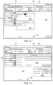
- FIG. 4is a schematic diagram of the electronic components of an exemplary embodiment of the implantable device of the present invention.
- FIGS. 5 A and 5 Bare, respectively, a perspective view of the implantable device of the present invention with the housing shown in outline and a perspective view of the obverse side of the implantable device with the housing and low water permeable filler removed.
- FIGS. 6 A, 6 B, 6 C and 6 Dare, respectively, an exploded perspective view of the drive assembly of the implantable device; front and plan views of the upper housing; and a perspective view of the manifold of an exemplary embodiment of the implantable device.
- FIGS. 7 A and 7 Bare, respectively, a plan view of the gear pump housing of the implantable device of FIG. 5 A , and a plan view of a model of the gear pump constructed in accordance with the principles of the present invention.
- FIGS. 8 A and 8 Bare, respectively, perspective and top views of the handpiece portion of an exemplary charging and communication system of the present invention.
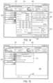
- FIG. 9is a schematic diagram of the electronic components of an exemplary embodiment of the charging and communication system of the present invention.
- FIG. 10is a schematic diagram of the functional components of the monitoring and control software employed in an exemplary embodiment of the system of the present invention.
- FIGS. 11 - 15are exemplary screenshots illustrating various aspects of the user interface of the monitoring and control system of the present invention.
- Embodiments of the present inventionprovide systems and methods where products diffuse out of the body via the peritoneal membrane.
- the present systems and methodspump to the patient's bladder by a subcutaneously implantable pump for evacuation with the urine, rather than pumping to an external device.
- the convenience to the patientis greatly improved because they need not visit a hospital or other facility to receive a sophisticated extracorporeal process, e.g., as in U.S. Pat. No. 7,169,303 to Sullivan, and need not wear an external pump and replaceable cartridge as in U.S. Pat. No. 8,012,118 to Curtin.
- the present systems and methodsmay also reduce the patient's blood volume, thus increasing the patient's comfort and reducing the likelihood that the patient will develop one or more complications.
- an implantable deviceincluding a pump that is specially configured to move fluid out of the peritoneal cavity and into the bladder, and that includes a plurality of sensors for monitoring and recording operating parameters relevant to the health of the patient.
- An externally held charging and communication systemperiodically charges and communicates with the implantable device, and downloads from the device the recorded operating parameters.
- Monitoring and control software on the treating physician's computerreceives the recorded operating parameters from the charging and communication system, and allows the physician to modify the operation of the implantable device based on the physician's perception of the patient's health as reflected in the recorded operating parameters.
- the monitoring and control softwaremay be configured to alert the physician as to a prediction or detection of infection based on the recorded operating parameters.
- the implantable deviceoptionally may also include one or more ultraviolet (UV) lamps configured to inhibit infection.
- UVultraviolet
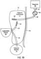
- System 10comprises implantable device 20 , external charging and communication system 30 , software-based monitoring and control system 40 , and reservoir 45 .
- monitoring and control system 40is installed and run on a conventional laptop computer used by the patient's physician.
- charging and communication system 30may be coupled, either wirelessly or using a cable, to monitoring and control system 40 to download for review data stored on implantable device 20 , or to adjust the operational parameters of the implantable device.
- Monitoring and control system 40also may be configured to upload and store date retrieved from charging and communication system 30 to a remote server for later access by the physician or charging and communications system 30 .
- Implantable device 20comprises an electromechanical pump having housing 21 configured for subcutaneous implantation. As described in further detail below with reference to FIG. 1 B , implantable device 20 may include an electrically-driven mechanical gear pump having inlet port 22 coupled to peritoneal catheter 23 and outlet port 24 coupled to bladder catheter 25 , and the fluid is separately provided to the patient's peritoneum from reservoir 45 .
- Peritoneal catheter 23comprises a tube having a first (proximal) end configured to be coupled to pump inlet 23 and a second (distal) end configured to be positioned in the peritoneal cavity.
- Bladder catheter 25comprises a tube having a first (proximal) end configured to be coupled to pump outlet 24 and a second (distal) end configured to be inserted through the wall of, and fixed within, a patient's bladder.
- both cathetersare made of medical-grade silicone and include polyester cuffs at their distal ends (not shown) to maintain the catheters in position.
- Peritoneal catheter 23 and bladder catheter 25are coupled to pump housing 21 using connector 26 configured to reduce the risk of improper installation and inadvertent disconnection, and may in addition include distinct cross-sections that reduce the risk of improper installation.
- Reservoir 45is configured to deliver fluid to the patient's peritoneal cavity via catheter 46 , which may have similar construction to the peritoneal catheter described further below with respect to FIGS. 2 A- 2 B .
- the proximal end of catheter 46may be configured to be removably coupled to an external reservoir 45 via an appropriate coupling allowing the patient to easily exchange a depleted reservoir for a fresh one, and the distal end of catheter 46 may configured for implantation in the patient's peritoneum, with a tissue cuff (not shown) to promote tissue ingrowth at the point at which catheter 46 crosses the patient's skin.
- the distal end of catheter 46may have a plurality of holes or apertures defined therein, like those discussed below with reference to FIG. 2 B .
- Reservoir 45may deliver the fluid to the peritoneal cavity by any suitable mechanism, For example, an external pump may be used to facilitate fluid flow from the reservoir 45 to the peritoneum, or the reservoir may be physically raised above the level of the peritoneum such that gravity draws the fluid into the peritoneum via catheter 46 .
- the distal end of reservoir catheter 46instead may be attached to the inlet port 22 of implantable device 20 , and implantable device 20 may be configured to pump the fluid from reservoir 45 into the peritoneal cavity via reservoir catheter 46 and peritoneal catheter 23 .
- reservoir 45may be external or implantable, and implantable device 45 further may include one or more passive or active valves to prevent fluid from being pumped out of the bladder and into the peritoneum at the same time that fluid is pumped from the reservoir and into the peritoneum.
- the composition of the dialysatemay include, for example, electrolytes and albumin, in sufficient concentrations as to cause sufficient quantities of products to diffuse into the dialysate via the peritoneal membrane.
- the albuminpreferably is provided at a concentration sufficient to bind to water insoluble or poorly water soluble products and thus facilitate their removal from the body via the bladder.
- Other components of the dialysatemay include sodium bicarbonate, although sodium chloride or sodium lactate may also suitably be used, and glucose.
- implantable device 20is configured to move fluid from the peritoneum to the bladder in quantities and intervals selected to provide sufficient time for a sufficient amount of products to diffuse into the fluid to maintain or improve the health of the patient. For example, relatively large quantities (e.g., 1-2.5 liters) may be moved in relatively long intervals (e.g., every 4-8 hours). In other embodiments, implantable device 20 may be configured to move fluid from the peritoneum to the bladder in short (e.g., 10 second) intervals (e.g., every 10-20 minutes). Such short but frequent intervals are expected to inhibit the accumulation of material on the interior lumens of catheters 23 and 25 , and reducing the risk for tissue ingrowth.
- short intervalse.g. 10 second intervals
- the fluid circuit of implantable device 20may be configured to provide an average flow rate of about 1-2.5 liters/hour, although much higher and lower flow rates are possible if needed.
- the pumping time and volumeincluding maximum and minimum limits for daily pumped volume and the time allowed to remain in the peritoneal cavity, may be programmed by the physician using monitoring and control system 40 as required for a specific patient.
- implantable device 20includes pressure sensors that monitor pressure in both the peritoneal cavity and the bladder, such that pumping of fluid into the bladder is disabled until the bladder is determined to have sufficient space to accommodate additional fluid.
- implantable device 10optionally may be programmed not to pump at night or when an accelerometer included in the implantable device indicates that the patient is asleep (and thus unlikely to be able to void the bladder).
- Implantable device 20preferably includes multiple separate fail-safe mechanisms, to ensure that urine cannot pass from the bladder to the peritoneal cavity through the pump, thereby reducing the risk of transmitting infection.
- external charging and communication system 30in a preferred form comprises base 31 and handpiece 32 .
- handpiece 32contains a controller, a radio transceiver, an inductive charging circuit, a battery, a quality-of-charging indicator and a display, and is removably coupled to base 31 to recharge its battery.
- Base 31may contain a transformer and circuitry for converting conventional 120V power service to a suitable DC current to charge handpiece 32 when coupled to base 31 .
- handpiece 32may include such circuitry and a detachable power cord, thereby permitting the handpiece to be directly plugged into a convention 120V wall socket to charge the battery.
- each of implantable device 20 and handpiece 32includes a device identifier stored in memory, such that handpiece 32 provided to the patient is coded to operate only with that patient's specific implantable device 20 .
- Handpiece 32preferably includes housing 33 having multi-function button 34 , display 35 , a plurality of light emitting diodes (LEDs, not shown) and inductive coil portion 36 .
- Multi-function button 34provides the patient the ability to issue a limited number of commands to implantable device 20
- display 35provides visible confirmation that a desired command has been input; it also displays battery status.
- Inductive coil portion 36houses an inductive coil that is used transfer energy from handpiece 32 to recharge the battery of implantable device 20 .
- the LEDswhich are visible through the material of housing 33 when lit, may be arranged in three rows of two LEDs each, and are coupled to the control circuitry and inductive charging circuit contained within handpiece 32 .
- the LEDsmay be arranged to light up to reflect the degree of inductive coupling achieved between handpiece 32 and implantable device 20 during recharging of the latter.
- the LEDsmay be omitted and an analog display provided on display 35 indicating the quality of inductive coupling.
- control circuitry contained within handpiece 32is coupled to the inductive charging circuit, battery, LEDs and radio transceiver, and includes memory for storing information from implantable device 20 .
- Handpiece 32also preferably includes a data port, such as a USB port, that permits the handpiece to be coupled to monitoring and control system 40 during visits by the patient to the physician's office.
- handpiece 32may include a wireless chip, e.g., conforming to the BLUETOOTHTM or IEEE 802.11 wireless standards, thereby enabling the handpiece to communicate wirelessly with monitoring and control system 40 , either directly or via the Internet.
- Monitoring and control system 40is intended primarily for use by the physician and comprises software configured to run on a conventional computer, e.g., a laptop as illustrated in FIG. 1 A .
- the softwareenables the physician to configure, monitor and control operation of charging and communication system 30 and implantable device 20 .
- the softwaremay include routines for configuring and controlling pump operation, such as a target amount of fluid to move daily or per motor actuation, intervals between pump actuation, and limits on peritoneal cavity pressure, bladder pressure, pump pressure, and battery temperature.
- System 40also may provide instructions to implantable device 20 via charging and control system 30 to control operation of implantable device 20 so as not to move fluid during specific periods (e.g., at night) or to defer pump actuation if the patient is asleep.
- System 40further may be configured, for example, to send immediate commands to the implantable device to start or stop the pump, or to operate the pump in reverse or at high power to unblock the pump or associated catheters.
- the software of system 40also may be configured to download real-time data relating to pump operation, as well as event logs stored during operation of implantable device 20 .
- system 40Based on the downloaded data, e.g., based on measurements made of the patient's temperature, respiratory rate, and/or fluid viscosity, the software of system 40 optionally may be configured to alert the physician to a prediction or detection of infection and/or a change in the patient's health for which an adjustment to the flow rate, volume, time and/or frequency of pump operation may be required. Finally, system 40 optionally may be configured to remotely receive raw or filtered operational data from a patient's handpiece 32 over a secure Internet channel.
- FIGS. 1 B- 1 Eplan views of various possible configurations of implantable device 20 and reservoir 45 , as implanted in a patient, will now be described. Methods of using system 10 , including device 20 and reservoir 45 implanted as illustrated in FIGS. 1 B- 1 E , to treat a patient will be provided further below with reference to FIG. 1 F .
- FIG. 1 Billustrates an embodiment in which implantable device 20 is implanted subcutaneously, preferably outside of the patient's peritoneum 11 as defined by peritoneal membrane 12 but beneath the subject's skin 14 so that it may readily be charged by, and communicate with, charging and communication system 30 illustrated in FIG. 1 A .
- Device 20is coupled via appropriate connectors (not shown) to peritoneal catheter 23 and bladder catheter 25 .
- Peritoneal catheter 23is configured for implantation in the patient's peritoneum 11 and preferably includes apertures 53 such as described in further detail below with reference to FIGS. 2 A- 2 B .
- Bladder catheter 25is configured for implantation in the patient's bladder 13 and preferably includes an anchor to secure the outlet end of the catheter within the bladder 13 , such as described in further detail below with reference to FIGS. 3 A- 3 B .
- reservoir 45is positioned outside of the body and fluidically coupled to the peritoneal cavity via catheter 46 .
- Catheter 46is coupled to reservoir 45 via connector 47 , which is configured so as to allow the patient to periodically replace reservoir 45 with ease.
- Catheter 46preferably includes apertures 53 ′, which may be similar in dimension and density to apertures 53 , and which allow flow into the peritoneum 11 in a relatively diffuse manner.
- external pump 48is configured to cause flow from reservoir 45 into the peritoneum 11 at a desired rate.
- reservoir 45may be positioned on belt 57 which is described further below with respect to FIG. 1 D and which includes pump 48 .
- Pump 48may be configured to communicate wirelessly with implantable device 20 so as to coordinate delivery into the patient's peritoneum.
- reservoir 45is positioned at a level above the peritoneum 11 such that gravity causes flow from reservoir 45 into the peritoneum at a desired rate.
- reservoir 45preferably provides fluid to the peritoneum 11 in a volume, at a rate, and with a frequency suitable to sufficiently fill the peritoneum to allow a sufficient amount of products to diffuse to maintain or improve the health of the patient.
- Such volume, rate, and frequencymay be approximately the same as the volume, rate, and frequency with which implantable device 20 removes products from the peritoneal cavity to the patient's bladder 13 .
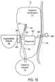
- reservoir 45may be positioned outside of the patient's body, e.g., using belt 57 described further below with reference to FIG. 1 D , and may be coupled to implantable device 20 via catheter 46 ′ and connector 47 .
- Implantable device 20is configured to pump into peritoneum 11 from reservoir 45 via catheters 46 ′ and 23 , and then at a later time to pump from peritoneum 11 into bladder 13 via catheters 23 and 25 .
- the inlet 22 of implantable device 20comprises a first valve 49 to which catheters 23 and 46 ′ are both connected
- the outlet 24 of implantable device 20comprises a second valve 49 ′ to which catheter 25 is connected.
- implantable device 20controls valves 49 and 49 ′ so as to prevent fluid from being inadvertently pumped from the bladder into the peritoneal cavity.
- implantable device 20may close off fluidic communication to catheter 25 by appropriately actuating valve 49 ′, may open fluidic communication between catheters 46 ′ and 23 by appropriately actuating valve 49 , and may turn in a first direction so as to pump fluid from reservoir 45 via catheters 46 ′ and 23 .
- implantable device 20may pump that fluid to the patient's bladder 13 by closing off fluidic communication to catheter 46 ′ and opening fluidic communication to catheter 23 by appropriately actuating valve 49 , opening fluidic communication to catheter 25 by appropriately actuating valve 49 ′, and turning in a second direction (opposite from the first) so as to pump the fluid into bladder 13 via catheters 23 and 25 .
- the functionalities of valves 49 and 49 ′may be provided by any desired number of valves that are disposed appropriately along catheters 23 , 25 , and 46 ′ and are controllably actuated by implantable device 20 , e.g., via valve controller 86 illustrated in FIG. 4 .
- valve 49 ′may be a passive check valve disposed along catheter 25 that inhibits fluid to flow from the bladder to device 20 .
- FIG. 1 Dillustrates a belt 57 that may be used to removably secure reservoir 45 illustrated in FIGS. 1 B and 1 C to the patient's body.
- Belt 57includes pouch(es) 58 , flexible band of material 59 , fastener 59 ′, and optional pump 48 .
- Pouch(es) 58may include one long, continuous pouch that contains the fluid, or alternatively may include a plurality of pouches interconnected by catheters, and may be coupled to catheter 46 or 46 ′ via connector 47 .
- pouch(es) 58hold a sufficient amount for one day or one treatment cycle, e.g., 1-2.5 liters, and may be configured for single use and easy replaceability, or may be sterilizable and refillable.
- Pouch(es) 58may be arranged generally linearly along the length of the flexible band of material 59 , and may be secured thereto by an appropriate mechanism, e.g., with thin bands of material secured by snaps, buttons, hook-and-pile fasteners, and the like.
- Flexible band of material 59may be formed of any suitable fabric, including but not limited to a stretchable, form-fitting material that may fit unobtrusively under the patient's clothes.
- Fastener 59 ′is configured to allow the patient to repeatedly wear belt 57 , and may include, for example, snap(s), a buckle, a zipper, or a hook-and-pile fastener, as is illustrated.
- Optional pump 48(including a power source such as a battery, not shown) is configured to facilitate flow of into the peritoneum, e.g., as described above with respect to FIG. 1 B .
- Pump 48may include a wireless transceiver that communicates with implantable device 20 to coordinate delivery from the reservoir to the peritoneum with the removal from the peritoneum to the bladder.
- an ultraviolet (UV) sourcesuch as described below with respect to FIGS. 4 and 5 B , and appropriate power source, may be provided on belt 57 and configured to irradiate the fluid before it enters, or as it enters, catheter 46 or 46 ′.
- FIG. 1 Eillustrates an alternative configuration to those of FIGS. 1 B- 1 D , in which reservoir 45 ′ is instead implanted within the patient's body, e.g., within the peritoneum 11 .
- Implantable device 20is configured to pump into peritoneum 11 from reservoir 45 , and then at a later time to pump from peritoneum 11 into bladder 13 , using catheters 46 , 23 , and 25 and valves 49 and 49 ′ in a manner analogous to that described above with respect to FIG. 1 D .
- catheters 46 , 23 , and 25 and valves 49 and 49 ′in a manner analogous to that described above with respect to FIG. 1 D .
- FIG. 1 Dinstead of positioning reservoir 45 on belt 47 , as illustrated in FIG. 1 D , or hanging reservoir 45 over the level of the peritoneum as described above with reference to FIG. 1 B , the embodiment illustrated in FIG.
- 1 Emay further improve convenience the patient by disposing reservoir 45 ′ within the peritoneal cavity and providing port 45 ′′ and port catheter 46 ′ via which the patient may periodically fill the reservoir.
- port 45 ′′comprises a flexible, self-sealing membrane that the patient may pierce with a needle connected to a separate, external reservoir (not shown) for re-filling internal reservoir 45 ′.
- FIGS. 1 A- 1 EMethods of using systems such as illustrated in FIGS. 1 A- 1 E will now be described with reference to FIG. 1 F .
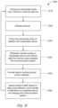
- Method 1000 illustrated in FIG. 1 Fincludes introducing to the peritoneal cavity from a reservoir that is internal or external to the patient's body (step 1010 ).
- a reservoirthat is internal or external to the patient's body
- Productsthen diffuse, e.g., via the peritoneal membrane, thus reducing the levels of those products in the patient's blood (step 1020 ).
- step 1030is pumped from the peritoneal cavity to the bladder with the implantable device.
- Such pumpingmay occur after a sufficient amount of time to draw a sufficient amount of products out of the body to maintain, or even improve, health.
- Energymay be wirelessly transferred to the implantable device, and data received from the device, using a charging and communication system such as described briefly above with reference to FIG. 1 A and as described in greater detail below with reference to FIGS. 8 A- 9 (step 1040 ).
- the implantable devicemay record parameters reflective of the health of the patient and the operation of the device, which parameters may be communicated to the charging and communication system.
- the datae.g., parameters recorded by the implantable device, then is provided to monitoring and control software, which is in communication with the charging and communication system and is under the control of the treating physician (step 1050 ).
- the health of the patientmay be assessed using the software, and the physician may remotely communicate any modifications to the flow rate, volume, time duration, or frequency with which the implantable device is to maintain in the peritoneal cavity before removing it to the bladder (step 1060 ). Such communication may be performed via the charging and communication system.
- FIGS. 2 A- 15Further details of selected components of the systems and methods of FIGS. A- 1 F will now be provided with reference to FIGS. 2 A- 15 .
- Peritoneal catheter 50corresponds to peritoneal catheter 23 described above with reference to FIGS. 1 A- 1 E , and preferably comprises tube 51 of medical-grade silicone including inlet (distal) end 52 having a plurality of through-wall holes 53 and outlet (proximal) end 54 .
- Peritoneal catheterpreferably has length L 1 of about 40 cm, with holes 53 extending over length L 2 of about 24 cm from inlet end 52 .
- Holes 53preferably are arranged circumferentially offset by about 90° and longitudinally offset between about 8 mm to 10 mm, as shown in FIG. 2 B .
- 29 holes 53are arranged in four rows of 7 holes each, extend only through one wall of the peritoneal catheter at each location, and have a size of between 2.0 to 2.5 mm.
- Peritoneal catheter 50preferably includes solid silicone plug 55 that fills distal end of the lumen for a distance of about 7-10 mm to reduce tissue ingrowth, and radiopaque strip 56 disposed on, or embedded within, the catheter that extends the entire length of the catheter, that renders the catheter visible in fluoroscopic or X-ray images.
- Peritoneal catheter 50may also include a polyester cuff (not shown) in the region away from holes 53 , to promote adhesion of the catheter to the surrounding tissue, thereby anchoring it in place.
- inlet end 52 of peritoneal catheter 50may have a spiral configuration, and an atraumatic tip, with holes 53 distributed over a length of the tubing to reduce the risk of clogging.
- inlet end 52may include a portion having an enlarged diameter, as disclosed in U.S. Pat. No. 4,657,530, or a reservoir as disclosed in FIGS. 9 to 16 of U.S. Patent Application Publication US 2009/0318844, the entire contents of both of which are incorporated herein by reference, to further reduce the risk of clogging.
- Inlet end 52also may terminate in a duck-bill valve, as shown for example in U.S. Pat. No. 4,240,434, thereby permitting the catheter to be cleaned in situ by disconnecting the outlet end of the catheter from implantable device 20 and extending a rod from the outlet end of catheter 50 through the duckbill valve at the inlet end.
- Inlet end 52also may include a polyester cuff to promote adhesion of the catheter to an adjacent tissue wall, thereby ensuring that the inlet end of the catheter remains in position.
- Outlet end 54also may include a connector for securing the outlet end of the peritoneal catheter to implantable device 20 .
- the distal end of the peritoneal catheter, up to the ingrowth cuffmay be configured to pass through a conventional 16 F peel-away sheath.
- the length of the peritoneal cathetermay be selected to ensure that it lays along the bottom of the body cavity, and is sufficiently resistant to torsional motion so as not to become twisted or kinked during or after implantation.
- Bladder catheter 60preferably comprises tube 61 of medical-grade silicone having inlet (proximal) end 62 and outlet (distal) end 63 including spiral structure 64 , and polyester ingrowth cuff 65 .
- Bladder catheter 60includes a single internal lumen that extends from inlet end 62 to a single outlet at the tip of spiral structure 64 , commonly referred to as a “pigtail” design.
- Inlet end 62may include a connector for securing the inlet end of the bladder catheter to implantable device 20 , or may have a length that can be trimmed to fit a particular patient.
- bladder catheter 60may have length L 3 of about 45 cm, with cuff 65 placed length L 4 of about 5 to 6 cm from spiral structure 64 .
- Bladder catheter 60may be loaded onto a stylet with spiral structure 64 straightened, and implanted using a minimally invasive technique in which outlet end 63 and spiral structure 64 are passed through the wall of a patient's bladder using the stylet. When the stylet is removed, spiral structure 64 returns to the coiled shape shown in FIG. 3 A .
- the remainder of the catheteris implanted using a tunneling technique, such that inlet end 62 of the catheter may be coupled to implantable device 20 .
- Spiral structure 64may reduce the risk that outlet end 63 accidentally will be pulled out of the bladder before the tissue surrounding the bladder heals sufficiently to incorporate ingrowth cuff 65 , thereby anchoring the bladder catheter in place.
- bladder catheter 60is configured to pass through a conventional peel-away sheath.
- Bladder catheter 60preferably is sufficiently resistant to torsional motion so as not to become twisted or kinked during or after implantation.
- peritoneal catheter 50 and bladder catheter 60preferably are different colors, have different exterior shapes (e.g., square and round) or have different connection characteristics so that they cannot be inadvertently interchanged during connection to implantable device 20 .
- bladder catheter 60may include an internal duckbill valve positioned midway between inlet 62 and outlet end 63 of the catheter to ensure that urine does not flow from the bladder into the peritoneal cavity if the bladder catheter is accidentally pulled free from the pump outlet of implantable device 20 and/or if the pump of implantable device 20 is actuated so as to draw fluid from reservoir 45 into the patient's peritoneal cavity.
- the peritoneal and bladder catheters devicesmay incorporate one or several anti-infective agents to inhibit the spread of infection between body cavities.
- anti-infective agentswhich may be utilized may include, e.g., bacteriostatic materials, bacteriocidal materials, one or more antibiotic dispensers, antibiotic eluting materials, and coatings that prevent bacterial adhesion, and combinations thereof.
- implantable device 20may include a UV lamp configured to irradiate fluid in the peritoneal and/or bladder catheters so as to kill any pathogens that may be present and thus inhibit the development of infection, as described further below with respect to FIGS. 4 and 5 B .
- peritoneal and bladder catheters 50 , 60may share a common wall, which may be convenient because the bladder and peritoneal cavity share a common wall, thereby facilitating insertion of a single dual-lumen tube.
- either or both of the peritoneal or bladder cathetersmay be reinforced along a portion of its length or along its entire length using ribbon or wire braiding or lengths of wire or ribbon embedded or integrated within or along the catheters.
- the braiding or wiremay be fabricated from metals such as stainless steels, superelastic metals such as nitinol, or from a variety of suitable polymers. Such reinforcement may also be used for catheter 46 connected to reservoir 45 .
- Bladder catheter 60 ′preferably comprises tube 61 ′ of medical-grade silicone having inlet end 62 ′, outlet end 63 ′ and polyester ingrowth cuff 65 ′.
- outlet end 63 ′includes malecot structure 66 , illustratively comprising four resilient wings 67 that expand laterally away from the axis of the catheter to reduce the risk that outlet end 63 ′ of the catheter will be inadvertently pulled loose after placement.
- Inlet end 62 ′may include a connector for securing the inlet end of the bladder catheter to implantable device 20 , or may have a length that can be trimmed to fit a particular patient.
- Malecot structure 66preferably is constructed so that wings 67 deform to a substantially flattened configuration when a stylet is inserted through the lumen of the catheter.
- bladder catheter 60 ′may be loaded onto a stylet, and using a minimally invasive technique, outlet end 63 ′ and malecot structure 66 may be passed through the wall of a patient's bladder using the stylet.
- wings 67 of the malecot structurereturn to the expanded shape shown in FIG. 3 B .
- Malecot structure 66may reduce the risk that outlet end 63 ′ accidentally will be pulled out of the bladder before the tissue surrounding the bladder heals sufficiently to incorporate ingrowth cuff 65 ′.
- the bladder catheter of FIG. 3 Bmay be configured to pass through a conventional peel-away sheath, and preferably is sufficiently resistant to torsional motion so as not to become twisted or kinked during or after implantation.
- Implantable device 20includes control circuitry, illustratively processor 70 coupled to nonvolatile memory 71 , such as flash memory or electrically erasable programmable read only memory, and volatile memory 72 via data buses.
- Processor 70is electrically coupled to electric motor 73 , battery 74 , inductive circuit 75 , radio transceiver 76 , UV lamp 85 , and a plurality of sensors, including humidity sensor 77 , a plurality of temperature sensors 78 , accelerometer 79 , a plurality of pressure sensors 80 , and respiratory rate sensor 81 .
- Inductive circuit 75is electrically coupled to coil 84 to receive energy transmitted from charging and communication system 30 , while transceiver 76 is coupled to antenna 82 , and likewise is configured to communicate with a transceiver in charging and communication system 30 , as described below.
- inductive circuit 75also may be coupled to infrared light emitting diode 83 .
- Motor 73may include a dedicated controller, which interprets and actuates motor 73 responsive to commands from processor 70 .
- processor 70is further in communication with valve controller 86 . All of the components depicted in FIG. 4 are contained within a low volume sealed biocompatible housing, as shown in FIG. 5 A .
- Processor 70executes firmware stored in nonvolatile memory 71 which controls operation of motor 73 responsive to signals generated by motor 73 , sensors 77 - 81 and commands received from transceiver 76 . Processor 70 also controls reception and transmission of messages via transceiver 76 and operation of inductive circuit 75 to charge battery 74 . In addition, processor 70 receives signals generated by Hall Effect sensors located within motor 73 , which are used to compute direction and revolutions of the gears of the gear pump, and thus fluid volume pumped and the viscosity of that fluid, as described below.
- Processor 70preferably includes a low-power mode of operation and includes an internal clock, such that the processor can be periodically awakened to handle pumping, pump tick mode, or communications and charging functions, and/or awakened to handle commands received by transceiver 76 from handpiece 32 .
- processor 70comprises a member of the MSP430 family of microcontroller units available from Texas Instruments, Incorporated, Dallas, Tex., and may incorporate the nonvolatile memory, volatile memory, and radio transceiver components depicted in FIG. 4 .
- the firmware executed on processor 70may be configured to respond directly to commands sent to implantable device 20 via charging and communication system 30 .
- Processor 70also is configured to monitor operation of motor 72 (and any associated motor controller) and sensors 77 - 81 , as described below, and to store data reflecting operation of the implantable device, including event logs and alarms. Thus, data is reported to the charging and communication system when it is next wirelessly coupled to the implantable device.
- processor 70generates up to eighty log entries per second prior to activating the pump, about eight log entries per second when the implantable system is actively pumping and about one log entry per hour when not pumping.
- Nonvolatile memory 71preferably comprises flash memory or EEPROM, and stores a unique device identifier for implantable device 20 , firmware to be executed on processor 70 , configuration set point data relating to operation of the implantable device, and optionally, coding to be executed on transceiver 76 and/or inductive circuit 75 , and a separate motor controller, if present.
- Firmware and set point data stored on nonvolatile memory 71may be updated using new instructions provided by control and monitoring system 40 via charging and communication system 30 .
- Volatile memory 72is coupled to and supports operation of processor 70 , and stores data and event log information gathered during operation of implantable device 20 . Volatile memory 72 also serves as a buffer for communications sent to, and received from, charging and communication system 30 .
- Transceiver 76preferably comprises a radio frequency transceiver and is configured for bi-directional communications via antenna 76 with a similar transceiver circuit disposed in handpiece 32 of charging and communication system 30 .
- Transceiver 76also may include a low power mode of operation, such that it periodically awakens to listen for incoming messages and responds only to those messages including the unique device identifier assigned to that implantable device.
- transceiver 76may be configured to send or receive data only when inductive circuit 75 of the implantable device is active.
- transceiver 76may employ an encryption routine to ensure that messages sent from, or received by, the implantable device cannot be intercepted or forged.
- Inductive circuit 75is coupled to coil 84 , and is configured to recharge battery 74 of the implantable device when exposed to a magnetic field supplied by a corresponding inductive circuit within handpiece 32 of charging and communication system 30 .
- inductive circuit 75is coupled to optional infrared LED 83 that emits an infrared signal when inductive circuit 75 is active. The infrared signal may be received by handpiece 32 of charging and communication system 30 to assist in locating the handpiece relative to the implantable device, thereby improving the magnetic coupling and energy transmission to the implantable device.
- inductive circuit 75optionally may be configured not only to recharge battery 74 , but to directly provide energy to motor 73 in a “boost” mode or jog/shake mode to unblock the pump.
- processor 70detects that motor 73 is stalled, e.g., due to a block created by proteins in the fluid, an alarm may be stored in memory.
- implantable device 20next communicates with charging and communication system 30 , the alarm is reported to handpiece 32 , and the patient may be given the option of depressing multifunction button 34 to apply an overvoltage to motor 73 from inductive circuit 75 for a predetermined time period to free the pump blockage.
- depressing the multi-function buttonmay cause processor 70 to execute a set of commands by which motor 73 is jogged or shaken, e.g., by alternatingly running the motor is reverse and then forward, to disrupt the blockage. Because such modes of operation may employ higher energy consumption than expected during normal operation, it is advantageous to drive the motor during such procedures with energy supplied via inductive circuit 75 .
- Battery 74preferably comprises a lithium ion or lithium polymer battery capable of long lasting operation, e.g., up to three years, when implanted in a human, so as to minimize the need for re-operations to replace implantable device 20 .
- battery 74supplies a nominal voltage of 3.6V, a capacity of 150 mAh when new, and a capacity of about 120 mAh after two years of use.
- battery 74is configured to supply a current of 280 mA to motor 73 when pumping; 25 mA when the transceiver is communicating with charging and communication system 30 ; 8 mA when processor 70 and related circuitry is active, but not pumping or communicating; and 0.3 mA when the implantable device is in low power mode.
- battery 74should be sized to permit a minimum current of at least 450 mAh for a period of 10 seconds and 1 A for 25 milliseconds during each charging cycle.
- Motor 73preferably is a brushless direct current or electronically commuted motor having a splined output shaft that drives a set of floating gears that operate as a gear pump, as described below.
- Motor 73may include a dedicated motor controller, separate from processor 70 , for controlling operation of the motor.
- Motor 73may include a plurality of Hall Effect sensors, preferably two or more, for determining motor position and direction of rotation. Due to the high humidity that may be encountered in implantable device 20 , processor 70 may include programming to operate motor 73 , although with reduced accuracy, even if some or all of the Hall Effect sensors fail.
- motor 73is capable of driving the gear pump to generate a nominal flow rate of 150 ml/min and applying a torque of about 1 mNm against a pressure head of 30 cm water at 3000 RPM.
- the motorpreferably is selected to drive the gears at from 1000 to 5000 RPM, corresponding to flow rates of from 50 to 260 ml/min, respectively.
- the motorpreferably has a stall torque of at least 3 mNm at 500 mA at 3 V, and more preferably 6 mNm in order to crush non-solid proteinaceous materials.
- the motorpreferably also supports a boost mode of operation, e.g., at 5 V, when powered directly through inductive circuit 75 .
- Motor 73preferably also is capable of being driven in reverse as part of a jogging or shaking procedure to unblock the gear pump.
- processor 70may be programmed to automatically and periodically wake up and enter a pump tick mode.
- the gear pumpis advanced slightly, e.g., about 120° as measured by the Hall Effect sensors, before processor 70 returns to low power mode.
- this intervalis about every 20 minutes, although it may be adjusted by the physician using the monitoring and control system.
- This pump tick modeis expected to prevent the fluid, which may have a high protein content, from partially solidifying, and blocking the gear pump.
- processor 70also may be programmed to enter a jog or shake mode when operating on battery power alone, to unblock the gear pump. Similar to the boost mode available when charging the implantable device with the handpiece of charging and communication system 30 , the jog or shake mode causes the motor to rapidly alternate the gears between forward and reverse directions to crush or loosen buildup in the gear pump or elsewhere in the fluid path. Specifically, in this mode of operation, if the motor does not start to turn within a certain time period after it is energized (e.g., 1 second), the direction of the motion is reversed for a short period of time and then reversed again to let the motor turn in the desired direction.
- a certain time period after it is energizede.g. 1 second
- the directionis again reversed for a period of time (e.g., another 10 msec). If the motor still is not able to advance the time interval between reversals of the motor direction is reduced to allow for the motor to develop more power, resulting in a shaking motion of the gears. If the motor does not turn forward for more than 4 seconds, the jog mode of operation is stopped, and an alarm is written to the event log. If the motor was unable to turn forward, processor 70 will introduce a backwards tick before the next scheduled fluid movement. A backward tick is the same as a tick (e.g., about 120° forward movement of the motor shaft) but in the reverse direction, and is intended to force the motor backwards before turning forward, which should allow the motor to gain momentum.
- a period of timee.g., another 10 msec.
- Sensors 77 - 81continually monitor humidity, temperature, acceleration, pressure, and respiratory rate, and provide corresponding signals to processor 70 which stores the corresponding data in memory 71 for later transmission to monitoring and control system 40 .
- humidity sensor 77is arranged to measure humidity within the housing of the implantable device, to ensure that the components of implantable device are operated within expected operational limits.
- Humidity sensor 77preferably is capable of sensing and reporting humidity within a range or 20% to 100% with high accuracy.
- One or more of temperature sensors 78may be disposed within the housing and monitor the temperature of the implantable device, and in particular battery 74 to ensure that the battery does not overheat during charging, while another one or more of temperature sensors 78 may be disposed so as to contact fluid entering at inlet 62 and thus monitor the temperature of the fluid, e.g., for use in assessing the patient's health.
- Accelerometer 79is arranged to measure acceleration of the implant, preferably along at least two axes, to detect periods of inactivity, e.g., to determine whether the patient is sleeping. This information is provided to processor 70 to ensure that the pump is not operated when the patient is indisposed to attend to voiding of the bladder.
- Implantable device 20preferably includes multiple pressure sensors 80 , which are continually monitored during waking periods of the processor.
- the implantable device of the present inventionpreferably includes four pressure sensors: a sensor to measure the pressure in the peritoneal cavity, a sensor to measure the ambient pressure, a sensor to measure the pressure at the outlet of the gear pump, and a sensor to measure the pressure in the bladder.
- These sensorspreferably are configured to measure absolute pressure between 450 mBar and 1300 mBar while consuming less than 50 mW at 3V.
- the sensors that measure pressure at the pump outlet and in the bladderare placed across a duckbill valve, which prevents reverse flow of urine back into the gear pump and also permits computation of flow rate based on the pressure drop across the duckbill valve.
- Respiratory rate monitor 81is configured to measure the patient's respiratory rate, e.g., for use in assessing the patient's health.
- the patient's respiratory ratemay be measured based on the outputs of one or more of pressure sensors 80 , e.g., based on changes in the ambient pressure or the pressure in the peritoneal cavity caused by the diaphragm periodically compressing that cavity during breathing.
- any desired number of additional sensors for measuring the health of the patientmay also be provided in operable communication with processor 70 and may output recordable parameters for storage in memory 71 and transmission to monitoring and control system 40 , that the physician may use to assess the patient's health.
- additional sensors for measuring the health of the patientmay also be provided in operable communication with processor 70 and may output recordable parameters for storage in memory 71 and transmission to monitoring and control system 40 , that the physician may use to assess the patient's health.
- chemical or biochemical sensorsmay be provided that are configured to monitor the levels of one or more products in the fluid.
- processor 70is programmed to pump a predetermined volume of fluid from the peritoneal cavity to the bladder after that fluid has been in the peritoneal cavity for a predetermined amount of time and with a predetermined frequency.
- Such volume, time, and frequencypreferably are sufficient for a sufficient amount of products to diffuse into the fluid via the peritoneal membrane to maintain or improve the health of the patient.
- the volume, time, and frequencymay be selected upon the health of the patient, the activity and habits of the patient, the permeability of the peritoneal membrane to the products, and the osmotic characteristics.
- the physicianmay initially program processor 70 with a first time, volume, and frequency based on his perception of the patient's health and habits, and later may adjust that initial programming to vary the volume, time, and/or frequency based on his perception of changes in the patient's health, for example based on changes over time in parameters measured by implantable device 20 and relayed to the physician via monitoring and control software 40 .
- processor 70is programmed to pump fluid from the peritoneal cavity to the bladder only when the pressure in the peritoneum exceeds a first predetermined value, and the pressure in the bladder is less than a second predetermined value, so that the bladder does not become overfull.
- the ambient pressure measurementmay be used to calculate a differential value for the peritoneal pressure. In this way, the predetermined pressure at which the pump begins operation may be reduced, to account for lower atmospheric pressure. Likewise, the ambient pressure may be used to adjust the predetermined value for bladder pressure. In this way, the threshold pressure at which the pumping ceases may be reduced, because the patient may experience bladder discomfort at a lower pressure when at a high altitude location.
- controller 70is in operable communication with UV lamp 85 , which is configured to irradiate and thus kill pathogens in the fluid both before and after that fluid is provided to the peritoneal cavity.
- UV lamp 85preferably generates light in the UV-C spectral range (about 200-280 nm), particularly in the range of about 250-265 nm, which is also referred to as the “germicidal spectrum” because light in that spectral range breaks down nucleic acids in the DNA of microorganisms.
- Low-pressure mercury lampshave an emission peak at approximately 253.7 nm, and may suitably be used for UV lamp 85 .
- UV lamp 85may be a UV light emitting diode (LED), which may be based on AlGaAs or GaN.
- UV lamp 85irradiates any fluid that enters the implantable device for a preselected amount of time sufficient to kill pathogens that may be present in that fluid.
- the flow rate of the fluid through the devicemay be selected (e.g., pre-programmed) so as to irradiate the fluid with a sufficient dosage of UV light to inhibit the growth of colonies of pathogens.
- dosages of 253.7 nm UV light of between about 5,500-7,000 ⁇ Ws/cm 2are sufficient to provide 100% kill rates for many organisms, including E.
- coliProteus spp., Klebsiella spp., Serratia spp., Leptospirosis spp., Staphylococcus haemolyticus , and Enterococci.
- Higher dosagese.g., between about 8,500-12,000 ⁇ Ws/cm 2 , may be required to provide 100% kill rates for other organisms, including Kendensiella ssp., Enterobacter spp., Psuedomonas spp., and Neisseria gonorrhoeae .
- the dosage to sufficiently inhibit colony growthmay be lower.
- Controller 70may be pre-programmed to set a flow rate of fluid through the tubing sufficient to inhibit colony growth of one or more target pathogens based on the intensity of UV lamp 85 , the reflective conditions within the portion of the housing in which UV lamp 85 is used (e.g., upper portion 93 described below with reference to FIG. 5 B ), the configuration of the tubing being exposed to the UV lamp, the distance between the tubing and the UV lamp, and the susceptibility of target pathogens to the spectrum emitted by UV lamp 85 .
- processor 70also may be in communication with valve controller 86 ; alternatively, valve controller 86 may be part of the functionality of processor 70 .
- Valve controller 86controls the actuation of any valves that may be used to control the flow of fluid between the reservoir, the peritoneum, and the bladder. For example, as described above with reference to FIGS.
- implantable device 20may be configured to pump fluid from an external or internal reservoir to the peritoneum, while actuating valves 49 and 49 ′ so as to close fluidic access to the bladder and thus avoid inadvertently pumping fluid from the bladder into the peritoneum; and may be configured to pump fluid from the peritoneum to the bladder, while actuating valves 49 and 49 ′ so as to close fluidic access to the reservoir and thus avoid inadvertently pumping fluid from the peritoneum into the reservoir.
- Valve controller 86may coordinate the actuation of valves 49 and 49 ′ in such a manner, or in any other appropriate manner based on the particular valve configuration.
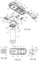
- FIGS. 5 A and 5 Bfurther details of an exemplary embodiment of implantable device 90 are provided.
- housing 91is shown as transparent, although it should of course be understood that housing 91 comprises opaque biocompatible plastic and/or metal alloy materials.
- FIG. 5 Bthe implantable device is shown with lower portion 92 of housing 91 removed from upper housing 93 and without a glass bead/epoxy filler material that is used to prevent moisture from accumulating in the device.
- motor 94is coupled to gear pump housing 95 , which is described in greater detail with respect to FIGS. 6 and 7 .
- FIG. 4are disposed on flexible circuit board substrate 96 , which extends around and is fastened to support member 97 .
- Coil 98(corresponding to coil 84 of FIG. 4 ) is disposed on flap 99 of the substrate and is coupled to the electronic components on flap 100 by flexible cable portion 101 .
- Support member 97is fastened to upper housing 93 and provides a cavity that holds battery 102 (corresponding to battery 74 of FIG. 4 ).
- Lower portion 92 of housing 91includes port 103 for injecting the glass bead/epoxy mixture after upper portion 93 and lower portion 92 of housing 91 are fastened together, to reduce space in the housing in which moisture can accumulate.
- Housing 91also may include features designed to reduce movement of the implantable pump once implanted within a patient, such as a suture hole to securely anchor the implantable device to the surrounding tissue. Housing 91 may in addition include a polyester ingrowth patch that facilitates attachment of the implantable device to the surrounding tissue following subcutaneous implantation.
- the implantable deviceoptionally may incorporate anti-clogging agents, such enzyme eluting materials that specifically target the proteinaceous components, enzyme eluting materials that specifically target the proteinaceous and encrustation promoting components of urine, chemical eluting surfaces, coatings that prevent adhesion of proteinaceous compounds, and combinations thereof.
- anti-clogging agentssuch as enzyme eluting materials that specifically target the proteinaceous components, enzyme eluting materials that specifically target the proteinaceous and encrustation promoting components of urine, chemical eluting surfaces, coatings that prevent adhesion of proteinaceous compounds, and combinations thereof.
- agentsif provided, may be integrated within or coated upon the surfaces of the various components of the system.
- upper housing 93optionally includes UV lamp 85 described further above with respect to FIG. 4 .
- the fluid channels 88 for conducting the fluidmay extend approximately linearly, or alternatively may include one or more curves or bends so as to increase the volume of fluid that may be simultaneously exposed UV lamp 86 , and thus allow for an increase in the flow rate.
- the fluid channels 88may include an approximate spiral, an approximate sine wave, or an approximate “S” curve so as to increase the volume of fluid that may be simultaneously exposed to UV lamp 86 .
- Upper housing 93further may include reflective coating 87 , e.g., a white coating such as ZnO or other diffuse or Lambertian reflector, so as to enhance irradiation of the tubing and shield the patient from potential UV light exposure.
- FIG. 6 Ais an exploded view showing assembly of motor 94 with gear pump housing 95 and upper housing 93 , as well as the components of the fluid path within the implantable device.
- Upper housing 93preferably comprises a high strength plastic or metal alloy material that can be molded or machined to include openings and channels to accommodate inlet nipple 102 , outlet nipple 103 , pressure sensors 104 a - 104 d , manifold 105 and screws 106 .
- Nipples 102 and 103preferably are machined from a high strength biocompatible metal alloy, and outlet nipple 103 further includes channel 107 that accepts elastomeric duckbill valve 108 .
- Outlet nipple 103further includes lateral recess 109 that accepts pressure sensor 104 a , which is arranged to measure pressure at the inlet end of the bladder catheter, corresponding to pressure in the patient's bladder (or peritoneal cavity).
- inlet nipple 102is disposed within opening 110 , which forms a channel in upper housing 93 that includes opening 111 for pressure sensor 104 b and opening 112 that couples to manifold 105 .
- Pressure sensor 104 bis arranged to measure the pressure at the outlet end of the peritoneal catheter, corresponding to pressure in the peritoneal cavity.
- Outlet nipple 103including duckbill valve 107 , is disposed within opening 113 of upper housing 93 so that lateral recess 108 is aligned with opening 114 to permit access to the electrical contacts of pressure sensor 104 a .
- Opening 113forms channel 115 that includes opening 116 for pressure sensor 104 c , and opening 117 that couples to manifold 105 .
- Upper housing 93preferably further includes opening 118 that forms a channel including opening 119 for accepting pressure sensor 104 d .
- Pressure sensor 104 dmeasures ambient pressure, and the output of this sensor is used to calculate differential pressures as described above.
- Upper housingfurther includes notch 120 for accepting connector 26 (see FIG. 1 A ) for retaining the peritoneal and bladder catheters coupled to inlet and outlet nipples 102 and 103 .
- Upper housing 93further includes recess 121 to accept manifold 105 , and peg 122 , to which support member 97 (see FIG. 5 B ) is connected.
- manifold 105preferably comprises a molded elastomeric component having two separate fluid channels (such channels designated 88 in FIG. 5 B ) that couple inlet and outlet flow paths through upper housing 93 to the gear pump.
- the first channelincludes inlet 124 and outlet 125
- the second channelincludes inlet 126 and outlet 127 .
- Inlet 124couples to opening 112 (see FIG. 6 C ) of the peritoneal path
- outlet 127couples to opening 117 of the bladder path.
- Manifold 105is configured to improve manufacturability of the implantable device, by simplifying construction of upper housing 93 and obviating the need to either cast or machine components with complicated non-linear flow paths.
- Optional UV lamp 86 and surface 87may be placed in suitable positions within housing 93 and relative to manifold 105 to sufficiently irradiate the fluid as motor 94 pumps the fluid through housing 93 .
- motor 94is coupled to gear pump housing 95 using mating threads 130 , such that splined shaft 131 of motor 94 passes through bearing 132 .
- the gear pump of the present inventioncomprises intermeshing gears 133 and 134 enclosed in gear pump housing 95 by O-ring seal 135 and plate 136 .
- the gear pumpis self-priming.
- Plate 136includes openings 137 and 138 that mate with outlet 125 and inlet 126 of manifold 105 , respectively.
- Splined shaft 131 of motor 94extends into opening 139 of gear 133 to provide floating engagement with that gear. Interaction of the splined shaft with the gears is described below with respect to FIG. 7 B .
- FIG. 7 Adepicts the obverse side of gear pump housing 95 of FIG. 6 A , and includes recess 140 that is sized to accept gears 133 and 134 , and groove 141 that accepts O-ring seal 135 .
- Gears 133 and 134are seated within recess 140 such that splined shaft 131 extends through opening 142 and floats within keyed opening 139 of gear 133 .
- Gears 133 and 134are dimensioned so as to sit within recess 140 with a close tolerance (e.g., 0.2 mm) to wall 143 of the recess, but spin as freely as the viscosity of the fluid permits. Openings 137 and 138 of plate 136 (see FIG.
- gears 133 and 134are positioned over the juncture of gears 133 and 134 (shown in dotted line in FIG. 7 A ) so that rotation of gear 133 in a clockwise direction (when viewed from above) creates suction that draws fluid into the gear pump housing through opening 137 , and expels fluid through opening 138 .
- motor 94drives gear 133 in a counterclockwise direction (as viewed from above)
- the gear pumpwill draw fluid into the gear pump housing through opening 138 and expel it through opening 137 , thereby reversing flow.
- gear 134has no axle, but instead floats freely within its portion of recess 140 .
- Splined shaft 131engages keyed opening 139 of gear 133 , so that gear 133 floats on splined shaft 131 .
- this arrangementimproves pump efficiency and manufacturability, and reduces power consumption by motor 94 by reducing the effects of manufacturing variations and thermal effects. In particular, slight variations in motor shaft eccentricity or straightness, resulting from manufacturing tolerances or differential thermal expansion, will not cause the gear to bind against the interior of recess 140 or against gear 134 .
- Gears 133 and 134include intermeshing lobes 144 that positively displace fluid as they engage and disengage, with substantially no bypass flow. In this manner the volume and viscosity of fluid transported by gears 133 and 134 may computed by tracking the number of motor revolutions sensed by the Hall Effect sensors disposed within motor 94 . As further shown in FIGS. 7 A and 7 B , recess 140 of gear pump housing 95 comprises two interconnected, substantially circular, lobes. This arrangement retains gears 133 and 134 in proper relation to wall 143 of the recess, as well as relative to one another.
- cusps 145formed where the two lobes intersect, are configured to form tangents to radii drawn from the centers of the respective lobes.
- configuring the cusps in this mannerreduces the potential for gears 133 and 134 to impinge upon wall 143 .
- charging and communication system 150comprises handpiece 151 and base 31 (see FIG. 1 A ).
- Base 31provides comprises a cradle for recharging handpiece 151 , and preferably contains a transformer and circuitry for converting conventional 120V power service to a suitable DC current to charge handpiece 151 when it is coupled to the base.
- handpiece 151may include circuitry for charging the handpiece battery, and a detachable power cord.
- handpiece 151may be directly plugged into a convention 120V wall socket for charging, and the power cord removed when the handpiece is used to recharge the implantable device.
- handpiece 151contains controller 152 , illustratively the processor of a micro-controller unit coupled to nonvolatile memory 153 (e.g., either EEPROM or flash memory), volatile memory 154 , radio transceiver 155 , inductive circuit 156 , battery 157 , indicator 158 and display 159 .
- Controller 152 , memories 153 and 154 , and radio transceiver 155may be incorporated into a single microcontroller unit, such as the MPS430 family of microprocessors, available from Texas Instruments Incorporated, Dallas, Tex.
- Transceiver 155is coupled to antenna 160 for sending and receiving information to implantable device 20 .
- Battery 157is coupled to connector 161 that removably couples with a connector in base 31 to recharge the battery.
- Port 162such as a USB port or comparable wireless circuit, is coupled to controller 152 to permit information to be exchanged between handpiece 151 and the monitoring and control system.
- Inductive circuit 156is coupled to coil 163 .
- Input device 164preferably a multi-function button, also is coupled to controller 152 to enable a patient to input a limited number of commands.
- Indicator 158illustratively comprises a plurality of LEDs that illuminate to indicate the quality of charge coupling achieved between the handpiece and implantable device, and therefore assist in optimizing the positioning of handpiece 151 relative to the implantable device during recharging. In one preferred embodiment, indicator 158 is omitted, and instead a bar indicator provided on display 159 that indicates the quality-of-charging resulting from the coupling of coils 163 and 84 .
- handpiece 151includes a device identifier stored in nonvolatile memory 153 that corresponds to the device identifier stored in nonvolatile memory 71 of the implantable device, such that handpiece 151 will communicate only with its corresponding implantable device 20 .
- a configurable handpiece for use in a physician's officemay include the ability to interrogate an implantable device to request that device's unique device identifier, and then change the device identifier of the monitoring and control system 40 to that of the patient's implantable device, so as to mimic the patient's handpiece. In this way, a physician may adjust the configuration of the implantable device if the patient forgets to bring his handpiece 151 with him during a visit to the physician's office.
- Controller 152executes firmware stored in nonvolatile memory 153 that controls communications and charging of the implantable device. Controller 152 also is configured to transfer and store data, such as event logs, uploaded to handpiece 151 from the implantable device, for later retransmission to monitoring and control system 40 via port 162 , during physician office visits. Alternatively, handpiece 151 may be configured to recognize a designated wireless access point within the physician's office, and to wirelessly communicate with monitoring and control system 40 during office visits. As a further alternative, base 31 may include telephone circuitry for automatically dialing and uploading information stored on handpiece 151 to a physician's website via a secure connection, such as alarm information.
- Controller 152preferably includes a low-power mode of operation and includes an internal clock, such that the controller periodically awakens to communicate with the implantable device to log data or to perform charging functions. Controller 152 preferably is configured to awaken when placed in proximity to the implantable device to perform communications and charging functions, and to transmit commands input using input device 164 . Controller 152 further may include programming for evaluating information received from the implantable device, and generating an alarm message on display 159 . Controller 152 also may include firmware for transmitting commands input using input device 164 to the implantable device, and monitoring operation of the implantable device during execution of such commands, for example, during boost or jogging/shaking operation of the gear pump to clear a blockage.
- controller 152controls and monitors various power operations of handpiece 151 , including operation of inductive circuit 156 during recharging of the implantable device, displaying the state of charge of battery 74 , and controlling charging and display of state of charge information for battery 157 .
- Nonvolatile memory 153preferably comprises flash memory or EEPROM, and stores the unique device identifier for its associated implantable device, firmware to be executed by controller 152 , configuration set point, and optionally, coding to be executed on transceiver 155 and/or inductive circuit 156 .
- Firmware and set point data stored on nonvolatile memory 153may be updated using information supplied by control and monitoring system 40 via port 162 .
- Volatile memory 154is coupled to and supports operation of controller 152 , and stores data and event log information uploaded from implantable device 20 .
- nonvolatile memory 153stores programming that enables the charging and communication system to perform some initial start-up functions without communicating with the monitor and control system.
- memory 153may include routines that make it possible to test the implantable device during implantation using the charging and communication system alone in a “self-prime mode” of operation.
- a buttonmay be provided that allows the physician to manually start the pump, and display 159 is used to provide feedback whether the pumping session was successful or not.
- Display 159 of the charging and communication systemalso may be used to display error messages designed to assist the physician in adjusting the position of the implantable device or peritoneal or bladder catheters. These functions preferably are disabled after the initial implantation of the implantable device.
- Transceiver 155preferably comprises a radio frequency transceiver, e.g., conforming to the BLUETOOTHTM or IEEE 802.11 wireless standards, and is configured for bi-directional communications via antenna 160 with transceiver circuit 76 disposed in the implantable device. Transceiver 155 also may include a low power mode of operation, such that it periodically awakens to listen for incoming messages and responds only to those messages including the unique device identifier assigned to its associated implantable device. Transceiver 155 preferably employs an encryption routine to ensure that messages sent to, or received from, the implantable device cannot be intercepted or forged.
- a radio frequency transceivere.g., conforming to the BLUETOOTHTM or IEEE 802.11 wireless standards, and is configured for bi-directional communications via antenna 160 with transceiver circuit 76 disposed in the implantable device. Transceiver 155 also may include a low power mode of operation, such that it periodically awakens to listen for incoming messages and responds only to
- Inductive circuit 156is coupled to coil 163 , and is configured to inductively couple with coil 84 of the implantable device to recharge battery 74 of the implantable device.
- inductive circuit 156is coupled to indicator 158 , preferably a plurality of LEDs that light to indicate the extent of magnetic coupling between coils 163 and 84 (and thus quality of charging), thereby assisting in positioning handpiece 151 relative to the implantable device.
- indicator 158preferably a plurality of LEDs that light to indicate the extent of magnetic coupling between coils 163 and 84 (and thus quality of charging), thereby assisting in positioning handpiece 151 relative to the implantable device.
- inductive coils 84 and 163are capable of establishing good coupling through a gap of 35 mm, when operating at a frequency of 315 kHz or less.
- charging and communication system 30may include an optional infrared sensor (not shown) which detects that infrared light emitted by LED 83 and further assists in positioning handpiece 151 to optimize magnetic coupling between coils 163 and 84 , thereby improving the energy transmission to the implantable device.
- an optional infrared sensor(not shown) which detects that infrared light emitted by LED 83 and further assists in positioning handpiece 151 to optimize magnetic coupling between coils 163 and 84 , thereby improving the energy transmission to the implantable device.
- controller 152may be configured to periodically communicate with the implantable device to retrieve temperature data generated by temperature sensor 78 and stored in memory 72 during inductive charging of battery 74 .
- Controller 152may include firmware to analyze the battery temperature, and to adjust the charging power supplied to inductive circuit 163 to maintain the temperature of the implantable device below a predetermined threshold, e.g., less than 2° C. above body temperature. That threshold may be set to reduce thermal expansion of the battery and surrounding electronic and mechanical components, for example, to reduce thermal expansion of motor and gear pump components and to reduce the thermal strain applied to the seal between lower portion 92 of housing and upper housing 93 .
- power supplied to inductive coil 163is cycled between high power (e.g., 120 mA) and low power (e.g., 40 mA) charging intervals responsive to the measured temperature within the implantable device.
- inductive circuit 156optionally may be configured to transfer additional power to motor 73 of the implantable device, via inductive circuit 75 and battery 74 , in a “boost” mode or jogging mode to unblock the gear pump.
- a “boost” mode or jogging modeto unblock the gear pump.
- the patientmay be given the option of using input device 164 to apply an overvoltage to motor 73 from inductive circuit 75 for a predetermined time period to free the blockage.
- activating input device 164may cause controller 152 to command processor 70 to execute a routine to jog or shake the gear pump by rapidly operating motor 74 in reverse and forward directions to disrupt the blockage. Because such modes of operation may employ higher energy consumption than expected during normal operation, inductive circuits 156 and 75 may be configured to supply the additional energy for such motor operation directly from the energy stored in battery 157 , instead of depleting battery 74 of the implantable device.
- Battery 157preferably comprises a lithium ion or lithium polymer battery capable of long lasting operation, e.g., up to three years. Battery 157 has sufficient capacity to supply power to handpiece 151 to operate controller 152 , transceiver 155 , inductive circuit 156 and the associated electronics while disconnected from base 31 and during charging of the implantable device. In a preferred embodiment, battery 157 has sufficient capacity to fully recharge battery 74 of the implantable device from a depleted state in a period of about 2-4 hours. Battery 157 also should be capable of recharging within about 2-4 hours.
- battery 157 and inductive circuit 156should be able to transfer sufficient charge to battery 74 via inductive circuit 75 to recharge the battery within about 30 minutes.
- Battery capacitypreferably is supervised by controller 152 using a charge accumulator algorithm.
- handpiece 151preferably includes housing 165 having multi-function button 166 (corresponding to input device 164 of FIG. 9 ) and display 167 (corresponding to display 159 of FIG. 9 ).
- multi-function button 166is disposed beneath a translucent portion of handpiece 151 , and corresponds to indicator 158 of FIG. 9 .
- Port 169enables the handpiece to be coupled to monitoring and control system 40 (and corresponds to port 162 of FIG. 9 ), while connector 170 (corresponding to connector 161 in FIG. 9 ) permits the handpiece to be coupled to base 31 to recharge battery 157 .
- Multi-function button 166provides the patient the ability to input a limited number of commands to the implantable device.
- Display 167preferably an OLED or LCD display, provides visible confirmation that a desired command input using multifunction button 166 has been received. Display 167 also may display the status and state of charge of battery 74 of the implantable device, the status and state of charge of battery 157 of handpiece 151 , signal strength of wireless communications, quality-of-charging, error and maintenance messages.
- Inductive coil portion 171 of housing 165houses inductive coil 163 .
- LEDs 168are visible through the material of housing 165 when lit, and preferably are arranged in three rows of two LEDs each. During charging, the LEDs light up to display the degree of magnetic coupling between inductive coils 163 and 84 , e.g., as determined by energy loss from inductive circuit 156 , and may be used by the patient to accurately position handpiece 151 relative to the implantable device.
- a low degree of couplingmay correspond to lighting of only two LEDs, an intermediate degree of coupling with lighting of four LEDs, and a preferred degree of coupling being reflected by lighting of all six LEDs.
- the patientmay adjust the position of handpiece 151 over the area where implantable device is located to obtain a preferred position for the handpiece, resulting in the shortest recharging time.
- LEDs 168are replaced with an analog bar display on display 167 , which indicates the quality of charge coupling.
- Software 180comprises a number of functional blocks, schematically depicted in FIG. 10 , including main block 184 , event logging block 182 , data download block 183 , configuration setup block 184 , user interface block 185 , alarm detection block 186 including health monitor block 191 and infection prediction block 192 , sensor calibration block 187 , firmware upgrade block 188 , device identifier block 189 and status information block 190 .
- the softwarepreferably is written in C++ and employs an object oriented format.
- the softwareis configured to run on top of a Microsoft Windows® (a registered trademark of Microsoft Corporation, Redmond, Wash.) or Unix-based operating system, such as are conventionally employed on desktop and laptop computers.
- the computer running monitoring and control system software 180preferably includes a data port, e.g., USB port or comparable wireless connection, that permits handpiece 151 of the charging and communication system to be coupled via port 169 .
- the computermay include a wireless card, e.g., conforming to the IEEE 802.11 standard, thereby enabling handpiece 151 to communicate wirelessly with the computer running software 180 .
- the charging and communication systemmay include telephony circuitry that automatically dials and uploads data, such as alarm data, from handpiece 151 to a secure website accessible by the patient's physician.
- Main block 184preferably consists of a main software routine that executes on the physician's computer, and controls overall operation of the other functional blocks.
- Main block 184enables the physician to download event data and alarm information stored on handpiece 151 to his office computer, and also permits control and monitoring software 180 to directly control operation of the implantable device when coupled to handpiece 151 .
- Main blockalso enables the physician to upload firmware updates and configuration data to the implantable device.
- Event Log block 182is a record of operational data downloaded from the implantable device via the charging and communication system, and may include, for example, pump start and stop times, motor position, sensor data for the peritoneal cavity and bladder pressures, patient temperature, respiratory rate or fluid temperature, pump outlet pressure, humidity, pump temperature, battery current, battery voltage, battery status, and the like.
- the event logalso may include the occurrence of events, such as pump blockage, operation in boost or jog modes, alarms or other abnormal conditions.
- Data Download block 183is a routine that handles communication with handpiece 151 to download data from volatile memory 154 after the handpiece is coupled to the computer running monitoring and control software 180 .
- Data Download block 183may initiates, either automatically or at the instigation of the physician via user interface block 185 , downloading of data stored in the event log.
- Configuration Setup block 184is a routine that configures the parameters stored within nonvolatile memory 71 that control operation of the implantable device.
- the interval timing parametersmay determine, e.g., how long the processor remains in sleep mode prior to being awakened to listen for radio communications or to control pump operation.
- the interval timing parametersmay control, for example, the duration of pump operation to move fluid from the peritoneum to the bladder and the interval between periodic tick movements that inhibit blockage of the implantable device and peritoneal and bladder catheters.
- Interval timing settings transmitted to the implantable device from monitoring and control software 180also may determine when and how often event data is written to nonvolatile memory 71 , and to configure timing parameters used by the firmware executed by processor 152 of handpiece 151 of the charging and communication system.
- Block 184also may be used by the physician to configure parameters stored within nonvolatile memory 71 relating to limit values on operation of processor 70 and motor 73 . These values may include minimum and maximum pressures at the peritoneal and bladder catheters, the maximum temperature differential during charging, times when the pump may and may not operate, etc.
- the limit values set by block 184also configure parameters that control operation of processor 152 of handpiece 151 .
- Block 184also may configure parameters store within nonvolatile memory 71 of the implantable device relating to control of operation of processor 70 and motor 73 . These values may include target daily volumes of fluid to transport, volume of fluid to be transported per pumping session, motor speed and duration per pumping session.
- Block 184also may specify the parameters of operation of motor 73 during boost mode of operation, when coupled to handpiece 151 , and shake/jog modes of operation when the implantable device is run using battery 74 alone.
- Such parametersmay include motor speed and voltage, duration/number of revolutions of the motor shaft when alternating between forward and reverse directions, etc.
- User interface block 185handles display of information retrieved from the monitoring and control system and implantable device via data download block 183 , and presents that information in an intuitive, easily understood format for physician review. As described below with respect to FIGS. 11 to 15 , such information may include status of the implantable device, status of the charging and control system, measured pressures, volume of fluid transported per pumping session or per day, etc. User interface block 185 also generates user interface screens that permit the physician to input information to configure the interval timing, limit and pump operation parameters discussed above with respect to block 184 .
- Alarm detection block 186may include a routine for evaluating the data retrieved from the implantable device or charging and communication system, and flagging abnormal conditions for the physician's attention.
- alarm detection block 186may include health monitor block 191 , which is configured to alert the physician to any changes in the patient's health that may warrant changing the volume, time, and/or frequency provided to the patient's peritoneum. For example, if data provided by the implantable device 20 indicate a buildup of products, then the physician may increase the volume, time, and/or frequency provided to and withdrawn from the patient's peritoneum. Or, if data provided by the implantable device 20 indicate a relatively low volume of products, then the physician may decrease the volume, time, and/or frequency provided to and withdrawn from the patient's peritoneum.
- Alarm detection block 186also, or alternatively, may include infection prediction block 192 , which is configured to predict or detect infection based on, for example, one or more of an increase in the patient's temperature above a predefined threshold, an increase in the patient's respiratory rate above a predefined threshold, and/or an increase in the fluid above a predefined threshold.
- infection prediction block 192is configured to predict or detect infection based on, for example, one or more of an increase in the patient's temperature above a predefined threshold, an increase in the patient's respiratory rate above a predefined threshold, and/or an increase in the fluid above a predefined threshold.
- Such flagsmay be communicated to the physician by changing status indicators presented by user interface block 185 , or by displaying to the physician specific information about increases in the patient's temperature, respiratory rate, or fluid viscosity via user interface block 185 .
- Sensor calibration block 187may include a routines for testing or measuring drift, of sensors 70 , 78 - 81 employed in the implantable device, e.g., due to aging or change in humidity. Block 187 may then compute offset values for correcting measured data from the sensors, and transmit that information to the implantable device for storage in nonvolatile memory 71 . For example, pressure sensors 104 a - 104 d may experience drift due to aging or temperature changes. Block 187 accordingly may compute offset values that are then transmitted and stored in the implantable device to account for such drift.
- Firmware upgrade block 188may comprise a routine for checking the version numbers of the processor or motor controller firmware installed on the implantable device and/or processor firmware on charging and communication system, and identify whether upgraded firmware exists. If so, the routine may notify the physician and permit the physician to download revised firmware to the implantable device for storage in nonvolatile memory 71 or to download revised firmware to the charging and communication system for storage in nonvolatile memory 153 .
- Device identifier block 189consists of a unique identifier for the implantable device that is stored in nonvolatile memory 71 and a routine for reading that data when the monitoring and control system is coupled to the implantable device via the charging and communication system.
- the device identifieris used by the implantable device to confirm that wireless communications received from a charging and communication system are intended for that specific implantable device.
- this informationis employed by handpiece 151 of the charging and communication system in determining whether a received message was generated by the implantable device associated with that handpiece.
- the device identifier informationis employed by monitoring and control software 180 to confirm that the handpiece and implantable device constitute a matched set.
- Status information block 190comprises a routine for interrogating implantable device, when connected via handpiece 151 , to retrieve current status date from the implantable device, and/or handpiece 151 .
- Such informationmay include, for example, battery status, the date and time on the internal clocks of the implantable device and handpiece, version control information for the firmware and hardware currently in use, and sensor data.
- FIG. 11shows main screen 200 that is displayed to a physician running monitoring and control software 180 .
- Main screen 200includes a status area that displays status information retrieved from the implantable device and the charging and communication system by the routine corresponding to block 190 of FIG. 10 .
- the status areaincludes status area 201 for the charging and communication system (referred to as the “Smart Charger) and status area 202 for the implantable device (referred to as the “ALFA Pump”).
- Each status areaincludes an icon showing whether the respective system is operating properly, indicated by a checkmark, the device identifier for that system, and whether the system is connected or active.
- Menu bar 203identifies the various screens that the physician can move between by highlighting the respective menu item.
- Workspace area 204is provided below the status area, and includes a display that changes depending upon the menu item selected. Below workspace area 204 , navigation panel 205 is displayed, which includes the version number of software 180 and a radio button that enables the displays in workspace area 204 to be refreshed.
- menu item “Information” with submenu item “Implant”is highlighted in menu bar 203 .
- workspace area 204illustratively shows, for the implantable device, battery status window 204 a , measured pressures window 204 b and firmware version control window 204 c .
- Battery status window 204 aincludes an icon representing the charge remaining in battery 74 , and may be depicted as full, three-quarters, one-half, one-quarter full or show an alarm that the battery is nearly depleted.
- the time component of window 204 aindicates the current time as received from the implantable device, where the date is expressed in DD/MM/YYYY format and time is expressed in HR/MIN/SEC format based on a 24 hour clock.
- Measured pressures window 204 bdisplays the bladder pressure, peritoneal pressure and ambient pressures in mBar measured by sensors 104 a , 104 b and 104 d respectively (see FIG. 6 A ).
- Version control window 204 cindicates the firmware version for processor 70 , for the motor controller, and the hardware version of the implantable device.
- Patient parameters window 204 ddisplays the patient's temperature, respiratory rate, and fluid viscosity. Note that if implantable device included other types of sensors, e.g., sensors that measure the levels of products in the fluid, then the parameters measured by such sensors could also be displayed in window 204 d.
- Alarm condition window 204 edisplays any changes in parameters that may indicate a change in the patient's health, such as the possible development of an infection or an improvement or worsening of the patient's health (Blocks 191 and 192 in FIG. 10 ). For example, as illustrated, alarm condition window 204 e may alert the physician that the patient's temperature is abnormally high, so that the physician then may follow up with the patient regarding the possibility of infection. In some embodiments, based on information displayed in windows 204 b , 204 d , and/or 204 e , the physician may adjust the operating parameters of the pump, e.g., using the interface described further below with reference to FIG. 14 .
- FIG. 12screen display 206 corresponding to selection of the “Smart Charger” submenu item in FIG. 11 is described.
- FIG. 12includes status area 201 for the charging and communication system, status area 202 for the implantable device, menu bar 203 , workspace area 204 , and navigation panel 205 as discussed above with respect to FIG. 11 .
- Screen display 206differs from screen display 200 in that the “Smart Charger” submenu item is highlighted, and workspace area 204 displays, for the charging and control system, battery status window 207 a and version control window 207 b .
- Battery status window 207 aincludes an icon representing the charge remaining in battery 157 , and may be depicted as full, three-quarters, one-half, one-quarter full or show an alarm that the battery is nearly depleted.
- the time component of window 207 aindicates the current time as received from handpiece 151 , where the date is expressed in DD/MM/YYYY format and time is expressed in HR/MIN/SEC format based on a 24 hour clock.
- Version control window 207 bindicates the firmware version for processor 152 , and the hardware version of the charging and control system.
- FIG. 13screen display 208 corresponding to selection of the “Download” menu item in FIG. 11 and “Log Files” submenu item is described, and implements the functionality of block 183 of software 180 .
- FIG. 13includes status area 201 for the charging and communication system, status area 202 for the implantable device, menu bar 203 , workspace area 204 , and navigation panel 205 , all as discussed above.
- Screen display 208differs from the “Information” screen display in that the “Log Files” submenu item is highlighted, and workspace area 204 displays download progress window 209 a and storage path window 209 b .
- Window 209 aincludes the path for the directory to which event logs may be downloaded from the implantable device via the charging and communication system.
- Window 209 aalso includes an “Open Download Folder” radio button that allows the physician to choose the directory path to which the event logs are downloaded, and a progress bar that is updated to reflect the amount of data downloaded.
- Window 209 bincludes a radio button that can be activated to download the event log to the path specified in window 209 a , and also includes an “Abort” radio button to interrupt the download process.
- FIG. 14is an exemplary depiction of screen display 210 , corresponding to selection of the “Pump Settings” menu item in FIG. 11 and “Fluid Transport” submenu item, and implements the functionality of blocks 184 and 190 of software 180 .
- FIG. 14includes status area 201 for the charging and communication system, status area 202 for the implantable device, menu bar 203 , workspace area 204 , and navigation panel 205 , all as discussed above.
- Screen display 210differs from the “Information” screen displays in that the “Fluid Transport” submenu item is highlighted, and workspace area 204 includes session volume window 211 a , fluid transport program window 211 b , minimum daily volume window 211 c , pressure window 211 d , and a radio button in navigation panel 205 that permits values entered in windows 211 a , 211 b and 211 d to be transmitted and stored in nonvolatile memory 71 of the implantable device.
- Session volume window 211 adisplays the current setting for the maximum daily volume to be pumped by the implantable device, the interval time between pumping sessions, the times of the day that the pump may be activated, the total daily pump time and the session volume per pumping session.
- the maximum daily volume displayed in window 211 acorresponds to the upper limit of fluid that the pump will transfer to peritoneum and/or to the bladder in a 24-hour period, although the actual volume pumped may be lower if the implantable device detects low fluid conditions.
- the physicianmay initially set this value based on perceived patient health, and the value may have an allowed range, e.g., of 20 ml to 4000 ml.
- the dwell time displayed in window 211 aallows the physician to set the amount of time to remain in the peritoneum.
- the interval time displayed in window 211 aallows the physician to set the frequency pumped into the peritoneum to the bladder (as well as from the reservoir to the peritoneum).
- the daily volume and interval timesare used by the configuration setup routine (block 184 of FIG. 10 ) to compute the session volume, which preferably is in a range of 500 ml to 2,500 ml.
- the time segments that the pump may be active, displayed in window 211 aoptionally may be used define the timeframes during which the implantable device can actively move fluid to the bladder; outside of these time segments, the implantable device will not move fluid but may implement the pump tick operation described above to turn the gears on a regular basis to prevent clogging of the gears.
- the physicianmay set the time segments such that the pump may operate at all hours of the day or night, as preservation of health may override convenience in some circumstances.
- the daily pump time displayed in window 211 ais shown in read-only format because it is the aggregate of the time segments entered in the time segments boxes.
- the session volume displayed in window 211 ais computed by block 183 as the amount of fluid transferred to the bladder in a single pumping session.
- Fluid transport program window 211 bdisplays the status of the program controlling operation of the pump of the implantable device based on the parameters set using block 184 of software 180 .
- the fluid transport programcan be stopped by clicking the “Off” button in window 211 b , which will cause the Pump to stop pumping until it is manually switched back on.
- the fluid transport programmay switched on again by pressing the “On” button in window 211 b . Because the implantable device preferably is implanted with the pump turned off, the physician or surgeon may use window 211 b to turn on the fluid transport program after the implantable device is first implanted.
- Minimum daily volume window 211 cdisplays the expected amount of fluid to be pumped to the bladder by the implantable device, and is computed by the configuration setup routine as the session volume times the number of sessions per day, based on the length of the prescribed time segments and interval timing input in window 211 a.
- Pressure window 211 d of FIG. 14permits the physician to input values of maximum bladder pressure and minimum peritoneal pressure that are used to control operation of the implantable pump.
- processor 70will command motor 73 to cease a current pumping session, or to skip a planned pumping session during the time segments identified in window 211 a , if the bladder pressure detected by the pressure sensors exceeds the value specified in window 211 d .
- processor 70will command motor 73 to cease a current pumping session, or to skip a planned pumping session during the time segments identified in window 211 a , if the peritoneal pressure detected by the pressure sensors is less than the value specified in window 211 d . If configured to operate in the above-described manner, the implantable device will neither cause patient discomfort by overfilling the patient's bladder, nor cause the peritoneal cavity to become excessively dry.
- FIG. 15an exemplary depiction of screen display 212 , corresponding to selection of the “Test” menu item in FIG. 11 and “Manual Test Run” submenu item is described.
- FIG. 15includes status area 201 for the charging and communication system, status area 202 for the implantable device, menu bar 203 , workspace area 204 , and navigation panel 205 , all as discussed above.
- Screen display 212differs from the “Information” screen displays in that the “Manual Test Run” submenu item is highlighted, and workspace area 204 includes manual pump cycle window 213 .
- Manual pump cycle window 213includes radio button “Start Test” which transmits a command to the implantable device via the charging and communication system to cause processor 70 to activate the pump for a predetermined period of time, e.g., a few seconds.
- Processor 70receives positional data from the Hall Effect sensors in motor 73 and measured pressure data across pressure sensors 104 c and 104 d .
- Processor 70computes a session volume and relays that information via the charging and communication system back to software 10 , which compares the measured data to a target session volume and provides a test result, e.g., percentage of session target volume achieved or pass/fail icon.
- the measured session volume, session target volume and test resultare displayed in window 213 .
- system 10may be modified to include additional devices configured to assess the physical and/or mental health of the patient, such as a hand-held biosensor that measures the levels of products, e.g., ammonia, c-reactive protein, plasma renin, serum sodium, serum creatinine, prothrombin time, and/or bilirubin, in a drop of the patient's blood.
- a hand-held biosensorthat measures the levels of products, e.g., ammonia, c-reactive protein, plasma renin, serum sodium, serum creatinine, prothrombin time, and/or bilirubin, in a drop of the patient's blood.
- system 10may be modified to include a hand-held or computer-based device that presents the patient with psychometric tests that measure the psychological health or electrophysiological activity of the subject.
- Such devicesmay be configured to wirelessly provide results to monitoring and control system 40 for the physician to use in assessing the patient's health and the possible need to adjust the operating parameters of implantable device 20 .
- the appended claimsare intended to cover all such changes and modifications that fall within the true spirit and scope of the invention.
Landscapes
- Health & Medical Sciences (AREA)
- Urology & Nephrology (AREA)
- Heart & Thoracic Surgery (AREA)
- Emergency Medicine (AREA)
- Anesthesiology (AREA)
- Engineering & Computer Science (AREA)
- Vascular Medicine (AREA)
- Biomedical Technology (AREA)
- Hematology (AREA)
- Life Sciences & Earth Sciences (AREA)
- Animal Behavior & Ethology (AREA)
- General Health & Medical Sciences (AREA)
- Public Health (AREA)
- Veterinary Medicine (AREA)
- External Artificial Organs (AREA)
Abstract
Description
Claims (18)
Priority Applications (1)
| Application Number | Priority Date | Filing Date | Title |
|---|---|---|---|
| US16/784,106US11793916B2 (en) | 2012-02-15 | 2020-02-06 | Systems and methods for fluid management |
Applications Claiming Priority (4)
| Application Number | Priority Date | Filing Date | Title |
|---|---|---|---|
| US13/397,498US8585635B2 (en) | 2012-02-15 | 2012-02-15 | Systems and methods for treating chronic liver failure based on peritoneal dialysis |
| US14/077,005US9956336B2 (en) | 2012-02-15 | 2013-11-11 | Methods of using a fluid management system |
| US15/965,727US10569003B2 (en) | 2012-02-15 | 2018-04-27 | Systems and methods for fluid management |
| US16/784,106US11793916B2 (en) | 2012-02-15 | 2020-02-06 | Systems and methods for fluid management |
Related Parent Applications (1)
| Application Number | Title | Priority Date | Filing Date |
|---|---|---|---|
| US15/965,727ContinuationUS10569003B2 (en) | 2012-02-15 | 2018-04-27 | Systems and methods for fluid management |
Publications (2)
| Publication Number | Publication Date |
|---|---|
| US20200188569A1 US20200188569A1 (en) | 2020-06-18 |
| US11793916B2true US11793916B2 (en) | 2023-10-24 |
Family
ID=48946212
Family Applications (4)
| Application Number | Title | Priority Date | Filing Date |
|---|---|---|---|
| US13/397,498Active2032-02-16US8585635B2 (en) | 2012-02-15 | 2012-02-15 | Systems and methods for treating chronic liver failure based on peritoneal dialysis |
| US14/077,005Active2035-05-26US9956336B2 (en) | 2012-02-15 | 2013-11-11 | Methods of using a fluid management system |
| US15/965,727ActiveUS10569003B2 (en) | 2012-02-15 | 2018-04-27 | Systems and methods for fluid management |
| US16/784,106Active2034-07-19US11793916B2 (en) | 2012-02-15 | 2020-02-06 | Systems and methods for fluid management |
Family Applications Before (3)
| Application Number | Title | Priority Date | Filing Date |
|---|---|---|---|
| US13/397,498Active2032-02-16US8585635B2 (en) | 2012-02-15 | 2012-02-15 | Systems and methods for treating chronic liver failure based on peritoneal dialysis |
| US14/077,005Active2035-05-26US9956336B2 (en) | 2012-02-15 | 2013-11-11 | Methods of using a fluid management system |
| US15/965,727ActiveUS10569003B2 (en) | 2012-02-15 | 2018-04-27 | Systems and methods for fluid management |
Country Status (1)
| Country | Link |
|---|---|
| US (4) | US8585635B2 (en) |
Families Citing this family (39)
| Publication number | Priority date | Publication date | Assignee | Title |
|---|---|---|---|---|
| US8202248B2 (en) | 2004-08-18 | 2012-06-19 | Sequana Medical Ag | Dialysis implant and methods of use |
| US9675327B2 (en) | 2011-02-16 | 2017-06-13 | Sequana Medical Ag | Apparatus and methods for noninvasive monitoring of cancerous cells |
| CA2827095C (en) | 2011-02-16 | 2018-11-20 | Sequana Medical Ag | Apparatus and methods for treating intracorporeal fluid accumulation |
| US9861733B2 (en) | 2012-03-23 | 2018-01-09 | Nxstage Medical Inc. | Peritoneal dialysis systems, devices, and methods |
| WO2012129501A2 (en) | 2011-03-23 | 2012-09-27 | Nxstage Medical, Inc. | Peritoneal dialysis systems, devices, and methods |
| US8585635B2 (en) | 2012-02-15 | 2013-11-19 | Sequana Medical Ag | Systems and methods for treating chronic liver failure based on peritoneal dialysis |
| FR2988996B1 (en)* | 2012-04-06 | 2015-01-23 | Uromems | METHOD AND DEVICE FOR CONTROLLING AN IMPLANTABLE DEVICE |
| US9144660B2 (en) | 2012-10-31 | 2015-09-29 | Sequana Medical Ag | Implantable catheters with staggered slits, and methods of using same |
| USD743542S1 (en) | 2012-10-31 | 2015-11-17 | Sequana Medical Ag | Catheter with staggered slits |
| USD743543S1 (en) | 2012-10-31 | 2015-11-17 | Sequana Medical Ag | Catheter with staggered slits |
| MX362597B (en)* | 2013-03-14 | 2019-01-25 | Baxter Int | SYSTEM AND METHOD FOR EXCHANGING PERITONEAL DIALYSIS HAVING A REUSABLE ENERGIZING UNIT. |
| US9457141B2 (en) | 2013-06-03 | 2016-10-04 | Bigfoot Biomedical, Inc. | Infusion pump system and method |
| US9446187B2 (en)* | 2013-06-03 | 2016-09-20 | Bigfoot Biomedical, Inc. | Infusion pump system and method |
| US20150073387A1 (en)* | 2013-09-10 | 2015-03-12 | Steven Bushnell | Bifurcated drainage tubing for rapid paracentesis |
| WO2015049588A2 (en)* | 2013-10-01 | 2015-04-09 | Md Start Sa | Systems and methods for moving and circulating fluid to treat alzheimer's disease |
| CN106102561A (en)* | 2014-01-14 | 2016-11-09 | 塞奎阿纳医疗股份公司 | Apparatus and method for the non-intruding monitor of cancerous tumor cell |
| EP3125762A1 (en)* | 2014-04-01 | 2017-02-08 | Berlinger & Co. AG | Catheter or cannula arrangement with flow sensor and related devices, systems, uses and methods |
| CA2949755C (en) | 2014-06-15 | 2022-08-02 | Paragate Medical Ltd. | Continuous implantable peritoneal dialysis |
| EP3302616A4 (en)* | 2015-05-28 | 2019-01-16 | Cook Medical Technologies LLC | PERITONEAL DIALYSIS SYSTEMS AND METHODS |
| WO2016193930A1 (en)* | 2015-06-03 | 2016-12-08 | Debiotech S.A. | Peritoneal dialysis treatment system and method of operation |
| KR101931854B1 (en) | 2015-08-27 | 2018-12-24 | 라이프리버 주식회사 | peritoneal circulation apparatus and bioartificial liver support system using the same |
| DE102015015624A1 (en)* | 2015-12-03 | 2017-06-08 | Fresenius Medical Care Deutschland Gmbh | dialysis machine |
| JP6430425B2 (en)* | 2016-03-10 | 2018-11-28 | ミネベアミツミ株式会社 | Motor drive control device, motor drive control method, and tube pump |
| US10447347B2 (en)* | 2016-08-12 | 2019-10-15 | Mc10, Inc. | Wireless charger and high speed data off-loader |
| CA3034358A1 (en)* | 2016-08-26 | 2018-03-01 | Sequana Medical Ag | Systems and methods for managing and analyzing data generated by an implantable device |
| US10716922B2 (en) | 2016-08-26 | 2020-07-21 | Sequana Medical Nv | Implantable fluid management system having clog resistant catheters, and methods of using same |
| WO2018045102A1 (en)* | 2016-08-30 | 2018-03-08 | Nxstage Medical, Inc. | Parameter monitoring in medical treatment systems |
| CA3062611A1 (en)* | 2017-05-14 | 2018-11-22 | Paragate Medical Ltd. | Implantable fluid extraction system |
| US11559618B2 (en) | 2017-05-24 | 2023-01-24 | Sequana Medical Nv | Formulations and methods for direct sodium removal in patients having severe renal dysfunction |
| EP3612246B1 (en)* | 2017-05-24 | 2020-12-30 | Sequana Medical NV | Direct sodium removal method, solution and apparatus to reduce fluid overload in heart failure patients |
| US11179516B2 (en) | 2017-06-22 | 2021-11-23 | Baxter International Inc. | Systems and methods for incorporating patient pressure into medical fluid delivery |
| EP3641850B1 (en) | 2017-06-24 | 2024-10-09 | NxStage Medical Inc. | Peritoneal dialysis fluid preparation systems |
| JP2021516089A (en) | 2018-02-28 | 2021-07-01 | ネクステージ メディカル インコーポレイテッド | Fluid preparation and treatment equipment, methods, and systems |
| US12220510B2 (en) | 2018-10-24 | 2025-02-11 | Bard Peripheral Vascular, Inc. | Implantable device for treating hypervolemia |
| EP3852859A1 (en) | 2018-10-24 | 2021-07-28 | Bard Peripheral Vascular, Inc. | Catheters, catheter-based systems, and methods thereof for treating hypervolemia |
| US12076472B2 (en)* | 2019-10-10 | 2024-09-03 | Fresenius Medical Care Holdings, Inc. | Systems and methods for monitoring fluid volumes during peritoneal dialysis |
| US11571555B2 (en) | 2020-03-16 | 2023-02-07 | Pleural Dynamics, Inc. | Automatic pleural-peritonal pump |
| GB2611491B (en)* | 2020-06-24 | 2024-09-04 | Winston Weisse Charles | Ureteral bypass devices and procedures |
| WO2023214238A1 (en) | 2022-05-02 | 2023-11-09 | Sequana Medical Nv | Formulations and methods for direct sodium removal in patients having heart failure and/or severe renal dysfunction |
Citations (298)
| Publication number | Priority date | Publication date | Assignee | Title |
|---|---|---|---|---|
| US3233610A (en) | 1962-05-28 | 1966-02-08 | Wade Stanley Charles | Hydrocephalus shunt pump |
| US3516410A (en) | 1968-01-03 | 1970-06-23 | Salomon Hakim | Cerebro-ventricular catheter |
| US3540451A (en) | 1967-02-28 | 1970-11-17 | William V Zeman | Drainage cannula with tissue connecting assemblies on both ends |
| US3575158A (en) | 1969-07-18 | 1971-04-20 | Fairchild Hiller Corp | Method of controlling urine flow from the bladder with an inplantable pump |
| US3608088A (en) | 1969-04-17 | 1971-09-28 | Univ Minnesota | Implantable blood pump |
| US3626950A (en) | 1970-06-19 | 1971-12-14 | Heyer Schulte Corp | Catheter with augmented drainage means |
| US3642004A (en) | 1970-01-05 | 1972-02-15 | Life Support Equipment Corp | Urethral valve |
| US3654932A (en) | 1969-11-26 | 1972-04-11 | John B Newkirk | Surgical drain for shunting fluid |
| US3669116A (en) | 1970-07-06 | 1972-06-13 | Heyer Schulte Corp | Drainage catheter with anticlogging means |
| US3810259A (en) | 1971-01-25 | 1974-05-14 | Fairchild Industries | Implantable urinary control apparatus |
| US3910283A (en) | 1973-10-09 | 1975-10-07 | Harry H Leveen | Process for treatment of ascites and device to accomplish same |
| US4014346A (en) | 1975-06-26 | 1977-03-29 | Research Corporation | Hermetically sealed cardiac pacer system and recharging system therefor |
| US4083786A (en) | 1975-03-20 | 1978-04-11 | Asahi Kasei Kogyo Kabushiki Kaisha | Apparatus for treating ascites |
| US4240434A (en) | 1978-10-10 | 1980-12-23 | Newkirk John B | Peritoneo-venous shunt |
| US4261341A (en) | 1979-06-08 | 1981-04-14 | Hakim Company Limited | Method and apparatus for the treatment of ascites |
| US4347543A (en) | 1979-12-13 | 1982-08-31 | Robert Bosch Gmbh | Rectifier circuit diode array and circuit protector |
| US4354933A (en) | 1981-02-23 | 1982-10-19 | Lester James P | Implantable artificial kidney |
| US4368737A (en) | 1980-07-07 | 1983-01-18 | Purdue Research Foundation | Implantable catheter |
| US4398910A (en) | 1981-02-26 | 1983-08-16 | Blake L W | Wound drain catheter |
| US4416657A (en) | 1982-08-13 | 1983-11-22 | Berglund Rickey T | Abdominal catheter implant |
| US4418693A (en) | 1980-12-10 | 1983-12-06 | Leveen Eric G | Vein and tubing passer surgical instrument |
| US4419094A (en) | 1981-06-08 | 1983-12-06 | The Kendall Company | Suprapubic catheter system |
| US4465481A (en) | 1981-02-26 | 1984-08-14 | Innovative Surgical Products, Inc. | Single piece wound drain catheter |
| US4468219A (en) | 1983-12-20 | 1984-08-28 | International Business Machines Corporation | Pump flow rate compensation system |
| US4475898A (en) | 1982-04-26 | 1984-10-09 | American Hospital Supply Corporation | Fetal ventriculo-amniotic shunt |
| US4475899A (en) | 1982-09-03 | 1984-10-09 | Becton, Dickinson And Company | Shunt valve and method of use |
| US4490137A (en) | 1982-09-30 | 1984-12-25 | Moukheibir Nabil W | Surgically implantable peritoneal dialysis apparatus |
| US4553956A (en) | 1982-09-03 | 1985-11-19 | Becton, Dickinson And Co. | Shunt valve and method of use |
| US4557724A (en) | 1981-02-17 | 1985-12-10 | University Of Utah Research Foundation | Apparatus and methods for minimizing cellular adhesion on peritoneal injection catheters |
| US4584994A (en) | 1983-09-30 | 1986-04-29 | Charles Bamberger | Electromagnetic implant |
| US4594631A (en) | 1983-06-28 | 1986-06-10 | Mitsubishi Denki Kabushiki Kaisha | Temperature protective circuit for a charging generator |
| US4595390A (en) | 1983-07-21 | 1986-06-17 | Salomon Hakim | Magnetically-adjustable cerebrospinal fluid shunt valve |
| US4610658A (en) | 1985-02-21 | 1986-09-09 | Henry Buchwald | Automated peritoneovenous shunt |
| US4610625A (en) | 1985-09-23 | 1986-09-09 | Bunn Richard L | Burner |
| US4615691A (en) | 1983-12-08 | 1986-10-07 | Salomon Hakim | Surgically-implantable stepping motor |
| US4618343A (en) | 1983-09-15 | 1986-10-21 | Fresenius Ag | Apparatus for peritoneal dialysis |
| US4632435A (en) | 1984-12-27 | 1986-12-30 | American Medical Systems, Inc. | Tubing connector system |
| US4650463A (en) | 1984-12-24 | 1987-03-17 | Leveen Harry H | Perforated tubing |
| US4657530A (en) | 1984-04-09 | 1987-04-14 | Henry Buchwald | Compression pump-catheter |
| US4687471A (en) | 1985-05-01 | 1987-08-18 | Curators Of The University Of Missouri | Peritoneal dialysis catheter |
| US4690673A (en) | 1985-11-26 | 1987-09-01 | Imed Corporation | Dual mode I.V. infusion device with distal sensor |
| US4725207A (en) | 1985-02-21 | 1988-02-16 | Regents Of The University Of Minnesota | Automated peritoneovenous shunt |
| JPS63143074A (en) | 1986-12-02 | 1988-06-15 | コドマン・アンド・シャ−トレフ・インコ−ポレイテッド | Improved body liquid drain apparatus |
| US4772257A (en) | 1983-12-08 | 1988-09-20 | Salomon Hakim | External programmer for magnetically-adjustable cerebrospinal fluid shunt valve |
| US4779614A (en) | 1987-04-09 | 1988-10-25 | Nimbus Medical, Inc. | Magnetically suspended rotor axial flow blood pump |
| US4784638A (en) | 1987-09-17 | 1988-11-15 | Neurodynamics, Inc. | Angled hole ventricular catheter and method of making same |
| USD303840S (en) | 1986-05-22 | 1989-10-03 | Snyder Laboratories, Inc. | Surgical drain tube |
| US4880414A (en) | 1987-12-31 | 1989-11-14 | Pharmacia Nu Tech | Catheter attachment system |
| US4886789A (en) | 1983-01-12 | 1989-12-12 | M. L. Laboratories Plc | Peritoneal dialysis and compositions for use therein |
| US4904236A (en) | 1987-01-30 | 1990-02-27 | Vir Engineering | Fluid flow control valve |
| EP0366389A2 (en) | 1988-10-24 | 1990-05-02 | Btg International Limited | Dialysis |
| US4950232A (en) | 1987-08-11 | 1990-08-21 | Surelab Superior Research Laboratories | Cerebrospinal fluid shunt system |
| US4963133A (en) | 1987-12-31 | 1990-10-16 | Pharmacia Deltec, Inc. | Catheter attachment system |
| US4963129A (en) | 1988-09-17 | 1990-10-16 | Willy Ruesch Ag | System for the drainage of body cavities |
| US4991594A (en) | 1989-11-20 | 1991-02-12 | Angelchik Jean P | Method and apparatus for removing ascitic fluid from abdominal cavity |
| US5011472A (en) | 1988-09-06 | 1991-04-30 | Brown University Research Foundation | Implantable delivery system for biological factors |
| US5021048A (en) | 1989-08-04 | 1991-06-04 | Medtronic, Inc. | Blood pump drive system |
| US5045057A (en) | 1988-06-01 | 1991-09-03 | Akzo Nv | Apparatus and method for withdrawing an optimum amount of blood per unit of time from a donor |
| US5057075A (en) | 1989-12-13 | 1991-10-15 | Moncrief Jack W | Method for implanting a catheter |
| US5071408A (en) | 1988-10-07 | 1991-12-10 | Ahmed Abdul Mateen | Medical valve |
| US5078688A (en) | 1989-09-22 | 1992-01-07 | Baxter International Inc. | Paracentesis catheter system |
| US5141493A (en) | 1990-01-26 | 1992-08-25 | Sarcos Group | Peritoneal dialysis system |
| US5147281A (en) | 1990-04-23 | 1992-09-15 | Advanced Medical Systems, Inc. | Biological fluid pumping means and method |
| JPH04327857A (en) | 1991-04-26 | 1992-11-17 | Nissho Corp | Peritoneum dialyzing device |
| US5167615A (en) | 1990-05-15 | 1992-12-01 | Pudenz-Schulte Medical Research Corporation | Flow control device having selectable alternative fluid pathways |
| US5180387A (en) | 1987-09-17 | 1993-01-19 | Neurodynamics, Inc. | Angled hole ventricular catheter with non-circular bore |
| US5254084A (en) | 1993-03-26 | 1993-10-19 | Geary Gregory L | Peritoneal catheter device for dialysis |
| US5356386A (en) | 1987-06-05 | 1994-10-18 | Uresil Corporation | Apparatus for locating body cavities |
| US5360414A (en) | 1992-10-08 | 1994-11-01 | Yarger Richard J | Tube for draining body cavities, viscera and wounds |
| US5385541A (en) | 1992-04-24 | 1995-01-31 | Loma Linda University Medical Center | Cerebrospinal fluid shunt capable of minimal invasive revision |
| US5387188A (en) | 1993-05-10 | 1995-02-07 | Pudenz-Schulte Medical Research Corporation | Pulsatile flow-accommodating fluid shunt |
| US5387192A (en) | 1994-01-24 | 1995-02-07 | Sims Deltec, Inc. | Hybrid portal and method |
| US5391143A (en) | 1993-03-12 | 1995-02-21 | Kensey Nash Corporation | Method and system for effecting weight reduction of living beings |
| US5395320A (en) | 1992-06-09 | 1995-03-07 | Sabratek Corporation | Programmable infusion pump with interchangeable tubing |
| US5395350A (en) | 1994-02-14 | 1995-03-07 | Summers; Daniel A. | Paracentesis valve |
| US5397354A (en) | 1992-08-19 | 1995-03-14 | Wilk; Peter J. | Method and device for removing a toxic substance from blood |
| US5431637A (en) | 1992-07-31 | 1995-07-11 | Sherwood Medical Company | Endotracheal suction catheter |
| US5472323A (en) | 1993-01-07 | 1995-12-05 | Tdk Corporation | Movable magnet type pump |
| US5474683A (en) | 1993-03-03 | 1995-12-12 | Deka Products Limited Partnership | Peritoneal dialysis systems and methods employing pneumatic pressure and temperature-corrected liquid volume measurements |
| US5489276A (en) | 1994-10-07 | 1996-02-06 | Kormed, Inc. | Vacuum tube tip construction |
| US5520632A (en) | 1991-04-11 | 1996-05-28 | Robert Leveen | Ascites valve |
| US5549579A (en) | 1992-11-20 | 1996-08-27 | Specialty Silicone Fabricators | Unitary drain and method for making |
| US5575770A (en) | 1995-04-05 | 1996-11-19 | Therex Corporation | Implantable drug infusion system with safe bolus capability |
| US5589197A (en) | 1993-10-04 | 1996-12-31 | Baxter International, Inc. | Low sodium peritoneal dialysis solution |
| US5593394A (en) | 1995-01-24 | 1997-01-14 | Kanesaka; Nozomu | Shaft for a catheter system |
| JPH0956810A (en) | 1995-08-28 | 1997-03-04 | Koike Medical:Kk | Liquid waste treatment equipment |
| US5637083A (en) | 1996-01-19 | 1997-06-10 | Pudenz-Schulte Medical Research Corporation | Implantable adjustable fluid flow control valve |
| US5676670A (en) | 1996-06-14 | 1997-10-14 | Beth Israel Deaconess Medical Center | Catheter apparatus and method for creating a vascular bypass in-vivo |
| WO1997041799A1 (en) | 1996-05-05 | 1997-11-13 | Influence Medical Technologies Ltd. | Implantable pump and prosthetic devices |
| US5713864A (en) | 1995-04-11 | 1998-02-03 | Sims Level 1, Inc. | Integral conductive polymer resistance heated tubing |
| US5725506A (en) | 1996-01-05 | 1998-03-10 | Denver Biomaterials, Inc. | Device for paracentesis and thoracentesis |
| WO1998016171A1 (en) | 1996-10-15 | 1998-04-23 | Mirimedical, Inc. | Treatment of renal failure |
| US5788468A (en) | 1994-11-03 | 1998-08-04 | Memstek Products, Llc | Microfabricated fluidic devices |
| US5830172A (en) | 1991-04-11 | 1998-11-03 | Leveen; Harry H. | Ascites valve |
| WO1999034116A1 (en) | 1997-12-31 | 1999-07-08 | Cummins Engine Company, Inc. | High efficiency gear pump |
| US5945449A (en) | 1996-11-01 | 1999-08-31 | Dialysis Solutions Inc. | Sterile bicarbonate concentrate |
| US5944684A (en) | 1995-08-31 | 1999-08-31 | The Regents Of The University Of California | Wearable peritoneum-based system for continuous renal function replacement and other biomedical applications |
| US5947911A (en) | 1997-01-09 | 1999-09-07 | Via Medical Corporation | Method and apparatus for reducing purge volume in a blood chemistry monitoring system |
| US5980480A (en) | 1996-07-11 | 1999-11-09 | Cs Fluids, Inc. | Method and apparatus for treating adult-onset dementia of the alzheimer's type |
| US5980478A (en) | 1997-10-10 | 1999-11-09 | Transvivo, Inc. | Apparatus and method for the treatment of acute and chronic renal disease by continuous passive plasma ultrafiltration |
| US5989207A (en) | 1997-11-03 | 1999-11-23 | Hughes; Boyd R. | Double swirl stent |
| US6007511A (en) | 1991-05-08 | 1999-12-28 | Prywes; Arnold S. | Shunt valve and therapeutic delivery system for treatment of glaucoma and methods and apparatus for its installation |
| US6017355A (en) | 1997-06-25 | 2000-01-25 | Bio Tap A/S | Intercutaneous implant device |
| US6022333A (en) | 1997-05-01 | 2000-02-08 | S.L.I.M. Tech, Ltd. | Method and system for removing materials from lymphatic and other fluids |
| USD420738S (en) | 1998-09-22 | 2000-02-15 | Chek Med Systems, Inc. | Paracentesis pump |
| US6027442A (en) | 1994-11-03 | 2000-02-22 | Uroscientific, Inc. | Urethra control device |
| EP0980685A2 (en) | 1998-06-17 | 2000-02-23 | Nissho Corporation | Peritoneal dialysis fluid and method for a continuous recirculating peritoneal dialysis using the same |
| JP2000072658A (en) | 1998-06-17 | 2000-03-07 | Nissho Corp | Peritoneal dialysing liquid and peritoneal dialysis |
| US6099513A (en) | 1996-08-27 | 2000-08-08 | Allegiance Corporation | Wound drain with alternating perimetrically arranged lumens and ducts |
| US6132415A (en) | 1999-02-09 | 2000-10-17 | Vasca, Inc. | Systems and methods for removing retained fluids and infusing therapeutic fluids |
| US6132405A (en) | 1995-10-10 | 2000-10-17 | Gambro Ab | Catheter for peritoneal dialysis |
| US6146354A (en) | 1996-05-24 | 2000-11-14 | Horizon Medical Products | Asymmetrical multi-lumen apheresis catheter with balanced flow rates |
| GB2350794A (en) | 1999-04-20 | 2000-12-13 | Nagy Adly Habib | Implantable pump |
| US6162487A (en) | 1995-11-08 | 2000-12-19 | Baylor College Of Medicine | Method of coating medical devices with a combination of antiseptics and antiseptic coating therefor |
| US6162238A (en) | 1999-02-24 | 2000-12-19 | Aaron V. Kaplan | Apparatus and methods for control of body lumens |
| US6193684B1 (en) | 1997-01-21 | 2001-02-27 | Vasca, Inc. | Device for percutaneous peritoneal dialysis |
| US6214802B1 (en) | 1998-05-21 | 2001-04-10 | Nissho Corporation | Peritoneal dialysis fluid |
| US6245039B1 (en) | 1998-10-05 | 2001-06-12 | Vasca, Inc. | Methods and apparatus for performing flow-through peritoneal dialysis |
| US6248726B1 (en) | 1985-06-22 | 2001-06-19 | M L Laboratories Plc | Method of peritoneal dialysis using glucose polymer solutions |
| US6254567B1 (en) | 1999-02-26 | 2001-07-03 | Nxstage Medical, Inc. | Flow-through peritoneal dialysis systems and methods with on-line dialysis solution regeneration |
| US6264601B1 (en) | 1999-04-02 | 2001-07-24 | World Heart Corporation | Implantable ventricular assist device |
| US20010025170A1 (en) | 1996-08-16 | 2001-09-27 | Valter Paderni | Apparatus for extracting fluids |
| WO2002007596A1 (en) | 2000-07-21 | 2002-01-31 | Medtronic, Inc. | Measurement and communication of body parameters |
| US20020013545A1 (en) | 1998-01-29 | 2002-01-31 | David Soltanpour | Synthetic muscle based diaphragm pump apparatuses |
| US20020022793A1 (en) | 1999-03-17 | 2002-02-21 | Medtronic, Inc. | Tool for adjusting an implantable adjustable fluid flow control valve |
| US6417750B1 (en) | 1994-05-02 | 2002-07-09 | Srs Medical Systems, Inc. | Magnetically-coupled implantable medical devices |
| US20020091352A1 (en) | 2001-01-09 | 2002-07-11 | Rex Medical | Peritoneal dialysis catheter and insertion method |
| US20020107467A1 (en) | 2000-10-20 | 2002-08-08 | Levin John M. | Prosthesis for internal peritoneal dialysis and method of providing peritoneal dialysis |
| US6436087B1 (en) | 1998-02-03 | 2002-08-20 | Salient Interventional Systems, Inc. | Methods and systems for treating ischemia |
| US20020123715A1 (en) | 2000-09-22 | 2002-09-05 | Sorenson James Levoy | Apparatus and method for peritoneal dialysis |
| US6478789B1 (en) | 1999-11-15 | 2002-11-12 | Allegiance Corporation | Wound drain with portals to enable uniform suction |
| US20030004495A1 (en) | 1996-07-11 | 2003-01-02 | Eunoe, Inc. | Apparatus and methods for volumetric CSF removal |
| US6533733B1 (en) | 1999-09-24 | 2003-03-18 | Ut-Battelle, Llc | Implantable device for in-vivo intracranial and cerebrospinal fluid pressure monitoring |
| US6554822B1 (en) | 1999-04-30 | 2003-04-29 | University Of Southern California | Microbolus infusion pump |
| US20030114898A1 (en) | 2001-12-19 | 2003-06-19 | Von Arx Jeffrey A. | Telemetry duty cycle management system for an implantable medical device |
| US20030114787A1 (en) | 2001-12-13 | 2003-06-19 | Victor Gura | Wearable peritoneal dialysis system |
| US20030163079A1 (en) | 2002-02-25 | 2003-08-28 | Burnett Daniel Rogers | Vesicular shunt for the drainage of excess fluid |
| US6613095B1 (en) | 2000-10-20 | 2003-09-02 | John M. Levin | Prosthesis for continuous internal peritoneal dialysis and continuous method of providing peritoneal dialysis |
| US20030171710A1 (en) | 2001-05-07 | 2003-09-11 | Bassuk William K. | Remote controlled transdermal medication delivery device |
| US6648906B2 (en) | 2000-04-06 | 2003-11-18 | Innercool Therapies, Inc. | Method and apparatus for regulating patient temperature by irrigating the bladder with a fluid |
| EP1362605A1 (en) | 2002-05-14 | 2003-11-19 | Bernhard Dr. Kreymann | Dialysis apparatus to remove protein bound substances |
| US20030217962A1 (en) | 2002-05-24 | 2003-11-27 | Robert Childers | Medical fluid pump |
| US20030220606A1 (en) | 2002-05-24 | 2003-11-27 | Don Busby | Compact housing for automated dialysis system |
| US20040018228A1 (en) | 2000-11-06 | 2004-01-29 | Afmedica, Inc. | Compositions and methods for reducing scar tissue formation |
| US6689085B1 (en) | 1996-07-11 | 2004-02-10 | Eunoe, Inc. | Method and apparatus for treating adult-onset dementia of the Alzheimer's type |
| WO2004012806A1 (en) | 2002-08-02 | 2004-02-12 | Potencia Medical Ag | Apparatus for distributing liquid in a patient's body |
| US20040106205A1 (en) | 2001-08-08 | 2004-06-03 | Stevenson Nigel R. | Use of isotopes to provide information to an article |
| US20040121982A1 (en) | 2002-12-20 | 2004-06-24 | Leo Martis | Biocompatible dialysis fluids containing icodextrins |
| US20040126775A1 (en) | 2001-01-12 | 2004-07-01 | Altieri Dario C. | Detection of survivin in the biological fluids of cancer patients |
| US20040147871A1 (en) | 2002-02-25 | 2004-07-29 | Burnett Daniel R. | Implantable fluid management system for the removal of excess fluid |
| US6827682B2 (en) | 1999-06-23 | 2004-12-07 | Mogens Bugge | Implantable device for utilization of the hydraulic energy of the heart |
| WO2004105730A1 (en) | 2003-05-28 | 2004-12-09 | Gambro Lundia Ab | Low sodium solution |
| US6845267B2 (en) | 2000-09-28 | 2005-01-18 | Advanced Bionics Corporation | Systems and methods for modulation of circulatory perfusion by electrical and/or drug stimulation |
| US6846168B2 (en) | 2001-11-13 | 2005-01-25 | William D. Davis | Pump with an electrodynamically supported impeller and a hydrodynamic bearing between the impeller and the stator |
| US6854467B2 (en) | 2000-05-04 | 2005-02-15 | Percardia, Inc. | Methods and devices for delivering a ventricular stent |
| US20050036983A1 (en)* | 2000-11-20 | 2005-02-17 | Jaime Simon | In vivo use of water absorbent polymers |
| WO2005018708A2 (en) | 2003-08-19 | 2005-03-03 | Theranova, Llc | Magnetic circumferentially coupled implantable pump |
| US6875192B1 (en) | 1998-11-10 | 2005-04-05 | Eunoe, Inc. | Devices and methods for removing cerebrospinal fluids from a patient's CSF space |
| US20050075700A1 (en)* | 2003-10-02 | 2005-04-07 | Medtronic, Inc. | External power source for an implantable medical device having an adjustable magnetic core and system and method related therefore |
| US6887214B1 (en) | 2000-09-12 | 2005-05-03 | Chf Solutions, Inc. | Blood pump having a disposable blood passage cartridge with integrated pressure sensors |
| US6894456B2 (en) | 2001-11-07 | 2005-05-17 | Quallion Llc | Implantable medical power module |
| US20050119598A1 (en) | 1999-09-22 | 2005-06-02 | Advanced Renal Technologies | High citrate dialysate and uses thereof |
| US6905474B2 (en) | 2000-09-11 | 2005-06-14 | Csf Dynamic A/S | Fluid shunt system and a method for the treatment of hydrocephalus |
| US6911014B2 (en) | 2001-10-05 | 2005-06-28 | Medical Components, Inc. | Continuous flow peritoneal dialysis catheter |
| JP2005171892A (en) | 2003-12-11 | 2005-06-30 | Seiko Epson Corp | Gear pump and liquid injection device |
| US6921378B2 (en) | 2001-10-09 | 2005-07-26 | Boston Scientific Scimed, Inc. | Anti-reflux drainage devices and methods |
| US6926691B2 (en) | 2000-12-11 | 2005-08-09 | Christoph Miethke | Hydrocephalus valve |
| US6945949B2 (en) | 1998-01-30 | 2005-09-20 | Percardia, Inc. | Left ventricular conduits to coronary arteries and methods for coronary bypass |
| US6953481B2 (en) | 1998-09-10 | 2005-10-11 | Percardia, Inc. | Designs for left ventricular conduit |
| US6955655B2 (en) | 1997-02-14 | 2005-10-18 | Nxstage Medical, Inc. | Hemofiltration system |
| US6960179B2 (en) | 2001-11-16 | 2005-11-01 | National Quality Care, Inc | Wearable continuous renal replacement therapy device |
| US6964652B2 (en) | 1999-08-04 | 2005-11-15 | Percardia, Inc. | Left ventricular conduits and methods for delivery |
| US6966889B2 (en) | 1992-08-13 | 2005-11-22 | Saab Mark A | Multi-lumen catheters and methods for using same |
| US6974445B2 (en) | 2000-11-03 | 2005-12-13 | Endoart Sa | Implantable medical device for delivering a liquid |
| US20050276868A1 (en) | 2004-06-10 | 2005-12-15 | Bart Degreve | Bicarbonate-based peritoneal dialysis solutions |
| US6976973B1 (en) | 2000-10-12 | 2005-12-20 | Baxter International Inc. | Peritoneal dialysis catheters |
| US6981964B2 (en) | 2001-05-22 | 2006-01-03 | Boston Scientific Scimed, Inc. | Draining bodily fluids with a stent |
| US20060010014A1 (en) | 1992-11-17 | 2006-01-12 | Health Hero Network, Inc. | Remote health monitoring and maintenance system |
| US20060024200A1 (en) | 2004-06-29 | 2006-02-02 | Mizuho Nishikiori | Clinical specimen processing apparatus |
| US6994700B2 (en) | 2002-09-20 | 2006-02-07 | Flowmedica, Inc. | Apparatus and method for inserting an intra-aorta catheter through a delivery sheath |
| WO2006023589A2 (en) | 2004-08-18 | 2006-03-02 | Novashunt, Inc. | Dialysis implant and methods of use |
| US7011095B2 (en) | 1998-09-10 | 2006-03-14 | Percardia, Inc. | Valve designs for left ventricular conduits |
| US7017340B2 (en) | 2004-08-18 | 2006-03-28 | Ford Global Technologies, Llc | Hydrokinetic torque converter for an automatic vehicle transmission |
| US7025739B2 (en) | 2001-08-09 | 2006-04-11 | Integra Lifesciences Corporation | System and method for treating elevated intracranial pressure |
| US20060094984A1 (en) | 2004-10-28 | 2006-05-04 | Wood Nathan P | Urine cell sample enhancement |
| US7063679B2 (en) | 2002-09-20 | 2006-06-20 | Flowmedica, Inc. | Intra-aortic renal delivery catheter |
| US7118857B2 (en) | 2004-02-27 | 2006-10-10 | Baxter International Inc. | Methods and compositions for detection of microbial contaminants in peritoneal dialysis solutions |
| US7128735B2 (en) | 2004-01-02 | 2006-10-31 | Richard Scott Weston | Reduced pressure wound treatment appliance |
| US7169303B2 (en) | 2003-05-28 | 2007-01-30 | Hemocleanse Technologies, Llc | Sorbent reactor for extracorporeal blood treatment systems, peritoneal dialysis systems, and other body fluid treatment systems |
| US20070055197A1 (en) | 2005-04-15 | 2007-03-08 | Marie Shakir | Peritoneal catheter support garment |
| US20070106205A1 (en) | 2002-02-11 | 2007-05-10 | Baxter International Inc. | Dialysis connector and cap having an integral disinfectant |
| US20070208323A1 (en) | 2006-03-06 | 2007-09-06 | Boston Scientific Scimed, Inc. | Improved medical device shaft designs |
| US20070228071A1 (en) | 2006-02-09 | 2007-10-04 | Dean Kamen | Fluid delivery systems and methods |
| US20070233042A1 (en) | 2006-03-31 | 2007-10-04 | Moehle Ryan T | Catheter including arcuate transition region |
| US20070255345A1 (en) | 2006-04-26 | 2007-11-01 | Krause Paul G | Method and System for Triggering an Implantable Medical Device for Risk Stratification Measurements |
| USD558342S1 (en) | 2007-03-19 | 2007-12-25 | Tyco Healthcare Group Lp | Three slot cruciform catheter section |
| USD558341S1 (en) | 2006-09-19 | 2007-12-25 | Tyco Healthcare Group Lp | Two slot cruciform catheter section |
| USD558338S1 (en) | 2006-03-01 | 2007-12-25 | Tyco Healthcare Group Lp | Catheter section |
| US20070299317A1 (en) | 2006-06-13 | 2007-12-27 | Hoyme Kenneth P | System and method for programming customized data collection for an autonomous medical device |
| US20080024294A1 (en) | 2003-06-23 | 2008-01-31 | Cardiac Pacemakers, Inc. | Systems, devices, and methods for selectively preventing data transfer from a medical device |
| WO2008055248A2 (en) | 2006-10-31 | 2008-05-08 | Novashunt Ag | An implantable fluid management device for the removal of excess fluid |
| US20080108935A1 (en) | 1999-10-22 | 2008-05-08 | Nyhart Eldon H Jr | Apparatus For The Controllable Modification Of Compound Concentration In A Tube |
| US20080129486A1 (en) | 2005-04-26 | 2008-06-05 | Joel Jeckelmann | Energy-Optimised Data Transmission for a Medical Appliance |
| US7419483B2 (en) | 2003-02-07 | 2008-09-02 | Alfred E. Mann Institute For Biomedical Engineering At The University Of Southern California | Surgical drain with positioning and protective features |
| US20080214983A1 (en) | 2005-03-15 | 2008-09-04 | Codman & Shurtleff, Inc. | Pressure sensing valve |
| US20080230450A1 (en) | 2005-01-07 | 2008-09-25 | Burbank Jeffrey H | Filtration System for Preparation of Fluids for Medical Applications |
| CN101291634A (en) | 2005-08-23 | 2008-10-22 | 史密夫和内修有限公司 | Telemetric Orthopedic Implants |
| US20090054874A1 (en) | 2007-08-23 | 2009-02-26 | C. R. Bard, Inc. | Multi-lumen catheter including a lumen having a variable cross sectional area |
| US20090069642A1 (en) | 2007-09-11 | 2009-03-12 | Aid Networks, Llc | Wearable Wireless Electronic Patient Data Communications and Physiological Monitoring Device |
| US7544301B2 (en) | 2004-08-19 | 2009-06-09 | Hhd Llc | Citrate-based dialysate chemical formulations |
| US20090171241A1 (en) | 2006-03-03 | 2009-07-02 | Garcia Maurice M | System and method for urinary tract cell collection, diagnosis, and chemotherapy |
| CN101485683A (en) | 2009-02-20 | 2009-07-22 | 成都青山利康药业有限公司 | Low-sodium peritoneal dialysis liquid |
| WO2009091267A2 (en) | 2008-01-18 | 2009-07-23 | Telemetry Research Limited | Selectable resonant frequency transcutaneous energy transfer system |
| WO2009096854A1 (en) | 2008-01-28 | 2009-08-06 | Milux Holding Sa | An implantable fluid movement device |
| US20090198174A1 (en) | 2000-02-10 | 2009-08-06 | Baxter International Inc. | System for monitoring and controlling peritoneal dialysis |
| US20090222065A1 (en) | 2006-04-06 | 2009-09-03 | Ethicon Endo-Surgery, Inc. | Physiological Parameter Analysis for an Implantable Restriction Device and a Data Logger |
| US20090275805A1 (en) | 2008-04-30 | 2009-11-05 | Welch Allyn, Inc. | On demand help/in-service for a medical device |
| US20090275924A1 (en) | 2006-04-26 | 2009-11-05 | Eastern Virginia Medical School | Systems and Methods for Monitoring and Controlling Internal Pressure of an Eye or Body Part |
| US20090304600A1 (en) | 2008-06-09 | 2009-12-10 | Anupkumar Shetty | Intradialytic administration of sodium thiosulfate |
| US20100010832A1 (en) | 2008-07-09 | 2010-01-14 | Willem Boute | System and Method for The Diagnosis and Alert of A Medical Condition Initiated By Patient Symptoms |
| US20100022902A1 (en) | 2008-07-25 | 2010-01-28 | Brian Bruce Lee | Virtual Physician Acute Myocardial Infarction Detection System and Method |
| US20100114012A1 (en) | 2008-11-03 | 2010-05-06 | Sandford Harold F | Portable Peritoneal Dialysis System |
| WO2010077851A2 (en) | 2008-12-15 | 2010-07-08 | Corventis, Inc. | Patient monitoring systems and methods |
| US20100185225A1 (en) | 2009-01-19 | 2010-07-22 | Albrecht Thomas E | Gui for an implantable distension device and a data logger |
| US20100215375A1 (en) | 2009-02-20 | 2010-08-26 | EchoStar Techonologies, L.L.C. | Methods and apparatus for learning remote control commands |
| US20100222846A1 (en) | 2007-10-24 | 2010-09-02 | Medtronic, Inc. | Remotely- requested integrity diagnostics |
| US20100234793A1 (en) | 2007-08-17 | 2010-09-16 | Searete Llc, A Limited Liability Corporation Of The State Of Delaware | Systems, devices and methods including infection-fighting and monitoring shunts |
| US20100270970A1 (en) | 2009-04-28 | 2010-10-28 | Shoichi Toya | Device housing a battery and charging pad |
| EP2244759A1 (en) | 2008-01-28 | 2010-11-03 | Milux Holding SA | A drainage device comprising a filter cleaning device |
| US20110025261A1 (en) | 2005-12-05 | 2011-02-03 | Research In Motion Limited | Portable electronic device and capacitive charger providing data transfer and associated methods |
| US20110034986A1 (en) | 2007-07-18 | 2011-02-10 | Chou Tony M | Systems and methods for treating a carotid artery |
| US20110163714A1 (en) | 2008-09-05 | 2011-07-07 | Koninklijke Philips Electronics N.V. | Inductive charger and charging method |
| US20110172545A1 (en) | 2008-10-29 | 2011-07-14 | Gregory Zlatko Grudic | Active Physical Perturbations to Enhance Intelligent Medical Monitoring |
| US20110184340A1 (en) | 2008-06-23 | 2011-07-28 | Kim Cheng Tan | Flow system of a dialysis device and a portable dialysis device |
| US20110184339A1 (en) | 2010-01-27 | 2011-07-28 | Ta-Lun Tan | Intelligent automatic peritoneal dialysis |
| CN201930383U (en) | 2010-12-08 | 2011-08-17 | 栾晓东 | Double-cavity drainage device after breast cancer operation |
| US20110202041A1 (en) | 2008-10-10 | 2011-08-18 | Milux Holding Sa | Fastening means for implantable medical control assembly |
| US8012118B2 (en) | 2006-03-08 | 2011-09-06 | Fresenius Medical Care Holdings, Inc. | Artificial kidney dialysis system |
| US20110245665A1 (en) | 2010-03-30 | 2011-10-06 | Angiodynamics, Inc. | Bronchial catheter and method of use |
| US20110291613A1 (en) | 2010-05-28 | 2011-12-01 | Qualcomm Incorporated | Temperature sensor interface for wireless and wired charging |
| US20120035255A1 (en) | 2008-11-28 | 2012-02-09 | Universita' Degli Studi Di Urbino | Derivative of [(3-hydroxy-4 pyron-2-yl)-methyl]-amine and use thereof as anti-neoplastic drugs |
| US20120032522A1 (en) | 2008-09-27 | 2012-02-09 | Schatz David A | Wireless energy transfer for implantable devices |
| US20120041279A1 (en) | 2010-08-13 | 2012-02-16 | Respiratory Motion, Inc. | Devices and methods for respiratory variation monitoring by measurement of respiratory volumes, motion and variability |
| WO2012078230A1 (en) | 2010-12-10 | 2012-06-14 | Everheart Systems, Inc. | Implantable wireless power system |
| US8241239B2 (en) | 2006-08-24 | 2012-08-14 | Fresenius Medical Care Holdings, Inc. | Device for removing fluid from blood in a patient |
| US20120209085A1 (en) | 2011-02-16 | 2012-08-16 | Thomas Werner Degen | Apparatus and methods for treating intracorporeal fluid accumulation |
| US20120235634A1 (en) | 2008-09-27 | 2012-09-20 | Hall Katherine L | Wireless energy transfer with variable size resonators for medical applications |
| US20120235503A1 (en) | 2008-09-27 | 2012-09-20 | Kesler Morris P | Secure wireless energy transfer in medical applications |
| US20130187619A1 (en) | 2012-01-19 | 2013-07-25 | Fairchild Semiconductor Corporation | Shunt regulator |
| US20130197428A1 (en) | 2011-05-26 | 2013-08-01 | Cosme Cruz | Peritoneal Dialysis Method |
| US20130199998A1 (en) | 2011-08-02 | 2013-08-08 | Medtronic, Inc. | Hemodialysis system having a flow path with a controlled compliant volume |
| US20130211322A1 (en) | 2012-02-15 | 2013-08-15 | Thomas Werner Degen | Systems and methods for treating chronic liver failure based on peritoneal dialysis |
| WO2013122580A1 (en) | 2012-02-15 | 2013-08-22 | Sequana Medical Ag | Systems and methods for treating chronic liver failure based on peritioneal dialysis |
| US20130289334A1 (en) | 2011-07-11 | 2013-10-31 | Kurt D. Badstibner | Transcutaneous power transmission and communication for implanted heart assist and other devices |
| WO2013166038A2 (en) | 2012-05-01 | 2013-11-07 | Nidus Medical, Llc | Peritoneal drain and infusion |
| US20130303971A1 (en) | 2010-09-10 | 2013-11-14 | Telemetry Research Limited | Catheter and shunt system including the catheter |
| US20130317476A1 (en) | 2012-05-23 | 2013-11-28 | Gary Searle | Collapse-resistant swellable catheter |
| US8600517B2 (en) | 2007-11-27 | 2013-12-03 | Peter Forsell | Energy transfer control adapted to a medical device system |
| US8612013B2 (en) | 2008-10-10 | 2013-12-17 | Milux Holdings SA | Method and apparatus for supplying energy to an implant |
| EP2676638A1 (en) | 2011-02-18 | 2013-12-25 | Piolax Medical Devices, Inc. | Stent for abdominal cavity-vein shunt |
| US20140005743A1 (en) | 2011-06-03 | 2014-01-02 | Joseph P. Giuffrida | Movement disorder therapy system, devices and methods of tuning |
| US20140018727A1 (en) | 2011-03-23 | 2014-01-16 | Nxstage Medical, Inc. | Peritoneal dialysis systems, devices, and methods |
| US8641659B2 (en) | 2011-02-17 | 2014-02-04 | Medtronic, Inc. | Method and device to treat kidney disease |
| US20140074180A1 (en) | 2012-09-10 | 2014-03-13 | Dustin A. Heldman | Movement disorder therapy system and methods of tuning remotely, intelligently and/or automatically |
| US20140098627A1 (en) | 2011-06-08 | 2014-04-10 | Nikkiso Company Limited | Mixing apparatus |
| US20140121590A1 (en) | 2012-10-31 | 2014-05-01 | Sequana Medical Ag | Implantable catheters with staggered slits, and methods of using same |
| US20140200481A1 (en) | 2011-02-16 | 2014-07-17 | Sequana Medical Ag | Apparatus and methods for noninvasive monitoring of cancerous cells |
| US20140213966A1 (en) | 2013-01-25 | 2014-07-31 | Covidien Lp | Hydrogel filled barbed suture |
| US20140266022A1 (en) | 2013-03-15 | 2014-09-18 | Sequana Medical Ag | Systems and methods for regulating inductive energy transfer to an implantable system |
| US20140275727A1 (en) | 2013-03-14 | 2014-09-18 | University Of Washington Through Its Center For Commercialization | Implantable Heart Pump Controller |
| US20140275827A1 (en) | 2013-03-14 | 2014-09-18 | Pacesetter, Inc. | Method and system for deriving effectiveness of medical treatment of a patient |
| US20150019257A1 (en) | 2013-07-15 | 2015-01-15 | Covidien Lp | System and method for predictive care management |
| US20150088090A1 (en) | 2012-02-21 | 2015-03-26 | Hospi Corporation | Method and apparatus for a clog resistant orifice |
| US8992456B1 (en) | 2009-02-17 | 2015-03-31 | N. Garrett Powell | Implantable pump for removal of cerebrospinal fluid |
| WO2015108782A1 (en) | 2014-01-14 | 2015-07-23 | Sequana Medical Ag | Apparatus and methods for noninvasive monitoring of cancerous cells |
| CN104994894A (en) | 2013-02-02 | 2015-10-21 | 美敦力公司 | Sodium management system for hemodialysis |
| USD743542S1 (en) | 2012-10-31 | 2015-11-17 | Sequana Medical Ag | Catheter with staggered slits |
| USD743543S1 (en) | 2012-10-31 | 2015-11-17 | Sequana Medical Ag | Catheter with staggered slits |
| US20150342872A1 (en) | 2014-06-01 | 2015-12-03 | Crititech, Inc. | Use of Paclitaxel Particles |
| US20160087687A1 (en) | 2008-09-27 | 2016-03-24 | Witricity Corporation | Communication in a wireless power transmission system |
| US9339636B1 (en) | 2012-09-06 | 2016-05-17 | Mubashir H Khan | Subcutaneous fluid pump |
| US20160151553A1 (en) | 2013-03-14 | 2016-06-02 | Yale University | Implantable heart pump controller |
| US20160183819A1 (en) | 2013-06-27 | 2016-06-30 | Theranova, Llc | Sensing foley catheter |
| US9440017B2 (en) | 2013-03-14 | 2016-09-13 | Baxter International Inc. | System and method for performing alternative and sequential blood and peritoneal dialysis modalities |
| US20160303313A1 (en) | 2015-04-16 | 2016-10-20 | Flowonix Medical Incorporated | Patient Programmer for Implantable Drug Delivery Device |
| WO2017034452A1 (en) | 2015-08-27 | 2017-03-02 | Triomed Ab | Apparatus for performing peritoneal ultrafiltration |
| US20170079760A1 (en) | 2015-09-18 | 2017-03-23 | Howard S. Newman | Transdermally powered electric pump in reservoir inflator for inflatable medical implants |
| US20170128654A1 (en) | 2014-06-15 | 2017-05-11 | Paragate Medical Ltd. | Continuous implantable peritoneal dialysis |
| US20170136221A1 (en) | 2013-06-17 | 2017-05-18 | Telemetry Research Limited | Catheter and shunt system including the catheter |
| US20170173262A1 (en) | 2017-03-01 | 2017-06-22 | François Paul VELTZ | Medical systems, devices and methods |
| US20170281848A1 (en) | 2014-11-21 | 2017-10-05 | Triomed Ab | Apparatus for performing peritoneal ultrafiltration |
| US20180043079A1 (en) | 2016-08-10 | 2018-02-15 | Medtronic, Inc. | Peritoneal dialysis intracycle osmotic agent adjustment |
| WO2018037359A1 (en) | 2016-08-26 | 2018-03-01 | Sequana Medical Ag | Implantable fluid management system having clog resistant catheters, and methods of using same |
| US20180060520A1 (en) | 2016-08-26 | 2018-03-01 | Sequana Medical Ag | Systems and methods for managing and analyzing data generated by an implantable device |
| US20180338914A1 (en) | 2017-05-24 | 2018-11-29 | Sequana Medical Ag | Direct sodium removal method, solution and apparatus to reduce fluid overload in heart failure patients |
| US10363353B2 (en) | 2011-06-24 | 2019-07-30 | Richard Wai Cheong Lo | Multi-container systems and uses thereof |
| US10744254B1 (en) | 2019-02-18 | 2020-08-18 | Simergent, LLC | Automated peritoneal dialysis device |
| US10964417B2 (en) | 2016-12-21 | 2021-03-30 | Baxter International Inc. | Medical fluid delivery system including a mobile platform for patient engagement and treatment compliance |
- 2012
- 2012-02-15USUS13/397,498patent/US8585635B2/enactiveActive
- 2013
- 2013-11-11USUS14/077,005patent/US9956336B2/enactiveActive
- 2018
- 2018-04-27USUS15/965,727patent/US10569003B2/enactiveActive
- 2020
- 2020-02-06USUS16/784,106patent/US11793916B2/enactiveActive
Patent Citations (389)
| Publication number | Priority date | Publication date | Assignee | Title |
|---|---|---|---|---|
| US3233610A (en) | 1962-05-28 | 1966-02-08 | Wade Stanley Charles | Hydrocephalus shunt pump |
| US3540451A (en) | 1967-02-28 | 1970-11-17 | William V Zeman | Drainage cannula with tissue connecting assemblies on both ends |
| US3516410A (en) | 1968-01-03 | 1970-06-23 | Salomon Hakim | Cerebro-ventricular catheter |
| US3608088A (en) | 1969-04-17 | 1971-09-28 | Univ Minnesota | Implantable blood pump |
| US3575158A (en) | 1969-07-18 | 1971-04-20 | Fairchild Hiller Corp | Method of controlling urine flow from the bladder with an inplantable pump |
| US3654932A (en) | 1969-11-26 | 1972-04-11 | John B Newkirk | Surgical drain for shunting fluid |
| US3642004A (en) | 1970-01-05 | 1972-02-15 | Life Support Equipment Corp | Urethral valve |
| US3626950A (en) | 1970-06-19 | 1971-12-14 | Heyer Schulte Corp | Catheter with augmented drainage means |
| US3669116A (en) | 1970-07-06 | 1972-06-13 | Heyer Schulte Corp | Drainage catheter with anticlogging means |
| US3810259A (en) | 1971-01-25 | 1974-05-14 | Fairchild Industries | Implantable urinary control apparatus |
| US3910283A (en) | 1973-10-09 | 1975-10-07 | Harry H Leveen | Process for treatment of ascites and device to accomplish same |
| US4083786A (en) | 1975-03-20 | 1978-04-11 | Asahi Kasei Kogyo Kabushiki Kaisha | Apparatus for treating ascites |
| US4014346A (en) | 1975-06-26 | 1977-03-29 | Research Corporation | Hermetically sealed cardiac pacer system and recharging system therefor |
| US4240434A (en) | 1978-10-10 | 1980-12-23 | Newkirk John B | Peritoneo-venous shunt |
| US4261341A (en) | 1979-06-08 | 1981-04-14 | Hakim Company Limited | Method and apparatus for the treatment of ascites |
| US4347543A (en) | 1979-12-13 | 1982-08-31 | Robert Bosch Gmbh | Rectifier circuit diode array and circuit protector |
| US4368737A (en) | 1980-07-07 | 1983-01-18 | Purdue Research Foundation | Implantable catheter |
| US4418693A (en) | 1980-12-10 | 1983-12-06 | Leveen Eric G | Vein and tubing passer surgical instrument |
| US4557724A (en) | 1981-02-17 | 1985-12-10 | University Of Utah Research Foundation | Apparatus and methods for minimizing cellular adhesion on peritoneal injection catheters |
| US4354933A (en) | 1981-02-23 | 1982-10-19 | Lester James P | Implantable artificial kidney |
| US4398910A (en) | 1981-02-26 | 1983-08-16 | Blake L W | Wound drain catheter |
| US4465481A (en) | 1981-02-26 | 1984-08-14 | Innovative Surgical Products, Inc. | Single piece wound drain catheter |
| US4419094A (en) | 1981-06-08 | 1983-12-06 | The Kendall Company | Suprapubic catheter system |
| US4475898A (en) | 1982-04-26 | 1984-10-09 | American Hospital Supply Corporation | Fetal ventriculo-amniotic shunt |
| US4416657A (en) | 1982-08-13 | 1983-11-22 | Berglund Rickey T | Abdominal catheter implant |
| US4475899A (en) | 1982-09-03 | 1984-10-09 | Becton, Dickinson And Company | Shunt valve and method of use |
| US4553956A (en) | 1982-09-03 | 1985-11-19 | Becton, Dickinson And Co. | Shunt valve and method of use |
| US4490137A (en) | 1982-09-30 | 1984-12-25 | Moukheibir Nabil W | Surgically implantable peritoneal dialysis apparatus |
| US4886789A (en) | 1983-01-12 | 1989-12-12 | M. L. Laboratories Plc | Peritoneal dialysis and compositions for use therein |
| US4594631A (en) | 1983-06-28 | 1986-06-10 | Mitsubishi Denki Kabushiki Kaisha | Temperature protective circuit for a charging generator |
| US4595390A (en) | 1983-07-21 | 1986-06-17 | Salomon Hakim | Magnetically-adjustable cerebrospinal fluid shunt valve |
| US4618343A (en) | 1983-09-15 | 1986-10-21 | Fresenius Ag | Apparatus for peritoneal dialysis |
| US4584994A (en) | 1983-09-30 | 1986-04-29 | Charles Bamberger | Electromagnetic implant |
| US4772257A (en) | 1983-12-08 | 1988-09-20 | Salomon Hakim | External programmer for magnetically-adjustable cerebrospinal fluid shunt valve |
| US4615691A (en) | 1983-12-08 | 1986-10-07 | Salomon Hakim | Surgically-implantable stepping motor |
| US4468219A (en) | 1983-12-20 | 1984-08-28 | International Business Machines Corporation | Pump flow rate compensation system |
| US4657530A (en) | 1984-04-09 | 1987-04-14 | Henry Buchwald | Compression pump-catheter |
| US4650463A (en) | 1984-12-24 | 1987-03-17 | Leveen Harry H | Perforated tubing |
| US4632435A (en) | 1984-12-27 | 1986-12-30 | American Medical Systems, Inc. | Tubing connector system |
| US4725207A (en) | 1985-02-21 | 1988-02-16 | Regents Of The University Of Minnesota | Automated peritoneovenous shunt |
| US4610658A (en) | 1985-02-21 | 1986-09-09 | Henry Buchwald | Automated peritoneovenous shunt |
| US4687471A (en) | 1985-05-01 | 1987-08-18 | Curators Of The University Of Missouri | Peritoneal dialysis catheter |
| US6248726B1 (en) | 1985-06-22 | 2001-06-19 | M L Laboratories Plc | Method of peritoneal dialysis using glucose polymer solutions |
| US4610625A (en) | 1985-09-23 | 1986-09-09 | Bunn Richard L | Burner |
| US4690673A (en) | 1985-11-26 | 1987-09-01 | Imed Corporation | Dual mode I.V. infusion device with distal sensor |
| USD303840S (en) | 1986-05-22 | 1989-10-03 | Snyder Laboratories, Inc. | Surgical drain tube |
| JPS63143074A (en) | 1986-12-02 | 1988-06-15 | コドマン・アンド・シャ−トレフ・インコ−ポレイテッド | Improved body liquid drain apparatus |
| US4850955A (en) | 1986-12-02 | 1989-07-25 | Codman & Shurtleff | Body fluid transfer device |
| US4904236A (en) | 1987-01-30 | 1990-02-27 | Vir Engineering | Fluid flow control valve |
| US4779614A (en) | 1987-04-09 | 1988-10-25 | Nimbus Medical, Inc. | Magnetically suspended rotor axial flow blood pump |
| US5356386A (en) | 1987-06-05 | 1994-10-18 | Uresil Corporation | Apparatus for locating body cavities |
| US4950232A (en) | 1987-08-11 | 1990-08-21 | Surelab Superior Research Laboratories | Cerebrospinal fluid shunt system |
| US5180387A (en) | 1987-09-17 | 1993-01-19 | Neurodynamics, Inc. | Angled hole ventricular catheter with non-circular bore |
| US4784638A (en) | 1987-09-17 | 1988-11-15 | Neurodynamics, Inc. | Angled hole ventricular catheter and method of making same |
| US4880414A (en) | 1987-12-31 | 1989-11-14 | Pharmacia Nu Tech | Catheter attachment system |
| US4963133A (en) | 1987-12-31 | 1990-10-16 | Pharmacia Deltec, Inc. | Catheter attachment system |
| US5045057A (en) | 1988-06-01 | 1991-09-03 | Akzo Nv | Apparatus and method for withdrawing an optimum amount of blood per unit of time from a donor |
| US5011472A (en) | 1988-09-06 | 1991-04-30 | Brown University Research Foundation | Implantable delivery system for biological factors |
| US4963129A (en) | 1988-09-17 | 1990-10-16 | Willy Ruesch Ag | System for the drainage of body cavities |
| US5071408A (en) | 1988-10-07 | 1991-12-10 | Ahmed Abdul Mateen | Medical valve |
| US5037385A (en) | 1988-10-24 | 1991-08-06 | National Research Development Corporation | Continuous ambulatory peritoneal dialysis method |
| EP0366389A2 (en) | 1988-10-24 | 1990-05-02 | Btg International Limited | Dialysis |
| US5021048A (en) | 1989-08-04 | 1991-06-04 | Medtronic, Inc. | Blood pump drive system |
| US5078688A (en) | 1989-09-22 | 1992-01-07 | Baxter International Inc. | Paracentesis catheter system |
| US4991594A (en) | 1989-11-20 | 1991-02-12 | Angelchik Jean P | Method and apparatus for removing ascitic fluid from abdominal cavity |
| US5057075A (en) | 1989-12-13 | 1991-10-15 | Moncrief Jack W | Method for implanting a catheter |
| US5141493A (en) | 1990-01-26 | 1992-08-25 | Sarcos Group | Peritoneal dialysis system |
| US5147281A (en) | 1990-04-23 | 1992-09-15 | Advanced Medical Systems, Inc. | Biological fluid pumping means and method |
| US5167615A (en) | 1990-05-15 | 1992-12-01 | Pudenz-Schulte Medical Research Corporation | Flow control device having selectable alternative fluid pathways |
| US5830172A (en) | 1991-04-11 | 1998-11-03 | Leveen; Harry H. | Ascites valve |
| US5520632A (en) | 1991-04-11 | 1996-05-28 | Robert Leveen | Ascites valve |
| JPH04327857A (en) | 1991-04-26 | 1992-11-17 | Nissho Corp | Peritoneum dialyzing device |
| US6007511A (en) | 1991-05-08 | 1999-12-28 | Prywes; Arnold S. | Shunt valve and therapeutic delivery system for treatment of glaucoma and methods and apparatus for its installation |
| US5385541A (en) | 1992-04-24 | 1995-01-31 | Loma Linda University Medical Center | Cerebrospinal fluid shunt capable of minimal invasive revision |
| US5395320A (en) | 1992-06-09 | 1995-03-07 | Sabratek Corporation | Programmable infusion pump with interchangeable tubing |
| US5431637A (en) | 1992-07-31 | 1995-07-11 | Sherwood Medical Company | Endotracheal suction catheter |
| US6966889B2 (en) | 1992-08-13 | 2005-11-22 | Saab Mark A | Multi-lumen catheters and methods for using same |
| US5397354A (en) | 1992-08-19 | 1995-03-14 | Wilk; Peter J. | Method and device for removing a toxic substance from blood |
| US5360414A (en) | 1992-10-08 | 1994-11-01 | Yarger Richard J | Tube for draining body cavities, viscera and wounds |
| US20060010014A1 (en) | 1992-11-17 | 2006-01-12 | Health Hero Network, Inc. | Remote health monitoring and maintenance system |
| US5549579A (en) | 1992-11-20 | 1996-08-27 | Specialty Silicone Fabricators | Unitary drain and method for making |
| US5472323A (en) | 1993-01-07 | 1995-12-05 | Tdk Corporation | Movable magnet type pump |
| US5474683A (en) | 1993-03-03 | 1995-12-12 | Deka Products Limited Partnership | Peritoneal dialysis systems and methods employing pneumatic pressure and temperature-corrected liquid volume measurements |
| US5391143A (en) | 1993-03-12 | 1995-02-21 | Kensey Nash Corporation | Method and system for effecting weight reduction of living beings |
| US5254084A (en) | 1993-03-26 | 1993-10-19 | Geary Gregory L | Peritoneal catheter device for dialysis |
| US5387188A (en) | 1993-05-10 | 1995-02-07 | Pudenz-Schulte Medical Research Corporation | Pulsatile flow-accommodating fluid shunt |
| US5631025A (en) | 1993-10-04 | 1997-05-20 | Baxter International Inc. | Low sodium peritoneal dialysis solution |
| US5589197A (en) | 1993-10-04 | 1996-12-31 | Baxter International, Inc. | Low sodium peritoneal dialysis solution |
| US5629025A (en) | 1993-10-04 | 1997-05-13 | Baxter International Inc. | Low sodium peritoneal dialysis solution |
| US5387192A (en) | 1994-01-24 | 1995-02-07 | Sims Deltec, Inc. | Hybrid portal and method |
| US5395350A (en) | 1994-02-14 | 1995-03-07 | Summers; Daniel A. | Paracentesis valve |
| US6417750B1 (en) | 1994-05-02 | 2002-07-09 | Srs Medical Systems, Inc. | Magnetically-coupled implantable medical devices |
| US5489276A (en) | 1994-10-07 | 1996-02-06 | Kormed, Inc. | Vacuum tube tip construction |
| US5788468A (en) | 1994-11-03 | 1998-08-04 | Memstek Products, Llc | Microfabricated fluidic devices |
| US6027442A (en) | 1994-11-03 | 2000-02-22 | Uroscientific, Inc. | Urethra control device |
| US5593394A (en) | 1995-01-24 | 1997-01-14 | Kanesaka; Nozomu | Shaft for a catheter system |
| US5575770A (en) | 1995-04-05 | 1996-11-19 | Therex Corporation | Implantable drug infusion system with safe bolus capability |
| US5713864A (en) | 1995-04-11 | 1998-02-03 | Sims Level 1, Inc. | Integral conductive polymer resistance heated tubing |
| JPH0956810A (en) | 1995-08-28 | 1997-03-04 | Koike Medical:Kk | Liquid waste treatment equipment |
| US5944684A (en) | 1995-08-31 | 1999-08-31 | The Regents Of The University Of California | Wearable peritoneum-based system for continuous renal function replacement and other biomedical applications |
| US6132405A (en) | 1995-10-10 | 2000-10-17 | Gambro Ab | Catheter for peritoneal dialysis |
| US6162487A (en) | 1995-11-08 | 2000-12-19 | Baylor College Of Medicine | Method of coating medical devices with a combination of antiseptics and antiseptic coating therefor |
| US5725506A (en) | 1996-01-05 | 1998-03-10 | Denver Biomaterials, Inc. | Device for paracentesis and thoracentesis |
| US5637083A (en) | 1996-01-19 | 1997-06-10 | Pudenz-Schulte Medical Research Corporation | Implantable adjustable fluid flow control valve |
| WO1997041799A1 (en) | 1996-05-05 | 1997-11-13 | Influence Medical Technologies Ltd. | Implantable pump and prosthetic devices |
| US6146354A (en) | 1996-05-24 | 2000-11-14 | Horizon Medical Products | Asymmetrical multi-lumen apheresis catheter with balanced flow rates |
| US5676670A (en) | 1996-06-14 | 1997-10-14 | Beth Israel Deaconess Medical Center | Catheter apparatus and method for creating a vascular bypass in-vivo |
| US6264625B1 (en) | 1996-07-11 | 2001-07-24 | Cs Fluids, Inc. | Method and apparatus for treating adult-onset dementia of the Alzheimer's type |
| US5980480A (en) | 1996-07-11 | 1999-11-09 | Cs Fluids, Inc. | Method and apparatus for treating adult-onset dementia of the alzheimer's type |
| US7025742B2 (en) | 1996-07-11 | 2006-04-11 | Integra Lifesciences Corporation | Internally powered CSF pump systems and methods |
| US6689085B1 (en) | 1996-07-11 | 2004-02-10 | Eunoe, Inc. | Method and apparatus for treating adult-onset dementia of the Alzheimer's type |
| US20030004495A1 (en) | 1996-07-11 | 2003-01-02 | Eunoe, Inc. | Apparatus and methods for volumetric CSF removal |
| US20010025170A1 (en) | 1996-08-16 | 2001-09-27 | Valter Paderni | Apparatus for extracting fluids |
| US6099513A (en) | 1996-08-27 | 2000-08-08 | Allegiance Corporation | Wound drain with alternating perimetrically arranged lumens and ducts |
| WO1998016171A1 (en) | 1996-10-15 | 1998-04-23 | Mirimedical, Inc. | Treatment of renal failure |
| US5902336A (en) | 1996-10-15 | 1999-05-11 | Mirimedical, Inc. | Implantable device and method for removing fluids from the blood of a patient method for implanting such a device and method for treating a patient experiencing renal failure |
| US5945449A (en) | 1996-11-01 | 1999-08-31 | Dialysis Solutions Inc. | Sterile bicarbonate concentrate |
| US5947911A (en) | 1997-01-09 | 1999-09-07 | Via Medical Corporation | Method and apparatus for reducing purge volume in a blood chemistry monitoring system |
| US6193684B1 (en) | 1997-01-21 | 2001-02-27 | Vasca, Inc. | Device for percutaneous peritoneal dialysis |
| US6955655B2 (en) | 1997-02-14 | 2005-10-18 | Nxstage Medical, Inc. | Hemofiltration system |
| US6022333A (en) | 1997-05-01 | 2000-02-08 | S.L.I.M. Tech, Ltd. | Method and system for removing materials from lymphatic and other fluids |
| US6017355A (en) | 1997-06-25 | 2000-01-25 | Bio Tap A/S | Intercutaneous implant device |
| US5980478A (en) | 1997-10-10 | 1999-11-09 | Transvivo, Inc. | Apparatus and method for the treatment of acute and chronic renal disease by continuous passive plasma ultrafiltration |
| US5989207A (en) | 1997-11-03 | 1999-11-23 | Hughes; Boyd R. | Double swirl stent |
| WO1999034116A1 (en) | 1997-12-31 | 1999-07-08 | Cummins Engine Company, Inc. | High efficiency gear pump |
| JP2000510552A (en) | 1997-12-31 | 2000-08-15 | クミンズ エンジン カンパニー インコーポレイテッド | High performance gear pump |
| US20020013545A1 (en) | 1998-01-29 | 2002-01-31 | David Soltanpour | Synthetic muscle based diaphragm pump apparatuses |
| US6949080B2 (en) | 1998-01-30 | 2005-09-27 | Percardia, Inc. | Left ventricular conduits to coronary arteries and methods for coronary bypass |
| US6945949B2 (en) | 1998-01-30 | 2005-09-20 | Percardia, Inc. | Left ventricular conduits to coronary arteries and methods for coronary bypass |
| US6436087B1 (en) | 1998-02-03 | 2002-08-20 | Salient Interventional Systems, Inc. | Methods and systems for treating ischemia |
| US6214802B1 (en) | 1998-05-21 | 2001-04-10 | Nissho Corporation | Peritoneal dialysis fluid |
| EP0980685A2 (en) | 1998-06-17 | 2000-02-23 | Nissho Corporation | Peritoneal dialysis fluid and method for a continuous recirculating peritoneal dialysis using the same |
| JP2000072658A (en) | 1998-06-17 | 2000-03-07 | Nissho Corp | Peritoneal dialysing liquid and peritoneal dialysis |
| US7011095B2 (en) | 1998-09-10 | 2006-03-14 | Percardia, Inc. | Valve designs for left ventricular conduits |
| US6953481B2 (en) | 1998-09-10 | 2005-10-11 | Percardia, Inc. | Designs for left ventricular conduit |
| USD420738S (en) | 1998-09-22 | 2000-02-15 | Chek Med Systems, Inc. | Paracentesis pump |
| US6245039B1 (en) | 1998-10-05 | 2001-06-12 | Vasca, Inc. | Methods and apparatus for performing flow-through peritoneal dialysis |
| US6585681B2 (en) | 1998-10-05 | 2003-07-01 | Vasca, Inc. | Methods and apparatus for performing flow-through peritoneal dialysis |
| US6875192B1 (en) | 1998-11-10 | 2005-04-05 | Eunoe, Inc. | Devices and methods for removing cerebrospinal fluids from a patient's CSF space |
| US6132415A (en) | 1999-02-09 | 2000-10-17 | Vasca, Inc. | Systems and methods for removing retained fluids and infusing therapeutic fluids |
| US6162238A (en) | 1999-02-24 | 2000-12-19 | Aaron V. Kaplan | Apparatus and methods for control of body lumens |
| US6254567B1 (en) | 1999-02-26 | 2001-07-03 | Nxstage Medical, Inc. | Flow-through peritoneal dialysis systems and methods with on-line dialysis solution regeneration |
| US20010027289A1 (en) | 1999-02-26 | 2001-10-04 | Treu Dennis M. | Flow-through peritoneal dialysis systems and methods with on-line dialysis solution regeneration |
| US20020022793A1 (en) | 1999-03-17 | 2002-02-21 | Medtronic, Inc. | Tool for adjusting an implantable adjustable fluid flow control valve |
| US6264601B1 (en) | 1999-04-02 | 2001-07-24 | World Heart Corporation | Implantable ventricular assist device |
| GB2350794A (en) | 1999-04-20 | 2000-12-13 | Nagy Adly Habib | Implantable pump |
| US6554822B1 (en) | 1999-04-30 | 2003-04-29 | University Of Southern California | Microbolus infusion pump |
| US6827682B2 (en) | 1999-06-23 | 2004-12-07 | Mogens Bugge | Implantable device for utilization of the hydraulic energy of the heart |
| US6964652B2 (en) | 1999-08-04 | 2005-11-15 | Percardia, Inc. | Left ventricular conduits and methods for delivery |
| US20050119598A1 (en) | 1999-09-22 | 2005-06-02 | Advanced Renal Technologies | High citrate dialysate and uses thereof |
| US6533733B1 (en) | 1999-09-24 | 2003-03-18 | Ut-Battelle, Llc | Implantable device for in-vivo intracranial and cerebrospinal fluid pressure monitoring |
| US20080108935A1 (en) | 1999-10-22 | 2008-05-08 | Nyhart Eldon H Jr | Apparatus For The Controllable Modification Of Compound Concentration In A Tube |
| US6478789B1 (en) | 1999-11-15 | 2002-11-12 | Allegiance Corporation | Wound drain with portals to enable uniform suction |
| US20090198174A1 (en) | 2000-02-10 | 2009-08-06 | Baxter International Inc. | System for monitoring and controlling peritoneal dialysis |
| US6648906B2 (en) | 2000-04-06 | 2003-11-18 | Innercool Therapies, Inc. | Method and apparatus for regulating patient temperature by irrigating the bladder with a fluid |
| US6854467B2 (en) | 2000-05-04 | 2005-02-15 | Percardia, Inc. | Methods and devices for delivering a ventricular stent |
| WO2002007596A1 (en) | 2000-07-21 | 2002-01-31 | Medtronic, Inc. | Measurement and communication of body parameters |
| JP2004513681A (en) | 2000-07-21 | 2004-05-13 | メドトロニック,インコーポレイテッド | Apparatus and method for measuring and communicating biological parameters |
| US6905474B2 (en) | 2000-09-11 | 2005-06-14 | Csf Dynamic A/S | Fluid shunt system and a method for the treatment of hydrocephalus |
| US6887214B1 (en) | 2000-09-12 | 2005-05-03 | Chf Solutions, Inc. | Blood pump having a disposable blood passage cartridge with integrated pressure sensors |
| US20050131340A1 (en) | 2000-09-22 | 2005-06-16 | Sorenson James L. | Apparatus and method for peritoneal dialysis |
| US20020123715A1 (en) | 2000-09-22 | 2002-09-05 | Sorenson James Levoy | Apparatus and method for peritoneal dialysis |
| US6845267B2 (en) | 2000-09-28 | 2005-01-18 | Advanced Bionics Corporation | Systems and methods for modulation of circulatory perfusion by electrical and/or drug stimulation |
| US6976973B1 (en) | 2000-10-12 | 2005-12-20 | Baxter International Inc. | Peritoneal dialysis catheters |
| US20040049288A1 (en) | 2000-10-20 | 2004-03-11 | Levin John M. | Prosthesis for internal peritoneal dialysis and method of providing peritoneal dialysis |
| US20020107467A1 (en) | 2000-10-20 | 2002-08-08 | Levin John M. | Prosthesis for internal peritoneal dialysis and method of providing peritoneal dialysis |
| US6613095B1 (en) | 2000-10-20 | 2003-09-02 | John M. Levin | Prosthesis for continuous internal peritoneal dialysis and continuous method of providing peritoneal dialysis |
| US6656227B2 (en) | 2000-10-20 | 2003-12-02 | John M. Levin | Prosthesis for internal peritoneal dialysis and method of providing peritoneal dialysis |
| US6974445B2 (en) | 2000-11-03 | 2005-12-13 | Endoart Sa | Implantable medical device for delivering a liquid |
| US20040018228A1 (en) | 2000-11-06 | 2004-01-29 | Afmedica, Inc. | Compositions and methods for reducing scar tissue formation |
| US20050036983A1 (en)* | 2000-11-20 | 2005-02-17 | Jaime Simon | In vivo use of water absorbent polymers |
| US6926691B2 (en) | 2000-12-11 | 2005-08-09 | Christoph Miethke | Hydrocephalus valve |
| US20020091352A1 (en) | 2001-01-09 | 2002-07-11 | Rex Medical | Peritoneal dialysis catheter and insertion method |
| US6986752B2 (en) | 2001-01-09 | 2006-01-17 | Rex Medical, Lp | Peritoneal dialysis catheter and insertion method |
| US20040126775A1 (en) | 2001-01-12 | 2004-07-01 | Altieri Dario C. | Detection of survivin in the biological fluids of cancer patients |
| US20030171710A1 (en) | 2001-05-07 | 2003-09-11 | Bassuk William K. | Remote controlled transdermal medication delivery device |
| US6981964B2 (en) | 2001-05-22 | 2006-01-03 | Boston Scientific Scimed, Inc. | Draining bodily fluids with a stent |
| US20040106205A1 (en) | 2001-08-08 | 2004-06-03 | Stevenson Nigel R. | Use of isotopes to provide information to an article |
| US7025739B2 (en) | 2001-08-09 | 2006-04-11 | Integra Lifesciences Corporation | System and method for treating elevated intracranial pressure |
| US6911014B2 (en) | 2001-10-05 | 2005-06-28 | Medical Components, Inc. | Continuous flow peritoneal dialysis catheter |
| US7670332B2 (en) | 2001-10-09 | 2010-03-02 | Boston Scientific Scimed, Inc. | Anti-reflux drainage devices and methods |
| US6921378B2 (en) | 2001-10-09 | 2005-07-26 | Boston Scientific Scimed, Inc. | Anti-reflux drainage devices and methods |
| US6894456B2 (en) | 2001-11-07 | 2005-05-17 | Quallion Llc | Implantable medical power module |
| US6846168B2 (en) | 2001-11-13 | 2005-01-25 | William D. Davis | Pump with an electrodynamically supported impeller and a hydrodynamic bearing between the impeller and the stator |
| US6960179B2 (en) | 2001-11-16 | 2005-11-01 | National Quality Care, Inc | Wearable continuous renal replacement therapy device |
| US20030114787A1 (en) | 2001-12-13 | 2003-06-19 | Victor Gura | Wearable peritoneal dialysis system |
| US20030114898A1 (en) | 2001-12-19 | 2003-06-19 | Von Arx Jeffrey A. | Telemetry duty cycle management system for an implantable medical device |
| US20070106205A1 (en) | 2002-02-11 | 2007-05-10 | Baxter International Inc. | Dialysis connector and cap having an integral disinfectant |
| US20050273034A1 (en) | 2002-02-25 | 2005-12-08 | Burnett Daniel R | Implantable fluid management system for the removal of excess fluid |
| US20040147871A1 (en) | 2002-02-25 | 2004-07-29 | Burnett Daniel R. | Implantable fluid management system for the removal of excess fluid |
| US20080154173A1 (en) | 2002-02-25 | 2008-06-26 | Novashunt Ag | Vesicular shunt for the drainage of excess fluid |
| US7909790B2 (en) | 2002-02-25 | 2011-03-22 | Novashunt Ag | Implantable fluid management system for the removal of excess fluid |
| US20050096582A1 (en) | 2002-02-25 | 2005-05-05 | Burnett Daniel R. | Implantable fluid management system for the removal of excess fluid |
| US7621886B2 (en) | 2002-02-25 | 2009-11-24 | Novashunt Ag | Implantable fluid management system for the removal of excess fluid |
| US8517973B2 (en) | 2002-02-25 | 2013-08-27 | Sequana Medical Ag | Implantable fluid management system for the removal of excess fluid |
| US7335179B2 (en) | 2002-02-25 | 2008-02-26 | Novashunt Ag | Vesicular shunt for the drainage of excess fluid |
| US20160331947A1 (en) | 2002-02-25 | 2016-11-17 | Sequana Medical Ag | Implantable fluid management system for the removal of excess fluid |
| US9913968B2 (en) | 2002-02-25 | 2018-03-13 | Sequana Medical Ag | Implantable fluid management system for the removal of excess fluid |
| US7311690B2 (en) | 2002-02-25 | 2007-12-25 | Novashunt Ag | Implantable fluid management system for the removal of excess fluid |
| US8394048B2 (en) | 2002-02-25 | 2013-03-12 | Sequana Medical Ag | Vesicular shunt for the drainage of excess fluid |
| US8882699B2 (en) | 2002-02-25 | 2014-11-11 | Sequana Medical Ag | Implantable fluid management system for the removal of excess fluid |
| US20030163079A1 (en) | 2002-02-25 | 2003-08-28 | Burnett Daniel Rogers | Vesicular shunt for the drainage of excess fluid |
| US7195608B2 (en) | 2002-02-25 | 2007-03-27 | Burnett Daniel R | Implantable fluid management system for the removal of excess fluid |
| WO2003072166A1 (en) | 2002-02-25 | 2003-09-04 | Burnett, Daniel, R | Vesicular shunt for the drainage of excess fluid |
| US9421347B2 (en) | 2002-02-25 | 2016-08-23 | Sequana Medical Ag | Implantable fluid management system for the removal of excess fluid |
| US20060036208A1 (en) | 2002-02-25 | 2006-02-16 | Theranova Llc | Implantable fluid management system for the removal of excess fluid |
| EP1362605A1 (en) | 2002-05-14 | 2003-11-19 | Bernhard Dr. Kreymann | Dialysis apparatus to remove protein bound substances |
| US20030220606A1 (en) | 2002-05-24 | 2003-11-27 | Don Busby | Compact housing for automated dialysis system |
| US6814547B2 (en) | 2002-05-24 | 2004-11-09 | Baxter International Inc. | Medical fluid pump |
| US6939111B2 (en) | 2002-05-24 | 2005-09-06 | Baxter International Inc. | Method and apparatus for controlling medical fluid pressure |
| US20030217962A1 (en) | 2002-05-24 | 2003-11-27 | Robert Childers | Medical fluid pump |
| EP1517718A1 (en) | 2002-05-24 | 2005-03-30 | Baxter International Inc. | Fluid pumping, valve and heating systems, methods and apparatuses for an automated dialysis machine |
| EP1517718B1 (en) | 2002-05-24 | 2010-10-06 | Baxter International Inc. | Fluid pumping, valve and heating systems, methods and apparatuses for an automated dialysis machine |
| EP1539294A1 (en) | 2002-08-02 | 2005-06-15 | Potencia Medical AG | Apparatus for distributing liquid in a patient's body |
| JP2005534400A (en) | 2002-08-02 | 2005-11-17 | ポテンシア・メディカル・アーゲー | Device for dispensing liquid into a patient's body |
| WO2004012806A1 (en) | 2002-08-02 | 2004-02-12 | Potencia Medical Ag | Apparatus for distributing liquid in a patient's body |
| US20040098113A1 (en) | 2002-08-02 | 2004-05-20 | Peter Forsell | Implantable ceramic valve pump assembly |
| EP1539294B1 (en) | 2002-08-02 | 2011-01-26 | Prosthesica AG | Apparatus for distributing liquid in a patient's body |
| US6979351B2 (en) | 2002-08-02 | 2005-12-27 | Potencia Medical Ag | Implantable ceramic valve pump assembly |
| US7063679B2 (en) | 2002-09-20 | 2006-06-20 | Flowmedica, Inc. | Intra-aortic renal delivery catheter |
| US6994700B2 (en) | 2002-09-20 | 2006-02-07 | Flowmedica, Inc. | Apparatus and method for inserting an intra-aorta catheter through a delivery sheath |
| US20040121982A1 (en) | 2002-12-20 | 2004-06-24 | Leo Martis | Biocompatible dialysis fluids containing icodextrins |
| US7419483B2 (en) | 2003-02-07 | 2008-09-02 | Alfred E. Mann Institute For Biomedical Engineering At The University Of Southern California | Surgical drain with positioning and protective features |
| US7169303B2 (en) | 2003-05-28 | 2007-01-30 | Hemocleanse Technologies, Llc | Sorbent reactor for extracorporeal blood treatment systems, peritoneal dialysis systems, and other body fluid treatment systems |
| WO2004105730A1 (en) | 2003-05-28 | 2004-12-09 | Gambro Lundia Ab | Low sodium solution |
| US20080024294A1 (en) | 2003-06-23 | 2008-01-31 | Cardiac Pacemakers, Inc. | Systems, devices, and methods for selectively preventing data transfer from a medical device |
| WO2005018708A2 (en) | 2003-08-19 | 2005-03-03 | Theranova, Llc | Magnetic circumferentially coupled implantable pump |
| US20050075700A1 (en)* | 2003-10-02 | 2005-04-07 | Medtronic, Inc. | External power source for an implantable medical device having an adjustable magnetic core and system and method related therefore |
| US8771221B2 (en) | 2003-11-03 | 2014-07-08 | Sequana Medical Ag | Implantable fluid management device for the removal of excess fluid |
| US8398577B2 (en) | 2003-11-03 | 2013-03-19 | Sequana Medical Ag | Implantable fluid management device for the removal of excess fluid |
| US20090318844A1 (en) | 2003-11-03 | 2009-12-24 | Novashunt Ag | Implantable fluid management device for the removal of excess fluid |
| JP2005171892A (en) | 2003-12-11 | 2005-06-30 | Seiko Epson Corp | Gear pump and liquid injection device |
| US7128735B2 (en) | 2004-01-02 | 2006-10-31 | Richard Scott Weston | Reduced pressure wound treatment appliance |
| US7118857B2 (en) | 2004-02-27 | 2006-10-10 | Baxter International Inc. | Methods and compositions for detection of microbial contaminants in peritoneal dialysis solutions |
| US20050276868A1 (en) | 2004-06-10 | 2005-12-15 | Bart Degreve | Bicarbonate-based peritoneal dialysis solutions |
| US20060024200A1 (en) | 2004-06-29 | 2006-02-02 | Mizuho Nishikiori | Clinical specimen processing apparatus |
| US8202248B2 (en) | 2004-08-18 | 2012-06-19 | Sequana Medical Ag | Dialysis implant and methods of use |
| US10398824B2 (en) | 2004-08-18 | 2019-09-03 | Sequana Medical Nv | Dialysis implant and methods of use |
| WO2006023589A2 (en) | 2004-08-18 | 2006-03-02 | Novashunt, Inc. | Dialysis implant and methods of use |
| US20060058731A1 (en) | 2004-08-18 | 2006-03-16 | Burnett Daniel R | Dialysis implant and methods of use |
| US7017340B2 (en) | 2004-08-18 | 2006-03-28 | Ford Global Technologies, Llc | Hydrokinetic torque converter for an automatic vehicle transmission |
| US9138523B2 (en) | 2004-08-18 | 2015-09-22 | Sequana Medical Ag | Dialysis implant and methods of use |
| US20160000984A1 (en) | 2004-08-18 | 2016-01-07 | Sequana Medical Ag | Dialysis implant and methods of use |
| US7544301B2 (en) | 2004-08-19 | 2009-06-09 | Hhd Llc | Citrate-based dialysate chemical formulations |
| US20060094984A1 (en) | 2004-10-28 | 2006-05-04 | Wood Nathan P | Urine cell sample enhancement |
| US20080230450A1 (en) | 2005-01-07 | 2008-09-25 | Burbank Jeffrey H | Filtration System for Preparation of Fluids for Medical Applications |
| US20080214983A1 (en) | 2005-03-15 | 2008-09-04 | Codman & Shurtleff, Inc. | Pressure sensing valve |
| US20070055197A1 (en) | 2005-04-15 | 2007-03-08 | Marie Shakir | Peritoneal catheter support garment |
| US20080129486A1 (en) | 2005-04-26 | 2008-06-05 | Joel Jeckelmann | Energy-Optimised Data Transmission for a Medical Appliance |
| CN101291634A (en) | 2005-08-23 | 2008-10-22 | 史密夫和内修有限公司 | Telemetric Orthopedic Implants |
| US20110025261A1 (en) | 2005-12-05 | 2011-02-03 | Research In Motion Limited | Portable electronic device and capacitive charger providing data transfer and associated methods |
| US20070228071A1 (en) | 2006-02-09 | 2007-10-04 | Dean Kamen | Fluid delivery systems and methods |
| USD558338S1 (en) | 2006-03-01 | 2007-12-25 | Tyco Healthcare Group Lp | Catheter section |
| US20090171241A1 (en) | 2006-03-03 | 2009-07-02 | Garcia Maurice M | System and method for urinary tract cell collection, diagnosis, and chemotherapy |
| US20070208323A1 (en) | 2006-03-06 | 2007-09-06 | Boston Scientific Scimed, Inc. | Improved medical device shaft designs |
| US8012118B2 (en) | 2006-03-08 | 2011-09-06 | Fresenius Medical Care Holdings, Inc. | Artificial kidney dialysis system |
| US20070233042A1 (en) | 2006-03-31 | 2007-10-04 | Moehle Ryan T | Catheter including arcuate transition region |
| US20090222065A1 (en) | 2006-04-06 | 2009-09-03 | Ethicon Endo-Surgery, Inc. | Physiological Parameter Analysis for an Implantable Restriction Device and a Data Logger |
| US20090275924A1 (en) | 2006-04-26 | 2009-11-05 | Eastern Virginia Medical School | Systems and Methods for Monitoring and Controlling Internal Pressure of an Eye or Body Part |
| US20070255345A1 (en) | 2006-04-26 | 2007-11-01 | Krause Paul G | Method and System for Triggering an Implantable Medical Device for Risk Stratification Measurements |
| US9381301B2 (en) | 2006-04-26 | 2016-07-05 | Eastern Virginia Medical School | Systems and methods for monitoring and controlling internal pressure of an eye or body part |
| US20070299317A1 (en) | 2006-06-13 | 2007-12-27 | Hoyme Kenneth P | System and method for programming customized data collection for an autonomous medical device |
| US8241239B2 (en) | 2006-08-24 | 2012-08-14 | Fresenius Medical Care Holdings, Inc. | Device for removing fluid from blood in a patient |
| US9138521B2 (en) | 2006-08-24 | 2015-09-22 | Fresenius Medical Care Holdings, Inc. | Device for removing fluid from blood in a patient |
| EP2054105B1 (en) | 2006-08-24 | 2018-07-18 | Fresenius Medical Care Holdings, Inc. | Device for removing fluid from blood in a patient |
| USD558341S1 (en) | 2006-09-19 | 2007-12-25 | Tyco Healthcare Group Lp | Two slot cruciform catheter section |
| WO2008055248A2 (en) | 2006-10-31 | 2008-05-08 | Novashunt Ag | An implantable fluid management device for the removal of excess fluid |
| USD558342S1 (en) | 2007-03-19 | 2007-12-25 | Tyco Healthcare Group Lp | Three slot cruciform catheter section |
| US20110034986A1 (en) | 2007-07-18 | 2011-02-10 | Chou Tony M | Systems and methods for treating a carotid artery |
| US20100234793A1 (en) | 2007-08-17 | 2010-09-16 | Searete Llc, A Limited Liability Corporation Of The State Of Delaware | Systems, devices and methods including infection-fighting and monitoring shunts |
| US20100249692A1 (en) | 2007-08-17 | 2010-09-30 | Searete Llc, A Limited Liability Corporation Of The State Of Delaware | Systems, devices, and methods including infection-Fighting and monitoring shunts |
| US20090054874A1 (en) | 2007-08-23 | 2009-02-26 | C. R. Bard, Inc. | Multi-lumen catheter including a lumen having a variable cross sectional area |
| US20090069642A1 (en) | 2007-09-11 | 2009-03-12 | Aid Networks, Llc | Wearable Wireless Electronic Patient Data Communications and Physiological Monitoring Device |
| US20100222846A1 (en) | 2007-10-24 | 2010-09-02 | Medtronic, Inc. | Remotely- requested integrity diagnostics |
| US8600517B2 (en) | 2007-11-27 | 2013-12-03 | Peter Forsell | Energy transfer control adapted to a medical device system |
| US9808634B2 (en) | 2007-11-27 | 2017-11-07 | Milux Holding Sa | Energy transfer control adapted to a medical device system |
| WO2009091267A2 (en) | 2008-01-18 | 2009-07-23 | Telemetry Research Limited | Selectable resonant frequency transcutaneous energy transfer system |
| US20100312163A1 (en) | 2008-01-28 | 2010-12-09 | Peter Forsell | Implantable fluid movement device |
| US20170304597A1 (en) | 2008-01-28 | 2017-10-26 | Peter Forsell | Implantable drainage device |
| US20180093081A1 (en) | 2008-01-28 | 2018-04-05 | Peter Forsell | Drainage device comprising a filter cleaning device |
| EP2244759A1 (en) | 2008-01-28 | 2010-11-03 | Milux Holding SA | A drainage device comprising a filter cleaning device |
| US8961448B2 (en) | 2008-01-28 | 2015-02-24 | Peter Forsell | Implantable drainage device |
| US9694165B2 (en) | 2008-01-28 | 2017-07-04 | Peter Mats Forsell | Implantable drainage device |
| EP2244667A1 (en) | 2008-01-28 | 2010-11-03 | Milux Holding SA | An implantable fluid movement device |
| WO2009096854A1 (en) | 2008-01-28 | 2009-08-06 | Milux Holding Sa | An implantable fluid movement device |
| US20100312164A1 (en) | 2008-01-28 | 2010-12-09 | Peter Forsell | Implantable drainage device |
| EP2244662A1 (en) | 2008-01-28 | 2010-11-03 | Milux Holding SA | Blood clot removal device, system, and method |
| EP2244760A1 (en) | 2008-01-28 | 2010-11-03 | Milux Holding SA | An implantable drainage device |
| EP2244758A1 (en) | 2008-01-28 | 2010-11-03 | Milux Holding SA | A drainage device comprising an active filter |
| EP2244663A1 (en) | 2008-01-28 | 2010-11-03 | Milux Holding SA | Blood clot removal device, system, and method |
| US20090275805A1 (en) | 2008-04-30 | 2009-11-05 | Welch Allyn, Inc. | On demand help/in-service for a medical device |
| US20090304600A1 (en) | 2008-06-09 | 2009-12-10 | Anupkumar Shetty | Intradialytic administration of sodium thiosulfate |
| US20110184340A1 (en) | 2008-06-23 | 2011-07-28 | Kim Cheng Tan | Flow system of a dialysis device and a portable dialysis device |
| US20100010832A1 (en) | 2008-07-09 | 2010-01-14 | Willem Boute | System and Method for The Diagnosis and Alert of A Medical Condition Initiated By Patient Symptoms |
| US20100022902A1 (en) | 2008-07-25 | 2010-01-28 | Brian Bruce Lee | Virtual Physician Acute Myocardial Infarction Detection System and Method |
| US20110163714A1 (en) | 2008-09-05 | 2011-07-07 | Koninklijke Philips Electronics N.V. | Inductive charger and charging method |
| US20120235634A1 (en) | 2008-09-27 | 2012-09-20 | Hall Katherine L | Wireless energy transfer with variable size resonators for medical applications |
| US20120235503A1 (en) | 2008-09-27 | 2012-09-20 | Kesler Morris P | Secure wireless energy transfer in medical applications |
| US20120032522A1 (en) | 2008-09-27 | 2012-02-09 | Schatz David A | Wireless energy transfer for implantable devices |
| US20160087687A1 (en) | 2008-09-27 | 2016-03-24 | Witricity Corporation | Communication in a wireless power transmission system |
| EP3275505A1 (en) | 2008-10-10 | 2018-01-31 | Kirk Promotion LTD. | Energy feedback half-wave half wave 2 |
| US20110202041A1 (en) | 2008-10-10 | 2011-08-18 | Milux Holding Sa | Fastening means for implantable medical control assembly |
| EP2349473B1 (en) | 2008-10-10 | 2016-12-14 | Kirk Promotion LTD. | Apparatus for supplying energy to an implant |
| US8965523B2 (en) | 2008-10-10 | 2015-02-24 | Peter Forsell | Method and apparatus for supplying energy to an implant |
| US8612013B2 (en) | 2008-10-10 | 2013-12-17 | Milux Holdings SA | Method and apparatus for supplying energy to an implant |
| US20110172545A1 (en) | 2008-10-29 | 2011-07-14 | Gregory Zlatko Grudic | Active Physical Perturbations to Enhance Intelligent Medical Monitoring |
| US20100114012A1 (en) | 2008-11-03 | 2010-05-06 | Sandford Harold F | Portable Peritoneal Dialysis System |
| US20120035255A1 (en) | 2008-11-28 | 2012-02-09 | Universita' Degli Studi Di Urbino | Derivative of [(3-hydroxy-4 pyron-2-yl)-methyl]-amine and use thereof as anti-neoplastic drugs |
| WO2010077851A2 (en) | 2008-12-15 | 2010-07-08 | Corventis, Inc. | Patient monitoring systems and methods |
| US20100185225A1 (en) | 2009-01-19 | 2010-07-22 | Albrecht Thomas E | Gui for an implantable distension device and a data logger |
| US8992456B1 (en) | 2009-02-17 | 2015-03-31 | N. Garrett Powell | Implantable pump for removal of cerebrospinal fluid |
| CN101485683A (en) | 2009-02-20 | 2009-07-22 | 成都青山利康药业有限公司 | Low-sodium peritoneal dialysis liquid |
| US20100215375A1 (en) | 2009-02-20 | 2010-08-26 | EchoStar Techonologies, L.L.C. | Methods and apparatus for learning remote control commands |
| US20100270970A1 (en) | 2009-04-28 | 2010-10-28 | Shoichi Toya | Device housing a battery and charging pad |
| US20110184339A1 (en) | 2010-01-27 | 2011-07-28 | Ta-Lun Tan | Intelligent automatic peritoneal dialysis |
| US20110245665A1 (en) | 2010-03-30 | 2011-10-06 | Angiodynamics, Inc. | Bronchial catheter and method of use |
| US8704484B2 (en) | 2010-05-28 | 2014-04-22 | Qualcomm Incorporated | Temperature sensor interface for wireless and wired charging |
| US20110291613A1 (en) | 2010-05-28 | 2011-12-01 | Qualcomm Incorporated | Temperature sensor interface for wireless and wired charging |
| US20120041279A1 (en) | 2010-08-13 | 2012-02-16 | Respiratory Motion, Inc. | Devices and methods for respiratory variation monitoring by measurement of respiratory volumes, motion and variability |
| US20130303971A1 (en) | 2010-09-10 | 2013-11-14 | Telemetry Research Limited | Catheter and shunt system including the catheter |
| CN201930383U (en) | 2010-12-08 | 2011-08-17 | 栾晓东 | Double-cavity drainage device after breast cancer operation |
| WO2012078230A1 (en) | 2010-12-10 | 2012-06-14 | Everheart Systems, Inc. | Implantable wireless power system |
| US9039652B2 (en) | 2011-02-16 | 2015-05-26 | Sequana Medical Ag | Apparatus and methods for treating intracorporeal fluid accumulation |
| WO2012112664A1 (en) | 2011-02-16 | 2012-08-23 | Sequana Medical Ag | Apparatus and methods for treating intracorporeal fluid accumulation |
| US20120209165A1 (en) | 2011-02-16 | 2012-08-16 | Thomas Werner Degen | Apparatus and methods for treating intracorporeal fluid accumulation |
| US20140200481A1 (en) | 2011-02-16 | 2014-07-17 | Sequana Medical Ag | Apparatus and methods for noninvasive monitoring of cancerous cells |
| US20160022971A1 (en) | 2011-02-16 | 2016-01-28 | Sequana Medical Ag | Apparatus and methods for treating intracorporeal fluid accumulation |
| US20120209085A1 (en) | 2011-02-16 | 2012-08-16 | Thomas Werner Degen | Apparatus and methods for treating intracorporeal fluid accumulation |
| US10252037B2 (en) | 2011-02-16 | 2019-04-09 | Sequana Medical Ag | Apparatus and methods for treating intracorporeal fluid accumulation |
| US9149613B2 (en) | 2011-02-16 | 2015-10-06 | Sequana Medical Ag | Apparatus and methods for treating intracorporeal fluid accumulation |
| US9675327B2 (en) | 2011-02-16 | 2017-06-13 | Sequana Medical Ag | Apparatus and methods for noninvasive monitoring of cancerous cells |
| US8641659B2 (en) | 2011-02-17 | 2014-02-04 | Medtronic, Inc. | Method and device to treat kidney disease |
| EP2676638B1 (en) | 2011-02-18 | 2017-07-12 | Piolax Medical Devices, Inc. | Stent for abdominal cavity-vein shunt |
| EP2676638A1 (en) | 2011-02-18 | 2013-12-25 | Piolax Medical Devices, Inc. | Stent for abdominal cavity-vein shunt |
| US20140018727A1 (en) | 2011-03-23 | 2014-01-16 | Nxstage Medical, Inc. | Peritoneal dialysis systems, devices, and methods |
| US20130197428A1 (en) | 2011-05-26 | 2013-08-01 | Cosme Cruz | Peritoneal Dialysis Method |
| US20140005743A1 (en) | 2011-06-03 | 2014-01-02 | Joseph P. Giuffrida | Movement disorder therapy system, devices and methods of tuning |
| US20140098627A1 (en) | 2011-06-08 | 2014-04-10 | Nikkiso Company Limited | Mixing apparatus |
| US10363353B2 (en) | 2011-06-24 | 2019-07-30 | Richard Wai Cheong Lo | Multi-container systems and uses thereof |
| US20130289334A1 (en) | 2011-07-11 | 2013-10-31 | Kurt D. Badstibner | Transcutaneous power transmission and communication for implanted heart assist and other devices |
| US20130199998A1 (en) | 2011-08-02 | 2013-08-08 | Medtronic, Inc. | Hemodialysis system having a flow path with a controlled compliant volume |
| US20130187619A1 (en) | 2012-01-19 | 2013-07-25 | Fairchild Semiconductor Corporation | Shunt regulator |
| US20180243495A1 (en) | 2012-02-15 | 2018-08-30 | Sequana Medical Ag | Systems and methods for fluid management |
| US8585635B2 (en) | 2012-02-15 | 2013-11-19 | Sequana Medical Ag | Systems and methods for treating chronic liver failure based on peritoneal dialysis |
| US20130211322A1 (en) | 2012-02-15 | 2013-08-15 | Thomas Werner Degen | Systems and methods for treating chronic liver failure based on peritoneal dialysis |
| US20140066841A1 (en) | 2012-02-15 | 2014-03-06 | Sequana Medical Ag | Systems and methods for treating chronic liver failure based on peritoneal dialysis |
| US9956336B2 (en) | 2012-02-15 | 2018-05-01 | Sequana Medical Ag | Methods of using a fluid management system |
| WO2013122580A1 (en) | 2012-02-15 | 2013-08-22 | Sequana Medical Ag | Systems and methods for treating chronic liver failure based on peritioneal dialysis |
| US20150088090A1 (en) | 2012-02-21 | 2015-03-26 | Hospi Corporation | Method and apparatus for a clog resistant orifice |
| US20140012180A1 (en) | 2012-05-01 | 2014-01-09 | Nidus Medical, Llc | Peritoneal drain and infusion |
| WO2013166038A2 (en) | 2012-05-01 | 2013-11-07 | Nidus Medical, Llc | Peritoneal drain and infusion |
| US20130317476A1 (en) | 2012-05-23 | 2013-11-28 | Gary Searle | Collapse-resistant swellable catheter |
| US9339636B1 (en) | 2012-09-06 | 2016-05-17 | Mubashir H Khan | Subcutaneous fluid pump |
| US20140074180A1 (en) | 2012-09-10 | 2014-03-13 | Dustin A. Heldman | Movement disorder therapy system and methods of tuning remotely, intelligently and/or automatically |
| US9144660B2 (en) | 2012-10-31 | 2015-09-29 | Sequana Medical Ag | Implantable catheters with staggered slits, and methods of using same |
| US20140121590A1 (en) | 2012-10-31 | 2014-05-01 | Sequana Medical Ag | Implantable catheters with staggered slits, and methods of using same |
| USD743543S1 (en) | 2012-10-31 | 2015-11-17 | Sequana Medical Ag | Catheter with staggered slits |
| USD743542S1 (en) | 2012-10-31 | 2015-11-17 | Sequana Medical Ag | Catheter with staggered slits |
| US20140213966A1 (en) | 2013-01-25 | 2014-07-31 | Covidien Lp | Hydrogel filled barbed suture |
| CN104994894A (en) | 2013-02-02 | 2015-10-21 | 美敦力公司 | Sodium management system for hemodialysis |
| US9440017B2 (en) | 2013-03-14 | 2016-09-13 | Baxter International Inc. | System and method for performing alternative and sequential blood and peritoneal dialysis modalities |
| US20160151553A1 (en) | 2013-03-14 | 2016-06-02 | Yale University | Implantable heart pump controller |
| US20140275727A1 (en) | 2013-03-14 | 2014-09-18 | University Of Washington Through Its Center For Commercialization | Implantable Heart Pump Controller |
| US20140275827A1 (en) | 2013-03-14 | 2014-09-18 | Pacesetter, Inc. | Method and system for deriving effectiveness of medical treatment of a patient |
| US20140266022A1 (en) | 2013-03-15 | 2014-09-18 | Sequana Medical Ag | Systems and methods for regulating inductive energy transfer to an implantable system |
| WO2014140277A1 (en) | 2013-03-15 | 2014-09-18 | Sequana Medical Ag | Systems and methods for regulating inductive energy transfer to an implantable system |
| US9577459B2 (en) | 2013-03-15 | 2017-02-21 | Sequana Medical Ag | Systems and methods for regulating inductive energy transfer to an implantable system |
| US20170136221A1 (en) | 2013-06-17 | 2017-05-18 | Telemetry Research Limited | Catheter and shunt system including the catheter |
| US20160183819A1 (en) | 2013-06-27 | 2016-06-30 | Theranova, Llc | Sensing foley catheter |
| US20150019257A1 (en) | 2013-07-15 | 2015-01-15 | Covidien Lp | System and method for predictive care management |
| WO2015108782A1 (en) | 2014-01-14 | 2015-07-23 | Sequana Medical Ag | Apparatus and methods for noninvasive monitoring of cancerous cells |
| US20150342872A1 (en) | 2014-06-01 | 2015-12-03 | Crititech, Inc. | Use of Paclitaxel Particles |
| US20170128654A1 (en) | 2014-06-15 | 2017-05-11 | Paragate Medical Ltd. | Continuous implantable peritoneal dialysis |
| US20170281848A1 (en) | 2014-11-21 | 2017-10-05 | Triomed Ab | Apparatus for performing peritoneal ultrafiltration |
| US20160303313A1 (en) | 2015-04-16 | 2016-10-20 | Flowonix Medical Incorporated | Patient Programmer for Implantable Drug Delivery Device |
| WO2017034452A1 (en) | 2015-08-27 | 2017-03-02 | Triomed Ab | Apparatus for performing peritoneal ultrafiltration |
| US20170079760A1 (en) | 2015-09-18 | 2017-03-23 | Howard S. Newman | Transdermally powered electric pump in reservoir inflator for inflatable medical implants |
| US20180043079A1 (en) | 2016-08-10 | 2018-02-15 | Medtronic, Inc. | Peritoneal dialysis intracycle osmotic agent adjustment |
| US10716922B2 (en) | 2016-08-26 | 2020-07-21 | Sequana Medical Nv | Implantable fluid management system having clog resistant catheters, and methods of using same |
| WO2018037359A1 (en) | 2016-08-26 | 2018-03-01 | Sequana Medical Ag | Implantable fluid management system having clog resistant catheters, and methods of using same |
| US20180060520A1 (en) | 2016-08-26 | 2018-03-01 | Sequana Medical Ag | Systems and methods for managing and analyzing data generated by an implantable device |
| US20180056050A1 (en) | 2016-08-26 | 2018-03-01 | Sequana Medical Ag | Implantable fluid management system having clog resistant catheters, and methods of using same |
| US10769244B2 (en) | 2016-08-26 | 2020-09-08 | Sequana Medical Nv | Systems and methods for managing and analyzing data generated by an implantable device |
| US10964417B2 (en) | 2016-12-21 | 2021-03-30 | Baxter International Inc. | Medical fluid delivery system including a mobile platform for patient engagement and treatment compliance |
| US20170173262A1 (en) | 2017-03-01 | 2017-06-22 | François Paul VELTZ | Medical systems, devices and methods |
| US20180338914A1 (en) | 2017-05-24 | 2018-11-29 | Sequana Medical Ag | Direct sodium removal method, solution and apparatus to reduce fluid overload in heart failure patients |
| US20180344917A1 (en) | 2017-05-24 | 2018-12-06 | Sequana Medical Ag | Direct sodium removal method, solution and apparatus to reduce fluid overload in heart failure patients |
| US10898631B2 (en) | 2017-05-24 | 2021-01-26 | Sequana Medical Nv | Direct sodium removal method, solution and apparatus to reduce fluid overload in heart failure patients |
| US10744254B1 (en) | 2019-02-18 | 2020-08-18 | Simergent, LLC | Automated peritoneal dialysis device |
Non-Patent Citations (80)
| Title |
|---|
| Bellot, Pablo, et al., Automated low flow pump system for the treatment of refractory ascites: A multi-center safety and efficacy study, Journal of Hepatology, 58(5):922-927 (2013). |
| Clinical Pharmacology and Biopharmaceutics Review, Center For Drug Evaluation and Research, Approval Package for: Application No. 21-321, Aug. 31, 2001. |
| Costanzo et al., "Early Ultrafiltration in Patients with Decompensated Heart Failure and Diuretic Resistance," J. Am. Coll. Cardiol., (2005), vol. 46(11):2047-2051. |
| Doty, et al., Effect of Increased Renal Venous Pressure On Renal Function, J. Trauma., 47(6):1000-3 (1999). |
| Extended European Search Report dated Jun. 6, 2012 in EP Patent Appl. Serial No. EP05786343.3, 6 pages. |
| Extended European Search Report dated May 7, 2021 in EP Patent Appl. Serial No. 20215794.7. |
| Extended European Search Report dated Sep. 14, 2011 in EP Patent Appl. Serial No. EP11172759.0, 6 pages. |
| Extended European Search Report dated Sep. 18, 2019 in EP Patent Appl. Serial No. 19172235.4. |
| Extended European Search Report dated Sep. 26, 2011 in EP Patent Appl. Serial No. EP07844792.7, 6 pages. |
| Francois, et al., Peritoneal Dialysis For Chronic Congestive Heart Failure, Blood Purif., 40(1):45-52 (2015). |
| Fukuda, et al., Survivin, a cancer target with an emerging role in normal adult tissues, Mol. Cancer Ther., 5(5):1087-1098 (2006). |
| Hanson, et al., Sodium in the dermis colocates to glycosaminoglycan scaffold, with diminishment in type 2 diabetes mellitus, JCI Insight, 6(12):e145470 (2021). |
| Hecking, et al., Sodium Setpoint and Sodium Gradient: Influence on Plasma Sodium Change and Weight Gain, Am J. Nephrol, 33(1):39-48 (2011). |
| Houlberg et al., "Terminal Right Heart Failure Due to Complex Congenital Cardiac Disease Successfully Managed by Home Peritoneal Drainage," Cardiol. Young, 13(6):568-70. |
| International Preliminary Report on Patentability dated May 16, 2014 in related Int'l PCT Patent Appl. No. PCT/US2012/025188. |
| International Search Report & Written Opinion dated Apr. 15, 2008 in Int'l PCT Patent Appl. No. PCT/US07/83261, 6 pages. |
| International Search Report & Written Opinion dated Aug. 24, 2018 in Int'l PCT Patent Appl. Serial No. PCT/IB2018/053587. |
| International Search Report & Written Opinion dated Jan. 4, 2018 in Int'l PCT Patent Appl. Serial No. PCT/IB2017/05509. |
| International Search Report & Written Opinion dated Jul. 3, 2012 in Int'l PCT Patent Appl. No. PCT/US12/25212, 34 pages. |
| International Search Report & Written Opinion dated Mar. 18, 2013 in Int'l PCT Appl. No. PCT/US2012/025188. |
| International Search Report & Written Opinion dated Sep. 28, 2005 in Int'l PCT Patent Appl. No. PCT/US04/26781, 4 pages. |
| International Search Report and Written Opinion dated Apr. 16, 2015 in Int'l PCT Patent Appl. No. PCT/US2015/010840. |
| International Search Report and Written Opinion dated Feb. 2, 2018 in Int'l PCT Patent Appl. No. PCT/IB2017/055093. |
| International Search Report dated Jul. 17, 2003, PCT/US03/05145, 3 pages. |
| Int'l Search Report dated Sep. 16, 2008 in Int'l PCT Patent Appl. No. PCT/US2005/029305. |
| Invitation to Pay Additional Fees and Communication Relating to the Results of the Partial International Search dated Dec. 8, 2017 in Int'l PCT Patent Appl. No. PCT/IB17/55093. |
| Kenny, Intra-Abdominal Pressure and Renal Function: The Venous Side of the Road, PulmCCM, Critical CareXr, GI and Nutrition, Jul. 14, 2016, accessed on line on Mar. 27, 2017 at http://pulmccm.org/main/2016/critical-care-review/intra-abdominal-pressure-renal-function/. |
| McCausland, et al., Dialysate Sodium, Serum Sodium and Mortality in Maintenance Hemodialysis, 27(4):1613-1618 (2012). |
| Medtronic Reveal Linq™ LNQ11, Insertable Cardiac Monitor, Clinician Manual, 98 pages (2015). |
| Munoz Mendoza, et al., Dialysate sodium and sodium gradient in maintenance hemodialysis: a neglected sodium restriction approach? Nephrol Dial Transplant, 26(4):1281-1287 (2011). |
| Nakayama, et al., Clinical Effect of Low Na Concentration Dialysate (120mEq/L) for CAPD Patients, Abstracts of the XIII Annual CAPD Conference, Peritoneal Dialysis International, vol. 13, Supplement 1, 1993. |
| Ortiz et al., "Long-Term Automated Peritoneal Dialysis in Patients with Refractory Congestive Heart Failure," Advances in Peritoneal Dialysis, (2003), vol. 19:77-80. |
| PCT International Search Report and Written Opinion dated Aug. 19, 2014 in PCT Patent Application No. PCT/EP2014/055104. |
| Pharmacology Review(s), Center for Drug Evaluation and Research, Approval Package for: Application No. 21-321, Dec. 14, 2001. |
| Puttagunta, et al., Peritoneal Dialysis for Heart Failure, Peritoneal Dialysis International, 35(6):645-649 (2015. |
| Rao, et al., "First-in-Human Experience With Peritoneal Direct Sodium Removal Using a Zero-Sodium Solution," A New Candidate Therapy for Volume Overload, Circulation, vol. 141, 2020, pp. 1043-1053. |
| Rosenblit et al., "Peritoneal-Urinary Drainage for Treatment of Refractory Ascites: A Pilot Study," J. of Vascular & Interventional Radiology, 9(6):998-1005 (1998). |
| Rosenblum, et al., Conceptual Considerations for Device-Based Therapy in Acute Decompensated Heart Failure, Circulation: Heart Failure, 13(4):e006731 (Apr. 2020). |
| Ruhi, et al., Use of Peritoneal Ultrafiltration in the Elderly Refractory Congestive Heart Failure Patients, Int. Urol, and Nephrol., 44(3):963-969 (2012). |
| Second Written Opinion dated May 16, 2019 in Int'l PCT Patent Appl. No. PCT/IB2018/053587. |
| Smyth, Chris, "Pump implant for cancer patients ‘is a game-changer’ for thousands", The Times, Health News, p. 11, Jan. 18, 2013. |
| Sort, et al., Effect of Intravenous Albumin on Renal Impairment and Mortality in Patients with Cirrhosis and Spontaneous Bacterial Peritonitis, The New England Journal of Medicine, 341(6):403-409 (Aug. 5, 1999). |
| Supplementary European Search Report dated Jun. 4, 2010 in EP Patent Appl. Serial No. EP03719316.6, 3 pages. |
| Tan et al., The Evidence on the Effectiveness of Management for Malignant Pleural Effusion: A Systematic Review, European Journal of Cardio-thoracic Surgery 29, 2006 (pp. 829-838). |
| Toto R.D., "Leveraging the Peritoneal as a New Diuretic Strategy for Heart Failure," Circulation, vol. 141, 2020, pp. 1054-1056. |
| Toxicology Review, NDA No. 21-321, Aug. 2001. |
| U.S. Appl. No. 10/369,550 / U.S. Pat. No. 7,335,179, filed Feb. 21, 2003 / Feb. 26, 2008. |
| U.S. Appl. No. 10/700,863 / U.S. Pat. No. 7,311,690, filed Nov. 3, 2003 / Dec. 26, 2007. |
| U.S. Appl. No. 10/826,237 / U.S. Pat. No. 7,909,790, filed Apr. 17, 2004 / Mar. 22, 2011. |
| U.S. Appl. No. 10/922,478 / U.S. Pat. No. 8,202,248, filed Aug. 18, 2004 / Jun. 19, 2012. |
| U.S. Appl. No. 11/181,539 / U.S. Pat. No. 7,621,886, filed Jul. 13, 2005 / Nov. 24, 2009. |
| U.S. Appl. No. 11/198,079 / U.S. Pat. No. 7,195,608, filed Aug. 4, 2005 / Mar. 27, 2007. |
| U.S. Appl. No. 11/933,214 / U.S. Pat. No. 8,398,577, filed Oct. 31, 2007 / Mar. 19, 2013. |
| U.S. Appl. No. 12/014,696 / U.S. Pat. No. 8,394,048, filed Jan. 15, 2008 / Mar. 12, 2013. |
| U.S. Appl. No. 13/029,069 / U.S. Pat. No. 8,517,973, filed Feb. 16, 2011 / Aug. 27, 2013. |
| U.S. Appl. No. 13/397,498 / U.S. Pat. No. 8,585,635, filed Feb. 15, 2012 / Nov. 19, 2013. |
| U.S. Appl. No. 13/397,509 / U.S. Pat. No. 9,149,613, filed Feb. 15, 2012 / Oct. 6, 2015. |
| U.S. Appl. No. 13/397,523 / U.S. Pat. No. 9,039,652, filed Feb. 15, 2012 / May 26, 2015. |
| U.S. Appl. No. 13/473,516 / U.S. Pat. No. 9,138,523, filed May 16, 2012 / Sep. 22, 2015. |
| U.S. Appl. No. 13/665,543 / U.S. Pat. No. 9,144,660, filed Oct. 31, 2013 / Sep. 29, 2015. |
| U.S. Appl. No. 13/789,250 / U.S. Pat. No. 8,771,221, filed Mar. 7, 2013 / Jul. 8, 2014. |
| U.S. Appl. No. 13/831,642 / U.S. Pat. No. 9,577,459, filed Mar. 15, 2013 / Feb. 21, 2017. |
| U.S. Appl. No. 13/973,981 / U.S. Pat. No. 8,882,699, filed Aug. 22, 2013 / Nov. 11, 2014. |
| U.S. Appl. No. 13/973,984 / U.S. Pat. No. 9,421,347, filed Aug. 22, 2013 / Aug. 23, 2016. |
| U.S. Appl. No. 14/077,005 / U.S. Pat. No. 9,956,336, filed Nov. 11, 2013 / May 1, 2018. |
| U.S. Appl. No. 14/155,079 / U.S. Pat. No. 9,673,527, filed Jan. 14, 2014 / Jun. 13, 2017. |
| U.S. Appl. No. 14/856,447, filed Sep. 16, 2015. |
| U.S. Appl. No. 14/874,187 / U.S. Pat. No. 10,252,037, filed Oct. 2, 2015 / Apr. 9, 2019. |
| U.S. Appl. No. 15/220,812 / U.S. Pat. No. 9,913,968, filed Jul. 27, 2016 / Mar. 13, 2018. |
| U.S. Appl. No. 15/249,192, filed Aug. 26, 2016. |
| U.S. Appl. No. 15/684,479, filed Aug. 23, 2017. |
| U.S. Appl. No. 15/965,727 / U.S. Pat. No. 10,569,003, filed Apr. 27, 2018 / Feb. 25, 2020. |
| U.S. Appl. No. 15/985,598, filed May 21, 2018. |
| U.S. Appl. No. 15/985,617, filed May 21, 2018. |
| U.S. Appl. No. 16/378,376, filed Apr. 8, 2019. |
| U.S. Appl. No. 16/550,035, filed Aug. 23, 2019. |
| Warnes et al., "ACC/AHA 2008 Guidelines for the Management of Adults With Congenital Heart Disease—A Report of the American College of Cardiology/American Heart Association Task Force on Practice Guidelines (Writing Committee to Develop Guidelines on the Management of Adults With Congenital Heart Disease)," JACC, 52(23):e143-e263 (2008). |
| Warren, et al., Management of Malignant Pleural Effusions Using the Pleurx Catheter, Ann. Thrac. Sur. 85, 2008, (pp. 1049-1055). |
| www.medtronic.com/us-en/patients/treatments-therapies/fainting-heart-monitor/reveal-linq-icm.html (May 2017) (Accessed Nov. 27, 2017). |
| Zepeda-Orozco, et al., Dialysis Disequilibrium Syndrome, Pediatr. Nephrol, 27:2205-2211 (2012). |
Also Published As
| Publication number | Publication date |
|---|---|
| US10569003B2 (en) | 2020-02-25 |
| US20140066841A1 (en) | 2014-03-06 |
| US20200188569A1 (en) | 2020-06-18 |
| US8585635B2 (en) | 2013-11-19 |
| US20180243495A1 (en) | 2018-08-30 |
| US9956336B2 (en) | 2018-05-01 |
| US20130211322A1 (en) | 2013-08-15 |
Similar Documents
| Publication | Publication Date | Title |
|---|---|---|
| US11793916B2 (en) | Systems and methods for fluid management | |
| US11464891B2 (en) | Implantable pump for direct sodium removal therapy having on-board analyte sensor | |
| EP2814537B1 (en) | Systems and methods for treating chronic liver failure based on peritioneal dialysis | |
| AU2016200862B2 (en) | Apparatus and methods for treating intracorporeal fluid accumulation | |
| US9675327B2 (en) | Apparatus and methods for noninvasive monitoring of cancerous cells | |
| CA2934900A1 (en) | Apparatus and methods for noninvasive monitoring of cancerous cells | |
| US20230001065A1 (en) | Implantable pump system enhancements for use in conductng direct sodium removal therapy | |
| WO2023148686A1 (en) | Implantable pump for direct sodium removal therapy having on-board analyte sensor |
Legal Events
| Date | Code | Title | Description |
|---|---|---|---|
| AS | Assignment | Owner name:SEQUANA MEDICAL NV, BELGIUM Free format text:CHANGE OF NAME;ASSIGNOR:SEQUANA MEDICAL AG;REEL/FRAME:051840/0799 Effective date:20181001 Owner name:SEQUANA MEDICAL AG, SWITZERLAND Free format text:ASSIGNMENT OF ASSIGNORS INTEREST;ASSIGNORS:DEGEN, THOMAS WERNER;THOMMEN, DANIEL THOMAS;JOHNSON, NOEL L.;SIGNING DATES FROM 20120501 TO 20120502;REEL/FRAME:051746/0584 | |
| FEPP | Fee payment procedure | Free format text:ENTITY STATUS SET TO UNDISCOUNTED (ORIGINAL EVENT CODE: BIG.); ENTITY STATUS OF PATENT OWNER: SMALL ENTITY | |
| FEPP | Fee payment procedure | Free format text:ENTITY STATUS SET TO SMALL (ORIGINAL EVENT CODE: SMAL); ENTITY STATUS OF PATENT OWNER: SMALL ENTITY | |
| STPP | Information on status: patent application and granting procedure in general | Free format text:APPLICATION DISPATCHED FROM PREEXAM, NOT YET DOCKETED | |
| AS | Assignment | Owner name:SEQUANA MEDICAL NV, BELGIUM Free format text:RELEASE BY SECURED PARTY;ASSIGNOR:BOOTSTRAP EUROPE S.C.SP.;REEL/FRAME:053375/0176 Effective date:20200716 | |
| STPP | Information on status: patent application and granting procedure in general | Free format text:DOCKETED NEW CASE - READY FOR EXAMINATION | |
| STPP | Information on status: patent application and granting procedure in general | Free format text:NON FINAL ACTION MAILED | |
| STPP | Information on status: patent application and granting procedure in general | Free format text:NOTICE OF ALLOWANCE MAILED -- APPLICATION RECEIVED IN OFFICE OF PUBLICATIONS | |
| STPP | Information on status: patent application and granting procedure in general | Free format text:PUBLICATIONS -- ISSUE FEE PAYMENT RECEIVED | |
| STPP | Information on status: patent application and granting procedure in general | Free format text:PUBLICATIONS -- ISSUE FEE PAYMENT VERIFIED | |
| STCF | Information on status: patent grant | Free format text:PATENTED CASE | |
| AS | Assignment | Owner name:KREOS CAPITAL VII (UK) LIMITED, UNITED KINGDOM Free format text:SECURITY INTEREST;ASSIGNOR:SEQUANA MEDICAL NV;REEL/FRAME:069049/0129 Effective date:20220719 |