US11793652B2 - Implant with improved bone contact - Google Patents
Implant with improved bone contactDownload PDFInfo
- Publication number
- US11793652B2 US11793652B2US16/995,192US202016995192AUS11793652B2US 11793652 B2US11793652 B2US 11793652B2US 202016995192 AUS202016995192 AUS 202016995192AUS 11793652 B2US11793652 B2US 11793652B2
- Authority
- US
- United States
- Prior art keywords
- strut
- implant
- contact member
- intervertebral implant
- enlarged contact
- Prior art date
- Legal status (The legal status is an assumption and is not a legal conclusion. Google has not performed a legal analysis and makes no representation as to the accuracy of the status listed.)
- Active, expires
Links
Images


Classifications
- A—HUMAN NECESSITIES
- A61—MEDICAL OR VETERINARY SCIENCE; HYGIENE
- A61F—FILTERS IMPLANTABLE INTO BLOOD VESSELS; PROSTHESES; DEVICES PROVIDING PATENCY TO, OR PREVENTING COLLAPSING OF, TUBULAR STRUCTURES OF THE BODY, e.g. STENTS; ORTHOPAEDIC, NURSING OR CONTRACEPTIVE DEVICES; FOMENTATION; TREATMENT OR PROTECTION OF EYES OR EARS; BANDAGES, DRESSINGS OR ABSORBENT PADS; FIRST-AID KITS
- A61F2/00—Filters implantable into blood vessels; Prostheses, i.e. artificial substitutes or replacements for parts of the body; Appliances for connecting them with the body; Devices providing patency to, or preventing collapsing of, tubular structures of the body, e.g. stents
- A61F2/02—Prostheses implantable into the body
- A61F2/30—Joints
- A61F2/44—Joints for the spine, e.g. vertebrae, spinal discs
- A61F2/4455—Joints for the spine, e.g. vertebrae, spinal discs for the fusion of spinal bodies, e.g. intervertebral fusion of adjacent spinal bodies, e.g. fusion cages
- A—HUMAN NECESSITIES
- A61—MEDICAL OR VETERINARY SCIENCE; HYGIENE
- A61F—FILTERS IMPLANTABLE INTO BLOOD VESSELS; PROSTHESES; DEVICES PROVIDING PATENCY TO, OR PREVENTING COLLAPSING OF, TUBULAR STRUCTURES OF THE BODY, e.g. STENTS; ORTHOPAEDIC, NURSING OR CONTRACEPTIVE DEVICES; FOMENTATION; TREATMENT OR PROTECTION OF EYES OR EARS; BANDAGES, DRESSINGS OR ABSORBENT PADS; FIRST-AID KITS
- A61F2/00—Filters implantable into blood vessels; Prostheses, i.e. artificial substitutes or replacements for parts of the body; Appliances for connecting them with the body; Devices providing patency to, or preventing collapsing of, tubular structures of the body, e.g. stents
- A61F2/02—Prostheses implantable into the body
- A61F2/28—Bones
- A61F2/2846—Support means for bone substitute or for bone graft implants, e.g. membranes or plates for covering bone defects
- A—HUMAN NECESSITIES
- A61—MEDICAL OR VETERINARY SCIENCE; HYGIENE
- A61F—FILTERS IMPLANTABLE INTO BLOOD VESSELS; PROSTHESES; DEVICES PROVIDING PATENCY TO, OR PREVENTING COLLAPSING OF, TUBULAR STRUCTURES OF THE BODY, e.g. STENTS; ORTHOPAEDIC, NURSING OR CONTRACEPTIVE DEVICES; FOMENTATION; TREATMENT OR PROTECTION OF EYES OR EARS; BANDAGES, DRESSINGS OR ABSORBENT PADS; FIRST-AID KITS
- A61F2/00—Filters implantable into blood vessels; Prostheses, i.e. artificial substitutes or replacements for parts of the body; Appliances for connecting them with the body; Devices providing patency to, or preventing collapsing of, tubular structures of the body, e.g. stents
- A61F2/02—Prostheses implantable into the body
- A61F2/30—Joints
- A61F2/30767—Special external or bone-contacting surface, e.g. coating for improving bone ingrowth
- A—HUMAN NECESSITIES
- A61—MEDICAL OR VETERINARY SCIENCE; HYGIENE
- A61B—DIAGNOSIS; SURGERY; IDENTIFICATION
- A61B17/00—Surgical instruments, devices or methods
- A61B17/56—Surgical instruments or methods for treatment of bones or joints; Devices specially adapted therefor
- A61B17/58—Surgical instruments or methods for treatment of bones or joints; Devices specially adapted therefor for osteosynthesis, e.g. bone plates, screws or setting implements
- A61B17/68—Internal fixation devices, including fasteners and spinal fixators, even if a part thereof projects from the skin
- A—HUMAN NECESSITIES
- A61—MEDICAL OR VETERINARY SCIENCE; HYGIENE
- A61F—FILTERS IMPLANTABLE INTO BLOOD VESSELS; PROSTHESES; DEVICES PROVIDING PATENCY TO, OR PREVENTING COLLAPSING OF, TUBULAR STRUCTURES OF THE BODY, e.g. STENTS; ORTHOPAEDIC, NURSING OR CONTRACEPTIVE DEVICES; FOMENTATION; TREATMENT OR PROTECTION OF EYES OR EARS; BANDAGES, DRESSINGS OR ABSORBENT PADS; FIRST-AID KITS
- A61F2/00—Filters implantable into blood vessels; Prostheses, i.e. artificial substitutes or replacements for parts of the body; Appliances for connecting them with the body; Devices providing patency to, or preventing collapsing of, tubular structures of the body, e.g. stents
- A61F2/02—Prostheses implantable into the body
- A61F2/30—Joints
- A61F2002/30001—Additional features of subject-matter classified in A61F2/28, A61F2/30 and subgroups thereof
- A61F2002/30003—Material related properties of the prosthesis or of a coating on the prosthesis
- A61F2002/3006—Properties of materials and coating materials
- A61F2002/30062—(bio)absorbable, biodegradable, bioerodable, (bio)resorbable, resorptive
- A—HUMAN NECESSITIES
- A61—MEDICAL OR VETERINARY SCIENCE; HYGIENE
- A61F—FILTERS IMPLANTABLE INTO BLOOD VESSELS; PROSTHESES; DEVICES PROVIDING PATENCY TO, OR PREVENTING COLLAPSING OF, TUBULAR STRUCTURES OF THE BODY, e.g. STENTS; ORTHOPAEDIC, NURSING OR CONTRACEPTIVE DEVICES; FOMENTATION; TREATMENT OR PROTECTION OF EYES OR EARS; BANDAGES, DRESSINGS OR ABSORBENT PADS; FIRST-AID KITS
- A61F2/00—Filters implantable into blood vessels; Prostheses, i.e. artificial substitutes or replacements for parts of the body; Appliances for connecting them with the body; Devices providing patency to, or preventing collapsing of, tubular structures of the body, e.g. stents
- A61F2/02—Prostheses implantable into the body
- A61F2/30—Joints
- A61F2002/30001—Additional features of subject-matter classified in A61F2/28, A61F2/30 and subgroups thereof
- A61F2002/30108—Shapes
- A61F2002/3011—Cross-sections or two-dimensional shapes
- A61F2002/30138—Convex polygonal shapes
- A61F2002/30156—Convex polygonal shapes triangular
- A—HUMAN NECESSITIES
- A61—MEDICAL OR VETERINARY SCIENCE; HYGIENE
- A61F—FILTERS IMPLANTABLE INTO BLOOD VESSELS; PROSTHESES; DEVICES PROVIDING PATENCY TO, OR PREVENTING COLLAPSING OF, TUBULAR STRUCTURES OF THE BODY, e.g. STENTS; ORTHOPAEDIC, NURSING OR CONTRACEPTIVE DEVICES; FOMENTATION; TREATMENT OR PROTECTION OF EYES OR EARS; BANDAGES, DRESSINGS OR ABSORBENT PADS; FIRST-AID KITS
- A61F2/00—Filters implantable into blood vessels; Prostheses, i.e. artificial substitutes or replacements for parts of the body; Appliances for connecting them with the body; Devices providing patency to, or preventing collapsing of, tubular structures of the body, e.g. stents
- A61F2/02—Prostheses implantable into the body
- A61F2/30—Joints
- A61F2002/30001—Additional features of subject-matter classified in A61F2/28, A61F2/30 and subgroups thereof
- A61F2002/30108—Shapes
- A61F2002/30199—Three-dimensional shapes
- A61F2002/30224—Three-dimensional shapes cylindrical
- A—HUMAN NECESSITIES
- A61—MEDICAL OR VETERINARY SCIENCE; HYGIENE
- A61F—FILTERS IMPLANTABLE INTO BLOOD VESSELS; PROSTHESES; DEVICES PROVIDING PATENCY TO, OR PREVENTING COLLAPSING OF, TUBULAR STRUCTURES OF THE BODY, e.g. STENTS; ORTHOPAEDIC, NURSING OR CONTRACEPTIVE DEVICES; FOMENTATION; TREATMENT OR PROTECTION OF EYES OR EARS; BANDAGES, DRESSINGS OR ABSORBENT PADS; FIRST-AID KITS
- A61F2/00—Filters implantable into blood vessels; Prostheses, i.e. artificial substitutes or replacements for parts of the body; Appliances for connecting them with the body; Devices providing patency to, or preventing collapsing of, tubular structures of the body, e.g. stents
- A61F2/02—Prostheses implantable into the body
- A61F2/30—Joints
- A61F2002/30001—Additional features of subject-matter classified in A61F2/28, A61F2/30 and subgroups thereof
- A61F2002/30108—Shapes
- A61F2002/30199—Three-dimensional shapes
- A61F2002/30289—Three-dimensional shapes helically-coiled
- A—HUMAN NECESSITIES
- A61—MEDICAL OR VETERINARY SCIENCE; HYGIENE
- A61F—FILTERS IMPLANTABLE INTO BLOOD VESSELS; PROSTHESES; DEVICES PROVIDING PATENCY TO, OR PREVENTING COLLAPSING OF, TUBULAR STRUCTURES OF THE BODY, e.g. STENTS; ORTHOPAEDIC, NURSING OR CONTRACEPTIVE DEVICES; FOMENTATION; TREATMENT OR PROTECTION OF EYES OR EARS; BANDAGES, DRESSINGS OR ABSORBENT PADS; FIRST-AID KITS
- A61F2/00—Filters implantable into blood vessels; Prostheses, i.e. artificial substitutes or replacements for parts of the body; Appliances for connecting them with the body; Devices providing patency to, or preventing collapsing of, tubular structures of the body, e.g. stents
- A61F2/02—Prostheses implantable into the body
- A61F2/30—Joints
- A61F2002/30001—Additional features of subject-matter classified in A61F2/28, A61F2/30 and subgroups thereof
- A61F2002/30316—The prosthesis having different structural features at different locations within the same prosthesis; Connections between prosthetic parts; Special structural features of bone or joint prostheses not otherwise provided for
- A61F2002/30535—Special structural features of bone or joint prostheses not otherwise provided for
- A61F2002/30593—Special structural features of bone or joint prostheses not otherwise provided for hollow
- A—HUMAN NECESSITIES
- A61—MEDICAL OR VETERINARY SCIENCE; HYGIENE
- A61F—FILTERS IMPLANTABLE INTO BLOOD VESSELS; PROSTHESES; DEVICES PROVIDING PATENCY TO, OR PREVENTING COLLAPSING OF, TUBULAR STRUCTURES OF THE BODY, e.g. STENTS; ORTHOPAEDIC, NURSING OR CONTRACEPTIVE DEVICES; FOMENTATION; TREATMENT OR PROTECTION OF EYES OR EARS; BANDAGES, DRESSINGS OR ABSORBENT PADS; FIRST-AID KITS
- A61F2/00—Filters implantable into blood vessels; Prostheses, i.e. artificial substitutes or replacements for parts of the body; Appliances for connecting them with the body; Devices providing patency to, or preventing collapsing of, tubular structures of the body, e.g. stents
- A61F2/02—Prostheses implantable into the body
- A61F2/30—Joints
- A61F2/30767—Special external or bone-contacting surface, e.g. coating for improving bone ingrowth
- A61F2002/3093—Special external or bone-contacting surface, e.g. coating for improving bone ingrowth for promoting ingrowth of bone tissue
- A—HUMAN NECESSITIES
- A61—MEDICAL OR VETERINARY SCIENCE; HYGIENE
- A61F—FILTERS IMPLANTABLE INTO BLOOD VESSELS; PROSTHESES; DEVICES PROVIDING PATENCY TO, OR PREVENTING COLLAPSING OF, TUBULAR STRUCTURES OF THE BODY, e.g. STENTS; ORTHOPAEDIC, NURSING OR CONTRACEPTIVE DEVICES; FOMENTATION; TREATMENT OR PROTECTION OF EYES OR EARS; BANDAGES, DRESSINGS OR ABSORBENT PADS; FIRST-AID KITS
- A61F2/00—Filters implantable into blood vessels; Prostheses, i.e. artificial substitutes or replacements for parts of the body; Appliances for connecting them with the body; Devices providing patency to, or preventing collapsing of, tubular structures of the body, e.g. stents
- A61F2/02—Prostheses implantable into the body
- A61F2/30—Joints
- A61F2/3094—Designing or manufacturing processes
- A61F2002/30985—Designing or manufacturing processes using three dimensional printing [3DP]
- A—HUMAN NECESSITIES
- A61—MEDICAL OR VETERINARY SCIENCE; HYGIENE
- A61F—FILTERS IMPLANTABLE INTO BLOOD VESSELS; PROSTHESES; DEVICES PROVIDING PATENCY TO, OR PREVENTING COLLAPSING OF, TUBULAR STRUCTURES OF THE BODY, e.g. STENTS; ORTHOPAEDIC, NURSING OR CONTRACEPTIVE DEVICES; FOMENTATION; TREATMENT OR PROTECTION OF EYES OR EARS; BANDAGES, DRESSINGS OR ABSORBENT PADS; FIRST-AID KITS
- A61F2/00—Filters implantable into blood vessels; Prostheses, i.e. artificial substitutes or replacements for parts of the body; Appliances for connecting them with the body; Devices providing patency to, or preventing collapsing of, tubular structures of the body, e.g. stents
- A61F2/02—Prostheses implantable into the body
- A61F2/30—Joints
- A61F2/44—Joints for the spine, e.g. vertebrae, spinal discs
- A61F2002/4495—Joints for the spine, e.g. vertebrae, spinal discs having a fabric structure, e.g. made from wires or fibres
- A—HUMAN NECESSITIES
- A61—MEDICAL OR VETERINARY SCIENCE; HYGIENE
- A61F—FILTERS IMPLANTABLE INTO BLOOD VESSELS; PROSTHESES; DEVICES PROVIDING PATENCY TO, OR PREVENTING COLLAPSING OF, TUBULAR STRUCTURES OF THE BODY, e.g. STENTS; ORTHOPAEDIC, NURSING OR CONTRACEPTIVE DEVICES; FOMENTATION; TREATMENT OR PROTECTION OF EYES OR EARS; BANDAGES, DRESSINGS OR ABSORBENT PADS; FIRST-AID KITS
- A61F2/00—Filters implantable into blood vessels; Prostheses, i.e. artificial substitutes or replacements for parts of the body; Appliances for connecting them with the body; Devices providing patency to, or preventing collapsing of, tubular structures of the body, e.g. stents
- A61F2/02—Prostheses implantable into the body
- A61F2/30—Joints
- A61F2/46—Special tools for implanting artificial joints
- A61F2/4603—Special tools for implanting artificial joints for insertion or extraction of endoprosthetic joints or of accessories thereof
- A61F2002/4629—Special tools for implanting artificial joints for insertion or extraction of endoprosthetic joints or of accessories thereof connected to the endoprosthesis or implant via a threaded connection
- A—HUMAN NECESSITIES
- A61—MEDICAL OR VETERINARY SCIENCE; HYGIENE
- A61F—FILTERS IMPLANTABLE INTO BLOOD VESSELS; PROSTHESES; DEVICES PROVIDING PATENCY TO, OR PREVENTING COLLAPSING OF, TUBULAR STRUCTURES OF THE BODY, e.g. STENTS; ORTHOPAEDIC, NURSING OR CONTRACEPTIVE DEVICES; FOMENTATION; TREATMENT OR PROTECTION OF EYES OR EARS; BANDAGES, DRESSINGS OR ABSORBENT PADS; FIRST-AID KITS
- A61F2250/00—Special features of prostheses classified in groups A61F2/00 - A61F2/26 or A61F2/82 or A61F9/00 or A61F11/00 or subgroups thereof
- A61F2250/0014—Special features of prostheses classified in groups A61F2/00 - A61F2/26 or A61F2/82 or A61F9/00 or A61F11/00 or subgroups thereof having different values of a given property or geometrical feature, e.g. mechanical property or material property, at different locations within the same prosthesis
- A61F2250/0026—Special features of prostheses classified in groups A61F2/00 - A61F2/26 or A61F2/82 or A61F9/00 or A61F11/00 or subgroups thereof having different values of a given property or geometrical feature, e.g. mechanical property or material property, at different locations within the same prosthesis differing in surface structures
- A—HUMAN NECESSITIES
- A61—MEDICAL OR VETERINARY SCIENCE; HYGIENE
- A61L—METHODS OR APPARATUS FOR STERILISING MATERIALS OR OBJECTS IN GENERAL; DISINFECTION, STERILISATION OR DEODORISATION OF AIR; CHEMICAL ASPECTS OF BANDAGES, DRESSINGS, ABSORBENT PADS OR SURGICAL ARTICLES; MATERIALS FOR BANDAGES, DRESSINGS, ABSORBENT PADS OR SURGICAL ARTICLES
- A61L27/00—Materials for grafts or prostheses or for coating grafts or prostheses
- A61L27/36—Materials for grafts or prostheses or for coating grafts or prostheses containing ingredients of undetermined constitution or reaction products thereof, e.g. transplant tissue, natural bone, extracellular matrix
- A61L27/3604—Materials for grafts or prostheses or for coating grafts or prostheses containing ingredients of undetermined constitution or reaction products thereof, e.g. transplant tissue, natural bone, extracellular matrix characterised by the human or animal origin of the biological material, e.g. hair, fascia, fish scales, silk, shellac, pericardium, pleura, renal tissue, amniotic membrane, parenchymal tissue, fetal tissue, muscle tissue, fat tissue, enamel
- A61L27/3608—Bone, e.g. demineralised bone matrix [DBM], bone powder
Definitions
- the embodimentsare generally directed to implants for supporting bone growth in a patient.
- Implants used in the body to stabilize an area and promote bone ingrowthprovide both stability (i.e., minimal deformation under pressure over time) and space for bone ingrowth.
- Spinal fusionalso known as spondylodesis or spondylosyndesis, is a surgical treatment method used for the treatment of various morbidities such as degenerative disc disease, spondylolisthesis (slippage of a vertebra), spinal stenosis, scoliosis, fracture, infection, or tumor.
- the aim of the spinal fusion procedureis to reduce instability and thus pain.
- the spinal fusion cageIn preparation for the spinal fusion, most of the intervertebral disc is removed.
- An implant, the spinal fusion cagemay be placed between the vertebra to maintain spine alignment and disc height.
- the fusioni.e., bone bridge, occurs between the endplates of the vertebrae.
- an intervertebral implantin one aspect, includes a body formed as an open lattice structure.
- the bodyincludes a central core and an outer portion.
- the bodyalso includes a contact surface and a perimeter surface.
- the contact surfaceis configured to confront a bone plate, the contact surface being spaced from the central core of the body.
- the contact surfacecan include a node, the node being an intersection of a first strut and a second strut.
- the first struthas a first longitudinal length and a first lateral width, the first longitudinal length being longer than the first lateral width.
- the second struthas a second longitudinal length and a second lateral width, the second longitudinal length being longer than the second lateral width.
- the nodecan include an enlarged contact member that extends between the first lateral width and the second lateral width.
- an intervertebral implantin another aspect, includes a body formed as a lattice structure.
- the bodyincludes a central core and an outer portion.
- the bodyalso includes a superior surface, an inferior surface and a perimeter surface.
- the superior surfaceis configured to confront an upper bone plate.
- the superior surfaceis spaced from the central core of the body.
- the inferior surfaceis configured to confront a lower bone plate.
- the inferior surfaceis spaced from the central core of the body.
- the superior surfaceincludes a node, the node being an intersection of a first strut and a second strut.
- the first struthas a first longitudinal length and a first lateral width, the first longitudinal length being longer than the first lateral width.
- the second struthas a second longitudinal length and a second lateral width, the second longitudinal length being longer than the second lateral width.
- the nodecan include an enlarged contact member that extends beyond the first lateral width and the second lateral width.
- a method of making an intervertebral implant having a bodyincludes a central core and an outer portion.
- the outer portionincludes a superior surface, an inferior surface, and a perimeter surface.
- the methodincludes the step of additively manufacturing a first layer.
- the first layeris proximate a base plate.
- the first layerforms a part of the perimeter surface.
- the methodalso includes a step of continuing to additively manufacture the perimeter surface.
- the methodalso includes a step of additively manufacturing the superior surface and the inferior surface, wherein the superior surface extends away from the base plate, and wherein the inferior surface extends away from the base plate.
- FIG. 1is a schematic isometric view of a step of implanting a device into a spinal column, according to an embodiment
- FIG. 2is a schematic isometric view of a device implanted within a spinal column, according to an embodiment
- FIG. 3is a schematic isometric view of an embodiment of an implant
- FIG. 4is a schematic isometric view of an embodiment of an implant
- FIG. 5is a schematic isometric view of an embodiment of an implant configured for improved bone contact
- FIG. 6is an enlarged top view of the implant of FIG. 5 , in which a single enlarged contact member is shown;
- FIG. 7is a schematic bottom view of the enlarged contact member shown in FIG. 6 ;
- FIG. 8is a cross-section view of the enlarged contact member shown in FIG. 7 ;
- FIG. 9is a schematic view of an alternate embodiment of an enlarged contact member for an implant.
- FIG. 10is a schematic view of another alternate embodiment of an enlarged contact member for an implant.
- FIG. 11is a schematic view of a prior art strut with a circular cross-sectional shape
- FIG. 12is a schematic view of the prior art strut of FIG. 11 in contact with a bone
- FIG. 13is a schematic isometric view of a strut with a flattened cross-sectional shape, according to an embodiment
- FIG. 14is a schematic view of the strut of FIG. 13 in contact with a bone
- FIG. 15is a schematic isometric view of a strut with a flattened cross-sectional shape, according to another embodiment
- FIG. 16is a schematic view of the strut of FIG. 15 in contact with a bone
- FIG. 17is a schematic view of a process of manufacturing an implant, according to an embodiment
- FIG. 18is a side view of the implant of FIG. 17 during manufacture
- FIG. 19is an enlarged view of an enlarged contact member of the implant of FIG. 17 during manufacture
- FIG. 20is a side view of the enlarged contact member shown in FIG. 19 ;
- FIG. 21is a schematic lateral view of another implant.
- FIG. 22is a schematic cross-sectional view of the implant shown in FIG. 21 .
- FIG. 1is a schematic view of an embodiment of an implant 100 .
- implant 100is shown adjacent to a portion of a spinal column 101 .
- FIG. 2an embodiment of implant 100 is shown following insertion between two adjacent vertebrae (vertebra 192 and vertebra 194 ) within spinal column 101 . This insertion is facilitated by use of an insertion tool 105 , which is shown schematically in FIGS. 1 and 2 .
- implant 100may also be referred to as a cage or fusion device.
- implant 100is configured to be implanted within a portion of the human body.
- implant 100may be configured for implantation into the spine.
- implant 100may be a spinal fusion implant, or spinal fusion device, which is inserted between adjacent vertebrae to provide support and/or facilitate fusion between the vertebrae.
- implant 100may be inserted using an anterior lumbar interbody fusion (ALIF) surgical procedure, where the disc space is fused by approaching the spine through the abdomen.
- ALIFanterior lumbar interbody fusion
- implant 100can be inserted through a small incision in the front or anterior side of the body.
- an anterior approachmay afford improved exposure to the disc space to a surgeon. The anterior approach can allow a larger device to be used for the fusion, increasing the surface area for fusion to occur and allowing for more postoperative stability.
- Insertion and placement of the disc along the front of a human bodycan also re-establish the patient's normal sagittal alignment in some cases, giving individuals a more normal inward curve to their low back.
- anteriorrefers to a side or portion of an implant that is intended to be oriented toward the front of the human body when the implant has been placed in the body.
- the term “posterior”refers to a side or portion of an implant that is intended to be oriented toward the back of the human body following implantation.
- the term “superior”refers” to a side or portion of an implant that is intended to be oriented toward a top (e.g., the head) of the body while “inferior” refers to a side or portion of an implant that is intended to be oriented toward a bottom of the body.
- lateralsides or portions of an implant, which are sides or portions facing along lateral directions of the body following implantation.
- FIGS. 3 - 4illustrate isometric views of an embodiment of implant 100 .
- FIG. 3is a posterior isometric view while FIG. 4 is an anterior isometric view.
- implant 100is understood to be configured with an anterior side 110 and a posterior side 112 .
- Implant 100may also include a first lateral side 114 and a second lateral side 116 that extend between posterior side 112 and anterior side 110 on opposing sides of implant 100 .
- implant 100may also include a superior side 130 and an inferior side 140 .
- Implant 100may also be associated with various edges that are located at the intersections between various sides. For example, superior side 130 and first lateral side 114 may meet at a superior-lateral edge. Likewise, inferior side 140 and first lateral side 114 may meet at an inferior-lateral edge. It may be appreciated that the term “edge” as used herein is not limited to a precise contour of implant 100 and is used instead to refer to a general region proximate the intersection of two sides or faces of implant 100 .
- the term “central”refers to a part that is located closer to the center of the implant.
- the “center of the implant”is generally defined as a vertical axis extending through the approximate middle of the implant, which may be approximately the location of the center of mass or the dimensional middle (i.e., equidistant from opposing sides.
- implant 100may be associated with a lateral axis 111 that extends along implant 100 between first lateral side 114 and second lateral side 116 . Additionally, implant 100 may be associated with a posterior-anterior axis 113 that extends between posterior side 112 and anterior side 110 . Moreover, implant 100 may be associated with a vertical axis 115 (which may also be referred to as a superior-inferior axis) that extends along the thickness dimension of implant 100 and which is generally perpendicular to both lateral axis 111 and posterior-anterior axis 113 .
- An implantmay also be associated with various reference planes or surfaces.
- the term “median plane”refers to a vertical plane that passes from the anterior side to the posterior side of the implant, dividing the implant into right and left halves, or lateral halves.
- the term “transverse plane”refers to a horizontal plane located in the center of the implant that divides the implant into superior and inferior halves.
- the term “coronal plane”refers to a vertical plane located in the center of the implant that divides the implant into anterior and posterior halves.
- the implantis symmetric about two planes, such as the transverse plane.
- Implant 100is comprised of one or more body members attached to one or more bone contacting elements.
- implant 100includes a first body member 120 .
- First body member 120generally comprises a block-like member forming a solid end or side for implant 100 .
- first body member 120is disposed at an anterior end of implant 100 .
- implant 100could comprise one or more body members on either of the lateral sides or on the posterior side of implant 100 .
- first body member 120may comprise a solid structure including various connected faces. As seen in FIG. 4 , first body member 120 includes exterior surface 121 that is further comprised of a first central face 150 , an angled face 151 , and a second central face 152 .
- an implantcan include one or more threaded cavities.
- a threaded cavitycan be configured to mate with a corresponding threaded tip on an implantation tool or device.
- a threaded cavitycan receive a fastener for purposes of fastening an implant to another device or component in an implantation system that uses multiple implants and/or multiple components.
- implant 100includes a threaded cavity 170 disposed in first body member 120 .
- threaded cavity 170may receive the threaded tip of an implantation tool (not shown). Such a tool could be used to drive implant 100 between adjacent vertebral bodies.
- one or more bone contacting elementsmay extend from first body member 120 .
- implant 100includes a plurality of bone contacting elements 200 that may be attached, and/or continuously formed (or “integrally formed”) with, first body member 120 .
- each bone contacting elementcomprises a distinctive member or element that spans a region or area of an implant.
- these elementsmay overlap or intersect, similar to elements in a lattice or other 3D mesh structure. In other embodiments, the elements may not overlap or intersect.
- Some embodimentsmay use elongated elements, in which the length of the element is greater than its width and its thickness. For example, in embodiments where an element has an approximately circular cross-sectional shape, the element has a length greater than its diameter.
- each bone contacting elementis seen to have an approximately rounded or circular cross-sectional shape (i.e., the element has the geometry of a solid tube) along at least a portion of the element.
- an elementcould have any other cross-sectional shape, including, but not limited to, various polygonal cross-sectional shapes (e.g., triangular, rectangular, etc.), as well as any other regular and/or irregular cross-sectional shapes.
- various polygonal cross-sectional shapese.g., triangular, rectangular, etc.
- any other regular and/or irregular cross-sectional shapesexamples of embodiments including a bone contacting element with a flattened cross-sectional shape are shown in FIGS. 13 - 16 and discussed in further detail below.
- the cross-sectional shape of a bone contacting elementcould vary along its length (e.g., the diameter could change along its length).
- Embodimentscan include provisions for protecting bone growth along and adjacent to bone contacting elements of an implant.
- a bone contacting elementcan be configured with a geometry that helps to protect new bone growth in selected regions that may be referred to as “protected fusion zones.”
- protected fusion zonesnew bone growth may be partially protected from forces transmitted directly between vertebrae and bone contacting surfaces of an implant, thereby increasing the rate at which new bone growth may propagate through the implant.
- a bone contacting elementcan have a spiral, helical, or twisted geometry that provide a series of such protected fusion zones for enhanced bone growth.
- a bone contacting elementcan have a planar undulating geometry (e.g., sinusoidal) that may also create protected fusion zones.
- an implantmay include bone contacting elements with a helical geometry and other bone contacting elements with a sinusoidal, or planar undulating geometry.
- Some bone contacting elementsmay have a generalized helical geometry.
- a “generalized helical geometry” or “spiraling geometry”refers to a geometry where a part (portion, member, etc.) winds, turns, twists, rotates, or is otherwise curved around a fixed path.
- the fixed pathcould be straight.
- the fixed pathcan be curved.
- the fixed pathis generally a combination of straight segments and curved segments.
- Curves having a generalized helical geometrymay be characterized by “coils,” “turns,” or “windings” about a fixed path.
- Exemplary parameters that may characterize the specific geometry of a generalized helical curvecan include coil diameter (including both a major and minor diameter) and the pitch (i.e., spacing between adjacent coils).
- the “amplitude” of a coil or loopmay also be used to describe the diameter or widthwise dimension of the coil or loop. Each of these parameters could be constant or could vary over the length of a generalized helical curve.
- Generalized helical curvesneed not be circular or even round.
- a generalized helical curvecould have a linearly segmented shape (or locally polygonal shape) such that each “coil” or “turn” is comprised of straight line segments rather than arcs or other curved segments.
- Generalized helical curvesmay also include combinations of curved and straight segments.
- each bone contacting elementcan be identified with one or more curves.
- Each bone contacting elementmay be identified with a central curve.
- the central curve of each bone contacting elementmay be defined as a curve that extends along the length (or longest dimension) of the bone contacting element such that each point along the curve is centrally positioned within the bone contacting element.
- each bone contacting elementmay be identified with one or more exterior surface curves.
- An exterior surface curve of a bone contacting elementmay be defined as a curve that extends along the length (or longest dimension) of the bone contacting element such that each point along the curve is positioned on the exterior surface.
- the approximately rounded or circular cross-sectional shape of bone contacting elementsmay apply unwanted stress to bone in areas where the bone contacting elements of the implant are in direct contact with the bone.
- the stress associated with the direct contact from the approximately rounded or circular cross-sectional shape of bone contacting elements of the implantcan weaken or otherwise damage the bone in the proximity of the implant.
- an implantmay be provided with components that are configured for improved bone contact.
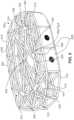
- FIG. 5is a schematic view of an exemplary embodiment of an implant 500 configured for improved bone contact.
- implant 500includes a body 502 formed as an open lattice structure made of a plurality of bone contacting elements or struts 510 .
- Body 502can include a central core 504 and an outer portion 506 .
- Central core 504is disposed approximately within the middle or center of body 502 of implant 500 .
- Outer portion 506is disposed outward from central core 504 and generally surrounds central core 504 .
- Outer portion 506extends from central core 504 to the perimeter edge of implant 500 .
- Plurality of struts 510form the open lattice structure of body 502 of implant 500 .
- Plurality of struts 510are generally elongate members having a longitudinal length and a lateral width, with the longitudinal length being longer than the lateral width.
- Plurality of struts 510can include one or more outer struts 512 and one or more inner struts 514 .
- outer struts 512are disposed along the perimeter edge of implant 500 and define the boundary of outer portion 506 .
- Outer struts 512can include substantially straight segments and/or curved or arched segments.
- outer struts 512may include combinations of curved and straight segments that assist with providing and defining the overall shape of implant 500 .
- Inner struts 514extend from the perimeter edge of implant 500 defined by outer struts 512 inward toward central core 504 of body 502 . Inner struts 514 intersect with one another at one or more nodes 520 . A plurality of inner struts 514 intersects at a plurality of nodes 520 to collectively form the open lattice structure of body 502 .
- inner struts 514are substantially straight segments.
- inner struts 514can include substantially straight segments, curved or arched segments, and/or a combination of curved and straight segments to form an open lattice structure.
- Body 502 of implant 500further includes a contact surface and a perimeter surface.
- the contact surfaceis configured to confront a bone plate when implant 500 is implanted into a patient.
- the contact surfaceis spaced apart from central core 504 of body 502 .
- the contact surfacecan be a superior surface configured to confront an upper bone plate and/or an inferior surface configured to confront a lower bone plate.
- an implantmay include a superior contact surface, an inferior contact surface, or both.
- the perimeter surface of body 502 of implant 500is disposed approximately orthogonal to the contact surface or contact surfaces of implant 500 and extends substantially circumferentially around the perimeter edge of outer portion 506 of implant 500 .
- the perimeter surface of body 502is not configured to confront a bone plate when implant 500 is implanted into a patient.
- outer portion 506 of body 502can include one or more screw plates 530 .
- Screw plates 530may include components configured to assist insertion and placement of implant 500 within a patient.
- the outer surface of screw plates 530is substantially planar with the remaining perimeter surface of body 502 .
- portions of screw plates 530can extend beyond the perimeter surface of body 502 of implant 500 .
- the contact surface of an implantcan include components configured for improved bone contact.
- superior and/or inferior contact surfaces of body 502 of implant 500include one or more enlarged contact members 540 .
- Enlarged contact members 540can be disposed at various locations on the contact surfaces of body 502 of implant 500 .
- enlarged contact members 540are located at one or more of plurality of nodes 520 where two or more of plurality of struts 510 intersect with each other.
- Additional enlarged contact members 540can be disposed at other nodes of intersection between two or more of plurality of struts 510 , including outer struts 512 , inner struts 514 , and/or a combination of both across various portions of the contact surfaces of implant 500 .
- FIG. 6illustrates an enlarged view of an exemplary embodiment of an enlarged contact member 540 .
- enlarged contact member 540is disposed at the node of an intersection between two or more of plurality of struts 510 .
- enlarged contact member 540is disposed at the node of an intersection between five inner struts 514 , including a first strut 610 , a second strut 612 , a third strut 614 , a fourth strut 616 , and a fifth strut 618 .
- Enlarged contact member 540includes a substantially flattened surface 600 that is configured to confront a bone plate of a patient. In some cases, flattened surface 600 of enlarged contact member 540 can be textured to assist with adhesion to the bone plate.
- enlarged contact member 540has a generally ovoid or rounded shape defined by an outer perimeter edge 602 .
- outer perimeter edge 602extends beyond the node of intersection between first strut 610 , second strut 612 , third strut 614 , fourth strut 616 , and fifth strut 618 .
- enlarged contact member 540also extends beyond the lateral width of each of first strut 610 , second strut 612 , third strut 614 , fourth strut 616 , and fifth strut 618 .
- enlarged contact member 540is wider than each of the lateral widths of first strut 610 , second strut 612 , third strut 614 , fourth strut 616 , and fifth strut 618 .
- Flattened surface 600 of enlarged contact member 540provides a substantially greater surface area for confronting a bone plate than would be provided by the node of intersection of plurality of struts 510 and/or the lateral width of any of the individual struts themselves. With this arrangement, enlarged contact member 540 assists with providing improved bone contact to implant 500 and allows forces and/or stresses applied to the bone to be distributed across the larger surface area of flattened surface 600 .
- FIG. 7the underside or bottom view of enlarged contact member 540 shown in FIG. 6 is illustrated.
- plurality of struts 510in this case, plurality of inner struts 514 , including first strut 610 , second strut 612 , third strut 614 , fourth strut 616 , and fifth strut 618 , intersect at node 520 .
- Enlarged contact member 540extends over node 520 such that outer perimeter edge 602 is spaced outward from node 520 .
- enlarged contact member 540also extends beyond the lateral width of each of first strut 610 , second strut 612 , third strut 614 , fourth strut 616 , and fifth strut 618 .
- first strut 610 , second strut 612 , third strut 614 , fourth strut 616 , and fifth strut 618have a substantially rounded cross-sectional shape.
- flattened surface 600is substantially flat and is configured to confront a bone plate of a patient.
- FIG. 8illustrates a cross section of a portion of enlarged contact member 540 taken along the line shown in FIG. 7 .
- the cross-sectional view of the portion of enlarged contact member 540shows substantially flattened surface 600 on one side of enlarged contact member 540 and the substantially rounded cross-sectional shape of first strut 610 on the opposite side.
- substantially flattened surface 600is oriented on implant 500 to face outward from central core 504 of implant.
- one or more flattened surfaces 600 of a plurality of enlarged contact members 540can be configured to provide superior and/or inferior contact surfaces of body 502 of implant 500 .
- the shape of enlarged contact member 540may be asymmetrical with respect to the intersection of two or more struts of plurality of struts 510 . That is, a portion of enlarged contact member 540 that extends in one direction from a node of intersection between two or more struts of plurality of struts 510 may have a different shape and/or size than another portion of enlarged contact member 540 that extends in a different direction from the node of intersection.
- FIGS. 9 and 10illustrated in more detail below, illustrate two alternate embodiments of an enlarged contact member having a generally asymmetrical shape with respect to the intersection of two or more struts of a plurality of struts.
- FIG. 9an underside bottom view of an alternate embodiment of an asymmetric enlarged contact member 930 is illustrated.
- a plurality of strutsincluding a first strut 910 , a second strut 912 , and a third strut 914 , intersect at a node 920 .
- Asymmetric enlarged contact member 930extends over node 920 such that an outer perimeter edge 932 of asymmetric enlarged contact member 930 is spaced outward from node 920 .
- Asymmetric enlarged contact member 930also extends over the lateral width of portions of each of first strut 910 , second strut 912 , and third strut 914 .
- the shape of asymmetric enlarged contact member 930is asymmetric with respect to the intersection of at least two struts of first strut 910 , second strut 912 , and/or third strut 914 .
- asymmetric enlarged contact member 930includes three areas disposed between the intersection of adjacent struts, including a first area 934 disposed between the intersection of first strut 910 and second strut 912 , a second area 936 disposed between the intersection of first strut 910 and third strut 914 , and a third area 938 disposed between the intersection of second strut 912 and third strut 914 .
- first area 934is larger than either or both of second area 936 and third area 938 .
- Asymmetric enlarged contact member 930is asymmetrically disposed with respect to the intersection of at least two struts of first strut 910 , second strut 912 , and/or third strut 914 such that first area 934 is asymmetric with second area 936 and third area 938 with respect to the intersection of first strut 910 and second strut 912 , second area 936 is asymmetric with first area 934 and third area 938 with respect to the intersection of second strut 912 and third strut 914 , and third area 938 is asymmetric with first area 934 and second area 936 with respect to the intersection of first strut 910 and third strut 914 .
- asymmetric enlarged contact member 930may provide a larger surface area for a contact surface of an implant in a particular location on the implant.
- asymmetric enlarged contact member 930may have an approximately teardrop or pear shape.
- the teardrop or pear shape of asymmetric enlarged contact member 930 shown in FIG. 9has a wider width at one end and a narrower width at the opposite end.
- asymmetric enlarged contact member 930is wider at one end located in first area 934 and is narrower at the opposite end located in second area 936 and/or third area 938 .
- outer perimeter edge 932 of asymmetric enlarged contact member 930defines a teardrop or pear shape.
- FIG. 10another alternate embodiment of an asymmetric enlarged contact member 1030 is illustrated from a bottom view.
- a plurality of strutsincluding a first strut 1010 , a second strut 1012 , a third strut 1014 , and a fourth strut 1016 intersect at a node 1020 .
- Asymmetric enlarged contact member 1030extends away from node 1020 such that an outer perimeter edge 1032 of asymmetric enlarged contact member 1030 is spaced outward from node 1020 .
- Asymmetric enlarged contact member 1030also extends over the lateral width of portions of first strut 1010 , second strut 1012 , and third strut 1014 .
- asymmetric enlarged contact member 1030does not extend in the opposite direction over node 1020 and does not extend over any portion of the lateral width of fourth strut 1016 .
- the shape of asymmetric enlarged contact member 930is asymmetric with respect to the intersection of at least two struts of first strut 1010 , second strut 1012 , and/or third strut 1014 .
- asymmetric enlarged contact member 1030includes two areas disposed between the intersection of adjacent struts, including a first area 1034 disposed between the intersection of first strut 1010 and second strut 1012 and a second area 1036 disposed between the intersection of second strut 1012 and third strut 1014 .
- asymmetric enlarged contact member 1030is absent between the intersection between third strut 1014 and fourth strut 1016 .
- asymmetric enlarged contact member 1030also is absent between the intersection between first strut 1010 and fourth strut 1016 .
- Asymmetric enlarged contact member 1030is asymmetrically disposed with respect to the intersection of at least two struts of first strut 1010 , second strut 1012 , third strut 1014 , and/or fourth strut 1016 such that first area 1034 or second area 1036 is asymmetric with respect to the intersection of first strut 1010 , second strut 1012 , third strut 1014 , and fourth strut 1016 at node 1020 .
- first area 1034 and second area 1036 of asymmetric enlarged contact member 1030extend outward from node 1020 in one direction, while asymmetric enlarged contact member 1030 is absent in the opposite direction from node 1020 .
- asymmetric enlarged contact member 1030may provide a larger surface area for a contact surface of an implant in a particular location and/or direction on the implant.
- asymmetric enlarged contact member 1030may have an approximately semi-circular or partially rounded shape.
- the semi-circular or partially rounded shape of asymmetric enlarged contact member 1030 shown in FIG. 10fans outward in an approximately radial direction from node 1020 such that outer perimeter edge 1032 defines the semi-circular or partially rounded shape.
- asymmetric enlarged contact member 1030extends away from first strut 1010 and third strut 1014 in one direction from node 1020 so as to define an approximately fan-shaped semi-circular shape.
- FIGS. 5 through 10illustrate embodiments of an exemplary enlarged contact member.
- an implantcan include any number of enlarged contact members with substantially similar configurations, as well as a combination of different configurations according to the previous embodiments.
- Implants according to the embodiments described hereinmay include enlarged contact members that are disposed at various nodes of intersection between two or more struts of a plurality of struts, including outer struts, inner struts, and/or a combination of both across various portions of the contact surfaces of the implant. With this configuration, an implant can be configured with enlarged contact members at selected locations across the contact surfaces of the implant as desired for a particular type or configuration of implant.
- an implantmay be provided with bone contacting elements or struts that have a cross-sectional profile configured to assist with improved bone contact.
- the approximately rounded or circular cross-sectional shape of bone contacting elements or strutsmay apply unwanted stress to bone in areas where the bone contacting elements of the implant are in direct contact with the bone.
- FIGS. 11 and 12illustrate an example of a prior art strut having an approximately rounded or circular cross-sectional shape.
- strut 1100has an approximately rounded or circular cross-sectional shape 1102 and a cylindrical outer surface 1104 .
- Strut 1100is placed in contact with a bone, as shown in FIG. 12 . Because of the rounded or circular cross-sectional shape 1102 of strut 1100 , only a small portion of cylindrical outer surface 1104 is in direct contact with the outer surface of bone 1120 . For example, in FIG. 11
- contact area 1130 between cylindrical outer surface 1104 of strut 1100 and bone 1120is a single point 1106 , e.g., a tangent to rounded or circular cross-sectional shape 1102 of strut 1100 , that forms a line extending along the length of strut 1100 in contact with bone 1120 .
- Such a small contact areacan place unwanted stress and force to bone 1120 along contact area 1130 .
- FIGS. 13 through 16illustrate various embodiments of cross-sectional shapes for a strut of an implant that can assist with dissipating force and stress over a larger contact area with a bone of a patient.
- an exemplary embodiment of a flattened strut 1300has an inverted semi-circular dome shape 1302 .
- flattened strut 1300includes a first portion having a rounded or semi-circular cross-sectional shape and a second portion having a generally flat shape.
- flat surface 1304 of flattened strut 1300is disposed along a top portion of flattened strut 1300 and semi-cylindrical outer surface 1306 extends from the top portion around the remaining portion of flattened strut 1300 to form the inverted semi-circular dome shape 1302 .
- Flat surface 1304 of flattened strut 1300provides a larger surface area for contact with a bone of a patient. As shown in FIG. 14 , flat surface 1304 of flattened strut 1300 is in direct contact with the outer surface of bone 1320 along contact area 1330 . In this embodiment, contact area 1330 extends across the lateral width of flattened strut 1300 and corresponds with the area of flat surface 1304 on the top portion of flattened strut 1300 . With this configuration, contact area 1330 of flattened strut 1300 is significantly larger than contact area 1130 provided by point 1106 in the prior art strut 1100 , described above.
- flattened strut 1500has an inverted bell shape 1502 .
- flattened strut 1500includes a first portion having a rounded or semi-circular cross-sectional shape, two portions on either side of the first portion that flare outward to form a generally convex contour, and a third portion having a generally flat shape.
- flat surface 1504 of flattened strut 1500is disposed along a top portion of flattened strut 1500 and a semi-cylindrical outer surface extends from an opposite bottom portion and flares outward to form a generally convex contoured surface on either side of the bottom portion.
- the flared-out portions on the sidesinclude a first wing 1506 and a second wing 1508 disposed on opposite sides of flat surface 1504 .
- the semi-cylindrical outer surface on the bottom portion, the flared first wing 1506 and flared second wing 1508 , and flat surface 1504 on the top portion of flattened strut 1500form the inverted bell shape 1502 .
- Flat surface 1504 of flattened strut 1500provides a larger surface area for contact with a bone of a patient. As shown in FIG. 15 , flat surface 1504 of flattened strut 1500 is in direct contact with the outer surface of bone 1520 along contact area 1530 . In this embodiment, contact area 1530 extends across the lateral width of flattened strut 1500 and corresponds with the area of flat surface 1504 on the top portion of flattened strut 1500 . With this configuration, contact area 1530 of flattened strut 1500 is significantly larger than contact area 1130 provided by point 1106 in the prior art strut 1100 , described above.
- flat surface 1504is also wider than flat surface 1304 of flattened strut 1300 to provide contact area 1530 of flattened strut 1500 that is larger than contact area 1330 of flattened strut 1300 .
- an implantmay be fabricated from biocompatible materials suitable for implantation in a human body, including, but not limited to, metals (e.g., titanium or other metals), synthetic polymers, ceramics, and/or their combinations, depending on the particular application and/or preference of a medical practitioner.
- the implantcan be formed from any suitable biocompatible, non-degradable material with sufficient strength.
- suitable materialsinclude, but are not limited to, titanium, biocompatible titanium alloys (e.g. ⁇ Titanium Alum inides, Ti 6 —Al 4 —V ELI (ASTM F 136), or Ti 6 —Al 4 —V (ASTM F 1108 and ASTM F 1472)) and inert, biocompatible polymers, such as polyether ether ketone (PEEK) (e.g. PEEK-OPTIMA®, Invibio Inc).
- the implantcontains a radiopaque marker to facilitate visualization during imaging.
- processes for making an implantcan vary.
- the entire implantmay be manufactured and assembled via injection-molding, cast or injection molding, insert-molding, co-extrusion, pultrusion, transfer molding, overmolding, compression molding, 3-Dimensional (3-D) printing, dip-coating, spray-coating, powder-coating, porous-coating, milling from a solid stock material, and their combinations.
- an exemplary process of manufacturing an implant with enlarged contact membersis illustrated.
- an additive manufacturing techniquefor example, 3-D printing, is used to manufacture an implant with enlarged contact members.
- an implantfor example, implant 500 , described above, is printed in a substantially vertical direction. That is, the implant is printed in a direction starting at one end along the perimeter surface of the implant and continuing to add layers until forming the opposite end of the perimeter surface.
- the exemplary process described hereis in contrast to printing in a substantially horizontal direction, which would be in a direction starting at the contact surface on one side of the implant (e.g., the top or bottom of the implant) and continuing to add layers until forming the contact surface on the opposite side of the implant.
- each of the inferior and superior contact surfaces on opposite sides of the implantare formed in a substantially vertical direction such that each successive layer adds material to both the inferior and superior contact surfaces on opposite sides of the implant during the same pass.
- an implant 1700is shown in a partially printed condition during an exemplary manufacturing process.
- the exemplary manufacturing processis an additive manufacturing process, for example, a 3-D printing process, that builds up material layer by layer to form the implant.
- the exemplary manufacturing processbegins by additively manufacturing a first layer 1704 proximate to a base plate 1702 .
- Base plate 1702is a platform or other component that is configured to provide a surface for building the implant during the exemplary manufacturing process.
- implant 1700is built in a substantially vertical direction.
- first layer 1704is a portion of a perimeter surface of implant 1700 .
- implant 1700has a substantially similar configuration as implant 500 , described above, with a central core surrounded by an outer portion, opposite contact surfaces spaced from the central core, and a perimeter surface disposed approximately orthogonal to the contact surfaces and extending around the perimeter of the outer portion.
- first layer 1704being a portion of the perimeter surface at one end of implant 1700 .
- implant 1700is in a partially manufactured condition with first layer 1704 proximate base plate 1702 and a plurality of struts 1710 extending away from first layer 1704 .
- plurality of struts 1710includes outer struts, substantially similar to outer struts 512 , described above.
- additional strutscan be manufactured, including additional outer struts, inner struts, substantially similar to inner struts 514 , described above, or a combination of outer and inner struts to form a lattice structure of implant 1700 .
- FIG. 18illustrates a side view of implant 1700 during the exemplary manufacturing process shown in FIG. 17 .
- first layer 1704is shown proximate to base plate 1702 and plurality of struts 1710 are shown in partial formation extending away from base plate 1702 .
- the contact surfaces on opposite sides of implant 1700are formed in layers such that material is added to both sides during the same pass of the additive manufacturing process.
- implant 1700includes a first contact surface 1800 and a second contact surface 1802 disposed on the opposite side of implant 1700 .
- first contact surface 1800can be an inferior surface and second contact surface can be a superior surface.
- each successive layeradds material to both first contact surface 1800 and second contact surface 1802 on opposite sides of implant 1700 during the same pass.
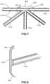
- FIG. 19illustrates a close-up view of an exemplary enlarged contact member 1900 that is additively manufactured on one or more of inferior and superior contact surfaces at nodes of intersection between plurality of struts 1710 .
- enlarged contact member 1900is formed at a node of intersection between a first strut 1910 , a second strut 1912 , a third strut 1914 , and a fourth strut 1916 . As seen in FIG.
- enlarged contact member 1900is oriented so that a flattened surface 1902 of enlarged contact member 1900 is configured to face outward on first contact surface 1800 of implant 1700 .
- flattened surface 1902 of enlarged contact member 1900is configured to confront a bone of a patient.
- enlarged contact memberscan be manufactured such that one end that is closer to the base plate is narrower than the other end that is disposed further from base plate.
- enlarged contact member 1900includes a first end 1906 that is disposed closer to base plate 1702 .
- first end 1906 of enlarged contact member 1900is formed first and successive layers build up additional material to form enlarged contact member 1900 .
- enlarged contact member 1900may become wider than first end 1906 .
- first end 1906is narrower than a second end 1908 that is disposed further from base plate 1702 . That is, second end 1908 of enlarged contact member 1900 has a larger width than first end 1906 of enlarged contact member 1900 .
- enlarged contact member 1900widens from first end 1906 to second end 1908 .
- This exemplary processcan provide an asymmetrical shape to enlarged contact member 1900 , for example, any of the asymmetrical shapes described above with reference to FIGS. 9 and 10 above.
- first end 1906 having a smaller width than second end 1908can provide a more secure attachment to plurality of struts 1710 and may also permit the width of enlarged contact member 1900 to increase gradually to the width at second end 1908 during the additive manufacturing process.
- the additive manufacturing process described abovecan provide texture to flattened surface 1902 of enlarged contact member 1900 .
- the addition of material in successive layers to form enlarged contact member 1900can provide surface irregularities that serve as a textured surface for flattened surface 1902 of enlarged contact member 1900 .
- the textured flattened surface 1902 of enlarged contact member 1900may assist with providing greater adhesion in contact with a bone of a patient.
- the implantmay be formed by additive manufacturing (e.g., 3-D printing) in an anatomical orientation. That is, the implant may be formed from the bottom up in its regular upright position, as it would be positioned within the body of the patient.
- the implantmay be formed by an additive manufacturing process in a non-anatomical orientation.
- the implantmay be formed on its side, as discussed above.
- the implantmay be formed beginning with the anterior surface and concluding with the posterior surface.
- the implantmay be formed beginning with one lateral side and concluding with the opposing lateral side.
- Provisionsmay be used to facilitate additive manufacturing in one or more particular orientations.
- additive manufacturingmay be facilitated by the orientations of the struts.
- the roof anglei.e., the angle between the underside of a structural component and a horizontal plane, may be 30 degrees or greater. In some embodiments, the minimum roof angle may be 32 degrees.
- thin, vertically oriented elementsmay be printed with the implant, but knocked out after the printing is completed.
- knock-out or punch-out elementsmay be utilized anywhere in the implent to facilitate manufacturing.
- closely-spaced, paper-thin vertical elementsmay be printed as a supportive base in order to additively manufacture structures with a roof angle of less than 30 degrees. With the vertical elements so closely spaced, there is a small enough span between the vertical elements that the horizontal structures can be added despite having a roof angle smaller than 30 degrees. Because the vertical elements are so thin, they can be easily broken away from the completed implant after the additive manufacturing process has been complete. That is, the vertical elements can be “knock-outs” or “punch-out” elements that are removed after manufacturing.
- implantsmay be provided that include one or more features disclosed in Sack, U.S. Patent Application Publication No. 2019/0151113, published on May 23, 2019, and entitled “Implant with Improved Flow Characteristics.”
- FIG. 21is a lateral view of implant 2600 when oriented standing on an anterior side 2615 as it would be during the manufacturing process illustrated in FIG. 26 .
- Implant 2600includes structural features having roof angles that are a minimum of 30 degrees.
- implant 2600also includes a posterior side 2620 .
- implant 2600may also include a superior surface 2640 and an inferior surface 2645 .
- implant 2600may include a plurality of peripheral struts around the perimeter of implant 2600 that are arranged in X-shaped configurations.
- first peripheral strut 2650has a roof angle 2655 .
- roof angle 2655may be 30 degrees or greater.
- roof angle 2655may be approximately 32 degrees.
- each of the peripheral strutsmay have roof angles of 30 degrees or greater.
- the minimum roof angle of the peripheral strutsmay be approximately 32 degrees.
- posterior structures extending in the superior-inferior directionmay have roof angles of 30 degrees or more.
- Posterior structure 2660may have a first anterior-facing surface 2665 and a second anterior-facing surface 2670 .
- first anterior-facing surface 2665 and second anterior-facing surface 2670may both have roof angles of 30 degrees or more.
- all structural elements extending in the superior-inferior directionmay have a minimum roof angle of 30 degrees or more.
- the minimum roof anglemay be approximately 32 degrees.
- the internal structures of implant 2600may also have minimum roof angles of 30 degrees or more.
- an internal strut 2675may have a roof angle 2680 .
- roof angle 2680may be 30 degrees or greater.
- roof angle 2680may be approximately 32 degrees.
- anterior-facing surface 2690 and second anterior-facing surface 2695may both have roof angles of 30 degrees or more.
- all structural elements extending in the superior-inferior directionmay have a minimum roof angle of 30 degrees or more.
- the minimum roof anglemay be approximately 32 degrees.
Landscapes
- Health & Medical Sciences (AREA)
- Engineering & Computer Science (AREA)
- Biomedical Technology (AREA)
- Orthopedic Medicine & Surgery (AREA)
- Transplantation (AREA)
- Heart & Thoracic Surgery (AREA)
- Oral & Maxillofacial Surgery (AREA)
- Cardiology (AREA)
- Vascular Medicine (AREA)
- Life Sciences & Earth Sciences (AREA)
- Animal Behavior & Ethology (AREA)
- General Health & Medical Sciences (AREA)
- Public Health (AREA)
- Veterinary Medicine (AREA)
- Neurology (AREA)
- Prostheses (AREA)
Abstract
Description
This application is a continuation of Sack, U.S. Pat. No. 10,744,001, issued Aug. 18, 2020, and titled “Implant with Improved Bone Contact,” the entire disclosure of which is hereby incorporated by reference.
The embodiments are generally directed to implants for supporting bone growth in a patient.
A variety of different implants are used in the body. Implants used in the body to stabilize an area and promote bone ingrowth provide both stability (i.e., minimal deformation under pressure over time) and space for bone ingrowth.
Spinal fusion, also known as spondylodesis or spondylosyndesis, is a surgical treatment method used for the treatment of various morbidities such as degenerative disc disease, spondylolisthesis (slippage of a vertebra), spinal stenosis, scoliosis, fracture, infection, or tumor. The aim of the spinal fusion procedure is to reduce instability and thus pain.
In preparation for the spinal fusion, most of the intervertebral disc is removed. An implant, the spinal fusion cage, may be placed between the vertebra to maintain spine alignment and disc height. The fusion, i.e., bone bridge, occurs between the endplates of the vertebrae.
In one aspect, an intervertebral implant includes a body formed as an open lattice structure. The body includes a central core and an outer portion. The body also includes a contact surface and a perimeter surface. The contact surface is configured to confront a bone plate, the contact surface being spaced from the central core of the body. The contact surface can include a node, the node being an intersection of a first strut and a second strut. The first strut has a first longitudinal length and a first lateral width, the first longitudinal length being longer than the first lateral width. The second strut has a second longitudinal length and a second lateral width, the second longitudinal length being longer than the second lateral width. The node can include an enlarged contact member that extends between the first lateral width and the second lateral width.
In another aspect, an intervertebral implant includes a body formed as a lattice structure. The body includes a central core and an outer portion. The body also includes a superior surface, an inferior surface and a perimeter surface. The superior surface is configured to confront an upper bone plate. The superior surface is spaced from the central core of the body. The inferior surface is configured to confront a lower bone plate. The inferior surface is spaced from the central core of the body. The superior surface includes a node, the node being an intersection of a first strut and a second strut. The first strut has a first longitudinal length and a first lateral width, the first longitudinal length being longer than the first lateral width. The second strut has a second longitudinal length and a second lateral width, the second longitudinal length being longer than the second lateral width. The node can include an enlarged contact member that extends beyond the first lateral width and the second lateral width.
In another aspect, a method of making an intervertebral implant having a body is provided. The body includes a central core and an outer portion. The outer portion includes a superior surface, an inferior surface, and a perimeter surface. The method includes the step of additively manufacturing a first layer. The first layer is proximate a base plate. The first layer forms a part of the perimeter surface. The method also includes a step of continuing to additively manufacture the perimeter surface. The method also includes a step of additively manufacturing the superior surface and the inferior surface, wherein the superior surface extends away from the base plate, and wherein the inferior surface extends away from the base plate.
Other systems, methods, features, and advantages of the embodiments will be, or will become, apparent to one of ordinary skill in the art upon examination of the following figures and detailed description. It is intended that all such additional systems, methods, features, and advantages be included within this description and this summary, be within the scope of the embodiments, and be protected by the following claims.
The embodiments can be better understood with reference to the following drawings and description. The components in the figures are not necessarily to scale, emphasis instead being placed upon illustrating the principles of the embodiments. Moreover, in the figures, like reference numerals designate corresponding parts throughout the different views.
Any of the embodiments described herein may make use of any of the body/support structures, frames, plates, coils, or other structures disclosed in:
- Hunt, U.S. Pat. No. 8,430,930, issued Apr. 30, 2013 and entitled “Truss Implant”;
- Hunt, U.S. Patent Appl. Publ. No. 2011/0313532, published Dec. 22, 2011 and entitled “Bone Implant Interface System and Method”;
- Hunt, U.S. Patent Appl. Publ. No. 2013/0030529, published Jan. 31, 2013 and entitled “Implant Interface system and method”;
- Hunt et al., U.S. Patent Appl. Publ. No. 2013/0123935, published May 16, 2013 and entitled “Method of Length Preservation During Bone Repair”;
- Hunt, U.S. Patent Appl. Publ. No. 2013/0218282, published Aug. 22, 2013 and entitled “Prosthetic Implant for Ball and Socket Joints and Method of Use”;
- Hunt et al., U.S. Pat. No. 9,271,845, issued Mar. 1, 2016 and entitled “Programmable Implants and Methods of Using Programmable Implants to Repair Bone Structures”;
- Hunt, U.S. Pat. No. 9,636,226, issued May 2, 2017 and entitled “Traumatic Bone Fracture Repair Systems and Methods”;
- Hunt, U.S. Patent Appl. Publ. No. 2014/0288650, published Sep. 25, 2014 and entitled “Motion Preservation Implant and Methods”; and
- Sack, U.S. Patent Appl. Publ. No. 2019/0151113, published May 23, 2019, and entitled “Implant with Improved Flow Characteristics.”
The entire disclosures of the patents and publications listed above are incorporated herein by reference in their entirety.
Implantation
For purposes of this disclosure,implant 100 may also be referred to as a cage or fusion device. In some embodiments,implant 100 is configured to be implanted within a portion of the human body. In some embodiments,implant 100 may be configured for implantation into the spine. In some embodiments,implant 100 may be a spinal fusion implant, or spinal fusion device, which is inserted between adjacent vertebrae to provide support and/or facilitate fusion between the vertebrae.
In some embodiments,implant 100 may be inserted using an anterior lumbar interbody fusion (ALIF) surgical procedure, where the disc space is fused by approaching the spine through the abdomen. In the ALIF approach, a three-inch to five-inch incision is typically made near the abdomen and the abdominal muscles are retracted to the side. In some cases,implant 100 can be inserted through a small incision in the front or anterior side of the body. In some cases, an anterior approach may afford improved exposure to the disc space to a surgeon. The anterior approach can allow a larger device to be used for the fusion, increasing the surface area for fusion to occur and allowing for more postoperative stability. An anterior approach often makes it possible to reduce some of the deformity caused by various conditions, such as isthmic spondylolisthesis. Insertion and placement of the disc along the front of a human body can also re-establish the patient's normal sagittal alignment in some cases, giving individuals a more normal inward curve to their low back.
Introduction to Implant
For purposes of clarity, reference is made to various directional adjectives throughout the detailed description and in the claims. As used herein, the term “anterior” refers to a side or portion of an implant that is intended to be oriented toward the front of the human body when the implant has been placed in the body. Likewise, the term “posterior” refers to a side or portion of an implant that is intended to be oriented toward the back of the human body following implantation. In addition, the term “superior refers” to a side or portion of an implant that is intended to be oriented toward a top (e.g., the head) of the body while “inferior” refers to a side or portion of an implant that is intended to be oriented toward a bottom of the body. Reference is also made herein to “lateral” sides or portions of an implant, which are sides or portions facing along lateral directions of the body following implantation.
Reference is also made to directions or axes that are relative to the implant itself, rather than to its intended orientation with regards to the body. For example, the term “central” refers to a part that is located closer to the center of the implant. As used herein, the “center of the implant” is generally defined as a vertical axis extending through the approximate middle of the implant, which may be approximately the location of the center of mass or the dimensional middle (i.e., equidistant from opposing sides.
An implant may also be associated with various axes. Referring toFIG.3 ,implant 100 may be associated with alateral axis 111 that extends alongimplant 100 between firstlateral side 114 and secondlateral side 116. Additionally,implant 100 may be associated with a posterior-anterior axis 113 that extends betweenposterior side 112 andanterior side 110. Moreover,implant 100 may be associated with a vertical axis115 (which may also be referred to as a superior-inferior axis) that extends along the thickness dimension ofimplant 100 and which is generally perpendicular to bothlateral axis 111 and posterior-anterior axis 113.
An implant may also be associated with various reference planes or surfaces. As used herein, the term “median plane” refers to a vertical plane that passes from the anterior side to the posterior side of the implant, dividing the implant into right and left halves, or lateral halves. As used herein, the term “transverse plane” refers to a horizontal plane located in the center of the implant that divides the implant into superior and inferior halves. As used herein, the term “coronal plane” refers to a vertical plane located in the center of the implant that divides the implant into anterior and posterior halves. In some embodiments, the implant is symmetric about two planes, such as the transverse plane.
In different embodiments, the geometry of one or more body members could vary. In some embodiments,first body member 120 may comprise a solid structure including various connected faces. As seen inFIG.4 ,first body member 120 includesexterior surface 121 that is further comprised of a firstcentral face 150, anangled face 151, and a secondcentral face 152.
Some embodiments can include one or more fastener-receiving provisions. In some embodiments, an implant can include one or more threaded cavities. In some embodiments, a threaded cavity can be configured to mate with a corresponding threaded tip on an implantation tool or device. In other embodiments, a threaded cavity can receive a fastener for purposes of fastening an implant to another device or component in an implantation system that uses multiple implants and/or multiple components.
As best seen inFIG.4 ,implant 100 includes a threadedcavity 170 disposed infirst body member 120. In some embodiments, threadedcavity 170 may receive the threaded tip of an implantation tool (not shown). Such a tool could be used to driveimplant 100 between adjacent vertebral bodies.
In some embodiments, one or more bone contacting elements may extend fromfirst body member 120. In the embodiment shown inFIGS.3-4 ,implant 100 includes a plurality ofbone contacting elements 200 that may be attached, and/or continuously formed (or “integrally formed”) with,first body member 120.
As used herein, each bone contacting element comprises a distinctive member or element that spans a region or area of an implant. In some embodiments, these elements may overlap or intersect, similar to elements in a lattice or other 3D mesh structure. In other embodiments, the elements may not overlap or intersect. Some embodiments may use elongated elements, in which the length of the element is greater than its width and its thickness. For example, in embodiments where an element has an approximately circular cross-sectional shape, the element has a length greater than its diameter. In the embodiments seen inFIGS.3-4 , each bone contacting element is seen to have an approximately rounded or circular cross-sectional shape (i.e., the element has the geometry of a solid tube) along at least a portion of the element. However, in other embodiments, an element could have any other cross-sectional shape, including, but not limited to, various polygonal cross-sectional shapes (e.g., triangular, rectangular, etc.), as well as any other regular and/or irregular cross-sectional shapes. Examples of embodiments including a bone contacting element with a flattened cross-sectional shape are shown inFIGS.13-16 and discussed in further detail below. In some cases, for example, the cross-sectional shape of a bone contacting element could vary along its length (e.g., the diameter could change along its length).
Geometry of Bone Contacting Elements
Embodiments can include provisions for protecting bone growth along and adjacent to bone contacting elements of an implant. In some embodiments, a bone contacting element can be configured with a geometry that helps to protect new bone growth in selected regions that may be referred to as “protected fusion zones.” In a protected fusion zone, new bone growth may be partially protected from forces transmitted directly between vertebrae and bone contacting surfaces of an implant, thereby increasing the rate at which new bone growth may propagate through the implant.
In some embodiments, a bone contacting element can have a spiral, helical, or twisted geometry that provide a series of such protected fusion zones for enhanced bone growth. In other embodiments, a bone contacting element can have a planar undulating geometry (e.g., sinusoidal) that may also create protected fusion zones. In some embodiments, an implant may include bone contacting elements with a helical geometry and other bone contacting elements with a sinusoidal, or planar undulating geometry.
Some bone contacting elements may have a generalized helical geometry. As used herein, a “generalized helical geometry” or “spiraling geometry” refers to a geometry where a part (portion, member, etc.) winds, turns, twists, rotates, or is otherwise curved around a fixed path. In some cases, the fixed path could be straight. In other cases, the fixed path can be curved. In the present embodiments, for example, the fixed path is generally a combination of straight segments and curved segments.
Curves having a generalized helical geometry (also referred to as generalized helical curves) may be characterized by “coils,” “turns,” or “windings” about a fixed path. Exemplary parameters that may characterize the specific geometry of a generalized helical curve can include coil diameter (including both a major and minor diameter) and the pitch (i.e., spacing between adjacent coils). In some cases, the “amplitude” of a coil or loop may also be used to describe the diameter or widthwise dimension of the coil or loop. Each of these parameters could be constant or could vary over the length of a generalized helical curve.
Generalized helical curves need not be circular or even round. In some embodiments, for example, a generalized helical curve could have a linearly segmented shape (or locally polygonal shape) such that each “coil” or “turn” is comprised of straight line segments rather than arcs or other curved segments. Generalized helical curves may also include combinations of curved and straight segments.
For purposes of characterizing the geometry of one or more bone contacting elements, each bone contacting element can be identified with one or more curves. Each bone contacting element may be identified with a central curve. The central curve of each bone contacting element may be defined as a curve that extends along the length (or longest dimension) of the bone contacting element such that each point along the curve is centrally positioned within the bone contacting element. In addition, each bone contacting element may be identified with one or more exterior surface curves. An exterior surface curve of a bone contacting element may be defined as a curve that extends along the length (or longest dimension) of the bone contacting element such that each point along the curve is positioned on the exterior surface.
In some situations, the approximately rounded or circular cross-sectional shape of bone contacting elements may apply unwanted stress to bone in areas where the bone contacting elements of the implant are in direct contact with the bone. For example, particularly in the case of older patients and/or patients with osteoporosis or other conditions that result in brittle or fragile bones, the stress associated with the direct contact from the approximately rounded or circular cross-sectional shape of bone contacting elements of the implant can weaken or otherwise damage the bone in the proximity of the implant. Accordingly, in some embodiments, an implant may be provided with components that are configured for improved bone contact.
Plurality ofstruts 510 form the open lattice structure ofbody 502 ofimplant 500. Plurality ofstruts 510 are generally elongate members having a longitudinal length and a lateral width, with the longitudinal length being longer than the lateral width. Plurality ofstruts 510 can include one or moreouter struts 512 and one or moreinner struts 514. In this embodiment,outer struts 512 are disposed along the perimeter edge ofimplant 500 and define the boundary ofouter portion 506. Outer struts512 can include substantially straight segments and/or curved or arched segments. In some embodiments,outer struts 512 may include combinations of curved and straight segments that assist with providing and defining the overall shape ofimplant 500.
Inner struts514 extend from the perimeter edge ofimplant 500 defined byouter struts 512 inward towardcentral core 504 ofbody 502. Inner struts514 intersect with one another at one ormore nodes 520. A plurality ofinner struts 514 intersects at a plurality ofnodes 520 to collectively form the open lattice structure ofbody 502. In this embodiment,inner struts 514 are substantially straight segments. In other embodiments,inner struts 514 can include substantially straight segments, curved or arched segments, and/or a combination of curved and straight segments to form an open lattice structure.
The perimeter surface ofbody 502 ofimplant 500 is disposed approximately orthogonal to the contact surface or contact surfaces ofimplant 500 and extends substantially circumferentially around the perimeter edge ofouter portion 506 ofimplant 500. Generally, the perimeter surface ofbody 502 is not configured to confront a bone plate whenimplant 500 is implanted into a patient.
In some embodiments,outer portion 506 ofbody 502 can include one ormore screw plates 530.Screw plates 530 may include components configured to assist insertion and placement ofimplant 500 within a patient. In this embodiment, the outer surface ofscrew plates 530 is substantially planar with the remaining perimeter surface ofbody 502. In other embodiments, portions ofscrew plates 530 can extend beyond the perimeter surface ofbody 502 ofimplant 500.
In some embodiments, the contact surface of an implant can include components configured for improved bone contact. In an exemplary embodiment, superior and/or inferior contact surfaces ofbody 502 ofimplant 500 include one or moreenlarged contact members 540.Enlarged contact members 540 can be disposed at various locations on the contact surfaces ofbody 502 ofimplant 500. In this embodiment,enlarged contact members 540 are located at one or more of plurality ofnodes 520 where two or more of plurality ofstruts 510 intersect with each other. Additionalenlarged contact members 540 can be disposed at other nodes of intersection between two or more of plurality ofstruts 510, includingouter struts 512,inner struts 514, and/or a combination of both across various portions of the contact surfaces ofimplant 500.
In an exemplary embodiment,enlarged contact member 540 has a generally ovoid or rounded shape defined by anouter perimeter edge 602. In this embodiment,outer perimeter edge 602 extends beyond the node of intersection betweenfirst strut 610,second strut 612,third strut 614,fourth strut 616, andfifth strut 618. In addition,enlarged contact member 540 also extends beyond the lateral width of each offirst strut 610,second strut 612,third strut 614,fourth strut 616, andfifth strut 618. That is,enlarged contact member 540 is wider than each of the lateral widths offirst strut 610,second strut 612,third strut 614,fourth strut 616, andfifth strut 618. Flattenedsurface 600 ofenlarged contact member 540 provides a substantially greater surface area for confronting a bone plate than would be provided by the node of intersection of plurality ofstruts 510 and/or the lateral width of any of the individual struts themselves. With this arrangement,enlarged contact member 540 assists with providing improved bone contact to implant500 and allows forces and/or stresses applied to the bone to be distributed across the larger surface area of flattenedsurface 600.
Referring now toFIG.7 , the underside or bottom view ofenlarged contact member 540 shown inFIG.6 is illustrated. In this embodiment, plurality ofstruts 510, in this case, plurality ofinner struts 514, includingfirst strut 610,second strut 612,third strut 614,fourth strut 616, andfifth strut 618, intersect atnode 520.Enlarged contact member 540 extends overnode 520 such thatouter perimeter edge 602 is spaced outward fromnode 520. As can be seen inFIG.7 ,enlarged contact member 540 also extends beyond the lateral width of each offirst strut 610,second strut 612,third strut 614,fourth strut 616, andfifth strut 618.
In this embodiment, on the underside ofenlarged contact member 540,first strut 610,second strut 612,third strut 614,fourth strut 616, andfifth strut 618 have a substantially rounded cross-sectional shape. As noted above, on the opposite side ofenlarged contact member 540, flattenedsurface 600 is substantially flat and is configured to confront a bone plate of a patient.
In one embodiment, the shape ofenlarged contact member 540 may be asymmetrical with respect to the intersection of two or more struts of plurality ofstruts 510. That is, a portion ofenlarged contact member 540 that extends in one direction from a node of intersection between two or more struts of plurality ofstruts 510 may have a different shape and/or size than another portion ofenlarged contact member 540 that extends in a different direction from the node of intersection. For example,FIGS.9 and10 , described in more detail below, illustrate two alternate embodiments of an enlarged contact member having a generally asymmetrical shape with respect to the intersection of two or more struts of a plurality of struts.
Referring now toFIG.9 , an underside bottom view of an alternate embodiment of an asymmetricenlarged contact member 930 is illustrated. In this embodiment, a plurality of struts, including afirst strut 910, asecond strut 912, and athird strut 914, intersect at anode 920. Asymmetric enlargedcontact member 930 extends overnode 920 such that anouter perimeter edge 932 of asymmetricenlarged contact member 930 is spaced outward fromnode 920. Asymmetric enlargedcontact member 930 also extends over the lateral width of portions of each offirst strut 910,second strut 912, andthird strut 914. In this embodiment, the shape of asymmetricenlarged contact member 930 is asymmetric with respect to the intersection of at least two struts offirst strut 910,second strut 912, and/orthird strut 914.
For example, as shown inFIG.9 , asymmetricenlarged contact member 930 includes three areas disposed between the intersection of adjacent struts, including afirst area 934 disposed between the intersection offirst strut 910 andsecond strut 912, asecond area 936 disposed between the intersection offirst strut 910 andthird strut 914, and athird area 938 disposed between the intersection ofsecond strut 912 andthird strut 914. In this example,first area 934 is larger than either or both ofsecond area 936 andthird area 938.
Asymmetric enlargedcontact member 930 is asymmetrically disposed with respect to the intersection of at least two struts offirst strut 910,second strut 912, and/orthird strut 914 such thatfirst area 934 is asymmetric withsecond area 936 andthird area 938 with respect to the intersection offirst strut 910 andsecond strut 912,second area 936 is asymmetric withfirst area 934 andthird area 938 with respect to the intersection ofsecond strut 912 andthird strut 914, andthird area 938 is asymmetric withfirst area 934 andsecond area 936 with respect to the intersection offirst strut 910 andthird strut 914. With this arrangement, asymmetricenlarged contact member 930 may provide a larger surface area for a contact surface of an implant in a particular location on the implant.
In an exemplary embodiment, asymmetricenlarged contact member 930 may have an approximately teardrop or pear shape. The teardrop or pear shape of asymmetricenlarged contact member 930 shown inFIG.9 has a wider width at one end and a narrower width at the opposite end. For example, asymmetricenlarged contact member 930 is wider at one end located infirst area 934 and is narrower at the opposite end located insecond area 936 and/orthird area 938. With this configuration,outer perimeter edge 932 of asymmetricenlarged contact member 930 defines a teardrop or pear shape.
Referring now toFIG.10 , another alternate embodiment of an asymmetricenlarged contact member 1030 is illustrated from a bottom view. In this embodiment, a plurality of struts, including afirst strut 1010, asecond strut 1012, athird strut 1014, and afourth strut 1016 intersect at anode 1020. Asymmetric enlargedcontact member 1030 extends away fromnode 1020 such that anouter perimeter edge 1032 of asymmetricenlarged contact member 1030 is spaced outward fromnode 1020. Asymmetric enlargedcontact member 1030 also extends over the lateral width of portions offirst strut 1010,second strut 1012, andthird strut 1014. In this embodiment, asymmetricenlarged contact member 1030 does not extend in the opposite direction overnode 1020 and does not extend over any portion of the lateral width offourth strut 1016. In this embodiment, the shape of asymmetricenlarged contact member 930 is asymmetric with respect to the intersection of at least two struts offirst strut 1010,second strut 1012, and/orthird strut 1014.
For example, as shown inFIG.10 , asymmetricenlarged contact member 1030 includes two areas disposed between the intersection of adjacent struts, including afirst area 1034 disposed between the intersection offirst strut 1010 andsecond strut 1012 and asecond area 1036 disposed between the intersection ofsecond strut 1012 andthird strut 1014. In contrast with the embodiment ofFIG.9 , in this embodiment, asymmetricenlarged contact member 1030 is absent between the intersection betweenthird strut 1014 andfourth strut 1016. In this embodiment, asymmetricenlarged contact member 1030 also is absent between the intersection betweenfirst strut 1010 andfourth strut 1016.
Asymmetric enlargedcontact member 1030 is asymmetrically disposed with respect to the intersection of at least two struts offirst strut 1010,second strut 1012,third strut 1014, and/orfourth strut 1016 such thatfirst area 1034 orsecond area 1036 is asymmetric with respect to the intersection offirst strut 1010,second strut 1012,third strut 1014, andfourth strut 1016 atnode 1020. As shown inFIG.10 ,first area 1034 andsecond area 1036 of asymmetricenlarged contact member 1030 extend outward fromnode 1020 in one direction, while asymmetricenlarged contact member 1030 is absent in the opposite direction fromnode 1020. With this arrangement, asymmetricenlarged contact member 1030 may provide a larger surface area for a contact surface of an implant in a particular location and/or direction on the implant.
In an exemplary embodiment, asymmetricenlarged contact member 1030 may have an approximately semi-circular or partially rounded shape. The semi-circular or partially rounded shape of asymmetricenlarged contact member 1030 shown inFIG.10 fans outward in an approximately radial direction fromnode 1020 such thatouter perimeter edge 1032 defines the semi-circular or partially rounded shape. In this embodiment, asymmetricenlarged contact member 1030 extends away fromfirst strut 1010 andthird strut 1014 in one direction fromnode 1020 so as to define an approximately fan-shaped semi-circular shape.
With regard to the shapes of enlarged contact members shown in the previous embodiments, including the shapes shown inFIGS.5 through10 described above, it should be understood that other shapes may also be provided, including, but not limited to, geometric and non-geometric or irregular shapes.
In some embodiments, an implant may be provided with bone contacting elements or struts that have a cross-sectional profile configured to assist with improved bone contact. As previously described, the approximately rounded or circular cross-sectional shape of bone contacting elements or struts may apply unwanted stress to bone in areas where the bone contacting elements of the implant are in direct contact with the bone. For example,FIGS.11 and12 illustrate an example of a prior art strut having an approximately rounded or circular cross-sectional shape.
As shown inFIG.11 ,strut 1100 has an approximately rounded or circularcross-sectional shape 1102 and a cylindricalouter surface 1104.Strut 1100 is placed in contact with a bone, as shown inFIG.12 . Because of the rounded or circularcross-sectional shape 1102 ofstrut 1100, only a small portion of cylindricalouter surface 1104 is in direct contact with the outer surface ofbone 1120. For example, inFIG.12 ,contact area 1130 between cylindricalouter surface 1104 ofstrut 1100 andbone 1120 is asingle point 1106, e.g., a tangent to rounded or circularcross-sectional shape 1102 ofstrut 1100, that forms a line extending along the length ofstrut 1100 in contact withbone 1120. Such a small contact area can place unwanted stress and force tobone 1120 alongcontact area 1130.
Referring now toFIG.13 , an exemplary embodiment of a flattenedstrut 1300 has an invertedsemi-circular dome shape 1302. In this embodiment, flattenedstrut 1300 includes a first portion having a rounded or semi-circular cross-sectional shape and a second portion having a generally flat shape. As shown inFIG.13 ,flat surface 1304 of flattenedstrut 1300 is disposed along a top portion of flattenedstrut 1300 and semi-cylindricalouter surface 1306 extends from the top portion around the remaining portion of flattenedstrut 1300 to form the invertedsemi-circular dome shape 1302.
Referring now toFIG.15 , another exemplary embodiment of a flattenedstrut 1500 has aninverted bell shape 1502. In this embodiment, flattenedstrut 1500 includes a first portion having a rounded or semi-circular cross-sectional shape, two portions on either side of the first portion that flare outward to form a generally convex contour, and a third portion having a generally flat shape. As shown inFIG.15 ,flat surface 1504 of flattenedstrut 1500 is disposed along a top portion of flattenedstrut 1500 and a semi-cylindrical outer surface extends from an opposite bottom portion and flares outward to form a generally convex contoured surface on either side of the bottom portion. The flared-out portions on the sides include afirst wing 1506 and asecond wing 1508 disposed on opposite sides offlat surface 1504. Together, the semi-cylindrical outer surface on the bottom portion, the flaredfirst wing 1506 and flaredsecond wing 1508, andflat surface 1504 on the top portion of flattenedstrut 1500 form theinverted bell shape 1502.
It should be understood that other configurations of cross-sectional shapes with flat surfaces for struts that are configured to provide an enlarged contact area with a bone of a patient are possible according to the principles described above with reference toFIGS.13-16 .
Manufacturing and Materials
The various components of an implant may be fabricated from biocompatible materials suitable for implantation in a human body, including, but not limited to, metals (e.g., titanium or other metals), synthetic polymers, ceramics, and/or their combinations, depending on the particular application and/or preference of a medical practitioner.
Generally, the implant can be formed from any suitable biocompatible, non-degradable material with sufficient strength. Typical materials include, but are not limited to, titanium, biocompatible titanium alloys (e.g. γTitanium Alum inides, Ti6—Al4—V ELI (ASTM F 136), or Ti6—Al4—V (ASTM F 1108 and ASTM F 1472)) and inert, biocompatible polymers, such as polyether ether ketone (PEEK) (e.g. PEEK-OPTIMA®, Invibio Inc). Optionally, the implant contains a radiopaque marker to facilitate visualization during imaging.
In different embodiments, processes for making an implant can vary. In some embodiments, the entire implant may be manufactured and assembled via injection-molding, cast or injection molding, insert-molding, co-extrusion, pultrusion, transfer molding, overmolding, compression molding, 3-Dimensional (3-D) printing, dip-coating, spray-coating, powder-coating, porous-coating, milling from a solid stock material, and their combinations.
Referring now toFIGS.17 through20 , an exemplary process of manufacturing an implant with enlarged contact members, according to any of the previous embodiments is illustrated. In this exemplary process, an additive manufacturing technique, for example, 3-D printing, is used to manufacture an implant with enlarged contact members. According to the exemplary process, an implant, for example,implant 500, described above, is printed in a substantially vertical direction. That is, the implant is printed in a direction starting at one end along the perimeter surface of the implant and continuing to add layers until forming the opposite end of the perimeter surface. The exemplary process described here is in contrast to printing in a substantially horizontal direction, which would be in a direction starting at the contact surface on one side of the implant (e.g., the top or bottom of the implant) and continuing to add layers until forming the contact surface on the opposite side of the implant.
With the exemplary process, each of the inferior and superior contact surfaces on opposite sides of the implant are formed in a substantially vertical direction such that each successive layer adds material to both the inferior and superior contact surfaces on opposite sides of the implant during the same pass.
Referring now toFIG.17 , animplant 1700 is shown in a partially printed condition during an exemplary manufacturing process. In this embodiment, the exemplary manufacturing process is an additive manufacturing process, for example, a 3-D printing process, that builds up material layer by layer to form the implant. The exemplary manufacturing process begins by additively manufacturing afirst layer 1704 proximate to abase plate 1702.Base plate 1702 is a platform or other component that is configured to provide a surface for building the implant during the exemplary manufacturing process. As discussed above, in this exemplary process,implant 1700 is built in a substantially vertical direction. In this case,first layer 1704 is a portion of a perimeter surface ofimplant 1700. That is,implant 1700 has a substantially similar configuration asimplant 500, described above, with a central core surrounded by an outer portion, opposite contact surfaces spaced from the central core, and a perimeter surface disposed approximately orthogonal to the contact surfaces and extending around the perimeter of the outer portion. With this configuration, the substantially vertical direction of manufacturing with the exemplary process results infirst layer 1704 being a portion of the perimeter surface at one end ofimplant 1700.
During the exemplary manufacturing process,additional layers 1720 of material are built up in the vertical direction by multiple passes, with each pass adding material tofirst layer 1704 and subsequent additional layers to continue to formimplant 1700. As shown inFIG.17 ,implant 1700 is in a partially manufactured condition withfirst layer 1704proximate base plate 1702 and a plurality ofstruts 1710 extending away fromfirst layer 1704. In this embodiment, plurality ofstruts 1710 includes outer struts, substantially similar toouter struts 512, described above. As additional layers are formed during the exemplary manufacturing process, additional struts can be manufactured, including additional outer struts, inner struts, substantially similar toinner struts 514, described above, or a combination of outer and inner struts to form a lattice structure ofimplant 1700.
For example, inFIG.18 ,implant 1700 includes afirst contact surface 1800 and asecond contact surface 1802 disposed on the opposite side ofimplant 1700. In this case,first contact surface 1800 can be an inferior surface and second contact surface can be a superior surface. During the additive manufacturing process, each successive layer adds material to bothfirst contact surface 1800 andsecond contact surface 1802 on opposite sides ofimplant 1700 during the same pass.
In some embodiments, enlarged contact members, which may be substantially similar to any of the previous embodiments of enlarged contact members described above, can also be made during the exemplary process of makingimplant 1700.FIG.19 illustrates a close-up view of an exemplaryenlarged contact member 1900 that is additively manufactured on one or more of inferior and superior contact surfaces at nodes of intersection between plurality ofstruts 1710. In this embodiment,enlarged contact member 1900 is formed at a node of intersection between afirst strut 1910, asecond strut 1912, athird strut 1914, and afourth strut 1916. As seen inFIG.20 , enlargedcontact member 1900 is oriented so that a flattenedsurface 1902 ofenlarged contact member 1900 is configured to face outward onfirst contact surface 1800 ofimplant 1700. With this arrangement, flattenedsurface 1902 ofenlarged contact member 1900 is configured to confront a bone of a patient.
In some embodiments, enlarged contact members can be manufactured such that one end that is closer to the base plate is narrower than the other end that is disposed further from base plate. As shown inFIG.19 , enlargedcontact member 1900 includes afirst end 1906 that is disposed closer tobase plate 1702. During the exemplary manufacturing process,first end 1906 ofenlarged contact member 1900 is formed first and successive layers build up additional material to formenlarged contact member 1900. In some cases, as successive layers build upenlarged contact member 1900, enlargedcontact member 1900 may become wider thanfirst end 1906.
As shown inFIG.19 ,first end 1906 is narrower than asecond end 1908 that is disposed further frombase plate 1702. That is,second end 1908 ofenlarged contact member 1900 has a larger width thanfirst end 1906 ofenlarged contact member 1900. With successive layers of additive manufacturing,enlarged contact member 1900 widens fromfirst end 1906 tosecond end 1908. This exemplary process can provide an asymmetrical shape toenlarged contact member 1900, for example, any of the asymmetrical shapes described above with reference toFIGS.9 and10 above. In addition,first end 1906 having a smaller width thansecond end 1908 can provide a more secure attachment to plurality ofstruts 1710 and may also permit the width ofenlarged contact member 1900 to increase gradually to the width atsecond end 1908 during the additive manufacturing process.
In addition, the additive manufacturing process described above can provide texture to flattenedsurface 1902 ofenlarged contact member 1900. The addition of material in successive layers to formenlarged contact member 1900 can provide surface irregularities that serve as a textured surface for flattenedsurface 1902 ofenlarged contact member 1900. With this arrangement, the textured flattenedsurface 1902 ofenlarged contact member 1900 may assist with providing greater adhesion in contact with a bone of a patient.
Thus, in some cases, the implant may be formed by additive manufacturing (e.g., 3-D printing) in an anatomical orientation. That is, the implant may be formed from the bottom up in its regular upright position, as it would be positioned within the body of the patient. However, in other cases, the implant may be formed by an additive manufacturing process in a non-anatomical orientation. For example, in some cases, the implant may be formed on its side, as discussed above. For instance, in some cases, the implant may be formed beginning with the anterior surface and concluding with the posterior surface. In some cases, the implant may be formed beginning with one lateral side and concluding with the opposing lateral side.
Provisions may be used to facilitate additive manufacturing in one or more particular orientations. For example, in some cases, additive manufacturing may be facilitated by the orientations of the struts. For example, in the orientation in which the implant is desired to be manufactured, the roof angle, i.e., the angle between the underside of a structural component and a horizontal plane, may be 30 degrees or greater. In some embodiments, the minimum roof angle may be 32 degrees.
Alternatively, or additionally, thin, vertically oriented elements, may be printed with the implant, but knocked out after the printing is completed. Such knock-out or punch-out elements may be utilized anywhere in the implent to facilitate manufacturing. In some embodiments, closely-spaced, paper-thin vertical elements may be printed as a supportive base in order to additively manufacture structures with a roof angle of less than 30 degrees. With the vertical elements so closely spaced, there is a small enough span between the vertical elements that the horizontal structures can be added despite having a roof angle smaller than 30 degrees. Because the vertical elements are so thin, they can be easily broken away from the completed implant after the additive manufacturing process has been complete. That is, the vertical elements can be “knock-outs” or “punch-out” elements that are removed after manufacturing. In some embodiments, implants may be provided that include one or more features disclosed in Sack, U.S. Patent Application Publication No. 2019/0151113, published on May 23, 2019, and entitled “Implant with Improved Flow Characteristics.”
In addition, as also shown inFIG.21 , posterior structures extending in the superior-inferior direction, such as aposterior structure 2660, may have roof angles of 30 degrees or more.Posterior structure 2660 may have a first anterior-facingsurface 2665 and a second anterior-facingsurface 2670. As shown inFIG.21 , first anterior-facingsurface 2665 and second anterior-facingsurface 2670 may both have roof angles of 30 degrees or more. For example, in some cases, all structural elements extending in the superior-inferior direction may have a minimum roof angle of 30 degrees or more. For instance, the minimum roof angle may be approximately 32 degrees.
It will also be understood that, in addition to the peripheral structures, the internal structures ofimplant 2600 may also have minimum roof angles of 30 degrees or more. For example, as shown inFIG.22 , aninternal strut 2675 may have aroof angle 2680. In some embodiments,roof angle 2680 may be 30 degrees or greater. For example, in some cases,roof angle 2680 may be approximately 32 degrees.
In addition, internal posterior structures, such as aposterior structure 2685, may have roof angles of 30 degrees or more.Posterior structure 2685 may have a first anterior-facingsurface 2690 and a second anterior-facingsurface 2695. As shown inFIG.22 , first anterior-facingsurface 2690 and second anterior-facingsurface 2695 may both have roof angles of 30 degrees or more. For example, in some cases, all structural elements extending in the superior-inferior direction may have a minimum roof angle of 30 degrees or more. For instance, the minimum roof angle may be approximately 32 degrees.
While various embodiments have been described, the description is intended to be exemplary, rather than limiting, and it will be apparent to those of ordinary skill in the art that many more embodiments and implementations are possible that are within the scope of the embodiments. Although many possible combinations of features are shown in the accompanying figures and discussed in this detailed description, many other combinations of the disclosed features are possible. Any feature of any embodiment may be used in combination with or substituted for any other feature or element in any other embodiment unless specifically restricted. Therefore, it will be understood that any of the features shown and/or discussed in the present disclosure may be implemented together in any suitable combination. Accordingly, the embodiments are not to be restricted except in light of the attached claims and their equivalents. Also, various modifications and changes may be made within the scope of the attached claims.
Claims (19)
1. An intervertebral implant comprising:
a body formed as an open lattice structure, the body including a central core and an outer portion;
the body including a contact surface and a perimeter surface;
the contact surface configured to confront a bone plate, the contact surface being spaced from the central core of the body;
the contact surface including a node defined by an intersection of a first strut and a second strut;
the first strut having a first longitudinal length and a first lateral width, the first longitudinal length being longer than the first lateral width;
the second strut having a second longitudinal length and a second lateral width, the second longitudinal length being longer than the second lateral width;
wherein the implant includes an enlarged contact member disposed at the node defined by the intersection of the first strut and the second strut;
wherein the enlarged contact member has a substantially flattened outer-facing surface forming part of the outer portion of the body;
wherein the enlarged contact member has an outer perimeter edge that extends beyond the node defined by the intersection of the first strut and the second strut; and
wherein at least a portion of the first strut and at least a portion of the second strut extend inward from the enlarged contact member toward the central core of the body.
2. The intervertebral implant according toclaim 1 , wherein the contact surface is a superior surface configured to confront an upper bone plate.
3. The intervertebral implant according toclaim 1 , wherein the contact surface is an inferior surface configured to confront a lower bone plate.
4. The intervertebral implant according toclaim 1 , wherein the enlarged contact member is asymmetrically disposed with respect to the intersection of the first strut and the second strut.
5. The intervertebral implant according toclaim 1 , wherein at least one of the first strut and the second strut includes a curved arch portion.
6. The intervertebral implant according toclaim 1 , wherein at least one of the first strut and the second strut has a flattened cross-sectional shape.
7. An intervertebral implant comprising:
a body formed as a lattice structure, the body including a central core and an outer portion;
the body including a superior surface, an inferior surface and a perimeter surface;
the superior surface configured to confront an upper bone plate, the superior surface being spaced from the central core of the body;
the inferior surface configured to confront a lower bone plate, the inferior surface being spaced from the central core of the body;
the superior surface including a node defined by an intersection of a first strut and a second strut;
the first strut having a first longitudinal length and a first lateral width, the first longitudinal length being longer than the first lateral width;
the second strut having a second longitudinal length and a second lateral width, the second longitudinal length being longer than the second lateral width;
wherein the implant includes an enlarged contact member disposed at the node defined by the intersection of the first strut and the second strut;
wherein the enlarged contact member has a substantially flattened outer-facing surface forming part of the outer portion of the body;
wherein the enlarged contact member has an outer perimeter edge that extends beyond the node defined by the intersection of the first strut and the second strut;
wherein at least a portion of the first strut and at least a portion of the second strut extend inward from the enlarged contact member toward the central core of the body; and
wherein the enlarged contact member is asymmetrically disposed with respect to the intersection of the first strut and the second strut.
8. The intervertebral implant according toclaim 7 , wherein at least one of the first strut and the second strut includes a curved arch portion.
9. The intervertebral implant according toclaim 7 , wherein the substantially flattened surface is oriented along one of the superior surface and the inferior surface of the intervertebral implant.
10. The intervertebral implant according toclaim 9 , wherein the substantially flattened surface is textured.
11. The intervertebral implant according toclaim 7 , further comprising a plurality of enlarged contact members on at least one of the superior surface and the inferior surface of the intervertebral implant.
12. The intervertebral implant according toclaim 7 , wherein at least one of the first strut and the second strut has a flattened cross-sectional shape.
13. The intervertebral implant according toclaim 12 , wherein the flattened cross-sectional shape of the at least one of the first strut and the second strut is oriented along one of the superior surface and the inferior surface of the intervertebral implant.
14. An intervertebral implant comprising:
a body formed as an open lattice structure, the body including a central core and an outer portion;
the body including a contact surface and a perimeter surface;
the contact surface configured to confront a bone plate, the contact surface being spaced from the central core of the body;
the implant including a node defined by an intersection of a first strut and a second strut;
the first strut having a first longitudinal length and a first lateral width, the first longitudinal length being longer than the first lateral width;
the second strut having a second longitudinal length and a second lateral width, the second longitudinal length being longer than the second lateral width;
wherein the implant includes an enlarged contact member disposed at the node defined by the intersection of the first strut and the second strut;
wherein the enlarged contact member has a substantially flattened outer-facing surface forming part of the outer portion of the body;
wherein the enlarged contact member has an outer perimeter edge that extends beyond the node defined by the intersection of the first strut and the second strut; and
wherein at least one of the first strut and the second strut includes a curved arch portion.
15. The intervertebral implant according toclaim 14 , wherein the contact surface is a superior surface configured to confront an upper bone plate.
16. The intervertebral implant according toclaim 14 , wherein the contact surface is an inferior surface configured to confront a lower bone plate.
17. The intervertebral implant according toclaim 14 , wherein the enlarged contact member is asymmetrically disposed with respect to the intersection of the first strut and the second strut.
18. The intervertebral implant according toclaim 14 , wherein at least one of the first strut and the second strut has a flattened cross-sectional shape.
19. The intervertebral implant according toclaim 14 , wherein at least a portion of the first strut and at least a portion of the second strut extend inward from the enlarged contact member toward the central core of the body.
Priority Applications (3)
| Application Number | Priority Date | Filing Date | Title |
|---|---|---|---|
| US16/995,192US11793652B2 (en) | 2017-11-21 | 2020-08-17 | Implant with improved bone contact |
| US18/491,186US12186200B2 (en) | 2017-11-21 | 2023-10-20 | Implant with improved bone contact |
| US19/011,502US20250134674A1 (en) | 2017-11-21 | 2025-01-06 | Implant with Improved Bone Contact |
Applications Claiming Priority (2)
| Application Number | Priority Date | Filing Date | Title |
|---|---|---|---|
| US15/820,125US10744001B2 (en) | 2017-11-21 | 2017-11-21 | Implant with improved bone contact |
| US16/995,192US11793652B2 (en) | 2017-11-21 | 2020-08-17 | Implant with improved bone contact |
Related Parent Applications (1)
| Application Number | Title | Priority Date | Filing Date |
|---|---|---|---|
| US15/820,125ContinuationUS10744001B2 (en) | 2017-11-21 | 2017-11-21 | Implant with improved bone contact |
Related Child Applications (1)
| Application Number | Title | Priority Date | Filing Date |
|---|---|---|---|
| US18/491,186ContinuationUS12186200B2 (en) | 2017-11-21 | 2023-10-20 | Implant with improved bone contact |
Publications (2)
| Publication Number | Publication Date |
|---|---|
| US20200375757A1 US20200375757A1 (en) | 2020-12-03 |
| US11793652B2true US11793652B2 (en) | 2023-10-24 |
Family
ID=66533834
Family Applications (4)
| Application Number | Title | Priority Date | Filing Date |
|---|---|---|---|
| US15/820,125Active2038-02-21US10744001B2 (en) | 2017-11-21 | 2017-11-21 | Implant with improved bone contact |
| US16/995,192Active2038-04-30US11793652B2 (en) | 2017-11-21 | 2020-08-17 | Implant with improved bone contact |
| US18/491,186ActiveUS12186200B2 (en) | 2017-11-21 | 2023-10-20 | Implant with improved bone contact |
| US19/011,502PendingUS20250134674A1 (en) | 2017-11-21 | 2025-01-06 | Implant with Improved Bone Contact |
Family Applications Before (1)
| Application Number | Title | Priority Date | Filing Date |
|---|---|---|---|
| US15/820,125Active2038-02-21US10744001B2 (en) | 2017-11-21 | 2017-11-21 | Implant with improved bone contact |
Family Applications After (2)
| Application Number | Title | Priority Date | Filing Date |
|---|---|---|---|
| US18/491,186ActiveUS12186200B2 (en) | 2017-11-21 | 2023-10-20 | Implant with improved bone contact |
| US19/011,502PendingUS20250134674A1 (en) | 2017-11-21 | 2025-01-06 | Implant with Improved Bone Contact |
Country Status (2)
| Country | Link |
|---|---|
| US (4) | US10744001B2 (en) |
| WO (1) | WO2019104208A1 (en) |
Cited By (1)
| Publication number | Priority date | Publication date | Assignee | Title |
|---|---|---|---|---|
| US20240050238A1 (en)* | 2017-11-21 | 2024-02-15 | Institute for Musculoskeletal Science and Education, Ltd. | Implant with Improved Bone Contact |
Families Citing this family (42)
| Publication number | Priority date | Publication date | Assignee | Title |
|---|---|---|---|---|
| US12279964B2 (en) | 2008-12-18 | 2025-04-22 | 4Web, Llc | Implants having bone growth promoting agents and methods of using such implants to repair bone structures |
| US12115071B2 (en) | 2012-09-25 | 2024-10-15 | 4Web, Llc | Programmable intramedullary implants and methods of using programmable intramedullary implants to repair bone structures |
| US11147688B2 (en) | 2013-10-15 | 2021-10-19 | Si-Bone Inc. | Implant placement |
| JP6542362B2 (en)* | 2014-09-18 | 2019-07-10 | エスアイ−ボーン・インコーポレイテッドSi−Bone, Inc. | Matrix implant |
| JP6768001B2 (en) | 2015-04-29 | 2020-10-14 | インスティテュート フォー マスキュロスケレタル サイエンス アンド エジュケイション,リミテッド | Coiled implants and systems and how to make them |
| US10449051B2 (en) | 2015-04-29 | 2019-10-22 | Institute for Musculoskeletal Science and Education, Ltd. | Implant with curved bone contacting elements |
| US10492921B2 (en) | 2015-04-29 | 2019-12-03 | Institute for Musculoskeletal Science and Education, Ltd. | Implant with arched bone contacting elements |
| US20200000595A1 (en) | 2016-06-07 | 2020-01-02 | HD LifeSciences LLC | High X-Ray Lucency Lattice Structures |
| US11033394B2 (en) | 2016-10-25 | 2021-06-15 | Institute for Musculoskeletal Science and Education, Ltd. | Implant with multi-layer bone interfacing lattice |
| US10478312B2 (en) | 2016-10-25 | 2019-11-19 | Institute for Musculoskeletal Science and Education, Ltd. | Implant with protected fusion zones |
| CA3061043A1 (en) | 2017-02-14 | 2018-08-23 | HD LifeSciences LLC | High x-ray lucency lattice structures and variably x-ray lucent markers |
| US10512549B2 (en) | 2017-03-13 | 2019-12-24 | Institute for Musculoskeletal Science and Education, Ltd. | Implant with structural members arranged around a ring |
| US10357377B2 (en) | 2017-03-13 | 2019-07-23 | Institute for Musculoskeletal Science and Education, Ltd. | Implant with bone contacting elements having helical and undulating planar geometries |
| CA3058365A1 (en) | 2017-04-01 | 2018-10-04 | HD LifeSciences LLC | Three-dimensional lattice structures for implants |
| US11116519B2 (en) | 2017-09-26 | 2021-09-14 | Si-Bone Inc. | Systems and methods for decorticating the sacroiliac joint |
| US10940015B2 (en) | 2017-11-21 | 2021-03-09 | Institute for Musculoskeletal Science and Education, Ltd. | Implant with improved flow characteristics |
| ES3011907T3 (en) | 2018-03-28 | 2025-04-08 | Si Bone Inc | Threaded implants for use across bone segments |
| US10531962B2 (en)* | 2018-05-08 | 2020-01-14 | Globus Medical, Inc. | Intervertebral spinal implant |
| US11497617B2 (en) | 2019-01-16 | 2022-11-15 | Nanohive Medical Llc | Variable depth implants |
| EP4613244A2 (en) | 2019-02-14 | 2025-09-10 | SI-Bone Inc. | Implants for spinal fixation and or fusion |
| US11369419B2 (en) | 2019-02-14 | 2022-06-28 | Si-Bone Inc. | Implants for spinal fixation and or fusion |
| WO2021097438A1 (en)* | 2019-11-15 | 2021-05-20 | 4Web, Inc. | Piezoelectric coated implants and methods of using piezoelectric coated implants to repair bone structures |
| JP7646654B2 (en) | 2019-11-21 | 2025-03-17 | エスアイ-ボーン・インコーポレイテッド | Rod coupling assembly for bone stabilization construct - Patent application |
| AU2020392121B2 (en) | 2019-11-27 | 2025-05-22 | Si-Bone, Inc. | Bone stabilizing implants and methods of placement across SI joints |
| EP4072452A4 (en) | 2019-12-09 | 2023-12-20 | SI-Bone, Inc. | Sacro-iliac joint stabilizing implants and methods of implantation |
| USD920516S1 (en) | 2020-01-08 | 2021-05-25 | Restor3D, Inc. | Osteotomy wedge |
| USD920517S1 (en) | 2020-01-08 | 2021-05-25 | Restor3D, Inc. | Osteotomy wedge |
| USD920515S1 (en) | 2020-01-08 | 2021-05-25 | Restor3D, Inc. | Spinal implant |
| DE102020103015A1 (en) | 2020-02-06 | 2021-08-12 | Aesculap Ag | Intervertebral implant |
| US11504240B2 (en)* | 2020-06-04 | 2022-11-22 | DePuy Synthes Products, Inc. | Modular bone graft cage |
| EP4178496A4 (en) | 2020-07-08 | 2024-08-14 | 4Web, Inc. | Implants having bone growth promoting agents contained within biodegradable materials |
| US11844697B2 (en) | 2020-09-03 | 2023-12-19 | Globus Medical, Inc. | Systems and methods for knee arthroplasty |
| US11730603B2 (en) | 2020-09-03 | 2023-08-22 | Globus Medical, Inc. | Systems and methods for knee arthroplasty |
| EP4259015A4 (en) | 2020-12-09 | 2024-09-11 | SI-Bone, Inc. | SACROILIAC JOINT STABILIZATION IMPLANTS AND METHODS OF IMPLANTATION |
| US11850144B1 (en) | 2022-09-28 | 2023-12-26 | Restor3D, Inc. | Ligament docking implants and processes for making and using same |
| US11806028B1 (en) | 2022-10-04 | 2023-11-07 | Restor3D, Inc. | Surgical guides and processes for producing and using the same |
| USD1051384S1 (en) | 2023-03-24 | 2024-11-12 | Restor3D, Inc. | Bone fixation pin |
| USD1053353S1 (en) | 2023-03-24 | 2024-12-03 | Restor3D, Inc. | Orthopedic screw |
| USD1052732S1 (en) | 2023-05-25 | 2024-11-26 | Restor3D, Inc. | Subtalar wedge |
| US20250025308A1 (en)* | 2023-07-21 | 2025-01-23 | Spinal Simplicity, Llc | Porous fusion device |
| WO2025038769A1 (en) | 2023-08-15 | 2025-02-20 | Si-Bone Inc. | Pelvic stabilization implants, methods of use and manufacture |
| US11960266B1 (en) | 2023-08-23 | 2024-04-16 | Restor3D, Inc. | Patient-specific medical devices and additive manufacturing processes for producing the same |
Citations (440)
| Publication number | Priority date | Publication date | Assignee | Title |
|---|---|---|---|---|
| US3720959A (en) | 1970-08-26 | 1973-03-20 | G Hahn | Mandibular prosthetic apparatus |
| US4038703A (en) | 1975-11-14 | 1977-08-02 | General Atomic Company | Prosthetic devices having a region of controlled porosity |
| JPS5328051U (en) | 1976-08-12 | 1978-03-10 | ||
| JPS5455020U (en) | 1977-09-19 | 1979-04-16 | ||
| JPS5684177U (en) | 1979-11-30 | 1981-07-07 | ||
| US4309777A (en) | 1980-11-13 | 1982-01-12 | Patil Arun A | Artificial intervertebral disc |
| US4759769A (en) | 1987-02-12 | 1988-07-26 | Health & Research Services Inc. | Artificial spinal disc |
| US4851008A (en) | 1988-02-01 | 1989-07-25 | Orthomet, Inc. | Bone implant prosthesis with substantially stress-free outer surface |
| US4889685A (en) | 1985-11-27 | 1989-12-26 | Permelec Electrode Ltd. | Process of producing titanium composite having a coil-shaped skeletal structure on the surface thereof |
| US4917704A (en) | 1987-07-09 | 1990-04-17 | Sulzer Brothers Limited | Intervertebral prosthesis |
| US4961740A (en) | 1988-10-17 | 1990-10-09 | Surgical Dynamics, Inc. | V-thread fusion cage and method of fusing a bone joint |
| US5055104A (en) | 1989-11-06 | 1991-10-08 | Surgical Dynamics, Inc. | Surgically implanting threaded fusion cages between adjacent low-back vertebrae by an anterior approach |
| US5198308A (en) | 1990-12-21 | 1993-03-30 | Zimmer, Inc. | Titanium porous surface bonded to a cobalt-based alloy substrate in an orthopaedic implant device |
| JPH05261146A (en) | 1991-08-07 | 1993-10-12 | Oscobal Ag | Metal wire structure and its manufacture |
| US5263953A (en) | 1991-12-31 | 1993-11-23 | Spine-Tech, Inc. | Apparatus and system for fusing bone joints |
| US5306310A (en) | 1991-08-27 | 1994-04-26 | Man Ceramics Gmbh | Vertebral prosthesis |
| WO1995010248A1 (en) | 1993-10-12 | 1995-04-20 | Danek Medical, Inc. | Anterior interbody fusion device |
| US5423817A (en) | 1993-07-29 | 1995-06-13 | Lin; Chih-I | Intervertebral fusing device |
| US5458638A (en) | 1989-07-06 | 1995-10-17 | Spine-Tech, Inc. | Non-threaded spinal implant |
| US5571192A (en) | 1994-07-02 | 1996-11-05 | Heinrich Ulrich | Prosthetic vertebral implant |
| US5607424A (en) | 1995-04-10 | 1997-03-04 | Tropiano; Patrick | Domed cage |
| US5609636A (en) | 1994-05-23 | 1997-03-11 | Spine-Tech, Inc. | Spinal implant |
| US5609635A (en) | 1988-06-28 | 1997-03-11 | Michelson; Gary K. | Lordotic interbody spinal fusion implants |
| US5709683A (en) | 1995-12-19 | 1998-01-20 | Spine-Tech, Inc. | Interbody bone implant having conjoining stabilization features for bony fusion |
| US5716416A (en) | 1996-09-10 | 1998-02-10 | Lin; Chih-I | Artificial intervertebral disk and method for implanting the same |
| WO1998048738A1 (en) | 1997-04-25 | 1998-11-05 | Stryker France S.A. | Two-part intersomatic implant |
| WO1998052498A1 (en) | 1997-05-23 | 1998-11-26 | Volkmar Jansson | Replacement structures for bones and cartilage |
| DE19722389A1 (en) | 1997-05-28 | 1998-12-10 | Eska Implants Gmbh & Co | Modular arthrodesic knee joint |
| USD403069S (en) | 1997-06-02 | 1998-12-22 | Sdgi Holdings, Inc. | Orthopedic bone support |
| US5885299A (en) | 1994-09-15 | 1999-03-23 | Surgical Dynamics, Inc. | Apparatus and method for implant insertion |
| US5888223A (en) | 1995-12-08 | 1999-03-30 | Bray, Jr.; Robert S. | Anterior stabilization device |
| US5897556A (en) | 1997-06-02 | 1999-04-27 | Sdgi Holdings, Inc. | Device for supporting weak bony structures |
| US5954504A (en) | 1997-03-31 | 1999-09-21 | Biohorizons Implants Systems | Design process for skeletal implants to optimize cellular response |
| US5968098A (en) | 1996-10-22 | 1999-10-19 | Surgical Dynamics, Inc. | Apparatus for fusing adjacent bone structures |
| US5973222A (en) | 1994-04-18 | 1999-10-26 | Bristol-Myers Squibb Co. | Orthopedic implant having a porous metal pad |
| US6039762A (en) | 1995-06-07 | 2000-03-21 | Sdgi Holdings, Inc. | Reinforced bone graft substitutes |
| US6090143A (en) | 1998-09-21 | 2000-07-18 | Meriwether; Michael W. | Box cage for intervertebral body fusion |
| US6102948A (en) | 1996-01-16 | 2000-08-15 | Surgical Dynamics Inc. | Spinal fusion device |
| US6126689A (en) | 1998-06-15 | 2000-10-03 | Expanding Concepts, L.L.C. | Collapsible and expandable interbody fusion device |
| US6149651A (en) | 1997-06-02 | 2000-11-21 | Sdgi Holdings, Inc. | Device for supporting weak bony structures |
| US6156037A (en) | 1998-10-28 | 2000-12-05 | Sdgi Holdings, Inc. | Anterior lateral spine cage-plate fixation device and technique |
| US6200348B1 (en) | 1998-02-06 | 2001-03-13 | Biedermann, Motech Gmbh | Spacer with adjustable axial length |
| US6206924B1 (en)* | 1999-10-20 | 2001-03-27 | Interpore Cross Internat | Three-dimensional geometric bio-compatible porous engineered structure for use as a bone mass replacement or fusion augmentation device |
| US6210412B1 (en) | 1988-06-13 | 2001-04-03 | Gary Karlin Michelson | Method for inserting frusto-conical interbody spinal fusion implants |
| US20010014826A1 (en) | 1995-02-14 | 2001-08-16 | Lutz Biedermann | Space holder, in particular for a vertebra or an intervertebral disk |
| US20010032018A1 (en) | 2000-04-07 | 2001-10-18 | Salvatore Castro | Apparatus for fusing adjacent bone structures |
| WO2002009625A1 (en) | 2000-07-31 | 2002-02-07 | Spinevision S.A. | Spine immobilising and osteosynthesis cage and method for making same |
| US6371987B1 (en) | 1998-04-23 | 2002-04-16 | Medinorm Ag Medizintechnische Produkte | Device for connecting vertebrae of the vertebral column |
| WO2002034168A1 (en) | 1997-06-02 | 2002-05-02 | Sdgi Holdings, Inc. | Devices for supporting bony structures |
| US20020052656A1 (en) | 2000-02-04 | 2002-05-02 | Michelson Gary Karlin | Expandable push-in interbody spinal fusion implant |
| FR2815846A1 (en) | 2000-10-30 | 2002-05-03 | Fixano | Device for anterior vertebral arthrodesis comprises cage inserted between two vertebrae and connector for linking vertebrae which is screwed on to top of cage |
| US6428575B2 (en) | 2000-01-06 | 2002-08-06 | Ja Kyo Koo | Prosthetic cage for spine |
| US20020123750A1 (en) | 2001-02-28 | 2002-09-05 | Lukas Eisermann | Woven orthopedic implants |
| US6464727B1 (en) | 1999-09-01 | 2002-10-15 | Hugh R. Sharkey | Intervertebral spacer implant |
| US6468309B1 (en) | 2000-10-05 | 2002-10-22 | Cleveland Clinic Foundation | Method and apparatus for stabilizing adjacent bones |
| US6494883B1 (en) | 2000-05-26 | 2002-12-17 | Bret A. Ferree | Bone reinforcers |
| US6500205B1 (en) | 2000-04-19 | 2002-12-31 | Gary K. Michelson | Expandable threaded arcuate interbody spinal fusion implant with cylindrical configuration during insertion |
| US20030003127A1 (en) | 2001-06-27 | 2003-01-02 | Ethicon, Inc. | Porous ceramic/porous polymer layered scaffolds for the repair and regeneration of tissue |
| US6520996B1 (en) | 1999-06-04 | 2003-02-18 | Depuy Acromed, Incorporated | Orthopedic implant |
| US6527805B2 (en) | 1999-12-15 | 2003-03-04 | Sulzer Orthopedics Ltd | Intervertebral implant |
| US6530956B1 (en) | 1998-09-10 | 2003-03-11 | Kevin A. Mansmann | Resorbable scaffolds to promote cartilage regeneration |
| US6537320B1 (en) | 1998-10-30 | 2003-03-25 | Gary K. Michelson | Self-broaching, rotatable, push-in interbody spinal fusion implant and method for deployment thereof |
| US20030060825A1 (en) | 2000-03-09 | 2003-03-27 | Alfaro Arthur A. | Anterior lumbar spacer |
| US20030078660A1 (en) | 2001-02-15 | 2003-04-24 | Dale Clifford | Orthopedic implant and method for orthopedic treatment |
| US20030083746A1 (en) | 2001-10-31 | 2003-05-01 | Kuslich Stephen D. | Vertebral spacer for spinal stabilization |
| US6558423B1 (en) | 1999-05-05 | 2003-05-06 | Gary K. Michelson | Interbody spinal fusion implants with multi-lock for locking opposed screws |
| US6569201B2 (en) | 2001-09-28 | 2003-05-27 | Depuy Acromed, Inc. | Hybrid composite interbody fusion device |
| US20030109928A1 (en) | 2000-07-12 | 2003-06-12 | Denis Pasquet | Intersomatic implant |
| US6582467B1 (en) | 2000-10-31 | 2003-06-24 | Vertelink Corporation | Expandable fusion cage |
| US6582431B1 (en) | 1997-02-06 | 2003-06-24 | Howmedica Osteonics Corp. | Expandable non-threaded spinal fusion device |
| US6616695B1 (en) | 1998-01-30 | 2003-09-09 | Stryker Spine | Implant for replacing a vertebra |
| US20030181913A1 (en) | 2000-10-05 | 2003-09-25 | The Cleveland Clinic Foundation | Apparatus for implantation into bone |
| WO2003099160A1 (en) | 2002-05-23 | 2003-12-04 | Ethicon Gmbh | Medical implant |
| US6666888B1 (en) | 2000-08-23 | 2003-12-23 | Roger P. Jackson | Threaded fusion cage with enhanced anterior support |
| US20030236571A1 (en) | 2001-10-18 | 2003-12-25 | Ralph James D. | Artificial intervertebral disc having a spider spring force restoring element |
| US6709458B2 (en) | 2000-02-04 | 2004-03-23 | Gary Karlin Michelson | Expandable push-in arcuate interbody spinal fusion implant with tapered configuration during insertion |
| US20040122518A1 (en) | 2002-12-19 | 2004-06-24 | Rhoda William S. | Intervertebral implant |
| US6758849B1 (en) | 1995-02-17 | 2004-07-06 | Sdgi Holdings, Inc. | Interbody spinal fusion implants |
| US20040193270A1 (en) | 2003-03-31 | 2004-09-30 | Depuyacromed, Inc. | Implantable bone graft |
| WO2004084774A1 (en) | 2003-03-24 | 2004-10-07 | Mathys Medizinaltechnik Ag | Vertebral disc or intervertebral disc prosthesis |
| US20040210312A1 (en) | 2003-03-15 | 2004-10-21 | Carsten Neumann | Implant for insertion between vertebrae of the spinal column |
| US6808537B2 (en) | 2000-07-07 | 2004-10-26 | Gary Karlin Michelson | Expandable implant with interlocking walls |
| US20040225361A1 (en) | 2003-03-14 | 2004-11-11 | Glenn Bradley J. | Intervertebral disk nuclear augmentation system |
| US20050015154A1 (en) | 2003-06-25 | 2005-01-20 | Baylor College Of Medicine Office Of Technology Administration | Tissue integration design for seamless implant fixation |
| US6846327B2 (en) | 2001-05-01 | 2005-01-25 | Amedica Corporation | Radiolucent bone graft |
| US6849093B2 (en) | 2001-03-09 | 2005-02-01 | Gary K. Michelson | Expansion constraining member adapted for use with an expandable interbody spinal fusion implant and method for use thereof |
| US20050027364A1 (en) | 2003-08-01 | 2005-02-03 | Kim Daniel H. | Prosthetic intervertebral disc and methods for using the same |
| US6863689B2 (en) | 2001-07-16 | 2005-03-08 | Spinecore, Inc. | Intervertebral spacer having a flexible wire mesh vertebral body contact element |
| US20050143733A1 (en) | 2002-02-11 | 2005-06-30 | Dominique Petit | System for fixing a part to a bone element |
| US6923810B1 (en) | 1988-06-13 | 2005-08-02 | Gary Karlin Michelson | Frusto-conical interbody spinal fusion implants |
| US20050177238A1 (en) | 2001-05-01 | 2005-08-11 | Khandkar Ashok C. | Radiolucent bone graft |
| US20050222681A1 (en) | 2002-06-17 | 2005-10-06 | Richard Richley | Devices and methods for minimally invasive treatment of degenerated spinal discs |
| US20050278027A1 (en) | 2004-06-11 | 2005-12-15 | Hyde Edward R Jr | Annulus fibrosus stent |
| US20050278028A1 (en) | 2004-06-09 | 2005-12-15 | Mujwid James R | Expandable helical cage |
| US6997953B2 (en) | 2002-09-30 | 2006-02-14 | Depuy Spine, Inc. | Method for implanting a laminoplasty |
| US20060041262A1 (en) | 2004-05-19 | 2006-02-23 | Calvert Jay W | Interlaced wire for implants |
| US20060052873A1 (en) | 2004-08-25 | 2006-03-09 | Buck Alfred E | Implant for surgical use in humans or vertebrates |
| US20060058881A1 (en) | 2004-09-16 | 2006-03-16 | Trieu Hai H | Intervertebral disc nucleus implants and methods |
| US20060100706A1 (en) | 2004-11-10 | 2006-05-11 | Shadduck John H | Stent systems and methods for spine treatment |
| US20060147332A1 (en) | 2004-12-30 | 2006-07-06 | Howmedica Osteonics Corp. | Laser-produced porous structure |
| US20060212118A1 (en) | 2005-03-16 | 2006-09-21 | Abernathie Dennis L | Spinal fusion cage and method of use |
| US20060217806A1 (en) | 2005-03-28 | 2006-09-28 | Peterman Marc M | Spinal system and method including lateral approach |
| US7135043B2 (en) | 2002-08-20 | 2006-11-14 | Showa Ika Kohgyo Co., Ltd. | Intervertebral cage |
| US7141068B2 (en) | 2003-07-01 | 2006-11-28 | Thomas Ross | Spinal spacer assembly |
| US20060293753A1 (en) | 2002-08-19 | 2006-12-28 | Lanx, Llc | Corrective artificial disc |
| US20070027544A1 (en) | 2005-07-28 | 2007-02-01 | Altiva Corporation | Spinal cage implant |
| WO2007022194A2 (en) | 2005-08-16 | 2007-02-22 | Benvenue Medical, Inc. | Spinal tissue distraction devices |
| US7186267B2 (en) | 2000-06-10 | 2007-03-06 | Psimedica Limited | Porous and/or polycrystalline silicon orthopaedic implant |
| US7241313B2 (en) | 2001-08-11 | 2007-07-10 | Stanmore Implants Worldwide Limited | Surgical implant |
| US20070179610A1 (en) | 2005-12-23 | 2007-08-02 | Lutz Biedermann | Multi-walled placeholder |
| US20070198090A1 (en) | 2006-02-03 | 2007-08-23 | Abdou M S | Use of Carbon Nanotubes in the Manufacture of Orthopedic Implants |
| US7261739B2 (en) | 2001-10-18 | 2007-08-28 | Spinecore, Inc. | Intervertebral spacer device having arch shaped spring element |
| US20070260324A1 (en) | 2006-05-05 | 2007-11-08 | Joshi Ashok V | Fully or Partially Bioresorbable Orthopedic Implant |
| US20080071356A1 (en) | 2005-04-27 | 2008-03-20 | Stout Medical Group, L.P. | Expandable support device and methods of use |
| US20080167686A1 (en) | 2007-01-05 | 2008-07-10 | Warsaw Orthopedic, Inc. | Non-Rigid Intervertebral Spacers |
| US20080183204A1 (en) | 2005-07-14 | 2008-07-31 | Stout Medical Group, L.P. | Expandable support device and method of use |
| US7410501B2 (en) | 2001-03-27 | 2008-08-12 | Warsaw Orthopedic, Inc. | Radially expanding interbody spinal fusion implants, instrumentation, and method of insertion |
| US7429270B2 (en) | 2003-04-14 | 2008-09-30 | Synthes (U.S.A.) | Intervertebral implant |
| US7435261B1 (en) | 2005-03-24 | 2008-10-14 | Frank Castro | Spinal implant and method of using spinal implant |
| US20080255666A1 (en) | 2007-04-13 | 2008-10-16 | Depuy Spine, Inc. | Facet fixation and fusion wedge and method of use |
| US7452369B2 (en) | 2004-10-18 | 2008-11-18 | Barry Richard J | Spine microsurgery techniques, training aids and implants |
| US20080300602A1 (en) | 2007-03-02 | 2008-12-04 | Schmitt Peter J | Fabric medical device having a tapered transition and method of making |
| US20080306595A1 (en) | 2004-03-26 | 2008-12-11 | Pearsalls Limited | Porous Implant For Spinal Disc Nucleus Replacement |
| US7465318B2 (en) | 2004-04-15 | 2008-12-16 | Soteira, Inc. | Cement-directing orthopedic implants |
| US20080312742A1 (en) | 2007-06-12 | 2008-12-18 | Dennis Lee Abernathie | Anterior Spinal Fusion and Fixation Cage with Integrated Plate and Method of Use |
| US20090030520A1 (en) | 2007-07-26 | 2009-01-29 | Lutz Biedermann | Fixation device for bones |
| US7485134B2 (en) | 2001-12-07 | 2009-02-03 | Simonson Rush E | Vertebral implants adapted for posterior insertion |
| US20090036985A1 (en) | 2004-01-22 | 2009-02-05 | Depuy International Limited | Vertebral Fusion Parts, Devices and Methods |
| US20090048675A1 (en) | 2007-04-25 | 2009-02-19 | Bhatnagar Mohit K | Spinal Fusion Implants with Selectively Applied Bone Growth Promoting Agent |
| US20090048678A1 (en) | 2005-05-26 | 2009-02-19 | Jeffrey Alan Saal | Spinal disc annulus augmentation |
| US20090062917A1 (en) | 2007-08-27 | 2009-03-05 | Foley Kevin T | Spinal interbody replacement devices |
| WO2009051779A1 (en) | 2007-10-17 | 2009-04-23 | Kitchen Michael S | Spinal stabilization device and method |
| US20090112321A1 (en) | 2005-08-04 | 2009-04-30 | Kitchen Michael S | Spinal stabilization device and method |
| US7527649B1 (en) | 2002-02-15 | 2009-05-05 | Nuvasive, Inc. | Intervertebral implant and related methods |
| US7534254B1 (en) | 1988-06-13 | 2009-05-19 | Warsaw Orthopedic, Inc. | Threaded frusto-conical interbody spinal fusion implants |
| US7537603B2 (en) | 2002-07-22 | 2009-05-26 | Acumed Llc | Bone fusion system |
| US7537616B1 (en) | 1999-10-20 | 2009-05-26 | Warsaw Orthopedic, Inc. | Impacted orthopedic bone support implant |
| US20090149958A1 (en) | 2007-11-01 | 2009-06-11 | Ann Prewett | Structurally reinforced spinal nucleus implants |
| JP4313005B2 (en) | 2002-08-23 | 2009-08-12 | タキロン株式会社 | Implant material |
| US7575598B2 (en) | 2005-03-03 | 2009-08-18 | Cervical Xpand, Llc | Anterior lumbar intervertebral stabilizer |
| US20090248162A1 (en) | 2008-03-25 | 2009-10-01 | Warsaw Orthopedic, Inc. | Microparticle delivery syringe and needle for placing suspensions and removing vehicle fluid |
| US7611217B2 (en) | 2005-09-29 | 2009-11-03 | Applied Materials, Inc. | Methods and systems for inkjet drop positioning |
| US7621952B2 (en) | 2004-06-07 | 2009-11-24 | Dfine, Inc. | Implants and methods for treating bone |
| US7621953B2 (en) | 2005-12-01 | 2009-11-24 | Warsaw Orthopedic, Inc. | End device for a vertebral implant |
| US7645475B2 (en) | 2004-03-03 | 2010-01-12 | Mentor Corporation | Devices having a textured surface |
| US20100016974A1 (en) | 2006-09-15 | 2010-01-21 | Janowski Brian P | Systems and methods for securing an implant in intervertebral space |
| US7655043B2 (en) | 2005-04-29 | 2010-02-02 | Warsaw Orthopedic, Inc. | Expandable spinal implant and associated instrumentation |
| US20100036498A1 (en) | 2008-04-03 | 2010-02-11 | Mcdevitt Dennis | Fusion cage with reverse thread profile (rtp) |
| US20100057216A1 (en) | 2008-07-23 | 2010-03-04 | Jamy Gannoe | System and method for joint resurfacing with dynamic fixation |
| WO2010028056A1 (en) | 2008-09-02 | 2010-03-11 | Synthes Usa, Llc | Implant with spiral anchor |
| CN101708138A (en) | 2009-02-12 | 2010-05-19 | 北京爱康宜诚医疗器材有限公司 | Artificial knee joint bone fusion prosthesis |
| US20100137990A1 (en) | 2007-02-20 | 2010-06-03 | National University Of Ireland, Galway | Porous Substrates for Implantation |
| US20100152856A1 (en) | 2008-12-17 | 2010-06-17 | Thomas Overes | Full-metal dampening intervertebral implant |
| US20100161061A1 (en) | 2008-12-18 | 2010-06-24 | Jessee Hunt | Truss implant |
| US20100185292A1 (en) | 2009-01-22 | 2010-07-22 | Stephen Hochschuler | Apparatus and method for stabilizing adjacent bone portions |
| WO2010097632A1 (en) | 2009-02-26 | 2010-09-02 | Depuy International Limited | Support structure implant for a bone cavity |
| US20100228299A1 (en) | 2009-02-23 | 2010-09-09 | Zrinski Ag | Implant for fusion of bones and/or bone parts |
| US7794500B2 (en) | 2004-10-27 | 2010-09-14 | Felix Brent A | Surgical implant |
| US7799056B2 (en) | 2007-12-31 | 2010-09-21 | Warsaw Orthopedic, Inc. | Bone fusion device and methods |
| US7803191B2 (en) | 2006-07-14 | 2010-09-28 | Biedermann Motech Gmbh | Spacer for insertion between two vertebrae |
| US7815665B2 (en) | 2003-09-24 | 2010-10-19 | N Spine, Inc. | Adjustable spinal stabilization system |
| US20100286778A1 (en) | 2007-04-18 | 2010-11-11 | Lukas Eisermann | Textile-Based Spinal Implant and Related Methods |
| US7846207B2 (en) | 2003-02-06 | 2010-12-07 | Synthes Usa, Llc | Intervertebral implant |
| US20110015741A1 (en) | 2009-07-16 | 2011-01-20 | Warsaw Orthopedic, Inc. | Spinal implant configured to apply radiation treatment and method |
| US7875075B2 (en) | 2005-09-26 | 2011-01-25 | Warsaw Orthopedic, Inc. | Hybrid intervertebral spinal fusion implant |
| JP2011015959A (en) | 2009-06-10 | 2011-01-27 | Hi-Lex Corporation | Scaffolding material and three-dimensional structure using the same |
| US7879103B2 (en) | 2005-04-15 | 2011-02-01 | Musculoskeletal Transplant Foundation | Vertebral disc repair |
| US7879100B2 (en) | 2007-01-19 | 2011-02-01 | Spinemedica, Llc | Methods and systems for forming implants with selectively exposed mesh for fixation and related implants |
| US20110029085A1 (en) | 2009-07-31 | 2011-02-03 | Warsaw Orthopedic, Inc. | Flexible spinal implant |
| US20110035019A1 (en) | 2009-07-09 | 2011-02-10 | Wright State University | Total ankle replacement system |
| US20110066192A1 (en) | 2009-09-15 | 2011-03-17 | William Frasier | Expandable Ring Intervertebral Fusion Device |
| US7935149B2 (en) | 2001-04-02 | 2011-05-03 | Warsaw Orthopedic, Inc. | Spinal fusion implant with bone screws |
| FR2955025A1 (en) | 2010-01-11 | 2011-07-15 | Kasios | Biocompatible metal piece i.e. titanium piece, for e.g. hip prosthesis implanted in human body, has passages arranged such that radiation traverses piece in three directions, where piece is partially in form of lattice when viewed from top |
| US20110190895A1 (en) | 2005-06-15 | 2011-08-04 | Jerome Segal | Mechanical Apparatus and Method for Artificial Disc Replacement |
| US20110190888A1 (en) | 2010-02-01 | 2011-08-04 | Bertele Theodore P | Composite Interbody Device And Method of Manufacture |
| US20110208311A1 (en) | 2007-11-28 | 2011-08-25 | Janowski Brian P | Device For Securing An Impalnt To Tissue |
| US8016887B1 (en) | 2005-03-24 | 2011-09-13 | Cardinal Spine, Llc | Spinal implant with overlay |
| US8021424B2 (en) | 2008-01-25 | 2011-09-20 | Aesculap Ag | Intervertebral implant |
| US20110230970A1 (en) | 2010-03-16 | 2011-09-22 | Pinnacle Spine Group, Llc | Intervertebral implants and graft delivery systems and methods |
| US20110245926A1 (en) | 2010-03-31 | 2011-10-06 | Kitchen Michael S | Intervertebral spacer and methods of use |
| US20110270401A1 (en) | 2000-03-10 | 2011-11-03 | Warsaw Orthopedic, Inc. | Synthetic reinforced interbody fusion implants |
| US8062365B2 (en) | 2003-08-04 | 2011-11-22 | Warsaw Orthopedic, Inc. | Bone supporting devices with bio-absorbable end members |
| US20110301709A1 (en) | 2010-06-03 | 2011-12-08 | Kilian Kraus | Intervertebral implant |
| US20110313528A1 (en) | 2010-06-17 | 2011-12-22 | Aesculap Implant Systems, Llc | Standalone interbody fusion device with locking and release mechanism |
| US20110313532A1 (en)* | 2010-06-18 | 2011-12-22 | Jessee Hunt | Bone implant interface system and method |
| US8092536B2 (en) | 2006-05-24 | 2012-01-10 | Disc Dynamics, Inc. | Retention structure for in situ formation of an intervertebral prosthesis |
| US20120010472A1 (en) | 2008-12-26 | 2012-01-12 | Scott Spann | Retractor for use during retroperitoneal lateral insertion of spinal implants |
| US8142507B2 (en) | 2006-11-16 | 2012-03-27 | Rex Medical, L.P. | Spinal implant and method of use |
| US8152849B2 (en) | 2005-10-26 | 2012-04-10 | Biedermann Motech Gmbh & Co. Kg | Implant with one piece swivel joint |
| US8182538B2 (en) | 2007-10-31 | 2012-05-22 | Depuy Spine, Inc. | Expandable fusion cage |
| US20120150300A1 (en) | 2010-12-08 | 2012-06-14 | Raj Nihalani | Inter-vertebral-body spacer |
| US20120158143A1 (en) | 2010-12-20 | 2012-06-21 | Shapiro Gary S | ALIF Spinal Cage |
| US8226718B2 (en) | 2005-03-24 | 2012-07-24 | Cardinal Spine, Llc | Spinal implant and method of using spinal implant |
| US20120191189A1 (en) | 2011-01-20 | 2012-07-26 | Huang meng-feng | Spinal implant with padded bone engaging projections |
| US20120191188A1 (en) | 2011-01-20 | 2012-07-26 | Huang meng-feng | Spinal implant with bone engaging projections |
| US8241363B2 (en) | 2007-12-19 | 2012-08-14 | Depuy Spine, Inc. | Expandable corpectomy spinal fusion cage |
| US8246683B2 (en) | 2005-03-24 | 2012-08-21 | Cardinal Spine, Llc | Spinal implant |
| US20120239150A1 (en) | 2005-05-06 | 2012-09-20 | Titan Spine, Llc | Friction Fit and Vertebral Endplate-Preserving Spinal Implant |
| US8298286B2 (en) | 2006-12-19 | 2012-10-30 | Warsaw Orthopedic, Inc. | Non-linear vertebral mesh |
| US20130021288A1 (en) | 2010-03-31 | 2013-01-24 | Nokia Corporation | Apparatuses, Methods and Computer Programs for a Virtual Stylus |
| US8361149B2 (en) | 2005-03-24 | 2013-01-29 | Cardinal Spine, Llc | Wedge-like spinal implant |
| US20130030529A1 (en)* | 2011-07-29 | 2013-01-31 | Jessee Hunt | Implant interface system and method |
| US8366777B2 (en) | 2006-11-23 | 2013-02-05 | Biedermann Technologies Gmbh & Co. Kg | Expandable intervertebral implant |
| US8414654B1 (en) | 2011-11-23 | 2013-04-09 | Amendia, Inc. | Bone implants and method of manufacture |
| US20130096685A1 (en) | 2011-10-18 | 2013-04-18 | Lfc Spolka Z O.O. | Intervertebral spinal implant |
| US8435300B2 (en) | 2001-05-03 | 2013-05-07 | DePuy Synthes Products, LLC | Intervertebral implant for transforaminal posterior lumbar interbody fusion procedure |
| US20130116793A1 (en) | 2010-07-23 | 2013-05-09 | Privelop-Spine Ag | Surgical implant |
| WO2013067528A1 (en) | 2011-11-03 | 2013-05-10 | 4-Web, Inc. | Method of length preservation during bone repair |
| US8454700B2 (en) | 2011-10-04 | 2013-06-04 | Zimmer Spine, Inc. | Interbody vertebral spacer |
| US8475533B1 (en) | 2012-09-27 | 2013-07-02 | Igip, Llc | System and stabilizer for spinal implant and methods of assisting stabilization of spinal implant |
| US20130184826A1 (en) | 2011-12-22 | 2013-07-18 | Basix Spine Llc | Bioabsorbable enclosures |
| US20130218288A1 (en) | 2012-02-09 | 2013-08-22 | Mx Orthopedics, Corp. | Dynamic porous coating for orthopedic implant |
| US20130226300A1 (en) | 2012-02-24 | 2013-08-29 | Ldr Medical | Anchoring device and system for an intervertebral implant, intervertebral implant and implantation instrument |
| US8551173B2 (en) | 2008-01-17 | 2013-10-08 | DePuy Synthes Products, LLC | Expandable intervertebral implant and associated method of manufacturing the same |
| US8568413B2 (en) | 2008-12-18 | 2013-10-29 | Sonoma Orthopedic Products, Inc. | Bone fixation device, tools and methods |
| JP5328051B2 (en) | 2010-07-14 | 2013-10-30 | ナカシマメディカル株式会社 | Intervertebral cage |
| US20130304211A1 (en) | 2010-10-05 | 2013-11-14 | Aces Ingenieurgesellschaft Mbh | Intervertebral medical implant |
| US8613769B2 (en) | 2003-04-03 | 2013-12-24 | Warsaw Orthopedic, Inc. | Apparatus and method for supporting vertebral bodies |
| US8623090B2 (en) | 2007-04-18 | 2014-01-07 | Life Spine, Inc. | Spinal disc prostheses |
| US20140018814A1 (en) | 2012-07-10 | 2014-01-16 | Zimmer, Inc. | Cementing of an orthopedic implant |
| US20140052260A1 (en) | 2011-04-26 | 2014-02-20 | Alphatec Spine, Inc. | Stand alone interbody fixation system |
| US20140058513A1 (en) | 2012-08-27 | 2014-02-27 | Kevin Gahman | Intervertebral Implant |
| US8673006B2 (en) | 2005-03-24 | 2014-03-18 | Igip, Llc | Spinal implant |
| JP5455020B2 (en) | 2009-06-08 | 2014-03-26 | ナカシマメディカル株式会社 | Intervertebral cage |
| WO2014052477A1 (en) | 2012-09-25 | 2014-04-03 | 4Web, Inc. | Programmable implants and methods of using programmable implants to repair bone structures |
| US8700198B2 (en) | 2010-06-08 | 2014-04-15 | Smith & Nephew, Inc. | Implant components and methods |
| US20140107785A1 (en) | 2012-10-11 | 2014-04-17 | Rhausler, Inc. | Bone plate and fusion cage interface |
| US8702808B2 (en) | 2008-10-17 | 2014-04-22 | Osteopore International Pte Ltd | Resorbable scaffolds for bone repair and long bone tissue engineering |
| US20140114418A1 (en) | 2012-10-23 | 2014-04-24 | Spinesmith Partners, L.P. | Facet fixation device |
| US8709042B2 (en) | 2004-09-21 | 2014-04-29 | Stout Medical Group, LP | Expandable support device and method of use |
| US8728160B2 (en) | 1999-01-27 | 2014-05-20 | Warsaw Orthopedic, Inc. | Expandable intervertebral spacer |
| US20140142707A1 (en) | 2007-06-29 | 2014-05-22 | DePuy Synthes Products, LLC | Flexible Chain Implants and Instrumentation |
| US8740981B2 (en) | 2008-04-04 | 2014-06-03 | Clariance | Nuclear implant |
| US20140172111A1 (en) | 2012-09-20 | 2014-06-19 | Conformis, Inc. | Solid freeform fabrication of implant components |
| US8771357B2 (en) | 2004-05-04 | 2014-07-08 | Biedermann Technologies Gmbh & Co. Kg | Flexible space holder |
| US8771368B2 (en) | 2012-04-24 | 2014-07-08 | William F. McKay | Interspinous bone implant device |
| US20140195005A1 (en) | 2013-01-08 | 2014-07-10 | Warsaw Orthopedic, Inc. | Osteograft implant |
| CN103932841A (en) | 2011-06-16 | 2014-07-23 | 王宁利 | Schlemm canal expandable stent and combination bodies thereof |
| US20140228960A1 (en)* | 2013-02-11 | 2014-08-14 | University Of Bern | Cervical implant for dogs |
| US20140228956A1 (en) | 2010-02-24 | 2014-08-14 | Mark Weiman | Expandable Intervertebral Spacer and Method of Posterior Insertion Thereof |
| US8808725B2 (en) | 2008-11-20 | 2014-08-19 | Cartiheal (2009) Ltd. | Solid forms for tissue repair |
| US20140243980A1 (en) | 2007-07-07 | 2014-08-28 | Jmea Corporation | Disk Fusion Implant |
| US20140249631A1 (en) | 2013-03-01 | 2014-09-04 | Mark Weiman | Articulating Expandable Intervertebral Implant |
| US20140277569A1 (en) | 2013-03-13 | 2014-09-18 | Warsaw Orthopedic, Inc. | Hybrid osteoinductive bone graft |
| US20140277457A1 (en) | 2011-03-23 | 2014-09-18 | Jeffrey E. Yeung | Tissue Repair with Space-Seeking Spirals of Filament |
| US20140277464A1 (en) | 2013-03-14 | 2014-09-18 | Synthes Usa, Llc | Expandable coil spinal implant |
| US8840614B2 (en) | 2010-11-15 | 2014-09-23 | DePuy Synthes Products, LLC | Graft collection and containment system for bone defects |
| US20140288650A1 (en) | 2013-03-15 | 2014-09-25 | 4Web, Inc. | Motion preservation implant and methods |
| US20140288649A1 (en) | 2013-03-15 | 2014-09-25 | 4Web, Inc. | Traumatic bone fracture repair systems and methods |
| US20140303736A1 (en) | 2011-10-14 | 2014-10-09 | Pierre Roussouly | Intersomatic Implant |
| WO2014168631A1 (en) | 2013-04-12 | 2014-10-16 | Mosci Corp. | Bioactive glass scaffolds, and method of making |
| US20140309743A1 (en) | 2005-09-16 | 2014-10-16 | Us Spine, Inc. | Steerable interbody fusion cage |
| US8864831B2 (en) | 2005-01-19 | 2014-10-21 | K2M, Inc. | Fixation of elastomer to rigid structures |
| US20140336771A1 (en) | 2011-11-17 | 2014-11-13 | Prosteel | Spinal intervertebral implant |
| US8894661B2 (en) | 2007-08-16 | 2014-11-25 | Smith & Nephew, Inc. | Helicoil interference fixation system for attaching a graft ligament to a bone |
| US8900312B2 (en) | 2013-03-12 | 2014-12-02 | Spine Wave, Inc. | Expandable interbody fusion device with graft chambers |
| US8900310B2 (en) | 2012-04-05 | 2014-12-02 | Zimmer Spine, Inc. | Interbody spacer |
| US20140358246A1 (en) | 2011-07-05 | 2014-12-04 | Mark M. Levy | Bone structural device |
| US8932356B2 (en) | 2007-11-27 | 2015-01-13 | Henning Kloss | Intervertebral implant |
| US8940052B2 (en) | 2012-07-26 | 2015-01-27 | DePuy Synthes Products, LLC | Expandable implant |
| US8940050B2 (en) | 2009-04-15 | 2015-01-27 | DePuy Synthes Products, LLC | Flexible vertebral spacer |
| US8951300B2 (en) | 2006-12-21 | 2015-02-10 | Rob Gene Parrish | Intervertebral disc spacer |
| US20150045903A1 (en) | 2013-08-09 | 2015-02-12 | David J. Neal | Orthopedic implants and methods of manufacturing orthopedic implants |
| JP5684177B2 (en) | 2012-03-19 | 2015-03-11 | シンセス ゲゼルシャフト ミット ベシュレンクテル ハフツングSynthes Gmbh | Porous implant |
| US8986383B2 (en) | 2005-03-24 | 2015-03-24 | Igip, Llc | End cap and connector for a spinal implant |
| US9011499B1 (en) | 2004-07-02 | 2015-04-21 | Ellipse Technologies, Inc | Expandable rod system to treat scoliosis and method of using the same |
| US20150112351A1 (en) | 2013-10-22 | 2015-04-23 | Spirit Spine Holdings Corporation, Inc. | Device for bone fixation |
| US20150127106A1 (en) | 2011-01-28 | 2015-05-07 | Spinesmith Partners, L.P. | Composite bone graft device |
| US9039766B1 (en) | 2011-06-30 | 2015-05-26 | Mx Orthopedics, Corp. | Wave spring for a spinal implant |
| US9060876B1 (en) | 2015-01-20 | 2015-06-23 | Ouroboros Medical, Inc. | Stabilized intervertebral scaffolding systems |
| US20150173910A1 (en) | 2012-08-29 | 2015-06-25 | Nlt Spine Ltd | Method and system for implants |
| US9101491B2 (en) | 2007-12-28 | 2015-08-11 | Nuvasive, Inc. | Spinal surgical implant and related methods |
| US20150223951A1 (en) | 2009-11-03 | 2015-08-13 | Howmedica Osteonics Corp. | Intervertebral implant with integrated fixation |
| US9138301B2 (en) | 2005-12-05 | 2015-09-22 | Mitsubishi Materials Corporation | Medical device and surface modification method for medical device |
| USD739935S1 (en) | 2011-10-26 | 2015-09-29 | Spinal Elements, Inc. | Interbody bone implant |
| US20150282944A1 (en) | 2012-10-19 | 2015-10-08 | Giancarlo Guizzardi | Vertebral fusion device and system |
| US9186252B2 (en) | 2011-07-26 | 2015-11-17 | Rita Leibinger GmbH & Co. KG | Tibia implant for tightening the patella tendons |
| US9220518B2 (en) | 2012-05-08 | 2015-12-29 | Zimmer, Inc. | Porous spacers, instruments, and methods for foot and ankle fusion |
| CN204931903U (en) | 2015-08-14 | 2016-01-06 | 西安交通大学第二附属医院 | A kind of Cervical vertebra 3D prints titanium cage |
| US9237958B2 (en) | 2004-06-30 | 2016-01-19 | Synergy Disc Replacement Inc. | Joint prostheses |
| US20160015437A1 (en) | 2014-07-21 | 2016-01-21 | Phalanx, Llc | Bone fusing device for fusing phalanges |
| US20160022430A1 (en) | 2014-07-28 | 2016-01-28 | Warsaw Orthopedic, Inc. | Spinal implant system and method |
| US9247970B2 (en) | 2009-08-19 | 2016-02-02 | DePuy Synthes Products, Inc. | Method and apparatus for augmenting bone |
| US9271765B2 (en) | 2011-02-24 | 2016-03-01 | Spinal Elements, Inc. | Vertebral facet joint fusion implant and method for fusion |
| US9271771B2 (en) | 2002-12-06 | 2016-03-01 | DePuy Synthes Products, Inc. | Device for osteosynthesis |
| US9289308B2 (en) | 2011-03-30 | 2016-03-22 | Trinity Orthopedics, Llc | Articulating interbody cage and methods thereof |
| US9289312B2 (en) | 2011-07-13 | 2016-03-22 | Vivex Biomedical, Inc. | Spinal implants with stem cells |
| WO2016044739A1 (en) | 2014-09-18 | 2016-03-24 | Si-Bone Inc. | Matrix implant |
| US20160166284A1 (en) | 2014-12-16 | 2016-06-16 | Oxford Performance Materials, Inc. | Methods and Systems For Local Administration of Therapeutics |
| US20160184103A1 (en) | 2012-02-09 | 2016-06-30 | Mx Orthopedics, Corp. | Porous coating for orthopedic implant utilizing porous, shape memory materials |
| US20160206440A1 (en) | 2015-01-21 | 2016-07-21 | Warsaw Orthopedic, Inc. | Unitarily formed expandable spinal implant and method of manufacturing and implanting same |
| US9408651B2 (en) | 2004-04-15 | 2016-08-09 | Globus Medical, Inc. | Cement-directing orthopedic implants |
| US9427328B2 (en) | 2014-03-10 | 2016-08-30 | Warsaw Orthopedic, Inc. | Interbody implant system and method |
| US9433511B2 (en) | 2005-05-06 | 2016-09-06 | Titan Spine, Llc | Interbody spinal implant having a roughened surface topography |
| EP3064175A1 (en) | 2015-03-03 | 2016-09-07 | SMed - TA/TD LLC | Orthopaedic implant with porous structural member |
| US9439948B2 (en) | 2006-10-30 | 2016-09-13 | The Regents Of The University Of Michigan | Degradable cage coated with mineral layers for spinal interbody fusion |
| US9439779B2 (en) | 2009-09-23 | 2016-09-13 | Zimmer Spine, Inc. | Composite implant |
| US20160262903A1 (en) | 2014-09-12 | 2016-09-15 | Wright Medical Technology | Talar dome prosthesis |
| US20160270920A1 (en) | 2014-10-23 | 2016-09-22 | Spinesmith Partners, L.P. | Treatment of skeletal voids with implantable substrate hydrated with bone marrow concentrate |
| US9452056B2 (en) | 2014-09-29 | 2016-09-27 | Biomet C.V. | Implants for fixation of the distal tibia |
| US9456907B1 (en) | 2005-03-24 | 2016-10-04 | Igip, Llc | Extendable spinal implant |
| US20160310294A1 (en) | 2015-04-23 | 2016-10-27 | Camber Spine Technologies, LLC | Spinal fusion implant for oblique insertion |
| US20160317320A1 (en) | 2015-04-28 | 2016-11-03 | Aegis Spine, Inc. | Intervertebral fusion cage |
| WO2016176496A1 (en) | 2015-04-29 | 2016-11-03 | Institute for Musculoskeletal Science and Education, Ltd. | Coiled implants and systems and methods of use thereof |
| US9517095B2 (en) | 2013-11-16 | 2016-12-13 | Rahul Vaidya | Method and apparatus for minimally invasive treatment of unstable pelvic ring injuries combined with hip arthroplasty |
| US9522028B2 (en) | 2013-07-03 | 2016-12-20 | Interventional Spine, Inc. | Method and apparatus for sacroiliac joint fixation |
| US9526548B2 (en) | 2012-08-09 | 2016-12-27 | Asfora Ip, Llc | System for joint fusion |
| US20160374727A1 (en) | 2011-09-21 | 2016-12-29 | Flexmedex, LLC | Support device and method |
| US20170007409A1 (en) | 2012-03-09 | 2017-01-12 | Richard G. Mauldin | Systems, device, and methods for joint fusion |
| US20170020685A1 (en) | 2012-10-11 | 2017-01-26 | Rhausler, Inc. | Fusion cage implant with lattice structure and grooves |
| US9554914B2 (en) | 2011-12-12 | 2017-01-31 | Wright Medical Technology, Inc. | Fusion implant |
| US9566095B2 (en) | 2014-05-01 | 2017-02-14 | Morgan Packard Lorio | Sacroiliac joint fastener, systems, and methods of using the same |
| US20170042697A1 (en)* | 2015-04-29 | 2017-02-16 | Institute of Musculoskeletal Science & Education | Implant With Arched Bone Contacting Elements |
| US20170049488A1 (en) | 2012-09-24 | 2017-02-23 | VGI Medical, LLC | Method for deploying a fusion device for sacroiliac joint fusion |
| US9603613B2 (en) | 2011-08-31 | 2017-03-28 | Biomet Manufacturing, Llc | Patient-specific sacroiliac guides and associated methods |
| US20170095337A1 (en) | 2014-05-02 | 2017-04-06 | The Royal Institution For The Advancement Of Learning/Mcgill University | Structural porous biomaterial and implant formed of same |
| US20170095352A1 (en) | 2007-07-02 | 2017-04-06 | Theken Spine, Llc | Spinal Cage Having Deployable Member |
| US20170100167A1 (en) | 2012-05-09 | 2017-04-13 | Coligne Ag | Iliac connector, connector head, spinal fixation system and method of stabilizing a spine |
| US9622880B2 (en) | 2012-10-23 | 2017-04-18 | Spinesmith Partners, L.P. | Mesenchymal cell-based soft fusion as a biological intervertebral disc replacement |
| US9629727B2 (en) | 2013-03-14 | 2017-04-25 | Atlas Spine, Inc. | Pedicle-based construct facet joint fixation device |
| US20170135733A1 (en) | 2013-03-15 | 2017-05-18 | Jcbd, Llc | Systems and methods for fusing a sacroiliac joint and anchoring an orthopedic appliance |
| US20170135706A1 (en) | 2010-06-29 | 2017-05-18 | Mighty Oak Medical, Inc. | Patient-matched apparatus and methods for performing surgical procedures |
| US20170143383A1 (en) | 2009-09-11 | 2017-05-25 | Globus Medical, Inc. | Spinous process fusion devices |
| US9662224B2 (en) | 2014-02-07 | 2017-05-30 | Globus Medical, Inc. | Variable lordosis spacer and related methods of use |
| US9662128B2 (en) | 2004-08-09 | 2017-05-30 | Si-Bone Inc. | Systems and methods for the fusion of the sacral-iliac joint |
| US9662158B2 (en) | 2004-08-09 | 2017-05-30 | Si-Bone Inc. | Systems and methods for the fixation or fusion of bone at or near a sacroiliac joint |
| US9662226B2 (en) | 2014-07-28 | 2017-05-30 | Warsaw Orthopedic, Inc. | Spinal implant system and method |
| US9668781B2 (en) | 2007-07-17 | 2017-06-06 | Ilion Medical, Inc. | Methods for delivery of screws for joint fusion |
| US20170156766A1 (en) | 2015-12-03 | 2017-06-08 | David M. Anderson | Hammertoe implant promoting bony in-growth |
| US20170156740A9 (en) | 2008-02-27 | 2017-06-08 | Ilion Medical, Inc. | Tools for performing less invasive orthopedic joint procedures |
| US20170156880A1 (en) | 2015-12-07 | 2017-06-08 | Nexus Spine, L.L.C. | Porous Interbody Spacer |
| US20170156878A1 (en) | 2015-12-07 | 2017-06-08 | Industrial Technology Research Institute | Implant device for osseous integration |
| US20170156879A1 (en) | 2015-12-02 | 2017-06-08 | Brian Patrick Janowski | Helical lock spacer, instruments and methods |
| US20170164979A1 (en) | 2012-07-20 | 2017-06-15 | Jcbd, Llc | Orthopedic anchoring methods |
| US20170181784A1 (en) | 2015-11-24 | 2017-06-29 | Ming Li | General anatomic self-locking plate for medial acetabulum and auxiliary apparatus thereof |
| US20170182222A1 (en) | 2015-05-18 | 2017-06-29 | Stryker European Holdings I, Llc | Partially resorbable implants and methods |
| US9700356B2 (en) | 2013-07-30 | 2017-07-11 | Jcbd, Llc | Systems for and methods of fusing a sacroiliac joint |
| US20170196693A1 (en) | 2016-01-12 | 2017-07-13 | Smed-Ta/Td, Llc | Orthopaedic implants wtih textured porous surfaces |
| US20170216034A1 (en) | 2016-01-28 | 2017-08-03 | DePuy Synthes Products, Inc. | Helical Graft Containment Cage |
| US20170239066A1 (en) | 2014-08-29 | 2017-08-24 | Newsouth Innovations Pty Limited | Fusion device |
| US20170239064A1 (en) | 2014-10-16 | 2017-08-24 | Additive Innovations, Llc | Additive manufactured titanium bone device |
| US20170258606A1 (en)* | 2015-10-21 | 2017-09-14 | Thomas Afzal | 3d printed osteogenesis scaffold |
| US9782270B2 (en) | 2014-08-08 | 2017-10-10 | Warsaw Orthopedic, Inc. | Spinal implant system and method |
| US9788967B2 (en) | 2014-12-01 | 2017-10-17 | Dae Jean JO | Intervertebral cage for spinal implant |
| US9814578B1 (en) | 2014-12-29 | 2017-11-14 | Yechiel Gotfried | Orthopedic implants |
| US20170348107A1 (en) | 2016-06-01 | 2017-12-07 | Corentec Co., Ltd | Implant having porous layer and molding method thereof |
| US20180110626A1 (en) | 2016-10-25 | 2018-04-26 | Institute for Musculoskeletal Science and Education, Ltd. | Implant With Protected Fusion Zones |
| US9987051B2 (en) | 2015-01-27 | 2018-06-05 | K2M, Inc. | Interbody spacer |
| US20180161477A1 (en) | 2016-12-08 | 2018-06-14 | Innotere Gmbh | Structured Mineral Bone Replacement Element |
| US10016279B1 (en) | 2010-07-30 | 2018-07-10 | K2M, Inc. | Spacer for spinal implant |
| US20180221156A1 (en) | 2016-06-07 | 2018-08-09 | HD LifeSciences LLC | Implant with Independent Endplates |
| US20180243104A1 (en) | 2017-01-24 | 2018-08-30 | G6 Solutions, LLC | Modular interbody fusion systems and methods |
| US20180256352A1 (en) | 2017-03-13 | 2018-09-13 | Institute for Musculoskeletal Science and Education, Ltd. | Implant With Bone Contacting Elements Having Helical And Undulating Planar Geometries |
| US20180256336A1 (en) | 2017-03-10 | 2018-09-13 | Life Spine, Inc. | 3-D Printed Orthopedic Implants |
| US20180280139A1 (en) | 2017-04-01 | 2018-10-04 | HD LifeSciences LLC | Fluid Interface System for Implants |
| US20180289503A1 (en) | 2017-03-31 | 2018-10-11 | Spineology Inc. | Oblique interbody device |
| US10098754B2 (en) | 2014-04-25 | 2018-10-16 | Neo Medical S.A. | Spine cage |
| US20180296343A1 (en) | 2017-04-18 | 2018-10-18 | Warsaw Orthopedic, Inc. | 3-d printing of porous implants |
| US20180296350A1 (en) | 2016-10-25 | 2018-10-18 | The Institute of Musculoskeletal Science & Education, Ltd. | Implant With Multi-Layer Bone Interfacing Lattice |
| US20180326493A1 (en) | 2015-11-20 | 2018-11-15 | Titan Spine, Inc. | Processes for additively manufacturing orthopedic implants |
| US20180333272A1 (en) | 2017-05-22 | 2018-11-22 | Warsaw Orthopedic, Inc | Spinal implant system and method |
| US20180338838A1 (en) | 2016-02-03 | 2018-11-29 | Globus Medical, Inc. | Intervertebral Spinal Implants, Associated Instruments, And Methods Thereof |
| US10143569B2 (en) | 2014-02-07 | 2018-12-04 | Globus Medical, Inc. | Variable lordosis spacer and related methods of use |
| US10154913B2 (en) | 2012-06-21 | 2018-12-18 | Renovis Surgical Technologies, Inc. | Surgical implant devices incorporating porous surfaces and a locking plate |
| US20180368991A1 (en) | 2015-07-16 | 2018-12-27 | Spineart Sa | Intervertebral cage for arthrodesis |
| US20180368981A1 (en) | 2015-12-18 | 2018-12-27 | Aesculap Ag | Medical product and medical kit for use when treating a bone cavity, in particular for use when filling and/or closing a bone cavity |
| US20190000636A1 (en) | 2017-06-29 | 2019-01-03 | Mantiz Logitech Co., Ltd. | Spinal implant with unit structure printed using 3d printer |
| US20190015209A1 (en) | 2017-07-17 | 2019-01-17 | Warsaw Orthopedic, Inc. | Bone implant having a mesh |
| US10182923B2 (en) | 2015-01-14 | 2019-01-22 | Stryker European Holdings I, Llc | Spinal implant with porous and solid surfaces |
| US20190038428A1 (en) | 2015-04-29 | 2019-02-07 | Institute for Musculoskeletal Science and Education, Ltd. | Implant with a diagonal insertion axis |
| US10213317B2 (en) | 2017-03-13 | 2019-02-26 | Institute for Musculoskeletal Science and Education | Implant with supported helical members |
| US20190060079A1 (en) | 2016-04-07 | 2019-02-28 | Icahn School Of Medicine At Mount Sinai | Apparatus, method and system for providing customizable bone implants |
| JP2019034071A (en) | 2017-08-21 | 2019-03-07 | 日本特殊陶業株式会社 | Vertebral body spacer |
| US10226357B2 (en) | 2013-08-14 | 2019-03-12 | Joimax Gmbh | Interbody cage |
| US20190076266A1 (en) | 2017-09-08 | 2019-03-14 | Pioneer Surgical Technology, Inc. | Intervertebral implants, instruments, and methods |
| US20190083282A1 (en) | 2007-02-28 | 2019-03-21 | Ryan K. Roeder | Implantable devices |
| JP2019041886A (en) | 2017-08-30 | 2019-03-22 | 日本特殊陶業株式会社 | Vertebral spacer |
| US20190091027A1 (en) | 2016-10-18 | 2019-03-28 | Spinecraft, LLC | Structure for facilitating bone attachment |
| US10265189B2 (en) | 2016-09-13 | 2019-04-23 | Warsaw Orthopedic, Inc. | Interbody spinal fusion device |
| US10278833B2 (en) | 2016-09-14 | 2019-05-07 | Globus Medical, Inc. | Center lordotic mesh cage |
| US10278834B2 (en) | 2016-09-14 | 2019-05-07 | Globus Medical, Inc. | Center lordotic mesh cage |
| US20190133769A1 (en) | 2017-11-06 | 2019-05-09 | Kevin D. Tetsworth | Truss implant with rounded corners |
| US20190151109A1 (en) | 2015-09-14 | 2019-05-23 | Zygofix Ltd. | Facet distraction and fusion prosthesis |
| US20190151113A1 (en) | 2017-11-21 | 2019-05-23 | Institute for Musculoskeletal Science and Education, Ltd. | Implant with Improved Flow Characteristics |
| EP3494931A1 (en) | 2017-12-08 | 2019-06-12 | Globus Medical, Inc. | Center lordotic mesh cage |
| US20190183653A1 (en)* | 2017-12-15 | 2019-06-20 | Innovasis, Inc. | Interbody Spinal Fusion Implant with Support Struts |
| EP3517078A1 (en) | 2018-01-24 | 2019-07-31 | SMed-TA/TD, LLC | Orthopaedic implant with porous structural member |
| US20190231554A1 (en)* | 2018-01-31 | 2019-08-01 | Institute for Musculoskeletal Science and Education, Ltd. | Implant with internal support members |
| US10368997B2 (en) | 2017-04-01 | 2019-08-06 | HD LifeSciences LLC | Three-dimensional lattice structures for implants |
| US10369009B2 (en) | 2016-05-03 | 2019-08-06 | Ldr Medical, S.A.S. | Vertebral system, implant and inserts for vertebral system |
| US20190254840A1 (en) | 2016-09-16 | 2019-08-22 | Mirus Llc | Interbody fusion devices and related methods of manufacture |
| US20190262139A1 (en) | 2018-02-27 | 2019-08-29 | Life Spine, Inc. | Height Adjustable Spine Implant |
| US20190274841A1 (en) | 2018-03-08 | 2019-09-12 | Nexus Spine, L.L.C. | Stand-Alone Interbody Fusion |
| US10413427B2 (en) | 2015-03-19 | 2019-09-17 | Warsaw Orthopedic, Inc. | Spinal implant system and method |
| US20190298542A1 (en) | 2010-07-23 | 2019-10-03 | Privelop-Spine Ag | Surgical implant |
| US20190314169A1 (en) | 2018-04-16 | 2019-10-17 | Amit Patel | Coated and layered vertebral disc arthrodesis prothesis |
| US10449051B2 (en) | 2015-04-29 | 2019-10-22 | Institute for Musculoskeletal Science and Education, Ltd. | Implant with curved bone contacting elements |
| US10449055B2 (en) | 2015-04-23 | 2019-10-22 | Disc Fix L.L.C. | Systems and methods for treatment of intervertebral disc derangements |
| JP2019180797A (en) | 2018-04-09 | 2019-10-24 | 日本特殊陶業株式会社 | Vertebral body spacer |
| US20190328546A1 (en) | 2018-03-21 | 2019-10-31 | Life Spine, Inc. | Steerable TLIF Spine Implant, Installer, and Method of Installation |
| US20190343645A1 (en) | 2018-05-08 | 2019-11-14 | Globus Medical, Inc. | Intervertebral spinal implant |
| JP2019201688A (en) | 2018-05-21 | 2019-11-28 | 学校法人早稲田大学 | Biological implantation material comprising promotion property of bone growth and production method thereof |
| US10512549B2 (en) | 2017-03-13 | 2019-12-24 | Institute for Musculoskeletal Science and Education, Ltd. | Implant with structural members arranged around a ring |
| US10525688B2 (en) | 2002-11-08 | 2020-01-07 | Howmedica Osteonics Corp. | Laser-produced porous surface |
| US10524929B2 (en) | 2017-04-19 | 2020-01-07 | Life Spine, Inc. | Stand-alone ALIF spine implants |
| US20200036011A1 (en) | 2017-05-22 | 2020-01-30 | Sumitomo Electric Industries, Ltd. | Metal porous body and method for producing metal porous body |
| EP3603580A1 (en) | 2018-08-02 | 2020-02-05 | Globus Medical, Inc. | Intervertebral spinal implants, associated instruments |
| US10561456B2 (en) | 2014-07-24 | 2020-02-18 | KYOCERA Medical Technologies, Inc. | Bone screw incorporating a porous surface formed by an additive manufacturing process |
| US10588755B2 (en) | 2015-06-25 | 2020-03-17 | Heraeus Medical Gmbh | Kit for building a cage for spondylodesis and method therefor |
| US20200113709A1 (en) | 2018-10-15 | 2020-04-16 | Jui-Yang HSIEH | Support element for implantation into or between subject's bones, and implant component and implant system containing the same |
| US20200138595A1 (en) | 2017-04-19 | 2020-05-07 | Life Spine, Inc. | Implant with bone screw retention |
| US10660764B2 (en) | 2016-06-14 | 2020-05-26 | The Trustees Of The Stevens Institute Of Technology | Load sustaining bone scaffolds for spinal fusion utilizing hyperbolic struts and translational strength gradients |
| JP6700135B2 (en) | 2016-07-25 | 2020-05-27 | 日本特殊陶業株式会社 | Vertebral body spacer |
| US10667924B2 (en) | 2017-03-13 | 2020-06-02 | Institute for Musculoskeletal Science and Education, Ltd. | Corpectomy implant |
| US10675158B2 (en) | 2015-12-16 | 2020-06-09 | Nuvasive, Inc. | Porous spinal fusion implant |
| US10675385B2 (en) | 2015-09-10 | 2020-06-09 | Obl S.A. | Medical device |
| US20200179128A1 (en) | 2018-12-05 | 2020-06-11 | Smed-Ta/Td, Llc | Adjusted stiffness orthopaedic implants and method of manufacture |
| US10682238B2 (en) | 2018-05-08 | 2020-06-16 | Globus Medical, Inc. | Intervertebral spinal implant |
| US20200190680A1 (en) | 2017-05-22 | 2020-06-18 | Sumitomo Electric Industries, Ltd. | Composite metal porous body and method for producing composite metal porous body |
| US20200214852A1 (en) | 2019-01-09 | 2020-07-09 | Osseus Fusion Systems | Highly radiographically opaque metal based interbody |
| US10716678B2 (en) | 2016-09-20 | 2020-07-21 | DePuy Synthes Products, Inc. | Intervertebral implant |
| US10722378B2 (en) | 2018-08-21 | 2020-07-28 | Warsaw Orthopedic, Inc. | Surgical implant including a body portion and at least one attached tier |
| US20200246160A1 (en) | 2019-02-01 | 2020-08-06 | Globus Medical, Inc. | Intervertebral spinal implant |
| US10744003B2 (en) | 2018-05-08 | 2020-08-18 | Globus Medical, Inc. | Intervertebral spinal implant |
| US10744001B2 (en) | 2017-11-21 | 2020-08-18 | Institute for Musculoskeletal Science and Education, Ltd. | Implant with improved bone contact |
| US20200268523A1 (en) | 2017-09-13 | 2020-08-27 | Joimax Gmbh | Intervertebral implant |
| US20200276019A1 (en) | 2019-02-07 | 2020-09-03 | PrinterPrezz, Inc. | Three dimensionally printed and nanocoated medical implants |
| US10765530B2 (en) | 2012-06-21 | 2020-09-08 | Renovis Surgical Technologies, Inc. | Surgical implant devices incorporating porous surfaces |
| US20200281727A1 (en) | 2019-02-12 | 2020-09-10 | PrinterPrezz, Inc. | Selective nano surface modulation of medical devices |
| US10772732B1 (en) | 2020-01-08 | 2020-09-15 | Restor3D, Inc. | Sheet based triply periodic minimal surface implants for promoting osseointegration and methods for producing same |
| US20200297505A1 (en) | 2019-03-19 | 2020-09-24 | Amplify, Inc. | Internal Bone Fixation Device |
| US20200323645A1 (en) | 2016-12-13 | 2020-10-15 | Aurora Spine, Inc. | Body density scan result-matched orthopedic implants and methods of use |
| US20200337856A1 (en) | 2018-01-11 | 2020-10-29 | K2M, Inc. | Implants and Instruments with Flexible Features |
| US10835388B2 (en) | 2017-09-20 | 2020-11-17 | Stryker European Operations Holdings Llc | Spinal implants |
| US20200376174A1 (en) | 2009-07-24 | 2020-12-03 | Warsaw Orthopedic Inc. | Implantable medical devices |
| JP2021016498A (en) | 2019-07-18 | 2021-02-15 | Towa株式会社 | Implant for bone treatment, manufacturing method of implant for bone treatment, and manufacturing device of implant for bone treatment |
| US20210046211A1 (en) | 2017-08-25 | 2021-02-18 | Ceramtec Gmbh | Ceramic Part Having At Least One Ceramic Foam for Medical Applications |
| US10940019B2 (en) | 2017-03-14 | 2021-03-09 | Alphatec Spine, Inc. | Intervertebral cage with porosity gradient |
| US20210069383A1 (en) | 2017-08-01 | 2021-03-11 | Chubu University Educational Foundation | Three-dimensional structure having bioactivity and production method therefor |
| US11065039B2 (en) | 2016-06-28 | 2021-07-20 | Providence Medical Technology, Inc. | Spinal implant and methods of using the same |
Family Cites Families (29)
| Publication number | Priority date | Publication date | Assignee | Title |
|---|---|---|---|---|
| US5059193A (en) | 1989-11-20 | 1991-10-22 | Spine-Tech, Inc. | Expandable spinal implant and surgical method |
| DE4133877C1 (en) | 1991-10-12 | 1993-05-19 | S + G Implants Gmbh, 2400 Luebeck, De | |
| DK1100417T3 (en) | 1998-08-03 | 2004-08-02 | Synthes Ag | Intervertebral allograft spacer |
| US6830570B1 (en) | 1999-10-21 | 2004-12-14 | Sdgi Holdings, Inc. | Devices and techniques for a posterior lateral disc space approach |
| EP1779812A1 (en) | 2005-10-26 | 2007-05-02 | Etervind AB | An osseointegration implant |
| US20080114454A1 (en)* | 2006-11-10 | 2008-05-15 | Warsaw Orthopedic, Inc. | Expandable Vertebral Body Implants Including Shape-Memory Materials and Methods of Use |
| KR20120047231A (en) | 2009-06-17 | 2012-05-11 | 트리니티 올쏘피딕스, 엘엘씨 | Expanding intervertebral device and methods of use |
| JP2015511838A (en) | 2012-02-08 | 2015-04-23 | フォー−ウェブ・インコーポレイテッド | Prosthetic implant for acetabular joint and method of using the same |
| USD681204S1 (en) | 2012-04-23 | 2013-04-30 | Nanovis, LLC | Lumbar-sacral interbody spacer implant |
| USD681812S1 (en) | 2012-04-23 | 2013-05-07 | Nanovis, LLC | Interbody spacer implant |
| US9364339B2 (en) | 2012-04-30 | 2016-06-14 | Peter L. Mayer | Unilaterally placed expansile spinal prosthesis |
| US20140107786A1 (en) | 2012-10-11 | 2014-04-17 | Rhausler, Inc. | Fusion cage implant with lattice structure |
| US10357277B2 (en) | 2014-07-08 | 2019-07-23 | Avinger, Inc. | High speed chronic total occlusion crossing devices |
| US10383740B2 (en) | 2016-04-29 | 2019-08-20 | Vivex Biomedical, Inc. | Bone growth enhancing implant |
| US10893945B2 (en) | 2017-09-29 | 2021-01-19 | Luis E Duarte | Bone cage including offset sets of protrusions within a bone ingrowth cavity and related methods |
| US11147679B2 (en) | 2018-02-05 | 2021-10-19 | Paragon Advanced Technologies, Inc. | Bone fixation device |
| SG11202009612YA (en) | 2018-03-26 | 2020-10-29 | Univ California | Medical implants and other articles of manufacture based on trabecular bone lattices |
| US20190315169A1 (en) | 2018-04-17 | 2019-10-17 | Ford Global Technologies, Llc | Indicator apparatus and related methods for use with vehicles |
| USD870288S1 (en) | 2018-07-31 | 2019-12-17 | The Regents Of The University Of California | Spinal interbody fusion implant |
| CN110179570B (en) | 2019-06-13 | 2021-08-03 | 上海交通大学 | A design method of a gradient porous cervical interbody cage |
| USD898197S1 (en) | 2019-09-25 | 2020-10-06 | Mirus Llc | Spinal implant |
| WO2021061205A1 (en) | 2019-09-25 | 2021-04-01 | Mirus, Llc | Interbody lattice structure |
| USD920515S1 (en) | 2020-01-08 | 2021-05-25 | Restor3D, Inc. | Spinal implant |
| USD920516S1 (en) | 2020-01-08 | 2021-05-25 | Restor3D, Inc. | Osteotomy wedge |
| US12251318B2 (en) | 2020-10-16 | 2025-03-18 | KYOCERA Medical Technologies, Inc. | Surgical implant device incorporating a lattice volume and associated method of manufacture |
| USD942623S1 (en) | 2020-11-13 | 2022-02-01 | Mirus Llc | Spinal implant |
| USD942624S1 (en) | 2020-11-13 | 2022-02-01 | Mirus Llc | Spinal implant |
| USD942011S1 (en) | 2020-11-13 | 2022-01-25 | Mirus Llc | Spinal implant |
| USD944400S1 (en) | 2020-11-13 | 2022-02-22 | Mirus Llc | Spinal implant |
- 2017
- 2017-11-21USUS15/820,125patent/US10744001B2/enactiveActive
- 2018
- 2018-11-21WOPCT/US2018/062300patent/WO2019104208A1/ennot_activeCeased
- 2020
- 2020-08-17USUS16/995,192patent/US11793652B2/enactiveActive
- 2023
- 2023-10-20USUS18/491,186patent/US12186200B2/enactiveActive
- 2025
- 2025-01-06USUS19/011,502patent/US20250134674A1/enactivePending
Patent Citations (592)
| Publication number | Priority date | Publication date | Assignee | Title |
|---|---|---|---|---|
| US3720959A (en) | 1970-08-26 | 1973-03-20 | G Hahn | Mandibular prosthetic apparatus |
| US4038703A (en) | 1975-11-14 | 1977-08-02 | General Atomic Company | Prosthetic devices having a region of controlled porosity |
| JPS5328051U (en) | 1976-08-12 | 1978-03-10 | ||
| JPS5455020U (en) | 1977-09-19 | 1979-04-16 | ||
| JPS5684177U (en) | 1979-11-30 | 1981-07-07 | ||
| US4309777A (en) | 1980-11-13 | 1982-01-12 | Patil Arun A | Artificial intervertebral disc |
| US4889685A (en) | 1985-11-27 | 1989-12-26 | Permelec Electrode Ltd. | Process of producing titanium composite having a coil-shaped skeletal structure on the surface thereof |
| US4759769A (en) | 1987-02-12 | 1988-07-26 | Health & Research Services Inc. | Artificial spinal disc |
| US4917704A (en) | 1987-07-09 | 1990-04-17 | Sulzer Brothers Limited | Intervertebral prosthesis |
| US4851008A (en) | 1988-02-01 | 1989-07-25 | Orthomet, Inc. | Bone implant prosthesis with substantially stress-free outer surface |
| US6210412B1 (en) | 1988-06-13 | 2001-04-03 | Gary Karlin Michelson | Method for inserting frusto-conical interbody spinal fusion implants |
| US6923810B1 (en) | 1988-06-13 | 2005-08-02 | Gary Karlin Michelson | Frusto-conical interbody spinal fusion implants |
| US7534254B1 (en) | 1988-06-13 | 2009-05-19 | Warsaw Orthopedic, Inc. | Threaded frusto-conical interbody spinal fusion implants |
| US5609635A (en) | 1988-06-28 | 1997-03-11 | Michelson; Gary K. | Lordotic interbody spinal fusion implants |
| US4961740B1 (en) | 1988-10-17 | 1997-01-14 | Surgical Dynamics Inc | V-thread fusion cage and method of fusing a bone joint |
| US4961740A (en) | 1988-10-17 | 1990-10-09 | Surgical Dynamics, Inc. | V-thread fusion cage and method of fusing a bone joint |
| US5458638A (en) | 1989-07-06 | 1995-10-17 | Spine-Tech, Inc. | Non-threaded spinal implant |
| US5055104A (en) | 1989-11-06 | 1991-10-08 | Surgical Dynamics, Inc. | Surgically implanting threaded fusion cages between adjacent low-back vertebrae by an anterior approach |
| US5198308A (en) | 1990-12-21 | 1993-03-30 | Zimmer, Inc. | Titanium porous surface bonded to a cobalt-based alloy substrate in an orthopaedic implant device |
| JPH05261146A (en) | 1991-08-07 | 1993-10-12 | Oscobal Ag | Metal wire structure and its manufacture |
| US5397359A (en) | 1991-08-07 | 1995-03-14 | Oscobal Ag | Metal wire structure for endoprosthetics |
| US5306310A (en) | 1991-08-27 | 1994-04-26 | Man Ceramics Gmbh | Vertebral prosthesis |
| US5263953A (en) | 1991-12-31 | 1993-11-23 | Spine-Tech, Inc. | Apparatus and system for fusing bone joints |
| US5423817A (en) | 1993-07-29 | 1995-06-13 | Lin; Chih-I | Intervertebral fusing device |
| JPH09503416A (en) | 1993-10-12 | 1997-04-08 | ダネク・メディカル・インコーポレーテッド | Pre-system internal adhesion device |
| WO1995010248A1 (en) | 1993-10-12 | 1995-04-20 | Danek Medical, Inc. | Anterior interbody fusion device |
| US5973222A (en) | 1994-04-18 | 1999-10-26 | Bristol-Myers Squibb Co. | Orthopedic implant having a porous metal pad |
| US5609636A (en) | 1994-05-23 | 1997-03-11 | Spine-Tech, Inc. | Spinal implant |
| US5658337A (en) | 1994-05-23 | 1997-08-19 | Spine-Tech, Inc. | Intervertebral fusion implant |
| US5571192A (en) | 1994-07-02 | 1996-11-05 | Heinrich Ulrich | Prosthetic vertebral implant |
| US5885299A (en) | 1994-09-15 | 1999-03-23 | Surgical Dynamics, Inc. | Apparatus and method for implant insertion |
| US20010014826A1 (en) | 1995-02-14 | 2001-08-16 | Lutz Biedermann | Space holder, in particular for a vertebra or an intervertebral disk |
| US6758849B1 (en) | 1995-02-17 | 2004-07-06 | Sdgi Holdings, Inc. | Interbody spinal fusion implants |
| US5607424A (en) | 1995-04-10 | 1997-03-04 | Tropiano; Patrick | Domed cage |
| US6039762A (en) | 1995-06-07 | 2000-03-21 | Sdgi Holdings, Inc. | Reinforced bone graft substitutes |
| US5888223A (en) | 1995-12-08 | 1999-03-30 | Bray, Jr.; Robert S. | Anterior stabilization device |
| US5709683A (en) | 1995-12-19 | 1998-01-20 | Spine-Tech, Inc. | Interbody bone implant having conjoining stabilization features for bony fusion |
| US6010502A (en) | 1995-12-19 | 2000-01-04 | Spine-Tech, Inc. | Method and apparatus for conjoining bone bodies |
| US6102948A (en) | 1996-01-16 | 2000-08-15 | Surgical Dynamics Inc. | Spinal fusion device |
| US5716416A (en) | 1996-09-10 | 1998-02-10 | Lin; Chih-I | Artificial intervertebral disk and method for implanting the same |
| US5968098A (en) | 1996-10-22 | 1999-10-19 | Surgical Dynamics, Inc. | Apparatus for fusing adjacent bone structures |
| US6582431B1 (en) | 1997-02-06 | 2003-06-24 | Howmedica Osteonics Corp. | Expandable non-threaded spinal fusion device |
| US5954504A (en) | 1997-03-31 | 1999-09-21 | Biohorizons Implants Systems | Design process for skeletal implants to optimize cellular response |
| WO1998048738A1 (en) | 1997-04-25 | 1998-11-05 | Stryker France S.A. | Two-part intersomatic implant |
| JP2001523129A (en) | 1997-04-25 | 2001-11-20 | ストリケ、フランス、ソシエテ、アノニム | Two-part intersomatic implant |
| US20020120334A1 (en) | 1997-04-25 | 2002-08-29 | Yves Crozet | Intersomatic implants in two parts |
| WO1998052498A1 (en) | 1997-05-23 | 1998-11-26 | Volkmar Jansson | Replacement structures for bones and cartilage |
| DE19722389A1 (en) | 1997-05-28 | 1998-12-10 | Eska Implants Gmbh & Co | Modular arthrodesic knee joint |
| WO2002034168A1 (en) | 1997-06-02 | 2002-05-02 | Sdgi Holdings, Inc. | Devices for supporting bony structures |
| US5897556A (en) | 1997-06-02 | 1999-04-27 | Sdgi Holdings, Inc. | Device for supporting weak bony structures |
| US6585770B1 (en) | 1997-06-02 | 2003-07-01 | Sdgi Holdings, Inc. | Devices for supporting bony structures |
| USD403069S (en) | 1997-06-02 | 1998-12-22 | Sdgi Holdings, Inc. | Orthopedic bone support |
| US6149651A (en) | 1997-06-02 | 2000-11-21 | Sdgi Holdings, Inc. | Device for supporting weak bony structures |
| US6616695B1 (en) | 1998-01-30 | 2003-09-09 | Stryker Spine | Implant for replacing a vertebra |
| US6200348B1 (en) | 1998-02-06 | 2001-03-13 | Biedermann, Motech Gmbh | Spacer with adjustable axial length |
| US6371987B1 (en) | 1998-04-23 | 2002-04-16 | Medinorm Ag Medizintechnische Produkte | Device for connecting vertebrae of the vertebral column |
| US6126689A (en) | 1998-06-15 | 2000-10-03 | Expanding Concepts, L.L.C. | Collapsible and expandable interbody fusion device |
| US6530956B1 (en) | 1998-09-10 | 2003-03-11 | Kevin A. Mansmann | Resorbable scaffolds to promote cartilage regeneration |
| US6090143A (en) | 1998-09-21 | 2000-07-18 | Meriwether; Michael W. | Box cage for intervertebral body fusion |
| US6156037A (en) | 1998-10-28 | 2000-12-05 | Sdgi Holdings, Inc. | Anterior lateral spine cage-plate fixation device and technique |
| US6537320B1 (en) | 1998-10-30 | 2003-03-25 | Gary K. Michelson | Self-broaching, rotatable, push-in interbody spinal fusion implant and method for deployment thereof |
| US8728160B2 (en) | 1999-01-27 | 2014-05-20 | Warsaw Orthopedic, Inc. | Expandable intervertebral spacer |
| US6558423B1 (en) | 1999-05-05 | 2003-05-06 | Gary K. Michelson | Interbody spinal fusion implants with multi-lock for locking opposed screws |
| US6520996B1 (en) | 1999-06-04 | 2003-02-18 | Depuy Acromed, Incorporated | Orthopedic implant |
| US6464727B1 (en) | 1999-09-01 | 2002-10-15 | Hugh R. Sharkey | Intervertebral spacer implant |
| US6206924B1 (en)* | 1999-10-20 | 2001-03-27 | Interpore Cross Internat | Three-dimensional geometric bio-compatible porous engineered structure for use as a bone mass replacement or fusion augmentation device |
| US7537616B1 (en) | 1999-10-20 | 2009-05-26 | Warsaw Orthopedic, Inc. | Impacted orthopedic bone support implant |
| US6527805B2 (en) | 1999-12-15 | 2003-03-04 | Sulzer Orthopedics Ltd | Intervertebral implant |
| US6428575B2 (en) | 2000-01-06 | 2002-08-06 | Ja Kyo Koo | Prosthetic cage for spine |
| US20020052656A1 (en) | 2000-02-04 | 2002-05-02 | Michelson Gary Karlin | Expandable push-in interbody spinal fusion implant |
| US20040059419A1 (en) | 2000-02-04 | 2004-03-25 | Michelson Gary Karlin | Expandable push-in arcuate interbody spinal fusion implant with tapered configuration during insertion |
| US6962606B2 (en) | 2000-02-04 | 2005-11-08 | Gary Karlin Michelson | Expandable push-in interbody spinal fusion implant |
| US6709458B2 (en) | 2000-02-04 | 2004-03-23 | Gary Karlin Michelson | Expandable push-in arcuate interbody spinal fusion implant with tapered configuration during insertion |
| US20030060825A1 (en) | 2000-03-09 | 2003-03-27 | Alfaro Arthur A. | Anterior lumbar spacer |
| US20110270401A1 (en) | 2000-03-10 | 2011-11-03 | Warsaw Orthopedic, Inc. | Synthetic reinforced interbody fusion implants |
| US6436141B2 (en) | 2000-04-07 | 2002-08-20 | Surgical Dynamics, Inc. | Apparatus for fusing adjacent bone structures |
| US20010032018A1 (en) | 2000-04-07 | 2001-10-18 | Salvatore Castro | Apparatus for fusing adjacent bone structures |
| US6500205B1 (en) | 2000-04-19 | 2002-12-31 | Gary K. Michelson | Expandable threaded arcuate interbody spinal fusion implant with cylindrical configuration during insertion |
| US6494883B1 (en) | 2000-05-26 | 2002-12-17 | Bret A. Ferree | Bone reinforcers |
| US7186267B2 (en) | 2000-06-10 | 2007-03-06 | Psimedica Limited | Porous and/or polycrystalline silicon orthopaedic implant |
| US6808537B2 (en) | 2000-07-07 | 2004-10-26 | Gary Karlin Michelson | Expandable implant with interlocking walls |
| US20030109928A1 (en) | 2000-07-12 | 2003-06-12 | Denis Pasquet | Intersomatic implant |
| WO2002009625A1 (en) | 2000-07-31 | 2002-02-07 | Spinevision S.A. | Spine immobilising and osteosynthesis cage and method for making same |
| US20040082953A1 (en) | 2000-07-31 | 2004-04-29 | Dominique Petit | Cage for immobilization of the spine and for osteosynthesis, method of manufacturing a cage, method of implanting a cage, and method of removing a cage |
| US6666888B1 (en) | 2000-08-23 | 2003-12-23 | Roger P. Jackson | Threaded fusion cage with enhanced anterior support |
| US20030181913A1 (en) | 2000-10-05 | 2003-09-25 | The Cleveland Clinic Foundation | Apparatus for implantation into bone |
| US6468309B1 (en) | 2000-10-05 | 2002-10-22 | Cleveland Clinic Foundation | Method and apparatus for stabilizing adjacent bones |
| US20020183847A1 (en) | 2000-10-05 | 2002-12-05 | The Cleveland Clinic Foundation | Method and apparatus for stabilizing adjacent bones |
| JP2004510494A (en) | 2000-10-05 | 2004-04-08 | ザ クリーブランド クリニック ファウンデーション | Adjacent bone fixation method and device |
| FR2815846A1 (en) | 2000-10-30 | 2002-05-03 | Fixano | Device for anterior vertebral arthrodesis comprises cage inserted between two vertebrae and connector for linking vertebrae which is screwed on to top of cage |
| US6582467B1 (en) | 2000-10-31 | 2003-06-24 | Vertelink Corporation | Expandable fusion cage |
| US20030078660A1 (en) | 2001-02-15 | 2003-04-24 | Dale Clifford | Orthopedic implant and method for orthopedic treatment |
| US7341601B2 (en) | 2001-02-28 | 2008-03-11 | Warsaw Orthopedic, Inc. | Woven orthopedic implants |
| US20020123750A1 (en) | 2001-02-28 | 2002-09-05 | Lukas Eisermann | Woven orthopedic implants |
| US6849093B2 (en) | 2001-03-09 | 2005-02-01 | Gary K. Michelson | Expansion constraining member adapted for use with an expandable interbody spinal fusion implant and method for use thereof |
| US7410501B2 (en) | 2001-03-27 | 2008-08-12 | Warsaw Orthopedic, Inc. | Radially expanding interbody spinal fusion implants, instrumentation, and method of insertion |
| US7935149B2 (en) | 2001-04-02 | 2011-05-03 | Warsaw Orthopedic, Inc. | Spinal fusion implant with bone screws |
| US6846327B2 (en) | 2001-05-01 | 2005-01-25 | Amedica Corporation | Radiolucent bone graft |
| US20050177238A1 (en) | 2001-05-01 | 2005-08-11 | Khandkar Ashok C. | Radiolucent bone graft |
| US8435300B2 (en) | 2001-05-03 | 2013-05-07 | DePuy Synthes Products, LLC | Intervertebral implant for transforaminal posterior lumbar interbody fusion procedure |
| US20030003127A1 (en) | 2001-06-27 | 2003-01-02 | Ethicon, Inc. | Porous ceramic/porous polymer layered scaffolds for the repair and regeneration of tissue |
| US6863689B2 (en) | 2001-07-16 | 2005-03-08 | Spinecore, Inc. | Intervertebral spacer having a flexible wire mesh vertebral body contact element |
| US7241313B2 (en) | 2001-08-11 | 2007-07-10 | Stanmore Implants Worldwide Limited | Surgical implant |
| US6569201B2 (en) | 2001-09-28 | 2003-05-27 | Depuy Acromed, Inc. | Hybrid composite interbody fusion device |
| US20030236571A1 (en) | 2001-10-18 | 2003-12-25 | Ralph James D. | Artificial intervertebral disc having a spider spring force restoring element |
| US7261739B2 (en) | 2001-10-18 | 2007-08-28 | Spinecore, Inc. | Intervertebral spacer device having arch shaped spring element |
| US20030083746A1 (en) | 2001-10-31 | 2003-05-01 | Kuslich Stephen D. | Vertebral spacer for spinal stabilization |
| US7485134B2 (en) | 2001-12-07 | 2009-02-03 | Simonson Rush E | Vertebral implants adapted for posterior insertion |
| US20050143733A1 (en) | 2002-02-11 | 2005-06-30 | Dominique Petit | System for fixing a part to a bone element |
| US7527649B1 (en) | 2002-02-15 | 2009-05-05 | Nuvasive, Inc. | Intervertebral implant and related methods |
| WO2003099160A1 (en) | 2002-05-23 | 2003-12-04 | Ethicon Gmbh | Medical implant |
| US20050222681A1 (en) | 2002-06-17 | 2005-10-06 | Richard Richley | Devices and methods for minimally invasive treatment of degenerated spinal discs |
| US7537603B2 (en) | 2002-07-22 | 2009-05-26 | Acumed Llc | Bone fusion system |
| US20060293753A1 (en) | 2002-08-19 | 2006-12-28 | Lanx, Llc | Corrective artificial disc |
| US7135043B2 (en) | 2002-08-20 | 2006-11-14 | Showa Ika Kohgyo Co., Ltd. | Intervertebral cage |
| JP4313005B2 (en) | 2002-08-23 | 2009-08-12 | タキロン株式会社 | Implant material |
| US6997953B2 (en) | 2002-09-30 | 2006-02-14 | Depuy Spine, Inc. | Method for implanting a laminoplasty |
| US10525688B2 (en) | 2002-11-08 | 2020-01-07 | Howmedica Osteonics Corp. | Laser-produced porous surface |
| US20200086625A1 (en) | 2002-11-08 | 2020-03-19 | The University Of Liverpool | Laser-Produced Porous Surface |
| US9271771B2 (en) | 2002-12-06 | 2016-03-01 | DePuy Synthes Products, Inc. | Device for osteosynthesis |
| US20160193057A1 (en) | 2002-12-19 | 2016-07-07 | DePuy Synthes Products, Inc. | Intervertebral implant |
| US20040122518A1 (en) | 2002-12-19 | 2004-06-24 | Rhoda William S. | Intervertebral implant |
| US7846207B2 (en) | 2003-02-06 | 2010-12-07 | Synthes Usa, Llc | Intervertebral implant |
| US20040225361A1 (en) | 2003-03-14 | 2004-11-11 | Glenn Bradley J. | Intervertebral disk nuclear augmentation system |
| US20040210312A1 (en) | 2003-03-15 | 2004-10-21 | Carsten Neumann | Implant for insertion between vertebrae of the spinal column |
| JP2006515194A (en) | 2003-03-24 | 2006-05-25 | マシーズ メディツィナルテヒニク アクチエンゲゼルシャフト | Intervertebral disc or intervertebral disc prosthesis |
| US20060052872A1 (en) | 2003-03-24 | 2006-03-09 | Armin Studer | Intervertebral disc prosthesis |
| US7628814B2 (en) | 2003-03-24 | 2009-12-08 | Synthes Usa, Llc | Intervertebral disc prosthesis |
| WO2004084774A1 (en) | 2003-03-24 | 2004-10-07 | Mathys Medizinaltechnik Ag | Vertebral disc or intervertebral disc prosthesis |
| US20040193270A1 (en) | 2003-03-31 | 2004-09-30 | Depuyacromed, Inc. | Implantable bone graft |
| US8613769B2 (en) | 2003-04-03 | 2013-12-24 | Warsaw Orthopedic, Inc. | Apparatus and method for supporting vertebral bodies |
| US7429270B2 (en) | 2003-04-14 | 2008-09-30 | Synthes (U.S.A.) | Intervertebral implant |
| US9364330B2 (en) | 2003-06-25 | 2016-06-14 | Biedermann Technologies Gmbh & Co. Kg | Tissue integration design for seamless implant fixation |
| US20050015154A1 (en) | 2003-06-25 | 2005-01-20 | Baylor College Of Medicine Office Of Technology Administration | Tissue integration design for seamless implant fixation |
| US7141068B2 (en) | 2003-07-01 | 2006-11-28 | Thomas Ross | Spinal spacer assembly |
| US20120296431A1 (en) | 2003-08-01 | 2012-11-22 | Spinal Kinetics, Inc. | Prosthetic Intervertebral Disc Implants |
| WO2005011523A2 (en) | 2003-08-01 | 2005-02-10 | Spinal Kinetics, Inc. | Prosthetic intervertebral disc and methods for using same |
| JP2010137069A (en) | 2003-08-01 | 2010-06-24 | Spinal Kinetics Inc | Prosthetic intervertebral disc and method for using the same |
| US20050027364A1 (en) | 2003-08-01 | 2005-02-03 | Kim Daniel H. | Prosthetic intervertebral disc and methods for using the same |
| US7153325B2 (en) | 2003-08-01 | 2006-12-26 | Ultra-Kinetics, Inc. | Prosthetic intervertebral disc and methods for using the same |
| US8062365B2 (en) | 2003-08-04 | 2011-11-22 | Warsaw Orthopedic, Inc. | Bone supporting devices with bio-absorbable end members |
| US7815665B2 (en) | 2003-09-24 | 2010-10-19 | N Spine, Inc. | Adjustable spinal stabilization system |
| US20090036985A1 (en) | 2004-01-22 | 2009-02-05 | Depuy International Limited | Vertebral Fusion Parts, Devices and Methods |
| US7645475B2 (en) | 2004-03-03 | 2010-01-12 | Mentor Corporation | Devices having a textured surface |
| US20080306595A1 (en) | 2004-03-26 | 2008-12-11 | Pearsalls Limited | Porous Implant For Spinal Disc Nucleus Replacement |
| US9408651B2 (en) | 2004-04-15 | 2016-08-09 | Globus Medical, Inc. | Cement-directing orthopedic implants |
| US7465318B2 (en) | 2004-04-15 | 2008-12-16 | Soteira, Inc. | Cement-directing orthopedic implants |
| US8771357B2 (en) | 2004-05-04 | 2014-07-08 | Biedermann Technologies Gmbh & Co. Kg | Flexible space holder |
| US20060041262A1 (en) | 2004-05-19 | 2006-02-23 | Calvert Jay W | Interlaced wire for implants |
| US7621952B2 (en) | 2004-06-07 | 2009-11-24 | Dfine, Inc. | Implants and methods for treating bone |
| US20050278028A1 (en) | 2004-06-09 | 2005-12-15 | Mujwid James R | Expandable helical cage |
| US7297162B2 (en) | 2004-06-09 | 2007-11-20 | Zimmer Spine, Inc. | Expandable helical cage |
| US20050278027A1 (en) | 2004-06-11 | 2005-12-15 | Hyde Edward R Jr | Annulus fibrosus stent |
| US9237958B2 (en) | 2004-06-30 | 2016-01-19 | Synergy Disc Replacement Inc. | Joint prostheses |
| US9011499B1 (en) | 2004-07-02 | 2015-04-21 | Ellipse Technologies, Inc | Expandable rod system to treat scoliosis and method of using the same |
| US9662158B2 (en) | 2004-08-09 | 2017-05-30 | Si-Bone Inc. | Systems and methods for the fixation or fusion of bone at or near a sacroiliac joint |
| US9662128B2 (en) | 2004-08-09 | 2017-05-30 | Si-Bone Inc. | Systems and methods for the fusion of the sacral-iliac joint |
| US9675394B2 (en) | 2004-08-09 | 2017-06-13 | Si-Bone Inc. | Systems and methods for the fixation or fusion of bone at or near a sacroiliac joint |
| US20060052873A1 (en) | 2004-08-25 | 2006-03-09 | Buck Alfred E | Implant for surgical use in humans or vertebrates |
| US20060058881A1 (en) | 2004-09-16 | 2006-03-16 | Trieu Hai H | Intervertebral disc nucleus implants and methods |
| US20170319353A1 (en) | 2004-09-21 | 2017-11-09 | Stout Medical Group, L.P. | Expandable support device and method of use |
| US8709042B2 (en) | 2004-09-21 | 2014-04-29 | Stout Medical Group, LP | Expandable support device and method of use |
| US7452369B2 (en) | 2004-10-18 | 2008-11-18 | Barry Richard J | Spine microsurgery techniques, training aids and implants |
| US7794500B2 (en) | 2004-10-27 | 2010-09-14 | Felix Brent A | Surgical implant |
| US20060100706A1 (en) | 2004-11-10 | 2006-05-11 | Shadduck John H | Stent systems and methods for spine treatment |
| US20060147332A1 (en) | 2004-12-30 | 2006-07-06 | Howmedica Osteonics Corp. | Laser-produced porous structure |
| US20170014235A1 (en) | 2004-12-30 | 2017-01-19 | Howmedica Osteonics Corp. | Laser-produced porous structure |
| US9456901B2 (en) | 2004-12-30 | 2016-10-04 | Howmedica Osteonics Corp. | Laser-produced porous structure |
| US8864831B2 (en) | 2005-01-19 | 2014-10-21 | K2M, Inc. | Fixation of elastomer to rigid structures |
| US7575598B2 (en) | 2005-03-03 | 2009-08-18 | Cervical Xpand, Llc | Anterior lumbar intervertebral stabilizer |
| US20060212118A1 (en) | 2005-03-16 | 2006-09-21 | Abernathie Dennis L | Spinal fusion cage and method of use |
| US8016887B1 (en) | 2005-03-24 | 2011-09-13 | Cardinal Spine, Llc | Spinal implant with overlay |
| US8246683B2 (en) | 2005-03-24 | 2012-08-21 | Cardinal Spine, Llc | Spinal implant |
| US8361149B2 (en) | 2005-03-24 | 2013-01-29 | Cardinal Spine, Llc | Wedge-like spinal implant |
| US9456907B1 (en) | 2005-03-24 | 2016-10-04 | Igip, Llc | Extendable spinal implant |
| US8226718B2 (en) | 2005-03-24 | 2012-07-24 | Cardinal Spine, Llc | Spinal implant and method of using spinal implant |
| US7435261B1 (en) | 2005-03-24 | 2008-10-14 | Frank Castro | Spinal implant and method of using spinal implant |
| US8986383B2 (en) | 2005-03-24 | 2015-03-24 | Igip, Llc | End cap and connector for a spinal implant |
| US8673006B2 (en) | 2005-03-24 | 2014-03-18 | Igip, Llc | Spinal implant |
| US20060217806A1 (en) | 2005-03-28 | 2006-09-28 | Peterman Marc M | Spinal system and method including lateral approach |
| US7879103B2 (en) | 2005-04-15 | 2011-02-01 | Musculoskeletal Transplant Foundation | Vertebral disc repair |
| US20080071356A1 (en) | 2005-04-27 | 2008-03-20 | Stout Medical Group, L.P. | Expandable support device and methods of use |
| US7655043B2 (en) | 2005-04-29 | 2010-02-02 | Warsaw Orthopedic, Inc. | Expandable spinal implant and associated instrumentation |
| US9433511B2 (en) | 2005-05-06 | 2016-09-06 | Titan Spine, Llc | Interbody spinal implant having a roughened surface topography |
| US20120239150A1 (en) | 2005-05-06 | 2012-09-20 | Titan Spine, Llc | Friction Fit and Vertebral Endplate-Preserving Spinal Implant |
| US20090048678A1 (en) | 2005-05-26 | 2009-02-19 | Jeffrey Alan Saal | Spinal disc annulus augmentation |
| US20110190895A1 (en) | 2005-06-15 | 2011-08-04 | Jerome Segal | Mechanical Apparatus and Method for Artificial Disc Replacement |
| US8021426B2 (en) | 2005-06-15 | 2011-09-20 | Ouroboros Medical, Inc. | Mechanical apparatus and method for artificial disc replacement |
| JP2009505686A (en) | 2005-07-14 | 2009-02-12 | スタウト メディカル グループ, エル.ピー. | Expandable support device and method of use |
| US20080183204A1 (en) | 2005-07-14 | 2008-07-31 | Stout Medical Group, L.P. | Expandable support device and method of use |
| US20170348115A1 (en) | 2005-07-14 | 2017-12-07 | E. Skott Greenhalgh | Expandable support device and method of use |
| US20070027544A1 (en) | 2005-07-28 | 2007-02-01 | Altiva Corporation | Spinal cage implant |
| US20090112321A1 (en) | 2005-08-04 | 2009-04-30 | Kitchen Michael S | Spinal stabilization device and method |
| US20130190880A1 (en) | 2005-08-16 | 2013-07-25 | Benvenue Medical, Inc. | Spinal tissue distraction devices |
| US8556978B2 (en) | 2005-08-16 | 2013-10-15 | Benvenue Medical, Inc. | Devices and methods for treating the vertebral body |
| US8801787B2 (en) | 2005-08-16 | 2014-08-12 | Benvenue Medical, Inc. | Methods of distracting tissue layers of the human spine |
| US8808376B2 (en) | 2005-08-16 | 2014-08-19 | Benvenue Medical, Inc. | Intravertebral implants |
| JP2009504332A (en) | 2005-08-16 | 2009-02-05 | ベンベニュー メディカル, インコーポレイテッド | Spinal distractor |
| WO2007022194A2 (en) | 2005-08-16 | 2007-02-22 | Benvenue Medical, Inc. | Spinal tissue distraction devices |
| US20140309743A1 (en) | 2005-09-16 | 2014-10-16 | Us Spine, Inc. | Steerable interbody fusion cage |
| US7875075B2 (en) | 2005-09-26 | 2011-01-25 | Warsaw Orthopedic, Inc. | Hybrid intervertebral spinal fusion implant |
| US7611217B2 (en) | 2005-09-29 | 2009-11-03 | Applied Materials, Inc. | Methods and systems for inkjet drop positioning |
| US8152849B2 (en) | 2005-10-26 | 2012-04-10 | Biedermann Motech Gmbh & Co. Kg | Implant with one piece swivel joint |
| US7621953B2 (en) | 2005-12-01 | 2009-11-24 | Warsaw Orthopedic, Inc. | End device for a vertebral implant |
| US9138301B2 (en) | 2005-12-05 | 2015-09-22 | Mitsubishi Materials Corporation | Medical device and surface modification method for medical device |
| US20070179610A1 (en) | 2005-12-23 | 2007-08-02 | Lutz Biedermann | Multi-walled placeholder |
| US9254199B2 (en) | 2005-12-23 | 2016-02-09 | Biedermann Technologies GmbH & Co., KG | Multi-walled placeholder |
| US20070198090A1 (en) | 2006-02-03 | 2007-08-23 | Abdou M S | Use of Carbon Nanotubes in the Manufacture of Orthopedic Implants |
| US20070260324A1 (en) | 2006-05-05 | 2007-11-08 | Joshi Ashok V | Fully or Partially Bioresorbable Orthopedic Implant |
| US8092536B2 (en) | 2006-05-24 | 2012-01-10 | Disc Dynamics, Inc. | Retention structure for in situ formation of an intervertebral prosthesis |
| US9744051B2 (en) | 2006-07-14 | 2017-08-29 | Biedermann Technologies Gmbh & Co. Kg | Spacer for insertion between two vertebrae |
| US7803191B2 (en) | 2006-07-14 | 2010-09-28 | Biedermann Motech Gmbh | Spacer for insertion between two vertebrae |
| US20100016974A1 (en) | 2006-09-15 | 2010-01-21 | Janowski Brian P | Systems and methods for securing an implant in intervertebral space |
| US9439948B2 (en) | 2006-10-30 | 2016-09-13 | The Regents Of The University Of Michigan | Degradable cage coated with mineral layers for spinal interbody fusion |
| US8142507B2 (en) | 2006-11-16 | 2012-03-27 | Rex Medical, L.P. | Spinal implant and method of use |
| US8366777B2 (en) | 2006-11-23 | 2013-02-05 | Biedermann Technologies Gmbh & Co. Kg | Expandable intervertebral implant |
| US8298286B2 (en) | 2006-12-19 | 2012-10-30 | Warsaw Orthopedic, Inc. | Non-linear vertebral mesh |
| US8951300B2 (en) | 2006-12-21 | 2015-02-10 | Rob Gene Parrish | Intervertebral disc spacer |
| US20080167686A1 (en) | 2007-01-05 | 2008-07-10 | Warsaw Orthopedic, Inc. | Non-Rigid Intervertebral Spacers |
| US7879100B2 (en) | 2007-01-19 | 2011-02-01 | Spinemedica, Llc | Methods and systems for forming implants with selectively exposed mesh for fixation and related implants |
| US20100137990A1 (en) | 2007-02-20 | 2010-06-03 | National University Of Ireland, Galway | Porous Substrates for Implantation |
| US20190083282A1 (en) | 2007-02-28 | 2019-03-21 | Ryan K. Roeder | Implantable devices |
| US20080300602A1 (en) | 2007-03-02 | 2008-12-04 | Schmitt Peter J | Fabric medical device having a tapered transition and method of making |
| US20080255666A1 (en) | 2007-04-13 | 2008-10-16 | Depuy Spine, Inc. | Facet fixation and fusion wedge and method of use |
| US20100286778A1 (en) | 2007-04-18 | 2010-11-11 | Lukas Eisermann | Textile-Based Spinal Implant and Related Methods |
| US8623090B2 (en) | 2007-04-18 | 2014-01-07 | Life Spine, Inc. | Spinal disc prostheses |
| US20090048675A1 (en) | 2007-04-25 | 2009-02-19 | Bhatnagar Mohit K | Spinal Fusion Implants with Selectively Applied Bone Growth Promoting Agent |
| US20080312742A1 (en) | 2007-06-12 | 2008-12-18 | Dennis Lee Abernathie | Anterior Spinal Fusion and Fixation Cage with Integrated Plate and Method of Use |
| US20140142707A1 (en) | 2007-06-29 | 2014-05-22 | DePuy Synthes Products, LLC | Flexible Chain Implants and Instrumentation |
| US20170095352A1 (en) | 2007-07-02 | 2017-04-06 | Theken Spine, Llc | Spinal Cage Having Deployable Member |
| US20140243980A1 (en) | 2007-07-07 | 2014-08-28 | Jmea Corporation | Disk Fusion Implant |
| US9668781B2 (en) | 2007-07-17 | 2017-06-06 | Ilion Medical, Inc. | Methods for delivery of screws for joint fusion |
| US20090030520A1 (en) | 2007-07-26 | 2009-01-29 | Lutz Biedermann | Fixation device for bones |
| US8894661B2 (en) | 2007-08-16 | 2014-11-25 | Smith & Nephew, Inc. | Helicoil interference fixation system for attaching a graft ligament to a bone |
| US20090062917A1 (en) | 2007-08-27 | 2009-03-05 | Foley Kevin T | Spinal interbody replacement devices |
| WO2009051779A1 (en) | 2007-10-17 | 2009-04-23 | Kitchen Michael S | Spinal stabilization device and method |
| US8182538B2 (en) | 2007-10-31 | 2012-05-22 | Depuy Spine, Inc. | Expandable fusion cage |
| US20090149958A1 (en) | 2007-11-01 | 2009-06-11 | Ann Prewett | Structurally reinforced spinal nucleus implants |
| US8932356B2 (en) | 2007-11-27 | 2015-01-13 | Henning Kloss | Intervertebral implant |
| US20110208311A1 (en) | 2007-11-28 | 2011-08-25 | Janowski Brian P | Device For Securing An Impalnt To Tissue |
| US8241363B2 (en) | 2007-12-19 | 2012-08-14 | Depuy Spine, Inc. | Expandable corpectomy spinal fusion cage |
| US9101491B2 (en) | 2007-12-28 | 2015-08-11 | Nuvasive, Inc. | Spinal surgical implant and related methods |
| US7799056B2 (en) | 2007-12-31 | 2010-09-21 | Warsaw Orthopedic, Inc. | Bone fusion device and methods |
| US20190388238A1 (en) | 2008-01-17 | 2019-12-26 | DePuy Synthes Products, Inc. | Expandable intervertebral implant and associated method of manufacturing the same |
| US8551173B2 (en) | 2008-01-17 | 2013-10-08 | DePuy Synthes Products, LLC | Expandable intervertebral implant and associated method of manufacturing the same |
| US10433977B2 (en) | 2008-01-17 | 2019-10-08 | DePuy Synthes Products, Inc. | Expandable intervertebral implant and associated method of manufacturing the same |
| US9295562B2 (en) | 2008-01-17 | 2016-03-29 | DePuy Synthes Products, Inc. | Expandable intervertebral implant and associated method of manufacturing the same |
| US10449058B2 (en) | 2008-01-17 | 2019-10-22 | DePuy Synthes Products, Inc. | Expandable intervertebral implant and associated method of manufacturing the same |
| US9433510B2 (en) | 2008-01-17 | 2016-09-06 | DePuy Synthes Products, Inc. | Expandable intervertebral implant and associated method of manufacturing the same |
| US9597197B2 (en) | 2008-01-17 | 2017-03-21 | DePuy Synthes Products, Inc. | Expandable intervertebral implant and associated method of manufacturing the same |
| US8021424B2 (en) | 2008-01-25 | 2011-09-20 | Aesculap Ag | Intervertebral implant |
| US20170156740A9 (en) | 2008-02-27 | 2017-06-08 | Ilion Medical, Inc. | Tools for performing less invasive orthopedic joint procedures |
| US20090248162A1 (en) | 2008-03-25 | 2009-10-01 | Warsaw Orthopedic, Inc. | Microparticle delivery syringe and needle for placing suspensions and removing vehicle fluid |
| US20100036498A1 (en) | 2008-04-03 | 2010-02-11 | Mcdevitt Dennis | Fusion cage with reverse thread profile (rtp) |
| US8740981B2 (en) | 2008-04-04 | 2014-06-03 | Clariance | Nuclear implant |
| US20100057216A1 (en) | 2008-07-23 | 2010-03-04 | Jamy Gannoe | System and method for joint resurfacing with dynamic fixation |
| WO2010028056A1 (en) | 2008-09-02 | 2010-03-11 | Synthes Usa, Llc | Implant with spiral anchor |
| US20110166660A1 (en) | 2008-09-02 | 2011-07-07 | Synthes Usa, Llc | Implant with spiral anchor |
| JP2012501236A (en) | 2008-09-02 | 2012-01-19 | ジンテス ゲゼルシャフト ミット ベシュレンクテル ハフツング | Implant with helical anchor |
| US8702808B2 (en) | 2008-10-17 | 2014-04-22 | Osteopore International Pte Ltd | Resorbable scaffolds for bone repair and long bone tissue engineering |
| US8808725B2 (en) | 2008-11-20 | 2014-08-19 | Cartiheal (2009) Ltd. | Solid forms for tissue repair |
| US8252059B2 (en) | 2008-12-17 | 2012-08-28 | Synthes Usa, Llc | Full-metal dampening intervertebral implant |
| US20100152856A1 (en) | 2008-12-17 | 2010-06-17 | Thomas Overes | Full-metal dampening intervertebral implant |
| US20180085230A1 (en) | 2008-12-18 | 2018-03-29 | 4Web, Inc. | Implant device allowing motion preservation |
| US8568413B2 (en) | 2008-12-18 | 2013-10-29 | Sonoma Orthopedic Products, Inc. | Bone fixation device, tools and methods |
| US8430930B2 (en) | 2008-12-18 | 2013-04-30 | 4-Web, Inc. | Truss implant |
| US20170216035A1 (en) | 2008-12-18 | 2017-08-03 | 4Web, Inc. | System and method of length preservation during bone repair |
| US9999516B2 (en) | 2008-12-18 | 2018-06-19 | 4Web, Inc. | Implant device having a non-planar surface |
| US9545317B2 (en) | 2008-12-18 | 2017-01-17 | 4Web, Inc. | Implant interface system and device |
| US20200155326A1 (en) | 2008-12-18 | 2020-05-21 | 4Web, Inc. | Implant having a shaft coated with a web structure |
| US9421108B2 (en) | 2008-12-18 | 2016-08-23 | 4Web, Inc. | Implant system and method |
| US20100161061A1 (en) | 2008-12-18 | 2010-06-24 | Jessee Hunt | Truss implant |
| US20120010717A1 (en) | 2008-12-26 | 2012-01-12 | Scott Spann | Spinal implant for use during retroperitoneal lateral insertion procedures |
| US20120010472A1 (en) | 2008-12-26 | 2012-01-12 | Scott Spann | Retractor for use during retroperitoneal lateral insertion of spinal implants |
| US20100185292A1 (en) | 2009-01-22 | 2010-07-22 | Stephen Hochschuler | Apparatus and method for stabilizing adjacent bone portions |
| CN101708138A (en) | 2009-02-12 | 2010-05-19 | 北京爱康宜诚医疗器材有限公司 | Artificial knee joint bone fusion prosthesis |
| US20100228299A1 (en) | 2009-02-23 | 2010-09-09 | Zrinski Ag | Implant for fusion of bones and/or bone parts |
| US8795362B2 (en) | 2009-02-26 | 2014-08-05 | Depuy International Limited | Support structure implant for a bone cavity |
| US20140303745A1 (en) | 2009-02-26 | 2014-10-09 | Depuy International Limited | Support structure implant for a bone cavity |
| WO2010097632A1 (en) | 2009-02-26 | 2010-09-02 | Depuy International Limited | Support structure implant for a bone cavity |
| US8940050B2 (en) | 2009-04-15 | 2015-01-27 | DePuy Synthes Products, LLC | Flexible vertebral spacer |
| JP5455020B2 (en) | 2009-06-08 | 2014-03-26 | ナカシマメディカル株式会社 | Intervertebral cage |
| JP2011015959A (en) | 2009-06-10 | 2011-01-27 | Hi-Lex Corporation | Scaffolding material and three-dimensional structure using the same |
| US20110035019A1 (en) | 2009-07-09 | 2011-02-10 | Wright State University | Total ankle replacement system |
| US20110015741A1 (en) | 2009-07-16 | 2011-01-20 | Warsaw Orthopedic, Inc. | Spinal implant configured to apply radiation treatment and method |
| US20200376174A1 (en) | 2009-07-24 | 2020-12-03 | Warsaw Orthopedic Inc. | Implantable medical devices |
| US20110029085A1 (en) | 2009-07-31 | 2011-02-03 | Warsaw Orthopedic, Inc. | Flexible spinal implant |
| US9247970B2 (en) | 2009-08-19 | 2016-02-02 | DePuy Synthes Products, Inc. | Method and apparatus for augmenting bone |
| US20170143383A1 (en) | 2009-09-11 | 2017-05-25 | Globus Medical, Inc. | Spinous process fusion devices |
| US20110066192A1 (en) | 2009-09-15 | 2011-03-17 | William Frasier | Expandable Ring Intervertebral Fusion Device |
| US9439779B2 (en) | 2009-09-23 | 2016-09-13 | Zimmer Spine, Inc. | Composite implant |
| US20150223951A1 (en) | 2009-11-03 | 2015-08-13 | Howmedica Osteonics Corp. | Intervertebral implant with integrated fixation |
| FR2955025A1 (en) | 2010-01-11 | 2011-07-15 | Kasios | Biocompatible metal piece i.e. titanium piece, for e.g. hip prosthesis implanted in human body, has passages arranged such that radiation traverses piece in three directions, where piece is partially in form of lattice when viewed from top |
| US8414820B2 (en) | 2010-02-01 | 2013-04-09 | Sb Technologies, Llc | Methods for enhancing an interbody device |
| US20110190888A1 (en) | 2010-02-01 | 2011-08-04 | Bertele Theodore P | Composite Interbody Device And Method of Manufacture |
| US8303879B2 (en) | 2010-02-01 | 2012-11-06 | Sb Technologies, Llc | Composite interbody device and method of manufacture |
| US20140228956A1 (en) | 2010-02-24 | 2014-08-14 | Mark Weiman | Expandable Intervertebral Spacer and Method of Posterior Insertion Thereof |
| US20110230970A1 (en) | 2010-03-16 | 2011-09-22 | Pinnacle Spine Group, Llc | Intervertebral implants and graft delivery systems and methods |
| US8343224B2 (en) | 2010-03-16 | 2013-01-01 | Pinnacle Spine Group, Llc | Intervertebral implants and graft delivery systems and methods |
| US20110245926A1 (en) | 2010-03-31 | 2011-10-06 | Kitchen Michael S | Intervertebral spacer and methods of use |
| US20130021288A1 (en) | 2010-03-31 | 2013-01-24 | Nokia Corporation | Apparatuses, Methods and Computer Programs for a Virtual Stylus |
| US20110301709A1 (en) | 2010-06-03 | 2011-12-08 | Kilian Kraus | Intervertebral implant |
| US8700198B2 (en) | 2010-06-08 | 2014-04-15 | Smith & Nephew, Inc. | Implant components and methods |
| US20110313528A1 (en) | 2010-06-17 | 2011-12-22 | Aesculap Implant Systems, Llc | Standalone interbody fusion device with locking and release mechanism |
| US20110313532A1 (en)* | 2010-06-18 | 2011-12-22 | Jessee Hunt | Bone implant interface system and method |
| US20130158672A1 (en) | 2010-06-18 | 2013-06-20 | 4-Web, Inc. | Bone implant interface system and method |
| US20170135706A1 (en) | 2010-06-29 | 2017-05-18 | Mighty Oak Medical, Inc. | Patient-matched apparatus and methods for performing surgical procedures |
| JP5328051B2 (en) | 2010-07-14 | 2013-10-30 | ナカシマメディカル株式会社 | Intervertebral cage |
| US20130116793A1 (en) | 2010-07-23 | 2013-05-09 | Privelop-Spine Ag | Surgical implant |
| US20190298542A1 (en) | 2010-07-23 | 2019-10-03 | Privelop-Spine Ag | Surgical implant |
| US10016279B1 (en) | 2010-07-30 | 2018-07-10 | K2M, Inc. | Spacer for spinal implant |
| US9452064B2 (en) | 2010-10-05 | 2016-09-27 | Aces Ingenieurgesellschaft Mbh | Intervertebral medical implant |
| US20130304211A1 (en) | 2010-10-05 | 2013-11-14 | Aces Ingenieurgesellschaft Mbh | Intervertebral medical implant |
| US8840614B2 (en) | 2010-11-15 | 2014-09-23 | DePuy Synthes Products, LLC | Graft collection and containment system for bone defects |
| US20120150300A1 (en) | 2010-12-08 | 2012-06-14 | Raj Nihalani | Inter-vertebral-body spacer |
| US20120158143A1 (en) | 2010-12-20 | 2012-06-21 | Shapiro Gary S | ALIF Spinal Cage |
| US20120191189A1 (en) | 2011-01-20 | 2012-07-26 | Huang meng-feng | Spinal implant with padded bone engaging projections |
| US20120191188A1 (en) | 2011-01-20 | 2012-07-26 | Huang meng-feng | Spinal implant with bone engaging projections |
| US20150127106A1 (en) | 2011-01-28 | 2015-05-07 | Spinesmith Partners, L.P. | Composite bone graft device |
| US9271765B2 (en) | 2011-02-24 | 2016-03-01 | Spinal Elements, Inc. | Vertebral facet joint fusion implant and method for fusion |
| US20140277457A1 (en) | 2011-03-23 | 2014-09-18 | Jeffrey E. Yeung | Tissue Repair with Space-Seeking Spirals of Filament |
| US9289308B2 (en) | 2011-03-30 | 2016-03-22 | Trinity Orthopedics, Llc | Articulating interbody cage and methods thereof |
| US20140052260A1 (en) | 2011-04-26 | 2014-02-20 | Alphatec Spine, Inc. | Stand alone interbody fixation system |
| CN103932841A (en) | 2011-06-16 | 2014-07-23 | 王宁利 | Schlemm canal expandable stent and combination bodies thereof |
| US9039766B1 (en) | 2011-06-30 | 2015-05-26 | Mx Orthopedics, Corp. | Wave spring for a spinal implant |
| US20140358246A1 (en) | 2011-07-05 | 2014-12-04 | Mark M. Levy | Bone structural device |
| US9289312B2 (en) | 2011-07-13 | 2016-03-22 | Vivex Biomedical, Inc. | Spinal implants with stem cells |
| US9186252B2 (en) | 2011-07-26 | 2015-11-17 | Rita Leibinger GmbH & Co. KG | Tibia implant for tightening the patella tendons |
| US20130030529A1 (en)* | 2011-07-29 | 2013-01-31 | Jessee Hunt | Implant interface system and method |
| US9603613B2 (en) | 2011-08-31 | 2017-03-28 | Biomet Manufacturing, Llc | Patient-specific sacroiliac guides and associated methods |
| US20160374727A1 (en) | 2011-09-21 | 2016-12-29 | Flexmedex, LLC | Support device and method |
| US8454700B2 (en) | 2011-10-04 | 2013-06-04 | Zimmer Spine, Inc. | Interbody vertebral spacer |
| US20140303736A1 (en) | 2011-10-14 | 2014-10-09 | Pierre Roussouly | Intersomatic Implant |
| US20130096685A1 (en) | 2011-10-18 | 2013-04-18 | Lfc Spolka Z O.O. | Intervertebral spinal implant |
| USD739935S1 (en) | 2011-10-26 | 2015-09-29 | Spinal Elements, Inc. | Interbody bone implant |
| US20130123935A1 (en) | 2011-11-03 | 2013-05-16 | Jessee Hunt | Method of length preservation during bone repair |
| JP2015502192A (en) | 2011-11-03 | 2015-01-22 | フォー−ウェブ・インコーポレイテッド | How to preserve length during bone repair |
| WO2013067528A1 (en) | 2011-11-03 | 2013-05-10 | 4-Web, Inc. | Method of length preservation during bone repair |
| US20140336771A1 (en) | 2011-11-17 | 2014-11-13 | Prosteel | Spinal intervertebral implant |
| US8414654B1 (en) | 2011-11-23 | 2013-04-09 | Amendia, Inc. | Bone implants and method of manufacture |
| US9554914B2 (en) | 2011-12-12 | 2017-01-31 | Wright Medical Technology, Inc. | Fusion implant |
| US20130184826A1 (en) | 2011-12-22 | 2013-07-18 | Basix Spine Llc | Bioabsorbable enclosures |
| US20130218288A1 (en) | 2012-02-09 | 2013-08-22 | Mx Orthopedics, Corp. | Dynamic porous coating for orthopedic implant |
| US20160184103A1 (en) | 2012-02-09 | 2016-06-30 | Mx Orthopedics, Corp. | Porous coating for orthopedic implant utilizing porous, shape memory materials |
| US9155819B2 (en) | 2012-02-09 | 2015-10-13 | Mx Orthopedics, Corp. | Dynamic porous coating for orthopedic implant |
| US20130226300A1 (en) | 2012-02-24 | 2013-08-29 | Ldr Medical | Anchoring device and system for an intervertebral implant, intervertebral implant and implantation instrument |
| US20170007409A1 (en) | 2012-03-09 | 2017-01-12 | Richard G. Mauldin | Systems, device, and methods for joint fusion |
| JP5684177B2 (en) | 2012-03-19 | 2015-03-11 | シンセス ゲゼルシャフト ミット ベシュレンクテル ハフツングSynthes Gmbh | Porous implant |
| US8900310B2 (en) | 2012-04-05 | 2014-12-02 | Zimmer Spine, Inc. | Interbody spacer |
| US8771368B2 (en) | 2012-04-24 | 2014-07-08 | William F. McKay | Interspinous bone implant device |
| US9220518B2 (en) | 2012-05-08 | 2015-12-29 | Zimmer, Inc. | Porous spacers, instruments, and methods for foot and ankle fusion |
| US20170100167A1 (en) | 2012-05-09 | 2017-04-13 | Coligne Ag | Iliac connector, connector head, spinal fixation system and method of stabilizing a spine |
| US10154913B2 (en) | 2012-06-21 | 2018-12-18 | Renovis Surgical Technologies, Inc. | Surgical implant devices incorporating porous surfaces and a locking plate |
| US10765530B2 (en) | 2012-06-21 | 2020-09-08 | Renovis Surgical Technologies, Inc. | Surgical implant devices incorporating porous surfaces |
| US20140018814A1 (en) | 2012-07-10 | 2014-01-16 | Zimmer, Inc. | Cementing of an orthopedic implant |
| US20170164979A1 (en) | 2012-07-20 | 2017-06-15 | Jcbd, Llc | Orthopedic anchoring methods |
| US9561117B2 (en) | 2012-07-26 | 2017-02-07 | DePuy Synthes Products, Inc. | Expandable implant |
| US8940052B2 (en) | 2012-07-26 | 2015-01-27 | DePuy Synthes Products, LLC | Expandable implant |
| US10058433B2 (en) | 2012-07-26 | 2018-08-28 | DePuy Synthes Products, Inc. | Expandable implant |
| US9566100B2 (en) | 2012-08-09 | 2017-02-14 | Asfora Ip, Llc | Screw for joint fusion |
| US9526548B2 (en) | 2012-08-09 | 2016-12-27 | Asfora Ip, Llc | System for joint fusion |
| US20140058513A1 (en) | 2012-08-27 | 2014-02-27 | Kevin Gahman | Intervertebral Implant |
| US20150173910A1 (en) | 2012-08-29 | 2015-06-25 | Nlt Spine Ltd | Method and system for implants |
| US20140172111A1 (en) | 2012-09-20 | 2014-06-19 | Conformis, Inc. | Solid freeform fabrication of implant components |
| US20170049488A1 (en) | 2012-09-24 | 2017-02-23 | VGI Medical, LLC | Method for deploying a fusion device for sacroiliac joint fusion |
| WO2014052477A1 (en) | 2012-09-25 | 2014-04-03 | 4Web, Inc. | Programmable implants and methods of using programmable implants to repair bone structures |
| US10849756B2 (en) | 2012-09-25 | 2020-12-01 | 4Web Medical | Programmable implant |
| US9271845B2 (en) | 2012-09-25 | 2016-03-01 | 4Web | Programmable implants and methods of using programmable implants to repair bone structures |
| US20140121776A1 (en)* | 2012-09-25 | 2014-05-01 | 4Web, Inc. | Programmable implants and methods of using programmable implants to repair bone structures |
| US9987137B2 (en) | 2012-09-25 | 2018-06-05 | 4Web, Inc. | Programmable implant having curved or arced struts |
| US9757235B2 (en) | 2012-09-25 | 2017-09-12 | 4Web, Inc. | Spinal programmable implant |
| US20160287388A1 (en) | 2012-09-25 | 2016-10-06 | 4Web, Inc. | Programmable implant having struts with different physical properties |
| JP2015529150A (en) | 2012-09-25 | 2015-10-05 | フォー−ウェブ・インコーポレイテッド | Programmable graft and method of using a programmable graft to repair bone structure |
| US9549823B2 (en) | 2012-09-25 | 2017-01-24 | 4-Web, Inc. | Programmable implant having curved or arced struts |
| US9572669B2 (en) | 2012-09-25 | 2017-02-21 | 4-Web, Inc. | Programmable implant having an angled exterior surface |
| US8475533B1 (en) | 2012-09-27 | 2013-07-02 | Igip, Llc | System and stabilizer for spinal implant and methods of assisting stabilization of spinal implant |
| US20140107785A1 (en) | 2012-10-11 | 2014-04-17 | Rhausler, Inc. | Bone plate and fusion cage interface |
| US9186257B2 (en) | 2012-10-11 | 2015-11-17 | Rhausler, Inc. | Bone plate and fusion cage interface |
| US20170020685A1 (en) | 2012-10-11 | 2017-01-26 | Rhausler, Inc. | Fusion cage implant with lattice structure and grooves |
| US20150282944A1 (en) | 2012-10-19 | 2015-10-08 | Giancarlo Guizzardi | Vertebral fusion device and system |
| US10159580B2 (en) | 2012-10-19 | 2018-12-25 | Tsunami S.R.L. | Vertebral fusion device and system |
| US9622880B2 (en) | 2012-10-23 | 2017-04-18 | Spinesmith Partners, L.P. | Mesenchymal cell-based soft fusion as a biological intervertebral disc replacement |
| US20140114418A1 (en) | 2012-10-23 | 2014-04-24 | Spinesmith Partners, L.P. | Facet fixation device |
| US20140195005A1 (en) | 2013-01-08 | 2014-07-10 | Warsaw Orthopedic, Inc. | Osteograft implant |
| US20140228960A1 (en)* | 2013-02-11 | 2014-08-14 | University Of Bern | Cervical implant for dogs |
| JP2014151209A (en) | 2013-02-11 | 2014-08-25 | Rita Leibinger Gmbh & Co Kg | Cervical implant for dogs |
| US20140249631A1 (en) | 2013-03-01 | 2014-09-04 | Mark Weiman | Articulating Expandable Intervertebral Implant |
| US8900312B2 (en) | 2013-03-12 | 2014-12-02 | Spine Wave, Inc. | Expandable interbody fusion device with graft chambers |
| US20140277569A1 (en) | 2013-03-13 | 2014-09-18 | Warsaw Orthopedic, Inc. | Hybrid osteoinductive bone graft |
| US9629727B2 (en) | 2013-03-14 | 2017-04-25 | Atlas Spine, Inc. | Pedicle-based construct facet joint fixation device |
| US20140277464A1 (en) | 2013-03-14 | 2014-09-18 | Synthes Usa, Llc | Expandable coil spinal implant |
| US20200297494A1 (en) | 2013-03-15 | 2020-09-24 | 4Web, Inc. | Motion preservation implant and methods |
| US9636226B2 (en) | 2013-03-15 | 2017-05-02 | 4Web, Inc. | Traumatic bone fracture repair systems and methods |
| US20180064540A1 (en) | 2013-03-15 | 2018-03-08 | 4Web, Inc. | Motion preservation implant and methods |
| US20140288649A1 (en) | 2013-03-15 | 2014-09-25 | 4Web, Inc. | Traumatic bone fracture repair systems and methods |
| US20140288650A1 (en) | 2013-03-15 | 2014-09-25 | 4Web, Inc. | Motion preservation implant and methods |
| US20170135733A1 (en) | 2013-03-15 | 2017-05-18 | Jcbd, Llc | Systems and methods for fusing a sacroiliac joint and anchoring an orthopedic appliance |
| WO2014168631A1 (en) | 2013-04-12 | 2014-10-16 | Mosci Corp. | Bioactive glass scaffolds, and method of making |
| US9522028B2 (en) | 2013-07-03 | 2016-12-20 | Interventional Spine, Inc. | Method and apparatus for sacroiliac joint fixation |
| US20170151005A1 (en) | 2013-07-03 | 2017-06-01 | Interventional Spine, Inc. | Method and apparatus for sacroiliac joint fixation |
| US9700356B2 (en) | 2013-07-30 | 2017-07-11 | Jcbd, Llc | Systems for and methods of fusing a sacroiliac joint |
| US20150045903A1 (en) | 2013-08-09 | 2015-02-12 | David J. Neal | Orthopedic implants and methods of manufacturing orthopedic implants |
| US10226357B2 (en) | 2013-08-14 | 2019-03-12 | Joimax Gmbh | Interbody cage |
| US20150112351A1 (en) | 2013-10-22 | 2015-04-23 | Spirit Spine Holdings Corporation, Inc. | Device for bone fixation |
| US9517095B2 (en) | 2013-11-16 | 2016-12-13 | Rahul Vaidya | Method and apparatus for minimally invasive treatment of unstable pelvic ring injuries combined with hip arthroplasty |
| US20190060083A1 (en) | 2014-02-07 | 2019-02-28 | Globus Medical, Inc. | Variable lordosis spacer and related methods of use |
| US10143569B2 (en) | 2014-02-07 | 2018-12-04 | Globus Medical, Inc. | Variable lordosis spacer and related methods of use |
| US9662224B2 (en) | 2014-02-07 | 2017-05-30 | Globus Medical, Inc. | Variable lordosis spacer and related methods of use |
| US9427328B2 (en) | 2014-03-10 | 2016-08-30 | Warsaw Orthopedic, Inc. | Interbody implant system and method |
| US10098754B2 (en) | 2014-04-25 | 2018-10-16 | Neo Medical S.A. | Spine cage |
| US9566095B2 (en) | 2014-05-01 | 2017-02-14 | Morgan Packard Lorio | Sacroiliac joint fastener, systems, and methods of using the same |
| US20170095337A1 (en) | 2014-05-02 | 2017-04-06 | The Royal Institution For The Advancement Of Learning/Mcgill University | Structural porous biomaterial and implant formed of same |
| US20160015437A1 (en) | 2014-07-21 | 2016-01-21 | Phalanx, Llc | Bone fusing device for fusing phalanges |
| US10561456B2 (en) | 2014-07-24 | 2020-02-18 | KYOCERA Medical Technologies, Inc. | Bone screw incorporating a porous surface formed by an additive manufacturing process |
| US9649200B2 (en) | 2014-07-28 | 2017-05-16 | Wasaw Orthopedic, Inc. | Spinal implant system and method |
| US9662226B2 (en) | 2014-07-28 | 2017-05-30 | Warsaw Orthopedic, Inc. | Spinal implant system and method |
| US20160022430A1 (en) | 2014-07-28 | 2016-01-28 | Warsaw Orthopedic, Inc. | Spinal implant system and method |
| US9782270B2 (en) | 2014-08-08 | 2017-10-10 | Warsaw Orthopedic, Inc. | Spinal implant system and method |
| US20170239066A1 (en) | 2014-08-29 | 2017-08-24 | Newsouth Innovations Pty Limited | Fusion device |
| US20160262903A1 (en) | 2014-09-12 | 2016-09-15 | Wright Medical Technology | Talar dome prosthesis |
| US10194962B2 (en) | 2014-09-18 | 2019-02-05 | Si-Bone Inc. | Matrix implant |
| US9662157B2 (en) | 2014-09-18 | 2017-05-30 | Si-Bone Inc. | Matrix implant |
| US20190159818A1 (en) | 2014-09-18 | 2019-05-30 | Si-Bone Inc. | Matrix implant |
| WO2016044739A1 (en) | 2014-09-18 | 2016-03-24 | Si-Bone Inc. | Matrix implant |
| US20160081809A1 (en) | 2014-09-18 | 2016-03-24 | Bret W. SCHNEIDER | Matrix implant |
| US9452056B2 (en) | 2014-09-29 | 2016-09-27 | Biomet C.V. | Implants for fixation of the distal tibia |
| US10117746B2 (en) | 2014-10-16 | 2018-11-06 | Ht Medical, Llc | Additive manufactured titanium bone device |
| US20170239064A1 (en) | 2014-10-16 | 2017-08-24 | Additive Innovations, Llc | Additive manufactured titanium bone device |
| US20160270920A1 (en) | 2014-10-23 | 2016-09-22 | Spinesmith Partners, L.P. | Treatment of skeletal voids with implantable substrate hydrated with bone marrow concentrate |
| US9788967B2 (en) | 2014-12-01 | 2017-10-17 | Dae Jean JO | Intervertebral cage for spinal implant |
| US20160166284A1 (en) | 2014-12-16 | 2016-06-16 | Oxford Performance Materials, Inc. | Methods and Systems For Local Administration of Therapeutics |
| US10004546B2 (en) | 2014-12-29 | 2018-06-26 | Yechiel Gotfried | Orthopedic implants |
| US9931209B2 (en) | 2014-12-29 | 2018-04-03 | Yechiel Gotfried | Orthopedic implants |
| US9814578B1 (en) | 2014-12-29 | 2017-11-14 | Yechiel Gotfried | Orthopedic implants |
| US10182923B2 (en) | 2015-01-14 | 2019-01-22 | Stryker European Holdings I, Llc | Spinal implant with porous and solid surfaces |
| US9060876B1 (en) | 2015-01-20 | 2015-06-23 | Ouroboros Medical, Inc. | Stabilized intervertebral scaffolding systems |
| US20160206439A1 (en) | 2015-01-20 | 2016-07-21 | Ouroboros Medical, Inc. | Stabilized, laterovertically-expanding fusion cage systems |
| US9402733B1 (en) | 2015-01-20 | 2016-08-02 | Integrity Implants, Inc | Stabilized, laterovertically-expanding fusion cage systems |
| US9907670B2 (en) | 2015-01-21 | 2018-03-06 | Warsaw Orthopedic, Inc. | Unitarily formed expandable spinal implant and method of manufacturing and implanting same |
| US20160206440A1 (en) | 2015-01-21 | 2016-07-21 | Warsaw Orthopedic, Inc. | Unitarily formed expandable spinal implant and method of manufacturing and implanting same |
| US10195524B2 (en) | 2015-01-21 | 2019-02-05 | Warsaw Orthopedic, Inc. | Unitarily formed expandable spinal implant and method of manufacturing and implanting same |
| US10660763B2 (en) | 2015-01-27 | 2020-05-26 | K2M, Inc. | Spinal implant |
| US10271958B2 (en) | 2015-01-27 | 2019-04-30 | K2M, Inc. | Interbody spacer |
| US20200237526A1 (en) | 2015-01-27 | 2020-07-30 | K2M, Inc. | Spinal Implant |
| US9987051B2 (en) | 2015-01-27 | 2018-06-05 | K2M, Inc. | Interbody spacer |
| US20200121470A1 (en) | 2015-01-27 | 2020-04-23 | K2M, Inc. | Vertebral Plate Systems And Methods Of Use |
| EP3064175A1 (en) | 2015-03-03 | 2016-09-07 | SMed - TA/TD LLC | Orthopaedic implant with porous structural member |
| US10413427B2 (en) | 2015-03-19 | 2019-09-17 | Warsaw Orthopedic, Inc. | Spinal implant system and method |
| US20190358058A1 (en) | 2015-03-19 | 2019-11-28 | Warsaw Orthopedic, Inc. | Spinal implant system and method |
| US10449055B2 (en) | 2015-04-23 | 2019-10-22 | Disc Fix L.L.C. | Systems and methods for treatment of intervertebral disc derangements |
| US20200000603A1 (en) | 2015-04-23 | 2020-01-02 | Disc Fix, L.L.C. | Systems and methods for treatment of intervertebral disc derangements |
| US20160310294A1 (en) | 2015-04-23 | 2016-10-27 | Camber Spine Technologies, LLC | Spinal fusion implant for oblique insertion |
| US20160317320A1 (en) | 2015-04-28 | 2016-11-03 | Aegis Spine, Inc. | Intervertebral fusion cage |
| US20200188133A1 (en) | 2015-04-29 | 2020-06-18 | Institute for Musculoskeleta Science and Education, Ltd. | Implant With Arched Bone Contacting Elements |
| US20170042697A1 (en)* | 2015-04-29 | 2017-02-16 | Institute of Musculoskeletal Science & Education | Implant With Arched Bone Contacting Elements |
| WO2016176496A1 (en) | 2015-04-29 | 2016-11-03 | Institute for Musculoskeletal Science and Education, Ltd. | Coiled implants and systems and methods of use thereof |
| US10433979B2 (en) | 2015-04-29 | 2019-10-08 | Institute Of Musculoskeletal Science And Education, Ltd. | Coiled implants and systems and methods of use thereof |
| US20160324656A1 (en) | 2015-04-29 | 2016-11-10 | Institute for Musculoskeletal Science and Education, Ltd. | Coiled implants and systems and methods of use thereof |
| US20200038197A1 (en) | 2015-04-29 | 2020-02-06 | Institute for Musculoskeletal Science and Education, Ltd. | Coiled Implants And Systems And Methods Of Use Thereof |
| US10449051B2 (en) | 2015-04-29 | 2019-10-22 | Institute for Musculoskeletal Science and Education, Ltd. | Implant with curved bone contacting elements |
| US20200188120A1 (en) | 2015-04-29 | 2020-06-18 | Institute for Musculoskeletal Science and Education, Ltd. | Implant With Curved Bone Contacting Elements |
| US10709570B2 (en) | 2015-04-29 | 2020-07-14 | Institute for Musculoskeletal Science and Education, Ltd. | Implant with a diagonal insertion axis |
| JP2020199326A (en) | 2015-04-29 | 2020-12-17 | インスティテュート フォー マスキュロスケレタル サイエンス アンド エジュケイション,リミテッド | Coiled implants and systems and methods of making the same |
| JP2018516646A (en) | 2015-04-29 | 2018-06-28 | インスティテュート フォー マスキュロスケレタル サイエンス アンド エジュケイション,リミテッド | Coiled implant and system and method of use thereof |
| US20190038428A1 (en) | 2015-04-29 | 2019-02-07 | Institute for Musculoskeletal Science and Education, Ltd. | Implant with a diagonal insertion axis |
| US9918849B2 (en) | 2015-04-29 | 2018-03-20 | Institute for Musculoskeletal Science and Education, Ltd. | Coiled implants and systems and methods of use thereof |
| US10492921B2 (en) | 2015-04-29 | 2019-12-03 | Institute for Musculoskeletal Science and Education, Ltd. | Implant with arched bone contacting elements |
| US20200337855A1 (en) | 2015-04-29 | 2020-10-29 | Institute for Musculoskeletal Science and Education, Ltd. | Implant with a diagonal insertion axis |
| US20170182222A1 (en) | 2015-05-18 | 2017-06-29 | Stryker European Holdings I, Llc | Partially resorbable implants and methods |
| US10537666B2 (en) | 2015-05-18 | 2020-01-21 | Stryker European Holdings I, Llc | Partially resorbable implants and methods |
| US10588755B2 (en) | 2015-06-25 | 2020-03-17 | Heraeus Medical Gmbh | Kit for building a cage for spondylodesis and method therefor |
| US20200229945A1 (en) | 2015-07-16 | 2020-07-23 | Spineart Sa | Intervertebral cage for arthrodesis |
| US20180368991A1 (en) | 2015-07-16 | 2018-12-27 | Spineart Sa | Intervertebral cage for arthrodesis |
| CN204931903U (en) | 2015-08-14 | 2016-01-06 | 西安交通大学第二附属医院 | A kind of Cervical vertebra 3D prints titanium cage |
| US10675385B2 (en) | 2015-09-10 | 2020-06-09 | Obl S.A. | Medical device |
| US20190151109A1 (en) | 2015-09-14 | 2019-05-23 | Zygofix Ltd. | Facet distraction and fusion prosthesis |
| US10507118B2 (en) | 2015-10-21 | 2019-12-17 | Mca Group, Llc | 3D printed osteogenesis scaffold |
| US20170258606A1 (en)* | 2015-10-21 | 2017-09-14 | Thomas Afzal | 3d printed osteogenesis scaffold |
| US20200352735A1 (en) | 2015-10-21 | 2020-11-12 | Mca Group, Llc | 3d printed osteogenesis scaffold |
| US20180326493A1 (en) | 2015-11-20 | 2018-11-15 | Titan Spine, Inc. | Processes for additively manufacturing orthopedic implants |
| US20170181784A1 (en) | 2015-11-24 | 2017-06-29 | Ming Li | General anatomic self-locking plate for medial acetabulum and auxiliary apparatus thereof |
| US20170156879A1 (en) | 2015-12-02 | 2017-06-08 | Brian Patrick Janowski | Helical lock spacer, instruments and methods |
| US20170156766A1 (en) | 2015-12-03 | 2017-06-08 | David M. Anderson | Hammertoe implant promoting bony in-growth |
| US10064737B2 (en) | 2015-12-07 | 2018-09-04 | Industrial Technology Research Institute | Implant device for osseous integration |
| WO2017100366A1 (en) | 2015-12-07 | 2017-06-15 | Nexus Spine, L.L.C. | Porous interbody spacer |
| US20170156878A1 (en) | 2015-12-07 | 2017-06-08 | Industrial Technology Research Institute | Implant device for osseous integration |
| US20170156880A1 (en) | 2015-12-07 | 2017-06-08 | Nexus Spine, L.L.C. | Porous Interbody Spacer |
| US20200261243A1 (en) | 2015-12-16 | 2020-08-20 | Nuvasive, Inc. | Porous Spinal Fusion Implant |
| US10675158B2 (en) | 2015-12-16 | 2020-06-09 | Nuvasive, Inc. | Porous spinal fusion implant |
| US20180368981A1 (en) | 2015-12-18 | 2018-12-27 | Aesculap Ag | Medical product and medical kit for use when treating a bone cavity, in particular for use when filling and/or closing a bone cavity |
| US20170196693A1 (en) | 2016-01-12 | 2017-07-13 | Smed-Ta/Td, Llc | Orthopaedic implants wtih textured porous surfaces |
| US20170216034A1 (en) | 2016-01-28 | 2017-08-03 | DePuy Synthes Products, Inc. | Helical Graft Containment Cage |
| US20180338838A1 (en) | 2016-02-03 | 2018-11-29 | Globus Medical, Inc. | Intervertebral Spinal Implants, Associated Instruments, And Methods Thereof |
| US20190060079A1 (en) | 2016-04-07 | 2019-02-28 | Icahn School Of Medicine At Mount Sinai | Apparatus, method and system for providing customizable bone implants |
| US10369009B2 (en) | 2016-05-03 | 2019-08-06 | Ldr Medical, S.A.S. | Vertebral system, implant and inserts for vertebral system |
| US20190336305A1 (en) | 2016-05-03 | 2019-11-07 | Ldr Medical, S.A.S. | Vertebral system, implant and inserts for vertebral system |
| US20170348107A1 (en) | 2016-06-01 | 2017-12-07 | Corentec Co., Ltd | Implant having porous layer and molding method thereof |
| US20180221156A1 (en) | 2016-06-07 | 2018-08-09 | HD LifeSciences LLC | Implant with Independent Endplates |
| US10660764B2 (en) | 2016-06-14 | 2020-05-26 | The Trustees Of The Stevens Institute Of Technology | Load sustaining bone scaffolds for spinal fusion utilizing hyperbolic struts and translational strength gradients |
| US11065039B2 (en) | 2016-06-28 | 2021-07-20 | Providence Medical Technology, Inc. | Spinal implant and methods of using the same |
| JP6700135B2 (en) | 2016-07-25 | 2020-05-27 | 日本特殊陶業株式会社 | Vertebral body spacer |
| US10265189B2 (en) | 2016-09-13 | 2019-04-23 | Warsaw Orthopedic, Inc. | Interbody spinal fusion device |
| US10278834B2 (en) | 2016-09-14 | 2019-05-07 | Globus Medical, Inc. | Center lordotic mesh cage |
| US10278833B2 (en) | 2016-09-14 | 2019-05-07 | Globus Medical, Inc. | Center lordotic mesh cage |
| US20190224023A1 (en) | 2016-09-14 | 2019-07-25 | Globus Medical, Inc. | Center lordotic mesh cage |
| US20190254840A1 (en) | 2016-09-16 | 2019-08-22 | Mirus Llc | Interbody fusion devices and related methods of manufacture |
| US10716678B2 (en) | 2016-09-20 | 2020-07-21 | DePuy Synthes Products, Inc. | Intervertebral implant |
| US20200337851A1 (en) | 2016-09-20 | 2020-10-29 | DePuy Synthes Products, Inc. | Intervertebral implant |
| US20190091027A1 (en) | 2016-10-18 | 2019-03-28 | Spinecraft, LLC | Structure for facilitating bone attachment |
| US20180110626A1 (en) | 2016-10-25 | 2018-04-26 | Institute for Musculoskeletal Science and Education, Ltd. | Implant With Protected Fusion Zones |
| US20180296350A1 (en) | 2016-10-25 | 2018-10-18 | The Institute of Musculoskeletal Science & Education, Ltd. | Implant With Multi-Layer Bone Interfacing Lattice |
| US20200188129A1 (en) | 2016-10-25 | 2020-06-18 | Institute for Musculoskeletal Science and Education, Ltd. | Implant With Protected Fusion Zones |
| US10478312B2 (en) | 2016-10-25 | 2019-11-19 | Institute for Musculoskeletal Science and Education, Ltd. | Implant with protected fusion zones |
| US20180161477A1 (en) | 2016-12-08 | 2018-06-14 | Innotere Gmbh | Structured Mineral Bone Replacement Element |
| US20200375758A1 (en) | 2016-12-13 | 2020-12-03 | Aurora Spine, Inc. | Body density scan result-matched orthopedic implants and methods of use |
| US20200323645A1 (en) | 2016-12-13 | 2020-10-15 | Aurora Spine, Inc. | Body density scan result-matched orthopedic implants and methods of use |
| US20180243104A1 (en) | 2017-01-24 | 2018-08-30 | G6 Solutions, LLC | Modular interbody fusion systems and methods |
| US20180256336A1 (en) | 2017-03-10 | 2018-09-13 | Life Spine, Inc. | 3-D Printed Orthopedic Implants |
| US10856999B2 (en) | 2017-03-13 | 2020-12-08 | Institute for Musculoskeletal Science and Education, Ltd. | Implant with supported helical members |
| US20190307574A1 (en) | 2017-03-13 | 2019-10-10 | Institute for Musculoskeletal Science and Education, Ltd. | Implant With Bone Contacting Elements Having Helical And Undulating Planar Geometries |
| US10357377B2 (en) | 2017-03-13 | 2019-07-23 | Institute for Musculoskeletal Science and Education, Ltd. | Implant with bone contacting elements having helical and undulating planar geometries |
| US10667924B2 (en) | 2017-03-13 | 2020-06-02 | Institute for Musculoskeletal Science and Education, Ltd. | Corpectomy implant |
| US20180256352A1 (en) | 2017-03-13 | 2018-09-13 | Institute for Musculoskeletal Science and Education, Ltd. | Implant With Bone Contacting Elements Having Helical And Undulating Planar Geometries |
| US10213317B2 (en) | 2017-03-13 | 2019-02-26 | Institute for Musculoskeletal Science and Education | Implant with supported helical members |
| US20200229940A1 (en) | 2017-03-13 | 2020-07-23 | Institute for Musculoskeletal Science and Education, Ltd. | Implant With Structural Members Arranged Around A Ring |
| US10512549B2 (en) | 2017-03-13 | 2019-12-24 | Institute for Musculoskeletal Science and Education, Ltd. | Implant with structural members arranged around a ring |
| US10940019B2 (en) | 2017-03-14 | 2021-03-09 | Alphatec Spine, Inc. | Intervertebral cage with porosity gradient |
| US20180289503A1 (en) | 2017-03-31 | 2018-10-11 | Spineology Inc. | Oblique interbody device |
| US20180280139A1 (en) | 2017-04-01 | 2018-10-04 | HD LifeSciences LLC | Fluid Interface System for Implants |
| US10368997B2 (en) | 2017-04-01 | 2019-08-06 | HD LifeSciences LLC | Three-dimensional lattice structures for implants |
| US20180296343A1 (en) | 2017-04-18 | 2018-10-18 | Warsaw Orthopedic, Inc. | 3-d printing of porous implants |
| US10524929B2 (en) | 2017-04-19 | 2020-01-07 | Life Spine, Inc. | Stand-alone ALIF spine implants |
| US20200138595A1 (en) | 2017-04-19 | 2020-05-07 | Life Spine, Inc. | Implant with bone screw retention |
| US20200036011A1 (en) | 2017-05-22 | 2020-01-30 | Sumitomo Electric Industries, Ltd. | Metal porous body and method for producing metal porous body |
| US10624760B2 (en) | 2017-05-22 | 2020-04-21 | Warsaw Orthopedic, Inc. | Spinal implant system and method |
| US20200190680A1 (en) | 2017-05-22 | 2020-06-18 | Sumitomo Electric Industries, Ltd. | Composite metal porous body and method for producing composite metal porous body |
| US20180333272A1 (en) | 2017-05-22 | 2018-11-22 | Warsaw Orthopedic, Inc | Spinal implant system and method |
| US20200222201A1 (en) | 2017-05-22 | 2020-07-16 | Warsaw Orthopedic Inc. | Spinal implant system and method |
| US10575965B2 (en) | 2017-06-29 | 2020-03-03 | Mantiz Logitech Co., Ltd. | Spinal implant with unit structure printed using 3D printer |
| US20190000636A1 (en) | 2017-06-29 | 2019-01-03 | Mantiz Logitech Co., Ltd. | Spinal implant with unit structure printed using 3d printer |
| US20190015209A1 (en) | 2017-07-17 | 2019-01-17 | Warsaw Orthopedic, Inc. | Bone implant having a mesh |
| US20210069383A1 (en) | 2017-08-01 | 2021-03-11 | Chubu University Educational Foundation | Three-dimensional structure having bioactivity and production method therefor |
| JP2019034071A (en) | 2017-08-21 | 2019-03-07 | 日本特殊陶業株式会社 | Vertebral body spacer |
| US20210046211A1 (en) | 2017-08-25 | 2021-02-18 | Ceramtec Gmbh | Ceramic Part Having At Least One Ceramic Foam for Medical Applications |
| JP2019041886A (en) | 2017-08-30 | 2019-03-22 | 日本特殊陶業株式会社 | Vertebral spacer |
| US20190076266A1 (en) | 2017-09-08 | 2019-03-14 | Pioneer Surgical Technology, Inc. | Intervertebral implants, instruments, and methods |
| US20200268523A1 (en) | 2017-09-13 | 2020-08-27 | Joimax Gmbh | Intervertebral implant |
| US10835388B2 (en) | 2017-09-20 | 2020-11-17 | Stryker European Operations Holdings Llc | Spinal implants |
| US20190133769A1 (en) | 2017-11-06 | 2019-05-09 | Kevin D. Tetsworth | Truss implant with rounded corners |
| US20190151113A1 (en) | 2017-11-21 | 2019-05-23 | Institute for Musculoskeletal Science and Education, Ltd. | Implant with Improved Flow Characteristics |
| US20200375757A1 (en) | 2017-11-21 | 2020-12-03 | Institute for Musculoskeletal Science and Education, Ltd. | Implant with Improved Bone Contact |
| US10744001B2 (en) | 2017-11-21 | 2020-08-18 | Institute for Musculoskeletal Science and Education, Ltd. | Implant with improved bone contact |
| EP3494931A1 (en) | 2017-12-08 | 2019-06-12 | Globus Medical, Inc. | Center lordotic mesh cage |
| US20190183653A1 (en)* | 2017-12-15 | 2019-06-20 | Innovasis, Inc. | Interbody Spinal Fusion Implant with Support Struts |
| US20200337856A1 (en) | 2018-01-11 | 2020-10-29 | K2M, Inc. | Implants and Instruments with Flexible Features |
| EP3517078A1 (en) | 2018-01-24 | 2019-07-31 | SMed-TA/TD, LLC | Orthopaedic implant with porous structural member |
| US10695192B2 (en) | 2018-01-31 | 2020-06-30 | Institute for Musculoskeletal Science and Education, Ltd. | Implant with internal support members |
| US20190231554A1 (en)* | 2018-01-31 | 2019-08-01 | Institute for Musculoskeletal Science and Education, Ltd. | Implant with internal support members |
| US20190262139A1 (en) | 2018-02-27 | 2019-08-29 | Life Spine, Inc. | Height Adjustable Spine Implant |
| US20190274841A1 (en) | 2018-03-08 | 2019-09-12 | Nexus Spine, L.L.C. | Stand-Alone Interbody Fusion |
| US20190328546A1 (en) | 2018-03-21 | 2019-10-31 | Life Spine, Inc. | Steerable TLIF Spine Implant, Installer, and Method of Installation |
| JP2019180797A (en) | 2018-04-09 | 2019-10-24 | 日本特殊陶業株式会社 | Vertebral body spacer |
| US20190314169A1 (en) | 2018-04-16 | 2019-10-17 | Amit Patel | Coated and layered vertebral disc arthrodesis prothesis |
| US20200038198A1 (en) | 2018-05-08 | 2020-02-06 | Globus Medical, Inc. | Intervertebral spinal implant |
| US10617532B2 (en) | 2018-05-08 | 2020-04-14 | Globus Medical, Inc. | Intervertebral spinal implant |
| US20200179133A1 (en) | 2018-05-08 | 2020-06-11 | Globus Medical, Inc. | Intervertebral spinal implant |
| US10517739B2 (en) | 2018-05-08 | 2019-12-31 | Globus Medical, Inc. | Intervertebral spinal implant |
| US10682238B2 (en) | 2018-05-08 | 2020-06-16 | Globus Medical, Inc. | Intervertebral spinal implant |
| US20200188132A1 (en) | 2018-05-08 | 2020-06-18 | Globus Medical, Inc. | Intervertebral spinal implant |
| US20200113707A1 (en) | 2018-05-08 | 2020-04-16 | Globus Medical, Inc. | Intervertebral spinal implant |
| US20200146842A1 (en) | 2018-05-08 | 2020-05-14 | Globus Medical, Inc. | Intervertebral spinal implant |
| US10744003B2 (en) | 2018-05-08 | 2020-08-18 | Globus Medical, Inc. | Intervertebral spinal implant |
| US10555819B2 (en) | 2018-05-08 | 2020-02-11 | Globus Medical, Inc. | Intervertebral spinal implant |
| US20200197189A1 (en) | 2018-05-08 | 2020-06-25 | Globus Medical, Inc. | Intervertebral spinal implant |
| US10524927B2 (en) | 2018-05-08 | 2020-01-07 | Globus Medical, Inc. | Intervertebral spinal implant |
| US20190343645A1 (en) | 2018-05-08 | 2019-11-14 | Globus Medical, Inc. | Intervertebral spinal implant |
| US10524926B2 (en) | 2018-05-08 | 2020-01-07 | Globus Medical, Inc. | Intervertebral spinal implant |
| US10531962B2 (en) | 2018-05-08 | 2020-01-14 | Globus Medical, Inc. | Intervertebral spinal implant |
| US20200345506A1 (en) | 2018-05-08 | 2020-11-05 | Globus Medical, Inc. | Intervertebral spinal implant |
| JP2019201688A (en) | 2018-05-21 | 2019-11-28 | 学校法人早稲田大学 | Biological implantation material comprising promotion property of bone growth and production method thereof |
| EP3603580A1 (en) | 2018-08-02 | 2020-02-05 | Globus Medical, Inc. | Intervertebral spinal implants, associated instruments |
| US20200315812A1 (en) | 2018-08-21 | 2020-10-08 | Warsaw Orthopedic, Inc. | Surgical implant including a body portion and at least one attached tier |
| US10722378B2 (en) | 2018-08-21 | 2020-07-28 | Warsaw Orthopedic, Inc. | Surgical implant including a body portion and at least one attached tier |
| US20200113709A1 (en) | 2018-10-15 | 2020-04-16 | Jui-Yang HSIEH | Support element for implantation into or between subject's bones, and implant component and implant system containing the same |
| US20200179128A1 (en) | 2018-12-05 | 2020-06-11 | Smed-Ta/Td, Llc | Adjusted stiffness orthopaedic implants and method of manufacture |
| US20200214852A1 (en) | 2019-01-09 | 2020-07-09 | Osseus Fusion Systems | Highly radiographically opaque metal based interbody |
| US20200246160A1 (en) | 2019-02-01 | 2020-08-06 | Globus Medical, Inc. | Intervertebral spinal implant |
| US20200276019A1 (en) | 2019-02-07 | 2020-09-03 | PrinterPrezz, Inc. | Three dimensionally printed and nanocoated medical implants |
| US20200281727A1 (en) | 2019-02-12 | 2020-09-10 | PrinterPrezz, Inc. | Selective nano surface modulation of medical devices |
| US20200297505A1 (en) | 2019-03-19 | 2020-09-24 | Amplify, Inc. | Internal Bone Fixation Device |
| JP2021016498A (en) | 2019-07-18 | 2021-02-15 | Towa株式会社 | Implant for bone treatment, manufacturing method of implant for bone treatment, and manufacturing device of implant for bone treatment |
| US10772732B1 (en) | 2020-01-08 | 2020-09-15 | Restor3D, Inc. | Sheet based triply periodic minimal surface implants for promoting osseointegration and methods for producing same |
Non-Patent Citations (40)
| Title |
|---|
| "FDA Clears Camber Spine Technologies' 3D Printed SPIRA Open Matrix ALIF", Orthopedic Design & Technology, Aug. 15, 2017, Aug. 2017. |
| Extended European Search Report dated Dec. 8, 2020 in European Application No. 20191843.0-1132. |
| Final Office Action dated Feb. 25, 2019 in U.S. Appl. No. 15/885,418. |
| Final Office Action dated Jun. 2, 2023 in U.S. Appl. No. 16/700,632. |
| Final Office Action dated Jun. 21, 2022 in U.S. Appl. No. 16/659,011. |
| Final Office Action dated Mar. 1, 2019 in U.S. Appl. No. 15/791,279. |
| Final Office Action dated Oct. 24, 2019 in U.S. Appl. No. 15/884,845. |
| International Search Report and Written Opinion dated Apr. 26, 2019 in PCT/US19/15946. |
| International Search Report and Written Opinion dated Aug. 19, 2016 in PCT/US2016/029865. |
| International Search Report and Written Opinion dated Jan. 18, 2018. |
| ISO/ASTM 52900:2015€ Standard Terminology for Additive Manufacturing—General Principles—Terminology, 2017, 2017. |
| Notice of Decision to Grant a Patent dated Jul. 7, 2022 in Japanese Application No. 2020-156917. |
| Notice of Decision to Grant a Patent dated Jul. 7, 2022 in Japanese Application No. 2020-156918. |
| Office Action dated Apr. 20, 2023 in JP Application No. 2022-124717. |
| Office Action dated Apr. 3, 2019 in Chinese Application No. 2016800391036. |
| Office Action dated Aug. 5, 2021 in Japanese Application No. 2019-543187. |
| Office Action dated Dec. 3, 2018 in U.S. Appl. No. 15/334,053. |
| Office Action dated Dec. 9, 2021 in Japanese Application No. 2020-540800. |
| Office Action dated Feb. 16, 2023 in Japanese Application No. 2021-197842. |
| Office Action dated Feb. 27, 2023 in U.S. Appl. No. 16/659,011. |
| Office Action dated Jan. 12, 2022 in Japanese Application No. 2019-543187. |
| Office Action dated Jul. 8, 2019 in U.S. Appl. No. 15/884,845. |
| Office Action dated Jun. 28, 2019 in European Application No. 16722008.6-1132. |
| Office Action dated Mar. 1, 2022 in U.S. Appl. No. 16/659,011. |
| Office Action dated Mar. 23, 2022 in Chinese Application No. 2017800805197. |
| Office Action dated Mar. 25, 2021 in Japanese Application No. 2019-543187. |
| Office Action dated Mar. 5, 2020 in Japanese Application No. 2017-556733. |
| Office Action dated May 2, 2018 in U.S. Appl. No. 15/334,053. |
| Office Action dated Nov. 1, 2018 in U.S. Appl. No. 15/885,418. |
| Office Action dated Nov. 2, 2021 in U.S. Appl. No. 16/593,101. |
| Office Action dated Nov. 5, 2020 in Australian Application No. 2019214987. |
| Office Action dated Oct. 15, 2021 in Australian Application No. 2019214987. |
| Office Action dated Oct. 25, 2018 in U.S. Appl. No. 15/791,279. |
| Office Action dated Sep. 15, 2022 in U.S. Appl. No. 16/700,632. |
| Office Action dated Sep. 2, 2021 in Japanese Application No. 2020-156917. |
| Office Action dated Sep. 2, 2021 in Japanese Application No. 2020-156918. |
| Office Action dated Sep. 3, 2020 in European Application No. 17866284. |
| Office Action dateded May 5, 2017 in U.S. Appl. No. 15/141,655. |
| Preliminary Office Action dated Jan. 24, 2022 in Brazilian Application No. 112019008325-1. |
| Supplemental Partial European Search Report dated May 15, 2020 in European Application No. 17866284. |
Cited By (2)
| Publication number | Priority date | Publication date | Assignee | Title |
|---|---|---|---|---|
| US20240050238A1 (en)* | 2017-11-21 | 2024-02-15 | Institute for Musculoskeletal Science and Education, Ltd. | Implant with Improved Bone Contact |
| US12186200B2 (en)* | 2017-11-21 | 2025-01-07 | Institute for Musculoskeletal Science and Education, Ltd. | Implant with improved bone contact |
Also Published As
| Publication number | Publication date |
|---|---|
| WO2019104208A1 (en) | 2019-05-31 |
| US12186200B2 (en) | 2025-01-07 |
| US20190151114A1 (en) | 2019-05-23 |
| US20240050238A1 (en) | 2024-02-15 |
| US10744001B2 (en) | 2020-08-18 |
| US20200375757A1 (en) | 2020-12-03 |
| US20250134674A1 (en) | 2025-05-01 |
Similar Documents
| Publication | Publication Date | Title |
|---|---|---|
| US12186200B2 (en) | Implant with improved bone contact | |
| US11951018B2 (en) | Implant with improved flow characteristics | |
| US12279968B2 (en) | Implant with bone contacting elements having helical and undulating planar geometries | |
| US12042399B2 (en) | Implant with protected fusion zones | |
| US11596525B2 (en) | Implants and instruments with flexible features | |
| US11559611B2 (en) | Medical device | |
| US11819419B2 (en) | Implant with curved bone contacting elements | |
| BR112019018973A2 (en) | corpectomy implant | |
| BR112019018977A2 (en) | implant with structural members arranged around a ring | |
| BR112019018986A2 (en) | implant with supported helical members | |
| US20240156613A1 (en) | Implant With Curved Bone Contacting Elements | |
| BR112018004850B1 (en) | MEDICAL DEVICE AND METHOD OF PRODUCING A MEDICAL DEVICE |
Legal Events
| Date | Code | Title | Description |
|---|---|---|---|
| FEPP | Fee payment procedure | Free format text:ENTITY STATUS SET TO UNDISCOUNTED (ORIGINAL EVENT CODE: BIG.); ENTITY STATUS OF PATENT OWNER: SMALL ENTITY | |
| FEPP | Fee payment procedure | Free format text:ENTITY STATUS SET TO SMALL (ORIGINAL EVENT CODE: SMAL); ENTITY STATUS OF PATENT OWNER: SMALL ENTITY | |
| STPP | Information on status: patent application and granting procedure in general | Free format text:DOCKETED NEW CASE - READY FOR EXAMINATION | |
| STPP | Information on status: patent application and granting procedure in general | Free format text:NON FINAL ACTION MAILED | |
| STPP | Information on status: patent application and granting procedure in general | Free format text:AWAITING TC RESP., ISSUE FEE NOT PAID | |
| STPP | Information on status: patent application and granting procedure in general | Free format text:AWAITING TC RESP., ISSUE FEE NOT PAID | |
| STPP | Information on status: patent application and granting procedure in general | Free format text:NOTICE OF ALLOWANCE MAILED -- APPLICATION RECEIVED IN OFFICE OF PUBLICATIONS | |
| STPP | Information on status: patent application and granting procedure in general | Free format text:PUBLICATIONS -- ISSUE FEE PAYMENT VERIFIED | |
| STCF | Information on status: patent grant | Free format text:PATENTED CASE |