US11789264B2 - Display with stacked light-guide elements providing different parts of field of view - Google Patents
Display with stacked light-guide elements providing different parts of field of viewDownload PDFInfo
- Publication number
- US11789264B2 US11789264B2US18/018,082US202218018082AUS11789264B2US 11789264 B2US11789264 B2US 11789264B2US 202218018082 AUS202218018082 AUS 202218018082AUS 11789264 B2US11789264 B2US 11789264B2
- Authority
- US
- United States
- Prior art keywords
- light
- optical element
- guide optical
- image
- display
- Prior art date
- Legal status (The legal status is an assumption and is not a legal conclusion. Google has not performed a legal analysis and makes no representation as to the accuracy of the status listed.)
- Active
Links
Images


Classifications
- G—PHYSICS
- G02—OPTICS
- G02B—OPTICAL ELEMENTS, SYSTEMS OR APPARATUS
- G02B27/00—Optical systems or apparatus not provided for by any of the groups G02B1/00 - G02B26/00, G02B30/00
- G02B27/01—Head-up displays
- G02B27/0101—Head-up displays characterised by optical features
- G—PHYSICS
- G02—OPTICS
- G02B—OPTICAL ELEMENTS, SYSTEMS OR APPARATUS
- G02B6/00—Light guides; Structural details of arrangements comprising light guides and other optical elements, e.g. couplings
- G02B6/0001—Light guides; Structural details of arrangements comprising light guides and other optical elements, e.g. couplings specially adapted for lighting devices or systems
- G02B6/0011—Light guides; Structural details of arrangements comprising light guides and other optical elements, e.g. couplings specially adapted for lighting devices or systems the light guides being planar or of plate-like form
- G02B6/0013—Means for improving the coupling-in of light from the light source into the light guide
- G02B6/0023—Means for improving the coupling-in of light from the light source into the light guide provided by one optical element, or plurality thereof, placed between the light guide and the light source, or around the light source
- G02B6/0031—Reflecting element, sheet or layer
- G—PHYSICS
- G02—OPTICS
- G02B—OPTICAL ELEMENTS, SYSTEMS OR APPARATUS
- G02B6/00—Light guides; Structural details of arrangements comprising light guides and other optical elements, e.g. couplings
- G02B6/0001—Light guides; Structural details of arrangements comprising light guides and other optical elements, e.g. couplings specially adapted for lighting devices or systems
- G02B6/0011—Light guides; Structural details of arrangements comprising light guides and other optical elements, e.g. couplings specially adapted for lighting devices or systems the light guides being planar or of plate-like form
- G02B6/0075—Arrangements of multiple light guides
- G02B6/0076—Stacked arrangements of multiple light guides of the same or different cross-sectional area
- G—PHYSICS
- G02—OPTICS
- G02B—OPTICAL ELEMENTS, SYSTEMS OR APPARATUS
- G02B27/00—Optical systems or apparatus not provided for by any of the groups G02B1/00 - G02B26/00, G02B30/00
- G02B27/01—Head-up displays
- G02B27/0101—Head-up displays characterised by optical features
- G02B2027/0118—Head-up displays characterised by optical features comprising devices for improving the contrast of the display / brillance control visibility
- G02B2027/012—Head-up displays characterised by optical features comprising devices for improving the contrast of the display / brillance control visibility comprising devices for attenuating parasitic image effects
- G—PHYSICS
- G02—OPTICS
- G02B—OPTICAL ELEMENTS, SYSTEMS OR APPARATUS
- G02B27/00—Optical systems or apparatus not provided for by any of the groups G02B1/00 - G02B26/00, G02B30/00
- G02B27/01—Head-up displays
- G02B27/0101—Head-up displays characterised by optical features
- G02B2027/0123—Head-up displays characterised by optical features comprising devices increasing the field of view
- G—PHYSICS
- G02—OPTICS
- G02B—OPTICAL ELEMENTS, SYSTEMS OR APPARATUS
- G02B6/00—Light guides; Structural details of arrangements comprising light guides and other optical elements, e.g. couplings
- G02B6/0001—Light guides; Structural details of arrangements comprising light guides and other optical elements, e.g. couplings specially adapted for lighting devices or systems
- G02B6/0011—Light guides; Structural details of arrangements comprising light guides and other optical elements, e.g. couplings specially adapted for lighting devices or systems the light guides being planar or of plate-like form
- G02B6/0013—Means for improving the coupling-in of light from the light source into the light guide
- G02B6/0015—Means for improving the coupling-in of light from the light source into the light guide provided on the surface of the light guide or in the bulk of it
- G02B6/0018—Redirecting means on the surface of the light guide
- G—PHYSICS
- G02—OPTICS
- G02B—OPTICAL ELEMENTS, SYSTEMS OR APPARATUS
- G02B6/00—Light guides; Structural details of arrangements comprising light guides and other optical elements, e.g. couplings
- G02B6/0001—Light guides; Structural details of arrangements comprising light guides and other optical elements, e.g. couplings specially adapted for lighting devices or systems
- G02B6/0011—Light guides; Structural details of arrangements comprising light guides and other optical elements, e.g. couplings specially adapted for lighting devices or systems the light guides being planar or of plate-like form
- G02B6/0033—Means for improving the coupling-out of light from the light guide
- G02B6/0035—Means for improving the coupling-out of light from the light guide provided on the surface of the light guide or in the bulk of it
- G02B6/0038—Linear indentations or grooves, e.g. arc-shaped grooves or meandering grooves, extending over the full length or width of the light guide
Definitions
- the present inventionrelates to displays and, in particular, it concerns a display with stacked light-guide optical elements that provide different parts of an image field of view.
- Certain head-up displaysemploy a light-guide optical element (LOE) formed as a transparent block of material with parallel external major surfaces which guide light by internal reflection, and with a set of partially-reflecting internal surfaces, obliquely angled to the major surfaces.
- LOElight-guide optical element
- a collimated imageis generated by an image projector and injected into the LOE (also referred to as a “waveguide” or “substrate”) so as to propagate within the LOE by internal reflection until being progressively coupled-out by the partially-reflecting internal surfaces towards the eye of the user. Examples of waveguides of this sort may be found in PCT patent application publication no. WO03081320A1.
- the angular dimensions of the field of view which can be displayed by such an arrangementare limited by geometrical optics considerations, such as the range of angles which can be trapped within the waveguide so as to propagate by internal reflection, and avoidance of overlap between an image and its conjugate within the waveguide.
- the present inventionis a display for providing an image to an eye of a user.
- a display for providing an image to an eye of a usercomprising: (a) a compound light-guide arrangement comprising: (i) a first light-guide optical element comprising a block of transparent material having a pair of mutually-parallel major surfaces for guiding light by internal reflection at the major surfaces, and (ii) a second light-guide optical element comprising a block of transparent material having a pair of mutually-parallel major surfaces for guiding light by internal reflection at the major surfaces, the first and second light-guide optical elements being stacked with the major surfaces juxtaposed; and (b) an image projector configured to project image illumination corresponding to a collimated image with an angular field of view, the image projector being optically coupled to the compound light-guide arrangement so as to introduce a first part of the image illumination to propagate by internal reflection within the first light-guide optical element and a second part
- the image projectorinjects the image illumination into the compound light-guide arrangement via one of the major surfaces, and wherein the first part of the image illumination is coupled into the first light-guide optical element by a first reflector and the second part of the image illumination is coupled into the second light-guide optical element by a second reflector.
- the first reflector and the second reflectorare non-parallel.
- the first reflector and the second reflectorare full reflectors in non-overlapping relation.
- the second reflectoris a partial reflector, and wherein light reaches the first reflector after passing through the second reflector.
- the second reflectoris internal to the second light-guide optical element, and wherein the first reflector is associated with a surface of a prism attached to the major surface of the first light-guide optical element that is further from the image projector.
- an adjustment mechanismfor allowing fine adjustment of an angle of the first reflector.
- the first light-guide optical element and the second light-guide optical elementare separated by an air gap.
- the transparent material of the first and second light-guide optical elementshas a first refractive index, and wherein the first light-guide optical element and the second light-guide optical element are separated by a layer of material having a second refractive index lower than the first refractive index.
- each of the juxtaposed major surfacesis provided with an anti-reflective coating.
- At least one of the juxtaposed major surfaces of the first light-guide optical element and the second light-guide optical elementis provided with an angularly-selective multi-layer dielectric coating configured to be fully reflective for angles of incidence greater than 60 degrees to a normal to the major surfaces and to have low reflectivity for angles of incidence smaller than 15 degrees to the normal.
- the first light-guide optical elementincludes a first set of mutually-parallel, partially-reflecting deflecting surfaces deployed between the major surfaces of the first light-guide optical element, the first set of deflecting surfaces being deployed to progressively deflect the first part of the image illumination propagating within the first light-guide optical element towards the first plurality of partially-reflecting surfaces
- the second light-guide optical elementincludes a second set of mutually-parallel, partially-reflecting deflecting surfaces deployed between the major surfaces of the second light-guide optical element, the second set of deflecting surfaces being deployed to progressively deflect the second part of the image illumination propagating within the second light-guide optical element towards the second plurality of partially-reflecting surfaces.
- lines of intersection of planes of the first set of deflecting surfaces with the major surfacesare non-parallel with lines of intersection of planes of the second set of deflecting surfaces with the major surfaces.
- the first light-guide optical elementincludes a first internal reflective surface, parallel to the first set of deflecting surfaces and deployed to deflect the first part of the image illumination propagating within the first light-guide optical element towards the first set of deflecting surfaces
- the second light-guide optical elementincludes a second internal reflective surface, parallel to the second set of deflecting surfaces and deployed to deflect the second part of the image illumination propagating within the second light-guide optical element towards the second set of deflecting surfaces.
- FIG. 1is a schematic side view of a display, constructed and operative according to the teachings of an embodiment of the present invention, employing a stack of light-guide optical elements (LOEs) to convey an image from a projector to the eye of a user, where each LOE conveys a different part of the field of view;
- LOEslight-guide optical elements
- FIG. 2is a view similar to FIG. 1 illustrating an implementation in which coupled-in rays are non-parallel to coupled-out rays, while parallel image rays of the projected image remain parallel in the coupled-out image;
- FIG. 3is a view similar to FIG. 1 illustrating a reduced dimension coupling-in aperture achieved by using an overlapping partially-reflecting coupling-in reflector;
- FIG. 4 Ais a view similar to FIG. 3 illustrating an implementation of a coupling-in reflector on an external prism on one LOE;
- FIG. 4 Bis a view similar to FIG. 4 A where the external prism is used together with an external reflector surface;
- FIG. 4 Cis a view similar to FIG. 4 B where the external reflector surface is rendered adjustable by use of a Risley wedge-prism pair;
- FIGS. 5 A- 5 Care front views of a second LOE, a first LOE and a stack assembled from the first and second LOEs, respectively, according to a further embodiment of the display of the present invention for providing aperture expansion in two dimensions;
- FIGS. 6 A- 6 Care side views corresponding to FIGS. 5 A- 5 C , respectively.
- the present inventionis a display for providing an image to an eye of a user.
- FIGS. 1 - 5all show implementations of a display, constructed and operative according to the teachings of the present invention, for providing an image to an eye of a user, where the eye is assumed to be located at a region designated 101 , referred to as the “eye motion box” (EMB), which denotes the range of eye positions for which the display is designed to provide a full image.
- EMBeye motion box
- the displayincludes a compound light-guide arrangement having first and second light-guide optical elements (“LOEs”, referred to interchangeably as “waveguides”) 10 and 20 , each formed as a block of transparent material having a pair of mutually-parallel major surfaces ( 13 and 14 for LOE 10 , and 23 and 24 for LOE 20 ).
- LOEsfirst and second light-guide optical elements
- the two LOEs 10 and 20are stacked with major surfaces 14 and 23 juxtaposed in such a manner that they retain their properties as separate waveguides, guiding propagation of light within each LOE by internal reflection at the major surfaces. This may be done by maintaining an air gap between the juxtaposed surfaces, by providing an intervening layer of material with lower refractive index, either as a distinct sheet of material or a layer of low-index adhesive, or by providing a coating on one or both of the juxtaposed surfaces which mimics TIR properties, typically in the form of a multi-layer dielectric coating.
- a relatively high transmissivityis preferably maintained for light passing through the compound light-guide arrangement at angles relatively close to perpendicular, typically by applying antireflective coatings, so as to allow viewing of an outside scene through the display.
- An image projector 100configured to project image illumination corresponding to a collimated image with an angular field of view, is optically coupled to the compound light-guide arrangement so as to introduce a first part of the image illumination to propagate by internal reflection within the first LOE 10 and a second part of the image illumination to propagate by internal reflection within the second LOE 20 .
- Various implementations of coupling-in arrangements for optically coupling the image projector 100 to the compound light-guide arrangementwill be discussed below.
- the first LOE 10includes a first coupling-out configuration having a first plurality of mutually-parallel, partially-reflecting surfaces 11 deployed between, and angled obliquely to, the major surfaces 13 and 14 .
- the first plurality of partially-reflecting surfaces 11are located in a first region of the compound light-guide arrangement for coupling-out a first part of the field of view of the image illumination for viewing by the eye of the user.
- the second LOE 20includes a second coupling-out configuration having a second plurality of mutually-parallel, partially-reflecting surfaces 21 deployed between, and angled obliquely to, the major surfaces 23 and 24 .
- the second plurality of partially-reflecting surfaces 21are non-parallel to the first plurality of partially-reflecting surfaces 11 and are located in a second region of the compound light-guide arrangement at least partially non-overlapping with the first region for coupling-out a second part of the field of view of the image illumination for viewing by the eye of the user.
- optical coupling of image projector 100 to the compound light-guide arrangement and deployment of the first and second pluralities of partially-reflecting surfaces 11 and 21are such that first and second rays of image illumination 15 and 25 emerging parallel from the image projector 100 and coupled respectively into the first and second light-guide optical elements 10 and 20 propagate at different angles within the first and second light-guide optical elements but are coupled out respectively by the first and second pluralities of partially-reflecting surfaces 11 and 21 as parallel rays 16 and 26 , respectively.
- each waveguideis required to convey only a subregion of the angular field of view
- the design requirements for angularly-selective coatings employed in the partially-reflecting surfaces of the coupling-out configurations, and various other components,are relaxed.
- each coupling-out surfaceis preferably partially reflective for the red, green and blue light at a range of angles corresponding to the desired image, while being highly transparent (anti-reflective) for red, green and blue at a range of angles corresponding to the conjugate image. If these properties are only required for a part of the field of view of the image, the design requirements are considerably relaxed.
- the displaycan be implemented to convey a field of view which is greater than could be conveyed by a single waveguide due to angular limitations of TIR and/or ghosts formed by crossing part of the image crossing the center plane of the waveguide and being folded on itself, and/or being reflected by an internal surface so as to reflect part of the image to overlap another part (i.e., when part of the image part of the convey propagates parallel to one the partially-reflecting coupling-out surfaces).
- the part of the FOV which is not required to be delivered by that waveguidecan be allowed to exceed these angular limitations, either being allowed to escape from TIR or with part of the image being folded on its conjugate, without impacting the quality of the image visible at the eye-motion box.
- the fact that all parts of the image originate from a single image projectorkeeps costs of manufacture low, and simplifies the task of maintaining aligning between the different parts of the displayed image.
- each LOEhas two major parallel surfaces 13 & 14 ( 23 & 24 for the second LOE 20 ), a set of inner parallel surfaces 11 ( 21 for the second LOE) with partial reflectance coating in an oblique angle to the major surfaces.
- the LOEoptionally also includes an internal surface 19 , 29 parallel to the major surfaces with partial reflection to homogenize the output intensity distribution.
- a particularly preferred implementation of this internal surfaceis a surface at the mid-plane of the waveguide with roughly 50% reflectivity for the range of angles corresponding to image illumination propagating within the waveguide, and low reflectivity (anti-reflective) at viewing angles nearer to perpendicular through the waveguide.
- the image projector 100(referred to interchangeably as a “POD”) employed with the devices of the present invention is preferably configured to generate a collimated image, i.e., in which the light of each image pixel is a parallel beam, collimated to infinity, with an angular direction corresponding to the pixel position.
- the image illuminationthus spans a range of angles corresponding to an angular field of view in two dimensions.
- Image projector 100includes at least one light source, typically deployed to illuminate a spatial light modulator, such as an LCOS chip.
- the spatial light modulatormodulates the projected intensity of each pixel of the image, thereby generating an image.
- the image projectormay include a scanning arrangement, typically implemented using one or more fast-scanning mirror, which scans illumination from a laser light source across an image plane of the projector while the intensity of the beam is varied synchronously with the motion on a pixel-by-pixel basis, thereby projecting a desired intensity for each pixel.
- collimating opticsare provided to generate an output projected image which is collimated to infinity.
- Some or all of the above componentsare typically arranged on surfaces of one or more polarizing beam-splitter (PBS) cube or other prism arrangement, as is well known in the art.
- PBSpolarizing beam-splitter
- image projector 100injects image illumination into the compound light-guide arrangement via one of the major surfaces 24 .
- a first part of the image illuminationis coupled into the first light-guide optical element 10 by a first reflector 12
- a second part of the image illuminationis coupled into the second light-guide optical element 20 by a second reflector 22 .
- first reflector 12 and second reflector 22are full reflectors in non-overlapping relation.
- the input aperture width of the two LOEsroughly equals the summation of each input aperture.
- the second reflector 22is a partial reflector, and light reaches the first reflector 12 after passing through the second reflector 22 .
- reflectors 12 and 22are internal reflectors integrated within the LOEs, i.e., between the planes of the corresponding major surfaces. Spatial overlap of the input apertures reduces the overall input aperture width.
- the coupling-in surface reflectivityshould be set to 50% for the LOE closer to the image projector.
- surfaces 12 and 22 overlap, and surface 22should have a reflectivity of approximately 50%.
- second reflector 22is internal to the second LOE 20 , while first reflector is associated, directly or indirectly, with a surface of a prism 120 attached to the major surface 13 of the first LOE 120 that is further from the image projector 100 .
- prism 120is glued to LOE 10 and light is reflected and coupled into the LOE by surface 121 of prism 120 .
- prism 120may cooperate with an external reflector surface 122 serving as the “first reflector”, so that light exits from prism 120 , is reflected from external surface 122 and reenters prism 120 so as to be guided inside the LOE, as shown in FIG. 4 B , where the ray 15 is reflected into LOE 10 by external surface 122 via prism 120 .
- surface 121may be provided with an AR (anti-reflection) coating.
- positioning of external reflector surface 122may be fixed by adhesive attachment of some associated surfaces, like surfaces 123 and 124 , to LOE 10 and/or prism 120 on areas that are not optically active (i.e., that the light reaching the EMB from the image projector does not hit these surfaces as it propagates).
- the display of the present inventionmay be provided with an adjustment mechanism for allowing fine adjustment of an angle of the first reflector.
- an active alignment system and processmay be used to ensure the parallelism of rays exiting both LOEs.
- a single collimated beam of lightis coupled into both LOEs.
- the beamis also measured at the output, as coupled-out from the LOEs by the arrays of partially-reflecting internal surfaces 11 and 21 . If the angle difference between 21 and 22 is not equal to the angle difference between 11 and 12, then the rays leaving LOE 10 will not be parallel to that of LOE 20 . If an external mirror is used as in FIG.
- the pitch and yaw of the mirrorcan be tilted using a suitable adjustment mechanism until parallelism between rays 16 and 26 is reached, and the position is then fixed by gluing surfaces 123 and 124 to preserve the orientation of reflector 122 .
- a similar active alignment processcan be implemented by providing a set of interchangeable prisms with small differences in angles that can be temporarily glued to LOE 10 , and the prism with closest angular difference between rays 16 and 26 is selected to be permanently glued to LOE 10 .
- FIG. 4 CAn alternative mechanism and corresponding method for adjusting the orientation of the first reflector input coupling surface of LOE 10 is illustrated in FIG. 4 C .
- two wedged windows 130 and 140are glued on top on prism 120 . These two wedged windows serve as a Risley prism pair. Typical wedge values would be of 1 degree and denoted as a. In the drawing, the angle is exaggerated for clarity of explanation. If the two wedge windows have their wedges oriented opposite one to the other as shown, a reflective outer surface 141 is parallel to the outer surface of prism 120 . By rotating window 140 relative to window 130 , the angle between the surface of prism 120 and reflective surface 141 can be varied up to 2 ⁇ .
- any polar angle in this rangecould be obtained.
- azimuthal adjustmentcan be obtained.
- any desired orientation of first reflector surface 141can be obtained by suitable rotation of the two wedge windows, thereby facilitating an active alignment process as described above.
- the two wedge windowsare then secured in their optimal positions by any suitable form of attachment, typically by use of optical adhesive. All intermediate surfaces are preferably provided with AR coatings in order to minimize unwanted reflections which might lead to ghost images.
- the first light-guide optical element 10preferably includes a first set of mutually-parallel, partially-reflecting deflecting surfaces 17 deployed between the major surfaces 13 , 14 of the first light-guide optical element 10 .
- the first set of deflecting surfaces 17are deployed to progressively deflect the image illumination propagating within the first light-guide optical element towards the first plurality of partially-reflecting surfaces 11 .
- the second light-guide optical element 20includes a second set of mutually-parallel, partially-reflecting deflecting surfaces 27 deployed between the major surfaces 23 , 24 of the second light-guide optical element 20 .
- the second set of deflecting surfaces 27are deployed to progressively deflect the part of the image illumination propagating within the second light-guide optical element towards the second plurality of partially-reflecting surfaces 21 .
- first LOE 10includes a first internal reflective surface 18 , parallel to the first set of deflecting surfaces 17 , and deployed to deflect the part of the image illumination propagating within the first light-guide optical element towards the first set of deflecting surfaces.
- second LOE 20includes a second internal reflective surface 28 , parallel to the second set of deflecting surfaces 27 and deployed to deflect the part of the image illumination propagating within the second light-guide optical element towards the second set of deflecting surfaces.
- FIGS. 5 A and 6 Ashow front and side views, respectively, of the second LOE 20
- FIGS. 5 B and 6 Bshow similar views of the first LOE 10
- FIGS. 5 C and 6 Cshow corresponding views of the assembled display.
- the features of second LOE 20are shown in dashed lines in order to facilitate differentiation of the features when stacked.
- this embodimentachieves and additional dimension of aperture expansion along the Y-direction.
- Deflecting surfaces 17 and 27are partially reflective surfaces, while internal reflective surfaces 18 and 28 are parallel to their respective deflecting surfaces, but are preferably full reflectors.
- the light coupled in from the image projector 100 by surface 22 to be guided by the second LOE 20is reflected by surface 28 so as to be deflected towards deflecting surfaces 27 , where it is progressive deflected and reflected by surfaces 27 . Since surfaces 27 and 28 are all parallel, the finally deflected rays from surfaces of array 27 will be parallel to the light coupled into the LOE by surface 22 .
- surfaces 27 and 17may not be parallel, parallel rays of light coupled into first LOE 10 and into second LOE 20 , may still emerge parallel.
- lines of intersection of planes of the first set of deflecting surfaces 17 with the major surfaces 13 , 14are non-parallel with lines of intersection of planes of the second set of deflecting surfaces 27 with the major surfaces.
- first set of deflecting surfaces 17 and/or the second set of deflecting surfaces 27are orthogonal to the major surfaces of the LOEs. In this case, both the direct image and its conjugate are deflected by these surfaces and are redirected towards the outcoupling region.
- first set of deflecting surfaces 17 and/or the second set of deflecting surfaces 27are oblique to the major surfaces of the LOE. In this case, only one image (either the primary image or its conjugate) are progressively deflected towards the coupling-out region, while the surfaces are preferably made substantially transparent in the range of angles of incidence corresponding to the unwanted image.
- the various surfaces and interfaces between elementsare most preferably imparted with angularly-selective properties. These properties can be generated conveniently using well established technology for designing and implementing multi-layer dielectric coatings in which a sequence of layers of specific thicknesses provide the desired properties.
- thisis performed so as to retain their properties as separate waveguides, guiding propagation of light within each LOE by internal reflection at the major surfaces. This may be done by maintaining an air gap between the juxtaposed surfaces, or by providing an intervening layer of material with lower refractive index, either as a distinct sheet of material or a layer of low-index adhesive. Alternatively, functional separation of the LOEs can be ensured by providing a coating on one or both of the juxtaposed surfaces which mimics TIR properties, typically in the form of a multi-layer dielectric coating.
- At least one of the juxtaposed major surfacesare provided with an angularly-selective multi-layer dielectric coating configured to be fully reflective (e.g., over 95% reflective) for angles of incidence greater than 60, more preferably over 50, and in some cases, from about 40 degrees and upwards, relative to a normal to the major surfaces, while having low reflectivity, preferably less than 5%, for angles of incidence smaller than 15 degrees, and more preferably up to about 30 degrees, to the normal.
- fully reflectivee.g., over 95% reflective
- visibility for a user looking through the compound waveguide at relatively low angles to a normal to the major surfacesis preferably maintained highly transparent by including antireflecting coatings on all surfaces and interfaces.
- homogenizing surfaces 19 and 29preferably have the desired (typically roughly 50%) reflectance within the range of angles at which the image illumination propagates within the LOEs, while being antireflective at small (near perpendicular) angles.
- the coupling-out partially-reflecting surfacesare also preferably partially-reflecting at angles of incidence corresponding to the desired part of the image, while being antireflecting for the conjugate image.
- the proportion of reflectance of the desired imagemay also sequentially increase between successive surfaces.
- All of the above propertiesare most preferably substantially uniform for different colors, allowing display of the relevant part of the field of view of a color image via each LOE.
Landscapes
- Physics & Mathematics (AREA)
- General Physics & Mathematics (AREA)
- Optics & Photonics (AREA)
- Optical Elements Other Than Lenses (AREA)
- Light Guides In General And Applications Therefor (AREA)
- Illuminated Signs And Luminous Advertising (AREA)
Abstract
Description
The present invention relates to displays and, in particular, it concerns a display with stacked light-guide optical elements that provide different parts of an image field of view. Certain head-up displays, particularly near-eye displays, employ a light-guide optical element (LOE) formed as a transparent block of material with parallel external major surfaces which guide light by internal reflection, and with a set of partially-reflecting internal surfaces, obliquely angled to the major surfaces. A collimated image is generated by an image projector and injected into the LOE (also referred to as a “waveguide” or “substrate”) so as to propagate within the LOE by internal reflection until being progressively coupled-out by the partially-reflecting internal surfaces towards the eye of the user. Examples of waveguides of this sort may be found in PCT patent application publication no. WO03081320A1.
The angular dimensions of the field of view which can be displayed by such an arrangement are limited by geometrical optics considerations, such as the range of angles which can be trapped within the waveguide so as to propagate by internal reflection, and avoidance of overlap between an image and its conjugate within the waveguide.
The present invention is a display for providing an image to an eye of a user. According to the teachings of an embodiment of the present invention there is provided, a display for providing an image to an eye of a user, the display comprising: (a) a compound light-guide arrangement comprising: (i) a first light-guide optical element comprising a block of transparent material having a pair of mutually-parallel major surfaces for guiding light by internal reflection at the major surfaces, and (ii) a second light-guide optical element comprising a block of transparent material having a pair of mutually-parallel major surfaces for guiding light by internal reflection at the major surfaces, the first and second light-guide optical elements being stacked with the major surfaces juxtaposed; and (b) an image projector configured to project image illumination corresponding to a collimated image with an angular field of view, the image projector being optically coupled to the compound light-guide arrangement so as to introduce a first part of the image illumination to propagate by internal reflection within the first light-guide optical element and a second part of the image illumination to propagate by internal reflection within the second light-guide optical element, wherein the first light-guide optical element includes a first coupling-out configuration comprising a first plurality of mutually-parallel, partially-reflecting surfaces deployed between the major surfaces of the first light-guide optical element and angled obliquely to the major surfaces, the first plurality of partially-reflecting surfaces being located in a first region of the compound light-guide arrangement for coupling-out a first part of the field of view of the image illumination for viewing by the eye of the user, and wherein the second light-guide optical element includes a second coupling-out configuration comprising a second plurality of mutually-parallel, partially-reflecting surfaces deployed between the major surfaces of the second light-guide optical element and angled obliquely to the major surfaces, the second plurality of partially-reflecting surfaces being non-parallel to the first plurality of partially-reflecting surfaces and located in a second region of the compound light-guide arrangement at least partially non-overlapping with the first region for coupling-out a second part of the field of view of the image illumination for viewing by the eye of the user, and wherein optical coupling of the image projector to the compound light-guide arrangement and deployment of the first and second pluralities of partially-reflecting surfaces are such that first and second rays of image illumination emerging parallel from the image projector and coupled respectively into the first and second light-guide optical elements propagate at different angles within the first and second light-guide optical elements but are coupled out respectively by the first and second pluralities of partially-reflecting surfaces as parallel rays. According to a further feature of an embodiment of the present invention, the image projector injects the image illumination into the compound light-guide arrangement via one of the major surfaces, and wherein the first part of the image illumination is coupled into the first light-guide optical element by a first reflector and the second part of the image illumination is coupled into the second light-guide optical element by a second reflector. According to a further feature of an embodiment of the present invention, the first reflector and the second reflector are non-parallel.
According to a further feature of an embodiment of the present invention, the first reflector and the second reflector are full reflectors in non-overlapping relation.
According to a further feature of an embodiment of the present invention, the second reflector is a partial reflector, and wherein light reaches the first reflector after passing through the second reflector.
According to a further feature of an embodiment of the present invention, the second reflector is internal to the second light-guide optical element, and wherein the first reflector is associated with a surface of a prism attached to the major surface of the first light-guide optical element that is further from the image projector.
According to a further feature of an embodiment of the present invention, there is also provided an adjustment mechanism for allowing fine adjustment of an angle of the first reflector.
According to a further feature of an embodiment of the present invention, the first light-guide optical element and the second light-guide optical element are separated by an air gap.
According to a further feature of an embodiment of the present invention, the transparent material of the first and second light-guide optical elements has a first refractive index, and wherein the first light-guide optical element and the second light-guide optical element are separated by a layer of material having a second refractive index lower than the first refractive index.
According to a further feature of an embodiment of the present invention, each of the juxtaposed major surfaces is provided with an anti-reflective coating.
According to a further feature of an embodiment of the present invention, at least one of the juxtaposed major surfaces of the first light-guide optical element and the second light-guide optical element is provided with an angularly-selective multi-layer dielectric coating configured to be fully reflective for angles of incidence greater than 60 degrees to a normal to the major surfaces and to have low reflectivity for angles of incidence smaller than 15 degrees to the normal.
According to a further feature of an embodiment of the present invention, the first light-guide optical element includes a first set of mutually-parallel, partially-reflecting deflecting surfaces deployed between the major surfaces of the first light-guide optical element, the first set of deflecting surfaces being deployed to progressively deflect the first part of the image illumination propagating within the first light-guide optical element towards the first plurality of partially-reflecting surfaces, and wherein the second light-guide optical element includes a second set of mutually-parallel, partially-reflecting deflecting surfaces deployed between the major surfaces of the second light-guide optical element, the second set of deflecting surfaces being deployed to progressively deflect the second part of the image illumination propagating within the second light-guide optical element towards the second plurality of partially-reflecting surfaces.
According to a further feature of an embodiment of the present invention, lines of intersection of planes of the first set of deflecting surfaces with the major surfaces are non-parallel with lines of intersection of planes of the second set of deflecting surfaces with the major surfaces.
According to a further feature of an embodiment of the present invention, the first light-guide optical element includes a first internal reflective surface, parallel to the first set of deflecting surfaces and deployed to deflect the first part of the image illumination propagating within the first light-guide optical element towards the first set of deflecting surfaces, and wherein the second light-guide optical element includes a second internal reflective surface, parallel to the second set of deflecting surfaces and deployed to deflect the second part of the image illumination propagating within the second light-guide optical element towards the second set of deflecting surfaces.
The invention is herein described, by way of example only, with reference to the accompanying drawings, wherein:
The present invention is a display for providing an image to an eye of a user.
The principles and operation of displays according to the present invention may be better understood with reference to the drawings and the accompanying description.
Referring now to the drawings,FIGS.1-5 all show implementations of a display, constructed and operative according to the teachings of the present invention, for providing an image to an eye of a user, where the eye is assumed to be located at a region designated101, referred to as the “eye motion box” (EMB), which denotes the range of eye positions for which the display is designed to provide a full image. Generally speaking, the display includes a compound light-guide arrangement having first and second light-guide optical elements (“LOEs”, referred to interchangeably as “waveguides”)10 and20, each formed as a block of transparent material having a pair of mutually-parallel major surfaces (13 and14 for LOE10, and23 and24 for LOE20).
The twoLOEs major surfaces
Animage projector 100, configured to project image illumination corresponding to a collimated image with an angular field of view, is optically coupled to the compound light-guide arrangement so as to introduce a first part of the image illumination to propagate by internal reflection within thefirst LOE 10 and a second part of the image illumination to propagate by internal reflection within thesecond LOE 20. Various implementations of coupling-in arrangements for optically coupling theimage projector 100 to the compound light-guide arrangement will be discussed below.
Thefirst LOE 10 includes a first coupling-out configuration having a first plurality of mutually-parallel, partially-reflectingsurfaces 11 deployed between, and angled obliquely to, themajor surfaces surfaces 11 are located in a first region of the compound light-guide arrangement for coupling-out a first part of the field of view of the image illumination for viewing by the eye of the user.
Thesecond LOE 20 includes a second coupling-out configuration having a second plurality of mutually-parallel, partially-reflectingsurfaces 21 deployed between, and angled obliquely to, themajor surfaces surfaces 21 are non-parallel to the first plurality of partially-reflectingsurfaces 11 and are located in a second region of the compound light-guide arrangement at least partially non-overlapping with the first region for coupling-out a second part of the field of view of the image illumination for viewing by the eye of the user.
The optical coupling ofimage projector 100 to the compound light-guide arrangement and deployment of the first and second pluralities of partially-reflectingsurfaces image illumination image projector 100 and coupled respectively into the first and second light-guideoptical elements surfaces parallel rays 16 and26, respectively.
At this point, it will already be appreciated that the present invention provides a number of significant advantages. Specifically, since each waveguide is required to convey only a subregion of the angular field of view, the design requirements for angularly-selective coatings employed in the partially-reflecting surfaces of the coupling-out configurations, and various other components, are relaxed. Specifically, each coupling-out surface is preferably partially reflective for the red, green and blue light at a range of angles corresponding to the desired image, while being highly transparent (anti-reflective) for red, green and blue at a range of angles corresponding to the conjugate image. If these properties are only required for a part of the field of view of the image, the design requirements are considerably relaxed. Additionally, or alternatively, the display can be implemented to convey a field of view which is greater than could be conveyed by a single waveguide due to angular limitations of TIR and/or ghosts formed by crossing part of the image crossing the center plane of the waveguide and being folded on itself, and/or being reflected by an internal surface so as to reflect part of the image to overlap another part (i.e., when part of the image part of the convey propagates parallel to one the partially-reflecting coupling-out surfaces). In each waveguide, the part of the FOV which is not required to be delivered by that waveguide can be allowed to exceed these angular limitations, either being allowed to escape from TIR or with part of the image being folded on its conjugate, without impacting the quality of the image visible at the eye-motion box. At the same time, the fact that all parts of the image originate from a single image projector keeps costs of manufacture low, and simplifies the task of maintaining aligning between the different parts of the displayed image. These and other advantages of the present invention will become clearer from the examples detailed below.
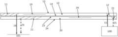
Turning now toFIG.1 , this illustrates an implementation of the display described above, with two LOEs10 and20, each formed as a slab structure of transparent material such as glass, or other material with a sufficient refractive index to support waveguide propagation. As mentioned, each LOE has two majorparallel surfaces 13 &14 (23 &24 for the second LOE20), a set of inner parallel surfaces11 (21 for the second LOE) with partial reflectance coating in an oblique angle to the major surfaces. The LOE optionally also includes aninternal surface
The image projector100 (referred to interchangeably as a “POD”) employed with the devices of the present invention is preferably configured to generate a collimated image, i.e., in which the light of each image pixel is a parallel beam, collimated to infinity, with an angular direction corresponding to the pixel position. The image illumination thus spans a range of angles corresponding to an angular field of view in two dimensions.Image projector 100 includes at least one light source, typically deployed to illuminate a spatial light modulator, such as an LCOS chip. The spatial light modulator modulates the projected intensity of each pixel of the image, thereby generating an image. Alternatively, the image projector may include a scanning arrangement, typically implemented using one or more fast-scanning mirror, which scans illumination from a laser light source across an image plane of the projector while the intensity of the beam is varied synchronously with the motion on a pixel-by-pixel basis, thereby projecting a desired intensity for each pixel. In both cases, collimating optics are provided to generate an output projected image which is collimated to infinity. Some or all of the above components are typically arranged on surfaces of one or more polarizing beam-splitter (PBS) cube or other prism arrangement, as is well known in the art.
In the particularly preferred implementations illustrated here,image projector 100 injects image illumination into the compound light-guide arrangement via one of the major surfaces24. In this case, a first part of the image illumination is coupled into the first light-guideoptical element 10 by afirst reflector 12, and a second part of the image illumination is coupled into the second light-guideoptical element 20 by asecond reflector 22. Thoughsurfaces reflectors surfaces surfaces surfaces 21 and24)parallel rays 15 &25 entering both LOEs will exit the LOEs from the inner surface array also parallel (rays 16 &26). That will happen although the FOV guided by each LOE will differ due to the different angles of slanted inner surfaces.
Furthermore, as shown inFIG.2 , even if input coupling surface and output coupling surface array are not parallel or at the same absolute angle to the major surfaces, so long as the angular difference is the same for both LOEs, then parallel rays15 &25 entering both LOEs will exit the LOEs from the inner partially-reflecting surface array also parallel (rays 16 &26), albeit with a different angle than they entered (i.e., rays15 and16 are not parallel in this figure).
In the exemplary implementations ofFIGS.1 and2 ,first reflector 12 andsecond reflector 22 are full reflectors in non-overlapping relation. In this case, the input aperture width of the two LOEs roughly equals the summation of each input aperture.
In an alternative set of implementations exemplified byFIG.3 , thesecond reflector 22 is a partial reflector, and light reaches thefirst reflector 12 after passing through thesecond reflector 22. In the case ofFIG.3 ,reflectors FIG.3 , surfaces12 and22 overlap, andsurface 22 should have a reflectivity of approximately 50%.
In a variant set of implementations illustrated inFIGS.4A-4C ,second reflector 22 is internal to thesecond LOE 20, while first reflector is associated, directly or indirectly, with a surface of aprism 120 attached to themajor surface 13 of thefirst LOE 120 that is further from theimage projector 100.
Specifically, in the case ofFIG.4A ,prism 120 is glued toLOE 10 and light is reflected and coupled into the LOE bysurface 121 ofprism 120.
In a further option illustrated inFIG.4B , instead of a reflective surface formed on the prism directly,prism 120 may cooperate with anexternal reflector surface 122 serving as the “first reflector”, so that light exits fromprism 120, is reflected fromexternal surface 122 and reentersprism 120 so as to be guided inside the LOE, as shown inFIG.4B , where theray 15 is reflected intoLOE 10 byexternal surface 122 viaprism 120. In this case,surface 121 may be provided with an AR (anti-reflection) coating. Optionally, positioning ofexternal reflector surface 122 may be fixed by adhesive attachment of some associated surfaces, likesurfaces LOE 10 and/orprism 120 on areas that are not optically active (i.e., that the light reaching the EMB from the image projector does not hit these surfaces as it propagates).
In certain particularly preferred implementations, the display of the present invention may be provided with an adjustment mechanism for allowing fine adjustment of an angle of the first reflector. Thus, in the implementation ofFIG.4B , an active alignment system and process may be used to ensure the parallelism of rays exiting both LOEs. In such an alignment procedure, a single collimated beam of light is coupled into both LOEs. The beam is also measured at the output, as coupled-out from the LOEs by the arrays of partially-reflectinginternal surfaces rays leaving LOE 10 will not be parallel to that ofLOE 20. If an external mirror is used as inFIG.4B , then the pitch and yaw of the mirror can be tilted using a suitable adjustment mechanism until parallelism betweenrays 16 and26 is reached, and the position is then fixed by gluingsurfaces reflector 122.
Furthermore, even in the case of aprism 120 with an integrated reflectingsurface 121 as shown inFIG.4A , a similar active alignment process can be implemented by providing a set of interchangeable prisms with small differences in angles that can be temporarily glued toLOE 10, and the prism with closest angular difference betweenrays 16 and26 is selected to be permanently glued toLOE 10.
An alternative mechanism and corresponding method for adjusting the orientation of the first reflector input coupling surface ofLOE 10 is illustrated inFIG.4C . In this case, on top onprism 120, two wedgedwindows outer surface 141 is parallel to the outer surface ofprism 120. By rotatingwindow 140 relative towindow 130, the angle between the surface ofprism 120 andreflective surface 141 can be varied up to 2α. Thus, by continuous rotation ofprism 140, any polar angle in this range could be obtained. By rotating window130 (together with window140) relative to the surface ofprism 120, azimuthal adjustment can be obtained. Thus, any desired orientation offirst reflector surface 141 can be obtained by suitable rotation of the two wedge windows, thereby facilitating an active alignment process as described above. The two wedge windows are then secured in their optimal positions by any suitable form of attachment, typically by use of optical adhesive. All intermediate surfaces are preferably provided with AR coatings in order to minimize unwanted reflections which might lead to ghost images.
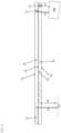
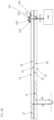
Turning now toFIGS.5A-6C , although the invention has thus far been illustrated in the context of a device which performs expansion of an optical aperture of the image projector in one dimension, the invention can also be implemented to advantage in the context of LOEs which perform aperture expansion in two dimensions. For such an implementation, the first light-guideoptical element 10 preferably includes a first set of mutually-parallel, partially-reflecting deflecting surfaces17 deployed between themajor surfaces optical element 10. The first set of deflectingsurfaces 17 are deployed to progressively deflect the image illumination propagating within the first light-guide optical element towards the first plurality of partially-reflectingsurfaces 11. Similarly, the second light-guideoptical element 20 includes a second set of mutually-parallel, partially-reflecting deflecting surfaces27 deployed between themajor surfaces optical element 20. The second set of deflectingsurfaces 27 are deployed to progressively deflect the part of the image illumination propagating within the second light-guide optical element towards the second plurality of partially-reflectingsurfaces 21. In the particularly preferred but non-limiting exemplary implementation ofFIGS.5A-6C ,first LOE 10 includes a first internalreflective surface 18, parallel to the first set of deflectingsurfaces 17, and deployed to deflect the part of the image illumination propagating within the first light-guide optical element towards the first set of deflecting surfaces. Similarly,second LOE 20 includes a second internalreflective surface 28, parallel to the second set of deflectingsurfaces 27 and deployed to deflect the part of the image illumination propagating within the second light-guide optical element towards the second set of deflecting surfaces.
For simplicity of presentation,FIGS.5A and6A show front and side views, respectively, of thesecond LOE 20,FIGS.5B and6B show similar views of thefirst LOE 10, andFIGS.5C and6C show corresponding views of the assembled display. The features ofsecond LOE 20 are shown in dashed lines in order to facilitate differentiation of the features when stacked.
Thus, in addition to the aperture expansion of the LOE in the X-direction achieved by the structures ofFIGS.1-4C , this embodiment achieves and additional dimension of aperture expansion along the Y-direction. Deflecting surfaces17 and27 are partially reflective surfaces, while internalreflective surfaces image projector 100 bysurface 22 to be guided by thesecond LOE 20 is reflected bysurface 28 so as to be deflected towards deflectingsurfaces 27, where it is progressive deflected and reflected by surfaces27. Sincesurfaces array 27 will be parallel to the light coupled into the LOE bysurface 22. The same applies also to rays being deflected bysurfaces LOE 10. Thus, althoughsurfaces first LOE 10 and intosecond LOE 20, may still emerge parallel.
In certain implementations, lines of intersection of planes of the first set of deflectingsurfaces 17 with themajor surfaces surfaces 27 with the major surfaces.
In certain implementations, first set of deflectingsurfaces 17 and/or the second set of deflectingsurfaces 27 are orthogonal to the major surfaces of the LOEs. In this case, both the direct image and its conjugate are deflected by these surfaces and are redirected towards the outcoupling region. In alternative implementations, first set of deflectingsurfaces 17 and/or the second set of deflectingsurfaces 27 are oblique to the major surfaces of the LOE. In this case, only one image (either the primary image or its conjugate) are progressively deflected towards the coupling-out region, while the surfaces are preferably made substantially transparent in the range of angles of incidence corresponding to the unwanted image.
Implementation Details—Coatings
For optimal implementation of the various embodiments described herein, the various surfaces and interfaces between elements are most preferably imparted with angularly-selective properties. These properties can be generated conveniently using well established technology for designing and implementing multi-layer dielectric coatings in which a sequence of layers of specific thicknesses provide the desired properties.
Regarding the juxtaposed surfaces of the two LOEs, as already mentioned, this is performed so as to retain their properties as separate waveguides, guiding propagation of light within each LOE by internal reflection at the major surfaces. This may be done by maintaining an air gap between the juxtaposed surfaces, or by providing an intervening layer of material with lower refractive index, either as a distinct sheet of material or a layer of low-index adhesive. Alternatively, functional separation of the LOEs can be ensured by providing a coating on one or both of the juxtaposed surfaces which mimics TIR properties, typically in the form of a multi-layer dielectric coating. Thus, at least one of the juxtaposed major surfaces, and most preferably both, are provided with an angularly-selective multi-layer dielectric coating configured to be fully reflective (e.g., over 95% reflective) for angles of incidence greater than 60, more preferably over 50, and in some cases, from about 40 degrees and upwards, relative to a normal to the major surfaces, while having low reflectivity, preferably less than 5%, for angles of incidence smaller than 15 degrees, and more preferably up to about 30 degrees, to the normal.
In each case, visibility for a user looking through the compound waveguide at relatively low angles to a normal to the major surfaces is preferably maintained highly transparent by including antireflecting coatings on all surfaces and interfaces.
Similarly, homogenizingsurfaces
The coupling-out partially-reflecting surfaces are also preferably partially-reflecting at angles of incidence corresponding to the desired part of the image, while being antireflecting for the conjugate image. The proportion of reflectance of the desired image may also sequentially increase between successive surfaces.
All of the above properties are most preferably substantially uniform for different colors, allowing display of the relevant part of the field of view of a color image via each LOE.
It will be appreciated that the above descriptions are intended only to serve as examples, and that many other embodiments are possible within the scope of the present invention as defined in the appended claims.
Claims (15)
1. A display for providing an image to an eye of a user, the display comprising:
(a) a compound light-guide arrangement comprising:
(i) a first light-guide optical element comprising a block of transparent material having a pair of mutually-parallel major surfaces for guiding light by internal reflection at said major surfaces, and
(ii) a second light-guide optical element comprising a block of transparent material having a pair of mutually-parallel major surfaces for guiding light by internal reflection at said major surfaces, said first and second light-guide optical elements being stacked with said major surfaces juxtaposed; and
(b) an image projector configured to project image illumination corresponding to a collimated image with an angular field of view, said image projector being optically coupled to said compound light-guide arrangement so as to introduce a first part of the image illumination to propagate by internal reflection within the first light-guide optical element and a second part of the image illumination to propagate by internal reflection within the second light-guide optical element,
wherein said first light-guide optical element includes a first coupling-out configuration comprising a first plurality of mutually-parallel, partially-reflecting surfaces deployed between said major surfaces of said first light-guide optical element and angled obliquely to said major surfaces, said first plurality of partially-reflecting surfaces being located in a first region of said compound light-guide arrangement for coupling-out a first part of the field of view of the image illumination for viewing by the eye of the user,
and wherein said second light-guide optical element includes a second coupling-out configuration comprising a second plurality of mutually-parallel, partially-reflecting surfaces deployed between said major surfaces of said second light-guide optical element and angled obliquely to said major surfaces, said second plurality of partially-reflecting surfaces being non-parallel to said first plurality of partially-reflecting surfaces and located in a second region of said compound light-guide arrangement at least partially non-overlapping with said first region for coupling-out a second part of the field of view of the image illumination for viewing by the eye of the user,
and wherein optical coupling of said image projector to said compound light-guide arrangement and deployment of said first and second pluralities of partially-reflecting surfaces are such that first and second rays of image illumination emerging parallel from said image projector and coupled respectively into said first and second light-guide optical elements propagate at different angles within said first and second light-guide optical elements but are coupled out respectively by said first and second pluralities of partially-reflecting surfaces as parallel rays.
2. The display ofclaim 1 , wherein said image projector injects said image illumination into said compound light-guide arrangement via one of said major surfaces, and wherein the first part of the image illumination is coupled into said first light-guide optical element by a first reflector and the second part of the image illumination is coupled into said second light-guide optical element by a second reflector.
3. The display ofclaim 2 , wherein said first reflector and said second reflector are non-parallel.
4. The display ofclaim 2 , wherein said first reflector and said second reflector are full reflectors in non-overlapping relation.
5. The display ofclaim 2 , wherein said second reflector is a partial reflector, and wherein light reaches said first reflector after passing through said second reflector.
6. The display ofclaim 2 , wherein said second reflector is internal to said second light-guide optical element, and wherein said first reflector is associated with a surface of a prism attached to the major surface of the first light-guide optical element that is further from said image projector.
7. The display ofclaim 6 , further comprising an adjustment mechanism for allowing fine adjustment of an angle of said first reflector.
8. The display ofclaim 1 , wherein said first light-guide optical element and said second light-guide optical element are separated by an air gap.
9. The display ofclaim 8 , wherein each of said juxtaposed major surfaces is provided with an anti-reflective coating.
10. The display ofclaim 1 , wherein the transparent material of said first and second light-guide optical elements has a first refractive index, and wherein said first light-guide optical element and said second light-guide optical element are separated by a layer of material having a second refractive index lower than said first refractive index.
11. The display ofclaim 10 , wherein each of said juxtaposed major surfaces is provided with an anti-reflective coating.
12. The display ofclaim 1 , wherein at least one of the juxtaposed major surfaces of said first light-guide optical element and said second light-guide optical element is provided with an angularly-selective multi-layer dielectric coating configured to be fully reflective for angles of incidence greater than 60 degrees to a normal to the major surfaces and to have low reflectivity for angles of incidence smaller than 15 degrees to the normal.
13. The display ofclaim 1 , wherein said first light-guide optical element includes a first set of mutually-parallel, partially-reflecting deflecting surfaces deployed between said major surfaces of said first light-guide optical element, said first set of deflecting surfaces being deployed to progressively deflect the first part of the image illumination propagating within said first light-guide optical element towards said first plurality of partially-reflecting surfaces,
and wherein said second light-guide optical element includes a second set of mutually-parallel, partially-reflecting deflecting surfaces deployed between said major surfaces of said second light-guide optical element, said second set of deflecting surfaces being deployed to progressively deflect the second part of the image illumination propagating within said second light-guide optical element towards said second plurality of partially-reflecting surfaces.
14. The display ofclaim 13 , wherein lines of intersection of planes of said first set of deflecting surfaces with said major surfaces are non-parallel with lines of intersection of planes of said second set of deflecting surfaces with said major surfaces.
15. The display ofclaim 13 , wherein said first light-guide optical element includes a first internal reflective surface, parallel to said first set of deflecting surfaces and deployed to deflect the first part of the image illumination propagating within said first light-guide optical element towards said first set of deflecting surfaces,
and wherein said second light-guide optical element includes a second internal reflective surface, parallel to said second set of deflecting surfaces and deployed to deflect the second part of the image illumination propagating within said second light-guide optical element towards said second set of deflecting surfaces.
Priority Applications (1)
| Application Number | Priority Date | Filing Date | Title |
|---|---|---|---|
| US18/018,082US11789264B2 (en) | 2021-07-04 | 2022-07-04 | Display with stacked light-guide elements providing different parts of field of view |
Applications Claiming Priority (3)
| Application Number | Priority Date | Filing Date | Title |
|---|---|---|---|
| US202163218329P | 2021-07-04 | 2021-07-04 | |
| PCT/IL2022/050714WO2023281499A1 (en) | 2021-07-04 | 2022-07-04 | Display with stacked light-guide elements providing different parts of field of view |
| US18/018,082US11789264B2 (en) | 2021-07-04 | 2022-07-04 | Display with stacked light-guide elements providing different parts of field of view |
Publications (2)
| Publication Number | Publication Date |
|---|---|
| US20230204952A1 US20230204952A1 (en) | 2023-06-29 |
| US11789264B2true US11789264B2 (en) | 2023-10-17 |
Family
ID=84801380
Family Applications (1)
| Application Number | Title | Priority Date | Filing Date |
|---|---|---|---|
| US18/018,082ActiveUS11789264B2 (en) | 2021-07-04 | 2022-07-04 | Display with stacked light-guide elements providing different parts of field of view |
Country Status (8)
| Country | Link |
|---|---|
| US (1) | US11789264B2 (en) |
| EP (1) | EP4256396A4 (en) |
| JP (1) | JP7475757B2 (en) |
| KR (1) | KR102676604B1 (en) |
| CN (1) | CN117396792B (en) |
| IL (1) | IL309966B2 (en) |
| TW (1) | TWI868462B (en) |
| WO (1) | WO2023281499A1 (en) |
Families Citing this family (1)
| Publication number | Priority date | Publication date | Assignee | Title |
|---|---|---|---|---|
| WO2024252389A2 (en)* | 2023-06-04 | 2024-12-12 | Lumus Ltd. | Light-guide optical elements with embedded beam splitter overlapping coupling-out region |
Citations (281)
| Publication number | Priority date | Publication date | Assignee | Title |
|---|---|---|---|---|
| US2329001A (en) | 1941-11-25 | 1943-09-07 | Randolph B Delmore | Pilot operated valve |
| US2748659A (en) | 1951-02-26 | 1956-06-05 | Jenaer Glaswerk Schott & Gen | Light source, searchlight or the like for polarized light |
| US2795069A (en) | 1956-02-07 | 1957-06-11 | George K C Hardesty | Laminated metal-plastic illuminable panel |
| US2886911A (en) | 1953-07-23 | 1959-05-19 | George K C Hardesty | Duo-panel edge illumination system |
| FR1485692A (en) | 1966-05-11 | 1967-06-23 | Advanced valve | |
| US3491245A (en) | 1967-04-10 | 1970-01-20 | George K C Hardesty | Guided light display panel |
| DE1422172B1 (en) | 1961-12-07 | 1970-11-12 | Kopperschmidt & Co Carl W | periscope |
| US3544190A (en) | 1968-11-29 | 1970-12-01 | Xerox Corp | Lens strip optical scanning system |
| US3626394A (en) | 1970-04-09 | 1971-12-07 | Magnavox Co | Magneto-optical system |
| US3667621A (en) | 1970-10-20 | 1972-06-06 | Wisconsin Foundry And Machine | Fluid power system for a self-contained unloading unit |
| US3677621A (en) | 1969-11-24 | 1972-07-18 | Vickers Ltd | Optical field flattening devices |
| US3737212A (en) | 1970-12-14 | 1973-06-05 | Gen Electric | Diffraction optics head up display |
| US3802763A (en) | 1971-09-01 | 1974-04-09 | Rank Organisation Ltd | Beam splitting prisms |
| US3857109A (en) | 1973-11-21 | 1974-12-24 | Us Navy | Longitudinally-pumped two-wavelength lasers |
| US3873209A (en) | 1973-12-10 | 1975-03-25 | Bell Telephone Labor Inc | Measurement of thin films by optical waveguiding technique |
| US3940204A (en) | 1975-01-23 | 1976-02-24 | Hughes Aircraft Company | Optical display systems utilizing holographic lenses |
| US3969023A (en) | 1975-03-06 | 1976-07-13 | American Optical Corporation | Method and apparatus for detecting layers of stress in lenses |
| US4084883A (en) | 1977-02-28 | 1978-04-18 | The University Of Rochester | Reflective polarization retarder and laser apparatus utilizing same |
| US4191446A (en) | 1974-12-16 | 1980-03-04 | U.S. Philips Corporation | Directional coupling-device for multi-mode optical fibres |
| US4309070A (en) | 1979-01-19 | 1982-01-05 | Smiths Industries Limited | Display apparatus |
| US4331387A (en) | 1980-07-03 | 1982-05-25 | Westinghouse Electric Corp. | Electro-optical modulator for randomly polarized light |
| FR2496905A1 (en) | 1980-12-24 | 1982-06-25 | France Etat | EPISCOPE WITH MULTIMODES REFLECTIONS |
| US4355864A (en) | 1980-03-26 | 1982-10-26 | Sperry Corporation | Magnetooptic switching devices |
| US4516828A (en) | 1982-05-03 | 1985-05-14 | General Motors Corporation | Duplex communication on a single optical fiber |
| EP0177959A1 (en) | 1984-10-10 | 1986-04-16 | Roger Faris | Nailing anchor and method of use |
| US4613216A (en) | 1984-03-27 | 1986-09-23 | L'etat Francais | Device for observation through a wall in two opposite directions |
| US4711512A (en) | 1985-07-12 | 1987-12-08 | Environmental Research Institute Of Michigan | Compact head-up display |
| US4715684A (en) | 1984-06-20 | 1987-12-29 | Hughes Aircraft Company | Optical system for three color liquid crystal light valve image projection system |
| US4775217A (en) | 1981-10-14 | 1988-10-04 | Gec Avionics Limited | Night vision viewing system |
| FR2617562A1 (en) | 1987-07-01 | 1989-01-06 | Verdelet Alain | Cock assembly with a valve |
| US4798448A (en) | 1988-02-16 | 1989-01-17 | General Electric Company | High efficiency illumination system for display devices |
| US4805988A (en) | 1987-07-24 | 1989-02-21 | Nelson Dones | Personal video viewing device |
| GB2220081A (en) | 1988-06-21 | 1989-12-28 | Hall & Watts Defence Optics Lt | Periscope apparatus |
| EP0365406A1 (en) | 1988-10-21 | 1990-04-25 | Thomson-Csf | Optical collimating system for a helmet visual |
| FR2638242A1 (en) | 1988-10-21 | 1990-04-27 | Thomson Csf | Optical collimation system, especially for a helmet display |
| US4932743A (en) | 1988-04-18 | 1990-06-12 | Ricoh Company, Ltd. | Optical waveguide device |
| EP0380035A2 (en) | 1989-01-23 | 1990-08-01 | Hughes Optical Products, Inc. | Helmet mounted display system |
| EP0399865A1 (en) | 1989-05-23 | 1990-11-28 | Thomson-Csf | Optical device for introduction of a collimated image into the field of view of an observer and helmet comprising such a device |
| US4978952A (en) | 1989-02-24 | 1990-12-18 | Collimated Displays Incorporated | Flat screen color video display |
| US5033828A (en) | 1988-12-02 | 1991-07-23 | Mitsui Petrochemical Industries, Ltd. | Optical output controlling method and apparatus |
| US5096520A (en) | 1990-08-01 | 1992-03-17 | Faris Sades M | Method for producing high efficiency polarizing filters |
| US5157526A (en) | 1990-07-06 | 1992-10-20 | Hitachi, Ltd. | Unabsorbing type polarizer, method for manufacturing the same, polarized light source using the same, and apparatus for liquid crystal display using the same |
| EP0543718A1 (en) | 1991-11-19 | 1993-05-26 | Thomson-Csf | Constituent material for sighting glasses and gun using these sighting glasses |
| US5231642A (en) | 1992-05-08 | 1993-07-27 | Spectra Diode Laboratories, Inc. | Semiconductor ring and folded cavity lasers |
| EP0566004A2 (en) | 1992-04-07 | 1993-10-20 | Hughes Aircraft Company | Virtual image display having a high efficiency grid beamsplitter |
| US5301067A (en) | 1992-05-06 | 1994-04-05 | Plx Inc. | High accuracy periscope assembly |
| GB2272980A (en) | 1992-11-26 | 1994-06-01 | Electro Optics Ind Ltd | Optical beam splitting lens |
| US5367399A (en) | 1992-02-13 | 1994-11-22 | Holotek Ltd. | Rotationally symmetric dual reflection optical beam scanner and system using same |
| GB2278222A (en) | 1993-05-20 | 1994-11-23 | Sharp Kk | Spatial light modulator |
| US5369415A (en) | 1992-06-29 | 1994-11-29 | Motorola, Inc. | Direct retinal scan display with planar imager |
| GB2278883A (en) | 1993-05-06 | 1994-12-14 | Stephen William Owen | Cam drive reciprocating piston engine. |
| WO1995010106A1 (en) | 1993-10-07 | 1995-04-13 | Virtual Vision, Inc. | Binocular head mounted display system |
| FR2721872A1 (en) | 1994-07-01 | 1996-01-05 | Renault Nationale Usines | DEVICE FOR IMPROVING THE VISION OF A ROAD SCENE |
| US5543877A (en) | 1992-10-23 | 1996-08-06 | Olympus Optical Co., Ltd. | Means for controlling driving of a driving fork and take-up spool for automatic feeding and rewinding of a film in a camera |
| US5555329A (en) | 1993-11-05 | 1996-09-10 | Alliesignal Inc. | Light directing optical structure |
| US5619601A (en) | 1993-12-28 | 1997-04-08 | Fujitsu Limited | Optical switch and optical distributor using polarization control and partial reflection |
| EP0770818A2 (en) | 1995-10-24 | 1997-05-02 | SHARP Corporation | Illuminator |
| US5650873A (en) | 1995-01-30 | 1997-07-22 | Lockheed Missiles & Space Company, Inc. | Micropolarization apparatus |
| US5680209A (en) | 1992-08-13 | 1997-10-21 | Maechler; Meinrad | Spectroscopic systems for the analysis of small and very small quantities of substances |
| US5712694A (en) | 1994-09-16 | 1998-01-27 | Kabushiki Kaisha Toshiba | LCD comprising a light separating element including a cholesteric liquid crystal sheet |
| US5724163A (en) | 1996-11-12 | 1998-03-03 | Yariv Ben-Yehuda | Optical system for alternative or simultaneous direction of light originating from two scenes to the eye of a viewer |
| WO1998015868A1 (en) | 1996-10-08 | 1998-04-16 | The Microoptical Corporation | Image combining system for eyeglasses and face masks |
| US5751480A (en) | 1991-04-09 | 1998-05-12 | Canon Kabushiki Kaisha | Plate-like polarizing element, a polarizing conversion unit provided with the element, and a projector provided with the unit |
| US5764412A (en) | 1994-10-15 | 1998-06-09 | Fujitsu Limited | Polarization separation/conversion device for polarized lighting apparatus and projection display unit |
| US5770847A (en) | 1994-12-23 | 1998-06-23 | Spectra-Physics Scanning Systems, Inc. | Bar code reader with multi-focus lens |
| US5829854A (en) | 1996-09-26 | 1998-11-03 | Raychem Corporation | Angled color dispersement and recombination prism |
| DE19725262A1 (en) | 1997-06-13 | 1998-12-24 | Vitaly Dr Lissotschenko | Optical beam transformation apparatus |
| US5883684A (en) | 1997-06-19 | 1999-03-16 | Three-Five Systems, Inc. | Diffusively reflecting shield optically, coupled to backlit lightguide, containing LED's completely surrounded by the shield |
| US5896232A (en) | 1997-08-07 | 1999-04-20 | International Business Machines Corporation | Highly efficient and compact frontlighting for polarization-based reflection light valves |
| US5919601A (en) | 1996-11-12 | 1999-07-06 | Kodak Polychrome Graphics, Llc | Radiation-sensitive compositions and printing plates |
| US5966223A (en) | 1993-02-26 | 1999-10-12 | Yeda Research & Development Co., Ltd. | Planar holographic optical device |
| WO1999052002A1 (en) | 1998-04-02 | 1999-10-14 | Elop Electro-Optics Industries Ltd. | Holographic optical devices |
| US5982536A (en) | 1995-10-17 | 1999-11-09 | Barr & Stroud Limited | Display system |
| US5999836A (en) | 1995-06-06 | 1999-12-07 | Nelson; Robert S. | Enhanced high resolution breast imaging device and method utilizing non-ionizing radiation of narrow spectral bandwidth |
| WO2000004407A1 (en) | 1998-07-17 | 2000-01-27 | Brookhaven Science Associates | Small inlet optical panel and a method of making a small inlet optical panel |
| US6021239A (en) | 1996-10-31 | 2000-02-01 | Sharp Kabushiki Kaisha | Photocoupler and method for producing the same |
| US6052500A (en) | 1996-12-03 | 2000-04-18 | Mitsubishi Gas Chemical Company, Inc. | Optical waveguide device for connections without optical axis adjustment |
| US6091548A (en) | 1997-10-01 | 2000-07-18 | Raytheon Company | Optical system with two-stage aberration correction |
| WO2000063738A1 (en) | 1999-04-21 | 2000-10-26 | U.S. Precision Lens Incorporated | Optical systems for reflective lcd's |
| US6144347A (en) | 1992-10-09 | 2000-11-07 | Sony Corporation | Head-mounted image display apparatus |
| JP2001021448A (en) | 1999-07-09 | 2001-01-26 | Ricoh Co Ltd | Apparatus and method for measuring refractive index distribution |
| WO2001027685A2 (en) | 1999-10-14 | 2001-04-19 | Stratos Product Development Company Llc | Virtual imaging system |
| US6222676B1 (en) | 1998-12-22 | 2001-04-24 | Olympus Optical Co., Ltd. | Image display apparatus |
| US6231992B1 (en) | 1998-09-04 | 2001-05-15 | Yazaki Corporation | Partial reflector |
| US20010030860A1 (en) | 2000-04-12 | 2001-10-18 | Hajime Kimura | Illumination apparatus |
| US6324330B1 (en) | 2000-07-10 | 2001-11-27 | Ultratech Stepper, Inc. | Folded light tunnel apparatus and method |
| US6322256B1 (en) | 1998-11-24 | 2001-11-27 | Nippon Electric Glass Co., Ltd. | Optical fiber holding capillary tube |
| EP1158336A2 (en) | 2000-05-21 | 2001-11-28 | Elop Electro-Optics Industries Ltd. | System and method for varying the transmittance of light through a media |
| WO2001095027A2 (en) | 2000-06-05 | 2001-12-13 | Lumus Ltd. | Substrate-guided optical beam expander |
| WO2001095025A1 (en) | 2000-06-08 | 2001-12-13 | Three-Five Systems, Inc. | Liquid crystal display element having a precisely controlled cell gap and method of making same |
| US20020015233A1 (en) | 2000-07-31 | 2002-02-07 | Daeyang E&C Co., Ltd. | Optical system for head mounted display |
| US6349001B1 (en) | 1997-10-30 | 2002-02-19 | The Microoptical Corporation | Eyeglass interface system |
| EP1180711A1 (en) | 2000-01-28 | 2002-02-20 | Seiko Epson Corporation | Optical reflection polarizer and projector comprising the same |
| US6362861B1 (en) | 2000-05-02 | 2002-03-26 | Agilent Technologies, Inc. | Microdisplay system |
| US6384982B1 (en) | 1996-10-08 | 2002-05-07 | The Microoptical Corporation | Compact image display system for eyeglasses or other head-borne frames |
| US6388814B2 (en) | 1999-12-28 | 2002-05-14 | Rohm Co., Ltd. | Head mounted display |
| US6404947B1 (en) | 1999-11-16 | 2002-06-11 | Matsushita Electric Industrial Co., Ltd. | Demultiplexer and demultiplexer-receiver |
| US6404550B1 (en) | 1996-07-25 | 2002-06-11 | Seiko Epson Corporation | Optical element suitable for projection display apparatus |
| WO2002082168A1 (en) | 2001-04-07 | 2002-10-17 | Cambridge Flat Projection Displays Limited | Display |
| US20020176173A1 (en) | 2001-04-30 | 2002-11-28 | Song Young-Ran | Wearable display system and process thereof |
| US6490104B1 (en) | 2000-09-15 | 2002-12-03 | Three-Five Systems, Inc. | Illumination system for a micro display |
| US20020191297A1 (en) | 2000-10-20 | 2002-12-19 | Gleckman Philip L. | Compact near-eye illumination system |
| US20030007157A1 (en) | 2001-07-03 | 2003-01-09 | Hulse Charles Andrew | Rhomb interleaver |
| US6509982B2 (en) | 2000-01-07 | 2003-01-21 | Honeywell International Inc. | Holographic diffusers |
| US20030020006A1 (en) | 2001-07-24 | 2003-01-30 | Janeczko Donald John | Planar diffractive relay |
| US20030063042A1 (en) | 1999-07-29 | 2003-04-03 | Asher A. Friesem | Electronic utility devices incorporating a compact virtual image display |
| US20030072160A1 (en) | 2001-10-13 | 2003-04-17 | Thomas Kuepper | Reflector for a high pressure gas discharge lamp |
| US6556282B2 (en) | 2001-09-04 | 2003-04-29 | Rosemount Aerospace, Inc. | Combined LOAS and LIDAR system |
| JP2003140081A (en) | 2001-11-06 | 2003-05-14 | Nikon Corp | Hologram combiner optical system |
| US20030090439A1 (en) | 2001-09-07 | 2003-05-15 | Spitzer Mark B. | Light weight, compact, remountable face-supported electronic display |
| US6577411B1 (en) | 1996-11-12 | 2003-06-10 | Planop-Planar Optics Ltd. | Optical system for alternative or simultaneous direction of light originating from two scenes to the eye of a viewer |
| EP1326102A1 (en) | 2000-07-24 | 2003-07-09 | Mitsubishi Rayon Co., Ltd. | Surface illuminant device and prism sheet used therefor |
| WO2003058320A1 (en) | 2002-01-11 | 2003-07-17 | Essilor International (Compagnie Générale d'Optique) | Ophthalmic lens with a projection insert |
| WO2003081320A1 (en) | 2002-03-21 | 2003-10-02 | Lumus Ltd. | Light guide optical device |
| US20030197938A1 (en) | 2002-04-12 | 2003-10-23 | Dietrich Schmidt | Arrangement for polarization of light |
| JP2003337298A (en) | 2002-05-17 | 2003-11-28 | Sony Corp | Image display device |
| EP1385023A1 (en) | 2002-07-17 | 2004-01-28 | C.R.F. Società Consortile per Azioni | A light guide for display devices of the head-mounted or head-up type |
| US6710902B2 (en) | 2001-04-13 | 2004-03-23 | Olympus Corporation | Observation optical system |
| US20040084088A1 (en) | 2002-10-31 | 2004-05-06 | Callies Robert E. | Pressure regulator and shut-off valve |
| US20040137189A1 (en) | 2002-11-08 | 2004-07-15 | Tellini Serena R. P. | Optical device and light guide system comprising it |
| US6775432B2 (en) | 2001-10-19 | 2004-08-10 | Santanu Basu | Method and apparatus for optical wavelength demultiplexing, multiplexing and routing |
| JP2004527801A (en) | 2001-05-26 | 2004-09-09 | テイリズ オプティクス リミテッド | Optical device using polarizing bees splitter |
| US6798579B2 (en) | 1999-04-27 | 2004-09-28 | Optical Products Development Corp. | Real imaging system with reduced ghost imaging |
| US20040233534A1 (en) | 1999-06-16 | 2004-11-25 | Hideyuki Nakanishi | Diffractive optical element that polarizes light and an optical pickup using the same |
| WO2004109349A2 (en) | 2003-06-10 | 2004-12-16 | Elop Electro-Optics Industries Ltd. | Method and system for displaying an informative image against a background image |
| US20050018308A1 (en) | 2003-05-22 | 2005-01-27 | Cassarly William J. | Light distribution apparatus and methods for illuminating optical systems |
| WO2005024491A1 (en) | 2003-09-10 | 2005-03-17 | Lumus Ltd. | Substrate-guided optical devices |
| WO2005024485A1 (en) | 2003-09-10 | 2005-03-17 | Lumus Ltd. | Optical devices particularly for remote viewing applications |
| JP2005084522A (en) | 2003-09-10 | 2005-03-31 | Nikon Corp | Combiner optics |
| US20050073577A1 (en) | 2003-09-03 | 2005-04-07 | Toshiyuki Sudo | Stereoscopic image display device |
| US20050084210A1 (en) | 2003-10-17 | 2005-04-21 | Samsung Electronics Co., Ltd. | Light tunnel, uniform light illuminating device and projector employing the same |
| US20050174658A1 (en) | 2004-02-05 | 2005-08-11 | Michael Long | Systems and methods for integrating light |
| US20050174641A1 (en) | 2002-11-26 | 2005-08-11 | Jds Uniphase Corporation | Polarization conversion light integrator |
| US6942925B1 (en) | 1997-08-11 | 2005-09-13 | Optiva, Inc. | Dichroic polarizer |
| WO2005093493A1 (en) | 2004-03-29 | 2005-10-06 | Sony Corporation | Optical device and virtual image display device |
| US20050225866A1 (en) | 2003-06-10 | 2005-10-13 | Abu-Ageel Nayef M | Light recycler and color display system including same |
| US20050265044A1 (en) | 2004-05-28 | 2005-12-01 | Yi-Ming Chen | Planar light-emitting device |
| WO2005124427A1 (en) | 2004-06-17 | 2005-12-29 | Lumus Ltd. | High brightness optical device |
| JP2006003872A (en) | 2004-05-17 | 2006-01-05 | Nikon Corp | Optical element, combiner optical system, and information display device |
| WO2006013565A1 (en) | 2004-08-05 | 2006-02-09 | Lumus Ltd. | Optical device for light coupling |
| US7016113B2 (en) | 1997-05-28 | 2006-03-21 | Lg.Philips Lcd Co., Ltd. | Large scale polarizer and polarizer system employing it |
| US20060126182A1 (en) | 2004-12-13 | 2006-06-15 | Nokia Corporation | General diffractive optics method for expanding an exit pupil |
| US20060146518A1 (en) | 2004-12-30 | 2006-07-06 | Matthew Dubin | Remotely coupled hybrid HUD backlight |
| US20060153518A1 (en) | 2003-06-10 | 2006-07-13 | Abu-Ageel Nayef M | Illumination system and display system employing same |
| US7088664B2 (en) | 2001-04-30 | 2006-08-08 | Samsung Electronics Co., Ltd. | Reflection type compound prism and optical pickup apparatus employing the same |
| WO2006085310A1 (en) | 2005-02-10 | 2006-08-17 | Lumus Ltd. | Substrate-guided optical device particularly for vision enhanced optical systems |
| WO2006085309A1 (en) | 2005-02-10 | 2006-08-17 | Lumus Ltd. | Substrate-guided optical device utilizing thin transparent layer |
| WO2006085308A1 (en) | 2005-02-10 | 2006-08-17 | Lumus Ltd. | Substrate-guide optical device utilizing polarization beam splitters |
| WO2006087709A1 (en) | 2005-02-17 | 2006-08-24 | Lumus Ltd. | Personal navigation system |
| WO2006098097A1 (en) | 2005-03-14 | 2006-09-21 | Nikon Corporation | Image display optical system and image display |
| US20060268421A1 (en) | 2005-05-30 | 2006-11-30 | Konic Minolta Holdings, Inc. | Image display apparatus and head mount display |
| US7175304B2 (en) | 2003-01-30 | 2007-02-13 | Touchsensor Technologies, Llc | Integrated low profile display |
| US20070052929A1 (en) | 2005-09-06 | 2007-03-08 | Stuart Allman | Light coupling system and method |
| US20070070859A1 (en) | 2004-05-17 | 2007-03-29 | Nikon Corporation | Optical elements and combiner optical systems and image-display units comprising same |
| US7205960B2 (en) | 2003-02-19 | 2007-04-17 | Mirage Innovations Ltd. | Chromatic planar optic display system |
| WO2007054928A1 (en) | 2005-11-08 | 2007-05-18 | Lumus Ltd. | Polarizing optical system |
| US20070188837A1 (en) | 2006-02-16 | 2007-08-16 | Konica Minolta Holdings, Inc. | Beam expanding optical element, beam expansion method, image display apparatus, and head-mounted display |
| WO2007093983A2 (en) | 2006-02-14 | 2007-08-23 | Lumus Ltd. | Substrate-guided imaging lens |
| WO2008023367A1 (en) | 2006-08-22 | 2008-02-28 | Lumus Ltd. | Substrate-guided optical device |
| US7339742B2 (en) | 2003-09-10 | 2008-03-04 | Lumas Ltd. | High brightness optical device |
| US7355795B1 (en) | 1994-06-13 | 2008-04-08 | Canon Kabushiki Kaisha | Head-up display device with curved optical surface having total reflection |
| US20080094586A1 (en) | 2004-12-06 | 2008-04-24 | Yoshikazu Hirayama | Image Display Optical System, Image Display Unit, Illuminating Optical System, And Liquid Crystal Display Unit |
| US20080151375A1 (en) | 2006-12-26 | 2008-06-26 | Ching-Bin Lin | Light guide means as dually effected by light concentrating and light diffusing |
| US20080192239A1 (en) | 2004-03-23 | 2008-08-14 | Tetsuya Otosaka | Measurement Method of Non-Circularity of Core Optical Fiber Base Material and Apparatus Therefor |
| US7430355B2 (en) | 2003-12-08 | 2008-09-30 | University Of Cincinnati | Light emissive signage devices based on lightwave coupling |
| US20080247150A1 (en) | 2007-04-04 | 2008-10-09 | Tatsuo Itoh | Surface illumination apparatus, and liquid crystal display with the same |
| WO2008129539A2 (en) | 2007-04-22 | 2008-10-30 | Lumus Ltd. | A collimating optical device and system |
| US7448170B2 (en) | 2002-01-16 | 2008-11-11 | Mara-Institut D.O.O. | Indirectly prestressed, concrete, roof-ceiling construction with flat soffit |
| WO2008149339A1 (en) | 2007-06-04 | 2008-12-11 | Lumus Ltd. | Distributed head-mounted display system |
| US20080316606A1 (en) | 2007-06-20 | 2008-12-25 | Canon Kabushiki Kaisha | Image observation apparatus and image observation system |
| US20090010023A1 (en) | 2007-07-05 | 2009-01-08 | I2Ic Corporation | Light source having transparent layers |
| WO2009009268A1 (en) | 2007-07-10 | 2009-01-15 | Microvision, Inc. | Substrate-guided relays for use with scanned beam image sources |
| WO2009074638A2 (en) | 2007-12-13 | 2009-06-18 | Optinvent | Optical guide and ocular vision optical system |
| US20090190222A1 (en) | 2005-09-07 | 2009-07-30 | Bae Systems Plc | Projection Display |
| CN101542346A (en) | 2006-11-28 | 2009-09-23 | 康宁光缆系统有限公司 | Fiber optic cable having a dry insert and methods of making the same |
| US7643214B2 (en) | 2004-06-17 | 2010-01-05 | Lumus Ltd. | Substrate-guided optical device with wide aperture |
| US20100111472A1 (en) | 2008-11-06 | 2010-05-06 | Microvision, Inc. | Substrate Guided Relay with Pupil Expanding Input Coupler |
| US20100202128A1 (en) | 2008-12-11 | 2010-08-12 | Robert Saccomanno | Non-invasive injection of light into a transparent substrate, such as a window pane through its face |
| JP2010217906A (en) | 2010-04-20 | 2010-09-30 | Panasonic Corp | Liquid crystal display |
| US20100278480A1 (en) | 2009-04-21 | 2010-11-04 | Vasylyev Sergiy V | Light collection and illumination systems employing planar waveguide |
| US20100291489A1 (en) | 2009-05-15 | 2010-11-18 | Api Nanofabrication And Research Corp. | Exposure methods for forming patterned layers and apparatus for performing the same |
| US20100290124A1 (en) | 2009-05-18 | 2010-11-18 | Canon Kabushiki Kaisha | Image display apparatus |
| US20110050595A1 (en) | 2009-09-03 | 2011-03-03 | Niklas Lundback | Large Scale Multi-User, Multi-Touch System |
| US20110096566A1 (en) | 2009-10-28 | 2011-04-28 | Coretronic Corporation | Backlight module |
| US7949252B1 (en) | 2008-12-11 | 2011-05-24 | Adobe Systems Incorporated | Plenoptic camera with large depth of field |
| US20110191690A1 (en) | 2010-02-03 | 2011-08-04 | Microsoft Corporation | Combined Surface User Interface |
| US7995275B2 (en) | 2005-08-18 | 2011-08-09 | Ricoh Company, Ltd. | Polarization conversion element, polarization conversion optical system and image projecting apparatus |
| US20110227661A1 (en) | 2010-03-19 | 2011-09-22 | Masashi Numata | Glass substrate bonding method, glass assembly, package manufacturing method, package, piezoelectric vibrator, oscillator, electronic device, and radio-controlled timepiece |
| US20110242661A1 (en) | 2008-12-12 | 2011-10-06 | Bae Systems Plc | waveguides |
| US8035872B2 (en) | 2004-06-29 | 2011-10-11 | Nikon Corporation | Image combiner and image display device |
| WO2011130720A2 (en) | 2010-04-16 | 2011-10-20 | Flex Lighting Ii, Llc | Sign comprising a film-based lightguide |
| US20120039576A1 (en) | 2009-04-08 | 2012-02-16 | International Business Machines Corporation | Optical waveguide with embedded light-reflecting feature and method for fabricating the same |
| US20120062998A1 (en) | 2010-09-13 | 2012-03-15 | Vuzix Corporation | Prismatic multiple waveguide for near-eye display |
| US8187481B1 (en) | 2005-05-05 | 2012-05-29 | Coho Holdings, Llc | Random texture anti-reflection optical surface treatment |
| US20120147361A1 (en) | 2010-12-13 | 2012-06-14 | Mitsubishi Electric Corporation | Wavelength monitor |
| WO2012088478A1 (en) | 2010-12-24 | 2012-06-28 | Chunyu Gao | An ergonomic head mounted display device and optical system |
| JP2012123936A (en) | 2010-12-06 | 2012-06-28 | Omron Corp | Plane light source device, and three-dimensional display device |
| US20120194781A1 (en) | 2011-01-28 | 2012-08-02 | Light Prescriptions Innovators, Llc | Autofocusing eyewear, especially for presbyopia correction |
| EP2530510A2 (en) | 2011-06-01 | 2012-12-05 | Sony Corporation | Display apparatus |
| US20130022316A1 (en) | 2011-07-19 | 2013-01-24 | Teraxion Inc. | Fiber Coupling Technique on a Waveguide |
| US8369019B2 (en) | 2008-04-14 | 2013-02-05 | Bae Systems Plc | Waveguides |
| US20130083404A1 (en) | 2011-09-30 | 2013-04-04 | Seiko Epson Corporation | Virtual image display device |
| WO2013065656A1 (en) | 2011-10-31 | 2013-05-10 | シャープ株式会社 | Pseudo-solar radiation device |
| US20130187836A1 (en) | 2010-04-30 | 2013-07-25 | Dewen Cheng | Wide angle and high resolution tiled head-mounted display device |
| WO2013175465A1 (en) | 2012-05-21 | 2013-11-28 | Lumus Ltd. | Head -mounted display with an eyeball - tracker integrated system |
| US20130321432A1 (en) | 2012-06-01 | 2013-12-05 | QUALCOMM MEMES Technologies, Inc. | Light guide with embedded fresnel reflectors |
| US20130334504A1 (en) | 2008-08-19 | 2013-12-19 | Plextronics, Inc. | Organic light emitting diode lighting devices |
| WO2013188464A1 (en) | 2012-06-11 | 2013-12-19 | Magic Leap, Inc. | Multiple depth plane three-dimensional display using a wave guide reflector array projector |
| US20140016051A1 (en) | 2010-12-22 | 2014-01-16 | Seereal Technologies S.A. | Combined light modulation device for tracking users |
| US20140043688A1 (en) | 2012-08-07 | 2014-02-13 | Nokia Corporation | Display Illumination Light Guide |
| US8655178B2 (en) | 2007-05-08 | 2014-02-18 | The Boeing Company | Method and apparatus for clearing an optical channel |
| US8665178B1 (en) | 2012-03-01 | 2014-03-04 | Google, Inc. | Partially-reflective waveguide stack and heads-up display using same |
| US8666208B1 (en) | 2010-11-05 | 2014-03-04 | Google Inc. | Moldable waveguide with embedded micro structures |
| US20140104665A1 (en) | 2012-04-25 | 2014-04-17 | Milan Momcilo Popovich | Holographic wide angle display |
| US8736963B2 (en) | 2012-03-21 | 2014-05-27 | Microsoft Corporation | Two-dimensional exit-pupil expansion |
| US8743464B1 (en) | 2010-11-03 | 2014-06-03 | Google Inc. | Waveguide with embedded mirrors |
| US20140185142A1 (en) | 2013-01-02 | 2014-07-03 | Google Inc. | Optical combiner for near-eye display |
| US20140226361A1 (en) | 2012-02-14 | 2014-08-14 | Sergiy Victorovich Vasylyev | Face-lit waveguide illumination systems |
| US20140226215A1 (en) | 2013-02-13 | 2014-08-14 | Seiko Epson Corporation | Virtual image display device |
| US8873148B1 (en) | 2011-12-12 | 2014-10-28 | Google Inc. | Eyepiece having total internal reflection based light folding |
| US8913865B1 (en) | 2013-06-27 | 2014-12-16 | Microsoft Corporation | Waveguide including light turning gaps |
| DE102013106392A1 (en) | 2013-06-19 | 2014-12-24 | Fraunhofer-Gesellschaft zur Förderung der angewandten Forschung e.V. | Process for producing an antireflection coating |
| US20150016777A1 (en) | 2012-06-11 | 2015-01-15 | Magic Leap, Inc. | Planar waveguide apparatus with diffraction element(s) and system employing same |
| US20150033865A1 (en) | 2013-07-30 | 2015-02-05 | Raytheon Company | Fiber optic vibration detection |
| US20150081313A1 (en) | 2013-09-16 | 2015-03-19 | Sunedison Llc | Methods and systems for photovoltaic site installation, commissioining, and provisioning |
| US20150138646A1 (en) | 2013-11-15 | 2015-05-21 | Seiko Epson Corporation | Optical element, image display device and method for manufacturing same |
| WO2015081313A2 (en) | 2013-11-27 | 2015-06-04 | Magic Leap, Inc. | Virtual and augmented reality systems and methods |
| US20150153569A1 (en) | 2013-12-02 | 2015-06-04 | Seiko Epson Corporation | Optical device and virtual image display apparatus |
| US20150160529A1 (en) | 2013-12-11 | 2015-06-11 | Sbg Labs Inc. | Holographic Waveguide Display |
| US20150182748A1 (en) | 2013-12-31 | 2015-07-02 | Nano Retina Ltd. | Wearable apparatus for delivery of power to a retinal prosthesis |
| US20150207990A1 (en) | 2012-08-20 | 2015-07-23 | The Regents Of The University Of California | Monocentric lens designs and associated imaging systems having wide field of view and high resolution |
| US20150219834A1 (en) | 2010-04-16 | 2015-08-06 | Flex Lighting Ii, Llc | Display with a film-based lightguide and light redirecting optical element |
| US20150241619A1 (en) | 2014-02-24 | 2015-08-27 | Google Inc. | Lightguide device with outcoupling structures |
| WO2015158828A1 (en) | 2014-04-17 | 2015-10-22 | Carl Zeiss Smart Optics Gmbh | Eyeglass lens for a display device which can be placed on the head of a user and generates an image, and display device having such an eyeglass lens |
| JP2016028275A (en) | 2014-07-09 | 2016-02-25 | 恵和株式会社 | Optical sheet, edge light type backlight unit, and method for manufacturing optical sheet |
| WO2016103251A1 (en) | 2014-12-25 | 2016-06-30 | Lumus Ltd. | Substrate-guided optical device |
| US20160234485A1 (en) | 2015-02-09 | 2016-08-11 | Steven John Robbins | Display System |
| US20160238844A1 (en) | 2013-09-27 | 2016-08-18 | Carl Zeiss Smart Optics Gmbh | Spectacle lens for a display device that can be fitted on the head of a user and generates an image, and display device with such a spectacle lens |
| WO2016132347A1 (en) | 2015-02-19 | 2016-08-25 | Lumus Ltd. | Compact head-mounted display system having uniform image |
| US20160312913A1 (en) | 2013-12-20 | 2016-10-27 | Imi Hydronic Engineering International Sa | A valve and a method of controlling a valve in a fluid conduit |
| JP2016197830A (en) | 2015-04-06 | 2016-11-24 | セイコーエプソン株式会社 | Display device, display device control method, and program |
| US20160341964A1 (en) | 2007-08-03 | 2016-11-24 | Lumus Ltd. | Substrate-guide optical device |
| US9523852B1 (en) | 2012-03-28 | 2016-12-20 | Rockwell Collins, Inc. | Micro collimator system and method for a head up display (HUD) |
| US20160370693A1 (en) | 2014-03-27 | 2016-12-22 | Olympus Corporation | Image display device |
| US20170075119A1 (en) | 2015-09-10 | 2017-03-16 | Vuzix Corporation | Imaging Light Guide With Reflective Turning Array |
| US20170097506A1 (en) | 2015-10-05 | 2017-04-06 | Magic Leap, Inc. | Microlens collimator for scanning optical fiber in virtual/augmented reality system |
| WO2017106873A1 (en) | 2015-12-18 | 2017-06-22 | Ostendo Technologies, Inc. | Systems and methods for augmented near-eye wearable displays |
| US20170192239A1 (en)* | 2016-01-06 | 2017-07-06 | Naoki Nakamura | Light guide, virtual image display device, and light guide unit |
| US20170242249A1 (en) | 2016-02-19 | 2017-08-24 | Richard Andrew Wall | Waveguide Pupil Relay |
| CN107238928A (en) | 2017-06-09 | 2017-10-10 | 京东方科技集团股份有限公司 | A kind of Waveguide array |
| US9805633B2 (en) | 2014-03-31 | 2017-10-31 | Lenovo (Beijing) Co., Ltd. | Display device and electronic apparatus |
| US20170336636A1 (en) | 2014-11-11 | 2017-11-23 | Lumus Ltd. | Compact head-mounted display system protected by a hyperfine structure |
| WO2017199232A1 (en) | 2016-05-18 | 2017-11-23 | Lumus Ltd. | Head-mounted imaging device |
| US20170343822A1 (en) | 2016-05-24 | 2017-11-30 | Osterhout Group, Inc. | Robust optics for a head-worn display |
| US20170363799A1 (en) | 2014-12-25 | 2017-12-21 | Lumus Ltd. | Method for fabricating a substrate-guided optical device |
| US20180003862A1 (en) | 2015-01-21 | 2018-01-04 | Tesseland Llc | Display device with total internal reflection |
| TW201809798A (en) | 2016-08-18 | 2018-03-16 | 盧姆斯有限公司 | Compact head-mounted display system having uniform image |
| US9933684B2 (en) | 2012-11-16 | 2018-04-03 | Rockwell Collins, Inc. | Transparent waveguide display providing upper and lower fields of view having a specific light output aperture configuration |
| US20180101087A1 (en) | 2016-02-24 | 2018-04-12 | Omron Corporation | Display device |
| US10048499B2 (en) | 2005-11-08 | 2018-08-14 | Lumus Ltd. | Polarizing optical system |
| US20180292599A1 (en) | 2017-04-06 | 2018-10-11 | Lumus Ltd | Light-guide optical element and method of its manufacture |
| US20180299678A1 (en)* | 2015-12-17 | 2018-10-18 | Carl Zeiss Ag | Optical system and method for transmitting a source image |
| US20180372940A1 (en) | 2016-06-21 | 2018-12-27 | Fusao Ishii | Illuminator for a wearable display |
| US10302835B2 (en) | 2017-02-22 | 2019-05-28 | Lumus Ltd. | Light guide optical assembly |
| US20190212487A1 (en) | 2017-03-22 | 2019-07-11 | Lumus Ltd. | Overlapping facets |
| US20190227215A1 (en) | 2018-01-21 | 2019-07-25 | Lumus Ltd. | Light-guide optical element with multiple-axis internal aperture expansion |
| US10520733B2 (en) | 2016-09-30 | 2019-12-31 | Seiko Epson Corporation | Virtual image display device including first and second light guiding units and manufacturing method thereof |
| US20200120329A1 (en) | 2018-01-02 | 2020-04-16 | Lumus Ltd. | Augmented reality displays with active alignment and corresponding methods |
| US20200278547A1 (en) | 2017-11-15 | 2020-09-03 | Carl Zeiss Jena Gmbh | Light guide for an hmd, hmd and method for transmitting an image in an hmd |
| US20200292819A1 (en)* | 2017-11-21 | 2020-09-17 | Lumus Ltd. | Optical aperture expansion arrangement for near-eye displays |
| US20200349902A1 (en)* | 2015-04-30 | 2020-11-05 | Sony Corporation | Display apparatus and initial setting method for display apparatus |
| US10830938B2 (en) | 2018-05-14 | 2020-11-10 | Lumus Ltd. | Projector configuration with subdivided optical aperture for near-eye displays, and corresponding optical systems |
| US20200355924A1 (en) | 2017-11-03 | 2020-11-12 | Carl Zeiss Ag | Light guide, imaging device and hmd having separate imaging channels |
| US20210033862A1 (en) | 2018-07-16 | 2021-02-04 | Lumus Ltd. | Light-Guide Optical Element Employing Polarized Internal Reflectors |
| US20210033872A1 (en) | 2018-05-22 | 2021-02-04 | Lumus Ltd. | Optical system and method for improvement of light field uniformity |
| US20210055218A1 (en) | 2018-04-08 | 2021-02-25 | Lumus Ltd. | Optical Sample Characterization |
| US20210055561A1 (en) | 2018-05-17 | 2021-02-25 | Lumus Ltd. | Near-eye display having overlapping projector assemblies |
| US20210063733A1 (en) | 2018-05-23 | 2021-03-04 | Lumus Ltd. | Optical system including light-guide optical element with partially-reflective internal surfaces |
| US20210072553A1 (en) | 2017-12-10 | 2021-03-11 | Lumus Ltd. | Image Projector |
| US20210080637A1 (en)* | 2019-01-29 | 2021-03-18 | Osram Opto Semiconductors Gmbh | µ-LED, µ-LED DEVICE, DISPLAY AND METHOD FOR THE SAME |
| US20210099691A1 (en) | 2018-01-02 | 2021-04-01 | Lumus Ltd. | Augmented reality displays with active alignment and corresponding methods |
Family Cites Families (9)
| Publication number | Priority date | Publication date | Assignee | Title |
|---|---|---|---|---|
| CN206649211U (en)* | 2017-02-24 | 2017-11-17 | 北京耐德佳显示技术有限公司 | A kind of nearly eye display device using Waveguide mode optical element |
| FR3020880B1 (en)* | 2014-05-09 | 2016-05-27 | Thales Sa | VISUAL HEAD COMPRISING AN OPTICAL MIXER WITH EXPANSION OF PUPIL PILOTABLE |
| US10302945B2 (en)* | 2015-08-12 | 2019-05-28 | Google Llc | Near-eye display with stacked lightguides |
| CN107024769B (en) | 2016-01-29 | 2019-12-27 | 北京灵犀微光科技有限公司 | Display system based on waveguide |
| KR102699560B1 (en)* | 2017-03-21 | 2024-08-27 | 매직 립, 인코포레이티드 | Stacked waveguides with different diffraction gratings for combined fields of view |
| WO2018213010A1 (en)* | 2017-05-17 | 2018-11-22 | Apple Inc. | Head-mounted display device with vision correction |
| JP7128751B2 (en) | 2019-01-23 | 2022-08-31 | 株式会社日立エルジーデータストレージ | Light guide plate and image display device |
| CN111221128B (en) | 2020-02-28 | 2022-03-04 | 深圳珑璟光电科技有限公司 | Near-to-eye waveguide display device capable of enlarging field angle |
| WO2022163672A1 (en) | 2021-01-29 | 2022-08-04 | 富士フイルム株式会社 | Image display device |
- 2022
- 2022-07-04KRKR1020237037850Apatent/KR102676604B1/enactiveActive
- 2022-07-04USUS18/018,082patent/US11789264B2/enactiveActive
- 2022-07-04CNCN202280033561.4Apatent/CN117396792B/enactiveActive
- 2022-07-04JPJP2023561902Apatent/JP7475757B2/enactiveActive
- 2022-07-04WOPCT/IL2022/050714patent/WO2023281499A1/ennot_activeCeased
- 2022-07-04ILIL309966Apatent/IL309966B2/enunknown
- 2022-07-04EPEP22837169.6Apatent/EP4256396A4/enactivePending
- 2022-07-04TWTW111125003Apatent/TWI868462B/enactive
Patent Citations (335)
| Publication number | Priority date | Publication date | Assignee | Title |
|---|---|---|---|---|
| US2329001A (en) | 1941-11-25 | 1943-09-07 | Randolph B Delmore | Pilot operated valve |
| US2748659A (en) | 1951-02-26 | 1956-06-05 | Jenaer Glaswerk Schott & Gen | Light source, searchlight or the like for polarized light |
| US2886911A (en) | 1953-07-23 | 1959-05-19 | George K C Hardesty | Duo-panel edge illumination system |
| US2795069A (en) | 1956-02-07 | 1957-06-11 | George K C Hardesty | Laminated metal-plastic illuminable panel |
| DE1422172B1 (en) | 1961-12-07 | 1970-11-12 | Kopperschmidt & Co Carl W | periscope |
| FR1485692A (en) | 1966-05-11 | 1967-06-23 | Advanced valve | |
| US3491245A (en) | 1967-04-10 | 1970-01-20 | George K C Hardesty | Guided light display panel |
| US3544190A (en) | 1968-11-29 | 1970-12-01 | Xerox Corp | Lens strip optical scanning system |
| US3677621A (en) | 1969-11-24 | 1972-07-18 | Vickers Ltd | Optical field flattening devices |
| US3626394A (en) | 1970-04-09 | 1971-12-07 | Magnavox Co | Magneto-optical system |
| US3667621A (en) | 1970-10-20 | 1972-06-06 | Wisconsin Foundry And Machine | Fluid power system for a self-contained unloading unit |
| US3737212A (en) | 1970-12-14 | 1973-06-05 | Gen Electric | Diffraction optics head up display |
| US3802763A (en) | 1971-09-01 | 1974-04-09 | Rank Organisation Ltd | Beam splitting prisms |
| US3857109A (en) | 1973-11-21 | 1974-12-24 | Us Navy | Longitudinally-pumped two-wavelength lasers |
| US3873209A (en) | 1973-12-10 | 1975-03-25 | Bell Telephone Labor Inc | Measurement of thin films by optical waveguiding technique |
| US4191446A (en) | 1974-12-16 | 1980-03-04 | U.S. Philips Corporation | Directional coupling-device for multi-mode optical fibres |
| US3940204A (en) | 1975-01-23 | 1976-02-24 | Hughes Aircraft Company | Optical display systems utilizing holographic lenses |
| US3969023A (en) | 1975-03-06 | 1976-07-13 | American Optical Corporation | Method and apparatus for detecting layers of stress in lenses |
| US4084883A (en) | 1977-02-28 | 1978-04-18 | The University Of Rochester | Reflective polarization retarder and laser apparatus utilizing same |
| US4309070A (en) | 1979-01-19 | 1982-01-05 | Smiths Industries Limited | Display apparatus |
| US4355864A (en) | 1980-03-26 | 1982-10-26 | Sperry Corporation | Magnetooptic switching devices |
| US4331387A (en) | 1980-07-03 | 1982-05-25 | Westinghouse Electric Corp. | Electro-optical modulator for randomly polarized light |
| FR2496905A1 (en) | 1980-12-24 | 1982-06-25 | France Etat | EPISCOPE WITH MULTIMODES REFLECTIONS |
| US4775217A (en) | 1981-10-14 | 1988-10-04 | Gec Avionics Limited | Night vision viewing system |
| US4516828A (en) | 1982-05-03 | 1985-05-14 | General Motors Corporation | Duplex communication on a single optical fiber |
| US4613216A (en) | 1984-03-27 | 1986-09-23 | L'etat Francais | Device for observation through a wall in two opposite directions |
| US4715684A (en) | 1984-06-20 | 1987-12-29 | Hughes Aircraft Company | Optical system for three color liquid crystal light valve image projection system |
| EP0177959A1 (en) | 1984-10-10 | 1986-04-16 | Roger Faris | Nailing anchor and method of use |
| US4711512A (en) | 1985-07-12 | 1987-12-08 | Environmental Research Institute Of Michigan | Compact head-up display |
| FR2617562A1 (en) | 1987-07-01 | 1989-01-06 | Verdelet Alain | Cock assembly with a valve |
| US4805988A (en) | 1987-07-24 | 1989-02-21 | Nelson Dones | Personal video viewing device |
| US4798448A (en) | 1988-02-16 | 1989-01-17 | General Electric Company | High efficiency illumination system for display devices |
| US4932743A (en) | 1988-04-18 | 1990-06-12 | Ricoh Company, Ltd. | Optical waveguide device |
| GB2220081A (en) | 1988-06-21 | 1989-12-28 | Hall & Watts Defence Optics Lt | Periscope apparatus |
| EP0365406A1 (en) | 1988-10-21 | 1990-04-25 | Thomson-Csf | Optical collimating system for a helmet visual |
| FR2638242A1 (en) | 1988-10-21 | 1990-04-27 | Thomson Csf | Optical collimation system, especially for a helmet display |
| US5453877A (en) | 1988-10-21 | 1995-09-26 | Thomson-Csf | Optical system of collimation notably for helmet display unit |
| US5033828A (en) | 1988-12-02 | 1991-07-23 | Mitsui Petrochemical Industries, Ltd. | Optical output controlling method and apparatus |
| EP0380035A2 (en) | 1989-01-23 | 1990-08-01 | Hughes Optical Products, Inc. | Helmet mounted display system |
| US4978952A (en) | 1989-02-24 | 1990-12-18 | Collimated Displays Incorporated | Flat screen color video display |
| EP0399865A1 (en) | 1989-05-23 | 1990-11-28 | Thomson-Csf | Optical device for introduction of a collimated image into the field of view of an observer and helmet comprising such a device |
| US5076664A (en) | 1989-05-23 | 1991-12-31 | Thomson-Csf | Optical device enabling the introduction of a collimated image in an observer's field of vision |
| US5157526A (en) | 1990-07-06 | 1992-10-20 | Hitachi, Ltd. | Unabsorbing type polarizer, method for manufacturing the same, polarized light source using the same, and apparatus for liquid crystal display using the same |
| US5096520A (en) | 1990-08-01 | 1992-03-17 | Faris Sades M | Method for producing high efficiency polarizing filters |
| US5751480A (en) | 1991-04-09 | 1998-05-12 | Canon Kabushiki Kaisha | Plate-like polarizing element, a polarizing conversion unit provided with the element, and a projector provided with the unit |
| EP0543718A1 (en) | 1991-11-19 | 1993-05-26 | Thomson-Csf | Constituent material for sighting glasses and gun using these sighting glasses |
| US5353134A (en) | 1991-11-19 | 1994-10-04 | Thomson-Csf | Weapon aiming device |
| US5367399A (en) | 1992-02-13 | 1994-11-22 | Holotek Ltd. | Rotationally symmetric dual reflection optical beam scanner and system using same |
| EP0566004A2 (en) | 1992-04-07 | 1993-10-20 | Hughes Aircraft Company | Virtual image display having a high efficiency grid beamsplitter |
| US5301067A (en) | 1992-05-06 | 1994-04-05 | Plx Inc. | High accuracy periscope assembly |
| US5231642A (en) | 1992-05-08 | 1993-07-27 | Spectra Diode Laboratories, Inc. | Semiconductor ring and folded cavity lasers |
| US5369415A (en) | 1992-06-29 | 1994-11-29 | Motorola, Inc. | Direct retinal scan display with planar imager |
| US5680209A (en) | 1992-08-13 | 1997-10-21 | Maechler; Meinrad | Spectroscopic systems for the analysis of small and very small quantities of substances |
| US6144347A (en) | 1992-10-09 | 2000-11-07 | Sony Corporation | Head-mounted image display apparatus |
| US5543877A (en) | 1992-10-23 | 1996-08-06 | Olympus Optical Co., Ltd. | Means for controlling driving of a driving fork and take-up spool for automatic feeding and rewinding of a film in a camera |
| GB2272980A (en) | 1992-11-26 | 1994-06-01 | Electro Optics Ind Ltd | Optical beam splitting lens |
| US5966223A (en) | 1993-02-26 | 1999-10-12 | Yeda Research & Development Co., Ltd. | Planar holographic optical device |
| GB2278883A (en) | 1993-05-06 | 1994-12-14 | Stephen William Owen | Cam drive reciprocating piston engine. |
| GB2278222A (en) | 1993-05-20 | 1994-11-23 | Sharp Kk | Spatial light modulator |
| WO1995010106A1 (en) | 1993-10-07 | 1995-04-13 | Virtual Vision, Inc. | Binocular head mounted display system |
| US5555329A (en) | 1993-11-05 | 1996-09-10 | Alliesignal Inc. | Light directing optical structure |
| US5619601A (en) | 1993-12-28 | 1997-04-08 | Fujitsu Limited | Optical switch and optical distributor using polarization control and partial reflection |
| US7355795B1 (en) | 1994-06-13 | 2008-04-08 | Canon Kabushiki Kaisha | Head-up display device with curved optical surface having total reflection |
| FR2721872A1 (en) | 1994-07-01 | 1996-01-05 | Renault Nationale Usines | DEVICE FOR IMPROVING THE VISION OF A ROAD SCENE |
| US5712694A (en) | 1994-09-16 | 1998-01-27 | Kabushiki Kaisha Toshiba | LCD comprising a light separating element including a cholesteric liquid crystal sheet |
| US5764412A (en) | 1994-10-15 | 1998-06-09 | Fujitsu Limited | Polarization separation/conversion device for polarized lighting apparatus and projection display unit |
| US5770847A (en) | 1994-12-23 | 1998-06-23 | Spectra-Physics Scanning Systems, Inc. | Bar code reader with multi-focus lens |
| US5650873A (en) | 1995-01-30 | 1997-07-22 | Lockheed Missiles & Space Company, Inc. | Micropolarization apparatus |
| US5999836A (en) | 1995-06-06 | 1999-12-07 | Nelson; Robert S. | Enhanced high resolution breast imaging device and method utilizing non-ionizing radiation of narrow spectral bandwidth |
| US5982536A (en) | 1995-10-17 | 1999-11-09 | Barr & Stroud Limited | Display system |
| EP0770818A2 (en) | 1995-10-24 | 1997-05-02 | SHARP Corporation | Illuminator |
| US6404550B1 (en) | 1996-07-25 | 2002-06-11 | Seiko Epson Corporation | Optical element suitable for projection display apparatus |
| US5829854A (en) | 1996-09-26 | 1998-11-03 | Raychem Corporation | Angled color dispersement and recombination prism |
| US6384982B1 (en) | 1996-10-08 | 2002-05-07 | The Microoptical Corporation | Compact image display system for eyeglasses or other head-borne frames |
| WO1998015868A1 (en) | 1996-10-08 | 1998-04-16 | The Microoptical Corporation | Image combining system for eyeglasses and face masks |
| US6021239A (en) | 1996-10-31 | 2000-02-01 | Sharp Kabushiki Kaisha | Photocoupler and method for producing the same |
| US5919601A (en) | 1996-11-12 | 1999-07-06 | Kodak Polychrome Graphics, Llc | Radiation-sensitive compositions and printing plates |
| US6577411B1 (en) | 1996-11-12 | 2003-06-10 | Planop-Planar Optics Ltd. | Optical system for alternative or simultaneous direction of light originating from two scenes to the eye of a viewer |
| US5724163A (en) | 1996-11-12 | 1998-03-03 | Yariv Ben-Yehuda | Optical system for alternative or simultaneous direction of light originating from two scenes to the eye of a viewer |
| US6052500A (en) | 1996-12-03 | 2000-04-18 | Mitsubishi Gas Chemical Company, Inc. | Optical waveguide device for connections without optical axis adjustment |
| US7016113B2 (en) | 1997-05-28 | 2006-03-21 | Lg.Philips Lcd Co., Ltd. | Large scale polarizer and polarizer system employing it |
| DE19725262A1 (en) | 1997-06-13 | 1998-12-24 | Vitaly Dr Lissotschenko | Optical beam transformation apparatus |
| US5883684A (en) | 1997-06-19 | 1999-03-16 | Three-Five Systems, Inc. | Diffusively reflecting shield optically, coupled to backlit lightguide, containing LED's completely surrounded by the shield |
| US5896232A (en) | 1997-08-07 | 1999-04-20 | International Business Machines Corporation | Highly efficient and compact frontlighting for polarization-based reflection light valves |
| US6942925B1 (en) | 1997-08-11 | 2005-09-13 | Optiva, Inc. | Dichroic polarizer |
| US6091548A (en) | 1997-10-01 | 2000-07-18 | Raytheon Company | Optical system with two-stage aberration correction |
| US6349001B1 (en) | 1997-10-30 | 2002-02-19 | The Microoptical Corporation | Eyeglass interface system |
| WO1999052002A1 (en) | 1998-04-02 | 1999-10-14 | Elop Electro-Optics Industries Ltd. | Holographic optical devices |
| US6580529B1 (en) | 1998-04-02 | 2003-06-17 | Elop Electro -Optics Industries Ltd. | Holographic optical devices |
| WO2000004407A1 (en) | 1998-07-17 | 2000-01-27 | Brookhaven Science Associates | Small inlet optical panel and a method of making a small inlet optical panel |
| US6231992B1 (en) | 1998-09-04 | 2001-05-15 | Yazaki Corporation | Partial reflector |
| US6322256B1 (en) | 1998-11-24 | 2001-11-27 | Nippon Electric Glass Co., Ltd. | Optical fiber holding capillary tube |
| US6222676B1 (en) | 1998-12-22 | 2001-04-24 | Olympus Optical Co., Ltd. | Image display apparatus |
| JP2002539498A (en) | 1999-03-17 | 2002-11-19 | ザ マイクロオプティカル コーポレイション | Eyeglasses and other head / bone / frame compact image display systems |
| WO2000063738A1 (en) | 1999-04-21 | 2000-10-26 | U.S. Precision Lens Incorporated | Optical systems for reflective lcd's |
| US6798579B2 (en) | 1999-04-27 | 2004-09-28 | Optical Products Development Corp. | Real imaging system with reduced ghost imaging |
| US20040233534A1 (en) | 1999-06-16 | 2004-11-25 | Hideyuki Nakanishi | Diffractive optical element that polarizes light and an optical pickup using the same |
| JP2001021448A (en) | 1999-07-09 | 2001-01-26 | Ricoh Co Ltd | Apparatus and method for measuring refractive index distribution |
| US20030063042A1 (en) | 1999-07-29 | 2003-04-03 | Asher A. Friesem | Electronic utility devices incorporating a compact virtual image display |
| US6671100B1 (en) | 1999-10-14 | 2003-12-30 | Stratos Product Development Llc | Virtual imaging system |
| WO2001027685A2 (en) | 1999-10-14 | 2001-04-19 | Stratos Product Development Company Llc | Virtual imaging system |
| US6404947B1 (en) | 1999-11-16 | 2002-06-11 | Matsushita Electric Industrial Co., Ltd. | Demultiplexer and demultiplexer-receiver |
| US6388814B2 (en) | 1999-12-28 | 2002-05-14 | Rohm Co., Ltd. | Head mounted display |
| US6509982B2 (en) | 2000-01-07 | 2003-01-21 | Honeywell International Inc. | Holographic diffusers |
| EP1180711A1 (en) | 2000-01-28 | 2002-02-20 | Seiko Epson Corporation | Optical reflection polarizer and projector comprising the same |
| US20010030860A1 (en) | 2000-04-12 | 2001-10-18 | Hajime Kimura | Illumination apparatus |
| US6362861B1 (en) | 2000-05-02 | 2002-03-26 | Agilent Technologies, Inc. | Microdisplay system |
| EP1158336A2 (en) | 2000-05-21 | 2001-11-28 | Elop Electro-Optics Industries Ltd. | System and method for varying the transmittance of light through a media |
| US6829095B2 (en) | 2000-06-05 | 2004-12-07 | Lumus, Ltd. | Substrate-guided optical beam expander |
| JP2003536102A (en) | 2000-06-05 | 2003-12-02 | ラマス リミテッド | Optical beam expander guided by substrate |
| WO2001095027A2 (en) | 2000-06-05 | 2001-12-13 | Lumus Ltd. | Substrate-guided optical beam expander |
| WO2001095025A1 (en) | 2000-06-08 | 2001-12-13 | Three-Five Systems, Inc. | Liquid crystal display element having a precisely controlled cell gap and method of making same |
| US6324330B1 (en) | 2000-07-10 | 2001-11-27 | Ultratech Stepper, Inc. | Folded light tunnel apparatus and method |
| EP1326102A1 (en) | 2000-07-24 | 2003-07-09 | Mitsubishi Rayon Co., Ltd. | Surface illuminant device and prism sheet used therefor |
| US20020015233A1 (en) | 2000-07-31 | 2002-02-07 | Daeyang E&C Co., Ltd. | Optical system for head mounted display |
| US6490104B1 (en) | 2000-09-15 | 2002-12-03 | Three-Five Systems, Inc. | Illumination system for a micro display |
| US20020191297A1 (en) | 2000-10-20 | 2002-12-19 | Gleckman Philip L. | Compact near-eye illumination system |
| US6542307B2 (en) | 2000-10-20 | 2003-04-01 | Three-Five Systems, Inc. | Compact near-eye illumination system |
| WO2002082168A1 (en) | 2001-04-07 | 2002-10-17 | Cambridge Flat Projection Displays Limited | Display |
| US6710902B2 (en) | 2001-04-13 | 2004-03-23 | Olympus Corporation | Observation optical system |
| US20020176173A1 (en) | 2001-04-30 | 2002-11-28 | Song Young-Ran | Wearable display system and process thereof |
| US7088664B2 (en) | 2001-04-30 | 2006-08-08 | Samsung Electronics Co., Ltd. | Reflection type compound prism and optical pickup apparatus employing the same |
| JP2004527801A (en) | 2001-05-26 | 2004-09-09 | テイリズ オプティクス リミテッド | Optical device using polarizing bees splitter |
| US6690513B2 (en) | 2001-07-03 | 2004-02-10 | Jds Uniphase Corporation | Rhomb interleaver |
| US20030007157A1 (en) | 2001-07-03 | 2003-01-09 | Hulse Charles Andrew | Rhomb interleaver |
| US20030020006A1 (en) | 2001-07-24 | 2003-01-30 | Janeczko Donald John | Planar diffractive relay |
| US6791760B2 (en) | 2001-07-24 | 2004-09-14 | Itt Manufacturing Enterprises, Inc. | Planar diffractive relay |
| US6556282B2 (en) | 2001-09-04 | 2003-04-29 | Rosemount Aerospace, Inc. | Combined LOAS and LIDAR system |
| US20030090439A1 (en) | 2001-09-07 | 2003-05-15 | Spitzer Mark B. | Light weight, compact, remountable face-supported electronic display |
| US20030072160A1 (en) | 2001-10-13 | 2003-04-17 | Thomas Kuepper | Reflector for a high pressure gas discharge lamp |
| US6775432B2 (en) | 2001-10-19 | 2004-08-10 | Santanu Basu | Method and apparatus for optical wavelength demultiplexing, multiplexing and routing |
| JP2003140081A (en) | 2001-11-06 | 2003-05-14 | Nikon Corp | Hologram combiner optical system |
| WO2003058320A1 (en) | 2002-01-11 | 2003-07-17 | Essilor International (Compagnie Générale d'Optique) | Ophthalmic lens with a projection insert |
| US20030218718A1 (en) | 2002-01-11 | 2003-11-27 | Renaud Moliton | Ophthalmic lens having a projection insert |
| US7448170B2 (en) | 2002-01-16 | 2008-11-11 | Mara-Institut D.O.O. | Indirectly prestressed, concrete, roof-ceiling construction with flat soffit |
| US8004765B2 (en) | 2002-03-21 | 2011-08-23 | Lumus Ltd. | Light guide optical device |
| US20050180687A1 (en) | 2002-03-21 | 2005-08-18 | Yaakov Amitai | Light guide optical device |
| EP1485747A1 (en) | 2002-03-21 | 2004-12-15 | Lumus Ltd | Light guide optical device |
| EP1562066A2 (en) | 2002-03-21 | 2005-08-10 | Lumus Ltd | Light guide optical device |
| WO2003081320A1 (en) | 2002-03-21 | 2003-10-02 | Lumus Ltd. | Light guide optical device |
| US7457040B2 (en) | 2002-03-21 | 2008-11-25 | Lumus Ltd. | Light guide optical device |
| US20090052046A1 (en) | 2002-03-21 | 2009-02-26 | Lumus Ltd. | Light guide optical device |
| US20030197938A1 (en) | 2002-04-12 | 2003-10-23 | Dietrich Schmidt | Arrangement for polarization of light |
| JP2003337298A (en) | 2002-05-17 | 2003-11-28 | Sony Corp | Image display device |
| EP1385023A1 (en) | 2002-07-17 | 2004-01-28 | C.R.F. Società Consortile per Azioni | A light guide for display devices of the head-mounted or head-up type |
| US20040085649A1 (en) | 2002-07-17 | 2004-05-06 | C.R.F. Societa Consortile Per Azioni | Light guide for display devices of the head-mounted or head-up type |
| US20040084088A1 (en) | 2002-10-31 | 2004-05-06 | Callies Robert E. | Pressure regulator and shut-off valve |
| US20040137189A1 (en) | 2002-11-08 | 2004-07-15 | Tellini Serena R. P. | Optical device and light guide system comprising it |
| US20050174641A1 (en) | 2002-11-26 | 2005-08-11 | Jds Uniphase Corporation | Polarization conversion light integrator |
| US7175304B2 (en) | 2003-01-30 | 2007-02-13 | Touchsensor Technologies, Llc | Integrated low profile display |
| US7205960B2 (en) | 2003-02-19 | 2007-04-17 | Mirage Innovations Ltd. | Chromatic planar optic display system |
| US20050018308A1 (en) | 2003-05-22 | 2005-01-27 | Cassarly William J. | Light distribution apparatus and methods for illuminating optical systems |
| WO2004109349A2 (en) | 2003-06-10 | 2004-12-16 | Elop Electro-Optics Industries Ltd. | Method and system for displaying an informative image against a background image |
| US20050225866A1 (en) | 2003-06-10 | 2005-10-13 | Abu-Ageel Nayef M | Light recycler and color display system including same |
| US20060153518A1 (en) | 2003-06-10 | 2006-07-13 | Abu-Ageel Nayef M | Illumination system and display system employing same |
| US20060132914A1 (en) | 2003-06-10 | 2006-06-22 | Victor Weiss | Method and system for displaying an informative image against a background image |
| US20050073577A1 (en) | 2003-09-03 | 2005-04-07 | Toshiyuki Sudo | Stereoscopic image display device |
| WO2005024485A1 (en) | 2003-09-10 | 2005-03-17 | Lumus Ltd. | Optical devices particularly for remote viewing applications |
| US7724442B2 (en) | 2003-09-10 | 2010-05-25 | Lumus Ltd. | Substrate-guided optical devices |
| JP2007505353A (en) | 2003-09-10 | 2007-03-08 | ラマス リミテッド | Substrate light guide optical device |
| US7339742B2 (en) | 2003-09-10 | 2008-03-04 | Lumas Ltd. | High brightness optical device |
| WO2005024969A2 (en) | 2003-09-10 | 2005-03-17 | Lumus Ltd. | Substrate-guided optical devices |
| JP2005084522A (en) | 2003-09-10 | 2005-03-31 | Nikon Corp | Combiner optics |
| US7021777B2 (en) | 2003-09-10 | 2006-04-04 | Lumus Ltd. | Optical devices particularly for remote viewing applications |
| WO2005024491A1 (en) | 2003-09-10 | 2005-03-17 | Lumus Ltd. | Substrate-guided optical devices |
| US20050084210A1 (en) | 2003-10-17 | 2005-04-21 | Samsung Electronics Co., Ltd. | Light tunnel, uniform light illuminating device and projector employing the same |
| US7430355B2 (en) | 2003-12-08 | 2008-09-30 | University Of Cincinnati | Light emissive signage devices based on lightwave coupling |
| US20050174658A1 (en) | 2004-02-05 | 2005-08-11 | Michael Long | Systems and methods for integrating light |
| US20080192239A1 (en) | 2004-03-23 | 2008-08-14 | Tetsuya Otosaka | Measurement Method of Non-Circularity of Core Optical Fiber Base Material and Apparatus Therefor |
| WO2005093493A1 (en) | 2004-03-29 | 2005-10-06 | Sony Corporation | Optical device and virtual image display device |
| US7418170B2 (en) | 2004-03-29 | 2008-08-26 | Sony Corporation | Optical device and virtual image display device |
| JP2006003872A (en) | 2004-05-17 | 2006-01-05 | Nikon Corp | Optical element, combiner optical system, and information display device |
| US20070070859A1 (en) | 2004-05-17 | 2007-03-29 | Nikon Corporation | Optical elements and combiner optical systems and image-display units comprising same |
| US20050265044A1 (en) | 2004-05-28 | 2005-12-01 | Yi-Ming Chen | Planar light-emitting device |
| WO2005124427A1 (en) | 2004-06-17 | 2005-12-29 | Lumus Ltd. | High brightness optical device |
| US7643214B2 (en) | 2004-06-17 | 2010-01-05 | Lumus Ltd. | Substrate-guided optical device with wide aperture |
| US8035872B2 (en) | 2004-06-29 | 2011-10-11 | Nikon Corporation | Image combiner and image display device |
| US7577326B2 (en) | 2004-08-05 | 2009-08-18 | Lumus Ltd. | Optical device for light coupling |
| US20080025667A1 (en) | 2004-08-05 | 2008-01-31 | Yaakov Amitai | Optical Device for Light Coupling |
| WO2006013565A1 (en) | 2004-08-05 | 2006-02-09 | Lumus Ltd. | Optical device for light coupling |
| US7778508B2 (en) | 2004-12-06 | 2010-08-17 | Nikon Corporation | Image display optical system, image display unit, illuminating optical system, and liquid crystal display unit |
| US20080094586A1 (en) | 2004-12-06 | 2008-04-24 | Yoshikazu Hirayama | Image Display Optical System, Image Display Unit, Illuminating Optical System, And Liquid Crystal Display Unit |
| US20060126182A1 (en) | 2004-12-13 | 2006-06-15 | Nokia Corporation | General diffractive optics method for expanding an exit pupil |
| US20060146518A1 (en) | 2004-12-30 | 2006-07-06 | Matthew Dubin | Remotely coupled hybrid HUD backlight |
| WO2006085308A1 (en) | 2005-02-10 | 2006-08-17 | Lumus Ltd. | Substrate-guide optical device utilizing polarization beam splitters |
| US20090122414A1 (en) | 2005-02-10 | 2009-05-14 | Lumus Ltd. | Substrate-Guided Optical Device Utilzing Thin Transparent Layer |
| US20080151379A1 (en) | 2005-02-10 | 2008-06-26 | Lumus Ltd. | Substrate-Guide Optical Device Utilizing Polarization Beam Splitters |
| WO2006085309A1 (en) | 2005-02-10 | 2006-08-17 | Lumus Ltd. | Substrate-guided optical device utilizing thin transparent layer |
| WO2006085310A1 (en) | 2005-02-10 | 2006-08-17 | Lumus Ltd. | Substrate-guided optical device particularly for vision enhanced optical systems |
| US9248616B2 (en) | 2005-02-10 | 2016-02-02 | Lumus Ltd. | Substrate-guide optical device |
| US20160170214A1 (en) | 2005-02-10 | 2016-06-16 | Lumus Ltd. | Substrate-guide optical device |
| US20160116743A1 (en) | 2005-02-10 | 2016-04-28 | Lumus Ltd. | Substrate-guide optical device |
| US7751122B2 (en) | 2005-02-10 | 2010-07-06 | Lumus Ltd. | Substrate-guided optical device particularly for vision enhanced optical systems |
| US7724443B2 (en) | 2005-02-10 | 2010-05-25 | Lumus Ltd. | Substrate-guided optical device utilizing thin transparent layer |
| WO2006087709A1 (en) | 2005-02-17 | 2006-08-24 | Lumus Ltd. | Personal navigation system |
| WO2006098097A1 (en) | 2005-03-14 | 2006-09-21 | Nikon Corporation | Image display optical system and image display |
| US8187481B1 (en) | 2005-05-05 | 2012-05-29 | Coho Holdings, Llc | Random texture anti-reflection optical surface treatment |
| US20060268421A1 (en) | 2005-05-30 | 2006-11-30 | Konic Minolta Holdings, Inc. | Image display apparatus and head mount display |
| US7995275B2 (en) | 2005-08-18 | 2011-08-09 | Ricoh Company, Ltd. | Polarization conversion element, polarization conversion optical system and image projecting apparatus |
| US20070052929A1 (en) | 2005-09-06 | 2007-03-08 | Stuart Allman | Light coupling system and method |
| US20090190222A1 (en) | 2005-09-07 | 2009-07-30 | Bae Systems Plc | Projection Display |
| US10261321B2 (en) | 2005-11-08 | 2019-04-16 | Lumus Ltd. | Polarizing optical system |
| US10048499B2 (en) | 2005-11-08 | 2018-08-14 | Lumus Ltd. | Polarizing optical system |
| WO2007054928A1 (en) | 2005-11-08 | 2007-05-18 | Lumus Ltd. | Polarizing optical system |
| US20080278812A1 (en) | 2005-11-08 | 2008-11-13 | Lumus Ltd. | Polarizing Optical System |
| WO2007093983A2 (en) | 2006-02-14 | 2007-08-23 | Lumus Ltd. | Substrate-guided imaging lens |
| US20070188837A1 (en) | 2006-02-16 | 2007-08-16 | Konica Minolta Holdings, Inc. | Beam expanding optical element, beam expansion method, image display apparatus, and head-mounted display |
| US20100067110A1 (en) | 2006-08-22 | 2010-03-18 | Lu | Substrate-guided optical device |
| WO2008023367A1 (en) | 2006-08-22 | 2008-02-28 | Lumus Ltd. | Substrate-guided optical device |
| CN101542346A (en) | 2006-11-28 | 2009-09-23 | 康宁光缆系统有限公司 | Fiber optic cable having a dry insert and methods of making the same |
| US20080151375A1 (en) | 2006-12-26 | 2008-06-26 | Ching-Bin Lin | Light guide means as dually effected by light concentrating and light diffusing |
| US20080247150A1 (en) | 2007-04-04 | 2008-10-09 | Tatsuo Itoh | Surface illumination apparatus, and liquid crystal display with the same |
| WO2008129539A2 (en) | 2007-04-22 | 2008-10-30 | Lumus Ltd. | A collimating optical device and system |
| US8655178B2 (en) | 2007-05-08 | 2014-02-18 | The Boeing Company | Method and apparatus for clearing an optical channel |
| WO2008149339A1 (en) | 2007-06-04 | 2008-12-11 | Lumus Ltd. | Distributed head-mounted display system |
| US20080316606A1 (en) | 2007-06-20 | 2008-12-25 | Canon Kabushiki Kaisha | Image observation apparatus and image observation system |
| US20090010023A1 (en) | 2007-07-05 | 2009-01-08 | I2Ic Corporation | Light source having transparent layers |
| WO2009009268A1 (en) | 2007-07-10 | 2009-01-15 | Microvision, Inc. | Substrate-guided relays for use with scanned beam image sources |
| US20160341964A1 (en) | 2007-08-03 | 2016-11-24 | Lumus Ltd. | Substrate-guide optical device |
| WO2009074638A2 (en) | 2007-12-13 | 2009-06-18 | Optinvent | Optical guide and ocular vision optical system |
| US8369019B2 (en) | 2008-04-14 | 2013-02-05 | Bae Systems Plc | Waveguides |
| US20130334504A1 (en) | 2008-08-19 | 2013-12-19 | Plextronics, Inc. | Organic light emitting diode lighting devices |
| US20100111472A1 (en) | 2008-11-06 | 2010-05-06 | Microvision, Inc. | Substrate Guided Relay with Pupil Expanding Input Coupler |
| US7949214B2 (en) | 2008-11-06 | 2011-05-24 | Microvision, Inc. | Substrate guided relay with pupil expanding input coupler |
| US7949252B1 (en) | 2008-12-11 | 2011-05-24 | Adobe Systems Incorporated | Plenoptic camera with large depth of field |
| US20100202128A1 (en) | 2008-12-11 | 2010-08-12 | Robert Saccomanno | Non-invasive injection of light into a transparent substrate, such as a window pane through its face |
| US20110242661A1 (en) | 2008-12-12 | 2011-10-06 | Bae Systems Plc | waveguides |
| US8965152B2 (en) | 2008-12-12 | 2015-02-24 | Bae Systems Plc | Waveguides |
| US20120039576A1 (en) | 2009-04-08 | 2012-02-16 | International Business Machines Corporation | Optical waveguide with embedded light-reflecting feature and method for fabricating the same |
| US20100278480A1 (en) | 2009-04-21 | 2010-11-04 | Vasylyev Sergiy V | Light collection and illumination systems employing planar waveguide |
| US20100291489A1 (en) | 2009-05-15 | 2010-11-18 | Api Nanofabrication And Research Corp. | Exposure methods for forming patterned layers and apparatus for performing the same |
| US20100290124A1 (en) | 2009-05-18 | 2010-11-18 | Canon Kabushiki Kaisha | Image display apparatus |
| US20110050595A1 (en) | 2009-09-03 | 2011-03-03 | Niklas Lundback | Large Scale Multi-User, Multi-Touch System |
| US20110096566A1 (en) | 2009-10-28 | 2011-04-28 | Coretronic Corporation | Backlight module |
| US20110191690A1 (en) | 2010-02-03 | 2011-08-04 | Microsoft Corporation | Combined Surface User Interface |
| US20110227661A1 (en) | 2010-03-19 | 2011-09-22 | Masashi Numata | Glass substrate bonding method, glass assembly, package manufacturing method, package, piezoelectric vibrator, oscillator, electronic device, and radio-controlled timepiece |
| WO2011130720A2 (en) | 2010-04-16 | 2011-10-20 | Flex Lighting Ii, Llc | Sign comprising a film-based lightguide |
| US20150219834A1 (en) | 2010-04-16 | 2015-08-06 | Flex Lighting Ii, Llc | Display with a film-based lightguide and light redirecting optical element |
| JP2010217906A (en) | 2010-04-20 | 2010-09-30 | Panasonic Corp | Liquid crystal display |
| US20130187836A1 (en) | 2010-04-30 | 2013-07-25 | Dewen Cheng | Wide angle and high resolution tiled head-mounted display device |
| US20120062998A1 (en) | 2010-09-13 | 2012-03-15 | Vuzix Corporation | Prismatic multiple waveguide for near-eye display |
| US8743464B1 (en) | 2010-11-03 | 2014-06-03 | Google Inc. | Waveguide with embedded mirrors |
| US8666208B1 (en) | 2010-11-05 | 2014-03-04 | Google Inc. | Moldable waveguide with embedded micro structures |
| JP2012123936A (en) | 2010-12-06 | 2012-06-28 | Omron Corp | Plane light source device, and three-dimensional display device |
| US20120147361A1 (en) | 2010-12-13 | 2012-06-14 | Mitsubishi Electric Corporation | Wavelength monitor |
| US20140016051A1 (en) | 2010-12-22 | 2014-01-16 | Seereal Technologies S.A. | Combined light modulation device for tracking users |
| WO2012088478A1 (en) | 2010-12-24 | 2012-06-28 | Chunyu Gao | An ergonomic head mounted display device and optical system |
| JP2014506340A (en) | 2010-12-24 | 2014-03-13 | オーガメンティッド ビジョン, インコーポレイテッド | Ergonomic head-mounted display device and optical system |
| US20120194781A1 (en) | 2011-01-28 | 2012-08-02 | Light Prescriptions Innovators, Llc | Autofocusing eyewear, especially for presbyopia correction |
| US20120306940A1 (en) | 2011-06-01 | 2012-12-06 | Sony Corporation | Display apparatus |
| EP2530510A2 (en) | 2011-06-01 | 2012-12-05 | Sony Corporation | Display apparatus |
| US20130022316A1 (en) | 2011-07-19 | 2013-01-24 | Teraxion Inc. | Fiber Coupling Technique on a Waveguide |
| US8976452B2 (en) | 2011-09-30 | 2015-03-10 | Seiko Epson Corporation | Virtual image display device |
| US20130083404A1 (en) | 2011-09-30 | 2013-04-04 | Seiko Epson Corporation | Virtual image display device |
| WO2013065656A1 (en) | 2011-10-31 | 2013-05-10 | シャープ株式会社 | Pseudo-solar radiation device |
| US8873148B1 (en) | 2011-12-12 | 2014-10-28 | Google Inc. | Eyepiece having total internal reflection based light folding |
| US20140226361A1 (en) | 2012-02-14 | 2014-08-14 | Sergiy Victorovich Vasylyev | Face-lit waveguide illumination systems |
| US8665178B1 (en) | 2012-03-01 | 2014-03-04 | Google, Inc. | Partially-reflective waveguide stack and heads-up display using same |
| US8736963B2 (en) | 2012-03-21 | 2014-05-27 | Microsoft Corporation | Two-dimensional exit-pupil expansion |
| US9523852B1 (en) | 2012-03-28 | 2016-12-20 | Rockwell Collins, Inc. | Micro collimator system and method for a head up display (HUD) |
| US20140104665A1 (en) | 2012-04-25 | 2014-04-17 | Milan Momcilo Popovich | Holographic wide angle display |
| WO2013175465A1 (en) | 2012-05-21 | 2013-11-28 | Lumus Ltd. | Head -mounted display with an eyeball - tracker integrated system |
| US20130321432A1 (en) | 2012-06-01 | 2013-12-05 | QUALCOMM MEMES Technologies, Inc. | Light guide with embedded fresnel reflectors |
| US20150016777A1 (en) | 2012-06-11 | 2015-01-15 | Magic Leap, Inc. | Planar waveguide apparatus with diffraction element(s) and system employing same |
| WO2013188464A1 (en) | 2012-06-11 | 2013-12-19 | Magic Leap, Inc. | Multiple depth plane three-dimensional display using a wave guide reflector array projector |
| US20140003762A1 (en) | 2012-06-11 | 2014-01-02 | Magic Leap, Inc. | Multiple depth plane three-dimensional display using a wave guide reflector array projector |
| US20140043688A1 (en) | 2012-08-07 | 2014-02-13 | Nokia Corporation | Display Illumination Light Guide |
| US20150207990A1 (en) | 2012-08-20 | 2015-07-23 | The Regents Of The University Of California | Monocentric lens designs and associated imaging systems having wide field of view and high resolution |
| US9933684B2 (en) | 2012-11-16 | 2018-04-03 | Rockwell Collins, Inc. | Transparent waveguide display providing upper and lower fields of view having a specific light output aperture configuration |
| US20180373115A1 (en) | 2012-11-16 | 2018-12-27 | Digilens, Inc. | Transparent Waveguide Display |
| US20140185142A1 (en) | 2013-01-02 | 2014-07-03 | Google Inc. | Optical combiner for near-eye display |
| US20140226215A1 (en) | 2013-02-13 | 2014-08-14 | Seiko Epson Corporation | Virtual image display device |
| DE102013106392A1 (en) | 2013-06-19 | 2014-12-24 | Fraunhofer-Gesellschaft zur Förderung der angewandten Forschung e.V. | Process for producing an antireflection coating |
| US8913865B1 (en) | 2013-06-27 | 2014-12-16 | Microsoft Corporation | Waveguide including light turning gaps |
| US20150033865A1 (en) | 2013-07-30 | 2015-02-05 | Raytheon Company | Fiber optic vibration detection |
| US20150081313A1 (en) | 2013-09-16 | 2015-03-19 | Sunedison Llc | Methods and systems for photovoltaic site installation, commissioining, and provisioning |
| US20160238844A1 (en) | 2013-09-27 | 2016-08-18 | Carl Zeiss Smart Optics Gmbh | Spectacle lens for a display device that can be fitted on the head of a user and generates an image, and display device with such a spectacle lens |
| US20150138646A1 (en) | 2013-11-15 | 2015-05-21 | Seiko Epson Corporation | Optical element, image display device and method for manufacturing same |
| WO2015081313A2 (en) | 2013-11-27 | 2015-06-04 | Magic Leap, Inc. | Virtual and augmented reality systems and methods |
| US20150153569A1 (en) | 2013-12-02 | 2015-06-04 | Seiko Epson Corporation | Optical device and virtual image display apparatus |
| US20150160529A1 (en) | 2013-12-11 | 2015-06-11 | Sbg Labs Inc. | Holographic Waveguide Display |
| US20160312913A1 (en) | 2013-12-20 | 2016-10-27 | Imi Hydronic Engineering International Sa | A valve and a method of controlling a valve in a fluid conduit |
| US20150182748A1 (en) | 2013-12-31 | 2015-07-02 | Nano Retina Ltd. | Wearable apparatus for delivery of power to a retinal prosthesis |
| US20150241619A1 (en) | 2014-02-24 | 2015-08-27 | Google Inc. | Lightguide device with outcoupling structures |
| US20160370693A1 (en) | 2014-03-27 | 2016-12-22 | Olympus Corporation | Image display device |
| US9805633B2 (en) | 2014-03-31 | 2017-10-31 | Lenovo (Beijing) Co., Ltd. | Display device and electronic apparatus |
| WO2015158828A1 (en) | 2014-04-17 | 2015-10-22 | Carl Zeiss Smart Optics Gmbh | Eyeglass lens for a display device which can be placed on the head of a user and generates an image, and display device having such an eyeglass lens |
| US20170045743A1 (en) | 2014-04-17 | 2017-02-16 | Carl Zeiss Smart Optics Gmbh | Spectacle lens for a display device that can be fitted on the head of a user and generates an image, and display device with such a spectacle lens |
| JP2016028275A (en) | 2014-07-09 | 2016-02-25 | 恵和株式会社 | Optical sheet, edge light type backlight unit, and method for manufacturing optical sheet |
| US20170336636A1 (en) | 2014-11-11 | 2017-11-23 | Lumus Ltd. | Compact head-mounted display system protected by a hyperfine structure |
| US20210003849A1 (en) | 2014-11-11 | 2021-01-07 | Lumus Ltd. | Compact head-mounted display system protected by a hyperfine structure |
| US20170363799A1 (en) | 2014-12-25 | 2017-12-21 | Lumus Ltd. | Method for fabricating a substrate-guided optical device |
| WO2016103251A1 (en) | 2014-12-25 | 2016-06-30 | Lumus Ltd. | Substrate-guided optical device |
| US20180003862A1 (en) | 2015-01-21 | 2018-01-04 | Tesseland Llc | Display device with total internal reflection |
| US20160234485A1 (en) | 2015-02-09 | 2016-08-11 | Steven John Robbins | Display System |
| US20210018755A1 (en) | 2015-02-19 | 2021-01-21 | Lumus Ltd. | Compact head-mounted display system having uniform image |
| WO2016132347A1 (en) | 2015-02-19 | 2016-08-25 | Lumus Ltd. | Compact head-mounted display system having uniform image |
| JP2016197830A (en) | 2015-04-06 | 2016-11-24 | セイコーエプソン株式会社 | Display device, display device control method, and program |
| US20200349902A1 (en)* | 2015-04-30 | 2020-11-05 | Sony Corporation | Display apparatus and initial setting method for display apparatus |
| US20170075119A1 (en) | 2015-09-10 | 2017-03-16 | Vuzix Corporation | Imaging Light Guide With Reflective Turning Array |
| US20170097506A1 (en) | 2015-10-05 | 2017-04-06 | Magic Leap, Inc. | Microlens collimator for scanning optical fiber in virtual/augmented reality system |
| US10191288B2 (en) | 2015-12-17 | 2019-01-29 | Carl Zeiss Ag | Optical system and method for transmitting a source image |
| US20180299678A1 (en)* | 2015-12-17 | 2018-10-18 | Carl Zeiss Ag | Optical system and method for transmitting a source image |
| WO2017106873A1 (en) | 2015-12-18 | 2017-06-22 | Ostendo Technologies, Inc. | Systems and methods for augmented near-eye wearable displays |
| US20170192239A1 (en)* | 2016-01-06 | 2017-07-06 | Naoki Nakamura | Light guide, virtual image display device, and light guide unit |
| US20170242249A1 (en) | 2016-02-19 | 2017-08-24 | Richard Andrew Wall | Waveguide Pupil Relay |
| US20180101087A1 (en) | 2016-02-24 | 2018-04-12 | Omron Corporation | Display device |
| WO2017199232A1 (en) | 2016-05-18 | 2017-11-23 | Lumus Ltd. | Head-mounted imaging device |
| US10739598B2 (en) | 2016-05-18 | 2020-08-11 | Lumus Ltd. | Head-mounted imaging device |
| US20170343822A1 (en) | 2016-05-24 | 2017-11-30 | Osterhout Group, Inc. | Robust optics for a head-worn display |
| US20180372940A1 (en) | 2016-06-21 | 2018-12-27 | Fusao Ishii | Illuminator for a wearable display |
| TW201809798A (en) | 2016-08-18 | 2018-03-16 | 盧姆斯有限公司 | Compact head-mounted display system having uniform image |
| US10520733B2 (en) | 2016-09-30 | 2019-12-31 | Seiko Epson Corporation | Virtual image display device including first and second light guiding units and manufacturing method thereof |
| US10302835B2 (en) | 2017-02-22 | 2019-05-28 | Lumus Ltd. | Light guide optical assembly |
| US20190212487A1 (en) | 2017-03-22 | 2019-07-11 | Lumus Ltd. | Overlapping facets |
| US20180292599A1 (en) | 2017-04-06 | 2018-10-11 | Lumus Ltd | Light-guide optical element and method of its manufacture |
| CN107238928A (en) | 2017-06-09 | 2017-10-10 | 京东方科技集团股份有限公司 | A kind of Waveguide array |
| US20200355924A1 (en) | 2017-11-03 | 2020-11-12 | Carl Zeiss Ag | Light guide, imaging device and hmd having separate imaging channels |
| US20200278547A1 (en) | 2017-11-15 | 2020-09-03 | Carl Zeiss Jena Gmbh | Light guide for an hmd, hmd and method for transmitting an image in an hmd |
| US20200292819A1 (en)* | 2017-11-21 | 2020-09-17 | Lumus Ltd. | Optical aperture expansion arrangement for near-eye displays |
| US20210072553A1 (en) | 2017-12-10 | 2021-03-11 | Lumus Ltd. | Image Projector |
| US20200120329A1 (en) | 2018-01-02 | 2020-04-16 | Lumus Ltd. | Augmented reality displays with active alignment and corresponding methods |
| US20210099691A1 (en) | 2018-01-02 | 2021-04-01 | Lumus Ltd. | Augmented reality displays with active alignment and corresponding methods |
| US20210033773A1 (en) | 2018-01-21 | 2021-02-04 | Lumus Ltd. | Light-guide optical element with multiple-axis internal aperture expansion |
| US20190227215A1 (en) | 2018-01-21 | 2019-07-25 | Lumus Ltd. | Light-guide optical element with multiple-axis internal aperture expansion |
| US20210055218A1 (en) | 2018-04-08 | 2021-02-25 | Lumus Ltd. | Optical Sample Characterization |
| US11221294B2 (en) | 2018-04-08 | 2022-01-11 | Lumus Ltd. | Optical sample characterization |
| US10830938B2 (en) | 2018-05-14 | 2020-11-10 | Lumus Ltd. | Projector configuration with subdivided optical aperture for near-eye displays, and corresponding optical systems |
| US20210055466A1 (en) | 2018-05-14 | 2021-02-25 | Lumus Ltd. | Projector configuration with subdivided optical aperture for near-eye displays, and corresponding optical systems |
| US11442273B2 (en) | 2018-05-17 | 2022-09-13 | Lumus Ltd. | Near-eye display having overlapping projector assemblies |
| US20210055561A1 (en) | 2018-05-17 | 2021-02-25 | Lumus Ltd. | Near-eye display having overlapping projector assemblies |
| US20210033872A1 (en) | 2018-05-22 | 2021-02-04 | Lumus Ltd. | Optical system and method for improvement of light field uniformity |
| US20210063733A1 (en) | 2018-05-23 | 2021-03-04 | Lumus Ltd. | Optical system including light-guide optical element with partially-reflective internal surfaces |
| US20210033862A1 (en) | 2018-07-16 | 2021-02-04 | Lumus Ltd. | Light-Guide Optical Element Employing Polarized Internal Reflectors |
| US20210080637A1 (en)* | 2019-01-29 | 2021-03-18 | Osram Opto Semiconductors Gmbh | µ-LED, µ-LED DEVICE, DISPLAY AND METHOD FOR THE SAME |
Non-Patent Citations (7)
| Title |
|---|
| Chin-Hao Chang et al: "Nanostrutured gradient-index antireflection diffractive optics", Optics Letters, vol. 36, No. 12, Jun. 15, 2011, p. 2354. |
| Da-Yong et al., "A Continuous Membrance Micro Deformable Mirror Based on Anodic Bonding of SOI to Glass Water", Microsystem Technologies, Micro and Nanosystems Information Storage and Processing Systems, vol. 16, No. 10, May 20, 2010 pp. 1765-1769. |
| Hemant Kumar Raut et al: "Anti-reflective coatings: A critical, in-depth review", Energy & Environmental Science, vol. 4, No. 10, Jan. 1, 2011, p. 3779. |
| Petros I Stavroulakis et al: "Suppression of backscattered diffraction from sub-wavelenght "moth-eye" arrays References and Links / Optics Express 1", Endeavour Nanotechnology Zoolog. Sci. Philos. Trans. J. Mod. Opt. Appl. Opt. Opt. Acta (Lond.) Appl. Opt. Appl. Opt. Opt. Lett. Jpn. J. Appl. Pjys. J. Ceram. Soc. Jpn. Opt. Commun. App;. Opt. Opt. Lett. Nanotechno, Jan. 1, 1967, pp. 79-84. |
| Qiaoyin Yang et al: "Antireflection effects at nanostructured material interfaces and the suppression of thin-film interference", Nanotechnology, vol. 24, No. 23, May 15, 2013, p. 235202. |
| R. J. Weiblen et al: "Optimized moth-eye anti-reflective structures for As_2S_3 chalcogentide optical fibers", Optics Express, vol. 24, No. 10, May 2, 2016 p. 10172. |
| S. Chattopadhyay et al: "Anti-reflecting and photonic nanostructures", Materials Science and Engineering: R: Repots, vol. 69, No. 1-3, Jun. 20, 2010, pp. 1-35. |
Also Published As
| Publication number | Publication date |
|---|---|
| EP4256396A4 (en) | 2024-05-29 |
| US20230204952A1 (en) | 2023-06-29 |
| CN117396792A (en) | 2024-01-12 |
| TW202307518A (en) | 2023-02-16 |
| CN117396792B (en) | 2025-02-25 |
| KR102676604B1 (en) | 2024-06-18 |
| EP4256396A1 (en) | 2023-10-11 |
| WO2023281499A1 (en) | 2023-01-12 |
| JP7475757B2 (en) | 2024-04-30 |
| IL309966B2 (en) | 2024-07-01 |
| IL309966B1 (en) | 2024-03-01 |
| TWI868462B (en) | 2025-01-01 |
| JP2024513496A (en) | 2024-03-25 |
| IL309966A (en) | 2024-01-04 |
| KR20230156802A (en) | 2023-11-14 |
Similar Documents
| Publication | Publication Date | Title |
|---|---|---|
| EP3688526B1 (en) | Augmented reality display | |
| US11714224B2 (en) | Optical systems including light-guide optical elements with two-dimensional expansion | |
| KR102638818B1 (en) | Lcos illumination via loe | |
| US12436400B2 (en) | Optical system | |
| EP3625617A1 (en) | Projector configuration with subdivided optical aperture for near-eye displays, and corresponding optical systems | |
| US12352974B2 (en) | Optical system for directing an image for viewing | |
| US20240411137A1 (en) | Optical system for near-eye displays | |
| US20230359034A1 (en) | Compound light-guide optical elements | |
| TW202144827A (en) | Optical systems including light-guide optical elements with two-dimensional expansion | |
| US11789264B2 (en) | Display with stacked light-guide elements providing different parts of field of view | |
| US20230266593A1 (en) | Optical element for compensation of chromatic aberration | |
| CN118103755A (en) | Optical system for near-eye display | |
| WO2025022385A1 (en) | Optical system with dual reflector coupling-in to lightguide | |
| TW202346963A (en) | Optical system for directing an image for viewing | |
| CN118435101A (en) | Optical system for guiding an image for viewing |
Legal Events
| Date | Code | Title | Description |
|---|---|---|---|
| AS | Assignment | Owner name:LUMUS LTD., ISRAEL Free format text:ASSIGNMENT OF ASSIGNORS INTEREST;ASSIGNORS:RONEN, EITAN;CHRIKI, RONEN;DANZIGER, YOCHAY;SIGNING DATES FROM 20220703 TO 20220704;REEL/FRAME:062495/0048 | |
| FEPP | Fee payment procedure | Free format text:ENTITY STATUS SET TO UNDISCOUNTED (ORIGINAL EVENT CODE: BIG.); ENTITY STATUS OF PATENT OWNER: LARGE ENTITY | |
| STPP | Information on status: patent application and granting procedure in general | Free format text:PUBLICATIONS -- ISSUE FEE PAYMENT RECEIVED | |
| STPP | Information on status: patent application and granting procedure in general | Free format text:PUBLICATIONS -- ISSUE FEE PAYMENT VERIFIED | |
| STCF | Information on status: patent grant | Free format text:PATENTED CASE |