US11789225B2 - Adapter panel with lateral sliding adapter arrays - Google Patents
Adapter panel with lateral sliding adapter arraysDownload PDFInfo
- Publication number
- US11789225B2 US11789225B2US17/687,881US202217687881AUS11789225B2US 11789225 B2US11789225 B2US 11789225B2US 202217687881 AUS202217687881 AUS 202217687881AUS 11789225 B2US11789225 B2US 11789225B2
- Authority
- US
- United States
- Prior art keywords
- chassis
- fiber
- connection
- panel system
- disposed
- Prior art date
- Legal status (The legal status is an assumption and is not a legal conclusion. Google has not performed a legal analysis and makes no representation as to the accuracy of the status listed.)
- Active
Links
Images


Classifications
- G—PHYSICS
- G02—OPTICS
- G02B—OPTICAL ELEMENTS, SYSTEMS OR APPARATUS
- G02B6/00—Light guides; Structural details of arrangements comprising light guides and other optical elements, e.g. couplings
- G02B6/44—Mechanical structures for providing tensile strength and external protection for fibres, e.g. optical transmission cables
- G02B6/4439—Auxiliary devices
- G02B6/444—Systems or boxes with surplus lengths
- G02B6/4441—Boxes
- G02B6/4446—Cable boxes, e.g. splicing boxes with two or more multi fibre cables
- H—ELECTRICITY
- H04—ELECTRIC COMMUNICATION TECHNIQUE
- H04Q—SELECTING
- H04Q1/00—Details of selecting apparatus or arrangements
- H04Q1/02—Constructional details
- H04Q1/14—Distribution frames
- H04Q1/142—Terminal blocks for distribution frames
- G—PHYSICS
- G02—OPTICS
- G02B—OPTICAL ELEMENTS, SYSTEMS OR APPARATUS
- G02B6/00—Light guides; Structural details of arrangements comprising light guides and other optical elements, e.g. couplings
- G02B6/24—Coupling light guides
- G02B6/36—Mechanical coupling means
- G02B6/38—Mechanical coupling means having fibre to fibre mating means
- G02B6/3807—Dismountable connectors, i.e. comprising plugs
- G02B6/3897—Connectors fixed to housings, casing, frames or circuit boards
- G—PHYSICS
- G02—OPTICS
- G02B—OPTICAL ELEMENTS, SYSTEMS OR APPARATUS
- G02B6/00—Light guides; Structural details of arrangements comprising light guides and other optical elements, e.g. couplings
- G02B6/44—Mechanical structures for providing tensile strength and external protection for fibres, e.g. optical transmission cables
- G02B6/4439—Auxiliary devices
- G02B6/444—Systems or boxes with surplus lengths
- G02B6/4452—Distribution frames
- G02B6/44526—Panels or rackmounts covering a whole width of the frame or rack
- G—PHYSICS
- G02—OPTICS
- G02B—OPTICAL ELEMENTS, SYSTEMS OR APPARATUS
- G02B6/00—Light guides; Structural details of arrangements comprising light guides and other optical elements, e.g. couplings
- G02B6/44—Mechanical structures for providing tensile strength and external protection for fibres, e.g. optical transmission cables
- G02B6/4439—Auxiliary devices
- G02B6/444—Systems or boxes with surplus lengths
- G02B6/4453—Cassettes
- G02B6/4455—Cassettes characterised by the way of extraction or insertion of the cassette in the distribution frame, e.g. pivoting, sliding, rotating or gliding
- H—ELECTRICITY
- H04—ELECTRIC COMMUNICATION TECHNIQUE
- H04Q—SELECTING
- H04Q1/00—Details of selecting apparatus or arrangements
- H04Q1/02—Constructional details
- H04Q1/023—Constructional details using sliding mechanisms for accessing the interior of the apparatus
- H—ELECTRICITY
- H04—ELECTRIC COMMUNICATION TECHNIQUE
- H04Q—SELECTING
- H04Q1/00—Details of selecting apparatus or arrangements
- H04Q1/02—Constructional details
- H04Q1/06—Cable ducts or mountings specially adapted for exchange installations
- G—PHYSICS
- G02—OPTICS
- G02B—OPTICAL ELEMENTS, SYSTEMS OR APPARATUS
- G02B6/00—Light guides; Structural details of arrangements comprising light guides and other optical elements, e.g. couplings
- G02B6/44—Mechanical structures for providing tensile strength and external protection for fibres, e.g. optical transmission cables
- G02B6/4439—Auxiliary devices
- G02B6/444—Systems or boxes with surplus lengths
- G02B6/44528—Patch-cords; Connector arrangements in the system or in the box
Definitions
- This disclosurerelates to devices for use in the telecommunications industry, and associated methods. More specifically, this disclosure relates to a termination panel for use in the telecommunications industry, and methods associated with termination panels.
- the present disclosurerelates to an adapter panel arrangement including a chassis and a panel of adapters.
- the adaptersdefine open rearward cable connections and open forward cable connections of the panel arrangement.
- the adaptersare arranged in arrays that slide independently of other arrays to provide access to the open rearward and open forward cable connections. Access to the connections is further provided by removable access panels attached to the top wall of the chassis and bottom access openings formed in a sliding drawer. Access to the interior region of the chassis is provided by a removable rear chassis wall.
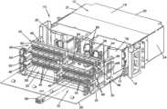
- FIG. 1is a front perspective view of one embodiment of an adapter panel arrangement, in accordance with the principles disclosed, shown with a drawer of the adapter panel arrangement in an open position;
- FIG. 2is a front perspective view of the adapter panel arrangement of FIG. 1 , shown with the drawer in a closed position;
- FIG. 3is a front perspective view of the adapter panel arrangement of FIG. 2 , shown with a cover of the arrangement closed;
- FIG. 4is a rear perspective view of the adapter panel arrangement of FIG. 1 ;
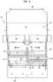
- FIG. 5is a side elevation view of the adapter panel arrangement of FIG. 4 ;
- FIG. 6is a top plan view of the adapter panel arrangement of FIG. 5 ;
- FIG. 7is a top perspective view of one embodiment of a sliding frame piece and an adapter array of the adapter panel arrangement of FIG. 1 , shown in isolation;
- FIG. 8is a side elevation view of the sliding frame piece and adapter array of FIG. 7 ;
- FIG. 9is a top plan view of the sliding frame piece and adapter array of FIG. 7 ;
- FIG. 10is a side elevation view of one embodiment of a guide of the adapter panel arrangement of FIG. 1 , shown in isolation;
- FIG. 11is a bottom perspective view of the guide of FIG. 10 ;
- FIG. 12is a top plan view of the guide of FIG. 10 , and a portion of the sliding frame piece of FIG. 9 ;
- FIG. 13is a front perspective view of the adapter panel arrangement of FIG. 2 , shown with an adapter array positioned in a forward position;
- FIG. 14is a side elevation view of the adapter panel arrangement of FIG. 13 ;
- FIG. 15is a top plan view of the adapter panel arrangement of FIG. 14 .
- FIG. 1illustrates a distribution frame or adapter panel arrangement 10 in accordance with the principles disclosed.
- the adapter panel arrangement 10is designed to provide a high density of cable terminations, yet facilitate access to the cable terminations from the rear during installation procedures, and from the front during post-installation procedures.
- the adapter panel arrangement 10 of the present disclosuregenerally includes a chassis 12 having an interior 14 .
- the interior 14is defined by a top wall 16 , a bottom wall 18 , a rear wall 20 , and side walls 22 , 24 .
- the adapter panel arrangement 10also includes a sliding drawer 34 that slides between an open position ( FIG. 1 ) and a closed position ( FIG. 2 ).
- a front cover 26is attached to the sliding drawer 34 . When the drawer 34 is in the closed position, the front cover 26 encloses the interior 14 of the chassis 12 when closed ( FIG. 3 ) and provides access to the interior 14 when open ( FIG. 2 ).
- the adapter panel arrangement 10includes a framework structure 30 ( FIG. 1 ) that is attached or mounted to the drawer 34 .
- a panel of adapters 32is mounted to the framework structure 30 .
- the drawer 34is designed to slide outward from the chassis 12 primarily for installation purposes. That is, the drawer 34 can be slid to the open position during installation or assembly of the adapter panel arrangement, but is position in the closed position ( FIG. 2 ) during operative use of the arrangement 10 .
- the framework structure 30 and the panel of adapters 32are located within the interior 14 of the chassis 12 and the drawer 34 is in the closed position ( FIG. 2 ).
- a useraccesses the panel of adapters 32 from a front opening 28 of the chassis 12 without sliding the drawer 34 forward.
- the panel of adapters 32includes a face panel 42 that defines a number of openings 44 (only one shown).
- Adapters 46are mounted within the openings 44 .
- the adaptersare LC type adapters; however, other types of adapters, such as SC, ST, FC and MPO type adapters can also be used in accordance with the principles disclosed.
- the adapters 46are blocked or grouped; each adapter block 58 including eight adapters 46 (four adapter pairs). Other number of adapters can be provided in an adapter block, such as four adapters (two adapter pairs), for example; the openings in the face panel 42 being correspondingly sized to receive the four-adapter blocks.
- single adapterscan be used and mounted with openings sized to receive the single adapters.
- the openings 44 of the face panel 42are arranged in rows; each row of mounted adapter blocks 58 defines an adapter array 48 .
- What is meant by a rowis that the openings 44 are arranged in a generally horizontal alignment, as opposed to being arranged in a column or in a vertical alignment; accordingly, the adapter arrays 48 are generally horizontal adapter arrays.
- the adapters 46 of the adapter blocks 58each includes a front connection end 50 ( FIG. 1 ) and a rear connection end 52 ( FIG. 4 ).
- the front connection ends 50 of the adapters 46are located toward the front opening 28 of the chassis 12
- the rear connection ends 52 of the adapters 46are located toward the rear wall 20 of the chassis 12 .
- the front connection ends 50 of the adapters 46define open frontward cable connection locations 54 ( FIG. 2 ) of the face panel 42
- the rear connection ends 52 of the adapters 46define open rearward cable connection locations 56 ( FIG. 4 ) of the face panel 42 .
- open cable connection locationsare locations that are provided in an open region in the chassis 12 , as opposed to a connection location that is enclosed within a housing or module, the housing or modules in turn being mounted within the chassis. That is, the panel of adapters 32 is a panel of unenclosed adapters 46 that are not enclosed relative to the other adapters 46 on the face panel 42 . While the panel of adapters itself is enclosed within the chassis 12 , the plurality of adapters 46 , and each of the adapter arrays 48 are not enclosed separately from the other adapters 46 or the other adapter arrays 48 .
- the adapter arrays 48 of the face panel 42are designed to slide in a lateral direction independent of other adapter arrays.
- the face panel 42is defined by a number of separate panel sections 60 .
- each separate panel sectiondefines one row of openings in which the blocks 58 of unenclosed adapters 46 are mounted, i.e., each panel section 60 contains one adapter array 48 .
- the panel sectionscan include, for example, two rows of openings that receive four-adapter blocks, for example; this panel section embodiment containing two adapter arrays.
- the face panel 42 of the adapter panel arrangement 10 illustratedincludes six panel sections 60 —two panel sections 60 positioned side-by-side, and stacked three panel sections high (see FIG. 1 ).
- Each panel section 60contains six blocks 58 having eight adapters 46 for a total of 288 frontward connection locations and rearward connection locations.
- Each separate panel section 60is designed to selectively slide in a forward, lateral direction (A) independent of the other panel sections.
- the forward, lateral direction (A)is a direction extending between the front opening 28 and the rear wall 20 , as opposed to a direction which is transverse to the bottom wall 18 of the chassis 12 , for example.
- each separate panel section 60 of the panel of adapters 32is attached to a sliding frame piece 62 .
- the sliding frame piece 62includes a pair of elongated rail members 64 .
- the elongated rail members 64include a forward rail portion 84 that extends forwardly from the panel section 60 , and a rearward rail portion 86 that extends rearwardly from the panel section 60 .
- the sliding frame piece 62can include a cross-support 88 to maintain the structural relationship of the rail members 64 .
- the pairs of elongated rail members 64are arranged to engage and slide within pairs of guides 66 (one shown in FIGS. 10 - 12 ) that are mounted to the framework structure 30 ( FIG. 1 ) of the arrangement 10 .
- the rail members 64 and the guides 66include a stop arrangement 68 that limits the sliding motion of the panel sections 60 between a rearward position (see the top panel section 60 in FIG. 5 ) and a forward position (see the bottom panel section 60 in FIG. 5 ).
- the stop arrangement 68( FIG. 12 ) is defined by at least one projection 70 ( FIGS. 10 and 11 ) located on each guide 66 of the pair of guides, and first and second pockets or detents 72 , 74 ( FIG. 9 ) formed in the rail members 64 .
- two projections 70(upper and lower projections) are provided on each of the guides 66 .
- upper and lower detents 72 , 74are formed in the rearward rail portions 86 of the rail members 64 .
- the detents 72 , 74formed in the rail members 64 and the projections 70 provided on the guides 66
- the detentscan be formed in the guides 66 and the projection correspondingly provided on the rail members 64 .
- the projections 70 of the guides 66seat within the first detents 72 of the rail members 64 to retain the panel section 60 in the rearward position.
- the guides 66are flexibly constructed so that when the panel section 60 is pulled forward, the projections 70 un-seat and slide along top and bottom surfaces 76 , 77 ( FIG. 8 ) of the rail members 64 .
- FIG. 12when the panel section 60 reaches the forward position, the projections 70 seat within the second detents 74 of the rail members 64 .
- This stop arrangement 68indicates to a user when the panel section 60 has reached the predetermined forward position, and similarly, the rearward position.
- the stop arrangement 68provides an indication of when the panel section 60 has moved a lateral distance D forward from the rearward position to the forward position.
- the lateral distance Dis no more than about 4.0 inches forward from the rearward position. In the illustrated embodiment, the lateral distance D is about 1.7 inches. Providing such an indication to the user prevents the user from moving the panel section 60 a distance beyond that which cables interconnected to the panel section 60 will allow.
- the present panel arrangement 10is designed such that the drawer 34 is intended to slide only during installation procedures, as opposed to post-installation or during operative use.
- cables 36such as fiber optic cables, are routed into the chassis 12 through rear openings 38 and terminated to the open rearward connection locations 56 of the face panel 42 (i.e., the rear connector ends 52 of the adapters 46 ).
- the fiber optic cables 36have a predetermined length that can be routed about cable storage spools or structures (see e.g., 78 , 80 in FIG. 1 ).
- the predetermined lengths of the cablesdo not have enough slack to accommodate drawer 34 movement during operative use, and the arrangement 10 does not have devices such as sliding radius limiters that take up or manage excessive movement of such cable slack.
- the predetermined lengths of the cablesgenerally accommodate only the limited sliding movement of the panel sections 60 . That is, while the drawer 34 may be slid out for purposes of installation, or for repairs requiring access to the region behind the panel of adapters 32 , the drawer 34 is not intended to slide for purposes of accessing the panel of adapters 32 during operative use of the adapter panel arrangement 10 . Operative use and access to the panel of adapters 32 is instead provided by the sliding movement of the panel sections 60 relative to the sliding movement of the drawer 34 .
- the lateral sliding movement of the panel sections 60provides access to the open cable connections (e.g., 54 , 56 ) defined by the adapter arrays 48 .
- Access to the open connection locations (e.g., 54 , 56 ) of the face panel 42is important in two primary instances: the first instance being during installation (e.g., during initial install or assembly, or during repair, replacement, or upgrade of the cable terminations at the rearward connection locations 56 of the panel 32 ); the second instance being after installation during operative use of the arrangement 10 .
- the drawer 34is pulled out to the open position.
- a technicianroutes the fiber optic cables 36 through the rear openings 38 of the chassis 12 and terminates the cables to the open rearward connection locations 56 of the panel of adapters 32 .
- one of the adapter arrays 48is positioned in the rearward position (e.g., the top array), while the remaining adapter arrays (e.g., the arrays located beneath the top array (see also FIGS. 5 and 6 )) are positioned in the forward position.
- the technicianhas better access to the open rearward connection locations 56 of the one panel section 60 positioned in the rearward position.
- the top wall 16 of the chassis 12includes removable access panels 92 .
- each of the panels 92slides outward in a direction B from the top wall 16 of the chassis 12 .
- the panels 92are shown engaged with the top wall 16 .
- each panel 92is locked in place by a flexible tab 94 that engages a hem or roll 98 formed in a top wall portion 100 of the top wall 16 .
- the flexible tab 94is defined by slots 96 formed in the panel 92 .
- the hem or roll 98is formed by bending or rolling a section of the top wall 16 over on itself; although structure can be attached to the top wall as an alternative to providing a hem.
- the flexible tab 94is flexed downward beyond the hem or roll 98 formed in the top wall portion 100 .
- the panelis then slid out in the direction shown in FIG. 2 and removed to define a top wall opening 104 (see e.g., FIG. 15 ) located adjacent to the front opening 28 of the chassis 12 .
- the top wall opening 104provides further access to the open rear connection locations 56 .
- the panel 92is place in relation to the top wall opening 104
- the flexible tab 94is flexed downward, and the panel 92 is then slid back into place.
- retaining flanges 102are formed in the top wall 16 at the top wall openings 104 . The retaining flanges 102 support the panels 92 when attached to the top wall 16 of the chassis 12 .
- the open rearward connection locations 56are typically access only during installation procedures, with the exception of repairs or upgrades, for example.
- the open frontward connection locations 54are accessed on a more regular basis to provide cross-connections between telecommunications equipment. Such use is referred to as operative use, or use that is post-installation and primarily involves maintaining or establishing cable terminations at the front connection ends 50 of the adapters 46 .
- the adapter panel arrangement 10is shown in operative use.
- the panel of adapters 32is accessed through the front opening 28 of the chassis 12 , with the drawer 34 positioned in the closed position.
- the cables 36 that enter the interior 14 of the chassis 12 through rear openings 38are terminated to the open rear connection locations 56 of the panel of adapters 32 .
- jumper cables or patching cables 40are also terminated to the panel of adapters 32 ; and in particular, to the open frontward connection locations 54 of the panel 32 .
- the patching cables 40provide the cross-connections between the adapter panel arrangement 10 and other telecommunications equipment (not shown).
- the patching cables 40are routed from the front opening 28 and through side openings 90 ( FIG. 3 ) of the chassis 12 to cable routing structure (e.g., channels, not shown) of the telecommunications system.
- each panel section 60 of the panel of adapters 32slides forward to separate the associated adapter array 48 from the other arrays.
- a techniciancan more easily grasp a particular connector of a patching cable 40 , and/or more easily terminate a patching cable to a particular adapter 46 of the forwardly-positioned array.
- the access panels 92 ( FIG. 13 ) of the top wall 16can be removed (as shown in FIG. 15 ) to provide even further access to the open frontward connection locations 54 of the panel sections.
- the forward rail portion 84 of the rail member 64can be used as a handle to pull the panel section 60 forward.
- the usercan slide the panel section 60 forward by grasping a retaining ring 82 attached to the rail member 64 of the sliding frame piece 62 .
- the retaining rings 82are attached to the ends of outer rail members 64 of the sliding frame piece 62 to protect the patching cables 40 from exceeding a minimum bend radius.
- additional access to the adapters 46is provided through cut-outs or bottom access openings 106 located adjacent to the front opening 28 of the chassis.
- the bottom access openings 106are formed in the drawer 34 of the chassis 12 .
- the front connection end 50 of the adapters 46 on the lower-most panel section 60can be difficult to access as finger space between the lower-most adapters and the drawer 34 is limited.
- a techniciansimply slides the lower-most panel section 60 outward relative to the drawer 34 such the that lower-most panel section 60 is adjacent the cut-out or opening 106 .
- the opening 106provides additional finger space equal to the thickness of the drawer. In the illustrated embodiment, the addition finger space is approximately 1 ⁇ 4 of an inch.
- the bottom access openings 106also provide better access to the lower-most adapters during installation or repair procedures.
- a techniciancan slide the drawer 34 outward using the bottom access openings 106 as handles, slide the lower-most panel 60 outward adjacent to the bottom access opening 106 ( FIG. 6 ), and then reach through the bottom access opening 106 , from beneath the drawer 34 , to access the front connection ends of the adapters on the lower-most panel.
- the bottom access openings 106have a length L.
- the length Lspans a substantial majority of the distance D 2 of which the plurality of adapters 46 span.
- the present chassis 12is also configured to provide access to the interior 14 of the chassis through the rear.
- the rear of the chassis 12is partly defined by a removable rear chassis portion 108 that provides access to the chassis interior 14 when initially installing cables, for example.
- the removable rear chassis portion 108is a two-part chassis portion. A first part 110 of the removable rear chassis portion 108 partly defines the top wall 16 of the chassis, and a second part 112 defines the rear wall 20 .
- the rear chassis portion 108is detachably secured to the remainder of the chassis 12 by latches 114 . To access the interior 14 of the chassis 12 , the rear chassis portion 108 is unlatched and removed.
- the first part 110 of the rear chassis portion 108has a depth D 1 that exposes the interior to provide access to interior cable routing areas.
- the depth D of the part 110 of the chassis portionprovides an exposed opening in the top wall that is at least about 5 inches.
- the exposed openingalso extends the width W of the chassis (i.e., extends from one side wall 22 of the chassis to the other side wall 24 ).
- the exposed opening through the top wall 16in addition to the removal of the rear wall 20 aids in routing cables within the interior of the chassis 12 .
- the disclosed panel arrangementcan be adapted for use in other applications.
- copper cablesmay be used exclusively from fiber optic cables; and accordingly various types of wire terminations or wire connectors can be provided on the face panel of the arrangement.
- the face panel of the arrangementcan be provided with a combination of fiber optic and copper connectors and/or adapters.
- the present adapter panel arrangement 10provides a high-density adapter panel arrangement while facilitating access to otherwise crowded front and rear connection locations. Because of the access design of the present arrangement, the amount of space utilized on racks and cabinets is minimized; or, in the alternative, allows for expansion and upgrade of systems having spatial constraints, as more densely packed connection locations are provided without sacrificing effective access to the connection locations.
Landscapes
- Physics & Mathematics (AREA)
- General Physics & Mathematics (AREA)
- Optics & Photonics (AREA)
- Engineering & Computer Science (AREA)
- Computer Networks & Wireless Communication (AREA)
- Light Guides In General And Applications Therefor (AREA)
Abstract
Description
This application is a continuation of application Ser. No. 16/851,587, filed Apr. 17, 2020, now U.S. Pat. No. 11,269,150, which is a continuation of application Ser. No. 16/675,883, filed Nov. 6, 2019, now U.S. Pat. No. 10,969,553, which is a continuation of application Ser. No. 16/272,349, filed Feb. 11, 2019, now U.S. Pat. No. 10,473,874, which is a continuation of application Ser. No. 15/997,852, filed Jun. 5, 2018, now U.S. Pat. No. 10,203,464, which is a continuation of application Ser. No. 15/645,464, filed Jul. 10, 2017, now U.S. Pat. No. 9,995,897, which is a continuation of application Ser. No. 14/813,955, filed Jul. 30, 2015, now U.S. Pat. No. 9,703,059, which is a continuation of application Ser. No. 14/515,182, filed Oct. 15, 2014, now U.S. Pat. No. 9,097,871, which is a continuation of application Ser. No. 13/722,373, filed Dec. 20, 2012, now U.S. Pat. No. 8,867,884, which is a continuation of application Ser. No. 12/930,782, filed Jan. 14, 2011, now U.S. Pat. No. 8,346,044, which is a continuation of application Ser. No. 12/460,162, filed Jul. 13, 2009, now U.S. Pat. No. 7,873,253, which is a continuation of application Ser. No. 11/715,258, filed Mar. 6, 2007, now U.S. Pat. No. 7,570,861, which is a continuation-in-part of application Ser. No. 11/655,760, filed Jan. 19, 2007, now U.S. Pat. No. 7,570,860, which applications are incorporated herein by reference in their entirety.
This disclosure relates to devices for use in the telecommunications industry, and associated methods. More specifically, this disclosure relates to a termination panel for use in the telecommunications industry, and methods associated with termination panels.
Many local area networks and telecommunication systems utilize termination panels to provide cross-connections between telecommunications equipment. Demand for greater telecommunication services has prompted the increase in circuit densities of termination panels. Notwithstanding the advances made in the art, there is a continuous need for further advances to improve upon high-density termination panels and associated methods. Improvements are needed, for example, to enhance termination access and cable management associated with installation, maintenance, repair, upgrade, and cross-connection procedures related to termination panels.
The present disclosure relates to an adapter panel arrangement including a chassis and a panel of adapters. The adapters define open rearward cable connections and open forward cable connections of the panel arrangement. The adapters are arranged in arrays that slide independently of other arrays to provide access to the open rearward and open forward cable connections. Access to the connections is further provided by removable access panels attached to the top wall of the chassis and bottom access openings formed in a sliding drawer. Access to the interior region of the chassis is provided by a removable rear chassis wall.
A variety of examples of desirable product features or methods are set forth in part in the description that follows, and in part will be apparent from the description, or may be learned by practicing various aspects of the disclosure. The aspects of the disclosure may relate to individual features as well as combinations of features. It is to be understood that both the foregoing general description and the following detailed description are explanatory only, and are not restrictive of the claimed invention.
Reference will now be made in detail to exemplary aspects of the present disclosure that are illustrated in the accompanying drawings. Wherever possible, the same reference numbers will be used throughout the drawings to refer to the same or like parts.
Theadapter panel arrangement 10 of the present disclosure generally includes achassis 12 having aninterior 14. The interior14 is defined by atop wall 16, abottom wall 18, arear wall 20, andside walls adapter panel arrangement 10 also includes a slidingdrawer 34 that slides between an open position (FIG.1 ) and a closed position (FIG.2 ). Afront cover 26 is attached to the slidingdrawer 34. When thedrawer 34 is in the closed position, thefront cover 26 encloses the interior14 of thechassis 12 when closed (FIG.3 ) and provides access to the interior14 when open (FIG.2 ).
Referring now toFIGS.1 and2 , theadapter panel arrangement 10 includes a framework structure30 (FIG.1 ) that is attached or mounted to thedrawer 34. A panel ofadapters 32 is mounted to theframework structure 30. As will be described in greater detail hereinafter, thedrawer 34 is designed to slide outward from thechassis 12 primarily for installation purposes. That is, thedrawer 34 can be slid to the open position during installation or assembly of the adapter panel arrangement, but is position in the closed position (FIG.2 ) during operative use of thearrangement 10. During operative use, theframework structure 30 and the panel ofadapters 32 are located within theinterior 14 of thechassis 12 and thedrawer 34 is in the closed position (FIG.2 ). A user accesses the panel ofadapters 32 from afront opening 28 of thechassis 12 without sliding thedrawer 34 forward.
Referring again toFIG.1 , the panel ofadapters 32 includes aface panel 42 that defines a number of openings44 (only one shown).Adapters 46 are mounted within theopenings 44. In the illustrated embodiment, the adapters are LC type adapters; however, other types of adapters, such as SC, ST, FC and MPO type adapters can also be used in accordance with the principles disclosed. Further, in the illustrated embodiment, theadapters 46 are blocked or grouped; eachadapter block 58 including eight adapters46 (four adapter pairs). Other number of adapters can be provided in an adapter block, such as four adapters (two adapter pairs), for example; the openings in theface panel 42 being correspondingly sized to receive the four-adapter blocks. Alternative, single adapters can be used and mounted with openings sized to receive the single adapters.
Theopenings 44 of theface panel 42 are arranged in rows; each row of mounted adapter blocks58 defines anadapter array 48. What is meant by a row is that theopenings 44 are arranged in a generally horizontal alignment, as opposed to being arranged in a column or in a vertical alignment; accordingly, theadapter arrays 48 are generally horizontal adapter arrays.
Referring now toFIGS.1 and4 , theadapters 46 of the adapter blocks58 each includes a front connection end50 (FIG.1 ) and a rear connection end52 (FIG.4 ). When mounted within theopenings 44, the front connection ends50 of theadapters 46 are located toward thefront opening 28 of thechassis 12, and the rear connection ends52 of theadapters 46 are located toward therear wall 20 of thechassis 12. The front connection ends50 of theadapters 46 define open frontward cable connection locations54 (FIG.2 ) of theface panel 42. The rear connection ends52 of theadapters 46 define open rearward cable connection locations56 (FIG.4 ) of theface panel 42.
What is meant by “open cable connection locations” are locations that are provided in an open region in thechassis 12, as opposed to a connection location that is enclosed within a housing or module, the housing or modules in turn being mounted within the chassis. That is, the panel ofadapters 32 is a panel ofunenclosed adapters 46 that are not enclosed relative to theother adapters 46 on theface panel 42. While the panel of adapters itself is enclosed within thechassis 12, the plurality ofadapters 46, and each of theadapter arrays 48 are not enclosed separately from theother adapters 46 or theother adapter arrays 48.
Referring now toFIGS.1,5 and6 , theadapter arrays 48 of theface panel 42 are designed to slide in a lateral direction independent of other adapter arrays. In particular, theface panel 42 is defined by a number ofseparate panel sections 60. In the illustrated embodiment, each separate panel section defines one row of openings in which theblocks 58 ofunenclosed adapters 46 are mounted, i.e., eachpanel section 60 contains oneadapter array 48. In other embodiments, the panel sections can include, for example, two rows of openings that receive four-adapter blocks, for example; this panel section embodiment containing two adapter arrays.
Theface panel 42 of theadapter panel arrangement 10 illustrated includes sixpanel sections 60—twopanel sections 60 positioned side-by-side, and stacked three panel sections high (seeFIG.1 ). Eachpanel section 60 contains sixblocks 58 having eightadapters 46 for a total of 288 frontward connection locations and rearward connection locations. Eachseparate panel section 60 is designed to selectively slide in a forward, lateral direction (A) independent of the other panel sections. The forward, lateral direction (A) is a direction extending between thefront opening 28 and therear wall 20, as opposed to a direction which is transverse to thebottom wall 18 of thechassis 12, for example.
Referring toFIGS.7-9 , eachseparate panel section 60 of the panel ofadapters 32 is attached to a slidingframe piece 62. The slidingframe piece 62 includes a pair ofelongated rail members 64. In the illustrated embodiment, theelongated rail members 64 include aforward rail portion 84 that extends forwardly from thepanel section 60, and arearward rail portion 86 that extends rearwardly from thepanel section 60. The slidingframe piece 62 can include a cross-support88 to maintain the structural relationship of therail members 64.
The pairs ofelongated rail members 64 are arranged to engage and slide within pairs of guides66 (one shown inFIGS.10-12 ) that are mounted to the framework structure30 (FIG.1 ) of thearrangement 10. Therail members 64 and theguides 66 include astop arrangement 68 that limits the sliding motion of thepanel sections 60 between a rearward position (see thetop panel section 60 inFIG.5 ) and a forward position (see thebottom panel section 60 inFIG.5 ).
Referring toFIGS.9-12 , the stop arrangement68 (FIG.12 ) is defined by at least one projection70 (FIGS.10 and11 ) located on eachguide 66 of the pair of guides, and first and second pockets ordetents 72,74 (FIG.9 ) formed in therail members 64. In the illustrated embodiment, two projections70 (upper and lower projections) are provided on each of theguides 66. Correspondingly, upper andlower detents 72,74 (seeFIG.8 ) are formed in therearward rail portions 86 of therail members 64. While the illustrated embodiment depicts thedetents rail members 64 and theprojections 70 provided on theguides 66, it is contemplated that the detents can be formed in theguides 66 and the projection correspondingly provided on therail members 64.
Referring still toFIGS.9-12 , when thepanel section 60 is positioned in the rearward position, theprojections 70 of theguides 66 seat within thefirst detents 72 of therail members 64 to retain thepanel section 60 in the rearward position. Theguides 66 are flexibly constructed so that when thepanel section 60 is pulled forward, theprojections 70 un-seat and slide along top andbottom surfaces 76,77 (FIG.8 ) of therail members 64. Referring toFIG.12 , when thepanel section 60 reaches the forward position, theprojections 70 seat within thesecond detents 74 of therail members 64. Thisstop arrangement 68 indicates to a user when thepanel section 60 has reached the predetermined forward position, and similarly, the rearward position.
Referring back toFIG.5 , in general, thestop arrangement 68 provides an indication of when thepanel section 60 has moved a lateral distance D forward from the rearward position to the forward position. In one embodiment, the lateral distance D is no more than about 4.0 inches forward from the rearward position. In the illustrated embodiment, the lateral distance D is about 1.7 inches. Providing such an indication to the user prevents the user from moving the panel section60 a distance beyond that which cables interconnected to thepanel section 60 will allow.
In particular, as previously described, thepresent panel arrangement 10 is designed such that thedrawer 34 is intended to slide only during installation procedures, as opposed to post-installation or during operative use. Referring toFIG.4 , during installation,cables 36, such as fiber optic cables, are routed into thechassis 12 throughrear openings 38 and terminated to the openrearward connection locations 56 of the face panel42 (i.e., the rear connector ends52 of the adapters46).
Thefiber optic cables 36 have a predetermined length that can be routed about cable storage spools or structures (see e.g.,78,80 inFIG.1 ). The predetermined lengths of the cables, however, do not have enough slack to accommodatedrawer 34 movement during operative use, and thearrangement 10 does not have devices such as sliding radius limiters that take up or manage excessive movement of such cable slack.
Inpresent panel arrangement 10, the predetermined lengths of the cables generally accommodate only the limited sliding movement of thepanel sections 60. That is, while thedrawer 34 may be slid out for purposes of installation, or for repairs requiring access to the region behind the panel ofadapters 32, thedrawer 34 is not intended to slide for purposes of accessing the panel ofadapters 32 during operative use of theadapter panel arrangement 10. Operative use and access to the panel ofadapters 32 is instead provided by the sliding movement of thepanel sections 60 relative to the sliding movement of thedrawer 34.
In general, the lateral sliding movement of thepanel sections 60 provides access to the open cable connections (e.g.,54,56) defined by theadapter arrays 48. Access to the open connection locations (e.g.,54,56) of theface panel 42 is important in two primary instances: the first instance being during installation (e.g., during initial install or assembly, or during repair, replacement, or upgrade of the cable terminations at therearward connection locations 56 of the panel32); the second instance being after installation during operative use of thearrangement 10.
Referring back toFIGS.1 and4 , during installation, thedrawer 34 is pulled out to the open position. As previously described, a technician routes thefiber optic cables 36 through therear openings 38 of thechassis 12 and terminates the cables to the openrearward connection locations 56 of the panel ofadapters 32. To provide better access to the rear connection ends52 of theadapters 46 defining therearward connection locations 56, one of theadapter arrays 48 is positioned in the rearward position (e.g., the top array), while the remaining adapter arrays (e.g., the arrays located beneath the top array (see alsoFIGS.5 and6 )) are positioned in the forward position. In this configuration, the technician has better access to the openrearward connection locations 56 of the onepanel section 60 positioned in the rearward position. Once cable terminations to thatparticular adapter array 48 are complete, that adapter array can be slid forward and the next array to which cables are to be terminated slid rearward.
Referring toFIG.4 , to provide even further access to the openrearward connection locations 56, thetop wall 16 of thechassis 12 includesremovable access panels 92. Referring toFIG.2 , each of thepanels 92 slides outward in a direction B from thetop wall 16 of thechassis 12. InFIG.2 , thepanels 92 are shown engaged with thetop wall 16. In particular, eachpanel 92 is locked in place by aflexible tab 94 that engages a hem or roll98 formed in atop wall portion 100 of thetop wall 16. Theflexible tab 94 is defined byslots 96 formed in thepanel 92. The hem or roll98 is formed by bending or rolling a section of thetop wall 16 over on itself; although structure can be attached to the top wall as an alternative to providing a hem.
To slide one of thepanels 92 out, theflexible tab 94 is flexed downward beyond the hem or roll98 formed in thetop wall portion 100. The panel is then slid out in the direction shown inFIG.2 and removed to define a top wall opening104 (see e.g.,FIG.15 ) located adjacent to thefront opening 28 of thechassis 12. The top wall opening104 provides further access to the openrear connection locations 56. To re-attach thepanel 92, thepanel 92 is place in relation to the top wall opening104, theflexible tab 94 is flexed downward, and thepanel 92 is then slid back into place. As shown inFIG.15 , retainingflanges 102 are formed in thetop wall 16 at thetop wall openings 104. The retainingflanges 102 support thepanels 92 when attached to thetop wall 16 of thechassis 12.
The openrearward connection locations 56 are typically access only during installation procedures, with the exception of repairs or upgrades, for example. The openfrontward connection locations 54, however, are accessed on a more regular basis to provide cross-connections between telecommunications equipment. Such use is referred to as operative use, or use that is post-installation and primarily involves maintaining or establishing cable terminations at the front connection ends50 of theadapters 46.
Referring now toFIGS.13-15 , theadapter panel arrangement 10 is shown in operative use. During operative use, the panel ofadapters 32 is accessed through thefront opening 28 of thechassis 12, with thedrawer 34 positioned in the closed position.
As previously described, thecables 36 that enter the interior14 of thechassis 12 throughrear openings 38 are terminated to the openrear connection locations 56 of the panel ofadapters 32. Referring toFIG.13 , jumper cables or patchingcables 40 are also terminated to the panel ofadapters 32; and in particular, to the openfrontward connection locations 54 of thepanel 32. The patchingcables 40 provide the cross-connections between theadapter panel arrangement 10 and other telecommunications equipment (not shown). The patchingcables 40 are routed from thefront opening 28 and through side openings90 (FIG.3 ) of thechassis 12 to cable routing structure (e.g., channels, not shown) of the telecommunications system.
Because of the high-density arrangement of theadapters 46, eachpanel section 60 of the panel ofadapters 32 slides forward to separate the associatedadapter array 48 from the other arrays. By separately positioning thepanel section 60 and the associatedadapter array 48 forward, a technician can more easily grasp a particular connector of a patchingcable 40, and/or more easily terminate a patching cable to aparticular adapter 46 of the forwardly-positioned array. In addition, and as previously described, the access panels92 (FIG.13 ) of thetop wall 16 can be removed (as shown inFIG.15 ) to provide even further access to the openfrontward connection locations 54 of the panel sections.
Referring again toFIG.13 , theforward rail portion 84 of therail member 64 can be used as a handle to pull thepanel section 60 forward. Alternatively, the user can slide thepanel section 60 forward by grasping a retainingring 82 attached to therail member 64 of the slidingframe piece 62. In the illustrated embodiment, the retaining rings82 are attached to the ends ofouter rail members 64 of the slidingframe piece 62 to protect the patchingcables 40 from exceeding a minimum bend radius.
Referring still toFIG.13 , additional access to theadapters 46 is provided through cut-outs orbottom access openings 106 located adjacent to thefront opening 28 of the chassis. Thebottom access openings 106 are formed in thedrawer 34 of thechassis 12. As can be understood, the front connection end50 of theadapters 46 on thelower-most panel section 60 can be difficult to access as finger space between the lower-most adapters and thedrawer 34 is limited. To better access to those particular adapters during operative use, a technician simply slides thelower-most panel section 60 outward relative to thedrawer 34 such the thatlower-most panel section 60 is adjacent the cut-out oropening 106. Theopening 106 provides additional finger space equal to the thickness of the drawer. In the illustrated embodiment, the addition finger space is approximately ¼ of an inch.
Thebottom access openings 106 also provide better access to the lower-most adapters during installation or repair procedures. Referring toFIGS.5 and6 , during an install, for example, a technician can slide thedrawer 34 outward using thebottom access openings 106 as handles, slide thelower-most panel 60 outward adjacent to the bottom access opening106 (FIG.6 ), and then reach through the bottom access opening106, from beneath thedrawer 34, to access the front connection ends of the adapters on the lower-most panel. Referring toFIG.6 , in the illustrated embodiment, thebottom access openings 106 have a length L. Preferably, the length L spans a substantial majority of the distance D2 of which the plurality ofadapters 46 span.
Referring back toFIG.4 , thepresent chassis 12 is also configured to provide access to the interior14 of the chassis through the rear. In particular, the rear of thechassis 12 is partly defined by a removablerear chassis portion 108 that provides access to thechassis interior 14 when initially installing cables, for example. In the illustrated embodiment, the removablerear chassis portion 108 is a two-part chassis portion. Afirst part 110 of the removablerear chassis portion 108 partly defines thetop wall 16 of the chassis, and asecond part 112 defines therear wall 20.
Therear chassis portion 108 is detachably secured to the remainder of thechassis 12 bylatches 114. To access theinterior 14 of thechassis 12, therear chassis portion 108 is unlatched and removed. Thefirst part 110 of therear chassis portion 108 has a depth D1 that exposes the interior to provide access to interior cable routing areas. In the illustrated embodiment, the depth D of thepart 110 of the chassis portion provides an exposed opening in the top wall that is at least about 5 inches. The exposed opening also extends the width W of the chassis (i.e., extends from oneside wall 22 of the chassis to the other side wall24). The exposed opening through thetop wall 16, in addition to the removal of therear wall 20 aids in routing cables within the interior of thechassis 12.
While the present disclosure is described with respect to use in a fiber optic application, the disclosed panel arrangement can be adapted for use in other applications. For example, in some applications, copper cables may be used exclusively from fiber optic cables; and accordingly various types of wire terminations or wire connectors can be provided on the face panel of the arrangement. Still, in other applications having hybrid cabling, or applications having both types of fiber optic and copper cabling, the face panel of the arrangement can be provided with a combination of fiber optic and copper connectors and/or adapters.
In general, the presentadapter panel arrangement 10 provides a high-density adapter panel arrangement while facilitating access to otherwise crowded front and rear connection locations. Because of the access design of the present arrangement, the amount of space utilized on racks and cabinets is minimized; or, in the alternative, allows for expansion and upgrade of systems having spatial constraints, as more densely packed connection locations are provided without sacrificing effective access to the connection locations.
The above specification provides a complete description of the present invention. Since many embodiments of the invention can be made without departing from the spirit and scope of the invention, certain aspects of the invention reside in the claims hereinafter appended.
Claims (20)
1. A fiber panel system comprising:
a chassis defining an interior accessible through an open front, the chassis extending along a depth between the open front and a rear and extending along a width between opposite first and second sides;
a connection arrangement coupled to the chassis, the connection arrangement including:
a sliding member configured to slide relative to the chassis between a first position in which the sliding member is disposed within the interior of the chassis and a second position in which the sliding member extends partially through the open front of the chassis;
a plurality of connection members carried by the sliding member, each of the connection members being slidingly mounted to the sliding member, each of the connection members carrying a plurality of fiber ports, the plurality of connection members including a first connection member and a second connection member disposed in a row along the width of the chassis; and
a finger access opening disposed in front of the first connection member, the finger access opening being defined through the sliding member.
2. The fiber panel system ofclaim 1 , wherein the finger access opening is a first finger access opening; and wherein a second finger access opening is disposed in front of the second connection member.
3. The fiber panel system ofclaim 2 , wherein the sliding member includes a web separating the first and second finger access openings.
4. The fiber panel system ofclaim 2 , wherein a guide rail is disposed between the first and second finger access openings, the guide rail engaging the first connection member to guide the first connection member in a slide along the sliding member.
5. The fiber panel system ofclaim 1 , wherein the fiber ports of each connection member are defined by adapters disposed in a row that extends along the width of the chassis when the connection member is mounted to the sliding member.
6. The fiber panel system ofclaim 1 , wherein first and second fiber guide members are carried with the sliding member, the first fiber guide member being disposed at the first side of the chassis and the second fiber guide member being disposed at the second side of the chassis.
7. The fiber panel system ofclaim 6 , wherein each of the first and second fiber guide members includes a fiber ring.
8. The fiber panel system ofclaim 6 , wherein each of the first and second fiber guide members is mounted to a respective one of the connection members.
9. The fiber panel system ofclaim 6 , wherein each of the first and second guide members defines a fiber passage facing outwardly towards a respective one of the first and second sides of the chassis when the sliding member is disposed within the chassis.
10. The fiber panel system ofclaim 1 , further comprising a front door pivotally mounted to the chassis to selectively cover the open front.
11. A fiber panel system comprising:
a chassis defining an interior accessible through an open front, the chassis extending along a depth between the open front and a rear and extending along a width between opposite first and second sides;
a connection arrangement coupled to the chassis, the connection arrangement including:
a sliding member configured to slide relative to the chassis between a first position in which the sliding member is disposed within the interior of the chassis and a second position in which the sliding member extends partially through the open front of the chassis;
a plurality of guides carried by the sliding member, each guide including a first part of a stop arrangement;
a connection member slidably mounted between two adjacent ones of the guides, the connection member including a row of fiber ports, the connection member also including a second part of the stop arrangement that engages the first part of the stop arrangement as the connection member is slid rearwardly along the two adjacent ones of the guides.
12. The fiber panel system ofclaim 11 , wherein a finger access opening disposed in front of the connection member, the finger access opening being defined through the sliding member.
13. The fiber panel system ofclaim 12 , wherein the connection member is one of a plurality of connection members and the finger access opening is one of a plurality of finger access openings; and wherein each finger access opening is disposed in front of a respective one of the connection members.
14. The fiber panel system ofclaim 13 , wherein the guides extend between the finger access openings.
15. The fiber panel system ofclaim 11 , wherein the fiber ports of the connection member are defined by adapters disposed in a row that extends along the width of the chassis when the connection member is mounted to the sliding member.
16. The fiber panel system ofclaim 11 , wherein first and second fiber guide members are carried with the sliding member, the first fiber guide member being disposed at the first side of the chassis and the second fiber guide member being disposed at the second side of the chassis.
17. The fiber panel system ofclaim 16 , wherein each of the first and second fiber guide members includes a fiber ring.
18. The fiber panel system ofclaim 16 , wherein the connection member is one of a plurality of connection members, wherein each of the first and second fiber guide members is mounted to a respective one of the plurality of connection members.
19. The fiber panel system ofclaim 16 , wherein each of the first and second fiber guide members defines a fiber passage facing outwardly towards a respective one of the first and second sides of the chassis when the sliding member is disposed within the chassis.
20. The fiber panel system ofclaim 11 , further comprising a front door pivotally mounted to the chassis to selectively cover the open front.
Priority Applications (3)
| Application Number | Priority Date | Filing Date | Title |
|---|---|---|---|
| US17/687,881US11789225B2 (en) | 2007-01-19 | 2022-03-07 | Adapter panel with lateral sliding adapter arrays |
| US18/486,340US12164168B2 (en) | 2007-01-19 | 2023-10-13 | Adapter panel with lateral sliding adapter arrays |
| US18/973,360US20250317671A1 (en) | 2007-01-19 | 2024-12-09 | Adapter panel with lateral sliding adapter arrays |
Applications Claiming Priority (13)
| Application Number | Priority Date | Filing Date | Title |
|---|---|---|---|
| US11/655,760US7570860B2 (en) | 2007-01-19 | 2007-01-19 | Adapter panel with lateral sliding adapter arrays |
| US11/715,258US7570861B2 (en) | 2007-01-19 | 2007-03-06 | Adapter panel with lateral sliding adapter arrays |
| US12/460,162US7873253B2 (en) | 2007-01-19 | 2009-07-13 | Adapter panel with lateral sliding adapter arrays |
| US12/930,782US8346044B2 (en) | 2007-01-19 | 2011-01-14 | Adapter panel with lateral sliding adapter arrays |
| US13/722,373US8867884B2 (en) | 2007-01-19 | 2012-12-20 | Adapter panel with lateral sliding adapter arrays |
| US14/515,182US9097871B2 (en) | 2007-01-19 | 2014-10-15 | Adapter panel with lateral sliding adapter arrays |
| US14/813,955US9703059B2 (en) | 2007-01-19 | 2015-07-30 | Adapter panel with lateral sliding adapter arrays |
| US15/645,464US9995897B2 (en) | 2007-01-19 | 2017-07-10 | Adapter panel with lateral sliding adapter arrays |
| US15/997,852US10203464B1 (en) | 2007-01-19 | 2018-06-05 | Adapter panel with lateral sliding adapter arrays |
| US16/272,349US10473874B2 (en) | 2007-01-19 | 2019-02-11 | Adapter panel with lateral sliding adapter arrays |
| US16/675,883US10969553B2 (en) | 2007-01-19 | 2019-11-06 | Adapter panel with lateral sliding adapter arrays |
| US16/851,587US11269150B2 (en) | 2007-01-19 | 2020-04-17 | Adapter panel with lateral sliding adapter arrays |
| US17/687,881US11789225B2 (en) | 2007-01-19 | 2022-03-07 | Adapter panel with lateral sliding adapter arrays |
Related Parent Applications (1)
| Application Number | Title | Priority Date | Filing Date |
|---|---|---|---|
| US16/851,587ContinuationUS11269150B2 (en) | 2007-01-19 | 2020-04-17 | Adapter panel with lateral sliding adapter arrays |
Related Child Applications (1)
| Application Number | Title | Priority Date | Filing Date |
|---|---|---|---|
| US18/486,340ContinuationUS12164168B2 (en) | 2007-01-19 | 2023-10-13 | Adapter panel with lateral sliding adapter arrays |
Publications (2)
| Publication Number | Publication Date |
|---|---|
| US20220260798A1 US20220260798A1 (en) | 2022-08-18 |
| US11789225B2true US11789225B2 (en) | 2023-10-17 |
Family
ID=39641310
Family Applications (17)
| Application Number | Title | Priority Date | Filing Date |
|---|---|---|---|
| US11/715,258ActiveUS7570861B2 (en) | 2007-01-19 | 2007-03-06 | Adapter panel with lateral sliding adapter arrays |
| US12/460,162ActiveUS7873253B2 (en) | 2007-01-19 | 2009-07-13 | Adapter panel with lateral sliding adapter arrays |
| US12/930,782Expired - Fee RelatedUS8346044B2 (en) | 2007-01-19 | 2011-01-14 | Adapter panel with lateral sliding adapter arrays |
| US13/722,373ActiveUS8867884B2 (en) | 2007-01-19 | 2012-12-20 | Adapter panel with lateral sliding adapter arrays |
| US14/515,182ActiveUS9097871B2 (en) | 2007-01-19 | 2014-10-15 | Adapter panel with lateral sliding adapter arrays |
| US14/813,877ActiveUS9638880B2 (en) | 2007-01-19 | 2015-07-30 | Adapter panel with lateral sliding adapter arrays |
| US14/813,955ActiveUS9703059B2 (en) | 2007-01-19 | 2015-07-30 | Adapter panel with lateral sliding adapter arrays |
| US14/813,989ActiveUS9709764B2 (en) | 2007-01-19 | 2015-07-30 | Adapter panel with lateral sliding adapter arrays |
| US14/813,909ActiveUS9645342B2 (en) | 2007-01-19 | 2015-07-30 | Adapter panel with lateral sliding adapter arrays |
| US15/645,464ActiveUS9995897B2 (en) | 2007-01-19 | 2017-07-10 | Adapter panel with lateral sliding adapter arrays |
| US15/997,852ActiveUS10203464B1 (en) | 2007-01-19 | 2018-06-05 | Adapter panel with lateral sliding adapter arrays |
| US16/272,349ActiveUS10473874B2 (en) | 2007-01-19 | 2019-02-11 | Adapter panel with lateral sliding adapter arrays |
| US16/675,883ActiveUS10969553B2 (en) | 2007-01-19 | 2019-11-06 | Adapter panel with lateral sliding adapter arrays |
| US16/851,587Active2027-05-28US11269150B2 (en) | 2007-01-19 | 2020-04-17 | Adapter panel with lateral sliding adapter arrays |
| US17/687,881ActiveUS11789225B2 (en) | 2007-01-19 | 2022-03-07 | Adapter panel with lateral sliding adapter arrays |
| US18/486,340ActiveUS12164168B2 (en) | 2007-01-19 | 2023-10-13 | Adapter panel with lateral sliding adapter arrays |
| US18/973,360PendingUS20250317671A1 (en) | 2007-01-19 | 2024-12-09 | Adapter panel with lateral sliding adapter arrays |
Family Applications Before (14)
| Application Number | Title | Priority Date | Filing Date |
|---|---|---|---|
| US11/715,258ActiveUS7570861B2 (en) | 2007-01-19 | 2007-03-06 | Adapter panel with lateral sliding adapter arrays |
| US12/460,162ActiveUS7873253B2 (en) | 2007-01-19 | 2009-07-13 | Adapter panel with lateral sliding adapter arrays |
| US12/930,782Expired - Fee RelatedUS8346044B2 (en) | 2007-01-19 | 2011-01-14 | Adapter panel with lateral sliding adapter arrays |
| US13/722,373ActiveUS8867884B2 (en) | 2007-01-19 | 2012-12-20 | Adapter panel with lateral sliding adapter arrays |
| US14/515,182ActiveUS9097871B2 (en) | 2007-01-19 | 2014-10-15 | Adapter panel with lateral sliding adapter arrays |
| US14/813,877ActiveUS9638880B2 (en) | 2007-01-19 | 2015-07-30 | Adapter panel with lateral sliding adapter arrays |
| US14/813,955ActiveUS9703059B2 (en) | 2007-01-19 | 2015-07-30 | Adapter panel with lateral sliding adapter arrays |
| US14/813,989ActiveUS9709764B2 (en) | 2007-01-19 | 2015-07-30 | Adapter panel with lateral sliding adapter arrays |
| US14/813,909ActiveUS9645342B2 (en) | 2007-01-19 | 2015-07-30 | Adapter panel with lateral sliding adapter arrays |
| US15/645,464ActiveUS9995897B2 (en) | 2007-01-19 | 2017-07-10 | Adapter panel with lateral sliding adapter arrays |
| US15/997,852ActiveUS10203464B1 (en) | 2007-01-19 | 2018-06-05 | Adapter panel with lateral sliding adapter arrays |
| US16/272,349ActiveUS10473874B2 (en) | 2007-01-19 | 2019-02-11 | Adapter panel with lateral sliding adapter arrays |
| US16/675,883ActiveUS10969553B2 (en) | 2007-01-19 | 2019-11-06 | Adapter panel with lateral sliding adapter arrays |
| US16/851,587Active2027-05-28US11269150B2 (en) | 2007-01-19 | 2020-04-17 | Adapter panel with lateral sliding adapter arrays |
Family Applications After (2)
| Application Number | Title | Priority Date | Filing Date |
|---|---|---|---|
| US18/486,340ActiveUS12164168B2 (en) | 2007-01-19 | 2023-10-13 | Adapter panel with lateral sliding adapter arrays |
| US18/973,360PendingUS20250317671A1 (en) | 2007-01-19 | 2024-12-09 | Adapter panel with lateral sliding adapter arrays |
Country Status (1)
| Country | Link |
|---|---|
| US (17) | US7570861B2 (en) |
Cited By (2)
| Publication number | Priority date | Publication date | Assignee | Title |
|---|---|---|---|---|
| US20230010410A1 (en)* | 2019-12-03 | 2023-01-12 | Commscope Technologies Llc | Splice enclosure for cable repairs |
| US12164168B2 (en) | 2007-01-19 | 2024-12-10 | Commscope Technologies Llc | Adapter panel with lateral sliding adapter arrays |
Families Citing this family (135)
| Publication number | Priority date | Publication date | Assignee | Title |
|---|---|---|---|---|
| US7570860B2 (en)* | 2007-01-19 | 2009-08-04 | Adc Telecommunications, Inc. | Adapter panel with lateral sliding adapter arrays |
| US7509016B2 (en)* | 2007-03-09 | 2009-03-24 | Adc Telecommunications, Inc. | Telecommunication rack unit tray |
| US7715679B2 (en) | 2007-05-07 | 2010-05-11 | Adc Telecommunications, Inc. | Fiber optic enclosure with external cable spool |
| US7756379B2 (en) | 2007-08-06 | 2010-07-13 | Adc Telecommunications, Inc. | Fiber optic enclosure with internal cable spool |
| US8179684B2 (en)* | 2007-10-29 | 2012-05-15 | Adc Telecommunications, Inc. | Sliding adapter panel with living hinge and forward/rearward locking |
| US8059931B2 (en)* | 2008-05-06 | 2011-11-15 | Realm Communications Group, Inc. | Fiber optic monitoring patch panel providing readily accessible monitoring ports |
| US8452148B2 (en)* | 2008-08-29 | 2013-05-28 | Corning Cable Systems Llc | Independently translatable modules and fiber optic equipment trays in fiber optic equipment |
| US8184938B2 (en) | 2008-08-29 | 2012-05-22 | Corning Cable Systems Llc | Rear-installable fiber optic modules and equipment |
| US7945135B2 (en)* | 2008-08-29 | 2011-05-17 | Corning Cable Systems Llc | Telescoping fiber optic module and related equipment |
| US11294136B2 (en) | 2008-08-29 | 2022-04-05 | Corning Optical Communications LLC | High density and bandwidth fiber optic apparatuses and related equipment and methods |
| AU2015203580A1 (en)* | 2008-08-29 | 2015-07-23 | Corning Optical Communications LLC | Rear-installable fiber optic modules and equipment |
| US7856166B2 (en)* | 2008-09-02 | 2010-12-21 | Corning Cable Systems Llc | High-density patch-panel assemblies for optical fiber telecommunications |
| US7697811B2 (en)* | 2008-09-08 | 2010-04-13 | Ortronics, Inc. | Horizontal fiber optic patching assembly |
| US8526774B2 (en)* | 2008-09-23 | 2013-09-03 | Adc Telecommunications, Inc. | Telecommunications panel and drawer arrangement |
| WO2010088604A1 (en)* | 2009-02-02 | 2010-08-05 | Adc Telecommunications, Inc. | Multi-fiber cable management panel |
| EP2221932B1 (en) | 2009-02-24 | 2011-11-16 | CCS Technology Inc. | Holding device for a cable or an assembly for use with a cable |
| US8270798B2 (en)* | 2009-02-27 | 2012-09-18 | Corning Cable Systems Llc | Routing guide for a movable fiber optic equipment tray or module |
| AU2009200824A1 (en)* | 2009-03-03 | 2010-09-23 | Tyco Electronics Services Gmbh | Consolidation point enclosure |
| US8897637B2 (en) | 2009-04-22 | 2014-11-25 | Adc Gmbh | Method and arrangement for identifying at least one object |
| US8699838B2 (en) | 2009-05-14 | 2014-04-15 | Ccs Technology, Inc. | Fiber optic furcation module |
| AU2015203581A1 (en)* | 2009-05-21 | 2015-07-23 | Corning Optical Communications LLC | Fiber optic equipment supporting moveable fiber optic equipment tray(s) and module(s), and related equipment and methods |
| AU2015203530B2 (en)* | 2009-05-21 | 2017-07-13 | Corning Optical Communications LLC | Fiber optic equipment guides and rails configured with stopping position(s), and related equipment and methods |
| EP2433165B1 (en)* | 2009-05-21 | 2016-12-21 | Corning Optical Communications LLC | Fiber optic equipment with guides and rails configured with stopping positions |
| US9075216B2 (en) | 2009-05-21 | 2015-07-07 | Corning Cable Systems Llc | Fiber optic housings configured to accommodate fiber optic modules/cassettes and fiber optic panels, and related components and methods |
| US8538226B2 (en)* | 2009-05-21 | 2013-09-17 | Corning Cable Systems Llc | Fiber optic equipment guides and rails configured with stopping position(s), and related equipment and methods |
| JP5706399B2 (en)* | 2009-05-21 | 2015-04-22 | コーニング ケーブル システムズ リミテッド ライアビリティ カンパニー | Fiber optic equipment supporting movable fiber optic equipment trays and modules, related equipment and methods |
| WO2010148325A1 (en) | 2009-06-19 | 2010-12-23 | Corning Cable Systems Llc | High fiber optic cable packing density apparatus |
| EP2443497B1 (en) | 2009-06-19 | 2020-03-04 | Corning Cable Systems LLC | High density and bandwidth fiber optic apparatus |
| US8712206B2 (en) | 2009-06-19 | 2014-04-29 | Corning Cable Systems Llc | High-density fiber optic modules and module housings and related equipment |
| US8714368B2 (en)* | 2009-09-09 | 2014-05-06 | Adc Telecommunications, Inc. | Pass-through trough |
| WO2011047281A1 (en) | 2009-10-16 | 2011-04-21 | Adc Telecommunications, Inc. | Managed connectivity in electrical systems and methods thereof |
| WO2011047288A1 (en) | 2009-10-16 | 2011-04-21 | Adc Telecommunications, Inc. | Managed connectivity in fiber optic systems and methods thereof |
| JP2013508918A (en) | 2009-10-19 | 2013-03-07 | エーディーシー テレコミュニケーションズ,インコーポレイティド | Managed electrical connection system |
| US8625950B2 (en)* | 2009-12-18 | 2014-01-07 | Corning Cable Systems Llc | Rotary locking apparatus for fiber optic equipment trays and related methods |
| US8992099B2 (en) | 2010-02-04 | 2015-03-31 | Corning Cable Systems Llc | Optical interface cards, assemblies, and related methods, suited for installation and use in antenna system equipment |
| WO2011100613A1 (en) | 2010-02-12 | 2011-08-18 | Adc Telecommunications, Inc. | Communications bladed system |
| WO2011100634A2 (en) | 2010-02-12 | 2011-08-18 | Adc Telecommunications, Inc. | Managed fiber connectivity systems |
| US8913866B2 (en) | 2010-03-26 | 2014-12-16 | Corning Cable Systems Llc | Movable adapter panel |
| JP5569097B2 (en)* | 2010-03-29 | 2014-08-13 | 富士通セミコンダクター株式会社 | Semiconductor device and lead frame |
| CA2796221C (en) | 2010-04-16 | 2018-02-13 | Ccs Technology, Inc. | Sealing and strain relief device for data cables |
| EP2381284B1 (en) | 2010-04-23 | 2014-12-31 | CCS Technology Inc. | Under floor fiber optic distribution device |
| US9632270B2 (en) | 2010-04-30 | 2017-04-25 | Corning Optical Communications LLC | Fiber optic housings configured for tool-less assembly, and related components and methods |
| AU2015224449B2 (en)* | 2010-04-30 | 2017-10-12 | Corning Optical Communications LLC | Fiber optic housings with removable panel clips |
| US8879881B2 (en)* | 2010-04-30 | 2014-11-04 | Corning Cable Systems Llc | Rotatable routing guide and assembly |
| US9720195B2 (en) | 2010-04-30 | 2017-08-01 | Corning Optical Communications LLC | Apparatuses and related components and methods for attachment and release of fiber optic housings to and from an equipment rack |
| US8705926B2 (en) | 2010-04-30 | 2014-04-22 | Corning Optical Communications LLC | Fiber optic housings having a removable top, and related components and methods |
| US8660397B2 (en) | 2010-04-30 | 2014-02-25 | Corning Cable Systems Llc | Multi-layer module |
| US9519118B2 (en) | 2010-04-30 | 2016-12-13 | Corning Optical Communications LLC | Removable fiber management sections for fiber optic housings, and related components and methods |
| US9075217B2 (en) | 2010-04-30 | 2015-07-07 | Corning Cable Systems Llc | Apparatuses and related components and methods for expanding capacity of fiber optic housings |
| CN110174737A (en) | 2010-06-23 | 2019-08-27 | Adc电信公司 | Telecommunication assembly |
| US8820860B2 (en)* | 2010-08-27 | 2014-09-02 | Commscope, Inc. Of North Carolina | Fiber optic enclosure having tamper resistant lock |
| US8718436B2 (en) | 2010-08-30 | 2014-05-06 | Corning Cable Systems Llc | Methods, apparatuses for providing secure fiber optic connections |
| US8696369B2 (en) | 2010-09-09 | 2014-04-15 | Adc Telecommunications, Inc. | Electrical plug with main contacts and retractable secondary contacts |
| WO2012054348A1 (en) | 2010-10-22 | 2012-04-26 | Adc Telecommunications, Inc. | Single-piece plug nose |
| US9279951B2 (en) | 2010-10-27 | 2016-03-08 | Corning Cable Systems Llc | Fiber optic module for limited space applications having a partially sealed module sub-assembly |
| US9116324B2 (en) | 2010-10-29 | 2015-08-25 | Corning Cable Systems Llc | Stacked fiber optic modules and fiber optic equipment configured to support stacked fiber optic modules |
| US8662760B2 (en) | 2010-10-29 | 2014-03-04 | Corning Cable Systems Llc | Fiber optic connector employing optical fiber guide member |
| WO2012068013A2 (en)* | 2010-11-15 | 2012-05-24 | Adc Telecommunications, Inc. | Cable management in rack systems |
| CA2819235C (en) | 2010-11-30 | 2018-01-16 | Corning Cable Systems Llc | Fiber device holder and strain relief device |
| WO2012106510A2 (en) | 2011-02-02 | 2012-08-09 | Corning Cable Systems Llc | Dense fiber optic connector assemblies and related connectors and cables suitable for establishing optical connections for optical backplanes in equipment racks |
| US8715012B2 (en) | 2011-04-15 | 2014-05-06 | Adc Telecommunications, Inc. | Managed electrical connectivity systems |
| US20120273627A1 (en)* | 2011-04-26 | 2012-11-01 | Panduit Corp. | Horizontal Cable Manager |
| US9008485B2 (en) | 2011-05-09 | 2015-04-14 | Corning Cable Systems Llc | Attachment mechanisms employed to attach a rear housing section to a fiber optic housing, and related assemblies and methods |
| US9064022B2 (en) | 2011-05-17 | 2015-06-23 | Adc Telecommunications, Inc. | Component identification and tracking system for telecommunication networks |
| CA2877896C (en) | 2011-06-24 | 2020-07-21 | Adc Telecommunications, Inc. | Fiber termination enclosure with modular plate assemblies |
| AU2012275598A1 (en) | 2011-06-30 | 2014-01-16 | Corning Optical Communications LLC | Fiber optic equipment assemblies employing non-U-width-sized housings and related methods |
| US8953924B2 (en) | 2011-09-02 | 2015-02-10 | Corning Cable Systems Llc | Removable strain relief brackets for securing fiber optic cables and/or optical fibers to fiber optic equipment, and related assemblies and methods |
| US9038832B2 (en) | 2011-11-30 | 2015-05-26 | Corning Cable Systems Llc | Adapter panel support assembly |
| US8995136B2 (en)* | 2011-12-23 | 2015-03-31 | Adc Telecommunications, Inc. | Communications bladed panel systems |
| US8842959B2 (en)* | 2012-06-28 | 2014-09-23 | Alcatel Lucent | Increased connector port density via extending faceplate |
| US9250409B2 (en) | 2012-07-02 | 2016-02-02 | Corning Cable Systems Llc | Fiber-optic-module trays and drawers for fiber-optic equipment |
| US9093796B2 (en) | 2012-07-06 | 2015-07-28 | Adc Telecommunications, Inc. | Managed electrical connectivity systems |
| WO2014022781A1 (en) | 2012-08-03 | 2014-02-06 | Joseph Christopher Coffey | Managed fiber connectivity systems |
| US9042702B2 (en) | 2012-09-18 | 2015-05-26 | Corning Cable Systems Llc | Platforms and systems for fiber optic cable attachment |
| US9203198B2 (en) | 2012-09-28 | 2015-12-01 | Commscope Technologies Llc | Low profile faceplate having managed connectivity |
| ES2551077T3 (en) | 2012-10-26 | 2015-11-16 | Ccs Technology, Inc. | Fiber optic management unit and fiber optic distribution device |
| ES1141660Y (en) | 2012-12-19 | 2015-10-14 | Tyco Electronics Raychem Bvba | Distribution device with incrementally added dividers |
| CN105074525A (en) | 2013-01-29 | 2015-11-18 | 泰科电子瑞侃有限公司 | Fiber Distribution System |
| US9285552B2 (en) | 2013-02-05 | 2016-03-15 | Commscope Technologies Llc | Optical assemblies with managed connectivity |
| US9379501B2 (en) | 2013-02-05 | 2016-06-28 | Commscope Technologies Llc | Optical assemblies with managed connectivity |
| US9423570B2 (en) | 2013-02-05 | 2016-08-23 | Commscope Technologies Llc | Optical assemblies with managed connectivity |
| US8985862B2 (en) | 2013-02-28 | 2015-03-24 | Corning Cable Systems Llc | High-density multi-fiber adapter housings |
| AP2015008820A0 (en) | 2013-04-24 | 2015-10-31 | Adc Czech Republic Sro | Optical fiber distribution system |
| EP2989496B1 (en) | 2013-04-24 | 2019-06-12 | CommScope Connectivity Belgium BVBA | Universal mounting mechanism for mounting a telecommunications chassis to a telecommunications fixture |
| CN105705976A (en) | 2013-09-23 | 2016-06-22 | 泰科电子英国有限公司 | Telecommunications chassis |
| US9500814B2 (en) | 2014-03-26 | 2016-11-22 | Commscope Technologies Llc | Optical adapter module with managed connectivity |
| CN106575024B (en) | 2014-06-23 | 2019-07-09 | Adc电信公司 | Undercarriage system with blades |
| WO2016012295A1 (en) | 2014-07-22 | 2016-01-28 | Tyco Electronics Raychem Bvba | Door hinge mechanism for telecommunicatons panel |
| EP3192274A4 (en) | 2014-09-11 | 2018-05-16 | ADC Telecommunications, Inc. | Door hinge mechanism for telecommunications panel |
| US9690065B2 (en) | 2014-09-12 | 2017-06-27 | Panduit Corp. | High density fiber enclosure and method |
| MX391386B (en)* | 2014-09-16 | 2025-03-11 | Commscope Czech Republic S R O | ROTATING INTERCONNECTION CABLE CARRIER. |
| US9516781B2 (en)* | 2015-02-19 | 2016-12-06 | All Systems Broadband, Inc. | Fiber optic shelf with a removable roof panel |
| AU2016239875C1 (en) | 2015-04-03 | 2021-06-24 | CommScope Connectivity Belgium BVBA | Telecommunications distribution elements |
| CN104965273B (en)* | 2015-06-30 | 2018-09-21 | 许继集团有限公司 | Wiring screen cabinet before optic fibre switching box body, optic fibre switching case and prefabricated cabin |
| EP3329346A4 (en) | 2015-07-29 | 2019-06-12 | Commscope Technologies LLC | CHASSIS SYSTEMS FOR BLADE SERVERS |
| CN105445868B (en)* | 2015-12-29 | 2017-03-22 | 深圳日海通讯技术股份有限公司 | High-density fiber distribution module and optical communication wire distribution equipment |
| US9720199B2 (en)* | 2016-01-06 | 2017-08-01 | FiberOne LLC | Optical fiber cassette with bend limiting and connector shield |
| US9817201B2 (en) | 2016-04-12 | 2017-11-14 | Ciena Corporation | Sliding assembly and method for fiber management |
| WO2017184501A1 (en) | 2016-04-19 | 2017-10-26 | Commscope, Inc. Of North Carolina | Door assembly for a telecommunications chassis with a combination hinge structure |
| ES2851948T3 (en) | 2016-04-19 | 2021-09-09 | Commscope Inc North Carolina | Telecom rack with slide out trays |
| US10215944B2 (en) | 2016-06-30 | 2019-02-26 | Panduit Corp. | Modular fiber optic tray |
| USD820234S1 (en)* | 2016-07-11 | 2018-06-12 | Leader Optec Limited | Telecommunications apparatus |
| CN109716188A (en)* | 2016-10-27 | 2019-05-03 | 华为技术有限公司 | Fusion panel, patch panel and optical cable transfer box |
| DE102016123912A1 (en)* | 2016-12-09 | 2018-06-14 | MCQ TECH GmbH | Cable routing for distribution panel and distribution panel with cable routing |
| ES2929573T3 (en) | 2017-02-23 | 2022-11-30 | Commscope Technologies Llc | High Fiber Count Termination Device |
| US9974205B1 (en)* | 2017-06-16 | 2018-05-15 | International Business Machines Corporation | Cable management bracket with side clamps |
| US10670822B2 (en) | 2017-06-28 | 2020-06-02 | Afl Telecommunications Llc | High density patch panel with modular cassettes |
| US10372174B2 (en)* | 2017-08-14 | 2019-08-06 | Gigamon Inc. | Cable management assemblies for electronic appliances |
| US10859782B2 (en)* | 2017-12-21 | 2020-12-08 | Ortronics, Inc. | Fiber enclosure |
| US11852882B2 (en) | 2018-02-28 | 2023-12-26 | Commscope Technologies Llc | Packaging assembly for telecommunications equipment |
| US11635578B2 (en) | 2018-04-17 | 2023-04-25 | CommScope Connectivity Belgium BVBA | Telecommunications distribution elements |
| CN108802938A (en)* | 2018-07-06 | 2018-11-13 | 太仓市鼎祥五金制品厂 | A kind of high efficiency cable splice closure |
| PL3844973T3 (en) | 2018-08-31 | 2025-03-03 | CommScope Connectivity Belgium BVBA | Frame assemblies for optical fiber distribution elements |
| EP3844546A1 (en) | 2018-08-31 | 2021-07-07 | CommScope Connectivity Belgium BVBA | Frame assemblies for optical fiber distribution elements |
| EP3844547A1 (en) | 2018-08-31 | 2021-07-07 | CommScope Connectivity Belgium BVBA | Frame assemblies for optical fiber distribution elements |
| WO2020043914A1 (en) | 2018-08-31 | 2020-03-05 | CommScope Connectivity Belgium BVBA | Frame assemblies for optical fiber distribution elements |
| EP3845044B1 (en) | 2018-08-31 | 2023-02-15 | CommScope Connectivity Belgium BVBA | Frame assemblies for optical fiber distribution elements |
| WO2020084012A1 (en) | 2018-10-23 | 2020-04-30 | CommScope Connectivity Belgium BVBA | Frame assemblies for optical fiber distribution elements |
| US10327353B1 (en)* | 2018-10-30 | 2019-06-18 | Moxa Inc. | Wire fixing structure |
| US12078859B2 (en) | 2019-01-14 | 2024-09-03 | Commscope Technologies Llc | Equipment panel with termination region |
| EP3914947A1 (en) | 2019-01-25 | 2021-12-01 | CommScope Connectivity Belgium BVBA | Frame assemblies for optical fiber distribution elements |
| US10969554B2 (en) | 2019-04-01 | 2021-04-06 | Afl Telecommunications Llc | Fiber optic tray systems |
| EP4236343B1 (en) | 2019-04-17 | 2025-03-12 | Afl Ig Llc | Patch panel with lifting cassette removal |
| WO2020242852A1 (en)* | 2019-05-24 | 2020-12-03 | Commscope Technologies Llc | Chassis panel with selectable cable management insert and cabling method therefore |
| EP3991527A4 (en)* | 2019-06-28 | 2023-09-27 | CommScope Technologies LLC | Bladed panel system and components therefore |
| US11369034B2 (en) | 2019-09-18 | 2022-06-21 | Ortronics, Inc. | Ejectable cassette, guide column, and ejectable cassette system |
| CN110646904B (en)* | 2019-10-21 | 2020-10-30 | 枣庄学院 | Optical fiber arrangement device for computer network |
| US11109506B2 (en) | 2019-11-14 | 2021-08-31 | Ciena Corporation | Fiber management sliding tray system |
| WO2021148544A1 (en) | 2020-01-22 | 2021-07-29 | CommScope Connectivity Belgium BVBA | Cable termination units for optical fiber distribution elements |
| US12099246B2 (en) | 2020-01-24 | 2024-09-24 | CommScope Connectivity Belgium BVBA | Telecommunications distribution elements |
| US11493717B2 (en) | 2020-07-31 | 2022-11-08 | Google Llc | Fiber optic cable distribution and management system |
| US11947178B2 (en) | 2020-09-17 | 2024-04-02 | Panduit Corp. | Optical distribution and splice frame including cassettes |
| US11595145B1 (en)* | 2021-09-02 | 2023-02-28 | Dell Products L.P. | High-density switch |
| US11719899B2 (en)* | 2021-09-02 | 2023-08-08 | Dell Products L.P. | High-density co-packaged optics networking system |
| US12082362B2 (en) | 2021-10-13 | 2024-09-03 | Qualcomm Incorporated | High airflow storage device array and related electronic modules |
Citations (71)
| Publication number | Priority date | Publication date | Assignee | Title |
|---|---|---|---|---|
| US4765710A (en) | 1985-07-30 | 1988-08-23 | Siemens Aktiengesellschaft | Distributing frame for optical waveguides and the like |
| EP0341027A2 (en) | 1988-05-02 | 1989-11-08 | Gte Control Devices Of Puerto Rico Incorporated | Fiber distribution panel |
| US5129030A (en) | 1991-05-30 | 1992-07-07 | At&T Bell Laboratories | Movable lightguide connector panel |
| US5167001A (en) | 1991-09-03 | 1992-11-24 | Northern Telecom Limited | Optical fiber storage and connector tray and shelf and tray assembly |
| US5420958A (en) | 1990-05-21 | 1995-05-30 | Minnesota Mining And Manufacturing Company | Optical fiber distribution center |
| US5497444A (en) | 1994-01-21 | 1996-03-05 | Adc Telecommunications, Inc. | High-density fiber distribution frame |
| US5613030A (en) | 1995-05-15 | 1997-03-18 | The Whitaker Corporation | High density fiber optic interconnection enclosure |
| US5758003A (en) | 1996-03-15 | 1998-05-26 | Adc Telecommunications, Inc. | High density fiber management |
| US5778131A (en) | 1993-09-29 | 1998-07-07 | Pirelli General Plc | Assembly for use in connecting optical fibres including a manifold device |
| US6195493B1 (en) | 1999-05-21 | 2001-02-27 | Scientific-Atlanta, Inc. | Universal chassis for CATV headends or telecommunications company central office for optical electronic equipment |
| JP2002082230A (en) | 2000-09-08 | 2002-03-22 | Nissho Musen Co Ltd | Cassette having optical fiber cable connecting adapter in termination box |
| US6385381B1 (en) | 1999-09-21 | 2002-05-07 | Lucent Technologies Inc. | Fiber optic interconnection combination closure |
| US6504988B1 (en) | 2000-01-24 | 2003-01-07 | Adc Telecommunications, Inc. | Cable management panel with sliding drawer |
| US6560114B2 (en) | 2001-06-29 | 2003-05-06 | Intel Corporation | Rack-mounted server and associated methods |
| US6591051B2 (en) | 2001-11-16 | 2003-07-08 | Adc Telecommunications, Inc. | Fiber termination block with angled slide |
| US20030174996A1 (en) | 2002-03-15 | 2003-09-18 | Fiber Optic Network Solutions, Inc. | Optical fiber enclosure system using integrated optical connector and coupler assembly |
| US6627812B2 (en) | 2001-08-24 | 2003-09-30 | Sun Microsystems, Inc. | Apparatus for containing electro-magnetic interference |
| US20030223723A1 (en) | 2002-05-28 | 2003-12-04 | Massey Gaines N. | Reconfigurable fiber optic cable management enclosure |
| US6715619B2 (en) | 2002-07-22 | 2004-04-06 | Adc Telecommunications, Inc. | Fiber management drawer and patch panel |
| US20040086252A1 (en) | 2002-11-05 | 2004-05-06 | Smith Trevor D. | Fiber panel with integrated couplers |
| US6752665B2 (en) | 2002-11-18 | 2004-06-22 | Trompeter Electronics, Inc. | Modular cross-connect with removable switch assembly |
| US6760531B1 (en) | 1999-03-01 | 2004-07-06 | Adc Telecommunications, Inc. | Optical fiber distribution frame with outside plant enclosure |
| US6854894B1 (en) | 2001-08-30 | 2005-02-15 | Bryan Yunker | Optical receptacle, transceiver and cage |
| US20050135768A1 (en) | 2003-12-23 | 2005-06-23 | Rapp David E. | High density optical fiber distribution frame with modules |
| US6937807B2 (en) | 2002-04-24 | 2005-08-30 | Adc Telecommunications, Inc. | Cable management panel with sliding drawer |
| US6944383B1 (en) | 2004-04-12 | 2005-09-13 | Adc Telecommunications, Inc. | Cable management panel with sliding drawer and methods |
| EP1603345A2 (en) | 2004-06-01 | 2005-12-07 | Commscope Solutions Properties, LLC | Modular communications shelf system and methods for using the same |
| US20060165366A1 (en) | 2005-01-24 | 2006-07-27 | Feustel Clay A | Optical fiber power splitter module apparatus |
| US7094095B1 (en) | 2005-02-25 | 2006-08-22 | Panduit Corp. | Stair-stepped angled patch panel |
| KR20060111757A (en) | 2005-04-25 | 2006-10-30 | 주식회사 케이티엔티 | Optical distribution box for high speed information and communication building |
| US20060261015A1 (en) | 2005-05-23 | 2006-11-23 | Blackwell Donald A | Interlocking modules for high packing ratios |
| US20060275008A1 (en) | 2005-06-03 | 2006-12-07 | Telect, Inc. | Fiber management system |
| US20060274515A1 (en) | 2005-06-04 | 2006-12-07 | Tellabs San Jose, Inc. | Methods and apparatus for a configurable chassis |
| US7171099B2 (en) | 2003-07-31 | 2007-01-30 | Adc Telecommunications, Inc. | Slide arrangement for cable drawer |
| US7194181B2 (en) | 2005-03-31 | 2007-03-20 | Adc Telecommunications, Inc. | Adapter block including connector storage |
| US7200316B2 (en) | 2003-11-26 | 2007-04-03 | Corning Cable Systems Llc | Connector housing for a communication network |
| US7257223B2 (en) | 2001-05-10 | 2007-08-14 | Adc Telecommunications, Inc. | Splitter assembly for a telecommunications system |
| US7273320B2 (en) | 2001-07-31 | 2007-09-25 | Pluris, Inc. | Method and apparatus for cleaning particulate matter from an optic-connector surface |
| US7318751B2 (en) | 2005-01-13 | 2008-01-15 | Tyco Electronics Corporation | Die-cast adapter |
| US20080025683A1 (en) | 2006-07-26 | 2008-01-31 | Adam Murano | Secure fiber optic network cassette assembly |
| US20080037209A1 (en) | 2006-08-11 | 2008-02-14 | Open Source Systems, Inc. | Computer chassis for two motherboards oriented one above the other |
| US7376322B2 (en) | 2004-11-03 | 2008-05-20 | Adc Telecommunications, Inc. | Fiber optic module and system including rear connectors |
| US7409137B2 (en) | 2006-10-04 | 2008-08-05 | Adc Telecommunications, Inc. | Slide arrangement for cable drawer |
| US7470068B2 (en) | 2002-05-03 | 2008-12-30 | Adc Gmbh | Coupling for optical-fiber connectors |
| US7474828B2 (en) | 2006-10-02 | 2009-01-06 | Emerson Network Power, Energy Systems, North America, Inc. | Slack limiting fiber management system for an optic fiber distribution hub |
| US20090129033A1 (en) | 2007-10-29 | 2009-05-21 | Mark Smrha | Sliding adapter panel with living hinge and forward/rearward locking |
| US7542649B1 (en) | 2008-02-27 | 2009-06-02 | Ofs Fitel Llc | Optical fiber line card assembly |
| US7570861B2 (en) | 2007-01-19 | 2009-08-04 | Adc Telecommunications, Inc. | Adapter panel with lateral sliding adapter arrays |
| US7570860B2 (en) | 2007-01-19 | 2009-08-04 | Adc Telecommunications, Inc. | Adapter panel with lateral sliding adapter arrays |
| US20090214171A1 (en) | 2007-01-19 | 2009-08-27 | Adc Telecommunications, Inc. | Fiber optic adapter cassette and panel |
| US7590328B2 (en) | 2007-08-02 | 2009-09-15 | Adc Telecommunications, Inc. | Fiber termination block with splitters |
| US7636507B2 (en) | 2005-06-17 | 2009-12-22 | Adc Telecommunications, Inc. | Compact blind mateable optical splitter |
| US7689089B2 (en) | 2006-10-11 | 2010-03-30 | Panduit Corp. | Release latch for pre-terminated cassette |
| US7756380B2 (en)* | 2008-07-31 | 2010-07-13 | Commscope, Inc. Of North Carolina | Hinged cable guide panel providing access to panel rear |
| US8009954B2 (en) | 2008-04-21 | 2011-08-30 | Adc Telecommunications, Inc. | Fiber optic splice tray |
| US20110267794A1 (en) | 2010-02-12 | 2011-11-03 | Chad Anderson | Communications bladed panel systems |
| US20110317974A1 (en) | 2010-06-23 | 2011-12-29 | Adc Telecommunications, Inc. | Telecommunications Assembly |
| US20110317971A1 (en) | 2008-05-12 | 2011-12-29 | Adc Communications (Shanghai) Co., Ltd. | Cable management panel |
| US8452148B2 (en) | 2008-08-29 | 2013-05-28 | Corning Cable Systems Llc | Independently translatable modules and fiber optic equipment trays in fiber optic equipment |
| US8538226B2 (en) | 2009-05-21 | 2013-09-17 | Corning Cable Systems Llc | Fiber optic equipment guides and rails configured with stopping position(s), and related equipment and methods |
| US8625950B2 (en)* | 2009-12-18 | 2014-01-07 | Corning Cable Systems Llc | Rotary locking apparatus for fiber optic equipment trays and related methods |
| US8690593B2 (en) | 2010-02-12 | 2014-04-08 | Adc Telecommunications, Inc. | Managed fiber connectivity systems |
| US8879881B2 (en) | 2010-04-30 | 2014-11-04 | Corning Cable Systems Llc | Rotatable routing guide and assembly |
| US8991950B2 (en) | 2013-07-10 | 2015-03-31 | Exablox Corporation | Modular electronics chassis |
| US20150309277A1 (en) | 2014-04-25 | 2015-10-29 | Adc Telecommunications, Inc. | Managed connectivity in cable spool assemblies |
| US9223094B2 (en) | 2012-10-05 | 2015-12-29 | Tyco Electronics Nederland Bv | Flexible optical circuit, cassettes, and methods |
| US9329353B2 (en) | 2011-10-07 | 2016-05-03 | Commscope Technologies Llc | Slidable fiber optic connection module with cable slack management |
| US9429714B2 (en) | 2012-01-17 | 2016-08-30 | Commscope Technologies Llc | Fiber optic adapter block |
| US9661787B2 (en) | 2015-06-29 | 2017-05-23 | Telefonaktiebolaget Lm Ericsson (Publ) | Facilitating front access to rear-mounted assembly in equipment chassis |
| US9823432B2 (en) | 2013-03-19 | 2017-11-21 | Adc Czech Republic, S.R.O. | Moveable bend control and patch cord support for telecommunications panel |
| US20180224621A1 (en) | 2015-07-29 | 2018-08-09 | Commscope Technologies Llc | Bladed chassis systems |
Family Cites Families (2)
| Publication number | Priority date | Publication date | Assignee | Title |
|---|---|---|---|---|
| MY131063A (en)* | 2002-05-17 | 2007-07-31 | Harn Marketing Sdn Bhd | Guide rails pull-out drawer/equipment |
| US9572271B2 (en)* | 2015-06-25 | 2017-02-14 | Facebook, Inc. | Wireless access device isolation cabinet |
- 2007
- 2007-03-06USUS11/715,258patent/US7570861B2/enactiveActive
- 2009
- 2009-07-13USUS12/460,162patent/US7873253B2/enactiveActive
- 2011
- 2011-01-14USUS12/930,782patent/US8346044B2/ennot_activeExpired - Fee Related
- 2012
- 2012-12-20USUS13/722,373patent/US8867884B2/enactiveActive
- 2014
- 2014-10-15USUS14/515,182patent/US9097871B2/enactiveActive
- 2015
- 2015-07-30USUS14/813,877patent/US9638880B2/enactiveActive
- 2015-07-30USUS14/813,955patent/US9703059B2/enactiveActive
- 2015-07-30USUS14/813,989patent/US9709764B2/enactiveActive
- 2015-07-30USUS14/813,909patent/US9645342B2/enactiveActive
- 2017
- 2017-07-10USUS15/645,464patent/US9995897B2/enactiveActive
- 2018
- 2018-06-05USUS15/997,852patent/US10203464B1/enactiveActive
- 2019
- 2019-02-11USUS16/272,349patent/US10473874B2/enactiveActive
- 2019-11-06USUS16/675,883patent/US10969553B2/enactiveActive
- 2020
- 2020-04-17USUS16/851,587patent/US11269150B2/enactiveActive
- 2022
- 2022-03-07USUS17/687,881patent/US11789225B2/enactiveActive
- 2023
- 2023-10-13USUS18/486,340patent/US12164168B2/enactiveActive
- 2024
- 2024-12-09USUS18/973,360patent/US20250317671A1/enactivePending
Patent Citations (117)
| Publication number | Priority date | Publication date | Assignee | Title |
|---|---|---|---|---|
| US4765710A (en) | 1985-07-30 | 1988-08-23 | Siemens Aktiengesellschaft | Distributing frame for optical waveguides and the like |
| EP0341027A2 (en) | 1988-05-02 | 1989-11-08 | Gte Control Devices Of Puerto Rico Incorporated | Fiber distribution panel |
| US5420958A (en) | 1990-05-21 | 1995-05-30 | Minnesota Mining And Manufacturing Company | Optical fiber distribution center |
| US5129030A (en) | 1991-05-30 | 1992-07-07 | At&T Bell Laboratories | Movable lightguide connector panel |
| US5167001A (en) | 1991-09-03 | 1992-11-24 | Northern Telecom Limited | Optical fiber storage and connector tray and shelf and tray assembly |
| US5778131A (en) | 1993-09-29 | 1998-07-07 | Pirelli General Plc | Assembly for use in connecting optical fibres including a manifold device |
| US5497444A (en) | 1994-01-21 | 1996-03-05 | Adc Telecommunications, Inc. | High-density fiber distribution frame |
| US5717810A (en) | 1994-01-21 | 1998-02-10 | Adc Telecommunications, Inc. | High-density fiber distribution frame |
| US5613030A (en) | 1995-05-15 | 1997-03-18 | The Whitaker Corporation | High density fiber optic interconnection enclosure |
| US5758003A (en) | 1996-03-15 | 1998-05-26 | Adc Telecommunications, Inc. | High density fiber management |
| US6760531B1 (en) | 1999-03-01 | 2004-07-06 | Adc Telecommunications, Inc. | Optical fiber distribution frame with outside plant enclosure |
| US6195493B1 (en) | 1999-05-21 | 2001-02-27 | Scientific-Atlanta, Inc. | Universal chassis for CATV headends or telecommunications company central office for optical electronic equipment |
| US6385381B1 (en) | 1999-09-21 | 2002-05-07 | Lucent Technologies Inc. | Fiber optic interconnection combination closure |
| US6504988B1 (en) | 2000-01-24 | 2003-01-07 | Adc Telecommunications, Inc. | Cable management panel with sliding drawer |
| JP2002082230A (en) | 2000-09-08 | 2002-03-22 | Nissho Musen Co Ltd | Cassette having optical fiber cable connecting adapter in termination box |
| US7257223B2 (en) | 2001-05-10 | 2007-08-14 | Adc Telecommunications, Inc. | Splitter assembly for a telecommunications system |
| US6560114B2 (en) | 2001-06-29 | 2003-05-06 | Intel Corporation | Rack-mounted server and associated methods |
| US7273320B2 (en) | 2001-07-31 | 2007-09-25 | Pluris, Inc. | Method and apparatus for cleaning particulate matter from an optic-connector surface |
| US6627812B2 (en) | 2001-08-24 | 2003-09-30 | Sun Microsystems, Inc. | Apparatus for containing electro-magnetic interference |
| US6854894B1 (en) | 2001-08-30 | 2005-02-15 | Bryan Yunker | Optical receptacle, transceiver and cage |
| US6591051B2 (en) | 2001-11-16 | 2003-07-08 | Adc Telecommunications, Inc. | Fiber termination block with angled slide |
| US20030174996A1 (en) | 2002-03-15 | 2003-09-18 | Fiber Optic Network Solutions, Inc. | Optical fiber enclosure system using integrated optical connector and coupler assembly |
| US6937807B2 (en) | 2002-04-24 | 2005-08-30 | Adc Telecommunications, Inc. | Cable management panel with sliding drawer |
| US7470068B2 (en) | 2002-05-03 | 2008-12-30 | Adc Gmbh | Coupling for optical-fiber connectors |
| US20030223723A1 (en) | 2002-05-28 | 2003-12-04 | Massey Gaines N. | Reconfigurable fiber optic cable management enclosure |
| US6715619B2 (en) | 2002-07-22 | 2004-04-06 | Adc Telecommunications, Inc. | Fiber management drawer and patch panel |
| US6804447B2 (en) | 2002-11-05 | 2004-10-12 | Adc Telecommunications, Inc. | Fiber panel with integrated couplers |
| US20040086252A1 (en) | 2002-11-05 | 2004-05-06 | Smith Trevor D. | Fiber panel with integrated couplers |
| US6752665B2 (en) | 2002-11-18 | 2004-06-22 | Trompeter Electronics, Inc. | Modular cross-connect with removable switch assembly |
| US7171099B2 (en) | 2003-07-31 | 2007-01-30 | Adc Telecommunications, Inc. | Slide arrangement for cable drawer |
| US7200316B2 (en) | 2003-11-26 | 2007-04-03 | Corning Cable Systems Llc | Connector housing for a communication network |
| US6920274B2 (en) | 2003-12-23 | 2005-07-19 | Adc Telecommunications, Inc. | High density optical fiber distribution frame with modules |
| US20050135768A1 (en) | 2003-12-23 | 2005-06-23 | Rapp David E. | High density optical fiber distribution frame with modules |
| US6944383B1 (en) | 2004-04-12 | 2005-09-13 | Adc Telecommunications, Inc. | Cable management panel with sliding drawer and methods |
| EP1603345A2 (en) | 2004-06-01 | 2005-12-07 | Commscope Solutions Properties, LLC | Modular communications shelf system and methods for using the same |
| US7376322B2 (en) | 2004-11-03 | 2008-05-20 | Adc Telecommunications, Inc. | Fiber optic module and system including rear connectors |
| US7318751B2 (en) | 2005-01-13 | 2008-01-15 | Tyco Electronics Corporation | Die-cast adapter |
| US20060165366A1 (en) | 2005-01-24 | 2006-07-27 | Feustel Clay A | Optical fiber power splitter module apparatus |
| US7094095B1 (en) | 2005-02-25 | 2006-08-22 | Panduit Corp. | Stair-stepped angled patch panel |
| US7194181B2 (en) | 2005-03-31 | 2007-03-20 | Adc Telecommunications, Inc. | Adapter block including connector storage |
| KR20060111757A (en) | 2005-04-25 | 2006-10-30 | 주식회사 케이티엔티 | Optical distribution box for high speed information and communication building |
| US20060261015A1 (en) | 2005-05-23 | 2006-11-23 | Blackwell Donald A | Interlocking modules for high packing ratios |
| US20060275008A1 (en) | 2005-06-03 | 2006-12-07 | Telect, Inc. | Fiber management system |
| US20060274515A1 (en) | 2005-06-04 | 2006-12-07 | Tellabs San Jose, Inc. | Methods and apparatus for a configurable chassis |
| US7636507B2 (en) | 2005-06-17 | 2009-12-22 | Adc Telecommunications, Inc. | Compact blind mateable optical splitter |
| US20080025683A1 (en) | 2006-07-26 | 2008-01-31 | Adam Murano | Secure fiber optic network cassette assembly |
| US20080037209A1 (en) | 2006-08-11 | 2008-02-14 | Open Source Systems, Inc. | Computer chassis for two motherboards oriented one above the other |
| US7474828B2 (en) | 2006-10-02 | 2009-01-06 | Emerson Network Power, Energy Systems, North America, Inc. | Slack limiting fiber management system for an optic fiber distribution hub |
| US7409137B2 (en) | 2006-10-04 | 2008-08-05 | Adc Telecommunications, Inc. | Slide arrangement for cable drawer |
| US7689089B2 (en) | 2006-10-11 | 2010-03-30 | Panduit Corp. | Release latch for pre-terminated cassette |
| US7873253B2 (en) | 2007-01-19 | 2011-01-18 | Adc Telecommunications, Inc. | Adapter panel with lateral sliding adapter arrays |
| US10203464B1 (en) | 2007-01-19 | 2019-02-12 | Commscope Technologies Llc | Adapter panel with lateral sliding adapter arrays |
| US20090214171A1 (en) | 2007-01-19 | 2009-08-27 | Adc Telecommunications, Inc. | Fiber optic adapter cassette and panel |
| US9690066B2 (en) | 2007-01-19 | 2017-06-27 | Commscope Technologies Llc | Adapter panel with lateral sliding adapter arrays |
| US7570861B2 (en) | 2007-01-19 | 2009-08-04 | Adc Telecommunications, Inc. | Adapter panel with lateral sliding adapter arrays |
| US9709764B2 (en) | 2007-01-19 | 2017-07-18 | Commscope Technologies Llc | Adapter panel with lateral sliding adapter arrays |
| US7570860B2 (en) | 2007-01-19 | 2009-08-04 | Adc Telecommunications, Inc. | Adapter panel with lateral sliding adapter arrays |
| US7873252B2 (en) | 2007-01-19 | 2011-01-18 | Adc Telecommunications, Inc. | Adapter panel with lateral sliding adapter arrays |
| US9645342B2 (en) | 2007-01-19 | 2017-05-09 | Commscope Technologies Llc | Adapter panel with lateral sliding adapter arrays |
| US9638879B2 (en) | 2007-01-19 | 2017-05-02 | Commscope Technologies Llc | Adapter panel with lateral sliding adapter arrays |
| US11333840B2 (en) | 2007-01-19 | 2022-05-17 | Commscope Technologies Llc | Adapter panel with lateral sliding adapter arrays |
| US11314028B2 (en) | 2007-01-19 | 2022-04-26 | Commscope Technologies Llc | Adapter panel with lateral sliding adapter arrays |
| US9638880B2 (en) | 2007-01-19 | 2017-05-02 | Commscope Technologies Llc | Adapter panel with lateral sliding adapter arrays |
| US9488796B2 (en) | 2007-01-19 | 2016-11-08 | Commscope Technologies Llc | Adapter panel with lateral sliding adapter arrays |
| US8340490B2 (en) | 2007-01-19 | 2012-12-25 | Adc Telecommunications, Inc. | Adapter panel with lateral sliding adapter arrays |
| US8346044B2 (en) | 2007-01-19 | 2013-01-01 | Adc Telecommunications, Inc. | Adapter panel with lateral sliding adapter arrays |
| US11300747B2 (en) | 2007-01-19 | 2022-04-12 | Commscope Technologies Llc | Adapter panel with lateral sliding adapter arrays |
| US11269150B2 (en) | 2007-01-19 | 2022-03-08 | Commscope Technologies Llc | Adapter panel with lateral sliding adapter arrays |
| US11262517B2 (en) | 2007-01-19 | 2022-03-01 | Commscope Technologies Llc | Adapter panel with lateral sliding adapter arrays |
| US10969553B2 (en) | 2007-01-19 | 2021-04-06 | Commscope Technologies Llc | Adapter panel with lateral sliding adapter arrays |
| US8867884B2 (en) | 2007-01-19 | 2014-10-21 | Adc Telecommunications, Inc. | Adapter panel with lateral sliding adapter arrays |
| US10739544B2 (en) | 2007-01-19 | 2020-08-11 | Commscope Technologies Llc | Adapter panel with lateral sliding adapter arrays |
| US8953921B2 (en) | 2007-01-19 | 2015-02-10 | Adc Telecommunications, Inc. | Adapter panel with lateral sliding adapter arrays |
| US10473874B2 (en) | 2007-01-19 | 2019-11-12 | Commscope Technologies Llc | Adapter panel with lateral sliding adapter arrays |
| US20150131958A1 (en) | 2007-01-19 | 2015-05-14 | Adc Telecommunications, Inc. | Adapter panel with lateral sliding adapter arrays |
| US9097871B2 (en) | 2007-01-19 | 2015-08-04 | Adc Telecommunications, Inc. | Adapter panel with lateral sliding adapter arrays |
| US20150286021A1 (en) | 2007-01-19 | 2015-10-08 | Adc Telecommunications, Inc. | Adapter panel with lateral sliding adapter arrays |
| US10310204B2 (en) | 2007-01-19 | 2019-06-04 | Commscope Technologies Llc | Adapter panel with lateral sliding adapter arrays |
| US20150331214A1 (en) | 2007-01-19 | 2015-11-19 | Adc Telecommunication, Inc. | Adapter panel with lateral sliding adapter arrays |
| US20150331215A1 (en) | 2007-01-19 | 2015-11-19 | Adc Telecommunications, Inc. | Adapter panel with lateral sliding adapter arrays |
| US20150331216A1 (en) | 2007-01-19 | 2015-11-19 | Adc Telecommunications, Inc. | Adapter panel with lateral sliding adapter arrays |
| US20150338594A1 (en) | 2007-01-19 | 2015-11-26 | Adc Telecommunications, Inc. | Adapter panel with lateral sliding adapter arrays |
| US20150338595A1 (en) | 2007-01-19 | 2015-11-26 | Adc Telecommunications, Inc. | Adapter panel with lateral sliding adapter arrays |
| US20150338597A1 (en) | 2007-01-19 | 2015-11-26 | Adc Telecommunications, Inc. | Adapter panel with lateral sliding adapter arrays |
| US20150338599A1 (en) | 2007-01-19 | 2015-11-26 | Adc Telecommunications, Inc. | Adapter panel with lateral sliding adapter arrays |
| US20150338598A1 (en) | 2007-01-19 | 2015-11-26 | Adc Telecommunication, Inc. | Adapter panel with lateral sliding adapter arrays |
| US20150338593A1 (en) | 2007-01-19 | 2015-11-26 | Adc Telecommunication, Inc. | Adapter panel with lateral sliding adapter arrays |
| US9703059B2 (en) | 2007-01-19 | 2017-07-11 | Commscope Technologies Llc | Adapter panel with lateral sliding adapter arrays |
| US9995897B2 (en) | 2007-01-19 | 2018-06-12 | Commscope Technologies Llc | Adapter panel with lateral sliding adapter arrays |
| US20180039039A1 (en) | 2007-01-19 | 2018-02-08 | Commscope Technologies Llc | Adapter panel with lateral sliding adapter arrays |
| US9435976B2 (en) | 2007-01-19 | 2016-09-06 | Commscope Technologies Llc | Adapter panel with lateral sliding adapter arrays |
| US9435974B2 (en) | 2007-01-19 | 2016-09-06 | Commscope Technologies Llc | Adapter panel with lateral sliding adapter arrays |
| US9448378B2 (en) | 2007-01-19 | 2016-09-20 | Commscope Technologies Llc | Adapter panel with lateral sliding adapter arrays |
| US9448379B2 (en) | 2007-01-19 | 2016-09-20 | Commscope Technologies Llc | Adapter panel with lateral sliding adapter arrays |
| US7590328B2 (en) | 2007-08-02 | 2009-09-15 | Adc Telecommunications, Inc. | Fiber termination block with splitters |
| US8179684B2 (en) | 2007-10-29 | 2012-05-15 | Adc Telecommunications, Inc. | Sliding adapter panel with living hinge and forward/rearward locking |
| US20090129033A1 (en) | 2007-10-29 | 2009-05-21 | Mark Smrha | Sliding adapter panel with living hinge and forward/rearward locking |
| US7542649B1 (en) | 2008-02-27 | 2009-06-02 | Ofs Fitel Llc | Optical fiber line card assembly |
| US8009954B2 (en) | 2008-04-21 | 2011-08-30 | Adc Telecommunications, Inc. | Fiber optic splice tray |
| US20110317971A1 (en) | 2008-05-12 | 2011-12-29 | Adc Communications (Shanghai) Co., Ltd. | Cable management panel |
| US7756380B2 (en)* | 2008-07-31 | 2010-07-13 | Commscope, Inc. Of North Carolina | Hinged cable guide panel providing access to panel rear |
| US20170131508A1 (en) | 2008-08-29 | 2017-05-11 | Corning Optical Communications LLC | Independently translatable modules and fiber optic equipment trays in fiber optic equipment |
| US8452148B2 (en) | 2008-08-29 | 2013-05-28 | Corning Cable Systems Llc | Independently translatable modules and fiber optic equipment trays in fiber optic equipment |
| US8538226B2 (en) | 2009-05-21 | 2013-09-17 | Corning Cable Systems Llc | Fiber optic equipment guides and rails configured with stopping position(s), and related equipment and methods |
| US8625950B2 (en)* | 2009-12-18 | 2014-01-07 | Corning Cable Systems Llc | Rotary locking apparatus for fiber optic equipment trays and related methods |
| US20110267794A1 (en) | 2010-02-12 | 2011-11-03 | Chad Anderson | Communications bladed panel systems |
| US8690593B2 (en) | 2010-02-12 | 2014-04-08 | Adc Telecommunications, Inc. | Managed fiber connectivity systems |
| US8879881B2 (en) | 2010-04-30 | 2014-11-04 | Corning Cable Systems Llc | Rotatable routing guide and assembly |
| US20110317974A1 (en) | 2010-06-23 | 2011-12-29 | Adc Telecommunications, Inc. | Telecommunications Assembly |
| US9329353B2 (en) | 2011-10-07 | 2016-05-03 | Commscope Technologies Llc | Slidable fiber optic connection module with cable slack management |
| US9429714B2 (en) | 2012-01-17 | 2016-08-30 | Commscope Technologies Llc | Fiber optic adapter block |
| US9223094B2 (en) | 2012-10-05 | 2015-12-29 | Tyco Electronics Nederland Bv | Flexible optical circuit, cassettes, and methods |
| US9823432B2 (en) | 2013-03-19 | 2017-11-21 | Adc Czech Republic, S.R.O. | Moveable bend control and patch cord support for telecommunications panel |
| US8991950B2 (en) | 2013-07-10 | 2015-03-31 | Exablox Corporation | Modular electronics chassis |
| US20150309277A1 (en) | 2014-04-25 | 2015-10-29 | Adc Telecommunications, Inc. | Managed connectivity in cable spool assemblies |
| US9661787B2 (en) | 2015-06-29 | 2017-05-23 | Telefonaktiebolaget Lm Ericsson (Publ) | Facilitating front access to rear-mounted assembly in equipment chassis |
| US20180224621A1 (en) | 2015-07-29 | 2018-08-09 | Commscope Technologies Llc | Bladed chassis systems |
Non-Patent Citations (35)
| Title |
|---|
| 2005 Product Catalog, CommScope Europe, S.PR.L., 13 pages (Nov. 2004). |
| 2006 European Product Catalog, Fiber Optic Cabling, Tyco Electronics AMP GmbH, 11 pages (Copyright 2005). |
| 2007 Solutions Catalog, CommScope, Inc., 27 pages (Feb. 2007). |
| 2007 Uniprise Catalog, CommScope, 31 pages (2007). |
| 2008 Product Catalog, Inc., 29 pages (Copyright 2008). |
| ADC Telecommunications Fiber Outside Plant Systems, 4 pgs.; Aug. 1998. |
| ADC Telecommunications Fiber Panel Products, Second Edition, 6 pgs.; Jul. 1996. |
| APA Cable & Networks Unveils 288-Port Fiber Distribution Panel for Central Office Use; Customizable Fiber Cable Panel is One of Densest in the Industry; Modular Design Allows Telcos, CLECs, MSOs to Expand Capacity as Needed, PR Newswire (New York), Jun. 20, 2006, 3 Pages. |
| Cabinets, Racks, Panels and Associated Equipment, EIA/ECA Standard, EIA/ECA-310-E, 26 pages (Dec. 2005). |
| Cable Management Tray Panels, ADC, 8 pages (Mar. 2004). |
| Corning Cable Systems; "Jumper Routing Procedure for Enhanced Management Frame"; Issue 2; dated Apr. 2002, 4 pgs. |
| Drawing of ADC Telecommunications Drawer, 1 page; Aug. 2006. |
| Drawing of ADC Telecommunications Drawer, 2 pages, Nov. 2006. |
| Fiber Optic Panels, 1st Edition, ADC Telecommunications, Inc., 93 pages (Oct. 2007). |
| Fiber Optic Products, Lucent Technologies, 46 pages (Jun. 1997). |
| Fiber Optic Products, Lucent Technologies, 62 pages, Issue 8 (Sep. 1999). |
| FOCIS 10, Fiber Optic Connector Intermateability Standard—Type LC, TIA/EIA Standard, TIA/EIA-604-10A, 36 pages (Mar. 2002). |
| FONS Introduces Family of Rack Mount Splice Shelves; A Natural Extension to FONS' Suite of High-Density Products for Complete Fiber-to-the-‘X’ Solutions, Business/Technology Editors Optical Fiber Communications 2002, Business Wire (New York), Apr. 3, 2002, 3 Pages. |
| LC Connector Products (Fiber), The Siemon Company, Feb. 2000, 4 Pages. |
| Lightwave—Fiber remains medium of choice for data center applications, www.lightwaveonline.com; Apr. 1, 2007, 5 Pages. |
| McCreary, Scott A. et al., Increasing rack capacity: An ongoing challenge, Fiberoptic Product News 16.5, May 2001, 7 Pages. |
| OmniReach™ FTTP Solutions, ADC Telecommunications, Inc., 12 pages, (Apr. 2004). |
| OMX™ VAM (Value-Added Module) User Manual, ACDP-90-281, Issue 1, pp. 1-8 (Nov. 2000). |
| Systimax Solutions Catalog, CommScope, Inc. 19 pages (Copyright 2008). |
| Systimax Solutions Catalog, CommScope, Inc., 32 pages (Sep. 2005). |
| Systimax Solutions, "Systimax G2 Fiber-Optic Connectivity Solution," Jun. 2005 (10 pgs). |
| Systimax Solutions, "Systimax InstaPATCH Plus Modular Shelf and DM2 Modules," Jun. 2005 (3 pgs). |
| Systimax Solutions, "Systimax InstaPATCH System," Aug. 2004 (7 pgs). |
| Systimax Solutions, "The Systimax 110 VisiPatch System—Clearly the Way Ahead," May 2004 (3 pgs). |
| Systimax Solutions, "The Systimax iPatch System," Jun. 2004 (8 pgs). |
| Systimax® InstaPATCH® Plus Modular Shelf and DM2 Modules, CommScope, Inc., pp. 1-4 (Oct. 2007). |
| Systimax® InstaPATCH™ MP-1U Termination Panel Installation Using InstaPATCH Plus Modules (for Indoor Use Only), Issue 1, pp. 1-6 (May 2005). |
| Value-Added Module (VAM) System: Monitor, Splitter, WDM and CWDM Modules and Chassis for Switching Office, Central Exchange and Headend Applications, 1st Edition, ADC Telecommunications, Inc., 36 pages (Feb. 2008). |
| Value-Added Module (VAM) System: Monitor, Splitter, WDM and CWDM Modules and Chassis, 4th Edition, ADC Telecommunications, Inc., 32 pages (Mar. 2007). |
| Value-Added-Module (VAM) System: Unmatched Functionality and Flexibility, 4th Edition, ADC Telecommunications, Inc., 35 pages, (Mar. 2006). |
Cited By (3)
| Publication number | Priority date | Publication date | Assignee | Title |
|---|---|---|---|---|
| US12164168B2 (en) | 2007-01-19 | 2024-12-10 | Commscope Technologies Llc | Adapter panel with lateral sliding adapter arrays |
| US20230010410A1 (en)* | 2019-12-03 | 2023-01-12 | Commscope Technologies Llc | Splice enclosure for cable repairs |
| US12206229B2 (en)* | 2019-12-03 | 2025-01-21 | Commscope Technologies Llc | Splice enclosure for cable repairs |
Also Published As
| Publication number | Publication date |
|---|---|
| US8346044B2 (en) | 2013-01-01 |
| US9638880B2 (en) | 2017-05-02 |
| US20200241228A1 (en) | 2020-07-30 |
| US9709764B2 (en) | 2017-07-18 |
| US20250317671A1 (en) | 2025-10-09 |
| US20190033545A1 (en) | 2019-01-31 |
| US20080175552A1 (en) | 2008-07-24 |
| US20200142145A1 (en) | 2020-05-07 |
| US10203464B1 (en) | 2019-02-12 |
| US12164168B2 (en) | 2024-12-10 |
| US10473874B2 (en) | 2019-11-12 |
| US20240142733A1 (en) | 2024-05-02 |
| US20140010511A1 (en) | 2014-01-09 |
| US10969553B2 (en) | 2021-04-06 |
| US7570861B2 (en) | 2009-08-04 |
| US11269150B2 (en) | 2022-03-08 |
| US20150338594A1 (en) | 2015-11-26 |
| US7873253B2 (en) | 2011-01-18 |
| US8867884B2 (en) | 2014-10-21 |
| US20190250349A1 (en) | 2019-08-15 |
| US20150331216A1 (en) | 2015-11-19 |
| US20150131958A1 (en) | 2015-05-14 |
| US9097871B2 (en) | 2015-08-04 |
| US20120020633A1 (en) | 2012-01-26 |
| US9703059B2 (en) | 2017-07-11 |
| US9645342B2 (en) | 2017-05-09 |
| US20150338599A1 (en) | 2015-11-26 |
| US20100111482A1 (en) | 2010-05-06 |
| US9995897B2 (en) | 2018-06-12 |
| US20170371119A1 (en) | 2017-12-28 |
| US20150338595A1 (en) | 2015-11-26 |
| US20220260798A1 (en) | 2022-08-18 |
Similar Documents
| Publication | Publication Date | Title |
|---|---|---|
| US11789225B2 (en) | Adapter panel with lateral sliding adapter arrays | |
| US12111507B2 (en) | Adapter panel with lateral sliding adapter arrays |
Legal Events
| Date | Code | Title | Description |
|---|---|---|---|
| FEPP | Fee payment procedure | Free format text:ENTITY STATUS SET TO UNDISCOUNTED (ORIGINAL EVENT CODE: BIG.); ENTITY STATUS OF PATENT OWNER: LARGE ENTITY | |
| STPP | Information on status: patent application and granting procedure in general | Free format text:DOCKETED NEW CASE - READY FOR EXAMINATION | |
| STPP | Information on status: patent application and granting procedure in general | Free format text:NOTICE OF ALLOWANCE MAILED -- APPLICATION RECEIVED IN OFFICE OF PUBLICATIONS | |
| STPP | Information on status: patent application and granting procedure in general | Free format text:AWAITING TC RESP, ISSUE FEE PAYMENT VERIFIED | |
| STPP | Information on status: patent application and granting procedure in general | Free format text:PUBLICATIONS -- ISSUE FEE PAYMENT VERIFIED | |
| STCF | Information on status: patent grant | Free format text:PATENTED CASE | |
| AS | Assignment | Owner name:APOLLO ADMINISTRATIVE AGENCY LLC, NEW YORK Free format text:SECURITY INTEREST;ASSIGNORS:ARRIS ENTERPRISES LLC;COMMSCOPE TECHNOLOGIES LLC;COMMSCOPE INC., OF NORTH CAROLINA;AND OTHERS;REEL/FRAME:069889/0114 Effective date:20241217 |