US11788816B2 - Electronic firearm accessory with light source - Google Patents
Electronic firearm accessory with light sourceDownload PDFInfo
- Publication number
- US11788816B2 US11788816B2US17/389,787US202117389787AUS11788816B2US 11788816 B2US11788816 B2US 11788816B2US 202117389787 AUS202117389787 AUS 202117389787AUS 11788816 B2US11788816 B2US 11788816B2
- Authority
- US
- United States
- Prior art keywords
- electronic
- set forth
- accessory
- electronic switch
- firearm accessory
- Prior art date
- Legal status (The legal status is an assumption and is not a legal conclusion. Google has not performed a legal analysis and makes no representation as to the accuracy of the status listed.)
- Active
Links
Images


Classifications
- F—MECHANICAL ENGINEERING; LIGHTING; HEATING; WEAPONS; BLASTING
- F41—WEAPONS
- F41G—WEAPON SIGHTS; AIMING
- F41G1/00—Sighting devices
- F41G1/32—Night sights, e.g. luminescent
- F41G1/34—Night sights, e.g. luminescent combined with light source, e.g. spot light
- F41G1/35—Night sights, e.g. luminescent combined with light source, e.g. spot light for illuminating the target, e.g. flash lights
- F—MECHANICAL ENGINEERING; LIGHTING; HEATING; WEAPONS; BLASTING
- F41—WEAPONS
- F41G—WEAPON SIGHTS; AIMING
- F41G11/00—Details of sighting or aiming apparatus; Accessories
- F41G11/001—Means for mounting tubular or beam shaped sighting or aiming devices on firearms
- F41G11/003—Mountings with a dove tail element, e.g. "Picatinny rail systems"
Definitions
- the present disclosuregenerally relates to firearm accessories and more particularly to firearm accessory mounts and switches.
- Firearm accessoriesuse various types of mounting systems for mounting the accessories on firearms.
- some riflesinclude a handguard or other structure having one or more accessory rails thereon, and some handguns include a rail under the barrel extending forward of the trigger guard.
- Firearm accessorieshave different types of mounts configured to interface with such rails to mount the accessories on the rails.
- Electronic firearm accessoriessuch as lights and lasers usually include some type of switch to enable the user to turn the accessory on or off or to otherwise change an operation (e.g., mode) of the accessory.
- a firearm accessory for mounting on a firearmincludes an accessory rail having opposite sides extending along a length of the accessory rail and having a recess between the opposite sides.
- the firearm accessoryincludes an accessory body having a firearm axis along which the length of the accessory rail extends when the firearm accessory is mounted on the firearm.
- the firearm accessoryincludes a firearm rail mount connected to the accessory body.
- the firearm rail mountincludes a first rail engagement arm and a second rail engagement arm.
- the first and second rail engagement armsare spaced from each other to define a gap for receiving the rail therein.
- the first and second rail engagement armsare shaped and arranged to engage opposite sides of the accessory rail when the accessory rail is received in the gap for mounting the firearm accessory on the firearm.
- the firearm rail mountincludes a retainer secured to the accessory body.
- the retainerhas recess engagement structure sized and shaped to interface with the recess of the accessory rail to prevent forward movement of the firearm accessory along the length of the accessory rail.
- the retaineris movable with respect to the accessory body to change a position of the retainer with respect to the accessory body along the firearm axis.
- an electronic firearm accessoryis mountable on a firearm.
- the electronic firearm accessoryincludes an accessory body and a mount for mounting the accessory body on the firearm.
- a light sourceis supported by the accessory body.
- Circuitryis in electrical communication with the light source.
- a switch assemblyis supported by the accessory body.
- the switch assemblyincludes an electronic switch in electrical communication with the circuitry.
- An actuatorincludes a push member engageable by a user and movable with respect to the electronic switch for actuating the electronic switch.
- the push memberhas an inner surface spaced from and facing the electronic switch.
- the actuatorincludes a finger having a proximal portion and a tip. The finger extends inward from the proximal portion to the tip adjacent the electronic switch. The tip is aligned with the electronic switch to press the electronic switch when the actuator is actuated.
- an electronic firearm accessoryin another aspect, includes a rear portion, a forward portion, and a length extending therebetween.
- the electronic firearm accessoryincludes an accessory body and a mount for mounting the accessory body on the firearm.
- the accessory bodyhas a firearm axis along which the length of the firearm extends when the electronic firearm accessory is mounted on the firearm.
- a light sourceis supported by the accessory body.
- Circuitry supported by the accessory bodyis in electrical communication with the light source.
- a circuit board structureat least partially defines the circuitry.
- the electronic firearm accessoryincludes first and second switch assemblies.
- the first switch assemblyincludes a first electronic switch and a first actuator.
- the second switch assemblyincludes a second electronic switch and a second actuator.
- the first and second electronic switchesare mounted on opposite sides of the circuit board structure and face laterally with respect to the firearm axis.
- the first and second actuatorsare engageable by and movable by a user to actuate the respective first and second electronic switches.
- an electronic firearm accessoryis mountable on a firearm.
- the electronic firearm accessoryis usable with at least one battery.
- the electronic firearm accessoryincludes a housing defining a battery compartment sized and shaped for holding the at least one battery therein.
- the housingdefines an opening to the battery compartment.
- the openingincludes an outer end and an inner end.
- the housingincludes a first housing portion and a second housing portion separate from and secured to the first housing portion.
- the housinghas a seam between the first and second housing portions. The seam extends between the inner end of the opening and the outer end of the opening.
- a capis sized and shaped to fit in the opening.
- a keeper inside the housingis configured to engage the cap to releasably maintain the cap in the opening.
- the accessoryincludes a mount for mounting the housing on the firearm.
- a light sourceis supported by the housing. Circuitry in electrical communication with the light source is configured to provide electrical communication between the battery compartment and the light source.
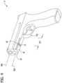
- FIG. 1is front perspective of a first embodiment of a firearm accessory of the present disclosure
- FIG. 2is a rear perspective of the firearm accessory of FIG. 1 ;
- FIG. 3is a partially exploded front perspective of the firearm accessory
- FIG. 4is a bottom perspective of a firearm having an accessory mounting rail
- FIG. 5is a side elevation of the firearm having the firearm accessory mounted on the accessory mounting rail;
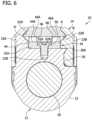
- FIG. 6is a fragmentary section of the firearm accessory on the accessory mounting rail taken in a plane including line 6 - 6 indicated in FIG. 5 ;
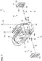
- FIG. 7is a partially exploded rear perspective of the firearm accessory
- FIG. 8is a rear perspective similar to FIG. 7 but with different parts exploded;
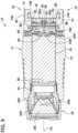
- FIG. 9is a section of the firearm accessory taken in a plane including line 9 - 9 of FIG. 1 ;
- FIG. 10is a rear perspective of an electrical assembly of the firearm accessory
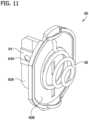
- FIG. 11is a front perspective of the electrical assembly of the firearm accessory
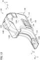
- FIG. 12is a front perspective of a firearm accessory of a second embodiment of the present disclosure.
- FIG. 13is a rear perspective of the firearm accessory of FIG. 12 ;
- FIG. 14is a side elevation of the firearm accessory mounted on a firearm
- FIG. 15is a partially exploded front elevation of the firearm accessory
- FIG. 16is a partially exploded front perspective of the firearm accessory with certain parts removed;
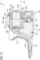
- FIG. 17is a section of the firearm accessory taken in a plane including line 17 - 17 of FIG. 13 ;
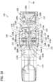
- FIG. 18is a section of the firearm accessory taken in a plane including line 18 - 18 of FIG. 12 ;
- FIG. 19is a perspective of a second embodiment of a retainer for use with the firearm accessory of FIG. 1 ;
- FIG. 20is a top view of the retainer of FIG. 19 on the firearm accessory of FIG. 1 .
- a firearm accessory of the present disclosureis generally indicated by the reference number 10 .
- the firearm accessory 10is an electronic firearm accessory in the form of a light for illuminating an area in front of the firearm (e.g., to assist in acquiring a target and/or aiming the firearm at the target).
- the firearm accessorycan be a different accessory such as a laser, or a light plus laser combination, or non-electronic accessory etc. without departing from the scope of the present invention.
- the light 10is configured for mounting on a firearm by connecting to a rail of the firearm.
- Accessory mounting railsare commonly provided on long guns such as rifles and shotguns, as well as on handguns such as pistols and revolvers.
- the illustrated light 10is intended for mounting on an accessory rail of a handgun in front of a trigger guard of the handgun.
- the light 10is discussed herein as being intended for a handgun, it will be appreciated that the light can be mountable on an accessory rail of a different type of firearm without departing from the scope of the present invention.
- An example handgun F including an accessory mounting rail Ris shown in FIG. 4 .
- the accessory rail Rextends forward of a trigger guard TG along a rail axis RA that is generally parallel to a barrel axis BA of the handgun.
- the illustrated accessory rail Ris shown as an integral part of the handgun F, but in other embodiments the accessory rail can be separate from and mounted on the handgun.
- Opposite left and right sides of the rail Rdefine ridges R′ extending along the rail axis RA that are configured for retainably mounting the light 10 on the rail.
- a recess Ge.g., slot or groove
- in the bottom of the rail Rextends transverse to the rail axis RA and is used to locate and prevent movement of the accessory along the rail.
- the position of the recess G along the length of the rail Ris not standard across all brands of handguns. In other words, a distance D 1 from the recess R to the trigger guard TG is different on various handguns. Some accessory rails may have multiple recesses spaced along the length of the rail at different distances from the trigger guard. It is desirable to mount the light 10 on the handgun F close to the trigger guard TG, so that switches of the light may be conveniently actuated by a user's hand holding the handgun.
- the light 10is designed to be used with a wide range of handguns having rails of different constructions (e.g., different rail recess locations) and is configurable to enable adjustable mounting on the handgun rail R to customize the location of the light with respect to the trigger guard TG.
- rails of different constructionse.g., different rail recess locations
- the lightgenerally includes an accessory body 12 , a firearm rail mount 14 , and two switch assemblies 16 .
- the accessory body 12includes a light head 20 and houses one or more batteries 18 ( FIG. 9 ) (broadly, “power source”), as described in further detail below.
- the firearm rail mount 14is connected to the accessory body 12 and is configured to support the accessory body on the firearm rail R.
- the switches 16are configured to be selectively positioned adjacent the trigger guard TG (e.g., outboard left and right sides of the trigger guard) when the light 10 is mounted on the accessory rail R, as shown in FIG. 5 .
- one of the switches 16may be conveniently actuated by the trigger finger of the user without significantly adjusting the user's hand on the grip of the handgun.
- the switches 16can be actuated by pressing them inward to turn the light 10 on and off, and to change between various modes of the light (e.g., high, low, strobe).
- the accessory body 12includes a housing 22 defining a generally cylindrical battery compartment holding the battery 18 .
- the housingincludes a threaded forward opening 24 configured to form a threaded connection with the light head 20 to support the light head on the housing.
- the light head 20defines a cap that closes the front end of the housing 22 and acts as a battery compartment cover.
- the light head 20includes a light head housing 20 A, a light source 20 B, a lens 20 C, and a bezel 20 D threaded on the light head housing.
- the light source 20 Bis an LED, but other light sources can be used without departing from the scope of the present invention.
- the light sourcecould be a laser.
- a tail cap 26is provided at the rear of housing 22 and will be described in further detail below.
- the accessory body 12has a front end defined by the light head 20 , a rear end defined by the tail cap 26 , and a length extending between the front and rear ends.
- the accessory body 12has a width transverse to the length that is less than the length, providing the accessory body with an elongate shape. Other shapes and constructions can be used without departing from the scope of the present invention.
- the accessory body 12has a firearm axis FA along which the length of the accessory rail R extends when the light 10 is mounted on the handgun F. When the light 10 is mounted on the rail, the firearm axis FA of the accessory body 12 is generally parallel with the barrel axis BA of the firearm. Referring to FIGS.
- the housing 22includes left and right side walls extending forward from the tail cap 26 to the light head 20 .
- the right side walldefines a rail engagement arm receiver 30 including a ridge 30 A extending along the firearm axis FA, for reasons which will become apparent.
- the housing 22has a generally flat upper wall 22 A including two threaded openings 22 B, for reasons which will be explained in further detail below.
- the firearm rail mount 14includes first and second rail engagement arms 32 A, 32 B, a retainer 34 , and three fasteners 36 , 38 .
- the first and second rail engagement arms 32 A, 32 Bare spaced from each other to define a gap for receiving the rail R therein.
- the first and second rail engagement arms 32 A, 32 Bare shaped and arranged to engage respective ridges R′ on the opposite sides of the rail R when the rail is received in the gap for retaining the light 10 on the rail. More specifically, the arms 32 A, 32 B have inward facing rail engagement surfaces 32 A′, 32 B′ shaped to conformally engage the ridges R on the opposite sides of the rails R.
- the rail engagement surfaces 32 A′, 32 B′are concave, and the arms are configured for clamping on the rail R.
- the first rail engagement arm 32 Ais formed as one piece with the housing 22 and extends upward from the housing.
- the second rail engagement arm 32 Bis separable from the housing 22 .
- a lower portion of the second rail engagement arm 32 Bis configured to conformally engage the ridge 30 A of the rail engagement arm receiver 30 to support and locate the second rail engagement arm 32 B on the housing 22 .
- the second rail engagement arm 32 Bis secured to the housing 22 by the fastener 36 in the form a bolt including a head and a threaded shaft.
- the threaded shaftextends through a transverse bore extending through an upper portion of the housing 22 to a threaded opening of a nut 40 at the other end of the bore.
- the nut 40has a flange that limits movement of the nut toward the second rail engagement arm 32 B.
- the arrangementis such that rotation of the bolt 36 tending to thread the bolt into the nut 40 causes the bolt to draw the second rail engagement arm 32 B toward the first rail engagement arm 32 A.
- the rail engagement arms 32 A, 32 Bare spaced appropriately to permit the rail R to be inserted between the rail engagement arms, and then the bolt 36 is rotated to clamp the rail between the rail engagement arms.
- the fit of the rail engagement surfaces 32 A′, 32 B′ against the ridges R′ of the rail Rlocates the light 10 vertically on the handgun F, and clamping of the arms 32 A, 32 B on the rail may provide resistance against longitudinal movement of the light along the rail. Arms that do not clamp the rail yet releasable retain the accessory on the rail can be used without departing from the scope of the present invention.
- the retainer 34is configured to engage the recess G of the rail R to limit movement of the light 10 along the length of the rail. For example, when the handgun F is fired, recoil of the handgun may tend to move the rail R rearward with respect to the light 10 .
- the retainer 34assists in preventing the light from migrating forward on the rail R in response to recoil of the handgun F.
- the retainer 34generally includes a base 44 and recess engagement structure 46 sized and shaped to interface with the recess G.
- the base 44engages the accessory body 12
- the recess engagement structure 46protrudes upward for receipt in the rail recess G.
- the retainer 34has a forward end, a rearward end, and a length extending therebetween along the firearm axis FA.
- the recess engagement structure 46is offset between the front and rear ends of the retainer 34 .
- the recess engagement structure 46is located a first distance D 2 from the front end of the retainer 34 and a second distance D 3 from the rear end different than the first distance.
- the base 44comprises a generally rectangular plate having a bottom surface (“accessory body engagement surface”) that engages the upper wall 22 A of the accessory body and having an upper surface 44 A facing away from the upper wall of the accessory body.
- An elongate slot 48is provided in the base 44 .
- the elongate slot 48has first and second ends spaced from each other along the firearm axis FA.
- Fasteners in the form of two screws 50are received through the slot 48 into the threaded openings 22 B in the housing 22 .
- the screws 50are spaced from each other along the firearm axis FA.
- the screws 50include threaded shafts and heads having tool engagement sockets to assist in rotating the screws.
- the screws 50are threadable into the threaded openings 22 B in the housing into fastened positions (e.g., FIGS. 1 , 2 , 6 ) in which the screws maintain the retainer 34 in position with respect to the accessory body 12 . More specifically, the heads of the screws 50 press the retainer 34 against the upper wall 22 A of the housing 22 with sufficient force to prevent longitudinal movement of the retainer along the firearm axis FA of the accessory 10 .
- the elongate slot 48is configured such that the heads of the screws 50 are countersunk in the base 44 when the screws are in the fastened positions.
- the elongate slot 48includes an upper or outer section that is wider and longer than a lower or inner section of the elongate slot, defining a shoulder 52 extending around the elongate slot where the upper section meets the lower section.
- the shoulder 52defines upward facing elongate fastener engagement surfaces 52 A, 52 B extending along opposite longitudinal sides of the elongate slot 48 against which the heads of the screws 50 bear to press the retainer against the housing.
- the screw headsare entirely within the upper section of the elongate slot 48 such that the screws heads are countersunk in the base 44 , flush with or below the upper surface 44 A of the base.
- the basecan have other configurations without departing from the scope of the present invention.
- the bottom surface of the basemay have bumps, ridges, or be otherwise configured to increase friction with the upper surface of the housing.
- the recess engagement structure 46 of the retainer 34includes first and second teeth 46 A (broadly, “protrusions”) extending upward from the base 44 .
- the teeth 46 Aare sized and shaped to be received in the firearm rail recess G and are located on opposite sides of the elongate slot 48 .
- the teeth 46 Aare provided in the form of generally rectangular posts. The teeth 46 A extend upward sufficiently to be received in the firearm rail recess G when the rail engagement arms 32 A, 32 B are in engagement with the firearm rail R.
- Other types of recess engagement structurecan be used without departing from the scope of the present invention.
- the retainer 34is configurable with respect to the accessory body 12 to change a location of the teeth 46 A along the firearm axis FA to achieve a desired location of the light 10 with respect to the trigger guard TG.
- the retainer 34is releasably fixable in various positions on the accessory body 12 along the firearm axis FA.
- the screws 50can be moved to unfastened positions by rotating the screws out of the threaded openings 22 B such that the screws no longer urge the retainer 34 against the accessory body 12 .
- the screws 50can be completely removed but need not be removed to permit movement of the retainer 34 .
- the base 44 of the retainer 34can slide on the upper wall 22 A of the housing 22 forward or rearward along the firearm axis FA to move the teeth 46 A to a desired position.
- the elongate slot 48permits the retainer 34 to move along the firearm axis FA in a relatively large range of motion without being restricted by engagement with the screws 50 . Because the teeth 46 A are offset on the base 44 , the teeth can be moved in yet a further range of movement by removing the screws 50 , reversing the orientation of the retainer 34 on the accessory body (reversing the front and rear ends of the retainer), and reinstalling the screws.
- the screws 50are rotated to their fastened positions to secure the retainer 34 in position.
- the location of the teeth 46 Acan be finely tuned to infinite locations to provide a custom fit of the light 10 on the firearm F. In most instances, the custom fit will be chosen such that the switches 16 of the light 10 are located for convenient actuation by the user (e.g., close to the trigger guard), as shown in FIG. 5 .
- a second embodiment of a retaineris indicated generally by the reference number 134 .
- the retainer 134is very similar to the retainer 34 and can be used in essentially the same way as described above with respect to the retainer 34 .
- the retainer 134includes a base 144 comprising a generally rectangular plate and includes retainer engagement structure in the form of two teeth 146 A.
- the two screws 50are used to fasten the retainer 134 to the accessory body 12 .
- An elongate slot 148is provided in the base 144 . The screws 50 extend through the slot 148 and are threadable into the threaded openings 22 B ( FIG.
- the retainer 134includes blocking structure 145 constructed to assist in maintaining the retainer in the desired position on the accessory body 12 .
- the blocking structure 145is provided to prevent the retainer 134 from moving rearward (away from the light head 20 ) on the accessory body 12 .
- the retainer 134will move rearward conjointly with the firearm under the recoil force.
- the sudden recoil forcecould cause the retainer to “slip” rearward on the accessory body.
- the blocking structure 145causes the accessory body 12 to move rearward conjointly with the retainer 134 and firearm F under the recoil force.
- the blocking structure 145prevents the retainer 134 from migrating rearward on the accessory body 12 in response to the recoil force.
- Such migration of the retainer 134 on the accessory body 12would be shown by forward migration of the accessory body 12 with respect to the firearm F.
- the blocking structurecomprises a series of ribs 145 protruding into the slot 148 constructed to engage the heads of the screws 50 .
- Ribs 145are provided at spaced locations along the length of the slot 148 , and corresponding pairs of ribs are provided on opposite sides of the slot.
- the ribs 145define a plurality of screw head receiving spaces 147 between adjacent pairs of ribs spaced along the length of the slot. In the illustrated embodiment, there are six screw head receiving spaces 147 .
- the screw head receiving spaces 147provide predetermined locations for the screws 50 to engage the retainer 134 .
- the pairs of ribs 145immediately forward of the screws 50 block forward migration of the screws in the slot 148 and thus prevent the retainer 134 from moving rearward on the accessory body 12 .
- blocking structure on the retainercan be constructed to engage the accessory body instead of or in addition to engaging the fasteners to prevent longitudinal movement of the retainer.
- the accessory bodycould include a plurality of ribs extending widthwise across the upper wall of the accessory body, and the bottom of the retainer could include a corresponding plurality of widthwise ribs that are arranged to mesh with the accessory body ribs when the screws are fastened to prevent longitudinal movement of the retainer on the accessory body.
- Many other arrangementsare possible.
- the electrical systemincludes circuitry placing the light source 20 B in electrical communication with the battery 18 .
- the circuitryincludes a first electrical contact 56 located in the battery compartment for contacting a positive terminal of the battery 18 , and a second electrical contact 58 in the form of a spring located in the battery compartment for contacting a negative terminal of the battery, thus placing the battery in electrical communication with the circuitry.
- the circuitryincludes a circuit board structure 60 in the tail cap 26 placing switch assemblies 16 in electronic communication with the circuitry.
- the circuitrycan complete the circuit between the circuit board structure 60 and the light source 20 B in any suitable way, such as an electrical lead (not shown) extending forward along the battery compartment from the circuit board structure to the light head 20 .
- the housing 22itself can be used complete the circuit from the circuit board structure 60 to the light head.
- the circuit board structure 60includes a first longitudinal circuit board 60 A and a second transverse circuit board 60 B in electrical communication with each other.
- the longitudinal circuit board 60 Ais joined to the transverse circuit board 60 B by tongue and groove connection as well as by brackets.
- the longitudinal circuit board 60 Aextends generally parallel with the firearm axis FA, and the transverse circuit board 60 B extends generally perpendicular to the firearm axis.
- the transverse circuit board 60 Bis sized and shaped to have a press fit in a receptacle 62 on the rear end of the housing 22 .
- the receptacle 62includes an upper arcuate flange 62 A and a lower arcuate flange 62 B for holding the transverse circuit board 60 B.
- the spring 58is mounted on and in electrical communication with the transverse circuit board 60 B.
- the longitudinal circuit board 60 Ais centrally located between the sides of the accessory body 12 and extends along the firearm axis FA.
- Two electronic switches 64are provided on opposite sides of the longitudinal circuit board 60 A and are in electrical communication with the longitudinal circuit board and thus the circuitry.
- the electronic switches 64face laterally with respect to the firearm axis FA.
- the electronic switches 64include pressure surfaces 64 A responsive to pressing thereon for actuation of the electronic switches.
- a gasket 66is sized and shaped to conformally fit over the rear end of the housing 22 , receptacle 62 , and circuit board structure 60 to isolate the circuitry from ingress of water.
- a section of the gasket 66wraps around the rear end of the longitudinal circuit board 60 A and includes portions 66 A on opposite sides of the longitudinal circuit board overlying the pressure surfaces 64 A of the electronic switches 64 .
- the tail cap 26is secured to the rear end of the housing 22 by left and right fasteners 68 A (only one being shown) in threaded openings 68 B and upper and lower studs 70 A (only one being shown) in openings 70 B.
- the tail cap 26supports switch actuators 72 configured to actuate the respective electronic switches 64 .
- the actuators 72are engagable by a user and movable with respect to the respective electronic switches 64 for actuating the electronic switches.
- the actuators 72include paddles 74 (broadly, “push members”) having proximal ends pivotally connected to the tail cap 26 by rods 76 .
- the rodsextend through brackets 78 on the tail cap 26 and through portions of the paddles 74 above and below the brackets.
- the paddles 74include push surfaces 74 A engageable by a hand of the user (e.g., trigger finger).
- the push surfaces 74 Ahave a protruding wave pattern to provide the user with tactile indication that their finger is on the push surface.
- the paddles 74have inner surfaces 74 B opposite the push surfaces 74 A facing inward toward the firearm axis FA.
- the paddles 74are pivotable inward about the rods 76 toward the firearm axis FA responsive to pushing force on the push surfaces 74 A.
- Each actuator 72includes a compression spring 80 and a pin 82 (broadly “finger”).
- the pins 82each include a head (broadly, “proximal portion”) and an elongate shaft having a tip.
- the pins 82extend through the springs 80 , and the pin and spring assemblies are received in recesses 84 ( FIG.
- each pin 82has a longitudinal axis that extends between the pin head and tip.
- the pins 82are elongate and have lengths along the longitudinal axes greater than their widths transverse to the longitudinal axes.
- the longitudinal axis of each pin 82is generally perpendicular to the push surface 74 A of the corresponding paddle 74 and intersects the pressure surface 64 A of the respective electronic switch 64 .
- the inner surfaces 74 B of the paddles 74each include a face 88 ( FIG.
- pin engagement portion(broadly, “pin engagement portion”) positioned to press on the heads of the respective pins 82 .
- the faces 88are concave and conformally engage the convex heads of the pins 82 while permitting some relative movement of the heads of the pins with respect to the paddles 74 .
- the springs 80have inner ends that engage the tail cap 26 and outer ends that engage the heads of the pins 82 to bias the pins away from the electronic switches 64 and thus bias the paddles 74 away from the electronic switches.
- the arrangementis such that the pins 82 act as fingers extending inward from the inner surfaces 74 B of the paddles 74 .
- Switch assemblies having other configurationscan be used without departing from the scope of the present invention.
- the pins 82are illustrated as being separate from the paddles 74 , the pins could be formed as one piece with the paddles.
- other types of actuators and fingers having other configurationscan be used. In some embodiments, the fingers can be omitted.
- a second embodiment of an electronic firearm accessory of the present disclosureis indicated generally at 110 .
- this firearm accessoryis a light 110 for mounting on a firearm F.
- the light 110is intended for mounting on a handgun F for illuminating an area in front of the handgun.
- the firearm accessorycan be a different accessory such as a laser, or light plus laser combination, or non-electronic accessory, etc. without departing from the scope of the present invention.
- the light 110generally includes an accessory body 112 , a firearm mount 114 , and two switch assemblies 116 .
- the accessory body 112houses one or more batteries 118 (broadly, “power source”) and includes a light head 120 , as described in further detail below.
- the firearm mount 114is configured to support the accessory body 112 on the trigger guard TG of the firearm F.
- the switches 116are configured to be positioned adjacent the trigger guard TG when the light 110 is mounted on the trigger guard, as shown in FIG. 14 .
- one of the switches 116may be conveniently actuated by the trigger finger of the user without significantly adjusting the user's hand on the grip of the handgun F.
- the switches 116can be actuated by pressing them inward to turn the light on and off, and to change between various modes of the light (e.g., high, low, strobe).
- the accessory body 112has a generally rectangular shape and includes a front end at which the light head 120 is positioned and a rear end connected to the firearm mount 114 .
- the accessory body 112has a length extending between the front and rear ends and a width less than and extending transverse to the length. Other shapes and constructions can be used without departing from the scope of the present invention.
- the accessory body 112has a firearm axis FA along which the length of the firearm barrel B extends when the light is mounted on the handgun. When the accessory 110 is mounted on the handgun F, the firearm axis FA of the accessory body extends along the length of the firearm. Referring to FIGS.
- the accessory body 112includes left and right side walls 112 A extending forward from the rear end to the front end.
- the accessory body 112has a generally flat upper wall 112 B and two fins 112 C extending upward to left and right sides of the upper wall to provide an integrated appearance of the light with the firearm F.
- the accessory body 112defines a housing for housing internal components of the light 110 .
- the accessory body 112 and firearm mount 114are formed by left and right shell pieces 121 A, 121 B constructed to fit together.
- the shell pieces 121 A, 121 Bmay be formed of injection molded plastic.
- the shell pieces 121 A, 121 Bare secured together by three screws 123 (broadly, “fasteners”).
- the shell pieces 121 A, 121 Bdefine generally hollow interior sections in which components of the light 110 are housed.
- the light 110includes a seam at which the two shell pieces 121 A, 121 B meet each other. In the illustrated embodiment, the seam is essentially planar, except for at a few locations. Other configurations can be used without departing from the present invention.
- the firearm mount 114is configured to envelope a forward portion of the trigger guard TG.
- the firearm mount 114is generally hollow and defines a channel 114 A through which the trigger guard TG extends when in the mount 114 .
- the accessory body 112includes a battery compartment 131 sized to hold one or more batteries 118 .
- the accessory body 112includes a front threaded opening 132 leading to the battery compartment 131 .
- a front end of the threaded opening 132is located at the front of the accessory body, and an inner end of the threaded opening is in the battery compartment 131 .
- the inner endincludes an annular flange 132 A separating the threaded opening from the remainder of the battery compartment 131 .
- a generally cylindrical cap 136 having an external threadis sized and shaped to be received in the front opening 132 and to form a threaded connection with the front opening to secure the batteries 118 in the battery compartment 131 .
- the cap 136has a cavity sized to at least partially receive one of the batteries 118 to provide a relatively compact arrangement.
- the cap 136includes a generally circular front wall 136 A and a cylindrical side wall 136 B (on which the external thread is provided) extending rearward from the front wall to define the cylindrical battery cavity.
- the front wall 136 Aincludes a tool socket sized and shaped for engagement by a tool (e.g., coin) to assist in rotating the cap.
- the capincludes an O-ring 136 C that frictionally engages the threaded opening 132 to serve as a retainer to resist rotation of the cap 136 to guard against the cap inadvertently rotating out of the threaded opening.
- the front threaded opening 132is crossed at the top and bottom of the threaded opening by portions 137 of the seam between the two shell pieces 121 A, 121 B.
- the seaminterrupts the thread of the threaded opening 132 .
- the seam portions that cross the threaded opening 132extend generally parallel to the firearm axis FA. In other embodiments, the seam portions can cross the threaded opening in other directions and/or at other locations.
- the internal thread in the opening 132can be referred to broadly as a keeper in the accessory body 112 configured to engage the cap 136 to maintain the cap in position closing the battery compartment 131 .
- Other keeperscan be used to maintain the cap in the opening (e.g., a bayonet connection or lug connection, etc.) can be used without departing from the scope of the present invention.
- the electrical systemincludes an electrical assembly indicated generally at 141 .
- the electrical assemblyincludes components of the light head 120 such as a lens 120 C, a light source 120 B, and a heat sink 120 D.
- the electrical assembly 141also includes a circuit board structure 160 to which the light head components are secured.
- the circuit board structure 160includes a single circuit board 160 A.
- the circuit board structurecan include other numbers of circuit boards in various configurations.
- the circuit board 160 Ais positioned centrally between the shell pieces 121 A, 121 B and extends along the firearm axis FA inside the accessory body 112 .
- the circuit board 160 Aat least partially defines circuitry of the light 110 that places the light source 120 B in electric communication with the batteries 118 .
- the circuit board 160 Asupports and is in electrical communication with positive and negative electrical contacts 156 , 158 for placing the batteries in electrical communication with the circuitry.
- the negative electrical contact 158is provided in the form of a wire wound into a conical compression spring portion 158 A that extends into the battery compartment for engaging a negative terminal of the rear battery 118 .
- the wire 158extends from the compression spring portion 158 A to the circuit board 160 A and mounts the spring portion on and electrically connects the spring to the circuit board.
- the positive electrical contact 156is provided in the form of an arm that extends from and is in electrical contact with a forward portion of the circuit board 160 A.
- the arm 156includes a proximal portion 156 A extending along a circuitous path to an arcuate distal portion 156 B of the arm.
- the arcuate distal portion 156 B of the arm 156includes a generally flat electrical conductor extending in an arc and having two portions 156 C protruding forward relative to the remainder of the arcuate conductor.
- the arrangementis such that when the cap 136 is threaded into and seated in the threaded opening 132 , the inner end of the cap engages one or both of the protruding portions 156 C of the positive contact 156 and presses the arcuate distal portion 156 B against the flange 132 A to ensure electrical contact between the cap and the positive contact.
- the cap 136is made of an electrically conductive material, and the cap's engagement with the positive terminal 156 of the forward battery 118 (the side wall and/or forward end of the forward battery) places the batteries in electrical communication with the positive electrical contact 156 and thus the circuit board 160 A.
- the electrical assembly 141also includes two electronic switches 164 that are parts of the switch assemblies 116 .
- the electronic switches 164are mounted on opposite sides of the circuit board 160 A in electric communication with the circuit board.
- the electronic switches 164face laterally with respect to the firearm axis FA.
- the switches 164include pressure surfaces 164 A responsive to pressing thereon for actuation of the electronic switches. Actuation of the electronic switches 164 can turn the light 110 on or off or otherwise change an operation of the light, such as changing modes (high, low, strobe, etc.).
- the switch assemblies 116further include respective actuators 172 on opposite sides of the accessory body 112 .
- the actuators 172include paddles 174 (broadly, “push members”) mounted on the side walls 112 A, 112 B of the accessory body 112 .
- the paddles 114have outer push surfaces 174 A engageable by a hand of a user (e.g., trigger finger) and movable inward for actuating the respective electronic switches 164 .
- the push surfaces 174 Ahave a protruding wave pattern to provide the user with tactile indication that their finger is on the push surface. As shown in FIG.
- the paddles 174include proximal ends having tabs 175 extending forward for pivotally connecting the paddles with respective ones of the side walls 112 A, 112 B of the accessory body 112 .
- Rounded protrusions or ribs 175 Aextend outward from the tabs 175 , which, as shown in FIG. 18 , are received in concave sockets 177 on inner surfaces of the accessory body side walls 112 A, 112 B to form pivot connections.
- the paddles 174are pivotable inward about the pivot connections toward the firearm axis FA responsive to pushing force on the push surfaces 174 A.
- the paddleshave inner major surfaces 174 B facing inward toward the firearm axis FA.
- the actuators 172each further include a compression spring 180 and a pin 182 (broadly “finger”) inboard of the paddles 174 .
- the pins 182each include a head (broadly, “proximal portion”) and an elongate shaft having a tip opposite the head.
- the pins 182extend through the springs 180 , and the pin and spring assemblies are received in cylindrical housings 181 ( FIG. 15 ) on the side walls 112 A, 112 B of the accessory body 112 .
- the pins 182extend through openings 183 ( FIG. 15 ) in the side walls 112 A, 112 B, and tips of the pins are aligned with the pressure surfaces 164 A of the electronic switches 164 for pressing and thus actuating the electronic switches.
- Each pin 182has a longitudinal axis that extends between the pin head and tip.
- the pins 182are elongate and have lengths along the longitudinal axes greater than their widths transverse to the longitudinal axes.
- the longitudinal axis of the pin 182is generally perpendicular to the push surface 174 A of the corresponding paddle 174 and intersects the pressure surface 164 A of the respective electronic switch 164 .
- the inner major surfaces 174 B of the paddles 174each include a face 188 ( FIG. 15 ) (broadly, “pin engagement portion”) positioned to press on the heads of the respective pins 182 .
- the faces 188are concave and conformally engage the convex heads of the pins 182 while permitting some relative movement of the heads with respect to the paddles 174 .
- the springs 180have inner ends that engage the accessory body side wall 112 A, 112 B in the cylindrical housings 181 and outer ends that engage the heads of the pins 182 to bias the pins away from the electronic switches 164 and thus bias the paddles 174 away from the electronic switches.
- Each switch assembly 116includes a stop 191 ( FIG. 15 ) for limiting outward movement of the paddle 174 under the bias of the spring 180 .
- the stop 191includes a screw 191 A (broadly, “fastener”) and washer 191 B through which the screw extends.
- the screws 191 Aextend outward through openings 193 ( FIG. 15 ) in the side walls 112 A, 112 B to the paddles 174 and are threaded into the paddles.
- the washers 191 Bare sized to engage the accessory body side walls 112 A, 112 B (e.g., at annular shoulders of the side walls) inside the accessory body 112 to limit outward movement of the washers and thus the screws by engagement of the screw heads with the washers.
- the arrangementis such that the pins 182 act as fingers extending inward from the inner major surfaces 174 B of the paddles 174 , and when a paddle is pivoted inward its respective pin 182 compresses the spring 180 and presses the pressure surface 164 A of the electronic switch 164 , thus actuating the electronic switch. Accordingly, the paddle push surface 174 A is pushable in the same direction in which the tip of the pin 182 moves (in the direction of the longitudinal axis of the pin) to actuate the electronic switch 164 . When the user releases the paddle 174 , the spring 180 pushes the pin 182 and paddle 174 outward to their non-actuated positions.
- the stops 191limit the outward movement of the paddles 174 under the bias of the springs 180 and locate the paddles in their non-actuated positions.
- the construction of the switch assemblies 116provides a relatively large effective push surface 174 A that is easily pushable by the user to actuate the switch assemblies with the mechanical advantage of the pivot connection of the paddle 174 to the accessory body 112 .
Landscapes
- Engineering & Computer Science (AREA)
- General Engineering & Computer Science (AREA)
- Physics & Mathematics (AREA)
- Optics & Photonics (AREA)
- Arrangement Of Elements, Cooling, Sealing, Or The Like Of Lighting Devices (AREA)
- Push-Button Switches (AREA)
Abstract
Description
Claims (86)
Priority Applications (2)
| Application Number | Priority Date | Filing Date | Title |
|---|---|---|---|
| US17/389,787US11788816B2 (en) | 2018-03-30 | 2021-07-30 | Electronic firearm accessory with light source |
| US18/351,822US12422220B2 (en) | 2018-03-30 | 2023-07-13 | Electronic firearm accessory with light source |
Applications Claiming Priority (2)
| Application Number | Priority Date | Filing Date | Title |
|---|---|---|---|
| US15/941,971US11105586B2 (en) | 2018-03-30 | 2018-03-30 | Electronic firearm accessory with light source |
| US17/389,787US11788816B2 (en) | 2018-03-30 | 2021-07-30 | Electronic firearm accessory with light source |
Related Parent Applications (1)
| Application Number | Title | Priority Date | Filing Date |
|---|---|---|---|
| US15/941,971ContinuationUS11105586B2 (en) | 2018-03-30 | 2018-03-30 | Electronic firearm accessory with light source |
Related Child Applications (1)
| Application Number | Title | Priority Date | Filing Date |
|---|---|---|---|
| US18/351,822ContinuationUS12422220B2 (en) | 2018-03-30 | 2023-07-13 | Electronic firearm accessory with light source |
Publications (2)
| Publication Number | Publication Date |
|---|---|
| US20210356231A1 US20210356231A1 (en) | 2021-11-18 |
| US11788816B2true US11788816B2 (en) | 2023-10-17 |
Family
ID=68056985
Family Applications (3)
| Application Number | Title | Priority Date | Filing Date |
|---|---|---|---|
| US15/941,971Active2038-10-19US11105586B2 (en) | 2018-03-30 | 2018-03-30 | Electronic firearm accessory with light source |
| US17/389,787ActiveUS11788816B2 (en) | 2018-03-30 | 2021-07-30 | Electronic firearm accessory with light source |
| US18/351,822ActiveUS12422220B2 (en) | 2018-03-30 | 2023-07-13 | Electronic firearm accessory with light source |
Family Applications Before (1)
| Application Number | Title | Priority Date | Filing Date |
|---|---|---|---|
| US15/941,971Active2038-10-19US11105586B2 (en) | 2018-03-30 | 2018-03-30 | Electronic firearm accessory with light source |
Family Applications After (1)
| Application Number | Title | Priority Date | Filing Date |
|---|---|---|---|
| US18/351,822ActiveUS12422220B2 (en) | 2018-03-30 | 2023-07-13 | Electronic firearm accessory with light source |
Country Status (1)
| Country | Link |
|---|---|
| US (3) | US11105586B2 (en) |
Cited By (3)
| Publication number | Priority date | Publication date | Assignee | Title |
|---|---|---|---|---|
| US20230228532A1 (en)* | 2021-11-08 | 2023-07-20 | Crimson Trace Corporation | Firearm accessory with path light |
| US20230349671A1 (en)* | 2020-01-17 | 2023-11-02 | Sig Sauer, Inc. | Adjustable firearm accessory |
| US20250027744A1 (en)* | 2021-09-24 | 2025-01-23 | Gel Blaster, Inc. | Blaster with accessory power connection and interchangeable nozzle components |
Families Citing this family (45)
| Publication number | Priority date | Publication date | Assignee | Title |
|---|---|---|---|---|
| US20180283670A1 (en)* | 2012-05-17 | 2018-10-04 | Emissive Energy Corp. | Pistol mounted light and operation thereof |
| US9435522B2 (en) | 2012-05-17 | 2016-09-06 | Emissive Energy Corp. | Pistol mounted light and operation thereof |
| TWD184900S (en)* | 2015-06-16 | 2017-08-11 | Sheltered Wings Inc D/B/A Vortex Optics | Riflescope |
| US10557688B2 (en)* | 2018-01-26 | 2020-02-11 | La Police Gear, Inc. | Accessory mounting assembly for a firearm |
| US11105586B2 (en)* | 2018-03-30 | 2021-08-31 | Aob Products Company | Electronic firearm accessory with light source |
| USD914260S1 (en)* | 2018-08-21 | 2021-03-23 | Streamlight, Inc | Flashlight having tail lights |
| USD951508S1 (en)* | 2019-07-12 | 2022-05-10 | Chen Guozheng | Tactical flashlight |
| USD907269S1 (en)* | 2019-07-23 | 2021-01-05 | Streamlight, Inc. | Mountable light |
| USD907267S1 (en)* | 2019-07-23 | 2021-01-05 | Streamlight, Inc. | Mountable light |
| USD907270S1 (en)* | 2019-07-23 | 2021-01-05 | Streamlight, Inc. | Mountable light |
| USD1005541S1 (en)* | 2019-07-23 | 2023-11-21 | Streamlight, Inc. | Mountable light |
| USD907268S1 (en)* | 2019-07-23 | 2021-01-05 | Streamlight, Inc. | Mountable light |
| USD919149S1 (en) | 2019-07-23 | 2021-05-11 | Streamlight, Inc. | Mountable light |
| US11543212B1 (en)* | 2019-11-22 | 2023-01-03 | Phillip Letts | Indexing scope mount assembly |
| CN110940230B (en)* | 2019-12-16 | 2025-04-08 | 珠海市敏夫光学仪器有限公司 | Chargeable sighting telescope support and sighting telescope with same |
| USD987765S1 (en)* | 2020-04-20 | 2023-05-30 | Primary Arms, Llc | Optical aiming device |
| US12203728B2 (en)* | 2020-04-22 | 2025-01-21 | Aob Products Company | Weapon accessory mount |
| CN111664424B (en)* | 2020-05-18 | 2022-10-11 | 深圳市傲雷电商科技股份有限公司 | Quick-release device of pistol gun lamp |
| AU2021318542A1 (en)* | 2020-07-28 | 2023-03-23 | Sheltered Wings, Inc. D/B/A Vortex Optics | Mounting system for mini red dot sights |
| USD997285S1 (en)* | 2020-08-07 | 2023-08-29 | Streamlight, Inc. | Mountable light |
| USD999624S1 (en)* | 2020-08-07 | 2023-09-26 | Streamlight, Inc. | Clamping members |
| US11506366B2 (en) | 2020-08-07 | 2022-11-22 | Streamlight, Inc. | Mountable light having interchangeable clamping elements |
| USD997413S1 (en)* | 2020-08-07 | 2023-08-29 | Streamlight, Inc. | Mountable light |
| US11585620B2 (en)* | 2020-08-09 | 2023-02-21 | Zrodelta, Llc | Mount for a firearm |
| USD1061979S1 (en) | 2021-01-07 | 2025-02-11 | Streamlight, Inc. | Mountable light |
| USD1091907S1 (en) | 2021-01-07 | 2025-09-02 | Streamlight, Inc. | Mountable light |
| USD1092809S1 (en) | 2021-01-07 | 2025-09-09 | Streamlight, Inc. | Mountable light |
| USD969261S1 (en)* | 2021-01-18 | 2022-11-08 | Xinjian Guo | Telescope |
| USD982534S1 (en)* | 2021-06-02 | 2023-04-04 | Milspec Enterprises, LLC | Switch actuator |
| US12235077B2 (en)* | 2021-11-01 | 2025-02-25 | Nextlevel Training Llc | Magazine attached illuminating device |
| US20230184517A1 (en)* | 2021-12-13 | 2023-06-15 | Exponential Innovation IP Holdings LLC | Accessory Mount System |
| USD1060775S1 (en)* | 2021-12-17 | 2025-02-04 | Huanic Corporation | LED flashlight |
| USD1069199S1 (en)* | 2021-12-30 | 2025-04-01 | Crimson Trace Corporation | Weapon light |
| US12123581B2 (en)* | 2022-01-14 | 2024-10-22 | Streamlight, Inc. | Portable light having changeable actuators |
| USD1048527S1 (en)* | 2022-01-14 | 2024-10-22 | Streamlight, Inc. | Cover for a light or similar article |
| USD1069020S1 (en)* | 2022-01-22 | 2025-04-01 | Carl Zeiss Ag | Thermal front attachment for telescopic sight |
| USD1068016S1 (en)* | 2022-01-22 | 2025-03-25 | Carl Zeiss Ag | Thermal front attachment for telescopic sight |
| USD1045000S1 (en)* | 2022-02-12 | 2024-10-01 | Huanic Corporation | Gun sight |
| US12287176B2 (en)* | 2022-04-26 | 2025-04-29 | Strike IP, LLC | Firearm optics mount plate with multiple footprints |
| EP4357722B1 (en)* | 2022-10-21 | 2025-03-12 | Glock Technology GmbH | Lighting assembly for a firearm, and a firearm equipped with the lighting assembly, and an actuating element for a lighting assembly |
| EP4357723B1 (en)* | 2022-10-21 | 2025-03-12 | Glock Technology GmbH | Lighting assembly for a firearm and a firearm equipped with the lighting assembly |
| USD1092674S1 (en)* | 2022-11-29 | 2025-09-09 | Guozheng Chen | Laser sight |
| USD1056283S1 (en)* | 2023-03-27 | 2024-12-31 | Lumaiii, Inc. | Spray paint gun light |
| USD1040395S1 (en)* | 2024-02-05 | 2024-08-27 | Beijing Huihaozi Technology Co., Ltd | Tactical flashlight |
| USD1051198S1 (en)* | 2024-08-08 | 2024-11-12 | Shenzhen Yixin Information Technology Co., Ltd. | Night vision monocular |
Citations (207)
| Publication number | Priority date | Publication date | Assignee | Title |
|---|---|---|---|---|
| US3579840A (en) | 1969-09-04 | 1971-05-25 | Olin Corp | Snap off telescope mount |
| US4688345A (en) | 1985-11-29 | 1987-08-25 | J. B. Holden Co. | Telescopic sight mount |
| US4697226A (en) | 1986-07-11 | 1987-09-29 | Verdin Joe L | Light mounting for firearms |
| US5033219A (en) | 1990-02-06 | 1991-07-23 | Emerging Technologies, Inc. | Modular laser aiming system |
| US5179235A (en) | 1991-09-10 | 1993-01-12 | Toole Ronald L | Pistol sighting device |
| US5194007A (en) | 1991-05-20 | 1993-03-16 | The United States Of America As Represented By The Secretary Of The Navy | Semiconductor laser weapon trainer and target designator for live fire |
| US5237773A (en) | 1991-09-20 | 1993-08-24 | Claridge Hi-Tec Inc. | Integral laser sight, switch for a gun |
| US5400540A (en) | 1992-10-08 | 1995-03-28 | Insight Technology Incorporated | Aiming light and mounting assembly therefor |
| US5430967A (en) | 1993-12-16 | 1995-07-11 | Insight Technology, Inc. | Aiming assistance device for a weapon |
| US5435091A (en) | 1993-08-05 | 1995-07-25 | Crimson Trace Corp. | Handgun sighting device |
| US5560703A (en) | 1993-10-27 | 1996-10-01 | Capps, Iii; Lewis W. | Handgun light mount |
| US5581898A (en) | 1993-07-30 | 1996-12-10 | Laser Devices, Inc. | Modular sighting laser for a firearm |
| US5584137A (en) | 1993-06-08 | 1996-12-17 | Teetzel; James W. | Modular laser apparatus |
| US5590486A (en) | 1994-12-27 | 1997-01-07 | Tac Star Industries, Inc. | Externally mountable laser sight for weapons and other applications |
| US5618099A (en) | 1994-07-29 | 1997-04-08 | Brubacher; Michael | Sighting device |
| US5628555A (en) | 1996-04-22 | 1997-05-13 | Streamlight, Inc. | Switch actuation mechanism for a firearm-mounted flashlight |
| US5685105A (en) | 1993-06-08 | 1997-11-11 | Teetzel; James W. | Apparatus for attaching a flashlight to a firearm |
| US5706600A (en) | 1994-07-08 | 1998-01-13 | Crimson Trace Corporation | Laser sighting device for a weapon |
| US5758448A (en) | 1997-01-02 | 1998-06-02 | Laser Devices, Inc. | Laser system mounting device |
| USD398410S (en) | 1995-06-05 | 1998-09-15 | Mark Kevin Fell | Combined flashlight and mount for a handgun |
| US5913669A (en) | 1997-08-29 | 1999-06-22 | The United States Of America As Represented By The Secretary Of The Army | Aiming light mount and system for shotgun |
| US6023875A (en) | 1995-10-16 | 2000-02-15 | Fell; Mark Kevin | Tactically advanced combat mount (TACM III ™) illuminating devices and illuminating mounting systems for firearms and other applications |
| US6185854B1 (en) | 1998-07-02 | 2001-02-13 | Insight Technology, Incorporated | Auxiliary device for a weapon and attachment thereof |
| US6230431B1 (en) | 1999-07-07 | 2001-05-15 | Limate Corporation | Night laser sight |
| US6276088B1 (en) | 1997-12-05 | 2001-08-21 | Laser Products Ltd. | Firearms with target illuminators |
| US6363648B1 (en) | 2000-01-27 | 2002-04-02 | William H. Grube | Laser aiming light for firearms |
| US6378237B1 (en) | 1997-12-05 | 2002-04-30 | Surefire, Llc | Firearms with target illuminators |
| US20020100204A1 (en) | 2001-01-04 | 2002-08-01 | Surefire, Llc | Target and navigation illuminators for firearms |
| US20020100202A1 (en) | 2001-02-01 | 2002-08-01 | Paul Lin | Sliding sheath type fixture for pistol accessory |
| US6438888B1 (en) | 2001-02-07 | 2002-08-27 | Quarton, Inc. | Fixture for quickly clipping accessory on pistol |
| US6513251B2 (en) | 2001-01-11 | 2003-02-04 | Quarton, Inc. | Illuminable laser sight |
| US6526688B1 (en) | 2001-08-13 | 2003-03-04 | Lewis Danielson | Apparatus and method for actuating a weapon accessory by a laser sighting beam |
| US6571503B2 (en) | 2001-01-16 | 2003-06-03 | Jeffrey C. Thorpe | Firearm mounted illumination device |
| US20030101632A1 (en) | 2001-10-24 | 2003-06-05 | Davenport Michael S. | Mounting assembly for a weapon accessory |
| US6606813B1 (en) | 2002-03-08 | 2003-08-19 | Exponent, Inc. | Weapon accessory mounting apparatus |
| US6609810B2 (en) | 2002-01-15 | 2003-08-26 | Surefire, Llc | Illumination apparatus with removably securable switch device |
| US20030202345A1 (en) | 2002-04-26 | 2003-10-30 | Surefire, Llc | Flashlight with securement capability |
| US6671991B1 (en) | 2002-07-03 | 2004-01-06 | Lewis A. Danielson | Target illuminator for long gun |
| US6698127B2 (en) | 2000-03-30 | 2004-03-02 | Christoph Weber | Bottom of a pistol magazine |
| US6722074B1 (en) | 2003-02-12 | 2004-04-20 | Farrell Industries, Inc. | Adjustable recoil lug for scope-mounting base |
| US20040148842A1 (en) | 2001-03-05 | 2004-08-05 | Juha Aalto | Rapid clamping base for an optic rifle sight |
| US6874269B2 (en) | 2003-01-03 | 2005-04-05 | Quarton, Inc. | Connecting device for weapon accessory |
| USD505177S1 (en) | 2004-01-09 | 2005-05-17 | Oscar M. Fell | Quick release mount for weapons with rail type mounting systems and other applications |
| US20050243542A1 (en) | 2004-04-29 | 2005-11-03 | Surefire, Llc | Switches for firearm electrical accessories |
| US20050246937A1 (en) | 2004-04-06 | 2005-11-10 | Surefire, Llc | Accessory devices for firearms |
| US20060196099A1 (en) | 2004-04-06 | 2006-09-07 | Surefire, Llc, A California Limited Liability Company | Accessory devices for firearms |
| US20060242882A1 (en) | 2005-04-29 | 2006-11-02 | Philip Liu | Gun barrel and trigger flashlight and/or laser mount structure |
| US7134234B1 (en) | 2005-01-25 | 2006-11-14 | John Makarounis | Mounting device |
| US20070006512A1 (en) | 2005-07-11 | 2007-01-11 | Blackpowder Products, Inc. | Universal scope mount |
| USD536116S1 (en) | 2005-10-04 | 2007-01-30 | Streamlight, Inc. | Light having a bendable neck |
| US7188978B2 (en) | 2004-11-15 | 2007-03-13 | Streamlight, Inc. | Light mountable on a mounting rail |
| US20070068058A1 (en) | 2005-09-29 | 2007-03-29 | Michael Remo | Night vision monocular housing and universal system for using same in various applications |
| US7199315B1 (en) | 2004-02-05 | 2007-04-03 | Streamlight, Inc. | Pressure actuated electrical switch |
| US7199351B2 (en) | 2002-06-21 | 2007-04-03 | Fuji Photo Film Co., Ltd. | Solid state image sensing apparatus with output level controller |
| US20070113462A1 (en) | 2005-11-23 | 2007-05-24 | Shu-Li Ho | Structure for fixing a gun scope |
| USD543446S1 (en) | 2004-11-15 | 2007-05-29 | Streamlight, Inc. | Head, for a fastener or actuator |
| USD548385S1 (en) | 2005-11-08 | 2007-08-07 | Streamlight, Inc. | Mountable light |
| US20070193103A1 (en) | 2006-01-20 | 2007-08-23 | Daniel Cheng | Gun system and accessory thereof |
| US7260910B2 (en) | 2005-01-25 | 2007-08-28 | Crimson Trace Corporation | Laser gunsight system for a firearm handgrip |
| US7264369B1 (en) | 2004-08-17 | 2007-09-04 | Insight Technology, Inc. | Switch configuration for a tactical illuminator |
| US20070227056A1 (en) | 2005-11-17 | 2007-10-04 | Howe Alan T | Tactical Illuminator |
| US20070277422A1 (en) | 2006-05-31 | 2007-12-06 | Leapers, Inc. | Firearm target illumination implement |
| US7325352B2 (en) | 2004-04-06 | 2008-02-05 | Surefire, Llc | Accessory devices for firearms |
| US7332682B2 (en) | 2004-04-29 | 2008-02-19 | Surefire, Llc | Switches for electrical accessories |
| US20080040965A1 (en)* | 1998-07-02 | 2008-02-21 | Solinsky Kenneth S | Auxiliary device for a weapon and attachment thereof |
| USD567894S1 (en) | 2004-06-28 | 2008-04-29 | Insight Technology Incorporated | Tactical illuminator |
| USD568508S1 (en) | 2006-02-07 | 2008-05-06 | Insight Technology, Inc. | Tactical flashlight |
| US20080148619A1 (en) | 2006-12-20 | 2008-06-26 | Prezine, Llc A Limited Liability Company Of Fl | Adjustable rail light mount |
| US20080205037A1 (en) | 2004-10-29 | 2008-08-28 | R/M Equpmint, Inc. | Interface Apparatus For Mounting A Portable Illumination Tool & Related Illumination Assembly |
| USD578599S1 (en) | 2006-01-23 | 2008-10-14 | Daniel Cheng | Laser sight |
| US20080253110A1 (en) | 2006-10-13 | 2008-10-16 | Chris Wu | Weapon Mount Tactical Light Trigger |
| US7472830B2 (en) | 2005-01-25 | 2009-01-06 | Crimson Trace Corporation | Compact laser aiming assembly for a firearm |
| US20090013580A1 (en) | 2006-02-04 | 2009-01-15 | Lasermax, Inc. | Firearm mount with embedded sight |
| USD585516S1 (en) | 2005-10-31 | 2009-01-27 | Optronics Products Company, Inc. | Gun light and bracket |
| US20090190339A1 (en) | 2008-01-29 | 2009-07-30 | Emissive Energy Corporation | Multi-function flashlight |
| USD603478S1 (en) | 2008-09-30 | 2009-11-03 | Crimson Trace Corporation | Laser gunsight system for a firearm trigger guard |
| US20090293855A1 (en) | 2008-05-28 | 2009-12-03 | Danielson Lewis A | Aiming Device and Method for Archery Bow |
| US20090307956A1 (en) | 2008-06-11 | 2009-12-17 | Christopher Gene Barret | Adjustable rifle telescope system with multiple fixed angle mount setpoints |
| US20100043271A1 (en) | 2005-03-22 | 2010-02-25 | Blackpowder Products, Inc. | Scope mounting system |
| US7674003B2 (en) | 2006-04-20 | 2010-03-09 | Streamlight, Inc. | Flashlight having plural switches and a controller |
| US7685759B2 (en) | 2006-11-01 | 2010-03-30 | Wilcox Industries Corp. | Three-point clamp for firearm mounting rail |
| USD612970S1 (en) | 2009-04-27 | 2010-03-30 | Streamlight, Inc. | Mountable light |
| US20100097789A1 (en) | 2004-11-15 | 2010-04-22 | Sharrah Raymond L | Light with keying arrangement mountable on a mounting rail |
| USD616957S1 (en) | 2008-05-12 | 2010-06-01 | Crimson Trace Corporation | Laser gunsight system for a firearm handgrip |
| US7735255B1 (en) | 2006-11-16 | 2010-06-15 | Blackhawk Industries Product Group Unlimited Llc | Offset accessory mount |
| US20100176741A1 (en) | 2009-01-13 | 2010-07-15 | Sharrah Raymond L | Light with removable head and cover |
| US20100229450A1 (en) | 2009-01-12 | 2010-09-16 | Novatac, Inc. | Quick release weapon mount and accessories for use therewith |
| US20100229449A1 (en) | 2006-12-27 | 2010-09-16 | Surefire, Llc | Rail clamp mount |
| US7805876B1 (en) | 2008-05-12 | 2010-10-05 | Crimson Trace Corporation | Laser gunsight system for a firearm handgrip |
| US20100254135A1 (en)* | 2009-04-03 | 2010-10-07 | Bayco Products, Ltd. | Optical Apparatus for Hand Held Lamps |
| US20100263256A1 (en) | 2006-05-08 | 2010-10-21 | Michael Angelo Spinelli | No-drill rear sight scope mount base |
| US7819547B1 (en) | 2007-06-01 | 2010-10-26 | Wilcox Industries Corp. | End cap switch for flashlight |
| USD628323S1 (en) | 2010-01-14 | 2010-11-30 | Surefire, Llc | Lighting device |
| US7896518B2 (en) | 2008-01-22 | 2011-03-01 | Powertech, Inc. | Multimode flashlight having light emitting diodes |
| US20110047850A1 (en) | 2008-11-24 | 2011-03-03 | Crimson Trace Corporation | Laser aiming device for weapon foregrip |
| US20110058362A1 (en) | 2009-03-18 | 2011-03-10 | Huanic Corporation | Led light laser sighting device |
| US7913441B1 (en) | 2008-02-08 | 2011-03-29 | L-3 Insight Technology Incorporated | Scope mount |
| USD636049S1 (en) | 2010-03-25 | 2011-04-12 | Crimson Trace Corporation | Laser gunsight system for a firearm |
| USD636837S1 (en) | 2010-03-25 | 2011-04-26 | Crimson Trace Corporation | Laser gunsight system for a firearm |
| US8028461B2 (en) | 2007-06-18 | 2011-10-04 | Patricia NuDyke | Switch for the control of weapon mounted electronic assemblies, a weapon having a control switch and a method for using weapon |
| US20110261559A1 (en) | 2010-04-22 | 2011-10-27 | Couture Eric D | Flashlight with Tail Cap and Remote Switch |
| US20110290968A1 (en) | 2010-05-27 | 2011-12-01 | Ivus Industries, Llc | Mounting assembly |
| US8117782B2 (en) | 2008-03-11 | 2012-02-21 | Powertech, Inc. | Tactical illuminator |
| US20120055061A1 (en) | 2010-07-27 | 2012-03-08 | Crimson Trace Inc. | Modular vertical foregrip |
| US20120055062A1 (en) | 2010-01-19 | 2012-03-08 | Mironichev Sergei Y | Mounting brackets for connecting tubular bodies |
| US8132355B1 (en) | 2006-11-16 | 2012-03-13 | Alliant Techsystems Inc. | Offset accessory mount and mounting system |
| US20120096755A1 (en) | 2008-01-14 | 2012-04-26 | Todd Griffin | Rail accessory mounting apparatus for weapon |
| US20120124885A1 (en) | 2010-11-16 | 2012-05-24 | Crimson Trace, Inc. | Modular sighting and lighting system for handguns |
| US20120144718A1 (en) | 2008-09-30 | 2012-06-14 | Crimson Trace Corporation | Laser gunsight system for a firearm trigger guard |
| US20120167436A1 (en) | 2010-01-18 | 2012-07-05 | Christopher Westra | Rail attachment mechanism |
| US8220946B1 (en) | 2006-11-01 | 2012-07-17 | Wilcox Industries Corp. | Modular flashlight apparatus for firearm |
| US20120198745A1 (en) | 2011-02-07 | 2012-08-09 | Juan Carlos Casas | Rapid attachment/detachment mechanism for weapon-mountable lighting devices |
| US20120216440A1 (en) | 2011-02-25 | 2012-08-30 | Juan Carlos Casas | Modular power supply for use in a weapon mountable designator/illuminator unit |
| US20120227304A1 (en) | 2011-03-10 | 2012-09-13 | IEA MIL-OPTICS GmbH | Device for mounting an additional device to a firearm |
| US8276307B2 (en) | 2009-09-30 | 2012-10-02 | Deros Mark A | Mount adapter device utilizing a push system |
| USD669553S1 (en) | 2011-05-11 | 2012-10-23 | Crimson Trace, Inc. | Laser device |
| USD669552S1 (en) | 2011-06-29 | 2012-10-23 | Crimson Trace, Inc. | Laser device |
| USD669958S1 (en) | 2011-05-10 | 2012-10-30 | Crimson Trace, Inc. | Laser device |
| USD669959S1 (en) | 2011-06-29 | 2012-10-30 | Crimson Trace, Inc. | Illumination device |
| USD669957S1 (en) | 2011-05-10 | 2012-10-30 | Crimson Trace, Inc. | Laser device |
| USD672005S1 (en) | 2010-12-30 | 2012-12-04 | Laser Aiming Systems Corporation | Laser gun sight |
| USD673709S1 (en) | 2011-10-31 | 2013-01-01 | Streamlight, Inc. | Mountable light |
| USD674525S1 (en) | 2011-10-31 | 2013-01-15 | Streamlight, Inc. | Mountable light |
| USD674862S1 (en) | 2011-06-29 | 2013-01-22 | Crimson Trace, Inc. | Illumination device |
| USD674861S1 (en) | 2011-06-29 | 2013-01-22 | Crimson Trace, Inc. | Illumination device |
| US20130185982A1 (en) | 2010-07-27 | 2013-07-25 | Crimson Trace Inc. | Laser aiming device |
| USD687120S1 (en) | 2011-11-09 | 2013-07-30 | Crimson Trace, Inc. | Laser device |
| US8499484B2 (en) | 2011-02-17 | 2013-08-06 | LW Schneider Incorporated | Assembly for mounting on a picatinny-type rail |
| US8510979B1 (en) | 2010-01-18 | 2013-08-20 | Timothy Scott Mortimer | Light-emitting and less-than-lethal-agent-emitting apparatus |
| USD689162S1 (en) | 2012-02-21 | 2013-09-03 | Crimson Trace, Inc. | Dual laser device |
| USD692518S1 (en) | 2011-11-09 | 2013-10-29 | Crimson Trace, Inc. | Laser device |
| US8578647B2 (en) | 2007-01-12 | 2013-11-12 | American Defense Manufacturing, Llc | Locking quick release clamp assembly |
| USD693898S1 (en) | 2011-11-02 | 2013-11-19 | Crimson Trace, Inc. | Laser device |
| US8584392B1 (en) | 2010-05-13 | 2013-11-19 | CQ Innovations, Inc. | Weapon mounted light |
| USD694847S1 (en) | 2011-11-09 | 2013-12-03 | Crimson Trace, Inc. | Laser device |
| USD694848S1 (en) | 2011-11-09 | 2013-12-03 | Crimson Trace, Inc. | Laser |
| USD696376S1 (en) | 2011-06-29 | 2013-12-24 | Crimson Trace, Inc. | Laser device |
| US20140018508A1 (en) | 2011-03-31 | 2014-01-16 | Shin-Etsu Chemical Co., Ltd. | Cationic (meth) acrylic silicone-based graft copolymer and cosmetic containing same |
| US8683731B2 (en) | 2011-09-26 | 2014-04-01 | Lasermax, Inc. | Firearm laser sight alignment assembly |
| US8683733B2 (en) | 2008-03-11 | 2014-04-01 | Powertech, Inc. | Tactical illuminator |
| US20140092588A1 (en) | 2012-09-28 | 2014-04-03 | David Toman | Low profile tactical illumination device |
| USD704297S1 (en) | 2012-12-20 | 2014-05-06 | Ncstar, Inc. | Reflex sight with integrated laser sight and flashlight |
| US8727561B2 (en) | 2011-03-17 | 2014-05-20 | Streamlight, Inc. | Light and/or device having a compartment accommodating batteries of different types, sizes and/or shapes |
| US8727565B2 (en) | 2009-09-14 | 2014-05-20 | James L. Ecker | LED lighting devices having improved light diffusion and thermal performance |
| US8727556B2 (en) | 2010-09-02 | 2014-05-20 | S & S Precision, Llc | Integrated illumination device mount |
| USD709158S1 (en) | 2013-01-09 | 2014-07-15 | Surefire, Llc | Lighting device |
| US8779583B2 (en) | 2008-07-24 | 2014-07-15 | Infineon Technologies Ag | Semiconductor device and manufacturing method |
| US20140196349A1 (en) | 2013-01-11 | 2014-07-17 | William H. Rogers | Selectively Releasable Flashlight Attachment Device for Handgun |
| US8783908B2 (en) | 2011-01-10 | 2014-07-22 | Powertech, Inc. | Multimode flashlight having light emitting diodes |
| USD709585S1 (en) | 2013-01-14 | 2014-07-22 | Crimson Trace, Inc. | Laser grip device |
| USD709981S1 (en) | 2013-01-14 | 2014-07-29 | Crimson Trace, Inc. | Laser device |
| USD712001S1 (en) | 2013-03-11 | 2014-08-26 | Surefire, Llc | Lighting device |
| US8813412B2 (en) | 2012-05-22 | 2014-08-26 | Steven M. Rorick | Quick detachable firearm accessory mount |
| US8820690B2 (en) | 2012-07-03 | 2014-09-02 | Streamlight, Inc. | Force spreading clamp |
| US20140252187A1 (en) | 2013-02-05 | 2014-09-11 | Cody Petrovic | Modular mounting system using picatinny-type rail |
| US8857097B2 (en) | 2012-05-22 | 2014-10-14 | Steven M. Rorick | Quick detachable firearm accessory mount |
| US20140305021A1 (en) | 2013-01-11 | 2014-10-16 | Alliance Sports Group, L.P. | Hinged Gun Mount Assembly |
| US8960942B2 (en) | 2010-12-02 | 2015-02-24 | Emissive Energy Corporation | Weapon mounted light and operation thereof |
| US8973296B1 (en) | 2014-08-18 | 2015-03-10 | Edward Kocmich, IV | Accessory rail adaptor |
| US20150124436A1 (en) | 2012-05-17 | 2015-05-07 | Emissive Energy Corporation | Pistol mounted light and operation thereof |
| USD729339S1 (en) | 2013-10-22 | 2015-05-12 | Laser Devices, Inc. | Dual beam aiming laser |
| US20150143734A1 (en) | 2013-11-27 | 2015-05-28 | Ryan M. Ley | Artificial Gun Mounting Accessory |
| US20150159847A1 (en) | 2012-05-17 | 2015-06-11 | Emissive Energy Corporation | Pistol mounted light and operation thereof |
| USD732134S1 (en) | 2014-01-09 | 2015-06-16 | Surefire, Llc | Lighting device |
| US20150241169A1 (en) | 2014-02-24 | 2015-08-27 | NcStar Inc. | Firearm Mount with Sight Module |
| US20150241174A1 (en) | 2014-02-27 | 2015-08-27 | Masina-Tuote Oy | Support for mounting an accessory to a weapon |
| USD738457S1 (en) | 2014-04-23 | 2015-09-08 | Crimson Trace Corporation | Laser device |
| USD738455S1 (en) | 2014-04-23 | 2015-09-08 | Crimson Trace Corporation | Laser device |
| USD738456S1 (en) | 2014-04-23 | 2015-09-08 | Crimson Trace Corporation | Laser device |
| USD738987S1 (en) | 2014-04-23 | 2015-09-15 | Crimson Trace Corporation | Laser device |
| US20150267999A1 (en) | 2013-10-18 | 2015-09-24 | Richard George Hovsepian | Flexible Switch for Laser Gun Sight |
| US20150276352A1 (en) | 2014-03-12 | 2015-10-01 | Quarton Inc. | Structure of laser sight |
| US20150276347A1 (en) | 2014-03-28 | 2015-10-01 | Streamlight, Inc. | Portable light with multiple light sources |
| USD740388S1 (en) | 2014-02-28 | 2015-10-06 | Crimson Trace Corporation | Laser device |
| US20150300386A1 (en) | 2014-02-28 | 2015-10-22 | Micro World Corp. | Hinged Mounting Clamp System |
| USD742991S1 (en) | 2014-02-28 | 2015-11-10 | Crimson Trace Corporation | Laser device |
| US20160003460A1 (en) | 2013-02-19 | 2016-01-07 | Guoying LI | Lamp with Assembling and Disassembling Function |
| US20160025120A1 (en) | 2014-07-25 | 2016-01-28 | S & S Precision, Llc | Accessory clips |
| USD749689S1 (en) | 2014-08-14 | 2016-02-16 | Ncstar, Inc. | Laser module for firearm |
| US9322617B2 (en) | 2012-03-13 | 2016-04-26 | Crimson Trace Corporation | Laser sight for rocket launcher |
| USD755341S1 (en) | 2014-10-14 | 2016-05-03 | Crimson Trace Corporation | Laser device |
| USD755340S1 (en) | 2014-10-14 | 2016-05-03 | Crimson Trace Corporation | Laser device |
| US20160146572A1 (en) | 2014-11-22 | 2016-05-26 | Ryan M. Ley | Mechanism for attachment of accessories to gun |
| US20160161220A1 (en)* | 2014-08-13 | 2016-06-09 | Larry E. Moore | Master module light source and trainer |
| US20160195366A1 (en) | 2015-01-05 | 2016-07-07 | Lasermax, Inc. | Firearm associated electronic device with acceleration resistant latch |
| US20160209168A1 (en)* | 2015-01-15 | 2016-07-21 | Streamlight, Inc. | Modular light mountable on a handgun and electrical lighting circuit |
| US20160209174A1 (en) | 2012-06-12 | 2016-07-21 | Crimson Trace Inc. | Reusable laser sighting device adapter for rocket launcher |
| USD763398S1 (en) | 2015-01-19 | 2016-08-09 | Crimson Trace Corporation | Laser device |
| USD763399S1 (en) | 2015-01-19 | 2016-08-09 | Crimson Trace Corporation | Laser device |
| USD763400S1 (en) | 2015-01-19 | 2016-08-09 | Crimson Trace Corporation | Laser device |
| US20160349013A1 (en) | 2014-11-28 | 2016-12-01 | Ryan M. Ley | Firearm Accessory Locking Structure |
| US20170138701A1 (en) | 2015-07-28 | 2017-05-18 | Lasermax, Inc. | Adjustable rail mounting system |
| US9658031B1 (en) | 2011-12-19 | 2017-05-23 | Laser Aiming Systems Corporation | Auto on green laser sight |
| US20170167817A1 (en) | 2015-03-20 | 2017-06-15 | S. Kyle Hayes | Bipod |
| USD792544S1 (en) | 2015-08-28 | 2017-07-18 | Crimson Trace Corporation | Laser device for firearm |
| US20170219314A1 (en) | 2016-01-28 | 2017-08-03 | Ryan McMakin | Scope mount and scope mounting system |
| US20170248389A1 (en) | 2013-02-22 | 2017-08-31 | Robert J. McCreight, Jr. | Dual-adjustable mounting shoe and related methods thereof |
| US9772161B1 (en) | 2016-08-04 | 2017-09-26 | Chung-Tien Cheng | Keymod handguard quick release structure |
| US9841258B1 (en) | 2016-09-23 | 2017-12-12 | Emissive Energy Corp. | Modular hybrid dovetail rail clamping assembly |
| US20180023926A1 (en) | 2015-01-12 | 2018-01-25 | Zen Technologies Ltd. | Adjusting assembly and method thereof |
| US9891023B2 (en) | 2010-01-15 | 2018-02-13 | Colt Canada Ip Holding Partnership | Apparatus and method for inductively powering and networking a rail of a firearm |
| US10001344B1 (en) | 2015-01-19 | 2018-06-19 | Michael B ALford | Riser for firearms accessory rails |
| US10001342B2 (en) | 2016-10-03 | 2018-06-19 | Streamlight, Inc. | Modular light mountable on a handgun |
| US10048040B1 (en) | 2016-01-06 | 2018-08-14 | Ratliff Traditions, Llc | Adjustable attachment system for weapon accessories |
| US10107592B1 (en) | 2018-04-11 | 2018-10-23 | Quarton, Inc. | Laser target pointer |
| US20190154243A1 (en)* | 2017-11-20 | 2019-05-23 | Streamlight, Inc. | Portable and/or mountable light |
| US11105586B2 (en)* | 2018-03-30 | 2021-08-31 | Aob Products Company | Electronic firearm accessory with light source |
- 2018
- 2018-03-30USUS15/941,971patent/US11105586B2/enactiveActive
- 2021
- 2021-07-30USUS17/389,787patent/US11788816B2/enactiveActive
- 2023
- 2023-07-13USUS18/351,822patent/US12422220B2/enactiveActive
Patent Citations (262)
| Publication number | Priority date | Publication date | Assignee | Title |
|---|---|---|---|---|
| US3579840A (en) | 1969-09-04 | 1971-05-25 | Olin Corp | Snap off telescope mount |
| US4688345A (en) | 1985-11-29 | 1987-08-25 | J. B. Holden Co. | Telescopic sight mount |
| US4697226A (en) | 1986-07-11 | 1987-09-29 | Verdin Joe L | Light mounting for firearms |
| US5033219A (en) | 1990-02-06 | 1991-07-23 | Emerging Technologies, Inc. | Modular laser aiming system |
| US5194007A (en) | 1991-05-20 | 1993-03-16 | The United States Of America As Represented By The Secretary Of The Navy | Semiconductor laser weapon trainer and target designator for live fire |
| US5179235A (en) | 1991-09-10 | 1993-01-12 | Toole Ronald L | Pistol sighting device |
| US5237773A (en) | 1991-09-20 | 1993-08-24 | Claridge Hi-Tec Inc. | Integral laser sight, switch for a gun |
| US5400540A (en) | 1992-10-08 | 1995-03-28 | Insight Technology Incorporated | Aiming light and mounting assembly therefor |
| US5584137A (en) | 1993-06-08 | 1996-12-17 | Teetzel; James W. | Modular laser apparatus |
| US5685105A (en) | 1993-06-08 | 1997-11-11 | Teetzel; James W. | Apparatus for attaching a flashlight to a firearm |
| US5581898A (en) | 1993-07-30 | 1996-12-10 | Laser Devices, Inc. | Modular sighting laser for a firearm |
| US5435091A (en) | 1993-08-05 | 1995-07-25 | Crimson Trace Corp. | Handgun sighting device |
| US5560703A (en) | 1993-10-27 | 1996-10-01 | Capps, Iii; Lewis W. | Handgun light mount |
| US5430967A (en) | 1993-12-16 | 1995-07-11 | Insight Technology, Inc. | Aiming assistance device for a weapon |
| US5706600A (en) | 1994-07-08 | 1998-01-13 | Crimson Trace Corporation | Laser sighting device for a weapon |
| US5618099A (en) | 1994-07-29 | 1997-04-08 | Brubacher; Michael | Sighting device |
| US5590486A (en) | 1994-12-27 | 1997-01-07 | Tac Star Industries, Inc. | Externally mountable laser sight for weapons and other applications |
| USD398410S (en) | 1995-06-05 | 1998-09-15 | Mark Kevin Fell | Combined flashlight and mount for a handgun |
| US6023875A (en) | 1995-10-16 | 2000-02-15 | Fell; Mark Kevin | Tactically advanced combat mount (TACM III ™) illuminating devices and illuminating mounting systems for firearms and other applications |
| US5628555A (en) | 1996-04-22 | 1997-05-13 | Streamlight, Inc. | Switch actuation mechanism for a firearm-mounted flashlight |
| US5758448A (en) | 1997-01-02 | 1998-06-02 | Laser Devices, Inc. | Laser system mounting device |
| US5913669A (en) | 1997-08-29 | 1999-06-22 | The United States Of America As Represented By The Secretary Of The Army | Aiming light mount and system for shotgun |
| US6276088B1 (en) | 1997-12-05 | 2001-08-21 | Laser Products Ltd. | Firearms with target illuminators |
| US6378237B1 (en) | 1997-12-05 | 2002-04-30 | Surefire, Llc | Firearms with target illuminators |
| US6185854B1 (en) | 1998-07-02 | 2001-02-13 | Insight Technology, Incorporated | Auxiliary device for a weapon and attachment thereof |
| US20080040965A1 (en)* | 1998-07-02 | 2008-02-21 | Solinsky Kenneth S | Auxiliary device for a weapon and attachment thereof |
| US6574901B1 (en) | 1998-07-02 | 2003-06-10 | Insight Technology Incorporated | Auxiliary device for a weapon and attachment thereof |
| US6230431B1 (en) | 1999-07-07 | 2001-05-15 | Limate Corporation | Night laser sight |
| US6363648B1 (en) | 2000-01-27 | 2002-04-02 | William H. Grube | Laser aiming light for firearms |
| US6698127B2 (en) | 2000-03-30 | 2004-03-02 | Christoph Weber | Bottom of a pistol magazine |
| US20020100204A1 (en) | 2001-01-04 | 2002-08-01 | Surefire, Llc | Target and navigation illuminators for firearms |
| US6513251B2 (en) | 2001-01-11 | 2003-02-04 | Quarton, Inc. | Illuminable laser sight |
| US6571503B2 (en) | 2001-01-16 | 2003-06-03 | Jeffrey C. Thorpe | Firearm mounted illumination device |
| US20020100202A1 (en) | 2001-02-01 | 2002-08-01 | Paul Lin | Sliding sheath type fixture for pistol accessory |
| US6438888B1 (en) | 2001-02-07 | 2002-08-27 | Quarton, Inc. | Fixture for quickly clipping accessory on pistol |
| US20040148842A1 (en) | 2001-03-05 | 2004-08-05 | Juha Aalto | Rapid clamping base for an optic rifle sight |
| US6526688B1 (en) | 2001-08-13 | 2003-03-04 | Lewis Danielson | Apparatus and method for actuating a weapon accessory by a laser sighting beam |
| US6578311B2 (en) | 2001-08-13 | 2003-06-17 | Cremson Trace Corporation | Apparatus and method for actuating a weapon accessory by a laser sighting beam |
| US20030101632A1 (en) | 2001-10-24 | 2003-06-05 | Davenport Michael S. | Mounting assembly for a weapon accessory |
| US6705038B2 (en) | 2001-10-24 | 2004-03-16 | Insight Technology Inc. | Mounting assembly for a weapon accessory |
| US6609810B2 (en) | 2002-01-15 | 2003-08-26 | Surefire, Llc | Illumination apparatus with removably securable switch device |
| US6606813B1 (en) | 2002-03-08 | 2003-08-19 | Exponent, Inc. | Weapon accessory mounting apparatus |
| US20030202345A1 (en) | 2002-04-26 | 2003-10-30 | Surefire, Llc | Flashlight with securement capability |
| US6994449B2 (en) | 2002-04-26 | 2006-02-07 | Surefire, Llc | Flashlight with securement capability |
| US7199351B2 (en) | 2002-06-21 | 2007-04-03 | Fuji Photo Film Co., Ltd. | Solid state image sensing apparatus with output level controller |
| US6671991B1 (en) | 2002-07-03 | 2004-01-06 | Lewis A. Danielson | Target illuminator for long gun |
| US6874269B2 (en) | 2003-01-03 | 2005-04-05 | Quarton, Inc. | Connecting device for weapon accessory |
| US6722074B1 (en) | 2003-02-12 | 2004-04-20 | Farrell Industries, Inc. | Adjustable recoil lug for scope-mounting base |
| USD505177S1 (en) | 2004-01-09 | 2005-05-17 | Oscar M. Fell | Quick release mount for weapons with rail type mounting systems and other applications |
| US7199315B1 (en) | 2004-02-05 | 2007-04-03 | Streamlight, Inc. | Pressure actuated electrical switch |
| US20070074444A1 (en) | 2004-04-06 | 2007-04-05 | Kim Paul Y | Accessory devices for firearms |
| US20060196099A1 (en) | 2004-04-06 | 2006-09-07 | Surefire, Llc, A California Limited Liability Company | Accessory devices for firearms |
| US7310903B2 (en) | 2004-04-06 | 2007-12-25 | Surefire, Llc | Accessory devices for firearms |
| US7591098B2 (en) | 2004-04-06 | 2009-09-22 | Surefire, Llc | Accessory devices for firearms |
| US7325352B2 (en) | 2004-04-06 | 2008-02-05 | Surefire, Llc | Accessory devices for firearms |
| US20050246937A1 (en) | 2004-04-06 | 2005-11-10 | Surefire, Llc | Accessory devices for firearms |
| US7360333B2 (en) | 2004-04-06 | 2008-04-22 | Surefire, Llc | Accessory devices for firearms |
| US20070068059A1 (en) | 2004-04-06 | 2007-03-29 | Kim Paul Y | Accessory devices for firearms |
| US7117624B2 (en) | 2004-04-06 | 2006-10-10 | Surefire, Llc | Accessory devices for firearms |
| US7438430B2 (en) | 2004-04-29 | 2008-10-21 | Surefire, Llc | Light beam generator apparatus |
| US20080094823A1 (en) | 2004-04-29 | 2008-04-24 | Kim Paul Y | Light beam generator apparatus |
| US7273292B2 (en) | 2004-04-29 | 2007-09-25 | Surefire, Llc | Switches for firearm electrical accessories |
| US7332682B2 (en) | 2004-04-29 | 2008-02-19 | Surefire, Llc | Switches for electrical accessories |
| US7441918B2 (en) | 2004-04-29 | 2008-10-28 | Surefire, Llc | Switches for electrical accessories |
| US20050243542A1 (en) | 2004-04-29 | 2005-11-03 | Surefire, Llc | Switches for firearm electrical accessories |
| US20070253189A1 (en) | 2004-04-29 | 2007-11-01 | Kim Paul Y | Switches for electrical accessories |
| USD567894S1 (en) | 2004-06-28 | 2008-04-29 | Insight Technology Incorporated | Tactical illuminator |
| US7264369B1 (en) | 2004-08-17 | 2007-09-04 | Insight Technology, Inc. | Switch configuration for a tactical illuminator |
| US7736013B2 (en) | 2004-10-29 | 2010-06-15 | R/M Equipment, Inc. | Interface apparatus for mounting a portable illumination tool & related illumination assembly |
| US20080205037A1 (en) | 2004-10-29 | 2008-08-28 | R/M Equpmint, Inc. | Interface Apparatus For Mounting A Portable Illumination Tool & Related Illumination Assembly |
| US20100097789A1 (en) | 2004-11-15 | 2010-04-22 | Sharrah Raymond L | Light with keying arrangement mountable on a mounting rail |
| US8226267B2 (en) | 2004-11-15 | 2012-07-24 | Streamlight, Inc. | Mountable light circuit structure |
| US7188978B2 (en) | 2004-11-15 | 2007-03-13 | Streamlight, Inc. | Light mountable on a mounting rail |
| US8371729B2 (en) | 2004-11-15 | 2013-02-12 | Streamlight, Inc. | Light with keying arrangement mountable on a mounting rail |
| US20100020535A1 (en) | 2004-11-15 | 2010-01-28 | Sharrah Raymond L | Mountable light circuit structure |
| US20070147042A1 (en) | 2004-11-15 | 2007-06-28 | Streamlight, Inc. | Mountable light providing illumination and optionally aiming |
| USD543446S1 (en) | 2004-11-15 | 2007-05-29 | Streamlight, Inc. | Head, for a fastener or actuator |
| US20130148367A1 (en) | 2004-11-15 | 2013-06-13 | Streamlight, Inc. | Light keying arrangement for mounting on a mounting rail |
| US7614760B2 (en) | 2004-11-15 | 2009-11-10 | Streamlight, Inc. | Mountable light providing illumination and optionally aiming |
| US7260910B2 (en) | 2005-01-25 | 2007-08-28 | Crimson Trace Corporation | Laser gunsight system for a firearm handgrip |
| US20090183416A1 (en) | 2005-01-25 | 2009-07-23 | Lewis Danielson | Laser gunsight system for a firearm handgrip |
| US20090293335A1 (en) | 2005-01-25 | 2009-12-03 | Lewis Danielson | Laser Gunsight System for a Firearm Handgrip |
| US7472830B2 (en) | 2005-01-25 | 2009-01-06 | Crimson Trace Corporation | Compact laser aiming assembly for a firearm |
| US7134234B1 (en) | 2005-01-25 | 2006-11-14 | John Makarounis | Mounting device |
| US20100043271A1 (en) | 2005-03-22 | 2010-02-25 | Blackpowder Products, Inc. | Scope mounting system |
| US7260912B2 (en) | 2005-04-29 | 2007-08-28 | Philip Liu | Gun barrel and trigger flashlight and/or laser mount structure |
| US20060242882A1 (en) | 2005-04-29 | 2006-11-02 | Philip Liu | Gun barrel and trigger flashlight and/or laser mount structure |
| US20070006512A1 (en) | 2005-07-11 | 2007-01-11 | Blackpowder Products, Inc. | Universal scope mount |
| US20070068058A1 (en) | 2005-09-29 | 2007-03-29 | Michael Remo | Night vision monocular housing and universal system for using same in various applications |
| USD536116S1 (en) | 2005-10-04 | 2007-01-30 | Streamlight, Inc. | Light having a bendable neck |
| USD585516S1 (en) | 2005-10-31 | 2009-01-27 | Optronics Products Company, Inc. | Gun light and bracket |
| USD548385S1 (en) | 2005-11-08 | 2007-08-07 | Streamlight, Inc. | Mountable light |
| US7493722B2 (en) | 2005-11-17 | 2009-02-24 | Insight Technology Incorporated | Tactical illuminator |
| US20070227056A1 (en) | 2005-11-17 | 2007-10-04 | Howe Alan T | Tactical Illuminator |
| US20070113462A1 (en) | 2005-11-23 | 2007-05-24 | Shu-Li Ho | Structure for fixing a gun scope |
| US7523583B2 (en) | 2006-01-20 | 2009-04-28 | Quarton Inc. | Gun system and accessory thereof |
| US20070193103A1 (en) | 2006-01-20 | 2007-08-23 | Daniel Cheng | Gun system and accessory thereof |
| USD578599S1 (en) | 2006-01-23 | 2008-10-14 | Daniel Cheng | Laser sight |
| US20090013580A1 (en) | 2006-02-04 | 2009-01-15 | Lasermax, Inc. | Firearm mount with embedded sight |
| US7743547B2 (en) | 2006-02-04 | 2010-06-29 | Lasermax, Inc. | Firearm mount with embedded sight |
| USD568508S1 (en) | 2006-02-07 | 2008-05-06 | Insight Technology, Inc. | Tactical flashlight |
| US8662701B2 (en) | 2006-04-20 | 2014-03-04 | Streamlight, Inc. | Flashlight having a controller providing programmable operating states |
| US7674003B2 (en) | 2006-04-20 | 2010-03-09 | Streamlight, Inc. | Flashlight having plural switches and a controller |
| US20100263256A1 (en) | 2006-05-08 | 2010-10-21 | Michael Angelo Spinelli | No-drill rear sight scope mount base |
| US20070277422A1 (en) | 2006-05-31 | 2007-12-06 | Leapers, Inc. | Firearm target illumination implement |
| US20080253110A1 (en) | 2006-10-13 | 2008-10-16 | Chris Wu | Weapon Mount Tactical Light Trigger |
| US7731380B2 (en) | 2006-10-13 | 2010-06-08 | Chris Wu | Weapon mount tactical light trigger |
| US8220946B1 (en) | 2006-11-01 | 2012-07-17 | Wilcox Industries Corp. | Modular flashlight apparatus for firearm |
| US7685759B2 (en) | 2006-11-01 | 2010-03-30 | Wilcox Industries Corp. | Three-point clamp for firearm mounting rail |
| US8453369B1 (en) | 2006-11-16 | 2013-06-04 | Alliant Techsystems Inc. | Offset mountable accessory |
| US7735255B1 (en) | 2006-11-16 | 2010-06-15 | Blackhawk Industries Product Group Unlimited Llc | Offset accessory mount |
| US7954971B1 (en) | 2006-11-16 | 2011-06-07 | Blackhawk Industries Product Group Unlimited Llc | Offset mountable light accessory |
| US8132355B1 (en) | 2006-11-16 | 2012-03-13 | Alliant Techsystems Inc. | Offset accessory mount and mounting system |
| US20080148619A1 (en) | 2006-12-20 | 2008-06-26 | Prezine, Llc A Limited Liability Company Of Fl | Adjustable rail light mount |
| US20100229449A1 (en) | 2006-12-27 | 2010-09-16 | Surefire, Llc | Rail clamp mount |
| US7941960B2 (en) | 2006-12-27 | 2011-05-17 | Surefire, Llc | Rail clamp mount |
| US8578647B2 (en) | 2007-01-12 | 2013-11-12 | American Defense Manufacturing, Llc | Locking quick release clamp assembly |
| US7819547B1 (en) | 2007-06-01 | 2010-10-26 | Wilcox Industries Corp. | End cap switch for flashlight |
| US8028461B2 (en) | 2007-06-18 | 2011-10-04 | Patricia NuDyke | Switch for the control of weapon mounted electronic assemblies, a weapon having a control switch and a method for using weapon |
| US20120096755A1 (en) | 2008-01-14 | 2012-04-26 | Todd Griffin | Rail accessory mounting apparatus for weapon |
| US8052297B2 (en) | 2008-01-22 | 2011-11-08 | Gross Barbara R | Multimode flashlight having light emitting diodes |
| US7896518B2 (en) | 2008-01-22 | 2011-03-01 | Powertech, Inc. | Multimode flashlight having light emitting diodes |
| US20090190339A1 (en) | 2008-01-29 | 2009-07-30 | Emissive Energy Corporation | Multi-function flashlight |
| US7784963B2 (en) | 2008-01-29 | 2010-08-31 | Emissive Energy Corporation | Multi-function flashlight |
| US20090190341A1 (en) | 2008-01-29 | 2009-07-30 | Emissive Energy Corporation | Control system for a multi-function flashlight |
| US7913441B1 (en) | 2008-02-08 | 2011-03-29 | L-3 Insight Technology Incorporated | Scope mount |
| US8117782B2 (en) | 2008-03-11 | 2012-02-21 | Powertech, Inc. | Tactical illuminator |
| US8683733B2 (en) | 2008-03-11 | 2014-04-01 | Powertech, Inc. | Tactical illuminator |
| US7805876B1 (en) | 2008-05-12 | 2010-10-05 | Crimson Trace Corporation | Laser gunsight system for a firearm handgrip |
| USD616957S1 (en) | 2008-05-12 | 2010-06-01 | Crimson Trace Corporation | Laser gunsight system for a firearm handgrip |
| US20090293855A1 (en) | 2008-05-28 | 2009-12-03 | Danielson Lewis A | Aiming Device and Method for Archery Bow |
| US20090307956A1 (en) | 2008-06-11 | 2009-12-17 | Christopher Gene Barret | Adjustable rifle telescope system with multiple fixed angle mount setpoints |
| US8779583B2 (en) | 2008-07-24 | 2014-07-15 | Infineon Technologies Ag | Semiconductor device and manufacturing method |
| US8256154B2 (en) | 2008-09-30 | 2012-09-04 | Crimson Trace Corporation | Laser gunsight system for a firearm trigger guard |
| USD603478S1 (en) | 2008-09-30 | 2009-11-03 | Crimson Trace Corporation | Laser gunsight system for a firearm trigger guard |
| US20120144718A1 (en) | 2008-09-30 | 2012-06-14 | Crimson Trace Corporation | Laser gunsight system for a firearm trigger guard |
| US20110047850A1 (en) | 2008-11-24 | 2011-03-03 | Crimson Trace Corporation | Laser aiming device for weapon foregrip |
| US20100229450A1 (en) | 2009-01-12 | 2010-09-16 | Novatac, Inc. | Quick release weapon mount and accessories for use therewith |
| US20100176741A1 (en) | 2009-01-13 | 2010-07-15 | Sharrah Raymond L | Light with removable head and cover |
| US8287157B2 (en) | 2009-01-13 | 2012-10-16 | Streamlight, Inc. | Light with removable head and cover |
| US20110058362A1 (en) | 2009-03-18 | 2011-03-10 | Huanic Corporation | Led light laser sighting device |
| US20100254135A1 (en)* | 2009-04-03 | 2010-10-07 | Bayco Products, Ltd. | Optical Apparatus for Hand Held Lamps |
| USD612970S1 (en) | 2009-04-27 | 2010-03-30 | Streamlight, Inc. | Mountable light |
| US8727565B2 (en) | 2009-09-14 | 2014-05-20 | James L. Ecker | LED lighting devices having improved light diffusion and thermal performance |
| US8276307B2 (en) | 2009-09-30 | 2012-10-02 | Deros Mark A | Mount adapter device utilizing a push system |
| USD628323S1 (en) | 2010-01-14 | 2010-11-30 | Surefire, Llc | Lighting device |
| US9891023B2 (en) | 2010-01-15 | 2018-02-13 | Colt Canada Ip Holding Partnership | Apparatus and method for inductively powering and networking a rail of a firearm |
| US20120167436A1 (en) | 2010-01-18 | 2012-07-05 | Christopher Westra | Rail attachment mechanism |
| US8510979B1 (en) | 2010-01-18 | 2013-08-20 | Timothy Scott Mortimer | Light-emitting and less-than-lethal-agent-emitting apparatus |
| US8322066B2 (en) | 2010-01-18 | 2012-12-04 | Christopher Westra | Rail attachment mechanism |
| US20120055062A1 (en) | 2010-01-19 | 2012-03-08 | Mironichev Sergei Y | Mounting brackets for connecting tubular bodies |
| USD636837S1 (en) | 2010-03-25 | 2011-04-26 | Crimson Trace Corporation | Laser gunsight system for a firearm |
| USD636049S1 (en) | 2010-03-25 | 2011-04-12 | Crimson Trace Corporation | Laser gunsight system for a firearm |
| US20110261559A1 (en) | 2010-04-22 | 2011-10-27 | Couture Eric D | Flashlight with Tail Cap and Remote Switch |
| US8584392B1 (en) | 2010-05-13 | 2013-11-19 | CQ Innovations, Inc. | Weapon mounted light |
| US20110290968A1 (en) | 2010-05-27 | 2011-12-01 | Ivus Industries, Llc | Mounting assembly |
| US8607492B2 (en) | 2010-07-27 | 2013-12-17 | Crimson Trace, Inc. | Modular vertical foregrip |
| US20130185982A1 (en) | 2010-07-27 | 2013-07-25 | Crimson Trace Inc. | Laser aiming device |
| US9134094B2 (en) | 2010-07-27 | 2015-09-15 | Crimson Trace Corporation | Laser aiming device |
| US20120055061A1 (en) | 2010-07-27 | 2012-03-08 | Crimson Trace Inc. | Modular vertical foregrip |
| US8727556B2 (en) | 2010-09-02 | 2014-05-20 | S & S Precision, Llc | Integrated illumination device mount |
| US8915009B2 (en) | 2010-11-16 | 2014-12-23 | Crimson Trace Corporation | Modular sighting and lighting system for handguns |
| US20120124885A1 (en) | 2010-11-16 | 2012-05-24 | Crimson Trace, Inc. | Modular sighting and lighting system for handguns |
| US8960942B2 (en) | 2010-12-02 | 2015-02-24 | Emissive Energy Corporation | Weapon mounted light and operation thereof |
| USD672005S1 (en) | 2010-12-30 | 2012-12-04 | Laser Aiming Systems Corporation | Laser gun sight |
| US8783908B2 (en) | 2011-01-10 | 2014-07-22 | Powertech, Inc. | Multimode flashlight having light emitting diodes |
| US20120198745A1 (en) | 2011-02-07 | 2012-08-09 | Juan Carlos Casas | Rapid attachment/detachment mechanism for weapon-mountable lighting devices |
| US8499484B2 (en) | 2011-02-17 | 2013-08-06 | LW Schneider Incorporated | Assembly for mounting on a picatinny-type rail |
| US8701331B2 (en) | 2011-02-17 | 2014-04-22 | L.W. Schneider, Inc. | Assembly for mounting on a Picatinny-type rail |
| US20120216440A1 (en) | 2011-02-25 | 2012-08-30 | Juan Carlos Casas | Modular power supply for use in a weapon mountable designator/illuminator unit |
| US8904698B2 (en) | 2011-02-25 | 2014-12-09 | Juan Carlos Casas | Modular power supply for use in a weapon mountable designator/illuminator unit |
| US20120227304A1 (en) | 2011-03-10 | 2012-09-13 | IEA MIL-OPTICS GmbH | Device for mounting an additional device to a firearm |
| US8727561B2 (en) | 2011-03-17 | 2014-05-20 | Streamlight, Inc. | Light and/or device having a compartment accommodating batteries of different types, sizes and/or shapes |
| US8779683B2 (en) | 2011-03-17 | 2014-07-15 | Streamlight, Inc. | Light having a circuit accommodating batteries of different types and/or sizes |
| US20140018508A1 (en) | 2011-03-31 | 2014-01-16 | Shin-Etsu Chemical Co., Ltd. | Cationic (meth) acrylic silicone-based graft copolymer and cosmetic containing same |
| USD669958S1 (en) | 2011-05-10 | 2012-10-30 | Crimson Trace, Inc. | Laser device |
| USD669957S1 (en) | 2011-05-10 | 2012-10-30 | Crimson Trace, Inc. | Laser device |
| USD669553S1 (en) | 2011-05-11 | 2012-10-23 | Crimson Trace, Inc. | Laser device |
| USD674861S1 (en) | 2011-06-29 | 2013-01-22 | Crimson Trace, Inc. | Illumination device |
| USD669959S1 (en) | 2011-06-29 | 2012-10-30 | Crimson Trace, Inc. | Illumination device |
| USD674862S1 (en) | 2011-06-29 | 2013-01-22 | Crimson Trace, Inc. | Illumination device |
| USD696376S1 (en) | 2011-06-29 | 2013-12-24 | Crimson Trace, Inc. | Laser device |
| USD669552S1 (en) | 2011-06-29 | 2012-10-23 | Crimson Trace, Inc. | Laser device |
| US8683731B2 (en) | 2011-09-26 | 2014-04-01 | Lasermax, Inc. | Firearm laser sight alignment assembly |
| US9377271B2 (en) | 2011-09-26 | 2016-06-28 | Lasermax, Inc. | Firearm laser sight alignment assembly |
| USD674525S1 (en) | 2011-10-31 | 2013-01-15 | Streamlight, Inc. | Mountable light |
| USD673709S1 (en) | 2011-10-31 | 2013-01-01 | Streamlight, Inc. | Mountable light |
| USD693898S1 (en) | 2011-11-02 | 2013-11-19 | Crimson Trace, Inc. | Laser device |
| USD694847S1 (en) | 2011-11-09 | 2013-12-03 | Crimson Trace, Inc. | Laser device |
| USD687120S1 (en) | 2011-11-09 | 2013-07-30 | Crimson Trace, Inc. | Laser device |
| USD692518S1 (en) | 2011-11-09 | 2013-10-29 | Crimson Trace, Inc. | Laser device |
| USD694848S1 (en) | 2011-11-09 | 2013-12-03 | Crimson Trace, Inc. | Laser |
| US9658031B1 (en) | 2011-12-19 | 2017-05-23 | Laser Aiming Systems Corporation | Auto on green laser sight |
| USD689162S1 (en) | 2012-02-21 | 2013-09-03 | Crimson Trace, Inc. | Dual laser device |
| US9322617B2 (en) | 2012-03-13 | 2016-04-26 | Crimson Trace Corporation | Laser sight for rocket launcher |
| US20150159847A1 (en) | 2012-05-17 | 2015-06-11 | Emissive Energy Corporation | Pistol mounted light and operation thereof |
| US9435522B2 (en) | 2012-05-17 | 2016-09-06 | Emissive Energy Corp. | Pistol mounted light and operation thereof |
| US9810411B2 (en) | 2012-05-17 | 2017-11-07 | Emissive Energy Corp. | Pistol mounted light and operation thereof |
| US20150124436A1 (en) | 2012-05-17 | 2015-05-07 | Emissive Energy Corporation | Pistol mounted light and operation thereof |
| US9488439B2 (en) | 2012-05-17 | 2016-11-08 | Emissive Energy Corp. | Pistol mounted light and operation thereof |
| US8857097B2 (en) | 2012-05-22 | 2014-10-14 | Steven M. Rorick | Quick detachable firearm accessory mount |
| US8813412B2 (en) | 2012-05-22 | 2014-08-26 | Steven M. Rorick | Quick detachable firearm accessory mount |
| US9404711B1 (en) | 2012-06-12 | 2016-08-02 | Crimson Trace Corporation | Reusable laser sighting device adapter for rocket launcher |
| US20160209174A1 (en) | 2012-06-12 | 2016-07-21 | Crimson Trace Inc. | Reusable laser sighting device adapter for rocket launcher |
| US8820690B2 (en) | 2012-07-03 | 2014-09-02 | Streamlight, Inc. | Force spreading clamp |
| US20140092588A1 (en) | 2012-09-28 | 2014-04-03 | David Toman | Low profile tactical illumination device |
| USD704297S1 (en) | 2012-12-20 | 2014-05-06 | Ncstar, Inc. | Reflex sight with integrated laser sight and flashlight |
| USD709158S1 (en) | 2013-01-09 | 2014-07-15 | Surefire, Llc | Lighting device |
| US20140305021A1 (en) | 2013-01-11 | 2014-10-16 | Alliance Sports Group, L.P. | Hinged Gun Mount Assembly |
| US20140196349A1 (en) | 2013-01-11 | 2014-07-17 | William H. Rogers | Selectively Releasable Flashlight Attachment Device for Handgun |
| US9091508B2 (en) | 2013-01-11 | 2015-07-28 | Alliance Sports Group, L.P. | Hinged gun mount assembly |
| USD709585S1 (en) | 2013-01-14 | 2014-07-22 | Crimson Trace, Inc. | Laser grip device |
| USD709981S1 (en) | 2013-01-14 | 2014-07-29 | Crimson Trace, Inc. | Laser device |
| US20140252187A1 (en) | 2013-02-05 | 2014-09-11 | Cody Petrovic | Modular mounting system using picatinny-type rail |
| US20160003460A1 (en) | 2013-02-19 | 2016-01-07 | Guoying LI | Lamp with Assembling and Disassembling Function |
| US20170248389A1 (en) | 2013-02-22 | 2017-08-31 | Robert J. McCreight, Jr. | Dual-adjustable mounting shoe and related methods thereof |
| USD712001S1 (en) | 2013-03-11 | 2014-08-26 | Surefire, Llc | Lighting device |
| US9328994B2 (en) | 2013-10-18 | 2016-05-03 | Richard George Hovsepian | Flexible switch for laser gun sight |
| US20150267999A1 (en) | 2013-10-18 | 2015-09-24 | Richard George Hovsepian | Flexible Switch for Laser Gun Sight |
| USD729339S1 (en) | 2013-10-22 | 2015-05-12 | Laser Devices, Inc. | Dual beam aiming laser |
| US20150143734A1 (en) | 2013-11-27 | 2015-05-28 | Ryan M. Ley | Artificial Gun Mounting Accessory |
| USD732134S1 (en) | 2014-01-09 | 2015-06-16 | Surefire, Llc | Lighting device |
| US20150241169A1 (en) | 2014-02-24 | 2015-08-27 | NcStar Inc. | Firearm Mount with Sight Module |
| US9506721B2 (en) | 2014-02-24 | 2016-11-29 | N cSTAR, Inc. | Firearm mount with sight module |
| US20150241174A1 (en) | 2014-02-27 | 2015-08-27 | Masina-Tuote Oy | Support for mounting an accessory to a weapon |
| USD740388S1 (en) | 2014-02-28 | 2015-10-06 | Crimson Trace Corporation | Laser device |
| US20150300386A1 (en) | 2014-02-28 | 2015-10-22 | Micro World Corp. | Hinged Mounting Clamp System |
| USD742991S1 (en) | 2014-02-28 | 2015-11-10 | Crimson Trace Corporation | Laser device |
| US20150276352A1 (en) | 2014-03-12 | 2015-10-01 | Quarton Inc. | Structure of laser sight |
| US20150276347A1 (en) | 2014-03-28 | 2015-10-01 | Streamlight, Inc. | Portable light with multiple light sources |
| USD738987S1 (en) | 2014-04-23 | 2015-09-15 | Crimson Trace Corporation | Laser device |
| USD738455S1 (en) | 2014-04-23 | 2015-09-08 | Crimson Trace Corporation | Laser device |
| USD738457S1 (en) | 2014-04-23 | 2015-09-08 | Crimson Trace Corporation | Laser device |
| USD738456S1 (en) | 2014-04-23 | 2015-09-08 | Crimson Trace Corporation | Laser device |
| US20160025120A1 (en) | 2014-07-25 | 2016-01-28 | S & S Precision, Llc | Accessory clips |
| US20160161220A1 (en)* | 2014-08-13 | 2016-06-09 | Larry E. Moore | Master module light source and trainer |
| USD749689S1 (en) | 2014-08-14 | 2016-02-16 | Ncstar, Inc. | Laser module for firearm |
| US8973296B1 (en) | 2014-08-18 | 2015-03-10 | Edward Kocmich, IV | Accessory rail adaptor |
| USD755340S1 (en) | 2014-10-14 | 2016-05-03 | Crimson Trace Corporation | Laser device |
| USD755341S1 (en) | 2014-10-14 | 2016-05-03 | Crimson Trace Corporation | Laser device |
| US20160146572A1 (en) | 2014-11-22 | 2016-05-26 | Ryan M. Ley | Mechanism for attachment of accessories to gun |
| US20160349013A1 (en) | 2014-11-28 | 2016-12-01 | Ryan M. Ley | Firearm Accessory Locking Structure |
| US20160195366A1 (en) | 2015-01-05 | 2016-07-07 | Lasermax, Inc. | Firearm associated electronic device with acceleration resistant latch |
| US20180023926A1 (en) | 2015-01-12 | 2018-01-25 | Zen Technologies Ltd. | Adjusting assembly and method thereof |
| US9772163B2 (en) | 2015-01-15 | 2017-09-26 | Streamlight, Inc. | Modular light mountable on a handgun |
| US20180031352A1 (en) | 2015-01-15 | 2018-02-01 | Streamlight, Inc. | Electrical lighting circuit for a portable light |
| US20160209168A1 (en)* | 2015-01-15 | 2016-07-21 | Streamlight, Inc. | Modular light mountable on a handgun and electrical lighting circuit |
| USD763398S1 (en) | 2015-01-19 | 2016-08-09 | Crimson Trace Corporation | Laser device |
| USD763400S1 (en) | 2015-01-19 | 2016-08-09 | Crimson Trace Corporation | Laser device |
| USD763399S1 (en) | 2015-01-19 | 2016-08-09 | Crimson Trace Corporation | Laser device |
| US10001344B1 (en) | 2015-01-19 | 2018-06-19 | Michael B ALford | Riser for firearms accessory rails |
| US20170167817A1 (en) | 2015-03-20 | 2017-06-15 | S. Kyle Hayes | Bipod |
| US20170138701A1 (en) | 2015-07-28 | 2017-05-18 | Lasermax, Inc. | Adjustable rail mounting system |
| USD792544S1 (en) | 2015-08-28 | 2017-07-18 | Crimson Trace Corporation | Laser device for firearm |
| US10048040B1 (en) | 2016-01-06 | 2018-08-14 | Ratliff Traditions, Llc | Adjustable attachment system for weapon accessories |
| US20170219314A1 (en) | 2016-01-28 | 2017-08-03 | Ryan McMakin | Scope mount and scope mounting system |
| US9772161B1 (en) | 2016-08-04 | 2017-09-26 | Chung-Tien Cheng | Keymod handguard quick release structure |
| US9841258B1 (en) | 2016-09-23 | 2017-12-12 | Emissive Energy Corp. | Modular hybrid dovetail rail clamping assembly |
| US10001342B2 (en) | 2016-10-03 | 2018-06-19 | Streamlight, Inc. | Modular light mountable on a handgun |
| US20190154243A1 (en)* | 2017-11-20 | 2019-05-23 | Streamlight, Inc. | Portable and/or mountable light |
| US11105586B2 (en)* | 2018-03-30 | 2021-08-31 | Aob Products Company | Electronic firearm accessory with light source |
| US10107592B1 (en) | 2018-04-11 | 2018-10-23 | Quarton, Inc. | Laser target pointer |
Non-Patent Citations (2)
| Title |
|---|
| 2001 Surefire WeaponLight Price List Catalog, Jan. 15, 2001, 13 pages. |
| M3 Tactical Illuminator Light Rail Adapter for Dovetails, GG&G, archived Jan. 13, 2004, accessed Jun. 21, 2017, 3 pages. |
Cited By (4)
| Publication number | Priority date | Publication date | Assignee | Title |
|---|---|---|---|---|
| US20230349671A1 (en)* | 2020-01-17 | 2023-11-02 | Sig Sauer, Inc. | Adjustable firearm accessory |
| US20250027744A1 (en)* | 2021-09-24 | 2025-01-23 | Gel Blaster, Inc. | Blaster with accessory power connection and interchangeable nozzle components |
| US12392576B2 (en)* | 2021-09-24 | 2025-08-19 | Go Play. Holdings Inc. | Blaster with accessory power connection and interchangeable nozzle components |
| US20230228532A1 (en)* | 2021-11-08 | 2023-07-20 | Crimson Trace Corporation | Firearm accessory with path light |
Also Published As
| Publication number | Publication date |
|---|---|
| US20230366657A1 (en) | 2023-11-16 |
| US20190301835A1 (en) | 2019-10-03 |
| US20210356231A1 (en) | 2021-11-18 |
| US12422220B2 (en) | 2025-09-23 |
| US11105586B2 (en) | 2021-08-31 |
Similar Documents
| Publication | Publication Date | Title |
|---|---|---|
| US11788816B2 (en) | Electronic firearm accessory with light source | |
| US10365069B1 (en) | Firearm accessory having firearm mount | |
| US7614760B2 (en) | Mountable light providing illumination and optionally aiming | |
| US10151564B2 (en) | Electronic weapon accessory and detachable mount with integrated control apparatus | |
| US11162665B2 (en) | Portable light having an interchangeable tail cap | |
| US5557872A (en) | Power supply for firearm accessories | |
| US8371729B2 (en) | Light with keying arrangement mountable on a mounting rail | |
| US7325352B2 (en) | Accessory devices for firearms | |
| EP2376832B1 (en) | Light with removable head and cover | |
| US6230431B1 (en) | Night laser sight | |
| US8567981B2 (en) | Laser aiming device integrated into an electro-optic battery source such as associated with a holographic sight | |
| US11118859B1 (en) | Forend for a firearm | |
| US5122932A (en) | Illuminated rotary bow sight system | |
| US20220003393A1 (en) | Weapon mounted light | |
| US20230228532A1 (en) | Firearm accessory with path light | |
| US20250164209A1 (en) | Firearms accessory device | |
| US4677782A (en) | Position actuated illuminated gunsight | |
| US12235075B1 (en) | Firearm accessory device | |
| HK1102139B (en) | Light mountable on a mounting rail | |
| HK1162648B (en) | Light with removable head and cover |
Legal Events
| Date | Code | Title | Description |
|---|---|---|---|
| AS | Assignment | Owner name:BATTENFELD TECHNOLOGIES, INC., MISSOURI Free format text:ASSIGNMENT OF ASSIGNORS INTEREST;ASSIGNOR:WAI, YU KING;REEL/FRAME:057045/0290 Effective date:20180717 Owner name:BATTENFELD TECHNOLOGIES, INC., MISSOURI Free format text:ASSIGNMENT OF ASSIGNORS INTEREST;ASSIGNORS:TAYON, JAMES;KINAMORE, MATTHEW;GIANLADIS, JAMES;AND OTHERS;SIGNING DATES FROM 20180709 TO 20180712;REEL/FRAME:057033/0406 | |
| FEPP | Fee payment procedure | Free format text:ENTITY STATUS SET TO UNDISCOUNTED (ORIGINAL EVENT CODE: BIG.); ENTITY STATUS OF PATENT OWNER: SMALL ENTITY | |
| FEPP | Fee payment procedure | Free format text:ENTITY STATUS SET TO SMALL (ORIGINAL EVENT CODE: SMAL); ENTITY STATUS OF PATENT OWNER: SMALL ENTITY | |
| AS | Assignment | Owner name:AOB PRODUCTS COMPANY, MISSOURI Free format text:CHANGE OF NAME;ASSIGNOR:BATTENFELD TECHNOLOGIES, INC.;REEL/FRAME:057318/0797 Effective date:20200601 | |
| STPP | Information on status: patent application and granting procedure in general | Free format text:DOCKETED NEW CASE - READY FOR EXAMINATION | |
| STPP | Information on status: patent application and granting procedure in general | Free format text:NON FINAL ACTION MAILED | |
| STPP | Information on status: patent application and granting procedure in general | Free format text:RESPONSE TO NON-FINAL OFFICE ACTION ENTERED AND FORWARDED TO EXAMINER | |
| STPP | Information on status: patent application and granting procedure in general | Free format text:FINAL REJECTION MAILED | |
| AS | Assignment | Owner name:CRIMSON TRACE CORPORATION, MISSOURI Free format text:ASSIGNMENT OF ASSIGNORS INTEREST;ASSIGNOR:AOB PRODUCTS COMPANY;REEL/FRAME:063444/0574 Effective date:20230426 | |
| AS | Assignment | Owner name:CRIMSON TRACE CORPORATION, MISSOURI Free format text:CORRECTIVE ASSIGNMENT TO CORRECT THE ASSIGNEE APPLICATION NUMBER17389797 PREVIOUSLY RECORDED ON REEL 063444 FRAME 0574. ASSIGNOR(S) HEREBY CONFIRMS THE ASSIGNMENT;ASSIGNOR:AOB PRODUCTS COMPANY;REEL/FRAME:063532/0587 Effective date:20230426 | |
| STPP | Information on status: patent application and granting procedure in general | Free format text:NOTICE OF ALLOWANCE MAILED -- APPLICATION RECEIVED IN OFFICE OF PUBLICATIONS | |
| STPP | Information on status: patent application and granting procedure in general | Free format text:PUBLICATIONS -- ISSUE FEE PAYMENT VERIFIED | |
| STCF | Information on status: patent grant | Free format text:PATENTED CASE |