US11788568B2 - Composed element, multi-layered board and panel-shaped element for forming this composed element - Google Patents
Composed element, multi-layered board and panel-shaped element for forming this composed elementDownload PDFInfo
- Publication number
- US11788568B2 US11788568B2US17/329,789US202117329789AUS11788568B2US 11788568 B2US11788568 B2US 11788568B2US 202117329789 AUS202117329789 AUS 202117329789AUS 11788568 B2US11788568 B2US 11788568B2
- Authority
- US
- United States
- Prior art keywords
- panel
- shaped elements
- shaped
- slot
- protrusion
- Prior art date
- Legal status (The legal status is an assumption and is not a legal conclusion. Google has not performed a legal analysis and makes no representation as to the accuracy of the status listed.)
- Active, expires
Links
Images


Classifications
- F—MECHANICAL ENGINEERING; LIGHTING; HEATING; WEAPONS; BLASTING
- F16—ENGINEERING ELEMENTS AND UNITS; GENERAL MEASURES FOR PRODUCING AND MAINTAINING EFFECTIVE FUNCTIONING OF MACHINES OR INSTALLATIONS; THERMAL INSULATION IN GENERAL
- F16B—DEVICES FOR FASTENING OR SECURING CONSTRUCTIONAL ELEMENTS OR MACHINE PARTS TOGETHER, e.g. NAILS, BOLTS, CIRCLIPS, CLAMPS, CLIPS OR WEDGES; JOINTS OR JOINTING
- F16B12/00—Jointing of furniture or the like, e.g. hidden from exterior
- F16B12/10—Jointing of furniture or the like, e.g. hidden from exterior using pegs, bolts, tenons, clamps, clips, or the like
- F16B12/12—Jointing of furniture or the like, e.g. hidden from exterior using pegs, bolts, tenons, clamps, clips, or the like for non-metal furniture parts, e.g. made of wood, of plastics
- F16B12/26—Jointing of furniture or the like, e.g. hidden from exterior using pegs, bolts, tenons, clamps, clips, or the like for non-metal furniture parts, e.g. made of wood, of plastics using snap-action elements
- A—HUMAN NECESSITIES
- A47—FURNITURE; DOMESTIC ARTICLES OR APPLIANCES; COFFEE MILLS; SPICE MILLS; SUCTION CLEANERS IN GENERAL
- A47B—TABLES; DESKS; OFFICE FURNITURE; CABINETS; DRAWERS; GENERAL DETAILS OF FURNITURE
- A47B47/00—Cabinets, racks or shelf units, characterised by features related to dismountability or building-up from elements
- A47B47/04—Cabinets, racks or shelf units, characterised by features related to dismountability or building-up from elements made mainly of wood or plastics
- A47B47/042—Panels connected without frames
- A—HUMAN NECESSITIES
- A47—FURNITURE; DOMESTIC ARTICLES OR APPLIANCES; COFFEE MILLS; SPICE MILLS; SUCTION CLEANERS IN GENERAL
- A47B—TABLES; DESKS; OFFICE FURNITURE; CABINETS; DRAWERS; GENERAL DETAILS OF FURNITURE
- A47B96/00—Details of cabinets, racks or shelf units not covered by a single one of groups A47B43/00 - A47B95/00; General details of furniture
- A47B96/20—Furniture panels or like furniture elements
- A47B96/201—Edge features
- A—HUMAN NECESSITIES
- A47—FURNITURE; DOMESTIC ARTICLES OR APPLIANCES; COFFEE MILLS; SPICE MILLS; SUCTION CLEANERS IN GENERAL
- A47B—TABLES; DESKS; OFFICE FURNITURE; CABINETS; DRAWERS; GENERAL DETAILS OF FURNITURE
- A47B96/00—Details of cabinets, racks or shelf units not covered by a single one of groups A47B43/00 - A47B95/00; General details of furniture
- A47B96/20—Furniture panels or like furniture elements
- A47B96/205—Composite panels, comprising several elements joined together
- A47B96/206—Composite panels, comprising several elements joined together with laminates comprising planar, continuous or separate layers
- B—PERFORMING OPERATIONS; TRANSPORTING
- B27—WORKING OR PRESERVING WOOD OR SIMILAR MATERIAL; NAILING OR STAPLING MACHINES IN GENERAL
- B27M—WORKING OF WOOD NOT PROVIDED FOR IN SUBCLASSES B27B - B27L; MANUFACTURE OF SPECIFIC WOODEN ARTICLES
- B27M3/00—Manufacture or reconditioning of specific semi-finished or finished articles
- B27M3/0013—Manufacture or reconditioning of specific semi-finished or finished articles of composite or compound articles
- B27M3/0026—Manufacture or reconditioning of specific semi-finished or finished articles of composite or compound articles characterised by oblong elements connected laterally
- B—PERFORMING OPERATIONS; TRANSPORTING
- B27—WORKING OR PRESERVING WOOD OR SIMILAR MATERIAL; NAILING OR STAPLING MACHINES IN GENERAL
- B27M—WORKING OF WOOD NOT PROVIDED FOR IN SUBCLASSES B27B - B27L; MANUFACTURE OF SPECIFIC WOODEN ARTICLES
- B27M3/00—Manufacture or reconditioning of specific semi-finished or finished articles
- B27M3/18—Manufacture or reconditioning of specific semi-finished or finished articles of furniture or of doors
- B—PERFORMING OPERATIONS; TRANSPORTING
- B32—LAYERED PRODUCTS
- B32B—LAYERED PRODUCTS, i.e. PRODUCTS BUILT-UP OF STRATA OF FLAT OR NON-FLAT, e.g. CELLULAR OR HONEYCOMB, FORM
- B32B21/00—Layered products comprising a layer of wood, e.g. wood board, veneer, wood particle board
- B32B21/02—Layered products comprising a layer of wood, e.g. wood board, veneer, wood particle board the layer being formed of fibres, chips, or particles, e.g. MDF, HDF, OSB, chipboard, particle board, hardboard
- B—PERFORMING OPERATIONS; TRANSPORTING
- B32—LAYERED PRODUCTS
- B32B—LAYERED PRODUCTS, i.e. PRODUCTS BUILT-UP OF STRATA OF FLAT OR NON-FLAT, e.g. CELLULAR OR HONEYCOMB, FORM
- B32B21/00—Layered products comprising a layer of wood, e.g. wood board, veneer, wood particle board
- B32B21/04—Layered products comprising a layer of wood, e.g. wood board, veneer, wood particle board comprising wood as the main or only constituent of a layer, which is next to another layer of the same or of a different material
- B—PERFORMING OPERATIONS; TRANSPORTING
- B32—LAYERED PRODUCTS
- B32B—LAYERED PRODUCTS, i.e. PRODUCTS BUILT-UP OF STRATA OF FLAT OR NON-FLAT, e.g. CELLULAR OR HONEYCOMB, FORM
- B32B3/00—Layered products comprising a layer with external or internal discontinuities or unevennesses, or a layer of non-planar shape; Layered products comprising a layer having particular features of form
- B32B3/02—Layered products comprising a layer with external or internal discontinuities or unevennesses, or a layer of non-planar shape; Layered products comprising a layer having particular features of form characterised by features of form at particular places, e.g. in edge regions
- B32B3/06—Layered products comprising a layer with external or internal discontinuities or unevennesses, or a layer of non-planar shape; Layered products comprising a layer having particular features of form characterised by features of form at particular places, e.g. in edge regions for securing layers together; for attaching the product to another member, e.g. to a support, or to another product, e.g. groove/tongue, interlocking
- E—FIXED CONSTRUCTIONS
- E04—BUILDING
- E04F—FINISHING WORK ON BUILDINGS, e.g. STAIRS, FLOORS
- E04F13/00—Coverings or linings, e.g. for walls or ceilings
- E04F13/07—Coverings or linings, e.g. for walls or ceilings composed of covering or lining elements; Sub-structures therefor; Fastening means therefor
- E04F13/08—Coverings or linings, e.g. for walls or ceilings composed of covering or lining elements; Sub-structures therefor; Fastening means therefor composed of a plurality of similar covering or lining elements
- E04F13/0889—Coverings or linings, e.g. for walls or ceilings composed of covering or lining elements; Sub-structures therefor; Fastening means therefor composed of a plurality of similar covering or lining elements characterised by the joints between neighbouring elements, e.g. with joint fillings or with tongue and groove connections
- E04F13/0894—Coverings or linings, e.g. for walls or ceilings composed of covering or lining elements; Sub-structures therefor; Fastening means therefor composed of a plurality of similar covering or lining elements characterised by the joints between neighbouring elements, e.g. with joint fillings or with tongue and groove connections with tongue and groove connections
- E—FIXED CONSTRUCTIONS
- E04—BUILDING
- E04F—FINISHING WORK ON BUILDINGS, e.g. STAIRS, FLOORS
- E04F13/00—Coverings or linings, e.g. for walls or ceilings
- E04F13/07—Coverings or linings, e.g. for walls or ceilings composed of covering or lining elements; Sub-structures therefor; Fastening means therefor
- E04F13/08—Coverings or linings, e.g. for walls or ceilings composed of covering or lining elements; Sub-structures therefor; Fastening means therefor composed of a plurality of similar covering or lining elements
- E04F13/10—Coverings or linings, e.g. for walls or ceilings composed of covering or lining elements; Sub-structures therefor; Fastening means therefor composed of a plurality of similar covering or lining elements of wood or with an outer layer of wood
- E—FIXED CONSTRUCTIONS
- E04—BUILDING
- E04F—FINISHING WORK ON BUILDINGS, e.g. STAIRS, FLOORS
- E04F15/00—Flooring
- E04F15/02—Flooring or floor layers composed of a number of similar elements
- E—FIXED CONSTRUCTIONS
- E04—BUILDING
- E04F—FINISHING WORK ON BUILDINGS, e.g. STAIRS, FLOORS
- E04F15/00—Flooring
- E04F15/02—Flooring or floor layers composed of a number of similar elements
- E04F15/02038—Flooring or floor layers composed of a number of similar elements characterised by tongue and groove connections between neighbouring flooring elements
- E—FIXED CONSTRUCTIONS
- E04—BUILDING
- E04F—FINISHING WORK ON BUILDINGS, e.g. STAIRS, FLOORS
- E04F15/00—Flooring
- E04F15/02—Flooring or floor layers composed of a number of similar elements
- E04F15/04—Flooring or floor layers composed of a number of similar elements only of wood or with a top layer of wood, e.g. with wooden or metal connecting members
- E04F15/045—Layered panels only of wood
- F—MECHANICAL ENGINEERING; LIGHTING; HEATING; WEAPONS; BLASTING
- F16—ENGINEERING ELEMENTS AND UNITS; GENERAL MEASURES FOR PRODUCING AND MAINTAINING EFFECTIVE FUNCTIONING OF MACHINES OR INSTALLATIONS; THERMAL INSULATION IN GENERAL
- F16B—DEVICES FOR FASTENING OR SECURING CONSTRUCTIONAL ELEMENTS OR MACHINE PARTS TOGETHER, e.g. NAILS, BOLTS, CIRCLIPS, CLAMPS, CLIPS OR WEDGES; JOINTS OR JOINTING
- F16B12/00—Jointing of furniture or the like, e.g. hidden from exterior
- F16B12/10—Jointing of furniture or the like, e.g. hidden from exterior using pegs, bolts, tenons, clamps, clips, or the like
- F16B12/12—Jointing of furniture or the like, e.g. hidden from exterior using pegs, bolts, tenons, clamps, clips, or the like for non-metal furniture parts, e.g. made of wood, of plastics
- F16B12/125—Jointing of furniture or the like, e.g. hidden from exterior using pegs, bolts, tenons, clamps, clips, or the like for non-metal furniture parts, e.g. made of wood, of plastics using mortise and tenon joints
- F—MECHANICAL ENGINEERING; LIGHTING; HEATING; WEAPONS; BLASTING
- F16—ENGINEERING ELEMENTS AND UNITS; GENERAL MEASURES FOR PRODUCING AND MAINTAINING EFFECTIVE FUNCTIONING OF MACHINES OR INSTALLATIONS; THERMAL INSULATION IN GENERAL
- F16B—DEVICES FOR FASTENING OR SECURING CONSTRUCTIONAL ELEMENTS OR MACHINE PARTS TOGETHER, e.g. NAILS, BOLTS, CIRCLIPS, CLAMPS, CLIPS OR WEDGES; JOINTS OR JOINTING
- F16B12/00—Jointing of furniture or the like, e.g. hidden from exterior
- F16B12/44—Leg joints; Corner joints
- F16B12/46—Non-metal corner connections
- F—MECHANICAL ENGINEERING; LIGHTING; HEATING; WEAPONS; BLASTING
- F16—ENGINEERING ELEMENTS AND UNITS; GENERAL MEASURES FOR PRODUCING AND MAINTAINING EFFECTIVE FUNCTIONING OF MACHINES OR INSTALLATIONS; THERMAL INSULATION IN GENERAL
- F16B—DEVICES FOR FASTENING OR SECURING CONSTRUCTIONAL ELEMENTS OR MACHINE PARTS TOGETHER, e.g. NAILS, BOLTS, CIRCLIPS, CLAMPS, CLIPS OR WEDGES; JOINTS OR JOINTING
- F16B5/00—Joining sheets or plates, e.g. panels, to one another or to strips or bars parallel to them
- F16B5/0004—Joining sheets, plates or panels in abutting relationship
- F16B5/0056—Joining sheets, plates or panels in abutting relationship by moving the sheets, plates or panels or the interlocking key perpendicular to the main plane
- F—MECHANICAL ENGINEERING; LIGHTING; HEATING; WEAPONS; BLASTING
- F16—ENGINEERING ELEMENTS AND UNITS; GENERAL MEASURES FOR PRODUCING AND MAINTAINING EFFECTIVE FUNCTIONING OF MACHINES OR INSTALLATIONS; THERMAL INSULATION IN GENERAL
- F16B—DEVICES FOR FASTENING OR SECURING CONSTRUCTIONAL ELEMENTS OR MACHINE PARTS TOGETHER, e.g. NAILS, BOLTS, CIRCLIPS, CLAMPS, CLIPS OR WEDGES; JOINTS OR JOINTING
- F16B5/00—Joining sheets or plates, e.g. panels, to one another or to strips or bars parallel to them
- F16B5/0004—Joining sheets, plates or panels in abutting relationship
- F16B5/008—Joining sheets, plates or panels in abutting relationship by a rotating or sliding and rotating movement
- F—MECHANICAL ENGINEERING; LIGHTING; HEATING; WEAPONS; BLASTING
- F16—ENGINEERING ELEMENTS AND UNITS; GENERAL MEASURES FOR PRODUCING AND MAINTAINING EFFECTIVE FUNCTIONING OF MACHINES OR INSTALLATIONS; THERMAL INSULATION IN GENERAL
- F16B—DEVICES FOR FASTENING OR SECURING CONSTRUCTIONAL ELEMENTS OR MACHINE PARTS TOGETHER, e.g. NAILS, BOLTS, CIRCLIPS, CLAMPS, CLIPS OR WEDGES; JOINTS OR JOINTING
- F16B5/00—Joining sheets or plates, e.g. panels, to one another or to strips or bars parallel to them
- F16B5/0004—Joining sheets, plates or panels in abutting relationship
- F16B5/0084—Joining sheets, plates or panels in abutting relationship characterised by particular locking means
- F16B5/0092—Joining sheets, plates or panels in abutting relationship characterised by particular locking means with locking means rotating about an axis parallel to the main plane and perpendicular to the abutting edge, e.g. screw, bayonet
- A—HUMAN NECESSITIES
- A47—FURNITURE; DOMESTIC ARTICLES OR APPLIANCES; COFFEE MILLS; SPICE MILLS; SUCTION CLEANERS IN GENERAL
- A47B—TABLES; DESKS; OFFICE FURNITURE; CABINETS; DRAWERS; GENERAL DETAILS OF FURNITURE
- A47B2230/00—Furniture jointing; Furniture with such jointing
- A47B2230/0074—Mortise and tenon joints or the like including some general male and female connections
- A47B2230/0081—Mortise and tenon type joints with some general male and female joints
- A—HUMAN NECESSITIES
- A47—FURNITURE; DOMESTIC ARTICLES OR APPLIANCES; COFFEE MILLS; SPICE MILLS; SUCTION CLEANERS IN GENERAL
- A47B—TABLES; DESKS; OFFICE FURNITURE; CABINETS; DRAWERS; GENERAL DETAILS OF FURNITURE
- A47B2230/00—Furniture jointing; Furniture with such jointing
- A47B2230/0074—Mortise and tenon joints or the like including some general male and female connections
- A47B2230/0096—Assembling sheet parts by male and female parts formed in the sheet thickness
- A—HUMAN NECESSITIES
- A47—FURNITURE; DOMESTIC ARTICLES OR APPLIANCES; COFFEE MILLS; SPICE MILLS; SUCTION CLEANERS IN GENERAL
- A47B—TABLES; DESKS; OFFICE FURNITURE; CABINETS; DRAWERS; GENERAL DETAILS OF FURNITURE
- A47B2230/00—Furniture jointing; Furniture with such jointing
- A47B2230/01—Assemblies of strip sections, able to hold panels and corner parts for furniture
- B—PERFORMING OPERATIONS; TRANSPORTING
- B32—LAYERED PRODUCTS
- B32B—LAYERED PRODUCTS, i.e. PRODUCTS BUILT-UP OF STRATA OF FLAT OR NON-FLAT, e.g. CELLULAR OR HONEYCOMB, FORM
- B32B2471/00—Floor coverings
- E—FIXED CONSTRUCTIONS
- E04—BUILDING
- E04F—FINISHING WORK ON BUILDINGS, e.g. STAIRS, FLOORS
- E04F2201/00—Joining sheets or plates or panels
- E04F2201/01—Joining sheets, plates or panels with edges in abutting relationship
- E04F2201/0107—Joining sheets, plates or panels with edges in abutting relationship by moving the sheets, plates or panels substantially in their own plane, perpendicular to the abutting edges
- E04F2201/0115—Joining sheets, plates or panels with edges in abutting relationship by moving the sheets, plates or panels substantially in their own plane, perpendicular to the abutting edges with snap action of the edge connectors
- E—FIXED CONSTRUCTIONS
- E04—BUILDING
- E04F—FINISHING WORK ON BUILDINGS, e.g. STAIRS, FLOORS
- E04F2201/00—Joining sheets or plates or panels
- E04F2201/01—Joining sheets, plates or panels with edges in abutting relationship
- E04F2201/0153—Joining sheets, plates or panels with edges in abutting relationship by rotating the sheets, plates or panels around an axis which is parallel to the abutting edges, possibly combined with a sliding movement
- E—FIXED CONSTRUCTIONS
- E04—BUILDING
- E04F—FINISHING WORK ON BUILDINGS, e.g. STAIRS, FLOORS
- E04F2201/00—Joining sheets or plates or panels
- E04F2201/04—Other details of tongues or grooves
- E04F2201/041—Tongues or grooves with slits or cuts for expansion or flexibility
- E—FIXED CONSTRUCTIONS
- E04—BUILDING
- E04F—FINISHING WORK ON BUILDINGS, e.g. STAIRS, FLOORS
- E04F2201/00—Joining sheets or plates or panels
- E04F2201/05—Separate connectors or inserts, e.g. pegs, pins, keys or strips
- E04F2201/0523—Separate tongues; Interlocking keys, e.g. joining mouldings of circular, square or rectangular shape
- F—MECHANICAL ENGINEERING; LIGHTING; HEATING; WEAPONS; BLASTING
- F16—ENGINEERING ELEMENTS AND UNITS; GENERAL MEASURES FOR PRODUCING AND MAINTAINING EFFECTIVE FUNCTIONING OF MACHINES OR INSTALLATIONS; THERMAL INSULATION IN GENERAL
- F16B—DEVICES FOR FASTENING OR SECURING CONSTRUCTIONAL ELEMENTS OR MACHINE PARTS TOGETHER, e.g. NAILS, BOLTS, CIRCLIPS, CLAMPS, CLIPS OR WEDGES; JOINTS OR JOINTING
- F16B12/00—Jointing of furniture or the like, e.g. hidden from exterior
- F16B12/44—Leg joints; Corner joints
- F16B12/46—Non-metal corner connections
- F16B2012/463—Non-metal corner connections for wooden members without additional elements
- F—MECHANICAL ENGINEERING; LIGHTING; HEATING; WEAPONS; BLASTING
- F16—ENGINEERING ELEMENTS AND UNITS; GENERAL MEASURES FOR PRODUCING AND MAINTAINING EFFECTIVE FUNCTIONING OF MACHINES OR INSTALLATIONS; THERMAL INSULATION IN GENERAL
- F16B—DEVICES FOR FASTENING OR SECURING CONSTRUCTIONAL ELEMENTS OR MACHINE PARTS TOGETHER, e.g. NAILS, BOLTS, CIRCLIPS, CLAMPS, CLIPS OR WEDGES; JOINTS OR JOINTING
- F16B12/00—Jointing of furniture or the like, e.g. hidden from exterior
- F16B12/44—Leg joints; Corner joints
- F16B12/46—Non-metal corner connections
- F16B2012/466—Non-metal corner connections using mortise and tenon joints
- Y—GENERAL TAGGING OF NEW TECHNOLOGICAL DEVELOPMENTS; GENERAL TAGGING OF CROSS-SECTIONAL TECHNOLOGIES SPANNING OVER SEVERAL SECTIONS OF THE IPC; TECHNICAL SUBJECTS COVERED BY FORMER USPC CROSS-REFERENCE ART COLLECTIONS [XRACs] AND DIGESTS
- Y10—TECHNICAL SUBJECTS COVERED BY FORMER USPC
- Y10T—TECHNICAL SUBJECTS COVERED BY FORMER US CLASSIFICATION
- Y10T403/00—Joints and connections
- Y10T403/70—Interfitted members
- Y10T403/7005—Lugged member, rotary engagement
- Y10T403/7073—
- Y—GENERAL TAGGING OF NEW TECHNOLOGICAL DEVELOPMENTS; GENERAL TAGGING OF CROSS-SECTIONAL TECHNOLOGIES SPANNING OVER SEVERAL SECTIONS OF THE IPC; TECHNICAL SUBJECTS COVERED BY FORMER USPC CROSS-REFERENCE ART COLLECTIONS [XRACs] AND DIGESTS
- Y10—TECHNICAL SUBJECTS COVERED BY FORMER USPC
- Y10T—TECHNICAL SUBJECTS COVERED BY FORMER US CLASSIFICATION
- Y10T428/00—Stock material or miscellaneous articles
- Y10T428/13—Hollow or container type article [e.g., tube, vase, etc.]
- Y—GENERAL TAGGING OF NEW TECHNOLOGICAL DEVELOPMENTS; GENERAL TAGGING OF CROSS-SECTIONAL TECHNOLOGIES SPANNING OVER SEVERAL SECTIONS OF THE IPC; TECHNICAL SUBJECTS COVERED BY FORMER USPC CROSS-REFERENCE ART COLLECTIONS [XRACs] AND DIGESTS
- Y10—TECHNICAL SUBJECTS COVERED BY FORMER USPC
- Y10T—TECHNICAL SUBJECTS COVERED BY FORMER US CLASSIFICATION
- Y10T428/00—Stock material or miscellaneous articles
- Y10T428/19—Sheets or webs edge spliced or joined
- Y—GENERAL TAGGING OF NEW TECHNOLOGICAL DEVELOPMENTS; GENERAL TAGGING OF CROSS-SECTIONAL TECHNOLOGIES SPANNING OVER SEVERAL SECTIONS OF THE IPC; TECHNICAL SUBJECTS COVERED BY FORMER USPC CROSS-REFERENCE ART COLLECTIONS [XRACs] AND DIGESTS
- Y10—TECHNICAL SUBJECTS COVERED BY FORMER USPC
- Y10T—TECHNICAL SUBJECTS COVERED BY FORMER US CLASSIFICATION
- Y10T428/00—Stock material or miscellaneous articles
- Y10T428/24—Structurally defined web or sheet [e.g., overall dimension, etc.]
- Y10T428/24008—Structurally defined web or sheet [e.g., overall dimension, etc.] including fastener for attaching to external surface
- Y—GENERAL TAGGING OF NEW TECHNOLOGICAL DEVELOPMENTS; GENERAL TAGGING OF CROSS-SECTIONAL TECHNOLOGIES SPANNING OVER SEVERAL SECTIONS OF THE IPC; TECHNICAL SUBJECTS COVERED BY FORMER USPC CROSS-REFERENCE ART COLLECTIONS [XRACs] AND DIGESTS
- Y10—TECHNICAL SUBJECTS COVERED BY FORMER USPC
- Y10T—TECHNICAL SUBJECTS COVERED BY FORMER US CLASSIFICATION
- Y10T428/00—Stock material or miscellaneous articles
- Y10T428/24—Structurally defined web or sheet [e.g., overall dimension, etc.]
- Y10T428/24479—Structurally defined web or sheet [e.g., overall dimension, etc.] including variation in thickness
- Y10T428/24488—Differential nonuniformity at margin
- Y—GENERAL TAGGING OF NEW TECHNOLOGICAL DEVELOPMENTS; GENERAL TAGGING OF CROSS-SECTIONAL TECHNOLOGIES SPANNING OVER SEVERAL SECTIONS OF THE IPC; TECHNICAL SUBJECTS COVERED BY FORMER USPC CROSS-REFERENCE ART COLLECTIONS [XRACs] AND DIGESTS
- Y10—TECHNICAL SUBJECTS COVERED BY FORMER USPC
- Y10T—TECHNICAL SUBJECTS COVERED BY FORMER US CLASSIFICATION
- Y10T428/00—Stock material or miscellaneous articles
- Y10T428/24—Structurally defined web or sheet [e.g., overall dimension, etc.]
- Y10T428/24942—Structurally defined web or sheet [e.g., overall dimension, etc.] including components having same physical characteristic in differing degree
- Y—GENERAL TAGGING OF NEW TECHNOLOGICAL DEVELOPMENTS; GENERAL TAGGING OF CROSS-SECTIONAL TECHNOLOGIES SPANNING OVER SEVERAL SECTIONS OF THE IPC; TECHNICAL SUBJECTS COVERED BY FORMER USPC CROSS-REFERENCE ART COLLECTIONS [XRACs] AND DIGESTS
- Y10—TECHNICAL SUBJECTS COVERED BY FORMER USPC
- Y10T—TECHNICAL SUBJECTS COVERED BY FORMER US CLASSIFICATION
- Y10T428/00—Stock material or miscellaneous articles
- Y10T428/31504—Composite [nonstructural laminate]
- Y10T428/31551—Of polyamidoester [polyurethane, polyisocyanate, polycarbamate, etc.]
- Y10T428/31591—Next to cellulosic
- Y—GENERAL TAGGING OF NEW TECHNOLOGICAL DEVELOPMENTS; GENERAL TAGGING OF CROSS-SECTIONAL TECHNOLOGIES SPANNING OVER SEVERAL SECTIONS OF THE IPC; TECHNICAL SUBJECTS COVERED BY FORMER USPC CROSS-REFERENCE ART COLLECTIONS [XRACs] AND DIGESTS
- Y10—TECHNICAL SUBJECTS COVERED BY FORMER USPC
- Y10T—TECHNICAL SUBJECTS COVERED BY FORMER US CLASSIFICATION
- Y10T428/00—Stock material or miscellaneous articles
- Y10T428/31504—Composite [nonstructural laminate]
- Y10T428/31971—Of carbohydrate
- Y10T428/31975—Of cellulosic next to another carbohydrate
- Y10T428/31978—Cellulosic next to another cellulosic
- Y10T428/31982—Wood or paper
Definitions
- This inventionrelates to a composed element, a multi-layered board and a panel-shaped element for forming such composed element.
- the inventionaims at a composed element comprising at least two panel-shaped elements which are coupled to each other, can be coupled to each other, respectively.
- the inventionrelates to any form of composed element comprising at least two or more panel-shaped elements, irrespective of the field of application, and irrespective of the fact whether the composed element substantially consists exclusively of the panel-shaped elements or whether these panel-shaped elements solely form a part thereof.
- the inventioncan be applied in any application, it is intended in particular for being applied in the fields of furniture, walls and wall coverings.
- the inventionin particular aims at connections between panel-shaped elements, as well as multi-layered boards, which are particularly suited for application for such panel-shaped elements.
- the inventionaims at connections between panel-shaped elements, which can be realized in a smooth manner and are suitable for being applied with furniture that is sold in dismantled condition and has to be assembled by the buyer himself.
- thisrelates in particular to so-called flat-pack furniture.
- connection accessorieswith the furniture in the form of a large number of pins, screws, clamping pins and so on.
- this large number of accessoriesmakes it difficult for the user to keep track of how he has to assemble a piece of furniture, and, on the other hand, the manufacturer has to package all these accessories along with the furniture parts, which requires extra costs and work.
- flat-pack furniturewherein all parts are delivered in a flat package, it is desired to keep the package to be sold as simple as possible, both in respect to a simple production and composition in a flat-pack and in respect to user-friendliness towards the buyer who has to assemble the furniture by himself.
- the present inventionrelates to a composed element, the composing parts of which can be coupled together in a functional manner, and wherein the coupling means applied therewith moreover preferably are of such kind that they can be produced easily, as well as provide in a coupling which technically is developed such that it interferes with the esthetical appearance of a piece of furniture only minimally or not at all.
- the inventionrelates to a composed element comprising at least two panel-shaped elements, which each have an edge zone in which coupling means are present in the form of a profiled part respectively extending in the longitudinal direction of the edge zone concerned, as well as each comprise an end face extending transversely to the respective edge zone, wherein said profiled parts allow coupling the panel-shaped elements together in an interlocking manner, with the characteristic that at least one of the panel-shaped elements comprises means which, at the location of the end face, hide from view at least a portion of the profiled part formed at the pertaining edge zone.
- this hereinpreferably relates to means which are already present at the panel-shaped elements before they are composed, thus, means which are provided or realized at the manufacturer's and which thus do not have to be provided after mounting the composed element.
- the design of the profiled partsno longer has an influence on the exterior of the composed element, and the exterior surface can be finished in an optimum manner.
- the manufacturerwhen realizing the profiled parts, it is no longer necessary to consider the effect thereof on the exterior, the manufacturer moreover has the possibility of optimizing the profiled part in an unlimited manner in respect to good connection characteristics.
- said meansconsist in that at the end face a strip of covering material is provided having next to said edge zone a contour course which differs from the contour course of said profiled part.
- the strip of covering materialhas a rectilinear contour course next to said edge zone. It is clear that in this manner a classical straight covering strip can be used.
- the strip of covering material at the height of said edge zonehas a contour course which, in the case that the edge zone is situated at a panel surface, is situated in the plane of this panel surface, and that, in the case that the edge zone is situated at a side edge, extends between the corner edges of this side edge.
- the strip of covering materialpreferably consists of an adhered edge strip, more particularly a laminate strip or an ABS strip (synthetic material strip of acrylonitrile butadiene styrene). This latter offers the advantage that it is stronger than a laminate strip, thereby having a better damage-resistance.
- said profiled partshows at least a recessed portion in the first edge zone
- said meansconsist of a filling material filling at least a part of the recessed portion next to said end face edge.
- the filling materialmay consist of a filling compound as well as of an insertion piece.
- the profiled part at said edge zoneis performed up to a distance from said narrow edge only, such that at the end of the edge zone situated near the narrow edge, there remains a panel portion, which as such is not provided with a profile.
- said meansare performed such that, in the coupled condition of the panel-shaped elements, both profiled parts, according to a view on the end face, are hidden from view. It is also preferred that the panel-shaped elements there, where they are coupled together, show end faces with a rectangular end contour, more particular, as if the boards would fit against each other with straight sides.
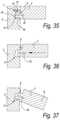
- the aforementioned coupling meansmay be of any kind, however, they are performed such that the panel-shaped elements can be joined together laterally. This latter means that two of such panel-shaped elements can be presented opposite each other with the edge zones provided with profiled parts and, from such position, can be coupled to each other by means of a suitable displacement. This movement may consist of a turning movement and/or a displacement, in which a coupling by means of a snap action is created.
- the coupling meanspreferably comprise a tongue and groove, as well as locking elements, which, in a normal mutual usage position of the panel-shaped elements, counteract the drifting-apart of tongue and groove.
- the inventionrelates to a composed element comprising at least two panel-shaped elements, which each have an edge zone in which coupling means are present in the form of a profiled part respectively extending in the longitudinal direction of the edge zone concerned, as well as each comprise an end face extending transversely to the respective edge zone, wherein said profiled parts allow coupling the panel-shaped elements together in an interlocking manner, with the characteristic that at least one of the panel-shaped elements is provided with a covering at the end face in the form of a strip of covering material, and that the profiled part extending to the same panel element extends continuously through said strip of covering material.
- a less expensive solutionis obtained, however, while still maintaining a certain finish at the front ends of the profiled parts.
- the inventionrelates to a composed element comprising at least two panel-shaped elements, which each have an edge zone in which coupling means are present in the form of a profiled part respectively extending in the longitudinal direction of the edge zone concerned, as well as each comprise an end face extending transversely to the respective edge zone, wherein said profiled parts effect that the panel-shaped elements are coupled together in an interlocking manner, with the characteristic that the profiled part of at least one of the panel-shaped elements extends continuously up to said end face such that at this side a contour of the profiled part is visible and that the composed element comprises an additional element, more particularly a front panel, which, at least in one usage position, is situated in front of said contour and substantially covers the latter and thereby hides it from view.
- said additional elementis a door, for example, a cupboard door, which in closed condition substantially covers that contour.
- the inventionrelates to a composed element in the form of a wall portion or a furniture element, with the characteristic that it comprises at least two panel-shaped elements; that at least one and preferably both of the panel-shaped elements consist of a board formed of at least two structural material layers, a first material and a second material layer, respectively; and that the panel-shaped elements are provided with coupling means in the form of profiled parts, which, in the assembled condition, effect that the panel-shaped elements are coupled together in an interlocking manner.
- This aspectoffers the advantage that by using two structural layers, possibilities are obtained for optimizing the panel-shaped elements.
- one material layermay be tailored to realizing sturdy coupling means therein, whereas the other material layer may be tailored to imparting the panel-shaped element a larger thickness and strength in an economic manner.
- the profiled partsare provided in the board material itself, more particularly by means of a machining cutting treatment, in particular a milling treatment.
- the composed element according to the fourth aspectis characterized in that the panel-shaped elements are connected at an angle by coupling means, wherein the coupling means comprise a tongue and groove integrated into the board material, as well as locking means present at the tongue and groove, which locking means counteract the drifting apart of the tongue and groove, wherein these locking means consist of locking elements, which are situated all along the side of the tongue situated closest to the inner side of the respective corner. Consequently, the locking elements are situated at a certain distance from the outer corner, due to which the risk of tearing off of certain parts under heavy load is minimized.
- such composed element hereinshall be made such that the panel-shaped elements form a corner connection which forms a flush corner at the exterior side, thus, is free from protruding portions.
- the composed elements according to the fourth aspectpreferably utilize a multi-layered board, which further also shows one or more of the following characteristics:
- the first material layeris MDF (Medium Density Fiberboard) or HDF (High Density Fiberboard);
- the second material layeris particle board
- the second material layeris a lightweight wood-based board
- the first material layerhas a smaller thickness than the second material layer
- the first material layerhas a thickness which is smaller than 0.7 times the thickness of the second material layer
- the multi-layered boardconsists, for at least 90% of its total thickness, of said first material layer and said second material layer;
- the first material layer and the second material layerconsist of separate boards which are adhered to each other, more particularly glued to each other;
- the first material layer and second material layerform part of a unitary pressed structure, wherein the first layer preferably is based on wood fibers and the second layer on wood particles;
- the first material layeris situated at the interior side in respect to the second layer.
- the coupling means and pertaining locking elementspreferably are realized at least partially in the first material layer.
- the first, second, third and fourth aspectare aspects which can be applied with panel-shaped elements coupled together in the same plane, as well as with panel-shaped elements coupled together at an angle.
- the inventionrelates to a composed element comprising at least two panel-shaped elements, which consist of a board material and which are connected together at an angle, with the characteristic that the panel-shaped elements are connected by means of coupling means which comprise a tongue and groove substantially made as profiled parts in the board material itself, wherein the tongue has a first side and an opposed second side, and wherein said coupling means further also comprise locking elements preventing, in coupled condition, the drifting apart of the tongue and groove.
- said coupling meansshow one or more of the following characteristics:
- said locking elementsare only present at one side of the tongue, whereas the other side thus is free from locking elements;
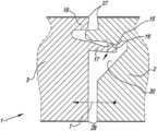
- the locking means or locking elementsconsist of at least one locking part at the tongue and at least one cooperating-therewith locking part in the groove, wherein the locking part is provided at the tongue at an elastically bendable part of the tongue, which part also forms one side of the tongue; said elastic part of the tongue protrudes further in distal direction than the remainder of the tongue; said elastic part is separated from the remainder of the tongue by means of a slot, which preferably is reaching deeper than the plane where the panel-shaped elements adjoin each other; the tongue is split in order to allow a snap movement, wherein the slot in the tongue preferably reaches deeper than the plane where the panel-shaped elements adjoin each other; said locking means are situated at only one side of the tongue, wherein this is the side of the tongue situated closest to the interior side of said corner; the coupling means and locking elements allow coupling by means of a snap movement; the coupling means and locking elements allow coupling by means of a snap movement as well as by means of a turning movement; the tongue is situated at the distal end of a panel-shaped element, in
- such composed elementfurther is characterized in that the panel-shaped elements consist of at least two structural material layers, a first material layer and a second material layer, respectively, wherein this composed element further shows any of the following characteristics:
- the tonguehas a side which is situated in the first material layer and an opposed side which is situated in the second material layer;
- the material of the first material layershows a finer structure than the material of the second material layer, whereas at least one of said locking elements is situated in the first material layer and more particularly is made in one piece therein, which allows an accurate realization of the locking element;
- the material of the first material layershows a finer structure than the material of the second material layer, wherein the locking elements both at the tongue and at the groove comprise a locking element, which both are situated in the first material layer of the panel-shaped element concerned.
- the locking elementsare realized in the finer material, for example, MDF or HDF, the risk is small that torn-off particles would exert a disadvantageous influence on the locking. Also, narrower tolerances can be applied.
- the panel-shaped elements at the exterior side of a corner formed by themadjoin each other in a flush manner, such that the corner concerned is free from protruding panel parts.
- the inventionrelates to a composed element, which is composed at least partially of a set of panel-shaped elements completely surrounding a space, with the characteristic that the panel-shaped elements are coupled to each other entirely around this space by means of coupling means in the form of profiled parts integrated into the edges of the panels, said profiled parts allowing that all these panel-shaped elements can be joined into each other laterally.
- said spaceis surrounded by four panel-shaped elements, which successively are laterally joined into each other by means of coupling means in the form of profiled parts integrated into the edges of these elements and thereby form an element with four corners.
- said four panel-shaped elementspossess profiled parts, which are composed such that the four panel-shaped elements can be joined together in at least one of the following manners:
- the panel-shaped elementscan be joined into each other at three of said four corners at least by means of a turning movement, whereas the panel-shaped elements which are adjacent to each other, at the fourth corner at least can be joined into each other laterally by means of a snap movement; the panel-shaped elements can be joined at all four corners into each other laterally at least by means of a snap movement; three of the four panel-shaped elements can be joined into each other at least at two successive corners by a turning movement, whereas the fourth panel-shaped element can be attached to, more particularly, in between, the other panels at least by means of a snap movement.
- the sixth aspectoffers the advantage of a simple assembly.
- the inventionrelates to a composed element, characterized in that it comprises a basic structure which, at least at three successive sides, is provided with a covering formed by panel-shaped elements, with the characteristic that these panel-shaped elements mutually are connected to each other by means of coupling means.
- a composed elementallows that the covering can easily be provided around the basic structure, due to said coupling means, and as such also is held in its place.
- the panel-shaped elementsconsist of board material, and the coupling means are formed at least by profiled parts formed in the board material itself.
- the basic structuremay consist of any element. It may relate, for example, to a carcass for a piece of kitchen furniture, a refrigerator, for example, a wine storage cupboard, and so on.
- the inventionrelates to a composed element, which is composed of a basic structure formed by a refrigerator, which is provided with a covering at a number of sides, with the characteristic that the covering consists of panel-shaped elements consisting of wood-based board provided with a laminate covering.
- This eighth aspectallows providing for a covering in an inexpensive manner.
- the wood-based boardis, for example, an MDF or HDF board.
- the inventionrelates to a composed element in the form of a wall portion or a furniture element, which comprises at least two panel-shaped elements, with the characteristic that they are connected by means of coupling means making use of a locking element, which is made as an insertion piece in an edge in one of the panel-shaped elements.
- a locking elementwhich is made as an insertion piece in an edge in one of the panel-shaped elements.
- the inventionrelates to a multi-layered board, with the characteristic that it consists of at least two structural material layers, a first material layer and a second material layer, respectively, which both are made as a wood composite and wherein the material of the first material layer shows a finer structure than the material of the second layer.
- a “wood composite”a composition is meant which is at least formed of components on the basis of wood and a binding agent connecting these components to each other. These components consist, for example, of wood particles and/or wood fibers and/or wood flour, also called sawdust.
- wood particles and/or wood fibers and/or wood flouralso called sawdust.
- sawdustwood particles and/or wood fibers and/or wood flour
- a “finer” structurein particular a structure is meant, which, in a cross-section of the first material layer, offers a finer surface than the surface obtained with a cross-section of the second material layer.
- Such “finer” structuremay consist, for example, in that finer wood components are applied in the first material layer and/or that a better filling is used in the first material layer, such that a less porous structure is obtained, and/or in that a higher density is applied in the first material layer.
- This multi-layered boardpreferably has a structure fulfilling one or more of the following possibilities:
- the first layeris formed on the basis of wood fiber material and more particularly consists of MDF or HDF;
- the second layeris formed on the basis of wood particles and more particularly consists of particle board;
- the second layeris made as a light-weight wood-based layer, for example, light-weight wood-based board; such light-weight wood-based layer or board consists of a wood composite in which one or more lighter filling materials are present;
- said light-weight wood-based boardcomprises as a filling material at least foamed synthetic material and/or flax chips or the like;
- the first layerhas a smaller thickness than the second layer
- the first layerhas a thickness which is smaller than 0.7 times the thickness of the second layer
- the multi-layered plateconsists, for at least 90% of its total thickness, of said first layer and said second layer;
- the first and second material layerconsist of particles, more particularly wood particles, however, the first material layer on average comprises more finer wood particles and/or more binding agent than the second material layer;
- the first layer and second layerconsist of separate boards which are adhered against each other, more particularly, glued against each other;
- the first layer and second layerform part of a unitary pressed structure, as a result of which the two layers can be realized in a single operation.
- structural layerslayers have to be understood which, viewed in cross-section, each form an essential component part of the thickness of the composed board. Layers, which thus, for example, are performed exclusively as a skin, such as, for example, a thin layer of finer particles at the surface of the board in order to obtain a smoother surface, can not be considered a structural layer.
- the first and second material layershow thicknesses each being at least 25% and still better at least 30% of the total thickness of the composed board.
- the difference intended by “finer structure”relates to a difference obtained by a production method applied explicitly for this purpose, more particularly by applying mutually different materials, mutually different material blends, or materials in different ratios, whereas a density distribution which is purely the result of, for example, pressing and consolidating a material mass in a press, where, as is known, a larger compression takes place at the surface than in the center, is not considered a “difference” as intended by the invention.
- a board which comprises at least two structural layers, which thus each have a considerable thickness in respect to the total thickness, and wherein the first material layer is formed by a pressed wood composite, whereas the second material layer comprises a pressed composite material of a lesser weightas such also is advantageous, irrespective whether the first material does have or does not have a finer structure than the second material layer.
- the present inventionthus also relates to a board, which is characterized in that it comprises at least two structural material layers, wherein the first material layer thereof is formed by a pressed wood composite, whereas the second material layer comprises a pressed composite material of a lesser weight, more particularly of the light-weight type.
- the first material layerconsists substantially, and still better exclusively, of wood composite, thus of wood components, such as wood particles and/or fibers, which are pressed and are consolidated by means of a binding agent, by which this first material layer, for example, is comparable to or consists of particle board or MDF/HDF board.
- the composite material of the second material layerpreferably is a composite, thus, material particles with binding agent, formed on the basis of one or more materials chosen from the series of:
- wood with foamed synthetic materialfor example, wood particles with foamed synthetic material and/or wood fibers with foamed synthetic material;
- flaxmore particularly flax particles, originating from flax shives
- grassessuch as hay, hemp or elephant grass
- the foamed synthetic materialcan be foamed during the production of the board, as well as already foamed beforehand and can be taken up between the wood components, for example, in the form of foamed particles, for example, granules, prior to pressing the whole to form a board.
- the first material layer and second material layerpreferably form a part of a unitary pressed structure, although it is not excluded to start for each of the two material layers from a separately manufactured board, wherein the respective boards then are attached to each other.
- structural layerslayers have to be understood which, viewed in cross-section, each form an essential component part of the thickness of the composed board. Layers, which thus, for example, are performed exclusively as a skin, such as, for example, a thin layer of finer particles at the surface of the board in order to obtain a smoother surface, can not be considered a structural layer.
- the first and second material layershow thicknesses each being at least 25% and still better at least 30% of the total thickness of the composed board.
- the boards of the tenth as well as of the eleventh aspect, apart from the mentioned two structural material layers,may comprise still other structural material layers.
- the boardswill be performed as sandwich panels, with at least three structural material layers, wherein then preferably two adjacent material layers of the aforementioned three material layers are formed by said first and second material layer.
- each material layerthen may have a relatively large thickness in relation to the total thickness, which is useful when coupling parts have to be realized in one of the material layers.
- the boards of the tenth and eleventh aspectmay be provided with a finish on one or both flat sides, for example, treated with melamine and/or printed and/or lacquered.
- the transition between the first material layer and the second material layermay be gradual.
- the middle of the transitionthen shall be considered the borderline.
- said multi-layered board according to the tenth or eleventh aspectis characterized in that it is made as a panel-shaped element, which, at least at two edges, is provided with coupling means for coupling several of such panel-shaped elements to each other in an interlocking manner, whether or not by the intermediary of provided in between profiled connecting pieces, wherein these coupling means show one or more of the following features:
- the coupling meansallow coupling at least two of such panel-shaped elements to each other in the same plane, preferably directly to each other;
- the coupling meansallow coupling at least two of such panel-shaped elements to each other at an angle, directly or, as further described, by means of intermediary pieces;
- the coupling meansconsist of a tongue and groove, as well as locking elements which, at least in a certain mutual position of the panel-shaped elements, prevent that the one element comes with its tongue out of the groove of the other element; said locking elements are only present at one side of the tongue, whereas the other side thus is free from locking elements;
- the locking meansconsist of at least one locking part at the tongue and at least one cooperating-therewith locking part in the groove, wherein the locking part at the tongue is provided at an elastically bendable part of the tongue, which also forms a side of the tongue; said elastic part of the tongue protrudes farther in distal direction than the remainder of the tongue; said elastic part is separated from the remainder of the tongue by means of a slot; said locking means are situated at only one side of the tongue, wherein this is the side of the tongue situated closest to the inner side of said corner; the tongue comprises a side
- the inventionrelates to a composed element comprising at least two panel-shaped elements, which mutually are at an angle, as well as at least one connecting piece, which can cooperate with both panel-shaped elements, with the characteristic that at least one of the panel-shaped elements comprises an edge zone in which coupling means are present in the form of a profiled part extending in the longitudinal direction of the edge zone concerned; that the connecting piece comprises at least one profiled part extending in the longitudinal direction thereof; and that said profiled parts allow laterally joining the panel-shaped element and the connecting piece into each other in an interlocking manner and in this way coupling them to each other.
- Such composed elementhas the advantage that it is easy to assemble and that the use of small components, such as screws, connecting pins, clamping systems and the like can be excluded for forming the corner connection. Also, it is easy to manufacture.
- the connecting piececan be realized from different materials, at manufacturer's choice, whereby for this purpose another material may be chosen than for the panel-shaped elements.
- the panel-shaped elementsconsist, for example, of laminated wood composite boards, such as laminated particle board or wood fiberboard, or multi-layered boards, such as already described herein above. Also, otherwise-coated wood composite boards are taken into account.
- the connecting piecespreferably are made as profiled laths. They may be formed, for example, by extrusion or by providing the necessary profiles in straight laths by means of a machining treatment, such as a milling process.
- the connecting piecesare MDF, HDF, solid wood, aluminum or synthetic material, more particularly Nylon, PET, PP, PVC and the like.
- the profiled partsmay be provided with a covering, for example, by means of a print and/or one or more lacquer layers and/or by encasing.
- any filmcan be used, for example, paper, PP, PVC, PET, veneer and the like.
- the connecting piecesmay have different lengths. Their final length may correspond to the depth of a piece of furniture or the like applying it, or differ therefrom. For example, it is not excluded to apply short connecting pieces, whereby then, for example, at least two thereof will have to be applied at a distance from each other along a respective edge of a piece of furniture. In such case, these connecting pieces may have a length of several centimeters or even have a length of one centimeter or less.
- the profiled part at the panel-shaped elementsis made in one piece therewith.
- the profiled partspreferably are configured such that the panel-shaped elements and the connecting pieces can be joined into each other at least by means of a snap movement. Still better, they are configured such that, at the location of one and the same connection, they can be joined into each other by turning as well as by snapping, at the assembler's choice.
- the profiled partspreferably apply a tongue and groove connection, wherein the tongue and groove are provided with locking parts or locking elements, which prevent the drifting apart.
- the tonguepreferably is situated at the distal end of the panel-shaped element, whereas the groove is provided in the connecting piece.
- the tongueis split for the purpose of the snap action.
- the slot present in the tongue to this aimextends up to a depth which, in mounted condition, is deeper than up to the plane where the panel-shaped elements adjoins the connecting piece.
- the composed element of the twelfth aspectpreferably is a furniture element.
- Thismay relate to a furniture element of any kind.
- a practical field of applicationis in modular hanging or standing cupboards.
- Another applicationis in kitchen cupboards, for example, for composing basic kitchen modules, which then are further finished by the kitchen installers, for example, by providing thereon front walls, countertops and the like.
- both panel-shaped elements adjoining theretoare coupled to the connecting piece in such manner by means of profiled parts. It is noted that the tongue and groove in a single-fold corner connection preferably are always situated closer to the inner corner than to the outer corner.
- connecting piecescan be applied, which allow a T-connection, a cross connection or a connection in the same plane, such that a plurality of furniture modules can be formed next to each other and one upon the other.
- the connecting piecesare mounted along the corner edges, where side walls have to be coupled with upper walls, lower walls, respectively, of a module. More particularly, it is preferred that the component parts of such module all around between side walls, upper wall and lower wall are coupled in such manner, thus, by means of the connecting pieces.
- the inventionrelates to a composed element, which comprises at least two modules situated next to each other, with side walls, upper walls and lower walls, which are formed by panel-shaped elements, characterized in that the side wall where the modules adjoin each other, is formed by a single common panel-shaped element; that there is a first connecting construction between this common panel-shaped element and the upper walls of the modules; that there is a second connecting construction between this common panel-shaped element and the lower walls of the modules; and that at the location of at least one of said connecting constructions, one of the panel-shaped elements, via a profiled part formed at this panel-shaped element, is coupled directly or indirectly to the other panel-shaped elements.
- the respective modulescan be assembled in a fast manner.
- a separate height adjustment and connection between separate side wallsis no longer necessary.
- spaceis saved, in consideration of the fact that between the modules, only a single common panel-shaped element is required.
- all panel-shaped elements which come together in said connecting constructionsare coupled to each other by means of profiled parts provided in the elements, whether or not by means of intermediate pieces.
- the eleventh aspectis particularly advantageous when building kitchen cupboards, in particular in modules offered as a basis to kitchen builders, which latter then build complete kitchen cupboards from these modules, by providing them, for example, with front panels, countertops, possible additional lateral coverings and a variety of accessories.
- the inventionalso relates to a board, which, over the majority of its thickness, comprises a pressed wood composite, which is at least composed of wood components and a binding agent, with the characteristic that in the wood composite, by means of its composition, a reinforcing layer of a local thickness is formed.
- a “local thickness”it is meant that the reinforcing layer shows a thickness which is smaller than the total thickness of the board and thus, viewed in a cross-section, is present only locally.
- the reinforcing layeris formed in the wood composite, which means that the reinforcing layer is in one piece integrated into the board and that this does not relate to a separate layer applied by gluing or the like between other board-shaped layers formed in advance.
- Such board of the fourteenth aspecthas the advantages that, on the one hand, it can be realized in an economic manner, and, on the other hand, it offers advantageous features in a large number of applications.
- Such boardcan be advantageously applied, for example, when manufacturing furniture panels.
- the furniture panels manufactured thereofthen show, amongst others, an increased bending resistance, due to which, when being applied, for example, as a shelf, they will sag less fast and/or can carry heavier loads.
- the boardis applied in the manufacture of panels which are provided with coupling means formed of the board material, which coupling means comprise locking parts or locking elements, and these coupling means are realized at least partially in the reinforcing layer.
- coupling meansformed of the board material, which coupling means comprise locking parts or locking elements, and these coupling means are realized at least partially in the reinforcing layer.
- a less expensive boardfor example, with a lower density and thus relatively with less wood composite, wherein due to the reinforcing layer, coupling means still can be realized therein, which have a normal or even better strength.
- a practical application thereoffor example, consists in manufacturing panels in MDF, wherein at least in a certain thickness thereof a reinforcing layer is integrated, such that at that location, an increased strength is created in the board, and such MDF board then can be used in many applications as a replacement for a HDF board, which as such is more expensive.
- the inventionis particularly useful with floor panels, furniture panels and ceiling panels, which are provided with coupling means at their edges, which coupling means allow coupling such panels to each other in an interlocking manner, whether directly or indirectly.
- the location of the reinforcing layercan be chosen in function of the application for which the board is used. Also, it is clear that possibly also two or more reinforcing layers can be provided in the board.
- the reinforcing layersubstantially extends over the entire board, preferably relatively uniform. This offers the advantage that, irrespective where a panel is formed from a board, for example, is sawed therefrom, it is always possible to form reinforced coupling means at the edge.
- the board according to the fourteenth aspectpreferably relates to a board of the type obtained by pressing a mat-shaped layer of wood composite, whether or not in combination with other materials, as is usual in the traditional manufacture of particle board and MDF/HDF boards.
- the wood composite which is applied in the board according to the fourteenth aspect of the inventionpreferably consists of wood fibers with a binding agent. More particularly, it is preferred that the wood composite is performed as a MDF or HDF board, in which then the reinforcing layer is integrated.
- the board according to the fourteenth aspectconsists of a particle board with a reinforcing layer integrated therein.
- the reinforcing layermay be performed in different ways.
- the reinforcing layermay be formed, for example, by locally applying wood components, which, at least in one certain direction, offer a higher strength than the remaining wood components.
- An example thereofis a particle board in which a wood fiber layer has been incorporated.
- the wood fiber layerwhich then is comparable, for example, to MDF or HDF, shows a higher tensile strength in the plane of the board than in the portion of the board which is composed of particles.
- it is preferred that the wood fiber layeris situated at one side of the board only or rather is situated in the middle, thus, at a distance from both sides, such in view of forming coupling means in this reinforcing layer.
- the reinforcing layerdoes not necessarily have to consist of wood composite and may also be formed by a reinforcing layer which utilizes other materials.
- a reinforcing layerwhich utilizes other materials.
- itmay be formed by glass fibers, which form a layer as such in between the wood composite, or which are blended with the wood composite over a certain thickness; preferably introduced as loose fiber particles which are consolidated by pressing.
- Another efficient technique of the inventionconsists in realizing the reinforcing layer by means of the applied binding agent.
- the boardis formed such that it comprises more binding agent at the location of the reinforcing layer.
- thismay relate to an additional amount of binding agent of the same binding agent which is applied in the remainder of the board, and/or to an additional amount of another material with a binding effect.
- binding agentswhich can be used in the layer to be reinforced, are elastomers and/or thermoplastics. More particularly, it is preferred that polyurethane is applied, in a non-foamed form, and still in particular thermoplastic polyurethane.
- the reinforcing layermay be provided adjacent to a surface of the board, thus, of the raw board, as well as within the board, thus, at a distance from the two flat sides of the board.
- the reinforcing layerpreferably is realized at that surface.
- the reinforcing layerpreferably is present over that portion of the thickness of the board, where this contributes to a reinforcement in the coupling means in the best way.
- the inventionalso relates to panels which are formed from a board according to the fourteenth aspect of the invention, more particularly panels with coupling means, which are at least partially performed in the reinforcing layer.
- thismay relate to furniture panels, wall or ceiling panels, as well as floor panels.
- the present inventionrelates to a board, which, for the majority of its thickness, is composed of a pressed wood composite, consisting of wood components bonded by a binding agent, characterized in that it is provided, over a local thickness, with a layer of elastomer and/or thermoplastic, more particularly polyurethane or a product on the basis of polyurethane, and more particularly thermoplastic polyurethane.
- a boardwhich, for the majority of its thickness, is composed of a pressed wood composite, consisting of wood components bonded by a binding agent, characterized in that it is provided, over a local thickness, with a layer of elastomer and/or thermoplastic, more particularly polyurethane or a product on the basis of polyurethane, and more particularly thermoplastic polyurethane.
- thisis a layer which forms part of the pressed board itself.
- the elastomer and/or the thermoplastic, and more particularly the polyurethanethus is situated between the wood components and/or the wood components are impregnated therewith.
- the elastomer and/or the thermoplastic, more particularly the polyurethane or the product on the basis of polyurethanemay be added to the wood components either in combination with the usual binding agent of the wood composite, or as a replacement thereof, at the location where the layer concerned has to be formed.
- the wood componentscan consist of particles and/or wood fibers, and such board can be realized, for example, in a similar manner as wood particle boards or wood fiberboards, such as MDF and HDF, wherein then it is started from two wood composites, on the one hand, a wood component which is at least glued with the elastomer and/or the thermoplastic, more particularly the polyurethane or the product on the basis of polyurethane, whether or not combined with other binding agent, and, on the other hand, a wood component which is glued with a binding agent which does not comprise said elastomer and/or the thermoplastic, more particularly the polyurethane or the product on the basis of polyurethane, or does comprise it to a considerably lesser extent.
- a mat consisting of different layerscan be formed by strewing the treated wood components, such that after pressing this mat a board according to the invention is obtained.
- thermoplastic in the board itselfin the form of a layer, more particularly the polyurethane or a product on the basis of polyurethane, and still more particularly thermoplastic polyurethane, are not excluded to achieve a board according to the fifteenth aspect.
- a possibilitymay consist in that the layer is formed by impregnating the upper side of an already formed particle board or wood fiberboard with the respective materials.
- the layer of elastomer and/or thermoplastic, more particularly polyurethane or a product on the basis of polyurethane, and in particular thermoplastic polyurethane,best is situated in the proximity of a surface of the board and more particularly preferably is adjacent to this surface. Consequently, such boards are considered particularly useful as a basic board for realizing floor panels from them, more particularly floor panels having a thin top layer on top of the basic layer of which they consist. As in such applications the respective layer then is directly beneath or at a very small distance beneath the top layer, a clearly observable dampening effect against footfall sound is obtained, which presumably is due to the fact that said layer forms a more or less elastic underlay for the mostly hard top layer.
- the above-mentioned effectis particularly useful with floor panels which are formed of such board and are provided with a laminate layer, in particular DPL (Direct Pressure Laminate).
- the top layeris hard and thin. Due to the hardness, usually an undesired footfall sound is produced when it is walked upon. Due to the fact that the top layer, however, is thin and said dampening layer is situated directly or almost directly underneath, a good dampening effect is obtained.
- there is an improvementsuch as in floor panels having a top layer of HPL (High Pressure Laminate) or a top layer consisting of one or more prints and/or one or more layers of lacquer, such as primers, decorative paint layers, transparent top layers and the like.
- the inventionwill show its usefulness, as the produced footfall sound as such then will be low and moreover is dampened well.
- the layer of elastomer and/or polyurethane, more particularly polyurethane or a product on the basis of polyurethane, and in particular thermoplastic polyurethane,is situated with its upper side preferably not farther than 2 mm and still better not more than 1 millimeter below the surface of the floor panel to be walked on.
- the inventionrelates to floor panels showing the above-mentioned characteristics.
- the inventionrelates to a composed element, which comprises at least two panel-shaped elements, which mutually are at an angle and are coupled by means of a connection, wherein one of the two forms a back part, whereas the other forms a part extending perpendicularly in respect to the back part, with the characteristic that at least one of the panel-shaped elements, for forming said connection, comprises a zone, more particularly an edge zone, at which coupling means are present in the form of a profiled part extending in the longitudinal direction of the respective zone, wherein this profiled part allows that said panel-shaped elements can be joined into each other directly or indirectly in an interlocking manner and in this way can be coupled to each other.
- the profiled part, as well as the portion in which it has to engage, which usually also will consist of a profiled part, hereinpreferably are configured such that the respective panel-shaped elements can be directly or indirectly joined laterally into each other in an interlocking manner.
- laterallyis meant that the panel-shaped elements, from a position in which the respective profiled parts are situated parallel opposite to each other, can be joined into each other, more particularly by means of a turning and/or snap movement, either directly into each other, or by the intermediary of a connecting piece.
- a composed element according to the sixteenth aspect of the inventionoffers the advantage that it is very easy to assemble and that due to the locking connection with the back part, a particularly stable construction is obtained.
- connectionBy an “interlocking” connection, it has to be understood that as soon as the panel-shaped elements are in a coupled condition and in the normal mutual position, they are prevented to come apart from each other.
- Such connectionpreferably is performed as a tongue and groove coupling, at which additional locking elements are present, for example, as already described above in connection with the other aspects.
- connectionextends in height
- the coupling means at the end facesare not visible and thus it is not necessary to apply particular means in order to hide the profiled parts from view at their upwardly directed ends.
- possible shelves or the likepreferably are put on between the side walls and/or intermediate walls by classical support means, such that the end faces of the side panels and/or partitions, which are directed forward, simply can be made straight. In other words, there are no continuous profiled parts in the end faces, which would have to be camouflaged one way or another.
- the sixteenth aspectis particularly advantageous with upright-directed connections, it may also be applied with horizontal connections between a back part and a panel-shaped element, such as between a back part, on the one hand, and a shelf, a bottom plank or a top plank, on the other hand.
- both respective panel-shaped elementsare provided with profiled parts, which then engage directly into each other. This offers the advantage that no separate connecting pieces are necessary and the cost of the construction remains limited.
- the aforementioned panel-shaped elementwhich is made as a back part, can be composed of a plurality of segments, which each as such also can be coupled to each other, whether directly or indirectly, by means of profiled parts.
- one or more lath-shaped connecting piecesare applied, which respectively also may perform a connection with an intermediate wall, preferably also by means of profiled parts, at the connecting pieces and at an edge of the intermediate wall, respectively.
- a particularly practical embodiment of a piece of furniture which is performed according to the sixteenth aspectconsists in that between the side walls and the back part, there are corner connections with profiled parts which are performed directly in the respective panel-shaped elements, whereas for the connections between the back part and the intermediate walls, use is made of connecting pieces.
- embodiments according to the sixteenth aspect of the inventionare particularly suitable for pieces of furniture in the form of a rack with shelves. It is clear that in this application as well as in other applications the term furniture or piece of furniture has to be broadly interpreted and that in this manner, this may relate, amongst others, to pieces of furniture in the form of standing cupboards, hanging cupboards and the like, as well as pieces of furniture in the form of a large assembly, for example, wall cabinets, dressings, large racks, for example, for shops, and the like.
- the sixteenth aspectalso relates to an upright-directed connection as described above, however, wherein the connection provides for a coupling between two panel-shaped elements which may have any shape, and of which thus none of the two necessarily has to form a back part.
- the inventionrelates to a composed element, wherein this composed element comprises at least two panel-shaped elements, which substantially are formed from a board material; wherein said panel-shaped elements are interconnected at an angle by means of coupling means comprising a tongue and a groove, which latter substantially are made as profiled parts in the board material; and wherein said coupling means also comprise locking elements which, in coupled condition, prevent the moving apart of the tongue and groove, with the characteristic that the panel-shaped elements are formed on the basis of board material in the form of particle board consisting of two or more layers, which layers, in respect to the average fineness of the particles, have a different degree of fineness, respectively a basic layer with coarser particles, more particularly chips, and at least one outer layer, or at least a more outward-situated layer, which is of a finer composition than the composition of the basic layer, in other words, with particles, chips, respectively, which on average are finer.
- the tongue and groove as well as the locking elementsare made in one piece as profiled parts in the board material.
- one or more of said locking elementsis, are, respectively, at least partially and preferably substantially, and still better entirely, situated in an outer layer of the particle board.
- the composed elementcomprises a locking element at the tongue, preferably in the form of a projection, wherein this locking element comprises a locking surface, with the characteristic that this locking surface is situated at least partially in the material of the respective outer layer. Still better, the locking element at the tongue is situated entirely or substantially entirely in the material of the respective outer layer. It is clear that hereby, a locking surface is obtained, the surface of which is strong and can be made very smooth. Also, a crumbling away of larger chips at this surface is excluded.
- the composed elementcomprises a locking element at the groove, which locking element has a locking surface, wherein this locking surface is at least partially situated in the material of the respective outer layer, or is situated outside of the outer layer, however, with a portion of this locking surface at least at a distance of less than 2 mm from the transition between the outer layer and the basic layer.
- the locking surfaceis situated outside of the outer layer and thus is situated in the basic layer, however, at a small distance from the outer layer, said distance, as aforementioned, being less than 2 mm, still the advantage is maintained that the material of the outer layer keeps exerting an improved support function when forces are created at the locking surface.
- the locking element at the grooveis situated entirely in the material of the respective outer layer.
- the respective outer layerpreferably has an average thickness between 1 and 5 mm, and still better between 2 and 5 mm.
- the minimum thickness of 1 mm and still better 2 mmoffers the advantage that sufficient stability is offered, whereas the maximum thickness of 5 mm provides for that the particle board is economically viable.
- a tongueshowing one or more of the following characteristics:
- split tonguealso in a composed element according to the seventeenth aspect provides for that, when joining the panel-shaped elements into each other, in particular when snapping them together, the material of the particle board is less extensively loaded than in the case that a non-split tongue would be applied.
- the corner connectionforms an inner and an outer corner
- the tongue and groove, globally seenare situated closer to the inner corner than to the outer corner.
- the seventeenth aspect of the inventionis particularly useful in the case of embodiments in which the tongue is situated at the end face of the respective panel-shaped element, whereas the groove is situated at a lateral surface of the other panel-shaped element concerned.
- the locking elements and locking surfacescan be situated optimally in the material of the respective outer layer concerned.
- particle boardwith a thickness of 12 to 30 mm and still better of 16 to 20 mm and still better of globally 18 mm is used for the board material, as this is a universal thickness, which, in a large number of applications, forms a good compromise between weight and necessary stability for a piece of furniture.
- the particle boardpreferably is realized from classical particle board material, thus, substantially on the basis of wood particles.
- thismay relate to pure wood as well as to recycled wood or a combination thereof.
- weight-reducing componentscomprise one or more materials of the following series: flax shives, particles of foamed synthetic material, peat. It is noted that also different weight-reducing components may be combined in one and the same basic layer.
- the amount of weight-reducing components in the basic layercan be chosen by the manufacturer, in function of the desired quality of the particle board, and in particular in function of the final strength of this particle board. It is clear that in the case of, for example, particles of foamed synthetic material or peat, still a relatively large amount of wood particles will be maintained in the basic layer in order to maintain the necessary strength.
- weight-reducing componentswhich as such are relatively woody, such as flax shives
- flax shivesit is not excluded to form the majority of the particles of the basic layer, or even all particles, of such flax shives.
- the outer layerpreferably still wood particles are used, which are less coarse than the particles of the basic layer.
- the particles of such outer layermay consist of fine chips with average dimensions smaller than those of the chips of the basic layer, as well as may consist of wood flour, also called sawdust, or of a combination of both.
- a stronger gluingwill take place than in the basic layer, in other words, per volume unit in the final product more glue will be applied in the outer layer than in the basic layer.
- Such stronger gluingis beneficial for the reinforcement of said locking parts, locking surfaces, respectively.
- the particle boardis provided with a coating, more particularly a melamine coating.
- a coatingmore particularly a melamine coating.
- Such melamine coatingcontributes to a local hardening of the surface, by which this may have an advantageous influence on the strength of the locking elements. More particularly, it is preferred that, for these reasons, such coating is at least present at the surface in which the groove is provided, and that it extends up to between the coupled panel-shaped elements, with the exception of the location where the groove is situated. In this manner, the direct edge regions at the entrance of the groove are reinforced.
- the inventionrelates to a composed element, wherein this composed element comprises at least two panel-shaped elements, which substantially are formed from a board material; wherein the aforementioned panel-shaped elements are connected to each other at an angle by means of coupling means comprising a tongue and a groove which substantially are realized as profiled parts in the board material; and wherein said coupling means also comprise locking elements which, in coupled condition, prevent the moving apart of tongue and groove, with the characteristic that the panel-shaped elements are formed on the basis of board material in the form of particle board; that the tongue is situated at the end face of the panel-shaped element concerned, whereas the groove is situated at a lateral surface of the panel-shaped element concerned; that at least the particle board comprising the groove is provided with a coating, more particularly a melamine coating; and that this coating is at least present at the surface in which the groove is provided, and that
- the inventionalso relates to a composed element, such as defined above or such as also described in the following, wherein at least one of the panel-shaped elements, and preferably both, is, are, respectively, made of a multi-layered board, such as described here above.
- the inventionrelates to panel-shaped elements which combine one or more characteristics of the various aforementioned aspects at the location of one and the same connection, of course, inasmuch as these characteristics are not contradictory.
- the inventionaims at all possible combinations of such characteristics.
- the inventionrelates to any form of composed element which comprises at least two or more panel-shaped elements, as mentioned above, irrespective of the field of application, and irrespective of the fact whether the composed element substantially consists exclusively of said panel-shaped elements or whether these panel-shaped elements only form a part thereof.
- the inventioncan be applied in any application, it is, for various of the aforementioned aspects, in particular intended for being applied in the sectors of furniture, walls and wall coverings.
- thismay relate, for example, to panel-shaped elements together forming a wall or wall covering, or which together form a large panel of a piece of furniture, such as, for example, a tabletop formed of multiple panel-shaped elements.
- the end facesform the lateral edge of this tabletop.
- thismay relate, for example, to panel-shaped elements forming different sides of a cupboard.
- a tablesuch as a party table; sports table, more particularly a ping-pong table or the like, wherein the tabletop consists of multiple of said coupleable or coupled panel-shaped elements;
- the panel-shaped elementsform at least a vertical and a horizontal wall
- a cupboardhaving a basic structure around which a covering casing is provided, wherein the composed element forms the covering casing or a portion thereof;
- the panel-shaped elementscan consist of parts which systematically have to be coupled one after the other; however, according to a variant, the elements also can form parts of the tabletop situated next to each other as well as one after the other, for example, in the form of four quadrants.
- the inventionalso relates to panel-shaped elements which allow realizing, together with other elements, a composed element according to the invention.
- FIG. 1represents a composed element according to the invention in dismounted condition
- FIGS. 2 and 3at a larger scale, represent views according to arrow F 2 and F 3 , respectively, in FIG. 1 ;
- FIGS. 4 and 5represent sections according to lines IV-IV and V-V, respectively, in FIG. 2 ;
- FIGS. 6 and 7represent sections according to lines VI-VI and VII-VII in FIG. 5 , respectively;
- FIGS. 8 and 9represent sections according to lines VIII-VIII and IX-IX in FIG. 3 ;
- FIGS. 10 and 11represent sections according to lines X-X and XI-XI in FIG. 9 ;
- FIGS. 12 and 13represent sections according to line XII-XII in FIG. 5 and line XIII-XIII in FIG. 8 , respectively;
- FIG. 14in cross-section and in mounted condition, represents the composed element of FIG. 1 ;
- FIGS. 15 and 16represent how the panel-shaped elements of the composed element can be joined
- FIG. 17represents a view on said composed element, on the finished end face thereof
- FIG. 18represents a composed element according to the invention, which is made in the form of a table
- FIGS. 19 and 20represent two variants of panel-shaped parts for realizing a composed element
- FIG. 21represents a composed element according to the invention with two panel-shaped elements coupled at an angle
- FIG. 22 in cross-sectionshows another composed element according to the invention.
- FIG. 23 at a larger scalerepresents the portion indicated by F 23 in FIG. 22 ;
- FIG. 24 in cross-sectionrepresents another composed element according to the invention.
- FIG. 25 at a larger scalerepresents the portion indicated by F 25 in FIG. 24 ;
- FIG. 26represents a front view of the composed element of FIG. 24 ;
- FIG. 27 in cross-sectionrepresents another composed element according to the invention.
- FIGS. 28 and 29represent two panel-shaped elements of the composed element of FIG. 27 ;
- FIG. 30 at a larger scalerepresents the portion indicated by F 30 in FIG. 27 ;
- FIGS. 31 and 32represent two embodiments of a multi-layered board according to the invention.
- FIGS. 33 and 34 in cross section and for two positionsrepresent a corner construction of another composed element according to the invention.
- FIGS. 35 to 37in cross-section and for three conditions, represent a corner construction of still another composed element according to the invention.
- FIGS. 38 , 39 and 40represent composed elements applying corner constructions from FIGS. 35 to 37 ;
- FIG. 41represents a composed element according to the invention, wherein separate connecting pieces are applied at the corners;
- FIG. 42at a larger scale, represents a cross-section according to line XLII-XLII in FIG. 41 ;
- FIG. 43represents a connecting piece from FIG. 41 as such
- FIG. 44in an exploded view, represents a number of component parts of a composed element similar to that of FIG. 41 , but wherein a back is present, too;
- FIGS. 45 and 46illustrate composed elements in exploded view, with various embodiments of connecting pieces
- FIG. 47represents a variant of the connecting piece of FIG. 43 ;
- FIG. 48represents a variant of the embodiment of FIG. 42 ;
- FIG. 49schematically represents another composed element according to the invention.
- FIG. 50represents a portion of a composed element according to the invention, in the form of a corner connection, wherein the panel-shaped elements are provided with a reinforcing layer;
- FIG. 51represents a floor panel which, according to the invention, is provided with a reinforcing layer
- FIGS. 52 and 53schematically represent another two boards, which are realized in accordance with a particular aspect of the invention.
- FIG. 54represents another composed element according to the invention, in the form of a piece of furniture
- FIG. 55represents a cross-section according to line LV-LV in FIG. 54 ;
- FIG. 56represents a variant of the embodiment of FIG. 54 ;
- FIG. 57represents a cross-section according to line LVII-LVII in FIG. 54 ;
- FIG. 58schematically and in exploded view represents a back and two side walls of a composed element according to the invention.
- FIG. 59 in perspective viewrepresents a variant of the embodiment of FIG. 58 ;
- FIG. 60represents a top view from the elements from FIG. 59 ;
- FIGS. 61 to 65represent various variants of the invention, respectively in a top view similar to that of FIG. 60 ;
- FIG. 66represents still another corner connection according to the invention.
- FIG. 67represents another composed element according to the invention.
- FIG. 68represents a cross-section according to line LXVIII-LXVIII in FIG. 67 ;
- FIG. 69represents a cross-section according to line LXIX-LXIX in FIG. 68 ;
- FIG. 70at a larger scale, represents the part indicated by F 70 in FIG. 68 ;
- FIGS. 71 and 72represent two variants of coupling means, which can be applied according to the invention.
- FIGS. 73 to 76represent some other embodiments of the invention.
- FIGS. 1 to 17represent a composed element 1 , as well as the component parts thereof, which is made at least in accordance with the aforementioned first aspect.
- the composed element 1comprises two panel-shaped elements 2 - 3 , which each have an edge zone 4 - 5 in which coupling means 6 - 7 are present in the form of a profiled part 8 - 9 respectively extending in the longitudinal direction of the edge zone 4 - 5 concerned, as well as each comprise at least one end face 10 - 11 extending transversely in respect to the respective edge zone 4 - 5 , wherein said coupling means 6 - 7 , and more particularly the profiled parts 8 - 9 , allow that the panel-shaped elements 2 - 3 can be coupled together in an interlocking manner.
- At least one of the panel-shaped elementsand in this example both panel-shaped elements 2 - 3 , comprises means 12 which hide from view at least a portion of the profiled parts 8 - 9 at the location of the end face 10 , 11 , respectively.
- the coupling means 6 - 7are of such kind that the panel-shaped elements 2 - 3 , as in FIG. 1 , can be presented opposite to each other and can be joined laterally into each other, as will be explained in the following.
- the coupling means 6 - 7preferably comprise a tongue 13 and a groove 14 , as well as locking elements 15 - 16 , which, in a normal mutual usage position of the panel-shaped elements 2 - 3 , counteract the drifting apart of tongue and groove, as can be seen in FIG. 14 , which shows the coupled condition.
- a particular characteristic of the embodiment of FIGS. 1 to 17consists in that the groove 14 is bordered by lips 17 - 18 , one lip 17 of which protrudes outwardly of the actual edge 19 of the panel-shaped element 3 concerned. Further, a recess 20 is provided at the panel-shaped element 2 , which recess, in the coupled condition, offers room for the protruding portion of the lip 17 and, as is evident from FIG. 15 , allows a free turning movement of this protruding portion.
- the aforementioned means 12consist in that at the end faces 10 - 11 a strip of covering material, 21 - 22 , respectively, is provided, which next to said edge zones shows a contour course 23 , 24 , respectively, which differs from the contour course 25 , 26 , respectively, of said profiled parts, which contour courses all are represented in FIG. 17 .
- the contour courses 23 and 24are rectilinear, as a consequence of which a simple finishing is possible.
- the strips of covering material 21 - 22have a contour course at the height of said edge zones which extends between the corner edges 27 - 28 of each respective side edge, such that the covering material does not protrude at its corners, which reduces the risk of being damaged, for example, by breaking off.
- the extremities of the strip-shaped covering material 21 - 22have a rectangular end contour, more particular, as if the panel-shaped elements fit against each other with straight sides, which thus are formed by said straight contour courses 23 and 24 , as well as by the contour lines 29 , 30 , 31 and 32 , which are determined by the corner edges 33 , 34 , 35 and 36 of the panel-shaped elements, where the large surfaces thereof are ending.
- the protruding parts 37 - 38 of the profiled parts at the respective edge zonesare performed up to a distance A from said end face only, or, in other words, are removed up to a distance A.
- the strip of covering materialmay consist of any suitable material.
- an adhered edge stripmore particularly a laminate strip or an ABS strip (acrylonitrile butadiene styrene), which are generally known for use as adhered edge strips.
- a laminate stripoffers the advantage that it is easy to make in the same color and/or with the same pattern as the laminate with which possibly the large surfaces of the panel-shaped elements 2 - 3 are covered.
- An ABS stripoffers the advantage that it is sturdier and will not be damaged as easily.
- Such adherable edge stripcan be applied in a known manner, which usually is performed by rolling such strip, by the intermediary of glue, against the end face to be covered and cutting it off automatically at the end, for example, with a severing cutter. It is noted that such severing cutter 39 simultaneously also may serve for removing the protruding parts 37 - 38 , as aforementioned, up to a distance A from the end face concerned, as a result of which no separate treatment is required to this aim. This treatment is represented schematically in FIGS. 7 and 11 .
- cutting off by means of such severing cutter 39possibly can also be realized at a very slight angle, for example, of 2 degrees, such that this severing cutter, at the location where it penetrates deeper into the panel, is directed somewhat away from the panel. By this, it is avoided that the severing cutter 39 , as a result of possible tolerance deviations, would cut into the flat side of the panel-shaped element concerned.
- the panel-shaped elementspossess a covering at one or both sides.
- Such coveringmay be of any kind and, for example, may be performed in the form of a laminate, for example, of the HPL type or the DPL type.
- other coveringscome into consideration, such as, for example, a foil, a lacquer layer, which as such may or may not be composed of multiple layers.
- thin laminate coverings 40 - 41are represented.
- the panel-shaped elements 2 - 3can be joined together in one or more well-determined ways and possibly also taken apart again.
- the coupling means 6 - 7allow joining the panel-shaped elements 2 and 3 together as desired, with a turning movement as well as with a translation and snap movement.
- the turning movement Wis represented in FIG. 15
- the translation movement Tis illustrated in FIG. 16 .
- the lip 17briefly bends out in order to provide for a snap-effect.
- the coupling means 2 - 3can be performed such, more particularly, have an overlapping design on certain locations, that the panel-shaped elements 2 and 3 are permanently drawn towards each other in the mounted condition, which term also is called “pretension” and as such is known from the sector of floor panels and is described, for example, in the document WO 97/47834.
- FIGS. 1 to 17represent an embodiment wherein the panel-shaped elements 2 - 3 in connected condition are situated in the same plane.
- the inventionis not restricted to such embodiments, but is also applicable to embodiments wherein the panel-shaped elements are connected at an angle, as will become clear from the further-described examples.
- the coupling means 6 - 7also can be provided at two or more sides of a panel-shaped element.
- panel-shaped elementsare applied having complementary coupling means at two opposite edges, for example, the above-described coupling means 6 and 7
- successively a plurality of these elementscan be coupled to each other.
- An example of such coupled panel-shaped elements 42is represented in FIG. 18 , wherein these, together with two end elements 43 , form a tabletop 44 .
- the end elements 43exclusively have coupling means at the longitudinal edges with which they border the elements 42 .
- the elements 42 - 43 in accordance with the inventionare provided with a strip of covering material 45 .
- the outwardly-directed longitudinal edges 46are provided with such covering material.
- the represented tableoffers the advantage that the tabletop is easy to handle and transport in parts. Also, such tabletop can easily be enlarged or shortened by applying more or less elements 42 .
- the inventionis particularly suitable for composing tables of a large format, such as long party tables or sports tables, for example, for playing ping-pong. Such tables thus also offer the advantage that they are easy to store when not in use. It is clear that suitable support structures 48 and legs 49 are provided.
- FIG. 19represents a variant of the invention, wherein said means 12 consist in that the protruding parts 37 - 38 , wherein solely the panel-shaped element 3 with the protruding part 38 is represented here, are shortened over a distance, whereas the recessed portions 50 associated with the profiled parts are filled up at the height of the end face, in this case, 11 , by means of a filling material 51 , as a result of which the respective panel-shaped elements, in this case, the represented element 3 , each obtain a rectilinear corner contour.
- the filling material 51may consist of a filling compound, which is finished flush with the adjoining sides, or of an insertion piece which is provided in the respective recessed portion 50 .
- a further covering of the end face 11possibly may be omitted.
- the filling materialforms a support for this stroke, as then at this location, too, gluing may be provided.
- the use of such filling material 51also offers the advantage that this technique may be applied for lacquered furniture, for example, with lacquered MDF/HDF cupboards.
- FIG. 20schematically represents a variant, wherein the recessed portion of the profile is enlarged to a larger recess 52 , for example, by means of a milling cutter 53 , which is moved over the distance A through the material of the panel-shaped element 3 .
- This techniqueoffers the advantage that the recess can be realized with a rectangular cross-section, which enables performing the insertion piece 51 in a simple manner as a small rectangular block which can be glued into the recess 52 .
- the respective protruding partsin this case, the protruding part 38 , can be removed up to the distance A.
- FIG. 21represents a composed element 1 , or at least a portion thereof, which is at least composed of two panel-shaped elements 2 and 3 , which are coupled to each other at an angle, wherein the whole forms an example of said second as well as said third aspect of the invention.
- the panel-shaped elements 2 and 3are composed in that they are coupled to each other, in this case, turned into each other, by means of profiled parts 8 - 9 in the form of a tongue 13 and a groove 14 .
- the tongue 13is situated at an edge zone 4 at a lateral end face of the panel-shaped element 2 .
- the groove 14is situated at one of the large surfaces of the panel-shaped element 3 , however, in an edge zone 5 thereof, by which thus a zone has to be understood which is situated in the proximity of an edge. In the example, this relates to the zone extending in height over the distance E.
- the panel-shaped elements 2 - 3show end faces 10 - 11 extending perpendicular in respect to the respective edge zones 4 - 5 ; said profiled parts allowing that the panel-shaped elements can be coupled to each other in an interlocking manner; the panel-shaped elements 2 - 3 are provided on the end face with a covering in the form of a strip of covering material 21 , 22 , respectively; and the profiled parts are performed continuously through the aforementioned strips of covering material 21 - 22 .
- an additional element 53is provided, more particularly a front panel, in this case, a door, for example a cupboard door, which, at least in a usage condition G, which in this case is the closed condition of the door, is situated in front of the contours, here generally indicated by reference 54 , of the coupling means and substantially covers them and thereby hides them from view.
- a front panelin this case, a door, for example a cupboard door, which, at least in a usage condition G, which in this case is the closed condition of the door, is situated in front of the contours, here generally indicated by reference 54 , of the coupling means and substantially covers them and thereby hides them from view.
- the above-described panel-shaped elements according to the inventioncan be composed in various manners.
- a simple board of the same or substantially the same materialis applied, for example, a simple MDF board (Medium Density Fiberboard) or HDF board (High Density Fiberboard), or a classical particle board, possibly with finer wood particles at the exterior surfaces.
- a simple boardis meant that only one essential structural material layer is applied, which does not exclude that other thin layers, such as coverings, may be present.
- the panel-shaped elementsconsist of a multi-layered board and then preferably will be realized in accordance with said fourth aspect of the invention.
- FIG. 14a variant is shown by means of the dashed line 55 , wherein the panel-shaped elements 2 - 3 consist of a board formed of at least two structural material layers, a first material layer 56 and a second material layer 57 , respectively.
- the multi-layered board, of which the panel-shaped elements consistmay be composed in various ways, amongst which, amongst others, the following important possibilities:
- the first material layer 56is MDF (Medium Density Fiberboard) or HDF (High Density Fiberboard);
- the second material layer 57is particle board
- the second material layer 57is a light-weight wood-based board, for example, particle board, in which synthetic foam material is incorporated;
- the first material layer 56has a smaller thickness than the second material layer 57 ;
- the first material layer 56has a thickness which is smaller than 0.7 times the thickness of the second material layer 57 ;
- the multi-layered boardconsists, for at least 90% of its total thickness, of said first material layer 56 and said second material layer 57 ;
- the first material layer 56 and the second material 57 layerconsist of separate boards which are adhered to each other, more particularly glued to each other;
- the first material layer 56 and second material layer 57form part of a unitary pressed structure, wherein the first material layer 56 preferably is based on wood fibers and the second material layer 57 on wood particles.
- the coupling means 6 - 7or at least the locking elements 15 - 16 , are situated in the first material layer 56 .
- FIG. 22represents a composed element 1 according to the invention, which is composed of four panel-shaped elements 58 , 59 , 60 and 61 , wherein this relates, for example, to a cupboard, more particularly a suspended cupboard, wherein the panel-shaped elements 58 - 60 form side walls, whereas the panel-shaped elements 59 and 61 form a top wall and bottom wall, respectively.
- the panel-shaped elements 58 and 60substantially consist of a board material with only one structural material layer, preferably MDF or HDF.
- the panel-shaped elements 59 and 61are composed of a composed board with two material layers 56 and 57 , in this case, two board materials glued against each other.
- the material layer 56consists of an MDF or HDF board
- the material layer 57consists of particle board, wherein both material layers are glued against each other.
- the coupling means 6 - 7preferably are performed exclusively in MDF or HDF, whereas the particle board material exclusively serves for creating a larger thickness at a lower cost.
- FIGS. 24 and 25represent a variant, wherein the first material layer 56 of the panel-shaped elements 59 and 61 is situated against the interior sides of the composed element 1 , with the advantage that the coupling means formed therein become situated at a pronounced distance X from the extremities 62 , thereby considerably reducing the risk of tearing off in the corners when the piece of furniture is subjected to a heavy load.
- FIG. 26represents that the end faces of the composed element 1 represented in FIG. 24 also, in accordance with the first aspect of the invention, may be provided with a covering formed by a strip-shaped covering material 63 - 64 - 65 - 66 , by which the actual profiled parts of the coupling means 6 - 7 are hidden from view.
- An important aspectconsists in that one may work with simple rectangular strips, whereas all four corners 67 of each strip in fact are connected to underlying board material and thus are attached thereto. It is clear that the panel-shaped elements 58 - 59 - 60 - 61 , apart from the covering formed by the strip-shaped covering material 63 - 64 - 65 - 66 , can be provided with a covering on other sides, too.
- FIG. 27represents a variant, wherein the panel-shaped elements 58 , 59 , 60 and 61 each are composed of two structural material layers 56 and 57 , in this case, a first structural material layer 56 of MDF or HDF board and a second structural material layer 57 of particle board. Further, the whole is provided with the necessary laminate coverings 68 . On the end faces of the whole, strips of covering material having a simple rectangular shape may be provided, analogous to FIG. 26 , wherein it is clear that it is intended to apply the laminate coverings 68 and the strips of covering material during the manufacture of the panel-shaped elements, thus, prior to joining the panel-shaped elements.
- the construction represented in FIG. 27allows composing the element 1 by turning the respective panel-shaped elements into each other at the location of three corners of the composed element 1 , whereas exclusively the fourth corner has to be effected by means of a snap-connection.
- the panel-shaped element 59is connected to the panel-shaped element 58 by means of a turning movement W 1 .
- the panel-shaped element 60is coupled to the panel-shaped element 59 by means of a turning movement W 2 , wherein this element 60 at the same time is forced somewhat further up into the position P represented in dashed line, by which sufficient space is created for then coupling the panel-shaped element 61 to the panel-shaped element 58 by means of a turning movement W 3 .
- the element 1then can be obtained in the completely assembled form by connecting the panel-shaped element 60 to the panel-shaped element 61 by means of a snap movement S. It is clear that in this manner, the panel-shaped elements easily can be coupled to each other by a user; for example, for composing a cupboard or the like in this manner.
- FIGS. 28 and 29represent that essentially only two designs need to be used for the panel-shaped elements to be applied.
- a tongue 13 and a groove 14are used for the coupling means.
- locking elements 15 and 16are used for the coupling means.
- coupling meansare used showing the following features:
- said locking elements 15 - 16are only present at one side 69 of the tongue 13 , whereas the other side 70 thus is free from locking elements;
- the locking meansconsist of at least one locking part 15 at the tongue 13 and at least one cooperating-therewith locking part 16 in the groove 14 , wherein the locking element 15 is provided on the tongue 13 at an elastically bendable part 71 of the tongue, which at the same time forms a side 69 of the tongue; in distal direction, said elastically bendable part 71 of the tongue protrudes farther than the remainder of the tongue; said elastic part 71 is separated from the remainder of the tongue 13 by means of a slot 72 ; said locking elements are situated on only one side of the tongue, wherein this is the side 69 of the tongue which is situated closest to the inner side of the corner 73 .
- coupling means with one or more of the above-listed characteristicsmay also be applied with panel-shaped elements which can be coupled to each other in the same plane, as well as with panel-shaped elements which as such are composed differently from the represented structure composed of two layers.
- FIGS. 27 to 30also illustrates that, when the panel-shaped elements consist of at least two structural material layers, a first material layer and a second material layer, respectively, then this composed element further may show any of the following characteristics:
- the tonguehas a side 69 which is situated in the first material layer 56 , and an opposite side 70 which is situated in the second material layer 57 ;
- the material of the first material layer 56has a finer structure than the material of the second material layer 57 , whereas at least one of said locking elements 15 - 16 is situated in the first material layer and more particularly is made in one piece therein; the material layer of the first material layer 56 has a finer structure than the material of the second material layer 47 , whereas the locking elements, both at the tongue and at the groove, comprise a locking element 15 , 16 , respectively, which both are situated in the first material layer of the respective panel-shaped element.
- FIGS. 21 to 27 and 30illustrate that according to the invention the panel-shaped elements adjoin each other in a flush manner at the exterior side of a corner formed thereby, such that the respective outer corner is straight and free from protruding panel portions.
- FIG. 30also illustrates once again that the coupling means, which are provided in a large flat side of a panel-shaped element, due to the specific construction can be realized at a proper distance from the edge.
- the groove in FIG. 30is situated at a considerable distance from the upper edge of the panel-shaped element 57 .
- the distance Zwhich is the distance from the exterior side up to the tongue, is more than 1 ⁇ 3 of the thickness TH of the panel-shaped elements.
- the inventionalso relates to a multi-layered board as such, with the characteristic that it consists of at least two material layers, a first material layer and a second material layer, respectively, which both are performed as a wood composite and wherein the material of the first material layer shows a finer structure than the material of the second material layer.
- FIGS. 31 and 32illustrate by means of two examples that various variants are possible.
- FIG. 31represents a construction where the first material layer 56 is formed on the basis of wood fiber material and, for example, consists of MDF board or HDF board, whereas the second layer 57 is formed on the basis of wood particles and more particularly consists of particle board, wherein both boards are glued one onto the other.
- the multi-layered boardmay be provided with a laminate covering 74 on one or both sides.
- other layersmay be provided. For example, one may start from two boards which each are provided with melamine on both sides, an MDF or HDF board and a particle board, respectively, which are glued to each other one upon the other.
- FIG. 32schematically represents a variant, wherein the first material layer 56 and the second material layer 57 form part of a unitary pressed structure.
- Such structuremay be realized by forming, in a production process of particle board, not only a mat of particles to be pressed, however, in combination therewith also incorporating a layer of fibers into the mat, preferably at one side of the mat, and then consolidating the whole in a press. The whole may or may not be provided with a laminate covering 74 .
- FIGS. 33 and 34represent still another composed element 1 illustrating a particular aspect of the invention.
- the composed element 1forms a wall or furniture element and shows the particular characteristic that coupling means 6 - 7 are applied, which utilize a locking element, in this case 16 , which is performed as an insertion piece provided in an edge in one of the panel-shaped elements, in this case, the panel-shaped element 3 .
- this insertion piececonsists of a strip, which is provided with a movable locking portion 75 , which latter can cooperate with a locking element 15 formed at the other panel-shaped element 2 .
- this insertion pieceis formed of a strip which, viewed in cross-section, is made of materials, preferably synthetic material, with different material characteristics. This offers the advantage that different characteristics may be imparted to the component parts thereof, depending on their function. More particularly, certain parts may be made suppler than others.
- the stripapart from the already mentioned locking portion 75 , also is composed of an attachment portion 76 , and a hinge portion 77 situated in between them.
- the locking portion 75 and the attachment portion 76are made of a harder and more rigid synthetic material than the hinge portion 77 , at the one hand, for having the locking portion 75 in coupled condition offer a good locking, and providing the attachment portion in a stable manner into a recess 78 provided for this purpose, and, on the other hand, for having the locking portion move in a supple manner by means of the hinge portion 77 .
- this hinge portion 77does not only possess the function of an hinge, however, also functions as an elastic matter pushing the locking portion 75 , in rest position, with its free extremity outward, up into the condition of FIG. 33 .
- the insertion piecewill be made from a strip formed by means of coextrusion.
- the panel-shaped elements 1 and 2can be coupled simply by, starting from the position in FIG. 33 , pressing them into each other with their tongue 13 and groove 14 , wherein the locking portion 75 then first is turned to the side in order to then be moved outward again and take place behind the locking element 15 , wherein then the locked condition of FIG. 34 is obtained.
- a recess 79may be provided in the longitudinal direction of the profile concerned, which recess may be helpful during the possible uncoupling of the panel-shaped elements 2 and 3 .
- Such recessallows pushing, in coupled condition, a small pin into it, which is sufficiently thick for pushing the locking portion 75 elastically inward, which undoes the locking.
- the front side of the composed element 1is provided with a finish, for example, by means of an adhered edge strip, care may be taken that the recess 79 is accessible exclusively along the back side of the composed element 1 , for example, the back side of a cupboard, such that during normal use the recess is not visible.
- Such coupling with an insertion pieceis particularly suitable for being applied in corner connections for furniture, on the one hand, because a stable connection can be realized therewith, and, on the other hand, because during joining, the tongue simply can be pressed into the groove without exerting torsion forces or the like.
- such composed element 1may possess still other components than the respective panel-shaped elements alone. Amongst these, there may also be components which reinforce the construction formed by the panel-shaped elements, and more particularly bring it into a rigid condition.
- a rectangular backmay be provided between the panel-shaped elements. This back simply may consist of a board which is provided between the panel-shaped elements, for example, during the joining thereof, and which takes place in a groove extending completely along the circumference.
- FIG. 32may be an example thereof, if the material layers 56 and 57 respectively were made of materials as is described in respect to the eleventh aspect.
- FIGS. 35 to 37in cross-section and for three conditions, represent a corner construction of still another composed element according to the invention, which, amongst others, meets the fifth aspect of the invention.
- the coupling means 6 - 7 and more particularly the tongue 13 and groove 14 and the locking elements 15 and 16are made in one piece in the panel-shaped elements 2 - 3 , for example, in the form of profiled parts 8 and 9 formed thereon by means of milling treatments.
- the tongue 13is situated at the outer end of the panel-shaped element 2 , whereas the groove 14 is situated in the side wall of the panel-shaped element 3 .
- Such arrangement and configurationoffers sturdy coupling means when the panel-shaped elements consist of board material which is formed of a composite pressed to boards.
- This embodimentillustrates that the groove 72 can extend deeper than up to the plane where the panel-shaped elements 2 - 3 adjoin each other, which is beneficial for the elasticity in the tongue.
- the panel-shaped elements 2 - 3 of FIGS. 35 - 37preferably consist of MDF or HDF.
- FIGS. 38 , 39 and 40represent a number of composed elements, more particularly furniture elements, which apply corner constructions as shown in FIGS. 35 to 37 .
- FIG. 38shows an arrangement wherein the horizontal panel-shaped elements 2 are provided between the vertical panel-shaped elements 3
- FIG. 39represents a variant, wherein the horizontal panel-shaped elements 3 are provided on top, at the bottom, respectively, against the vertical panel-shaped elements 2
- the one or the other solutionmay be chosen.
- the embodiment of FIG. 38is suitable for hanging cupboards, where it is desired that the horizontal panel-shaped elements 2 at the side edges are not visible.
- the embodiment of FIG. 39in its turn then is more suitable for standing cupboards, wherein the couplings with heavy loads from the top downward only can be pressed tighter into each other and the risk of tearing-off of coupling parts is excluded.
- FIG. 40illustrates that at the same edge zone of a panel-shaped element 3 a plurality of grooves 14 may be present, which allow a coupling in T-connection or crosswise connection of several panel-shaped elements 2 - 3 .
- FIGS. 41 to 43relate to a composed element 1 , in this case, a piece of furniture, which is realized in accordance with the twelfth aspect of the invention.
- This composed element 1does comprise panel-shaped elements 80 , which mutually are at an angle, as well as connecting pieces 81 , which respectively cooperate with the two adjacent panel-shaped elements.
- At least one of the panel-shaped elements 80and in this case even each of the panel-shaped elements 80 , comprises edge zones 4 at which coupling means 6 are present in the form of a profiled part 8 extending in the longitudinal direction of the respective edge zone, whereas the connecting pieces 81 comprise at least one, and in this case respectively two, profiled parts 9 extending in the longitudinal direction thereof, in such a manner that the profiled parts 8 and 9 allow that the panel-shaped elements 80 and the connecting pieces 81 can be joined laterally into each other in an interlocking manner and in this manner the panel-shaped elements 80 can be coupled to each other by the intermediary of the connecting pieces 81 .
- the profiled parts 8 and 9preferably are performed in the form of a tongue 13 and a groove 14 .
- a tongue 13 and groove 14are applied which show one or more of the characteristics which are described in the introduction or in respect to the other embodiments.
- the use of a split tongue 13as described by means of FIGS. 35 to 37 , is useful.
- profiled partsare applied which allow at least that the panel-shaped elements 80 can be provided in the connecting pieces by means of snap action, and still better can be realized such that they can be joined into each other by snapping as well as turning.
- FIG. 43clearly shows that the connecting pieces 81 can be made as laths.
- FIG. 44illustrates how such composed element can be provided with a back part 82 .
- back part 82can be provided in seats 83 , more particularly grooves, in the panel-shaped elements 80 .
- seats 84can be provided in the connecting pieces 81 .
- the back part 82After assembly, the back part 82 automatically stays at its place. Moreover, in this manner it imparts stability to the whole. It is clear that applying a back part in this manner is also possible with all composed elements of the other aspects of the invention.
- connecting piecescan be applied which allow a further connection in the same plane, a T-connection or a crosswise connection, such that a plurality of furniture modules next to and on top of each other can be formed.
- Embodiments of such connecting piecesare represented in FIGS. 45 and 46 and indicated with 81 A, 81 B and 81 C, respectively.
- FIG. 47represents an example of such covering 85 at the outer end of a connecting piece 81 .
- the cooperating profiled parts of a panel-shaped element 80 and a connecting piece 81also can be covered by a front panel, for example, by a door in closed condition.
- FIG. 48represents a variant, wherein the connecting piece 81 is rounded at the outer corner.
- FIG. 49schematically represents an embodiment of the thirteenth aspect of the invention.
- a composed elementwhich comprises at least two modules 86 situated next to each other, with side walls, upper walls and bottom walls, which are formed by panel-shaped elements, in this case 80 and 80 D, characterized in that the side wall where the modules adjoin each other, is formed by a single common panel-shaped element, here 80 D; that there is a first connecting construction 87 between this common panel-shaped element 80 D and the upper walls of the modules 86 ; that there is a second connecting construction between this common panel-shaped element 80 D and the bottom walls of the modules 86 ; and that at the location of at least one of said connecting constructions, one of the panel-shaped elements, via a profiled part formed at this panel-shaped element, is coupled directly or indirectly to the other panel-shaped elements.
- FIG. 49also schematically represents how this can be applied in a piece of kitchen furniture, wherein the necessary legs 89 can be provided under such modules and a countertop 90 can be attached thereto, as well as not represented front parts and other accessories can be attached thereto.
- composition of the composed element of FIG. 40also meets the thirteenth aspect of the invention.
- FIGS. 50 and 51represent panel-shaped elements, which are made of boards 91
- FIGS. 52 and 53represent portions of boards 91 , which each are made in accordance with the fourteenth aspect of the invention and for this purpose are provided with a reinforcing layer 92 integrated into the board 91 .
- FIG. 50this relates to panel-shaped elements 2 - 3 for a piece of furniture or the like, whereas in FIG. 51 a panel-shaped element is represented in the form of a floor panel 93 .
- the reinforcing layer 92is provided over a local thickness, thus, not the total thickness of the board 91 , however, at the location of the coupling means, in this case at least such that the locking elements or locking parts 15 - 16 are situated in this layer 92 and thus are reinforced.
- floor panels which are provided with a top layer 94it also happens that due to continuous strain, tears may occur next to the edges, directly beneath this top layer 94 , in particular with laminate. In such case, it may then be desirable to work with a local reinforcing layer 92 A, which is situated directly or almost directly under the top layer 94 .
- FIG. 52represents a board such as applied in FIG. 50 . Possibly, the board 50 can be coated, for example, with laminate coverings 74 .
- FIG. 53represents a board wherein the reinforcing layer 92 is provided in the center.
- FIGS. 50 to 52also form examples of the fifteenth aspect of the invention, at least when the materials of the board 91 and of the layer 92 , which latter then does not necessarily has to be reinforcing, meet the material requirements of this fifteenth aspect described in the introduction.
- this fifteenth aspectthus shows its advantages in particular with floor panels wherein the layer 92 A is situated directly underneath the top layer 94 , as also is described in greater detail in the introduction.
- FIGS. 54 to 65represent a number of embodiments of the invention, wherein at least the aforementioned sixteenth aspect is applied.
- FIG. 54shows a composed element 1 in the form of a rack, which is composed of a plurality of panel-shaped elements, in this case, a back part 94 , side walls 95 - 96 , a bottom part 97 , a top part 98 and shelves 99 .
- connections 100are realized between the panel-shaped element functioning as back part 94 and the panel-shaped elements functioning as side walls 95 - 96 , due to which the composed element 1 meets the aforementioned sixteenth aspect of the invention described in the introduction.
- the side walls 95 - 96extend perpendicularly in respect to the back part 94 , and both are provided with zones, in this case, edge zones 4 - 5 with profiled parts 8 - 9 allowing a connection.
- profiled parts 8 - 9which are applied in the sixteenth aspect, preferably use is made of a tongue and groove, too, at which locking elements are present.
- profiled parts 8 - 9are represented, which are similar to those of, for example, FIGS. 35 to 37 , wherein use is made of a split tongue, which fits into a groove.
- connections 100which are made according to the sixteenth aspect.
- connection 100thus is equipped with a tongue and groove which shows one or more of the characteristics which were described in respect to preceding tongue and groove connections. These characteristics have been sufficiently described heretofore and thus are not specifically repeated here.
- locking elementswhich are made as an insertion piece, for example, as represented in FIGS. 33 and 34 .
- the back part 94is provided between the side walls 95 and 96 .
- FIGS. 56 and 57represent a variant, wherein the back part 94 extends up to behind the rear edge of the side walls 95 and 96 .
- the connections 100preferably are realized such that the side walls 95 - 96 can be coupled to the back part 94 at least by means of a turning movement, as is indicated in both embodiments by arrows 101 .
- the connections 100preferably are configured such that they do not allow or at least counteract a further turning than into the position in which the side walls 95 - 96 are standing perpendicular or almost perpendicular to the back part 94 .
- By then providing the bottom part 97 and/or the top part 98 and/or the shelves 99 between the side walls 95 - 96for example, by means of classical support means 102 , which here are represented only schematically, the side walls 95 - 96 automatically are prevented from turning back inwards.
- FIG. 58represents a variant, wherein also an intermediate wall 103 is present, which can be coupled to the back part 94 by means of profiled parts 8 and 9 extending in the height. For clarity's sake, the shelves are not depicted.
- FIGS. 59 and 60represent a further variant, wherein the panel-shaped element, which functions as a back part 94 , is composed from a plurality of segments 104 , which are coupled to each other by means of a connecting piece 81 A.
- FIG. 61represents a variant hereof.
- FIGS. 62 to 65illustrate further variants with one and more connecting pieces 81 B, which moreover provide for a coupling with each time an intermediate wall 103 .
- the advantage of such connecting piece 81 Bis that the three panel-shaped elements coming together at their edges, thus, two segments 104 and an intermediate wall 103 , can be coupled to each other in a smooth manner.
- segments 104may be worked with segments 104 , which are all the same for one and the same piece of furniture, which makes it easier for the assembler.
- segments 104which are all the same for one and the same piece of furniture, which makes it easier for the assembler.
- FIGS. 62 and 64form examples hereof.
- connecting piecesfor example, such as the earlier described connecting pieces 81 , at the corners between the back part 94 and the side walls 95 - 96 , however, for simplicity's sake as well as for esthetic purposes, the embodiments without connecting pieces at the corners are preferred.
- the inventionalso relates to panel-shaped elements which are intended for realizing a composed element according to the sixteenth aspect.
- FIG. 66represents another particular embodiment of a corner connection, which, amongst others, fulfills the fifth aspect of the invention.
- the particularity of the embodiment of FIG. 66consists in that the panel-shaped elements 2 - 3 adjoin each other at least partially with a miter joint, whereas they still are connected to each other by means of profiled parts 8 - 9 .
- the connectionshows one or more of the following three characteristics, which here all are applicable:
- the corner edges 105 and 106as well as the corner edges 107 and 108 of the panel-shaped elements 2 - 3 , adjoin each other at the height of the diagonal 109 of the miter; at least a portion 110 of the contact surfaces between the panel-shaped elements 2 - 3 coincides with said diagonal 109 ; the panel-shaped elements 2 - 3 each are finished with a strip of covering material at their end faces, wherein these strips adjoin each other in a miter joint according to a line 111 .
- a particularity of the represented embodimentconsists in that the plane 112 in which the tongue and groove are situated, is not perpendicular to the diagonal 109 , but coincides or approximately coincides with the plane of one of the panel-shaped elements, and, as represented, preferably the plane of the panel-shaped element 2 , which is provided with the tongue.
- Thisallows that, by exerting a force perpendicularly to the flat side of the panel-shaped element 3 , it will automatically be situated in the prolongation of the tongue and groove, and consequently the panel-shaped elements can be joined together in an optimum manner. According to variants, however, it is not excluded to realize the tongue and groove in another direction.
- FIGS. 67 to 69a particular application of the invention is represented, wherein the composed element 1 is a drawer.
- the particularity hereinis that at least two, and in this case even a plurality, of the component parts, more particularly the upright-standing walls, are performed as panel-shaped elements 2 - 3 , which according to the invention are interconnected at an angle by means of coupling means 6 - 7 in the form of a tongue 13 and groove 14 , wherein the coupling means 6 - 7 also comprise locking elements 15 - 16 , which in coupled condition prevent moving the tongue and groove out of each other, i.e. at least prevent simply taking them apart.
- the drawer of the represented exampleis composed of two panel-shaped elements 2 forming the back wall 113 and the front wall 114 , respectively, and two panel-shaped elements 3 forming the two side walls 115 and 116 , respectively, of the drawer.
- the drawercomprises a bottom 117 , which, as represented in FIG. 69 , preferably simply is provided in a groove 118 in the respective panel-shaped elements 2 - 3 .
- the draweralso is provided with a separate front panel 119 , which is attached to the front wall 114 , for example, by means of screws 120 .
- the coupling means 6 - 7in this case consist of profiled parts extending in vertical direction.
- the general configurationpreferably is as depicted in FIG. 68 . More particularly, the tongues 13 are located at the distal extremities of the back wall 113 and front wall 114 , whereas the grooves 14 are situated at the inwardly directed surfaces of the side walls 115 - 116 .
- the advantageis obtained that, when using the drawer and when pulling it out, the force exerted therein then has a direction which is perpendicular to the coupling direction of the tongue and groove, and the force exerted when pulling out a drawer never results in a force forcing the coupling means out of each other.
- a side wallfor example, 116
- the back wall 113 and the front wall 114are attached thereto by respectively providing them, by means of a turning movement, with the pertaining tongue 13 in the respective groove 14 of the side wall 116 .
- the bottom 117from the side where the side wall 115 still has to be provided, can be slid into the grooves 118 of the back wall 113 and the front wall 114 , such until the bottom also comes to sit with an edge in the groove 118 of the side wall 116 .
- the side wall 155is fixed on the still free distal extremities of the back wall 113 and front wall 114 by bringing the respective tongues and grooves into each other by means of a snap effect. This can be performed, for example, by placing the drawer upright, with the side wall 116 at the bottom, and tapping in this position the side wall 115 down onto the then upwardly directed tongues 13 of the back wall 113 and front wall 114 .
- the bottom 117preferably has such dimensions that, when it is sitting at one edge 121 entirely in the groove 118 of the side wall 116 , it will reach, at the opposite edge 122 , to beyond the distal extremities of the tongues 13 which are present there. This excess length is indicated in FIG. 68 by the distance F.
- coupling means 123with which the front panel 119 is fixed on the remainder of the drawer by snapping it on.
- These coupling means 123are schematically represented as an alternative in FIG. 68 .
- mating profiled partsfor example, at the distal foremost extremities of the side walls 115 and 116 and in the back wall of the front panel 119 .
- FIG. 67also shows that the edges of the panel-shaped elements, in particular the upper edges, can be taped with straight strips of covering material, such as laminate strips 124 or the like, such that in accordance with the first aspect of the invention, the profiled parts of the coupling means 6 - 7 are hidden from view.
- a draweras described above, also forms an application of the sixteenth aspect of the invention, as the back wall 113 then also forms a back part as required by this sixteenth aspect.
- the inventionalso relates to drawers in which no coupling, such as aforementioned, with the back wall is applied, but yet couplings according to the invention are applied at other places in the drawer.
- the inventionalso relates to drawers, of which the back wall and the two side walls are interconnected by film hinges at their cooperating extremities, and wherein solely coupling means according to the invention are provided between a front wall and the adjoining side walls.
- FIG. 70at a larger scale, represents the portion indicated by F 70 in FIG. 68 .
- the coupling represented in this figurepreferably fulfills a number of particular features. These features, which hereafter are summarized with reference to FIG. 70 , the majority of which already has been mentioned above or has been represented in the figures, each have to be considered a separate aspect of the invention, however, applied in a corner connection. Thus, these aspects of the invention do not have to be mutually combined. However, all random combinations of two or more features are possible. Also, these aspects of the invention are not restricted to the represented application of the drawer, but can be used in any application of a corner connection between panel-shaped elements.
- the inventionas such also relates to a composed element 1 , which comprises at least two panel-shaped elements 2 - 3 , which are connected to each other at an angle, characterized in that the panel-shaped elements 2 - 3 are connected by means of coupling means 6 - 7 comprising a tongue 13 and groove 14 , which latter are substantially made as profiled parts, preferably in the board material itself, wherein said coupling means 6 - 7 further also comprise locking elements 15 - 16 , which, in coupled condition, prevent the moving apart of tongue and groove, wherein the composed element and more particularly one of the coupling means show one or more of the following features:
- the tongue 13is situated at the distal extremity of a panel-shaped element 2
- the groove 14is situated in the side wall of the other panel-shaped element 3 , in other words, in any of the large surfaces thereof;
- the tongue 13is fitting, by means of a snap connection, in the groove 14 , such by pressing the respective panel-shaped element 2 with the tongue 2 in its plane towards the groove 14 , or vice versa;
- the tongue 13fits into the groove 14 by means of a turning movement
- the tongue 13 and groove 14are configured such that they can be brought into each other by a turning movement as well as by a snap movement via a translation, and this at the assembler's choice;
- the locking element 15 at the tongue 13is situated at the side of the tongue 13 which is directed towards the inner corner;
- the tongue 13is split
- the tongue 13is split, and as a consequence shows two portions 125 and 126 , and only one of these portions, in this case, the portion 125 which also serves as the elastically bendable part 71 , is provided with a locking element 15 ;
- the tongue 13is split and consequently comprises two portions 125 and 126 , and only one of these portions is provided with a locking element 15 , wherein the portion 125 , which comprises the locking element 15 , in distal direction extends farther than the other portion 126 ; the tongue 13 is split and the slot 72 extends up to a greater depth than the basic plane where the panel-shaped elements 2 - 3 adjoin each other; the tongue 13 is split and there is exclusively a locking element 15 present at that portion of the tongue 13 which is situated at the side of the slot directed towards the inner corner, with the advantage that the extremity of the panel-shaped element comprising the groove is not subjected to loads on weak places; the tongue 13 can be snapped into the groove 14 by means of a mutual translation movement, wherein the tongue is split and one of the two portions of the split tongue 13 is provided with a locking element, wherein this portion 125 is elastically bendable; the tongue 13 can be snapped into the groove 14 by means of a mutual translation movement, wherein the tongue 13 is split and one of the two
- the mentioned dimensionspreferably are determined by the basic board, which may or may not be composed, thus, without considering the thickness of a possibly present covering which is present on the basic board, such as the aforementioned laminate coverings 40 - 41 , or the covering generally indicated with reference 128 in FIG. 70 .
- these thicknessesindeed may be included into the dimensions. This latter preferably will be done when the coverings are thicker than 2 mm, as this covering then, so to speak, will serve as a structural component.
- the bent-out elastic partis formed such that the force caused by the bending-out generates, via the locking elements 15 - 16 , generates a force component pulling the panel-shaped element 2 with the tongue permanently into the groove of the panel-shaped element 3 .
- the tongue and/or grooveare at least partially reinforced.
- thisis already represented by means of a layered structure.
- a local reinforcementmay be provided, too.
- FIG. 71represents an example thereof, with the particularity that the bendable portion 125 of the tongue 13 is impregnated with a reinforcing agent 129 , as well as the material portion between the groove 14 and the end face, or thus the extremity 127 , of the panel-shaped element 3 in which the groove is provided, as well as the zone of and around the locking element 16 . It is clear that such reinforcement may occur at only one of these locations, as well as at possible other locations. All these reinforcements have the purpose of avoiding that the respective portions would tear or split off when the corner connection is subjected to excessive forces. Such reinforcement also can contribute to an increase of the elasticity in the portion 125 .
- Such reinforcementmay be realized, for example, by means of an impregnation with a reinforcing agent, such as polyurethane, before or after the milling of the actual profiles.
- a reinforcing agentsuch as polyurethane
- the tongue 13 and groove 14preferably are manufactured in one piece from the board material of the panel-shaped elements 2 - 3 , for example, by means of the necessary milling treatments.
- thisdoes not exclude that certain portions of the tongue and/or groove and/or of the edge zone in which they are situated, are realized of another material.
- a possibility thereofis represented in FIG. 72 , wherein in the respective edge zone an insertion piece 130 is integrated, which consists of another material than the panel-shaped element 2 and of which the tongue 13 is formed.
- Such insertion piece 130consists, for example, of synthetic material, such as PVC and the like, whereas the actual board material, for example, is wood-based and consists, for example, of particle board or HDF or MDF.
- the insertion piecemay consist of MDF or HDF, whereas the board material consists of particle board.
- Such insertion piece 130can be formed beforehand and be mounted at the edge of the panel-shaped element, however, it may also be realized, as schematically represented in FIG. 72 , by laying on a material mass 131 along the respective edge, for example, by extrusion, and forming, after it has solidified, the respective coupling means, in this case the tongue 13 , there from, for example, by means of a milling treatment. Therein, the material mass 131 can be held at the panel-shaped element by an adhesive effect and/or due to the fact that it gets stuck behind the edges of a groove 132 .
- the panel-shaped elementswhich comprise the groove, on the one hand, and the tongue, on the other hand.
- the panel-shaped element which comprises the least critical coupling part, which mostly is the groovethen can be made from a board material of lower quality, which makes it possible to employ a less expensive material for this purpose.
- both the tongue and the groovecan be made in one piece of particle board, even in the case of a classic particle board.
- a brittle couplingmight be created, wherein chips might come loose from the tongue and interfere with good coupling.
- the inventorhas found that in corner connections still good results were obtained.
- a split tongueis extra advantageous, because both portions then are more movable when loosened portions get between the surfaces of tongue and groove, and/or because the slot forms a space in which loosened particles can be collected without having an interfering function.
- a reinforcing agentfor example, such as represented in FIG. 71 .
- a composed element according to the inventioncomprises one or more panels, wherein such panel as such comprises, at two opposite edge zones, a coupling means, as aforementioned, in the form of a tongue, and preferably further comprises no coupling means in the form of a groove. Also, it is preferred that other panels then comprise only coupling means in the form of a groove.
- the panel-shaped elementscan be optimized better and realized more simply. For example, then, as aforementioned, a panel-shaped element exclusively having grooves can be made of particle board, and, due to the absence of tongues at this element, there is no necessity of switching to a more expensive material, such as MDF or HDF.
- FIG. 73represents another particular embodiment of a tongue 13 , which is locally reinforced. In this embodiment, two reinforcement possibilities are applied.
- the first possibilityprovides a reinforcement 133 of the tongue surface, in this case at the side which is facing away from the inner corner and is facing away from the locking element.
- This reinforcementmay consist of synthetic material or glue, which is applied on the respective surface and still better is taken up at least partially and preferably entirely in the surface.
- the application thereofmay be performed in any manner, for example, by means of jetting on, spraying on or even by applying this synthetic material or glue on the surface by means of a transfer tape or the like, which comprises this synthetic material or glue, wherein this synthetic material or glue then is transferred onto the surface of the tongue by unrolling the tape against the surface of the tongue.
- a press-on treatmentmay be performed in order to effect that this material penetrates into the surface of the tongue.
- a machine after-treatment of the surfacemay be provided, for example, by means of re-profiling by means of a finishing cutter.
- the second possibilityis a reinforcement 134 in the form of an elastic filler in the slot 72 , possibly in a widened portion 135 , which to this aim is formed in the slot.
- such fillermay consist of foamed glue, more particularly foamed “hot melt” glue.
- reinforcements 133 and 134are particularly useful for particle board and actually offer solutions for usefully applying particle board, which is less expensive than MDF and HDF, in such composed elements.
- FIG. 74a portion of a composed element according to the seventeenth aspect of the invention is represented.
- This composed elementcomprises at least two panel-shaped elements 2 - 3 , which substantially are formed from a board material; wherein these panel-shaped elements are interconnected at an angle by means of coupling means comprising a tongue 13 and a groove 14 , which substantially are realized as profiled parts in the board material; and wherein said coupling means also comprise locking elements 15 - 16 , which, in coupled condition, prevent the moving apart of tongue and groove, with the particularity that the panel-shaped elements are formed on the basis of board material in the form of particle board consisting of two or more layers, which layers, in respect to the average fineness of the particles, have a different degree of fineness, amongst which at least one outer layer 136 , 137 , respectively, and each time at least a basic layer 138 , 139 , respectively.
- the basic layer 138 , 139is realized on the basis of coarser particles, more particularly chips, whereas each respective outer layer 136 - 137 , or at least more outwardly situated layer, has a finer composition than the composition of the basic layer 138 - 139 , in other words, with particles, chips, respectively, which on average are finer. It is clear that hereby, the advantages mentioned in the introduction are obtained. As becomes clear from the further description, in the represented corner connection in particular the outer layers 136 and 137 situated at the sides of the inner corner are of importance. However, it is preferred that particle board is used which is symmetrically constructed and thus also at the other sides comprises outer layers 140 and 141 of a finer composition than the basic layer 138 , 139 , respectively.
- such outer layermay be realized as a relatively thin layer and thus in fact functions as a kind of skin.
- the inventorhas found that such outer layer, however small the thickness thereof may be, already contributes considerably to a better coupling.
- FIG. 74shows that the tongue 13 and groove 14 as well as the locking elements 15 and 16 are made in one piece as profiled parts in the board material.
- both locking elements 15 and 16are realized at least partially, and in this case even entirely, in an outer layer 136 , 137 , respectively.
- the locking element 15 over its entire height HLconsists of the material of the outer layer 136 , as well as over its entire length, thus, in the horizontal direction in FIG. 74 . More particularly, it is even preferred herein that, as illustrated, by means of the material of the layer 136 a continuous connection remains present between this locking element 15 and the remainder of the layer 136 . Thus, the transition 144 between the outer layer 136 and the basic layer 138 extends continuously through the tongue 13 up to the distal end thereof.
- the locking element 15 at the tongue 13is performed in the form of a projection and has a locking surface 142 , which in this case thus is situated entirely in the material of the respective outer layer 136 , which allows an even finish.
- the locking element 16 at the groove 14is situated entirely in the material of the respective outer layer 137 .
- the locking element 16is situated over its entire length LL in the material of the outer layer 137 .
- the locking element 16 at the groove 14also has a locking surface 143 , which is situated at least partially, and in this case entirely, in the material of the respective outer layer 137 .
- the locking surfacemay also be situated outside of the outer layer 137 , however, with a portion of this locking surface 143 at least at a distance of less than 2 mm from the transition 145 between the outer layer 137 and the basic layer 139 . According to this embodiment, this means that the locking surface 143 is situated at the right hand side at a distance from the transition 145 . When this distance remains limited to said 2 mm, the material of the outer layer 137 keeps exerting a useful supporting influence.
- Said outer layersform, as it were, a skin.
- the average thickness of these outer layers or skinwhich is indicated by DS, preferably is situated between 1 and 5 mm and still better between 2 and 5 mm.
- transitions 144 - 145 - 146 - 147are represented as rectilinear, however, in reality such transition is somewhat irregular, and such outer layer gradually merges into the basic layer.
- transitionin a real product, thus, the average location through the transition zone has to be understood.
- outer layer 137also forms a stable support edge 148 at the entrance of the groove 14 .
- the tongueis split
- the tongueis split and thereby divided into two portions 125 - 126 , wherein only one portion 125 comprises a locking element 15 ;
- the tongueis split and thereby divided into two portions, wherein only one portion 125 comprises a locking element 15 and this portion 125 protrudes farther than the other portion 126 ;
- the tongueis split and the slot 72 extends deeper than the plane on which the tongue is situated;
- the corner connectionforms an inner and an outer corner and the tongue 13 and groove 14 , globally seen, are situated closer to the inner corner than to the outer corner;
- the tongue 13is situated at the front end of the respective panel-shaped element 2 , whereas the groove 14 is situated at a lateral surface of the respective panel-shaped element 3 ;
- the coupling meansallow a connection by means of a turning movement as well as by means of a snap movement.
- the particle boardis provided with a coating, more particularly a melamine coating.
- a coatingmore particularly a melamine coating.
- such coatingis at least present at the surface in which the groove is provided, and that the latter extends up to between the coupled panel-shaped elements, with the exception of the location where the groove is situated. In this manner, the direct edge regions at the entrance of the groove are reinforced.
- the difference in fineness among the particles of the basic layer and the outer layeris at least a visually discernible difference.
- itrelates to a difference as already applied in many particle boards as such.
- the basic layer per weight unitwill comprise a relatively large amount of chips which are larger than 2.5 mm, whereas such outer layer comprises a relatively large amount of chips having smaller dimensions.
- both panel-shaped elements 2 and 3preferably are realized from the same particle board.
- panel-shaped elementsare made in accordance therewith, and the other is realized in another manner.
- panel-shaped elementsmay be used which are realized according to the seventeenth aspect, however, which indeed are mutually connected by the intermediary of a connecting piece, such as the aforementioned connecting piece 81 .
- FIG. 75shows a variant of an embodiment with a non-split tongue 13 .
- non-split embodimentalso allows for a connection, for example, in particle board, however, that considerably large forces must be exerted during joining in the case that the connection must be realized by a snap movement, thereby increasing the damage risk. Also, pulling such panel-shaped elements out of each other, thus, without turning, is very difficult and is accompanied by a large damage risk.
- the designercan determine the amount of force which is necessary for moving the panel-shaped elements by a snap movement into each other and possibly also out of each other. In this manner, it may possibly also be provided for that the required force during snapping together is not excessively large and that snapping into each other simply is possible by manual pressing on, without requiring any tools.
- FIG. 76also represents that it is not excluded to provide the tongue 13 at both sides with a locking element 15 , 149 , respectively, although this is less recommended in certain embodiments, as then the risk increases that the portion 150 bordering the groove 14 will tear off.
- the groove 14which becomes clear, amongst others, from the examples of the FIGS. 73 to 76 , as well as of many embodiments already represented above, increases in depth from the side situated farthest from the inner corner towards the side situated closest to the inner corner. For example, in FIG. 74 the groove 14 is deeper at the location of the portion 125 than at the location of the portion 126 .
- the bottom wall of the groovepreferably has the shape of a fluent line and preferably also fluently merges into the sidewalls of the groove, all in order to reduce the risk of tearing in and further tearing off.
- a “connection at an angle”must be seen broadly. This may relate to solely a corner connection, as illustrated in FIG. 74 , but it may also relate to a T-connection, wherein then, for example, in FIG. 74 the panel-shaped element 3 extends further in height, or to a cross connection. Couplings according to the invention may also be applied, for example, for interconnecting furniture panels in the middle of a piece of furniture, and thus not only at a corner, for example, in order to provide a stable connection with side walls by means of shelves.
- corner connectionsare suitable in particular for realizing connections at 90 degrees, however, it is not excluded to apply them also for connections at angles differing from 90 degrees.
- panel-shaped elementswhich are provided with a laminate covering
- any other panel-shaped elementssuch as, for example, panels covered with veneer, multi-layered panels, panels made as so-called “engineered wood”, panels provided with any covering, and so on.
- Another general characteristicconsists in that, when a composed element according to the invention comprises four panel-shaped panels all around, which respectively can be joined into each other by means of coupling means according to the invention, wherein thus four connections are realized in the corners, then at least one of the connections allows joining by means of a snap connection. More particularly, it is preferred that at least two of the other connections allow joining by turning. In the most preferred embodiment, at least two connections situated at the same panel-shaped element can be performed at least by turning, whereas the two opposite connections can be realized at least by a translation and snap movement.
- the panel-shaped elements 2 - 3 of such composed elementare manufactured of wood fiberboard of the type such as MDF, however, with a low density, which means an average density of less than 600 kg per cubic meter, also called Low Density Fiberboard, and preferably even less than 550 kg per cubic meter.
- MDFwood fiberboard
- a low densitywhich means an average density of less than 600 kg per cubic meter, also called Low Density Fiberboard, and preferably even less than 550 kg per cubic meter.
- a “composed element”an element has to be understood which comprises two or more elements, more particularly panel-shaped elements, which already are composed, as well as comprises elements which are not yet composed, however, which are intended for being composed.
Landscapes
- Engineering & Computer Science (AREA)
- Architecture (AREA)
- General Engineering & Computer Science (AREA)
- Life Sciences & Earth Sciences (AREA)
- Wood Science & Technology (AREA)
- Mechanical Engineering (AREA)
- Civil Engineering (AREA)
- Structural Engineering (AREA)
- Manufacturing & Machinery (AREA)
- Forests & Forestry (AREA)
- Panels For Use In Building Construction (AREA)
- Finishing Walls (AREA)
- Laminated Bodies (AREA)
- Furniture Connections (AREA)
- Assembled Shelves (AREA)
- Veneer Processing And Manufacture Of Plywood (AREA)
- Connection Of Plates (AREA)
- Burglar Alarm Systems (AREA)
- Battery Mounting, Suspending (AREA)
- Floor Finish (AREA)
Abstract
Description
said elastic part of the tongue protrudes further in distal direction than the remainder of the tongue;
said elastic part is separated from the remainder of the tongue by means of a slot, which preferably is reaching deeper than the plane where the panel-shaped elements adjoin each other;
the tongue is split in order to allow a snap movement, wherein the slot in the tongue preferably reaches deeper than the plane where the panel-shaped elements adjoin each other; said locking means are situated at only one side of the tongue, wherein this is the side of the tongue situated closest to the interior side of said corner;
the coupling means and locking elements allow coupling by means of a snap movement; the coupling means and locking elements allow coupling by means of a snap movement as well as by means of a turning movement;
the tongue is situated at the distal end of a panel-shaped element, in other words, on the end side thereof, whereas the groove is situated at the side wall of the other panel-shaped element; the panel-shaped elements are realized from board material of pressed and consolidated wood components, such as particle board or wood fiberboard, for example, MDF or HDF, wherein the coupling means comprise a tongue which extends distally in the plane of the pertaining panel-shaped element, whereas the groove extends perpendicularly to the plane of the panel-shaped element in which it is provided.
the material of the first material layer shows a finer structure than the material of the second material layer, wherein the locking elements both at the tongue and at the groove comprise a locking element, which both are situated in the first material layer of the panel-shaped element concerned.
the panel-shaped elements can be joined at all four corners into each other laterally at least by means of a snap movement;
three of the four panel-shaped elements can be joined into each other at least at two successive corners by a turning movement, whereas the fourth panel-shaped element can be attached to, more particularly, in between, the other panels at least by means of a snap movement.
said locking elements are only present at one side of the tongue, whereas the other side thus is free from locking elements;
the locking means consist of at least one locking part at the tongue and at least one cooperating-therewith locking part in the groove, wherein the locking part at the tongue is provided at an elastically bendable part of the tongue, which also forms a side of the tongue; said elastic part of the tongue protrudes farther in distal direction than the remainder of the tongue;
said elastic part is separated from the remainder of the tongue by means of a slot; said locking means are situated at only one side of the tongue, wherein this is the side of the tongue situated closest to the inner side of said corner;
the tongue comprises a side which is situated in the first material layer and an opposed side which is situated in the second material layer;
at least one of the aforementioned locking elements is situated in the first material layer and more particularly is made in one piece therewith;
said locking elements, at the tongue as well as at the groove, both are situated in the first material layer;
the entire tongue and groove, in which by the groove at least the directed towards each other flanks of the groove are intended, as well as the pertaining locking elements are realized in the material of the first material layer.
in distal direction, said elastically
said
the material layer of the
the panel-shaped elements2-3 each are finished with a strip of covering material at their end faces, wherein these strips adjoin each other in a miter joint according to a line111.
the
the
the
the
the
the distance Z at which the tongue is situated from the side of the panel-shaped element which is located at the inner corner, is larger than ⅓ of the total thickness TH of the respective panel-shaped
the depth DG of the
the
the thickness of the panel-shaped
the
the
the coupling means are applied for realizing a corner connection between vertically extending panel-shaped elements;
in the coupled condition, one or more spaces are present between the periphery of the tongue and the wall of the groove, with the advantage that possible interfering particles can be pushed away in these.
Claims (14)
Priority Applications (3)
| Application Number | Priority Date | Filing Date | Title |
|---|---|---|---|
| US17/329,789US11788568B2 (en) | 2008-12-17 | 2021-05-25 | Composed element, multi-layered board and panel-shaped element for forming this composed element |
| US18/450,114US12123441B2 (en) | 2008-12-17 | 2023-08-15 | Composed element, multi-layered board and panel-shaped element for forming this composed element |
| US18/797,040US20240392821A1 (en) | 2008-12-17 | 2024-08-07 | Composed element, multi-layered board and panel-shaped element for forming this composed element |
Applications Claiming Priority (12)
| Application Number | Priority Date | Filing Date | Title |
|---|---|---|---|
| BE2008/0677 | 2008-12-17 | ||
| BE2008/0677ABE1018389A3 (en) | 2008-12-17 | 2008-12-17 | COMPOSITE ELEMENT, MULTI-LAYER PLATE AND PANEL-SHAPED ELEMENT FOR FORMING SUCH COMPOSITE ELEMENT. |
| US17559609P | 2009-05-05 | 2009-05-05 | |
| DE202009008825UDE202009008825U1 (en) | 2008-12-17 | 2009-06-26 | Composite element, multilayer panel and panel-shaped member for molding such composite element |
| DE202009008825.1 | 2009-06-26 | ||
| WOPCT/IB2009/054812 | 2009-10-29 | ||
| PCT/IB2009/054812WO2010070472A2 (en) | 2008-12-17 | 2009-10-29 | Composed element, multi -layered board and panel-shaped element for forming this composed element |
| IBPCT/IB2009/054812 | 2009-10-29 | ||
| PCT/IB2009/055816WO2010070605A2 (en) | 2008-12-17 | 2009-12-17 | Composed element, multi-layered board and panel-shaped element for forming this composed element |
| US201113140618A | 2011-06-17 | 2011-06-17 | |
| US15/638,698US11085475B2 (en) | 2008-12-17 | 2017-06-30 | Composed element, multi-layered board and panel-shaped element for forming this composed element |
| US17/329,789US11788568B2 (en) | 2008-12-17 | 2021-05-25 | Composed element, multi-layered board and panel-shaped element for forming this composed element |
Related Parent Applications (1)
| Application Number | Title | Priority Date | Filing Date |
|---|---|---|---|
| US15/638,698ContinuationUS11085475B2 (en) | 2008-12-17 | 2017-06-30 | Composed element, multi-layered board and panel-shaped element for forming this composed element |
Related Child Applications (1)
| Application Number | Title | Priority Date | Filing Date |
|---|---|---|---|
| US18/450,114ContinuationUS12123441B2 (en) | 2008-12-17 | 2023-08-15 | Composed element, multi-layered board and panel-shaped element for forming this composed element |
Publications (2)
| Publication Number | Publication Date |
|---|---|
| US20210277924A1 US20210277924A1 (en) | 2021-09-09 |
| US11788568B2true US11788568B2 (en) | 2023-10-17 |
Family
ID=41180779
Family Applications (13)
| Application Number | Title | Priority Date | Filing Date |
|---|---|---|---|
| US13/140,590ActiveUS9175703B2 (en) | 2008-12-17 | 2009-10-29 | Composed element, multi-layered board and panel-shaped element for forming this composed element |
| US13/140,618Active2031-06-19US9695856B2 (en) | 2008-12-17 | 2009-12-17 | Composed element, multi-layered board and panel-shaped element for forming this composed element |
| US14/324,504ActiveUS9347470B2 (en) | 2008-12-17 | 2014-07-07 | Composed element, multi-layered board and panel-shaped element for forming this composed element |
| US15/145,324ActiveUS9797427B2 (en) | 2008-12-17 | 2016-05-03 | Composed element, multi-layered board and panel-shaped element for forming this composed element |
| US15/638,698Expired - Fee RelatedUS11085475B2 (en) | 2008-12-17 | 2017-06-30 | Composed element, multi-layered board and panel-shaped element for forming this composed element |
| US15/700,958ActiveUS10323670B2 (en) | 2008-12-17 | 2017-09-11 | Composed element, multi-layered board and panel-shaped element for forming this composed element |
| US16/401,421ActiveUS10731689B2 (en) | 2008-12-17 | 2019-05-02 | Composed element, multi-layered board and panel-shaped element for forming this composed element |
| US16/911,893ActiveUS10935063B2 (en) | 2008-12-17 | 2020-06-25 | Composed element, multi-layered board and panel-shaped element for forming this composed element |
| US17/156,190ActiveUS11319977B2 (en) | 2008-12-17 | 2021-01-22 | Composed element, multi-layered board and panel-shaped element for forming this composed element |
| US17/329,789Active2030-01-18US11788568B2 (en) | 2008-12-17 | 2021-05-25 | Composed element, multi-layered board and panel-shaped element for forming this composed element |
| US17/697,344AbandonedUS20220299058A1 (en) | 2008-12-17 | 2022-03-17 | Composed element, multi-layered board and panel-shaped element for forming this composed element |
| US18/450,114ActiveUS12123441B2 (en) | 2008-12-17 | 2023-08-15 | Composed element, multi-layered board and panel-shaped element for forming this composed element |
| US18/797,040PendingUS20240392821A1 (en) | 2008-12-17 | 2024-08-07 | Composed element, multi-layered board and panel-shaped element for forming this composed element |
Family Applications Before (9)
| Application Number | Title | Priority Date | Filing Date |
|---|---|---|---|
| US13/140,590ActiveUS9175703B2 (en) | 2008-12-17 | 2009-10-29 | Composed element, multi-layered board and panel-shaped element for forming this composed element |
| US13/140,618Active2031-06-19US9695856B2 (en) | 2008-12-17 | 2009-12-17 | Composed element, multi-layered board and panel-shaped element for forming this composed element |
| US14/324,504ActiveUS9347470B2 (en) | 2008-12-17 | 2014-07-07 | Composed element, multi-layered board and panel-shaped element for forming this composed element |
| US15/145,324ActiveUS9797427B2 (en) | 2008-12-17 | 2016-05-03 | Composed element, multi-layered board and panel-shaped element for forming this composed element |
| US15/638,698Expired - Fee RelatedUS11085475B2 (en) | 2008-12-17 | 2017-06-30 | Composed element, multi-layered board and panel-shaped element for forming this composed element |
| US15/700,958ActiveUS10323670B2 (en) | 2008-12-17 | 2017-09-11 | Composed element, multi-layered board and panel-shaped element for forming this composed element |
| US16/401,421ActiveUS10731689B2 (en) | 2008-12-17 | 2019-05-02 | Composed element, multi-layered board and panel-shaped element for forming this composed element |
| US16/911,893ActiveUS10935063B2 (en) | 2008-12-17 | 2020-06-25 | Composed element, multi-layered board and panel-shaped element for forming this composed element |
| US17/156,190ActiveUS11319977B2 (en) | 2008-12-17 | 2021-01-22 | Composed element, multi-layered board and panel-shaped element for forming this composed element |
Family Applications After (3)
| Application Number | Title | Priority Date | Filing Date |
|---|---|---|---|
| US17/697,344AbandonedUS20220299058A1 (en) | 2008-12-17 | 2022-03-17 | Composed element, multi-layered board and panel-shaped element for forming this composed element |
| US18/450,114ActiveUS12123441B2 (en) | 2008-12-17 | 2023-08-15 | Composed element, multi-layered board and panel-shaped element for forming this composed element |
| US18/797,040PendingUS20240392821A1 (en) | 2008-12-17 | 2024-08-07 | Composed element, multi-layered board and panel-shaped element for forming this composed element |
Country Status (35)
| Country | Link |
|---|---|
| US (13) | US9175703B2 (en) |
| EP (7) | EP3800308B1 (en) |
| JP (1) | JP5788328B2 (en) |
| KR (7) | KR20110094328A (en) |
| CN (6) | CN103932510A (en) |
| AU (1) | AU2009329212B2 (en) |
| BE (1) | BE1018389A3 (en) |
| BR (2) | BRPI0923024B1 (en) |
| CA (4) | CA3112646A1 (en) |
| CL (1) | CL2011001437A1 (en) |
| CO (1) | CO6331407A2 (en) |
| CR (1) | CR20110345A (en) |
| DE (2) | DE202009008825U1 (en) |
| DK (2) | DK2378921T4 (en) |
| EA (1) | EA031226B1 (en) |
| EC (1) | ECSP11011141A (en) |
| EG (1) | EG26336A (en) |
| ES (1) | ES2467674T5 (en) |
| GE (1) | GEP20156391B (en) |
| HR (1) | HRP20140438T1 (en) |
| IL (1) | IL213591A (en) |
| MA (1) | MA33168B1 (en) |
| MX (2) | MX366680B (en) |
| MY (3) | MY188337A (en) |
| NZ (1) | NZ592659A (en) |
| PE (1) | PE20120564A1 (en) |
| PL (3) | PL2378921T5 (en) |
| PT (1) | PT2378921E (en) |
| RU (1) | RU2541279C2 (en) |
| SG (1) | SG171089A1 (en) |
| SI (1) | SI2378921T1 (en) |
| TN (1) | TN2011000215A1 (en) |
| UA (1) | UA105643C2 (en) |
| WO (2) | WO2010070472A2 (en) |
| ZA (1) | ZA201103232B (en) |
Cited By (2)
| Publication number | Priority date | Publication date | Assignee | Title |
|---|---|---|---|---|
| US12297649B2 (en) | 2022-10-27 | 2025-05-13 | Primesource Building Products, Inc. | Deck clip |
| US12442198B2 (en) | 2024-04-18 | 2025-10-14 | Primesource Building Products, Inc. | Deck clip |
Families Citing this family (169)
| Publication number | Priority date | Publication date | Assignee | Title |
|---|---|---|---|---|
| MY152779A (en) | 2008-01-31 | 2014-11-28 | Valinge Innovation Ab | Mechanical locking of floor panels, methods to install and uninstall panels, a method and an equipment to produce the locking system, a method to connect a displaceable tongue to a panel and a tongue blank |
| US8112967B2 (en) | 2008-05-15 | 2012-02-14 | Valinge Innovation Ab | Mechanical locking of floor panels |
| BE1018389A3 (en) | 2008-12-17 | 2010-10-05 | Unilin Bvba | COMPOSITE ELEMENT, MULTI-LAYER PLATE AND PANEL-SHAPED ELEMENT FOR FORMING SUCH COMPOSITE ELEMENT. |
| WO2010087752A1 (en) | 2009-01-30 | 2010-08-05 | Välinge Innovation Belgium BVBA | Mechanical lockings of floor panels and a tongue blank |
| US8956071B2 (en)* | 2009-02-12 | 2015-02-17 | Moss Holding Company | Quick release joint system for assembling frames |
| BR112012016569A2 (en) | 2010-01-12 | 2016-04-05 | Vaelinge Innovation Ab | mechanical locking system for floor panels |
| CA2786680C (en) | 2010-02-04 | 2018-06-12 | Vaelinge Innovation Ab | Mechanical locking system for floor panels and a tongue therefore |
| JP4897902B2 (en)* | 2010-03-05 | 2012-03-14 | スガツネ工業株式会社 | Shelf receiving device and shelf holder |
| EP2377684A1 (en)* | 2010-04-08 | 2011-10-19 | Johns Manville Europe GmbH | New compound materials, method for their manufacture and application thereof for floors |
| CN102844506B (en) | 2010-04-15 | 2015-08-12 | 巴尔特利奥-斯巴诺吕克斯股份公司 | floor components |
| KR101899170B1 (en)* | 2010-06-03 | 2018-09-14 | 유니린 비브이비에이 | Composed element and corner connection applied herewith |
| BE1019361A5 (en) | 2010-06-03 | 2012-06-05 | Unilin Bvba | COMPOSED ELEMENT. |
| EP2575542B1 (en) | 2010-06-03 | 2021-03-10 | Unilin, BV | Composed element and corner connection applied herewith |
| EP2455648B1 (en)* | 2010-11-23 | 2019-01-09 | Ecotherm Austria GmbH | Linking element for container insulations |
| BE1019701A5 (en)* | 2010-12-13 | 2012-10-02 | Unilin Bvba | DOOR, AND FURNITURE THAT CONTAINS SUCH DOOR. |
| DK2481848T3 (en)* | 2011-02-01 | 2015-12-14 | Ivc Nv | Process for making a plate-shaped product and plate-shaped product made thereby |
| US8806832B2 (en)* | 2011-03-18 | 2014-08-19 | Inotec Global Limited | Vertical joint system and associated surface covering system |
| BE1019891A5 (en) | 2011-03-28 | 2013-02-05 | Unilin Bvba | COMPOSITIONED ELEMENT AND BACK WALL CONSTRUCTION APPLIED HEREIN. |
| UA109938C2 (en) | 2011-05-06 | 2015-10-26 | MECHANICAL LOCKING SYSTEM FOR CONSTRUCTION PANELS | |
| BE1020044A5 (en)* | 2011-06-29 | 2013-04-02 | Unilin Bvba | TRAY, TRAY CONSTRUCTION AND METHOD FOR MANUFACTURING A TRAY. |
| UA114715C2 (en) | 2011-07-05 | 2017-07-25 | Сералок Інновейшн Аб | Mechanical locking of floor panels with a glued tongue |
| US9725912B2 (en) | 2011-07-11 | 2017-08-08 | Ceraloc Innovation Ab | Mechanical locking system for floor panels |
| US8650826B2 (en) | 2011-07-19 | 2014-02-18 | Valinge Flooring Technology Ab | Mechanical locking system for floor panels |
| US8857126B2 (en) | 2011-08-15 | 2014-10-14 | Valinge Flooring Technology Ab | Mechanical locking system for floor panels |
| US8769905B2 (en) | 2011-08-15 | 2014-07-08 | Valinge Flooring Technology Ab | Mechanical locking system for floor panels |
| US8763340B2 (en) | 2011-08-15 | 2014-07-01 | Valinge Flooring Technology Ab | Mechanical locking system for floor panels |
| BE1020453A3 (en)* | 2011-12-01 | 2013-10-01 | Unilin Bvba | FURNITURE AND METHOD FOR MANUFACTURING FURNITURE. |
| BE1020305A5 (en) | 2011-12-05 | 2013-07-02 | Unilin Bvba | PACKED SET OF PANELS. |
| DE102011057023B4 (en) | 2011-12-23 | 2017-11-02 | Guido Schulte | Glueless body |
| DE102011057018B4 (en) | 2011-12-23 | 2017-11-02 | Guido Schulte | Glueless body |
| DE102012105219A1 (en)* | 2011-12-23 | 2013-06-27 | Guido Schulte | Glueless body |
| BE1022209B1 (en)* | 2012-01-12 | 2016-03-01 | I.V.C. N.V. | FLOOR PANEL |
| BE1020495A4 (en) | 2012-02-08 | 2013-11-05 | Unilin Bvba | COMPOSED ELEMENT AND CORNER CONNECTION APPLIED HEREIN. |
| WO2013121320A1 (en) | 2012-02-13 | 2013-08-22 | Unilin, Bvba | Method for manufacturing a drawer |
| US8596013B2 (en) | 2012-04-04 | 2013-12-03 | Valinge Innovation Ab | Building panel with a mechanical locking system |
| US9216541B2 (en) | 2012-04-04 | 2015-12-22 | Valinge Innovation Ab | Method for producing a mechanical locking system for building panels |
| DE102012103831A1 (en) | 2012-05-02 | 2013-11-07 | Guido Schulte | Corner connection of two components |
| US8985514B2 (en)* | 2012-06-20 | 2015-03-24 | The Boeing Company | Composite structural panels and aircraft fuselages |
| CN102715740A (en)* | 2012-07-13 | 2012-10-10 | 江苏永发医用设备有限公司 | Medical bedside table body of assembled structure |
| CA2831529C (en)* | 2012-10-29 | 2017-02-28 | Madison T. J. Sawatzky | Laminate concrete panels for use as countertops or the like |
| PL2923012T3 (en) | 2012-11-22 | 2020-04-30 | Ceraloc Innovation Ab | Mechanical locking system for floor panels |
| DE102013100352A1 (en) | 2013-01-14 | 2014-07-17 | Guido Schulte | Glueless panel composite and method for glueless joining of two panel elements |
| DE102013100481B4 (en)* | 2013-01-17 | 2015-08-06 | Wolfgang Fünfgeld | Modular system, in particular for furniture, exhibition structures or the like and furniture or exhibition construction |
| US20140331584A1 (en)* | 2013-05-13 | 2014-11-13 | Victor Amend | Dividing wall panel and method of manufacturing same |
| PT3014034T (en) | 2013-06-27 | 2019-11-29 | Vaelinge Innovation Ab | Building panel with a mechanical locking system |
| DE202014100090U1 (en) | 2013-08-09 | 2014-11-13 | Paul Henke Gmbh & Co. Kg | Connection fitting for furniture parts |
| US9726210B2 (en) | 2013-09-16 | 2017-08-08 | Valinge Innovation Ab | Assembled product and a method of assembling the product |
| CN109854597B (en) | 2013-09-16 | 2021-03-19 | 瓦林格创新股份有限公司 | Combination product and method for assembling the same |
| US9151060B2 (en)* | 2013-10-22 | 2015-10-06 | Stramos Oy | Construction block |
| US20150110554A1 (en)* | 2013-10-22 | 2015-04-23 | Plastic Safety Systems, Inc. | Portable roadway warning device |
| MX376334B (en)* | 2014-01-10 | 2025-03-07 | Vaelinge Innovation Ab | FURNITURE BOARD. |
| UA119763C2 (en)* | 2014-01-10 | 2019-08-12 | Велінге Інновейшн Аб | ASSEMBLED PRODUCT AND METHOD OF ASSEMBLING THE PRODUCT |
| MY175150A (en)* | 2014-01-10 | 2020-06-11 | Valinge Innovation Ab | Panels comprising a mechanical locking device and an assembled product comprising the panels |
| DE202014100089U1 (en) | 2014-01-10 | 2015-04-13 | Paul Henke Gmbh & Co. Kg | Connection fitting for furniture parts |
| US9714672B2 (en) | 2014-01-10 | 2017-07-25 | Valinge Innovation Ab | Panels comprising a mechanical locking device and an assembled product comprising the panels |
| EP3122958B1 (en) | 2014-03-24 | 2022-01-26 | Flooring Industries Limited, SARL | A set of mutually lockable panels |
| US9260870B2 (en) | 2014-03-24 | 2016-02-16 | Ivc N.V. | Set of mutually lockable panels |
| JP2015188509A (en)* | 2014-03-27 | 2015-11-02 | 株式会社岡村製作所 | Panel unit and furniture system |
| EP3851684A1 (en) | 2014-05-09 | 2021-07-21 | Välinge Innovation AB | Mechanical locking system for building panels |
| CN106460394B (en) | 2014-05-14 | 2019-09-17 | 瓦林格创新股份有限公司 | Building panel with mechanical locking system |
| US10246883B2 (en) | 2014-05-14 | 2019-04-02 | Valinge Innovation Ab | Building panel with a mechanical locking system |
| BR112016029151A2 (en) | 2014-07-11 | 2017-08-22 | Vaelinge Innovation Ab | panel with a slider |
| DE102014110124A1 (en) | 2014-07-18 | 2016-01-21 | Guido Schulte | Tongue and Federeckverbindung of two components under inclusion of an additional tongue and groove connector |
| DE102014110123B4 (en) | 2014-07-18 | 2025-04-24 | Guido Schulte | Corner connection of two components with a gap |
| WO2016046800A1 (en) | 2014-09-26 | 2016-03-31 | Flooring Industries Limited, Sarl | Floor panel for forming a floor covering and method for manufacturing a floor panel. |
| BE1022484B1 (en) | 2014-10-17 | 2016-05-03 | Unilin Bvba | COMPOSITIONED ELEMENT, DRAWER AND METHOD FOR MANUFACTURING SUCH DRAWER |
| BE1022567B1 (en) | 2014-10-31 | 2016-06-07 | Unilin Bvba | Furniture |
| JP6900313B2 (en) | 2014-11-27 | 2021-07-07 | ベーリンゲ、イノベイション、アクチボラグVaelinge Innovation Ab | Mechanical locking system for floor panels |
| ES2758673T3 (en) | 2014-12-19 | 2020-05-06 | Vaelinge Innovation Ab | Panels comprising a mechanical locking device |
| DE102015206713A1 (en)* | 2015-04-15 | 2016-10-20 | Airbus Operations Gmbh | Kit and method for housing construction of a vehicle cabin monument |
| EP3285620A4 (en) | 2015-04-21 | 2018-11-14 | Välinge Innovation AB | Panel with a slider |
| KR20170141223A (en)* | 2015-04-30 | 2017-12-22 | 뵈린게 이노베이션 에이비이 | A panel having a fastening device |
| WO2016180980A1 (en)* | 2015-05-13 | 2016-11-17 | Falquon Gmbh | Panel and method for laying panels |
| KR101587044B1 (en)* | 2015-07-08 | 2016-01-20 | 주식회사 티마운트 | Ping-pong table upper surface with increasing ping-pong ball rotation and method for manufacturing of the same |
| EP3329065A1 (en)* | 2015-07-27 | 2018-06-06 | Hamberger Industriewerke GmbH | Panel |
| UA125554C2 (en) | 2015-09-22 | 2022-04-20 | Велінге Інновейшн Аб | Panels comprising a mechanical locking device and an assembled product comprising the panels |
| MX2018006522A (en) | 2015-12-03 | 2018-11-29 | Vaelinge Innovation Ab | Panels comprising a mechanical locking device and an assembled product comprising the panels. |
| DE102015226598B4 (en)* | 2015-12-22 | 2017-08-31 | Tobias Petri | Method for building a furniture assembly and associated furniture assembly |
| EP3407765B1 (en)* | 2016-01-26 | 2021-03-03 | Välinge Innovation AB | Panels comprising a mechanical locking device to obtain a furniture product |
| KR20180109957A (en) | 2016-02-04 | 2018-10-08 | 뵈린게 이노베이션 에이비이 | Set of panels for assembled products |
| CA3011703A1 (en) | 2016-02-09 | 2017-08-17 | Valinge Innovation Ab | Element and method for providing dismantling groove |
| US10415613B2 (en) | 2016-02-09 | 2019-09-17 | Valinge Innovation Ab | Set of panel-shaped elements for a composed element |
| JP6921834B2 (en)* | 2016-02-15 | 2021-08-18 | ベーリンゲ、イノベイション、アクチボラグVaelinge Innovation Ab | How to form panels for furniture products |
| BE1024157B1 (en)* | 2016-04-25 | 2017-11-24 | Flooring Industries Limited, Sarl | Set of floor panels and method for installing this set of floor panels. |
| KR101800119B1 (en) | 2016-05-18 | 2017-11-21 | 박형선 | Combination structure of timber frame |
| CN105852436B (en)* | 2016-05-20 | 2018-04-03 | 宁波欧琳厨具有限公司 | A kind of smooth cabinet of fixing compact |
| CN105901970B (en)* | 2016-05-20 | 2018-03-13 | 宁波欧琳厨具有限公司 | A kind of multi-functional welding integral cabinet |
| CN105852432B (en)* | 2016-05-20 | 2018-03-13 | 宁波欧琳厨具有限公司 | A kind of Height Adjustable cabinet of backboard |
| CN105852433B (en)* | 2016-05-20 | 2018-04-03 | 宁波欧琳厨具有限公司 | A kind of cabinet |
| US20190330843A1 (en)* | 2016-06-19 | 2019-10-31 | Marcel Eric MOROKUTTI | Construction apparatus and method |
| IT201600070959A1 (en)* | 2016-07-07 | 2018-01-07 | Leonardo Srl | JUNCTION TO INTERCHANGE A FIRST AND SECOND PANEL OF FURNITURE AND OTHER FURNITURE ITEMS |
| BR102016019163B1 (en)* | 2016-08-18 | 2021-10-13 | André Cavalcante De Albuquerque | FURNITURE MANUFACTURING PROCESS USING POLYMER EXTRUDED PROFILES |
| CN117703894A (en) | 2016-10-27 | 2024-03-15 | 瓦林格创新股份有限公司 | Panel assembly with mechanical locking means |
| KR102611209B1 (en)* | 2016-10-31 | 2023-12-08 | 김종원 | Drawer of furniture |
| CN206414030U (en)* | 2016-11-11 | 2017-08-18 | 黄刚 | Storing keeps away calamity Multifunctional cabinet |
| WO2018098532A1 (en)* | 2016-11-30 | 2018-06-07 | Sourcecorp Victoria Pty Ltd | A system for joining interlocking panels |
| US10765204B2 (en)* | 2016-12-20 | 2020-09-08 | Terry Store-Age S.P.A. | Assemblable modular wardrobe made of plastic material |
| US12084869B2 (en)* | 2017-04-18 | 2024-09-10 | Louisiana-Pacific Corp. | Self-spacing lap siding product |
| EP3612739A4 (en) | 2017-04-20 | 2020-12-23 | Välinge Innovation AB | PLATES FOR AN ASSEMBLED PRODUCT |
| RU2690331C2 (en)* | 2017-05-10 | 2019-05-31 | Денис Андреевич Гранаткин | Connection of parts from sheet material of non-uniform thickness by tenon-groove connection method |
| HRP20230089T1 (en) | 2017-05-15 | 2023-03-17 | Välinge Innovation AB | Elements and a locking device for an assembled product |
| EP3645806B1 (en) | 2017-06-27 | 2024-10-30 | Unilin, BV | Wall or ceiling panel and wall or ceiling assembly |
| CN207620259U (en)* | 2017-07-19 | 2018-07-17 | 上海协承昌化工有限公司 | A kind of plank and its decoration panel |
| CN109386123A (en)* | 2017-08-10 | 2019-02-26 | 浙江菱格木业有限公司 | For re-packing for installation floor |
| US11261893B2 (en) | 2017-08-15 | 2022-03-01 | National Nail Corp. | Hidden fastener unit and related method of use |
| USD850897S1 (en) | 2018-05-18 | 2019-06-11 | National Nail Corp. | Fastener positioning device |
| US12234654B2 (en) | 2017-08-15 | 2025-02-25 | National Nail Corp. | Hidden fastener unit and related method of use |
| US11898357B2 (en) | 2017-08-15 | 2024-02-13 | National Nail Corp. | Hidden fastener unit and related method of use |
| USD924044S1 (en) | 2019-11-20 | 2021-07-06 | National Nail Corp. | Fastener positioning device |
| USD945870S1 (en) | 2020-11-17 | 2022-03-15 | National Nail Corp. | Fastener positioning device |
| US10378218B2 (en) | 2017-08-15 | 2019-08-13 | National Nail Corp. | Hidden fastener unit and related method of use |
| USD853829S1 (en) | 2018-06-01 | 2019-07-16 | National Nail Corp. | Fastener positioning device |
| US11111679B2 (en) | 2017-08-15 | 2021-09-07 | National Nail Corp. | Hidden fastener unit and related method of use |
| US11149445B2 (en) | 2017-08-15 | 2021-10-19 | National Nail Corp. | Hidden fastener unit and related method of use |
| USD1019365S1 (en) | 2023-05-31 | 2024-03-26 | National Nail Corp. | Fastener positioning device |
| RU2740868C1 (en) | 2017-12-22 | 2021-01-21 | Велинге Инновейшн Аб | Set of panels, method of their assembling and locking device for furniture product |
| CN111465773B (en) | 2017-12-22 | 2021-11-02 | 瓦林格创新股份有限公司 | Panel set, method for assembling the panel set and locking device for furniture products |
| EP4324999A3 (en) | 2018-01-11 | 2024-05-15 | Unilin, BV | Set of floor panels and method for installing this set of floor panels |
| EP3745922A4 (en)* | 2018-01-30 | 2021-11-03 | Pålskog Teknik AB | CONE ARRANGEMENT AND METHOD OF MANUFACTURING SUCH AN ARRANGEMENT |
| CA3093012A1 (en) | 2018-03-06 | 2019-09-12 | Clickstair Pty Ltd | Furniture system |
| MY204146A (en) | 2018-03-23 | 2024-08-09 | Vlinge Innovation Ab | Panels comprising a mechanical locking device and an assembled product comprising the panels |
| EP3543427A1 (en)* | 2018-03-23 | 2019-09-25 | Franz Eschlbeck | Panel, second panel, panel connection and method of manufacturing the panel connection |
| SE543558C2 (en)* | 2018-03-27 | 2021-03-30 | Ikea Supply Ag | A laminated building material for use in furniture elements and a method for its production |
| JP7046672B2 (en)* | 2018-03-28 | 2022-04-04 | 株式会社河合楽器製作所 | Mounting structure for long piano parts |
| US11448252B2 (en) | 2018-04-18 | 2022-09-20 | Valinge Innovation Ab | Set of panels with a mechanical locking device |
| PL3781822T3 (en)* | 2018-04-18 | 2024-11-18 | Välinge Innovation AB | Set of panels with a mechanical locking device |
| EA202092409A1 (en) | 2018-04-18 | 2021-02-26 | Велинге Инновейшн Аб | SYMMETRIC TONGUE AND T-SHAPED KNOT |
| PL3781824T3 (en) | 2018-04-18 | 2024-06-24 | Välinge Innovation AB | Set of panels with a mechanical locking device |
| US11614114B2 (en) | 2018-04-19 | 2023-03-28 | Valinge Innovation Ab | Panels for an assembled product |
| US20200008574A1 (en)* | 2018-06-20 | 2020-01-09 | Adeptus IP, LLC | Ready-to-assemble furniture kit, construction and method of assembly |
| LT6702B (en) | 2018-06-26 | 2020-02-25 | UAB "Adolesa" | Structural furniture element |
| US11629507B2 (en)* | 2018-08-01 | 2023-04-18 | Xylo Technologies Ag | Method for the production of panels from a board, press plate, method for the production of a board and board |
| US20230076157A1 (en)* | 2018-08-24 | 2023-03-09 | Mcs Industries, Inc. | Wall hanging system |
| PT3844407T (en) | 2018-08-30 | 2024-06-18 | Vaelinge Innovation Ab | Set of panels with a mechanical locking device |
| DE102018122907A1 (en)* | 2018-09-18 | 2020-03-19 | Bulthaup Gmbh & Co. Kg | Plate and method of making a plate |
| AT522092B1 (en)* | 2018-12-20 | 2020-08-15 | Blum Gmbh Julius | Furniture drive |
| CN109853356A (en)* | 2018-12-25 | 2019-06-07 | 浙江中隧桥波形钢腹板有限公司 | Quick assembled type waveform board member, corrugated sheet Rapid Combination case and its assembly method |
| USD850898S1 (en) | 2019-01-07 | 2019-06-11 | National Nail Corp. | Fastener positioning device |
| US11060302B2 (en) | 2019-01-10 | 2021-07-13 | Valinge Innovation Ab | Unlocking system for panels |
| EP3918213A1 (en)* | 2019-01-29 | 2021-12-08 | Vilox AB | Joining system for furniture parts |
| JP3236228U (en)* | 2019-02-26 | 2022-02-07 | レヨ ホールディングス エスディーエヌ ビーエイチディー | Panel assembly |
| DE202019101580U1 (en)* | 2019-03-20 | 2020-06-30 | Otto Fuchs - Kommanditgesellschaft - | Profile network |
| EP3718437A1 (en)* | 2019-04-05 | 2020-10-07 | Välinge Innovation AB | Method for assembling a piece of furniture |
| US11260619B2 (en)* | 2019-04-25 | 2022-03-01 | The Boeing Company | Composite panel systems and methods |
| EP3735861A1 (en) | 2019-05-09 | 2020-11-11 | Flooring Industries Limited, SARL | Set of at least two panels with coupling means |
| IT201900010050A1 (en)* | 2019-06-25 | 2020-12-25 | Poliedro Innovazione Srl | WOODEN SURFACE COVERING FOR PRE-EXISTING AND NON-EXISTING STRUCTURES |
| SE544408C2 (en)* | 2019-12-18 | 2022-05-10 | Vilox Ab | Joining system for furniture, furniture portion comprising the joining system and method for manufacturing the joining element of the joining system |
| WO2021165769A1 (en) | 2020-02-17 | 2021-08-26 | Flooring Industries Limited, Sarl | Board, method for manufacturing a board and a panel comprising such board material |
| US20230078831A1 (en) | 2020-02-17 | 2023-03-16 | Flooring Industries Limited, Sarl | Board, method for manufacturing a board and a panel comprising such board material |
| CN115867171A (en)* | 2020-07-17 | 2023-03-28 | 瓦林格创新股份有限公司 | Mechanical locking system for panels |
| KR102233242B1 (en) | 2020-08-04 | 2021-03-29 | 주식회사 미다스엔지니어링 | Decoration panel |
| CN111972880B (en)* | 2020-09-23 | 2024-09-10 | 广西新高盛薄型建陶有限公司 | Middle island platform with composite board |
| EP4248796A4 (en)* | 2020-12-21 | 2024-05-08 | Kinki University | EASY TO ASSEMBLE BED, MULTI-PURPOSE TABLE AND LIGHTWEIGHT TRANSPORT PLATE |
| US11731252B2 (en) | 2021-01-29 | 2023-08-22 | National Nail Corp. | Screw guide and related method of use |
| US20220288810A1 (en)* | 2021-03-12 | 2022-09-15 | Ideal Cabinet Operations, Ltd. | Outdoor cabinet |
| BE1029288B1 (en) | 2021-04-09 | 2022-11-17 | Decruy Nv | IMPROVED FURNITURE COMPOSITION, ESPECIALLY A DRAWER |
| US20220338632A1 (en)* | 2021-04-27 | 2022-10-27 | Charles William Burgett | Construction panel with modular lattice/composite design |
| US11346111B1 (en)* | 2021-05-14 | 2022-05-31 | Superior Aluminum Products, Inc. | Decorative column assembly |
| NL1044047B1 (en)* | 2021-06-01 | 2022-12-14 | M Quint Holding Leersum B V | Furniture and method of building it |
| BE1029431B1 (en)* | 2021-06-14 | 2023-05-03 | Findes | A COMPOSITION CONTAINING A BAT ATTACHED TO A FLAT SUPPORT |
| US11773600B2 (en) | 2021-07-23 | 2023-10-03 | Bath Systems, LLC | Wall paneling system |
| EP4413272A4 (en)* | 2021-10-04 | 2025-05-14 | Välinge Innovation AB | MECHANICAL CONNECTION ARRANGEMENT FOR PANELS |
| RU2769563C1 (en)* | 2021-10-18 | 2022-04-04 | Вячеслав Игоревич Кададов | Table top manufacturing method |
| KR102400762B1 (en)* | 2022-01-24 | 2022-05-23 | (주)이즈라커 | Prefab Storage Box |
| IL291736A (en) | 2022-03-27 | 2023-10-01 | Flooring Ind Ltd Sarl | Composed element and corner connection applied herewith |
| KR102474820B1 (en)* | 2022-06-03 | 2022-12-06 | 영원우드엔스틸 주식회사 | Prefab storage closet |
| WO2024084324A1 (en) | 2022-10-20 | 2024-04-25 | Unilin, Bv | Composed element and corner connection applied herewith. |
| USD1022684S1 (en) | 2023-02-23 | 2024-04-16 | National Nail Corp. | Fastener positioning device |
| GR20230100161A (en)* | 2023-02-23 | 2024-09-06 | Αχιλλεας Γεωργιου Βαρκας | Semi-furnished panel for cabinet construction |
Citations (318)
| Publication number | Priority date | Publication date | Assignee | Title |
|---|---|---|---|---|
| BE465593A (en) | ||||
| US242026A (en) | 1881-05-24 | Knock-down box | ||
| US316176A (en) | 1885-04-21 | Fbank h | ||
| US325049A (en) | 1885-08-25 | Knockdown furniture | ||
| US372694A (en) | 1887-11-08 | Joint for boxes | ||
| US443271A (en) | 1890-12-23 | Butter-box | ||
| US517348A (en) | 1894-03-27 | Method of preparing lumber-trimmings for boxes | ||
| US634581A (en) | 1898-11-21 | 1899-10-10 | Robert H Miller | Carpenter's square. |
| US637212A (en) | 1899-03-18 | 1899-11-14 | Eugene F Harris | Timber lock-joint. |
| US653514A (en) | 1900-02-08 | 1900-07-10 | Jean H Kasschau | Box. |
| US671954A (en) | 1900-07-21 | 1901-04-16 | Matthias B Eaton | Lumber-joint. |
| US786940A (en) | 1904-12-10 | 1905-04-11 | Hero M Amsden | Knockdown sectional bookcase. |
| US861911A (en) | 1905-11-04 | 1907-07-30 | William Stewart | Joint for articles of furniture or woodwork. |
| US873496A (en) | 1905-11-22 | 1907-12-10 | John J Corell | System of shelf-supports. |
| US881673A (en) | 1907-03-11 | 1908-03-10 | Arthur L Ellison | Wardrobe or safe. |
| US1032674A (en) | 1911-11-06 | 1912-07-16 | Thomas S Holland | Interlocking joint. |
| US1070572A (en) | 1912-09-10 | 1913-08-19 | Spofford F Wyckoff | Joint for wooden columns, conduits, and the like. |
| US1159229A (en) | 1912-11-18 | 1915-11-02 | Fred Wilder Keith | Knockdown box. |
| US1194636A (en) | 1916-08-15 | Silent door latch | ||
| CH83681A (en) | 1918-12-30 | 1920-01-02 | Eugen Ruschke | Containers for jams and similar thick or mushy masses |
| US1436858A (en) | 1922-03-22 | 1922-11-28 | Walter P Riester | Screen frame |
| US1468786A (en) | 1922-02-04 | 1923-09-25 | Jacob S Knechtel | Cabinet joint |
| US1533099A (en) | 1924-07-14 | 1925-04-14 | Robert E Carroll | Square-corner glue joint |
| US1534468A (en) | 1922-10-30 | 1925-04-21 | Jr John J Shea | Joint structure |
| US1743492A (en) | 1927-08-02 | 1930-01-14 | Harry E Sipe | Resilient plug, dowel, and coupling pin |
| US1922994A (en) | 1932-11-25 | 1933-08-15 | Charles G Voigt | Trimming joint |
| US1954242A (en) | 1932-07-28 | 1934-04-10 | Thomas E Heppenstall | Dovetail spring joint |
| US2002228A (en) | 1933-08-31 | 1935-05-21 | Reconstruction Finance Corp | Corner construction for furniture or the like |
| US2065133A (en) | 1933-07-05 | 1936-12-22 | Thomas E Heppenstall | Shelving |
| US2116584A (en) | 1936-10-05 | 1938-05-10 | Shelby Leon | T-lock joint |
| US2362904A (en) | 1943-01-20 | 1944-11-14 | Allied Purchasing Corp | Joint for demountable furniture |
| GB598687A (en) | 1945-11-03 | 1948-02-24 | Ernest Goodall Malthouse | Improvements in or relating to joints for prefabricated structures |
| US2453918A (en) | 1945-03-15 | 1948-11-16 | Joseph P Jansen | Joint for composite structural elements |
| US2496184A (en) | 1946-06-11 | 1950-01-31 | Canon Paul L Von | Furniture drawer construction and method |
| US2551775A (en) | 1946-11-22 | 1951-05-08 | Canon Paul L Von | Corner joint structure for knockdown boxes |
| DE808626C (en) | 1946-01-11 | 1951-07-16 | William Cookson | Connection between resilient plate-shaped construction parts |
| US2607375A (en) | 1948-07-31 | 1952-08-19 | Gillespie | Dovetailing attachment |
| FR1016352A (en) | 1950-04-15 | 1952-11-10 | Improvement in the manufacture of rigid objects in thin plates | |
| US2681483A (en) | 1948-10-14 | 1954-06-22 | Morawetz Hugo | Dowel connection |
| FR1103169A (en) | 1954-06-25 | 1955-10-31 | New manufacturing process for removable and transformable furniture using prefabricated elements | |
| US2732706A (en) | 1956-01-31 | Friedman | ||
| US2801895A (en) | 1954-08-23 | 1957-08-06 | Walter A Duckworth | Interlocked-joint structures |
| GB794401A (en) | 1956-08-23 | 1958-05-07 | Weldalloy Bodies Ltd | Interlocking system for panel and other structures |
| US2863185A (en) | 1954-02-16 | 1958-12-09 | Arnold T Riedi | Joint construction including a fastener for securing two structural members together in edge-to-edge closely abutting relation |
| US2872712A (en) | 1956-09-17 | 1959-02-10 | Potlatch Forests Inc | Wall board construction |
| DE1812390U (en) | 1959-12-18 | 1960-06-02 | Ver Schulmoebelfabriken G M B | CONNECTING ARRANGEMENT OF A BOARD WITH AN INTERMEDIATE PIECE. |
| US2981669A (en) | 1958-10-22 | 1961-04-25 | Sylvania Corning Nuclear Corp | Reactor fuel plate assembly and method |
| US3021187A (en) | 1959-12-17 | 1962-02-13 | George M Mitchell | Dovetail method of cabinet construction |
| FR1318585A (en) | 1962-03-30 | 1963-02-15 | August Moralt | wood powder form elements |
| US3078888A (en) | 1960-11-03 | 1963-02-26 | Herman L Bruemmer | Dovetailing machine and method |
| US3090086A (en) | 1958-07-07 | 1963-05-21 | Fata Bernard | Tapered dove-tail joints |
| FR1345888A (en) | 1962-12-28 | 1963-12-13 | Hoechst Ag | Polyolefin cabinet |
| US3195968A (en) | 1962-12-06 | 1965-07-20 | Lok Trim Corp | Knock-down furniture |
| GB1004008A (en) | 1962-11-16 | 1965-09-08 | Design Furniture Ltd | Improvements in or relating to cabinet furniture |
| GB1046810A (en) | 1963-12-10 | 1966-10-26 | Hudson Patents Ltd | Knock-down furniture or cabinets |
| US3284152A (en) | 1963-03-07 | 1966-11-08 | Kuche Und Haustechnik G M B H | Knockdown furniture |
| US3325585A (en) | 1966-03-15 | 1967-06-13 | John H Brenneman | Combined panel fastener and electrical conduit |
| US3347610A (en) | 1966-07-28 | 1967-10-17 | Pilliod Cabinet Company | Cabinet construction |
| US3378958A (en) | 1966-09-21 | 1968-04-23 | Goodrich Co B F | Extrusions having integral portions of different stiffness |
| US3410441A (en) | 1966-06-29 | 1968-11-12 | Jeff S. Rhyne | Container |
| FR1557100A (en) | 1967-12-12 | 1969-02-14 | ||
| DE1484108A1 (en) | 1962-07-05 | 1969-04-17 | Georg Blaschke | Components made of plastic |
| DE1298440B (en) | 1965-07-30 | 1969-06-26 | Holzwerte Ag | Collapsible box |
| DE6909680U (en) | 1969-03-10 | 1969-09-25 | Rehau Plastiks Gmbh Fa | REAR BRACKET PROFILE FOR FURNITURE |
| DE6923049U (en) | 1969-06-10 | 1969-10-16 | Schock & Co Gmbh Fa | DRAWER OR BOX-SHAPED FURNITURE |
| BE740678A (en) | 1969-02-11 | 1970-04-23 | Collapsible fruit boxes - of expanded polystyrene panels with hinge zones reinforced with polypropylene tape | |
| US3526071A (en) | 1969-02-17 | 1970-09-01 | Kogyo Gomu Co Ltd | Panel for curtain walls and method of jointing corners of the same |
| US3539425A (en) | 1966-11-09 | 1970-11-10 | Arthur Marburg | Method of assembling the walls of a box-like structure |
| US3547171A (en) | 1968-12-13 | 1970-12-15 | Jimmy R Jacumin | Woodworking method |
| DE1935283A1 (en) | 1969-07-11 | 1971-01-14 | Alfred Schmidt | Combination furniture |
| NL6912630A (en) | 1969-08-19 | 1971-02-23 | ||
| DE1654545A1 (en) | 1967-06-09 | 1971-05-19 | Wolfgang Sandrock | Plastic drawer made from side elements in the plug-in assembly system |
| DE1955922A1 (en) | 1969-11-06 | 1971-06-09 | Hefendehl Hansfriedrich | Box furniture made of plastic |
| DE2008785A1 (en) | 1970-02-25 | 1971-09-09 | Xaver Frede Moebelfabrik | Plug profile for connecting parts |
| US3664011A (en) | 1969-08-08 | 1972-05-23 | Jacques Guillon Designers Inc | Method of making a joinery joint |
| DE2153713A1 (en) | 1971-10-28 | 1973-05-03 | Groth | PANEL CONSTRUCTION SYSTEM WITH CLAMPING-IN CONNECTING ELEMENTS |
| FR2143136B1 (en) | 1971-06-21 | 1973-07-13 | Hoffmann Leresche Charle | |
| US3745736A (en) | 1968-04-19 | 1973-07-17 | Fischer Artur | Composite wall construction |
| US3760547A (en) | 1969-08-13 | 1973-09-25 | J Brenneman | Spline and seat connector assemblies |
| FR2186076A5 (en) | 1972-05-25 | 1974-01-04 | See Jacques | |
| DE2300675A1 (en) | 1973-01-08 | 1974-07-11 | Franz Josef Lang | SHELVES |
| US3885845A (en) | 1974-06-27 | 1975-05-27 | Hans Krieks | Knock-down furniture system |
| US3902291A (en) | 1972-06-23 | 1975-09-02 | Peter Zucht | Building elements for models |
| DE2426722A1 (en) | 1974-06-01 | 1975-12-18 | Duepree Hans Werner | Corner connection for furniture drawer parts - consists of two rims interconnected by a thin strip |
| US3933401A (en) | 1971-03-23 | 1976-01-20 | Armstrong Cork Company | Foamed poly(vinyl chloride) drawer sides |
| US3950915A (en) | 1974-08-30 | 1976-04-20 | Empire Sheet Metal Mfg. Co. Ltd. | Attaching means for members at an angle to one another |
| US4012090A (en) | 1975-11-05 | 1977-03-15 | Raymond Pfeifer | Knockdown put-together drawer |
| US4012155A (en) | 1975-05-02 | 1977-03-15 | Morris Max O | Snap lock connector for components such as knock-down furniture components |
| US4019298A (en) | 1973-07-18 | 1977-04-26 | Johnson Iv John J | Beam suspension system |
| US4025216A (en) | 1975-03-19 | 1977-05-24 | Newage Kitchens Limited | Knockdown interlocking connectors |
| US4037380A (en) | 1976-01-29 | 1977-07-26 | Pollock Gordon J | Interior partition structure with resiliently-biased panels |
| US4047777A (en) | 1975-11-10 | 1977-09-13 | Raymond Pfeifer | Knockdown put-together article of furniture |
| US4089614A (en) | 1976-05-12 | 1978-05-16 | Itw Limited | Furniture connector |
| US4099887A (en)* | 1977-07-18 | 1978-07-11 | Einhard Mackenroth | Structural joints |
| US4110946A (en) | 1977-08-15 | 1978-09-05 | Afp Corporation | Split back furniture article and method of assembly |
| FR2313629B1 (en) | 1975-06-05 | 1978-09-08 | Hamon Henri | |
| US4112986A (en) | 1975-07-31 | 1978-09-12 | Manufacturing Approaches & Total Concepts, Inc. | Automatic dadoing machine |
| US4116513A (en) | 1977-01-17 | 1978-09-26 | Kessler Products Company | Drawer construction |
| DE2330532B2 (en) | 1973-06-15 | 1978-09-28 | Team Form Ag, Staefa (Schweiz) | Dismountable cabinet |
| CA1065944A (en) | 1977-03-15 | 1979-11-06 | Max O. Morris | Snap lock connector for components such as knock-down furniture components |
| USRE30154E (en) | 1976-09-02 | 1979-11-20 | Bose Corporation | Joining |
| US4195462A (en) | 1975-03-14 | 1980-04-01 | Wood I Systems, Inc. | Fabricated wood structural member |
| CH616617A5 (en) | 1976-05-03 | 1980-04-15 | Oesterr Hiag Werke Ag | Chipboard panel which is provided on at least one side with a covering layer of melamine resin, and process for producing such a panel |
| US4206956A (en) | 1977-10-12 | 1980-06-10 | Ingenjorsfirma Eifa Ab | Knock-down cupboard assembly |
| GB2041146A (en) | 1979-01-15 | 1980-09-03 | Adam R A | Panel jointing system |
| GB2051916A (en) | 1979-05-02 | 1981-01-21 | Ludford D | Structural Panels, Connectors Therefor and a Structure Erected Therefrom |
| US4279455A (en) | 1980-01-24 | 1981-07-21 | Santo Philip J | Drawer assembly |
| DE3041781A1 (en) | 1980-11-05 | 1982-06-24 | Terbrack Kunststoff GmbH & Co KG, 4426 Vreden | Skating or bowling rink tongue and groove panels - have tongue kink fitting trapezoid or half trapezium groove recess |
| JPS5841251U (en) | 1981-09-14 | 1983-03-18 | 株式会社 多田木工製作所 | Furniture corner material |
| EP0077092A1 (en) | 1981-10-07 | 1983-04-20 | Koninklijke Philips Electronics N.V. | Mounting support for plate-shaped members |
| US4391008A (en) | 1980-07-29 | 1983-07-05 | Yamaoka Don N | Elements for assembly of knocked-down waterbed pedestal |
| JPS58149709A (en) | 1982-02-27 | 1983-09-06 | 松下電工株式会社 | Counter connecting structure |
| US4416097A (en) | 1976-02-20 | 1983-11-22 | Weir Richard L | Universal beam construction system |
| US4422488A (en) | 1981-09-09 | 1983-12-27 | Centre De Recherche Industrielle Du Quebec | Machine for producing drawer-sides |
| US4456497A (en) | 1982-09-29 | 1984-06-26 | Eberle George F | Wood I-beam and method of fabricating the same |
| US4462647A (en) | 1983-03-14 | 1984-07-31 | Gerald Key | Knock-down cupboard |
| US4466675A (en) | 1982-10-19 | 1984-08-21 | Hirsh Company | Knock-down drawer assembly |
| US4471822A (en) | 1983-02-04 | 1984-09-18 | Goldenhill Wood Products, Inc. | Machine for manufacturing drawer sides |
| US4514104A (en) | 1982-06-18 | 1985-04-30 | Monitronik Ltee | Self-supporting element for mosaic display panel |
| DE3244398C2 (en) | 1982-12-01 | 1985-05-15 | Team Form Ag, Hinwil | Arrangement for the detachable angular connection of two plate-shaped elements |
| WO1987000406A1 (en) | 1985-07-24 | 1987-01-29 | Garcia Andre | Method for fabricating furniture and method for assembling furniture, furniture prepacked in kits and final furniture obtained |
| US4640437A (en) | 1983-07-14 | 1987-02-03 | Kremsmunster, Austria | Insulated container and insulating element therefor |
| US4651651A (en) | 1985-11-12 | 1987-03-24 | Merchandising Innovations, Inc. | Shelving units |
| NL8502524A (en) | 1985-09-16 | 1987-04-16 | Albertus Van Den Bosch | Box with walls and door - accommodates walls between top and bottom plates secured by dowels in holes |
| DE8708112U1 (en) | 1987-06-09 | 1987-09-17 | Prell, Heinrich, 4056 Schwalmtal | Piece of furniture, made up of several detachable components |
| US4750794A (en) | 1984-11-21 | 1988-06-14 | Bass Cabinet Manufacturing, Inc. | Slide-fitted article of furniture |
| US4758056A (en) | 1987-02-12 | 1988-07-19 | Buck Ken D | Cabinet and method for making |
| EP0274683A1 (en) | 1987-01-08 | 1988-07-20 | Julius Blum Gesellschaft m.b.H. | Connecting piece to connect a drawer rail |
| CA1240914A (en) | 1983-06-01 | 1988-08-23 | Roy M. Wieland | Knock-down furniture assembly |
| FR2597173B1 (en) | 1986-04-10 | 1988-10-07 | Forschle Andre | DEVICE FOR EASILY ASSEMBLING AND MODIFYING THE COMPOSITION OF A KITCHEN FURNITURE |
| US4800821A (en) | 1987-02-24 | 1989-01-31 | Harbor Industries | Dispensing rack |
| US4832421A (en) | 1988-04-27 | 1989-05-23 | Shoffner Donald I | Ready-to-assemble cabinet |
| EP0330748A2 (en) | 1988-02-15 | 1989-09-06 | Pan-Brasilia Werk Gmbh | Cupboard or sideboard |
| US4884854A (en) | 1989-03-16 | 1989-12-05 | Joffe Edward J | Interconnecting panels for knockdown structures |
| US4886326A (en) | 1988-01-29 | 1989-12-12 | Tetrad Marketing/Sales Ltd. | Interlock system for ready to assemble furniture, and furniture incorporating such system |
| US4888933A (en) | 1965-10-28 | 1989-12-26 | Edgar Guomundsson | Structural panel |
| US4909581A (en) | 1988-12-12 | 1990-03-20 | American Moulding & Millwork Company | Drawer construction |
| US4966421A (en) | 1987-07-24 | 1990-10-30 | Craig Mengel | Method of and structure for the joining of substantially rigid parts together |
| US4974389A (en) | 1989-12-05 | 1990-12-04 | Nordel | Wooden structural member |
| US4996817A (en) | 1987-03-31 | 1991-03-05 | Nelson Thomas J | Furniture edge construction |
| CA1297525C (en) | 1987-12-07 | 1992-03-17 | Jericho P. Pauer | Table leg securement device |
| EP0479767A1 (en) | 1990-10-03 | 1992-04-08 | Wolfgang Katteneder | Mitre joint |
| JPH0450633U (en) | 1990-09-07 | 1992-04-28 | ||
| US5148850A (en) | 1989-06-28 | 1992-09-22 | Paneltech Ltd. | Weatherproof continuous hinge connector for articulated vehicular overhead doors |
| GB2256023A (en) | 1991-05-18 | 1992-11-25 | Magnet Holdings Ltd | Joint |
| EP0423596B1 (en) | 1989-10-17 | 1993-04-28 | Goldbach GmbH Holz-, Kunststoff-und Metallverarbeitung | Furnitures in the shape of a cupboard or a shelf with a fixing leg showing string sections as jointing elements of side walls and back walls |
| US5247773A (en) | 1988-11-23 | 1993-09-28 | Weir Richard L | Building structures |
| US5267425A (en) | 1991-06-11 | 1993-12-07 | Forintek Canada Corp. | I-beam joint |
| DE4224250A1 (en) | 1992-07-22 | 1994-01-27 | Framec Spa San Giorgio Monferr | Coupling profile for connection of heat insulated components - has interlocking profile with locking element having rounded profile sections |
| US5295341A (en) | 1992-07-10 | 1994-03-22 | Nikken Seattle, Inc. | Snap-together flooring system |
| WO1994010462A1 (en) | 1992-11-05 | 1994-05-11 | Tandy Corporation | Foldable frame with self-locking mechanism |
| US5323584A (en)* | 1989-09-11 | 1994-06-28 | Jager Industries Inc. | Structural beam and joint therefor |
| US5348778A (en) | 1991-04-12 | 1994-09-20 | Bayer Aktiengesellschaft | Sandwich elements in the form of slabs, shells and the like |
| US5368380A (en) | 1993-01-08 | 1994-11-29 | Rubbermaid Incorporated | Cabinet assembly |
| GB2281950A (en) | 1993-09-16 | 1995-03-22 | Peter Herbert Edward Bennett | Slide assembly jointing system |
| US5454331A (en) | 1992-06-30 | 1995-10-03 | Green; Douglas | Furniture constructions |
| US5475960A (en)* | 1991-04-01 | 1995-12-19 | Lindal; Walter | Wooden frame building construction |
| EP0698357A1 (en) | 1994-08-26 | 1996-02-28 | Julius Blum Gesellschaft m.b.H. | Fitting for furniture, especially connector |
| US5499886A (en) | 1994-03-02 | 1996-03-19 | Sauder Woodworking Co. | Coupling assembly for furniture components |
| EP0543589B1 (en) | 1991-11-19 | 1996-04-03 | Denel (Pty) Limited | Multi-purpose tile heater |
| US5527103A (en) | 1993-10-01 | 1996-06-18 | Pittman; Charles | Cabinet of improved design and construction |
| RU2063158C1 (en) | 1993-05-28 | 1996-07-10 | Василий Сергеевич Бобылев | Panel |
| DE19503948A1 (en) | 1995-02-07 | 1996-08-08 | Bub Frank Martin | Structural element for covering wall or floor tiles, e.g. in bathrooms, shower rooms etc. |
| US5548937A (en) | 1993-08-05 | 1996-08-27 | Shimonohara; Takeshige | Method of jointing members and a jointing structure |
| US5555980A (en) | 1994-09-23 | 1996-09-17 | Johnson's Trading Post, Inc. | Collapsible palletized container |
| US5597221A (en)* | 1995-11-01 | 1997-01-28 | Sauder Woodworking Co. | Drawer assembly having interlocking members |
| US5605389A (en) | 1994-09-16 | 1997-02-25 | Angeles Group, Inc. | Cabinet, bookcase, locker and cubby structures |
| US5647181A (en) | 1994-10-11 | 1997-07-15 | Hunts; Larry David | Construction system and method for connecting rigid sheet-like panels together into doll houses, play houses, utility sheds and other structures |
| US5658086A (en) | 1995-11-24 | 1997-08-19 | Brokaw; Paul E. | Furniture connector |
| US5662399A (en) | 1995-09-01 | 1997-09-02 | Doxey Furniture Corporation | Ready-to-assemble cabinet |
| WO1997047834A1 (en) | 1996-06-11 | 1997-12-18 | Unilin Beheer B.V. | Floor covering, consisting of hard floor panels and method for manufacturing such floor panels |
| DE19706651A1 (en) | 1997-02-20 | 1998-08-27 | Juergen John | Shuttering panels for building construction |
| US5803561A (en) | 1997-01-23 | 1998-09-08 | Puehlhorn; Richard J. | Assembly made from dove tail panels and the method of assembling |
| EP0871156A2 (en) | 1997-04-07 | 1998-10-14 | Abex Display Systems | Slidable locking system for disengageable panels |
| US5893617A (en) | 1997-05-02 | 1999-04-13 | M. F. Interior Design Co., Ltd. | Connecting assembly for horizontal boards and wall boards of a cabinet |
| US5899251A (en) | 1995-01-16 | 1999-05-04 | Turner; Allan William | Wood machineable joint |
| WO1999022150A1 (en) | 1997-10-09 | 1999-05-06 | New Ideas As | Arrangements for essentially rigid connection of adjacent construction panels, e.g. furniture panels, in a right angle, furniture constructions, and use of said arrangements in a furniture design |
| US5911180A (en) | 1996-08-21 | 1999-06-15 | Mullens; Gordon E. | Knock-down (unassembled) interlocking shelf unit |
| US5970675A (en) | 1997-12-05 | 1999-10-26 | James D. Wright | Modular panel assembly |
| DE19827597A1 (en) | 1998-06-20 | 1999-12-23 | Harald Windecker | Shelving unit of assembled panels |
| US6045290A (en) | 1995-08-29 | 2000-04-04 | Ikea International A/S | Corner joint between the end portions of two board-like members |
| US6086995A (en) | 1994-05-13 | 2000-07-11 | Decora North America | Self-wound self-adhesive surface covering material |
| DE20009333U1 (en) | 2000-05-24 | 2000-09-07 | Oster Möbelwerkstätten GmbH, 56812 Dohr | Wooden wall part |
| EP1035334A1 (en) | 1999-03-08 | 2000-09-13 | Remo Reinhard | Edge joint |
| CN2404402Y (en) | 2000-02-22 | 2000-11-08 | 林正华 | An easy-to-assemble filing cabinet |
| DE3937231C2 (en) | 1989-11-09 | 2001-01-04 | Gefinex Jackon Gmbh | Corner profile |
| US6309039B1 (en) | 2000-02-24 | 2001-10-30 | Gh Canada Inc. | Container with bottom panel and method of making same |
| US6314701B1 (en) | 1998-02-09 | 2001-11-13 | Steven C. Meyerson | Construction panel and method |
| US20020020127A1 (en) | 2000-06-20 | 2002-02-21 | Thiers Bernard Paul Joseph | Floor covering |
| US6357194B1 (en) | 1999-03-11 | 2002-03-19 | Archie Valejo Jones, Jr. | Tapered dovetail joint |
| WO2002033271A1 (en) | 2000-10-16 | 2002-04-25 | Saga, Sia | Twig joint for furniture |
| US20020046528A1 (en) | 1999-04-30 | 2002-04-25 | Darko Pervan | Locking system, floorboard comprising such a locking system, as well as method for making floorboards |
| CN2492701Y (en) | 2001-08-06 | 2002-05-22 | 杨绍斌 | Dismount-free expanding plate connecting structure |
| US6413007B1 (en)* | 2000-05-01 | 2002-07-02 | Sauder Woodworking Co. | Joint assembly |
| US20020093272A1 (en) | 2001-01-13 | 2002-07-18 | Darren Saravis | Assemble-in-place modular storage |
| FR2826391A1 (en) | 2001-06-20 | 2002-12-27 | Arnaud Becker | Assembly mechanism for panel edges comprises male and female parts fitting longitudinal edges, male part being elastically deformable |
| US6502002B2 (en) | 1998-05-13 | 2002-12-31 | Thermwood Corporation | System and method of implementing new product designs on computer numerical control machines |
| WO2003016654A1 (en) | 2001-08-10 | 2003-02-27 | Akzenta Paneele + Profile Gmbh | Panel and fastening system for such a panel |
| US20030066813A1 (en) | 2001-05-21 | 2003-04-10 | Taylor Gregory Albert | Furniture assembly system |
| US6553724B1 (en) | 2000-05-05 | 2003-04-29 | Robert A. Bigler | Panel and trade show booth made therefrom |
| US20030155847A1 (en) | 2002-02-19 | 2003-08-21 | Henkel Richard E. | Mostly pre-assembled kit for casegood furniture |
| EP1344950A1 (en) | 2002-03-11 | 2003-09-17 | Karma Design B.V. | System of profiles for constructing cupboards |
| EP1374737A1 (en) | 2002-06-18 | 2004-01-02 | Matthias Sauerwein | Furniture and shelf construction system and use thereof |
| US20040049999A1 (en) | 2002-09-12 | 2004-03-18 | Kevin Krieger | Curved wall panel system |
| US20040060255A1 (en) | 2002-09-18 | 2004-04-01 | Franz Knauseder | Panels with connecting clip |
| US20040090156A1 (en) | 2002-11-11 | 2004-05-13 | Siam Steel International Public Company Limited | Knock-down 2 swing door storage cupboard |
| EP1420125A2 (en) | 2002-11-15 | 2004-05-19 | Kronotec Ag | Device for locking building panels, especially floor panels |
| WO2004052150A1 (en) | 2002-12-10 | 2004-06-24 | Konstantinos Vassiliou | Modular cupboard structure |
| US20040168392A1 (en) | 2001-06-17 | 2004-09-02 | Karl-Heinz Konzelmann | Panels comprising an interlocking snap-in profile |
| US20040177584A1 (en) | 2003-03-06 | 2004-09-16 | Valinge Aluminium Ab | Flooring and method for installation and manufacturing thereof |
| WO2004085765A1 (en) | 2003-03-24 | 2004-10-07 | Kronotec Ag | Device for connecting building boards, especially floor panels |
| DE202004013651U1 (en) | 2004-01-30 | 2004-11-11 | Industrie Service Center Siebengebirge Ag | Demountable multiple use packing crate has plastic extrusion strips fitted to component panels to interlock into a self supporting crate and break down for a compact return when empty |
| US6817153B2 (en)* | 2002-10-02 | 2004-11-16 | Robert Steinberg | Cornerboard assembly |
| DE202004010897U1 (en) | 2004-07-13 | 2004-11-18 | Nolte-Möbel GmbH & Co. KG | Connection of thin wooden board to thick wooden element for furniture making has groove with undercut in front, passing into deep parallel groove |
| US6820950B1 (en) | 2002-08-26 | 2004-11-23 | Ching-Ching Trading Co. | Modular case for holding articles |
| US6827028B1 (en) | 2002-12-11 | 2004-12-07 | E. Pryor Callaway | Collapsible support |
| US20040253051A1 (en) | 2002-08-23 | 2004-12-16 | Anton Hurtz Gmbh + Co. Kg | Connecting Device |
| WO2005020754A1 (en) | 2003-08-22 | 2005-03-10 | Fritz Egger Beschichtungswerk Marienmünster Gmbh & Co. Kg | Foldable element, in particular for furniture |
| US6874291B1 (en) | 1999-11-24 | 2005-04-05 | Ralf D. Weber | Universal structural element |
| WO2005046950A1 (en) | 2003-11-13 | 2005-05-26 | Swedwood International Ab | Particle board |
| GB2408554A (en) | 2003-11-08 | 2005-06-01 | Benjamin John Ridehough | Joints for wooden furniture |
| US20050115184A1 (en) | 2002-06-20 | 2005-06-02 | Detlev Schmidt | Panel connection |
| DE202005005498U1 (en) | 2005-04-07 | 2005-06-23 | Saxinger, Horst Oskar | Compound body, for furniture, is composed of separate shaped segments cut from medium density fiberboard to click together and be glued in place |
| EP1554951A1 (en) | 1999-05-26 | 2005-07-20 | Luis Antonio Lira Campino | Furniture production system |
| DE102004055951A1 (en) | 2003-11-20 | 2005-07-28 | Pergo (Europe) Ab | Medium density fibreboard laminar floor covering has overlapping tongue and groove joint locked by pin |
| US6922965B2 (en) | 2003-07-25 | 2005-08-02 | Ilinois Tool Works Inc. | Bonded interlocking flooring |
| DE10344161B4 (en) | 2003-09-22 | 2005-09-01 | W. Lehbrink Gmbh & Co. Kg, Maschinenfabrik | Method of producing a fiberboard back panel for furniture |
| EP1574633A2 (en) | 2004-03-04 | 2005-09-14 | Alfred Dipl.-Ing. Konnerth | Rapidly mountable prefabricated wall elements |
| DE202005010758U1 (en) | 2004-07-13 | 2005-09-22 | Nolte-Möbel GmbH & Co. KG | System for connecting thin panels with thick panels comprises grooves in thick panels with undercut at their outer ends and parallel inner sections, into which thin panel is fitted with corresponding tongues and ribs at its outer ends |
| US20050225216A1 (en) | 2001-09-06 | 2005-10-13 | K-Binet, Inc. | Cabinet door |
| EP0756044B1 (en) | 1995-07-24 | 2005-11-02 | BRIOUDE FABRICATION Société Anonyme | System for interior arrangement or invisible fastener device for panels or facing panels |
| US20060010820A1 (en) | 2000-12-22 | 2006-01-19 | Richard Schwitte | Wall boards or panel boards for use in interior construction and dry construction |
| JP2006020979A (en) | 2004-07-09 | 2006-01-26 | Shin Mori | Multipurpose storage unit |
| WO2006008393A1 (en) | 2004-06-22 | 2006-01-26 | Roysol | Covering panel for wooden flooring, wainscot paneling or similar, used for the assembly of several of such panels in order to dress a wall, ceiling or floor |
| US20060064940A1 (en) | 2004-09-24 | 2006-03-30 | Mark Cappelle | Floor panel and floor covering composed of such floor panels |
| US20060080927A1 (en) | 2004-10-15 | 2006-04-20 | Werzalit Ag & Co. Kg | Profiled element for establishing tongue and groove connections, and laminate thereof |
| DE202004019882U1 (en) | 2004-12-20 | 2006-04-27 | Fritz Egger Gmbh & Co. | Furniture parts with connecting means |
| US20060101769A1 (en) | 2004-10-22 | 2006-05-18 | Valinge Aluminium Ab | Mechanical locking system for floor panels |
| US20060236642A1 (en) | 2005-03-30 | 2006-10-26 | Valinge Aluminium Ab | Mechanical locking system for panels and method of installing same |
| US20060260254A1 (en) | 2005-05-20 | 2006-11-23 | Valinge Aluminium Ab | Mechanical Locking System For Floor Panels |
| US7152383B1 (en) | 2003-04-10 | 2006-12-26 | Eps Specialties Ltd., Inc. | Joining of foam core panels |
| US20070006543A1 (en) | 2005-07-11 | 2007-01-11 | Pergo (Europe) Ab | Joint for panels |
| US7171791B2 (en) | 2001-01-12 | 2007-02-06 | Valinge Innovation Ab | Floorboards and methods for production and installation thereof |
| US20070134613A1 (en) | 2004-02-27 | 2007-06-14 | Align Technology, Inc. | Method and system for providing dynamic orthodontic assessment and treatment profiles |
| WO2007079845A1 (en) | 2006-01-13 | 2007-07-19 | Akzenta Paneele + Profile Gmbh | A locking element for a fixing system for plate-shaped panels, a fixing system with said locking element, panels with said fixing system, methods for locking panels and a method of automatically mounting a locking element to a panel as well as an apparatus therefor |
| US20070175156A1 (en) | 2006-01-12 | 2007-08-02 | Valinge Innovation Ab | Laminate floor panels |
| US20070175143A1 (en) | 2006-01-12 | 2007-08-02 | Valinge Innovation Ab | Laminate floor panels |
| US7255236B1 (en) | 2005-01-31 | 2007-08-14 | Sauder Woodworking Co. | Shelf assembly |
| US20070193178A1 (en) | 2006-02-10 | 2007-08-23 | Flooring Technologies Ltd. | Device and method for locking two building boards |
| WO2007131903A2 (en) | 2006-05-11 | 2007-11-22 | Fritz Egger Gmbh & Co. | Additional element for a furniture part made of a lightweight structural panel, furniture part and piece of furniture |
| WO2007145572A1 (en) | 2006-06-16 | 2007-12-21 | Pergo (Europe) Ab | A decorative, low noise laminate equipped with a patterned balance layer formed by compression |
| CN101099618A (en) | 2007-07-26 | 2008-01-09 | 刘瑞东 | Mortise and tenon type furniture |
| US20080010937A1 (en) | 2006-07-14 | 2008-01-17 | Valinge Innovation Ab | Locking system comprising a combination lock for panels |
| WO2008021044A2 (en) | 2006-08-08 | 2008-02-21 | Ricker Michael B | Glueless panel locking system |
| US20080104921A1 (en) | 2006-07-11 | 2008-05-08 | Valinge Innovation Ab | Mechanical locking of floor panels with a flexible bristle tongue |
| US20080110125A1 (en) | 2006-11-15 | 2008-05-15 | Valinge Innovation Ab | Mechanical Locking Of Floor Panels With Vertical Folding |
| WO2008068245A1 (en) | 2006-12-06 | 2008-06-12 | Akzenta Paneele + Profile Gmbh | Panel and floor covering |
| US20080134614A1 (en) | 2004-10-22 | 2008-06-12 | Valinge Innovation Ab | Mechanical locking system for panels and method of installing same |
| WO2008083662A1 (en) | 2007-01-12 | 2008-07-17 | Akzenta Paneele + Profile Gmbh | Panel and floor covering |
| WO2008098783A1 (en) | 2007-02-16 | 2008-08-21 | Interglarion Limited | Trim panel |
| GB2428078B (en) | 2005-07-06 | 2008-08-27 | Esp | A fastener |
| US7451535B2 (en) | 2003-03-07 | 2008-11-18 | Masterbrand Cabinets, Inc. | Semi-frameless cabinet and method for making the same |
| WO2008150234A1 (en) | 2007-06-05 | 2008-12-11 | Rickard Olsson | Drawer design and assembly method |
| US20080302051A1 (en)* | 2007-06-05 | 2008-12-11 | Irvin Bearinger | Snap lock joint |
| US20090019806A1 (en) | 2007-07-20 | 2009-01-22 | Moritz Andre Muehlebach | Flooring system |
| NL1034336C2 (en) | 2007-09-05 | 2009-03-09 | Martinus Bernard Grevers | Dovetail connection for building cabinet, has body with projection, where cross section of groove is equal to cross section of projection, so that projection can be placed in groove in direction parallel to flat head area |
| WO2009044235A1 (en) | 2007-10-04 | 2009-04-09 | Steen Sauer | An assembly system for connecting furniture elements |
| US20090100782A1 (en) | 2007-09-06 | 2009-04-23 | Flooring Technologies Ltd., Malta | Device for connecting and interlocking of two base plates, especially floor panels |
| US20090129859A1 (en) | 2005-05-27 | 2009-05-21 | Benny Andersson | Assembly between a side member and a rear panel of a piece of furniture |
| WO2009066153A2 (en) | 2007-11-23 | 2009-05-28 | Flooring Industries Limited, Sarl | Floor panel |
| EP2065526A2 (en) | 2007-11-30 | 2009-06-03 | Reiner Zoller | Connection system and device |
| DE102008005067A1 (en) | 2008-01-18 | 2009-07-23 | Hansen, Björn | Cylindrical wall panel for furniture- and rack system in private home, has four side surfaces, where two of side surfaces have recesses running parallel to edges and extending up to base surface |
| DE202008004148U1 (en) | 2008-03-26 | 2009-08-06 | Hettich-Heinze Gmbh & Co. Kg | furniture body |
| US20090193748A1 (en) | 2008-01-31 | 2009-08-06 | Valinge Innovation Belgium Bvba | Mechanical locking of floor panels |
| DE202008004145U1 (en) | 2008-03-26 | 2009-08-06 | Hettich-Heinze Gmbh & Co. Kg | furniture body |
| EP2105064A1 (en) | 2008-03-26 | 2009-09-30 | Hettich-Heinze GmbH & Co. KG | Furniture body |
| US20090249723A1 (en) | 2006-11-28 | 2009-10-08 | Palmer/Snyder Furniture Company | Portable Panel Construction and Method for Making the Same |
| DE202009008825U1 (en) | 2008-12-17 | 2009-10-15 | Unilin B.V.B.A. | Composite element, multilayer panel and panel-shaped member for molding such composite element |
| DE202009010381U1 (en) | 2009-07-31 | 2009-11-19 | Kan, Kuo-Ying | combination plate |
| GB2460856A (en) | 2008-06-12 | 2009-12-16 | Peter David Bailey | Inter-engaging panel construction system |
| US7637068B2 (en) | 2002-04-03 | 2009-12-29 | Valinge Innovation Ab | Mechanical locking system for floorboards |
| US7641414B1 (en) | 2004-09-04 | 2010-01-05 | Joyce Jared L | Furniture and joint systems |
| US20100018149A1 (en) | 2006-10-31 | 2010-01-28 | Bernard Paul Joseph Thiers | Floor panel and floor covering consisting of such floor panels |
| US20100173122A1 (en) | 2009-01-08 | 2010-07-08 | Thermwood Corporation | Structure and method of assembly thereof |
| WO2010078509A1 (en) | 2009-01-05 | 2010-07-08 | Lama Pema Wangdak | Modular components for constructing larger system |
| US20100189492A1 (en) | 2009-01-27 | 2010-07-29 | Bush Industries, Inc. | Quick Assembly Desk System And Components Therefor |
| US20100205888A1 (en) | 2006-05-18 | 2010-08-19 | Rk Intellectual Property (Pty) Ltd | Connector for panels or panel-like components |
| EP2250926A2 (en) | 2009-05-11 | 2010-11-17 | Jörg Bünger | A panel joining system and its manufacture |
| US20100290831A1 (en) | 2008-05-08 | 2010-11-18 | Sauder Woodworking Company | Coupling assembly for furniture components |
| WO2011000751A1 (en) | 2009-07-02 | 2011-01-06 | Paul Hettich Gmbh & Co. Kg | Drawer |
| FR2949046A1 (en) | 2009-08-12 | 2011-02-18 | Paperflow | STORAGE CABINET WITH SUPERMABLE MODULE (S) |
| US7950755B2 (en) | 2004-12-03 | 2011-05-31 | Saint-Gobain Glass France | Shelf, particularly for refrigeration units, which is designed to support at least one accessory and corresponding accessories |
| US20110126487A1 (en) | 2004-04-08 | 2011-06-02 | Raymond Browning | Snap fit pultrusion for housing elements |
| WO2011070307A1 (en) | 2009-12-10 | 2011-06-16 | Lacoste | Furniture element, in particular for commercial furniture |
| EP2348222A1 (en) | 2007-01-31 | 2011-07-27 | IKD Produktion A/S | A structure of assembled sandwich panels in an angular relationship |
| US7997044B2 (en) | 2004-04-19 | 2011-08-16 | Marhaygue, Llc | Enclosure and method for making an enclosure |
| DE202009018418U1 (en) | 2009-01-02 | 2011-08-17 | Julius Blum Gmbh | Furniture fitting for releasably connecting two furniture parts |
| US8001910B2 (en) | 2008-05-08 | 2011-08-23 | Maria Yee, Inc. | Hollow core glue laminated furniture |
| US20110206448A1 (en) | 2004-07-07 | 2011-08-25 | Woodwelding Ag | Method for joining two objects and corresponding joining element |
| US20110271632A1 (en) | 2009-01-16 | 2011-11-10 | Mark Cappelle | Floor panel |
| EP1647205B1 (en) | 2003-06-19 | 2011-12-28 | Grupo T Diffusion, s.a. | Furniture structure for the production of cabinets, bookcases and similar |
| US8092112B2 (en) | 2007-12-18 | 2012-01-10 | Haworth, Inc. | Dowel assembly for a furniture system |
| JP4854248B2 (en) | 2005-09-27 | 2012-01-18 | 倉敷紡績株式会社 | Ventilation decorative member and its construction method |
| EP1855854B1 (en) | 2004-11-29 | 2012-04-04 | Patenttitoimisto T. Poutanen OY | Joint between wood pieces |
| JP3176020U (en) | 2009-05-12 | 2012-06-07 | 曹蕾 | Furniture connection stopper |
| US8206054B1 (en) | 2007-09-21 | 2012-06-26 | Sauder Woodworking Co. | Furniture coupling assembly |
| US8220217B2 (en) | 2007-07-20 | 2012-07-17 | Innovaris Ag | Flooring system |
| EP2260742B1 (en) | 2009-06-08 | 2012-09-05 | Caga Vertriebsgesellschaft mbH | Furniture system |
| US8302361B2 (en) | 2007-03-26 | 2012-11-06 | Kronotec Ag | Panel, especially floor panel |
| DE102006007522B4 (en) | 2006-02-16 | 2013-01-24 | Warendorfer Küchen GmbH | furniture body |
| US20130051905A1 (en) | 2010-02-19 | 2013-02-28 | Inter IKEA Systems B.V. (NL) | Furniture element and method of manufacturing |
| US20130071172A1 (en)* | 2010-06-03 | 2013-03-21 | Unilin, Bvba | Composed element |
| US20130170904A1 (en) | 2010-06-03 | 2013-07-04 | Unilin, Bvba | Composed element and corner connection applied herewith |
| US20130241103A1 (en) | 2012-03-14 | 2013-09-19 | Pergo (Europe) Ab | Method for producing a flooring or wall element |
| US8622489B2 (en) | 2006-08-16 | 2014-01-07 | Insourcing Specialists, Inc. | Cabinet system and method of assembling the same |
| US8641155B2 (en) | 2007-07-26 | 2014-02-04 | David Lee | Modular furniture system |
| JP5574316B2 (en) | 2009-01-21 | 2014-08-20 | 国立大学法人岩手大学 | Assembled storage furniture and connector used therefor |
| US8991055B2 (en) | 2006-06-02 | 2015-03-31 | Flooring Industries Limited, Sarl | Floor covering, floor element and method for manufacturing floor elements |
Family Cites Families (42)
| Publication number | Priority date | Publication date | Assignee | Title |
|---|---|---|---|---|
| US37212A (en) | 1862-12-23 | Improvement in lamp-insulators | ||
| CH433633A (en)* | 1965-01-21 | 1967-04-15 | Pritelli Jun Giuseppe | Modular furniture |
| US3491896A (en)* | 1967-10-19 | 1970-01-27 | Thomas H Crary | Sectional structure |
| US3874753A (en)* | 1972-07-21 | 1975-04-01 | Iwate Fuji Sangyo Kk | Unit furniture |
| US4021089A (en)* | 1976-01-15 | 1977-05-03 | Bush Paul S | Knock down modular unit and assemblies thereof |
| USD259690S (en)* | 1977-12-22 | 1981-06-30 | Johannes Buchsteiner Gmbh & Co. Kg | Dish with hinged cover |
| US5103614A (en)* | 1987-05-12 | 1992-04-14 | Eidai Industry Co., Ltd. | Soundproofing woody flooring |
| USD320327S (en)* | 1989-04-06 | 1991-10-01 | Hollins Edward J | Butter dish |
| BR9307333A (en) | 1992-10-27 | 1999-06-01 | Gloeckemann Peck Engineering P | Alternative engine |
| US6421970B1 (en)* | 1995-03-07 | 2002-07-23 | Perstorp Flooring Ab | Flooring panel or wall panel and use thereof |
| SE9500810D0 (en)* | 1995-03-07 | 1995-03-07 | Perstorp Flooring Ab | Floor tile |
| US6324809B1 (en)* | 1997-11-25 | 2001-12-04 | Premark Rwp Holdings, Inc. | Article with interlocking edges and covering product prepared therefrom |
| US6345481B1 (en)* | 1997-11-25 | 2002-02-12 | Premark Rwp Holdings, Inc. | Article with interlocking edges and covering product prepared therefrom |
| US6183585B1 (en)* | 1998-01-23 | 2001-02-06 | Basil T. Kelley | Method for making corners for laminate and veneer countertops |
| US6182413B1 (en)* | 1999-07-27 | 2001-02-06 | Award Hardwood Floors, L.L.P. | Engineered hardwood flooring system having acoustic attenuation characteristics |
| DE10008108C1 (en) | 2000-02-22 | 2001-05-23 | Kronotec Ag | Panel, especially a floorboard panel, comprises a tongue on one end and a groove on the other end provided with locking devices which prevent movement against the connection direction of two interlocked panels |
| SE518184C2 (en)* | 2000-03-31 | 2002-09-03 | Perstorp Flooring Ab | Floor covering material comprising disc-shaped floor elements which are joined together by means of interconnecting means |
| US6363677B1 (en)* | 2000-04-10 | 2002-04-02 | Mannington Mills, Inc. | Surface covering system and methods of installing same |
| RU2175848C1 (en)* | 2000-06-13 | 2001-11-20 | Общество с ограниченной ответственностью "Эльпино" | Furniture element |
| US6601357B2 (en)* | 2000-09-06 | 2003-08-05 | George Tunis | Un-reinforced thermoplastic coating |
| SE520926C2 (en) | 2000-12-11 | 2003-09-16 | Pergo Ab | Process for making a decorative laminate with sound-absorbing elastomeric layer |
| NZ527354A (en)* | 2001-01-12 | 2004-09-24 | Valinge Aluminium Ab | Floorboards and methods for production and installation thereof |
| DE10103505B4 (en)* | 2001-01-26 | 2008-06-26 | Pergo (Europe) Ab | Floor or wall panel |
| US20040211144A1 (en)* | 2001-06-27 | 2004-10-28 | Stanchfield Oliver O. | Flooring panel or wall panel and use thereof |
| US8028486B2 (en)* | 2001-07-27 | 2011-10-04 | Valinge Innovation Ab | Floor panel with sealing means |
| BE1014345A3 (en)* | 2001-08-14 | 2003-09-02 | Unilin Beheer Bv | Floor panel and method for manufacturing it. |
| KR100466260B1 (en)* | 2001-09-05 | 2005-01-13 | 김용진 | Multipurpose modular furniture for receiving an article |
| DE10206877B4 (en)* | 2002-02-18 | 2004-02-05 | E.F.P. Floor Products Fussböden GmbH | Panel, especially floor panel |
| SE525657C2 (en)* | 2002-04-08 | 2005-03-29 | Vaelinge Innovation Ab | Flooring boards for floating floors made of at least two different layers of material and semi-finished products for the manufacture of floorboards |
| JP4013736B2 (en)* | 2002-11-08 | 2007-11-28 | ヤマハ株式会社 | Wood fiber integrated board and pachinko machine gauge board |
| EP1516977A1 (en)* | 2003-09-17 | 2005-03-23 | Cosmo S.p.A. | Panel, in particular for wood floors |
| AT500407B8 (en) | 2004-03-23 | 2007-02-15 | Kaindl Flooring Gmbh | CONNECTION PLATE |
| US7914091B1 (en)* | 2004-09-04 | 2011-03-29 | Joyce Jared L | Furniture systems |
| DE202004015275U1 (en)* | 2004-09-17 | 2005-05-04 | Hdm Gmbh | Panel, in particular, floor panel comprises a tongue section which carries or interacts with a locking element and has a greater elasticity than the locking element |
| CN2856538Y (en)* | 2005-12-24 | 2007-01-10 | 徐谦 | Combined member |
| CN2894422Y (en)* | 2006-04-12 | 2007-05-02 | 鲍俊武 | Three-dimensional space combined structural member |
| HUE027794T2 (en) | 2006-04-14 | 2016-11-28 | Yekalon Ind Inc | A floor block, a floor system and a laying method therefor |
| DE102006018277B4 (en)* | 2006-04-20 | 2008-04-17 | Kronotec Ag | Building board and method for producing a building board |
| CN100575640C (en)* | 2007-03-13 | 2009-12-30 | 滁州扬子木业有限公司 | Wooden floor and its manufacturing method and installation method |
| US20080297015A1 (en)* | 2007-05-30 | 2008-12-04 | Steelcase Inc. | Storage unit back stop and method |
| DE102008027631A1 (en)* | 2008-06-05 | 2009-12-10 | Flooring Technologies Ltd. | Wood fiber board, in particular for floor panels |
| US8590976B2 (en)* | 2010-10-01 | 2013-11-26 | Clark Davis | Knock down furniture with locking joints |
- 2008
- 2008-12-17BEBE2008/0677Apatent/BE1018389A3/ennot_activeIP Right Cessation
- 2009
- 2009-06-26DEDE202009008825Upatent/DE202009008825U1/ennot_activeExpired - Lifetime
- 2009-10-29MXMX2014000892Apatent/MX366680B/enunknown
- 2009-10-29EAEA201100961Apatent/EA031226B1/ennot_activeIP Right Cessation
- 2009-10-29JPJP2011541642Apatent/JP5788328B2/enactiveActive
- 2009-10-29WOPCT/IB2009/054812patent/WO2010070472A2/ennot_activeApplication Discontinuation
- 2009-10-29MXMX2011005708Apatent/MX340007B/enactiveIP Right Grant
- 2009-10-29GEGEAP200912297Apatent/GEP20156391B/enunknown
- 2009-10-29PEPE2011001231Apatent/PE20120564A1/ennot_activeApplication Discontinuation
- 2009-10-29NZNZ592659Apatent/NZ592659A/enunknown
- 2009-10-29MYMYPI2011002484Apatent/MY188337A/enunknown
- 2009-10-29EPEP20207163.5Apatent/EP3800308B1/enactiveActive
- 2009-10-29USUS13/140,590patent/US9175703B2/enactiveActive
- 2009-10-29CACA3112646Apatent/CA3112646A1/enactivePending
- 2009-10-29CNCN201410203597.XApatent/CN103932510A/enactivePending
- 2009-10-29SGSG2011031721Apatent/SG171089A1/enunknown
- 2009-10-29BRBRPI0923024Apatent/BRPI0923024B1/ennot_activeIP Right Cessation
- 2009-10-29KRKR1020117015735Apatent/KR20110094328A/ennot_activeCeased
- 2009-10-29DEDE202009019151.6Upatent/DE202009019151U1/ennot_activeExpired - Lifetime
- 2009-10-29KRKR1020227018817Apatent/KR20220082102A/ennot_activeCeased
- 2009-10-29MYMYPI2016002207Apatent/MY198341A/enunknown
- 2009-10-29EPEP09793577.9Apatent/EP2373194B1/enactiveActive
- 2009-10-29KRKR1020207037237Apatent/KR20210000744A/ennot_activeCeased
- 2009-10-29CNCN200980150705.9Apatent/CN102256507B/enactiveActive
- 2009-10-29EPEP17153220.3Apatent/EP3181008B1/enactiveActive
- 2009-10-29KRKR1020197025161Apatent/KR20190103479A/ennot_activeCeased
- 2009-10-29CACA2741588Apatent/CA2741588C/enactiveActive
- 2009-10-29KRKR1020177016043Apatent/KR20170071611A/ennot_activeCeased
- 2009-10-29UAUAA201105524Apatent/UA105643C2/enunknown
- 2009-10-29KRKR1020197006406Apatent/KR102048667B1/enactiveActive
- 2009-10-29CACA3028044Apatent/CA3028044C/enactiveActive
- 2009-10-29MAMA33994Apatent/MA33168B1/enunknown
- 2009-10-29AUAU2009329212Apatent/AU2009329212B2/enactiveActive
- 2009-10-29KRKR1020237031734Apatent/KR102834617B1/enactiveActive
- 2009-12-17SISI200930921Tpatent/SI2378921T1/enunknown
- 2009-12-17USUS13/140,618patent/US9695856B2/enactiveActive
- 2009-12-17PLPL09807461.0Tpatent/PL2378921T5/enunknown
- 2009-12-17PLPL20171332.8Tpatent/PL3729998T3/enunknown
- 2009-12-17CACA2741593Apatent/CA2741593C/enactiveActive
- 2009-12-17EPEP09807461.0Apatent/EP2378921B2/enactiveActive
- 2009-12-17CNCN201711169363.8Apatent/CN107836851A/enactivePending
- 2009-12-17BRBRPI0922564Apatent/BRPI0922564B1/enactiveIP Right Grant
- 2009-12-17ESES09807461Tpatent/ES2467674T5/enactiveActive
- 2009-12-17DKDK09807461.0Tpatent/DK2378921T4/enactive
- 2009-12-17EPEP23197571.5Apatent/EP4302648A1/enactivePending
- 2009-12-17EPEP20171332.8Apatent/EP3729998B1/enactiveActive
- 2009-12-17CNCN201710623400.1Apatent/CN107268923A/enactivePending
- 2009-12-17EPEP13197014.7Apatent/EP2712518B1/enactiveActive
- 2009-12-17PTPT98074610Tpatent/PT2378921E/enunknown
- 2009-12-17MYMYPI2011002483Apatent/MY155060A/enunknown
- 2009-12-17CNCN2009801507078Apatent/CN102256508A/enactivePending
- 2009-12-17PLPL13197014Tpatent/PL2712518T3/enunknown
- 2009-12-17RURU2011129674/12Apatent/RU2541279C2/enactive
- 2009-12-17CNCN201711169376.5Apatent/CN107874474B/enactiveActive
- 2009-12-17WOPCT/IB2009/055816patent/WO2010070605A2/enactiveApplication Filing
- 2009-12-17HRHRP20140438ATpatent/HRP20140438T1/enunknown
- 2011
- 2011-03-08DKDKBA201100046Upatent/DK201100046U3/ennot_activeIP Right Cessation
- 2011-05-03TNTN2011000215Apatent/TN2011000215A1/enunknown
- 2011-05-04ZAZA2011/03232Apatent/ZA201103232B/enunknown
- 2011-06-13CLCL2011001437Apatent/CL2011001437A1/enunknown
- 2011-06-13COCO11073164Apatent/CO6331407A2/enactiveIP Right Grant
- 2011-06-16ILIL213591Apatent/IL213591A/enactiveIP Right Grant
- 2011-06-16EGEG2011061008Apatent/EG26336A/enactive
- 2011-06-17CRCR20110345Apatent/CR20110345A/enunknown
- 2011-06-17ECECSP11011141patent/ECSP11011141A/enunknown
- 2014
- 2014-07-07USUS14/324,504patent/US9347470B2/enactiveActive
- 2016
- 2016-05-03USUS15/145,324patent/US9797427B2/enactiveActive
- 2017
- 2017-06-30USUS15/638,698patent/US11085475B2/ennot_activeExpired - Fee Related
- 2017-09-11USUS15/700,958patent/US10323670B2/enactiveActive
- 2019
- 2019-05-02USUS16/401,421patent/US10731689B2/enactiveActive
- 2020
- 2020-06-25USUS16/911,893patent/US10935063B2/enactiveActive
- 2021
- 2021-01-22USUS17/156,190patent/US11319977B2/enactiveActive
- 2021-05-25USUS17/329,789patent/US11788568B2/enactiveActive
- 2022
- 2022-03-17USUS17/697,344patent/US20220299058A1/ennot_activeAbandoned
- 2023
- 2023-08-15USUS18/450,114patent/US12123441B2/enactiveActive
- 2024
- 2024-08-07USUS18/797,040patent/US20240392821A1/enactivePending
Patent Citations (377)
| Publication number | Priority date | Publication date | Assignee | Title |
|---|---|---|---|---|
| US1194636A (en) | 1916-08-15 | Silent door latch | ||
| US2732706A (en) | 1956-01-31 | Friedman | ||
| US316176A (en) | 1885-04-21 | Fbank h | ||
| US325049A (en) | 1885-08-25 | Knockdown furniture | ||
| US372694A (en) | 1887-11-08 | Joint for boxes | ||
| US443271A (en) | 1890-12-23 | Butter-box | ||
| US242026A (en) | 1881-05-24 | Knock-down box | ||
| US517348A (en) | 1894-03-27 | Method of preparing lumber-trimmings for boxes | ||
| BE465593A (en) | ||||
| US634581A (en) | 1898-11-21 | 1899-10-10 | Robert H Miller | Carpenter's square. |
| US637212A (en) | 1899-03-18 | 1899-11-14 | Eugene F Harris | Timber lock-joint. |
| US653514A (en) | 1900-02-08 | 1900-07-10 | Jean H Kasschau | Box. |
| US671954A (en) | 1900-07-21 | 1901-04-16 | Matthias B Eaton | Lumber-joint. |
| US786940A (en) | 1904-12-10 | 1905-04-11 | Hero M Amsden | Knockdown sectional bookcase. |
| US861911A (en) | 1905-11-04 | 1907-07-30 | William Stewart | Joint for articles of furniture or woodwork. |
| US873496A (en) | 1905-11-22 | 1907-12-10 | John J Corell | System of shelf-supports. |
| US881673A (en) | 1907-03-11 | 1908-03-10 | Arthur L Ellison | Wardrobe or safe. |
| US1032674A (en) | 1911-11-06 | 1912-07-16 | Thomas S Holland | Interlocking joint. |
| US1070572A (en) | 1912-09-10 | 1913-08-19 | Spofford F Wyckoff | Joint for wooden columns, conduits, and the like. |
| US1159229A (en) | 1912-11-18 | 1915-11-02 | Fred Wilder Keith | Knockdown box. |
| CH83681A (en) | 1918-12-30 | 1920-01-02 | Eugen Ruschke | Containers for jams and similar thick or mushy masses |
| US1468786A (en) | 1922-02-04 | 1923-09-25 | Jacob S Knechtel | Cabinet joint |
| US1436858A (en) | 1922-03-22 | 1922-11-28 | Walter P Riester | Screen frame |
| US1534468A (en) | 1922-10-30 | 1925-04-21 | Jr John J Shea | Joint structure |
| US1533099A (en) | 1924-07-14 | 1925-04-14 | Robert E Carroll | Square-corner glue joint |
| US1743492A (en) | 1927-08-02 | 1930-01-14 | Harry E Sipe | Resilient plug, dowel, and coupling pin |
| US1954242A (en) | 1932-07-28 | 1934-04-10 | Thomas E Heppenstall | Dovetail spring joint |
| US1922994A (en) | 1932-11-25 | 1933-08-15 | Charles G Voigt | Trimming joint |
| US2065133A (en) | 1933-07-05 | 1936-12-22 | Thomas E Heppenstall | Shelving |
| US2002228A (en) | 1933-08-31 | 1935-05-21 | Reconstruction Finance Corp | Corner construction for furniture or the like |
| US2116584A (en) | 1936-10-05 | 1938-05-10 | Shelby Leon | T-lock joint |
| US2362904A (en) | 1943-01-20 | 1944-11-14 | Allied Purchasing Corp | Joint for demountable furniture |
| US2453918A (en) | 1945-03-15 | 1948-11-16 | Joseph P Jansen | Joint for composite structural elements |
| GB598687A (en) | 1945-11-03 | 1948-02-24 | Ernest Goodall Malthouse | Improvements in or relating to joints for prefabricated structures |
| DE808626C (en) | 1946-01-11 | 1951-07-16 | William Cookson | Connection between resilient plate-shaped construction parts |
| US2496184A (en) | 1946-06-11 | 1950-01-31 | Canon Paul L Von | Furniture drawer construction and method |
| US2551775A (en) | 1946-11-22 | 1951-05-08 | Canon Paul L Von | Corner joint structure for knockdown boxes |
| US2607375A (en) | 1948-07-31 | 1952-08-19 | Gillespie | Dovetailing attachment |
| US2681483A (en) | 1948-10-14 | 1954-06-22 | Morawetz Hugo | Dowel connection |
| FR1016352A (en) | 1950-04-15 | 1952-11-10 | Improvement in the manufacture of rigid objects in thin plates | |
| US2863185A (en) | 1954-02-16 | 1958-12-09 | Arnold T Riedi | Joint construction including a fastener for securing two structural members together in edge-to-edge closely abutting relation |
| FR1103169A (en) | 1954-06-25 | 1955-10-31 | New manufacturing process for removable and transformable furniture using prefabricated elements | |
| US2801895A (en) | 1954-08-23 | 1957-08-06 | Walter A Duckworth | Interlocked-joint structures |
| GB794401A (en) | 1956-08-23 | 1958-05-07 | Weldalloy Bodies Ltd | Interlocking system for panel and other structures |
| US2872712A (en) | 1956-09-17 | 1959-02-10 | Potlatch Forests Inc | Wall board construction |
| US3090086A (en) | 1958-07-07 | 1963-05-21 | Fata Bernard | Tapered dove-tail joints |
| US2981669A (en) | 1958-10-22 | 1961-04-25 | Sylvania Corning Nuclear Corp | Reactor fuel plate assembly and method |
| US3021187A (en) | 1959-12-17 | 1962-02-13 | George M Mitchell | Dovetail method of cabinet construction |
| DE1812390U (en) | 1959-12-18 | 1960-06-02 | Ver Schulmoebelfabriken G M B | CONNECTING ARRANGEMENT OF A BOARD WITH AN INTERMEDIATE PIECE. |
| US3078888A (en) | 1960-11-03 | 1963-02-26 | Herman L Bruemmer | Dovetailing machine and method |
| FR1318585A (en) | 1962-03-30 | 1963-02-15 | August Moralt | wood powder form elements |
| DE1484108A1 (en) | 1962-07-05 | 1969-04-17 | Georg Blaschke | Components made of plastic |
| GB1004008A (en) | 1962-11-16 | 1965-09-08 | Design Furniture Ltd | Improvements in or relating to cabinet furniture |
| US3195968A (en) | 1962-12-06 | 1965-07-20 | Lok Trim Corp | Knock-down furniture |
| FR1345888A (en) | 1962-12-28 | 1963-12-13 | Hoechst Ag | Polyolefin cabinet |
| US3284152A (en) | 1963-03-07 | 1966-11-08 | Kuche Und Haustechnik G M B H | Knockdown furniture |
| GB1046810A (en) | 1963-12-10 | 1966-10-26 | Hudson Patents Ltd | Knock-down furniture or cabinets |
| DE1298440B (en) | 1965-07-30 | 1969-06-26 | Holzwerte Ag | Collapsible box |
| US4888933A (en) | 1965-10-28 | 1989-12-26 | Edgar Guomundsson | Structural panel |
| US3325585A (en) | 1966-03-15 | 1967-06-13 | John H Brenneman | Combined panel fastener and electrical conduit |
| US3410441A (en) | 1966-06-29 | 1968-11-12 | Jeff S. Rhyne | Container |
| US3347610A (en) | 1966-07-28 | 1967-10-17 | Pilliod Cabinet Company | Cabinet construction |
| US3378958A (en) | 1966-09-21 | 1968-04-23 | Goodrich Co B F | Extrusions having integral portions of different stiffness |
| US3539425A (en) | 1966-11-09 | 1970-11-10 | Arthur Marburg | Method of assembling the walls of a box-like structure |
| DE1654545A1 (en) | 1967-06-09 | 1971-05-19 | Wolfgang Sandrock | Plastic drawer made from side elements in the plug-in assembly system |
| FR1557100A (en) | 1967-12-12 | 1969-02-14 | ||
| US3745736A (en) | 1968-04-19 | 1973-07-17 | Fischer Artur | Composite wall construction |
| US3547171A (en) | 1968-12-13 | 1970-12-15 | Jimmy R Jacumin | Woodworking method |
| BE740678A (en) | 1969-02-11 | 1970-04-23 | Collapsible fruit boxes - of expanded polystyrene panels with hinge zones reinforced with polypropylene tape | |
| US3526071A (en) | 1969-02-17 | 1970-09-01 | Kogyo Gomu Co Ltd | Panel for curtain walls and method of jointing corners of the same |
| DE6909680U (en) | 1969-03-10 | 1969-09-25 | Rehau Plastiks Gmbh Fa | REAR BRACKET PROFILE FOR FURNITURE |
| DE6923049U (en) | 1969-06-10 | 1969-10-16 | Schock & Co Gmbh Fa | DRAWER OR BOX-SHAPED FURNITURE |
| DE1935283A1 (en) | 1969-07-11 | 1971-01-14 | Alfred Schmidt | Combination furniture |
| US3664011A (en) | 1969-08-08 | 1972-05-23 | Jacques Guillon Designers Inc | Method of making a joinery joint |
| US3760547A (en) | 1969-08-13 | 1973-09-25 | J Brenneman | Spline and seat connector assemblies |
| NL6912630A (en) | 1969-08-19 | 1971-02-23 | ||
| DE1955922A1 (en) | 1969-11-06 | 1971-06-09 | Hefendehl Hansfriedrich | Box furniture made of plastic |
| US3722971A (en) | 1969-11-06 | 1973-03-27 | Hefendehl H | Plastic box furniture |
| DE2008785A1 (en) | 1970-02-25 | 1971-09-09 | Xaver Frede Moebelfabrik | Plug profile for connecting parts |
| US3933401A (en) | 1971-03-23 | 1976-01-20 | Armstrong Cork Company | Foamed poly(vinyl chloride) drawer sides |
| FR2143136B1 (en) | 1971-06-21 | 1973-07-13 | Hoffmann Leresche Charle | |
| DE2153713A1 (en) | 1971-10-28 | 1973-05-03 | Groth | PANEL CONSTRUCTION SYSTEM WITH CLAMPING-IN CONNECTING ELEMENTS |
| FR2186076A5 (en) | 1972-05-25 | 1974-01-04 | See Jacques | |
| US3902291A (en) | 1972-06-23 | 1975-09-02 | Peter Zucht | Building elements for models |
| DE2300675A1 (en) | 1973-01-08 | 1974-07-11 | Franz Josef Lang | SHELVES |
| DE2330532B2 (en) | 1973-06-15 | 1978-09-28 | Team Form Ag, Staefa (Schweiz) | Dismountable cabinet |
| US4019298A (en) | 1973-07-18 | 1977-04-26 | Johnson Iv John J | Beam suspension system |
| DE2426722A1 (en) | 1974-06-01 | 1975-12-18 | Duepree Hans Werner | Corner connection for furniture drawer parts - consists of two rims interconnected by a thin strip |
| US3885845A (en) | 1974-06-27 | 1975-05-27 | Hans Krieks | Knock-down furniture system |
| US3950915A (en) | 1974-08-30 | 1976-04-20 | Empire Sheet Metal Mfg. Co. Ltd. | Attaching means for members at an angle to one another |
| US4195462A (en) | 1975-03-14 | 1980-04-01 | Wood I Systems, Inc. | Fabricated wood structural member |
| US4025216A (en) | 1975-03-19 | 1977-05-24 | Newage Kitchens Limited | Knockdown interlocking connectors |
| US4012155A (en) | 1975-05-02 | 1977-03-15 | Morris Max O | Snap lock connector for components such as knock-down furniture components |
| FR2313629B1 (en) | 1975-06-05 | 1978-09-08 | Hamon Henri | |
| US4112986A (en) | 1975-07-31 | 1978-09-12 | Manufacturing Approaches & Total Concepts, Inc. | Automatic dadoing machine |
| US4012090A (en) | 1975-11-05 | 1977-03-15 | Raymond Pfeifer | Knockdown put-together drawer |
| US4047777A (en) | 1975-11-10 | 1977-09-13 | Raymond Pfeifer | Knockdown put-together article of furniture |
| US4037380A (en) | 1976-01-29 | 1977-07-26 | Pollock Gordon J | Interior partition structure with resiliently-biased panels |
| US4416097A (en) | 1976-02-20 | 1983-11-22 | Weir Richard L | Universal beam construction system |
| CH616617A5 (en) | 1976-05-03 | 1980-04-15 | Oesterr Hiag Werke Ag | Chipboard panel which is provided on at least one side with a covering layer of melamine resin, and process for producing such a panel |
| US4089614A (en) | 1976-05-12 | 1978-05-16 | Itw Limited | Furniture connector |
| USRE30154E (en) | 1976-09-02 | 1979-11-20 | Bose Corporation | Joining |
| US4116513A (en) | 1977-01-17 | 1978-09-26 | Kessler Products Company | Drawer construction |
| CA1065944A (en) | 1977-03-15 | 1979-11-06 | Max O. Morris | Snap lock connector for components such as knock-down furniture components |
| US4099887A (en)* | 1977-07-18 | 1978-07-11 | Einhard Mackenroth | Structural joints |
| US4110946A (en) | 1977-08-15 | 1978-09-05 | Afp Corporation | Split back furniture article and method of assembly |
| US4206956A (en) | 1977-10-12 | 1980-06-10 | Ingenjorsfirma Eifa Ab | Knock-down cupboard assembly |
| GB2041146A (en) | 1979-01-15 | 1980-09-03 | Adam R A | Panel jointing system |
| GB2051916A (en) | 1979-05-02 | 1981-01-21 | Ludford D | Structural Panels, Connectors Therefor and a Structure Erected Therefrom |
| US4279455A (en) | 1980-01-24 | 1981-07-21 | Santo Philip J | Drawer assembly |
| US4391008A (en) | 1980-07-29 | 1983-07-05 | Yamaoka Don N | Elements for assembly of knocked-down waterbed pedestal |
| DE3041781A1 (en) | 1980-11-05 | 1982-06-24 | Terbrack Kunststoff GmbH & Co KG, 4426 Vreden | Skating or bowling rink tongue and groove panels - have tongue kink fitting trapezoid or half trapezium groove recess |
| US4422488A (en) | 1981-09-09 | 1983-12-27 | Centre De Recherche Industrielle Du Quebec | Machine for producing drawer-sides |
| JPS5841251U (en) | 1981-09-14 | 1983-03-18 | 株式会社 多田木工製作所 | Furniture corner material |
| EP0077092A1 (en) | 1981-10-07 | 1983-04-20 | Koninklijke Philips Electronics N.V. | Mounting support for plate-shaped members |
| JPS58149709A (en) | 1982-02-27 | 1983-09-06 | 松下電工株式会社 | Counter connecting structure |
| US4514104A (en) | 1982-06-18 | 1985-04-30 | Monitronik Ltee | Self-supporting element for mosaic display panel |
| US4456497A (en) | 1982-09-29 | 1984-06-26 | Eberle George F | Wood I-beam and method of fabricating the same |
| US4466675A (en) | 1982-10-19 | 1984-08-21 | Hirsh Company | Knock-down drawer assembly |
| DE3244398C2 (en) | 1982-12-01 | 1985-05-15 | Team Form Ag, Hinwil | Arrangement for the detachable angular connection of two plate-shaped elements |
| US4471822A (en) | 1983-02-04 | 1984-09-18 | Goldenhill Wood Products, Inc. | Machine for manufacturing drawer sides |
| US4462647A (en) | 1983-03-14 | 1984-07-31 | Gerald Key | Knock-down cupboard |
| CA1279814C (en) | 1983-06-01 | 1991-02-05 | Roy M. Wieland | Knock-down furniture assembly |
| CA1240914A (en) | 1983-06-01 | 1988-08-23 | Roy M. Wieland | Knock-down furniture assembly |
| CA1296611C (en) | 1983-06-01 | 1992-03-03 | Roy M. Wieland | Joint for demountable furniture |
| US4640437A (en) | 1983-07-14 | 1987-02-03 | Kremsmunster, Austria | Insulated container and insulating element therefor |
| US4750794A (en) | 1984-11-21 | 1988-06-14 | Bass Cabinet Manufacturing, Inc. | Slide-fitted article of furniture |
| WO1987000406A1 (en) | 1985-07-24 | 1987-01-29 | Garcia Andre | Method for fabricating furniture and method for assembling furniture, furniture prepacked in kits and final furniture obtained |
| NL8502524A (en) | 1985-09-16 | 1987-04-16 | Albertus Van Den Bosch | Box with walls and door - accommodates walls between top and bottom plates secured by dowels in holes |
| US4651651A (en) | 1985-11-12 | 1987-03-24 | Merchandising Innovations, Inc. | Shelving units |
| FR2597173B1 (en) | 1986-04-10 | 1988-10-07 | Forschle Andre | DEVICE FOR EASILY ASSEMBLING AND MODIFYING THE COMPOSITION OF A KITCHEN FURNITURE |
| EP0274683A1 (en) | 1987-01-08 | 1988-07-20 | Julius Blum Gesellschaft m.b.H. | Connecting piece to connect a drawer rail |
| US4984929A (en) | 1987-01-08 | 1991-01-15 | Julius Blum Gesellschaft M.B.H. | Fitting for fastening the rail member of a drawer |
| US4758056A (en) | 1987-02-12 | 1988-07-19 | Buck Ken D | Cabinet and method for making |
| US4800821A (en) | 1987-02-24 | 1989-01-31 | Harbor Industries | Dispensing rack |
| US4996817A (en) | 1987-03-31 | 1991-03-05 | Nelson Thomas J | Furniture edge construction |
| DE8708112U1 (en) | 1987-06-09 | 1987-09-17 | Prell, Heinrich, 4056 Schwalmtal | Piece of furniture, made up of several detachable components |
| US4966421B1 (en) | 1987-07-24 | 1993-04-06 | Mengel Craig | |
| US4966421A (en) | 1987-07-24 | 1990-10-30 | Craig Mengel | Method of and structure for the joining of substantially rigid parts together |
| CA1297525C (en) | 1987-12-07 | 1992-03-17 | Jericho P. Pauer | Table leg securement device |
| US4886326A (en) | 1988-01-29 | 1989-12-12 | Tetrad Marketing/Sales Ltd. | Interlock system for ready to assemble furniture, and furniture incorporating such system |
| EP0330748A2 (en) | 1988-02-15 | 1989-09-06 | Pan-Brasilia Werk Gmbh | Cupboard or sideboard |
| US4832421A (en) | 1988-04-27 | 1989-05-23 | Shoffner Donald I | Ready-to-assemble cabinet |
| US5247773A (en) | 1988-11-23 | 1993-09-28 | Weir Richard L | Building structures |
| US4909581A (en) | 1988-12-12 | 1990-03-20 | American Moulding & Millwork Company | Drawer construction |
| US4884854A (en) | 1989-03-16 | 1989-12-05 | Joffe Edward J | Interconnecting panels for knockdown structures |
| US5148850A (en) | 1989-06-28 | 1992-09-22 | Paneltech Ltd. | Weatherproof continuous hinge connector for articulated vehicular overhead doors |
| US5323584A (en)* | 1989-09-11 | 1994-06-28 | Jager Industries Inc. | Structural beam and joint therefor |
| EP0423596B1 (en) | 1989-10-17 | 1993-04-28 | Goldbach GmbH Holz-, Kunststoff-und Metallverarbeitung | Furnitures in the shape of a cupboard or a shelf with a fixing leg showing string sections as jointing elements of side walls and back walls |
| DE3937231C2 (en) | 1989-11-09 | 2001-01-04 | Gefinex Jackon Gmbh | Corner profile |
| US4974389A (en) | 1989-12-05 | 1990-12-04 | Nordel | Wooden structural member |
| JPH0450633U (en) | 1990-09-07 | 1992-04-28 | ||
| EP0479767A1 (en) | 1990-10-03 | 1992-04-08 | Wolfgang Katteneder | Mitre joint |
| US5475960A (en)* | 1991-04-01 | 1995-12-19 | Lindal; Walter | Wooden frame building construction |
| US5348778A (en) | 1991-04-12 | 1994-09-20 | Bayer Aktiengesellschaft | Sandwich elements in the form of slabs, shells and the like |
| GB2256023A (en) | 1991-05-18 | 1992-11-25 | Magnet Holdings Ltd | Joint |
| US5267425A (en) | 1991-06-11 | 1993-12-07 | Forintek Canada Corp. | I-beam joint |
| EP0543589B1 (en) | 1991-11-19 | 1996-04-03 | Denel (Pty) Limited | Multi-purpose tile heater |
| US5454331A (en) | 1992-06-30 | 1995-10-03 | Green; Douglas | Furniture constructions |
| US5295341A (en) | 1992-07-10 | 1994-03-22 | Nikken Seattle, Inc. | Snap-together flooring system |
| DE4224250A1 (en) | 1992-07-22 | 1994-01-27 | Framec Spa San Giorgio Monferr | Coupling profile for connection of heat insulated components - has interlocking profile with locking element having rounded profile sections |
| WO1994010462A1 (en) | 1992-11-05 | 1994-05-11 | Tandy Corporation | Foldable frame with self-locking mechanism |
| US5368380A (en) | 1993-01-08 | 1994-11-29 | Rubbermaid Incorporated | Cabinet assembly |
| RU2063158C1 (en) | 1993-05-28 | 1996-07-10 | Василий Сергеевич Бобылев | Panel |
| US5548937A (en) | 1993-08-05 | 1996-08-27 | Shimonohara; Takeshige | Method of jointing members and a jointing structure |
| GB2281950A (en) | 1993-09-16 | 1995-03-22 | Peter Herbert Edward Bennett | Slide assembly jointing system |
| US5527103A (en) | 1993-10-01 | 1996-06-18 | Pittman; Charles | Cabinet of improved design and construction |
| US5499886A (en) | 1994-03-02 | 1996-03-19 | Sauder Woodworking Co. | Coupling assembly for furniture components |
| US6086995A (en) | 1994-05-13 | 2000-07-11 | Decora North America | Self-wound self-adhesive surface covering material |
| EP0698357A1 (en) | 1994-08-26 | 1996-02-28 | Julius Blum Gesellschaft m.b.H. | Fitting for furniture, especially connector |
| US5611637A (en) | 1994-08-26 | 1997-03-18 | Julius Blum Gesellschaft M.B.H. | Furniture fitting |
| US5605389A (en) | 1994-09-16 | 1997-02-25 | Angeles Group, Inc. | Cabinet, bookcase, locker and cubby structures |
| US5555980A (en) | 1994-09-23 | 1996-09-17 | Johnson's Trading Post, Inc. | Collapsible palletized container |
| US5647181A (en) | 1994-10-11 | 1997-07-15 | Hunts; Larry David | Construction system and method for connecting rigid sheet-like panels together into doll houses, play houses, utility sheds and other structures |
| US5899251A (en) | 1995-01-16 | 1999-05-04 | Turner; Allan William | Wood machineable joint |
| DE19503948A1 (en) | 1995-02-07 | 1996-08-08 | Bub Frank Martin | Structural element for covering wall or floor tiles, e.g. in bathrooms, shower rooms etc. |
| EP0756044B1 (en) | 1995-07-24 | 2005-11-02 | BRIOUDE FABRICATION Société Anonyme | System for interior arrangement or invisible fastener device for panels or facing panels |
| US6045290A (en) | 1995-08-29 | 2000-04-04 | Ikea International A/S | Corner joint between the end portions of two board-like members |
| US5662399A (en) | 1995-09-01 | 1997-09-02 | Doxey Furniture Corporation | Ready-to-assemble cabinet |
| US5597221A (en)* | 1995-11-01 | 1997-01-28 | Sauder Woodworking Co. | Drawer assembly having interlocking members |
| US5658086A (en) | 1995-11-24 | 1997-08-19 | Brokaw; Paul E. | Furniture connector |
| WO1997047834A1 (en) | 1996-06-11 | 1997-12-18 | Unilin Beheer B.V. | Floor covering, consisting of hard floor panels and method for manufacturing such floor panels |
| US5911180A (en) | 1996-08-21 | 1999-06-15 | Mullens; Gordon E. | Knock-down (unassembled) interlocking shelf unit |
| US5803561A (en) | 1997-01-23 | 1998-09-08 | Puehlhorn; Richard J. | Assembly made from dove tail panels and the method of assembling |
| DE19706651A1 (en) | 1997-02-20 | 1998-08-27 | Juergen John | Shuttering panels for building construction |
| EP0871156A2 (en) | 1997-04-07 | 1998-10-14 | Abex Display Systems | Slidable locking system for disengageable panels |
| US5893617A (en) | 1997-05-02 | 1999-04-13 | M. F. Interior Design Co., Ltd. | Connecting assembly for horizontal boards and wall boards of a cabinet |
| WO1999022150A1 (en) | 1997-10-09 | 1999-05-06 | New Ideas As | Arrangements for essentially rigid connection of adjacent construction panels, e.g. furniture panels, in a right angle, furniture constructions, and use of said arrangements in a furniture design |
| US5970675A (en) | 1997-12-05 | 1999-10-26 | James D. Wright | Modular panel assembly |
| US6314701B1 (en) | 1998-02-09 | 2001-11-13 | Steven C. Meyerson | Construction panel and method |
| US6502002B2 (en) | 1998-05-13 | 2002-12-31 | Thermwood Corporation | System and method of implementing new product designs on computer numerical control machines |
| DE19827597A1 (en) | 1998-06-20 | 1999-12-23 | Harald Windecker | Shelving unit of assembled panels |
| EP1035334A1 (en) | 1999-03-08 | 2000-09-13 | Remo Reinhard | Edge joint |
| US6357194B1 (en) | 1999-03-11 | 2002-03-19 | Archie Valejo Jones, Jr. | Tapered dovetail joint |
| US20020046528A1 (en) | 1999-04-30 | 2002-04-25 | Darko Pervan | Locking system, floorboard comprising such a locking system, as well as method for making floorboards |
| EP1554951A1 (en) | 1999-05-26 | 2005-07-20 | Luis Antonio Lira Campino | Furniture production system |
| US6874291B1 (en) | 1999-11-24 | 2005-04-05 | Ralf D. Weber | Universal structural element |
| CN2404402Y (en) | 2000-02-22 | 2000-11-08 | 林正华 | An easy-to-assemble filing cabinet |
| US6309039B1 (en) | 2000-02-24 | 2001-10-30 | Gh Canada Inc. | Container with bottom panel and method of making same |
| US6413007B1 (en)* | 2000-05-01 | 2002-07-02 | Sauder Woodworking Co. | Joint assembly |
| US6553724B1 (en) | 2000-05-05 | 2003-04-29 | Robert A. Bigler | Panel and trade show booth made therefrom |
| DE20009333U1 (en) | 2000-05-24 | 2000-09-07 | Oster Möbelwerkstätten GmbH, 56812 Dohr | Wooden wall part |
| US20020020127A1 (en) | 2000-06-20 | 2002-02-21 | Thiers Bernard Paul Joseph | Floor covering |
| WO2002033271A1 (en) | 2000-10-16 | 2002-04-25 | Saga, Sia | Twig joint for furniture |
| US20060010820A1 (en) | 2000-12-22 | 2006-01-19 | Richard Schwitte | Wall boards or panel boards for use in interior construction and dry construction |
| EP1343943B1 (en) | 2000-12-22 | 2006-02-22 | hülsta-werke Hüls GmbH & Co. KG | Board for use in interior construction and dry construction, and method for producing new walls of a room or for paneling already existing surfaces of a room |
| US7171791B2 (en) | 2001-01-12 | 2007-02-06 | Valinge Innovation Ab | Floorboards and methods for production and installation thereof |
| US20020093272A1 (en) | 2001-01-13 | 2002-07-18 | Darren Saravis | Assemble-in-place modular storage |
| US20030066813A1 (en) | 2001-05-21 | 2003-04-10 | Taylor Gregory Albert | Furniture assembly system |
| US20040168392A1 (en) | 2001-06-17 | 2004-09-02 | Karl-Heinz Konzelmann | Panels comprising an interlocking snap-in profile |
| FR2826391A1 (en) | 2001-06-20 | 2002-12-27 | Arnaud Becker | Assembly mechanism for panel edges comprises male and female parts fitting longitudinal edges, male part being elastically deformable |
| US20040222722A1 (en) | 2001-08-06 | 2004-11-11 | Shaobin Yang | Connecting structure of panels |
| CN2492701Y (en) | 2001-08-06 | 2002-05-22 | 杨绍斌 | Dismount-free expanding plate connecting structure |
| US8966853B2 (en) | 2001-08-10 | 2015-03-03 | Akzenta Paneele + Profile Gmbh | Panel and fastening system for such panel |
| WO2003016654A1 (en) | 2001-08-10 | 2003-02-27 | Akzenta Paneele + Profile Gmbh | Panel and fastening system for such a panel |
| US20050225216A1 (en) | 2001-09-06 | 2005-10-13 | K-Binet, Inc. | Cabinet door |
| US20030155847A1 (en) | 2002-02-19 | 2003-08-21 | Henkel Richard E. | Mostly pre-assembled kit for casegood furniture |
| EP1344950A1 (en) | 2002-03-11 | 2003-09-17 | Karma Design B.V. | System of profiles for constructing cupboards |
| US7637068B2 (en) | 2002-04-03 | 2009-12-29 | Valinge Innovation Ab | Mechanical locking system for floorboards |
| EP1374737A1 (en) | 2002-06-18 | 2004-01-02 | Matthias Sauerwein | Furniture and shelf construction system and use thereof |
| US20050115184A1 (en) | 2002-06-20 | 2005-06-02 | Detlev Schmidt | Panel connection |
| US20040253051A1 (en) | 2002-08-23 | 2004-12-16 | Anton Hurtz Gmbh + Co. Kg | Connecting Device |
| US6820950B1 (en) | 2002-08-26 | 2004-11-23 | Ching-Ching Trading Co. | Modular case for holding articles |
| US20040049999A1 (en) | 2002-09-12 | 2004-03-18 | Kevin Krieger | Curved wall panel system |
| US7021019B2 (en) | 2002-09-18 | 2006-04-04 | Kaindl Flooring Gmbh | Panels with connecting clip |
| US20040060255A1 (en) | 2002-09-18 | 2004-04-01 | Franz Knauseder | Panels with connecting clip |
| US6817153B2 (en)* | 2002-10-02 | 2004-11-16 | Robert Steinberg | Cornerboard assembly |
| US20040090156A1 (en) | 2002-11-11 | 2004-05-13 | Siam Steel International Public Company Limited | Knock-down 2 swing door storage cupboard |
| US7484337B2 (en) | 2002-11-15 | 2009-02-03 | Kronotec. Ag | Floor panel and method of laying a floor panel |
| EP1420125A2 (en) | 2002-11-15 | 2004-05-19 | Kronotec Ag | Device for locking building panels, especially floor panels |
| US20040128934A1 (en) | 2002-11-15 | 2004-07-08 | Hendrik Hecht | Floor panel and method of laying a floor panel |
| WO2004052150A1 (en) | 2002-12-10 | 2004-06-24 | Konstantinos Vassiliou | Modular cupboard structure |
| US6827028B1 (en) | 2002-12-11 | 2004-12-07 | E. Pryor Callaway | Collapsible support |
| US20040177584A1 (en) | 2003-03-06 | 2004-09-16 | Valinge Aluminium Ab | Flooring and method for installation and manufacturing thereof |
| US7451535B2 (en) | 2003-03-07 | 2008-11-18 | Masterbrand Cabinets, Inc. | Semi-frameless cabinet and method for making the same |
| US20070028547A1 (en) | 2003-03-24 | 2007-02-08 | Kronotec Ag | Device for connecting building boards, especially floor panels |
| WO2004085765A1 (en) | 2003-03-24 | 2004-10-07 | Kronotec Ag | Device for connecting building boards, especially floor panels |
| US7152383B1 (en) | 2003-04-10 | 2006-12-26 | Eps Specialties Ltd., Inc. | Joining of foam core panels |
| EP1647205B1 (en) | 2003-06-19 | 2011-12-28 | Grupo T Diffusion, s.a. | Furniture structure for the production of cabinets, bookcases and similar |
| US6922965B2 (en) | 2003-07-25 | 2005-08-02 | Ilinois Tool Works Inc. | Bonded interlocking flooring |
| WO2005020754A1 (en) | 2003-08-22 | 2005-03-10 | Fritz Egger Beschichtungswerk Marienmünster Gmbh & Co. Kg | Foldable element, in particular for furniture |
| DE10344161B4 (en) | 2003-09-22 | 2005-09-01 | W. Lehbrink Gmbh & Co. Kg, Maschinenfabrik | Method of producing a fiberboard back panel for furniture |
| GB2408554A (en) | 2003-11-08 | 2005-06-01 | Benjamin John Ridehough | Joints for wooden furniture |
| US20090042019A1 (en) | 2003-11-13 | 2009-02-12 | Swedwood International Ab | Particle board |
| US20120217671A1 (en) | 2003-11-13 | 2012-08-30 | Shedwood International Ab | Particle board |
| WO2005046950A1 (en) | 2003-11-13 | 2005-05-26 | Swedwood International Ab | Particle board |
| US8398905B2 (en) | 2003-11-13 | 2013-03-19 | Swedwood International Ab | Particle board |
| DE102004055951A1 (en) | 2003-11-20 | 2005-07-28 | Pergo (Europe) Ab | Medium density fibreboard laminar floor covering has overlapping tongue and groove joint locked by pin |
| DE202004013651U1 (en) | 2004-01-30 | 2004-11-11 | Industrie Service Center Siebengebirge Ag | Demountable multiple use packing crate has plastic extrusion strips fitted to component panels to interlock into a self supporting crate and break down for a compact return when empty |
| US20070134613A1 (en) | 2004-02-27 | 2007-06-14 | Align Technology, Inc. | Method and system for providing dynamic orthodontic assessment and treatment profiles |
| EP1574633A3 (en) | 2004-03-04 | 2005-10-05 | Alfred Dipl.-Ing. Konnerth | Rapidly mountable prefabricated wall elements |
| EP1574633A2 (en) | 2004-03-04 | 2005-09-14 | Alfred Dipl.-Ing. Konnerth | Rapidly mountable prefabricated wall elements |
| US20110126487A1 (en) | 2004-04-08 | 2011-06-02 | Raymond Browning | Snap fit pultrusion for housing elements |
| US7997044B2 (en) | 2004-04-19 | 2011-08-16 | Marhaygue, Llc | Enclosure and method for making an enclosure |
| WO2006008393A1 (en) | 2004-06-22 | 2006-01-26 | Roysol | Covering panel for wooden flooring, wainscot paneling or similar, used for the assembly of several of such panels in order to dress a wall, ceiling or floor |
| US20110206448A1 (en) | 2004-07-07 | 2011-08-25 | Woodwelding Ag | Method for joining two objects and corresponding joining element |
| JP2006020979A (en) | 2004-07-09 | 2006-01-26 | Shin Mori | Multipurpose storage unit |
| DE202004010897U1 (en) | 2004-07-13 | 2004-11-18 | Nolte-Möbel GmbH & Co. KG | Connection of thin wooden board to thick wooden element for furniture making has groove with undercut in front, passing into deep parallel groove |
| DE202005010758U1 (en) | 2004-07-13 | 2005-09-22 | Nolte-Möbel GmbH & Co. KG | System for connecting thin panels with thick panels comprises grooves in thick panels with undercut at their outer ends and parallel inner sections, into which thin panel is fitted with corresponding tongues and ribs at its outer ends |
| US8231301B1 (en) | 2004-09-04 | 2012-07-31 | Edison Nation, Llc | Furniture systems |
| US7641414B1 (en) | 2004-09-04 | 2010-01-05 | Joyce Jared L | Furniture and joint systems |
| US20060064940A1 (en) | 2004-09-24 | 2006-03-30 | Mark Cappelle | Floor panel and floor covering composed of such floor panels |
| US20060080927A1 (en) | 2004-10-15 | 2006-04-20 | Werzalit Ag & Co. Kg | Profiled element for establishing tongue and groove connections, and laminate thereof |
| US20140190112A1 (en) | 2004-10-22 | 2014-07-10 | Välinge Innovation AB | Mechanical locking system for panels and method of installing same |
| US8707650B2 (en) | 2004-10-22 | 2014-04-29 | Valinge Innovation Ab | Mechanical locking system for panels and method of installing same |
| US7634884B2 (en) | 2004-10-22 | 2009-12-22 | Valinge Innovation AG | Mechanical locking system for panels and method of installing same |
| US7841145B2 (en) | 2004-10-22 | 2010-11-30 | Valinge Innovation Ab | Mechanical locking system for panels and method of installing same |
| US20060101769A1 (en) | 2004-10-22 | 2006-05-18 | Valinge Aluminium Ab | Mechanical locking system for floor panels |
| US20080066415A1 (en) | 2004-10-22 | 2008-03-20 | Darko Pervan | Mechanical locking system for panels and method of installing same |
| US20080155930A1 (en) | 2004-10-22 | 2008-07-03 | Valinge Innovation Ab | Mechanical locking system for panels and method of installing same |
| US8042311B2 (en) | 2004-10-22 | 2011-10-25 | Valinge Innovation Ab | Mechanical locking system for panels and method of installing same |
| US20080134614A1 (en) | 2004-10-22 | 2008-06-12 | Valinge Innovation Ab | Mechanical locking system for panels and method of installing same |
| EP1855854B1 (en) | 2004-11-29 | 2012-04-04 | Patenttitoimisto T. Poutanen OY | Joint between wood pieces |
| US7950755B2 (en) | 2004-12-03 | 2011-05-31 | Saint-Gobain Glass France | Shelf, particularly for refrigeration units, which is designed to support at least one accessory and corresponding accessories |
| DE202004019882U1 (en) | 2004-12-20 | 2006-04-27 | Fritz Egger Gmbh & Co. | Furniture parts with connecting means |
| EP1671562A1 (en) | 2004-12-20 | 2006-06-21 | Fritz Egger GmbH & Co | Furniture parts with connection means |
| US7255236B1 (en) | 2005-01-31 | 2007-08-14 | Sauder Woodworking Co. | Shelf assembly |
| US20120036804A1 (en) | 2005-03-30 | 2012-02-16 | Valinge Innovation Ab | Mechanical locking system for floor panels |
| US7866110B2 (en) | 2005-03-30 | 2011-01-11 | Valinge Innovation Ab | Mechanical locking system for panels and method of installing same |
| US20080034708A1 (en) | 2005-03-30 | 2008-02-14 | Valinge Innovation Ab | Mechanical locking system for panels and method of installing same |
| US8387327B2 (en) | 2005-03-30 | 2013-03-05 | Valinge Innovation Ab | Mechanical locking system for floor panels |
| US8079196B2 (en) | 2005-03-30 | 2011-12-20 | Valinge Innovation Ab | Mechanical locking system for panels |
| US20060236642A1 (en) | 2005-03-30 | 2006-10-26 | Valinge Aluminium Ab | Mechanical locking system for panels and method of installing same |
| DE202005005498U1 (en) | 2005-04-07 | 2005-06-23 | Saxinger, Horst Oskar | Compound body, for furniture, is composed of separate shaped segments cut from medium density fiberboard to click together and be glued in place |
| US20060260254A1 (en) | 2005-05-20 | 2006-11-23 | Valinge Aluminium Ab | Mechanical Locking System For Floor Panels |
| US20090129859A1 (en) | 2005-05-27 | 2009-05-21 | Benny Andersson | Assembly between a side member and a rear panel of a piece of furniture |
| US8757917B2 (en) | 2005-05-27 | 2014-06-24 | Benny Andersson | Assembly between a side member and a rear panel of a piece of furniture |
| US20140255092A1 (en) | 2005-05-27 | 2014-09-11 | Benny Andersson | Assembly between a side member and a rear member of a piece of furniture |
| GB2428078B (en) | 2005-07-06 | 2008-08-27 | Esp | A fastener |
| US20070006543A1 (en) | 2005-07-11 | 2007-01-11 | Pergo (Europe) Ab | Joint for panels |
| US20140033630A1 (en) | 2005-07-11 | 2014-02-06 | Pergo (Europe) Ab | Joint for panels |
| JP4854248B2 (en) | 2005-09-27 | 2012-01-18 | 倉敷紡績株式会社 | Ventilation decorative member and its construction method |
| US20070175156A1 (en) | 2006-01-12 | 2007-08-02 | Valinge Innovation Ab | Laminate floor panels |
| US20070175143A1 (en) | 2006-01-12 | 2007-08-02 | Valinge Innovation Ab | Laminate floor panels |
| US20120073235A1 (en) | 2006-01-13 | 2012-03-29 | Akzenta Paneele + Profile Gmbh | Apparatus for premounting of locking elements to a panel |
| WO2007079845A1 (en) | 2006-01-13 | 2007-07-19 | Akzenta Paneele + Profile Gmbh | A locking element for a fixing system for plate-shaped panels, a fixing system with said locking element, panels with said fixing system, methods for locking panels and a method of automatically mounting a locking element to a panel as well as an apparatus therefor |
| US20080236088A1 (en) | 2006-01-13 | 2008-10-02 | Akzenta Paneele + Profile Gmbh | Locking Element for a Fixing System for Plate-Shaped Panels, a Fixing System with Said Locking Element, Panels with Said Fixing System, Methods for Locking Panels and a Method of Automatically Mounting a Locking Element to a Panel as Well as an Apparatus Therefore |
| US20070193178A1 (en) | 2006-02-10 | 2007-08-23 | Flooring Technologies Ltd. | Device and method for locking two building boards |
| DE102006007522B4 (en) | 2006-02-16 | 2013-01-24 | Warendorfer Küchen GmbH | furniture body |
| EP2015652B1 (en) | 2006-05-11 | 2012-03-28 | Fritz Egger GmbH & Co. OG | Additional element for a furniture part made of a lightweight structural panel, furniture part and piece of furniture |
| WO2007131903A2 (en) | 2006-05-11 | 2007-11-22 | Fritz Egger Gmbh & Co. | Additional element for a furniture part made of a lightweight structural panel, furniture part and piece of furniture |
| US20100205888A1 (en) | 2006-05-18 | 2010-08-19 | Rk Intellectual Property (Pty) Ltd | Connector for panels or panel-like components |
| US8991055B2 (en) | 2006-06-02 | 2015-03-31 | Flooring Industries Limited, Sarl | Floor covering, floor element and method for manufacturing floor elements |
| US20100021699A1 (en) | 2006-06-16 | 2010-01-28 | Pergo (Europe) Ab | Decorative, low noise laminate equipped with a patterned balance layer formed by compression |
| WO2007145572A1 (en) | 2006-06-16 | 2007-12-21 | Pergo (Europe) Ab | A decorative, low noise laminate equipped with a patterned balance layer formed by compression |
| US20080104921A1 (en) | 2006-07-11 | 2008-05-08 | Valinge Innovation Ab | Mechanical locking of floor panels with a flexible bristle tongue |
| US20080010937A1 (en) | 2006-07-14 | 2008-01-17 | Valinge Innovation Ab | Locking system comprising a combination lock for panels |
| US20080053029A1 (en)* | 2006-08-08 | 2008-03-06 | Ricker Michael B | Glueless panel locking system |
| US7654055B2 (en) | 2006-08-08 | 2010-02-02 | Ricker Michael B | Glueless panel locking system |
| WO2008021044A2 (en) | 2006-08-08 | 2008-02-21 | Ricker Michael B | Glueless panel locking system |
| US8622489B2 (en) | 2006-08-16 | 2014-01-07 | Insourcing Specialists, Inc. | Cabinet system and method of assembling the same |
| US20100018149A1 (en) | 2006-10-31 | 2010-01-28 | Bernard Paul Joseph Thiers | Floor panel and floor covering consisting of such floor panels |
| US20080110125A1 (en) | 2006-11-15 | 2008-05-15 | Valinge Innovation Ab | Mechanical Locking Of Floor Panels With Vertical Folding |
| US20090249723A1 (en) | 2006-11-28 | 2009-10-08 | Palmer/Snyder Furniture Company | Portable Panel Construction and Method for Making the Same |
| WO2008068245A1 (en) | 2006-12-06 | 2008-06-12 | Akzenta Paneele + Profile Gmbh | Panel and floor covering |
| US20100043333A1 (en) | 2006-12-06 | 2010-02-25 | Akzenta Paneele + Profile Gmbh | Panel and floor covering |
| US8381476B2 (en) | 2006-12-06 | 2013-02-26 | Akzenta Paneele + Profile Gmbh | Panel and floor covering |
| WO2008083662A1 (en) | 2007-01-12 | 2008-07-17 | Akzenta Paneele + Profile Gmbh | Panel and floor covering |
| EP2348222A1 (en) | 2007-01-31 | 2011-07-27 | IKD Produktion A/S | A structure of assembled sandwich panels in an angular relationship |
| US20100009115A1 (en) | 2007-02-16 | 2010-01-14 | Interglarion Limited | Trim panel |
| DE102007007832A1 (en) | 2007-02-16 | 2008-11-20 | Kaindl Flooring Gmbh | trim panel |
| WO2008098783A1 (en) | 2007-02-16 | 2008-08-21 | Interglarion Limited | Trim panel |
| US8206802B2 (en) | 2007-02-16 | 2012-06-26 | Interglarion Limited | Trim panel |
| US8511040B2 (en) | 2007-03-26 | 2013-08-20 | Kronotec Ag | Panel, especially floor panel |
| US8302361B2 (en) | 2007-03-26 | 2012-11-06 | Kronotec Ag | Panel, especially floor panel |
| US20080302051A1 (en)* | 2007-06-05 | 2008-12-11 | Irvin Bearinger | Snap lock joint |
| WO2008150234A1 (en) | 2007-06-05 | 2008-12-11 | Rickard Olsson | Drawer design and assembly method |
| US7726088B2 (en) | 2007-07-20 | 2010-06-01 | Moritz Andre Muehlebach | Flooring system |
| US20090019806A1 (en) | 2007-07-20 | 2009-01-22 | Moritz Andre Muehlebach | Flooring system |
| US8220217B2 (en) | 2007-07-20 | 2012-07-17 | Innovaris Ag | Flooring system |
| US8641155B2 (en) | 2007-07-26 | 2014-02-04 | David Lee | Modular furniture system |
| US20140042115A1 (en) | 2007-07-26 | 2014-02-13 | David W. Lee | Modular Furniture System |
| CN101099618A (en) | 2007-07-26 | 2008-01-09 | 刘瑞东 | Mortise and tenon type furniture |
| NL1034336C2 (en) | 2007-09-05 | 2009-03-09 | Martinus Bernard Grevers | Dovetail connection for building cabinet, has body with projection, where cross section of groove is equal to cross section of projection, so that projection can be placed in groove in direction parallel to flat head area |
| US7980039B2 (en) | 2007-09-06 | 2011-07-19 | Flooring Technologies Ltd. | Device for connecting and interlocking of two base plates, especially floor panels |
| US20090100782A1 (en) | 2007-09-06 | 2009-04-23 | Flooring Technologies Ltd., Malta | Device for connecting and interlocking of two base plates, especially floor panels |
| US8206054B1 (en) | 2007-09-21 | 2012-06-26 | Sauder Woodworking Co. | Furniture coupling assembly |
| WO2009044235A8 (en) | 2007-10-04 | 2010-09-23 | Steen Sauer | An assembly system for connecting furniture elements |
| WO2009044235A1 (en) | 2007-10-04 | 2009-04-09 | Steen Sauer | An assembly system for connecting furniture elements |
| US20140130437A1 (en) | 2007-11-23 | 2014-05-15 | Flooring Industries Limited, Sarl | Floor panel |
| US8621814B2 (en) | 2007-11-23 | 2014-01-07 | Flooring Industries Limited, Sarl | Floor panel |
| WO2009066153A2 (en) | 2007-11-23 | 2009-05-28 | Flooring Industries Limited, Sarl | Floor panel |
| EP2065526A2 (en) | 2007-11-30 | 2009-06-03 | Reiner Zoller | Connection system and device |
| US8092112B2 (en) | 2007-12-18 | 2012-01-10 | Haworth, Inc. | Dowel assembly for a furniture system |
| DE102008005067A1 (en) | 2008-01-18 | 2009-07-23 | Hansen, Björn | Cylindrical wall panel for furniture- and rack system in private home, has four side surfaces, where two of side surfaces have recesses running parallel to edges and extending up to base surface |
| US20090193748A1 (en) | 2008-01-31 | 2009-08-06 | Valinge Innovation Belgium Bvba | Mechanical locking of floor panels |
| EP2105063A1 (en) | 2008-03-26 | 2009-09-30 | Hettich-Heinze GmbH & Co. KG | Furniture body |
| EP2105064A1 (en) | 2008-03-26 | 2009-09-30 | Hettich-Heinze GmbH & Co. KG | Furniture body |
| DE202008004145U1 (en) | 2008-03-26 | 2009-08-06 | Hettich-Heinze Gmbh & Co. Kg | furniture body |
| DE202008004148U1 (en) | 2008-03-26 | 2009-08-06 | Hettich-Heinze Gmbh & Co. Kg | furniture body |
| US8001910B2 (en) | 2008-05-08 | 2011-08-23 | Maria Yee, Inc. | Hollow core glue laminated furniture |
| US20100290831A1 (en) | 2008-05-08 | 2010-11-18 | Sauder Woodworking Company | Coupling assembly for furniture components |
| GB2460856A (en) | 2008-06-12 | 2009-12-16 | Peter David Bailey | Inter-engaging panel construction system |
| US20120027967A1 (en) | 2008-12-17 | 2012-02-02 | Luc Maertens | Composed element, multi-layered board and panel-shaped element for forming this composed element |
| WO2010070605A2 (en) | 2008-12-17 | 2010-06-24 | Unilin, Bvba | Composed element, multi-layered board and panel-shaped element for forming this composed element |
| EP2378921A2 (en) | 2008-12-17 | 2011-10-26 | Unilin BVBA | Composed element, multi-layered board and panel-shaped element for forming this composed element |
| US20110280655A1 (en) | 2008-12-17 | 2011-11-17 | Luc Maertens | Composed element, multi-layered board and panel-shaped element for forming this composed element |
| DE202009008825U1 (en) | 2008-12-17 | 2009-10-15 | Unilin B.V.B.A. | Composite element, multilayer panel and panel-shaped member for molding such composite element |
| DE202009018418U1 (en) | 2009-01-02 | 2011-08-17 | Julius Blum Gmbh | Furniture fitting for releasably connecting two furniture parts |
| WO2010078509A1 (en) | 2009-01-05 | 2010-07-08 | Lama Pema Wangdak | Modular components for constructing larger system |
| US20100173122A1 (en) | 2009-01-08 | 2010-07-08 | Thermwood Corporation | Structure and method of assembly thereof |
| US20110271632A1 (en) | 2009-01-16 | 2011-11-10 | Mark Cappelle | Floor panel |
| JP5574316B2 (en) | 2009-01-21 | 2014-08-20 | 国立大学法人岩手大学 | Assembled storage furniture and connector used therefor |
| US20100189492A1 (en) | 2009-01-27 | 2010-07-29 | Bush Industries, Inc. | Quick Assembly Desk System And Components Therefor |
| EP2250926A2 (en) | 2009-05-11 | 2010-11-17 | Jörg Bünger | A panel joining system and its manufacture |
| JP3176020U (en) | 2009-05-12 | 2012-06-07 | 曹蕾 | Furniture connection stopper |
| EP2260742B1 (en) | 2009-06-08 | 2012-09-05 | Caga Vertriebsgesellschaft mbH | Furniture system |
| WO2011000751A1 (en) | 2009-07-02 | 2011-01-06 | Paul Hettich Gmbh & Co. Kg | Drawer |
| US20120133259A1 (en) | 2009-07-02 | 2012-05-31 | Paul Hettich Gmbh & Co. Kg | Drawer |
| DE202009010381U1 (en) | 2009-07-31 | 2009-11-19 | Kan, Kuo-Ying | combination plate |
| FR2949046A1 (en) | 2009-08-12 | 2011-02-18 | Paperflow | STORAGE CABINET WITH SUPERMABLE MODULE (S) |
| WO2011070307A1 (en) | 2009-12-10 | 2011-06-16 | Lacoste | Furniture element, in particular for commercial furniture |
| US20130051905A1 (en) | 2010-02-19 | 2013-02-28 | Inter IKEA Systems B.V. (NL) | Furniture element and method of manufacturing |
| US20130170904A1 (en) | 2010-06-03 | 2013-07-04 | Unilin, Bvba | Composed element and corner connection applied herewith |
| US20130071172A1 (en)* | 2010-06-03 | 2013-03-21 | Unilin, Bvba | Composed element |
| US9719542B2 (en)* | 2010-06-03 | 2017-08-01 | Unilin, Bvba | Composed element and corner connection applied herewith |
| US20130241103A1 (en) | 2012-03-14 | 2013-09-19 | Pergo (Europe) Ab | Method for producing a flooring or wall element |
Non-Patent Citations (11)
| Title |
|---|
| Binsch et al., "Specialist for Carpentry", Europe Directory, Wood Technology, 14th Edition, Publishing Europe Training, Nourney, Vollmer GmbH & Co, 1990, 7 Pages. |
| Further Submission of Opponent in European Patent No. EP 2378921, Jan. 25, 2017, 3 Pages. |
| Korean Office Action from corresponding KR Application No. 10-2019-7025161, dated Sep. 18, 2019. |
| Office Action from corresponding Korean Application No. 10-2019-7025161, dated May 6, 2020. |
| Opposition to European Patent No. EP 2378921, Dec. 19, 2014, 39 Pages. |
| Response to Opposition against EP Patent No. 2378921, dated Jun. 3, 2015, 9 Pages. |
| Response to the Preliminary Opinion of the Opposition Division, EP Patent 2378921, dated Dec. 22, 2016. |
| Result of Oral Proceedings regarding Opposition against Application No. 09807461.0, Feb. 7, 2017, 1 Page. |
| Submission of Opponent against EP Patent No. 2378921 Jul. 17, 2015, 16 Pages. |
| Submission of Opponent against EP Patent No. 2378921 Sep. 7, 2015, 7 Pages. |
| Summons to Attend Oral Proceedings for EP Application No. 09807461.0, Jun. 2, 2016, 10 Pages. |
Cited By (3)
| Publication number | Priority date | Publication date | Assignee | Title |
|---|---|---|---|---|
| US12297649B2 (en) | 2022-10-27 | 2025-05-13 | Primesource Building Products, Inc. | Deck clip |
| US12352054B2 (en) | 2022-10-27 | 2025-07-08 | Primesource Building Products, Inc. | Deck clip |
| US12442198B2 (en) | 2024-04-18 | 2025-10-14 | Primesource Building Products, Inc. | Deck clip |
Also Published As
Similar Documents
| Publication | Publication Date | Title |
|---|---|---|
| US12123441B2 (en) | Composed element, multi-layered board and panel-shaped element for forming this composed element |
Legal Events
| Date | Code | Title | Description |
|---|---|---|---|
| AS | Assignment | Owner name:UNILIN, BV, BELGIUM Free format text:ASSIGNMENT OF ASSIGNORS INTEREST;ASSIGNOR:UNILIN, BVBA;REEL/FRAME:056345/0742 Effective date:20191219 Owner name:UNILIN, BVBA, BELGIUM Free format text:ASSIGNMENT OF ASSIGNORS INTEREST;ASSIGNORS:MAERTENS, LUC;CAPPELLE, MARK;VANHASTEL, LUC;AND OTHERS;REEL/FRAME:056345/0719 Effective date:20110623 | |
| FEPP | Fee payment procedure | Free format text:ENTITY STATUS SET TO UNDISCOUNTED (ORIGINAL EVENT CODE: BIG.); ENTITY STATUS OF PATENT OWNER: LARGE ENTITY | |
| STPP | Information on status: patent application and granting procedure in general | Free format text:DOCKETED NEW CASE - READY FOR EXAMINATION | |
| STPP | Information on status: patent application and granting procedure in general | Free format text:NON FINAL ACTION MAILED | |
| AS | Assignment | Owner name:FLOORING INDUSTRIES LIMITED SARL, LUXEMBOURG Free format text:NUNC PRO TUNC ASSIGNMENT;ASSIGNOR:UNILIN, BV;REEL/FRAME:062075/0868 Effective date:20220808 | |
| STPP | Information on status: patent application and granting procedure in general | Free format text:NOTICE OF ALLOWANCE MAILED -- APPLICATION RECEIVED IN OFFICE OF PUBLICATIONS | |
| STPP | Information on status: patent application and granting procedure in general | Free format text:NOTICE OF ALLOWANCE MAILED -- APPLICATION RECEIVED IN OFFICE OF PUBLICATIONS | |
| STPP | Information on status: patent application and granting procedure in general | Free format text:PUBLICATIONS -- ISSUE FEE PAYMENT VERIFIED | |
| STPP | Information on status: patent application and granting procedure in general | Free format text:AWAITING TC RESP, ISSUE FEE PAYMENT VERIFIED | |
| STPP | Information on status: patent application and granting procedure in general | Free format text:PUBLICATIONS -- ISSUE FEE PAYMENT VERIFIED | |
| STCF | Information on status: patent grant | Free format text:PATENTED CASE | |
| AS | Assignment | Owner name:UNILIN BV, BELGIUM Free format text:NUNC PRO TUNC ASSIGNMENT;ASSIGNOR:FLOORING INDUSTRIES LIMITED, SARL;REEL/FRAME:066805/0445 Effective date:20240318 |