US11787104B2 - Methods for fiber reinforced additive manufacturing - Google Patents
Methods for fiber reinforced additive manufacturingDownload PDFInfo
- Publication number
- US11787104B2 US11787104B2US15/637,199US201715637199AUS11787104B2US 11787104 B2US11787104 B2US 11787104B2US 201715637199 AUS201715637199 AUS 201715637199AUS 11787104 B2US11787104 B2US 11787104B2
- Authority
- US
- United States
- Prior art keywords
- layer
- toolpath
- fiber
- fill
- printed part
- Prior art date
- Legal status (The legal status is an assumption and is not a legal conclusion. Google has not performed a legal analysis and makes no representation as to the accuracy of the status listed.)
- Active, expires
Links
Images


Classifications
- B—PERFORMING OPERATIONS; TRANSPORTING
- B29—WORKING OF PLASTICS; WORKING OF SUBSTANCES IN A PLASTIC STATE IN GENERAL
- B29C—SHAPING OR JOINING OF PLASTICS; SHAPING OF MATERIAL IN A PLASTIC STATE, NOT OTHERWISE PROVIDED FOR; AFTER-TREATMENT OF THE SHAPED PRODUCTS, e.g. REPAIRING
- B29C64/00—Additive manufacturing, i.e. manufacturing of three-dimensional [3D] objects by additive deposition, additive agglomeration or additive layering, e.g. by 3D printing, stereolithography or selective laser sintering
- B29C64/10—Processes of additive manufacturing
- B29C64/106—Processes of additive manufacturing using only liquids or viscous materials, e.g. depositing a continuous bead of viscous material
- B29C64/118—Processes of additive manufacturing using only liquids or viscous materials, e.g. depositing a continuous bead of viscous material using filamentary material being melted, e.g. fused deposition modelling [FDM]
- B—PERFORMING OPERATIONS; TRANSPORTING
- B29—WORKING OF PLASTICS; WORKING OF SUBSTANCES IN A PLASTIC STATE IN GENERAL
- B29C—SHAPING OR JOINING OF PLASTICS; SHAPING OF MATERIAL IN A PLASTIC STATE, NOT OTHERWISE PROVIDED FOR; AFTER-TREATMENT OF THE SHAPED PRODUCTS, e.g. REPAIRING
- B29C64/00—Additive manufacturing, i.e. manufacturing of three-dimensional [3D] objects by additive deposition, additive agglomeration or additive layering, e.g. by 3D printing, stereolithography or selective laser sintering
- B29C64/10—Processes of additive manufacturing
- B29C64/106—Processes of additive manufacturing using only liquids or viscous materials, e.g. depositing a continuous bead of viscous material
- B—PERFORMING OPERATIONS; TRANSPORTING
- B29—WORKING OF PLASTICS; WORKING OF SUBSTANCES IN A PLASTIC STATE IN GENERAL
- B29C—SHAPING OR JOINING OF PLASTICS; SHAPING OF MATERIAL IN A PLASTIC STATE, NOT OTHERWISE PROVIDED FOR; AFTER-TREATMENT OF THE SHAPED PRODUCTS, e.g. REPAIRING
- B29C64/00—Additive manufacturing, i.e. manufacturing of three-dimensional [3D] objects by additive deposition, additive agglomeration or additive layering, e.g. by 3D printing, stereolithography or selective laser sintering
- B29C64/20—Apparatus for additive manufacturing; Details thereof or accessories therefor
- B—PERFORMING OPERATIONS; TRANSPORTING
- B29—WORKING OF PLASTICS; WORKING OF SUBSTANCES IN A PLASTIC STATE IN GENERAL
- B29C—SHAPING OR JOINING OF PLASTICS; SHAPING OF MATERIAL IN A PLASTIC STATE, NOT OTHERWISE PROVIDED FOR; AFTER-TREATMENT OF THE SHAPED PRODUCTS, e.g. REPAIRING
- B29C64/00—Additive manufacturing, i.e. manufacturing of three-dimensional [3D] objects by additive deposition, additive agglomeration or additive layering, e.g. by 3D printing, stereolithography or selective laser sintering
- B29C64/30—Auxiliary operations or equipment
- B29C64/386—Data acquisition or data processing for additive manufacturing
- B29C64/393—Data acquisition or data processing for additive manufacturing for controlling or regulating additive manufacturing processes
- B—PERFORMING OPERATIONS; TRANSPORTING
- B29—WORKING OF PLASTICS; WORKING OF SUBSTANCES IN A PLASTIC STATE IN GENERAL
- B29C—SHAPING OR JOINING OF PLASTICS; SHAPING OF MATERIAL IN A PLASTIC STATE, NOT OTHERWISE PROVIDED FOR; AFTER-TREATMENT OF THE SHAPED PRODUCTS, e.g. REPAIRING
- B29C70/00—Shaping composites, i.e. plastics material comprising reinforcements, fillers or preformed parts, e.g. inserts
- B29C70/04—Shaping composites, i.e. plastics material comprising reinforcements, fillers or preformed parts, e.g. inserts comprising reinforcements only, e.g. self-reinforcing plastics
- B29C70/06—Fibrous reinforcements only
- B29C70/10—Fibrous reinforcements only characterised by the structure of fibrous reinforcements, e.g. hollow fibres
- B29C70/16—Fibrous reinforcements only characterised by the structure of fibrous reinforcements, e.g. hollow fibres using fibres of substantial or continuous length
- B—PERFORMING OPERATIONS; TRANSPORTING
- B33—ADDITIVE MANUFACTURING TECHNOLOGY
- B33Y—ADDITIVE MANUFACTURING, i.e. MANUFACTURING OF THREE-DIMENSIONAL [3-D] OBJECTS BY ADDITIVE DEPOSITION, ADDITIVE AGGLOMERATION OR ADDITIVE LAYERING, e.g. BY 3-D PRINTING, STEREOLITHOGRAPHY OR SELECTIVE LASER SINTERING
- B33Y10/00—Processes of additive manufacturing
- B—PERFORMING OPERATIONS; TRANSPORTING
- B33—ADDITIVE MANUFACTURING TECHNOLOGY
- B33Y—ADDITIVE MANUFACTURING, i.e. MANUFACTURING OF THREE-DIMENSIONAL [3-D] OBJECTS BY ADDITIVE DEPOSITION, ADDITIVE AGGLOMERATION OR ADDITIVE LAYERING, e.g. BY 3-D PRINTING, STEREOLITHOGRAPHY OR SELECTIVE LASER SINTERING
- B33Y30/00—Apparatus for additive manufacturing; Details thereof or accessories therefor
- G—PHYSICS
- G05—CONTROLLING; REGULATING
- G05B—CONTROL OR REGULATING SYSTEMS IN GENERAL; FUNCTIONAL ELEMENTS OF SUCH SYSTEMS; MONITORING OR TESTING ARRANGEMENTS FOR SUCH SYSTEMS OR ELEMENTS
- G05B15/00—Systems controlled by a computer
- G05B15/02—Systems controlled by a computer electric
- G—PHYSICS
- G06—COMPUTING OR CALCULATING; COUNTING
- G06F—ELECTRIC DIGITAL DATA PROCESSING
- G06F30/00—Computer-aided design [CAD]
- B—PERFORMING OPERATIONS; TRANSPORTING
- B29—WORKING OF PLASTICS; WORKING OF SUBSTANCES IN A PLASTIC STATE IN GENERAL
- B29K—INDEXING SCHEME ASSOCIATED WITH SUBCLASSES B29B, B29C OR B29D, RELATING TO MOULDING MATERIALS OR TO MATERIALS FOR MOULDS, REINFORCEMENTS, FILLERS OR PREFORMED PARTS, e.g. INSERTS
- B29K2025/00—Use of polymers of vinyl-aromatic compounds or derivatives thereof as moulding material
- B29K2025/04—Polymers of styrene
- B29K2025/08—Copolymers of styrene, e.g. AS or SAN, i.e. acrylonitrile styrene
- B—PERFORMING OPERATIONS; TRANSPORTING
- B29—WORKING OF PLASTICS; WORKING OF SUBSTANCES IN A PLASTIC STATE IN GENERAL
- B29K—INDEXING SCHEME ASSOCIATED WITH SUBCLASSES B29B, B29C OR B29D, RELATING TO MOULDING MATERIALS OR TO MATERIALS FOR MOULDS, REINFORCEMENTS, FILLERS OR PREFORMED PARTS, e.g. INSERTS
- B29K2063/00—Use of EP, i.e. epoxy resins or derivatives thereof, as moulding material
- B—PERFORMING OPERATIONS; TRANSPORTING
- B29—WORKING OF PLASTICS; WORKING OF SUBSTANCES IN A PLASTIC STATE IN GENERAL
- B29K—INDEXING SCHEME ASSOCIATED WITH SUBCLASSES B29B, B29C OR B29D, RELATING TO MOULDING MATERIALS OR TO MATERIALS FOR MOULDS, REINFORCEMENTS, FILLERS OR PREFORMED PARTS, e.g. INSERTS
- B29K2071/00—Use of polyethers, e.g. PEEK, i.e. polyether-etherketone or PEK, i.e. polyetherketone or derivatives thereof, as moulding material
- B—PERFORMING OPERATIONS; TRANSPORTING
- B29—WORKING OF PLASTICS; WORKING OF SUBSTANCES IN A PLASTIC STATE IN GENERAL
- B29K—INDEXING SCHEME ASSOCIATED WITH SUBCLASSES B29B, B29C OR B29D, RELATING TO MOULDING MATERIALS OR TO MATERIALS FOR MOULDS, REINFORCEMENTS, FILLERS OR PREFORMED PARTS, e.g. INSERTS
- B29K2077/00—Use of PA, i.e. polyamides, e.g. polyesteramides or derivatives thereof, as moulding material
- B—PERFORMING OPERATIONS; TRANSPORTING
- B29—WORKING OF PLASTICS; WORKING OF SUBSTANCES IN A PLASTIC STATE IN GENERAL
- B29K—INDEXING SCHEME ASSOCIATED WITH SUBCLASSES B29B, B29C OR B29D, RELATING TO MOULDING MATERIALS OR TO MATERIALS FOR MOULDS, REINFORCEMENTS, FILLERS OR PREFORMED PARTS, e.g. INSERTS
- B29K2079/00—Use of polymers having nitrogen, with or without oxygen or carbon only, in the main chain, not provided for in groups B29K2061/00 - B29K2077/00, as moulding material
- B29K2079/08—PI, i.e. polyimides or derivatives thereof
- B29K2079/085—Thermoplastic polyimides, e.g. polyesterimides, PEI, i.e. polyetherimides, or polyamideimides; Derivatives thereof
- B—PERFORMING OPERATIONS; TRANSPORTING
- B33—ADDITIVE MANUFACTURING TECHNOLOGY
- B33Y—ADDITIVE MANUFACTURING, i.e. MANUFACTURING OF THREE-DIMENSIONAL [3-D] OBJECTS BY ADDITIVE DEPOSITION, ADDITIVE AGGLOMERATION OR ADDITIVE LAYERING, e.g. BY 3-D PRINTING, STEREOLITHOGRAPHY OR SELECTIVE LASER SINTERING
- B33Y50/00—Data acquisition or data processing for additive manufacturing
- B33Y50/02—Data acquisition or data processing for additive manufacturing for controlling or regulating additive manufacturing processes
Definitions
- “Three dimensional printing” as an artincludes various methods such as Stereolithography (SLA) and Fused Filament Fabrication (FFF).
- SLAStereolithography
- FFFFused Filament Fabrication
- preimpregnated (“prepreg”) composite sheets of fabric impregnated with a resin binderare layered into a mold, heated, and cured.
- preimpregnated (“prepreg”) composite sheets of fabric impregnated with a resin binderare layered into a mold, heated, and cured.
- Composite Filament Windingsticky “tows” including multiple thousands of individual carbon strands are wound around a custom mandrel to form a rotationally symmetric part.
- a method for generating three-dimensional toolpath instructions for a three dimensional printerincludes receiving a three-dimensional geometry and slicing it three-dimensional geometry into layers.
- An isotropic fill materiale.g., polymer
- An anisotropic fill tool path for controlling a three dimensional printer to deposit a substantially anisotropic fill materiale.g., continuous fiber reinforced polymer
- An anisotropic characteristic of the substantially anisotropic fill materialis oriented relative to a trajectory of the anisotropic fill tool path.
- a methodgenerates toolpath instructions for a three dimensional printer for a first anisotropic fill material tool path defining at least part of an interior of a first layer, a second anisotropic fill material tool path defining at least part of an interior of a second layer, and an isotropic fill material tool path defining at least part of a perimeter and at least part of an interior of a third layer intervening between the first and second layers.
- one of the anisotropic fill tool paths for controlling a three dimensional printer to deposit a substantially anisotropic fill materialis deposited in a location adjacent to and reinforcing a negative subcontour within an interior of the first layer.
- one of the anisotropic fill toolpathsis computed based on the other anisotropic fill tool path, and is in a location adjacent to and reinforcing the anisotropic tool path of the first layer.
- this computed second anisotropic fill toolpathis located within the first layer.
- this computed second anisotropic fill toolpathis located within a second layer adjacent to the first layer.
- the one of the anisotropic tool pathsdefines at least part of an interior of a first layer and includes a first start point
- another anisotropic tool pathdefines at least part of an interior of a second layer, and includes a second start point offset from the first start point
- one of the anisotropic tool pathsdefines at least part of an interior of a first layer and includes a first crossover to an adjacent portion of the first anisotropic toolpath, and wherein another anisotropic tool path defines at least part of an interior of a second layer, and includes a second crossover to an adjacent portion of that anisotropic toolpath, the second crossover being offset from the first crossover.
- two anisotropic fill tool paths for controlling a three dimensional printer to deposit the substantially anisotropic fill materialare generated, one based upon the other but in a remote layer, and a centroid is established between them.
- An isotropic fill material tool path for controlling a three dimensional printer to deposit a substantially isotropic fill materialdefines at least part of a perimeter and at least part of an interior of a third layer, optionally proximate the centroid, and intervening between the first and second layers.
- one of the anisotropic fill tool pathsfollows an irregular trajectory including an offset from a compound subcontour boundary.
- crossoversare generated between adjacent offsets of the anisotropic fill tool path, and the cross-overs are arranged on a curved portion of the anisotropic fill tool path.
- FIGS. 1 A through 1 Care schematic representations of a three dimensional printing system using a continuous core reinforced filament together with an extruded resin filament, in which FIG. 1 A is a schematic view of a continuous core reinforced filament-extrusion printer, FIG. 1 B is a cross-sectional and schematic view of a compound extrusion and fiber printhead assembly, and FIG. 1 C is a close-up cross-section of a fiber printhead assembly;
- FIGS. 2 A through 2 Care schematic representations of a three dimensional printing system using a continuous core reinforced filament together with stereolithography or selective laser sintering in which FIGS. 1 A and 1 B are schematic views of a continuous core reinforced filament-SLA/SLS printer, and FIG. 1 C is a schematic view of a tacking process;
- FIG. 3is a block diagram and schematic representation of a three dimensional printer capable of printing with the compound extrusion and fiber printhead assembly of FIG. 1 C ;
- FIG. 4is a flow chart describing the overall operation of the 3D printer of FIG. 3 .
- FIG. 5is a block diagram and schematic representation of a three dimensional printer system, including a CAD station, a slicer and path generator, a region and path designer, and the three dimensional printer;
- FIG. 6is a call diagram depicting an exchange of data structures among elements of the three dimensional printer system
- FIG. 7is a flow chart describing the overall operation of the slicer and path generator of FIG. 4 ;
- FIG. 8is are flow chart describing the overall operation of a subcontour or region generator of FIG. 7 ;
- FIG. 9is a flow chart describing processing of global rules in FIG. 8 ;
- FIG. 10 Ashows an exemplary on-screen part rendering and logic structure for the rule processing of FIG. 9 for global operations
- FIG. 10 Bshows an exemplary on-screen part rendering and logic structure for the rule processing of FIG. 9 for layer operations
- FIGS. 11 A- 11 Cshow models, renderings, representations of toolpaths, and data structures as carried out by the part rendering and logic structure of FIG. 10 A , for a sandwich panel rule example;
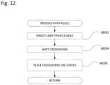
- FIG. 12is a flow chart describing processing of path rules in FIG. 8 ;
- FIG. 13shows an exemplary on-screen part rendering and logic structure for the rule processing of FIG. 12 ;
- FIGS. 14 A- 14 Dshow models, renderings, representations of toolpaths, and data structures as carried out by the part rendering and logic structure of FIG. 13 , for a crossover movement example;
- FIG. 15is a flow chart describing processing of region rules in FIG. 8 ;
- FIG. 16shows an exemplary on-screen part rendering and logic structure for the rule processing of FIG. 15 .
- FIGS. 17 A- 17 Cshow models, renderings, representations of toolpaths, and data structures as carried out by the part rendering and logic structure of FIG. 16 , for a region extrusion example;
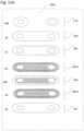
- FIG. 18shows exemplary composite layup in contrasting directions
- FIGS. 19 A- 19 Cshow exemplary six-axis shell layup in contrasting directions
- FIG. 19 D- 19 Gshow exemplary weighted distribution of composite lay-up according to the present embodiments to increase effective moment of inertia
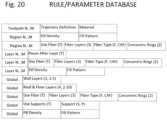
- FIG. 20shows a rule and parameter database structure for the present embodiments.
- FIG. 21shows an exemplary file format for recording the final state after operation of prioritized or ordered rules and parameters for the process of FIG. 8 .
- 3D printeris inclusive of both discrete printers and/or toolhead accessories to manufacturing machinery which carry out an additive manufacturing sub-process within a larger process.
- a 3D printeris controlled by a motion controller 20 which interprets dedicated G-code 702 and drives various actuators of the 3D printer in accordance with the G-code 702 .
- extrusionshall have its conventional meaning, e.g., a process in which a stock material is pressed through a die to take on a specific shape of a lower cross-sectional area than the stock material.
- Fused Filament FabricationFFF
- extrusion nozzleshall have its conventional meaning, e.g., a device designed to control the direction or characteristics of an extrusion fluid flow, especially to increase velocity and/or restrict cross-sectional area, as the fluid flow exits (or enters) an enclosed chamber.
- the present disclosureshall also use the coined word “conduit nozzle” or “nozzlet” to describe a terminal printing head, in which unlike a FFF nozzle, there is no significant back pressure, or additional velocity created in the printing material, and the cross sectional area of the printing material, including the matrix and the embedded fiber(s), remains substantially similar throughout the process (even as deposited in bonded ranks to the part).
- deposition headshall include extrusion nozzles, conduit nozzles, and/or hybrid nozzles.
- filamenttypically refers to the entire cross-sectional area of a spooled build material
- filamentrefers to individual fibers of, for example, carbon fiber (in which, for example, a “1K tow” will have 1000 individual strands).
- strandshall mean individual fibers that are, for example, embedded in a matrix, together forming an entire composite “filament”.
- FIGS. 1 A- 1 Cdepict embodiments of three dimensional printers, each with at least two printing approaches—one which applies a fiber reinforced composite filament, and one which applies pure or neat matrix resin (thermoplastic or curing).
- the fiber reinforced composite filament 2(also referred to herein as continuous core reinforced filament) may be substantially void free and include a polymer or resin that coats or impregnates an internal continuous single core or multistrand core.
- the fiber reinforced composite filament 2is fed through a conduit nozzle 10 heated (e.g., by a band heater or coil heater) to a controlled temperature selected for the matrix material to maintain a predetermined viscosity, force of adhesion of bonded ranks, and/or a surface finish.
- the filament 2is dragged or pulled through the conduit nozzle 10 .
- the continuous core reinforced filament 2is applied onto a build platen 16 to build successive layers 14 to form a three dimensional structure.
- One or both of (i) the position and orientation of the build platen 16 or (ii) the position and orientation of the conduit nozzle 10are controlled by a controller 20 to deposit the continuous core reinforced filament 2 in the desired location and direction.
- Position and orientation control mechanismsinclude gantry systems, robotic arms, and/or H frames, any of these equipped with position and/or displacement sensors to the controller 20 to monitor the relative position or velocity of conduit nozzle 10 relative to the build platen 16 and/or the layers 14 of the part being constructed.
- the controller 20may use sensed X, Y, and/or Z positions and/or displacement or velocity vectors to control subsequent movements of the conduit nozzle 10 or platen 16 .
- the three dimensional printer 1000may include displacement, velocity, or acceleration transducers in any of three translation and/or three rotation axes detecting a position or movement of the conduit nozzle 10 relative to the build platen 16 .
- a (e.g., laser) range sensormay scan the section ahead of the conduit nozzle 10 in order to correct the Z height of the conduit nozzle 10 , or the fill volume required, to match a desired deposition profile.
- the three dimensional printer 1000may include a cutter 8 controlled by the controller 20 that cuts the continuous core reinforced filament (e.g., without the formation of tails) during the deposition process in order to (i) form separate features and components on the structure as well as (ii) control the directionality or anisotropy of the deposited material and/or bonded ranks in multiple sections and layers.
- FIG. 1 Aalso depicts at least one secondary print head 18 optionally employed with the three dimensional printer 1000 to print, e.g., protective coatings on the part including 100% resin FFF extrusion, a UV resistant or a scratch resistant coating.
- a description of a coupled or compound FFF printhead 1800may be found herein, and this description applies to protective coatings in general.
- a spool(not shown) supplies under mild tension an unmelted void free fiber reinforced composite filament.
- the filamentincluding at least one axial fiber strand extending within a matrix material of the filament, having no substantial air gaps within the matrix material.
- the fiber reinforced composite filament 2includes a nylon matrix 4 A that impregnates hundreds or thousands of continuous carbon fiber strands 6 A.
- the driven roller 42 and an idle roller 40feed or push the unmelted filament at a feed rate (optionally variably controllable by the controller 20 , optionally less than the printing rate, and optionally a differential between the feed and printing rates absorbed by a one-way bearing), along a clearance fit zone that prevents buckling of filament.
- a feed rateoptionally variably controllable by the controller 20 , optionally less than the printing rate, and optionally a differential between the feed and printing rates absorbed by a one-way bearing
- the melted matrix material 6 A and the axial fiber strands 4 A of the filament 2are pressed into the part with axial compression, and as the build platen and print head are translated with respect to one another, the end of the filament contacts the ironing lip 726 and is subsequently continually ironed in a transverse pressure zone 3040 to form bonded ranks in the part 14 .
- Either or both of the printing head or conduit nozzle 708 or the build platform 16may be translated, e.g., the feed rate and/or the printing rate are controlled to maintain compression in the filament in the threading stage, and to maintain neutral to positive tension in the printing operation.
- the matrix material 4 A of the filament 2may be heated and melted in the non-contact zone (in particular, so that there is less opportunity to stick to the walls of the conduit nozzle 708 ), but is in this embodiment generally melted or liquefied at the ironing lip or tip 726 .
- the feed and printing ratesmay be monitored or controlled to maintain compression, neutral tension, or positive tension within the unsupported zone as well as primarily via axial compressive or tensile force within fiber strand(s) extending along the filament.
- the transverse pressure zone 3040includes an ironing lip 726 that reshapes the filament 2 .
- This ironing lip 726compacts or presses the filament 2 into the part and may also receive heat conducted from the heated walls 714 , in order to melt or liquefy the matrix material 4 A in the transverse pressure zone 3040 .
- the ironing lip 726 in the transverse pressure zone 3040flattens the melted filament 2 on the top side, applying an ironing force to the melted matrix material and the axial fiber strands as the filament 2 is deposited in bonded ranks. This may be facilitated by ensuring that the height of the bottom of the ironing lip 726 to the top of the layer below is less than the diameter of the filament.
- Another reshaping forceis applied as a normal reaction force from the part itself, which flattens the bonded ranks on at least two sides as the melted matrix material 4 A and the axial fiber strands 6 A are ironed to form laterally and vertically bonded ranks (i.e., the ironing also forces the bonded ranks into adjacent ranks).
- the pressure and heat applied by ironingimproves diffusion and fiber penetration into neighboring ranks.
- Unmelted fiber reinforced filamentis cut at or adjacent the clearance fit zone, but may be may be cut in a gap 62 between a guide tube 72 (having a clearance fit) and the conduit nozzle 708 ; within the conduit nozzle 708 , e.g., upstream of the non-contact zone 3030 ; or alternatively or in addition, the core reinforced filament may be cut by a cutter 8 positioned at or adjacent either one of the clearance fit zone 3010 , 3020 or the ironing lip 725 .
- the feed and/or printing ratecan be controlled by the controller 20 to maintain neutral to positive tension in the composite filament 2 between the ironing lip 726 and the part 14 primarily via tensile force within the fiber strands 4 A extending along the filament 2 , in particular at the end of bonded ranks; in making a turn to begin a new adjacent rank in the opposite direction; and/or to form bridges through open space, e.g. by bridging the fiber reinforced composite filament 2 in the transverse pressure zone 3040 from a connection to a first portion of the part across the open space to bridge then reconnect the fiber reinforced composite filament 2 to a second portion of the part 14 .
- a substantially constant cross sectional area of the fiber reinforced composite filamentis maintained in the clearance fit zone, the unsupported zone, the transverse pressure zone, and also as a bonded rank is attached to the workpiece or part 14 .
- FIG. 1 Bdepicts a cross section of a compound (dual) print head with an extrusion printhead 1800 and extrusion nozzle 1802 for FFF and a fiber deposition printhead 199 and conduit nozzle 708 for continuous fiber reinforced thermoplastic deposition. Like numbered features are similar to those described with respect to FIGS. 1 A and 1 B .
- each of the printheads 1800 and 199are mounted on the same linear guide such that the X, Y motorized mechanism of the printer moves them in unison.
- the FFF printhead 1800includes an extrusion nozzle 1802 with melt zone or melt reservoir 1804 , a heater 1806 for heating the heater block and the nozzle.
- the melt reservoir 1804continues into a high thermal gradient zone 1808 , substantially formed by a thermal resistor 1809 mounted outside the heating block.
- a heat sinksurrounds the thermal resistor 1809 to further enhance the thermal gradient.
- the thermal gradientseparates the melt reservoir 1804 from an unmelted zone 1810 , which may be inside the thermal resistor 1809 and/or a Teflon tube 1811 .
- a 1.75-1.8 mm or 3 mm thermoplastic filament driven through, e.g., a Bowden tubeprovides extrusion back pressure in the melt reservoir 1804 .
- the companion continuous fiber embedded filament printhead 199includes the conduit nozzle 708 , the composite ironing tip 728 , and the limited contact cavity 714 , in this example each within a heating block heated by a heater 715 .
- a cold feed zone 712is formed within a receiving tube 64 , including a capillary-like receiving tube of rigid material and a small diameter (e.g. inner diameter of 32 thou) Teflon/PTFE tube extending into the nozzle 708 .
- the cold feed zoneis surrounded in this case by a PEEK insulating block 66 a and a heat sink 66 b , but these are fully optional.
- an unattached terminal end of the fiber-embedded filamentmay be held in the cold feed zone, e.g., at height P 1 .
- Distance P 1as well as cutter-to-tip distance R 1 , are retained in a database for permitting the controller 20 to thread and advance the fiber-embedded filament as discussed herein.
- the controller 20is operatively connected to the cutter 8 , 8 A, and feed rollers 42 facing idle rollers 40 .
- FIG. 1 Cshows a schematic close-up cross section of the conduit nozzle 708 .
- the inner diameter of the receiving tube 64(in this case, at a position where a Teflon/PTFE inner tube forms the inner diameter) is approximately 11 ⁇ 2 to 21 ⁇ 2 times (at, e.g., 32 thou) the diameter of the filament 2 (at, e.g., 13 thou) shown therewithin.
- the inner diameter or inner width of the terminal cavity 714at, e.g., 40 thou (is from two to six times the diameter of the filament 2 shown therein. These are preferred ranges, it is considered the diameter of the receiving tube may be from 1 1/10 to 3 times the diameter of the filament, and the inner diameter of the terminal cavity from two to 12 times the diameter of the filament.
- the terminal cavityis preferably of larger diameter than the receiving tube.
- the heated composite filament ironing tip 726is moved relative to the part, at a height above the part of less than the filament diameter, to iron the fiber reinforced composite filament as it is deposited to reshape a substantially oval or circular bundle of inelastic axial fiber strands (labeled 2 a ) within the fiber reinforced composite filament to a substantially flattened block of inelastic fibers strands within a bonded rank (labeled 2 C) of the part.
- Axial compression and/or laterally pressing the melted matrix filament 2 into bonded ranksmay enhance final part properties. For example, FIG.
- FIG. 1 Cshows a composite fiber reinforced filament 2 applied with a compaction force, axial compression, or lateral pressure 62 .
- the compaction pressurefrom axial compression and flattening from the ironing lip, compresses or reshapes the substantially circular cross-section filament 2 a into the preceding layer below and into a second, substantially rectangular cross-section compacted shape.
- the entire filamentforms a bonded rank (i.e., bonded to the layer below and previous ranks on the same layer) as it is shaped.
- the filament 2 bboth spreads and interior strands intrude into adjacent bonded ranks 2 c on the same layer and is compressed into the underlying shaped filament or bonded rank of material 2 d .
- the axial compression of the filament 2 and/or especially the physical pressing by the printer head 70 , conduit nozzle or ironing lip 508 , 726 , 208 in zone 3040may be used to apply a compression pressure directly to the deposited material or bonded ranks to force them to spread or compact or flatten into the ranks beside and/or below.
- Cross-sectional areais substantially or identically maintained.
- pressuremay be applied through a trailing pressure plate behind the print head; a full width pressure plate spanning the entire part that applies compaction pressure to an entire layer at a time; and/or heat, pressure, or vacuum may be applied during printing, after each layer, or to the part as a whole to reflow the resin in the layer and achieve the desired amount of compaction (forcing of walls together and reduction and elimination of voids) within the final part.
- FIGS. 2 A- 2 Cdepict an embodiment of a three dimensional printer 3001 in applying a fiber reinforced composite filament 2 together with DLP-SLA, SLA, or SSS to build a structure. Like numbered features are similar to those described with respect to FIG. 1 A .
- a reinforced filamentmay employ a matrix that is finished by curing cycle, e.g., using heat, light, lasers, and/or radiation.
- curing cyclee.g., using heat, light, lasers, and/or radiation.
- continuous carbon fibersare embedded in a partially cured epoxy such that the extruded component sticks together, but requires a post-cure to fully harden.
- preformed continuous core reinforced filamentsin some embodiments, the continuous core reinforced filament may be formed by combining a resin matrix and a solid continuous core in a heated extrusion nozzle.
- the resin matrix and the solid continuous coreare able to be combined without the formation of voids along the interface due to the ease with which the resin wets the continuous perimeter of the solid core as compared to the multiple interfaces in a multistrand core. Therefore, such an embodiment may be of particular use where it is desirable to alter the properties of the deposited material.
- FIGS. 2 A and 2 Bdepict a hybrid system employing stereolithography (and/or selective laser sintering) to provide the matrix about the embedded fiber, i.e. processes in which a continuous resin in liquid or powder form is solidified layer by layer by sweeping a focused radiation curing beam (laser, UV) in desired layer configurations.
- stereolithography process associated with the deposition of each layercan be modified into a two-step process that enables construction of composite components including continuous core filaments in desired locations and directions.
- a continuous core or fibermay be deposited in a desired location and direction within a layer to be printed, either completely or partially submerged in the resin.
- the adjoining resinis cured to harden around the fiber. This may either be done as the continuous fiber is deposited, or it may be done after the continuous fiber has been deposited. In one embodiment, the entire layer is printed with a single continuous fiber without the need to cut the continuous fiber. In other embodiments, reinforcing fibers may be provided in different sections of the printed layer with different orientations. In order to facilitate depositing the continuous fiber in multiple locations and directions, the continuous fiber may be terminated using a cutter as described herein, or by the laser that is used to harden the resin.
- FIG. 2 Bdepicts a part 1600 being built on a platen 1602 using stereolithography or selective layer sintering.
- the part 1600is immersed in a liquid resin (photopolymer) material 1604 contained in a tray 1606 .
- the platen 1602is moved by a layer thickness to sequentially lower after the formation of each layer to keep the part 1600 submerged.
- a continuous core filament 1608is fed through a conduit nozzle 1610 and deposited onto the part 1600 .
- the conduit nozzle 1610is controlled to deposit the continuous core filament 1608 in a desired location as well as a desired direction within the layer being formed.
- the feed rate of the continuous core filament 1608may be equal to the speed of the conduit nozzle 1610 to avoid disturbing the already deposited continuous core filaments.
- appropriate electromagnetic radiatione.g., laser 1612
- the distance between the location 1614 and the conduit nozzle 1610may be selected to allow the continuous core filament to be completely submerged within the liquid resin prior to curing.
- the laseris generated by a source 1616 and is directed by a controllable mirror 1618 .
- the three dimensional printeralso includes a cutter 1620 to enable the termination of the continuous core filament as noted above.
- the deposited filamentis held in place by one or more “tacks”, which are a sufficient amount of hardened resin material that holds the continuous core filament in position while additional core material is deposited.
- the continuous core filament 1608is tacked in place at multiple discrete points 1622 by the laser 1612 as the continuous core filament is deposited by a nozzle, not depicted.
- the laser 1612is directed along a predetermined pattern to cure the liquid resin material 1604 and form the current layer. Similar to the above system, appropriate electromagnetic radiation (e.g., laser 1612 ), is generated by a source 1616 and directed by a controllable mirror 1618 .
- the balance of the materialcan be cured to maximize cross linking between adjacent strands is maximized, e.g., when a sufficient number of strands has been deposited onto a layer and tacked in place, the resin may be cured in beads that are perpendicular to the direction of the deposited strands of continuous core filament. Curing the resin in a direction perpendicular to the deposited strands may provide increased bonding between adjacent strands to improve the part strength in a direction perpendicular to the direction of the deposited strands of continuous core filament. If separate portions of the layer include strands of continuous core filament oriented in different directions, the cure pattern may include lines that are perpendicular or parallel to the direction of the strands of continuous fibers core material in each portion of the layer.
- FIG. 3depicts a block diagram and control system of the three dimensional printer which controls the mechanisms, sensors, and actuators therein, and executes instructions to perform the control profiles depicted in and processes herein.
- a printeris depicted in schematic form to show possible configurations of three commanded motors 116 , 118 , and 120 . It should be noted that this printer may include the compound assembly of printheads 199 , 1800 depicted in FIG. 1 C .
- the three-dimensional printer 3001includes a controller 20 which is operatively connected to the fiber head heater 715 , the fiber filament drive 42 and the plurality of actuators 116 , 118 , 120 , wherein the controller 20 executes instructions which cause the filament drive to hold an unattached terminal end of the composite filament 2 in the cold feed zone 712 between the fiber filament drive 42 and the ironing tip 726 .
- the instructionsare held in flash memory and executed in RAM (not shown; may be embedded in the controller 20 ).
- An actuator 114 for applying a spray coat, as discussed herein,may also be connected to the controller 20 .
- a filament feed 1830be controlled by the controller to supply the extrusion printhead 1800 .
- a printhead board 110optionally mounted on the compound printhead 199 , 1800 and moving therewith and connected to the main controller 20 via ribbon cable, breaks out certain inputs and outputs.
- the temperature of the ironing tip 726may be monitored by the controller 20 by a thermistor or thermocouple 102 ; and the temperature of the heater block holding nozzle 1802 of any companion extrusion printhead 1800 may be measured by a thermistor or thermocouple 1832 .
- a heater 715 for heating the ironing tip 726 and a heater 1806 for heating the extrusion nozzle 1802are controlled by the controller 20 .
- a heat sink fan 106 and a part fan 108each for cooling, may be shared between the printheads 199 , 1800 and controlled by the controller 20 .
- Rangefinder 15is also monitored by the controller 20 .
- the cutter 8 actuatorwhich may be a servomotor, a solenoid, or equivalent, is also operatively connected.
- a lifter motor for lifting one or either printhead 199 , 1800 away from the part (e.g., to control dripping)may also be controlled.
- Limit switches 112 for detecting when the actuators 116 , 118 , 120 have reached the end of their proper travel rangeare also monitored by the controller 20 .
- an additional breakout board 122which may include a separate microcontroller, provides user interface and connectivity to the controller 20 .
- An 802.11 Wi-Fi transceiverconnects the controller to a local wireless network and to the Internet at large and sends and receives remote inputs, commands, and control parameters.
- a touch screen display panel 128provides user feedback and accepts inputs, commands, and control parameters from the user. Flash memory 126 and RAM 130 store programs and active instructions for the user interface microcontroller and the controller 20 .
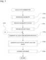
- FIG. 4depicts a flowchart showing a printing operation of the printers 1000 in FIGS. 1 - 3 .
- FIG. 4describes, as a coupled functionality, control routines that may be carried out to alternately and in combination use the co-mounted FFF extrusion head 1800 and fiber reinforced filament printing head 199 of FIG. 1 C .
- step S 10determines in step S 10 whether the next segment to be printed is a fiber segment or not, and routes the process to S 12 in the case of a fiber filament segment to be printed and to step S 14 in the case of other segments, including e.g., base, fill, or coatings.
- Step S 12is described in detail with reference to FIGS. 2 and 12 .
- the routine of FIG. 11checks for slice completion at step S 16 , and if segments remain within the slice, increments to the next planned segment and continues the determination and printing of fiber segments and/or non-fiber segments at step S 18 .
- “Segment” as used hereincorresponds to “toolpath” and “trajectory”, and means a linear row, road, or rank having a beginning and an end, which may be open or closed, a line, a loop, curved, straight, etc.
- a segmentbegins when a printhead begins a continuous deposit of material, and terminates when the printhead stops depositing.
- a “slice”is a single layer or lamina to be printed in the 3D printer, and a slice may include one segment, many segments, lattice fill of cells, different materials, and/or a combination of fiber-embedded filament segments and pure polymer segments.
- a “part”includes a plurality of slices to build up the part.
- FIG. 12 's control routinepermits dual-mode printing with two different printheads, including the compound printheads 199 , 1800 of FIG. 1 C , and using both timing approaches of FIG. 5 .
- FIG. 5depicts a block diagram of a three dimensional printer system, including devices in the system and relevant databases, data structures, control messages, and file formats which cooperate to control the printers of FIGS. 1 - 3 and as described throughout.
- FIG. 6depicts a call diagram in which data types and operations are related and communicated between devices.
- the processin order to construct a part using a 3D printer 1000 , the process usually begins with a solid model corresponding to a part (“PRT”) of interest represented by a data structure (“files” 802 , having a drawing container DWG with assemblies “ASSY” comprising various parts “PRT”), but may also begin with a polygon mesh of the desired part (STL 902 in FIG. 3 ). As shown in FIGS. 5 and 6 , in order to construct a part using a 3D printer 1000 , the process usually begins with a solid model corresponding to a part (“PRT”) of interest represented by a data structure (“files” 802 , having a drawing container DWG with assemblies “ASSY” comprising various parts “PRT”), but may also begin with a polygon mesh of the desired part (STL 902 in FIG. 3 ). As shown in FIGS.
- the solid modelmay be represented by non-uniform rational b-spline NURBS data, and this may be stored and processed by a CAD program on a workstation, server, or virtualized/cloud server 2000 , and communicated by file or data structure to a meshing program on the same or a different workstation, server, or virtualized/cloud server 2000 .
- One of the data structures most amenable to division into layers for additive manufacturingis the surface mesh of cells or polygons having edges, faces and vertices stored as a geometry file (e.g., STL, OBJ, PLY, AMF or WRL file).
- ⁇⁇ ⁇ ⁇ ⁇ ⁇ ⁇ ⁇ ⁇ ⁇ ⁇ ⁇ ⁇ ⁇ ⁇ ⁇ ⁇ ⁇ ⁇ ⁇ ⁇ ⁇ ⁇ ⁇ ⁇ ⁇ ⁇ ⁇ ⁇ ⁇ ⁇ ⁇ ⁇ ⁇ ⁇ ⁇ ⁇ ⁇ ⁇ ⁇ ⁇ ⁇ ⁇ ⁇ ⁇ ⁇ ⁇ ⁇ ⁇ ⁇ ⁇ ⁇ ⁇ ⁇ ⁇ ⁇ ⁇ ⁇ ⁇ ⁇ ⁇ ⁇ ⁇ ⁇ ⁇ ⁇ ⁇ ⁇ ⁇ ⁇ ⁇ ⁇ ⁇ ⁇ ⁇ ⁇ ⁇ ⁇ ⁇ ⁇ ⁇ ⁇ ⁇ ⁇ ⁇ ⁇ ⁇ ⁇ ⁇ ⁇ ⁇ ⁇ ⁇ ⁇ ⁇ ⁇ ⁇ ⁇ ⁇ ⁇ ⁇ ⁇ ⁇ ⁇ ⁇ ⁇ ⁇ ⁇ ⁇ ⁇ ⁇ ⁇ ⁇ ⁇ ⁇ ⁇ ⁇ ⁇ ⁇ ⁇ ⁇ ⁇ ⁇ ⁇ ⁇ ⁇
- a geometry fileis “sliced” by a family of slicer routines 904 (as shown in FIGS. 5 and 6 , resident on a workstation, server, or virtualized/cloud server) in a direction parallel to the expected build platen to create a series of layers or lamina (“Empty Deck” 906 ).—receives the geometry file.
- Geometry filesare usually without material definition, and each individual lamina would be initially treated as of homogenous or isotropic material properties.
- one embodiment of a geometry file 902may include markers, boundaries, sub-geometries, divisions, boundary conditions, or the like specifying a different material property according to volumetric location within the geometry file.
- toolpaths(“layers and slices” 1002 ) are calculated by a path planner 1004 for controlling actuators to deposit, focus a laser or lamp or projector to cure, solidify, or otherwise apply material.
- the toolpath generatoris also resident on a workstation, server, or virtualized/cloud server.
- “toolpath”encompasses both moving a tool through space and pure electromagnetic paths (e.g., optical, radiation) “moved” with mirrors and lenses.
- Toolpathsmay be arranged within contours, which may subdivide a layer perimeter into areas of different attention, e.g., where a larger or smaller deposition head is necessary to reach some part of the lamina geometry, or to observe rule sets 1006 for different parts of the layer (e.g., walls, interior perimeter, fills). Toolpaths are generated per internal algorithms that determine offsets, scales, and cellular decomposition for complete coverage approaches of the various contours. Some parameter control may be applied to the rules 1006 (e.g., an adjustable 1-5 thicknesses of deposited plastic for an outer perimeter forming rule).
- An FFF toolpathmay have variables including extrusion width (relating to the nozzle size, nozzle height from build surface, and extrusion speed).
- Other deposition toolpaths in additive manufacturingmay have variables similarly relevant to the physics and chemistry of the individual process.
- a customizer routine 2008may permit changes to the generated toolpaths, regions or subcontours, contours, layers, and mesh. Some customizations may require merely re-pathing, others may create new regions, others may create new geometry model sections—these changes may be done as they are entered by a user, or may be batched and redone. Optionally, after all customizations are done, the process is returned to the earliest practical phase with all changes protected to be re-meshed, re-sliced, or re-pathed.
- the toolpathsare used to create an instruction file for actuation, conventionally called a “G-code” file or stream 1102 .
- the toolpath generator 2006generates toolpaths may also serve as the G-code generator 2010 by interpreting the toolpaths into a machine-specific code.
- the G-codeis sequenced including all starting and finishing times, control or command variables (e.g., speed for a motor, current for a heater), and the like, to arrange the actuator instructions sufficient for a job to complete.
- the G-code 1002 filebecause it is dependent upon physical arrangement of the printer itself, is typically printer specific.
- This processdoes not include any provision for, the unique characteristics of embedded and/or reinforcing continuous or semi-continuous fiber—i.e. anisotropic characteristics including stress, strain, thermal conductivity, load and support direction specific design, or the like.
- FIGS. 5 and 6for the purpose of reference terms throughout, show a series of steps in the data structure, each of which is optionally combined with an adjacent step.
- a reference part as stored in a CAD geometry fileincludes a definition of exterior walls, upward facing “floors” and downward facing “ceilings”, interior “roofs”, interior through-holes, and interior “solid” spaces.
- the 3D data structurewhen converted into an STL, is transformed into a geometry mesh defining only the exterior perimeter, but retains all of the characteristics of the more complex CAD representation. As noted, this is optional, as the mesh representation is easier to “slice”. Defective, non-“watertight” or non-manifold STLs may be repaired such that all vertices are properly connected, but the representation as a mesh remains essentially similar.
- “slicing” the STLincludes two conceptual steps, which are often done together. First, at each height increment, a cross-section must be taken through the STL parallel to the anticipated build platen orientation. Second, necessary toolpaths are expressed as G-code for a deposition head to deposit material along the exterior interior perimeters of the slice and also to create any interior structures (such as fills). The toolpaths and G-code may be generated at each slicing operation, such that these steps are merged. For the purpose of this discussion, “slicing” will be discussed as set of merged steps in which cross-sectional slices are taken and path planning and G-code are generated for uniform material fill.
- slicing operationsidentify and use toolpaths to surround exterior and interior lateral walls (e.g., three fused polymer rows at each); fill interior volumes with cellular or lattice structures; form ceilings, floors, and roofs with slower print speeds; and create temporary support structures used during the print cycle.
- toolpaths for moving tools from origin to print start to print stop, and for feeding and retracting filament to start and stop extrusionare created.
- FIG. 7is a flow chart describing the overall operation of path planner, i.e., the slice, contour, subcontour (region) and path generator and planners depicted in FIGS. 5 and 6 .
- the fiber path planner of FIG. 7receives as an input a “sliced” database of layers from the slicer, in this case referred to as a “sliced stack” or “empty deck”.
- This sliced stack databasemay be in the form of, per layer, topological information (contours, defined as a solid or a hole via the conventional right hand rule), and/or toolpath information (trajectories), metadata, and/or G-code or an equivalent.
- one form of subsetwould include the “SLC” file format or an equivalent, which includes only the geometry of the contours.
- a supersetcould include the STL file, or analyses or parameters recognized from the STL file (e.g., a label for a through hole that is shared by code segments generating that through hole in G-Code).
- the initial input for a first pass on a 3D part to be printed, where no layer-by-layer fiber path generation has yet been performed that could be repathedis the “slices and contours”. It is an optional object of the present disclosure to subsequently deal with re-pathing on a database of layers rather than with the 3D model geometry, to thereby only repath those contours and those layers that should be changed. However, the present disclosure further contemplates that in some situations, repathing from an earlier stage may be beneficial (e.g., for Boolean and/or parametric operations supported at the region level, in addition to or in the alternative to at the layered level).
- Toolpaths/G-codeare built up from a platen assumption; material is not extruded in the same location twice; and the tool need not be moved back in the Z direction opposite to the direction of build, even for the case of multi-material or multi-part STLs. Should changes need to be made, the process of generating new tool-paths is generally to redo the part in CAD, create a new STL, and reslice/repath the entire geometry file (STL).
- the process of FIG. 7can be entered with its own output, i.e., the process of FIG. 7 is intended to analyze and change both data sets having only layers and contours, as well as the “slices, contours, regions, and toolpaths” set generated by the toolpath generator and modified in customization, and there are cases in which it may be beneficial to do so (e.g., in case incremental processes are interdependent).
- step S 750the process, in a mesh pre-processing step, corrects the STL file for various errors, including at least one of: correcting face normal orientation; self-intersections; non-manifold geometry and manifold errors; vertices not incident to any edge; edges without any incident triangles; edges with more than two incident triangles; vertices with a non-disc neighborhood; disconnected, or unwanted handles, tunnels, components, or cavities; erroneous holes or cavities; triangles with (near-) zero area.
- Techniquesinclude merging vertices within a prescribed distance; merging or stitching adjacent boundary edges; clipping then merging overlapping patches; hole filling by inserting vertices; converting mesh into point cloud and remeshing. This step may generate a simplified, more robust, mesh in which each vertex and edge is uniquely defined, and faces are generated from defined vertices and edges.
- the processslices the (pre-processed or corrected) geometry (e.g., triangle) mesh in to layers, strata, or slices (these terms used interchangeably).
- Techniquesinclude checking all triangles or groups of proximate triangles vs. all cutting planes for intersections; checking all edges vs. all cutting planes for intersections (sweep plane slicing); or checking all planes for intersections with intervals representative of each triangle. This generates a set of two dimensional slices at a fixed height or variable height (either may be recorded as metadata for a particular slice).
- the fixed or variable heightmay be of any thickness/resolution printable by the target 3D printer, e.g., 0.02′′, 0.01′′, 0.005′′, 0.001′′, 0.1 mm and multiples of these, or even of a lesser thickness/resolution useful for inter or intra-layer insertions.
- Each sliceincludes at least one positive contour (e.g., an outer perimeter) and may include one or more negative contours (e.g., a hole or holes).
- a positive contourmay also create a proxy for a hole, e.g., by specifying a perimeter that loops to touch (e.g., meld with) itself to create such hole proxies(s).
- step S 754the process inventories the state of default rules for FFF and fiber printing selected for automated contours and toolpaths, and sets an order of operations for the default rules selected.
- An exemplary state of such rulesare shown in FIGS. 20 and 21 and described with reference thereto.
- the order of operation of rulesmay be linear, recursive, or otherwise arranged.
- a predetermined overall order of operationsmay interrelate all possible operations.
- a change in rulese.g., changing or adding or subtracting a rule
- any time during the processmay, by interrupt, trigger, commit or otherwise, restart the process at step S 755 (entry point “A”) to accommodate the change.
- the usermay be afforded an opportunity to modify these default rules before the first execution of step S 756 (e.g., skip to step S 760 ).
- step S 756the process applies the ruleset, layer by layer, according to the order of operations, to determine sub-contours, i.e., two dimensional topological sub-areas and/or holes within a positive contour, as new dependent positive and/or negative contours.
- negative contoursmay form holes, or positive contours may form proxies for holes.
- positive contoursmay be created by ruleset to trigger or force a desired pathing or filling of fiber or material.
- Sub-contoursmay have perimeters coincident with an enclosing or neighboring contour, and a positive sub-contour may form a wall of a hole in the layer).
- FIGS. 8 A and 8 Binclude further detail on sub-contour generation.
- step S 758the process applies the ruleset, contour by contour, according to the order of operations, to generate desired toolpaths for filling of fiber or material, as well as transitions therebetween, for one or more fiber laying tools and for one or more material deposition tools.
- the initial printing strategyis complete.
- the toolpathsmay be translated to G-code and the part may be printed, and an end-user may be offered the opportunity to review and/or print the toolpath state or the part (e.g., at the beginning of the customization process).
- a segment, toolpath or pathis a sequence of trajectories and contours.
- a trajectoryis a connected sequence of path commands.
- Toolpath commandsmay include line segments and partial elliptical arcs, and optionally Bezier curve segments.
- Each path commandmay have path coordinates, and a pair of path coordinates may be an X, Y location that is a control point.
- a contouris a closed trajectory with the same start and end point.
- Toolpathsare executed (e.g., by a deposition printhead, by laser or UV curing, by flash DLP curing) or rendered (e.g., to display upon a review panel) by “stroking” the path.
- the “stroking”may be depositing material or curing material as swept out by a fixed-width deposition centered on the trajectory that travels along the trajectory orthogonal to the trajectory's tangent direction. Stroking may be by area or accumulated (an entire area may be flashed by DLP as a toolpath).
- parallel or offset toolpathsmay be created using offset generation for non-Bezier base paths and offset stroking for Bezier (e.g., cubic or quadratic control point) base paths.
- offset stroking for Bezier pathsmay be difficult to render
- FFF material or fiber pathsmay be non-Bezier approximations.
- Resolution-independent path renderingmay be performed by via vector graphic libraries for GPU accelerated path rendering (e.g., OpenVG) even to calculate toolpaths and offsets of physical continuous fiber paths.
- step S 760the process permits the customization, layer by layer, contour by contour, and/or path by path, of the completed toolpath and printing strategy.
- the customization processis optional, as is each type of customization.
- subcontoursor “regions” and in some cases toolpaths are generated layer by layer in a priority or order of precedence.
- Global rulesare optionally of lowest precedence, as they are most likely to be overridden by direct user changes (actual design decisions) or indirect user changes (results of design decisions).
- FIG. 8 AThe process of FIG. 8 A is carried out both initially and in later editing stages.
- an initial passno user changes of fiber paths or regions/subcontours will have been recorded, so there will be no user edited fiber paths or subcontours to process at highest priority.
- the highest prioritymay be global rules.
- higher priority rulesonce defining a toolpath and/or region, are generally protected as the next, lower priority set of rules are processed.
- the usermay be given a warning and opportunity to elevate the priority of a nominally lower priority rule.
- the priority stackmay also be considered an order of operations. Higher priority actions are optionally not disturbed by later actions unless a failure mode rule is broken.
- the general order of rulesis: failure mode rules (e.g., limits of the platen or of the tool heads, of unsupported spans of a particular material, etc.); toolpath rules; then subcontour rules; then layer rules; then global rules.
- failure mode rulese.g., limits of the platen or of the tool heads, of unsupported spans of a particular material, etc.
- toolpath rulese.g., toolpath rules
- subcontour rulese.g., subcontour rules
- layer rulese.g., a particular material, etc.
- global rulese.g., direct edits are or were preferably only permitted in a manner which does not violate (optional) failure mode rules (e.g., another failure mode rule may be that an unsupported spans of isotropic fill material can extend, e.g., no more than 1 cm in length, or other length specified as a property of the material).
- step S 850initially, in any layer in which a toolpath was edited, any manual or automated operation in which a toolpath is or was directly edited by a user is processed by first plotting the related toolpath (and any dependencies) and then defining the envelope which the toolpath occupies, protecting the envelope as a region or subcontour.
- An example toolpath edit operationis changing the position of control points or waypoints of a curve defining a toolpath.
- step S 852among all the layers, the regions or subcontours protected in step S 850 are now “off limits”.
- Manual or heuristic operations in which a subcontour is or was directly edited by a userare processed by protecting the region or subcontour.
- Toolpathsmay be generated at a later time.
- An example subcontour edit operationis specifying a void volume (e.g., an solid model to be overmolded) that extends through several layers.
- step S 854layer rules (i.e., rules that have been set for an entire layer) are processed. Regions or subcontours protected in prior steps are now “off limits”. Manual or heuristic operations in which a layer is or was directly edited by a user are processed by protecting all remaining regions or subcontours in the layer. Toolpaths may be generated at a later time. An example layer edit operation is specifying that fiber fill will be used on a particular layer that had not by toolpath, subcontour or global rules otherwise been defined as a fiber layer.
- step S 856global rules (i.e., rules that have been set for the entire part) are processed.
- Typical global rulesare shown in a priority stack in FIG. 8 C , e.g., with wall thicknesses of highest priority and infill of lowest priority. Some or all global rules may optionally or alternatively take precedence over other rules.
- FIG. 9is a flow chart in which different types of global rule are executed. As noted, although FIG. 9 may take place after the other routines of the slicing and path planning process (or at lower priority), the user may be presented with the results of FIG. 9 's processing of default and global rules before any customizations are made or processes. As noted, a later path, region, layer, or volume customization that deposits fiber or other second material at a wall, floor, roof, fiber fill region, exception fill region, or area fill region may optionally (e.g., set by a parameter) override the global wall thickness setting; and each successive toolpaths generation defines regions in each layer which are nominally protected vs. later toolpath generation.
- a later path, region, layer, or volume customizationthat deposits fiber or other second material at a wall, floor, roof, fiber fill region, exception fill region, or area fill region may optionally (e.g., set by a parameter) override the global wall thickness setting; and each successive toolpaths generation defines regions in each layer which are nominally
- step S 8560the process of FIG. 9 refers to database settings for wall thicknesses and generates toolpaths corresponding to the walls of the part.
- Wallsmay be the perimeters of contours, subcontours, or regions.
- a typical global settingmay be from 2-4 bonded ranks; inner walls (holes) and outer walls (shells) may have different global or default settings.
- step S 8562the routine generates “roofs” and “floors” according to a set parameter (e.g., independently settable at a default 3 layers of any of 1-5 layers, or as a thickness for variable thickness layers).
- a roofis an external surface facing “up” (i.e., the direction in which layers are built), a floor is an external surface facing “down” (opposite to up).
- step S 8562the routine generates fiber fills according to global rules discussed herein with respect to FIGS. 10 through 11 C .
- FIG. 10shows an exemplary on-screen part rendering and logic structure for the rule processing of FIG. 9 .
- a view panel 1002includes an on-screen rendering of a geometry file retained in memory or other database.
- the geometry file rendered in the view panel 1002may be shown in different views (e.g., isometric, perspective, orthogonal), and/or in different sections, and/or with or without layers, contours, regions or toolpaths rendered within. Examples include an isometric model shown in FIG. 10 ; an exploded view of layers shown in FIG. 11 A , a “layer at a time” plan view with a layer number control slider shown in FIGS. 11 B and 11 C .
- occluded toolpaths or surfacesmay be hidden or shown, and rendered lines and surfaces may be rendered with selective color and transparency as set by the user.
- Contour, region, layer, fill, material, and other metadata corresponding to a characteristicmay be rendered in outline and/or highlighted with selective color and transparency as set by the user.
- a selection panel 1004includes a set of user interface elements that correspond to command flags, arrays, and lists stored in memory or other database (e.g., as shown in FIGS. 20 and/or 21 ). As disclosed herein, whether or not particularly disclosed separately in discussion of data structures, each on-screen rendering corresponds to that data structure discussed herein necessary to render the view, and each view panel and selection panel user interface element corresponds to a respective flag, array, or list retained in a database in like form to those particularly detailed.
- Exemplary global rules that control path planning for each layer that are available to the path planner, and also available to a display renderer for the view panel and a controls renderer for the selection panel,are shown in the view panel 1004 .
- Numbering for features rendered in the view panel 1004may reference any of FIG. 10 (display), FIG. 9 (process control), FIGS. 20 and/or 21 (rule sets and data structures), as each are related as the data structures defining operations and the part are created and changed by process control according to rule sets and priorities, and the results of the changes displayed to the user.
- FIG. 10display
- FIG. 9process control
- FIGS. 20 and/or 21rule sets and data structures
- the usermay select (and the path planner thereby execute) the thickness of and/or number of bonded ranks forming inner and/or outer walls or shells, the thickness and/or number of bonded layers for floors and/or roof dense or watertight fills; whether or not to use peelable and/or solid supports for printing overhangs; and/or a fill pattern (triangle, hex, square, cellular) for infill of inner areas for weight reduction.
- a configuration filee.g., layer thickness and/or bonded row width; variable feedrate for curves, bends, or outer/inner walls; bridging (printing unsupported spans) lengths for neat plastic or fiber; or limitations for printing spurs (single walled sections).
- the usermay choose to “use fiber” as a parameter P 02 , where a “use” setting permits global, path, layer, and region fiber reinforcement, a “no fiber” setting suppresses all fiber reinforcement, and a “custom” setting permits only path, layer, or region determined fiber reinforcement.
- the usermay specify a parameter P 06 as a number of immediately adjacent fiber layers, and a parameter P 08 as a number of immediately adjacent fiber shells or ranks, for global fiber operations (which optionally becomes the initial setting for any path, layer, or regions setting).
- the usermay set a parameter P 04 as a type of fiber (e.g., carbon fiber, aramid fiber, or fiberglass).
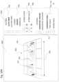
- the exemplary model M 01 shown in FIG. 10 to receive the operations of the rulesets and ultimately to be printedis a connecting rod including a torque transmitting feature F 02 including a polygonal hole/spline surrounded by a large reinforcing circular mount, a slip fit feature F 04 including a cylindrical through hole surrounded by a smaller reinforcing circular mount, and an arm feature F 06 spanning the two features F 02 and F 06 .
- “Spanning” hereinmeans extending beyond the lateral or lengthwise extent of one or two features, e.g., a span length F 08 extends past the edges of the hole features F 02 and F 04 , is longer than the outer edge-to-edge length.
- Detail settings that may be set at a global levelalso include (i) a parameter for false/dense/lean migrate or stagger for sets of fiber crossovers, which for adjacent layers moves the location of a group of crossovers between adjacent offsets so that crossovers are concentrated in zones or spread out as desired; (ii) a parameter for curves/straightaways for the preferred location of fiber crossovers; or (iii) a parameter for higher or lower moment of inertia, to concentrate fiber to the perimeters or center of a part.
- FIG. 11 A- 11 Cshows an exemplary display on the view panel 1002 , and is generated by rendering to screen 2D definitions (optionally presented in 3D) of contours, subcontours, and toolpaths, with optional processing for occlusion and showing and hiding particular feature types.
- Regions/subcontoursmay be shown with dotted lines; fiber toolpaths with grayscale, wider lines; and matrix or resin fill toolpaths with solid lines (excepting short segments extending between fiber toolpaths, which represent crossovers).
- a toolpathmay represent either resin/material fill or fiber (e.g., for honeycomb, triangular, or other volumetric sparse fill).
- FIGS. 11 A- 11 Calso corresponds to the toolpaths generated by the operation of FIG. 10 (display), FIG. 9 (process control), FIGS. 20 and 21 (rule sets and data structures).
- the exemplary part as initially configured to be printedrepresents a layer definition of slicing to the path generator, a display on the view panel; a definition of contours, subcontours/regions; and a definition of a subset of toolpaths.
- a notation with “X”indicates a layer is repeated (possibly through a cycle of complementary layer patterns) that number of times, e.g., “90x” means 90 adjacent layers forming a set.
- Fiber reinforcement strategieswhich may in some cases be used in combination and which may have sub-strategies, include Concentric Inward, Boustrophedon (ox rows), Concentric Outward, or Sandwich Panel.
- Concentric fillis performed within a layer by first obtaining 80-105% (preferably 85-99%) fiber-width offsets from an outer perimeter of a region of the layer. That is, the offsets form concentric paths that are 80-105% (preferably 85-99%) of the fiber-width as laid.
- One advantageous globally set regionis the non-wall region adjacent a shell or wall thickness region (e.g., 1-3 bonded ranks thick).
- Fiberis deposited by controlling the deposition head to stroke the center of the concentric fiber fill offsets. When the offset has been looped, an S-shaped crossover lays fiber into the neighboring offset. Concentric fill is suitable for bending and tension in particular, and is efficient (fewer turns) as well as inherently strong (no fiber separation permits more force to be transmitted and distributed along the fiber length).
- concentric fiber fillmay be set to be adjacent a floor and or a roof, and/or at a set number of layers from the top and/or bottom of the part. Concentric fill may have no particular orientation, as its direction depends on the perimeter of the part.
- the concentric fill algorithmmay be used for other strategies (e.g., for surrounding holes or hole splines for reinforcement).
- other settingscan be used in combination to, e.g., migrate the crossover between layers, locate crossovers in a particular place, or repeat or vary concentric fill patterns.
- Ox-row fill or Raster fillis performed in back and forth rows.
- U.S. Pat. No. 6,934,600herein incorporated by reference in its entirety, discloses various implementations of raster fill for nanotube impregnated three dimensional printing.
- Ox-row fillis performed by specifying an orientation of rows (e.g., lengthwise, widthwise, or at a specified angle) and a region.
- One advantageous globally set regionis again a non-wall region adjacent a shell or wall thickness region.
- Parallel straight rows, offset by 80-105% (preferably 85-99%) of the fiber width as laid,are calculated side by side traversing the region. If a cutter is available sufficiently close to the tip of the deposition head, the fibers may be cut at each turn.
- Boustrophedon pathscan be connected at end rows by 180 degree curved fiber paths of the same diameter as the offset, or by folded paths of two right angles (these may alternate). Fiber is again deposited by controlling the deposition head to stroke the center of the concentric fiber fill offsets. When the offset has been looped, an S-shaped crossover lays fiber into the neighboring offset.
- ox-row fiber fillmay be set to be adjacent a floor and or a roof, and/or at a set number of layers from the top and/or bottom of the part.
- Ox-row fillmay be set to substantially repeat a direction of fill (for increased cumulative strength in that direction, or to provide arbitrary or predetermined patterns of two, three, four or more varying directions to increase multi-directional strength (e.g., 90-90 would represent two adjacent 90 degree perpendicular layers; 60-60-60 three adjacent layers each rotated 60 degrees, 45-45-45-45 four layers following a repeating pattern of reinforcing crisscrossing layers).
- a direction of fillfor increased cumulative strength in that direction, or to provide arbitrary or predetermined patterns of two, three, four or more varying directions to increase multi-directional strength (e.g., 90-90 would represent two adjacent 90 degree perpendicular layers; 60-60-60 three adjacent layers each rotated 60 degrees, 45-45-45-45 four layers following a repeating pattern of reinforcing crisscrossing layers).
- successive layers of compositemay, like traditional lay-up, be laid down at 0°, 45°, 90°, and other desired angles to provide part strength in multiple directions and to increase the strength-to-weight ratio.
- the controller 20may be controlled to deposit the reinforcing fibers with an axial alignment in one or more particular directions and locations.
- the axial alignment of the reinforcing fibersmay be selected for one or more individual sections within a layer, and may also be selected for individual layers.
- a first layer 1200may have a first reinforcing fiber orientation and a second layer 1202 may have a second reinforcing fiber orientation.
- a first section 1204 within the first layer 1200may have a fiber orientation that is different than a second section 1206 , or any number of other sections, within the same layer.
- Concentric fiber outward fillis distinct in from concentric fill in that (i) the fiber loops are offset from an inner perimeter formed by an envelope about features or parts to be spanned, rather than outside in. Otherwise, the description with respect to concentric fill applies as would be understood by one of ordinary skill in the art.
- Fillis performed within a layer by first determining an interior region to be surrounded, e.g., first obtaining an envelope about two features to be circled. Offsets are generated at 80-105% (preferably 85-99%) fiber-width from an outer perimeter of the envelope. Fiber is deposited by controlling the deposition head to stroke the center of the concentric fiber fill offsets. Any S-shaped crossovers may be concentrated on the lengthwise ends, i.e., the curves. of the loops.
- a “spiral” offset of linearly increasing offset distancemay be used to avoid cross-overs, but a spiral offset typically does not fully wrap features such as holes.
- the envelope generation and inner perimeter startmay be used for other strategies.
- Through-hole fillmay treat each hole as an envelope, and extend the fill from top to bottom of the part, lining a hole along greater than 80 percent of its top-to-bottom length.
- other settingscan be used in combination to, e.g., migrate the crossover between layers, locate crossovers in a particular place, or repeat or vary concentric fill patterns.
- the embodiment of a part rendered and processed as shown in FIGS. 11 A- 11 Cincludes, but are not limited to, the operation of the following rules:
- FIGS. 11 A- 11 C and figures of similar appearanceare similarly labeled for the purpose of discussion, a region is in most cases recorded a per-layer entity, and may be encoded as associated with other regions, as part of a set, or otherwise.
- a layer set L 02includes multiple slices (e.g., 5 x slices at 0.1 mm for a 0.5 mm height) through the torque transmitting feature F 02 and slip fit feature F 04 shown in FIG. 10 A .
- Each layer of set L 02is shown with four regions: three wall regions R 02 , R 04 , R 06 at each of outer positive contour W 06 and two inner negative contours W 02 , W 04 , as well as a dense or solid fill region.
- Layer set L 02includes successive layers of “floor” following the number of floors set as a parameter, and may be “solid” filled (e.g., having a toolpath for unreinforced material or plastic that fills in the entire layer, either by tight raster/ox row fills or offsets).
- Layer set L 04 . 1is generated by various rules, and includes, but is not limited to, six regions in each layer: the three wall regions R 02 , R 04 , R 06 of lower layer set L 02 reproduced and/or extended, a sparse fill region of triangular cells R 10 , and a fiber concentric fill region R 08 .
- the concentric fill region R 08 as a “fiber fill”would be generated after the walls R 02 , R 04 , and R 06 , but before the sparse fill region R 10 (e.g., per steps S 8562 - 8560 of FIG. 9 ). As shown in FIGS.
- the concentric fill ruleobserves the precedence of the wall or shell rule (e.g., contour walls are 3 shells thick, as set and recorded by default or by parameter entry similar to FIG. 10 ), and generates three successive offsets (per, e.g., parameter P 06 of FIG. 10 ).
- a “rule”may take the form of a subroutine, class, object, script, state machine, or other executable code; and/or of a set of sequential primitive operations.
- Crossover toolpaths TP 06are shown in an exemplary default position.
- Three fiber layersare set as parameter P 06 in FIG. 10 (from an exemplary available 1-10, but fiber layers may be set up to and including the entire set of layers).
- Layer set L 04 . 2is similar to layer set L 04 . 1 (may be identical, or may be complementary).
- the operation of a sandwich panel rule as set by parameter P 12 in FIG. 10creates two layers sets L 04 . 1 and L 04 . 2 separated by a sparse infill layer set L 06 .
- a sandwich panel rule or fillmay be considered a special case or combination of other fills, under operation of a combination rule.
- sandwich panel filltwo sets of multi-layer fiber fills (such as concentric, ox-row or ox-row in four 45-45-45-45 angled layers) are separated in the direction of printing. Between these two sets, a cell-based infill provides a web connecting the strong layers. Different processes may be used to arrange the sandwich panel.
- a rectangular prism nucleusis expanded to fill the interior space available (e.g., until abutting exterior shells/walls, floors, and or/roofs), and at least one top and bottom layers of the prism are fiber filled with the selected fiber pattern (e.g., concentric, ox-row or 4 layers of ox-row at 45-45-45-45 angles), with the intervening layers being filled with a cellular infill (optionally with fiber cellular infill, as discussed herein).
- the selected fiber patterne.g., concentric, ox-row or 4 layers of ox-row at 45-45-45-45 angles
- a start layer having a substantial interior regionis filled with fiber (e.g., a layer adjacent a floor or roof occupying more than 50% of the layer area, or a layer having the greatest area), and if the substantial interior region is repeated in parallel for a certain number of layers (e.g., 100 layers), then the sparse polymer infill is again filled.
- fibere.g., a layer adjacent a floor or roof occupying more than 50% of the layer area, or a layer having the greatest area
- the sandwich panel rule set by parameter P 12is shown in combination in FIGS. 110 , 11 A- 11 C with the concentric fill rule, and operation of other rules are complementary.
- the additional rulewill act as a parameter of the sandwich panel rule and change the operation of that rule.
- the fill in layers L 04 . 1 and L 04 . 2may be carried out in a tight “raster” pattern as discussed in U.S. Pat. No. 6,934,600, but would remain several layers with fiber fill L 04 . 2 separated by many more sparse infill layers L 06 from another set of complementary layers L 04 . 1 to complete a part particularly strong in bending because of the increase effective moment of inertia of the sandwich panel form.
- the additional rulewould operate separately in a predetermined priority or order of operation.
- the “reinforce through holes” rule of parameter P 14when the “reinforce through holes” rule of parameter P 14 is set, either or both of the holes through torque transmitting feature F 02 and slip fit feature F 04 would be surrounded and reinforced by generating offsets about higher priority protected regions, extending from top to bottom (L 02 . . . L 10 ), as modified by other parameters.
- FIG. 17 Cshows a reinforced through hole of this type, although in the case of FIG. 17 C the hole is reinforced by a region extrusion operation rather than a global rule.
- the sandwich panel rule or fillmay incorporate shells in the manner shown and describe with respect to FIGS. 19 D- 19 G , in part or in whole, and embedded within a part or extending to the outer shell.
- the structure of FIG. 19 Emay be created with the operation of a sandwich panel rule in which, similar to layers L 04 . 1 , L 04 . 2 , and L 05 , concentric fill creates offsets from the outermost protected region (in the case of FIG. 19 E , without an outermost protected unreinforced resin wall).
- the structure of FIGS. 19 F and 19 Gmay be created with the operation of a sandwich panel rule in the case of FIG.
- the concentric fillis set to a higher number of fiber shells toward the perimeter of the (e.g., twice as many as outer layers on the centroid side, which could be carried out herein at least as a global rule, a region edit, a layer edit, or a dropped library object), or in the case of FIG. 19 G in which a higher number of fiber layers is set.
- Layer set L 06is generated by a roof parameter variation which specifies that additional walls L 06 B must be surround the inner and outermost walls of outer and inner contour walls regions L 06 A, in order to provide anchor points for the solid or dense fill in the lowermost roof region (in this case, the initially formed anchor walls may be overrun by the toolpath of the sparse fill to provide the anchor).
- Layer set L 06is generated by a roof rule similar to the floor rule of layer set L 02 , and layer set L 10 completes the torque transmitting feature F 02 and slip fit feature F 04 with dense fill (e.g., 90 layers at 0.1 mm, for 0.9 cm height).
- Any exception fill(e.g., per step S 8568 of FIG. 9 ) would be of second lowest priority and conducted before the remainder sparse infill, optionally with special control parameters.
- any interstitial distance between bonded ranks formed between borders of regions R 02 , R 04 and the fiber fill region R 08be smaller than the width of the nominal width of fiber printing, a slower extrusion, higher temperature, slower feed speed, slower curing speed, or the like of pure resin fill may be tuned to inject or deposit fill into the interstitial area before the remainder pattern fill is used to sparsely reinforce the interior.
- An exemplary interstitial, exception fillis shown as region R 16 of FIG. 16 . In this situation, changes made to fiber pathing via the tools of FIG. 13 create an interstitial area between a fiber region and negative contour wall region, which is optionally treated as an exception to the sparse infill region R 10 A.
- the operation of the global rule setin the form of executable code or parameters controlling parameterized executable code, permits automated path generation, and global customizations.
- the global rule setis in one embodiment of lesser priority than path, region, or layer customizations, it may be the first sequential rule set that conducts toolpath generation.
- the per-layer operation rule set and order of operationsincludes a subset or superset of the global operations shown in FIG. 9 , but is essentially similar.
- the user(or an automated overriding function) may change many of the global rules on a layer by layer basis. Layers are each processed in the order shown in FIG. 9 .
- FIG. 10 Bshows an exemplary display for layer rule operations on a view panel 1002 , and is again generated by rendering to screen 2D definitions (optionally presented in 3D) of contours, subcontours, and toolpaths, with optional processing for occlusion and showing and hiding particular feature types.
- An alternative plan view per layeris shown in the view panel 1002 , set to the sixth layer (of an exemplary approximately 200 layers).
- An end usermay optionally return to another view (e.g., semi-transparent isometric), but retain the same controls and layer number slider P 01 .
- a scenariois carried out in FIG. 10 B in the per-layer editing method (a combination of pathing customization step S 760 , which presents different interfaces for implementation of rules, and rule processing and region protection step S 854 , which processes and protects user changes on a layer by layer basis).
- a userwishes to directly generate a structure similar to that of FIG. 19 F by doubling the amount of fiber reinforcement in an outermost layer, or at least in a layer distant from the centroid, to improve the effective moment of inertia.
- roofs and floorsare set to be a low number of layers, e.g., five as in FIG. 11 A , and the roof and floor global setting is protected versus user edits, then the target layers for direct editing of globally automated operations be in this example layers 6 and 101 .
- the userhas specified 6 fiber shells instead of the 3 fiber shells consistent with the global rules, and moreover has turned off “sparse infill”. Accordingly, three additional offsets are generated, and fiber pathed (toolpath TP 04 B) to follow those offsets and rendered to screen.
- these customizationsmay be associated with layer 6 and recorded in a rule/parameter database as shown, e.g., “Layer 6 —Concentric Rings 6 —Fill Pattern off”. Additionally or in the alternative, with reference to FIG.
- the regions created by the changemay be recorded in a file or database as protected versus global operations, i.e., protected subcontours.
- protected subcontoursi.e., protected subcontours.
- the layer changeis not protected versus region or path change by the user.
- the last two offsets generated for fiber fillno longer loop about the hole and interior negative contours.
- This operationgenerates a potential exception fill, as well as a potential stress concentration in the fiber cusps on the inboard side of the negative contour.
- a smoothing operationmay be applied as a global rule, or as a layer rule that may be set per layer, to remove the cusp and stress concentration, for the purpose of this disclosure the cusps will be used as an example for user editing of paths and/or regions.
- FIG. 12is a flow chart in which different types of path rule are executed.
- direct editing toolpathsor heuristic or algorithmic determination of toolpaths, takes precedence in one embodiment.
- a path customization that deposits fiber or polymer at a wall, floor, roof, fiber fill region, exception fill region, or area fill regionmay optionally override the global, layer, or regional rules or settings.
- step S 8502the process of FIG. 9 refers to any recorded direct edits (again, which may be manual or automated operations) that were recorded, and generates the corresponding toolpaths, protecting the region surrounding those toolpaths from region, layer, or global operations.
- the discussion of FIG. 13 belowwill describe exemplary direct edits.
- step S 8504groups of crossovers directed to be shifted, or required to be shifted by operation of heuristic or other rule, are shifted.
- the crossover toolpaths TP 06 , TP 08 , TP 10are “shifted” by—even were they placed by global rule in a default position—staggered or relatively migrated about the track of the concentric band. In this manner, stress concentration and/or slight reduction in tensile strength is distributed among layers, rather than stacked up among layers.
- step S 8504groups of crossovers directed to be shifted, or required to be shifted by operation of heuristic or other rule, are shifted.
- the crossover toolpaths TP 06 , TP 08 , TP 10are “shifted” by being staggered or relatively migrated about the track of the concentric band. In this manner, stress concentration and/or slight reduction in tensile strength is distributed among layers, rather than stacked up among layers.
- the shifting of crossoversmay override crossovers placed by global rule in a default or enabling position (e.g., as shown in FIG. 13 at location TP 0 , in a location that permits the continuous fiber to remain an uncut track).
- step S 8504groups of crossovers directed to be placed on curves, or required to be placed on curves by operation of heuristic or other rule, are so pathed.
- the crossover toolpaths TP 06 , TP 08 , TP 10are located on a curve rather than on a straight section.
- straight sectionsmay be intended to bear tension or compression load, and placement of crossovers on a curve, minimizes the stress concentration and nominally lower strength along the fiber.
- the curveconnects the straightaways and may be a superior location for the crossovers.
- the placement of crossovers on curvesis by example a path operation, but may be a global, layer or region operation.
- FIG. 13shows an exemplary on-screen part rendering and logic structure for the rule processing of FIG. 12 . Parameters for crossover migration or placement are not shown, but could be available in this structure.
- the view panel 1002includes an on-screen rendering of a target layer of the geometry file retained in memory or other database.
- the selection panel 1004includes a set of user interface elements that correspond to command flags, arrays, and lists stored in memory or other database (e.g., as shown in FIGS. 20 and/or 21 ).
- Exemplary tools and rules that control path planning for the current layerare available to the path planner, to a display renderer for the view panel 1002 and to a controls renderer for the selection panel 1004 , are as shown in the view panel 1004 .
- Numbering for features rendered in the view panel 1004may reference any of FIG. 13 (display), FIG. 12 (process control), FIG. 20 (rule sets), and/or FIG. 21 (data structures), each inter-related as the data structures defining the operations and the part are created and changed by process control according to rule sets and priorities, and the results of the changes displayed to the user.
- the usermay choose a subset of the same changes available at the layer level (e.g., the number of shells or the pathing strategy).
- a set of direct editing toolsare available, and the implementation thereof via mouse or touch driven interface connected to record selections and move graphical indicia representative of screen location would be understood by one of ordinary skill in the art.
- a lock for editingpermits the user some protection from inadvertent edits, although an undo function is operative for FIG. 13 and would also help.
- the toolsetincludes (i) a fiber selection cursor, for choosing one or more entire trajectories, segments, or toolpaths (ii) control point selection, addition, and deletion cursor, for selecting, moving, adding, and deleting control points of fiber trajectories/toolpaths rendered in FIG.
- segment joining and splitting cursorsfor combining and splitting toolpaths (especially should heuristic or algorithmic path generation at the global, layer, or regional level be an obstacle to the designer's intent)
- a move crossover cursorfor selecting and moving a group of related (i.e., adjacent to one another in parallel offsets) crossovers, e.g., along the track or to a curved portion of the track as discussed herein, and
- an add new offset cursorwhich will generate a new offset from a selected trajectory or toolpath, and fill the offset with a reinforced fiber toolpath (adding a crossover as necessary).
- FIG. 13an example scenario is carried out in FIG. 13 in the per-path editing method, a combination of pathing customization step S 760 , which presents the interface of FIG. 13 for the implementation of toolpath-level rules, and rule processing and region protection step S 850 , which processes and protects user changes on a toolpath-by-toolpath basis).
- a userwishes to directly remove the cusps generated in the explanation of FIG. 10 B , continuing the design intent to implement a structure similar to that of FIG. 19 F .
- the userhas used the control point cursor to select the innermost fiber loop, and has already deleted control points to render a semicircle instead of the cusps.
- This editis complete.
- the userhas used the control point cursor to activate a ghost loop having NURBS or Bezier control points, and has plotted a curved, lesser stress path (outlined as a dual line ghost path).
- the new toolpathsare recorded and protected versus coarser changes. Accordingly, one complex fiber toolpath is repathed (toolpath TP 04 B) to follow the new path and be rendered to screen.
- these customizationsmay be associated with layer 6 and recorded in a rule/parameter database e.g., “Toolpath #150—trajectory data”.
- a rule/parameter databasee.g., “Toolpath #150—trajectory data”.
- the regions created by the changemay be recorded in a file or database as regions protected versus global operations as well as layer operations and region operations.
- FIGS. 14 B- 14 Eshow both exemplary rules S 8504 and S 8506 of FIG. 12 in operation (together).
- a layer set L 26 of “floor” layersincludes multiple slices each shown with four regions, substantially similar to layers 1 - 5 of FIG. 11 A .
- Layer set L 24is a stack of sparse infill and walls, with a particularly thick wall (in many cases, the sparse infill could extend to the outer wall).
- Layer set L 22is generated by various rules, and includes, but is not limited to, six regions in each layer: the three wall regions (similar to R 02 , R 04 , R 06 of FIGS. 11 A- 11 C ), a fiber reinforced composite concentric outward fill region having a fiber reinforced fill TP 12 , and two remainder regions (i.e., area fills per FIG. 9 ), which are inside and outside of the fiber concentric outward fill region.
- the concentric outward fillsurrounds an envelope extending between the two hole features.
- S 8504 and S 8506 of FIG. 12the group of three offsets TP 06 , TP 08 and TP 10 in three adjacent layers are both staggered with respect to one another, and concentrated in a curved section.
- the remaining layersare similar to layers already discussed herein.
- the operation of the toolpath level rule setpermits semi-automated toolpath customizations.
- the toolpath rule setis in one embodiment of higher priority over region, layer or global customizations, this priority may be otherwise arranged.
- FIG. 15is a flow chart in which different types of region rule are executed.
- direct editing toolpathsor heuristic or algorithmic determination of toolpaths, takes precedence over the region rules.
- step S 8524the process of FIG. 15 refers to any recorded direct region edits (again, which may be manual or automated operations) that were recorded, and generates the corresponding toolpaths, protecting the region surrounding those toolpaths from layer or global operations.
- the discussion of FIG. 16 belowwill describe exemplary direct edits.
- FIG. 16shows an exemplary on-screen part rendering and logic structure for the rule processing of FIG. 15 .
- Parameters for global or layer fill rules applicable to regionsare not shown, but could be available in this structure.
- the view panel 1002includes an on-screen rendering of a target layer and target regions of the geometry file retained in memory or other database.
- the selection panel 1004includes a set of user interface elements that correspond to command flags, arrays, and lists stored in memory or other database (e.g., as shown in FIGS. 20 and/or 21 ).
- Exemplary tools and rules that control region generation and planning for the current layer and current regionsare available to the path planner, to a display renderer for the view panel 1002 and to a controls renderer for the selection panel 1004 , are as shown in the view panel 1004 .
- Numbering for features rendered in the view panel 1004may reference any of FIG. 16 (display), FIG. 15 (process control), FIG. 20 (rule sets), and/or FIG. 21 (data structures), each inter-related as the data structures defining the operations and the part are created and changed by process control according to rule sets and priorities, and the results of the changes displayed to the user.
- the usermay choose a subset of the same changes available at the layer level (e.g., the number of shells or the pathing strategy), although this is not shown in FIG. 16 .
- a set of direct editing toolsare available, as with FIG. 13 the implementation thereof via mouse or touch driven interface as understood by one of ordinary skill in the art, with a functionally similar lock for editing and an undo function.
- the toolsetincludes (i) a region selection cursor, for choosing one or more entire regions, (ii) control point selection, addition, and deletion cursor, for selecting, moving, adding, and deleting control points of region contours rendered in FIG.
- Boolean region joining and splitting operatorsfor combining and splitting regions selected with the selection cursor (again, especially should heuristic or algorithmic region generation at the global, layer, or regional level be an obstacle to the designer's intent)
- a conform to neighbor operatorfor incrementally expanding a region boundary to fully conform to neighboring regions, to avoid, e.g., gaps, overlaps, non-watertight, and/or non-manifold errors in creation of regions,
- a make offset shape operatorfor creating a new region that is an offset of an existing region (a dialog may ask how wide the offset should be)
- a convert to hole operatorfor converting a region into a negative contour
- a convert to solid operatorfor converting a region into a solid and/or positive contour
- an extrude operatorfor replicating a region up or down a specified number of layers, inclusive
- a shape primitive operatorfor creating
- Toolpath appearancehas been hidden in FIG. 16 for the sake of explanation and visibility of regions, but operation of the region direct editing tools would include the ability to show or hide toolpaths within the regions, regenerate such toolpaths, select new toolpath rules (e.g., change the fill type of a region). For example, upon creation of a shape, solid, or a Boolean operation between dissimilar filled shapes, the user would be required to specify a fill (solid, sparse infill, or fiber infill; of whatever type).
- the extrusion operatortakes precedence over layer and global rules, but not over paths.
- a region extruded from a present layer in the region editing modewill “punch through” global or layer defaults, but will not “punch through” a user-tuned toolpath.
- the extrusion operatorwould permit extrusion to all layers (as with all slider controls disclosed herein, by direct entry or otherwise, e.g., by continuing to increment or decrement at the end of the slider range).
- One example use of the extrusion toolis to extend a particular fiber toolpath design or complex sparse in-fill region internally within the part.
- a solid infill (by default) hexagon shapemay be created with the shape tool, placed in a desired position according to its displayed size and location from contours of the part (e.g., “show dimensions” toggle “on” or measurable with a measuring tool), extruded through the part, then punched through with the convert to hole operator.
- contours of the parte.g., “show dimensions” toggle “on” or measurable with a measuring tool
- automatically created regionscan be, of course, operated on in the region editing window.
- a protected boundary region created by a customized toolpath design using the toolset and rules of FIG. 13would be available for editing, replication, or extrusion in the end-user interface of FIG. 16 or otherwise to programmatic operation.
- the end-usermay receive a dialog or other warning and authorize editing, extruding, or replicating of the protected toolpath-region.
- FIG. 16an example scenario is carried out in FIG. 16 in the per-region editing method, a combination of pathing customization step S 760 , which presents the interface of FIG. 16 for the implementation of region-level rules, and rule processing and region protection step S 852 , which processes and protects user changes on a region-by-region basis.
- userwishes to designate and propagate a small area as an exceptional fill.
- the usermay use the select region cursor to select two small remainder regions R 12 , which absent algorithmic detection or user intervention will be filled with the same area infill of region R 10 A.
- remainder regions R 12were created as cutouts from the expansion and subsequent manual rerouting of carbon concentric fill, creating and modifying region R 08 A.
- the usermay extrude them up and down to the extent they will fill in poorly with area fill, then convert to solid, where upon the user will be given a choice of fill—and would select either solid fill or a dense fill for such exceptions. Accordingly, the exceptional regions would be printed with solid fill rather than a poor infill.
- the user's edit of region contentchanges the automatic area infill such that torque transmitting feature F 02 is reinforced along two polygonal sides to transmit force through solid polymer to the concentric fiber fill surrounding it.
- FIGS. 17 A- 17 Cshow a second exemplary region select and extrude operation per FIGS. 15 and 16 .
- a layer set L 40 of “floor” layerincludes one representative slice (although more floors would be used in practice, this layer is not used in the example).
- layer set L 42includes three regions R 20 , R 22 , R 24 having concentric hole reinforcement, extending through three layers.
- the usersets the current layer to the top layer of layer set L 42 , and selects the region R 25 with the region selection tool.
- the regionis extruded, using the region extrusion operator, up five layers, through layer sets L 44 (roof layers of similar contour) and L 46 (circular mounts of much smaller contour). Should the region R 24 not extrude well into the smaller contour, it can be shaped using the tools and operators. For the present example, the region R 24 replicates unchanged in form as an extrusion, now regions R 26 - 34 .
- the userreceives a warning that a global rule is in conflict (i.e., a global rule requirement of a roof in the topmost layer of the part, of layer set L 46 ), and declines to overrule the global rule. Having committed the extrusion, the user is prompted with a choice of fills (e.g., selectable from (i) the same identical fill as the parent region, (ii) a newly pathed fill of the same type as the parent region, or (iii) a new fill of any compatible type). The user selects identical fill, which is propagated (contingent on any overriding global rules) to the penultimate layer of layer set L 46 , as shown in FIG. 17 C .
- the operation of the region level rule setin the form of executable code or parameters controlling parameterized executable code, permits automated region generation, and region customizations.
- the region rule setis in one embodiment of lesser priority than path, but greater priority than layer or global customizations, this priority may be otherwise arranged.
- the methods described herein as carried out by path planner or printermay form three dimensional shells over the outer contour of a stack of two dimensional layers. This may prevent delamination and increase torsional rigidity of the part.
- the print heads and/or deposition heads (including optical or radiative curing) of FIGS. 1 A- 1 C and 2 A- 2 Cmay articulate, and or deposit, in one to three rotational degrees of freedom in addition to the three translation degrees of freedom; and the path planner may generate paths in space corresponding to these additional degrees of freedom.
- FIGS. 19 A- 19 Cdepict various parts formed using the printer head depicted in FIGS. 1 A- 1 C and 2 A- 2 C .
- FIG. 19 Ashows a part including a plurality of sections 1322 deposited as two dimensional layers in the XY plane. Sections 1324 and 1326 are subsequently deposited in the ZY plane to give the part increased strength in the Z direction.
- FIG. 19 Bshow a related method of shell printing, where layers 1328 and 1330 are formed in the XY plane and are overlaid with shells 1332 and 1334 which extend in both the XY and ZY planes.
- the shells 1332 and 1334may either completely overlap the underlying core formed from layers 1328 and 1330 , see portion 1336 , or one or more of the shells may only overly a portion of the underlying core.
- shell 1332overlies both layers 1328 and 1330 .
- shell 1334does not completely overlap the layer 1328 and creates a stepped construction as depicted in the figure.
- FIG. 19 Cshows an alternative embodiment where a support material 1340 is added to raise the part relative to a build platen, or other supporting surface, such that the pivoting head of the three dimensional printer has clearance between the part and the supporting surface to enable the deposition of the shell 1342 onto the underlying layers 1344 of the part core.
- the above described printer headmay also be used to form a part with discrete subsections including different orientations of a continuous core reinforced filament.
- the orientation of the continuous core reinforced filament in one subsectionmay be substantially in the XY direction, while the direction in another subsection may be in the XZ or YZ direction.
- the path planning and printing processesmay utilize a fill pattern that uses high-strength composite material in selected areas and filler material (e.g., less strong composite or pure resin such as nylon) in other locations, see FIGS. 19 D- 19 G , which depict stacks of layers in cross section.
- reinforcementis conducted by identifying an internal volume or volumes in the shape of simplified beams or panel, e.g., an interior prism or volume spanning and extending beyond bending load and/or support points.
- the partmay be oriented during planning for deposition such that layers within the volume span the anticipated load and/or support points.
- Fibermay be fiber added within the interior prism volume remote from a centroid of a cross section of the volume, to increase effective moment of inertia (particularly for bending or compression loads). Fibers may be deposited in multiple adjacent bonded ranks and/or layers, to increase fiber rank interaction and reinforcement of neighbors (particularly for compression and tension loads). Through holes or mounts through which or into which load members are expected to be inserted may each be smoothly looped by fiber, optionally directly at the wall of such mount (particularly for tension and torsion loads, looping may permit fewer stress concentrations and the transmission of tension through smooth paths).
- the strength to weight performance of a beamis optimized by placing fiber ranks as far as possible (i.e., at the farthest position both within the part and that does not violating any higher priority rules in effect at the boundary of the part) from the centroid of a cross-section to increase effective moment of inertia.
- a part formed completely from the fill material 1350is depicted in FIG. 19 D .
- a composite material 1352is deposited at the radially outward most portions of the part and extending inwards for a desired distance to provide a desired increase in stiffness and strength. The remaining portion of the part is formed with the fill material 1350 .
- a usermay extend the use of composite versus filler either more or less from the various corners of the part as illustrated by the series of figures FIGS. 19 D- 19 G .
- a control algorithm controlled by controller 20may use a concentric fill pattern that traces the outside corners and wall sections of the part, for a specified number of concentric infill passes, the remainder of the part may then be filled using a desired fill material.
Landscapes
- Engineering & Computer Science (AREA)
- Chemical & Material Sciences (AREA)
- Materials Engineering (AREA)
- Physics & Mathematics (AREA)
- Manufacturing & Machinery (AREA)
- Mechanical Engineering (AREA)
- Optics & Photonics (AREA)
- General Engineering & Computer Science (AREA)
- General Physics & Mathematics (AREA)
- Composite Materials (AREA)
- Textile Engineering (AREA)
- Theoretical Computer Science (AREA)
- Automation & Control Theory (AREA)
- Computer Hardware Design (AREA)
- Evolutionary Computation (AREA)
- Geometry (AREA)
- Architecture (AREA)
- Software Systems (AREA)
Abstract
Description
- (i) concentric fiber fill in the region R08 between the outermost wall region R06 and the neighboring
- (ii) pure polymer triangular infill in the region R10, which is a remainder region (set after the other regions are defined) extending between the limits of the fiber fill region R08 and the negative contour W02, W04 wall regions R02, R04.
- (iii) a sandwich panel rule as discussed below, and
- (iv) a rule to outline lowest roof holes as discussed below, among other rules.
Claims (8)
Priority Applications (1)
| Application Number | Priority Date | Filing Date | Title |
|---|---|---|---|
| US15/637,199US11787104B2 (en) | 2013-03-22 | 2017-06-29 | Methods for fiber reinforced additive manufacturing |
Applications Claiming Priority (15)
| Application Number | Priority Date | Filing Date | Title |
|---|---|---|---|
| US201361804235P | 2013-03-22 | 2013-03-22 | |
| US201361815531P | 2013-04-24 | 2013-04-24 | |
| US201361831600P | 2013-06-05 | 2013-06-05 | |
| US201361847113P | 2013-07-17 | 2013-07-17 | |
| US201361878029P | 2013-09-15 | 2013-09-15 | |
| US201361880129P | 2013-09-19 | 2013-09-19 | |
| US201361881946P | 2013-09-24 | 2013-09-24 | |
| US201361883440P | 2013-09-27 | 2013-09-27 | |
| US201361902256P | 2013-11-10 | 2013-11-10 | |
| US201361907431P | 2013-11-22 | 2013-11-22 | |
| US14/222,318US20140291886A1 (en) | 2013-03-22 | 2014-03-21 | Three dimensional printing |
| US14/297,437US9370896B2 (en) | 2013-06-05 | 2014-06-05 | Methods for fiber reinforced additive manufacturing |
| US14/333,881US9149988B2 (en) | 2013-03-22 | 2014-07-17 | Three dimensional printing |
| US14/491,439US9694544B2 (en) | 2013-03-22 | 2014-09-19 | Methods for fiber reinforced additive manufacturing |
| US15/637,199US11787104B2 (en) | 2013-03-22 | 2017-06-29 | Methods for fiber reinforced additive manufacturing |
Related Parent Applications (1)
| Application Number | Title | Priority Date | Filing Date |
|---|---|---|---|
| US14/491,439ContinuationUS9694544B2 (en) | 2013-03-22 | 2014-09-19 | Methods for fiber reinforced additive manufacturing |
Publications (2)
| Publication Number | Publication Date |
|---|---|
| US20180022032A1 US20180022032A1 (en) | 2018-01-25 |
| US11787104B2true US11787104B2 (en) | 2023-10-17 |
Family
ID=53367338
Family Applications (2)
| Application Number | Title | Priority Date | Filing Date |
|---|---|---|---|
| US14/491,439Active2034-06-26US9694544B2 (en) | 2013-03-22 | 2014-09-19 | Methods for fiber reinforced additive manufacturing |
| US15/637,199Active2036-01-12US11787104B2 (en) | 2013-03-22 | 2017-06-29 | Methods for fiber reinforced additive manufacturing |
Family Applications Before (1)
| Application Number | Title | Priority Date | Filing Date |
|---|---|---|---|
| US14/491,439Active2034-06-26US9694544B2 (en) | 2013-03-22 | 2014-09-19 | Methods for fiber reinforced additive manufacturing |
Country Status (1)
| Country | Link |
|---|---|
| US (2) | US9694544B2 (en) |
Families Citing this family (141)
| Publication number | Priority date | Publication date | Assignee | Title |
|---|---|---|---|---|
| US9511543B2 (en) | 2012-08-29 | 2016-12-06 | Cc3D Llc | Method and apparatus for continuous composite three-dimensional printing |
| US9102098B2 (en) | 2012-12-05 | 2015-08-11 | Wobbleworks, Inc. | Hand-held three-dimensional drawing device |
| US10682844B2 (en) | 2013-03-22 | 2020-06-16 | Markforged, Inc. | Embedding 3D printed fiber reinforcement in molded articles |
| US11237542B2 (en) | 2013-03-22 | 2022-02-01 | Markforged, Inc. | Composite filament 3D printing using complementary reinforcement formations |
| US10953609B1 (en) | 2013-03-22 | 2021-03-23 | Markforged, Inc. | Scanning print bed and part height in 3D printing |
| CN107187022B (en) | 2013-03-22 | 2020-08-11 | 格雷戈里·托马斯·马克 | Three-dimensional printing |
| US9579851B2 (en) | 2013-03-22 | 2017-02-28 | Markforged, Inc. | Apparatus for fiber reinforced additive manufacturing |
| US9815268B2 (en) | 2013-03-22 | 2017-11-14 | Markforged, Inc. | Multiaxis fiber reinforcement for 3D printing |
| US9694544B2 (en) | 2013-03-22 | 2017-07-04 | Markforged, Inc. | Methods for fiber reinforced additive manufacturing |
| US9956725B2 (en) | 2013-03-22 | 2018-05-01 | Markforged, Inc. | Three dimensional printer for fiber reinforced composite filament fabrication |
| US9156205B2 (en) | 2013-03-22 | 2015-10-13 | Markforged, Inc. | Three dimensional printer with composite filament fabrication |
| US9186846B1 (en) | 2013-03-22 | 2015-11-17 | Markforged, Inc. | Methods for composite filament threading in three dimensional printing |
| US11981069B2 (en) | 2013-03-22 | 2024-05-14 | Markforged, Inc. | Three dimensional printing of composite reinforced structures |
| US9126365B1 (en) | 2013-03-22 | 2015-09-08 | Markforged, Inc. | Methods for composite filament fabrication in three dimensional printing |
| US9186848B2 (en) | 2013-03-22 | 2015-11-17 | Markforged, Inc. | Three dimensional printing of composite reinforced structures |
| US9149988B2 (en) | 2013-03-22 | 2015-10-06 | Markforged, Inc. | Three dimensional printing |
| US9688028B2 (en) | 2013-03-22 | 2017-06-27 | Markforged, Inc. | Multilayer fiber reinforcement design for 3D printing |
| EP3130444B1 (en) | 2013-06-05 | 2020-04-01 | Markforged, Inc. | Method for fiber reinforced additive manufacturing |
| WO2015042422A1 (en)* | 2013-09-19 | 2015-03-26 | Markforged, Inc. | Methods for fiber reinforced additive manufacturing |
| WO2015057886A1 (en)* | 2013-10-15 | 2015-04-23 | Wolf And Associates, Inc. | Three-dimensional printer systems and methods |
| US10406758B2 (en)* | 2013-11-12 | 2019-09-10 | Robotic Research | System and method for 3D printing parts with additional features |
| US20160221259A1 (en)* | 2014-02-19 | 2016-08-04 | Makerbot Industries, Llc | Tool path for color three-dimensional printing |
| US9796140B2 (en)* | 2014-06-19 | 2017-10-24 | Autodesk, Inc. | Automated systems for composite part fabrication |
| ES2899960T3 (en)* | 2014-08-29 | 2022-03-15 | Microsoft Technology Licensing Llc | Manufacture of three-dimensional objects |
| CN105799164B (en)* | 2014-12-29 | 2018-05-15 | 三纬国际立体列印科技股份有限公司 | Printhead assembly |
| US10040235B2 (en)* | 2014-12-30 | 2018-08-07 | Wobbleworks, Inc. | Extrusion device for three-dimensional drawing |
| US10421238B2 (en)* | 2014-12-31 | 2019-09-24 | Makerbot Industries, Llc | Detection and use of printer configuration information |
| US20160274572A1 (en)* | 2015-03-19 | 2016-09-22 | Michael G. Littrell | Three Dimensional (3D) Printing and CAD File Quoting System |
| US10889067B1 (en)* | 2015-04-13 | 2021-01-12 | Lockheed Martin Corporation | Tension-wound solid state additive manufacturing |
| CN106257979A (en) | 2015-04-17 | 2016-12-28 | 沃博沃克斯有限公司 | The distribution driving pressure of the peripheral of silk thread in extrusion device |
| US10201941B2 (en) | 2015-07-31 | 2019-02-12 | The Boeing Company | Systems for additively manufacturing composite parts |
| US10232550B2 (en) | 2015-07-31 | 2019-03-19 | The Boeing Company | Systems for additively manufacturing composite parts |
| US10343355B2 (en) | 2015-07-31 | 2019-07-09 | The Boeing Company | Systems for additively manufacturing composite parts |
| US10343330B2 (en) | 2015-07-31 | 2019-07-09 | The Boeing Company | Systems for additively manufacturing composite parts |
| US10112380B2 (en) | 2015-07-31 | 2018-10-30 | The Boeing Company | Methods for additively manufacturing composite parts |
| US10232570B2 (en) | 2015-07-31 | 2019-03-19 | The Boeing Company | Systems for additively manufacturing composite parts |
| US10195784B2 (en) | 2015-07-31 | 2019-02-05 | The Boeing Company | Systems for additively manufacturing composite parts |
| US10830176B2 (en) | 2015-08-26 | 2020-11-10 | Rohr, Inc. | Additive manufacturing fiber-reinforced, thrust reverser cascade |
| CA3011260A1 (en)* | 2016-01-15 | 2017-07-20 | Markforged, Inc. | Continuous and random reinforcement in a 3d printed part |
| US11178166B2 (en)* | 2016-02-22 | 2021-11-16 | The Regents Of The University Of California | Information leakage-aware computer aided cyber-physical manufacturing |
| US10875288B2 (en) | 2016-03-10 | 2020-12-29 | Mantis Composites Inc. | Additive manufacturing of composite materials |
| JP6766465B2 (en)* | 2016-06-20 | 2020-10-14 | 株式会社大林組 | Structure design system, structure design method and structure design program |
| EP3485403A1 (en)* | 2016-08-12 | 2019-05-22 | Siemens Product Lifecycle Management Software Inc. | Computer aided design with high resolution lattice structures using graphics processing units (gpu) |
| US10625467B2 (en) | 2016-09-06 | 2020-04-21 | Continuous Composites Inc. | Additive manufacturing system having adjustable curing |
| US10759113B2 (en) | 2016-09-06 | 2020-09-01 | Continuous Composites Inc. | Additive manufacturing system having trailing cure mechanism |
| US20180065307A1 (en) | 2016-09-06 | 2018-03-08 | Cc3D Llc | Systems and methods for controlling additive manufacturing |
| US10543640B2 (en) | 2016-09-06 | 2020-01-28 | Continuous Composites Inc. | Additive manufacturing system having in-head fiber teasing |
| US20180065317A1 (en) | 2016-09-06 | 2018-03-08 | Cc3D Llc | Additive manufacturing system having in-situ fiber splicing |
| RU169634U1 (en)* | 2016-09-30 | 2017-03-27 | Автономная некоммерческая образовательная организация высшего образования "Сколковский институт науки и технологий" | Extruder for additive manufacturing of composite materials |
| US10766594B2 (en) | 2016-11-03 | 2020-09-08 | Continuous Composites Inc. | Composite vehicle body |
| US20210094230A9 (en) | 2016-11-04 | 2021-04-01 | Continuous Composites Inc. | System for additive manufacturing |
| US10953598B2 (en) | 2016-11-04 | 2021-03-23 | Continuous Composites Inc. | Additive manufacturing system having vibrating nozzle |
| US10457033B2 (en) | 2016-11-07 | 2019-10-29 | The Boeing Company | Systems and methods for additively manufacturing composite parts |
| US11440261B2 (en) | 2016-11-08 | 2022-09-13 | The Boeing Company | Systems and methods for thermal control of additive manufacturing |
| US10766241B2 (en) | 2016-11-18 | 2020-09-08 | The Boeing Company | Systems and methods for additive manufacturing |
| US10843452B2 (en)* | 2016-12-01 | 2020-11-24 | The Boeing Company | Systems and methods for cure control of additive manufacturing |
| CN110325304B (en)* | 2016-12-02 | 2022-04-15 | 马克弗巨德有限公司 | Method of reducing distortion in an additively manufactured part |
| US10000011B1 (en) | 2016-12-02 | 2018-06-19 | Markforged, Inc. | Supports for sintering additively manufactured parts |
| JP2020513478A (en)* | 2016-12-02 | 2020-05-14 | マークフォージド,インコーポレーテッド | Sintered additive manufacturing parts with densified link platform |
| US10576683B2 (en) | 2017-01-16 | 2020-03-03 | The Boeing Company | Multi-part filaments for additive manufacturing and related systems and methods |
| US10040240B1 (en) | 2017-01-24 | 2018-08-07 | Cc3D Llc | Additive manufacturing system having fiber-cutting mechanism |
| US10857726B2 (en) | 2017-01-24 | 2020-12-08 | Continuous Composites Inc. | Additive manufacturing system implementing anchor curing |
| US20180229092A1 (en) | 2017-02-13 | 2018-08-16 | Cc3D Llc | Composite sporting equipment |
| US10798783B2 (en) | 2017-02-15 | 2020-10-06 | Continuous Composites Inc. | Additively manufactured composite heater |
| US10543673B2 (en)* | 2017-03-16 | 2020-01-28 | Microsoft Technology Licensing, Llc | Detecting and compensating for an anomaly in three-dimensional object fabrication |
| RU2662015C1 (en) | 2017-04-10 | 2018-07-23 | Общество С Ограниченной Ответственностью "Анизопринт" | Print head for additive production |
| US10759159B2 (en) | 2017-05-31 | 2020-09-01 | The Boeing Company | Feedstock lines for additive manufacturing |
| US10814569B2 (en) | 2017-06-29 | 2020-10-27 | Continuous Composites Inc. | Method and material for additive manufacturing |
| US20190001563A1 (en) | 2017-06-29 | 2019-01-03 | Cc3D Llc | Print head for additive manufacturing system |
| US20190009475A1 (en)* | 2017-07-05 | 2019-01-10 | Wematter Ab | Method for calculating a path in additive manufacturing |
| US10821672B2 (en) | 2017-07-06 | 2020-11-03 | The Boeing Company | Methods for additive manufacturing |
| US10814550B2 (en) | 2017-07-06 | 2020-10-27 | The Boeing Company | Methods for additive manufacturing |
| US10471510B2 (en)* | 2017-08-15 | 2019-11-12 | General Electric Company | Selective modification of build strategy parameter(s) for additive manufacturing |
| US10406633B2 (en) | 2017-08-15 | 2019-09-10 | General Electric Company | Selective modification of build strategy parameter(s) for additive manufacturing |
| US10338569B2 (en)* | 2017-08-15 | 2019-07-02 | General Electric Company | Selective modification of build strategy parameter(s) for additive manufacturing |
| US11485088B2 (en)* | 2017-10-03 | 2022-11-01 | Jabil Inc. | Apparatus, system and method of process monitoring and control in an additive manufacturing environment |
| RU2674138C1 (en) | 2017-10-03 | 2018-12-04 | Общество С Ограниченной Ответственностью "Анизопринт" | Products from composite materials manufacturing method by 3d printing and device for its implementation |
| US10319499B1 (en) | 2017-11-30 | 2019-06-11 | Cc3D Llc | System and method for additively manufacturing composite wiring harness |
| CN109866418A (en)* | 2017-12-04 | 2019-06-11 | 三纬国际立体列印科技股份有限公司 | The 3D printer and its gradation Method of printing of graded printing |
| US11400685B2 (en)* | 2017-12-15 | 2022-08-02 | Unm Rainforest Innovations | Gradually recruited fiber reinforced polymer (FRP) composite |
| US10131088B1 (en) | 2017-12-19 | 2018-11-20 | Cc3D Llc | Additive manufacturing method for discharging interlocking continuous reinforcement |
| US11292190B2 (en)* | 2017-12-26 | 2022-04-05 | Arevo, Inc. | Depositing arced portions of fiber-reinforced thermoplastic filament |
| US10046511B1 (en) | 2017-12-26 | 2018-08-14 | Arevo, Inc. | Alleviating torsional forces on fiber-reinforced thermoplastic filament |
| US11167495B2 (en) | 2017-12-29 | 2021-11-09 | Continuous Composites Inc. | System and method for additively manufacturing functional elements into existing components |
| US10081129B1 (en) | 2017-12-29 | 2018-09-25 | Cc3D Llc | Additive manufacturing system implementing hardener pre-impregnation |
| US10919222B2 (en) | 2017-12-29 | 2021-02-16 | Continuous Composites Inc. | System and method for additively manufacturing functional elements into existing components |
| US10759114B2 (en) | 2017-12-29 | 2020-09-01 | Continuous Composites Inc. | System and print head for continuously manufacturing composite structure |
| US10857729B2 (en) | 2017-12-29 | 2020-12-08 | Continuous Composites Inc. | System and method for additively manufacturing functional elements into existing components |
| WO2019191678A1 (en) | 2018-03-30 | 2019-10-03 | Mantis Composites Inc. | 5-axis continuous carbon fiber 3d printing and meta-materials, parts, structures, systems, and design methods thereby enabled |
| US11161300B2 (en) | 2018-04-11 | 2021-11-02 | Continuous Composites Inc. | System and print head for additive manufacturing system |
| US11110656B2 (en) | 2018-04-12 | 2021-09-07 | Continuous Composites Inc. | System for continuously manufacturing composite structure |
| US11130284B2 (en) | 2018-04-12 | 2021-09-28 | Continuous Composites Inc. | System and head for continuously manufacturing composite structure |
| US11037706B2 (en) | 2018-05-15 | 2021-06-15 | Aptiv Technologies Limited | Apparatus and method for manufacturing assembly having multiple separated conductors embedded within a substrate |
| US11052603B2 (en) | 2018-06-07 | 2021-07-06 | Continuous Composites Inc. | Additive manufacturing system having stowable cutting mechanism |
| EP3582044B1 (en)* | 2018-06-14 | 2022-04-13 | Sandvik Machining Solutions AB | Machining based on strategies selected from a database |
| US10732521B2 (en) | 2018-08-07 | 2020-08-04 | 3DFortify, Inc. | Systems and methods for alignment of anisotropic inclusions in additive manufacturing processes |
| EP3843996B1 (en)* | 2018-08-29 | 2024-12-25 | Tritone Technologies Ltd. | A method of manufacturing a molded layered product |
| US20200086563A1 (en)* | 2018-09-13 | 2020-03-19 | Cc3D Llc | System and head for continuously manufacturing composite structure |
| PL238313B1 (en)* | 2018-09-14 | 2021-08-09 | Rebuild Spolka Z Ograniczona Odpowiedzialnoscia | Device for automatic structural reinforcement and method of automatic structural reinforcement |
| US11235522B2 (en) | 2018-10-04 | 2022-02-01 | Continuous Composites Inc. | System for additively manufacturing composite structures |
| US11511480B2 (en) | 2018-10-26 | 2022-11-29 | Continuous Composites Inc. | System for additive manufacturing |
| US10668664B1 (en) | 2018-11-09 | 2020-06-02 | Thermwood Corporation | Systems and methods for printing components using additive manufacturing |
| US11420390B2 (en) | 2018-11-19 | 2022-08-23 | Continuous Composites Inc. | System for additively manufacturing composite structure |
| US11358331B2 (en) | 2018-11-19 | 2022-06-14 | Continuous Composites Inc. | System and head for continuously manufacturing composite structure |
| CN109397692B (en)* | 2018-11-21 | 2024-06-18 | 源秩科技(上海)有限公司 | Fiber-reinforced multi-nozzle parallel printing device and printing method |
| US20200238603A1 (en) | 2019-01-25 | 2020-07-30 | Continuous Composites Inc. | System for additively manufacturing composite structure |
| DE102019001976A1 (en) | 2019-03-20 | 2020-09-24 | Karlsruher Institut für Technologie | Additive manufacturing process of a mold using microwave radiation, microwave printing device and additive printing device for 3D printing of a filament comprising a fiber composite material |
| US11167484B2 (en) | 2019-04-10 | 2021-11-09 | Northrop Grumman Systems Corporation | Printing machine for fabricating 3D integrated composite structures and having a rotatable extruder module |
| US11413806B2 (en) | 2019-04-10 | 2022-08-16 | Northrop Grumman Systems Corporation | Method for fabricating a 3D composite structure including smoothing of support structures |
| US11117319B2 (en) | 2019-04-10 | 2021-09-14 | Northrop Grumman Systems Corporation | Printing machine for fabricating 3D integrated composite structures and having a multiple extruder module |
| US11220044B2 (en) | 2019-04-10 | 2022-01-11 | Northrop Grumman Systems Corporation | Methods for deposition and fabrication of 3D integrated composite structures |
| US11167483B2 (en) | 2019-04-10 | 2021-11-09 | Northrop Grumman Systems Corporation | Methods and apparatus for fabrication of 3D integrated composite structures |
| US11173654B2 (en) | 2019-04-10 | 2021-11-16 | Northrop Grumman Systems Corporation | Method for fabricating multi-material structure for 3D integrated composite structures |
| US11123916B2 (en) | 2019-05-06 | 2021-09-21 | Rohr, Inc. | Forming a thrust reverser cascade using corrugated bodies |
| EP4242762A3 (en) | 2019-05-17 | 2023-12-27 | Markforged, Inc. | 3d printing apparatus and method |
| US20200376758A1 (en) | 2019-05-28 | 2020-12-03 | Continuous Composites Inc. | System for additively manufacturing composite structure |
| US20220297380A1 (en)* | 2019-06-12 | 2022-09-22 | Stratasys Ltd. | System and method for selection of a print head of a three-dimensional printer |
| JP7342477B2 (en)* | 2019-07-19 | 2023-09-12 | セイコーエプソン株式会社 | Three-dimensional object manufacturing method and three-dimensional printing device |
| US11009853B2 (en) | 2019-07-29 | 2021-05-18 | Toyota Motor Engineering & Manufacturing North America, Inc. | Method of tool path generation for additive manufacturing with vector distribution |
| EP4031947B1 (en)* | 2019-09-18 | 2025-01-15 | Autodesk, Inc. | Hybrid additive and subtractive manufacturing |
| US11220049B2 (en) | 2019-10-29 | 2022-01-11 | Saudi Arabian Oil Company | System and method for three-dimensional printing of fiber reinforced thermoplastics with multi-axial reinforcement |
| US11840022B2 (en) | 2019-12-30 | 2023-12-12 | Continuous Composites Inc. | System and method for additive manufacturing |
| US11904534B2 (en) | 2020-02-25 | 2024-02-20 | Continuous Composites Inc. | Additive manufacturing system |
| US11926100B2 (en) | 2020-06-23 | 2024-03-12 | Continuous Composites Inc. | Systems and methods for controlling additive manufacturing |
| US11613080B2 (en) | 2020-09-11 | 2023-03-28 | Continuous Composites Inc. | Print head for additive manufacturing system |
| US20220126508A1 (en)* | 2020-10-23 | 2022-04-28 | Continuous Composites Inc. | Print head for additive manufacturing system |
| WO2022118202A1 (en)* | 2020-12-03 | 2022-06-09 | Mark One S.R.L. | An extruding device for making three-dimensional objects |
| US20220227057A1 (en) | 2021-01-19 | 2022-07-21 | Markforged, Inc | Z-scale and misalignment calibration for 3d printing |
| USD995629S1 (en) | 2021-01-29 | 2023-08-15 | Wobble Works, Inc. | Drawing tool |
| US12259708B2 (en) | 2021-04-16 | 2025-03-25 | Markforged, Inc. | Apparatus and method for producing a 3D part using implicit representation |
| US11926099B2 (en) | 2021-04-27 | 2024-03-12 | Continuous Composites Inc. | Additive manufacturing system |
| US20230030783A1 (en)* | 2021-07-30 | 2023-02-02 | nVariate, Inc. | Watertight Spline Modeling for Additive Manufacturing |
| US12172379B2 (en) | 2021-08-11 | 2024-12-24 | General Electric Company | Cleaning system for additive manufacturing |
| US12134226B2 (en) | 2021-10-20 | 2024-11-05 | Continuous Composites Inc. | Systems and methods of additive manufacturing |
| EP4180150A1 (en) | 2021-11-15 | 2023-05-17 | Markforged, Inc. | Apparatus and method for extrusion compensation in 3d printing |
| EP4436763A4 (en) | 2021-11-23 | 2025-10-15 | Wobbleworks Inc | PORTABLE THREE-DIMENSIONAL DRAWING DEVICE |
| US11891808B2 (en) | 2022-01-19 | 2024-02-06 | Oatey Co. | Roof flashing |
| EP4215341A1 (en) | 2022-01-19 | 2023-07-26 | Markforged, Inc. | Apparatus and method for performing in-process testing for verification of print parameters in a 3d printing apparatus |
| US12409496B2 (en) | 2022-04-27 | 2025-09-09 | The Boeing Company | Pre-heating methods for performing electron beam powder bed fusion |
| US12343933B2 (en) | 2022-08-25 | 2025-07-01 | The Boeing Company | Methods of additively manufacturing a manufactured component and systems that perform the methods |
| CN116638751B (en)* | 2023-05-20 | 2024-03-01 | 南京航空航天大学 | Printing method based on high-temperature and low-temperature dual-material spatial distribution |
Citations (222)
| Publication number | Priority date | Publication date | Assignee | Title |
|---|---|---|---|---|
| DE402257C (en) | 1923-09-14 | 1924-09-17 | Fried Krupp Grusonwerk Akt Ges | Wet magnetic separation on drum separators with the material being deposited on the upper part of the drum |
| US4291841A (en) | 1980-03-31 | 1981-09-29 | Western Electric Company, Inc. | Methods of and apparatus for taking up lightguide fiber |
| JPS58122116A (en) | 1982-01-18 | 1983-07-20 | Furukawa Electric Co Ltd:The | Manufacturing method of metal tube with extra length and striated body |
| US4720251A (en) | 1984-08-24 | 1988-01-19 | Muesco Mallay Houston Inc. | Extrusion die plate construction |
| JPH01266231A (en) | 1988-04-13 | 1989-10-24 | Nippon Oil Co Ltd | Rope manufacturing method |
| US5002712A (en) | 1988-10-19 | 1991-03-26 | Bayer Aktiengesellschaft | Manufacturing composite materials |
| US5037691A (en) | 1986-09-15 | 1991-08-06 | Compositech, Ltd. | Reinforced plastic laminates for use in the production of printed circuit boards and process for making such laminates and resulting products |
| US5096530A (en) | 1990-06-28 | 1992-03-17 | 3D Systems, Inc. | Resin film recoating method and apparatus |
| US5121329A (en) | 1989-10-30 | 1992-06-09 | Stratasys, Inc. | Apparatus and method for creating three-dimensional objects |
| US5155324A (en) | 1986-10-17 | 1992-10-13 | Deckard Carl R | Method for selective laser sintering with layerwise cross-scanning |
| US5285995A (en) | 1992-05-14 | 1994-02-15 | Aura Systems, Inc. | Optical table active leveling and vibration cancellation system |
| JPH07117141A (en) | 1993-10-28 | 1995-05-09 | Sekisui Chem Co Ltd | Production of fiber reinforced thermosetting resin molding |
| US5447793A (en) | 1989-10-20 | 1995-09-05 | Montsinger; Lawrence V. | Apparatus and method for forming fiber filled thermoplastic composite materials |
| US5764521A (en) | 1995-11-13 | 1998-06-09 | Stratasys Inc. | Method and apparatus for solid prototyping |
| US5866058A (en) | 1997-05-29 | 1999-02-02 | Stratasys Inc. | Method for rapid prototyping of solid models |
| US5885316A (en) | 1996-11-25 | 1999-03-23 | Fuji Photo Optical Co., Ltd. | Nozzle tip for glass injection cartridge |
| US5906863A (en) | 1994-08-08 | 1999-05-25 | Lombardi; John | Methods for the preparation of reinforced three-dimensional bodies |
| JPH11207828A (en) | 1998-01-23 | 1999-08-03 | Jatco Corp | Method and apparatus for producing shaped article |
| US5936861A (en) | 1997-08-15 | 1999-08-10 | Nanotek Instruments, Inc. | Apparatus and process for producing fiber reinforced composite objects |
| US5955119A (en) | 1990-12-21 | 1999-09-21 | International Business Machines Corporation | Carbide rod screening nozzles |
| US6054077A (en) | 1999-01-11 | 2000-04-25 | Stratasys, Inc. | Velocity profiling in an extrusion apparatus |
| US6070107A (en) | 1997-04-02 | 2000-05-30 | Stratasys, Inc. | Water soluble rapid prototyping support and mold material |
| US6080343A (en) | 1997-03-17 | 2000-06-27 | Sandia Corporation | Methods for freeform fabrication of structures |
| US6085957A (en) | 1996-04-08 | 2000-07-11 | Stratasys, Inc. | Volumetric feed control for flexible filament |
| US6099783A (en) | 1995-06-06 | 2000-08-08 | Board Of Trustees Operating Michigan State University | Photopolymerizable compositions for encapsulating microelectronic devices |
| US6129872A (en) | 1998-08-29 | 2000-10-10 | Jang; Justin | Process and apparatus for creating a colorful three-dimensional object |
| US6153034A (en)* | 1997-08-03 | 2000-11-28 | Micromod R.P. Ltd | Rapid prototyping |
| US6214279B1 (en) | 1999-10-02 | 2001-04-10 | Nanotek Instruments, Inc. | Apparatus and process for freeform fabrication of composite reinforcement preforms |
| US20010030383A1 (en) | 1999-04-20 | 2001-10-18 | Stratasys, Inc. | Filament cassette and loading system |
| WO2001089714A1 (en) | 2000-05-19 | 2001-11-29 | Nederlandse Organisatie Voor Toegepast-Natuurwetenschappelijk Onderzoek Tno | Dispensing head and method for dispensing solidifying material |
| US20020009935A1 (en) | 1999-03-23 | 2002-01-24 | Hexcel Corporation | Core-crush resistant fabric and prepreg for fiber reinforced composite sandwich structures |
| US6363606B1 (en) | 1998-10-16 | 2002-04-02 | Agere Systems Guardian Corp. | Process for forming integrated structures using three dimensional printing techniques |
| US6372178B1 (en) | 1998-02-09 | 2002-04-16 | Arizona Board Of Regents Acting For And On Behalf Of Arizona State University | Method for freeform fabrication of a three-dimensional object |
| US20020062909A1 (en) | 2000-11-29 | 2002-05-30 | Jang Bor Z. | Layer-additive method and apparatus for freeform fabrication of 3-D objects |
| US20020079607A1 (en) | 1999-04-06 | 2002-06-27 | Hawley Ronald C. | Method and apparatus for compounding resin and fiber |
| US6421820B1 (en) | 1999-12-13 | 2002-07-16 | Infineon Technologies Ag | Semiconductor device fabrication using a photomask with assist features |
| US20020102322A1 (en) | 2001-01-16 | 2002-08-01 | Herbert Gunther | Hot runner nozzle |
| US20020113331A1 (en) | 2000-12-20 | 2002-08-22 | Tan Zhang | Freeform fabrication method using extrusion of non-cross-linking reactive prepolymers |
| US20020165304A1 (en) | 2000-12-04 | 2002-11-07 | Mulligan Anthony C. | Methods and appratus for preparation of three-dimensional bodies |
| US20020172817A1 (en) | 2001-05-17 | 2002-11-21 | Owens Charles R. | Preform for manufacturing a material having a plurality of voids and method of making the same |
| US6492651B2 (en) | 2001-02-08 | 2002-12-10 | 3D Systems, Inc. | Surface scanning system for selective deposition modeling |
| US6504127B1 (en)* | 1999-09-30 | 2003-01-07 | National Research Council Of Canada | Laser consolidation methodology and apparatus for manufacturing precise structures |
| US20030044593A1 (en) | 2001-01-02 | 2003-03-06 | Vaidyanathan K. Ranji | Continuous fiber reinforced composites and methods, apparatuses, and compositions for making the same |
| US20030056870A1 (en) | 2001-09-21 | 2003-03-27 | Stratasys, Inc. | High-precision modeling filament |
| US6547210B1 (en) | 2000-02-17 | 2003-04-15 | Wright Medical Technology, Inc. | Sacrificial insert for injection molding |
| US20030090034A1 (en) | 2000-04-17 | 2003-05-15 | Muelhaupt Rolf | Device and method for the production of three-dimensional objects |
| US20030186042A1 (en) | 2002-05-07 | 2003-10-02 | Dunlap Earl N. | Process for tempering rapid prototype parts |
| US20030236588A1 (en) | 2002-03-14 | 2003-12-25 | Jang Bor Z. | Nanotube fiber reinforced composite materials and method of producing fiber reinforced composites |
| US20040067711A1 (en) | 2002-10-07 | 2004-04-08 | Bliton Richard James | Colored reinforced articles of manufacture and method of making the same |
| WO2004050323A1 (en) | 2002-12-03 | 2004-06-17 | Objet Geometries Ltd. | Process of and apparatus for three-dimensional printing |
| US20040124146A1 (en) | 2002-12-30 | 2004-07-01 | Scimed Life Systems, Inc. | Porous spun polymeric structures and method of making same |
| US20040140078A1 (en) | 2002-08-20 | 2004-07-22 | Jianxin Liu | Novel casting process and articles for performing same |
| US20040166140A1 (en) | 1996-07-02 | 2004-08-26 | Santini John T. | Implantable device for controlled release of drug |
| US6823230B1 (en) | 2000-09-07 | 2004-11-23 | Honeywell International Inc. | Tool path planning process for component by layered manufacture |
| JP2004331706A (en) | 2003-04-30 | 2004-11-25 | Tosoh Corp | High-density polyethylene resin and container using the resin |
| US20040253365A1 (en) | 2001-08-23 | 2004-12-16 | Warren William L. | Architecture tool and methods of use |
| US6859681B1 (en) | 1999-09-27 | 2005-02-22 | The Pom Group | Multi-material toolpath generation for direct metal deposition |
| US20050061422A1 (en) | 2003-09-22 | 2005-03-24 | Martin James P. | Multiple tape laying apparatus and method |
| US20050104257A1 (en) | 2003-09-04 | 2005-05-19 | Peihua Gu | Multisource and multimaterial freeform fabrication |
| US20050109451A1 (en) | 2003-11-20 | 2005-05-26 | Hauber David E. | Composite tape laying apparatus and method |
| US20050156352A1 (en) | 2002-06-21 | 2005-07-21 | Krauss-Maffei Kunststofftechnik Gmbh | Method of and apparatus for injection molding multicomponent fiber-reinforced molded parts |
| US20050279185A1 (en) | 2004-06-18 | 2005-12-22 | Iowa State University Research Foundation, Inc. | Ultra-hard boride-based metal matrix reinforcement |
| US20060047052A1 (en) | 1999-12-07 | 2006-03-02 | Barrera Enrique V | Oriented nanofibers embedded in polymer matrix |
| US7020539B1 (en) | 2002-10-01 | 2006-03-28 | Southern Methodist University | System and method for fabricating or repairing a part |
| US7127309B2 (en) | 2004-02-10 | 2006-10-24 | Stratasys, Inc. | Modeling apparatus with tray substrate |
| US20070003650A1 (en) | 2001-03-01 | 2007-01-04 | Schroeder Ernest C | Apparatus for fabricating fiber reinforced plastic parts |
| US20070036964A1 (en) | 2005-08-15 | 2007-02-15 | Lockheed Martin Corporation | Direct manufacturing using thermoplastic and thermoset |
| US20070151167A1 (en) | 2006-01-04 | 2007-07-05 | Iowa State University Research Foundation, Inc. | Wear-resistant boride composites with high percentage of reinforcement phase |
| US20070179657A1 (en) | 2006-01-31 | 2007-08-02 | Stratasys, Inc. | Method for building three-dimensional objects with extrusion-based layered deposition systems |
| US20070225856A1 (en) | 2006-03-27 | 2007-09-27 | Slaughter Victor B | Method and system for toolpath generation |
| US20070228592A1 (en) | 2006-04-03 | 2007-10-04 | Stratasys, Inc. | Auto tip calibration in an extrusion apparatus |
| US20070252871A1 (en) | 2003-01-16 | 2007-11-01 | Silverbrook Research Pty Ltd | Three dimensional (3d) printer system with placement and curing mechanisms |
| CN101133107A (en) | 2005-02-01 | 2008-02-27 | 日本电信电话株式会社 | Fiber-reinforced composite material and method for producing same |
| CN101193953A (en) | 2005-05-17 | 2008-06-04 | 埃克森美孚研究工程公司 | Method of preparing fiber reinforced polypropylene composites |
| US20080206394A1 (en) | 2007-02-27 | 2008-08-28 | Husky Injection Molding Systems Ltd. | Composite Nozzle Tip Method |
| US20080251975A1 (en) | 2007-04-12 | 2008-10-16 | Purdue Research Foundation | Molding processes and tool therefor |
| US20080274229A1 (en) | 2007-05-03 | 2008-11-06 | Husky Injection Molding Systems Ltd. | Nanocrystalline Hot Runner Nozzle |
| WO2009009137A1 (en) | 2007-07-11 | 2009-01-15 | Stratasys, Inc. | Method for building three-dimensional objects with thin-wall regions |
| US20090022615A1 (en) | 2007-07-20 | 2009-01-22 | Phillips Plastics Corporation | Method of molding complex structures using a sacrificial material |
| US20090065965A1 (en) | 2007-09-07 | 2009-03-12 | Plasticomp, Llc | reinforced thermoplastic resin and device and method for producing very long fiber reinforced thermoplastic resins |
| US20090092833A1 (en) | 2007-10-04 | 2009-04-09 | Invista North America S.A. R.L. | Reinforcing fiber bundles for making fiber reinforced polymer composites |
| US20090095410A1 (en) | 2007-10-16 | 2009-04-16 | Ingersoll Machine Tools, Inc. | Fiber Placement Machine Platform System Having Interchangeable Head and Creel Assemblies |
| US20090174709A1 (en) | 2008-01-08 | 2009-07-09 | Stratasys, Inc. | Method for building three-dimensional objects containing embedded inserts |
| CN101484397A (en) | 2006-06-09 | 2009-07-15 | 克利夫兰州立大学 | High strength composite materials and related processes |
| US20090199948A1 (en) | 2008-02-12 | 2009-08-13 | The Boeing Company | Automated fiber placement compensation |
| US20090220632A1 (en) | 2008-02-28 | 2009-09-03 | Husky Injection Molding Systems Ltd. | Hot Runner Nozzle System |
| US20090234616A1 (en) | 2008-02-21 | 2009-09-17 | Syncretek Llc | Automatic Repair Planning and Part Archival System (ARPPAS) |
| US7625200B2 (en) | 2007-07-31 | 2009-12-01 | Stratasys, Inc. | Extrusion head for use in extrusion-based layered deposition modeling |
| KR20100004475A (en) | 2008-07-04 | 2010-01-13 | 재단법인서울대학교산학협력재단 | Manufacturing method and apparatus for insulation circuit using cross printing method |
| US20100024987A1 (en) | 2007-04-03 | 2010-02-04 | Nordson Corporation | Protective member and nozzle assembly configured to resist wear |
| US20100028641A1 (en) | 2008-06-30 | 2010-02-04 | Eaton Corporattion | Friction- and wear-reducing coating |
| US20100151072A1 (en) | 2008-12-16 | 2010-06-17 | Automatik Plastics Machinery Gmbh | Die plate and method for manufacture thereof |
| US20100191360A1 (en) | 2007-07-25 | 2010-07-29 | Object Geometries Ltd. | Solid freeform fabrication using a plurality of modeling materials |
| CN101801647A (en) | 2007-08-06 | 2010-08-11 | 空中客车英国有限公司 | Method and apparatus for manufacturing a composite material |
| US20100243764A1 (en) | 2007-07-31 | 2010-09-30 | Hokuriku Seikei Industrial Co., Ltd. | Nozzle member and process for producing the same |
| US20110001264A1 (en) | 2008-03-14 | 2011-01-06 | Toray Industries, Inc. | Production method and production device of film having fine irregular pattern on surface |
| US20110032301A1 (en) | 2004-09-21 | 2011-02-10 | Z Corporation | Apparatus and methods for servicing 3d printers |
| US20110070394A1 (en) | 2009-09-23 | 2011-03-24 | Stratasys, Inc. | Seam concealment for three-dimensional models |
| US20110143108A1 (en) | 2008-05-09 | 2011-06-16 | Fit Fruth Innovative Technologien Gmbh | Fibers and methods for use in solid freeform fabrication |
| US20110178621A1 (en) | 2010-01-15 | 2011-07-21 | Stratasys, Inc. | Method for generating and building support structures with deposition-based digital manufacturing systems |
| US20110222081A1 (en) | 2010-03-15 | 2011-09-15 | Chen Yi | Printing Three-Dimensional Objects Using Hybrid Format Data |
| US20110230111A1 (en) | 2010-03-19 | 2011-09-22 | Weir Charles R | Fibers containing additives for use in fibrous insulation |
| US20110289791A1 (en) | 2002-11-12 | 2011-12-01 | Guy Menchik | Cartridge apparatus for three-dimensional object printing |
| US20120060468A1 (en) | 2010-09-13 | 2012-03-15 | Experimental Propulsion Lab, Llc | Additive manufactured propulsion system |
| US20120070523A1 (en) | 2010-09-22 | 2012-03-22 | Stratasys, Inc. | Liquefier assembly for use in extrusion-based additive manufacturing systems |
| US8153183B2 (en) | 2008-10-21 | 2012-04-10 | Stratasys, Inc. | Adjustable platform assembly for digital manufacturing system |
| US20120092724A1 (en) | 2010-08-18 | 2012-04-19 | Pettis Nathaniel B | Networked three-dimensional printing |
| JP2012097449A (en) | 2010-11-01 | 2012-05-24 | Sumitomo Electric Ind Ltd | Pc steel |
| US20120140041A1 (en) | 2009-05-14 | 2012-06-07 | Airbus Operations (S.A.S) | Method and system for the remote inspection of a structure |
| US20120144795A1 (en) | 2009-05-04 | 2012-06-14 | Faisal Knappe | Method and device for producing a thread made from a plurality of individual filaments and monofilament thread produced through the method |
| US20120156445A1 (en) | 2009-07-01 | 2012-06-21 | Leonhard Kurz Stiftung & Co. Kg | Multilayer Body |
| US8221669B2 (en) | 2009-09-30 | 2012-07-17 | Stratasys, Inc. | Method for building three-dimensional models in extrusion-based digital manufacturing systems using ribbon filaments |
| KR101172859B1 (en) | 2010-10-04 | 2012-08-09 | 서울대학교산학협력단 | Ultra precision machining apparatus using nano-scale three dimensional printing and method using the same |
| US20120231225A1 (en) | 2010-09-17 | 2012-09-13 | Stratasys, Inc. | Core-shell consumable materials for use in extrusion-based additive manufacturing systems |
| US20120247655A1 (en) | 2009-11-13 | 2012-10-04 | Karlsruher Institut Fuer Technologie | Method for producing a component from a fiber-reinforced material |
| US8295972B2 (en) | 2008-10-07 | 2012-10-23 | Celeritive Technologies, Inc. | High performance milling |
| US20130004610A1 (en) | 2010-03-31 | 2013-01-03 | VOXEIJET TECHNOLOGY GmbH | Device for producing three-dimensional models |
| WO2013017284A2 (en) | 2011-08-04 | 2013-02-07 | Arburg Gmbh + Co. Kg | Method and device for producing a three-dimensional object comprising a fiber feed |
| US20130075952A1 (en) | 2009-11-13 | 2013-03-28 | Mercury Plastics, Inc. | Method of making an overmolded waterway connection |
| US20130164498A1 (en) | 2011-12-21 | 2013-06-27 | Adc Acquisition Company | Thermoplastic composite prepreg for automated fiber placement |
| US20130205920A1 (en) | 2012-02-10 | 2013-08-15 | Adam Perry Tow | Automated visual pipetting |
| US20130221192A1 (en) | 2012-02-29 | 2013-08-29 | Ford Motor Company | Interchangeable mold inserts |
| US20130233471A1 (en) | 2012-03-08 | 2013-09-12 | Randall A. Kappesser | Small flat composite placement system |
| US20130241102A1 (en) | 2012-03-16 | 2013-09-19 | Stratasys, Inc. | Liquefier assembly having inlet liner for use in additive manufacturing system |
| US20130242317A1 (en) | 2012-03-16 | 2013-09-19 | Stratasys, Inc. | Automated calibration method for additive manufacturing system, and method of use thereof |
| US20130320467A1 (en) | 2010-12-08 | 2013-12-05 | Condalign As | Method for assembling conductive particles into conductive pathways and sensors thus formed |
| US20130327917A1 (en) | 2012-06-08 | 2013-12-12 | Makerbot Industries, Llc | Build platform leveling with tactile feedback |
| US20130337265A1 (en) | 2012-06-19 | 2013-12-19 | EADS UK Limited British | Thermoplastic polymer powder |
| US20130337256A1 (en) | 2012-06-19 | 2013-12-19 | Eads Uk Limited | Extrusion-based additive manufacturing system |
| US20140039663A1 (en) | 2012-07-31 | 2014-02-06 | Makerbot Industries, Llc | Augmented three-dimensional printing |
| US20140044822A1 (en) | 2012-08-08 | 2014-02-13 | MakerBot Industries,LLC | Three dimensional printer with removable, replaceable print nozzle |
| US20140048969A1 (en) | 2012-08-16 | 2014-02-20 | Stratasys, Inc. | Print head nozzle for use with additive manufacturing system |
| US20140048970A1 (en) | 2012-08-16 | 2014-02-20 | Stratasys, Inc. | Draw control for extrusion-based additive manufacturing systems |
| US20140065847A1 (en) | 2012-09-03 | 2014-03-06 | Sagalio, Inc. | Method and system for smart contact arrays |
| US20140061974A1 (en) | 2012-08-29 | 2014-03-06 | Kenneth Tyler | Method and apparatus for continuous composite three-dimensional printing |
| US20140090528A1 (en) | 2011-05-19 | 2014-04-03 | Dieffenbacher GmbH Maschinen-und Anlagenbau | Method and device for transporting a fiber contour cut out from a planar woven fabric in the course of producing fiber-reinforced plastic molded parts |
| US20140121813A1 (en) | 2012-10-29 | 2014-05-01 | Makerbot Industries, Llc | Three-dimensional fabrication with cavity filling |
| US20140154347A1 (en) | 2012-12-05 | 2014-06-05 | Wobble Works LLC | Hand-held three-dimensional drawing device |
| US20140159284A1 (en) | 2012-12-07 | 2014-06-12 | Stratasys, Inc. | Liquefier assembly for use in additive manufacturing system |
| US20140210137A1 (en) | 2013-01-25 | 2014-07-31 | Radiant Fabrication, Inc. | Fixed Printhead Fused Filament Fabrication Printer and Method |
| EP2762520A1 (en) | 2011-09-30 | 2014-08-06 | Fuji Jukogyo Kabushiki Kaisha | Fiber-reinforced resin composite material and process for producing same |
| US20140232035A1 (en) | 2013-02-19 | 2014-08-21 | Hemant Bheda | Reinforced fused-deposition modeling |
| US8815141B2 (en) | 2010-09-22 | 2014-08-26 | Stratasys, Inc. | Method for building three-dimensional models with extrusion-based additive manufacturing systems |
| US8827684B1 (en) | 2013-12-23 | 2014-09-09 | Radiant Fabrication | 3D printer and printhead unit with multiple filaments |
| US20140277661A1 (en) | 2013-03-15 | 2014-09-18 | Microsoft Corporation | Full color three-dimensional object fabrication |
| US20140268604A1 (en) | 2013-03-14 | 2014-09-18 | Board Of Regents, The University Of Texas System | Methods and Systems For Embedding Filaments in 3D Structures, Structural Components, and Structural Electronic, Electromagnetic and Electromechanical Components/Devices |
| US20140265037A1 (en) | 2013-03-15 | 2014-09-18 | ProtoParadigm LLC | Inductively Heated Extruder Heater |
| WO2014153535A2 (en) | 2013-03-22 | 2014-09-25 | Gregory Thomas Mark | Three dimensional printing |
| US20140287139A1 (en) | 2013-03-19 | 2014-09-25 | Eads Uk Limited | Extrusion-based additive manufacturing |
| US20140322383A1 (en) | 2013-04-25 | 2014-10-30 | Andrew Rutter | Gloucester print head |
| US20140328963A1 (en) | 2013-03-22 | 2014-11-06 | Markforged, Inc. | Apparatus for fiber reinforced additive manufacturing |
| US20140328964A1 (en) | 2013-03-22 | 2014-11-06 | Markforged, Inc. | Three dimensional printing |
| CN104149339A (en) | 2014-07-09 | 2014-11-19 | 西安交通大学 | Continuous long-fiber reinforced-type composite material 3D printer and printing method thereof |
| WO2014193505A1 (en) | 2013-05-31 | 2014-12-04 | United Technologies Corporation | Continuous fiber-reinforced component fabrication |
| US20140358273A1 (en) | 2013-06-04 | 2014-12-04 | Stratasys, Inc. | Platen Planarizing Process for Additive Manufacturing System |
| US20140361460A1 (en) | 2013-06-05 | 2014-12-11 | Markforged, Inc. | Methods for fiber reinforced additive manufacturing |
| US8916085B2 (en) | 2011-06-02 | 2014-12-23 | A. Raymond Et Cie | Process of making a component with a passageway |
| US20150014885A1 (en) | 2013-07-15 | 2015-01-15 | California Institute Of Technology | Systems and methods for additive manufacturing processes that strategically buildup objects |
| US20150037446A1 (en) | 2013-08-01 | 2015-02-05 | Brian L. Douglass | Fused filament fabrication system and method |
| WO2015042422A1 (en) | 2013-09-19 | 2015-03-26 | Markforged, Inc. | Methods for fiber reinforced additive manufacturing |
| WO2015077262A1 (en) | 2013-11-19 | 2015-05-28 | Guill Tool & Engineering | Coextruded, multilayered and multicomponent 3d printing inputs |
| US20150165666A1 (en) | 2013-12-12 | 2015-06-18 | United Technologies Corporation | Systems and methods for manufacturing fiber-reinforced polymeric components |
| US20150165691A1 (en) | 2013-03-22 | 2015-06-18 | Markforged, Inc. | Methods for fiber reinforced additive manufacturing |
| US20150165690A1 (en) | 2012-07-18 | 2015-06-18 | Adam P. Tow | Systems and methods for manufacturing of multi-property anatomically customized devices |
| US20150183161A1 (en) | 2013-12-31 | 2015-07-02 | Nike, Inc. | 3d print head |
| US20150197063A1 (en) | 2014-01-12 | 2015-07-16 | Zohar SHINAR | Device, method, and system of three-dimensional printing |
| US20150201499A1 (en) | 2014-01-12 | 2015-07-16 | Zohar SHINAR | Device, system, and method of three-dimensional printing |
| WO2015120429A1 (en) | 2014-02-10 | 2015-08-13 | President And Fellows Of Harvard College | Three-dimensional (3d) printed composite structure and 3d printable composite ink formulation |
| US20150239178A1 (en) | 2014-02-26 | 2015-08-27 | Freespace Composites Inc. | Manufacturing system using topology optimization design software, novel three-dimensional printing mechanisms and structural composite materials |
| US20150242737A1 (en) | 2014-01-23 | 2015-08-27 | Glazberg, Applebaum & co. | Encoding information in physical properties of an object |
| US9126365B1 (en) | 2013-03-22 | 2015-09-08 | Markforged, Inc. | Methods for composite filament fabrication in three dimensional printing |
| US9126367B1 (en) | 2013-03-22 | 2015-09-08 | Markforged, Inc. | Three dimensional printer for fiber reinforced composite filament fabrication |
| US20150266244A1 (en) | 2014-03-19 | 2015-09-24 | Autodesk, Inc. | Systems and methods for improved 3d printing |
| US20150287247A1 (en) | 2014-04-02 | 2015-10-08 | Autodesk, Inc. | Integrating components into 3d printed objects |
| US9156205B2 (en) | 2013-03-22 | 2015-10-13 | Markforged, Inc. | Three dimensional printer with composite filament fabrication |
| US20150290875A1 (en) | 2013-03-22 | 2015-10-15 | Markforged, Inc. | Three dimensional printing of composite reinforced structures |
| US20150298393A1 (en) | 2014-04-22 | 2015-10-22 | Thomas William Suarez | 3d printer system having a rotatable platform, metal flake filament, multiple heaters, and modularity |
| US20150321427A1 (en) | 2014-05-06 | 2015-11-12 | Autodesk, Inc. | Systems and methods for designing programmable parts for models and optimizing 3d printing |
| US20150342720A1 (en) | 2014-05-29 | 2015-12-03 | Sabanci Üniversitesi | Artificial hollow biological tissue network and method for preparation thereof |
| US9207540B1 (en) | 2014-05-30 | 2015-12-08 | Lockheed Martin Corporation | Integrating functional and fluidic circuits in joule-thomson microcoolers |
| WO2016011252A1 (en) | 2014-07-17 | 2016-01-21 | Markforged, Inc. | Apparatus for fiber reinforced additive manufacturing |
| US20160068678A1 (en) | 2014-09-09 | 2016-03-10 | Jf Polymers (Suzhou) Co. Ltd. | Poylmeric composition for use as a temporary support material in extrusion based additive manufacturing |
| US20160067927A1 (en) | 2014-09-09 | 2016-03-10 | Disney Enterprises, Inc. | Three dimensional (3d) printed objects with embedded identification (id) elements |
| US20160075089A1 (en) | 2014-09-15 | 2016-03-17 | Massachusetts Institute Of Technology | Methods and apparatus for additive manufacturing along user-specified toolpaths |
| US20160120040A1 (en) | 2014-10-23 | 2016-04-28 | Nascent Objects, Inc. | Fabrication of Intra-Structure Conductive Traces and Interconnects for Three-Dimensional Manufactured Structures |
| US20160114432A1 (en)* | 2013-06-10 | 2016-04-28 | Renishaw Plc | Selective laser solidification apparatus and method |
| US20160129634A1 (en) | 2014-11-07 | 2016-05-12 | Sandia Corporation | Two-Fluid Hydrodynamic Printing |
| US20160179064A1 (en) | 2014-12-17 | 2016-06-23 | General Electric Company | Visualization of additive manufacturing process data |
| US20160192741A1 (en) | 2015-01-05 | 2016-07-07 | Markforged, Inc. | Footwear fabrication by composite filament 3d printing |
| US20160221259A1 (en) | 2014-02-19 | 2016-08-04 | Makerbot Industries, Llc | Tool path for color three-dimensional printing |
| US9427399B2 (en) | 2012-10-04 | 2016-08-30 | Robert W. Adams | Process for making controlled release medical implant products |
| US20160257033A1 (en)* | 2013-03-08 | 2016-09-08 | Stratasys, Inc. | Three-dimensional parts having interconnected hollow patterns, method of manufacturing and method of producing composite part |
| US20160263832A1 (en) | 2015-03-10 | 2016-09-15 | Siemens Product Lifecycle Management Software Inc. | Apparatus and method for additive manufacturing |
| US20160290880A1 (en) | 2013-11-18 | 2016-10-06 | President And Fellows Of Harvard College | Printed stretchable strain sensor |
| US20160303794A1 (en) | 2015-04-20 | 2016-10-20 | Xerox Corporation | Injection molding to finish parts printed with a three-dimensional object printer |
| US20160325491A1 (en) | 2013-12-26 | 2016-11-10 | Texas Tech University System | Microwave-induced localized heating of cnt filled polymer composites for enhanced inter-bead diffusive bonding of fused filament fabricated parts |
| US20160339633A1 (en) | 2014-01-17 | 2016-11-24 | Graphene 3D Lab Inc. | Fused filament fabrication using multi-segment filament |
| US9511544B2 (en) | 2011-06-02 | 2016-12-06 | A. Raymond et Cie | Method of making fasteners by three-dimensional printing |
| US20160361873A1 (en) | 2015-02-05 | 2016-12-15 | Nathan Christopher Maier | Cartridge feeder for additive manufacturing |
| US20170021564A1 (en) | 2014-03-31 | 2017-01-26 | Cmet Inc. | Three-dimensional molding device |
| US20170057164A1 (en) | 2015-08-31 | 2017-03-02 | Colorado School Of Mines | Hybrid additive manufacturing method and apparatus made therefrom |
| US20170057170A1 (en) | 2015-08-28 | 2017-03-02 | Intel IP Corporation | Facilitating intelligent calibration and efficeint performance of three-dimensional printers |
| US20170087635A1 (en)* | 2015-09-25 | 2017-03-30 | SLM Solutions Group AG | Apparatus for producing a three-dimensional work piece with improved gas flow |
| US20170106594A1 (en) | 2014-03-21 | 2017-04-20 | Laing O'rourke Australia Pty Limited | Method and Apparatus for Fabricating a Composite Object |
| US20170136707A1 (en) | 2015-11-18 | 2017-05-18 | Stratasys, Inc. | Filament feeding device having a capacitive filament displacement sensor for use in additive manufacturing system |
| US20170137955A1 (en) | 2015-11-12 | 2017-05-18 | California Institute Of Technology | Method for Embedding Inserts, Fasteners and Features into Metal Core Truss Panels |
| US20170136703A1 (en) | 2015-11-12 | 2017-05-18 | The Boeing Company | Apparatus and Method to Predetermine a Mechanical Property of a Three-dimensional Object Built by Additive Manufacturing |
| US20170151713A1 (en) | 2014-03-07 | 2017-06-01 | Polar 3D Llc | Three dimensional printer |
| US20170173889A1 (en) | 2015-12-16 | 2017-06-22 | Stratasys, Inc. | User-dependent views of a shared print tray |
| US20170255183A1 (en) | 2016-03-04 | 2017-09-07 | Inovatech Engineering Corp. | Direct client initiated cnc tool setting |
| US20170259502A1 (en) | 2016-03-10 | 2017-09-14 | Mantis Composites Inc. | Additive manufacturing of composite materials |
| CN107443739A (en) | 2016-05-30 | 2017-12-08 | 刘江 | A kind of same layer continuous fiber composite material 3D printer ejecting device |
| US20170361497A1 (en) | 2014-12-12 | 2017-12-21 | Marc CRESCENTI SAVALL | Procedure and system for manufacturing a part made from composite material and part made from composite material obtained by means of said method |
| US9849631B1 (en) | 2014-02-14 | 2017-12-26 | Marvell International Ltd. | Three dimensional (3D) printing by selective rotation of a build platform |
| US10061301B2 (en) | 2015-12-21 | 2018-08-28 | Palo Alto Research Center Incorporated | Toolpath planning process for conductive materials |
| US10118375B2 (en) | 2014-09-18 | 2018-11-06 | The Boeing Company | Extruded deposition of polymers having continuous carbon nanotube reinforcements |
| US10131088B1 (en) | 2017-12-19 | 2018-11-20 | Cc3D Llc | Additive manufacturing method for discharging interlocking continuous reinforcement |
| US10160193B2 (en) | 2014-11-14 | 2018-12-25 | Orbital Composites, Inc. | Additive manufacturing techniques and systems to form composite materials |
| US10254499B1 (en) | 2016-08-05 | 2019-04-09 | Southern Methodist University | Additive manufacturing of active devices using dielectric, conductive and magnetic materials |
| US20190202119A1 (en) | 2017-12-29 | 2019-07-04 | Cc3D Llc | System and print head for continuously manufacturing composite structure |
| US20210362406A1 (en) | 2017-11-29 | 2021-11-25 | Lotte Chemical Corporation | Continuous Fiber Reinforced Thermoplastic Resin Composite Material and Method for Producing Same |
| US20220063190A1 (en) | 2020-08-28 | 2022-03-03 | University Of South Carolina | In-line polymerization for customizable composite fiber manufacture in additive manufacturing |
Family Cites Families (2)
| Publication number | Priority date | Publication date | Assignee | Title |
|---|---|---|---|---|
| DE4102257A1 (en) | 1991-01-23 | 1992-07-30 | Artos Med Produkte | Appts. for mfg. reinforced components in laser-cured polymer - has laser-curable polymer in bath, laser directed at polymer surface where fibres pass through polymer and are guided relative to laser beam angle |
| US9399320B2 (en)* | 2013-03-08 | 2016-07-26 | Stratasys, Inc. | Three-dimensional parts having interconnected hollow patterns, and method for generating and printing thereof |
- 2014
- 2014-09-19USUS14/491,439patent/US9694544B2/enactiveActive
- 2017
- 2017-06-29USUS15/637,199patent/US11787104B2/enactiveActive
Patent Citations (266)
| Publication number | Priority date | Publication date | Assignee | Title |
|---|---|---|---|---|
| DE402257C (en) | 1923-09-14 | 1924-09-17 | Fried Krupp Grusonwerk Akt Ges | Wet magnetic separation on drum separators with the material being deposited on the upper part of the drum |
| US4291841A (en) | 1980-03-31 | 1981-09-29 | Western Electric Company, Inc. | Methods of and apparatus for taking up lightguide fiber |
| JPS58122116A (en) | 1982-01-18 | 1983-07-20 | Furukawa Electric Co Ltd:The | Manufacturing method of metal tube with extra length and striated body |
| US4720251A (en) | 1984-08-24 | 1988-01-19 | Muesco Mallay Houston Inc. | Extrusion die plate construction |
| US5037691A (en) | 1986-09-15 | 1991-08-06 | Compositech, Ltd. | Reinforced plastic laminates for use in the production of printed circuit boards and process for making such laminates and resulting products |
| US5155324A (en) | 1986-10-17 | 1992-10-13 | Deckard Carl R | Method for selective laser sintering with layerwise cross-scanning |
| JPH01266231A (en) | 1988-04-13 | 1989-10-24 | Nippon Oil Co Ltd | Rope manufacturing method |
| US5002712A (en) | 1988-10-19 | 1991-03-26 | Bayer Aktiengesellschaft | Manufacturing composite materials |
| US5447793A (en) | 1989-10-20 | 1995-09-05 | Montsinger; Lawrence V. | Apparatus and method for forming fiber filled thermoplastic composite materials |
| US5121329A (en) | 1989-10-30 | 1992-06-09 | Stratasys, Inc. | Apparatus and method for creating three-dimensional objects |
| US5340433A (en) | 1989-10-30 | 1994-08-23 | Stratasys, Inc. | Modeling apparatus for three-dimensional objects |
| US5096530A (en) | 1990-06-28 | 1992-03-17 | 3D Systems, Inc. | Resin film recoating method and apparatus |
| US5955119A (en) | 1990-12-21 | 1999-09-21 | International Business Machines Corporation | Carbide rod screening nozzles |
| US5285995A (en) | 1992-05-14 | 1994-02-15 | Aura Systems, Inc. | Optical table active leveling and vibration cancellation system |
| JPH07117141A (en) | 1993-10-28 | 1995-05-09 | Sekisui Chem Co Ltd | Production of fiber reinforced thermosetting resin molding |
| US5906863A (en) | 1994-08-08 | 1999-05-25 | Lombardi; John | Methods for the preparation of reinforced three-dimensional bodies |
| US6099783A (en) | 1995-06-06 | 2000-08-08 | Board Of Trustees Operating Michigan State University | Photopolymerizable compositions for encapsulating microelectronic devices |
| US5764521A (en) | 1995-11-13 | 1998-06-09 | Stratasys Inc. | Method and apparatus for solid prototyping |
| US6085957A (en) | 1996-04-08 | 2000-07-11 | Stratasys, Inc. | Volumetric feed control for flexible filament |
| US20040166140A1 (en) | 1996-07-02 | 2004-08-26 | Santini John T. | Implantable device for controlled release of drug |
| US5885316A (en) | 1996-11-25 | 1999-03-23 | Fuji Photo Optical Co., Ltd. | Nozzle tip for glass injection cartridge |
| US6080343A (en) | 1997-03-17 | 2000-06-27 | Sandia Corporation | Methods for freeform fabrication of structures |
| US6070107A (en) | 1997-04-02 | 2000-05-30 | Stratasys, Inc. | Water soluble rapid prototyping support and mold material |
| US5866058A (en) | 1997-05-29 | 1999-02-02 | Stratasys Inc. | Method for rapid prototyping of solid models |
| US6153034A (en)* | 1997-08-03 | 2000-11-28 | Micromod R.P. Ltd | Rapid prototyping |
| US5936861A (en) | 1997-08-15 | 1999-08-10 | Nanotek Instruments, Inc. | Apparatus and process for producing fiber reinforced composite objects |
| JPH11207828A (en) | 1998-01-23 | 1999-08-03 | Jatco Corp | Method and apparatus for producing shaped article |
| US6372178B1 (en) | 1998-02-09 | 2002-04-16 | Arizona Board Of Regents Acting For And On Behalf Of Arizona State University | Method for freeform fabrication of a three-dimensional object |
| US6129872A (en) | 1998-08-29 | 2000-10-10 | Jang; Justin | Process and apparatus for creating a colorful three-dimensional object |
| US6363606B1 (en) | 1998-10-16 | 2002-04-02 | Agere Systems Guardian Corp. | Process for forming integrated structures using three dimensional printing techniques |
| US6054077A (en) | 1999-01-11 | 2000-04-25 | Stratasys, Inc. | Velocity profiling in an extrusion apparatus |
| US20020009935A1 (en) | 1999-03-23 | 2002-01-24 | Hexcel Corporation | Core-crush resistant fabric and prepreg for fiber reinforced composite sandwich structures |
| US20020079607A1 (en) | 1999-04-06 | 2002-06-27 | Hawley Ronald C. | Method and apparatus for compounding resin and fiber |
| US20010030383A1 (en) | 1999-04-20 | 2001-10-18 | Stratasys, Inc. | Filament cassette and loading system |
| US6859681B1 (en) | 1999-09-27 | 2005-02-22 | The Pom Group | Multi-material toolpath generation for direct metal deposition |
| US6504127B1 (en)* | 1999-09-30 | 2003-01-07 | National Research Council Of Canada | Laser consolidation methodology and apparatus for manufacturing precise structures |
| US6214279B1 (en) | 1999-10-02 | 2001-04-10 | Nanotek Instruments, Inc. | Apparatus and process for freeform fabrication of composite reinforcement preforms |
| US20060047052A1 (en) | 1999-12-07 | 2006-03-02 | Barrera Enrique V | Oriented nanofibers embedded in polymer matrix |
| US6421820B1 (en) | 1999-12-13 | 2002-07-16 | Infineon Technologies Ag | Semiconductor device fabrication using a photomask with assist features |
| US6547210B1 (en) | 2000-02-17 | 2003-04-15 | Wright Medical Technology, Inc. | Sacrificial insert for injection molding |
| US20030090034A1 (en) | 2000-04-17 | 2003-05-15 | Muelhaupt Rolf | Device and method for the production of three-dimensional objects |
| JP2003534159A (en) | 2000-05-19 | 2003-11-18 | ネイダーランゼ、オルガニザティー、ボー、トゥーゲパストナトゥールウェテンシャッペルーク、オンダーツォーク、ティーエヌオー | Improved FDM products, methods and apparatus |
| WO2001089714A1 (en) | 2000-05-19 | 2001-11-29 | Nederlandse Organisatie Voor Toegepast-Natuurwetenschappelijk Onderzoek Tno | Dispensing head and method for dispensing solidifying material |
| US6823230B1 (en) | 2000-09-07 | 2004-11-23 | Honeywell International Inc. | Tool path planning process for component by layered manufacture |
| US20020062909A1 (en) | 2000-11-29 | 2002-05-30 | Jang Bor Z. | Layer-additive method and apparatus for freeform fabrication of 3-D objects |
| US20020165304A1 (en) | 2000-12-04 | 2002-11-07 | Mulligan Anthony C. | Methods and appratus for preparation of three-dimensional bodies |
| US20020113331A1 (en) | 2000-12-20 | 2002-08-22 | Tan Zhang | Freeform fabrication method using extrusion of non-cross-linking reactive prepolymers |
| US20030044593A1 (en) | 2001-01-02 | 2003-03-06 | Vaidyanathan K. Ranji | Continuous fiber reinforced composites and methods, apparatuses, and compositions for making the same |
| US20050230029A1 (en) | 2001-01-02 | 2005-10-20 | Advanced Ceramics Research, Inc. | Continuous fiber reinforced composites and methods, apparatuses, and compositions for making the same |
| US20020102322A1 (en) | 2001-01-16 | 2002-08-01 | Herbert Gunther | Hot runner nozzle |
| US6492651B2 (en) | 2001-02-08 | 2002-12-10 | 3D Systems, Inc. | Surface scanning system for selective deposition modeling |
| US20070003650A1 (en) | 2001-03-01 | 2007-01-04 | Schroeder Ernest C | Apparatus for fabricating fiber reinforced plastic parts |
| US20080176092A1 (en) | 2001-05-17 | 2008-07-24 | Hexas Llc | Methods and systems for manufacturing a structure having organized areas |
| US20020172817A1 (en) | 2001-05-17 | 2002-11-21 | Owens Charles R. | Preform for manufacturing a material having a plurality of voids and method of making the same |
| US6986739B2 (en) | 2001-08-23 | 2006-01-17 | Sciperio, Inc. | Architecture tool and methods of use |
| US20040253365A1 (en) | 2001-08-23 | 2004-12-16 | Warren William L. | Architecture tool and methods of use |
| US20030056870A1 (en) | 2001-09-21 | 2003-03-27 | Stratasys, Inc. | High-precision modeling filament |
| US6934600B2 (en) | 2002-03-14 | 2005-08-23 | Auburn University | Nanotube fiber reinforced composite materials and method of producing fiber reinforced composites |
| US20030236588A1 (en) | 2002-03-14 | 2003-12-25 | Jang Bor Z. | Nanotube fiber reinforced composite materials and method of producing fiber reinforced composites |
| US20030186042A1 (en) | 2002-05-07 | 2003-10-02 | Dunlap Earl N. | Process for tempering rapid prototype parts |
| US20050156352A1 (en) | 2002-06-21 | 2005-07-21 | Krauss-Maffei Kunststofftechnik Gmbh | Method of and apparatus for injection molding multicomponent fiber-reinforced molded parts |
| US20040140078A1 (en) | 2002-08-20 | 2004-07-22 | Jianxin Liu | Novel casting process and articles for performing same |
| US7020539B1 (en) | 2002-10-01 | 2006-03-28 | Southern Methodist University | System and method for fabricating or repairing a part |
| US20040067711A1 (en) | 2002-10-07 | 2004-04-08 | Bliton Richard James | Colored reinforced articles of manufacture and method of making the same |
| US20110289791A1 (en) | 2002-11-12 | 2011-12-01 | Guy Menchik | Cartridge apparatus for three-dimensional object printing |
| US20140175706A1 (en) | 2002-12-03 | 2014-06-26 | Stratasys Ltd. | Method for printing of three-dimensional objects |
| WO2004050323A1 (en) | 2002-12-03 | 2004-06-17 | Objet Geometries Ltd. | Process of and apparatus for three-dimensional printing |
| US20040124146A1 (en) | 2002-12-30 | 2004-07-01 | Scimed Life Systems, Inc. | Porous spun polymeric structures and method of making same |
| US7083697B2 (en) | 2002-12-30 | 2006-08-01 | Boston Scientific Scimed, Inc. | Porous spun polymeric structures and method of making same |
| US20070252871A1 (en) | 2003-01-16 | 2007-11-01 | Silverbrook Research Pty Ltd | Three dimensional (3d) printer system with placement and curing mechanisms |
| JP2004331706A (en) | 2003-04-30 | 2004-11-25 | Tosoh Corp | High-density polyethylene resin and container using the resin |
| US20050104257A1 (en) | 2003-09-04 | 2005-05-19 | Peihua Gu | Multisource and multimaterial freeform fabrication |
| US20050061422A1 (en) | 2003-09-22 | 2005-03-24 | Martin James P. | Multiple tape laying apparatus and method |
| US20050109451A1 (en) | 2003-11-20 | 2005-05-26 | Hauber David E. | Composite tape laying apparatus and method |
| US7127309B2 (en) | 2004-02-10 | 2006-10-24 | Stratasys, Inc. | Modeling apparatus with tray substrate |
| US20050279185A1 (en) | 2004-06-18 | 2005-12-22 | Iowa State University Research Foundation, Inc. | Ultra-hard boride-based metal matrix reinforcement |
| US20110032301A1 (en) | 2004-09-21 | 2011-02-10 | Z Corporation | Apparatus and methods for servicing 3d printers |
| US20090054552A1 (en) | 2005-02-01 | 2009-02-26 | Kyoto University | Fiber-reinforced composite material and process for producing the same |
| CN101133107A (en) | 2005-02-01 | 2008-02-27 | 日本电信电话株式会社 | Fiber-reinforced composite material and method for producing same |
| CN101193953A (en) | 2005-05-17 | 2008-06-04 | 埃克森美孚研究工程公司 | Method of preparing fiber reinforced polypropylene composites |
| CN101300299A (en) | 2005-05-17 | 2008-11-05 | 埃克森美孚研究工程公司 | Fiber reinforced polypropylene compositions |
| US20070036964A1 (en) | 2005-08-15 | 2007-02-15 | Lockheed Martin Corporation | Direct manufacturing using thermoplastic and thermoset |
| US20070151167A1 (en) | 2006-01-04 | 2007-07-05 | Iowa State University Research Foundation, Inc. | Wear-resistant boride composites with high percentage of reinforcement phase |
| US20070179657A1 (en) | 2006-01-31 | 2007-08-02 | Stratasys, Inc. | Method for building three-dimensional objects with extrusion-based layered deposition systems |
| US20070225856A1 (en) | 2006-03-27 | 2007-09-27 | Slaughter Victor B | Method and system for toolpath generation |
| US20070228592A1 (en) | 2006-04-03 | 2007-10-04 | Stratasys, Inc. | Auto tip calibration in an extrusion apparatus |
| CN101484397A (en) | 2006-06-09 | 2009-07-15 | 克利夫兰州立大学 | High strength composite materials and related processes |
| US20100203351A1 (en) | 2006-06-09 | 2010-08-12 | Nayfeh Taysir H | High strength composite materials and related processes |
| US20080206394A1 (en) | 2007-02-27 | 2008-08-28 | Husky Injection Molding Systems Ltd. | Composite Nozzle Tip Method |
| US20100024987A1 (en) | 2007-04-03 | 2010-02-04 | Nordson Corporation | Protective member and nozzle assembly configured to resist wear |
| US20080251975A1 (en) | 2007-04-12 | 2008-10-16 | Purdue Research Foundation | Molding processes and tool therefor |
| US20080274229A1 (en) | 2007-05-03 | 2008-11-06 | Husky Injection Molding Systems Ltd. | Nanocrystalline Hot Runner Nozzle |
| WO2009009137A1 (en) | 2007-07-11 | 2009-01-15 | Stratasys, Inc. | Method for building three-dimensional objects with thin-wall regions |
| CN101689229A (en) | 2007-07-11 | 2010-03-31 | 斯特拉塔西斯公司 | Method for building three-dimensional objects with thin-wall regions |
| US8050786B2 (en) | 2007-07-11 | 2011-11-01 | Stratasys, Inc. | Method for building three-dimensional objects with thin wall regions |
| US20090022615A1 (en) | 2007-07-20 | 2009-01-22 | Phillips Plastics Corporation | Method of molding complex structures using a sacrificial material |
| US20100191360A1 (en) | 2007-07-25 | 2010-07-29 | Object Geometries Ltd. | Solid freeform fabrication using a plurality of modeling materials |
| US7625200B2 (en) | 2007-07-31 | 2009-12-01 | Stratasys, Inc. | Extrusion head for use in extrusion-based layered deposition modeling |
| US20100243764A1 (en) | 2007-07-31 | 2010-09-30 | Hokuriku Seikei Industrial Co., Ltd. | Nozzle member and process for producing the same |
| JP2010535117A (en) | 2007-07-31 | 2010-11-18 | ストラタシス,インコーポレイテッド | Extrusion head for use in extrusion stacking systems |
| US8066842B2 (en) | 2007-08-06 | 2011-11-29 | Airbus Operations Limited | Method and apparatus for manufacturing a composite material |
| CN101801647A (en) | 2007-08-06 | 2010-08-11 | 空中客车英国有限公司 | Method and apparatus for manufacturing a composite material |
| US20090065965A1 (en) | 2007-09-07 | 2009-03-12 | Plasticomp, Llc | reinforced thermoplastic resin and device and method for producing very long fiber reinforced thermoplastic resins |
| US20090092833A1 (en) | 2007-10-04 | 2009-04-09 | Invista North America S.A. R.L. | Reinforcing fiber bundles for making fiber reinforced polymer composites |
| CN101815746A (en) | 2007-10-04 | 2010-08-25 | 因维斯塔技术有限公司 | Reinforcing fiber bundle for producing fiber-reinforced polymer composites |
| US20090095410A1 (en) | 2007-10-16 | 2009-04-16 | Ingersoll Machine Tools, Inc. | Fiber Placement Machine Platform System Having Interchangeable Head and Creel Assemblies |
| US20090174709A1 (en) | 2008-01-08 | 2009-07-09 | Stratasys, Inc. | Method for building three-dimensional objects containing embedded inserts |
| US20090199948A1 (en) | 2008-02-12 | 2009-08-13 | The Boeing Company | Automated fiber placement compensation |
| US20090234616A1 (en) | 2008-02-21 | 2009-09-17 | Syncretek Llc | Automatic Repair Planning and Part Archival System (ARPPAS) |
| US20090220632A1 (en) | 2008-02-28 | 2009-09-03 | Husky Injection Molding Systems Ltd. | Hot Runner Nozzle System |
| US20110001264A1 (en) | 2008-03-14 | 2011-01-06 | Toray Industries, Inc. | Production method and production device of film having fine irregular pattern on surface |
| US20110143108A1 (en) | 2008-05-09 | 2011-06-16 | Fit Fruth Innovative Technologien Gmbh | Fibers and methods for use in solid freeform fabrication |
| US20100028641A1 (en) | 2008-06-30 | 2010-02-04 | Eaton Corporattion | Friction- and wear-reducing coating |
| KR100995983B1 (en) | 2008-07-04 | 2010-11-23 | 재단법인서울대학교산학협력재단 | Cross-printing method and apparatus of circuit board |
| KR20100004475A (en) | 2008-07-04 | 2010-01-13 | 재단법인서울대학교산학협력재단 | Manufacturing method and apparatus for insulation circuit using cross printing method |
| US8295972B2 (en) | 2008-10-07 | 2012-10-23 | Celeritive Technologies, Inc. | High performance milling |
| US8153183B2 (en) | 2008-10-21 | 2012-04-10 | Stratasys, Inc. | Adjustable platform assembly for digital manufacturing system |
| US20100151072A1 (en) | 2008-12-16 | 2010-06-17 | Automatik Plastics Machinery Gmbh | Die plate and method for manufacture thereof |
| US20120144795A1 (en) | 2009-05-04 | 2012-06-14 | Faisal Knappe | Method and device for producing a thread made from a plurality of individual filaments and monofilament thread produced through the method |
| US20120140041A1 (en) | 2009-05-14 | 2012-06-07 | Airbus Operations (S.A.S) | Method and system for the remote inspection of a structure |
| US20120156445A1 (en) | 2009-07-01 | 2012-06-21 | Leonhard Kurz Stiftung & Co. Kg | Multilayer Body |
| US20130095303A1 (en)* | 2009-09-23 | 2013-04-18 | Stratasys, Inc. | Seam concealment for three-dimensional models |
| US20110070394A1 (en) | 2009-09-23 | 2011-03-24 | Stratasys, Inc. | Seam concealment for three-dimensional models |
| US8221669B2 (en) | 2009-09-30 | 2012-07-17 | Stratasys, Inc. | Method for building three-dimensional models in extrusion-based digital manufacturing systems using ribbon filaments |
| US20130075952A1 (en) | 2009-11-13 | 2013-03-28 | Mercury Plastics, Inc. | Method of making an overmolded waterway connection |
| US20120247655A1 (en) | 2009-11-13 | 2012-10-04 | Karlsruher Institut Fuer Technologie | Method for producing a component from a fiber-reinforced material |
| US20110178621A1 (en) | 2010-01-15 | 2011-07-21 | Stratasys, Inc. | Method for generating and building support structures with deposition-based digital manufacturing systems |
| US20110222081A1 (en) | 2010-03-15 | 2011-09-15 | Chen Yi | Printing Three-Dimensional Objects Using Hybrid Format Data |
| US20110230111A1 (en) | 2010-03-19 | 2011-09-22 | Weir Charles R | Fibers containing additives for use in fibrous insulation |
| US20130004610A1 (en) | 2010-03-31 | 2013-01-03 | VOXEIJET TECHNOLOGY GmbH | Device for producing three-dimensional models |
| US20120092724A1 (en) | 2010-08-18 | 2012-04-19 | Pettis Nathaniel B | Networked three-dimensional printing |
| US20120060468A1 (en) | 2010-09-13 | 2012-03-15 | Experimental Propulsion Lab, Llc | Additive manufactured propulsion system |
| US20120231225A1 (en) | 2010-09-17 | 2012-09-13 | Stratasys, Inc. | Core-shell consumable materials for use in extrusion-based additive manufacturing systems |
| US8920697B2 (en) | 2010-09-17 | 2014-12-30 | Stratasys, Inc. | Method for building three-dimensional objects in extrusion-based additive manufacturing systems using core-shell consumable filaments |
| US20120070523A1 (en) | 2010-09-22 | 2012-03-22 | Stratasys, Inc. | Liquefier assembly for use in extrusion-based additive manufacturing systems |
| US8815141B2 (en) | 2010-09-22 | 2014-08-26 | Stratasys, Inc. | Method for building three-dimensional models with extrusion-based additive manufacturing systems |
| US20140120197A1 (en) | 2010-09-22 | 2014-05-01 | Stratasys, Inc. | Liquefier assembly for use in extrusion-based additive manufacturing systems |
| KR101172859B1 (en) | 2010-10-04 | 2012-08-09 | 서울대학교산학협력단 | Ultra precision machining apparatus using nano-scale three dimensional printing and method using the same |
| JP2012097449A (en) | 2010-11-01 | 2012-05-24 | Sumitomo Electric Ind Ltd | Pc steel |
| US20130320467A1 (en) | 2010-12-08 | 2013-12-05 | Condalign As | Method for assembling conductive particles into conductive pathways and sensors thus formed |
| US20140090528A1 (en) | 2011-05-19 | 2014-04-03 | Dieffenbacher GmbH Maschinen-und Anlagenbau | Method and device for transporting a fiber contour cut out from a planar woven fabric in the course of producing fiber-reinforced plastic molded parts |
| US9511544B2 (en) | 2011-06-02 | 2016-12-06 | A. Raymond et Cie | Method of making fasteners by three-dimensional printing |
| US8916085B2 (en) | 2011-06-02 | 2014-12-23 | A. Raymond Et Cie | Process of making a component with a passageway |
| WO2013017284A2 (en) | 2011-08-04 | 2013-02-07 | Arburg Gmbh + Co. Kg | Method and device for producing a three-dimensional object comprising a fiber feed |
| EP2762520A1 (en) | 2011-09-30 | 2014-08-06 | Fuji Jukogyo Kabushiki Kaisha | Fiber-reinforced resin composite material and process for producing same |
| US20130164498A1 (en) | 2011-12-21 | 2013-06-27 | Adc Acquisition Company | Thermoplastic composite prepreg for automated fiber placement |
| US20130209600A1 (en) | 2012-02-10 | 2013-08-15 | Adam Perry Tow | Multi-axis, multi-purpose robotics automation and quality adaptive additive manufacturing |
| US20130205920A1 (en) | 2012-02-10 | 2013-08-15 | Adam Perry Tow | Automated visual pipetting |
| US20130221192A1 (en) | 2012-02-29 | 2013-08-29 | Ford Motor Company | Interchangeable mold inserts |
| US20130233471A1 (en) | 2012-03-08 | 2013-09-12 | Randall A. Kappesser | Small flat composite placement system |
| US20130242317A1 (en) | 2012-03-16 | 2013-09-19 | Stratasys, Inc. | Automated calibration method for additive manufacturing system, and method of use thereof |
| US20130241102A1 (en) | 2012-03-16 | 2013-09-19 | Stratasys, Inc. | Liquefier assembly having inlet liner for use in additive manufacturing system |
| US20130327917A1 (en) | 2012-06-08 | 2013-12-12 | Makerbot Industries, Llc | Build platform leveling with tactile feedback |
| US20130337256A1 (en) | 2012-06-19 | 2013-12-19 | Eads Uk Limited | Extrusion-based additive manufacturing system |
| US20130337265A1 (en) | 2012-06-19 | 2013-12-19 | EADS UK Limited British | Thermoplastic polymer powder |
| US20180001585A1 (en) | 2012-06-19 | 2018-01-04 | Airbus Group Limited | Filament for extrusion-based additive manufacturing system |
| US20150165690A1 (en) | 2012-07-18 | 2015-06-18 | Adam P. Tow | Systems and methods for manufacturing of multi-property anatomically customized devices |
| US20140034214A1 (en) | 2012-07-31 | 2014-02-06 | Makerbot Industries, Llc | Build material switching |
| US20140036035A1 (en) | 2012-07-31 | 2014-02-06 | Makerbot Industries, Llc | Printer with laser scanner and tool-mounted camera |
| US20140039663A1 (en) | 2012-07-31 | 2014-02-06 | Makerbot Industries, Llc | Augmented three-dimensional printing |
| US20140044822A1 (en) | 2012-08-08 | 2014-02-13 | MakerBot Industries,LLC | Three dimensional printer with removable, replaceable print nozzle |
| WO2014028826A1 (en) | 2012-08-16 | 2014-02-20 | Stratasys, Inc. | Print head nozzle for use with additive manufacturing system |
| US20140048970A1 (en) | 2012-08-16 | 2014-02-20 | Stratasys, Inc. | Draw control for extrusion-based additive manufacturing systems |
| US20140048969A1 (en) | 2012-08-16 | 2014-02-20 | Stratasys, Inc. | Print head nozzle for use with additive manufacturing system |
| US20190022922A1 (en) | 2012-08-16 | 2019-01-24 | Stratasys, Inc. | Print head nozzle for use with additive manufacturing system |
| US10029415B2 (en) | 2012-08-16 | 2018-07-24 | Stratasys, Inc. | Print head nozzle for use with additive manufacturing system |
| US20140061974A1 (en) | 2012-08-29 | 2014-03-06 | Kenneth Tyler | Method and apparatus for continuous composite three-dimensional printing |
| US20170080642A1 (en) | 2012-08-29 | 2017-03-23 | Cc3D Llc | Method and apparatus for continuous composite three-dimensional printing |
| US20140065847A1 (en) | 2012-09-03 | 2014-03-06 | Sagalio, Inc. | Method and system for smart contact arrays |
| US9427399B2 (en) | 2012-10-04 | 2016-08-30 | Robert W. Adams | Process for making controlled release medical implant products |
| US20140121813A1 (en) | 2012-10-29 | 2014-05-01 | Makerbot Industries, Llc | Three-dimensional fabrication with cavity filling |
| US20140154347A1 (en) | 2012-12-05 | 2014-06-05 | Wobble Works LLC | Hand-held three-dimensional drawing device |
| US20140159284A1 (en) | 2012-12-07 | 2014-06-12 | Stratasys, Inc. | Liquefier assembly for use in additive manufacturing system |
| US20140210137A1 (en) | 2013-01-25 | 2014-07-31 | Radiant Fabrication, Inc. | Fixed Printhead Fused Filament Fabrication Printer and Method |
| US20140232035A1 (en) | 2013-02-19 | 2014-08-21 | Hemant Bheda | Reinforced fused-deposition modeling |
| US20160257033A1 (en)* | 2013-03-08 | 2016-09-08 | Stratasys, Inc. | Three-dimensional parts having interconnected hollow patterns, method of manufacturing and method of producing composite part |
| US20140268604A1 (en) | 2013-03-14 | 2014-09-18 | Board Of Regents, The University Of Texas System | Methods and Systems For Embedding Filaments in 3D Structures, Structural Components, and Structural Electronic, Electromagnetic and Electromechanical Components/Devices |
| US20140277661A1 (en) | 2013-03-15 | 2014-09-18 | Microsoft Corporation | Full color three-dimensional object fabrication |
| US20140265037A1 (en) | 2013-03-15 | 2014-09-18 | ProtoParadigm LLC | Inductively Heated Extruder Heater |
| US20140287139A1 (en) | 2013-03-19 | 2014-09-25 | Eads Uk Limited | Extrusion-based additive manufacturing |
| US10611082B2 (en) | 2013-03-22 | 2020-04-07 | Markforged, Inc. | Apparatus for fiber reinforced additive manufacturing |
| US20150266243A1 (en) | 2013-03-22 | 2015-09-24 | Markforged, Inc. | Three dimensional printer for fiber reinforced composite filament fabrication |
| US9327453B2 (en) | 2013-03-22 | 2016-05-03 | Markforged, Inc. | Three dimensional printer for fiber reinforced composite filament fabrication |
| US10016942B2 (en) | 2013-03-22 | 2018-07-10 | Markforged, Inc. | Three dimensional printing |
| US20140328963A1 (en) | 2013-03-22 | 2014-11-06 | Markforged, Inc. | Apparatus for fiber reinforced additive manufacturing |
| US10076876B2 (en) | 2013-03-22 | 2018-09-18 | Markforged, Inc. | Three dimensional printing |
| US10099427B2 (en) | 2013-03-22 | 2018-10-16 | Markforged, Inc. | Three dimensional printer with composite filament fabrication |
| US20150165691A1 (en) | 2013-03-22 | 2015-06-18 | Markforged, Inc. | Methods for fiber reinforced additive manufacturing |
| US20140328964A1 (en) | 2013-03-22 | 2014-11-06 | Markforged, Inc. | Three dimensional printing |
| US9579851B2 (en) | 2013-03-22 | 2017-02-28 | Markforged, Inc. | Apparatus for fiber reinforced additive manufacturing |
| CA2907492C (en) | 2013-03-22 | 2022-03-29 | Gregory Thomas Mark | Three dimensional printing |
| US20150290875A1 (en) | 2013-03-22 | 2015-10-15 | Markforged, Inc. | Three dimensional printing of composite reinforced structures |
| WO2014153535A2 (en) | 2013-03-22 | 2014-09-25 | Gregory Thomas Mark | Three dimensional printing |
| US20140291886A1 (en) | 2013-03-22 | 2014-10-02 | Gregory Thomas Mark | Three dimensional printing |
| US9694544B2 (en) | 2013-03-22 | 2017-07-04 | Markforged, Inc. | Methods for fiber reinforced additive manufacturing |
| US9126365B1 (en) | 2013-03-22 | 2015-09-08 | Markforged, Inc. | Methods for composite filament fabrication in three dimensional printing |
| US9126367B1 (en) | 2013-03-22 | 2015-09-08 | Markforged, Inc. | Three dimensional printer for fiber reinforced composite filament fabrication |
| US9156205B2 (en) | 2013-03-22 | 2015-10-13 | Markforged, Inc. | Three dimensional printer with composite filament fabrication |
| EP3725497A1 (en) | 2013-03-22 | 2020-10-21 | Mark, Gregory Thomas | Three-dimensional printer |
| US20140322383A1 (en) | 2013-04-25 | 2014-10-30 | Andrew Rutter | Gloucester print head |
| WO2014193505A1 (en) | 2013-05-31 | 2014-12-04 | United Technologies Corporation | Continuous fiber-reinforced component fabrication |
| US10059057B2 (en) | 2013-05-31 | 2018-08-28 | United Technologies Corporation | Continuous fiber-reinforced component fabrication |
| US20140358273A1 (en) | 2013-06-04 | 2014-12-04 | Stratasys, Inc. | Platen Planarizing Process for Additive Manufacturing System |
| US9370896B2 (en) | 2013-06-05 | 2016-06-21 | Markforged, Inc. | Methods for fiber reinforced additive manufacturing |
| US20140361460A1 (en) | 2013-06-05 | 2014-12-11 | Markforged, Inc. | Methods for fiber reinforced additive manufacturing |
| US20160114432A1 (en)* | 2013-06-10 | 2016-04-28 | Renishaw Plc | Selective laser solidification apparatus and method |
| US20150014885A1 (en) | 2013-07-15 | 2015-01-15 | California Institute Of Technology | Systems and methods for additive manufacturing processes that strategically buildup objects |
| US20150037446A1 (en) | 2013-08-01 | 2015-02-05 | Brian L. Douglass | Fused filament fabrication system and method |
| WO2015042422A1 (en) | 2013-09-19 | 2015-03-26 | Markforged, Inc. | Methods for fiber reinforced additive manufacturing |
| US20160290880A1 (en) | 2013-11-18 | 2016-10-06 | President And Fellows Of Harvard College | Printed stretchable strain sensor |
| WO2015077262A1 (en) | 2013-11-19 | 2015-05-28 | Guill Tool & Engineering | Coextruded, multilayered and multicomponent 3d printing inputs |
| US20150165666A1 (en) | 2013-12-12 | 2015-06-18 | United Technologies Corporation | Systems and methods for manufacturing fiber-reinforced polymeric components |
| US8827684B1 (en) | 2013-12-23 | 2014-09-09 | Radiant Fabrication | 3D printer and printhead unit with multiple filaments |
| US10414147B2 (en) | 2013-12-26 | 2019-09-17 | Texas Tech University System | Electromagnetic wave-induced localized heating of CNT filled polymer composites for enhanced inter-bead diffusive bonding of fused filament fabricated parts |
| US20160325491A1 (en) | 2013-12-26 | 2016-11-10 | Texas Tech University System | Microwave-induced localized heating of cnt filled polymer composites for enhanced inter-bead diffusive bonding of fused filament fabricated parts |
| US20150183161A1 (en) | 2013-12-31 | 2015-07-02 | Nike, Inc. | 3d print head |
| US20150201499A1 (en) | 2014-01-12 | 2015-07-16 | Zohar SHINAR | Device, system, and method of three-dimensional printing |
| US20150197063A1 (en) | 2014-01-12 | 2015-07-16 | Zohar SHINAR | Device, method, and system of three-dimensional printing |
| US20160339633A1 (en) | 2014-01-17 | 2016-11-24 | Graphene 3D Lab Inc. | Fused filament fabrication using multi-segment filament |
| US20150242737A1 (en) | 2014-01-23 | 2015-08-27 | Glazberg, Applebaum & co. | Encoding information in physical properties of an object |
| WO2015120429A1 (en) | 2014-02-10 | 2015-08-13 | President And Fellows Of Harvard College | Three-dimensional (3d) printed composite structure and 3d printable composite ink formulation |
| US20160346997A1 (en) | 2014-02-10 | 2016-12-01 | President And Fellows Of Harvard College | Three-dimensional (3d) printed composite structure and 3d printable composite ink formulation |
| US9849631B1 (en) | 2014-02-14 | 2017-12-26 | Marvell International Ltd. | Three dimensional (3D) printing by selective rotation of a build platform |
| US20160221259A1 (en) | 2014-02-19 | 2016-08-04 | Makerbot Industries, Llc | Tool path for color three-dimensional printing |
| US20150239178A1 (en) | 2014-02-26 | 2015-08-27 | Freespace Composites Inc. | Manufacturing system using topology optimization design software, novel three-dimensional printing mechanisms and structural composite materials |
| US20170151713A1 (en) | 2014-03-07 | 2017-06-01 | Polar 3D Llc | Three dimensional printer |
| US20150266244A1 (en) | 2014-03-19 | 2015-09-24 | Autodesk, Inc. | Systems and methods for improved 3d printing |
| US10293594B2 (en) | 2014-03-21 | 2019-05-21 | Laing O'rourke Australia Pty Limited | Method and apparatus for fabricating a composite object |
| US20170106594A1 (en) | 2014-03-21 | 2017-04-20 | Laing O'rourke Australia Pty Limited | Method and Apparatus for Fabricating a Composite Object |
| US20170021564A1 (en) | 2014-03-31 | 2017-01-26 | Cmet Inc. | Three-dimensional molding device |
| US20150287247A1 (en) | 2014-04-02 | 2015-10-08 | Autodesk, Inc. | Integrating components into 3d printed objects |
| US20150298393A1 (en) | 2014-04-22 | 2015-10-22 | Thomas William Suarez | 3d printer system having a rotatable platform, metal flake filament, multiple heaters, and modularity |
| US20150321427A1 (en) | 2014-05-06 | 2015-11-12 | Autodesk, Inc. | Systems and methods for designing programmable parts for models and optimizing 3d printing |
| US20150342720A1 (en) | 2014-05-29 | 2015-12-03 | Sabanci Üniversitesi | Artificial hollow biological tissue network and method for preparation thereof |
| US9207540B1 (en) | 2014-05-30 | 2015-12-08 | Lockheed Martin Corporation | Integrating functional and fluidic circuits in joule-thomson microcoolers |
| CN104149339A (en) | 2014-07-09 | 2014-11-19 | 西安交通大学 | Continuous long-fiber reinforced-type composite material 3D printer and printing method thereof |
| WO2016011252A1 (en) | 2014-07-17 | 2016-01-21 | Markforged, Inc. | Apparatus for fiber reinforced additive manufacturing |
| US20160068678A1 (en) | 2014-09-09 | 2016-03-10 | Jf Polymers (Suzhou) Co. Ltd. | Poylmeric composition for use as a temporary support material in extrusion based additive manufacturing |
| US20160067927A1 (en) | 2014-09-09 | 2016-03-10 | Disney Enterprises, Inc. | Three dimensional (3d) printed objects with embedded identification (id) elements |
| US20160075089A1 (en) | 2014-09-15 | 2016-03-17 | Massachusetts Institute Of Technology | Methods and apparatus for additive manufacturing along user-specified toolpaths |
| US10118375B2 (en) | 2014-09-18 | 2018-11-06 | The Boeing Company | Extruded deposition of polymers having continuous carbon nanotube reinforcements |
| US20160120040A1 (en) | 2014-10-23 | 2016-04-28 | Nascent Objects, Inc. | Fabrication of Intra-Structure Conductive Traces and Interconnects for Three-Dimensional Manufactured Structures |
| US20160129634A1 (en) | 2014-11-07 | 2016-05-12 | Sandia Corporation | Two-Fluid Hydrodynamic Printing |
| US10160193B2 (en) | 2014-11-14 | 2018-12-25 | Orbital Composites, Inc. | Additive manufacturing techniques and systems to form composite materials |
| US20170361497A1 (en) | 2014-12-12 | 2017-12-21 | Marc CRESCENTI SAVALL | Procedure and system for manufacturing a part made from composite material and part made from composite material obtained by means of said method |
| US20160179064A1 (en) | 2014-12-17 | 2016-06-23 | General Electric Company | Visualization of additive manufacturing process data |
| US20160192741A1 (en) | 2015-01-05 | 2016-07-07 | Markforged, Inc. | Footwear fabrication by composite filament 3d printing |
| US20160361873A1 (en) | 2015-02-05 | 2016-12-15 | Nathan Christopher Maier | Cartridge feeder for additive manufacturing |
| US20160263832A1 (en) | 2015-03-10 | 2016-09-15 | Siemens Product Lifecycle Management Software Inc. | Apparatus and method for additive manufacturing |
| US20160303794A1 (en) | 2015-04-20 | 2016-10-20 | Xerox Corporation | Injection molding to finish parts printed with a three-dimensional object printer |
| US20170057170A1 (en) | 2015-08-28 | 2017-03-02 | Intel IP Corporation | Facilitating intelligent calibration and efficeint performance of three-dimensional printers |
| US20170057164A1 (en) | 2015-08-31 | 2017-03-02 | Colorado School Of Mines | Hybrid additive manufacturing method and apparatus made therefrom |
| US20170087635A1 (en)* | 2015-09-25 | 2017-03-30 | SLM Solutions Group AG | Apparatus for producing a three-dimensional work piece with improved gas flow |
| US20170137955A1 (en) | 2015-11-12 | 2017-05-18 | California Institute Of Technology | Method for Embedding Inserts, Fasteners and Features into Metal Core Truss Panels |
| US20170136703A1 (en) | 2015-11-12 | 2017-05-18 | The Boeing Company | Apparatus and Method to Predetermine a Mechanical Property of a Three-dimensional Object Built by Additive Manufacturing |
| US20170136707A1 (en) | 2015-11-18 | 2017-05-18 | Stratasys, Inc. | Filament feeding device having a capacitive filament displacement sensor for use in additive manufacturing system |
| US20170173889A1 (en) | 2015-12-16 | 2017-06-22 | Stratasys, Inc. | User-dependent views of a shared print tray |
| US10061301B2 (en) | 2015-12-21 | 2018-08-28 | Palo Alto Research Center Incorporated | Toolpath planning process for conductive materials |
| US20170255183A1 (en) | 2016-03-04 | 2017-09-07 | Inovatech Engineering Corp. | Direct client initiated cnc tool setting |
| US20170259502A1 (en) | 2016-03-10 | 2017-09-14 | Mantis Composites Inc. | Additive manufacturing of composite materials |
| CN107443739A (en) | 2016-05-30 | 2017-12-08 | 刘江 | A kind of same layer continuous fiber composite material 3D printer ejecting device |
| US10254499B1 (en) | 2016-08-05 | 2019-04-09 | Southern Methodist University | Additive manufacturing of active devices using dielectric, conductive and magnetic materials |
| US20210362406A1 (en) | 2017-11-29 | 2021-11-25 | Lotte Chemical Corporation | Continuous Fiber Reinforced Thermoplastic Resin Composite Material and Method for Producing Same |
| US10131088B1 (en) | 2017-12-19 | 2018-11-20 | Cc3D Llc | Additive manufacturing method for discharging interlocking continuous reinforcement |
| US20190202119A1 (en) | 2017-12-29 | 2019-07-04 | Cc3D Llc | System and print head for continuously manufacturing composite structure |
| US20220063190A1 (en) | 2020-08-28 | 2022-03-03 | University Of South Carolina | In-line polymerization for customizable composite fiber manufacture in additive manufacturing |
Non-Patent Citations (32)
| Title |
|---|
| "List of thermal conductives" https://en.wikipedia.org/wiki/List_of_thermal_conductivities, accessed Mar. 27, 2019 (Year: 2019). |
| "Printed strain gauges for aircraft load detection using Aerosol Jet printing", Fraunhofer, 39 pages (Year: 2011). |
| "Sandwich-structured Composite", wikipedia.com, Dec. 29, 2009 version, accessed Apr. 18, 2018 at https://en.wikipedia.org/w/index.php?title=Sandwich-structured_composite&oldid=334666649 (Year: 2009). |
| "Thermal Conductivity of Metals", The Engineering Toolbox, http://www.engineeringtoolbox.com/thermal-conductivity-metalsd_858.html, Sep. 15, 2017, 6 pages. |
| Ahn et al., Anisoptropic material properties of fused deposition modeling ABS, Rapid Prorotyping vol. 8, No. 4, 2002, pp. 248-257. |
| ATI technical data sheet, ATI metals, Allegheny Technologies Incorporated, https://www.atimetals.com/Products/Documents/ <http://www.atimetals.com/Products/Documents/datasheets/stainless-specialty-steel/martensitic/ati_410_420_425_mod_440a_440c_tds_en2_v2.pdf (Year: 2014). |
| August et al., Recent Developments in Automated Fiber Placement of Thermoplastic Composites, SAMPE Technical Conference Proceedings, Wichita, KS, Oct. 23, 2013. |
| Bales, Steven, "Know Your Mold Coatings", Plastics Technology, http://www.ptonlinecom/articles/know-your-mold-coatings, Dec. 1, 2004, 8 pages. |
| Brett Compton, "3D printing of composites with controlled architecture," Engineering Conferences International, ECI Digital Archives, Composites at Lake Louise (CALL 2015), Fall Nov. 9, 2015, pp. 30. |
| Brett G. Compton and Jennifer A. Lewis, "3D-Printing of Lighweight Cellular Compsites," Advanced Materials 2014, 26, pp. 5930-5935. |
| Compton, B. G. et al., "3D-Printing of Lightweight Cellular Composites," Advanced Materials 2014, vol. 26, pp. 5930-5935. |
| Dell'Anno et al., Automated Manufacture of 3D Reinforced Aerospace Composite Structures, International Journal of Structural Integrity, 2012, vol. 3, Iss 1, pp. 22-40. |
| Devleig et al., High-Speed Fiber Placement on Large Complex Structures, No. 2007-01-3843. SAE International 2007. |
| Donghong, Ding et al: "A tool-path generation strategy for wire and arc additive manufacturing," The International Journal of Advanced Manufacturing Technology, vol. 73, No. 1-4, Apr. 11, 2014 (Apr. 11, 2014), pp. 173-183, XP055472255, London, ISSN: 0268-3768, DOI: 10.1007/s00170-014-5808-5. |
| Extended European Search Report from corresponding European Application No. 14846161.9 dated Apr. 3, 2017. |
| Extended European Search Report from corresponding European Application No. 21152444.2 dated May 17, 2021. |
| Geek magazine—hacker daily blog "To Skolkovo created the Russia's first composite 3D-printer", Feb. 24, 2015, Retreived from the internet: <http://geek-mag.com/posts/246332/>. |
| Gray IV, R.W., Baird, D.G. and Behn, J.H., 1998. Thermoplastic composites reinforced with long fiber thermotropic liquid crystalline polymers for fused deposition modeling. Polymer composites, 19(4), pp. 383-394. (Year: 1998). |
| Gray, R.W. IV et al., 1997, Effects ofProcessing Conditions on Prototypes Reinforced with TLCPs for Fused Deposition Modeling, In 1997 International Solid Freeform Fabrication Symposium (Year: 1998). |
| Hasenjaeger, Programming and Simulating Automated Fiber Placement (AFP) CNC Machines, SAMPE Journal, vol. 49, No. 6, Nov./Dec. 2013. |
| Hossain et al, Improving Tensile Mechanical Properties of FDM-Manufactured Specimens via Modifying Build Parameters, Proceedings of Solid Freeform Fabrication Symposium, Austin, Texas, Aug. 16, 2013. |
| https://community.ultimaker.com/topic/3248-some-questions-on-perimeters-100-infill-extrusion-width/ (Year: 2013). |
| Lamontia et al, "Contoured Tape Laying and Fiber Placement Heads for Automated Fiber Placement of Large Composite Aerospace Structures," 34th ISTC, Baltimore, Md, Nov. 4-7, 2002. |
| Lantern Robotics (https://www.fabbaloo.com/blog/2014/4/18/how-to-make-any-3d-printed-part-much-stronger and see https:// imgur.com/a/EHxkE & https://www.reddit.com/r/3Dprinting/comments/22jwlm/injecting_hot_melt_adhesive_for_100_solid_faster/ (Year: 2014). |
| Liu et al., "Wear of Materials", 2003, p. 1345. |
| Mondo et al., Overview of Thermoplastic Composite ATL and AFP Technologies, ITHEC 2012, Oct. 30, 2012, Messe Bremen, Germany. |
| Rower, Robot Driven Automatic Tapehead for Complex Composite Lay-ups, No. 10AMAF-0066, SAE International 2010, Aerospace Manufacturing and Automated Fastening Conference & Exhibition, Sep. 28, 2010. |
| Shofner, M.L. et al., 2003, Nanofiber-reinforced polymers prepared by fused deposition modeling, Journal of applied polymer science, 89(11), pp. 3081-3090 (Year: 2003). |
| Shofner, M.L. et al., 2003, Single wall nanotube and vapor grown carbon fiber reinforced polymers processed by extrusion freeform fabrication. Composites Part A: Applied Science and Manufacturing, 34( 12), pp. 1207-1217 (Year: 2003). |
| Slocum, Alexander: "Kinematic Couplings: A Review of Design Principles and Applications", International Journal of Machine Tools and Manufacture 50.4 (2010): 310-327. |
| This 3D printer could allow ISS components to be created in space—YouTube. Published on May 20, 2016. Retreived from the internet: <URL:<https://www.youtube.com/watch?v=YwrTfOjEFtw>. |
| Zieman et al., Anisotropic Mechanical Properties of ABS Parts Fabricated by Fused Deposition Modelling, INTECH Open Access Publisher, 2012. |
Also Published As
| Publication number | Publication date |
|---|---|
| US20180022032A1 (en) | 2018-01-25 |
| US20150165691A1 (en) | 2015-06-18 |
| US9694544B2 (en) | 2017-07-04 |
Similar Documents
| Publication | Publication Date | Title |
|---|---|---|
| US11787104B2 (en) | Methods for fiber reinforced additive manufacturing | |
| EP3046749B1 (en) | Methods for fiber reinforced additive manufacturing | |
| US11577462B2 (en) | Scanning print bed and part height in 3D printing | |
| US10603841B2 (en) | Multilayer fiber reinforcement design for 3D printing | |
| US10696039B2 (en) | Multilayer fiber reinforcement design for 3D printing | |
| EP3221128B1 (en) | Multilayer fiber reinforcement design for 3d printing | |
| US10682844B2 (en) | Embedding 3D printed fiber reinforcement in molded articles | |
| CA3011286C (en) | Embedding 3d printed fiber reinforcement in molded articles | |
| US6934600B2 (en) | Nanotube fiber reinforced composite materials and method of producing fiber reinforced composites | |
| AU2017208085B2 (en) | Continuous and random reinforcement in a 3D printed part | |
| US10259160B2 (en) | Wear resistance in 3D printing of composites | |
| US20170173868A1 (en) | Continuous and random reinforcement in a 3d printed part | |
| HK40055771A (en) | Methods for fiber reinforced additive manufacturing |
Legal Events
| Date | Code | Title | Description |
|---|---|---|---|
| AS | Assignment | Owner name:MARKFORGED, INC., MASSACHUSETTS Free format text:ASSIGNMENT OF ASSIGNORS INTEREST;ASSIGNORS:MARK, GREGORY THOMAS;BENHAIM, DAVID STEVEN;PARANGI, ABRAHAM LAWRENCE;AND OTHERS;REEL/FRAME:043851/0207 Effective date:20150217 | |
| STPP | Information on status: patent application and granting procedure in general | Free format text:DOCKETED NEW CASE - READY FOR EXAMINATION | |
| STPP | Information on status: patent application and granting procedure in general | Free format text:NON FINAL ACTION MAILED | |
| STPP | Information on status: patent application and granting procedure in general | Free format text:NON FINAL ACTION MAILED | |
| STPP | Information on status: patent application and granting procedure in general | Free format text:RESPONSE TO NON-FINAL OFFICE ACTION ENTERED AND FORWARDED TO EXAMINER | |
| STPP | Information on status: patent application and granting procedure in general | Free format text:FINAL REJECTION MAILED | |
| STPP | Information on status: patent application and granting procedure in general | Free format text:DOCKETED NEW CASE - READY FOR EXAMINATION | |
| STPP | Information on status: patent application and granting procedure in general | Free format text:NON FINAL ACTION MAILED | |
| STPP | Information on status: patent application and granting procedure in general | Free format text:NOTICE OF ALLOWANCE MAILED -- APPLICATION RECEIVED IN OFFICE OF PUBLICATIONS | |
| STPP | Information on status: patent application and granting procedure in general | Free format text:PUBLICATIONS -- ISSUE FEE PAYMENT RECEIVED | |
| STPP | Information on status: patent application and granting procedure in general | Free format text:PUBLICATIONS -- ISSUE FEE PAYMENT VERIFIED | |
| STCF | Information on status: patent grant | Free format text:PATENTED CASE | |
| CC | Certificate of correction | ||
| AS | Assignment | Owner name:CONTINUOUS COMPOSITES INC., IDAHO Free format text:SECURITY INTEREST;ASSIGNOR:MARKFORGED, INC.;REEL/FRAME:069508/0868 Effective date:20240920 | |
| FEPP | Fee payment procedure | Free format text:ENTITY STATUS SET TO UNDISCOUNTED (ORIGINAL EVENT CODE: BIG.); ENTITY STATUS OF PATENT OWNER: LARGE ENTITY |