US11786720B2 - Catheter pump with off-set motor position - Google Patents
Catheter pump with off-set motor positionDownload PDFInfo
- Publication number
- US11786720B2 US11786720B2US17/106,569US202017106569AUS11786720B2US 11786720 B2US11786720 B2US 11786720B2US 202017106569 AUS202017106569 AUS 202017106569AUS 11786720 B2US11786720 B2US 11786720B2
- Authority
- US
- United States
- Prior art keywords
- assembly
- motor
- catheter
- guidewire
- drive
- Prior art date
- Legal status (The legal status is an assumption and is not a legal conclusion. Google has not performed a legal analysis and makes no representation as to the accuracy of the status listed.)
- Active, expires
Links
Images


Classifications
- A—HUMAN NECESSITIES
- A61—MEDICAL OR VETERINARY SCIENCE; HYGIENE
- A61M—DEVICES FOR INTRODUCING MEDIA INTO, OR ONTO, THE BODY; DEVICES FOR TRANSDUCING BODY MEDIA OR FOR TAKING MEDIA FROM THE BODY; DEVICES FOR PRODUCING OR ENDING SLEEP OR STUPOR
- A61M60/00—Blood pumps; Devices for mechanical circulatory actuation; Balloon pumps for circulatory assistance
- A61M60/40—Details relating to driving
- A61M60/403—Details relating to driving for non-positive displacement blood pumps
- A61M60/408—Details relating to driving for non-positive displacement blood pumps the force acting on the blood contacting member being mechanical, e.g. transmitted by a shaft or cable
- A61M60/411—Details relating to driving for non-positive displacement blood pumps the force acting on the blood contacting member being mechanical, e.g. transmitted by a shaft or cable generated by an electromotor
- A61M60/414—Details relating to driving for non-positive displacement blood pumps the force acting on the blood contacting member being mechanical, e.g. transmitted by a shaft or cable generated by an electromotor transmitted by a rotating cable, e.g. for blood pumps mounted on a catheter
- A—HUMAN NECESSITIES
- A61—MEDICAL OR VETERINARY SCIENCE; HYGIENE
- A61M—DEVICES FOR INTRODUCING MEDIA INTO, OR ONTO, THE BODY; DEVICES FOR TRANSDUCING BODY MEDIA OR FOR TAKING MEDIA FROM THE BODY; DEVICES FOR PRODUCING OR ENDING SLEEP OR STUPOR
- A61M60/00—Blood pumps; Devices for mechanical circulatory actuation; Balloon pumps for circulatory assistance
- A61M60/10—Location thereof with respect to the patient's body
- A61M60/122—Implantable pumps or pumping devices, i.e. the blood being pumped inside the patient's body
- A61M60/126—Implantable pumps or pumping devices, i.e. the blood being pumped inside the patient's body implantable via, into, inside, in line, branching on, or around a blood vessel
- A61M60/13—Implantable pumps or pumping devices, i.e. the blood being pumped inside the patient's body implantable via, into, inside, in line, branching on, or around a blood vessel by means of a catheter allowing explantation, e.g. catheter pumps temporarily introduced via the vascular system
- A—HUMAN NECESSITIES
- A61—MEDICAL OR VETERINARY SCIENCE; HYGIENE
- A61M—DEVICES FOR INTRODUCING MEDIA INTO, OR ONTO, THE BODY; DEVICES FOR TRANSDUCING BODY MEDIA OR FOR TAKING MEDIA FROM THE BODY; DEVICES FOR PRODUCING OR ENDING SLEEP OR STUPOR
- A61M60/00—Blood pumps; Devices for mechanical circulatory actuation; Balloon pumps for circulatory assistance
- A61M60/10—Location thereof with respect to the patient's body
- A61M60/122—Implantable pumps or pumping devices, i.e. the blood being pumped inside the patient's body
- A61M60/165—Implantable pumps or pumping devices, i.e. the blood being pumped inside the patient's body implantable in, on, or around the heart
- A61M60/178—Implantable pumps or pumping devices, i.e. the blood being pumped inside the patient's body implantable in, on, or around the heart drawing blood from a ventricle and returning the blood to the arterial system via a cannula external to the ventricle, e.g. left or right ventricular assist devices
- A—HUMAN NECESSITIES
- A61—MEDICAL OR VETERINARY SCIENCE; HYGIENE
- A61M—DEVICES FOR INTRODUCING MEDIA INTO, OR ONTO, THE BODY; DEVICES FOR TRANSDUCING BODY MEDIA OR FOR TAKING MEDIA FROM THE BODY; DEVICES FOR PRODUCING OR ENDING SLEEP OR STUPOR
- A61M60/00—Blood pumps; Devices for mechanical circulatory actuation; Balloon pumps for circulatory assistance
- A61M60/20—Type thereof
- A61M60/205—Non-positive displacement blood pumps
- A61M60/216—Non-positive displacement blood pumps including a rotating member acting on the blood, e.g. impeller
- A—HUMAN NECESSITIES
- A61—MEDICAL OR VETERINARY SCIENCE; HYGIENE
- A61M—DEVICES FOR INTRODUCING MEDIA INTO, OR ONTO, THE BODY; DEVICES FOR TRANSDUCING BODY MEDIA OR FOR TAKING MEDIA FROM THE BODY; DEVICES FOR PRODUCING OR ENDING SLEEP OR STUPOR
- A61M60/00—Blood pumps; Devices for mechanical circulatory actuation; Balloon pumps for circulatory assistance
- A61M60/40—Details relating to driving
- A61M60/403—Details relating to driving for non-positive displacement blood pumps
- A61M60/422—Details relating to driving for non-positive displacement blood pumps the force acting on the blood contacting member being electromagnetic, e.g. using canned motor pumps
- A—HUMAN NECESSITIES
- A61—MEDICAL OR VETERINARY SCIENCE; HYGIENE
- A61M—DEVICES FOR INTRODUCING MEDIA INTO, OR ONTO, THE BODY; DEVICES FOR TRANSDUCING BODY MEDIA OR FOR TAKING MEDIA FROM THE BODY; DEVICES FOR PRODUCING OR ENDING SLEEP OR STUPOR
- A61M60/00—Blood pumps; Devices for mechanical circulatory actuation; Balloon pumps for circulatory assistance
- A61M60/50—Details relating to control
- A61M60/508—Electronic control means, e.g. for feedback regulation
- A61M60/515—Regulation using real-time patient data
- A—HUMAN NECESSITIES
- A61—MEDICAL OR VETERINARY SCIENCE; HYGIENE
- A61M—DEVICES FOR INTRODUCING MEDIA INTO, OR ONTO, THE BODY; DEVICES FOR TRANSDUCING BODY MEDIA OR FOR TAKING MEDIA FROM THE BODY; DEVICES FOR PRODUCING OR ENDING SLEEP OR STUPOR
- A61M60/00—Blood pumps; Devices for mechanical circulatory actuation; Balloon pumps for circulatory assistance
- A61M60/50—Details relating to control
- A61M60/508—Electronic control means, e.g. for feedback regulation
- A61M60/538—Regulation using real-time blood pump operational parameter data, e.g. motor current
- A—HUMAN NECESSITIES
- A61—MEDICAL OR VETERINARY SCIENCE; HYGIENE
- A61M—DEVICES FOR INTRODUCING MEDIA INTO, OR ONTO, THE BODY; DEVICES FOR TRANSDUCING BODY MEDIA OR FOR TAKING MEDIA FROM THE BODY; DEVICES FOR PRODUCING OR ENDING SLEEP OR STUPOR
- A61M60/00—Blood pumps; Devices for mechanical circulatory actuation; Balloon pumps for circulatory assistance
- A61M60/10—Location thereof with respect to the patient's body
- A61M60/122—Implantable pumps or pumping devices, i.e. the blood being pumped inside the patient's body
- A61M60/126—Implantable pumps or pumping devices, i.e. the blood being pumped inside the patient's body implantable via, into, inside, in line, branching on, or around a blood vessel
- A61M60/148—Implantable pumps or pumping devices, i.e. the blood being pumped inside the patient's body implantable via, into, inside, in line, branching on, or around a blood vessel in line with a blood vessel using resection or like techniques, e.g. permanent endovascular heart assist devices
- A—HUMAN NECESSITIES
- A61—MEDICAL OR VETERINARY SCIENCE; HYGIENE
- A61M—DEVICES FOR INTRODUCING MEDIA INTO, OR ONTO, THE BODY; DEVICES FOR TRANSDUCING BODY MEDIA OR FOR TAKING MEDIA FROM THE BODY; DEVICES FOR PRODUCING OR ENDING SLEEP OR STUPOR
- A61M60/00—Blood pumps; Devices for mechanical circulatory actuation; Balloon pumps for circulatory assistance
- A61M60/20—Type thereof
- A61M60/205—Non-positive displacement blood pumps
- A61M60/211—Non-positive displacement blood pumps using a jet, venturi or entrainment effect for pumping the blood
- A—HUMAN NECESSITIES
- A61—MEDICAL OR VETERINARY SCIENCE; HYGIENE
- A61M—DEVICES FOR INTRODUCING MEDIA INTO, OR ONTO, THE BODY; DEVICES FOR TRANSDUCING BODY MEDIA OR FOR TAKING MEDIA FROM THE BODY; DEVICES FOR PRODUCING OR ENDING SLEEP OR STUPOR
- A61M60/00—Blood pumps; Devices for mechanical circulatory actuation; Balloon pumps for circulatory assistance
- A61M60/50—Details relating to control
- A61M60/508—Electronic control means, e.g. for feedback regulation
- A61M60/577—High-frequency driving
- A—HUMAN NECESSITIES
- A61—MEDICAL OR VETERINARY SCIENCE; HYGIENE
- A61M—DEVICES FOR INTRODUCING MEDIA INTO, OR ONTO, THE BODY; DEVICES FOR TRANSDUCING BODY MEDIA OR FOR TAKING MEDIA FROM THE BODY; DEVICES FOR PRODUCING OR ENDING SLEEP OR STUPOR
- A61M60/00—Blood pumps; Devices for mechanical circulatory actuation; Balloon pumps for circulatory assistance
- A61M60/80—Constructional details other than related to driving
- A61M60/802—Constructional details other than related to driving of non-positive displacement blood pumps
- A61M60/827—Sealings between moving parts
- A61M60/829—Sealings between moving parts having a purge fluid supply
Definitions
- This applicationis directed to heart pumps that can be applied percutaneously and driven extracorporeally with a motor.
- Heart diseaseis a major health problem that has high mortality rate. Physicians increasingly use mechanical circulatory support systems for treating heart failure. The treatment of acute heart failure requires a device that can provide support to the patient quickly. Physicians desire treatment options that can be deployed quickly and minimally-invasively.
- Intra-aortic balloon pumpsare currently the most common type of circulatory support devices for treating acute heart failure.
- IABPsare commonly used to treat heart failure, such as to stabilize a patient after cardiogenic shock, during treatment of acute myocardial infarction (MI) or decompensated heart failure, or to support a patient during high risk percutaneous coronary intervention (PCI).
- Circulatory support systemsmay be used alone or with pharmacological treatment.
- an IABPis positioned in the aorta and actuated in a counterpulsation fashion to provide partial support to the circulatory system.
- More recently minimally-invasive rotary blood pumphave been developed in an attempt to increase the level of potential support (i.e., higher flow).
- a rotary blood pumpis typically inserted into the body and connected to the cardiovascular system, for example, to the left ventricle and the ascending aorta to assist the pumping function of the heart.
- Other known applicationspumping venous blood from the right ventricle to the pulmonary artery for support of the right side of the heart.
- An aim of acute circulatory support devicesis to reduce the load on the heart muscle for a period of time, to stabilize the patient prior to heart transplant or for continuing support.
- a pumpwith improved performance and clinical outcomes.
- a pumpthat can provide elevated flow rates with reduced risk of hemolysis and thrombosis.
- a pumpthat can be inserted minimally-invasively and provide sufficient flow rates for various indications while reducing the risk of major adverse events.
- a heart pumpthat can be placed minimally-invasively, for example, through a 15 FR or 12 FR incision.
- a heart pumpthat can provide an average flow rate of 4 Lpm or more during operation, for example, at 62 mmHg of head pressure.
- a motorconfigured to drive an operative device, e.g., a impeller, at a distal portion of the pump. It can be important for the motor to be configured to allow for percutaneous insertion of the pump's operative device.
- a drive shaft or cableis required to operate at a high rotational speed.
- Such operating conditionsmay be greatly improved by providing structures that enable more precise rotational positioning of one or more components.
- Such operating conditionsmay be greatly improved by providing structures that provide more symmetrical flow of lubricant at least adjacent to or around rotational interfaces including those adjacent to speed or torque transfer members, such as gears, sprockets and other mechanical interface or rotating magnet assemblies or other rotors, such as at the proximal end of the drive shaft.
- a catheter pump assemblyin one embodiment, includes an elongate body, an elongate flexible shaft, and an impeller.
- the elongate bodyhas a proximal end, a distal end and at least one lumen extending therebetween.
- the elongate flexible shafthas a proximal end and a distal end.
- the elongate flexible shaftextends through the lumen.
- the impelleris coupled with the distal end of the elongate flexible shaft.
- the catheter pump assemblyalso includes a driven component, a motor, and a tension member.
- the driven componentis coupled with the elongate flexible member.
- the tension memberis coupled with the motor and with the driven component to cause the driven component to rotate when the motor rotates and thereby to cause the elongate flexible shaft and the impeller to rotate.
- a catheter pump assemblyin one embodiment, includes a catheter assembly and a drive system.
- the catheter assemblyincludes an elongate body, an elongate flexible shaft, and an impeller.
- the elongate bodyhas a proximal end and a distal end and at least one lumen extending therebetween.
- the elongate flexible shaftextends through the lumen.
- the elongate flexible shafthas a proximal end and a distal end.
- the impelleris coupled with the distal end of the elongate flexible shaft.
- the catheter assemblyincludes a first transmission housing disposed at the proximal end of the elongate body.
- a driven componentis journaled in the first transmission housing.
- the driven componentis coupled with the proximal end of the elongate flexible shaft.
- the drive systemincludes a second transmission housing, a drive component, a motor and a tension member.
- the second transmission housinghas an enclosed space therein and an open end configured to receive the first transmission housing.
- the drive componentis journaled in the second transmission housing and is configured to engage the driven component when the first transmission housing is received in the open end of the second transmission housing.
- the tension memberis coupled with the motor and extends within the second transmission housing to engage the drive component and to cause the drive component to rotate, and thereby to cause the driven component to rotate.
- a catheter pump assemblyin another embodiment, includes a catheter assembly, an operating fluid system, and a drive system.
- the catheter assemblyhas an elongate body, an elongate flexible shaft, an impeller, and a driven component.
- the elongate bodyhas a proximal end and a distal end, a first lumen and a second lumen extending between the proximal and distal ends.
- the elongate flexible shafthas a proximal end and a distal end and extends through the first lumen.
- the impelleris disposed distal of the distal end of the elongate flexible shaft.
- the driven componentis coupled with the proximal end of the elongate flexible shaft and is supported for rotation adjacent to the proximal end of the elongate body.
- An outflow portis disposed proximal of the driven component.
- the operating fluid systemincludes a source of operating fluid in communication with the second lumen of the elongate body. The operating fluid is flowable into the second lumen and distally within the elongate body and thereafter proximally in the first lumen to cool and/or lubricate the elongate flexible drive shaft and the driven component.
- the operating fluidmay be referred to herein as an infusate or an infusant.
- the drive systemhas a motor and a transmission for transferring torque to the driven component.
- the motoris disposed laterally of the outflow port such that the operating fluid can be removed from the catheter assembly through the outflow port proximally of the driven component without flowing through the motor.
- a catheter pump assemblyin another embodiment, includes an elongate flexible shaft and a transmission housing.
- the elongate flexible shaftextends through a lumen of a catheter body.
- An impelleris disposed distal of a distal end of the elongate flexible shaft.
- a driven componentis coupled with the proximal end of the elongate flexible shaft and is supported for rotation relative to the catheter body.
- the transmission housinghas a follower shaft disposed therein.
- the follower shafthas a proximal end and a distal end.
- the follower shaftis supported by a bearing at each of the proximal and distal ends thereof.
- a drive componentis mounted on the follower shaft adjacent to the distal end thereof.
- a speed and torque transfer memberis mounted adjacent to the proximal end of the follower shaft.
- the speed and torque transfer memberis configured to transfer a torque applied thereto to the follower shaft and thereby to the drive component and thereby to the driven component to rotate the elongate flexible shaft and the impeller.
- FIG. 1illustrates one embodiment of a catheter pump configured for percutaneous application and operation
- FIG. 2is a plan view of one embodiment of a catheter adapted to be used with the catheter pump of FIG. 1 ;
- FIG. 3show a distal portion of the catheter system similar to that of FIG. 2 in position within the anatomy
- FIG. 4is a schematic view of a catheter assembly and a drive assembly
- FIG. 4 Ais an enlarged view of a priming apparatus shown in FIG. 4 ;
- FIG. 5is a three dimensional (3D) perspective view of a drive assembly as the drive assembly is being coupled to a driven assembly;
- FIG. 6is a plan view of the drive assembly coupled and secured to the driven assembly
- FIG. 7is a 3D perspective view of a motor assembly including the drive assembly of FIG. 6 , wherein various components have been removed for ease of illustration;
- FIG. 7 Ais a schematic view of another embodiment of a motor assembly that can be used to drive an impeller of a catheter assembly
- FIG. 8is a plan view of the motor assembly that illustrates a motor, a drive magnet and a driven magnet
- FIG. 9is a 3D perspective view of a first securement device configured to secure the drive assembly to the driven assembly;
- FIGS. 10 A- 10 Care 3D perspective views of a second securement device configured to secure the drive assembly to the driven assembly;
- FIG. 11illustrates a side schematic view of a motor assembly according to another embodiment
- FIGS. 12 A- 12 Billustrates side schematic views of a motor assembly according to yet another embodiment
- FIG. 13is a side view of a distal tip member disposed at a distal end of the catheter assembly, according to one embodiment
- FIG. 14is a side cross-sectional view of a distal tip member disposed at a distal end of the catheter assembly, according to another embodiment.
- FIG. 15illustrates a catheter pump assembly including an off-set motor drive system.
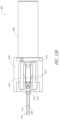
- FIG. 16is a partial assembly view of an embodiment with separate housings enclosing portions of a motor assembly and a transmission assembly.
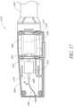
- FIG. 17is a partial assembly view showing internal components of one embodiment of a transmission assembly.
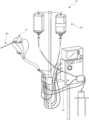
- FIGS. 1 - 3show aspects of a catheter pump 10 that can provide high performance flow rates.
- the pump 10includes a motor driven by a controller 22 .
- the controller 22directs the operation of the motor 14 and an infusion or operating fluid system 26 that supplies a flow of operating fluid or infusate in the pump 10 .
- a catheter system 80 that can be coupled with the motor 14houses an impeller within a distal portion thereof.
- the impelleris rotated remotely by the motor 14 when the pump 10 is operating.
- the motor 14can be disposed outside the patient.
- the motor 14is separate from the controller 22 , e.g., to be placed closer to the patient.
- the motor 14is part of the controller 22 .
- the controller 22is integrated into a patient-adjacent motor assembly 14 .
- the motoris miniaturized to be insertable into the patient.
- Such embodimentsallow a shaft conveying torque to an impeller or other operating element at the distal end to be much shorter, e.g., shorter than the distance from the aortic valve to the aortic arch (about 5 cm or less).
- Some examples of miniaturized motors catheter pumps and related components and methodsare discussed in U.S. Pat. Nos. 5,964,694; 6,007,478; 6,178,922; and 6,176,848, all of which are hereby incorporated by reference herein in their entirety for all purposes.
- Various embodiments of a motorare disclosed herein, including embodiments having separate drive and driven assemblies to enable the use of a guidewire guide passing through the catheter pump.
- a guidewire guidecan facilitate passing a guidewire through the catheter pump for percutaneous delivery of the pump's operative device to a patient's heart.
- a motoris separated from a drive component employing a drive belt or other tension member or off-set transmission arrangement.
- Such further embodimentscan improve access to the proximal end of a catheter assembly of the pump 10 .
- Such further embodimentsalso can improve operation of the rotating components of the pump 10 .
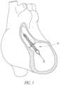
- FIG. 3illustrates one use of the catheter pump 10 .
- a distal portion of the pump 10which can include an impeller assembly 92 , is placed in the left ventricle LV of the heart to pump blood from the LV into the aorta.
- the pump 10can be used in this way to treat patients with a wide range of conditions, including cardiogenic shock, myocardial infarction, and other cardiac conditions, and also to support a patient during a procedure such as percutaneous coronary intervention.
- One convenient manner of placement of the distal portion of the pump 10 in the heartis by percutaneous access and delivery using the Seldinger technique or other methods familiar to cardiologists. These approaches enable the pump 10 to be used in emergency medicine, a catheter lab and in other non-surgical settings.
- Modificationscan also enable the pump 10 to support the right side of the heart.
- Example modifications that could be used for right side supportinclude providing delivery features and/or shaping a distal portion that is to be placed through at least one heart valve from the venous side, such as is discussed in U.S. Pat. Nos. 6,544,216; 7,070,555; and US 2012-0203056A1, all of which are hereby incorporated by reference herein in their entirety for all purposes.
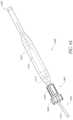
- FIG. 2shows features that facilitate small blood vessel percutaneous delivery and high performance, including up to and in some cases exceeding normal cardiac output in all phases of the cardiac cycle.
- the catheter system 80includes a catheter body 84 and a sheath assembly 88 .
- the catheter body 84can include an elongate body with proximal and distal end, in which a length of the body 84 enables the pump 10 to be applied to a patient from a peripheral vascular location.
- the impeller assembly 92is coupled with the distal end of the catheter body 84 .
- the impeller assembly 92is expandable and collapsible. In the collapsed state, the distal end of the catheter system 80 can be advanced to the heart, for example, through an artery.
- FIGS. 2 and 3illustrate the expanded state.
- the collapsed statecan be provided by advancing a distal end 94 of an elongate body 96 distally over the impeller assembly 92 to cause the impeller assembly 92 to collapse.
- Thisprovides an outer profile throughout the catheter assembly 80 that is of small diameter, for example, to a catheter size of about 12.5 FR in various arrangements.
- the impeller assembly 92includes a self-expanding material that facilitates expansion.
- the catheter body 84on the other hand preferably is a polymeric body that has high flexibility.
- the mechanical components rotatably supporting the impeller within the impeller assembly 92permit high rotational speeds while controlling heat and particle generation that can come with high speeds.
- the infusion system 26delivers a cooling and lubricating solution (sometimes referred to herein as an operating fluid) to the distal portion of the catheter system 80 for these purposes.
- an operating fluidsometimes referred to herein as an operating fluid
- the space for delivery of this fluidis extremely limited. Some of the space is also used for return of the operating fluid.
- Providing secure connection and reliable routing of operating fluid into and out of the catheter assembly 80is critical and challenging in view of the small profile of the catheter body 84 .
- the catheter pump systemWhen activated, the catheter pump system can effectively increase the flow of blood out of the heart and through the patient's vascular system.
- the pumpcan be configured to produce a maximum flow rate (e.g. low mm Hg) of greater than 4 Lpm, greater than 4.5 Lpm, greater than 5 Lpm, greater than 5.5 Lpm, greater than 6 Lpm, greater than 6.5 Lpm, greater than 7 Lpm, greater than 7.5 Lpm, greater than 8 Lpm, greater than 9 Lpm, or greater than 10 Lpm.
- a maximum flow ratee.g. low mm Hg
- the pumpcan be configured to produce an average flow rate at 62 mmHg of greater than 2 Lpm, greater than 2.5 Lpm, greater than 3 Lpm, greater than 3.5 Lpm, greater than 4 Lpm, greater than 4.25 Lpm, greater than 4.5 Lpm, greater than 5 Lpm, greater than 5.5 Lpm, or greater than 6 Lpm.
- FIG. 4Another example of a catheter assembly 100 A is illustrated in FIG. 4 .
- Embodiments of the catheter pump of this applicationcan be configured with a motor that is capable of coupling to (and in some arrangements optionally decoupling from) the catheter assembly 100 A.
- This arrangementprovides a number of advantages over a non-disconnectable motor.
- accesscan be provided to a proximal end of the catheter assembly 100 A prior to or during use.
- a catheter pumpis delivered over a guidewire.
- the guidewiremay be conveniently extended through the entire length of the catheter assembly 100 A and out of a proximal portion thereof that is completely enclosed in a coupled configuration.
- connection of the proximal portion of the catheter assembly 100 A to a motor housingcan be completed after a guidewire has been used to guide the operative device of the catheter pump to a desired location within the patient, e.g., to a chamber of the patient's heart.
- a housing enclosing a portion of a motor or drive assemblyprovides proximal end access to a guidewire lumen or to one or a plurality of ports or conduits for removing fluids from the assembly 100 A.
- the connection between the motor housing and the catheter assemblyis configured to be permanent, such that the catheter assembly, the motor housing and the motor are disposable components.
- the coupling between the motor housing and the catheter assemblyis disengageable, such that the motor and motor housing can be decoupled from the catheter assembly after use.
- the catheter assembly distal of the motorcan be disposable, and the motor and motor housing can be re-usable.
- the motorcan be configured in various manner such that the connection to the rotating shaft can be made within the motor housing or adjacent the housing depending on the application and design parameters. For example, it may be desired to configure the motor so it can be re-used as capital equipment and the catheter is disposable.
- a priming apparatus 1400can be disposed over an impeller assembly 116 A.
- the impeller assembly 116 Acan include an expandable cannula or housing and an impeller with one or more blades. As the impeller rotates, blood can be pumped proximally (or distally in some implementations) to function as a cardiac assist device.
- FIG. 4also shows one example of a priming apparatus 1400 disposed over the impeller assembly 116 A near the distal end 170 A of the elongate body 174 A.
- FIG. 4 Ais an enlarged view of the priming apparatus 1400 shown in FIG. 4 .
- the priming apparatus 1400can be used in connection with a procedure to expel air from the impeller assembly 116 A, e.g., any air that is trapped within the housing or that remains within the elongate body 174 A near the distal end 170 A.
- the priming proceduremay be performed before the pump is inserted into the patient's vascular system, so that air bubbles are not allowed to enter and/or injure the patient.
- the priming apparatus 1400can include a primer housing 1401 configured to be disposed around both the elongate body 174 A and the impeller assembly 116 A.
- a sealing cap 1406can be applied to the proximal end 1402 of the primer housing 1401 to substantially seal the priming apparatus 1400 for priming, i.e., so that air does not proximally enter the elongate body 174 A and also so that priming fluid does not flow out of the proximal end of the housing 1401 .
- the sealing cap 1406can couple to the primer housing 1401 in any way known to a skilled artisan.
- the sealing cap 1406is threaded onto the primer housing by way of a threaded connector 1405 located at the proximal end 1402 of the primer housing 1401 .
- the sealing cap 1406can include a sealing recess disposed at the distal end of the sealing cap 1406 .
- the sealing recesscan be configured to allow the elongate body 174 A to pass through the sealing cap 1406 .
- the priming operationcan proceed by introducing fluid into the sealed priming apparatus 1400 to expel air from the impeller assembly 116 A and the elongate body 174 A.
- Fluidcan be introduced into the priming apparatus 1400 in a variety of ways.
- fluidcan be introduced distally through the elongate body 174 A into the priming apparatus 1400 .
- an inletsuch as a luer, can optionally be formed on a side of the primer housing 1401 to allow for introduction of fluid into the priming apparatus 1400 .
- a gas permeable membranecan be disposed on a distal end 1404 of the primer housing 1401 .
- the gas permeable membranecan permit air to escape from the primer housing 1401 during priming.
- the priming apparatus 1400also can advantageously be configured to collapse an expandable portion of the catheter assembly 100 A.
- the primer housing 1401can include a funnel 1415 where the inner diameter of the housing decreases from distal to proximal.
- the funnel 1415may be gently curved such that relative proximal movement of an impeller housing of the impeller assembly 116 A causes the impeller housing to be collapsed by the funnel 1415 .
- the distal end 170 A of the elongate body 174 Acan be moved distally relative to the collapsed housing.
- the catheter assembly 100 Acan be removed from the priming housing 1400 before a percutaneous heart procedure is performed, e.g., before the pump is activated to pump blood.
- the embodiments disclosed hereinmay be implemented such that the total time for infusing the system is minimized or reduced.
- the time to fully infuse the systemcan be about six minutes or less.
- the time to infusecan be about three minutes or less.
- the total time to infuse the systemcan be about 45 seconds or less. It should be appreciated that lower times to infuse can be advantageous for use with cardiovascular patients.
- the elongate body 174 Aextends proximally from the impeller assembly 116 A to an infusate device 195 configured to allow for infusate to enter the catheter assembly 100 A and for waste fluid to leave the catheter assembly 100 A.
- a catheter body 120 A(which also passes through the elongate body 174 A) can extend proximally and couple to a driven assembly 201 .
- the driven assembly 201can be configured to receive torque applied by a drive assembly 203 , which is shown as being decoupled from the driven assembly 201 and the catheter assembly 100 A in FIG. 4 .
- a drive shaftcan extend from the driven assembly 201 through the catheter body 120 A to couple to an impeller shaft at or proximal to the impeller assembly 116 A.
- the catheter body 120 Acan pass within the elongate catheter body 174 A such that the external catheter body 174 A can axially translate relative to the catheter body 120 A.
- FIG. 4illustrates a guidewire 235 extending from a proximal guidewire opening 237 in the driven assembly 201 .
- a clinicianmay insert the guidewire 235 through the patient's vascular system to the heart to prepare a path for the operative device (e.g., the impeller assembly 116 A) to the heart.
- the catheter assemblycan include a guidewire guide tube (see FIG. 12 ) passing through a central internal lumen of the catheter assembly 100 A from the proximal guidewire opening 237 .
- the guidewire guide tubecan be pre-installed in the catheter assembly 100 A to provide the clinician with a preformed pathway along which to insert the guidewire 235 .
- a guidewireis first placed in a conventional way, e.g., through a needle into a peripheral blood vessel, and along the path between that blood vessel and the heart and into a heart chamber, e.g., into the left ventricle. Thereafter, a distal end opening of the catheter assembly 100 A or guidewire guide tube 312 (discussed below in connection with FIGS. 13 and 14 ) can be advanced over the proximal end of the guidewire 235 to enable delivery to the catheter assembly 100 A. After the proximal end of the guidewire 235 is urged proximally within the catheter assembly 100 A and emerges from the guidewire opening 237 and/or guidewire guide, the catheter assembly 100 A can be advanced into the patient.
- the guidewire guideis withdrawn proximally while holding the catheter assembly 100 A.
- the guidewire guide tube 312is taken off of the catheter assembly 100 A so that guidewire lumens from the proximal end to the distal end of the catheter assembly 100 A are directly over the guidewire.
- the cliniciancan thus insert the guidewire 235 through the proximal guidewire opening 237 and urge the guidewire 235 along the guidewire guide tube until the guidewire 235 extends from a distal guidewire opening (not shown) in the distal end of the catheter assembly 100 A.
- the cliniciancan continue urging the guidewire 235 through the patient's vascular system until the distal end of the guidewire 235 is positioned in the desired chamber of the patient's heart.
- a proximal end portion of the guidewire 235can extend from the proximal guidewire opening 237 .
- the cliniciancan maneuver the impeller assembly 116 A over the guidewire 235 until the impeller assembly 116 A reaches the distal end of the guidewire 235 in the heart.
- the cliniciancan remove the guidewire 235 and the guidewire guide tube.
- the guidewire guide tubecan also be removed before or after the guidewire 235 is removed in some implementations.
- the cliniciancan activate a motor to rotate the impeller and begin operation of the pump.
- a central lumen or tubee.g., a guidewire guide
- a motor or drive assemblyhaving a lumen through which the guidewire 235 can pass.
- the drive assembly 203can be securely coupled to the driven assembly 201 such that vibratory, axial, or other external forces do not decouple the drive assembly 203 from the driven assembly 201 during operation.
- separating the motor 14 from the driven assembly 201enhances smooth operation by reducing vibrations in the driven assembly 201 and also provides better access to the proximal end of the catheter assembly 100 A.
- the motor 14can be laterally offset form the driven assembly 201 . Laterally offset includes arrangements where the motor 14 is disposed to the side of a rotational axis of the driven assembly 201 .
- the motor 14can have an output shaft that rotates about an axis that is parallel to the rotational axis of the driven assembly 201 .
- a plane perpendicular to and intersecting the output shaft of the motor 14 and/or perpendicular to and intersecting a drive component coupled with the output shaftcan intersect a drive component disposed in the driven assembly 201 .
- the motor 14can be axially spaced form the driven assembly 201 .
- the motor 14also can be rotationally separate from the driven assembly.
- FIG. 5illustrates one embodiment of a motor assembly 206 as the driven assembly 201 is being coupled to the drive assembly 203 .
- the driven assembly 201can include a flow diverter 205 and a flow diverter housing 207 that houses the flow diverter 205 .
- the flow diverter 205can be configured with a plurality of internal cavities, passages, and channels that are configured to route fluid to and from the patient during a medical procedure.
- an infusatecan be directed into the flow diverter from a source of infusate.
- the infusateis a fluid that flows into the catheter body 120 A to provide useful benefits, such as cooling moving parts and keeping blood from entering certain parts of the catheter assembly 100 A.
- the infusateis diverted distally by flow channels in the flow diverter 205 . Some of the infusate that flows distally is re-routed back through the catheter body 120 A and may be diverted out of the catheter assembly 100 A by the flow diverter 205 .
- a driven magnet 204can be disposed within the flow diverter 205 in various embodiments.
- the driven magnet 204can be journaled for rotation in a proximal portion of the flow diverter housing 207 .
- the proximal portioncan project proximally of a proximal face of a distal portion of the flow diverter housing 207 .
- the driven magnet 204can be disposed outside the flow diverter 205 .
- the driven magnet 204can be configured to rotate freely relative to the flow diverter 205 and/or the flow diverter housing 207 .
- the catheter body 120 Acan extend from a distal end of the flow diverter housing 207 .
- a drive shaft 208can pass through the catheter body 120 A from the proximal end of the flow diverter housing 207 to the distal end 170 A of the elongate body 174 A.
- the drive shaft 208can be configured to drive the impeller located at the distal end of the catheter assembly 100 A.
- a distal end of the drive shaft 208can couple to an impeller shaft, which rotates the impeller.
- the drive assembly 203can include a drive housing 211 A or a motor housing 211 having an opening 202 in a cap 212 of the motor housing 211 .
- the motor housing 211can also have a sliding member 213 , which can be configured to couple to the patient's body by way of, e.g., a connector 291 coupled to an adhesive or bandage on the patient's body. Because the motor and motor housing 211 can have a relatively high mass, it can be important to ensure that the motor housing 211 is stably supported. In one implementation, therefore, the motor housing 211 can be supported by the patient's body by way of the sliding member 213 and the connector 291 shown in FIG. 4 .
- the sliding member 213can slide along a track 214 located on a portion of the motor housing 211 , such that relative motion between the motor assembly 206 and the patient does not decouple the sliding member 213 from the patient's body.
- the sliding member 213 and connector 291can therefore be configured to provide a structural interface between the motor housing 206 and a platform for supporting the motor housing 211 .
- the platform supporting the motor housing 211can be the patient, since the motor housing 211 may be positioned quite close to the insertion point. In other arrangements, however, the platform supporting the motor housing 211 may be an external structure.
- a securement deviceis configured to lock or secure the drive assembly 203 to the driven assembly 201 once the driven assembly 201 is fully inserted into the drive assembly 203 .
- the securement devicecan be configured to secure the drive assembly 203 to the driven assembly 201 by inserting the driven assembly 201 into the drive assembly 203 and then rotating the drive assembly 203 with respect to the driven assembly 201 .
- coupling the drive assembly 203 to the driven assembly 201may be irreversible, such that there may be no release mechanism to decouple the drive assembly 203 from the driven assembly 201 .
- the catheter assembly 100 A (including the driven assembly 201 ) and the motor housing 211may be disposable components. In other implementations, however, a release mechanism may be provided to remove the drive assembly 203 from the driven assembly 201 .
- the drive assembly 203can thereby be used multiple times in some embodiments.
- FIG. 6illustrates the motor assembly 206 in the assembled state, e.g., after the drive assembly 203 has been secured to the driven assembly 201 .
- the drive assembly 203is activated (e.g., a motor is activated to rotate an output shaft)
- the driven assembly 201which is operably coupled to the drive assembly, is also activated.
- the activated driven assemblycan cause the drive shaft 208 to rotate, which in turn causes the impeller to rotate to thereby pump blood through the patient.
- FIGS. 7 - 8illustrate the motor assembly 206 with one wall of the motor housing 211 removed so that various internal components in the housing 211 can be better illustrated.
- a motor 220can be positioned within the housing 211 and mounted by way of a motor mount 226 .
- the motor 220can operably couple to a drive magnet 221 .
- the motor 220can include an output shaft 222 that rotates the drive magnet 221 .
- the drive magnet 221can rotate relative to the motor mount 226 and the motor housing 211 . Further, in some arrangements, the drive magnet 221 can be free to translate axially between the motor mount and a barrier 224 .
- the barrier 224can be mounted to the motor housing 211 and at least partially within the cap 212 to support at least the drive magnet 221 .
- the drive assembly 203can comprise a plurality of motor windings configured to induce rotation of the drive magnet 221 .
- motor windingscan operate directly on a driven magnet within the driven assembly 201 .
- the windingscan be activated in phases to create an electric and/or magnetic field or fields and thereby commutate the driven magnet. Examples of such a configuration are described in U.S. Pat. No. 4,846,152 to Wampler et al. and U.S. Pat. No. 4,895,557 to Moise et al.
- FIG. 7 Aillustrates further details of a frameless motor assembly 14 A in which windings are used to induce rotation of a rotor 228 .
- the rotor 228can include one or more magnets and thus may correspond to the driven magnet 204 or may be coupled with the drive magnet 221 .
- the rotor 228is positioned within a stator or armature assembly 230 .
- the armature assembly 230can take any suitable form, such as including a ring-shaped or cylindrical hub in which a plurality of windings 232 are disposed.
- the windings 232are coupled by a lead 234 to a control system that is configured (e.g., with one or more processors) to supply the windings 232 with current in an ordered fashion to efficiently energize the windings to drive the rotor 228 .
- the control systemcan be part of the controller 22 .
- the rotor 228can be coupled with a shaft 236 to drive the working end of the catheter pump 10 .
- the shaft 236can be coupled with or can include the proximal end of the drive shaft 208 .
- the shaft 236is coupled with a drive component of a transmission including a tension member, as discussed further below in connection with FIGS. 15 - 17 .
- the motor assembly 14 Acan include a sensor 237 that is disposed in the magnetic field of the armature assembly 230 and/or the rotor 228 .
- the sensor 237can provide feedback to the motor control system, which may be part of the controller 22 , to assist in driving the windings of the armature assembly 230 .
- the motor assembly 14 Acan include a housing 238 in which the armature assembly 230 and rotor 228 are disposed.
- the housing 238can include a first recess configured to receive a first portion of the armature assembly 230 and a cap 239 configured to receive a second portion of the armature assembly 230 .
- the housing 238 and cap 239hold the first and second portions and thereby.
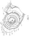
- the drive magnet 221is illustrated in phantom, such that the driven magnet 204 can be seen disposed within the drive magnet 221 .
- the poles of the drive magnet 221can be formed on an interior surface of the drive magnet 221
- the poles of the driven magnet 204can be formed on an exterior surface of the driven magnet 204 .
- the poles of the drive magnet 221can magnetically engage with corresponding, opposite poles of the driven magnet 204 to cause the driven magnet 204 to rotate with, or follow, the drive magnet 221 .
- the driven magnet 204can be mechanically coupled to the drive shaft 208 , rotation of the drive magnet 221 can cause the driven magnet 204 and the drive shaft 208 to rotate at a speed determined in part by the speed of the motor 220 . Furthermore, when the driven magnet 204 is inserted into the drive magnet 221 , the poles of each magnet can cause the drive magnet 221 and the driven magnet 204 to self-align. The magnetic forces between the drive magnet 221 and the driven magnet 204 can assist in coupling the drive assembly 203 to the driven assembly 201 .
- FIG. 9a 3D perspective view of various components at the interface between the drive assembly 203 and the driven assembly 201 is shown. Various components have been hidden to facilitate illustration of one means to secure the drive assembly 203 to the driven assembly 201 .
- a first securement device 240is illustrated in FIG. 9 .
- the first securement devicecan comprise a first projection 240 a and a second projection 240 b .
- a locking recess 244can be formed in the cap 212 around at least a portion of a perimeter of the opening 202 .
- a lip 242can also extend from the perimeter at least partially into the opening 202 .
- the lip 242can also extend proximally from the locking recess 244 such that a step is formed between the locking recess 244 and the lip 242 .
- a flange 246can be coupled to or formed integrally with the flow diverter housing 207 .
- the flange 246can include a plurality of apertures 247 a , 247 b , 247 c , 247 d that are configured to permit tubes and cables to pass therethrough to fluidly communicate with lumens within the flow diverter 205 .
- three tubes and one electrical cablecan pass through the apertures 247 a - d .
- the electrical cablecan be configured to electrically couple to a sensor within the catheter assembly 100 A, e.g., a pressure sensor.
- the three tubescan be configured to carry fluid to and from the catheter assembly 100 A.
- a first tubecan be configured to carry infusate into the catheter assembly 100 A
- a second tubecan be configured to transport fluids to the pressure sensor region
- the third tubecan be configured to transport waste fluid out of the catheter assembly 100 A.
- one or more fluid passagesmay provide fluid communication between fluid channels in the catheter assembly 100 A and a proximal portion of a transmission or drive component as discussed below in connection with FIGS. 15 - 17 .
- a fluid conduitcan be coupled with a proximal port of a shaft in a drive component or transmission to convey waste fluid to a waste container.
- the tubes and cable(s)can pass through the apertures 247 a - d of the flange 246 and can rest against the motor housing 211 .
- the apertures 247 a - dcan advantageously prevent the tubes and cable(s) from becoming entangled with one another or with other components of the catheter pump system.
- the first and second projections 240 a , 240 bcan pass through the opening and engage the locking recess 244 .
- the projections 240 a , 240 b and the locking recess 244can be sized and shaped such that axial translation of the projections 240 a , 240 b through the opening 202 causes a flange or tab 248 at a distal end of each projection 240 a , 240 b to extend over the locking recess 244 .
- the tabs 248 at the distal end of the projections 240 a , 240 bare biased to deform radially outward to engage the locking recess 244 to secure the driven assembly 201 to the drive assembly 203 .
- the flow diverter housing 207can be rotated relative to the motor cap 212 .
- the clinicianis able to position the impeller assembly 116 A within the patient at a desired angle or configuration to achieve the best pumping performance.
- the lip 242can act to restrict the relative rotation between the driven assembly 201 (e.g., the flow diverter housing 207 ) and the drive assembly 203 (e.g. the cap 212 and the motor housing 211 ).
- the flange 246 and apertures 247 a - dcan be circumferentially aligned with the projections 240 a , 240 b .
- the lip 242can be circumferentially aligned with the sliding member 213 , the track 214 , and the connector 291 of the motor housing 211 . If the flange 246 and projections 240 a , 240 b are rotated such that they circumferentially align with the lip 242 , then the tubes and cable(s) that extend from the apertures 247 a - d may become entangled with or otherwise obstructed by the sliding member 213 and the connector 291 .
- the sliding member 213 and the connector 291do not interfere or obstruct the tubes and cable(s) extending out of the apertures 247 a - d of the flange 246 .
- the lip 242 formed in the cap 212can act to solve this problem by ensuring that the flange 246 is circumferentially offset from the sliding member 213 and the connector 291 .
- the flow diverter housing 207can be rotated until one of the projections 240 a , 240 b bears against a side of the lip 242 .
- the lip 242can ensure that the flange 246 and apertures 247 a - d are circumferentially offset from the sliding member 213 , the track 214 , and the connector 291 .
- connection between the driven assembly 201 and the drive assembly 203may be configured such that the drive assembly 203 may not be removed from the driven assembly 201 .
- the secure connection between the two assembliescan advantageously ensure that the motor housing 211 is not accidentally disengaged from the catheter assembly 100 A during a medical procedure.
- both the catheter assembly 100 A and the drive assembly 203may preferably be disposable.
- the drive assembly 203may be removably engaged with the catheter assembly 100 A (e.g., engaged with the driven assembly 201 ).
- the lip 242may be sized and shaped such that when the drive assembly 203 is rotated relative to the driven assembly 201 , the tabs 248 are deflected radially inward over the lip 242 such that the driven assembly 201 can be withdrawn from the opening 202 .
- the lip 242may include a ramped portion along the sides of the lip 242 to urge the projections 240 a , 240 b radially inward. It should be appreciated that other release mechanisms are possible.
- FIGS. 10 A- 10 Can additional means to secure the drive assembly 203 to the driven assembly 201 is disclosed.
- a locking O-ring 253can be mounted to the barrier 224 that is disposed within the motor housing 211 and at least partially within the cap 212 .
- the locking O-ring 253can be mounted on an inner surface of the drive or motor housing 203 surrounding the recess or opening 202 into which the driven assembly 212 can be received
- the locking O-ringcan act as a detent mechanism and can be configured to be secured within an arcuate channel formed in an outer surface of the driven assembly 201 , e.g., in an outer surface of the flow diverter 205 in some embodiments.
- various other mechanismscan act as a detent to secure the driven assembly 201 to the drive assembly 203 .
- a spring plunger or other type of spring-loaded featuremay be cut or molded into the barrier 224 , in a manner similar to the locking O-ring 253 of FIGS. 10 A- 10 C .
- the spring plunger or spring-loaded featurecan be configured to engage the arcuate channel, as explained below with respect to FIG. 10 C . Skilled artisans will understand that other types of detent mechanisms can be employed.
- FIG. 10 Billustrates the same 3D perspective of the drive assembly 203 as shown in FIG. 10 A , except the cap 212 has been hidden to better illustrate the locking O-ring 253 and a second, stabilizing O-ring 255 .
- the O-ring 255is an example of a damper that can be provided between the motor 220 and the catheter assembly 100 A.
- the dampercan provide a vibration absorbing benefit in some embodiments. In other embodiment, the damper may reduce noise when the pump is operating.
- the dampercan also both absorb vibration and reduce noise in some embodiments.
- the stabilizing O-ring 255can be disposed within the cap 212 and can be sized and shaped to fit along the inner recess forming the inner perimeter of the cap 212 .
- the stabilizing O-ring 255can be configured to stabilize the cap 212 and the motor housing 211 against vibrations induced by operation of the motor 220 .
- the stabilizing O-ring 255can absorb the vibrations transmitted through the cap 212 .
- the stabilizing O-ring 255can support the cap 212 to prevent the cap from deforming or deflecting in response to vibrations.
- the O-ring 255can act to dampen the vibrations, which can be significant given the high rotational speeds involved in the exemplary device.
- a damping materialcan also be applied around the motor 220 to further dampen vibrations.
- the damping materialcan be any suitable damping material, e.g., a visco-elastic or elastic polymer.
- the damping materialmay be applied between the motor mount 226 and the motor 220 in some embodiments.
- the damping materialmay also be applied around the body of the motor 220 between the motor 220 and the motor housing 211 .
- the damping materialmay be captured by a rib formed in the motor housing 211 . The rib may be formed around the motor 220 in some embodiments.
- the flow diverter 205(or the flow diverter housing in some embodiments) can include an arcuate channel 263 formed in an outer surface of the flow diverter 205 .
- the arcuate channel 263can be sized and shaped to receive the locking O-ring 253 when the flow diverter 205 is inserted into the opening 202 of the drive assembly 203 .
- the locking O-ring 253can be urged or slid over an edge of the channel 263 and can be retained in the arcuate channel 263 .
- the locking O-ring 253 and the arcuate channel 263can operate to act as a second securement device. Axial forces applied to the motor assembly 206 can thereby be mechanically resisted, as the walls of the arcuate channel 263 bear against the locking O-ring 253 to prevent the locking O-ring 253 from translating relative to the arcuate channel 263 .
- other internal locking mechanismse.g., within the driven assembly 201 and/or the drive assembly 203
- the driven magnet 204 and the drive magnet 221may be configured to assist in securing the two assemblies together, in addition to aligning the poles of the magnets. Other internal locking mechanisms may be suitable.
- FIG. 10 Calso illustrates a resealable member 266 disposed within the proximal end portion of the driven assembly 201 , e.g., the proximal end of the catheter assembly 100 A as shown in FIG. 4 .
- the proximal guidewire opening 237can be formed in the resealable member 266 .
- the guidewire 235can be inserted through the proximal guidewire opening 237 and can be maneuvered through the patient's vasculature. After guiding the operative device of the pump to the heart, the guidewire 235 can be removed from the catheter assembly 100 A by pulling the guidewire 235 out through the proximal guidewire opening 237 .
- the resealable member 266can therefore be formed of an elastic, self-sealing material that is capable of closing and sealing the proximal guidewire opening 237 when the guidewire 235 is removed.
- the resealable membercan be formed of any suitable material, such as an elastomeric material.
- the resealable member 266can be formed of any suitable polymer, e.g., a silicone or polyisoprene polymer. Skilled artisans will understand that other suitable materials may be used.
- FIG. 11illustrates yet another embodiment of a motor assembly 206 A coupled to a catheter assembly.
- a flow diverteris disposed over and coupled to a catheter body 271 that can include a multi-lumen sheath configured to transport fluids into and away from the catheter assembly.
- the flow diverter 205 Acan provide support to the catheter body 271 and a drive shaft configured to drive the impeller assembly.
- the motor assembly 206 Acan include a motor 220 A that has a hollow lumen therethrough.
- the guidewire 235may extend through the proximal guidewire opening 237 A formed proximal to the motor 220 A, rather than between the motor 220 A and the flow diverter 205 A.
- a resealable member 266 Amay be formed in the proximal guidewire opening 237 A such that the resealable member 266 A can close the opening 237 A when the guidewire 235 is removed from the catheter assembly.
- a rotary seal 273may be disposed inside a lip of the flow diverter 205 A. The rotary seal 273 may be disposed over and may contact a motor shaft extending from the motor 220 A. The rotary seal 273 can act to seal fluid within the flow diverter 205 A. In some embodiments, a hydrodynamic seal can be created to prevent fluid from breaching the rotary seal 273 .
- the motor 220 Acan be permanently secured to the flow diverter 205 A and catheter assembly. Because the proximal guidewire opening 237 is positioned proximal the motor, the motor 220 A need not be coupled with the catheter assembly in a separate coupling step. The motor 220 A and the catheter assembly can thus be disposable in this embodiment.
- the motor 220 Acan include an output shaft and rotor magnetically coupled with a rotatable magnet in the flow diverter 205 A.
- the motor 220 Acan also include a plurality of windings that are energized to directly drive the rotatable magnet in the flow diverter 205 A.
- the motor 220 Ais permanently attached to the flow diverter but is off-set to provide one or more benefits to the motor assembly 206 A. For example, the off-set position enables better support of the rotational components within the flow diverter or housing for the motor.
- FIGS. 12 A- 12 Billustrate another embodiment of a motor coupling having a driven assembly 401 and a drive assembly 403 .
- the embodiment of FIGS. 12 A- 12 Bcan include a mechanical coupling disposed between an output shaft of a motor and a proximal end of a flexible drive shaft or cable.
- the embodiment of FIGS. 12 A- 12 Bcan include a guidewire guide tube that terminates at a location distal to a motor shaft 476 that extends from a motor 420 .
- an adapter shaft 472can operably couple to the motor shaft 476 extending from the motor 420 .
- a distal end portion 477 of the adapter shaft 472can mechanically couple to a proximal portion of an extension shaft 471 having a central lumen 478 therethrough.
- one or more trajectories 473can be formed in channels within a motor housing 475 at an angle to the central lumen 478 of the extension shaft 471 .
- the motor housing 475can enclose at least the adapter shaft 472 and can include one or more slots 474 formed through a wall of the housing 475 .
- a guidewire(not shown in FIG. 12 B ) may pass through the guidewire guide tube from the distal end portion of the catheter assembly and may exit the assembly through the central lumen 478 near the distal end portion 477 of the adapter shaft 472 (or, alternatively, near the proximal end portion of the extension shaft 471 ).
- one of the extension shaft 471 and the adapter shaft 472may include a resealable member disposed therein to reseal the lumen through which the guidewire passes, as explained above.
- the extension shaft 471 and the adapter shaft 472can be combined into a single structure.
- the guidewireWhen the guidewire exits the central lumen 478 , the guidewire can pass along the angled trajectories 473 which can be formed in channels and can further pass through the slots 474 to the outside environs.
- the trajectories 473can follow from angled ports in the adapter shaft 472 .
- a cliniciancan thereby pull the guidewire through the slots 474 such that the end of the guidewire can easily be pulled from the patient after guiding the catheter assembly to the heart chamber or other desired location.
- the motor shaft 476 and motor 420need not include a central lumen for housing the guidewire. Rather, the motor shaft 476 may be solid and the guidewire can simply pass through the slots 474 formed in the side of the housing 475 .
- the drive assembly 403can mechanically couple to the driven assembly 401 .
- a distal end portion 479 of the extension shaft 471may be inserted into an opening in a flow diverter housing 455 .
- the distal end portion 479 of the extension shaft 471may be positioned within a recess 451 and may couple to a proximal end of a drive cable 450 that is mechanically coupled to the impeller assembly.
- a rotary seal 461may be positioned around the opening and can be configured to seal the motor 420 and/or motor housing 475 from fluid within the flow diverter 405 .
- the motor 420allows the motor 420 to be positioned proximal of the rotary seal in order to minimize or prevent exposing the motor 420 to fluid that may inadvertently leak from the flow diverter. It should be appreciated that the extension shaft 471 may be lengthened in order to further isolate or separate the motor 420 from the fluid diverter 405 in order to minimize the risk of leaking fluids.
- the motor 420is off-set from the proximal end of the driven assembly 401 .
- a tension member or other lateral drive componentcan be provided to engage the output shaft of the motor 420 with the driven assembly 401 .
- a belt or other tension membershown, e.g., in FIG. 16
- Other lateral drive arrangementse.g., arrangements where the motor mounted off of the rotational axis of the driven assembly 401 ) can employ one or more direct engagement components such as gears.
- FIG. 13illustrates a distal end portion 300 of a catheter assembly, such as the catheter assembly 100 A described above.
- a cannula housing 302can couple to a distal tip member 304 .
- the distal tip member 304can be configured to assist in guiding the operative device of the catheter assembly, e.g., an impeller assembly (which can be similar to or the same as impeller assembly 116 A), along the guidewire 235 .
- the exemplary distal tip member 304is formed of a flexible material and has a rounded end to prevent injury to the surrounding tissue.
- a guidewire guide tube 312can extend through a central lumen of the catheter assembly.
- the guidewire guide tube 312can pass through the impeller shaft (not shown, as the impeller is located proximal to the distal end portion 300 shown in FIG. 13 ) and a lumen formed within the distal tip member 304 .
- the guidewire guide tube 312may extend distally past the distal end of the distal tip member 304 .
- the cliniciancan introduce a proximal end of the guidewire into the distal end of the guidewire guide tube 312 , which in FIG. 13 extends distally beyond the tip member 304 .
- the guidewire guide tube 312can be removed from the catheter assembly in some implementations.
- the distal tip member 304can comprise a flexible, central body 306 , a proximal coupling member 308 , and a rounded tip 310 at the distal end of the tip member 304 .
- the central body 306can provide structural support for the distal tip member 304 .
- the proximal coupling member 308can be coupled to or integrally formed with the central body 306 .
- the proximal coupling member 308can be configured to couple the distal end of the cannula housing 302 to the distal tip member 304 .
- the rounded tip 310also referred to as a ball tip, can be integrally formed with the central body 306 at a distal end of the tip member 304 .
- the rounded tip 310is flexible and has a round shape, if the tip member 304 contacts or interacts with the patient's anatomy, the rounded tip 310 can have sufficient compliance so as to deflect away from the anatomy instead of puncturing or otherwise injuring the anatomy.
- the distal tip member 304can advantageously include sufficient structure by way of the central body 306 such that the tip member 304 can accurately track the guidewire 235 to position the impeller assembly within the heart. Yet, because the tip member 304 is made of a flexible material and includes the rounded tip 310 , any mechanical interactions with the anatomy can be clinically safe for the patient.
- FIG. 13One potential problem with the embodiment of FIG. 13 is that it can be difficult for the clinician to insert the guidewire into the narrow lumen of the guidewire guide tube 312 . Since the guidewire guide tube 312 has a small inner diameter relative to the size of the clinician's hands, the clinician may have trouble inserting the guidewire into the distal end of the guidewire guide tube 312 , which extends past the distal end of the tip member 304 in FIG. 13 . In addition, when the clinician inserts the guidewire into the guidewire guide tube 312 , the distal edges of the guidewire guide tube 312 may scratch or partially remove a protective coating applied on the exterior surface of the guidewire.
- Damage to the coating on the guidewiremay harm the patient as the partially uncoated guidewire is passed through the patient's vasculature. Accordingly, it can be desirable in various arrangements to make it easier for the clinician to insert the guidewire into the distal end of the catheter assembly, and/or to permit insertion of the guidewire into the catheter assembly while maintaining the protective coating on the guidewire.
- the cannula housing 302(which may form part of an operative device) may be collapsed into a stored configuration in some embodiments such that the cannula housing is disposed within an outer sheath.
- a distal end or edge of the outer sheathmay abut the tip member 304 .
- the distal edge of the outer sheathmay extend over the tip member 304 A, or the sheath may have an outer diameter such that the distal edge of the outer sheath is exposed.
- the distal edge of the outer sheathmay scratch, scrape, or otherwise harm the anatomy. There is a therefore a need to prevent harm to the patient's anatomy due to scraping of the distal edge of the sheath against the vasculature.
- FIG. 14is a side cross-sectional view of a distal tip member 304 A disposed at a distal end 300 A of the catheter assembly, according to another embodiment.
- the reference numerals in FIG. 14may refer to components similar to or the same as those in FIG. 13 .
- the distal tip member 304 Acan couple to a cannula housing 302 A.
- the distal tip member 304 Acan include a flexible, central body 306 A, a proximal coupling member 308 A, and a rounded tip 310 A at the distal end of the tip member 304 A.
- a guidewire guide tube 312 Acan pass through the cannula housing 302 A and a lumen passing through the distal tip member 304 A.
- the central body 306 Acan include a bump 314 disposed near a proximal portion of the tip member 304 A.
- the bump 314 illustrated in FIG. 14may advantageously prevent the outer sheath from scraping or scratching the anatomy when the sheath is advanced through the patient's vascular system.
- the sheathwill advance over the cannula housing 302 A such that the distal edge or end of the sheath will abut or be adjacent the bump 314 of the tip member 304 A.
- the bump 314can act to shield the patient's anatomy from sharp edges of the outer sheath as the distal end 300 A is advanced through the patient.
- the patientmay not be harmed when the bump 314 interact with the anatomy, because the bump 314 includes a rounded, smooth profile. Accordingly, the bump 314 in FIG. 14 may advantageously improve patient outcomes by further protecting the patient's anatomy.
- the guidewire guide tube 312 A of FIG. 14does not extend distally past the end of the tip member 306 A. Rather, in FIG. 14 , the central lumen passing through the tip member 304 A may include a proximal lumen 315 and a distal lumen 313 . As shown in FIG. 14 , the proximal lumen 315 may have an inner diameter larger than an inner diameter of the distal lumen 313 . A stepped portion or shoulder 311 may define the transition between the proximal lumen 315 and the distal lumen 313 . As illustrated in FIG.
- the inner diameter of the proximal lumen 315is sized to accommodate the guidewire guide tube 312 A as it passes through a portion of the tip member 304 A.
- the inner diameter of the distal lumen 313 in FIG. 14is sized to be smaller than the outer diameter of the guidewire guide tube 312 A such that the guidewire guide tube 312 A is too large to pass through the distal lumen 313 of the tip member 304 A.
- the thickness of the guidewire guide tube 312 Amay be made smaller than the height of the stepped portion or shoulder 311 , e.g., smaller than the difference between the inner diameter of the proximal lumen 315 and the inner diameter of the distal lumen 313 .
- the embodiment illustrated in FIG. 14may assist the clinician in inserting the guidewire (e.g., the guidewire 235 described above) into the distal end 300 A of the catheter assembly.
- the guidewire guide tube 312 Amay be inserted through the central lumen of the catheter assembly.
- the guidewire guide tube 312 Amay pass distally through a portion of the motor, the catheter body, the impeller assembly and cannula housing 302 A, and through the proximal lumen 315 of the tip member 304 A.
- the guidewire guide tube 312 Amay be urged further distally until the distal end of the guidewire guide tube 312 A reaches the shoulder 311 .
- the shoulder 311may prevent further insertion of the guidewire guide tube 312 in the distal direction. Because the inner diameter of the distal lumen 313 is smaller than the outer diameter of the guidewire guide tube 312 A, the distal end of the guidewire guide tube 312 A may be disposed just proximal of the shoulder 311 , as shown in FIG. 14 .
- the clinicianmay insert the proximal end of the guidewire (such as the guidewire 235 described above) proximally through the distal lumen 313 passing through the rounded tip 310 A at the distal end of the tip member 304 A. Because the tip member 304 A is flexible, the clinician can easily bend or otherwise manipulate the distal end of the tip member 304 A to accommodate the small guidewire. Unlike the guidewire guide tube 312 A, which may be generally stiffer than the tip member 304 A, the clinician may easily deform the tip member 304 A to urge the guidewire into the distal lumen 313 .
- the cliniciancan urge the guidewire proximally past the stepped portion 311 and into the larger guidewire guide tube 312 A, which may be positioned within the proximal lumen 315 .
- the exemplary guide tube and shoulderadvantageously avoid damaging or removing the coating.
- the shoulder 311may substantially prevent the guidewire guide tube 312 A from scraping the exterior coating off of the guidewire.
- the guidewireeasily passes from the distal lumen 313 to the proximal lumen 315 .
- the guidewiremay then be urged proximally through the impeller and catheter assembly until the guidewire protrudes from the proximal end of the system, such as through the proximal guidewire opening 237 described above with reference to FIG. 4 .
- FIGS. 15 - 17illustrate features of further embodiments in connection with a catheter pump assembly 500 .
- catheter pump assembly 500is similar to catheter assembly 100 A described above, except it includes a modified drive system 504 .
- the assembly 500includes the catheter assembly 100 A discussed above, in some cases with some modifications as discussed below.
- the catheter pump assembly 500includes a drive system 504 and a fluid removal system 508 .
- drive system 504is similar to drive system 206 described above.
- the fluid removal system 508can be part of an operating fluid system, for example incorporating components of the infusion system 26 discussed above and any of the additional features discussed below.
- the drive system 504includes a motor assembly 512 and a transmission assembly 516 that allows the motor assembly 512 to be positioned away from or off-axis from the proximal end of the catheter assembly 100 A.
- the motor assembly 512includes a housing 524 having a motor unit 528 disposed therein.
- the motor unit 528includes an electric motor 532 that is electrically coupled with and controlled by a controller, e.g., by the controller 22 .
- the housing 524is sufficiently rigid and stable to reduce or minimize external vibrations or other environmental conditions from affecting the operation of the electric motor 532 or the components mechanically coupled therewith. This can be important to ensure the forces experienced by motor are absorbed by the housing and transmitted to stabilizing platform instead of being translated through the catheter pump assembly.
- One or more motor mounts 538also can be provided to secure the motor 532 within the housing 524 .
- the motor 532can include an output shaft 540 that is rotated by a rotor of the motor 532 .
- a drive component 548is coupled with, e.g., mounted on, the output shaft 540 such that the shaft 540 and the drive component 548 are rotated about a first axis 552 .
- the transmission assembly 516can be located at least in part in a housing 564 that is separate from the housing 524 .
- the housing 564has a shaft 568 disposed therein and journaled for rotation.
- the shaft 568can be supported by bearings 570 disposed on proximal and distal ends thereof.
- a driven component 572can be coupled with, e.g., mounted on, the shaft 568 .
- the shaft 568 and the driven component 572can freely rotate in the housing 564 about a second axis 576 , which can be offset from the first axis 552 .
- the shaft 568preferably includes a lumen that can be fluidly coupled at a distal end thereof with a proximal portion of the infusion or operating fluid system 26 and at a proximal end thereof with a conduit 584 to convey the fluid to a waste vessel 588 .
- the lumen in the shaft, the conduit 584 and the vessel 588can all be part of the fluid removal system 508 .
- the operating fluid from the system 26is directed into the catheter assembly 100 A and at least a portion flows proximally over certain components of the catheter assembly 100 A.
- a rotatable magnetcan be mounted to rotate in the flow diverter housing 207 . This rotating structure is sometimes referred to herein as a rotor.
- the driven component 572can be located in a proximal portion of the housings 564 .
- the driven component 572 and the drive component 548comprise working portions of a power train between the motor and the catheter assembly 100 A.
- These componentcan take a conventional form, e.g., as gears, sprockets, pulleys, or variable torque members.
- a distal portion of the housing 564can enclose a drive component 596 configured to be rotated with the shaft 568 .
- the drive component 596is sometimes described as a second drive component and the drive component 548 is sometimes referred to as a first drive component herein.
- the use of “first” and “second” in this contextis arbitrary with the “first” member being closer to the source of torque, e.g., the motor 532 .
- the drive component 596is configured to be engaged with the proximal end of the catheter assembly 100 A in the same way discussed above, e.g., with paired permanent magnets, or with gears or other direct contact mechanical interface.
- the drive component 596can comprise a cup-like structure that can receive the proximal end of the catheter assembly 100 A.
- a driven component of the catheter assembly 100 Asuch as a rotor or other member including magnets, such as the magnets 204 , is engaged with the drive component 596 .
- FIGS. 15 and 16show that the catheter pump assembly 500 includes a tension member 604 that extends between the motor assembly 512 and the driven component 572 of the transmission assembly 516 .
- the tension member 604can be considered part of the transmission assembly 516 .
- the driven component 572which can include or be coupled with the magnets 204 , can be coupled with an elongate flexible member such as the drive shaft 208 .
- the tension member 604can be coupled with the motor unit 528 and with the driven component 572 , including the magnet or magnets 204 , to cause the driven component 572 to rotate when the motor 532 rotates and thereby cause the drive shaft 208 (or other elongate flexible member) and the impeller assembly 92 to rotate.
- the tension member 604can take any suitable form that is suitable for transferring torque between the drive and driven members 548 , 572 as will be understood by one of skill from the description herein.
- the tension member 604can comprise a drive belt such as a tooth belt, a cog belt, a notch belt, a V-belt.
- the tension member 604can comprise a chain or other flexible driving member.
- the drive and driven members 548 , 572can be cogs.
- FIGS. 15 - 17illustrate the pump catheter pump assembly 500 comprising two separate housings.
- the transmission assembly 516 and the motor assembly 512are disposed in the same housing. Separate or separable housings are advantageous in facilitating one or more re-usable components.
- the transmission assembly 516is reusable.
- the motor assembly 512is reusable.
- the transmission assembly 516can be used a first number of times. In some embodiments, the motor assembly 512 can be used a second number of times greater than the first number of times.
- the motor assemblies discussed herein and systems incorporating themprovide many advantages. For example, sterilizing the components of the catheter pumps incorporating one or more features discussed herein can be facilitated by separating the driven assembly 201 from the motor unit 528 or the motor assembly 14 A, That is, in various methods of use, a catheter assembly can be sterilized apart from a motor assembly or motor unit and/or transmission assembly. In various methods of use, the motor assembly or motor unit and/or transmission assembly can be sterilized and reused whereas the catheter assembly can be disposable. By providing transfer of rotation through a tension member, the drive components coupled with the motor unit or motor assembly and coupled with the proximal end of the catheter assembly can easily be decoupled or disassembled for separate sterilization.
- the using a tension member to transfer torque from the motor unit or motor assemblyprovides for isolation or insulation between the catheter assembly and the motor.
- Mechanical isolation of the motor from the catheter assemblyis useful in that due to normal manufacturing variation in the components of the motor, there may be noticeable vibration upon operation of the motor.
- the tension membercan absorb some of that vibration and reduce the amplitude or frequency of the vibration as felt by the catheter assembly.
- the drive component coupled with the proximal end of the catheter assemblycan be better supported so that such drive component has less or no eccentricity in rotation.
- the separation of the motor unit or motor assembly from the catheter assemblyalso enables isolation of the heat of the motor from the proximal end of the catheter assembly.
- Certain advantageous motor designsgenerate significant heat.
- the motor assembly 14 Ainduces rotation by driving current through coils to generate magnetic fields. It is preferred that the proximal end of the catheter assembly be adjacent to the patient, and in some cases mounted on the patient's leg or otherwise directly contacting the patient.
- the off-set positioning of the motor assembly 14 Aenables the heat generating components to be isolated or insulated from the patient while still permitting the proximal end of the catheter assembly to be at or on the patient. Regardless of the type of motor used, higher speeds generally generate more heat.
- the off-set positioning of the motor unit or motor assemblyalso allows the movements of the catheter assembly to not be felt by or to be only minimally felt by the motor unit or motor assembly. Any such movement or heat generated by the catheter assembly can be isolated from and thus prevented from compromising or damaging the motor.
- the structures aboveprovide for modular use of components.
- robust locking devicescan be provided between housings (see, e.g., the structures of FIG. 9 and corresponding description) enabling the catheter assembly can be securely connected to a transmission assembly.
- a tension membersuch as a belt
- a motor assembly or motor unitcan be reused one or more times while the catheter assembly will generally be disposed of in each use.
- FIG. 16shows that operating fluid can be removed from the proximal end of the catheter assembly rather than being diverted through a more complex manifold out of a side portion of the catheter assembly. This relieves the need to pressure-seal the catheter assembly at a location distal of the drive component disposed within the catheter assembly. This arrangement is also more tolerant of small breaches in seals. That is, the operating fluid may be a biocompatible fluid such as saline. Such a fluid can be corrosive to the motor unit or motor assembly.
- a guidewire passageis provided through an assembly including the catheter assembly and the transmission assembly.
- This passageenables easier access to a guidewire and in some cases reintroduction of a guidewire into a system when partially engaged.
- the transmission assemblymay be coupled with the catheter assembly while retaining the ability to advance the catheter assembly over the guidewire. This can be achieved by directing the guidewire through the same channel that the operating fluid flows, e.g., to exit the proximal end of the catheter assembly and/or transmission assembly. This allows the clinician some flexibility in the order of assembly and/or more convenient repositioning without fully disassembling the motor unit/assembly, transmission assembly, and catheter assembly.
- one or more componentscan be treated as capital equipment with the cost of such components being defrayed over many uses.
- the console, the motor unit or motor assembly, and the transmission assemblycan be re-used many times and the catheter assembly and the tension member (e.g., belt) can be disposed of after one or more uses.
Landscapes
- Health & Medical Sciences (AREA)
- Heart & Thoracic Surgery (AREA)
- Engineering & Computer Science (AREA)
- Cardiology (AREA)
- Life Sciences & Earth Sciences (AREA)
- Anesthesiology (AREA)
- Biomedical Technology (AREA)
- Hematology (AREA)
- Mechanical Engineering (AREA)
- Animal Behavior & Ethology (AREA)
- General Health & Medical Sciences (AREA)
- Public Health (AREA)
- Veterinary Medicine (AREA)
- Medical Informatics (AREA)
- Vascular Medicine (AREA)
- External Artificial Organs (AREA)
Abstract
Description
Claims (12)
Priority Applications (2)
| Application Number | Priority Date | Filing Date | Title |
|---|---|---|---|
| US17/106,569US11786720B2 (en) | 2014-04-15 | 2020-11-30 | Catheter pump with off-set motor position |
| US18/462,285US20230405302A1 (en) | 2014-04-15 | 2023-09-06 | Catheter pump with off-set motor position |
Applications Claiming Priority (5)
| Application Number | Priority Date | Filing Date | Title |
|---|---|---|---|
| US201461979876P | 2014-04-15 | 2014-04-15 | |
| PCT/US2015/025959WO2015160942A1 (en) | 2014-04-15 | 2015-04-15 | Catheter pump with off-set motor position |
| US201615303711A | 2016-10-12 | 2016-10-12 | |
| US16/776,122US11173297B2 (en) | 2014-04-15 | 2020-01-29 | Catheter pump with off-set motor position |
| US17/106,569US11786720B2 (en) | 2014-04-15 | 2020-11-30 | Catheter pump with off-set motor position |
Related Parent Applications (1)
| Application Number | Title | Priority Date | Filing Date |
|---|---|---|---|
| US16/776,122ContinuationUS11173297B2 (en) | 2014-04-15 | 2020-01-29 | Catheter pump with off-set motor position |
Related Child Applications (1)
| Application Number | Title | Priority Date | Filing Date |
|---|---|---|---|
| US18/462,285ContinuationUS20230405302A1 (en) | 2014-04-15 | 2023-09-06 | Catheter pump with off-set motor position |
Publications (2)
| Publication Number | Publication Date |
|---|---|
| US20210077677A1 US20210077677A1 (en) | 2021-03-18 |
| US11786720B2true US11786720B2 (en) | 2023-10-17 |
Family
ID=54324536
Family Applications (4)
| Application Number | Title | Priority Date | Filing Date |
|---|---|---|---|
| US15/303,711Active2036-08-14US10583232B2 (en) | 2014-04-15 | 2015-04-15 | Catheter pump with off-set motor position |
| US16/776,122Active2035-09-11US11173297B2 (en) | 2014-04-15 | 2020-01-29 | Catheter pump with off-set motor position |
| US17/106,569Active2035-11-12US11786720B2 (en) | 2014-04-15 | 2020-11-30 | Catheter pump with off-set motor position |
| US18/462,285PendingUS20230405302A1 (en) | 2014-04-15 | 2023-09-06 | Catheter pump with off-set motor position |
Family Applications Before (2)
| Application Number | Title | Priority Date | Filing Date |
|---|---|---|---|
| US15/303,711Active2036-08-14US10583232B2 (en) | 2014-04-15 | 2015-04-15 | Catheter pump with off-set motor position |
| US16/776,122Active2035-09-11US11173297B2 (en) | 2014-04-15 | 2020-01-29 | Catheter pump with off-set motor position |
Family Applications After (1)
| Application Number | Title | Priority Date | Filing Date |
|---|---|---|---|
| US18/462,285PendingUS20230405302A1 (en) | 2014-04-15 | 2023-09-06 | Catheter pump with off-set motor position |
Country Status (2)
| Country | Link |
|---|---|
| US (4) | US10583232B2 (en) |
| WO (1) | WO2015160942A1 (en) |
Cited By (9)
| Publication number | Priority date | Publication date | Assignee | Title |
|---|---|---|---|---|
| US12064615B2 (en) | 2018-05-30 | 2024-08-20 | Kardion Gmbh | Axial-flow pump for a ventricular assist device and method for producing an axial-flow pump for a ventricular assist device |
| US12107474B2 (en) | 2018-05-16 | 2024-10-01 | Kardion Gmbh | End-face rotating joint for transmitting torques |
| US12144976B2 (en) | 2018-06-21 | 2024-11-19 | Kardion Gmbh | Method and device for detecting a wear condition of a ventricular assist device and for operating same, and ventricular assist device |
| US12194287B2 (en) | 2018-05-30 | 2025-01-14 | Kardion Gmbh | Method of manufacturing electrical conductor tracks in a region of an intravascular blood pump |
| US12201823B2 (en) | 2018-05-30 | 2025-01-21 | Kardion Gmbh | Line device for conducting a blood flow for a heart support system, heart support system, and method for producing a line device |
| US12263333B2 (en) | 2018-06-21 | 2025-04-01 | Kardion Gmbh | Stator vane device for guiding the flow of a fluid flowing out of an outlet opening of a ventricular assist device, ventricular assist device with stator vane device, method for operating a stator vane device and manufacturing method |
| US12383727B2 (en) | 2018-05-30 | 2025-08-12 | Kardion Gmbh | Motor housing module for a heart support system, and heart support system and method for mounting a heart support system |
| US12390633B2 (en) | 2018-08-07 | 2025-08-19 | Kardion Gmbh | Bearing device for a heart support system, and method for rinsing a space in a bearing device for a heart support system |
| US12403296B2 (en) | 2018-05-30 | 2025-09-02 | Kardion Gmbh | Apparatus for anchoring a ventricular assist system in a blood vessel, operating method, production method for producing an apparatus and ventricular assist system |
Families Citing this family (47)
| Publication number | Priority date | Publication date | Assignee | Title |
|---|---|---|---|---|
| CN102380135A (en) | 2006-03-23 | 2012-03-21 | 宾州研究基金会 | Heart assist device with expandable impeller pump |
| US9358329B2 (en) | 2012-07-03 | 2016-06-07 | Thoratec Corporation | Catheter pump |
| US20170312403A1 (en) | 2016-04-27 | 2017-11-02 | Sarah Elizabeth Hagarty | Simple Closed Loop System for Direct Harvest and Transfer for High Volume Fat Grafting |
| EP3808401A1 (en) | 2016-07-21 | 2021-04-21 | Tc1 Llc | Gas-filled chamber for catheter pump motor assembly |
| US11160970B2 (en) | 2016-07-21 | 2021-11-02 | Tc1 Llc | Fluid seals for catheter pump motor assembly |
| CA3039285A1 (en) | 2016-10-25 | 2018-05-03 | Magenta Medical Ltd. | Ventricular assist device |
| DE102017102824A1 (en)* | 2017-02-13 | 2018-08-16 | Cardiobridge Gmbh | Catheter pump with drive unit and catheter |
| US20200054824A1 (en)* | 2017-05-05 | 2020-02-20 | Sarah Elizabeth Hagarty | A system for the harvest and transfer for high volume fat grafting using a centrifugal pump |
| CA3066361A1 (en) | 2017-06-07 | 2018-12-13 | Shifamed Holdings, Llc | Intravascular fluid movement devices, systems, and methods of use |
| EP3668558B1 (en)* | 2017-08-14 | 2025-07-23 | Heartware, Inc. | Pump to motor connection system |
| EP3443993A1 (en)* | 2017-08-17 | 2019-02-20 | Berlin Heart GmbH | Pump with a rotor sensor for recording physiologic parameters, flow and motion parameters |
| WO2019094963A1 (en) | 2017-11-13 | 2019-05-16 | Shifamed Holdings, Llc | Intravascular fluid movement devices, systems, and methods of use |
| US10905808B2 (en) | 2018-01-10 | 2021-02-02 | Magenta Medical Ltd. | Drive cable for use with a blood pump |
| EP3638336B1 (en) | 2018-01-10 | 2022-04-06 | Magenta Medical Ltd. | Ventricular assist device |
| DE102018201030B4 (en) | 2018-01-24 | 2025-10-16 | Kardion Gmbh | Magnetic dome element with magnetic bearing function |
| CN112004563B (en) | 2018-02-01 | 2024-08-06 | 施菲姆德控股有限责任公司 | Intravascular blood pump and methods of use and manufacture |
| US11213294B2 (en)* | 2018-03-28 | 2022-01-04 | Cilag Gmbh International | Surgical instrument comprising co-operating lockout features |
| DE102018207611A1 (en) | 2018-05-16 | 2019-11-21 | Kardion Gmbh | Rotor bearing system |
| DE102018208879A1 (en) | 2018-06-06 | 2020-01-30 | Kardion Gmbh | Method for determining a total fluid volume flow in the area of an implanted, vascular support system |
| DE102018208945A1 (en) | 2018-06-06 | 2019-12-12 | Kardion Gmbh | An analysis device and method for analyzing a viscosity of a fluid |
| DE102018208929A1 (en) | 2018-06-06 | 2019-12-12 | Kardion Gmbh | A method of determining a flow rate of fluid flowing through an implanted vascular support system |
| DE102018208913A1 (en) | 2018-06-06 | 2019-12-12 | Kardion Gmbh | A method of operating an implanted ventricular assist device |
| DE102018208899A1 (en) | 2018-06-06 | 2019-12-12 | Kardion Gmbh | A method for determining the speed of sound in a fluid in the region of an implanted vascular support system |
| DE102018208936A1 (en) | 2018-06-06 | 2019-12-12 | Kardion Gmbh | Determining device and method for determining a viscosity of a fluid |
| DE102018208933A1 (en) | 2018-06-06 | 2019-12-12 | Kardion Gmbh | A method of determining a flow rate of fluid flowing through an implanted vascular support system |
| DE102018208862A1 (en) | 2018-06-06 | 2019-12-12 | Kardion Gmbh | Implantable vascular support system |
| DE102018211327A1 (en) | 2018-07-10 | 2020-01-16 | Kardion Gmbh | Impeller for an implantable vascular support system |
| DE102018212153A1 (en) | 2018-07-20 | 2020-01-23 | Kardion Gmbh | Inlet line for a pump unit of a cardiac support system, cardiac support system and method for producing an inlet line for a pump unit of a cardiac support system |
| US12161857B2 (en) | 2018-07-31 | 2024-12-10 | Shifamed Holdings, Llc | Intravascular blood pumps and methods of use |
| WO2020073047A1 (en) | 2018-10-05 | 2020-04-09 | Shifamed Holdings, Llc | Intravascular blood pumps and methods of use |
| AU2020211431B2 (en) | 2019-01-24 | 2024-10-24 | Magenta Medical Ltd | Ventricular assist device |
| EP3753594A1 (en)* | 2019-06-18 | 2020-12-23 | Abiomed Europe GmbH | System and method for preparing a catheter before use |
| WO2021011473A1 (en) | 2019-07-12 | 2021-01-21 | Shifamed Holdings, Llc | Intravascular blood pumps and methods of manufacture and use |
| US11654275B2 (en) | 2019-07-22 | 2023-05-23 | Shifamed Holdings, Llc | Intravascular blood pumps with struts and methods of use and manufacture |
| WO2021062265A1 (en) | 2019-09-25 | 2021-04-01 | Shifamed Holdings, Llc | Intravascular blood pump systems and methods of use and control thereof |
| EP4501393A3 (en) | 2019-09-25 | 2025-04-09 | Shifamed Holdings, LLC | Catheter blood pumps and collapsible pump housings |
| US12121713B2 (en) | 2019-09-25 | 2024-10-22 | Shifamed Holdings, Llc | Catheter blood pumps and collapsible blood conduits |
| EP4072650A4 (en) | 2019-12-11 | 2024-01-10 | Shifamed Holdings, LLC | Descending aorta and vena cava blood pumps |
| WO2021150355A1 (en) | 2020-01-21 | 2021-07-29 | Boston Scientific Scimed Inc | Electromagnetically driven blood pump |
| DE102020102474A1 (en) | 2020-01-31 | 2021-08-05 | Kardion Gmbh | Pump for conveying a fluid and method for manufacturing a pump |
| US20230043385A1 (en)* | 2020-02-05 | 2023-02-09 | Shifamed Holdings, Llc | Intravascular blood pumps, motors, and fluid control |
| US12076548B2 (en)* | 2020-03-03 | 2024-09-03 | Boston Scientific Scimed, Inc. | Blood pump with pivotable housing |
| EP3984589B1 (en) | 2020-04-07 | 2023-08-23 | Magenta Medical Ltd. | Magnetic phase sensing |
| NL2028130B1 (en) | 2021-05-03 | 2022-11-10 | Cardiacbooster B V | Cardiac assist device with high frequency operation |
| CN115192895A (en)* | 2022-07-01 | 2022-10-18 | 微创投资控股有限公司 | Medical instrument |
| CN116212228A (en)* | 2023-03-23 | 2023-06-06 | 深圳核心医疗科技股份有限公司 | Blood pump distal extension, inlet window assembly and blood pump |
| CN116236684B (en)* | 2023-04-26 | 2024-03-12 | 心擎医疗(苏州)股份有限公司 | Catheter pump |
Citations (448)
| Publication number | Priority date | Publication date | Assignee | Title |
|---|---|---|---|---|
| US1902418A (en) | 1931-11-02 | 1933-03-21 | Jensen Salsbery Lab Inc | Surgical instrument |
| US2356659A (en) | 1941-11-24 | 1944-08-22 | Aguiar Clovis De Paiva | Nozzle for duodenal pump tubes |
| US2649052A (en) | 1947-04-17 | 1953-08-18 | Marine Products Company | Rotary pump or motor |
| US2664050A (en) | 1949-03-02 | 1953-12-29 | Gen Motors Corp | Domestic appliance |
| US2684035A (en) | 1947-10-02 | 1954-07-20 | Philip G Kemp | Fluid pump |
| US2789511A (en) | 1953-05-25 | 1957-04-23 | Jabsco Pump Co | Flexible vane pump impeller |
| US2896926A (en) | 1956-01-10 | 1959-07-28 | Chapman Harold Eric | Device for mixing or treating fluids or free-flowing powders |
| US2935068A (en) | 1955-08-04 | 1960-05-03 | Donaldson John Shearman | Surgical procedure and apparatus for use in carrying out the same |
| US3025647A (en) | 1960-01-12 | 1962-03-20 | Harvey H Moody | Two-way positive cable drive mechanism |
| US3080824A (en) | 1961-02-27 | 1963-03-12 | James A Boyd | Fluid moving device |
| US3135943A (en) | 1962-04-10 | 1964-06-02 | Welex Electronics | Underwater thermometric apparatus |
| US3455540A (en) | 1968-01-04 | 1969-07-15 | Emil G Marcmann | Stirring device |
| US3510229A (en) | 1968-07-23 | 1970-05-05 | Maytag Co | One-way pump |
| JPS4823295U (en) | 1971-07-23 | 1973-03-16 | ||
| US3812812A (en) | 1973-06-25 | 1974-05-28 | M Hurwitz | Trolling propeller with self adjusting hydrodynamic spoilers |
| US3860968A (en) | 1969-11-20 | 1975-01-21 | Max Shapiro | Compact, implantable apparatus for pumping blood to sustain blood circulation in a living body |
| US3904901A (en) | 1972-11-03 | 1975-09-09 | Anvar | Rotary electric machine with super-conducting winding |
| FR2267800A1 (en) | 1974-04-17 | 1975-11-14 | Anvar | Catheter insertion system - uses auxiliary fluid injected in catheter and forming propulsion jets |
| US3995617A (en) | 1972-05-31 | 1976-12-07 | Watkins David H | Heart assist method and catheter |
| US4115040A (en) | 1976-05-28 | 1978-09-19 | Franz Klaus-Union | Permanent magnet type pump |
| US4129129A (en) | 1977-03-18 | 1978-12-12 | Sarns, Inc. | Venous return catheter and a method of using the same |
| US4135253A (en) | 1976-11-30 | 1979-01-23 | Medtronic, Inc. | Centrifugal blood pump for cardiac assist |
| US4143425A (en) | 1977-10-27 | 1979-03-13 | Runge Thomas M | Left atrial to descending thoracic aorta left ventricular assist device |
| US4149535A (en) | 1976-05-06 | 1979-04-17 | Gist-Brocades N.V. | Catheter holding device |
| US4304524A (en) | 1979-09-07 | 1981-12-08 | Woodcoxon Engineering (International) Limited | Marine propellers |
| US4382199A (en) | 1980-11-06 | 1983-05-03 | Nu-Tech Industries, Inc. | Hydrodynamic bearing system for a brushless DC motor |
| US4392836A (en) | 1980-05-21 | 1983-07-12 | Kanto Seiki Co., Ltd. | Device for connecting speedometer to flexible shaft |
| US4458366A (en) | 1975-05-09 | 1984-07-10 | Macgregor David C | Artificial implantable blood pump |
| US4540402A (en) | 1982-04-20 | 1985-09-10 | Karl Aigner | Double perfusion catheter |
| US4560375A (en) | 1983-06-30 | 1985-12-24 | Pudenz-Schulte Medical Research Corp. | Flow control valve |
| JPS6114101A (en) | 1984-06-29 | 1986-01-22 | Nippon Sanso Kk | Hydrogen purification equipment |
| US4589822A (en) | 1984-07-09 | 1986-05-20 | Mici Limited Partnership Iv | Centrifugal blood pump with impeller |
| US4625712A (en) | 1983-09-28 | 1986-12-02 | Nimbus, Inc. | High-capacity intravascular blood pump utilizing percutaneous access |
| US4655745A (en) | 1985-07-29 | 1987-04-07 | Corbett Joseph E | Ventricular catheter |
| US4686982A (en) | 1985-06-19 | 1987-08-18 | John Nash | Spiral wire bearing for rotating wire drive catheter |
| US4696667A (en) | 1986-03-20 | 1987-09-29 | Helmut Masch | Intravascular catheter and method |
| US4704121A (en) | 1983-09-28 | 1987-11-03 | Nimbus, Inc. | Anti-thrombogenic blood pump |
| US4728319A (en) | 1986-03-20 | 1988-03-01 | Helmut Masch | Intravascular catheter |
| US4753221A (en) | 1986-10-22 | 1988-06-28 | Intravascular Surgical Instruments, Inc. | Blood pumping catheter and method of use |
| US4769006A (en) | 1985-05-13 | 1988-09-06 | Kos Medical Technologies, Ltd. | Hydrodynamically propelled pacing catheter |
| US4817586A (en) | 1987-11-24 | 1989-04-04 | Nimbus Medical, Inc. | Percutaneous bloom pump with mixed-flow output |
| US4846152A (en) | 1987-11-24 | 1989-07-11 | Nimbus Medical, Inc. | Single-stage axial flow blood pump |
| US4895557A (en) | 1987-12-07 | 1990-01-23 | Nimbus Medical, Inc. | Drive mechanism for powering intravascular blood pumps |
| US4900227A (en) | 1988-06-14 | 1990-02-13 | Thomson-Brandt-Armements | Wind power of hydraulic power machine with axial feed, radial outflow, and variable geometry vanes, and projectiles fitted with wind power or hydraulic power machines of this type |
| US4902272A (en) | 1987-06-17 | 1990-02-20 | Abiomed Cardiovascular, Inc. | Intra-arterial cardiac support system |
| US4906229A (en) | 1988-05-03 | 1990-03-06 | Nimbus Medical, Inc. | High-frequency transvalvular axisymmetric blood pump |
| US4908012A (en) | 1988-08-08 | 1990-03-13 | Nimbus Medical, Inc. | Chronic ventricular assist system |
| US4919647A (en) | 1988-10-13 | 1990-04-24 | Kensey Nash Corporation | Aortically located blood pumping catheter and method of use |
| US4944722A (en) | 1989-02-23 | 1990-07-31 | Nimbus Medical, Inc. | Percutaneous axial flow blood pump |
| US4955856A (en) | 1989-06-30 | 1990-09-11 | Phillips Steven J | Method and apparatus for installing a ventricular assist device cannulae |
| US4957504A (en) | 1988-12-02 | 1990-09-18 | Chardack William M | Implantable blood pump |
| US4964864A (en) | 1988-09-27 | 1990-10-23 | American Biomed, Inc. | Heart assist pump |
| US4969865A (en) | 1989-01-09 | 1990-11-13 | American Biomed, Inc. | Helifoil pump |
| US4976270A (en) | 1989-03-28 | 1990-12-11 | Vanderbilt University | Apparatus for continuously sampling plasma |
| US4985014A (en) | 1989-07-11 | 1991-01-15 | Orejola Wilmo C | Ventricular venting loop |
| US4994017A (en) | 1988-09-28 | 1991-02-19 | Toyo Boseki Kabushiki Kaisha | Circulation apparatus |
| US4995857A (en) | 1989-04-07 | 1991-02-26 | Arnold John R | Left ventricular assist device and method for temporary and permanent procedures |
| US5000177A (en) | 1990-01-29 | 1991-03-19 | Cardiac Pacemakers, Inc. | Bipolar lead adapter with resilient housing and rigid retainers for plug seals |
| US5021048A (en) | 1989-08-04 | 1991-06-04 | Medtronic, Inc. | Blood pump drive system |
| GB2239675A (en) | 1989-12-05 | 1991-07-10 | Man Fai Shiu | Pump for pumping liquid |
| US5045072A (en) | 1989-06-13 | 1991-09-03 | Cordis Corporation | Catheter having highly radiopaque, flexible tip |
| US5049134A (en) | 1989-05-08 | 1991-09-17 | The Cleveland Clinic Foundation | Sealless heart pump |
| US5061256A (en) | 1987-12-07 | 1991-10-29 | Johnson & Johnson | Inflow cannula for intravascular blood pumps |
| US5089016A (en) | 1989-06-15 | 1992-02-18 | Abiomed Cardiovascular, Inc. | Blood pump |
| US5092844A (en) | 1990-04-10 | 1992-03-03 | Mayo Foundation For Medical Education And Research | Intracatheter perfusion pump apparatus and method |
| US5098256A (en) | 1989-11-21 | 1992-03-24 | The Cleveland Clinic Foundation | Viscous seal blood pump |
| US5106368A (en) | 1990-04-20 | 1992-04-21 | Cook Incorporated | Collapsible lumen catheter for extracorporeal treatment |
| US5112292A (en) | 1989-01-09 | 1992-05-12 | American Biomed, Inc. | Helifoil pump |
| US5112200A (en) | 1990-05-29 | 1992-05-12 | Nu-Tech Industries, Inc. | Hydrodynamically suspended rotor axial flow blood pump |
| US5129883A (en) | 1990-07-26 | 1992-07-14 | Michael Black | Catheter |
| US5142155A (en) | 1991-03-11 | 1992-08-25 | Hewlett-Packard Company | Catheter tip fluorescence-quenching fiber optic pressure sensor |
| US5147186A (en) | 1989-08-04 | 1992-09-15 | Bio Medicus, Inc. | Blood pump drive system |
| US5163910A (en) | 1990-04-10 | 1992-11-17 | Mayo Foundation For Medical Education And Research | Intracatheter perfusion pump apparatus and method |
| US5169378A (en) | 1990-07-20 | 1992-12-08 | Diego Figuera | Intra-ventricular expansible assist pump |
| US5171212A (en) | 1991-02-08 | 1992-12-15 | Minnesota Mining And Manufacturing Company | Blood pumping system with backflow warning |
| US5190528A (en) | 1990-10-19 | 1993-03-02 | Boston University | Percutaneous transseptal left atrial cannulation system |
| US5195960A (en) | 1987-04-27 | 1993-03-23 | Site Microsurgical Systems, Inc. | Disposable vacuum/peristaltic pump cassette system |
| EP0533432A1 (en) | 1991-09-17 | 1993-03-24 | Yamauchi, Teiyu | Catheter device |
| US5201679A (en) | 1991-12-13 | 1993-04-13 | Attwood Corporation | Marine propeller with breakaway hub |
| US5211546A (en) | 1990-05-29 | 1993-05-18 | Nu-Tech Industries, Inc. | Axial flow blood pump with hydrodynamically suspended rotor |
| US5221270A (en) | 1991-06-28 | 1993-06-22 | Cook Incorporated | Soft tip guiding catheter |
| US5234407A (en) | 1991-03-06 | 1993-08-10 | Baxter International Inc. | Method and device for exchanging cardiovascular guide catheter while a previously inserted angioplasty guide wire remains in place |
| US5234416A (en) | 1991-06-06 | 1993-08-10 | Advanced Cardiovascular Systems, Inc. | Intravascular catheter with a nontraumatic distal tip |
| US5290227A (en) | 1992-08-06 | 1994-03-01 | Pasque Michael K | Method of implanting blood pump in ascending aorta or main pulmonary artery |
| US5300112A (en) | 1992-07-14 | 1994-04-05 | Aai Corporation | Articulated heart pump |
| JPH06114101A (en) | 1992-09-30 | 1994-04-26 | Nippon Zeon Co Ltd | Blood circulation device |
| US5312341A (en) | 1992-08-14 | 1994-05-17 | Wayne State University | Retaining apparatus and procedure for transseptal catheterization |
| US5344443A (en) | 1992-09-17 | 1994-09-06 | Rem Technologies, Inc. | Heart pump |
| US5346458A (en) | 1990-06-25 | 1994-09-13 | Klaus Affeld | Electrohydraulic energy converter for cardiac assist devices and artificial hearts |
| US5360317A (en) | 1992-07-30 | 1994-11-01 | Spin Corporation | Centrifugal blood pump |
| US5376114A (en) | 1992-10-30 | 1994-12-27 | Jarvik; Robert | Cannula pumps for temporary cardiac support and methods of their application and use |
| US5393197A (en) | 1993-11-09 | 1995-02-28 | Lemont Aircraft Corporation | Propulsive thrust ring system |
| US5393207A (en) | 1993-01-21 | 1995-02-28 | Nimbus, Inc. | Blood pump with disposable rotor assembly |
| US5405341A (en) | 1993-06-03 | 1995-04-11 | Med-Pro Design, Inc. | Catheter with multiple lumens |
| US5415637A (en) | 1993-04-14 | 1995-05-16 | Advanced Cardiovascular Systems, Inc. | Temporary stenting catheter with drug delivery capabilities |
| US5437541A (en) | 1993-12-30 | 1995-08-01 | Vainrub; John | Blade for axial fan |
| US5449342A (en) | 1991-09-30 | 1995-09-12 | Nippon Zeon Co., Ltd. | Apparatus for assisting blood circulation |
| US5458459A (en) | 1992-07-30 | 1995-10-17 | Haemonetics Corporation | Centrifugal blood pump with impeller blades forming a spin inducer |
| US5490763A (en) | 1994-09-15 | 1996-02-13 | Abrams; Andrew L. | Pump for shear sensitive fluids |
| US5505701A (en) | 1993-11-22 | 1996-04-09 | Anaya Fernandez De Lomana; Eugenio F. | Intra-aortic balloon catheter |
| US5527159A (en) | 1993-11-10 | 1996-06-18 | The United States Of America As Represented By The Administrator Of The National Aeronautics And Space Administration | Rotary blood pump |
| US5534287A (en) | 1993-04-23 | 1996-07-09 | Schneider (Europe) A.G. | Methods for applying an elastic coating layer on stents |
| US5533957A (en) | 1994-05-06 | 1996-07-09 | Trustees Of Boston University | Method of tissue retroperfusion |
| US5554114A (en) | 1994-10-20 | 1996-09-10 | Micro Therapeutics, Inc. | Infusion device with preformed shape |
| US5588812A (en) | 1995-04-19 | 1996-12-31 | Nimbus, Inc. | Implantable electric axial-flow blood pump |
| US5609574A (en) | 1992-11-02 | 1997-03-11 | Localmed, Inc. | Intravascular catheter with infusion array |
| US5613935A (en) | 1994-12-16 | 1997-03-25 | Jarvik; Robert | High reliability cardiac assist system |
| WO1997015228A1 (en) | 1995-10-26 | 1997-05-01 | Medisystems Technology Corporation | Pressure measurement in blood treatment |
| JPH09114101A (en) | 1995-10-18 | 1997-05-02 | Konica Corp | Storage method for image forming material |
| US5643226A (en) | 1993-02-24 | 1997-07-01 | Minnesota Mining And Manufacturing | Low velocity aortic cannula |
| WO1997037697A1 (en) | 1996-04-04 | 1997-10-16 | Rau Guenter | Intravascular blood pump |
| US5702418A (en) | 1995-09-12 | 1997-12-30 | Boston Scientific Corporation | Stent delivery system |
| US5704926A (en) | 1994-11-23 | 1998-01-06 | Navarre Biomedical, Ltd. | Flexible catheter |
| US5707218A (en) | 1995-04-19 | 1998-01-13 | Nimbus, Inc. | Implantable electric axial-flow blood pump with blood cooled bearing |
| US5722930A (en) | 1992-08-06 | 1998-03-03 | Electric Boat Corporation | Reciprocating pump circulatory assist arrangement |
| US5725570A (en) | 1992-03-31 | 1998-03-10 | Boston Scientific Corporation | Tubular medical endoprostheses |
| US5725513A (en) | 1994-05-18 | 1998-03-10 | Schneider (Usa) Inc | Thin wall catheter with reinforcing sleeve |
| US5730628A (en) | 1996-09-25 | 1998-03-24 | Pacesetter, Inc. | Multi-contact connector for an implantable medical device |
| US5735897A (en) | 1993-10-19 | 1998-04-07 | Scimed Life Systems, Inc. | Intravascular stent pump |
| US5738649A (en) | 1996-04-16 | 1998-04-14 | Cardeon Corporation | Peripheral entry biventricular catheter system for providing access to the heart for cardiopulmonary surgery or for prolonged circulatory support of the heart |
| US5741429A (en) | 1991-09-05 | 1998-04-21 | Cardia Catheter Company | Flexible tubular device for use in medical applications |
| JPH1099447A (en) | 1996-06-13 | 1998-04-21 | Nitinol Devices & Components Inc | Stent |
| US5741234A (en) | 1996-07-16 | 1998-04-21 | Aboul-Hosn; Walid Nagib | Anatomical cavity access sealing condit |
| US5746709A (en) | 1996-04-25 | 1998-05-05 | Medtronic, Inc. | Intravascular pump and bypass assembly and method for using the same |
| US5749855A (en) | 1992-09-02 | 1998-05-12 | Reitan; Oyvind | Catheter pump |
| US5776161A (en) | 1995-10-16 | 1998-07-07 | Instent, Inc. | Medical stents, apparatus and method for making same |
| US5776111A (en) | 1996-11-07 | 1998-07-07 | Medical Components, Inc. | Multiple catheter assembly |
| US5779721A (en) | 1996-07-26 | 1998-07-14 | Kensey Nash Corporation | System and method of use for revascularizing stenotic bypass grafts and other blood vessels |
| US5807311A (en) | 1996-11-29 | 1998-09-15 | Palestrant; Aubrey M. | Dialysis catheter having rigid and collapsible lumens and related method |
| US5814011A (en) | 1996-04-25 | 1998-09-29 | Medtronic, Inc. | Active intravascular lung |
| US5824070A (en) | 1995-10-30 | 1998-10-20 | Jarvik; Robert | Hybrid flow blood pump |
| US5851174A (en) | 1996-09-17 | 1998-12-22 | Robert Jarvik | Cardiac support device |
| US5859482A (en) | 1997-02-14 | 1999-01-12 | General Electric Company | Liquid cooled electric motor frame |
| US5868703A (en) | 1996-04-10 | 1999-02-09 | Endoscopic Technologies, Inc. | Multichannel catheter |
| US5868702A (en) | 1991-07-16 | 1999-02-09 | Heartport, Inc. | System for cardiac procedures |
| US5888242A (en) | 1996-11-01 | 1999-03-30 | Nimbus, Inc. | Speed control system for implanted blood pumps |
| US5911685A (en) | 1996-04-03 | 1999-06-15 | Guidant Corporation | Method and apparatus for cardiac blood flow assistance |
| US5941813A (en) | 1996-07-23 | 1999-08-24 | Cardiotools Herzchirurgietechnik Gmbh | Cardiac assist device |
| US5957941A (en) | 1996-09-27 | 1999-09-28 | Boston Scientific Corporation | Catheter system and drive assembly thereof |
| US5964694A (en) | 1997-04-02 | 1999-10-12 | Guidant Corporation | Method and apparatus for cardiac blood flow assistance |
| US6007479A (en) | 1996-07-08 | 1999-12-28 | H.D.S. Systems Ltd. | Heart assist system and method |
| US6007478A (en) | 1997-11-13 | 1999-12-28 | Impella Cardiotechnik Aktiengesellschaft | Cannula having constant wall thickness with increasing distal flexibility and method of making |
| US6015272A (en) | 1996-06-26 | 2000-01-18 | University Of Pittsburgh | Magnetically suspended miniature fluid pump and method of designing the same |
| US6015434A (en) | 1996-07-26 | 2000-01-18 | Agency Of Industrial Science & Technology, Ministry Of International Trade & Industry | Artificial heart pump |
| US6018208A (en) | 1999-01-26 | 2000-01-25 | Nimbus, Inc. | Articulated motor stator assembly for a pump |
| US6027863A (en) | 1991-09-05 | 2000-02-22 | Intratherapeutics, Inc. | Method for manufacturing a tubular medical device |
| WO2000012148A2 (en) | 1998-08-27 | 2000-03-09 | A-Med Systems Inc. | Intravascular cannulation apparatus and methods of use |
| WO2000019097A1 (en) | 1998-09-30 | 2000-04-06 | A-Med Systems, Inc. | Blood pump system with magnetic cable drive |
| US6053705A (en) | 1996-09-10 | 2000-04-25 | Sulzer Electronics Ag | Rotary pump and process to operate it |
| US6056719A (en) | 1998-03-04 | 2000-05-02 | Scimed Life Systems, Inc. | Convertible catheter incorporating a collapsible lumen |
| US6059760A (en) | 1997-08-14 | 2000-05-09 | Medtronic, Inc. | Cannula having reverse flow tip |
| US6068610A (en) | 1993-04-29 | 2000-05-30 | Scimed Life Systems, Inc. | Intravascular catheter with a recoverable guide wire lumen and method of use |
| US6071093A (en) | 1996-10-18 | 2000-06-06 | Abiomed, Inc. | Bearingless blood pump and electronic drive system |
| US6083260A (en) | 1997-07-11 | 2000-07-04 | A-Med Systems, Inc. | Reverse flow transport pump and organ stabilization apparatus including related methods |
| US6086570A (en) | 1998-09-29 | 2000-07-11 | A-Med Systems, Inc. | Hemostasis valve with membranes having offset apertures |
| US6086527A (en) | 1998-04-02 | 2000-07-11 | Scimed Life Systems, Inc. | System for treating congestive heart failure |
| WO2000043062A1 (en) | 1999-01-22 | 2000-07-27 | Cardeon Corporation | Aortic catheter with flow divider and methods for preventing cerebral embolization |
| US6106494A (en) | 1999-03-19 | 2000-08-22 | Stryker Corporation | Self-contained fluid management pump system for surgical procedures |
| US6113536A (en) | 1998-09-30 | 2000-09-05 | A-Med Systems, Inc. | Device and method of attaching a blood pump and tubes to a surgical retractor |
| US6123659A (en) | 1999-01-26 | 2000-09-26 | Nimbus Inc. | Blood pump with profiled outflow region |
| US6132363A (en) | 1997-09-30 | 2000-10-17 | L.Vad Technology, Inc. | Cardiovascular support control system |
| WO2000061207A1 (en) | 1999-04-09 | 2000-10-19 | Orqis Medical Corporation | Heart assist system |
| US6136025A (en) | 1999-07-27 | 2000-10-24 | Barbut; Denise R. | Endoscopic arterial pumps for treatment of cardiac insufficiency and venous pumps for right-sided cardiac support |
| WO2000069489A1 (en) | 1999-05-18 | 2000-11-23 | A-Med Systems, Inc. | Supplemental port for catheter perfusion of surgical site |
| US6152704A (en) | 1998-09-30 | 2000-11-28 | A-Med Systems, Inc. | Blood pump with turbine drive |
| US6162194A (en) | 1998-05-20 | 2000-12-19 | Apollo Camera, Llc | Surgical irrigation apparatus and methods for use |
| US6176848B1 (en) | 1996-04-04 | 2001-01-23 | Impella Cardiotechnik Gmbh | Intravascular blood pump |
| US6176822B1 (en) | 1998-03-31 | 2001-01-23 | Impella Cardiotechnik Gmbh | Intracardiac blood pump |
| US6186665B1 (en) | 1999-01-26 | 2001-02-13 | Nimbus, Inc. | Motor rotor bearing assembly for a blood pump |
| US6190357B1 (en) | 1998-04-21 | 2001-02-20 | Cardiothoracic Systems, Inc. | Expandable cannula for performing cardiopulmonary bypass and method for using same |
| US6190304B1 (en) | 1999-07-13 | 2001-02-20 | University Of North Texas Health Science Center At Fort Worth | Enhanced intra-aortic balloon assist device |
| US6200260B1 (en) | 1997-10-09 | 2001-03-13 | Fore Flow Corporation | Implantable heart assist system |
| WO2001017581A2 (en) | 1999-09-03 | 2001-03-15 | A-Med Systems, Inc. | Guidable intravascular blood pump and related methods |
| US6210397B1 (en) | 1999-01-13 | 2001-04-03 | A-Med Systems, Inc. | Sealing cannula device |
| US6210133B1 (en) | 1998-09-30 | 2001-04-03 | A-Med Systems, Inc. | Blood pump with sterile motor housing |
| US6214846B1 (en) | 1997-06-27 | 2001-04-10 | Merck Sharp & Dohme Limited | Substituted 3-(benzylamino)piperidine derivatives and their use as therapeutic agents |
| WO2001024867A1 (en) | 1999-10-06 | 2001-04-12 | Thomas Wolffgram | Catheter for carrying out the combined examination of the left ventricle and of the right and left coronary arteries |
| US6217541B1 (en) | 1999-01-19 | 2001-04-17 | Kriton Medical, Inc. | Blood pump using cross-flow principles |
| US6227797B1 (en) | 1997-09-05 | 2001-05-08 | Ventrassist Pty Ltd And University Of Technology | Rotary pump with hydrodynamically suspended impeller |
| US6234960B1 (en) | 1998-09-30 | 2001-05-22 | A-Med Systems, Inc. | Heart stabilizer apparatus |
| US6234995B1 (en) | 1998-11-12 | 2001-05-22 | Advanced Interventional Technologies, Inc. | Apparatus and method for selectively isolating a proximal anastomosis site from blood in an aorta |
| US6245026B1 (en) | 1996-07-29 | 2001-06-12 | Farallon Medsystems, Inc. | Thermography catheter |
| US6245007B1 (en) | 1999-01-28 | 2001-06-12 | Terumo Cardiovascular Systems Corporation | Blood pump |
| US6247892B1 (en) | 1999-07-26 | 2001-06-19 | Impsa International Inc. | Continuous flow rotary pump |
| US6248091B1 (en) | 1996-06-04 | 2001-06-19 | Wolfram Voelker | Balloon catheter |
| US6254359B1 (en) | 1996-05-10 | 2001-07-03 | The United States Of America As Represented By The Administrator Of The National Aeronautics And Space Administration | Method for providing a jewel bearing for supporting a pump rotor shaft |
| US6254564B1 (en) | 1998-09-10 | 2001-07-03 | Percardia, Inc. | Left ventricular conduit with blood vessel graft |
| US6287336B1 (en) | 1995-10-16 | 2001-09-11 | Medtronic, Inc. | Variable flexibility stent |
| US6287319B1 (en) | 1999-03-30 | 2001-09-11 | Amed Systems, Inc. | Cannula with balloon tip |
| US6295877B1 (en) | 1999-03-30 | 2001-10-02 | A-Med Systems, Inc. | Pressure sensing cannula |
| US6299635B1 (en) | 1997-09-29 | 2001-10-09 | Cook Incorporated | Radially expandable non-axially contracting surgical stent |
| US6305962B1 (en) | 1999-02-16 | 2001-10-23 | Nimbus, Incorporated | Inline cable connector |
| US6395026B1 (en) | 1998-05-15 | 2002-05-28 | A-Med Systems, Inc. | Apparatus and methods for beating heart bypass surgery |
| US6413222B1 (en) | 2000-04-13 | 2002-07-02 | Boston Scientific Corporation | Catheter drive shaft clutch |
| US6425007B1 (en) | 1995-06-30 | 2002-07-23 | Sun Microsystems, Inc. | Network navigation and viewing system for network management system |
| US6422990B1 (en) | 1997-11-26 | 2002-07-23 | Vascor, Inc. | Blood pump flow rate control method and apparatus utilizing multiple sensors |
| US20020107506A1 (en) | 2001-01-09 | 2002-08-08 | Mcguckin James F | Dialysis catheter |
| TW500877B (en) | 2001-11-09 | 2002-09-01 | Ind Tech Res Inst | Thermolysis reaction actuating pump system |
| US6447441B1 (en) | 1998-08-07 | 2002-09-10 | Cardiacassist, Inc. | Non-invasive flow indicator for a rotary blood pump |
| WO2002070039A2 (en) | 2001-03-01 | 2002-09-12 | Three Arch Partners | Intravascular device for treatment of hypertension |
| US6454775B1 (en) | 1999-12-06 | 2002-09-24 | Bacchus Vascular Inc. | Systems and methods for clot disruption and retrieval |
| US6468298B1 (en) | 2000-12-28 | 2002-10-22 | Advanced Cardiovascular Systems, Inc. | Gripping delivery system for self-expanding stents and method of using the same |
| US6503224B1 (en) | 1997-06-12 | 2003-01-07 | Scimed Life Systems, Inc. | Perfusion balloon catheter |
| US6508787B2 (en) | 1995-09-26 | 2003-01-21 | Fraunhofer-Gesellschaft Zur Foerderung Der Angewandten Forschung E.V. | System for actively supporting the flow of body fluids |
| US6508777B1 (en) | 1998-05-08 | 2003-01-21 | Cardeon Corporation | Circulatory support system and method of use for isolated segmental perfusion |
| US20030018380A1 (en) | 2000-07-07 | 2003-01-23 | Craig Charles H. | Platinum enhanced alloy and intravascular or implantable medical devices manufactured therefrom |
| US6517315B2 (en) | 2001-05-29 | 2003-02-11 | Hewlett-Packard Company | Enhanced performance fan with the use of winglets |
| US6517528B1 (en) | 2000-04-13 | 2003-02-11 | Scimed Life Systems, Inc. | Magnetic catheter drive shaft clutch |
| US6527699B1 (en) | 2000-06-02 | 2003-03-04 | Michael P. Goldowsky | Magnetic suspension blood pump |
| US6533716B1 (en) | 1998-03-07 | 2003-03-18 | Thomas Schmitz-Rode | Self-deploying axial-flow pump introduced intravascularly for temporary cardiac support |
| US6532964B2 (en) | 1997-07-11 | 2003-03-18 | A-Med Systems, Inc. | Pulmonary and circulatory blood flow support devices and methods for heart surgery procedures |
| US6544216B1 (en) | 1998-05-13 | 2003-04-08 | Impella Cardiotechnik Aktiengesellschaft | Intracardiac blood pump |
| US6547519B2 (en) | 2001-04-13 | 2003-04-15 | Hewlett Packard Development Company, L.P. | Blower impeller apparatus with pivotable blades |
| US6565598B1 (en) | 1999-10-26 | 2003-05-20 | Biotronik Mess -Und Therapiegeraete Gmbh & Co. Ingenieurbuero Berlin | Stent with a closed structure |
| US6610004B2 (en) | 1997-10-09 | 2003-08-26 | Orqis Medical Corporation | Implantable heart assist system and method of applying same |
| US6613008B2 (en) | 2000-06-13 | 2003-09-02 | A-Med Systems, Inc. | Integrated system for cardiopulmonary bypass and related methods |
| US6616323B2 (en) | 2000-10-04 | 2003-09-09 | Mcgill Technology Limited | Food blending apparatus |
| US6623420B2 (en) | 2001-08-16 | 2003-09-23 | Apex Medical, Inc. | Physiological heart pump control |
| US6623475B1 (en) | 1998-12-02 | 2003-09-23 | Impella Cardiosystems Ag | Blood pump without bearing |
| US6641093B2 (en) | 2000-11-24 | 2003-11-04 | Newfrey Llc | Clip arrangement for releasably fastening an object to at least one line |
| US6641558B1 (en) | 1998-09-30 | 2003-11-04 | A-Med Systems, Inc. | Method and apparatus for preventing air embolisms |
| US20030208097A1 (en) | 1999-06-18 | 2003-11-06 | Aboul-Hosn Walid N | Cannulation system and related methods |
| US20030205233A1 (en) | 1999-12-02 | 2003-11-06 | A-Med Systems, Inc. | Surgical drape and panel assembly |
| US6645241B1 (en) | 1992-07-08 | 2003-11-11 | Ernst Peter Strecker | Endoprosthesis that can be percutaneously implanted in the patient's body |
| US6652548B2 (en) | 2000-03-31 | 2003-11-25 | Bacchus Vascular Inc. | Expansible shearing catheters for thrombus removal |
| US20030231959A1 (en) | 2002-06-12 | 2003-12-18 | William Hackett | Impeller assembly for centrifugal pumps |
| WO2003103745A2 (en) | 2002-06-11 | 2003-12-18 | Walid Aboul-Hosn | Expandable blood pump and related methods |
| US6673105B1 (en) | 2001-04-02 | 2004-01-06 | Advanced Cardiovascular Systems, Inc. | Metal prosthesis coated with expandable ePTFE |
| US6692318B2 (en) | 2001-10-26 | 2004-02-17 | The Penn State Research Foundation | Mixed flow pump |
| EP1393762A1 (en) | 2002-08-29 | 2004-03-03 | Precimedix S.A. | Peristaltic medical pump |
| US6709418B1 (en) | 1997-07-11 | 2004-03-23 | A-Med Systems, Inc. | Apparatus and methods for entering cavities of the body |
| US6716189B1 (en) | 1996-10-04 | 2004-04-06 | United States Surgical Corporation | Circulatory support system |
| US6749598B1 (en) | 1999-01-11 | 2004-06-15 | Flowmedica, Inc. | Apparatus and methods for treating congestive heart disease |
| US6776794B1 (en) | 2001-11-28 | 2004-08-17 | Advanced Cardiovascular Systems, Inc. | Stent pattern with mirror image |
| US6783328B2 (en) | 1996-09-30 | 2004-08-31 | Terumo Cardiovascular Systems Corporation | Method and apparatus for controlling fluid pumps |
| US6790171B1 (en) | 1999-03-09 | 2004-09-14 | Universitair Medisch Cenrum Utrecht | Method and device for transventricular mechanical circulatory support |
| US6794784B2 (en) | 2000-05-25 | 2004-09-21 | Kabushiki Kaisha Toshiba | Permanent magnet reluctance motor with embedded permanent magnet holes |
| US6794789B2 (en) | 2000-11-25 | 2004-09-21 | Impella Cardiosystems Ag | Miniature motor |
| US6814713B2 (en) | 2001-04-25 | 2004-11-09 | A-Med Systems, Inc. | Systems for performing minimally invasive cardiac medical procedures |
| US6818001B2 (en) | 2000-04-05 | 2004-11-16 | Pathway Medical Technologies, Inc. | Intralumenal material removal systems and methods |
| US6817836B2 (en) | 2002-09-10 | 2004-11-16 | Miwatec Incorporated | Methods and apparatus for controlling a continuous flow rotary blood pump |
| US6860713B2 (en) | 2002-11-27 | 2005-03-01 | Nidec Corporation | Fan with collapsible blades, redundant fan system, and related method |
| US20050049696A1 (en) | 1999-02-06 | 2005-03-03 | Thorsten Siess | Device for intravascular cardiac valve surgery |
| US6866805B2 (en) | 2001-12-27 | 2005-03-15 | Advanced Cardiovascular Systems, Inc. | Hybrid intravascular stent |
| US6866625B1 (en) | 1999-04-23 | 2005-03-15 | Ventrassist Pty Ltd | Rotary blood pump and control system therefor |
| US20050085683A1 (en) | 2003-10-15 | 2005-04-21 | Bolling Steven F. | Implantable heart assist system and method of applying same |
| US6889082B2 (en) | 1997-10-09 | 2005-05-03 | Orqis Medical Corporation | Implantable heart assist system and method of applying same |
| US6887215B2 (en) | 2001-06-01 | 2005-05-03 | Boston Scientific Scimed, Inc. | Compressible ureteral stent for comfort |
| US20050113631A1 (en) | 2003-11-12 | 2005-05-26 | Bolling Steven F. | Cannulae having a redirecting tip |
| US6901289B2 (en) | 2000-12-29 | 2005-05-31 | Medtronic, Inc. | System for providing electrical stimulation to a left chamber of a heart |
| US20050137680A1 (en) | 2003-12-22 | 2005-06-23 | John Ortiz | Variable density braid stent |
| US6926662B1 (en) | 1998-12-23 | 2005-08-09 | A-Med Systems, Inc. | Left and right side heart support |
| US6942611B2 (en) | 2000-04-01 | 2005-09-13 | Impella Cardiosystems Ag | Paracardiac blood pump |
| US6949066B2 (en) | 2002-08-21 | 2005-09-27 | World Heart Corporation | Rotary blood pump diagnostics and cardiac output controller |
| WO2005089674A1 (en) | 2004-03-15 | 2005-09-29 | Medtronic Vascular Inc. | Radially crush-resistant stent |
| EP1591079A1 (en) | 2004-04-29 | 2005-11-02 | Cordis Corporation | Locking stent having multiple locking points |
| US20050250975A1 (en) | 2003-05-13 | 2005-11-10 | Michel Carrier | Blood pump with dual inlet passages |
| US6966748B2 (en) | 1997-09-05 | 2005-11-22 | Ventrassist PTY Ltd. and University of Technology at Sydney | Rotary pump with exclusively hydrodynamically suspended impeller |
| US6972956B2 (en) | 2003-01-16 | 2005-12-06 | Hewlett-Packard Development Company, L.P. | Collapsible fan and system and method incorporating same |
| WO2005123158A1 (en) | 2004-06-10 | 2005-12-29 | Orqis Medical Corporation | Cannulae and system having reduced flow resistance |
| US6981942B2 (en) | 2001-11-19 | 2006-01-03 | University Of Medicine And Dentristy Of New Jersey | Temporary blood circulation assist device |
| US6984392B2 (en) | 2000-08-31 | 2006-01-10 | Bio-Gate Bioinnovative Materials Gmbh | Antimicrobial material for implanting in bones |
| US7011620B1 (en) | 1999-12-04 | 2006-03-14 | Impella Cardiosystems Ag | Intravascular blood pump |
| US7010954B2 (en) | 2000-12-05 | 2006-03-14 | Impella Cardiosystems Ag | Method for calibrating a pressure sensor or a flow sensor at a rotary pump |
| US20060058869A1 (en) | 2004-09-14 | 2006-03-16 | Vascular Architects, Inc., A Delaware Corporation | Coiled ladder stent |
| US7014417B2 (en) | 2001-11-28 | 2006-03-21 | Horn Gmbh & Co. Kg | Auto suction hybrid pump |
| US20060063965A1 (en) | 1998-06-19 | 2006-03-23 | Aboul-Hosn Walid N | Apparatus and methods for entering cavities of the body |
| US7022100B1 (en) | 1999-09-03 | 2006-04-04 | A-Med Systems, Inc. | Guidable intravascular blood pump and related methods |
| US7027875B2 (en) | 2000-12-01 | 2006-04-11 | Impella Cardiosystems Ag | Intravascular pump |
| US20060089521A1 (en) | 2004-10-21 | 2006-04-27 | Chang Sheldon S L | Rotor driven linear flow blood pump |
| US7037069B2 (en) | 2003-10-31 | 2006-05-02 | The Gorman-Rupp Co. | Impeller and wear plate |
| US7070555B2 (en) | 2000-08-18 | 2006-07-04 | Impella Cardiosystems Ag | Intracardiac blood pump |
| US20060155158A1 (en) | 2002-06-11 | 2006-07-13 | Aboul-Hosn Walid N | Percutaneously introduced blood pump and related methods |
| US7122019B1 (en) | 2000-11-28 | 2006-10-17 | Flowmedica Inc. | Intra-aortic renal drug delivery catheter |
| US7150711B2 (en) | 2001-04-30 | 2006-12-19 | Berlin Heart Ag | Method for controlling an assist pump for fluid delivery systems with pulsatile pressure |
| US7160243B2 (en) | 2004-03-25 | 2007-01-09 | Terumo Corporation | Method and system for controlling blood pump flow |
| US7172551B2 (en) | 2004-04-12 | 2007-02-06 | Scimed Life Systems, Inc. | Cyclical pressure coronary assist pump |
| US7175588B2 (en) | 2002-01-08 | 2007-02-13 | Micromed Technology, Inc. | Method and system for detecting ventricular collapse |
| US7229258B2 (en) | 2003-09-25 | 2007-06-12 | Medforte Research Foundation | Streamlined unobstructed one-pass axial-flow pump |
| US7241257B1 (en) | 2002-06-28 | 2007-07-10 | Abbott Cardiovascular Systems, Inc. | Devices and methods to perform minimally invasive surgeries |
| US7262531B2 (en) | 2000-10-25 | 2007-08-28 | Guokun Li | Magnetic suspension bearing |
| US7267667B2 (en) | 2002-07-11 | 2007-09-11 | Boston Scientific Scimed, Inc. | Fluid management system for coronary intervention |
| US7284956B2 (en) | 2002-09-10 | 2007-10-23 | Miwatec Co., Ltd. | Methods and apparatus for controlling a continuous flow rotary blood pump |
| US7288111B1 (en) | 2002-03-26 | 2007-10-30 | Thoratec Corporation | Flexible stent and method of making the same |
| US7290929B2 (en) | 2004-02-09 | 2007-11-06 | Varian Medical Systems Technologies, Inc. | Mounting system for an X-ray tube |
| US20080004645A1 (en) | 2006-06-30 | 2008-01-03 | Atheromed, Inc. | Atherectomy devices and methods |
| US7329236B2 (en) | 1999-01-11 | 2008-02-12 | Flowmedica, Inc. | Intra-aortic renal drug delivery catheter |
| US20080103516A1 (en) | 2006-10-04 | 2008-05-01 | Pathway Medical Technologies, Inc. | Interventional catheters having cutter assemblies and differential cutting surfaces for use in such assemblies |
| US20080119943A1 (en) | 2006-11-16 | 2008-05-22 | Armstrong Joseph R | Stent having flexibly connected adjacent stent elements |
| US20080132748A1 (en) | 2006-12-01 | 2008-06-05 | Medical Value Partners, Llc | Method for Deployment of a Medical Device |
| US7393181B2 (en) | 2004-09-17 | 2008-07-01 | The Penn State Research Foundation | Expandable impeller pump |
| US7469716B2 (en) | 2002-09-06 | 2008-12-30 | Gambro Lundia Ab | Multiway valve |
| US20090018567A1 (en) | 2006-06-30 | 2009-01-15 | Artheromed, Inc. | Atherectomy devices, systems, and methods |
| US20090024085A1 (en) | 2006-06-30 | 2009-01-22 | Artheromed, Inc | Atherectomy devices, systems, and methods |
| US7491163B2 (en) | 2001-06-06 | 2009-02-17 | Orqis Medical Corporation | Multilumen catheter for minimizing limb ischemia |
| US20090099638A1 (en) | 2007-10-11 | 2009-04-16 | Med Institute, Inc. | Motorized deployment system |
| CA2701870A1 (en) | 2007-10-27 | 2009-04-30 | Akzo Nobel Coatings International B.V. | Thermal transfer printing |
| US20090112312A1 (en) | 2007-02-26 | 2009-04-30 | Larose Jeffrey A | Intravascular ventricular assist device |
| US20090118567A1 (en) | 2007-11-01 | 2009-05-07 | Thorsten Siess | Purge-free miniature rotary pump |
| US7534258B2 (en) | 2001-06-11 | 2009-05-19 | Advanced Cardiovascular Systems, Inc. | Intravascular stent |
| WO2009073037A1 (en) | 2007-12-07 | 2009-06-11 | Medical Value Partners, Llc | Medical device |
| WO2009076460A2 (en) | 2007-12-12 | 2009-06-18 | Cornova, Inc. | Flexible expandable stent and methods of deployment |
| US20090167679A1 (en) | 2007-12-31 | 2009-07-02 | Zvi Klier | Pointing device and method |
| US20090182188A1 (en) | 2006-08-30 | 2009-07-16 | Circulite, Inc. | Devices, methods and systems for establishing supplemental blood flow in the circulatory system |
| US20090234378A1 (en) | 2007-10-22 | 2009-09-17 | Atheromed, Inc. | Atherectomy devices and methods |
| US7605298B2 (en) | 2004-01-09 | 2009-10-20 | Bio-Gate Ag | Wound covering |
| US7619560B2 (en) | 2005-06-08 | 2009-11-17 | Nxp B.V. | GPS processing arrangement |
| US7633193B2 (en) | 2007-01-17 | 2009-12-15 | Honeywell International Inc. | Thermal and secondary flow management of electrically driven compressors |
| US7645225B2 (en) | 2000-03-27 | 2010-01-12 | Alexander Medvedev | Chronic performance control system for rotodynamic blood pumps |
| US7657324B2 (en) | 1998-08-12 | 2010-02-02 | Cardiac Pacemakers, Inc. | Seal for use with cardiac lead |
| US20100030186A1 (en) | 2008-07-31 | 2010-02-04 | Boston Scientific Scimed, Inc. | Extendable aspiration catheter |
| US20100041939A1 (en) | 2007-03-24 | 2010-02-18 | Abiomed Europe Gmbh | Blood pump with micromotor |
| US20100047099A1 (en) | 2008-08-20 | 2010-02-25 | Seiko Epson Corporation | Micropump |
| US7682673B2 (en) | 1998-12-28 | 2010-03-23 | Tayside Flow Technologies Limited | Blood-flow tubing |
| US7722568B2 (en) | 2007-01-29 | 2010-05-25 | Onset Medical Corporation | Expandable intra-aortic balloon pump sheath |
| US7736296B2 (en) | 2004-10-14 | 2010-06-15 | Abiomed Europe Gmbh | Intracardiac blood pump |
| US7758521B2 (en) | 1999-10-29 | 2010-07-20 | Medtronic, Inc. | Methods and systems for accessing the pericardial space |
| US7766892B2 (en) | 1999-01-11 | 2010-08-03 | Gad Keren | Apparatus and methods for treating congestive heart disease |
| US7811279B2 (en) | 2003-07-16 | 2010-10-12 | Sasha John | Programmable medical drug delivery systems and methods for delivery of multiple fluids and concentrations |
| US20100268017A1 (en) | 2003-08-08 | 2010-10-21 | Thorsten Siess | Intracardiac Pumping Device |
| US7820205B2 (en) | 2004-10-05 | 2010-10-26 | Inovex Co., Ltd. | Platinum colloid-containing aqueous solution for treating schizophrenia |
| US20100274330A1 (en) | 2003-03-14 | 2010-10-28 | Light Sciences Oncology, Inc. | Device for treatment of blood vessels using light |
| US7828710B2 (en) | 2007-06-05 | 2010-11-09 | Medical Value Partners, Llc | Apparatus comprising a drive cable for a medical device |
| US20100286791A1 (en) | 2006-11-21 | 2010-11-11 | Goldsmith David S | Integrated system for the ballistic and nonballistic infixion and retrieval of implants |
| WO2010127871A1 (en) | 2009-05-05 | 2010-11-11 | Ecp Entwicklungsgesellschaft Mbh | A fluid pump changeable in diameter, in particular for medical application |
| WO2010133567A1 (en) | 2009-05-18 | 2010-11-25 | Cardiobridge Gmbh | Catheter pump |
| US7842976B2 (en) | 2007-10-30 | 2010-11-30 | Elpida Memory, Inc. | Semiconductor device having MOS transistors which are serially connected via contacts and conduction layer |
| WO2010149393A1 (en) | 2009-06-25 | 2010-12-29 | Ecp Entwicklungsgesellschaft Mbh | Compressible and expandable blade for a fluid pump |
| US7878967B1 (en) | 2005-10-06 | 2011-02-01 | Sanjaya Khanal | Heart failure/hemodynamic device |
| US20110034874A1 (en) | 2008-06-23 | 2011-02-10 | Oeyvind Reitan | Catheter pump for circulatory support |
| EP2298374A1 (en) | 2007-10-08 | 2011-03-23 | Ais Gmbh Aachen Innovative Solutions | Catheter device |
| US20110071338A1 (en) | 2004-09-17 | 2011-03-24 | The Penn State Research Foundation | Heart assist device with expandable impeller pump |
| WO2011035929A2 (en) | 2009-09-22 | 2011-03-31 | Ecp Entwicklungsgesellschaft Mbh | Compressible rotor for a fluid pump |
| US20110076439A1 (en) | 2008-05-30 | 2011-03-31 | Jacob Zeilon | Multi-layered structure, product comprising said structure and a method for producing said structure |
| WO2011035926A1 (en) | 2009-09-22 | 2011-03-31 | Ecp Entwicklungsgesellschaft Mbh | Rotor for an axial flow pump for conveying a fluid |
| US7918828B2 (en) | 2003-11-28 | 2011-04-05 | Health Equipment Denmark Aps | Medical securing device |
| WO2011039091A1 (en) | 2009-09-30 | 2011-04-07 | Abiomed Europe Gmbh | Heart support system |
| US7935102B2 (en) | 2007-12-21 | 2011-05-03 | Indian Wells Medical, Inc | Method and apparatus for prevention of catheter air intake |
| US7942844B2 (en) | 2006-04-28 | 2011-05-17 | Medtronic Minimed, Inc. | Remote monitoring for networked fluid infusion systems |
| US7942804B2 (en) | 2004-05-20 | 2011-05-17 | Cor-Med Vascular, Inc. | Replaceable expandable transmyocardial ventricular assist device |
| US7955365B2 (en) | 2006-04-07 | 2011-06-07 | Medtronic Vascular, Inc. | Closed loop catheter photopolymerization system and method of treating a vascular condition |
| US20110152906A1 (en) | 2006-06-30 | 2011-06-23 | Atheromed, Inc. | Devices, systems, and methods for debulking restenosis of a blood vessel |
| WO2011076439A1 (en) | 2009-12-23 | 2011-06-30 | Ecp Entwicklungsgesellschaft Mbh | Radially compressible and expandable rotor for a fluid pump |
| WO2011089022A1 (en) | 2010-01-25 | 2011-07-28 | Ecp Entwicklungsgesellschaft Mbh | Fluid pump having a radially compressible rotor |
| US7993259B2 (en) | 2009-01-23 | 2011-08-09 | Wei-Chang Kang | Percutaneous intra-aortic ventricular assist device |
| US7998190B2 (en) | 2002-06-17 | 2011-08-16 | California Institute Of Technology | Intravascular miniature stent pump |
| US8012079B2 (en) | 2004-08-13 | 2011-09-06 | Procyrion, Inc. | Method and apparatus for long-term assisting a left ventricle to pump blood |
| US20110237863A1 (en) | 2008-09-26 | 2011-09-29 | WorldHeart, Inc. | Magnetically-levitated blood pump with optimization method enabling miniaturization |
| US8079948B2 (en) | 2007-08-29 | 2011-12-20 | NuCardia, Inc. | Article comprising an impeller |
| WO2012007140A1 (en) | 2010-07-15 | 2012-01-19 | Ecp Entwicklungsgesellschaft Mbh | Radially compressible and expandable rotor for a pump having an impeller blade |
| WO2012007141A1 (en) | 2010-07-15 | 2012-01-19 | Ecp Entwicklungsgesellschaft Mbh | Rotor for a pump, produced with a first elastic material |
| US8114008B2 (en) | 2008-02-22 | 2012-02-14 | Mitsubishi Heavy Industries, Ltd. | Blood pump and pump unit |
| US8123669B2 (en) | 2005-04-16 | 2012-02-28 | Abiomed Europe Gmbh | Method for controlling a blood pump |
| US20120059213A1 (en) | 2010-09-07 | 2012-03-08 | Spence Paul A | Cannula Systems and Methods |
| US20120109172A1 (en) | 2008-06-23 | 2012-05-03 | Schmitz Gregory P | Selective tissue removal tool for use in medical applications and methods for making and using |
| US8177703B2 (en) | 2005-06-06 | 2012-05-15 | The Cleveland Clinic Foundation | Blood pump |
| US8206350B2 (en) | 1998-08-18 | 2012-06-26 | Medtronic Minimed, Inc. | External infusion device with remote programming, bolus estimator and/or vibration alarm capabilities |
| US8209015B2 (en) | 2007-10-09 | 2012-06-26 | Stealth Therapeutics, Inc. | Enhanced stability implantable medical device |
| US20120172654A1 (en) | 2010-12-30 | 2012-07-05 | Cook Incorporated | Ventricular assist device |
| US20120172655A1 (en) | 2011-01-05 | 2012-07-05 | Campbell Robert L | Impeller housing for percutaneous heart pump |
| US8216122B2 (en) | 2006-06-12 | 2012-07-10 | Abiomed, Inc. | Method and apparatus for pumping blood |
| US20120178986A1 (en) | 2011-01-06 | 2012-07-12 | Campbell Robert L | Percutaneous heart pump |
| US20120184803A1 (en) | 2009-08-06 | 2012-07-19 | Ecp Entwicklungsgesellschaft Mbh | Catheter device having a coupling device for a drive device |
| US8236044B2 (en) | 2006-06-30 | 2012-08-07 | Boston Scientific Scimed, Inc. | Stent design with variable expansion columns along circumference |
| US8235943B2 (en) | 2007-12-21 | 2012-08-07 | Indian Wells Medical, Inc. | Method and apparatus for prevention of catheter air intake |
| US8236040B2 (en) | 2008-04-11 | 2012-08-07 | Endologix, Inc. | Bifurcated graft deployment systems and methods |
| US8255050B2 (en) | 2007-02-27 | 2012-08-28 | Miracor Medical Systems Gmbh | Catheter to assist the performance of a heart |
| US8257312B2 (en) | 2008-07-30 | 2012-09-04 | Medtronic, Inc. | Integrated slitter for medical instrument inserter |
| US20120224970A1 (en) | 2009-09-22 | 2012-09-06 | Ecp Entwicklungsgesellschaft Mbh | Fluid pump having at least one impeller blade and a support device |
| US8262619B2 (en) | 2010-09-30 | 2012-09-11 | Tyco Healthcare Group Lp | Introducer sheath for catheters |
| US20120234411A1 (en) | 2009-09-22 | 2012-09-20 | Mario Scheckel | Functional element, in particular fluid pump, having a housing and a conveying element |
| US8277470B2 (en) | 1999-09-17 | 2012-10-02 | Tyco Healthcare Group Lp | Mechanical pump for removal of fragmented matter and methods of manufacture and use |
| US20120265002A1 (en) | 2009-10-23 | 2012-10-18 | Ecp Entwicklungsgesellschaft Mbh | Catheter pump arrangement and flexible shaft arrangement having a core |
| US8317715B2 (en) | 2009-03-17 | 2012-11-27 | Opsens Inc. | Eccentric pressure catheter with guidewire compatibility |
| US8329913B2 (en) | 2004-10-29 | 2012-12-11 | Zeria Pharmaceutical Co., Ltd. | Carbazole derivative, solvate thereof, or pharmaceutically acceptable salt thereof |
| US8333687B2 (en) | 2007-10-24 | 2012-12-18 | Circulite, Inc. | Methods of securing a cannula assembly, implanting a circulatory assist system and crossing a tissue barrier |
| US8348991B2 (en) | 2006-03-29 | 2013-01-08 | Boston Scientific Scimed, Inc. | Stent with overlap and high expansion |
| US8364278B2 (en) | 2002-01-29 | 2013-01-29 | Boston Scientific Neuromodulation Corporation | Lead assembly for implantable microstimulator |
| US20130039465A1 (en) | 2010-04-20 | 2013-02-14 | Shimadzu Corporation | X-ray apparatus |
| US8382818B2 (en) | 2009-07-02 | 2013-02-26 | Tryton Medical, Inc. | Ostium support for treating vascular bifurcations |
| US20130053622A1 (en) | 2009-09-09 | 2013-02-28 | Abiomed, Inc | Method for simultaneously delivering fluid to a dual lumen catheter with a single fluid source |
| US20130053623A1 (en) | 2011-08-29 | 2013-02-28 | Don W.E Evans | Expandable vascular pump |
| US8409128B2 (en) | 2007-03-16 | 2013-04-02 | Mwf Consult Ltd. | Device for supporting the heart and circulatory system |
| US20130085318A1 (en) | 2010-06-25 | 2013-04-04 | Ecp Entwicklungsgesellschaft Mbh | System for introducing a pump |
| US8414645B2 (en) | 2009-08-27 | 2013-04-09 | Medtronic, Inc. | Transcatheter valve delivery systems and methods |
| US20130096364A1 (en) | 2011-10-13 | 2013-04-18 | Steven H. Reichenbach | Pump and method for mixed flow blood pumping |
| US20130106212A1 (en) | 2011-10-27 | 2013-05-02 | Kabushiki Kaisha Kobe Seiko Sho (Kobe Steel, Ltd.) | Motor having heat transfer sheet |
| US8439859B2 (en) | 2007-10-08 | 2013-05-14 | Ais Gmbh Aachen Innovative Solutions | Catheter device |
| US8449443B2 (en) | 2008-10-06 | 2013-05-28 | Indiana University Research And Technology Corporation | Active or passive assistance in the circulatory system |
| US20130138205A1 (en) | 2011-11-28 | 2013-05-30 | MI-VAD, Inc. | Ventricular assist device and method |
| US8489190B2 (en) | 2007-10-08 | 2013-07-16 | Ais Gmbh Aachen Innovative Solutions | Catheter device |
| US20130204362A1 (en) | 2010-07-15 | 2013-08-08 | Ecp Entwicklungsgesellschaft Mbh | Blood pump for the invasive application within a body of a patient |
| US20130209292A1 (en) | 2005-07-01 | 2013-08-15 | Doan Baykut | Axial flow blood pump with hollow rotor |
| WO2013120957A1 (en)* | 2012-02-16 | 2013-08-22 | Abiomed Europe Gmbh | Intravascular blood pump |
| US8535211B2 (en) | 2009-07-01 | 2013-09-17 | Thoratec Corporation | Blood pump with expandable cannula |
| US20130245360A1 (en) | 2010-08-27 | 2013-09-19 | Ecp Entwicklungsgesellschaft Mbh | Implantable Blood Conveying Device, Manipulating Device and Coupling Device |
| US8545380B2 (en) | 2006-09-14 | 2013-10-01 | Circulite, Inc. | Intravascular blood pump and catheter |
| US8545379B2 (en) | 2007-07-19 | 2013-10-01 | Circulite, Inc. | Cannula for heart chamber implantation and related systems and methods |
| WO2013148697A1 (en) | 2012-03-26 | 2013-10-03 | Procyrion, Inc. | Systems and methods for fluid flows and/or pressures for circulation and perfusion enhancement |
| WO2013160407A1 (en) | 2012-04-27 | 2013-10-31 | Abiomed Europe Gmbh | Intravascular rotary blood pump |
| US20130303970A1 (en) | 2012-05-14 | 2013-11-14 | Thoratec Corporation | Distal bearing support |
| US20130303969A1 (en) | 2012-05-14 | 2013-11-14 | Thoratec Corporation | Sheath system for catheter pump |
| US8585572B2 (en) | 2007-07-18 | 2013-11-19 | Surgery In Motion, Ltd | Cardiac assist device |
| US8591393B2 (en) | 2011-01-06 | 2013-11-26 | Thoratec Corporation | Catheter pump |
| US8597170B2 (en) | 2011-01-05 | 2013-12-03 | Thoratec Corporation | Catheter pump |
| US20130338559A1 (en)* | 2010-02-17 | 2013-12-19 | Novita Therapeutics, Llc | Blood pump systems and methods |
| US20140010686A1 (en) | 2012-07-03 | 2014-01-09 | Thoratec Corporation | Motor assembly for catheter pump |
| US20140012065A1 (en) | 2012-07-03 | 2014-01-09 | Thoratec Corporation | Catheter pump |
| WO2014019274A1 (en) | 2012-08-03 | 2014-02-06 | 上海交通大学医学院附属上海儿童医学中心 | Single-fulcrum magnetomotive centrifugal blood pump |
| US20140067057A1 (en) | 2012-08-31 | 2014-03-06 | Justin Aron Callaway | Ventricular cuff |
| US20140066691A1 (en)* | 2012-08-31 | 2014-03-06 | Andre Siebenhaar | Instability Detection Algorithm for an Implantable Blood Pump |
| US20140088455A1 (en) | 2003-03-04 | 2014-03-27 | Convatec Technologies Inc. | Apparatus for monitoring intra-abdominal pressure |
| US8690749B1 (en) | 2009-11-02 | 2014-04-08 | Anthony Nunez | Wireless compressible heart pump |
| US8721516B2 (en) | 2008-12-05 | 2014-05-13 | Ecp Entwicklungsgesellschaft Mbh | Fluid pump with a rotor |
| US8721517B2 (en) | 2012-05-14 | 2014-05-13 | Thoratec Corporation | Impeller for catheter pump |
| US8734331B2 (en) | 2011-08-29 | 2014-05-27 | Minnetronix, Inc. | Expandable blood pumps and methods of their deployment and use |
| US20140163664A1 (en) | 2006-11-21 | 2014-06-12 | David S. Goldsmith | Integrated system for the ballistic and nonballistic infixion and retrieval of implants with or without drug targeting |
| US8784441B2 (en) | 1998-05-01 | 2014-07-22 | Microvention, Inc. | Embolectomy catheters and methods for treating stroke and other small vessel thromboembolic disorders |
| US8790236B2 (en) | 2005-10-05 | 2014-07-29 | Heartware, Inc. | Axial flow-pump with multi-grooved rotor |
| US8795576B2 (en) | 2010-12-01 | 2014-08-05 | Abiomed, Inc. | Radiopaque cannula marker |
| US8814933B2 (en) | 2004-11-12 | 2014-08-26 | Abiomed Europe Gmbh | Foldable intravascularly inserted blood pump |
| US8814776B2 (en) | 2010-12-01 | 2014-08-26 | Abiomed, Inc. | Loading guide lumen |
| US20140255176A1 (en) | 2011-12-22 | 2014-09-11 | Ecp Entwicklungsgesellschaft Mbh | Pump housing with an interior for accommodating a pump rotor |
| US20140276948A1 (en) | 2013-03-15 | 2014-09-18 | Corindus, Inc. | Catheter system with magnetic coupling |
| US20140275725A1 (en) | 2013-03-13 | 2014-09-18 | Thoratec Corporation | Fluid handling system |
| US20140275726A1 (en) | 2013-03-15 | 2014-09-18 | Thoratec Corporation | Catheter pump assembly including a stator |
| US8849398B2 (en) | 2011-08-29 | 2014-09-30 | Minnetronix, Inc. | Expandable blood pump for cardiac support |
| US20140303596A1 (en) | 2011-12-22 | 2014-10-09 | Ecp Entwicklungsgesellschaft Mbh | Sheath device for inserting a catheter |
| US20150051435A1 (en) | 2012-05-09 | 2015-02-19 | Abiomed Europe Gmbh | Intravascular blood pump |
| US20150080743A1 (en) | 2012-04-27 | 2015-03-19 | Abiomed Europe Gmbh | Intravascular rotary blood pump |
| US20150087890A1 (en) | 2012-04-27 | 2015-03-26 | Abiomed Europe Gmbh | Catheter system and intravascular blood pump comprising said catheter system |
| US8992406B2 (en) | 2010-05-26 | 2015-03-31 | Abiomed, Inc. | Anatomic fit of a percutaneous VAD for right heart support |
| US20150141738A1 (en) | 2011-12-22 | 2015-05-21 | Ecp Entwecklungsgesellschagt Mbh | Sheath device for inserting a catheter |
| US20150141739A1 (en) | 2012-07-31 | 2015-05-21 | Po-Lin Hsu | Axial-flow blood pump |
| US20150151032A1 (en) | 2012-06-06 | 2015-06-04 | Heartware, Inc. | Speed change algorithim for a continuous flow blood pump |
| US9089670B2 (en) | 2009-02-04 | 2015-07-28 | Ecp Entwicklungsgesellschaft Mbh | Catheter device having a catheter and an actuation device |
| US20150209498A1 (en) | 2010-02-17 | 2015-07-30 | F. Nicholas Franano | Blood pump systems and methods |
| US20150250935A1 (en) | 2014-03-05 | 2015-09-10 | Medtronic Vascular Galway | Modular Implantable Ventricular Assist Device |
| US20150290372A1 (en) | 2014-04-15 | 2015-10-15 | Thoratec Corporation | Sensors for catheter pumps |
| US20150343179A1 (en) | 2012-12-21 | 2015-12-03 | Epc Entwicklungsgesellschaft Mbh | Sheath assembly for insertion of a cord-shaped element, particularly a catheter, into the body of a patient |
| US9217442B2 (en) | 2010-03-05 | 2015-12-22 | Ecp Entwicklungsgesellschaft Mbh | Pump or rotary cutter for operation in a fluid |
| US9314558B2 (en) | 2009-12-23 | 2016-04-19 | Ecp Entwicklungsgesellschaft Mbh | Conveying blades for a compressible rotor |
| US9327067B2 (en) | 2012-05-14 | 2016-05-03 | Thoratec Corporation | Impeller for catheter pump |
| US9328741B2 (en) | 2010-05-17 | 2016-05-03 | Ecp Entwicklungsgesellschaft Mbh | Pump arrangement |
| US9358330B2 (en) | 2009-12-23 | 2016-06-07 | Ecp Entwicklungsgesellschaft Mbh | Pump device having a detection device |
| US20160250400A1 (en) | 2013-10-11 | 2016-09-01 | Ecp Entwicklungsgesellschaft Mbh | Compressible motor, implantation arrangement, and method for positioning the motor |
| US20160250399A1 (en) | 2013-10-14 | 2016-09-01 | Ecp Entwicklungsgesellschaft Mbh | Method for operating a supply device which supplies a liquid to a channel, and supply device, hollow catheter, and catheter pump |
| US20160256620A1 (en) | 2013-11-01 | 2016-09-08 | Ecp Entwicklungsgesellschaft Mbh | Flexible catheter with a drive shaft |
Family Cites Families (10)
| Publication number | Priority date | Publication date | Assignee | Title |
|---|---|---|---|---|
| JPS4823295B1 (en) | 1966-01-29 | 1973-07-12 | ||
| AU2807389A (en) | 1987-12-07 | 1989-07-05 | Nimbus Medical, Inc. | Inflow cannula for intravascular blood pumps |
| CA2157575C (en) | 1994-04-01 | 2000-03-07 | Lilip Lau | Self-expandable stent and stent-graft and method of using them |
| US6210318B1 (en) | 1999-03-09 | 2001-04-03 | Abiomed, Inc. | Stented balloon pump system and method for using same |
| DE20304533U1 (en) | 2003-03-21 | 2004-08-05 | Impella Cardiosystems Ag | An insertion device for inserting an object into a body vessel |
| US20080167679A1 (en) | 2007-01-06 | 2008-07-10 | Papp John E | Cage and Sleeve Assembly for a Filtering Device |
| ATE480274T1 (en) | 2007-10-08 | 2010-09-15 | Ais Gmbh Aachen Innovative Sol | CATHETER DEVICE |
| US20100127871A1 (en) | 2008-11-26 | 2010-05-27 | Pontin Srl | System and method for verification of shipped products using rfid tags |
| EP2497521A1 (en) | 2011-03-10 | 2012-09-12 | ECP Entwicklungsgesellschaft mbH | Push device for axial insertion of a string-shaped, flexible body |
| EP2868331B1 (en) | 2013-11-01 | 2016-07-13 | ECP Entwicklungsgesellschaft mbH | Pump, in particular blood pump |
- 2015
- 2015-04-15USUS15/303,711patent/US10583232B2/enactiveActive
- 2015-04-15WOPCT/US2015/025959patent/WO2015160942A1/enactiveApplication Filing
- 2020
- 2020-01-29USUS16/776,122patent/US11173297B2/enactiveActive
- 2020-11-30USUS17/106,569patent/US11786720B2/enactiveActive
- 2023
- 2023-09-06USUS18/462,285patent/US20230405302A1/enactivePending
Patent Citations (528)
| Publication number | Priority date | Publication date | Assignee | Title |
|---|---|---|---|---|
| US1902418A (en) | 1931-11-02 | 1933-03-21 | Jensen Salsbery Lab Inc | Surgical instrument |
| US2356659A (en) | 1941-11-24 | 1944-08-22 | Aguiar Clovis De Paiva | Nozzle for duodenal pump tubes |
| US2649052A (en) | 1947-04-17 | 1953-08-18 | Marine Products Company | Rotary pump or motor |
| US2684035A (en) | 1947-10-02 | 1954-07-20 | Philip G Kemp | Fluid pump |
| US2664050A (en) | 1949-03-02 | 1953-12-29 | Gen Motors Corp | Domestic appliance |
| US2789511A (en) | 1953-05-25 | 1957-04-23 | Jabsco Pump Co | Flexible vane pump impeller |
| US2935068A (en) | 1955-08-04 | 1960-05-03 | Donaldson John Shearman | Surgical procedure and apparatus for use in carrying out the same |
| US2896926A (en) | 1956-01-10 | 1959-07-28 | Chapman Harold Eric | Device for mixing or treating fluids or free-flowing powders |
| US3025647A (en) | 1960-01-12 | 1962-03-20 | Harvey H Moody | Two-way positive cable drive mechanism |
| US3080824A (en) | 1961-02-27 | 1963-03-12 | James A Boyd | Fluid moving device |
| US3135943A (en) | 1962-04-10 | 1964-06-02 | Welex Electronics | Underwater thermometric apparatus |
| US3455540A (en) | 1968-01-04 | 1969-07-15 | Emil G Marcmann | Stirring device |
| US3510229A (en) | 1968-07-23 | 1970-05-05 | Maytag Co | One-way pump |
| US3860968A (en) | 1969-11-20 | 1975-01-21 | Max Shapiro | Compact, implantable apparatus for pumping blood to sustain blood circulation in a living body |
| JPS4823295U (en) | 1971-07-23 | 1973-03-16 | ||
| US3995617A (en) | 1972-05-31 | 1976-12-07 | Watkins David H | Heart assist method and catheter |
| US3904901A (en) | 1972-11-03 | 1975-09-09 | Anvar | Rotary electric machine with super-conducting winding |
| US3812812A (en) | 1973-06-25 | 1974-05-28 | M Hurwitz | Trolling propeller with self adjusting hydrodynamic spoilers |
| FR2267800A1 (en) | 1974-04-17 | 1975-11-14 | Anvar | Catheter insertion system - uses auxiliary fluid injected in catheter and forming propulsion jets |
| US4458366A (en) | 1975-05-09 | 1984-07-10 | Macgregor David C | Artificial implantable blood pump |
| US4458366C1 (en) | 1975-05-09 | 2001-02-20 | David C Macgregor | Artificial implantable blood pump |
| US4149535A (en) | 1976-05-06 | 1979-04-17 | Gist-Brocades N.V. | Catheter holding device |
| US4115040A (en) | 1976-05-28 | 1978-09-19 | Franz Klaus-Union | Permanent magnet type pump |
| US4135253A (en) | 1976-11-30 | 1979-01-23 | Medtronic, Inc. | Centrifugal blood pump for cardiac assist |
| US4129129A (en) | 1977-03-18 | 1978-12-12 | Sarns, Inc. | Venous return catheter and a method of using the same |
| US4143425A (en) | 1977-10-27 | 1979-03-13 | Runge Thomas M | Left atrial to descending thoracic aorta left ventricular assist device |
| US4304524A (en) | 1979-09-07 | 1981-12-08 | Woodcoxon Engineering (International) Limited | Marine propellers |
| US4392836A (en) | 1980-05-21 | 1983-07-12 | Kanto Seiki Co., Ltd. | Device for connecting speedometer to flexible shaft |
| US4382199A (en) | 1980-11-06 | 1983-05-03 | Nu-Tech Industries, Inc. | Hydrodynamic bearing system for a brushless DC motor |
| US4540402A (en) | 1982-04-20 | 1985-09-10 | Karl Aigner | Double perfusion catheter |
| US4560375A (en) | 1983-06-30 | 1985-12-24 | Pudenz-Schulte Medical Research Corp. | Flow control valve |
| US4625712A (en) | 1983-09-28 | 1986-12-02 | Nimbus, Inc. | High-capacity intravascular blood pump utilizing percutaneous access |
| US4704121A (en) | 1983-09-28 | 1987-11-03 | Nimbus, Inc. | Anti-thrombogenic blood pump |
| JPS6114101A (en) | 1984-06-29 | 1986-01-22 | Nippon Sanso Kk | Hydrogen purification equipment |
| US4589822A (en) | 1984-07-09 | 1986-05-20 | Mici Limited Partnership Iv | Centrifugal blood pump with impeller |
| US4769006A (en) | 1985-05-13 | 1988-09-06 | Kos Medical Technologies, Ltd. | Hydrodynamically propelled pacing catheter |
| US4686982A (en) | 1985-06-19 | 1987-08-18 | John Nash | Spiral wire bearing for rotating wire drive catheter |
| US4655745A (en) | 1985-07-29 | 1987-04-07 | Corbett Joseph E | Ventricular catheter |
| US4728319A (en) | 1986-03-20 | 1988-03-01 | Helmut Masch | Intravascular catheter |
| US4696667A (en) | 1986-03-20 | 1987-09-29 | Helmut Masch | Intravascular catheter and method |
| US4753221A (en) | 1986-10-22 | 1988-06-28 | Intravascular Surgical Instruments, Inc. | Blood pumping catheter and method of use |
| US5195960A (en) | 1987-04-27 | 1993-03-23 | Site Microsurgical Systems, Inc. | Disposable vacuum/peristaltic pump cassette system |
| US4902272A (en) | 1987-06-17 | 1990-02-20 | Abiomed Cardiovascular, Inc. | Intra-arterial cardiac support system |
| US4817586A (en) | 1987-11-24 | 1989-04-04 | Nimbus Medical, Inc. | Percutaneous bloom pump with mixed-flow output |
| US4846152A (en) | 1987-11-24 | 1989-07-11 | Nimbus Medical, Inc. | Single-stage axial flow blood pump |
| US5061256A (en) | 1987-12-07 | 1991-10-29 | Johnson & Johnson | Inflow cannula for intravascular blood pumps |
| US4895557A (en) | 1987-12-07 | 1990-01-23 | Nimbus Medical, Inc. | Drive mechanism for powering intravascular blood pumps |
| US4906229A (en) | 1988-05-03 | 1990-03-06 | Nimbus Medical, Inc. | High-frequency transvalvular axisymmetric blood pump |
| US4900227A (en) | 1988-06-14 | 1990-02-13 | Thomson-Brandt-Armements | Wind power of hydraulic power machine with axial feed, radial outflow, and variable geometry vanes, and projectiles fitted with wind power or hydraulic power machines of this type |
| US4908012A (en) | 1988-08-08 | 1990-03-13 | Nimbus Medical, Inc. | Chronic ventricular assist system |
| US4964864A (en) | 1988-09-27 | 1990-10-23 | American Biomed, Inc. | Heart assist pump |
| US5112349A (en) | 1988-09-27 | 1992-05-12 | American Biomed, Inc. | Heart assist pump |
| US4994017A (en) | 1988-09-28 | 1991-02-19 | Toyo Boseki Kabushiki Kaisha | Circulation apparatus |
| US4919647A (en) | 1988-10-13 | 1990-04-24 | Kensey Nash Corporation | Aortically located blood pumping catheter and method of use |
| US4957504A (en) | 1988-12-02 | 1990-09-18 | Chardack William M | Implantable blood pump |
| US4969865A (en) | 1989-01-09 | 1990-11-13 | American Biomed, Inc. | Helifoil pump |
| US5112292A (en) | 1989-01-09 | 1992-05-12 | American Biomed, Inc. | Helifoil pump |
| US4944722A (en) | 1989-02-23 | 1990-07-31 | Nimbus Medical, Inc. | Percutaneous axial flow blood pump |
| US4976270A (en) | 1989-03-28 | 1990-12-11 | Vanderbilt University | Apparatus for continuously sampling plasma |
| US4995857A (en) | 1989-04-07 | 1991-02-26 | Arnold John R | Left ventricular assist device and method for temporary and permanent procedures |
| US5049134A (en) | 1989-05-08 | 1991-09-17 | The Cleveland Clinic Foundation | Sealless heart pump |
| US5045072A (en) | 1989-06-13 | 1991-09-03 | Cordis Corporation | Catheter having highly radiopaque, flexible tip |
| US5089016A (en) | 1989-06-15 | 1992-02-18 | Abiomed Cardiovascular, Inc. | Blood pump |
| US4955856A (en) | 1989-06-30 | 1990-09-11 | Phillips Steven J | Method and apparatus for installing a ventricular assist device cannulae |
| US4985014A (en) | 1989-07-11 | 1991-01-15 | Orejola Wilmo C | Ventricular venting loop |
| US5021048A (en) | 1989-08-04 | 1991-06-04 | Medtronic, Inc. | Blood pump drive system |
| US5147186A (en) | 1989-08-04 | 1992-09-15 | Bio Medicus, Inc. | Blood pump drive system |
| US5098256A (en) | 1989-11-21 | 1992-03-24 | The Cleveland Clinic Foundation | Viscous seal blood pump |
| GB2239675A (en) | 1989-12-05 | 1991-07-10 | Man Fai Shiu | Pump for pumping liquid |
| US5000177A (en) | 1990-01-29 | 1991-03-19 | Cardiac Pacemakers, Inc. | Bipolar lead adapter with resilient housing and rigid retainers for plug seals |
| US5163910A (en) | 1990-04-10 | 1992-11-17 | Mayo Foundation For Medical Education And Research | Intracatheter perfusion pump apparatus and method |
| US5092844A (en) | 1990-04-10 | 1992-03-03 | Mayo Foundation For Medical Education And Research | Intracatheter perfusion pump apparatus and method |
| US5106368A (en) | 1990-04-20 | 1992-04-21 | Cook Incorporated | Collapsible lumen catheter for extracorporeal treatment |
| US5211546A (en) | 1990-05-29 | 1993-05-18 | Nu-Tech Industries, Inc. | Axial flow blood pump with hydrodynamically suspended rotor |
| US5112200A (en) | 1990-05-29 | 1992-05-12 | Nu-Tech Industries, Inc. | Hydrodynamically suspended rotor axial flow blood pump |
| US5346458A (en) | 1990-06-25 | 1994-09-13 | Klaus Affeld | Electrohydraulic energy converter for cardiac assist devices and artificial hearts |
| US5169378A (en) | 1990-07-20 | 1992-12-08 | Diego Figuera | Intra-ventricular expansible assist pump |
| US5129883A (en) | 1990-07-26 | 1992-07-14 | Michael Black | Catheter |
| US5190528A (en) | 1990-10-19 | 1993-03-02 | Boston University | Percutaneous transseptal left atrial cannulation system |
| US5171212A (en) | 1991-02-08 | 1992-12-15 | Minnesota Mining And Manufacturing Company | Blood pumping system with backflow warning |
| US5234407A (en) | 1991-03-06 | 1993-08-10 | Baxter International Inc. | Method and device for exchanging cardiovascular guide catheter while a previously inserted angioplasty guide wire remains in place |
| US5142155A (en) | 1991-03-11 | 1992-08-25 | Hewlett-Packard Company | Catheter tip fluorescence-quenching fiber optic pressure sensor |
| US5234416A (en) | 1991-06-06 | 1993-08-10 | Advanced Cardiovascular Systems, Inc. | Intravascular catheter with a nontraumatic distal tip |
| US5221270A (en) | 1991-06-28 | 1993-06-22 | Cook Incorporated | Soft tip guiding catheter |
| US5868702A (en) | 1991-07-16 | 1999-02-09 | Heartport, Inc. | System for cardiac procedures |
| US6027863A (en) | 1991-09-05 | 2000-02-22 | Intratherapeutics, Inc. | Method for manufacturing a tubular medical device |
| US5741429A (en) | 1991-09-05 | 1998-04-21 | Cardia Catheter Company | Flexible tubular device for use in medical applications |
| EP0533432A1 (en) | 1991-09-17 | 1993-03-24 | Yamauchi, Teiyu | Catheter device |
| US5449342A (en) | 1991-09-30 | 1995-09-12 | Nippon Zeon Co., Ltd. | Apparatus for assisting blood circulation |
| US5201679A (en) | 1991-12-13 | 1993-04-13 | Attwood Corporation | Marine propeller with breakaway hub |
| US5725570A (en) | 1992-03-31 | 1998-03-10 | Boston Scientific Corporation | Tubular medical endoprostheses |
| US6645241B1 (en) | 1992-07-08 | 2003-11-11 | Ernst Peter Strecker | Endoprosthesis that can be percutaneously implanted in the patient's body |
| US5405383A (en) | 1992-07-14 | 1995-04-11 | Aai Corporation | Articulated heart pump and method of use |
| US5300112A (en) | 1992-07-14 | 1994-04-05 | Aai Corporation | Articulated heart pump |
| US5360317A (en) | 1992-07-30 | 1994-11-01 | Spin Corporation | Centrifugal blood pump |
| US5458459A (en) | 1992-07-30 | 1995-10-17 | Haemonetics Corporation | Centrifugal blood pump with impeller blades forming a spin inducer |
| US5290227A (en) | 1992-08-06 | 1994-03-01 | Pasque Michael K | Method of implanting blood pump in ascending aorta or main pulmonary artery |
| US5722930A (en) | 1992-08-06 | 1998-03-03 | Electric Boat Corporation | Reciprocating pump circulatory assist arrangement |
| US5312341A (en) | 1992-08-14 | 1994-05-17 | Wayne State University | Retaining apparatus and procedure for transseptal catheterization |
| US5749855A (en) | 1992-09-02 | 1998-05-12 | Reitan; Oyvind | Catheter pump |
| US5344443A (en) | 1992-09-17 | 1994-09-06 | Rem Technologies, Inc. | Heart pump |
| JPH06114101A (en) | 1992-09-30 | 1994-04-26 | Nippon Zeon Co Ltd | Blood circulation device |
| US5888241A (en) | 1992-10-30 | 1999-03-30 | Jarvik; Robert | Cannula pumps for temporary cardiac support and methods of their application and use |
| US5776190A (en) | 1992-10-30 | 1998-07-07 | Jarvik; Robert | Cannula pumps for temporary cardiac support and methods of their application and use |
| US5376114A (en) | 1992-10-30 | 1994-12-27 | Jarvik; Robert | Cannula pumps for temporary cardiac support and methods of their application and use |
| US5755784A (en) | 1992-10-30 | 1998-05-26 | Jarvik; Robert | Cannula pumps for temporary cardiac support and methods of their application and use |
| US5609574A (en) | 1992-11-02 | 1997-03-11 | Localmed, Inc. | Intravascular catheter with infusion array |
| US5393207A (en) | 1993-01-21 | 1995-02-28 | Nimbus, Inc. | Blood pump with disposable rotor assembly |
| US5643226A (en) | 1993-02-24 | 1997-07-01 | Minnesota Mining And Manufacturing | Low velocity aortic cannula |
| US5415637A (en) | 1993-04-14 | 1995-05-16 | Advanced Cardiovascular Systems, Inc. | Temporary stenting catheter with drug delivery capabilities |
| US5534287A (en) | 1993-04-23 | 1996-07-09 | Schneider (Europe) A.G. | Methods for applying an elastic coating layer on stents |
| US6068610A (en) | 1993-04-29 | 2000-05-30 | Scimed Life Systems, Inc. | Intravascular catheter with a recoverable guide wire lumen and method of use |
| US5405341A (en) | 1993-06-03 | 1995-04-11 | Med-Pro Design, Inc. | Catheter with multiple lumens |
| US5735897A (en) | 1993-10-19 | 1998-04-07 | Scimed Life Systems, Inc. | Intravascular stent pump |
| US5393197A (en) | 1993-11-09 | 1995-02-28 | Lemont Aircraft Corporation | Propulsive thrust ring system |
| US5678306A (en) | 1993-11-10 | 1997-10-21 | The United States Of America As Represented By The Administrator Of The National Aeronautics And Space Administration | Method for reducing pumping damage to blood |
| US5692882A (en) | 1993-11-10 | 1997-12-02 | The United States Of America As Represented By The Administrator Of The National Aeronautics And Space Administration | Axial pump |
| US5527159A (en) | 1993-11-10 | 1996-06-18 | The United States Of America As Represented By The Administrator Of The National Aeronautics And Space Administration | Rotary blood pump |
| US5505701A (en) | 1993-11-22 | 1996-04-09 | Anaya Fernandez De Lomana; Eugenio F. | Intra-aortic balloon catheter |
| US5437541A (en) | 1993-12-30 | 1995-08-01 | Vainrub; John | Blade for axial fan |
| US5533957A (en) | 1994-05-06 | 1996-07-09 | Trustees Of Boston University | Method of tissue retroperfusion |
| US5725513A (en) | 1994-05-18 | 1998-03-10 | Schneider (Usa) Inc | Thin wall catheter with reinforcing sleeve |
| US5490763A (en) | 1994-09-15 | 1996-02-13 | Abrams; Andrew L. | Pump for shear sensitive fluids |
| US5554114A (en) | 1994-10-20 | 1996-09-10 | Micro Therapeutics, Inc. | Infusion device with preformed shape |
| US5704926A (en) | 1994-11-23 | 1998-01-06 | Navarre Biomedical, Ltd. | Flexible catheter |
| US5613935A (en) | 1994-12-16 | 1997-03-25 | Jarvik; Robert | High reliability cardiac assist system |
| US5707218A (en) | 1995-04-19 | 1998-01-13 | Nimbus, Inc. | Implantable electric axial-flow blood pump with blood cooled bearing |
| US5588812A (en) | 1995-04-19 | 1996-12-31 | Nimbus, Inc. | Implantable electric axial-flow blood pump |
| US5951263A (en) | 1995-04-19 | 1999-09-14 | Nimbus, Inc. | Implantable electric axial-flow blood pump with blood-cooled bearing |
| US6425007B1 (en) | 1995-06-30 | 2002-07-23 | Sun Microsystems, Inc. | Network navigation and viewing system for network management system |
| US5702418A (en) | 1995-09-12 | 1997-12-30 | Boston Scientific Corporation | Stent delivery system |
| US6508787B2 (en) | 1995-09-26 | 2003-01-21 | Fraunhofer-Gesellschaft Zur Foerderung Der Angewandten Forschung E.V. | System for actively supporting the flow of body fluids |
| US5776161A (en) | 1995-10-16 | 1998-07-07 | Instent, Inc. | Medical stents, apparatus and method for making same |
| US6287336B1 (en) | 1995-10-16 | 2001-09-11 | Medtronic, Inc. | Variable flexibility stent |
| JPH09114101A (en) | 1995-10-18 | 1997-05-02 | Konica Corp | Storage method for image forming material |
| WO1997015228A1 (en) | 1995-10-26 | 1997-05-01 | Medisystems Technology Corporation | Pressure measurement in blood treatment |
| US5824070A (en) | 1995-10-30 | 1998-10-20 | Jarvik; Robert | Hybrid flow blood pump |
| US5921913A (en) | 1996-04-03 | 1999-07-13 | Guidant Corporation | Statorless intravascular microaxial flow pump |
| US5911685A (en) | 1996-04-03 | 1999-06-15 | Guidant Corporation | Method and apparatus for cardiac blood flow assistance |
| WO1997037697A1 (en) | 1996-04-04 | 1997-10-16 | Rau Guenter | Intravascular blood pump |
| US6176848B1 (en) | 1996-04-04 | 2001-01-23 | Impella Cardiotechnik Gmbh | Intravascular blood pump |
| US5868703A (en) | 1996-04-10 | 1999-02-09 | Endoscopic Technologies, Inc. | Multichannel catheter |
| US5738649A (en) | 1996-04-16 | 1998-04-14 | Cardeon Corporation | Peripheral entry biventricular catheter system for providing access to the heart for cardiopulmonary surgery or for prolonged circulatory support of the heart |
| US5814011A (en) | 1996-04-25 | 1998-09-29 | Medtronic, Inc. | Active intravascular lung |
| US5746709A (en) | 1996-04-25 | 1998-05-05 | Medtronic, Inc. | Intravascular pump and bypass assembly and method for using the same |
| US6254359B1 (en) | 1996-05-10 | 2001-07-03 | The United States Of America As Represented By The Administrator Of The National Aeronautics And Space Administration | Method for providing a jewel bearing for supporting a pump rotor shaft |
| US6248091B1 (en) | 1996-06-04 | 2001-06-19 | Wolfram Voelker | Balloon catheter |
| JPH1099447A (en) | 1996-06-13 | 1998-04-21 | Nitinol Devices & Components Inc | Stent |
| US6015272A (en) | 1996-06-26 | 2000-01-18 | University Of Pittsburgh | Magnetically suspended miniature fluid pump and method of designing the same |
| US6007479A (en) | 1996-07-08 | 1999-12-28 | H.D.S. Systems Ltd. | Heart assist system and method |
| US6228063B1 (en) | 1996-07-16 | 2001-05-08 | A-Med Systems, Inc. | Anatomical cavity access sealing conduit |
| US5741234A (en) | 1996-07-16 | 1998-04-21 | Aboul-Hosn; Walid Nagib | Anatomical cavity access sealing condit |
| US5941813A (en) | 1996-07-23 | 1999-08-24 | Cardiotools Herzchirurgietechnik Gmbh | Cardiac assist device |
| US6015434A (en) | 1996-07-26 | 2000-01-18 | Agency Of Industrial Science & Technology, Ministry Of International Trade & Industry | Artificial heart pump |
| US5779721A (en) | 1996-07-26 | 1998-07-14 | Kensey Nash Corporation | System and method of use for revascularizing stenotic bypass grafts and other blood vessels |
| US6245026B1 (en) | 1996-07-29 | 2001-06-12 | Farallon Medsystems, Inc. | Thermography catheter |
| US6053705A (en) | 1996-09-10 | 2000-04-25 | Sulzer Electronics Ag | Rotary pump and process to operate it |
| US5851174A (en) | 1996-09-17 | 1998-12-22 | Robert Jarvik | Cardiac support device |
| US5730628A (en) | 1996-09-25 | 1998-03-24 | Pacesetter, Inc. | Multi-contact connector for an implantable medical device |
| US5957941A (en) | 1996-09-27 | 1999-09-28 | Boston Scientific Corporation | Catheter system and drive assembly thereof |
| US6783328B2 (en) | 1996-09-30 | 2004-08-31 | Terumo Cardiovascular Systems Corporation | Method and apparatus for controlling fluid pumps |
| US7264606B2 (en) | 1996-10-04 | 2007-09-04 | United States Surgical Corporation | Circulatory support system |
| US6716189B1 (en) | 1996-10-04 | 2004-04-06 | United States Surgical Corporation | Circulatory support system |
| US6071093A (en) | 1996-10-18 | 2000-06-06 | Abiomed, Inc. | Bearingless blood pump and electronic drive system |
| US5888242A (en) | 1996-11-01 | 1999-03-30 | Nimbus, Inc. | Speed control system for implanted blood pumps |
| US5776111A (en) | 1996-11-07 | 1998-07-07 | Medical Components, Inc. | Multiple catheter assembly |
| US5807311A (en) | 1996-11-29 | 1998-09-15 | Palestrant; Aubrey M. | Dialysis catheter having rigid and collapsible lumens and related method |
| US5859482A (en) | 1997-02-14 | 1999-01-12 | General Electric Company | Liquid cooled electric motor frame |
| US5964694A (en) | 1997-04-02 | 1999-10-12 | Guidant Corporation | Method and apparatus for cardiac blood flow assistance |
| US6139487A (en) | 1997-04-02 | 2000-10-31 | Impella Cardiotechnik Ag | Intracardiac pump device |
| US6058593A (en) | 1997-04-02 | 2000-05-09 | Impella Cardiotechnick Gmbh | Method for producing a micro motor |
| US6609883B2 (en) | 1997-05-09 | 2003-08-26 | Ventrassist Pty Ltd | Rotary pump with hydrodynamically suspended impeller |
| US6503224B1 (en) | 1997-06-12 | 2003-01-07 | Scimed Life Systems, Inc. | Perfusion balloon catheter |
| US6214846B1 (en) | 1997-06-27 | 2001-04-10 | Merck Sharp & Dohme Limited | Substituted 3-(benzylamino)piperidine derivatives and their use as therapeutic agents |
| US6709418B1 (en) | 1997-07-11 | 2004-03-23 | A-Med Systems, Inc. | Apparatus and methods for entering cavities of the body |
| US6123725A (en) | 1997-07-11 | 2000-09-26 | A-Med Systems, Inc. | Single port cardiac support apparatus |
| US6532964B2 (en) | 1997-07-11 | 2003-03-18 | A-Med Systems, Inc. | Pulmonary and circulatory blood flow support devices and methods for heart surgery procedures |
| US6083260A (en) | 1997-07-11 | 2000-07-04 | A-Med Systems, Inc. | Reverse flow transport pump and organ stabilization apparatus including related methods |
| US6059760A (en) | 1997-08-14 | 2000-05-09 | Medtronic, Inc. | Cannula having reverse flow tip |
| US6966748B2 (en) | 1997-09-05 | 2005-11-22 | Ventrassist PTY Ltd. and University of Technology at Sydney | Rotary pump with exclusively hydrodynamically suspended impeller |
| US6227797B1 (en) | 1997-09-05 | 2001-05-08 | Ventrassist Pty Ltd And University Of Technology | Rotary pump with hydrodynamically suspended impeller |
| US6974436B1 (en) | 1997-09-19 | 2005-12-13 | A-Med Systems, Inc. | Integrated pump and cannula system and related methods |
| US6935344B1 (en) | 1997-09-19 | 2005-08-30 | A-Med Systems, Inc. | Methods and systems for providing right and/or left heart support during cardiac surgery |
| US6299635B1 (en) | 1997-09-29 | 2001-10-09 | Cook Incorporated | Radially expandable non-axially contracting surgical stent |
| US6132363A (en) | 1997-09-30 | 2000-10-17 | L.Vad Technology, Inc. | Cardiovascular support control system |
| US7998054B2 (en) | 1997-10-09 | 2011-08-16 | Thoratec Corporation | Implantable heart assist system and method of applying same |
| US6610004B2 (en) | 1997-10-09 | 2003-08-26 | Orqis Medical Corporation | Implantable heart assist system and method of applying same |
| US7125376B2 (en) | 1997-10-09 | 2006-10-24 | Orqis Medical Corporation | Implantable heart assist system and method of applying same |
| US6200260B1 (en) | 1997-10-09 | 2001-03-13 | Fore Flow Corporation | Implantable heart assist system |
| US6387037B1 (en) | 1997-10-09 | 2002-05-14 | Orqis Medical Corporation | Implantable heart assist system and method of applying same |
| US20120004495A1 (en) | 1997-10-09 | 2012-01-05 | Thoratec Corporation | Implantable heart assist system and method of applying same |
| US6889082B2 (en) | 1997-10-09 | 2005-05-03 | Orqis Medical Corporation | Implantable heart assist system and method of applying same |
| US6428464B1 (en) | 1997-10-09 | 2002-08-06 | Orqis Medical Corporation | Implantable heart assist system |
| US7144365B2 (en) | 1997-10-09 | 2006-12-05 | Orqis Medical Corporation | Implantable heart assist system and method of applying same |
| US6007478A (en) | 1997-11-13 | 1999-12-28 | Impella Cardiotechnik Aktiengesellschaft | Cannula having constant wall thickness with increasing distal flexibility and method of making |
| US6422990B1 (en) | 1997-11-26 | 2002-07-23 | Vascor, Inc. | Blood pump flow rate control method and apparatus utilizing multiple sensors |
| US6056719A (en) | 1998-03-04 | 2000-05-02 | Scimed Life Systems, Inc. | Convertible catheter incorporating a collapsible lumen |
| US6533716B1 (en) | 1998-03-07 | 2003-03-18 | Thomas Schmitz-Rode | Self-deploying axial-flow pump introduced intravascularly for temporary cardiac support |
| US6176822B1 (en) | 1998-03-31 | 2001-01-23 | Impella Cardiotechnik Gmbh | Intracardiac blood pump |
| US6086527A (en) | 1998-04-02 | 2000-07-11 | Scimed Life Systems, Inc. | System for treating congestive heart failure |
| US6190357B1 (en) | 1998-04-21 | 2001-02-20 | Cardiothoracic Systems, Inc. | Expandable cannula for performing cardiopulmonary bypass and method for using same |
| US8784441B2 (en) | 1998-05-01 | 2014-07-22 | Microvention, Inc. | Embolectomy catheters and methods for treating stroke and other small vessel thromboembolic disorders |
| US6508777B1 (en) | 1998-05-08 | 2003-01-21 | Cardeon Corporation | Circulatory support system and method of use for isolated segmental perfusion |
| US6544216B1 (en) | 1998-05-13 | 2003-04-08 | Impella Cardiotechnik Aktiengesellschaft | Intracardiac blood pump |
| US6395026B1 (en) | 1998-05-15 | 2002-05-28 | A-Med Systems, Inc. | Apparatus and methods for beating heart bypass surgery |
| US7381179B2 (en) | 1998-05-15 | 2008-06-03 | A-Med Systems, Inc. | Pulmonary and circulatory blood flow support devices and methods for heart surgery procedures |
| US6162194A (en) | 1998-05-20 | 2000-12-19 | Apollo Camera, Llc | Surgical irrigation apparatus and methods for use |
| US20060063965A1 (en) | 1998-06-19 | 2006-03-23 | Aboul-Hosn Walid N | Apparatus and methods for entering cavities of the body |
| US6447441B1 (en) | 1998-08-07 | 2002-09-10 | Cardiacassist, Inc. | Non-invasive flow indicator for a rotary blood pump |
| US7657324B2 (en) | 1998-08-12 | 2010-02-02 | Cardiac Pacemakers, Inc. | Seal for use with cardiac lead |
| US8206350B2 (en) | 1998-08-18 | 2012-06-26 | Medtronic Minimed, Inc. | External infusion device with remote programming, bolus estimator and/or vibration alarm capabilities |
| WO2000012148A2 (en) | 1998-08-27 | 2000-03-09 | A-Med Systems Inc. | Intravascular cannulation apparatus and methods of use |
| US6254564B1 (en) | 1998-09-10 | 2001-07-03 | Percardia, Inc. | Left ventricular conduit with blood vessel graft |
| US6086570A (en) | 1998-09-29 | 2000-07-11 | A-Med Systems, Inc. | Hemostasis valve with membranes having offset apertures |
| US6210133B1 (en) | 1998-09-30 | 2001-04-03 | A-Med Systems, Inc. | Blood pump with sterile motor housing |
| US6641558B1 (en) | 1998-09-30 | 2003-11-04 | A-Med Systems, Inc. | Method and apparatus for preventing air embolisms |
| US6234960B1 (en) | 1998-09-30 | 2001-05-22 | A-Med Systems, Inc. | Heart stabilizer apparatus |
| US6113536A (en) | 1998-09-30 | 2000-09-05 | A-Med Systems, Inc. | Device and method of attaching a blood pump and tubes to a surgical retractor |
| US6152704A (en) | 1998-09-30 | 2000-11-28 | A-Med Systems, Inc. | Blood pump with turbine drive |
| WO2000019097A1 (en) | 1998-09-30 | 2000-04-06 | A-Med Systems, Inc. | Blood pump system with magnetic cable drive |
| US6234995B1 (en) | 1998-11-12 | 2001-05-22 | Advanced Interventional Technologies, Inc. | Apparatus and method for selectively isolating a proximal anastomosis site from blood in an aorta |
| US6623475B1 (en) | 1998-12-02 | 2003-09-23 | Impella Cardiosystems Ag | Blood pump without bearing |
| US7785246B2 (en) | 1998-12-23 | 2010-08-31 | Maquet Cardiovascular Llc | Left and right side heart support |
| US8540615B2 (en) | 1998-12-23 | 2013-09-24 | Maquet Cardiovascular Llc | Left and right side heart support |
| US6926662B1 (en) | 1998-12-23 | 2005-08-09 | A-Med Systems, Inc. | Left and right side heart support |
| US7682673B2 (en) | 1998-12-28 | 2010-03-23 | Tayside Flow Technologies Limited | Blood-flow tubing |
| US8110267B2 (en) | 1998-12-29 | 2012-02-07 | Tayside Flow Technologies Limited | Blood-flow tubing |
| US20080103442A1 (en) | 1999-01-11 | 2008-05-01 | Flowmedica, Inc. | Intra-aortic renal drug delivery catheter |
| US7766892B2 (en) | 1999-01-11 | 2010-08-03 | Gad Keren | Apparatus and methods for treating congestive heart disease |
| US20070100314A1 (en) | 1999-01-11 | 2007-05-03 | Flowmedica, Inc. | Apparatus and methods for treating congestive heart disease |
| US6749598B1 (en) | 1999-01-11 | 2004-06-15 | Flowmedica, Inc. | Apparatus and methods for treating congestive heart disease |
| US7329236B2 (en) | 1999-01-11 | 2008-02-12 | Flowmedica, Inc. | Intra-aortic renal drug delivery catheter |
| US7335192B2 (en) | 1999-01-11 | 2008-02-26 | Flowmedica, Inc. | Apparatus and methods for treating congestive heart disease |
| US7341570B2 (en) | 1999-01-11 | 2008-03-11 | Flowmedica, Inc. | Apparatus and methods for treating congestive heart disease |
| US7780628B1 (en) | 1999-01-11 | 2010-08-24 | Angiodynamics, Inc. | Apparatus and methods for treating congestive heart disease |
| US6210397B1 (en) | 1999-01-13 | 2001-04-03 | A-Med Systems, Inc. | Sealing cannula device |
| US6217541B1 (en) | 1999-01-19 | 2001-04-17 | Kriton Medical, Inc. | Blood pump using cross-flow principles |
| WO2000043062A1 (en) | 1999-01-22 | 2000-07-27 | Cardeon Corporation | Aortic catheter with flow divider and methods for preventing cerebral embolization |
| US6123659A (en) | 1999-01-26 | 2000-09-26 | Nimbus Inc. | Blood pump with profiled outflow region |
| US6018208A (en) | 1999-01-26 | 2000-01-25 | Nimbus, Inc. | Articulated motor stator assembly for a pump |
| US6186665B1 (en) | 1999-01-26 | 2001-02-13 | Nimbus, Inc. | Motor rotor bearing assembly for a blood pump |
| US6245007B1 (en) | 1999-01-28 | 2001-06-12 | Terumo Cardiovascular Systems Corporation | Blood pump |
| US20050049696A1 (en) | 1999-02-06 | 2005-03-03 | Thorsten Siess | Device for intravascular cardiac valve surgery |
| US6305962B1 (en) | 1999-02-16 | 2001-10-23 | Nimbus, Incorporated | Inline cable connector |
| US6790171B1 (en) | 1999-03-09 | 2004-09-14 | Universitair Medisch Cenrum Utrecht | Method and device for transventricular mechanical circulatory support |
| US6106494A (en) | 1999-03-19 | 2000-08-22 | Stryker Corporation | Self-contained fluid management pump system for surgical procedures |
| US6287319B1 (en) | 1999-03-30 | 2001-09-11 | Amed Systems, Inc. | Cannula with balloon tip |
| US6295877B1 (en) | 1999-03-30 | 2001-10-02 | A-Med Systems, Inc. | Pressure sensing cannula |
| WO2000061207A1 (en) | 1999-04-09 | 2000-10-19 | Orqis Medical Corporation | Heart assist system |
| US6866625B1 (en) | 1999-04-23 | 2005-03-15 | Ventrassist Pty Ltd | Rotary blood pump and control system therefor |
| WO2000069489A1 (en) | 1999-05-18 | 2000-11-23 | A-Med Systems, Inc. | Supplemental port for catheter perfusion of surgical site |
| US20050165269A9 (en) | 1999-06-18 | 2005-07-28 | Aboul-Hosn Walid N. | Cannulation system and related methods |
| US20030208097A1 (en) | 1999-06-18 | 2003-11-06 | Aboul-Hosn Walid N | Cannulation system and related methods |
| US6190304B1 (en) | 1999-07-13 | 2001-02-20 | University Of North Texas Health Science Center At Fort Worth | Enhanced intra-aortic balloon assist device |
| US6247892B1 (en) | 1999-07-26 | 2001-06-19 | Impsa International Inc. | Continuous flow rotary pump |
| US6136025A (en) | 1999-07-27 | 2000-10-24 | Barbut; Denise R. | Endoscopic arterial pumps for treatment of cardiac insufficiency and venous pumps for right-sided cardiac support |
| US7022100B1 (en) | 1999-09-03 | 2006-04-04 | A-Med Systems, Inc. | Guidable intravascular blood pump and related methods |
| WO2001017581A2 (en) | 1999-09-03 | 2001-03-15 | A-Med Systems, Inc. | Guidable intravascular blood pump and related methods |
| EP1207934A2 (en) | 1999-09-03 | 2002-05-29 | A-Med Systems, Inc. | Guidable intravascular blood pump and related methods |
| US7731675B2 (en) | 1999-09-03 | 2010-06-08 | Maquet Cardiovascular Llc | Guidable intravascular blood pump and related methods |
| US8277470B2 (en) | 1999-09-17 | 2012-10-02 | Tyco Healthcare Group Lp | Mechanical pump for removal of fragmented matter and methods of manufacture and use |
| WO2001024867A1 (en) | 1999-10-06 | 2001-04-12 | Thomas Wolffgram | Catheter for carrying out the combined examination of the left ventricle and of the right and left coronary arteries |
| US6565598B1 (en) | 1999-10-26 | 2003-05-20 | Biotronik Mess -Und Therapiegeraete Gmbh & Co. Ingenieurbuero Berlin | Stent with a closed structure |
| US7758521B2 (en) | 1999-10-29 | 2010-07-20 | Medtronic, Inc. | Methods and systems for accessing the pericardial space |
| US20030205233A1 (en) | 1999-12-02 | 2003-11-06 | A-Med Systems, Inc. | Surgical drape and panel assembly |
| US7011620B1 (en) | 1999-12-04 | 2006-03-14 | Impella Cardiosystems Ag | Intravascular blood pump |
| US6454775B1 (en) | 1999-12-06 | 2002-09-24 | Bacchus Vascular Inc. | Systems and methods for clot disruption and retrieval |
| US6660014B2 (en) | 1999-12-06 | 2003-12-09 | Bacchus Vascular, Inc. | Systems and methods for clot disruption and retrieval |
| US7645225B2 (en) | 2000-03-27 | 2010-01-12 | Alexander Medvedev | Chronic performance control system for rotodynamic blood pumps |
| US6652548B2 (en) | 2000-03-31 | 2003-11-25 | Bacchus Vascular Inc. | Expansible shearing catheters for thrombus removal |
| US6942611B2 (en) | 2000-04-01 | 2005-09-13 | Impella Cardiosystems Ag | Paracardiac blood pump |
| US6818001B2 (en) | 2000-04-05 | 2004-11-16 | Pathway Medical Technologies, Inc. | Intralumenal material removal systems and methods |
| US6517528B1 (en) | 2000-04-13 | 2003-02-11 | Scimed Life Systems, Inc. | Magnetic catheter drive shaft clutch |
| US6413222B1 (en) | 2000-04-13 | 2002-07-02 | Boston Scientific Corporation | Catheter drive shaft clutch |
| US6794784B2 (en) | 2000-05-25 | 2004-09-21 | Kabushiki Kaisha Toshiba | Permanent magnet reluctance motor with embedded permanent magnet holes |
| US6527699B1 (en) | 2000-06-02 | 2003-03-04 | Michael P. Goldowsky | Magnetic suspension blood pump |
| US6613008B2 (en) | 2000-06-13 | 2003-09-02 | A-Med Systems, Inc. | Integrated system for cardiopulmonary bypass and related methods |
| US20030018380A1 (en) | 2000-07-07 | 2003-01-23 | Craig Charles H. | Platinum enhanced alloy and intravascular or implantable medical devices manufactured therefrom |
| US7070555B2 (en) | 2000-08-18 | 2006-07-04 | Impella Cardiosystems Ag | Intracardiac blood pump |
| US20060018943A1 (en) | 2000-08-31 | 2006-01-26 | Bio-Gate Bioinnovative Materials Gmbh | Antimicrobial material for implanting in bones |
| US6984392B2 (en) | 2000-08-31 | 2006-01-10 | Bio-Gate Bioinnovative Materials Gmbh | Antimicrobial material for implanting in bones |
| US6616323B2 (en) | 2000-10-04 | 2003-09-09 | Mcgill Technology Limited | Food blending apparatus |
| US7262531B2 (en) | 2000-10-25 | 2007-08-28 | Guokun Li | Magnetic suspension bearing |
| US6641093B2 (en) | 2000-11-24 | 2003-11-04 | Newfrey Llc | Clip arrangement for releasably fastening an object to at least one line |
| US6794789B2 (en) | 2000-11-25 | 2004-09-21 | Impella Cardiosystems Ag | Miniature motor |
| US7122019B1 (en) | 2000-11-28 | 2006-10-17 | Flowmedica Inc. | Intra-aortic renal drug delivery catheter |
| US7027875B2 (en) | 2000-12-01 | 2006-04-11 | Impella Cardiosystems Ag | Intravascular pump |
| US7010954B2 (en) | 2000-12-05 | 2006-03-14 | Impella Cardiosystems Ag | Method for calibrating a pressure sensor or a flow sensor at a rotary pump |
| US6468298B1 (en) | 2000-12-28 | 2002-10-22 | Advanced Cardiovascular Systems, Inc. | Gripping delivery system for self-expanding stents and method of using the same |
| US6901289B2 (en) | 2000-12-29 | 2005-05-31 | Medtronic, Inc. | System for providing electrical stimulation to a left chamber of a heart |
| US20020107506A1 (en) | 2001-01-09 | 2002-08-08 | Mcguckin James F | Dialysis catheter |
| WO2002070039A2 (en) | 2001-03-01 | 2002-09-12 | Three Arch Partners | Intravascular device for treatment of hypertension |
| US6673105B1 (en) | 2001-04-02 | 2004-01-06 | Advanced Cardiovascular Systems, Inc. | Metal prosthesis coated with expandable ePTFE |
| US6547519B2 (en) | 2001-04-13 | 2003-04-15 | Hewlett Packard Development Company, L.P. | Blower impeller apparatus with pivotable blades |
| US6814713B2 (en) | 2001-04-25 | 2004-11-09 | A-Med Systems, Inc. | Systems for performing minimally invasive cardiac medical procedures |
| US7150711B2 (en) | 2001-04-30 | 2006-12-19 | Berlin Heart Ag | Method for controlling an assist pump for fluid delivery systems with pulsatile pressure |
| US6517315B2 (en) | 2001-05-29 | 2003-02-11 | Hewlett-Packard Company | Enhanced performance fan with the use of winglets |
| US6776578B2 (en) | 2001-05-29 | 2004-08-17 | Hewlett-Packard Development Company, L.P. | Winglet-enhanced fan |
| US6887215B2 (en) | 2001-06-01 | 2005-05-03 | Boston Scientific Scimed, Inc. | Compressible ureteral stent for comfort |
| US7491163B2 (en) | 2001-06-06 | 2009-02-17 | Orqis Medical Corporation | Multilumen catheter for minimizing limb ischemia |
| US7534258B2 (en) | 2001-06-11 | 2009-05-19 | Advanced Cardiovascular Systems, Inc. | Intravascular stent |
| US6623420B2 (en) | 2001-08-16 | 2003-09-23 | Apex Medical, Inc. | Physiological heart pump control |
| US6692318B2 (en) | 2001-10-26 | 2004-02-17 | The Penn State Research Foundation | Mixed flow pump |
| TW500877B (en) | 2001-11-09 | 2002-09-01 | Ind Tech Res Inst | Thermolysis reaction actuating pump system |
| US6981942B2 (en) | 2001-11-19 | 2006-01-03 | University Of Medicine And Dentristy Of New Jersey | Temporary blood circulation assist device |
| US6776794B1 (en) | 2001-11-28 | 2004-08-17 | Advanced Cardiovascular Systems, Inc. | Stent pattern with mirror image |
| US7014417B2 (en) | 2001-11-28 | 2006-03-21 | Horn Gmbh & Co. Kg | Auto suction hybrid pump |
| US6866805B2 (en) | 2001-12-27 | 2005-03-15 | Advanced Cardiovascular Systems, Inc. | Hybrid intravascular stent |
| US7175588B2 (en) | 2002-01-08 | 2007-02-13 | Micromed Technology, Inc. | Method and system for detecting ventricular collapse |
| US8364278B2 (en) | 2002-01-29 | 2013-01-29 | Boston Scientific Neuromodulation Corporation | Lead assembly for implantable microstimulator |
| US20060264695A1 (en) | 2002-02-15 | 2006-11-23 | Anthony Viole | Implantable heart assist system and method of applying same |
| US20060270894A1 (en) | 2002-02-15 | 2006-11-30 | Anthony Viole | Implantable heart assist system and method of applying same |
| US20080275290A1 (en) | 2002-02-15 | 2008-11-06 | Anthony Viole | Implantable heart assist system and method of applying same |
| US7331921B2 (en) | 2002-02-15 | 2008-02-19 | Orqis Medical Corporation | Implantable heart assist system and method of applying same |
| US7288111B1 (en) | 2002-03-26 | 2007-10-30 | Thoratec Corporation | Flexible stent and method of making the same |
| WO2003103745A2 (en) | 2002-06-11 | 2003-12-18 | Walid Aboul-Hosn | Expandable blood pump and related methods |
| US20060155158A1 (en) | 2002-06-11 | 2006-07-13 | Aboul-Hosn Walid N | Percutaneously introduced blood pump and related methods |
| US20030231959A1 (en) | 2002-06-12 | 2003-12-18 | William Hackett | Impeller assembly for centrifugal pumps |
| US7998190B2 (en) | 2002-06-17 | 2011-08-16 | California Institute Of Technology | Intravascular miniature stent pump |
| US7819833B2 (en) | 2002-06-28 | 2010-10-26 | Advanced Cardiovascular Systems, Inc. | Methods to perform minimally invasive surgeries |
| US7241257B1 (en) | 2002-06-28 | 2007-07-10 | Abbott Cardiovascular Systems, Inc. | Devices and methods to perform minimally invasive surgeries |
| US7267667B2 (en) | 2002-07-11 | 2007-09-11 | Boston Scientific Scimed, Inc. | Fluid management system for coronary intervention |
| US6949066B2 (en) | 2002-08-21 | 2005-09-27 | World Heart Corporation | Rotary blood pump diagnostics and cardiac output controller |
| EP1393762A1 (en) | 2002-08-29 | 2004-03-03 | Precimedix S.A. | Peristaltic medical pump |
| US7469716B2 (en) | 2002-09-06 | 2008-12-30 | Gambro Lundia Ab | Multiway valve |
| US6817836B2 (en) | 2002-09-10 | 2004-11-16 | Miwatec Incorporated | Methods and apparatus for controlling a continuous flow rotary blood pump |
| US7284956B2 (en) | 2002-09-10 | 2007-10-23 | Miwatec Co., Ltd. | Methods and apparatus for controlling a continuous flow rotary blood pump |
| US6860713B2 (en) | 2002-11-27 | 2005-03-01 | Nidec Corporation | Fan with collapsible blades, redundant fan system, and related method |
| US6972956B2 (en) | 2003-01-16 | 2005-12-06 | Hewlett-Packard Development Company, L.P. | Collapsible fan and system and method incorporating same |
| US20140088455A1 (en) | 2003-03-04 | 2014-03-27 | Convatec Technologies Inc. | Apparatus for monitoring intra-abdominal pressure |
| US20100274330A1 (en) | 2003-03-14 | 2010-10-28 | Light Sciences Oncology, Inc. | Device for treatment of blood vessels using light |
| US20050250975A1 (en) | 2003-05-13 | 2005-11-10 | Michel Carrier | Blood pump with dual inlet passages |
| US7811279B2 (en) | 2003-07-16 | 2010-10-12 | Sasha John | Programmable medical drug delivery systems and methods for delivery of multiple fluids and concentrations |
| US20100268017A1 (en) | 2003-08-08 | 2010-10-21 | Thorsten Siess | Intracardiac Pumping Device |
| US7229258B2 (en) | 2003-09-25 | 2007-06-12 | Medforte Research Foundation | Streamlined unobstructed one-pass axial-flow pump |
| US20050085683A1 (en) | 2003-10-15 | 2005-04-21 | Bolling Steven F. | Implantable heart assist system and method of applying same |
| US7037069B2 (en) | 2003-10-31 | 2006-05-02 | The Gorman-Rupp Co. | Impeller and wear plate |
| EP2263732A2 (en) | 2003-11-12 | 2010-12-22 | Thoratec Corporation | Cannulae having a redirecting tip |
| US20050113631A1 (en) | 2003-11-12 | 2005-05-26 | Bolling Steven F. | Cannulae having a redirecting tip |
| US7918828B2 (en) | 2003-11-28 | 2011-04-05 | Health Equipment Denmark Aps | Medical securing device |
| US20050137680A1 (en) | 2003-12-22 | 2005-06-23 | John Ortiz | Variable density braid stent |
| US7605298B2 (en) | 2004-01-09 | 2009-10-20 | Bio-Gate Ag | Wound covering |
| US7290929B2 (en) | 2004-02-09 | 2007-11-06 | Varian Medical Systems Technologies, Inc. | Mounting system for an X-ray tube |
| WO2005089674A1 (en) | 2004-03-15 | 2005-09-29 | Medtronic Vascular Inc. | Radially crush-resistant stent |
| US7160243B2 (en) | 2004-03-25 | 2007-01-09 | Terumo Corporation | Method and system for controlling blood pump flow |
| US7172551B2 (en) | 2004-04-12 | 2007-02-06 | Scimed Life Systems, Inc. | Cyclical pressure coronary assist pump |
| EP1591079A1 (en) | 2004-04-29 | 2005-11-02 | Cordis Corporation | Locking stent having multiple locking points |
| US7942804B2 (en) | 2004-05-20 | 2011-05-17 | Cor-Med Vascular, Inc. | Replaceable expandable transmyocardial ventricular assist device |
| WO2005123158A1 (en) | 2004-06-10 | 2005-12-29 | Orqis Medical Corporation | Cannulae and system having reduced flow resistance |
| US8012079B2 (en) | 2004-08-13 | 2011-09-06 | Procyrion, Inc. | Method and apparatus for long-term assisting a left ventricle to pump blood |
| US20060058869A1 (en) | 2004-09-14 | 2006-03-16 | Vascular Architects, Inc., A Delaware Corporation | Coiled ladder stent |
| US7393181B2 (en) | 2004-09-17 | 2008-07-01 | The Penn State Research Foundation | Expandable impeller pump |
| US7927068B2 (en) | 2004-09-17 | 2011-04-19 | Thoratec Corporation | Expandable impeller pump |
| US8376707B2 (en) | 2004-09-17 | 2013-02-19 | Thoratec Corporation | Expandable impeller pump |
| US20130066140A1 (en) | 2004-09-17 | 2013-03-14 | Thoratec Corporation | Heart assist device with expandable impeller pump |
| US20130129503A1 (en) | 2004-09-17 | 2013-05-23 | Thoratec Corporation | Expandable impeller pump |
| US20110071338A1 (en) | 2004-09-17 | 2011-03-24 | The Penn State Research Foundation | Heart assist device with expandable impeller pump |
| US7820205B2 (en) | 2004-10-05 | 2010-10-26 | Inovex Co., Ltd. | Platinum colloid-containing aqueous solution for treating schizophrenia |
| US7736296B2 (en) | 2004-10-14 | 2010-06-15 | Abiomed Europe Gmbh | Intracardiac blood pump |
| US20060089521A1 (en) | 2004-10-21 | 2006-04-27 | Chang Sheldon S L | Rotor driven linear flow blood pump |
| US8329913B2 (en) | 2004-10-29 | 2012-12-11 | Zeria Pharmaceutical Co., Ltd. | Carbazole derivative, solvate thereof, or pharmaceutically acceptable salt thereof |
| US8814933B2 (en) | 2004-11-12 | 2014-08-26 | Abiomed Europe Gmbh | Foldable intravascularly inserted blood pump |
| US20150031936A1 (en) | 2004-12-03 | 2015-01-29 | Heartware, Inc. | Axial flow pump with multi-grooved rotor |
| US8123669B2 (en) | 2005-04-16 | 2012-02-28 | Abiomed Europe Gmbh | Method for controlling a blood pump |
| US20120226097A1 (en) | 2005-06-06 | 2012-09-06 | Smith William A | Blood pump |
| US20120245404A1 (en) | 2005-06-06 | 2012-09-27 | Smith William A | Blood pump |
| US8177703B2 (en) | 2005-06-06 | 2012-05-15 | The Cleveland Clinic Foundation | Blood pump |
| US7619560B2 (en) | 2005-06-08 | 2009-11-17 | Nxp B.V. | GPS processing arrangement |
| US20130209292A1 (en) | 2005-07-01 | 2013-08-15 | Doan Baykut | Axial flow blood pump with hollow rotor |
| US8790236B2 (en) | 2005-10-05 | 2014-07-29 | Heartware, Inc. | Axial flow-pump with multi-grooved rotor |
| US7878967B1 (en) | 2005-10-06 | 2011-02-01 | Sanjaya Khanal | Heart failure/hemodynamic device |
| US8348991B2 (en) | 2006-03-29 | 2013-01-08 | Boston Scientific Scimed, Inc. | Stent with overlap and high expansion |
| US7955365B2 (en) | 2006-04-07 | 2011-06-07 | Medtronic Vascular, Inc. | Closed loop catheter photopolymerization system and method of treating a vascular condition |
| US7942844B2 (en) | 2006-04-28 | 2011-05-17 | Medtronic Minimed, Inc. | Remote monitoring for networked fluid infusion systems |
| US8216122B2 (en) | 2006-06-12 | 2012-07-10 | Abiomed, Inc. | Method and apparatus for pumping blood |
| US20130103063A1 (en) | 2006-06-30 | 2013-04-25 | Atheromed, Inc. | Devices, systems, and methods for performing atherectomy including delivery of a bioactive material |
| US8236044B2 (en) | 2006-06-30 | 2012-08-07 | Boston Scientific Scimed, Inc. | Stent design with variable expansion columns along circumference |
| US20080004645A1 (en) | 2006-06-30 | 2008-01-03 | Atheromed, Inc. | Atherectomy devices and methods |
| US20090024085A1 (en) | 2006-06-30 | 2009-01-22 | Artheromed, Inc | Atherectomy devices, systems, and methods |
| US20090018567A1 (en) | 2006-06-30 | 2009-01-15 | Artheromed, Inc. | Atherectomy devices, systems, and methods |
| US20110152906A1 (en) | 2006-06-30 | 2011-06-23 | Atheromed, Inc. | Devices, systems, and methods for debulking restenosis of a blood vessel |
| US20110152907A1 (en) | 2006-06-30 | 2011-06-23 | Atheromed, Inc. | Devices, systems, and methods for performing atherectomy including delivery of a bioactive material |
| US20090182188A1 (en) | 2006-08-30 | 2009-07-16 | Circulite, Inc. | Devices, methods and systems for establishing supplemental blood flow in the circulatory system |
| US8545380B2 (en) | 2006-09-14 | 2013-10-01 | Circulite, Inc. | Intravascular blood pump and catheter |
| US20140005467A1 (en) | 2006-09-14 | 2014-01-02 | Circulite, Inc. | Intravascular blood pump and catheter |
| US20080103516A1 (en) | 2006-10-04 | 2008-05-01 | Pathway Medical Technologies, Inc. | Interventional catheters having cutter assemblies and differential cutting surfaces for use in such assemblies |
| US20150025558A1 (en) | 2006-10-04 | 2015-01-22 | Boston Scientific Limited | Interventional catheters having cutter assemblies and differential cutting surfaces for use in such assemblies |
| US20080119943A1 (en) | 2006-11-16 | 2008-05-22 | Armstrong Joseph R | Stent having flexibly connected adjacent stent elements |
| US20100286791A1 (en) | 2006-11-21 | 2010-11-11 | Goldsmith David S | Integrated system for the ballistic and nonballistic infixion and retrieval of implants |
| US20140163664A1 (en) | 2006-11-21 | 2014-06-12 | David S. Goldsmith | Integrated system for the ballistic and nonballistic infixion and retrieval of implants with or without drug targeting |
| US20080132748A1 (en) | 2006-12-01 | 2008-06-05 | Medical Value Partners, Llc | Method for Deployment of a Medical Device |
| US7633193B2 (en) | 2007-01-17 | 2009-12-15 | Honeywell International Inc. | Thermal and secondary flow management of electrically driven compressors |
| US7722568B2 (en) | 2007-01-29 | 2010-05-25 | Onset Medical Corporation | Expandable intra-aortic balloon pump sheath |
| US20140148638A1 (en) | 2007-02-26 | 2014-05-29 | Heartware, Inc. | Intravascular ventricular assist device |
| US20090112312A1 (en) | 2007-02-26 | 2009-04-30 | Larose Jeffrey A | Intravascular ventricular assist device |
| US20120029265A1 (en) | 2007-02-26 | 2012-02-02 | Heartware, Inc. | Intravascular ventricular assist device |
| US8801590B2 (en) | 2007-02-27 | 2014-08-12 | Miracor Medical Systems Gmbh | Catheter to assist the performance of a heart |
| US8255050B2 (en) | 2007-02-27 | 2012-08-28 | Miracor Medical Systems Gmbh | Catheter to assist the performance of a heart |
| US8409128B2 (en) | 2007-03-16 | 2013-04-02 | Mwf Consult Ltd. | Device for supporting the heart and circulatory system |
| US20100041939A1 (en) | 2007-03-24 | 2010-02-18 | Abiomed Europe Gmbh | Blood pump with micromotor |
| US8388565B2 (en) | 2007-06-05 | 2013-03-05 | NuCardia, Inc. | Apparatus comprising a drive cable for a medical device (II) |
| US7828710B2 (en) | 2007-06-05 | 2010-11-09 | Medical Value Partners, Llc | Apparatus comprising a drive cable for a medical device |
| US8585572B2 (en) | 2007-07-18 | 2013-11-19 | Surgery In Motion, Ltd | Cardiac assist device |
| US8545379B2 (en) | 2007-07-19 | 2013-10-01 | Circulite, Inc. | Cannula for heart chamber implantation and related systems and methods |
| US8079948B2 (en) | 2007-08-29 | 2011-12-20 | NuCardia, Inc. | Article comprising an impeller |
| US20130345492A1 (en) | 2007-10-08 | 2013-12-26 | Ais Gmbh Aachen Innovative Solutions | Catheter device |
| US8439859B2 (en) | 2007-10-08 | 2013-05-14 | Ais Gmbh Aachen Innovative Solutions | Catheter device |
| EP2298374A1 (en) | 2007-10-08 | 2011-03-23 | Ais Gmbh Aachen Innovative Solutions | Catheter device |
| US8489190B2 (en) | 2007-10-08 | 2013-07-16 | Ais Gmbh Aachen Innovative Solutions | Catheter device |
| US20130237744A1 (en) | 2007-10-08 | 2013-09-12 | Ais Gmbh Aachen Innovative Solutions | Catheter device |
| US8209015B2 (en) | 2007-10-09 | 2012-06-26 | Stealth Therapeutics, Inc. | Enhanced stability implantable medical device |
| US20090099638A1 (en) | 2007-10-11 | 2009-04-16 | Med Institute, Inc. | Motorized deployment system |
| US20090234378A1 (en) | 2007-10-22 | 2009-09-17 | Atheromed, Inc. | Atherectomy devices and methods |
| US8333687B2 (en) | 2007-10-24 | 2012-12-18 | Circulite, Inc. | Methods of securing a cannula assembly, implanting a circulatory assist system and crossing a tissue barrier |
| CA2701870A1 (en) | 2007-10-27 | 2009-04-30 | Akzo Nobel Coatings International B.V. | Thermal transfer printing |
| US7842976B2 (en) | 2007-10-30 | 2010-11-30 | Elpida Memory, Inc. | Semiconductor device having MOS transistors which are serially connected via contacts and conduction layer |
| US20090118567A1 (en) | 2007-11-01 | 2009-05-07 | Thorsten Siess | Purge-free miniature rotary pump |
| WO2009073037A1 (en) | 2007-12-07 | 2009-06-11 | Medical Value Partners, Llc | Medical device |
| WO2009076460A2 (en) | 2007-12-12 | 2009-06-18 | Cornova, Inc. | Flexible expandable stent and methods of deployment |
| US8235943B2 (en) | 2007-12-21 | 2012-08-07 | Indian Wells Medical, Inc. | Method and apparatus for prevention of catheter air intake |
| US7935102B2 (en) | 2007-12-21 | 2011-05-03 | Indian Wells Medical, Inc | Method and apparatus for prevention of catheter air intake |
| US20090167679A1 (en) | 2007-12-31 | 2009-07-02 | Zvi Klier | Pointing device and method |
| US8114008B2 (en) | 2008-02-22 | 2012-02-14 | Mitsubishi Heavy Industries, Ltd. | Blood pump and pump unit |
| US8236040B2 (en) | 2008-04-11 | 2012-08-07 | Endologix, Inc. | Bifurcated graft deployment systems and methods |
| US20110076439A1 (en) | 2008-05-30 | 2011-03-31 | Jacob Zeilon | Multi-layered structure, product comprising said structure and a method for producing said structure |
| US20110034874A1 (en) | 2008-06-23 | 2011-02-10 | Oeyvind Reitan | Catheter pump for circulatory support |
| US8579858B2 (en) | 2008-06-23 | 2013-11-12 | Cardiobridge Gmbh | Catheter pump for circulatory support |
| US20120109172A1 (en) | 2008-06-23 | 2012-05-03 | Schmitz Gregory P | Selective tissue removal tool for use in medical applications and methods for making and using |
| US8727959B2 (en) | 2008-06-23 | 2014-05-20 | Cardiobridge Gmbh | Catheter pump for circulatory support |
| US8257312B2 (en) | 2008-07-30 | 2012-09-04 | Medtronic, Inc. | Integrated slitter for medical instrument inserter |
| US20100030186A1 (en) | 2008-07-31 | 2010-02-04 | Boston Scientific Scimed, Inc. | Extendable aspiration catheter |
| US20100047099A1 (en) | 2008-08-20 | 2010-02-25 | Seiko Epson Corporation | Micropump |
| US20110237863A1 (en) | 2008-09-26 | 2011-09-29 | WorldHeart, Inc. | Magnetically-levitated blood pump with optimization method enabling miniaturization |
| US8449443B2 (en) | 2008-10-06 | 2013-05-28 | Indiana University Research And Technology Corporation | Active or passive assistance in the circulatory system |
| US20140301822A1 (en) | 2008-12-05 | 2014-10-09 | Ecp Entwicklungsgesellschaft Mbh | Fluid pump with a rotor |
| US8998792B2 (en) | 2008-12-05 | 2015-04-07 | Ecp Entwicklungsgesellschaft Mbh | Fluid pump with a rotor |
| US8721516B2 (en) | 2008-12-05 | 2014-05-13 | Ecp Entwicklungsgesellschaft Mbh | Fluid pump with a rotor |
| US7993259B2 (en) | 2009-01-23 | 2011-08-09 | Wei-Chang Kang | Percutaneous intra-aortic ventricular assist device |
| US9089670B2 (en) | 2009-02-04 | 2015-07-28 | Ecp Entwicklungsgesellschaft Mbh | Catheter device having a catheter and an actuation device |
| US8317715B2 (en) | 2009-03-17 | 2012-11-27 | Opsens Inc. | Eccentric pressure catheter with guidewire compatibility |
| US8944748B2 (en) | 2009-05-05 | 2015-02-03 | Ecp Entwicklungsgesellschaft Mbh | Fluid pump changeable in diameter, in particular for medical application |
| WO2010127871A1 (en) | 2009-05-05 | 2010-11-11 | Ecp Entwicklungsgesellschaft Mbh | A fluid pump changeable in diameter, in particular for medical application |
| WO2010133567A1 (en) | 2009-05-18 | 2010-11-25 | Cardiobridge Gmbh | Catheter pump |
| US8617239B2 (en) | 2009-05-18 | 2013-12-31 | Cardiobridge Gmbh | Catheter pump |
| WO2010149393A1 (en) | 2009-06-25 | 2010-12-29 | Ecp Entwicklungsgesellschaft Mbh | Compressible and expandable blade for a fluid pump |
| US20120142994A1 (en) | 2009-06-25 | 2012-06-07 | Ecp[ Entwicklungsgellschaft Mbh | Compressible and expandable blade for a fluid pump |
| US8684904B2 (en) | 2009-07-01 | 2014-04-01 | Thoratec Corporation | Blood pump with expandable cannula |
| US20130331639A1 (en) | 2009-07-01 | 2013-12-12 | Thoratec Corporation | Blood pump with expandable cannula |
| US8535211B2 (en) | 2009-07-01 | 2013-09-17 | Thoratec Corporation | Blood pump with expandable cannula |
| US8382818B2 (en) | 2009-07-02 | 2013-02-26 | Tryton Medical, Inc. | Ostium support for treating vascular bifurcations |
| US20120184803A1 (en) | 2009-08-06 | 2012-07-19 | Ecp Entwicklungsgesellschaft Mbh | Catheter device having a coupling device for a drive device |
| US8414645B2 (en) | 2009-08-27 | 2013-04-09 | Medtronic, Inc. | Transcatheter valve delivery systems and methods |
| US20130053622A1 (en) | 2009-09-09 | 2013-02-28 | Abiomed, Inc | Method for simultaneously delivering fluid to a dual lumen catheter with a single fluid source |
| US20120234411A1 (en) | 2009-09-22 | 2012-09-20 | Mario Scheckel | Functional element, in particular fluid pump, having a housing and a conveying element |
| WO2011035929A2 (en) | 2009-09-22 | 2011-03-31 | Ecp Entwicklungsgesellschaft Mbh | Compressible rotor for a fluid pump |
| US20120224970A1 (en) | 2009-09-22 | 2012-09-06 | Ecp Entwicklungsgesellschaft Mbh | Fluid pump having at least one impeller blade and a support device |
| WO2011035926A1 (en) | 2009-09-22 | 2011-03-31 | Ecp Entwicklungsgesellschaft Mbh | Rotor for an axial flow pump for conveying a fluid |
| US9028216B2 (en) | 2009-09-22 | 2015-05-12 | Ecp Entwicklungsgesellschaft Mbh | Rotor for an axial flow pump for conveying a fluid |
| US9089634B2 (en) | 2009-09-22 | 2015-07-28 | Ecp Entwicklungsgesellschaft Mbh | Fluid pump having at least one impeller blade and a support device |
| WO2011039091A1 (en) | 2009-09-30 | 2011-04-07 | Abiomed Europe Gmbh | Heart support system |
| US20120265002A1 (en) | 2009-10-23 | 2012-10-18 | Ecp Entwicklungsgesellschaft Mbh | Catheter pump arrangement and flexible shaft arrangement having a core |
| US8690749B1 (en) | 2009-11-02 | 2014-04-08 | Anthony Nunez | Wireless compressible heart pump |
| US9358330B2 (en) | 2009-12-23 | 2016-06-07 | Ecp Entwicklungsgesellschaft Mbh | Pump device having a detection device |
| US9314558B2 (en) | 2009-12-23 | 2016-04-19 | Ecp Entwicklungsgesellschaft Mbh | Conveying blades for a compressible rotor |
| WO2011076439A1 (en) | 2009-12-23 | 2011-06-30 | Ecp Entwicklungsgesellschaft Mbh | Radially compressible and expandable rotor for a fluid pump |
| US20130041202A1 (en) | 2010-01-25 | 2013-02-14 | Ecp Entwicklungsgesellschaft Mbh | Fluid pump having a radially compressible rotor |
| WO2011089022A1 (en) | 2010-01-25 | 2011-07-28 | Ecp Entwicklungsgesellschaft Mbh | Fluid pump having a radially compressible rotor |
| US20150209498A1 (en) | 2010-02-17 | 2015-07-30 | F. Nicholas Franano | Blood pump systems and methods |
| US20130338559A1 (en)* | 2010-02-17 | 2013-12-19 | Novita Therapeutics, Llc | Blood pump systems and methods |
| US9217442B2 (en) | 2010-03-05 | 2015-12-22 | Ecp Entwicklungsgesellschaft Mbh | Pump or rotary cutter for operation in a fluid |
| US20130039465A1 (en) | 2010-04-20 | 2013-02-14 | Shimadzu Corporation | X-ray apparatus |
| US9328741B2 (en) | 2010-05-17 | 2016-05-03 | Ecp Entwicklungsgesellschaft Mbh | Pump arrangement |
| US8992406B2 (en) | 2010-05-26 | 2015-03-31 | Abiomed, Inc. | Anatomic fit of a percutaneous VAD for right heart support |
| US20130085318A1 (en) | 2010-06-25 | 2013-04-04 | Ecp Entwicklungsgesellschaft Mbh | System for introducing a pump |
| WO2012007141A1 (en) | 2010-07-15 | 2012-01-19 | Ecp Entwicklungsgesellschaft Mbh | Rotor for a pump, produced with a first elastic material |
| WO2012007140A1 (en) | 2010-07-15 | 2012-01-19 | Ecp Entwicklungsgesellschaft Mbh | Radially compressible and expandable rotor for a pump having an impeller blade |
| US20130204362A1 (en) | 2010-07-15 | 2013-08-08 | Ecp Entwicklungsgesellschaft Mbh | Blood pump for the invasive application within a body of a patient |
| US20130245360A1 (en) | 2010-08-27 | 2013-09-19 | Ecp Entwicklungsgesellschaft Mbh | Implantable Blood Conveying Device, Manipulating Device and Coupling Device |
| US20120059213A1 (en) | 2010-09-07 | 2012-03-08 | Spence Paul A | Cannula Systems and Methods |
| US8262619B2 (en) | 2010-09-30 | 2012-09-11 | Tyco Healthcare Group Lp | Introducer sheath for catheters |
| US8814776B2 (en) | 2010-12-01 | 2014-08-26 | Abiomed, Inc. | Loading guide lumen |
| US8795576B2 (en) | 2010-12-01 | 2014-08-05 | Abiomed, Inc. | Radiopaque cannula marker |
| US20120172654A1 (en) | 2010-12-30 | 2012-07-05 | Cook Incorporated | Ventricular assist device |
| US8597170B2 (en) | 2011-01-05 | 2013-12-03 | Thoratec Corporation | Catheter pump |
| US20120172655A1 (en) | 2011-01-05 | 2012-07-05 | Campbell Robert L | Impeller housing for percutaneous heart pump |
| US8485961B2 (en) | 2011-01-05 | 2013-07-16 | Thoratec Corporation | Impeller housing for percutaneous heart pump |
| US20120178986A1 (en) | 2011-01-06 | 2012-07-12 | Campbell Robert L | Percutaneous heart pump |
| US8591393B2 (en) | 2011-01-06 | 2013-11-26 | Thoratec Corporation | Catheter pump |
| US8734331B2 (en) | 2011-08-29 | 2014-05-27 | Minnetronix, Inc. | Expandable blood pumps and methods of their deployment and use |
| US20130053623A1 (en) | 2011-08-29 | 2013-02-28 | Don W.E Evans | Expandable vascular pump |
| US8849398B2 (en) | 2011-08-29 | 2014-09-30 | Minnetronix, Inc. | Expandable blood pump for cardiac support |
| US9162017B2 (en) | 2011-08-29 | 2015-10-20 | Minnetronix, Inc. | Expandable vascular pump |
| US20130096364A1 (en) | 2011-10-13 | 2013-04-18 | Steven H. Reichenbach | Pump and method for mixed flow blood pumping |
| US20130106212A1 (en) | 2011-10-27 | 2013-05-02 | Kabushiki Kaisha Kobe Seiko Sho (Kobe Steel, Ltd.) | Motor having heat transfer sheet |
| US20130138205A1 (en) | 2011-11-28 | 2013-05-30 | MI-VAD, Inc. | Ventricular assist device and method |
| US20150141738A1 (en) | 2011-12-22 | 2015-05-21 | Ecp Entwecklungsgesellschagt Mbh | Sheath device for inserting a catheter |
| US20140303596A1 (en) | 2011-12-22 | 2014-10-09 | Ecp Entwicklungsgesellschaft Mbh | Sheath device for inserting a catheter |
| US20140255176A1 (en) | 2011-12-22 | 2014-09-11 | Ecp Entwicklungsgesellschaft Mbh | Pump housing with an interior for accommodating a pump rotor |
| US20150051436A1 (en) | 2012-02-16 | 2015-02-19 | Abiomed Europe Gmbh | Intravascular blood pump |
| WO2013120957A1 (en)* | 2012-02-16 | 2013-08-22 | Abiomed Europe Gmbh | Intravascular blood pump |
| AU2013220350A1 (en)* | 2012-02-16 | 2014-09-11 | Abiomed Europe Gmbh | Intravascular blood pump |
| WO2013148697A1 (en) | 2012-03-26 | 2013-10-03 | Procyrion, Inc. | Systems and methods for fluid flows and/or pressures for circulation and perfusion enhancement |
| WO2013160407A1 (en) | 2012-04-27 | 2013-10-31 | Abiomed Europe Gmbh | Intravascular rotary blood pump |
| US20150087890A1 (en) | 2012-04-27 | 2015-03-26 | Abiomed Europe Gmbh | Catheter system and intravascular blood pump comprising said catheter system |
| US20150080743A1 (en) | 2012-04-27 | 2015-03-19 | Abiomed Europe Gmbh | Intravascular rotary blood pump |
| US20150051435A1 (en) | 2012-05-09 | 2015-02-19 | Abiomed Europe Gmbh | Intravascular blood pump |
| US8721517B2 (en) | 2012-05-14 | 2014-05-13 | Thoratec Corporation | Impeller for catheter pump |
| US9327067B2 (en) | 2012-05-14 | 2016-05-03 | Thoratec Corporation | Impeller for catheter pump |
| US20130303970A1 (en) | 2012-05-14 | 2013-11-14 | Thoratec Corporation | Distal bearing support |
| US20130303969A1 (en) | 2012-05-14 | 2013-11-14 | Thoratec Corporation | Sheath system for catheter pump |
| US20150151032A1 (en) | 2012-06-06 | 2015-06-04 | Heartware, Inc. | Speed change algorithim for a continuous flow blood pump |
| US20140010686A1 (en) | 2012-07-03 | 2014-01-09 | Thoratec Corporation | Motor assembly for catheter pump |
| US20140012065A1 (en) | 2012-07-03 | 2014-01-09 | Thoratec Corporation | Catheter pump |
| US20150141739A1 (en) | 2012-07-31 | 2015-05-21 | Po-Lin Hsu | Axial-flow blood pump |
| WO2014019274A1 (en) | 2012-08-03 | 2014-02-06 | 上海交通大学医学院附属上海儿童医学中心 | Single-fulcrum magnetomotive centrifugal blood pump |
| US20140066691A1 (en)* | 2012-08-31 | 2014-03-06 | Andre Siebenhaar | Instability Detection Algorithm for an Implantable Blood Pump |
| US20140067057A1 (en) | 2012-08-31 | 2014-03-06 | Justin Aron Callaway | Ventricular cuff |
| US20150343179A1 (en) | 2012-12-21 | 2015-12-03 | Epc Entwicklungsgesellschaft Mbh | Sheath assembly for insertion of a cord-shaped element, particularly a catheter, into the body of a patient |
| US20140275725A1 (en) | 2013-03-13 | 2014-09-18 | Thoratec Corporation | Fluid handling system |
| US20140276948A1 (en) | 2013-03-15 | 2014-09-18 | Corindus, Inc. | Catheter system with magnetic coupling |
| US9308302B2 (en) | 2013-03-15 | 2016-04-12 | Thoratec Corporation | Catheter pump assembly including a stator |
| US20140275726A1 (en) | 2013-03-15 | 2014-09-18 | Thoratec Corporation | Catheter pump assembly including a stator |
| US20160184500A1 (en) | 2013-03-15 | 2016-06-30 | Thoratec Corporation | Catheter pump assembly including a stator |
| US20160250400A1 (en) | 2013-10-11 | 2016-09-01 | Ecp Entwicklungsgesellschaft Mbh | Compressible motor, implantation arrangement, and method for positioning the motor |
| US20160250399A1 (en) | 2013-10-14 | 2016-09-01 | Ecp Entwicklungsgesellschaft Mbh | Method for operating a supply device which supplies a liquid to a channel, and supply device, hollow catheter, and catheter pump |
| US20160256620A1 (en) | 2013-11-01 | 2016-09-08 | Ecp Entwicklungsgesellschaft Mbh | Flexible catheter with a drive shaft |
| US20150250935A1 (en) | 2014-03-05 | 2015-09-10 | Medtronic Vascular Galway | Modular Implantable Ventricular Assist Device |
| US20150290372A1 (en) | 2014-04-15 | 2015-10-15 | Thoratec Corporation | Sensors for catheter pumps |
Non-Patent Citations (45)
| Title |
|---|
| Impella CP®—Instructions for Use & Clinical Reference Manual (United States only), Abiomed, Inc., Jul. 2014, 148 pages, www.abiomed.com. |
| Impella LD® with the Impella° Controller—Circulatory Support System—Instructions for Use & Clinical Reference Manual (United States only), Abiomed, Inc., Sep. 2010, 132 pages, www.abiomed.com. |
| JOMED Reitan Catheter Pump RCP, Feb. 18, 2003, in 4 pages. |
| JOMED Reitan Catheter Pump RCP, Percutaneous Circulatory Support, in 10 pages, believed to be published prior to Oct. 15, 2003. |
| Krishnamani R, DeNofrio D, Konstam MA Emerging ventricular assist devices for long-term cardiac support. Nat Rev Cardiol 2010; 7-71-6. |
| Kunst et al. , "Integrated unit for programmable control of the 21 F Hemopump and registration of physiological signals," Medical & Biological Engineering & Computing, Nov. 1994, pp. 694-696. |
| Mihaylov, D. et al., Evaluation of the Optimal Driving Mode During Left Ventricular Assist with Pulsatile Catheter Pump in Calves, Artificial Organs 23(12): 1117-1122; 1999. |
| Mihaylov, Di Miter et al., Development of a New Introduction Technique for the Pulsatile Catheter Pump, Artificial Organs 21 (5): 425-427; 1997. |
| Minimally Invasive Cardiac Assist JOMED Catheter Pump™. in 6 pages. |
| Morgan NB. "Medical Shape memory alloy applications—the market and its products," Mat Sci Eng 2004; 378: 16-23. |
| Morsink, PLJ et al., Numerical Modelling of Blood Flow Behaviour in the Valved Catheter of the PUCA Pump, a LVAD, The International Journal of Artificial Organs 20(5): 277-284; 1997. |
| Nishimura et al. The enabler cannula pump: a novel circulatory support system. The International Journal of Artificial Organs, vol. 22, No. 5, 1999, pp. 317-323. |
| Nullity Action against the owner of the German part DE 50 2007 005 015.6 of European patent EP 2 04 7 872 B1, dated Jul. 13, 2015, in 61 pages. |
| Petrini L, Migliavacca F. Biomedical Applications of Shape Memory Alloys. Journal of Metallurgy 2011. |
| Raess D, Weber D. Impella 2.5 J. Cardiovasc Transl Res 2009; 2 (2): 168-72. |
| Rakhorst Gerhard et al. In Vitro Evaluation of the Influence of Pulsatile Intraventricular Pumping on Ventricular Pressure Patterns, Artificial Organs 18(7): 494-499; 1994. |
| Reitan, Evaluation of a New Percutaneous Cardiac Assist Device, Department of Cardiology, Faculty of Medicine, Lund University, Sweden, 2002, in 172 pages. |
| Reitan, Oyvind, et al., Hemodynamic Effects of a New Percutaneous Circulatory Support Device in a Left Ventricular Failure Model. ASAIO Journal 2003: 49:731-6. |
| Reitan, Oyvind, et al., Hydrodynamic Properties of a New Percutaneous Intra-aortic Axial Flow Pump. ASAIO Journal 2000. pp. 323-329. |
| Rothman, "The Reitan Catheter Pump: A New Versatile Approach for Hemodynamic Support", London Chest Hospital Barts & The London NHS Trust, Oct. 22-27, 2006 (TCT 2006: Transcatheter Cardiovascular Therapeutics 181h Annual Scientific Symposium, Final Program), in 48 pages. |
| Schmitz-Rode et al., "Axial flow catheter pump for circulatory support," Biomedizinische Technik, 2002, Band 4 7, Erganzungsband 1, Teil 1, pp. 142-143. |
| Schmitz-Rode, Thomas et al.,"An Expandable Percutaneous Catheter Pump for Left Ventricular Support", Journal of the American College of Cardiology, vol. 45, No. 11, 2005, pp. 1856-1861. |
| Shabari et al.,"Improved Hemodynamics with a Novel Miniaturized Intra-Aortic Axial Flow Pump in a Porcine Model of Acute Left Ventricular Dysfunction," ASAIO Journal, 2013, pp. 240-245: vol. 59. |
| Sharony et al. Cardiopulmonary Support and Physiology—The Intra-Aortic Cannula Pump: A Novel Assist Device for the Acutely Failing Heart. The Journal of Thoracic and Cardiovascular Surgery, Nov. 1992, vol. 118, No. 5, pp. 924-929. |
| Sharony, R. et al. Right heart support during off-pump coronary artery surgery—a multicenter study. Heart Surg Forum. 2002;5(1):13-16. |
| Siess et al. ,"Basic Design Criteria for Rotary Blood Pumps", Rotary Blood Pumps, 2000, in 15 pages. |
| Siess et al. ,"From a Lab Type to a Product: A Retrospective View on Impella'S Assist Technology", Artificial Organs, 2001, vol. 25, No. 5, pp. 414-421. |
| Siess et al., "Concept, realization, and first in vitro testing of an intraarterial microaxial blood pump," Artificial Organs, 1995, pp. 644-652, vol. 19, No. 7, Blackwell Science, Inc., Boston, International Society for Artificial Organs. |
| Siess et al., "Hydraulic refinement of an intraarterial microaxial blood pump", The International Journal of Artificial Organs, 1995, vol. 18, No. 5, pp. 273-285. |
| Siess et al.,"System analysis and development of intravascular rotation pumps for cardiac assist," Dissertation, Shaker Verlag, Aachen, 1999, 39 pages. |
| Siess,"Systemanalyse und Entwicklung intravasaler Rotationspumpen zur Herzunterstlitzung", Helmholtz-Institut fur Blomedixinische Technik an der RWfH Aachen, Jun. 24, 1998, in 105 pages. |
| Smith EJ, et al. "First-In-Man Study of the Reitan Catheter Pump for circulatory Support in Patients Undergoing High-Risk Percutaneous Coronary Intervention," Catheter Cardiovasc Interv 2009; 73(7):859-65. |
| Sokolowski W., Metcalfe A, Hayashi S., Yuahia L., Raymond k , "Medical Applications of Shape Memory Polymers." Biomed Mater 2007;2(1 ):S23-S27. |
| Stoeckel D, Pelton A, Duerig T. Self-Expanding nitinol stents: material and design considerations European Radiology. 2004; 14:292-301. |
| Stolinski et al. ,"The heart-pump interaction: effects of a microaxial blood pump," International Journal of Artificial Organs, 2002, pp. 1082-1088, vol. 25, Issue 11. |
| Supplemental European Search Report received from the European Patent Office in EP Application No. EP 05799883 dated Mar. 19, 2010, 3 pages. |
| Takagaki et al. A Novel Miniature Ventricular Assist Device for Hemodynamic Support. ASAIO Journal 2001, pp. 412-416. |
| Throckmorton A, et al. ,"Flexible Impeller Blades in an Axial Flow Pump for Intravascular Cavopulmonary Assistance of the Fontan Physiology." Cardiovasc Eng Technology 2010; 1(4): 244-55. |
| Throckmorton et al., "Uniquely shaped cardiovascular stents enhance the pressure generation of intravascular blood pumps," The Journal of Thoracic and Cardiovascular Surgery, Sep. 2012, pp. 704-709, vol. 133, No. 3. |
| Verkerke, Bart et al., The PUCA Pump: A Left Ventricular Assist Device, Artificial Organs 17(5): 365-368; 1993. |
| Verkerke, CJ et al., Numerical Simulation of the PUCA Pump, A Left Ventricular Assist Device, Abstracts of the XIXth ESAO Congress, The International Journal of Artificial Organs 15(9): 543; 1992. |
| Verkerke, Gijsbertus et al., Numerical Simulation of the Pulsating Catheter Pump: A Left Ventricular Assist Device, Artificial Organs 23(10): 924-931; 1999. |
| Wampler, Richard. K., et al., The Sternotomy Hemopump, A Second Generation Intraarterial Ventricular Assist Device; Johnson and Johnson Interventional Systems, pp. M218-223 1993. |
| Weber et al. ,"Principles of Impella Cardiac Support," Supplemental to Cardiac Interventions Today, Aug./Sep. 2009. |
| Written Opinion received in PCT Application No. PCT/US2003/04853, dated Feb. 25, 2004, 5 pages. |
Cited By (9)
| Publication number | Priority date | Publication date | Assignee | Title |
|---|---|---|---|---|
| US12107474B2 (en) | 2018-05-16 | 2024-10-01 | Kardion Gmbh | End-face rotating joint for transmitting torques |
| US12064615B2 (en) | 2018-05-30 | 2024-08-20 | Kardion Gmbh | Axial-flow pump for a ventricular assist device and method for producing an axial-flow pump for a ventricular assist device |
| US12194287B2 (en) | 2018-05-30 | 2025-01-14 | Kardion Gmbh | Method of manufacturing electrical conductor tracks in a region of an intravascular blood pump |
| US12201823B2 (en) | 2018-05-30 | 2025-01-21 | Kardion Gmbh | Line device for conducting a blood flow for a heart support system, heart support system, and method for producing a line device |
| US12383727B2 (en) | 2018-05-30 | 2025-08-12 | Kardion Gmbh | Motor housing module for a heart support system, and heart support system and method for mounting a heart support system |
| US12403296B2 (en) | 2018-05-30 | 2025-09-02 | Kardion Gmbh | Apparatus for anchoring a ventricular assist system in a blood vessel, operating method, production method for producing an apparatus and ventricular assist system |
| US12144976B2 (en) | 2018-06-21 | 2024-11-19 | Kardion Gmbh | Method and device for detecting a wear condition of a ventricular assist device and for operating same, and ventricular assist device |
| US12263333B2 (en) | 2018-06-21 | 2025-04-01 | Kardion Gmbh | Stator vane device for guiding the flow of a fluid flowing out of an outlet opening of a ventricular assist device, ventricular assist device with stator vane device, method for operating a stator vane device and manufacturing method |
| US12390633B2 (en) | 2018-08-07 | 2025-08-19 | Kardion Gmbh | Bearing device for a heart support system, and method for rinsing a space in a bearing device for a heart support system |
Also Published As
| Publication number | Publication date |
|---|---|
| US20200164126A1 (en) | 2020-05-28 |
| US20170028115A1 (en) | 2017-02-02 |
| US10583232B2 (en) | 2020-03-10 |
| US20210077677A1 (en) | 2021-03-18 |
| WO2015160942A1 (en) | 2015-10-22 |
| US20230405302A1 (en) | 2023-12-21 |
| US11173297B2 (en) | 2021-11-16 |
Similar Documents
| Publication | Publication Date | Title |
|---|---|---|
| US11786720B2 (en) | Catheter pump with off-set motor position | |
| US12102813B2 (en) | Motor assembly for catheter pump | |
| US20240252809A1 (en) | Motor assembly for catheter pump | |
| US11331470B2 (en) | Catheter pump with access ports | |
| US10449279B2 (en) | Guide features for percutaneous catheter pump |
Legal Events
| Date | Code | Title | Description |
|---|---|---|---|
| AS | Assignment | Owner name:THORATEC CORPORATION, CALIFORNIA Free format text:ASSIGNMENT OF ASSIGNORS INTEREST;ASSIGNOR:MULLER, PAUL F.;REEL/FRAME:054543/0628 Effective date:20140806 Owner name:TC1 LLC, CALIFORNIA Free format text:ASSIGNMENT OF ASSIGNORS INTEREST;ASSIGNOR:THORATEC LLC;REEL/FRAME:054543/0601 Effective date:20161128 Owner name:THORATEC LLC, CALIFORNIA Free format text:ASSIGNMENT OF ASSIGNORS INTEREST;ASSIGNOR:THORATEC CORPORATION;REEL/FRAME:054542/0970 Effective date:20161128 | |
| FEPP | Fee payment procedure | Free format text:ENTITY STATUS SET TO UNDISCOUNTED (ORIGINAL EVENT CODE: BIG.); ENTITY STATUS OF PATENT OWNER: LARGE ENTITY | |
| STPP | Information on status: patent application and granting procedure in general | Free format text:APPLICATION DISPATCHED FROM PREEXAM, NOT YET DOCKETED | |
| STPP | Information on status: patent application and granting procedure in general | Free format text:DOCKETED NEW CASE - READY FOR EXAMINATION | |
| STPP | Information on status: patent application and granting procedure in general | Free format text:NON FINAL ACTION MAILED | |
| STPP | Information on status: patent application and granting procedure in general | Free format text:RESPONSE TO NON-FINAL OFFICE ACTION ENTERED AND FORWARDED TO EXAMINER | |
| STPP | Information on status: patent application and granting procedure in general | Free format text:NOTICE OF ALLOWANCE MAILED -- APPLICATION RECEIVED IN OFFICE OF PUBLICATIONS | |
| STPP | Information on status: patent application and granting procedure in general | Free format text:NOTICE OF ALLOWANCE MAILED -- APPLICATION RECEIVED IN OFFICE OF PUBLICATIONS | |
| STPP | Information on status: patent application and granting procedure in general | Free format text:PUBLICATIONS -- ISSUE FEE PAYMENT RECEIVED | |
| STPP | Information on status: patent application and granting procedure in general | Free format text:PUBLICATIONS -- ISSUE FEE PAYMENT VERIFIED | |
| STCF | Information on status: patent grant | Free format text:PATENTED CASE |