US11786668B2 - Drug delivery devices, systems, and methods with force transfer elements - Google Patents
Drug delivery devices, systems, and methods with force transfer elementsDownload PDFInfo
- Publication number
- US11786668B2 US11786668B2US16/140,165US201816140165AUS11786668B2US 11786668 B2US11786668 B2US 11786668B2US 201816140165 AUS201816140165 AUS 201816140165AUS 11786668 B2US11786668 B2US 11786668B2
- Authority
- US
- United States
- Prior art keywords
- force transfer
- substantially cylindrical
- drug delivery
- delivery device
- transfer elements
- Prior art date
- Legal status (The legal status is an assumption and is not a legal conclusion. Google has not performed a legal analysis and makes no representation as to the accuracy of the status listed.)
- Active, expires
Links
- 238000012546transferMethods0.000titleclaimsabstractdescription152
- 238000012377drug deliveryMethods0.000titleclaimsabstractdescription135
- 238000000034methodMethods0.000titledescription6
- 239000003814drugSubstances0.000claimsabstractdescription100
- 229940079593drugDrugs0.000claimsabstractdescription94
- 239000007788liquidSubstances0.000claimsabstractdescription38
- 238000003780insertionMethods0.000claimsabstractdescription13
- 230000037431insertionEffects0.000claimsabstractdescription13
- 230000007246mechanismEffects0.000claimsdescription98
- 230000004913activationEffects0.000description17
- 238000005096rolling processMethods0.000description16
- 230000007704transitionEffects0.000description10
- 230000008901benefitEffects0.000description9
- 125000006850spacer groupChemical group0.000description9
- 210000000988bone and boneAnatomy0.000description4
- 230000003993interactionEffects0.000description4
- 239000012530fluidSubstances0.000description3
- 239000002184metalSubstances0.000description3
- 238000007792additionMethods0.000description2
- 239000000853adhesiveSubstances0.000description2
- 230000001070adhesive effectEffects0.000description2
- 230000008859changeEffects0.000description2
- 238000005530etchingMethods0.000description2
- NOESYZHRGYRDHS-UHFFFAOYSA-NinsulinChemical compoundN1C(=O)C(NC(=O)C(CCC(N)=O)NC(=O)C(CCC(O)=O)NC(=O)C(C(C)C)NC(=O)C(NC(=O)CN)C(C)CC)CSSCC(C(NC(CO)C(=O)NC(CC(C)C)C(=O)NC(CC=2C=CC(O)=CC=2)C(=O)NC(CCC(N)=O)C(=O)NC(CC(C)C)C(=O)NC(CCC(O)=O)C(=O)NC(CC(N)=O)C(=O)NC(CC=2C=CC(O)=CC=2)C(=O)NC(CSSCC(NC(=O)C(C(C)C)NC(=O)C(CC(C)C)NC(=O)C(CC=2C=CC(O)=CC=2)NC(=O)C(CC(C)C)NC(=O)C(C)NC(=O)C(CCC(O)=O)NC(=O)C(C(C)C)NC(=O)C(CC(C)C)NC(=O)C(CC=2NC=NC=2)NC(=O)C(CO)NC(=O)CNC2=O)C(=O)NCC(=O)NC(CCC(O)=O)C(=O)NC(CCCNC(N)=N)C(=O)NCC(=O)NC(CC=3C=CC=CC=3)C(=O)NC(CC=3C=CC=CC=3)C(=O)NC(CC=3C=CC(O)=CC=3)C(=O)NC(C(C)O)C(=O)N3C(CCC3)C(=O)NC(CCCCN)C(=O)NC(C)C(O)=O)C(=O)NC(CC(N)=O)C(O)=O)=O)NC(=O)C(C(C)CC)NC(=O)C(CO)NC(=O)C(C(C)O)NC(=O)C1CSSCC2NC(=O)C(CC(C)C)NC(=O)C(NC(=O)C(CCC(N)=O)NC(=O)C(CC(N)=O)NC(=O)C(NC(=O)C(N)CC=1C=CC=CC=1)C(C)C)CC1=CN=CN1NOESYZHRGYRDHS-UHFFFAOYSA-N0.000description2
- 239000000463materialSubstances0.000description2
- 238000012986modificationMethods0.000description2
- 230000004048modificationEffects0.000description2
- 229940124597therapeutic agentDrugs0.000description2
- 102000004877InsulinHuman genes0.000description1
- 108090001061InsulinProteins0.000description1
- 230000000295complement effectEffects0.000description1
- 238000013461designMethods0.000description1
- 230000000694effectsEffects0.000description1
- 238000004146energy storageMethods0.000description1
- 238000005516engineering processMethods0.000description1
- -1for exampleSubstances0.000description1
- 239000011521glassSubstances0.000description1
- 229940125396insulinDrugs0.000description1
- 210000004324lymphatic systemAnatomy0.000description1
- 230000000926neurological effectEffects0.000description1
- 210000000056organAnatomy0.000description1
- 229920000642polymerPolymers0.000description1
- 238000007789sealingMethods0.000description1
- 229910001220stainless steelInorganic materials0.000description1
- 239000010935stainless steelSubstances0.000description1
- 238000007920subcutaneous administrationMethods0.000description1
- 210000002229urogenital systemAnatomy0.000description1
- 230000002792vascularEffects0.000description1
- 230000000007visual effectEffects0.000description1
Images


Classifications
- A—HUMAN NECESSITIES
- A61—MEDICAL OR VETERINARY SCIENCE; HYGIENE
- A61M—DEVICES FOR INTRODUCING MEDIA INTO, OR ONTO, THE BODY; DEVICES FOR TRANSDUCING BODY MEDIA OR FOR TAKING MEDIA FROM THE BODY; DEVICES FOR PRODUCING OR ENDING SLEEP OR STUPOR
- A61M5/00—Devices for bringing media into the body in a subcutaneous, intra-vascular or intramuscular way; Accessories therefor, e.g. filling or cleaning devices, arm-rests
- A61M5/178—Syringes
- A61M5/31—Details
- A61M5/315—Pistons; Piston-rods; Guiding, blocking or restricting the movement of the rod or piston; Appliances on the rod for facilitating dosing ; Dosing mechanisms
- A61M5/31565—Administration mechanisms, i.e. constructional features, modes of administering a dose
- A—HUMAN NECESSITIES
- A61—MEDICAL OR VETERINARY SCIENCE; HYGIENE
- A61M—DEVICES FOR INTRODUCING MEDIA INTO, OR ONTO, THE BODY; DEVICES FOR TRANSDUCING BODY MEDIA OR FOR TAKING MEDIA FROM THE BODY; DEVICES FOR PRODUCING OR ENDING SLEEP OR STUPOR
- A61M5/00—Devices for bringing media into the body in a subcutaneous, intra-vascular or intramuscular way; Accessories therefor, e.g. filling or cleaning devices, arm-rests
- A61M5/14—Infusion devices, e.g. infusing by gravity; Blood infusion; Accessories therefor
- A61M5/142—Pressure infusion, e.g. using pumps
- A61M5/14244—Pressure infusion, e.g. using pumps adapted to be carried by the patient, e.g. portable on the body
- A61M5/14248—Pressure infusion, e.g. using pumps adapted to be carried by the patient, e.g. portable on the body of the skin patch type
- A—HUMAN NECESSITIES
- A61—MEDICAL OR VETERINARY SCIENCE; HYGIENE
- A61M—DEVICES FOR INTRODUCING MEDIA INTO, OR ONTO, THE BODY; DEVICES FOR TRANSDUCING BODY MEDIA OR FOR TAKING MEDIA FROM THE BODY; DEVICES FOR PRODUCING OR ENDING SLEEP OR STUPOR
- A61M5/00—Devices for bringing media into the body in a subcutaneous, intra-vascular or intramuscular way; Accessories therefor, e.g. filling or cleaning devices, arm-rests
- A61M5/14—Infusion devices, e.g. infusing by gravity; Blood infusion; Accessories therefor
- A61M5/142—Pressure infusion, e.g. using pumps
- A61M5/145—Pressure infusion, e.g. using pumps using pressurised reservoirs, e.g. pressurised by means of pistons
- A61M5/1452—Pressure infusion, e.g. using pumps using pressurised reservoirs, e.g. pressurised by means of pistons pressurised by means of pistons
- A61M5/1454—Pressure infusion, e.g. using pumps using pressurised reservoirs, e.g. pressurised by means of pistons pressurised by means of pistons spring-actuated, e.g. by a clockwork
- A—HUMAN NECESSITIES
- A61—MEDICAL OR VETERINARY SCIENCE; HYGIENE
- A61M—DEVICES FOR INTRODUCING MEDIA INTO, OR ONTO, THE BODY; DEVICES FOR TRANSDUCING BODY MEDIA OR FOR TAKING MEDIA FROM THE BODY; DEVICES FOR PRODUCING OR ENDING SLEEP OR STUPOR
- A61M5/00—Devices for bringing media into the body in a subcutaneous, intra-vascular or intramuscular way; Accessories therefor, e.g. filling or cleaning devices, arm-rests
- A61M5/178—Syringes
- A61M5/24—Ampoule syringes, i.e. syringes with needle for use in combination with replaceable ampoules or carpules, e.g. automatic
- A61M5/2455—Ampoule syringes, i.e. syringes with needle for use in combination with replaceable ampoules or carpules, e.g. automatic with sealing means to be broken or opened
- A—HUMAN NECESSITIES
- A61—MEDICAL OR VETERINARY SCIENCE; HYGIENE
- A61M—DEVICES FOR INTRODUCING MEDIA INTO, OR ONTO, THE BODY; DEVICES FOR TRANSDUCING BODY MEDIA OR FOR TAKING MEDIA FROM THE BODY; DEVICES FOR PRODUCING OR ENDING SLEEP OR STUPOR
- A61M5/00—Devices for bringing media into the body in a subcutaneous, intra-vascular or intramuscular way; Accessories therefor, e.g. filling or cleaning devices, arm-rests
- A61M5/178—Syringes
- A61M5/31—Details
- A61M5/32—Needles; Details of needles pertaining to their connection with syringe or hub; Accessories for bringing the needle into, or holding the needle on, the body; Devices for protection of needles
- A61M5/3287—Accessories for bringing the needle into the body; Automatic needle insertion
- A—HUMAN NECESSITIES
- A61—MEDICAL OR VETERINARY SCIENCE; HYGIENE
- A61M—DEVICES FOR INTRODUCING MEDIA INTO, OR ONTO, THE BODY; DEVICES FOR TRANSDUCING BODY MEDIA OR FOR TAKING MEDIA FROM THE BODY; DEVICES FOR PRODUCING OR ENDING SLEEP OR STUPOR
- A61M5/00—Devices for bringing media into the body in a subcutaneous, intra-vascular or intramuscular way; Accessories therefor, e.g. filling or cleaning devices, arm-rests
- A61M5/14—Infusion devices, e.g. infusing by gravity; Blood infusion; Accessories therefor
- A61M5/142—Pressure infusion, e.g. using pumps
- A61M5/14244—Pressure infusion, e.g. using pumps adapted to be carried by the patient, e.g. portable on the body
- A61M5/14248—Pressure infusion, e.g. using pumps adapted to be carried by the patient, e.g. portable on the body of the skin patch type
- A61M2005/14252—Pressure infusion, e.g. using pumps adapted to be carried by the patient, e.g. portable on the body of the skin patch type with needle insertion means
- A—HUMAN NECESSITIES
- A61—MEDICAL OR VETERINARY SCIENCE; HYGIENE
- A61M—DEVICES FOR INTRODUCING MEDIA INTO, OR ONTO, THE BODY; DEVICES FOR TRANSDUCING BODY MEDIA OR FOR TAKING MEDIA FROM THE BODY; DEVICES FOR PRODUCING OR ENDING SLEEP OR STUPOR
- A61M5/00—Devices for bringing media into the body in a subcutaneous, intra-vascular or intramuscular way; Accessories therefor, e.g. filling or cleaning devices, arm-rests
- A61M5/14—Infusion devices, e.g. infusing by gravity; Blood infusion; Accessories therefor
- A61M5/142—Pressure infusion, e.g. using pumps
- A61M5/14244—Pressure infusion, e.g. using pumps adapted to be carried by the patient, e.g. portable on the body
- A61M2005/14268—Pressure infusion, e.g. using pumps adapted to be carried by the patient, e.g. portable on the body with a reusable and a disposable component
- A—HUMAN NECESSITIES
- A61—MEDICAL OR VETERINARY SCIENCE; HYGIENE
- A61M—DEVICES FOR INTRODUCING MEDIA INTO, OR ONTO, THE BODY; DEVICES FOR TRANSDUCING BODY MEDIA OR FOR TAKING MEDIA FROM THE BODY; DEVICES FOR PRODUCING OR ENDING SLEEP OR STUPOR
- A61M5/00—Devices for bringing media into the body in a subcutaneous, intra-vascular or intramuscular way; Accessories therefor, e.g. filling or cleaning devices, arm-rests
- A61M5/14—Infusion devices, e.g. infusing by gravity; Blood infusion; Accessories therefor
- A61M5/142—Pressure infusion, e.g. using pumps
- A61M5/145—Pressure infusion, e.g. using pumps using pressurised reservoirs, e.g. pressurised by means of pistons
- A61M2005/14506—Pressure infusion, e.g. using pumps using pressurised reservoirs, e.g. pressurised by means of pistons mechanically driven, e.g. spring or clockwork
- A—HUMAN NECESSITIES
- A61—MEDICAL OR VETERINARY SCIENCE; HYGIENE
- A61M—DEVICES FOR INTRODUCING MEDIA INTO, OR ONTO, THE BODY; DEVICES FOR TRANSDUCING BODY MEDIA OR FOR TAKING MEDIA FROM THE BODY; DEVICES FOR PRODUCING OR ENDING SLEEP OR STUPOR
- A61M5/00—Devices for bringing media into the body in a subcutaneous, intra-vascular or intramuscular way; Accessories therefor, e.g. filling or cleaning devices, arm-rests
- A61M5/178—Syringes
- A61M5/31—Details
- A61M5/315—Pistons; Piston-rods; Guiding, blocking or restricting the movement of the rod or piston; Appliances on the rod for facilitating dosing ; Dosing mechanisms
- A61M5/31511—Piston or piston-rod constructions, e.g. connection of piston with piston-rod
- A61M2005/31518—Piston or piston-rod constructions, e.g. connection of piston with piston-rod designed to reduce the overall size of an injection device, e.g. using flexible or pivotally connected chain-like rod members
Definitions
- Embodimentsgenerally relate to medication delivery. More particularly, embodiments relate to force transfer elements used to actuate wearable drug delivery devices.
- many conventional drug delivery systemsare designed to be wearable and to deliver a drug more slowly to the patient.
- these conventional wearable drug delivery systemsoften require a patient to transfer a drug or other medicine from a vial to a container within the drug delivery system. Transferring the drug can be a challenging task for many patients as it may require precise handling of the drug, a transfer mechanism (e.g., a syringe), and the drug delivery system.
- Some conventional wearable drug delivery systemsuse prefilled cartridges that contain the drug intended for the patient, obviating the need for such drug transfers.
- these conventional cartridge-based drug delivery systemsare often bulky and cumbersome due to the included cartridge and can be uncomfortable when worn by the patient.
- the present inventionin various embodiments includes drug delivery devices, systems, and methods with force transfer elements. Fluids may be driving through and/or out of devices with force transfer elements and/or drive mechanisms of this disclosure.
- a drug delivery devicemay include a drug container for storing a liquid drug.
- a first end of the drug containermay be sealed by a plunger.
- a needle conduitmay be coupled to the plunger.
- a needle insertion componentmay be coupled to the needle conduit.
- a drive mechanismmay be coupled to the plunger.
- the drive mechanismmay include a drive spring and a plurality of linked force transfer elements.
- the plurality of linked force transfer elementsmay include a plurality of spherical body links.
- the spherical bodymay link each comprise partial spherical sections that may be coupled to adjacent body links via a ball and recess connection.
- the spherical body linksmay each include spherical sections coupled to connector links via a disc and recess connection.
- the linked force transfer elementsmay include partial spherical sections that may each having at least one roller coupled thereto.
- the plurality of linked force transfer elementmay include a plurality of chain links.
- Each of the plurality of chain linksmay include a depending portion that may be configured to be received in a recess portion of an adjacent chain link to enable adjacent links to pivot with respect to each other.
- a drug delivery devicemay include a drug container for storing a liquid drug.
- a first end of the drug containermay be sealed by a plunger.
- a needle conduitmay be coupled to the plunger.
- a needle insertion componentmay be coupled to the needle conduit.
- a drive mechanismmay be coupled to the plunger.
- the drive mechanismmay include a drive spring and may include a plurality of non-spherical force transfer elements.
- the plurality of non-spherical force transfer elementsmay include a plurality of dog bone shaped links.
- Each of the plurality of non-spherical force transfer elementsmay comprise first and second shells biased apart by an elastic element.
- Each of the plurality of non-spherical force transfer elementsmay comprise a flexible rod and first and second guide rollers.
- Each of the plurality of non-spherical force transfer elementsmay include first and second roller elements and may include a reduced diameter section disposed therebetween.
- a bushed connecting rodmay be coupled between adjacent one of said non-spherical force transfer elements.
- the bushed connecting rodmay be rotatably coupled to the reduced diameter section of the non-spherical force transfer elements.
- a drug delivery devicemay include a drug container for storing a liquid drug.
- a first end of the drug containermay be sealed by a plunger.
- a needle conduitmay be coupled to the plunger.
- a needle insertion componentmay be coupled to the needle conduit.
- a drive mechanismmay be coupled to the plunger.
- the drive mechanismmay include a drive spring and may include a plurality of substantially cylindrical force transfer elements.
- Each of the plurality of cylindrical force transfer elementsmay include a cylindrical portion having a groove and a protrusion.
- the groove and protrusionmay be configured to engage a corresponding protrusion and a corresponding groove of an adjacent one of the plurality of cylindrical force transfer elements.
- the groove and the protrusionmay be disposed adjacent each other at an upper end of each of said plurality of cylindrical force transfer elements.
- the groove and protrusionmay be configured to engage the corresponding protrusion and the corresponding groove of said adjacent one of said plurality of cylindrical force transfer elements.
- the plurality of cylindrical force transfer elementsmay include a rail-engaging groove in the cylindrical portion, and may include a track-engaging portion configured to engage a rail disposed on a sidewall of a track of said drug delivery device.
- a substantially U-shaped trackmay have a straight track portion with walls spaced apart from each other a first distance, and a curved track portion with walls spaced apart from each other a second distance that may be smaller than the first distance.
- Each of the plurality of substantially cylindrical force transfer elementsmay include an hourglass shape having upper and lower portions that may be coupled by a reduced diameter portion.
- Each of the upper and lower portionsmay include a cylindrical portion that tapers to the reduced diameter portion to form upper and lower angled transition portions.
- the upper and lower angled portionsmay be straight angled portions.
- the upper and lower angled portionsmay each comprise curved portions.
- FIG. 1illustrates an exemplary drug delivery device in accordance with an embodiment of the present disclosure.
- FIG. 2illustrates an arrangement of internal components of the drug delivery devices of FIG. 1 in accordance with an embodiment of the present disclosure.
- FIGS. 3 A and 3 Billustrate an arrangement of force transfer elements for use with the drug delivery device of FIG. 1 in accordance with an embodiment of the present disclosure.
- FIGS. 4 A- 4 Cillustrate an arrangement of force transfer elements for use with the drug delivery device of FIG. 1 in accordance with an embodiment of the present disclosure.
- FIGS. 5 A and 5 Billustrate an arrangement of force transfer elements for use with the drug delivery device of FIG. 1 in accordance with an embodiment of the present disclosure.
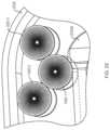
- FIGS. 6 A and 6 Billustrates an arrangement of force transfer elements for use with the drug delivery device of FIG. 1 in accordance with an embodiment of the present disclosure.
- FIGS. 7 A and 7 Billustrate an arrangement of force transfer elements for use with the drug delivery device of FIG. 1 in accordance with an embodiment of the present disclosure.
- FIGS. 8 A and 8 Billustrate an arrangement of force transfer elements for use with the drug delivery device of FIG. 1 in accordance with an embodiment of the present disclosure.
- FIGS. 9 A and 9 Billustrate an arrangement of force transfer elements for use with the drug delivery device of FIG. 1 in accordance with an embodiment of the present disclosure.
- FIG. 10illustrates an arrangement of force transfer elements for use with the drug delivery device of FIG. 1 in accordance with an embodiment of the present disclosure.
- FIG. 11illustrates an arrangement of force transfer elements for use with the drug delivery device of FIG. 1 in accordance with an embodiment of the present disclosure.
- FIG. 12illustrates an arrangement of force transfer elements for use with the drug delivery device of FIG. 1 in accordance with an embodiment of the present disclosure.
- FIG. 13illustrates an arrangement of force transfer elements for use with the drug delivery device of FIG. 1 in accordance with an embodiment of the present disclosure.
- FIGS. 14 A and 14 Billustrate an arrangement of force transfer elements for use with the drug delivery device of FIG. 1 in accordance with an embodiment of the present disclosure.
- FIG. 15illustrates an arrangement of force transfer elements for use with the drug delivery device of FIG. 1 in accordance with an embodiment of the present disclosure.
- FIG. 16illustrates an arrangement of force transfer elements for use with the drug delivery device of FIG. 1 in accordance with an embodiment of the present disclosure.
- FIG. 17illustrates an arrangement of force transfer elements for use with the drug delivery device of FIG. 1 in accordance with an embodiment of the present disclosure.
- FIG. 18illustrates an arrangement of force transfer elements for use with the drug delivery device of FIG. 1 in accordance with an embodiment of the present disclosure.
- FIGS. 19 A- 19 Cillustrate an arrangement of force transfer elements for use with the drug delivery device of FIG. 1 in accordance with an embodiment of the present disclosure.
- FIGS. 20 A and 20 Billustrate an arrangement of a guide system for use with the force transfer elements of FIGS. 19 A- 19 C and the drug delivery device of FIG. 1 in accordance with an embodiment of the present disclosure.
- FIGS. 21 - 23illustrate the force transfer elements of FIGS. 19 A- 19 C at first, second and third states of operation, respectively, in accordance with an embodiment of the present disclosure.
- the conjunction “and”includes each of the structures, components, features, or the like, which are so conjoined, unless the context clearly indicates otherwise, and the conjunction “or” includes one or the others of the structures, components, features, or the like, which are so conjoined, singly and in any combination and number, unless the context clearly indicates otherwise.
- the term “or”is generally employed in its sense including “and/or” unless the content clearly dictates otherwise.
- numeric valuesare herein assumed to be modified by the term “about,” whether or not explicitly indicated.
- the term “about”, in the context of numeric values,generally refers to a range of numbers that one of skill in the art would consider equivalent to the recited value (i.e., having the same function or result). In many instances, the term “about” may include numbers that are rounded to the nearest significant figure. Other uses of the term “about” (i.e., in a context other than numeric values) may be assumed to have their ordinary and customary definition(s), as understood from and consistent with the context of the specification, unless otherwise specified.
- references in the specification to “an embodiment”, “some embodiments”, “other embodiments”, etc.indicate that the embodiment(s) described may include a particular feature, structure, or characteristic, but every embodiment may not necessarily include the particular feature, structure, or characteristic. Moreover, such phrases are not necessarily referring to the same embodiment. Further, when a particular feature, structure, or characteristic is described in connection with an embodiment, it would be within the knowledge of one skilled in the art to effect such feature, structure, or characteristic in connection with other embodiments, whether or not explicitly described, unless clearly stated to the contrary.
- This disclosurepresents various systems, components, and methods for delivering a liquid drug or medicine to a patient or user.
- Each of the systems, components, and methods disclosed hereinprovides one or more advantages over conventional systems, components, and methods.
- Various embodimentsinclude a wearable drug delivery device that can deliver a liquid drug stored in a container to a patient or user.
- the containercan be a prefilled cartridge that can be loaded into the drug delivery device by the patient or that can be preloaded within the drug delivery device when provided to the patient.
- a sealed end of the containercan be pierced to couple the stored liquid drug to a needle conduit.
- the needle conduitcan be coupled to a needle insertion component that provides access to the patient.
- a drive system of the drug delivery devicecan expel the liquid drug from the container to the patient through the needle conduit.
- the drive systemcan include an energy storage component and one or more energy/force transfer components to enable the drug delivery device to maintain a small form factor. The result is enhanced patient's comfort when using the drug delivery device.
- Other embodimentsare disclosed and described.
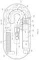
- FIG. 1illustrates an embodiment of a drug delivery device 100 with force transfer elements according to the present disclosure.
- the drug delivery device 100can include a top portion or cover 102 and a lower portion or base 104 .
- the top portion 102 and the lower portion 104can together form a housing of the drug delivery device 100 .
- the top portion 102 and the lower portion 104can be coupled together to form an outside of the drug delivery device 100 .
- the top portion 102 and the lower portion 104can be formed from any material including, for example, plastic, metal, rubber, or any combination thereof.
- the drug delivery device 100can be used to deliver a therapeutic agent (e.g., a drug) drug to a patient or user.
- the drug delivery device 100can include a container for retaining a liquid drug.
- the drug delivery device 100can be used to deliver the liquid drug from the container to the patient. Any type of liquid drug can be stored by the drug delivery device 100 and delivered to a patient.
- the containercan contain any therapeutic agent such as, for example, a drug, a subcutaneous injectable, a medicine, or a biologic.
- a patient receiving a drug or other medicine (or any liquid) from the drug delivery device 100can also be referred to as a user.
- the drug delivery device 100can operate as a bolus drug delivery device.
- the drug delivery device 100can provide any amount of the stored liquid drug to a patient over any period of time.
- the drug delivery device 100can provide the stored liquid drug to the patient in a single dose over a desired amount of time.
- the drug delivery device 100can provide the stored liquid drug to the patient over multiple doses.
- the top portion 102 of the drug delivery device 100can include a raised portion 106 .
- the raised portion 106can be elongated and run along a side of the drug delivery device 100 .
- a liquid drug cartridgecan be approximately positioned under the raised portion 106 such that the raised portion 106 accommodates the size and positioning of the liquid drug container within the drug delivery device 102 .
- the top portion 102can also include a patient interaction element or component 108 .
- the patient interaction element 108can be a push button or other patient input device. The patient interaction element 108 can be used to activate the drug delivery device 100 .
- the drug delivery device 100can be a wearable drug delivery device 100 .
- the drug delivery device 100can be an on-body delivery system (OBDS).
- OBDSon-body delivery system
- the drug delivery device 100can be coupled to a patient in a number of ways.
- the lower portion 104 of the drug delivery device 100can include an adhesive for attaching to a patient.
- the drug delivery device 100can be attached to a secondary device attached or worn by the patient such that the drug delivery device 100 fits onto or can be coupled to the secondary device.
- FIG. 2illustrates an arrangement of internal components of the drug delivery device 100 with force transfer elements according to the present disclosure.
- the drug delivery device 100can include a drug container 202 .
- the drug container 202can include a first end 204 and a second end 206 .
- the drug container 202can be sealed at or near the first end 204 and the second end 206 .
- the first end 204can include a neck and a cap as shown.
- the second end 206can include a plunger 208 .
- a liquid drug 210can be contained between a sealing arrangement provided at the first end 204 of the drug container 202 and the plunger 208 .
- the first end 204 of the drug container 202can be sealed by a septum.
- the drug container 202 of the drug delivery device 100can be a drug cartridge such as, for example, an ISO standardized drug cartridge.
- the liquid drug 210is accessed through the second end 206 of the drug container 202 .
- a drug container access mechanism or component 212can be positioned at or near the second end 206 for accessing the liquid drug 210 .
- the drug container access mechanism 212can access the liquid drug 210 through the plunger 208 .
- the drug container access mechanism 212can include a needle or other component at an end of the needle conduit 214 to pierce the plunger 208 to access the liquid drug 210 .
- the access mechanism 212can include an access spring 213 disposed between a first plate 211 and a second plate 215 .
- the first and second plates 211 , 215can include a wall configured to contain the access spring 213 .
- One or more force transfer elementscan be at least partially disposed within and/or adjacent the second plate 215 .
- the access spring 213can provide a force load against the force transmitting spheres 220 to keep them substantially stable within the device.
- the needle and/or the needle conduit 214can extend over (but not in contact with) one or more force transmitting spheres 220 , bend at about 90° through the second plate 215 (e.g., through a wall of the second plate 215 ), bend at about 90° such that the needle conduit extends substantially parallel through a central axis of the access spring 213 , through a central aperture of the first plate 211 , and at least partially through an end of the plunger 208 .
- the plunger 208Prior to piercing through a second end of the plunger 208 , the plunger 208 may have one or both ends remain unpierced and the liquid drug 210 inaccessible and sealed within the drug container 202 .
- the drug container access mechanism 212can remain in an idle state prior to being activated to access the liquid drug 210 . After activation, the needle of the drug container access mechanism 212 can extend through the plunger 208 .
- the drug container access mechanism 212can couple the liquid drug 210 to a needle conduit 214 .
- the needle conduit 214can include tubing (e.g., plastic tubing or metal tubing) and can provide a path for a portion of the liquid drug 210 that is expelled from the primary drug container 202 .
- the needle conduit 214can route the liquid drug 210 from the primary drug container 202 to a needle insertion mechanism or component 216 .
- the needle insertion mechanism 216can provide an entry point to a patient.
- the needle insertion mechanism 216can include a hard needle and/or a soft needle or cannula that provides access to the patient such that the liquid drug 210 can be delivered to the patient.
- the drug delivery device 100can also include a drive spring 218 and a plurality of force transfer elements (e.g., force transmitting spheres 220 ), which in the illustrated embodiment are ball bearings.
- force transmitting spheres 220can be formed of any type of material including glass, metal (e.g., stainless steel), a polymer, other plastic, or the like.
- the drive spring 218 and the force transmitting spheres 220can be used to expel the liquid drug 210 from the primary drug container 202 .
- the drive spring 218can apply a force that can be applied to the spheres 220 .
- the force transmitting spheres 220can be arranged to transfer the force from the drive spring 218 to the plunger 208 .
- the plunger 208can advance into the drug container 202 (toward the first end 204 ).
- the liquid drug 210 within the drug container 202can be forced into the needle conduit 214 and on to the needle insertion mechanism 216 for delivery to the patient.
- the drive spring 218is a coil spring, though it will be appreciated that it could be any appropriate type of spring, and may consist of multiple springs.
- a dead bolt 222 or other fixed elementcan be positioned at one end of the drive spring 218 to provide a stable reference for the drive spring 218 (e.g., a push off point).
- the dead bolt 222can be coupled to the inner top surface of the lower portion 104 .
- the bottom portion 104 of the drug delivery device 100can include a track 224 for guiding the force transmitting spheres 220 as they are pushed by the drive spring 218 toward the plunger 208 .
- the track 224can completely surround or cover the force transmitting spheres 220 , and can form any shape and can be arranged to take on any shape to guide the force transmitting spheres 220 from the drive spring 218 to the drug container 202 .
- the drive spring 218Prior to activation, the drive spring 218 can be in an idle state. While in an idle state, the drive spring 218 can be compressed (e.g., as shown in FIG. 2 ). When activated, the drive spring 218 can be allowed to expand. For example, after activation, the drive spring 218 can be allowed to expand in a direction away from the dead bolt 222 . When initially activated, the drive spring 218 can apply a force against the force transmitting spheres 220 which, in turn, press the plunger 208 into the drug container access mechanism 212 to cause a needle coupled to the needle conduit 214 to pierce the plunger 208 .
- the primary drug container 202can be drained of its contents and delivered to a patient.
- the drive spring 218 and the force transmitting spheres 220can be sized and adjusted to help regulate a flow of the liquid drug 210 from the primary drug container 202 to the needle insertion mechanism 216 based on a variety factors including the viscosity of the liquid drug 210 and the diameter of the needle conduit 214 .
- the drive spring 218when the drive spring 218 is allowed to expand it applies a force in a direction 230 against the force transmitting spheres 220 .
- the direction 230can correspond to a direction in which the drive spring 218 is allowed to expand, based on a positioning of the dead bolt 222 , which can provide a thrust point for the drive spring 218 .
- the force transmitting spheres 220can translate or transfer the force from the drive spring 218 to the plunger 208 .
- the force transmitting spheres 220allow the force to be translated to a different direction than the original direction of the force.
- the force transmitting spheres 220can apply the force along a curved path, and finally in a direction toward the first end 204 of the primary drug container 202 relative to the second end 206 of the primary drug container 202 . Consequently, the force transmitting spheres 220 enable the force provide by the drive spring 218 provided in a first direction to be applied to the plunger 208 in a second, approximately opposite direction, via, e.g., the second plate 215 , access spring 213 , and first plate 211 , as described above.
- the direction 230 of the force provided by the drive spring 218can cause the force transmitting spheres 220 to move in the direction 232 —that is, through the track 224 toward the second end 206 of the primary drug container 202 .
- the force transmitting spheres 220can therefore transfer the force from the drive spring 218 to the plunger 208 , thereby causing the plunger 208 to move in a direction 240 .
- the movement of the plunger 208 in the direction 240can force the liquid drug 210 out of the primary drug container 202 and into the needle conduit 214 .
- FIG. 2includes a drug delivery device including a drive mechanism employing a plurality of force transmitting spheres 220
- forcemay be transferred from the drive spring 218 to the plunger 208 using force transmitting elements having a variety of other configurations.
- force transmitting elementshaving a variety of other configurations.
- Such alternative configurationsare described throughout this disclosure. It will be appreciated that each of the described alternative force transmitting elements can be implemented in various drug delivery devices such as the drug delivery device 100 described in relation to FIGS. 1 and 2 .
- a drive mechanism 301 with force transfer elementsincludes a plurality of spherical body links 320 disposed within a track 324 formed in or on the bottom 104 ( FIG. 1 ) of the drug delivery device 100 .
- Each spherical body link 320includes a partial spherical portion 320 a , a neck portion 320 b , and a rounded head portion 320 c .
- the partial spherical portions 320 aeach have a recess 320 d therein for receiving the head portion 320 c of an adjacent link.
- the recess 320 dmay receive the head portion 320 c of an adjacent link via a snap-fit.
- the recess 320 dis sized and shaped to enable the received head portion 320 c to pivot therein, thus allowing the individual links to pivot with respect to each other. This, in turn, enables the drive mechanism 301 to move through the curved section 325 of the track 324 .
- An advantage of this embodimentis that the spherical body links 320 can be shorter than a similarly sized sphere (e.g., 220 ), thus allowing for more individual links along the length of the drive mechanism 301 . Such an arrangement can be a benefit because it allows for greater articulation of the drive mechanism in the curved section 325 of the track 324 .
- a first end 301 a of the drive mechanism 301is configured to engage a drive spring (e.g., the spring 218 of FIG. 2 ), while the second end 301 b of the drive mechanism is configured to engage a plunger (e.g., the plunger 208 of FIG. 2 ).
- Activation and operation of the drug delivery device 100 including the drive mechanism 301 of this embodimentmay be substantially the same as described in relation to the embodiment of FIG. 2 .
- FIGS. 4 A and 4 Bshow a drive mechanism 401 with force transfer elements according to the present disclosure including a plurality of spherical rollers 420 disposed within a track 424 formed in or on the bottom 104 ( FIG. 1 ) of the drug delivery device 100 .
- Each spherical roller 420includes first and second circumferential slots 420 a , 420 b for receiving first and second arms 421 a , 421 b of a spacer 421 .
- the first and second circumferential slots 420 a , 420 bmay be parallel, and may slindingly receive the first and second arms 421 a , 421 b of the spacer 421 to enable the spherical rollers 420 to rotate with respect to the spacer 421 and with respect to adjacent spherical rollers. This, in turn, enables the drive mechanism 401 to move through the curved section 425 of the track 424 .
- An advantage of this embodimentis that the spacers 421 prevent the spherical roller 420 from touching each other on the large diameter, thus facilitating rolling movement of the rollers.
- a first end 401 a of the drive mechanism 401is configured to engage a drive spring 218 ( FIG. 2 ), while the second end 401 b of the drive mechanism is configured to engage a plunger 208 .
- Activation and operation of the drug delivery device 100 including the drive mechanism 401 of this embodimentmay be substantially the same as described in relation to the embodiment of FIG. 2 .
- FIGS. 5 A and 5 Bshow a rolling ball link 520 of a drive mechanism with force transfer elements according to the present disclosure.
- Each rolling ball link 520includes a partial spherical portion 520 a , a neck portion 520 b , and a base portion 520 c .
- the base portions 520 c of each rolling ball link 520has a recess 520 d therein for receiving the head portion 520 a of an adjacent link.
- the recess 520 dmay receive the head portion 520 a of an adjacent link via a snap-fit.
- the recess 520 dis sized and shaped to enable the received head portion 520 a to pivot therein, thus allowing the individual links to pivot with respect to each other.
- Each base portion 520 ccan have a triangular shape, and can have a roller 520 e rotatably disposed at each apex of the triangle. This enables the rollers 520 e of each rolling ball link 520 to ride on the track and to spin.
- the rolling ball links 520can be shorter than comparably sized spheres, thus allowing for more links in the curved section of the track. Such an arrangement can be a benefit because it allows for greater articulation of the drive mechanism in the curved section of the track.
- a plurality of rolling ball links 520can be coupled together to form a drive mechanism, which is configured to engage a drive spring 218 ( FIG. 2 ) at one end, and to engage a plunger 208 at an opposite end.
- Activation and operation of the drug delivery device 100 including the plurality of rolling ball links 520 of this embodimentmay be substantially the same as described in relation to the embodiment of FIG. 2 .
- FIGS. 6 A and 6 Bshow a drive mechanism 601 with force transfer elements according to the present disclosure including a plurality of partial spherical rollers 620 disposed within a track 624 formed in or on the bottom 104 ( FIG. 1 ) of the drug delivery device 100 .
- Each partial spherical roller 620includes a recess 620 a for receiving the spherical portion 620 b of an adjacent partial spherical roller 620 in the manner of a caterpillar.
- the nested arrangement of partial spherical rollers 620allows the partial spherical rollers to rotate with respect to adjacent partial spherical rollers 620 .
- the nesting arrangementalso means that the partial spherical rollers 620 can be shorter than comparably sized spheres, thus allowing for more links in the curved section 625 of the track. Such an arrangement can be a benefit because it allows for greater articulation of the drive mechanism 601 in the curved section 625 of the track 624 .
- a plurality of bearings 621can be disposed between the associated nested partial spherical rollers 620 to reduce friction between the recess 620 a of one partial spherical roller and the spherical portion 620 b of an adjacent roller.
- a first end 601 a of the drive mechanism 601is configured to engage a drive spring 218 ( FIG. 2 ), while the second end 601 b of the drive mechanism is configured to engage a plunger 208 .
- Activation and operation of the drug delivery device 100 including the drive mechanism 601 of this embodimentmay be substantially the same as described in relation to the embodiment of FIG. 2 .
- FIGS. 7 A and 7 Bshow a roller bearing link 720 for a drive mechanism with force transfer elements according to the present disclosure where each link 720 includes a plurality of roller bearings 721 .
- each of the roller bearings 721may be disposed on or in a separate face 722 of the roller bearing link.
- the facesare disposed 120-degrees apart from each other such that the roller bearing link 720 is supported at three points (i.e., at the three bearings).
- Each roller bearing link 720may have a recess for receiving a pivot connector 723 to enable adjacent roller bearing links to pivot with respect to each other.
- the track 724 of this embodimentmay include separately spaced rails 726 upon which the roller bearings 721 may run.
- the rails 726are disposed only in the curved section of the track, while in other embodiments the rails are employed along the entire length of the track.
- a plurality of roller bearing links 720can be coupled together to form a drive mechanism that is configured to engage a drive spring 218 ( FIG. 2 ) at one end, and to engage a plunger 208 at an opposite end.
- Activation and operation of the drug delivery device 100 including the plurality of roller bearing link 720 of this embodimentmay be substantially the same as described in relation to the embodiment of FIG. 2 .
- FIGS. 8 A and 8 Bshow a drive mechanism 801 with force transfer elements according to the present disclosure including a plurality of spherical rollers 820 disposed within a track 824 formed in or on the bottom 104 ( FIG. 1 ) of the drug delivery device 100 .
- Each spherical roller 820includes a central circumferential slot 820 a for receiving a portion of a disc spacer 821 .
- the circumferential slot 820 amay slindingly receive the disc spacer 821 to enable the spherical rollers 820 to rotate with respect to the disc spacer 821 and with respect to adjacent spherical rollers. This, in turn, enables the drive mechanism 801 to move through the curved section 825 of the track 824 .
- an advantage of this embodimentis that the disc spacers 821 prevent the spherical rollers 820 from touching each other on the large diameter, thus facilitating rolling movement of the rollers. Another advantage is that the disc spacers 821 prevent the spherical rollers 820 from rotating in directions other than that which facilitates movement of the drive mechanism 801 along the track 824 .
- a first end 801 a of the drive mechanism 801is configured to engage a drive spring 218 ( FIG. 2 ), while the second end 801 b of the drive mechanism is configured to engage a plunger 208 .
- Activation and operation of the drug delivery device 100 including the drive mechanism 801 of this embodimentmay be substantially the same as described in relation to the embodiment of FIG. 2 .
- FIGS. 9 A and 9 Bshow a drive mechanism 901 with force transfer elements according to the present disclosure comprising a roller chain having individual chain links 920 disposed within a track 924 formed in or on the bottom 104 ( FIG. 1 ) of the drug delivery device 100 .
- Each chain link 920is rotatably coupled to an adjacent chain link 920 via a pin 921 , which enables the chain links 920 to rotate with respect to the pin 921 and with respect to adjacent chain links 920 .
- Each pin 921includes a cylindrical hollow body roller 923 about the pin 921 and between the chain links 920 .
- the rollers 923make contact with the track 924 and may spin about their respective pin 921 while the chain links 920 separate the pins 921 and keep the rollers 923 from contacting each other and allow the rollers 923 to roll. This, in turn, enables the drive mechanism 901 to move through the curved section 925 of the track 924 .
- a first end 901 a of the drive mechanism 901is configured to engage a drive spring 218 ( FIG. 2 ), while the second end 901 b of the drive mechanism is configured to engage a plunger 208 .
- Activation and operation of the drug delivery device 100 including the drive mechanism 901 of this embodimentmay be substantially the same as described in relation to the embodiment of FIG. 2 .
- FIG. 10shows a drive mechanism 1001 with force transfer elements according to the present disclosure including a plurality of split sphere elements 1020 disposed within a track 1024 formed in or on the bottom 104 ( FIG. 1 ) of the drug delivery device 100 .
- Each split sphere element 1020includes first and second shells 1020 a , 1020 b with an expanding element 1021 , such as a spring, disposed therebetween biasing the first and second shells apart.
- This arrangementenables the entire track 1024 to be filled with expanding split sphere elements 1020 , as opposed to a single long spring (such as might be used with a single-spring arrangement).
- the disclosed arrangement of split sphere elements 1020can make the drive mechanism 1001 compliant through the curved section 1025 of the track 1024 .
- a first end 1001 a of the drive mechanism 1001is configured to engage a drive spring 218 ( FIG. 2 ), while the second end 1001 b of the drive mechanism is configured to engage a plunger 208 .
- Activation and operation of the drug delivery device 100 including the drive mechanism 1001 of this embodimentmay be substantially the same as described in relation to the embodiment of FIG. 2 .
- the drive mechanism 1001may partially or completely replace the need for a drive spring (such as drive spring 218 of FIG. 2 ). Replacing the drive spring may lower the spring constant (often the “k” variable in the art) or average spring constant needed for the springs of the device.
- FIG. 11shows a drive mechanism 1101 with force transfer elements according to the present disclosure including a plurality of dog bone shaped (i.e., wider ends than a thinner middle section connecting the wider ends) elements 1120 disposed within a track 1124 formed in or on the bottom 104 ( FIG. 1 ) of the drug delivery device 100 .
- Each dog bone shaped elements 1120include first and second ends 1120 a , 1120 b connected by a neck portion 1120 c .
- the diameter of the first and second ends 1120 a , 1120 bcan be sized to slide within the track 1124 .
- the diameter of the neck portion 1120 cmay be smaller than the diameter of the first and second ends 1120 a , 1120 b .
- the disclosed arrangement of dog bone shaped elements 1120can reduce the total number of individual parts making up the drive mechanism 1101 , while enabling the mechanism to be highly compliant through the curved section 1125 of the track 1124 .
- a first end 1101 a of the drive mechanism 1101is configured to engage a drive spring 218 ( FIG. 2 ), while the second end 1101 b of the drive mechanism is configured to engage a plunger 208 .
- Activation and operation of the drug delivery device 100 including the drive mechanism 1101 of this embodimentmay be substantially the same as described in relation to the embodiment of FIG. 2 .
- FIG. 12shows a drive mechanism 1201 with force transfer elements according to the present disclosure comprising a plurality of inter-engaged custom link members 1220 .
- Each custom link members 1220includes a first end having a depending portion 1220 a and a second end having a recess 1220 b .
- the depending portion 1220 a of one custom link member 1220is configured to be received in the recess 1220 b of a directly adjacent custom link member 1220 .
- the depending portions 1220 amay be rounded or spherical while the recesses 1220 b may be sized and shaped to enable the received depending portion 1220 a to pivot therein, thus allowing the individual links to pivot with respect to each other.
- the disclosed arrangementallows the drive mechanism 1201 to pivot the custom link members 1220 and articulate around the curved portion 225 of a guide track 224 ( FIG. 2 ).
- the arrangementalso enables the use of single-piece links 1220 that have the column strength of a chain, without the complexity and part count.
- the drive mechanism 1201can be disposed within an appropriate track 224 ( FIG. 2 ), and can have first and second ends for engaging a drive spring 218 at one end, and to engage a plunger 208 at an opposite end.
- Activation and operation of the drug delivery device 100 including the plurality of custom link members 1220 of this embodimentmay be substantially the same as described in relation to the embodiment of FIG. 2 .
- FIG. 13shows a drive mechanism 1301 with force transfer elements according to the present disclosure including a plurality of spherical rollers 1320 engaged with a track 1324 formed in or on the bottom 104 ( FIG. 1 ) of the drug delivery device 100 .
- First and second spherical rollers 1321 , 1322oppose associated ones of the plurality of spherical rollers 1320 at each end of the curved portion 1325 of the track 1324 .
- a flexible guide rod 1326is guided through the track 1324 via the plurality of spherical rollers 1320 .
- the flexible guide rod 1326is constrained and guided into/out of the track 1324 via the first and second spherical rollers 1321 , 1322 .
- the flexible guide rod 1326can be sufficiently flexible to move through the curved section 1325 of the track 1324 while still maintaining a desired column strength to move the plunger 208 ( FIG. 2 ).
- a first end 1301 a of the drive mechanism 1301is configured to engage a drive spring 218 ( FIG. 2 ), while the second end 1301 b of the drive mechanism is configured to engage a plunger 208 .
- Activation and operation of the drug delivery device 100 including the drive mechanism 1301 of this embodimentmay be substantially the same as described in relation to the embodiment of FIG. 2 .
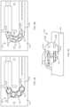
- FIGS. 14 A and 14 Bshow a drive mechanism 1401 with force transfer elements according to the present disclosure comprising a roller chain having a plurality individual chain links 1420 , where adjacent chain links 1420 are coupled together by a bushed connecting link 1421 .
- Each chain link 1420can have first and second roller portions 1422 connected via a reduced-diameter portion 1423 .
- the first and second roller portions 1422can be sized to conform to the inner dimension of an associated guide track 224 ( FIG. 2 ) so that they can ride on the walls of the guide track.
- the bushed connecting link 1421can engage the reduced-diameter portions 1423 of adjacent chain links 1420 .
- the bushed connecting link 1421can couple to each of the reduced-diameter portions 1423 of adjacent chain links 1420 via a collar 1421 a that allows the individual chain links 1420 to rotate with respect to the bushed connecting link 1421 .
- the bushed connecting link 1421may be stiff enough to transmit the spring force from the drive spring 218 ( FIG. 2 ) to the plunger 208 , while enabling the individual chain links 1420 to pivot with respect to each other. This, in turn, enables the drive mechanism 1401 to move through the curved section 225 ( FIG. 2 ) of the track 224 .
- a plurality of chain links 1420can be coupled together to form a drive mechanism 1401 that is configured to engage a drive spring 218 ( FIG. 2 ) at one end, and to engage a plunger 208 at an opposite end.
- Activation and operation of the drug delivery device 100 including the plurality of chain links 1420 of this embodimentmay be substantially the same as described in relation to the embodiment of FIG. 2 .
- FIG. 14 Bshows an example embodiment of how the individual chain links 1420 can be assembled from upper and lower portions 1420 a , 1420 b .
- the upper and lower portions 1420 a , 1420 bcan have first and second reduced diameter portions 1423 a , 1423 b .
- the first reduced diameter portion 1423 aincludes a projection 1424 a received within a recess 1424 b in the second reduced diameter portion 1423 b .
- the projection 1424 acan be fixed within the recess 1424 b using any of a variety of appropriate technologies, including press-fit, adhesives, threads, and the like.
- the first and second reduced diameter portionswould be engaged with each other within a collar 1421 a of bushed connecting link 1421 .
- FIG. 15shows an embodiment in which the force transfer elements according to the present disclosure comprise cylindrical elements 1500 .
- the cylinders 1500may be roller pins, which can maximize the transfer of loads, while minimizing deformation of the pin or its opposing surfaces. Input forces (from the drive spring 218 ( FIG. 2 )) will not equal output forces, due to losses in friction around the curved portion 225 of the track 224 . Minimizing point loading and deformation, however, will tend to provide the highest output forces (i.e., highest efficiency).
- Providing the force transfer elements as cylindrically shaped elements 1500allows for a plurality of elements to transfer the maximum force vector while minimizing losses and conforming to the track 224 within the drug delivery device 100 without buckling.
- FIG. 16shows an exemplary cylindrical force transfer element 1620 for a drive mechanism with force transfer elements according to the present disclosure.
- the force transfer element 1620may have top and bottom portions 1620 a , 1620 b and a central portion 1620 c .
- First and second reduced diameter portions 1620 d , 1620 emay be located between the top and central portions 1620 a , 1620 c and the bottom and central portions 1620 b , 1620 c , respectively.
- the top and bottom portions 1620 a , 1620 bmay include beveled upper/lower surfaces 1620 f , 1620 g to reduce the surface area that will contact surfaces of the track 224 ( FIG. 2 ).
- the first and second reduced diameter portions 1620 d , 1620 emay receive rail or other protruding features of the track 224 to guide and support the cylindrical force transfer elements 1620 within the straight portions of the track (e.g., where the spring 218 extends).
- a plurality of cylindrical force transfer elements 1620can be coupled together to form a drive mechanism that is configured to engage a drive spring 218 ( FIG. 2 ) at one end, and to engage a plunger 208 at an opposite end.
- Activation and operation of the drug delivery device 100 including the plurality of cylindrical force transfer elements 1620 of this embodimentmay be substantially the same as described in relation to the embodiment of FIG. 2 .
- FIG. 17shows a pair of exemplary cylindrical force transfer elements 1720 a , 1720 b for a drive mechanism with force transfer elements according to the present disclosure which include keying features that allow the elements 1720 a , 1720 b to couple together while also allowing them to rotate with respect to each other (e.g., when traversing the curved portion 225 of the track 224 ( FIG. 2 ).
- the cylindrical force transfer elements 1720 a , 1720 bare 180-degree rotated images of each other.
- Each of the force transfer elements 1720 a , 1720 bincludes a circumferential recess 1721 and a circumferential projection 1722 .
- the recess 1721 and projection 1722are sized and positioned so that the projection is received within the recess 1721 when the force transfer elements 1720 a , 1720 b are coupled together.
- the projection 1722may be loosely received within the recess 1721 to enable the force transfer elements 1720 a , 1720 b to rotate about their respective longitudinal axes A-A, B-B and to rotate with respect to each other about axes parallel to their longitudinal axes. This will enable the force transfer elements 1720 a , 1720 b to traverse the curved portion 225 of the track 224 of the drug delivery device 100 .
- the interaction of the projection 1722 and recess 1721may, however, prevent rotation of the force transfer elements 1720 a , 1720 b about other axes.
- the cylindrical force transfer elements 1720 a , 1720 b of this embodimentwill not randomly “fan-out” or twist within the track 224 of the drug delivery device 100 . Rather, they will be rotationally constrained from the cylinders that remain in the track.
- FIG. 18shows an embodiment of a drive mechanism 1801 for a drive mechanism with force transfer elements according to the present disclosure including a plurality of cylindrical force transfer elements 1820 disposed within a track 1824 formed in or on the bottom 104 ( FIG. 1 ) of the drug delivery device 100 .
- Each cylindrical force transfer elements 1820includes a cylindrical body portion 1820 a , and offset top and bottom portions 1820 b . Adjacent the offset top and bottom portions 1820 b are recess portions 1820 c . The recess portions 1820 c are configured to slidingly engage respective offset top and bottom portions 1820 b of an adjacent cylindrical force transfer element 1820 .
- This overlapping engagementallows adjacent cylindrical force transfer element 1820 to move with respect to each other as the drive mechanism 1801 traverses the curved portion 1825 of the track 1824 , while preventing them from “fanning-out,” over-rotating with respect to each other, or twisting within the track 1824 of the drug delivery device 100 .
- Each of the plurality of cylindrical force transfer elements 1820may also include one or more grooves 1820 d disposed in the cylindrical body portion 1820 a . These grooves 1820 d may be oriented so that they are parallel to the bottom 104 of the drug delivery device. 100 .
- the grooves 1820 dmay be sized and shaped to interface with guide rails 1826 disposed on one or more surfaces of the track 1824 .
- the guide rails 1826are disposed in a straight portion of the track 1824 adjacent to the drive spring 1818 .
- the railsmay be disposed in the curved portion of the track in addition to the straight portion.
- a first end 1801 a of the drive mechanism 1801is configured to engage a drive spring 1818
- the second end 1801 b of the drive mechanismis configured to engage a plunger 1808 .
- Activation and operation of the drug delivery device 100 including the drive mechanism 1801 of this embodimentmay be substantially the same as described in relation to the embodiment of FIG. 2 .
- FIGS. 19 A- 23show a drive mechanism with force transfer elements according to the present disclosure in which the force transfer elements are designed as constant angular velocity force transfer rollers 1920 .
- the force transfer rollers 1920have an hourglass shape in profile, and include upper and lower portions 1920 a , 1920 b coupled by a reduced diameter portion 1920 c .
- Each of the upper and lower portions 1920 a , 1920 bhas a cylindrical portion 1920 d , which tapers to the reduced diameter portion 1920 c resulting in upper and lower angled transition portions 1920 e , 1920 f
- the top and/or bottom surfaces of the cylindrical portions 1920 dinclude an array of radial etching markers even spaced about a center point of the cylindrical portions 1920 d .
- the etchingsprovide visual indication of motion of the rollers 1920 that may be measurable (e.g., a number of marks rotating and/or translating along a track).
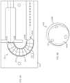
- FIGS. 20 A and 20 Bshow a track 2024 for use with the force transfer rollers 1920 .
- the track 2024may be generally U-shaped, comprising a pair of straight track portions 2024 a , 2024 b and an intermediate curved track portion 2025 .
- the inner walls of the straight track portions 2024 a , 2024 b and the outer track wall of the curved track portion 2025may be flat.
- the inner track wall of the curved track portion 2025may have an expanded radius “R” and a tapered cross-section that produces a reduced-thickness portion 2025 a at the perimeter of the inner track wall of the curved track portion.
- the substantially U-shaped track 2024includes the straight track portions 2024 a , 2024 b with walls spaced apart from each other a first distance, and a curved track portion 2025 with walls spaced apart from each other a second distance that is smaller than the first distance.
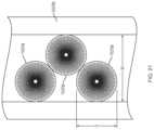
- FIG. 21shows the configuration of the force transfer rollers 1920 while they are in the straight portion 2024 b (or 2024 a ) of the track 2024 . While the force transfer rollers 1920 are in the straight portion of the track they all roll on the largest radius portions (i.e., upper and lower portions 1920 a , 1920 b ). As can be seen, the upper and lower portions 1920 a , 1920 b have diameters “D” that are smaller than a width “W” of the track 2024 . The force transfer rollers 1920 thus adjust their relative positions to fit within the track 2024 , creating a double stack arrangement. In the straight portion of the track, both stacks of rollers are rolling on equal radii. The ability to roll comes from the double stack design and avoids forced sliding that can occur in a single stack arrangement.
- FIG. 22shows the positions of the force transfer rollers 1920 in a transition region between the straight portion 2024 a / 2024 b and the curved portion 2025 .
- the rollers in the inside stack ( 1920 - 1 )will roll on a non-constant radius surface 2025 a to maintain contact with the rollers in the outside stack ( 1920 - 2 , 1920 - 3 ). While the rollers are going through the transition area they will roll on the angled transition portion 1920 f ( FIG. 19 A ), bringing the radius down from to the final size before rolling in the curved section 2025 .
- the radius of the force transfer rollers 1920changes with angular distance travelled until the rollers reach the curved section of the track. Entering the curved section 2025 may cause the force transfer rollers 1920 to slip instead of roll if the geometry between rollers changes.
- the angle between rollersis smaller when they are travelling in the straight portion than when they are in the curved portion.
- the transition curvemay need both the inner and outer stacks to have different, changing radii at the same time to maintain 100% rolling.
- the angled transition portion 1920 f( FIG. 19 A ) may not be a straight line, but rather may be a radius change as defined by a curve.
- FIG. 23shows the rollers 1920 in the curved portion of the track 2025 .
- the inner stack ( 1920 - 1 )rolls on the smallest radius to maintain a constant linear velocity relative to the rollers in the outside stack ( 1920 - 2 , 1920 - 3 ).
- the outside stackrolls on the largest radii (cylindrical portions 1920 d ).
- the ratio between radiiis equal to the ratio between track radii.
- vis constant and equal for both stacks.
- thisis achieved by having equal radii and an equal linear distance.
- the outside trackhas a larger linear distance, so the rollers must change radius to compensate.
- the track 2024should include a variable radius portion ( 2025 a ) to meet the roller and facilitate rolling at the appropriate radius for that point in the transition.
Landscapes
- Health & Medical Sciences (AREA)
- Heart & Thoracic Surgery (AREA)
- Vascular Medicine (AREA)
- Engineering & Computer Science (AREA)
- Anesthesiology (AREA)
- Biomedical Technology (AREA)
- Hematology (AREA)
- Life Sciences & Earth Sciences (AREA)
- Animal Behavior & Ethology (AREA)
- General Health & Medical Sciences (AREA)
- Public Health (AREA)
- Veterinary Medicine (AREA)
- Dermatology (AREA)
- Infusion, Injection, And Reservoir Apparatuses (AREA)
Abstract
Description
Claims (20)
Priority Applications (1)
| Application Number | Priority Date | Filing Date | Title |
|---|---|---|---|
| US16/140,165US11786668B2 (en) | 2017-09-25 | 2018-09-24 | Drug delivery devices, systems, and methods with force transfer elements |
Applications Claiming Priority (2)
| Application Number | Priority Date | Filing Date | Title |
|---|---|---|---|
| US201762562802P | 2017-09-25 | 2017-09-25 | |
| US16/140,165US11786668B2 (en) | 2017-09-25 | 2018-09-24 | Drug delivery devices, systems, and methods with force transfer elements |
Publications (2)
| Publication Number | Publication Date |
|---|---|
| US20190091416A1 US20190091416A1 (en) | 2019-03-28 |
| US11786668B2true US11786668B2 (en) | 2023-10-17 |
Family
ID=65808613
Family Applications (1)
| Application Number | Title | Priority Date | Filing Date |
|---|---|---|---|
| US16/140,165Active2040-03-16US11786668B2 (en) | 2017-09-25 | 2018-09-24 | Drug delivery devices, systems, and methods with force transfer elements |
Country Status (1)
| Country | Link |
|---|---|
| US (1) | US11786668B2 (en) |
Families Citing this family (2)
| Publication number | Priority date | Publication date | Assignee | Title |
|---|---|---|---|---|
| WO2024256914A1 (en)* | 2023-06-16 | 2024-12-19 | Janssen Biotech, Inc. | Drug delivery device |
| WO2024256913A1 (en)* | 2023-06-16 | 2024-12-19 | Janssen Biotech, Inc. | Drug delivery device |
Citations (315)
| Publication number | Priority date | Publication date | Assignee | Title |
|---|---|---|---|---|
| US1441508A (en) | 1921-12-06 | 1923-01-09 | Jensen Anton Marius | Cylindrical slide valve |
| GB357139A (en) | 1929-06-14 | 1931-09-14 | Paul Von Vago | |
| US2198666A (en) | 1936-09-30 | 1940-04-30 | Lakeland Foundation | Syringe |
| US2752918A (en) | 1949-08-17 | 1956-07-03 | Auguste Rooseboom | Hypodermic injection apparatus |
| GB810488A (en) | 1955-03-01 | 1959-03-18 | Eduard Woydt | Liquid pressure piston-engine or reciprocating pump |
| CA606281A (en) | 1960-10-04 | Dann Morris | Cartridge for metering syringe | |
| GB875034A (en) | 1957-07-01 | 1961-08-16 | Renault | Improvements in or relating to valves for fluids under pressure |
| US3176712A (en) | 1961-10-03 | 1965-04-06 | Ramsden Clement | Non-return valve |
| US3297260A (en) | 1964-09-21 | 1967-01-10 | Conrad R Barlow | Nozzle and valve assembly |
| US3464359A (en) | 1967-11-13 | 1969-09-02 | Medimeter Corp The | Apparatus for moving fluid from one system to a second system |
| GB1204836A (en) | 1968-05-20 | 1970-09-09 | Thermal Hydraulics Corp | Thermal actuator |
| FR2096275A5 (en) | 1970-06-13 | 1972-02-11 | Ismatec Sa | |
| US3885662A (en) | 1973-12-26 | 1975-05-27 | Ibm | Steerable follower selection mechanism |
| US3946732A (en) | 1973-08-08 | 1976-03-30 | Ampoules, Inc. | Two-chamber mixing syringe |
| US3947692A (en) | 1974-08-05 | 1976-03-30 | Viron E. Payne, Inc. | Digital transducers |
| US3993061A (en) | 1975-02-28 | 1976-11-23 | Ivac Corporation | Syringe pump drive system and disposable syringe cartridge |
| IL46017A (en) | 1974-11-07 | 1977-11-30 | Ampoules Inc | Two-chamber mixing syringe |
| US4108177A (en) | 1976-04-23 | 1978-08-22 | Michel Louis Paul Pistor | Automatic injector device |
| US4152098A (en) | 1977-01-03 | 1979-05-01 | Clark Ivan P | Micropump |
| GB2008806A (en) | 1977-11-03 | 1979-06-06 | Danfoss As | Controllable heating means for small masses |
| US4210173A (en) | 1976-12-06 | 1980-07-01 | American Hospital Supply Corporation | Syringe pumping system with valves |
| US4221219A (en) | 1978-07-31 | 1980-09-09 | Metal Bellows Corporation | Implantable infusion apparatus and method |
| FR2455269A1 (en) | 1978-01-17 | 1980-11-21 | Marceau Serge | Dynamic dosing of liquid food product - utilises compressed air operation of cylinders to move liquid dose to outlet |
| US4257324A (en) | 1978-10-30 | 1981-03-24 | Bell & Howell Company | Position monitoring methods and apparatus |
| US4268150A (en) | 1980-01-28 | 1981-05-19 | Laurence Chen | Disposable camera with simplified film advance and indicator |
| WO1981001658A1 (en) | 1979-12-13 | 1981-06-25 | M Loeb | Wearable insulin infusion system having a tubular reservoir and a positive displacement metering means |
| US4277226A (en) | 1979-03-09 | 1981-07-07 | Avi, Inc. | IV Pump with empty supply reservoir and occlusion detector |
| GB2077367A (en) | 1978-09-05 | 1981-12-16 | Mandroian Harold | Three valve precision pump apparatus with head pressure flow through protection |
| US4313439A (en) | 1980-03-24 | 1982-02-02 | Biotek, Inc. | Automated, spring-powered medicament infusion system |
| FR2507637A1 (en) | 1981-06-16 | 1982-12-17 | Libero Elettrotecnica | Thermo-electric drive for detergent reservoir of automatic dishwasher - has thermistor heating substance which expands and operates lever |
| US4371790A (en) | 1980-09-19 | 1983-02-01 | Rmr Systems, Inc. | Fluid measuring system |
| US4417889A (en) | 1980-12-31 | 1983-11-29 | Choi Soo Bong | Device for a portable automatic syringe |
| US4424720A (en) | 1980-12-15 | 1984-01-10 | Ivac Corporation | Mechanism for screw drive and syringe plunger engagement/disengagement |
| US4435173A (en) | 1982-03-05 | 1984-03-06 | Delta Medical Industries | Variable rate syringe pump for insulin delivery |
| US4475905A (en) | 1982-09-30 | 1984-10-09 | Himmelstrup Anders B | Injection device |
| US4498843A (en) | 1982-08-02 | 1985-02-12 | Schneider Philip H | Insulin infusion pump |
| US4507115A (en) | 1981-04-01 | 1985-03-26 | Olympus Optical Co., Ltd. | Medical capsule device |
| JPS6063133A (en) | 1983-09-16 | 1985-04-11 | Sekisui Plastics Co Ltd | box making machine |
| US4551134A (en) | 1982-08-06 | 1985-11-05 | Nuvatec, Inc. | Intravenous set |
| US4562751A (en) | 1984-01-06 | 1986-01-07 | Nason Clyde K | Solenoid drive apparatus for an external infusion pump |
| US4567549A (en) | 1985-02-21 | 1986-01-28 | Blazer International Corp. | Automatic takeup and overload protection device for shape memory metal actuator |
| US4585439A (en) | 1983-09-07 | 1986-04-29 | Disetronic Ag. | Portable infusion unit |
| US4601707A (en) | 1980-06-03 | 1986-07-22 | Albisser Anthony M | Insulin infusion device |
| WO1986006796A1 (en) | 1985-05-15 | 1986-11-20 | Henning Munk Ejlersen | A hose pump, in particular an insulin pump |
| US4634427A (en) | 1984-09-04 | 1987-01-06 | American Hospital Supply Company | Implantable demand medication delivery assembly |
| US4671429A (en) | 1983-11-15 | 1987-06-09 | Thomas J. Lipton, Inc. | Method and apparatus for volumetric dosing viscous products |
| US4678408A (en) | 1984-01-06 | 1987-07-07 | Pacesetter Infusion, Ltd. | Solenoid drive apparatus for an external infusion pump |
| US4684368A (en) | 1984-06-01 | 1987-08-04 | Parker Hannifin Corporation | Inverted pump |
| US4685903A (en) | 1984-01-06 | 1987-08-11 | Pacesetter Infusion, Ltd. | External infusion pump apparatus |
| US4755169A (en) | 1985-05-20 | 1988-07-05 | Survival Technology, Inc. | Automatic medicament ingredient mixing and injecting apparatus |
| US4766889A (en) | 1986-06-26 | 1988-08-30 | Medical Engineering Corporation | Infusion erectile system |
| US4808161A (en) | 1986-03-04 | 1989-02-28 | Kamen Dean L | Pressure-measurement flow control system |
| US4846797A (en) | 1985-05-14 | 1989-07-11 | Intelligent Medicine, Inc. | Syringe positioning device for enhancing fluid flow control |
| US4858619A (en) | 1987-06-29 | 1989-08-22 | Toth Marie A | Intracranial pressure monitoring system |
| US4898579A (en) | 1987-06-26 | 1990-02-06 | Pump Controller Corporation | Infusion pump |
| US4908022A (en)* | 1988-08-15 | 1990-03-13 | Habley Medical Technology Corporation | Disposable safety syringe having a retractable needle cannula and cannula lock |
| US4908017A (en) | 1985-05-14 | 1990-03-13 | Ivion Corporation | Failsafe apparatus and method for effecting syringe drive |
| US4944659A (en) | 1987-01-27 | 1990-07-31 | Kabivitrum Ab | Implantable piezoelectric pump system |
| US4969874A (en) | 1987-05-18 | 1990-11-13 | Disetronic Ag | Infusion device |
| US4991743A (en) | 1989-11-06 | 1991-02-12 | Cobe Laboratories, Inc. | Controlled flow accumulator |
| US5007458A (en) | 1990-04-23 | 1991-04-16 | Parker Hannifin Corporation | Poppet diaphragm valve |
| US5020325A (en) | 1990-02-13 | 1991-06-04 | Procedes Vernet | Heat motor |
| EP0454331A1 (en) | 1990-04-16 | 1991-10-30 | Minimed Inc., doing business as Minimed Technologies | Infusionssystem für die Medikation |
| US5062841A (en) | 1988-08-12 | 1991-11-05 | The Regents Of The University Of California | Implantable, self-regulating mechanochemical insulin pump |
| US5147311A (en) | 1987-09-09 | 1992-09-15 | Ewald Pickhard | Injection device for use with a deformable ampoule |
| US5178609A (en) | 1990-06-19 | 1993-01-12 | Kato Hatsujo Kaisha, Ltd. | Medical liquid injector for continuous transfusion |
| US5205819A (en) | 1989-05-11 | 1993-04-27 | Bespak Plc | Pump apparatus for biomedical use |
| US5213483A (en) | 1991-06-19 | 1993-05-25 | Strato Medical Corporation | Peristaltic infusion pump with removable cassette and mechanically keyed tube set |
| US5222362A (en) | 1989-01-10 | 1993-06-29 | Maus Daryl D | Heat-activated drug delivery system and thermal actuators therefor |
| DE4200595A1 (en) | 1992-01-13 | 1993-07-15 | Michail Efune | Assembly group for infusion set for insulin pump - involves steel needle inside plastics cannula with only limited axial movement and drawn back into cannula during infusion. |
| US5236416A (en) | 1991-05-23 | 1993-08-17 | Ivac Corporation | Syringe plunger position detection and alarm generation |
| WO1993020864A1 (en) | 1992-04-10 | 1993-10-28 | Novo Nordisk A/S | Infusion pump |
| US5261884A (en) | 1992-04-29 | 1993-11-16 | Becton, Dickinson And Company | Syringe pump control system |
| US5261882A (en) | 1993-04-26 | 1993-11-16 | Sealfon Andrew I | Negator spring-powered syringe |
| US5277338A (en) | 1990-12-21 | 1994-01-11 | Odin Developments Limited | Fluid metering apparatus |
| US5281202A (en) | 1991-09-03 | 1994-01-25 | Fresenius Ag | Device for draining a flexible fluid container |
| JPH0663133A (en) | 1992-06-18 | 1994-03-08 | Raifu Technol Kenkyusho | Portable automatic chemical injection device |
| WO1994015660A1 (en) | 1993-01-05 | 1994-07-21 | Berney Jean Claude | Powered-plunger infusion device |
| US5346476A (en) | 1992-04-29 | 1994-09-13 | Edward E. Elson | Fluid delivery system |
| JPH06296690A (en) | 1993-04-14 | 1994-10-25 | Nippon Medical Supply Corp | Syringe pump |
| US5364342A (en) | 1992-02-05 | 1994-11-15 | Nestle S.A. | Microsurgical cassette |
| US5388615A (en) | 1992-12-11 | 1995-02-14 | Busak & Luyken Gmbh & Co. | Sealing means and sealing valve for container openings |
| US5433710A (en) | 1993-03-16 | 1995-07-18 | Minimed, Inc. | Medication infusion pump with fluoropolymer valve seat |
| US5503628A (en) | 1995-03-15 | 1996-04-02 | Jettek, Inc. | Patient-fillable hypodermic jet injector |
| US5520661A (en) | 1994-07-25 | 1996-05-28 | Baxter International Inc. | Fluid flow regulator |
| US5533389A (en) | 1986-03-04 | 1996-07-09 | Deka Products Limited Partnership | Method and system for measuring volume and controlling flow |
| FR2731475A1 (en) | 1995-03-07 | 1996-09-13 | Thomson Dauphinoise | Thermal/mechanical device for mounting electric heating or cooling component on thermal actuator |
| JPH08238324A (en) | 1995-03-04 | 1996-09-17 | Nissho Corp | Means for mixed injection of plural medicinal liquids |
| US5582593A (en) | 1994-07-21 | 1996-12-10 | Hultman; Barry W. | Ambulatory medication delivery system |
| US5618269A (en) | 1995-05-04 | 1997-04-08 | Sarcos, Inc. | Pressure-driven attachable topical fluid delivery system |
| US5628309A (en) | 1996-01-25 | 1997-05-13 | Raya Systems, Inc. | Meter for electrically measuring and recording injection syringe doses |
| US5637095A (en) | 1995-01-13 | 1997-06-10 | Minimed Inc. | Medication infusion pump with flexible drive plunger |
| EP0789146A1 (en) | 1995-07-27 | 1997-08-13 | Seiko Epson Corporation | Microvalve and method of manufacturing the same, micropump using the microvalve and method of manufacturing the same, and apparatus using the micropump |
| US5665070A (en) | 1995-01-19 | 1997-09-09 | I-Flow Corporation | Infusion pump with magnetic bag compression |
| US5713875A (en) | 1994-07-29 | 1998-02-03 | Abbott Laboratories | System for administration of a liquid agent to a patient with a syringe pump |
| US5748827A (en) | 1996-10-23 | 1998-05-05 | University Of Washington | Two-stage kinematic mount |
| US5747350A (en) | 1993-04-02 | 1998-05-05 | Boehringer Mannheim Gmbh | System for dosing liquids |
| US5776103A (en) | 1995-10-11 | 1998-07-07 | Science Incorporated | Fluid delivery device with bolus injection site |
| US5779676A (en) | 1995-10-11 | 1998-07-14 | Science Incorporated | Fluid delivery device with bolus injection site |
| US5785688A (en) | 1996-05-07 | 1998-07-28 | Ceramatec, Inc. | Fluid delivery apparatus and method |
| US5797881A (en) | 1996-06-20 | 1998-08-25 | Gadot; Amir | Intravenous infusion apparatus |
| DE19723648C1 (en) | 1997-06-05 | 1998-08-27 | Disetronic Licensing Ag | Controlled infusion equipment with leak and reverse flow prevention used e.g. in insulin therapy |
| US5800397A (en) | 1995-04-20 | 1998-09-01 | Invasatec, Inc. | Angiographic system with automatic high/low pressure switching |
| US5807075A (en) | 1993-11-23 | 1998-09-15 | Sarcos, Inc. | Disposable ambulatory microprocessor controlled volumetric pump |
| EP0867196A2 (en) | 1997-03-26 | 1998-09-30 | Disetronic Licensing AG | Catheter system for transdermal passages |
| US5839467A (en) | 1993-10-04 | 1998-11-24 | Research International, Inc. | Micromachined fluid handling devices |
| WO1998055073A1 (en) | 1997-06-03 | 1998-12-10 | Kunshan Wang | A medical apparatus comprising an elastic valve-type stopper and a piercing needle |
| WO1998056293A1 (en) | 1997-06-09 | 1998-12-17 | Minimed Inc. | Insertion set for a transcutaneous sensor |
| WO1999010049A1 (en) | 1997-08-29 | 1999-03-04 | Cycle-Ops Products, Inc. | Exercise resistance device |
| WO1999010040A1 (en) | 1997-08-27 | 1999-03-04 | Science Incorporated | Fluid delivery device with temperature controlled energy source |
| US5891097A (en) | 1994-08-12 | 1999-04-06 | Japan Storage Battery Co., Ltd. | Electrochemical fluid delivery device |
| US5897530A (en) | 1997-12-24 | 1999-04-27 | Baxter International Inc. | Enclosed ambulatory pump |
| US5906597A (en) | 1998-06-09 | 1999-05-25 | I-Flow Corporation | Patient-controlled drug administration device |
| US5911716A (en) | 1992-01-24 | 1999-06-15 | I-Flow Corporation | Platen pump |
| US5919167A (en) | 1998-04-08 | 1999-07-06 | Ferring Pharmaceuticals | Disposable micropump |
| US5957890A (en) | 1997-06-09 | 1999-09-28 | Minimed Inc. | Constant flow medication infusion pump |
| US5971963A (en) | 1998-08-18 | 1999-10-26 | Choi; Soo Bong | Portable automatic syringe device and injection needle unit thereof |
| WO1999062576A1 (en) | 1998-06-04 | 1999-12-09 | Elan Corporation, Plc | Gas driven drug delivery device |
| US6019747A (en) | 1997-10-21 | 2000-02-01 | I-Flow Corporation | Spring-actuated infusion syringe |
| US6050457A (en) | 1995-12-06 | 2000-04-18 | The Procter & Gamble Company | High pressure manually-actuated spray pump |
| WO2000029047A1 (en) | 1998-11-18 | 2000-05-25 | Phiscience Gmbh, Entwicklung Von Sensoren | Portable device and method for the mobile supply of medicaments with wireless transmission of data for control or programming purposes |
| US6068615A (en) | 1994-07-22 | 2000-05-30 | Health Hero Network, Inc. | Inductance-based dose measurement in syringes |
| US6086615A (en) | 1995-09-12 | 2000-07-11 | Seattle Orthopedic Group, Inc. | Prosthetic pylon having a compressible medium to support a patient's weight |
| US6159188A (en) | 1998-01-14 | 2000-12-12 | Robert L. Rogers | Apparatus and method for delivery of micro and submicro quantities of materials |
| EP1065378A2 (en) | 1999-06-28 | 2001-01-03 | California Institute of Technology | Microfabricated elastomeric valve and pump systems |
| US6190359B1 (en) | 1996-04-30 | 2001-02-20 | Medtronic, Inc. | Method and apparatus for drug infusion |
| US6200293B1 (en) | 1997-08-27 | 2001-03-13 | Science Incorporated | Fluid delivery device with temperature controlled energy source |
| US20010016710A1 (en) | 1999-02-12 | 2001-08-23 | Minimed Inc. | Incremental motion pump mechanisms druven by shape memory alloy wire or the like |
| WO2001078812A1 (en) | 2000-04-13 | 2001-10-25 | Novo Nordisk A/S | A drug delivery device provided with a one-way mechanism |
| US20010056258A1 (en) | 2000-03-22 | 2001-12-27 | Evans Robert F. | Drug delivery and monitoring system |
| EP1177802A1 (en) | 2000-07-31 | 2002-02-06 | Becton Dickinson and Company | Wearable, self-contained drug infusion device |
| US6352522B1 (en) | 1996-12-13 | 2002-03-05 | Boo Yoon Tech, Inc. | Disposable syringe assembly |
| US20020029018A1 (en) | 1996-03-30 | 2002-03-07 | Peter Jeffrey | Materials delivery device |
| US20020032374A1 (en) | 2000-02-10 | 2002-03-14 | Holker James D. | Analyte sensor and method of making the same |
| WO2002020073A2 (en) | 2000-09-08 | 2002-03-14 | Insulet Corporation | Devices, systems and methods for patient infusion |
| US20020037221A1 (en) | 2000-06-06 | 2002-03-28 | Mastrangelo Carlos H. | Thermally activated polymer device |
| US6363609B1 (en) | 2000-10-20 | 2002-04-02 | Short Block Technologies, Inc. | Method and apparatus for aligning crankshaft sections |
| WO2002026282A2 (en) | 2000-06-28 | 2002-04-04 | Science Incorporated | Fluid delivery device with light activated energy source |
| WO2002068823A1 (en) | 2000-11-06 | 2002-09-06 | Nanostream Inc. | Uni-directional flow microfluidic components |
| WO2002076535A1 (en) | 2001-03-27 | 2002-10-03 | Dca Design International Limited | Improvements in and relating to an injection device |
| CN1375338A (en) | 2002-03-22 | 2002-10-23 | 张�浩 | Heating infusion device |
| US6474219B2 (en) | 2000-03-24 | 2002-11-05 | Novo Nordisk A/S | Flexible piston rod |
| US20020173769A1 (en) | 2001-05-18 | 2002-11-21 | Gray Larry B. | Infusion set for a fluid pump |
| US20020173830A1 (en) | 2000-01-21 | 2002-11-21 | Starkweather Timothy J. | Method and apparatus for communicating between an ambulatory medical device and a control device via telemetry using randomized data |
| US6485462B1 (en) | 1997-08-27 | 2002-11-26 | Science Incorporated | Fluid delivery device with heat activated energy source |
| US6485461B1 (en) | 2000-04-04 | 2002-11-26 | Insulet, Inc. | Disposable infusion device |
| US6488652B1 (en) | 1998-02-02 | 2002-12-03 | Medtronic, Inc. | Safety valve assembly for implantable benefical agent infusion device |
| US6520936B1 (en) | 1999-06-08 | 2003-02-18 | Medtronic Minimed, Inc. | Method and apparatus for infusing liquids using a chemical reaction in an implanted infusion device |
| US20030040715A1 (en) | 2001-08-21 | 2003-02-27 | D'antonio Nicholas F. | Hypodermic jet injection kit |
| US20030055380A1 (en) | 2001-09-19 | 2003-03-20 | Flaherty J. Christopher | Plunger for patient infusion device |
| US6537249B2 (en) | 2000-12-18 | 2003-03-25 | Science, Incorporated | Multiple canopy |
| US6539286B1 (en) | 1998-01-26 | 2003-03-25 | Micron Technology, Inc. | Fluid level sensor |
| NL1019126C1 (en) | 2001-10-05 | 2003-04-08 | Fondse Valves B V | Dosing pump for e.g. measuring intercellular moisture, contains pump chamber with ejector and sliding part for sealing inlet and outlet ports |
| US6569115B1 (en) | 1997-08-28 | 2003-05-27 | Mdc Investment Holdings, Inc. | Pre-filled retractable needle injection device |
| US20030109827A1 (en) | 2001-12-07 | 2003-06-12 | Elan Pharma International Limited | Drug delivery system and method |
| US6595956B1 (en) | 1998-03-23 | 2003-07-22 | Joseph Gross | Drug delivery device |
| US20030163097A1 (en) | 2002-02-28 | 2003-08-28 | Fleury Michael T. | Huber needle with anti-rebound safety mechanism |
| US20030198558A1 (en) | 2002-04-22 | 2003-10-23 | Nason Clyde K. | Shape memory alloy wire driven positive displacement micropump with pulsatile output |
| US20030199825A1 (en) | 2002-04-23 | 2003-10-23 | Flaherty J. Christopher | Dispenser for patient infusion device |
| WO2003097133A1 (en) | 2002-05-17 | 2003-11-27 | Owen Mumford Limited | Injection device with automatically retractable needle |
| US6656158B2 (en) | 2002-04-23 | 2003-12-02 | Insulet Corporation | Dispenser for patient infusion device |
| US20040010207A1 (en) | 2002-07-15 | 2004-01-15 | Flaherty J. Christopher | Self-contained, automatic transcutaneous physiologic sensing system |
| US6699218B2 (en) | 2000-11-09 | 2004-03-02 | Insulet Corporation | Transcutaneous delivery means |
| EP1403519A1 (en) | 2002-09-27 | 2004-03-31 | Novo Nordisk A/S | Membrane pump with stretchable pump membrane |
| US20040064088A1 (en) | 2002-09-30 | 2004-04-01 | William Gorman | Dispenser components and methods for patient infusion device |
| US20040068224A1 (en) | 2002-10-02 | 2004-04-08 | Couvillon Lucien Alfred | Electroactive polymer actuated medication infusion pumps |
| US20040069044A1 (en) | 1999-04-29 | 2004-04-15 | Gilad Lavi | Device for measuring a volume of drug |
| US6723072B2 (en) | 2002-06-06 | 2004-04-20 | Insulet Corporation | Plunger assembly for patient infusion device |
| WO2004032994A2 (en) | 2002-10-09 | 2004-04-22 | Therasense, Inc. | Fluid delivery device, system and method |
| US20040092865A1 (en) | 2001-11-09 | 2004-05-13 | J. Christopher Flaherty | Transcutaneous delivery means |
| US20040094733A1 (en) | 2001-08-31 | 2004-05-20 | Hower Robert W. | Micro-fluidic system |
| US6749407B2 (en) | 2002-08-22 | 2004-06-15 | Motorola, Inc. | Method of installing valves in a micro-pump |
| WO2004056412A2 (en) | 2002-12-23 | 2004-07-08 | M2 Medical A/S | A disposable, wearable insulin dispensing device, a combination of such a device and a programming controller and a method of controlling the operation of such a device |
| US20040153032A1 (en) | 2002-04-23 | 2004-08-05 | Garribotto John T. | Dispenser for patient infusion device |
| JP2004247271A (en) | 2003-02-12 | 2004-09-02 | Bimetal Japan Kk | Voltage sensing switch |
| JP2004274719A (en) | 2003-02-18 | 2004-09-30 | Fujitsu Hitachi Plasma Display Ltd | Predriver circuit, capacitive load drive circuit, and plasma display |
| WO2004110526A1 (en) | 2003-06-17 | 2004-12-23 | Disetronic Licensing Ag | Modular infusion pump |
| US20050020980A1 (en) | 2003-06-09 | 2005-01-27 | Yoshio Inoue | Coupling system for an infusion pump |
| US6851260B2 (en) | 2001-01-17 | 2005-02-08 | M 2 Medical A/S | Shape memory alloy actuator |
| US6883778B1 (en) | 1996-11-18 | 2005-04-26 | Nypro Inc. | Apparatus for reducing fluid drawback through a medical valve |
| JP2005188355A (en) | 2003-12-25 | 2005-07-14 | Nikkiso Co Ltd | Diaphragm pump |
| US20050165363A1 (en) | 2002-03-18 | 2005-07-28 | Judson Jared A. | Medication dispensing apparatus with gear set for mechanical advantage |
| US20050203461A1 (en) | 2002-04-23 | 2005-09-15 | Insulet Corporation | Transcutaneous fluid delivery system |
| US20050238507A1 (en) | 2002-04-23 | 2005-10-27 | Insulet Corporation | Fluid delivery device |
| US20050277882A1 (en) | 2004-05-26 | 2005-12-15 | Kriesel Marshall S | Infusion apparatus |
| US20060041229A1 (en) | 2002-07-16 | 2006-02-23 | Insulet Corporation | Flow restriction system and method for patient infusion device |
| US20060079765A1 (en) | 2004-10-13 | 2006-04-13 | Liebel-Flarsheim Company | Powerhead of a power injection system |
| JP2006159228A (en) | 2004-12-06 | 2006-06-22 | Mitsubishi Heavy Ind Ltd | Brazing method for heat exchanger and preheating apparatus for brazing |
| US20060155210A1 (en) | 2005-01-10 | 2006-07-13 | Ethicon Endo-Surgery, Inc. | Biopsy instrument with improved needle penetration |
| US20060173439A1 (en) | 2005-01-18 | 2006-08-03 | Thorne Gale H Jr | Syringe drive system |
| US20060178633A1 (en) | 2005-02-03 | 2006-08-10 | Insulet Corporation | Chassis for fluid delivery device |
| US7104275B2 (en) | 2002-04-01 | 2006-09-12 | Emerson Electric Co. | Pinch valve |
| JP2006249130A (en) | 2005-03-08 | 2006-09-21 | Dainippon Ink & Chem Inc | Manufacturing method of oligomer containing fluorinated alkyl group |
| US7128727B2 (en) | 2002-09-30 | 2006-10-31 | Flaherty J Christopher | Components and methods for patient infusion device |
| US20060253085A1 (en) | 2005-05-06 | 2006-11-09 | Medtronic Minimed, Inc. | Dual insertion set |
| US20070005018A1 (en) | 2005-06-14 | 2007-01-04 | Tengiz Tekbuchava | Catheter for introduction of medications to the tissues of a heart or other organ |
| US7160272B1 (en) | 2002-05-31 | 2007-01-09 | Elcam Plastic | Y-site medical valve |
| DE102005040344A1 (en) | 2005-08-25 | 2007-03-01 | Fresenius Kabi Deutschland Gmbh | Pump for use as infusion pump, has delivery bolt or piston supported in housing in movable manner, and drive unit for driving delivery bolt or piston, where movement of delivery bolt or piston is limited by upper and lower end stops |
| US20070073236A1 (en)* | 2005-09-26 | 2007-03-29 | Morten Mernoe | Dispensing fluid from an infusion pump system |
| US20070088271A1 (en) | 2005-10-18 | 2007-04-19 | Richards Cynthia C | Medication device |
| US20070118405A1 (en) | 2003-04-18 | 2007-05-24 | Insulet Corporation | User Interface For Infusion Pump Remote Controller And Method Of Using The Same |
| WO2007066152A2 (en) | 2005-12-08 | 2007-06-14 | Owen Mumford Ltd | Substance delivery device |
| US20070282269A1 (en) | 2006-05-31 | 2007-12-06 | Seattle Medical Technologies | Cannula delivery apparatus and method for a disposable infusion device |
| US20080004515A1 (en) | 2006-06-30 | 2008-01-03 | Abbott Diabetes Care, Inc. | Integrated Analyte Sensor and Infusion Device and Methods Therefor |
| US20080051738A1 (en) | 2006-08-23 | 2008-02-28 | Medtronic Minimed, Inc. | Infusion medium delivery system, device and method with needle inserter and needle inserter device and method |
| US20080114304A1 (en) | 2006-11-13 | 2008-05-15 | Medical Components, Inc | Syringe for sequential expression of different liquids and method of using same |
| US20080172028A1 (en) | 2006-10-17 | 2008-07-17 | Blomquist Michael L | Insulin pump having selectable insulin absorption models |
| US7410478B2 (en)* | 2001-08-17 | 2008-08-12 | Chih Ming Wang | Safety syringe with needle retracting mechanism |
| US20080243211A1 (en) | 2007-04-02 | 2008-10-02 | Baxter International Inc. | User selectable masking sounds for medical instruments |
| WO2008133702A1 (en) | 2007-04-30 | 2008-11-06 | Medtronic Minimed, Inc. | Needle inserting and fluid flow connection for infusion medium delivery system |
| US20080294040A1 (en) | 2007-01-10 | 2008-11-27 | Khader Mohiuddin | Volumetric pump |
| US20090024083A1 (en) | 2007-06-25 | 2009-01-22 | Kriesel Marshall S | Fluid dispenser with additive sub-system |
| US20090062767A1 (en) | 2007-08-29 | 2009-03-05 | Medtronic Minimed, Inc. | Combined sensor and infusion set using separated sites |
| WO2009039203A2 (en) | 2007-09-17 | 2009-03-26 | Satish Sundar | High precision infusion pump controller |
| JP2009514580A (en) | 2005-11-02 | 2009-04-09 | インジェクティカ アーゲー | Implantable injection device |
| GB2456681A (en) | 2006-10-26 | 2009-07-29 | Starbridge Systems Ltd | Therapeutic liquid pump with different valve actuation pressures |
| US20090198215A1 (en) | 2007-04-30 | 2009-08-06 | Medtronic Minimed, Inc. | Adhesive patch systems and methods |
| US20090278875A1 (en) | 2005-11-14 | 2009-11-12 | Mydata Automation Ab | Jetting Apparatus and Method of Improving the Performance of a Jetting Apparatus |
| WO2009141005A1 (en) | 2008-05-20 | 2009-11-26 | Tecpharma Licensing Ag | Device for administering an injectable product comprising a residual amount display |
| US20090326472A1 (en) | 2008-06-26 | 2009-12-31 | Calibra Medical, Inc. | Disposable infusion device with automatically releasable cannula driver |
| US20100036326A1 (en) | 2007-04-19 | 2010-02-11 | Rudolf Matusch | Disposable injector comprising at least one draw hook and a sliding wedge-type gear for unlocking a locking element |
| WO2010022069A2 (en) | 2008-08-18 | 2010-02-25 | Calibra Medical, Inc. | Drug infusion system with reusable and disposable components |
| US20100152658A1 (en) | 2008-12-16 | 2010-06-17 | Medtronic Minimed, Inc. | Needle insertion systems and methods |
| WO2010077279A1 (en) | 2008-12-09 | 2010-07-08 | Becton, Dickinson And Company | Multi-stroke delivery pumping mechanism for a drug delivery device for high pressure injections |
| US7771392B2 (en) | 2007-11-29 | 2010-08-10 | Roche Diagnostics Operations, Inc. | Lead screw delivery device using reusable shape memory actuator drive |
| US20100241066A1 (en) | 2006-05-29 | 2010-09-23 | Novo Nordisk A/S | Mechanism for Injection Device |
| WO2010139793A1 (en) | 2009-06-04 | 2010-12-09 | Novo Nordisk A/S | Mixing device with piston coupling arrangement |
| WO2011010198A2 (en) | 2009-07-23 | 2011-01-27 | Thierry Navarro | Fluid delivery system comprising a fluid pumping device and a drive system |
| US20110054399A1 (en) | 2009-09-02 | 2011-03-03 | Medtronic Minimed, Inc. | Insertion device systems and methods |
| WO2011031458A1 (en) | 2009-08-25 | 2011-03-17 | Medtronic Minimed, Inc. | Reservoir barrier layer systems and methods |
| US7914499B2 (en) | 2006-03-30 | 2011-03-29 | Valeritas, Inc. | Multi-cartridge fluid delivery device |
| US20110073620A1 (en) | 2007-11-17 | 2011-03-31 | Brian Leonard Verrilli | Twisting translational displacement pump cartridge |
| US7951114B2 (en) | 2002-10-09 | 2011-05-31 | Abbott Diabetes Care Inc. | Device and method employing shape memory alloy |
| WO2011069935A2 (en) | 2009-12-07 | 2011-06-16 | Sanofi-Aventis Deutschland Gmbh | Drive assembly for a drug delivery device and drug delivery device |
| US20110144586A1 (en) | 2009-07-30 | 2011-06-16 | Tandem Diabetes Care, Inc. | Infusion pump system with disposable cartridge having pressure venting and pressure feedback |
| WO2011075042A1 (en) | 2009-12-14 | 2011-06-23 | Shl Group Ab | Medicament delivery device |
| US20110180480A1 (en) | 2008-08-12 | 2011-07-28 | Peter Kloeffel | Reverse-osmosis system with an apparatus for reducing noise and method for reducing noise in a reverse-osmosis system |
| US20110230833A1 (en) | 2010-03-21 | 2011-09-22 | Mania Landman | Device and Method for Injecting Fluids or Gels |
| WO2011133823A1 (en) | 2010-04-21 | 2011-10-27 | Abbott Biotechnology Ltd. | Wearable automatic injection device for controlled delivery of therapeutic agents |
| EP2397181A1 (en) | 2010-06-18 | 2011-12-21 | F. Hoffmann-La Roche AG | Insertion device having a permanently locking rotating needle cover |
| US20120078161A1 (en) | 2004-03-08 | 2012-03-29 | Masterson Steven P | Apparatus for electrically mediated delivery of therapeutic agents |
| WO2012073032A1 (en) | 2010-12-02 | 2012-06-07 | Oval Medical Technologies Limited | A drive assembly for an autoinjector and a method of assembling an autoinjector |
| EP2468338A1 (en) | 2010-12-21 | 2012-06-27 | Sanofi-Aventis Deutschland GmbH | Auto-injector |
| US20120172817A1 (en)* | 2009-02-05 | 2012-07-05 | Sanofi-Aventis Deutschland Gmbh | Medicament Delivery Devices |
| US20120209207A1 (en) | 2006-02-09 | 2012-08-16 | Gray Larry B | Adhesive and peripheral systems and methods for medical devices |
| US8267921B2 (en) | 2007-07-20 | 2012-09-18 | Medingo Ltd. | Manually operable portable infusion device |
| US20130006213A1 (en) | 2009-11-03 | 2013-01-03 | Theo Arnitz | Device for substantially germ-free provision of a fluid medium |
| US20130017099A1 (en) | 2010-03-17 | 2013-01-17 | Sensile Pat Ag | Micropump |
| US8382703B1 (en) | 2011-10-18 | 2013-02-26 | King Saud University | Piezoelectric dual-syringe insulin pump |
| US20130064701A1 (en) | 2011-09-12 | 2013-03-14 | Satoshi Konishi | Pumping apparatus |
| WO2013050535A2 (en) | 2011-10-07 | 2013-04-11 | Novo Nordisk A/S | System for determining position of element |
| US20130177455A1 (en) | 2011-12-21 | 2013-07-11 | DEKA Productions Limited Partnership | System, Method, and Apparatus for Infusing Fluid |
| US20130178803A1 (en) | 2008-12-12 | 2013-07-11 | Sanofi-Aventis Deutschland Gmbh | Resettable Drive Mechanism for a Medication Delivery Device and Medication Delivery Device |
| US8499913B2 (en) | 2011-05-20 | 2013-08-06 | The Boeing Company | Shape memory alloy actuator system and method |
| US20130245545A1 (en) | 2011-09-20 | 2013-09-19 | Medingo Ltd. | Drug Injection Devices, Systems and Methods |
| WO2013137893A1 (en) | 2012-03-15 | 2013-09-19 | Becton, Dickinson And Company | Multiple use disposable injection pen |
| WO2013149186A1 (en) | 2012-03-30 | 2013-10-03 | Insulet Corporation | Fluid delivery device with transcutaneous access tool, insertion mechansim and blood glucose monitoring for use therewith |
| US20130267932A1 (en) | 2010-11-03 | 2013-10-10 | Sanofi-Aventis Deutschland Gmbh | Needle Assembly for the Delivery of at Least Two Medicaments |
| US20130296792A1 (en) | 2009-09-15 | 2013-11-07 | Medimop Medical Projects Ltd. | Cartridge insertion assembly |
| US20140018730A1 (en) | 2011-03-31 | 2014-01-16 | Sanofi-Aventis Deutschland Gmbh | Dosing Mechanism |
| WO2014029416A1 (en) | 2012-08-20 | 2014-02-27 | Roche Diagnostics Gmbh | Therapeutic system with an adaptor for an infusion set |
| EP2703024A1 (en) | 2011-04-26 | 2014-03-05 | Taisei Kako Co., Ltd. | Elastic sealing body for prefilled syringe |
| US20140148784A1 (en) | 2011-04-21 | 2014-05-29 | Abbvie Inc. | Wearable automatic injection device for controlled administration of therapeutic agents |
| US20140171901A1 (en) | 2012-12-13 | 2014-06-19 | Schott Ag | Device for retaining and storing liquid media and method of expelling the liquid media |
| WO2014149357A1 (en) | 2013-03-22 | 2014-09-25 | Amgen Inc. | Injector and method of assembly |
| EP1874390B1 (en) | 2005-03-28 | 2014-10-01 | Insulet Corporation | Fluid delivery device |
| WO2014179774A1 (en) | 2013-05-03 | 2014-11-06 | Becton, Dickinson And Company | Drug delivery device |
| US8905995B2 (en)* | 2005-04-06 | 2014-12-09 | Asante Solutions, Inc. | Medicine dispensing device |
| US8920376B2 (en) | 2010-04-20 | 2014-12-30 | Minipumps, Llc | Fill-status sensors for drug pump devices |
| US8939935B2 (en) | 2011-09-02 | 2015-01-27 | Unitract Syringe Pty Ltd | Drive mechanism for drug delivery pumps with integrated status indication |
| US20150041498A1 (en) | 2012-02-09 | 2015-02-12 | Arte Corporation | Device for accommodating a freeze-dried pharmaceutical product and method of manufacturing a sealed vessel accommodating a freeze-dried pharmaceutical product |
| US20150051487A1 (en) | 2013-03-11 | 2015-02-19 | Boston Scientific Limited | Double action infusion system |
| US20150057613A1 (en) | 2013-08-23 | 2015-02-26 | Unitract Syringe Pty Ltd | Integrated pierceable seal fluid pathway connection and drug containers for drug delivery pumps |
| US20150064036A1 (en) | 2012-03-19 | 2015-03-05 | B. Braun Melsungen Ag | Piston pump |
| WO2015032772A1 (en) | 2013-09-03 | 2015-03-12 | Sanofi | Mechanism for a drug delivery device and drug delivery device comprising the mechanism |
| WO2015048791A1 (en) | 2013-09-30 | 2015-04-02 | Medimop Medical Projects Ltd. | Adhesive cover peeler and needle cover remover for autoinjector |
| US20150137017A1 (en) | 2013-11-15 | 2015-05-21 | Ivenix, Inc. | Fluid flow regulator assembly |
| WO2015081337A2 (en) | 2013-12-01 | 2015-06-04 | Becton, Dickinson And Company | Medicament device |
| US20150202386A1 (en) | 2012-08-28 | 2015-07-23 | Osprey Medical, Inc. | Volume monitoring device utilizing hall sensor-based systems |
| WO2015117854A1 (en) | 2014-02-06 | 2015-08-13 | Novo Nordisk A/S | A cartridge and needle assembly in combination |
| US20150290389A1 (en) | 2012-12-10 | 2015-10-15 | Sanofi-Aventis Deutschland Gmbh | Medical pump and method of operating the same |
| US20150297825A1 (en) | 2014-04-18 | 2015-10-22 | Becton, Dickinson And Company | Split piston metering pump |
| WO2015167201A1 (en) | 2014-04-29 | 2015-11-05 | 최규동 | Length-reducing syringe driving device |
| US9192716B2 (en) | 2011-03-16 | 2015-11-24 | Sanofi-Aventis Deutschland Gmbh | Drive mechanism for a drug delivery device and drug delivery device |
| WO2015177082A1 (en) | 2014-05-19 | 2015-11-26 | Medicom Innovation Partner A/S | A medical cartridge comprising a one way valve |
| US20160008549A1 (en) | 2013-03-13 | 2016-01-14 | Sanofi-Aventis Deutschland Gmbh | Assembly for a drug delivery device comprising a feedback feature |
| CN204972511U (en) | 2014-07-02 | 2016-01-20 | 贝克顿·迪金森公司 | Micropump of medicine is carried through infusion |
| US20160055842A1 (en) | 2014-08-20 | 2016-02-25 | Dreamwell, Ltd | Smart pillows and processes for providing active noise cancellation and biofeedback |
| US20160082242A1 (en) | 2013-05-31 | 2016-03-24 | 3M Innovative Properties Company | Microneedle injection and infusion apparatus and method of using same |
| US20160129190A1 (en) | 2013-06-12 | 2016-05-12 | Daicel Corporation | Injector |
| US20160213851A1 (en) | 2015-01-27 | 2016-07-28 | Weibel Cds Ag | Dosing appratus for dispensing a fluid under aseptic conditions |
| US9539596B2 (en) | 2012-03-08 | 2017-01-10 | Musashi Engineering, Inc. | Liquid dispensing apparatus, coating apparatus for same, and liquid dispensing method |
| US20170021137A1 (en) | 2014-04-24 | 2017-01-26 | Becton, Dickinson And Company | Catheter insertion mechanism for a patch pump |
| US20170021096A1 (en) | 2014-04-24 | 2017-01-26 | Becton, Dickinson And Company | Cannula Insertion and Retraction Device for Infusion Device |
| JP6098988B2 (en) | 2012-09-28 | 2017-03-22 | 味の素株式会社 | Support-containing prepolymer sheet |
| US20170100541A1 (en) | 2014-08-18 | 2017-04-13 | Windgap Medical, Llc | Portable Drug Mixing and Delivery Device and Associated Methods |
| CN206175149U (en) | 2014-04-07 | 2017-05-17 | 贝克顿·迪金森公司 | Rotatory measuring pump |
| WO2017089253A1 (en)* | 2015-11-27 | 2017-06-01 | Sanofi-Aventis Deutschland Gmbh | Auto-injector |
| US20170216516A1 (en) | 2016-01-28 | 2017-08-03 | Deka Products Limited Partnership | Apparatus for monitoring, regulating, or controlling fluid flow |
| US20170239415A1 (en) | 2014-09-10 | 2017-08-24 | Becton, Dickinson And Company | Activation system and method for on-body medical devices |
| CN107096091A (en) | 2017-06-08 | 2017-08-29 | 广州欧浦瑞医疗科技有限公司 | A kind of mechanical infusion pressurizer and pressure method |
| WO2017148855A1 (en) | 2016-03-01 | 2017-09-08 | Novo Nordisk A/S | Switch arrangement for drug delivery device with data capture |
| US20170290975A1 (en) | 2016-04-06 | 2017-10-12 | Flextronics Ap, Llc | Automatic injection device having a drive system with a shape memory spring |
| GB2549750A (en) | 2016-04-27 | 2017-11-01 | Owen Mumford Ltd | Medicament delivery device |
| US20180021521A1 (en) | 2016-07-21 | 2018-01-25 | Amgen Inc | Drug delivery device with a rotatable drive mechanism |
| US20180185579A1 (en) | 2017-03-03 | 2018-07-05 | Jerry Joseph | Treatment system with automated cannula and sensor inserter, fluid delivery device, and drive mechanism for use therewith |
| CN108472441A (en) | 2016-01-06 | 2018-08-31 | 维森楚私人有限公司 | A kind of fluid delivery system |
| US20180313346A1 (en) | 2016-01-06 | 2018-11-01 | Vincentra B.V. | Shape memory actuator |
| CN105764543B (en) | 2013-12-04 | 2019-05-14 | 豪夫迈·罗氏有限公司 | Portable infusion system including the stepping switch mechanism controlled for valve |
| US20190192782A1 (en) | 2016-05-30 | 2019-06-27 | Novo Nordisk A/S | Mounting feature for accessory device |
| US10441723B2 (en) | 2016-08-14 | 2019-10-15 | Insulet Corporation | Variable fill drug delivery device |
| US20190365993A1 (en) | 2017-01-31 | 2019-12-05 | Societe Industrielle De Sonceboz Sa | Drug delivery device |
| US20200009315A1 (en) | 2017-02-20 | 2020-01-09 | Aptar France Sas | Automatic fluid product injection device |
| US10695485B2 (en) | 2017-03-07 | 2020-06-30 | Insulet Corporation | Very high volume user filled drug delivery device |
| WO2021016452A1 (en) | 2019-07-25 | 2021-01-28 | Becton, Dickinson And Company | Rotational metering pump for insulin patch |
- 2018
- 2018-09-24USUS16/140,165patent/US11786668B2/enactiveActive
Patent Citations (336)
| Publication number | Priority date | Publication date | Assignee | Title |
|---|---|---|---|---|
| CA606281A (en) | 1960-10-04 | Dann Morris | Cartridge for metering syringe | |
| US1441508A (en) | 1921-12-06 | 1923-01-09 | Jensen Anton Marius | Cylindrical slide valve |
| GB357139A (en) | 1929-06-14 | 1931-09-14 | Paul Von Vago | |
| US2198666A (en) | 1936-09-30 | 1940-04-30 | Lakeland Foundation | Syringe |
| US2752918A (en) | 1949-08-17 | 1956-07-03 | Auguste Rooseboom | Hypodermic injection apparatus |
| GB810488A (en) | 1955-03-01 | 1959-03-18 | Eduard Woydt | Liquid pressure piston-engine or reciprocating pump |
| GB875034A (en) | 1957-07-01 | 1961-08-16 | Renault | Improvements in or relating to valves for fluids under pressure |
| US3176712A (en) | 1961-10-03 | 1965-04-06 | Ramsden Clement | Non-return valve |
| US3297260A (en) | 1964-09-21 | 1967-01-10 | Conrad R Barlow | Nozzle and valve assembly |
| US3464359A (en) | 1967-11-13 | 1969-09-02 | Medimeter Corp The | Apparatus for moving fluid from one system to a second system |
| GB1204836A (en) | 1968-05-20 | 1970-09-09 | Thermal Hydraulics Corp | Thermal actuator |
| FR2096275A5 (en) | 1970-06-13 | 1972-02-11 | Ismatec Sa | |
| US3946732A (en) | 1973-08-08 | 1976-03-30 | Ampoules, Inc. | Two-chamber mixing syringe |
| US3885662A (en) | 1973-12-26 | 1975-05-27 | Ibm | Steerable follower selection mechanism |
| US3947692A (en) | 1974-08-05 | 1976-03-30 | Viron E. Payne, Inc. | Digital transducers |
| IL46017A (en) | 1974-11-07 | 1977-11-30 | Ampoules Inc | Two-chamber mixing syringe |
| US3993061A (en) | 1975-02-28 | 1976-11-23 | Ivac Corporation | Syringe pump drive system and disposable syringe cartridge |
| US4108177A (en) | 1976-04-23 | 1978-08-22 | Michel Louis Paul Pistor | Automatic injector device |
| US4210173A (en) | 1976-12-06 | 1980-07-01 | American Hospital Supply Corporation | Syringe pumping system with valves |
| US4152098A (en) | 1977-01-03 | 1979-05-01 | Clark Ivan P | Micropump |
| GB2008806A (en) | 1977-11-03 | 1979-06-06 | Danfoss As | Controllable heating means for small masses |
| FR2455269A1 (en) | 1978-01-17 | 1980-11-21 | Marceau Serge | Dynamic dosing of liquid food product - utilises compressed air operation of cylinders to move liquid dose to outlet |
| US4221219A (en) | 1978-07-31 | 1980-09-09 | Metal Bellows Corporation | Implantable infusion apparatus and method |
| GB2077367A (en) | 1978-09-05 | 1981-12-16 | Mandroian Harold | Three valve precision pump apparatus with head pressure flow through protection |
| US4257324A (en) | 1978-10-30 | 1981-03-24 | Bell & Howell Company | Position monitoring methods and apparatus |
| US4277226A (en) | 1979-03-09 | 1981-07-07 | Avi, Inc. | IV Pump with empty supply reservoir and occlusion detector |
| WO1981001658A1 (en) | 1979-12-13 | 1981-06-25 | M Loeb | Wearable insulin infusion system having a tubular reservoir and a positive displacement metering means |
| US4268150A (en) | 1980-01-28 | 1981-05-19 | Laurence Chen | Disposable camera with simplified film advance and indicator |
| US4313439A (en) | 1980-03-24 | 1982-02-02 | Biotek, Inc. | Automated, spring-powered medicament infusion system |
| US4601707A (en) | 1980-06-03 | 1986-07-22 | Albisser Anthony M | Insulin infusion device |
| US4371790A (en) | 1980-09-19 | 1983-02-01 | Rmr Systems, Inc. | Fluid measuring system |
| US4424720A (en) | 1980-12-15 | 1984-01-10 | Ivac Corporation | Mechanism for screw drive and syringe plunger engagement/disengagement |
| US4417889A (en) | 1980-12-31 | 1983-11-29 | Choi Soo Bong | Device for a portable automatic syringe |
| US4507115A (en) | 1981-04-01 | 1985-03-26 | Olympus Optical Co., Ltd. | Medical capsule device |
| FR2507637A1 (en) | 1981-06-16 | 1982-12-17 | Libero Elettrotecnica | Thermo-electric drive for detergent reservoir of automatic dishwasher - has thermistor heating substance which expands and operates lever |
| US4435173A (en) | 1982-03-05 | 1984-03-06 | Delta Medical Industries | Variable rate syringe pump for insulin delivery |
| US4498843A (en) | 1982-08-02 | 1985-02-12 | Schneider Philip H | Insulin infusion pump |
| US4551134A (en) | 1982-08-06 | 1985-11-05 | Nuvatec, Inc. | Intravenous set |
| US4475905A (en) | 1982-09-30 | 1984-10-09 | Himmelstrup Anders B | Injection device |
| US4585439A (en) | 1983-09-07 | 1986-04-29 | Disetronic Ag. | Portable infusion unit |
| JPS6063133A (en) | 1983-09-16 | 1985-04-11 | Sekisui Plastics Co Ltd | box making machine |
| US4671429A (en) | 1983-11-15 | 1987-06-09 | Thomas J. Lipton, Inc. | Method and apparatus for volumetric dosing viscous products |
| US4678408A (en) | 1984-01-06 | 1987-07-07 | Pacesetter Infusion, Ltd. | Solenoid drive apparatus for an external infusion pump |
| US4562751A (en) | 1984-01-06 | 1986-01-07 | Nason Clyde K | Solenoid drive apparatus for an external infusion pump |
| US4685903A (en) | 1984-01-06 | 1987-08-11 | Pacesetter Infusion, Ltd. | External infusion pump apparatus |
| US4684368A (en) | 1984-06-01 | 1987-08-04 | Parker Hannifin Corporation | Inverted pump |
| US4634427A (en) | 1984-09-04 | 1987-01-06 | American Hospital Supply Company | Implantable demand medication delivery assembly |
| US4567549A (en) | 1985-02-21 | 1986-01-28 | Blazer International Corp. | Automatic takeup and overload protection device for shape memory metal actuator |
| US4846797A (en) | 1985-05-14 | 1989-07-11 | Intelligent Medicine, Inc. | Syringe positioning device for enhancing fluid flow control |
| US4908017A (en) | 1985-05-14 | 1990-03-13 | Ivion Corporation | Failsafe apparatus and method for effecting syringe drive |
| WO1986006796A1 (en) | 1985-05-15 | 1986-11-20 | Henning Munk Ejlersen | A hose pump, in particular an insulin pump |
| US4755169A (en) | 1985-05-20 | 1988-07-05 | Survival Technology, Inc. | Automatic medicament ingredient mixing and injecting apparatus |
| US4808161A (en) | 1986-03-04 | 1989-02-28 | Kamen Dean L | Pressure-measurement flow control system |
| US5533389A (en) | 1986-03-04 | 1996-07-09 | Deka Products Limited Partnership | Method and system for measuring volume and controlling flow |
| US4766889A (en) | 1986-06-26 | 1988-08-30 | Medical Engineering Corporation | Infusion erectile system |
| US4944659A (en) | 1987-01-27 | 1990-07-31 | Kabivitrum Ab | Implantable piezoelectric pump system |
| US4969874A (en) | 1987-05-18 | 1990-11-13 | Disetronic Ag | Infusion device |
| US4898579A (en) | 1987-06-26 | 1990-02-06 | Pump Controller Corporation | Infusion pump |
| US4858619A (en) | 1987-06-29 | 1989-08-22 | Toth Marie A | Intracranial pressure monitoring system |
| US5147311A (en) | 1987-09-09 | 1992-09-15 | Ewald Pickhard | Injection device for use with a deformable ampoule |
| US5062841A (en) | 1988-08-12 | 1991-11-05 | The Regents Of The University Of California | Implantable, self-regulating mechanochemical insulin pump |
| US4908022A (en)* | 1988-08-15 | 1990-03-13 | Habley Medical Technology Corporation | Disposable safety syringe having a retractable needle cannula and cannula lock |
| US5222362A (en) | 1989-01-10 | 1993-06-29 | Maus Daryl D | Heat-activated drug delivery system and thermal actuators therefor |
| US5205819A (en) | 1989-05-11 | 1993-04-27 | Bespak Plc | Pump apparatus for biomedical use |
| US4991743A (en) | 1989-11-06 | 1991-02-12 | Cobe Laboratories, Inc. | Controlled flow accumulator |
| US5020325A (en) | 1990-02-13 | 1991-06-04 | Procedes Vernet | Heat motor |
| EP0454331A1 (en) | 1990-04-16 | 1991-10-30 | Minimed Inc., doing business as Minimed Technologies | Infusionssystem für die Medikation |
| US5007458A (en) | 1990-04-23 | 1991-04-16 | Parker Hannifin Corporation | Poppet diaphragm valve |
| US5178609A (en) | 1990-06-19 | 1993-01-12 | Kato Hatsujo Kaisha, Ltd. | Medical liquid injector for continuous transfusion |
| US5277338A (en) | 1990-12-21 | 1994-01-11 | Odin Developments Limited | Fluid metering apparatus |
| US5236416A (en) | 1991-05-23 | 1993-08-17 | Ivac Corporation | Syringe plunger position detection and alarm generation |
| US5213483A (en) | 1991-06-19 | 1993-05-25 | Strato Medical Corporation | Peristaltic infusion pump with removable cassette and mechanically keyed tube set |
| US5281202A (en) | 1991-09-03 | 1994-01-25 | Fresenius Ag | Device for draining a flexible fluid container |
| DE4200595A1 (en) | 1992-01-13 | 1993-07-15 | Michail Efune | Assembly group for infusion set for insulin pump - involves steel needle inside plastics cannula with only limited axial movement and drawn back into cannula during infusion. |
| US5911716A (en) | 1992-01-24 | 1999-06-15 | I-Flow Corporation | Platen pump |
| US5364342A (en) | 1992-02-05 | 1994-11-15 | Nestle S.A. | Microsurgical cassette |
| WO1993020864A1 (en) | 1992-04-10 | 1993-10-28 | Novo Nordisk A/S | Infusion pump |
| US5346476A (en) | 1992-04-29 | 1994-09-13 | Edward E. Elson | Fluid delivery system |
| US5261884A (en) | 1992-04-29 | 1993-11-16 | Becton, Dickinson And Company | Syringe pump control system |
| JPH0663133A (en) | 1992-06-18 | 1994-03-08 | Raifu Technol Kenkyusho | Portable automatic chemical injection device |
| US5388615A (en) | 1992-12-11 | 1995-02-14 | Busak & Luyken Gmbh & Co. | Sealing means and sealing valve for container openings |
| WO1994015660A1 (en) | 1993-01-05 | 1994-07-21 | Berney Jean Claude | Powered-plunger infusion device |
| US5433710A (en) | 1993-03-16 | 1995-07-18 | Minimed, Inc. | Medication infusion pump with fluoropolymer valve seat |
| US5747350A (en) | 1993-04-02 | 1998-05-05 | Boehringer Mannheim Gmbh | System for dosing liquids |
| JPH06296690A (en) | 1993-04-14 | 1994-10-25 | Nippon Medical Supply Corp | Syringe pump |
| US5261882A (en) | 1993-04-26 | 1993-11-16 | Sealfon Andrew I | Negator spring-powered syringe |
| US5839467A (en) | 1993-10-04 | 1998-11-24 | Research International, Inc. | Micromachined fluid handling devices |
| US5807075A (en) | 1993-11-23 | 1998-09-15 | Sarcos, Inc. | Disposable ambulatory microprocessor controlled volumetric pump |
| US5582593A (en) | 1994-07-21 | 1996-12-10 | Hultman; Barry W. | Ambulatory medication delivery system |
| US6068615A (en) | 1994-07-22 | 2000-05-30 | Health Hero Network, Inc. | Inductance-based dose measurement in syringes |
| US5520661A (en) | 1994-07-25 | 1996-05-28 | Baxter International Inc. | Fluid flow regulator |
| US5713875A (en) | 1994-07-29 | 1998-02-03 | Abbott Laboratories | System for administration of a liquid agent to a patient with a syringe pump |
| US5891097A (en) | 1994-08-12 | 1999-04-06 | Japan Storage Battery Co., Ltd. | Electrochemical fluid delivery device |
| US5637095A (en) | 1995-01-13 | 1997-06-10 | Minimed Inc. | Medication infusion pump with flexible drive plunger |
| US5665070A (en) | 1995-01-19 | 1997-09-09 | I-Flow Corporation | Infusion pump with magnetic bag compression |
| JPH08238324A (en) | 1995-03-04 | 1996-09-17 | Nissho Corp | Means for mixed injection of plural medicinal liquids |
| FR2731475A1 (en) | 1995-03-07 | 1996-09-13 | Thomson Dauphinoise | Thermal/mechanical device for mounting electric heating or cooling component on thermal actuator |
| US5503628A (en) | 1995-03-15 | 1996-04-02 | Jettek, Inc. | Patient-fillable hypodermic jet injector |
| US5800397A (en) | 1995-04-20 | 1998-09-01 | Invasatec, Inc. | Angiographic system with automatic high/low pressure switching |
| US5618269A (en) | 1995-05-04 | 1997-04-08 | Sarcos, Inc. | Pressure-driven attachable topical fluid delivery system |
| EP0789146A1 (en) | 1995-07-27 | 1997-08-13 | Seiko Epson Corporation | Microvalve and method of manufacturing the same, micropump using the microvalve and method of manufacturing the same, and apparatus using the micropump |
| US6086615A (en) | 1995-09-12 | 2000-07-11 | Seattle Orthopedic Group, Inc. | Prosthetic pylon having a compressible medium to support a patient's weight |
| US5776103A (en) | 1995-10-11 | 1998-07-07 | Science Incorporated | Fluid delivery device with bolus injection site |
| US5779676A (en) | 1995-10-11 | 1998-07-14 | Science Incorporated | Fluid delivery device with bolus injection site |
| US6050457A (en) | 1995-12-06 | 2000-04-18 | The Procter & Gamble Company | High pressure manually-actuated spray pump |
| US5628309A (en) | 1996-01-25 | 1997-05-13 | Raya Systems, Inc. | Meter for electrically measuring and recording injection syringe doses |
| US20020029018A1 (en) | 1996-03-30 | 2002-03-07 | Peter Jeffrey | Materials delivery device |
| US6190359B1 (en) | 1996-04-30 | 2001-02-20 | Medtronic, Inc. | Method and apparatus for drug infusion |
| US5785688A (en) | 1996-05-07 | 1998-07-28 | Ceramatec, Inc. | Fluid delivery apparatus and method |
| US5797881A (en) | 1996-06-20 | 1998-08-25 | Gadot; Amir | Intravenous infusion apparatus |
| US5748827A (en) | 1996-10-23 | 1998-05-05 | University Of Washington | Two-stage kinematic mount |
| US6883778B1 (en) | 1996-11-18 | 2005-04-26 | Nypro Inc. | Apparatus for reducing fluid drawback through a medical valve |
| US6352522B1 (en) | 1996-12-13 | 2002-03-05 | Boo Yoon Tech, Inc. | Disposable syringe assembly |
| EP0867196A2 (en) | 1997-03-26 | 1998-09-30 | Disetronic Licensing AG | Catheter system for transdermal passages |
| WO1998055073A1 (en) | 1997-06-03 | 1998-12-10 | Kunshan Wang | A medical apparatus comprising an elastic valve-type stopper and a piercing needle |
| DE19723648C1 (en) | 1997-06-05 | 1998-08-27 | Disetronic Licensing Ag | Controlled infusion equipment with leak and reverse flow prevention used e.g. in insulin therapy |
| US5957890A (en) | 1997-06-09 | 1999-09-28 | Minimed Inc. | Constant flow medication infusion pump |
| WO1998056293A1 (en) | 1997-06-09 | 1998-12-17 | Minimed Inc. | Insertion set for a transcutaneous sensor |
| US6485462B1 (en) | 1997-08-27 | 2002-11-26 | Science Incorporated | Fluid delivery device with heat activated energy source |
| US5961492A (en) | 1997-08-27 | 1999-10-05 | Science Incorporated | Fluid delivery device with temperature controlled energy source |
| US6527744B1 (en) | 1997-08-27 | 2003-03-04 | Science Incorporated | Fluid delivery device with light activated energy source |
| US6200293B1 (en) | 1997-08-27 | 2001-03-13 | Science Incorporated | Fluid delivery device with temperature controlled energy source |
| WO1999010040A1 (en) | 1997-08-27 | 1999-03-04 | Science Incorporated | Fluid delivery device with temperature controlled energy source |
| US6174300B1 (en) | 1997-08-27 | 2001-01-16 | Science Incorporated | Fluid delivery device with temperature controlled energy source |
| US6569115B1 (en) | 1997-08-28 | 2003-05-27 | Mdc Investment Holdings, Inc. | Pre-filled retractable needle injection device |
| WO1999010049A1 (en) | 1997-08-29 | 1999-03-04 | Cycle-Ops Products, Inc. | Exercise resistance device |
| US6019747A (en) | 1997-10-21 | 2000-02-01 | I-Flow Corporation | Spring-actuated infusion syringe |
| US5897530A (en) | 1997-12-24 | 1999-04-27 | Baxter International Inc. | Enclosed ambulatory pump |
| US6159188A (en) | 1998-01-14 | 2000-12-12 | Robert L. Rogers | Apparatus and method for delivery of micro and submicro quantities of materials |
| US6539286B1 (en) | 1998-01-26 | 2003-03-25 | Micron Technology, Inc. | Fluid level sensor |
| US6488652B1 (en) | 1998-02-02 | 2002-12-03 | Medtronic, Inc. | Safety valve assembly for implantable benefical agent infusion device |
| US6595956B1 (en) | 1998-03-23 | 2003-07-22 | Joseph Gross | Drug delivery device |
| US5919167A (en) | 1998-04-08 | 1999-07-06 | Ferring Pharmaceuticals | Disposable micropump |
| WO1999062576A1 (en) | 1998-06-04 | 1999-12-09 | Elan Corporation, Plc | Gas driven drug delivery device |
| US5906597A (en) | 1998-06-09 | 1999-05-25 | I-Flow Corporation | Patient-controlled drug administration device |
| US5971963A (en) | 1998-08-18 | 1999-10-26 | Choi; Soo Bong | Portable automatic syringe device and injection needle unit thereof |
| WO2000029047A1 (en) | 1998-11-18 | 2000-05-25 | Phiscience Gmbh, Entwicklung Von Sensoren | Portable device and method for the mobile supply of medicaments with wireless transmission of data for control or programming purposes |
| US6375638B2 (en) | 1999-02-12 | 2002-04-23 | Medtronic Minimed, Inc. | Incremental motion pump mechanisms powered by shape memory alloy wire or the like |
| US20010016710A1 (en) | 1999-02-12 | 2001-08-23 | Minimed Inc. | Incremental motion pump mechanisms druven by shape memory alloy wire or the like |
| US20040069044A1 (en) | 1999-04-29 | 2004-04-15 | Gilad Lavi | Device for measuring a volume of drug |
| US6520936B1 (en) | 1999-06-08 | 2003-02-18 | Medtronic Minimed, Inc. | Method and apparatus for infusing liquids using a chemical reaction in an implanted infusion device |
| EP1065378A2 (en) | 1999-06-28 | 2001-01-03 | California Institute of Technology | Microfabricated elastomeric valve and pump systems |
| US20020173830A1 (en) | 2000-01-21 | 2002-11-21 | Starkweather Timothy J. | Method and apparatus for communicating between an ambulatory medical device and a control device via telemetry using randomized data |
| US20020032374A1 (en) | 2000-02-10 | 2002-03-14 | Holker James D. | Analyte sensor and method of making the same |
| US20010056258A1 (en) | 2000-03-22 | 2001-12-27 | Evans Robert F. | Drug delivery and monitoring system |
| US6474219B2 (en) | 2000-03-24 | 2002-11-05 | Novo Nordisk A/S | Flexible piston rod |
| US6485461B1 (en) | 2000-04-04 | 2002-11-26 | Insulet, Inc. | Disposable infusion device |
| WO2001078812A1 (en) | 2000-04-13 | 2001-10-25 | Novo Nordisk A/S | A drug delivery device provided with a one-way mechanism |
| US20020037221A1 (en) | 2000-06-06 | 2002-03-28 | Mastrangelo Carlos H. | Thermally activated polymer device |
| WO2002026282A2 (en) | 2000-06-28 | 2002-04-04 | Science Incorporated | Fluid delivery device with light activated energy source |
| EP1177802A1 (en) | 2000-07-31 | 2002-02-06 | Becton Dickinson and Company | Wearable, self-contained drug infusion device |
| WO2002020073A2 (en) | 2000-09-08 | 2002-03-14 | Insulet Corporation | Devices, systems and methods for patient infusion |
| US20030097092A1 (en) | 2000-09-08 | 2003-05-22 | Flaherty J. Christopher | Devices, systems and methods for patient infusion |
| US6363609B1 (en) | 2000-10-20 | 2002-04-02 | Short Block Technologies, Inc. | Method and apparatus for aligning crankshaft sections |
| WO2002068823A1 (en) | 2000-11-06 | 2002-09-06 | Nanostream Inc. | Uni-directional flow microfluidic components |
| US6699218B2 (en) | 2000-11-09 | 2004-03-02 | Insulet Corporation | Transcutaneous delivery means |
| US6537249B2 (en) | 2000-12-18 | 2003-03-25 | Science, Incorporated | Multiple canopy |
| US6851260B2 (en) | 2001-01-17 | 2005-02-08 | M 2 Medical A/S | Shape memory alloy actuator |
| WO2002076535A1 (en) | 2001-03-27 | 2002-10-03 | Dca Design International Limited | Improvements in and relating to an injection device |
| US20020173769A1 (en) | 2001-05-18 | 2002-11-21 | Gray Larry B. | Infusion set for a fluid pump |
| US7410478B2 (en)* | 2001-08-17 | 2008-08-12 | Chih Ming Wang | Safety syringe with needle retracting mechanism |
| US20030040715A1 (en) | 2001-08-21 | 2003-02-27 | D'antonio Nicholas F. | Hypodermic jet injection kit |
| US20040094733A1 (en) | 2001-08-31 | 2004-05-20 | Hower Robert W. | Micro-fluidic system |
| US20030055380A1 (en) | 2001-09-19 | 2003-03-20 | Flaherty J. Christopher | Plunger for patient infusion device |
| NL1019126C1 (en) | 2001-10-05 | 2003-04-08 | Fondse Valves B V | Dosing pump for e.g. measuring intercellular moisture, contains pump chamber with ejector and sliding part for sealing inlet and outlet ports |
| US20040092865A1 (en) | 2001-11-09 | 2004-05-13 | J. Christopher Flaherty | Transcutaneous delivery means |
| US20030109827A1 (en) | 2001-12-07 | 2003-06-12 | Elan Pharma International Limited | Drug delivery system and method |
| US20030163097A1 (en) | 2002-02-28 | 2003-08-28 | Fleury Michael T. | Huber needle with anti-rebound safety mechanism |
| US20050165363A1 (en) | 2002-03-18 | 2005-07-28 | Judson Jared A. | Medication dispensing apparatus with gear set for mechanical advantage |
| CN1375338A (en) | 2002-03-22 | 2002-10-23 | 张�浩 | Heating infusion device |
| US7104275B2 (en) | 2002-04-01 | 2006-09-12 | Emerson Electric Co. | Pinch valve |
| US20030198558A1 (en) | 2002-04-22 | 2003-10-23 | Nason Clyde K. | Shape memory alloy wire driven positive displacement micropump with pulsatile output |
| US20040153032A1 (en) | 2002-04-23 | 2004-08-05 | Garribotto John T. | Dispenser for patient infusion device |
| US20030199825A1 (en) | 2002-04-23 | 2003-10-23 | Flaherty J. Christopher | Dispenser for patient infusion device |
| US20050238507A1 (en) | 2002-04-23 | 2005-10-27 | Insulet Corporation | Fluid delivery device |
| US20050203461A1 (en) | 2002-04-23 | 2005-09-15 | Insulet Corporation | Transcutaneous fluid delivery system |
| US6656158B2 (en) | 2002-04-23 | 2003-12-02 | Insulet Corporation | Dispenser for patient infusion device |
| WO2003097133A1 (en) | 2002-05-17 | 2003-11-27 | Owen Mumford Limited | Injection device with automatically retractable needle |
| US7160272B1 (en) | 2002-05-31 | 2007-01-09 | Elcam Plastic | Y-site medical valve |
| US6723072B2 (en) | 2002-06-06 | 2004-04-20 | Insulet Corporation | Plunger assembly for patient infusion device |
| US20040010207A1 (en) | 2002-07-15 | 2004-01-15 | Flaherty J. Christopher | Self-contained, automatic transcutaneous physiologic sensing system |
| US7018360B2 (en) | 2002-07-16 | 2006-03-28 | Insulet Corporation | Flow restriction system and method for patient infusion device |
| US20060041229A1 (en) | 2002-07-16 | 2006-02-23 | Insulet Corporation | Flow restriction system and method for patient infusion device |
| US6749407B2 (en) | 2002-08-22 | 2004-06-15 | Motorola, Inc. | Method of installing valves in a micro-pump |
| EP1403519A1 (en) | 2002-09-27 | 2004-03-31 | Novo Nordisk A/S | Membrane pump with stretchable pump membrane |
| US7128727B2 (en) | 2002-09-30 | 2006-10-31 | Flaherty J Christopher | Components and methods for patient infusion device |
| US20040064088A1 (en) | 2002-09-30 | 2004-04-01 | William Gorman | Dispenser components and methods for patient infusion device |
| US7144384B2 (en) | 2002-09-30 | 2006-12-05 | Insulet Corporation | Dispenser components and methods for patient infusion device |
| US20060282290A1 (en) | 2002-09-30 | 2006-12-14 | Insulet Corporation | Components and Methods For Patient Infusion Device |
| US20040068224A1 (en) | 2002-10-02 | 2004-04-08 | Couvillon Lucien Alfred | Electroactive polymer actuated medication infusion pumps |
| WO2004032994A2 (en) | 2002-10-09 | 2004-04-22 | Therasense, Inc. | Fluid delivery device, system and method |
| US7951114B2 (en) | 2002-10-09 | 2011-05-31 | Abbott Diabetes Care Inc. | Device and method employing shape memory alloy |
| US20050273059A1 (en) | 2002-12-23 | 2005-12-08 | M 2 Medical A/S | Disposable, wearable insulin dispensing device, a combination of such a device and a programming controller and a method of controlling the operation of such a device |
| WO2004056412A2 (en) | 2002-12-23 | 2004-07-08 | M2 Medical A/S | A disposable, wearable insulin dispensing device, a combination of such a device and a programming controller and a method of controlling the operation of such a device |
| JP2004247271A (en) | 2003-02-12 | 2004-09-02 | Bimetal Japan Kk | Voltage sensing switch |
| JP2004274719A (en) | 2003-02-18 | 2004-09-30 | Fujitsu Hitachi Plasma Display Ltd | Predriver circuit, capacitive load drive circuit, and plasma display |
| US20070118405A1 (en) | 2003-04-18 | 2007-05-24 | Insulet Corporation | User Interface For Infusion Pump Remote Controller And Method Of Using The Same |
| US20050020980A1 (en) | 2003-06-09 | 2005-01-27 | Yoshio Inoue | Coupling system for an infusion pump |
| WO2004110526A1 (en) | 2003-06-17 | 2004-12-23 | Disetronic Licensing Ag | Modular infusion pump |
| JP2005188355A (en) | 2003-12-25 | 2005-07-14 | Nikkiso Co Ltd | Diaphragm pump |
| US20120078161A1 (en) | 2004-03-08 | 2012-03-29 | Masterson Steven P | Apparatus for electrically mediated delivery of therapeutic agents |
| US20050277882A1 (en) | 2004-05-26 | 2005-12-15 | Kriesel Marshall S | Infusion apparatus |
| US20060079765A1 (en) | 2004-10-13 | 2006-04-13 | Liebel-Flarsheim Company | Powerhead of a power injection system |
| JP2006159228A (en) | 2004-12-06 | 2006-06-22 | Mitsubishi Heavy Ind Ltd | Brazing method for heat exchanger and preheating apparatus for brazing |
| US20060155210A1 (en) | 2005-01-10 | 2006-07-13 | Ethicon Endo-Surgery, Inc. | Biopsy instrument with improved needle penetration |
| US20060173439A1 (en) | 2005-01-18 | 2006-08-03 | Thorne Gale H Jr | Syringe drive system |
| US20060178633A1 (en) | 2005-02-03 | 2006-08-10 | Insulet Corporation | Chassis for fluid delivery device |
| JP2006249130A (en) | 2005-03-08 | 2006-09-21 | Dainippon Ink & Chem Inc | Manufacturing method of oligomer containing fluorinated alkyl group |
| EP1874390B1 (en) | 2005-03-28 | 2014-10-01 | Insulet Corporation | Fluid delivery device |
| US8905995B2 (en)* | 2005-04-06 | 2014-12-09 | Asante Solutions, Inc. | Medicine dispensing device |
| US20060253085A1 (en) | 2005-05-06 | 2006-11-09 | Medtronic Minimed, Inc. | Dual insertion set |
| US20070005018A1 (en) | 2005-06-14 | 2007-01-04 | Tengiz Tekbuchava | Catheter for introduction of medications to the tissues of a heart or other organ |
| DE102005040344A1 (en) | 2005-08-25 | 2007-03-01 | Fresenius Kabi Deutschland Gmbh | Pump for use as infusion pump, has delivery bolt or piston supported in housing in movable manner, and drive unit for driving delivery bolt or piston, where movement of delivery bolt or piston is limited by upper and lower end stops |
| US20070073236A1 (en)* | 2005-09-26 | 2007-03-29 | Morten Mernoe | Dispensing fluid from an infusion pump system |
| US20070088271A1 (en) | 2005-10-18 | 2007-04-19 | Richards Cynthia C | Medication device |
| JP2009514580A (en) | 2005-11-02 | 2009-04-09 | インジェクティカ アーゲー | Implantable injection device |
| US20090278875A1 (en) | 2005-11-14 | 2009-11-12 | Mydata Automation Ab | Jetting Apparatus and Method of Improving the Performance of a Jetting Apparatus |
| WO2007066152A2 (en) | 2005-12-08 | 2007-06-14 | Owen Mumford Ltd | Substance delivery device |
| US20120209207A1 (en) | 2006-02-09 | 2012-08-16 | Gray Larry B | Adhesive and peripheral systems and methods for medical devices |
| US20200345931A1 (en) | 2006-02-09 | 2020-11-05 | Deka Products Limited Partnership | Adhesive and Peripheral Systems and Methods for Medical Devices |
| US20160025544A1 (en) | 2006-02-09 | 2016-01-28 | Deka Products Limited Partnership | Device to Determine Volume of Fluid Dispensed |
| US7914499B2 (en) | 2006-03-30 | 2011-03-29 | Valeritas, Inc. | Multi-cartridge fluid delivery device |
| US20100241066A1 (en) | 2006-05-29 | 2010-09-23 | Novo Nordisk A/S | Mechanism for Injection Device |
| US20070282269A1 (en) | 2006-05-31 | 2007-12-06 | Seattle Medical Technologies | Cannula delivery apparatus and method for a disposable infusion device |
| US20080004515A1 (en) | 2006-06-30 | 2008-01-03 | Abbott Diabetes Care, Inc. | Integrated Analyte Sensor and Infusion Device and Methods Therefor |
| US20080051738A1 (en) | 2006-08-23 | 2008-02-28 | Medtronic Minimed, Inc. | Infusion medium delivery system, device and method with needle inserter and needle inserter device and method |
| US20080172028A1 (en) | 2006-10-17 | 2008-07-17 | Blomquist Michael L | Insulin pump having selectable insulin absorption models |
| GB2456681A (en) | 2006-10-26 | 2009-07-29 | Starbridge Systems Ltd | Therapeutic liquid pump with different valve actuation pressures |
| US20080114304A1 (en) | 2006-11-13 | 2008-05-15 | Medical Components, Inc | Syringe for sequential expression of different liquids and method of using same |
| US20080294040A1 (en) | 2007-01-10 | 2008-11-27 | Khader Mohiuddin | Volumetric pump |
| US20080243211A1 (en) | 2007-04-02 | 2008-10-02 | Baxter International Inc. | User selectable masking sounds for medical instruments |
| US20100036326A1 (en) | 2007-04-19 | 2010-02-11 | Rudolf Matusch | Disposable injector comprising at least one draw hook and a sliding wedge-type gear for unlocking a locking element |
| US20090198215A1 (en) | 2007-04-30 | 2009-08-06 | Medtronic Minimed, Inc. | Adhesive patch systems and methods |
| WO2008133702A1 (en) | 2007-04-30 | 2008-11-06 | Medtronic Minimed, Inc. | Needle inserting and fluid flow connection for infusion medium delivery system |
| US20090024083A1 (en) | 2007-06-25 | 2009-01-22 | Kriesel Marshall S | Fluid dispenser with additive sub-system |
| US8267921B2 (en) | 2007-07-20 | 2012-09-18 | Medingo Ltd. | Manually operable portable infusion device |
| US20090062767A1 (en) | 2007-08-29 | 2009-03-05 | Medtronic Minimed, Inc. | Combined sensor and infusion set using separated sites |
| WO2009039203A2 (en) | 2007-09-17 | 2009-03-26 | Satish Sundar | High precision infusion pump controller |
| US20110073620A1 (en) | 2007-11-17 | 2011-03-31 | Brian Leonard Verrilli | Twisting translational displacement pump cartridge |
| US7771392B2 (en) | 2007-11-29 | 2010-08-10 | Roche Diagnostics Operations, Inc. | Lead screw delivery device using reusable shape memory actuator drive |
| WO2009141005A1 (en) | 2008-05-20 | 2009-11-26 | Tecpharma Licensing Ag | Device for administering an injectable product comprising a residual amount display |
| US20090326472A1 (en) | 2008-06-26 | 2009-12-31 | Calibra Medical, Inc. | Disposable infusion device with automatically releasable cannula driver |
| US20110180480A1 (en) | 2008-08-12 | 2011-07-28 | Peter Kloeffel | Reverse-osmosis system with an apparatus for reducing noise and method for reducing noise in a reverse-osmosis system |
| WO2010022069A2 (en) | 2008-08-18 | 2010-02-25 | Calibra Medical, Inc. | Drug infusion system with reusable and disposable components |
| WO2010077279A1 (en) | 2008-12-09 | 2010-07-08 | Becton, Dickinson And Company | Multi-stroke delivery pumping mechanism for a drug delivery device for high pressure injections |
| US20130178803A1 (en) | 2008-12-12 | 2013-07-11 | Sanofi-Aventis Deutschland Gmbh | Resettable Drive Mechanism for a Medication Delivery Device and Medication Delivery Device |
| US20100152658A1 (en) | 2008-12-16 | 2010-06-17 | Medtronic Minimed, Inc. | Needle insertion systems and methods |
| US20120172817A1 (en)* | 2009-02-05 | 2012-07-05 | Sanofi-Aventis Deutschland Gmbh | Medicament Delivery Devices |
| WO2010139793A1 (en) | 2009-06-04 | 2010-12-09 | Novo Nordisk A/S | Mixing device with piston coupling arrangement |
| CN102498292B (en) | 2009-07-23 | 2015-07-08 | 斯维斯诺弗产品责任有限公司 | Fluid delivery system comprising a fluid pumping device and a drive system |
| WO2011010198A2 (en) | 2009-07-23 | 2011-01-27 | Thierry Navarro | Fluid delivery system comprising a fluid pumping device and a drive system |
| US20110144586A1 (en) | 2009-07-30 | 2011-06-16 | Tandem Diabetes Care, Inc. | Infusion pump system with disposable cartridge having pressure venting and pressure feedback |
| WO2011031458A1 (en) | 2009-08-25 | 2011-03-17 | Medtronic Minimed, Inc. | Reservoir barrier layer systems and methods |
| US20110054399A1 (en) | 2009-09-02 | 2011-03-03 | Medtronic Minimed, Inc. | Insertion device systems and methods |
| US20130296792A1 (en) | 2009-09-15 | 2013-11-07 | Medimop Medical Projects Ltd. | Cartridge insertion assembly |
| US20130006213A1 (en) | 2009-11-03 | 2013-01-03 | Theo Arnitz | Device for substantially germ-free provision of a fluid medium |
| WO2011069935A2 (en) | 2009-12-07 | 2011-06-16 | Sanofi-Aventis Deutschland Gmbh | Drive assembly for a drug delivery device and drug delivery device |
| WO2011075042A1 (en) | 2009-12-14 | 2011-06-23 | Shl Group Ab | Medicament delivery device |
| US20130017099A1 (en) | 2010-03-17 | 2013-01-17 | Sensile Pat Ag | Micropump |
| US20110230833A1 (en) | 2010-03-21 | 2011-09-22 | Mania Landman | Device and Method for Injecting Fluids or Gels |
| US8920376B2 (en) | 2010-04-20 | 2014-12-30 | Minipumps, Llc | Fill-status sensors for drug pump devices |
| WO2011133823A1 (en) | 2010-04-21 | 2011-10-27 | Abbott Biotechnology Ltd. | Wearable automatic injection device for controlled delivery of therapeutic agents |
| US9180244B2 (en) | 2010-04-21 | 2015-11-10 | Abbvie Biotechnology Ltd | Wearable automatic injection device for controlled delivery of therapeutic agents |
| EP2397181A1 (en) | 2010-06-18 | 2011-12-21 | F. Hoffmann-La Roche AG | Insertion device having a permanently locking rotating needle cover |
| US20130267932A1 (en) | 2010-11-03 | 2013-10-10 | Sanofi-Aventis Deutschland Gmbh | Needle Assembly for the Delivery of at Least Two Medicaments |
| WO2012073032A1 (en) | 2010-12-02 | 2012-06-07 | Oval Medical Technologies Limited | A drive assembly for an autoinjector and a method of assembling an autoinjector |
| EP2468338A1 (en) | 2010-12-21 | 2012-06-27 | Sanofi-Aventis Deutschland GmbH | Auto-injector |
| US9192716B2 (en) | 2011-03-16 | 2015-11-24 | Sanofi-Aventis Deutschland Gmbh | Drive mechanism for a drug delivery device and drug delivery device |
| US20140018730A1 (en) | 2011-03-31 | 2014-01-16 | Sanofi-Aventis Deutschland Gmbh | Dosing Mechanism |
| US20140148784A1 (en) | 2011-04-21 | 2014-05-29 | Abbvie Inc. | Wearable automatic injection device for controlled administration of therapeutic agents |
| EP2703024A1 (en) | 2011-04-26 | 2014-03-05 | Taisei Kako Co., Ltd. | Elastic sealing body for prefilled syringe |
| US8499913B2 (en) | 2011-05-20 | 2013-08-06 | The Boeing Company | Shape memory alloy actuator system and method |
| US8939935B2 (en) | 2011-09-02 | 2015-01-27 | Unitract Syringe Pty Ltd | Drive mechanism for drug delivery pumps with integrated status indication |
| US20130064701A1 (en) | 2011-09-12 | 2013-03-14 | Satoshi Konishi | Pumping apparatus |
| US20130245545A1 (en) | 2011-09-20 | 2013-09-19 | Medingo Ltd. | Drug Injection Devices, Systems and Methods |
| WO2013050535A2 (en) | 2011-10-07 | 2013-04-11 | Novo Nordisk A/S | System for determining position of element |
| US8382703B1 (en) | 2011-10-18 | 2013-02-26 | King Saud University | Piezoelectric dual-syringe insulin pump |
| US20130177455A1 (en) | 2011-12-21 | 2013-07-11 | DEKA Productions Limited Partnership | System, Method, and Apparatus for Infusing Fluid |
| US20150041498A1 (en) | 2012-02-09 | 2015-02-12 | Arte Corporation | Device for accommodating a freeze-dried pharmaceutical product and method of manufacturing a sealed vessel accommodating a freeze-dried pharmaceutical product |
| US9539596B2 (en) | 2012-03-08 | 2017-01-10 | Musashi Engineering, Inc. | Liquid dispensing apparatus, coating apparatus for same, and liquid dispensing method |
| WO2013137893A1 (en) | 2012-03-15 | 2013-09-19 | Becton, Dickinson And Company | Multiple use disposable injection pen |
| US20150064036A1 (en) | 2012-03-19 | 2015-03-05 | B. Braun Melsungen Ag | Piston pump |
| EP2830499A1 (en) | 2012-03-30 | 2015-02-04 | Insulet Corporation | Fluid delivery device with transcutaneous access tool, insertion mechansim and blood glucose monitoring for use therewith |
| US9402950B2 (en) | 2012-03-30 | 2016-08-02 | Insulet Corporation | Fluid delivery device, transcutaneous access tool and fluid drive mechanism for use therewith |
| WO2013149186A1 (en) | 2012-03-30 | 2013-10-03 | Insulet Corporation | Fluid delivery device with transcutaneous access tool, insertion mechansim and blood glucose monitoring for use therewith |
| US20140127048A1 (en) | 2012-03-30 | 2014-05-08 | Insulet Corporation | Fluid delivery device, transcutaneous access tool and fluid drive mechanism for use therewith |
| US20140128839A1 (en) | 2012-03-30 | 2014-05-08 | Insulet Corporation | Fluid delivery device and transcutaneous access tool with blood glucose monitoring for use therewith |
| US20140142508A1 (en) | 2012-03-30 | 2014-05-22 | Insulet Corporation | Fluid delivery device, transcutaneous access tool and insertion mechanism for use therewith |
| WO2014029416A1 (en) | 2012-08-20 | 2014-02-27 | Roche Diagnostics Gmbh | Therapeutic system with an adaptor for an infusion set |
| US20150202386A1 (en) | 2012-08-28 | 2015-07-23 | Osprey Medical, Inc. | Volume monitoring device utilizing hall sensor-based systems |
| JP6098988B2 (en) | 2012-09-28 | 2017-03-22 | 味の素株式会社 | Support-containing prepolymer sheet |
| US20150290389A1 (en) | 2012-12-10 | 2015-10-15 | Sanofi-Aventis Deutschland Gmbh | Medical pump and method of operating the same |
| US20140171901A1 (en) | 2012-12-13 | 2014-06-19 | Schott Ag | Device for retaining and storing liquid media and method of expelling the liquid media |
| US20150051487A1 (en) | 2013-03-11 | 2015-02-19 | Boston Scientific Limited | Double action infusion system |
| US20160008549A1 (en) | 2013-03-13 | 2016-01-14 | Sanofi-Aventis Deutschland Gmbh | Assembly for a drug delivery device comprising a feedback feature |
| WO2014149357A1 (en) | 2013-03-22 | 2014-09-25 | Amgen Inc. | Injector and method of assembly |
| WO2014179774A1 (en) | 2013-05-03 | 2014-11-06 | Becton, Dickinson And Company | Drug delivery device |
| US20160082242A1 (en) | 2013-05-31 | 2016-03-24 | 3M Innovative Properties Company | Microneedle injection and infusion apparatus and method of using same |
| US20160129190A1 (en) | 2013-06-12 | 2016-05-12 | Daicel Corporation | Injector |
| US20150057613A1 (en) | 2013-08-23 | 2015-02-26 | Unitract Syringe Pty Ltd | Integrated pierceable seal fluid pathway connection and drug containers for drug delivery pumps |
| US20160193423A1 (en) | 2013-09-03 | 2016-07-07 | Sanofi | Mechanism for a Drug Delivery Device and Drug Delivery Device Comprising the Mechanism |
| WO2015032772A1 (en) | 2013-09-03 | 2015-03-12 | Sanofi | Mechanism for a drug delivery device and drug delivery device comprising the mechanism |
| WO2015048791A1 (en) | 2013-09-30 | 2015-04-02 | Medimop Medical Projects Ltd. | Adhesive cover peeler and needle cover remover for autoinjector |
| US20150137017A1 (en) | 2013-11-15 | 2015-05-21 | Ivenix, Inc. | Fluid flow regulator assembly |
| WO2015081337A2 (en) | 2013-12-01 | 2015-06-04 | Becton, Dickinson And Company | Medicament device |
| CN105764543B (en) | 2013-12-04 | 2019-05-14 | 豪夫迈·罗氏有限公司 | Portable infusion system including the stepping switch mechanism controlled for valve |
| WO2015117854A1 (en) | 2014-02-06 | 2015-08-13 | Novo Nordisk A/S | A cartridge and needle assembly in combination |
| JP2017513577A (en) | 2014-04-07 | 2017-06-01 | ベクトン・ディキンソン・アンド・カンパニーBecton, Dickinson And Company | Rotary metering pump for insulin patch |
| CN206175149U (en) | 2014-04-07 | 2017-05-17 | 贝克顿·迪金森公司 | Rotatory measuring pump |
| US20150297825A1 (en) | 2014-04-18 | 2015-10-22 | Becton, Dickinson And Company | Split piston metering pump |
| US20170021096A1 (en) | 2014-04-24 | 2017-01-26 | Becton, Dickinson And Company | Cannula Insertion and Retraction Device for Infusion Device |
| US20170021137A1 (en) | 2014-04-24 | 2017-01-26 | Becton, Dickinson And Company | Catheter insertion mechanism for a patch pump |
| WO2015167201A1 (en) | 2014-04-29 | 2015-11-05 | 최규동 | Length-reducing syringe driving device |
| WO2015177082A1 (en) | 2014-05-19 | 2015-11-26 | Medicom Innovation Partner A/S | A medical cartridge comprising a one way valve |
| CN204972511U (en) | 2014-07-02 | 2016-01-20 | 贝克顿·迪金森公司 | Micropump of medicine is carried through infusion |
| US20170100541A1 (en) | 2014-08-18 | 2017-04-13 | Windgap Medical, Llc | Portable Drug Mixing and Delivery Device and Associated Methods |
| US20160055842A1 (en) | 2014-08-20 | 2016-02-25 | Dreamwell, Ltd | Smart pillows and processes for providing active noise cancellation and biofeedback |
| US20170239415A1 (en) | 2014-09-10 | 2017-08-24 | Becton, Dickinson And Company | Activation system and method for on-body medical devices |
| US20160213851A1 (en) | 2015-01-27 | 2016-07-28 | Weibel Cds Ag | Dosing appratus for dispensing a fluid under aseptic conditions |
| WO2017089253A1 (en)* | 2015-11-27 | 2017-06-01 | Sanofi-Aventis Deutschland Gmbh | Auto-injector |
| CN108472441A (en) | 2016-01-06 | 2018-08-31 | 维森楚私人有限公司 | A kind of fluid delivery system |
| US20180313346A1 (en) | 2016-01-06 | 2018-11-01 | Vincentra B.V. | Shape memory actuator |
| US20170216516A1 (en) | 2016-01-28 | 2017-08-03 | Deka Products Limited Partnership | Apparatus for monitoring, regulating, or controlling fluid flow |
| WO2017148855A1 (en) | 2016-03-01 | 2017-09-08 | Novo Nordisk A/S | Switch arrangement for drug delivery device with data capture |
| US20170290975A1 (en) | 2016-04-06 | 2017-10-12 | Flextronics Ap, Llc | Automatic injection device having a drive system with a shape memory spring |
| WO2017187177A1 (en) | 2016-04-27 | 2017-11-02 | Owen Mumford Limited | Medicament delivery device |
| GB2549750A (en) | 2016-04-27 | 2017-11-01 | Owen Mumford Ltd | Medicament delivery device |
| US20190192782A1 (en) | 2016-05-30 | 2019-06-27 | Novo Nordisk A/S | Mounting feature for accessory device |
| US20180021521A1 (en) | 2016-07-21 | 2018-01-25 | Amgen Inc | Drug delivery device with a rotatable drive mechanism |
| US10441723B2 (en) | 2016-08-14 | 2019-10-15 | Insulet Corporation | Variable fill drug delivery device |
| US20190365993A1 (en) | 2017-01-31 | 2019-12-05 | Societe Industrielle De Sonceboz Sa | Drug delivery device |
| US20200009315A1 (en) | 2017-02-20 | 2020-01-09 | Aptar France Sas | Automatic fluid product injection device |
| US20180185579A1 (en) | 2017-03-03 | 2018-07-05 | Jerry Joseph | Treatment system with automated cannula and sensor inserter, fluid delivery device, and drive mechanism for use therewith |
| US10695485B2 (en) | 2017-03-07 | 2020-06-30 | Insulet Corporation | Very high volume user filled drug delivery device |
| CN107096091A (en) | 2017-06-08 | 2017-08-29 | 广州欧浦瑞医疗科技有限公司 | A kind of mechanical infusion pressurizer and pressure method |
| WO2021016452A1 (en) | 2019-07-25 | 2021-01-28 | Becton, Dickinson And Company | Rotational metering pump for insulin patch |
Non-Patent Citations (32)
| Title |
|---|
| Author unknown, "The Animas R-1000 Insulin Pump—Animas Corporation intends to exit the insulin pump business and discontinue the manufacturing and sale of Animas® Vibe® and One Touch Ping® insulin pumps." [online], Dec. 1999 [retrieved on Jan. 8, 2019]. Retrieved from the Internet URL: http://www.animaspatientsupport.com/, 2 pages. |
| Author unknown, CeramTec "Discover the Electro Ceramic Products CeramTec acquired from Morgan Advanced Materials" [online], Mar. 1, 2001 [retrieved on Jan. 8, 2019. Retrieved from the Internet URL: http://www.morgantechnicalceramics.com/, 2 pages. |
| EPO Search Report dated Nov. 11, 2015, received in corresponding Application No. 13768938.6, 7 pages. |
| European Search Report and Written Opinion for the European Patent Application No. EP19177571, dated Oct. 30, 2019, 8 pages. |
| European Search Report and Written Opinion for the European Patent Application No. EP20174878, dated Sep. 29, 2020, 8 pages. |
| Galante, et al., "Design, Modeling, and Performance of a High Force Piezoelectric Inchworm Motor," Journal of Intelligent Material Systems and Structures, vol. 10, 962-972 (1999), 11 pages. |
| International Preliminary Report on Patentability for the International Patent Application No. PCT/US18/14351, dated Aug. 1, 2019, 7 pages. |
| International Preliminary Report on Patentability for the International Patent Application No. PCT/US2017/034811, dated Nov. 27, 2018, 10 pages. |
| International Preliminary Report on Patentability for the International Patent Application No. PCT/US2017/046508 dated Feb. 12, 2019, 10 pages. |
| International Preliminary Report on Patentability for the International Patent Application No. PCT/US2017/046737, dated Feb. 19, 2019, 8 pages. |
| International Preliminary Report on Patentability for the International Patent Application No. PCT/US2017/046777, dated Feb. 19, 2019, 8 pages. |
| International Preliminary Report on Patentability for the International Patent Application No. PCT/US2017/055054, dated Apr. 9, 2019, 8 pages. |
| International Preliminary Report on Patentability for the International Patent Application No. PCT/US2018/045155, dated Feb. 13, 2020, 10 pages. |
| International Search Report and Written Opinion for Application No. PCT/US2019/059854, dated Aug. 26, 2020, 15 pages. |
| International Search Report and Written Opinion for International application No. PCT/GB2007/004073, dated Jan. 31, 2008, 8 pages. |
| International Search Report and Written Opinion for International Application No. PCT/US2017/034811, dated Oct. 18, 2017, 17 pages. |
| International Search Report and Written Opinion for International Application No. PCT/US2017/034814, dated Oct. 11, 2017, 18 pages. |
| International Search Report and Written Opinion for International Application No. PCT/US2017/046508, dated Jan. 17, 2018, 14 pages. |
| International Search Report and Written Opinion for International Application No. PCT/US2017/046737, dated Dec. 14, 2017, 11 pages. |
| International Search Report and Written Opinion for International Application No. PCT/US2017/046777, dated Dec. 13, 2017, 14 pages. |
| International Search Report and Written Opinion for International Application No. PCT/US2017/055054, dated Jan. 25, 2018, 13 pages. |
| International Search Report and Written Opinion for International Application No. PCT/US2018/014351, dated Jun. 4, 2018, 9 pages. |
| International Search Report and Written Opinion for International Application No. PCT/US2018/045155, dated Oct. 15, 2018, 15 pages. |
| International Search Report and Written Opinion for International Patent Application No. PCT/US2022/029012, dated Aug. 19, 2022, 12 pages. |
| International Search Report and Written Opinion for the International Patent Application No. PCT/US2019/035756, dated Jul. 31, 2019, 11 pages. |
| International Search Report and Written Opinion for the International Patent Application No. PCT/US2019/063615, dated May 3, 2020, 16 pages. |
| International Search Report and Written Opinion for the International Patent Application No. PCT/US2021/055581, dated Feb. 8, 2022, 19 pages. |
| International Search Report and Written Opinion for the International Patent Application No. PCT/US2022/011356, dated Apr. 29, 2022, 19 pages. |
| International Search Report and Written Opinion, Application No. PCT/US2022/016713, dated Aug. 5, 2022, 19 pages. |
| Lind, et al.,"Linear Motion Miniature Actuators." Paper presented at the 2nd Tampere International Conference on Machine Automation, Tampere, Finland (Sep. 1998), 2 pages. |
| PCT International Search Report and Written Opinion dated Aug. 6, 2013, received in corresponding PCT Application No. PCT/US13/34674, pp. 1-19. |
| Vaughan, M.E., "The Design, Fabrication, and Modeling of a Piezoelectric Linear Motor." Master's thesis, Virginia Polytechnic Institute and State University, VA. (2001), 93 pages. |
Also Published As
| Publication number | Publication date |
|---|---|
| US20190091416A1 (en) | 2019-03-28 |
Similar Documents
| Publication | Publication Date | Title |
|---|---|---|
| US11045603B2 (en) | Needle insertion mechanisms for drug containers | |
| US11229740B2 (en) | Very high volume user filled drug delivery device | |
| US20210379293A1 (en) | Single dose drug delivery device | |
| US11786668B2 (en) | Drug delivery devices, systems, and methods with force transfer elements | |
| US20220339350A1 (en) | Pressure jacket having syringe retaining element | |
| CN100369639C (en) | Loading mechanism of infusion pump | |
| EP0435512B1 (en) | Portable drug delivery device including pump with tapered barrel | |
| KR101593924B1 (en) | Connector device | |
| EP4306146A2 (en) | Pre-filled cartridge-based drug delivery device | |
| JP5634068B2 (en) | Injection button | |
| US8197451B2 (en) | Ampoule with a seal in two compression states | |
| US20240198002A1 (en) | Processes and devices for delivery of fluid by chemical reaction | |
| KR102541205B1 (en) | Syringe systems, piston seal systems, stopper systems and methods of use and assemblies | |
| CN106050914A (en) | Linear limiter | |
| EP3707422B1 (en) | Pressure spike absorbing systems | |
| US20050267422A1 (en) | Fluid delivery apparatus | |
| US10744067B2 (en) | Filling aid and methods for self-filling a cartridge | |
| EP2830686B1 (en) | Plunger for a medication cartridge | |
| JP2003507093A (en) | Device for administering injectable drugs | |
| WO2015105937A1 (en) | Piston | |
| JP2009106359A (en) | Fluid injection device and fluid injection device set | |
| CN105722542A (en) | Drive mechanism for injection device | |
| JP2010101286A (en) | Pump and pressure-feeding mechanism of the same | |
| US20180228965A1 (en) | Drug syringe | |
| KR20240177398A (en) | Liquid Medicine Infuser |
Legal Events
| Date | Code | Title | Description |
|---|---|---|---|
| FEPP | Fee payment procedure | Free format text:ENTITY STATUS SET TO UNDISCOUNTED (ORIGINAL EVENT CODE: BIG.); ENTITY STATUS OF PATENT OWNER: LARGE ENTITY | |
| AS | Assignment | Owner name:INSULET CORPORATION, MASSACHUSETTS Free format text:ASSIGNMENT OF ASSIGNORS INTEREST;ASSIGNORS:NAZZARO, DAVID;MCLAUGHLIN, IAN;BARNES, JEFF;AND OTHERS;SIGNING DATES FROM 20181001 TO 20181018;REEL/FRAME:047247/0357 | |
| STPP | Information on status: patent application and granting procedure in general | Free format text:DOCKETED NEW CASE - READY FOR EXAMINATION | |
| STPP | Information on status: patent application and granting procedure in general | Free format text:NON FINAL ACTION MAILED | |
| STPP | Information on status: patent application and granting procedure in general | Free format text:RESPONSE TO NON-FINAL OFFICE ACTION ENTERED AND FORWARDED TO EXAMINER | |
| AS | Assignment | Owner name:MORGAN STANLEY SENIOR FUNDING, INC., AS COLLATERAL AGENT, MARYLAND Free format text:SECURITY INTEREST;ASSIGNOR:INSULET CORPORATION;REEL/FRAME:056135/0974 Effective date:20210504 | |
| STPP | Information on status: patent application and granting procedure in general | Free format text:NON FINAL ACTION MAILED | |
| STPP | Information on status: patent application and granting procedure in general | Free format text:RESPONSE TO NON-FINAL OFFICE ACTION ENTERED AND FORWARDED TO EXAMINER | |
| STPP | Information on status: patent application and granting procedure in general | Free format text:FINAL REJECTION MAILED | |
| STPP | Information on status: patent application and granting procedure in general | Free format text:DOCKETED NEW CASE - READY FOR EXAMINATION | |
| STPP | Information on status: patent application and granting procedure in general | Free format text:NON FINAL ACTION MAILED | |
| STPP | Information on status: patent application and granting procedure in general | Free format text:RESPONSE TO NON-FINAL OFFICE ACTION ENTERED AND FORWARDED TO EXAMINER | |
| STPP | Information on status: patent application and granting procedure in general | Free format text:FINAL REJECTION MAILED | |
| STPP | Information on status: patent application and granting procedure in general | Free format text:RESPONSE AFTER FINAL ACTION FORWARDED TO EXAMINER | |
| STPP | Information on status: patent application and granting procedure in general | Free format text:DOCKETED NEW CASE - READY FOR EXAMINATION | |
| STPP | Information on status: patent application and granting procedure in general | Free format text:NON FINAL ACTION MAILED | |
| STPP | Information on status: patent application and granting procedure in general | Free format text:NOTICE OF ALLOWANCE MAILED -- APPLICATION RECEIVED IN OFFICE OF PUBLICATIONS | |
| STPP | Information on status: patent application and granting procedure in general | Free format text:PUBLICATIONS -- ISSUE FEE PAYMENT VERIFIED | |
| STCF | Information on status: patent grant | Free format text:PATENTED CASE |