US11786652B2 - System and method for drive member position and fluid injector system mechanical calibration - Google Patents
System and method for drive member position and fluid injector system mechanical calibrationDownload PDFInfo
- Publication number
- US11786652B2 US11786652B2US16/623,828US201816623828AUS11786652B2US 11786652 B2US11786652 B2US 11786652B2US 201816623828 AUS201816623828 AUS 201816623828AUS 11786652 B2US11786652 B2US 11786652B2
- Authority
- US
- United States
- Prior art keywords
- fluid
- syringe
- drive member
- injector
- slack
- Prior art date
- Legal status (The legal status is an assumption and is not a legal conclusion. Google has not performed a legal analysis and makes no representation as to the accuracy of the status listed.)
- Active, expires
Links
Images


Classifications
- A—HUMAN NECESSITIES
- A61—MEDICAL OR VETERINARY SCIENCE; HYGIENE
- A61M—DEVICES FOR INTRODUCING MEDIA INTO, OR ONTO, THE BODY; DEVICES FOR TRANSDUCING BODY MEDIA OR FOR TAKING MEDIA FROM THE BODY; DEVICES FOR PRODUCING OR ENDING SLEEP OR STUPOR
- A61M5/00—Devices for bringing media into the body in a subcutaneous, intra-vascular or intramuscular way; Accessories therefor, e.g. filling or cleaning devices, arm-rests
- A61M5/14—Infusion devices, e.g. infusing by gravity; Blood infusion; Accessories therefor
- A61M5/1407—Infusion of two or more substances
- A—HUMAN NECESSITIES
- A61—MEDICAL OR VETERINARY SCIENCE; HYGIENE
- A61M—DEVICES FOR INTRODUCING MEDIA INTO, OR ONTO, THE BODY; DEVICES FOR TRANSDUCING BODY MEDIA OR FOR TAKING MEDIA FROM THE BODY; DEVICES FOR PRODUCING OR ENDING SLEEP OR STUPOR
- A61M5/00—Devices for bringing media into the body in a subcutaneous, intra-vascular or intramuscular way; Accessories therefor, e.g. filling or cleaning devices, arm-rests
- A61M5/14—Infusion devices, e.g. infusing by gravity; Blood infusion; Accessories therefor
- A61M5/142—Pressure infusion, e.g. using pumps
- A61M5/145—Pressure infusion, e.g. using pumps using pressurised reservoirs, e.g. pressurised by means of pistons
- A61M5/1452—Pressure infusion, e.g. using pumps using pressurised reservoirs, e.g. pressurised by means of pistons pressurised by means of pistons
- A61M5/14546—Front-loading type injectors
- A—HUMAN NECESSITIES
- A61—MEDICAL OR VETERINARY SCIENCE; HYGIENE
- A61M—DEVICES FOR INTRODUCING MEDIA INTO, OR ONTO, THE BODY; DEVICES FOR TRANSDUCING BODY MEDIA OR FOR TAKING MEDIA FROM THE BODY; DEVICES FOR PRODUCING OR ENDING SLEEP OR STUPOR
- A61M5/00—Devices for bringing media into the body in a subcutaneous, intra-vascular or intramuscular way; Accessories therefor, e.g. filling or cleaning devices, arm-rests
- A61M5/14—Infusion devices, e.g. infusing by gravity; Blood infusion; Accessories therefor
- A61M5/142—Pressure infusion, e.g. using pumps
- A61M5/145—Pressure infusion, e.g. using pumps using pressurised reservoirs, e.g. pressurised by means of pistons
- A61M5/1452—Pressure infusion, e.g. using pumps using pressurised reservoirs, e.g. pressurised by means of pistons pressurised by means of pistons
- A61M5/14566—Pressure infusion, e.g. using pumps using pressurised reservoirs, e.g. pressurised by means of pistons pressurised by means of pistons with a replaceable reservoir for receiving a piston rod of the pump
- A—HUMAN NECESSITIES
- A61—MEDICAL OR VETERINARY SCIENCE; HYGIENE
- A61M—DEVICES FOR INTRODUCING MEDIA INTO, OR ONTO, THE BODY; DEVICES FOR TRANSDUCING BODY MEDIA OR FOR TAKING MEDIA FROM THE BODY; DEVICES FOR PRODUCING OR ENDING SLEEP OR STUPOR
- A61M5/00—Devices for bringing media into the body in a subcutaneous, intra-vascular or intramuscular way; Accessories therefor, e.g. filling or cleaning devices, arm-rests
- A61M5/14—Infusion devices, e.g. infusing by gravity; Blood infusion; Accessories therefor
- A61M5/142—Pressure infusion, e.g. using pumps
- A61M2005/14208—Pressure infusion, e.g. using pumps with a programmable infusion control system, characterised by the infusion program
- A—HUMAN NECESSITIES
- A61—MEDICAL OR VETERINARY SCIENCE; HYGIENE
- A61M—DEVICES FOR INTRODUCING MEDIA INTO, OR ONTO, THE BODY; DEVICES FOR TRANSDUCING BODY MEDIA OR FOR TAKING MEDIA FROM THE BODY; DEVICES FOR PRODUCING OR ENDING SLEEP OR STUPOR
- A61M5/00—Devices for bringing media into the body in a subcutaneous, intra-vascular or intramuscular way; Accessories therefor, e.g. filling or cleaning devices, arm-rests
- A61M5/14—Infusion devices, e.g. infusing by gravity; Blood infusion; Accessories therefor
- A61M5/142—Pressure infusion, e.g. using pumps
- A61M5/145—Pressure infusion, e.g. using pumps using pressurised reservoirs, e.g. pressurised by means of pistons
- A61M5/1452—Pressure infusion, e.g. using pumps using pressurised reservoirs, e.g. pressurised by means of pistons pressurised by means of pistons
- A61M5/14546—Front-loading type injectors
- A61M2005/14553—Front-loading type injectors comprising a pressure jacket
- A—HUMAN NECESSITIES
- A61—MEDICAL OR VETERINARY SCIENCE; HYGIENE
- A61M—DEVICES FOR INTRODUCING MEDIA INTO, OR ONTO, THE BODY; DEVICES FOR TRANSDUCING BODY MEDIA OR FOR TAKING MEDIA FROM THE BODY; DEVICES FOR PRODUCING OR ENDING SLEEP OR STUPOR
- A61M2205/00—General characteristics of the apparatus
- A61M2205/33—Controlling, regulating or measuring
- A61M2205/3306—Optical measuring means
- A—HUMAN NECESSITIES
- A61—MEDICAL OR VETERINARY SCIENCE; HYGIENE
- A61M—DEVICES FOR INTRODUCING MEDIA INTO, OR ONTO, THE BODY; DEVICES FOR TRANSDUCING BODY MEDIA OR FOR TAKING MEDIA FROM THE BODY; DEVICES FOR PRODUCING OR ENDING SLEEP OR STUPOR
- A61M2205/00—General characteristics of the apparatus
- A61M2205/33—Controlling, regulating or measuring
- A61M2205/332—Force measuring means
- A—HUMAN NECESSITIES
- A61—MEDICAL OR VETERINARY SCIENCE; HYGIENE
- A61M—DEVICES FOR INTRODUCING MEDIA INTO, OR ONTO, THE BODY; DEVICES FOR TRANSDUCING BODY MEDIA OR FOR TAKING MEDIA FROM THE BODY; DEVICES FOR PRODUCING OR ENDING SLEEP OR STUPOR
- A61M2205/00—General characteristics of the apparatus
- A61M2205/35—Communication
- A61M2205/3546—Range
- A61M2205/3561—Range local, e.g. within room or hospital
- A—HUMAN NECESSITIES
- A61—MEDICAL OR VETERINARY SCIENCE; HYGIENE
- A61M—DEVICES FOR INTRODUCING MEDIA INTO, OR ONTO, THE BODY; DEVICES FOR TRANSDUCING BODY MEDIA OR FOR TAKING MEDIA FROM THE BODY; DEVICES FOR PRODUCING OR ENDING SLEEP OR STUPOR
- A61M5/00—Devices for bringing media into the body in a subcutaneous, intra-vascular or intramuscular way; Accessories therefor, e.g. filling or cleaning devices, arm-rests
- A61M5/14—Infusion devices, e.g. infusing by gravity; Blood infusion; Accessories therefor
- A61M5/1407—Infusion of two or more substances
- A61M5/1408—Infusion of two or more substances in parallel, e.g. manifolds, sequencing valves
- A—HUMAN NECESSITIES
- A61—MEDICAL OR VETERINARY SCIENCE; HYGIENE
- A61M—DEVICES FOR INTRODUCING MEDIA INTO, OR ONTO, THE BODY; DEVICES FOR TRANSDUCING BODY MEDIA OR FOR TAKING MEDIA FROM THE BODY; DEVICES FOR PRODUCING OR ENDING SLEEP OR STUPOR
- A61M5/00—Devices for bringing media into the body in a subcutaneous, intra-vascular or intramuscular way; Accessories therefor, e.g. filling or cleaning devices, arm-rests
- A61M5/14—Infusion devices, e.g. infusing by gravity; Blood infusion; Accessories therefor
- A61M5/168—Means for controlling media flow to the body or for metering media to the body, e.g. drip meters, counters ; Monitoring media flow to the body
- A61M5/16804—Flow controllers
- A61M5/16827—Flow controllers controlling delivery of multiple fluids, e.g. sequencing, mixing or via separate flow-paths
- A—HUMAN NECESSITIES
- A61—MEDICAL OR VETERINARY SCIENCE; HYGIENE
- A61M—DEVICES FOR INTRODUCING MEDIA INTO, OR ONTO, THE BODY; DEVICES FOR TRANSDUCING BODY MEDIA OR FOR TAKING MEDIA FROM THE BODY; DEVICES FOR PRODUCING OR ENDING SLEEP OR STUPOR
- A61M5/00—Devices for bringing media into the body in a subcutaneous, intra-vascular or intramuscular way; Accessories therefor, e.g. filling or cleaning devices, arm-rests
- A61M5/14—Infusion devices, e.g. infusing by gravity; Blood infusion; Accessories therefor
- A61M5/168—Means for controlling media flow to the body or for metering media to the body, e.g. drip meters, counters ; Monitoring media flow to the body
- A61M5/16877—Adjusting flow; Devices for setting a flow rate
- A61M5/16881—Regulating valves
Definitions
- the present disclosurerelates generally to a system and method for calibrating a fluid injector, such as a medical fluid injector, and further, to a system and method for drive member position calibration of the fluid injector and characterization and correcting for mechanical slack in fluid injector systems.
- a medical practitionersuch as a physician injects a patient with one or more medical fluids.
- a number of fluid delivery systemshaving injector-actuated syringes and fluid injectors for pressurized injection of fluids, such as a contrast solution (often referred to simply as “contrast”), a flushing agent, such as saline, and other medical fluids have been developed for use in procedures such as angiography, computed tomography (CT), ultrasound, magnetic resonance imaging (MRI), positron emission tomography (PET), and other imaging procedures.
- CTcomputed tomography
- MRImagnetic resonance imaging
- PETpositron emission tomography
- these fluid delivery systemsare designed to deliver a preset amount of fluid at a desired flow rate.
- An actual flow rate (or delivered volume) of fluid that is delivered to the patientis targeted to be as close as possible to the desired flow rate (or desired volume).
- the actual performance of the fluid delivery systemis a function of many factors due to overall impedance and capacitance of the fluid delivery system.
- impedance and capacitance of the fluid delivery systemmay cause a fluid flow over-rate or under-rate (or volume over- or under-delivery) from a desired flow rate (or desired volume).
- an improved method for calibrating the zero position of the drive member of an injector systemis disclosed.
- an automated method of position calibration of the drive member of a fluid injectoris disclosed. This method addresses sources of error in positional accuracy, such as disposable syringe tolerance and injector wear over time.
- methods and fluid injector systems for determining and correcting for the amount of slack in a fluid injection apparatusare described. An understanding of the calibration and the amount of slack in a fluid injection system allows a processor to correct for the slack, thereby ensuring more accurate fluid delivery to the patient and more accurate imaging processes.
- the position of the drive member of the fluid injector systemmay be calibrated according to the following steps. At least one disposable syringe comprising a drive member is inserted in a syringe port and an injector piston is operably connected to the drive member.
- the drive memberis driven distally from a proximal position in the syringe body, until it contacts the distal end of the interior of the syringe, and cannot travel further or a specified level or magnitude of resistance is detected.
- the drive membercontinues to be driven distally until a load force value on the distal end of the syringe is reached.
- the force on the drive memberslowly is decreased until the load force value reaches zero or a predetermined load force value.
- the position of the drive memberis recorded as the zero volume position for that syringe.
- the zero positionmay be recorded and saved by the injector for each individual syringe, such as by recording the zero position by a processor within its memory, and then used during injection protocols utilizing that syringe to more accurately deliver a desired fluid volume and/or flow rate.
- the position of the drive member of the fluid injector systemmay be calibrated according to the following steps. At least one disposable syringe comprising a drive member is inserted in a syringe port and an injector piston is operably connected to the drive member. The drive member is moved proximally from a distal position in the syringe body thereby drawing a vacuum load, until it reaches a predetermined vacuum load. The force on the drive member may then be released and the drive member may move distally until the vacuum load force value reaches zero or a predetermined vacuum load force value. The position of the drive member is recorded as the zero volume position for that syringe.
- the zero positionmay be recorded and saved by the injector for each individual syringe, such as by recording the zero position by a processor within its memory, and then used during injection protocols utilizing that syringe to more accurately deliver a desired fluid volume and/or flow rate.
- this methodmay be stored on memory, controlled by a processor, and carried out automatically whenever a new syringe or set of syringes is connected to the injector. According to other examples, this method may be carried out at the prompting of a user or the processor may prompt a user and recommend that the method be carried out.
- a method of the present disclosuremay be used to track wear on a syringe if it is applied multiple times, wherein the changes in the zero volume position are tracked over the use-life of the syringe.
- the method of the present disclosuremay be used to track wear on the injector components and/or a batch of syringes if applied to the batch of syringes over time, wherein the zero volume positions of the syringes are tracked and changes in the zero volume position is monitored over time. This may have applications in predictive maintenance of the injector, and the syringes.
- a method according to the present disclosuremay be used to verify whether a syringe is faulty, for example if the zero volume position is outside of a pre-determined range, wherein the determined range is representative of normal variance within the accepted syringe tolerances.
- a zero volume position that is too proximal along the longitudinal axis, relative to the predetermined rangemay indicate a fault condition, such as a cocked or misaligned plunger.
- a zero volume position that is too far distal along the longitudinal axis, relative to the predetermined rangemay indicate other problems or fault conditions. Either boundary issue relative to the expected predetermined range may indicate an error or alarm condition to the user with respective notification to the user via a visual and/or audible alert, and in certain conditions may cause the injector to cease injection procedures.
- the method according to the present disclosuremay be used to measure recoil of a plunger or a syringe as an indication of wear of injector components or wear of syringe components in a multi-use syringe set.
- the method according to the present disclosuremay measure static or dynamic friction of the plunger and/or the interior surface of the syringe body at the beginning of injection procedures, and initial values may be compared to expected, standard values, or measured values over time for a syringe design.
- Static and/or dynamic frictionmay be compared to known coefficients of friction of silicone, silicone compounds, and/or mixtures containing silicone to assess the presence or absence of silicone in the plunger and/or syringe. This may provide information on production standards for various production batches of syringes.
- a fluid injector system for delivering fluid to a patientincludes a fluid injector having a processor and at least one piston, and at least one syringe removably connected to the fluid injector and including a plunger disposed in a barrel of the at least one syringe and reversibly movable along a longitudinal axis of the syringe.
- the at least one piston of the fluid injectoris configured to engage the plunger and travel along the longitudinal axis inside the barrel of the at least one syringe, and at least one valve is in fluid communication with the at least one syringe and at least one fluid container.
- the valveis switchable between a first position in which the at least one syringe is in fluid communication with the at least one fluid container, a second position in which the at least one syringe is isolated from the at least one fluid container, and a third position where the at least one syringe is in fluid communication with a patient.
- the processor of the fluid injectoris programmed or configured to drive the at least one piston of the fluid injector to a distal end of the at least one syringe, retract the at least one piston toward a proximal end of the at least one syringe to draw fluid into the at least one syringe from the at least one fluid container, measure and store a reference position of the at least one piston within the at least one syringe, switch the at least one valve from the first position to the second position, drive the at least one piston toward the distal end of the at least one syringe until a desired load on the piston is reached, measure and store a contact position of the at least one piston within the at least one syringe, wherein the contact position is a position where the desired load is reached, and derive a slack correction volume based at least partially on the difference between the reference position and the contact position.
- the processor of the fluid injectoris programmed or configured to switch the at least one valve between the first position and the second position.
- the processor of the fluid injectoris programmed or configured to relieve pressure in the at least one syringe.
- the systemmay repeatedly determine and store a slack correction volume over a specified time period, for example, at an initial use of the at least one syringe or at the beginning of the day, week, month, or other selected time period.
- the fluid injectorfor example the processor, may develop a slack curve for each piston of the injector as a function of time. The injector may then be configured to provide an alert to a user if a measured slack correction volume for at least one piston is significantly different from an expected slack correction volume based on the slack curve for the at least one piston.
- a method for characterizing and correcting fluid injection system slackincludes: driving at least one drive member of a fluid injector to a distal end of at least one syringe connected to the fluid injector, retracting the at least one drive member toward a proximal end of the at least one syringe to draw fluid into the at least one syringe from at least one fluid container in fluid communication with the at least one syringe, switching at least one valve, which may be a stopcock, from a first position where the at least one syringe is in fluid communication with the at least one fluid container a second position where the at least one syringe is isolated from the at least one fluid container to isolate the at least one syringe from the at least one part of the fluid injection system, measuring and storing a reference position of the at least one drive member within the at least one syringe, driving the at least one drive member toward the distal end of the at least one syringe until
- a method for characterizing and correcting fluid injection system slackincludes driving at least one drive member of a fluid injector to a distal end of at least one syringe connected to the fluid injector, retracting the at least one drive member toward a proximal end of the at least one syringe to draw fluid into the at least one syringe from at least one fluid container in fluid communication with the at least one syringe, switching at least one valve from a first position where the at least one syringe is in fluid communication with the at least one fluid container to a second position where the at least one syringe is isolated from the at least one fluid container to isolate the at least one syringe from the at least one part of the fluid injection system, driving the at least one drive member toward the distal end of the at least one syringe until a desired load on the at least one drive member is reached, measuring and storing a contact position of the at least one drive member within the at least one s
- the methodsfurther include evacuating the fluid from the at least one syringe, filling the at least one syringe with a desired volume of fluid plus an additional volume of fluid equal to the slack correction volume, and delivering the fluid from the at least one syringe to a patient.
- the method stepsare performed at least partially by a processor configured to control a motor driving the drive member of the injector.
- the methodsmay include the system repeatedly determining and storing a slack correction volume over a specified time period, for example, at an initial use of the at least one syringe or at the beginning of the day, week, month, or other selected time period.
- the methodmay further include the fluid injector, for example the processor, developing a slack curve for each drive member of the injector as a function of time.
- the methodmay then include providing an alert to a user if a measured slack correction volume for at least one drive member is significantly different from an expected slack correction volume based on the slack curve for the at least one drive member.
- a method for calibrating the position of a drive member of a fluid injector systemcomprising the steps of: engaging at least one syringe comprising a drive member with at least one piston of a fluid injector such that the at least one piston is in operable communication with the drive member of the at least one syringe; driving the drive member with the at least one piston to a distal-most position in the at least one syringe; applying a first predetermined load force on a distal end of the at least one syringe with the drive member; recording a position of the drive member at which the first predetermined load force is achieved; moving the drive member in a proximal direction at a predetermined rate until a second predetermined load force that is less than the first predetermined load force is achieved; and recording a position of the drive member at which the second predetermined load force is achieved.
- Clause 3A method of clause 1, wherein the at least one syringe comprises a rolling diaphragm syringe having a proximal end as the drive member and comprising a piston engagement portion, and wherein the at least one piston releasably engages the piston engagement portion to drive the drive member.
- Clause 4A method of any of clauses 1 to 3, wherein the at least one piston includes a linear actuator.
- Clause 5A method of any of clauses 1 to 4, wherein the at least one piston includes a motor.
- Clause 6A method of any of clauses 1 to 5, further including the step of releasing the load force applied to the drive member at a predetermined rate until the load force value is reduced to zero or a predetermined value.
- Clause 7A method of any of clauses 1 to 5, further including the step of driving the drive member in a proximal direction at a predetermined rate until the load force value is reduced to zero or a predetermined value.
- An injection systemincludes a fluid injector comprising at least one piston, at least one syringe having a drive member, a distal end and configured to contain fluid, at least one piston on the fluid injector and configured to operatively engage the drive member of the at least one syringe; and at least one computing device having memory and a controller in operable communication with the at least one piston, wherein the controller is configured to apply a distal force to the at least one piston to drive the drive member in a distal direction to a distal-most position on the distal end of the at least one syringe, apply a first predetermined load force to the distal end of the at least one syringe with the drive member, move the drive member in a proximal direction until a second predetermined load force that is less than the first predetermined load force is achieved, and store in the memory a position of the drive member at which the second predetermined load force is achieved.
- Clause 10The injection system of clause 8 or clause 9, wherein the at least one syringe includes a rolling diaphragm syringe having a proximal end as the drive member and including a piston engagement portion, and wherein the at least one piston releasably engages the piston engagement portion to drive the drive member.
- Clause 11The injection system of any of clauses 8 to 10, wherein the at least one piston includes a linear actuator.
- Clause 12The injection system of any of clauses 8 to 11, wherein the at least one piston includes a motor.
- Clause 13The injection system of any of clauses 8 to 12, wherein the controller is configured to release the load force applied to the drive member at a predetermined rate until the load force value is reduced to zero or a predetermined value.
- Clause 14The injection system of any of clauses 8 to 13, wherein the controller is configured to drive the drive member in a proximal direction at a predetermined rate until the load force value is reduced to zero or a predetermined value.
- a fluid injector systemfor delivering at least one fluid to a patient, the system comprising: a fluid injector having a processor and at least one drive member; at least one syringe removably connected to the fluid injector and comprising a plunger disposed in a barrel of the at least one syringe and reversibly movable along a longitudinal axis of the at least one syringe, wherein the at least one drive member of the fluid injector is configured to engage the plunger and travel along the longitudinal axis inside the barrel of the at least one syringe; and at least one valve in fluid communication with the at least one syringe and at least one fluid container, wherein the valve is switchable between a first position in which the syringe is in fluid communication with the fluid container, a second position in which the at least one syringe is isolated from the fluid container, and a third position where the at least one syringe is in fluid communication with a patient; wherein, the processor
- Clause 16The system of clause 15, wherein the processor of the fluid injector is programmed or configured to switch the at least one valve between the first position, the second position, and the third position.
- Clause 17The system of clause 15 or 16, wherein the processor of the fluid injector is programmed or configured to relieve pressure in the at least one syringe.
- a method for characterizing and correcting fluid injection system slackcomprising: driving at least one drive member of a fluid injector to a distal end of at least one syringe connected to the fluid injector; retracting the at least one drive member toward a proximal end of the at least one syringe to draw fluid into the at least one syringe from at least one fluid container in fluid communication with the at least one syringe; switching at least one valve from a first position where the at least one syringe is in fluid communication with the at least one fluid container to a second position where the at least one syringe is isolated from the at least one fluid container to isolate the at least one syringe from the at least one part of the fluid injection system; measuring and storing a reference position of the at least one drive member within the at least one syringe; driving the at least one drive member toward the distal end of the at least one syringe until a desired load on the at least one drive member
- Clause 19The method of clause 18, further comprising evacuating the fluid from the at least one syringe; filling the at least one syringe with a desired volume of fluid plus an additional volume of fluid equal to the slack correction volume; and delivering the fluid from the at least one syringe to a patient.
- Clause 20The method of clause 18 or 19, wherein the method steps are performed at least partially by a processor configured to control a motor driving the at least one drive member of the injector.
- Clause 21The method of any of clauses 18 to 20, wherein the slack correction volume is determined at an initial use of the at least one syringe.
- Clause 22The method of any of clauses 18 to 21, further comprising repeatedly measuring and storing the slack correction volume over time to develop a slack curve of the at least one drive member of the at least one injector as a function of time.
- Clause 23The method of any of clauses 18 to 22, further comprising alerting a user if a measured slack correction volume for the at least one drive member is significantly different from an expected slack correction volume based on the slack curve for the at least one drive member.
- a method for characterizing and correcting fluid injection system slackcomprising: driving at least one drive member of a fluid injector to a distal end of at least one syringe connected to the fluid injector; retracting the at least one drive member toward a proximal end of the at least one syringe to draw fluid into the at least one syringe from at least one fluid container in fluid communication with the at least one syringe; switching at least one valve from a first position where the at least one syringe is in fluid communication with the at least one fluid container to a second position where the at least one syringe is isolated from the at least one fluid container to isolate the at least one syringe from the at least one part of the fluid injection system; driving the at least one drive member toward the distal end of the at least one syringe until a desired load on the at least one drive member is reached; measuring and storing a contact position of the at least one drive member within the at least one s
- Clause 25The method of clause 24, further comprising evacuating the fluid from the at least one syringe; filling the at least one syringe with a desired volume of fluid plus an additional volume of fluid equal to the slack correction volume; and delivering the fluid from the at least one syringe to a patient.
- Clause 26The method of clause 24 or 25, wherein the method steps are performed at least partially by a processor configured to control a motor driving the drive member of the injector.
- Clause 27The method of any of clauses 24 to 26, wherein the slack correction volume is determined at an initial use, for example an initial fill, of the at least one syringe.
- Clause 28The method of any of clauses 24 to 27, further comprising repeatedly measuring and storing the slack correction volume over time to develop a slack curve of the at least one drive member of the at least one injector as a function of time.
- Clause 29The method of any of clauses 24 to 28, further comprising alerting a user if a measured slack correction volume for the at least one drive member is significantly different from an expected slack correction volume based on the slack curve for the at least one drive member.
- FIG. 1is a perspective view of a fluid delivery system according to an example of the present disclosure
- FIG. 2is a side cross-sectional view of a syringe configured for use with the fluid delivery system of FIG. 1 ;
- FIG. 3is a perspective view of a fluid delivery system according to another example of the present disclosure.
- FIG. 4is a side cross-sectional view of a syringe configured for use with the fluid delivery system of FIG. 3 ;
- FIG. 5is a perspective view of a fluid delivery system according to another example of the present disclosure.
- FIG. 6is a front perspective view of a multi-use disposable system configured for use with the fluid delivery system of FIG. 5 ;
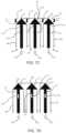
- FIG. 7 Ais a schematic depiction of a multi-use disposable system wherein the plungers of the syringes are disposed in a proximal position;
- FIG. 7 Bis a schematic depiction according to FIG. 7 A wherein the plungers are driven toward a distal position
- FIG. 7 Cis a schematic depiction according to FIG. 7 A wherein the plungers are disposed and compressed at the distal-most position in the syringes;
- FIG. 7 Dis a schematic depiction according to FIG. 7 A wherein the plungers are released;
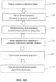
- FIGS. 8 A and 8 Bare flow charts depicting methods for calibrating the position of a drive mechanism of a fluid injector in accordance with examples according to the present disclosure
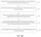
- FIG. 9is a flow chart depicting another method for calibrating the position of a drive mechanism of a fluid injector in accordance with an example according to the present disclosure.
- FIG. 10is a cross-sectional view of the syringe of FIG. 6 , illustrating slack between the piston and the plunger during a filling operation;
- FIG. 11is a cross-sectional view of the syringe of FIG. 6 , illustrating the removal of slack during a delivery operation;
- FIG. 12is a step diagram of a method according to an example of the present disclosure.
- FIG. 13is a step diagram of a method according to another example of the present disclosure.
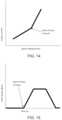
- FIG. 14is a graph of motor current versus piston displacement used to determine a point of slack removal from the fluid delivery system.
- FIG. 15is a graph of strain gauge signal versus time used to determine a point of slack removal from the fluid delivery system.
- proximalrefers to a portion of a syringe and/or a plunger nearest a fluid injector when a syringe and/or a plunger is oriented for connecting to a fluid injector.
- distalrefers to a portion of a syringe and/or a plunger farthest away from a fluid injector when a syringe and/or a plunger is oriented for connecting to a fluid injector.
- radialrefers to a direction in a cross-sectional plane normal to a longitudinal axis of a syringe, a plunger, and/or a piston extending between proximal and distal ends.
- circumferentialrefers to a direction around an inner or outer surface of a sidewall of a syringe, a plunger, and/or a piston.
- axialrefers to a direction along a longitudinal axis of a syringe, a piston, and/or a piston extending between the proximal and distal ends.
- openwhen used to refer to a fluid delivery component means that the system is in fluid connection with an outlet, for example through a nozzle or the open end of a tubing component or catheter.
- fluid flowmay be constrained, for example by forcing a fluid through a small diameter fluid path where flow may be determined by physical parameters of the system and the fluid, such as tubing diameter, fluid path constrictions, applied pressure, viscosity, etc.
- closedwhen used to refer to a fluid delivery component means that the system is not in fluid connection with an outlet, for example where fluid flow is stopped by a valve, such as a stopcock, high crack pressure valve, pinch valve, and the like.
- slackmeans mechanical slack, including a clearance or lost motion in a mechanism caused by gaps between parts, compression of mechanical components under applied load (such as by applied pressure), deflection of mechanical components under applied load (such as by applied pressure), that results in a delay of pressurized delivery of a fluid from a fluid injection after application of force.
- Characterizing an impedance of a fluid delivery system to minimize a difference between desired and actual fluid delivery system performancerequires consideration of how energy from an energy source is used in or moves through the system.
- the energy output or loss from the fluid delivery systemmay be in the form of heat losses through frictional forces or of work done on the fluid delivery system. For example, some of the energy carried by the pressurized fluid as it is delivered under pressure through a catheter is lost through resistive, frictional, or dissipative heating of the fluid.
- pressurized delivery of fluidcan also increase the potential energy of the system in terms of an increase in overall volume of system components or compressive forces on system components, as discussed herein.
- the kinetic energy of pressurized fluid moving through the fluid delivery systemcan affect the overall performance of the fluid delivery system.
- inertial forces of moving contrast material and expansion of the containers and/or tubing associated with the systemmay cause a phase lag between movement of the syringe plunger within the injector syringe and movement of contrast material out of the catheter and into the patient.
- capacitanceis directly correlative to injection pressure and inversely correlative to volume of contrast medium and saline in the syringes. In other words, capacitance increases with an increase in injection pressure and an increase in volume of fluid in the syringes.
- Total system capacitanceis inherent to each fluid delivery system and depends on a plurality of factors beyond pressure and volume of fluid remaining in the system, including, without limitation, injector construction, mechanical properties of materials used to construct the syringe, plunger, pressure jacket surrounding the syringe, and fluid lines delivering the fluid to the patient, size of the syringe, plunger, pressure jacket, diameter of tubing or other orifices through which the fluid must pass under pressure, and fluid properties, such as temperature, viscosity, and density.
- inefficiencies in the drivetrain of the injection systemcan add further uncertainty to the difference between a desired volume and flow rate of fluid to be delivered, and the volume and flow rate that are actually delivered. These inefficiencies may create slack, and can result in an aggregated difference between the desired volume and/or flow rate of fluid to be delivered, and the actual volume and or flow rate of fluid delivered.
- the accuracy of fluid deliveryis based on the ability of the fluid injector to accurately characterize the pressure in the syringes. This characterization is based, at least in part, on calibrating the drive member using a calibration station or fixtures configured for accurately measuring the pressure imparted on a fluid by the drive member.
- Traditional pressure calibration of fluid injectorsmay be performed by pushing fluid at varying rates through a frictionless fixture with a fixed orifice.
- Pressure of the fluidis then measured using a pressure gauge, where a real pressure signal is either recorded or fed back into the fluid injector to correlate the load signal of the drive member, such as voltage or current measurement, to a real pressure value.
- Conventional calibration stationsare cumbersome, difficult to set up and operate, and have compounded errors, leading to inaccurate pressure characterization of the drive member. For example, errors include friction in the fixture, air in the fluid path, lack of data points on a correlative timescale, and gauge reading inaccuracies.
- conventional calibrationdoes not provide for real-time adjustment based on factors, such as component wear, differences in syringe tolerance, fluid characteristics, and volumes of syringes used since it is performed infrequently, such as when the injector is serviced. Changes in injector components can add up over time to increase volume inaccuracies, such as by changing a zero point used to calibrate the volume accuracies of fluid delivery.
- a related problem common to fluid delivery systemsis the inability to characterize and correct for slack at the interface of the plunger of the syringe and the piston of the fluid injector.
- Slackresults from an imperfect connection between the piston and plunger which allows some degree of separation of the plunger relative to the piston during operation of the fluid delivery system.
- Major contributing factors to slackinclude the manufacturing tolerances for components of the plunger, the piston, and/or components of a drive motor, which result in components that fit together with varying degrees of imperfection or tolerance. Tolerances may also be designed into the components for ease of use.
- Another major source of slackincludes component wear which causes the fit between the plunger and piston to loosen with repeated use. Slack may also be introduced from other sources, including backlash on gears and/or ball screws driving the fluid injector, the interface between the syringe and the injector, the interface between piston and plunger, and any other surfaces which experience load during fluid injection.
- Slackis most evident in the fluid delivery system during the transition from a filling operation to a delivery operation.
- the piston of the fluid injectoris drawn away from the tip of the syringe, i.e., in the proximal direction, pulling the plunger along with it.
- system slackfor example at the interface of the piston and plunger, may allow the piston to move a small but significant distance without movement of the plunger, creating a gap between the piston and the plunger. Due to friction between the plunger and the syringe barrel, the gap may be maintained throughout the filling operation.
- the pistonchanges direction and moves toward the tip of the syringe, i.e., in the distal direction.
- distal movement of the pistonmay not immediately induce movement of the plunger, and thus does not cause fluid to be injected until the piston travels the length of the gap corresponding to the slack of the system. This travel may produce inaccuracies in volume of fluid delivered by the fluid injector, such as under delivery, during an injection procedure.
- This ideal injector slack distancemay be derived from aggregating delivery data of many fluid delivery systems including multiple syringes and plungers, as well as statistical analyses of the machining tolerances of the components of the fluid delivery system. Such delivery data can be used to determine the extra volume of fluid necessary to deliver the desired total volume of fluid. The extra volume may then be converted to overdrive of the piston, and programmed into the individual fluid delivery system.
- the position of the drive member of the fluid injector systemmay be calibrated.
- At least one fluid reservoiroptionally comprising a drive member, may be engaged with the injector and an injector pressurization feature may be operably connected to the drive member.
- Suitable fluid reservoirsinclude a syringe (such as a disposable or reusable syringe), a peristaltic pump reservoir, a compressible bag, and combinations thereof.
- the fluid injectormay include one fluid reservoir, while other embodiments the fluid injector may include a plurality of fluid reservoirs, such as two, three, or even more fluid reservoirs.
- Drive membersmay include plungers for syringes, end walls of enclosed rolling diaphragm syringes, peristaltic pump roller, and compressible clam shell-type drive members.
- Injector pressurization featuresinclude pistons, peristaltic pump drive, and the like.
- Drive membersmay be driven by a motive force, such as a reciprocally operable via electro-mechanical drive components such as a ball screw shaft driven by the motor, a voice coil actuator, a rack-and-pinion gear drive, a linear motor, a linear actuator, a rotary motor, and the like.
- the motormay be an electric motor.
- the drive membermay be driven distally from a proximal position in the syringe body to a specified distal potion in the syringe body, for example until it contacts the distal end of the interior of the syringe.
- the drive membercontinues to be driven distally until a load force value on the distal end of the syringe is reached.
- the load force valuemay, for example, be as a result of compressive forces, such as mechanical slack, plunger compression, friction, and deflection, among other forces on the system.
- the force on the drive member slowlymay then be decreased until the load force value reaches zero or a predetermined load force value.
- the position of the drive membermay be recorded as the zero volume, for example, the zero volume position (e.g., in milliliters), for that syringe where all fluid has been expelled from the syringe.
- the zero volume positionmay be recorded and saved by a processor associated with the injector for each individual syringe, such as by recording the zero volume position by a processor within its memory, and then used during injection protocols utilizing that syringe to more accurately deliver a desired fluid volume and/or flow rate.
- Measuring the force and associated change in position between the compressed position and the zero positionmay be used, for example, to identify or determine the position where at least one of the following occur: the piston contacts the plunger, when the fluid is first compressed, when the plunger first contacts the end of the syringe, when a deflection is detected on a restraint such as a syringe/injector engagement restraint, when a valve is cracked such as a high pressure crack valve, when a sidewall of a rolling diaphragm syringe (as described herein) first starts to roll in upon itself, and when the exterior of the syringe contacts a pressure jacket feature.
- measuring the force and associated change in position between the compressed position and the zero positionmay be used to determine a priming volume as part of a start of day or start of new injector protocol process.
- the measuring of force and/or change in associated positionmay be used to detect when a priming or purging operation is completed, for example by detecting a change in pressure force associated with the transition from expelling air to expelling a liquid.
- the measuring of force and/or change in associated positionmay be used to check the fidelity of a valve seal or other component in the fluid injector system.
- the load or strain on a system componentmay be measured, for example by a pressure sensor, a strain gauge, a measure of motor current or combinations of any thereof.
- the processormay determine and store the strain on a linear motor and/or displacement of the piston and/or plunger.
- the processormay store the amount of partial or full rotations of the roller pump and in embodiments where the reservoir is a compressible bag, the processor may determine and store the distance to compress the bag.
- the methods described hereinmay also provide calibration of the drive member.
- the methodmay include placing the fluid reservoir or pump in fluid isolation, for example by closing a valve, as described herein.
- the drive memberfor example a rotor pump or angularly compressive force, may pressurize the fluid in the reservoir to a first predetermined pressure.
- the displacement of the drive member required to reach the first predetermined pressureis recorded and the drive member is further driven to pressurize the fluid in the closed system to a second predetermined pressure and the additional displacement of the drive member to reach the second predetermined pressure is recorded.
- the difference between the drive member displacement to reach the first predetermined pressure and the displacement required to reach the second predetermined pressureis calculated and the value is used to calibrate the fluid injection system and position of the drive member to account for mechanical slack and/or system compliance. Once the system is calibrated, the processor may use this calibration to correct for fluid flow inaccuracies during an injection procedure to deliver an accurate fluid volume.
- the drive membermay pull a vacuum on the fluid reservoir for determining the zero position for the reservoir and drive member.
- the position of the drive member of the fluid injector systemmay be calibrated according to the following process.
- the drive membermay be moved proximally from a distal position in the syringe body thereby drawing a vacuum load within the reservoir, for example a syringe, until it reaches a predetermined vacuum load.
- the force on the drive membermay then be released and the drive member may move distally until the vacuum load force value reaches zero or a predetermined vacuum load force value.
- the position of the drive memberis recorded as the zero volume position for that syringe.
- the zero volume positionmay be recorded and saved by the injector for each individual syringe, such as by recording the zero position by a processor within its memory, and then used during injection protocols utilizing that syringe to more accurately deliver a desired fluid volume and/or flow rate.
- injectormay be in communication with a processor, for example a processor associated with the injector, a separate processing unit, a hospital information network processor, or a processor connected by a wired or wireless method.
- the various embodiments of the methodmay be stored in memory, controlled by a processor and/or an operator, and carried out automatically or manually whenever a new syringe or set of syringes is connected to the injector or at the start of a new injection protocol. According to other examples, this method may be carried out at the prompting of a user or the processor may prompt a user and recommend that the method be carried out.
- a method of the present disclosuremay be used to track wear on injector mechanical components, such as the motor or drive train, or on a fluid reservoir or fluid path, for example a syringe and/or tube set, over multiple uses or injection protocols.
- changes in the zero volume positionmay be tracked over a period of time, such as over a specified period of use for the injector or the use-life of the fluid reservoir/syringe and or tube set to monitor component wear or failure.
- the methods of the present disclosuremay be used to track wear on the injector components and/or a batch of syringes if applied to the batch of syringes over time, wherein the zero volume positions of the syringes are tracked and changes in the zero volume position is monitored over time. This may have applications in predictive maintenance of the injector, and the syringes. If excessive or sudden wear or failure is detected, the component may be repaired or replaced to avoid additional damage to the injector or injury to the patient or operator.
- a method according to the present disclosuremay be used to verify whether a fluid reservoir, such as a syringe or fluid path, is faulty, for example if the zero volume position is outside of a pre-determined range, wherein the determined range is representative of normal variance within the accepted syringe tolerances.
- a zero volume position that is too proximal along the longitudinal axis, relative to the predetermined rangemay indicate a fault condition, such as a cocked or misaligned plunger.
- a zero volume position that is too far distal along the longitudinal axis, relative to the predetermined rangemay indicate other problems or fault conditions such as a leak or weakness in a valve, fluid path, or fluid reservoir.
- Either boundary issue relative to the expected predetermined rangemay indicate an error or alarm condition to the user with respective notification to the user via a visual and/or audible alert, and in certain conditions may cause the injector to cease injection procedures until the error is corrected.
- the method according to the present disclosuremay be used to measure recoil of a plunger or a syringe as an indication of wear of injector components or wear of syringe components in a multi-use syringe set.
- the method according to the present disclosuremay measure static or dynamic friction of the plunger and/or the interior surface of the syringe body at the beginning of injection procedures, and initial values may be compared to expected, standard values, or measured values over time for a syringe design.
- Static and/or dynamic frictionmay be compared to known coefficients of friction of silicone, silicone compounds, and/or mixtures containing silicone to assess the presence or absence of silicone in the plunger and/or syringe. This may provide information on production standards for various production batches of syringes.
- a fluid injector system for delivering fluid to a patientincludes a fluid injector having a processor and at least one piston, and at least one syringe removably connected to the fluid injector and including a plunger disposed in a barrel of the at least one syringe and reversibly movable along a longitudinal axis of the syringe.
- the fluid injectormay include two or more syringes, three syringes, or even greater than three syringes for injecting saline and one or more contrast media or other medical fluids.
- the at least one piston of the fluid injectormay be configured to engage the plunger of the at least one syringe and travel along the longitudinal axis inside the barrel of the at least one syringe, and at least one valve is in fluid communication with the at least one syringe and at least one fluid container.
- the valvemay be switchable between a first position in which the at least one syringe is in fluid communication with the at least one fluid container and isolated from fluid communication with a patient (i.e., a first open position), a second position in which the at least one syringe is isolated from fluid communication with both the at least one fluid container and the patient (i.e., a closed position), and a third position where the at least one syringe is isolated from fluid communication with the fluid container and in fluid communication with a patient (i.e., a second open position).
- the processormay be associated with the fluid injector and may be programmed or configured to provide one or more commands including commands to drive the at least one piston of the fluid injector to a distal end of the at least one syringe, retract the at least one piston toward a proximal end of the at least one syringe to draw fluid into the at least one syringe from the at least one fluid container, measure and store a reference position of the at least one piston within the at least one syringe, switch the at least one valve from the first position to the second position, drive the at least one piston toward the distal end of the at least one syringe until a desired load on the piston is reached, measure and store a contact position of the at least one piston within the at least one syringe, wherein the contact position is a position where the desired load is reached, and derive a slack correction volume based at least partially on the difference between the reference position and the contact position.
- the processormay then calibrate the injector and/or syringe based on the stored correction volume.
- the processor of the fluid injectormay be programmed or configured to switch the at least one valve between the first open position and the second closed position. By controlling the valve position, the injector may calculate and calibrate the system in the open state or the closed state.
- the processor of the fluid injectormay be programmed or configured to relieve pressure in the at least one syringe after a pressurizing stroke by the drive member when the syringe is part of a closed system, for example by either moving the drive member and plunger in a proximal direction, for example by small incremental releases of the load force or by releasing the load force at a predetermined rate until the load force value is reduced to zero, which may indicate a zero position (i.e., no further proximal movement of the plunger) is observed, or alternatively by releasing all load force applied to the plunger and allowing the drive member to move freely in the proximal direction as the pressure within the syringe is equalized.
- measurement of when the proximal movement of the plunger ceasesmay provide a zero position that may be used to calibrate the injector components associated with the syringe.
- the systemmay repeatedly determine and store a slack correction volume over a specified time period, for example, at an initial use of the at least one syringe or at the beginning of the day, week, month, or other selected time period.
- the fluid injectorfor example the processor, may develop a slack curve for each piston of the injector as a function of time. The injector may then be configured to provide an alert to a user if a measured slack correction volume for at least one piston is significantly different from an expected slack correction volume based on the slack curve for the at least one piston.
- a fluid injector 10such as an automated or powered fluid injector, is adapted to interface with and actuate one or more syringes 12 (hereinafter referred to as “syringe 12 ”), which may be filed with a fluid F, such as contrast media, saline solution, or any desired medical fluid.
- the injector 10may be used during a medical procedure to inject the medical fluid into the body of a patient by driving a plunger 14 of each syringe 12 with a drive member, such as piston 19 (shown in FIG. 2 ), such as linear actuator or a piston element.
- the injector 10may be a multi-syringe injector having two, three or more syringes, wherein the several syringes 12 may be oriented in a side-by-side or other relationship and may be separately actuated by respective drive members/pistons 16 associated with the injector 10 .
- the injector 10may be configured to deliver fluid from one or both of the syringes 12 , sequentially or concurrently.
- the fluid injector 10may have at least one bulk fluid source (not shown) for filling the syringes 12 with fluid.
- the injector 10may be operably connected to a computing device 300 having a controller and memory.
- a fluid path set 17may be in fluid communication with each syringe 12 to place each syringe in fluid communication with a catheter for delivering the fluid F from each syringes 12 to a catheter (not shown) inserted into a patient at a vascular access site.
- fluid flow from the one or more syringes 12may be regulated by a fluid control module (not shown) that operates various valves, stopcocks, and flow regulating structures to regulate the delivery of the saline solution and contrast to the patient based on user selected injection parameters, such as injection flow rate, duration, total injection volume, and ratio of fluids from the syringes 12 , including specific ratios of each fluid in a dual flow injection protocol.
- the drive member 19such as a reciprocally driven piston moved by a motor 31 , may be configured to extend into and from the respective syringe port 13 through an opening in the front end of the injector housing.
- a separate drive member/piston 19may be provided for each syringe 12 .
- Each drive member/piston 19is configured to impart a motive force to at least a portion of the syringe 12 , such as the plunger 14 or a distal end of a rolling diaphragm syringe (for example, as described in PCT/US2017/056747; WO 2016/172467; and WO 2015/164783, the disclosures of which are incorporated herein by this reference).
- the drive member or piston 19may be reciprocally operable via electro-mechanical drive components such as a ball screw shaft driven by the motor 31 , a voice coil actuator, a rack-and-pinion gear drive, a linear motor, a linear actuator, and the like.
- the motor 31may be an electric motor.
- Suitable front-loading fluid injectors 10are disclosed in U.S. Pat. Nos. 5,383,858; 7,553,294; 7,666,169; 9,173,995; 9,199,033; and 9,474,857; and in PCT Application Publication Nos. WO 2016/191485 and WO 2016/112163, the disclosures of which are incorporated by reference in their entirety.
- the syringe 12generally has a cylindrical syringe barrel 18 formed from glass, metal, or a suitable medical-grade plastic.
- the barrel 18has a proximal end 20 and a distal end 24 , with a sidewall 119 extending therebetween along a length of a longitudinal axis 15 extending through a center of the barrel 18 .
- the distal end 24may have a conical shape that narrows in a distal direction from the cylindrical barrel 18 .
- a nozzle 22extends from the distal end 24 .
- the barrel 18has an outer surface 21 and an inner surface 23 with an interior volume 25 configured for receiving the fluid therein.
- the proximal end 20 of the barrel 18may be sealed with the plunger 14 that is reciprocally movable through the barrel 18 by reciprocal movement of the corresponding piston 19 or drive member.
- the plunger 14forms a liquid-tight seal against the inner surface 23 of the barrel 18 as the plunger 14 is advanced moved through the barrel 18 .
- the injector 10may be associated with and operatively connected to a processor 300 , such as a computing device having a controller and memory, for example by a wired or wireless (wifi, Bluetooth etc.) connection such that operation of the injector and various data points determined therefrom may be stored and utilized in calculations and injector protocols.
- the proximal end 20 of the syringe 12is sized and adapted for being removably inserted in a syringe port 13 of an injector 10 (shown in FIG. 1 ).
- the proximal end 20 of the syringe 12defines an insertion section 30 that is configured to be removably inserted into the syringe port 13 of the injector 10 while the remaining portion of the syringe 12 remains outside of the syringe port 13 .
- the syringe 12may be made of any suitable medical-grade plastic or polymeric material, desirably a clear or substantially translucent plastic material.
- the material of the syringe 12is desirably selected to meet the required tensile and planar stress requirements, water vapor transmission, and chemical/biological compatibility.
- Exemplary syringes suitable for use with the injector 10 depicted in FIG. 1are described in U.S. Pat. Nos. 5,383,858; 6,322,535; 6,652,489; 9,173,995; and 9,199,033, the disclosures of which are all incorporated by reference in their entirety.
- the injector 10may be configured for receiving and retaining a pressure jacket 32 within each syringe port 13 of the injector 10 .
- FIGS. 1 and 3illustrate fluid injectors 10 with two syringe ports 13 , which for the injector 10 shown in FIG. 3 each having a corresponding pressure jacket 32
- other examples of the fluid injector 10may include a single syringe port 13 and optionally, a corresponding pressure jacket 32 or more than two syringe ports 13 with an optional corresponding number of pressure jackets 32 .
- each pressure jacket 32may be configured to receive a syringe, such as a syringe for an angiographic (CV) procedure, or a rolling diaphragm syringe 34 (suitable examples of which are described in described in PCT/US2017/056747; WO 2016/172467; and WO 2015/164783).
- a fluid path setsimilar to the fluid path set 17 shown in FIG. 1 , may be fluidly connected with a discharge end of each rolling diaphragm syringe 34 for delivering fluid from the syringes 34 through tubing connected to a catheter, needle, or other fluid delivery connection (not shown) inserted into a patient at a vascular access site.
- the syringe 12 or 34may be a pre-filled syringe, i.e., the syringe may be prefilled with a medical fluid, such as a contrast agent or saline, when provided by the syringe manufacturer.
- the pre-filled syringemay be required to be spiked or otherwise punctured at the discharge end prior to an injection procedure to allow fluid to be expelled from the syringe into a fluid line to the patient, as described herein.
- the fluid injector 10may have at least one bulk fluid source (not shown) for filling the syringes 12 with fluid.
- the injector 10may be operably connected to a computing device 300 having a controller and memory.
- the rolling diaphragm syringe 34generally includes a hollow body 36 defining an interior volume 38 .
- the body 36has a forward or distal end 40 , a rearward or proximal end 42 , and a flexible sidewall 44 extending therebetween.
- the proximal end 42may be configured to act as piston to pressurize the syringe interior to draw in or expel fluid therefrom, as described herein.
- the sidewall 44 of the rolling diaphragm syringe 34defines a soft, pliable or flexible, yet self-supporting body that is configured to roll upon itself, as a “rolling diaphragm”, under the action of the a drive member or piston of the fluid injector 10 .
- the drive member/piston 19may be configured to releasably engage a drive member engagement portion 52 at the proximal end 42 of the rolling diaphragm syringe 34 (examples of which are described in PCT/US2017/056747).
- the sidewall 44is configured to roll such that its outer surface is folded and inverted in a radially inward direction as the drive member/piston 19 moves the proximal end 42 in a distal direction and unrolled and unfolded in the opposite manner in a radially outward direction as the drive member/piston 19 retract the proximal end 42 in a proximal direction.
- the rearward or proximal portion of the sidewall 44connects to a closed end wall 46 , and a forward or distal portion of the sidewall 44 defines a discharge neck 48 opposite the closed end wall 46 .
- the closed end wall 46may have a concave shape to facilitate the initiation of the inversion or rolling of the sidewall 44 , enhance mechanical strength of the closed end wall 46 , and/or to provide a receiving pocket to receive a distal end of drive member/piston 19 .
- the closed end wall 46may define a receiving end pocket for interfacing directly with a similarly-shaped distal end of the drive member/piston 19 .
- At least a portion of the drive member/piston 19may be shaped to substantially match the shape of the closed end wall 46 or, alternatively, pressure from the drive member/piston 19 as it is moved distally may conform the end wall 46 to substantially match the shape of at least a portion of the drive member/piston 19 .
- the end wall 46may have a central portion 50 having a substantially dome-shaped structure and a drive member engagement portion 52 extending proximally from the central portion 50 .
- the drive member engagement portion 52is configured for releasably interacting with a corresponding engagement mechanism on the drive member/piston 19 of the fluid injector 10 , for example as the drive member/piston is retracted.
- the rolling diaphragm syringe 34may be made of any suitable medical-grade plastic or polymeric material, desirably a clear or substantially translucent plastic material. The material of the rolling diaphragm syringe 34 is desirably selected to meet the required tensile and planar stress requirements, water vapor transmission, and chemical/biological compatibility.
- a fluid injector 10is shown in accordance with another example of the present disclosure.
- the injector 10has a housing 54 that encloses various mechanical drive components, electrical and power components necessary to drive the mechanical drive components, and control components, such as electronic memory and electronic control devices used to control operation of reciprocally movable pistons (not shown).
- the fluid injector 10further has a multi-patient disposable system (MUDS) 56 that is removably connectable with the fluid injector 10 .
- the MUDS 56has one or more syringes or pumps 58 .
- the number of syringes 58corresponds to the number of pistons on the fluid injector 10 .
- the MUDS 56has three syringes 58 in a side-by-side arrangement.
- Each syringe 58has a bulk fluid connector 60 for connecting to a respective bulk fluid source (not shown) via a MUDS fluid path 62 .
- the MUDS fluid path 62may be formed as a flexible tube with a spike element at its terminal end that connects to the bulk fluid connector 60 .
- the fluid injector 10may have at least one bulk fluid source (not shown) for filling the syringes 12 with fluid.
- the injector 10may be operably connected to a computing device 300 having a controller and memory. Injector 10 and the corresponding MUDS 56 as illustrated in FIG. 5 are described in detail in WO 2016/112163, the disclosure of which is incorporated herein by this reference.
- the MUDS 56has a frame 64 for supporting the one or more syringes 58 .
- the syringes 58may be removably or non-removably connected to the frame 64 .
- Each syringe 58has an elongated, substantially cylindrical syringe body.
- Each syringe 58has a filling port 66 in fluid communication with the MUDS fluid path 62 for filling the syringe 58 with fluid from a bulk fluid source.
- Each syringe 58further has a discharge outlet or conduit 68 at the terminal portion of its distal end. The discharge outlet 68 of each syringe 58 is in fluid communication with a manifold 69 .
- a valve 72is associated with each discharge outlet 68 and is operable between a filling position, where the filling port 66 is in fluid communication with the syringe interior while the discharge outlet 68 is in fluid isolation from the syringe interior, and a delivery position, where the discharge outlet 68 is in fluid communication with the syringe interior while the filling port 66 is in fluid isolation from the syringe interior.
- the manifold 69has a fluid pathway that is in fluid communication with each syringe 58 and with a fluid outlet line 74 in fluid communication with a port 76 configured for connecting to a single use fluid path element (not shown) for delivering fluid to the patient. Examples of suitable MUDSs are disclosed in PCT Application Publication No. WO 2016/112163, the disclosure of which is incorporated herein by reference in its entirety.
- the motor 31( FIG. 2 ) provides the motive force to reciprocally drive the drive member/piston 19 in a distal direction and discharges fluid within the syringes 12 , 34 or MUDS 56 .
- the motor 31may have drive components, such as gears and shafts, that are operatively connected to the drive member/piston 19 to reciprocally move the drive member/piston 19 .
- Each motor 31must be calibrated to correlate its operating characteristics, such as input current or output torque, to a flow rate or pressure and tolerances associated therewith.
- calibrationmay be desirable to compensate for any variations or out of specification behavior from any of the different components of the fluid injectors 10 , such as any variations in motor performance characteristics, particularly in fluid injectors with two or more syringes driven by two or more motors.
- conversion of motor input torque for one motor 31 to an injector output pressuremay be different for another motor 31 .
- This variationmay be further compounded by variations in tolerances of the drivetrain of the fluid injector 10 .
- the accuracy of flow rate or pressure in a fluid injector 10is directly correlative to a system and method used to calibrate the motor 31 .
- the fluid injector 10may have at least one bulk fluid source (not shown) for filling the syringes 12 with fluid.
- the injector 10may be operably connected to a computing device 300 having a controller and memory.
- an example according to the present disclosuremay include at least one syringe, such as a previously described MUDS.
- Each empty syringe 58is engaged in the injector 54 and plungers 14 are operatively connected to a corresponding piston 19 .
- the piston 19such as one or more linear actuators or reciprocally driven pistons moved by a motor 31 as in FIG. 2 , drive the plungers 14 distally along the longitudinal axis 15 of the bodies of the syringes 58 , until the plungers contact the distal ends 24 of the syringes 58 .
- this loadmay be measured for each syringe/piston combination by sensors 160 in operable connection with the plungers 14 and/or the pistons 19 .
- sensors 160are depicted schematically.
- Sensors 160may be pressure sensors, voltage sensors, transducers, or any sensor consistent with the present disclosure known in the art.
- the plungers 14may comprise a material that compresses under the load force.
- the forcemay be applied by the plungers 14 and/or pistons 19 depicted by arrows 150 until the reciprocal load force depicted by arrows 155 reaches a predetermined level or range.
- the load depicted by arrows 155may range from 25 to 200 psi or in other embodiments range from 50 to 100 psi.
- the force appliedmay be a load anywhere between zero and the maximum load capable by the motor or piston used by the injector system.
- the loadmay not be a pre-determined level, but may be the maximum amount of force that can be generated by a piston 19 . It is to be understood that a particular load may be more preferable depending on the architecture of the fluid injector used. For example, different types of syringes used in the same injector may result in different capacitance, and it may be preferable to set a different zero volume position based on different syringes.
- the force exerted by the plunger 14may be gradually lessened until the load force value measured by each of the sensors 160 is a second predetermined value, such as zero load force (i.e., when there is no reciprocal force or load, or some other predetermined value that is less than the predetermined level or range depicted by arrows 155 in FIG. 7 C .
- the piston 19may gradually be retracted in a proximal direction, or the force applied in the distal direction gradually may be released and the released load force may move the piston 19 in the proximal direction until a zero load force value is obtained.
- thismay be a passive retraction which allows the potential energy created by the kinetic loading of the motor driving the pistons to unwind, or release, like a spring until it has reached a predetermined load less than that which was generated at maximum.
- the direction of the gradual proximal motionis depicted by arrows 170 .
- the position or positions of the piston 19 in this statemay be recorded or stored on a memory device, such as external or internal memory of a computing device or the fluid injector, not shown, and calibrated as the position of zero volume of fluid in the syringes, or the “zero volume” position. It is to be understood that the zero volume position may vary depending on the elasticity of the plunger 14 , the piston 19 , or other parameters of the fluid injector 10 .
- a mechanical stopcan be utilized to identify the zero volume position.
- thismay comprise a trip switch set by the position reached by the plunger 14 and/or the piston 19 at maximum load.
- FIGS. 7 A- 7 DThe schematic depiction in FIGS. 7 A- 7 D is not applicable only to a MUDS. It is to be understood that the schematic depiction therein also would apply to injectors 10 including syringes 12 according to FIG. 1 and/or FIG. 2 , as well as rolling diaphragm syringes 34 according to FIG. 3 and FIG. 4 . Embodiments may be applied to pre-filled syringes, as described herein.
- the zero volume positionis to be understood to be the position when the piston 19 , 52 is incapable of injecting any additional fluid during injection proceedings.
- the zero volume positionmay be utilized to accurately determine the volume of fluid held within the syringe at any time by comparison of the current piston position to the zero volume position.
- FIG. 8 Ais flow chart illustrating an embodiment of a method of the present disclosure.
- the fluid injector systemis placed into a state 205 in preparation for a calibration protocol, for example by installing the one or more fluid reservoirs, for example the at least one syringe 12 , 58 , 34 , and engaging the respective drive members, such as a plunger, in operable communication with at least one piston 19 .
- the drive members, such as the at least one piston 19is driven 215 in a distal direction when pressurization of the fluid reservoir is desired or in the proximal direction when pulling a vacuum or relieving pressure is desired. While moving the drive member, the force response of the system may be monitored and/or measured 225 to determine a load force on the system.
- the position of the drive memberis determined and noted 235 by the injector processor 300 and stored 245 in the processor memory.
- the stored drive member positionmay then be used by the processor 300 of the injector 10 in stored algorithms and/or other programmed behaviors 255 as required by the stored injector protocols.
- FIG. 8 Bis a flow chart depicting a method according to an embodiment of the present disclosure.
- Step 210is to engage at least one syringe 12 , 58 , 34 comprising a drive member, such as a plunger, in operable communication with at least one piston 19 .
- Step 220is to drive the drive member and at least one piston 19 to a distal-most position in the at least one syringe 12 , 58 , 34 .
- Step 230is to apply a first predetermined load force on a distal end of the at least one syringe 12 , 58 , 34 with the drive member and at least one piston 19 .
- the position of the drive member and at least one piston 19 in step 230may be recorded in certain embodiments (not shown).
- Step 240is to allow the drive member and at least one piston 19 to move in a proximal direction until the load force is reduced to a second predetermined load force that is lower than the first predetermined load force.
- the second predetermined load forcemay be zero.
- the term “allow” according to step 240is inclusive, in various examples, of driving the drive member and at least one piston 19 in a proximal direction, releasing or lessening force applied on the drive member in a distal direction.
- Step 250is to store a position of the drive member at which the second predetermined load force value is achieved. It is to be understood that additional steps consistent with the present disclosure may be included in this method.
- FIG. 9is a flow chart depicting another method according to an embodiment of the present disclosure.
- Step 310is to engage at least one pre-filled syringe comprising a drive member, such as a plunger, in operable communication with at least one piston 19 .
- Step 320is to close off the fluid line and drive the drive member in a distal direction until a first predetermined load is achieved.
- the piston extension in this statemay be measured.
- Step 330is to allow the drive member and at least one piston to move in a proximal direction until the load force is reduced to a second predetermined load force that is lower than the first predetermined load force, or a predetermined piston extension, is achieved.
- the second predetermined load forcemay be zero.
- Step 330is inclusive, in various examples, of driving the drive member and at least one piston 19 in a proximal direction, releasing or lessening force applied on the drive member in a distal direction.
- Step 340is to store a position of the drive member at which the second predetermined load force value or piston extension is achieved. It is to be understood that additional steps consistent with the present disclosure may be included in this method.
- the system and method according to the present disclosureis beneficial because it allows calibration without the presence of medical fluid, thereby reducing waste and potential contamination.
- the various methodsallow for monitoring of changes of zero volume position over time for a specific injector or syringe set up.
- Examples according to the present disclosuremay be used to track wear on a syringe if the syringe is used multiple times by tracking changes in the zero volume position over multiple uses.
- the method of the present disclosuremay be used to track wear on a batch of syringes by tracking changes in the zero volume positions of the syringes in the batch.
- Further examples of the present disclosuremay be used to track wear on the injector, such as by tracking changes in the zero volume position of the drive member of the injector. Over time, the anticipated position of the drive member may change due to wear on various components of the drive member. This may have applications in predictive maintenance of the injector, and the syringes.
- Various embodiments according to the present disclosuremay be used to determine whether a syringe is damaged (for example, whether the syringe is punctured or cracked) based on whether the determined zero volume position is at a more proximal or distal position than anticipated.
- the determined zero volume positionmay also be used to determine defects in a syringe or batch of syringes if the zero volume position is outside of expected parameters, such as factory settings.
- a cocked or misaligned plungermay be indicated if the determined zero volume position is too proximal. If the determined zero volume position is too distal, another error or failure may be indicated, such as, for example a failure in the syringe or reservoir restraint where the restraint has failed or the tolerances have increased over the use life of the injector to a point where they fall outside the approved tolerances. Errors warning the user of these conditions may be returned by software in the memory of a computing device 300 , and/or the injection procedure may be halted by the controller until the error has been rectified.
- Examples according the present disclosurealso may be used to determine the amount of recoil in a plunger, or recoil due to syringe capacitance. This may be used to determine whether the plunger and/or syringe is fit for use, or the amount of wear on the plunger and/or syringe.
- Examples consistent with this disclosuremay involve determining whether a syringe is new or used based on the zero volume position when compared to an expected zero volume position.
- Examples consistent with this disclosuremay be used to measure breakaway (i.e., static) and dynamic friction on the way up, at the start of the day or initial use of a multi-use syringe.
- the initially measured values for frictionmay be correlated with measured values over time. This may be used to assess silicone presence—or gross silicone absence—if the measured value falls outside the expected range or tolerance. This may be useful in order to assure the quality of the syringe production. This may be useful to measure the accuracy of the system's pressure prediction algorithm. For example, if silicone is not present, the running friction of the plunger will be high, and the system may mistake that frictional loss for pressure—disarming or limiting the injection.
- Examples consistent with the present disclosuremay be applied to pre-filled syringes.
- an embodiment of the method and/or system hereinmay be applied to a pre-filled syringe with a closed stopcock prior to the start of an injection.
- the piston of a fluid injectormay apply a load to a predetermined value, and the extension of the piston required to generate that load may be measured.
- Load applied to a piston or other drive membermay be determined, for example, by a strain gauge, measured motor current or effort, or change in motor current/effort, a pressure sensor, force sensor, measured compression, and the like.
- This measurementmay be utilized to calculate compliance values of the fluid injector, and those values can be used to over-drive the piston to provide a corrected volume of fluid during an injection procedure in a system using active fluid control.
- the calculated compliance valuesmay be used to determine a zero volume position.
- the present disclosureprovides for a method for characterizing and correcting a fluid injector system for volume discrepancies associated with mechanical slack from injector components, component deflection under an applied force, and compliance due to volume expansion resulting from hydraulic pressurization of fluid delivery components.
- the present disclosureprovides methods and fluid injector systems configured for characterizing and correcting for fluid injection system slack.
- System slackas defined herein, may lead to inaccuracies in fluid volume delivery and lowered image quality.
- System slack according to these methodsmay be determined on an open system or a closed system, depending on injector configuration. While various embodiments are described fully with a syringe-type fluid reservoir, similar methodologies may be applied to fluid injectors comprising peristaltic pump-based and compressible bag based fluid reservoirs and drive systems.
- the methodsmay include driving at least one drive member of a fluid injector, such as a piston engaged with a plunger or with the proximal end wall of a rolling diaphragm, to a distal end of at least one syringe connected to the fluid injector; retracting the at least one drive member toward a proximal end of the at least one syringe to draw in a volume of fluid, such as a liquid medical fluid, into the at least one syringe from at least one fluid container in fluid communication with the at least one syringe when the valve is in a first, fill position; switching at least one valve, which may be a stopcock, one-way valve, high pressure cracking valve, or pinch valve, from the first, fill position where the at least one syringe is in fluid communication with the at least one fluid container to a second, closed position where the at least one syringe is isolated from the at least one fluid container
- the slack correction volumemay then be stored within a memory of a processor associated with the fluid injector and used to determine more accurate fluid delivery volumes for the particular syringe, for example where the syringe is a multi-use syringe, multi-use syringe set, or multi-use injection reservoir.
- the slack correction valuemay also be used to provide more accurate fluid delivery volumes for subsequent similar syringes (e.g., syringes from same manufacturer and/or having the same fluid volume capacity) utilized by the injector system.
- the methodmay involve pulling a vacuum on the fluid in the syringe by proximally retracting the drive member until a desired applied vacuum is achieved, as measured for example by strain sensor, a force sensor, a pressure sensor, motor current or effort, or similar measurement, and measuring the vacuum position of the drive member; releasing the applied retraction force on the drive member, either gradually, in a step-wise fashion, or at one time and allowing the drive member to return to a position where no vacuum force is applied to the drive member; measuring the neutral position of the drive member; and deriving a slack correction volume from the difference in volume of the fluid when the drive member is in the vacuum position and when the drive member is in the neutral position, where the slack correction volume includes a component associated with the mechanical slack of the drive member and motor associated with the at least one syringe.
- the processormay store and monitor a series of slack correction values over a time period and provide an alert when sudden deviations in the slack correction value are observed or the change in slack correction reaches a level indicating service of the injector is desired or required.
- the derived slack correction volumemay be, at least in part, the difference of fluid volume ( ⁇ V) in the syringe under the desired load compared to the volume of the fluid in the syringe when the syringe is not under applied load, such as after drawing in fluid and closing of the valve.
- the desired applied loadmay be substantially similar to a load applied during a typical fluid injection, for example, from 1 psi to 300 psi for a CT injection or from 300 psi to 1,200 psi for an angiography injection.
- the desired loadmay be equal to the amount of load necessary to take up all slack, with may be measured, for example by applying an increasing amount of load until no further movement of the drive member due to slack uptake is observed.
- the various components of the slack valueinclude, but are not limited to, mechanical slack, deflection, compression of components under mechanical load or fluid pressure, such as compression of the plunger cover under fluid pressure, and volume expansion under fluid pressure of system components upstream of the valve, including the syringe sidewalls, valve components, and upstream fluid path surfaces.
- the methodmay further include evacuating the fluid from the at least one syringe, filling the at least one syringe with a desired volume of fluid plus an additional volume of fluid equal to the slack correction volume, and delivering the fluid from the at least one syringe to a patient.
- evacuating the fluid from the at least one syringefilling the at least one syringe with a desired volume of fluid plus an additional volume of fluid equal to the slack correction volume, and delivering the fluid from the at least one syringe to a patient.
- the method stepsmay be performed at least partially by a processor configured to control a motor driving the at least one drive member of the fluid injector.
- the processormay include programming machine language to direct the processor to conduct the method at specified times.
- the methodmay include the system repeatedly determining and storing a slack correction volume over a specified time period, for example, at an initial use of the at least one syringe or at the beginning of the day, week, month, or other selected time period.
- the methodmay further include the fluid injector, for example the processor, developing a slack curve for each drive member of the injector as a function of time.
- the methodmay then include providing an alert to a user if a measured slack correction volume for at least one drive member is significantly different from an expected slack correction volume based on the slack curve for the at least one drive member.
- the processormay monitor the slack correction volume, for example with a slack curve, and when a slack volume degrades to a certain value, the processer may alert the technician, hospital, or even notify the service personnel directly that service is desired or required.
- a method for characterizing and correcting fluid injection system slackmay include driving at least one drive member, for example a piston engaged with a syringe plunger or a proximal end wall of a rolling diaphragm syringe, of a fluid injector to a distal end of at least one syringe connected to the fluid injector; retracting the at least one drive member toward a proximal end of the at least one syringe to draw fluid, such as a liquid medical fluid, into the at least one syringe from at least one fluid container in fluid communication with the at least one syringe when the valve is in a first, fill position; switching at least one valve, which may be a stopcock, one-way valve, high pressure cracking valve, or pinch valve, from the first, fill position where the at least one syringe is in fluid communication with the at least one fluid container to a second, closed position where the at least one syringe is isolated
- the methodmay further include evacuating the fluid from the at least one syringe, filling the at least one syringe with a desired volume of fluid plus an additional volume of fluid equal to the slack correction volume, and delivering the fluid from the at least one syringe to a patient as part of a fluid injection protocol.
- the method stepsmay be performed at least partially by a processor configured to control a motor driving the drive member of the injector.
- the methodmay include the system repeatedly determining and storing a slack correction volume over a specified time period, for example, at an initial use of the at least one syringe or at the beginning of the day, week, month, or other selected time period.
- the methodmay further include the fluid injector, for example the processor, developing a slack curve for each drive member of the injector as a function of time.
- the methodmay then include providing an alert to a user if a measured slack correction volume for at least one drive member is significantly different from an expected slack correction volume based on the slack curve for the at least one drive member.
- the processormay monitor the slack correction volume, for example with a slack curve, and when a slack volume degrades to a certain value, the processer may alert the technician, hospital, or even notify the service personnel directly that service is desired or required.
- FIG. 10shows the syringe 12 of FIG. 2 or 5 , but illustrates an imperfect interface between a piston 19 , and the plunger 14 of the syringe 12 .
- the syringe 12is shown in fluid communication with a valve 72 in a first position and a fluid container 80 storing a fluid F such as a contrast imaging agent, saline, or other medical fluid.
- a fluid Fsuch as a contrast imaging agent, saline, or other medical fluid.
- the imperfect interface between the piston 19 and the plunger 14permits slack 70 to propagate between the piston 19 and the plunger 14 when opposing loads are applied to the piston 19 and the plunger 14 . Additional components of the slack may arise from tolerances, imperfect contact, and wear in injector components such as gears and mechanical connections associated with the piston 19 and motor 31 of the injector.
- fluid Fis drawn from the container 80 into the interior volume 25 of the syringe 12 by moving the plunger 14 from the distal end 24 to the proximal end 20 of the syringe 12 .
- the motor 31draws the piston 19 , which is connected to the plunger 14 , towards the proximal end 20 of the syringe 12 .
- Engagement between the plunger 14 and the piston 19permit movement between the plunger 14 and the piston 19 allowing the slack 70 to propagate.
- the motor 31may distally drive the piston 19 a distance corresponding to a calculated volume equal to the slack following any proximal movement of the piston 19 so that any subsequent distal movement of the piston 19 will have pre-compensated for the slack so that fluid delivery is accurate based on the pre-compensated piston position.
- processor 300 implementing software for controlling the motor 31may be configured to characterize and correct for the slack 70 in the fluid delivery system. Further, slack values may be continually calculated and adjusted for to account for continuing wear to the injector over time.
- the slack 70 between the piston 19 and plunger 14 as described hereinis intended as an exemplary illustration of how one source of slack 70 propagates in the system. It is not to be construed as the principal or only source of slack 70 contemplated by the present disclosure. Other sources of slack 70 in the system are propagated and may be accounted for in a similar manner to provide improved accuracies for actual injection volumes. These sources of slack 70 may also include, but are not limited to, slack 70 from backlash on gears and/or ball screws in the motor 31 , the interface between the syringe 12 and the injector 10 , and any other surfaces which experience load during fluid injection. Other sources of slack in the system may be known to one of ordinary skill in the art and may be accounted for by the system and methods described herein, including the stacking of tolerances between the injector 10 , syringe 12 , and drive components.
- the amount of slack 70remains substantially the same for each cycle of filling and delivery operations of the injector 10 over a specific period of time, so long as the components of the injector 10 (e.g., disposable syringes, MUDS, etc.), particularly the piston 19 and plunger 14 , are not changed, for example due to wear, during this period. As such, the slack calculation may not need to be constantly updated. Therefore, once the slack 70 is characterized for one cycle, the processor 300 may be programmed or configured to account for the slack 70 for any subsequent cycles by converting the slack 70 into an overdrive distance or volume necessary to deliver the desired amount of the fluid F.
- the processor 300may be programmed or configured to account for the slack 70 for any subsequent cycles by converting the slack 70 into an overdrive distance or volume necessary to deliver the desired amount of the fluid F.
- the slack 70may also be continually monitored, for example if there is particular concern with component wear in a particular configuration.
- the process of deriving a slack correction volumeis set forth with reference to FIGS. 12 and 10 .
- any sequence or method stepsare understood to be implemented by the processor 300 , but, where context allows, may also be implemented by a technician, physician, nurse, or the like.
- FIG. 12A step diagram for characterizing the slack 70 according to one example of the present disclosure is illustrated in FIG. 12 .
- the injector 10 and syringe 12are setup with the piston 19 extended distally such that the plunger 14 is located at an end-of-travel position towards the distal end 24 of the barrel 18 .
- the plunger 14is retracted by the piston 19 via operation of the motor 31 toward the proximal end 20 of the syringe 12 , drawing a predetermined volume of the fluid F from the container 80 into the interior volume 25 of the syringe 12 .
- the fluid path set 17may be purged of air by first drawing a partial volume of fluid F into the syringe 12 and then driving the piston 19 distally to force the fluid F through the fluid path set 17 to displace the air. Purging the air may be necessary to accurately measure the slack 70 in the system. After purging the fluid path set 17 of air, the remaining fluid necessary to achieve the predetermined volume of the fluid F may be drawn into the syringe 12 .
- the predetermined volume of the fluid Fmay be equal to the volume intended for delivery to the patient, plus an additional slack volume to account for the slack 70 between the piston 19 and the plunger 14 and any necessary excess volume necessary to correct for system capacitance and impedance.
- the plunger 14may be drawn back to the 210 milliliter position and then driven forward to the 200 milliliter position to account for the 10 milliliters of slack 70 .
- the predetermined volume of the fluid Fmay not be the intended fluid volume for delivery to the patient, but rather some intermediate volume to determine the slack 70 at some intermediate time of the delivery operation. Regardless of the predetermined volume, the additional slack volume at this stage may be derived from methods for characterizing slack as described herein.
- the valve 72which may be, for example, a stopcock valve, is then switched at step 903 to a position isolating the syringe 12 from the container 80 .
- the position of the piston 19is measured and stored as reference position X 1 at step 904 (see FIG. 10 ).
- the motor 31is then driven to move the piston 19 toward the distal end 24 of the syringe 12 step 905 . Because the valve 72 is in the second, closed position, none of the fluid F is actually delivered to the patient, causing pressure to build in the fluid F between the plunger 14 and the valve 72 . This rising pressure results from the piston 19 moving in a distal direction, pressing the piston 19 and plunger 14 together and compressing the fluid F and the plunger surface.
- the piston 19is driven in the distal direction until a desired load on the piston 19 is reached.
- the desired loadmay be the load at which fluid is to be delivered to the patient under a normal delivery operation, such as in the range of 0 psi to 300 psi, for example 50 psi. More generally, the desired load is determined based on contact between the plunger 14 and the piston 19 .
- pressuremay be directly measured by a transducer at any location between the syringe 12 and the valve 72 .
- the loadmay be derived from the current of the motor 31 or from deformation of any component between the syringe 12 and the valve 72 .
- the loadmay be determined from a strain gauge located on some component of the injection 10 or syringe 12 , particularly the piston 19 .
- the loadmay be determined by deformation of the restraint holding the syringe 12 to the injector 10 .
- FIGS. 14 - 15show graphical representations of slack removal using current of the motor 31 and the signal from the strain gauge, respectively.
- a slack correction volumemay be derived by subtracting the volume between the conical engagement surfaces of the piston 19 and the plunger 14 at the reference position X 1 from the volume between the conical engagement surfaces of the piston 19 and the plunger 14 at the contact position X 2 .
- the slack correction volumeis then stored for use as the additional volume of fluid F to draw from the container 80 in subsequent filling operations.
- the slack correctionmay be determined as the time at a specific piston movement rate to move the piston from the reference position X 1 to the contact position X 2 . In this manner, the exact amount of additional movement of the piston 19 may be executed during each transition from a filling operation to a delivery operation, and vice versa.
- the distal movement of the piston 19 to account for the volume due to the slack correctionmay be done after any proximal movement of the piston 19 , even if not immediately transitioning to fluid delivery by further distal movement of the piston, so that the slack volume has been accounted for the next distal movement of the syringe.
- the fluid reservoiris pre-corrected and any distal movement has accounted for the slack, thereby accurately beginning fluid delivering and minimizing any time to actual fluid delivery due to slack.
- the determined value of the slack 70may be used during each subsequent delivery operation, preventing under delivery, over delivery, waste and spillage of fluid, and pressure damage to system components.
- pressuremay be relieved from the syringe 12 .
- the reference position X 1is measured after the syringe 12 is pressurized, as illustrated in the step diagram of FIG. 13 .
- the injector 10 and syringe 21are setup with the piston 19 extended distally at step 1001 , the piston 19 is retracted to draw a predetermined volume of the fluid F from the container 80 into the interior volume 25 at step 1002 , and the valve 72 is switched to a second, closed position at step 1003 .
- Steps 1001 - 1003are performed substantially as described above in reference to steps 901 - 903 of FIG. 12 , including the purging of air from the fluid path set 17 .
- the piston 19is then driven in the distal direction until a desired load on the piston 19 is reached at step 1004 , substantially as described above in reference to step 905 of FIG. 12 .
- the drive currentis then removed from the motor 31 to relieve the applied pressure in the system at step 1005 , allowing unwanted pressure to be removed from the fluid path set 17 .
- the displacement of the position of the plunger 14is then measured and stored while the slack 70 is removed from the system at step 1006 . Accuracy may be enhanced by measuring the displacement of the plunger 14 rapidly upon relieving pressure in the system.
- the slack correction volumeis calculated and stored substantially based on the displacement measured at step 906 .
- the slack correction volumemay be derived by converting the displacement measured at step 906 to a volume between the conical engagement surfaces of the piston 19 and the plunger 14 at the reference position X 1 from the volume between the conical engagement surfaces of the piston 19 and the plunger 14 at the contact position X 2 .
- the slack correction volumeis then stored for use as the additional volume of fluid F to draw from the container 80 in subsequent filling operations.
- the step of relieving pressure from the syringe 12 in the method of either of FIG. 12 or 13may occur at alternative times during the execution of the methods to remove unwanted and/or undesirable pressure.
- pressure reliefmay be performed prior to measuring and storing the contact position X 2 at step 906 .
- Characterizing and storing the slack 70 according to the systems and methods described hereinis particularly suited for use during the initial filling of each disposable component, such as the syringe 12 , when the disposable component is placed into service.
- each disposable componentsuch as the syringe 12
- the present disclosureis not limited in the time and manner of implementation.
- characterizing and storing the slack 70may be performed at periodic intervals, such as each injection, each day, each week, or each month throughout the life of the injector 10 to recalibrate for component wear.
- the measured slack 70may be used in a statistical analysis or as part of a predictive maintenance protocol to intelligently alert users and/or service technicians that an injector 10 , syringe 12 , diaphragm syringe 34 , and/or MUDS 56 is operating abnormally or otherwise requires service.
- a slack curve based on repeated slack volume measurements as a function of timemay be prepared. At a selected time, a new slack measurement may be taken and compared to the slack curve.
- Any significant or unexpected deviation of the measured slack from that expected from the slack curvemay be indicative of unexpected wear or potential failure of the mechanical components of the injector 10 or potential issues with a particular syringe set.
- the systemmay then alert the user of the abnormal reading so that a new syringe set may be installed and/or a service call may be scheduled.
Landscapes
- Health & Medical Sciences (AREA)
- Vascular Medicine (AREA)
- Engineering & Computer Science (AREA)
- Anesthesiology (AREA)
- Biomedical Technology (AREA)
- Heart & Thoracic Surgery (AREA)
- Hematology (AREA)
- Life Sciences & Earth Sciences (AREA)
- Animal Behavior & Ethology (AREA)
- General Health & Medical Sciences (AREA)
- Public Health (AREA)
- Veterinary Medicine (AREA)
- Physics & Mathematics (AREA)
- Fluid Mechanics (AREA)
- Infusion, Injection, And Reservoir Apparatuses (AREA)
Abstract
Description
Claims (8)
Priority Applications (1)
| Application Number | Priority Date | Filing Date | Title |
|---|---|---|---|
| US16/623,828US11786652B2 (en) | 2017-08-31 | 2018-08-28 | System and method for drive member position and fluid injector system mechanical calibration |
Applications Claiming Priority (4)
| Application Number | Priority Date | Filing Date | Title |
|---|---|---|---|
| US201762552589P | 2017-08-31 | 2017-08-31 | |
| US201762552427P | 2017-08-31 | 2017-08-31 | |
| US16/623,828US11786652B2 (en) | 2017-08-31 | 2018-08-28 | System and method for drive member position and fluid injector system mechanical calibration |
| PCT/US2018/048284WO2019046261A1 (en) | 2017-08-31 | 2018-08-28 | System and method for drive member position and fluid injector system mechanical calibration |
Publications (2)
| Publication Number | Publication Date |
|---|---|
| US20200179595A1 US20200179595A1 (en) | 2020-06-11 |
| US11786652B2true US11786652B2 (en) | 2023-10-17 |
Family
ID=63528958
Family Applications (1)
| Application Number | Title | Priority Date | Filing Date |
|---|---|---|---|
| US16/623,828Active2040-08-15US11786652B2 (en) | 2017-08-31 | 2018-08-28 | System and method for drive member position and fluid injector system mechanical calibration |
Country Status (7)
| Country | Link |
|---|---|
| US (1) | US11786652B2 (en) |
| EP (1) | EP3675930B1 (en) |
| JP (1) | JP7252143B2 (en) |
| CN (1) | CN110891630B (en) |
| AU (1) | AU2018326380B2 (en) |
| CA (1) | CA3067740A1 (en) |
| WO (1) | WO2019046261A1 (en) |
Families Citing this family (12)
| Publication number | Priority date | Publication date | Assignee | Title |
|---|---|---|---|---|
| EP1762259B2 (en) | 2005-09-12 | 2025-01-01 | Unomedical A/S | Inserter for an infusion set with a first and second spring units |
| WO2012123274A1 (en) | 2011-03-14 | 2012-09-20 | Unomedical A/S | Inserter system with transport protection |
| AU2018317866B2 (en) | 2017-08-18 | 2024-06-13 | Bayer Healthcare Llc | System, method, and computer program product for predictive maintenance |
| AU2018326386B2 (en) | 2017-08-31 | 2024-03-28 | Bayer Healthcare Llc | Fluid injector system volume compensation system and method |
| JP7450608B2 (en) | 2018-08-28 | 2024-03-15 | バイエル・ヘルスケア・エルエルシー | Fluid injector system, method for preventing fluid backflow, and computer program product |
| JP7040392B2 (en)* | 2018-10-03 | 2022-03-23 | 株式会社島津製作所 | How to adjust the sample injection device and sample injection device |
| US11458292B2 (en) | 2019-05-20 | 2022-10-04 | Unomedical A/S | Rotatable infusion device and methods thereof |
| AU2020387553A1 (en)* | 2019-11-21 | 2022-06-02 | Bayer Healthcare Llc | System, method, and computer program product for smart fluid injector performance monitoring |
| US11957542B2 (en) | 2020-04-30 | 2024-04-16 | Automed Patent Holdco, Llc | Sensing complete injection for animal injection device |
| AU2021264011A1 (en) | 2020-04-30 | 2022-11-10 | Bayer Healthcare Llc | System, device, and method for safeguarding wellbeing of patients for fluid injection |
| AU2021401901A1 (en)* | 2020-12-15 | 2023-06-22 | Becton, Dickinson And Company | Apparatuses and methods for normalizing loaded pump motor data to unloaded pump motor data during a fluid movement operation |
| CN118317802A (en) | 2021-09-30 | 2024-07-09 | 法国加柏公司 | Injection device for receiving an injection member |
Citations (531)
| Publication number | Priority date | Publication date | Assignee | Title |
|---|---|---|---|---|
| US383858A (en) | 1888-06-05 | mepartland | ||
| US508584A (en) | 1893-11-14 | Device for mixing hot and gold water for bathing | ||
| US945143A (en) | 1909-07-28 | 1910-01-04 | Iacques Szamek | Apparatus for mixing liquids. |
| GB201800A (en) | 1922-09-18 | 1923-08-09 | Robert Sowter Hubbard | An improved toy |
| US2511291A (en) | 1947-03-12 | 1950-06-13 | Grover C Mueller | Mixer for liquids |
| US2583206A (en) | 1949-12-01 | 1952-01-22 | Separator Ab | Apparatus for homogenizing |
| US3156236A (en) | 1961-12-07 | 1964-11-10 | Cordis Corp | Medical injector |
| US3159312A (en) | 1962-09-28 | 1964-12-01 | Budd Co | Dispensing device for mixing two viscous fluids |
| US3276472A (en) | 1963-12-03 | 1966-10-04 | Medex Inc | Medical valve |
| US3349713A (en) | 1964-09-12 | 1967-10-31 | Glanzstoff Koln G M B H | Process and device for mixing liquids of differing viscosities |
| US3520295A (en) | 1968-03-06 | 1970-07-14 | Gen Electric | Cardiac r-wave detector with automatic gain control |
| US3523523A (en) | 1966-06-30 | 1970-08-11 | Contraves Ag | Power driven medical injector syringe with electromagnetic coupling means |
| US3623474A (en) | 1966-07-25 | 1971-11-30 | Medrad Inc | Angiographic injection equipment |
| US3635444A (en) | 1970-09-08 | 1972-01-18 | Amvit | Static mixer |
| US3671208A (en) | 1970-10-09 | 1972-06-20 | Wayne G Medsker | Fluid mixing apparatus |
| US3701345A (en) | 1970-09-29 | 1972-10-31 | Medrad Inc | Angiographic injector equipment |
| US3719207A (en) | 1969-11-13 | 1973-03-06 | Fuji Photo Film Co Ltd | Apparatus for transporting fluid |
| US3755655A (en) | 1971-10-26 | 1973-08-28 | Tac Ind Inc | Machine processed data card |
| US3793600A (en) | 1971-03-16 | 1974-02-19 | Strategic Automated Systems In | Record medium with validating and cancelling feature and method |
| US3812843A (en) | 1973-03-12 | 1974-05-28 | Lear Siegler Inc | Method and apparatus for injecting contrast media into the vascular system |
| US3817843A (en) | 1971-04-13 | 1974-06-18 | Electricity Council | Electrodeposition of iron foil |
| US3839708A (en) | 1972-06-28 | 1974-10-01 | Searle Medidata Inc | Input-output terminal for hospital information system |
| JPS5017781A (en) | 1973-06-15 | 1975-02-25 | ||
| US3868967A (en) | 1973-02-16 | 1975-03-04 | Shropshire Kenneth W | Adapter for mixing fluids |
| US3888239A (en) | 1974-06-21 | 1975-06-10 | Morton K Rubinstein | Fluid injection system |
| US3895220A (en) | 1973-09-07 | 1975-07-15 | Docutronix Inc | Selectively encodable envelope insert and related apparatus |
| US3898983A (en) | 1973-10-03 | 1975-08-12 | James O Elam | Device and method for detecting the degree of muscle relaxation of a medical patient |
| US3927955A (en) | 1971-08-23 | 1975-12-23 | East West Medical Products Inc | Medical cassette pump |
| US3941126A (en) | 1974-08-08 | 1976-03-02 | Dietrich Joseph W | Apparatus for long term intravenous administration of diluted incompatible multiple medications |
| US3958103A (en) | 1973-05-31 | 1976-05-18 | Omron Tateisi Electronics Co. | Automatic ticket vending system |
| US3968195A (en) | 1974-06-17 | 1976-07-06 | Marilyn Bishop | Method for making sterile connections |
| US3995381A (en) | 1975-06-27 | 1976-12-07 | Ken Max Manfred | Low visibility answer sheet and method of testing |
| US4001549A (en) | 1971-06-10 | 1977-01-04 | Corwin Edward J | Marking document and template assembly and method of making the assembly |
| US4006736A (en) | 1974-11-27 | 1977-02-08 | Medrad, Inc. | Angiographic injector |
| US4038981A (en) | 1974-07-26 | 1977-08-02 | Burron Medical Products, Inc. | Electronically controlled intravenous infusion set |
| US4044757A (en) | 1976-01-14 | 1977-08-30 | The Kendall Company | Cholangiography device and method |
| US4090502A (en) | 1975-08-22 | 1978-05-23 | Medical Institute Of Hoshokai | Remote-controlled barium injection apparatus |
| US4135247A (en) | 1977-08-15 | 1979-01-16 | Siemens Aktiengesellschaft | Tomography signal processing system |
| US4151845A (en) | 1977-11-25 | 1979-05-01 | Miles Laboratories, Inc. | Blood glucose control apparatus |
| US4187057A (en) | 1978-01-11 | 1980-02-05 | Stewart-Naumann Laboratories, Inc. | Peristaltic infusion pump and disposable cassette for use therewith |
| US4191183A (en) | 1977-10-31 | 1980-03-04 | Barry Mendelson | Mixing chamber for use in plural medical liquid intravenous administration set |
| US4199000A (en) | 1978-07-19 | 1980-04-22 | Edstrom William E | Cross-contamination isolator |
| US4204775A (en) | 1978-08-08 | 1980-05-27 | General Dynamics Corporation Pomona Division | Mixing device for simultaneously dispensing two-part liquid compounds from packaging kit |
| US4208136A (en) | 1978-12-01 | 1980-06-17 | Komax Systems, Inc. | Static mixing apparatus |
| US4207871A (en) | 1978-06-07 | 1980-06-17 | Imed Corporation | System for controlling the flow of intravenous fluids to a patient |
| WO1980001754A1 (en) | 1979-02-28 | 1980-09-04 | Abbott Lab | Novel valve employing hydrophobic and hydrophilic membranes |
| US4223675A (en) | 1978-07-24 | 1980-09-23 | Baxter Travenol Laboratories, Inc. | Solution containers such as blood bags and system for preparing same |
| US4262824A (en) | 1978-02-17 | 1981-04-21 | Baxter Travenol Laboratories, Inc. | Low-current E-frame electronic magnet with a permanent magnet armature for an I. V. valving controller |
| US4263916A (en) | 1978-03-27 | 1981-04-28 | University Of Southern California | Image averaging for angiography by registration and combination of serial images |
| US4280494A (en) | 1979-06-26 | 1981-07-28 | Cosgrove Robert J Jun | System for automatic feedback-controlled administration of drugs |
| US4284073A (en) | 1977-10-11 | 1981-08-18 | Krause Horst E | Method and apparatus for pumping blood within a vessel |
| US4315247A (en) | 1979-08-13 | 1982-02-09 | Germanton Charles E | Security systems employing an electronic lock and key apparatus |
| US4319568A (en) | 1979-10-29 | 1982-03-16 | Vickers Limited | Liquid dispensing apparatus |
| US4329067A (en) | 1978-04-19 | 1982-05-11 | Bruce J. Landis | Fluid mixer |
| FR2493708A1 (en) | 1980-11-07 | 1982-05-14 | Mecaserto | Appts. for preparing solns. for physiological injection - to automate mixing and transfer from remote control |
| US4340153A (en) | 1980-11-28 | 1982-07-20 | Spivey David L | Method and apparatus for medication dispensing |
| US4341153A (en) | 1980-01-08 | 1982-07-27 | Truswal Systems Corp. | Splicing and truss assembly apparatus and methods |
| JPS5815842A (en) | 1981-07-20 | 1983-01-29 | 株式会社東芝 | Image contour extraction device |
| US4392847A (en) | 1979-01-08 | 1983-07-12 | Whitney Douglass G | Injection and monitoring system |
| US4392849A (en) | 1981-07-27 | 1983-07-12 | The Cleveland Clinic Foundation | Infusion pump controller |
| US4396385A (en) | 1980-12-05 | 1983-08-02 | Baxter Travenol Laboratories, Inc. | Flow metering apparatus for a fluid infusion system |
| DE3203594A1 (en) | 1982-02-03 | 1983-08-11 | Siemens AG, 1000 Berlin und 8000 München | X-RAY DIAGNOSTIC SYSTEM FOR ANGIOGRAPHIC X-RAY IMAGES |
| US4402310A (en) | 1979-11-22 | 1983-09-06 | Olympus Optical Co., Ltd. | Endoscope system |
| US4409966A (en) | 1981-05-29 | 1983-10-18 | Lambrecht Richard M | Method and apparatus for injecting a substance into the bloodstream of a subject |
| US4434822A (en) | 1979-11-05 | 1984-03-06 | Baxter Travenol Laboratories, Inc. | System for the sterile mixing of materials |
| US4434820A (en) | 1982-05-05 | 1984-03-06 | Glass John P | Syringe loader and method |
| US4441823A (en) | 1982-07-19 | 1984-04-10 | Power Harold H | Static line mixer |
| US4444198A (en) | 1981-12-21 | 1984-04-24 | Petre John H | Circulatory monitoring system and method |
| US4447230A (en) | 1981-08-05 | 1984-05-08 | Quest Medical, Inc. | Intravenous administration set assembly |
| US4448200A (en) | 1978-03-27 | 1984-05-15 | University Of Southern California | System and method for dynamic background subtraction |
| US4474476A (en) | 1982-08-05 | 1984-10-02 | Jack Thomsen | Chemical printing liquid method and system |
| EP0121216A1 (en) | 1983-03-31 | 1984-10-10 | Kabushiki Kaisha Toshiba | X-ray television diagnostic apparatus |
| US4479760A (en) | 1982-12-28 | 1984-10-30 | Baxter Travenol Laboratories, Inc. | Actuator apparatus for a prepackaged fluid processing module having pump and valve elements operable in response to applied pressures |
| US4479762A (en) | 1982-12-28 | 1984-10-30 | Baxter Travenol Laboratories, Inc. | Prepackaged fluid processing module having pump and valve elements operable in response to applied pressures |
| US4479761A (en) | 1982-12-28 | 1984-10-30 | Baxter Travenol Laboratories, Inc. | Actuator apparatus for a prepackaged fluid processing module having pump and valve elements operable in response to externally applied pressures |
| JPS59214432A (en) | 1983-05-20 | 1984-12-04 | 株式会社東芝 | Radiation diagnostic apparatus |
| EP0129910A1 (en) | 1983-06-27 | 1985-01-02 | Kabushiki Kaisha Toshiba | X-ray diagnostic apparatus for allowing stereoscopic visualization on X-ray images of an object under examination |
| WO1985000292A1 (en) | 1983-07-11 | 1985-01-31 | Imperial Chemical Industries Plc | Fluid delivery apparatus |
| US4504908A (en) | 1982-03-15 | 1985-03-12 | General Electric Company | Matched filter for X-ray temporal subtraction |
| US4509526A (en) | 1983-02-08 | 1985-04-09 | Lawrence Medical Systems, Inc. | Method and system for non-invasive ultrasound Doppler cardiac output measurement |
| US4512764A (en) | 1982-09-27 | 1985-04-23 | Wunsch Richard E | Manifold for controlling administration of multiple intravenous solutions and medications |
| US4542459A (en) | 1982-11-26 | 1985-09-17 | General Electric Company | Matched filter for x-ray hybrid subtraction |
| US4544949A (en) | 1982-03-05 | 1985-10-01 | Tokyo Shibaura Denki Kabushiki Kaisha | X-Ray diagnostic apparatus and method |
| JPS60194934A (en) | 1984-03-19 | 1985-10-03 | 株式会社日立メデイコ | X-ray vessel image fluoroscopic apparatus |
| JPS60194935A (en) | 1984-03-19 | 1985-10-03 | 株式会社日立メデイコ | X-ray vessel image fluoroscopic apparatus |
| FR2561949A1 (en) | 1984-03-29 | 1985-10-04 | Arc Services | System for transporting parcels |
| US4551133A (en) | 1984-04-16 | 1985-11-05 | American Hospital Supply Corporation | Patient controlled medication infusion system |
| US4552130A (en) | 1983-03-01 | 1985-11-12 | Olympus Optical Co., Ltd. | Air and liquid supplying device for endoscopes |
| JPS60253197A (en) | 1984-05-29 | 1985-12-13 | Toshiba Corp | X-ray diagnostic equipment |
| US4559036A (en) | 1983-12-14 | 1985-12-17 | Wunsch Richard E | Apparatus for controlling administration of multiple intravenous solutions and medications |
| US4563175A (en) | 1983-12-19 | 1986-01-07 | Lafond Margaret | Multiple syringe pump |
| US4585009A (en) | 1983-02-28 | 1986-04-29 | E. R. Squibb & Sons, Inc. | Strontium-rubidium infusion pump with in-line dosimetry |
| EP0189491A1 (en) | 1983-08-19 | 1986-08-06 | Intermedicat Gmbh | Device for dosed simultaneous infusing solutions |
| EP0192786A2 (en) | 1985-02-18 | 1986-09-03 | Medrad Incorporated | Processor-controlled angiographic injector device |
| US4610670A (en) | 1983-06-13 | 1986-09-09 | E. I. Du Pont De Nemours And Company | Sterile connection process, apparatus and system |
| US4611340A (en) | 1983-05-20 | 1986-09-09 | Kabushiki Kaisha Toshiba | Apparatus for examining a biological object by using radiation |
| US4610790A (en) | 1984-02-10 | 1986-09-09 | Sterimatics Company Limited Partnership | Process and system for producing sterile water and sterile aqueous solutions |
| US4626144A (en) | 1984-03-21 | 1986-12-02 | Urma Aktiengesellschaft | Boring tool with balancing means for non-vibrating boring |
| US4625494A (en) | 1983-04-28 | 1986-12-02 | Pfrimmer & Co. Pharmazeutische Werke Erlangen | Method and apparatus for making mixtures of pharmaceutical liquids |
| US4633307A (en) | 1984-09-13 | 1986-12-30 | Kabushiki Kaisha Toshiba | Digital subtraction fluorographic method and apparatus |
| US4634426A (en) | 1984-12-11 | 1987-01-06 | Baxter Travenol Laboratories | Medical infusion controller and user interface |
| US4636144A (en) | 1982-07-06 | 1987-01-13 | Fujisawa Pharmaceutical Co., Ltd. | Micro-feed pump for an artificial pancreas |
| US4655197A (en) | 1982-12-01 | 1987-04-07 | Snyder Laboratories, Inc. | Lavage system with variable frequency, flow rate and pressure |
| US4662906A (en) | 1984-04-12 | 1987-05-05 | Pall Corporation | Cardiotomy reservoir |
| US4672651A (en) | 1985-03-28 | 1987-06-09 | Hitachi Medical Corporation | Method of and apparatus for reconstructing shape of interested part of object through irradiation with X-rays |
| US4676776A (en) | 1985-01-18 | 1987-06-30 | Intelligent Medicine, Inc. | Device and method for effecting application of a therapeutic agent |
| US4682170A (en) | 1983-11-25 | 1987-07-21 | Kabushiki Kaisha Toshiba | Apparatus for collecting toll |
| US4689670A (en) | 1984-01-19 | 1987-08-25 | Kabushiki Kaisha Toshiba | Method and apparatus for measuring a biological function of a subject |
| JPS62216199A (en) | 1986-03-18 | 1987-09-22 | Toshiba Corp | X-ray CT device |
| EP0245160A1 (en) | 1986-05-06 | 1987-11-11 | General Electric Cgr S.A. | X-ray installation with a communication network |
| US4710166A (en) | 1985-11-08 | 1987-12-01 | Quest Medical, Inc. | Automated drug additive infusion system |
| US4723261A (en) | 1983-12-22 | 1988-02-02 | U.S. Philips Corporation | X-ray examination apparatus incorporating image subtraction |
| JPS6340538A (en) | 1986-08-06 | 1988-02-20 | 株式会社東芝 | Ct image diagnostic method |
| WO1988003815A1 (en) | 1985-06-04 | 1988-06-02 | Baxter Deutschland Gmbh | Multi-path valve for a device for producing or administering infusion solutions |
| US4750643A (en) | 1986-08-04 | 1988-06-14 | Sugrin Surgical Instrumentation, Inc. | Sterile fluid dispensing system and method |
| US4754786A (en) | 1986-09-05 | 1988-07-05 | Roderick Roberts | Sterile fluid storage and dispensing apparatus and method for filling same |
| US4781687A (en) | 1986-10-16 | 1988-11-01 | Baxter Travenol Laboratories, Inc. | Irrigation system utilizing air bladder pressure regulator and method of use |
| US4783273A (en) | 1987-01-29 | 1988-11-08 | Gambro Ab | Method and apparatus for supplying concentrate for use in medical treatments |
| JPS63290547A (en) | 1987-05-25 | 1988-11-28 | Hitachi Medical Corp | Television tomographic imaging apparatus |
| US4789014A (en) | 1986-12-05 | 1988-12-06 | Baxter International Inc. | Automated system for adding multiple fluids to a single container |
| US4793357A (en) | 1986-11-24 | 1988-12-27 | Picker International, Inc. | CT blood flow mapping with xenon gas enhancement |
| US4795429A (en) | 1987-10-28 | 1989-01-03 | Feldstein Marvin A | Method and apparatus for use in the control of intravenous medication introduction |
| US4798590A (en) | 1983-11-22 | 1989-01-17 | Medical Technology Products, Inc. | Intravenous infusion pumping system including independent pump set |
| US4804454A (en) | 1986-03-19 | 1989-02-14 | Honda Giken Kagyo Kabushiki Kaisha | Oxygen concentration sensing apparatus |
| DE3726452A1 (en) | 1987-08-08 | 1989-02-16 | Schael Wilfried | Peristaltic pump for medical purposes |
| US4823833A (en) | 1982-06-24 | 1989-04-25 | Baxter Healthcare Corporation | Fluid communication device |
| US4835521A (en) | 1987-11-05 | 1989-05-30 | Emhart Industries, Inc. | Fluid status detector |
| US4836187A (en) | 1986-12-27 | 1989-06-06 | Kabushiki Kaisha Toshiba | Constant pressure apparatus of an endoscope |
| EP0319275A1 (en) | 1987-12-04 | 1989-06-07 | Pacesetter Infusion Limited doing business as Minimed Technologies | Patient-side occlusion detection system for a medication infusion system |
| US4838856A (en) | 1987-07-02 | 1989-06-13 | Truckee Meadows Research & Development | Fluid infusion flow control system |
| US4840620A (en) | 1986-04-07 | 1989-06-20 | Terumo Corporation | Portable pump for infusing medicine into a living body |
| US4844052A (en) | 1987-03-11 | 1989-07-04 | Kabushiki Kaisha Toshiba | Apparatus for transmitting liquid and gas in an endoscope |
| US4853521A (en) | 1987-12-28 | 1989-08-01 | Claeys Ronald W | System for verifying and recording drug administration to a patient |
| US4854301A (en) | 1986-11-13 | 1989-08-08 | Olympus Optical Co., Ltd. | Endoscope apparatus having a chair with a switch |
| US4854324A (en) | 1984-01-31 | 1989-08-08 | Medrad, Inc. | Processor-controlled angiographic injector device |
| US4857056A (en) | 1988-07-06 | 1989-08-15 | Sherwood Medical Company | Auto-flush syringe pump |
| JPH01207038A (en) | 1988-02-13 | 1989-08-21 | Hitachi Medical Corp | Ct apparatus equipped with contrast medium density control function |
| US4874359A (en) | 1987-12-14 | 1989-10-17 | White Frederick R | Power infuser |
| EP0337924A2 (en) | 1988-04-13 | 1989-10-18 | Mic Medical Instrument Corporation | Device for the biofeedback control of body parameters |
| US4879880A (en) | 1989-01-17 | 1989-11-14 | Frank Harrison | Air temperature regulator |
| US4880014A (en) | 1987-08-14 | 1989-11-14 | Zarowitz Barbara J | Method for determining therapeutic drug dosage using bioelectrical resistance and reactance measurements |
| EP0343501A2 (en) | 1988-05-21 | 1989-11-29 | Fresenius AG | Multiple infusion system |
| US4887208A (en) | 1987-12-18 | 1989-12-12 | Schneider Bruce H | Sales and inventory control system |
| US4887554A (en) | 1987-05-27 | 1989-12-19 | Whitford Darryl R | Animal drench |
| US4901731A (en) | 1988-04-27 | 1990-02-20 | Millar Instruments, Inc. | Single sensor pressure differential device |
| US4903705A (en) | 1984-11-09 | 1990-02-27 | Hitachi Medical Corporation | Digital radiography apparatus |
| US4913154A (en) | 1987-11-19 | 1990-04-03 | Siemens Aktiengesellschaft | Medical examination installation with improved image contrast |
| EP0365301A1 (en) | 1988-10-20 | 1990-04-25 | Picker International, Inc. | Imaging apparatuses and methods |
| EP0364966A1 (en) | 1988-10-18 | 1990-04-25 | Kabushiki Kaisha Toshiba | Diagnosis apparatus using X-ray CT device |
| US4922916A (en) | 1987-11-19 | 1990-05-08 | Siemens Aktiengesellschaft | Medical examination installation with improved image contrast |
| US4925444A (en) | 1987-08-07 | 1990-05-15 | Baxter Travenol Laboratories, Inc. | Closed multi-fluid delivery system and method |
| US4929818A (en) | 1988-11-15 | 1990-05-29 | Rainbarrel Corporation | Method and apparatus for vending a containerized product on multiple occasions following at least one refill of the container with the product |
| EP0372152A1 (en) | 1988-12-09 | 1990-06-13 | Nippon Identograph Co., Ltd | Continuous photographing and observing of a three-dimensional image |
| US4935005A (en) | 1985-06-05 | 1990-06-19 | Nestle, S.A. | Opthalmic fluid flow control system |
| US4936832A (en) | 1986-11-24 | 1990-06-26 | Vaillancourt Vincent L | Ambulatory disposable infusion delivery system |
| US4943279A (en) | 1988-09-30 | 1990-07-24 | C. R. Bard, Inc. | Medical pump with infusion controlled by a detachable coded label |
| US4943987A (en) | 1987-08-07 | 1990-07-24 | Kabushiki Kaisha Toshiba | Method and system for displaying X-ray images of blood-vessel structure parts of subject |
| US4943779A (en) | 1988-05-19 | 1990-07-24 | Worcester Polytechnic Institute | Digital sweep generator |
| EP0378896A2 (en) | 1988-11-23 | 1990-07-25 | Picker International, Inc. | Radiation detectors |
| US4947412A (en) | 1988-10-20 | 1990-08-07 | Picker International, Inc. | X-ray detector for CT scanners |
| US4946256A (en) | 1989-01-11 | 1990-08-07 | Nm Laser Products, Inc. | Right angle shutter for laser beam |
| US4946439A (en) | 1988-08-15 | 1990-08-07 | Critikon, Inc. | Dual source parenteral infusion system with secondary infusion module |
| US4950245A (en) | 1988-07-08 | 1990-08-21 | I-Flow Corporation | Multiple fluid cartridge and pump |
| US4952068A (en) | 1989-03-21 | 1990-08-28 | Flint Theodore R | Static mixing device and container |
| US4954129A (en) | 1988-07-25 | 1990-09-04 | Abbott Laboratories | Hydrodynamic clot flushing |
| JPH02224647A (en) | 1989-02-28 | 1990-09-06 | Hitachi Medical Corp | Ct device |
| JPH02234747A (en) | 1989-03-09 | 1990-09-17 | Toshiba Corp | Synchronized image capture device |
| US4976687A (en) | 1987-05-11 | 1990-12-11 | James Martin | Apparatus for controlling the supplying of intravenous fluids |
| US4978335A (en) | 1989-09-29 | 1990-12-18 | Medex, Inc. | Infusion pump with bar code input to computer |
| US4981467A (en) | 1990-02-27 | 1991-01-01 | Baxter International Inc. | Apparatus and method for the detection of air in fluid delivery systems |
| US4995064A (en) | 1990-01-29 | 1991-02-19 | Siemens Medical Systems, Inc. | Continuously sweeping multiple-pass image acquisition system for peripheral angiography |
| JPH0355040A (en) | 1989-07-21 | 1991-03-08 | Shimadzu Corp | X-ray rotary stereo digital subtraction device |
| US5004472A (en) | 1988-08-10 | 1991-04-02 | Wallace William D | Medical pressure sensing and display system |
| US5009654A (en) | 1989-03-10 | 1991-04-23 | Baxter International Inc. | Sterile product and method for sterilizing and assembling such product |
| US5010473A (en) | 1989-08-31 | 1991-04-23 | Duke University | Method and apparatus for model-based control of an open-loop process |
| US5013173A (en) | 1989-04-04 | 1991-05-07 | Katsumune Shiraishi | Container for a cosmetic liquid |
| EP0429191A2 (en) | 1989-11-17 | 1991-05-29 | Picker International, Inc. | Imaging apparatus and methods |
| US5032112A (en) | 1989-11-22 | 1991-07-16 | Baxter International Inc. | Dual source intravenous administration set having an intravenous pump |
| US5040537A (en) | 1987-11-24 | 1991-08-20 | Hitachi, Ltd. | Method and apparatus for the measurement and medical treatment using an ultrasonic wave |
| WO1991014232A1 (en) | 1990-03-15 | 1991-09-19 | Mount Sinai School Of Medicine Of The City University Of New York | Functional organ images |
| WO1991014233A1 (en) | 1990-03-15 | 1991-09-19 | Mount Sinai School Of Medicine Of The City University Of New York | A method and apparatus for forming images using orthogonal polynomials for temporal deconvolution |
| US5053002A (en) | 1988-01-11 | 1991-10-01 | Olympus Corporation | Irrigation system for angioscope |
| US5056568A (en) | 1986-12-05 | 1991-10-15 | Clintec Nutrition Company | Automated system for adding multiple fluids to a single container |
| US5059171A (en) | 1990-06-21 | 1991-10-22 | Boc Health Care, Inc. | Bubble detection system |
| US5059173A (en) | 1990-04-04 | 1991-10-22 | Sacco John J | IV apparatus |
| US5061243A (en) | 1985-08-06 | 1991-10-29 | Baxter International Inc. | System and apparatus for the patient-controlled delivery of a beneficial agent, and set therefor |
| US5069662A (en) | 1988-10-21 | 1991-12-03 | Delcath Systems, Inc. | Cancer treatment |
| US5078683A (en) | 1990-05-04 | 1992-01-07 | Block Medical, Inc. | Programmable infusion system |
| CA2045070A1 (en) | 1990-07-31 | 1992-02-01 | Kazuaki Mizoguchi | Control system for dsa and ptca |
| US5088981A (en) | 1985-01-18 | 1992-02-18 | Howson David C | Safety enhanced device and method for effecting application of a therapeutic agent |
| EP0471455A2 (en) | 1990-08-14 | 1992-02-19 | Picker International, Inc. | Imaging apparatus and methods |
| EP0475563A1 (en) | 1990-09-04 | 1992-03-18 | Picker International, Inc. | Imaging apparatus and methods |
| US5100380A (en) | 1984-02-08 | 1992-03-31 | Abbott Laboratories | Remotely programmable infusion system |
| US5104387A (en) | 1990-05-25 | 1992-04-14 | St. Jude Medical, Inc. | Bi-planar fluid control valve |
| US5104374A (en) | 1990-01-16 | 1992-04-14 | Bishko Jay R | Electronic fluid flow rate controller for controlling the infusion of intravenous drugs into a patient |
| JPH04115677A (en) | 1990-08-31 | 1992-04-16 | Shimadzu Corp | Digital X-ray imaging device |
| US5108365A (en) | 1990-06-20 | 1992-04-28 | Woods Jr Walter T | Transluminal infusion of magnesium during coronary angioplasty |
| US5111492A (en) | 1990-07-06 | 1992-05-05 | General Electric Cgr S.A. | X-ray diagnosis system for angiographic examination with device for the automatic tracking of a contrast medium |
| US5113905A (en) | 1989-03-27 | 1992-05-19 | Michael D. Hoyle | Carbon dioxide fill manifold and method |
| US5123056A (en) | 1990-02-02 | 1992-06-16 | Siemens Medical Systems, Inc. | Whole-leg x-ray image processing and display techniques |
| US5125018A (en) | 1990-06-29 | 1992-06-23 | Kabushiki Kaisha Toshiba | X-ray diagnostic apparatus |
| US5123121A (en) | 1988-03-07 | 1992-06-23 | Bell Helmets, Inc. | Helmet retention system with adjustable buckle |
| US5128121A (en) | 1988-04-08 | 1992-07-07 | Nycomed As | Mixture of a positive and negative contrast agent for magnetic resonance imaging |
| US5133336A (en) | 1990-10-22 | 1992-07-28 | Endoscopy Support Services, Inc. | Disposable liquid supply system for use in an endoscope |
| US5135000A (en) | 1990-09-19 | 1992-08-04 | Raizot University Authority For Applied Research & Industrial Development Ltd. | Method of measuring regional tissue blood flow |
| GB2252656A (en) | 1991-02-11 | 1992-08-12 | Keymed | Endoscopy training apparatus |
| US5140862A (en) | 1991-02-06 | 1992-08-25 | Pappalardo Joseph T | Injection pump calibration device |
| US5150292A (en) | 1989-10-27 | 1992-09-22 | Arch Development Corporation | Method and system for determination of instantaneous and average blood flow rates from digital angiograms |
| US5180895A (en) | 1988-09-28 | 1993-01-19 | Unilever Patent Holdings B.V. | Microwave heating apparatus |
| US5180896A (en) | 1990-10-11 | 1993-01-19 | University Of Florida | System and method for in-line heating of medical fluid |
| US5190744A (en) | 1990-03-09 | 1993-03-02 | Salutar | Methods for detecting blood perfusion variations by magnetic resonance imaging |
| US5191878A (en) | 1990-04-12 | 1993-03-09 | Olympus Optical Co., Ltd. | Endoscope device |
| US5196007A (en) | 1991-06-07 | 1993-03-23 | Alan Ellman | Electrosurgical handpiece with activator |
| US5199604A (en) | 1990-05-04 | 1993-04-06 | Sultan Chemists, Inc. | Irrigation system and method for delivering a selected one of multiple liquid solutions to a treatment site |
| JPH0584296A (en) | 1991-05-14 | 1993-04-06 | Nemoto Kiyourindou:Kk | Injection apparatus for medical use |
| US5207642A (en) | 1987-08-07 | 1993-05-04 | Baxter International Inc. | Closed multi-fluid delivery system and method |
| US5215095A (en) | 1990-08-10 | 1993-06-01 | University Technologies International | Optical imaging system for neurosurgery |
| US5228070A (en) | 1988-10-20 | 1993-07-13 | Picker International, Inc. | Constant image quality CT scanner with variable radiation flux density |
| US5230614A (en) | 1992-06-03 | 1993-07-27 | Allergan, Inc. | Reduced pulsation tapered ramp pump head |
| WO1993015658A1 (en) | 1992-02-14 | 1993-08-19 | University Of Southampton | Computer assisted pulsed digital angiography |
| US5242390A (en) | 1991-05-03 | 1993-09-07 | Goldrath Milton H | Endometrium coagulating surgical method for thermal destruction of the endometrium |
| US5249579A (en) | 1990-03-09 | 1993-10-05 | E-Z-Em, Inc. | Contrast media injector |
| US5267174A (en) | 1989-09-29 | 1993-11-30 | Healthtech Services Corp. | Interactive medication delivery system |
| US5269756A (en) | 1992-11-13 | 1993-12-14 | Medicpro Inc. | Irrigation apparatus and method for suction catheters |
| WO1993025141A1 (en) | 1992-06-08 | 1993-12-23 | University Of Washington | Solid tumor, cortical function, and nerve imaging |
| US5273537A (en) | 1992-03-06 | 1993-12-28 | Scimed Life Systems, Inc. | Power-assisted inflation apparatus |
| US5274218A (en) | 1990-09-07 | 1993-12-28 | Mitsubishi Jukogyo Kabushiki Kaisha | Magnetic recording method and circuit for toll road ticket |
| CA2077712A1 (en) | 1991-04-22 | 1993-12-30 | Michael Kampfe | Process and device for the production of a contrast medium from a concentrate |
| US5286252A (en) | 1988-02-19 | 1994-02-15 | Gensia Pharmaceuticals, Inc. | Diagnosis, evaluation and treatment of coronary artery disease by exercise simulation using closed loop drug delivery of an exercise simulating agent beta agonist |
| US5295967A (en) | 1992-09-23 | 1994-03-22 | Becton, Dickinson And Company | Syringe pump having continuous pressure monitoring and display |
| US5300031A (en) | 1991-06-07 | 1994-04-05 | Liebel-Flarsheim Company | Apparatus for injecting fluid into animals and disposable front loadable syringe therefor |
| US5301656A (en) | 1991-04-19 | 1994-04-12 | Olympus Optical Co., Ltd. | Endoscope |
| US5301672A (en) | 1991-12-09 | 1994-04-12 | Siemens Aktiengesellschaft | Radiological diagnostics system employing a contrast agent |
| EP0595474A2 (en) | 1992-09-29 | 1994-05-04 | Minimed Inc., doing business as Minimed Technologies | Data transfer system for an infusion pump |
| US5311568A (en) | 1992-05-01 | 1994-05-10 | Picker International, Inc. | Optical alignment means utilizing inverse projection of a test pattern/target |
| US5310997A (en) | 1992-09-10 | 1994-05-10 | Tandy Corporation | Automated order and delivery system |
| US5313992A (en) | 1992-12-11 | 1994-05-24 | Abbott Laboratories | Transfer tubing set for compounding solutions |
| US5317506A (en) | 1989-01-30 | 1994-05-31 | Abbott Laboratories | Infusion fluid management system |
| EP0600448A2 (en) | 1992-11-30 | 1994-06-08 | Olympus Optical Co., Ltd | Delivery service management system |
| US5329459A (en) | 1989-09-29 | 1994-07-12 | Healthtech Services Corporation | Interactive medication delivery system |
| US5328463A (en) | 1992-09-18 | 1994-07-12 | Namic U.S.A. Corporation | Contrast media and fluid introduction system |
| WO1994015664A1 (en) | 1993-01-07 | 1994-07-21 | Man Fai Shiu | Manifold |
| US5334141A (en) | 1992-06-26 | 1994-08-02 | Medrad, Inc. | Extravasation detection system and apparatus |
| US5339799A (en) | 1991-04-23 | 1994-08-23 | Olympus Optical Co., Ltd. | Medical system for reproducing a state of contact of the treatment section in the operation unit |
| US5349625A (en) | 1992-03-27 | 1994-09-20 | Siemens Aktiengesellschaft | X-ray diagnostics installation for peripheral angiography examinations |
| US5349635A (en) | 1992-11-19 | 1994-09-20 | At&T Bell Laboratories | Half-duplex or full-duplex automode operation for use in data communications equipment |
| US5352979A (en) | 1992-08-07 | 1994-10-04 | Conturo Thomas E | Magnetic resonance imaging with contrast enhanced phase angle reconstruction |
| US5354273A (en) | 1992-12-14 | 1994-10-11 | Mallinckrodt Medical, Inc. | Delivery apparatus with pressure controlled delivery |
| EP0619122A1 (en) | 1993-04-08 | 1994-10-12 | Getz Bros. Co.,Ltd. | Syringe control system for DSA and PTCA |
| US5362948A (en) | 1990-10-23 | 1994-11-08 | Matsushita Electric Industrial Co., Ltd. | Facsimile-use automatic order and sales management system |
| US5361761A (en) | 1992-06-17 | 1994-11-08 | Wisconsin Alumni Research Foundation | Method and apparatus for measuring blood iodine concentration |
| US5368567A (en) | 1992-07-27 | 1994-11-29 | Schneider (Usa) Inc. | Dilatation balloon catheter with infusion lumen |
| US5368570A (en) | 1991-11-12 | 1994-11-29 | Imed Corporation | Apparatus for infusing medical solutions |
| US5368562A (en) | 1993-07-30 | 1994-11-29 | Pharmacia Deltec, Inc. | Systems and methods for operating ambulatory medical devices such as drug delivery devices |
| US5373231A (en) | 1993-06-10 | 1994-12-13 | G. G. B. Industries, Inc. | Integrated circuit probing apparatus including a capacitor bypass structure |
| US5378231A (en) | 1992-11-25 | 1995-01-03 | Abbott Laboratories | Automated drug infusion system |
| US5383231A (en) | 1991-06-28 | 1995-01-17 | Kabushiki Kaisha Toshiba | Method and apparatus for acquiring X-ray CT image in helical scanning mode, utilizing electrocardiogram |
| US5382232A (en) | 1992-03-13 | 1995-01-17 | Ivac Corporation | Infusion system with air-in-line clear function |
| US5383858A (en) | 1992-08-17 | 1995-01-24 | Medrad, Inc. | Front-loading medical injector and syringe for use therewith |
| US5385540A (en) | 1993-05-26 | 1995-01-31 | Quest Medical, Inc. | Cardioplegia delivery system |
| US5388139A (en) | 1989-12-07 | 1995-02-07 | Electromed International | High-voltage power supply and regulator circuit for an X-ray tube with closed-loop feedback for controlling X-ray exposure |
| US5392849A (en) | 1990-09-28 | 1995-02-28 | Matsushita Refrigeration Company | Layer-built heat exchanger |
| US5400792A (en) | 1990-11-20 | 1995-03-28 | Siemens Aktiengesellschaft | Medical diagnostics installation controllable from a central work station |
| US5417213A (en) | 1993-06-07 | 1995-05-23 | Prince; Martin R. | Magnetic resonance arteriography with dynamic intravenous contrast agents |
| US5431627A (en) | 1993-11-12 | 1995-07-11 | Abbott Laboratories | Cassette identification system for use with a multi-program drug infusion pump |
| US5433704A (en) | 1991-06-25 | 1995-07-18 | Medication Delivery Devices | Infusion pump, treatment fluid bag therefor, and method for the use thereof |
| JPH07178169A (en) | 1993-12-24 | 1995-07-18 | Nemoto Kyorindo:Kk | Mri injecting device |
| DE4426387A1 (en) | 1993-07-28 | 1995-08-24 | Manfred Linner | X=Ray contrast medium injection system using catheter |
| US5445621A (en) | 1991-12-20 | 1995-08-29 | Abbott Laboratories | Drug identification and security apparatus for infusion and pumping systems |
| US5450847A (en) | 1991-04-22 | 1995-09-19 | Schering Aktiengesellschaft | Process for making doses formulation of contrast media from concentrate |
| US5453639A (en) | 1992-09-04 | 1995-09-26 | International Business Machines Corporation | Planarized semiconductor structure using subminimum features |
| US5456255A (en) | 1993-07-12 | 1995-10-10 | Kabushiki Kaisha Toshiba | Ultrasonic diagnosis apparatus |
| US5459769A (en) | 1994-11-09 | 1995-10-17 | General Electric Company | Procedure for monitoring contrast agent application in a CT imaging system |
| US5458128A (en) | 1994-06-17 | 1995-10-17 | Polanyi; Michael | Method and apparatus for noninvasively measuring concentration of a dye in arterial blood |
| US5460609A (en) | 1993-11-22 | 1995-10-24 | Advanced Cardiovascular Systems, Inc. | Electromechanical inflation/deflation system |
| US5464391A (en) | 1994-03-03 | 1995-11-07 | Northgate Technologies Inc. | Irrigation system for a surgical site |
| US5468240A (en) | 1992-12-03 | 1995-11-21 | Conmed Corporation | Manual control device for laparoscopic instrument |
| US5469849A (en) | 1993-06-14 | 1995-11-28 | Kabushiki Kaisha Toshiba | Ultrasound diagnosis apparatus |
| US5469769A (en) | 1983-09-09 | 1995-11-28 | Yamaha Corporation | Soundboard for musical instruments |
| US5472403A (en) | 1993-05-11 | 1995-12-05 | The Regents Of The University Of California | Device for automatic injection of radionuclide |
| US5474683A (en) | 1993-03-03 | 1995-12-12 | Deka Products Limited Partnership | Peritoneal dialysis systems and methods employing pneumatic pressure and temperature-corrected liquid volume measurements |
| US5485831A (en) | 1992-11-30 | 1996-01-23 | University Hospital (London) Development Corporation | Pulse-injector for quantitative angiographic blood-flow measurements |
| US5489265A (en) | 1994-06-15 | 1996-02-06 | Ivac Corporation | Restrictor fitting for an infusion pump |
| JPH0849598A (en) | 1994-07-05 | 1996-02-20 | Ishikawa Gasket Kk | Metal-laminated gasket with coupling member |
| US5494036A (en) | 1993-11-26 | 1996-02-27 | Medrad, Inc. | Patient infusion system for use with MRI |
| US5494822A (en) | 1992-09-21 | 1996-02-27 | Bio-Preserve Medical Corporation | Organ perfusion device |
| US5496273A (en) | 1991-12-20 | 1996-03-05 | Abbott Laboratories | Automated drug infusion system with autopriming |
| US5507412A (en) | 1993-06-19 | 1996-04-16 | Dragerwerk Ag | Centralized multichannel fluid delivery system |
| US5515851A (en) | 1993-07-30 | 1996-05-14 | Goldstein; James A. | Angiographic fluid control system |
| US5522798A (en) | 1994-10-17 | 1996-06-04 | Abbott Laboratories | Control of a multi-channel drug infusion pump using a pharmacokinetic model |
| US5531697A (en) | 1994-04-15 | 1996-07-02 | Sims Deltec, Inc. | Systems and methods for cassette identification for drug pumps |
| US5531679A (en) | 1994-03-14 | 1996-07-02 | Schulman; Joseph H. | Fluidic infusion system for catheter or probe |
| US5533978A (en) | 1994-11-07 | 1996-07-09 | Teirstein; Paul S. | Method and apparatus for uninterrupted delivery of radiographic dye |
| US5544215A (en) | 1995-01-13 | 1996-08-06 | Picker International, Inc. | Digital angiography system with automatically determined frame rates |
| US5552130A (en) | 1994-05-02 | 1996-09-03 | Bayer Aktiengesellschaft | Process for the continuous preparation of nitrosyl chloride |
| US5560317A (en) | 1994-10-19 | 1996-10-01 | N J Phillips Pty Limited | Mechanism to dispense medication to animals |
| US5566092A (en) | 1993-12-30 | 1996-10-15 | Caterpillar Inc. | Machine fault diagnostics system and method |
| WO1996032975A1 (en) | 1995-04-20 | 1996-10-24 | Invasatec, Inc. | Self-purging angiographic injector |
| US5569208A (en) | 1995-08-01 | 1996-10-29 | Merit Medical Systems, Inc. | System for managing delivery of contrast media |
| US5569181A (en) | 1993-10-28 | 1996-10-29 | Medrad, Inc. | Sterility assurance for contrast delivery system |
| US5573515A (en) | 1995-04-20 | 1996-11-12 | Invasatec, Inc. | Self purging angiographic injector |
| US5579767A (en) | 1993-06-07 | 1996-12-03 | Prince; Martin R. | Method for imaging abdominal aorta and aortic aneurysms |
| US5583902A (en) | 1995-10-06 | 1996-12-10 | Bhb General Partnership | Method of and apparatus for predicting computed tomography contrast enhancement |
| US5590654A (en) | 1993-06-07 | 1997-01-07 | Prince; Martin R. | Method and apparatus for magnetic resonance imaging of arteries using a magnetic resonance contrast agent |
| US5601086A (en) | 1995-05-12 | 1997-02-11 | The United States Of America As Represented By The Administrator Of The National Aeronautics And Space Administration | Beat frequency ultrasonic microsphere contrast agent detection system |
| US5611344A (en) | 1996-03-05 | 1997-03-18 | Acusphere, Inc. | Microencapsulated fluorinated gases for use as imaging agents |
| CA2234050A1 (en) | 1995-10-06 | 1997-04-10 | Bhb, L.C. | Predicting ct contrast enhancement with feedback |
| JPH0999034A (en) | 1995-06-02 | 1997-04-15 | Eli Lilly & Co | Container for liquid medicine |
| DE19702896A1 (en) | 1996-01-19 | 1997-07-24 | Schering Ag | Diagnostic systems control |
| US5681285A (en) | 1992-10-15 | 1997-10-28 | Baxter International Inc. | Infusion pump with an electronically loadable drug library and a user interface for loading the library |
| US5687708A (en) | 1995-10-30 | 1997-11-18 | Gas Research Institute | Gas-fired batch booster water heater apparatus |
| US5713358A (en) | 1996-03-26 | 1998-02-03 | Wisconsin Alumni Research Foundation | Method for producing a time-resolved series of 3D magnetic resonance angiograms during the first passage of contrast agent |
| US5724976A (en) | 1994-12-28 | 1998-03-10 | Kabushiki Kaisha Toshiba | Ultrasound imaging preferable to ultrasound contrast echography |
| US5739508A (en) | 1994-07-12 | 1998-04-14 | Medrad, Inc. | Closed loop information path for medical fluid delivery systems |
| US5743266A (en) | 1995-04-25 | 1998-04-28 | Molecular Biosystems, Inc. | Method for processing real-time contrast enhanced ultrasonic images |
| DE19647701A1 (en) | 1996-11-08 | 1998-05-14 | Schering Ag | Device for obtaining constant densities of contrast media in tissues and organs |
| US5768405A (en) | 1993-07-22 | 1998-06-16 | U.S Philips Corporation | Digital image processing method for local determination of the center and the width of objects in the form of contrasting bands on a background |
| JPH10211198A (en) | 1997-01-30 | 1998-08-11 | Toshiba Corp | X-ray CT system |
| US5796862A (en) | 1996-08-16 | 1998-08-18 | Eastman Kodak Company | Apparatus and method for identification of tissue regions in digital mammographic images |
| US5800397A (en) | 1995-04-20 | 1998-09-01 | Invasatec, Inc. | Angiographic system with automatic high/low pressure switching |
| US5806519A (en) | 1993-10-28 | 1998-09-15 | Medrad, Inc. | Total system for contrast delivery |
| US5808203A (en) | 1997-05-12 | 1998-09-15 | Medrad, Inc. | Fluid pressure measurement devices |
| US5827219A (en) | 1993-10-28 | 1998-10-27 | Medrad, Inc. | Injection system and pumping system for use therein |
| US5827504A (en) | 1994-12-16 | 1998-10-27 | Bracco Research S.A. | Method of echographic imaging using frozen gasbubble suspensions |
| US5840026A (en) | 1994-09-21 | 1998-11-24 | Medrad, Inc. | Patient specific dosing contrast delivery systems and methods |
| US5843037A (en) | 1993-10-28 | 1998-12-01 | Medrad Inc. | Multipatient fluid dispensing |
| US5846517A (en) | 1996-09-11 | 1998-12-08 | Imarx Pharmaceutical Corp. | Methods for diagnostic imaging using a renal contrast agent and a vasodilator |
| US5865744A (en) | 1996-09-16 | 1999-02-02 | Lemelson; Jerome H. | Method and system for delivering therapeutic agents |
| US5873861A (en) | 1996-11-12 | 1999-02-23 | Medrad, Inc. | Plunger systems |
| GB2328745A (en) | 1997-08-26 | 1999-03-03 | Hewlett Packard Co | Ultrasonic echographic system |
| US5881124A (en) | 1994-03-31 | 1999-03-09 | Arch Development Corporation | Automated method and system for the detection of lesions in medical computed tomographic scans |
| US5882343A (en) | 1995-04-20 | 1999-03-16 | Invasatec, Inc. | Dual port syringe |
| US5902054A (en) | 1996-01-31 | 1999-05-11 | Canon Kabushiki Kaisha | Energy saving image edging method and device |
| US5903454A (en) | 1991-12-23 | 1999-05-11 | Hoffberg; Linda Irene | Human-factored interface corporating adaptive pattern recognition based controller apparatus |
| WO1999024095A2 (en) | 1997-11-07 | 1999-05-20 | Invasatec, Inc. | Angiographic injector system with multiple processor redundancy |
| US5916165A (en) | 1997-11-06 | 1999-06-29 | Invasatec, Inc. | Pneumatic controller and method |
| US5947935A (en) | 1996-11-12 | 1999-09-07 | Medrad, Inc. | Syringes, syringe plungers and injector systems |
| US5987347A (en) | 1997-12-15 | 1999-11-16 | General Electric Company | Method for removing streak artifacts in medical images |
| US5988587A (en) | 1997-10-10 | 1999-11-23 | Invasatec, Inc. | Control device for providing a variable control signal to a fluid-supplying machine |
| US6046225A (en) | 1989-08-02 | 2000-04-04 | Cobe Laboratories, Inc. | Method of treatment with medical agents |
| US6056902A (en) | 1995-06-19 | 2000-05-02 | Hettinga; Siebolt | Method and apparatus for molding a plastic article including injecting based upon a pressure-dominated control algorithm after detecting an indicia of a decrease in the surface area of the melt front |
| US6055985A (en) | 1999-04-09 | 2000-05-02 | B.H.B., L.C. | Methods for injecting a contrast medium to generate prolonged uniform vascular enhancement |
| US6073042A (en) | 1997-09-25 | 2000-06-06 | Siemens Medical Systems, Inc. | Display of three-dimensional MRA images in which arteries can be distinguished from veins |
| JP2000175900A (en) | 1998-12-16 | 2000-06-27 | Toshiba Iyo System Engineering Kk | X-ray CT system |
| EP1016427A2 (en) | 1998-12-28 | 2000-07-05 | Nemoto Kyorindo Co., Ltd. | A method and device for filing a syringe with a chemical solution |
| US6099502A (en) | 1995-04-20 | 2000-08-08 | Acist Medical Systems, Inc. | Dual port syringe |
| US6113568A (en) | 1996-07-31 | 2000-09-05 | Medinnova Sf | Vein catheter for coaxial blood stream and use of a split needle for its introduction in a vein |
| US6132396A (en) | 1996-02-06 | 2000-10-17 | Plasmaseal Llc | Apparatus for applying tissue sealant |
| WO2000061216A1 (en) | 1999-04-09 | 2000-10-19 | B.H.B., L.C. | Contrast injector for injecting a contrast medium to generate prolonged uniform vascular enhancement |
| DE19919572A1 (en) | 1999-04-29 | 2000-11-30 | Fresenius Medical Care De Gmbh | Determining gaseous component of dialysis fluid, blood etc. by detecting pump chamber pressure and piston capacity |
| US6186146B1 (en) | 1996-08-30 | 2001-02-13 | Delcath Systems Inc | Cancer treatment method |
| US6201889B1 (en) | 1996-04-24 | 2001-03-13 | Shriners Hospital For Children | Apparatus and computer program for generating a feedback code |
| US6221045B1 (en) | 1995-04-20 | 2001-04-24 | Acist Medical Systems, Inc. | Angiographic injector system with automatic high/low pressure switching |
| US6236706B1 (en) | 1996-12-12 | 2001-05-22 | General Electric Company | Methods and apparatus for predicting contrast agent uptake in a computed tomography system |
| WO2001041835A2 (en) | 1999-12-07 | 2001-06-14 | Medrad, Inc. | Syringes, syringe tubing and fluid transfer systems |
| US6248093B1 (en) | 1998-10-29 | 2001-06-19 | Minimed Inc. | Compact pump drive system |
| US20010018937A1 (en) | 1998-12-28 | 2001-09-06 | Shigeru Nemoto | Method and device for pre-filling a syringe with a contrast agent |
| US6313131B1 (en) | 1999-02-16 | 2001-11-06 | Upsher-Smith Laboratories, Inc. | Method of kidney treatment |
| US6317623B1 (en) | 1999-03-12 | 2001-11-13 | Medrad, Inc. | Apparatus and method for controlling contrast enhanced imaging procedures |
| US6322535B1 (en) | 1996-11-12 | 2001-11-27 | Medrad, Inc. | Prefillable syringes and injectors for use therewith |
| US20020007116A1 (en) | 1999-07-30 | 2002-01-17 | Doug Zatezalo | Programmable injector control |
| US20020010551A1 (en) | 2000-02-11 | 2002-01-24 | Ge Wang | System and method of bolus-chasing angiography with adaptive real-time computed tomography (CT) |
| US6381486B1 (en) | 1999-01-08 | 2002-04-30 | Wisconsin Alumni Research Foundation | Magnetic resonance angiography with vessel segmentation |
| US6387098B1 (en) | 1999-10-21 | 2002-05-14 | Peter Alexander Cole | Intramedullary catheter nail apparatus and method |
| US6397097B1 (en) | 1998-03-16 | 2002-05-28 | Siemens Aktiengesellschaft | Method and control apparatus for tracking a contrast agent in an examination subject using a medical imaging device |
| US6397093B1 (en) | 1996-12-05 | 2002-05-28 | Essential Medical Devices, Inc. | Non-invasive carboxyhemoglobin analyzer |
| US6402697B1 (en) | 1999-01-21 | 2002-06-11 | Metasensors, Inc. | Non-invasive cardiac output and pulmonary function monitoring using respired gas analysis techniques and physiological modeling |
| US6423719B1 (en) | 1999-02-16 | 2002-07-23 | Upsher-Smith Laboratories, Inc. | Method for treating benign prostate hyperplasia |
| US20020099254A1 (en) | 2001-01-23 | 2002-07-25 | Movahed M. Reza | Method and apparatus to remove substances from vessels of the heart and other parts of the body to minimize or aviod renal or other harm or dysfunction |
| US20020123702A1 (en) | 2001-02-26 | 2002-09-05 | Young Cho | Method & apparatus for mitigating renal failure using mechanical vibration including ultrasound and heat |
| US6471674B1 (en) | 2000-04-21 | 2002-10-29 | Medrad, Inc. | Fluid delivery systems, injector systems and methods of fluid delivery |
| US6478735B1 (en) | 1999-01-28 | 2002-11-12 | The United States Of America As Represented By The Administrator Of The National Aeronautics And Space Administration | Physiological feedback method and system |
| US6503226B1 (en) | 1999-08-04 | 2003-01-07 | Grupo Grifols, S.A. | Apparatus for angiography by the injection of CO2 |
| US6520930B2 (en) | 1999-11-24 | 2003-02-18 | Medrad, Inc. | Injectors, injector systems and injector control |
| WO2003015633A1 (en) | 2001-08-16 | 2003-02-27 | Koninklijke Philips Electronics Nv | System for assistance of parameter determination and diagnosis in mri and ct dynamic uptake studies |
| US6527718B1 (en) | 1999-08-20 | 2003-03-04 | Brian G Connor | Ultrasound system for continuous imaging and delivery of an encapsulated agent |
| JP2003102724A (en) | 2001-09-21 | 2003-04-08 | Ge Medical Systems Global Technology Co Llc | Contrast medium amount calculation device, contrast medium injection device, and tomographic imaging apparatus |
| JP2003116843A (en) | 2001-10-16 | 2003-04-22 | Toshiba Corp | Index calculation method, apparatus, and storage medium for blood flow dynamics of capillaries in brain tissue |
| US6556695B1 (en) | 1999-02-05 | 2003-04-29 | Mayo Foundation For Medical Education And Research | Method for producing high resolution real-time images, of structure and function during medical procedures |
| US6554819B2 (en) | 2001-01-09 | 2003-04-29 | Mount Sinai School Of Medicine Of New York University | Method and device for preventing contrast associated nephropathy |
| US6574496B1 (en) | 1999-05-19 | 2003-06-03 | Amersham Health As | Magnetic resonance imaging |
| US6572851B2 (en) | 1997-03-12 | 2003-06-03 | Takashi Muramatsu | Method for suppressing or treating drug-induced nephropathy |
| US6575930B1 (en) | 1999-03-12 | 2003-06-10 | Medrad, Inc. | Agitation devices and dispensing systems incorporating such agitation devices |
| US20030120171A1 (en) | 2000-09-08 | 2003-06-26 | Leonidas Diamantopoulos | Vasular temperature measuring device and process for measuring vascular temperature |
| JP2003210456A (en) | 2002-01-21 | 2003-07-29 | Toshiba Corp | Processing device for time-series images |
| JP2003225234A (en) | 2002-02-01 | 2003-08-12 | Hitachi Medical Corp | Blood stream kinetics analyzing device |
| US6626862B1 (en) | 2000-04-04 | 2003-09-30 | Acist Medical Systems, Inc. | Fluid management and component detection system |
| US20030195462A1 (en) | 1998-08-18 | 2003-10-16 | Medtronic Minimed, Inc. | External infusion device with remote programming, bolus estimator and/or vibration alarm capabilities |
| US20030216683A1 (en) | 2001-11-26 | 2003-11-20 | Nili-Med Ltd. | Drug delivery device and method |
| US6652489B2 (en) | 2000-02-07 | 2003-11-25 | Medrad, Inc. | Front-loading medical injector and syringes, syringe interfaces, syringe adapters and syringe plungers for use therewith |
| US6656157B1 (en) | 1995-04-20 | 2003-12-02 | Acist Medical Systems, Inc. | Infinitely refillable syringe |
| US20030226539A1 (en) | 2002-06-05 | 2003-12-11 | Kim Jay S. | Fluid swirling device for an internal combustion engine |
| US6673033B1 (en) | 1999-11-24 | 2004-01-06 | Medrad, Inc. | Injectors, injector systems and injector control |
| US20040011740A1 (en) | 2002-06-26 | 2004-01-22 | Bernard Steven J. | Method and device for removal of radiocontrast media from blood |
| US6685733B1 (en) | 2002-04-10 | 2004-02-03 | Radiant Medical, Inc. | Methods and systems for reducing substance-induced renal damage |
| US6691047B1 (en) | 2000-03-16 | 2004-02-10 | Aksys, Ltd. | Calibration of pumps, such as blood pumps of dialysis machine |
| US20040025452A1 (en) | 2002-08-12 | 2004-02-12 | Mclean Frederick Bruce | Baluster retaining member |
| WO2004012787A2 (en) | 2002-08-02 | 2004-02-12 | Liebel-Flarsheim Company | Injector |
| US20040044302A1 (en) | 2002-06-26 | 2004-03-04 | Chf Solutions, Inc. | Method and device for removal of radiocontrast media from blood |
| US20040064041A1 (en) | 2002-05-30 | 2004-04-01 | Lazzaro Frank A. | Front-loading medical injector and syringes, syringe interfaces, syringe adapters and syringe plungers for use therewith |
| WO2004035116A1 (en) | 2002-10-16 | 2004-04-29 | Abbott Laboratories | Medical cassette pump with single force sensor to determine the operating status |
| US20040092905A1 (en) | 2002-11-06 | 2004-05-13 | Sidam Di Azzolini Graziano E C.S.A.S. | Fluid mixing unit, particularly for mixing diagnostic or medical fluids along biomedical lines |
| US20040097806A1 (en) | 2002-11-19 | 2004-05-20 | Mark Hunter | Navigation system for cardiac therapies |
| JP2004174008A (en) | 2002-11-28 | 2004-06-24 | Olympus Corp | Endoscope information system, endoscope and program |
| US6775764B1 (en) | 2001-04-24 | 2004-08-10 | Cisco Technology, Inc | Search function for data lookup |
| US20040154788A1 (en) | 1999-03-27 | 2004-08-12 | Symonds Keith Thomas | Heat exchanger |
| US6776764B2 (en) | 2002-03-01 | 2004-08-17 | University Of Pittsburgh Of The Commonwealth System Of Higher Education | Use of aortic pulse pressure and flow in bedside hemodynamic management |
| US20040162484A1 (en) | 2003-02-18 | 2004-08-19 | Nemoto Kyorindo Co., Ltd. | Liquid injector with appropriate operating conditions set by selecting displayed image |
| JP2004236849A (en) | 2003-02-06 | 2004-08-26 | Ge Medical Systems Global Technology Co Llc | Magnetic resonance imaging apparatus |
| US20040163655A1 (en) | 2003-02-24 | 2004-08-26 | Plc Systems Inc. | Method and catheter system applicable to acute renal failure |
| WO2004091688A2 (en) | 2003-04-08 | 2004-10-28 | Medrad, Inc. | Fluid delivery systems, devices and methods for delivery of hazardous fluids |
| JP2004298550A (en) | 2003-04-01 | 2004-10-28 | Nemoto Kyorindo:Kk | Chemical injection system |
| US20040254533A1 (en) | 2002-12-20 | 2004-12-16 | Schriver Ralph H. | Fluid injection apparatus with front load pressure jacket, light illumination, and syringe sensing |
| US20040253183A1 (en) | 2002-01-25 | 2004-12-16 | Uber Arthur E. | Apparatus, system and method for generating bubbles on demand |
| WO2005016165A1 (en) | 2003-08-05 | 2005-02-24 | Flowmedica, Inc. | System and method for prevention of radiocontrast induced nephropathy |
| US6866653B2 (en) | 2002-10-31 | 2005-03-15 | Kyongtae T. Bae | Method and apparatus for sequential delivery of multiple injectable substances stored in a prefilled syringe |
| US6876720B2 (en) | 2001-12-20 | 2005-04-05 | Kabushiki Kaisha Toshiba | X-ray computed tomography apparatus |
| US6879853B2 (en) | 1997-10-06 | 2005-04-12 | James F. M. Meaney | Method and apparatus for magnetic resonance arteriography using contrast agents |
| WO2005035995A1 (en) | 2003-10-11 | 2005-04-21 | Kvaerner Process Systems A.S. | Fluid phase distribution adjuster |
| US20050107697A1 (en) | 1998-12-23 | 2005-05-19 | Ralph Berke | Contrast agent injection system |
| US20050171487A1 (en) | 1998-08-21 | 2005-08-04 | Medrad, Inc. | Connector and tubing assembly for use with a syringe |
| CN1671428A (en) | 2002-08-08 | 2005-09-21 | 株式会社根本杏林堂 | Medicine liquid injection device for injecting plural kinds of medicine liquid without mixing them |
| US20050234407A1 (en) | 2004-04-16 | 2005-10-20 | Spohn Michael A | Fluid delivery system, fluid control device, and methods associated with the fluid delivery system and fluid control device |
| US20050234428A1 (en) | 2004-04-16 | 2005-10-20 | Spohn Michael A | Fluid delivery system, fluid path set, sterile connector and improved drip chamber and pressure isolation mechanism |
| US6983590B2 (en) | 2002-10-22 | 2006-01-10 | General Motors Corporation | Secondary air injection diagnostic system using pressure feedback |
| US20060052794A1 (en) | 2004-08-17 | 2006-03-09 | Scimed Life Systems, Inc. | Apparatus and methods for delivering compounds into vertebrae for vertebroplasty |
| US20060079843A1 (en) | 2004-10-13 | 2006-04-13 | Liebel-Flarsheim Company | Powerhead control in a power injection system |
| US20060079765A1 (en) | 2004-10-13 | 2006-04-13 | Liebel-Flarsheim Company | Powerhead of a power injection system |
| WO2006042093A1 (en) | 2004-10-06 | 2006-04-20 | E-Z-Em, Inc. | Medical imaging system, dispensing system, method, and computer program product for assessing patient renal function prior to dispensing a contrast media as part of a medical imaging procedure |
| US7094216B2 (en) | 2000-10-18 | 2006-08-22 | Medrad, Inc. | Injection system having a pressure isolation mechanism and/or a handheld controller |
| US20070068964A1 (en) | 2005-09-27 | 2007-03-29 | Yokogawa Electric Corporation | Chemical reaction cartridge and method using same |
| US20070129705A1 (en) | 2005-12-01 | 2007-06-07 | Medrad, Inc. | Fluid delivery system, fluid path, and medical connector for use with the fluid delivery system and fluid path |
| US20070161970A1 (en) | 2004-04-16 | 2007-07-12 | Medrad, Inc. | Fluid Delivery System, Fluid Path Set, and Pressure Isolation Mechanism with Hemodynamic Pressure Dampening Correction |
| WO2007079016A2 (en) | 2005-12-30 | 2007-07-12 | Medtronic Minimed, Inc. | Method and apparatus for detecting occlusions in an ambulatory infusion pump |
| WO2007092618A2 (en) | 2006-02-09 | 2007-08-16 | Deka Products Limited Partnership | Fluid delivery systems and methods |
| US7267666B1 (en) | 1995-04-20 | 2007-09-11 | Acist Medical Systems, Inc. | Angiographic injector system with multiple processor redundancy |
| US7267667B2 (en) | 2002-07-11 | 2007-09-11 | Boston Scientific Scimed, Inc. | Fluid management system for coronary intervention |
| WO2007116891A1 (en) | 2006-04-06 | 2007-10-18 | Nemoto Kyorindo Co., Ltd. | Chemical injector |
| WO2007116862A1 (en) | 2006-04-05 | 2007-10-18 | Nemoto Kyorindo Co., Ltd. | Medicinal-liquid injection device |
| WO2007116840A1 (en) | 2006-04-04 | 2007-10-18 | Nemoto Kyorindo Co., Ltd. | Drug solution injector |
| US7292720B2 (en) | 2002-07-09 | 2007-11-06 | Siemens Aktiengesellschaft | Method and magnetic resonance tomography apparatus for graphic planning of angiographic exposures using a contrast agent |
| WO2007133942A2 (en) | 2006-05-11 | 2007-11-22 | Acist Medical System, Inc. | Air purge in a fluid injection system |
| US20070276327A1 (en) | 2006-05-23 | 2007-11-29 | John Kalafut | Devices, systems and methods for detecting increase fluid levels in tissue |
| US20080015406A1 (en) | 2005-02-24 | 2008-01-17 | Dlugos Daniel F | External Mechanical Pressure Sensor for Gastric Band Pressure Measurements |
| US20080045925A1 (en) | 2006-06-19 | 2008-02-21 | Stepovich Matthew J | Drug delivery system |
| US20080086087A1 (en) | 2004-04-16 | 2008-04-10 | Spohn Michael A | Fluid delivery system including a fluid path set with sterile check valve connector |
| WO2008078604A1 (en) | 2006-12-22 | 2008-07-03 | Nemoto Kyorindo Co., Ltd. | Chemical solution injection device |
| US20080167621A1 (en) | 2005-05-16 | 2008-07-10 | Wagner Gary S | Multi-Barrel Syringe Having Integral Manifold |
| US20080183131A1 (en) | 2001-02-14 | 2008-07-31 | Acist Medical Systems, Inc. | Catheter Fluid Control System |
| WO2008106108A1 (en) | 2007-02-26 | 2008-09-04 | Cardinal Health 303, Inc. | Automatic relay pump system |
| WO2009051995A1 (en) | 2007-10-19 | 2009-04-23 | Medrad, Inc. | Methods for capicitance volume correction in fluid delivery systems |
| US20090112164A1 (en) | 2007-10-30 | 2009-04-30 | Medrad, Inc. | System and method for proportional mixing and continuous delivery of fluids |
| US7553295B2 (en) | 2002-06-17 | 2009-06-30 | Iradimed Corporation | Liquid infusion apparatus |
| US20090234226A1 (en) | 2006-04-04 | 2009-09-17 | Nemoto Kyorindo Co., Ltd. | Chemical liquid injector |
| US20090247961A1 (en) | 2008-03-31 | 2009-10-01 | Tyco Healthcare Group Lp | Self-Capping Syringe Assembly With One-Way Valve |
| US20090312744A1 (en) | 2008-06-12 | 2009-12-17 | Keeley Daniel J | Pulsatile flux drug delivery |
| US7666169B2 (en) | 2003-11-25 | 2010-02-23 | Medrad, Inc. | Syringe and syringe plungers for use with medical injectors |
| WO2010027636A1 (en) | 2008-08-25 | 2010-03-11 | Mallinckrodt Inc. | Medical fluid injector calibration apparatus |
| US7688057B2 (en) | 2007-07-10 | 2010-03-30 | Rosemount Inc. | Noise diagnosis of operating conditions for an electromagnetic flowmeter |
| US20100130809A1 (en) | 2007-04-05 | 2010-05-27 | Micromed Technology, Inc. | Blood pump system |
| US20100249586A1 (en) | 2007-11-19 | 2010-09-30 | Cocker Robin C | Fluid Delivery System with Multi-Dose Fluid Source |
| US20100262078A1 (en) | 2009-03-31 | 2010-10-14 | Smiths Medical Asd, Inc. | Systems and methods to address air, leaks and occlusions in an insulin pump system |
| US20100331779A1 (en) | 2009-06-29 | 2010-12-30 | Acist Medical Systems, Inc. | Method and System for Removing Air from a Flow Path of a Fluid Injection Device |
| US7861893B2 (en) | 2006-11-10 | 2011-01-04 | Ethicon Endo-Surgery, Inc. | Adhesive dispenser for surgery |
| WO2011011346A1 (en) | 2009-07-24 | 2011-01-27 | Medrad, Inc. | Multi-fluid medical injector system and methods of operation |
| US7925330B2 (en) | 2004-11-24 | 2011-04-12 | Medrad, Inc. | Devices, systems and methods for determining parameters of one or more phases of an injection procedure |
| WO2011097487A2 (en) | 2010-02-05 | 2011-08-11 | Deka Products Limited Partnership | Infusion pump apparatus, method and system |
| US8007487B2 (en) | 2007-12-21 | 2011-08-30 | Carticept Medical, Inc. | Method of treating a joint using an articular injection system |
| WO2011125303A1 (en) | 2010-04-05 | 2011-10-13 | Nemoto Kyorindo Co., Ltd. | Mixing device, mixing tube, drug solution injecting system, and drug solution mixing method |
| US20110275988A1 (en) | 2010-05-06 | 2011-11-10 | Becton, Dickinson And Company | Systems and methods for providing a closed venting hazardous drug iv set |
| WO2012048277A2 (en) | 2010-10-07 | 2012-04-12 | Massachusetts Institute Of Technology | Injection methods using a servo-controlled needle-free injector |
| US20120101472A1 (en) | 2009-07-09 | 2012-04-26 | Schroeder Tania M | Multi-chamber cellular mixing and delivery system and method |
| US20120123229A1 (en)* | 2009-05-05 | 2012-05-17 | Carefusion 303, Inc. | Model-based infusion site monitor |
| JP4960180B2 (en) | 2007-08-31 | 2012-06-27 | 株式会社根本杏林堂 | Chemical injection device and chemical injection system |
| US20120178629A1 (en) | 2010-12-23 | 2012-07-12 | Hudson Bruce W | Apparatus and methods for preparing an emulsion |
| US20120203177A1 (en) | 2006-02-09 | 2012-08-09 | Deka Products Limited Partnership | Infusion pump assembly |
| US20120204997A1 (en) | 2011-02-15 | 2012-08-16 | Acist Medical Systems, Inc. | Monitoring injector operation |
| US20120217231A1 (en) | 2009-08-27 | 2012-08-30 | Varian Medical Systems, Inc. | Electron emitter and method of making same |
| US20120245560A1 (en) | 2011-03-22 | 2012-09-27 | Hochman Mark N | Multi-vessel computer control drug delivery |
| US8295914B2 (en) | 2004-11-16 | 2012-10-23 | Medrad, Inc. | Systems and methods of determining patient transfer functions and modeling patient response to a pharmaceutical injection |
| WO2012155035A1 (en) | 2011-05-12 | 2012-11-15 | Medrad, Inc. | Fluid injection system having various systems for controlling an injection procedure |
| US20130030290A1 (en) | 2010-04-06 | 2013-01-31 | Nemoto Kyorindo Co., Ltd. | Medical fluid injector device |
| US8377003B2 (en) | 2007-11-20 | 2013-02-19 | Mallinckrodt Llc | Power injector with ram retraction |
| WO2013043868A1 (en) | 2011-09-21 | 2013-03-28 | Medrad, Inc. | Continuous multi-fluid delivery system and method |
| US8439863B2 (en) | 2007-05-04 | 2013-05-14 | Mallinckrodt Llc | Methods for controlling medical fluid injections |
| US20130123619A1 (en) | 2011-05-04 | 2013-05-16 | Acist Medical Systems, Inc. | Hemodynamic pressure sensor test system and method |
| US8486017B2 (en) | 2002-09-26 | 2013-07-16 | Nemoto Kyorindo Co., Ltd. | Liquid injector for injecting contrast medium at variable rate into a subject who is to be imaged by imaging diagnostic apparatus |
| US20130245439A1 (en) | 2010-11-24 | 2013-09-19 | James R. Small | Medical Fluid Injector System |
| US20130245604A1 (en) | 2010-11-29 | 2013-09-19 | Sanofi-Aventis Deutschland Gmbh | Auto-Injector Device with a Medicated Module |
| US20130261993A1 (en) | 2012-03-30 | 2013-10-03 | Timothy L. Ruchti | Air detection system and method for detecting air in a pump of an infusion system |
| JP5490840B2 (en) | 2012-03-21 | 2014-05-14 | 株式会社根本杏林堂 | Chemical injection device and chemical injection system |
| US20140142537A1 (en) | 2011-07-18 | 2014-05-22 | Mallinckrodt Llc | Injection System with Capacitive Sensing |
| WO2014144651A2 (en) | 2013-03-15 | 2014-09-18 | Bayer Medical Care Inc. | An intelligent and configurable fluid delivery system and methods for its use |
| US20140276550A1 (en) | 2013-03-15 | 2014-09-18 | Medrad, Inc. | Medical fluid injector |
| WO2014179326A1 (en) | 2013-05-01 | 2014-11-06 | Bayer Medical Care Inc. | Fluid path set bolus control device |
| WO2014190264A1 (en) | 2013-05-24 | 2014-11-27 | Hospira, Inc. | Multi-sensor infusion system for detecting air or an occlusion in the infusion system |
| WO2015106107A1 (en) | 2014-01-10 | 2015-07-16 | Bayer Medical Care Inc. | Single-use disposable set connector |
| WO2015164783A1 (en) | 2014-04-25 | 2015-10-29 | Bayer Medical Care Inc. | Syringe with rolling diaphragm |
| US9173995B1 (en) | 2014-10-28 | 2015-11-03 | Bayer Healthcare Llc | Self-orienting syringe and syringe interface |
| US9199033B1 (en) | 2014-10-28 | 2015-12-01 | Bayer Healthcare Llc | Self-orienting syringe and syringe interface |
| US20160030662A1 (en) | 2013-03-15 | 2016-02-04 | Bayer Medical Care Inc. | An intelligent and configurable fluid delivery system and methods for its use |
| US9259527B2 (en) | 2012-10-17 | 2016-02-16 | Bayer Healthcare Llc | Fluid delivery system with high and low pressure hand manifold |
| US9333293B2 (en) | 2007-05-09 | 2016-05-10 | Acist Medical Systems, Inc. | Injector device, method, and computer program product for detecting a vacuum within a syringe |
| WO2016112163A1 (en) | 2015-01-09 | 2016-07-14 | Bayer Healthcare Llc | Multiple fluid delivery system with multi-use disposable set and features thereof |
| US20160278725A1 (en) | 2012-12-19 | 2016-09-29 | Koninklijke Philips N.V. | X-ray controlled contract agent injection |
| WO2016172467A1 (en) | 2015-04-24 | 2016-10-27 | Bayer Healthcare Llc | Syringe with rolling diaphragm |
| US9480791B2 (en) | 2009-12-21 | 2016-11-01 | Bayer Healthcare Llc | Pumping devices, systems and methods for use with medical fluids including compensation for variations in pressure or flow rate |
| US9480788B2 (en) | 2012-11-30 | 2016-11-01 | Acist Medical Systems, Inc. | Medical injection systems and methods related to user activated control devices |
| US20160331896A1 (en) | 2014-01-22 | 2016-11-17 | Nemoto Kyorindo Co., Ltd. | Imaging system and injecting apparatus |
| WO2016191485A1 (en) | 2015-05-27 | 2016-12-01 | Bayer Health Care Llc | Fluid injection systems and features |
| WO2017012781A1 (en) | 2015-07-20 | 2017-01-26 | Fresenius Vial Sas | Method and system for performing a continuous infusion process |
| US9555379B2 (en) | 2013-03-13 | 2017-01-31 | Bayer Healthcare Llc | Fluid path set with turbulent mixing chamber, backflow compensator |
| US20170056603A1 (en) | 2015-08-28 | 2017-03-02 | Bayer Healthcare Llc | System and Method for Syringe Fluid Fill Verification and Image Recognition of Power Injector System Features |
| WO2017038575A1 (en) | 2015-08-28 | 2017-03-09 | 株式会社根本杏林堂 | Medicinal liquid injecting circuit, medicinal liquid injecting system provided with said medicinal liquid injecting circuit, and medical imaging system |
| US20170143898A1 (en) | 2014-04-02 | 2017-05-25 | David Grosse-Wentrup | Infusion system and method for integrity monitoring of an infusion system |
| WO2017096072A1 (en) | 2015-12-04 | 2017-06-08 | Icu Medical, Inc. | Systems methods and components for transferring medical fluids |
| WO2017152036A1 (en) | 2016-03-03 | 2017-09-08 | Bayer Healthcare Llc | System and method for improved fluid delivery in multi-fluid injector systems |
| US20170258982A1 (en) | 2016-03-10 | 2017-09-14 | Bayer Healthcare Llc | System and methods for pre-injection pressure prediction in injection procedures |
| US20170290971A1 (en) | 2014-09-04 | 2017-10-12 | Fresenius Medical Care Deutschland Gmbh | Method of determining a system compressibility value of a medical membrane pump drive |
| US20170343446A1 (en) | 2004-03-05 | 2017-11-30 | Waters Technologies Corporation | Pressure monitor optimization of fluid path utilization |
| US9861752B2 (en) | 2014-04-18 | 2018-01-09 | Covidien Lp | Mixing nozzle |
| US9901671B2 (en) | 2001-05-30 | 2018-02-27 | Acist Medical Systems, Inc. | Medical injection system |
| WO2018060505A1 (en) | 2016-09-29 | 2018-04-05 | Koninklijke Philips N.V. | Piezoelectric membrane pump for the infusion of liquids |
| WO2018075386A1 (en) | 2016-10-17 | 2018-04-26 | Bayer Healthcare Llc | Fluid injector with syringe engagement mechanism |
| WO2018089882A1 (en) | 2016-11-14 | 2018-05-17 | Bayer Healthcare Llc | Methods and systems for verifying the contents of a syringe used for medical fluid delivery |
| US20180133392A1 (en) | 2016-11-17 | 2018-05-17 | Nemoto Kyorindo Co., Ltd. | Injection protocol generating apparatus, injection apparatus and imaging system with generating apparatus, injection protocol generating method and injection protocol generating program |
| US9987413B2 (en) | 2013-12-03 | 2018-06-05 | Ulrich Gmbh & Co. Kg | Injection system for injection of a fluid and method for control thereof |
| US10041483B2 (en) | 2011-07-29 | 2018-08-07 | Debiotech S.A. | Method for accurate and low-consumption MEMS micropump actuation and device for carrying out said method |
| US10112008B2 (en) | 2006-07-06 | 2018-10-30 | Debiotech S.A. | Medical device for administering a solution |
| USD847985S1 (en) | 2007-03-14 | 2019-05-07 | Bayer Healthcare Llc | Syringe plunger cover |
| US10391234B2 (en) | 2014-06-09 | 2019-08-27 | Bayer Healthcare Llc | Tubing assemby |
Family Cites Families (12)
| Publication number | Priority date | Publication date | Assignee | Title |
|---|---|---|---|---|
| DE4042101C2 (en)* | 1990-12-28 | 1996-09-19 | Medical Support Gmbh | Testing device for syringe and infusion pumps |
| CA2129284C (en)* | 1993-11-24 | 1999-03-09 | Kenneth J. Niehoff | Controlling plunger drives for fluid injection in animals |
| CN1225023A (en)* | 1996-07-05 | 1999-08-04 | 诺沃挪第克公司 | Dose setting device |
| US6200289B1 (en) | 1998-04-10 | 2001-03-13 | Milestone Scientific, Inc. | Pressure/force computer controlled drug delivery system and the like |
| US7449008B2 (en)* | 1998-04-10 | 2008-11-11 | Milestone Scientific, Inc. | Drug infusion device with tissue identification using pressure sensing |
| US20070093753A1 (en)* | 2005-09-19 | 2007-04-26 | Lifescan, Inc. | Malfunction Detection Via Pressure Pulsation |
| WO2008123524A1 (en)* | 2007-04-02 | 2008-10-16 | Nemoto Kyorindo Co., Ltd. | Chemical liquid injection device |
| WO2009091851A2 (en)* | 2008-01-18 | 2009-07-23 | Mallinckrodt Inc. | Medical fluid injector with auto-calibration based on system wear and usage |
| US9381300B2 (en)* | 2010-09-24 | 2016-07-05 | Perqflo, Llc | Infusion pumps |
| US8469942B2 (en)* | 2010-12-22 | 2013-06-25 | Medtronic Minimed, Inc. | Occlusion detection for a fluid infusion device |
| CN106421978B (en)* | 2012-12-21 | 2020-03-24 | 德卡产品有限公司 | Syringe pump system |
| PL3110475T3 (en)* | 2014-02-26 | 2019-12-31 | Tecpharma Licensing Ag | Device for administering a fluid product |
- 2018
- 2018-08-28WOPCT/US2018/048284patent/WO2019046261A1/ennot_activeCeased
- 2018-08-28AUAU2018326380Apatent/AU2018326380B2/enactiveActive
- 2018-08-28EPEP18766492.5Apatent/EP3675930B1/enactiveActive
- 2018-08-28USUS16/623,828patent/US11786652B2/enactiveActive
- 2018-08-28CNCN201880044345.3Apatent/CN110891630B/enactiveActive
- 2018-08-28CACA3067740Apatent/CA3067740A1/enactivePending
- 2018-08-28JPJP2019572078Apatent/JP7252143B2/enactiveActive
Patent Citations (615)
| Publication number | Priority date | Publication date | Assignee | Title |
|---|---|---|---|---|
| US383858A (en) | 1888-06-05 | mepartland | ||
| US508584A (en) | 1893-11-14 | Device for mixing hot and gold water for bathing | ||
| US945143A (en) | 1909-07-28 | 1910-01-04 | Iacques Szamek | Apparatus for mixing liquids. |
| GB201800A (en) | 1922-09-18 | 1923-08-09 | Robert Sowter Hubbard | An improved toy |
| US2511291A (en) | 1947-03-12 | 1950-06-13 | Grover C Mueller | Mixer for liquids |
| US2583206A (en) | 1949-12-01 | 1952-01-22 | Separator Ab | Apparatus for homogenizing |
| US3156236A (en) | 1961-12-07 | 1964-11-10 | Cordis Corp | Medical injector |
| US3159312A (en) | 1962-09-28 | 1964-12-01 | Budd Co | Dispensing device for mixing two viscous fluids |
| US3276472A (en) | 1963-12-03 | 1966-10-04 | Medex Inc | Medical valve |
| US3349713A (en) | 1964-09-12 | 1967-10-31 | Glanzstoff Koln G M B H | Process and device for mixing liquids of differing viscosities |
| US3523523A (en) | 1966-06-30 | 1970-08-11 | Contraves Ag | Power driven medical injector syringe with electromagnetic coupling means |
| US3623474A (en) | 1966-07-25 | 1971-11-30 | Medrad Inc | Angiographic injection equipment |
| US3520295A (en) | 1968-03-06 | 1970-07-14 | Gen Electric | Cardiac r-wave detector with automatic gain control |
| US3719207A (en) | 1969-11-13 | 1973-03-06 | Fuji Photo Film Co Ltd | Apparatus for transporting fluid |
| US3635444A (en) | 1970-09-08 | 1972-01-18 | Amvit | Static mixer |
| US3701345A (en) | 1970-09-29 | 1972-10-31 | Medrad Inc | Angiographic injector equipment |
| US3671208A (en) | 1970-10-09 | 1972-06-20 | Wayne G Medsker | Fluid mixing apparatus |
| US3793600A (en) | 1971-03-16 | 1974-02-19 | Strategic Automated Systems In | Record medium with validating and cancelling feature and method |
| US3817843A (en) | 1971-04-13 | 1974-06-18 | Electricity Council | Electrodeposition of iron foil |
| US4001549A (en) | 1971-06-10 | 1977-01-04 | Corwin Edward J | Marking document and template assembly and method of making the assembly |
| US3927955A (en) | 1971-08-23 | 1975-12-23 | East West Medical Products Inc | Medical cassette pump |
| US3755655A (en) | 1971-10-26 | 1973-08-28 | Tac Ind Inc | Machine processed data card |
| US3839708A (en) | 1972-06-28 | 1974-10-01 | Searle Medidata Inc | Input-output terminal for hospital information system |
| US3868967A (en) | 1973-02-16 | 1975-03-04 | Shropshire Kenneth W | Adapter for mixing fluids |
| US3812843A (en) | 1973-03-12 | 1974-05-28 | Lear Siegler Inc | Method and apparatus for injecting contrast media into the vascular system |
| US3958103A (en) | 1973-05-31 | 1976-05-18 | Omron Tateisi Electronics Co. | Automatic ticket vending system |
| JPS5017781A (en) | 1973-06-15 | 1975-02-25 | ||
| US3895220A (en) | 1973-09-07 | 1975-07-15 | Docutronix Inc | Selectively encodable envelope insert and related apparatus |
| US3898983A (en) | 1973-10-03 | 1975-08-12 | James O Elam | Device and method for detecting the degree of muscle relaxation of a medical patient |
| US3968195A (en) | 1974-06-17 | 1976-07-06 | Marilyn Bishop | Method for making sterile connections |
| US3888239A (en) | 1974-06-21 | 1975-06-10 | Morton K Rubinstein | Fluid injection system |
| US4038981A (en) | 1974-07-26 | 1977-08-02 | Burron Medical Products, Inc. | Electronically controlled intravenous infusion set |
| US3941126A (en) | 1974-08-08 | 1976-03-02 | Dietrich Joseph W | Apparatus for long term intravenous administration of diluted incompatible multiple medications |
| US4006736A (en) | 1974-11-27 | 1977-02-08 | Medrad, Inc. | Angiographic injector |
| US3995381A (en) | 1975-06-27 | 1976-12-07 | Ken Max Manfred | Low visibility answer sheet and method of testing |
| US4090502A (en) | 1975-08-22 | 1978-05-23 | Medical Institute Of Hoshokai | Remote-controlled barium injection apparatus |
| US4044757A (en) | 1976-01-14 | 1977-08-30 | The Kendall Company | Cholangiography device and method |
| US4135247A (en) | 1977-08-15 | 1979-01-16 | Siemens Aktiengesellschaft | Tomography signal processing system |
| US4284073A (en) | 1977-10-11 | 1981-08-18 | Krause Horst E | Method and apparatus for pumping blood within a vessel |
| US4191183A (en) | 1977-10-31 | 1980-03-04 | Barry Mendelson | Mixing chamber for use in plural medical liquid intravenous administration set |
| US4151845A (en) | 1977-11-25 | 1979-05-01 | Miles Laboratories, Inc. | Blood glucose control apparatus |
| US4187057A (en) | 1978-01-11 | 1980-02-05 | Stewart-Naumann Laboratories, Inc. | Peristaltic infusion pump and disposable cassette for use therewith |
| US4262824A (en) | 1978-02-17 | 1981-04-21 | Baxter Travenol Laboratories, Inc. | Low-current E-frame electronic magnet with a permanent magnet armature for an I. V. valving controller |
| US4263916A (en) | 1978-03-27 | 1981-04-28 | University Of Southern California | Image averaging for angiography by registration and combination of serial images |
| US4448200A (en) | 1978-03-27 | 1984-05-15 | University Of Southern California | System and method for dynamic background subtraction |
| US4329067A (en) | 1978-04-19 | 1982-05-11 | Bruce J. Landis | Fluid mixer |
| US4207871A (en) | 1978-06-07 | 1980-06-17 | Imed Corporation | System for controlling the flow of intravenous fluids to a patient |
| US4199000A (en) | 1978-07-19 | 1980-04-22 | Edstrom William E | Cross-contamination isolator |
| US4223675A (en) | 1978-07-24 | 1980-09-23 | Baxter Travenol Laboratories, Inc. | Solution containers such as blood bags and system for preparing same |
| US4204775A (en) | 1978-08-08 | 1980-05-27 | General Dynamics Corporation Pomona Division | Mixing device for simultaneously dispensing two-part liquid compounds from packaging kit |
| US4208136A (en) | 1978-12-01 | 1980-06-17 | Komax Systems, Inc. | Static mixing apparatus |
| US4392847A (en) | 1979-01-08 | 1983-07-12 | Whitney Douglass G | Injection and monitoring system |
| WO1980001754A1 (en) | 1979-02-28 | 1980-09-04 | Abbott Lab | Novel valve employing hydrophobic and hydrophilic membranes |
| US4280494A (en) | 1979-06-26 | 1981-07-28 | Cosgrove Robert J Jun | System for automatic feedback-controlled administration of drugs |
| US4315247A (en) | 1979-08-13 | 1982-02-09 | Germanton Charles E | Security systems employing an electronic lock and key apparatus |
| US4319568A (en) | 1979-10-29 | 1982-03-16 | Vickers Limited | Liquid dispensing apparatus |
| US4434822A (en) | 1979-11-05 | 1984-03-06 | Baxter Travenol Laboratories, Inc. | System for the sterile mixing of materials |
| US4402310A (en) | 1979-11-22 | 1983-09-06 | Olympus Optical Co., Ltd. | Endoscope system |
| US4341153A (en) | 1980-01-08 | 1982-07-27 | Truswal Systems Corp. | Splicing and truss assembly apparatus and methods |
| FR2493708A1 (en) | 1980-11-07 | 1982-05-14 | Mecaserto | Appts. for preparing solns. for physiological injection - to automate mixing and transfer from remote control |
| US4340153A (en) | 1980-11-28 | 1982-07-20 | Spivey David L | Method and apparatus for medication dispensing |
| US4396385A (en) | 1980-12-05 | 1983-08-02 | Baxter Travenol Laboratories, Inc. | Flow metering apparatus for a fluid infusion system |
| US4409966A (en) | 1981-05-29 | 1983-10-18 | Lambrecht Richard M | Method and apparatus for injecting a substance into the bloodstream of a subject |
| JPS5815842A (en) | 1981-07-20 | 1983-01-29 | 株式会社東芝 | Image contour extraction device |
| US4392849A (en) | 1981-07-27 | 1983-07-12 | The Cleveland Clinic Foundation | Infusion pump controller |
| US4447230A (en) | 1981-08-05 | 1984-05-08 | Quest Medical, Inc. | Intravenous administration set assembly |
| US4444198A (en) | 1981-12-21 | 1984-04-24 | Petre John H | Circulatory monitoring system and method |
| DE3203594A1 (en) | 1982-02-03 | 1983-08-11 | Siemens AG, 1000 Berlin und 8000 München | X-RAY DIAGNOSTIC SYSTEM FOR ANGIOGRAPHIC X-RAY IMAGES |
| US4477923A (en) | 1982-02-03 | 1984-10-16 | Siemens Aktiengesellschaft | X-ray diagnostic system for angiographic radiographs |
| US4544949A (en) | 1982-03-05 | 1985-10-01 | Tokyo Shibaura Denki Kabushiki Kaisha | X-Ray diagnostic apparatus and method |
| US4504908A (en) | 1982-03-15 | 1985-03-12 | General Electric Company | Matched filter for X-ray temporal subtraction |
| US4434820A (en) | 1982-05-05 | 1984-03-06 | Glass John P | Syringe loader and method |
| US4823833A (en) | 1982-06-24 | 1989-04-25 | Baxter Healthcare Corporation | Fluid communication device |
| US4636144A (en) | 1982-07-06 | 1987-01-13 | Fujisawa Pharmaceutical Co., Ltd. | Micro-feed pump for an artificial pancreas |
| US4441823A (en) | 1982-07-19 | 1984-04-10 | Power Harold H | Static line mixer |
| US4474476A (en) | 1982-08-05 | 1984-10-02 | Jack Thomsen | Chemical printing liquid method and system |
| US4512764A (en) | 1982-09-27 | 1985-04-23 | Wunsch Richard E | Manifold for controlling administration of multiple intravenous solutions and medications |
| US4542459A (en) | 1982-11-26 | 1985-09-17 | General Electric Company | Matched filter for x-ray hybrid subtraction |
| US4655197A (en) | 1982-12-01 | 1987-04-07 | Snyder Laboratories, Inc. | Lavage system with variable frequency, flow rate and pressure |
| US4479761A (en) | 1982-12-28 | 1984-10-30 | Baxter Travenol Laboratories, Inc. | Actuator apparatus for a prepackaged fluid processing module having pump and valve elements operable in response to externally applied pressures |
| US4479762A (en) | 1982-12-28 | 1984-10-30 | Baxter Travenol Laboratories, Inc. | Prepackaged fluid processing module having pump and valve elements operable in response to applied pressures |
| US4479760A (en) | 1982-12-28 | 1984-10-30 | Baxter Travenol Laboratories, Inc. | Actuator apparatus for a prepackaged fluid processing module having pump and valve elements operable in response to applied pressures |
| US4509526A (en) | 1983-02-08 | 1985-04-09 | Lawrence Medical Systems, Inc. | Method and system for non-invasive ultrasound Doppler cardiac output measurement |
| US4585941A (en) | 1983-02-28 | 1986-04-29 | E. R. Squibb & Sons, Inc. | Dosimetry system for strontium-rubidium infusion pump |
| US4585009A (en) | 1983-02-28 | 1986-04-29 | E. R. Squibb & Sons, Inc. | Strontium-rubidium infusion pump with in-line dosimetry |
| US4552130A (en) | 1983-03-01 | 1985-11-12 | Olympus Optical Co., Ltd. | Air and liquid supplying device for endoscopes |
| EP0121216A1 (en) | 1983-03-31 | 1984-10-10 | Kabushiki Kaisha Toshiba | X-ray television diagnostic apparatus |
| US4612572A (en) | 1983-03-31 | 1986-09-16 | Tokyo Shibaura Denki Kabushiki Kaisha | X-ray television diagnostic apparatus |
| US4625494A (en) | 1983-04-28 | 1986-12-02 | Pfrimmer & Co. Pharmazeutische Werke Erlangen | Method and apparatus for making mixtures of pharmaceutical liquids |
| US4611340A (en) | 1983-05-20 | 1986-09-09 | Kabushiki Kaisha Toshiba | Apparatus for examining a biological object by using radiation |
| JPS59214432A (en) | 1983-05-20 | 1984-12-04 | 株式会社東芝 | Radiation diagnostic apparatus |
| US4610670A (en) | 1983-06-13 | 1986-09-09 | E. I. Du Pont De Nemours And Company | Sterile connection process, apparatus and system |
| EP0129910A1 (en) | 1983-06-27 | 1985-01-02 | Kabushiki Kaisha Toshiba | X-ray diagnostic apparatus for allowing stereoscopic visualization on X-ray images of an object under examination |
| US4578802A (en) | 1983-06-27 | 1986-03-25 | Kabushiki Kaisha Toshiba | X-ray diagnostic apparatus for allowing stereoscopic visualization on X-ray images of an object under examination |
| WO1985000292A1 (en) | 1983-07-11 | 1985-01-31 | Imperial Chemical Industries Plc | Fluid delivery apparatus |
| EP0189491A1 (en) | 1983-08-19 | 1986-08-06 | Intermedicat Gmbh | Device for dosed simultaneous infusing solutions |
| US5469769A (en) | 1983-09-09 | 1995-11-28 | Yamaha Corporation | Soundboard for musical instruments |
| US4798590A (en) | 1983-11-22 | 1989-01-17 | Medical Technology Products, Inc. | Intravenous infusion pumping system including independent pump set |
| US4682170A (en) | 1983-11-25 | 1987-07-21 | Kabushiki Kaisha Toshiba | Apparatus for collecting toll |
| US4559036A (en) | 1983-12-14 | 1985-12-17 | Wunsch Richard E | Apparatus for controlling administration of multiple intravenous solutions and medications |
| US4563175A (en) | 1983-12-19 | 1986-01-07 | Lafond Margaret | Multiple syringe pump |
| US4723261A (en) | 1983-12-22 | 1988-02-02 | U.S. Philips Corporation | X-ray examination apparatus incorporating image subtraction |
| US4689670A (en) | 1984-01-19 | 1987-08-25 | Kabushiki Kaisha Toshiba | Method and apparatus for measuring a biological function of a subject |
| US4854324A (en) | 1984-01-31 | 1989-08-08 | Medrad, Inc. | Processor-controlled angiographic injector device |
| US5304126A (en) | 1984-02-08 | 1994-04-19 | Abbott Laboratories | Infusion system having plural fluid flow lines |
| US5100380A (en) | 1984-02-08 | 1992-03-31 | Abbott Laboratories | Remotely programmable infusion system |
| US4610790A (en) | 1984-02-10 | 1986-09-09 | Sterimatics Company Limited Partnership | Process and system for producing sterile water and sterile aqueous solutions |
| JPS60194934A (en) | 1984-03-19 | 1985-10-03 | 株式会社日立メデイコ | X-ray vessel image fluoroscopic apparatus |
| JPS60194935A (en) | 1984-03-19 | 1985-10-03 | 株式会社日立メデイコ | X-ray vessel image fluoroscopic apparatus |
| US4626144A (en) | 1984-03-21 | 1986-12-02 | Urma Aktiengesellschaft | Boring tool with balancing means for non-vibrating boring |
| FR2561949A1 (en) | 1984-03-29 | 1985-10-04 | Arc Services | System for transporting parcels |
| US4662906A (en) | 1984-04-12 | 1987-05-05 | Pall Corporation | Cardiotomy reservoir |
| US4551133A (en) | 1984-04-16 | 1985-11-05 | American Hospital Supply Corporation | Patient controlled medication infusion system |
| JPS60253197A (en) | 1984-05-29 | 1985-12-13 | Toshiba Corp | X-ray diagnostic equipment |
| US4633307A (en) | 1984-09-13 | 1986-12-30 | Kabushiki Kaisha Toshiba | Digital subtraction fluorographic method and apparatus |
| US4903705A (en) | 1984-11-09 | 1990-02-27 | Hitachi Medical Corporation | Digital radiography apparatus |
| US4634426A (en) | 1984-12-11 | 1987-01-06 | Baxter Travenol Laboratories | Medical infusion controller and user interface |
| US5088981A (en) | 1985-01-18 | 1992-02-18 | Howson David C | Safety enhanced device and method for effecting application of a therapeutic agent |
| US4676776A (en) | 1985-01-18 | 1987-06-30 | Intelligent Medicine, Inc. | Device and method for effecting application of a therapeutic agent |
| EP0192786A2 (en) | 1985-02-18 | 1986-09-03 | Medrad Incorporated | Processor-controlled angiographic injector device |
| US4672651A (en) | 1985-03-28 | 1987-06-09 | Hitachi Medical Corporation | Method of and apparatus for reconstructing shape of interested part of object through irradiation with X-rays |
| WO1988003815A1 (en) | 1985-06-04 | 1988-06-02 | Baxter Deutschland Gmbh | Multi-path valve for a device for producing or administering infusion solutions |
| US4935005A (en) | 1985-06-05 | 1990-06-19 | Nestle, S.A. | Opthalmic fluid flow control system |
| US5061243A (en) | 1985-08-06 | 1991-10-29 | Baxter International Inc. | System and apparatus for the patient-controlled delivery of a beneficial agent, and set therefor |
| US4710166A (en) | 1985-11-08 | 1987-12-01 | Quest Medical, Inc. | Automated drug additive infusion system |
| JPS62216199A (en) | 1986-03-18 | 1987-09-22 | Toshiba Corp | X-ray CT device |
| US4804454A (en) | 1986-03-19 | 1989-02-14 | Honda Giken Kagyo Kabushiki Kaisha | Oxygen concentration sensing apparatus |
| US4840620A (en) | 1986-04-07 | 1989-06-20 | Terumo Corporation | Portable pump for infusing medicine into a living body |
| EP0245160A1 (en) | 1986-05-06 | 1987-11-11 | General Electric Cgr S.A. | X-ray installation with a communication network |
| US5054044A (en) | 1986-05-06 | 1991-10-01 | Thomson-Cgr | Radiology installation with a communications network |
| US4750643A (en) | 1986-08-04 | 1988-06-14 | Sugrin Surgical Instrumentation, Inc. | Sterile fluid dispensing system and method |
| JPS6340538A (en) | 1986-08-06 | 1988-02-20 | 株式会社東芝 | Ct image diagnostic method |
| US4754786A (en) | 1986-09-05 | 1988-07-05 | Roderick Roberts | Sterile fluid storage and dispensing apparatus and method for filling same |
| US4781687A (en) | 1986-10-16 | 1988-11-01 | Baxter Travenol Laboratories, Inc. | Irrigation system utilizing air bladder pressure regulator and method of use |
| US4854301A (en) | 1986-11-13 | 1989-08-08 | Olympus Optical Co., Ltd. | Endoscope apparatus having a chair with a switch |
| US4936832A (en) | 1986-11-24 | 1990-06-26 | Vaillancourt Vincent L | Ambulatory disposable infusion delivery system |
| US4793357A (en) | 1986-11-24 | 1988-12-27 | Picker International, Inc. | CT blood flow mapping with xenon gas enhancement |
| US5056568A (en) | 1986-12-05 | 1991-10-15 | Clintec Nutrition Company | Automated system for adding multiple fluids to a single container |
| US4789014A (en) | 1986-12-05 | 1988-12-06 | Baxter International Inc. | Automated system for adding multiple fluids to a single container |
| US4836187A (en) | 1986-12-27 | 1989-06-06 | Kabushiki Kaisha Toshiba | Constant pressure apparatus of an endoscope |
| US4783273A (en) | 1987-01-29 | 1988-11-08 | Gambro Ab | Method and apparatus for supplying concentrate for use in medical treatments |
| US4844052A (en) | 1987-03-11 | 1989-07-04 | Kabushiki Kaisha Toshiba | Apparatus for transmitting liquid and gas in an endoscope |
| US4976687A (en) | 1987-05-11 | 1990-12-11 | James Martin | Apparatus for controlling the supplying of intravenous fluids |
| JPS63290547A (en) | 1987-05-25 | 1988-11-28 | Hitachi Medical Corp | Television tomographic imaging apparatus |
| US4887554A (en) | 1987-05-27 | 1989-12-19 | Whitford Darryl R | Animal drench |
| US4838856A (en) | 1987-07-02 | 1989-06-13 | Truckee Meadows Research & Development | Fluid infusion flow control system |
| US4943987A (en) | 1987-08-07 | 1990-07-24 | Kabushiki Kaisha Toshiba | Method and system for displaying X-ray images of blood-vessel structure parts of subject |
| US4925444A (en) | 1987-08-07 | 1990-05-15 | Baxter Travenol Laboratories, Inc. | Closed multi-fluid delivery system and method |
| US5207642A (en) | 1987-08-07 | 1993-05-04 | Baxter International Inc. | Closed multi-fluid delivery system and method |
| DE3726452A1 (en) | 1987-08-08 | 1989-02-16 | Schael Wilfried | Peristaltic pump for medical purposes |
| US4880014A (en) | 1987-08-14 | 1989-11-14 | Zarowitz Barbara J | Method for determining therapeutic drug dosage using bioelectrical resistance and reactance measurements |
| US4795429A (en) | 1987-10-28 | 1989-01-03 | Feldstein Marvin A | Method and apparatus for use in the control of intravenous medication introduction |
| US4835521A (en) | 1987-11-05 | 1989-05-30 | Emhart Industries, Inc. | Fluid status detector |
| US4913154A (en) | 1987-11-19 | 1990-04-03 | Siemens Aktiengesellschaft | Medical examination installation with improved image contrast |
| US4922916A (en) | 1987-11-19 | 1990-05-08 | Siemens Aktiengesellschaft | Medical examination installation with improved image contrast |
| US5040537A (en) | 1987-11-24 | 1991-08-20 | Hitachi, Ltd. | Method and apparatus for the measurement and medical treatment using an ultrasonic wave |
| EP0319275A1 (en) | 1987-12-04 | 1989-06-07 | Pacesetter Infusion Limited doing business as Minimed Technologies | Patient-side occlusion detection system for a medication infusion system |
| US4874359A (en) | 1987-12-14 | 1989-10-17 | White Frederick R | Power infuser |
| US4887208A (en) | 1987-12-18 | 1989-12-12 | Schneider Bruce H | Sales and inventory control system |
| US4853521A (en) | 1987-12-28 | 1989-08-01 | Claeys Ronald W | System for verifying and recording drug administration to a patient |
| US5053002A (en) | 1988-01-11 | 1991-10-01 | Olympus Corporation | Irrigation system for angioscope |
| JPH01207038A (en) | 1988-02-13 | 1989-08-21 | Hitachi Medical Corp | Ct apparatus equipped with contrast medium density control function |
| US5286252A (en) | 1988-02-19 | 1994-02-15 | Gensia Pharmaceuticals, Inc. | Diagnosis, evaluation and treatment of coronary artery disease by exercise simulation using closed loop drug delivery of an exercise simulating agent beta agonist |
| US5123121A (en) | 1988-03-07 | 1992-06-23 | Bell Helmets, Inc. | Helmet retention system with adjustable buckle |
| US5128121A (en) | 1988-04-08 | 1992-07-07 | Nycomed As | Mixture of a positive and negative contrast agent for magnetic resonance imaging |
| US5002055A (en) | 1988-04-13 | 1991-03-26 | Mic Medical Instruments Corporation | Apparatus for the biofeedback control of body functions |
| EP0337924A2 (en) | 1988-04-13 | 1989-10-18 | Mic Medical Instrument Corporation | Device for the biofeedback control of body parameters |
| US4901731A (en) | 1988-04-27 | 1990-02-20 | Millar Instruments, Inc. | Single sensor pressure differential device |
| US4943779A (en) | 1988-05-19 | 1990-07-24 | Worcester Polytechnic Institute | Digital sweep generator |
| EP0343501A2 (en) | 1988-05-21 | 1989-11-29 | Fresenius AG | Multiple infusion system |
| US4966579A (en) | 1988-05-21 | 1990-10-30 | Fresenius Ag | Apparatus for dosed continuous simultaneous infusion of a plurality of infusion solutions or medicaments |
| US4857056A (en) | 1988-07-06 | 1989-08-15 | Sherwood Medical Company | Auto-flush syringe pump |
| US4950245A (en) | 1988-07-08 | 1990-08-21 | I-Flow Corporation | Multiple fluid cartridge and pump |
| US4954129A (en) | 1988-07-25 | 1990-09-04 | Abbott Laboratories | Hydrodynamic clot flushing |
| US5004472B1 (en) | 1988-08-10 | 1995-02-28 | Utah Medical Products Inc | Medical pressure sensing and display system |
| US5004472A (en) | 1988-08-10 | 1991-04-02 | Wallace William D | Medical pressure sensing and display system |
| US4946439A (en) | 1988-08-15 | 1990-08-07 | Critikon, Inc. | Dual source parenteral infusion system with secondary infusion module |
| US5180895A (en) | 1988-09-28 | 1993-01-19 | Unilever Patent Holdings B.V. | Microwave heating apparatus |
| US4943279A (en) | 1988-09-30 | 1990-07-24 | C. R. Bard, Inc. | Medical pump with infusion controlled by a detachable coded label |
| EP0364966A1 (en) | 1988-10-18 | 1990-04-25 | Kabushiki Kaisha Toshiba | Diagnosis apparatus using X-ray CT device |
| US5018173A (en) | 1988-10-18 | 1991-05-21 | Kabushiki Kaisha Toshiba | Diagnosis apparatus using X-ray CT device |
| EP0365301A1 (en) | 1988-10-20 | 1990-04-25 | Picker International, Inc. | Imaging apparatuses and methods |
| US5166961A (en) | 1988-10-20 | 1992-11-24 | Picker International, Inc. | CT scanner having multiple detector widths |
| US5262946A (en) | 1988-10-20 | 1993-11-16 | Picker International, Inc. | Dynamic volume scanning for CT scanners |
| US4965726A (en) | 1988-10-20 | 1990-10-23 | Picker International, Inc. | CT scanner with segmented detector array |
| US5228070A (en) | 1988-10-20 | 1993-07-13 | Picker International, Inc. | Constant image quality CT scanner with variable radiation flux density |
| US4947412A (en) | 1988-10-20 | 1990-08-07 | Picker International, Inc. | X-ray detector for CT scanners |
| US5069662A (en) | 1988-10-21 | 1991-12-03 | Delcath Systems, Inc. | Cancer treatment |
| US4929818A (en) | 1988-11-15 | 1990-05-29 | Rainbarrel Corporation | Method and apparatus for vending a containerized product on multiple occasions following at least one refill of the container with the product |
| EP0378896A2 (en) | 1988-11-23 | 1990-07-25 | Picker International, Inc. | Radiation detectors |
| US5034987A (en) | 1988-12-09 | 1991-07-23 | Nippon Identograph Co., Ltd. | Continuous photographing and observing of a three-dimensional image |
| EP0372152A1 (en) | 1988-12-09 | 1990-06-13 | Nippon Identograph Co., Ltd | Continuous photographing and observing of a three-dimensional image |
| US4946256A (en) | 1989-01-11 | 1990-08-07 | Nm Laser Products, Inc. | Right angle shutter for laser beam |
| US4879880A (en) | 1989-01-17 | 1989-11-14 | Frank Harrison | Air temperature regulator |
| US5317506A (en) | 1989-01-30 | 1994-05-31 | Abbott Laboratories | Infusion fluid management system |
| JPH02224647A (en) | 1989-02-28 | 1990-09-06 | Hitachi Medical Corp | Ct device |
| JPH02234747A (en) | 1989-03-09 | 1990-09-17 | Toshiba Corp | Synchronized image capture device |
| US5009654B1 (en) | 1989-03-10 | 1993-07-13 | Baxter Int | |
| US5009654A (en) | 1989-03-10 | 1991-04-23 | Baxter International Inc. | Sterile product and method for sterilizing and assembling such product |
| US4952068A (en) | 1989-03-21 | 1990-08-28 | Flint Theodore R | Static mixing device and container |
| US5113905A (en) | 1989-03-27 | 1992-05-19 | Michael D. Hoyle | Carbon dioxide fill manifold and method |
| US5013173A (en) | 1989-04-04 | 1991-05-07 | Katsumune Shiraishi | Container for a cosmetic liquid |
| JPH0355040A (en) | 1989-07-21 | 1991-03-08 | Shimadzu Corp | X-ray rotary stereo digital subtraction device |
| US6046225A (en) | 1989-08-02 | 2000-04-04 | Cobe Laboratories, Inc. | Method of treatment with medical agents |
| US5010473A (en) | 1989-08-31 | 1991-04-23 | Duke University | Method and apparatus for model-based control of an open-loop process |
| US4978335A (en) | 1989-09-29 | 1990-12-18 | Medex, Inc. | Infusion pump with bar code input to computer |
| US5267174A (en) | 1989-09-29 | 1993-11-30 | Healthtech Services Corp. | Interactive medication delivery system |
| US5329459A (en) | 1989-09-29 | 1994-07-12 | Healthtech Services Corporation | Interactive medication delivery system |
| US5150292A (en) | 1989-10-27 | 1992-09-22 | Arch Development Corporation | Method and system for determination of instantaneous and average blood flow rates from digital angiograms |
| US5276614A (en) | 1989-11-17 | 1994-01-04 | Picker International, Inc. | Dynamic bandwidth reconstruction |
| EP0429191A2 (en) | 1989-11-17 | 1991-05-29 | Picker International, Inc. | Imaging apparatus and methods |
| US5032112A (en) | 1989-11-22 | 1991-07-16 | Baxter International Inc. | Dual source intravenous administration set having an intravenous pump |
| US5388139A (en) | 1989-12-07 | 1995-02-07 | Electromed International | High-voltage power supply and regulator circuit for an X-ray tube with closed-loop feedback for controlling X-ray exposure |
| US5104374A (en) | 1990-01-16 | 1992-04-14 | Bishko Jay R | Electronic fluid flow rate controller for controlling the infusion of intravenous drugs into a patient |
| EP0439711B1 (en) | 1990-01-29 | 1995-05-24 | Siemens Aktiengesellschaft | Continuously sweeping multiple-pass image acquisition system for peripheral angiography |
| US4995064A (en) | 1990-01-29 | 1991-02-19 | Siemens Medical Systems, Inc. | Continuously sweeping multiple-pass image acquisition system for peripheral angiography |
| US5123056A (en) | 1990-02-02 | 1992-06-16 | Siemens Medical Systems, Inc. | Whole-leg x-ray image processing and display techniques |
| US4981467A (en) | 1990-02-27 | 1991-01-01 | Baxter International Inc. | Apparatus and method for the detection of air in fluid delivery systems |
| US5190744A (en) | 1990-03-09 | 1993-03-02 | Salutar | Methods for detecting blood perfusion variations by magnetic resonance imaging |
| US5249579A (en) | 1990-03-09 | 1993-10-05 | E-Z-Em, Inc. | Contrast media injector |
| US5249122A (en) | 1990-03-15 | 1993-09-28 | Mount Sinai School Of Medicine Of The City University Of New York | Method and apparatus for forming images using orthogonal polynomials for temporal deconvolution |
| WO1991014233A1 (en) | 1990-03-15 | 1991-09-19 | Mount Sinai School Of Medicine Of The City University Of New York | A method and apparatus for forming images using orthogonal polynomials for temporal deconvolution |
| WO1991014232A1 (en) | 1990-03-15 | 1991-09-19 | Mount Sinai School Of Medicine Of The City University Of New York | Functional organ images |
| US5287273A (en) | 1990-03-15 | 1994-02-15 | Mount Sinai School Of Medicine | Functional organ images |
| US5059173A (en) | 1990-04-04 | 1991-10-22 | Sacco John J | IV apparatus |
| US5191878A (en) | 1990-04-12 | 1993-03-09 | Olympus Optical Co., Ltd. | Endoscope device |
| US5078683A (en) | 1990-05-04 | 1992-01-07 | Block Medical, Inc. | Programmable infusion system |
| US5199604A (en) | 1990-05-04 | 1993-04-06 | Sultan Chemists, Inc. | Irrigation system and method for delivering a selected one of multiple liquid solutions to a treatment site |
| US5104387A (en) | 1990-05-25 | 1992-04-14 | St. Jude Medical, Inc. | Bi-planar fluid control valve |
| US5108365A (en) | 1990-06-20 | 1992-04-28 | Woods Jr Walter T | Transluminal infusion of magnesium during coronary angioplasty |
| US5059171A (en) | 1990-06-21 | 1991-10-22 | Boc Health Care, Inc. | Bubble detection system |
| US5125018A (en) | 1990-06-29 | 1992-06-23 | Kabushiki Kaisha Toshiba | X-ray diagnostic apparatus |
| US5111492A (en) | 1990-07-06 | 1992-05-05 | General Electric Cgr S.A. | X-ray diagnosis system for angiographic examination with device for the automatic tracking of a contrast medium |
| CA2045070A1 (en) | 1990-07-31 | 1992-02-01 | Kazuaki Mizoguchi | Control system for dsa and ptca |
| US5215095A (en) | 1990-08-10 | 1993-06-01 | University Technologies International | Optical imaging system for neurosurgery |
| EP0471455A2 (en) | 1990-08-14 | 1992-02-19 | Picker International, Inc. | Imaging apparatus and methods |
| JPH04115677A (en) | 1990-08-31 | 1992-04-16 | Shimadzu Corp | Digital X-ray imaging device |
| EP0475563A1 (en) | 1990-09-04 | 1992-03-18 | Picker International, Inc. | Imaging apparatus and methods |
| US5274218A (en) | 1990-09-07 | 1993-12-28 | Mitsubishi Jukogyo Kabushiki Kaisha | Magnetic recording method and circuit for toll road ticket |
| US5135000A (en) | 1990-09-19 | 1992-08-04 | Raizot University Authority For Applied Research & Industrial Development Ltd. | Method of measuring regional tissue blood flow |
| US5392849A (en) | 1990-09-28 | 1995-02-28 | Matsushita Refrigeration Company | Layer-built heat exchanger |
| US5180896A (en) | 1990-10-11 | 1993-01-19 | University Of Florida | System and method for in-line heating of medical fluid |
| US5133336A (en) | 1990-10-22 | 1992-07-28 | Endoscopy Support Services, Inc. | Disposable liquid supply system for use in an endoscope |
| US5362948A (en) | 1990-10-23 | 1994-11-08 | Matsushita Electric Industrial Co., Ltd. | Facsimile-use automatic order and sales management system |
| US5400792A (en) | 1990-11-20 | 1995-03-28 | Siemens Aktiengesellschaft | Medical diagnostics installation controllable from a central work station |
| US5140862A (en) | 1991-02-06 | 1992-08-25 | Pappalardo Joseph T | Injection pump calibration device |
| GB2252656A (en) | 1991-02-11 | 1992-08-12 | Keymed | Endoscopy training apparatus |
| US5301656A (en) | 1991-04-19 | 1994-04-12 | Olympus Optical Co., Ltd. | Endoscope |
| US5450847A (en) | 1991-04-22 | 1995-09-19 | Schering Aktiengesellschaft | Process for making doses formulation of contrast media from concentrate |
| US5592940A (en) | 1991-04-22 | 1997-01-14 | Schering Aktiengesellschaft | Process for making doses formulation of contrast media from concentrate |
| CA2077712A1 (en) | 1991-04-22 | 1993-12-30 | Michael Kampfe | Process and device for the production of a contrast medium from a concentrate |
| US5339799A (en) | 1991-04-23 | 1994-08-23 | Olympus Optical Co., Ltd. | Medical system for reproducing a state of contact of the treatment section in the operation unit |
| US5242390A (en) | 1991-05-03 | 1993-09-07 | Goldrath Milton H | Endometrium coagulating surgical method for thermal destruction of the endometrium |
| JPH0584296A (en) | 1991-05-14 | 1993-04-06 | Nemoto Kiyourindou:Kk | Injection apparatus for medical use |
| US5196007A (en) | 1991-06-07 | 1993-03-23 | Alan Ellman | Electrosurgical handpiece with activator |
| US5300031A (en) | 1991-06-07 | 1994-04-05 | Liebel-Flarsheim Company | Apparatus for injecting fluid into animals and disposable front loadable syringe therefor |
| US5433704A (en) | 1991-06-25 | 1995-07-18 | Medication Delivery Devices | Infusion pump, treatment fluid bag therefor, and method for the use thereof |
| US5383231A (en) | 1991-06-28 | 1995-01-17 | Kabushiki Kaisha Toshiba | Method and apparatus for acquiring X-ray CT image in helical scanning mode, utilizing electrocardiogram |
| US5368570A (en) | 1991-11-12 | 1994-11-29 | Imed Corporation | Apparatus for infusing medical solutions |
| US5301672A (en) | 1991-12-09 | 1994-04-12 | Siemens Aktiengesellschaft | Radiological diagnostics system employing a contrast agent |
| US5445621A (en) | 1991-12-20 | 1995-08-29 | Abbott Laboratories | Drug identification and security apparatus for infusion and pumping systems |
| US5496273A (en) | 1991-12-20 | 1996-03-05 | Abbott Laboratories | Automated drug infusion system with autopriming |
| US5903454A (en) | 1991-12-23 | 1999-05-11 | Hoffberg; Linda Irene | Human-factored interface corporating adaptive pattern recognition based controller apparatus |
| WO1993015658A1 (en) | 1992-02-14 | 1993-08-19 | University Of Southampton | Computer assisted pulsed digital angiography |
| US5273537A (en) | 1992-03-06 | 1993-12-28 | Scimed Life Systems, Inc. | Power-assisted inflation apparatus |
| US5382232A (en) | 1992-03-13 | 1995-01-17 | Ivac Corporation | Infusion system with air-in-line clear function |
| US5616124A (en) | 1992-03-13 | 1997-04-01 | Ivac Medical Systems, Inc. | Infusion system with air-in-line clear function |
| US5349625A (en) | 1992-03-27 | 1994-09-20 | Siemens Aktiengesellschaft | X-ray diagnostics installation for peripheral angiography examinations |
| US5311568A (en) | 1992-05-01 | 1994-05-10 | Picker International, Inc. | Optical alignment means utilizing inverse projection of a test pattern/target |
| US5230614A (en) | 1992-06-03 | 1993-07-27 | Allergan, Inc. | Reduced pulsation tapered ramp pump head |
| WO1993025141A1 (en) | 1992-06-08 | 1993-12-23 | University Of Washington | Solid tumor, cortical function, and nerve imaging |
| US5361761A (en) | 1992-06-17 | 1994-11-08 | Wisconsin Alumni Research Foundation | Method and apparatus for measuring blood iodine concentration |
| US5334141A (en) | 1992-06-26 | 1994-08-02 | Medrad, Inc. | Extravasation detection system and apparatus |
| US5368567A (en) | 1992-07-27 | 1994-11-29 | Schneider (Usa) Inc. | Dilatation balloon catheter with infusion lumen |
| US5352979A (en) | 1992-08-07 | 1994-10-04 | Conturo Thomas E | Magnetic resonance imaging with contrast enhanced phase angle reconstruction |
| US5383858B1 (en) | 1992-08-17 | 1996-10-29 | Medrad Inc | Front-loading medical injector and syringe for use therewith |
| US5383858A (en) | 1992-08-17 | 1995-01-24 | Medrad, Inc. | Front-loading medical injector and syringe for use therewith |
| US5453639A (en) | 1992-09-04 | 1995-09-26 | International Business Machines Corporation | Planarized semiconductor structure using subminimum features |
| US5310997A (en) | 1992-09-10 | 1994-05-10 | Tandy Corporation | Automated order and delivery system |
| US5328463A (en) | 1992-09-18 | 1994-07-12 | Namic U.S.A. Corporation | Contrast media and fluid introduction system |
| US5494822A (en) | 1992-09-21 | 1996-02-27 | Bio-Preserve Medical Corporation | Organ perfusion device |
| US5295967A (en) | 1992-09-23 | 1994-03-22 | Becton, Dickinson And Company | Syringe pump having continuous pressure monitoring and display |
| US5376070A (en) | 1992-09-29 | 1994-12-27 | Minimed Inc. | Data transfer system for an infusion pump |
| EP0595474A2 (en) | 1992-09-29 | 1994-05-04 | Minimed Inc., doing business as Minimed Technologies | Data transfer system for an infusion pump |
| US5681285A (en) | 1992-10-15 | 1997-10-28 | Baxter International Inc. | Infusion pump with an electronically loadable drug library and a user interface for loading the library |
| US5269756A (en) | 1992-11-13 | 1993-12-14 | Medicpro Inc. | Irrigation apparatus and method for suction catheters |
| US5349635A (en) | 1992-11-19 | 1994-09-20 | At&T Bell Laboratories | Half-duplex or full-duplex automode operation for use in data communications equipment |
| US5547470A (en) | 1992-11-25 | 1996-08-20 | Abbott Laboratories | Automated drug infusion system |
| US5378231A (en) | 1992-11-25 | 1995-01-03 | Abbott Laboratories | Automated drug infusion system |
| EP0600448A2 (en) | 1992-11-30 | 1994-06-08 | Olympus Optical Co., Ltd | Delivery service management system |
| US5485831A (en) | 1992-11-30 | 1996-01-23 | University Hospital (London) Development Corporation | Pulse-injector for quantitative angiographic blood-flow measurements |
| US5468240A (en) | 1992-12-03 | 1995-11-21 | Conmed Corporation | Manual control device for laparoscopic instrument |
| US5313992A (en) | 1992-12-11 | 1994-05-24 | Abbott Laboratories | Transfer tubing set for compounding solutions |
| US5354273A (en) | 1992-12-14 | 1994-10-11 | Mallinckrodt Medical, Inc. | Delivery apparatus with pressure controlled delivery |
| WO1994015664A1 (en) | 1993-01-07 | 1994-07-21 | Man Fai Shiu | Manifold |
| US5474683A (en) | 1993-03-03 | 1995-12-12 | Deka Products Limited Partnership | Peritoneal dialysis systems and methods employing pneumatic pressure and temperature-corrected liquid volume measurements |
| EP0619122A1 (en) | 1993-04-08 | 1994-10-12 | Getz Bros. Co.,Ltd. | Syringe control system for DSA and PTCA |
| US5472403A (en) | 1993-05-11 | 1995-12-05 | The Regents Of The University Of California | Device for automatic injection of radionuclide |
| US5385540A (en) | 1993-05-26 | 1995-01-31 | Quest Medical, Inc. | Cardioplegia delivery system |
| US6754521B2 (en) | 1993-06-07 | 2004-06-22 | Martin R. Prince | Method and apparatus for magnetic resonance imaging of arteries using a magnetic resonance contrast agent |
| US5579767A (en) | 1993-06-07 | 1996-12-03 | Prince; Martin R. | Method for imaging abdominal aorta and aortic aneurysms |
| US5590654A (en) | 1993-06-07 | 1997-01-07 | Prince; Martin R. | Method and apparatus for magnetic resonance imaging of arteries using a magnetic resonance contrast agent |
| US20010027265A1 (en) | 1993-06-07 | 2001-10-04 | Prince Martin R. | Method and apparatus for imaging abdominal aorta and aortic aneurysms |
| US5417213A (en) | 1993-06-07 | 1995-05-23 | Prince; Martin R. | Magnetic resonance arteriography with dynamic intravenous contrast agents |
| US5799649A (en) | 1993-06-07 | 1998-09-01 | Prince; Martin R. | Method for imaging abdominal aorta and aortic aneurysms |
| US5553619A (en) | 1993-06-07 | 1996-09-10 | Prince; Martin R. | Method and apparatus for administration of contrast agents for use in magnetic resonance arteriography |
| US5373231A (en) | 1993-06-10 | 1994-12-13 | G. G. B. Industries, Inc. | Integrated circuit probing apparatus including a capacitor bypass structure |
| US5469849A (en) | 1993-06-14 | 1995-11-28 | Kabushiki Kaisha Toshiba | Ultrasound diagnosis apparatus |
| US5507412A (en) | 1993-06-19 | 1996-04-16 | Dragerwerk Ag | Centralized multichannel fluid delivery system |
| US5456255A (en) | 1993-07-12 | 1995-10-10 | Kabushiki Kaisha Toshiba | Ultrasonic diagnosis apparatus |
| US5768405A (en) | 1993-07-22 | 1998-06-16 | U.S Philips Corporation | Digital image processing method for local determination of the center and the width of objects in the form of contrasting bands on a background |
| DE4426387A1 (en) | 1993-07-28 | 1995-08-24 | Manfred Linner | X=Ray contrast medium injection system using catheter |
| US5515851A (en) | 1993-07-30 | 1996-05-14 | Goldstein; James A. | Angiographic fluid control system |
| US5368562A (en) | 1993-07-30 | 1994-11-29 | Pharmacia Deltec, Inc. | Systems and methods for operating ambulatory medical devices such as drug delivery devices |
| US6442418B1 (en) | 1993-10-28 | 2002-08-27 | Medrad, Inc. | Total system for contrast delivery |
| US5806519A (en) | 1993-10-28 | 1998-09-15 | Medrad, Inc. | Total system for contrast delivery |
| US6731971B2 (en) | 1993-10-28 | 2004-05-04 | Medrad, Inc. | Fluid delivery system including a reusable flow path and a per-patient disposable fluid path |
| US20020026148A1 (en) | 1993-10-28 | 2002-02-28 | Medrad, Inc. | Multi-patient fluid dispensing |
| US6149627A (en) | 1993-10-28 | 2000-11-21 | Medrad, Inc. | Multi-patient fluid dispensing |
| US5827219A (en) | 1993-10-28 | 1998-10-27 | Medrad, Inc. | Injection system and pumping system for use therein |
| US6063052A (en) | 1993-10-28 | 2000-05-16 | Medrad, Inc. | Injection system and pumping system for use therein |
| US5843037A (en) | 1993-10-28 | 1998-12-01 | Medrad Inc. | Multipatient fluid dispensing |
| US5569181A (en) | 1993-10-28 | 1996-10-29 | Medrad, Inc. | Sterility assurance for contrast delivery system |
| US6306117B1 (en) | 1993-10-28 | 2001-10-23 | Medrad, Inc. | Multi-patient fluid dispensing |
| US5431627A (en) | 1993-11-12 | 1995-07-11 | Abbott Laboratories | Cassette identification system for use with a multi-program drug infusion pump |
| US5460609A (en) | 1993-11-22 | 1995-10-24 | Advanced Cardiovascular Systems, Inc. | Electromechanical inflation/deflation system |
| US5494036A (en) | 1993-11-26 | 1996-02-27 | Medrad, Inc. | Patient infusion system for use with MRI |
| JPH07178169A (en) | 1993-12-24 | 1995-07-18 | Nemoto Kyorindo:Kk | Mri injecting device |
| US5566092A (en) | 1993-12-30 | 1996-10-15 | Caterpillar Inc. | Machine fault diagnostics system and method |
| US5464391A (en) | 1994-03-03 | 1995-11-07 | Northgate Technologies Inc. | Irrigation system for a surgical site |
| US5531679A (en) | 1994-03-14 | 1996-07-02 | Schulman; Joseph H. | Fluidic infusion system for catheter or probe |
| US5881124A (en) | 1994-03-31 | 1999-03-09 | Arch Development Corporation | Automated method and system for the detection of lesions in medical computed tomographic scans |
| US5531697A (en) | 1994-04-15 | 1996-07-02 | Sims Deltec, Inc. | Systems and methods for cassette identification for drug pumps |
| US5552130A (en) | 1994-05-02 | 1996-09-03 | Bayer Aktiengesellschaft | Process for the continuous preparation of nitrosyl chloride |
| US5489265A (en) | 1994-06-15 | 1996-02-06 | Ivac Corporation | Restrictor fitting for an infusion pump |
| US5458128A (en) | 1994-06-17 | 1995-10-17 | Polanyi; Michael | Method and apparatus for noninvasively measuring concentration of a dye in arterial blood |
| JPH0849598A (en) | 1994-07-05 | 1996-02-20 | Ishikawa Gasket Kk | Metal-laminated gasket with coupling member |
| US5739508A (en) | 1994-07-12 | 1998-04-14 | Medrad, Inc. | Closed loop information path for medical fluid delivery systems |
| US5920054A (en) | 1994-07-12 | 1999-07-06 | Medrad, Inc. | Closed loop information path for medical fluid delivery systems |
| US5840026A (en) | 1994-09-21 | 1998-11-24 | Medrad, Inc. | Patient specific dosing contrast delivery systems and methods |
| US20030050556A1 (en) | 1994-09-21 | 2003-03-13 | Uber Arthur E. | Patient specific dosing contrast delivery systems and methods |
| US20010056233A1 (en) | 1994-09-21 | 2001-12-27 | Medrad, Inc. | Patient specific dosing contrast delivery systems and methods |
| US5522798A (en) | 1994-10-17 | 1996-06-04 | Abbott Laboratories | Control of a multi-channel drug infusion pump using a pharmacokinetic model |
| US5560317A (en) | 1994-10-19 | 1996-10-01 | N J Phillips Pty Limited | Mechanism to dispense medication to animals |
| US5533978A (en) | 1994-11-07 | 1996-07-09 | Teirstein; Paul S. | Method and apparatus for uninterrupted delivery of radiographic dye |
| US5459769A (en) | 1994-11-09 | 1995-10-17 | General Electric Company | Procedure for monitoring contrast agent application in a CT imaging system |
| US5827504A (en) | 1994-12-16 | 1998-10-27 | Bracco Research S.A. | Method of echographic imaging using frozen gasbubble suspensions |
| US5724976A (en) | 1994-12-28 | 1998-03-10 | Kabushiki Kaisha Toshiba | Ultrasound imaging preferable to ultrasound contrast echography |
| US5544215A (en) | 1995-01-13 | 1996-08-06 | Picker International, Inc. | Digital angiography system with automatically determined frame rates |
| US5573515A (en) | 1995-04-20 | 1996-11-12 | Invasatec, Inc. | Self purging angiographic injector |
| US20040215144A1 (en) | 1995-04-20 | 2004-10-28 | Doug Duchon | System for detecting air |
| US6221045B1 (en) | 1995-04-20 | 2001-04-24 | Acist Medical Systems, Inc. | Angiographic injector system with automatic high/low pressure switching |
| WO1996032975A1 (en) | 1995-04-20 | 1996-10-24 | Invasatec, Inc. | Self-purging angiographic injector |
| US7267666B1 (en) | 1995-04-20 | 2007-09-11 | Acist Medical Systems, Inc. | Angiographic injector system with multiple processor redundancy |
| US6344030B1 (en) | 1995-04-20 | 2002-02-05 | Acist Medical Systems, Inc. | Random speed change injector |
| US5882343A (en) | 1995-04-20 | 1999-03-16 | Invasatec, Inc. | Dual port syringe |
| US20020151854A1 (en) | 1995-04-20 | 2002-10-17 | Doug Duchon | System for detecting air |
| US6099502A (en) | 1995-04-20 | 2000-08-08 | Acist Medical Systems, Inc. | Dual port syringe |
| US6656157B1 (en) | 1995-04-20 | 2003-12-02 | Acist Medical Systems, Inc. | Infinitely refillable syringe |
| US5800397A (en) | 1995-04-20 | 1998-09-01 | Invasatec, Inc. | Angiographic system with automatic high/low pressure switching |
| US5743266A (en) | 1995-04-25 | 1998-04-28 | Molecular Biosystems, Inc. | Method for processing real-time contrast enhanced ultrasonic images |
| US5601086A (en) | 1995-05-12 | 1997-02-11 | The United States Of America As Represented By The Administrator Of The National Aeronautics And Space Administration | Beat frequency ultrasonic microsphere contrast agent detection system |
| US5725500A (en) | 1995-06-02 | 1998-03-10 | Eli Lilly And Company | Containers for liquid medicaments |
| JPH0999034A (en) | 1995-06-02 | 1997-04-15 | Eli Lilly & Co | Container for liquid medicine |
| US6056902A (en) | 1995-06-19 | 2000-05-02 | Hettinga; Siebolt | Method and apparatus for molding a plastic article including injecting based upon a pressure-dominated control algorithm after detecting an indicia of a decrease in the surface area of the melt front |
| US5569208A (en) | 1995-08-01 | 1996-10-29 | Merit Medical Systems, Inc. | System for managing delivery of contrast media |
| US5583902A (en) | 1995-10-06 | 1996-12-10 | Bhb General Partnership | Method of and apparatus for predicting computed tomography contrast enhancement |
| CA2234050A1 (en) | 1995-10-06 | 1997-04-10 | Bhb, L.C. | Predicting ct contrast enhancement with feedback |
| EP0869738A1 (en) | 1995-10-06 | 1998-10-14 | Bhb, L.C. | Predicting ct contrast enhancement with feedback |
| WO1997012550A1 (en) | 1995-10-06 | 1997-04-10 | Bhb, L.C. | Predicting ct contrast enhancement with feedback |
| US5687208A (en) | 1995-10-06 | 1997-11-11 | Bhb General Partnership | Method of and apparatus for predicting computed tomography contrast enhancement with feedback |
| US5687708A (en) | 1995-10-30 | 1997-11-18 | Gas Research Institute | Gas-fired batch booster water heater apparatus |
| DE19702896A1 (en) | 1996-01-19 | 1997-07-24 | Schering Ag | Diagnostic systems control |
| US5902054A (en) | 1996-01-31 | 1999-05-11 | Canon Kabushiki Kaisha | Energy saving image edging method and device |
| US6132396A (en) | 1996-02-06 | 2000-10-17 | Plasmaseal Llc | Apparatus for applying tissue sealant |
| US5611344A (en) | 1996-03-05 | 1997-03-18 | Acusphere, Inc. | Microencapsulated fluorinated gases for use as imaging agents |
| US5713358A (en) | 1996-03-26 | 1998-02-03 | Wisconsin Alumni Research Foundation | Method for producing a time-resolved series of 3D magnetic resonance angiograms during the first passage of contrast agent |
| US6201889B1 (en) | 1996-04-24 | 2001-03-13 | Shriners Hospital For Children | Apparatus and computer program for generating a feedback code |
| US6113568A (en) | 1996-07-31 | 2000-09-05 | Medinnova Sf | Vein catheter for coaxial blood stream and use of a split needle for its introduction in a vein |
| US5796862A (en) | 1996-08-16 | 1998-08-18 | Eastman Kodak Company | Apparatus and method for identification of tissue regions in digital mammographic images |
| US6186146B1 (en) | 1996-08-30 | 2001-02-13 | Delcath Systems Inc | Cancer treatment method |
| US5846517A (en) | 1996-09-11 | 1998-12-08 | Imarx Pharmaceutical Corp. | Methods for diagnostic imaging using a renal contrast agent and a vasodilator |
| US5865744A (en) | 1996-09-16 | 1999-02-02 | Lemelson; Jerome H. | Method and system for delivering therapeutic agents |
| DE19647701A1 (en) | 1996-11-08 | 1998-05-14 | Schering Ag | Device for obtaining constant densities of contrast media in tissues and organs |
| WO1998020919A1 (en) | 1996-11-08 | 1998-05-22 | Schering Ag | Device to obtain constant density of contrast agents in tissues and organs |
| US5873861A (en) | 1996-11-12 | 1999-02-23 | Medrad, Inc. | Plunger systems |
| US5947935A (en) | 1996-11-12 | 1999-09-07 | Medrad, Inc. | Syringes, syringe plungers and injector systems |
| US6322535B1 (en) | 1996-11-12 | 2001-11-27 | Medrad, Inc. | Prefillable syringes and injectors for use therewith |
| US6397093B1 (en) | 1996-12-05 | 2002-05-28 | Essential Medical Devices, Inc. | Non-invasive carboxyhemoglobin analyzer |
| US6236706B1 (en) | 1996-12-12 | 2001-05-22 | General Electric Company | Methods and apparatus for predicting contrast agent uptake in a computed tomography system |
| JPH10211198A (en) | 1997-01-30 | 1998-08-11 | Toshiba Corp | X-ray CT system |
| US6572851B2 (en) | 1997-03-12 | 2003-06-03 | Takashi Muramatsu | Method for suppressing or treating drug-induced nephropathy |
| US5808203A (en) | 1997-05-12 | 1998-09-15 | Medrad, Inc. | Fluid pressure measurement devices |
| GB2328745A (en) | 1997-08-26 | 1999-03-03 | Hewlett Packard Co | Ultrasonic echographic system |
| US6073042A (en) | 1997-09-25 | 2000-06-06 | Siemens Medical Systems, Inc. | Display of three-dimensional MRA images in which arteries can be distinguished from veins |
| US6879853B2 (en) | 1997-10-06 | 2005-04-12 | James F. M. Meaney | Method and apparatus for magnetic resonance arteriography using contrast agents |
| US5988587A (en) | 1997-10-10 | 1999-11-23 | Invasatec, Inc. | Control device for providing a variable control signal to a fluid-supplying machine |
| US5916165A (en) | 1997-11-06 | 1999-06-29 | Invasatec, Inc. | Pneumatic controller and method |
| WO1999024095A2 (en) | 1997-11-07 | 1999-05-20 | Invasatec, Inc. | Angiographic injector system with multiple processor redundancy |
| US5987347A (en) | 1997-12-15 | 1999-11-16 | General Electric Company | Method for removing streak artifacts in medical images |
| US6397097B1 (en) | 1998-03-16 | 2002-05-28 | Siemens Aktiengesellschaft | Method and control apparatus for tracking a contrast agent in an examination subject using a medical imaging device |
| US20030195462A1 (en) | 1998-08-18 | 2003-10-16 | Medtronic Minimed, Inc. | External infusion device with remote programming, bolus estimator and/or vibration alarm capabilities |
| US20030212364A1 (en) | 1998-08-18 | 2003-11-13 | Medtronic Minimed, Inc. | External infusion device with remote programming, bolus estimator and/or vibration alarm capabilities |
| US20050171487A1 (en) | 1998-08-21 | 2005-08-04 | Medrad, Inc. | Connector and tubing assembly for use with a syringe |
| US6248093B1 (en) | 1998-10-29 | 2001-06-19 | Minimed Inc. | Compact pump drive system |
| JP2000175900A (en) | 1998-12-16 | 2000-06-27 | Toshiba Iyo System Engineering Kk | X-ray CT system |
| US20050107697A1 (en) | 1998-12-23 | 2005-05-19 | Ralph Berke | Contrast agent injection system |
| US20010018937A1 (en) | 1998-12-28 | 2001-09-06 | Shigeru Nemoto | Method and device for pre-filling a syringe with a contrast agent |
| EP1016427A2 (en) | 1998-12-28 | 2000-07-05 | Nemoto Kyorindo Co., Ltd. | A method and device for filing a syringe with a chemical solution |
| US6381486B1 (en) | 1999-01-08 | 2002-04-30 | Wisconsin Alumni Research Foundation | Magnetic resonance angiography with vessel segmentation |
| US6402697B1 (en) | 1999-01-21 | 2002-06-11 | Metasensors, Inc. | Non-invasive cardiac output and pulmonary function monitoring using respired gas analysis techniques and physiological modeling |
| US6478735B1 (en) | 1999-01-28 | 2002-11-12 | The United States Of America As Represented By The Administrator Of The National Aeronautics And Space Administration | Physiological feedback method and system |
| US6556695B1 (en) | 1999-02-05 | 2003-04-29 | Mayo Foundation For Medical Education And Research | Method for producing high resolution real-time images, of structure and function during medical procedures |
| US6423719B1 (en) | 1999-02-16 | 2002-07-23 | Upsher-Smith Laboratories, Inc. | Method for treating benign prostate hyperplasia |
| US6313131B1 (en) | 1999-02-16 | 2001-11-06 | Upsher-Smith Laboratories, Inc. | Method of kidney treatment |
| US7351221B2 (en) | 1999-03-12 | 2008-04-01 | Medrad, Inc. | Container for agitating and injecting a multi-component medium |
| US6317623B1 (en) | 1999-03-12 | 2001-11-13 | Medrad, Inc. | Apparatus and method for controlling contrast enhanced imaging procedures |
| US6575930B1 (en) | 1999-03-12 | 2003-06-10 | Medrad, Inc. | Agitation devices and dispensing systems incorporating such agitation devices |
| US20040154788A1 (en) | 1999-03-27 | 2004-08-12 | Symonds Keith Thomas | Heat exchanger |
| US6470889B1 (en) | 1999-04-09 | 2002-10-29 | B.H.B., L.C. | Method for injecting a contrast medium to generate prolonged uniform vascular enhancement |
| US6635030B1 (en) | 1999-04-09 | 2003-10-21 | B.H.B. Llc | Contrast injector for injecting a contrast medium to generate prolonged uniform vascular enhancement |
| US6055985A (en) | 1999-04-09 | 2000-05-02 | B.H.B., L.C. | Methods for injecting a contrast medium to generate prolonged uniform vascular enhancement |
| WO2000061216A1 (en) | 1999-04-09 | 2000-10-19 | B.H.B., L.C. | Contrast injector for injecting a contrast medium to generate prolonged uniform vascular enhancement |
| DE19919572A1 (en) | 1999-04-29 | 2000-11-30 | Fresenius Medical Care De Gmbh | Determining gaseous component of dialysis fluid, blood etc. by detecting pump chamber pressure and piston capacity |
| US6574496B1 (en) | 1999-05-19 | 2003-06-03 | Amersham Health As | Magnetic resonance imaging |
| US6643537B1 (en) | 1999-07-30 | 2003-11-04 | Medrad, Inc. | Programmable injector control |
| US20020007116A1 (en) | 1999-07-30 | 2002-01-17 | Doug Zatezalo | Programmable injector control |
| US6503226B1 (en) | 1999-08-04 | 2003-01-07 | Grupo Grifols, S.A. | Apparatus for angiography by the injection of CO2 |
| US6527718B1 (en) | 1999-08-20 | 2003-03-04 | Brian G Connor | Ultrasound system for continuous imaging and delivery of an encapsulated agent |
| US6387098B1 (en) | 1999-10-21 | 2002-05-14 | Peter Alexander Cole | Intramedullary catheter nail apparatus and method |
| US6520930B2 (en) | 1999-11-24 | 2003-02-18 | Medrad, Inc. | Injectors, injector systems and injector control |
| US6673033B1 (en) | 1999-11-24 | 2004-01-06 | Medrad, Inc. | Injectors, injector systems and injector control |
| WO2001041835A2 (en) | 1999-12-07 | 2001-06-14 | Medrad, Inc. | Syringes, syringe tubing and fluid transfer systems |
| US6652489B2 (en) | 2000-02-07 | 2003-11-25 | Medrad, Inc. | Front-loading medical injector and syringes, syringe interfaces, syringe adapters and syringe plungers for use therewith |
| US20020010551A1 (en) | 2000-02-11 | 2002-01-24 | Ge Wang | System and method of bolus-chasing angiography with adaptive real-time computed tomography (CT) |
| US6691047B1 (en) | 2000-03-16 | 2004-02-10 | Aksys, Ltd. | Calibration of pumps, such as blood pumps of dialysis machine |
| US6626862B1 (en) | 2000-04-04 | 2003-09-30 | Acist Medical Systems, Inc. | Fluid management and component detection system |
| US6699219B2 (en) | 2000-04-21 | 2004-03-02 | Medrad, Inc. | Fluid delivery systems, injector systems and methods of fluid delivery |
| US6471674B1 (en) | 2000-04-21 | 2002-10-29 | Medrad, Inc. | Fluid delivery systems, injector systems and methods of fluid delivery |
| US20030120171A1 (en) | 2000-09-08 | 2003-06-26 | Leonidas Diamantopoulos | Vasular temperature measuring device and process for measuring vascular temperature |
| US7094216B2 (en) | 2000-10-18 | 2006-08-22 | Medrad, Inc. | Injection system having a pressure isolation mechanism and/or a handheld controller |
| US6554819B2 (en) | 2001-01-09 | 2003-04-29 | Mount Sinai School Of Medicine Of New York University | Method and device for preventing contrast associated nephropathy |
| US20020099254A1 (en) | 2001-01-23 | 2002-07-25 | Movahed M. Reza | Method and apparatus to remove substances from vessels of the heart and other parts of the body to minimize or aviod renal or other harm or dysfunction |
| US20080183131A1 (en) | 2001-02-14 | 2008-07-31 | Acist Medical Systems, Inc. | Catheter Fluid Control System |
| US20020123702A1 (en) | 2001-02-26 | 2002-09-05 | Young Cho | Method & apparatus for mitigating renal failure using mechanical vibration including ultrasound and heat |
| US6775764B1 (en) | 2001-04-24 | 2004-08-10 | Cisco Technology, Inc | Search function for data lookup |
| US9901671B2 (en) | 2001-05-30 | 2018-02-27 | Acist Medical Systems, Inc. | Medical injection system |
| WO2003015633A1 (en) | 2001-08-16 | 2003-02-27 | Koninklijke Philips Electronics Nv | System for assistance of parameter determination and diagnosis in mri and ct dynamic uptake studies |
| US6597938B2 (en) | 2001-08-16 | 2003-07-22 | Koninklijke Philips Electronics, N.V. | System for assistance of parameter determination and diagnosis in MRI dynamic uptake studies |
| JP2003102724A (en) | 2001-09-21 | 2003-04-08 | Ge Medical Systems Global Technology Co Llc | Contrast medium amount calculation device, contrast medium injection device, and tomographic imaging apparatus |
| JP2003116843A (en) | 2001-10-16 | 2003-04-22 | Toshiba Corp | Index calculation method, apparatus, and storage medium for blood flow dynamics of capillaries in brain tissue |
| US20030216683A1 (en) | 2001-11-26 | 2003-11-20 | Nili-Med Ltd. | Drug delivery device and method |
| US6876720B2 (en) | 2001-12-20 | 2005-04-05 | Kabushiki Kaisha Toshiba | X-ray computed tomography apparatus |
| JP2003210456A (en) | 2002-01-21 | 2003-07-29 | Toshiba Corp | Processing device for time-series images |
| US20040253183A1 (en) | 2002-01-25 | 2004-12-16 | Uber Arthur E. | Apparatus, system and method for generating bubbles on demand |
| JP2003225234A (en) | 2002-02-01 | 2003-08-12 | Hitachi Medical Corp | Blood stream kinetics analyzing device |
| US6776764B2 (en) | 2002-03-01 | 2004-08-17 | University Of Pittsburgh Of The Commonwealth System Of Higher Education | Use of aortic pulse pressure and flow in bedside hemodynamic management |
| US6685733B1 (en) | 2002-04-10 | 2004-02-03 | Radiant Medical, Inc. | Methods and systems for reducing substance-induced renal damage |
| US7553294B2 (en) | 2002-05-30 | 2009-06-30 | Medrad, Inc. | Syringe plunger sensing mechanism for a medical injector |
| US20040064041A1 (en) | 2002-05-30 | 2004-04-01 | Lazzaro Frank A. | Front-loading medical injector and syringes, syringe interfaces, syringe adapters and syringe plungers for use therewith |
| US20030226539A1 (en) | 2002-06-05 | 2003-12-11 | Kim Jay S. | Fluid swirling device for an internal combustion engine |
| US7553295B2 (en) | 2002-06-17 | 2009-06-30 | Iradimed Corporation | Liquid infusion apparatus |
| US20040044302A1 (en) | 2002-06-26 | 2004-03-04 | Chf Solutions, Inc. | Method and device for removal of radiocontrast media from blood |
| US20040011740A1 (en) | 2002-06-26 | 2004-01-22 | Bernard Steven J. | Method and device for removal of radiocontrast media from blood |
| US7292720B2 (en) | 2002-07-09 | 2007-11-06 | Siemens Aktiengesellschaft | Method and magnetic resonance tomography apparatus for graphic planning of angiographic exposures using a contrast agent |
| US7267667B2 (en) | 2002-07-11 | 2007-09-11 | Boston Scientific Scimed, Inc. | Fluid management system for coronary intervention |
| WO2004012787A2 (en) | 2002-08-02 | 2004-02-12 | Liebel-Flarsheim Company | Injector |
| CN1671428A (en) | 2002-08-08 | 2005-09-21 | 株式会社根本杏林堂 | Medicine liquid injection device for injecting plural kinds of medicine liquid without mixing them |
| US20060167415A1 (en) | 2002-08-08 | 2006-07-27 | Shigeru Nemoto | Medicine liquid injection device for injecting plural kinds of medicine liquid without mixing them |
| US20040025452A1 (en) | 2002-08-12 | 2004-02-12 | Mclean Frederick Bruce | Baluster retaining member |
| US8486017B2 (en) | 2002-09-26 | 2013-07-16 | Nemoto Kyorindo Co., Ltd. | Liquid injector for injecting contrast medium at variable rate into a subject who is to be imaged by imaging diagnostic apparatus |
| WO2004035116A1 (en) | 2002-10-16 | 2004-04-29 | Abbott Laboratories | Medical cassette pump with single force sensor to determine the operating status |
| US6983590B2 (en) | 2002-10-22 | 2006-01-10 | General Motors Corporation | Secondary air injection diagnostic system using pressure feedback |
| US6866653B2 (en) | 2002-10-31 | 2005-03-15 | Kyongtae T. Bae | Method and apparatus for sequential delivery of multiple injectable substances stored in a prefilled syringe |
| US20040092905A1 (en) | 2002-11-06 | 2004-05-13 | Sidam Di Azzolini Graziano E C.S.A.S. | Fluid mixing unit, particularly for mixing diagnostic or medical fluids along biomedical lines |
| US20040097806A1 (en) | 2002-11-19 | 2004-05-20 | Mark Hunter | Navigation system for cardiac therapies |
| JP2004174008A (en) | 2002-11-28 | 2004-06-24 | Olympus Corp | Endoscope information system, endoscope and program |
| US8337456B2 (en) | 2002-12-20 | 2012-12-25 | Medrad, Inc. | Syringe having a proximal end with an outward extending lip |
| US20040254533A1 (en) | 2002-12-20 | 2004-12-16 | Schriver Ralph H. | Fluid injection apparatus with front load pressure jacket, light illumination, and syringe sensing |
| US7563249B2 (en) | 2002-12-20 | 2009-07-21 | Medrad, Inc. | Syringe having an alignment flange, an extending lip and a radial expansion section of reduced wall thickness |
| US20090216192A1 (en) | 2002-12-20 | 2009-08-27 | Medrad, Inc. | Fluid injection apparatus having anti-rotation elements to limit syringe plunger rotation |
| JP2004236849A (en) | 2003-02-06 | 2004-08-26 | Ge Medical Systems Global Technology Co Llc | Magnetic resonance imaging apparatus |
| US20040162484A1 (en) | 2003-02-18 | 2004-08-19 | Nemoto Kyorindo Co., Ltd. | Liquid injector with appropriate operating conditions set by selecting displayed image |
| US20040167415A1 (en) | 2003-02-24 | 2004-08-26 | Plc Systems Inc. | Method and system for prevention of radiocontrast nephropathy |
| US20040163655A1 (en) | 2003-02-24 | 2004-08-26 | Plc Systems Inc. | Method and catheter system applicable to acute renal failure |
| JP2004298550A (en) | 2003-04-01 | 2004-10-28 | Nemoto Kyorindo:Kk | Chemical injection system |
| WO2004091688A2 (en) | 2003-04-08 | 2004-10-28 | Medrad, Inc. | Fluid delivery systems, devices and methods for delivery of hazardous fluids |
| WO2005016165A1 (en) | 2003-08-05 | 2005-02-24 | Flowmedica, Inc. | System and method for prevention of radiocontrast induced nephropathy |
| WO2005035995A1 (en) | 2003-10-11 | 2005-04-21 | Kvaerner Process Systems A.S. | Fluid phase distribution adjuster |
| US7666169B2 (en) | 2003-11-25 | 2010-02-23 | Medrad, Inc. | Syringe and syringe plungers for use with medical injectors |
| US20170343446A1 (en) | 2004-03-05 | 2017-11-30 | Waters Technologies Corporation | Pressure monitor optimization of fluid path utilization |
| US20090247865A1 (en) | 2004-04-16 | 2009-10-01 | Medrad, Inc. | Drip chamber and fluid level sensing mechanism for a fluid delivery system |
| US20050234428A1 (en) | 2004-04-16 | 2005-10-20 | Spohn Michael A | Fluid delivery system, fluid path set, sterile connector and improved drip chamber and pressure isolation mechanism |
| US8147464B2 (en) | 2004-04-16 | 2012-04-03 | Medrad, Inc. | Drip chamber and fluid level sensing mechanism for a fluid delivery system |
| US20050234407A1 (en) | 2004-04-16 | 2005-10-20 | Spohn Michael A | Fluid delivery system, fluid control device, and methods associated with the fluid delivery system and fluid control device |
| US20070161970A1 (en) | 2004-04-16 | 2007-07-12 | Medrad, Inc. | Fluid Delivery System, Fluid Path Set, and Pressure Isolation Mechanism with Hemodynamic Pressure Dampening Correction |
| US20080086087A1 (en) | 2004-04-16 | 2008-04-10 | Spohn Michael A | Fluid delivery system including a fluid path set with sterile check valve connector |
| US20060052794A1 (en) | 2004-08-17 | 2006-03-09 | Scimed Life Systems, Inc. | Apparatus and methods for delivering compounds into vertebrae for vertebroplasty |
| WO2006042093A1 (en) | 2004-10-06 | 2006-04-20 | E-Z-Em, Inc. | Medical imaging system, dispensing system, method, and computer program product for assessing patient renal function prior to dispensing a contrast media as part of a medical imaging procedure |
| US20060079843A1 (en) | 2004-10-13 | 2006-04-13 | Liebel-Flarsheim Company | Powerhead control in a power injection system |
| US20060079765A1 (en) | 2004-10-13 | 2006-04-13 | Liebel-Flarsheim Company | Powerhead of a power injection system |
| US9101708B2 (en) | 2004-10-13 | 2015-08-11 | Liebel-Flarsheim Company Llc | Powerhead control in a power injection system |
| US8295914B2 (en) | 2004-11-16 | 2012-10-23 | Medrad, Inc. | Systems and methods of determining patient transfer functions and modeling patient response to a pharmaceutical injection |
| EP2990073A1 (en) | 2004-11-24 | 2016-03-02 | Bayer Medical Care Inc. | Devices, systems and methods for fluid delivery |
| US7925330B2 (en) | 2004-11-24 | 2011-04-12 | Medrad, Inc. | Devices, systems and methods for determining parameters of one or more phases of an injection procedure |
| US9238099B2 (en) | 2004-11-24 | 2016-01-19 | Bayer Healthcare Llc | System and apparatus for modeling pressures generated during an injection procedure |
| US20080015406A1 (en) | 2005-02-24 | 2008-01-17 | Dlugos Daniel F | External Mechanical Pressure Sensor for Gastric Band Pressure Measurements |
| US20080167621A1 (en) | 2005-05-16 | 2008-07-10 | Wagner Gary S | Multi-Barrel Syringe Having Integral Manifold |
| US20070068964A1 (en) | 2005-09-27 | 2007-03-29 | Yokogawa Electric Corporation | Chemical reaction cartridge and method using same |
| US20070129705A1 (en) | 2005-12-01 | 2007-06-07 | Medrad, Inc. | Fluid delivery system, fluid path, and medical connector for use with the fluid delivery system and fluid path |
| WO2007079016A2 (en) | 2005-12-30 | 2007-07-12 | Medtronic Minimed, Inc. | Method and apparatus for detecting occlusions in an ambulatory infusion pump |
| US20070219496A1 (en) | 2006-02-09 | 2007-09-20 | Dean Kamen | Pumping fluid delivery systems and methods using force application assembly |
| WO2007092618A2 (en) | 2006-02-09 | 2007-08-16 | Deka Products Limited Partnership | Fluid delivery systems and methods |
| US20120203177A1 (en) | 2006-02-09 | 2012-08-09 | Deka Products Limited Partnership | Infusion pump assembly |
| WO2007116840A1 (en) | 2006-04-04 | 2007-10-18 | Nemoto Kyorindo Co., Ltd. | Drug solution injector |
| US20090234226A1 (en) | 2006-04-04 | 2009-09-17 | Nemoto Kyorindo Co., Ltd. | Chemical liquid injector |
| JP5227791B2 (en) | 2006-04-05 | 2013-07-03 | 株式会社根本杏林堂 | Chemical injection device |
| WO2007116862A1 (en) | 2006-04-05 | 2007-10-18 | Nemoto Kyorindo Co., Ltd. | Medicinal-liquid injection device |
| WO2007116891A1 (en) | 2006-04-06 | 2007-10-18 | Nemoto Kyorindo Co., Ltd. | Chemical injector |
| JP5063593B2 (en) | 2006-04-06 | 2012-10-31 | 株式会社根本杏林堂 | Chemical injection device |
| WO2007133942A2 (en) | 2006-05-11 | 2007-11-22 | Acist Medical System, Inc. | Air purge in a fluid injection system |
| US20070276327A1 (en) | 2006-05-23 | 2007-11-29 | John Kalafut | Devices, systems and methods for detecting increase fluid levels in tissue |
| US20080045925A1 (en) | 2006-06-19 | 2008-02-21 | Stepovich Matthew J | Drug delivery system |
| US10112008B2 (en) | 2006-07-06 | 2018-10-30 | Debiotech S.A. | Medical device for administering a solution |
| US7861893B2 (en) | 2006-11-10 | 2011-01-04 | Ethicon Endo-Surgery, Inc. | Adhesive dispenser for surgery |
| WO2008078604A1 (en) | 2006-12-22 | 2008-07-03 | Nemoto Kyorindo Co., Ltd. | Chemical solution injection device |
| JP5203971B2 (en) | 2006-12-22 | 2013-06-05 | 株式会社根本杏林堂 | Chemical injection device |
| WO2008106108A1 (en) | 2007-02-26 | 2008-09-04 | Cardinal Health 303, Inc. | Automatic relay pump system |
| USD847985S1 (en) | 2007-03-14 | 2019-05-07 | Bayer Healthcare Llc | Syringe plunger cover |
| US20100130809A1 (en) | 2007-04-05 | 2010-05-27 | Micromed Technology, Inc. | Blood pump system |
| US8439863B2 (en) | 2007-05-04 | 2013-05-14 | Mallinckrodt Llc | Methods for controlling medical fluid injections |
| US9242083B2 (en) | 2007-05-04 | 2016-01-26 | Liebel-Flarsheim Company Llc | Methods for controlling medical fluid injections |
| US9333293B2 (en) | 2007-05-09 | 2016-05-10 | Acist Medical Systems, Inc. | Injector device, method, and computer program product for detecting a vacuum within a syringe |
| US7688057B2 (en) | 2007-07-10 | 2010-03-30 | Rosemount Inc. | Noise diagnosis of operating conditions for an electromagnetic flowmeter |
| JP4960180B2 (en) | 2007-08-31 | 2012-06-27 | 株式会社根本杏林堂 | Chemical injection device and chemical injection system |
| WO2009051995A1 (en) | 2007-10-19 | 2009-04-23 | Medrad, Inc. | Methods for capicitance volume correction in fluid delivery systems |
| US8403909B2 (en) | 2007-10-19 | 2013-03-26 | Medrad, Inc. | Methods for capacitance volume correction in fluid delivery systems |
| US20100222768A1 (en)* | 2007-10-19 | 2010-09-02 | Medrad, Inc. | Methods for capacitance volume correction in fluid delivery systems |
| US8162903B2 (en) | 2007-10-30 | 2012-04-24 | Medrad, Inc. | System and method for proportional mixing and continuous delivery of fluids |
| US20090112164A1 (en) | 2007-10-30 | 2009-04-30 | Medrad, Inc. | System and method for proportional mixing and continuous delivery of fluids |
| US20100249586A1 (en) | 2007-11-19 | 2010-09-30 | Cocker Robin C | Fluid Delivery System with Multi-Dose Fluid Source |
| US8377003B2 (en) | 2007-11-20 | 2013-02-19 | Mallinckrodt Llc | Power injector with ram retraction |
| US8007487B2 (en) | 2007-12-21 | 2011-08-30 | Carticept Medical, Inc. | Method of treating a joint using an articular injection system |
| US20090247961A1 (en) | 2008-03-31 | 2009-10-01 | Tyco Healthcare Group Lp | Self-Capping Syringe Assembly With One-Way Valve |
| US20090312744A1 (en) | 2008-06-12 | 2009-12-17 | Keeley Daniel J | Pulsatile flux drug delivery |
| WO2010027636A1 (en) | 2008-08-25 | 2010-03-11 | Mallinckrodt Inc. | Medical fluid injector calibration apparatus |
| WO2010117841A1 (en) | 2009-03-31 | 2010-10-14 | Smiths Medical Asd, Inc. | Systems and methods to address air, leaks and occlusions in an insulin pump system |
| US20100262078A1 (en) | 2009-03-31 | 2010-10-14 | Smiths Medical Asd, Inc. | Systems and methods to address air, leaks and occlusions in an insulin pump system |
| US20120123229A1 (en)* | 2009-05-05 | 2012-05-17 | Carefusion 303, Inc. | Model-based infusion site monitor |
| US20100331779A1 (en) | 2009-06-29 | 2010-12-30 | Acist Medical Systems, Inc. | Method and System for Removing Air from a Flow Path of a Fluid Injection Device |
| WO2011002744A1 (en) | 2009-06-29 | 2011-01-06 | Acist Medical Systems, Inc. | Method and system for removing air from a flow path of a fluid injection device |
| US8905969B2 (en) | 2009-06-29 | 2014-12-09 | Acist Medical Systems, Inc. | Method and system for removing air from a flow path of a fluid injection device |
| US20120101472A1 (en) | 2009-07-09 | 2012-04-26 | Schroeder Tania M | Multi-chamber cellular mixing and delivery system and method |
| US20140027009A1 (en) | 2009-07-24 | 2014-01-30 | Medrad, Inc. | Multi-fluid medical injector system and methods of operation |
| US8945051B2 (en) | 2009-07-24 | 2015-02-03 | Bayer Medical Care Inc. | Multi-fluid medical injector system and methods of operation |
| WO2011011346A1 (en) | 2009-07-24 | 2011-01-27 | Medrad, Inc. | Multi-fluid medical injector system and methods of operation |
| US9474857B2 (en) | 2009-07-24 | 2016-10-25 | Bayer Healthcare Llc | Multi-fluid medical injector system and methods of operation |
| US20120217231A1 (en) | 2009-08-27 | 2012-08-30 | Varian Medical Systems, Inc. | Electron emitter and method of making same |
| US9480791B2 (en) | 2009-12-21 | 2016-11-01 | Bayer Healthcare Llc | Pumping devices, systems and methods for use with medical fluids including compensation for variations in pressure or flow rate |
| WO2011097487A2 (en) | 2010-02-05 | 2011-08-11 | Deka Products Limited Partnership | Infusion pump apparatus, method and system |
| WO2011125303A1 (en) | 2010-04-05 | 2011-10-13 | Nemoto Kyorindo Co., Ltd. | Mixing device, mixing tube, drug solution injecting system, and drug solution mixing method |
| US9314749B2 (en) | 2010-04-05 | 2016-04-19 | Nemoto Kyorindo Co., Ltd. | Mixing device, mixing tube, drug solution injecting system, and drug solution mixing method |
| US20130030290A1 (en) | 2010-04-06 | 2013-01-31 | Nemoto Kyorindo Co., Ltd. | Medical fluid injector device |
| US20110275988A1 (en) | 2010-05-06 | 2011-11-10 | Becton, Dickinson And Company | Systems and methods for providing a closed venting hazardous drug iv set |
| US20120089114A1 (en) | 2010-10-07 | 2012-04-12 | Massachusetts Institute Of Technology | Injection methods using a servo-controlled needle-free injector |
| WO2012048277A2 (en) | 2010-10-07 | 2012-04-12 | Massachusetts Institute Of Technology | Injection methods using a servo-controlled needle-free injector |
| CN103347552A (en) | 2010-11-24 | 2013-10-09 | 马林克罗特有限公司 | Medical Fluid Injection System |
| US20130245439A1 (en) | 2010-11-24 | 2013-09-19 | James R. Small | Medical Fluid Injector System |
| US20130245604A1 (en) | 2010-11-29 | 2013-09-19 | Sanofi-Aventis Deutschland Gmbh | Auto-Injector Device with a Medicated Module |
| US20120178629A1 (en) | 2010-12-23 | 2012-07-12 | Hudson Bruce W | Apparatus and methods for preparing an emulsion |
| US20120204997A1 (en) | 2011-02-15 | 2012-08-16 | Acist Medical Systems, Inc. | Monitoring injector operation |
| US20120245560A1 (en) | 2011-03-22 | 2012-09-27 | Hochman Mark N | Multi-vessel computer control drug delivery |
| US20130123619A1 (en) | 2011-05-04 | 2013-05-16 | Acist Medical Systems, Inc. | Hemodynamic pressure sensor test system and method |
| WO2012155035A1 (en) | 2011-05-12 | 2012-11-15 | Medrad, Inc. | Fluid injection system having various systems for controlling an injection procedure |
| US20140142537A1 (en) | 2011-07-18 | 2014-05-22 | Mallinckrodt Llc | Injection System with Capacitive Sensing |
| US10041483B2 (en) | 2011-07-29 | 2018-08-07 | Debiotech S.A. | Method for accurate and low-consumption MEMS micropump actuation and device for carrying out said method |
| WO2013043868A1 (en) | 2011-09-21 | 2013-03-28 | Medrad, Inc. | Continuous multi-fluid delivery system and method |
| JP5490840B2 (en) | 2012-03-21 | 2014-05-14 | 株式会社根本杏林堂 | Chemical injection device and chemical injection system |
| US20130261993A1 (en) | 2012-03-30 | 2013-10-03 | Timothy L. Ruchti | Air detection system and method for detecting air in a pump of an infusion system |
| US9259527B2 (en) | 2012-10-17 | 2016-02-16 | Bayer Healthcare Llc | Fluid delivery system with high and low pressure hand manifold |
| US9480788B2 (en) | 2012-11-30 | 2016-11-01 | Acist Medical Systems, Inc. | Medical injection systems and methods related to user activated control devices |
| US20160278725A1 (en) | 2012-12-19 | 2016-09-29 | Koninklijke Philips N.V. | X-ray controlled contract agent injection |
| US9555379B2 (en) | 2013-03-13 | 2017-01-31 | Bayer Healthcare Llc | Fluid path set with turbulent mixing chamber, backflow compensator |
| US20160030662A1 (en) | 2013-03-15 | 2016-02-04 | Bayer Medical Care Inc. | An intelligent and configurable fluid delivery system and methods for its use |
| US20140276550A1 (en) | 2013-03-15 | 2014-09-18 | Medrad, Inc. | Medical fluid injector |
| WO2014144651A2 (en) | 2013-03-15 | 2014-09-18 | Bayer Medical Care Inc. | An intelligent and configurable fluid delivery system and methods for its use |
| WO2014179326A1 (en) | 2013-05-01 | 2014-11-06 | Bayer Medical Care Inc. | Fluid path set bolus control device |
| WO2014190264A1 (en) | 2013-05-24 | 2014-11-27 | Hospira, Inc. | Multi-sensor infusion system for detecting air or an occlusion in the infusion system |
| US9987413B2 (en) | 2013-12-03 | 2018-06-05 | Ulrich Gmbh & Co. Kg | Injection system for injection of a fluid and method for control thereof |
| US10549084B2 (en) | 2014-01-10 | 2020-02-04 | Bayer Healthcare Llc | Single-use disposable set connector |
| WO2015106107A1 (en) | 2014-01-10 | 2015-07-16 | Bayer Medical Care Inc. | Single-use disposable set connector |
| US20160331896A1 (en) | 2014-01-22 | 2016-11-17 | Nemoto Kyorindo Co., Ltd. | Imaging system and injecting apparatus |
| US20170143898A1 (en) | 2014-04-02 | 2017-05-25 | David Grosse-Wentrup | Infusion system and method for integrity monitoring of an infusion system |
| US9861752B2 (en) | 2014-04-18 | 2018-01-09 | Covidien Lp | Mixing nozzle |
| WO2015164783A1 (en) | 2014-04-25 | 2015-10-29 | Bayer Medical Care Inc. | Syringe with rolling diaphragm |
| US20170035974A1 (en) | 2014-04-25 | 2017-02-09 | Bayer Health Care Llc | Syringe with rolling diaphragm |
| US10391234B2 (en) | 2014-06-09 | 2019-08-27 | Bayer Healthcare Llc | Tubing assemby |
| US20170290971A1 (en) | 2014-09-04 | 2017-10-12 | Fresenius Medical Care Deutschland Gmbh | Method of determining a system compressibility value of a medical membrane pump drive |
| US9199033B1 (en) | 2014-10-28 | 2015-12-01 | Bayer Healthcare Llc | Self-orienting syringe and syringe interface |
| US9173995B1 (en) | 2014-10-28 | 2015-11-03 | Bayer Healthcare Llc | Self-orienting syringe and syringe interface |
| WO2016112163A1 (en) | 2015-01-09 | 2016-07-14 | Bayer Healthcare Llc | Multiple fluid delivery system with multi-use disposable set and features thereof |
| WO2016172467A1 (en) | 2015-04-24 | 2016-10-27 | Bayer Healthcare Llc | Syringe with rolling diaphragm |
| WO2016191485A1 (en) | 2015-05-27 | 2016-12-01 | Bayer Health Care Llc | Fluid injection systems and features |
| WO2017012781A1 (en) | 2015-07-20 | 2017-01-26 | Fresenius Vial Sas | Method and system for performing a continuous infusion process |
| US10201666B2 (en) | 2015-08-28 | 2019-02-12 | Bayer Healthcare Llc | System and method for syringe fluid fill verification and image recognition of power injector system features |
| US20170056603A1 (en) | 2015-08-28 | 2017-03-02 | Bayer Healthcare Llc | System and Method for Syringe Fluid Fill Verification and Image Recognition of Power Injector System Features |
| WO2017038575A1 (en) | 2015-08-28 | 2017-03-09 | 株式会社根本杏林堂 | Medicinal liquid injecting circuit, medicinal liquid injecting system provided with said medicinal liquid injecting circuit, and medical imaging system |
| WO2017096072A1 (en) | 2015-12-04 | 2017-06-08 | Icu Medical, Inc. | Systems methods and components for transferring medical fluids |
| US20190083699A1 (en) | 2016-03-03 | 2019-03-21 | Bayer Healthcare Llc | System and method for improved fluid delivery in multi-fluid injector systems |
| WO2017152036A1 (en) | 2016-03-03 | 2017-09-08 | Bayer Healthcare Llc | System and method for improved fluid delivery in multi-fluid injector systems |
| US20170258982A1 (en) | 2016-03-10 | 2017-09-14 | Bayer Healthcare Llc | System and methods for pre-injection pressure prediction in injection procedures |
| WO2018060505A1 (en) | 2016-09-29 | 2018-04-05 | Koninklijke Philips N.V. | Piezoelectric membrane pump for the infusion of liquids |
| WO2018075386A1 (en) | 2016-10-17 | 2018-04-26 | Bayer Healthcare Llc | Fluid injector with syringe engagement mechanism |
| WO2018089882A1 (en) | 2016-11-14 | 2018-05-17 | Bayer Healthcare Llc | Methods and systems for verifying the contents of a syringe used for medical fluid delivery |
| US20180133392A1 (en) | 2016-11-17 | 2018-05-17 | Nemoto Kyorindo Co., Ltd. | Injection protocol generating apparatus, injection apparatus and imaging system with generating apparatus, injection protocol generating method and injection protocol generating program |
Non-Patent Citations (63)
| Title |
|---|
| "Digital Injector for Angiography", Sias. (Sep. 7, 1993). |
| "Infus O.R. Multi-Drug Syringe Pump with Smart Labels," Bard MedSystems Division Inc., pp. 2693-2696 (2005). |
| "International Preliminary Report on Patentability from PCT Application No. PCT/US2018/048284", dated Mar. 12, 2020. |
| "The Solution for Your IV Formulas", Valley Lab. Inc., E-39-15, 3399, 3400, 2646. |
| Angelini, P., "Use of mechanical injectors during percutaneous transluminal coronary angioplasty (PTCA)," Catheterization and Cardiovascular Diagnosis, vol. 16, Issue 3, pp. 193-194, Mar. 1989. |
| Angiography, Catheterization and Cardiovascular Diagnosis, vol. 19, pp. 123-128, 1990. |
| Awai Kazuo; et al., "Aortic and Hepatic Enhancement and Tumor-to-Liver Contrast: Analysis of the Effect of Different Concentrations of Contrast Material at Multi-Detector Row Helical CT.", Radiology, 2002, vol. 224; Issue 3., 757-763. |
| Awai, K., et al., "Effect of contrast material injection duration and rate on aortic peak time and peak enhancement at dynamic CT involving injection protocol with dose tailored to patient weight," Radiology, vol. 230, Issue 1, pp. 142-150, 2004. |
| Bae, et al. "Aortic and Hepatic Contrast Medium Enhancement at CT—Part I, Prediction with a Computer Model", Radiology 1998;207:647-655. |
| Bae, K.T. et al., "Peak Contrast Enhancement in CT and MR Angiography: When Does it Occur and Why? Pharmacokinetic Study in a Porcine Model", Radiology, vol. 227, Jun. 2003, pp. 809-816. |
| Bae, K.T., et al., "Multiphasic Injection Method for Uniform Prolonged Vascular Enhancement at CT Angiography: Pharmacokinetic Analysis and Experimental Porcine Model," Radiology, vol. 216, Issue 3, pp. 872-880 (Sep. 2000). |
| Bae, K.T., et al., "Uniform vascular contrast enhancement and reduced contrast medium volume achieved by using exponentially decelerated contrast material injection method," Radiology, vol. 231, Issue 3, pp. 732-736, 2004. |
| Baker, Aaron; et al. "Fluid Mechanics Analysis of a Spring-Loaded Jet Injector." IEEE Transactions on Biomedical Engineering, vol. 46, No. 2, Feb. 1999. |
| Becker, C.R., et al., "Optimal contrast application for cardiac 4-detector-row computed tomography," Investigative Radiology, vol. 38, Issue 11, pp. 690-694 (Nov. 2003). |
| Blomley, M.J.K. and Dawson, P., "Bolus Dynamics: Theoretical and Experimental Aspects," The Brit. J. ofRadiology, vol. 70, No. 832, pp. 351-359 (Apr. 1997). |
| Brunette J.; et al., "Comparative rheology of low- and iso-osmolarity contrast agents at different temperature", Catheterization and Cardiovascular Interventions, 2008, vol. 71 Issue No. 1, 78-83. |
| Cademartiri, F. and Luccichenti, G., et al. "Sixteen-row multislice computed tomography: basic concepts, protocols, and enhanced clinical applications," Seminars in Ultrasound, CT and MRI, vol. 25, Issue 1, pp. 2-16, 2004. |
| Dardik, H. et al., "Remote Hydraulic Syringe Actuator," Arch. Surg., vol. 115, Issue 1, Jan. 1980. |
| Dawson, P. and Blomley, M., "The value of mathematical modelling in understanding contrast enhancement in CT with particular reference to the detection of hypovascular liver metastases," European Journal of Radiology, vol. 41, Issue 3, pp. 222-236 (Mar. 2002). |
| Disposable Low-Cost Catheter Tip Sensor Measures Blood Pressure during Surgery, Sensor (Jul. 1989). |
| EZ Chem Brochure, E-Z-EM, Inc. (Jul. 2007). |
| Fisher, M E. and Teo, K.I., "Optimal insulin infusion resulting from a mathematical model of blood glucose dynamics", IEEE Transactions on Biomedical Engineering, vol. 36, Issue 4, pp. 479-486, 1989. |
| Flegal, K.M., et al., "Prevalence and trends in obesity among US adults," JAMA, 2002, vol. 288, Issue 14, pp. 1-4, (1999-2000). |
| Fleischmann, D. and Hittmair, K., "Mathematical analysis of arterial enhancement and optimization of bolus geometry for CT angiography using the discrete Fourier transform," Journal of Computer Assisted Tomography, vol. 23, Issue 3, pp. 474-484 (May/Jun. 1999). |
| Fleischmann, D., "Contrast Medium Injection Technique," In: U. Joseph Schoepf: "Multidetector—Row CT of The Thorax," pp. 47-59 (Jan. 22, 2004). |
| Fleischmann, D., "Present and Future Trends in Multiple Detector—Row CT Applications; CT Angiography", European Radiology, vol. 12, Issue 2, Supplement 2, Jul. 2002, pp. s11-s15. |
| Gardiner, G. A., et al., "Selective Coronary Angiography Using a Power Injector," AJR Am J Roentgenol., vol. 146, Issue 4, pp. 831-833 (Apr. 1986). |
| Garrett, J. S., et al., "Measurement of cardiac output by cine computed tomography," The American Journal of Cardiology, vol. 56, Issue 10, pp. 657-661, 1985. |
| Gembicki, F.W., "Vector Optimization for Control with Performance and Parameter Sensitivity Indices," PhD Thesis Case Western Reserve University, 1974. |
| Gentilini A., et al., "A new paradigm for the closed-loop intraoperative administration of analgesics in humans," IEEE Transactions on Biomedical Engineering, vol. 49, Issue 4, pp. 289-299 (Apr. 2002). |
| Gerlowski L.E. and Jain R.K., "Physiologically Based Pharmacokinetic Modeling: Principles and Applications," Journal of Pharmaceutical Sciences, vol. 72, pp. 1104-1125, Oct. 1983. |
| Goss, J. E., et al., "Power injection of contrast media during percutaneous transluminal coronary artery angioplasty," Catheterization and Cardiovascular Diagnosis, vol. 16, Issue 3, pp. 195-198 (Mar. 1989). |
| Grant, S.C.D. et al., "Reduction of Radiation Exposure to the Cardiologist during Coronary Angiography by the Use of a Remotely Controlled Mechanical Pump for Injection of Contrast Medium," Catheterization and Cardiovascular Diagnosis, vol. 25, Issue 2, pp. 107-109 (Feb. 1992). |
| Hackstein, N. et al., "Glomerular Filtration Rate Measured by Using Triphasic Helical CT with a Two-Point Patlak Plot Technique," Radiology, vol. 230, Issue 1, pp. 221-226, Jan. 2004. |
| Hansen, P.C, Regularization tools: a MATLAB package for analysis and solution of discrete ill-posed problems, Numerical Algorithms, vol. 6, Issue 1, pp. 35, 1994. |
| Hansen, P.C., "The truncated SVD as a method for regularization," BIT Numerical Mathematics, vol. 27, Issue 4, pp. 534-555, 1987. |
| Harris P., H. D. "The Human Pulmonary Circulation," Edinburgh, Churchill Livingstone, (Appendix I), 1986. |
| Hayes, M., "Statistical Digital Signal Processing and Modeling", New York, New York, Wiley and Sons, 1996, pp. 154-177, (Prony's method). |
| Heiken; J.P. et al., "Dynamic Contrast-Enhanced CT of the Liver: Comparison of Contrast Medium Injection Rates and Uniphasicand Biphasic Injection Protocols", Radiology, May 1993, vol. 187, No. 2, pp. 327-331. |
| Ireland, M.A., et al., "Safety and Convenience of a Mechanical Injector Pump for Coronary Angiography," Catheterization and Cardiovascular Diagnosis, vol. 16, Issue 3, pp. 199-201 (1989). |
| Jacobs, J.R., "Algorithm for optimal linear model-based control with application to pharmacokinetic model-driven drug delivery," IEEE Transactions on Biomedical Engineering, vol. 37, Issue 1, pp. 107-109 (Jan. 1990). |
| Korosec, F.R., "Physical Principles of Phase-Contrast, Time-of-Flight, and Contrast-Enhanced MR Angiography," 41st Annual Meeting of American Association of Physicists in Medicine, Jul. 25-29, 1999. |
| Korosec, Frank, "Basic Principles of Phase-contrast, Time-of-flight, and Contrast-enhanced MR Angiography", 1999. |
| Krause, W, "Application of pharmacokinetics to computed tomography: injection rates and schemes: mono-, bi-, or multiphasic?," Investigative Radiology, vol. 31, Issue 2, pp. 91-100, Feb. 1996. |
| Krieger, R. A., "CO2-Power-Assisted Hand-Held Syringe: Better Visualization during Diagnostic and InterventionalAngiography," Cathet Cardiovasc Diagn., vol. 19, Issue 2, pp. 123-128 (Feb. 1990). |
| Liebel-Flarsheim Company, "Angiomat 6000 Digital Injection System-Operator's Manual", Document No. 600950, Rev. 1, Jan. 1990. |
| Mahnken, A. H., et al., "Determination of cardiac output with multislice spiral computed tomography: a validation study," Investigative Radiology, vol. 39, Issue 8, pp. 451-454, Aug. 2004. |
| Mahnken, A. H., et al., "Measurement of cardiac output from a test-bolus injection in multislice computed tomography," European Radiology, vol. 13, Issue 11, pp. 2498-2504, 2003. |
| Mark V/Mark V Plus Injector Operation Manual KMP 805P Rev. B. Medrad, Inc, 1990. |
| McClellan, J.H., "Parametric Signal Modeling," Chapter 1 in Advanced Topics in Signal Processing, Pentice-Hall, Englewood Cliffs, NJ (1988). |
| MCT and MCT Plus Injection Systems Operation Manual KMP 810P, Medrad, Inc, 1991. |
| Morden Peter.; et al., "The Role of Saline Flush Injection Rate in Displacement of CT Injectable Peripherally Inserted Central Catheter Tip During Power Injection of Contrast Material", AJR, Jan. 2014, 202, W13-W18. |
| Neatpisarnvanit, C. and Boston, J.R., "Estimation of plasma insulin from plasma glucose", IEEE Transactions on Biomedical Engineering, vol. 49, Issue 11, pp. 1253-1259, 2002. |
| Ostergaard, L., et al., "High resolution measurement of cerebral blood flow using intravascular tracer boluspassages. Part 1: Mathematical approach and statistical analysis," Magnetic Resonance in Medicine, vol. 36, Issue 5,pp. 715-725 (Nov. 1996). |
| Ostergaard, L., et al., "High resolution measurement of cerebral blood flow using intravascular tracer boluspassages. Part II: Experimental comparison and preliminary results," Magn Reson Med, vol. 36, Issue 5, pp. 726-736(Nov. 1996). |
| Parker, K.J., et al., "A Particulate Contrast Agent With Potential for Ultrasound Imaging of Liver," Ultrasound in Medicine & Biology, vol. 13, Issue 9, pp. 555-566 (Sep. 1987). |
| Rosen, B.R. et al., "Perfusion Imaging with NMR Contrast Agents," Magentic Resonance in Medicine, vol. 14, No. 2, pp. 249-265, May 1, 1990. |
| Sablayrolles, J-L, "Cardiac CT: Experience from Daily Practice", Advance CT, A GE Healthcare Publication. Aug. 2004. |
| Stevens, M.A., et al. "A Prospective Randomized Trial of Prevention Measures in Patients at High Risk for Contrast Nephropathy," J. of the ACC, vol. 33, Issue 2, pp. 403-411, Feb. 1999. |
| SWISS; Medical Care., "CT Expres Contrast Media Delivery System Operation Manual Rev 1", 2004. |
| Wada D.R. and Ward; D.S., "The hybrid model: a new pharmacokinetic model for computer-controlled infusion pumps", IEEE Transactions on Biomedical Engineering, 1994, vol. 41, Issue 2, pp. 134-142. |
| Wada, D.R. and Ward, D.S., "Open loop control of multiple drug effects in anesthesia", IEEE Transactions on Biomedical Engineering, vol. 42, Issue 7, pp. 666-677, 1995. |
| Yamashita, Y. et al., "Abdominal Helical CT: Evaluation of Optimal Doses of Intravenous Contrast Material—A Prospective Randomized Study," Radiology, vol. 216, Issue 3, pp. 718-723, Sep. 1, 2000. |
Also Published As
| Publication number | Publication date |
|---|---|
| AU2018326380A1 (en) | 2020-01-16 |
| EP3675930A1 (en) | 2020-07-08 |
| JP2020532338A (en) | 2020-11-12 |
| EP3675930B1 (en) | 2024-01-17 |
| CN110891630A (en) | 2020-03-17 |
| CN110891630B (en) | 2022-04-26 |
| AU2018326380B2 (en) | 2024-02-29 |
| WO2019046261A1 (en) | 2019-03-07 |
| CA3067740A1 (en) | 2019-03-07 |
| JP7252143B2 (en) | 2023-04-04 |
| US20200179595A1 (en) | 2020-06-11 |
Similar Documents
| Publication | Publication Date | Title |
|---|---|---|
| US11786652B2 (en) | System and method for drive member position and fluid injector system mechanical calibration | |
| US11598664B2 (en) | Injector pressure calibration system and method | |
| US11779702B2 (en) | Method for dynamic pressure control in a fluid injector system | |
| US12214155B2 (en) | Fluid injector system volume compensation system and method | |
| JP2023171736A (en) | Fluid path impedance assessment to improve fluid delivery performance | |
| JP7191821B2 (en) | Method and system for confirming contents of syringes used for medical fluid delivery | |
| US20230226285A1 (en) | Injector pressure calibration system and method |
Legal Events
| Date | Code | Title | Description |
|---|---|---|---|
| FEPP | Fee payment procedure | Free format text:ENTITY STATUS SET TO UNDISCOUNTED (ORIGINAL EVENT CODE: BIG.); ENTITY STATUS OF PATENT OWNER: LARGE ENTITY | |
| AS | Assignment | Owner name:BAYER HEALTHCARE LLC, NEW JERSEY Free format text:ASSIGNMENT OF ASSIGNORS INTEREST;ASSIGNORS:MCDERMOTT, MICHAEL;MARSH, CHELSEA;SPOHN, MICHAEL;AND OTHERS;SIGNING DATES FROM 20171106 TO 20171207;REEL/FRAME:051743/0753 | |
| AS | Assignment | Owner name:BAYER HEALTHCARE LLC, NEW JERSEY Free format text:ASSIGNMENT OF ASSIGNORS INTEREST;ASSIGNOR:DELBRUGGE, VINCE;REEL/FRAME:051806/0749 Effective date:20200212 | |
| AS | Assignment | Owner name:BAYER HEALTHCARE LLC, NEW JERSEY Free format text:ASSIGNMENT OF ASSIGNORS INTEREST;ASSIGNOR:DELBRUGGE, VINCE;REEL/FRAME:051818/0940 Effective date:20200212 | |
| STPP | Information on status: patent application and granting procedure in general | Free format text:APPLICATION DISPATCHED FROM PREEXAM, NOT YET DOCKETED | |
| STPP | Information on status: patent application and granting procedure in general | Free format text:DOCKETED NEW CASE - READY FOR EXAMINATION | |
| STPP | Information on status: patent application and granting procedure in general | Free format text:NON FINAL ACTION MAILED | |
| STPP | Information on status: patent application and granting procedure in general | Free format text:RESPONSE TO NON-FINAL OFFICE ACTION ENTERED AND FORWARDED TO EXAMINER | |
| STPP | Information on status: patent application and granting procedure in general | Free format text:NON FINAL ACTION MAILED | |
| STPP | Information on status: patent application and granting procedure in general | Free format text:NOTICE OF ALLOWANCE MAILED -- APPLICATION RECEIVED IN OFFICE OF PUBLICATIONS | |
| STPP | Information on status: patent application and granting procedure in general | Free format text:NOTICE OF ALLOWANCE MAILED -- APPLICATION RECEIVED IN OFFICE OF PUBLICATIONS | |
| STPP | Information on status: patent application and granting procedure in general | Free format text:PUBLICATIONS -- ISSUE FEE PAYMENT RECEIVED | |
| STPP | Information on status: patent application and granting procedure in general | Free format text:PUBLICATIONS -- ISSUE FEE PAYMENT VERIFIED | |
| STCF | Information on status: patent grant | Free format text:PATENTED CASE | |
| CC | Certificate of correction |