US11786258B2 - Cutting burr shank configuration - Google Patents
Cutting burr shank configurationDownload PDFInfo
- Publication number
- US11786258B2 US11786258B2US17/208,260US202117208260AUS11786258B2US 11786258 B2US11786258 B2US 11786258B2US 202117208260 AUS202117208260 AUS 202117208260AUS 11786258 B2US11786258 B2US 11786258B2
- Authority
- US
- United States
- Prior art keywords
- diamond
- shaped portion
- cutting burr
- shank
- facets
- Prior art date
- Legal status (The legal status is an assumption and is not a legal conclusion. Google has not performed a legal analysis and makes no representation as to the accuracy of the status listed.)
- Active, expires
Links
Images


Classifications
- A—HUMAN NECESSITIES
- A61—MEDICAL OR VETERINARY SCIENCE; HYGIENE
- A61B—DIAGNOSIS; SURGERY; IDENTIFICATION
- A61B17/00—Surgical instruments, devices or methods
- A61B17/16—Instruments for performing osteoclasis; Drills or chisels for bones; Trepans
- A61B17/1613—Component parts
- A61B17/1615—Drill bits, i.e. rotating tools extending from a handpiece to contact the worked material
- A61B17/1617—Drill bits, i.e. rotating tools extending from a handpiece to contact the worked material with mobile or detachable parts
- A—HUMAN NECESSITIES
- A61—MEDICAL OR VETERINARY SCIENCE; HYGIENE
- A61B—DIAGNOSIS; SURGERY; IDENTIFICATION
- A61B17/00—Surgical instruments, devices or methods
- A61B17/16—Instruments for performing osteoclasis; Drills or chisels for bones; Trepans
- A61B17/1613—Component parts
- A61B17/162—Chucks or tool parts which are to be held in a chuck
- Y—GENERAL TAGGING OF NEW TECHNOLOGICAL DEVELOPMENTS; GENERAL TAGGING OF CROSS-SECTIONAL TECHNOLOGIES SPANNING OVER SEVERAL SECTIONS OF THE IPC; TECHNICAL SUBJECTS COVERED BY FORMER USPC CROSS-REFERENCE ART COLLECTIONS [XRACs] AND DIGESTS
- Y10—TECHNICAL SUBJECTS COVERED BY FORMER USPC
- Y10T—TECHNICAL SUBJECTS COVERED BY FORMER US CLASSIFICATION
- Y10T408/00—Cutting by use of rotating axially moving tool
- Y10T408/89—Tool or Tool with support
- Y10T408/907—Tool or Tool with support including detailed shank
Definitions
- surgeonsmay utilize a surgical drilling instrument for drilling, cutting or shaping bones that utilize a numerous different kinds and sizes of cutting burrs and attachments.
- the cutting burrneeds to be changed. The change must be done timely and efficiently in view of the surgical demands.
- the portion of the cutting burr, namely, the proximate end of the shanktypically lacks a configuration to accommodate this change of the cutting burr.
- the cutting burrmay have a pair of axially spaced six sided diamond-shaped portions, where one diamond-shaped portion may be formed at an edge of the proximal end of the cutting burr and provides a positive connection with a drive spindle that is connected to a drive motor of the surgical drilling instrument.
- a second, axially disposed diamond-shaped portionis adapted to mate with a locking pawl of the surgical drilling instrument. The locking pawl engages the axially disposed diamond-shaped portion to lock the cutting burr into the surgical drilling instrument with substantially no axial movement.
- a detent pawlis provided to hold the cutting burr within the surgical instrument when it is in a loading position.
- the detent pawlmay engage the axially disposed diamond-shaped portion at a side opposite the locking pawl.
- the diamond-shaped portion at the proximal endis sized such that it can be used with older surgical drilling instruments that may not be provided with a complementary receiving recess for the diamond-shaped portion.
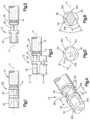
- FIG. 1a fragmentary top plan view illustrating the axially spaced six-sided diamond-shaped cut out portion or portions formed on the proximate end of the shank of the cutting burr;
- FIG. 2is a perspective view of FIG. 1 ;
- FIG. 3is another prospective view of FIG. 1 slightly turned illustrating one of the facets in each of the six-sided diamond-shaped portions;
- FIG. 4is another perspective view of FIG. 2 slightly turned illustrating the top facets of the six-sided diamond-shaped portions
- FIG. 5is an end view taken along lines 5 - 5 of FIG. 3 illustrating the shape of the six-sided diamond-shaped portion formed in the cutting burr shank;
- FIG. 6is a sectional view taken along lines 6 - 6 of FIG. 4 illustrating the shape of the six-sided diamond-shaped portion and illustrating the different sizes and the orientation of the six-sided diamond portion formed in the cutting burr shank;
- FIGS. 7 A and 7 Billustrate a backwards compatibility of the cutting burr of FIGS. 1 - 6 within a receiving portion of conventional surgical drill
- FIGS. 8 A and 8 Billustrate a self-alignment aspect of the diamond-shaped portion at a proximal end of the cutting burr in relation to a keyed slot of a surgical drill
- FIG. 9is an elevated view of the cutting burr with a spherical shaped cutting bit illustrating the diamond-shaped portions formed in the shank thereof;
- FIG. 10is another elevated view of an example cutting burr.
- FIG. 11is another elevated view of an example cutting burr.
- cutting burrmay be analogous with terms such as bit, drill bit, surgical drill bit and the like.
- attachmentmay have several meanings within the text of this application, but when generalized as a component of a surgical drilling instrument it refers to a portion of the instrument that attaches to the end of the motor/locking mechanism and receives the cutting burr.
- An “attachment”may be a controlled depth attachment, a minimally invasive attachment and the like.
- the surgical drilling instrumentmay include an integral motor (electric or pneumatic) and a locking mechanism and an attachment releasably connected to the locking mechanism.
- a cutting burr of the present disclosureincludes a shank that defines two substantially diamond-shaped portions.
- the substantially diamond-shaped portionsprovide for ease of insertion and removal of the cutting burr to and from a compatible surgical drill.
- the substantially diamond-shaped portionsalso enable the surgical drill to direct higher levels of torque to the cutting burr during surgical procedures.
- the cutting burris generally illustrated by reference numeral 10 .
- the attachment portion 12 of the shank 16 of the cutting burr 10is generally shown as reference numeral 12 .
- a proximal end 14 of the shank 16is formed with a pair of axially spaced six-sided diamond-shaped portions 18 and 20 .
- an upper surface of portion 18includes an apex 32 and a pair of facets 34 and 34 a also fairing to side edges 34 b and 34 c .
- the side edges 34 b and 34 cmay be curved to match the radius of curvature of an outer surface of the shank 16 . As shown in FIGS.
- an upper surface 24 of the portion 20includes apex 26 and a pair of facets 30 and 30 a fairing from the apex 26 to the side edges 30 b and 30 c .
- the side edges 30 b and 30 cmay be curved to match the radius of curvature of an outer surface of the shank 16 .
- the diametrical dimensions of the vertices in both portionsis less than the diameter of the main body of the shank.
- the shank 16may include an annular groove 29 .
- the lower surfaces of the pair of six-sided diamond portions 18 and 20are a mirror image of the upper surface. While the diamond-shaped portions 18 and 20 are described as being “diamond-shaped,” it is noted that such terminology is intended to encompass any six-sided (hexagon) shape having a cross-section with flat edges that meet at a six vertices, curved edges that meet at six points, or some combination of both to form the six sides. The flat and curved edges, and combinations thereof, may be applied to other polygon shapes having different numbers of sides.
- the diamond-shaped portion 18 at the outermost proximal endis designed to be inserted into a mating drive portion of a surgical drill, as will be described with reference to FIGS. 8 A and 8 B .
- the diamond-shaped portion 20is provided as an abutment surface of a retractable locking pawl of the surgical drill to provide axial locking of the shank 16 within the surgical drill.
- the locking pawlmay axially abut the adjacent abutment surface of the diamond-shaped portion 20 to axially lock the cutting burr 10 in place, thus providing substantially zero axial movement.
- an engagement portion of locking pawlmay be contoured having a generally V-shape with inner surfaces that fit against the facets 30 and 30 a of the diamond-shaped portion 20 .
- a back wall 42may be formed perpendicular with relation to the central line A and faces a front wall 40 that is tapered from the facet (e.g., 30 a ) to the outside diameter of the shank 16 .
- an engagement face of the locking pawlmay abut against the back wall 42 to provide axial locking of the cutting burr 10 within the surgical drill.
- a tapered front wall 40may facilitate the engagement of the locking pawl into the diamond-shaped portion 20 .
- the diamond-shaped portion 20may also be engaged by a detent pawl of the surgical drill.
- an engagement end of detent pawlmay be contoured, e.g., having a generally hill shape to partially fit into the diamond-shaped portion 20 on an opposite side of the engagement end of the locking pawl.
- the detent pawlmay be provided to apply a sufficient force on the diamond-shaped portion 20 to allow the cutting burr 10 to be moved in and out of the surgical drill, while reducing the likelihood that the cutting burr will inadvertently fall out of the surgical drill when in a loading position.
- the two diamond shapesmay be different in size, where the diamond shape in diamond-shaped portion 18 is larger than the diamond shape of the diamond-shaped portion 20 .
- the vertices 32 and 36fall below the outer diameter of the shank 16 and both diamond shapes are in axial alignment with each other and may be oriented in parallel relationship.
- the diamond-shaped portion 20 and the diamond-shaped portion 18may be the same size, or the diamond-shaped portion 18 may be larger than the diamond-shaped portion 20 .
- the vertices 26 and 32 of diamond-shaped portions 20 and 18are along a same line and in a same plane as the center line A.
- Exemplary dimensions of the six-sided diamond diamond-shaped portions 18 and 20are listed in degrees (°) and inches (′′) and may be substantially as follows:
- the angle of the facets of the six-sided diamond in the diamond-shaped portion 20 —a47°;
- the width of the facets of the six-sided diamond in the diamond-shaped portion 20 —b0.046′′;
- the width of the facets of the six-sided diamond in the diamond-shaped portion 18 —c0.065′′;
- the length between the proximal end and the back wall of diamond-shaped portion 18 f0.149′′. This dimension may contribute to the feature of substantially reducing the axial play of the cutting burr.
- the diamond-shaped portions 18 and 20provide sufficient cross-sectional dimensions to meet strength and reliability requirements needed for high-speed, large force surgical applications. Facets 34 and 34 a of the diamond shape 18 provide positive engagement surfaces in both clockwise and counter-clockwise rotational directions and are sufficiently sized to withstand rotations forces in either direction without wobbling within the surgical drill. For example, some surgical drills provide bi-directional rotation, allowing the surgeon to selectively reverse rotation for various surgical techniques. In conventional designs, there may be rotational play between a bit end and a drive portion. However, the symmetrical diamond facets 34 and 34 a of the diamond-shaped portion 18 provide substantial drive surfaces in either direction.
- a conventional drill instrumentmay include an insert 106 that defines a generally rectangular slot 105 having rounded side walls.
- the rounded side wallsmay be shaped with a radius of curvature that parallels the outer wall of the insert 106 .
- Conventional cutting burrsmay include a complementary generally rectangular portion having rounded side walls that is received by the slot 105 .
- the insert 106may be driven by a motor, thus providing rotational force on the cutting burr.
- facets 34 a and 34 d of the diamond-shaped portion 18engage the inner walls of the slot 105 .
- the dimension c of the diamond-shaped portion 18may be sized such that the surface area of the facets 34 a and 34 d is substantial enough to withstand the torque provided by the motor of the conventional drill instrument.
- the cutting burr 10 of the present disclosuremay be utilized by conventional drill instruments.
- the cutting burr 10 of the present disclosureprovides for a level of self-alignment within the insert 106 .
- the insert 106may be provided in a compatible surgical drill and define a diamond-shaped key slot 107 , a pointed shaped inlet end 109 , and opposing holes 110 that formed in the insert 106 for receiving dowel pin which may serve to locate the cutting burr 10 when inserted into the key slot 107 .
- the inlet end 109serves to facilitate the alignment and insertion of the cutting burr 10 as it is advanced toward and into the key slot 107 of the insert 106 . For example, if the diamond-shaped portion 18 is not in alignment with the key slot 107 ( FIG.
- a bottom surface of the diamond-shaped portion 18will contact an apex 111 of the inlet end 109 causing the cutting burr 10 to rotate into alignment with the key slot 107 .
- the cooperative engagement of the diamond-shaped portion 18 and inlet end 109facilitates the easy insertion of the cutting burr 10 into the compatible surgical drill.
- the diamond portion 18serves to provide a secure connection in the key slot 107 .
- FIGS. 9 , 10 , and 11illustrate different example cutting bits 22 provided at a distal end on the shank 16 .
- the shank 16may include the attachment portion 12 .
- the cutting bits 22may be milled or cut-out portions.
- the cutting burr 10 in FIG. 9exemplifies a fluted ball or drill bit; the cutting burr 10 in FIG. 10 exemplifies a diamond ball; and the cutting burr 10 in FIG. 11 exemplifies a twist drill.
- the cutting bits 22are presented only as examples and are not intended to limit the scope of the present disclosure as numerous variations are possible.
- a cutting burris provided with an attachment end that has a configuration and dimensions that serve to facilitate the insertion of the cutting burr into the surgical cutting instrument.
- an attachment endWhen locked in the running position there is a structure that prevents the cutting burr from having any axial movement. Also, there is a positive connection such that the cutting burr rotates concentrically without any wobbling motion.
Landscapes
- Health & Medical Sciences (AREA)
- Surgery (AREA)
- Life Sciences & Earth Sciences (AREA)
- Biomedical Technology (AREA)
- Medical Informatics (AREA)
- Orthopedic Medicine & Surgery (AREA)
- Oral & Maxillofacial Surgery (AREA)
- Engineering & Computer Science (AREA)
- Dentistry (AREA)
- Heart & Thoracic Surgery (AREA)
- Nuclear Medicine, Radiotherapy & Molecular Imaging (AREA)
- Molecular Biology (AREA)
- Animal Behavior & Ethology (AREA)
- General Health & Medical Sciences (AREA)
- Public Health (AREA)
- Veterinary Medicine (AREA)
- Surgical Instruments (AREA)
Abstract
Description
Claims (20)
Priority Applications (1)
| Application Number | Priority Date | Filing Date | Title |
|---|---|---|---|
| US17/208,260US11786258B2 (en) | 2011-04-07 | 2021-03-22 | Cutting burr shank configuration |
Applications Claiming Priority (6)
| Application Number | Priority Date | Filing Date | Title |
|---|---|---|---|
| US13/082,016US8690876B2 (en) | 2011-04-07 | 2011-04-07 | Cutting burr shank configuration |
| US14/223,011US9402638B2 (en) | 2011-04-07 | 2014-03-24 | Cutting burr shank configuration |
| US15/225,043US9820756B2 (en) | 2011-04-07 | 2016-08-01 | Cutting burr shank configuration |
| US15/818,314US10154849B2 (en) | 2011-04-07 | 2017-11-20 | Cutting burr shank configuration |
| US16/222,446US10952747B2 (en) | 2011-04-07 | 2018-12-17 | Cutting burr shank configuration |
| US17/208,260US11786258B2 (en) | 2011-04-07 | 2021-03-22 | Cutting burr shank configuration |
Related Parent Applications (1)
| Application Number | Title | Priority Date | Filing Date |
|---|---|---|---|
| US16/222,446ContinuationUS10952747B2 (en) | 2011-04-07 | 2018-12-17 | Cutting burr shank configuration |
Publications (2)
| Publication Number | Publication Date |
|---|---|
| US20210204965A1 US20210204965A1 (en) | 2021-07-08 |
| US11786258B2true US11786258B2 (en) | 2023-10-17 |
Family
ID=46966670
Family Applications (6)
| Application Number | Title | Priority Date | Filing Date |
|---|---|---|---|
| US13/082,016Active2032-03-13US8690876B2 (en) | 2011-04-07 | 2011-04-07 | Cutting burr shank configuration |
| US14/223,011ActiveUS9402638B2 (en) | 2011-04-07 | 2014-03-24 | Cutting burr shank configuration |
| US15/225,043Active2031-05-10US9820756B2 (en) | 2011-04-07 | 2016-08-01 | Cutting burr shank configuration |
| US15/818,314ActiveUS10154849B2 (en) | 2011-04-07 | 2017-11-20 | Cutting burr shank configuration |
| US16/222,446Active2031-09-19US10952747B2 (en) | 2011-04-07 | 2018-12-17 | Cutting burr shank configuration |
| US17/208,260Active2031-08-19US11786258B2 (en) | 2011-04-07 | 2021-03-22 | Cutting burr shank configuration |
Family Applications Before (5)
| Application Number | Title | Priority Date | Filing Date |
|---|---|---|---|
| US13/082,016Active2032-03-13US8690876B2 (en) | 2011-04-07 | 2011-04-07 | Cutting burr shank configuration |
| US14/223,011ActiveUS9402638B2 (en) | 2011-04-07 | 2014-03-24 | Cutting burr shank configuration |
| US15/225,043Active2031-05-10US9820756B2 (en) | 2011-04-07 | 2016-08-01 | Cutting burr shank configuration |
| US15/818,314ActiveUS10154849B2 (en) | 2011-04-07 | 2017-11-20 | Cutting burr shank configuration |
| US16/222,446Active2031-09-19US10952747B2 (en) | 2011-04-07 | 2018-12-17 | Cutting burr shank configuration |
Country Status (1)
| Country | Link |
|---|---|
| US (6) | US8690876B2 (en) |
Families Citing this family (18)
| Publication number | Priority date | Publication date | Assignee | Title |
|---|---|---|---|---|
| US20120253323A1 (en)* | 2011-03-29 | 2012-10-04 | Warsaw Orthopedic, Inc. | Rotationally driven surgical tool assembly and method |
| US8801713B2 (en)* | 2011-04-07 | 2014-08-12 | DePuy Synthes Products, LLC | Surgical drill instrument with motor and locking mechanism to receive an attachment and a cutting burr |
| US8690876B2 (en) | 2011-04-07 | 2014-04-08 | DePuy Synthes Products, LLC | Cutting burr shank configuration |
| US9011443B2 (en)* | 2012-09-20 | 2015-04-21 | Depuy Mitek, Llc | Low profile reamers and methods of use |
| US20160242792A1 (en)* | 2013-10-16 | 2016-08-25 | Orthopaedic International, Inc. | A device for inserting a surgical pin into a bone structure |
| US10314610B2 (en) | 2015-03-25 | 2019-06-11 | Medtronic Ps Medical, Inc. | Slanted drive axis rotary surgical cutting tools and powered handpieces |
| US10080579B2 (en) | 2015-03-25 | 2018-09-25 | Medtronic Ps Medical, Inc. | Pin drive rotary surgical cutting tools and powered handpieces |
| US10849634B2 (en)* | 2018-06-20 | 2020-12-01 | Medtronic Xomed, Inc. | Coupling portion for rotary surgical cutting systems |
| US11253330B2 (en) | 2018-09-26 | 2022-02-22 | Mako Surgical Corp. | Systems and tools for use with surgical robotic manipulators |
| US20220136329A1 (en)* | 2019-03-01 | 2022-05-05 | Bly Ip Inc. | High speed drilling system and methods of using same |
| US11517328B2 (en) | 2019-03-19 | 2022-12-06 | Arthrex, Inc. | Force absorption system for disposable shavers and burrs |
| USD910098S1 (en)* | 2019-08-12 | 2021-02-09 | Woodpeckers, Llc | Woodworking pilot reamer |
| US11154941B2 (en) | 2019-08-12 | 2021-10-26 | Woodpeckers, Llc | Method and apparatus for milling pen blanks |
| USD955452S1 (en) | 2019-08-12 | 2022-06-21 | Woodpeckers, Llc | Pen mill cutter head |
| USD927949S1 (en)* | 2019-11-06 | 2021-08-17 | Glendo Llc | Graver tool |
| USD956222S1 (en) | 2020-08-21 | 2022-06-28 | Stryker European Operations Limited | Surgical bur assembly |
| DE102021118412A1 (en) | 2021-07-16 | 2023-01-19 | Aesculap Ag | Automatic RFID tool coupling |
| CN115044950B (en)* | 2022-06-21 | 2023-07-18 | 青岛理工大学 | Bionic desert beetle self-transportation bone micro-grinding head and preparation process thereof |
Citations (151)
| Publication number | Priority date | Publication date | Assignee | Title |
|---|---|---|---|---|
| US170604A (en) | 1875-11-30 | Improvement in hose-nozzles | ||
| US170694A (en) | 1875-12-07 | Improvement in holders for tools | ||
| US233709A (en) | 1880-10-26 | starr | ||
| US233707A (en)* | 1880-10-26 | staee | ||
| US269627A (en)* | 1882-12-26 | Alarm device for screw-machines | ||
| US283745A (en)* | 1883-08-28 | La roy bartlett | ||
| US287683A (en) | 1883-10-30 | And eli t | ||
| US302870A (en)* | 1884-07-29 | Ence white and samuel s | ||
| US327558A (en)* | 1885-10-06 | Holding-tool for jewelers and engravers | ||
| US359798A (en)* | 1887-03-22 | William b | ||
| US415983A (en)* | 1889-11-26 | starr | ||
| US418108A (en)* | 1889-12-24 | Sylvania | ||
| US474011A (en)* | 1892-05-03 | Dental tool | ||
| US553226A (en)* | 1896-01-21 | Bit-brace | ||
| US748398A (en)* | 1903-03-23 | 1903-12-29 | William Green Middleton | Drill-chuck. |
| US988154A (en)* | 1908-12-09 | 1911-03-28 | Winton Motor Carriage Co | Broaching-machine. |
| US988903A (en)* | 1909-05-29 | 1911-04-04 | Hio P Eilers | Drill. |
| US1135057A (en)* | 1910-12-08 | 1915-04-13 | Christian Girl | Threading device. |
| US1188533A (en)* | 1915-05-14 | 1916-06-27 | Frank Cobey | Chuck. |
| US1433590A (en)* | 1922-10-31 | A corpora | ||
| US1503962A (en)* | 1921-04-08 | 1924-08-05 | John E Marsden | Method of producing glassware |
| US1578397A (en) | 1923-02-03 | 1926-03-30 | Frank L Cone | Stock pusher |
| US1717663A (en) | 1927-12-07 | 1929-06-18 | Checkley George | Propeller |
| US1726012A (en)* | 1927-06-25 | 1929-08-27 | Bilz William Fredrick | Nail driver |
| US1862337A (en)* | 1931-01-28 | 1932-06-07 | George W Emrick | Tap, drill, and similar tool |
| US1947957A (en)* | 1932-08-11 | 1934-02-20 | Bullard Co | Workholder |
| US2012280A (en)* | 1932-05-25 | 1935-08-27 | Sullivan Machinery Co | Chuck mechanism |
| US2101347A (en)* | 1936-06-24 | 1937-12-07 | Willard C Robinette | Tap |
| US2367863A (en)* | 1943-03-26 | 1945-01-23 | Teletype Corp | Centrifugal chuck |
| US2390950A (en)* | 1942-11-17 | 1945-12-11 | Lanfranconi Frederic Alexander | Tap |
| US2405018A (en)* | 1945-02-17 | 1946-07-30 | Victor Metal Products Corp | Automatic gripper |
| US2448817A (en)* | 1944-11-11 | 1948-09-07 | Reconstruction Finance Corp | Fastening device |
| US2473380A (en)* | 1947-04-10 | 1949-06-14 | Bryant Grinder Corp | Combination diaphragm and clamp chuck |
| US2494166A (en)* | 1945-08-03 | 1950-01-10 | Nat Acme Co | Floating chuck |
| US2543290A (en)* | 1943-10-21 | 1951-02-27 | Johansson Erik Johannes | Chuck |
| US2614781A (en)* | 1949-06-16 | 1952-10-21 | William A Engel | Aircraft seat leg release means |
| US2686682A (en)* | 1952-07-08 | 1954-08-17 | Csaki Joachim | Automatic gripping means for machine tools and the like |
| US2740974A (en)* | 1954-03-15 | 1956-04-10 | Lewis Lazarus | Rotary metal cutting tool having a locally annealed shank portion |
| US2769643A (en)* | 1954-04-26 | 1956-11-06 | Davos Products Co | Collet chucks |
| US2787010A (en)* | 1955-09-14 | 1957-04-02 | Ralph E Uphoff | Hollow slotted tap with support means for the slotted portion |
| US2874985A (en)* | 1957-03-28 | 1959-02-24 | Black & Decker Mfg Co | Drill chuck and spindle connection |
| US2939643A (en)* | 1955-10-17 | 1960-06-07 | Jr Arthur Barsam | Removable spindle rewind mechanism |
| US2955831A (en)* | 1959-01-27 | 1960-10-11 | Paul I Zandberg | Bur chuck |
| US3046029A (en) | 1959-08-07 | 1962-07-24 | Hoffman Electronics Corp | Seed crystal holding chucks |
| US3054308A (en)* | 1960-11-15 | 1962-09-18 | Star Cutter Company | Drill |
| US3084898A (en)* | 1960-02-04 | 1963-04-09 | Charles W Mccallum | Fluid actuated valve |
| US3136347A (en)* | 1962-10-15 | 1964-06-09 | Greenlee Bros & Co | Drill bit shank |
| USRE25804E (en) | 1965-06-22 | Misuracaelectrical erasing machine | ||
| US3252667A (en)* | 1963-12-23 | 1966-05-24 | Western Electric Co | Centrifugal chuck |
| US3466971A (en)* | 1963-09-18 | 1969-09-16 | Monarch Machine Tool Co | Tool holder |
| US3533638A (en)* | 1968-05-20 | 1970-10-13 | Kearney & Trecker Corp | Tool locking mechanism |
| US3574374A (en)* | 1969-01-16 | 1971-04-13 | Orthopedic Equipment Co | Surgical instrument |
| US3589826A (en)* | 1969-08-25 | 1971-06-29 | Trw Inc | Drill bit |
| US3596917A (en)* | 1969-02-17 | 1971-08-03 | Monarch Machine Tool Co | Tool adapter |
| US3599996A (en)* | 1969-06-25 | 1971-08-17 | Donald G Holt | Toolholder for a machine tool |
| US4032163A (en)* | 1976-01-26 | 1977-06-28 | Holt Donald G | Quick change in-motion tool chuck |
| US4055185A (en)* | 1976-03-02 | 1977-10-25 | American Sterilizer Company | Rotary drill for surgeons |
| US4073497A (en) | 1976-08-02 | 1978-02-14 | Double E Company, Inc. | Care chuck stop assembly |
| US4115024A (en) | 1976-03-04 | 1978-09-19 | Amtel, Inc. | Spade drill blade |
| US4114276A (en)* | 1976-05-06 | 1978-09-19 | Dentalwerk Burmoos Gesellschaft M.B.H. | Dental tool handpiece assembly with removable spacer member |
| US4131165A (en)* | 1976-04-28 | 1978-12-26 | Robert Bosch Gmbh | Hammer drill |
| US4298074A (en)* | 1976-08-09 | 1981-11-03 | American Safety Equipment Corporation | Surgical device using impulse motor |
| US4303252A (en)* | 1980-03-21 | 1981-12-01 | Cooper Industries, Inc. | Chuck for rotary tool |
| US4325661A (en) | 1979-06-15 | 1982-04-20 | Tickins Jack J | Drill bit end protectors |
| US4374481A (en)* | 1979-10-10 | 1983-02-22 | Michael Brodie | Adjustable socket with detachable or lockable engaging handle component |
| US4565472A (en)* | 1981-11-11 | 1986-01-21 | Hilti Aktiengesellschaft | Drill for hand-held drilling devices |
| US4632195A (en)* | 1985-06-03 | 1986-12-30 | Fansteel Inc. | Roof drill system |
| US4710075A (en)* | 1986-10-01 | 1987-12-01 | Boehringer Mannheim Corporation | Adjustable drill gauge |
| JPH029507A (en) | 1988-06-24 | 1990-01-12 | Teikku Ag | Quick exchange type tap holder |
| US4984667A (en) | 1989-03-24 | 1991-01-15 | Tjaden Harold M | Coupling device |
| JPH0319703A (en) | 1989-04-05 | 1991-01-28 | Hertel Ag Werkzeuge & Hartstoff | Chucking device for tool |
| US5037251A (en)* | 1989-03-24 | 1991-08-06 | Roth Alfred C | Thread tap |
| US5074025A (en)* | 1991-03-05 | 1991-12-24 | Jarvis Cutting Tools, Inc. | Threaded shank drill assembly |
| US5152642A (en) | 1991-06-12 | 1992-10-06 | Hextap, Inc. | Metal injection molded rotary metal cutting tool |
| US5218890A (en) | 1992-06-03 | 1993-06-15 | Christ Jr William H | Keyless adjustable driver |
| US5271697A (en)* | 1987-06-25 | 1993-12-21 | Tapmatic International Corporation (Tic Ag) | Tap and quick change tap holder assembly |
| US5421682A (en)* | 1993-04-26 | 1995-06-06 | Hilti Aktiengesellschaft | Tool bit chucking shank |
| US5433562A (en)* | 1993-12-03 | 1995-07-18 | J. D. Phillips Corporation | Cutter quick change system |
| JPH07214406A (en) | 1994-01-21 | 1995-08-15 | Robert Bosch Gmbh | Tool retainer |
| US5466101A (en)* | 1993-11-30 | 1995-11-14 | Robert Bosch Gmbh | Device on hand power tools for driving tools |
| WO1996010962A1 (en) | 1994-10-07 | 1996-04-18 | The Anspach Effort, Inc. | Tool holding mechanism for a motor driven surgical instrument |
| US5542846A (en)* | 1994-09-30 | 1996-08-06 | Young Dental Manufacturing, Co., Inc. | Dental tool chuck |
| US5658305A (en) | 1990-08-31 | 1997-08-19 | Baker; John W. | Surgical router bit |
| US5664792A (en)* | 1996-08-07 | 1997-09-09 | Tseng; Hans | Tool fixing mechanism |
| US5735535A (en)* | 1994-09-29 | 1998-04-07 | Stryker Corporation | Powered high speed rotary surgical handpiece chuck and tools |
| US5741263A (en)* | 1997-04-18 | 1998-04-21 | Midas Rex Pneumatic Tools, Inc. | Mutiple flat quick release coupling |
| US5820136A (en)* | 1996-10-24 | 1998-10-13 | Power Tool Holders Incorporated | Quick release integrated collet and chuck device |
| US5833246A (en) | 1997-05-06 | 1998-11-10 | Linvatec Corporation | Centrifugal chuck for surgical handpiece |
| US5888200A (en)* | 1996-08-02 | 1999-03-30 | Stryker Corporation | Multi-purpose surgical tool system |
| US5921563A (en)* | 1997-04-21 | 1999-07-13 | Power Tool Holders Incorporated | Quick release integrated collet and chuck device |
| US5957634A (en) | 1997-03-07 | 1999-09-28 | Carpinetti; David J. | Quick change drill extender system |
| JP2000052114A (en) | 1998-07-31 | 2000-02-22 | Hilti Ag | Tool holder for drill and/or chisel device |
| US6033408A (en)* | 1996-07-30 | 2000-03-07 | Midas Rex, L.P. | Resecting tool for magnetic field environment |
| US6129363A (en)* | 1998-01-14 | 2000-10-10 | Rohm Gmbh | Drill chuck with plastic chuck body |
| US20010006280A1 (en)* | 1999-12-24 | 2001-07-05 | Rohm Gmbh | Holder for collar of workpiece or tool |
| US6302408B1 (en) | 1997-05-10 | 2001-10-16 | Eva-Maria Zierpka | Tool system that can be coupled to a lathe drive shaft |
| US20010042964A1 (en)* | 1999-05-03 | 2001-11-22 | Sanjeev Bedi | Quick-connect mechanism |
| US20020009341A1 (en) | 2000-07-24 | 2002-01-24 | Vasudeva Kallash C. | Two-piece drill bits |
| US6341926B1 (en)* | 2000-02-02 | 2002-01-29 | Lien-Huang Liu | Cutting tool |
| JP2002137111A (en) | 2000-09-01 | 2002-05-14 | Credo Tool Co | Speedily exchangeable mandrel assembly for use together with hole saw and pilot drill bit |
| US20020058958A1 (en)* | 2000-02-18 | 2002-05-16 | Walen James G. | Cutting attachment for a surgical handpiece designed to be selectively coupled to the handpiece |
| US6409181B1 (en) | 2000-07-19 | 2002-06-25 | Chun Chu Hsueh | Combination type electric drill chuck structure |
| US6423070B1 (en) | 1999-11-13 | 2002-07-23 | Dieter Von Zeppelin | High speed motor for the surgical treatment of bones |
| US20020151902A1 (en)* | 2001-03-21 | 2002-10-17 | Medtronic, Inc. | Surgical instrument with rotary cutting member and quick release coupling arrangement |
| US20020159850A1 (en) | 2000-02-13 | 2002-10-31 | Michael Ravid | Countersinking tool for fast-exchange chucks |
| US20020165549A1 (en)* | 2001-04-30 | 2002-11-07 | Medtronic, Inc. | Surgical instrument and attachment |
| US6533235B1 (en)* | 2000-05-25 | 2003-03-18 | Lear Corporation | Twisted end interference fit flex shaft |
| US6533291B2 (en)* | 2001-02-14 | 2003-03-18 | Power Tool Holders Incorporated | Chuck having quick change mechanism |
| US20030060841A1 (en)* | 2001-09-25 | 2003-03-27 | Del Rio Eddy H. | High speed surgical instrument |
| US20030060829A1 (en)* | 2001-09-25 | 2003-03-27 | Del Rio Eddy H. | Miniature cutter shaft configuration |
| CN1406700A (en) | 2001-08-28 | 2003-04-02 | 马克斯泰克制造有限公司 | Assembled drill |
| US20030163134A1 (en)* | 2001-03-21 | 2003-08-28 | Medtronic, Inc. D/B/A Medtronic Midas Rex | Surgical instrument with rotary cutting member and quick release coupling arrangement |
| US6705807B1 (en)* | 1999-11-24 | 2004-03-16 | Black & Decker Inc. | Hole saw and connection method |
| US6725749B1 (en)* | 2002-10-16 | 2004-04-27 | Mou-Tang Liou | Tool including a tool bit and a handle |
| US6769846B2 (en) | 2002-08-22 | 2004-08-03 | Walter Persk{dot over (e)} GmbH | Machine tool coupling device |
| CN2631675Y (en) | 2003-08-13 | 2004-08-11 | 陈昆镇 | Multipurpose drill |
| US6780189B2 (en)* | 2002-06-07 | 2004-08-24 | Medtronic, Inc. | Surgical instrument with a collet locking and indexing system |
| WO2004082490A1 (en) | 2003-03-15 | 2004-09-30 | Aesculap Ag & Co. Kg | Coupling for a surgical rotary drive tool holder |
| US20050096661A1 (en)* | 2003-10-31 | 2005-05-05 | Medtronic, Inc. | Insulated battery pack and method of manufacturing same |
| CN1672641A (en) | 2004-03-22 | 2005-09-28 | 陈振堃 | Improved Structure of Transmission Mechanism of Eyebrow Tattoo Machine |
| US20060049587A1 (en) | 2004-09-09 | 2006-03-09 | Cornwell Webster R | Tool connector |
| US7028589B1 (en)* | 2005-06-29 | 2006-04-18 | Ming-Ta Cheng | Resilient positioning assembly for an axle in a power tool |
| CN2774405Y (en) | 2004-12-24 | 2006-04-26 | 徐天松 | General drill power hand machine |
| US7114728B2 (en)* | 2004-07-30 | 2006-10-03 | Chang-Ying Chen | Rapid detached connecting device |
| US7140817B1 (en)* | 2002-07-23 | 2006-11-28 | Black & Decker Inc. | Router bit system |
| CN2882550Y (en) | 2006-03-14 | 2007-03-28 | 申屠裕华 | Operation suction cutter |
| US7207400B2 (en)* | 2004-04-07 | 2007-04-24 | Kennametal Inc. | Coupler and roof drill bit assembly using such coupler |
| US7258349B2 (en)* | 2003-05-15 | 2007-08-21 | Robert Bosch Gmbh | Hand power tool |
| WO2008020828A2 (en) | 2006-08-08 | 2008-02-21 | Rinner James A | Tool chuck |
| US7367762B2 (en) | 2004-03-31 | 2008-05-06 | Nippei Toyama Corporation | Main spindle apparatus and tool holder clamp unit used therefor |
| US20080119863A1 (en)* | 2003-09-22 | 2008-05-22 | Ams Research Corporation | Prolapse Repair |
| US20080208229A1 (en)* | 2007-02-28 | 2008-08-28 | Medtronic, Inc. | Motor Assembly for a Powered Surgical Instrument |
| US20080208195A1 (en) | 2002-12-20 | 2008-08-28 | Medtronic, Inc. | Surgical Instrument With Telescoping Attachment |
| CN101365390A (en) | 2006-09-12 | 2009-02-11 | 维达保健公司 | Apparatus and methods for biopsy and aspiration of bone marrow |
| US20090146421A1 (en) | 2005-05-23 | 2009-06-11 | Bjorn Engdahl | Hose Coupling Provided With Non Return Valve and a Combined Locking and Obstructing Body |
| US20090273146A1 (en)* | 2008-05-05 | 2009-11-05 | Credo Technology Corporation & Robert Bosch Gmbh | Clamping apparatus for a reciprocating tool |
| US20090326540A1 (en)* | 2008-06-30 | 2009-12-31 | Medtronic Xomed, Inc. | Chuck for Reciprocating Surgical Instrument |
| US20100063524A1 (en)* | 2008-09-05 | 2010-03-11 | Mccombs Daniel L | Medical/surgical powered handpiece for rotating the shaft of a accessory, the handpiece having a coupling assembly that facilitates the fine or coarse adjustment of the extension of the accessory shaft |
| US7712746B2 (en)* | 2005-11-25 | 2010-05-11 | Hilti Aktiengesellschaft | Chuck |
| US20100219594A1 (en)* | 2009-02-27 | 2010-09-02 | Irwin Industrial Tool Company | Quick change tool bit holder |
| US7845428B2 (en)* | 2005-05-31 | 2010-12-07 | Yukiwa Seiko Kabushiki Kaisha | Rotating tool |
| EP2292163A1 (en) | 2002-03-22 | 2011-03-09 | Gyrus Ent, L.L.C. | Powered surgical apparatus and method of manufacturing powered surgical apparatus |
| JP2011136530A (en) | 2009-12-29 | 2011-07-14 | Hitachi Koki Co Ltd | Drill bit |
| US20120003057A1 (en)* | 2010-07-02 | 2012-01-05 | Leyba Frank L | Wrenchable drill bit |
| US8273097B2 (en)* | 2010-04-30 | 2012-09-25 | Medtronic Xomed, Inc. | Powered surgical tissue cutting instrument having an irrigation system |
| US20120259337A1 (en)* | 2011-04-07 | 2012-10-11 | Synthes Usa, Llc | Surgical drill instrument with motor and locking mechanism to receive an attachment and a cutting burr |
| WO2012138338A1 (en) | 2011-04-07 | 2012-10-11 | Synthes Usa, Llc | Surgical drill instrument with motor and locking mechanism to receive an attachment and a cutting burr |
| US20120259336A1 (en)* | 2011-04-07 | 2012-10-11 | Synthes Usa, Llc | Cutting burr shank configuration |
| US20120275875A1 (en)* | 2009-11-13 | 2012-11-01 | Simon Dean Gischus | Machine tool bit |
| US8403338B2 (en)* | 2008-05-07 | 2013-03-26 | Roehm Gmbh | Device usable as gripper head or chuck |
| US20130130663A1 (en) | 2006-03-03 | 2013-05-23 | Samsung Electronics Co., Ltd. | Method and system for providing notification message in a mobile broadcast system |
Family Cites Families (3)
| Publication number | Priority date | Publication date | Assignee | Title |
|---|---|---|---|---|
| JPS60121271U (en) | 1984-01-25 | 1985-08-15 | 矢崎総業株式会社 | Terminal connection device |
| JPH0319703Y2 (en) | 1985-09-19 | 1991-04-25 | ||
| PL2693956T3 (en) | 2011-04-07 | 2015-11-30 | Depuy Synthes Products Llc | Cutting burr shank configuration |
- 2011
- 2011-04-07USUS13/082,016patent/US8690876B2/enactiveActive
- 2014
- 2014-03-24USUS14/223,011patent/US9402638B2/enactiveActive
- 2016
- 2016-08-01USUS15/225,043patent/US9820756B2/enactiveActive
- 2017
- 2017-11-20USUS15/818,314patent/US10154849B2/enactiveActive
- 2018
- 2018-12-17USUS16/222,446patent/US10952747B2/enactiveActive
- 2021
- 2021-03-22USUS17/208,260patent/US11786258B2/enactiveActive
Patent Citations (187)
| Publication number | Priority date | Publication date | Assignee | Title |
|---|---|---|---|---|
| US474011A (en)* | 1892-05-03 | Dental tool | ||
| US287683A (en) | 1883-10-30 | And eli t | ||
| US233709A (en) | 1880-10-26 | starr | ||
| US233707A (en)* | 1880-10-26 | staee | ||
| US269627A (en)* | 1882-12-26 | Alarm device for screw-machines | ||
| US283745A (en)* | 1883-08-28 | La roy bartlett | ||
| US418108A (en)* | 1889-12-24 | Sylvania | ||
| US302870A (en)* | 1884-07-29 | Ence white and samuel s | ||
| US327558A (en)* | 1885-10-06 | Holding-tool for jewelers and engravers | ||
| US359798A (en)* | 1887-03-22 | William b | ||
| US170694A (en) | 1875-12-07 | Improvement in holders for tools | ||
| US415983A (en)* | 1889-11-26 | starr | ||
| USRE25804E (en) | 1965-06-22 | Misuracaelectrical erasing machine | ||
| US553226A (en)* | 1896-01-21 | Bit-brace | ||
| US1433590A (en)* | 1922-10-31 | A corpora | ||
| US170604A (en) | 1875-11-30 | Improvement in hose-nozzles | ||
| US748398A (en)* | 1903-03-23 | 1903-12-29 | William Green Middleton | Drill-chuck. |
| US988154A (en)* | 1908-12-09 | 1911-03-28 | Winton Motor Carriage Co | Broaching-machine. |
| US988903A (en)* | 1909-05-29 | 1911-04-04 | Hio P Eilers | Drill. |
| US1135057A (en)* | 1910-12-08 | 1915-04-13 | Christian Girl | Threading device. |
| US1188533A (en)* | 1915-05-14 | 1916-06-27 | Frank Cobey | Chuck. |
| US1503962A (en)* | 1921-04-08 | 1924-08-05 | John E Marsden | Method of producing glassware |
| US1578397A (en) | 1923-02-03 | 1926-03-30 | Frank L Cone | Stock pusher |
| US1726012A (en)* | 1927-06-25 | 1929-08-27 | Bilz William Fredrick | Nail driver |
| US1717663A (en) | 1927-12-07 | 1929-06-18 | Checkley George | Propeller |
| US1862337A (en)* | 1931-01-28 | 1932-06-07 | George W Emrick | Tap, drill, and similar tool |
| US2012280A (en)* | 1932-05-25 | 1935-08-27 | Sullivan Machinery Co | Chuck mechanism |
| US1947957A (en)* | 1932-08-11 | 1934-02-20 | Bullard Co | Workholder |
| US2101347A (en)* | 1936-06-24 | 1937-12-07 | Willard C Robinette | Tap |
| US2390950A (en)* | 1942-11-17 | 1945-12-11 | Lanfranconi Frederic Alexander | Tap |
| US2367863A (en)* | 1943-03-26 | 1945-01-23 | Teletype Corp | Centrifugal chuck |
| US2543290A (en)* | 1943-10-21 | 1951-02-27 | Johansson Erik Johannes | Chuck |
| US2448817A (en)* | 1944-11-11 | 1948-09-07 | Reconstruction Finance Corp | Fastening device |
| US2405018A (en)* | 1945-02-17 | 1946-07-30 | Victor Metal Products Corp | Automatic gripper |
| US2494166A (en)* | 1945-08-03 | 1950-01-10 | Nat Acme Co | Floating chuck |
| US2473380A (en)* | 1947-04-10 | 1949-06-14 | Bryant Grinder Corp | Combination diaphragm and clamp chuck |
| US2614781A (en)* | 1949-06-16 | 1952-10-21 | William A Engel | Aircraft seat leg release means |
| US2686682A (en)* | 1952-07-08 | 1954-08-17 | Csaki Joachim | Automatic gripping means for machine tools and the like |
| US2740974A (en)* | 1954-03-15 | 1956-04-10 | Lewis Lazarus | Rotary metal cutting tool having a locally annealed shank portion |
| US2769643A (en)* | 1954-04-26 | 1956-11-06 | Davos Products Co | Collet chucks |
| US2787010A (en)* | 1955-09-14 | 1957-04-02 | Ralph E Uphoff | Hollow slotted tap with support means for the slotted portion |
| US2939643A (en)* | 1955-10-17 | 1960-06-07 | Jr Arthur Barsam | Removable spindle rewind mechanism |
| US2874985A (en)* | 1957-03-28 | 1959-02-24 | Black & Decker Mfg Co | Drill chuck and spindle connection |
| US2955831A (en)* | 1959-01-27 | 1960-10-11 | Paul I Zandberg | Bur chuck |
| US3046029A (en) | 1959-08-07 | 1962-07-24 | Hoffman Electronics Corp | Seed crystal holding chucks |
| US3084898A (en)* | 1960-02-04 | 1963-04-09 | Charles W Mccallum | Fluid actuated valve |
| US3054308A (en)* | 1960-11-15 | 1962-09-18 | Star Cutter Company | Drill |
| US3136347A (en)* | 1962-10-15 | 1964-06-09 | Greenlee Bros & Co | Drill bit shank |
| US3466971A (en)* | 1963-09-18 | 1969-09-16 | Monarch Machine Tool Co | Tool holder |
| US3252667A (en)* | 1963-12-23 | 1966-05-24 | Western Electric Co | Centrifugal chuck |
| US3533638A (en)* | 1968-05-20 | 1970-10-13 | Kearney & Trecker Corp | Tool locking mechanism |
| US3574374A (en)* | 1969-01-16 | 1971-04-13 | Orthopedic Equipment Co | Surgical instrument |
| US3596917A (en)* | 1969-02-17 | 1971-08-03 | Monarch Machine Tool Co | Tool adapter |
| US3599996A (en)* | 1969-06-25 | 1971-08-17 | Donald G Holt | Toolholder for a machine tool |
| US3589826A (en)* | 1969-08-25 | 1971-06-29 | Trw Inc | Drill bit |
| US4032163A (en)* | 1976-01-26 | 1977-06-28 | Holt Donald G | Quick change in-motion tool chuck |
| US4055185A (en)* | 1976-03-02 | 1977-10-25 | American Sterilizer Company | Rotary drill for surgeons |
| US4115024A (en) | 1976-03-04 | 1978-09-19 | Amtel, Inc. | Spade drill blade |
| US4131165A (en)* | 1976-04-28 | 1978-12-26 | Robert Bosch Gmbh | Hammer drill |
| US4114276A (en)* | 1976-05-06 | 1978-09-19 | Dentalwerk Burmoos Gesellschaft M.B.H. | Dental tool handpiece assembly with removable spacer member |
| US4073497A (en) | 1976-08-02 | 1978-02-14 | Double E Company, Inc. | Care chuck stop assembly |
| US4298074A (en)* | 1976-08-09 | 1981-11-03 | American Safety Equipment Corporation | Surgical device using impulse motor |
| US4325661A (en) | 1979-06-15 | 1982-04-20 | Tickins Jack J | Drill bit end protectors |
| US4374481A (en)* | 1979-10-10 | 1983-02-22 | Michael Brodie | Adjustable socket with detachable or lockable engaging handle component |
| US4303252A (en)* | 1980-03-21 | 1981-12-01 | Cooper Industries, Inc. | Chuck for rotary tool |
| US4565472A (en)* | 1981-11-11 | 1986-01-21 | Hilti Aktiengesellschaft | Drill for hand-held drilling devices |
| US4632195A (en)* | 1985-06-03 | 1986-12-30 | Fansteel Inc. | Roof drill system |
| US4710075A (en)* | 1986-10-01 | 1987-12-01 | Boehringer Mannheim Corporation | Adjustable drill gauge |
| US5271697A (en)* | 1987-06-25 | 1993-12-21 | Tapmatic International Corporation (Tic Ag) | Tap and quick change tap holder assembly |
| JPH029507A (en) | 1988-06-24 | 1990-01-12 | Teikku Ag | Quick exchange type tap holder |
| US5037251A (en)* | 1989-03-24 | 1991-08-06 | Roth Alfred C | Thread tap |
| US4984667A (en) | 1989-03-24 | 1991-01-15 | Tjaden Harold M | Coupling device |
| JPH0319703A (en) | 1989-04-05 | 1991-01-28 | Hertel Ag Werkzeuge & Hartstoff | Chucking device for tool |
| US5658305A (en) | 1990-08-31 | 1997-08-19 | Baker; John W. | Surgical router bit |
| US5074025A (en)* | 1991-03-05 | 1991-12-24 | Jarvis Cutting Tools, Inc. | Threaded shank drill assembly |
| US5152642A (en) | 1991-06-12 | 1992-10-06 | Hextap, Inc. | Metal injection molded rotary metal cutting tool |
| US5218890A (en) | 1992-06-03 | 1993-06-15 | Christ Jr William H | Keyless adjustable driver |
| US5421682A (en)* | 1993-04-26 | 1995-06-06 | Hilti Aktiengesellschaft | Tool bit chucking shank |
| US5466101A (en)* | 1993-11-30 | 1995-11-14 | Robert Bosch Gmbh | Device on hand power tools for driving tools |
| US5433562A (en)* | 1993-12-03 | 1995-07-18 | J. D. Phillips Corporation | Cutter quick change system |
| JPH07214406A (en) | 1994-01-21 | 1995-08-15 | Robert Bosch Gmbh | Tool retainer |
| US5833704A (en) | 1994-09-29 | 1998-11-10 | Stryker Corporation | Powered high speed rotary surgical handpiece chuck and tools therefore |
| US5735535A (en)* | 1994-09-29 | 1998-04-07 | Stryker Corporation | Powered high speed rotary surgical handpiece chuck and tools |
| US5542846A (en)* | 1994-09-30 | 1996-08-06 | Young Dental Manufacturing, Co., Inc. | Dental tool chuck |
| WO1996010962A1 (en) | 1994-10-07 | 1996-04-18 | The Anspach Effort, Inc. | Tool holding mechanism for a motor driven surgical instrument |
| USRE37358E1 (en)* | 1994-10-07 | 2001-09-04 | The Anspach Effort, Inc. | Tool holding mechanism for a motor driven surgical instrument |
| US5630818A (en)* | 1994-10-07 | 1997-05-20 | The Anspach Effort, Inc. | Tool holding mechanism for a motor driven surgical instrument |
| US5904687A (en)* | 1994-10-07 | 1999-05-18 | The Anspach Effort, Inc. | Tool holdling mechanism for a motor driven surgical instrument |
| US5601560A (en)* | 1994-10-07 | 1997-02-11 | The Anspach Effort, Inc. | Tool bit for a motor driven surgical instrument |
| US6033408A (en)* | 1996-07-30 | 2000-03-07 | Midas Rex, L.P. | Resecting tool for magnetic field environment |
| US5888200A (en)* | 1996-08-02 | 1999-03-30 | Stryker Corporation | Multi-purpose surgical tool system |
| US5941891A (en)* | 1996-08-02 | 1999-08-24 | Stryker Corporation | Multi-purpose surgical tool system |
| US6045564A (en)* | 1996-08-02 | 2000-04-04 | Stryker Corporation | Multi-purpose surgical tool system |
| US5664792A (en)* | 1996-08-07 | 1997-09-09 | Tseng; Hans | Tool fixing mechanism |
| US5820136A (en)* | 1996-10-24 | 1998-10-13 | Power Tool Holders Incorporated | Quick release integrated collet and chuck device |
| US5957634A (en) | 1997-03-07 | 1999-09-28 | Carpinetti; David J. | Quick change drill extender system |
| US5741263A (en)* | 1997-04-18 | 1998-04-21 | Midas Rex Pneumatic Tools, Inc. | Mutiple flat quick release coupling |
| US5921563A (en)* | 1997-04-21 | 1999-07-13 | Power Tool Holders Incorporated | Quick release integrated collet and chuck device |
| US5833246A (en) | 1997-05-06 | 1998-11-10 | Linvatec Corporation | Centrifugal chuck for surgical handpiece |
| US6302408B1 (en) | 1997-05-10 | 2001-10-16 | Eva-Maria Zierpka | Tool system that can be coupled to a lathe drive shaft |
| US6129363A (en)* | 1998-01-14 | 2000-10-10 | Rohm Gmbh | Drill chuck with plastic chuck body |
| US6135461A (en) | 1998-07-31 | 2000-10-24 | Hilti Aktiengesellschaft | Chuck for drilling and chiseling tools |
| JP2000052114A (en) | 1998-07-31 | 2000-02-22 | Hilti Ag | Tool holder for drill and/or chisel device |
| US20010042964A1 (en)* | 1999-05-03 | 2001-11-22 | Sanjeev Bedi | Quick-connect mechanism |
| US6423070B1 (en) | 1999-11-13 | 2002-07-23 | Dieter Von Zeppelin | High speed motor for the surgical treatment of bones |
| US6705807B1 (en)* | 1999-11-24 | 2004-03-16 | Black & Decker Inc. | Hole saw and connection method |
| US20010006280A1 (en)* | 1999-12-24 | 2001-07-05 | Rohm Gmbh | Holder for collar of workpiece or tool |
| US6341926B1 (en)* | 2000-02-02 | 2002-01-29 | Lien-Huang Liu | Cutting tool |
| US20020159850A1 (en) | 2000-02-13 | 2002-10-31 | Michael Ravid | Countersinking tool for fast-exchange chucks |
| US20020058958A1 (en)* | 2000-02-18 | 2002-05-16 | Walen James G. | Cutting attachment for a surgical handpiece designed to be selectively coupled to the handpiece |
| US7465309B2 (en) | 2000-02-18 | 2008-12-16 | Stryker Corporation | Surgical handpiece with a push rod that both transfers rotational movement to an output drive shaft and that actuates a cutting accessory locking assembly |
| US20030130663A1 (en)* | 2000-02-18 | 2003-07-10 | Walen James G. | Surgical handpiece with coupling assembly for connecting a cutting accessory to the handpiece at different locations along the length of the cutting accessory |
| US6533235B1 (en)* | 2000-05-25 | 2003-03-18 | Lear Corporation | Twisted end interference fit flex shaft |
| US6409181B1 (en) | 2000-07-19 | 2002-06-25 | Chun Chu Hsueh | Combination type electric drill chuck structure |
| US6572311B2 (en)* | 2000-07-24 | 2003-06-03 | Maxtech Manufacturing Inc. | Two-piece drill bits |
| US20020009341A1 (en) | 2000-07-24 | 2002-01-24 | Vasudeva Kallash C. | Two-piece drill bits |
| JP2002137111A (en) | 2000-09-01 | 2002-05-14 | Credo Tool Co | Speedily exchangeable mandrel assembly for use together with hole saw and pilot drill bit |
| US6623220B2 (en) | 2000-09-01 | 2003-09-23 | Credo Tool Corporation | Quick change mandrel assembly for use with a hole saw and a pilot drill bit |
| US6533291B2 (en)* | 2001-02-14 | 2003-03-18 | Power Tool Holders Incorporated | Chuck having quick change mechanism |
| US20020151902A1 (en)* | 2001-03-21 | 2002-10-17 | Medtronic, Inc. | Surgical instrument with rotary cutting member and quick release coupling arrangement |
| US20030163134A1 (en)* | 2001-03-21 | 2003-08-28 | Medtronic, Inc. D/B/A Medtronic Midas Rex | Surgical instrument with rotary cutting member and quick release coupling arrangement |
| US7011661B2 (en)* | 2001-03-21 | 2006-03-14 | Medtronic, Inc. | Surgical instrument with rotary cutting member and quick release coupling arrangement |
| US7066940B2 (en)* | 2001-03-21 | 2006-06-27 | Medtronic, Inc. | Surgical instrument with rotary cutting member and quick release coupling arrangement |
| US20020165549A1 (en)* | 2001-04-30 | 2002-11-07 | Medtronic, Inc. | Surgical instrument and attachment |
| CN1406700A (en) | 2001-08-28 | 2003-04-02 | 马克斯泰克制造有限公司 | Assembled drill |
| US6607533B2 (en)* | 2001-09-25 | 2003-08-19 | The Anspbell Effort, Inc | Miniature cutter shaft configuration |
| US20030060829A1 (en)* | 2001-09-25 | 2003-03-27 | Del Rio Eddy H. | Miniature cutter shaft configuration |
| US20030060841A1 (en)* | 2001-09-25 | 2003-03-27 | Del Rio Eddy H. | High speed surgical instrument |
| US6733218B2 (en)* | 2001-09-25 | 2004-05-11 | The Anspach Effort, Inc. | High speed surgical instrument |
| EP2292163A1 (en) | 2002-03-22 | 2011-03-09 | Gyrus Ent, L.L.C. | Powered surgical apparatus and method of manufacturing powered surgical apparatus |
| US6780189B2 (en)* | 2002-06-07 | 2004-08-24 | Medtronic, Inc. | Surgical instrument with a collet locking and indexing system |
| US7140817B1 (en)* | 2002-07-23 | 2006-11-28 | Black & Decker Inc. | Router bit system |
| US7316529B2 (en)* | 2002-07-23 | 2008-01-08 | Black & Decker Inc. | Router bit system |
| US6769846B2 (en) | 2002-08-22 | 2004-08-03 | Walter Persk{dot over (e)} GmbH | Machine tool coupling device |
| US6725749B1 (en)* | 2002-10-16 | 2004-04-27 | Mou-Tang Liou | Tool including a tool bit and a handle |
| US20080208195A1 (en) | 2002-12-20 | 2008-08-28 | Medtronic, Inc. | Surgical Instrument With Telescoping Attachment |
| WO2004082490A1 (en) | 2003-03-15 | 2004-09-30 | Aesculap Ag & Co. Kg | Coupling for a surgical rotary drive tool holder |
| US20060053974A1 (en) | 2003-03-15 | 2006-03-16 | Aesculap Ag & Co. Kg | Coupling for a surgical rotary drive hand piece |
| US7258349B2 (en)* | 2003-05-15 | 2007-08-21 | Robert Bosch Gmbh | Hand power tool |
| CN2631675Y (en) | 2003-08-13 | 2004-08-11 | 陈昆镇 | Multipurpose drill |
| US20080119863A1 (en)* | 2003-09-22 | 2008-05-22 | Ams Research Corporation | Prolapse Repair |
| US20050096661A1 (en)* | 2003-10-31 | 2005-05-05 | Medtronic, Inc. | Insulated battery pack and method of manufacturing same |
| CN1672641A (en) | 2004-03-22 | 2005-09-28 | 陈振堃 | Improved Structure of Transmission Mechanism of Eyebrow Tattoo Machine |
| US7367762B2 (en) | 2004-03-31 | 2008-05-06 | Nippei Toyama Corporation | Main spindle apparatus and tool holder clamp unit used therefor |
| US7207400B2 (en)* | 2004-04-07 | 2007-04-24 | Kennametal Inc. | Coupler and roof drill bit assembly using such coupler |
| US7114728B2 (en)* | 2004-07-30 | 2006-10-03 | Chang-Ying Chen | Rapid detached connecting device |
| US20060049587A1 (en) | 2004-09-09 | 2006-03-09 | Cornwell Webster R | Tool connector |
| CN2774405Y (en) | 2004-12-24 | 2006-04-26 | 徐天松 | General drill power hand machine |
| US20090146421A1 (en) | 2005-05-23 | 2009-06-11 | Bjorn Engdahl | Hose Coupling Provided With Non Return Valve and a Combined Locking and Obstructing Body |
| US7845428B2 (en)* | 2005-05-31 | 2010-12-07 | Yukiwa Seiko Kabushiki Kaisha | Rotating tool |
| US7028589B1 (en)* | 2005-06-29 | 2006-04-18 | Ming-Ta Cheng | Resilient positioning assembly for an axle in a power tool |
| US7712746B2 (en)* | 2005-11-25 | 2010-05-11 | Hilti Aktiengesellschaft | Chuck |
| US20130130663A1 (en) | 2006-03-03 | 2013-05-23 | Samsung Electronics Co., Ltd. | Method and system for providing notification message in a mobile broadcast system |
| CN2882550Y (en) | 2006-03-14 | 2007-03-28 | 申屠裕华 | Operation suction cutter |
| WO2008020828A2 (en) | 2006-08-08 | 2008-02-21 | Rinner James A | Tool chuck |
| CN101365390A (en) | 2006-09-12 | 2009-02-11 | 维达保健公司 | Apparatus and methods for biopsy and aspiration of bone marrow |
| US20080208229A1 (en)* | 2007-02-28 | 2008-08-28 | Medtronic, Inc. | Motor Assembly for a Powered Surgical Instrument |
| US20090273146A1 (en)* | 2008-05-05 | 2009-11-05 | Credo Technology Corporation & Robert Bosch Gmbh | Clamping apparatus for a reciprocating tool |
| US8403338B2 (en)* | 2008-05-07 | 2013-03-26 | Roehm Gmbh | Device usable as gripper head or chuck |
| US20090326540A1 (en)* | 2008-06-30 | 2009-12-31 | Medtronic Xomed, Inc. | Chuck for Reciprocating Surgical Instrument |
| US20100063524A1 (en)* | 2008-09-05 | 2010-03-11 | Mccombs Daniel L | Medical/surgical powered handpiece for rotating the shaft of a accessory, the handpiece having a coupling assembly that facilitates the fine or coarse adjustment of the extension of the accessory shaft |
| US20100219594A1 (en)* | 2009-02-27 | 2010-09-02 | Irwin Industrial Tool Company | Quick change tool bit holder |
| US20120275875A1 (en)* | 2009-11-13 | 2012-11-01 | Simon Dean Gischus | Machine tool bit |
| JP2011136530A (en) | 2009-12-29 | 2011-07-14 | Hitachi Koki Co Ltd | Drill bit |
| US8273097B2 (en)* | 2010-04-30 | 2012-09-25 | Medtronic Xomed, Inc. | Powered surgical tissue cutting instrument having an irrigation system |
| US20120003057A1 (en)* | 2010-07-02 | 2012-01-05 | Leyba Frank L | Wrenchable drill bit |
| US8690876B2 (en)* | 2011-04-07 | 2014-04-08 | DePuy Synthes Products, LLC | Cutting burr shank configuration |
| US20160338713A1 (en)* | 2011-04-07 | 2016-11-24 | DePuy Synthes Products, Inc. | Cutting burr shank configuration |
| WO2012138338A1 (en) | 2011-04-07 | 2012-10-11 | Synthes Usa, Llc | Surgical drill instrument with motor and locking mechanism to receive an attachment and a cutting burr |
| US20120259337A1 (en)* | 2011-04-07 | 2012-10-11 | Synthes Usa, Llc | Surgical drill instrument with motor and locking mechanism to receive an attachment and a cutting burr |
| US8801713B2 (en)* | 2011-04-07 | 2014-08-12 | DePuy Synthes Products, LLC | Surgical drill instrument with motor and locking mechanism to receive an attachment and a cutting burr |
| US20140303624A1 (en)* | 2011-04-07 | 2014-10-09 | DePuy Synthes Products, LLC | Cutting burr shank configuration |
| US20150032111A1 (en)* | 2011-04-07 | 2015-01-29 | DePuy Synthes Products, LLC | Surgical drill instrument with motor and locking mechanism to receive an attachment and a cutting burr |
| US9113917B2 (en)* | 2011-04-07 | 2015-08-25 | DePuy Synthes Products, Inc. | Surgical drill instrument with motor and locking mechanism to receive an attachment and a cutting burr |
| US9381023B2 (en) | 2011-04-07 | 2016-07-05 | DePuy Synthes Products, Inc. | Surgical drill instrument with motor and locking mechanism to receive an attachment and a cutting burr |
| US9402638B2 (en)* | 2011-04-07 | 2016-08-02 | DePuy Synthes Products, Inc. | Cutting burr shank configuration |
| US20160270799A1 (en) | 2011-04-07 | 2016-09-22 | DePuy Synthes Products, Inc. | Surgical drill instrument with motor and locking mechanism to receive an attachment and a cutting burr |
| US20120259336A1 (en)* | 2011-04-07 | 2012-10-11 | Synthes Usa, Llc | Cutting burr shank configuration |
| US9681879B2 (en) | 2011-04-07 | 2017-06-20 | DePuy Synthes Products, Inc. | Surgical drill instrument with motor and locking mechanism to receive an attachment and a cutting burr |
| US9820756B2 (en)* | 2011-04-07 | 2017-11-21 | DePuy Synthes Products, Inc. | Cutting burr shank configuration |
| US20180132865A1 (en)* | 2011-04-07 | 2018-05-17 | DePuy Synthes Products, Inc. | Cutting burr shank configuration |
| US10154849B2 (en)* | 2011-04-07 | 2018-12-18 | DePuy Synthes Products, Inc. | Cutting burr shank configuration |
| US10194921B2 (en) | 2011-04-07 | 2019-02-05 | DePuy Synthes Products, Inc. | Surgical drill instrument with motor and locking mechanism to receive an attachment and a cutting burr |
| US20190223888A1 (en)* | 2011-04-07 | 2019-07-25 | DePuy Synthes Products, Inc. | Cutting burr shank configuration |
| US20190239900A1 (en) | 2011-04-07 | 2019-08-08 | DePuy Synthes Products, Inc. | Surgical drill instrument with motor and locking mechanism to receive an attachment and a cutting burr |
| US10952747B2 (en)* | 2011-04-07 | 2021-03-23 | DePuy Synthes Products, Inc. | Cutting burr shank configuration |
| US20210204965A1 (en)* | 2011-04-07 | 2021-07-08 | DePuy Synthes Products, Inc. | Cutting burr shank configuration |
Non-Patent Citations (5)
| Title |
|---|
| International Preliminary Report on Patentability and Written Opinion, dated Oct. 8, 2013, received in connection with corresponding International Patent Application No. PCT/US2011/031505. |
| International Preliminary Report on Patentability and Written Opinion, dated Oct. 8, 2013, received in connection with related International Patent Application No. PCT/US2011/031512. |
| International Search Report, dated Feb. 28, 2012, received in connection with corresponding International Patent Application No. PCT/US2011/031505. |
| International Search Report, dated Jan. 4, 2012, received in connection with related International Patent Application No. PCT/US2011/031512. |
| Office Action, dated Dec. 16, 2014, received in connection with JP Patent Application No. 2014503639. (English Translation). |
Also Published As
| Publication number | Publication date |
|---|---|
| US20140303624A1 (en) | 2014-10-09 |
| US20190223888A1 (en) | 2019-07-25 |
| US8690876B2 (en) | 2014-04-08 |
| US9820756B2 (en) | 2017-11-21 |
| US20160338713A1 (en) | 2016-11-24 |
| US20180132865A1 (en) | 2018-05-17 |
| US20120259336A1 (en) | 2012-10-11 |
| US10952747B2 (en) | 2021-03-23 |
| US20210204965A1 (en) | 2021-07-08 |
| US10154849B2 (en) | 2018-12-18 |
| US9402638B2 (en) | 2016-08-02 |
Similar Documents
| Publication | Publication Date | Title |
|---|---|---|
| US11786258B2 (en) | Cutting burr shank configuration | |
| EP2693956B1 (en) | Cutting burr shank configuration | |
| US11826058B2 (en) | Surgical drill instrument with motor and locking mechanism to receive an attachment and a cutting burr | |
| US7188554B2 (en) | Medical fastener and tool | |
| JP5801471B2 (en) | Surgical drill instrument having a motor and a locking mechanism for receiving attachment and cutting burrs | |
| CN101208181B (en) | Combination screwdrivers and combination fasteners for hex and lobe head fastening systems | |
| AU2011269806C1 (en) | Cannulated flexible drive shaft | |
| KR20190046915A (en) | Multiple connection drive shaft | |
| CN114642474A (en) | Rotary cutting tool and power handpiece adapter assembly, system and method of use | |
| HK1194941B (en) | Cutting burr shank configuration | |
| HUE027614T2 (en) | Cutting burr shank configuration |
Legal Events
| Date | Code | Title | Description |
|---|---|---|---|
| FEPP | Fee payment procedure | Free format text:ENTITY STATUS SET TO UNDISCOUNTED (ORIGINAL EVENT CODE: BIG.); ENTITY STATUS OF PATENT OWNER: LARGE ENTITY | |
| STPP | Information on status: patent application and granting procedure in general | Free format text:APPLICATION DISPATCHED FROM PREEXAM, NOT YET DOCKETED | |
| STPP | Information on status: patent application and granting procedure in general | Free format text:DOCKETED NEW CASE - READY FOR EXAMINATION | |
| STPP | Information on status: patent application and granting procedure in general | Free format text:NON FINAL ACTION MAILED | |
| AS | Assignment | Owner name:SYNTHES GMBH, SWITZERLAND Free format text:ASSIGNMENT OF ASSIGNORS INTEREST;ASSIGNOR:SYNTHES USA, LLC;REEL/FRAME:062298/0690 Effective date:20110518 Owner name:SYNTHES USA, LLC, PENNSYLVANIA Free format text:ASSIGNMENT OF ASSIGNORS INTEREST;ASSIGNORS:DEL RIO, EDDY H.;ENCK, DUANE JEFFREY;REEL/FRAME:062298/0671 Effective date:20110502 Owner name:DEPUY SPINE, LLC, MASSACHUSETTS Free format text:ASSIGNMENT OF ASSIGNORS INTEREST;ASSIGNOR:SYNTHES USA, LLC;REEL/FRAME:062308/0798 Effective date:20121230 Owner name:DEPUY SYNTHES PRODUCTS, LLC, MASSACHUSETTS Free format text:CHANGE OF NAME;ASSIGNOR:HAND INNOVATIONS LLC;REEL/FRAME:062311/0116 Effective date:20121231 Owner name:DEPUY SYNTHES PRODUCTS, INC., MASSACHUSETTS Free format text:CHANGE OF NAME;ASSIGNOR:DEPUY SYNTHES PRODUCTS, LLC;REEL/FRAME:062311/0190 Effective date:20141219 Owner name:HAND INNOVATIONS LLC, FLORIDA Free format text:ASSIGNMENT OF ASSIGNORS INTEREST;ASSIGNOR:DEPUY SPINE, LLC;REEL/FRAME:062309/0001 Effective date:20121230 | |
| STPP | Information on status: patent application and granting procedure in general | Free format text:NOTICE OF ALLOWANCE MAILED -- APPLICATION RECEIVED IN OFFICE OF PUBLICATIONS | |
| STPP | Information on status: patent application and granting procedure in general | Free format text:PUBLICATIONS -- ISSUE FEE PAYMENT RECEIVED | |
| STPP | Information on status: patent application and granting procedure in general | Free format text:PUBLICATIONS -- ISSUE FEE PAYMENT VERIFIED | |
| STCF | Information on status: patent grant | Free format text:PATENTED CASE |