US11786191B2 - Contrast-enhanced tomosynthesis with a copper filter - Google Patents
Contrast-enhanced tomosynthesis with a copper filterDownload PDFInfo
- Publication number
- US11786191B2 US11786191B2US17/322,329US202117322329AUS11786191B2US 11786191 B2US11786191 B2US 11786191B2US 202117322329 AUS202117322329 AUS 202117322329AUS 11786191 B2US11786191 B2US 11786191B2
- Authority
- US
- United States
- Prior art keywords
- ray
- breast
- filter
- tomosynthesis
- energy
- Prior art date
- Legal status (The legal status is an assumption and is not a legal conclusion. Google has not performed a legal analysis and makes no representation as to the accuracy of the status listed.)
- Active, expires
Links
- RYGMFSIKBFXOCR-UHFFFAOYSA-NCopperChemical compound[Cu]RYGMFSIKBFXOCR-UHFFFAOYSA-N0.000titleclaimsdescription15
- 229910052802copperInorganic materials0.000titleclaimsdescription15
- 239000010949copperSubstances0.000titleclaimsdescription15
- 210000000481breastAnatomy0.000claimsabstractdescription121
- 239000002872contrast mediaSubstances0.000claimsabstractdescription50
- 238000000034methodMethods0.000claimsabstractdescription42
- 238000003384imaging methodMethods0.000claimsdescription83
- 238000012545processingMethods0.000claimsdescription12
- 230000007246mechanismEffects0.000claimsdescription7
- 238000010521absorption reactionMethods0.000claimsdescription5
- 230000003100immobilizing effectEffects0.000claims2
- 238000005286illuminationMethods0.000abstractdescription11
- 238000005516engineering processMethods0.000abstractdescription10
- 230000002708enhancing effectEffects0.000abstractdescription3
- 239000000463materialSubstances0.000description21
- 210000001519tissueAnatomy0.000description20
- 238000009607mammographyMethods0.000description18
- 230000006835compressionEffects0.000description16
- 238000007906compressionMethods0.000description16
- 230000002308calcificationEffects0.000description10
- 208000004434CalcinosisDiseases0.000description9
- 238000004891communicationMethods0.000description9
- 238000001914filtrationMethods0.000description9
- 210000004872soft tissueAnatomy0.000description8
- 238000001514detection methodMethods0.000description6
- 239000006260foamSubstances0.000description4
- 230000033001locomotionEffects0.000description4
- 230000008685targetingEffects0.000description4
- ZCYVEMRRCGMTRW-UHFFFAOYSA-N7553-56-2Chemical group[I]ZCYVEMRRCGMTRW-UHFFFAOYSA-N0.000description3
- 206010006187Breast cancerDiseases0.000description3
- 208000026310Breast neoplasmDiseases0.000description3
- 206010028980NeoplasmDiseases0.000description3
- 230000008901benefitEffects0.000description3
- 238000011156evaluationMethods0.000description3
- 229910052740iodineInorganic materials0.000description3
- 239000011630iodineSubstances0.000description3
- 238000001228spectrumMethods0.000description3
- 230000002159abnormal effectEffects0.000description2
- 230000005856abnormalityEffects0.000description2
- 238000001574biopsyMethods0.000description2
- 238000003745diagnosisMethods0.000description2
- 230000004069differentiationEffects0.000description2
- 238000010191image analysisMethods0.000description2
- 230000006872improvementEffects0.000description2
- 238000002347injectionMethods0.000description2
- 239000007924injectionSubstances0.000description2
- 230000003902lesionEffects0.000description2
- 238000012986modificationMethods0.000description2
- 230000004048modificationEffects0.000description2
- 230000003287optical effectEffects0.000description2
- 230000009467reductionEffects0.000description2
- 238000012216screeningMethods0.000description2
- 206010048782Breast calcificationsDiseases0.000description1
- 206010006272Breast massDiseases0.000description1
- 241001201483Selenia <moth>Species0.000description1
- BQCADISMDOOEFD-UHFFFAOYSA-NSilverChemical compound[Ag]BQCADISMDOOEFD-UHFFFAOYSA-N0.000description1
- 239000000853adhesiveSubstances0.000description1
- 230000001070adhesive effectEffects0.000description1
- 229910052782aluminiumInorganic materials0.000description1
- XAGFODPZIPBFFR-UHFFFAOYSA-NaluminiumChemical compound[Al]XAGFODPZIPBFFR-UHFFFAOYSA-N0.000description1
- 238000013459approachMethods0.000description1
- 230000002238attenuated effectEffects0.000description1
- 210000000988bone and boneAnatomy0.000description1
- 201000011510cancerDiseases0.000description1
- 238000004140cleaningMethods0.000description1
- 238000013170computed tomography imagingMethods0.000description1
- 230000001276controlling effectEffects0.000description1
- 238000011161developmentMethods0.000description1
- 238000002059diagnostic imagingMethods0.000description1
- 238000004090dissolutionMethods0.000description1
- 230000000694effectsEffects0.000description1
- 229920002457flexible plasticPolymers0.000description1
- 230000006870functionEffects0.000description1
- 230000003993interactionEffects0.000description1
- PNDPGZBMCMUPRI-UHFFFAOYSA-NiodineChemical compoundIIPNDPGZBMCMUPRI-UHFFFAOYSA-N0.000description1
- 230000004807localizationEffects0.000description1
- 239000000203mixtureSubstances0.000description1
- 230000006855networkingEffects0.000description1
- 229920003023plasticPolymers0.000description1
- 230000008569processEffects0.000description1
- 230000001105regulatory effectEffects0.000description1
- 230000008439repair processEffects0.000description1
- 230000004044responseEffects0.000description1
- 229910052703rhodiumInorganic materials0.000description1
- 239000010948rhodiumSubstances0.000description1
- MHOVAHRLVXNVSD-UHFFFAOYSA-Nrhodium atomChemical compound[Rh]MHOVAHRLVXNVSD-UHFFFAOYSA-N0.000description1
- 230000035945sensitivityEffects0.000description1
- 229910052709silverInorganic materials0.000description1
- 239000004332silverSubstances0.000description1
- 230000003068static effectEffects0.000description1
- 239000000758substrateSubstances0.000description1
- 238000012360testing methodMethods0.000description1
- 230000007723transport mechanismEffects0.000description1
- 210000003462veinAnatomy0.000description1
Images


Classifications
- A—HUMAN NECESSITIES
- A61—MEDICAL OR VETERINARY SCIENCE; HYGIENE
- A61B—DIAGNOSIS; SURGERY; IDENTIFICATION
- A61B6/00—Apparatus or devices for radiation diagnosis; Apparatus or devices for radiation diagnosis combined with radiation therapy equipment
- A61B6/40—Arrangements for generating radiation specially adapted for radiation diagnosis
- A61B6/4035—Arrangements for generating radiation specially adapted for radiation diagnosis the source being combined with a filter or grating
- A—HUMAN NECESSITIES
- A61—MEDICAL OR VETERINARY SCIENCE; HYGIENE
- A61B—DIAGNOSIS; SURGERY; IDENTIFICATION
- A61B6/00—Apparatus or devices for radiation diagnosis; Apparatus or devices for radiation diagnosis combined with radiation therapy equipment
- A61B6/02—Arrangements for diagnosis sequentially in different planes; Stereoscopic radiation diagnosis
- A61B6/025—Tomosynthesis
- A—HUMAN NECESSITIES
- A61—MEDICAL OR VETERINARY SCIENCE; HYGIENE
- A61B—DIAGNOSIS; SURGERY; IDENTIFICATION
- A61B6/00—Apparatus or devices for radiation diagnosis; Apparatus or devices for radiation diagnosis combined with radiation therapy equipment
- A61B6/04—Positioning of patients; Tiltable beds or the like
- A61B6/0407—Supports, e.g. tables or beds, for the body or parts of the body
- A61B6/0414—Supports, e.g. tables or beds, for the body or parts of the body with compression means
- A—HUMAN NECESSITIES
- A61—MEDICAL OR VETERINARY SCIENCE; HYGIENE
- A61B—DIAGNOSIS; SURGERY; IDENTIFICATION
- A61B6/00—Apparatus or devices for radiation diagnosis; Apparatus or devices for radiation diagnosis combined with radiation therapy equipment
- A61B6/40—Arrangements for generating radiation specially adapted for radiation diagnosis
- A61B6/4035—Arrangements for generating radiation specially adapted for radiation diagnosis the source being combined with a filter or grating
- A61B6/4042—K-edge filters
- A—HUMAN NECESSITIES
- A61—MEDICAL OR VETERINARY SCIENCE; HYGIENE
- A61B—DIAGNOSIS; SURGERY; IDENTIFICATION
- A61B6/00—Apparatus or devices for radiation diagnosis; Apparatus or devices for radiation diagnosis combined with radiation therapy equipment
- A61B6/44—Constructional features of apparatus for radiation diagnosis
- A61B6/4429—Constructional features of apparatus for radiation diagnosis related to the mounting of source units and detector units
- A61B6/4452—Constructional features of apparatus for radiation diagnosis related to the mounting of source units and detector units the source unit and the detector unit being able to move relative to each other
- A—HUMAN NECESSITIES
- A61—MEDICAL OR VETERINARY SCIENCE; HYGIENE
- A61B—DIAGNOSIS; SURGERY; IDENTIFICATION
- A61B6/00—Apparatus or devices for radiation diagnosis; Apparatus or devices for radiation diagnosis combined with radiation therapy equipment
- A61B6/46—Arrangements for interfacing with the operator or the patient
- A61B6/461—Displaying means of special interest
- A—HUMAN NECESSITIES
- A61—MEDICAL OR VETERINARY SCIENCE; HYGIENE
- A61B—DIAGNOSIS; SURGERY; IDENTIFICATION
- A61B6/00—Apparatus or devices for radiation diagnosis; Apparatus or devices for radiation diagnosis combined with radiation therapy equipment
- A61B6/50—Apparatus or devices for radiation diagnosis; Apparatus or devices for radiation diagnosis combined with radiation therapy equipment specially adapted for specific body parts; specially adapted for specific clinical applications
- A61B6/502—Apparatus or devices for radiation diagnosis; Apparatus or devices for radiation diagnosis combined with radiation therapy equipment specially adapted for specific body parts; specially adapted for specific clinical applications for diagnosis of breast, i.e. mammography
- A—HUMAN NECESSITIES
- A61—MEDICAL OR VETERINARY SCIENCE; HYGIENE
- A61B—DIAGNOSIS; SURGERY; IDENTIFICATION
- A61B6/00—Apparatus or devices for radiation diagnosis; Apparatus or devices for radiation diagnosis combined with radiation therapy equipment
- A61B6/52—Devices using data or image processing specially adapted for radiation diagnosis
- A61B6/5205—Devices using data or image processing specially adapted for radiation diagnosis involving processing of raw data to produce diagnostic data
- A—HUMAN NECESSITIES
- A61—MEDICAL OR VETERINARY SCIENCE; HYGIENE
- A61B—DIAGNOSIS; SURGERY; IDENTIFICATION
- A61B6/00—Apparatus or devices for radiation diagnosis; Apparatus or devices for radiation diagnosis combined with radiation therapy equipment
- A61B6/48—Diagnostic techniques
- A61B6/481—Diagnostic techniques involving the use of contrast agents
Definitions
- Medical imagingis used for detection of cancerous cells in breast tissue.
- a plurality of different imaging processes, image acquisition parameters, and image processing techniquesare used to enhance images for better detection of abnormal tissue.
- the technologyrelates to a method for contrast-enhanced tomosynthesis imaging.
- the methodincludes compressing a breast of a patient, the patient's breast positioned substantially between an x-ray source and an x-ray detector, wherein a filter is positioned between the x-ray source and the patient's breast, and wherein the patient's breast has been exposed to a contrast agent.
- the methodincludes acquiring, while compressing the patient's breast, a plurality of tomosynthesis projection images at an x-ray dose passing through the filter, wherein the filter proportionally filters a subset of energies of the x-ray dose, wherein the x-ray dose includes at least one x-ray energy greater than 40 keV. Further, the method includes processing the plurality of tomosynthesis projection images to obtain a plurality of filtered reconstructed tomosynthesis slice images; and displaying at least one image of the filtered reconstructed tomosynthesis slice images.
- the filterincludes copper.
- the subset of energies of the x-ray dose proportionally filtered by the filterincludes at least one energy below 30 keV.
- the subset of energies of the x-ray dose proportionally filtered by the filterincludes energies below 40 keV.
- the contrast agenthas an absorption of the x-ray dose that is greater for higher energies.
- an apparatus for contrast-enhanced tomosynthesis imagingincludes: an x-ray source capable of selectively moving relative to a patient's breast; an imaging x-ray detector; a compression mechanism for compressing the patient's breast, the compression mechanism disposed between the x-ray source and the imaging x-ray detector; a filter insertable into the apparatus between the x-ray source and the patient's breast, wherein the filter proportionally filters a subset of energies of an x-ray dose emittable by the x-ray source; a processor; and memory storing instructions that, when executed by the processor, cause the apparatus to perform a set of operations.
- the set of operationsincludes selectively moving the x-ray source through at a plurality of selectable positions while emitting an x-ray dose from the x-ray source. Additionally, the set of operations includes detecting, by the x-ray detector, the x-ray dose from the plurality of selectable positions, after the x-ray dose passes through the filter and the patient's breast. Based on the detected x-ray dose from the plurality of selectable positions, the set of operations includes generating, by the processor operatively connected to the x-ray detector, a plurality of tomosynthesis projection images. The set of operations further includes processing, by the processor, the plurality of tomosynthesis projection images to obtain a plurality of filtered reconstructed tomosynthesis slice images.
- the filter of the apparatusincludes an element with an atomic number of at least 21.
- the filtercomprises as sheet member that has a thickness ranging from 0.1 mm to 0.5 mm.
- the sheet member of the filtercomprises copper.
- the apparatusfurther includes a tilting mechanism to tilt the patient's breast as the x-ray source selectively moves through the plurality of selectable positions.
- FIG. 1 Adepicts is a schematic view of an exemplary imaging system.
- FIG. 1 Bdepicts a perspective view of the imaging system of FIG. 1 A
- FIG. 2 Adepicts a top perspective view of an example x-ray filter.
- FIG. 2 Bdepicts a bottom perspective view of the example x-ray filter of FIG. 2 A .
- FIG. 3depicts a graph of a quantity of x-rays detected versus energy.
- FIG. 4 Adepicts an example tomosynthesis reconstructed image slice of a breast at a lower x-ray energy.
- FIG. 4 Bdepicts an example tomosynthesis reconstructed image slice of the breast of FIG. 4 A at a higher x-ray energy as imaged through a filter.
- FIG. 5 Adepicts a Cranial-Caudal (CC) view of a breast generated by subtracting a high energy image and low energy image.
- CCCranial-Caudal
- FIG. 5 Bdepicts a CC view of the breast of FIG. 5 A generated from a reconstructed slice of tomosynthesis images taken at a high energy through a filter.
- FIG. 6 Adepicts a mediolateral oblique (MLO) view of a breast generated by subtracting a high energy image and low energy image.
- MLOmediolateral oblique
- FIG. 6 Bdepicts an MLO view of the breast of FIG. 6 A generated from a reconstructed slice of tomosynthesis images taken at a high energy through a filter.
- FIG. 7depicts an example method for contrast-enhanced tomosynthesis with a copper filter.
- FIG. 8illustrates an exemplary suitable operating environment for a specimen imaging system.
- a mammogramis an x-ray image of inner breast tissue that is used to visualize normal and abnormal structures within a breast.
- Mammographyis commonly used for breast cancer screening, diagnosis, and evaluation, because mammography often shows breast lumps and/or calcifications before they are manually palpable, thus providing early tumor detection.
- Mammographypresents difficulties, however, when determining whether a detected abnormality is cancerous or benign. This may be due to mammography resulting in a two-dimensional projection image representing a three-dimensional structure of the breast. Overlapping structures in the compressed breast may confound image interpretation and diagnosis of a two-dimensional image. Mammography may also present difficulty in determining cancerous or benign cells because the x-rays that are often used to obtain the mammography image have energies that are in a range that helps achieve a desirable Signal to Noise Ratio (SNR) but at the same time may cause the x-rays to be attenuated to a similar degree by breast structures that may have different clinical significance.
- SNRSignal to Noise Ratio
- Breast tomosynthesisis a three-dimensional imaging technology that involves acquiring images of a stationary compressed breast at multiple angles during a short scan (otherwise referred to herein as a sweep). The individual projection tomosynthesis images taken at respective angles of the imaging x-ray beam relative to the breast are then computer-processed into a series of reconstructed tomosynthesis slice images, each representing a respective slice of the breast.
- the tomosynthesis projection images or reconstructed slice imagescan be displayed individually, concurrently, or dynamically.
- Breast tomosynthesistypically uses a field digital mammography (FFDM) platform.
- FFDMfield digital mammography
- an x-ray tubemoves in an arc above the breast and a series of 11 to 22 low dose x-ray 2-D tomosynthesis projection images are obtained (i.e., a tomosynthesis scan or a tomosynthesis sweep).
- the sum of the dose from all of the 2-D tomosynthesis projection imagesmay be similar to the dose from a single conventional digital mammogram.
- These low-dose 2-D tomosynthesis projection imagesare reconstructed into a series of 3-D slice images, each representing a slice of the breast where each slice is, for example, 1-5 mm thick.
- the slice imagestypically conform to planes parallel to the platform supporting the breast during image acquisition, but could be oriented differently.
- An advantage of breast tomosynthesis compared to conventional mammographyis that, by showing the breast as a series of slices rather than a single mammogram, a lesion may be seen with greater clarity because much of the superimposed tissue present in a conventional mammogram has been removed.
- Reconstructed tomosynthesis slice imagesreduce or eliminate problems caused by tissue overlap and structure noise in two-dimensional mammography imaging.
- Digital breast tomosynthesisalso offers the possibility of reduced breast compression, improved diagnostic and screening accuracy, fewer recalls, and 3D lesion localization.
- An example of a multi-mode breast tomosynthesis/mammography systemis described in commonly assigned U.S. Pat. No. 7,869,563.
- Other aspects of breast tomosynthesis and mammographyare described in commonly assigned U.S. Pat. Nos. 7,991,106, 7,760,924, 7,702,142, 7,245,694, and 9,020,579, which are hereby incorporated by reference.
- contrast-enhanced imagingIn contrast-enhanced imaging, a contrast agent is introduced into the breast, typically through an injection in a vein remote from the breast, and x-ray images are taken after (as well as possibly before) the contrast agent has reached the breast.
- a contrast agentis iodine-based.
- the contrast agentmay illuminate with high-energy x-rays, which may depend on the atomic number of the contrast agent.
- the contrast agenthelps highlight vascularity in the breast.
- breast vascularitymay appear more clearly in the resulting subtraction image. Imaging of the vessels around a tumor is believed to allow improved detection of breast cancer.
- contrast agentsmay be used in a variety of x-ray imaging methods, including breast CT, breast tomosynthesis, and digital mammography.
- contrast enhanced imagesare obtained using two methods.
- the firstinvolves subtraction of images obtained pre-contrast agent and post-contrast agent. This method is referred to as time subtraction.
- the second methodis referred to as dual-energy contrast imaging.
- imagesare obtained at low energy and high energy after the injection of a contrast agent.
- the imagesare obtained at energies above and below a K-absorption edge (k-edge) of the contrast agent (e.g., for iodine, 33.2 keV).
- k-edgeK-absorption edge
- the absorption of x-raysis increased, resulting in an increase of contrast from the iodine contrast agent in the high energy image.
- the imaging equipmentuses software-based techniques. Additionally, for dual-energy imaging, software is needed to control the energy of x-rays emitted (e.g., high energy or low energy). Not all imaging devices are equipped with processing power or software that is capable of subtraction techniques or controlling energy of x-rays. For imaging devices that may not have these software or processing capabilities, or for imaging devices for which integrate these capabilities would be too costly, other improvements of breast tomosynthesis may be considered.
- the present disclosureprovides systems and methods for enhancing images acquired using breast tomosynthesis, without image subtraction or dual-energy imaging.
- the present technologyprovides performing breast tomosynthesis in the presence of an x-ray filter.
- an x-ray filtermay be placed between an x-ray source and breast tissue.
- the filtermay proportionally filter out a subset of the energies emitted by the x-ray source.
- a filtermay include characteristics to filter x-ray energies based on a k-edge of a contrast agent introduced into the breast, such that the breast tissue has relatively greater exposure to x-ray energies above the k-edge of the contrast agent to illuminate the contrast agent without substantial illumination of other breast tissue.
- tomosynthesis images similar to those obtained using subtractionmay be acquired without software-based contrast enhancing techniques.
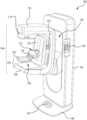
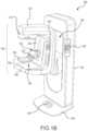
- FIGS. 1 A- 1 Bshow different views of an example imaging system 100 .
- FIG. 1 Ais a schematic view of the example imaging system 100 .
- FIG. 1 Bis a perspective view of the imaging system 100 .
- the imaging system 100immobilizes a patient's breast 102 for x-ray imaging (either or both of mammography and tomosynthesis) via a breast compression immobilizer unit 104 that includes a static breast support platform 106 and a foam compressive element 108 .
- a breast compression immobilizer unit 104that includes a static breast support platform 106 and a foam compressive element 108 .
- Different paddles, each having different purposes,are known in the art. Certain examples paddles are also described herein for context.
- the breast support platform 106 and the foam compressive element 108each have a compression surface 110 and 112 , respectively, that move towards each other to compress, immobilize, stabilize, or otherwise hold and secure the breast 102 during imaging procedures.
- the compression surface 110 , 112is exposed so as to directly contact the breast 102 .
- Compression surface 110may be a rigid plastic, a flexible plastic, a resilient foam, a mesh or screen, and so on.
- Compression surface 112is a lower surface of the foam compressive element 108 .
- the platform 106also houses an image receptor 116 and, optionally, a tilting mechanism 118 , and optionally an anti-scatter grid (not depicted, but disposed above the image receptor 116 ).
- the immobilizer unit 104is in a path of an imaging beam 120 emanating from x-ray source 122 , such that the beam 120 impinges on the image receptor 116 .
- the immobilizer unit 104is supported on a first support arm 124 via a compression arm 134 , which is configured to be raised and lowered along the support arm 124 .
- the x-ray source 122is supported on a second support arm, also referred to as a tube head 126 .
- support arms 124 and 126can rotate as a unit about an axis 128 between different imaging orientations such as craniocaudal (CC) and mediolateral oblique (MLO), so that the system 100 can take a mammogram projection image at each orientation.
- CCcraniocaudal
- MLOmediolateral oblique
- the terms front, lower, and upperpertain to using a CC imaging orientation, with the patient facing the front of the imaging system, although it should be understood that other imaging orientations, including MLO, are used with the same equipment.
- the image receptor 116remains in place relative to the platform 106 while an image is taken.
- the immobilizer unit 104releases the breast 102 for movement of arms 124 , 126 to a different imaging orientation.
- the support arm 124stays in place, with the breast 102 immobilized and remaining in place, while at least the second support arm 126 rotates the x-ray source 122 relative to the immobilizer unit 104 and the compressed breast 102 about the axis 128 .
- the system 100takes plural tomosynthesis projection images of the breast 102 at respective angles of the beam 120 relative to the breast 102 .
- the image receptor 116may be tilted relative to the breast support platform 106 and in sync with the rotation of the second support arm 126 .
- the tiltingcan be through the same angle as the rotation of the x-ray source 122 but may also be through a different angle selected such that the beam 120 remains substantially in the same position on the image receptor 116 for each of the plural images.
- the tiltingcan be about an axis 130 , which can but need not be in the image plane of the image receptor 116 .
- the tilting mechanism 118 that is coupled to the image receptor 116can drive the image receptor 116 in a tilting motion.
- the breast support platform 106can be horizontal or can be at an angle to the horizontal, e.g., at an orientation similar to that for conventional MLO imaging in mammography.
- the system 100can be solely a mammography system, a CT system, or solely a tomosynthesis system, or a “combo” system that can perform multiple forms of imaging.
- An example of such a combo systemhas been offered by the assignee hereof under the trade name Selenia Dimensions.
- the image receptor 116When the system is operated, the image receptor 116 produces imaging information in response to illumination by the imaging beam 120 and supplies it to an image processor 132 for processing and generating breast x-ray images.
- the imaging system 100includes a floor mount or base 140 for supporting the imaging system 100 on a floor.
- a gantry 142extends upwards from the base 140 and rotatably supports both the tube head 208 and a support arm 210 .
- the tube head 126 and support arm 124are configured to rotate discretely from each other and may also be raised and lowered along a face 144 of the gantry 142 so as to accommodate patients of different heights.
- the x-ray source 122is disposed within the tube head 208 . Together, the tube head 126 and support arm 124 may be referred to as a C-arm 124 .
- a number of interfaces and display screensare disposed on the imaging system 100 . These include a foot display screen 146 , a gantry interface 148 , a support arm interface 150 , and a compression arm interface 152 .
- the various interfaces 148 , 150 , and 152may include one or more tactile buttons, knobs, switches, as well as one or more display screens, including capacitive touch screens with graphic user interfaces (GUIs) so as to enable user interaction with and control of the imaging system 100 .
- GUIsgraphic user interfaces
- the foot display screen 146is primarily a display screen, though a capacitive touch screen might be utilized if required or desired.
- an x-ray filter 170may be used.
- a filter 170may filter out x-rays travelling through the filter that are below a certain energy. In an example, lower energies may be filtered out proportionally more than higher energies, up to a threshold energy (above which little to no x-rays are filtered).
- the filter 170may be a variety of materials, shapes, sizes, and thickness. Additionally, the filter 170 may be interchangeable or customizable.
- the filter 170is positioned in the imaging system 100 to filter out certain x-ray energies of an x-ray beam emitted from an x-ray source 122 prior to the beam passing through the breast 102 .
- the filter 170may be positioned at the x-ray source 122 , such that the x-rays pass through the filter 170 prior to reaching the compression paddle 108 and breast 102 .
- the filter 170may be positionable on, coupled to, or removably insertable into the tube head 126 or the compression element 108 of the imaging system 100 .
- the filtermay be disposed on the compression paddle (e.g., the filter may be secured to a rigid substrate of the compression paddle.
- the effects of the filter 170may be combined with illumination of a contrast agent.
- the breast 102may be introduced to a contrast agent prior to imaging with the imaging system 100 .
- a filter 170may filter out a subset of energies of an x-ray beam based on the contrast agent (e.g., an appropriate filter 170 may be selected based on a selected contrast agent).
- the filter 170may be selectable or interchangeable.
- an x-ray filter wheel or slidemay be provided to switch filters as required or desired.
- the filter 170may be manually selected or inserted into the imaging system 100 .
- a variety of different filter materialsis appreciated, including rhodium, silver, aluminum, copper, or any other material capable of filtering x-ray energies. By filtering out x-ray energies below the k-edge of the contrast agent, the contrast agent is illuminated with minimal illumination of other aspects of the breast tissue (e.g., which would illuminate at lower x-ray energies).
- FIGS. 2 A- 2 Bdepict different views of an example configuration for an x-ray filter 200 .
- FIG. 2 Ashows a top perspective view the x-ray filter 200
- FIG. 2 Bshows a bottom perspective view of the x-ray filter 200 .
- the filtermay include an edge member 202 and a sheet member 204 .
- the edge member 202is capable of securing a sheet member 204 made of filter material.
- the edge member 202may detachably secure the sheet member 204 such that the sheet member 204 may be removed, such as for replacement, cleaning, or repair.
- the edge member 202may removably couple to itself about a sheet member 204 , frictionally hold the sheet member 204 , releasably clamp the sheet member 204 , or allow the sheet member 204 to slide in and out, etc.
- the edge member 202may accommodate sheet members 204 of a variety of shapes, sizes, thicknesses, and densities.
- the sheet membermay be rectangular, ovular, triangular, etc.
- the edge member 202may removably couplable to an imaging device (e.g., imaging system 100 in FIGS. 1 A- 1 B ).
- the edge member 202may be inserted into a slot in the imaging system or attached to an exterior surface of the imaging system (e.g., via hook and loop fasteners, adhesive, clips, screws or an equivalent, etc.).
- the sheet member 204filters out a subset of x-ray energies passing through the sheet member 204 .
- Energys filtered out by the sheet member 204may be based on a composition of the sheet member 204 , including the material and thickness.
- the material of the sheet member 204 of the filter 200includes an element with an atomic number of at least 21.
- the sheet member 204is composed of copper. Different materials may be associated with filtering of different x-ray energies.
- the thickness of the sheet member 204may vary.
- the sheet member 204may have a thickness between about 0.1 mm and about 1 mm.
- the thickness of the sheet member 204is between about 0.1 mm and about 0.5 mm, such as 0.1 mm, 0.2 mm, 0.3 mm, 0.4 mm, 0.5 mm, or thicknesses approximately the same as those listed.
- the thickness of the sheet member 204may be uniform or may vary along the width or length of the sheet member 204 .
- a sheet member 204 with a varying thicknessmay be adjusted about the imaging device to adjust a quantity of x-rays filtered.
- FIG. 3depicts a graph 300 of a quantity of x-rays detected versus energy.
- the graph 300shows an example unfiltered x-ray beam energy profile 302 , a first filtered x-ray beam energy profile 304 , and a second filtered x-ray beam energy profile 306 .
- the unfiltered x-ray beam energy profile 302includes energies from energy x 1 to energy x 5 .
- a first filtere.g., the quantity of x-rays at the energies of the unfiltered x-ray beam pass through a first sheet member, such as sheet member 204 of filter 200 in FIGS.
- the first filtere.g., a sheet member of a filter
- the first filteris a first thickness and is made of a material that filters energies below energy x 4 (i.e., the material of the first filter filters out x-rays below energy x 4 , which may be at or below a k-edge of a contrast agent). At lower the energies, a greater percentage of x-rays may be filtered out.
- the unfiltered x-ray beam energy profile 302is substantially the same as the first filtered x-ray beam energy profile 304 (e.g., at energy x 4 , both profile 302 and profile 304 have approximately a quantity y 4 of x-rays detected).
- the quantity of x-rays detectedmay progressively diverge.
- the first filtered x-ray beam energy profile 304includes energies from energy x 2 , which is greater than x 1 , to energy x 5 .
- the second filtere.g., the quantity of x-rays at the energies of the unfiltered x-ray beam pass through a second sheet member, or a different portion of the first sheet member in the case of a varying sheet thickness
- the second filteris the same material as the first filter (filtering out x-rays below energy x 4 ), but has a thickness greater than the first filter. Similar to the first filter, at lower the energies, a greater percentage of x-rays detected may be filtered out.
- the second filtermay filter out more x-rays than the first filter, but still allow x-rays with energies greater than or equal to x 4 to pass through.
- the second filtered x-ray beam energy profile 306is substantially the same as the unfiltered x-ray beam energy profile 302 and the first filtered x-ray beam energy profile 304 (e.g., at energy x 4 , profile 302 , profile 304 , and profile 306 have approximately a quantity y 4 of x-rays detected).
- the quantity of x-rays detectedmay progressively diverge from the unfiltered x-ray beam energy profile 302 and the first filtered x-ray beam energy profile 304 .
- the second filtered x-ray beam energy profile 306includes energies from energy x 3 , greater than x 2 , to energy x 5 .
- filter materialmay be selected to reduce a quantity of x-rays that have energies below a filtering threshold (e.g., energy x 4 ), which may correspond with a k-edge of a contrast agent (e.g., be at or below the k-edge), and the thickness of the filter may correspond with a relative reduction of the x-rays.
- a filtering thresholde.g., energy x 4
- the filter materialmay be selected to maximize absorption of x-rays by the contrast agent and/or calcifications in breast tissue.
- a filter material's impact on its filtering thresholde.g., energy x 4
- the filter materialmay proportionally filter out lower energies than higher energies with a relationship of the third power (e.g., a cubic relationship).
- filter materialmay be selected based on availability or industry-accepted materials.
- a filtermay be composed of copper, due in part to regulatory testing of copper filters in the breast imaging industry for 2D imaging.
- FIGS. 4 A- 4 Bshow a view of a breast using two different imaging techniques.
- FIG. 4 Adepicts an example tomosynthesis reconstructed image slice of a breast at a lower x-ray energy.
- FIG. 4 Bdepicts an example tomosynthesis reconstructed image slice of the breast of FIG. 4 A at a higher x-ray energy as imaged through a filter.
- a contrast agentwas introduced into the breast and was present at the time the images were captured.
- contrast in a tomosynthesis imageis influenced by soft tissue.
- contrast in a tomosynthesis imageis influenced by the contrast agent and calcifications. Presence of soft tissue in an x-ray image may interfere with an evaluation of tissue as cancerous or benign. Additionally, it may be advantageous to have better illumination and contrast associated with the presence of a contrast agent and calcification for the tissue evaluation. Thus, imaging of breast tissue may be improved by imaging with higher energy x-rays that are at or above a k-edge of a contrast agent, while filtering out lower energy x-rays to reduce artifacts cause by soft tissue.
- a filter with a high-energy x-ray beamBy using a filter with a high-energy x-ray beam, high energy x-rays are permitted to travel through the filter and illuminate the contrast agent and calcifications in the breast, while concurrently filtering out lower energy x-rays included in the x-ray beam.
- the arrangement of a filter with high-energy imaging, while the breast tissue is introduced to a contrast agentprovides an alternative to other contrast-enhanced techniques that may require additional software for x-ray energy control (e.g., for dual-energy imaging) and imaging processing (e.g., for subtraction of two images).
- the results obtained by using a filter with high-energy x-raysenhance x-ray images of breast tissue (as shown in FIGS. 4 A- 4 B ) and produce images that are comparable to images obtained using software-based approaches (as discussed with respect to FIGS. 5 A, 5 B, 6 A, and 6 B , below).
- FIG. 4 Awhich depicts a tomosynthesis reconstructed slice 400 A produced from low-energy x-rays without a filter
- soft tissueis present in the x-ray image with little differentiation of the illumination of the area of interest 402 , which includes a contrast agent and a calcification.
- FIG. 4 Bwhich depicts a tomosynthesis reconstructed slice 400 B produced from high-energy x-rays with a copper filter
- artifacts from soft tissueare reduced while providing greater illumination of the contrast agent and calcification in the area of interest 404 .
- FIG. 4 Bshows a tomosynthesis slice 400 B obtained using high-energy x-rays and a filter
- any energy x-ray beamshould be appreciated. For example, if a filter is used with low-energy x-rays, artifacts from soft tissue will be reduced without significantly reducing illumination of the contrast agent and calcifications, providing better differentiation of an area of interest.
- the tomosynthesis reconstructed slices obtained using high-energy x-rays and a filtermay be used in a variety of applications.
- tomosynthesis reconstructed slicesmay be used for biopsy guidance, pre-targeting of an area of interest (e.g., area of interest 402 or area of interest 404 ), targeting of an area of interest, pre-fire or post-fire imaging, etc.
- FIGS. 5 A- 5 Bshow CC views of a breast generated using different imaging techniques. Specifically, FIG. 5 A depicts a CC view of the breast generated by subtracting a high energy image and low energy image. FIG. 5 B depicts a CC view of the breast generated from a reconstructed slice of tomosynthesis images taken at a high energy through a filter. Additionally, FIGS. 6 A- 6 B show MLO views of a breast generated using different imaging techniques. Specifically, FIG. 6 A depicts an MLO view of a breast generated by subtracting a high energy image and low energy image. FIG. 6 B depicts an MLO view of the breast of FIG. 6 A generated from a reconstructed slice of tomosynthesis images taken at a high energy through a filter.
- the techniques described hereinproduce tomosynthesis reconstructed slices that are comparable to other known software-based techniques.
- the CC tomosynthesis slice 500 A and the MLO tomosynthesis slice 600 Aeach obtained using software-based subtraction of images, show illumination of a contrast agent and calcifications while reducing soft tissue artifacts.
- the CC tomosynthesis slice 500 B and the MLO tomosynthesis slice 600 Beach obtained using a single tomosynthesis sweep with high-energy x-rays filtered through a copper filter, also show illumination of a contrast agent and calcifications while reducing soft tissue artifacts.
- described techniques of filtering x-rays with a filter in a single tomosynthesis sweep to produce tomosynthesis reconstructed slices without software-based subtractionyield results similar to those of software-based subtraction.
- FIG. 7depicts an example method for contrast-enhanced tomosynthesis with a copper filter.
- the operations described with respect to FIG. 7may be carried out by the systems described herein (e.g., imaging system 100 or by operating environment 800 ).
- the methodbegins at operation 702 , where a patient's breast is compressed and positioned between an x-ray source (e.g., x-ray source 122 ) and an x-ray detector (e.g., x-ray receptor 116 ).
- a filtere.g., filter 170 or filter 200
- the patient's breaste.g., breast 102 .
- the filteris positioned such that x-rays generated by the x-ray source flow through the filter prior to traveling through the breast for detection by the x-ray detector.
- the filtermay be composed of a material and may have a thickness. The material and thickness of the filter is associated with a reduction in the quantity of x-rays at a subset of energies of an x-ray beam that pass through the filter.
- the filtermay have a copper material that is 0.3 mm thick.
- the filtermay have a material and thickness that filters out x-rays below 40 keV or filters out x-rays below 30 keV.
- the filtermay not filter out x-rays above 40 keV or above 45 keV.
- a plurality of tomosynthesis projection imagesare acquired through the filter. For example, at each image in the tomosynthesis sweep, the x-rays generated and emitted by the x-ray source are filtered through a physical filter prior to intercepting the breast and prior to detection by the x-ray detector.
- the plurality of tomosynthesis projection imagesmay be acquired in a single tomosynthesis sweep.
- the x-ray sourcemay emit an x-ray beam that does not have an energy that is controlled by software.
- the x-ray beam emitted by the x-ray source to acquire the plurality of tomosynthesis projection imagesmay have a wide spectrum of x-ray energies.
- the wide spectrumis then filtered by intercepting the physical filter, resulting in a narrower spectrum of x-ray energies.
- the x-ray beam emitted by the x-ray sourcemay be high energy or low energy or include both high and low energy x-rays.
- the breastmay include a contrast agent.
- the contrast agentmay be introduced prior to compression at operation 702 .
- the contrast agentmay be introduced to the breast after compression at operation 702 but prior to acquiring the tomosynthesis projection images at operation 704 .
- the tomosynthesis projection imagesmay be acquired after the contrast agent has spread through the breast and prior to substantial dissolution.
- the plurality of tomosynthesis projection imagesare processed to obtain a plurality of filtered reconstructed tomosynthesis slice images.
- the processing at operation 706may not use subtraction of other tomosynthesis projection images.
- the plurality of filtered reconstructed tomosynthesis slice imagesmay be generated only from the plurality of tomosynthesis projection images (e.g., as may be acquired with a single tomosynthesis sweep).
- at least one image of the filtered reconstructed tomosynthesis slice imagesis displayed. As further described herein, the displayed image may be used for biopsy guidance, pre-targeting of an area of interest (e.g., area of interest 402 or area of interest 404 ), targeting of an area of interest, pre-fire or post-fire imaging, etc.
- FIG. 8illustrates an exemplary suitable operating environment 800 for a specimen imaging system described herein.
- operating environment 800typically includes at least one processing unit (or processor) 802 and memory 804 .
- memory 804storing, instructions to perform projection of an image onto a specimen
- memory 804may be volatile (such as RAM), non-volatile (such as RAM, flash memory, etc.), or some combination of the two.
- This most basic configurationis illustrated in FIG. 8 by dashed line 806 .
- environment 800may also include storage devices (removable, 808 , and/or non-removable, 810 ) including, but not limited to, magnetic or optical disks or tape.
- environment 800may also have input device(s) 814 such as keyboard, mouse, pen, voice input, etc. and/or output device(s) 816 such as a display, speakers, printer, etc.
- input device(s) 814such as keyboard, mouse, pen, voice input, etc.
- output device(s) 816such as a display, speakers, printer, etc.
- Also included in the environmentmay be one or more communication connections 812 , such as LAN, WAN, point to point, etc. In embodiments, the connections may be operable to facility point-to-point communications, connection-oriented communications, connectionless communications, etc.
- Operating environment 800typically includes at least some form of computer readable media.
- Computer readable mediacan be any available media that can be accessed by one or more processing units (or processors) 802 or other devices comprising the operating environment.
- Computer readable mediamay comprise computer storage media and communication media.
- Computer storage mediaincludes volatile and nonvolatile, removable and non-removable media implemented in any method or technology for storage of information such as computer readable instructions, data structures, program modules or other data.
- Computer storage mediaincludes, RAM, ROM, EEPROM, flash memory or other memory technology, CD-ROM, digital versatile disks (DVD) or other optical storage, magnetic cassettes, magnetic tape, magnetic disk storage or other magnetic storage devices, or any other non-transitory medium which can be used to store the desired information.
- Computer storage mediadoes not include communication media.
- Communication mediaembodies computer readable instructions, data structures, program modules, or other data in a modulated data signal such as a carrier wave or other transport mechanism and includes any information delivery media.
- modulated data signalmeans a signal that has one or more of its characteristics set or changed in such a manner as to encode information in the signal.
- communication mediaincludes wired media such as a wired network or direct-wired connection, and wireless media such as acoustic, RF, infrared, microwave, and other wireless media. Combinations of the any of the above should also be included within the scope of computer readable media.
- the operating environment 800may be a single computer operating in a networked environment using logical connections to one or more remote computers.
- the remote computermay be a personal computer, a server, a router, a network PC, a peer device or other common network node, and typically includes many or all of the elements described above as well as others not so mentioned.
- the operating environment 800may be shared between one or more imaging systems, such as a breast imaging system and a specimen imaging system (e.g., system 100 ).
- each imaging systeme.g., breast imaging system
- each imaging systemmay each have a unique operating environment 800 .
- the operating environment 800may be shared between multiple breast imaging system(s) and/or multiple specimen imaging system(s).
- the logical connectionsmay include any method supported by available communications media. Such networking environments are commonplace in offices, enterprise-wide computer networks, intranets, and the Internet.
- a systemmay have at least one processor and memory storing instructions that, when executed by the at least one processor, cause the system to perform the methods described herein.
Landscapes
- Health & Medical Sciences (AREA)
- Life Sciences & Earth Sciences (AREA)
- Engineering & Computer Science (AREA)
- Medical Informatics (AREA)
- Biomedical Technology (AREA)
- Heart & Thoracic Surgery (AREA)
- High Energy & Nuclear Physics (AREA)
- Physics & Mathematics (AREA)
- Nuclear Medicine, Radiotherapy & Molecular Imaging (AREA)
- Optics & Photonics (AREA)
- Pathology (AREA)
- Radiology & Medical Imaging (AREA)
- Veterinary Medicine (AREA)
- Biophysics (AREA)
- Molecular Biology (AREA)
- Surgery (AREA)
- Animal Behavior & Ethology (AREA)
- General Health & Medical Sciences (AREA)
- Public Health (AREA)
- Dentistry (AREA)
- Oral & Maxillofacial Surgery (AREA)
- Human Computer Interaction (AREA)
- Computer Vision & Pattern Recognition (AREA)
- Apparatus For Radiation Diagnosis (AREA)
Abstract
Description
Medical imaging is used for detection of cancerous cells in breast tissue. A plurality of different imaging processes, image acquisition parameters, and image processing techniques are used to enhance images for better detection of abnormal tissue.
It is with respect to these and other general considerations that the aspects disclosed herein have been made. Also, although relatively specific problems may be discussed, it should be understood that the examples should not be limited to solving the specific problems identified in the background or elsewhere in this disclosure.
Examples of the present disclosure describe systems and methods relating to contrast-enhanced tomosynthesis with a copper filter. In an aspect, the technology relates to a method for contrast-enhanced tomosynthesis imaging. The method includes compressing a breast of a patient, the patient's breast positioned substantially between an x-ray source and an x-ray detector, wherein a filter is positioned between the x-ray source and the patient's breast, and wherein the patient's breast has been exposed to a contrast agent. Additionally, the method includes acquiring, while compressing the patient's breast, a plurality of tomosynthesis projection images at an x-ray dose passing through the filter, wherein the filter proportionally filters a subset of energies of the x-ray dose, wherein the x-ray dose includes at least one x-ray energy greater than 40 keV. Further, the method includes processing the plurality of tomosynthesis projection images to obtain a plurality of filtered reconstructed tomosynthesis slice images; and displaying at least one image of the filtered reconstructed tomosynthesis slice images.
In an example, the filter includes copper. In another example, the subset of energies of the x-ray dose proportionally filtered by the filter includes at least one energy below 30 keV. In a further example, the subset of energies of the x-ray dose proportionally filtered by the filter includes energies below 40 keV. In yet another example, the contrast agent has an absorption of the x-ray dose that is greater for higher energies.
In another aspect, an apparatus for contrast-enhanced tomosynthesis imaging is disclosed. The apparatus includes: an x-ray source capable of selectively moving relative to a patient's breast; an imaging x-ray detector; a compression mechanism for compressing the patient's breast, the compression mechanism disposed between the x-ray source and the imaging x-ray detector; a filter insertable into the apparatus between the x-ray source and the patient's breast, wherein the filter proportionally filters a subset of energies of an x-ray dose emittable by the x-ray source; a processor; and memory storing instructions that, when executed by the processor, cause the apparatus to perform a set of operations. The set of operations includes selectively moving the x-ray source through at a plurality of selectable positions while emitting an x-ray dose from the x-ray source. Additionally, the set of operations includes detecting, by the x-ray detector, the x-ray dose from the plurality of selectable positions, after the x-ray dose passes through the filter and the patient's breast. Based on the detected x-ray dose from the plurality of selectable positions, the set of operations includes generating, by the processor operatively connected to the x-ray detector, a plurality of tomosynthesis projection images. The set of operations further includes processing, by the processor, the plurality of tomosynthesis projection images to obtain a plurality of filtered reconstructed tomosynthesis slice images.
In an example, the filter of the apparatus includes an element with an atomic number of at least 21. In another example, the filter comprises as sheet member that has a thickness ranging from 0.1 mm to 0.5 mm. In a further example, the sheet member of the filter comprises copper. In yet another example, the apparatus further includes a tilting mechanism to tilt the patient's breast as the x-ray source selectively moves through the plurality of selectable positions.
This Summary is provided to introduce a selection of concepts in a simplified form that are further described below in the Detailed Description. This Summary is not intended to identify key features or essential features of the claimed subject matter, nor is it intended to be used to limit the scope of the claimed subject matter. Additional aspects, features, and/or advantages of examples will be set forth in part in the description which follows and, in part, will be apparent from the description, or may be learned by practice of the disclosure.
The accompanying figures illustrate one or more aspects of the disclosed methods and systems. In the appended figures, similar components and/or features may have the same reference label. Further, various components of the same type may be distinguished by following the reference label with a second label that distinguishes among the similar components. If only the first reference label is used in the specification, the description is applicable to any one of the similar components having the same first reference label irrespective of the second reference label. Non-limiting and non-exhaustive examples are described with reference to the following figures:
While examples of the disclosure are amenable to various modifications and alternate forms, specific examples have been shown by way of example in the drawings and are described in detail below. The intention is not to limit the scope of the disclosure to the particular examples described. On the contrary, the disclosure is intended to cover all modifications, equivalents, and alternatives falling within the scope of the disclosure and the appended claims.
Various aspects of the disclosure are described more fully below, with reference to the accompanying drawings, which show specific example aspects. However, different aspects of the disclosure may be implemented in many different forms and should not be construed as limited to the aspects described herein; rather, these aspects are provided so that this disclosure will be thorough and complete and will fully convey the scope of the aspects to those skilled in the art. Aspects may be practiced as methods, systems, or devices. The following detailed description is, therefore, not to be interpreted in a limiting sense.
Breast cancer is one of the leading causes of cancer-related mortality of women. A mammogram is an x-ray image of inner breast tissue that is used to visualize normal and abnormal structures within a breast. Mammography is commonly used for breast cancer screening, diagnosis, and evaluation, because mammography often shows breast lumps and/or calcifications before they are manually palpable, thus providing early tumor detection.
Mammography presents difficulties, however, when determining whether a detected abnormality is cancerous or benign. This may be due to mammography resulting in a two-dimensional projection image representing a three-dimensional structure of the breast. Overlapping structures in the compressed breast may confound image interpretation and diagnosis of a two-dimensional image. Mammography may also present difficulty in determining cancerous or benign cells because the x-rays that are often used to obtain the mammography image have energies that are in a range that helps achieve a desirable Signal to Noise Ratio (SNR) but at the same time may cause the x-rays to be attenuated to a similar degree by breast structures that may have different clinical significance.
Efforts to improve the sensitivity and specificity of breast x-rays have included the development of breast tomosynthesis systems. Breast tomosynthesis is a three-dimensional imaging technology that involves acquiring images of a stationary compressed breast at multiple angles during a short scan (otherwise referred to herein as a sweep). The individual projection tomosynthesis images taken at respective angles of the imaging x-ray beam relative to the breast are then computer-processed into a series of reconstructed tomosynthesis slice images, each representing a respective slice of the breast. The tomosynthesis projection images or reconstructed slice images can be displayed individually, concurrently, or dynamically.
Breast tomosynthesis typically uses a field digital mammography (FFDM) platform. In one example, an x-ray tube moves in an arc above the breast and a series of 11 to 22 low dose x-ray 2-D tomosynthesis projection images are obtained (i.e., a tomosynthesis scan or a tomosynthesis sweep). The sum of the dose from all of the 2-D tomosynthesis projection images may be similar to the dose from a single conventional digital mammogram. These low-dose 2-D tomosynthesis projection images are reconstructed into a series of 3-D slice images, each representing a slice of the breast where each slice is, for example, 1-5 mm thick. The slice images typically conform to planes parallel to the platform supporting the breast during image acquisition, but could be oriented differently. An advantage of breast tomosynthesis compared to conventional mammography is that, by showing the breast as a series of slices rather than a single mammogram, a lesion may be seen with greater clarity because much of the superimposed tissue present in a conventional mammogram has been removed.
Reconstructed tomosynthesis slice images reduce or eliminate problems caused by tissue overlap and structure noise in two-dimensional mammography imaging. Digital breast tomosynthesis also offers the possibility of reduced breast compression, improved diagnostic and screening accuracy, fewer recalls, and 3D lesion localization. An example of a multi-mode breast tomosynthesis/mammography system is described in commonly assigned U.S. Pat. No. 7,869,563. Other aspects of breast tomosynthesis and mammography are described in commonly assigned U.S. Pat. Nos. 7,991,106, 7,760,924, 7,702,142, 7,245,694, and 9,020,579, which are hereby incorporated by reference.
In an effort to improve imaging to differentiate cancerous tissue from benign abnormalities in breast x-ray imaging, consideration has been given to contrast-enhanced imaging and dual-energy imaging. In contrast-enhanced imaging, a contrast agent is introduced into the breast, typically through an injection in a vein remote from the breast, and x-ray images are taken after (as well as possibly before) the contrast agent has reached the breast. In an example, a contrast agent is iodine-based. The contrast agent may illuminate with high-energy x-rays, which may depend on the atomic number of the contrast agent. The contrast agent helps highlight vascularity in the breast. If images of the same breast taken before and after the arrival of the contrast agent in the breast are subtracted from each other (and absent breast motion between the times the two images are taken), breast vascularity may appear more clearly in the resulting subtraction image. Imaging of the vessels around a tumor is believed to allow improved detection of breast cancer. The use of contrast agents may be used in a variety of x-ray imaging methods, including breast CT, breast tomosynthesis, and digital mammography.
In x-ray breast mammography or tomosynthesis, contrast enhanced images are obtained using two methods. The first involves subtraction of images obtained pre-contrast agent and post-contrast agent. This method is referred to as time subtraction. The second method is referred to as dual-energy contrast imaging. In this method images are obtained at low energy and high energy after the injection of a contrast agent. The images are obtained at energies above and below a K-absorption edge (k-edge) of the contrast agent (e.g., for iodine, 33.2 keV). At x-ray energies just above the k-edge, the absorption of x-rays is increased, resulting in an increase of contrast from the iodine contrast agent in the high energy image. Subtraction of these two images enhances iodine contrast while suppressing the contrast of normal breast anatomy. An advantage of dual-energy contrast enhanced mammography is that both images may be obtained in a very short time and therefore the images may be subtracted with little patient motion. This is not true for subtraction of pre-contrast agent and post-contrast agent images because typically there will be more than a minute separating the acquisition of the two images.
For contrast-enhanced methods using subtraction (e.g., time subtraction or dual-energy subtraction), the imaging equipment uses software-based techniques. Additionally, for dual-energy imaging, software is needed to control the energy of x-rays emitted (e.g., high energy or low energy). Not all imaging devices are equipped with processing power or software that is capable of subtraction techniques or controlling energy of x-rays. For imaging devices that may not have these software or processing capabilities, or for imaging devices for which integrate these capabilities would be too costly, other improvements of breast tomosynthesis may be considered.
Accordingly, the present disclosure provides systems and methods for enhancing images acquired using breast tomosynthesis, without image subtraction or dual-energy imaging. The present technology provides performing breast tomosynthesis in the presence of an x-ray filter. For example, an x-ray filter may be placed between an x-ray source and breast tissue. The filter may proportionally filter out a subset of the energies emitted by the x-ray source. A filter may include characteristics to filter x-ray energies based on a k-edge of a contrast agent introduced into the breast, such that the breast tissue has relatively greater exposure to x-ray energies above the k-edge of the contrast agent to illuminate the contrast agent without substantial illumination of other breast tissue. Thus, tomosynthesis images similar to those obtained using subtraction may be acquired without software-based contrast enhancing techniques.
Theimmobilizer unit 104 is supported on afirst support arm 124 via acompression arm 134, which is configured to be raised and lowered along thesupport arm 124. Thex-ray source 122 is supported on a second support arm, also referred to as atube head 126. For mammography, supportarms axis 128 between different imaging orientations such as craniocaudal (CC) and mediolateral oblique (MLO), so that thesystem 100 can take a mammogram projection image at each orientation. (The terms front, lower, and upper pertain to using a CC imaging orientation, with the patient facing the front of the imaging system, although it should be understood that other imaging orientations, including MLO, are used with the same equipment.) In operation, theimage receptor 116 remains in place relative to theplatform 106 while an image is taken. Theimmobilizer unit 104 releases thebreast 102 for movement ofarms support arm 124 stays in place, with thebreast 102 immobilized and remaining in place, while at least thesecond support arm 126 rotates thex-ray source 122 relative to theimmobilizer unit 104 and thecompressed breast 102 about theaxis 128. Thesystem 100 takes plural tomosynthesis projection images of thebreast 102 at respective angles of thebeam 120 relative to thebreast 102.
Concurrently and optionally, theimage receptor 116 may be tilted relative to thebreast support platform 106 and in sync with the rotation of thesecond support arm 126. The tilting can be through the same angle as the rotation of thex-ray source 122 but may also be through a different angle selected such that thebeam 120 remains substantially in the same position on theimage receptor 116 for each of the plural images. The tilting can be about anaxis 130, which can but need not be in the image plane of theimage receptor 116. Thetilting mechanism 118 that is coupled to theimage receptor 116 can drive theimage receptor 116 in a tilting motion. For tomosynthesis imaging and/or CT imaging, thebreast support platform 106 can be horizontal or can be at an angle to the horizontal, e.g., at an orientation similar to that for conventional MLO imaging in mammography. Thesystem 100 can be solely a mammography system, a CT system, or solely a tomosynthesis system, or a “combo” system that can perform multiple forms of imaging. An example of such a combo system has been offered by the assignee hereof under the trade name Selenia Dimensions.
When the system is operated, theimage receptor 116 produces imaging information in response to illumination by theimaging beam 120 and supplies it to animage processor 132 for processing and generating breast x-ray images. A system control andworkstation unit 138 including software controls the operation of the system and interacts with the operator to receive commands and deliver information including processed-ray images.
Theimaging system 100 includes a floor mount orbase 140 for supporting theimaging system 100 on a floor. Agantry 142 extends upwards from thebase 140 and rotatably supports both the tube head208 and a support arm210. Thetube head 126 andsupport arm 124 are configured to rotate discretely from each other and may also be raised and lowered along aface 144 of thegantry 142 so as to accommodate patients of different heights. Thex-ray source 122 is disposed within the tube head208. Together, thetube head 126 andsupport arm 124 may be referred to as a C-arm 124.
A number of interfaces and display screens are disposed on theimaging system 100. These include afoot display screen 146, agantry interface 148, asupport arm interface 150, and acompression arm interface 152. In general, thevarious interfaces imaging system 100. In general, thefoot display screen 146 is primarily a display screen, though a capacitive touch screen might be utilized if required or desired.
One challenge with theimaging system 100 is that images may lack sufficient contrast for a radiologist to determine if tissue is cancerous or benign. To improve identification of tissue, anx-ray filter 170 may be used. Afilter 170 may filter out x-rays travelling through the filter that are below a certain energy. In an example, lower energies may be filtered out proportionally more than higher energies, up to a threshold energy (above which little to no x-rays are filtered). Thefilter 170 may be a variety of materials, shapes, sizes, and thickness. Additionally, thefilter 170 may be interchangeable or customizable. Thefilter 170 is positioned in theimaging system 100 to filter out certain x-ray energies of an x-ray beam emitted from anx-ray source 122 prior to the beam passing through thebreast 102. For example, thefilter 170 may be positioned at thex-ray source 122, such that the x-rays pass through thefilter 170 prior to reaching thecompression paddle 108 andbreast 102. For example, thefilter 170 may be positionable on, coupled to, or removably insertable into thetube head 126 or thecompression element 108 of theimaging system 100. In another example, the filter may be disposed on the compression paddle (e.g., the filter may be secured to a rigid substrate of the compression paddle.
The effects of thefilter 170 may be combined with illumination of a contrast agent. For example, thebreast 102 may be introduced to a contrast agent prior to imaging with theimaging system 100. Afilter 170 may filter out a subset of energies of an x-ray beam based on the contrast agent (e.g., anappropriate filter 170 may be selected based on a selected contrast agent). Thefilter 170 may be selectable or interchangeable. For example, an x-ray filter wheel or slide may be provided to switch filters as required or desired. Alternatively, thefilter 170 may be manually selected or inserted into theimaging system 100. A variety of different filter materials is appreciated, including rhodium, silver, aluminum, copper, or any other material capable of filtering x-ray energies. By filtering out x-ray energies below the k-edge of the contrast agent, the contrast agent is illuminated with minimal illumination of other aspects of the breast tissue (e.g., which would illuminate at lower x-ray energies).
Thesheet member 204, as otherwise described herein, filters out a subset of x-ray energies passing through thesheet member 204. Energies filtered out by thesheet member 204 may be based on a composition of thesheet member 204, including the material and thickness. In an example, the material of thesheet member 204 of thefilter 200 includes an element with an atomic number of at least 21. In an instance, thesheet member 204 is composed of copper. Different materials may be associated with filtering of different x-ray energies. Additionally, the thickness of thesheet member 204 may vary. For example, thesheet member 204 may have a thickness between about 0.1 mm and about 1 mm. In another example, the thickness of thesheet member 204 is between about 0.1 mm and about 0.5 mm, such as 0.1 mm, 0.2 mm, 0.3 mm, 0.4 mm, 0.5 mm, or thicknesses approximately the same as those listed. The thickness of thesheet member 204 may be uniform or may vary along the width or length of thesheet member 204. For example, asheet member 204 with a varying thickness may be adjusted about the imaging device to adjust a quantity of x-rays filtered.
When applying a second filter (e.g., the quantity of x-rays at the energies of the unfiltered x-ray beam pass through a second sheet member, or a different portion of the first sheet member in the case of a varying sheet thickness) to the unfiltered x-raybeam energy profile 302, the second filtered x-raybeam energy profile 306 is obtained. In this example, the second filter is the same material as the first filter (filtering out x-rays below energy x4), but has a thickness greater than the first filter. Similar to the first filter, at lower the energies, a greater percentage of x-rays detected may be filtered out. At a greater thickness, the second filter may filter out more x-rays than the first filter, but still allow x-rays with energies greater than or equal to x4to pass through. For example, at energies at or above x4, the second filtered x-raybeam energy profile 306 is substantially the same as the unfiltered x-raybeam energy profile 302 and the first filtered x-ray beam energy profile304 (e.g., at energy x4,profile 302,profile 304, andprofile 306 have approximately a quantity y4of x-rays detected). Alternatively, at energies below x4, the quantity of x-rays detected may progressively diverge from the unfiltered x-raybeam energy profile 302 and the first filtered x-raybeam energy profile 304. In the example shown, the second filtered x-raybeam energy profile 306 includes energies from energy x3, greater than x2, to energy x5.
Thus, filter material may be selected to reduce a quantity of x-rays that have energies below a filtering threshold (e.g., energy x4), which may correspond with a k-edge of a contrast agent (e.g., be at or below the k-edge), and the thickness of the filter may correspond with a relative reduction of the x-rays. In some examples, the filter material may be selected to maximize absorption of x-rays by the contrast agent and/or calcifications in breast tissue. A filter material's impact on its filtering threshold (e.g., energy x4) is based on the filter material's atomic number. In some examples, the filter material may proportionally filter out lower energies than higher energies with a relationship of the third power (e.g., a cubic relationship). As another example, filter material may be selected based on availability or industry-accepted materials. In an instance, a filter may be composed of copper, due in part to regulatory testing of copper filters in the breast imaging industry for 2D imaging.
At lower x-ray energies, contrast in a tomosynthesis image is influenced by soft tissue. At higher x-ray energies, contrast in a tomosynthesis image is influenced by the contrast agent and calcifications. Presence of soft tissue in an x-ray image may interfere with an evaluation of tissue as cancerous or benign. Additionally, it may be advantageous to have better illumination and contrast associated with the presence of a contrast agent and calcification for the tissue evaluation. Thus, imaging of breast tissue may be improved by imaging with higher energy x-rays that are at or above a k-edge of a contrast agent, while filtering out lower energy x-rays to reduce artifacts cause by soft tissue.
By using a filter with a high-energy x-ray beam, high energy x-rays are permitted to travel through the filter and illuminate the contrast agent and calcifications in the breast, while concurrently filtering out lower energy x-rays included in the x-ray beam. The arrangement of a filter with high-energy imaging, while the breast tissue is introduced to a contrast agent, provides an alternative to other contrast-enhanced techniques that may require additional software for x-ray energy control (e.g., for dual-energy imaging) and imaging processing (e.g., for subtraction of two images). The results obtained by using a filter with high-energy x-rays enhance x-ray images of breast tissue (as shown inFIGS.4A-4B ) and produce images that are comparable to images obtained using software-based approaches (as discussed with respect toFIGS.5A,5B,6A, and6B , below).
As shown inFIG.4A , which depicts a tomosynthesis reconstructedslice 400A produced from low-energy x-rays without a filter, soft tissue is present in the x-ray image with little differentiation of the illumination of the area ofinterest 402, which includes a contrast agent and a calcification. Alternatively, inFIG.4B , which depicts a tomosynthesis reconstructedslice 400B produced from high-energy x-rays with a copper filter, artifacts from soft tissue are reduced while providing greater illumination of the contrast agent and calcification in the area ofinterest 404. AlthoughFIG.4B shows atomosynthesis slice 400B obtained using high-energy x-rays and a filter, any energy x-ray beam should be appreciated. For example, if a filter is used with low-energy x-rays, artifacts from soft tissue will be reduced without significantly reducing illumination of the contrast agent and calcifications, providing better differentiation of an area of interest.
The tomosynthesis reconstructed slices obtained using high-energy x-rays and a filter, such as thetomosynthesis slice 400B shown inFIG.4B , may be used in a variety of applications. For example, tomosynthesis reconstructed slices may be used for biopsy guidance, pre-targeting of an area of interest (e.g., area ofinterest 402 or area of interest404), targeting of an area of interest, pre-fire or post-fire imaging, etc.
The techniques described herein produce tomosynthesis reconstructed slices that are comparable to other known software-based techniques. For example, in bothFIG.5A andFIG.6A , theCC tomosynthesis slice 500A and theMLO tomosynthesis slice 600A, each obtained using software-based subtraction of images, show illumination of a contrast agent and calcifications while reducing soft tissue artifacts. Similarly, in bothFIG.5B andFIG.6B , theCC tomosynthesis slice 500B and theMLO tomosynthesis slice 600B, each obtained using a single tomosynthesis sweep with high-energy x-rays filtered through a copper filter, also show illumination of a contrast agent and calcifications while reducing soft tissue artifacts. Thus, described techniques of filtering x-rays with a filter in a single tomosynthesis sweep to produce tomosynthesis reconstructed slices without software-based subtraction yield results similar to those of software-based subtraction.
Atoperation 704, a plurality of tomosynthesis projection images are acquired through the filter. For example, at each image in the tomosynthesis sweep, the x-rays generated and emitted by the x-ray source are filtered through a physical filter prior to intercepting the breast and prior to detection by the x-ray detector. The plurality of tomosynthesis projection images may be acquired in a single tomosynthesis sweep. The x-ray source may emit an x-ray beam that does not have an energy that is controlled by software. For example, the x-ray beam emitted by the x-ray source to acquire the plurality of tomosynthesis projection images may have a wide spectrum of x-ray energies. The wide spectrum is then filtered by intercepting the physical filter, resulting in a narrower spectrum of x-ray energies. The x-ray beam emitted by the x-ray source may be high energy or low energy or include both high and low energy x-rays.
At the time of acquiring a plurality of tomosynthesis projection images through the filter, the breast may include a contrast agent. The contrast agent may be introduced prior to compression atoperation 702. Alternatively, the contrast agent may be introduced to the breast after compression atoperation 702 but prior to acquiring the tomosynthesis projection images atoperation 704. The tomosynthesis projection images may be acquired after the contrast agent has spread through the breast and prior to substantial dissolution.
Atoperation 706, the plurality of tomosynthesis projection images are processed to obtain a plurality of filtered reconstructed tomosynthesis slice images. The processing atoperation 706 may not use subtraction of other tomosynthesis projection images. For example, the plurality of filtered reconstructed tomosynthesis slice images may be generated only from the plurality of tomosynthesis projection images (e.g., as may be acquired with a single tomosynthesis sweep). Atoperation 708, at least one image of the filtered reconstructed tomosynthesis slice images is displayed. As further described herein, the displayed image may be used for biopsy guidance, pre-targeting of an area of interest (e.g., area ofinterest 402 or area of interest404), targeting of an area of interest, pre-fire or post-fire imaging, etc.
Communication media embodies computer readable instructions, data structures, program modules, or other data in a modulated data signal such as a carrier wave or other transport mechanism and includes any information delivery media. The term “modulated data signal” means a signal that has one or more of its characteristics set or changed in such a manner as to encode information in the signal. By way of example, and not limitation, communication media includes wired media such as a wired network or direct-wired connection, and wireless media such as acoustic, RF, infrared, microwave, and other wireless media. Combinations of the any of the above should also be included within the scope of computer readable media.
The operatingenvironment 800 may be a single computer operating in a networked environment using logical connections to one or more remote computers. The remote computer may be a personal computer, a server, a router, a network PC, a peer device or other common network node, and typically includes many or all of the elements described above as well as others not so mentioned. As an example, the operatingenvironment 800 may be shared between one or more imaging systems, such as a breast imaging system and a specimen imaging system (e.g., system100). As another example, each imaging system (e.g., breast imaging system) may each have aunique operating environment 800. As a further example, the operatingenvironment 800 may be shared between multiple breast imaging system(s) and/or multiple specimen imaging system(s). The logical connections may include any method supported by available communications media. Such networking environments are commonplace in offices, enterprise-wide computer networks, intranets, and the Internet.
Although aspects of the present disclosure are described with respect to image analysis of living breast tissue, it should be appreciated that the present disclosure may also be useful in variety of other applications where identifying different densities of cells may improve image analysis, such as imaging excised breast tissue, other tissue, bone, living organisms, body parts, or any other object, living or dead.
As should be appreciated, while the above methods have been described in a particular order, no such order is inherently necessary for each operation identified in the methods. For instance, the operations identified in the methods may be performed concurrently with other operations or in different orders. In addition, the methods described above may be performed by the systems described herein. For example, a system may have at least one processor and memory storing instructions that, when executed by the at least one processor, cause the system to perform the methods described herein.
The embodiments described herein may be employed using software, hardware, or a combination of software and hardware to implement and perform the systems and methods disclosed herein. Although specific devices have been recited throughout the disclosure as performing specific functions, one of skill in the art will appreciate that these devices are provided for illustrative purposes, and other devices may be employed to perform the functionality disclosed herein without departing from the scope of the disclosure.
This disclosure describes some embodiments of the present technology with reference to the accompanying drawings, in which only some of the possible embodiments were shown. Other aspects may, however, be embodied in many different forms and should not be construed as limited to the embodiments set forth herein. Rather, these embodiments were provided so that this disclosure was thorough and complete and fully conveyed the scope of the possible embodiments to those skilled in the art. Further, as used herein and in the claims, the phrase “at least one of element A, element B, or element C” is intended to convey any of: element A, element B, element C, elements A and B, elements A and C, elements B and C, and elements A, B, and C.
Although specific embodiments are described herein, the scope of the technology is not limited to those specific embodiments. One skilled in the art will recognize other embodiments or improvements that are within the scope and spirit of the present technology. Therefore, the specific structure, acts, or media are disclosed only as illustrative embodiments. The scope of the technology is defined by the following claims and any equivalents therein.
Claims (10)
1. A method for contrast-enhanced tomosynthesis imaging, the method comprising:
immobilizing a breast of a patient that has been exposed to a contrast agent, the patient's breast positioned substantially between an x-ray source and an x-ray detector, wherein a filter is positioned between the x-ray source and the patient's breast to proportionally filter a subset of energies of x-ray dose from the x-ray source;
acquiring, while the patient's breast is immobilized, a plurality of tomosynthesis projection images at a single x-ray energy passing through the filter, and wherein the single x-ray energy includes at least one x-ray energy greater than 33 keV;
processing the plurality of tomosynthesis projection images without image subtraction to obtain a plurality of filtered reconstructed tomosynthesis slice images; and
displaying at least one image of the filtered reconstructed tomosynthesis slice images.
2. The method ofclaim 1 , wherein the filter comprises copper.
3. The method ofclaim 1 , wherein the subset of energies of the single x-ray energy proportionally filtered by the filter includes at least one energy below 33 keV.
4. The method ofclaim 3 , wherein the subset of energies of the single x-ray energy proportionally filtered by the filter includes energies below 40 keV.
5. The method ofclaim 3 , wherein the contrast agent has an absorption of the single x-ray energy that is greater for higher energies.
6. An apparatus for contrast-enhanced tomosynthesis imaging, the apparatus comprising:
an x-ray source capable of selectively moving relative to a patient's breast;
an imaging x-ray detector;
a immobilization mechanism for immobilizing the patient's breast, wherein the patient's breast has been exposed to a contrast agent, the immobilization mechanism disposed between the x-ray source and the imaging x-ray detector and comprising a paddle disposed between the breast and the x-ray source and a platform disposed between the breast and the x-ray detector;
a filter insertable into the apparatus between the x-ray source and the patient's breast, wherein the filter proportionally filters a subset of energies of an x-ray dose emittable by the x-ray source;
a processor; and
memory storing instructions that, when executed by the processor, cause the apparatus to perform a set of operations comprising:
selectively moving the x-ray source through a plurality of selectable positions while emitting a single emission of a single x-ray energy from the x-ray source at each of the plurality of selectable positions;
detecting, by the x-ray detector, the single emission of the single x-ray energy from the plurality of selectable positions, after the single emission of the single x-ray energy passes through the filter and the patient's breast;
based on the detected single emission of the single x-ray energy from the plurality of selectable positions, generating, by the processor operatively connected to the x-ray detector, a plurality of tomosynthesis projection images; and
processing without image subtraction, by the processor, the plurality of tomosynthesis projection images to obtain a plurality of filtered reconstructed tomosynthesis slice images.
7. The system ofclaim 6 , wherein the filter comprises an element with an atomic number of at least 21.
8. The system ofclaim 7 , wherein the filter comprises as sheet member that has a thickness ranging from 0.1 mm to 0.5 mm.
9. The system ofclaim 8 , wherein the sheet member of the filter comprises copper.
10. The system ofclaim 8 , wherein the sheet member is removably secured by an edge member.
Priority Applications (1)
| Application Number | Priority Date | Filing Date | Title |
|---|---|---|---|
| US17/322,329US11786191B2 (en) | 2021-05-17 | 2021-05-17 | Contrast-enhanced tomosynthesis with a copper filter |
Applications Claiming Priority (1)
| Application Number | Priority Date | Filing Date | Title |
|---|---|---|---|
| US17/322,329US11786191B2 (en) | 2021-05-17 | 2021-05-17 | Contrast-enhanced tomosynthesis with a copper filter |
Publications (2)
| Publication Number | Publication Date |
|---|---|
| US20220361831A1 US20220361831A1 (en) | 2022-11-17 |
| US11786191B2true US11786191B2 (en) | 2023-10-17 |
Family
ID=83999310
Family Applications (1)
| Application Number | Title | Priority Date | Filing Date |
|---|---|---|---|
| US17/322,329Active2041-12-17US11786191B2 (en) | 2021-05-17 | 2021-05-17 | Contrast-enhanced tomosynthesis with a copper filter |
Country Status (1)
| Country | Link |
|---|---|
| US (1) | US11786191B2 (en) |
Families Citing this family (2)
| Publication number | Priority date | Publication date | Assignee | Title |
|---|---|---|---|---|
| EP1816965B1 (en) | 2004-11-26 | 2016-06-29 | Hologic, Inc. | Integrated multi-mode mammography/tomosynthesis x-ray system |
| EP4129188A1 (en) | 2017-08-16 | 2023-02-08 | Hologic, Inc. | Techniques for breast imaging patient motion artifact compensation |
Citations (301)
| Publication number | Priority date | Publication date | Assignee | Title |
|---|---|---|---|---|
| US3365575A (en) | 1964-12-10 | 1968-01-23 | Charles & Stella Guttman Breas | Breast x-ray apparatus with means to accurately position the body of a patient |
| US3502878A (en) | 1967-09-22 | 1970-03-24 | Us Health Education & Welfare | Automatic x-ray apparatus for limiting the field size of a projected x-ray beam in response to film size and to source-to-film distance |
| US3863073A (en) | 1973-04-26 | 1975-01-28 | Machlett Lab Inc | Automatic system for precise collimation of radiation |
| US3971950A (en) | 1975-04-14 | 1976-07-27 | Xerox Corporation | Independent compression and positioning device for use in mammography |
| JPS53151381U (en) | 1977-05-04 | 1978-11-29 | ||
| US4160906A (en) | 1977-06-23 | 1979-07-10 | General Electric Company | Anatomically coordinated user dominated programmer for diagnostic x-ray apparatus |
| US4212306A (en) | 1978-05-18 | 1980-07-15 | Khalid Mahmud | Breast examination device and method |
| US4310766A (en) | 1978-09-06 | 1982-01-12 | Siemens Aktiengesellschaft | Motor driven x-ray grid and film-holder assembly |
| US4380086A (en) | 1980-11-24 | 1983-04-12 | Picker Corporation | Radiation imaging system with cyclically shiftable grid assembly |
| US4496557A (en) | 1981-08-27 | 1985-01-29 | Adir | Tricyclic ethers, their preparation and the pharmaceutical compositions containing them |
| US4513433A (en) | 1980-10-04 | 1985-04-23 | U.S. Philips Corporation | Fluoroscopy apparatus for forming layer images of a three-dimensional object |
| US4542521A (en) | 1982-09-29 | 1985-09-17 | Siemens Aktiengesellschaft | Radiographic installation for an x-ray examination apparatus |
| US4559641A (en) | 1983-06-24 | 1985-12-17 | Thomson-Cgr | Retractable cassette holder for a radiological and radiographic examination apparatus |
| US4658409A (en) | 1983-11-04 | 1987-04-14 | Siemens Aktiengesellschaft | Compression device for an X-ray diagnostic apparatus |
| US4662379A (en) | 1984-12-20 | 1987-05-05 | Stanford University | Coronary artery imaging system using gated tomosynthesis |
| US4706269A (en) | 1985-03-11 | 1987-11-10 | Reina Leo J | Anti-scatter grid structure |
| US4721856A (en) | 1984-10-29 | 1988-01-26 | Fuji Photo Film Co., Ltd. | Mammographic radiation image recording and read-out apparatus |
| US4744099A (en) | 1983-11-03 | 1988-05-10 | Siemens Aktiengesellschaft | X-ray diagnostic apparatus comprising radiation filters |
| US4752948A (en) | 1986-12-01 | 1988-06-21 | University Of Chicago | Mobile radiography alignment device |
| US4760589A (en) | 1986-04-21 | 1988-07-26 | Siczek Aldona A | Grid cabinet and cassette tray for an X-ray examination apparatus |
| US4763343A (en) | 1986-09-23 | 1988-08-09 | Yanaki Nicola E | Method and structure for optimizing radiographic quality by controlling X-ray tube voltage, current, focal spot size and exposure time |
| US4773087A (en) | 1986-04-14 | 1988-09-20 | University Of Rochester | Quality of shadowgraphic x-ray images |
| US4773086A (en) | 1983-12-16 | 1988-09-20 | Yokogawa Medical Systems, Limited | Operator console for X-ray tomographs |
| US4819258A (en) | 1986-11-28 | 1989-04-04 | Bennett X-Ray Corp. | Auto-setting of KV in an x-ray machine after selection of technic factors |
| US4821727A (en) | 1986-10-30 | 1989-04-18 | Elscint Ltd. | Mammographic biopsy needle holder system |
| WO1990005485A1 (en) | 1988-11-23 | 1990-05-31 | Nrt-Nordisk Roentgen Teknik A/S | X-ray apparatus |
| US4969174A (en) | 1989-09-06 | 1990-11-06 | General Electric Company | Scanning mammography system with reduced scatter radiation |
| US4989227A (en) | 1989-04-28 | 1991-01-29 | General Electric Cgr S.A. | Cassette carrier adaptable in size and position for mammography |
| US5018176A (en) | 1989-03-29 | 1991-05-21 | General Electric Cgr S.A. | Mammograph equipped with an integrated device for taking stereotaxic photographs and a method of utilization of said mammograph |
| US5029193A (en) | 1989-07-03 | 1991-07-02 | Siemens Aktiengesellschaft | X-ray diagnostic installation for mammography exposures |
| USRE33634E (en) | 1986-09-23 | 1991-07-09 | Method and structure for optimizing radiographic quality by controlling X-ray tube voltage, current focal spot size and exposure time | |
| US5051904A (en) | 1988-03-24 | 1991-09-24 | Olganix Corporation | Computerized dynamic tomography system |
| US5078142A (en) | 1989-11-21 | 1992-01-07 | Fischer Imaging Corporation | Precision mammographic needle biopsy system |
| US5163075A (en) | 1991-08-08 | 1992-11-10 | Eastman Kodak Company | Contrast enhancement of electrographic imaging |
| US5164976A (en) | 1989-09-06 | 1992-11-17 | General Electric Company | Scanning mammography system with improved skin line viewing |
| US5199056A (en) | 1989-11-28 | 1993-03-30 | Darrah Carol J | Mammography compression paddle |
| US5212637A (en) | 1989-11-22 | 1993-05-18 | Stereometrix Corporation | Method of investigating mammograms for masses and calcifications, and apparatus for practicing such method |
| US5240011A (en) | 1991-11-27 | 1993-08-31 | Fischer Imaging Corporation | Motorized biopsy needle positioner |
| US5256370A (en) | 1992-05-04 | 1993-10-26 | The Indium Corporation Of America | Lead-free alloy containing tin, silver and indium |
| US5274690A (en) | 1992-01-06 | 1993-12-28 | Picker International, Inc. | Rotating housing and anode/stationary cathode x-ray tube with magnetic susceptor for holding the cathode stationary |
| US5289520A (en) | 1991-11-27 | 1994-02-22 | Lorad Corporation | Stereotactic mammography imaging system with prone position examination table and CCD camera |
| US5291539A (en) | 1992-10-19 | 1994-03-01 | General Electric Company | Variable focussed X-ray grid |
| US5313510A (en) | 1991-07-22 | 1994-05-17 | Siemens Aktiengesellschaft | X-ray tube for computer tomography |
| US5359637A (en) | 1992-04-28 | 1994-10-25 | Wake Forest University | Self-calibrated tomosynthetic, radiographic-imaging system, method, and device |
| US5365562A (en) | 1993-09-20 | 1994-11-15 | Fischer Imaging Corporation | Digital imaging apparatus |
| US5415169A (en) | 1989-11-21 | 1995-05-16 | Fischer Imaging Corporation | Motorized mammographic biopsy apparatus |
| US5452367A (en) | 1993-11-29 | 1995-09-19 | Arch Development Corporation | Automated method and system for the segmentation of medical images |
| US5506877A (en) | 1994-11-23 | 1996-04-09 | The General Hospital Corporation | Mammography breast compression device and method |
| US5526394A (en) | 1993-11-26 | 1996-06-11 | Fischer Imaging Corporation | Digital scan mammography apparatus |
| US5528658A (en) | 1994-09-28 | 1996-06-18 | Siemens Aktiengesellschaft | X-ray tube having an annular vacuum housing |
| US5539797A (en) | 1993-03-29 | 1996-07-23 | Ge Medical Systems Sa | Method and apparatus for digital stereotaxic mammography |
| US5553111A (en) | 1994-10-26 | 1996-09-03 | The General Hospital Corporation | Apparatus and method for improved tissue imaging |
| US5592562A (en) | 1994-01-19 | 1997-01-07 | International Business Machines Corporation | Inspection system for cross-sectional imaging |
| US5594769A (en) | 1991-11-27 | 1997-01-14 | Thermotrex Corporation | Method and apparatus for obtaining stereotactic mammographic guided needle breast biopsies |
| US5596200A (en) | 1992-10-14 | 1997-01-21 | Primex | Low dose mammography system |
| US5598454A (en) | 1994-04-26 | 1997-01-28 | Siemens Aktiengesellschaft | X-ray diagnostics installation |
| US5627869A (en) | 1995-11-22 | 1997-05-06 | Thermotrex Corporation | Mammography apparatus with proportional collimation |
| EP0775467A1 (en) | 1995-11-23 | 1997-05-28 | Planmed Oy | Method and system for controlling the functions of a mammography apparatus |
| US5657362A (en) | 1995-02-24 | 1997-08-12 | Arch Development Corporation | Automated method and system for computerized detection of masses and parenchymal distortions in medical images |
| US5668889A (en) | 1990-04-19 | 1997-09-16 | Fuji Photo Film Co., Ltd. | Apparatus for determining an image position, and method for adjusting read-out conditions and/or image processing conditions for a radiation image |
| US5706327A (en) | 1996-02-09 | 1998-01-06 | Trex Medical Corporation | Method and apparatus for mammographic compression |
| WO1998003115A1 (en) | 1996-07-23 | 1998-01-29 | The General Hospital Corporation | Tomosynthesis system for breast imaging |
| WO1998016903A1 (en) | 1996-10-16 | 1998-04-23 | Vital Images, Inc. | Advanced diagnostic viewer |
| US5769086A (en) | 1995-12-06 | 1998-06-23 | Biopsys Medical, Inc. | Control system and method for automated biopsy device |
| US5818898A (en) | 1995-11-07 | 1998-10-06 | Kabushiki Kaisha Toshiba | X-ray imaging apparatus using X-ray planar detector |
| US5828722A (en) | 1996-05-17 | 1998-10-27 | Sirona Dental Systems Gmbh & Co., Kg | X-ray diagnostic apparatus for tomosynthesis having a detector that detects positional relationships |
| US5841829A (en) | 1997-05-13 | 1998-11-24 | Analogic Corporation | Optimal channel filter for CT system with wobbling focal spot |
| US5844965A (en) | 1989-11-24 | 1998-12-01 | Thomas Jefferson University | Method and apparatus for using film density measurements of a radiograph to monitor the reproducibility of X-ray exposure parameters of a mammography unit |
| US5864146A (en) | 1996-11-13 | 1999-01-26 | University Of Massachusetts Medical Center | System for quantitative radiographic imaging |
| US5878104A (en) | 1996-05-17 | 1999-03-02 | Sirona Dental Systems Gmbh & Co. Kg | Method for producing tomosynthesis exposures employing a reference object formed by a region of the examination subject |
| US5896437A (en) | 1996-05-17 | 1999-04-20 | Sirona Dental Systems Gmbh & Co. Kg | X-ray diagnostics apparatus for tomosynthesis having a reference object in fixed relationship to a radiation emitter |
| US5941832A (en) | 1991-09-27 | 1999-08-24 | Tumey; David M. | Method and apparatus for detection of cancerous and precancerous conditions in a breast |
| US5970118A (en) | 1993-01-27 | 1999-10-19 | Sokolov; Oleg | Cellular X-ray grid |
| US5983123A (en) | 1993-10-29 | 1999-11-09 | United States Surgical Corporation | Methods and apparatus for performing ultrasound and enhanced X-ray imaging |
| US5999836A (en) | 1995-06-06 | 1999-12-07 | Nelson; Robert S. | Enhanced high resolution breast imaging device and method utilizing non-ionizing radiation of narrow spectral bandwidth |
| US6005907A (en) | 1996-05-17 | 1999-12-21 | Sirona Dental Systems Gmbh & Co. Kg | Method and apparatus for producing tomosynthesis exposures employing a reference object composed of a number of sub-objects |
| EP0982001A1 (en) | 1998-08-25 | 2000-03-01 | General Electric Company | Protocol driven image reconstruction, display, and processing in a multislice imaging system |
| US6075879A (en) | 1993-09-29 | 2000-06-13 | R2 Technology, Inc. | Method and system for computer-aided lesion detection using information from multiple images |
| US6091841A (en) | 1997-09-04 | 2000-07-18 | Qualia Computing, Inc. | Method and system for segmenting desired regions in digital mammograms |
| EP1028451A1 (en) | 1998-11-25 | 2000-08-16 | Picker International, Inc. | X-Ray tube assembly and method of generating a plurality of X-ray beams |
| WO2000051484A2 (en) | 1998-11-25 | 2000-09-08 | Fischer Imaging Corporation | User interface system for mammographic imager |
| US6137527A (en) | 1996-12-23 | 2000-10-24 | General Electric Company | System and method for prompt-radiology image screening service via satellite |
| US6149301A (en) | 1998-12-30 | 2000-11-21 | General Electric Company | X-ray target centering apparatus for radiographic imaging system |
| US6167115A (en) | 1997-03-06 | 2000-12-26 | Canon Kabushiki Kaisha | Radiation image pickup apparatus and driving method therefor |
| US6175117B1 (en) | 1998-01-23 | 2001-01-16 | Quanta Vision, Inc. | Tissue analysis apparatus |
| US6196715B1 (en) | 1959-04-28 | 2001-03-06 | Kabushiki Kaisha Toshiba | X-ray diagnostic system preferable to two dimensional x-ray detection |
| US6207958B1 (en) | 1996-02-12 | 2001-03-27 | The University Of Akron | Multimedia detectors for medical imaging |
| US6216540B1 (en) | 1995-06-06 | 2001-04-17 | Robert S. Nelson | High resolution device and method for imaging concealed objects within an obscuring medium |
| US6233473B1 (en) | 1999-02-16 | 2001-05-15 | Hologic, Inc. | Determining body composition using fan beam dual-energy x-ray absorptiometry |
| US6243441B1 (en) | 1999-07-13 | 2001-06-05 | Edge Medical Devices | Active matrix detector for X-ray imaging |
| US6244507B1 (en) | 1999-06-25 | 2001-06-12 | Canon Kabushiki Kaisha | Automatic grid parameter logging for digital radiography |
| US6256369B1 (en) | 1999-03-31 | 2001-07-03 | Analogic Corporation | Computerized tomography scanner with longitudinal flying focal spot |
| US6256370B1 (en) | 2000-01-24 | 2001-07-03 | General Electric Company | Method and apparatus for performing tomosynthesis |
| US6272207B1 (en) | 1999-02-18 | 2001-08-07 | Creatv Microtech, Inc. | Method and apparatus for obtaining high-resolution digital X-ray and gamma ray images |
| US6289235B1 (en) | 1998-03-05 | 2001-09-11 | Wake Forest University | Method and system for creating three-dimensional images using tomosynthetic computed tomography |
| US6292530B1 (en) | 1999-04-29 | 2001-09-18 | General Electric Company | Method and apparatus for reconstructing image data acquired by a tomosynthesis x-ray imaging system |
| US20010038681A1 (en) | 2000-02-11 | 2001-11-08 | Brandeis University | Method and system for low-dose three-dimensional imaging of a scene |
| US6327336B1 (en) | 2000-06-05 | 2001-12-04 | Direct Radiography Corp. | Radiogram showing location of automatic exposure control sensor |
| JP2001346786A (en) | 2000-06-08 | 2001-12-18 | Fuji Photo Film Co Ltd | Questionable image detecting method, reproducing method, and detecting system |
| US6341156B1 (en) | 1999-05-14 | 2002-01-22 | Siemens Aktiengesellschaft | X-ray diagnostic apparatus with relatively moved x-ray source and detector |
| US20020012450A1 (en) | 1998-01-09 | 2002-01-31 | Osamu Tsujii | Image processing apparatus and method |
| US6345194B1 (en) | 1995-06-06 | 2002-02-05 | Robert S. Nelson | Enhanced high resolution breast imaging device and method utilizing non-ionizing radiation of narrow spectral bandwidth |
| US6375352B1 (en) | 1999-10-01 | 2002-04-23 | General Electric Company | Apparatus and method for obtaining x-ray tomosynthesis data for mammography |
| US20020048343A1 (en) | 2000-09-08 | 2002-04-25 | Laurent Launay | Three-dimensional image generating method and device and associated radiology apparatus |
| US20020050986A1 (en) | 2000-08-11 | 2002-05-02 | Hitoshi Inoue | Image display apparatus and method, and storage medium |
| US20020070970A1 (en) | 2000-11-22 | 2002-06-13 | Wood Susan A. | Graphical user interface for display of anatomical information |
| US20020075997A1 (en) | 2000-12-18 | 2002-06-20 | Unger Christopher David | Medical diagnostic method and apparatus to control dual energy exposure techniques based on image information |
| US6411836B1 (en) | 1999-12-30 | 2002-06-25 | General Electric Company | Method and apparatus for user preferences configuring in an image handling system |
| US6415015B2 (en) | 1999-12-28 | 2002-07-02 | Ge Medical Systems Sa | Method and system of compensation of thickness of an organ |
| US6418189B1 (en) | 2000-01-24 | 2002-07-09 | Analogic Corporation | Explosive material detection apparatus and method using dual energy information of a scan |
| US20020090055A1 (en) | 2000-11-27 | 2002-07-11 | Edge Medical Devices Ltd. | Digital X-ray bucky including grid storage |
| US20020094062A1 (en) | 2000-09-29 | 2002-07-18 | Enrico Dolazza | Method of and system for improving the signal to noise characteristics of images from a digital X-ray detector receiving bi-chromatic X-ray energy |
| JP2002219124A (en) | 2000-11-23 | 2002-08-06 | Siemens Elema Ab | X-ray diagnostic apparatus |
| US6442288B1 (en) | 1997-12-17 | 2002-08-27 | Siemens Aktiengesellschaft | Method for reconstructing a three-dimensional image of an object scanned in the context of a tomosynthesis, and apparatus for tomosynthesis |
| US20020122533A1 (en) | 2000-12-19 | 2002-09-05 | Alain Marie | Mammography apparatus and method |
| US20020126798A1 (en) | 2001-03-09 | 2002-09-12 | Marconi Medical Systems, Inc. | Dual filament, electrostatically controlled focal spot for x-ray tubes |
| US6480565B1 (en) | 1999-11-18 | 2002-11-12 | University Of Rochester | Apparatus and method for cone beam volume computed tomography breast imaging |
| US6490476B1 (en) | 1999-10-14 | 2002-12-03 | Cti Pet Systems, Inc. | Combined PET and X-ray CT tomograph and method for using same |
| US20030007598A1 (en) | 2000-11-24 | 2003-01-09 | U-Systems, Inc. | Breast cancer screening with adjunctive ultrasound mammography |
| US20030010923A1 (en) | 2001-07-16 | 2003-01-16 | Edge Medical Devices Ltd. | High resolution detector for X-ray imaging |
| US20030018272A1 (en) | 2001-06-28 | 2003-01-23 | Treado Patrick J. | Method for Raman chemical imaging and characterization of calcification in tissue |
| US20030026386A1 (en) | 2001-02-01 | 2003-02-06 | Cha-Mei Tang | Anti-scatter grids and collimator designs, and their motion, fabrication and assembly |
| WO2003020114A2 (en) | 2001-08-31 | 2003-03-13 | Analogic Corporation | Image positioning method and system for tomosynthesis in a digital x-ray radiography system |
| US20030058989A1 (en) | 2001-07-25 | 2003-03-27 | Giuseppe Rotondo | Real-time digital x-ray imaging apparatus |
| US6542575B1 (en) | 1999-08-31 | 2003-04-01 | General Electric Company | Correction methods and apparatus for digital x-ray imaging |
| US20030072409A1 (en) | 2001-10-12 | 2003-04-17 | Kaufhold John Patrick | Methods and apparatus for estimating a material composition of an imaged object |
| US20030072417A1 (en) | 2001-10-12 | 2003-04-17 | Kaufhold John Patrick | Method and apparatus for calibrating an imaging system |
| US6553096B1 (en) | 2000-10-06 | 2003-04-22 | The University Of North Carolina Chapel Hill | X-ray generating mechanism using electron field emission cathode |
| US6556655B1 (en) | 1998-11-27 | 2003-04-29 | Ge Medical Systems Sa | Method for automatic detection of glandular tissue |
| WO2003037046A2 (en) | 2001-10-19 | 2003-05-01 | Hologic, Inc. | Mammography system and method employing offset compression paddles, automatic collimation, and retractable anti-scatter grid |
| US20030097055A1 (en) | 2001-11-21 | 2003-05-22 | Philips Medical Systems(Cleveland), Inc. | Method of reviewing tomographic scans with a large number of images |
| US20030095624A1 (en) | 2001-11-21 | 2003-05-22 | Eberhard Jeffrey Wayne | Dose management system for mammographic tomosynthesis |
| US6574304B1 (en) | 2002-09-13 | 2003-06-03 | Ge Medical Systems Global Technology Company, Llc | Computer aided acquisition of medical images |
| US6574629B1 (en) | 1998-12-23 | 2003-06-03 | Agfa Corporation | Picture archiving and communication system |
| WO2003057564A1 (en) | 2001-12-21 | 2003-07-17 | Nektar Therapeutics | Apparatus and method for sealing cavities |
| US6597762B1 (en) | 2002-11-27 | 2003-07-22 | Ge Medical Systems Global Technology Co., Llc | Method and apparatus of lesion detection and validation based on multiple reviews of a CT image |
| US20030149364A1 (en) | 2002-02-01 | 2003-08-07 | Ajay Kapur | Methods, system and apparatus for digital imaging |
| US20030169847A1 (en) | 2001-11-21 | 2003-09-11 | University Of Massachusetts Medical Center | System and method for x-ray fluoroscopic imaging |
| US6620111B2 (en) | 2001-04-20 | 2003-09-16 | Ethicon Endo-Surgery, Inc. | Surgical biopsy device having automatic rotation of the probe for taking multiple samples |
| US6626849B2 (en) | 2001-11-01 | 2003-09-30 | Ethicon Endo-Surgery, Inc. | MRI compatible surgical biopsy device |
| US6633674B1 (en) | 1999-11-24 | 2003-10-14 | General Electric Company | Picture archiving and communication system employing improved data compression |
| US20030194121A1 (en) | 2002-04-15 | 2003-10-16 | General Electric Company | Computer aided detection (CAD) for 3D digital mammography |
| US20030194050A1 (en) | 2002-04-15 | 2003-10-16 | General Electric Company | Multi modality X-ray and nuclear medicine mammography imaging system and method |
| US20030194051A1 (en) | 2002-04-15 | 2003-10-16 | General Electric | Tomosynthesis X-ray mammogram system and method with automatic drive system |
| US6638235B2 (en) | 2000-11-06 | 2003-10-28 | Suros Surgical Systems, Inc. | Biopsy apparatus |
| US6647092B2 (en) | 2002-01-18 | 2003-11-11 | General Electric Company | Radiation imaging system and method of collimation |
| US20030210254A1 (en) | 2002-05-13 | 2003-11-13 | Doan William D. | Method, system and computer product for displaying axial images |
| US20030212327A1 (en) | 2000-11-24 | 2003-11-13 | U-Systems Inc. | Adjunctive ultrasound processing and display for breast cancer screening |
| US20030215120A1 (en) | 2002-05-15 | 2003-11-20 | Renuka Uppaluri | Computer aided diagnosis of an image set |
| US20040008809A1 (en) | 1998-07-24 | 2004-01-15 | Webber Richard L. | Method and system for creating task-dependent three-dimensional images |
| US20040066882A1 (en) | 2002-10-07 | 2004-04-08 | Eberhard Jeffrey Wayne | Continuous scan RAD tomosynthesis system and method |
| US20040066884A1 (en) | 2002-10-07 | 2004-04-08 | Hermann Claus Bernhard Erich | Continuous scan tomosynthesis system and method |
| US20040070582A1 (en) | 2002-10-11 | 2004-04-15 | Matthew Warren Smith To Sonocine, Inc. | 3D modeling system |
| US20040094167A1 (en) | 2000-03-17 | 2004-05-20 | Brady John Michael | Three-dimensional reconstructions of a breast from two x-ray mammographics |
| US20040101095A1 (en) | 2002-11-27 | 2004-05-27 | Hologic Inc. | Full field mammography with tissue exposure control, tomosynthesis, and dynamic field of view processing |
| WO2004043535A2 (en) | 2002-11-12 | 2004-05-27 | University Of Rochester | Apparatus and method for cone beam volume computed tomography breast imaging |
| US6748044B2 (en) | 2002-09-13 | 2004-06-08 | Ge Medical Systems Global Technology Company, Llc | Computer assisted analysis of tomographic mammography data |
| US20040109529A1 (en) | 2002-12-10 | 2004-06-10 | General Electric Company | Full field digital tomosynthesis method and apparatus |
| US20040146221A1 (en) | 2003-01-23 | 2004-07-29 | Siegel Scott H. | Radiography Image Management System |
| US20040171986A1 (en) | 1999-04-26 | 2004-09-02 | Scimed Life System, Inc. | Apparatus and methods for guiding a needle |
| US20040170561A1 (en)* | 1998-09-08 | 2004-09-02 | Jesse Salb | Functional radiographic imaging methods and agents |
| US20040190682A1 (en) | 2003-01-14 | 2004-09-30 | Josef Deuringer | Method and device for setting the focal spot position of an X-ray tube by regulation |
| US20040213378A1 (en) | 2003-04-24 | 2004-10-28 | The University Of North Carolina At Chapel Hill | Computed tomography system for imaging of human and small animal |
| US6813334B2 (en) | 2000-10-20 | 2004-11-02 | Koninklijke Philips Electronics N.V. | Tomosynthesis in a limited angular range |
| US20040247081A1 (en) | 2003-06-03 | 2004-12-09 | Ge Medical Systems Global Technology Company, Llc | Methods and apparatus for multiple image acquisition on a digital detector |
| US20040264627A1 (en) | 2003-06-25 | 2004-12-30 | Besson Guy M. | Dynamic multi-spectral X-ray projection imaging |
| US20050025278A1 (en) | 2003-07-29 | 2005-02-03 | Akira Hagiwara | X-ray CT system |
| US20050078797A1 (en) | 2002-03-01 | 2005-04-14 | Mats Danielsson | X-ray protection device |
| US6885724B2 (en) | 2003-08-22 | 2005-04-26 | Ge Medical Systems Global Technology Company, Llc | Radiographic tomosynthesis image acquisition utilizing asymmetric geometry |
| US20050089205A1 (en) | 2003-10-23 | 2005-04-28 | Ajay Kapur | Systems and methods for viewing an abnormality in different kinds of images |
| US20050105679A1 (en) | 2003-02-12 | 2005-05-19 | Tao Wu | Tomosynthesis imaging system and method |
| US20050113681A1 (en) | 2002-11-27 | 2005-05-26 | Defreitas Kenneth F. | X-ray mammography with tomosynthesis |
| US20050113715A1 (en) | 2000-11-06 | 2005-05-26 | Jeffrey Schwindt | Biopsy apparatus |
| US20050117694A1 (en) | 2003-12-01 | 2005-06-02 | Tom Francke | Tomographic apparatus and method |
| WO2005051197A2 (en) | 2003-11-26 | 2005-06-09 | Koninklijke Philips Electronics, N.V. | Workflow optimization for high throughput imaging environment |
| US20050129172A1 (en) | 2003-11-17 | 2005-06-16 | Thomas Mertelmeier | X-ray diagnostic apparatus for mammography examinations |
| US6909792B1 (en) | 2000-06-23 | 2005-06-21 | Litton Systems, Inc. | Historical comparison of breast tissue by image processing |
| US6909790B2 (en) | 2002-02-15 | 2005-06-21 | Inventec Corporation | System and method of monitoring moving objects |
| US20050133706A1 (en) | 2003-12-18 | 2005-06-23 | Eberhard Jeffrey W. | Method and system for three dimensional tomosynthesis imaging |
| US20050135664A1 (en) | 2003-12-23 | 2005-06-23 | Kaufhold John P. | Methods and apparatus for reconstruction of volume data from projection data |
| US20050135555A1 (en) | 2003-12-23 | 2005-06-23 | Claus Bernhard Erich H. | Method and system for simultaneously viewing rendered volumes |
| US20050226375A1 (en) | 2004-03-31 | 2005-10-13 | Eberhard Jeffrey W | Enhanced X-ray imaging system and method |
| US6957099B1 (en) | 1999-02-23 | 2005-10-18 | Teraview Limited | Method and apparatus for terahertz imaging |
| US20050248347A1 (en) | 2000-07-28 | 2005-11-10 | Fonar Corporation | Stand-up vertical field MRI apparatus |
| WO2005110230A1 (en) | 2004-05-14 | 2005-11-24 | Philips Intellectual Property & Standards Gmbh | System and method for diagnosing breast cancer |
| WO2005112767A1 (en) | 2004-05-21 | 2005-12-01 | Tissuomics Limited | Apparatus and method for penetrating radiation measurements |
| US6978040B2 (en) | 2001-12-19 | 2005-12-20 | Canon Kabushiki Kaisha | Optical recovery of radiographic geometry |
| US20060034426A1 (en) | 2004-08-04 | 2006-02-16 | Jorg Freudenberger | X-ray device that emits an x-ray beam with a scanning-like movement |
| US20060074288A1 (en) | 2004-10-04 | 2006-04-06 | Thomas Kelly | Estimating visceral fat by dual-energy x-ray absorptiometry |
| DE102004051820A1 (en) | 2004-10-25 | 2006-05-04 | Siemens Ag | Tomography apparatus and method for a tomography apparatus for generating multiple energy images |
| US20060098855A1 (en) | 2002-11-27 | 2006-05-11 | Gkanatsios Nikolaos A | Image handling and display in X-ray mammography and tomosynthesis |
| DE102004051401A1 (en) | 2004-10-21 | 2006-05-24 | Siemens Ag | Method for diagnosis in three-dimensional imaging, in particular in mammography |
| WO2006055830A2 (en) | 2004-11-15 | 2006-05-26 | Hologic, Inc. | Matching geometry generation and display of mammograms and tomosynthesis images |
| WO2006058160A2 (en) | 2004-11-26 | 2006-06-01 | Hologic, Inc. | Integrated multi-mode mammography/tomosynthesis x-ray system and method |
| JP2006231054A (en) | 2005-02-21 | 2006-09-07 | General Electric Co <Ge> | Imaging apparatus having protection screen |
| US7110502B2 (en) | 2003-05-12 | 2006-09-19 | Canon Kabushiki Kaisha | Radiographic apparatus and method for switching a grid |
| US20060210016A1 (en) | 2005-03-17 | 2006-09-21 | Tom Francke | Scanning-based detection of ionizing radiation for tomosynthesis |
| US7127091B2 (en) | 2000-12-22 | 2006-10-24 | Koninklijke Philips Electronics, N.V. | Method and apparatus for visualizing a limited part of a 3D medical image-point-related data set, through basing a rendered image on an intermediate region between first and second clipping planes, and including spectroscopic viewing of such region |
| US20060262898A1 (en) | 2005-05-20 | 2006-11-23 | Varian Medical Systems, Inc. | System and method for imaging and treatment of tumorous tissue in breasts using computed tomography and radiotherapy |
| US20060269041A1 (en) | 2005-05-18 | 2006-11-30 | Thomas Mertelmeier | Mammography method and apparatus for generating digital tomosynthetic 3D image |
| US20070036265A1 (en) | 2005-08-15 | 2007-02-15 | Zhenxue Jing | X-ray mammography/tomosynthesis of patient's breast |
| US20070078335A1 (en) | 2005-09-30 | 2007-04-05 | Eli Horn | System and method for in-vivo feature detection |
| US7206462B1 (en) | 2000-03-17 | 2007-04-17 | The General Hospital Corporation | Method and system for the detection, comparison and volumetric quantification of pulmonary nodules on medical computed tomography scans |
| US20070140419A1 (en) | 2005-09-13 | 2007-06-21 | Henri Souchay | Method and apparatus for combining images |
| JP2007521911A (en) | 2004-02-13 | 2007-08-09 | セクトラ マメア エービー | Method and configuration for X-ray imaging |
| JP2007229269A (en) | 2006-03-01 | 2007-09-13 | Fujifilm Corp | Mammography device and breast compression plate used in the mammography device |
| US20070217573A1 (en)* | 2005-12-21 | 2007-09-20 | Siemens Aktiengesellschaft | Method for recording projection image |
| US20070223651A1 (en) | 2006-03-21 | 2007-09-27 | Wagenaar Douglas J | Dual modality mammography device |
| WO2007129244A2 (en) | 2006-05-05 | 2007-11-15 | Philips Intellectual Property & Standards Gmbh | X-ray tube with oscillating anode |
| US7302031B2 (en) | 2005-10-27 | 2007-11-27 | Sectra Mamea Ab | Method and arrangement relating to X-ray imaging |
| US20070280412A1 (en) | 2006-03-27 | 2007-12-06 | Kenneth Defreitas | Breast compression for digital mammography, tomosynthesis and other modalities |
| US7315607B2 (en) | 2005-09-02 | 2008-01-01 | Siemens Aktiengesellschaft | Mammograph system with a face shield |
| US20080019581A1 (en) | 2002-11-27 | 2008-01-24 | Gkanatsios Nikolaos A | Image Handling and display in X-ray mammography and tomosynthesis |
| US7323692B2 (en) | 2004-08-10 | 2008-01-29 | Research Foundation Of State University Of New York | Flat-panel detector with avalanche gain |
| US7331264B2 (en) | 2004-06-30 | 2008-02-19 | Hitachi Koki Co., Ltd. | Miter saw having mechanism for adjusting tilting angle of circular saw blade |
| US20080045833A1 (en) | 2006-02-15 | 2008-02-21 | Defreitas Kenneth F | Breast biopsy and needle localization using tomosynthesis systems |
| US20080056436A1 (en) | 2006-08-30 | 2008-03-06 | General Electric Company | Acquisition and reconstruction of projection data using a stationary CT geometry |
| JP2008067933A (en) | 2006-09-14 | 2008-03-27 | Toshiba Corp | Digital mammography equipment |
| JP2008086471A (en) | 2006-09-29 | 2008-04-17 | Fujifilm Corp | Radiation imaging equipment |
| US20080101537A1 (en) | 2006-10-26 | 2008-05-01 | Fujifilm Corporation | Tomographic image obtainment apparatus and method |
| US20080112534A1 (en) | 2004-10-18 | 2008-05-15 | Defreitas Kenneth F | Mammography system and method employing offset compression paddles, automatic collimations, and retractable anti-scatter grid |
| US20080118023A1 (en) | 2005-02-11 | 2008-05-22 | Besson Guy M | Method And System For Dynamic Low Dose X-ray Imaging |
| WO2008072144A1 (en) | 2006-12-12 | 2008-06-19 | Philips Intellectual Property & Standards Gmbh | Device and method for x-ray tube focal spot size and position control |
| US20080212861A1 (en) | 2005-07-26 | 2008-09-04 | Koninklijke Philips Electronics N. V. | Revolutionary Series Control for Medical Imaging Archive Manager |
| US20080285712A1 (en) | 2005-10-19 | 2008-11-20 | Kopans Daniel B | Imaging System and Related Techniques |
| US20080317196A1 (en) | 2007-04-23 | 2008-12-25 | Yasuhiro Imai | X-ray ct apparatus |
| JP2009500048A (en) | 2005-04-21 | 2009-01-08 | アンテロジェン・カンパニー・リミテッド | Transplantation of differentiated immature adipocytes and biodegradable scaffolds for tissue augmentation |
| US20090080602A1 (en) | 2006-08-03 | 2009-03-26 | Kenneth Brooks | Dedicated breast radiation imaging/therapy system |
| US20090175408A1 (en) | 2007-12-04 | 2009-07-09 | Goodsitt Mitchell M | Compression paddle and methods for using the same in various medical procedures |
| US20090213987A1 (en) | 2003-11-26 | 2009-08-27 | Jay Stein | System and Method for Low Dose Tomosynthesis |
| US20090238424A1 (en) | 2008-03-19 | 2009-09-24 | Kazumasa Arakita | Image processing apparatus and image processing method |
| US20090237924A1 (en) | 2008-03-24 | 2009-09-24 | Cooper Technologies Company | Beam adjustment mechanism for an led light fixture |
| WO2009122328A1 (en) | 2008-03-31 | 2009-10-08 | Koninklijke Philips Electronics N. V. | Fast tomosynthesis scanner apparatus and ct-based method based on rotational step-and-shoot image acquisition without focal spot motion during continuous tube movement for use in cone-beam volume ct mammography imaging |
| US20090262887A1 (en) | 2008-04-17 | 2009-10-22 | Razvan Gabriel Iordache | Mammography system and method for its operation |
| US20090268865A1 (en) | 2003-11-26 | 2009-10-29 | Baorui Ren | X-ray imaging with X-ray markers that provide adjunct information but preserve image quality |
| WO2009136349A2 (en) | 2008-05-09 | 2009-11-12 | Philips Intellectual Property & Standards Gmbh | X-Ray Examination System with Integrated Actuator Means for Performing Translational and/or Rotational Disuplacement Movements of at Least One X-Radiation Emitting Anode's Focal Spot Relative to a Stationary Reference Position and Means for Compensating Resulting Parallel and/or Angular Shifts of the Emitted X-Ray Beams |
| US7630533B2 (en) | 2007-09-20 | 2009-12-08 | Hologic, Inc. | Breast tomosynthesis with display of highlighted suspected calcifications |
| US7630531B2 (en) | 2006-01-31 | 2009-12-08 | Mevis Medical Solutions, Inc. | Enhanced navigational tools for comparing medical images |
| US20100020937A1 (en) | 2006-10-13 | 2010-01-28 | Koninklijke Philips Electronics N.V. | Electron optical apparatus, x-ray emitting device and method of producing an electron beam |
| US20100034450A1 (en) | 2008-01-15 | 2010-02-11 | Thomas Mertelmeier | Method and device for producing a tomosynthetic 3d x-ray image |
| US20100054400A1 (en) | 2008-08-29 | 2010-03-04 | Hologic, Inc. | Multi-mode tomosynthesis/mammography gain calibration and image correction using gain map information from selected projection angles |
| US20100091940A1 (en) | 2008-10-06 | 2010-04-15 | Jasmina Ludwig | Tomosynthesis apparatus and method to operate a tomosynthesis apparatus |
| WO2010070554A1 (en) | 2008-12-17 | 2010-06-24 | Koninklijke Philips Electronics N.V. | X-ray examination apparatus and method |
| US7760924B2 (en) | 2002-11-27 | 2010-07-20 | Hologic, Inc. | System and method for generating a 2D image from a tomosynthesis data set |
| US20100189227A1 (en) | 2009-01-26 | 2010-07-29 | General Electric Company | System and method to manage maintenance of a radiological imaging system |
| US7792245B2 (en) | 2008-06-24 | 2010-09-07 | Hologic, Inc. | Breast tomosynthesis system with shifting face shield |
| US20100226475A1 (en) | 2009-03-03 | 2010-09-09 | Hologic Inc. | Mammography/tomosynthesis systems and methods automatically deriving breast characteristics from breast x-ray images and automatically adjusting image processing parameters accordingly |
| US20100290585A1 (en) | 2009-05-13 | 2010-11-18 | Eva Eliasson | Mammography method and mammography apparatus |
| US20100303202A1 (en) | 2008-11-24 | 2010-12-02 | Baorui Ren | Method and System for Controlling X-Ray Focal Spot Characteristics for Tomoysythesis and Mammography Imaging |
| US20100313196A1 (en) | 2009-06-03 | 2010-12-09 | Apple Inc. | Managing securely installed applications |
| US7894646B2 (en) | 2003-08-01 | 2011-02-22 | Hitachi Medical Corporation | Medical image diagnosis support device and method for calculating degree of deformation from normal shapes of organ regions |
| JP2011072667A (en) | 2009-09-30 | 2011-04-14 | Fujifilm Corp | X-ray image photographing apparatus, x-ray image processing method, and program |
| WO2011058730A1 (en) | 2009-11-10 | 2011-05-19 | 株式会社 ホンダ・ハドロニクス | Signal generator for respiratory gating, tomography device, radiation simulator, and radiation therapy device |
| US20110178389A1 (en) | 2008-05-02 | 2011-07-21 | Eigen, Inc. | Fused image moldalities guidance |
| US20110188624A1 (en) | 2009-11-23 | 2011-08-04 | Hologic Inc. | Tomosynthesis with shifting focal spot and oscillating collimator blades |
| US20110234630A1 (en) | 2008-11-28 | 2011-09-29 | Fujifilm Medical Systems USA, Inc | Active Overlay System and Method for Accessing and Manipulating Imaging Displays |
| CN102222594A (en) | 2010-04-16 | 2011-10-19 | 西门子公司 | Annular cathode segment, X-ray tube formed by the annular cathode segment and manufacturing method thereof |
| US20110257919A1 (en) | 2005-04-28 | 2011-10-20 | Qami | Method and apparatus for automated quality assurance in medical imaging |
| US20110268246A1 (en) | 2009-10-23 | 2011-11-03 | Ehud Dafni | Methods, circuits, devices, apparatus, assemblies and systems for computer tomography |
| JP2011250842A (en) | 2010-05-31 | 2011-12-15 | Toshiba Corp | Mammography apparatus |
| US20120033868A1 (en) | 2010-08-05 | 2012-02-09 | Baorui Ren | Detecting and quantifying patient motion during tomosynthesis scans |
| US20120051502A1 (en) | 2010-08-31 | 2012-03-01 | Fujifilm Corporation | Mammography system |
| US20120238870A1 (en)* | 2011-03-08 | 2012-09-20 | Hologic, Inc. | System and method for dual energy and/or contrast enhanced breast imaging for screening, diagnosis and biopsy |
| US20120236987A1 (en) | 2011-03-18 | 2012-09-20 | David Ruimi | Multiple energy ct scanner |
| US20130211261A1 (en) | 2010-05-07 | 2013-08-15 | Koninklijke Philips Electronics N.V. | Motion compensation and patient feedback in medical imaging systems |
| US20130272494A1 (en) | 2002-11-27 | 2013-10-17 | Hologic, Inc. | X-ray mammography with tomosynthesis |
| US20130272493A1 (en) | 2012-04-11 | 2013-10-17 | Fujifilm Corporation | Radiographic imaging device, radiographic imaging method and program storage medium |
| US8565860B2 (en) | 2000-08-21 | 2013-10-22 | Biosensors International Group, Ltd. | Radioactive emission detector equipped with a position tracking system |
| US8571289B2 (en) | 2002-11-27 | 2013-10-29 | Hologic, Inc. | System and method for generating a 2D image from a tomosynthesis data set |
| WO2013184213A2 (en) | 2012-05-14 | 2013-12-12 | The General Hospital Corporation | A distributed, field emission-based x-ray source for phase contrast imaging |
| EP2732764A1 (en) | 2012-11-19 | 2014-05-21 | Samsung Electronics Co., Ltd | Radiation imaging apparatus, computed tomography apparatus, and radiation imaging method |
| US8787522B2 (en) | 2010-10-05 | 2014-07-22 | Hologic, Inc | Upright x-ray breast imaging with a CT mode, multiple tomosynthesis modes, and a mammography mode |
| US8824752B1 (en) | 2013-03-15 | 2014-09-02 | Heartflow, Inc. | Methods and systems for assessing image quality in modeling of patient anatomic or blood flow characteristics |
| US8853635B2 (en) | 2010-06-02 | 2014-10-07 | Mayo Foundation For Medical Education And Research | Method and apparatus for dual-modality ultrasonic and nuclear emission mammography |
| WO2014176445A2 (en) | 2013-04-26 | 2014-10-30 | Stango Timothy R | X-ray mammography and/or breast tomosynthesis using a compression paddle |
| US20140328458A1 (en) | 2011-11-21 | 2014-11-06 | Koninklijke Philips N.V. | Individual monitoring of compression for mammographic examinations |
| EP2819145A1 (en) | 2013-06-26 | 2014-12-31 | Samsung Electronics Co., Ltd | X-ray generator and X-ray imaging apparatus including the same |
| JP2015530706A (en) | 2012-08-16 | 2015-10-15 | ナノックス イメージング ピーエルシー | Imaging device |
| CN105286904A (en) | 2015-09-21 | 2016-02-03 | 北京国药恒瑞美联信息技术有限公司 | Mammary machine compression device |
| US20160066875A1 (en) | 2014-09-09 | 2016-03-10 | General Electric Company | Multiple frame acquisition for exposure control in x-ray medical imagers |
| US20160189376A1 (en) | 2014-12-24 | 2016-06-30 | General Electric Company | Method and system for obtaining low dose tomosynthesis and material decomposition images |
| US20160209995A1 (en) | 2015-01-19 | 2016-07-21 | Samsung Electronics Co., Ltd. | Image processing apparatus, medical imaging apparatus, and image processing method |
| US20160220207A1 (en) | 2015-02-04 | 2016-08-04 | Dental Imaging Technologies Corporation | Panoramic imaging using multi-spectral x-ray source |
| US20160256125A1 (en) | 2010-10-05 | 2016-09-08 | Hologic, Inc. | X-ray breast tomosynthesis enhancing spatial resolution including in the thickness direction of a flattened breast |
| US20160302746A1 (en) | 2013-10-30 | 2016-10-20 | Koninklijke Philips N.V. | Method and device for displaying medical images |
| US20160331339A1 (en) | 2015-05-15 | 2016-11-17 | The Trustees Of Columbia University In The City Of New York | Systems And Methods For Early Detection And Monitoring Of Osteoarthritis |
| US20170032546A1 (en) | 2015-07-28 | 2017-02-02 | PME IP Pty Ltd | Apparatus and method for visualizing digital breast tomosynthesis and other volumetric images |
| US20170071562A1 (en) | 2014-01-15 | 2017-03-16 | Alara Systems, Inc | Converting low-dose to higher dose 3d tomosynthesis images through machine-learning processes |
| EP3143935A1 (en) | 2015-08-27 | 2017-03-22 | Samsung Electronics Co., Ltd. | Tomography apparatus and method of reconstructing tomography images |
| US20170316588A1 (en) | 2014-11-20 | 2017-11-02 | Koninklijke Philips N.V. | Method for generation of synthetic mammograms from tomosynthesis data |
| US20170319167A1 (en) | 2016-05-09 | 2017-11-09 | Toshiba Medical Systems Corporation | X-ray ct device and medical information management device |
| US20170367674A1 (en) | 2016-06-22 | 2017-12-28 | Fujifilm Corporation | Mammography apparatus, control device, mammography apparatus control method, and mammography apparatus control program |
| US20180130201A1 (en) | 2016-11-10 | 2018-05-10 | General Electric Company | Combined medical imaging |
| WO2018170265A1 (en) | 2017-03-15 | 2018-09-20 | Hologic, Inc. | Techniques for patient positioning quality assurance prior to mammographic image acquisition |
| US20190059830A1 (en) | 2017-08-22 | 2019-02-28 | Hologic, Inc. | Computed tomography system for imaging multiple anatomical targets |
| US20190336794A1 (en) | 2016-06-23 | 2019-11-07 | Our New Medical Technologies | Imaging method using radiation source, shielding body, treatment head, and treatment device |
| US20190388051A1 (en) | 2018-06-25 | 2019-12-26 | Fujifilm Corporation | Imaging control device, imaging control method, and imaging control program |
| US20200029927A1 (en) | 2017-03-31 | 2020-01-30 | Hologic, Inc. | Multiple modality body composition analysis |
| US20200085393A1 (en) | 2018-09-13 | 2020-03-19 | Hologic, Inc. | Generating synthesized projection images for 3d breast tomosynthesis or multi-mode x-ray breast imaging |
| US20200222023A1 (en) | 2017-08-16 | 2020-07-16 | Hologic, Inc. | Image quality compliance tool |
| US20200352531A1 (en) | 2016-04-22 | 2020-11-12 | Hologic, Inc. | Tomosynthesis with shifting focal spot x-ray system using an addressable array |
- 2021
- 2021-05-17USUS17/322,329patent/US11786191B2/enactiveActive
Patent Citations (465)
| Publication number | Priority date | Publication date | Assignee | Title |
|---|---|---|---|---|
| US6196715B1 (en) | 1959-04-28 | 2001-03-06 | Kabushiki Kaisha Toshiba | X-ray diagnostic system preferable to two dimensional x-ray detection |
| US3365575A (en) | 1964-12-10 | 1968-01-23 | Charles & Stella Guttman Breas | Breast x-ray apparatus with means to accurately position the body of a patient |
| US3502878A (en) | 1967-09-22 | 1970-03-24 | Us Health Education & Welfare | Automatic x-ray apparatus for limiting the field size of a projected x-ray beam in response to film size and to source-to-film distance |
| US3863073A (en) | 1973-04-26 | 1975-01-28 | Machlett Lab Inc | Automatic system for precise collimation of radiation |
| US3971950A (en) | 1975-04-14 | 1976-07-27 | Xerox Corporation | Independent compression and positioning device for use in mammography |
| JPS53151381U (en) | 1977-05-04 | 1978-11-29 | ||
| US4160906A (en) | 1977-06-23 | 1979-07-10 | General Electric Company | Anatomically coordinated user dominated programmer for diagnostic x-ray apparatus |
| US4212306A (en) | 1978-05-18 | 1980-07-15 | Khalid Mahmud | Breast examination device and method |
| US4310766A (en) | 1978-09-06 | 1982-01-12 | Siemens Aktiengesellschaft | Motor driven x-ray grid and film-holder assembly |
| US4513433A (en) | 1980-10-04 | 1985-04-23 | U.S. Philips Corporation | Fluoroscopy apparatus for forming layer images of a three-dimensional object |
| US4380086A (en) | 1980-11-24 | 1983-04-12 | Picker Corporation | Radiation imaging system with cyclically shiftable grid assembly |
| US4496557A (en) | 1981-08-27 | 1985-01-29 | Adir | Tricyclic ethers, their preparation and the pharmaceutical compositions containing them |
| US4542521A (en) | 1982-09-29 | 1985-09-17 | Siemens Aktiengesellschaft | Radiographic installation for an x-ray examination apparatus |
| US4559641A (en) | 1983-06-24 | 1985-12-17 | Thomson-Cgr | Retractable cassette holder for a radiological and radiographic examination apparatus |
| US4744099A (en) | 1983-11-03 | 1988-05-10 | Siemens Aktiengesellschaft | X-ray diagnostic apparatus comprising radiation filters |
| US4658409A (en) | 1983-11-04 | 1987-04-14 | Siemens Aktiengesellschaft | Compression device for an X-ray diagnostic apparatus |
| US4773086A (en) | 1983-12-16 | 1988-09-20 | Yokogawa Medical Systems, Limited | Operator console for X-ray tomographs |
| US4721856A (en) | 1984-10-29 | 1988-01-26 | Fuji Photo Film Co., Ltd. | Mammographic radiation image recording and read-out apparatus |
| US4662379A (en) | 1984-12-20 | 1987-05-05 | Stanford University | Coronary artery imaging system using gated tomosynthesis |
| US4706269A (en) | 1985-03-11 | 1987-11-10 | Reina Leo J | Anti-scatter grid structure |
| US4773087A (en) | 1986-04-14 | 1988-09-20 | University Of Rochester | Quality of shadowgraphic x-ray images |
| US4760589A (en) | 1986-04-21 | 1988-07-26 | Siczek Aldona A | Grid cabinet and cassette tray for an X-ray examination apparatus |
| US4763343A (en) | 1986-09-23 | 1988-08-09 | Yanaki Nicola E | Method and structure for optimizing radiographic quality by controlling X-ray tube voltage, current, focal spot size and exposure time |
| USRE33634E (en) | 1986-09-23 | 1991-07-09 | Method and structure for optimizing radiographic quality by controlling X-ray tube voltage, current focal spot size and exposure time | |
| US4821727A (en) | 1986-10-30 | 1989-04-18 | Elscint Ltd. | Mammographic biopsy needle holder system |
| US4819258A (en) | 1986-11-28 | 1989-04-04 | Bennett X-Ray Corp. | Auto-setting of KV in an x-ray machine after selection of technic factors |
| US4752948A (en) | 1986-12-01 | 1988-06-21 | University Of Chicago | Mobile radiography alignment device |
| US5051904A (en) | 1988-03-24 | 1991-09-24 | Olganix Corporation | Computerized dynamic tomography system |
| WO1990005485A1 (en) | 1988-11-23 | 1990-05-31 | Nrt-Nordisk Roentgen Teknik A/S | X-ray apparatus |
| US5018176A (en) | 1989-03-29 | 1991-05-21 | General Electric Cgr S.A. | Mammograph equipped with an integrated device for taking stereotaxic photographs and a method of utilization of said mammograph |
| US4989227A (en) | 1989-04-28 | 1991-01-29 | General Electric Cgr S.A. | Cassette carrier adaptable in size and position for mammography |
| US5029193A (en) | 1989-07-03 | 1991-07-02 | Siemens Aktiengesellschaft | X-ray diagnostic installation for mammography exposures |
| US5164976A (en) | 1989-09-06 | 1992-11-17 | General Electric Company | Scanning mammography system with improved skin line viewing |
| US4969174A (en) | 1989-09-06 | 1990-11-06 | General Electric Company | Scanning mammography system with reduced scatter radiation |
| US5803912A (en) | 1989-11-21 | 1998-09-08 | Fischer Imaging Corporation | Positioning function mammographic biopsy function system with offset |
| US5735264A (en) | 1989-11-21 | 1998-04-07 | Fischer Imaging Corporation | Motorized mammographic biopsy apparatus |
| US5078142A (en) | 1989-11-21 | 1992-01-07 | Fischer Imaging Corporation | Precision mammographic needle biopsy system |
| US5415169A (en) | 1989-11-21 | 1995-05-16 | Fischer Imaging Corporation | Motorized mammographic biopsy apparatus |
| US6022325A (en) | 1989-11-21 | 2000-02-08 | Fischer Imaging Corporation | Mammographic biopsy apparatus |
| US5212637A (en) | 1989-11-22 | 1993-05-18 | Stereometrix Corporation | Method of investigating mammograms for masses and calcifications, and apparatus for practicing such method |
| US5844965A (en) | 1989-11-24 | 1998-12-01 | Thomas Jefferson University | Method and apparatus for using film density measurements of a radiograph to monitor the reproducibility of X-ray exposure parameters of a mammography unit |
| US5199056A (en) | 1989-11-28 | 1993-03-30 | Darrah Carol J | Mammography compression paddle |
| US5668889A (en) | 1990-04-19 | 1997-09-16 | Fuji Photo Film Co., Ltd. | Apparatus for determining an image position, and method for adjusting read-out conditions and/or image processing conditions for a radiation image |
| US5313510A (en) | 1991-07-22 | 1994-05-17 | Siemens Aktiengesellschaft | X-ray tube for computer tomography |
| US5163075A (en) | 1991-08-08 | 1992-11-10 | Eastman Kodak Company | Contrast enhancement of electrographic imaging |
| US5941832A (en) | 1991-09-27 | 1999-08-24 | Tumey; David M. | Method and apparatus for detection of cancerous and precancerous conditions in a breast |
| US5289520A (en) | 1991-11-27 | 1994-02-22 | Lorad Corporation | Stereotactic mammography imaging system with prone position examination table and CCD camera |
| US5594769A (en) | 1991-11-27 | 1997-01-14 | Thermotrex Corporation | Method and apparatus for obtaining stereotactic mammographic guided needle breast biopsies |
| US5240011A (en) | 1991-11-27 | 1993-08-31 | Fischer Imaging Corporation | Motorized biopsy needle positioner |
| US5426685A (en) | 1991-11-27 | 1995-06-20 | Thermotrex Corporation | Stereotactic mammography system imaging |
| US5609152A (en) | 1991-11-27 | 1997-03-11 | Thermotrex Corporation | Prone position stereotactic mammography needle biopsy apparatus and method for using the same |
| US5274690A (en) | 1992-01-06 | 1993-12-28 | Picker International, Inc. | Rotating housing and anode/stationary cathode x-ray tube with magnetic susceptor for holding the cathode stationary |
| US5359637A (en) | 1992-04-28 | 1994-10-25 | Wake Forest University | Self-calibrated tomosynthetic, radiographic-imaging system, method, and device |
| US5668844A (en) | 1992-04-28 | 1997-09-16 | Webber; Richard L. | Self-calibrated tomosynthetic, radiographic-imaging system, method, and device |
| US5256370A (en) | 1992-05-04 | 1993-10-26 | The Indium Corporation Of America | Lead-free alloy containing tin, silver and indium |
| US5256370B1 (en) | 1992-05-04 | 1996-09-03 | Indium Corp America | Lead-free alloy containing tin silver and indium |
| US5596200A (en) | 1992-10-14 | 1997-01-21 | Primex | Low dose mammography system |
| US5291539A (en) | 1992-10-19 | 1994-03-01 | General Electric Company | Variable focussed X-ray grid |
| US5970118A (en) | 1993-01-27 | 1999-10-19 | Sokolov; Oleg | Cellular X-ray grid |
| US5539797A (en) | 1993-03-29 | 1996-07-23 | Ge Medical Systems Sa | Method and apparatus for digital stereotaxic mammography |
| US5365562A (en) | 1993-09-20 | 1994-11-15 | Fischer Imaging Corporation | Digital imaging apparatus |
| US6075879A (en) | 1993-09-29 | 2000-06-13 | R2 Technology, Inc. | Method and system for computer-aided lesion detection using information from multiple images |
| US5983123A (en) | 1993-10-29 | 1999-11-09 | United States Surgical Corporation | Methods and apparatus for performing ultrasound and enhanced X-ray imaging |
| US5526394A (en) | 1993-11-26 | 1996-06-11 | Fischer Imaging Corporation | Digital scan mammography apparatus |
| US5452367A (en) | 1993-11-29 | 1995-09-19 | Arch Development Corporation | Automated method and system for the segmentation of medical images |
| US5719952A (en) | 1994-01-19 | 1998-02-17 | International Business Machines Corporation | Inspection system for cross-sectional imaging |
| US5592562A (en) | 1994-01-19 | 1997-01-07 | International Business Machines Corporation | Inspection system for cross-sectional imaging |
| US5598454A (en) | 1994-04-26 | 1997-01-28 | Siemens Aktiengesellschaft | X-ray diagnostics installation |
| US5528658A (en) | 1994-09-28 | 1996-06-18 | Siemens Aktiengesellschaft | X-ray tube having an annular vacuum housing |
| US5553111A (en) | 1994-10-26 | 1996-09-03 | The General Hospital Corporation | Apparatus and method for improved tissue imaging |
| US5506877A (en) | 1994-11-23 | 1996-04-09 | The General Hospital Corporation | Mammography breast compression device and method |
| US5657362A (en) | 1995-02-24 | 1997-08-12 | Arch Development Corporation | Automated method and system for computerized detection of masses and parenchymal distortions in medical images |
| US6345194B1 (en) | 1995-06-06 | 2002-02-05 | Robert S. Nelson | Enhanced high resolution breast imaging device and method utilizing non-ionizing radiation of narrow spectral bandwidth |
| US5999836A (en) | 1995-06-06 | 1999-12-07 | Nelson; Robert S. | Enhanced high resolution breast imaging device and method utilizing non-ionizing radiation of narrow spectral bandwidth |
| US6216540B1 (en) | 1995-06-06 | 2001-04-17 | Robert S. Nelson | High resolution device and method for imaging concealed objects within an obscuring medium |
| US5818898A (en) | 1995-11-07 | 1998-10-06 | Kabushiki Kaisha Toshiba | X-ray imaging apparatus using X-ray planar detector |
| US5627869A (en) | 1995-11-22 | 1997-05-06 | Thermotrex Corporation | Mammography apparatus with proportional collimation |
| EP0775467A1 (en) | 1995-11-23 | 1997-05-28 | Planmed Oy | Method and system for controlling the functions of a mammography apparatus |
| US5769086A (en) | 1995-12-06 | 1998-06-23 | Biopsys Medical, Inc. | Control system and method for automated biopsy device |
| US5706327A (en) | 1996-02-09 | 1998-01-06 | Trex Medical Corporation | Method and apparatus for mammographic compression |
| US6207958B1 (en) | 1996-02-12 | 2001-03-27 | The University Of Akron | Multimedia detectors for medical imaging |
| US5828722A (en) | 1996-05-17 | 1998-10-27 | Sirona Dental Systems Gmbh & Co., Kg | X-ray diagnostic apparatus for tomosynthesis having a detector that detects positional relationships |
| US5896437A (en) | 1996-05-17 | 1999-04-20 | Sirona Dental Systems Gmbh & Co. Kg | X-ray diagnostics apparatus for tomosynthesis having a reference object in fixed relationship to a radiation emitter |
| US6005907A (en) | 1996-05-17 | 1999-12-21 | Sirona Dental Systems Gmbh & Co. Kg | Method and apparatus for producing tomosynthesis exposures employing a reference object composed of a number of sub-objects |
| US5878104A (en) | 1996-05-17 | 1999-03-02 | Sirona Dental Systems Gmbh & Co. Kg | Method for producing tomosynthesis exposures employing a reference object formed by a region of the examination subject |
| US5872828A (en) | 1996-07-23 | 1999-02-16 | The General Hospital Corporation | Tomosynthesis system for breast imaging |
| WO1998003115A1 (en) | 1996-07-23 | 1998-01-29 | The General Hospital Corporation | Tomosynthesis system for breast imaging |
| US20030073895A1 (en) | 1996-10-15 | 2003-04-17 | Nields Morgan W. | User interface system for mammographic imager |
| WO1998016903A1 (en) | 1996-10-16 | 1998-04-23 | Vital Images, Inc. | Advanced diagnostic viewer |
| US6219059B1 (en) | 1996-10-16 | 2001-04-17 | Vital Images, Inc. | Interactive control of voxel attributes using selectable characteristics |
| US5986662A (en) | 1996-10-16 | 1999-11-16 | Vital Images, Inc. | Advanced diagnostic viewer employing automated protocol selection for volume-rendered imaging |
| US5864146A (en) | 1996-11-13 | 1999-01-26 | University Of Massachusetts Medical Center | System for quantitative radiographic imaging |
| US6137527A (en) | 1996-12-23 | 2000-10-24 | General Electric Company | System and method for prompt-radiology image screening service via satellite |
| US6167115A (en) | 1997-03-06 | 2000-12-26 | Canon Kabushiki Kaisha | Radiation image pickup apparatus and driving method therefor |
| US5841829A (en) | 1997-05-13 | 1998-11-24 | Analogic Corporation | Optimal channel filter for CT system with wobbling focal spot |
| US6091841A (en) | 1997-09-04 | 2000-07-18 | Qualia Computing, Inc. | Method and system for segmenting desired regions in digital mammograms |
| US6442288B1 (en) | 1997-12-17 | 2002-08-27 | Siemens Aktiengesellschaft | Method for reconstructing a three-dimensional image of an object scanned in the context of a tomosynthesis, and apparatus for tomosynthesis |
| US20020012450A1 (en) | 1998-01-09 | 2002-01-31 | Osamu Tsujii | Image processing apparatus and method |
| US6175117B1 (en) | 1998-01-23 | 2001-01-16 | Quanta Vision, Inc. | Tissue analysis apparatus |
| US6289235B1 (en) | 1998-03-05 | 2001-09-11 | Wake Forest University | Method and system for creating three-dimensional images using tomosynthetic computed tomography |
| US20040008809A1 (en) | 1998-07-24 | 2004-01-15 | Webber Richard L. | Method and system for creating task-dependent three-dimensional images |
| EP0982001A1 (en) | 1998-08-25 | 2000-03-01 | General Electric Company | Protocol driven image reconstruction, display, and processing in a multislice imaging system |
| US6141398A (en) | 1998-08-25 | 2000-10-31 | General Electric Company | Protocol driven image reconstruction, display, and processing in a multislice imaging system |
| US20040170561A1 (en)* | 1998-09-08 | 2004-09-02 | Jesse Salb | Functional radiographic imaging methods and agents |
| US6459925B1 (en) | 1998-11-25 | 2002-10-01 | Fischer Imaging Corporation | User interface system for mammographic imager |
| WO2000051484A2 (en) | 1998-11-25 | 2000-09-08 | Fischer Imaging Corporation | User interface system for mammographic imager |
| EP1028451A1 (en) | 1998-11-25 | 2000-08-16 | Picker International, Inc. | X-Ray tube assembly and method of generating a plurality of X-ray beams |
| US6556655B1 (en) | 1998-11-27 | 2003-04-29 | Ge Medical Systems Sa | Method for automatic detection of glandular tissue |
| US6574629B1 (en) | 1998-12-23 | 2003-06-03 | Agfa Corporation | Picture archiving and communication system |
| US6149301A (en) | 1998-12-30 | 2000-11-21 | General Electric Company | X-ray target centering apparatus for radiographic imaging system |
| US6233473B1 (en) | 1999-02-16 | 2001-05-15 | Hologic, Inc. | Determining body composition using fan beam dual-energy x-ray absorptiometry |
| US6272207B1 (en) | 1999-02-18 | 2001-08-07 | Creatv Microtech, Inc. | Method and apparatus for obtaining high-resolution digital X-ray and gamma ray images |
| US6957099B1 (en) | 1999-02-23 | 2005-10-18 | Teraview Limited | Method and apparatus for terahertz imaging |
| US6256369B1 (en) | 1999-03-31 | 2001-07-03 | Analogic Corporation | Computerized tomography scanner with longitudinal flying focal spot |
| US20040171986A1 (en) | 1999-04-26 | 2004-09-02 | Scimed Life System, Inc. | Apparatus and methods for guiding a needle |
| US6292530B1 (en) | 1999-04-29 | 2001-09-18 | General Electric Company | Method and apparatus for reconstructing image data acquired by a tomosynthesis x-ray imaging system |
| US6341156B1 (en) | 1999-05-14 | 2002-01-22 | Siemens Aktiengesellschaft | X-ray diagnostic apparatus with relatively moved x-ray source and detector |
| US6244507B1 (en) | 1999-06-25 | 2001-06-12 | Canon Kabushiki Kaisha | Automatic grid parameter logging for digital radiography |
| US6243441B1 (en) | 1999-07-13 | 2001-06-05 | Edge Medical Devices | Active matrix detector for X-ray imaging |
| US6542575B1 (en) | 1999-08-31 | 2003-04-01 | General Electric Company | Correction methods and apparatus for digital x-ray imaging |
| US6375352B1 (en) | 1999-10-01 | 2002-04-23 | General Electric Company | Apparatus and method for obtaining x-ray tomosynthesis data for mammography |
| US6490476B1 (en) | 1999-10-14 | 2002-12-03 | Cti Pet Systems, Inc. | Combined PET and X-ray CT tomograph and method for using same |
| US7697660B2 (en) | 1999-11-18 | 2010-04-13 | University Of Rochester | Apparatus and method for cone beam computed tomography breast imaging |
| US6480565B1 (en) | 1999-11-18 | 2002-11-12 | University Of Rochester | Apparatus and method for cone beam volume computed tomography breast imaging |
| US6987831B2 (en) | 1999-11-18 | 2006-01-17 | University Of Rochester | Apparatus and method for cone beam volume computed tomography breast imaging |
| US6912319B1 (en) | 1999-11-24 | 2005-06-28 | Ge Medical Systems Information Technologies, Inc. | Method and system for lossless wavelet decomposition, compression and decompression of data |
| US6633674B1 (en) | 1999-11-24 | 2003-10-14 | General Electric Company | Picture archiving and communication system employing improved data compression |
| US6415015B2 (en) | 1999-12-28 | 2002-07-02 | Ge Medical Systems Sa | Method and system of compensation of thickness of an organ |
| US6411836B1 (en) | 1999-12-30 | 2002-06-25 | General Electric Company | Method and apparatus for user preferences configuring in an image handling system |
| US6256370B1 (en) | 2000-01-24 | 2001-07-03 | General Electric Company | Method and apparatus for performing tomosynthesis |
| US6418189B1 (en) | 2000-01-24 | 2002-07-09 | Analogic Corporation | Explosive material detection apparatus and method using dual energy information of a scan |
| US6744848B2 (en) | 2000-02-11 | 2004-06-01 | Brandeis University | Method and system for low-dose three-dimensional imaging of a scene |
| US20010038681A1 (en) | 2000-02-11 | 2001-11-08 | Brandeis University | Method and system for low-dose three-dimensional imaging of a scene |
| US20040094167A1 (en) | 2000-03-17 | 2004-05-20 | Brady John Michael | Three-dimensional reconstructions of a breast from two x-ray mammographics |
| US7206462B1 (en) | 2000-03-17 | 2007-04-17 | The General Hospital Corporation | Method and system for the detection, comparison and volumetric quantification of pulmonary nodules on medical computed tomography scans |
| US6327336B1 (en) | 2000-06-05 | 2001-12-04 | Direct Radiography Corp. | Radiogram showing location of automatic exposure control sensor |
| JP2001346786A (en) | 2000-06-08 | 2001-12-18 | Fuji Photo Film Co Ltd | Questionable image detecting method, reproducing method, and detecting system |
| US6909792B1 (en) | 2000-06-23 | 2005-06-21 | Litton Systems, Inc. | Historical comparison of breast tissue by image processing |
| US20050248347A1 (en) | 2000-07-28 | 2005-11-10 | Fonar Corporation | Stand-up vertical field MRI apparatus |
| US20020050986A1 (en) | 2000-08-11 | 2002-05-02 | Hitoshi Inoue | Image display apparatus and method, and storage medium |
| US8565860B2 (en) | 2000-08-21 | 2013-10-22 | Biosensors International Group, Ltd. | Radioactive emission detector equipped with a position tracking system |
| US20020048343A1 (en) | 2000-09-08 | 2002-04-25 | Laurent Launay | Three-dimensional image generating method and device and associated radiology apparatus |
| US20020094062A1 (en) | 2000-09-29 | 2002-07-18 | Enrico Dolazza | Method of and system for improving the signal to noise characteristics of images from a digital X-ray detector receiving bi-chromatic X-ray energy |
| US6553096B1 (en) | 2000-10-06 | 2003-04-22 | The University Of North Carolina Chapel Hill | X-ray generating mechanism using electron field emission cathode |
| US6813334B2 (en) | 2000-10-20 | 2004-11-02 | Koninklijke Philips Electronics N.V. | Tomosynthesis in a limited angular range |
| US20060155209A1 (en) | 2000-11-06 | 2006-07-13 | Miller Michael E | Selectively detachable outer cannula hub |
| US6638235B2 (en) | 2000-11-06 | 2003-10-28 | Suros Surgical Systems, Inc. | Biopsy apparatus |
| US20060030784A1 (en) | 2000-11-06 | 2006-02-09 | Miller Michael E | Collection filter |
| US20050113715A1 (en) | 2000-11-06 | 2005-05-26 | Jeffrey Schwindt | Biopsy apparatus |
| US20060129062A1 (en) | 2000-11-06 | 2006-06-15 | Nicoson Zachary R | Fluid control element for biopsy apparatus |
| US20050049521A1 (en) | 2000-11-06 | 2005-03-03 | Suros Surgical Systems, Inc. | Collection filter for biopsy apparatus |
| US20040267157A1 (en) | 2000-11-06 | 2004-12-30 | Miller Michael E | Biopsy apparatus |
| US6758824B1 (en) | 2000-11-06 | 2004-07-06 | Suros Surgical Systems, Inc. | Biopsy apparatus |
| US20020070970A1 (en) | 2000-11-22 | 2002-06-13 | Wood Susan A. | Graphical user interface for display of anatomical information |
| JP2002219124A (en) | 2000-11-23 | 2002-08-06 | Siemens Elema Ab | X-ray diagnostic apparatus |
| US20030212327A1 (en) | 2000-11-24 | 2003-11-13 | U-Systems Inc. | Adjunctive ultrasound processing and display for breast cancer screening |
| US20030007598A1 (en) | 2000-11-24 | 2003-01-09 | U-Systems, Inc. | Breast cancer screening with adjunctive ultrasound mammography |
| US20020090055A1 (en) | 2000-11-27 | 2002-07-11 | Edge Medical Devices Ltd. | Digital X-ray bucky including grid storage |
| US6501819B2 (en) | 2000-12-18 | 2002-12-31 | Ge Medical Systems Global Technology Company, Llc | Medical diagnostic method and apparatus to control dual energy exposure techniques based on image information |
| US20020075997A1 (en) | 2000-12-18 | 2002-06-20 | Unger Christopher David | Medical diagnostic method and apparatus to control dual energy exposure techniques based on image information |
| US20020122533A1 (en) | 2000-12-19 | 2002-09-05 | Alain Marie | Mammography apparatus and method |
| US7127091B2 (en) | 2000-12-22 | 2006-10-24 | Koninklijke Philips Electronics, N.V. | Method and apparatus for visualizing a limited part of a 3D medical image-point-related data set, through basing a rendered image on an intermediate region between first and second clipping planes, and including spectroscopic viewing of such region |
| US20030026386A1 (en) | 2001-02-01 | 2003-02-06 | Cha-Mei Tang | Anti-scatter grids and collimator designs, and their motion, fabrication and assembly |
| US20020126798A1 (en) | 2001-03-09 | 2002-09-12 | Marconi Medical Systems, Inc. | Dual filament, electrostatically controlled focal spot for x-ray tubes |
| US6620111B2 (en) | 2001-04-20 | 2003-09-16 | Ethicon Endo-Surgery, Inc. | Surgical biopsy device having automatic rotation of the probe for taking multiple samples |
| US20030018272A1 (en) | 2001-06-28 | 2003-01-23 | Treado Patrick J. | Method for Raman chemical imaging and characterization of calcification in tissue |
| US20030010923A1 (en) | 2001-07-16 | 2003-01-16 | Edge Medical Devices Ltd. | High resolution detector for X-ray imaging |
| US20060126780A1 (en) | 2001-07-25 | 2006-06-15 | Gendex Corporation | Real-time digital x-ray imaging apparatus |
| US7016461B2 (en) | 2001-07-25 | 2006-03-21 | Gendex Corporation | Real-time digital x-ray imaging apparatus |
| US7319736B2 (en) | 2001-07-25 | 2008-01-15 | Gendex Corporation | Real-time digital x-ray imaging apparatus |
| US20030058989A1 (en) | 2001-07-25 | 2003-03-27 | Giuseppe Rotondo | Real-time digital x-ray imaging apparatus |
| WO2003020114A2 (en) | 2001-08-31 | 2003-03-13 | Analogic Corporation | Image positioning method and system for tomosynthesis in a digital x-ray radiography system |
| US20030072417A1 (en) | 2001-10-12 | 2003-04-17 | Kaufhold John Patrick | Method and apparatus for calibrating an imaging system |
| US20030072409A1 (en) | 2001-10-12 | 2003-04-17 | Kaufhold John Patrick | Methods and apparatus for estimating a material composition of an imaged object |
| US7443949B2 (en) | 2001-10-19 | 2008-10-28 | Hologic, Inc. | Mammography system and method employing offset compression paddles, automatic collimation, and retractable anti-scatter grid |
| US7688940B2 (en) | 2001-10-19 | 2010-03-30 | Hologic, Inc. | Mammography system and method employing offset compression paddles, automatic collimation, and retractable anti-scatter grid |
| US8559595B2 (en) | 2001-10-19 | 2013-10-15 | Hologic, Inc. | Mammography system and method employing offset compression paddles automatic collimation and retractable anti-scatter grid |
| US7986765B2 (en) | 2001-10-19 | 2011-07-26 | Hologic, Inc. | Mammography system and method employing offset compression paddles, automatic collimation, and retractable anti-scatter grid |
| US20070076844A1 (en) | 2001-10-19 | 2007-04-05 | Defreitas Kenneth F | Mammography system and method employing offset compression paddles, automatic collimation, and retractable anti-scatter grid |
| US20050063509A1 (en) | 2001-10-19 | 2005-03-24 | Defreitas Kenneth F | Mammography system and method employing offset compression paddles automatic collimation and retractable anti-scatter grid |
| US7319735B2 (en) | 2001-10-19 | 2008-01-15 | Hologic, Inc. | Mammography system and method employing offset compression paddles, automatic collimation, and retractable anti-scatter grid |
| WO2003037046A2 (en) | 2001-10-19 | 2003-05-01 | Hologic, Inc. | Mammography system and method employing offset compression paddles, automatic collimation, and retractable anti-scatter grid |
| US20140098935A1 (en) | 2001-10-19 | 2014-04-10 | Hologic, Inc. | Mammography System and Method Employing Offset Compression Paddles, Automatic Collimation, and Retractable Anti-scatter Grid |
| US20100150306A1 (en) | 2001-10-19 | 2010-06-17 | Hologic, Inc. | Mammography System And Method Employing Offset Compression Paddles, Automatic Collimation, And Retractable Anti-scatter Grid |
| US6626849B2 (en) | 2001-11-01 | 2003-09-30 | Ethicon Endo-Surgery, Inc. | MRI compatible surgical biopsy device |
| US6751285B2 (en) | 2001-11-21 | 2004-06-15 | General Electric Company | Dose management system for mammographic tomosynthesis |
| US20030169847A1 (en) | 2001-11-21 | 2003-09-11 | University Of Massachusetts Medical Center | System and method for x-ray fluoroscopic imaging |
| US20030095624A1 (en) | 2001-11-21 | 2003-05-22 | Eberhard Jeffrey Wayne | Dose management system for mammographic tomosynthesis |
| US20030097055A1 (en) | 2001-11-21 | 2003-05-22 | Philips Medical Systems(Cleveland), Inc. | Method of reviewing tomographic scans with a large number of images |
| US6978040B2 (en) | 2001-12-19 | 2005-12-20 | Canon Kabushiki Kaisha | Optical recovery of radiographic geometry |
| WO2003057564A1 (en) | 2001-12-21 | 2003-07-17 | Nektar Therapeutics | Apparatus and method for sealing cavities |
| US20040066904A1 (en) | 2002-01-18 | 2004-04-08 | Eberhard Jeffrey Wayne | Radiation imaging system and method of collimation |
| US6647092B2 (en) | 2002-01-18 | 2003-11-11 | General Electric Company | Radiation imaging system and method of collimation |
| US20030149364A1 (en) | 2002-02-01 | 2003-08-07 | Ajay Kapur | Methods, system and apparatus for digital imaging |
| US6909790B2 (en) | 2002-02-15 | 2005-06-21 | Inventec Corporation | System and method of monitoring moving objects |
| US20050078797A1 (en) | 2002-03-01 | 2005-04-14 | Mats Danielsson | X-ray protection device |
| US20030194051A1 (en) | 2002-04-15 | 2003-10-16 | General Electric | Tomosynthesis X-ray mammogram system and method with automatic drive system |
| US20030194121A1 (en) | 2002-04-15 | 2003-10-16 | General Electric Company | Computer aided detection (CAD) for 3D digital mammography |
| US6882700B2 (en) | 2002-04-15 | 2005-04-19 | General Electric Company | Tomosynthesis X-ray mammogram system and method with automatic drive system |
| US20030194050A1 (en) | 2002-04-15 | 2003-10-16 | General Electric Company | Multi modality X-ray and nuclear medicine mammography imaging system and method |
| US20030210254A1 (en) | 2002-05-13 | 2003-11-13 | Doan William D. | Method, system and computer product for displaying axial images |
| US20030215120A1 (en) | 2002-05-15 | 2003-11-20 | Renuka Uppaluri | Computer aided diagnosis of an image set |
| US6748044B2 (en) | 2002-09-13 | 2004-06-08 | Ge Medical Systems Global Technology Company, Llc | Computer assisted analysis of tomographic mammography data |
| US6574304B1 (en) | 2002-09-13 | 2003-06-03 | Ge Medical Systems Global Technology Company, Llc | Computer aided acquisition of medical images |
| US20040066884A1 (en) | 2002-10-07 | 2004-04-08 | Hermann Claus Bernhard Erich | Continuous scan tomosynthesis system and method |
| US6940943B2 (en) | 2002-10-07 | 2005-09-06 | General Electric Company | Continuous scan tomosynthesis system and method |
| US6970531B2 (en) | 2002-10-07 | 2005-11-29 | General Electric Company | Continuous scan RAD tomosynthesis system and method |
| US20040066882A1 (en) | 2002-10-07 | 2004-04-08 | Eberhard Jeffrey Wayne | Continuous scan RAD tomosynthesis system and method |
| US20040070582A1 (en) | 2002-10-11 | 2004-04-15 | Matthew Warren Smith To Sonocine, Inc. | 3D modeling system |
| WO2004043535A2 (en) | 2002-11-12 | 2004-05-27 | University Of Rochester | Apparatus and method for cone beam volume computed tomography breast imaging |
| US20060098855A1 (en) | 2002-11-27 | 2006-05-11 | Gkanatsios Nikolaos A | Image handling and display in X-ray mammography and tomosynthesis |
| US7123684B2 (en) | 2002-11-27 | 2006-10-17 | Hologic, Inc. | Full field mammography with tissue exposure control, tomosynthesis, and dynamic field of view processing |
| US6597762B1 (en) | 2002-11-27 | 2003-07-22 | Ge Medical Systems Global Technology Co., Llc | Method and apparatus of lesion detection and validation based on multiple reviews of a CT image |
| US20040101095A1 (en) | 2002-11-27 | 2004-05-27 | Hologic Inc. | Full field mammography with tissue exposure control, tomosynthesis, and dynamic field of view processing |
| EP1569556A1 (en) | 2002-11-27 | 2005-09-07 | Hologic, Inc. | Full field mammography with tissue exposure control, tomosynthesis, and dynamic field of view processing |
| US20090296882A1 (en) | 2002-11-27 | 2009-12-03 | Hologic, Inc. | Image Handling And Display In X-Ray Mammography And Tomosynthess |
| US7760853B2 (en) | 2002-11-27 | 2010-07-20 | Hologic, Inc. | Full field mammography with tissue exposure control, tomosynthesis, and dynamic field of view processing |
| US7616801B2 (en) | 2002-11-27 | 2009-11-10 | Hologic, Inc. | Image handling and display in x-ray mammography and tomosynthesis |
| US7760924B2 (en) | 2002-11-27 | 2010-07-20 | Hologic, Inc. | System and method for generating a 2D image from a tomosynthesis data set |
| US7831296B2 (en) | 2002-11-27 | 2010-11-09 | Hologic, Inc. | X-ray mammography with tomosynthesis |
| US7916915B2 (en) | 2002-11-27 | 2011-03-29 | Hologic, Inc | Image handling and display in x-ray mammography and tomosynthesis |
| US9498175B2 (en) | 2002-11-27 | 2016-11-22 | Hologic, Inc. | System and method for low dose tomosynthesis |
| US7949091B2 (en) | 2002-11-27 | 2011-05-24 | Hologic, Inc. | Full field mammography with tissue exposure control, tomosynthesis, and dynamic field of view processing |
| US20170024113A1 (en) | 2002-11-27 | 2017-01-26 | Hologic, Inc. | Image handling and display in x-ray mammography and tomosynthesis |
| US7577282B2 (en) | 2002-11-27 | 2009-08-18 | Hologic, Inc. | Image handling and display in X-ray mammography and tomosynthesis |
| US8285020B2 (en) | 2002-11-27 | 2012-10-09 | Hologic, Inc. | Image handling and display in x-ray mammography and tomosynthesis |
| US20090141859A1 (en) | 2002-11-27 | 2009-06-04 | Hologic, Inc. | Image Handling and Display in X-Ray Mammography and Tomosynthesis |
| US20130028374A1 (en) | 2002-11-27 | 2013-01-31 | Hologic, Inc. | Image handling and display in x-ray mammography and tomosynthesis |
| US10959694B2 (en) | 2002-11-27 | 2021-03-30 | Hologic, Inc. | Full field mammography with tissue exposure control, tomosynthesis, and dynamic field of view processing |
| US20200348835A1 (en) | 2002-11-27 | 2020-11-05 | Hologic, Inc. | Image handling and display in x-ray mammography and tomosynthesis |
| US20050113681A1 (en) | 2002-11-27 | 2005-05-26 | Defreitas Kenneth F. | X-ray mammography with tomosynthesis |
| US8416915B2 (en) | 2002-11-27 | 2013-04-09 | Hologic, Inc. | Full field mammography with tissue exposure control, tomosynthesis, and dynamic field of view processing |
| US8452379B2 (en) | 2002-11-27 | 2013-05-28 | Hologic, Inc. | X-ray mammography with tomosynthesis |
| US10719223B2 (en) | 2002-11-27 | 2020-07-21 | Hologic, Inc. | Image handling and display in X-ray mammography and tomosynthesis |
| US20090010384A1 (en) | 2002-11-27 | 2009-01-08 | Hologic, Inc. | Full field mammography with tissue exposure control, tomosynthesis, and dynamic field of view processing |
| US20160270742A9 (en) | 2002-11-27 | 2016-09-22 | Hologic, Inc. | System and Method for Low Dose Tomosynthesis |
| US10638994B2 (en) | 2002-11-27 | 2020-05-05 | Hologic, Inc. | X-ray mammography with tomosynthesis |
| US20080019581A1 (en) | 2002-11-27 | 2008-01-24 | Gkanatsios Nikolaos A | Image Handling and display in X-ray mammography and tomosynthesis |
| US9460508B2 (en) | 2002-11-27 | 2016-10-04 | Hologic, Inc. | Image handling and display in X-ray mammography and tomosynthesis |
| US20130272494A1 (en) | 2002-11-27 | 2013-10-17 | Hologic, Inc. | X-ray mammography with tomosynthesis |
| US20200012417A1 (en) | 2002-11-27 | 2020-01-09 | Hologic, Inc. | Image handling and display in x-ray mammography and tomosynthesis |
| US9851888B2 (en) | 2002-11-27 | 2017-12-26 | Hologic, Inc. | Image handling and display in X-ray mammography and tomosynthesis |
| US10452252B2 (en) | 2002-11-27 | 2019-10-22 | Hologic, Inc. | Image handling and display in X-ray mammography and tomosynthesis |
| US20150310611A1 (en) | 2002-11-27 | 2015-10-29 | Hologic, Inc. | Image handling and display in x-ray mammography and tomosynthesis |
| US20070030949A1 (en) | 2002-11-27 | 2007-02-08 | Zhenxue Jing | Full field mammography with tissue exposure control, tomosynthesis, and dynamic field of view processing |
| US7430272B2 (en) | 2002-11-27 | 2008-09-30 | Hologic, Inc. | Full field mammography with tissue exposure control, tomosynthesis, and dynamic field of view processing |
| US10296199B2 (en) | 2002-11-27 | 2019-05-21 | Hologic, Inc. | Image handling and display in X-Ray mammography and tomosynthesis |
| US20190095087A1 (en) | 2002-11-27 | 2019-03-28 | Hologic, Inc. | Image handling and display in x-ray mammography and tomosynthesis |
| US8571289B2 (en) | 2002-11-27 | 2013-10-29 | Hologic, Inc. | System and method for generating a 2D image from a tomosynthesis data set |
| US20140044230A1 (en) | 2002-11-27 | 2014-02-13 | Hologic, Inc. | System and Method for Low Dose Tomosynthesis |
| US20140086471A1 (en) | 2002-11-27 | 2014-03-27 | Hologic, Inc. | System and Method for Generating A 2D Image from a Tomosynthesis Data Set |
| US8831171B2 (en) | 2002-11-27 | 2014-09-09 | Hologic, Inc. | Full field mammography with tissue exposure control, tomosynthesis, and dynamic field of view processing |
| US10108329B2 (en) | 2002-11-27 | 2018-10-23 | Hologic, Inc. | Image handling and display in x-ray mammography and tomosynthesis |
| US20140376690A1 (en) | 2002-11-27 | 2014-12-25 | Hologic, Inc. | Full field mammography with tissue exposure control, tomosynthesis, and dynamic field of view processing |
| US9042612B2 (en) | 2002-11-27 | 2015-05-26 | Hologic, Inc. | Image handling and display in X-ray mammography and tomosynthesis |
| US20150160848A1 (en) | 2002-11-27 | 2015-06-11 | Hologic, Inc. | Image handling and display in x-ray mammography and tomosynthesis |
| US20180188937A1 (en) | 2002-11-27 | 2018-07-05 | Hologic, Inc. | Image handling and display in x-ray mammography and tomosynthesis |
| US20180177476A1 (en) | 2002-11-27 | 2018-06-28 | Hologic, Inc. | Full field mammography with tissue exposure control, tomosynthesis, and dynamic field of view processing |
| US20060291618A1 (en) | 2002-12-10 | 2006-12-28 | General Electric Company | Tomographic mammography method |
| EP1428473A2 (en) | 2002-12-10 | 2004-06-16 | General Electric Company | Full field digital tomosynthesis method and apparatus |
| US7110490B2 (en) | 2002-12-10 | 2006-09-19 | General Electric Company | Full field digital tomosynthesis method and apparatus |
| US20040109529A1 (en) | 2002-12-10 | 2004-06-10 | General Electric Company | Full field digital tomosynthesis method and apparatus |
| US20040190682A1 (en) | 2003-01-14 | 2004-09-30 | Josef Deuringer | Method and device for setting the focal spot position of an X-ray tube by regulation |
| US7001071B2 (en) | 2003-01-14 | 2006-02-21 | Siemens Aktiengesellschaft | Method and device for setting the focal spot position of an X-ray tube by regulation |
| US20040146221A1 (en) | 2003-01-23 | 2004-07-29 | Siegel Scott H. | Radiography Image Management System |
| US20050105679A1 (en) | 2003-02-12 | 2005-05-19 | Tao Wu | Tomosynthesis imaging system and method |
| US20040213378A1 (en) | 2003-04-24 | 2004-10-28 | The University Of North Carolina At Chapel Hill | Computed tomography system for imaging of human and small animal |
| US7110502B2 (en) | 2003-05-12 | 2006-09-19 | Canon Kabushiki Kaisha | Radiographic apparatus and method for switching a grid |
| US20040247081A1 (en) | 2003-06-03 | 2004-12-09 | Ge Medical Systems Global Technology Company, Llc | Methods and apparatus for multiple image acquisition on a digital detector |
| US6895076B2 (en) | 2003-06-03 | 2005-05-17 | Ge Medical Systems Global Technology Company, Llc | Methods and apparatus for multiple image acquisition on a digital detector |
| US20040264627A1 (en) | 2003-06-25 | 2004-12-30 | Besson Guy M. | Dynamic multi-spectral X-ray projection imaging |
| US6950493B2 (en) | 2003-06-25 | 2005-09-27 | Besson Guy M | Dynamic multi-spectral CT imaging |
| US7116749B2 (en) | 2003-06-25 | 2006-10-03 | Besson Guy M | Methods for acquiring multi spectral data of an object |
| US7190758B2 (en) | 2003-07-29 | 2007-03-13 | Ge Medical Systems Global Technology Company, Llc | X-ray CT system |
| US20050025278A1 (en) | 2003-07-29 | 2005-02-03 | Akira Hagiwara | X-ray CT system |
| US7894646B2 (en) | 2003-08-01 | 2011-02-22 | Hitachi Medical Corporation | Medical image diagnosis support device and method for calculating degree of deformation from normal shapes of organ regions |
| US6885724B2 (en) | 2003-08-22 | 2005-04-26 | Ge Medical Systems Global Technology Company, Llc | Radiographic tomosynthesis image acquisition utilizing asymmetric geometry |
| US20050089205A1 (en) | 2003-10-23 | 2005-04-28 | Ajay Kapur | Systems and methods for viewing an abnormality in different kinds of images |
| US20050129172A1 (en) | 2003-11-17 | 2005-06-16 | Thomas Mertelmeier | X-ray diagnostic apparatus for mammography examinations |
| US6999554B2 (en) | 2003-11-17 | 2006-02-14 | Siemens Aktiengesellschaft | X-ray diagnostic apparatus for mammography examinations |
| WO2005051197A2 (en) | 2003-11-26 | 2005-06-09 | Koninklijke Philips Electronics, N.V. | Workflow optimization for high throughput imaging environment |
| US20180344276A1 (en) | 2003-11-26 | 2018-12-06 | Hologic, Inc. | X-ray mammography with tomosynthesis |
| US20170135650A1 (en) | 2003-11-26 | 2017-05-18 | Hologic, Inc. | System and method for low dose tomosynthesis |
| US8565372B2 (en) | 2003-11-26 | 2013-10-22 | Hologic, Inc | System and method for low dose tomosynthesis |
| US20090213987A1 (en) | 2003-11-26 | 2009-08-27 | Jay Stein | System and Method for Low Dose Tomosynthesis |
| US20090268865A1 (en) | 2003-11-26 | 2009-10-29 | Baorui Ren | X-ray imaging with X-ray markers that provide adjunct information but preserve image quality |
| US10413255B2 (en) | 2003-11-26 | 2019-09-17 | Hologic, Inc. | System and method for low dose tomosynthesis |
| US20180289347A1 (en) | 2003-11-26 | 2018-10-11 | Hologic, Inc. | X-ray mammography with tomosynthesis |
| US20220071582A1 (en) | 2003-11-26 | 2022-03-10 | Hologic, Inc. | X-ray mammography with tomosynthesis |
| US11096644B2 (en) | 2003-11-26 | 2021-08-24 | Hologic, Inc. | X-ray mammography with tomosynthesis |
| US20050117694A1 (en) | 2003-12-01 | 2005-06-02 | Tom Francke | Tomographic apparatus and method |
| US20050133706A1 (en) | 2003-12-18 | 2005-06-23 | Eberhard Jeffrey W. | Method and system for three dimensional tomosynthesis imaging |
| US7244063B2 (en) | 2003-12-18 | 2007-07-17 | General Electric Company | Method and system for three dimensional tomosynthesis imaging |
| US20050135664A1 (en) | 2003-12-23 | 2005-06-23 | Kaufhold John P. | Methods and apparatus for reconstruction of volume data from projection data |
| US20050135555A1 (en) | 2003-12-23 | 2005-06-23 | Claus Bernhard Erich H. | Method and system for simultaneously viewing rendered volumes |
| JP2007521911A (en) | 2004-02-13 | 2007-08-09 | セクトラ マメア エービー | Method and configuration for X-ray imaging |
| US20050226375A1 (en) | 2004-03-31 | 2005-10-13 | Eberhard Jeffrey W | Enhanced X-ray imaging system and method |
| US7142633B2 (en) | 2004-03-31 | 2006-11-28 | General Electric Company | Enhanced X-ray imaging system and method |
| US20070225600A1 (en) | 2004-05-14 | 2007-09-27 | Koninklijke Philips Electronics, N.V. | System And Method For Diagnosing Breast Cancer |
| WO2005110230A1 (en) | 2004-05-14 | 2005-11-24 | Philips Intellectual Property & Standards Gmbh | System and method for diagnosing breast cancer |
| WO2005112767A1 (en) | 2004-05-21 | 2005-12-01 | Tissuomics Limited | Apparatus and method for penetrating radiation measurements |
| US7331264B2 (en) | 2004-06-30 | 2008-02-19 | Hitachi Koki Co., Ltd. | Miter saw having mechanism for adjusting tilting angle of circular saw blade |
| US20060034426A1 (en) | 2004-08-04 | 2006-02-16 | Jorg Freudenberger | X-ray device that emits an x-ray beam with a scanning-like movement |
| US7286645B2 (en) | 2004-08-04 | 2007-10-23 | Siemens Aktiengesellschaft | X-ray device that emits an x-ray beam with a scanning-like movement |
| US7323692B2 (en) | 2004-08-10 | 2008-01-29 | Research Foundation Of State University Of New York | Flat-panel detector with avalanche gain |
| US20060074288A1 (en) | 2004-10-04 | 2006-04-06 | Thomas Kelly | Estimating visceral fat by dual-energy x-ray absorptiometry |
| US20080112534A1 (en) | 2004-10-18 | 2008-05-15 | Defreitas Kenneth F | Mammography system and method employing offset compression paddles, automatic collimations, and retractable anti-scatter grid |
| US7609806B2 (en) | 2004-10-18 | 2009-10-27 | Hologic Inc. | Mammography system and method employing offset compression paddles, automatic collimations, and retractable anti-scatter grid |
| DE102004051401A1 (en) | 2004-10-21 | 2006-05-24 | Siemens Ag | Method for diagnosis in three-dimensional imaging, in particular in mammography |
| US20060109951A1 (en) | 2004-10-25 | 2006-05-25 | Stefan Popescu | X-ray tomography apparatus and operating method for generating multiple energy images |
| DE102004051820A1 (en) | 2004-10-25 | 2006-05-04 | Siemens Ag | Tomography apparatus and method for a tomography apparatus for generating multiple energy images |
| US20100195882A1 (en) | 2004-11-15 | 2010-08-05 | Hologic, Inc. | Matching Geometry Generation And Display Of Mammograms And Tomosynthesis Images |
| US20140232752A1 (en) | 2004-11-15 | 2014-08-21 | Hologic, Inc. | Matching geometry generation and display of mammograms and tomosynthesis |
| US8712127B2 (en) | 2004-11-15 | 2014-04-29 | Hologic, Inc. | Matching geometry generation and display of mammograms and tomosynthesis images |
| US20080130979A1 (en) | 2004-11-15 | 2008-06-05 | Baorui Ren | Matching Geometry Generation and Display of Mammograms and Tomosynthesis Images |
| EP2602743A2 (en) | 2004-11-15 | 2013-06-12 | Hologic, Inc. | Matching geometry generation and display of mammograms and tomosynthesis images |
| US8155421B2 (en) | 2004-11-15 | 2012-04-10 | Hologic, Inc. | Matching geometry generation and display of mammograms and tomosynthesis images |
| WO2006055830A2 (en) | 2004-11-15 | 2006-05-26 | Hologic, Inc. | Matching geometry generation and display of mammograms and tomosynthesis images |
| US7702142B2 (en) | 2004-11-15 | 2010-04-20 | Hologic, Inc. | Matching geometry generation and display of mammograms and tomosynthesis images |
| US20190200942A1 (en) | 2004-11-26 | 2019-07-04 | Hologic, Inc. | Integrated multi-mode mammography/tomosynthesis x-ray system and method |
| US20210128087A1 (en) | 2004-11-26 | 2021-05-06 | Hologic, Inc. | Integrated multi-mode mammography/tomosynthesis x-ray system and method |
| WO2006058160A2 (en) | 2004-11-26 | 2006-06-01 | Hologic, Inc. | Integrated multi-mode mammography/tomosynthesis x-ray system and method |
| US9549709B2 (en) | 2004-11-26 | 2017-01-24 | Hologic, Inc. | Integrated multi-mode mammography/tomosynthesis X-ray system and method |
| US10905385B2 (en) | 2004-11-26 | 2021-02-02 | Hologic, Inc. | Integrated multi-mode mammography/tomosynthesis x-ray system and method |
| US10194875B2 (en) | 2004-11-26 | 2019-02-05 | Hologic, Inc. | Integrated multi-mode mammography/tomosynthesis X-ray system and method |
| US8175219B2 (en) | 2004-11-26 | 2012-05-08 | Hologic, Inc. | Integrated multi-mode mammography/tomosynthesis X-ray system and method |
| US20170128028A1 (en) | 2004-11-26 | 2017-05-11 | Hologic, Inc. | Integrated multi-mode mammography/tomosynthesis x-ray system and method |
| US20090003519A1 (en) | 2004-11-26 | 2009-01-01 | Kenneth Defreitas | Integrated Multi-Mode Mammography/Tomosynthesis X-Ray System And Method |
| US20140044231A1 (en) | 2004-11-26 | 2014-02-13 | Hologic, Inc. | Integrated Multi-Mode Mammography/Tomosynthesis X-Ray System and Method |
| US8565374B2 (en) | 2004-11-26 | 2013-10-22 | Hologic, Inc. | Integrated multi-mode mammography/tomosynthesis x-ray system and method |
| US20150049859A1 (en) | 2004-11-26 | 2015-02-19 | Hologic, Inc. | Integrated multi-mode mammography/tomosynthesis x-ray system and method |
| US7869563B2 (en) | 2004-11-26 | 2011-01-11 | Hologic, Inc. | Integrated multi-mode mammography/tomosynthesis x-ray system and method |
| US20110069809A1 (en) | 2004-11-26 | 2011-03-24 | Hologic, Inc. | Integrated multi-mode mammography/tomosynthesis x-ray system and method |
| US9066706B2 (en) | 2004-11-26 | 2015-06-30 | Hologic, Inc. | Integrated multi-mode mammography/tomosynthesis x-ray system and method |
| US20080118023A1 (en) | 2005-02-11 | 2008-05-22 | Besson Guy M | Method And System For Dynamic Low Dose X-ray Imaging |
| JP2006231054A (en) | 2005-02-21 | 2006-09-07 | General Electric Co <Ge> | Imaging apparatus having protection screen |
| US20060210016A1 (en) | 2005-03-17 | 2006-09-21 | Tom Francke | Scanning-based detection of ionizing radiation for tomosynthesis |
| JP2009500048A (en) | 2005-04-21 | 2009-01-08 | アンテロジェン・カンパニー・リミテッド | Transplantation of differentiated immature adipocytes and biodegradable scaffolds for tissue augmentation |
| US20110257919A1 (en) | 2005-04-28 | 2011-10-20 | Qami | Method and apparatus for automated quality assurance in medical imaging |
| US20060269041A1 (en) | 2005-05-18 | 2006-11-30 | Thomas Mertelmeier | Mammography method and apparatus for generating digital tomosynthetic 3D image |
| US20060262898A1 (en) | 2005-05-20 | 2006-11-23 | Varian Medical Systems, Inc. | System and method for imaging and treatment of tumorous tissue in breasts using computed tomography and radiotherapy |
| US20080212861A1 (en) | 2005-07-26 | 2008-09-04 | Koninklijke Philips Electronics N. V. | Revolutionary Series Control for Medical Imaging Archive Manager |
| US7583786B2 (en) | 2005-08-15 | 2009-09-01 | Hologic, Inc. | X-ray mammography/tomosynthesis of patient's breast |
| US7245694B2 (en) | 2005-08-15 | 2007-07-17 | Hologic, Inc. | X-ray mammography/tomosynthesis of patient's breast |
| JP2007050264A (en) | 2005-08-15 | 2007-03-01 | Hologic Inc | X-ray mammography / tomosynthesis of the patient's chest |
| US20070036265A1 (en) | 2005-08-15 | 2007-02-15 | Zhenxue Jing | X-ray mammography/tomosynthesis of patient's breast |
| US20090304147A1 (en) | 2005-08-15 | 2009-12-10 | Hologic, Inc. | X-ray mammography/tomosynthesis of patient's breast |
| EP1759637A2 (en) | 2005-08-15 | 2007-03-07 | Hologic, Inc. | X-ray mammography/tomosynthesis of patient's breast |
| US7881428B2 (en) | 2005-08-15 | 2011-02-01 | Hologic, Inc. | X-ray mammography/tomosynthesis of patient's breast |
| US20070242800A1 (en) | 2005-08-15 | 2007-10-18 | Zhenxue Jing | X-ray mammography/tomosynthesis of patient's breast |
| US7315607B2 (en) | 2005-09-02 | 2008-01-01 | Siemens Aktiengesellschaft | Mammograph system with a face shield |
| US20070140419A1 (en) | 2005-09-13 | 2007-06-21 | Henri Souchay | Method and apparatus for combining images |
| US20070078335A1 (en) | 2005-09-30 | 2007-04-05 | Eli Horn | System and method for in-vivo feature detection |
| US20080285712A1 (en) | 2005-10-19 | 2008-11-20 | Kopans Daniel B | Imaging System and Related Techniques |
| US7302031B2 (en) | 2005-10-27 | 2007-11-27 | Sectra Mamea Ab | Method and arrangement relating to X-ray imaging |
| US20070217573A1 (en)* | 2005-12-21 | 2007-09-20 | Siemens Aktiengesellschaft | Method for recording projection image |
| US7630531B2 (en) | 2006-01-31 | 2009-12-08 | Mevis Medical Solutions, Inc. | Enhanced navigational tools for comparing medical images |
| US20080045833A1 (en) | 2006-02-15 | 2008-02-21 | Defreitas Kenneth F | Breast biopsy and needle localization using tomosynthesis systems |
| JP2007229269A (en) | 2006-03-01 | 2007-09-13 | Fujifilm Corp | Mammography device and breast compression plate used in the mammography device |
| US20070223651A1 (en) | 2006-03-21 | 2007-09-27 | Wagenaar Douglas J | Dual modality mammography device |
| US20070280412A1 (en) | 2006-03-27 | 2007-12-06 | Kenneth Defreitas | Breast compression for digital mammography, tomosynthesis and other modalities |
| US20090135997A1 (en) | 2006-03-27 | 2009-05-28 | Hologic, Inc. | Breast Compression For Digital Mammography, Tomosynthesis And Other Modalities |
| WO2007129244A2 (en) | 2006-05-05 | 2007-11-15 | Philips Intellectual Property & Standards Gmbh | X-ray tube with oscillating anode |
| US20090080602A1 (en) | 2006-08-03 | 2009-03-26 | Kenneth Brooks | Dedicated breast radiation imaging/therapy system |
| US20090080594A1 (en) | 2006-08-03 | 2009-03-26 | Kenneth Brooks | Dedicated breast radiation imaging/therapy system |
| US20080056436A1 (en) | 2006-08-30 | 2008-03-06 | General Electric Company | Acquisition and reconstruction of projection data using a stationary CT geometry |
| US7616731B2 (en) | 2006-08-30 | 2009-11-10 | General Electric Company | Acquisition and reconstruction of projection data using a stationary CT geometry |
| JP2008067933A (en) | 2006-09-14 | 2008-03-27 | Toshiba Corp | Digital mammography equipment |
| JP2008086471A (en) | 2006-09-29 | 2008-04-17 | Fujifilm Corp | Radiation imaging equipment |
| US20100020937A1 (en) | 2006-10-13 | 2010-01-28 | Koninklijke Philips Electronics N.V. | Electron optical apparatus, x-ray emitting device and method of producing an electron beam |
| US7839979B2 (en) | 2006-10-13 | 2010-11-23 | Koninklijke Philips Electronics N.V. | Electron optical apparatus, X-ray emitting device and method of producing an electron beam |
| US20080101537A1 (en) | 2006-10-26 | 2008-05-01 | Fujifilm Corporation | Tomographic image obtainment apparatus and method |
| WO2008072144A1 (en) | 2006-12-12 | 2008-06-19 | Philips Intellectual Property & Standards Gmbh | Device and method for x-ray tube focal spot size and position control |
| US20100020938A1 (en) | 2006-12-12 | 2010-01-28 | Koninklijke Philips Electronics N.V. | Device and method for x-ray tube focal spot size and position control |
| US20080317196A1 (en) | 2007-04-23 | 2008-12-25 | Yasuhiro Imai | X-ray ct apparatus |
| US7630533B2 (en) | 2007-09-20 | 2009-12-08 | Hologic, Inc. | Breast tomosynthesis with display of highlighted suspected calcifications |
| US8131049B2 (en) | 2007-09-20 | 2012-03-06 | Hologic, Inc. | Breast tomosynthesis with display of highlighted suspected calcifications |
| US20100086188A1 (en) | 2007-09-20 | 2010-04-08 | Hologic, Inc. | Breast Tomosynthesis With Display Of Highlighted Suspected Calcifications |
| US20090175408A1 (en) | 2007-12-04 | 2009-07-09 | Goodsitt Mitchell M | Compression paddle and methods for using the same in various medical procedures |
| US20100034450A1 (en) | 2008-01-15 | 2010-02-11 | Thomas Mertelmeier | Method and device for producing a tomosynthetic 3d x-ray image |
| US20090238424A1 (en) | 2008-03-19 | 2009-09-24 | Kazumasa Arakita | Image processing apparatus and image processing method |
| US20090237924A1 (en) | 2008-03-24 | 2009-09-24 | Cooper Technologies Company | Beam adjustment mechanism for an led light fixture |
| WO2009122328A1 (en) | 2008-03-31 | 2009-10-08 | Koninklijke Philips Electronics N. V. | Fast tomosynthesis scanner apparatus and ct-based method based on rotational step-and-shoot image acquisition without focal spot motion during continuous tube movement for use in cone-beam volume ct mammography imaging |
| US20110026667A1 (en) | 2008-03-31 | 2011-02-03 | Koninklijke Philips Electronics N.V. | Fast tomosynthesis scanner apparatus and ct-based method based on rotational step-and-shoot image acquistion without focal spot motion during continuous tube movement for use in cone-beam volume ct mammography imaging |
| US20090262887A1 (en) | 2008-04-17 | 2009-10-22 | Razvan Gabriel Iordache | Mammography system and method for its operation |
| US20110178389A1 (en) | 2008-05-02 | 2011-07-21 | Eigen, Inc. | Fused image moldalities guidance |
| WO2009136349A2 (en) | 2008-05-09 | 2009-11-12 | Philips Intellectual Property & Standards Gmbh | X-Ray Examination System with Integrated Actuator Means for Performing Translational and/or Rotational Disuplacement Movements of at Least One X-Radiation Emitting Anode's Focal Spot Relative to a Stationary Reference Position and Means for Compensating Resulting Parallel and/or Angular Shifts of the Emitted X-Ray Beams |
| US7792245B2 (en) | 2008-06-24 | 2010-09-07 | Hologic, Inc. | Breast tomosynthesis system with shifting face shield |
| US20100054400A1 (en) | 2008-08-29 | 2010-03-04 | Hologic, Inc. | Multi-mode tomosynthesis/mammography gain calibration and image correction using gain map information from selected projection angles |
| US7991106B2 (en) | 2008-08-29 | 2011-08-02 | Hologic, Inc. | Multi-mode tomosynthesis/mammography gain calibration and image correction using gain map information from selected projection angles |
| US8031834B2 (en) | 2008-10-06 | 2011-10-04 | Siemens Aktiengesellschaft | Tomosynthesis apparatus and method to operate a tomosynthesis apparatus |
| US20100091940A1 (en) | 2008-10-06 | 2010-04-15 | Jasmina Ludwig | Tomosynthesis apparatus and method to operate a tomosynthesis apparatus |
| US8873716B2 (en) | 2008-11-24 | 2014-10-28 | Hologic, Inc. | Method and system for controlling x-ray focal spot characteristics for tomosynthesis and mammography imaging |
| JP2012509714A (en) | 2008-11-24 | 2012-04-26 | ホロジック, インコーポレイテッド | Method and system for controlling X-ray focus characteristics for tomosynthesis and mammography imaging |
| US20140314198A1 (en) | 2008-11-24 | 2014-10-23 | Hologic, Inc. | Tomosynthesis with shifting focal spot and oscillatig collimator blades |
| US8457282B2 (en) | 2008-11-24 | 2013-06-04 | Hologic, Inc. | Method and system for controlling X-ray focal spot characteristics for tomosynthesis and mammography imaging |
| US20160106383A1 (en) | 2008-11-24 | 2016-04-21 | Hologic, Inc. | Tomosynthesis with shifting focal spot and oscillatig collimator blades |
| US9895115B2 (en) | 2008-11-24 | 2018-02-20 | Hologic, Inc. | Tomosynthesis with shifting focal spot and oscillating collimator blades |
| US9502148B2 (en) | 2008-11-24 | 2016-11-22 | Hologic, Inc. | Tomosynthesis with shifting focal spot and oscillating collimator blades |
| US20100303202A1 (en) | 2008-11-24 | 2010-12-02 | Baorui Ren | Method and System for Controlling X-Ray Focal Spot Characteristics for Tomoysythesis and Mammography Imaging |
| US8767911B2 (en) | 2008-11-24 | 2014-07-01 | Hologic, Inc. | Tomosynthesis with shifting focal spot and oscillating collimator blades |
| US9226721B2 (en) | 2008-11-24 | 2016-01-05 | Hologic, Inc. | Tomosynthesis with shifting focal spot and oscillating collimator blades |
| US20110234630A1 (en) | 2008-11-28 | 2011-09-29 | Fujifilm Medical Systems USA, Inc | Active Overlay System and Method for Accessing and Manipulating Imaging Displays |
| JP2012511988A (en) | 2008-12-17 | 2012-05-31 | コーニンクレッカ フィリップス エレクトロニクス エヌ ヴィ | X-ray inspection apparatus and method |
| WO2010070554A1 (en) | 2008-12-17 | 2010-06-24 | Koninklijke Philips Electronics N.V. | X-ray examination apparatus and method |
| US20100189227A1 (en) | 2009-01-26 | 2010-07-29 | General Electric Company | System and method to manage maintenance of a radiological imaging system |
| US7885384B2 (en) | 2009-01-26 | 2011-02-08 | General Electric Company | System and method to manage maintenance of a radiological imaging system |
| US20100226475A1 (en) | 2009-03-03 | 2010-09-09 | Hologic Inc. | Mammography/tomosynthesis systems and methods automatically deriving breast characteristics from breast x-ray images and automatically adjusting image processing parameters accordingly |
| US8170320B2 (en) | 2009-03-03 | 2012-05-01 | Hologic, Inc. | Mammography/tomosynthesis systems and methods automatically deriving breast characteristics from breast x-ray images and automatically adjusting image processing parameters accordingly |
| US20100290585A1 (en) | 2009-05-13 | 2010-11-18 | Eva Eliasson | Mammography method and mammography apparatus |
| US20100313196A1 (en) | 2009-06-03 | 2010-12-09 | Apple Inc. | Managing securely installed applications |
| JP2011072667A (en) | 2009-09-30 | 2011-04-14 | Fujifilm Corp | X-ray image photographing apparatus, x-ray image processing method, and program |
| US20110268246A1 (en) | 2009-10-23 | 2011-11-03 | Ehud Dafni | Methods, circuits, devices, apparatus, assemblies and systems for computer tomography |
| WO2011058730A1 (en) | 2009-11-10 | 2011-05-19 | 株式会社 ホンダ・ハドロニクス | Signal generator for respiratory gating, tomography device, radiation simulator, and radiation therapy device |
| US20110188624A1 (en) | 2009-11-23 | 2011-08-04 | Hologic Inc. | Tomosynthesis with shifting focal spot and oscillating collimator blades |
| US8515005B2 (en) | 2009-11-23 | 2013-08-20 | Hologic Inc. | Tomosynthesis with shifting focal spot and oscillating collimator blades |
| CN102222594A (en) | 2010-04-16 | 2011-10-19 | 西门子公司 | Annular cathode segment, X-ray tube formed by the annular cathode segment and manufacturing method thereof |
| DE102010027871A1 (en) | 2010-04-16 | 2011-10-20 | Siemens Aktiengesellschaft | Annular cathode segment useful for a computed tomography system, comprises several emitter positions on an annular cathode of an X-ray tube |
| US20130211261A1 (en) | 2010-05-07 | 2013-08-15 | Koninklijke Philips Electronics N.V. | Motion compensation and patient feedback in medical imaging systems |
| JP2011250842A (en) | 2010-05-31 | 2011-12-15 | Toshiba Corp | Mammography apparatus |
| US8853635B2 (en) | 2010-06-02 | 2014-10-07 | Mayo Foundation For Medical Education And Research | Method and apparatus for dual-modality ultrasonic and nuclear emission mammography |
| US20120033868A1 (en) | 2010-08-05 | 2012-02-09 | Baorui Ren | Detecting and quantifying patient motion during tomosynthesis scans |
| US9498180B2 (en) | 2010-08-05 | 2016-11-22 | Hologic, Inc. | Detecting and quantifying patient motion during tomosynthesis scans |
| US20120051502A1 (en) | 2010-08-31 | 2012-03-01 | Fujifilm Corporation | Mammography system |
| US20160256125A1 (en) | 2010-10-05 | 2016-09-08 | Hologic, Inc. | X-ray breast tomosynthesis enhancing spatial resolution including in the thickness direction of a flattened breast |
| US8787522B2 (en) | 2010-10-05 | 2014-07-22 | Hologic, Inc | Upright x-ray breast imaging with a CT mode, multiple tomosynthesis modes, and a mammography mode |
| US20140321607A1 (en) | 2010-10-05 | 2014-10-30 | Hologic, Inc. | Upright x-ray breast imaging with a ct mode, multiple tomosynthesis modes, and a mammography mode |
| US9020579B2 (en) | 2011-03-08 | 2015-04-28 | Hologic, Inc. | System and method for dual energy and/or contrast enhanced breast imaging for screening, diagnosis and biopsy |
| US20120238870A1 (en)* | 2011-03-08 | 2012-09-20 | Hologic, Inc. | System and method for dual energy and/or contrast enhanced breast imaging for screening, diagnosis and biopsy |
| US20120236987A1 (en) | 2011-03-18 | 2012-09-20 | David Ruimi | Multiple energy ct scanner |
| US20140328458A1 (en) | 2011-11-21 | 2014-11-06 | Koninklijke Philips N.V. | Individual monitoring of compression for mammographic examinations |
| US20130272493A1 (en) | 2012-04-11 | 2013-10-17 | Fujifilm Corporation | Radiographic imaging device, radiographic imaging method and program storage medium |
| WO2013184213A2 (en) | 2012-05-14 | 2013-12-12 | The General Hospital Corporation | A distributed, field emission-based x-ray source for phase contrast imaging |
| JP2015530706A (en) | 2012-08-16 | 2015-10-15 | ナノックス イメージング ピーエルシー | Imaging device |
| EP2732764A1 (en) | 2012-11-19 | 2014-05-21 | Samsung Electronics Co., Ltd | Radiation imaging apparatus, computed tomography apparatus, and radiation imaging method |
| US8824752B1 (en) | 2013-03-15 | 2014-09-02 | Heartflow, Inc. | Methods and systems for assessing image quality in modeling of patient anatomic or blood flow characteristics |
| WO2014176445A2 (en) | 2013-04-26 | 2014-10-30 | Stango Timothy R | X-ray mammography and/or breast tomosynthesis using a compression paddle |
| EP2819145A1 (en) | 2013-06-26 | 2014-12-31 | Samsung Electronics Co., Ltd | X-ray generator and X-ray imaging apparatus including the same |
| US20160302746A1 (en) | 2013-10-30 | 2016-10-20 | Koninklijke Philips N.V. | Method and device for displaying medical images |
| US20170071562A1 (en) | 2014-01-15 | 2017-03-16 | Alara Systems, Inc | Converting low-dose to higher dose 3d tomosynthesis images through machine-learning processes |
| US20160066875A1 (en) | 2014-09-09 | 2016-03-10 | General Electric Company | Multiple frame acquisition for exposure control in x-ray medical imagers |
| US20170316588A1 (en) | 2014-11-20 | 2017-11-02 | Koninklijke Philips N.V. | Method for generation of synthetic mammograms from tomosynthesis data |
| US20160189376A1 (en) | 2014-12-24 | 2016-06-30 | General Electric Company | Method and system for obtaining low dose tomosynthesis and material decomposition images |
| US20160209995A1 (en) | 2015-01-19 | 2016-07-21 | Samsung Electronics Co., Ltd. | Image processing apparatus, medical imaging apparatus, and image processing method |
| US20160220207A1 (en) | 2015-02-04 | 2016-08-04 | Dental Imaging Technologies Corporation | Panoramic imaging using multi-spectral x-ray source |
| US20160331339A1 (en) | 2015-05-15 | 2016-11-17 | The Trustees Of Columbia University In The City Of New York | Systems And Methods For Early Detection And Monitoring Of Osteoarthritis |
| US20170032546A1 (en) | 2015-07-28 | 2017-02-02 | PME IP Pty Ltd | Apparatus and method for visualizing digital breast tomosynthesis and other volumetric images |
| EP3143935A1 (en) | 2015-08-27 | 2017-03-22 | Samsung Electronics Co., Ltd. | Tomography apparatus and method of reconstructing tomography images |
| CN105286904A (en) | 2015-09-21 | 2016-02-03 | 北京国药恒瑞美联信息技术有限公司 | Mammary machine compression device |
| US20200352531A1 (en) | 2016-04-22 | 2020-11-12 | Hologic, Inc. | Tomosynthesis with shifting focal spot x-ray system using an addressable array |
| US11076820B2 (en) | 2016-04-22 | 2021-08-03 | Hologic, Inc. | Tomosynthesis with shifting focal spot x-ray system using an addressable array |
| US20170319167A1 (en) | 2016-05-09 | 2017-11-09 | Toshiba Medical Systems Corporation | X-ray ct device and medical information management device |
| US20170367674A1 (en) | 2016-06-22 | 2017-12-28 | Fujifilm Corporation | Mammography apparatus, control device, mammography apparatus control method, and mammography apparatus control program |
| US20190336794A1 (en) | 2016-06-23 | 2019-11-07 | Our New Medical Technologies | Imaging method using radiation source, shielding body, treatment head, and treatment device |
| US20180130201A1 (en) | 2016-11-10 | 2018-05-10 | General Electric Company | Combined medical imaging |
| WO2018170265A1 (en) | 2017-03-15 | 2018-09-20 | Hologic, Inc. | Techniques for patient positioning quality assurance prior to mammographic image acquisition |
| US20200029927A1 (en) | 2017-03-31 | 2020-01-30 | Hologic, Inc. | Multiple modality body composition analysis |
| US20200222023A1 (en) | 2017-08-16 | 2020-07-16 | Hologic, Inc. | Image quality compliance tool |
| US20220378389A1 (en) | 2017-08-16 | 2022-12-01 | Hologic, Inc. | Image quality compliance tool |
| US20230000455A1 (en) | 2017-08-16 | 2023-01-05 | Hologic, Inc. | Image quality compliance tool |
| US20190059830A1 (en) | 2017-08-22 | 2019-02-28 | Hologic, Inc. | Computed tomography system for imaging multiple anatomical targets |
| US10881359B2 (en) | 2017-08-22 | 2021-01-05 | Hologic, Inc. | Computed tomography system for imaging multiple anatomical targets |
| US20190388051A1 (en) | 2018-06-25 | 2019-12-26 | Fujifilm Corporation | Imaging control device, imaging control method, and imaging control program |
| US20200085393A1 (en) | 2018-09-13 | 2020-03-19 | Hologic, Inc. | Generating synthesized projection images for 3d breast tomosynthesis or multi-mode x-ray breast imaging |
| US11090017B2 (en) | 2018-09-13 | 2021-08-17 | Hologic, Inc. | Generating synthesized projection images for 3D breast tomosynthesis or multi-mode x-ray breast imaging |
Non-Patent Citations (27)
| Title |
|---|
| "Essentials for life: Senographe Essential Full-Field Digital Mammography system", GE Health-care Brochure, MM-0132-05.06-EN-US, 2006, 12 pgs. |
| "Filtered Back Projection," (NYGREN) published May 8, 2007; URL:http://web.archive.org/web/19991010131715/http://www.owlnet.rice.edu/-.about.e1ec539/Projects97/cult/node2.html., 2 pgs. |
| "Lorad Selenia" Document B-BI-SEO US/Intl (May 2006) copyright Hologic 2006, 12 pgs. |
| Acrin website, located at https://www.acrin.org/PATIENTS/ABOUTIMAGINGEXAMSANDAGENTS/ABOUTMAMMOGRAPHYANDTOMOSYNTHESIS.aspx, "About Mammography and Tomosynthesis", obtained online on Dec. 8, 2015, 5 pgs. |
| American College of Radiology website, located at http://www.acr.org/FAQs/DBT-FAQ, "Digital Breast Tomosynthesis FAQ For Insurers", obtained online on Dec. 8, 2015, 2 pages. |
| Aslund, Magnus, "Digital Mammography with a Photon Counting Detector in a Scanned Multislit Geometry", Doctoral Thesis, Dept of Physics, Royal Institute of Technology, Stockholm, Sweden, Apr. 2007, 51 pages. |
| Chan, Heang-Ping et al., "ROC study of the effect of stereoscopic imaging on assessment of breast lesions", Medical Physics, vol. 32, No. 4, Apr. 2005, 7 pgs. |
| Cole, Elodia, et al., "The Effects of Gray Scale Image Processing on Digital Mammography Interpretation Performance", Academic Radiology, vol. 12, No. 5, pp. 585-595, May 2005. |
| Digital Clinical Reports, Tomosynthesis, GE Brochure 98-5493, Nov. 1998, 8 pgs. |
| Dobbins, James T., "Digital x-ray tomosynthesis: current state of the art and clinical potential," Physics in Medicine and Biology, Taylor and Francis LTD, London GB, vol. 48, No. 19, Oct. 7, 2003, 42 pages. |
| Grant, David G., "Tomosynthesis: a three-dimensional imaging technique", IEEE Trans. Biomed. Engineering, vol. BME-19, #1, Jan. 1972, pp. 20-28. |
| Japanese Notice of Rejection in Application 2018-554775, dated Feb. 22, 2021, 10 pages. |
| Japanese Office Action mailed in Application 2016-087710, dated Mar. 1, 2017, 5 pages. |
| Japanese Office Action mailed in Application 2017-001579, dated Mar. 29, 2017, 1 page. (No English Translation.). |
| Kachelriess, Marc et al., "Flying Focal Spot (FFS) in Cone-Beam CT", 2004 IEEE Nuclear Science Symposium Conference Record, Oct. 16-22, 2004, Rome Italy, vol. 6, pp. 3759-3763. |
| Kita et al., "Correspondence between different view breast X-rays using simulation of breast deformation", Proceedings 1998 IEE Computer Society Conference on Computer Vision and Pattern Recognition, Santa Barbara, CA, Jun. 23-25, 1998, pp. 700-707. |
| Mammographic Accreditation Phantom, http://www.cirsinc.com/pdfs/015cp.pdf. (2006), 2 pgs. |
| Niklason et al., "Digital breast tomosynthesis: potentially a new method for breast cancer screening", In Digital Mammography, 1998, 6 pages. |
| Niklason, Loren T. et al., "Digital Tomosynthesis in Breast Imaging", Radiology, Nov. 1997, vol. 205, No. 2, pp. 399-406. |
| Pediconi, Federica et al., "Color-coded automated signal intensity-curve for detection and characterization of breast lesions: Preliminary evaluation of a new software for MR-based breast imaging", International Congress Series 1281 (2005) 1081-1086. |
| Pisano, Etta D., "Digital Mammography", Radiology, vol. 234, No. 2, Feb. 2005, pp. 353-362. |
| Senographe 700 & 800T (GE); 2-page download on Jun. 22, 2006 from www.gehealthcare.com/inen/rad/whe/products/mswh800t.html.; Figures 1-7 on 4 sheets re lateral shift compression paddle, 2 pgs. |
| Smith, A., "Fundamentals of Breast Tomosynthesis", White Paper, Hologic Inc., WP-00007, Jun. 2008, 8 pgs. |
| Smith, Andrew, PhD, "Full Field Breast Tomosynthesis", Hologic White Paper, Oct. 2004, 6 pgs. |
| Thurfjell, "Mammography screening: one versus two views and independent double reading", Acta Radiologica 35, No. 4, 1994, pp. 345-350. |
| Wheeler F. W., et al. "Micro-Calcification Detection in Digital Tomosynthesis Mammography", Proceedings of SPIE, Conf-Physics of Semiconductor Devices, Dec. 11, 2001 to Dec. 15, 2001, Delhi, SPIE, US, vol. 6144, Feb. 13, 2006, 12 pgs. |
| Wu, Tao, et al. "Tomographic Mammography Using a Limited Number of Low-Dose Cone-Beam Projection Images" Medical Physics, AIP, Melville, NY, vol. 30, No. 3, Mar. 1, 2003, p. 365-380. |
Also Published As
| Publication number | Publication date |
|---|---|
| US20220361831A1 (en) | 2022-11-17 |
Similar Documents
| Publication | Publication Date | Title |
|---|---|---|
| US12239471B2 (en) | System and method for dual energy and/or contrast enhanced breast imaging for screening, diagnosis and biopsy | |
| US10837921B2 (en) | Specimen radiography with tomosynthesis in a cabinet with geometric magnification | |
| US9138193B2 (en) | Specimen radiography with tomosynthesis in a cabinet | |
| JP5792250B2 (en) | Integrated multi-mode mammography / tomosynthesis x-ray system and method | |
| EP2428163B1 (en) | Methods and systems for dynamically modifying acquisition parameter during image acquisition | |
| US20170135650A1 (en) | System and method for low dose tomosynthesis | |
| EP4214672B1 (en) | Systems and methods for confirming tissue specimens removed using contrast-enhanced x-ray imaging | |
| JP2013511318A (en) | Tomographic composite mammography with expanded field of view | |
| US12186119B2 (en) | Interactive model interface for image selection in medical imaging systems | |
| US11786191B2 (en) | Contrast-enhanced tomosynthesis with a copper filter | |
| JP2012245329A (en) | Image processing apparatus, radiographic image radiographing system, image processing program, and image processing method | |
| JP7129880B2 (en) | IMAGE DISPLAY DEVICE, RADIATION IMAGE DISPLAY SYSTEM, IMAGE DISPLAY METHOD AND IMAGE DISPLAY PROGRAM | |
| US20250255565A1 (en) | Specimen radiography with tomosynthesis in a cabinet plus |
Legal Events
| Date | Code | Title | Description |
|---|---|---|---|
| FEPP | Fee payment procedure | Free format text:ENTITY STATUS SET TO UNDISCOUNTED (ORIGINAL EVENT CODE: BIG.); ENTITY STATUS OF PATENT OWNER: LARGE ENTITY | |
| STPP | Information on status: patent application and granting procedure in general | Free format text:DOCKETED NEW CASE - READY FOR EXAMINATION | |
| STPP | Information on status: patent application and granting procedure in general | Free format text:NOTICE OF ALLOWANCE MAILED -- APPLICATION RECEIVED IN OFFICE OF PUBLICATIONS | |
| STPP | Information on status: patent application and granting procedure in general | Free format text:PUBLICATIONS -- ISSUE FEE PAYMENT VERIFIED | |
| STCF | Information on status: patent grant | Free format text:PATENTED CASE |