US11783443B2 - Extraction of standardized images from a single view or multi-view capture - Google Patents
Extraction of standardized images from a single view or multi-view captureDownload PDFInfo
- Publication number
- US11783443B2 US11783443B2US16/518,558US201916518558AUS11783443B2US 11783443 B2US11783443 B2US 11783443B2US 201916518558 AUS201916518558 AUS 201916518558AUS 11783443 B2US11783443 B2US 11783443B2
- Authority
- US
- United States
- Prior art keywords
- designated
- images
- view
- image
- component
- Prior art date
- Legal status (The legal status is an assumption and is not a legal conclusion. Google has not performed a legal analysis and makes no representation as to the accuracy of the status listed.)
- Active
Links
Images


Classifications
- G—PHYSICS
- G06—COMPUTING OR CALCULATING; COUNTING
- G06T—IMAGE DATA PROCESSING OR GENERATION, IN GENERAL
- G06T3/00—Geometric image transformations in the plane of the image
- G06T3/06—Topological mapping of higher dimensional structures onto lower dimensional surfaces
- G06T3/067—Reshaping or unfolding 3D tree structures onto 2D planes
- G06T3/0037—
- G—PHYSICS
- G06—COMPUTING OR CALCULATING; COUNTING
- G06T—IMAGE DATA PROCESSING OR GENERATION, IN GENERAL
- G06T17/00—Three dimensional [3D] modelling, e.g. data description of 3D objects
- G—PHYSICS
- G06—COMPUTING OR CALCULATING; COUNTING
- G06T—IMAGE DATA PROCESSING OR GENERATION, IN GENERAL
- G06T7/00—Image analysis
- G06T7/70—Determining position or orientation of objects or cameras
- G—PHYSICS
- G06—COMPUTING OR CALCULATING; COUNTING
- G06T—IMAGE DATA PROCESSING OR GENERATION, IN GENERAL
- G06T2207/00—Indexing scheme for image analysis or image enhancement
- G06T2207/20—Special algorithmic details
- G06T2207/20036—Morphological image processing
- G06T2207/20044—Skeletonization; Medial axis transform
- G—PHYSICS
- G06—COMPUTING OR CALCULATING; COUNTING
- G06T—IMAGE DATA PROCESSING OR GENERATION, IN GENERAL
- G06T2207/00—Indexing scheme for image analysis or image enhancement
- G06T2207/30—Subject of image; Context of image processing
- G06T2207/30244—Camera pose
- G—PHYSICS
- G06—COMPUTING OR CALCULATING; COUNTING
- G06T—IMAGE DATA PROCESSING OR GENERATION, IN GENERAL
- G06T2207/00—Indexing scheme for image analysis or image enhancement
- G06T2207/30—Subject of image; Context of image processing
- G06T2207/30248—Vehicle exterior or interior
Definitions
- Visual digital media contentis commonly used to analyze objects.
- imagesmay be captured from various viewpoints, whereas performing consistent analysis across different objects and different views of the same object often involves standardized object views.
- video or images of a productmay be captured from different viewpoints, while similar products may commonly be advertised with images from one or more standard viewpoints.
- current techniques for selecting images captured from standard viewpoints from sets of imagesare ineffective. Accordingly, improved techniques selecting images captured from standard viewpoints from sets of images are desired.
- component informationmay be identified for each input image of an object.
- the component informationmay indicate a portion of the input image in which a particular component of the object is depicted.
- a viewpointmay be determined for each input image that indicates a camera pose for the input image relative to the object.
- a three-dimensional skeleton of the objectmay be determined based on the viewpoints and the component information.
- a multi-view panel corresponding to the designated component of the object that is navigable in three dimensions and that the portions of the input images in which the designated component of the object is depictedmay be stored on a storage device.
- a subset of the plurality of imagesmay be selected in which each image is captured from a respective viewpoint that is proximate to a respective one of a plurality of designated viewpoints.
- Each of the input imagesmay be mapped to a top-down view of the object.
- the multi-view panelmay be generated based on target viewpoint information defined in the top-down view of the object.
- the plurality of imagesmay form a multi-view capture of the object navigable in three dimensions constructed based in part on inertial measurement unit (IMU) data collected from an IMU in a mobile phone.
- the objectmay be a vehicle, and the three-dimensional skeleton may include a door and a windshield.
- the respective viewpointmay include a respective distance of the camera from the object.
- the respective camera posemay include a respective vertical angle identifying a respective angular height of the viewpoint relative to a 2D plane parallel to a surface on which the object is situated.
- the respective camera posemay include a respective rotational angle identifying a respective degree of rotation of the viewpoint relative to a designated fixed position of the object.
- the respective camera posemay include a respective position identifying a respective position of the viewpoint relative to a designated fixed position of the object.
- FIG. 1illustrates a first method for standardized image view identification, performed in accordance with one or more embodiments.
- FIG. 2illustrates an example of an object component identification procedure, performed in accordance with one or more embodiments.
- FIG. 3illustrates a second method for standardized image view identification, performed in accordance with one or more embodiments.
- FIG. 4illustrates one example of a method for performing geometric analysis of a perspective view image, performed in accordance with one or more embodiments.
- FIG. 5illustrates one example of a method for performing perspective image to top-down view mapping, performed in accordance with one or more embodiments.
- FIG. 6illustrates an image processed in accordance with one or more embodiments.
- FIG. 7illustrates a third method for standardized image view identification, performed in accordance with one or more embodiments.
- FIG. 8illustrates a fourth method for standardized image view identification, performed in accordance with one or more embodiments.
- FIG. 9illustrates an example of a surround view acquisition system configured in accordance with various embodiment.
- FIG. 10illustrates an example of a device capturing multiple views of an object of interest.
- FIG. 11illustrates an example of a device capturing views of an object of interest to create a multi-view media representation to which a filter may be applied.
- FIG. 12illustrates a particular example of a computer system configured in accordance with various embodiment.
- FIG. 13illustrates a first method for determining object orientation, performed in accordance with one or more embodiments.
- FIG. 14illustrates a second method for determining object orientation, performed in accordance with one or more embodiments.
- techniques and mechanisms described hereinfacilitate the identification of a standardized view or views from a larger set of images captured from a variety of viewing perspectives focused on an object of interest.
- Such techniqueshave a variety of applications.
- the requirements for these standardized viewsmay be based on regulations. Alternately, the requirements may be based on common practices for displaying objects. Manually extracting those standardized views from a vast set of images is a time-consuming and error-prone task. Accordingly, automated techniques for standardized image extraction are desired.
- a vehicle dealermay capture a number of different images of a vehicle, and a set of standardized views may be extracted from the image set to facilitate marketing.
- a vehicle insurance providermay seek to generate standardized views of a vehicle for documenting the processing of insurance claims.
- Another context in which the automated generation of a standardized set of views is particularly usefulis in e-commerce.
- many similar versions of an objectare available for purchase. Constructing a standardized set of views allows for those objects to be presented in a similar, standardized way on a website.
- the input image setmay originate from a multi-view capture.
- the input image setmay originate from a continuous capture during a sweep around an object of interest.
- the sweepmay include a full 360-degree set of views or may include images collected along a smaller arc.
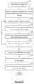
- FIG. 1illustrates a method 100 for standardized image view identification, performed in accordance with one or more embodiments.
- the method 100may be performed on a computing device such as a client machine or remote server.
- a requestis received to identify one or more standardized images from a set of input images.
- the input imagesmay be captured by a conventional camera.
- the input imagesmay be captured by a camera at a mobile computing device such as a smartphone.
- the set of imagesmay be included in a multi-view capture. Additional details regarding multi-view representation construction and other features are discussed in co-pending and commonly assigned U.S. patent application Ser. No. 15/934,624, “Conversion of an Interactive Multi-view Image Data Set into a Video”, by Holzer et al., filed Mar. 23, 2018, which is hereby incorporated by reference in its entirety and for all purposes.
- the input imagesmay include supplementary data such as data collected from an inertial measurement unit (IMU).
- IMUinertial measurement unit
- Such datamay include measurements originating from a gyroscope and/or an accelerometer such as acceleration and/or rotational velocity data.
- additional datasuch as orientation and/or location data may be determined.
- An input imageis selected for analysis at 104 .
- imagesmay be selected for analysis in sequence, in parallel, at random, or in any suitable order.
- an object component in the selected imageare identified at 106 .
- an object componentmay be identified at least in part via a neural network.
- the selected imagemay be used as an input to a neural network, which was trained on domain-specific data and identifies points on each image that locate salient parts of the images.
- the networkmay be trained to recognize wheels, lights, and parts of the frame.
- the identification of object componentsmay yield one or more annotated images.
- identified componentsmay be mapped to 2D coordinates and/or frame numbers within the image-set.
- FIG. 2An example of an object component identification procedure is shown in FIG. 2 .
- An input image at 202is provided as input to a neural network 204 , which results in an annotated image with identified components at 206 .
- Camera pose information for the selected input imageis determined at 108 .
- the camera posesmay be extracted using a computer vision algorithm. Additional details regarding pose detection, which is also referred to herein as object orientation detection, are discussed with respect to FIGS. 13 and 14 .
- the term camera posemay refer to the viewpoint or viewing angle of the camera relative to the object captured in the image.
- camera pose informationmay be estimated for a viewpoint in order to associate each image in a sequence of images with a viewpoint.
- Camera-posesmay be estimated by an algorithm that uses the images and, optionally, additional information received from the capturing device. Such information may include angle, location, acceleration, velocity, drift correction, or other such data collected or determined based on information from a gyroscope, an accelerometer, magnetometer, or other such sensor associated with the camera. Such input data may be used to facilitate the determination of camera pose information using a bundle adjustment procedure.
- the estimated posesprovide information about the relative position of the camera towards the object of interest.
- An example of camera pose detectionis shown at 208 .
- the systemmay determine that the image was captured from a designated location on the right side of the vehicle.
- imagesmay continue to be selected for analysis until all images have been analyzed. Alternately, images may continue to be selected until each of a designated set of standardized images have been selected.
- a 3D skeleton of the objectis created at 112 .
- creating a 3D skeletonmay involve using the location of the components in the image set identified at 106 along with the camera pose information determined at 106 .
- the skeleton computed in 3D spacemay be projected to the frames of the image-set by using the inferred 3D positions and camera poses. Additional details regarding skeleton detection and other features are discussed in co-pending and commonly assigned U.S. patent application Ser. No. 15/427,026, titled “Skeleton Detection and Tracking via Client-server Communication” by Holzer et al, filed Feb. 7, 2017, which is hereby incorporated by reference in its entirety and for all purposes.
- One or more individual panels for the objectare generated at 114 .
- the systemmay generate a set of standardized images using a domain-specific rule set.
- the domain-specific rule setmay designate one or more viewpoints.
- the domain-specific rule setmay also designate a region crop associated with a viewpoint.
- the region cropmay identify a portion of a component to include in a standardized image associated with the viewpoint.
- each individual panelmay include one or more views of the object or parts of the object.
- a panelmay include an entire image selected from the set of input images. Alternately, the panel may include a cropped portion of one or more images.
- An example rule for generating a panel of a front wheel of a vehiclemay be defined as follows.
- the front wheel positionedis determined by first identifying images with a suitable top-down viewing angle. Then, the wheel position is identified, and the crop area determined based on the wheel location in the image and the distance between the front and back wheel.
- An example of an application of such a ruleis shown at 212 in FIG. 2 .
- image at 212shows a standardized view of the front wheel.
- a number of standardized views of a single componentmay be combined to create a localized multi-view of that component.
- standardized views of the front wheel shown at 212may be captured from different viewpoints, and these different standardized viewpoints may be combined to create a multi-view of the wheel.
- a machine learning algorithmmay be trained to detect a bounding box around a component of an object (e.g., a part or panel of a vehicle) that is to be represented via a standardized image. After estimating the bounding box for a specific component in an input image or in a multi-view representation, the area within the bounding box may be extracted and presented as a result. In particular embodiments, such techniques may be applied to object interiors as well as object exteriors.
- the one or more individual panelsare stored on a storage device at 116 .
- the panelsmay be stored as a newly created image-set. Alternately, or additionally, the panels may be stored as an image-sequence, which may be subject to video playback.
- the one or more individual panelsmay be transmitted to a remote location via a network, such as to a remote server or to a client machine.
- the operations performed in FIG. 1 or in other methods described hereinmay be used to extract standardized views from a video.
- a 360-degree view of a vehiclemay be used as input to extract views of the vehicle at 45-degree angles around the vehicle.
- a crop of the imagemay contain the entire object.
- the bounding box of the object inside the imagemay be obtained at least in part with a neural network for object detection.
- the bounding box of the object inside the imagemay be obtained at least in part directly from the 3D skeleton determined at 112 , which may be re-projected onto one or more frames.
- camera pose informationmay be determined at 108 before, after, or in parallel to the identification of the one or more object components at 106 .
- a 2D skeletonmay be estimated from an input image or from each viewpoint of a multi-view representation. Then, the areas to extract may be defined relative to the joint locations of the skeleton. The joint locations may be treated as salient key-points that a machine learning algorithm is trained to detect.
- the method 100 shown in FIG. 1 and other methods described hereinmay be applied to capture viewpoints from the interior of an object.
- points near the locations that are to be extractedmay be tracked across images. Such point tracking may facilitate the smoothing of the location of the area to extract and/or the construction of a multi-view crop that is more stable than would otherwise be the case.
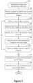
- FIG. 3illustrates a method 300 for standardized image view identification, performed in accordance with one or more embodiments.
- the method 300may be performed on a computing device such as a client machine or remote server.
- a requestis received to identify one or more standardized images from a set of input images.
- the set of imagesmay be included in a multi-view capture.
- the input imagesmay be captured by a conventional camera. Alternately, the input images may be captured by a smartphone camera.
- the input imagesmay include supplementary data such as data collected from an inertial measurement unit (IMU).
- IMUinertial measurement unit
- Such datamay include measurements originating from a gyroscope and/or an accelerometer such as orientation, location, and/or acceleration information.
- An input imageis selected for analysis at 304 .
- imagesmay be selected for analysis in sequence, in parallel, at random, or in any suitable order.
- the input imageis mapped to a top-down view.
- Techniques and mechanisms that may be used to facilitate top-down view mappingare discussed in additional detail with respect to FIGS. 4 , 5 , and 6 .
- one or more standardized images to extractare identified.
- a mapping of the top-down view to the input imageprovides a way to determine the corresponding image location for each location in the top-down view. Therefore, a standardized image or multi-view crop can be defined in the top-down view.
- the panels or image locations of a vehiclemay be defined in such a top-down view.
- the systemcan employ an example of the designated perspectives for an instance of the object. For example, desired image crops may be specified for a specific vehicle.
- the top-down mapping networkcan then map these examples to the top-down view. In this way, the same crops may be generated for other object instances as described herein.
- a per-pixel classificationmay be run on the image to identify a part of the object that is visible.
- the mappingmay be computed for every viewpoint of the multi-view representation.
- points near the locations that are to be extractedmay be tracked for use in smoothing the location of the area to extract. Such an approach may result in a multi-view crop that is more stable.
- top-down view mappingis described with respect to the exterior of an object
- similar techniquesmay be applied to interior views of an object such as a vehicle.
- various types of input formatsmay be used for the interior of an object. For example, a single image may be taken using a regular camera. As another example, a photo sphere (i.e. a 360-degree image) may be taken using a 360 camera or stitched together from multiple single images, or a multi-view representation. If an object interior is used as an input, then the trained mapping may map points from the input image data to a common representation for interiors of the object type captured, similar to a top-down view of a vehicle exterior.
- imagesmay continue to be selected for analysis until all images have been analyzed. Alternately, images may continue to be selected until each of a designated set of standardized images have been selected.
- One or more individual panels for the objectare generated at 314 .
- the systemmay generate a set of standardized images using a domain-specific rule set.
- the domain-specific rule setmay designate one or more viewpoints.
- An example for such a selection methodcan be to select the image for which the cropped area fills the most area (in pixels) or where the corresponding 3D part faces the camera the most.
- the resulting extracted cropsmay be multi-view representations.
- the one or more individual panelsare stored on a storage device at 316 .
- the panelsmay be stored as a newly created image-set. Alternately, or additionally, the panels may be stored as an image-sequence, which may be subject to video playback.
- the one or more individual panelsmay be transmitted to a remote location via a network, such as to a remote server or to a client machine.
- the operations performed in FIG. 3may be used to extract standardized views from a video.
- a 360-degree view of a vehiclemay be used as input to extract views of the vehicle at 45-degree angles around the vehicle.
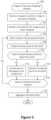
- FIG. 4illustrates one example of a method 400 for performing geometric analysis of a perspective view image, performed in accordance with one or more embodiments.
- the method 400may be performed on any suitable computing device.
- the method 400may be performed on a mobile computing device such as a smartphone.
- the method 400may be performed on a remote server in communication with a mobile computing device.
- a request to construct a top-down mapping of an objectis received at 402 .
- the requestmay be generated as part of a procedure to identify one or more standard object views.
- a video or image set of the object captured from one or more perspectivesis identified.
- the video or image setis referred to herein as “source data”.
- the source datamay include a 360-degree view of the object. Alternately, the source data may include a view that has less than 360-degree coverage.
- the source datamay include data captured from a camera.
- the cameramay be located on a mobile computing device such a mobile phone.
- one or more traditional camerasmay be used to capture such information.
- the source datamay include data collected from an inertial measurement unit (IMU).
- IMU datamay include information acceleration data and/or angular velocity data.
- sensor datasuch as camera location, camera angle, device velocity, or any of a wide variety of data may be collected.
- the objectis identified at 406 .
- the objectmay be identified based on user input. For example, a user may identify the object as a vehicle or person via a user interface component such as a drop-down menu.
- the objectmay be identified based on image recognition.
- the source datamay be analyzed to determine that the subject of the source data is a vehicle, a person, or another such object.
- the source datamay include a variety of image data.
- the image recognition proceduremay identify commonalities between the different perspective views to isolate the object that is the subject of the source data from other objects that are present in some portion of the source data but not in other portions of the source data.
- each facemay represent a part of the object surface that could be approximated as being planar.
- the vehicle's door panel or roofmay be represented as a face in a 2D mesh because the door and roof are approximately planar despite being slightly curved.
- vertices and faces of a 2D meshmay be identified by analyzing the source data. Alternately, or additionally, the identification of the object at 406 may allow for the retrieval of a predetermined 2D mesh. For example, a vehicle object may be associated with a default 2D mesh that may be retrieved upon request.
- Visibility anglesare determined for each vertex of the object at 410 .
- a visibility angleindicates the range of object angles with respect to the camera for which the vertex is visible.
- visibility angles of a 2D meshmay be identified by analyzing the source data. Alternately, or additionally, the identification of the object at 406 may allow for the retrieval of predetermined visibility angle along with a predetermined 2D mesh. For example, a vehicle object may be associated with a default 2D mesh with associated visibility angle that may be retrieved upon request.
- visibility anglesmay be used to extract standardized images. For example, once the object orientation is estimated, the viewpoints may be selected that best fit the angles that match the designated standardized image viewpoints.
- a 3D skeleton of the objectis constructed at 4 : 12 .
- constructing a 3D skeletonmay involve any of a variety of operations.
- a neural networkmay detect a 2D skeleton based on a 2D image.
- the detected 2D skeletonmay then be combined with other 2D skeletons detected from other images, and/or camera pose information.
- Camera pose informationmay identify the spatial relationship between the camera and an object in a perspective view of the object.
- the camera pose informationmay include 3D camera orientation information identifying a rotational relationship of the camera to the object.
- the camera pose informationmay include 3D translation information identifying a camera position relative to the object.
- camera pose informationmay include multiple (e.g., six) degrees of freedom.
- a 3D skeletonmay be identified based on a combination of the camera pose information and the 2D skeleton from one or more perspective view images.
- a 3D surface mesh model of an objectmay be available.
- a mesh modelmay be computed through segmentation and space carving or through other 3D reconstruction methods.
- a 3D surface mesh modelmay more precisely follow the surface of an actual object than the 3D skeleton mesh model.
- the mapping proceduremay identify the nearest surface mesh points to the skeleton joints and then define a mapping from the skeleton mesh to the surface mesh (or vice versa) using those skeleton joints to surface mesh correspondences. This mapping may be used to facilitate improved point or pixel mapping.
- an object sub-typeis detected at 414 .
- an object sub-typemay be a refinement of the object identification performed at 406 based on the additional information defined and determined at operations 408 - 412 .
- a vehicle object typemay be refined to reflect a body type such as a sedan, a sports utility vehicle, or a pickup truck.
- an object sub-typemay be identified in any of various ways. For example, an object sub-type may be automatically detected from the 3D skeleton. As another example, an object sub-type may be identified based on user input. As another example, an object sub-type may be identified based on a machine learning algorithm, which may be applied to the original source data and/or to refines of the source data such as the 3D skeleton.
- position information for additional 3D jointsis determined at 416 .
- the position of additional 3D jointsmay be inferred from the existing 3D skeleton. For example, a 3D skeleton of a vehicle may reveal that the vehicle has four wheels, even if a wheel is not visible in the source data. In this way, the final 3D skeleton may be expanded to include all of the vertices of the mesh defined in the top-down image.
- the inference of additional 3D jointsmay depend on the object sub-type. For example, a pickup truck may have different 3D joints than a sedan or sports utility vehicle.
- a surface mesh of the vehicleis determined at 418 .
- the surface meshmay be determined by using the 3D skeleton joints as vertices of the mesh. For example, each face of the mesh may approximate the object shape with a planar surface.
- FIG. 5illustrates one example of a method 500 for performing perspective image to top-down view mapping, performed in accordance with one or more embodiments.
- the method 500may be performed to map each pixel of an object represented in a perspective view to the corresponding point in a predefined top-down view of that class of objects.
- the method 500may be performed on any suitable computing device.
- the method 500may be performed on a mobile computing device such as a smartphone.
- the method 500may be performed on a remote server in communication with a mobile computing device.
- a request to construct a top-down mapping of an objectis received at 502 .
- the requestmay be generated after the performance of geometric analysis as discussed with respect to the method 400 shown in FIG. 4 .
- the requestmay identify one or more images for which to perform the top-down mapping.
- the images used to perform the geometric analysis discussed with respect to FIG. 1may be used for image to top-down mapping.
- a 3D mesh for the image to top-down mappingis identified at 504 .
- the 3D meshmay be constructed as discussed with respect to the method 400 shown in FIG. 4 .
- the 3D meshmay provide a three-dimensional representation of the object and serve as an intervening representation between the actual perspective view image and the top-down view.
- pixelsmay be selected for analysis.
- pixelsmay be selected in any suitable order. For example, pixels may be selected sequentially. As another example, pixels may be selected based on characteristics such as location or color. Such a selection process may facilitate faster analysis by focusing the analysis on portions of the image most likely to be present in the 3D mesh.
- the pixelis projected onto the 3D mesh at 508 .
- projecting the pixel onto the 3D meshmay involve simulating a camera ray passing by the pixel position in the image plan and into the 3D mesh. Upon simulating such a camera ray, barycentric coordinates of the intersection point with respect to the vertices of the intersection face may be extracted.
- a machine learning approachmay be used to perform image to top-down mapping on a single image.
- a machine learning algorithmmay be run on the perspective image as a whole.
- the machine learning algorithmmay identify 2D locations of each pixel (or a subset of them) in the top-down image.
- a machine learning approachmay be used to perform top-down to image mapping. For example, given a perspective image and a point of interest in the top-down image, the machine learning algorithm may be run on the perspective image for identifying the top-down locations of its points. Then, the point of interest in the top-down image may be mapped to the perspective image.
- mapping the point of interest in the top-down image to the perspective imagemay involve first selecting the points in the perspective image whose top-down mapping is closest to the interest point. Then, the selected points in the perspective image may be interpolated.
- FIG. 6Examples of an image to top-down mapping are shown in FIG. 6 .
- the locations of pixels in images of vehicle componentsare represented by colored dots. These dot locations are mapped from fixed locations 602 in the perspective view to corresponding locations 605 on the top-down view 606 .
- the projections of the 3D skeleton joints facesmay be used together with the corresponding joints and faces in the top-down view to directly define image transformations that map pixel information from the perspective views into the top-down view and vice versa.
- the computed pixel valuesare aggregated at 518 .
- aggregating the computing pixel valuesmay involve, for example, storing a cohesive pixel map on a storage device or memory module.
- FIG. 7illustrates a method 700 for standardized image view identification, performed in accordance with one or more embodiments.
- the method 700may be performed on a computing device such as a client machine or remote server.
- a requestis received to identify one or more standardized images from a set of input images.
- the set of imagesmay be included in a multi-view capture.
- the input imagesmay be captured by a conventional camera. Alternately, the input images may be captured by a smartphone camera.
- the input imagesmay include supplementary data such as data collected from an inertial measurement unit (IMU). Such data may include measurements originating from a gyroscope and/or an accelerometer such as acceleration and/or angular velocity information.
- IMUinertial measurement unit
- a machine learning model trained to perform image portion classificationis identified.
- one or more standardized imagesare determined based on the trained model. According to various embodiments, various types of machine learning models may be used.
- a machine learning algorithmmay be trained to directly output a designated cropped region from a designated input image. Such an approach may be applied on a single image or on different viewpoints of a multi-view representation.
- a machine learning algorithmmay be trained to label one or more of pixels of an input image or of a multi-view representation as a component of an object such as a vehicle. For example, each pixel in an input image may be independently classified. Then, different pixels with the same label may be clustered together and used to extract the image data covered by those pixels as a desired crop. In particular embodiments, such techniques may be applied to object interiors as well as object exteriors.
- a machine learning algorithmmay be employed to identify features of an object.
- semantic informationmay be associated with positions on the individual images. In conjunction with the camera poses, this semantic information facilitates the extraction of a three-dimensional map of the object where the relevant parts have been identified.
- the one or more individual panelsare stored on a storage device at 708 .
- the panelsmay be stored as a newly-created image-set. Alternately, or additionally, the panels may be stored as an image-sequence which may be subject to video playback.
- the one or more individual panelsmay be transmitted to a remote location via a network, such as to a remote server or to a client machine.
- FIG. 8illustrates a method 800 for standardized image view identification, performed in accordance with one or more embodiments.
- the method 800may be performed on a computing device such as a client machine or remote server.
- a requestis received to identify one or more standardized images from a set of input images.
- the set of imagesmay be included in a multi-view capture.
- the input imagesmay be captured by a conventional camera. Alternately, the input images may be captured by a smartphone camera.
- the input imagesmay include supplementary data such as data collected from an inertial measurement unit (IMU).
- IMUinertial measurement unit
- Such datamay include measurements originating from a gyroscope and/or an accelerometer such as acceleration and/or angular velocity data.
- a 3D model of an object included in the input imagesis determined.
- one or more standardized imagesare determined based on the 3D model. According to various embodiments, various 3D model approaches may be used.
- the construction of a 3D modelmay involve computing one or more segmentation masks, estimating one or more 3D poses, and/or performing space carving.
- the meshmay be refined using an image-based mesh refinement.
- a machine learning algorithmmay be used to classify the different parts of the 3D model as specific object components (e.g., vehicle parts).
- the object component classificationsmay then be projected back into the original viewpoint images. Standardized image views may then be determined as discussed, for example, with respect to FIG. 1 .
- a 3D model of the objectmay be matched with a reference 3D model of an object.
- the specification of the crop areasmay be done with respect to the reference 3D model. That specification may then be propagated onto the 3D model reconstruction obtained from the visual data of the multi-view representation. The propagated information may be back-projected into the original image data from the locations where the crop regions were extracted.
- matching between an estimated 3D model and a reference 3D modelmay involve first estimating the orientation of the 3D model.
- Orientation estimationmay add a strong constraint on the possible matching between the two 3D models.
- the one or more individual panelsare stored on a storage device at 808 .
- the panelsmay be stored as a newly-created image-set. Alternately, or additionally, the panels may be stored as an image-sequence which may be subject to video playback.
- the one or more individual panelsmay be transmitted to a remote location via a network, such as to a remote server or to a client machine.
- a multi-view interactive digital media representationincludes much more information than a single image. Whereas a single image may include information such as a grid of color pixels and the date/time of capture, a multi-view interactive digital media representation includes information such as such as grids of color pixels, date/time of capture, spatial information (flow/3D), location, and inertial measurement unit information (IMU) (i.e., compass, gravity, orientation).
- a multi-view interactive digital media representationbrings focus to an object of interest because it provides separation between the foreground and background.
- a multi-view interactive digital media representationprovides more information about the scale, context, and shape of the object of interest.
- aspects of the object that are not visible from a single viewcan be provided in a multi-view interactive digital media representation.
- the surround view acquisition system 900is depicted in a flow sequence that can be used to generate a surround view.
- the data used to generate a surround viewcan come from a variety of sources.
- datasuch as, but not limited to two-dimensional (2D) images 904 can be used to generate a surround view.
- 2D imagescan include color image data streams such as multiple image sequences, video data, etc., or multiple images in any of various formats for images, depending on the application.
- Another source of data that can be used to generate a surround viewincludes location information 906 .
- This location information 906can be obtained from sources such as accelerometers, gyroscopes, magnetometers, GPS, Wi-Fi, IMU-like systems (Inertial Measurement Unit systems), and the like.
- sourcessuch as accelerometers, gyroscopes, magnetometers, GPS, Wi-Fi, IMU-like systems (Inertial Measurement Unit systems), and the like.
- Yet another source of data that can be used to generate a surround viewcan include depth images 908 . These depth images can include depth, 3D, or disparity image data streams, and the like, and can be captured by devices such as, but not limited to, stereo cameras, time-of-flight cameras, three-dimensional cameras, and the like.
- the datacan then be fused together at sensor fusion block 910 .
- a surround viewcan be generated a combination of data that includes both 2D images 904 and location information 906 , without any depth images 908 provided.
- depth images 908 and location information 906can be used together at sensor fusion block 910 .
- Various combinations of image datacan be used with location information at 906 , depending on the application and available data.
- the data that has been fused together at sensor fusion block 910is then used for content modeling 912 and context modeling 914 .
- the subject matter featured in the imagescan be separated into content and context.
- the contentcan be delineated as the object of interest and the context can be delineated as the scenery surrounding the object of interest.
- the contentcan be a three-dimensional model, depicting an object of interest, although the content can be a two-dimensional image in some embodiments.
- the contextcan be a two-dimensional model depicting the scenery surrounding the object of interest.
- the contextcan also include three-dimensional aspects in some embodiments.
- the contextcan be depicted as a “flat” image along a cylindrical “canvas,” such that the “flat” image appears on the surface of a cylinder.
- some examplesmay include three-dimensional context models, such as when some objects are identified in the surrounding scenery as three-dimensional objects.
- the models provided by content modeling 912 and context modeling 914can be generated by combining the image and location information data.
- context and content of a surround vieware determined based on a specified object of interest.
- an object of interestis automatically chosen based on processing of the image and location information data. For instance, if a dominant object is detected in a series of images, this object can be selected as the content.
- a user specified target 902can be chosen. It should be noted, however, that a surround view can be generated without a user specified target in some applications.
- one or more enhancement algorithmscan be applied at enhancement algorithm(s) block 916 .
- various algorithmscan be employed during capture of surround view data, regardless of the type of capture mode employed. These algorithms can be used to enhance the user experience. For instance, automatic frame selection, stabilization, view interpolation, filters, and/or compression can be used during capture of surround view data.
- these enhancement algorithmscan be applied to image data after acquisition of the data. In other examples, these enhancement algorithms can be applied to image data during capture of surround view data.
- automatic frame selectioncan be used to create a more enjoyable surround view. Specifically, frames are automatically selected so that the transition between them will be smoother or more even.
- This automatic frame selectioncan incorporate blur- and overexposure-detection in some applications, as well as more uniformly sampling poses such that they are more evenly distributed.
- stabilizationcan be used for a surround view in a manner similar to that used for video.
- key frames in a surround viewcan be stabilized to produce improvements such as smoother transitions, improved/enhanced focus on the content, etc.
- improvementssuch as smoother transitions, improved/enhanced focus on the content, etc.
- there are many additional sources of stabilization for a surround viewsuch as by using IMU information, depth information, computer vision techniques, direct selection of an area to be stabilized, face detection, and the like.
- IMU informationcan be very helpful for stabilization.
- IMU informationprovides an estimate, although sometimes a rough or noisy estimate, of the camera tremor that may occur during image capture. This estimate can be used to remove, cancel, and/or reduce the effects of such camera tremor.
- depth informationif available, can be used to provide stabilization for a surround view. Because points of interest in a surround view are three-dimensional, rather than two-dimensional, these points of interest are more constrained and tracking/matching of these points is simplified as the search space reduces. Furthermore, descriptors for points of interest can use both color and depth information and therefore, become more discriminative.
- automatic or semi-automatic content selectioncan be easier to provide with depth information. For instance, when a user selects a particular pixel of an image, this selection can be expanded to fill the entire surface that touches it.
- contentcan also be selected automatically by using a foreground/background differentiation based on depth. In various examples, the content can stay relatively stable/visible even when the context changes.
- computer vision techniquescan also be used to provide stabilization for surround views. For instance, key points can be detected and tracked. However, in certain scenes, such as a dynamic scene or static scene with parallax, no simple warp exists that can stabilize everything. Consequently, there is a trade-off in which certain aspects of the scene receive more attention to stabilization and other aspects of the scene receive less attention. Because a surround view is often focused on a particular object of interest, a surround view can be content-weighted so that the object of interest is maximally stabilized in some examples.
- Another way to improve stabilization in a surround viewincludes direct selection of a region of a screen. For instance, if a user taps to focus on a region of a screen, then records a convex surround view, the area that was tapped can be maximally stabilized. This allows stabilization algorithms to be focused on a particular area or object of interest.
- face detectioncan be used to provide stabilization. For instance, when recording with a front-facing camera, it is often likely that the user is the object of interest in the scene. Thus, face detection can be used to weight stabilization about that region. When face detection is precise enough, facial features themselves (such as eyes, nose, mouth) can be used as areas to stabilize, rather than using generic key points.
- view interpolationcan be used to improve the viewing experience.
- synthetic, intermediate viewscan be rendered on the fly. This can be informed by content-weighted key point tracks and IMU information as described above, as well as by denser pixel-to-pixel matches. If depth information is available, fewer artifacts resulting from mismatched pixels may occur, thereby simplifying the process.
- view interpolationcan be applied during capture of a surround view in some embodiments. In other embodiments, view interpolation can be applied during surround view generation.
- filterscan also be used during capture or generation of a surround view to enhance the viewing experience.
- aesthetic filterscan similarly be applied to surround images.
- these filterscan be extended to include effects that are ill-defined in two dimensional photos. For instance, in a surround view, motion blur can be added to the background (i.e. context) while the content remains crisp.
- a drop-shadowcan be added to the object of interest in a surround view.
- compressioncan also be used as an enhancement algorithm 916 .
- compressioncan be used to enhance user-experience by reducing data upload and download costs.
- surround viewsuse spatial information, far less data can be sent for a surround view than a typical video, while maintaining desired qualities of the surround view.
- the IMU, key point tracks, and user input, combined with the view interpolation described above,can all reduce the amount of data that must be transferred to and from a device during upload or download of a surround view.
- a variable compression stylecan be chosen for the content and context.
- This variable compression stylecan include lower quality resolution for background information (i.e. context) and higher quality resolution for foreground information (i.e. content) in some examples.
- the amount of data transmittedcan be reduced by sacrificing some of the context quality, while maintaining a desired level of quality for the content.
- a surround view 918is generated after any enhancement algorithms are applied.
- the surround viewcan provide a multi-view interactive digital media representation.
- the surround viewcan include three-dimensional model of the content and a two-dimensional model of the context.
- the contextcan represent a “flat” view of the scenery or background as projected along a surface, such as a cylindrical or other-shaped surface, such that the context is not purely two-dimensional.
- the contextcan include three-dimensional aspects.
- surround viewsprovide numerous advantages over traditional two-dimensional images or videos. Some of these advantages include: the ability to cope with moving scenery, a moving acquisition device, or both; the ability to model parts of the scene in three-dimensions; the ability to remove unnecessary, redundant information and reduce the memory footprint of the output dataset; the ability to distinguish between content and context; the ability to use the distinction between content and context for improvements in the user-experience; the ability to use the distinction between content and context for improvements in memory footprint (an example would be high quality compression of content and low quality compression of context); the ability to associate special feature descriptors with surround views that allow the surround views to be indexed with a high degree of efficiency and accuracy; and the ability of the user to interact and change the viewpoint of the surround view.
- the characteristics described abovecan be incorporated natively in the surround view representation, and provide the capability for use in various applications. For instance, surround views can be used in applying filters or visual effects.
- a surround view 918user feedback for acquisition 920 of additional image data can be provided.
- a surround viewis determined to need additional views to provide a more accurate model of the content or context, a user may be prompted to provide additional views.
- these additional viewscan be processed by the system 900 and incorporated into the surround view.
- FIG. 10shown is an example of a device capturing multiple views of an object of interest from different locations. The capture device is indicated as camera 1012 , and moves from location 1022 to location 1024 and from location 1024 to location 1026 .
- the multiple camera views 1002 , 1004 , and 1006 captured by camera 1012can be fused together into a three-dimensional (3D) model. According to various embodiments, multiple images can be captured from various viewpoints and fused together to provide a multi-view digital media representation.
- camera 1012moves to locations 1022 , 1024 , and 1026 , respectively, along paths 1028 and 1030 , in proximity to an object of interest 1008 .
- Scenerycan surround the object of interest 1008 such as object 1008 .
- Views 1002 , 1004 , and 1006are captured by camera 1012 from locations 1022 , 1024 , and 1026 and include overlapping subject matter.
- each view 1002 , 1004 , and 1006includes the object of interest 1008 and varying degrees of visibility of the scenery surrounding the object 1010 .
- view 1002includes a view of the object of interest 1008 in front of the cylinder that is part of the scenery surrounding the object 1008 .
- View 1004shows the object of interest 1008 to one side of the cylinder
- view 1006shows the object of interest without any view of the cylinder.
- the various views 1002 , 1004 , and 1006along with their associated locations 1022 , 1024 , and 1026 , respectively, provide a rich source of information about object of interest 1008 and the surrounding context that can be used to produce a multi-view digital media representation, such as a surround view.
- the various views 1002 , 1004 , and 1006provide information about different sides of the object of interest and the relationship between the object of interest and the scenery. These views also provide information about the relative size and scale of the object of interest in relation to the scenery.
- views from different sides of the objectprovide information about the shape and texture of the object. According to various embodiments, this information can be used to parse out the object of interest 1008 into content and the scenery 1010 as the context. In particular examples, the content can then be used for applying filters.
- FIG. 11shown is an example of a device capturing views of an object of interest.
- multiple views of the object 1008may be captured by the device 1170 from different locations.
- datais acquired when a user taps a record button 1180 on capture device 1170 to begin recording images of the object.
- filteringcan be provided at the device 1170 , and prompts for the user to capture particular views can be provided during the session.
- the systemcan prompt the user to move the device 1170 in a particular direction or may prompt the user to provide additional information.
- filtering suggestionsmay be reiteratively refined to provide accurate results.
- the usermay choose to stop recording by tapping the record button 1180 again. In other examples, the user can tap and hold the record button during the session, and release to stop recording.
- the recordingcaptures a series of images that can be used to generate a multi-view digital media representation that can be for filtering either in real-time or after-the-fact.
- applying a filter to a multi-view digital media representationmay involve processing a succession of images taken from different perspectives.
- the client devicemay perform low-level processing such as two-dimensional analysis of individual images.
- the servermay perform high-level processing such as combining different individual images to produce a three-dimensional model of an object that is the subject of a multi-view video.
- a computer systemthat can be used to implement particular examples of the present invention.
- the computer system 1200can be used to map views between images according to various embodiments described above.
- the computer system 1200may be, for example, a server, a client machine, a mobile phone, a laptop, a desktop computer, or any other suitable device.
- a system 1200 suitable for implementing particular embodiments of the present inventionincludes a processor 1201 , a memory 1203 , a communications interface 1211 , and a bus 1215 (e.g., a PCI bus).
- the interface 1211may include separate input and output interfaces, or may be a unified interface supporting both operations.
- the processor 1201When acting under the control of appropriate software or firmware, the processor 1201 is responsible for such tasks such as optimization. Various specially configured devices can also be used in place of a processor 1201 or in addition to processor 1201 . The complete implementation can also be done in custom hardware.
- the communications interface 1211is typically configured to send and receive data packets or data segments over a network. Particular examples of interfaces the device supports include Ethernet interfaces, frame relay interfaces, cable interfaces, DSL interfaces, token ring interfaces, and the like.
- the storage device 1205is configured to store information on one or more non-transitory storage media such as a hard disk or network attached storage system.
- various very high-speed interfacesmay be provided such as fast Ethernet interfaces, Gigabit Ethernet interfaces, ATM interfaces, HSSI interfaces, POS interfaces, FDDI interfaces and the like.
- these interfacesmay include ports appropriate for communication with the appropriate media.
- theymay also include an independent processor and, in some instances, volatile RAM.
- the independent processorsmay control such communications intensive tasks as packet switching, media control and management.
- the system 1200uses memory 1203 to store data and program instructions and maintained a local side cache.
- the program instructionsmay control the operation of an operating system and/or one or more applications, for example.
- the memory or memoriesmay also be configured to store received metadata and batch requested metadata.
- the present inventionrelates to tangible, machine readable media that include program instructions, state information, etc. for performing various operations described herein.
- machine-readable mediainclude hard disks, floppy disks, magnetic tape, optical media such as CD-ROM disks and DVDs; magneto-optical media such as optical disks, and hardware devices that are specially configured to store and perform program instructions, such as read-only memory devices (ROM) and programmable read-only memory devices (PROMs).
- program instructionsinclude both machine code, such as produced by a compiler, and files containing higher level code that may be executed by the computer using an interpreter.
- the systemmay extract full images of an object from specific angles.
- the orientation of the objectmay be estimated. For instance, orientation estimation may be performed on a vehicle. The viewpoints that best correspond to the specific angles may then be returned.
- An object bounding box detectormay be applied to crop out the region that contains the object, or at least delineate a tighter region around the object.
- regions targeted for cropping or extractionmay be defined in any of various ways.
- One such approachis to specify the regions in the top-down view.
- Another optionis to specify the regions in given images of a car, which are then mapped onto a top-down view.
- example images of desired crop resultsmay be provided. These example images are then analyzed in a way that allows the extraction of the corresponding crop regions from novel images, videos, and/or multi-view captures.
- bounding box detection for object partsmay be performed on an input image to estimate which object parts are visible.
- Another approachis to use a neural network that directly maps each pixel of the provided image to a top-down view, and use the mapped information on the top-down view to specify the desired crop regions for novel images.
- a neural networkmay directly classify an input image as a specific object part.
- a neural networkmay classify all pixels of the input image as specific object parts, which is then used to estimate a corresponding cropping region for novel images.
- Yet another approachis to implement a neural network that receives the input image and identifies the four corners of the specified crop in a top-down view.
- Still another approachinvolves applying a neural network to both a reference image with the desired crop and an input image and then directly output the cropped image.
- points near the locations that are too be extractedmay be tracked across images. Such point tracking may facilitate the smoothing of the location of the area to extract and/or the construction of a multi-view crop that is more stable than would otherwise be the case.
- a neural networkmay receive the result from a previous image as an input and combine that result with the current image to provide an improved fitting result from the current image.
- techniques and mechanisms described hereinmay involve the use of additional sensor data to obtain improved results.
- additional sensor dataFor example, a depth sensor, an additional camera, IMU data, or other such information may be used.
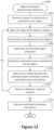
- FIG. 13illustrates a method 1300 of determining an orientation of an object, performed in accordance with one or more embodiments.
- the method 1300may be performed on any suitable computing device.
- the method 1300may be performed on a mobile computing device such as a smartphone.
- the method 1300may be performed on a remote server in communication with a mobile computing device.
- a request to determine an orientation of an objectis received at 1302 .
- the requestmay be received at a user interface.
- the requestmay be received via an application at a mobile computing device.
- the requestmay be received at a user interface at a laptop.
- an image of the objectis selected for analysis.
- the imagemay be a single two-dimensional image of the object.
- the imagemay be one of a series of two-dimensional images of the object captured from different viewpoints.
- the imagemay be a single frame of a video stream of the object.
- the imagemay be a 360-degree multi-view capture of the object.
- the imagemay include a view that has less than 360-degree coverage.
- a bounding box for the objectis determined at 1306 .
- a bounding box for the objectmay include coordinates of a rectangular or non-rectangular border that encloses the object in the selected image.
- the bounding boxmay be determined by a neural network.
- a neural networkmay be trained to determine the coordinates of the visible object pixels in an image of the object.
- the neural networkmay facilitate the determination of the pixel coordinates and the width, height, or other characteristics of the bounding box enclosing the object.
- the bounding boxmay be determined by a different type of algorithm.
- the bounding boxmay be determined at least in part based on user input.
- the bounding boxmay be determined by a user super-imposing a border on the image to enclose the object.
- the bounding boxmay be determined by the user tapping on the object with an algorithm automatically estimating the extent of the bounding based on the selection.
- the usermay select points or regions in the foreground and background, and an algorithm automatically separates both to estimate the extent of a corresponding bounding box.
- an estimated object orientationis determined.
- the estimated object orientationmay be determined by a neural network.
- a neural networkmay be trained to determine the estimated object orientation through an analysis of the object from one or more images of an object.
- the estimated object orientationmay include estimates about an object's roll, elevation, angular position, attitude, and azimuth angle.
- An estimated camera orientationis identified at 1310 .
- camera orientationmay be estimated from data collected from an inertial measurement unit (IMU).
- the IMUmay be associated with a mobile computing device, such as a smartphone.
- a mobile computing devicemay include sensors such as a camera capable of capturing visual data such as an image or video stream.
- a mobile computing devicemay also include an accelerometer, a gyroscope, and other such sensors capable of capturing IMU data.
- IMU datamay include information such as camera location, camera angle, device velocity, device acceleration, or any of a wide variety of data collected from accelerometers or other such sensors.
- IMU orientationmay identify orientation information associated with the camera.
- the IMU orientationmay then be used to infer orientation information about the object.
- the IMU orientationmay indicate that the image was captured with a camera located at a particular height and angle relative to the object and/or ground.
- the orientation estimationmight be done using a pose estimation algorithm based on image data. In some configurations, the pose estimation method might also consider the available IMU data.
- an offsetis determined between the estimated object orientation and the estimated camera orientation.
- the determinationmay be made at least in part by identifying a difference between the two values. Alternately, or additionally, the determination may be made at least in part by refining the object orientation based on additional information characterizing the position and angle of the camera.
- additional imagesmay be selected until all available images have been analyzed. For example, each image associated with a multi-view capture may be analyzed. If multiple images have been processed, then a combined offset may be to be calculated. For example, the offset can be averaged from the results obtained from multiple images. In another example, a robust method for estimating the final offset from multiple computed offsets might be used, for instance to handle outliers such as an inaccurate orientation estimation for certain images.
- the determination made at 1314may be made at least in part automatically.
- the estimated object orientation procedure at 1308may attempt to estimate an orientation for the object, but may fail due to incomplete image information or other information.
- a determinationmay be automatically made to prompt the user to capture or upload additional images of the object.
- the determination made at 1314may be made at least in part as a request by a user. For example, a user may be prompted to select an additional image for analysis. Alternately or additionally, a user may be prompted to review an estimated object orientation, and a user may review the estimated object orientation and may elect to analyze additional images of the object in order to improve the accuracy or quality of the estimated object orientation. In some implementations, every N-th frame of the multi-view capture might be processed.
- the orientation estimation informationis stored.
- storing the orientation estimation informationmay involve storing one or more orientation values for each of the images analyzed in FIG. 13 .
- orientation informationmay be stored to supplement a multi-view capture.
- the orientation estimationmay be stored on a storage device. Alternately, or additionally, the orientation estimation may be transmitted to a remote location via a network.
- one or more operations shown in FIG. 13may be omitted.
- any or all of operations 1310 and 1312may be omitted.
- FIG. 14illustrates a method for determining an object orientation based on 3D data.
- the method 1400may be performed on any suitable computing device.
- the method 1400may be performed on a mobile computing device such as a smartphone.
- the method 1400may be performed on a remote server in communication with a mobile computing device.
- a request to determine an orientation of an objectis received at 1402 .
- the requestmay be received at a user interface.
- image information for the objectis captured.
- the image informationmay include a video or image set of the object is captured from multiple perspectives.
- the image informationmay include a 360-degree view of the object. Alternately, the image information may include a view that has less than 360-degree coverage.
- An objectis identified for analysis at 1406 .
- the objectmay be identified via an algorithm.
- the objectmay be identified via an image recognition algorithm.
- the objectmay be identified via a bounding box algorithm.
- the objectmay be identified based at least in part on user input. For instance, a user may identify the object as a vehicle via a user interface component such as a drop-down menu.
- points of referenceare identified on the object.
- points of referencemay include one or more fiducial points on the object.
- Fiducial pointsare identifiable locations on objects of a particular type that in general should be present on all or nearly all objects of that type and that provide an indication as to the object's orientation.
- fiducial pointsmay include but are not limited to the vehicle's headlights, rearview mirror, and wheels.
- the reference pointsmay be identified via an algorithm, such as an image recognition algorithm. Alternately or additionally, reference points may be identified in part through user input.
- a sparse 3D mesh of an objectis determined at 1410 .
- the sparse 3D meshmay be determined by using the fiducial points identified in operation 1408 as vertices of the mesh. For example, each face of the mesh may approximate the object shape with a planar surface.
- a 3D representation of the objectis determined.
- the 3D representationmay be constructed by elevating the fiducial points to 3D space and constructing a sparse 3D mesh from their locations.
- the object's orientationmay be inferred based on cues such as surface normal of the faces of the mesh, visibility states of the fidicual points in a plurality of image, or other such features.
- the elevation into 3D spacemight be done using triangulation.
- a depth mapmight be computed for each frame which is then used to elevate the 14D points into 3D.
- the 3D representationmay be a 3D skeleton.
- 14D skeleton detectionmay be performed on every frame using a machine learning procedure.
- 3D camera pose estimationmay be performed to determine a location and angle of the camera with respect to the object for a particular frame.
- a 3D skeletonmay be reconstructed from one or more 2D skeletons and/or one or more 3D models.
- the 3D reconstruction of the object surfacemay include one or more of a variety of reconstruction procedures. For example, dominant axes may be computed to estimate orientation. As another example, an object model such as a vehicle model that has a reference orientation may be fit into a 3D reconstructed model based on the input data. As another example, one or more parts of a 3D reconstructed model may be classified to estimate an orientation of the object.
- Estimated orientation for the objectis determined at 1414 .
- the estimated object orientationmay be determined by a neural network.
- a neural networkmay be trained to determine the estimated object orientation through an analysis of the object from one or more images of an object.
- the estimated object orientationmay include estimates about an object's dominant axes, roll, elevation, angular position, attitude, and azimuth angle.
- the object orientationmay be estimated based on the sparse 3D mesh determined at operation 1410 and/or the 3D skeleton determined at operation 1412 .
- the fiducial points identified in operation 1408facilitate the triangulation of fiducial points of the object in 3D space to help determine the azimuth, roll, elevation, and axes of the designated object.
- the 3D skeletonmay facilitate the inference of the object's orientation based on cues such as, but not limited to, the surface normals of the faces of the mesh, and the visibility states of the fiducial points in the images of the object, and information about the three axes of the 3D skeleton model determined at operation 1412 .
- the estimated object orientationmay be determined based on a 3D reconstruction of the object.
- the object orientationmay be estimated based on the dominant axes of the 3D reconstruction of an object.
- the orientation for a designated objectmay be estimated by incorporating the orientation of a known reference object with reference orientation with a 3D reconstructed model of the designated object.
- parts of the 3D reconstructed modelmay be identified to determine orientation of the object.
- the license platemay be identified as a reference point relative to the rearview mirror to estimate the orientation of the vehicle.
- the orientation estimation informationis stored.
- the orientation estimationmay be stored on a storage device. Alternately, or additionally, the orientation estimation may be transmitted to a remote location via a network.
- the object orientationmay be estimated based on the determination of specific reference points on the object. For example, in the case of a vehicle, a specific reference point such as the license plate may be detected in one or more images of a multi-view image set. Based on the location of the license plate in the image relative to other reference points, such as the vehicle's headlights, the orientation of the object may be inferred.
- this determinationmay be performed on a 3D model of the object.
- the location of the license platemay be used to estimate global angle for the vehicle.
- the trajectory of a feature such as a license platemay be fit to an ellipse in image space, which corresponds to a sphere around the vehicle in 3D space, and the location on the ellipse is used to estimate the vehicle's orientation.
- the estimated object orientationmay be determined from a single image.
- the objectmay not be visible from all angles or perspectives from a single image, or an image may not supply a minimum number of reference points visible to determine a sparse 3D mesh capable of facilitating the determination of a 3D skeleton of the object.
- a neural networkmay be trained to predict coordinates of the visible object pixels in a top-down view of the object.
- the pointsmay be lifted to 3D based on a predefined correspondence between the top-down view and a 3D mesh. Then, the transformation between the image points and the 3D mesh may be used to obtain the 3D orientation of the vehicle.
- the estimated object orientationmay be determined from a single image via top-down view mapping.
- a networkmay be trained that takes an image of an object such as a vehicle as input and maps every point of the image onto a top-down view. Based on the distribution of the points on the top-down view, the system may then draw an inference about the orientation of the object with respect to the camera.
- orientationmay be estimated from a single image using a component classifier.
- a networkmay be trained to identify object components such as car parts. For instance, each pixel of the image may be classified as belonging to an object component or as part of the background. The visible object components may then be used to estimate an orientation of the object.
- the object orientationmay be directly estimated from the detected 2D skeleton by considering which joints of the 2D skeleton are detected (i.e. are visible).
- the estimated object orientationmay be determined from a single image via using a neural network trained directly to determine an N degree-of-freedom pose.
- a 3 degree-of-freedom posemay include azimuth, roll, and elevation.
- a 6 degree-of-freedom posemay include 3 degrees of freedom for orientation and 3 degrees of freedom for translation.
- a combination of 3 degrees of freedom for translation and 3 degrees of freedom for positionmay be used.
- a 2 degree-of-freedom posemay include 1 degree-of-freedom for orientation and 1 degree-of-freedom for the distance between the camera and the object.
- any of the approaches involving a single imagemay be applied on a multi-view data set and the results combined (e.g., averaged) to improve the overall results.
- any combination of the methods described hereinmay be used to increase robustness and/or provide a failsafe. For example, orientation may be independent estimated using three different methods, and then the results cross-checked.
Landscapes
- Engineering & Computer Science (AREA)
- Physics & Mathematics (AREA)
- General Physics & Mathematics (AREA)
- Theoretical Computer Science (AREA)
- Computer Vision & Pattern Recognition (AREA)
- Computer Graphics (AREA)
- Geometry (AREA)
- Software Systems (AREA)
- Image Analysis (AREA)
Abstract
Description
- FORALL poses WITH top_down_angle BETWEEN (60°,120°):
- img=GET_IMAGE_OF_POSE(pose)
- p=GET_WHEEL_POSITION_ON_POSE(pose)
- cx=0.3*HDISTANCE(pose,FRONT_WHEEL,BACK_WHEEL)
- cy=0.4*VDISTANCE(pose,FRONT_WHEEL,FRONT_ROOF)
- ADD_TO_PANEL(CROP(img,p,cx,cy))
- FORALL poses WITH top_down_angle BETWEEN (60°,120°):
Claims (12)
Priority Applications (2)
| Application Number | Priority Date | Filing Date | Title |
|---|---|---|---|
| US16/518,558US11783443B2 (en) | 2019-01-22 | 2019-07-22 | Extraction of standardized images from a single view or multi-view capture |
| US18/240,773US20230419438A1 (en) | 2019-01-22 | 2023-08-31 | Extraction of standardized images from a single-view or multi-view capture |
Applications Claiming Priority (4)
| Application Number | Priority Date | Filing Date | Title |
|---|---|---|---|
| US201962795440P | 2019-01-22 | 2019-01-22 | |
| US201962795434P | 2019-01-22 | 2019-01-22 | |
| US201962795427P | 2019-01-22 | 2019-01-22 | |
| US16/518,558US11783443B2 (en) | 2019-01-22 | 2019-07-22 | Extraction of standardized images from a single view or multi-view capture |
Related Child Applications (1)
| Application Number | Title | Priority Date | Filing Date |
|---|---|---|---|
| US18/240,773ContinuationUS20230419438A1 (en) | 2019-01-22 | 2023-08-31 | Extraction of standardized images from a single-view or multi-view capture |
Publications (2)
| Publication Number | Publication Date |
|---|---|
| US20200234398A1 US20200234398A1 (en) | 2020-07-23 |
| US11783443B2true US11783443B2 (en) | 2023-10-10 |
Family
ID=71609065
Family Applications (2)
| Application Number | Title | Priority Date | Filing Date |
|---|---|---|---|
| US16/518,558ActiveUS11783443B2 (en) | 2019-01-22 | 2019-07-22 | Extraction of standardized images from a single view or multi-view capture |
| US18/240,773AbandonedUS20230419438A1 (en) | 2019-01-22 | 2023-08-31 | Extraction of standardized images from a single-view or multi-view capture |
Family Applications After (1)
| Application Number | Title | Priority Date | Filing Date |
|---|---|---|---|
| US18/240,773AbandonedUS20230419438A1 (en) | 2019-01-22 | 2023-08-31 | Extraction of standardized images from a single-view or multi-view capture |
Country Status (1)
| Country | Link |
|---|---|
| US (2) | US11783443B2 (en) |
Families Citing this family (14)
| Publication number | Priority date | Publication date | Assignee | Title |
|---|---|---|---|---|
| US11176704B2 (en) | 2019-01-22 | 2021-11-16 | Fyusion, Inc. | Object pose estimation in visual data |
| US12204869B2 (en) | 2019-01-22 | 2025-01-21 | Fyusion, Inc. | Natural language understanding for visual tagging |
| US12243170B2 (en) | 2019-01-22 | 2025-03-04 | Fyusion, Inc. | Live in-camera overlays |
| US10887582B2 (en) | 2019-01-22 | 2021-01-05 | Fyusion, Inc. | Object damage aggregation |
| US12203872B2 (en) | 2019-01-22 | 2025-01-21 | Fyusion, Inc. | Damage detection from multi-view visual data |
| US11783443B2 (en) | 2019-01-22 | 2023-10-10 | Fyusion, Inc. | Extraction of standardized images from a single view or multi-view capture |
| CA3134440A1 (en)* | 2019-03-18 | 2020-09-24 | Geomagical Labs, Inc. | System and method for virtual modeling of indoor scenes from imagery |
| GB2582315B (en)* | 2019-03-19 | 2023-05-17 | Sony Interactive Entertainment Inc | Method and system for generating an image |
| US12244784B2 (en) | 2019-07-29 | 2025-03-04 | Fyusion, Inc. | Multiview interactive digital media representation inventory verification |
| US11776142B2 (en) | 2020-01-16 | 2023-10-03 | Fyusion, Inc. | Structuring visual data |
| US11562474B2 (en) | 2020-01-16 | 2023-01-24 | Fyusion, Inc. | Mobile multi-camera multi-view capture |
| US11605151B2 (en) | 2021-03-02 | 2023-03-14 | Fyusion, Inc. | Vehicle undercarriage imaging |
| CN114036969B (en)* | 2021-03-16 | 2023-07-25 | 上海大学 | 3D human body action recognition algorithm under multi-view condition |
| US12374045B2 (en)* | 2022-03-10 | 2025-07-29 | Streem, Llc | Efficient texture mapping of a 3-D mesh |
Citations (102)
| Publication number | Priority date | Publication date | Assignee | Title |
|---|---|---|---|---|
| US5764306A (en) | 1997-03-18 | 1998-06-09 | The Metaphor Group | Real-time method of digitally altering a video data stream to remove portions of the original image and substitute elements to create a new image |
| US5923380A (en) | 1995-10-18 | 1999-07-13 | Polaroid Corporation | Method for replacing the background of an image |
| US6067369A (en) | 1996-12-16 | 2000-05-23 | Nec Corporation | Image feature extractor and an image feature analyzer |
| US20020063714A1 (en) | 2000-10-04 | 2002-05-30 | Michael Haas | Interactive, multimedia advertising systems and methods |
| US6453069B1 (en) | 1996-11-20 | 2002-09-17 | Canon Kabushiki Kaisha | Method of extracting image from input image using reference image |
| US20020198713A1 (en) | 1999-01-29 | 2002-12-26 | Franz Alexander M. | Method and apparatus for perfoming spoken language translation |
| US6788309B1 (en) | 2000-10-03 | 2004-09-07 | Ati International Srl | Method and apparatus for generating a video overlay |
| US20040258306A1 (en) | 2003-06-23 | 2004-12-23 | Shoestring Research, Llc | Fiducial designs and pose estimation for augmented reality |
| US6879956B1 (en) | 1999-09-30 | 2005-04-12 | Sony Corporation | Speech recognition with feedback from natural language processing for adaptation of acoustic models |
| US6912313B2 (en) | 2001-05-31 | 2005-06-28 | Sharp Laboratories Of America, Inc. | Image background replacement method |
| US7249019B2 (en) | 2002-08-06 | 2007-07-24 | Sri International | Method and apparatus for providing an integrated speech recognition and natural language understanding for a dialog system |
| US20070253618A1 (en) | 2006-03-20 | 2007-11-01 | Samsung Electronics Co., Ltd | Camera calibration method and medium and 3D object reconstruction method and medium using the same |
| US7292257B2 (en) | 2004-06-28 | 2007-11-06 | Microsoft Corporation | Interactive viewpoint video system and process |
| US20080101656A1 (en) | 2006-10-30 | 2008-05-01 | Thomas Henry Barnes | Method and apparatus for managing parking lots |
| US20080180436A1 (en) | 2007-01-26 | 2008-07-31 | Captivemotion, Inc. | Method of Capturing, Processing, and Rendering Images. |
| US20090289957A1 (en) | 2006-05-22 | 2009-11-26 | Rafael Advanced Defense Systems Ltd | Methods and system for communication and displaying points-of-interest |
| US20100111370A1 (en) | 2008-08-15 | 2010-05-06 | Black Michael J | Method and apparatus for estimating body shape |
| US20100251101A1 (en) | 2009-03-31 | 2010-09-30 | Haussecker Horst W | Capture and Display of Digital Images Based on Related Metadata |
| US7949529B2 (en) | 2005-08-29 | 2011-05-24 | Voicebox Technologies, Inc. | Mobile systems and methods of supporting natural language human-machine interactions |
| US20110218825A1 (en) | 2010-03-03 | 2011-09-08 | International Business Machines Corporation | Three-dimensional interactive vehicle damage claim interface |
| US20130297353A1 (en) | 2008-01-18 | 2013-11-07 | Mitek Systems | Systems and methods for filing insurance claims using mobile imaging |
| US20140119604A1 (en) | 2012-10-30 | 2014-05-01 | Canon Kabushiki Kaisha | Method, apparatus and system for detecting a supporting surface region in an image |
| US20140172245A1 (en) | 2011-01-21 | 2014-06-19 | United States Of America As Represented By The Secretary Of The Navy | Vehicle damage detection system and method of manufacturing the same |
| US20150029304A1 (en) | 2013-07-23 | 2015-01-29 | Lg Electronics Inc. | Mobile terminal and panorama capturing method thereof |
| US20150097931A1 (en) | 2013-10-09 | 2015-04-09 | United Sciences, Llc. | Calibration of 3d scanning device |
| US20150103170A1 (en) | 2013-10-11 | 2015-04-16 | Ccc Information Services | Image capturing and automatic labeling system |
| US20150125049A1 (en) | 2013-11-04 | 2015-05-07 | Facebook, Inc. | Systems and methods for facial representation |
| US20150278987A1 (en) | 2014-03-25 | 2015-10-01 | Panasonic Intellectual Property Management Co., Ltd. | Multi-viewpoint image capturing method and image display method |
| US20150317527A1 (en) | 2011-12-29 | 2015-11-05 | Intel Corporation | System, methods, and apparatus for in-vehicle fiducial mark tracking and interpretation |
| US9182229B2 (en) | 2010-12-23 | 2015-11-10 | Trimble Navigation Limited | Enhanced position measurement systems and methods |
| US20150347845A1 (en) | 2014-05-30 | 2015-12-03 | Lifetouch Inc. | Photographic scene replacement system |
| US20150365661A1 (en) | 2013-03-27 | 2015-12-17 | Fujifilm Corporation | Image capturing apparatus, calibration method, and non-transitory computer-readable medium |
| US9218698B2 (en) | 2012-03-14 | 2015-12-22 | Autoconnect Holdings Llc | Vehicle damage detection and indication |
| US20160035096A1 (en) | 2012-12-28 | 2016-02-04 | Trimble Navigation Limited | Scene documentation |
| WO2016064921A1 (en) | 2014-10-20 | 2016-04-28 | MedSight Tech Corp. | Automatic detection of regions of interest in 3d space |
| US9467750B2 (en) | 2013-05-31 | 2016-10-11 | Adobe Systems Incorporated | Placing unobtrusive overlays in video content |
| US9495764B1 (en) | 2016-03-21 | 2016-11-15 | URC Ventures, Inc. | Verifying object measurements determined from mobile device images |
| US20170109930A1 (en) | 2015-10-16 | 2017-04-20 | Fyusion, Inc. | Augmenting multi-view image data with synthetic objects using imu and image data |
| WO2017115149A1 (en) | 2015-12-31 | 2017-07-06 | Dacuda Ag | A method and system for real-time 3d capture and live feedback with monocular cameras |
| US20170199647A1 (en) | 2015-12-31 | 2017-07-13 | Unmanned Innovation, Inc. | Unmanned aerial vehicle rooftop inspection system |
| US20170208246A1 (en) | 2013-04-30 | 2017-07-20 | Sony Corporation | Client terminal, display control method, program, and system |
| US20170277363A1 (en)* | 2015-07-15 | 2017-09-28 | Fyusion, Inc. | Automatic tagging of objects on a multi-view interactive digital media representation of a dynamic entity |
| US20170293894A1 (en) | 2016-04-06 | 2017-10-12 | American International Group, Inc. | Automatic assessment of damage and repair costs in vehicles |
| WO2017195228A1 (en) | 2016-05-09 | 2017-11-16 | Uesse S.R.L. | Process and system to analyze deformations in motor vehicles |
| US20180027178A1 (en)* | 2016-07-19 | 2018-01-25 | Gopro, Inc. | Mapping of spherical image data into rectangular faces for transport and decoding across networks |
| US9886771B1 (en) | 2016-05-20 | 2018-02-06 | Ccc Information Services Inc. | Heat map of vehicle damage |
| US9886636B2 (en) | 2013-05-23 | 2018-02-06 | GM Global Technology Operations LLC | Enhanced top-down view generation in a front curb viewing system |
| US20180160102A1 (en) | 2016-12-01 | 2018-06-07 | Thomson Licensing | Method for 3d reconstruction of an environment of a mobile device, corresponding computer program product and device |
| US20180190017A1 (en) | 2017-01-04 | 2018-07-05 | Daqri, Llc | Environmental Mapping System |
| US20180225858A1 (en) | 2017-02-03 | 2018-08-09 | Sony Corporation | Apparatus and method to generate realistic rigged three dimensional (3d) model animation for view-point transform |
| US20180255290A1 (en) | 2015-09-22 | 2018-09-06 | Fyusion, Inc. | System and method for generating combined embedded multi-view interactive digital media representations |
| US20180260793A1 (en) | 2016-04-06 | 2018-09-13 | American International Group, Inc. | Automatic assessment of damage and repair costs in vehicles |
| US20180293552A1 (en) | 2017-04-11 | 2018-10-11 | Alibaba Group Holding Limited | Image-based vehicle maintenance plan |
| US20180315260A1 (en) | 2017-05-01 | 2018-11-01 | PiMios, LLC | Automotive diagnostics using supervised learning models |
| US20180322623A1 (en) | 2017-05-08 | 2018-11-08 | Aquifi, Inc. | Systems and methods for inspection and defect detection using 3-d scanning |
| US20180338126A1 (en) | 2017-05-22 | 2018-11-22 | Fyusion, Inc. | Snapshots at predefined intervals or angles |
| US20180349746A1 (en) | 2017-05-31 | 2018-12-06 | Uber Technologies, Inc. | Top-View Lidar-Based Object Detection |
| US20190012394A1 (en) | 2014-07-30 | 2019-01-10 | NthGen Software Inc. | System and method of a dynamic interface for capturing vehicle data |
| US20190035165A1 (en) | 2012-02-24 | 2019-01-31 | Matterport, Inc. | Employing three-dimensional (3d) data predicted from two-dimensional (2d) images using neural networks for 3d modeling applications and other applications |
| US20190066304A1 (en) | 2017-08-31 | 2019-02-28 | Microsoft Technology Licensing, Llc | Real-time object segmentation in live camera mode |
| US20190073641A1 (en) | 2017-09-01 | 2019-03-07 | Allstate Insurance Company | Analyzing Images and Videos of Damaged Vehicles to Determine Damaged Vehicle Parts and Vehicle Asymmetries |
| US20190098277A1 (en) | 2017-09-22 | 2019-03-28 | Canon Kabushiki Kaisha | Image processing apparatus, image processing method, image processing system, and storage medium |
| US20190116322A1 (en) | 2017-10-13 | 2019-04-18 | Fyusion, Inc. | Skeleton-based effects and background replacement |
| US20190147583A1 (en) | 2017-11-10 | 2019-05-16 | Ford Global Technologies, Llc | Method for monitoring damage to motor vehicles |
| US20190147221A1 (en)* | 2017-11-15 | 2019-05-16 | Qualcomm Technologies Inc. | Pose estimation and model retrieval for objects in images |
| US20190164301A1 (en) | 2017-11-24 | 2019-05-30 | Electronics And Telecommunications Research Institute | Apparatus and method of learning pose of moving object |
| US10319094B1 (en) | 2016-05-20 | 2019-06-11 | Ccc Information Services Inc. | Technology for capturing, transmitting, and analyzing images of objects |
| US20190189007A1 (en) | 2017-12-18 | 2019-06-20 | Ford Global Technologies, Llc | Inter-vehicle cooperation for physical exterior damage detection |
| US20190197196A1 (en) | 2017-12-26 | 2019-06-27 | Seiko Epson Corporation | Object detection and tracking |
| US20190196698A1 (en) | 2017-12-22 | 2019-06-27 | Adobe Inc. | Removing and Replacing Objects in Images According to a Directed User Conversation |
| US20190205086A1 (en) | 2017-12-30 | 2019-07-04 | Oh Crikey Inc. | Image tagging with audio files in a wide area network |
| US10373387B1 (en) | 2017-04-07 | 2019-08-06 | State Farm Mutual Automobile Insurance Company | Systems and methods for enhancing and developing accident scene visualizations |
| WO2019186545A1 (en) | 2018-03-29 | 2019-10-03 | Uveye Ltd. | System of vehicle inspection and method thereof |
| US20190318759A1 (en) | 2018-04-12 | 2019-10-17 | Qualcomm Incorporated | Context-based detection of end-point of utterance |
| US20190317519A1 (en) | 2018-04-17 | 2019-10-17 | Baidu Usa Llc | Method for transforming 2d bounding boxes of objects into 3d positions for autonomous driving vehicles (advs) |
| GB2573170A (en) | 2018-04-27 | 2019-10-30 | Canon Kk | 3D Skeleton reconstruction from images using matching 2D skeletons |
| US20190335156A1 (en) | 2018-04-26 | 2019-10-31 | Fyusion, Inc. | Visual annotation using tagging sessions |
| US20190349571A1 (en) | 2018-05-11 | 2019-11-14 | Ford Global Technologies, Llc | Distortion correction for vehicle surround view camera projections |
| WO2019229912A1 (en) | 2018-05-30 | 2019-12-05 | 株式会社ニコン | Information processing device, information processing method, information processing program, and microscope |
| US20190392569A1 (en) | 2018-06-22 | 2019-12-26 | Caterpillar Inc. | Measurement platform that automatically determines wear of machine components based on images |
| WO2020009948A1 (en) | 2018-07-05 | 2020-01-09 | Fyusion, Inc. | Providing recording guidance in generating a multi-view interactive digital media representation |
| US10573012B1 (en) | 2015-10-14 | 2020-02-25 | Allstate Insurance Company | Three dimensional image scan for vehicle |
| US20200111201A1 (en) | 2018-10-05 | 2020-04-09 | The Toronto-Dominion Bank | System and method for verifying image data of a vehicle |
| US20200118342A1 (en) | 2018-10-15 | 2020-04-16 | University Of Maryland, College Park | Methods and apparatuses for dynamic navigable 360 degree environments |
| US10636148B1 (en) | 2016-05-20 | 2020-04-28 | Ccc Information Services Inc. | Image processing system to detect contours of an object in a target object image |
| US20200151860A1 (en) | 2018-11-13 | 2020-05-14 | Adobe Inc. | Intelligent identification of replacement regions for mixing and replacing of persons in group portraits |
| US10657647B1 (en)* | 2016-05-20 | 2020-05-19 | Ccc Information Services | Image processing system to detect changes to target objects using base object models |
| US20200193675A1 (en)* | 2017-03-06 | 2020-06-18 | 3D Patents, Llc | Multi-view processing unit systems and methods |
| WO2020125726A1 (en) | 2018-12-20 | 2020-06-25 | 深圳市道通智能航空技术有限公司 | Autonomous landing method and device for unmanned aerial vehicle, and unmanned aerial vehicle |
| US20200234424A1 (en) | 2019-01-22 | 2020-07-23 | Fyusion, Inc. | Damage detection from multi-view visual data |
| US20200234451A1 (en) | 2019-01-22 | 2020-07-23 | Fyusion, Inc. | Automatic background replacement for single-image and multi-view captures |
| US20200234398A1 (en) | 2019-01-22 | 2020-07-23 | Fyusion, Inc | Extraction of standardized images from a single view or multi-view capture |
| US20200234397A1 (en) | 2019-01-22 | 2020-07-23 | Fyusion, Inc. | Automatic view mapping for single-image and multi-view captures |
| US20200231286A1 (en) | 2019-01-22 | 2020-07-23 | The Boeing Company | Methods for arranging passenger seats and passenger service units in aircraft cabins |
| US20200233892A1 (en) | 2012-04-27 | 2020-07-23 | Mobitv, Inc. | Search-based navigation of media content |
| WO2020154096A1 (en) | 2019-01-22 | 2020-07-30 | Fyusion, Inc. | Damage detection from multi-view visual data |
| US20200258309A1 (en) | 2019-01-22 | 2020-08-13 | Fyusion, Inc. | Live in-camera overlays |
| US20200257862A1 (en) | 2019-01-22 | 2020-08-13 | Fyusion, Inc. | Natural language understanding for visual tagging |
| US20200312028A1 (en) | 2019-03-27 | 2020-10-01 | Drone Technology LLC | System and method for structure inspection |
| US20200322546A1 (en) | 2019-04-02 | 2020-10-08 | ACV Auctions Inc. | Vehicle undercarriage imaging system |
| US20200349757A1 (en) | 2019-05-03 | 2020-11-05 | Fyusion, Inc. | Object capture coverage evaluation |
| US10893213B2 (en) | 2019-04-02 | 2021-01-12 | ACV Auctions Inc. | Vehicle undercarriage imaging system |
- 2019
- 2019-07-22USUS16/518,558patent/US11783443B2/enactiveActive
- 2023
- 2023-08-31USUS18/240,773patent/US20230419438A1/ennot_activeAbandoned
Patent Citations (108)
| Publication number | Priority date | Publication date | Assignee | Title |
|---|---|---|---|---|
| US5923380A (en) | 1995-10-18 | 1999-07-13 | Polaroid Corporation | Method for replacing the background of an image |
| US6453069B1 (en) | 1996-11-20 | 2002-09-17 | Canon Kabushiki Kaisha | Method of extracting image from input image using reference image |
| US6067369A (en) | 1996-12-16 | 2000-05-23 | Nec Corporation | Image feature extractor and an image feature analyzer |
| US5764306A (en) | 1997-03-18 | 1998-06-09 | The Metaphor Group | Real-time method of digitally altering a video data stream to remove portions of the original image and substitute elements to create a new image |
| US20020198713A1 (en) | 1999-01-29 | 2002-12-26 | Franz Alexander M. | Method and apparatus for perfoming spoken language translation |
| US6879956B1 (en) | 1999-09-30 | 2005-04-12 | Sony Corporation | Speech recognition with feedback from natural language processing for adaptation of acoustic models |
| US6788309B1 (en) | 2000-10-03 | 2004-09-07 | Ati International Srl | Method and apparatus for generating a video overlay |
| US20020063714A1 (en) | 2000-10-04 | 2002-05-30 | Michael Haas | Interactive, multimedia advertising systems and methods |
| US6912313B2 (en) | 2001-05-31 | 2005-06-28 | Sharp Laboratories Of America, Inc. | Image background replacement method |
| US7249019B2 (en) | 2002-08-06 | 2007-07-24 | Sri International | Method and apparatus for providing an integrated speech recognition and natural language understanding for a dialog system |
| US20040258306A1 (en) | 2003-06-23 | 2004-12-23 | Shoestring Research, Llc | Fiducial designs and pose estimation for augmented reality |
| US7565004B2 (en) | 2003-06-23 | 2009-07-21 | Shoestring Research, Llc | Fiducial designs and pose estimation for augmented reality |
| US7292257B2 (en) | 2004-06-28 | 2007-11-06 | Microsoft Corporation | Interactive viewpoint video system and process |
| US7949529B2 (en) | 2005-08-29 | 2011-05-24 | Voicebox Technologies, Inc. | Mobile systems and methods of supporting natural language human-machine interactions |
| US20070253618A1 (en) | 2006-03-20 | 2007-11-01 | Samsung Electronics Co., Ltd | Camera calibration method and medium and 3D object reconstruction method and medium using the same |
| US20090289957A1 (en) | 2006-05-22 | 2009-11-26 | Rafael Advanced Defense Systems Ltd | Methods and system for communication and displaying points-of-interest |
| US20080101656A1 (en) | 2006-10-30 | 2008-05-01 | Thomas Henry Barnes | Method and apparatus for managing parking lots |
| US20080180436A1 (en) | 2007-01-26 | 2008-07-31 | Captivemotion, Inc. | Method of Capturing, Processing, and Rendering Images. |
| US20130297353A1 (en) | 2008-01-18 | 2013-11-07 | Mitek Systems | Systems and methods for filing insurance claims using mobile imaging |
| US20100111370A1 (en) | 2008-08-15 | 2010-05-06 | Black Michael J | Method and apparatus for estimating body shape |
| US20100251101A1 (en) | 2009-03-31 | 2010-09-30 | Haussecker Horst W | Capture and Display of Digital Images Based on Related Metadata |
| US20110218825A1 (en) | 2010-03-03 | 2011-09-08 | International Business Machines Corporation | Three-dimensional interactive vehicle damage claim interface |
| US9182229B2 (en) | 2010-12-23 | 2015-11-10 | Trimble Navigation Limited | Enhanced position measurement systems and methods |
| US20140172245A1 (en) | 2011-01-21 | 2014-06-19 | United States Of America As Represented By The Secretary Of The Navy | Vehicle damage detection system and method of manufacturing the same |
| US20150317527A1 (en) | 2011-12-29 | 2015-11-05 | Intel Corporation | System, methods, and apparatus for in-vehicle fiducial mark tracking and interpretation |
| US20190035165A1 (en) | 2012-02-24 | 2019-01-31 | Matterport, Inc. | Employing three-dimensional (3d) data predicted from two-dimensional (2d) images using neural networks for 3d modeling applications and other applications |
| US9218698B2 (en) | 2012-03-14 | 2015-12-22 | Autoconnect Holdings Llc | Vehicle damage detection and indication |
| US20200233892A1 (en) | 2012-04-27 | 2020-07-23 | Mobitv, Inc. | Search-based navigation of media content |
| US20140119604A1 (en) | 2012-10-30 | 2014-05-01 | Canon Kabushiki Kaisha | Method, apparatus and system for detecting a supporting surface region in an image |
| US20160035096A1 (en) | 2012-12-28 | 2016-02-04 | Trimble Navigation Limited | Scene documentation |
| US20150365661A1 (en) | 2013-03-27 | 2015-12-17 | Fujifilm Corporation | Image capturing apparatus, calibration method, and non-transitory computer-readable medium |
| US20170208246A1 (en) | 2013-04-30 | 2017-07-20 | Sony Corporation | Client terminal, display control method, program, and system |
| US9886636B2 (en) | 2013-05-23 | 2018-02-06 | GM Global Technology Operations LLC | Enhanced top-down view generation in a front curb viewing system |
| US9467750B2 (en) | 2013-05-31 | 2016-10-11 | Adobe Systems Incorporated | Placing unobtrusive overlays in video content |
| US20150029304A1 (en) | 2013-07-23 | 2015-01-29 | Lg Electronics Inc. | Mobile terminal and panorama capturing method thereof |
| US20150097931A1 (en) | 2013-10-09 | 2015-04-09 | United Sciences, Llc. | Calibration of 3d scanning device |
| US20150103170A1 (en) | 2013-10-11 | 2015-04-16 | Ccc Information Services | Image capturing and automatic labeling system |
| US20150125049A1 (en) | 2013-11-04 | 2015-05-07 | Facebook, Inc. | Systems and methods for facial representation |
| US20150278987A1 (en) | 2014-03-25 | 2015-10-01 | Panasonic Intellectual Property Management Co., Ltd. | Multi-viewpoint image capturing method and image display method |
| US20150347845A1 (en) | 2014-05-30 | 2015-12-03 | Lifetouch Inc. | Photographic scene replacement system |
| US20190012394A1 (en) | 2014-07-30 | 2019-01-10 | NthGen Software Inc. | System and method of a dynamic interface for capturing vehicle data |
| WO2016064921A1 (en) | 2014-10-20 | 2016-04-28 | MedSight Tech Corp. | Automatic detection of regions of interest in 3d space |
| US20170277363A1 (en)* | 2015-07-15 | 2017-09-28 | Fyusion, Inc. | Automatic tagging of objects on a multi-view interactive digital media representation of a dynamic entity |
| US10698558B2 (en) | 2015-07-15 | 2020-06-30 | Fyusion, Inc. | Automatic tagging of objects on a multi-view interactive digital media representation of a dynamic entity |
| US20180255290A1 (en) | 2015-09-22 | 2018-09-06 | Fyusion, Inc. | System and method for generating combined embedded multi-view interactive digital media representations |
| US10573012B1 (en) | 2015-10-14 | 2020-02-25 | Allstate Insurance Company | Three dimensional image scan for vehicle |
| US20170109930A1 (en) | 2015-10-16 | 2017-04-20 | Fyusion, Inc. | Augmenting multi-view image data with synthetic objects using imu and image data |
| US20170199647A1 (en) | 2015-12-31 | 2017-07-13 | Unmanned Innovation, Inc. | Unmanned aerial vehicle rooftop inspection system |
| WO2017115149A1 (en) | 2015-12-31 | 2017-07-06 | Dacuda Ag | A method and system for real-time 3d capture and live feedback with monocular cameras |
| US9495764B1 (en) | 2016-03-21 | 2016-11-15 | URC Ventures, Inc. | Verifying object measurements determined from mobile device images |
| US20180260793A1 (en) | 2016-04-06 | 2018-09-13 | American International Group, Inc. | Automatic assessment of damage and repair costs in vehicles |
| US20170293894A1 (en) | 2016-04-06 | 2017-10-12 | American International Group, Inc. | Automatic assessment of damage and repair costs in vehicles |
| WO2017195228A1 (en) | 2016-05-09 | 2017-11-16 | Uesse S.R.L. | Process and system to analyze deformations in motor vehicles |
| US9886771B1 (en) | 2016-05-20 | 2018-02-06 | Ccc Information Services Inc. | Heat map of vehicle damage |
| US10657647B1 (en)* | 2016-05-20 | 2020-05-19 | Ccc Information Services | Image processing system to detect changes to target objects using base object models |
| US10636148B1 (en) | 2016-05-20 | 2020-04-28 | Ccc Information Services Inc. | Image processing system to detect contours of an object in a target object image |
| US10319094B1 (en) | 2016-05-20 | 2019-06-11 | Ccc Information Services Inc. | Technology for capturing, transmitting, and analyzing images of objects |
| US20180027178A1 (en)* | 2016-07-19 | 2018-01-25 | Gopro, Inc. | Mapping of spherical image data into rectangular faces for transport and decoding across networks |
| US20180160102A1 (en) | 2016-12-01 | 2018-06-07 | Thomson Licensing | Method for 3d reconstruction of an environment of a mobile device, corresponding computer program product and device |
| US20180190017A1 (en) | 2017-01-04 | 2018-07-05 | Daqri, Llc | Environmental Mapping System |
| US20180225858A1 (en) | 2017-02-03 | 2018-08-09 | Sony Corporation | Apparatus and method to generate realistic rigged three dimensional (3d) model animation for view-point transform |
| US20200193675A1 (en)* | 2017-03-06 | 2020-06-18 | 3D Patents, Llc | Multi-view processing unit systems and methods |
| US10373387B1 (en) | 2017-04-07 | 2019-08-06 | State Farm Mutual Automobile Insurance Company | Systems and methods for enhancing and developing accident scene visualizations |
| US20180293552A1 (en) | 2017-04-11 | 2018-10-11 | Alibaba Group Holding Limited | Image-based vehicle maintenance plan |
| US20180315260A1 (en) | 2017-05-01 | 2018-11-01 | PiMios, LLC | Automotive diagnostics using supervised learning models |
| US20180322623A1 (en) | 2017-05-08 | 2018-11-08 | Aquifi, Inc. | Systems and methods for inspection and defect detection using 3-d scanning |
| US20180338126A1 (en) | 2017-05-22 | 2018-11-22 | Fyusion, Inc. | Snapshots at predefined intervals or angles |
| US20180349746A1 (en) | 2017-05-31 | 2018-12-06 | Uber Technologies, Inc. | Top-View Lidar-Based Object Detection |
| US20190066304A1 (en) | 2017-08-31 | 2019-02-28 | Microsoft Technology Licensing, Llc | Real-time object segmentation in live camera mode |
| US20190073641A1 (en) | 2017-09-01 | 2019-03-07 | Allstate Insurance Company | Analyzing Images and Videos of Damaged Vehicles to Determine Damaged Vehicle Parts and Vehicle Asymmetries |
| US20190098277A1 (en) | 2017-09-22 | 2019-03-28 | Canon Kabushiki Kaisha | Image processing apparatus, image processing method, image processing system, and storage medium |
| US20190116322A1 (en) | 2017-10-13 | 2019-04-18 | Fyusion, Inc. | Skeleton-based effects and background replacement |
| US20190147583A1 (en) | 2017-11-10 | 2019-05-16 | Ford Global Technologies, Llc | Method for monitoring damage to motor vehicles |
| US20190147221A1 (en)* | 2017-11-15 | 2019-05-16 | Qualcomm Technologies Inc. | Pose estimation and model retrieval for objects in images |
| US20190164301A1 (en) | 2017-11-24 | 2019-05-30 | Electronics And Telecommunications Research Institute | Apparatus and method of learning pose of moving object |
| US20190189007A1 (en) | 2017-12-18 | 2019-06-20 | Ford Global Technologies, Llc | Inter-vehicle cooperation for physical exterior damage detection |
| US20190196698A1 (en) | 2017-12-22 | 2019-06-27 | Adobe Inc. | Removing and Replacing Objects in Images According to a Directed User Conversation |
| US20190197196A1 (en) | 2017-12-26 | 2019-06-27 | Seiko Epson Corporation | Object detection and tracking |
| US20190205086A1 (en) | 2017-12-30 | 2019-07-04 | Oh Crikey Inc. | Image tagging with audio files in a wide area network |
| WO2019186545A1 (en) | 2018-03-29 | 2019-10-03 | Uveye Ltd. | System of vehicle inspection and method thereof |
| US20190318759A1 (en) | 2018-04-12 | 2019-10-17 | Qualcomm Incorporated | Context-based detection of end-point of utterance |
| US20190317519A1 (en) | 2018-04-17 | 2019-10-17 | Baidu Usa Llc | Method for transforming 2d bounding boxes of objects into 3d positions for autonomous driving vehicles (advs) |
| US20190335156A1 (en) | 2018-04-26 | 2019-10-31 | Fyusion, Inc. | Visual annotation using tagging sessions |
| GB2573170A (en) | 2018-04-27 | 2019-10-30 | Canon Kk | 3D Skeleton reconstruction from images using matching 2D skeletons |
| US20190349571A1 (en) | 2018-05-11 | 2019-11-14 | Ford Global Technologies, Llc | Distortion correction for vehicle surround view camera projections |
| WO2019229912A1 (en) | 2018-05-30 | 2019-12-05 | 株式会社ニコン | Information processing device, information processing method, information processing program, and microscope |
| US20190392569A1 (en) | 2018-06-22 | 2019-12-26 | Caterpillar Inc. | Measurement platform that automatically determines wear of machine components based on images |
| WO2020009948A1 (en) | 2018-07-05 | 2020-01-09 | Fyusion, Inc. | Providing recording guidance in generating a multi-view interactive digital media representation |
| US20200111201A1 (en) | 2018-10-05 | 2020-04-09 | The Toronto-Dominion Bank | System and method for verifying image data of a vehicle |
| US20200118342A1 (en) | 2018-10-15 | 2020-04-16 | University Of Maryland, College Park | Methods and apparatuses for dynamic navigable 360 degree environments |
| US20200151860A1 (en) | 2018-11-13 | 2020-05-14 | Adobe Inc. | Intelligent identification of replacement regions for mixing and replacing of persons in group portraits |
| WO2020125726A1 (en) | 2018-12-20 | 2020-06-25 | 深圳市道通智能航空技术有限公司 | Autonomous landing method and device for unmanned aerial vehicle, and unmanned aerial vehicle |
| US20200234398A1 (en) | 2019-01-22 | 2020-07-23 | Fyusion, Inc | Extraction of standardized images from a single view or multi-view capture |
| US20200234424A1 (en) | 2019-01-22 | 2020-07-23 | Fyusion, Inc. | Damage detection from multi-view visual data |
| US20200234451A1 (en) | 2019-01-22 | 2020-07-23 | Fyusion, Inc. | Automatic background replacement for single-image and multi-view captures |
| US20200234397A1 (en) | 2019-01-22 | 2020-07-23 | Fyusion, Inc. | Automatic view mapping for single-image and multi-view captures |
| US20200231286A1 (en) | 2019-01-22 | 2020-07-23 | The Boeing Company | Methods for arranging passenger seats and passenger service units in aircraft cabins |
| US20200236343A1 (en) | 2019-01-22 | 2020-07-23 | Fyusion, Inc. | Object damage aggregation |
| US20200234488A1 (en) | 2019-01-22 | 2020-07-23 | Fyusion, Inc. | Damage detection from multi-view visual data |
| US20200236296A1 (en) | 2019-01-22 | 2020-07-23 | Fyusion, Inc. | Damage detection from multi-view visual data |
| WO2020154096A1 (en) | 2019-01-22 | 2020-07-30 | Fyusion, Inc. | Damage detection from multi-view visual data |
| US20200258309A1 (en) | 2019-01-22 | 2020-08-13 | Fyusion, Inc. | Live in-camera overlays |
| US20200257862A1 (en) | 2019-01-22 | 2020-08-13 | Fyusion, Inc. | Natural language understanding for visual tagging |
| US11004188B2 (en) | 2019-01-22 | 2021-05-11 | Fyusion, Inc. | Damage detection from multi-view visual data |
| US20200312028A1 (en) | 2019-03-27 | 2020-10-01 | Drone Technology LLC | System and method for structure inspection |
| US20200322546A1 (en) | 2019-04-02 | 2020-10-08 | ACV Auctions Inc. | Vehicle undercarriage imaging system |
| US10893213B2 (en) | 2019-04-02 | 2021-01-12 | ACV Auctions Inc. | Vehicle undercarriage imaging system |
| US20200349757A1 (en) | 2019-05-03 | 2020-11-05 | Fyusion, Inc. | Object capture coverage evaluation |
Non-Patent Citations (87)
| Title |
|---|
| Alberto Chavez-Aragon, et al., "Vision-Based Detection and Labelling of Multiple Vehicle Parts", 2011 14th International IEEE Conference on Intelligent Transportation Systems Washington, DC, USA. Oct. 5-7, 2011, 6 pages. |
| Dorfler Martin et al., "Application of Surface Reconstruction for Car Undercarriage Inspection", 2020 3rd International Conference on Intelligent Robotic and Control Engineering (IRCE), IEEE, (Aug. 10, 2020), doi: 10.1109/IRCE50905.2020.9199251, pp. 47-51, XP033828019 Abstract Only. |
| Extended European Search Report issued in App. No. EP20744281.5, dated Aug. 12, 2022, 7 pages. |
| Gerd Lindner et al., "Structure-Preserving Sparsification of Social Networks", arXiv:1505.00564vl [cs.SI] May 4, 2015, 8 pages. |
| Giegerich, et al., "Automated Classification of "Bad Images" by Means of Machine Learning for Improvied Analysis of Vehicle Undercarriages," TechConnect Briefs 2022, pp. 1-4. |
| Green, et al., "Vehicle Underscarriage Scanning for use in Crash Reconstruction," FARO White Paper, 2015, 5 pages. |
| International Search Report and Written Opinion for App. No. PCT/US2021/013431, dated May 6, 2021, 10 pages. |
| International Search Report and Written Opinion for App. No. PCT/US2021/013471, dated May 6, 2021, 10 pages. |
| International Search Report and Written Opinion for App. No. PCT/US2021/013472, dated May 11, 2021, 10 pages. |
| Int'l Application Serial No. PCT/US20/12592, Int'l Search Report and Written Opinion dated Apr. 21, 2020, 9 pages. |
| IVUS Intelligent Vehicle Undercarriage Scanner Brochusre, GatekeeperSecurity.com, 2 pages. |
| Jeff Donahue et al., "DeCAF: ADeep Convolutional Activation Feature for Generic Visual Recognition", arXiv: 1310.153 |v| [cs.CV] Oct. 6, 2013, 10 pages. |
| Kiong, Frederick Chong Chuen, "Vehicle Undercarriage Scanning System," A disseration for ENG 4111 and ENG 4112 Research Project, University of Southern Queensland (USQ), Oct. 27, 2005, 163 pages. |
| Office Action (Final Rejection) dated Apr. 19, 2022 for U.S. Appl. No. 16/692,219 (pp. 1-13). |
| Office Action (Final Rejection) dated Aug. 12, 2022 for U.S. Appl. No. 16/518,501 (pp. 1-21). |
| Office Action (Final Rejection) dated Aug. 31, 2022 for U.S. Appl. No. 17/144,879 (pp. 1-14). |
| Office Action (Final Rejection) dated Dec. 7, 2021 for U.S. Appl. No. 16/518,501 (pp. 1-21). |
| Office Action (Final Rejection) dated Jan. 19, 2022 for U.S. Appl. No. 16/861,097 (pp. 1-16). |
| Office Action (Final Rejection) dated Jan. 19, 2022 for U.S. Appl. No. 16/861,100 (pp. 1-19). |
| Office Action (Final Rejection) dated Jan. 20, 2022 for U.S. Appl. No. 17/215,596 (pp. 1-16). |
| Office Action (Final Rejection) dated Jan. 31, 2023 for U.S. Appl. No. 17/351,124 (pp. 1-14). |
| Office Action (Final Rejection) dated Jun. 14, 2021 for U.S. Appl. No. 16/518,570 (pp. 1-24). |
| Office Action (Final Rejection) dated Mar. 3, 2022 for U.S. Appl. No. 17/174,250 (pp. 1-24). |
| Office Action (Final Rejection) dated Nov. 14, 2022 for U.S. Appl. No. 16/861,097 (pp. 1-19). |
| Office Action (Final Rejection) dated Nov. 14, 2022 for U.S. Appl. No. 16/861,100 (pp. 1-19). |
| Office Action (Non-Final Rejection) dated Apr. 14, 2022 for U.S. Appl. No. 17/144,879 (pp. 1-12). |
| Office Action (Non-Final Rejection) dated Aug. 18, 2022 for U.S. Appl. No. 17/174,250 (pp. 1-17). |
| Office Action (Non-Final Rejection) dated Dec. 22, 2022 for U.S. Appl. No. 17/502,579 (pp. 1-20). |
| Office Action (Non-Final Rejection) dated Dec. 7, 2021 for U.S. Appl. No. 16/692,219 (pp. 1-12). |
| Office Action (Non-Final Rejection) dated Jan. 13, 2023 for U.S. Appl. No. 16/518,501 (pp. 1-21). |
| Office Action (Non-Final Rejection) dated Jan. 6, 2023 for U.S. Appl. No. 17/144,879 (pp. 1-14). |
| Office Action (Non-Final Rejection) dated Jul. 22, 2022 for U.S. Appl. No. 17/351,124 (pp. 1-12). |
| Office Action (Non-Final Rejection) dated Jun. 15, 2022 for U.S. Appl. No. 16/861,097 (pp. 1-17). |
| Office Action (Non-Final Rejection) dated Jun. 15, 2022 for U.S. Appl. No. 16/861,100 (pp. 1-18). |
| Office Action (Non-Final Rejection) dated Mar. 16, 2023 for U.S. Appl. No. 16/937,884 (pp. 1-30). |
| Office Action (Non-Final Rejection) dated Mar. 28, 2022 for U.S. Appl. No. 16/518,501 (pp. 1-21). |
| Office Action (Non-Final Rejection) dated Oct. 4, 2021 for U.S. Appl. No. 16/861,097 (pp. 1-15). |
| Office Action (Non-Final Rejection) dated Sep. 16, 2022 for U.S. Appl. No. 16/937,884 (pp. 1-29). |
| Office Action (Non-Final Rejection) dated Sep. 2, 2021 for U.S. Appl. No. 17/174,250 (pp. 1-22). |
| Office Action (Non-Final Rejection) dated Sep. 20, 2021 for U.S. Appl. No. 16/861,100 (pp. 1-19). |
| Office Action (Non-Final Rejection) dated Sep. 24, 2021 for U.S. Appl. No. 17/215,596 (pp. 1-14). |
| Office Action (Notice of Allowance and Fees Due (PTOL-85)) dated Apr. 4, 2023 for U.S. Appl. No. 17/174,250 (pp. 1-8). |
| Office Action (Notice of Allowance and Fees Due (PTOL-85)) dated Apr. 7, 2022 for U.S. Appl. No. 17/215,596 (pp. 1-9). |
| Office Action (Notice of Allowance and Fees Due (PTOL-85)) dated Aug. 17, 2022 for U.S. Appl. No. 16/692,219 (pp. 1-7). |
| Office Action (Notice of Allowance and Fees Due (PTOL-85)) dated Dec. 19, 2022 for U.S. Appl. No. 17/190,268 (pp. 1-4). |
| Office Action (Notice of Allowance and Fees Due (PTOL-85)) dated Feb. 13, 2023 for U.S. Appl. No. 17/190,268 (pp. 1-4). |
| Office Action (Notice of Allowance and Fees Due (PTOL-85)) dated May 1, 2023 for U.S. Appl. No. 17/502,579 (pp. 1-8). |
| Office Action (Notice of Allowance and Fees Due (PTOL-85)) dated Nov. 15, 2022 for U.S. Appl. No. 17/190,268 (pp. 1-7). |
| Office Action (Notice of Allowance and Fees Due (PTOL-85)) dated Sep. 15, 2021 for U.S. Appl. No. 16/518,570 (pp. 1-8). |
| Office Action (Notice of Allowance and Fees Due (PTOL-85)) dated Sep. 19, 2022 for U.S. Appl. No. 17/144,885 (pp. 1-7). |
| Office Action dated Jul. 16, 2021 for U.S. Appl. No. 16/518,501 (pp. 1-23). |
| Office Action dated Jun. 14, 2021 for U.S. Appl. No. 16/518,570 (pp. 1-24). |
| Office Action dated Jun. 15, 2022 for U.S. Appl. No. 17/190,268 (pp. 1-17). |
| Office Action dated May 18, 2021 for U.S. Appl. No. 16/692,219 (pp. 1-13). |
| Riza Alp Guler et al., "DensePose: Dense Human Pose Estimation in the Wild", arXiv:1802.00434v1 [cs.CV] Feb. 1, 2018, 12 pages. |
| Robert Ross et al, "Mobile robot mosaic imaging of vehicle undercarriages using catadioptric vision", Control, Automation and Information Sciences (ICCAIS), 2012 International Conference on, IEEE, (Nov. 26, 2012), doi: 10.1109/ICCAIS.2012.6466596, ISBN 978-1-4673-0812-0, pp. 247-252, XP032335072 Abstract Only. |
| S. R. Sukumar et al., "Under Vehicle Inspection with 3d Imaging", 3D Imaging for Safety and Security, Dordrecht, Springer Netherlands, (Jan. 1, 2007), vol. 35, pp. 249-278, doi:10.1007/978-1-4020-6182-0_11, ISBN 978-1-4020-6181-3, XP055518511. |
| Shubham Tulsiani and Jitendra Malik, "Viewpoints and Keypoints", arXiv:1411 6067v2 [cs.CV] Apr. 26, 2015, 10 pages. |
| U.S. Appl. No. 16/518,501, CTFR—Final Rejection, dated Dec. 9, 2020, 16 pgs. |
| U.S. Appl. No. 16/518,501, Examiner Interview Summary Record (Ptol-413), dated Nov. 23, 2020, 2 pgs. |
| U.S. Appl. No. 16/518,501, Non-Final Rejection, dated Sep. 1, 2020, 15 pgs. |
| U.S. Appl. No. 16/518,512, Examiner Interview Summary Record (Ptol-413), dated Nov. 19, 2020, 3 pgs. |
| U.S. Appl. No. 16/518,512, Non-Final Rejection, dated Oct. 1, 2020, 24 pgs. |
| U.S. Appl. No. 16/518,512, Notice of Allowance dated Dec. 16, 2020, 9 pgs. |
| U.S. Appl. No. 16/518,512, Notice of Allowance dated Jan. 25, 2021, 7 pgs. |
| U.S. Appl. No. 16/518,512, Office Action Appendix, dated Nov. 19, 2020, 1 pg. |
| U.S. Appl. No. 16/518,558, Examiner Interview Summary dated Dec. 16, 2020, 1 pg. |
| U.S. Appl. No. 16/518,558, Final Office Action dated Dec. 16, 2020, 16 pgs. |
| U.S. Appl. No. 16/518,558, Non-Final Rejection, dated Sep. 8, 2020, 14 pgs. |
| U.S. Appl. No. 16/518,570, Non-Final Office Action dated Jan. 6, 2021, 2017 pgs. |
| U.S. Appl. No. 16/518,585, Non-Final Rejection, dated Sep. 3, 2020, 13 pgs. |
| U.S. Appl. No. 16/518,585, Notice of Allowance dated Dec. 14, 2020, 5 pgs. |
| U.S. Appl. No. 16/596,516, Non-Final Rejection, dated Jun. 23, 2020, 37 pgs. |
| U.S. Appl. No. 16/596,516, Notice of Allowance and Fees Due (Ptol-85), dated Sep. 21, 2020, 10 pgs. |
| U.S. Appl. No. 16/692,133, Non-Final Rejection, dated Jul. 24, 2020, 17 pgs. |
| U.S. Appl. No. 16/692,133, Notice of Allowance dated Dec. 15, 2020, 7pgs. |
| U.S. Appl. No. 16/692,170, Non-Final Rejection, dated Nov. 20, 2020, 13 pgs. |
| U.S. Appl. No. 16/692,170, Notice of Allowance dated Feb. 9, 2021, 8 pgs. |
| U.S. Appl. No. 16/692,219, Non-Final Rejection, dated Dec. 8, 2020, 9 pgs. |
| U.S. Appl. No. 16/861,100, Advisory Action dated Jun. 10, 2021, 3 pgs. |
| U.S. Appl. No. 16/861,100, Examiner Interview Summary dated Feb. 10, 2021, 2 pgs. |
| U.S. Appl. No. 16/861,100, Examiner Interview Summary dated Jun. 10, 2021, 1 pg. |
| U.S. Appl. No. 16/861,100, Examiner Interview Summary dated Jun. 3, 2021, 2 pgs. |
| U.S. Appl. No. 16/861,100, Final Office Action dated Feb. 26, 21, 15 pgs. |
| U.S. Appl. No. 16/861,100, Non-Final Rejection, dated Oct. 8, 2020, 11 pgs. |
| Wenhao Lu, et al., "Parsing Semantic Parts of Cars Using Graphical Models and Segment Appearance Consistency", arXiv:1406.2375v2 [cs.CV] Jun. 11, 2014, 12 pages. |
| Zhou, X. Q., H. K. Huang, and Shieh-Liang Lou. "Authenticity and integrity of digital mammography images." IEEE transactions on medical imaging 20.8 (2001): 784-791 (Year: 2001). |
Also Published As
| Publication number | Publication date |
|---|---|
| US20200234398A1 (en) | 2020-07-23 |
| US20230419438A1 (en) | 2023-12-28 |
Similar Documents
| Publication | Publication Date | Title |
|---|---|---|
| US20230419438A1 (en) | Extraction of standardized images from a single-view or multi-view capture | |
| US12131502B2 (en) | Object pose estimation in visual data | |
| US12243170B2 (en) | Live in-camera overlays | |
| US11989822B2 (en) | Damage detection from multi-view visual data | |
| US10949978B2 (en) | Automatic background replacement for single-image and multi-view captures | |
| US20200234397A1 (en) | Automatic view mapping for single-image and multi-view captures | |
| US10950032B2 (en) | Object capture coverage evaluation | |
| US12203872B2 (en) | Damage detection from multi-view visual data | |
| US12204869B2 (en) | Natural language understanding for visual tagging | |
| US20240257445A1 (en) | Damage detection from multi-view visual data | |
| US20240386585A1 (en) | Structuring visual data | |
| US20210225038A1 (en) | Visual object history | |
| US20220254008A1 (en) | Multi-view interactive digital media representation capture |
Legal Events
| Date | Code | Title | Description |
|---|---|---|---|
| FEPP | Fee payment procedure | Free format text:ENTITY STATUS SET TO UNDISCOUNTED (ORIGINAL EVENT CODE: BIG.); ENTITY STATUS OF PATENT OWNER: LARGE ENTITY | |
| AS | Assignment | Owner name:FYUSION, INC., CALIFORNIA Free format text:ASSIGNMENT OF ASSIGNORS INTEREST;ASSIGNORS:HOLZER, STEFAN JOHANNES JOSEF;MUNARO, MATTEO;WAWRO, MARTIN MARKUS HUBERT;AND OTHERS;REEL/FRAME:049832/0745 Effective date:20190711 | |
| FEPP | Fee payment procedure | Free format text:ENTITY STATUS SET TO SMALL (ORIGINAL EVENT CODE: SMAL); ENTITY STATUS OF PATENT OWNER: LARGE ENTITY | |
| FEPP | Fee payment procedure | Free format text:PETITION RELATED TO MAINTENANCE FEES GRANTED (ORIGINAL EVENT CODE: PTGR); ENTITY STATUS OF PATENT OWNER: LARGE ENTITY | |
| STPP | Information on status: patent application and granting procedure in general | Free format text:NON FINAL ACTION MAILED | |
| STPP | Information on status: patent application and granting procedure in general | Free format text:FINAL REJECTION MAILED | |
| STCV | Information on status: appeal procedure | Free format text:NOTICE OF APPEAL FILED | |
| STPP | Information on status: patent application and granting procedure in general | Free format text:DOCKETED NEW CASE - READY FOR EXAMINATION | |
| STPP | Information on status: patent application and granting procedure in general | Free format text:NON FINAL ACTION MAILED | |
| STPP | Information on status: patent application and granting procedure in general | Free format text:FINAL REJECTION MAILED | |
| STPP | Information on status: patent application and granting procedure in general | Free format text:ADVISORY ACTION MAILED | |
| STPP | Information on status: patent application and granting procedure in general | Free format text:DOCKETED NEW CASE - READY FOR EXAMINATION | |
| STPP | Information on status: patent application and granting procedure in general | Free format text:NON FINAL ACTION MAILED | |
| FEPP | Fee payment procedure | Free format text:ENTITY STATUS SET TO UNDISCOUNTED (ORIGINAL EVENT CODE: BIG.); ENTITY STATUS OF PATENT OWNER: LARGE ENTITY | |
| STPP | Information on status: patent application and granting procedure in general | Free format text:RESPONSE TO NON-FINAL OFFICE ACTION ENTERED AND FORWARDED TO EXAMINER | |
| STPP | Information on status: patent application and granting procedure in general | Free format text:FINAL REJECTION MAILED | |
| STPP | Information on status: patent application and granting procedure in general | Free format text:ADVISORY ACTION MAILED | |
| STPP | Information on status: patent application and granting procedure in general | Free format text:DOCKETED NEW CASE - READY FOR EXAMINATION | |
| STPP | Information on status: patent application and granting procedure in general | Free format text:NOTICE OF ALLOWANCE MAILED -- APPLICATION RECEIVED IN OFFICE OF PUBLICATIONS | |
| STPP | Information on status: patent application and granting procedure in general | Free format text:PUBLICATIONS -- ISSUE FEE PAYMENT RECEIVED | |
| STPP | Information on status: patent application and granting procedure in general | Free format text:PUBLICATIONS -- ISSUE FEE PAYMENT VERIFIED | |
| STCF | Information on status: patent grant | Free format text:PATENTED CASE |