US11779728B2 - Introducer sheath with expandable introducer - Google Patents
Introducer sheath with expandable introducerDownload PDFInfo
- Publication number
- US11779728B2 US11779728B2US16/690,593US201916690593AUS11779728B2US 11779728 B2US11779728 B2US 11779728B2US 201916690593 AUS201916690593 AUS 201916690593AUS 11779728 B2US11779728 B2US 11779728B2
- Authority
- US
- United States
- Prior art keywords
- sheath
- introducer
- plug
- lumen
- housing
- Prior art date
- Legal status (The legal status is an assumption and is not a legal conclusion. Google has not performed a legal analysis and makes no representation as to the accuracy of the status listed.)
- Active, expires
Links
Images


Classifications
- A—HUMAN NECESSITIES
- A61—MEDICAL OR VETERINARY SCIENCE; HYGIENE
- A61M—DEVICES FOR INTRODUCING MEDIA INTO, OR ONTO, THE BODY; DEVICES FOR TRANSDUCING BODY MEDIA OR FOR TAKING MEDIA FROM THE BODY; DEVICES FOR PRODUCING OR ENDING SLEEP OR STUPOR
- A61M25/00—Catheters; Hollow probes
- A61M25/01—Introducing, guiding, advancing, emplacing or holding catheters
- A61M25/06—Body-piercing guide needles or the like
- A61M25/0662—Guide tubes
- A—HUMAN NECESSITIES
- A61—MEDICAL OR VETERINARY SCIENCE; HYGIENE
- A61M—DEVICES FOR INTRODUCING MEDIA INTO, OR ONTO, THE BODY; DEVICES FOR TRANSDUCING BODY MEDIA OR FOR TAKING MEDIA FROM THE BODY; DEVICES FOR PRODUCING OR ENDING SLEEP OR STUPOR
- A61M25/00—Catheters; Hollow probes
- A61M25/0021—Catheters; Hollow probes characterised by the form of the tubing
- A61M25/0023—Catheters; Hollow probes characterised by the form of the tubing by the form of the lumen, e.g. cross-section, variable diameter
- A61M25/0026—Multi-lumen catheters with stationary elements
- A61M25/003—Multi-lumen catheters with stationary elements characterized by features relating to least one lumen located at the distal part of the catheter, e.g. filters, plugs or valves
- A—HUMAN NECESSITIES
- A61—MEDICAL OR VETERINARY SCIENCE; HYGIENE
- A61B—DIAGNOSIS; SURGERY; IDENTIFICATION
- A61B17/00—Surgical instruments, devices or methods
- A61B17/00234—Surgical instruments, devices or methods for minimally invasive surgery
- A—HUMAN NECESSITIES
- A61—MEDICAL OR VETERINARY SCIENCE; HYGIENE
- A61F—FILTERS IMPLANTABLE INTO BLOOD VESSELS; PROSTHESES; DEVICES PROVIDING PATENCY TO, OR PREVENTING COLLAPSING OF, TUBULAR STRUCTURES OF THE BODY, e.g. STENTS; ORTHOPAEDIC, NURSING OR CONTRACEPTIVE DEVICES; FOMENTATION; TREATMENT OR PROTECTION OF EYES OR EARS; BANDAGES, DRESSINGS OR ABSORBENT PADS; FIRST-AID KITS
- A61F2/00—Filters implantable into blood vessels; Prostheses, i.e. artificial substitutes or replacements for parts of the body; Appliances for connecting them with the body; Devices providing patency to, or preventing collapsing of, tubular structures of the body, e.g. stents
- A61F2/02—Prostheses implantable into the body
- A61F2/24—Heart valves ; Vascular valves, e.g. venous valves; Heart implants, e.g. passive devices for improving the function of the native valve or the heart muscle; Transmyocardial revascularisation [TMR] devices; Valves implantable in the body
- A61F2/2427—Devices for manipulating or deploying heart valves during implantation
- A61F2/2436—Deployment by retracting a sheath
- A—HUMAN NECESSITIES
- A61—MEDICAL OR VETERINARY SCIENCE; HYGIENE
- A61B—DIAGNOSIS; SURGERY; IDENTIFICATION
- A61B17/00—Surgical instruments, devices or methods
- A61B17/00234—Surgical instruments, devices or methods for minimally invasive surgery
- A61B2017/00238—Type of minimally invasive operation
- A61B2017/00243—Type of minimally invasive operation cardiac
- A—HUMAN NECESSITIES
- A61—MEDICAL OR VETERINARY SCIENCE; HYGIENE
- A61F—FILTERS IMPLANTABLE INTO BLOOD VESSELS; PROSTHESES; DEVICES PROVIDING PATENCY TO, OR PREVENTING COLLAPSING OF, TUBULAR STRUCTURES OF THE BODY, e.g. STENTS; ORTHOPAEDIC, NURSING OR CONTRACEPTIVE DEVICES; FOMENTATION; TREATMENT OR PROTECTION OF EYES OR EARS; BANDAGES, DRESSINGS OR ABSORBENT PADS; FIRST-AID KITS
- A61F2/00—Filters implantable into blood vessels; Prostheses, i.e. artificial substitutes or replacements for parts of the body; Appliances for connecting them with the body; Devices providing patency to, or preventing collapsing of, tubular structures of the body, e.g. stents
- A61F2/95—Instruments specially adapted for placement or removal of stents or stent-grafts
- A61F2/962—Instruments specially adapted for placement or removal of stents or stent-grafts having an outer sleeve
- A—HUMAN NECESSITIES
- A61—MEDICAL OR VETERINARY SCIENCE; HYGIENE
- A61M—DEVICES FOR INTRODUCING MEDIA INTO, OR ONTO, THE BODY; DEVICES FOR TRANSDUCING BODY MEDIA OR FOR TAKING MEDIA FROM THE BODY; DEVICES FOR PRODUCING OR ENDING SLEEP OR STUPOR
- A61M25/00—Catheters; Hollow probes
- A61M25/0021—Catheters; Hollow probes characterised by the form of the tubing
- A61M25/0023—Catheters; Hollow probes characterised by the form of the tubing by the form of the lumen, e.g. cross-section, variable diameter
- A61M2025/0024—Expandable catheters or sheaths
- A—HUMAN NECESSITIES
- A61—MEDICAL OR VETERINARY SCIENCE; HYGIENE
- A61M—DEVICES FOR INTRODUCING MEDIA INTO, OR ONTO, THE BODY; DEVICES FOR TRANSDUCING BODY MEDIA OR FOR TAKING MEDIA FROM THE BODY; DEVICES FOR PRODUCING OR ENDING SLEEP OR STUPOR
- A61M25/00—Catheters; Hollow probes
- A61M25/01—Introducing, guiding, advancing, emplacing or holding catheters
- A61M25/06—Body-piercing guide needles or the like
- A61M25/0662—Guide tubes
- A61M2025/0681—Systems with catheter and outer tubing, e.g. sheath, sleeve or guide tube
Definitions
- the present applicationconcerns embodiments of a system for introducing a delivery apparatus into a patient's vasculature.
- the delivery apparatusmay comprise a catheter-based technology for repairing and/or replacing heart valves, as well as for delivering an implant, such as a prosthetic heart valve to a heart via the patient's vasculature.
- Delivery apparatusesare used to implant prosthetic devices, such as a prosthetic heart valve, at locations inside the body that are not readily accessible by surgery or where access without invasive surgery is desirable.
- prosthetic devicessuch as a prosthetic heart valve
- aortic, mitral, tricuspid, and/or pulmonary prosthetic heart valvescan be delivered to a treatment site using minimally invasive surgical techniques.
- the delivery apparatusesmay comprise endovascular catheter assemblies.
- An introducer sheathmay be used to introduce a delivery apparatus into a patient's vasculature (e.g., the femoral artery).
- An introducer sheathgenerally has an elongated sleeve that is inserted into the vasculature and a housing that contains one or more sealing valves that allow a delivery apparatus to be placed in fluid communication with the vasculature with minimal blood loss.
- Conventional methods of accessing a vessel, such as a femoral artery, prior to introducing the delivery apparatusinclude dilating the vessel using multiple dilators or sheaths that progressively increase in diameter. This repeated insertion and vessel dilation can increase the time the procedure takes, as well as the risk of damage to the vessel.
- the present disclosureis directed to systems, apparatuses, and methods of introducing a delivery apparatus into a patient's vasculature.
- the systemmay include a sheath and an introducer positioned therein for introduction to the patient's vasculature.
- the introducermay include a plug, or an expandable portion of the introducer, for expansion at a position distal of the distal end of the sheath.
- the plug, or expandable portion of the introducermay be withdrawn in a proximal direction through the sheath to expand the sheath prior to insertion of the delivery apparatus.
- the sheathaccordingly may be expanded without requiring insertion of multiple dilators or sheaths that progressively increase in diameter.
- the plug, or expandable portion of the introducermay be integrated into the introducer such that the introducer operates as a standard introducer for the sheath to gain access to the vasculature.
- the plug, or expandable portion of the introducermay be sized such that a transient expansion of the sheath occurs upon the plug being withdrawn through the sheath.
- the transient expansionmay expand a portion of the sheath at a time, to reduce the pulling force required by the plug and to reduce the possibility of the plug being stuck within the sheath.
- the expansion of the sheathmay comprise a preconditioning of the sheath prior to introduction of the delivery apparatus. The preconditioning of the sheath may allow for a lower push force for the delivery apparatus as it is passed through the sheath and into the patient's vasculature.
- Embodiments of the present disclosureinclude a system for introducing a delivery apparatus into a patient's vasculature.
- the systemmay include a sheath having a distal end, a proximal end, an interior diameter, a lumen, and a length extending from the distal end to the proximal end.
- the sheathmay be configured to be inserted into the patient's vasculature and to expand in a direction radially outward from the lumen.
- An introducermay have a channel for receiving a guide wire and may be configured to be positioned within the lumen of the sheath.
- a plugmay be coupled to the introducer and configured to move from a first position in which the plug has a first diameter to a second position in which the plug has a second diameter that is greater than the first diameter and greater than the interior diameter of the sheath, the plug in the first position being configured to fit within the lumen, and the plug in the second position having a length that is less than the length of the sheath and being configured to slide within the lumen in a direction from the distal end of the sheath towards the proximal end of the sheath to expand the sheath in the direction radially outward from the lumen.
- Embodiments of the present disclosureinclude a system for introducing a delivery apparatus into a patient's vasculature.
- the systemmay include a sheath having a distal end, a proximal end, an interior diameter, a lumen, and a length extending from the distal end to the proximal end.
- the sheathmay be configured to be inserted into the patient's vasculature and to expand in a direction radially outward from the lumen.
- An introducermay have a channel for receiving a guide wire and may be configured to be positioned within the lumen of the sheath.
- the introducermay have an expandable portion including a plurality of supports, the expandable portion configured to move from a first position in which the plurality of supports are flattened and have a first diameter to a second position in which the plurality of supports extend radially outward from the introducer and have a second diameter that is larger than the first diameter and the interior diameter of the sheath, the expandable portion being configured to slide within the lumen in the second position to expand the sheath in the direction radially outward from the lumen.
- Embodiments of the present disclosureinclude a method that may include inserting a guide wire into a patient's vasculature.
- the methodmay include inserting a guide wire into a patient's vasculature.
- the methodmay include inserting an introducer and a sheath into the patient's vasculature over the guide wire, the sheath extending around the introducer and having a distal end and a proximal end and having a lumen, and being configured to expand in a direction radially outward from the lumen.
- the methodmay include activating a plug positioned in the patient's vasculature to move from a first position in which the plug has a first diameter to a second position in which the plug has a second diameter that is greater than an interior diameter of the sheath.
- the methodmay include sliding the plug in the second position through the lumen of the sheath in a direction from the distal end of the sheath towards the proximal end of the sheath to expand the sheath in the direction radially outward from the lumen.
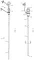
- FIG. 1illustrates a side view of a system according to an embodiment of the present disclosure.
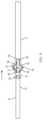
- FIG. 2illustrates a side view of the sheath shown in FIG. 1 .
- FIG. 3illustrates a cross sectional view of the sheath shown in FIG. 2 along line A-A in FIG. 2 .
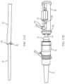
- FIG. 4illustrates a side view of the introducer shown in FIG. 1 .
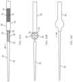
- FIG. 5illustrates a close-up side view of the distal end of the introducer shown in FIG. 4 .
- FIG. 6illustrates a close-up perspective side view of the introducer housing shown in FIG. 4 disassembled, with an inner shaft and an outer shaft shown in cross-section.
- FIG. 7illustrates a cross sectional view of the system shown in FIG. 1 along a midline of the system.
- FIG. 8 Aillustrates a close-up side view of the distal end of the sheath and the introducer shown in FIG. 1 .
- FIG. 8 Billustrates a close-up side view of the control housing shown in FIG. 1 .
- FIG. 9illustrates a close-up side view of the distal end of the sheath and the introducer shown in FIG. 1 .
- FIG. 10 Aillustrates a close-up side view of the distal end of the sheath and the introducer shown in FIG. 1 .
- FIG. 10 Billustrates a close-up side view of the control housing shown in FIG. 1 .
- FIG. 11 Aillustrates a close-up side view of the distal end of the sheath and the introducer shown in FIG. 1 .
- FIG. 11 Billustrates a close-up side view of the control housing shown in FIG. 1 .
- FIG. 12 Aillustrates a side view of the system shown in FIG. 1 .
- FIG. 12 Billustrates a schematic view of a portion of a sheath shown in FIG. 1 .
- FIG. 13 Aillustrates a cross sectional view of introducer shown in FIG. 8 A along line B-B in FIG. 8 A .
- FIG. 13 Billustrates a cross sectional view of introducer shown in FIG. 10 A along line C-C in FIG. 10 A .
- FIG. 14 Aillustrates a side view of a system according to an embodiment of the present disclosure, with a portion cut away.
- FIG. 14 Billustrates a side view of the system shown in FIG. 14 A .
- FIG. 14 Cillustrates a side view of the system shown in FIG. 14 A .
- FIG. 15 Aillustrates a side view of a portion of a system according to an embodiment of the present disclosure, with a portion cut away.
- FIG. 15 Billustrates a side view of the portion of system shown in FIG. 15 A .
- FIG. 15 Cillustrates a side view of the portion of system shown in FIG. 15 A .
- FIG. 16 Aillustrates a side view of a portion of a system according to an embodiment of the present disclosure, with a portion cut away.
- FIG. 16 Billustrates a side view of the portion of system shown in FIG. 16 A .
- FIG. 16 Cillustrates a side view of the portion of system shown in FIG. 16 A .
- FIG. 17illustrates a chart of reduced push force of the delivery apparatus through an expanded sheath of the system, according to an embodiment of the present disclosure.
- FIG. 18illustrates a side view of a delivery apparatus, according to an embodiment of the present disclosure.
- FIG. 19illustrates a flow chart of a method, according to an embodiment of the present disclosure.
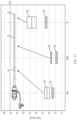
- FIG. 1illustrates an embodiment of a system 10 for introducing a delivery apparatus into a patient's vasculature.
- the system 10may include a sheath 12 and an introducer 14 .
- the introducer 14may be positioned within a lumen of the sheath 12 , as shown in FIG. 1 .
- a control housing 16may be positioned at a proximal end of the system and may include a sheath housing 18 and an introducer housing 20 .
- the sheath housing 18 and introducer housing 20may couple together, as shown in FIG. 1 .
- the sheath 12 and introducer 14are shown in an insertion configuration, for insertion together into the patient's vasculature. Upon insertion into the patient's vasculature, the introducer 14 may be withdrawn longitudinally from the sheath 12 , leaving the sheath 12 within the patient's vasculature. Features of the sheath 12 and the introducer 14 individually are discussed below, as well as the operation of the sheath 12 and introducer 14 together.
- FIG. 2illustrates the sheath 12 separated from the introducer 14 .
- the sheath 12comprises an elongate body that may have a cylindrical shape.
- the sheath 12has a distal end 22 and a proximal end 24 and a length extending from the distal end 22 to the proximal end 24 .
- the sheath 12is configured to be inserted into a patient's vasculature.
- the sheath 12may comprise an introducer sheath that is used to introduce a delivery apparatus into the patient's vasculature.
- the vasculaturemay comprise the blood vessels of the patient's body which may include the femoral artery or other vessels of the patient's body.
- the vasculaturesuch as the femoral artery, may be narrow or stiff, and may be difficult to easily insert a delivery apparatus therein.
- the delivery apparatusmay be larger than the vasculature, or may be unwieldy to penetrate through the skin or vasculature of the patient to pass therethrough by itself.
- the vasculaturemay be too fragile to receive the delivery apparatus without use of an introducer sheath.
- the sheath 12accordingly may be inserted into the patient's vasculature prior to the delivery apparatus being introduced, to provide an entryway or guide path for the delivery apparatus to introduce the delivery apparatus into the patient's vasculature. After the sheath 12 is inserted, the sheath 12 may remain positioned within and surrounded by the patient's vasculature. The delivery apparatus may then be passed through the lumen of the sheath 12 for introduction into the patient's body. The sheath 12 may remain in the vasculature until a desired time to remove the sheath 12 .
- the sheath 12may be inserted into the vasculature percutaneously or a portion of the patient's body may be surgically opened for the sheath 12 to access the vasculature.
- the delivery apparatusmay be configured in a manner such as the delivery apparatus 11 shown in FIG. 18 .
- the delivery apparatus 11may comprise a device for delivering an implant 13 , or other type of implantable device, to a patient.
- the delivery apparatus 11may comprise a catheter, and may include a steerable guide catheter 15 (also referred to as a flex catheter) and a balloon catheter 17 extending through the guide catheter 15 .
- the guide catheter 15 and the balloon catheter 17may be adapted to slide longitudinally relative to each other to facilitate delivery and positioning of the implant 13 at an implantation site in the patient's body.
- the delivery apparatus 11may comprise an endovascular catheter assembly for endovascular deployment of the implant 13 .
- the implant 13may comprise a prosthetic device, such as a prosthetic heart valve to be delivered to replace a heart valve of the patient.
- the prosthetic heart valvemay be an aortic, mitral, tricuspid, and/or pulmonary heart valve for implantation.
- the prosthetic heart valvemay be an expandable heart valve that is passed through the patient's vasculature in an undeployed configuration and then is expanded into a deployed configuration when placed in the desired position (e.g., at the heart valve to be replaced).
- the delivery apparatus 11may be configured to pass through the patient's vasculature to deliver the implant 13 to the desired location (e.g., the location of the heart valve to be replaced).
- a deployment devicesuch as the balloon of the balloon catheter 17 may deploy the heart valve in position.
- other forms of implantsmay be utilized, such as stents or filters, or diagnostic devices, among others.
- other forms of delivery apparatusesthan shown in FIG. 18 may be utilized.
- the delivery apparatus 11passes through the lumen of the sheath 12 to reach a desired position in the patient's body. As shown in FIG. 18 , the delivery apparatus 11 may pass through an opening at the proximal end of the sheath 12 (the sheath housing 18 is not shown in FIG. 18 ) for passage through the lumen of the sheath 12 and the vasculature of the patient.
- the delivery apparatus and the systems disclosed hereinmay be used in transcatheter aortic valve implantation (TAVI).
- TAVItranscatheter aortic valve implantation
- the delivery apparatus and the systems disclosed hereinmay be utilized for transarterial access, including transfemoral access, to a patient's heart.
- the sheath housing 18may be positioned at the proximal end 24 of the sheath 12 .
- the sheath housing 18may comprise a cylindrical body and may include a coupler 21 for coupling to another housing or component of the system.
- the sheath housing 18may include an internal chamber 19 (marked in FIG. 7 ) for the delivery apparatus 11 to be passed through to be delivered to the patient's vasculature.
- the sheath housing 18may be configured to remain external to the patient's vasculature when the sheath 12 is inserted therein and may be configured to remain external to the patient's skin for a percutaneous implantation of the sheath 12 .
- the sheath housing 18may be configured for a user (such as a surgeon) to grip to manipulate the sheath 12 .
- the sheath 12may include a strain relief portion 26 at the proximal end 24 of the sheath 12 .
- the strain relief portion 26may be sized larger than a proximate portion of the sheath 12 and may seal the entry point of the vasculature, to reduce the possibility of blood or other fluid being released between the exterior surface of the sheath 12 and the vasculature.
- the sheath housing 18may include a fluid port 28 for passing fluid such as blood to or from the patient's vasculature.
- Tubing 30 with a valve 31may be coupled to the fluid port 28 , for passing fluid through the fluid port 28 and for sealing flow of the fluid through the fluid port 28 .
- FIG. 3illustrates a cross sectional view of the sheath 12 along line A-A in FIG. 2 .
- the sheath 12has a lumen 32 and one or more walls surrounding the lumen 32 .
- the wallsmay include an inner tubing wall 34 that surrounds the lumen 32 and an outer tubing wall 36 that surrounds the inner tubing wall 34 .
- the inner tubing wall 34may have an interior surface that comprises the interior surface 38 of the sheath 12 .
- the inner tubing wall 34may include a thick portion 40 and a thin portion 42 .
- the inner tubing wall 34may be folded upon itself such that a fold exists at the thin portion 42 , as shown in FIG. 3 . The fold may result in a channel 44 being positioned between the inner tubing wall 34 and the outer tubing wall 36 .
- a seal 46(marked in FIG. 2 ) may be positioned along the length of the sheath 12 to prevent blood or other fluid flow from passing through the channel 44 and out of the proximal end 24 of the sheath 12 .
- the outer tubing wall 36may have an exterior surface that comprises the exterior surface 37 of the sheath 12 .
- the outer tubing wall 36may include multiple layers, including an inner layer 48 and an outer layer 50 extending around the inner layer 48 .
- Reinforcements 52may be provided in the sheath 12 .
- the reinforcements 52may comprise elongate rods that may be positioned between the inner layer 48 and the outer layer 50 of the outer tubing wall 36 and may extend along the length of the sheath 12 .
- the reinforcements 52may provide strength to the sheath 12 .
- the sheath 12may have an outer diameter 54 and an interior diameter 56 .
- the outer diameter 54may be the diameter of the exterior surface 37 of the sheath, and the interior diameter 56 may be the diameter of the interior surface 38 of the sheath 12 .
- the sheath 12may be configured to expand in a direction radially outward from the lumen 32 .
- the sheath 12may be configured to expand in a variety of manners, and may be flexible in a direction radially outward from the lumen 32 .
- the inner tubing wall 34 and the outer tubing wall 36may each be configured to expand in a direction radially outward from the lumen 32 .
- the inner tubing wall 34 and the outer tubing wall 36may both be flexible to allow for expansion in the direction radially outward from the lumen 32 .
- the inner tubing wall 34may be configured such that the thin portion 42 is more flexible than the thick portion 40 and accordingly fully or partially unfolds to expand the fold when a force is applied to the inner tubing wall 34 radially outward from the lumen 32 .
- the unfolding of the inner tubing wall 34allows the inner tubing wall 34 to expand in the direction radially outward from the lumen 32 .
- the outer tubing wall 36may be stretchable and may correspondingly expand in the direction radially outward from the lumen 32 by the force of the inner tubing wall 34 pressing against the outer tubing wall 36 .
- the expansion of the sheath 12 in the direction radially outward from the lumen 32may result in an increased size of the lumen 32 , the interior diameter 56 , and the outer diameter 54 .
- a compressible wallmay be utilized to expand the sheath 12 .
- the sheath 12may expand by the interior diameter 56 being increased in size, or both the interior diameter 56 and outer diameter 54 being increased in size.
- the sheath 12may be configured for a localized expansion, in which the expansion occurs at a location where an object is passing therethrough.
- the sheath 12may be configured to expand to allow for a relatively low-profile, or narrow outer diameter 54 , insertion into the patient's vasculature.
- the narrow outer diameter 54may be sized to fit within the patient's vasculature with relatively low insertion push force.
- the narrow outer diameter 54may correspond to a narrow interior diameter 56 .
- the narrow interior diameter 56may be too narrow to receive the delivery apparatus 11 or may result in relatively high insertion push force to be provided by the delivery apparatus 11 .
- the expansion of the sheath 12 in the direction radially outward from the lumen 32increases the interior diameter 56 of the sheath 12 and may thus reduce the insertion push force that is needed for the delivery apparatus 11 .
- the sheath 12may be elastic, and may be biased in a direction towards the lumen 32 .
- the sheath 12accordingly may attempt to contract or otherwise reduce in size.
- the reduction in sizemay occur in a variety of manners.
- the outer tubing wall 36may be elastic and configured to apply a force in a direction radially towards the lumen 32 upon being forced in a direction radially outward from the lumen 32 by the inner tubing wall 34 .
- the outer tubing wall 36upon expansion, may apply a compressive force to the inner tubing wall 34 . This compressive force may serve to reduce the size of the lumen 32 and the interior diameter 56 of the sheath 12 .
- the entirety of the sheath wallmay be elastic and biased in the direction radially towards the lumen 32 .
- other meansmay be utilized to bias the sheath 12 in the direction towards the lumen 32 .
- the sheath 12may be configured such that the elastic restoring force of the sheath 12 does not fully move the sheath 12 back to its pre-expanded size.
- the sheath 12is shown in a pre-expanded configuration.
- the sheath 12has an interior diameter 56 .
- the sheathmay be expanded by an object being passed through the lumen 32 of the sheath that has a diameter larger than the interior diameter 56 of the sheath 12 .
- the interior diameter 56will increase to a larger size (due to the larger diameter of the object).
- the outer diameter 54may also increase to a larger size.
- the sheath 12may elastically return towards the lumen 32 , but not fully back to the size or diameter shown in FIG. 3 .
- the resulting interior diameter 56 of the sheathmay be larger than the diameter in the pre-expanded configuration, but not larger that its diameter when the object is passing through.
- the resulting outer diameter 54may be larger than the diameter in the pre-expanded configuration, but not larger that its diameter when the object is passing through.
- the sheath 12may be configured for a partial return to its pre-expanded configuration and size.
- the sheath 12may be configured to be elastic (e.g., partially return to a pre-expanded configuration) to allow for a reduction in the size of the outer diameter 54 upon the delivery apparatus 11 being passed therethrough.
- the reduced size of the outer diameter 54may allow for ease of removal of the sheath 12 from the patient's vasculature and reduced stress being applied to the vasculature when the delivery apparatus 11 is not positioned within the sheath 12 .
- the introducer 14may be utilized to introduce the sheath 12 into the vasculature of the patient's body.
- the introducer 14is configured to be positioned within the lumen of the sheath 12 to introduce the sheath 12 into the vasculature of the patient's body, as shown in FIG. 1 .
- FIG. 4illustrates the introducer 14 separated from the sheath 12 .
- the introducer 14comprises an elongate body having a distal end 60 , a proximal end 62 (marked in FIG. 7 ) and a length extending from the distal end 60 to the proximal end 62 .
- the introducer 14may be configured to have a length that is greater than the length of the sheath 12 , such that a portion of the introducer 14 extends beyond the distal end 22 of the sheath 12 (marked in FIG. 2 ).
- the introducer 14may include a tip 64 .
- the tip 64may be tapered down to the distal end 60 of the introducer 14 .
- the tapered distal tip 64may be configured to extend beyond the distal end 22 of the sheath 12 when the introducer 14 is positioned within the lumen of the sheath 12 , as shown in FIGS. 1 and 7 .
- the introducer 14may include an outer shaft 66 (marked in FIGS. 5 and 7 ) that extends along a length of the introducer 14 .
- the outer shaft 66may have a proximal end 68 (marked in FIG. 7 ) and a distal end 70 and a length extending from the distal end 70 to the proximal end 68 .
- the outer shaft 66may comprise a tube extending around a portion of the introducer, such that the portion of the introducer 14 that is within the outer shaft 66 comprises an inner shaft 72 (marked in FIGS. 5 and 7 ) and such that the outer shaft 66 comprises an outer tube.
- the introducer 14may comprise a two-part shaft (inner shaft 72 and outer shaft 66 ).
- FIG. 5illustrates a close-up view of the distal end 70 of the outer shaft 66 , with a portion cut away to show the inner shaft 72 within the outer shaft 66 .
- the inner shaft 72 portionmay comprise a portion 74 of the introducer and the tip 64 may comprise a thicker portion 76 of the introducer 14 such that the portion 74 is a thin portion 74 and the portion 76 is a thick portion 76 .
- the introducer 14may transition between the inner shaft 72 portion to the thick portion 76 at a step 75 .
- a plug 78may be coupled to the introducer 14 .
- the plug 78may comprise an expandable portion of the introducer 14 .
- the plug 78accordingly may be integral with the introducer 14 .
- the plug 78may comprise a plurality of supports 80 .
- the plurality of supports 80may be separated from each other by a respective slit 82 or other form of separation between the supports 80 .
- the supports 80may comprise slats that are separated by slits 82 .
- the supports 80 and slits 82may extend longitudinally along the introducer 14 .
- the supports 80may include proximal supports 84 and distal supports 86 , each of which may be configured to pivot at pivot portions 88 of the plug 78 .
- the proximal supports 84 and distal supports 86may couple to each other at a pivot portion 90 of the plug 78 , which may be a central pivot portion 90 .
- the pivot portions 88 , 90may be unpivoted, or flattened, in the position shown in FIG. 5 .
- a distal portion of the plug 78may include additional supports 92 separated by slits 94 .
- the plug 78may be configured to be integral with the outer shaft 66 , as shown in FIG. 5 .
- the supports 80may each be integral with the outer shaft 66 .
- the slits 82 , 94may comprise slits in the outer shaft 66 .
- the plug 78may be a portion of the outer shaft 66 , and may be activated by manipulation of the outer shaft 66 .
- the plug 78may be configured to move from a first position in which the plug 78 has a first diameter to a second position in which the plug 78 has a second diameter that is greater than the first diameter.
- the plug 78is shown in FIG. 5 in a first position, in which the plug 78 is flattened, or in an unexpanded configuration or undeployed configuration.
- the supports 80extend along the longitudinal axis of the introducer 14 and around the inner shaft 72 of the introducer 14 .
- the plug 78has a diameter 96 in the first position.
- the plug 78may move to a second position, as shown in FIG.
- the plug 78in which the plug 78 is in an expanded configuration, or deployed configuration, and has a diameter 98 that is greater than the diameter 96 , and greater than the interior diameter 56 of the sheath 12 (marked in FIG. 3 ).
- the supports 80 in the second positionextend radially outward from the introducer 14 .
- the plug 78 in the first positionmay be configured to fit within the lumen 32 of the sheath 12 .
- the plug 78may have a diameter 96 that is sized to fit within the lumen 32 of the sheath 12 .
- the diameter 96may be substantially equal to or less than to the diameter 100 of the thick portion 76 of the introducer 14 (which is the outer diameter of the introducer 14 ).
- the diameter 100 of the introducer 14may be configured to be at or less than the interior diameter 56 of the sheath 12 .
- the introducer housing 20may be positioned at the proximal end of the introducer 14 .
- FIG. 6illustrates a disassembled view of the introducer housing 20 , with the outer shaft 66 and inner shaft 72 shown in cross section. An outer shaft housing 102 and an inner shaft housing 104 are shown separated from an interior chamber 106 of the introducer housing 20 .
- the introducer housing 20may be configured to couple to the sheath housing 18 .
- the introducer housing 20may be configured as a control device for controlling the introducer 14 and the plug 78 .
- the introducer housing 20may include an interior chamber 106 .
- the introducer housing 20may include a slide channel 108 and locks 103 , 105 , 107 .
- the slide channel 108may be configured as a cut-out in the body of the introducer housing 20
- the locks 103 , 105 , 107may be configured as cut-outs in the body of the introducer housing 20 in a transverse direction as the slide channel 108 .
- the introducer housing 20may include a distal end 109 and a proximal end 111 and a length extending from the distal end 109 to the proximal end 111 .
- the distal end 109may include an opening 113 that extends around a portion of the sheath housing 18 , particularly the coupler 21 (marked in FIG. 2 ).
- a securing devicesuch as a securing ring 115 may extend over the body of the introducer housing 20 at the coupler 21 to couple the introducer housing 20 to the sheath housing 18 .
- the proximal end 111 of the introducer housing 20may include an opening 117 for a guide wire 114 (marked in FIG. 7 ) to extend through.
- the introducer housing 20may be configured for a user (such as a surgeon) to grip to manipulate the introducer 14 and the plug 78 .
- the introducer housing 20may include an outer shaft housing 102 and an inner shaft housing 104 .
- the outer shaft housing 102 and the inner shaft housing 104may be positioned within the interior chamber 106 of the introducer housing 20 .
- the outer shaft housing 102 and the inner shaft housing 104may be configured to move relative to each other to control the plug 78 and separately control the outer shaft 66 and the inner shaft 72 .
- the outer shaft housing 102may couple to the proximal end 68 of the outer shaft 66 (marked in FIG. 7 ).
- the outer shaft housing 102may include a fluid port 110 for passing fluid such as blood to or from the patient's vasculature.
- Tubing 97 with a valve 99(marked in FIG. 4 ) may be coupled to the fluid port 110 for passing fluid through the fluid port 110 and for sealing flow of the fluid through the fluid port 110 .
- the outer shaft housing 102may be configured to move relative to the body of the introducer housing 20 and relative to the sheath housing 18 and the inner shaft housing 104 , such that the outer shaft housing 102 and the outer shaft 66 may move relative to the inner shaft 72 and the sheath 12 .
- the outer shaft housing 102may be configured to slide longitudinally within the interior chamber 106 of the introducer housing 20 with the fluid port 110 extending through the slide channel 108 .
- the outer shaft housing 102may also be configured to rotate within the body of the introducer housing 20 around the longitudinal axis that the outer shaft 66 extends along.
- the outer shaft housing 102may be configured to rotate around this longitudinal axis to have the fluid port 110 rotate in and out of the lock 103 and lock 105 .
- the inner shaft housing 104may couple to the proximal end 62 (marked in FIG. 7 ) of the inner shaft 72 .
- the inner shaft housing 104may include a control surface 112 that may be positioned exterior of the body of the introducer housing 20 when the inner shaft housing 104 is positioned within the interior chamber 106 of the introducer housing 20 .
- the connection between the body of the inner shaft housing 104 and the control surface 112may extend through the slide channel 108 , such that the body of the inner shaft housing 104 is within the interior chamber 106 and the control surface 112 is exterior.
- the control surface 112may be configured for a user (such as a surgeon) to manipulate to control the inner shaft 72 and the plug 78 .
- the inner shaft housing 104may be configured to move relative to the body of the introducer housing 20 and relative to the sheath housing 18 and the outer shaft housing 102 , such that the inner shaft housing 104 and the inner shaft 72 may move relative to the outer shaft 66 and the sheath 12 .
- the inner shaft housing 104may be configured to slide longitudinally within the interior chamber 106 of the introducer housing 20 .
- the inner shaft housing 104may also be configured to rotate within the body of the introducer housing 20 around the longitudinal axis that the inner shaft 72 extends along.
- the inner shaft housing 104may be configured to rotate around this longitudinal axis to have the connection between the body of the inner shaft housing 104 and the control surface 112 rotate in and out of the lock 105 and lock 107 .
- the introducer 14is configured to be inserted into, and positioned within the lumen 32 of the sheath 12 , upon the introducer 14 and sheath 12 being introduced into the patient's vasculature.
- the introducer 14preferably comprises a rigid body with sufficient strength to guide the sheath 12 into the patient's vasculature, with sufficient flexibility to allow for flexible movements of the introducer 14 and sheath 12 together.
- the tapered tip 64 of the introduceris preferably shaped to improve ease of penetration and access of the patient's vasculature by opening the interior of the vasculature as the introducer 14 and sheath 12 together are inserted into the vasculature.
- the tip 64may be configured to be soft and flexible to reduce the possibility of damaging the patient's vasculature.
- the sheath 12 and introducer 14may be configured to be held in an insertion configuration in which the sheath 12 is positioned around the introducer 14 when introduced into the patient's vasculature.
- An insertion configurationis shown in FIG. 1 .
- the sheath 12 and introducer 14may be held in position relative to each other by the coupling between the sheath housing 18 and the introducer housing 20 .
- the tip 64 of the introducer 14extends beyond the distal end 22 of the sheath 12 .
- the introducer 14is held in position relative to the sheath 12 such that a length of the introducer 14 extends beyond the distal end 22 of the sheath 12 and the plug 78 is within the lumen of the sheath 12 .
- This position of the introducer 14 and the plug 78 relative to the sheath 12may be referred to as an insertion position, for introduction into the patient's vasculature.
- the sheath 12 and introducer 14 in the insertion configurationmay be introduced into the patient's vasculature by being slid over a guide wire 114 (marked in FIG. 7 ) that has been previously introduced into the patient's vasculature.
- the sheath 12 in this configurationis preferably sized to fit within the vasculature of the patient, and has a relatively low profile, or narrow outer diameter.
- FIG. 7illustrates a cross sectional view of the system shown in FIG. 1 along a midline of the system.
- the introducer 14may include an internal channel 116 that extends along its length, from the distal end 60 of the introducer 14 to the proximal end 62 of the introducer 14 (the proximal end of the inner shaft 72 ).
- the channel 116is configured to receive a guide wire 114 that the introducer 14 extends over when the introducer 14 is inserted into the vasculature of the patient's body.
- the tip 64 of the introducer 14may couple to the inner shaft 72 portion of the introducer 14 via a threaded connection 118 .
- a threaded connection 118may be utilized.
- the outer shaft 66is shown to extend over the inner shaft 72 from the distal end 70 of the outer shaft 66 to the proximal end 68 of the outer shaft 66 .
- the plug 78is in the first position and positioned within the sheath 12 .
- the outer tubing wall 36 of the sheath 12is shown extending over the inner tubing wall 34 of the sheath 12 , which accordingly extends over the introducer 14 and the plug 78 .
- the channel 44 of the sheath 12is shown extending proximally from the distal end 22 of the sheath 12 .
- the sheath 12 at the distal end 22may be configured with a taper to allow for a smooth tapered transition between the introducer 14 and the sheath 12 at a distal opening 119 of the sheath 12 .
- the distal opening 119may be at the distal end 22 of the sheath 12 and configured for the introducer 14 and plug 78 to pass therethrough.
- the proximal end 24 of the sheath 12may couple to an outer housing 120 , or distal housing, of the sheath housing 18 .
- the outer housing 120may be threaded or otherwise coupled to an inner housing 122 , or proximal housing, of the sheath housing 18 .
- the inner housing 122may include the interior chamber 19 that may transfer fluids to or from the system, for example, via the fluid port 28 , and may receive the introducer 14 , including the inner shaft 72 and outer shaft 66 .
- a movable wall 124comprising a plurality of flaps may be positioned in the interior chamber 19 and may form a seal around the introducer 14 when the introducer 14 is positioned within the sheath 12 and passes through the movable wall 124 .
- the introducer housing 20is shown coupled to the coupler 21 .
- the introducer housing 20may be positioned over the coupler 21 .
- the securing ring 115may extend over the introducer housing 20 at the coupler 21 to couple the introducer housing 20 to the sheath housing 18 with a press fit or the like.
- the outer shaft housing 102is shown positioned within the interior chamber 106 of the introducer housing 20 .
- a seal 128may be positioned within the outer shaft housing 102 and may seal the connection between the outer shaft housing 102 and the inner shaft 72 such that fluid does not leak when the outer shaft housing 102 moves relative to the inner shaft 72 .
- the outer shaft housing 102 in FIG. 7is locked in position relative to the other components of the system.
- the locked position in FIG. 7is caused by the fluid port 110 being positioned in the lock 105 .
- the locked positionprevents the outer shaft housing 102 and the outer shaft 66 from sliding relative to other components of the system.
- the inner shaft housing 104is shown to include an internal channel 131 that allows the guide wire 114 and the proximal end 62 of the introducer 14 to pass therethrough.
- the inner shaft housing 104 in FIG. 7is locked in position relative to the other components of the system.
- the locked position in FIG. 7is caused by the connection between the body of the inner shaft housing 104 and the control surface 112 being positioned in the lock 107 (the lock 107 is shown in FIG. 6 ).
- the locked positionprevents the inner shaft housing 104 and the inner shaft 72 from sliding relative to other components of the system.
- the system shown in FIG. 7is in a configuration for insertion into the patient's vasculature.
- the componentsare preferably locked in position relative to each other such that the components do not slide or otherwise move relative to each other upon insertion, aside from the system sliding along the guide wire 114 .
- the plug 78may be activated from the first position to the second position and the introducer 14 may be withdrawn from the sheath 12 .
- Such an operationleaves the sheath 12 in position within the patient's vasculature, in position to introduce a delivery apparatus (such as delivery apparatus 11 shown in FIG. 18 ).
- FIGS. 8 A and 8 Billustrate a step in the movement of the plug 78 from the first position to the second position.
- the introducer 14 and plug 78have been moved to an advanced configuration, in an advanced position distally beyond the opening 119 of the sheath 12 .
- the introducer 14 and plug 78have slid distally relative to the sheath 12 .
- the sliding movement of the introducer 14 and plug 78may be by a defined distance.
- the introducer 14 and plug 78slide relative to the guide wire 114 (shown in FIG. 7 ).
- the plug 78preferably remains in the first position during this movement to the advanced position.
- the sheath 12does not slide within the patient's vasculature during this movement.
- the outer shaft 66may slide relative to the sheath 12 as well to move the plug 78 into the desired position.
- FIG. 13 Aa cross sectional view of the introducer 14 is shown along line B-B in FIG. 8 A .
- the plurality of supports 80are shown to extend along the inner shaft 72 and are separated by slits 82 .
- FIG. 8 AThe movement of the introducer 14 and plug 78 in FIG. 8 A may be produced by the movement of the outer shaft housing 102 and the inner shaft housing 104 relative to the body of the introducer housing 20 .
- FIG. 8 Bshows the movement of the housings 102 , 104 .
- the outer shaft housing 102has released from the lock 105 by being rotated out of the lock 105 .
- the outer shaft housing 102may rotate around the longitudinal axis that the outer shaft 66 extends along to rotate out of the lock 105 .
- the inner shaft housing 104may also rotate out of the lock 107 .
- housings 102 , 104may each slide longitudinally within the introducer housing 20 and slide distally to the distal end of the slide channel 108 .
- the housings 102 , 104may slide a defined length to correspondingly extend the introducer 14 and plug 78 the defined length from the opening 119 of the sheath 12 shown in FIG. 8 A .
- the introducer 14accordingly may be sized to have a length that is greater than the sheath 12 by at least the length of the plug 78 in the first position, to allow the plug 78 to be slid out from the end of the sheath 12 .
- the outer shaft housing 102and particularly the fluid port 110 , may rotate within the introducer housing 20 to lock into lock 103 .
- the outer shaft 66 and accordingly the plug 78may be held in position relative to the sheath 12 .
- the inner shaft 72may be able to slide proximally relative to the outer shaft 66 , the plug 78 , and the sheath 12 . This movement may be available because the inner shaft housing 104 is not locked relative to the introducer housing 20 .
- the inner shaft housing 104may slide longitudinally proximally relative to the introducer housing 20 , with the outer shaft housing 102 being locked into lock 103 , to retract the inner shaft 72 relative to the plug 78 .
- FIG. 9illustrates a view of the inner shaft 72 of the introducer 14 being partially retracted, or partially slid proximally, relative to the plug 78 .
- the plug 78is in an intermediate position between the first position (as represented in FIG. 8 A ) and the second position (as represented in FIG. 10 A ).
- the arrow shown in FIG. 9illustrates the movement of the inner shaft 72 of the introducer 14 relative to the plug 78 .
- a portion of the introducer 14for example the step 75 of the introducer 14 , may press against the plug 78 in the proximal direction to apply a force to the plug 78 .
- the force of the introducer 14 applied by the introducer 14 to the plug 78causes the plug to move from the first position to the second position.
- the force of the introducer 14 against the plug 78may cause the distal portion of the plug 78 to overlap the thick portion 76 of the introducer 14 .
- the slits 94may allow for expansion of the distal portion such that the distal portion flares open and may form an angled portion of the plug 78 tapering outward in the distal direction.
- the supports 80may bow outward from the inner shaft 72 of the introducer 14 .
- the proximal supports 84 and distal supports 86may each pivot at opposite angles relative to each other.
- the proximal supports 84 and distal supports 86may each pivot about respective pivot portions 88 , 90 .
- the inner shaft 72 of the introducer 14may continue to slide proximally relative to the sheath 12 and outer shaft 66 until the inner shaft 72 of the introducer 14 reaches a position shown in FIG. 10 A .
- the plug 78may be positioned on the introducer 14 such that the plug 78 moves from the first position to the second position at a position distal the opening 119 of the sheath 12 , and exterior of the lumen of the sheath 12 , when the introducer 14 is positioned within the lumen 32 .
- the introducer 14has continued to apply a force against the plug 78 in the proximal direction until the proximal supports 84 have overlapped the distal supports 86 .
- the distal supports 86have folded under the respective proximal supports 84 .
- the supports 80are configured to bend to move the plug 78 from the first position to the second position.
- the respective supports 80overlap upon itself in the second position.
- the supports in this configurationform a plurality of protrusions extending outward from the introducer 14 .
- the distal portion of the plug 78 that overlaps the thick portion 76 of the introducer 14forms a bump 127 that the supports 84 , 86 are positioned over, and the bump 127 supports the supports 84 , 86 to increase the diameter 98 of the plug 78 .
- the supports 84 , 86together form a conical shape tapering outward in the distal direction.
- the plug 78 in this positionhas a diameter 98 that is greater than the diameter 96 of the plug in the first position (as shown in FIG. 5 ), and is greater than the interior diameter 56 of the sheath 12 , as is marked in FIG. 3 .
- the plug 78 in this positionis in a deployed configuration, or expanded configuration.
- the plug 78 in the second positionextends radially outward from the introducer 14 .
- the plug 78 in the second positionhas a length that is less than the length of the sheath 12 and is configured to slide within the lumen 32 in a direction from the distal end 22 of the sheath 12 towards the proximal end 24 of the sheath 12 to expand the sheath 12 in a direction radially outward from the lumen 32 .
- the length of the plug 78 in the second positionmay, in one embodiment, be less than 2% the length of the sheath 12 .
- the length of the plug 78 in the second positionmay in one embodiment be less than 5% the length of the sheath 12 .
- the length of the plug 78 in the second positionmay in one embodiment be less than 10% the length of the sheath 12 .
- the length of the plug 78 in the second positionin other embodiments may be less than 20%, 30%, 40% or 50% the length of the sheath 12 , among other lengths.
- the plug 78may be positioned on the introducer 14 such that the entirety of the plug 78 in the second position is closer to the distal end 60 of the introducer 14 than the proximal end 62 of the introducer 14 .
- FIG. 13 Ba cross sectional view of the introducer 14 is shown along line C-C in FIG. 10 A .
- the plurality of supports 80are shown to extend outward radially from the inner shaft 72 .
- the number of supports 80is shown to be six in FIG. 13 B , however, in other embodiments the number may be greater or lesser. In one embodiment, one support may be utilized.
- FIG. 10 Billustrates the position of the outer shaft housing 102 and the inner shaft housing 104 relative to the introducer housing 20 when the plug 78 is in the position shown in FIG. 10 A .
- the introducer housing 20remains coupled to the sheath housing 18 .
- the outer shaft housing 102remains locked in the lock 103 .
- the inner shaft housing 104has slid proximally relative to the outer shaft housing 102 and has been placed into lock 105 by being rotated into lock 105 .
- the distance between the outer shaft housing 102 and the inner shaft housing 104may be a defined distance, defining a relative distance of movement between the inner shaft 72 of the introducer 14 and the plug 78 .
- the introducer housing 20may be released from the sheath housing 18 .
- the securing devicesuch as the securing ring 115 may be released and the introducer housing 20 may be pulled proximally from the sheath housing 18 .
- the plug 78may enter the opening 119 of the sheath 12 and slide relative to the sheath 12 within the lumen of the sheath 12 .
- FIG. 11 Aillustrates the plug 78 and introducer 14 being slid proximally within the lumen of the sheath 12 .
- the plug 78has entered the opening 119 of the sheath 12 .
- FIG. 11 Billustrates the configuration of the introducer housing 20 in which the introducer housing 20 is released from the sheath housing 18 and moved proximally. The movement of the introducer housing 20 retracts or withdraws the introducer 14 from the sheath 12 , while leaving the sheath 12 in place within the patient's vasculature.
- the increased diameter of the plug 78 in the second position, as the plug 78 is slid proximally through the sheath's 12 lumencauses the sheath 12 to expand.
- the interior diameter 56 and lumen 32 (marked in FIG. 3 ) of the sheath 12are increased by the radial pressing force applied by the plug 78 to the interior surface 38 of the sheath 12 (also marked in FIG. 3 ).
- the plug 78preferably has a length that is less than the length of the sheath 12 , such that as the plug 78 is slid proximally through the lumen of the sheath 12 , a transient expansion of the sheath 12 occurs. Thus, only a portion of the sheath 12 has a force applied to it and has a localized expansion caused by the plug 78 at a given moment.
- the plug 78may be coupled to the introducer 14 such that withdrawal of the introducer 14 through the lumen 32 in the proximal direction causes the plug 78 to enter the opening 119 of the sheath 12 and slide within the lumen 32 in the proximal direction to transiently expand the sheath 12 in the direction radially outward from the lumen 32 .
- the transient force to a portion of the sheath 12allows for a lesser force to be applied to the sheath 12 than if the entirety of the sheath 12 were expanded at once.
- the sliding motion of the plug 78reduces static friction that may exist between the plug 78 and the interior surface of the sheath 12 .
- the sliding motionalso reduces the possibility of the plug 78 becoming stuck in the lumen, due to the kinetic energy provided to the plug 78 and the reduction of adhesive forces that may exist between the outer surface of the plug 78 and the interior surface of the sheath if the plug 78 were deployed within the lumen.
- FIG. 12 Aillustrates the transient expansion of the sheath 12 .
- the plug 78is being slid proximally relative to the sheath 12 .
- the location of the plug 78 within the sheathis marked in FIG. 12 A as reference number 129 .
- the plug 78may expand the sheath 12 at the position of the plug 78 and may leave an increased size in the sheath 12 in the distal portion of the sheath 12 .
- FIG. 12 Billustrates a representation of the movement of the plug 78 within the sheath 12 .
- the plug 78has not yet passed through the proximal portion of the sheath 12 marked as portion 130 .
- the plug 78is within the portion of the sheath 12 marked as portion 132 .
- the plug 78has passed through the portion of the sheath 12 marked as portion 134 .
- the diameter of the sheath 12 at portion 132is larger than in portion 130 because the plug 78 has not yet passed through portion 130 .
- the diameter of the sheath 12 at portion 134may be less than the diameter at portion 132 because the sheath may be elastic and biased in a direction radially towards the lumen.
- the plug 78accordingly may be configured to transiently expand a distal portion of the sheath 12 , and then a central portion of the sheath 12 , and then a proximal portion of the sheath 12 in successive order, rather than expanding a distal, central, and proximal portion of the sheath 12 all at one time.
- the plug 78may be sized or have a length relative to the length of the sheath 12 to only expand a portion of the sheath 12 at one time.
- the sheath 12may be configured to partially return to a pre-expanded configuration, as discussed previously.
- the difference in diameter between portion 134 and portion 130may decrease the insertion push force of a delivery apparatus inserted through the sheath 12 after the introducer 14 and plug 78 have been removed from the sheath 12 .
- the plug 78 and introducer 14may continue to be withdrawn from the sheath 12 until completely removed from the lumen of the sheath 12 .
- a delivery apparatussuch as the apparatus 11 shown in FIG. 18 may be inserted into the sheath 12 in a distal direction with a reduced pushing force due to the expanded lumen size.
- the systemallows for insertion of the sheath 12 and the introducer 14 into the patient's vasculature with a relatively low-profile, or narrow outer diameter.
- the plug 78serves to expand the sheath 12 , providing a larger lumen 32 size and larger interior diameter 56 .
- the sheath 12may partially return to a pre-expanded configuration upon the plug passing therethrough (as marked as portion 134 in FIG. 12 B ), however, the enhanced size of the sheath 12 nonetheless reduces insertion push force required for the delivery apparatus to be inserted through the sheath 12 .
- the sheath 12accordingly may be preconditioned for introduction of the delivery apparatus via a plug 78 integrated with the introducer 14 .
- the systemprovides benefits over prior methods of sheath expansion.
- prior methodsonce the introducer (without a plug) is removed from the sheath, one or more dilator rods may be inserted through the sheath in the distal direction to progressively expand the size of the sheath.
- These prior methodsmay include multiple steps (e.g., insert sheath and introducer, remove introducer, insert and remove multiple dilator rods) before insertion of the delivery apparatus.
- the systemmay alleviate these issues by allowing removal of the introducer with the expanded plug to expand the sheath, without multiple dilator rods needing to be inserted into the sheath. The system may thus provide a reduced number of steps during a medical procedure.
- the delivery apparatusis simply pushed through the sheath without the sheath being pre-expanded by a dilator rod or otherwise.
- FIG. 17illustrates a chart of reduced push force of the delivery apparatus through an expanded sheath 12 of the system.
- the vertical axis of the chartdisplays push force in Newtons.
- the horizontal axiscorresponds to select portions of the sheath 12 (the seal 46 , the body of the sheath 12 between the seal and the tip, and the tip at the distal end 22 of the sheath 12 ).
- the lower bars 136 , 138 , 140 in the chartcorrespond to the push force required for a delivery apparatus through a sheath that has been pre-expanded according to the systems, apparatuses, and methods of the present disclosure.
- the bar 136corresponds to the push force required at the seal 46 .
- the bar 138corresponds to the push force required through the body of the sheath 12 between the seal and the tip.
- the bar 140corresponds to the push force required through the tip at the distal end 22 of the sheath 12 .
- the upper bars 142 , 144 , 146 in the chartcorrespond to the push force required for a delivery apparatus through an expandable sheath that has not been pre-expanded according to the present disclosure.
- the bar 142corresponds to the push force required at a seal of the unexpanded sheath.
- the bar 144corresponds to the push force required through the body of the unexpanded sheath between the seal and the tip.
- the bar 146corresponds to the push force required through the tip at a distal end of the unexpanded sheath.
- the push forceis shown to reduce for the pre-expanded sheath according to the systems, apparatuses, and methods of the present disclosure.
- the push force at the seal 46is approximately 15% less for the pre-expanded sheath according to the present disclosure (about 18N versus 21N).
- the push force through the body of the unexpanded sheath between the seal and the tipis approximately 18% less for the pre-expanded sheath according to the present disclosure (about 15.5N versus 19N).
- the push force at the tip at a distal end of the unexpanded sheathis approximately 27% less for the pre-expanded sheath according to the present disclosure (about 22.5N versus 31N).
- the systems, apparatuses, and methods of the present disclosuremay result in a reduced push force for a delivery apparatus, as well as reducing a number of steps performed during a medical procedure, among other beneficial results.
- FIGS. 14 A- 16 Cillustrate variations of embodiments of systems for introducing a delivery apparatus into a patient's vasculature.
- the features of the embodiments of FIGS. 14 A- 16 Cmay be utilized with or applied to the embodiments of FIGS. 1 - 13 B
- the features of the embodiments of FIGS. 1 - 13 Bmay be utilized with or applied to the embodiments of FIGS. 14 A- 16 C .
- FIGS. 14 A , B, and Cillustrate an embodiment of a system 148 in which the plug 150 comprises an inflatable body.
- the plug 150may comprise an expandable portion of the introducer 154 that is coupled to the introducer 154 .
- the systemincludes a sheath 152 , and an introducer 154 .
- the sheath 152may be configured similarly as the sheath 12 in the embodiments of FIGS. 1 - 13 B .
- the systemmay include a control housing 156 that may be positioned at a proximal end of the system and may include a sheath housing 158 and an introducer housing 160 .
- a fluid port 162may couple to the sheath housing 158 for passing fluid through the sheath 152 .
- Tubing 164may be coupled to the fluid port 162 for passing fluid through the fluid port 162 , and may include a valve for sealing flow of the fluid through the fluid port 162 .
- a fluid port 166may couple to the introducer housing 160 for passing fluid through the introducer 154 and to the plug 150 .
- Tubing 168may be coupled to the fluid port 166 for passing fluid through the fluid port 166 , and may include a valve for sealing flow of the fluid through the fluid port 166 .
- the sheath 152 and introducer 154may be inserted into the patient's vasculature in a similar manner as the system discussed in regard to FIGS. 1 - 13 B .
- FIG. 14 Aillustrates the system in an insertion configuration, in which the introducer 154 is positioned within the sheath 152 and the plug 150 and introducer 154 are in an insertion position within the sheath 152 .
- the plug 150is flattened, or in an unexpanded configuration or undeployed configuration, within the sheath 152 .
- the sheath housing 158 and introducer housing 160may be locked in position relative to each other to lock the corresponding sheath 152 and introducer 154 in position relative to each other and to secure the plug 150 within the lumen of the sheath 152 .
- the introducer 154may include an internal lumen 169 configured to convey a fluid or other material to or from the plug 150 .
- the internal lumen 169may be utilized to inflate the plug 150 with fluid, which may be provided by the fluid port 166 and tubing 168 .
- the introducer 154may also include an internal channel 155 , similar to the channel 116 of the introducer 14 , for receiving a guide wire.
- FIG. 14 Billustrates the system in an advanced configuration, in which the introducer is advanced distally through the sheath 152 and the plug 150 is exterior of the sheath 152 .
- the plug 150 and introducer 154are in an advanced position distal of the sheath 152 .
- the plug 150is flattened, or in an unexpanded configuration or undeployed configuration.
- the plug 150may be in the first position, which may be a deflated state of the plug 150 .
- the introducer housing 160may be advanced distally towards the sheath housing 158 to advance and expose the plug 150 .
- the plug 150may be inflated to move to the second position and increase the diameter of the plug 150 .
- FIG. 14 Cillustrates the plug 150 inflated to the second position, or the expanded configuration, or deployed configuration.
- the plug 150 in the second positionhas a length that is less than the length of the sheath 152 and has a diameter that is larger than the interior diameter of the sheath 152 .
- the plug 150may extend radially outward from the introducer 154 .
- the plug 150may comprise an inflatable body such as a balloon.
- the plug 150may have a tapered shape that tapers outward from a proximal portion of the plug 150 to a distal portion of the plug 150 .
- the plug 150may have a conical shape to ease entry into the sheath 152 when the plug 150 is pulled proximally.
- the plug 150may be activated to the second position by being inflated via fluid passing through the fluid port 166 .
- the plug 150may be pulled through the sheath 152 in a similar manner as discussed in regard to FIGS. 1 - 13 B .
- the plug 150when retracted or withdrawn through the sheath 152 serves to expand the sheath 152 in a similar manner as discussed in regard to FIGS. 1 - 13 B .
- a transient expansionmay result, as discussed in regard to the embodiments of FIGS. 1 - 13 B .
- FIGS. 15 A , B, and Cillustrate an embodiment of a system in which the plug 170 comprises a bellows structure.
- the systemincludes a sheath 172 and an introducer 174 .
- the sheath 172may be configured similarly as the sheath 12 in the embodiments of FIGS. 1 - 13 B .
- the plug 170may comprise an expandable portion of the introducer 174 that is coupled to the introducer 174 .
- the systemmay also include a control housing positioned at a proximal end of the system and may include a sheath housing and an introducer housing in a similar manner as discussed in regard to FIGS. 1 - 13 B .
- FIG. 15 Aillustrates a close-up view of the distal end 176 of the sheath 172 , with a portion cut-away.
- the introducer 174may include an inner shaft 171 and an outer shaft 173 in a similar manner as discussed in regard to FIGS. 1 - 13 B .
- the inner shaft 171may include an internal channel 175 , similar to the channel 116 of the introducer 14 , for receiving a guide wire.
- the plug 170may be integral with the outer shaft 173 .
- the introducer 174may include a thicker portion 177 coupled to the thinner portion (represented by inner shaft 171 ) at a step 179 .
- the plug 170may comprise a plurality of supports 178 separated by respective pivot portions 180 .
- the supports 178may comprise walls and the pivot portions 180 may comprise creases between the walls.
- the supports 178may be coupled to the outer shaft 173 of the introducer 174 in a similar manner as the supports 80 of the plug 78 in FIGS. 1 - 13 B .
- the introducer 174 and plug 170may be positioned within the lumen of the sheath 172 in an insertion configuration, for insertion together into the patient's vasculature.
- the plug 170 and introducer 174may be in an insertion position within the sheath 172 .
- the plug 170may be flattened, or in an unexpanded configuration or undeployed configuration.
- the plug 170may be in the first position.
- FIG. 15 Aillustrates the system in the advanced configuration.
- the introducer 174 and plug 170may move to an advanced position, distal of the distal end 176 of the sheath 172 in a similar manner as discussed in regard to the embodiments of FIGS. 1 - 13 B .
- the plug 170is positioned exterior of the lumen of the sheath 172 .
- the plug 170remains in the first position, and is flattened or in an undeployed or unexpanded configuration.
- FIG. 15 Billustrates the plug 170 in the second position, or in an expanded configuration, or deployed configuration.
- the plug 170has compressed such that the supports 178 , in the form of walls, bend to increase the diameter of the plug 170 .
- the supports 178bend to move the plug 170 from the first position to the second position.
- the supports 178extend radially outward from the introducer 174 .
- the extension of the supports 178 outward from the introducer 174increases the diameter of the plug 170 to be greater than the interior diameter of the sheath 172 .
- the plug 170may be activated from the first position to the second position by the force of the thicker portion 177 or step 179 against the plug 170 , in a similar manner as discussed in regard to the embodiments of FIGS. 1 - 13 B .
- the plug 170 in the second positionhas a length that is less than the length of the sheath 172 .
- FIG. 15 Cillustrates the plug 170 retracted or withdrawn through the sheath 172 .
- the plug 170may be pulled through the sheath 172 in a similar manner as discussed in regard to FIGS. 1 - 13 B .
- the plug 170when pulled through the sheath 172 serves to expand the sheath 172 in a similar manner as discussed in regard to FIGS. 1 - 13 B .
- a transient expansionmay result, as discussed in regard to the embodiments of FIGS. 1 - 13 B .
- FIGS. 16 A , B, and Cillustrate an embodiment of a system in which the plug 182 comprises a self-expanding structure.
- the systemincludes a sheath 184 and an introducer 186 .
- the sheath 184may be configured similarly as the sheath 12 in the embodiments of FIGS. 1 - 13 B .
- the plug 182may comprise an expandable portion of the introducer 186 that is coupled to the introducer 186 .
- the systemmay also include a control housing positioned at a proximal end of the system and may include a sheath housing and an introducer housing in a similar manner as discussed in regard to FIGS. 1 - 13 B .
- FIG. 16 Aillustrates a close-up view of the distal end 188 of the sheath 184 , with a portion cut-away.
- the introducer 186may include an inner shaft 190 and an outer shaft 192 in a similar manner as discussed in regard to FIGS. 1 - 13 B .
- the inner shaft 190may include an internal channel 191 , similar to the channel 116 of the introducer 14 , for receiving a guide wire.
- the plug 182may be integral with the outer shaft 192 .
- the introducer 186may include a thicker portion 194 coupled to the thinner portion (represented by inner shaft 190 ) at a step 196 .
- the plug 182may comprises a plurality of supports 198 slidably disposed along the inner shaft 190 .
- the supports 198may comprise arms and may be made of a self-expanding material such as nitinol.
- the self-expanding materialmay be configured to automatically expand upon being moved exterior of the lumen of the sheath 184 .
- Nitinolfor example, may respond to the patient's body heat to transform into an expanded configuration upon being moved exterior of the lumen of the sheath 184 .
- the supports 198may be coupled to the outer shaft 192 of the introducer 186 in a similar manner as the supports 80 of the plug 78 in FIGS. 1 - 13 B .
- the introducer 186 and plug 182may be positioned within the lumen of the sheath 184 in an insertion configuration, for insertion together into the patient's vasculature.
- the plug 182 and introducer 186may be in an insertion position within the sheath 184 .
- the plug 182may be flattened, or in an unexpanded configuration or undeployed configuration.
- the plug 182may be in the first position.
- FIG. 16 Aillustrates the system in the advanced configuration.
- the introducer 186 and plug 182may be moved to an advanced position distal of the distal end 188 of the sheath 184 in a similar manner as discussed in regard to the embodiments of FIGS. 1 - 13 B .
- the plug 182is positioned exterior of the lumen of the sheath 184 .
- the plug 182remains in the first position, and is flattened or in an undeployed or unexpanded configuration.
- FIG. 16 Billustrates the plug 182 in the second position, or in an expanded configuration, or deployed configuration.
- the supports 198 of the plug 182have self-expanded to a larger configuration outward from the introducer 186 to increase the diameter of the plug 182 to be greater than the interior diameter of the sheath 184 .
- the supports 198extend radially outward from the introducer 186 .
- the supports 198bend to move the plug 182 from the first position to the second position.
- the plug 182 in the second positionhas a length that is less than the length of the sheath 184 .
- the plug 182may be activated from the first position to the second position by being moved exterior of the lumen of the sheath 184 , and the plug 182 may self-expand to the second position.
- FIG. 16 Cillustrates the plug 182 retracted or withdrawn through the sheath 184 .
- the plug 182may be pulled through the sheath 184 in a similar manner as discussed in regard to FIGS. 1 - 13 B .
- the plug 182when pulled through the sheath 184 serves to expand the sheath 184 in a similar manner as discussed in regard to FIGS. 1 - 13 B .
- a transient expansionmay result, as discussed in regard to the embodiments of FIGS. 1 - 13 B .
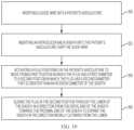
- FIG. 19illustrates a method that may utilize the systems and apparatuses disclosed herein.
- the methodmay comprise a method of pre-conditioning a sheath for introduction of a delivery apparatus therethrough.
- the methodmay first include a step 200 of inserting a guide wire into a patient's vasculature.
- the stepmay include accessing the patient's vasculature and passing the guide wire therein until reaching the desired position within the patient's body.
- the methodmay then include a step 202 of inserting an introducer and a sheath into the patient's vasculature over the guide wire.
- the introducer and sheathmay be configured as the embodiments of the introducers and sheaths disclosed herein.
- the sheathmay extend around the introducer and may have a distal end and a proximal end and may have a lumen, and may be configured to expand in a direction radially outward from the lumen.
- the introducermay be positioned within the lumen of the sheath upon introduction, as disclosed herein.
- the sheath and introducermay be in an insertion configuration, with the introducer and plug, or expandable portion of the introducer, in an insertion position within the lumen of the sheath.
- the plug, or expandable portion of the introducermay be flattened or in an unexpanded or undeployed configuration within the lumen of the sheath upon insertion into the patient's vasculature.
- the methodmay include a step 204 of activating the plug, or expandable portion of the introducer, positioned within the patient's vasculature to move from a first position in which the plug has a first diameter to a second position in which the plug has a second diameter that is greater than an interior diameter of the sheath.
- the step of activatingmay include any of the methods disclosed herein, including advancing the plug, or expandable portion of the introducer, beyond the distal end of the sheath and pressing against the plug, inflating the plug, or simply extending the plug beyond the distal end of the sheath in a self-expanding embodiment (e.g., an embodiment using nitinol or the like), including other methods of activation.
- the methodmay include a step 206 of sliding the plug, or the expandable portion of the introducer, through the lumen of the sheath in a direction from the distal end of the sheath towards the proximal end of the sheath to expand the sheath in the direction radially outward from the lumen.
- the plug, or expandable portion of the introduceris in the second position with a diameter greater than the interior diameter of the sheath.
- the expansion of the sheathmay comprise a transient expansion, as disclosed herein.
- Additional stepsmay include introducing a delivery apparatus through the pre-expanded sheath, in a manner disclosed herein.
- the embodiments of systems, apparatuses, and methods disclosed hereinmay be modified or combined as desired.
- the sheaths disclosed hereinmay have a variety of shapes, including a cylindrical cross section, rectangular cross section, or other shape, for example a hexagonal cross section or other shape.
- the introducers disclosed hereinmay have a variety of shapes with a different structure than disclosed herein.
- the means for activating the plugmay be varied, for example the configuration of locks in the introducer housing may be varied or a different apparatus for activating the plug may be used.
- the configuration of the housings disclosed hereinmay be varied, or may be excluded in certain embodiments.
- any of the systems, apparatuses, and methods disclosed hereinmay be modified to utilize self-expanding materials or structures, such as nitinol.
- the plug 78 described in regard to FIGS. 1 - 13 Bmay be modified to be self-expanding, and utilize a material such as nitinol.
- the materials used in the sheaths and introducers and plugs disclosed hereinmay be varied as desired.
- the introducersmay be made of HDPE or LDPE or other materials as desired.
- the plugs, or expandable portions of the introducersmay be made of nylon, HDPE, a shape memory material (such as nitinol), ABS, PEBAX, or urethane, or other materials.
- the sizes of the sheaths utilizedmay be varied as desired. In one embodiment a 14-F sheath, with a 5.9 millimeter outer diameter may be utilized. In other embodiments, a lesser or greater outer diameter may be utilized. A 16-F, 18-F, or 20-F size sheath, or other size sheath may be utilized as desired. In one embodiment, a sheath having a length of 36 centimeters, or a lesser or greater length may be utilized.
- sheathsmay be implemented independently of the introducers, which may also be implemented independently of the plugs.
- the various apparatuses of the systemmay be implemented independently.
Landscapes
- Health & Medical Sciences (AREA)
- Life Sciences & Earth Sciences (AREA)
- Cardiology (AREA)
- Biomedical Technology (AREA)
- Engineering & Computer Science (AREA)
- Animal Behavior & Ethology (AREA)
- Heart & Thoracic Surgery (AREA)
- General Health & Medical Sciences (AREA)
- Public Health (AREA)
- Veterinary Medicine (AREA)
- Surgery (AREA)
- Transplantation (AREA)
- Oral & Maxillofacial Surgery (AREA)
- Vascular Medicine (AREA)
- Anesthesiology (AREA)
- Hematology (AREA)
- Pulmonology (AREA)
- Biophysics (AREA)
- Medical Informatics (AREA)
- Molecular Biology (AREA)
- Nuclear Medicine, Radiotherapy & Molecular Imaging (AREA)
- Media Introduction/Drainage Providing Device (AREA)
Abstract
Description
Claims (20)
Priority Applications (2)
| Application Number | Priority Date | Filing Date | Title |
|---|---|---|---|
| US16/690,593US11779728B2 (en) | 2018-11-01 | 2019-11-21 | Introducer sheath with expandable introducer |
| US18/375,902US12409297B2 (en) | 2018-11-01 | 2023-10-02 | Introducer sheath with expandable introducer |
Applications Claiming Priority (3)
| Application Number | Priority Date | Filing Date | Title |
|---|---|---|---|
| US201862754516P | 2018-11-01 | 2018-11-01 | |
| PCT/US2019/058371WO2020092253A2 (en) | 2018-11-01 | 2019-10-28 | Introducer sheath with expandable introducer |
| US16/690,593US11779728B2 (en) | 2018-11-01 | 2019-11-21 | Introducer sheath with expandable introducer |
Related Parent Applications (1)
| Application Number | Title | Priority Date | Filing Date |
|---|---|---|---|
| PCT/US2019/058371ContinuationWO2020092253A2 (en) | 2018-11-01 | 2019-10-28 | Introducer sheath with expandable introducer |
Related Child Applications (1)
| Application Number | Title | Priority Date | Filing Date |
|---|---|---|---|
| US18/375,902ContinuationUS12409297B2 (en) | 2018-11-01 | 2023-10-02 | Introducer sheath with expandable introducer |
Publications (2)
| Publication Number | Publication Date |
|---|---|
| US20200139079A1 US20200139079A1 (en) | 2020-05-07 |
| US11779728B2true US11779728B2 (en) | 2023-10-10 |
Family
ID=70458339
Family Applications (1)
| Application Number | Title | Priority Date | Filing Date |
|---|---|---|---|
| US16/690,593Active2040-08-15US11779728B2 (en) | 2018-11-01 | 2019-11-21 | Introducer sheath with expandable introducer |
Country Status (1)
| Country | Link |
|---|---|
| US (1) | US11779728B2 (en) |
Cited By (2)
| Publication number | Priority date | Publication date | Assignee | Title |
|---|---|---|---|---|
| US20240024624A1 (en)* | 2018-11-01 | 2024-01-25 | Edwards Lifesciences Corporation | Introducer sheath with expandable introducer |
| WO2025158334A1 (en)* | 2024-01-24 | 2025-07-31 | Medtronic, Inc. | Devices and methods for loading a transfer sleeve over a capsule of a medical device delivery system |
Families Citing this family (5)
| Publication number | Priority date | Publication date | Assignee | Title |
|---|---|---|---|---|
| US10912919B2 (en) | 2017-01-23 | 2021-02-09 | Edwards Lifesciences Corporation | Expandable sheath |
| WO2020123281A1 (en)* | 2018-12-12 | 2020-06-18 | Edwards Lifesciences Corporation | Combined introducer and expandable sheath |
| AU2021376271A1 (en)* | 2020-11-04 | 2023-06-08 | Edwards Lifesciences Corporation | Systems, tools, and methods for delivering implants and catheters for a prosthetic valve |
| WO2022261372A1 (en)* | 2021-06-10 | 2022-12-15 | Edwards Lifesciences Corporation | Expandable sheath for introducting an endovascular delivery device into a body |
| WO2024263844A1 (en)* | 2023-06-22 | 2024-12-26 | Edwards Lifesciences Corporation | Pre-dilated expandable sheath with protective cover |
Citations (139)
| Publication number | Priority date | Publication date | Assignee | Title |
|---|---|---|---|---|
| US519297A (en) | 1894-05-01 | Bauer | ||
| US4035849A (en) | 1975-11-17 | 1977-07-19 | William W. Angell | Heart valve stent and process for preparing a stented heart valve prosthesis |
| US4592340A (en) | 1984-05-02 | 1986-06-03 | Boyles Paul W | Artificial catheter means |
| US4955895A (en) | 1986-12-23 | 1990-09-11 | Terumo Kabushiki Kaisha | Vasodilating catheter |
| US4994077A (en) | 1989-04-21 | 1991-02-19 | Dobben Richard L | Artificial heart valve for implantation in a blood vessel |
| US5059177A (en) | 1990-04-19 | 1991-10-22 | Cordis Corporation | Triple lumen balloon catheter |
| WO1991017720A1 (en) | 1990-05-18 | 1991-11-28 | Henning Rud Andersen | A valve prosthesis for implantation in the body and a catheter for implantating such valve prosthesis |
| US5176698A (en) | 1991-01-09 | 1993-01-05 | Scimed Life Systems, Inc. | Vented dilatation cathether and method for venting |
| US5192297A (en) | 1991-12-31 | 1993-03-09 | Medtronic, Inc. | Apparatus and method for placement and implantation of a stent |
| US5266073A (en) | 1987-12-08 | 1993-11-30 | Wall W Henry | Angioplasty stent |
| US5325845A (en) | 1992-06-08 | 1994-07-05 | Adair Edwin Lloyd | Steerable sheath for use with selected removable optical catheter |
| US5358496A (en) | 1991-10-18 | 1994-10-25 | Ethicon, Inc. | Endoscopic tissue manipulator |
| US5411552A (en) | 1990-05-18 | 1995-05-02 | Andersen; Henning R. | Valve prothesis for implantation in the body and a catheter for implanting such valve prothesis |
| US5421832A (en)* | 1989-12-13 | 1995-06-06 | Lefebvre; Jean-Marie | Filter-catheter and method of manufacturing same |
| US5554185A (en) | 1994-07-18 | 1996-09-10 | Block; Peter C. | Inflatable prosthetic cardiovascular valve for percutaneous transluminal implantation of same |
| US5591195A (en) | 1995-10-30 | 1997-01-07 | Taheri; Syde | Apparatus and method for engrafting a blood vessel |
| US5599305A (en) | 1994-10-24 | 1997-02-04 | Cardiovascular Concepts, Inc. | Large-diameter introducer sheath having hemostasis valve and removable steering mechanism |
| DE19532846A1 (en) | 1995-09-06 | 1997-03-13 | Georg Dr Berg | Valve for use in heart |
| US5632760A (en) | 1994-10-20 | 1997-05-27 | Cordis Corporation | Balloon catheter for stent implantation |
| US5639274A (en) | 1995-06-02 | 1997-06-17 | Fischell; Robert E. | Integrated catheter system for balloon angioplasty and stent delivery |
| US5728068A (en) | 1994-06-14 | 1998-03-17 | Cordis Corporation | Multi-purpose balloon catheter |
| US5749890A (en) | 1996-12-03 | 1998-05-12 | Shaknovich; Alexander | Method and system for stent placement in ostial lesions |
| EP0850607A1 (en) | 1996-12-31 | 1998-07-01 | Cordis Corporation | Valve prosthesis for implantation in body channels |
| US5782809A (en) | 1994-06-20 | 1998-07-21 | Terumo Kabushiki Kaisha | Vascular catheter |
| US5824044A (en) | 1994-05-12 | 1998-10-20 | Endovascular Technologies, Inc. | Bifurcated multicapsule intraluminal grafting system |
| WO1999012483A1 (en) | 1997-09-11 | 1999-03-18 | Genzyme Corporation | Articulating endoscopic implant rotator surgical apparatus and method for using same |
| US5908405A (en) | 1994-10-28 | 1999-06-01 | Intella Interventional Systems, Inc. | Low profile balloon-on-a-wire catheter with shapeable and/or deflectable tip and method |
| US5916147A (en) | 1997-09-22 | 1999-06-29 | Boury; Harb N. | Selectively manipulable catheter |
| US5961536A (en) | 1997-10-14 | 1999-10-05 | Scimed Life Systems, Inc. | Catheter having a variable length balloon and method of using the same |
| US5968068A (en) | 1996-09-12 | 1999-10-19 | Baxter International Inc. | Endovascular delivery system |
| US6019777A (en) | 1997-04-21 | 2000-02-01 | Advanced Cardiovascular Systems, Inc. | Catheter and method for a stent delivery system |
| US6027510A (en) | 1997-12-08 | 2000-02-22 | Inflow Dynamics Inc. | Stent delivery system |
| US6033381A (en) | 1989-09-06 | 2000-03-07 | Boston Scientific Corporation | Angioplasty balloon catheter and adaptor |
| DE19907646A1 (en) | 1999-02-23 | 2000-08-24 | Georg Berg | Valve for blood vessels uses flap holders and counterpart holders on stent to latch together in place and all channeled for guide wire. |
| US6143016A (en) | 1997-04-21 | 2000-11-07 | Advanced Cardiovascular Systems, Inc. | Sheath and method of use for a stent delivery system |
| US6174327B1 (en) | 1998-02-27 | 2001-01-16 | Scimed Life Systems, Inc. | Stent deployment apparatus and method |
| US6217585B1 (en) | 1996-08-16 | 2001-04-17 | Converge Medical, Inc. | Mechanical stent and graft delivery system |
| US20010002445A1 (en) | 1997-12-29 | 2001-05-31 | The Cleveland Clinic Foundation | Bioprosthetic cardiovascular valve system |
| US6251092B1 (en) | 1997-12-30 | 2001-06-26 | Medtronic, Inc. | Deflectable guiding catheter |
| US20010007082A1 (en) | 1996-08-23 | 2001-07-05 | Dusbabek Andrew J. | Stent delivery system having stent securement apparatus |
| WO2001049213A2 (en) | 1999-12-31 | 2001-07-12 | Advanced Bio Prosthetic Surfaces, Ltd. | Endoluminal cardiac and venous valve prostheses and methods of manufacture and delivery thereof |
| WO2001054625A1 (en) | 2000-01-31 | 2001-08-02 | Cook Biotech Incorporated | Stent valves and uses of same |
| WO2001076510A2 (en) | 2000-04-06 | 2001-10-18 | Edwards Lifesciences Corporation | Minimally-invasive heart valves and methods of use |
| US20020032481A1 (en) | 2000-09-12 | 2002-03-14 | Shlomo Gabbay | Heart valve prosthesis and sutureless implantation of a heart valve prosthesis |
| WO2002022054A1 (en) | 2000-09-12 | 2002-03-21 | Gabbay S | Valvular prosthesis and method of using same |
| FR2815844A1 (en) | 2000-10-31 | 2002-05-03 | Jacques Seguin | TUBULAR SUPPORT FOR SETTING UP, BY PERCUTANEOUS, OF A REPLACEMENT HEART VALVE |
| US6383171B1 (en) | 1999-10-12 | 2002-05-07 | Allan Will | Methods and devices for protecting a passageway in a body when advancing devices through the passageway |
| US20020058995A1 (en) | 1991-07-16 | 2002-05-16 | Stevens John H. | Endovascular aortic valve replacement |
| WO2002047575A2 (en) | 2000-12-15 | 2002-06-20 | Angiomed Gmbh & Co. Medizintechnik Kg | Stent with valve |
| WO2002060352A1 (en) | 2001-01-30 | 2002-08-08 | Ev3 Santa Rosa, Inc. | Medical system and method for remodeling an extravascular tissue structure |
| US6461382B1 (en) | 2000-09-22 | 2002-10-08 | Edwards Lifesciences Corporation | Flexible heart valve having moveable commissures |
| US6471672B1 (en) | 1999-11-10 | 2002-10-29 | Scimed Life Systems | Selective high pressure dilation balloon |
| US20020165461A1 (en) | 2001-05-02 | 2002-11-07 | Hayzelden Robert C. | Steerable catheter with shaft support system for resisting axial compressive loads |
| US6500147B2 (en) | 1999-02-22 | 2002-12-31 | Medtronic Percusurge, Inc. | Flexible catheter |
| US6514228B1 (en) | 1999-03-05 | 2003-02-04 | Scimed Life Systems, Inc. | Balloon catheter having high flow tip |
| US6527979B2 (en) | 1999-08-27 | 2003-03-04 | Corazon Technologies, Inc. | Catheter systems and methods for their use in the treatment of calcified vascular occlusions |
| US20030050694A1 (en) | 2001-09-13 | 2003-03-13 | Jibin Yang | Methods and apparatuses for deploying minimally-invasive heart valves |
| WO2003047468A1 (en) | 2001-10-11 | 2003-06-12 | Percutaneous Valve Technologies | Implantable prosthetic valve |
| US6579305B1 (en) | 1995-12-07 | 2003-06-17 | Medtronic Ave, Inc. | Method and apparatus for delivery deployment and retrieval of a stent comprising shape-memory material |
| US20030120341A1 (en) | 2001-12-21 | 2003-06-26 | Hani Shennib | Devices and methods of repairing cardiac valves |
| WO2004019825A1 (en) | 2002-08-13 | 2004-03-11 | Fraunhofer-Gesellschaft zur Förderung der angewandten Forschung e.V. | Device for the implantation and fixing of heart valve prostheses |
| US6733525B2 (en) | 2001-03-23 | 2004-05-11 | Edwards Lifesciences Corporation | Rolled minimally-invasive heart valves and methods of use |
| US20040093061A1 (en) | 2001-12-03 | 2004-05-13 | Xtent, Inc. A Delaware Corporation | Apparatus and methods for delivery of multiple distributed stents |
| US6764504B2 (en) | 2001-01-04 | 2004-07-20 | Scimed Life Systems, Inc. | Combined shaped balloon and stent protector |
| US20040143197A1 (en) | 2001-08-21 | 2004-07-22 | Synovis Interventional Solutions | Steerable stylet |
| US20040186563A1 (en) | 2003-03-18 | 2004-09-23 | Lobbi Mario M. | Minimally-invasive heart valve with cusp positioners |
| US6830584B1 (en) | 1999-11-17 | 2004-12-14 | Jacques Seguin | Device for replacing a cardiac valve by percutaneous route |
| US20040260389A1 (en) | 2003-04-24 | 2004-12-23 | Cook Incorporated | Artificial valve prosthesis with improved flow dynamics |
| US20050080474A1 (en) | 2003-10-14 | 2005-04-14 | Xtent, Inc. | Fixed stent delivery devices and methods |
| US20050137689A1 (en) | 2003-12-23 | 2005-06-23 | Sadra Medical, A Delware Corporation | Retrievable heart valve anchor and method |
| US20050149160A1 (en) | 2003-12-23 | 2005-07-07 | Scimed Life Systems, Inc. | Stent delivery catheter |
| US20050203617A1 (en) | 2004-02-27 | 2005-09-15 | Cardiacmd, Inc. | Prosthetic heart valves, scaffolding structures, and systems and methods for implantation of same |
| WO2005102015A2 (en) | 2004-04-23 | 2005-11-03 | 3F Therapeutics, Inc. | Implantable prosthetic valve |
| US20050245894A1 (en) | 1996-05-20 | 2005-11-03 | Medtronic Vascular, Inc. | Methods and apparatuses for drug delivery to an intravascular occlusion |
| US7011094B2 (en) | 2001-03-02 | 2006-03-14 | Emphasys Medical, Inc. | Bronchial flow control devices and methods of use |
| WO2006032051A2 (en) | 2004-09-14 | 2006-03-23 | Edwards Lifesciences Ag | Device and method for treatment of heart valve regurgitation |
| US7018406B2 (en) | 1999-11-17 | 2006-03-28 | Corevalve Sa | Prosthetic valve for transluminal delivery |
| WO2006111391A1 (en) | 2005-04-21 | 2006-10-26 | Edwards Lifesciences Ag | A blood flow controlling apparatus |
| US20060282150A1 (en) | 2005-06-08 | 2006-12-14 | Xtent, Inc. | Devices and methods for operating and controlling interventional apparatus |
| WO2006138173A2 (en) | 2005-06-13 | 2006-12-28 | Edwards Lifesciences Corporation | Heart valve delivery system |
| US20070073389A1 (en) | 2001-11-28 | 2007-03-29 | Aptus Endosystems, Inc. | Endovascular aneurysm devices, systems, and methods |
| US20070088431A1 (en) | 2005-10-18 | 2007-04-19 | Henry Bourang | Heart valve delivery system with valve catheter |
| US20070112422A1 (en) | 2005-11-16 | 2007-05-17 | Mark Dehdashtian | Transapical heart valve delivery system and method |
| WO2007067942A1 (en) | 2005-12-07 | 2007-06-14 | Arbor Surgical Technologies, Inc. | Connection systems for two piece prosthetic heart valve assemblies |
| US20070203575A1 (en) | 2006-02-27 | 2007-08-30 | Cardiacmd, Inc., A California Corporation | Methods and devices for delivery of prosthetic heart valves and other prosthetics |
| US20070219612A1 (en) | 2006-03-20 | 2007-09-20 | Xtent, Inc. | Apparatus and methods for deployment of linked prosthetic segments |
| US20070239254A1 (en) | 2006-04-07 | 2007-10-11 | Chris Chia | System for percutaneous delivery and removal of a prosthetic valve |
| US20070244546A1 (en) | 2006-04-18 | 2007-10-18 | Medtronic Vascular, Inc. | Stent Foundation for Placement of a Stented Valve |
| US20070265700A1 (en) | 2005-10-26 | 2007-11-15 | Eliasen Kenneth A | Safety for Mitral Valve Plug |
| US7318278B2 (en) | 2002-09-20 | 2008-01-15 | Edwards Lifesciences Corporation | Method of manufacture of a heart valve support frame |
| US7320704B2 (en) | 2004-05-05 | 2008-01-22 | Direct Flow Medical, Inc. | Nonstented temporary valve for cardiovascular therapy |
| US7320702B2 (en) | 2005-06-08 | 2008-01-22 | Xtent, Inc. | Apparatus and methods for deployment of multiple custom-length prostheses (III) |
| US20080065011A1 (en) | 2006-09-08 | 2008-03-13 | Philippe Marchand | Integrated heart valve delivery system |
| US7374571B2 (en) | 2001-03-23 | 2008-05-20 | Edwards Lifesciences Corporation | Rolled minimally-invasive heart valves and methods of manufacture |
| US20080294230A1 (en) | 2007-05-24 | 2008-11-27 | Cook Incorporated | Apparatus and methods for deploying self-expanding stents |
| US20090024428A1 (en) | 2007-07-19 | 2009-01-22 | Hudock Jr Robert | System for and method of processing business personnel information |
| US20090069889A1 (en) | 2007-09-07 | 2009-03-12 | Sorin Biomedica Cardio S.R.L. | Streamlined, apical delivery system for in situ deployment of cardiac valve prostheses |
| US20090138079A1 (en) | 2007-10-10 | 2009-05-28 | Vector Technologies Ltd. | Prosthetic heart valve for transfemoral delivery |
| US20090157175A1 (en) | 2007-12-14 | 2009-06-18 | Edwards Lifesciences Corporation | Leaflet attachment frame for a prosthetic valve |
| US20090192585A1 (en) | 2008-01-24 | 2009-07-30 | Medtronic, Inc. | Delivery Systems and Methods of Implantation for Prosthetic Heart Valves |
| US20090221965A1 (en)* | 2008-02-28 | 2009-09-03 | Peter Osypka | Insertion sleeve for an insertion instrument |
| US20090228093A1 (en) | 2008-02-29 | 2009-09-10 | Edwards Lifesciences Corporation | Expandable member for deploying a prosthetic device |
| US7594926B2 (en) | 2001-11-09 | 2009-09-29 | Boston Scientific Scimed, Inc. | Methods, systems and devices for delivering stents |
| US7597709B2 (en) | 2001-10-24 | 2009-10-06 | Boston Scientific Scimed, Inc. | Inner member support block |
| US20090276040A1 (en) | 2008-05-01 | 2009-11-05 | Edwards Lifesciences Corporation | Device and method for replacing mitral valve |
| US20090281619A1 (en) | 2008-05-09 | 2009-11-12 | Edwards Lifesciences Corporation | Low Profile Delivery System for Transcatheter Heart Valve |
| US20090299456A1 (en) | 2005-01-12 | 2009-12-03 | Cook Incorporated | Delivery system with helical shaft |
| US20090319037A1 (en) | 2008-06-20 | 2009-12-24 | Edwards Lifesciences Corporation | Retaining mechanisms for prosthetic valves |
| US20100030318A1 (en) | 2003-09-03 | 2010-02-04 | Bolton Medical, Inc. | Dual Capture Device for Stent Graft Delivery System and Method for Capturing a Stent Graft |
| US20100036473A1 (en) | 2007-06-22 | 2010-02-11 | Icon Medical Corp. | Heatable delivery device |
| US20100036472A1 (en) | 2008-08-08 | 2010-02-11 | Abbott Cardiovascular Systems Inc. | Delivery system with variable delivery rate for deploying a medical device |
| US20100049313A1 (en) | 2008-08-22 | 2010-02-25 | Edwards Lifesciences Corporation | Prosthetic heart valve and delivery apparatus |
| US20100076541A1 (en) | 2007-04-27 | 2010-03-25 | Terumo Kabushiki Kaisha | Stent delivery system |
| US20100076402A1 (en) | 2008-09-22 | 2010-03-25 | James Mazzone | Biasing a Catheter Balloon |
| US20100082089A1 (en) | 2008-10-01 | 2010-04-01 | Arshad Quadri | Delivery system for vascular implant |
| US20100094394A1 (en) | 2008-10-06 | 2010-04-15 | Bradley Beach | Reconstrainable stent delivery system |
| US20100121425A1 (en) | 2007-04-05 | 2010-05-13 | Tamotsu Shimada | Stent delivery system |
| US20100145431A1 (en) | 2003-09-12 | 2010-06-10 | Abbott Vascular Solutions Inc. | Delivery system for medical devices |
| US20100161036A1 (en) | 2008-12-19 | 2010-06-24 | Edwards Lifesciences Corporation | Quick-connect prosthetic heart valve and methods |
| US20100174363A1 (en) | 2009-01-07 | 2010-07-08 | Endovalve, Inc. | One Piece Prosthetic Valve Support Structure and Related Assemblies |
| US7785366B2 (en) | 2005-10-26 | 2010-08-31 | Maurer Christopher W | Mitral spacer |
| WO2010121076A2 (en) | 2009-04-15 | 2010-10-21 | Cardiaq Valve Technologies, Inc. | Vascular implant and delivery system |
| US20110015729A1 (en) | 2009-07-14 | 2011-01-20 | Edwards Lifesciences Corporation | Transapical delivery system for heart valves |
| US20110137331A1 (en) | 2009-12-07 | 2011-06-09 | Michael Walsh | Perfusion device |
| US7959661B2 (en) | 1999-05-20 | 2011-06-14 | Boston Scientific Scimed, Inc. | Delivery system for endoluminal implant |
| US20110160846A1 (en) | 2007-08-23 | 2011-06-30 | Direct Flow Medical, Inc. | Translumenally implantable heart valve with formed in place support |
| US8029556B2 (en) | 2006-10-04 | 2011-10-04 | Edwards Lifesciences Corporation | Method and apparatus for reshaping a ventricle |
| US20120123529A1 (en) | 2010-10-05 | 2012-05-17 | Edwards Lifesciences Corporation | Prosthetic heart valve |
| US20120239142A1 (en) | 2011-02-25 | 2012-09-20 | Jun Liu | Prosthetic heart valve delivery apparatus |
| USRE43882E1 (en) | 1999-07-30 | 2012-12-25 | Incept, Llc | Vascular device for emboli, thrombus and foreign body removal and methods of use |
| US20130030519A1 (en) | 2011-07-27 | 2013-01-31 | Edwards Lifesciences Corporation | Delivery systems for prosthetic heart valve |
| US8449606B2 (en) | 2005-10-26 | 2013-05-28 | Cardiosolutions, Inc. | Balloon mitral spacer |
| US8475523B2 (en) | 2010-02-17 | 2013-07-02 | Medtronic, Inc. | Distal tip assembly for a heart valve delivery catheter |
| US20130317598A1 (en) | 2005-05-24 | 2013-11-28 | Edwards Lifesciences Corporation | Rapid deployment prosthetic heart valves |
| US20140296962A1 (en) | 2011-10-21 | 2014-10-02 | Syntheon Cardiology, Llc | Actively Controllable Stent, Stent Graft, Heart Valve and Method of Controlling Same |
| US20170065415A1 (en) | 2015-09-04 | 2017-03-09 | Edwards Lifesciences Corporation | Delivery system for prosthetic heart valve |
| US20180153689A1 (en) | 2016-12-06 | 2018-06-07 | Edwards Lifesciences Corporation | Mechanically expanding heart valve and delivery apparatus therefor |
| US20180200478A1 (en)* | 2017-01-17 | 2018-07-19 | DePuy Synthes Products, Inc. | System and method for delivering a catheter |
| US20180344456A1 (en) | 2017-06-05 | 2018-12-06 | Edwards Lifesciences Corporation | Mechanically expandable heart valve |
- 2019
- 2019-11-21USUS16/690,593patent/US11779728B2/enactiveActive
Patent Citations (184)
| Publication number | Priority date | Publication date | Assignee | Title |
|---|---|---|---|---|
| US519297A (en) | 1894-05-01 | Bauer | ||
| US4035849A (en) | 1975-11-17 | 1977-07-19 | William W. Angell | Heart valve stent and process for preparing a stented heart valve prosthesis |
| US4592340A (en) | 1984-05-02 | 1986-06-03 | Boyles Paul W | Artificial catheter means |
| US4955895A (en) | 1986-12-23 | 1990-09-11 | Terumo Kabushiki Kaisha | Vasodilating catheter |
| US5266073A (en) | 1987-12-08 | 1993-11-30 | Wall W Henry | Angioplasty stent |
| US4994077A (en) | 1989-04-21 | 1991-02-19 | Dobben Richard L | Artificial heart valve for implantation in a blood vessel |
| US6033381A (en) | 1989-09-06 | 2000-03-07 | Boston Scientific Corporation | Angioplasty balloon catheter and adaptor |
| US5421832A (en)* | 1989-12-13 | 1995-06-06 | Lefebvre; Jean-Marie | Filter-catheter and method of manufacturing same |
| US5059177A (en) | 1990-04-19 | 1991-10-22 | Cordis Corporation | Triple lumen balloon catheter |
| US5840081A (en) | 1990-05-18 | 1998-11-24 | Andersen; Henning Rud | System and method for implanting cardiac valves |
| US6168614B1 (en) | 1990-05-18 | 2001-01-02 | Heartport, Inc. | Valve prosthesis for implantation in the body |
| US6582462B1 (en) | 1990-05-18 | 2003-06-24 | Heartport, Inc. | Valve prosthesis for implantation in the body and a catheter for implanting such valve prosthesis |
| US5411552A (en) | 1990-05-18 | 1995-05-02 | Andersen; Henning R. | Valve prothesis for implantation in the body and a catheter for implanting such valve prothesis |
| WO1991017720A1 (en) | 1990-05-18 | 1991-11-28 | Henning Rud Andersen | A valve prosthesis for implantation in the body and a catheter for implantating such valve prosthesis |
| EP0592410B1 (en) | 1990-05-18 | 1995-10-11 | ANDERSEN, Henning Rud | A valve prosthesis for implantation in the body and a catheter for implantating such valve prosthesis |
| US7618446B2 (en) | 1990-05-18 | 2009-11-17 | Edwards Lifesciences Ag | Valve prosthesis for implantation in the body and a catheter for implanting such valve prosthesis |
| US5176698A (en) | 1991-01-09 | 1993-01-05 | Scimed Life Systems, Inc. | Vented dilatation cathether and method for venting |
| US20020058995A1 (en) | 1991-07-16 | 2002-05-16 | Stevens John H. | Endovascular aortic valve replacement |
| US5358496A (en) | 1991-10-18 | 1994-10-25 | Ethicon, Inc. | Endoscopic tissue manipulator |
| US5192297A (en) | 1991-12-31 | 1993-03-09 | Medtronic, Inc. | Apparatus and method for placement and implantation of a stent |
| US5325845A (en) | 1992-06-08 | 1994-07-05 | Adair Edwin Lloyd | Steerable sheath for use with selected removable optical catheter |
| US6235050B1 (en) | 1994-05-12 | 2001-05-22 | Endovascular Technologies, Inc. | System and method for intraluminally deploying a bifurcated graft |
| US5824044A (en) | 1994-05-12 | 1998-10-20 | Endovascular Technologies, Inc. | Bifurcated multicapsule intraluminal grafting system |
| US5728068A (en) | 1994-06-14 | 1998-03-17 | Cordis Corporation | Multi-purpose balloon catheter |
| US5782809A (en) | 1994-06-20 | 1998-07-21 | Terumo Kabushiki Kaisha | Vascular catheter |
| US5554185A (en) | 1994-07-18 | 1996-09-10 | Block; Peter C. | Inflatable prosthetic cardiovascular valve for percutaneous transluminal implantation of same |
| US5632760A (en) | 1994-10-20 | 1997-05-27 | Cordis Corporation | Balloon catheter for stent implantation |
| US5599305A (en) | 1994-10-24 | 1997-02-04 | Cardiovascular Concepts, Inc. | Large-diameter introducer sheath having hemostasis valve and removable steering mechanism |
| US5908405A (en) | 1994-10-28 | 1999-06-01 | Intella Interventional Systems, Inc. | Low profile balloon-on-a-wire catheter with shapeable and/or deflectable tip and method |
| US5639274A (en) | 1995-06-02 | 1997-06-17 | Fischell; Robert E. | Integrated catheter system for balloon angioplasty and stent delivery |
| DE19532846A1 (en) | 1995-09-06 | 1997-03-13 | Georg Dr Berg | Valve for use in heart |
| US5591195A (en) | 1995-10-30 | 1997-01-07 | Taheri; Syde | Apparatus and method for engrafting a blood vessel |
| US6579305B1 (en) | 1995-12-07 | 2003-06-17 | Medtronic Ave, Inc. | Method and apparatus for delivery deployment and retrieval of a stent comprising shape-memory material |
| US20050245894A1 (en) | 1996-05-20 | 2005-11-03 | Medtronic Vascular, Inc. | Methods and apparatuses for drug delivery to an intravascular occlusion |
| US6217585B1 (en) | 1996-08-16 | 2001-04-17 | Converge Medical, Inc. | Mechanical stent and graft delivery system |
| US20010007082A1 (en) | 1996-08-23 | 2001-07-05 | Dusbabek Andrew J. | Stent delivery system having stent securement apparatus |
| US20100274344A1 (en) | 1996-08-23 | 2010-10-28 | Boston Scientific Scimed, Inc. | Stent Delivery System Having Stent Securement Apparatus |
| US20040133263A1 (en) | 1996-08-23 | 2004-07-08 | Scimed Life Systems, Inc. | Stent delivery system having stent securement apparatus |
| US6379372B1 (en) | 1996-09-12 | 2002-04-30 | Edwards Lifesciences Corp. | Endovascular delivery system |
| US5968068A (en) | 1996-09-12 | 1999-10-19 | Baxter International Inc. | Endovascular delivery system |
| US5749890A (en) | 1996-12-03 | 1998-05-12 | Shaknovich; Alexander | Method and system for stent placement in ostial lesions |
| WO1998029057A1 (en) | 1996-12-31 | 1998-07-09 | Cordis Corporation | Valve prosthesis for implantation in body channels |
| EP0850607A1 (en) | 1996-12-31 | 1998-07-01 | Cordis Corporation | Valve prosthesis for implantation in body channels |
| US7585321B2 (en) | 1996-12-31 | 2009-09-08 | Edwards Lifesciences Pvt, Inc. | Methods of implanting a prosthetic heart valve within a native heart valve |
| US6908481B2 (en) | 1996-12-31 | 2005-06-21 | Edwards Lifesciences Pvt, Inc. | Value prosthesis for implantation in body channels |
| US6143016A (en) | 1997-04-21 | 2000-11-07 | Advanced Cardiovascular Systems, Inc. | Sheath and method of use for a stent delivery system |
| US6019777A (en) | 1997-04-21 | 2000-02-01 | Advanced Cardiovascular Systems, Inc. | Catheter and method for a stent delivery system |
| US6162208A (en) | 1997-09-11 | 2000-12-19 | Genzyme Corporation | Articulating endoscopic implant rotator surgical apparatus and method for using same |
| WO1999012483A1 (en) | 1997-09-11 | 1999-03-18 | Genzyme Corporation | Articulating endoscopic implant rotator surgical apparatus and method for using same |
| US5916147A (en) | 1997-09-22 | 1999-06-29 | Boury; Harb N. | Selectively manipulable catheter |
| US5961536A (en) | 1997-10-14 | 1999-10-05 | Scimed Life Systems, Inc. | Catheter having a variable length balloon and method of using the same |
| US6027510A (en) | 1997-12-08 | 2000-02-22 | Inflow Dynamics Inc. | Stent delivery system |
| US20010002445A1 (en) | 1997-12-29 | 2001-05-31 | The Cleveland Clinic Foundation | Bioprosthetic cardiovascular valve system |
| US6251092B1 (en) | 1997-12-30 | 2001-06-26 | Medtronic, Inc. | Deflectable guiding catheter |
| US6174327B1 (en) | 1998-02-27 | 2001-01-16 | Scimed Life Systems, Inc. | Stent deployment apparatus and method |
| US6500147B2 (en) | 1999-02-22 | 2002-12-31 | Medtronic Percusurge, Inc. | Flexible catheter |
| DE19907646A1 (en) | 1999-02-23 | 2000-08-24 | Georg Berg | Valve for blood vessels uses flap holders and counterpart holders on stent to latch together in place and all channeled for guide wire. |
| US6514228B1 (en) | 1999-03-05 | 2003-02-04 | Scimed Life Systems, Inc. | Balloon catheter having high flow tip |
| US7959661B2 (en) | 1999-05-20 | 2011-06-14 | Boston Scientific Scimed, Inc. | Delivery system for endoluminal implant |
| USRE43882E1 (en) | 1999-07-30 | 2012-12-25 | Incept, Llc | Vascular device for emboli, thrombus and foreign body removal and methods of use |
| US6527979B2 (en) | 1999-08-27 | 2003-03-04 | Corazon Technologies, Inc. | Catheter systems and methods for their use in the treatment of calcified vascular occlusions |
| US6383171B1 (en) | 1999-10-12 | 2002-05-07 | Allan Will | Methods and devices for protecting a passageway in a body when advancing devices through the passageway |
| US6471672B1 (en) | 1999-11-10 | 2002-10-29 | Scimed Life Systems | Selective high pressure dilation balloon |
| US7018406B2 (en) | 1999-11-17 | 2006-03-28 | Corevalve Sa | Prosthetic valve for transluminal delivery |
| US6830584B1 (en) | 1999-11-17 | 2004-12-14 | Jacques Seguin | Device for replacing a cardiac valve by percutaneous route |
| US7018408B2 (en) | 1999-12-31 | 2006-03-28 | Abps Venture One, Ltd. | Endoluminal cardiac and venous valve prostheses and methods of manufacture and delivery thereof |
| US6458153B1 (en) | 1999-12-31 | 2002-10-01 | Abps Venture One, Ltd. | Endoluminal cardiac and venous valve prostheses and methods of manufacture and delivery thereof |
| WO2001049213A2 (en) | 1999-12-31 | 2001-07-12 | Advanced Bio Prosthetic Surfaces, Ltd. | Endoluminal cardiac and venous valve prostheses and methods of manufacture and delivery thereof |
| US20080125853A1 (en) | 1999-12-31 | 2008-05-29 | Abps Venture One, Ltd. | Endoluminal cardiac and venous valve prostheses and methods of manufacture and delivery thereof |
| US6652578B2 (en) | 1999-12-31 | 2003-11-25 | Abps Venture One, Ltd. | Endoluminal cardiac and venous valve prostheses and methods of manufacture and delivery thereof |
| WO2001054625A1 (en) | 2000-01-31 | 2001-08-02 | Cook Biotech Incorporated | Stent valves and uses of same |
| US20050096736A1 (en) | 2000-01-31 | 2005-05-05 | Osse Francisco J. | Percutaneous heart valve devices |
| WO2001076510A2 (en) | 2000-04-06 | 2001-10-18 | Edwards Lifesciences Corporation | Minimally-invasive heart valves and methods of use |
| US6767362B2 (en) | 2000-04-06 | 2004-07-27 | Edwards Lifesciences Corporation | Minimally-invasive heart valves and methods of use |
| US6454799B1 (en) | 2000-04-06 | 2002-09-24 | Edwards Lifesciences Corporation | Minimally-invasive heart valves and methods of use |
| US20040186565A1 (en) | 2000-04-06 | 2004-09-23 | Stefan Schreck | Minimally-invasive heart valves with wireforms |
| US20020032481A1 (en) | 2000-09-12 | 2002-03-14 | Shlomo Gabbay | Heart valve prosthesis and sutureless implantation of a heart valve prosthesis |
| US20030040792A1 (en) | 2000-09-12 | 2003-02-27 | Shlomo Gabbay | Heart valve prosthesis and sutureless implantation of a heart valve prosthesis |
| WO2002022054A1 (en) | 2000-09-12 | 2002-03-21 | Gabbay S | Valvular prosthesis and method of using same |
| US6461382B1 (en) | 2000-09-22 | 2002-10-08 | Edwards Lifesciences Corporation | Flexible heart valve having moveable commissures |
| FR2815844A1 (en) | 2000-10-31 | 2002-05-03 | Jacques Seguin | TUBULAR SUPPORT FOR SETTING UP, BY PERCUTANEOUS, OF A REPLACEMENT HEART VALVE |
| WO2002036048A1 (en) | 2000-10-31 | 2002-05-10 | Jacques Seguin | Tubular support for setting, by percutaneous route, a substitution cusp |
| WO2002047575A2 (en) | 2000-12-15 | 2002-06-20 | Angiomed Gmbh & Co. Medizintechnik Kg | Stent with valve |
| US6764504B2 (en) | 2001-01-04 | 2004-07-20 | Scimed Life Systems, Inc. | Combined shaped balloon and stent protector |
| WO2002060352A1 (en) | 2001-01-30 | 2002-08-08 | Ev3 Santa Rosa, Inc. | Medical system and method for remodeling an extravascular tissue structure |
| US7011094B2 (en) | 2001-03-02 | 2006-03-14 | Emphasys Medical, Inc. | Bronchial flow control devices and methods of use |
| US6733525B2 (en) | 2001-03-23 | 2004-05-11 | Edwards Lifesciences Corporation | Rolled minimally-invasive heart valves and methods of use |
| US7276084B2 (en) | 2001-03-23 | 2007-10-02 | Edwards Lifesciences Corporation | Rolled minimally invasive heart valves |
| US7374571B2 (en) | 2001-03-23 | 2008-05-20 | Edwards Lifesciences Corporation | Rolled minimally-invasive heart valves and methods of manufacture |
| US20020165461A1 (en) | 2001-05-02 | 2002-11-07 | Hayzelden Robert C. | Steerable catheter with shaft support system for resisting axial compressive loads |
| US20040143197A1 (en) | 2001-08-21 | 2004-07-22 | Synovis Interventional Solutions | Steerable stylet |
| US20030050694A1 (en) | 2001-09-13 | 2003-03-13 | Jibin Yang | Methods and apparatuses for deploying minimally-invasive heart valves |
| WO2003030776A2 (en) | 2001-10-09 | 2003-04-17 | Shlomo Gabbay | Heart valve prosthesis and method of its implantation |
| US7393360B2 (en) | 2001-10-11 | 2008-07-01 | Edwards Lifesciences Pvt, Inc. | Implantable prosthetic valve |
| US7510575B2 (en) | 2001-10-11 | 2009-03-31 | Edwards Lifesciences Corporation | Implantable prosthetic valve |
| WO2003047468A1 (en) | 2001-10-11 | 2003-06-12 | Percutaneous Valve Technologies | Implantable prosthetic valve |
| US6893460B2 (en) | 2001-10-11 | 2005-05-17 | Percutaneous Valve Technologies Inc. | Implantable prosthetic valve |
| US6730118B2 (en) | 2001-10-11 | 2004-05-04 | Percutaneous Valve Technologies, Inc. | Implantable prosthetic valve |
| US7597709B2 (en) | 2001-10-24 | 2009-10-06 | Boston Scientific Scimed, Inc. | Inner member support block |
| US7594926B2 (en) | 2001-11-09 | 2009-09-29 | Boston Scientific Scimed, Inc. | Methods, systems and devices for delivering stents |
| US20070073389A1 (en) | 2001-11-28 | 2007-03-29 | Aptus Endosystems, Inc. | Endovascular aneurysm devices, systems, and methods |
| US20040093061A1 (en) | 2001-12-03 | 2004-05-13 | Xtent, Inc. A Delaware Corporation | Apparatus and methods for delivery of multiple distributed stents |
| US7137993B2 (en) | 2001-12-03 | 2006-11-21 | Xtent, Inc. | Apparatus and methods for delivery of multiple distributed stents |
| US20030120341A1 (en) | 2001-12-21 | 2003-06-26 | Hani Shennib | Devices and methods of repairing cardiac valves |
| WO2004019825A1 (en) | 2002-08-13 | 2004-03-11 | Fraunhofer-Gesellschaft zur Förderung der angewandten Forschung e.V. | Device for the implantation and fixing of heart valve prostheses |
| US7318278B2 (en) | 2002-09-20 | 2008-01-15 | Edwards Lifesciences Corporation | Method of manufacture of a heart valve support frame |
| US20040186563A1 (en) | 2003-03-18 | 2004-09-23 | Lobbi Mario M. | Minimally-invasive heart valve with cusp positioners |
| US20040260389A1 (en) | 2003-04-24 | 2004-12-23 | Cook Incorporated | Artificial valve prosthesis with improved flow dynamics |
| US20100030318A1 (en) | 2003-09-03 | 2010-02-04 | Bolton Medical, Inc. | Dual Capture Device for Stent Graft Delivery System and Method for Capturing a Stent Graft |
| US20100145431A1 (en) | 2003-09-12 | 2010-06-10 | Abbott Vascular Solutions Inc. | Delivery system for medical devices |
| US20050080474A1 (en) | 2003-10-14 | 2005-04-14 | Xtent, Inc. | Fixed stent delivery devices and methods |
| US20050149160A1 (en) | 2003-12-23 | 2005-07-07 | Scimed Life Systems, Inc. | Stent delivery catheter |
| US20050137689A1 (en) | 2003-12-23 | 2005-06-23 | Sadra Medical, A Delware Corporation | Retrievable heart valve anchor and method |
| US20050203617A1 (en) | 2004-02-27 | 2005-09-15 | Cardiacmd, Inc. | Prosthetic heart valves, scaffolding structures, and systems and methods for implantation of same |
| WO2005084595A1 (en) | 2004-02-27 | 2005-09-15 | Cardiacmd, Inc. | Prosthetic heart valve delivery systems and methods |
| US20050203614A1 (en) | 2004-02-27 | 2005-09-15 | Cardiacmd, Inc. | Prosthetic heart valves, scaffolding structures, and systems and methods for implantation of same |
| WO2005102015A3 (en) | 2004-04-23 | 2007-04-19 | 3F Therapeutics Inc | Implantable prosthetic valve |
| WO2005102015A2 (en) | 2004-04-23 | 2005-11-03 | 3F Therapeutics, Inc. | Implantable prosthetic valve |
| US20060025857A1 (en) | 2004-04-23 | 2006-02-02 | Bjarne Bergheim | Implantable prosthetic valve |
| US7435257B2 (en) | 2004-05-05 | 2008-10-14 | Direct Flow Medical, Inc. | Methods of cardiac valve replacement using nonstented prosthetic valve |
| US7320704B2 (en) | 2004-05-05 | 2008-01-22 | Direct Flow Medical, Inc. | Nonstented temporary valve for cardiovascular therapy |
| WO2006032051A2 (en) | 2004-09-14 | 2006-03-23 | Edwards Lifesciences Ag | Device and method for treatment of heart valve regurgitation |
| US20100198347A1 (en) | 2004-09-14 | 2010-08-05 | Edwards Lifesciences Ag | Device and method for treatment of heart valve regurgitation |
| US20090299456A1 (en) | 2005-01-12 | 2009-12-03 | Cook Incorporated | Delivery system with helical shaft |
| WO2006111391A1 (en) | 2005-04-21 | 2006-10-26 | Edwards Lifesciences Ag | A blood flow controlling apparatus |
| US20130317598A1 (en) | 2005-05-24 | 2013-11-28 | Edwards Lifesciences Corporation | Rapid deployment prosthetic heart valves |
| US7320702B2 (en) | 2005-06-08 | 2008-01-22 | Xtent, Inc. | Apparatus and methods for deployment of multiple custom-length prostheses (III) |
| US20060282150A1 (en) | 2005-06-08 | 2006-12-14 | Xtent, Inc. | Devices and methods for operating and controlling interventional apparatus |
| WO2006138173A2 (en) | 2005-06-13 | 2006-12-28 | Edwards Lifesciences Corporation | Heart valve delivery system |
| US20070005131A1 (en) | 2005-06-13 | 2007-01-04 | Taylor David M | Heart valve delivery system |
| US7780723B2 (en) | 2005-06-13 | 2010-08-24 | Edwards Lifesciences Corporation | Heart valve delivery system |
| US20110054596A1 (en) | 2005-06-13 | 2011-03-03 | Edwards Lifesciences Corporation | Method of Delivering a Prosthetic Heart Valve |
| WO2007047488A2 (en) | 2005-10-18 | 2007-04-26 | Edwards Lifesciences Corporation | Heart valve delivery system with valve catheter |
| US20070088431A1 (en) | 2005-10-18 | 2007-04-19 | Henry Bourang | Heart valve delivery system with valve catheter |
| US8167932B2 (en) | 2005-10-18 | 2012-05-01 | Edwards Lifesciences Corporation | Heart valve delivery system with valve catheter |
| US7785366B2 (en) | 2005-10-26 | 2010-08-31 | Maurer Christopher W | Mitral spacer |
| US20070265700A1 (en) | 2005-10-26 | 2007-11-15 | Eliasen Kenneth A | Safety for Mitral Valve Plug |
| US8449606B2 (en) | 2005-10-26 | 2013-05-28 | Cardiosolutions, Inc. | Balloon mitral spacer |
| US20070112422A1 (en) | 2005-11-16 | 2007-05-17 | Mark Dehdashtian | Transapical heart valve delivery system and method |
| WO2007067942A1 (en) | 2005-12-07 | 2007-06-14 | Arbor Surgical Technologies, Inc. | Connection systems for two piece prosthetic heart valve assemblies |
| US20070203575A1 (en) | 2006-02-27 | 2007-08-30 | Cardiacmd, Inc., A California Corporation | Methods and devices for delivery of prosthetic heart valves and other prosthetics |
| US20070219612A1 (en) | 2006-03-20 | 2007-09-20 | Xtent, Inc. | Apparatus and methods for deployment of linked prosthetic segments |
| US20070239254A1 (en) | 2006-04-07 | 2007-10-11 | Chris Chia | System for percutaneous delivery and removal of a prosthetic valve |
| US20070244546A1 (en) | 2006-04-18 | 2007-10-18 | Medtronic Vascular, Inc. | Stent Foundation for Placement of a Stented Valve |
| US8568472B2 (en) | 2006-09-08 | 2013-10-29 | Edwards Lifesciences Corporation | Integrated heart valve delivery system |
| US20080065011A1 (en) | 2006-09-08 | 2008-03-13 | Philippe Marchand | Integrated heart valve delivery system |
| US8029556B2 (en) | 2006-10-04 | 2011-10-04 | Edwards Lifesciences Corporation | Method and apparatus for reshaping a ventricle |
| US20100121425A1 (en) | 2007-04-05 | 2010-05-13 | Tamotsu Shimada | Stent delivery system |
| US20100076541A1 (en) | 2007-04-27 | 2010-03-25 | Terumo Kabushiki Kaisha | Stent delivery system |
| US20080294230A1 (en) | 2007-05-24 | 2008-11-27 | Cook Incorporated | Apparatus and methods for deploying self-expanding stents |
| US20100036473A1 (en) | 2007-06-22 | 2010-02-11 | Icon Medical Corp. | Heatable delivery device |
| US20090024428A1 (en) | 2007-07-19 | 2009-01-22 | Hudock Jr Robert | System for and method of processing business personnel information |
| US20110160846A1 (en) | 2007-08-23 | 2011-06-30 | Direct Flow Medical, Inc. | Translumenally implantable heart valve with formed in place support |
| US20090069889A1 (en) | 2007-09-07 | 2009-03-12 | Sorin Biomedica Cardio S.R.L. | Streamlined, apical delivery system for in situ deployment of cardiac valve prostheses |
| US20090138079A1 (en) | 2007-10-10 | 2009-05-28 | Vector Technologies Ltd. | Prosthetic heart valve for transfemoral delivery |
| US20090157175A1 (en) | 2007-12-14 | 2009-06-18 | Edwards Lifesciences Corporation | Leaflet attachment frame for a prosthetic valve |
| US20090192585A1 (en) | 2008-01-24 | 2009-07-30 | Medtronic, Inc. | Delivery Systems and Methods of Implantation for Prosthetic Heart Valves |
| US20090221965A1 (en)* | 2008-02-28 | 2009-09-03 | Peter Osypka | Insertion sleeve for an insertion instrument |
| US20090228093A1 (en) | 2008-02-29 | 2009-09-10 | Edwards Lifesciences Corporation | Expandable member for deploying a prosthetic device |
| US20090276040A1 (en) | 2008-05-01 | 2009-11-05 | Edwards Lifesciences Corporation | Device and method for replacing mitral valve |
| US9061119B2 (en) | 2008-05-09 | 2015-06-23 | Edwards Lifesciences Corporation | Low profile delivery system for transcatheter heart valve |
| US20090281619A1 (en) | 2008-05-09 | 2009-11-12 | Edwards Lifesciences Corporation | Low Profile Delivery System for Transcatheter Heart Valve |
| US20090319037A1 (en) | 2008-06-20 | 2009-12-24 | Edwards Lifesciences Corporation | Retaining mechanisms for prosthetic valves |
| US20100036472A1 (en) | 2008-08-08 | 2010-02-11 | Abbott Cardiovascular Systems Inc. | Delivery system with variable delivery rate for deploying a medical device |
| US20100049313A1 (en) | 2008-08-22 | 2010-02-25 | Edwards Lifesciences Corporation | Prosthetic heart valve and delivery apparatus |
| US20100076402A1 (en) | 2008-09-22 | 2010-03-25 | James Mazzone | Biasing a Catheter Balloon |
| US20100082089A1 (en) | 2008-10-01 | 2010-04-01 | Arshad Quadri | Delivery system for vascular implant |
| US20100094394A1 (en) | 2008-10-06 | 2010-04-15 | Bradley Beach | Reconstrainable stent delivery system |
| US20100161036A1 (en) | 2008-12-19 | 2010-06-24 | Edwards Lifesciences Corporation | Quick-connect prosthetic heart valve and methods |
| US20100174363A1 (en) | 2009-01-07 | 2010-07-08 | Endovalve, Inc. | One Piece Prosthetic Valve Support Structure and Related Assemblies |
| WO2010121076A2 (en) | 2009-04-15 | 2010-10-21 | Cardiaq Valve Technologies, Inc. | Vascular implant and delivery system |
| US20110015729A1 (en) | 2009-07-14 | 2011-01-20 | Edwards Lifesciences Corporation | Transapical delivery system for heart valves |
| US20110137331A1 (en) | 2009-12-07 | 2011-06-09 | Michael Walsh | Perfusion device |
| US8475523B2 (en) | 2010-02-17 | 2013-07-02 | Medtronic, Inc. | Distal tip assembly for a heart valve delivery catheter |
| US20120123529A1 (en) | 2010-10-05 | 2012-05-17 | Edwards Lifesciences Corporation | Prosthetic heart valve |
| US20120239142A1 (en) | 2011-02-25 | 2012-09-20 | Jun Liu | Prosthetic heart valve delivery apparatus |
| US20130030519A1 (en) | 2011-07-27 | 2013-01-31 | Edwards Lifesciences Corporation | Delivery systems for prosthetic heart valve |
| US9119716B2 (en) | 2011-07-27 | 2015-09-01 | Edwards Lifesciences Corporation | Delivery systems for prosthetic heart valve |
| US9795477B2 (en) | 2011-07-27 | 2017-10-24 | Edwards Lifesciences Corporation | Delivery systems for prosthetic heart valve |
| US20140296962A1 (en) | 2011-10-21 | 2014-10-02 | Syntheon Cardiology, Llc | Actively Controllable Stent, Stent Graft, Heart Valve and Method of Controlling Same |
| US20170065415A1 (en) | 2015-09-04 | 2017-03-09 | Edwards Lifesciences Corporation | Delivery system for prosthetic heart valve |
| US20180153689A1 (en) | 2016-12-06 | 2018-06-07 | Edwards Lifesciences Corporation | Mechanically expanding heart valve and delivery apparatus therefor |
| US20180200478A1 (en)* | 2017-01-17 | 2018-07-19 | DePuy Synthes Products, Inc. | System and method for delivering a catheter |
| US20180344456A1 (en) | 2017-06-05 | 2018-12-06 | Edwards Lifesciences Corporation | Mechanically expandable heart valve |
Cited By (3)
| Publication number | Priority date | Publication date | Assignee | Title |
|---|---|---|---|---|
| US20240024624A1 (en)* | 2018-11-01 | 2024-01-25 | Edwards Lifesciences Corporation | Introducer sheath with expandable introducer |
| US12409297B2 (en)* | 2018-11-01 | 2025-09-09 | Edwards Lifesciences Corporation | Introducer sheath with expandable introducer |
| WO2025158334A1 (en)* | 2024-01-24 | 2025-07-31 | Medtronic, Inc. | Devices and methods for loading a transfer sleeve over a capsule of a medical device delivery system |
Also Published As
| Publication number | Publication date |
|---|---|
| US20200139079A1 (en) | 2020-05-07 |
Similar Documents
| Publication | Publication Date | Title |
|---|---|---|
| US11779728B2 (en) | Introducer sheath with expandable introducer | |
| US8808370B2 (en) | Recoil inhibitor for prosthetic valve | |
| EP1765224B1 (en) | Device for assisting in the implantation of prosthetic valve | |
| CN110769887B (en) | Expandable sheath and method of using same | |
| CN113101013B (en) | Carrier and retriever for transcatheter heart valve and method of crimping a transcatheter heart valve | |
| EP3340934B1 (en) | Delivery device of transapical delivery of replacement mitral valve | |
| EP2694152B1 (en) | Apical puncture access and closure system | |
| US10398469B2 (en) | Expandable introducer sheath | |
| US20160310304A1 (en) | Device for placing a vascular implant | |
| CN107438415A (en) | Through conduit prosthetic heart valve delivery system and method | |
| CN219743002U (en) | Delivery device and guiding sheath | |
| US12409297B2 (en) | Introducer sheath with expandable introducer | |
| JP7725374B2 (en) | Intravascular delivery device having a variable length balloon | |
| US20220346933A1 (en) | Filter for deployment system | |
| US20220346950A1 (en) | Systems and methods for fluid control | |
| US20250186746A1 (en) | Introducer with expandable plug | |
| CN220459454U (en) | Expansion system and delivery system | |
| US20250248813A1 (en) | Loader Sheath and Methods for Preparing Prosthetic Heart Valve Delivery System |
Legal Events
| Date | Code | Title | Description |
|---|---|---|---|
| FEPP | Fee payment procedure | Free format text:ENTITY STATUS SET TO UNDISCOUNTED (ORIGINAL EVENT CODE: BIG.); ENTITY STATUS OF PATENT OWNER: LARGE ENTITY | |
| AS | Assignment | Owner name:EDWARDS LIFESCIENCES CORPORATION, CALIFORNIA Free format text:ASSIGNMENT OF ASSIGNORS INTEREST;ASSIGNORS:LE, TUNG T.;TRAN, SONNY;REEL/FRAME:051269/0336 Effective date:20181203 | |
| STPP | Information on status: patent application and granting procedure in general | Free format text:DOCKETED NEW CASE - READY FOR EXAMINATION | |
| STPP | Information on status: patent application and granting procedure in general | Free format text:NON FINAL ACTION MAILED | |
| STPP | Information on status: patent application and granting procedure in general | Free format text:RESPONSE TO NON-FINAL OFFICE ACTION ENTERED AND FORWARDED TO EXAMINER | |
| STPP | Information on status: patent application and granting procedure in general | Free format text:FINAL REJECTION MAILED | |
| STPP | Information on status: patent application and granting procedure in general | Free format text:DOCKETED NEW CASE - READY FOR EXAMINATION | |
| STPP | Information on status: patent application and granting procedure in general | Free format text:NON FINAL ACTION MAILED | |
| STPP | Information on status: patent application and granting procedure in general | Free format text:NOTICE OF ALLOWANCE MAILED -- APPLICATION RECEIVED IN OFFICE OF PUBLICATIONS | |
| STPP | Information on status: patent application and granting procedure in general | Free format text:PUBLICATIONS -- ISSUE FEE PAYMENT RECEIVED | |
| STPP | Information on status: patent application and granting procedure in general | Free format text:PUBLICATIONS -- ISSUE FEE PAYMENT VERIFIED | |
| STCF | Information on status: patent grant | Free format text:PATENTED CASE |