US11779353B2 - Bone material removal device and a method for use thereof - Google Patents
Bone material removal device and a method for use thereofDownload PDFInfo
- Publication number
- US11779353B2 US11779353B2US16/561,089US201916561089AUS11779353B2US 11779353 B2US11779353 B2US 11779353B2US 201916561089 AUS201916561089 AUS 201916561089AUS 11779353 B2US11779353 B2US 11779353B2
- Authority
- US
- United States
- Prior art keywords
- bone
- bore
- carving
- cannula
- removal device
- Prior art date
- Legal status (The legal status is an assumption and is not a legal conclusion. Google has not performed a legal analysis and makes no representation as to the accuracy of the status listed.)
- Active, expires
Links
Images


Classifications
- A—HUMAN NECESSITIES
- A61—MEDICAL OR VETERINARY SCIENCE; HYGIENE
- A61B—DIAGNOSIS; SURGERY; IDENTIFICATION
- A61B17/00—Surgical instruments, devices or methods
- A61B17/16—Instruments for performing osteoclasis; Drills or chisels for bones; Trepans
- A61B17/1662—Instruments for performing osteoclasis; Drills or chisels for bones; Trepans for particular parts of the body
- A61B17/1675—Instruments for performing osteoclasis; Drills or chisels for bones; Trepans for particular parts of the body for the knee
- A—HUMAN NECESSITIES
- A61—MEDICAL OR VETERINARY SCIENCE; HYGIENE
- A61B—DIAGNOSIS; SURGERY; IDENTIFICATION
- A61B17/00—Surgical instruments, devices or methods
- A61B17/16—Instruments for performing osteoclasis; Drills or chisels for bones; Trepans
- A61B17/1613—Component parts
- A61B17/1615—Drill bits, i.e. rotating tools extending from a handpiece to contact the worked material
- A61B17/1617—Drill bits, i.e. rotating tools extending from a handpiece to contact the worked material with mobile or detachable parts
- A—HUMAN NECESSITIES
- A61—MEDICAL OR VETERINARY SCIENCE; HYGIENE
- A61B—DIAGNOSIS; SURGERY; IDENTIFICATION
- A61B17/00—Surgical instruments, devices or methods
- A61B17/16—Instruments for performing osteoclasis; Drills or chisels for bones; Trepans
- A61B17/1613—Component parts
- A61B17/1631—Special drive shafts, e.g. flexible shafts
- A—HUMAN NECESSITIES
- A61—MEDICAL OR VETERINARY SCIENCE; HYGIENE
- A61B—DIAGNOSIS; SURGERY; IDENTIFICATION
- A61B17/00—Surgical instruments, devices or methods
- A61B17/16—Instruments for performing osteoclasis; Drills or chisels for bones; Trepans
- A61B17/1635—Instruments for performing osteoclasis; Drills or chisels for bones; Trepans for grafts, harvesting or transplants
- A—HUMAN NECESSITIES
- A61—MEDICAL OR VETERINARY SCIENCE; HYGIENE
- A61B—DIAGNOSIS; SURGERY; IDENTIFICATION
- A61B17/00—Surgical instruments, devices or methods
- A61B17/16—Instruments for performing osteoclasis; Drills or chisels for bones; Trepans
- A61B17/1642—Instruments for performing osteoclasis; Drills or chisels for bones; Trepans for producing a curved bore
- A—HUMAN NECESSITIES
- A61—MEDICAL OR VETERINARY SCIENCE; HYGIENE
- A61B—DIAGNOSIS; SURGERY; IDENTIFICATION
- A61B17/00—Surgical instruments, devices or methods
- A61B17/16—Instruments for performing osteoclasis; Drills or chisels for bones; Trepans
- A61B17/1613—Component parts
- A61B17/1633—Sleeves, i.e. non-rotating parts surrounding the bit shaft, e.g. the sleeve forming a single unit with the bit shaft
Definitions
- the present inventionin some embodiments thereof, relates to bone removal devices, and more particularly, but not exclusively, to devices that change effective diameter of bores.
- ACLAnterior Cruciate Ligament
- Some ligament or tendon reconstructive proceduresbenefit from drilling an undercut deep to the surface of the bone to accommodate an anchor for the implanted tissue.
- Some commonly used devices that produce an undercut in boneemploy a blade having a single carving edge that circumferentially scrapes and widens a portion of a wall of a drilled bore.
- Such techniquesutilize high friction between the blade and bone not only requiring an effort to operate but may also produce debris mainly consisting of small particles that may interfere with anchor placement and removal of which may be challenging.
- a bone material removal devicecomprising a forward tip, a cannula, a bore widening element including a bone carving portion, the element operative to axially slide relative to the cannula and at least partially extend in a circumferential direction and wherein axial movement of the bore widening element as a whole relative to said cannula radially extends said carving portion that travels and extends radially bringing the bore widening element from a closed retracted position in which the bone carving portion is retracted to within a diameter of the cannula or a virtual axial extension thereof to an open extended position in which the bone carving portion extends in a circumferential direction beyond a diameter of a surface of the cannula or virtual extension thereof and carves bone from a wall of a bore.
- At least one resilient armincluding at least one carving portion at the end thereof; and wherein axial movement brings the at least one arm to engage a fixed surface that geometrically interferes with the axial movement and bends the arm deflecting the carving portions that travels and extends radially in a circumferential direction beyond a surface of the cannula and carves bone from a wall of a bore.
- a bone material removal devicehaving a single elastic member bore widening element wherein the bore widening element includes at least two distally extending arms having at least one carving portion at a distal end thereof and separated by a longitudinal recess having a proximal closed end and a distal open end.
- a bone material removal devicehaving a single elastic member bore widening element having one or more arms that define a widened portion at the distal end of the bore widening element that includes the carving portion and defines a distally facing inwardly proximally tapered surface at a distal aspect of the carving portion.
- a bone material removal devicehaving a carving portion that includes at least one carving edge.
- a bone material removal device having a carving portioncomprises at least two first and second carving edges angled in respect to each other and joined at least at one end.
- a bone material removal devicehaving a first carving edge cuts a main portion of a fragment of bone creating a first surface of the fragment and the second carving edge cuts a second adjoining surface of the fragment detaching the fragment of bone.
- a bone material removal device having a bore widening elementincludes at least two distally extending arms having at least one carving portion at a distal end thereof and separated by a longitudinal recess and wherein the first carving edge, the second carving edge and the angle therebetween, define a rake angle that provides a surface up and along which removed residual material rises and is collected into the recess.
- a bone material removal devicehaving a carving portion that also comprises a radially positioned curved plain bordered at one side thereof by the first carving edge and forming an end relief or clearance curve that prevents the rubbing of the carving portions against the bone.
- a bone material removal devicehaving a carving portion that is joined with an outer surface of the arms by a generally proximally inwardly tapered surface.
- a bone material removal devicehaving a protrusion.
- a bone material removal devicewherein the axial movement of the bore widening element brings at least one resilient arm to engage the protrusion that geometrically interferes with the axial movement of the bore widening element and bends the arm deflecting the carving portions that travels and extends radially in a circumferential direction beyond a surface of the cannula and carves bone from a wall of a bore.
- a bone material removal devicehaving a protrusion that extends proximally from a proximally facing surface between the forward tip and the bore widening element and wherein the at least one resilient arm also includes a distally facing inclined surface at a distal aspect of the carving portion thereof and wherein the axial movement brings the inclined surface of the carving portion to engage the protrusion that geometrically interferes with the axial movement of the bore widening element and bends the arm and deflects the carving portions radially.
- either of the two matching surfaces, or bothmaybe inclined.
- a bone material removal devicewherein the at least one resilient arm includes a centrally facing surface and wherein the protrusion abuts the centrally facing surface so that the axial movement of the bore widening element relative to the cannula brings the centrally facing surface to be urged against the protrusion that geometrically interferes with the axial movement of the arm, bends and deflects the arm bringing the carving portions to travel and extend radially beyond a surface of the cannula and carve bone from a wall of a bore.
- a bone material removal devicewherein a resilient arm also comprises a non-carving portion that extends distally beyond at least one carving portion and bordered proximally thereby terminating at an inclined surface and wherein the axial movement brings the inclined surface of the non-carving portion to engage the protrusion that geometrically interferes with the axial movement of the bore widening element and bends the arm bringing the carving portions to travel and extend radially beyond a surface of the cannula and carve bone from a wall of a bore.
- a bone material removal deviceincludes a carving portion that is extended radially by bending forces exerted on a single surface of at least one arm of the widening element.
- a bone material removal devicewherein having a cannula that comprises a hollow portion and at least one through openings in a wall thereof and wherein the bone carving portion extends in a circumferential direction through at least one opening.
- a carving portionscomprises at least one proximally inwardly tapered surface and the bore widening element is housed in a stressed state within the cannula and wherein the axial displacement urges the inclined surfaces against and over distally facing shoulders of at least one opening disengaging the inclined surfaces therefrom and bringing about radial extension of at least one carving portion.
- a bone material removal devicewherein a radial extension of at least one carving portion is effected by the tendency of the stressed bore widening element to return to its original resting state.
- a bone material removal devicewherein a bone material removal device also includes counter support to support the carving portion in the extended position.
- a bone material removal devicewherein a bone material removal device also includes counter support to oppose centrally directed radial forces and prevent the carving portion from retraction back into the cannula.
- a bone material removal devicewherein a bone material removal device also comprises a protrusion that acts as a counter support.
- a bone material removal devicewherein the at least one arm, when fully deflected, is generally parallel to the longitudinal axis of the bone material removal device and the blade supported by a counter support.
- a bone material removal devicewherein a tip is a bone drilling tip.
- a method for removal of bone material from bonecomprising:
- a methodwherein converting the axial force exerted against the surface by the axial movement of the bore widening element to a radially directed force radially deflecting the carving portions into an extended circumferential position.
- a method for removal of bone material from bonecomprising:
- a bore widening elementhaving at least one carving portion including at least one inclined surface in a stressed state within a cannula
- a method for removal of bone material from bonecomprising:
- a bone material removal bone material removal devicecomprising a cannula, and a single elastic member including a bore widening element having a carving portion and a forward tip and operative to axially slide relative to the cannula and to extend in a circumferential direction and wherein axial movement of the widening element relative to the cannula elastically radially extends the carving portion to an extended carving position.
- a bone material removal devicewherein a single elastic member is moveably housed in the cannula.
- a bone material removal devicewherein a carving portion is attached to at least one cylindrical portion.
- a bone material removal devicewherein a single elastic member is movingly housed in the cannula.
- a bone material removal devicewherein a cannula has a proximal portion having an inner circumference substantially larger than the outer diameter of the thickest portion of the single member.
- a bone material removal devicewherein a cannula also includes an inwardly tapered portion located adjacent to a distal end of the cannula and a cylindrical portion.
- a bone material removal devicewherein a diameter of a inner circumference of the cylindrical portion located at the distal end of the cannula is substantially equal to the outer diameter of the thickest portion of the single member and supports primarily axial and rotational movement and minimal to no radial movement of the single elastic member.
- a bone material removal devicewherein in operation, a drilling tip acts as a first shaft capture point and a point of contact between the bone widening element and an inner circumference of the cannula acts as a second shaft capture point.
- a bone material removal devicewherein axial movement of an elastic member in respect to a cannula shortens the distance between a first shaft capture point and the second shaft capture point, increasing the rigidity of a bone widening element and bringing the carving portion to be translated radially.
- a bone material removal devicewherein contact of an elastic member with a tip of a cannula creates a third shaft capture being at or below a threshold length from the first shaft capture at which the distal end of the bore widening element loses its resilience, becomes rigid bringing the carving portion to be translated radially.
- a bone material removal devicewherein in a cannula an elastic member is in a stressed state in which the first and second cylindrical portions are not aligned with a longitudinal axis of the bone material removal device.
- a bone material removal devicewherein resilience of an elastic member supports accommodation of the widening element within a bore drilled by a bore drilling tip conforming to the diameter thereof.
- a bone material removal devicewherein at least a peak of the carving portion does not protrude radially and remains generally aligned with the longitudinal axis of the bone material removal device.
- a bone material removal devicewherein a carving portion comprises at least one carving edge.
- a bone material removal devicewherein a carving portion comprises at least two first and second carving edges angled in respect to each other and joined at least at one end.
- a bone material removal devicewherein the first carving edge cuts a main portion of a fragment of bone creating a first surface of the fragment and the second carving edge cuts a second adjoining surface of the fragment detaching the fragment of bone.
- bore widening elementincludes at least two distally extending arms having at least one carving portion at a distal end thereof and separated by a longitudinal recess and wherein the first carving edge, the second carving edge and the angle therebetween, define a rake angle that provides a surface up and along which removed residual material rises and is collected into the recess.
- a carving portioncomprises a radially positioned curved plain bordered at one side thereof by the first carving edge and forming an end relief or clearance curve that prevents the rubbing of the carving portions against the bone.
- a method for removal of bone material from bonecomprising drilling a bore in the bone, introducing a single elastic member including a bore widening element having a carving portion and a tip through a cannula into the bore and stressing the member to conform to the diameter of the bore, reducing the distance between a shaft capture point on the member and the tip bringing about a reduction of a bending moment acting upon the carving portion and increasing the rigidity of the member, bringing about radially directed force on the carving portion urging it to extend radially to an extended position and carving bone from walls of a bore and creating an undercut in the bone.
- a method for removal of bone material from bonecomprising drilling a bore in the bone, introducing a single elastic member including a bore widening element having a carving portion and a tip through a cannula into the bore stressing the member to conform to the diameter of the bore, reducing the distance between a shaft capture point on the member and the tip relieving the stress on the member, allowing the member to return to a resting state bringing about radially directed force on the carving portion urging it to extend radially to an extended position and carving bone from walls of a bore and creating an undercut in the bone.
- a bone material removal devicecomprising a forward tip, a cannula, a widening element including a bone carving portion operative to axially slide relative to the cannula and move between a resting state and a stressed state and to extend in a circumferential direction; and wherein axial movement of the widening element relative to the cannula elastically radially extends the blade to an extended carving position.
- a bone material removal devicecomprising a cannula, a bore widening element including at least one bone carving portion and an inclined surface, a pusher rod and wherein the bore widening element is limited to movement in a radial direction only and wherein the pusher rod moves axially, engages the inclined surface actuating the bore widening element that travels in a purely radial direction, bringing the carving portion to travel and extend radially beyond a surface of the bone material removal device.
- a bone material removal devicewherein movement of a bore widening element is limited by a radial-direction-guiding mechanism.
- a radial-direction-guiding mechanismcomprises elongated slot-like cutouts cut through the width of the bore widening element, the length of the cutouts oriented radially from the longitudinal axis of the bone material removal device and at least one pin fixed to a wall of the device and protruding radially inward through the cutouts.
- a bone material removal devicewherein a bore widening element is resiliently attached to a wall of the device by a resilient attachment that exerts tension, optionally constant, in a radially inward direction
- a bone material removal devicewherein a resilient attachment resists outward radial extension of the bore widening element.
- a bone material removal devicecomprising a forward tip and at least one opening located at a predetermined distance proximally from a forward tip.
- a bone material removal devicewherein a forward tip is a bone drilling tip.
- a bone material removal devicewherein a bone material removal device also includes a lumen that communicates with the atmosphere via the opening, and wherein at rest the bone carving portion is at least partially retracted into the lumen, disposed within margins of opening and not protruding therefrom.
- a bone material removal devicewherein a tip of the pusher rod is inclined.
- a bone material removal devicewherein a carving portion comprises at least one carving edge.
- a carving portionalso comprises a radially positioned curved surface bordered at one side thereof by the first carving edge and forming an end relief or clearance curve that prevents the rubbing of the carving portions against the bone.
- a bone material removal devicewherein the carving portion comprises at least two first and second carving edges angled in respect to each other and joined at least at one end.
- a bone material removal devicewherein a first carving edge cuts a main portion of a fragment of bone creating a first surface of the fragment and the second carving edge cuts a second adjoining surface of the fragment detaching the fragment of bone.
- a bone material removal devicewherein a bore widening element includes at least two distally extending arms having at least one carving portion at a distal end thereof and separated by a longitudinal recess and wherein the first carving edge, the second carving edge and the angle therebetween, define a rake angle that provides a surface up and along a clearance curve which removed residual material rises and is collected into the device.
- a method for removal of bone material from bone from bonecomprising:
- the present inventionin some embodiments thereof, seeks to provide an improved bone material removal device.
- a bone material removal deviceincluding a cylindrical element arranged along a longitudinal axis and having a proximal end and a distal end, the distal end has a first cylindrical portion, a second cylindrical portion and a radially extending protrusion which joins the first cylindrical portion and the second cylindrical portion and extends radially outwardly from the longitudinal axis.
- the protrusionextends outwardly from the longitudinal axis by 0.1 mm-0.2 mm.
- the drilling deviceincluding a cannula having a proximal cylindrical portion of a first diameter and a distal cylindrical portion of a second diameter, the first diameter is substantially greater than the second diameter, a bone material removal device adapted to be inserted and longitudinally displaced with respect to the cannula and having a cylindrical element, the diameter of the cylindrical element substantially equals the second diameter.
- a method of drilling a varying diameter boreincluding the steps of:
- a cannulaproviding a cylindrical element arranged along a longitudinal axis and having a proximal end and a distal end and adapted to be inserted and longitudinally displaced with respect to the cannula; the distal end has a radially extending protrusion which extends outwardly from the longitudinal axis; distally advancing the cylindrical element with respect to the cannula to create a longitudinal bore within a bone of a patient; further distally advancing the cylindrical element with respect to the cannula to create an undercut using the radially extending protrusion.
- a bone material removal deviceconfigured to be advanced in two stages, including a cylindrical element arranged along a longitudinal axis and having a proximal end and a distal end, the distal end has a first cylindrical portion, a second cylindrical portion and a radially extending protrusion which joins the first cylindrical portion and the second cylindrical portion and extends outwardly from the longitudinal axis.
- a first stage in which the radially extending protrusion is deflected and the first cylindrical portion, the second cylindrical portion and the radially extending protrusionare aligned along the longitudinal axis to create a straight bore within a bone;
- a bone material removal deviceincluding a drilling element having an outer surface and a widening element arranged along a mutual longitudinal axis, and wherein the drilling element and the widening element are longitudinally displaceable with respect to each other, the widening element selectively assumes a closed position enabling drilling of a first bore of a first diameter and an open position enabling drilling of a second bore of a second diameter, whereas the second diameter is preferably greater than the first diameter.
- the widening elementincludes cutting edges and in the closed position, the cutting edges extend radially to be aligned with the outer surface of the drilling element.
- the cutting edgesextend radially outwardly from the outer surface of the drilling element to form an undercut within the bone of a patient.
- the length of the undercutis a function of the length of the cutting edge.
- the drilling elementfurther has an internal protrusion and the widening element further has deflectable arms spaced one from another and having at least one widened portion defining the cutting edge.
- the bone material removal deviceassumes the open position when the deflectable arms slide over the internal protrusion and thus are spaced further away from each other.
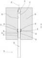
- FIG. 1is a simplified side view illustration and an enlargement view of a bone material removal device constructed and operative in accordance with an embodiment of the present invention, shown in an unstressed orientation and outside of a bone of a patient;
- FIG. 2is a side view illustration and an enlargement view of a bone material removal device of FIG. 1 shown in a deflected orientation and outside of a bone of a patient;
- FIG. 3is a partial cut away side view illustration and an enlargement view of a bone material removal device of FIG. 1 inserted into a cannula, showing the positioning of the cannula over the bone of a patient;
- FIGS. 4 A and 4 Bare a partial cut away side view illustration and an enlargement view and cross section view simplified illustrations of a bone material removal device of FIG. 1 inserted into a cannula, showing a first operative drilling orientation within the bone of a patient;
- FIGS. 5 A, 5 B and 5 Care a partial cut away side view illustration and an enlargement view and cross section view simplified illustrations of a bone material removal device of FIG. 1 inserted into a cannula, showing a second operative drilling orientation within the bone of a patient;
- FIG. 6is a partial cut away side view illustration and an enlargement view of a bone material removal device of FIG. 1 inserted into a cannula, showing removal of the bone material removal device from the bone of a patient;
- FIG. 7is a simplified pictorial illustration of a bone material removal device constructed and operative in accordance with an embodiment of the present invention.
- FIG. 8 Ais a simplified pictorial illustration of a drill element of the bone material removal device of FIG. 7 ;
- FIG. 8 Bis a simplified cross sectional view illustration and an enlargement thereof of the drill element of FIG. 8 A , section being taken along lines B-B in FIG. 8 A ;
- FIG. 9 Ais a simplified pictorial and cross section view illustration of a bore widening element of the bone material removal device of FIG. 7 ;
- FIG. 9 Bis a simplified cross sectional view illustration of the bore widening element of FIG. 9 A , section being taken along lines B-B in FIG. 9 A ;
- FIG. 10 Aillustrates two different simplified planar views, front and side views respectively, of the assembled bone material removal device of FIG. 7 in a closed operative orientation
- FIG. 10 Bis a simplified partial cross sectional view illustration of the assembled bone material removal device of FIG. 7 in the closed operative orientation, section being taken along lines B-B in FIG. 10 A ;
- FIG. 10 Cis a simplified side view of the assembled bone material removal device in a closed operative orientation shown within the bone of a patient;
- FIG. 10 Dis an enlargement of FIG. 10 C , illustrating the assembled bone material removal device in a closed operative orientation shown within the bone of a patient;
- FIG. 11is a simplified planar front and a partial cross sectional view of an example of the assembled bone material removal device of FIG. 7 in a transitional operative orientation between the closed orientation position of FIGS. 10 A-D and open orientation of FIGS. 12 A-D .
- FIG. 12 Aillustrates two different simplified planar views, front and side views respectively, of the assembled bone material removal device of FIG. 7 in an open operative orientation
- FIG. 12 Bis a simplified partial cross sectional view illustration of the assembled bone material removal device of FIG. 7 in the open operative orientation, section being taken along lines B-B in FIG. 12 A ;
- FIG. 12 Cis a simplified side view of the assembled bone material removal device in an open operative orientation shown within the bone of a patient;
- FIG. 12 Dis an enlargement of FIG. 12 C , illustrating the assembled bone material removal device in an open operative orientation shown within the bone of a patient;
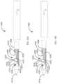
- FIGS. 13 A and 13 Bare cross section view simplified illustrations of additional embodiments of a bone material removal device.
- FIGS. 14 A and 14 Bare cross section view simplified illustrations of additional embodiments of a bone material removal device.
- bone material removal deviceas used in this disclosure should be taken to mean a device that separates a portion of bone material in any form from a bone regardless of whether the separated material is cleared away from the bone or not.
- treating edgeshould be taken to mean an edge of a portion of the bone material removal device operative to separate a portion of bone material, in any form, from a bone.
- cutting portionshould be taken to mean a portion of the bone material removal device including a carving edge.
- shaft captureand “shaft capture point” are used interchangeably in this disclosure and mean a point of contact between a shaft and a surrounding surface that temporarily limits radial movement of the shaft at that location.
- a bone material removal deviceis disclosed herein, which is particularly useful for drilling a small diameter bore having one or more portions with varying diameters.
- An aspect of some embodiments of the inventionrelates to a bone material removal device in which axial movement of at least a portion of the device is converted to radial extension of one or more carving portions.
- the conversionis without constraining axial movement of a part of the removal device.
- the conversionis by geometrical interference with axial movement, which interference converts axial movement into radial extension, while optionally allowing axial movement past the interference, so there is no constraint.
- the entire bone removal deviceis a single monolithic element formed of one piece of material, for example, metal.
- the bone removal deviceis in two or more parts, one which moves axially and one which moves radially.
- radial movementextends said carving portion from a reduced diameter which is smaller than (or larger by no more than 10% or 20 or intermediate percentages) a bore in the bone and/or diameter of enclosing cannula or a virtual axial extension of the cannula in a distal direction, to an expanded diameter which extends radially beyond a surface of the cannula and/or a surface of said virtual extension, for example, extending 10%, 20%, 30%, 40%, 50% or intermediate or greater percentages of a radius of the cannula or virtual axial extension thereof and/or bore (e.g., typical diameter without widened section).
- the bone removal devicecomprises a carving portion, which portion translates to a new radial position.
- the portiondoes not pivot and/or otherwise rotate around an axial hinge.
- the carving portionis robust.
- the carving portionhas cross-section of, for example, at least 20%, 40%, 60%, 70% or intermediate or greater percentages of a cross-section of a lumen of a cannula within which said portion is located.
- the portionis robust and does not bend during deployment, rather, any bending is at a part of the device which is not part of the carving portion.
- robustnessis provided by said portion material extending in a pure radial direction from inside the cannula, which it is optionally supported by the cannula to outside the cannula where it cute.
- extensionis provided over at least 50%, 60%, 80% or greater or intermediate percentages of the axial length of the carving edge of the carving portion.
- translationis relatively or substantially pure radial translation, for example, including less that 75%, 60%, 30%, 20%, 10% or smaller or intermediate percentages of axial translation, as a percentage of distance of radial translation.
- radial movementcomprises a bending of the bone removal device, but not at a carving edge and/or not at a bending of more than 10, 20, 30, 40 or 50 degrees or intermediate angles.
- any bendingis at a bending radius of more than 1 mm, 3 mm, 5 mm, 10 mm or intermediate or greater bending radiuses.
- any bendingis due to radially applied forces on the carving portion rather than axially applied forces.
- An aspect of some embodiments of the inventionrelates to a method in which converting axial force exerted against a surface by axial movement of a bore widening element to a radially directed force radially deflecting the carving portions into an extended circumferential position.
- An aspect of some embodiments of the inventionrelates to an elastic bone material removal device being a single member that may be moveably housed in a cannula.
- the bone material removal devicemay include a bore drilling tip and a bore widening element being a protrusion including a carving portion, disposed between two cylindrical portions.
- the drilling tipmay act as a first shaft capture and a point of contact between the bore widening element and an inner circumference of the cannula may act as a second shaft capture.
- Axial movement of the device in respect to the cannulachanges the location of the second shaft capture and shortens the distance between the first and second shaft captures, increasing the rigidity of the bore widening element.
- an aspect of embodiments of the inventionrelates to an elastic bone material removal device bone including a widening element with one or more resilient arms including carving portions at an end thereof and urged to move axially and engage a fixed surface that bends the arms and deflects the carving portions radially.
- the bore widening elementincludes one or more arms having carving portions may be fixed in place and a moveable surface may be urged to move axially to engage the bore widening element, bend the arms and deflect the carving surface radially.
- An aspect of embodiments of the inventionrelates to a bore widening element including one or more carving portions that may be limited to movement in a radial direction only and a pusher rod that moves axially to engage the bore widening element actuating the bore widening element that travels in a purely radial direction and bringing a carving portion thereof to travel and extend radially beyond a surface of a bone material removal device.
- An aspect of embodiments of the inventionrelates to an elastic bone material removal device with bore widening element that includes one or more carving portions having proximally inwardly tapered or inclined surfaces and may be housed in a stressed state within a cannula.
- Axial displacement of the bore widening element along the cannulamay bring the proximally inwardly tapered or inclined surfaces to be urged against and slide over shoulders of openings in the cannula wall and eventually be disengaged from the shoulders, allowing for gradual radial extension of one or more carving edges through the opening effected by the tendency of the bore widening element to return to its original resting state.
- An aspect of embodiments of the inventionrelates to a bone material removal device including a moveable bore widening element being a single elastic member having a carving portion and in which axial movement of the bore widening element in respect to a fixed deflecting surface brings a non-carving end-portion of the bore widening element to contact the fixed surface and be deflected thereby bringing the carving portions to travel and extend radially beyond a surface of the cannula and carve bone from a wall of a bore.
- the bore widening elementmay fixed and the deflecting surface moveable to be axially moved to engage the fixed bore widening element, bend the arms and deflect the carving portion radially.
- some embodiments of the inventionrelate to a bone material removal device including a hingeless mechanism operative to effect transition of the device from a resting state to a stressed state and vice versa and convert axial movement relative to a cannula of a bore widening element having one or more carving edges to radial movement and extension of the carving edges.
- some embodiments of the inventionrelate to a bone material removal device accommodated within a cannula and includes a mechanism operative to collect and remove residual material and debris such as bone fragments from a created undercut and store the debris within the cannula.
- FIG. 1is a simplified side view illustration and an enlargement thereof of a bone material removal device constructed and operative in accordance with an embodiment of the present invention, shown in an unstressed or resting state and outside of a bone of a patient.
- FIG. 1illustrates a bone material removal device 100 that may be a single elastic member that includes both a bore drilling tip 116 and a radially protruding circumferentially bore widening element 110 having a carving portion.
- Bone material removal device 100may have a proximal end 102 and a distal end 104 .
- Device 100may be mainly arranged along a longitudinal axis 105 and may be formed from a biocompatible shape memory alloy such as, for example, Nitinol.
- bone material removal device 100may optionally be formed as a cylinder at the majority of its longitudinal extent.
- the cylinderoptionally may have a diameter in the range of 0.5 mm-3 mm, alternatively and optionally in the range of 0.5 mm-2.5 mm and alternatively and optionally in the range of 1 mm-2 mm.
- distal end 104 of bone material removal device 100may optionally have a first generally cylindrical portion 106 terminating at a distally facing shoulder 107 , a second generally cylindrical portion 108 and a bore widening element slightly radially extending so that the bore widening element does not depart from the diameter of a bore drilled by bore drilling tip 116 .
- the bore widening elementmay extend radially with respect to longitudinal axis 105 for example in a conical shape, arc shape, triangular shape or any other shape.
- the bore widening elementis a slightly radially extending eccentric protrusion 110 having a generally convex outer surface 112 including a carving portion throughout its length and a generally concave inner surface 114 .
- inner surface 114may have other geometrical shapes.
- inner surface 114may be flat forming a triangular protrusion 110 .
- Protrusion 110optionally joins first cylindrical portion 106 and second cylindrical portion 108 .
- protrusion 110may optionally extend outwardly from longitudinal axis 105 by 0.05-0.4 mm, alternatively and optionally by 0.075-0.3 mm and alternatively and optionally by 0.1 mm-0.2 mm.
- the outer diameter of distal end 104 of the bone material removal device 100is smaller than the outer diameter of the remainder of the bone material removal device 100 .
- the majority of the longitudinal extent of bone material removal device 100is arranged along longitudinal axis 105 except for protrusion 110 that may extend radially outwardly therefrom.
- Bone material removal device 100bore drilling tip 116 at the distal end 104 thereof, may be located distally from second cylindrical portion 108 .
- the length of the distal end 104is optionally more than a threshold length of, for example, 10 mm in order to prevent rigidity thereof.
- a threshold lengthof, for example, 10 mm in order to prevent rigidity thereof.
- this characteristicallows to vary the rigidity of distal end 104 as desired by lengthening or shortening the distance between bore drilling tip 116 and a shaft capture point located along device 100 .
- the shorter the length between bore drilling tip 116 and a shaft capture point located along device 100the greater the rigidity of distal end 104 down to a threshold length (e.g., 8 mm) at and below which distal end 104 becomes fully rigid.
- the length of distal end 104may optionally be in the range of 10 mm-25 mm, alternatively and optionally 13 mm-23 mm and alternatively and optionally 15 mm-20 mm.
- first cylindrical portion 106 and second cylindrical portion 108are mutually aligned along longitudinal axis 105 .
- FIG. 2is a side view illustration and an enlargement view of the bone material removal device embodiment of bone material removal device 100 of FIG. 1 in a stressed state.
- the example shown in FIG. 2demonstrates the elastic qualities of bone material removal device 100 derived from material characteristics e.g., those of shape memory alloys.
- material characteristicse.g., those of shape memory alloys.
- FIG. 2when stressed, bone material removal device 100 shown outside a bone of a patient can be elastically deformed into a deflected orientation. However, due to its elastic and shape memory qualities, bone material removal device 100 may return to its original unstressed or resting state shape shown in FIG. 1 once stress is relieved therefrom.
- distal end 104 of the bone material removal device 100is radially deflected due to the elastic characteristics of the bone material removal device 100 .
- First cylindrical portion 106 and second cylindrical portion 108are not aligned with longitudinal axis 105 .
- the resilience of distal end 104 of the elastic member being bone material removal device 100 at this stagealso supports accommodation of distal end 104 within a bore drilled by bore drilling tip 116 conforming to the diameter thereof, at least the peak if not all of the carving portion of convex outer surface 112 does not protrude radially and remains generally aligned with longitudinal axis 105 .
- FIG. 3is a partial cut away side view illustration and an enlargement view of the bone material removal device 100 of FIG. 1 inserted into a cannula, showing the positioning of the cannula over the bone of a patient.
- the embodiment of the bone material removal device of FIG. 3depicts one example of bone material removal device 100 inserted into a drill guiding tool 120 having a handle 122 at its proximal end 124 and a longitudinal cannula 126 at its distal end 128 , tool 120 is arranged along longitudinal axis 105 .
- Cannula 126has a teethed tip 130 at its distal end for fixedly positioning the cannula over a location on a patient's bone 200 .
- Drill guiding tool 120may be positioned over the patient's bone 200 such that teethed tip 130 of cannula 126 engages the bone 200 and the bone material removal device 100 inserted into cannula 126 , extend along proximal cylindrical portion 134 and terminate proximally to the inwardly tapered portion 136 .
- bone material removal device 100is shown to be positioned in the unstressed or resting state similar to that shown in FIG. 1 .
- FIG. 4 Ais a partial cut away side view illustration and an enlargement view of the bone material removal device 100 of FIG. 1 inserted into cannula 126 , showing a first operative drilling orientation within bone 200 of a patient.
- Cannula 126may have a proximal cylindrical portion 134 having an inner circumference 132 including a first diameter (d 1 ), an inwardly tapered portion 136 located adjacent to a distal end 128 of cannula 126 and a cylindrical portion 138 having an inner circumference having a second diameter (d 2 ) and located at the distal end 128 of cannula 126 . It is appreciated that the first diameter of portion 134 inner circumference 132 may be substantially greater than the second diameter (d 2 ) of distalmost cylindrical portion 138 at distal end 128 .
- the outer diameter (d 3 ) of bone material removal device 100may be substantially equal to second diameter (d 2 ) of the inner circumference of cylinder 138 of distal end 128 of cannula 126 , so that to support primarily axial and rotational movement and minimal to no movement of device 100 in a radial direction within distal portion 128 inner circumference (d 2 ) of cylindrical portion 138 .
- FIGS. 4 A, 4 B, 5 A, 5 B and 5 Care cross-section view simplified illustrations of examples of operative stages of bone material removal device 100 at various points in time as it is advanced distally into the patient's bone 200 .
- FIGS. 4 A- 5 B disclosed hereinbelowdemonstrate conversion of bone material removal device 100 from a bore-drilling device to an undercut producing device by conversion of axial movement of device 100 to radial translation and extension of one or more carving edges of protrusion 100 for example, by means of transition of device 100 from a resting state to a stressed state or vice versa. These steps may be commonly carried out in a continuous fashion.
- a freedom degreeexists between bone material removal device 100 and cannula 126 that allows the bone material removal device 100 to be advanced distally longitudinally along longitudinal axis 105 due to the elastic characteristics of the bone material removal device 100 .
- the freedom degreeis created due to the fact that the outer diameter (d 3 ) of the remainder of bone material removal device 100 , i.e., the thickest portion of the device 3 100 , except of the distal end 104 is substantially smaller than the first diameter (d 1 ) of the proximal cylindrical portion 134 of the cannula 126 .
- device 100may be free to move radially within cannula 126 inner circumference 132 so that a point of contact (not shown) of portion 134 inner circumference 132 with bone material removal device 100 can form a first shaft capture wherein the bone surrounding drilling tip 116 (i.e., bore 202 , FIGS. 5 A, 5 B and 5 C ) may form a second shaft capture.
- the specific location of the first point of contact (capture)may vary throughout the drilling process.
- the distance between the first and second shaft capturesmay create a first bending moment on bone material removal device 100 that elastically deforms device 100 into a stressed state such as that depicted in FIG. 2 .
- the elastic characteristics of device 100bring protrusion 110 to succumb to bending forces thereupon and bend to become aligned with longitudinal axis 105 and with first cylindrical portion 106 and second cylindrical portion 108 , conforming to the diameter of a bore drilled by bore drilling tip 116 thus providing for longitudinal advancement of the device 100 within the bone 200 of the patient and thus formation of a small diameter bore therewithin.
- first cylindrical portion 106 , second cylindrical portion 108 and protrusion 110are mutually aligned along longitudinal axis 105 having a diameter equal or less than the radius of a bore drilled by bore drilling tip 116 during the operative orientation shown in FIGS. 4 A and 4 B , while distally facing shoulder 107 does not yet engage the distalmost cylindrical portion 138 of the cannula 126 .
- FIGS. 4 A and 4 BIt is seen in FIGS. 4 A and 4 B that distal advancement of the bone material removal device 100 results in a straight longitudinal bore 202 in the patient's bone 200 .
- the longitudinal bore 202 that is formed in this operative orientationoptionally has a diameter in the range of 2 mm-4 mm, alternatively and optionally in the range of 1.5 mm-3 mm and alternatively and optionally in the range of 1 mm-2 mm, corresponding to the outer diameter of first cylindrical portion 106 and second cylindrical portion 108 .
- FIGS. 5 A, 5 B and 5 Care partial cut away side view illustration and an enlargement view and cross-section view simplified illustrations of the embodiment of bone material removal device 100 of FIG. 1 inserted into cannula 126 , showing a second operative drilling orientation within the bone 200 of a patient.
- the bone material removal device 100is advanced further distally into the patient's bone 200 . Further distal advancement of the bone material removal device 100 can be in the range of approximately 1 mm-8 mm, alternatively and optionally 1.5 mm-7 mm and alternatively and optionally from 2 mm-6 mm.
- the freedom degreeis lost due to the fact that the outer diameter of the remainder of a bone material removal device 100 except of the distal end 104 engages the substantially equal diameter of the distalmost cylindrical portion 138 of the cannula 126 .
- the bone surrounding drilling tip 116i.e., bore 202
- the bone surrounding drilling tip 116may remain a second shaft capture but distalmost cylindrical portion 138 becomes a third shaft capture replacing the second shaft capture located at a contact point along portion 134 inner circumference 132 .
- the distance between the first and third shaft capturesbeing shorter than the distance between the second and first shaft captures, may create a second smaller bending moment on bone material removal device 100 down to a threshold length designated in FIG. 5 B with the letter (L) (e.g., the tip of the cannula) at and below which distal end 104 becomes fully rigid.
- protrusion 110As illustrated in FIG. 5 C the increased rigidity of distal end 104 brings protrusion 110 to extend radially and to perform an undercut within the bone 200 of a patient by means of rotation about longitudinal axis 105 , increasing in diameter and creating a bore (undercut) 204 having a diameter, which is substantially larger than the diameter of bore 202 . Due to the rigid characteristics of the bone material removal device 100 at this stage, protrusion 110 protrudes radially externally to longitudinal axis 105 , thus providing for longitudinal advancement of the bone material removal device 100 within bone 200 of the patient and thus formation of a large diameter bore therewithin, corresponding to the outer diameter formed by protrusion 110 .
- first cylindrical portion 106 and second cylindrical portion 108are mutually aligned along longitudinal axis 105 during the operative orientation shown in FIGS. 5 A- 5 C and that protrusion 110 extends radially outwardly with respect to longitudinal axis 105 since the distally facing shoulder 107 engages the distalmost cylindrical portion 138 of the cannula 126 and prevents from the protrusion 110 to lose rigidity.
- Undercut 204 that is formed in the operative orientation shown in FIGS. 5 A- 5 Coptionally has a diameter in the range of 0.6 mm-3.2 mm, alternatively and optionally 1 mm-2.8 mm and alternatively and optionally 1.2 mm-2.4 mm, corresponding to the outer diameter of the protrusion 110 in its most radially extended configuration.
- FIGS. 5 A- 5 CIt is seen in FIGS. 5 A- 5 C that further distal advancement of the bone material removal device 100 results in formation of an undercut 204 generally in the middle of the straight longitudinal bore 202 formed in the patient's bone 200 .
- FIG. 6is a partial cut away side view illustration and an enlargement view of the embodiment of the bone material removal device of FIG. 1 inserted into the cannula 126 , showing removal of the bone material removal device 100 from the bone 200 of a patient.
- the bone material removal device 100has been withdrawn from the patient's bone 200 , leaving the bone with formed bore having varying diameters, longitudinal bore 202 of a smaller diameter and undercut 204 of a larger diameter.
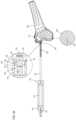
- FIG. 7is a simplified pictorial illustration of a bone material removal device 300 constructed and operative in accordance with an additional embodiment of the present invention.
- bone material removal device 300optionally includes a drilling element 302 optionally having a form of a cannula and having a proximal end 310 and a distal end 312 and formed of a biocompatible metal. Distal end 312 may be sealed by a tapered drilling tip 314 .
- Drilling element 302may optionally have a diameter in the range 2 mm-4 mm, alternatively and optionally in the range of 1.5 mm-3 mm and alternatively and optionally in the range of 1 mm-2 mm.
- Device 300may also include a bore widening element 304 disposed between distal end 312 and proximal end 310 of drilling element 302 and be at least partially inserted therein.
- Drilling element 302connects at proximal end 310 to a handle 306 having a pushing element 308 inserted therein in contact with bore widening element 304 .
- drilling element 302 and bore widening element 304can be connected to a power tool, e.g., a power drill.
- Drilling element 302 and the bore widening element 304are arranged along a mutual longitudinal axis 309 .
- the bore widening element 304may be at least partially inserted into the drilling element 302 and be selectively positioned in a closed position enabling drilling a bore of a first diameter within the bone of a patient and in an open, radially extended position enabling drilling a bore of a second diameter within the bone of a patient, wherein the first diameter may optionally be equal to the outer diameter of the tubular or cannula portion of the drilling element 302 and the second diameter may be greater than the first diameter, thus forming an undercut within the bone of a patient.
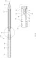
- FIG. 8 Ais a simplified pictorial illustration of the drill element 302 of the bone material removal device 300 of FIG. 7
- FIG. 8 Bwhich is a simplified cross sectional view illustration and an enlargement thereof of the drilling element 302 of FIG. 8 A , section being taken along lines B-B in FIG. 8 A .
- Drilling element 302may optionally be integrally made of a biocompatible material (e.g., metal) and arranged along longitudinal axis 309 .
- a biocompatible materiale.g., metal
- FIGS. 8 A & 8 Bit is seen in FIGS. 8 A & 8 B that one or more through openings 320 in a wall 335 of drilling element 302 radially extend through drilling element 302 transversely to longitudinal axis 309 .
- An inner surface 336 of drilling element 302 wall 335defines a hollow portion of drilling element 302 proximally to opening 320 and optionally solid distally to opening 320 .
- Each of the openings 320longitudinally extends from a distally facing shoulder 322 to a proximally facing shoulder 324 .
- drilling tip 314can be fixedly coupled to the drilling element 302 or alternatively integrally made therewith.
- the solid part of the drilling element 302extends proximally from the drilling tip 314 to approximately adjacent the proximally facing shoulder 324 and defines a proximally facing surface 326 at this location.
- a protrusion 328optionally extends proximally from surface 326 .
- the protrusion 328 shown in FIG. 8 Boptionally has a cylindrical portion 330 and a proximal portion 332 having one or more inclined surfaces (e.g., conical or tapered) proximally extending therefrom. It is appreciated that protrusion 328 can alternatively be formed as a cone along its entire longitudinal extent or any other widening geometry, for example pyramidal or any other suitable shape.
- the conical portion 332defines one or more distally extending tapered or inclined surfaces 334 extending in one or more radial directions.
- conical portion 332may define two distally extending tapered or inclined surfaces 334 extending in mutually opposite radial directions.
- the hollow part of the drilling element 302defines an outer surface 335 and an inner surface 336 .
- FIG. 9 Ais a simplified pictorial and cross section view illustration of an example of bore widening element 304 of the bone material removal device 300 of FIG. 7 and to FIG. 9 B , which is a simplified cross sectional view illustration of bore widening element 304 of FIG. 9 A , section being taken along lines B-B in FIG. 9 A .
- Bore widening element 304optionally has a proximal end 350 and a distal end 352 and can be integrally made of an elastic biocompatible material having shape memory qualities material (e.g., metal) and be arranged along longitudinal axis 309 .
- shape memory qualities materiale.g., metal
- a generally cylindrical recess 354is formed at the proximal end 350 to be engaged by pushing element 308 ( FIG. 7 ), distally extends therefrom and terminates at a proximally facing surface 356 .
- one or more distally extending arms 358may extend from approximately the middle of the longitudinal extent of bore widening element 304 to the distal end 352 , centrally facing surfaces thereof bordering and separated by a longitudinal recess 360 having a proximal closed end and a distal open end.
- Each of the arms 358defines an outer surface 362 .
- bore widening element 304 depicted in FIGS. 9 A and 9 Bmay be in a resting, unstressed state so that arms 358 can be deflected inwardly one towards the other when force is exerted on outer surface 362 in a radially inward direction. Arms 358 can be deflected outwardly to be further separated one from each other when force is exerted on the inner surface of the arms 358 in a radially outward direction.
- bore widening element 304 depicted in FIGS. 9 A and 9 Bmay be in a stressed or loaded state.
- Each of the arms 358defines a widened portion 364 at the distal end 352 of the widening element 304 .
- Each of the widened portions 364preferably defines a distally facing preferably inwardly proximally tapered or inclined surface 366 .
- Inwardly proximally tapered or inclined surface 366define a distal aspect of carving portions 368 proximally extending from surfaces 366 .
- Carving portions 368are generally longitudinal widened defining an outer carving edge 370 or several carving edges 370 as will be explained in greater detail below and a radially positioned curved surface 921 bordered at one side thereof by carving edge 370 and forming an end relief or clearance curve that prevents the rubbing of carving portions 368 against the bone, reducing the amount of force (e.g., torque) required for operation of device 300 .
- Longitudinal carving portions 368are joined with outer surfaces 362 of arms 358 by a generally proximally inwardly tapered or inclined surface 372 . It is appreciated that the longitudinal carving portions 368 can be cylindrical or alternatively can be conical or have any other suitable shape.
- widened portions 364may be generally positioned at an angle with respect to each other.
- bore widening element 304may have a single arm 358 carrying one or more carving portions 368 . In other embodiments, bore widening element 304 may have more than one arm only one of which carrying one or more carving portions 368 .
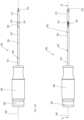
- FIGS. 10 A- 10 Dare simplified illustrations of examples of operative stages of bone material removal device 300 at various points in time as it is advanced distally into the patient's bone 200 .
- FIG. 10 Aillustrates two different simplified planar views, front and side views respectively, of an example of the assembled bone material removal device 300 of FIG. 7 in a closed operative orientation
- FIG. 10 Bwhich is a simplified partial cross sectional view illustration of the assembled bone material removal device 300 of FIG. 7 in the closed operative orientation, section being taken along lines B-B in FIG. 10 A
- FIG. 10 Cis a simplified side view of the assembled bone material removal device 300 in a closed operative orientation shown within the bone of a patient
- FIG. 10 Dwhich is an enlargement of FIG. 10 C , illustrating the assembled bone material removal device 300 in a closed operative orientation shown within the bone of a patient.
- bore widening element 304is inserted into the drilling element 302 , such that they are mutually arranged along longitudinal axis 309 .
- pushing element 308is not yet fully inserted into the handle 306 , thus bore widening element 304 is positioned at rest ( FIG. 10 B ) in a proximal location, thus providing for closed operative orientation of the bone material removal device 300 . In this proximal location, pushing element 308 does not engage the proximally facing surface 356 of recess 354 of bore widening element 304 .
- the widened portions 364 of arms 358 of the widening element 304are each located within the respective opening 320 of the drilling element 302 , such that proximally inwardly tapered or inclined surfaces 372 are located adjacent the distally facing shoulders 322 defined by openings 320 of the drilling element 302 .
- arms 358 of the widening element 304are positioned in a closed resting state operative orientation.
- arms 358may optionally be generally slightly radially inwardly deflected toward each other by means of inward radial force exerted by the inner surface 336 of the drilling element 302 on the proximally inwardly tapered or inclined surfaces 372 of widened portions 364 of the arms 358 of widening element 304 .
- carving edges 370 of widening element 304may slightly extend radially so that only to be aligned with the outer surface 337 of the drilling element 302 .
- the drilling radius of the outer surface of the drilling element 302is substantially equal to the drilling radius formed by the carving edges 370 of the widening element 304 thus forming an initial bore 400 of a first diameter is formed within the bone 402 of a patient particularly seen in FIGS. 10 C and 10 D .
- the radius of the initially drilled borecan be for example in the range of 0.2 mm-1.4 mm, alternatively and optionally 0.4 mm-1.2 mm and alternatively and optionally 0.5 mm-1 mm or any other radius, preferably equal to the outer diameter of drilling element 302 .
- FIG. 11which is a simplified planar front and a partial cross sectional view of an example of the embodiment of assembled bone material removal device 300 of FIG. 7 in a transitional operative orientation between the closed orientation position of FIG. 10 A- 10 D and open orientation of FIGS. 12 A- 12 D .
- pushing element 308has been partially advanced axially distally and is partially inserted into handle 306 , such that its distal end engages bore widening element 304 , axially displacing bore widening element 304 distally to be partially engaged by protrusion 328 tapered or inclined surfaces 334 .
- Pushing element 308may attach and lock into recess 354 by quick release coupling system or alternatively and optionally by a threaded mechanism allowing to axially gradually move widening element 304 as desired by turning pushing element 308 .
- Axially distally displaced bore widening element 304may move axially and engage distally extending tapered or inclined surfaces 334 of protrusion 328 , which geometrically interfere with the axial movement of bore widening element 304 and may exert radially directed bending force on arms 358 of bore widening element 304 bringing the carving portions to travel and extend radially and outwardly through one or more openings 320 .
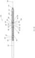
- FIG. 12 Aillustrates two different simplified planar views, front and side views respectively, of the assembled bone material removal device 300 of FIG. 7 in a fully open operative orientation
- FIG. 12 Bwhich is a simplified partial cross sectional view illustration of the assembled bone material removal device 300 of FIG. 7 in the fully open operative orientation, section being taken along lines B-B in FIG. 12 A
- FIG. 12 Cwhich is a simplified side view of the assembled bone material removal device 300 in a fully open operative orientation shown within the bone of a patient
- FIG. 12 Dwhich is an enlargement of FIG. 12 C , illustrating the assembled bone material removal device 300 in a fully open operative orientation shown within the bone of a patient.
- bore widening element 304remains inserted into the drilling element 302 , such that they are mutually arranged along longitudinal axis 309 .
- the bore widening portion 304is fully axially displaced with respect to drilling element 302 .
- pushing element 308is now fully inserted into the handle 306 , such that its distal end (not shown) engages proximally facing surface 356 of recess 354 of bore widening element 304 and thus axially displaces bore widening element 304 distally to be positioned at a distal location, thus providing for open operative orientation of the bone material removal device 300
- a power toolcan be used, selectively changing between a closed operative orientation and an open operative orientation of the bone material removal device 300 for example, by means of changing the direction of rotation of the power tool, without requiring manipulation of mechanical means, such as pushing element 308 .
- Distal displacement of bore widening element 304may bring widened portions 364 of arms 358 of bore widening element 304 to slide axially longitudinally with respect to the openings 320 of drilling element 302 , such that the distally facing preferably inwardly proximally tapered or inclined surfaces 366 of bore widening element 304 engage distally extending tapered or inclined surfaces 334 of protrusion 328 of the drilling element 302 and slide therealong.
- Arms 358succumb to bending forces thereupon and are thereby spaced one from another by means of outward radial force exerted by the distally extending tapered or inclined surfaces 334 entering longitudinal recess 360 formed between the arms 358 of widening element bringing about radial displacement and extension of widened carving portions 368 through one or more openings 320 , positioning carving portions 368 in a fully extended position and bone material removal device 300 in a fully open operative orientation.
- distally facing preferably inwardly proximally tapered or inclined surface 366may be located adjacent the proximally facing shoulders 324 defined by openings 320 of the drilling element 302 and widened carving portions 368 and carving edges 370 locked in a radially extended position by cylindrical portion 330 of protrusion 328 .
- Cylindrical portion 330 of protrusion 328thereby acts as a counter support to support carving portions 368 in the extended position, oppose centrally directed radial forces and prevent carving portions 368 from retracting into drilling element 302 .
- carving edges 370 of bore widening portion 304extend radially outwardly from the outer surface 337 of drilling element 302 through one or more openings 320 operative to carve bone in walls of a bore and create an undercut in the bone.
- the drilling diameter formed by the carving edges 370 of the bore widening element 304is substantially greater than the drilling diameter initially formed by drilling tip 314 of the drilling element 302 .
- an undercut 404 having a second diameteris formed over the initial bore 400 of a first diameter in the bone 402 of a patient, whereas the second diameter is substantially greater than the first diameter.
- the radius of the undercutcan be for example in the range of 1.5 mm-2.5 mm, alternatively and optionally 1 mm-2 mm and alternatively and optionally 0.75 mm-1.25 mm.
- carving edge 370may be tapered to a point or inclined, it is a further particular feature of an embodiment of the present invention that 370 has a length and the length of the undercut 404 formed in the bone 402 of a patient is a function of the length of the carving edge 370 of the bore widening element 304 .
- carving portionis optionally extended radially by bending forces exerted on a single surface of an arm of the widening element.
- bore widening element 304 depicted in FIGS. 9 A and 9 Bmay be in a stressed or loaded state inside drilling element 302 , stressing bore widening element 304 arms 358 into an angle in respect to each other.
- an initial bore 400 of a first diametercan be formed within the bone 402 of a patient ( FIGS. 10 C and 10 D ).
- pushing element 308has been partially advanced axially distally and is partially inserted into handle 306 , such that its distal end engages bore widening element 304 , axially displacing bore widening element 304 distally.
- Axial displacement of bore widening element 304 in respect to drilling element 302brings proximally inwardly tapered surface 372 to gradually engage and slide over distally facing shoulder 322 .
- bone material removal device 300may tend to return to its original unstressed or resting state shape shown in FIGS. 9 A and 9 B once stress is relieved therefrom allowing bore widening element 304 arms 358 to extend outwardly radially through one or more openings 320 .
- bore widening element 304is fully axially displaced with respect to drilling element 302 and proximally inwardly tapered surface 372 is no longer in contact and limited by distally facing shoulder 322 .
- This stageallows bore widening element 304 to fully return to its original unstressed or resting state shape shown in FIGS. 9 A and 9 B and bore widening element 304 arms 358 to fully extend outwardly radially through one or more openings 320 .
- protrusion 328may act as a counter support to support carving portions 368 in the extended position, oppose centrally directed radial forces and prevent carving portions 368 from retracting into drilling element 302 .
- widened carving portions 368may include one carving edge or two or more carving edges 902 and 904 respectively, angled in respect to each other and joined at least at one end.
- a first or main carving edge 902may be operative to cut a main portion of a fragment of bone creating a first surface of the fragment and a second or auxiliary carving edge 904 may be operative to cut along a second adjoining surface of the fragment thus carving and detaching the fragment of bone.
- a leading wallWhen rotated in a direction depicted in FIG. 9 A by an arrow designated reference numeral 950 a leading wall, defined by the direction of rotation and by main carving edge 902 , auxiliary carving edge 904 and the angle therebetween, may define a rake angle 906 that provides a surface up and along which removed residual material (i.e., fragment of bone) may rise over an end relief or clearance curved surface 921 (broken line arrow 952 ) or along distally facing inwardly proximally tapered surface 366 to be collected into recess 360 (broken line arrow 954 ).
- residual drilling materialcan infiltrate recess 360 , act as a lubricant and thus allow for smooth displacement of the widening element 304 with respect to the drilling element 302 .
- FIGS. 13 A and 13 Bare cross section view simplified illustrations of additional embodiments of a bone material removal device.
- FIG. 13 Adepicts an embodiment of a bone material removal device 1300 similar to the embodiment of FIG. 7 , differing from the embodiment of FIG. 7 in that a non-carving end-portion 1310 of one or more arms 1302 of bore widening element 1304 extends distally beyond one or more carving portions 1306 and bordered proximally thereby terminating at inwardly proximally tapered or inclined surface 1308 of arms 1302 .
- Axial movement of bore widening element 1304 in respect to drilling element 302brings inwardly proximally tapered or inclined surface 1308 of non-carving end-portion 1310 of arms 1302 to engage protrusion 328 that geometrically interferes with the axial movement of bore widening element 1304 and bends arms 1302 deflecting the arm bringing carving portion 1306 to travel and extend radially beyond a surface of the cannula and carve bone from a wall of a bore.
- an embodiment of a bone material removal device 1350 similar to the embodiment of FIG. 7differing from the embodiment of FIG. 7 in that recess 360 is narrow proximately and widens distally bordered and defined by centrally facing surfaces 1314 of arms 1302 and a fixed protrusion 1352 is disposed abutting centrally facing surfaces 1314 and/or within a distal portion of recess 360 between two or more centrally facing surfaces 1314 of arms 1312 .
- One or more non-carving proximal portions 1312 of arms 1302extend from arms 1302 origin at the proximal border of recess 360 to a carving portion 1306 and distally bordered thereby.
- Axial movement of bore widening element 1304brings one or more surfaces of non-carving proximal portions 1312 of arms 1302 defining recess 360 to be urged against protrusion 1352 that geometrically interferes with the axial movement of bore widening element 1304 and bends arms 1302 and deflecting the arm bringing carving portion 1306 to travel and extend radially beyond a surface of the cannula and carve bone from a wall of a bore.
- carving portion 364 / 1306is extended radially by bending forces exerted on a single surface of one or more arms 358 / 1302 of widening element 304 / 1304 respectively. Additionally, in some embodiments, when one or more arms 358 / 1302 are fully deflected and one or more carving portions 364 / 1306 are fully extended radially, one or more arms 358 / 1302 is generally parallel to the longitudinal axis of the device and carving portions 364 / 1306 supported by a counter support such as, for example, protrusion 328 .
- a bore widening element 1402 including one or more carving portions 1404may be limited to movement in a radial direction only and a pusher rod 1426 may be urged to move axially to engage the bore widening element actuating bore widening element 1402 that travels in a purely radial direction and bringing carving portion 1404 to travel and extend radially beyond surface 1406 of bone material removal device 1400 .
- bone material removal device 1400may include a lumen 1428 that communicates with the atmosphere via an opening 1408 in a wall 1410 thereof.
- a distal margin 1412 of opening 1408may be located at a predetermined distance proximally from a bone drilling tip 1414 , opening 1408 extending longitudinally and proximally therefrom.
- Longitudinal bore widening element 1402may include a bone carving portion 1404 that may be generally longitudinally widened defining an outer carving edge 1416 or several carving edges 1416 .
- Bone carving portion 1404may also define a radially positioned curved surface (not shown in FIG.
- This curved surfaceis similar to curved surface 921 described herein with reference to FIG. 9 A .
- Longitudinal bore widening element 1402may be resiliently attached to wall 1410 of bore widening device 1400 by a resilient attachment that exerts constant tension in a radially inward direction, resisting outward radial extension of bore widening element 1402 such that at rest bone carving portion 1414 is at least partially retracted into a lumen 1420 of bone material removal device 1400 disposed within margins of opening 1408 and not protruding therefrom.
- One or more elongated slot-like cutouts 1422may be cut through the width of element 1402 the length of the cutouts oriented radially from the longitudinal axis of bone material removal device 1400 . Movement of longitudinal bore widening element 1402 may be limited in a radial direction only by a radial-direction-guiding mechanism that includes one or more pins 1424 fixed to wall 1410 and protruding radially inward, optionally perpendicular to and through cutouts 1422 . Bore widening element 1402 may also include an inclined surface 1432 along a border thereof or protruding from a surface of element 1402 .
- Bone material removal device 1400may also include a pusher rod 1426 that moves axially within a lumen 1428 of bone material removal device 1400 .
- a tip 1430 of pusher rod 1426may be inclined.
- pusher rod 1426may move axially and tip 1430 engages and slides along inclined surface 1432 exerting an outwardly radially directed force acting against and overcoming radially inward tension effected by the resilient attachment of bore widening element 1402 to wall 1410 , actuating bore widening element 1402 that travels in a purely radial direction limited by the radial-direction guiding mechanism and brings bone carving portion 1404 to protrude circumferentially through opening 1408 into a fully extended bone carving position shown in FIG. 14 B .
- Carving portion 1404may be similar in structure to widened carving portion 368 also including a first carving edge 902 , a second carving edge 904 and the angle therebetween that may define a rake angle 906 that provides a surface up and along which removed residual material (i.e., fragment of bone) may rise over an end relief or clearance curved surface 921 to be collected into bone material removal device 1400 .
- First carving edge 902may cut a main portion of a fragment of bone creating a first surface of the fragment and second carving edge 904 may cut along a second adjoining surface of the fragment thus carving and detaching the fragment of bone.
- compositions, method or structuremay include additional ingredients, steps and/or parts, but only if the additional ingredients, steps and/or parts do not materially alter the basic and novel characteristics of the claimed composition, method or structure.
- a compoundor “at least one compound” may include a plurality of compounds, including mixtures thereof.
- range formatis merely for convenience and brevity and should not be construed as an inflexible limitation on the scope of the invention. Accordingly, the description of a range should be considered to have specifically disclosed all the possible subranges as well as individual numerical values within that range. For example, description of a range such as “from 1 to 6” should be considered to have specifically disclosed subranges such as “from 1 to 3”, “from 1 to 4”, “from 1 to 5”, “from 2 to 4”, “from 2 to 6”, “from 3 to 6”, etc.; as well as individual numbers within that range, for example, 1, 2, 3, 4, 5, and 6. This applies regardless of the breadth of the range.
- methodrefers to manners, means, techniques and procedures for accomplishing a given task including, but not limited to, those manners, means, techniques and procedures either known to, or readily developed from known manners, means, techniques and procedures by practitioners of the chemical, pharmacological, biological, biochemical and medical arts.
- treatingincludes abrogating, substantially inhibiting, slowing or reversing the progression of a condition, substantially ameliorating clinical or aesthetical symptoms of a condition or substantially preventing the appearance of clinical or aesthetical symptoms of a condition.
Landscapes
- Health & Medical Sciences (AREA)
- Surgery (AREA)
- Life Sciences & Earth Sciences (AREA)
- Biomedical Technology (AREA)
- Medical Informatics (AREA)
- Orthopedic Medicine & Surgery (AREA)
- Oral & Maxillofacial Surgery (AREA)
- Engineering & Computer Science (AREA)
- Dentistry (AREA)
- Heart & Thoracic Surgery (AREA)
- Nuclear Medicine, Radiotherapy & Molecular Imaging (AREA)
- Molecular Biology (AREA)
- Animal Behavior & Ethology (AREA)
- General Health & Medical Sciences (AREA)
- Public Health (AREA)
- Veterinary Medicine (AREA)
- Transplantation (AREA)
- Surgical Instruments (AREA)
- Dental Tools And Instruments Or Auxiliary Dental Instruments (AREA)
Abstract
Description
- disengaging the surfaces from the shoulder; and
- allowing the bore widening element to return to a resting state by bringing the carving portions to travel and extend radially through the opening and beyond a surface of the cannula and
- carving bone from a wall of a bore.
- bringing a bore widening element having at least one resilient arm and at least one carving portion at the end thereof to move axially;
- placing a geometrically interfering surface in the path of travel of the at least one resilient arm; and
- engaging the arm with the interfering surface bending and deflecting the arm; and
- bringing the carving portion to travel and extend radially; and
- carving bone from a wall of a bore.
- limiting movement of a bore widening element having a carving portion and an inclined surface to movement in a radial direction only, axially moving a pusher rod,
- engaging the pusher rod with the inclined surface, actuating the bore widening element that travels in a purely radial direction, bringing the carving portion to travel and extend radially beyond a surface of a bone material removal device; and carving a portion of bone.
Claims (19)
Priority Applications (2)
| Application Number | Priority Date | Filing Date | Title |
|---|---|---|---|
| US16/561,089US11779353B2 (en) | 2015-04-09 | 2019-09-05 | Bone material removal device and a method for use thereof |
| US18/370,446US20240000463A1 (en) | 2015-04-09 | 2023-09-20 | Bone material removal device and a method for use thereof |
Applications Claiming Priority (5)
| Application Number | Priority Date | Filing Date | Title |
|---|---|---|---|
| US201562144991P | 2015-04-09 | 2015-04-09 | |
| US201562151375P | 2015-04-22 | 2015-04-22 | |
| PCT/IL2016/050370WO2016162869A2 (en) | 2015-04-09 | 2016-04-07 | Bone material removal device and a method for use thereof |
| US15/318,677US10448959B2 (en) | 2015-04-09 | 2016-04-07 | Bone material removal device and a method for use thereof |
| US16/561,089US11779353B2 (en) | 2015-04-09 | 2019-09-05 | Bone material removal device and a method for use thereof |
Related Parent Applications (2)
| Application Number | Title | Priority Date | Filing Date |
|---|---|---|---|
| US15/318,677ContinuationUS10448959B2 (en) | 2015-04-09 | 2016-04-07 | Bone material removal device and a method for use thereof |
| PCT/IL2016/050370ContinuationWO2016162869A2 (en) | 2015-04-09 | 2016-04-07 | Bone material removal device and a method for use thereof |
Related Child Applications (1)
| Application Number | Title | Priority Date | Filing Date |
|---|---|---|---|
| US18/370,446ContinuationUS20240000463A1 (en) | 2015-04-09 | 2023-09-20 | Bone material removal device and a method for use thereof |
Publications (2)
| Publication Number | Publication Date |
|---|---|
| US20190388102A1 US20190388102A1 (en) | 2019-12-26 |
| US11779353B2true US11779353B2 (en) | 2023-10-10 |
Family
ID=57073130
Family Applications (3)
| Application Number | Title | Priority Date | Filing Date |
|---|---|---|---|
| US15/318,677ActiveUS10448959B2 (en) | 2015-04-09 | 2016-04-07 | Bone material removal device and a method for use thereof |
| US16/561,089Active2039-01-12US11779353B2 (en) | 2015-04-09 | 2019-09-05 | Bone material removal device and a method for use thereof |
| US18/370,446PendingUS20240000463A1 (en) | 2015-04-09 | 2023-09-20 | Bone material removal device and a method for use thereof |
Family Applications Before (1)
| Application Number | Title | Priority Date | Filing Date |
|---|---|---|---|
| US15/318,677ActiveUS10448959B2 (en) | 2015-04-09 | 2016-04-07 | Bone material removal device and a method for use thereof |
Family Applications After (1)
| Application Number | Title | Priority Date | Filing Date |
|---|---|---|---|
| US18/370,446PendingUS20240000463A1 (en) | 2015-04-09 | 2023-09-20 | Bone material removal device and a method for use thereof |
Country Status (5)
| Country | Link |
|---|---|
| US (3) | US10448959B2 (en) |
| EP (1) | EP3282956A4 (en) |
| JP (2) | JP7007190B2 (en) |
| CN (1) | CN107530091B (en) |
| WO (1) | WO2016162869A2 (en) |
Families Citing this family (14)
| Publication number | Priority date | Publication date | Assignee | Title |
|---|---|---|---|---|
| CN108670349B (en) | 2013-04-24 | 2021-06-04 | Tag医疗器材农业合作有限公司 | Device and method for bone material removal |
| US11219466B2 (en) | 2018-06-06 | 2022-01-11 | Acumed Llc | Orthopedic reamer with expandable cutting head |
| BR112017008135B1 (en) | 2014-10-19 | 2022-11-16 | T.A.G. Medical Devices - Agriculture Cooperative Ltd | SET INCLUDING A GUIDANCE SYSTEM AND BONE MATERIAL REMOVAL DEVICE AND METHOD FOR DRILLING A BONE TUNNEL INTO A BONE |
| JP7007190B2 (en) | 2015-04-09 | 2022-01-24 | ティー.エー.ジー. メディカル デヴァイシス-アグリカルチャー コーポラティヴ リミテッド | Bone material remover and how to use it |
| CA3003306C (en)* | 2015-11-17 | 2019-04-16 | Lenkbar, Llc | Surgical tunneling instrument with expandable section |
| EP3799806A1 (en) | 2016-02-11 | 2021-04-07 | T.A.G. Medical Devices - Agriculture Cooperative Ltd. | Bone material removal device |
| EP3448274B1 (en) | 2016-04-24 | 2024-05-15 | T.A.G. Medical Products Corporation Ltd. | Guiding device |
| CN110709019B (en)* | 2017-06-22 | 2023-12-26 | 史密夫和内修有限公司 | Surgical drill guide and system |
| US11026669B2 (en)* | 2017-07-13 | 2021-06-08 | Medtronic Vascular, Inc. | Collapsible dilator |
| IL280574B2 (en) | 2018-08-01 | 2025-08-01 | Tag Medical Devices Agriculture Coop Ltd | Adjustable drilling device and method for using the same |
| IT201800010757A1 (en)* | 2018-12-03 | 2020-06-03 | Cgm Spa | SURGICAL INSTRUMENT TO SCRAP AND COLLECT BONE PARTICLES |
| US11490898B2 (en)* | 2019-10-18 | 2022-11-08 | Depuy Synthes Products, Inc | Surgical saw blade |
| CN111202598B (en)* | 2020-02-26 | 2021-05-04 | 四川大学 | A bur for the extraction of impacted wisdom teeth |
| EP4572685A1 (en)* | 2022-10-04 | 2025-06-25 | Boston Scientific Neuromodulation Corporation | Tools for creating a vertebral tunnel for use in rf ablation and methods of making and using |
Citations (143)
| Publication number | Priority date | Publication date | Assignee | Title |
|---|---|---|---|---|
| US854956A (en) | 1906-11-16 | 1907-05-28 | Charles F Martin | Veterinary surgical instrument. |
| US1006468A (en) | 1911-01-09 | 1911-10-24 | Leonard H Des Isles | Fastener for railway-rails. |
| US1106767A (en) | 1913-07-10 | 1914-08-11 | Edwin C Miller | Rail-holding device. |
| US1173882A (en) | 1915-07-16 | 1916-02-29 | Clarence O Smith | Railroad-spike. |
| US1204330A (en) | 1915-03-04 | 1916-11-07 | Adolphus G Adair | Rail-spike. |
| US1237142A (en) | 1916-11-18 | 1917-08-14 | Karl L Aase | Spike. |
| US1958399A (en) | 1932-06-03 | 1934-05-08 | Natural Food Products Company | Reamer for citrus fruits |
| US3195378A (en)* | 1957-08-07 | 1965-07-20 | Cogsdill Tool Prod | Cutting tool |
| US3540324A (en) | 1965-03-12 | 1970-11-17 | Ture Axel Johansson | Rotary cutting tool |
| US3690357A (en) | 1970-07-07 | 1972-09-12 | Roberto Lugo | Adjustable depth groove cutter and support therefor |
| US3702611A (en) | 1971-06-23 | 1972-11-14 | Meyer Fishbein | Surgical expansive reamer for hip socket |
| JPS4862067A (en) | 1971-12-01 | 1973-08-30 | ||
| US3945076A (en) | 1974-12-10 | 1976-03-23 | Thomas Sung | Circular toothbrush |
| US4411324A (en)* | 1980-06-30 | 1983-10-25 | Heinrich Liebig | Bore undercutting tool |
| US4475852A (en)* | 1981-12-24 | 1984-10-09 | Santrade Ltd. | Retractable rotary cutting tool |
| US4541423A (en) | 1983-01-17 | 1985-09-17 | Barber Forest C | Drilling a curved hole |
| US4635737A (en)* | 1984-03-08 | 1987-01-13 | Kabushiki Kaishi Miyanaga | Undercutting drill |
| US4710070A (en) | 1985-02-15 | 1987-12-01 | Erix Tool Ab | Device in back spot facing tools |
| US4738255A (en) | 1986-04-07 | 1988-04-19 | Biotron Labs, Inc. | Suture anchor system |
| US4883048A (en) | 1986-10-03 | 1989-11-28 | Purnell Mark L | Apparatus and method for use in performing a surgical operation |
| US4920958A (en) | 1986-11-05 | 1990-05-01 | Minnesota Mining And Manufacturing Company | Drill guide assembly |
| JPH02184409A (en) | 1988-11-24 | 1990-07-18 | Artur Fischer Gmbh | Apparatus for making undercut part within drill hole |
| US4998981A (en) | 1989-04-24 | 1991-03-12 | Kabushiki Kaisha Miyanaga | Bit for drilling an undercut hole |
| US5112337A (en) | 1991-02-05 | 1992-05-12 | Depuy Du Pont Orthopaedics | Variable angle, selective length tibial drill guide |
| US5330468A (en) | 1993-10-12 | 1994-07-19 | Burkhart Stephen S | Drill guide device for arthroscopic surgery |
| US5445639A (en)* | 1989-05-10 | 1995-08-29 | Spine-Tech, Inc. | Intervertebral reamer construction |
| US5507606A (en) | 1995-05-04 | 1996-04-16 | R. Steiner Technologies, Inc. | Back spotfacing tool |
| US5514136A (en) | 1994-09-06 | 1996-05-07 | Wright Medical Technology, Inc. | Surgical instrument for driving and rotating a long bone prosthesis |
| US5591170A (en)* | 1994-10-14 | 1997-01-07 | Genesis Orthopedics | Intramedullary bone cutting saw |
| WO1997016118A1 (en) | 1995-10-30 | 1997-05-09 | Biomedical Enterprises, Inc. | Materials collection system and uses thereof |
| US5643273A (en) | 1995-02-17 | 1997-07-01 | Clark; Ron | ACL bone tunnel projection drill guide and method for its use |
| US5645589A (en) | 1994-08-22 | 1997-07-08 | Li Medical Technologies, Inc. | Anchor and method for securement into a bore |
| US5681320A (en) | 1991-12-13 | 1997-10-28 | Mcguire; David A. | Bone-cutting guide |
| US5797709A (en)* | 1995-01-23 | 1998-08-25 | Payne; David Patrick | Drills |
| US5817095A (en) | 1996-02-22 | 1998-10-06 | Smith & Nephew, Inc. | Undercutting surgical instrument |
| US5839860A (en) | 1996-12-31 | 1998-11-24 | R. Steiner Technolgoies, Inc. | Intertially activated spotfacing and counterboring tool |
| US6015411A (en) | 1996-10-23 | 2000-01-18 | Nagoya Screw Mfg. Co., Ltd. | Bone excavating apparatus for repairing ligament and a bone tunnel forming method |
| US6120511A (en) | 1997-11-18 | 2000-09-19 | Chan; Kwan-Ho | Drill guide assembly and method for producing a bone tunnel |
| US6162227A (en) | 1996-08-26 | 2000-12-19 | Plus Endoprothetik Ag | Bone cutter |
| US6210415B1 (en) | 2000-02-18 | 2001-04-03 | Lab Engineering & Manufacturing, Inc. | Surgical drill guide |
| WO2001058629A1 (en) | 2000-02-09 | 2001-08-16 | Matsuda Medical Co.,Ltd | Drill for drilling lateral hole |
| WO2001082838A2 (en) | 2000-04-28 | 2001-11-08 | Smith & Nephew, Inc. | Cartilage grafting |
| CN2469895Y (en) | 2001-03-21 | 2002-01-09 | 王玉山 | Sneak-dilating decompressor for head of femur |
| US6358251B1 (en) | 2000-03-21 | 2002-03-19 | University Of Washington | Method and apparatus for forming a cavity in soft tissue or bone |
| US6383188B2 (en) | 2000-02-15 | 2002-05-07 | The Spineology Group Llc | Expandable reamer |
| US20020165550A1 (en) | 1999-10-21 | 2002-11-07 | George Frey | Devices and techniques for a posterior lateral disc space approach |
| US20020183758A1 (en) | 2001-06-01 | 2002-12-05 | Middleton Lance M. | Tissue cavitation device and method |
| US20020193799A1 (en) | 2001-06-18 | 2002-12-19 | Chappuis James L. | Surgical instrumentation and method for forming a passage in bone having an enlarged cross-sectional portion |
| US6679886B2 (en) | 2000-09-01 | 2004-01-20 | Synthes (Usa) | Tools and methods for creating cavities in bone |
| US20040126196A1 (en) | 2002-12-30 | 2004-07-01 | Cogsdill Tool Products, Inc. | Backspot facing tool |
| US6780175B1 (en)* | 1996-02-23 | 2004-08-24 | Memory Medical Systems, Inc. | Medical instrument with slotted memory metal tube |
| US20040208717A1 (en)* | 2003-04-17 | 2004-10-21 | Secant Medical, Llc | Tool with deployable cutting blade |
| US20040254585A1 (en) | 2001-03-13 | 2004-12-16 | Whittaker Gregory R. | Method and apparatus for fixing a graft in a bone tunnel |
| US20050113836A1 (en) | 2003-11-25 | 2005-05-26 | Lozier Antony J. | Expandable reamer |
| US20050131345A1 (en) | 2002-05-31 | 2005-06-16 | Larry Miller | Apparatus and method for accessing the bone marrow of the sternum |
| US6923813B2 (en) | 2003-09-03 | 2005-08-02 | Kyphon Inc. | Devices for creating voids in interior body regions and related methods |
| US20060025774A1 (en) | 2004-07-29 | 2006-02-02 | Meyer Fishbein | Minimally invasive collapsible surgical reamer |
| WO2006060420A1 (en) | 2004-11-30 | 2006-06-08 | Vertelink Corporation | Transpedicular intervertebral disk access methods and devices |
| US20060149268A1 (en) | 2004-11-19 | 2006-07-06 | Csaba Truckai | Bone treatment systems and methods |
| US7097648B1 (en) | 1999-01-27 | 2006-08-29 | Disc-O-Tech Medical Technologies Ltd. | Expandable element delivery system |
| US20060195112A1 (en) | 2002-12-03 | 2006-08-31 | Ek Steven W | System and method for retrograde procedure |
| US20060241629A1 (en) | 2005-04-07 | 2006-10-26 | Zimmer Technology, Inc. | Expandable reamer |
| US20060264957A1 (en) | 2000-02-16 | 2006-11-23 | Trans1, Inc. | Apparatus for performing a discectomy through a trans-sacral axial bore within the vertebrae of the spine |
| CN1925798A (en) | 2004-02-05 | 2007-03-07 | Bti,I+D,有限公司 | Method and tools for low-speed milling without irrigation and with extraction and recovery of tissue particles |
| EP1785103A1 (en) | 2005-11-10 | 2007-05-16 | Arthrex, Inc. | Apparatus for anterior cruciate ligament (ACL) reconstruction using rotary drill cutter to form retrograde sockets |
| US20070123889A1 (en) | 2005-10-14 | 2007-05-31 | Malandain Hugues F | Mechanical cavity-creation surgical device and methods and kits for using such devices |
| WO2007120903A2 (en) | 2006-04-14 | 2007-10-25 | Blackstone Medical, Inc. | Percutaneous facet fusion system and method |
| US20070276392A1 (en) | 2007-01-09 | 2007-11-29 | Disc-O-Tech Medical Technologies Ltd | Soft Tissue to Bone Fixation |
| US20070282345A1 (en)* | 2006-06-01 | 2007-12-06 | Yedlicka Joseph W | Cavity creation device and methods of use |
| US20080103506A1 (en) | 2006-10-30 | 2008-05-01 | Depuy Mitek, Inc. | Methods and devices for ligament repair |
| US20080114364A1 (en)* | 2006-11-15 | 2008-05-15 | Aoi Medical, Inc. | Tissue cavitation device and method |
| US20080140078A1 (en) | 2006-11-22 | 2008-06-12 | Sonoma Orthopedic Products, Inc. | Surgical tools for use in deploying bone repair devices |
| US20080154271A1 (en) | 2006-12-22 | 2008-06-26 | Sascha Berberich | Device For Guiding A Drilling Tool For Forming A Second Bore In A Bone |
| US20080183174A1 (en) | 2006-12-11 | 2008-07-31 | Arthrosurface Incorporated | Retrograde resection apparatus and method |
| US20090018468A1 (en) | 2007-05-09 | 2009-01-15 | Janssens Jaak Ph | Medical tool arrangement |
| US7485119B2 (en) | 2000-03-07 | 2009-02-03 | Zimmer Technology, Inc. | Method and apparatus for reducing femoral fractures |
| US20090171359A1 (en) | 2007-05-02 | 2009-07-02 | Jerry Sterrett | Combined flip cutter and drill |
| US20090254092A1 (en) | 2008-04-03 | 2009-10-08 | Albiol Llorach Agusti | Cutting apparatus for performing osteotomy |
| US7637910B2 (en) | 2006-03-21 | 2009-12-29 | Arthrex, Inc. | Method of ACL reconstruction using dual-sided rotary drill cutter |
| CN201394046Y (en) | 2009-04-29 | 2010-02-03 | 李庆波 | Eccentric amplifier |
| WO2010013027A1 (en) | 2008-07-29 | 2010-02-04 | Depuy International Ltd | An instrument for forming a cavity within a bone |
| US7682378B2 (en) | 2004-11-10 | 2010-03-23 | Dfine, Inc. | Bone treatment systems and methods for introducing an abrading structure to abrade bone |
| CN101677823A (en) | 2006-11-15 | 2010-03-24 | Aoi医药公司 | Tissue cavitation device and method |
| WO2010065047A1 (en) | 2008-12-02 | 2010-06-10 | Asfora Wilson T | Analgesic implant device and system |
| US20100168747A1 (en) | 2008-12-30 | 2010-07-01 | Howmedica Osteonics Corp. | Method and apparatus for removal of tissue |
| CN101795629A (en) | 2007-05-21 | 2010-08-04 | Aoi医药公司 | Articulating cavitation device |
| US20100241124A1 (en) | 2009-03-18 | 2010-09-23 | Smith & Nephew, Inc. | Soft Tissue Manipulator Assembly |
| US20100249785A1 (en)* | 2007-03-07 | 2010-09-30 | Andres Betts | Betts Osteotome |
| WO2010111246A1 (en) | 2009-03-23 | 2010-09-30 | Soteira, Inc. | Devices and methods for vertebrostenting |
| WO2010115134A1 (en) | 2009-04-02 | 2010-10-07 | Spine View, Inc. | Minimally invasive discectomy |
| CN201617897U (en) | 2010-03-12 | 2010-11-03 | 北京市富乐科技开发有限公司 | Dual-purpose femoral head single-knife sneaking drilling and expanding device |
| ES2351563A1 (en) | 2008-11-04 | 2011-02-08 | Agustin Albiol Llorach | Improvements in the patent p200800991 by system for the practice of osteotomy. (Machine-translation by Google Translate, not legally binding) |
| US20110034910A1 (en) | 2009-08-10 | 2011-02-10 | Tyco Healthcare Group Lp | System and method for preventing reprocessing of a powered surgical instrument |
| US20110087257A1 (en) | 2009-04-02 | 2011-04-14 | Spine View, Inc. | Minimally invasive discectomy |
| US7927332B2 (en) | 2004-11-12 | 2011-04-19 | Acumed Llc | Bone reamer |
| US7938835B2 (en) | 1998-08-14 | 2011-05-10 | Kyphon Sarl | Systems and methods for treating vertebral bodies |
| US20110164937A1 (en) | 2008-06-06 | 2011-07-07 | Gerry Byrne | Cutting Tool |
| US20110166581A1 (en) | 2008-09-10 | 2011-07-07 | Van Der Merwe Willem Mare | surgical drill aimer |
| US20110166575A1 (en)* | 2010-01-04 | 2011-07-07 | Zyga Technology, Inc. | Sacroiliac fusion system |
| US20110190832A1 (en) | 2010-01-20 | 2011-08-04 | Kyle Taylor | Apparatus and methods for bone access and cavity preparation |
| US20110251616A1 (en) | 2010-04-12 | 2011-10-13 | K2M, Inc. | Expandable reamer and method of use |
| US8038679B2 (en) | 2007-05-23 | 2011-10-18 | Stryker Trauma Gmbh | Reaming device |
| US8038678B2 (en) | 2006-04-25 | 2011-10-18 | Arthrex, Inc. | Arthroscopic unicompartmental knee and method of formation |
| US8048079B2 (en) | 2007-06-07 | 2011-11-01 | Arthrex, Inc. | Retrograde cutting instrument |
| US20120022568A1 (en) | 2010-03-03 | 2012-01-26 | Orthovita, Inc. | Instrument for Use in Bone and Method of Use |
| US20120059382A1 (en) | 2008-04-30 | 2012-03-08 | Paulos Lonnie E | Guide systems and methods for ligament reconstruction |
| US20120209274A1 (en) | 2011-02-10 | 2012-08-16 | Wright Medical Technology, Inc. | Expandable surgical device |
| US20120239072A1 (en) | 2011-03-18 | 2012-09-20 | Carlos Rodriguez | Vertebral Cavitation Surgical Tool |
| US20120245585A1 (en) | 2011-03-25 | 2012-09-27 | Biomet Sports Medicine, Llc | Method and Apparatus for Forming a Bone Hole |
| JP2012187384A (en) | 2011-08-04 | 2012-10-04 | Smith & Nephew Inc | Cutting instrument |
| US20130030442A1 (en) | 2011-07-26 | 2013-01-31 | Howmedica Osteonics Corp. | Pcl guides for drilling tibial and femoral tunnels |
| US8388621B2 (en) | 2008-03-06 | 2013-03-05 | Smith & Nephew, Inc. | Retrodrill system |
| US20130150859A1 (en) | 2011-12-13 | 2013-06-13 | Biomet Manufacturing Corp. | Glenoid reamer |
| US20130165935A1 (en) | 2011-12-27 | 2013-06-27 | Jerry R. Griffiths | Expandable retrograde drill |
| WO2013192080A1 (en) | 2012-06-18 | 2013-12-27 | Smith & Nephew, Inc. | Modular reamer retrograde attachment |
| US20140039552A1 (en) | 2012-08-03 | 2014-02-06 | Howmedica Osteonics Corp. | Soft tissue fixation devices and methods |
| WO2014089198A1 (en) | 2012-12-05 | 2014-06-12 | Smith & Nephew, Inc. | Surgical instrument |
| US20140257297A1 (en) | 2013-03-08 | 2014-09-11 | Arthrex, Inc. | Expandable reamer |
| US20140276844A1 (en) | 2013-03-12 | 2014-09-18 | Smith & Nephew, Inc. | Retro guidewire reamer |
| US20140316413A1 (en) | 2009-05-20 | 2014-10-23 | Osseon Therapeutics, Inc. | Steerable curvable vertebroplasty drill |
| US20140324052A1 (en) | 2004-03-03 | 2014-10-30 | Boston Scientific Scimed, Inc. | Apparatus and methods for removing vertebral bone and disc tissue |
| WO2014174521A1 (en) | 2013-04-24 | 2014-10-30 | T.A.G. Medical Devices - Agriculture Cooperative Ltd. | Bone material removal devices |
| US20150073417A1 (en) | 2013-09-06 | 2015-03-12 | Biomet Manufacturing, Llc | Modular reamer drill tip connector assembly |
| US20150150570A1 (en) | 2013-11-22 | 2015-06-04 | Takiron Co., Ltd. | Jig for guide pin piercing |
| JP2015136589A (en) | 2014-01-24 | 2015-07-30 | アリオメディカル株式会社 | reverse drill |
| US20150265287A1 (en)* | 2014-03-18 | 2015-09-24 | Sascha Berberich | Tool and method for generating an undercut in a bone |
| US9295479B2 (en)* | 2013-03-14 | 2016-03-29 | Spinal Stabilization Technologies, Llc | Surgical device |
| WO2016063279A2 (en) | 2014-10-19 | 2016-04-28 | T.A.G. Medical Devices - Agriculture Cooperative Ltd. | A kit including a guiding system and a bone material removal device and method of use thereof |
| US9381021B2 (en) | 2011-09-23 | 2016-07-05 | Biomet Sports Medicine, Llc | Method and apparatus for forming a hole in bone during a surgical procedure |
| US20160199145A1 (en) | 2015-01-09 | 2016-07-14 | Biomet Manufacturing, Llc | Method and apparatus for measurement of intramedullary length with radiopaque markings |
| JP2016523542A (en) | 2013-07-05 | 2016-08-12 | インターナショナル トバコ マシーネリー ポーランド エスピー.ゼット オー.オー. | Leisure mechanism for rod making machine |
| WO2016162869A2 (en) | 2015-04-09 | 2016-10-13 | T.A.G. Medical Devices - Agriculture Cooperative Ltd. | Bone material removal device and a method for use thereof |
| WO2017137998A2 (en) | 2016-02-11 | 2017-08-17 | T.A.G. Medical Devices - Agriculture Cooperative Ltd. | Bone material removal device and a method for use thereof |
| US9795395B2 (en) | 2014-06-10 | 2017-10-24 | Medos International Sarl | Retro-cutting instrument with adjustable limit setting |
| WO2017187436A1 (en) | 2016-04-24 | 2017-11-02 | T.A.G. Medical Devices - Agriculture Cooperative Ltd. | Guiding device and method of using thereof |
| US9848890B2 (en)* | 2011-07-15 | 2017-12-26 | Globus Medical, Inc. | Devices and methods for the preparation of intervertebral discs |
| US9918722B2 (en)* | 2014-07-31 | 2018-03-20 | Amendia, Inc. | Vertical cutter and method of use |
| WO2018051356A1 (en) | 2016-09-18 | 2018-03-22 | T.A.G. Medical Devices - Agriculture Cooperative Ltd. | Multiple head drill |
| US9950445B2 (en)* | 2013-08-23 | 2018-04-24 | Kabushiki Kaisha Miyanaga | Hole-drilling device for drilling hole with expanded diameter hole portion |
| US20190059910A1 (en) | 2017-08-22 | 2019-02-28 | Arthrex, Inc. | Control system for retrograde drill medical device |
| US10405872B2 (en) | 2016-08-14 | 2019-09-10 | Viant As&O Holdings, Llc | Cutting head for an intramedullary reamer |
| WO2020026252A2 (en) | 2018-08-01 | 2020-02-06 | T.A.G. Medical Devices - Agriculture Cooperative Ltd. | Adjustable drilling device and a method for use thereof |
| US20200246023A1 (en) | 2009-07-10 | 2020-08-06 | Peter Mats Forsell | Hip Joint Device |
- 2016
- 2016-04-07JPJP2017552067Apatent/JP7007190B2/enactiveActive
- 2016-04-07EPEP16776225.1Apatent/EP3282956A4/enactivePending
- 2016-04-07CNCN201680027825.XApatent/CN107530091B/enactiveActive
- 2016-04-07WOPCT/IL2016/050370patent/WO2016162869A2/ennot_activeCeased
- 2016-04-07USUS15/318,677patent/US10448959B2/enactiveActive
- 2019
- 2019-09-05USUS16/561,089patent/US11779353B2/enactiveActive
- 2023
- 2023-09-20USUS18/370,446patent/US20240000463A1/enactivePending
- 2024
- 2024-01-12JPJP2024003421Apatent/JP2024029236A/enactivePending
Patent Citations (183)
| Publication number | Priority date | Publication date | Assignee | Title |
|---|---|---|---|---|
| US854956A (en) | 1906-11-16 | 1907-05-28 | Charles F Martin | Veterinary surgical instrument. |
| US1006468A (en) | 1911-01-09 | 1911-10-24 | Leonard H Des Isles | Fastener for railway-rails. |
| US1106767A (en) | 1913-07-10 | 1914-08-11 | Edwin C Miller | Rail-holding device. |
| US1204330A (en) | 1915-03-04 | 1916-11-07 | Adolphus G Adair | Rail-spike. |
| US1173882A (en) | 1915-07-16 | 1916-02-29 | Clarence O Smith | Railroad-spike. |
| US1237142A (en) | 1916-11-18 | 1917-08-14 | Karl L Aase | Spike. |
| US1958399A (en) | 1932-06-03 | 1934-05-08 | Natural Food Products Company | Reamer for citrus fruits |
| US3195378A (en)* | 1957-08-07 | 1965-07-20 | Cogsdill Tool Prod | Cutting tool |
| US3540324A (en) | 1965-03-12 | 1970-11-17 | Ture Axel Johansson | Rotary cutting tool |
| US3690357A (en) | 1970-07-07 | 1972-09-12 | Roberto Lugo | Adjustable depth groove cutter and support therefor |
| US3702611A (en) | 1971-06-23 | 1972-11-14 | Meyer Fishbein | Surgical expansive reamer for hip socket |
| JPS4862067A (en) | 1971-12-01 | 1973-08-30 | ||
| US3945076A (en) | 1974-12-10 | 1976-03-23 | Thomas Sung | Circular toothbrush |
| US4411324A (en)* | 1980-06-30 | 1983-10-25 | Heinrich Liebig | Bore undercutting tool |
| US4475852A (en)* | 1981-12-24 | 1984-10-09 | Santrade Ltd. | Retractable rotary cutting tool |
| US4541423A (en) | 1983-01-17 | 1985-09-17 | Barber Forest C | Drilling a curved hole |
| US4635737A (en)* | 1984-03-08 | 1987-01-13 | Kabushiki Kaishi Miyanaga | Undercutting drill |
| US4710070A (en) | 1985-02-15 | 1987-12-01 | Erix Tool Ab | Device in back spot facing tools |
| US4738255A (en) | 1986-04-07 | 1988-04-19 | Biotron Labs, Inc. | Suture anchor system |
| US4883048A (en) | 1986-10-03 | 1989-11-28 | Purnell Mark L | Apparatus and method for use in performing a surgical operation |
| US4920958A (en) | 1986-11-05 | 1990-05-01 | Minnesota Mining And Manufacturing Company | Drill guide assembly |
| JPH02184409A (en) | 1988-11-24 | 1990-07-18 | Artur Fischer Gmbh | Apparatus for making undercut part within drill hole |
| US4992010A (en)* | 1988-11-24 | 1991-02-12 | Fischerwerke Artur Fischer Gmbh & Co Kg | Device for forming an undercut in a drilled hole |
| US4998981A (en) | 1989-04-24 | 1991-03-12 | Kabushiki Kaisha Miyanaga | Bit for drilling an undercut hole |
| US5445639A (en)* | 1989-05-10 | 1995-08-29 | Spine-Tech, Inc. | Intervertebral reamer construction |
| US5112337A (en) | 1991-02-05 | 1992-05-12 | Depuy Du Pont Orthopaedics | Variable angle, selective length tibial drill guide |
| US5681320A (en) | 1991-12-13 | 1997-10-28 | Mcguire; David A. | Bone-cutting guide |
| US5330468A (en) | 1993-10-12 | 1994-07-19 | Burkhart Stephen S | Drill guide device for arthroscopic surgery |
| US5645589A (en) | 1994-08-22 | 1997-07-08 | Li Medical Technologies, Inc. | Anchor and method for securement into a bore |
| US5514136A (en) | 1994-09-06 | 1996-05-07 | Wright Medical Technology, Inc. | Surgical instrument for driving and rotating a long bone prosthesis |
| US5591170A (en)* | 1994-10-14 | 1997-01-07 | Genesis Orthopedics | Intramedullary bone cutting saw |
| US5797709A (en)* | 1995-01-23 | 1998-08-25 | Payne; David Patrick | Drills |
| US5643273A (en) | 1995-02-17 | 1997-07-01 | Clark; Ron | ACL bone tunnel projection drill guide and method for its use |
| US5507606A (en) | 1995-05-04 | 1996-04-16 | R. Steiner Technologies, Inc. | Back spotfacing tool |
| CN1203518A (en) | 1995-10-30 | 1998-12-30 | 生物医药事业公司 | Material collection system and uses thereof |
| JPH11514905A (en) | 1995-10-30 | 1999-12-21 | バイオメディカル エンタープライジーズ,インコーポレイテッド | Material collection system and its use |
| WO1997016118A1 (en) | 1995-10-30 | 1997-05-09 | Biomedical Enterprises, Inc. | Materials collection system and uses thereof |
| US5817095A (en) | 1996-02-22 | 1998-10-06 | Smith & Nephew, Inc. | Undercutting surgical instrument |
| US6780175B1 (en)* | 1996-02-23 | 2004-08-24 | Memory Medical Systems, Inc. | Medical instrument with slotted memory metal tube |
| US6162227A (en) | 1996-08-26 | 2000-12-19 | Plus Endoprothetik Ag | Bone cutter |
| US6015411A (en) | 1996-10-23 | 2000-01-18 | Nagoya Screw Mfg. Co., Ltd. | Bone excavating apparatus for repairing ligament and a bone tunnel forming method |
| US5839860A (en) | 1996-12-31 | 1998-11-24 | R. Steiner Technolgoies, Inc. | Intertially activated spotfacing and counterboring tool |
| US6120511A (en) | 1997-11-18 | 2000-09-19 | Chan; Kwan-Ho | Drill guide assembly and method for producing a bone tunnel |
| US7938835B2 (en) | 1998-08-14 | 2011-05-10 | Kyphon Sarl | Systems and methods for treating vertebral bodies |
| US7097648B1 (en) | 1999-01-27 | 2006-08-29 | Disc-O-Tech Medical Technologies Ltd. | Expandable element delivery system |
| US20020165550A1 (en) | 1999-10-21 | 2002-11-07 | George Frey | Devices and techniques for a posterior lateral disc space approach |
| WO2001058629A1 (en) | 2000-02-09 | 2001-08-16 | Matsuda Medical Co.,Ltd | Drill for drilling lateral hole |
| US6383188B2 (en) | 2000-02-15 | 2002-05-07 | The Spineology Group Llc | Expandable reamer |
| USRE42757E1 (en) | 2000-02-15 | 2011-09-27 | Spineology, Inc. | Expandable reamer |
| US20060264957A1 (en) | 2000-02-16 | 2006-11-23 | Trans1, Inc. | Apparatus for performing a discectomy through a trans-sacral axial bore within the vertebrae of the spine |
| US6210415B1 (en) | 2000-02-18 | 2001-04-03 | Lab Engineering & Manufacturing, Inc. | Surgical drill guide |
| US7485119B2 (en) | 2000-03-07 | 2009-02-03 | Zimmer Technology, Inc. | Method and apparatus for reducing femoral fractures |
| US6358251B1 (en) | 2000-03-21 | 2002-03-19 | University Of Washington | Method and apparatus for forming a cavity in soft tissue or bone |
| WO2001082838A2 (en) | 2000-04-28 | 2001-11-08 | Smith & Nephew, Inc. | Cartilage grafting |
| JP2003531676A (en) | 2000-04-28 | 2003-10-28 | スミス アンド ネフュー インコーポレーテッド | Cartilage transplantation |
| US6679886B2 (en) | 2000-09-01 | 2004-01-20 | Synthes (Usa) | Tools and methods for creating cavities in bone |
| US20040254585A1 (en) | 2001-03-13 | 2004-12-16 | Whittaker Gregory R. | Method and apparatus for fixing a graft in a bone tunnel |
| CN2469895Y (en) | 2001-03-21 | 2002-01-09 | 王玉山 | Sneak-dilating decompressor for head of femur |
| US6746451B2 (en) | 2001-06-01 | 2004-06-08 | Lance M. Middleton | Tissue cavitation device and method |
| US20020183758A1 (en) | 2001-06-01 | 2002-12-05 | Middleton Lance M. | Tissue cavitation device and method |
| US20020193799A1 (en) | 2001-06-18 | 2002-12-19 | Chappuis James L. | Surgical instrumentation and method for forming a passage in bone having an enlarged cross-sectional portion |
| US20050131345A1 (en) | 2002-05-31 | 2005-06-16 | Larry Miller | Apparatus and method for accessing the bone marrow of the sternum |
| US7914545B2 (en) | 2002-12-03 | 2011-03-29 | Arthrosurface, Inc | System and method for retrograde procedure |
| US20060195112A1 (en) | 2002-12-03 | 2006-08-31 | Ek Steven W | System and method for retrograde procedure |
| US7172374B2 (en) | 2002-12-30 | 2007-02-06 | Cogsdill Tool Products, Inc. | Backspot facing tool |
| US20040126196A1 (en) | 2002-12-30 | 2004-07-01 | Cogsdill Tool Products, Inc. | Backspot facing tool |
| JP2006523542A (en) | 2003-04-17 | 2006-10-19 | セカント メディカル エルエルシー | Tool with expandable cutting edge |
| US20040208717A1 (en)* | 2003-04-17 | 2004-10-21 | Secant Medical, Llc | Tool with deployable cutting blade |
| US7179024B2 (en) | 2003-04-17 | 2007-02-20 | Stout Medical Group, L.P. | Tool with deployable cutting blade |
| US20050240193A1 (en) | 2003-09-03 | 2005-10-27 | Kyphon Inc. | Devices for creating voids in interior body regions and related methods |
| US6923813B2 (en) | 2003-09-03 | 2005-08-02 | Kyphon Inc. | Devices for creating voids in interior body regions and related methods |
| EP1535579A2 (en) | 2003-11-25 | 2005-06-01 | Zimmer Technology, Inc. | Expandable reamer |
| US20050113836A1 (en) | 2003-11-25 | 2005-05-26 | Lozier Antony J. | Expandable reamer |
| CN1925798A (en) | 2004-02-05 | 2007-03-07 | Bti,I+D,有限公司 | Method and tools for low-speed milling without irrigation and with extraction and recovery of tissue particles |
| US20140324052A1 (en) | 2004-03-03 | 2014-10-30 | Boston Scientific Scimed, Inc. | Apparatus and methods for removing vertebral bone and disc tissue |
| US20060025774A1 (en) | 2004-07-29 | 2006-02-02 | Meyer Fishbein | Minimally invasive collapsible surgical reamer |
| US7682378B2 (en) | 2004-11-10 | 2010-03-23 | Dfine, Inc. | Bone treatment systems and methods for introducing an abrading structure to abrade bone |
| US7927332B2 (en) | 2004-11-12 | 2011-04-19 | Acumed Llc | Bone reamer |
| US20060149268A1 (en) | 2004-11-19 | 2006-07-06 | Csaba Truckai | Bone treatment systems and methods |
| WO2006060420A1 (en) | 2004-11-30 | 2006-06-08 | Vertelink Corporation | Transpedicular intervertebral disk access methods and devices |
| JP2008521511A (en) | 2004-11-30 | 2008-06-26 | ウォーソー・オーソペディック・インコーポレーテッド | Method and apparatus for transvertebral access to intervertebral disc |
| US20060241629A1 (en) | 2005-04-07 | 2006-10-26 | Zimmer Technology, Inc. | Expandable reamer |
| US20070123889A1 (en) | 2005-10-14 | 2007-05-31 | Malandain Hugues F | Mechanical cavity-creation surgical device and methods and kits for using such devices |
| US20110098709A1 (en) | 2005-10-14 | 2011-04-28 | Kyphon Sarl | Mechanical cavity-creation surgical device and methods and kits for using such devices |
| US20140194880A1 (en) | 2005-11-10 | 2014-07-10 | Arthrex, Inc. | System for acl reconstruction using retrograde cutter |
| EP1785103A1 (en) | 2005-11-10 | 2007-05-16 | Arthrex, Inc. | Apparatus for anterior cruciate ligament (ACL) reconstruction using rotary drill cutter to form retrograde sockets |
| US7637910B2 (en) | 2006-03-21 | 2009-12-29 | Arthrex, Inc. | Method of ACL reconstruction using dual-sided rotary drill cutter |
| WO2007120903A2 (en) | 2006-04-14 | 2007-10-25 | Blackstone Medical, Inc. | Percutaneous facet fusion system and method |
| JP2009533159A (en) | 2006-04-14 | 2009-09-17 | ブラックストーン メディカル,インコーポレイティド | System and method for percutaneous facet joint fixation |
| US8038678B2 (en) | 2006-04-25 | 2011-10-18 | Arthrex, Inc. | Arthroscopic unicompartmental knee and method of formation |
| US20070282345A1 (en)* | 2006-06-01 | 2007-12-06 | Yedlicka Joseph W | Cavity creation device and methods of use |
| US20080103506A1 (en) | 2006-10-30 | 2008-05-01 | Depuy Mitek, Inc. | Methods and devices for ligament repair |
| CN101677823A (en) | 2006-11-15 | 2010-03-24 | Aoi医药公司 | Tissue cavitation device and method |
| US20080114364A1 (en)* | 2006-11-15 | 2008-05-15 | Aoi Medical, Inc. | Tissue cavitation device and method |
| US20080140078A1 (en) | 2006-11-22 | 2008-06-12 | Sonoma Orthopedic Products, Inc. | Surgical tools for use in deploying bone repair devices |
| US20080183174A1 (en) | 2006-12-11 | 2008-07-31 | Arthrosurface Incorporated | Retrograde resection apparatus and method |
| US20100268234A1 (en) | 2006-12-15 | 2010-10-21 | John Martin Aho | Devices and Methods for Vertebrostenting |
| US20080154271A1 (en) | 2006-12-22 | 2008-06-26 | Sascha Berberich | Device For Guiding A Drilling Tool For Forming A Second Bore In A Bone |
| US20070276392A1 (en) | 2007-01-09 | 2007-11-29 | Disc-O-Tech Medical Technologies Ltd | Soft Tissue to Bone Fixation |
| US20100249785A1 (en)* | 2007-03-07 | 2010-09-30 | Andres Betts | Betts Osteotome |
| US20090171359A1 (en) | 2007-05-02 | 2009-07-02 | Jerry Sterrett | Combined flip cutter and drill |
| US20090018468A1 (en) | 2007-05-09 | 2009-01-15 | Janssens Jaak Ph | Medical tool arrangement |
| CN101795629A (en) | 2007-05-21 | 2010-08-04 | Aoi医药公司 | Articulating cavitation device |
| US8038679B2 (en) | 2007-05-23 | 2011-10-18 | Stryker Trauma Gmbh | Reaming device |
| US8048079B2 (en) | 2007-06-07 | 2011-11-01 | Arthrex, Inc. | Retrograde cutting instrument |
| US8388621B2 (en) | 2008-03-06 | 2013-03-05 | Smith & Nephew, Inc. | Retrodrill system |
| US20090254092A1 (en) | 2008-04-03 | 2009-10-08 | Albiol Llorach Agusti | Cutting apparatus for performing osteotomy |
| US20120059382A1 (en) | 2008-04-30 | 2012-03-08 | Paulos Lonnie E | Guide systems and methods for ligament reconstruction |
| US20110164937A1 (en) | 2008-06-06 | 2011-07-07 | Gerry Byrne | Cutting Tool |
| US20110130760A1 (en) | 2008-07-29 | 2011-06-02 | Depuy International Ltd | Instrument for forming a cavity within a bone |
| WO2010013027A1 (en) | 2008-07-29 | 2010-02-04 | Depuy International Ltd | An instrument for forming a cavity within a bone |
| JP2011529365A (en) | 2008-07-29 | 2011-12-08 | デピュー インターナショナル リミテッド | Instruments that form cavities inside bones |
| US20110166581A1 (en) | 2008-09-10 | 2011-07-07 | Van Der Merwe Willem Mare | surgical drill aimer |
| ES2351563A1 (en) | 2008-11-04 | 2011-02-08 | Agustin Albiol Llorach | Improvements in the patent p200800991 by system for the practice of osteotomy. (Machine-translation by Google Translate, not legally binding) |
| WO2010065047A1 (en) | 2008-12-02 | 2010-06-10 | Asfora Wilson T | Analgesic implant device and system |
| US20100168747A1 (en) | 2008-12-30 | 2010-07-01 | Howmedica Osteonics Corp. | Method and apparatus for removal of tissue |
| US20100241124A1 (en) | 2009-03-18 | 2010-09-23 | Smith & Nephew, Inc. | Soft Tissue Manipulator Assembly |
| WO2010111246A1 (en) | 2009-03-23 | 2010-09-30 | Soteira, Inc. | Devices and methods for vertebrostenting |
| JP2012522604A (en) | 2009-04-02 | 2012-09-27 | スパイン ビュー, インコーポレイテッド | Minimally invasive discectomy |
| WO2010115134A1 (en) | 2009-04-02 | 2010-10-07 | Spine View, Inc. | Minimally invasive discectomy |
| US20110087257A1 (en) | 2009-04-02 | 2011-04-14 | Spine View, Inc. | Minimally invasive discectomy |
| CN201394046Y (en) | 2009-04-29 | 2010-02-03 | 李庆波 | Eccentric amplifier |
| US20140316413A1 (en) | 2009-05-20 | 2014-10-23 | Osseon Therapeutics, Inc. | Steerable curvable vertebroplasty drill |
| US20200246023A1 (en) | 2009-07-10 | 2020-08-06 | Peter Mats Forsell | Hip Joint Device |
| US20110034910A1 (en) | 2009-08-10 | 2011-02-10 | Tyco Healthcare Group Lp | System and method for preventing reprocessing of a powered surgical instrument |
| JP2013516275A (en) | 2010-01-04 | 2013-05-13 | ザイガ テクノロジー インコーポレイテッド | Undercut system for preparing sacroiliac joint fusion |
| US20110166575A1 (en)* | 2010-01-04 | 2011-07-07 | Zyga Technology, Inc. | Sacroiliac fusion system |
| US20110190832A1 (en) | 2010-01-20 | 2011-08-04 | Kyle Taylor | Apparatus and methods for bone access and cavity preparation |
| US20120022568A1 (en) | 2010-03-03 | 2012-01-26 | Orthovita, Inc. | Instrument for Use in Bone and Method of Use |
| CN201617897U (en) | 2010-03-12 | 2010-11-03 | 北京市富乐科技开发有限公司 | Dual-purpose femoral head single-knife sneaking drilling and expanding device |
| US20110251616A1 (en) | 2010-04-12 | 2011-10-13 | K2M, Inc. | Expandable reamer and method of use |
| US20120209274A1 (en) | 2011-02-10 | 2012-08-16 | Wright Medical Technology, Inc. | Expandable surgical device |
| US20120239072A1 (en) | 2011-03-18 | 2012-09-20 | Carlos Rodriguez | Vertebral Cavitation Surgical Tool |
| US20120245585A1 (en) | 2011-03-25 | 2012-09-27 | Biomet Sports Medicine, Llc | Method and Apparatus for Forming a Bone Hole |
| US9848890B2 (en)* | 2011-07-15 | 2017-12-26 | Globus Medical, Inc. | Devices and methods for the preparation of intervertebral discs |
| US9198676B2 (en) | 2011-07-26 | 2015-12-01 | Howmedica Osteonics Corp. | PCL guides for drilling tibial and femoral tunnels |
| US20130030442A1 (en) | 2011-07-26 | 2013-01-31 | Howmedica Osteonics Corp. | Pcl guides for drilling tibial and femoral tunnels |
| JP2012187384A (en) | 2011-08-04 | 2012-10-04 | Smith & Nephew Inc | Cutting instrument |
| US9381021B2 (en) | 2011-09-23 | 2016-07-05 | Biomet Sports Medicine, Llc | Method and apparatus for forming a hole in bone during a surgical procedure |
| US20130150859A1 (en) | 2011-12-13 | 2013-06-13 | Biomet Manufacturing Corp. | Glenoid reamer |
| US20130165935A1 (en) | 2011-12-27 | 2013-06-27 | Jerry R. Griffiths | Expandable retrograde drill |
| WO2013192080A1 (en) | 2012-06-18 | 2013-12-27 | Smith & Nephew, Inc. | Modular reamer retrograde attachment |
| US20140039552A1 (en) | 2012-08-03 | 2014-02-06 | Howmedica Osteonics Corp. | Soft tissue fixation devices and methods |
| WO2014089198A1 (en) | 2012-12-05 | 2014-06-12 | Smith & Nephew, Inc. | Surgical instrument |
| JP2014171864A (en) | 2013-03-08 | 2014-09-22 | Arthrex Inc | Expandable reamer |
| US20140257297A1 (en) | 2013-03-08 | 2014-09-11 | Arthrex, Inc. | Expandable reamer |
| US11517329B2 (en)* | 2013-03-08 | 2022-12-06 | Arthrex, Inc. | Expandable reamer |
| US20140276844A1 (en) | 2013-03-12 | 2014-09-18 | Smith & Nephew, Inc. | Retro guidewire reamer |
| US9295479B2 (en)* | 2013-03-14 | 2016-03-29 | Spinal Stabilization Technologies, Llc | Surgical device |
| US20160038157A1 (en) | 2013-04-24 | 2016-02-11 | T.A.G. Medical Devices - Agriculture Cooperative Ltd. | Bone material removal devices |
| JP2016516524A (en) | 2013-04-24 | 2016-06-09 | ティー.エー.ジー.・メディカル・ディバイシーズ−アグリカルチャー・コーポレイティブ・リミテッドT.A.G. Medical Devices−Agriculture Cooperative Ltd. | Aggregation device |
| WO2014174521A1 (en) | 2013-04-24 | 2014-10-30 | T.A.G. Medical Devices - Agriculture Cooperative Ltd. | Bone material removal devices |
| US20170224359A1 (en) | 2013-04-24 | 2017-08-10 | T.A.G. Medical Devices - Agriculture Cooperative Ltd. | Bone material removal devices |
| JP2016523542A (en) | 2013-07-05 | 2016-08-12 | インターナショナル トバコ マシーネリー ポーランド エスピー.ゼット オー.オー. | Leisure mechanism for rod making machine |
| US9950445B2 (en)* | 2013-08-23 | 2018-04-24 | Kabushiki Kaisha Miyanaga | Hole-drilling device for drilling hole with expanded diameter hole portion |
| US20150073417A1 (en) | 2013-09-06 | 2015-03-12 | Biomet Manufacturing, Llc | Modular reamer drill tip connector assembly |
| US20150150570A1 (en) | 2013-11-22 | 2015-06-04 | Takiron Co., Ltd. | Jig for guide pin piercing |
| JP2015136589A (en) | 2014-01-24 | 2015-07-30 | アリオメディカル株式会社 | reverse drill |
| US20150265287A1 (en)* | 2014-03-18 | 2015-09-24 | Sascha Berberich | Tool and method for generating an undercut in a bone |
| US9795395B2 (en) | 2014-06-10 | 2017-10-24 | Medos International Sarl | Retro-cutting instrument with adjustable limit setting |
| US9918722B2 (en)* | 2014-07-31 | 2018-03-20 | Amendia, Inc. | Vertical cutter and method of use |
| US20200163684A1 (en) | 2014-10-19 | 2020-05-28 | T.A.G. Medical Devices - Agriculture Cooperative Ltd. | Kit including a guiding system and a bone material removal device |
| US20170245869A1 (en) | 2014-10-19 | 2017-08-31 | T.A.G. Medical Devices-Agriculture Cooperative Ltd | Kit including a guiding system and a bone material removal device |
| US20210259710A1 (en) | 2014-10-19 | 2021-08-26 | T.A.G. Medical Devices - Agriculture Cooperative Ltd. | Kit including a guiding system and a bone material removal device |
| WO2016063279A2 (en) | 2014-10-19 | 2016-04-28 | T.A.G. Medical Devices - Agriculture Cooperative Ltd. | A kit including a guiding system and a bone material removal device and method of use thereof |
| US20160199145A1 (en) | 2015-01-09 | 2016-07-14 | Biomet Manufacturing, Llc | Method and apparatus for measurement of intramedullary length with radiopaque markings |
| WO2016162869A2 (en) | 2015-04-09 | 2016-10-13 | T.A.G. Medical Devices - Agriculture Cooperative Ltd. | Bone material removal device and a method for use thereof |
| US20170128086A1 (en) | 2015-04-09 | 2017-05-11 | T.A.G. Medical Devices - Agriculture Cooperative Ltd. | Bone material removal device and a method for use thereof |
| JP2018513735A (en) | 2015-04-09 | 2018-05-31 | ティー.エー.ジー. メディカル デヴァイシス−アグリカルチャー コーポラティヴ リミテッド | Bone material removal device and method of use thereof |
| US20200275939A1 (en) | 2016-02-11 | 2020-09-03 | T.A.G. Medical Devices - Agriculture Cooperative Ltd. | Bone material removal device and a method for use thereof |
| WO2017137998A2 (en) | 2016-02-11 | 2017-08-17 | T.A.G. Medical Devices - Agriculture Cooperative Ltd. | Bone material removal device and a method for use thereof |
| US20220409216A1 (en) | 2016-02-11 | 2022-12-29 | T.A.G. Medical Products Corporation Ltd. | Bone material removal device and a method for use thereof |
| US20180360467A1 (en) | 2016-02-11 | 2018-12-20 | T.A.G. Medical Devices - Agriculture Cooperative Ltd. | Bone material removal device and a method for use thereof |
| US20190167281A1 (en) | 2016-04-24 | 2019-06-06 | T.A.G. Medical Devices - Agriculture Cooperative Ltd. | Guiding device and method of using thereof |
| US20200405327A1 (en) | 2016-04-24 | 2020-12-31 | T.A.G. Medical Devices - Agriculture Cooperative Ltd. | Guiding device and method of using thereof |
| US20210259714A1 (en) | 2016-04-24 | 2021-08-26 | T.A.G. Medical Devices - Agriculture Cooperative Ltd. | Guiding device and method of using thereof |
| WO2017187436A1 (en) | 2016-04-24 | 2017-11-02 | T.A.G. Medical Devices - Agriculture Cooperative Ltd. | Guiding device and method of using thereof |
| US10405872B2 (en) | 2016-08-14 | 2019-09-10 | Viant As&O Holdings, Llc | Cutting head for an intramedullary reamer |
| WO2018051356A1 (en) | 2016-09-18 | 2018-03-22 | T.A.G. Medical Devices - Agriculture Cooperative Ltd. | Multiple head drill |
| US20190059910A1 (en) | 2017-08-22 | 2019-02-28 | Arthrex, Inc. | Control system for retrograde drill medical device |
| US20220104834A1 (en) | 2018-08-01 | 2022-04-07 | T.A.G. Medical Devices - Agriculture Cooperative Ltd. | Adjustable drilling device and a method for use thereof |
| US20210298768A1 (en) | 2018-08-01 | 2021-09-30 | T.A.G. Medical Devices - Agriculture Cooperative Ltd. | Adjustable drilling device and a method for use thereof |
| WO2020026252A2 (en) | 2018-08-01 | 2020-02-06 | T.A.G. Medical Devices - Agriculture Cooperative Ltd. | Adjustable drilling device and a method for use thereof |
Non-Patent Citations (104)
| Title |
|---|
| Advisory Action Before the Filing of An Appeal Brief dated Apr. 1, 2019 From the Re. U.S. Appl. No. 15/318,677. (8 pages). |
| Advisory Action Before the Filing of An Appeal Brief dated Feb. 28, 2018 From the Re. U.S. Appl. No. 15/498,731. (3 pages). |
| Applicant-Initiated Interview Summary dated Feb. 26, 2019 From the Re. U.S. Appl. No. 15/318,677. (3 pages). |
| Applicant-Initiated Interview Summary dated Jul. 18, 2018 From the Re. U.S. Appl. No. 15/498,731. (4 pages). |
| Communication Pursuant to Article 94(3) EPC dated Jan. 27, 2023 From the European Patent Office Re. Application No. 16776225.1 (7 Pages). |
| Communication Pursuant to Article 94(3) EPC dated Jul. 27, 2021 From the European Patent Office Re. Application No. 15804626.8. (7 Pages). |
| Communication Pursuant to Article 94(3) EPC dated Jun. 8, 2018 From the European Patent Office Re. Application No. 17205443.9. (5 Pages). |
| Communication Pursuant to Article 94(3) EPC dated Mar. 1, 2018 From the European Patent Office Re. Application No. 15804626.8. (3 Pages). |
| Communication Pursuant to Article 94(3) EPC dated Mar. 16, 2021 From the European Patent Office Re. Application No. 17205443.9. (6 Pages). |
| Communication Pursuant to Article 94(3) EPC dated Mar. 16, 2022 From the European Patent Office Re. Application No. 15804626.8. (5 Pages). |
| Communication Pursuant to Article 94(3) EPC dated May 17, 2021 From the European Patent Office Re. Application No. 17788940.9. (6 Pages). |
| Communication Pursuant to Article 94(3) EPC dated Nov. 11, 2021 From the European Patent Office Re. Application No. 17205443.9. (5 Pages). |
| Communication Relating to the Results of the Partial International Search dated May 19, 2016 From the International Searching Authority Re. Application No. PCT/IL2015/051033. |
| English Translation Dated May 16, 2022 of Examination Report dated Apr. 20, 2022 From the Servico Publico Federal, Ministerio da Economia, Instituto Nacional da Propriedade Industrial do Brasil Re Application No. BR11 2017 008135 0 . (3 Pages). |
| European Search Report and the European Search Opinion dated Mar. 2, 2021 From the European Patent Office Re. Application No. 20209453.8. (5 Pages). |
| European Search Report dated Apr. 30, 2018 From the European Patent Office Re. Application No. 17205443.9. (5 Pages). |
| Examination Report dated Apr. 20, 2022 From the Servico Publico Federal, Ministerio da Economia, Instituto Nacional da Propriedade Industrial do Brasil Re Application No. BR11 2017 008135 0 and Its Summary Into English. (8 Pages). |
| Examination Report dated Jan. 15, 2020 From the Servico Publico Federal, Ministerio da Economia, Instituto Nacional da Propriedade Industrial do Brasil Re. Application No. BR112015026975-3 and Its Summary in English. (4 Pages). |
| Examination Report dated Sep. 1, 2021 From the Servico Publico Federal, Ministerio da Economia, Instituto Nacional da Propriedade Industrial do Brasil RE Application No. BR12 2020 008361 1 and Its Summary Into English. (8 Pages). |
| Examination Report Under Sections 12 & 13 of the Patents Act, 1970 and the Patents Rules, 2003 Dated Aug. 31, 2022 From the Government of India, Intellectual Property India, Patents, Designs, Trade Marks, Geographical Indications, The Patent Office Re. Application No. 202128040474. (6 Pages). |
| Examination Report Under Sections 12 & 13 of the Patents Act, 1970 and the Patents Rules, 2003 Dated Mar. 5, 2021 From the Government of India, Intellectual Property India, Patents, Designs, Trade Marks, Geographical Indications, The Patent Office Re. Application No. 201727016824. (7 Pages). |
| Examination Report Under Sections 12 & 13 of the Patents Act, 1970 and the Patents Rules, 2003 Dated Sep. 28, 2020 From the Government of India, Intellectual Property India, Patents, Designs, Trade Marks, Geographical Indications, The Patent Office Re. Application No. 2954/MUMNP/2015. (7 Pages). |
| Final Office Action dated May 11, 2021 From the Japan Patent Office Re. Application No. 2018-241087 and Its Translation Into English. (4 Pages). |
| Final Official Action dated Mar. 11, 2022 together with Interview Summay dated Feb. 23, 2022 from Re. U.S. Appl. No. 17/552,393. (8 pages). |
| Final Official Action together with Interview Summary dated Oct. 13, 2022 from the Re. U.S. Appl. No. 17/552,393. (18 pages). |
| International Preliminary Report on Patentability dated Aug. 23, 2018 From the International Bureau of WIPO Re. Application No. PCT/IL2017/050170. (16 Pages). |
| International Preliminary Report on Patentability dated Feb. 11, 2021 From the International Bureau of WIPO Re. Application No. PCT/IL2019/050876. (11 Pages). |
| International Preliminary Report on Patentability dated May 4, 2017 From the International Bureau of WIPO Re. Application No. PCT/IL2015/051033. (11 Pages). |
| International Preliminary Report on Patentability dated Nov. 5, 2015 From the International Bureau of WIPO Re. Application No. PCT/IL2014/050381. |
| International Preliminary Report on Patentability dated Oct. 19, 2017 From the International Bureau of WIPO Re. Application No. PCT/IL2016/050370. (12 Pages). |
| International Search Report and the Written Opinion dated Aug. 11, 2017 From the International Searching Authority Re. Application No. PCT/IL2017/050170. (24 Pages). |
| International Search Report and the Written Opinion dated Aug. 29, 2017 From the International Searching Authority Re. Application No. PCT/IL2017/050469. (17 Pages). |
| International Search Report and the Written Opinion dated Aug. 4, 2016 From the International Searching Authority Re. Application No. PCT/IL2015/051033. |
| International Search Report and the Written Opinion dated Jan. 22, 2020 From the International Searching Authority Re. Application No. PCT/IL2019/050876. (19 Pages). |
| International Search Report and the Written Opinion dated Oct. 7, 2016 From the International Searching Authority Re. Application No. PCT/IL2016/050370. |
| International Search Report and the Written Opinion dated Sep. 10, 2014 From the International Searching Authority Re. Application No. PCT/IL2014/050381. |
| Interview Summary dated Dec. 11, 2020 from the Re. U.S. Appl. No. 16/090,820. (2 pages). |
| Invitation to Pay Additional Fees Dated Aug. 1, 2016 From the International Searching Authority Re. Application No. PCT/IL2016/050370. |
| Invitation to Pay Additional Fees Dated May 17, 2017 From the International Searching Authority Re. Application No. PCT/IL2017/050170. (2 Pages). |
| Invitation to Pay Additional Fees Dated Nov. 13, 2019 From the International Searching Authority Re. Application No. PCT/IL2019/050876. (3 Pages). |
| Notice of Allowance dated Aug. 16, 2021 from the Re. U.S. Appl. No. 17/264,895. (35 pages). |
| Notice of Allowance dated Feb. 18, 2021 From the Re. U.S. Appl. No. 16/740,597. (44 Pages). |
| Notice of Allowance dated Feb. 3, 2023 from the Re. U.S. Appl. No. 17/319,116. (81 pages). |
| Notice Of Allowance dated Jan. 16, 2020 From the Re. U.S. Appl. No. 16/059,098. (23 pages). |
| Notice of Allowance dated Mar. 1, 2023 from the Re. U.S. Appl. No. 17/552,393. (8 pages). |
| Notice of Allowance dated Oct. 22, 2020 From the Re. U.S. Appl. No. 16/090,820. (12 Pages). |
| Notice Of Allowance dated Sep. 13, 2019 From the Re. U.S. Appl. No. 15/519,844. (6 pages). |
| Notice of Allowance with Interview Summary dated May 4, 2022 From the Re. U.S. Appl. No. 16/877,551. (80 Pages). |
| Notice of Decision of Rejection dated Sep. 4, 2018 From the Japan Patent Office Re. Application No. 2016-509605. (4 Pages). |
| Notice of Reason for Rejection dated Feb. 18, 2020 From the Japan Patent Office Re. Application No. 2017-552067 and Its Translation Into English. (30 Pages). |
| Notice of Reason for Rejection dated Feb. 27, 2018 From the Japan Patent Office Re. Application No. 2016-509605. (2 Pages). |
| Notice of Reason(s) for Rejection dated Aug. 3, 2021 From the Japan Patent Office Re. Application No. 2017-552067 and Its Translation Into English. (9 Pages). |
| Notice of Reason(s) for Rejection dated Jan. 17, 2023 From the Japan Patent Office Re. Application No. 2022-001060 and Its Translation Into English. (20 Pages). |
| Notice of Reasons for Rejection dated Apr. 12, 2022 From the Japan Patent Office Re. Application No. 2021-503166 and Its Translation Into English. (9 Pages). |
| Notice of Reasons for Rejection dated Aug. 20, 2019 From the Japan Patent Office Re. Application No. 2017-521086. (7 Pages). |
| Notice of Reasons for Rejection dated Dec. 1, 2020 From the Japan Patent Office Re. Application No. 2017-552067 and Its Translation Into English. (9 Pages). |
| Notice of Reasons for Rejection dated Dec. 10, 2019 From the Japan Patent Office Re. Application No. 2017-521086. (7 Pages). |
| Notice of Reasons for Rejection dated Dec. 8, 2020 From the Japan Patent Office Re. Application No. 2018-241087 (4 Pages). |
| Notice of Reasons for Rejection dated Jan. 21, 2020 From the Japan Patent Office Re. Application No. 2016-509605. (3 Pages). |
| Notice of Reasons for Rejection dated Jul. 7, 2020 From the Japan Patent Office Re. Application No. 2017-521086. (3 Pages). |
| Notice of Reasons for Rejection dated Mar. 10, 2020 From the Japan Patent Office Re. Application No. 2018-241087 and Its Translation Into English. (13 Pages. |
| Notification of Office Action and Search Report dated Aug. 1, 2019 From the State Intellectual Property Office of the People's Republic of China Re. Application No. 201680027825.X. (7 Pages). |
| Notification of Office Action and Search Report dated Aug. 15, 2017 From the State Intellectual Property Office of the People's Republic of China Re. Application No. 201480035299.2. (6 Pages). |
| Notification of Office Action and Search Report dated Jul. 9, 2019 From the State Intellectual Property Office of the People's Republic of China Re. Application No. 201580069380.7. (5 Pages). |
| Notification of Office Action and Search Report dated Jun. 1, 2020 From the State Intellectual Property Office of the People's Republic of China Re. Application No. 201810460549.7. (8 Pages). |
| Notification of Office Action and Search Report dated May 6, 2020 From the State Intellectual Property Office of the People's Republic of China Re. Application No. 201680027825.X. (6 Pages). |
| Notification of Office Action and Search Report dated Nov. 10, 2020 From the State Intellectual Property Office of the People's Republic of China Re. Application No. 201680027825.X. (4 Pages). |
| Notification of Office Action dated Dec. 4, 2018 From the State Intellectual Property Office of the People's Republic of China Re. Application No. 201580069380.7 and Its Translation Into English. (4 Pages). |
| Notification of Office Action dated Nov. 30, 2020 From the State Intellectual Property Office of the People's Republic of China Re. Application No. 201810460549.7. (5 Pages). |
| Official Action dated Apr. 18, 2017 From the Re. U.S. Appl. No. 15/318,677. (21 pages). |
| Official Action dated Aug. 29, 2018 From the Re. U.S. Appl. No. 15/318,677. (17 pages). |
| Official Action dated Dec. 13, 2017 From the Re. U.S. Appl. No. 15/498,731. (12 pages). |
| Official Action dated Jan. 23, 2019 From the Re. U.S. Appl. No. 15/318,677. (16 pages). |
| Official Action dated Jul. 17, 2017 From the Re. U.S. Appl. No. 15/498,731. (13 Pages). |
| Official Action dated Jun. 24, 2022 from Re. U.S. Appl. No. 17/552,393. (138 pages). |
| Official Action dated Mar. 27, 2018 From the Re. U.S. Appl. No. 15/318,677. (15 pages). |
| Official Action dated Mar. 29, 2018From the Re. U.S. Appl. No. 15/498,731. (15 pages). |
| Official Action dated May 24, 2019 From the Re. U.S. Appl. No. 15/519,844. (28 pages). |
| Official Action dated Nov. 2, 2016 From the Re. U.S. Appl. No. 14/919,921. |
| Official Action dated Nov. 8, 2017 From the Re. U.S. Appl. No. 15/318,677. (17 pages). |
| Relatorio de Busca e Parecer [Search Report and Opinion] dated Mar. 24, 2021 From the Servico Publico Federal, Ministerio da Economia, Instituto Nacional da Propriedade Industrial do Brasil, INPI Re. Application No. BR122020008361-1 and Its Translation Into English. (8 Pages). |
| Restriction Official Action dated Feb. 11, 2016 From the Re. U.S. Appl. No. 14/919,921. |
| Restriction Official Action dated Jul. 2, 2020 from the Re. U.S. Appl. No. 16/090,820. (7 pages). |
| Restriction Official Action dated Jul. 8, 2016 From the Re. U.S. Appl. No. 14/919,921. |
| Restriction Official Action dated Sep. 20, 2022 from Re. U.S. Appl. No. 17/016,458. (7 pages). |
| Search Report and Explanation dated Apr. 16, 2020 From the Servico Publico Federal, Ministerio da Economia, Instituto Nacional da Propriedade Industrial do Brasil Re. Application No. BR112017008135-0 and Its Summary in English. (5 Pages). |
| Second Restriction Official Action Dated Feb. 28, 2023 from the Re. Application No. 17/016,458. (7 pages). |
| Supplementary European Search Report and the European Search Opinion dated Apr. 6, 2020 From the European Patent Office Re. Application No. 17788940.9. (5 Pages). |
| Supplementary European Search Report and the European Search Opinion dated Dec. 13, 2018 From the European Patent Office Re. Application No. 16776225.1. (8 Pages). |
| Supplementary European Search Report and the European Search Opinion dated Jan. 30, 2019 From the European Patent Office Re. Application No. 17749987.8. (6 Pages). |
| Supplementary European Search Report and the European Search Opinion dated Mar. 2, 2022 From the European Patent Office Re. Application No. 19845184.1.(10 Pages). |
| Translation Dated Aug. 23, 2019 of Notification of Office Action dated Aug. 1, 2019 From the State Intellectual Property Office of the People's Republic of China Re. Application No. 201680027825.X. (4 Pages). |
| Translation Dated Dec. 30, 2020 of Notice of Reasons for Rejection dated Dec. 8, 2020 From the Japan Patent Office Re. Application No. 2018-241087. (4 Pages). |
| Translation Dated Dec. 9, 2020 of Notification of Office Action dated Nov. 30, 2020 From the State Intellectual Property Office of the People's Republic of China Re. Application No. 201810460549.7. (6 Pages). |
| Translation Dated Feb. 7, 2020 of Notice of Reasons for Rejection dated Jan. 21, 2020 From the Japan Patent Office Re. Application No. 2016-509605. (3 Pages). |
| Translation Dated Jan. 9, 2020 of Notice of Reasons for Rejection dated Dec. 10, 2019 From the Japan Patent Office Re. Application No. 2017-521086. (8 Pages). |
| Translation Dated Jul. 14, 2019 of Notification of Office Action dated Jul. 9, 2019 From the State Intellectual Property Office of the People's Republic of China Re. Application No. 201580069380.7. (1 Page). |
| Translation Dated Jun. 22, 2020 of Notification of Office Action dated Jun. 1, 2020 From the State Intellectual Property Office of the People's Republic of China Re. Application No. 201810460549.7. (4 Pages). |
| Translation Dated Jun. 4, 2020 of Notification of Office Action dated May 6, 2020 From the State Intellectual Property Office of the People's Republic of China Re. Application No. 201680027825.X. (4 Pages). |
| Translation Dated Mar. 22, 2018 of Notice of Reason for Rejection dated Feb. 27, 2018 From the Japan Patent Office Re. Application No. 2016-509605. (2 Pages). |
| Translation Dated Nov. 26, 2020 of Notification of Office Action dated Nov. 10, 2020 From the State Intellectual Property Office of the People's Republic of China Re. Application No. 201680027825.X. (3 Pages). |
| Translation Dated Oct. 5, 2018 of Notice of Decision of Rejection dated Sep. 4, 2018 From the Japan Patent Office Re. Application No. 2016-509605. (4 Pages). |
| Translation Dated Sep. 4, 2019 of Notice of Reasons for Rejection dated Aug. 20, 2019 From the Japan Patent Office Re. Application No. 2017-521086. (7 Pages). |
| Translation of Notification of Office Action dated Aug. 15, 2017 From the State Intellectual Property Office of the People's Republic of China Re. Application No. 201480035299.2. (3 Pages). |
Also Published As
| Publication number | Publication date |
|---|---|
| EP3282956A4 (en) | 2019-01-16 |
| JP2024029236A (en) | 2024-03-05 |
| US20170128086A1 (en) | 2017-05-11 |
| US10448959B2 (en) | 2019-10-22 |
| US20190388102A1 (en) | 2019-12-26 |
| US20240000463A1 (en) | 2024-01-04 |
| CN107530091A (en) | 2018-01-02 |
| WO2016162869A9 (en) | 2017-01-19 |
| JP2022043309A (en) | 2022-03-15 |
| WO2016162869A2 (en) | 2016-10-13 |
| WO2016162869A3 (en) | 2016-12-08 |
| CN107530091B (en) | 2021-08-03 |
| EP3282956A2 (en) | 2018-02-21 |
| JP2018513735A (en) | 2018-05-31 |
| JP7007190B2 (en) | 2022-01-24 |
Similar Documents
| Publication | Publication Date | Title |
|---|---|---|
| US11779353B2 (en) | Bone material removal device and a method for use thereof | |
| US20240065842A1 (en) | Spinal spacing implant, spinal spacer assembly, expander and insertion instrument, kit and methods of assembly and use | |
| US8747412B2 (en) | System and method for bone anchor removal | |
| CN108670349B (en) | Device and method for bone material removal | |
| AU2007212750B2 (en) | Medical device installation tool | |
| CN105055054B (en) | The interpyramidal spacer of vertebra and connecting plate component | |
| CA2667928C (en) | Surgical cutting devices and methods | |
| US10492927B2 (en) | Cup impactor | |
| CN107106186A (en) | Kit including Guidance System and Bone Material Removal Device | |
| CN104185452A (en) | Novel implant inserter with laterally extending dovetail engagement feature | |
| WO2020026252A2 (en) | Adjustable drilling device and a method for use thereof | |
| JP6765833B2 (en) | Systems and methods for attaching surgical instruments to a patient's bone | |
| US8449548B2 (en) | Broach handle with flexure spring | |
| US20150313611A1 (en) | Undercutting bone drills and methods of use | |
| AU2007284136B2 (en) | Insertion system for implanting a medical device and surgical methods | |
| JP7753108B2 (en) | Bone material removal device | |
| JP6461518B2 (en) | Surgical unit for joint replacement | |
| US20200305939A1 (en) | A targeting device for fixation of bone fragments at a bone fracture | |
| EP3389522B1 (en) | Expandable bone nail |
Legal Events
| Date | Code | Title | Description |
|---|---|---|---|
| FEPP | Fee payment procedure | Free format text:ENTITY STATUS SET TO UNDISCOUNTED (ORIGINAL EVENT CODE: BIG.); ENTITY STATUS OF PATENT OWNER: SMALL ENTITY | |
| FEPP | Fee payment procedure | Free format text:ENTITY STATUS SET TO SMALL (ORIGINAL EVENT CODE: SMAL); ENTITY STATUS OF PATENT OWNER: SMALL ENTITY | |
| AS | Assignment | Owner name:T.A.G. MEDICAL DEVICES - AGRICULTURE COOPERATIVE LTD., ISRAEL Free format text:ASSIGNMENT OF ASSIGNORS INTEREST;ASSIGNORS:SLOBITKER, LEON;SITRY, HAGAY;KOTOV, ALEXANDER;AND OTHERS;REEL/FRAME:050963/0559 Effective date:20160321 Owner name:T.A.G. MEDICAL DEVICES - AGRICULTURE COOPERATIVE L Free format text:ASSIGNMENT OF ASSIGNORS INTEREST;ASSIGNORS:SLOBITKER, LEON;SITRY, HAGAY;KOTOV, ALEXANDER;AND OTHERS;REEL/FRAME:050963/0559 Effective date:20160321 | |
| STPP | Information on status: patent application and granting procedure in general | Free format text:DOCKETED NEW CASE - READY FOR EXAMINATION | |
| STPP | Information on status: patent application and granting procedure in general | Free format text:NON FINAL ACTION MAILED | |
| STPP | Information on status: patent application and granting procedure in general | Free format text:RESPONSE TO NON-FINAL OFFICE ACTION ENTERED AND FORWARDED TO EXAMINER | |
| STPP | Information on status: patent application and granting procedure in general | Free format text:NOTICE OF ALLOWANCE MAILED -- APPLICATION RECEIVED IN OFFICE OF PUBLICATIONS | |
| AS | Assignment | Owner name:T.A.G. MEDICAL PRODUCTS CORPORATION LTD., ISRAEL Free format text:ASSIGNMENT OF ASSIGNORS INTEREST;ASSIGNOR:T.A.G. MEDICAL DEVICES - AGRICULTURE COOPERATIVE LTD.;REEL/FRAME:063837/0940 Effective date:20230531 | |
| STPP | Information on status: patent application and granting procedure in general | Free format text:PUBLICATIONS -- ISSUE FEE PAYMENT VERIFIED | |
| STCF | Information on status: patent grant | Free format text:PATENTED CASE |