US11779250B2 - Systems and methods for recording biomagnetic fields of the human heart - Google Patents
Systems and methods for recording biomagnetic fields of the human heartDownload PDFInfo
- Publication number
- US11779250B2 US11779250B2US17/328,315US202117328315AUS11779250B2US 11779250 B2US11779250 B2US 11779250B2US 202117328315 AUS202117328315 AUS 202117328315AUS 11779250 B2US11779250 B2US 11779250B2
- Authority
- US
- United States
- Prior art keywords
- shielded enclosure
- mcg
- active shield
- passively shielded
- passively
- Prior art date
- Legal status (The legal status is an assumption and is not a legal conclusion. Google has not performed a legal analysis and makes no representation as to the accuracy of the status listed.)
- Active, expires
Links
Images


Classifications
- A—HUMAN NECESSITIES
- A61—MEDICAL OR VETERINARY SCIENCE; HYGIENE
- A61B—DIAGNOSIS; SURGERY; IDENTIFICATION
- A61B5/00—Measuring for diagnostic purposes; Identification of persons
- A61B5/24—Detecting, measuring or recording bioelectric or biomagnetic signals of the body or parts thereof
- A61B5/242—Detecting biomagnetic fields, e.g. magnetic fields produced by bioelectric currents
- A61B5/243—Detecting biomagnetic fields, e.g. magnetic fields produced by bioelectric currents specially adapted for magnetocardiographic [MCG] signals
- A—HUMAN NECESSITIES
- A61—MEDICAL OR VETERINARY SCIENCE; HYGIENE
- A61B—DIAGNOSIS; SURGERY; IDENTIFICATION
- A61B5/00—Measuring for diagnostic purposes; Identification of persons
- A61B5/0033—Features or image-related aspects of imaging apparatus, e.g. for MRI, optical tomography or impedance tomography apparatus; Arrangements of imaging apparatus in a room
- A61B5/0046—Arrangements of imaging apparatus in a room, e.g. room provided with shielding or for improved access to apparatus
- A—HUMAN NECESSITIES
- A61—MEDICAL OR VETERINARY SCIENCE; HYGIENE
- A61B—DIAGNOSIS; SURGERY; IDENTIFICATION
- A61B5/00—Measuring for diagnostic purposes; Identification of persons
- A61B5/68—Arrangements of detecting, measuring or recording means, e.g. sensors, in relation to patient
- A61B5/6801—Arrangements of detecting, measuring or recording means, e.g. sensors, in relation to patient specially adapted to be attached to or worn on the body surface
- A61B5/6802—Sensor mounted on worn items
- A61B5/6804—Garments; Clothes
- A61B5/6805—Vests, e.g. shirts or gowns
- A—HUMAN NECESSITIES
- A61—MEDICAL OR VETERINARY SCIENCE; HYGIENE
- A61B—DIAGNOSIS; SURGERY; IDENTIFICATION
- A61B5/00—Measuring for diagnostic purposes; Identification of persons
- A61B5/68—Arrangements of detecting, measuring or recording means, e.g. sensors, in relation to patient
- A61B5/6801—Arrangements of detecting, measuring or recording means, e.g. sensors, in relation to patient specially adapted to be attached to or worn on the body surface
- A61B5/6813—Specially adapted to be attached to a specific body part
- A61B5/6823—Trunk, e.g., chest, back, abdomen, hip
- A—HUMAN NECESSITIES
- A61—MEDICAL OR VETERINARY SCIENCE; HYGIENE
- A61B—DIAGNOSIS; SURGERY; IDENTIFICATION
- A61B5/00—Measuring for diagnostic purposes; Identification of persons
- A61B5/68—Arrangements of detecting, measuring or recording means, e.g. sensors, in relation to patient
- A61B5/6887—Arrangements of detecting, measuring or recording means, e.g. sensors, in relation to patient mounted on external non-worn devices, e.g. non-medical devices
- A61B5/6888—Cabins
- A—HUMAN NECESSITIES
- A61—MEDICAL OR VETERINARY SCIENCE; HYGIENE
- A61B—DIAGNOSIS; SURGERY; IDENTIFICATION
- A61B5/00—Measuring for diagnostic purposes; Identification of persons
- A61B5/68—Arrangements of detecting, measuring or recording means, e.g. sensors, in relation to patient
- A61B5/6887—Arrangements of detecting, measuring or recording means, e.g. sensors, in relation to patient mounted on external non-worn devices, e.g. non-medical devices
- A61B5/6889—Rooms
- G—PHYSICS
- G01—MEASURING; TESTING
- G01R—MEASURING ELECTRIC VARIABLES; MEASURING MAGNETIC VARIABLES
- G01R33/00—Arrangements or instruments for measuring magnetic variables
- G01R33/007—Environmental aspects, e.g. temperature variations, radiation, stray fields
- G01R33/0076—Protection, e.g. with housings against stray fields
- G—PHYSICS
- G01—MEASURING; TESTING
- G01R—MEASURING ELECTRIC VARIABLES; MEASURING MAGNETIC VARIABLES
- G01R33/00—Arrangements or instruments for measuring magnetic variables
- G01R33/0094—Sensor arrays
- G—PHYSICS
- G01—MEASURING; TESTING
- G01R—MEASURING ELECTRIC VARIABLES; MEASURING MAGNETIC VARIABLES
- G01R33/00—Arrangements or instruments for measuring magnetic variables
- G01R33/02—Measuring direction or magnitude of magnetic fields or magnetic flux
- G—PHYSICS
- G01—MEASURING; TESTING
- G01R—MEASURING ELECTRIC VARIABLES; MEASURING MAGNETIC VARIABLES
- G01R33/00—Arrangements or instruments for measuring magnetic variables
- G01R33/02—Measuring direction or magnitude of magnetic fields or magnetic flux
- G01R33/025—Compensating stray fields
- G—PHYSICS
- G01—MEASURING; TESTING
- G01R—MEASURING ELECTRIC VARIABLES; MEASURING MAGNETIC VARIABLES
- G01R33/00—Arrangements or instruments for measuring magnetic variables
- G01R33/02—Measuring direction or magnitude of magnetic fields or magnetic flux
- G01R33/032—Measuring direction or magnitude of magnetic fields or magnetic flux using magneto-optic devices, e.g. Faraday or Cotton-Mouton effect
- G—PHYSICS
- G01—MEASURING; TESTING
- G01R—MEASURING ELECTRIC VARIABLES; MEASURING MAGNETIC VARIABLES
- G01R33/00—Arrangements or instruments for measuring magnetic variables
- G01R33/20—Arrangements or instruments for measuring magnetic variables involving magnetic resonance
- G01R33/24—Arrangements or instruments for measuring magnetic variables involving magnetic resonance for measuring direction or magnitude of magnetic fields or magnetic flux
- G01R33/26—Arrangements or instruments for measuring magnetic variables involving magnetic resonance for measuring direction or magnitude of magnetic fields or magnetic flux using optical pumping
- G—PHYSICS
- G01—MEASURING; TESTING
- G01R—MEASURING ELECTRIC VARIABLES; MEASURING MAGNETIC VARIABLES
- G01R33/00—Arrangements or instruments for measuring magnetic variables
- G01R33/20—Arrangements or instruments for measuring magnetic variables involving magnetic resonance
- G01R33/28—Details of apparatus provided for in groups G01R33/44 - G01R33/64
- G01R33/42—Screening
- G01R33/421—Screening of main or gradient magnetic field
- G01R33/4215—Screening of main or gradient magnetic field of the gradient magnetic field, e.g. using passive or active shielding of the gradient magnetic field
- A—HUMAN NECESSITIES
- A61—MEDICAL OR VETERINARY SCIENCE; HYGIENE
- A61B—DIAGNOSIS; SURGERY; IDENTIFICATION
- A61B2562/00—Details of sensors; Constructional details of sensor housings or probes; Accessories for sensors
- A61B2562/02—Details of sensors specially adapted for in-vivo measurements
- A61B2562/0223—Magnetic field sensors
- A—HUMAN NECESSITIES
- A61—MEDICAL OR VETERINARY SCIENCE; HYGIENE
- A61B—DIAGNOSIS; SURGERY; IDENTIFICATION
- A61B2562/00—Details of sensors; Constructional details of sensor housings or probes; Accessories for sensors
- A61B2562/18—Shielding or protection of sensors from environmental influences, e.g. protection from mechanical damage
- A61B2562/182—Electrical shielding, e.g. using a Faraday cage
Definitions
- the present disclosureis directed to the area of magnetic field measurement systems including systems for recording biomagnetic fields of, or near, the heart.
- the present disclosureis also directed to magnetic field measurement systems and methods for suppressing background or interfering magnetic fields.
- MCGMagnetocardiography
- SQUIDssuperconducting quantum interference devices
- OPMsdiscrete optically pumped magnetometers
- MCGmagnetocardiography
- MCGmagnetocardiography
- OPMoptically pumped magnetometers
- active shield coilswithin the passively shielded enclosure and stationary relative to the passively shielded enclosure and the MCG measurement device, wherein the active shield coils are configured to further reduce the ambient background magnetic field within a user area of the passively shielded enclosure.
- the MCG measurement systemincludes at least one magnetic field generator disposed adjacent the OPMs to reduce the ambient background magnetic field experienced by the OPMs.
- the MCG measurement deviceis wearable by a user.
- the MCG measurement deviceis disposed in a vest or harness.
- the MCG measurement deviceis mounted so that a user moves next to, or leans against, the MCG measurement device.
- At least one of the active shield coilsis configured for attachment to at least one of the walls of the passively shielded enclosure. In at least some embodiments, all of the active shield coils are configured for attachment to the walls of the passively shielded enclosure. In at least some embodiments, at least one of the active shield coils is configured for free-standing in the passively shielded enclosure.
- the MCG systemfurther includes an active shield controller coupleable to the active shield coils, wherein the active shield controller is configured to provide a plurality of independent channels with each of the active shield coils coupled to any one of the independent channels.
- the active shield coilsinclude at least thirty active shield coils.
- the wallsinclude a floor, a ceiling, and a first wall having an open doorway without a door for entering or exiting into the passively shielded enclosure, the shielding arrangement further including a vestibular wall extending from the first wall toward another of the walls to define, and at least partially separate, a vestibular area of the passively shielded enclosure adjacent the doorway and a user area of the passively shielded enclosure.
- the MCG systemfurther includes a mobile platform, wherein the passively shielded enclosure is mounted on the mobile platform.
- the MCG systemfurther includes at least one sensing modality disposed in the passively shielded enclosure to monitor a position or orientation of the MCG measurement device.
- the MCG systemfurther includes an active shield controller coupleable to the active shield coils and to the at least one sensing modality and configured to alter generation of magnetic fields by the active shield coils in response to the monitored position or orientation of the MCG measurement device.
- the MCG systemfurther includes at least one piece of exercise equipment disposed in the passively shielded enclosure and configured for use by a user during MCG measurement.
- Another embodimentis a shielding arrangement for a magnetocardiography (MCG) system that includes a passively shielded enclosure having walls defining the passively shielded enclosure, each of the walls including passive magnetic shielding material to reduce an ambient background magnetic field within the passively shielded enclosure, wherein the walls include a floor, a ceiling, and a first vertical wall having an open doorway without a door for entering or exiting into the passively shielded enclosure; a vestibular wall extending from the first vertical wall to define, and at least partially separate, a vestibular area of the passively shielded enclosure adjacent the doorway and a user area of the passively shielded enclosure; and active shield coils distributed within the passively shielded enclosure and configured to further reduce the ambient background magnetic field within the user area of the passively shielded enclosure.
- MCGmagnetocardiography
- the shielding arrangementfurther includes at least one piece of exercise equipment disposed in the passively shielded enclosure and configured for use by a user during MCG measurement.
- at least one of the active shield coilsis configured for attachment to at least one of the walls of the passively shielded enclosure.
- the shielding arrangementfurther includes an active shield controller coupleable to the active shield coils, wherein the active shield controller is configured to provide a plurality of independent channels with each of the active shield coils coupled to any one of the independent channels.
- the shielding arrangementfurther includes a mobile platform, wherein the passively shielded enclosure is mounted on the mobile platform.
- FIG. 1 Ais a schematic block diagram of one embodiment of a magnetic field measurement system, according to the invention.
- FIG. 1 Bis a schematic block diagram of one embodiment of a magnetometer, according to the invention.
- FIG. 2shows a magnetic spectrum with lines indicating dynamic ranges of magnetometers operating in different modes
- FIG. 3shows a logarithmic graph of ambient background magnetic field and shows a range for operation of optically pumped magnetometers, as well as ranges for the ambient background magnetic field before and after reduction using passive and active shielding components, according to the invention
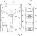
- FIG. 4is schematic side view of one embodiment of components of a magnetocardiography (MCG) or other magnetic field measurement system including a passively shielded enclosure, according to the invention
- FIG. 5is schematic plan view of one embodiment of an MCG or other magnetic field measurement system including a passively shielded enclosure with a shielded door, according to the invention
- FIG. 6is schematic plan view of one embodiment of an MCG or other magnetic field measurement system including a passively shielded enclosure with an open entryway, according to the invention
- FIGS. 7 A and 7 Bare a schematic side view of one embodiment of a passively shielded enclosure in which a user can use exercise equipment during MCG measurement, according to the invention
- FIG. 8is schematic plan view of one embodiment of an MCG or other magnetic field measurement system including a passively shielded enclosure with an open entryway for multiple users, according to the invention
- FIG. 9is schematic side view of one embodiment of components of an MCG or other magnetic field measurement system including a passively shielded enclosure on a mobile platform, according to the invention.
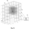
- FIG. 10is an illustration of an array of active shield coils with a user within the array, according to the invention.
- the present disclosureis directed to the area of magnetic field measurement systems including systems for recording biomagnetic fields of, or near, the heart.
- the present disclosureis also directed to magnetic field measurement systems and methods for suppressing background or interfering magnetic fields.
- the present disclosureutilizes the measurement of biomagnetic fields of, or near the heart to exemplify the OPMs, systems, and methods described herein, it will be understood that the OPMs, systems, and methods can be used in any other suitable application.
- ambient background magnetic fieldand “background magnetic field” are interchangeable and used to identify the magnetic field or fields associated with sources other than the magnetic field measurement system and the magnetic field sources of interest, such as biological source(s) (for example, magnetic signals from a user's heart) or non-biological source(s) of interest.
- the termscan include, for example, the Earth's magnetic field, as well as magnetic fields from magnets, electromagnets, electrical devices, and other signal or field generators in the environment, except for the magnetic field generator(s) that are part of the magnetic field measurement system.
- gas cellvapor cell
- vapor gas cellvapor gas cell
- An optically pumped magnetometeris a basic component used in optical magnetometry to measure magnetic fields. While there are many types of OPMs, in general magnetometers operate in two modalities: vector mode and scalar mode. In vector mode, the OPM can measure one, two, or all three vector components of the magnetic field; while in scalar mode the OPM can measure the total magnitude of the magnetic field.
- Vector mode magnetometersmeasure a specific component of the magnetic field, such as the radial and tangential components of magnetic fields with respect to the body of user.
- Vector mode OPMsoften operate at zero-field and may utilize a spin exchange relaxation free (SERF) mode to reach femto-Tesla sensitivities.
- SERF mode OPMis one example of a vector mode OPM, but other vector mode OPMs can be used at higher magnetic fields.
- SERF mode magnetometerscan have high sensitivity but may not function in the presence of magnetic fields higher than the linewidth of the magnetic resonance of the atoms of about 10 nT, which is much smaller than the magnetic field strength generated by the Earth.
- conventional SERF mode magnetometersoften operate inside magnetically shielded rooms that isolate the sensor from ambient magnetic fields including Earth's magnetic field.
- Magnetometers operating in the scalar modecan measure the total magnitude of the magnetic field. (Magnetometers in the vector mode can also be used for magnitude measurements.) Scalar mode OPMs often have lower sensitivity than SERF mode OPMs and are capable of operating in higher magnetic field environments.
- the magnetic field measurement systems described hereincan be used to measure or observe electromagnetic signals generated by one or more magnetic field sources (for example, biomagnetic signals from the heart or other biological sources) of interest.
- the systemcan measure biologically generated magnetic fields and, at least in some embodiments, can measure biologically generated magnetic fields in an unshielded or partially shielded environment. Aspects of a magnetic field measurement system will be exemplified below using magnetic signals from, or near, the heart of a user; however, biological signals from other areas of the body, as well as non-biological signals, can be measured using the system. This technology can also be applicable for uses outside biomedical sensing.
- the systemcan be a wearable MCG system that can be used outside a magnetically shielded room.
- FIG. 1 Ais a block diagram of components of one embodiment of a magnetic field measurement system 140 .
- the system 140can include a computing device 150 or any other similar device that includes a processor 152 , a memory 154 , a display 156 , an input device 158 , one or more magnetometers 160 (for example, an array of magnetometers) which can be OPMs, one or more magnetic field generators 162 , and, optionally, one or more other sensors 164 (e.g., non-magnetic field sensors).
- the system 140 and its use and operationwill be described herein with respect to the measurement of cardiac signals arising from one or more magnetic field sources of interest in or near the heart of a user as an example. It will be understood, however, that the system can be adapted and used to measure signals from other magnetic field sources of interest including, but not limited to, other neural signals, other biological signals, as well as non-biological signals.
- the computing device 150can be a computer, tablet, mobile device, field programmable gate array (FPGA), microcontroller, or any other suitable device for processing information or instructions.
- the computing device 150can be local to the user or can include components that are non-local to the user including one or both of the processor 152 or memory 154 (or portions thereof).
- the usermay operate a terminal that is connected to a non-local computing device.
- the memory 154can be non-local to the user.
- the computing device 150can utilize any suitable processor 152 including one or more hardware processors that may be local to the user or non-local to the user or other components of the computing device.
- the memory 154illustrates a type of computer-readable media, namely computer-readable storage media.
- Computer-readable storage mediamay include, but is not limited to, volatile, nonvolatile, non-transitory, removable, and non-removable media implemented in any method or technology for storage of information, such as computer readable instructions, data structures, program modules, or other data. Examples of computer-readable storage media include RAM, ROM, EEPROM, flash memory, or other memory technology, CD-ROM, digital versatile disks (“DVD”) or other optical storage, magnetic cassettes, magnetic tape, magnetic disk storage or other magnetic storage devices, or any other medium which can be used to store the desired information and which can be accessed by a computing device.
- Communication methodsprovide another type of computer readable media; namely communication media.
- Communication mediatypically embodies computer-readable instructions, data structures, program modules, or other data in a modulated data signal such as a carrier wave, data signal, or other transport mechanism and include any information delivery media.
- modulated data signaland “carrier-wave signal” includes a signal that has one or more of its characteristics set or changed in such a manner as to encode information, instructions, data, and the like, in the signal.
- communication mediaincludes wired media such as twisted pair, coaxial cable, fiber optics, wave guides, and other wired media and wireless media such as acoustic, RF, infrared, and other wireless media.
- the display 156can be any suitable display device, such as a monitor, screen, or the like, and can include a printer. In some embodiments, the display is optional. In some embodiments, the display 156 may be integrated into a single unit with the computing device 150 , such as a tablet, smart phone, or smart watch. In at least some embodiments, the display is not local to the user.
- the input device 158can be, for example, a keyboard, mouse, touch screen, track ball, joystick, voice recognition system, or any combination thereof, or the like. In at least some embodiments, the input device is not local to the user.
- the magnetic field generator(s) 162can be, for example, Helmholtz coils, solenoid coils, planar coils, saddle coils, electromagnets, permanent magnets, or any other suitable arrangement for generating a magnetic field.
- the magnetic field generator 162can include three orthogonal sets of coils to generate magnetic fields along three orthogonal axes. Other coil arrangements can also be used.
- the optional sensor(s) 164can include, but are not limited to, one or more position sensors, orientation sensors, accelerometers, image recorders, or the like or any combination thereof.
- the one or more magnetometers 160can be any suitable magnetometer including, but not limited to, any suitable optically pumped magnetometer. Arrays of magnetometers are described in more detail herein. In at least some embodiments, at least one of the one or more magnetometers (or all of the magnetometers) of the system is arranged for operation in the SERF mode. Examples of magnetic field measurement systems, including arrangements for magnetoencephalography (MEG) which can be used or modified for magnetocardiography (MCG), or methods of making such systems or components for such systems are described in U.S. Patent Application Publications Nos.
- MEGmagnetoencephalography
- MCGmagnetocardiography
- FIG. 1 Bis a schematic block diagram of one embodiment of a magnetometer 160 which includes a vapor cell 170 (also referred to as a “cell” or “vapor cell”) such as an alkali metal vapor cell; a heating device 176 to heat the cell 170 ; a light source 172 ; and a detector 174 .
- a vapor cell 170also referred to as a “cell” or “vapor cell”
- a heating device 176to heat the cell 170
- a light source 172to heat the cell 170
- a detector 174detector
- coils of a magnetic field generator 162can be positioned around the vapor cell 170 .
- the vapor cell 170can include, for example, an alkali metal vapor (for example, rubidium in natural abundance, isotopically enriched rubidium, potassium, or cesium, or any other suitable alkali metal such as lithium, sodium, or francium) and, optionally, one, or both, of a quenching gas (for example, nitrogen) and a buffer gas (for example, nitrogen, helium, neon, or argon).
- the vapor cellmay include the alkali metal atoms in a prevaporized form prior to heating to generate the vapor.
- the pump and probe light sources 172 a , 172 bcan each include, for example, a laser to, respectively, optically pump the alkali metal atoms and probe the vapor cell.
- the pump and probe light sources 172 a , 172 bmay also include optics (such as lenses, waveplates, collimators, polarizers, and objects with reflective surfaces) for beam shaping and polarization control and for directing the light from the light source to the cell and detector.
- suitable light sourcesinclude, but are not limited to, a diode laser (such as a vertical-cavity surface-emitting laser (VCSEL), distributed Bragg reflector laser (DBR), or distributed feedback laser (DFB)), light-emitting diode (LED), lamp, or any other suitable light source.
- a diode lasersuch as a vertical-cavity surface-emitting laser (VCSEL), distributed Bragg reflector laser (DBR), or distributed feedback laser (DFB)
- VCSELvertical-cavity surface-emitting laser
- DBRdistributed Bragg reflector laser
- DFBdistributed feedback laser
- LEDlight-emitting diode
- lampor any other suitable light source.
- the detector 174can include, for example, an optical detector to measure the optical properties of the transmitted probe light field amplitude, phase, or polarization, as quantified through optical absorption and dispersion curves, spectrum, or polarization or the like or any combination thereof.
- suitable detectorsinclude, but are not limited to, a photodiode, charge coupled device (CCD) array, CMOS array, camera, photodiode array, single photon avalanche diode (SPAD) array, avalanche photodiode (APD) array, or any other suitable optical sensor array that can measure the change in transmitted light at the optical wavelengths of interest.
- FIG. 2shows the magnetic spectrum from 1 fT to 100 ⁇ T in magnetic field strength on a logarithmic scale.
- the magnitude of magnetic fields generated by the human brainare indicated by range 201 and the magnitude of the background ambient magnetic field, including the Earth's magnetic field, by range 202 .
- the strength of the Earth's magnetic fieldcovers a range as it depends on the position on the Earth as well as the materials of the surrounding environment where the magnetic field is measured.
- Range 210indicates the approximate measurement range of a magnetometer (e.g., an OPM) operating in the SERF mode (e.g., a SERF magnetometer) and range 211 indicates the approximate measurement range of a magnetometer operating in a scalar mode (e.g., a scalar magnetometer.)
- a SERF magnetometeris more sensitive than a scalar magnetometer, but many conventional SERF magnetometers typically only operate up to about 0 to 200 nT while the scalar magnetometer starts in the 10 to 100 fT range but extends above 10 to 100 ⁇ T.
- Magnetocardiographytechnologies measure cardiac activity by recording magnetic fields produced by electrical currents occurring naturally in the heart.
- MCG systemscan utilize SQUIDs (superconducting quantum interference devices) or OPMs (optically pumped magnetometers) to detect and record the magnetic fields.
- SQUID-MCG systemscan suffer from unnatural user motion constraints due to the bulk of the SQUID sensors and associated insulation.
- OPMsattain sufficient sensitivity to acquire magnetic signals, such as cardio-magnetic signals, when operating in low ambient background magnetic fields.
- “low”indicates magnetic field strengths that are a fraction of the linewidth of the magnetic resonance of the OPM, which is typically in the 1 to tens of nanoTesla.
- the ordinary environmental ambient background magnetic field in human-relevant contexts on Earthis typically on the order of 50 microTesla at low frequency, and hundreds of nanoTesla root-mean-square (RMS) amplitude at the harmonics of the local powerline frequencies. This unmitigated ambient background magnetic field is large with respect to typical magnetic resonance linewidths of OPMs.
- OPMs with optical pumping parameters selected for relatively small magnetic resonance linewidthmay have limited dynamic range and typically utilize high magnetic field shielding (for example, a passively shielded room or an active shielding arrangement or a combination thereof) to reduce the ambient background magnetic field.
- high magnetic field shieldingfor example, a passively shielded room or an active shielding arrangement or a combination thereof
- OPM-MCG with no passive shieldingmay suffer from stringent requirements for wearable active shielding components, which may reduce signal-to-noise because of high-current driver electronics noise.
- Such OPM arrangementsmay prevent or hinder dense coverage with OPMs by having large wearable coil systems to provide the needed active shielding. This can result in a relatively large fraction of volume unusable for
- OPM coverage within each OPM module due to the active shieldingcan also result in limited nearest-neighbor OPM module packing density.
- Such coil systemsmay also reduce signal-to-noise because of high-current driver electronics noise and may prevent dense full human chest coverage with a relatively large number of OPMs.
- MCGmagnetocardiography
- AN MCG systemwill be used herein to describe the systems and methods, but it will be understood that the disclosed elements can also be used with other magnetic field measurement systems.
- MCG systems, as described hereincan induce OPMs as described herein and in the cited references and can provide high fidelity recordings.
- these MCG systems and methodsallow for user motion (such as exercise) and various activities such as, for example, sitting, standing, exercising, or sleeping during the MCG recordings.
- the MCG systemcan include a comfortable, manufacturable magnetically shielded environment (MSE) that includes a combination of passive and active shield components.
- MSEmanufacturable magnetically shielded environment
- the ambient background magnetic fieldis attenuated by a stationary passive shield enclosure. “Stationary” means stationary with respect to the user(s).
- the ambient background magnetic fieldcan be further attenuated by stationary active shield components, such as one or more arrays of coils fixed to, or disposed within, the interior of the passively shielded enclosure.
- the residual ambient background magnetic fieldcan also be attenuated by active shield components, such as the magnetic field generators 162 of FIGS. 1 A and 1 B (which are optionally wearable).
- the optically pumped magnetometer (OPM) sensor modulesinclude integrated active shield components (for example, active shield coils and the magnetic field generators 162 of FIGS. 1 A and 1 B ).
- the active shield coilscan have an operating range sufficient to overlap with the lower bound of the residual ambient background magnetic field that penetrates the stationary passively shielded enclosure and reduced by the optional active shield fixed to, or disposed within, the passively shielded enclosure.
- OPM modules with active shield coilscan provide a substantially uniform ambient background magnetic field across an ensemble of multiple OPMs within one OPM module.
- the systemusing these passive and active shield components, can provide dense human chest coverage with at least 36 to 1000 OPMs per user.
- the MCG systemcan also include other components, such as, OPM controller electronics to control operation of the OPMs; OPM laser(s) and fiber optic light delivery system(s) from the laser(s) to the OPMs; OPM detector electronics coupled to the OPMs to receive detected cardiac signals from the OPMs; a control computing device (for example, a desktop or laptop computer) that interfaces with the OPM controller electronics and OPM detector electronics; a mechanical support for the OPM modules; active shield driver(s) to power and control the active shield components; and user interaction components (UIC) including, but not limited to, a controller, keyboard, screen, audio components, or head or eye movement tracking components including magnetic, gyroscopic, optical, and visual tracking components.
- OPM controller electronicsto control operation of the OPMs
- OPM detector electronicscoupled to the OPMs to receive detected cardiac signals from the OPMs
- a control computing devicefor example, a
- the MCG systemcan also include software (for example, software residing on the control computer or other computing device) to record magnetic cardiac signals, environmental signals, user motion; to provide a user interface control; to provide stimulus inputs to a user; or any combination thereof.
- softwarefor example, software residing on the control computer or other computing device to record magnetic cardiac signals, environmental signals, user motion; to provide a user interface control; to provide stimulus inputs to a user; or any combination thereof.
- the references cited hereininclude examples of these components and software that can be utilized in the MCG systems (and other magnetic field measurement systems) described herein.
- FIG. 3illustrates one embodiment of parameter interactions of a magnetic field measurement system in relation to the total input magnetic field at the OPM.
- the horizontal axisindicates the magnitude of the magnetic field on a logarithmic scale.
- a typical OPM magnetic resonance response 330(such as a dispersive Lorentzian) has a limited operating domain 331 for best sensitivity, given by the width of the magnetic resonance. This domain is usually no greater than tens of nano-Tesla (nT).
- FIG. 3illustrates a specific example of an OPM with a 60 nT domain maximum.
- the shielding components of an MCG systemreduce the total magnitude of the ambient background magnetic field to a value less than the maximum of this domain, and preferably much less than the domain maximum, to enable sufficient sensitivity for acquisition of faint signals such as those due to cardiac or neural signals or other sources of biomagnetism. As described herein, this can be accomplished with a combination of passive and active shielding components.
- Region 332illustrates the magnitude of the ambient background magnetic field without any attenuation.
- the ambient background magnetic fieldis attenuated from approximately 50,000 nT by a comfortable stationary passively shielded enclosure having a moderate shielding factor on the order of 200 to 250 to produce a resulting ambient background magnetic field in region 334 , as described herein.
- the shielding factor or a passively shielded enclosurecan be in a range of 50 to 500.
- achieving a higher passive shielding factormay be less desirable from the standpoint of user comfort because such passive shielding factors may require the use of a sealed door to achieve the passive shielding factor. Higher passive shielding factors may also degrade manufacturability which could limit population-scale studies or use.
- the residual unshielded fraction of the ambient background magnetic fieldcan be further attenuated by a stationary active shield system.
- active shield coilscan be affixed (for example, as panels or other structural elements) to the interior walls of, or otherwise disposed or positioned within, the stationary passively shielded enclosure.
- the MCG or other magnetic field measurement systemcan include a passively shielded enclosure with active shield coils in the form of panels to provide a substantial actively shielded open volume which can permit substantial user motion.
- the active shield coilscan be used to allow for user motion by shifting the region in which the ambient background magnetic field is most reduced as the user moves.
- the stationary active shield systemcan include an active shield control system to monitor the residual ambient background magnetic field in the passively shielded enclosure and attenuate the residual ambient background magnetic field within a target region inside the passively shielded enclosure.
- the active shield control systemcan alter the magnetic fields generated by the active shield system to move the target region with the lowest residual ambient background magnetic field to, for example, follow movements of the user.
- the stationary active shield systemmay be optionally enhanced by user-tracking feedback control that tracks the user's movement within the actively shielded volume inside the stationary passively shielded enclosure to maintain the OPMs in a target region of reduced ambient background magnetic field of some usable volume that can move with the user.
- the residual ambient background magnetic fieldcan be further attenuated to a region 336 by an active shield subsystem (such as magnetic field generators 162 of FIGS. 1 A and 1 B ) which may be wearable
- the active shield subsystemcan facilitate user comfort with high performance by use of compact coils and low-noise electronics. In at least some embodiments, these are enabled by limiting the maximum domain of the operating range of the active shield system to generating attenuating magnetic fields no greater than approximately 1000 nT.
- the OPMis operated in a large-magnetic-linewidth regime to increase the domain of operation to encompass the residual unshielded fraction of the ambient background magnetic field that passes through the passive and active shield subsystems.
- One method to attain large linewidth in an OPMincludes operating with relatively high input light power, which causes power broadening of the intrinsic magnetic resonance. This method has the additional advantages of: 1) integrating well with the active and passive shield subsystems via lightweight, flexible optical-fiber tether to a distant high-power laser source while maintaining user comfort and allowing user movement; or 2) increasing the magnetic resonance linewidth, without substantially degrading the OPM performance, in the domain where OPM noise is determined by the pump laser photon shot noise.
- An MCG or other magnetic field measurement systemcan include a number of OPMs disposed in an MCG measurement device.
- the MCG measurement devicecan be a wearable device in the form of vest, harness, or the like or in a device (which is optionally mounted and may be portable) that the user moves or stands near (or next to) or leans upon.
- the OPM linear range or operating domainis at least 20 nT.
- the number of OPMs in the MCG measurement deviceis at least 5, 10, 12, 15, 20, 25, 32, 50, 64, 100, 128, 200, or more.
- the systemincludes at least 5, 10, 12, 15, 20, or more OPMs on, or near, the chest of the user.
- the active magnetic shield coilscan compensate for an ambient background magnetic field of at least 50 nT.
- the residual ambient background magnetic field after reduction by passive shielding of an MCG systemis in the range of 50 to 1000 nT.
- the residual ambient background magnetic field around the user after reduction by the optional stationary active shield coilsis no more than 50, 75, or 100 nT.
- FIG. 4illustrates a cross-sectional view of at least some components of one embodiment of an MCG or other magnetic field measurement system 400 with a shielding arrangement 401 .
- the user 406is wearing or standing/moving near an MCG measurement device 405 (for example, a sensor vest, harness, or non-wearable device) populated with OPM modules 403 .
- the user 406is in a magnetically shielded environment (MSE) formed by the shielding arrangement 401 to reduce the ambient background magnetic field for operation of the OPM modules 403 and measurement of cardiac signals using the OPM modules.
- MSEmagnetically shielded environment
- the shielding arrangement 401can be, for example, a combination of passive shielding, for example, a passively shielded enclosure 407 (such as a passively shielded room), and optional active shielding for reduction of the residual ambient background magnetic field by, for example, active shield coils 418 (e.g., electromagnetic coils).
- passive shieldingfor example, a passively shielded enclosure 407 (such as a passively shielded room)
- active shield coils 418e.g., electromagnetic coils
- the passively shielded enclosure 407can be made using passive shielding material, such as mu-metal or permalloy, or any other suitable material that reduces the ambient background magnetic field within the passively shielded enclosure.
- the passively shielded enclosure 407can be a room and can include a floor 407 a , a ceiling 407 b , and one or more vertical walls 407 c extending from the floor to the ceiling.
- Each of the floor 407 a , ceiling 407 b , and vertical wall(s) 407 ccan include the passive shielding material.
- FIG. 5is a plan view of one embodiment of a passively shielded enclosure 407 in which a user 406 is seated on a chair 414 with the MCG measurement device 405 .
- This passively shielded enclosure 407includes a floor 407 a , a ceiling (not shown), and multiple vertical walls 407 c , as well as a door 408 , one or more (or all) of which include the passive shielding material.
- the optional active shield coils 418are disposed on the vertical walls 407 c and, optionally, the door 408 .
- active shield coils 418may also be disposed on the floor 407 a or ceiling (not shown) or both.
- some or all of the active shield coilscan be disposed around the passively shielded enclosure.
- one or more of the active shield coils 418can be free-standing elements disposed in the passively shielded enclosure 407 .
- the passively shielded enclosure 407 of FIG. 5may pose challenges for use.
- the door 408may be a weak region in the passive shielding.
- the door 408may be large, heavy, or otherwise imposing.
- the passively shielded enclosure 407may also feel uncomfortable or claustrophobic to at least some individuals, particularly when the door is closed.
- FIG. 6illustrates another embodiment of a passively shielded enclosure 407 with a user 406 seated in a chair with the MCG measurement device 405 .
- This passively shielded enclosure 407includes a floor 407 a , ceiling (not shown), and multiple vertical walls 407 c , as well as a vestibular wall 407 d , all of which include the passive shielding material.
- the vestibular wall 407 dcan spatially separate the space into a vestibular area 409 a and a user area 409 b .
- This passively shielded enclosure 407does not include a door, but rather has an open entryway 408 a .
- the vestibular wall 407 d and vestibular area 409 aremove the need for a shielded door.
- the vestibular wall 407 dat least partially separates the user area 409 b from the open entryway 408 a . Removing the shielded door can greatly improve the user experience and feeling of openness but may reduce the shielding factor of the passively shielded enclosure 407 .
- the presence of an open entryway 408 aalthough separated from the user 406 by the vestibular wall 407 d , may result in the passively shielded enclosure 407 feeling more comfortable or less claustrophobic for the user.
- the vestibular wall 407 dcan extend from one of the vertical walls 407 c toward another one of the vertical walls, as illustrated in FIG. 6 .
- the vestibular wall 407 dcan extend from floor 407 a to ceiling (not shown).
- the vestibular wall 407 dmay not extend all of the way to the floor 407 a or the ceiling (not shown) or both.
- the absence of a door to the passively shielded enclosure 407 and the use of the vestibular wall 407 d and vestibular area 409 amay make access (entry and exit) easier and more natural for a user or technical/medical personnel.
- compensation for reduced passive shielding due to the absence of the doorcan be achieved through the use of the vestibular wall 407 d , which may reduce the ambient background magnetic field within the user area 409 b of the passively shielded enclosure 407 which may be enhanced by the optional incorporation of passive shielding material in the vestibular wall.
- further reductioncan be achieved using the optional active shield coils 418 in the passively shielded enclosure and the active shield coils within the OPM modules 403 .
- the optional active shield coils 418are disposed on the vertical walls 407 c and, optionally, the vestibular wall 407 d . Passive shielding on the vestibular wall 407 d or the active shield coils 418 (or both) can be used to compensate for the loss of passive shielding at the open entryway 408 a . In at least some embodiments, active shield coils 418 may also be disposed on the floor 407 a or ceiling (not shown) or both.
- the active shield coils 418instead of disposing the active shield coils 418 on the vertical walls 407 c , vestibular wall 407 d , or other parts of the passively shielded enclosure 407 , some or all of the active shield coils can be disposed around the passively shielded enclosure. In at least some embodiments, one or more of the active shield coils 418 can be free-standing elements disposed in the passively shielded enclosure 407 .
- an active shield controller 424is coupled to the active shield coils 418 to control the reduction in the ambient background magnetic field within the passively shielded enclosure 407 .
- the active shield controller 424has multiple channels with one or more of the active shield coils 418 coupled to each channel. For example, there can be two, three, four, six, eight, ten, twelve, 15, 20, 25, or more channels and two, four, six, eight, ten, twelve, 15, 20, 25, 30, 32, 40, 50, 60, 64, 70, 80, 90, 100, 120, 128, or more active shield coils.
- two or more of the channelsare independently operable meaning that operation of the independent channels does not depend on the other channels.
- the active shield coils 418are conductive wire or conductive traces and may be mounted on a substrate, such as a printed circuit board substrate.
- user movementis monitored through one or more (for example, a combination of two or more) sensing modalities including, but not limited to, optical tracking 412 , magnetic tracking implemented through the OPM modules 403 or other magnetic tracking units, inertial tracking, or ultrasound tracking or the like.
- the sensing modalitiesmay also be used to track the pose (position and orientation) of the MCG measurement device 405 and OPM modules 403 .
- the usermay be free standing, seated in a chair 414 , or sleeping. Examples of sensing modalities systems, as used in the magnetically shielded environments described herein, or methods of using such systems, are described more fully in U.S. Provisional Patent Applications Ser. Nos. 63/052,327; 63/076,880; 63/080,248; and 63/135,364, all of which are incorporated herein by reference in its entirety.
- the active shield controller 424alters the magnetic fields generated by the active shield coils 418 to control the reduction in the ambient background magnetic field around the MCG measurement device 405 and OPM modules 403 .
- the residual ambient background magnetic field after reduction using the active shield coils 418is not uniform within the passively shielded enclosure 407 , but instead has a region with the lowest residual ambient background magnetic field that can be shifted or moved, using the active shield controller 424 and in response to the detection of user movement by the one or more sensing modalities, to remain at or near the MCG measurement device 405 and OPM modules 403 .
- passive shielding with relatively high shielding factortypically greater than 5000
- active shieldingis used.
- the MCG or other magnetic field measurement system disclosed hereinuses both, with reduced requirements on the shielding factor from either passive or active shielding, in concert with a relatively large magnetic linewidth provided by suitable choice of optical pumping parameters in the OPM module.
- the passive shielding factor requirementscan be on the order of 200 to 300.
- this passive shielding factorcan allow for a door-free, single-layer mu-metal environment.
- the active shielding currentscan be achieved using low power electronics, on the order of 100 s of mA, and therefore the active field magnitudes are similarly achieved.
- optical pumping parameterscan be attained by high-power laser sources, which are remote with respect to the OPMs and coupled optically by flexible, lightweight fiber optic lines.
- the systems and methodsprovide for the acquisition of cardiac data in environmental conditions conducive to unbiased, natural human response.
- the MCG or other magnetic field measurement systemallows for user movement, accessibility (no locking hinged-door required), and peripheral support by combining open-shielding, high dynamic range OPMs, and sophisticated control all in a single system.
- the usercan move freely and, at least in some embodiments, the user's motions are tracked by visual tracking software, which is digitized, saved, and time synced with the cardiac signal data (e.g., MCG data).
- the user's motionsare fed back into the control system to (for example, constantly or periodically) adjust the active shielding to reduce the ambient background magnetic field to the operational range of the OPMs at the location of the user.
- FIGS. 7 A and 7 Billustrate a user 406 actively exercising within a passively shielded enclosure 407 and monitored by the MCG measurement device 405 .
- Exercise equipment 438may be used as necessary and could include steps, treadmill, cycle, stair-climber, trampoline, or the like or any other suitable exercise equipment.
- Oxygen usage monitoring/delivery equipment 439 or other biomonitoring equipmente.g., blood pressure cuffs, pulse oximeters, or the like
- biomonitoring equipmente.g., blood pressure cuffs, pulse oximeters, or the like
- FIG. 8is a top view of an embodiment of a passively shielded enclosure 407 with an open entryway 408 a for a multi-user (for example, users 406 a , 406 b ) MCG or other magnetic field measurement system.
- a multi-userfor example, users 406 a , 406 b
- MCGmagnetic field measurement system
- FIG. 9illustrates one embodiment of a mobile MCG or other magnetic field measurement system by mounting the passively shielded enclosure 407 (with or without a shield door 408 ) on a mobile platform 980 that could be any of, but not limited to, a trailer, shipping container, train car, airplane, watercraft, van, recreational vehicle, or the like.
- the mobile MCG system described hereincan be easily moved from location to location, as necessary. This can be particularly useful for locating the MCG system in close proximity to a testing site of a population or other study.
- the user 406can experience audio/visual stimulus from a screen or monitor 411 with or without sound generation capability.
- the MCG or other magnetic field measurement systemcan use the measured cardiac signals to provide feedback based on the audio/visual stimulus.
- the MCG or other magnetic field measurement systemcan also include one or more peripheral input devices 413 to provide feedback based on the audio/visual stimulus through one or more of the following: cardiac activity (for example, the MCG signal), spoken response, movement, touch, or any other suitable mechanism.
- peripheral input devicesinclude, but are not limited to, microphones, joysticks, hand-held controllers or the like, a mouse, buttons, cameras (for example, to detect eye motion, gaze direction, blinking, facial expression, hand or limb movement, or the like or any combination thereof), biometric devices (for example, to detect heart rate, respiration rate, skin conductivity, or the like or any combination thereof), or the like or any combination thereof
- the large dynamic range of the OPMsallows for the use of peripheral devices 413 which may have an associated active magnetic field due to electrical currents in the peripheral device or passive fields due to ferromagnetic materials such as nickel or iron.
- the MCG system 400can include one or more exterior equipment cabinets 426 that provide storage for one or more of a system controller 421 (for example, an OPM/detector controller), a system computer 422 , lasers 423 , or the active shield controller 424 . Examples of these components can be found in the references cited above and incorporated herein by reference in their entireties.
- a system controller 421for example, an OPM/detector controller
- system computer 422for example, a system computer 422 , lasers 423 , or the active shield controller 424 . Examples of these components can be found in the references cited above and incorporated herein by reference in their entireties.
- FIG. 10illustrates one embodiment of the active shield coils.
- a quantity of seventy ( 70 ) shield coils 418are shown as boxes.
- each of the shield coils 418corresponds to a different independent channel, although in some embodiments, each channel might be coupled to two, three, four, or more shield coils.
- the shield coils 418are 50 cm ⁇ 50 cm square loops placed on the four vertical walls closest to the user 406 , but not on the floor or ceiling or in the vestibule.
- This configurationcan generate a large zero-field region around the user 406 where a residual ambient background magnetic field of 300 ⁇ T can be reduced to less 57 nT.
- a residual ambient background magnetic field of 300 ⁇ Tcan be reduced to less 57 nT.
- the maximum current to achieve thisis 190 mA.
- the active shield controller 424generates the control signals for each of the shield coils.
- the MCG or other magnetic field measurement systems and methods described hereincan use one or more of the following: a door-free stationary passive shielded environment; an optional stationary active compensation coil array with, in at least some embodiments, 10 or more independent control channels; magnetic user tracking; large dynamic range (i.e., large magnetic linewidth) OPMs, for example, larger than 20 nT; a modular (optionally wearable) active shielding system; arrays of OPMs within each active shielding module; or integrated screen(s), speaker(s), or peripheral(s) or any combination thereof.
- the systemcan be fully enclosed and optionally can be transported as a single unit and may include wheels (for example, a trailer, as shown in FIG. 9 ).
- the systemcan include an optical user tracking system, an optical user pose identification system, or the like or any combination thereof.
- the favorable manufacturability and low cost of the disclosed simple stationary passive shield arrangement of the MCG systems described abovecan better allow for population-level studies, cardiac studies, drug studies, health/wellness studies, other medical studies, user exercise/movement studies, sleep studies, meditation studies, product or consumer studies, or the like or any combination thereof, particularly the studies which utilize a relatively large population of participants/subjects, as compared to the current state-of-the-art MCG systems.
Landscapes
- Health & Medical Sciences (AREA)
- Life Sciences & Earth Sciences (AREA)
- Physics & Mathematics (AREA)
- Engineering & Computer Science (AREA)
- Animal Behavior & Ethology (AREA)
- Veterinary Medicine (AREA)
- Biophysics (AREA)
- Biomedical Technology (AREA)
- Heart & Thoracic Surgery (AREA)
- Medical Informatics (AREA)
- Molecular Biology (AREA)
- Surgery (AREA)
- Pathology (AREA)
- General Health & Medical Sciences (AREA)
- Public Health (AREA)
- Condensed Matter Physics & Semiconductors (AREA)
- General Physics & Mathematics (AREA)
- Nuclear Medicine, Radiotherapy & Molecular Imaging (AREA)
- Cardiology (AREA)
- Radiology & Medical Imaging (AREA)
- Epidemiology (AREA)
- Environmental & Geological Engineering (AREA)
- Toxicology (AREA)
- Power Engineering (AREA)
- Measurement And Recording Of Electrical Phenomena And Electrical Characteristics Of The Living Body (AREA)
Abstract
Description
Claims (20)
Priority Applications (1)
| Application Number | Priority Date | Filing Date | Title |
|---|---|---|---|
| US17/328,315US11779250B2 (en) | 2020-05-28 | 2021-05-24 | Systems and methods for recording biomagnetic fields of the human heart |
Applications Claiming Priority (9)
| Application Number | Priority Date | Filing Date | Title |
|---|---|---|---|
| US202063031469P | 2020-05-28 | 2020-05-28 | |
| US202063052327P | 2020-07-15 | 2020-07-15 | |
| US202063076015P | 2020-09-09 | 2020-09-09 | |
| US202063076880P | 2020-09-10 | 2020-09-10 | |
| US202063080248P | 2020-09-18 | 2020-09-18 | |
| US202063089456P | 2020-10-08 | 2020-10-08 | |
| US202163136093P | 2021-01-11 | 2021-01-11 | |
| US202163140150P | 2021-01-21 | 2021-01-21 | |
| US17/328,315US11779250B2 (en) | 2020-05-28 | 2021-05-24 | Systems and methods for recording biomagnetic fields of the human heart |
Publications (2)
| Publication Number | Publication Date |
|---|---|
| US20210369165A1 US20210369165A1 (en) | 2021-12-02 |
| US11779250B2true US11779250B2 (en) | 2023-10-10 |
Family
ID=76523452
Family Applications (1)
| Application Number | Title | Priority Date | Filing Date |
|---|---|---|---|
| US17/328,315Active2042-05-19US11779250B2 (en) | 2020-05-28 | 2021-05-24 | Systems and methods for recording biomagnetic fields of the human heart |
Country Status (2)
| Country | Link |
|---|---|
| US (1) | US11779250B2 (en) |
| WO (1) | WO2021242682A1 (en) |
Families Citing this family (5)
| Publication number | Priority date | Publication date | Assignee | Title |
|---|---|---|---|---|
| WO2021242680A1 (en)* | 2020-05-28 | 2021-12-02 | Hi Llc | Systems and methods for recording neural activity |
| CN113974576B (en)* | 2021-12-23 | 2022-04-22 | 北京航空航天大学杭州创新研究院 | Sleep quality monitoring system and monitoring method based on magnetocardiogram |
| CN115778395B (en)* | 2022-11-08 | 2024-12-10 | 成都原力辰教育科技有限公司 | A cardiac magnetic field measurement system, method, electronic device and storage medium |
| WO2024196890A1 (en)* | 2023-03-17 | 2024-09-26 | SB Technology, Inc. | Systems and methods for biomagnetic field imaging |
| US12310734B2 (en) | 2023-03-17 | 2025-05-27 | SB Technology, Inc. | Systems and methods for biomagnetic field imaging |
Citations (158)
| Publication number | Priority date | Publication date | Assignee | Title |
|---|---|---|---|---|
| US3173082A (en) | 1961-03-14 | 1965-03-09 | Varian Associates | Optically driven spin precession method and apparatus |
| US3257608A (en) | 1961-02-02 | 1966-06-21 | Varian Associates | Optical magnetometers |
| US3495161A (en) | 1967-01-19 | 1970-02-10 | Varian Associates | Optically driven atomic resonator systems employing means for modulating the sense of rotational polarization of the pumping light |
| US3501689A (en) | 1966-06-06 | 1970-03-17 | Varian Associates | Magnetometer |
| US3513381A (en) | 1967-07-17 | 1970-05-19 | Varian Associates | Off-resonant light as a probe of optically pumped alkali vapors |
| US4193029A (en) | 1963-03-04 | 1980-03-11 | The United States Of America As Represented By The Secretary Of The Navy | Pulsed helium magnetometer |
| US4951674A (en) | 1989-03-20 | 1990-08-28 | Zanakis Michael F | Biomagnetic analytical system using fiber-optic magnetic sensors |
| US5018724A (en)* | 1988-11-28 | 1991-05-28 | Siemens Aktiengesellschaft | Arrangement for measuring physiologically generated weak biomagnetic signals while the examination subject is at rest and exercising |
| WO1992001362A1 (en) | 1990-07-12 | 1992-01-23 | Biomagnetic Technologies, Inc. | Construction of shielded room for biomagnetic measurements |
| US5189368A (en) | 1976-09-24 | 1993-02-23 | Lockheed Sanders, Inc. | Magnetometer |
| US5192921A (en) | 1991-12-31 | 1993-03-09 | Westinghouse Electric Corp. | Miniaturized atomic frequency standard |
| US5225778A (en) | 1990-06-14 | 1993-07-06 | Commissariat A L'energie Atomique | Optical pumping, resonance magnetometer using a sequential polarization |
| US5254947A (en) | 1990-06-14 | 1993-10-19 | Commissariat A L'energie Atomique | Optical pumping, resonance magnetometer using a plurality of multiplexed beams |
| US5309095A (en) | 1990-12-21 | 1994-05-03 | Neuromag Oy | Compact magnetometer probe and an array of them covering the whole human skull for measurement of magnetic fields arising from the activity of the brain |
| US5442289A (en) | 1989-07-31 | 1995-08-15 | Biomagnetic Technologies, Inc. | Biomagnetometer having flexible sensor |
| US5444372A (en) | 1992-07-22 | 1995-08-22 | Biomagnetic Technologies, Inc. | Magnetometer and method of measuring a magnetic field |
| US5471985A (en) | 1994-08-01 | 1995-12-05 | Biomagnetic Technologies, Inc. | Biomagnetometer with whole head coverage of a seated or reclined subject |
| US5506200A (en) | 1992-02-06 | 1996-04-09 | Biomagnetic Technologies, Inc. | Compact superconducting magnetometer having no vacuum insulation |
| US5526811A (en) | 1993-06-15 | 1996-06-18 | Biomagnetic Technologies, Inc. | Apparatus and process for determining the sources of biomagnetic activity |
| US5713354A (en) | 1994-08-01 | 1998-02-03 | Biomagnetic Technologies, Inc. | Biomagnetometer with whole head coverage of a seated reclined subject |
| US6144872A (en) | 1999-04-30 | 2000-11-07 | Biomagnetic Technologies, Inc. | Analyzing events in the thalamus by noninvasive measurements of the cortex of the brain |
| US6339328B1 (en) | 1997-03-10 | 2002-01-15 | The Secretary Of State For Defence | Magnetic gradiometer incorporating global feedback |
| US6472869B1 (en) | 2001-06-18 | 2002-10-29 | United States Of America As Represented By The Secretary Of The Air Force | Diode laser-pumped magnetometer |
| US6665553B2 (en) | 2001-04-27 | 2003-12-16 | Hitachi, Ltd. | Biomagnetic field measuring apparatus using squid magnetometers for evaluating a rotational property of a current in a subject |
| US6806784B2 (en) | 2001-07-09 | 2004-10-19 | The National Institute Of Standards And Technology | Miniature frequency standard based on all-optical excitation and a micro-machined containment vessel |
| US20040232912A1 (en) | 2003-05-19 | 2004-11-25 | Akira Tsukamoto | Magnetic field measurement system |
| US6831522B2 (en) | 2001-07-09 | 2004-12-14 | The United States Of America As Represented By The Secretary Of Commerce | Method of minimizing the short-term frequency instability of laser-pumped atomic clocks |
| US20050007118A1 (en) | 2003-04-09 | 2005-01-13 | John Kitching | Micromachined alkali-atom vapor cells and method of fabrication |
| US20050046851A1 (en) | 2003-09-02 | 2005-03-03 | Riley William J. | Miniature gas cell with folded optics |
| WO2005081794A2 (en) | 2004-02-18 | 2005-09-09 | Princeton University | Method and system for operating an atomic clock with alternating-polarization light |
| US20050206377A1 (en) | 2002-10-16 | 2005-09-22 | The Trustees Of Princeton University | High sensitivity atomic magnetometer and methods for using same |
| US20070120563A1 (en) | 2005-11-28 | 2007-05-31 | Ryuuzou Kawabata | Magnetic field measurement system and optical pumping magnetometer |
| US20070167723A1 (en)* | 2005-12-29 | 2007-07-19 | Intel Corporation | Optical magnetometer array and method for making and using the same |
| US20070205767A1 (en) | 2005-11-28 | 2007-09-06 | The Regents Of The University Of California | Atomic magnetic gradiometer for room temperature high sensitivity magnetic field detection |
| US20080294386A1 (en)* | 2005-04-28 | 2008-11-27 | Elekta Ab (Publ.) | Method and Device For Interference Suppression in Electromagnetic Multi-Channel Measurement |
| US20090079426A1 (en) | 2007-09-25 | 2009-03-26 | General Electric Company, A New York Corporation | Electromagnetic tracking employing scalar-magnetometer |
| US7521928B2 (en) | 2006-11-07 | 2009-04-21 | Trustees Of Princeton University | Subfemtotesla radio-frequency atomic magnetometer for nuclear quadrupole resonance detection |
| US20090101806A1 (en) | 2005-03-28 | 2009-04-23 | High Energy Accelerator Research Organization | Vessel for Rare Gas Filling, and Method for Polarization of Rare Gas Atomic Nucleus Using Said Vessel |
| US20100219820A1 (en) | 2007-04-13 | 2010-09-02 | University Of Floarida Research Foundation, Inc. | Atomic Magnetometer Sensor Array Magnetoencephalogram Systems and Methods |
| US7826065B1 (en) | 2008-07-15 | 2010-11-02 | Sandia Corporation | Tuned optical cavity magnetometer |
| US7872473B2 (en) | 2007-08-07 | 2011-01-18 | The United States of America as represented by the Secretary of Commerce, the National Institute of Standards and Technology | Compact atomic magnetometer and gyroscope based on a diverging laser beam |
| US20110062956A1 (en) | 2008-08-14 | 2011-03-17 | U.S. Government As Represented By The Secretary Of The Army | Mems device with supplemental flux concentrator |
| US7994783B2 (en) | 2008-02-08 | 2011-08-09 | The Regents Of The Univerisity Of California | Integrated microchip incorporating atomic magnetometer and microfluidic channel for NMR and MRI |
| US8054074B2 (en) | 2008-03-26 | 2011-11-08 | Canon Kabushiki Kaisha | Atomic magnetometer and magnetic force measuring method |
| US20120112749A1 (en) | 2010-11-01 | 2012-05-10 | The Regents Of The University Of California | Apparatus and method for increasing spin relaxation times for alkali atoms in alkali vapor cells |
| US8212556B1 (en) | 2010-01-12 | 2012-07-03 | Sandia Corporation | Atomic magnetometer |
| US8258884B2 (en) | 2009-12-22 | 2012-09-04 | Teledyne Scientific & Imaging, Llc | System for charging a vapor cell |
| US8319156B2 (en) | 2009-12-22 | 2012-11-27 | Teledyne Scientific & Imaging, Llc | System for heating a vapor cell |
| US8334690B2 (en) | 2009-08-07 | 2012-12-18 | The United States of America as represented by the Secretary of Commerce, the National Institute of Standards and Technology | Atomic magnetometer and method of sensing magnetic fields |
| US8373413B2 (en) | 2007-06-05 | 2013-02-12 | Canon Kabushiki Kaisha | Magnetic sensing method, atomic magnetometer and magnetic resonance imaging apparatus |
| US8405389B2 (en) | 2007-12-28 | 2013-03-26 | Canon Kabushiki Kaisha | Atomic magnetometer and magnetic sensing method |
| US20130082700A1 (en) | 2011-09-30 | 2013-04-04 | Canon Kabushiki Kaisha | Nuclear magnetic resonance imaging apparatus and nuclear magnetic resonance imaging method |
| US20130082701A1 (en) | 2011-09-30 | 2013-04-04 | Canon Kabushiki Kaisha | Nuclear magnetic resonance imaging apparatus and nuclear magnetic resonance imaging method |
| US20130265042A1 (en) | 2012-04-06 | 2013-10-10 | Hitachi, Ltd. | Optical Pumping Magnetometer |
| US8587304B2 (en) | 2007-09-05 | 2013-11-19 | The Regents Of The University Of California | Optical atomic magnetometer |
| WO2014031985A1 (en) | 2012-08-24 | 2014-02-27 | The Trustees Of Dartmouth College | Method and apparatus for magnetic susceptibility tomography, magnetoencephalography, and taggant or contrast agent detection |
| US20140077612A1 (en)* | 2012-09-18 | 2014-03-20 | Seiko Epson Corporation | Magnetic shielding device and magnetic shielding method |
| US20140121491A1 (en) | 2011-07-13 | 2014-05-01 | Sumitomo Heavy Industries, Ltd. | Magnetoencephalography meter and neuromagnetism measuring method |
| EP2738627A2 (en) | 2012-11-05 | 2014-06-04 | CSEM Centre Suisse d'Electronique et de Microtechnique SA - Recherche et Développement | Micro-machined vapor cell |
| US8836327B2 (en) | 2011-12-07 | 2014-09-16 | Texas Instruments Incorporated | Micro-fabricated atomic magnetometer and method of forming the magnetometer |
| US20140306700A1 (en) | 2011-11-18 | 2014-10-16 | Hitachi, Ltd. | Magnetic field measuring apparatus and method for manufacturing same |
| US20140354275A1 (en) | 2013-06-03 | 2014-12-04 | The Trustees Of Princeton University | Atomic magnetometry using pump-probe operation and multipass cells |
| US8906470B2 (en) | 2011-05-26 | 2014-12-09 | CSEM Centre Suisse d'Electronique et de Microtechnique SA—Recherche et Developpment | Method for producing a microfabricated atomic vapor cell |
| US20150022200A1 (en) | 2013-07-18 | 2015-01-22 | Canon Kabushiki Kaisha | Optically pumped magnetometer and optical pumping magnetic force measuring method |
| US8941377B2 (en) | 2012-02-10 | 2015-01-27 | Canon Kabushiki Kaisha | Optically pumped magnetometer and magnetic sensing method |
| US20150054504A1 (en) | 2012-03-29 | 2015-02-26 | Canon Kabushiki Kaisha | Optically pumped magnetometer and method of measuring magnetic force |
| CN104730484A (en) | 2015-03-23 | 2015-06-24 | 东南大学 | Determination method for SERF of atomic spin magnetometer |
| US9084549B2 (en) | 2008-07-15 | 2015-07-21 | Stichting Katholieke Universiteit, Radbound Universiteit Nijmegen | Method for processing a brain wave signal and brain computer interface |
| US9095266B1 (en) | 2010-08-02 | 2015-08-04 | Chi Yung Fu | Method for treating a patient |
| US9116201B2 (en) | 2014-01-30 | 2015-08-25 | QuSpin Inc. | Method for detecting zero-field resonance |
| US9140657B2 (en) | 2009-04-13 | 2015-09-22 | The Regents Of The University Of California | Detection of J-coupling using atomic magnetometer |
| US9140590B2 (en) | 2011-02-09 | 2015-09-22 | Texas Instruments Incorporated | System and method of power-saving in MEMS sensor applications |
| EP2380029B1 (en) | 2009-01-16 | 2015-10-21 | Toyota Jidosha Kabushiki Kaisha | Ultrasensitive magnetic sensor based on giant faraday rotation |
| US9169974B2 (en) | 2013-07-23 | 2015-10-27 | Texas Instruments Incorporated | Multiple-cavity vapor cell structure for micro-fabricated atomic clocks, magnetometers, and other devices |
| US20150378316A1 (en) | 2014-06-30 | 2015-12-31 | Texas Instruments Incorporated | Microfabricated atomic clocks (mfac) & magnetometers (mfam): highsensitivity vapor cell structure with internal condensation site |
| US9244137B2 (en) | 2013-04-25 | 2016-01-26 | Canon Kabushiki Kaisha | Optical pumping magnetometer and magnetic sensing method |
| US20160061913A1 (en) | 2014-08-29 | 2016-03-03 | Canon Kabushiki Kaisha | Optically pumped atomic magnetometer and magnetic sensing method |
| US9291508B1 (en) | 2013-03-13 | 2016-03-22 | Sandia Corporation | Light-pulse atom interferometric device |
| US20160116553A1 (en) | 2014-10-24 | 2016-04-28 | Korea Research Institute Of Standards And Science | Atomic magnetometer and operating method of the same |
| US9343447B2 (en) | 2014-09-26 | 2016-05-17 | Texas Instruments Incorporated | Optically pumped sensors or references with die-to-package cavities |
| JP2016109665A (en) | 2014-12-02 | 2016-06-20 | セイコーエプソン株式会社 | Magnetic field measurement method and magnetic field measurement device |
| US9383419B2 (en) | 2010-08-13 | 2016-07-05 | Canon Kabushiki Kaisha | Magnetic gradiometer and magnetic sensing method |
| US9417293B2 (en) | 2012-12-31 | 2016-08-16 | Texas Instruments Incorporated | Magnetic field sensor linearization architecture and method |
| US9429918B2 (en) | 2014-06-20 | 2016-08-30 | Texas Instruments Incorporated | Atomic clocks and magnetometers with vapor cells having condensation sites in fluid communication with a cavity to hold a vapor condensation away from an optical path |
| US20160291099A1 (en) | 2015-04-06 | 2016-10-06 | Seiko Epson Corporation | Magnetism detection sensor and magnetism measurement apparatus |
| US20160313417A1 (en) | 2013-12-03 | 2016-10-27 | Hitachi, Ltd. | Magnetic Field Measuring Apparatus |
| US20170023654A1 (en) | 2015-07-21 | 2017-01-26 | Canon Kabushiki Kaisha | Optically pumped magnetometer and magnetic sensing method |
| US20170023653A1 (en) | 2015-07-21 | 2017-01-26 | Canon Kabushiki Kaisha | Optically pumped magnetometer and magnetic sensing method |
| US9568565B2 (en) | 2013-07-23 | 2017-02-14 | Texas Instruments Incorporated | Vapor cell structure having cavities connected by channels for micro-fabricated atomic clocks, magnetometers, and other devices |
| US9575144B2 (en) | 2012-10-12 | 2017-02-21 | Twinleaf Llc | System and method for atom-modulated, low-drift sensor |
| US20170067969A1 (en) | 2012-07-11 | 2017-03-09 | Nativis, Inc. | Miniaturized molecular interrogation and data system |
| US9638768B2 (en) | 2014-06-02 | 2017-05-02 | Twinleaf Llc | Circuit board integrated atomic magnetometer and gyroscope |
| US9639062B2 (en) | 2015-03-30 | 2017-05-02 | Texas Instruments Incorporated | Vapor cell and method for making same |
| WO2017095998A1 (en) | 2015-12-02 | 2017-06-08 | The Trustees Of Princeton University | Pulsed scalar atomic magnetometer |
| US20170199138A1 (en) | 2016-01-11 | 2017-07-13 | Texas Instruments Incorporated | Sensor fluid reservoirs for microfabricated sensor cells |
| US9726733B2 (en) | 2012-02-22 | 2017-08-08 | Geometrics, Inc. | Optical magnetometers |
| US9726626B2 (en) | 2012-02-22 | 2017-08-08 | Geometrics, Inc. | Quantum mechanical measurement device |
| US20170261564A1 (en) | 2016-03-08 | 2017-09-14 | Texas Instruments Incorporated | Reduction of magnetic sensor component variation due to magnetic materials through the application of magnetic field |
| US9791536B1 (en) | 2017-04-28 | 2017-10-17 | QuSpin, Inc. | Mutually calibrated magnetic imaging array |
| US20170331485A1 (en) | 2016-05-11 | 2017-11-16 | CSEM Centre Suisse d'Electronique et de Microtechnique SA - Recherche et Développement | Alkali vapor cell |
| US9829544B2 (en) | 2014-05-05 | 2017-11-28 | Northrop Grumman Systems Corporation | Magnetic field trimming in an atomic sensor system |
| US20170343617A1 (en) | 2016-05-31 | 2017-11-30 | Lockheed Martin Corporation | Selected volume continuous illumination magnetometer |
| US20170343695A1 (en) | 2016-05-31 | 2017-11-30 | Lockheed Martin Corporation | Magneto-Optical Detecting Apparatus and Methods |
| US20170356969A1 (en) | 2016-06-14 | 2017-12-14 | Seiko Epson Corporation | Magnetic field measuring apparatus and manufacturing method of magnetic field measuring apparatus |
| US20170360322A1 (en) | 2016-06-15 | 2017-12-21 | Seiko Epson Corporation | Magnetic field measuring apparatus and cell array |
| US20170363695A1 (en) | 2016-06-21 | 2017-12-21 | Seiko Epson Corporation | Magnetic field measuring device and method for manufacturing magnetic field measuring device |
| US9851418B2 (en) | 2015-11-20 | 2017-12-26 | Element Six Technologies Limited | Diamond magnetometer |
| US20180003777A1 (en) | 2016-06-30 | 2018-01-04 | The Charles Stark Draper Laboratory, Inc. | Calibration and Monitoring for 3-Axis Magnetometer Arrays of Arbitrary Geometry |
| CN107562188A (en) | 2017-07-17 | 2018-01-09 | 北京大学 | Brain machine interface system and its application method based on atom magnetometer |
| JP2018004462A (en) | 2016-07-04 | 2018-01-11 | セイコーエプソン株式会社 | Magnetic field measurement device, method for adjusting magnetic field measurement device, and method for manufacturing magnetic field measurement device |
| US9869731B1 (en) | 2014-03-31 | 2018-01-16 | The Regents Of The University Of California | Wavelength-modulated coherence pumping and hyperfine repumping for an atomic magnetometer |
| US20180038921A1 (en) | 2016-08-03 | 2018-02-08 | Texas Instruments Incorporated | Temperature gradient in microfabricated sensor cavity |
| US9964609B2 (en) | 2012-04-18 | 2018-05-08 | Canon Kabushiki Kaisha | Optically pumped magnetometer |
| US20180128885A1 (en) | 2016-11-10 | 2018-05-10 | Texas Instruments Incorporated | Extended signal paths in microfabricated sensors |
| US9970999B2 (en) | 2012-06-06 | 2018-05-15 | Northrop Grumman Systems Corporation | Nuclear magnetic resonance probe system |
| US20180156875A1 (en) | 2016-12-02 | 2018-06-07 | Texas Instruments Incorporated | Package for chip scale magnetometer or atomic clock |
| US9995800B1 (en) | 2014-04-29 | 2018-06-12 | National Technology & Engineering Solutions Of Sandia, Llc | Atomic magnetometer with multiple spatial channels |
| US20180219353A1 (en) | 2017-02-02 | 2018-08-02 | QuSpin, Inc. | Method for Stabilizing Atomic Devices |
| US20180238974A1 (en) | 2017-02-17 | 2018-08-23 | QuSpin Inc. | Gradient Field Optically Pumped Magnetometer |
| US10088535B1 (en) | 2018-06-06 | 2018-10-02 | QuSpin, Inc. | System and method for measuring a magnetic gradient field |
| US20180313913A1 (en) | 2017-04-28 | 2018-11-01 | Teledyne Scientific & Imaging, Llc. | Physics Package for Compact Atomic Device |
| US20180313908A1 (en) | 2017-04-28 | 2018-11-01 | QuSpin Inc. | System for continuously calibrating a magnetic imaging array |
| US20180372813A1 (en) | 2017-05-31 | 2018-12-27 | Northrop Grumman Systems Corporation | Pulsed-beam atomic magnetometer system |
| US10194865B2 (en) | 2013-07-30 | 2019-02-05 | Emotiv, Inc. | Wearable system for detecting and measuring biosignals |
| US10314508B2 (en) | 2014-07-24 | 2019-06-11 | Stichting Katholieke Universiteit | Brain computer interface using broadband evoked potentials |
| US10371764B2 (en) | 2015-07-08 | 2019-08-06 | Commissariat A L'energie Atomique Et Aux Energies Alternatives | All-optical and isotropic magnetometer |
| US20190298202A1 (en)* | 2018-03-28 | 2019-10-03 | Asahi Kasei Microdevices Corporation | Magnetocardiographic measurement apparatus, calibration method, and recording medium having recorded thereon calibration program |
| CN110477898A (en)* | 2019-08-28 | 2019-11-22 | 张海军 | A kind of wearable medical monitoring device and system based on weak magnetic detection |
| US20190368191A1 (en)* | 2017-02-13 | 2019-12-05 | Tdk Corporation | Magnetically shielded room |
| US20190391213A1 (en) | 2018-06-25 | 2019-12-26 | Hi Llc | Magnetic field measurement systems and methods of making and using |
| US20200025844A1 (en) | 2018-07-17 | 2020-01-23 | Hi Llc | Magnetic field measurement system and method of using variable dynamic range optical magnetometers |
| CN110742607A (en) | 2019-11-12 | 2020-02-04 | 北京航空航天大学 | A slide-type wearable brain magnetic cap for measuring human brain magnetic field signals |
| US20200056263A1 (en) | 2018-08-17 | 2020-02-20 | Hi Llc | Dispensing of alkali metals mediated by zero oxidation state gold surfaces |
| US20200057116A1 (en) | 2018-08-17 | 2020-02-20 | Hi Llc | Integrated gas cell and optical components for atomic magnetometry and methods for making and using |
| US20200057115A1 (en) | 2018-08-20 | 2020-02-20 | Hi Llc | Magnetic field shaping components for magnetic field measurement systems and methods for making and using |
| US20200064421A1 (en) | 2018-08-24 | 2020-02-27 | Hamamatsu Photonics K.K. | Cell for optically pumped magnetic sensor |
| US20200072916A1 (en) | 2018-08-28 | 2020-03-05 | Hi Llc | Systems and methods including multi-mode operation of optically pumped magnetometer(s) |
| CN110859610A (en) | 2018-08-27 | 2020-03-06 | 中科知影(北京)科技有限公司 | Magnetoencephalography detection device |
| US20200088811A1 (en) | 2018-09-18 | 2020-03-19 | Hi Llc | Dynamic magnetic shielding and beamforming using ferrofluid for compact magnetoencephalography (meg) |
| US20200109481A1 (en) | 2018-10-09 | 2020-04-09 | Hi Llc | Dispensing of alkali metals via electrodeposition using alkali metal salts in ionic liquids |
| US20200123416A1 (en) | 2018-10-19 | 2020-04-23 | Hi Llc | Methods and systems using molecular glue for covalent bonding of solid substrates |
| WO2020084194A1 (en) | 2018-10-23 | 2020-04-30 | Megin Oy | Head-mountable apparatus |
| US20200191883A1 (en) | 2018-12-18 | 2020-06-18 | Hi Llc | Covalently-bound anti-relaxation surface coatings and application in magnetometers |
| US20200241094A1 (en) | 2019-01-25 | 2020-07-30 | Hi Llc | Magnetic field measurement system with amplitude-selective magnetic shield |
| US20200256929A1 (en) | 2019-02-12 | 2020-08-13 | Hi Llc | Neural feedback loop filters for enhanced dynamic range magnetoencephalography (meg) systems and methods |
| US10772561B2 (en) | 2016-04-01 | 2020-09-15 | Thomas Alan Donaldson | Sensors to determine neuronal activity of an organism to facilitate a human-machine interface |
| US20200309873A1 (en) | 2019-03-29 | 2020-10-01 | Hi Llc | Integrated magnetometer arrays for magnetoencephalography (meg) detection systems and methods |
| US20200334559A1 (en) | 2019-04-19 | 2020-10-22 | Hi Llc | Systems and methods for suppression of interferences in magnetoencephalography (meg) and other magnetometer measurements |
| US20200341081A1 (en) | 2019-04-23 | 2020-10-29 | Hi Llc | Compact optically pumped magnetometers with pump and probe configuration and systems and methods |
| US20200381128A1 (en) | 2019-05-31 | 2020-12-03 | Hi Llc | Magnetoencephalography (meg) phantoms for simulating neural activity |
| US20200400763A1 (en) | 2019-06-21 | 2020-12-24 | Hi Llc | Systems and methods with angled input beams for an optically pumped magnetometer |
| US20210011094A1 (en) | 2019-07-12 | 2021-01-14 | Hi Llc | Detachable arrangement for on-scalp magnetoencephalography (meg) calibration |
| US20210015427A1 (en) | 2019-07-20 | 2021-01-21 | QuSpin Inc. | Easily customizable multi-shell meg helmet |
| US20210015385A1 (en) | 2019-07-16 | 2021-01-21 | Hi Llc | Systems and methods for frequency and wide-band tagging of magnetoencephalograpy (meg) signals |
| US20210041512A1 (en) | 2019-08-06 | 2021-02-11 | Hi Llc | Systems and methods for multiplexed or interleaved operation of magnetometers |
| US20210041513A1 (en) | 2019-08-06 | 2021-02-11 | Hi Llc | Systems and methods having an optical magnetometer array with beam splitters |
| US20210063510A1 (en) | 2019-09-03 | 2021-03-04 | Hi Llc | Methods and systems for fast field zeroing for magnetoencephalography (meg) |
| US20210369166A1 (en)* | 2020-05-28 | 2021-12-02 | Hi Llc | Systems and methods for recording neural activity |
- 2021
- 2021-05-24WOPCT/US2021/033864patent/WO2021242682A1/ennot_activeCeased
- 2021-05-24USUS17/328,315patent/US11779250B2/enactiveActive
Patent Citations (178)
| Publication number | Priority date | Publication date | Assignee | Title |
|---|---|---|---|---|
| US3257608A (en) | 1961-02-02 | 1966-06-21 | Varian Associates | Optical magnetometers |
| US3173082A (en) | 1961-03-14 | 1965-03-09 | Varian Associates | Optically driven spin precession method and apparatus |
| US4193029A (en) | 1963-03-04 | 1980-03-11 | The United States Of America As Represented By The Secretary Of The Navy | Pulsed helium magnetometer |
| US3501689A (en) | 1966-06-06 | 1970-03-17 | Varian Associates | Magnetometer |
| US3495161A (en) | 1967-01-19 | 1970-02-10 | Varian Associates | Optically driven atomic resonator systems employing means for modulating the sense of rotational polarization of the pumping light |
| US3513381A (en) | 1967-07-17 | 1970-05-19 | Varian Associates | Off-resonant light as a probe of optically pumped alkali vapors |
| US5189368A (en) | 1976-09-24 | 1993-02-23 | Lockheed Sanders, Inc. | Magnetometer |
| US5018724A (en)* | 1988-11-28 | 1991-05-28 | Siemens Aktiengesellschaft | Arrangement for measuring physiologically generated weak biomagnetic signals while the examination subject is at rest and exercising |
| US4951674A (en) | 1989-03-20 | 1990-08-28 | Zanakis Michael F | Biomagnetic analytical system using fiber-optic magnetic sensors |
| US5442289A (en) | 1989-07-31 | 1995-08-15 | Biomagnetic Technologies, Inc. | Biomagnetometer having flexible sensor |
| US5254947A (en) | 1990-06-14 | 1993-10-19 | Commissariat A L'energie Atomique | Optical pumping, resonance magnetometer using a plurality of multiplexed beams |
| US5225778A (en) | 1990-06-14 | 1993-07-06 | Commissariat A L'energie Atomique | Optical pumping, resonance magnetometer using a sequential polarization |
| WO1992001362A1 (en) | 1990-07-12 | 1992-01-23 | Biomagnetic Technologies, Inc. | Construction of shielded room for biomagnetic measurements |
| US5309095A (en) | 1990-12-21 | 1994-05-03 | Neuromag Oy | Compact magnetometer probe and an array of them covering the whole human skull for measurement of magnetic fields arising from the activity of the brain |
| US5192921A (en) | 1991-12-31 | 1993-03-09 | Westinghouse Electric Corp. | Miniaturized atomic frequency standard |
| US5506200A (en) | 1992-02-06 | 1996-04-09 | Biomagnetic Technologies, Inc. | Compact superconducting magnetometer having no vacuum insulation |
| US5444372A (en) | 1992-07-22 | 1995-08-22 | Biomagnetic Technologies, Inc. | Magnetometer and method of measuring a magnetic field |
| US5526811A (en) | 1993-06-15 | 1996-06-18 | Biomagnetic Technologies, Inc. | Apparatus and process for determining the sources of biomagnetic activity |
| US5471985A (en) | 1994-08-01 | 1995-12-05 | Biomagnetic Technologies, Inc. | Biomagnetometer with whole head coverage of a seated or reclined subject |
| US5713354A (en) | 1994-08-01 | 1998-02-03 | Biomagnetic Technologies, Inc. | Biomagnetometer with whole head coverage of a seated reclined subject |
| US6339328B1 (en) | 1997-03-10 | 2002-01-15 | The Secretary Of State For Defence | Magnetic gradiometer incorporating global feedback |
| US6144872A (en) | 1999-04-30 | 2000-11-07 | Biomagnetic Technologies, Inc. | Analyzing events in the thalamus by noninvasive measurements of the cortex of the brain |
| US6665553B2 (en) | 2001-04-27 | 2003-12-16 | Hitachi, Ltd. | Biomagnetic field measuring apparatus using squid magnetometers for evaluating a rotational property of a current in a subject |
| US6472869B1 (en) | 2001-06-18 | 2002-10-29 | United States Of America As Represented By The Secretary Of The Air Force | Diode laser-pumped magnetometer |
| US6831522B2 (en) | 2001-07-09 | 2004-12-14 | The United States Of America As Represented By The Secretary Of Commerce | Method of minimizing the short-term frequency instability of laser-pumped atomic clocks |
| US6806784B2 (en) | 2001-07-09 | 2004-10-19 | The National Institute Of Standards And Technology | Miniature frequency standard based on all-optical excitation and a micro-machined containment vessel |
| US20050206377A1 (en) | 2002-10-16 | 2005-09-22 | The Trustees Of Princeton University | High sensitivity atomic magnetometer and methods for using same |
| US7038450B2 (en) | 2002-10-16 | 2006-05-02 | Trustees Of Princeton University | High sensitivity atomic magnetometer and methods for using same |
| US7145333B2 (en) | 2002-10-16 | 2006-12-05 | The Trustees Of Princeton University | High sensitivity atomic magnetometer and methods for using same |
| US20050007118A1 (en) | 2003-04-09 | 2005-01-13 | John Kitching | Micromachined alkali-atom vapor cells and method of fabrication |
| US20040232912A1 (en) | 2003-05-19 | 2004-11-25 | Akira Tsukamoto | Magnetic field measurement system |
| US20050046851A1 (en) | 2003-09-02 | 2005-03-03 | Riley William J. | Miniature gas cell with folded optics |
| WO2005081794A2 (en) | 2004-02-18 | 2005-09-09 | Princeton University | Method and system for operating an atomic clock with alternating-polarization light |
| US7102451B2 (en) | 2004-02-18 | 2006-09-05 | Princeton University, Office Of Technology, Licensing & Intellectual Property | Method and system for operating an atomic clock with alternating-polarization light |
| US20090101806A1 (en) | 2005-03-28 | 2009-04-23 | High Energy Accelerator Research Organization | Vessel for Rare Gas Filling, and Method for Polarization of Rare Gas Atomic Nucleus Using Said Vessel |
| US20080294386A1 (en)* | 2005-04-28 | 2008-11-27 | Elekta Ab (Publ.) | Method and Device For Interference Suppression in Electromagnetic Multi-Channel Measurement |
| US7656154B2 (en) | 2005-11-28 | 2010-02-02 | Hitachi High-Technologies Corporation | Magnetic field measurement system and optical pumping magnetometer |
| US20070205767A1 (en) | 2005-11-28 | 2007-09-06 | The Regents Of The University Of California | Atomic magnetic gradiometer for room temperature high sensitivity magnetic field detection |
| US20070120563A1 (en) | 2005-11-28 | 2007-05-31 | Ryuuzou Kawabata | Magnetic field measurement system and optical pumping magnetometer |
| US20070167723A1 (en)* | 2005-12-29 | 2007-07-19 | Intel Corporation | Optical magnetometer array and method for making and using the same |
| US7521928B2 (en) | 2006-11-07 | 2009-04-21 | Trustees Of Princeton University | Subfemtotesla radio-frequency atomic magnetometer for nuclear quadrupole resonance detection |
| US20100219820A1 (en) | 2007-04-13 | 2010-09-02 | University Of Floarida Research Foundation, Inc. | Atomic Magnetometer Sensor Array Magnetoencephalogram Systems and Methods |
| US8373413B2 (en) | 2007-06-05 | 2013-02-12 | Canon Kabushiki Kaisha | Magnetic sensing method, atomic magnetometer and magnetic resonance imaging apparatus |
| US7872473B2 (en) | 2007-08-07 | 2011-01-18 | The United States of America as represented by the Secretary of Commerce, the National Institute of Standards and Technology | Compact atomic magnetometer and gyroscope based on a diverging laser beam |
| US8587304B2 (en) | 2007-09-05 | 2013-11-19 | The Regents Of The University Of California | Optical atomic magnetometer |
| US20090079426A1 (en) | 2007-09-25 | 2009-03-26 | General Electric Company, A New York Corporation | Electromagnetic tracking employing scalar-magnetometer |
| US8405389B2 (en) | 2007-12-28 | 2013-03-26 | Canon Kabushiki Kaisha | Atomic magnetometer and magnetic sensing method |
| US7994783B2 (en) | 2008-02-08 | 2011-08-09 | The Regents Of The Univerisity Of California | Integrated microchip incorporating atomic magnetometer and microfluidic channel for NMR and MRI |
| US8054074B2 (en) | 2008-03-26 | 2011-11-08 | Canon Kabushiki Kaisha | Atomic magnetometer and magnetic force measuring method |
| US9084549B2 (en) | 2008-07-15 | 2015-07-21 | Stichting Katholieke Universiteit, Radbound Universiteit Nijmegen | Method for processing a brain wave signal and brain computer interface |
| US7826065B1 (en) | 2008-07-15 | 2010-11-02 | Sandia Corporation | Tuned optical cavity magnetometer |
| US20110062956A1 (en) | 2008-08-14 | 2011-03-17 | U.S. Government As Represented By The Secretary Of The Army | Mems device with supplemental flux concentrator |
| EP3037836B1 (en) | 2009-01-16 | 2017-09-13 | Toyota Jidosha Kabushiki Kaisha | Ultrasensitive magnetic sensor based on giant faraday rotation |
| EP2380029B1 (en) | 2009-01-16 | 2015-10-21 | Toyota Jidosha Kabushiki Kaisha | Ultrasensitive magnetic sensor based on giant faraday rotation |
| US9140657B2 (en) | 2009-04-13 | 2015-09-22 | The Regents Of The University Of California | Detection of J-coupling using atomic magnetometer |
| US8334690B2 (en) | 2009-08-07 | 2012-12-18 | The United States of America as represented by the Secretary of Commerce, the National Institute of Standards and Technology | Atomic magnetometer and method of sensing magnetic fields |
| US8258884B2 (en) | 2009-12-22 | 2012-09-04 | Teledyne Scientific & Imaging, Llc | System for charging a vapor cell |
| US8319156B2 (en) | 2009-12-22 | 2012-11-27 | Teledyne Scientific & Imaging, Llc | System for heating a vapor cell |
| US8212556B1 (en) | 2010-01-12 | 2012-07-03 | Sandia Corporation | Atomic magnetometer |
| US9095266B1 (en) | 2010-08-02 | 2015-08-04 | Chi Yung Fu | Method for treating a patient |
| US9383419B2 (en) | 2010-08-13 | 2016-07-05 | Canon Kabushiki Kaisha | Magnetic gradiometer and magnetic sensing method |
| US20120112749A1 (en) | 2010-11-01 | 2012-05-10 | The Regents Of The University Of California | Apparatus and method for increasing spin relaxation times for alkali atoms in alkali vapor cells |
| US9677905B2 (en) | 2011-02-09 | 2017-06-13 | Texas Instruments Incorporated | Method of power-saving in MEMS sensor applications |
| US9140590B2 (en) | 2011-02-09 | 2015-09-22 | Texas Instruments Incorporated | System and method of power-saving in MEMS sensor applications |
| US20180100749A1 (en) | 2011-02-09 | 2018-04-12 | Texas Instruments Incorporated | System of power-saving in mems sensor applications |
| US9846054B2 (en) | 2011-02-09 | 2017-12-19 | Texas Instruments Incorporated | System of power-saving in MEMS sensor applications |
| US8906470B2 (en) | 2011-05-26 | 2014-12-09 | CSEM Centre Suisse d'Electronique et de Microtechnique SA—Recherche et Developpment | Method for producing a microfabricated atomic vapor cell |
| US20140121491A1 (en) | 2011-07-13 | 2014-05-01 | Sumitomo Heavy Industries, Ltd. | Magnetoencephalography meter and neuromagnetism measuring method |
| US20130082700A1 (en) | 2011-09-30 | 2013-04-04 | Canon Kabushiki Kaisha | Nuclear magnetic resonance imaging apparatus and nuclear magnetic resonance imaging method |
| US20130082701A1 (en) | 2011-09-30 | 2013-04-04 | Canon Kabushiki Kaisha | Nuclear magnetic resonance imaging apparatus and nuclear magnetic resonance imaging method |
| US20140306700A1 (en) | 2011-11-18 | 2014-10-16 | Hitachi, Ltd. | Magnetic field measuring apparatus and method for manufacturing same |
| US8836327B2 (en) | 2011-12-07 | 2014-09-16 | Texas Instruments Incorporated | Micro-fabricated atomic magnetometer and method of forming the magnetometer |
| US8941377B2 (en) | 2012-02-10 | 2015-01-27 | Canon Kabushiki Kaisha | Optically pumped magnetometer and magnetic sensing method |
| US9726626B2 (en) | 2012-02-22 | 2017-08-08 | Geometrics, Inc. | Quantum mechanical measurement device |
| US9726733B2 (en) | 2012-02-22 | 2017-08-08 | Geometrics, Inc. | Optical magnetometers |
| US20150054504A1 (en) | 2012-03-29 | 2015-02-26 | Canon Kabushiki Kaisha | Optically pumped magnetometer and method of measuring magnetic force |
| US20130265042A1 (en) | 2012-04-06 | 2013-10-10 | Hitachi, Ltd. | Optical Pumping Magnetometer |
| US9366735B2 (en) | 2012-04-06 | 2016-06-14 | Hitachi, Ltd. | Optical pumping magnetometer |
| US9964609B2 (en) | 2012-04-18 | 2018-05-08 | Canon Kabushiki Kaisha | Optically pumped magnetometer |
| US9970999B2 (en) | 2012-06-06 | 2018-05-15 | Northrop Grumman Systems Corporation | Nuclear magnetic resonance probe system |
| US20170067969A1 (en) | 2012-07-11 | 2017-03-09 | Nativis, Inc. | Miniaturized molecular interrogation and data system |
| US9395425B2 (en) | 2012-08-24 | 2016-07-19 | The Trustees Of Dartmouth College | Method and apparatus for magnetic susceptibility tomography, magnetoencephalography, and taggant or contrast agent detection |
| WO2014031985A1 (en) | 2012-08-24 | 2014-02-27 | The Trustees Of Dartmouth College | Method and apparatus for magnetic susceptibility tomography, magnetoencephalography, and taggant or contrast agent detection |
| US20150219732A1 (en)* | 2012-08-24 | 2015-08-06 | The Trustees Of Dartmouth College | Method and Apparatus For Magnetic Susceptibility Tomography, Magnetoencephalography, and Taggant Or Contrast Agent Detection |
| US20140077612A1 (en)* | 2012-09-18 | 2014-03-20 | Seiko Epson Corporation | Magnetic shielding device and magnetic shielding method |
| US9915711B2 (en) | 2012-10-12 | 2018-03-13 | Twinleaf Llc | System and method for atom-modulated, low-drift sensor |
| US9575144B2 (en) | 2012-10-12 | 2017-02-21 | Twinleaf Llc | System and method for atom-modulated, low-drift sensor |
| EP2738627A3 (en) | 2012-11-05 | 2015-02-18 | CSEM Centre Suisse d'Electronique et de Microtechnique SA - Recherche et Développement | Micro-machined vapor cell |
| EP2738627A2 (en) | 2012-11-05 | 2014-06-04 | CSEM Centre Suisse d'Electronique et de Microtechnique SA - Recherche et Développement | Micro-machined vapor cell |
| US9417293B2 (en) | 2012-12-31 | 2016-08-16 | Texas Instruments Incorporated | Magnetic field sensor linearization architecture and method |
| US9291508B1 (en) | 2013-03-13 | 2016-03-22 | Sandia Corporation | Light-pulse atom interferometric device |
| US9244137B2 (en) | 2013-04-25 | 2016-01-26 | Canon Kabushiki Kaisha | Optical pumping magnetometer and magnetic sensing method |
| US20140354275A1 (en) | 2013-06-03 | 2014-12-04 | The Trustees Of Princeton University | Atomic magnetometry using pump-probe operation and multipass cells |
| US20150022200A1 (en) | 2013-07-18 | 2015-01-22 | Canon Kabushiki Kaisha | Optically pumped magnetometer and optical pumping magnetic force measuring method |
| US9601225B2 (en) | 2013-07-23 | 2017-03-21 | Texas Instruments Incorporated | Multiple-cavity vapor cell structure for micro-fabricated atomic clocks, magnetometers, and other devices |
| US10024929B2 (en) | 2013-07-23 | 2018-07-17 | Texas Instruments Incorporated | Vapor cell structure having cavities connected by channels for micro-fabricated atomic clocks, magnetometers, and other devices |
| US9568565B2 (en) | 2013-07-23 | 2017-02-14 | Texas Instruments Incorporated | Vapor cell structure having cavities connected by channels for micro-fabricated atomic clocks, magnetometers, and other devices |
| US9169974B2 (en) | 2013-07-23 | 2015-10-27 | Texas Instruments Incorporated | Multiple-cavity vapor cell structure for micro-fabricated atomic clocks, magnetometers, and other devices |
| US10194865B2 (en) | 2013-07-30 | 2019-02-05 | Emotiv, Inc. | Wearable system for detecting and measuring biosignals |
| US20160313417A1 (en) | 2013-12-03 | 2016-10-27 | Hitachi, Ltd. | Magnetic Field Measuring Apparatus |
| US20160223627A1 (en) | 2014-01-30 | 2016-08-04 | QuSpin Inc. | System for detecting zero-field resonance |
| US9116201B2 (en) | 2014-01-30 | 2015-08-25 | QuSpin Inc. | Method for detecting zero-field resonance |
| US9964610B2 (en) | 2014-01-30 | 2018-05-08 | QuSpinc, Inc. | System for detecting zero-field resonance |
| US9869731B1 (en) | 2014-03-31 | 2018-01-16 | The Regents Of The University Of California | Wavelength-modulated coherence pumping and hyperfine repumping for an atomic magnetometer |
| US9995800B1 (en) | 2014-04-29 | 2018-06-12 | National Technology & Engineering Solutions Of Sandia, Llc | Atomic magnetometer with multiple spatial channels |
| US9829544B2 (en) | 2014-05-05 | 2017-11-28 | Northrop Grumman Systems Corporation | Magnetic field trimming in an atomic sensor system |
| US9638768B2 (en) | 2014-06-02 | 2017-05-02 | Twinleaf Llc | Circuit board integrated atomic magnetometer and gyroscope |
| US9429918B2 (en) | 2014-06-20 | 2016-08-30 | Texas Instruments Incorporated | Atomic clocks and magnetometers with vapor cells having condensation sites in fluid communication with a cavity to hold a vapor condensation away from an optical path |
| US20150378316A1 (en) | 2014-06-30 | 2015-12-31 | Texas Instruments Incorporated | Microfabricated atomic clocks (mfac) & magnetometers (mfam): highsensitivity vapor cell structure with internal condensation site |
| US10314508B2 (en) | 2014-07-24 | 2019-06-11 | Stichting Katholieke Universiteit | Brain computer interface using broadband evoked potentials |
| US20160061913A1 (en) | 2014-08-29 | 2016-03-03 | Canon Kabushiki Kaisha | Optically pumped atomic magnetometer and magnetic sensing method |
| US9343447B2 (en) | 2014-09-26 | 2016-05-17 | Texas Instruments Incorporated | Optically pumped sensors or references with die-to-package cavities |
| US9927501B2 (en) | 2014-10-24 | 2018-03-27 | Korea Research Institute Of Standards And Science | Atomic magnetometer and operating method of the same |
| US20160116553A1 (en) | 2014-10-24 | 2016-04-28 | Korea Research Institute Of Standards And Science | Atomic magnetometer and operating method of the same |
| JP2016109665A (en) | 2014-12-02 | 2016-06-20 | セイコーエプソン株式会社 | Magnetic field measurement method and magnetic field measurement device |
| CN104730484A (en) | 2015-03-23 | 2015-06-24 | 东南大学 | Determination method for SERF of atomic spin magnetometer |
| US9948314B2 (en) | 2015-03-30 | 2018-04-17 | Texas Instruments Incorporated | Vapor cell and method for making same |
| US9639062B2 (en) | 2015-03-30 | 2017-05-02 | Texas Instruments Incorporated | Vapor cell and method for making same |
| US20160291099A1 (en) | 2015-04-06 | 2016-10-06 | Seiko Epson Corporation | Magnetism detection sensor and magnetism measurement apparatus |
| US10371764B2 (en) | 2015-07-08 | 2019-08-06 | Commissariat A L'energie Atomique Et Aux Energies Alternatives | All-optical and isotropic magnetometer |
| US20170023653A1 (en) | 2015-07-21 | 2017-01-26 | Canon Kabushiki Kaisha | Optically pumped magnetometer and magnetic sensing method |
| US20170023654A1 (en) | 2015-07-21 | 2017-01-26 | Canon Kabushiki Kaisha | Optically pumped magnetometer and magnetic sensing method |
| US9851418B2 (en) | 2015-11-20 | 2017-12-26 | Element Six Technologies Limited | Diamond magnetometer |
| WO2017095998A1 (en) | 2015-12-02 | 2017-06-08 | The Trustees Of Princeton University | Pulsed scalar atomic magnetometer |
| US20170199138A1 (en) | 2016-01-11 | 2017-07-13 | Texas Instruments Incorporated | Sensor fluid reservoirs for microfabricated sensor cells |
| US20170261564A1 (en) | 2016-03-08 | 2017-09-14 | Texas Instruments Incorporated | Reduction of magnetic sensor component variation due to magnetic materials through the application of magnetic field |
| US10162016B2 (en) | 2016-03-08 | 2018-12-25 | Texas Instruments Incorporated | Reduction of magnetic sensor component variation due to magnetic materials through the application of magnetic field |
| US10772561B2 (en) | 2016-04-01 | 2020-09-15 | Thomas Alan Donaldson | Sensors to determine neuronal activity of an organism to facilitate a human-machine interface |
| US20170331485A1 (en) | 2016-05-11 | 2017-11-16 | CSEM Centre Suisse d'Electronique et de Microtechnique SA - Recherche et Développement | Alkali vapor cell |
| US20170343695A1 (en) | 2016-05-31 | 2017-11-30 | Lockheed Martin Corporation | Magneto-Optical Detecting Apparatus and Methods |
| US20170343617A1 (en) | 2016-05-31 | 2017-11-30 | Lockheed Martin Corporation | Selected volume continuous illumination magnetometer |
| US20170356969A1 (en) | 2016-06-14 | 2017-12-14 | Seiko Epson Corporation | Magnetic field measuring apparatus and manufacturing method of magnetic field measuring apparatus |
| US20170360322A1 (en) | 2016-06-15 | 2017-12-21 | Seiko Epson Corporation | Magnetic field measuring apparatus and cell array |
| US20170363695A1 (en) | 2016-06-21 | 2017-12-21 | Seiko Epson Corporation | Magnetic field measuring device and method for manufacturing magnetic field measuring device |
| US20180003777A1 (en) | 2016-06-30 | 2018-01-04 | The Charles Stark Draper Laboratory, Inc. | Calibration and Monitoring for 3-Axis Magnetometer Arrays of Arbitrary Geometry |
| JP2018004462A (en) | 2016-07-04 | 2018-01-11 | セイコーエプソン株式会社 | Magnetic field measurement device, method for adjusting magnetic field measurement device, and method for manufacturing magnetic field measurement device |
| US20180038921A1 (en) | 2016-08-03 | 2018-02-08 | Texas Instruments Incorporated | Temperature gradient in microfabricated sensor cavity |
| US20180128885A1 (en) | 2016-11-10 | 2018-05-10 | Texas Instruments Incorporated | Extended signal paths in microfabricated sensors |
| US20180156875A1 (en) | 2016-12-02 | 2018-06-07 | Texas Instruments Incorporated | Package for chip scale magnetometer or atomic clock |
| US20180219353A1 (en) | 2017-02-02 | 2018-08-02 | QuSpin, Inc. | Method for Stabilizing Atomic Devices |
| US20190368191A1 (en)* | 2017-02-13 | 2019-12-05 | Tdk Corporation | Magnetically shielded room |
| US20180238974A1 (en) | 2017-02-17 | 2018-08-23 | QuSpin Inc. | Gradient Field Optically Pumped Magnetometer |
| US20180313913A1 (en) | 2017-04-28 | 2018-11-01 | Teledyne Scientific & Imaging, Llc. | Physics Package for Compact Atomic Device |
| US20180313908A1 (en) | 2017-04-28 | 2018-11-01 | QuSpin Inc. | System for continuously calibrating a magnetic imaging array |
| US9791536B1 (en) | 2017-04-28 | 2017-10-17 | QuSpin, Inc. | Mutually calibrated magnetic imaging array |
| US20180372813A1 (en) | 2017-05-31 | 2018-12-27 | Northrop Grumman Systems Corporation | Pulsed-beam atomic magnetometer system |
| CN107562188A (en) | 2017-07-17 | 2018-01-09 | 北京大学 | Brain machine interface system and its application method based on atom magnetometer |
| US20190298202A1 (en)* | 2018-03-28 | 2019-10-03 | Asahi Kasei Microdevices Corporation | Magnetocardiographic measurement apparatus, calibration method, and recording medium having recorded thereon calibration program |
| US10088535B1 (en) | 2018-06-06 | 2018-10-02 | QuSpin, Inc. | System and method for measuring a magnetic gradient field |
| US20190391213A1 (en) | 2018-06-25 | 2019-12-26 | Hi Llc | Magnetic field measurement systems and methods of making and using |
| US20200025844A1 (en) | 2018-07-17 | 2020-01-23 | Hi Llc | Magnetic field measurement system and method of using variable dynamic range optical magnetometers |
| US20200057116A1 (en) | 2018-08-17 | 2020-02-20 | Hi Llc | Integrated gas cell and optical components for atomic magnetometry and methods for making and using |
| US20200056263A1 (en) | 2018-08-17 | 2020-02-20 | Hi Llc | Dispensing of alkali metals mediated by zero oxidation state gold surfaces |
| US20200057115A1 (en) | 2018-08-20 | 2020-02-20 | Hi Llc | Magnetic field shaping components for magnetic field measurement systems and methods for making and using |
| US20200064421A1 (en) | 2018-08-24 | 2020-02-27 | Hamamatsu Photonics K.K. | Cell for optically pumped magnetic sensor |
| CN110859610A (en) | 2018-08-27 | 2020-03-06 | 中科知影(北京)科技有限公司 | Magnetoencephalography detection device |
| US20200072916A1 (en) | 2018-08-28 | 2020-03-05 | Hi Llc | Systems and methods including multi-mode operation of optically pumped magnetometer(s) |
| US20200088811A1 (en) | 2018-09-18 | 2020-03-19 | Hi Llc | Dynamic magnetic shielding and beamforming using ferrofluid for compact magnetoencephalography (meg) |
| US20200109481A1 (en) | 2018-10-09 | 2020-04-09 | Hi Llc | Dispensing of alkali metals via electrodeposition using alkali metal salts in ionic liquids |
| US20200123416A1 (en) | 2018-10-19 | 2020-04-23 | Hi Llc | Methods and systems using molecular glue for covalent bonding of solid substrates |
| WO2020084194A1 (en) | 2018-10-23 | 2020-04-30 | Megin Oy | Head-mountable apparatus |
| US20200191883A1 (en) | 2018-12-18 | 2020-06-18 | Hi Llc | Covalently-bound anti-relaxation surface coatings and application in magnetometers |
| US20200241094A1 (en) | 2019-01-25 | 2020-07-30 | Hi Llc | Magnetic field measurement system with amplitude-selective magnetic shield |
| US20200256929A1 (en) | 2019-02-12 | 2020-08-13 | Hi Llc | Neural feedback loop filters for enhanced dynamic range magnetoencephalography (meg) systems and methods |
| US20200309873A1 (en) | 2019-03-29 | 2020-10-01 | Hi Llc | Integrated magnetometer arrays for magnetoencephalography (meg) detection systems and methods |
| US20200334559A1 (en) | 2019-04-19 | 2020-10-22 | Hi Llc | Systems and methods for suppression of interferences in magnetoencephalography (meg) and other magnetometer measurements |
| US20200341081A1 (en) | 2019-04-23 | 2020-10-29 | Hi Llc | Compact optically pumped magnetometers with pump and probe configuration and systems and methods |
| US20200381128A1 (en) | 2019-05-31 | 2020-12-03 | Hi Llc | Magnetoencephalography (meg) phantoms for simulating neural activity |
| US20200400763A1 (en) | 2019-06-21 | 2020-12-24 | Hi Llc | Systems and methods with angled input beams for an optically pumped magnetometer |
| US20210011094A1 (en) | 2019-07-12 | 2021-01-14 | Hi Llc | Detachable arrangement for on-scalp magnetoencephalography (meg) calibration |
| US20210015385A1 (en) | 2019-07-16 | 2021-01-21 | Hi Llc | Systems and methods for frequency and wide-band tagging of magnetoencephalograpy (meg) signals |
| US20210015427A1 (en) | 2019-07-20 | 2021-01-21 | QuSpin Inc. | Easily customizable multi-shell meg helmet |
| US20210041512A1 (en) | 2019-08-06 | 2021-02-11 | Hi Llc | Systems and methods for multiplexed or interleaved operation of magnetometers |
| US20210041513A1 (en) | 2019-08-06 | 2021-02-11 | Hi Llc | Systems and methods having an optical magnetometer array with beam splitters |
| CN110477898A (en)* | 2019-08-28 | 2019-11-22 | 张海军 | A kind of wearable medical monitoring device and system based on weak magnetic detection |
| US20210063510A1 (en) | 2019-09-03 | 2021-03-04 | Hi Llc | Methods and systems for fast field zeroing for magnetoencephalography (meg) |
| CN110742607A (en) | 2019-11-12 | 2020-02-04 | 北京航空航天大学 | A slide-type wearable brain magnetic cap for measuring human brain magnetic field signals |
| US20210369166A1 (en)* | 2020-05-28 | 2021-12-02 | Hi Llc | Systems and methods for recording neural activity |
Non-Patent Citations (120)
| Title |
|---|
| A.B. Baranga et al., An atomic magnetometer for brain activity imaging, Real Time Conference 2005. 14th IEEE-NPSS. pp. 417-418. |
| Alexandrov, E. B., Balabas, M. V., Kulyasov, V. N., Ivanov, A. E., Pazgalev, A. S., Rasson, J. L., . . . (2004). Three-component variometer based on a scalar potassium sensor. Measurement Science and Technology, 15(5), 918-922. |
| Allred, J. C., Lyman, R. N., Kornack, T. W., & Romalis, M. V. (2002). High-sensitivity atomic magnetometer unaffected by spin-exchange relaxation. Physical review letters, 89(13), 130801. |
| Anthony P. Colombo, Tony R. Carter, Amir Borna, Yuan-Yu Jau, Cort N. Johnson, Amber L. Dagel, and Peter D. D. Schwindt, "Four-channel optically pumped atomic magnetometer for magnetoencephalography," Opt. Express 24, 15403-15416 (2016). |
| Arjen Stolk, Ana Todorovic, Jan-Mathijs Schoffelen, and Robert Oostenveld. "Online and offline tools for head movement compensation in MEG." Neuroimage 68 (2013): 39-48. |
| Bagherzadeh, Yasaman, Daniel Baldauf, Dimitrios Pantazis, and Robert Desimone. "Alpha synchrony and the neurofeedback control of spatial attention." Neuron 105, No. 3 (2020): 577-587. |
| Balabas et al. Polarized alkali vapor with minute-long transverse spin-relaxation time, Phys. Rev. Lett. 105, 070801—Published Aug. 12, 2010. |
| Barbieri, F., Trauchessec, V., Caruso, L., Trejo-Rosillo, J., Telenczuk, B., Paul, E., . . . & Ouanounou, G. (2016). Local recording of biological magnetic fields using Giant Magneto Resistance-based micro-probes. Scientific reports, 6, 39330. |
| Bell, W.E., and Bloom, A.L., "Optically driven spin precession." Physical Review Letters 6, (6), 280 (1961). |
| Bloom, A. L., "Principles of operation of the rubidium vapor magnetometer." Applied Optics 1(1), 61-68 (1962). |
| Borna, A., Carter, T.R., Goldberg, J.D., Colombo, A.P., Jau, Y.Y., Berry, C., McKay, J., Stephen, J., Weisend, M. and Schwindt, P.D., "A 20-channel magnetoencephalography system based on optically pumped magnetometers." Physics in Medicine & Biology, 62(23), 8909 (2017). |
| Borna, Amir & Carter, Tony & Colombo, Anthony & Jau, Y-Y & McKay, Jim & Weisend, Michael & Taulu, Samu & Stephen, Julia & Schwindt, Peter. (2018). Non-Invasive Functional-Brain-Imaging with a Novel Magnetoencephalography System. 9 Pages. |
| Borna, Amir, et al. "A 20-channel magnetoencephalography system based on optically pumped magnetometers." Physics in Medicine & Biology 62.23 (2017): 8909. |
| Boto, E, Holmes, N, Leggett, J, Roberts, G, Shah, V, Meyer, SS, Muñoz, LD, Mullinger, KJ, Tierney, TM, Bestmann, S, Barnes, GR, Bowtell, R & Brookes, MJ 2018, ‘Moving magnetoencephalography towards real world applications with a wearable system’, Nature, vol. 555, pp. 657-661. |
| Boto, Elena, Sofie S. Meyer, Vishal Shah, Orang Alem, Svenja Knappe, Peter Kruger, T. Mark Fromhold, et al. "A New Generation of Magnetoencephalography: Room Temperature Measurements Using Optically-Pumped Magnetometers." NeuroImage 149 (Apr. 1, 2017): 404-14. |
| Bruno, A. C., and P. Costa Ribeiro. "Spatial Fourier Calibration Method for Multichannel SQUID Magnetometers." Review of Scientific Instruments 62, No. 4 (Apr. 1, 1991): 1005-9. |
| Budker, D. and Romalis, M., "Optical magnetometry". Nature physics, 3(4), 227-234 (2007). |
| Chella, Federico, Filippo Zappasodi, Laura Marzetti, Stefania Della Penna, and Vittorio Pizzella. "Calibration of a Multichannel MEG System Based on the Signal Space Separation Method." Physics in Medicine and Biology 57 (Jul. 13, 2012): 4855-70. |
| Chutani, R., Maurice, V., Passilly, N. et al. Laser light routing in an elongated micromachined vapor cell with diffraction gratings for atomic clock applications. Sci Rep 5, 14001 (2015). https://doi.org/10.1038/srep14001. |
| Dang, H.B. & Maloof, A.C. & Romalis, Michael. (2009). Ultra-high sensitivity magnetic field and magnetization measurements with an atomic magnetometer. Applied Physics Letters. 97. 10.1063/1.3491215. |
| de Cheveigné, A., Wong, D.D., Di Liberto, G.M., Hjortkjaer, J., Slaney, M. and Lalor, E., "Decoding the auditory brain with canonical component analysis." NeuroImage, 172, 206-216 (2018). |
| Dmitry Budker and Michael Romalis, "Optical Magnetometry," Nature Physics, 2008, https://arxiv.org/abs/physics/0611246v1. |
| Donley, E.A. & Hodby, E & Hollberg, L & Kitching, J. (2007). Demonstration of high-performance compact magnetic shields for chip-scale atomic devices. The Review of scientific instruments. 78. 083102. |
| Dupont-Roc, J & Haroche, S & Cohen-Tannoudji, C. (1969). Detection of very weak magnetic fields (10-9gauss) by 87Rb zero-field level crossing resonances. Physics Letters A—Phys Lett A. 28. 638-639. 10.1016/0375-9601(69)90480-0. |
| Eklund, E. Jesper, Andrei M. Shkel, Svenja Knappe, Elizabeth A. Donley and John Kitching. "Glass-blown spherical microcells for chip-scale atomic devices." (2008). |
| F. Jackson Kimball, D & Dudley, J & Li, Y & Thulasi, Swecha & Pustelny, Szymon & Budker, Dmitry & Zolotorev, Max. (2016). Magnetic shielding and exotic spin-dependent interactions. Physical Review D. 94. 10.1103/PhysRevD.94.082005. |
| Fang, J. and Qin, J., 2012. In situ triaxial magnetic field compensation for the spin-exchange-relaxation-free atomic magnetometer. Review of Scientific Instruments, 83(10), p. 103104. |
| Garrido-Jurado, Sergio, Rafael Muñoz-Salinas, Francisco José Madrid-Cuevas and Manuel J. Marín-Jiménez. "Automatic generation and detection of highly reliable fiducial markers under occlusion." Pattern Recognit. 47 (2014): 2280-2292. |
| Gascoyne, L., Furlong, P. L., Hillebrand, A., Worthen, S. F., & Witton, C., "Localising the auditory N1m with event-related beamformers: localisation accuracy following bilateral and unilateral stimulation." Scientific reports, 6(1), 1-9 (2016). |
| Gravrand, O., Khokhlov, A., & JL, L. M. (2001). On the calibration of a vectorial 4He pumped magnetometer. Earth, planets and space , 53 (10), 949-958. |
| Griffith, Clark & Jimenez-Martinez, Ricardo & Shah, Vishal & Knappe, Svenja & Kitching, John. (2009). Miniature atomic magnetometer integrated with flux concentrators. Applied Physics Letters—Appl Phys Lett. 94. 10.1063/1.3056152. |
| Griffith, W.C., Knappe, S. and Kitching, J., "Femtotesla atomic magnetometry in a microfabricated vapor cell." Optics express 18, (26), 27167-27172 (2010). |
| Haifeng Dong et al: "Atomic-Signal-Based Zero-Field Finding Technique for Unshielded Atomic Vector Magnetometer", IEEE Sensors Journal, IEEE Service Center, New York, NY, US, vol. 13, No. 1, Jan. 1, 2013 (Jan. 1, 2013), pp. 186-189. |
| Hämäläinen, Matti & Hari, Riitta & Ilmoniemi, Risto J. & Knuutila, Jukka & Lounasmaa, Olli V. Apr. 1993. Magnetoencephalograph—theory, instrumentation, and applications to noninvasive studies of the working human brain. Reviews of Modern Physics. vol. 65, Issue 2. 413-497. |
| Happer, W., "Optical pumping", Rev. Mod. Phys., 44 (2), 169-249 (1972). |
| Hill RM, Boto E, Holmes N, et al. A tool for functional brain imaging with lifespan compliance [published correction appears in Nat Commun. Dec. 4, 2019;10(1):5628]. Nat Commun. 2019;10(1):4785. Published Nov. 5, 2019. doi:10.1038/s41467-019-12486-x. |
| Hill RM, Boto E, Rea M, et al. Multi-channel whole-head OPM-MEG: Helmet design and a comparison with a conventional system [published online ahead of print, May 29, 2020]. Neuroimage. 2020;219:116995. doi:10.1016/j.neuroimage.2020.116995. |
| Holmes, N., Tierney, T.M., Leggett, J. et al. Balanced, bi-planar magnetic field and field gradient coils for field compensation in wearable magnetoencephalography. Sci Rep 9, 14196 (2019). |
| Holmes, Niall, et al. "A bi-planar coil system for nulling background magnetic fields in scalp mounted magnetoencephalography." Neuroimage 181 (2018): 760-774. (Year: 2018).* |
| Hu, Yanhui & Hu, Zhaohui & Liu, Xuejing & Li, Yang & Zhang, Ji & Yao, Han & Ding, Ming. (2017). Reduction of far off-resonance laser frequency drifts based on the second harmonic of electro-optic modulator detection in the optically pumped magnetometer. Applied Optics. 56. 5927. 10.1364/AO.56.005927. |
| Huang, Haichao, et al. "Single-beam three-axis atomic magnetometer." Applied Physics Letters 109.6 (2016): 062404. (Year: 2016). |
| Hunter, D. and Piccolomo, S. and Pritchard, J. D. and Brockie, N. L. and Dyer, T. E. and Riis, E. (2018) Free-induction-decay magnetometer based on a microfabricated Cs vapor cell. Physical Review Applied (10).ISSN 2331-7019. |
| Iivanainen, J., Stenroos, M. and Parkkonen, L., "Measuring MEG closer to the brain: Performance of on-scalp sensor arrays." NeuroImage 147, 542-553 (2017). |
| Iivanainen, J., Zetter, R., Grön, M., Hakkarainen, K. and Parkkonen, L., "On-scalp MEG system utilizing an actively shielded array of optically-pumped magnetometers." Neuroimage 194, 244-258 (2019). |
| Ijsselsteijn, R & Kielpinski, Mark & Woetzel, S & Scholtes, Theo & Kessler, Ernst & Stolz, Ronny & Schultze, V & Meyer, H-G. (2012). A full optically operated magnetometer array: An experimental study. The Review of scientific instruments. 83. 113106. 10.1063/1.4766961. |
| Ilmoniemi, R. (2009). The triangle phantom in magnetoencephalography. In 24th Annual Meeting of Japan Biomagnetism and Bioelecctromagnetics Society, Kanazawa, Japan, May 28-29, 2009 (pp. 6263). |
| International Search Report and Written Opinion for PCT Application No. PCT/US2021/033864 dated Sep. 2, 2021. |
| J. A. Neuman, P. Wang, and A. Gallagher, Robust high-temperature sapphire cell for metal vapors, Review of Scientific Instruments, vol. 66, Issue 4, Apr. 1995, pp. 3021-3023. |
| J. Kitching, "Chip-scale atomic devices," Appl. Phys. Rev. 5(3), 031302 (2018), 39 pages. |
| J. M. Leger et al., In-flight performance of the Absolute Scalar Magnetometer vector mode on board the Swarm satellites, Earth, Planets, and Space (2015) 67:57. |
| J. Seltzer, S & Romalis, Michael. (2010). High-temperature alkali vapor cells with antirelaxation surface coatings. Journal of Applied Physics. 106. 114905-114905. 10.1063/1.3236649. |
| Jimenez-Martinez R, Kennedy DJ, Rosenbluh M, et al. Optical hyperpolarization and NMR detection of 129Xe on a microfluidic chip. Nat Commun. 2014;5:3908. Published May 20, 2014. doi:10.1038/ncomms4908. |
| Jiménez-Martínez, R., Griffith, W. C., Wang, Y. J., Knappe, S., Kitching, J., Smith, K., & Prouty, M. D. (2010). Sensitivity comparison of Mx and frequency-modulated bell-bloom Cs magnetometers in a microfabricated cell. IEEE Transactions on Instrumentation and Measurement, 59(2), 372-378. |
| Johnson, et al., Magnetoencephalography with a two-color pump-probe, fiber-coupled atomic magnetometer, Applied Physics Letters 97, 243703 2010. |
| Joon Lee, Hyun & Shim, Jeong & Moon, Han Seb & Kim, Kiwoong. (2014). Flat-response spin-exchange relaxation free atomic magnetometer under negative feedback. Optics Express. 22. 10.1364/OE.22.019887. |
| Kim, Young Jin & Savukov, I. (2016). Ultra-sensitive Magnetic Microscopy with an Optically Pumped Magnetometer. Scientific Reports. 6. 24773. 10.1038/srep24773. |
| Kitching, J., Knappe, S. and Donley, E.A., "Atomic sensors—a review." IEEE Sensors Journal, 11(9), 1749-1758 (2011). |
| Kitching, J., Knappe, S., Gerginov, V., Shah, V., Schwindt, P.D., Lindseth, B., Donley E.A., "Chip-scale atomic devices: precision atomic instruments based on MEMS." In Frequency Standards and Metrology, 445-453 (2009). |
| Kiwoong Kim, Samo Begus, Hui Xia, Seung-Kyun Lee, Vojko Jazbinsek, Zvonko Trontelj, Michael V. Romalis, Multi-channel atomic magnetometer for magnetoencephalography: A configuration study. NeuroImage 89 (2014) 143-151 http://physics.princeton.edu/romalis/papers/Kim_2014.pdf. |
| Knappe, Svenja & Sander, Tilmann & Trahms, Lutz. (2012). Optically-Pumped Magnetometers for MEG. Magnetoencephalography: From Signals to Dynamic Cortical Networks. 993-999. 10.1007/978-3-642-33045-2_49. |
| Kominis, I.K., Kornack, T.W., Allred, J.C. and Romalis, M.V., 2003. A subfemtotesla multichannel atomic magnetometer. Nature, 422(6932), p. 596. |
| Korth, H., K. Strohbehn, F. Tejada, A. G. Andreou, J. Kitching, S. Knappe, S. J. Lehtonen, S. M. London, and M. Kafel (2016), Miniature atomic scalarmagnetometer for space based on the rubidium isotope 87Rb, J. Geophys. Res. Space Physics, 121, 7870-7880, doi: 10.1002/2016JA022389. |
| Kuriki, S., et al. "Active compensation in combination with weak passive shielding for magnetocardiographic measurements." Review of scientific instruments 73.2 (2002): 440-445. (Year: 2002).* |
| Larry J. Ryan, Robert E. Slocum, and Robert B. Steves, Miniature Vector Laser Magnetometer Measurements of Earth's Field, May 10, 2004, 4 pgs. |
| Ledbetter, M.P., Savukov, I.M., Acosta, V.M., Budker, D. and Romalis, M.V., "Spin-exchange-relaxation-free magnetometry with Cs vapor." Physical Review A, 77(3), 033408 (2008). |
| Lee, S.-K & Romalis, Michael. (2008). Calculation of Magnetic Field Noise from High-Permeability Magnetic Shields and Conducting Objects with Simple Geometry. Journal of Applied Physics. 103. 084904-084904. 10.1063/1.2885711. |
| Lenz, J. and Edelstein, S., 2006. Magnetic sensors and their applications. IEEE Sensors journal, 6(3), pp. 631-649. |
| Li, S & Vachaspati, Pranjal & Sheng, Dehong & Dural, Nezih & Romalis, Michael. (2011). Optical rotation in excess of 100 rad generated by Rb vapor in a multipass cell. Phys. Rev. A. 84. 10.1103/PhysRevA.84.061403. |
| Lightfoot, G., "Summary of the N1-P2 cortical auditory evoked potential to estimate the auditory threshold in adults". Seminars in hearing, 37(1), 1 (2016). |
| Lorenz, V. O., Dai, X., Green, H., Asnicar, T. R., & Cundiff, S. T. (2008). High-density, high-temperature alkali vapor cell. Review of Scientific Instruments, 79(12), 4 pages. |
| Manon Kok, Jeroen D. Hol and Thomas B. Schon (2017), "Using Inertial Sensors for Position and Orientation Estimation", Foundations and Trends in Signal Processing: vol. 11: No. 1-2, pp. 1-153. http://dx.doi.org/10.1561/2000000094. |
| Masuda, Y & Ino, T & Skoy, Vadim & Jones, G.L. (2005). 3He polarization via optical pumping in a birefringent cell. Applied Physics Letters. 87. 10.1063/1.2008370. |
| Maze, J. R., Stanwix, P. L., Hodges, J. S., Hong, S., Taylor, J. M., Cappellaro, P., . . . & Yacoby, A. (2008). Nanoscale magnetic sensing with an individual electronic spin in diamond. Nature, 455(7213), 644. |
| Mellinger, J., Schalk, G., Braun, C., Preissl, H., Rosenstiel, W., Birbaumer, N. and Kübler, A., "An MEG-based brain-computer interface (BCI)." Neuroimage, 36(3), 581-593 (2007). |
| N. Holmes, J. Leggett, E. Boto, G. Roberts, R.M. Hill, T.M. Tierney, V. Shah, G.R. Barnes, M.J. Brookes, R. Bowtell A bi-planar coil system for nulling background magnetic fields in scalp mounted magnetoencephalography Neuroimage, 181 (2018), pp. 760-774. |
| Nagel, S., & Spüler, M. (2019). Asynchronous non-invasive high-speed BCI speller with robust non-control state detection. Scientific Reports, 9(1), 8269. |
| Navau, Carles & Prat-Camps, Jordi & Sanchez, Alvaro. (2012). Magnetic Energy Harvesting and Concentration at a Distance by Transformation Optics. Physical review letters. 109. 263903. 10.1103/PhysRevLett.109.263903. |
| Okada, Y.C., Lahteenmaki, A. and Xu, C., "Experimental analysis of distortion of magnetoencephalography signals by the skull." Clinical neurophysiology 110 (2), 230-238 (1999). |
| Orang Alem et al: "Fetal magnetocardiography measurements with an array of microfabricated optically pumped magnetometers", Physics in Medicine and Biology, Institute of Physics Publishing, Bristol GB, vol. 60, No. 12, Jun. 4, 2015 (Jun. 4, 2015), pp. 4797-4811. |
| Orang Alem, Rahul Mhaskar, Ricardo Jiménez-Martínez, Dong Sheng, John LeBlanc, Lutz Trahms, Tilmann Sander, John Kitching, and Svenja Knappe, "Magnetic field imaging with microfabricated optically-pumped magnetometers," Opt. Express 25, 7849-7858 (2017). |
| Oyama D. Dry phantom for magnetoencephalography—Configuration, calibration, and contribution. J Neurosci Methods. 2015;251:24-36. doi: 0.1016/j.jneumeth.2015.05.004. |
| Pasquarelli, A, M De Melis, Laura Marzetti, Hans-Peter Müller, and S N Erné. "Calibration of a Vector-MEG Helmet System." Neurology & Clinical Neurophysiology□: NCN 2004 (Feb. 1, 2004): 94. |
| Pfeiffer, Christoph, Lau M. Andersen, Daniel Lundqvist, Matti Hämalainen, Justin F. Schneiderman, and Robert Oostenveld. "Localizing On-Scalp MEG Sensors Using an Array of Magnetic Dipole Coils." PLOS ONE 13, No. 5 (May 10, 2018): e0191111. |
| Purcell, E.M., Field, G.B., "Influence of collisions upon population of hyperfine states in hydrogen", Astrophys. J., 124, 542 (1956). |
| Pyragius, T., Marin Florez, H., & Fernholz, T. (2019). A Voigt effect based 3D vector magnetometer. Physical Review A, 100(2), https://doi.org/10.1103/PhysRevA.100.023416. |
| R. E. Slocum & L. J. Ryan, Design and operation of the minature vector laser magnetometer, Nasa Earth Science Technology Conference 2003. |
| Roberts, G., Holmes, N., Alexander, N., Boto, E., Leggett, J., Hill, R.M., Shah, V., Rea, M., Vaughan, R., Maguire, E.A. and Kessler, K., "Towards OPM-MEG in a virtual reality environment." NeuroImage, 199, 408-417 (2019). |
| Robinson, J.T., Pohlmeyer, E., Gather, M.C., Kemere, C., Kitching, J.E., Malliaras, G.G., Marblestone, A., Shepard, K.L., Stieglitz, T. and Xie, C., "Developing Next-Generation Brain Sensing Technologies—A Review." IEEE sensors journal, 19(22), 10163-10175 (2019). |
| Rodriguez Vince: "On the design of door-less access passages to shielded enclosures", 2017 Antenna Measurement Techniques Association Symposium (AMTA), AMTA, Oct. 15, 2017 (Oct. 15, 2017), pp. 1-6. |
| Rui Zhang, Rahul Mhaskar, Ken Smith, Easswar Balasubramaniam, Mark Prouty. "All Optical Scalar Atomic Magnetometer Capable of Vector Measurement," Submitted on Nov. 17, 2020. https://arxiv.org/abs/2011.08943; Geometrics, Inc., San Jose, CA, 95131, USA. |
| Sander TH, Preusser J, Mhaskar R, Kitching J, Trahms L, Knappe S. Magnetoencephalography with a chip-scale atomic magnetometer. Biomed Opt Express. 2012;3(5):981-90. |
| Schoenmaker, Jeroen & R Pirota, K & Teixeira, Julio. (2013). Magnetic flux amplification by Lenz lenses. The Review of scientific instruments. 84. 085120. 10.1063/1.4819234. |
| Scott Jeffrey Seltzer: "Developments in alkali-metal atomic magnetometry", Nov. 1, 2008 (Nov. 1, 2008), XP055616618, ISBN: 978-0-549-93355-7 Retrieved from the Internet: URL:http://physics.princeton.edu/atomic/romalis/papers/Seltzer%20Thesis.pdf [retrieved on Aug. 29, 2019] pp. 148-159. |
| Seltzer, S. J., and Romalis, M.V., "Unshielded three-axis vector operation of a spin-exchange-relaxation-free atomic magnetometer." Applied physics letters 85.20 (2004): 4804-4806. |
| Shah, V., Knappe, S., Schwindt, P.D. and Kitching, J., "Subpicotesla atomic magnetometry with a microfabricated vapour cell." Nature Photon 1, 649-652 (2007). |
| Sheng, Dehong & Li, S & Dural, Nezih & Romalis, Michael. (2013). Subfemtotesla Scalar Atomic Magnetometry Using Multipass Cells. Physical review letters. 110. 160802. 10.1103/PhysRevLett.110.160802. |
| Sheng, Dong & R. Perry, Abigail & Krzyzewski, Sean & Geller, Shawn & Kitching, John & Knappe, Svenja. (2017). A microfabricated optically-pumped magnetic gradiometer. Applied Physics Letters. 110. 10.1063/1.4974349. |
| Slocum et al., Self-Calibrating Vector Magnetometer for Space, https://esto.nasa.gov/conferences/estc-2002/Papers/B3P4(Slocum).pdf. |
| Smit Mobile Equipment B.V.: "Mobile MRI", Dec. 19, 2016 (Dec. 19, 2016), Retrieved from the Internet: URL:https://web.archive.org/web/20161219022429/https://smit.one/products/mobile%20mri.html. |
| Stephan Lau et al: "Optimal Magnetic Sensor Vests for Cardiac Source Imaging", Sensors, vol. 16, No. 6, May 24, 2016 (May 24, 2016), p. 754. |
| Taulu S and Kajola M., 2005, Presentation of electromagnetic multichannel data: the signal space separation method. J. Appl. Phys. (97) 124905 (2005). |
| Taulu S, Simola J and Kajola M., 2005, Applications of the signal space separation method. IEEE Trans. Signal Process. (53) 3359-3372 (2005). |
| Taulu S, Simola J., 2006, Spatiotemporal signal space separation method for rejecting nearby interference in MEG measurements. Phys. Med. Biol. (51) 1759-1768 (2006). |
| Thielen, J., van den Broek, P., Farquhar, J., & Desain, P. (2015). Broad-Band Visually Evoked Potentials: Re(con) volution in Brain-Computer Interfacing. PloS One, 10(7), e0133797. https://doi.org/10.1371/journal.pone.0133797. |
| Tierney, T. M., Holmes, N., Meyer, S. S., Boto, E., Roberts, G., Leggett, J., . . . Barnes, G. R. (2018). Cognitive neuroscience using wearable magnetometer arrays: Non-invasive assessment of language function. NeuroImage, 181, 513-520. |
| Tierney, T.M., Holmes, N., Mellor, S., López, J.D., Roberts, G., Hill, R.M., Boto, E., Leggett, J., Shah, V., Brookes, M.J. and Bowtell, R., "Optically pumped magnetometers: From quantum origins to multi-channel magnetoencephalography." NeuroImage, 199, 598-608 (2019). |
| Uusitalo M and Ilmoniemi R., 1997, Signal-space projection method for separating MEG or EEG into components. Med. Biol. Comput. (35) 135-140. |
| V. Kazemi and J. Sullivan, "One millisecond face alignment with an ensemble of regression trees," 2014 IEEE Conference on Computer Vision and Pattern Recognition, Columbus, OH, 2014, pp. 1867-1874, doi: 10.1109/CVPR.2014.241. |
| Virtanen, J., Ahveninen, J., Ilmoniemi, R. J., Naatanen, R., & Pekkonen, E., "Replicability of MEG and EEG measures of the auditory N1/N1m-response." Electroencephalography and Clinical Neurophysiology/Evoked Potentials Section, 108(3), 291-298 (1998). |
| Vivaldi, Valentina, Sara Sommariva, and Alberto Sorrentino. "A Simplex Method for the Calibration of a MEG Device." Communications in Applied and Industrial Mathematics 10 (Jan. 1, 2019): 35-46. |
| Volkmar Schultze et al. An Optically Pumped Magnetometer Working in the Light-Shift Dispersed Mz Mode, Sensors 2017, 17, 561; doi:10.3390/s17030561. |
| Vovrosh, Jamie & Voulazeris, Georgios & Petrov, Plamen & Zou, Ji & Gaber Beshay, Youssef & Benn, Laura & Woolger, David & Attallah, Moataz & Boyer, Vincent & Bongs, Kai & Holynski, Michael. (2018). Additive manufacturing of magnetic shielding and ultra-high vacuum flange for cold atom sensors. Scientific Reports. 8. 10.1038/s41598-018-20352-x. |
| Vrba J, Robinson SE. Signal processing in magnetoencephalography. Methods. 2001;25(2):249-271. doi:10.1006/meth 2001.1238. |
| Wang, Qingmeng, et al. "A high performance static magnetic shielded room for detecting biomagnetic nanoparticles." 2010 Asia-Pacific International Symposium on Electromagnetic Compatibility. IEEE, 2010 (Year: 2010).* |
| Wolpaw, J.R., McFarland, D.J., Neat, G.W. and Forneris, C.A., "An EEG-based brain-computer interface for cursor control." Electroencephalography and clinical neurophysiology, 78(3), 252-259 (1991). |
| Xia, H. & Ben-Amar Baranga, Andrei & Hoffman, D. & Romalis, Michael. (2006). Magnetoencephalography with an atomic magnetometer. Applied Physics Letters—Appl Phys Lett. 89. 10.1063/1.2392722. |
| Zetter, R., Iivanainen, J. & Parkkonen, L. Optical Co-registration of MRI and On-scalp MEG. Sci Rep 9, 5490 (2019). https://doi.org/10.1038/s41598-019-41763-4. |
| Zhang Xin et al: "Detection and analysis of MEG signals in occipital region with double channel OPM sensors", Journal of Neuroscience Methods, Elsevier Science Publisher B. V., Amsterdam, NL, vol. 346, Sep. 17, 2020 (Sep. 17, 2020). |
| Zhang, et al., Magnetoencephalography using a compact multichannel atomic magnetometer with pump-probe configuration, AIP Advances 8, 125028 (2018). |
| Zhang, R., Xiao, W., Ding, Y., Feng, Y., Peng, X., Shen, L., Sun, C., Wu, T., Wu, Y., Yang, Y. and Zheng, Z., "Recording brain activities in unshielded Earth's field with optically pumped atomic magnetometers." Science Advances, 6(24) (2020). |
Also Published As
| Publication number | Publication date |
|---|---|
| WO2021242682A1 (en) | 2021-12-02 |
| US20210369165A1 (en) | 2021-12-02 |
Similar Documents
| Publication | Publication Date | Title |
|---|---|---|
| US11779251B2 (en) | Systems and methods for recording neural activity | |
| US11779250B2 (en) | Systems and methods for recording biomagnetic fields of the human heart | |
| US20210041512A1 (en) | Systems and methods for multiplexed or interleaved operation of magnetometers | |
| US11022658B2 (en) | Neural feedback loop filters for enhanced dynamic range magnetoencephalography (MEG) systems and methods | |
| Brookes et al. | Magnetoencephalography with optically pumped magnetometers (OPM-MEG): the next generation of functional neuroimaging | |
| Rea et al. | Precision magnetic field modelling and control for wearable magnetoencephalography | |
| Pratt et al. | Kernel Flux: a whole-head 432-magnetometer optically-pumped magnetoencephalography (OP-MEG) system for brain activity imaging during natural human experiences | |
| Alem et al. | An integrated full-head OPM-MEG system based on 128 zero-field sensors | |
| US10976386B2 (en) | Magnetic field measurement system and method of using variable dynamic range optical magnetometers | |
| Okada et al. | BabyMEG: A whole-head pediatric magnetoencephalography system for human brain development research | |
| US20210015385A1 (en) | Systems and methods for frequency and wide-band tagging of magnetoencephalograpy (meg) signals | |
| Marhl et al. | Transforming and comparing data between standard SQUID and OPM-MEG systems | |
| Kim et al. | Multi-channel atomic magnetometer for magnetoencephalography: A configuration study | |
| US11428756B2 (en) | Magnetic field measurement or recording systems with validation using optical tracking data | |
| Sander et al. | Optically pumped magnetometers enable a new level of biomagnetic measurements | |
| Wei et al. | Nested magnetic field compensation with regulated coefficients for bio-magnetic field measurement | |
| Schofield et al. | Quantum enabled functional neuroimaging: the why and how of magnetoencephalography using optically pumped magnetometers | |
| US11980466B2 (en) | Nested and parallel feedback control loops for ultra-fine measurements of magnetic fields from the brain using a neural detection system | |
| US20250261890A1 (en) | Systems and Methods for Biomagnetic Field Imaging | |
| Wang et al. | Methods for improving movement compatibility of wearable OPM-MEG: A review | |
| Tan et al. | A Brain-Computer Interface System based on Magnetoencephalography with Optically Pumped Magnetometers | |
| US11766217B2 (en) | Systems and methods for multimodal pose and motion tracking for magnetic field measurement or recording systems | |
| Knappe et al. | Microfabricated optically-pumped magnetometers for imaging applications | |
| Limes et al. | Total-field atomic gradiometer for unshielded portable magnetoencephalography | |
| Blouin et al. | On the dynamics of spatial updating |
Legal Events
| Date | Code | Title | Description |
|---|---|---|---|
| FEPP | Fee payment procedure | Free format text:ENTITY STATUS SET TO UNDISCOUNTED (ORIGINAL EVENT CODE: BIG.); ENTITY STATUS OF PATENT OWNER: SMALL ENTITY | |
| AS | Assignment | Owner name:HI LLC, CALIFORNIA Free format text:ASSIGNMENT OF ASSIGNORS INTEREST;ASSIGNORS:ALFORD, JAMU;PRATT, ETHAN;LEDBETTER, MICAH;AND OTHERS;SIGNING DATES FROM 20210527 TO 20210528;REEL/FRAME:056402/0823 | |
| FEPP | Fee payment procedure | Free format text:ENTITY STATUS SET TO SMALL (ORIGINAL EVENT CODE: SMAL); ENTITY STATUS OF PATENT OWNER: SMALL ENTITY | |
| AS | Assignment | Owner name:TRIPLEPOINT PRIVATE VENTURE CREDIT INC., CALIFORNIA Free format text:SECURITY INTEREST;ASSIGNOR:HI LLC;REEL/FRAME:057047/0328 Effective date:20210701 | |
| STPP | Information on status: patent application and granting procedure in general | Free format text:DOCKETED NEW CASE - READY FOR EXAMINATION | |
| STPP | Information on status: patent application and granting procedure in general | Free format text:NOTICE OF ALLOWANCE MAILED -- APPLICATION RECEIVED IN OFFICE OF PUBLICATIONS | |
| STPP | Information on status: patent application and granting procedure in general | Free format text:PUBLICATIONS -- ISSUE FEE PAYMENT RECEIVED | |
| STPP | Information on status: patent application and granting procedure in general | Free format text:PUBLICATIONS -- ISSUE FEE PAYMENT VERIFIED | |
| STCF | Information on status: patent grant | Free format text:PATENTED CASE |