US11775937B2 - Dynamic capacity ranges for workforce routing - Google Patents
Dynamic capacity ranges for workforce routingDownload PDFInfo
- Publication number
- US11775937B2 US11775937B2US15/287,481US201615287481AUS11775937B2US 11775937 B2US11775937 B2US 11775937B2US 201615287481 AUS201615287481 AUS 201615287481AUS 11775937 B2US11775937 B2US 11775937B2
- Authority
- US
- United States
- Prior art keywords
- appointment time
- appointment
- time windows
- distance
- capacity
- Prior art date
- Legal status (The legal status is an assumption and is not a legal conclusion. Google has not performed a legal analysis and makes no representation as to the accuracy of the status listed.)
- Active, expires
Links
Images


Classifications
- G06Q10/1095—
- G—PHYSICS
- G06—COMPUTING OR CALCULATING; COUNTING
- G06Q—INFORMATION AND COMMUNICATION TECHNOLOGY [ICT] SPECIALLY ADAPTED FOR ADMINISTRATIVE, COMMERCIAL, FINANCIAL, MANAGERIAL OR SUPERVISORY PURPOSES; SYSTEMS OR METHODS SPECIALLY ADAPTED FOR ADMINISTRATIVE, COMMERCIAL, FINANCIAL, MANAGERIAL OR SUPERVISORY PURPOSES, NOT OTHERWISE PROVIDED FOR
- G06Q10/00—Administration; Management
- G06Q10/04—Forecasting or optimisation specially adapted for administrative or management purposes, e.g. linear programming or "cutting stock problem"
- G06Q10/047—Optimisation of routes or paths, e.g. travelling salesman problem
- G—PHYSICS
- G06—COMPUTING OR CALCULATING; COUNTING
- G06Q—INFORMATION AND COMMUNICATION TECHNOLOGY [ICT] SPECIALLY ADAPTED FOR ADMINISTRATIVE, COMMERCIAL, FINANCIAL, MANAGERIAL OR SUPERVISORY PURPOSES; SYSTEMS OR METHODS SPECIALLY ADAPTED FOR ADMINISTRATIVE, COMMERCIAL, FINANCIAL, MANAGERIAL OR SUPERVISORY PURPOSES, NOT OTHERWISE PROVIDED FOR
- G06Q10/00—Administration; Management
- G06Q10/06—Resources, workflows, human or project management; Enterprise or organisation planning; Enterprise or organisation modelling
- G06Q10/063—Operations research, analysis or management
- G06Q10/0631—Resource planning, allocation, distributing or scheduling for enterprises or organisations
- G06Q10/06311—Scheduling, planning or task assignment for a person or group
- G06Q10/063116—Schedule adjustment for a person or group
- G—PHYSICS
- G06—COMPUTING OR CALCULATING; COUNTING
- G06Q—INFORMATION AND COMMUNICATION TECHNOLOGY [ICT] SPECIALLY ADAPTED FOR ADMINISTRATIVE, COMMERCIAL, FINANCIAL, MANAGERIAL OR SUPERVISORY PURPOSES; SYSTEMS OR METHODS SPECIALLY ADAPTED FOR ADMINISTRATIVE, COMMERCIAL, FINANCIAL, MANAGERIAL OR SUPERVISORY PURPOSES, NOT OTHERWISE PROVIDED FOR
- G06Q10/00—Administration; Management
- G06Q10/06—Resources, workflows, human or project management; Enterprise or organisation planning; Enterprise or organisation modelling
- G06Q10/063—Operations research, analysis or management
- G06Q10/0631—Resource planning, allocation, distributing or scheduling for enterprises or organisations
- G06Q10/06312—Adjustment or analysis of established resource schedule, e.g. resource or task levelling, or dynamic rescheduling
- G—PHYSICS
- G06—COMPUTING OR CALCULATING; COUNTING
- G06Q—INFORMATION AND COMMUNICATION TECHNOLOGY [ICT] SPECIALLY ADAPTED FOR ADMINISTRATIVE, COMMERCIAL, FINANCIAL, MANAGERIAL OR SUPERVISORY PURPOSES; SYSTEMS OR METHODS SPECIALLY ADAPTED FOR ADMINISTRATIVE, COMMERCIAL, FINANCIAL, MANAGERIAL OR SUPERVISORY PURPOSES, NOT OTHERWISE PROVIDED FOR
- G06Q10/00—Administration; Management
- G06Q10/06—Resources, workflows, human or project management; Enterprise or organisation planning; Enterprise or organisation modelling
- G06Q10/063—Operations research, analysis or management
- G06Q10/0631—Resource planning, allocation, distributing or scheduling for enterprises or organisations
- G06Q10/06314—Calendaring for a resource
- G—PHYSICS
- G06—COMPUTING OR CALCULATING; COUNTING
- G06Q—INFORMATION AND COMMUNICATION TECHNOLOGY [ICT] SPECIALLY ADAPTED FOR ADMINISTRATIVE, COMMERCIAL, FINANCIAL, MANAGERIAL OR SUPERVISORY PURPOSES; SYSTEMS OR METHODS SPECIALLY ADAPTED FOR ADMINISTRATIVE, COMMERCIAL, FINANCIAL, MANAGERIAL OR SUPERVISORY PURPOSES, NOT OTHERWISE PROVIDED FOR
- G06Q10/00—Administration; Management
- G06Q10/06—Resources, workflows, human or project management; Enterprise or organisation planning; Enterprise or organisation modelling
- G06Q10/063—Operations research, analysis or management
- G06Q10/0631—Resource planning, allocation, distributing or scheduling for enterprises or organisations
- G06Q10/06316—Sequencing of tasks or work
- G—PHYSICS
- G06—COMPUTING OR CALCULATING; COUNTING
- G06Q—INFORMATION AND COMMUNICATION TECHNOLOGY [ICT] SPECIALLY ADAPTED FOR ADMINISTRATIVE, COMMERCIAL, FINANCIAL, MANAGERIAL OR SUPERVISORY PURPOSES; SYSTEMS OR METHODS SPECIALLY ADAPTED FOR ADMINISTRATIVE, COMMERCIAL, FINANCIAL, MANAGERIAL OR SUPERVISORY PURPOSES, NOT OTHERWISE PROVIDED FOR
- G06Q10/00—Administration; Management
- G06Q10/10—Office automation; Time management
- G06Q10/109—Time management, e.g. calendars, reminders, meetings or time accounting
- G06Q10/1093—Calendar-based scheduling for persons or groups
Definitions
- a customer wishing to make a service appointmentis typically assisted by a booking agent.
- the booking agentin some cases, is able to make decisions about availability of field service representatives (FSRs) for scheduling appointments, based, for example, upon estimates of worker capacity and filling daily quotas.
- FSRsfield service representatives
- a pool of FSRsmust collectively service a set of jobs distributed over a geographic area.
- jobsmay only be serviced within certain time windows, technicians have restrictions upon the jobs they can perform, and routes must be determined for each technician such that all jobs are serviced.
- Routesmay be selected based upon a set of criteria that may include factors such as total travel time and distance, slack time between jobs, and capacity.
- the set of criteriamay represent a business policy or may otherwise reflect trade-offs that are to be considered when determining routes.
- Finding optimal routes for FSRs and jobsis an NP-complete problem (e.g., the well-known traveling salesman problem), and a problem that has been computationally impractical to solve through traditional means. Efficient travel through a region may not be achievable through straight paths, e.g., due to roads, traffic, and impediments. Determining the optimal route between multiple points at the time of routing reduces the efficiency of the routing algorithm.
- Optimal street level routing (SLR)has traditionally been regarded as computationally impractical due to the significant number of permutations of potential paths.
- subjective factorscan influence perceived quality of a route, as perceived by an FSR.
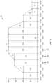
- FIG. 1is a graph showing effective available worker coverage or capacity per appointment time window during the course of an aggregate of shifts of a work day in accordance to an embodiment.
- FIG. 2is a graph showing effective available worker coverage or capacity per appointment time window and values therefor during the course of an aggregate of shifts of a work day in accordance to an embodiment.
- FIG. 3is a graph showing effective available worker coverage or capacity per appointment time window and a transition between outbound travel and inbound travel of workers during the course of an aggregate of shifts of a work day in accordance to an embodiment.
- FIG. 4is a so-called distance line representing a capacity model in accordance to an embodiment.
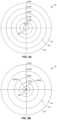
- FIG. 5 Ais a radial plot representing a capacity model for an outbound portion of the work day in accordance to an embodiment.
- FIG. 5 Bis a radial plot representing a capacity model for an inbound portion of the work day in accordance to an embodiment.
- FIG. 6 Ais a radial plot representing a capacity model for an outbound portion of the work day on which the distance of a new job location under consideration for scheduling is shown in accordance to an embodiment.
- FIG. 6 Bis a radial plot representing a capacity model for an inbound portion of the work day on which the distance of a new job location under consideration for scheduling is shown in accordance to an embodiment.
- FIG. 7is a diagram showing an example of a series of jobs to be assigned between a pair of workers in accordance to a workforce routing embodiment.
- FIG. 8is a diagram showing the series of jobs to be assigned between a pair of workers as shown in FIG. 7 with scheduling times listed for each job in accordance to a workforce routing embodiment.
- FIG. 9is a plot of a venturing/homing amplification factor over the course of a shift of the workers in the example shown in FIGS. 7 and 8 in accordance to an embodiment.
- FIG. 10is example of pseudo-code for an iterative route creation process in accordance to an embodiment.
- Embodiments described hereindisclose systems and methods that provide a booking agent with information for suggesting or selecting desirable service appointment windows for jobs during an appointment scheduling process.
- the information and suggestions providedare not merely limited to available workforce capacity.
- Illustrative examples of a booking agentinclude one or more of a customer service representative (CSR), and a computer-implemented appointment scheduling system, service, or application (e.g., an interactive scheduling system for use by a CSR, a web-based scheduling system or other automated interactive system for use by a customer, and the like).
- CSRcustomer service representative
- a computer-implemented appointment scheduling system, service, or applicatione.g., an interactive scheduling system for use by a CSR, a web-based scheduling system or other automated interactive system for use by a customer, and the like.
- the appointment scheduling processnecessarily occurs first and precedes the use of or any consideration for workforce routing algorithms which actually assign specific sequences of job locations to specific workers during a particular work day or shift.
- the route generation processnecessarily occurs after the appointment times have already been established and set by the booking agent, and these functions are separate and one is not considered relative to the other.
- booking agentswhen a booking agent makes decisions about availability of FSRs for scheduling appointments, little information is typically available to the booking agent to enable efficient chaining of appointments within the locales. While worker capacity may be tracked, for example, using an estimated number of available workers covering a set of known shift patterns, this information may only be used by a booking agent to distribute appointments at times of day so that the appointments occur evenly across the shifts that are worked. Accordingly, booking agents have conventionally considered no information needed for efficiently grouping the appointments physically with respect to times and locations. Thus, while an even distribution over workers' shift periods may be achieved via conventional approaches, the physical distribution of appointment destinations may result in routes that involve significant over-traversal of the working area.
- a problemoccurs due to appointment scheduling not making any attempt to schedule appointments in a manner that addresses the ability to produce efficient grouping or chaining of a sequence of appointments based upon physical location of the jobs.
- customer service representatives or other booking agentsnecessarily must make decisions about schedule availability based upon estimates of remaining worker shift capacity and the need to fill daily quotas; however, they are without information needed to address the above stated problem with respect to efficient grouping of job locations throughout a work day or shift.
- embodiments disclosed hereinenable the booking agent to have advance knowledge and information to better conform the service appointments as they are taken to so-called venturing and homing patterns preferred by field workers and that better meet business objectives. By necessity, this must occur at an early stage of the scheduling process before any use of detailed street-level optimizers or workforce routing algorithms construct routes for the workforce for a particular work day, shift, or aggregate of shifts from pre-booked appointments.
- embodiments disclosed hereinhelp a booking agent to make better decisions concerning the scheduling of customer time windows and is based upon the physical or geographic locations of the jobs paired with knowledge about existing commitments.
- a workforce routing algorithmis provided with the most ideal scenario and set of appointments for efficiently chaining a sequence of routes in accordance to physical locations of job sites.
- a further concept of workforce routinginvolves so-called bisecting coverage which refers to an out-in pattern, wherein the union of coverage of shifts is bisected.
- coverageis split down the center of the aggregate of shift patterns to allow the greatest opportunity for workers to assist one another.
- By centering the fan-out, fan-in pattern on the center of the aggregate of all worked shiftsa natural center point of coverage is established. Over time, this should give a natural human understanding of the time of day that workers reach the outer boundary for a service area and therefore an understanding of where most workers will be at a particular time of day. This information may be also be utilized to lead to a better understanding of how to perform labor forecasting.
- the maximum radius for a depot from which workers are initially dispatched during a shift for providing service in a service area covered by the depotdefines the working boundary for a specific service area. This may also be referred to as the so-called “rMAX” (Maximum Radius for Depot). Job locations outside of the rMAX boundary will generally not be considered by workers dispatched from the depot in the specific service area.
- embodimentsmay use outbound and inbound time poles (i.e., so-called Asymmetric Time Poles) of different scales.
- the width of the so-called “tree-rings” in an outgoing portion of the daywill be different than the widths of their counterparts in an incoming section (e.g., the width of the first hour of the day may be different than the width of the last hour of the day), and accordingly the outgoing and incoming ring patterns are not necessarily expected to be symmetrical.
- times or time rangesare typically based on increments of a number of minutes; conventionally, fifteen minutes is generally considered useful for providing a range within which a human technician can be considered “on time” (i.e., fifteen-minute increments).
- FSRs, booking agents, and othersmay respond negatively to more precise times (e.g., scheduling down to the minute), which would imply a higher degree of accuracy than real-world conditions will generally permit. If a booking agent promises that an FSR will arrive at 10:15 and the FSR is five minutes late, the lateness is more easily excused as part of life than if the booking agent promises the FSR will arrive at 10:07. Where a time appears to be expressed more precisely, an inference of high accuracy may result in a shorter period of lateness being less easily excused.
- Embodiments of methods and systems used for booking appointmentsare provided by way of the following example.
- the followingis an example walkthrough, in an embodiment, of how a method causes appointment times to be recommended by a booking agent based upon job location and current bookings.
- a depothas 200 workers split into three groups with each group working a different shift.
- Each shiftmay have a total duration of eight hours.
- the distribution of the workers and their shifts for this examplemay be as follows:
- the above informationis plotted in graph 10 of FIG. 1 .
- the line 12provides information describing the availability of workers throughout the day.
- the X-axis 14corresponds to time throughout the aggregate of shifts, and the Y-axis 16 identifies the number of workers.
- Each dot in the graph 10represents the number of workers available to be assigned jobs at the beginning of each hour.
- the line 12 in graph 10is formed by connecting the dots. See FIG. 1 .
- FIG. 2provides a graph 18 that includes the same line 12 as presented in FIG. 1 .
- effective coverages for time windowsare derived by calculating the area 20 under the line 12 per time window (in this example, each time window is exactly one hour).
- FIG. 2provides a relative view of effective worker coverages within coarse-grain time windows. It should be noted that the effective coverages are necessarily different from actual coverages. For instance, in the time window 9:00-10:00 there are actually 100 workers according to the example. However, since the line 12 rises from 100 workers at 9:00 to 160 workers at 10:00 (i.e., the beginning of the next shift), the effective coverage for 9:00 to 10:00 determined from the area under line 12 is 130 workers as shown in FIG. 2 . Accordingly, the total area 20 for each time window is displayed beneath each time window below the X-axis 24 of FIG. 2 .
- a relative measure of coverage between different appointment time windowscan be determined. This forms the basis of the relative distances between time markers that can be provide on a so-called distance line, which is discussed below in greater detail.
- the 08:00 to 09:00 window(total area of 100, i.e. 100 effective coverage of workers) is one half (100/200 or 50%) as well effectively covered as the 12:00 to 13:00 window (total area of 200, i.e. 200 effective coverage of workers), whereas the 10:00 to 11:00 window (160 effective coverage of workers) window is four-fifths (160/200 or 80%) as well covered as the 14:00 to 15:00 window (200 effective coverage of workers).
- FIG. 3depicts an illustrative example of bisecting coverage according to the scenario discussed above.
- FIG. 3is a graph 26 that include line 12 shown in FIG. 1 and the total area information 22 per time window as shown in FIG. 2 .
- the graph 26includes a bisecting line 28 to split the total coverage window of the example into two portions.
- the bisecting line 28reinforces the concept of implied routes proceeding outwards at the start of shifts (i.e., between 8:00 and 14:00 in FIG. 3 ) and then inward toward the end of the shifts (i.e., between 14:00 and 20:00 in FIG. 3 ).
- the midpoint of the 08:00 to 20:00 shifts in this particular exampleis 14:00 and is therefore the transition point at which the outbound and inbound portions, 30 and 32 , of worker coverage are split.
- the bisecting line 28is located between the portions, 30 and 32 , which are labeled “Outbound” and “Inbound” in the graph 26 .
- the distance line 34represents the distances associated with particular time markers or windows and may be is used to suggest times for new job appointments to be entered into an appointment scheduling system by a booking agent.
- suggestionsare able to be generated based upon knowledge of the distance from a depot 36 of the new job location to be scheduled.
- knowledge of the depot-to-job location distance and its application to the capacity modeli.e., distance line 34 ) is all that is needed for embodiments to make a suggestion for an appointment time window.
- the length of the distance line 34represents the maximum distance that is serviced by the depot (i.e., it defines the outmost location within the coverage or service area or rMAX).
- the end 38 of the distance line 34corresponds to the rMAX distance for the depot 36 .
- the outbound-to-inbound transition defined by line 28 in FIG. 3is correlated to the end 38 of the distance line 34 (this represents the maximum distance serviced by the depot).
- the end 38 of the distance line 34automatically corresponds to the time 14:00 as defined by line 28 in FIG. 3 (i.e., distance is correlated to time).
- the outbound and inbound time markers or windowsare thereafter placed along the height or length of the distance line 34 according to their relative weights in terms of worker coverage discussed above. See FIG. 4
- Table 1illustrates the percentage of the distance line 34 each time window occupies. The percentage is calculated by dividing the effective coverage or weight for a window by the total weight of all the windows within either the outbound or inbound portions defined in FIG. 3 . For instance, referring to FIG. 3 and adding all the total effective coverages of each window in the outbound portion of the graph, a total weight for outbound is 970 (i.e., 100+130+160+180+200+200 for the outbound period of 8:00 to 14:00). A total weight for inbound is 760 (i.e., 200+200+150+100+70+40 for the inbound period of 14:00 to 20:00).
- the distance line 34is plotted using the relative weights as shown in Table 1.
- the outbound scale(on the right-hand side of FIG. 4 ) is different than the inbound scale (on the left-hand side of FIG. 4 ) due to more worker coverage in the earlier outbound part of the day (i.e., 970 as compared to 760).
- Periods of low coveragesuch as 18:00-19:00 and 19:00-20:00 occupy relatively short distances on the distance line 34 . See these windows near depot 38 in distance line 34 .
- the distance line 34 shown in FIG. 4describes or models, in the illustrative example of an embodiment, the ideal times for scheduling of a new appointment in direct correlation to the distance from the depot of a job location to be scheduled.
- the upper end 38 of the distance line 34represents the furthest distance or rMAX that the depot will serve and the transition point between outbound travel and inbound travel of workers.
- the location of the job request and distance from the depot 36can be readily determined or obtained. For instance, a job location located half the rMAX distance will be located half way up the distance line 34 . In this manner, times and appointment windows can be recommended corresponding to the nearest inbound and outbound times and windows shown on the distance line 34 . For instance, a new job located half the distance between the depot and the rMAX location may be given a time window for an appointment corresponding to the 11:00-1200 time window during the outbound portion of the day or the 15:00-16:00 time window during the inbound portion of the day.
- the recommended timesmay be returned to the nearest fifteen minutes and the values may be interpolated. For example, if a job needing an appointment is located a distance away from the depot such that it falls on the distance line 34 exactly corresponding to the 16:00 marker, both the times 16:00 and 11:15 may be recommended since those are the closest times quantized on fifteen minute windows.
- the time windowscan have any length, as desired, such as 10 minutes, 20 minutes, 30 minutes, an hour, and the like.
- FIG. 4can also be plotted radially as shown, for instance, in FIGS. 5 A and 5 B which depict radial plots 40 (corresponding to outbound travel from the depot) and 42 (corresponding to inbound travel to the depot), respectively.
- Each of the radial plots, 40 and 42include so-called coverage rings 44 (i.e., so-called tree-rings) which represent time windows in an illustrative example of an embodiment.
- coverage rings 44i.e., so-called tree-rings
- the radial plotscan be generated illustrating coverage rings by time windows.
- the radial plot 40 of FIG. 5 Adepicts outbound time windows (rings at 9:00 to 14:00) as concentric rings, with the time window 8:00-9:00 located at the center 46 (corresponding to depot location) of the radial plot and 14:00 forming the outer edge 48 of the radial plot (corresponding to the rMAX distance of the depot).
- FIG. 5 Bdepicts inbound time windows (rings at 14:00 to 19:00) as concentric rings, with 14:00 at the outer edge 48 , and the time window 19:00-20:00 at the center 46 .
- time windowsi.e., tree-rings
- time windows with lower effective worker coverage or capacityare wider and time windows with lower effective worker coverage or capacity are narrower.
- wider time windowsare associated with a greater percentage of distances along the distance line 34 .
- the time window 18:00-19:00 in FIG. 5 Bis narrow as compared to the time window 14:00-15:00. Since the wider rings cover more area (i.e., more distance), there is a higher chance that new jobs will fall within those areas (i.e., the rings that are wider) and correspondingly within the time windows with higher coverage.
- FIGS. 6 A and 6 Bdepict the same radial plots, 40 and 42 , as shown in FIGS. 5 A and 5 B .
- the radial plotsdefine coverage rings based on time windows and distance of the job from the depot and may be used by a booking agent to schedule appointments in accordance with embodiments.
- a dot or symbol 50is marked on the plots, 40 and 42 , corresponding to the physical or geographic location of the job within the service area (i.e., its distance from the depot).
- the dot 50is used to determine which times would be most favorable for the booking agent to suggest.
- the dot 50is closest to the 11:30 outbound slot ( FIG. 6 A ) and to the 16:00 inbound slot ( FIG. 6 B ). Accordingly, these are the times that would be suggested to a booking agent according to an embodiment.
- the effective worker coverage value discussed aboveis updated by adjusting the information on the graphs, distance line, radial plots and widths of rings thereon. For instance, assuming that the customer located as discussed above is offered the choice of 11:30 and 16:00 by the booking agent and selects the 11:30 time slot, availability or coverage capacity for the 11:00-12:00 time window would be decremented by one. Rather than the initial 180 effective coverage value for the 11:00-12:00 time window as initially indicated in FIG. 2 , this value would now be adjusted to 179. This, in turn, affects the distance line 34 and radial plots, 40 and 42 .
- embodiments disclosed hereinare able to significantly reduce the number of jobs subsequently left unassigned by an automated workforce routing system or algorithm. For example, in a simulation having 500 jobs and 100 workers, in comparison to a control run with a substantially random assignment of capacity, an embodiment in which capacity was assigned using at least aspects of the embodiments disclose herein was able to provide improvements that reduced the number of jobs remaining unassigned. For instance, unassigned jobs may be reduced by 60% to 80% as compared to conventional methods.
- worker schedulesmay be estimated or predicted ahead of time (e.g., one or more days into the future) to assist with routing on the day of appointment.
- travel distance for a jobmay be estimated using straight-line distances, e.g., to save computation time. Such an estimate can, in some cases, provide a more generally useful advance representation than computation of street-level distances, since travel conditions may in some cases change significantly between the day that an appointment is made and the day of the appointment or of the routing for the appointment.
- Some embodiments disclosed hereinmay be used to provide value outside the area of pre-processing for workforce routing.
- the embodiments described abovemay be used to provide information for capacity refinements and predictions, instead of for booking.
- the embodiments disclosed abovemay be computationally simpler than a full routing solution in that fewer factors (e.g., traffic, etc.) need to be taken into consideration. Accordingly, these embodiments may be useful, for example, for labor forecasting, as well as routing and scheduling, and can help to provide higher efficiency routes, e.g., with respect to capacity.
- aspects of the above disclosure with respect to selecting appointment times for jobsmay be usable, for example, as a pre-processing tool for improving the results produced by an automatic workforce routing system which builds routes for technicians including a sequence of jobs over the course of a technician's shift.
- an automatic workforce routing systemwhich builds routes for technicians including a sequence of jobs over the course of a technician's shift.
- the followingis an illustrative example of an embodiment of an automatic workforce routing system suitable for use with the embodiments disclosed above in the previous example.
- a next-best-ranked searchcan build solutions that satisfy the objectives quickly. Furthermore, the solutions can be audited as the results are entirely deterministic. Accordingly, the use of dynamic temporal weighting components permits choices to be constrained even further and can be encoded to reflect conditions such as traffic, desires to venture and home, system-wide balance, and a need to pair workers with jobs appropriate to their skill levels and inventory.
- Route creationmay use configurable weighting components to deterministically assign routes to technicians based upon weighted choice mechanics.
- a modelis presented herein of a modular routing service capable of answering questions from perspectives beyond route creation. A deterministic approach is taken with the goal of servicing requests for in-depth analysis behind the choices that are made. Models are described offering previews of how changes in configuration affect potential outcomes.
- the approachuses a process wherein workers attempt to take their highest ranked options at every iteration of the job selection process.
- a virtual mediatormay resolve conflicts between workers that wish to select the same job.
- the mediation processmay involve a balance metric that prevents the same workers from winning or losing repeatedly.
- Weighting componentsare used to calculate the relative value of a job at different points in the route creation process. These components represent not only the business objectives but also the changing nature of value throughout route construction.
- the route creation processis iterative. All workers begin at their start locations and receive a single job assignment per iteration until a set of stop conditions are met such as reaching the end of their shift or finding no remaining viable jobs from which to choose. The route creation process ends when all workers have met their stop conditions.
- Optionsare ranked by computing a discrete value for each option and then sorting by that value.
- the score for each jobrepresents the attractiveness of that job to a specific worker and at a specific point in the route creation process.
- the value of a jobvaries due to a variety of dynamic conditions, such as traffic, current workload, the need for breaks, and softer criteria such as the desire for aesthetically pleasing route shapes and a need to finish near a stated home location.
- Arcsrepresent the physical routes between jobs. Each job has many incoming and outgoing arcs. When workers rank their options, they consider factors about both the arcs (travel time, distance, traffic conditions, etc.) and the jobs (skills required, time windows, etc.).
- step 54for each active worker, each arc, or each job in a set of job locations available to be scheduled, is scored and a ranking of jobs from highest to lowest is generated per worker.
- step 58if a job is the top ranking for only one worker, then that worker is assigned the job (i.e., the highest ranked job for the specific worker).
- step 56for a job that is the top ranked job for multiple of the workers, then a winner and losers are selected. The losers then move to their second ranked job and so forth until all workers are assigned a job. Thereafter, this process repeats until all jobs have been assigned or until all shifts have ended.
- a conflictoccurs when two or more workers attempt to select the same job. In this case, one worker is selected to receive the job while the other workers move to the next selection in their ranked lists. The round ends when all workers have either selected a job or run out of jobs on their list.
- points that are used in subsequent conflictsmay be awarded points that are used in subsequent conflicts.
- the pointsare used to scale the weightings each worker presents when resolving conflict. For example, a worker may lose a point when winning a conflict and may gain a point when losing one.
- a system-wide constantmay specify the amount of scaling each point applies.
- a workforce routing scenario 60is shown in FIG. 7 and identifies six jobs (Job 1, Job 2, Job 3, Job 4, Job 5, and Job 6) and two workers (Worker 1 and Worker 2). For purposes of starting the routing process, all jobs are connected to all other jobs and all workers are connected to all jobs. For this example, all connections are assumed to be two-way.
- Table 4lists the skills that are required for each of the jobs.
- the jobsrelate to a worker of a company providing television, Internet, and telephone services and the jobs do not list the proficiency levels that are required; rather, only workers list proficiency levels with their skills.
- Business objectivesare used to specify what level of proficiency constitutes having a skill.
- the columns in Table 4 listing worker skillsreflect the skills which the workers have at the required level of proficiency as indicated, for instance, in a business objective configuration setting.
- both workershave the same 08:00-12:00 shift and that the modeled traffic pattern for this shift period is a sine wave of period 0 ⁇ x ⁇ .
- the amplification curve 62 in FIG. 9see the amplification curve 62 in FIG. 9 .
- the following descriptionprovides a step-by-step walkthrough of the routing process for the six jobs, two worker scenario 60 described above. Each job selection round is analyzed to provide an insight into the process used to build the resulting routes for the two workers.
- the scores for each componentare calculated.
- the scoresare then strengthened by their coefficients.
- Finally the resulting appeals(score multiplied by strengthening coefficient) are added together to produce a total appeal value or score for each job.
- Rankingsare applied by sorting the jobs by their appeal.
- Table 5shows the weightings for each job for Worker 1 at 08:00.
- the right-most column of strengthshows the strengthening coefficients for each of the components.
- the total appeal and resulting rankingsare shown at the bottom of Table 5.
- the skills and timeslot components in this examplehave been strengthened, meaning that their output values will contribute more strongly to the overall appeal of the jobs considered. For instance, the score for the skills is multiplied by 1.5 and the score for time slot has been multiplied by 2.5.
- the following formulascan be used to calculate the distance component score for each of the jobs considered by Worker 1.
- the worker's virtual time clockis used to determine how many hours of the current shift period have elapsed.
- the longest distanceincludes arcs connecting the workers to their first job.
- the travel time componentis calculated using the same formulae as with the distance component.
- the value for 1is the maximum travel time on any arc rather than the maximum distance.
- the skill weightingrepresents the percentage of the skills required for the job that the worker possesses at the appropriate proficiency level. Looking at Table 6 of required skills it can be seen that there are four jobs for which Worker 1 is missing one skill (i.e., “Internet”).
- Job 1Job 2 Job 3 Job 4 Job 5 Job 6 1 Install X X X X X Repair X X X X TV X X X X X X X X Internet X- X- X- missing missing missing missing Telephone X X X
- Slack timedescribes the amount of time a worker may be idling between jobs, and time slot represents how early in the scheduled time window the worker would likely arrive.
- the slack time and time slot scoresare calculated using exponential decay with an initial x-offset. In other words, a penalty is assessed for each minute over an acceptable threshold (15 minutes in this example) for each minute over that threshold the worker is expected to arrive. Each additional minute is penalized more heavily than the last. So a worker arriving fifteen minutes late is not penalized at all. A worker arriving twenty minutes late is penalized a small amount, a worker arriving thirty minutes late is penalized a lot more, and a worker arriving sixty minutes late is penalized so heavily as to barely receive any score value from the slack time component at all.
- Job 1is scheduled to start at 10:00 (see FIG. 10 ).
- Worker 1has a shift that starts at 8:00 and it is estimated travel time to Job 1 by Worker 1 is twelve minutes. Accordingly, Worker 1 can readily arrive by 10:00 to the job location; thus, the time slot is considered to be 0 minutes corresponding to a full score of 1.0.
- Worker 1will have a lot of slack time. For instance, Worker 1 may arrive at Job 1 at 8:12. Thus, the slack time before Job 1 is scheduled is 108 minutes. This is considered too high and the corresponding score is very low (i.e., 0.0068). Scores for the other jobs are calculated in a similar manner.
- Job 2is the highest ranked job for Worker 1.
- step 58if this is not the highest ranked job for Worker 2, then Worker 1 is assigned Job 2 to begin the shift and Worker 2 is assigned another one of the jobs that is highest ranked for Worker 2.
- Job 2is highest ranked for both Worker 1 and Worker 2
- the worker with the highest total appeal valueis awarded the job and the other worker is assigned their second ranked job.
- This iterative processcontinues for round 2 and round 3 until all six of the jobs are assigned to Worker 1 and Worker 2 or until the end of the shift is reached.
- scoringcan be used as a scoring component.
- the manner in which scoring components affect route creationmay be as follows: when a virtual worker searches for a job, it ranks all of the jobs that are currently available to it. This ranking value is comprised of several different components, one of which is the venturing score.
- a workerhas three available options, Job A, Job B, or Job C.
- the workermight score these three jobs, as follows.
- the above referenced scoremay be a composite of different scoring components. Accordingly, the 5.3 score for Job A listed above might have been derived as shown in Table 8.
- an illustrative example of the formula used to derive the venturing scoreis:
- venturing scoring componenthas influenced the ranking (and subsequently the selection) of jobs alongside other factors used to make a job selection choice in the process of building workforce routing.
- weightingcan then be strengthened to reflect how important the concept of venturing is on the final outcome.
- a company with a workforcemight weight their scoring components as shown in Table 10.
- the venturing scoring componentwould be multiplied by a factor of 5 before being aggregated.
- an embodimentmay be provided by a computer-implemented method for workforce scheduling.
- the methodincludes executing on a processor the step of generating a capacity model that associates distances of locations within a service area from a location of a depot from which workers servicing the service area are dispatched with a series of appointment time windows available for scheduling within a pre-determined time period such that appointment time windows having a relatively greater amount of available worker capacity are associated with a greater range of distances than appointment time windows having a relatively smaller amount of available worker capacity.
- a distance from the depot to a location of an appointment being scheduled within the service areamay be determined and at least one appointment time window suggestion is automatically produced for the appointment being scheduled based on the appointment time windows that are defined in the capacity model associated with the distance from the depot to the location of the appointment being scheduled.
- the methodmay include providing the appointment time window suggestions to a booking agent for use in scheduling an appointment and may include dynamically updating the capacity model as available worker capacity within at least one appointment time window changes.
- the methodmay also include the step of providing the capacity model as an input to an automated workforce routing system.
- an earlier set of appointment time windowsmay be designated for outbound travel to locations of appointments within the service area relative to the location of the depot and a later set of appointment time windows may be designated for inbound travel to locations of appointments within the service area relative to the location of the depot.
- a beginning of an earliest appointment time window and an end of a latest appointment time window within the series of appointment time windowsmay be associated with the location of the depot, and a transition between the set of appointment time windows designated for outbound travel and the set of appointment time windows designated for inbound travel may be associated with a distance representing an outermost boundary of the service area for workers dispatched from the depot such that the capacity model associates one outbound appointment time window and one inbound appointment time window for each location within the service area.
- the transitionmay correspond to the mid-point of the series of appointment time windows as measured in time.
- a percentage of the distance between the location of the depot and the outermost boundary associated with an individual appointment time window within the set of appointment time windows designated for outbound travelmay correspond to a percentage of the amount of available worker capacity within the individual appointment time window relative to the aggregate of available worker capacities for the set of appointment time windows designated for outbound travel.
- the capacity modelmay be displayed in various forms. For instance, a display in the form of a distance line having a length corresponding to a distance from the depot to the outermost boundary with the set of appointment time windows designated for outbound travel identified lengthwise on one side of the distance line and the set of appointment time windows designated for inbound travel identified lengthwise on an opposite side of the distance line may be utilized.
- the capacity model in the form of at least one radial plot having a center representing the location of the depot and a radius of a length representing a distance from the depot to the outermost boundary of the service area and a series of concentric rings representing the set of appointment time windows designated for one of outbound travel and inbound travelmay be utilized.
- a system for carrying out the above methodsmay include software or the like provided on a circuit board or within another electronic device and can include various processors, microprocessors, controllers, chips, disk drives, and the like. It will be apparent to one of ordinary skill in the art that systems, modules, processors, servers, and the like may be implemented as electronic components, software, hardware or a combination of hardware and software for purposes of providing a system.
- An embodimentmay also include at least one non-transitory computer readable storage medium having computer program instructions stored thereon that, when executed by at least one processor, can cause the at least one processor to perform any of the steps described above.
Landscapes
- Business, Economics & Management (AREA)
- Human Resources & Organizations (AREA)
- Engineering & Computer Science (AREA)
- Strategic Management (AREA)
- Economics (AREA)
- Entrepreneurship & Innovation (AREA)
- Operations Research (AREA)
- Marketing (AREA)
- Quality & Reliability (AREA)
- Tourism & Hospitality (AREA)
- Physics & Mathematics (AREA)
- General Business, Economics & Management (AREA)
- General Physics & Mathematics (AREA)
- Theoretical Computer Science (AREA)
- Development Economics (AREA)
- Game Theory and Decision Science (AREA)
- Educational Administration (AREA)
- Data Mining & Analysis (AREA)
- Management, Administration, Business Operations System, And Electronic Commerce (AREA)
Abstract
Description
| TABLE 1 | |
| OUTBOUND | INBOUND |
| Time | Weight | Percent | Time | Weight | Percent |
| 8:00-9:00 | 100 | 10.3 | 14:00-15:00 | 200 | 26.3 |
| 9:00-10:00 | 130 | 13.4 | 15:00-16:00 | 200 | 26.3 |
| 10:00-11:00 | 160 | 16.5 | 16:00-17:00 | 150 | 19.7 |
| 11:00-12:00 | 180 | 18.6 | 17:00-18:00 | 100 | 13.2 |
| 12:00-13:00 | 200 | 20.6 | 18:00-19:00 | 70 | 9.2 |
| 13:00-14:00 | 200 | 20.6 | 19:00-20:00 | 40 | 5.3 |
| 970 | 100.0 | 760 | 100.0 | ||
s=Σw=final arc score
| TABLE 2 | ||
| FROM (in miles) | ||
| DISTANCES | ||||||||
| TO | 13 | 14 | 17 | 11 | 12 | 6 | 9 | ||
| (in | 20 | 8 | 10 | ||||||
| miles) | 22 | 8 | 7 | 12 | 10 | ||||
| 14 | 8 | 9 | 9 | 10 | 8 | ||||
| 10 | 7 | 4 | 11 | 13 | 9 | 11 | |||
| 8 | 11 | 11 | 9 | 10 | 7 | 7 | |||
| TABLE 3 | ||
| FROM (in minutes) | ||
| Job | 1 | ||||||||
| TO | 30 | 28 | 30 | 21 | 18 | 12 | 14 | ||
| (in | 29 | 15 | 21 | ||||||
| mins.) | 32 | 17 | 21 | 20 | 19 | ||||
| 26 | 17 | 20 | 24 | 22 | 15 | ||||
| 20 | 16 | 12 | 26 | 22 | 17 | 20 | |||
| 19 | 24 | 18 | 13 | 18 | 15 | 12 | |||
| TABLE 4 | ||||||||
| Worker | ||||||||
| SKILLS | Job | |||||||
| 1 | 1 | 2 | ||||||
| Install | X | X | X | X | X | |||
| Repair | X | X | X | X | X | |||
| TV | X | X | X | X | X | X | X | X |
| Internet | X | X | X | X | X | |||
| Telephone | X | X | X | X | ||||
| TABLE 5 |
| Weightings | |||||||
| Distance |
| 6 | 8 | 12 | 10 | 9 | 7 | 1.0 |
| score | 0.2923 | 0.2297 | 0.1221 | 0.1726 | 0.2004 | 0.2604 | ||
| appeal | 0.2923 | 0.2297 | 0.1221 | 0.1726 | 0.2004 | 0.2604 |
| 12 | 15 | 20 | 22 | 17 | 15 | 1.0 |
| score | 0.2222 | 0.1642 | 0.0843 | 0.0590 | 0.1295 | 0.1642 | ||
| appeal | 0.2222 | 0.1642 | 0.0843 | 0.0590 | 0.1295 | 0.1642 |
| Skills | 1.5 |
| score | 1.00 | 0.66 | 0.66 | 1.00 | 0.75 | 0.75 | ||
| appeal | 1.5 | 0.99 | 0.99 | 1.5 | 1.125 | 1.125 |
| Slack Time | 108 | 0 | 0 | 38 | 43 | 105 | 1.0 |
| score | 0.0068 | 1.0000 | 1.0000 | 0.1727 | 0.1371 | 0.0078 | ||
| appeal | 0.0068 | 1.0000 | 1.0000 | 0.1727 | 0.1371 | 0.0078 |
| 0 | 15 | 20 | 0 | 0 | 0 | 2.5 |
| score | 1.000 | 1.000 | 0.7937 | 1.0000 | 1.0000 | 1.0000 | ||
| appeal | 2.5 | 2.5 | 1.9842 | 2.5 | 2.5 | 2.5 |
| Total Appeal | 4.5213 | 4.8839 | 4.1806 | 4.4043 | 4.0920 | 4.0574 | |
| 2 | 1 | 4 | 3 | 5 | 6 | ||
| TABLE 6 | |||||||
| SKILLS | Job | ||||||
| 1 | 1 | ||||||
| Install | X | X | X | X | X | ||
| Repair | X | X | X | X | |||
| TV | X | X | X | X | X | X | X |
| Internet | X- | X- | X- | X- | |||
| missing | missing | missing | missing | ||||
| Telephone | X | X | X | ||||
| TABLE 7 | |||
| Job | Score | ||
| Job A | 5.3 | ||
| Job B | 4.1 | ||
| Job C | 6.2 | ||
| TABLE 8 |
| Job A |
| Scoring component | Score | ||
| Distance | 0.70 | ||
| Travel | 0.55 | ||
| Skills | 0.83 | ||
| Equipment | 0.84 | ||
| Schedule | 0.61 | ||
| Wait Time | 0.94 | ||
| Venturing | 0.83 | ||
where:
| TABLE 9 | |||
| Job | Score | ||
| 1 | Job C | 6.2 | |
| 2 | Job A | 5.3 | |
| 3 | Job B | 4.1 | |
| TABLE 10 | ||||
| Scoring component | Weight | Strengthen by | ||
| High | 5 | |||
| Low | 1 | |||
| . | . | . | ||
| . | . | . | ||
| . | . | . | ||
| High | 5 | |||
Claims (19)
Priority Applications (6)
| Application Number | Priority Date | Filing Date | Title |
|---|---|---|---|
| US15/287,481US11775937B2 (en) | 2015-10-08 | 2016-10-06 | Dynamic capacity ranges for workforce routing |
| DE112016004631.6TDE112016004631T5 (en) | 2015-10-08 | 2016-10-07 | Dynamic capacity ranges for employee route planning |
| CA3000883ACA3000883C (en) | 2015-10-08 | 2016-10-07 | Dynamic capacity ranges for workforce routing |
| GB1805034.4AGB2556847A (en) | 2015-10-08 | 2016-10-07 | Dynamic capacity ranges for workforce routing |
| PCT/US2016/055992WO2017062769A1 (en) | 2015-10-08 | 2016-10-07 | Dynamic capacity ranges for workforce routing |
| US18/236,094US20230394441A1 (en) | 2015-10-08 | 2023-08-21 | Dynamic capacity ranges for workforce routing |
Applications Claiming Priority (2)
| Application Number | Priority Date | Filing Date | Title |
|---|---|---|---|
| US201562238937P | 2015-10-08 | 2015-10-08 | |
| US15/287,481US11775937B2 (en) | 2015-10-08 | 2016-10-06 | Dynamic capacity ranges for workforce routing |
Related Child Applications (1)
| Application Number | Title | Priority Date | Filing Date |
|---|---|---|---|
| US18/236,094ContinuationUS20230394441A1 (en) | 2015-10-08 | 2023-08-21 | Dynamic capacity ranges for workforce routing |
Publications (2)
| Publication Number | Publication Date |
|---|---|
| US20170103369A1 US20170103369A1 (en) | 2017-04-13 |
| US11775937B2true US11775937B2 (en) | 2023-10-03 |
Family
ID=57206399
Family Applications (2)
| Application Number | Title | Priority Date | Filing Date |
|---|---|---|---|
| US15/287,481Active2036-12-02US11775937B2 (en) | 2015-10-08 | 2016-10-06 | Dynamic capacity ranges for workforce routing |
| US18/236,094AbandonedUS20230394441A1 (en) | 2015-10-08 | 2023-08-21 | Dynamic capacity ranges for workforce routing |
Family Applications After (1)
| Application Number | Title | Priority Date | Filing Date |
|---|---|---|---|
| US18/236,094AbandonedUS20230394441A1 (en) | 2015-10-08 | 2023-08-21 | Dynamic capacity ranges for workforce routing |
Country Status (5)
| Country | Link |
|---|---|
| US (2) | US11775937B2 (en) |
| CA (1) | CA3000883C (en) |
| DE (1) | DE112016004631T5 (en) |
| GB (1) | GB2556847A (en) |
| WO (1) | WO2017062769A1 (en) |
Families Citing this family (53)
| Publication number | Priority date | Publication date | Assignee | Title |
|---|---|---|---|---|
| US10606859B2 (en) | 2014-11-24 | 2020-03-31 | Asana, Inc. | Client side system and method for search backed calendar user interface |
| CN107256450B (en)* | 2017-05-22 | 2020-10-13 | 武汉大学 | Water photoelectric complementary scheduling capacity configuration method considering long-short nesting decision |
| US10977434B2 (en) | 2017-07-11 | 2021-04-13 | Asana, Inc. | Database model which provides management of custom fields and methods and apparatus therfor |
| US11640584B2 (en)* | 2017-08-22 | 2023-05-02 | Verint Americas Inc | System and method for real-time predictive scheduling |
| US10623359B1 (en) | 2018-02-28 | 2020-04-14 | Asana, Inc. | Systems and methods for generating tasks based on chat sessions between users of a collaboration environment |
| US11138021B1 (en) | 2018-04-02 | 2021-10-05 | Asana, Inc. | Systems and methods to facilitate task-specific workspaces for a collaboration work management platform |
| US10613735B1 (en) | 2018-04-04 | 2020-04-07 | Asana, Inc. | Systems and methods for preloading an amount of content based on user scrolling |
| US10785046B1 (en) | 2018-06-08 | 2020-09-22 | Asana, Inc. | Systems and methods for providing a collaboration work management platform that facilitates differentiation between users in an overarching group and one or more subsets of individual users |
| US10616151B1 (en) | 2018-10-17 | 2020-04-07 | Asana, Inc. | Systems and methods for generating and presenting graphical user interfaces |
| US20200226506A1 (en)* | 2018-11-14 | 2020-07-16 | Shashank Srivastava | Methods and systems for automated salesbeat optimization |
| US10956845B1 (en) | 2018-12-06 | 2021-03-23 | Asana, Inc. | Systems and methods for generating prioritization models and predicting workflow prioritizations |
| US11568366B1 (en) | 2018-12-18 | 2023-01-31 | Asana, Inc. | Systems and methods for generating status requests for units of work |
| US11113667B1 (en) | 2018-12-18 | 2021-09-07 | Asana, Inc. | Systems and methods for providing a dashboard for a collaboration work management platform |
| US10684870B1 (en) | 2019-01-08 | 2020-06-16 | Asana, Inc. | Systems and methods for determining and presenting a graphical user interface including template metrics |
| US11782737B2 (en) | 2019-01-08 | 2023-10-10 | Asana, Inc. | Systems and methods for determining and presenting a graphical user interface including template metrics |
| US11204683B1 (en) | 2019-01-09 | 2021-12-21 | Asana, Inc. | Systems and methods for generating and tracking hardcoded communications in a collaboration management platform |
| CN109978471B (en)* | 2019-04-11 | 2021-01-08 | 聊城大学 | Cold-chain logistics path optimization method with time window |
| US11341445B1 (en)* | 2019-11-14 | 2022-05-24 | Asana, Inc. | Systems and methods to measure and visualize threshold of user workload |
| US11783253B1 (en) | 2020-02-11 | 2023-10-10 | Asana, Inc. | Systems and methods to effectuate sets of automated actions outside and/or within a collaboration environment based on trigger events occurring outside and/or within the collaboration environment |
| US11599855B1 (en) | 2020-02-14 | 2023-03-07 | Asana, Inc. | Systems and methods to attribute automated actions within a collaboration environment |
| US11763259B1 (en) | 2020-02-20 | 2023-09-19 | Asana, Inc. | Systems and methods to generate units of work in a collaboration environment |
| US20230206147A1 (en)* | 2020-02-26 | 2023-06-29 | Soham Inc | Improved employee schedule forecasting |
| US11900323B1 (en) | 2020-06-29 | 2024-02-13 | Asana, Inc. | Systems and methods to generate units of work within a collaboration environment based on video dictation |
| US11455601B1 (en) | 2020-06-29 | 2022-09-27 | Asana, Inc. | Systems and methods to measure and visualize workload for completing individual units of work |
| US11449836B1 (en) | 2020-07-21 | 2022-09-20 | Asana, Inc. | Systems and methods to facilitate user engagement with units of work assigned within a collaboration environment |
| US11568339B2 (en) | 2020-08-18 | 2023-01-31 | Asana, Inc. | Systems and methods to characterize units of work based on business objectives |
| US11769115B1 (en) | 2020-11-23 | 2023-09-26 | Asana, Inc. | Systems and methods to provide measures of user workload when generating units of work based on chat sessions between users of a collaboration environment |
| US11405435B1 (en) | 2020-12-02 | 2022-08-02 | Asana, Inc. | Systems and methods to present views of records in chat sessions between users of a collaboration environment |
| US11694162B1 (en) | 2021-04-01 | 2023-07-04 | Asana, Inc. | Systems and methods to recommend templates for project-level graphical user interfaces within a collaboration environment |
| US11676107B1 (en) | 2021-04-14 | 2023-06-13 | Asana, Inc. | Systems and methods to facilitate interaction with a collaboration environment based on assignment of project-level roles |
| US11553045B1 (en) | 2021-04-29 | 2023-01-10 | Asana, Inc. | Systems and methods to automatically update status of projects within a collaboration environment |
| US11803814B1 (en) | 2021-05-07 | 2023-10-31 | Asana, Inc. | Systems and methods to facilitate nesting of portfolios within a collaboration environment |
| US11792028B1 (en) | 2021-05-13 | 2023-10-17 | Asana, Inc. | Systems and methods to link meetings with units of work of a collaboration environment |
| US11809222B1 (en) | 2021-05-24 | 2023-11-07 | Asana, Inc. | Systems and methods to generate units of work within a collaboration environment based on selection of text |
| US12141756B1 (en) | 2021-05-24 | 2024-11-12 | Asana, Inc. | Systems and methods to generate project-level graphical user interfaces within a collaboration environment |
| US12093859B1 (en) | 2021-06-02 | 2024-09-17 | Asana, Inc. | Systems and methods to measure and visualize workload for individual users |
| US12182505B1 (en) | 2021-06-10 | 2024-12-31 | Asana, Inc. | Systems and methods to provide user-generated project-level graphical user interfaces within a collaboration environment |
| US11756000B2 (en) | 2021-09-08 | 2023-09-12 | Asana, Inc. | Systems and methods to effectuate sets of automated actions within a collaboration environment including embedded third-party content based on trigger events |
| US12159262B1 (en) | 2021-10-04 | 2024-12-03 | Asana, Inc. | Systems and methods to provide user-generated graphical user interfaces within a collaboration environment |
| US11635884B1 (en) | 2021-10-11 | 2023-04-25 | Asana, Inc. | Systems and methods to provide personalized graphical user interfaces within a collaboration environment |
| US12093896B1 (en) | 2022-01-10 | 2024-09-17 | Asana, Inc. | Systems and methods to prioritize resources of projects within a collaboration environment |
| US11997425B1 (en) | 2022-02-17 | 2024-05-28 | Asana, Inc. | Systems and methods to generate correspondences between portions of recorded audio content and records of a collaboration environment |
| US12190292B1 (en) | 2022-02-17 | 2025-01-07 | Asana, Inc. | Systems and methods to train and/or use a machine learning model to generate correspondences between portions of recorded audio content and work unit records of a collaboration environment |
| US11836681B1 (en) | 2022-02-17 | 2023-12-05 | Asana, Inc. | Systems and methods to generate records within a collaboration environment |
| US12118514B1 (en) | 2022-02-17 | 2024-10-15 | Asana, Inc. | Systems and methods to generate records within a collaboration environment based on a machine learning model trained from a text corpus |
| US12051045B1 (en) | 2022-04-28 | 2024-07-30 | Asana, Inc. | Systems and methods to characterize work unit records of a collaboration environment based on stages within a workflow |
| US12288171B1 (en) | 2022-07-18 | 2025-04-29 | Asana, Inc. | Systems and methods to provide records for new users of a collaboration environment |
| US12412156B1 (en) | 2022-07-21 | 2025-09-09 | Asana, Inc. | Systems and methods to characterize work unit records of a collaboration environment based on freeform arrangement of visual content items |
| US11863601B1 (en) | 2022-11-18 | 2024-01-02 | Asana, Inc. | Systems and methods to execute branching automation schemes in a collaboration environment |
| US12287849B1 (en) | 2022-11-28 | 2025-04-29 | Asana, Inc. | Systems and methods to automatically classify records managed by a collaboration environment |
| US12401655B1 (en) | 2023-04-24 | 2025-08-26 | Asana, Inc. | Systems and methods to manage access to assets of a computer environment based on user and asset grouping |
| US12423121B1 (en) | 2023-11-09 | 2025-09-23 | Asana, Inc. | Systems and methods to customize a user interface of a collaboration environment based on ranking of work unit records managed by the collaboration environment |
| CN118229255B (en)* | 2024-05-24 | 2024-08-30 | 松立控股集团股份有限公司 | Automatic scheduling method and system for inspector based on mixed integer programming |
Citations (23)
| Publication number | Priority date | Publication date | Assignee | Title |
|---|---|---|---|---|
| US5111391A (en) | 1989-10-05 | 1992-05-05 | Mrs. Fields, Inc. | System and method for making staff schedules as a function of available resources as well as employee skill level, availability and priority |
| US5233533A (en) | 1989-12-19 | 1993-08-03 | Symmetrix, Inc. | Scheduling method and apparatus |
| US6321133B1 (en) | 1998-12-04 | 2001-11-20 | Impresse Corporation | Method and apparatus for order promising |
| US20010049619A1 (en)* | 1999-06-07 | 2001-12-06 | G. Edward Powell | Method and system for allocating specific appointment time windows in a service industry |
| US20020019759A1 (en) | 2000-06-16 | 2002-02-14 | Sundararajan Arunapuram | Transportation planning, execution, and freight payments managers and related methods |
| US6418398B1 (en) | 1998-10-01 | 2002-07-09 | International Business Machines Corporation | Optimization with ruin recreate |
| US20030033184A1 (en) | 2000-10-03 | 2003-02-13 | Moshe Benbassat | Method and system for assigning human resources to provide services |
| US20050060217A1 (en) | 2003-08-29 | 2005-03-17 | James Douglas | Customer service support system |
| US20060167734A1 (en) | 2004-08-19 | 2006-07-27 | Scott Gale R | Delivery operations information system with route and unit maintenance feature and methods of use |
| US20060241986A1 (en) | 2005-04-22 | 2006-10-26 | Harper Charles N | Production optimizer for supply chain management |
| US20060262967A1 (en) | 2005-05-09 | 2006-11-23 | United Parcel Service Of America, Inc. | Systems and methods for routing and scheduling |
| US20070179829A1 (en)* | 2006-01-27 | 2007-08-02 | Sbc Knowledge Ventures, L.P. | Method and apparatus for workflow scheduling and forecasting |
| US7788121B1 (en)* | 2004-04-28 | 2010-08-31 | Dennis E Smith | Method and system for efficiently dispatching service vehicles |
| US20100312605A1 (en)* | 2009-06-09 | 2010-12-09 | Accenture Global Services Gmbh | Technician control system |
| US7869946B2 (en) | 2005-02-04 | 2011-01-11 | Microsoft Corporation | Efficient navigation routing system and method |
| US20130166341A1 (en)* | 2011-12-22 | 2013-06-27 | Hewlett-Packard Development Company Lp | Service provider selection |
| US20140278654A1 (en)* | 2013-03-15 | 2014-09-18 | International Business Machines Corporation | Spatio-temporal approach to scheduling field operations |
| US20140278652A1 (en)* | 2013-03-15 | 2014-09-18 | First Service Networks Inc. | Hybrid system and method for selecting and deploying field technicians in a facilities management hybrid workforce |
| US8849689B1 (en) | 2012-01-23 | 2014-09-30 | Intuit Inc. | Method and system for providing dynamic appointment scheduling and tracking |
| US20160216873A1 (en)* | 2015-01-28 | 2016-07-28 | Nicholas Filippi | Graphical interface for automatically binned information |
| CN105913653A (en)* | 2016-06-27 | 2016-08-31 | 华南理工大学 | Public transport intelligent vehicle planning and scheduling system and public transport intelligent vehicle planning and scheduling method under cloud platform environment |
| US20170083585A1 (en)* | 2015-09-21 | 2017-03-23 | Splunk Inc. | Circular timeline displays of timestamped event data |
| DE102019116170A1 (en)* | 2019-06-13 | 2020-12-17 | Jan Fritz Usadel | Process for the user-friendly representation of locations of selected destinations in a modified electronic map view. |
Family Cites Families (1)
| Publication number | Priority date | Publication date | Assignee | Title |
|---|---|---|---|---|
| US8996295B2 (en)* | 2012-09-11 | 2015-03-31 | GM Global Technology Operations LLC | Vehicle range projection |
- 2016
- 2016-10-06USUS15/287,481patent/US11775937B2/enactiveActive
- 2016-10-07CACA3000883Apatent/CA3000883C/enactiveActive
- 2016-10-07GBGB1805034.4Apatent/GB2556847A/ennot_activeWithdrawn
- 2016-10-07DEDE112016004631.6Tpatent/DE112016004631T5/enactivePending
- 2016-10-07WOPCT/US2016/055992patent/WO2017062769A1/ennot_activeCeased
- 2023
- 2023-08-21USUS18/236,094patent/US20230394441A1/ennot_activeAbandoned
Patent Citations (24)
| Publication number | Priority date | Publication date | Assignee | Title |
|---|---|---|---|---|
| US5111391A (en) | 1989-10-05 | 1992-05-05 | Mrs. Fields, Inc. | System and method for making staff schedules as a function of available resources as well as employee skill level, availability and priority |
| US5233533A (en) | 1989-12-19 | 1993-08-03 | Symmetrix, Inc. | Scheduling method and apparatus |
| US6418398B1 (en) | 1998-10-01 | 2002-07-09 | International Business Machines Corporation | Optimization with ruin recreate |
| US6321133B1 (en) | 1998-12-04 | 2001-11-20 | Impresse Corporation | Method and apparatus for order promising |
| US20070038498A1 (en) | 1999-06-07 | 2007-02-15 | Powell G E | Method and system for allocating specific appointment time windows in a service industry |
| US20010049619A1 (en)* | 1999-06-07 | 2001-12-06 | G. Edward Powell | Method and system for allocating specific appointment time windows in a service industry |
| US20020019759A1 (en) | 2000-06-16 | 2002-02-14 | Sundararajan Arunapuram | Transportation planning, execution, and freight payments managers and related methods |
| US20030033184A1 (en) | 2000-10-03 | 2003-02-13 | Moshe Benbassat | Method and system for assigning human resources to provide services |
| US20050060217A1 (en) | 2003-08-29 | 2005-03-17 | James Douglas | Customer service support system |
| US7788121B1 (en)* | 2004-04-28 | 2010-08-31 | Dennis E Smith | Method and system for efficiently dispatching service vehicles |
| US20060167734A1 (en) | 2004-08-19 | 2006-07-27 | Scott Gale R | Delivery operations information system with route and unit maintenance feature and methods of use |
| US7869946B2 (en) | 2005-02-04 | 2011-01-11 | Microsoft Corporation | Efficient navigation routing system and method |
| US20060241986A1 (en) | 2005-04-22 | 2006-10-26 | Harper Charles N | Production optimizer for supply chain management |
| US20060262967A1 (en) | 2005-05-09 | 2006-11-23 | United Parcel Service Of America, Inc. | Systems and methods for routing and scheduling |
| US20070179829A1 (en)* | 2006-01-27 | 2007-08-02 | Sbc Knowledge Ventures, L.P. | Method and apparatus for workflow scheduling and forecasting |
| US20100312605A1 (en)* | 2009-06-09 | 2010-12-09 | Accenture Global Services Gmbh | Technician control system |
| US20130166341A1 (en)* | 2011-12-22 | 2013-06-27 | Hewlett-Packard Development Company Lp | Service provider selection |
| US8849689B1 (en) | 2012-01-23 | 2014-09-30 | Intuit Inc. | Method and system for providing dynamic appointment scheduling and tracking |
| US20140278654A1 (en)* | 2013-03-15 | 2014-09-18 | International Business Machines Corporation | Spatio-temporal approach to scheduling field operations |
| US20140278652A1 (en)* | 2013-03-15 | 2014-09-18 | First Service Networks Inc. | Hybrid system and method for selecting and deploying field technicians in a facilities management hybrid workforce |
| US20160216873A1 (en)* | 2015-01-28 | 2016-07-28 | Nicholas Filippi | Graphical interface for automatically binned information |
| US20170083585A1 (en)* | 2015-09-21 | 2017-03-23 | Splunk Inc. | Circular timeline displays of timestamped event data |
| CN105913653A (en)* | 2016-06-27 | 2016-08-31 | 华南理工大学 | Public transport intelligent vehicle planning and scheduling system and public transport intelligent vehicle planning and scheduling method under cloud platform environment |
| DE102019116170A1 (en)* | 2019-06-13 | 2020-12-17 | Jan Fritz Usadel | Process for the user-friendly representation of locations of selected destinations in a modified electronic map view. |
Non-Patent Citations (24)
| Title |
|---|
| "OptaPlanner User Guide", jboss.org, Community Documentation, Version 6.0.0, 137 pgs. |
| A. Poot, et al., "A Savings Based Method for Real-Life Vehicle Routing Problems", Econometric Institute Report EI9938/A, Aug. 1, 1999, pp. 1-18. |
| B.L. Hollis, et al., "Real-Life Vehicle Routing with Time Windows for Visual Attractiveness and Operational Robustness", Asia-Pacific Journal of Operational Research, vol. 29, No. 4, 1250017-1 [29 pages], DOI: 10.1142/S0217595912500170, Aug. 2012. |
| Budak, G., Chen, X. Evaluation of the size of time windows for the travelling salesman problem in delivery operations. Complex Intell. Syst. 6, 681-695 (2020). https://doi.org/10.1007/s40747-020-00167 (Year: 2020).* |
| C. Gretton, et al., "A Study of Shape Penalties in Vehicle Routing", Optimisation Research Group, NICTA, 4 pgs. |
| ClickSoftware Technologies Ltd., "Street-Level Routing: Where the Rubber Meets the Road", URL:www.clicksoftware.com/globalassets/aasite_assets/documents/bp/bp_street-level-routing_en.pdf, 12 pages, 2014. |
| G. Rand, "The life and times of the Savings Method for Vehicle Routing Problems", ORiON, vol. 25(2), 2009, pp. 125-145. |
| L.M. Gambardella, et al., "An Ant Colony System Hybridized with a New Local Search for the Sequential Ordering Problem", Informs Journal on Computing, vol. 12, No. 3, Summer 2000, pp. 237-255. |
| L.M. Gambardella, et al., "Ant Colony Optimization for Vehicle Routing Problems: From Theory to Applications", Galleria Rassegna Bimestrale di Cultura 9, No. 1, pp. 1-50, 2004. |
| L.M. Gambardella, et al., "MACS-VRPTW: A Multiple Ant Colony System for Vehicle Routing Problems with Time Windows", In D. Corne, et al. as editors, New Ideas in Optimization, 1999, 17 pgs. |
| L.M. Gambardella, et al., "Solving symmetric and asymmetric TPSs by ant colonies", IEEE Conference on Evolutionary Computation, 1996, pp. 622-627. |
| M. Constantino, et al., "The mixed capacitated arc routing problem with non-overlapping routes", European Journal of Operational Research, vol. 244, Issue 2, pp. 445-456, Jul. 2015 (available online Jan. 29, 2015). |
| M. Dorigo, et al., "The ant system: optimization by a colony of cooperating agents", IEEE Transactions on Systems, Man and Cybernetics—Part B, vol. 26, No. 1, 1996, 26 pgs. |
| M. Hosny, "Heuristic Techniques for Solving the Vehicle Routing Problem with Time Windows", 2011 International Conference on Future Information Technology, IPCSIT vol. 13, 2011, pp. 19-23. |
| NPL search, 2 pages. Nov. 28, 2010, http://www.prtctransit.org/local-bus/pdf/OL-Route1.pdf (Year: 2010).* |
| NPL search, 2 pages. Nov. 28, 2010, http://www.prtctransit.org/local-bus/pdf/OL-Route1.pdf.* |
| NPL search, 2 pages. Nov. 28, 2013 http:///www.prtctransit.org/local-bus/pdf/OL-Route1.pdf (Year: 2010) (Year: 2010).* |
| Official Action, RE: Canadian Application No. 3,000,883, dated Feb. 20, 2019. |
| Official Action, RE: Canadian Application No. 3,000,883, dated Jan. 27, 2020. |
| P. Kilby, et al., "Flexible routing combing Constraint Programming, Large Neighbourhood Search, and Feature-based Insertion", Proceedings on 2nd Workshop on Artificial Intelligence and Logistics, 22nd International Joint Conference on Artificial Intelligence (IJCAI), edited by K. Schill, et al. on Jul. 16, 2011, pp. 43-48. |
| PCT Search Report & Written Opinion, RE: Application No. PCT/US2016/055992, dated Nov. 30, 2016. |
| R. Garrido, et al., "Natural Behavior Based Metaheuristics for the Vehicle Routing Problem with Time Window", NICSO 2006, Proceedings of the Workshop on Nature Inspired Cooperative Strategies for Optimization, edited by D. Pelta, et al. pp. 15-24. |
| V. Tam, et al., "An Effective Search Framework Combining Meta-Heuristics to Solve the Vehicle Routing Problems with Time Windows", Intechopen, 2008, 23 pgs. |
| Voccia, Stacy Ann. "Stochastic Last-Mile Delivery Problems with Time Constraints." ProQuest Dissertations Publishing, 2015. Print. (Year: 2015).* |
Also Published As
| Publication number | Publication date |
|---|---|
| GB2556847A (en) | 2018-06-06 |
| DE112016004631T5 (en) | 2018-06-28 |
| CA3000883A1 (en) | 2017-04-13 |
| US20230394441A1 (en) | 2023-12-07 |
| CA3000883C (en) | 2023-10-24 |
| US20170103369A1 (en) | 2017-04-13 |
| GB201805034D0 (en) | 2018-05-09 |
| WO2017062769A1 (en) | 2017-04-13 |
Similar Documents
| Publication | Publication Date | Title |
|---|---|---|
| US20230394441A1 (en) | Dynamic capacity ranges for workforce routing | |
| US10713603B2 (en) | System and method of work assignment management | |
| Bhulai et al. | Simple methods for shift scheduling in multiskill call centers | |
| Laslo | Project portfolio management: An integrated method for resource planning and scheduling to minimize planning/scheduling-dependent expenses | |
| Psaraftis | Dynamic vehicle routing problems | |
| US5408663A (en) | Resource allocation methods | |
| US8225319B2 (en) | Scheduling allocation of a combination of resources to a task that has a constraint | |
| US20050216324A1 (en) | System and method for constructing a schedule that better achieves one or more business goals | |
| JPH06259402A (en) | Assigning method of resource to lot for attaining target of system | |
| US7954106B2 (en) | Estimating resource usage system for allocating resources to tasks based upon the rating value of tasks and resources mapping | |
| JPH09511080A (en) | Resource allocation | |
| US20050106549A1 (en) | Optimization of class scheduling under demand uncertainty | |
| Klevanskiy et al. | Multi-project scheduling: multicriteria time-cost trade-off problem | |
| Er-Rbib et al. | Preference-based and cyclic bus driver rostering problem with fixed days off | |
| US20170004420A1 (en) | Worker venturing coefficent for workforce routing | |
| WO2007090410A1 (en) | A method and system for resource planning | |
| Melder | Mathematical Models And Algorithmic Solution Approaches For The Slot Allocation Problem | |
| US20230075043A1 (en) | Resource allocation and booking system | |
| Marasco et al. | A mathematical model for the management of a Service Center | |
| Koot et al. | An ALNS Heuristic for the Dynamic Railway Crew Planning Problem | |
| Murray et al. | Development of a systematic approach to project selection for rural economic development | |
| JP2709010B2 (en) | Reasoning method for scheduling | |
| CN112836963A (en) | Quantitative auxiliary evaluation method for annual plan execution condition evaluation task | |
| WO2005091181A1 (en) | A system and method for constructing a schedule that better achieves one or more business goals | |
| Ahmadian et al. | Decision-Making in Simultaneous Games: Reviewing the Past for the Future |
Legal Events
| Date | Code | Title | Description |
|---|---|---|---|
| AS | Assignment | Owner name:ARRIS ENTERPRISES LLC, GEORGIA Free format text:ASSIGNMENT OF ASSIGNORS INTEREST;ASSIGNOR:THOMPSON, STUART;REEL/FRAME:040217/0183 Effective date:20161025 | |
| STPP | Information on status: patent application and granting procedure in general | Free format text:NON FINAL ACTION MAILED | |
| STPP | Information on status: patent application and granting procedure in general | Free format text:RESPONSE TO NON-FINAL OFFICE ACTION ENTERED AND FORWARDED TO EXAMINER | |
| AS | Assignment | Owner name:WILMINGTON TRUST, NATIONAL ASSOCIATION, AS COLLATERAL AGENT, CONNECTICUT Free format text:PATENT SECURITY AGREEMENT;ASSIGNOR:ARRIS ENTERPRISES LLC;REEL/FRAME:049820/0495 Effective date:20190404 Owner name:JPMORGAN CHASE BANK, N.A., NEW YORK Free format text:ABL SECURITY AGREEMENT;ASSIGNORS:COMMSCOPE, INC. OF NORTH CAROLINA;COMMSCOPE TECHNOLOGIES LLC;ARRIS ENTERPRISES LLC;AND OTHERS;REEL/FRAME:049892/0396 Effective date:20190404 Owner name:JPMORGAN CHASE BANK, N.A., NEW YORK Free format text:TERM LOAN SECURITY AGREEMENT;ASSIGNORS:COMMSCOPE, INC. OF NORTH CAROLINA;COMMSCOPE TECHNOLOGIES LLC;ARRIS ENTERPRISES LLC;AND OTHERS;REEL/FRAME:049905/0504 Effective date:20190404 Owner name:WILMINGTON TRUST, NATIONAL ASSOCIATION, AS COLLATE Free format text:PATENT SECURITY AGREEMENT;ASSIGNOR:ARRIS ENTERPRISES LLC;REEL/FRAME:049820/0495 Effective date:20190404 | |
| STPP | Information on status: patent application and granting procedure in general | Free format text:FINAL REJECTION MAILED | |
| STPP | Information on status: patent application and granting procedure in general | Free format text:DOCKETED NEW CASE - READY FOR EXAMINATION | |
| STPP | Information on status: patent application and granting procedure in general | Free format text:NON FINAL ACTION MAILED | |
| AS | Assignment | Owner name:WILMINGTON TRUST, DELAWARE Free format text:SECURITY INTEREST;ASSIGNORS:ARRIS SOLUTIONS, INC.;ARRIS ENTERPRISES LLC;COMMSCOPE TECHNOLOGIES LLC;AND OTHERS;REEL/FRAME:060752/0001 Effective date:20211115 | |
| STPP | Information on status: patent application and granting procedure in general | Free format text:RESPONSE TO NON-FINAL OFFICE ACTION ENTERED AND FORWARDED TO EXAMINER | |
| STPP | Information on status: patent application and granting procedure in general | Free format text:FINAL REJECTION MAILED | |
| STPP | Information on status: patent application and granting procedure in general | Free format text:ADVISORY ACTION MAILED | |
| STPP | Information on status: patent application and granting procedure in general | Free format text:NOTICE OF ALLOWANCE MAILED -- APPLICATION RECEIVED IN OFFICE OF PUBLICATIONS | |
| STPP | Information on status: patent application and granting procedure in general | Free format text:PUBLICATIONS -- ISSUE FEE PAYMENT VERIFIED | |
| STCF | Information on status: patent grant | Free format text:PATENTED CASE | |
| AS | Assignment | Owner name:APOLLO ADMINISTRATIVE AGENCY LLC, NEW YORK Free format text:SECURITY INTEREST;ASSIGNORS:ARRIS ENTERPRISES LLC;COMMSCOPE TECHNOLOGIES LLC;COMMSCOPE INC., OF NORTH CAROLINA;AND OTHERS;REEL/FRAME:069889/0114 Effective date:20241217 | |
| AS | Assignment | Owner name:RUCKUS WIRELESS, LLC (F/K/A RUCKUS WIRELESS, INC.), NORTH CAROLINA Free format text:RELEASE OF SECURITY INTEREST AT REEL/FRAME 049905/0504;ASSIGNOR:JPMORGAN CHASE BANK, N.A., AS COLLATERAL AGENT;REEL/FRAME:071477/0255 Effective date:20241217 Owner name:COMMSCOPE TECHNOLOGIES LLC, NORTH CAROLINA Free format text:RELEASE OF SECURITY INTEREST AT REEL/FRAME 049905/0504;ASSIGNOR:JPMORGAN CHASE BANK, N.A., AS COLLATERAL AGENT;REEL/FRAME:071477/0255 Effective date:20241217 Owner name:COMMSCOPE, INC. OF NORTH CAROLINA, NORTH CAROLINA Free format text:RELEASE OF SECURITY INTEREST AT REEL/FRAME 049905/0504;ASSIGNOR:JPMORGAN CHASE BANK, N.A., AS COLLATERAL AGENT;REEL/FRAME:071477/0255 Effective date:20241217 Owner name:ARRIS SOLUTIONS, INC., NORTH CAROLINA Free format text:RELEASE OF SECURITY INTEREST AT REEL/FRAME 049905/0504;ASSIGNOR:JPMORGAN CHASE BANK, N.A., AS COLLATERAL AGENT;REEL/FRAME:071477/0255 Effective date:20241217 Owner name:ARRIS TECHNOLOGY, INC., NORTH CAROLINA Free format text:RELEASE OF SECURITY INTEREST AT REEL/FRAME 049905/0504;ASSIGNOR:JPMORGAN CHASE BANK, N.A., AS COLLATERAL AGENT;REEL/FRAME:071477/0255 Effective date:20241217 Owner name:ARRIS ENTERPRISES LLC (F/K/A ARRIS ENTERPRISES, INC.), NORTH CAROLINA Free format text:RELEASE OF SECURITY INTEREST AT REEL/FRAME 049905/0504;ASSIGNOR:JPMORGAN CHASE BANK, N.A., AS COLLATERAL AGENT;REEL/FRAME:071477/0255 Effective date:20241217 |