US11774159B2 - Flexible adhesive tape for cooling beverages, pipes and other articles - Google Patents
Flexible adhesive tape for cooling beverages, pipes and other articlesDownload PDFInfo
- Publication number
- US11774159B2 US11774159B2US16/418,980US201916418980AUS11774159B2US 11774159 B2US11774159 B2US 11774159B2US 201916418980 AUS201916418980 AUS 201916418980AUS 11774159 B2US11774159 B2US 11774159B2
- Authority
- US
- United States
- Prior art keywords
- layer
- tape
- cooling
- endothermic
- reactants
- Prior art date
- Legal status (The legal status is an assumption and is not a legal conclusion. Google has not performed a legal analysis and makes no representation as to the accuracy of the status listed.)
- Active
Links
- 238000001816coolingMethods0.000titleclaimsabstractdescription44
- 235000013361beverageNutrition0.000titleclaimsabstractdescription16
- 239000002390adhesive tapeSubstances0.000title1
- 239000000376reactantSubstances0.000claimsabstractdescription29
- 230000000694effectsEffects0.000claimsdescription3
- 230000037431insertionEffects0.000claims1
- 238000003780insertionMethods0.000claims1
- 239000000463materialSubstances0.000abstractdescription15
- 238000006243chemical reactionMethods0.000abstractdescription11
- 239000004020conductorSubstances0.000abstractdescription7
- 238000009413insulationMethods0.000abstractdescription5
- 238000007710freezingMethods0.000abstractdescription4
- 230000008014freezingEffects0.000abstractdescription4
- 239000010410layerSubstances0.000description49
- 230000004888barrier functionEffects0.000description13
- NLXLAEXVIDQMFP-UHFFFAOYSA-NAmmonia chlorideChemical compound[NH4+].[Cl-]NLXLAEXVIDQMFP-UHFFFAOYSA-N0.000description12
- QTBSBXVTEAMEQO-UHFFFAOYSA-NAcetic acidChemical compoundCC(O)=OQTBSBXVTEAMEQO-UHFFFAOYSA-N0.000description9
- 230000001070adhesive effectEffects0.000description8
- 239000004033plasticSubstances0.000description8
- 229920003023plasticPolymers0.000description8
- 150000001875compoundsChemical class0.000description7
- XLYOFNOQVPJJNP-UHFFFAOYSA-NwaterSubstancesOXLYOFNOQVPJJNP-UHFFFAOYSA-N0.000description7
- WCUXLLCKKVVCTQ-UHFFFAOYSA-MPotassium chlorideChemical compound[Cl-].[K+]WCUXLLCKKVVCTQ-UHFFFAOYSA-M0.000description6
- CDBYLPFSWZWCQE-UHFFFAOYSA-LSodium CarbonateChemical compound[Na+].[Na+].[O-]C([O-])=OCDBYLPFSWZWCQE-UHFFFAOYSA-L0.000description6
- 239000000853adhesiveSubstances0.000description6
- 235000019270ammonium chlorideNutrition0.000description6
- 229920002261Corn starchPolymers0.000description5
- 229920000704biodegradable plasticPolymers0.000description5
- 239000008120corn starchSubstances0.000description5
- 239000013078crystalSubstances0.000description5
- 229910052751metalInorganic materials0.000description5
- 239000002184metalSubstances0.000description5
- 239000004809TeflonSubstances0.000description4
- 229920006362Teflon®Polymers0.000description4
- 230000004913activationEffects0.000description4
- 229920001971elastomerPolymers0.000description4
- 239000004744fabricSubstances0.000description4
- 238000012986modificationMethods0.000description4
- 230000004048modificationEffects0.000description4
- 229920001343polytetrafluoroethylenePolymers0.000description4
- 239000004810polytetrafluoroethyleneSubstances0.000description4
- 239000005060rubberSubstances0.000description4
- 239000007787solidSubstances0.000description4
- PAWQVTBBRAZDMG-UHFFFAOYSA-N2-(3-bromo-2-fluorophenyl)acetic acidChemical compoundOC(=O)CC1=CC=CC(Br)=C1FPAWQVTBBRAZDMG-UHFFFAOYSA-N0.000description3
- XSQUKJJJFZCRTK-UHFFFAOYSA-NUreaChemical compoundNC(N)=OXSQUKJJJFZCRTK-UHFFFAOYSA-N0.000description3
- 229960000583acetic acidDrugs0.000description3
- 235000011054acetic acidNutrition0.000description3
- NGLMYMJASOJOJY-UHFFFAOYSA-Oazanium;calcium;nitrateChemical compound[NH4+].[Ca].[O-][N+]([O-])=ONGLMYMJASOJOJY-UHFFFAOYSA-O0.000description3
- ZUDYPQRUOYEARG-UHFFFAOYSA-Lbarium(2+);dihydroxide;octahydrateChemical compoundO.O.O.O.O.O.O.O.[OH-].[OH-].[Ba+2]ZUDYPQRUOYEARG-UHFFFAOYSA-L0.000description3
- 239000004202carbamideSubstances0.000description3
- 235000013877carbamideNutrition0.000description3
- MEYVLGVRTYSQHI-UHFFFAOYSA-Lcobalt(2+) sulfate heptahydrateChemical compoundO.O.O.O.O.O.O.[Co+2].[O-]S([O-])(=O)=OMEYVLGVRTYSQHI-UHFFFAOYSA-L0.000description3
- 239000001103potassium chlorideSubstances0.000description3
- 235000011164potassium chlorideNutrition0.000description3
- 229910000029sodium carbonateInorganic materials0.000description3
- 239000000126substanceSubstances0.000description3
- FYSNRJHAOHDILO-UHFFFAOYSA-Nthionyl chlorideChemical compoundClS(Cl)=OFYSNRJHAOHDILO-UHFFFAOYSA-N0.000description3
- 229920000742CottonPolymers0.000description2
- XLOMVQKBTHCTTD-UHFFFAOYSA-NZinc monoxideChemical compound[Zn]=OXLOMVQKBTHCTTD-UHFFFAOYSA-N0.000description2
- 239000012530fluidSubstances0.000description2
- 239000007789gasSubstances0.000description2
- 239000007788liquidSubstances0.000description2
- 238000000034methodMethods0.000description2
- 229920001778nylonPolymers0.000description2
- 239000000843powderSubstances0.000description2
- 229920006395saturated elastomerPolymers0.000description2
- 239000004677NylonSubstances0.000description1
- 239000012790adhesive layerSubstances0.000description1
- 230000027455bindingEffects0.000description1
- 238000009739bindingMethods0.000description1
- 239000002775capsuleSubstances0.000description1
- 239000003054catalystSubstances0.000description1
- 238000010276constructionMethods0.000description1
- 230000000977initiatory effectEffects0.000description1
- 238000004519manufacturing processMethods0.000description1
- 239000000203mixtureSubstances0.000description1
- 235000021260warm beverageNutrition0.000description1
- 239000011787zinc oxideSubstances0.000description1
Images


Classifications
- F—MECHANICAL ENGINEERING; LIGHTING; HEATING; WEAPONS; BLASTING
- F25—REFRIGERATION OR COOLING; COMBINED HEATING AND REFRIGERATION SYSTEMS; HEAT PUMP SYSTEMS; MANUFACTURE OR STORAGE OF ICE; LIQUEFACTION SOLIDIFICATION OF GASES
- F25D—REFRIGERATORS; COLD ROOMS; ICE-BOXES; COOLING OR FREEZING APPARATUS NOT OTHERWISE PROVIDED FOR
- F25D5/00—Devices using endothermic chemical reactions, e.g. using frigorific mixtures
- F25D5/02—Devices using endothermic chemical reactions, e.g. using frigorific mixtures portable, i.e. adapted to be carried personally
- B—PERFORMING OPERATIONS; TRANSPORTING
- B32—LAYERED PRODUCTS
- B32B—LAYERED PRODUCTS, i.e. PRODUCTS BUILT-UP OF STRATA OF FLAT OR NON-FLAT, e.g. CELLULAR OR HONEYCOMB, FORM
- B32B15/00—Layered products comprising a layer of metal
- B32B15/04—Layered products comprising a layer of metal comprising metal as the main or only constituent of a layer, which is next to another layer of the same or of a different material
- B32B15/06—Layered products comprising a layer of metal comprising metal as the main or only constituent of a layer, which is next to another layer of the same or of a different material of natural rubber or synthetic rubber
- B—PERFORMING OPERATIONS; TRANSPORTING
- B32—LAYERED PRODUCTS
- B32B—LAYERED PRODUCTS, i.e. PRODUCTS BUILT-UP OF STRATA OF FLAT OR NON-FLAT, e.g. CELLULAR OR HONEYCOMB, FORM
- B32B15/00—Layered products comprising a layer of metal
- B32B15/04—Layered products comprising a layer of metal comprising metal as the main or only constituent of a layer, which is next to another layer of the same or of a different material
- B32B15/08—Layered products comprising a layer of metal comprising metal as the main or only constituent of a layer, which is next to another layer of the same or of a different material of synthetic resin
- B—PERFORMING OPERATIONS; TRANSPORTING
- B32—LAYERED PRODUCTS
- B32B—LAYERED PRODUCTS, i.e. PRODUCTS BUILT-UP OF STRATA OF FLAT OR NON-FLAT, e.g. CELLULAR OR HONEYCOMB, FORM
- B32B25/00—Layered products comprising a layer of natural or synthetic rubber
- B32B25/04—Layered products comprising a layer of natural or synthetic rubber comprising rubber as the main or only constituent of a layer, which is next to another layer of the same or of a different material
- B32B25/042—Layered products comprising a layer of natural or synthetic rubber comprising rubber as the main or only constituent of a layer, which is next to another layer of the same or of a different material of natural rubber or synthetic rubber
- B—PERFORMING OPERATIONS; TRANSPORTING
- B32—LAYERED PRODUCTS
- B32B—LAYERED PRODUCTS, i.e. PRODUCTS BUILT-UP OF STRATA OF FLAT OR NON-FLAT, e.g. CELLULAR OR HONEYCOMB, FORM
- B32B25/00—Layered products comprising a layer of natural or synthetic rubber
- B32B25/04—Layered products comprising a layer of natural or synthetic rubber comprising rubber as the main or only constituent of a layer, which is next to another layer of the same or of a different material
- B32B25/08—Layered products comprising a layer of natural or synthetic rubber comprising rubber as the main or only constituent of a layer, which is next to another layer of the same or of a different material of synthetic resin
- B—PERFORMING OPERATIONS; TRANSPORTING
- B32—LAYERED PRODUCTS
- B32B—LAYERED PRODUCTS, i.e. PRODUCTS BUILT-UP OF STRATA OF FLAT OR NON-FLAT, e.g. CELLULAR OR HONEYCOMB, FORM
- B32B27/00—Layered products comprising a layer of synthetic resin
- B32B27/06—Layered products comprising a layer of synthetic resin as the main or only constituent of a layer, which is next to another layer of the same or of a different material
- B32B27/08—Layered products comprising a layer of synthetic resin as the main or only constituent of a layer, which is next to another layer of the same or of a different material of synthetic resin
- B—PERFORMING OPERATIONS; TRANSPORTING
- B32—LAYERED PRODUCTS
- B32B—LAYERED PRODUCTS, i.e. PRODUCTS BUILT-UP OF STRATA OF FLAT OR NON-FLAT, e.g. CELLULAR OR HONEYCOMB, FORM
- B32B27/00—Layered products comprising a layer of synthetic resin
- B32B27/12—Layered products comprising a layer of synthetic resin next to a fibrous or filamentary layer
- B—PERFORMING OPERATIONS; TRANSPORTING
- B32—LAYERED PRODUCTS
- B32B—LAYERED PRODUCTS, i.e. PRODUCTS BUILT-UP OF STRATA OF FLAT OR NON-FLAT, e.g. CELLULAR OR HONEYCOMB, FORM
- B32B27/00—Layered products comprising a layer of synthetic resin
- B32B27/32—Layered products comprising a layer of synthetic resin comprising polyolefins
- B32B27/322—Layered products comprising a layer of synthetic resin comprising polyolefins comprising halogenated polyolefins, e.g. PTFE
- B—PERFORMING OPERATIONS; TRANSPORTING
- B32—LAYERED PRODUCTS
- B32B—LAYERED PRODUCTS, i.e. PRODUCTS BUILT-UP OF STRATA OF FLAT OR NON-FLAT, e.g. CELLULAR OR HONEYCOMB, FORM
- B32B7/00—Layered products characterised by the relation between layers; Layered products characterised by the relative orientation of features between layers, or by the relative values of a measurable parameter between layers, i.e. products comprising layers having different physical, chemical or physicochemical properties; Layered products characterised by the interconnection of layers
- B32B7/02—Physical, chemical or physicochemical properties
- B32B7/027—Thermal properties
- B—PERFORMING OPERATIONS; TRANSPORTING
- B32—LAYERED PRODUCTS
- B32B—LAYERED PRODUCTS, i.e. PRODUCTS BUILT-UP OF STRATA OF FLAT OR NON-FLAT, e.g. CELLULAR OR HONEYCOMB, FORM
- B32B7/00—Layered products characterised by the relation between layers; Layered products characterised by the relative orientation of features between layers, or by the relative values of a measurable parameter between layers, i.e. products comprising layers having different physical, chemical or physicochemical properties; Layered products characterised by the interconnection of layers
- B32B7/04—Interconnection of layers
- B32B7/12—Interconnection of layers using interposed adhesives or interposed materials with bonding properties
- B—PERFORMING OPERATIONS; TRANSPORTING
- B32—LAYERED PRODUCTS
- B32B—LAYERED PRODUCTS, i.e. PRODUCTS BUILT-UP OF STRATA OF FLAT OR NON-FLAT, e.g. CELLULAR OR HONEYCOMB, FORM
- B32B9/00—Layered products comprising a layer of a particular substance not covered by groups B32B11/00 - B32B29/00
- B32B9/02—Layered products comprising a layer of a particular substance not covered by groups B32B11/00 - B32B29/00 comprising animal or vegetable substances, e.g. cork, bamboo, starch
- B—PERFORMING OPERATIONS; TRANSPORTING
- B32—LAYERED PRODUCTS
- B32B—LAYERED PRODUCTS, i.e. PRODUCTS BUILT-UP OF STRATA OF FLAT OR NON-FLAT, e.g. CELLULAR OR HONEYCOMB, FORM
- B32B9/00—Layered products comprising a layer of a particular substance not covered by groups B32B11/00 - B32B29/00
- B32B9/04—Layered products comprising a layer of a particular substance not covered by groups B32B11/00 - B32B29/00 comprising such particular substance as the main or only constituent of a layer, which is next to another layer of the same or of a different material
- B32B9/041—Layered products comprising a layer of a particular substance not covered by groups B32B11/00 - B32B29/00 comprising such particular substance as the main or only constituent of a layer, which is next to another layer of the same or of a different material of metal
- B—PERFORMING OPERATIONS; TRANSPORTING
- B32—LAYERED PRODUCTS
- B32B—LAYERED PRODUCTS, i.e. PRODUCTS BUILT-UP OF STRATA OF FLAT OR NON-FLAT, e.g. CELLULAR OR HONEYCOMB, FORM
- B32B9/00—Layered products comprising a layer of a particular substance not covered by groups B32B11/00 - B32B29/00
- B32B9/04—Layered products comprising a layer of a particular substance not covered by groups B32B11/00 - B32B29/00 comprising such particular substance as the main or only constituent of a layer, which is next to another layer of the same or of a different material
- B32B9/043—Layered products comprising a layer of a particular substance not covered by groups B32B11/00 - B32B29/00 comprising such particular substance as the main or only constituent of a layer, which is next to another layer of the same or of a different material of natural rubber or synthetic rubber
- B—PERFORMING OPERATIONS; TRANSPORTING
- B32—LAYERED PRODUCTS
- B32B—LAYERED PRODUCTS, i.e. PRODUCTS BUILT-UP OF STRATA OF FLAT OR NON-FLAT, e.g. CELLULAR OR HONEYCOMB, FORM
- B32B9/00—Layered products comprising a layer of a particular substance not covered by groups B32B11/00 - B32B29/00
- B32B9/04—Layered products comprising a layer of a particular substance not covered by groups B32B11/00 - B32B29/00 comprising such particular substance as the main or only constituent of a layer, which is next to another layer of the same or of a different material
- B32B9/045—Layered products comprising a layer of a particular substance not covered by groups B32B11/00 - B32B29/00 comprising such particular substance as the main or only constituent of a layer, which is next to another layer of the same or of a different material of synthetic resin
- C—CHEMISTRY; METALLURGY
- C09—DYES; PAINTS; POLISHES; NATURAL RESINS; ADHESIVES; COMPOSITIONS NOT OTHERWISE PROVIDED FOR; APPLICATIONS OF MATERIALS NOT OTHERWISE PROVIDED FOR
- C09J—ADHESIVES; NON-MECHANICAL ASPECTS OF ADHESIVE PROCESSES IN GENERAL; ADHESIVE PROCESSES NOT PROVIDED FOR ELSEWHERE; USE OF MATERIALS AS ADHESIVES
- C09J1/00—Adhesives based on inorganic constituents
- C—CHEMISTRY; METALLURGY
- C09—DYES; PAINTS; POLISHES; NATURAL RESINS; ADHESIVES; COMPOSITIONS NOT OTHERWISE PROVIDED FOR; APPLICATIONS OF MATERIALS NOT OTHERWISE PROVIDED FOR
- C09J—ADHESIVES; NON-MECHANICAL ASPECTS OF ADHESIVE PROCESSES IN GENERAL; ADHESIVE PROCESSES NOT PROVIDED FOR ELSEWHERE; USE OF MATERIALS AS ADHESIVES
- C09J11/00—Features of adhesives not provided for in group C09J9/00, e.g. additives
- C09J11/02—Non-macromolecular additives
- C09J11/04—Non-macromolecular additives inorganic
- C—CHEMISTRY; METALLURGY
- C09—DYES; PAINTS; POLISHES; NATURAL RESINS; ADHESIVES; COMPOSITIONS NOT OTHERWISE PROVIDED FOR; APPLICATIONS OF MATERIALS NOT OTHERWISE PROVIDED FOR
- C09J—ADHESIVES; NON-MECHANICAL ASPECTS OF ADHESIVE PROCESSES IN GENERAL; ADHESIVE PROCESSES NOT PROVIDED FOR ELSEWHERE; USE OF MATERIALS AS ADHESIVES
- C09J11/00—Features of adhesives not provided for in group C09J9/00, e.g. additives
- C09J11/02—Non-macromolecular additives
- C09J11/06—Non-macromolecular additives organic
- C—CHEMISTRY; METALLURGY
- C09—DYES; PAINTS; POLISHES; NATURAL RESINS; ADHESIVES; COMPOSITIONS NOT OTHERWISE PROVIDED FOR; APPLICATIONS OF MATERIALS NOT OTHERWISE PROVIDED FOR
- C09J—ADHESIVES; NON-MECHANICAL ASPECTS OF ADHESIVE PROCESSES IN GENERAL; ADHESIVE PROCESSES NOT PROVIDED FOR ELSEWHERE; USE OF MATERIALS AS ADHESIVES
- C09J7/00—Adhesives in the form of films or foils
- C09J7/20—Adhesives in the form of films or foils characterised by their carriers
- C09J7/29—Laminated material
- C—CHEMISTRY; METALLURGY
- C09—DYES; PAINTS; POLISHES; NATURAL RESINS; ADHESIVES; COMPOSITIONS NOT OTHERWISE PROVIDED FOR; APPLICATIONS OF MATERIALS NOT OTHERWISE PROVIDED FOR
- C09K—MATERIALS FOR MISCELLANEOUS APPLICATIONS, NOT PROVIDED FOR ELSEWHERE
- C09K5/00—Heat-transfer, heat-exchange or heat-storage materials, e.g. refrigerants; Materials for the production of heat or cold by chemical reactions other than by combustion
- C09K5/16—Materials undergoing chemical reactions when used
- C09K5/18—Non-reversible chemical reactions
- B—PERFORMING OPERATIONS; TRANSPORTING
- B32—LAYERED PRODUCTS
- B32B—LAYERED PRODUCTS, i.e. PRODUCTS BUILT-UP OF STRATA OF FLAT OR NON-FLAT, e.g. CELLULAR OR HONEYCOMB, FORM
- B32B2307/00—Properties of the layers or laminate
- B32B2307/30—Properties of the layers or laminate having particular thermal properties
- B32B2307/302—Conductive
- B—PERFORMING OPERATIONS; TRANSPORTING
- B32—LAYERED PRODUCTS
- B32B—LAYERED PRODUCTS, i.e. PRODUCTS BUILT-UP OF STRATA OF FLAT OR NON-FLAT, e.g. CELLULAR OR HONEYCOMB, FORM
- B32B2307/00—Properties of the layers or laminate
- B32B2307/30—Properties of the layers or laminate having particular thermal properties
- B32B2307/304—Insulating
- B—PERFORMING OPERATIONS; TRANSPORTING
- B32—LAYERED PRODUCTS
- B32B—LAYERED PRODUCTS, i.e. PRODUCTS BUILT-UP OF STRATA OF FLAT OR NON-FLAT, e.g. CELLULAR OR HONEYCOMB, FORM
- B32B2307/00—Properties of the layers or laminate
- B32B2307/70—Other properties
- B32B2307/716—Degradable
- B32B2307/7163—Biodegradable
- B—PERFORMING OPERATIONS; TRANSPORTING
- B32—LAYERED PRODUCTS
- B32B—LAYERED PRODUCTS, i.e. PRODUCTS BUILT-UP OF STRATA OF FLAT OR NON-FLAT, e.g. CELLULAR OR HONEYCOMB, FORM
- B32B2405/00—Adhesive articles, e.g. adhesive tapes
- C—CHEMISTRY; METALLURGY
- C09—DYES; PAINTS; POLISHES; NATURAL RESINS; ADHESIVES; COMPOSITIONS NOT OTHERWISE PROVIDED FOR; APPLICATIONS OF MATERIALS NOT OTHERWISE PROVIDED FOR
- C09J—ADHESIVES; NON-MECHANICAL ASPECTS OF ADHESIVE PROCESSES IN GENERAL; ADHESIVE PROCESSES NOT PROVIDED FOR ELSEWHERE; USE OF MATERIALS AS ADHESIVES
- C09J2400/00—Presence of inorganic and organic materials
- C09J2400/10—Presence of inorganic materials
- C09J2400/12—Ceramic
- C—CHEMISTRY; METALLURGY
- C09—DYES; PAINTS; POLISHES; NATURAL RESINS; ADHESIVES; COMPOSITIONS NOT OTHERWISE PROVIDED FOR; APPLICATIONS OF MATERIALS NOT OTHERWISE PROVIDED FOR
- C09J—ADHESIVES; NON-MECHANICAL ASPECTS OF ADHESIVE PROCESSES IN GENERAL; ADHESIVE PROCESSES NOT PROVIDED FOR ELSEWHERE; USE OF MATERIALS AS ADHESIVES
- C09J2400/00—Presence of inorganic and organic materials
- C09J2400/20—Presence of organic materials
Definitions
- the present inventionrelates to tapes and bindings. More specifically, the present invention relates to systems and methods for cooling beverages, pipes and other articles.
- Cooling tapeis known in the art but only as a heat sink, not as a structure capable of providing active cooling per se.
- the inventive tapeincludes a first layer of thermally conductive material; a second layer of thermal insulation; and a third layer of endothermic material, sandwiched between the first and second layers.
- the third layeris constructed with reactants effective to cause an endothermic chemical reaction.
- the inventionprovides a beverage cooling device.
- the inventionprovides a pipe cooling/freezing device.
- a breakable barrier in the third layerseparates the reactants so the cooling can be initiated at any point by breaking the barrier.
- the third layercould include multiple layers saturated or interwoven with reactants.
- the reactantsare dry solid compounds such as ammonium nitrate, calcium ammonium nitrate, potassium chloride, ammonium chloride or urea.
- the tapeis adapted for activation by breaking a barrier separating water filled chambers and chambers with one or more of the dry compounds, allowing them to mix to initiate the endothermic reaction.
- the reactantscould be implemented with barium hydroxide octahydrate crystals and dry ammonium chloride or thionyl chloride (SOCl2) and cobalt (II) sulfate heptahydrate or ethanoic acid and sodium carbonate.
- SOCl2dry ammonium chloride or thionyl chloride
- IIcobalt
- the third layercould be implemented as a powder or crystal or implemented as a liquid in which case the third layer has sealed borders.
- the third layercan be implemented with segmented lengths of endothermic reactants to allow for the tape to be cut at various lengths without cutting through a layer of reactants.
- the beverage cooling devicecan be implemented as a cooling pad with a first layer of thermally conductive material; a second layer of material which may or may not include material providing thermal insulation to prevent the freezing of the object that the cooling pad is set on; and a third layer of endothermic material, sandwiched between the first and second layers.
- At least one of the layershas a contour effective to create suction whereby the pad adheres to a surface to be cooled.
- This layermay also have adhesive to stick the surface of the object being cooled.
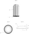
- FIG. 1is perspective view of the cooling tape of the present invention mounted on a beverage container in accordance with an illustrative embodiment of the invention.
- FIG. 2is a top view of the cooling tape of FIG. 1 .
- FIG. 3 ais top schematic view of an illustrative embodiment of the cooling tape of the present invention.
- FIG. 3 bis a sectional end view of the tape depicted in FIG. 3 a.
- FIG. 3 cis a sectional side view of the tape depicted in FIG. 3 a.
- FIG. 4 ais an elevated side view of an illustrative embodiment of the tape of the present invention implemented as an elastic ring.
- FIG. 4 bis an elevated side view of an alternative embodiment of the tape of the present invention implemented with a hook type fastener.
- FIG. 4 cis an elevated side view of a second alternative embodiment of the tape of the present invention implemented with a hook and loop type fastener.
- FIG. 4 dis an elevated side view of third alternative alternative embodiment of the tape of the present invention implemented with a snap type fastener.
- FIG. 5is perspective view of the cooling pad of the present invention mounted under a beverage container in accordance with an illustrative embodiment of the invention.
- FIG. 5 ais a top plan view of the pad depicted in FIG. 4 .
- FIG. 5 bis a sectional side view of the pad depicted in FIG. 4 .
- FIG. 1is perspective view of the cooling tape 10 of the present invention mounted on a beverage container 20 in accordance with an illustrative embodiment of the invention.
- FIG. 2is a top view of the cooling tape 10 of FIG. 1 mounted on the beverage container 20 .
- FIG. 3 ais top schematic view of an illustrative embodiment of the cooling tape 10 of the present invention.
- FIG. 3 bis a sectional end view of the tape depicted in FIG. 3 a.
- FIG. 3 cis a sectional side view of the tape depicted in FIG. 3 a.
- the inventive tapeincludes a first layer 12 of thermally conductive material; a second layer 16 of thermal insulation; and a third layer 14 of endothermic material, sandwiched between the first and second layers 12 and 16 respectively.
- the first layer 12may be made of porous or non-porous fabric with or without elastic properties, plastic, biodegradable plastic (made of corn starch or other traditional petrochemical), rubber, metal, PTFE or Teflon.
- the second layer 16may be plastic, biodegradable plastic (made of corn starch or other traditional petrochemical), rubber, metal, PTFE or Teflon.
- the third layer 14is constructed with reactants effective to cause an endothermic chemical reaction.
- the device 10may be implemented in accordance with the teachings of U.S. Pat. No. 6,036,004 issued Mar. 14, 2000 to M. L. Bowen entitled MULTI-COMPARTMENT BAG WITH BREAKABLE WALLS, the teachings of which are hereby incorporated herein by reference.
- the reactantsare dry, solid compounds such as ammonium nitrate, calcium ammonium nitrate, potassium chloride, ammonium chloride or urea.
- the tapeis activated by breaking a barrier (not shown) separating water filled chambers and chambers with one or more of the above-mentioned dry compounds, allowing them to mix initiating an endothermic reaction.
- the endothermic reactionis effectuated with dry compounds using, by way of example:
- a breakable barrierin the third layer 14 separates the reactants so the cooling can be initiated at any point by breaking the barrier.
- the third layer 14could include multiple layers saturated or interwoven with reactants.
- the reactantsmay be dry solid compounds such as ammonium nitrate, calcium ammonium nitrate, potassium chloride, ammonium chloride or urea.
- the tapeis adapted for activation by breaking a barrier separating water filled chambers and chambers with one or more of the dry compounds, allowing them to mix to initiate the endothermic reaction.
- the reactantscould be implemented with barium hydroxide octahydrate crystals and dry ammonium chloride or thionyl chloride (SOCl2) and cobalt (II) sulfate heptahydrate or ethanoic acid and sodium carbonate.
- the third layer 14could be implemented as a powder or crystal or implemented as a liquid in which case the third layer has sealed borders.
- the third layercan be implemented with segmented lengths of endothermic reactants to allow for the tape to be cut at various lengths without cutting through a layer of reactants.
- the segmentsare separated by cutting or tearing along the seams 15 depicted in FIG. 3 a.
- the tapemay be implemented as a ring or strip with various fasteners as illustrated in FIGS. 4 a - d .
- FIG. 4 ais an elevated side view of an illustrative embodiment of the tape of the present invention implemented with elastic layers to provide an elastic ring.
- FIG. 4 bis an elevated side view of an alternative embodiment of the tape of the present invention implemented with a hook type fastener 30 .
- FIG. 4 cis an elevated side view of a second alternative embodiment of the tape of the present invention implemented with a hook and loop (aka Velcro) type fastener 40 .
- FIG. 4 dis an elevated side view of third alternative embodiment of the tape of the present invention implemented with a snap type fastener 50 .
- All of the above described fastenersmay be made of plastic, biodegradable plastic (made of corn starch or other traditional petrochemical), metal or other suited material.
- the tapemay be wrapped in a spiral pattern around the pipe and secured in place with adhesive material provided on layers 12 and 16 .
- the tape 10is designed for activation upon a tight wrapping of the tape around the pipe.
- Various embodimentswould be made to accommodate pipes of various sizes and to effect activation upon proper application thereto.
- FIG. 5is perspective view of the cooling pad of the present invention mounted under a beverage container in accordance with an illustrative embodiment of the invention.
- FIG. 5 ais a top plan view of the pad depicted in FIG. 4 .
- FIG. 5 bis a sectional side view of the pad depicted in FIG. 4 .
- a beverage cooling devicecan be implemented as a cooling pad 10 ′ with a first layer of thermally conductive material 16 ′; a second layer of material 12 ′; and a third layer of endothermic material 14 ′, sandwiched between the first and second layers 12 ′ and 16 ′ respectively.
- Layer 16 ′may or may not have an adhesive layer to aid in sticking the pad to the bottom of the can.
- the first layer 16 ′is plastic or other suitable thermally conductive material and the second layer 12 ′ is plastic or other suitably rigid material, with or without adhesive properties and made with or without material providing thermal insulation, depending on the attributes desired or required for a given application.
- the third layer 14 ′has a contour effective to create suction whereby the pad 10 ′ adheres to a surface to be cooled.
- the contouris dome shaped in contemplation of a beverage can 20 with a concave bottom surface.
- the inventive tape 10may be fabricated by applying a strong adhesive such as zinc oxide or other suitable adhesive to layer 16 .
- the top layer 12fabricated in the same manner as the bottom layer 16 , is applied to the endothermic layer 14 .
- the top and bottom layers 12 and 16may be 97% tightly woven elasticated cotton with 3% nylon fibers or implemented with a ratio of cotton or nylon better suited for a particular application.
- the top and bottom layers 12 and 16may also be constructed without any elastic properties and with or without adhesive properties depending on what it is being applied to.
- the first layer 12may be made of porous or non-porous fabric with or without elastic properties, plastic, biodegradable plastic (made of corn starch or other traditional petrochemical), rubber, metal, PTFE or Teflon.
- the second layer 16may be plastic, biodegradable plastic (made of corn starch or other traditional petrochemical), rubber, metal, PTFE, or Teflon.
- a hollow section of the tape 10could be provided and filled with a pre-made, plastic, enclosed tube of reactants. This eliminates the need for the tape to be leak proof. This also simplifies the manufacturing process as the tape can be made with a hollow core and then tubes can be inserted that are either filled with reactants that cool. Those tubes can also be filled with varying quantities depending on the desired intensity of heat or cool.
- the pad 10could be constructed so when a can or bottle is placed and pressed on top of the dome 16 a barrier is broken from the pressure. This would activate the reaction of cooling the can or bottle.
- multiple cooling pads 10could be connected within one large pad with six domes to enable the cooling of multiple cans at once. For practical purposes you could set a six pack of cans on top of a pad with six domes. Each pad could be activated by the pressure of each can or a central water chamber barrier could be broken to activate each pad segment via water as a catalyst.
- the tapemay be constructed in multiple ways.
- the tapemay be constructed to contain hollow chambers that can hold and separate the individual reactants.
- individual reactantscan either be enclosed in a flexible, leak-proof container that will fit into each chamber of the tape or the tape can be constructed of leak-proof material so the raw reactants can be placed directly inside each chamber.
- the tapecan be constructed of leak-proof material so the raw reactants can be placed directly inside each chamber.
- the tapecould also be constructed with multiple layers of pre-made reactant strips that are stacked or glued onto each other but separated by a barrier. Squeezing the tape by hand could break the barriers and initiate the endothermic reaction.
- Non-human useTape being adhered to an inanimate object can be made as cold as needed depending on the desired outcome. Practical uses are cooling warm beverages or freezing water to produce ice in remote areas. Another practical use is to freeze a leaking water pipe to temporarily stop a leak. This would enable the pipe to be cut and capped while the damaged pipe section can be repaired or replaced. Again, the reactants can be adjusted to obtain the desired temperature and length of cooling time.
- the tapehas a width of 1-6 inches, a thickness of 1-40 mm and a length of 3 inches to any length
- the tapecan be manufactured to have segmented lengths of endothermic reactants to allow for the tape to be cut at various lengths without cutting through the container, pouch or layer of reactants.
- the present inventionis not limited to the fabrics and chemicals disclosed herein. Other combinations of fabrics and chemicals may be employed without departing from the scope of the present teachings.
- a plurality of small capsulesmay be provided within the tape which, when squeezed by a user, ruptures and releases a mix of chemicals leading to an endothermic cooling effect.
Landscapes
- Chemical & Material Sciences (AREA)
- Engineering & Computer Science (AREA)
- Organic Chemistry (AREA)
- Thermal Sciences (AREA)
- Physics & Mathematics (AREA)
- Combustion & Propulsion (AREA)
- Chemical Kinetics & Catalysis (AREA)
- Inorganic Chemistry (AREA)
- General Chemical & Material Sciences (AREA)
- Materials Engineering (AREA)
- Ceramic Engineering (AREA)
- Mechanical Engineering (AREA)
- General Engineering & Computer Science (AREA)
- Thermotherapy And Cooling Therapy Devices (AREA)
- Packages (AREA)
Abstract
Description
- the reaction of barium hydroxide octahydrate crystals with dry ammonium chloride;
- the reaction of thionyl chloride (SOCl2) with cobalt (II) sulfate heptahydrate; and/or
- reacting ethanoic acid with sodium carbonate
Claims (1)
Priority Applications (2)
| Application Number | Priority Date | Filing Date | Title |
|---|---|---|---|
| US16/418,980US11774159B2 (en) | 2018-06-28 | 2019-05-21 | Flexible adhesive tape for cooling beverages, pipes and other articles |
| PCT/US2020/033650WO2020236842A1 (en) | 2019-05-21 | 2020-05-19 | Flexible heating and cooling tape |
Applications Claiming Priority (4)
| Application Number | Priority Date | Filing Date | Title |
|---|---|---|---|
| US16/022,569US10492957B1 (en) | 2018-06-28 | 2018-06-28 | Flexible adhesive physio tape with thermal properties |
| US16/120,651US10350109B1 (en) | 2018-06-28 | 2018-09-04 | Flexible adhesive physio tape with cooling properties |
| US16/184,188US10342889B1 (en) | 2018-06-28 | 2018-11-08 | Electrically actuated adhesive physio tape with thermal properties |
| US16/418,980US11774159B2 (en) | 2018-06-28 | 2019-05-21 | Flexible adhesive tape for cooling beverages, pipes and other articles |
Related Parent Applications (2)
| Application Number | Title | Priority Date | Filing Date |
|---|---|---|---|
| US16/022,569Continuation-In-PartUS10492957B1 (en) | 2018-06-28 | 2018-06-28 | Flexible adhesive physio tape with thermal properties |
| US16/184,188Continuation-In-PartUS10342889B1 (en) | 2018-06-28 | 2018-11-08 | Electrically actuated adhesive physio tape with thermal properties |
Publications (2)
| Publication Number | Publication Date |
|---|---|
| US20200256608A1 US20200256608A1 (en) | 2020-08-13 |
| US11774159B2true US11774159B2 (en) | 2023-10-03 |
Family
ID=71944830
Family Applications (1)
| Application Number | Title | Priority Date | Filing Date |
|---|---|---|---|
| US16/418,980ActiveUS11774159B2 (en) | 2018-06-28 | 2019-05-21 | Flexible adhesive tape for cooling beverages, pipes and other articles |
Country Status (1)
| Country | Link |
|---|---|
| US (1) | US11774159B2 (en) |
Families Citing this family (2)
| Publication number | Priority date | Publication date | Assignee | Title |
|---|---|---|---|---|
| US11643261B2 (en)* | 2020-02-28 | 2023-05-09 | Illinois Tool Works Inc. | Biodegradable multi-pack carriers |
| FI20235289A1 (en) | 2023-03-13 | 2024-09-14 | Kl Tech Oy | Self-heating and/or -cooling thermal layer and a product containing such a layer |
Citations (38)
| Publication number | Priority date | Publication date | Assignee | Title |
|---|---|---|---|---|
| US3175558A (en)* | 1962-03-14 | 1965-03-30 | James C Caillonette | Thermal therapeutic pack |
| US3299890A (en)* | 1963-06-11 | 1967-01-24 | San Francisco Res Corp | Surgical bandage, dressing and the like |
| US3900035A (en)* | 1974-07-03 | 1975-08-19 | Dennis W Welch | Therapeutic elastic bandage |
| US3940905A (en)* | 1973-06-25 | 1976-03-02 | Perry 3Rd Thomas William | Method and apparatus for making a thermal compress |
| US4344303A (en)* | 1980-12-01 | 1982-08-17 | Kelly Jr C Brantley | Beverage container cooler |
| US4397315A (en)* | 1981-09-16 | 1983-08-09 | The Kendall Company | Dressing with temperature pack |
| US4932333A (en)* | 1989-07-14 | 1990-06-12 | Sico Incorporated | Stabilizing wheels for folding table |
| US4989418A (en)* | 1990-07-10 | 1991-02-05 | Hewlett Kenneth M | Cooling wrap |
| US5005374A (en)* | 1990-04-27 | 1991-04-09 | Chillynex Corporation | Thermal wraps |
| US5304216A (en)* | 1993-01-26 | 1994-04-19 | Wallace Robert B | Ice pack apparatus |
| US5395399A (en)* | 1993-06-14 | 1995-03-07 | Sport Wrapz, Inc. | Thermal wrap for a body member |
| US5431622A (en)* | 1992-08-10 | 1995-07-11 | Okanagan House Inc. | Thermal bandage |
| US5934100A (en)* | 1998-03-23 | 1999-08-10 | Hornick; Robert | Beverage keg cooling jacket |
| US6036004A (en) | 1997-12-03 | 2000-03-14 | Bowen; Michael L. | Multi-compartment bag with breakable walls |
| US6128915A (en)* | 1999-05-06 | 2000-10-10 | Wagner; Peter P. G. | Portable food and beverage cooling device |
| US20020042641A1 (en)* | 2000-10-06 | 2002-04-11 | Weyerhaeuser Company | Wrap-ons aromatic thermal wraps |
| US20020052569A1 (en)* | 1999-08-10 | 2002-05-02 | Larry R. Horning | Bandage for application of therapeutic cold or heat treatments to injuries |
| US6427678B1 (en)* | 1999-06-14 | 2002-08-06 | William K. Trzeciak | Fishing rod handle warmer |
| US20030055366A1 (en)* | 2001-09-18 | 2003-03-20 | Chalek Matthew J. | Reusable/disposable thermal application and holder device |
| US20030109816A1 (en)* | 2001-12-08 | 2003-06-12 | Charles A. Lachenbruch | Warmable bandage for promoting bandage for promoting wound healing |
| US6666836B1 (en)* | 2001-04-06 | 2003-12-23 | Sti Medical Products, Inc. | Thermal treatment system |
| US6786062B1 (en)* | 2001-11-20 | 2004-09-07 | Harry R. Greenberg | Beverage cooling device |
| US20050080368A1 (en)* | 2002-11-14 | 2005-04-14 | Hurwitz Marni Lynn | Bandage with cooling capabilities |
| US7089757B2 (en)* | 2002-04-15 | 2006-08-15 | Jung Wook Yang | Device for cooling object |
| US7249385B2 (en)* | 2004-01-20 | 2007-07-31 | Richard Schukraft | Finger/toe tip protective apparatus |
| US7264602B1 (en)* | 2006-06-28 | 2007-09-04 | Longsworth Sheryl M | Bandage assembly |
| US20080141683A1 (en)* | 2006-12-13 | 2008-06-19 | O'connor Amanda L | Chambered instant cold pack |
| US7588548B2 (en)* | 2005-04-22 | 2009-09-15 | Kopreski Michael C | Endothermic bandage with dispenser for the treatment of burns and other injuries |
| US20100005828A1 (en)* | 2008-07-14 | 2010-01-14 | David Fedell | Beverage Cooling Device and Method of Use Thereof |
| US20110034887A1 (en)* | 2009-08-10 | 2011-02-10 | Arctic Ease, LLC | Cooling products and methods |
| US20120095380A1 (en)* | 2009-06-15 | 2012-04-19 | Molnlycke Health Care Ab | Wound dressing with high liquid handling capacity |
| US20140054010A1 (en)* | 2012-08-24 | 2014-02-27 | Cp Concepts, Llc | Container chilling apparatus |
| US20140166672A1 (en)* | 2011-12-14 | 2014-06-19 | Owens-Brockway Glass Container Inc. | Container Thermal Core And Closure Remover |
| US20150297396A1 (en)* | 2014-04-22 | 2015-10-22 | Rapid Aid Corp. | Method of manufacturing disposable cold pack and related disposable cold pack containing phosphate ammonium nitrate |
| US20170105877A1 (en)* | 2014-06-10 | 2017-04-20 | M4 Medical Pty Ltd | Wound dressing |
| US9702609B2 (en)* | 2014-06-17 | 2017-07-11 | Cold Can Innovations, LLC | Vessel cooling system and associated methods |
| CN106982271A (en)* | 2016-12-28 | 2017-07-25 | 湖南大学 | A kind of gadget cooled for smart mobile phone cold compress |
| EP3345126A1 (en) | 2015-08-31 | 2018-07-11 | I.R.I.S. | Method and system for correction of an image from a hand-held scanning device |
Family Cites Families (1)
| Publication number | Priority date | Publication date | Assignee | Title |
|---|---|---|---|---|
| US9078742B2 (en)* | 2006-12-15 | 2015-07-14 | Kimberly-Clark Worldwide, Inc. | Self-activated cooling device |
- 2019
- 2019-05-21USUS16/418,980patent/US11774159B2/enactiveActive
Patent Citations (38)
| Publication number | Priority date | Publication date | Assignee | Title |
|---|---|---|---|---|
| US3175558A (en)* | 1962-03-14 | 1965-03-30 | James C Caillonette | Thermal therapeutic pack |
| US3299890A (en)* | 1963-06-11 | 1967-01-24 | San Francisco Res Corp | Surgical bandage, dressing and the like |
| US3940905A (en)* | 1973-06-25 | 1976-03-02 | Perry 3Rd Thomas William | Method and apparatus for making a thermal compress |
| US3900035A (en)* | 1974-07-03 | 1975-08-19 | Dennis W Welch | Therapeutic elastic bandage |
| US4344303A (en)* | 1980-12-01 | 1982-08-17 | Kelly Jr C Brantley | Beverage container cooler |
| US4397315A (en)* | 1981-09-16 | 1983-08-09 | The Kendall Company | Dressing with temperature pack |
| US4932333A (en)* | 1989-07-14 | 1990-06-12 | Sico Incorporated | Stabilizing wheels for folding table |
| US5005374A (en)* | 1990-04-27 | 1991-04-09 | Chillynex Corporation | Thermal wraps |
| US4989418A (en)* | 1990-07-10 | 1991-02-05 | Hewlett Kenneth M | Cooling wrap |
| US5431622A (en)* | 1992-08-10 | 1995-07-11 | Okanagan House Inc. | Thermal bandage |
| US5304216A (en)* | 1993-01-26 | 1994-04-19 | Wallace Robert B | Ice pack apparatus |
| US5395399A (en)* | 1993-06-14 | 1995-03-07 | Sport Wrapz, Inc. | Thermal wrap for a body member |
| US6036004A (en) | 1997-12-03 | 2000-03-14 | Bowen; Michael L. | Multi-compartment bag with breakable walls |
| US5934100A (en)* | 1998-03-23 | 1999-08-10 | Hornick; Robert | Beverage keg cooling jacket |
| US6128915A (en)* | 1999-05-06 | 2000-10-10 | Wagner; Peter P. G. | Portable food and beverage cooling device |
| US6427678B1 (en)* | 1999-06-14 | 2002-08-06 | William K. Trzeciak | Fishing rod handle warmer |
| US20020052569A1 (en)* | 1999-08-10 | 2002-05-02 | Larry R. Horning | Bandage for application of therapeutic cold or heat treatments to injuries |
| US20020042641A1 (en)* | 2000-10-06 | 2002-04-11 | Weyerhaeuser Company | Wrap-ons aromatic thermal wraps |
| US6666836B1 (en)* | 2001-04-06 | 2003-12-23 | Sti Medical Products, Inc. | Thermal treatment system |
| US20030055366A1 (en)* | 2001-09-18 | 2003-03-20 | Chalek Matthew J. | Reusable/disposable thermal application and holder device |
| US6786062B1 (en)* | 2001-11-20 | 2004-09-07 | Harry R. Greenberg | Beverage cooling device |
| US20030109816A1 (en)* | 2001-12-08 | 2003-06-12 | Charles A. Lachenbruch | Warmable bandage for promoting bandage for promoting wound healing |
| US7089757B2 (en)* | 2002-04-15 | 2006-08-15 | Jung Wook Yang | Device for cooling object |
| US20050080368A1 (en)* | 2002-11-14 | 2005-04-14 | Hurwitz Marni Lynn | Bandage with cooling capabilities |
| US7249385B2 (en)* | 2004-01-20 | 2007-07-31 | Richard Schukraft | Finger/toe tip protective apparatus |
| US7588548B2 (en)* | 2005-04-22 | 2009-09-15 | Kopreski Michael C | Endothermic bandage with dispenser for the treatment of burns and other injuries |
| US7264602B1 (en)* | 2006-06-28 | 2007-09-04 | Longsworth Sheryl M | Bandage assembly |
| US20080141683A1 (en)* | 2006-12-13 | 2008-06-19 | O'connor Amanda L | Chambered instant cold pack |
| US20100005828A1 (en)* | 2008-07-14 | 2010-01-14 | David Fedell | Beverage Cooling Device and Method of Use Thereof |
| US20120095380A1 (en)* | 2009-06-15 | 2012-04-19 | Molnlycke Health Care Ab | Wound dressing with high liquid handling capacity |
| US20110034887A1 (en)* | 2009-08-10 | 2011-02-10 | Arctic Ease, LLC | Cooling products and methods |
| US20140166672A1 (en)* | 2011-12-14 | 2014-06-19 | Owens-Brockway Glass Container Inc. | Container Thermal Core And Closure Remover |
| US20140054010A1 (en)* | 2012-08-24 | 2014-02-27 | Cp Concepts, Llc | Container chilling apparatus |
| US20150297396A1 (en)* | 2014-04-22 | 2015-10-22 | Rapid Aid Corp. | Method of manufacturing disposable cold pack and related disposable cold pack containing phosphate ammonium nitrate |
| US20170105877A1 (en)* | 2014-06-10 | 2017-04-20 | M4 Medical Pty Ltd | Wound dressing |
| US9702609B2 (en)* | 2014-06-17 | 2017-07-11 | Cold Can Innovations, LLC | Vessel cooling system and associated methods |
| EP3345126A1 (en) | 2015-08-31 | 2018-07-11 | I.R.I.S. | Method and system for correction of an image from a hand-held scanning device |
| CN106982271A (en)* | 2016-12-28 | 2017-07-25 | 湖南大学 | A kind of gadget cooled for smart mobile phone cold compress |
Non-Patent Citations (1)
| Title |
|---|
| Written Opinion of PCT International Searching Authority dated Oct. 5, 2020. |
Also Published As
| Publication number | Publication date |
|---|---|
| US20200256608A1 (en) | 2020-08-13 |
Similar Documents
| Publication | Publication Date | Title |
|---|---|---|
| US10350109B1 (en) | Flexible adhesive physio tape with cooling properties | |
| US6083256A (en) | NNT or cold pad with inner element | |
| US2602302A (en) | Combination ice and hot pack | |
| US5069208A (en) | Therapeutic device comprising a mass of a thermally active material | |
| US6036004A (en) | Multi-compartment bag with breakable walls | |
| US11774159B2 (en) | Flexible adhesive tape for cooling beverages, pipes and other articles | |
| US5967308A (en) | Multi-compartment bag with breakable walls | |
| US9476630B2 (en) | Method and apparatus for water storage and transport | |
| US5840080A (en) | Hot or cold applicator with inner element | |
| US5398848A (en) | Portable liquid container | |
| JP2013540662A5 (en) | ||
| US20080119916A1 (en) | Cold Compress for Therapeutic Cooling | |
| US20120165910A1 (en) | Cold compress for therapeutic cooling | |
| KR101948865B1 (en) | Neck cooling tube | |
| EP0286382A2 (en) | Self-cooling container | |
| MXPA05002902A (en) | Pressure activated reaction vessel and package. | |
| US5313809A (en) | Insulating wrap | |
| US7744940B2 (en) | Food product warming or cooling package | |
| JP6918205B2 (en) | Cold storage equipment | |
| CN211316675U (en) | Cold chain anti-collision medicine bag of portable refrigerator medicine | |
| US10913241B2 (en) | Flexible adhesive tape for heating beverages, pipes and other articles | |
| WO2020236842A1 (en) | Flexible heating and cooling tape | |
| CN106642875B (en) | Fresh-keeping bag using dry ice as cold source | |
| CN206187688U (en) | Cold -stored cup and cold -stored retainer cup | |
| US9625207B2 (en) | Beverage cooling device |
Legal Events
| Date | Code | Title | Description |
|---|---|---|---|
| FEPP | Fee payment procedure | Free format text:ENTITY STATUS SET TO UNDISCOUNTED (ORIGINAL EVENT CODE: BIG.); ENTITY STATUS OF PATENT OWNER: SMALL ENTITY | |
| FEPP | Fee payment procedure | Free format text:ENTITY STATUS SET TO SMALL (ORIGINAL EVENT CODE: SMAL); ENTITY STATUS OF PATENT OWNER: SMALL ENTITY | |
| STPP | Information on status: patent application and granting procedure in general | Free format text:ADVISORY ACTION MAILED | |
| STPP | Information on status: patent application and granting procedure in general | Free format text:RESPONSE TO NON-FINAL OFFICE ACTION ENTERED AND FORWARDED TO EXAMINER | |
| STPP | Information on status: patent application and granting procedure in general | Free format text:FINAL REJECTION MAILED | |
| STPP | Information on status: patent application and granting procedure in general | Free format text:RESPONSE AFTER FINAL ACTION FORWARDED TO EXAMINER | |
| STPP | Information on status: patent application and granting procedure in general | Free format text:ADVISORY ACTION MAILED | |
| STPP | Information on status: patent application and granting procedure in general | Free format text:DOCKETED NEW CASE - READY FOR EXAMINATION | |
| STPP | Information on status: patent application and granting procedure in general | Free format text:NON FINAL ACTION MAILED | |
| STPP | Information on status: patent application and granting procedure in general | Free format text:NON FINAL ACTION MAILED | |
| STPP | Information on status: patent application and granting procedure in general | Free format text:RESPONSE TO NON-FINAL OFFICE ACTION ENTERED AND FORWARDED TO EXAMINER | |
| STPP | Information on status: patent application and granting procedure in general | Free format text:FINAL REJECTION MAILED | |
| STPP | Information on status: patent application and granting procedure in general | Free format text:ADVISORY ACTION MAILED | |
| STPP | Information on status: patent application and granting procedure in general | Free format text:DOCKETED NEW CASE - READY FOR EXAMINATION | |
| STPP | Information on status: patent application and granting procedure in general | Free format text:NON FINAL ACTION MAILED | |
| STPP | Information on status: patent application and granting procedure in general | Free format text:AWAITING TC RESP., ISSUE FEE NOT PAID | |
| STPP | Information on status: patent application and granting procedure in general | Free format text:NOTICE OF ALLOWANCE MAILED -- APPLICATION RECEIVED IN OFFICE OF PUBLICATIONS | |
| STPP | Information on status: patent application and granting procedure in general | Free format text:PUBLICATIONS -- ISSUE FEE PAYMENT VERIFIED | |
| STCF | Information on status: patent grant | Free format text:PATENTED CASE |