US11774004B2 - Pressurized dual packing seal valve - Google Patents
Pressurized dual packing seal valveDownload PDFInfo
- Publication number
- US11774004B2 US11774004B2US17/485,674US202117485674AUS11774004B2US 11774004 B2US11774004 B2US 11774004B2US 202117485674 AUS202117485674 AUS 202117485674AUS 11774004 B2US11774004 B2US 11774004B2
- Authority
- US
- United States
- Prior art keywords
- valve
- fluid
- seal
- pressurizing fluid
- pressure
- Prior art date
- Legal status (The legal status is an assumption and is not a legal conclusion. Google has not performed a legal analysis and makes no representation as to the accuracy of the status listed.)
- Active
Links
- 238000012856packingMethods0.000titleclaimsabstractdescription47
- 230000009977dual effectEffects0.000title1
- 239000012530fluidSubstances0.000claimsabstractdescription94
- 238000000034methodMethods0.000claimsabstractdescription42
- 230000008569processEffects0.000claimsabstractdescription32
- 230000009471actionEffects0.000claimsabstractdescription8
- 238000012423maintenanceMethods0.000claimsabstractdescription8
- IJGRMHOSHXDMSA-UHFFFAOYSA-NAtomic nitrogenChemical compoundN#NIJGRMHOSHXDMSA-UHFFFAOYSA-N0.000claimsabstractdescription6
- 229910001873dinitrogenInorganic materials0.000claimsabstractdescription4
- 210000004907glandAnatomy0.000claimsdescription7
- 230000001105regulatory effectEffects0.000claimsdescription6
- 238000000926separation methodMethods0.000claimsdescription4
- 238000004891communicationMethods0.000claimsdescription3
- 238000012544monitoring processMethods0.000claimsdescription3
- 125000006850spacer groupChemical group0.000claimsdescription3
- QVGXLLKOCUKJST-UHFFFAOYSA-Natomic oxygenChemical compound[O]QVGXLLKOCUKJST-UHFFFAOYSA-N0.000description4
- 230000001590oxidative effectEffects0.000description4
- 239000001301oxygenSubstances0.000description4
- 229910052760oxygenInorganic materials0.000description4
- 238000013461designMethods0.000description3
- 230000003068static effectEffects0.000description3
- 230000001419dependent effectEffects0.000description2
- 238000010586diagramMethods0.000description2
- 239000007789gasSubstances0.000description2
- 239000002184metalSubstances0.000description2
- 238000012986modificationMethods0.000description2
- 230000004048modificationEffects0.000description2
- 230000004888barrier functionEffects0.000description1
- 229910052757nitrogenInorganic materials0.000description1
- 238000012546transferMethods0.000description1
Images


Classifications
- F—MECHANICAL ENGINEERING; LIGHTING; HEATING; WEAPONS; BLASTING
- F16—ENGINEERING ELEMENTS AND UNITS; GENERAL MEASURES FOR PRODUCING AND MAINTAINING EFFECTIVE FUNCTIONING OF MACHINES OR INSTALLATIONS; THERMAL INSULATION IN GENERAL
- F16K—VALVES; TAPS; COCKS; ACTUATING-FLOATS; DEVICES FOR VENTING OR AERATING
- F16K41/00—Spindle sealings
- F16K41/003—Spindle sealings by fluid
- F—MECHANICAL ENGINEERING; LIGHTING; HEATING; WEAPONS; BLASTING
- F16—ENGINEERING ELEMENTS AND UNITS; GENERAL MEASURES FOR PRODUCING AND MAINTAINING EFFECTIVE FUNCTIONING OF MACHINES OR INSTALLATIONS; THERMAL INSULATION IN GENERAL
- F16J—PISTONS; CYLINDERS; SEALINGS
- F16J15/00—Sealings
- F16J15/002—Sealings comprising at least two sealings in succession
- F16J15/004—Sealings comprising at least two sealings in succession forming of recuperation chamber for the leaking fluid
- F—MECHANICAL ENGINEERING; LIGHTING; HEATING; WEAPONS; BLASTING
- F16—ENGINEERING ELEMENTS AND UNITS; GENERAL MEASURES FOR PRODUCING AND MAINTAINING EFFECTIVE FUNCTIONING OF MACHINES OR INSTALLATIONS; THERMAL INSULATION IN GENERAL
- F16K—VALVES; TAPS; COCKS; ACTUATING-FLOATS; DEVICES FOR VENTING OR AERATING
- F16K1/00—Lift valves or globe valves, i.e. cut-off apparatus with closure members having at least a component of their opening and closing motion perpendicular to the closing faces
- F—MECHANICAL ENGINEERING; LIGHTING; HEATING; WEAPONS; BLASTING
- F16—ENGINEERING ELEMENTS AND UNITS; GENERAL MEASURES FOR PRODUCING AND MAINTAINING EFFECTIVE FUNCTIONING OF MACHINES OR INSTALLATIONS; THERMAL INSULATION IN GENERAL
- F16K—VALVES; TAPS; COCKS; ACTUATING-FLOATS; DEVICES FOR VENTING OR AERATING
- F16K37/00—Special means in or on valves or other cut-off apparatus for indicating or recording operation thereof, or for enabling an alarm to be given
- F16K37/0008—Mechanical means
- F16K37/0016—Mechanical means having a graduated scale
- F—MECHANICAL ENGINEERING; LIGHTING; HEATING; WEAPONS; BLASTING
- F16—ENGINEERING ELEMENTS AND UNITS; GENERAL MEASURES FOR PRODUCING AND MAINTAINING EFFECTIVE FUNCTIONING OF MACHINES OR INSTALLATIONS; THERMAL INSULATION IN GENERAL
- F16K—VALVES; TAPS; COCKS; ACTUATING-FLOATS; DEVICES FOR VENTING OR AERATING
- F16K37/00—Special means in or on valves or other cut-off apparatus for indicating or recording operation thereof, or for enabling an alarm to be given
- F16K37/0075—For recording or indicating the functioning of a valve in combination with test equipment
- F16K37/0091—For recording or indicating the functioning of a valve in combination with test equipment by measuring fluid parameters
- F—MECHANICAL ENGINEERING; LIGHTING; HEATING; WEAPONS; BLASTING
- F16—ENGINEERING ELEMENTS AND UNITS; GENERAL MEASURES FOR PRODUCING AND MAINTAINING EFFECTIVE FUNCTIONING OF MACHINES OR INSTALLATIONS; THERMAL INSULATION IN GENERAL
- F16K—VALVES; TAPS; COCKS; ACTUATING-FLOATS; DEVICES FOR VENTING OR AERATING
- F16K41/00—Spindle sealings
- F16K41/02—Spindle sealings with stuffing-box ; Sealing rings
- F—MECHANICAL ENGINEERING; LIGHTING; HEATING; WEAPONS; BLASTING
- F16—ENGINEERING ELEMENTS AND UNITS; GENERAL MEASURES FOR PRODUCING AND MAINTAINING EFFECTIVE FUNCTIONING OF MACHINES OR INSTALLATIONS; THERMAL INSULATION IN GENERAL
- F16K—VALVES; TAPS; COCKS; ACTUATING-FLOATS; DEVICES FOR VENTING OR AERATING
- F16K41/00—Spindle sealings
- F16K41/10—Spindle sealings with diaphragm, e.g. shaped as bellows or tube
Definitions
- the inventionrelates to valves, and more particularly, to valves that form a seal using packing.
- a bellows seal valveis typically used.
- a bellows seal valvecomprises an accordion-like bellows 100 .
- One end 102 of the bellows 100is welded or attached to the valve stem 104 .
- the other end 106 of the bellows 100is welded to a part 108 that can be clamped or otherwise attached to the valve bonnet 109 .
- the valve stem 104is moved in a linear valve stroke so as to control the position of a valve plug 110 relative to a valve seat 112 .
- the bellows 100compresses or expands along with the linear motion of the sliding valve stem 104 .
- the bellows 100has a static seal at each end 102 , 106 , and the circumference of the valve stem 104 is covered by the bellows 100 , a metal barrier between the process fluid inside of the valve and the external atmosphere is provided, eliminating leakage at the valve stem 104 .
- the process fluidis outside of the bellows 100
- the atmosphereis inside of the bellows 100 .
- the process fluidis inside of the bellows 100 and the atmosphere is outside of the bellows 100 .
- a set of packing 114is provided above the bellows 100 to provide a second seal.
- valve stem packing 114typically allows a higher level of leakage than a bellows 100 , there is a high probability that if the bellows 100 were to developed a leak path, at least some process fluid would escape through the bellows 100 and valve stem packing 114 to the outside environment.
- the present inventionis a reliable valve design that is less prone to leakage than conventional bellows valves, while also being less expensive than conventional bellows valves.
- a linear stroke valveincludes a pair of packing seals that are spaced apart by a gap space along the valve stem, for example within a gland area of the valve. Leakage through the packing seals is prevented by introducing a pressurizing fluid, such as nitrogen, into the gap space between the packing seals and maintaining the pressurizing fluid at a gap pressure that is higher than the process fluid pressure so as to ensure that any leakage past the packing seals will be of the pressurizing fluid into the process fluid or into the environment, while any escape of the process fluid into the environment is prevented.
- a pressurizing fluidsuch as nitrogen
- the volume between the packing sealswill normally be constant and static, and there will normally be no flow of the pressurization fluid into the valve once the desired pressure of the pressurizing fluid is established within the valve.
- the pressure and/or flow rate of the pressurizing fluidis monitored, so that any leakage of the pressurizing fluid through either or both of the packing seals is easily detected as a decrease in the pressure and/or as an increased flow rate of the pressurizing fluid into the valve.
- leakage of small amounts of the pressurizing fluid into the process fluid and/or into the environmentmay be tolerable.
- a maintenance actioncan be applied to the valve, for example by re-tightening or replacing the packing, or replacing the valve.
- the pressurizing gascan serve to protect inner rings of the packing seals by displacing oxygen away from them.
- Oxidizing resistant rings of packingcan be placed on the outsides of the packing seals to protect inner rings that might otherwise be oxidized.
- this arrangementfurther protects the valve fluid from oxygen ingress when the process fluid is drained from the system and a vacuum is created that might otherwise suck air into the valve from the outside environment.
- One general aspect of the present inventionis a valve system comprising a valve.
- the valveincludes a valve seat; a valve plug configured to control a flow of process fluid through the valve according to a separation between the valve plug and the valve seat; a valve stem in mechanical communication with the valve plug and configured such that linear actuation of the valve stem controls the separation between the valve plug and the valve seat; first and second packing seals surrounding the valve stem, each of the packing seals forming a seal between the valve stem and a surrounding gland housing, the first and second packing seals being separated from each other along the valve stem by a seal gap, and a seal pressurization port configured to allow a seal pressurizing fluid to enter into the seal gap and to be pressurized within the seal gap to a desired gap pressure.
- Embodimentsfurther include a pressurization fluid source, a pressurizing fluid pressure regulating apparatus, and a pressurization fluid line that provides fluid communication between the pressurization fluid source and the seal pressurization port of the valve.
- Some of these embodimentsfurther include a pressure measuring device configured to measure a pressure of the pressurizing fluid within the gap space.
- a flow measuring deviceconfigured to measure a flow rate of the pressurizing fluid into the gap space.
- Another general aspect of the present inventionis a method of preventing process fluid leakage along a valve stem of a linear stroke valve.
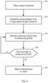
- the methodincludes providing a valve system according to the first general aspect, determining or estimating a process pressure of the process fluid, and applying a pressurizing fluid to the seal pressurization port, the pressurizing fluid being pressurized to a gap pressure that is higher than the process pressure.
- Embodimentsfurther include monitoring at least one of a pressure of the pressuring fluid and a flow rate of the pressurizing fluid.
- the methodcan further include, if the monitored pressure or the monitored flow rate changes by more than a specified amount, determining that a leak has developed in the valve, and applying a maintenance action to the valve.
- the maintenance actionincludes at least one of re-tightening at least one of the packing seals, replacing at least one of the packing seals, and replacing the valve.
- the pressurizing fluidcan be nitrogen gas.
- FIG. 1is a sectional view of a bellows valve of the prior art
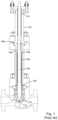
- FIG. 2is a sectional view drawn to scale of an embodiment of the present invention
- FIG. 3is a side view of a valve system according to an embodiment of the present invention, with the valve drawn to scale;
- FIG. 4is a flow diagram indicating a method of the present invention.
- the present inventionis a reliable valve design that is less prone to leakage than conventional bellows valves, while also being less expensive than conventional bellows valves.
- a sealis formed with the valve stem 104 of a linear stroke valve by a pair of packing seals 114 , 200 that are separated from each other along the valve stem 104 by a seal gap 206 .
- the packing seals 114 , 200are both located within a gland area of the valve, and a spacer 204 is provided within the gap space 206 .
- the valvefurther includes a pressurization port 202 .
- the pressurization port 202can be used to inject a pressurizing fluid, such as nitrogen gas 300 , through a pressurizing fluid transfer line 302 into the gap space 206 between the packing seals 114 , 200 .
- a pressure regulating device 306can then be used to establish and maintain the pressurizing fluid within the gap space 206 at a higher pressure than the process fluid, thereby ensuring that any leakage past the packing seals 114 , 200 will be of the pressurizing fluid into the process fluid and/or into the environment, while any escape of the process fluid into the environment will be prevented.
- the volume of the gap space 206 between the packing seals 114 , 200will normally be constant and static, and there will normally be no flow 304 of the pressurization fluid into the valve once the desired gap pressure of the pressurizing fluid is established within the gap space 206 .
- the pressure and/or flow rate of the pressurizing fluidis monitored 404 , for example using a flow gage 304 as shown in FIG. 3 , so that any leakage of the pressurizing fluid past either or both of the packing seals 114 , 200 is easily detected and quantified as a decrease in the pressure and/or increase in the flow rate of the pressurizing fluid.
- leakage of small amounts of the pressurizing fluid into the process fluid and/or into the environmentmay be tolerable.
- a maintenance actioncan be applied 408 to the valve, for example by re-tightening or replacing one or both of the packing seals 114 , 200 , or replacing the valve.
- the pressurizing gascan serve to protect the inner rings of the packing seals 114 , 200 by displacing oxygen away from them.
- Oxidizing resistant rings of packingcan be placed on the outsides of the packing seals 114 , 200 to protect inner rings that might otherwise be oxidized.
- the inventionfurther protects the process fluid from oxygen ingress when the process fluid is drained from the system and a vacuum is created that might otherwise suck air into the valve from the outside environment.
Landscapes
- Engineering & Computer Science (AREA)
- General Engineering & Computer Science (AREA)
- Mechanical Engineering (AREA)
- Details Of Valves (AREA)
- Valve Housings (AREA)
- Lift Valve (AREA)
- Examining Or Testing Airtightness (AREA)
Abstract
Description
Claims (7)
Priority Applications (10)
| Application Number | Priority Date | Filing Date | Title |
|---|---|---|---|
| US17/485,674US11774004B2 (en) | 2021-09-27 | 2021-09-27 | Pressurized dual packing seal valve |
| CN202280065391.8ACN118019937A (en) | 2021-09-27 | 2022-09-13 | Pressurized double-packing sealing valve |
| KR1020247009409AKR20240042550A (en) | 2021-09-27 | 2022-09-13 | Pressurized double packing seal valve |
| MX2024003432AMX2024003432A (en) | 2021-09-27 | 2022-09-13 | PRESSURIZED DOUBLE PACKING SEAL VALVE. |
| JP2024518766AJP2024536857A (en) | 2021-09-27 | 2022-09-13 | Pressurized double packing seal valve |
| PCT/US2022/043349WO2023048992A1 (en) | 2021-09-27 | 2022-09-13 | Pressurized dual packing seal valve |
| CA3232309ACA3232309A1 (en) | 2021-09-27 | 2022-09-13 | Pressurized dual packing seal valve |
| IL311822AIL311822A (en) | 2021-09-27 | 2022-09-13 | Pressure valve with double sealing material |
| AU2022352114AAU2022352114B2 (en) | 2021-09-27 | 2022-09-13 | Pressurized dual packing seal valve |
| EP22873428.1AEP4409170B1 (en) | 2021-09-27 | 2022-09-13 | Pressurized dual packing seal valve |
Applications Claiming Priority (1)
| Application Number | Priority Date | Filing Date | Title |
|---|---|---|---|
| US17/485,674US11774004B2 (en) | 2021-09-27 | 2021-09-27 | Pressurized dual packing seal valve |
Publications (2)
| Publication Number | Publication Date |
|---|---|
| US20230096922A1 US20230096922A1 (en) | 2023-03-30 |
| US11774004B2true US11774004B2 (en) | 2023-10-03 |
Family
ID=85718090
Family Applications (1)
| Application Number | Title | Priority Date | Filing Date |
|---|---|---|---|
| US17/485,674ActiveUS11774004B2 (en) | 2021-09-27 | 2021-09-27 | Pressurized dual packing seal valve |
Country Status (10)
| Country | Link |
|---|---|
| US (1) | US11774004B2 (en) |
| EP (1) | EP4409170B1 (en) |
| JP (1) | JP2024536857A (en) |
| KR (1) | KR20240042550A (en) |
| CN (1) | CN118019937A (en) |
| AU (1) | AU2022352114B2 (en) |
| CA (1) | CA3232309A1 (en) |
| IL (1) | IL311822A (en) |
| MX (1) | MX2024003432A (en) |
| WO (1) | WO2023048992A1 (en) |
Citations (18)
| Publication number | Priority date | Publication date | Assignee | Title |
|---|---|---|---|---|
| US3776558A (en)* | 1972-03-17 | 1973-12-04 | Exxon Production Research Co | Tandem packing for a reciprocating pump |
| US4270760A (en)* | 1979-10-15 | 1981-06-02 | Greiman Myrl H W | Sealing assembly |
| US4451047A (en)* | 1981-07-31 | 1984-05-29 | Smith International, Inc. | Seal |
| US4878677A (en)* | 1988-12-15 | 1989-11-07 | Hydrochem Developments Ltd. | Shut off seal about a shaft of a device having a side entry into a tank |
| US4899899A (en)* | 1989-06-21 | 1990-02-13 | Triten Corporation | Pressure vessel |
| US5290046A (en)* | 1992-07-08 | 1994-03-01 | Houston James L | Internal live loading packing gland |
| US5365971A (en) | 1992-10-09 | 1994-11-22 | Nuovopignone-Industrie Meccaniche E Fonderia S.P.A. | Seal system, particularly suitable for process valves |
| US5540253A (en)* | 1994-11-16 | 1996-07-30 | Triten Corporation | Plug valve |
| US20010032952A1 (en)* | 2000-01-14 | 2001-10-25 | Ruben Lah | Floating stuffing box assembly |
| US20030041651A1 (en) | 2000-12-20 | 2003-03-06 | Juergen Krieger | Method and device for determining leaks at the seal of a valve |
| US20050151107A1 (en)* | 2003-12-29 | 2005-07-14 | Jianchao Shu | Fluid control system and stem joint |
| US20070085279A1 (en)* | 2003-05-15 | 2007-04-19 | Burdick Wade A | Dynamic Sealing Arrangement For Movable Shaft |
| US20130139888A1 (en)* | 2011-12-01 | 2013-06-06 | Garlock Sealing Technologies, Llc | Stuffing box flow diverter and methods therefor |
| US20140077109A1 (en)* | 2011-07-29 | 2014-03-20 | Ckd Corporation | Fluid control valve |
| US20160025688A1 (en)* | 2013-03-11 | 2016-01-28 | Mecanique Analytique Inc. | Diaphragm Valve with Sealing Assembly, Chromatographic System Including Same and Method of Operation Thereof |
| US20160109035A1 (en) | 2014-10-21 | 2016-04-21 | Fisher Controls International Llc | Gas pressurized packing system for control valves |
| US20160131261A1 (en) | 2014-11-06 | 2016-05-12 | Aes Engineering Ltd. | Mechanical seal support system |
| US20170292606A1 (en) | 2014-12-29 | 2017-10-12 | Nuovo Pignone Srl | Seal assembly for a valve stem |
Family Cites Families (4)
| Publication number | Priority date | Publication date | Assignee | Title |
|---|---|---|---|---|
| JP2573645Y2 (en)* | 1992-07-23 | 1998-06-04 | 山武ハネウエル株式会社 | Valve device |
| JP3334066B2 (en)* | 1995-03-30 | 2002-10-15 | 株式会社山武 | Valve device |
| JP4688117B2 (en)* | 2000-04-10 | 2011-05-25 | 株式会社アルバック | Sealing mechanism against explosive or ignitable gases |
| JP2002213618A (en)* | 2001-01-23 | 2002-07-31 | Toyota Motor Corp | Seal structure, seal abnormality detection method, heating furnace seal structure, heating furnace seal abnormality detection method |
- 2021
- 2021-09-27USUS17/485,674patent/US11774004B2/enactiveActive
- 2022
- 2022-09-13EPEP22873428.1Apatent/EP4409170B1/enactiveActive
- 2022-09-13WOPCT/US2022/043349patent/WO2023048992A1/ennot_activeCeased
- 2022-09-13JPJP2024518766Apatent/JP2024536857A/enactivePending
- 2022-09-13CNCN202280065391.8Apatent/CN118019937A/enactivePending
- 2022-09-13CACA3232309Apatent/CA3232309A1/enactivePending
- 2022-09-13AUAU2022352114Apatent/AU2022352114B2/enactiveActive
- 2022-09-13ILIL311822Apatent/IL311822A/enunknown
- 2022-09-13KRKR1020247009409Apatent/KR20240042550A/enactivePending
- 2022-09-13MXMX2024003432Apatent/MX2024003432A/enunknown
Patent Citations (18)
| Publication number | Priority date | Publication date | Assignee | Title |
|---|---|---|---|---|
| US3776558A (en)* | 1972-03-17 | 1973-12-04 | Exxon Production Research Co | Tandem packing for a reciprocating pump |
| US4270760A (en)* | 1979-10-15 | 1981-06-02 | Greiman Myrl H W | Sealing assembly |
| US4451047A (en)* | 1981-07-31 | 1984-05-29 | Smith International, Inc. | Seal |
| US4878677A (en)* | 1988-12-15 | 1989-11-07 | Hydrochem Developments Ltd. | Shut off seal about a shaft of a device having a side entry into a tank |
| US4899899A (en)* | 1989-06-21 | 1990-02-13 | Triten Corporation | Pressure vessel |
| US5290046A (en)* | 1992-07-08 | 1994-03-01 | Houston James L | Internal live loading packing gland |
| US5365971A (en) | 1992-10-09 | 1994-11-22 | Nuovopignone-Industrie Meccaniche E Fonderia S.P.A. | Seal system, particularly suitable for process valves |
| US5540253A (en)* | 1994-11-16 | 1996-07-30 | Triten Corporation | Plug valve |
| US20010032952A1 (en)* | 2000-01-14 | 2001-10-25 | Ruben Lah | Floating stuffing box assembly |
| US20030041651A1 (en) | 2000-12-20 | 2003-03-06 | Juergen Krieger | Method and device for determining leaks at the seal of a valve |
| US20070085279A1 (en)* | 2003-05-15 | 2007-04-19 | Burdick Wade A | Dynamic Sealing Arrangement For Movable Shaft |
| US20050151107A1 (en)* | 2003-12-29 | 2005-07-14 | Jianchao Shu | Fluid control system and stem joint |
| US20140077109A1 (en)* | 2011-07-29 | 2014-03-20 | Ckd Corporation | Fluid control valve |
| US20130139888A1 (en)* | 2011-12-01 | 2013-06-06 | Garlock Sealing Technologies, Llc | Stuffing box flow diverter and methods therefor |
| US20160025688A1 (en)* | 2013-03-11 | 2016-01-28 | Mecanique Analytique Inc. | Diaphragm Valve with Sealing Assembly, Chromatographic System Including Same and Method of Operation Thereof |
| US20160109035A1 (en) | 2014-10-21 | 2016-04-21 | Fisher Controls International Llc | Gas pressurized packing system for control valves |
| US20160131261A1 (en) | 2014-11-06 | 2016-05-12 | Aes Engineering Ltd. | Mechanical seal support system |
| US20170292606A1 (en) | 2014-12-29 | 2017-10-12 | Nuovo Pignone Srl | Seal assembly for a valve stem |
Non-Patent Citations (1)
| Title |
|---|
| International Search Report and Written Opinion for PCT Appl. No. PCT/US2022/043349 dated Dec. 27, 2022, 9 pages. |
Also Published As
| Publication number | Publication date |
|---|---|
| IL311822A (en) | 2024-05-01 |
| KR20240042550A (en) | 2024-04-02 |
| MX2024003432A (en) | 2024-04-03 |
| US20230096922A1 (en) | 2023-03-30 |
| EP4409170A4 (en) | 2024-12-25 |
| JP2024536857A (en) | 2024-10-08 |
| AU2022352114A1 (en) | 2024-04-04 |
| CA3232309A1 (en) | 2023-03-30 |
| WO2023048992A1 (en) | 2023-03-30 |
| CN118019937A (en) | 2024-05-10 |
| EP4409170A1 (en) | 2024-08-07 |
| AU2022352114B2 (en) | 2025-06-12 |
| EP4409170B1 (en) | 2025-07-02 |
| EP4409170C0 (en) | 2025-07-02 |
Similar Documents
| Publication | Publication Date | Title |
|---|---|---|
| US3472062A (en) | Testable and pressurized multiple ply bellows | |
| US20200166154A1 (en) | Vacuum valve having a pressure sensor | |
| US10359113B2 (en) | Seal assembly for a valve stem | |
| US9513183B2 (en) | Process isolation diaphragm assembly for metal process seal | |
| KR20150012201A (en) | External seal structure of vacuum valve | |
| US20200102946A1 (en) | Seal Assembly for Reciprocating Compressor | |
| US20160239027A1 (en) | Pressure compensator and method of manufacturing a pressure compensator | |
| CN1126891C (en) | Protective features for pipelines | |
| US11774004B2 (en) | Pressurized dual packing seal valve | |
| US4537385A (en) | Low emission valve | |
| US5941530A (en) | Unidirectional environment barrier seal for subsea wellhead equipment and valves | |
| US10533669B2 (en) | Bi-directional flow control valve | |
| US11466793B1 (en) | Pressure compensated bellows valve | |
| US11467056B2 (en) | Sensing leak in a multi-seal sealing assembly with sensors | |
| CN113758654A (en) | Sealing ring sealing capacity verifying device | |
| EP3428492B1 (en) | Sealing cap | |
| WO1998021508A1 (en) | Uni-directional environmental barrier seal | |
| CN107559468A (en) | The controllable high-leak tightness valve of pressure medium | |
| KR20050068821A (en) | Gas line leak check system of semiconductor equipment | |
| JPS63275878A (en) | Anti-leak structure of regulation valve |
Legal Events
| Date | Code | Title | Description |
|---|---|---|---|
| FEPP | Fee payment procedure | Free format text:ENTITY STATUS SET TO UNDISCOUNTED (ORIGINAL EVENT CODE: BIG.); ENTITY STATUS OF PATENT OWNER: LARGE ENTITY | |
| AS | Assignment | Owner name:FLOWSERVE MANAGEMENT COMPANY, TEXAS Free format text:ASSIGNMENT OF ASSIGNORS INTEREST;ASSIGNORS:PARISH, PAUL JEFFREY;NELSON, MICHAEL P.;REEL/FRAME:057801/0565 Effective date:20210727 | |
| AS | Assignment | Owner name:FLOWSERVE PTE. LTD., SINGAPORE Free format text:ASSIGNMENT OF ASSIGNORS INTEREST;ASSIGNOR:FLOWSERVE MANAGEMENT COMPANY;REEL/FRAME:063309/0644 Effective date:20230216 | |
| STPP | Information on status: patent application and granting procedure in general | Free format text:ADVISORY ACTION MAILED | |
| STPP | Information on status: patent application and granting procedure in general | Free format text:NOTICE OF ALLOWANCE MAILED -- APPLICATION RECEIVED IN OFFICE OF PUBLICATIONS | |
| STPP | Information on status: patent application and granting procedure in general | Free format text:PUBLICATIONS -- ISSUE FEE PAYMENT RECEIVED | |
| STPP | Information on status: patent application and granting procedure in general | Free format text:PUBLICATIONS -- ISSUE FEE PAYMENT VERIFIED | |
| STCF | Information on status: patent grant | Free format text:PATENTED CASE |