US11771900B2 - Circuitry for medical stimulation systems - Google Patents
Circuitry for medical stimulation systemsDownload PDFInfo
- Publication number
- US11771900B2 US11771900B2US16/898,157US202016898157AUS11771900B2US 11771900 B2US11771900 B2US 11771900B2US 202016898157 AUS202016898157 AUS 202016898157AUS 11771900 B2US11771900 B2US 11771900B2
- Authority
- US
- United States
- Prior art keywords
- flexible body
- tube
- medical device
- proximal
- segment
- Prior art date
- Legal status (The legal status is an assumption and is not a legal conclusion. Google has not performed a legal analysis and makes no representation as to the accuracy of the status listed.)
- Active, expires
Links
Images


Classifications
- A—HUMAN NECESSITIES
- A61—MEDICAL OR VETERINARY SCIENCE; HYGIENE
- A61N—ELECTROTHERAPY; MAGNETOTHERAPY; RADIATION THERAPY; ULTRASOUND THERAPY
- A61N1/00—Electrotherapy; Circuits therefor
- A61N1/18—Applying electric currents by contact electrodes
- A61N1/32—Applying electric currents by contact electrodes alternating or intermittent currents
- A61N1/36—Applying electric currents by contact electrodes alternating or intermittent currents for stimulation
- A61N1/3605—Implantable neurostimulators for stimulating central or peripheral nerve system
- A61N1/3606—Implantable neurostimulators for stimulating central or peripheral nerve system adapted for a particular treatment
- A61N1/3611—Respiration control
- A—HUMAN NECESSITIES
- A61—MEDICAL OR VETERINARY SCIENCE; HYGIENE
- A61N—ELECTROTHERAPY; MAGNETOTHERAPY; RADIATION THERAPY; ULTRASOUND THERAPY
- A61N1/00—Electrotherapy; Circuits therefor
- A61N1/02—Details
- A61N1/04—Electrodes
- A61N1/0404—Electrodes for external use
- A61N1/0408—Use-related aspects
- A61N1/0452—Specially adapted for transcutaneous muscle stimulation [TMS]
- A—HUMAN NECESSITIES
- A61—MEDICAL OR VETERINARY SCIENCE; HYGIENE
- A61N—ELECTROTHERAPY; MAGNETOTHERAPY; RADIATION THERAPY; ULTRASOUND THERAPY
- A61N1/00—Electrotherapy; Circuits therefor
- A61N1/02—Details
- A61N1/04—Electrodes
- A61N1/0404—Electrodes for external use
- A61N1/0408—Use-related aspects
- A61N1/0456—Specially adapted for transcutaneous electrical nerve stimulation [TENS]
- A—HUMAN NECESSITIES
- A61—MEDICAL OR VETERINARY SCIENCE; HYGIENE
- A61N—ELECTROTHERAPY; MAGNETOTHERAPY; RADIATION THERAPY; ULTRASOUND THERAPY
- A61N1/00—Electrotherapy; Circuits therefor
- A61N1/02—Details
- A61N1/04—Electrodes
- A61N1/0404—Electrodes for external use
- A61N1/0472—Structure-related aspects
- A61N1/0476—Array electrodes (including any electrode arrangement with more than one electrode for at least one of the polarities)
- A—HUMAN NECESSITIES
- A61—MEDICAL OR VETERINARY SCIENCE; HYGIENE
- A61N—ELECTROTHERAPY; MAGNETOTHERAPY; RADIATION THERAPY; ULTRASOUND THERAPY
- A61N1/00—Electrotherapy; Circuits therefor
- A61N1/02—Details
- A61N1/04—Electrodes
- A61N1/05—Electrodes for implantation or insertion into the body, e.g. heart electrode
- A—HUMAN NECESSITIES
- A61—MEDICAL OR VETERINARY SCIENCE; HYGIENE
- A61N—ELECTROTHERAPY; MAGNETOTHERAPY; RADIATION THERAPY; ULTRASOUND THERAPY
- A61N1/00—Electrotherapy; Circuits therefor
- A61N1/18—Applying electric currents by contact electrodes
- A61N1/32—Applying electric currents by contact electrodes alternating or intermittent currents
- A61N1/36—Applying electric currents by contact electrodes alternating or intermittent currents for stimulation
- A61N1/3601—Applying electric currents by contact electrodes alternating or intermittent currents for stimulation of respiratory organs
- A—HUMAN NECESSITIES
- A61—MEDICAL OR VETERINARY SCIENCE; HYGIENE
- A61N—ELECTROTHERAPY; MAGNETOTHERAPY; RADIATION THERAPY; ULTRASOUND THERAPY
- A61N1/00—Electrotherapy; Circuits therefor
- A61N1/02—Details
- A61N1/04—Electrodes
- A61N1/05—Electrodes for implantation or insertion into the body, e.g. heart electrode
- A61N1/0517—Esophageal electrodes
- A—HUMAN NECESSITIES
- A61—MEDICAL OR VETERINARY SCIENCE; HYGIENE
- A61N—ELECTROTHERAPY; MAGNETOTHERAPY; RADIATION THERAPY; ULTRASOUND THERAPY
- A61N1/00—Electrotherapy; Circuits therefor
- A61N1/02—Details
- A61N1/04—Electrodes
- A61N1/05—Electrodes for implantation or insertion into the body, e.g. heart electrode
- A61N1/0519—Endotracheal electrodes
- A—HUMAN NECESSITIES
- A61—MEDICAL OR VETERINARY SCIENCE; HYGIENE
- A61N—ELECTROTHERAPY; MAGNETOTHERAPY; RADIATION THERAPY; ULTRASOUND THERAPY
- A61N1/00—Electrotherapy; Circuits therefor
- A61N1/02—Details
- A61N1/04—Electrodes
- A61N1/05—Electrodes for implantation or insertion into the body, e.g. heart electrode
- A61N1/0551—Spinal or peripheral nerve electrodes
- H—ELECTRICITY
- H05—ELECTRIC TECHNIQUES NOT OTHERWISE PROVIDED FOR
- H05K—PRINTED CIRCUITS; CASINGS OR CONSTRUCTIONAL DETAILS OF ELECTRIC APPARATUS; MANUFACTURE OF ASSEMBLAGES OF ELECTRICAL COMPONENTS
- H05K1/00—Printed circuits
- H05K1/02—Details
- H05K1/0277—Bendability or stretchability details
- H05K1/028—Bending or folding regions of flexible printed circuits
- H—ELECTRICITY
- H05—ELECTRIC TECHNIQUES NOT OTHERWISE PROVIDED FOR
- H05K—PRINTED CIRCUITS; CASINGS OR CONSTRUCTIONAL DETAILS OF ELECTRIC APPARATUS; MANUFACTURE OF ASSEMBLAGES OF ELECTRICAL COMPONENTS
- H05K1/00—Printed circuits
- H05K1/18—Printed circuits structurally associated with non-printed electric components
- H05K1/189—Printed circuits structurally associated with non-printed electric components characterised by the use of a flexible or folded printed circuit
- H—ELECTRICITY
- H05—ELECTRIC TECHNIQUES NOT OTHERWISE PROVIDED FOR
- H05K—PRINTED CIRCUITS; CASINGS OR CONSTRUCTIONAL DETAILS OF ELECTRIC APPARATUS; MANUFACTURE OF ASSEMBLAGES OF ELECTRICAL COMPONENTS
- H05K2201/00—Indexing scheme relating to printed circuits covered by H05K1/00
- H05K2201/03—Conductive materials
- H05K2201/0302—Properties and characteristics in general
- H05K2201/0308—Shape memory alloy [SMA]
- H—ELECTRICITY
- H05—ELECTRIC TECHNIQUES NOT OTHERWISE PROVIDED FOR
- H05K—PRINTED CIRCUITS; CASINGS OR CONSTRUCTIONAL DETAILS OF ELECTRIC APPARATUS; MANUFACTURE OF ASSEMBLAGES OF ELECTRICAL COMPONENTS
- H05K2201/00—Indexing scheme relating to printed circuits covered by H05K1/00
- H05K2201/05—Flexible printed circuits [FPCs]
- H05K2201/056—Folded around rigid support or component
Definitions
- Embodiments of this disclosurerelate to systems, devices, and apparatuses for providing electrical circuits, leads, and/or electrodes on medical devices configured for stimulation of a body.
- Embodiments of this disclosuregenerally relate to medical devices (including systems) for the stimulation of nerves and/or muscles, including a flexible circuitry construction for use during the stimulation of muscles and/or nerves.
- systemsmay restore, enhance, and/or modulate diminished neurophysiological functions using electrical stimulation.
- Some embodimentsprovide a flexible layer disposed over a medical device for positioning electrodes external of the device and adjacent to one or more target nerves during a procedure.
- Critical care patientsmay generally experience higher levels of diaphragm, lung, brain, heart, and/or other organ injury.
- the respiratory musclese.g., diaphragm, sternocleidomastoid, scalenes, pectoralis minor, external intercostals, internal intercostals, abdominals, quadratus, etc.
- a patient's lungsmay suffer from ventilator-induced trauma, including high and low pressure injuries.
- Cognitive effects of MVmay be caused by several factors, including aberrant neuro-signaling and inflammatory responses. Limiting a duration for which patients are subjected to MV may contribute toward minimizing such negative side effects.
- Embodiments of the present disclosurerelate to, among other things, systems, devices, and methods for applying stimulation to one or more anatomical targets.
- Embodiments of flexible circuitry apparatuses for the systems and devices described hereinmay be used with MV, such as, for example, stimulation of respiratory nerves and/or respiratory muscles.
- MVsuch as, for example, stimulation of respiratory nerves and/or respiratory muscles.
- Each of the embodiments disclosed hereinmay include one or more of the features described in connection with any of the other disclosed embodiments.
- a medical devicemay include a flexible body having a proximal end and a distal end and an electrode positioned on the body proximate the distal end.
- the electrodeis configured to provide an electrical charge for stimulating tissue.
- the medical devicemay include an electrical connection positioned on the body proximate the proximal end.
- the electrical connectionis configured to electrically couple the electrode to a power source.
- the medical devicemay include an electrical lead connecting the electrode to the electrical connection, wherein the lead is on or in the flexible body.
- the bodyis configured to have a first configuration prior to being secured to an exterior of a tube and a second configuration having a shape that conforms to a profile of the tube with the electrode secured to an exterior of the tube
- the medical devicemay include the tube.
- the flexible bodyis helically wound about the exterior of the tube in a plurality of winds, to achieve the second configuration.
- the medical devicemay include the tube, and securing the flexible body about the exterior of the tube causes the tube to have regions of varying flexibility at locations of the tube having the flexible body.
- the flexible bodyincludes a dielectric substrate film disposed between the electrode and the electrical lead.
- the flexible bodyfurther includes a hole through the dielectric substrate film, and the hole is filled with a conductive material electrically connecting the electrode to the electrical lead.
- the medical deviceincludes a sensor, an electronic chip, or an integrated circuit disposed within the dielectric substrate film and between the electrode and the electrical lead.
- the flexible bodyin the first configuration, includes at least one segment having an enlarged width relative to an adjacent portion of the flexible body, wherein the at least one segment is less flexible than the adjacent portion of the flexible body.
- the flexible body, in the first configurationincludes at least one segment having a nonlinear configuration adjacent to a portion of the flexible body having a linear configuration, wherein the at least one segment is more flexible than the portion.
- the medical deviceincludes the tube.
- the flexible body, in the first configurationincludes at least one bend between the proximal end and the distal end such that a longitudinal axis of a proximal portion proximal to the bend is transverse to a longitudinal axis of a distal portion distal to the bend.
- a flexibility of a segment of the medical device having the proximal portiondiffers from a flexibility of a segment of the medical device having the distal portion, due to the arrangements of the proximal and distal portions on the tube.
- the at least one bendcauses a change in direction of a helical wind of the flexible body about the tube, when the flexible body is on the second configuration.
- the flexible bodyincludes at least one segment having a stiffening structure that is configured to increase a stiffness of the flexible body relative to an adjacent portion of the flexible body.
- the flexible bodyincludes at least one segment at the distal end having a plurality of branches, wherein each of the plurality of branches includes an array of electrodes.
- the at least one segmentis angled relative to the proximal end such that such that a longitudinal axis of the plurality of branches is transverse to a longitudinal axis of the flexible body.
- the flexible bodyincludes a second segment proximal of the distal end and having a plurality of second branches, wherein each of the plurality of second branches includes a second array of electrodes.
- a medical devicemay include a tube having a longitudinal length and at least one lumen.
- the tubeis configured to receive at least one of a device and a fluid in the at least one lumen.
- the medical devicemay include a flexible body having a stimulation array configured to provide an electrical charge for stimulating tissue.
- the flexible bodyincludes a proximal portion and a distal portion separated from the proximal portion by at least one bend.
- the flexible bodyis configured to cover at least a portion of the longitudinal length of the tube such that the stimulation array is disposed about an exterior of the tubular body.
- the at least one bendis configured to arrange one of the proximal portion and the distal portion in a linear configuration and the other of the proximal portion and the distal portion in a nonlinear configuration relative to the tube, when the flexible body is wound about the exterior of the tube.
- the stimulation arrayincludes a distal electrode array positioned on the flexible body proximate to the distal portion.
- the distal electrode arrayis configured to provide the electrical charge for stimulating tissue at a first location.
- the stimulation arrayincludes a proximal electrode array positioned on the flexible body proximate to the proximal portion.
- the proximal electrode arrayis configured to provide the electrical charge for stimulating tissue at a second location that is different than the first location.
- the stimulation arrayincludes an electrical connection positioned on the flexible body proximate to the proximal portion and configured to electrically couple the distal electrode array and the proximal electrode array to a power source.
- the at least one bendcauses a change in direction of a helical wind of the flexible body about the tube, and a longitudinal axis of the proximal portion proximal to the at least one bend is transverse to a longitudinal axis of the distal portion distal to the at least one bend.
- a flexibility of a portion of the medical device having the proximal portiondiffers from a flexibility of a portion of the medical device having the distal portion, due to the arrangements of the proximal portion and distal portion on the tube.
- a medical devicemay include a tube and a circuit having a flexible body including a proximal portion and a distal portion that is angled relative to the proximal portion.
- the distal portionhaving a plurality of branches each including an array of electrodes configured to provide an electrical charge for stimulating tissue.
- the flexible bodyis configured to engage the tube with the proximal portion disposed over the tube in a helical configuration, and the distal portion is disposed over the tube in a linear configuration, such that the plurality of branches is arranged substantially parallel to a longitudinal axis of the tube.
- the plurality of branchesare positioned about a circumference of the tube at spaced intervals.
- the circuitis configured to modify a flexibility of the tube when the flexible body engages the tube, with the flexibility varying between a segment of the tube having the proximal portion and a segment of the tube having the distal portion.
- FIG. 1illustrates a side view of an exemplary circuit device including a series of electrical and conductive components, according to various embodiments of the present disclosure
- FIG. 2illustrates a partial side view of the circuit device of FIG. 1 including electrical circuitry associated with the electrical and conductive components, according to one or more embodiments of the present disclosure
- FIG. 3illustrates a perspective view of the circuit device of FIG. 1 attached to a medical device in a helical configuration, according to various embodiments;
- FIG. 4 Aillustrates a cross-sectional view of the circuit device of FIG. 1 attached to the medical device of FIG. 3 and including an electrode, according to one or more embodiments;
- FIG. 4 Billustrates a cross-sectional view of the circuit device of FIG. 1 attached to the medical device of FIG. 3 and including a device component, according to one or more embodiments;
- FIG. 5illustrates a perspective view of the circuit device of FIG. 1 including a device component, according to one or more embodiments of the present disclosure
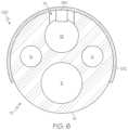
- FIG. 6illustrates a cross-sectional view of the circuit device of FIG. 1 with the device component received within a slot of the medical device of FIG. 3 , according to one or more embodiments of the present disclosure
- FIG. 7 Aillustrates a side view the circuit device of FIG. 1 printed on a planar sheet and including one or more curved bends, according to one or more embodiments of the present disclosure
- FIG. 7 Billustrates a side view of the circuit device of FIG. 1 printed on a planar sheet and including one or more angular bends, according to one or more embodiments of the present disclosure
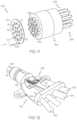
- FIG. 8illustrates a perspective of the circuit device of FIG. 1 attached to the medical device of FIG. 3 and including a hub; according to an embodiment of the present disclosure
- FIG. 9illustrates a partial perspective view of the circuit device of FIG. 1 electrically coupled to the hub of FIG. 8 in a first configuration, according to one or more embodiments of the present disclosure
- FIG. 10illustrates a partial perspective view of the circuit device of FIG. 1 electrically coupled to the hub of FIG. 8 in a second configuration, according to one or more embodiments of the present disclosure
- FIG. 11illustrates a partial perspective view of the circuit device of FIG. 1 electrically coupled to a connector assembly, according to one or more embodiments of the present disclosure
- FIG. 12illustrates of a partial perspective view of the circuit device of FIG. 1 electrically coupled to the hub of FIG. 8 and including a control unit, according to an embodiment of the present disclosure
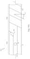
- FIG. 13illustrates a side view of another exemplary circuit device including a widened segment having reduced flexibility, according to one or more embodiments of the present disclosure
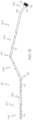
- FIG. 14illustrates a side view of another exemplary circuit device including a non-linear segment having enhanced flexibility, according to one or more embodiments of the present disclosure
- FIG. 15illustrates a side view of another exemplary circuit device including angular bends, according to one or more embodiments of the present disclosure
- FIG. 16illustrates a perspective view of the circuit device of FIG. 15 attached to the medical device of FIG. 3 and including a flexible segment (low density) and a rigid segment (high density) between the angular bends to provide variable flexibility and other attributes, according to one or more embodiments of the present disclosure;
- FIG. 17illustrates a perspective view of another exemplary circuit device attached to the medical device of FIG. 3 and including a distal segment extending parallel to the medical device, according to one or more embodiments of the present disclosure
- FIG. 17 Aillustrates a partial side view of the circuit device of FIG. 17 with the distal segment including a bend, according to one or more embodiments of the present disclosure
- FIG. 18illustrates a side view of another exemplary circuit device including a series of stiffener mechanisms, according to one or more embodiments of the present disclosure
- FIG. 19illustrates a side view of another exemplary circuit device including an angled distal segment formed of a pair of branches, according to one or more embodiments of the present disclosure
- FIG. 20illustrates a side view of another exemplary circuit device including an angled distal segment formed of a plurality of branches, according to one or more embodiments of the present disclosure
- FIG. 21illustrates a perspective view of the circuit device of FIG. 20 attached to the medical device of FIG. 3 , according to one or more embodiments of the present disclosure
- FIG. 22illustrates a side view of another exemplary circuit device including an angled intermediate segment formed of a pair of branches and an angled distal segment formed of a pair of branches, according to one or more embodiments of the present disclosure
- FIG. 23illustrates a side view of an exemplary circuit device including an electrical circuit at a proximal end, according to one or more embodiments of the present disclosure.
- FIG. 24illustrates a perspective view of the circuit device of FIG. 23 with the electrical circuit received within a connector assembly, according to one or more embodiments of the present disclosure.
- the terms “comprises,” “comprising,” “including,” “having,” or other variations thereof,are intended to cover a non-exclusive inclusion such that a process, method, article, or apparatus that comprises a list of elements does not include only those elements, but may include other elements not expressly listed or inherent to such a process, method, article, or apparatus.
- exemplaryis used herein in the sense of “example,” rather than “ideal.”
- proximalmeans a direction closer to an operator and the term “distal” means a direction further from an operator.
- distalmeans a direction further from an operator.
- approximatelyor like terms (e.g., “about,” “substantially”) encompass values within 10% of the stated value.
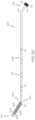
- FIG. 1shows a circuit device 100 according to an example of the present disclosure.
- Circuit device 100may include a flexible body 102 having a longitudinal length defined between a distal end 104 and a proximal end 106 .
- Flexible body 102may include a flexible, planar substrate defined by an exterior surface 101 and an interior surface 103 ( FIG. 2 ).
- flexible body 102may generally include a linear configuration between distal end 104 and an intermediate portion of flexible body 102 distal of proximal end 106 .
- flexible body 102may have a substantially constant and nominal width between distal end 104 and proximal end 106 .
- Flexible body 102may include a bend 108 adjacent to proximal end 106 such that proximal end 106 may have a transverse alignment relative to the intermediate portion of flexible body 102 and distal end 104 (the axis of end 106 is transverse to the axis of the intermediate portion). As described further herein, bend 108 may form an angle that aligns a longitudinal axis of proximal end 106 with a central axis of a medical device. Flexible body 102 may further include a proximal tab 110 at proximal end 106 that may have a width that is relatively greater than a width of flexible body 102 at distal end 104 and/or the intermediate portion. Proximal tab 110 may be sized and/or shaped to receive one or more circuitry components thereon, such as conductive pads 112 .
- Flexible body 102may be formed of a flexible material having pliability properties such that circuit device 100 may be configured to deform a shape, geometry, and/or configuration of flexible body 102 .
- flexible body 102may be formed of Liquid Crystal Polymer (LCP), thermoplastics, polyimide, PEEK polyester, silicone, other elastomers, and the like.
- Flexible body 102may be construed of multiple layers of materials, such as, for example, electrically conductive and/or non-conductive materials.
- circuit device 100may be configured to engage a medical device and flexible body 102 may be configured to conform to a profile of the medical device when attached thereto.
- circuit device 100is an electrical connection device that may include a flexible printed circuit board and/or a flex ribbon circuit.
- circuit device 100may include flexible circuitry on flexible body 102 , such as one or more (e.g., a plurality) electrical and/or conductive components including conductive pads 112 and electrodes 114 .
- circuit device 100includes a pair of electrodes 114 patterned on exterior surface 101 adjacent to distal end 104 and a pair of conductive pads 112 patterned on exterior surface 101 adjacent to proximal end 106 .
- Conductive pads 112are included on proximal tab 110 , and circuit device 100 may include at least one conductive pad 112 for each electrode 114 on flexible body 102 .
- Conductive pads 112may be configured to connect electrodes 114 to an ancillary device (e.g., a programmable energy delivery system, a power source, etc.) for transmission of an electric current thereto.
- Electrodes 114may be configured to treat a target site of a subject (e.g., a patient) when receiving the electrical current from the ancillary device.
- electrodes 114may be operable to stimulate a target site (e.g., a nerve, ganglia, etc.), deliver energy to tissue (e.g., thermal, electrical, etc.), and/or sense a physiologic parameter from or at the target site when distal end 104 is positioned at the target site.
- electrodes 114may form one or more stimulation arrays that are wired or wirelessly connected to one or more circuits, processors, devices, systems, applications, units, or controllers. Each electrode 114 of the stimulation array may include one or more nodes for delivering stimulation. As described in further detail herein, electrodes 114 may be supported on a medical device (e.g., an intravenous catheter, a guidewire, a stimulation lead, a needle, a probe, a lead, a patch, etc.) and may be configured to be placed on, or inserted into, a patient (e.g., a neck, torso, blood vessel, etc.) or placed on the surface of the skin. It should be understood that additional and/or fewer electrodes 114 of varying shapes and/or sizes may be included on flexible body 102 than those shown and described herein.
- a medical devicee.g., an intravenous catheter, a guidewire, a stimulation lead, a needle, a probe, a lead, a patch, etc.
- Electrodes 114may be positioned along exterior surface 101 in various complex arrangements relative to one another to form high current densities along flexible body 102 . It should be appreciated that flexible body 102 may be configured to permit enhanced variety in positioning electrodes 114 axially and radially along a circumference of a medical device (e.g., a catheter) when circuit device 100 is attached thereto. Stated differently, a position of electrodes 114 may not be limited by a structure of a medical device, such as, for example, a geometry of an inner lumen of the medical device, due to the incorporation of electrodes 114 on circuit device 100 in lieu of the medical device.
- a medical devicee.g., a catheter
- Electrodes 114may be configured to deliver stimulation as monopolar, bipolar, tripolar, or other multipolar electrodes.
- a stimulation transmitted by electrodes 114may refer to an electrical signal transmitted by a single electrode 114 (anode) to the ground reference (cathode) that is positioned away from the anode to generate a larger electrical field (monopolar electrical stimulation); an electrical signal transmitted from an anode electrode 114 to a cathode electrode 114 (bipolar stimulation); or an electrical signal transmitted from one or more electrodes 114 to one or more other electrodes 114 (multipolar electrical stimulation) (e.g., from a cathode to two anodes, from two cathodes to an anode, or from a cathode to three or more anodes, or from two cathodes to two anodes, etc.).
- Electrodes 114As any of these electrode combinations and configurations are contemplated, for clarity when referring to one or more processes, methods, or modes of operation, such types of electrical signal transmission may all be referred to as a stimulation transmitted by one electrode 114 or a combination of electrodes 114 .
- FIG. 2interior surface 103 of flexible body 102 is shown and a relative position of conductive pads 112 and electrodes 114 on exterior surface 101 are schematically depicted for illustrative purposes.
- Each conductive pad 112may be connected to a corresponding electrode 114 via a conductive (electrical) lead 116 extending along interior surface 103 .
- Conductive leads 116may include circuit traces patterned on interior surface 103 , and conductive leads 116 may define a conductive pathway between conductive pads 112 and electrodes 114 .
- Conductive leads 116may be configured to negate a necessity of including wires to connect electrodes 114 to a power source, thereby simplifying a circuitry construction of circuit device 100 .
- Each conductive lead 116may include a distal end positioned adjacent to distal end 104 at a location of electrode 114 , and a proximal end positioned adjacent to proximal end 106 at a location of conductive pad 112 .
- Circuit device 100may include at least one conductive lead 116 for each corresponding pair of conductive pads 112 and electrodes 114 on flexible body 102 .
- An electrical current received by circuit device 100 from an ancillary device (e.g., a power source, etc.) at conductive pads 112may be delivered to electrodes 114 via conductive leads 116 .
- flexible body 102may include a shape memory alloy wire (not shown) disposed along exterior surface 101 and/or interior surface 103 .
- the wiremay be configured to selectively manipulate a shape of flexible body 102 , such as, for example, in response to receiving a current and/or an increase in temperature (e.g., from a subject's body, etc.).
- the wiremay be operable to adjust a shape of a medical device when circuit device 100 is attached thereto. Control of a shape and/or orientation of the medical device may allow for control of a stimulation field generated by electrodes 114 .
- a shape and intensity of a stimulation fieldmay be further controlled by a shape, size, charge, and/or arrangement of electrodes 114 relative to one another along flexible body 102 .
- Medical device 10may include a tubular body 12 having a longitudinal length defined between a distal tip 14 and a proximal tip 16 .
- medical device 10may include a catheter, a flexible tube, a sheath, a scope, a lead, a probe, a hypotube, a patch, a cable, and/or various other flexible instruments suitable for intravascular, percutaneous, or transcutaneous delivery.
- medical device 10may include an intravenous catheter having a flexibility sufficient to traverse a subject's blood vessels, esophagus, nasal cavity, and/or various other anatomical lumens, passageways, etc.
- tubular body 12may be formed of an extruded polymer having homogenous properties (e.g., a constant thickness, etc.) between distal tip 14 and proximal tip 16 such that tubular body 12 may include a substantially consistent flexural strength along the longitudinal length.
- circuit device 100may be configured to increase a material thickness along certain portions of tubular body 12 and/or include one or more structures that modify the properties of tubular body 12 (e.g., increase or decrease rigidity or flexibility, affect shape memory, etc.) when flexible body 102 is attached thereto.
- Tubular device 12may include one or more lumens (see FIG. 6 ) defined between distal tip 14 and proximal tip 16 .
- the one or more lumensmay be sized, shaped, and configured to receive one or more devices therein, including, but not limited to, an irrigation device, an ultrasound device, an optical device, an imaging device, a sensing device, an illumination device, a guidewire, a diagnostic or therapeutic device, etc., and/or receive a fluid.
- Distal tip 14may include an opening in communication with the one or more lumens of tubular body 12 such that the one or more devices received within the lumens may extend outwardly from distal tip 14 through the opening.
- Distal tip 14may have an atraumatic configuration to minimize injury to tissue when traversed through a subject.
- Circuit device 100may be disposed about medical device 10 and secured to an outer surface of tubular body 12 .
- Flexible body 102is configured to have a first configuration prior to being secured to an exterior of tubular body 12 and a second configuration having a shape that conforms to a profile of the tubular body 12 with electrodes 114 secured to an exterior of tubular body 12 .
- flexible body 102may be configured to conform to a geometry of tubular body 12 (e.g., cylindrical).
- distal end 104may be secured to a distal portion of tubular body 12 adjacent to and proximal of distal tip 14 .
- Proximal end 106may be secured to a proximal portion of tubular body 12 adjacent to and distal of proximal tip 16 .
- Circuit device 100may be attached to medical device 10 at one or more locations and by various methods, including, for example, bonding flexible body 102 to an exterior of tubular body 12 (e.g., thermal bonding, thermal welding, thermal lamination, ultrasonic welding, laser welding, RF welding, adhesive bonding, solvent bonding, chemical reaction, and/or solvent bonding). It should be appreciated that a resulting flexural property of tubular body 12 may vary based on various factors, including but not limited to, the method of bonding flexible body 102 thereto, a configuration/arrangement of flexible body 102 relative to tubular body 12 , and/or a material composition of flexible body 102 .
- circuit device 100may be treated to modify the surface properties of flexible body 102 prior to limitation or bonding onto tubular body 12 .
- surface treatmentsmay include, but are not limited to, micro-blasting, sand blasting, plasma treatment, chemical etching, filing, grinding, electroplating, thermal spraying, physical vapor deposition, electron beam heating, and more.
- the resulting flexural properties of the combined assembly of medical device 10 and circuit device 100may influence the performance of tubular body 12 during a procedure.
- the flexural propertiesmay be decreased in specific regions along a longitudinal length of tubular body 12 to influence where tubular body 12 may bend during a procedure, such as when navigating through anatomical structures of a subject.
- the flexural propertiesmay be decreased to further reduce stress along specific regions of tubular body 12 that may be maintained in a bent configuration when positioned at a target site within a subject.
- the flexural propertiesmay be configured to influence a direction of bending tubular body 12 .
- flexible body 102may be disposed about tubular body 12 in various arrangements and/or configurations to position electrodes 114 at a desired location relative to tubular body 12 . It should be appreciated that electrodes 114 may be positioned at a variety of axial locations along tubular member 12 , and/or various radial positions around tubular member 12 , to achieve varying physical properties of medical device 10 .
- flexible body 102may be attached to tubular body 12 in a manner that may be parallel or transverse (e.g., perpendicular) to a central axis of tubular body 12 .
- flexible body 102may be attached to tubular body 12 at an angle that is transverse to a central axis of tubular body 12 such that circuit device 100 is secured to medical device 10 in a helical configuration.
- Flexible body 102may be wound about the central axis of tubular body 12 in a plurality of helical winds 115 (i.e., helix turns). A pair of adjacent helical winds 115 may form a gap 117 therebetween.
- Electrodes 114may be wrapped around a circumference of tubular body 12 and flexible body 102 may conform to a profile of tubular body 12 .
- flexible body 102may be helically wrapped with a substantially constant pitch and uniform gaps 117 between adjacent helical winds 115 . Accordingly, circuit device 100 may have constant flexural properties along a longitudinal length of flexible body 102 . In other embodiments, flexible body 102 may be helically wrapped to have varying pitches and/or gaps (see FIGS. 16 - 17 ), including no gaps, to selectively adjust the flexural properties of circuit device 100 at various locations along tubular body 12 .
- a substantial length of tubular body 12may be disposed underneath flexible body 102 .
- bend 108may form an angle between an intermediate portion of flexible body 102 and proximal end 106 to align proximal end 106 with the central axis of tubular body 12 .
- the plurality of helical winds 115may terminate at bend 108 such that proximal end 106 may extend substantially parallel to tubular body 12 .
- the helical configuration of flexible body 102may extend from distal end 104 to bend 108 such that proximal portion 106 may be maintained in a non-helical (e.g., linear) configuration that is parallel to the central axis of tubular body 12 .
- distal tip 14may be positioned relatively distal of distal end 104
- proximal tip 16may be positioned proximal of bend 108 and relatively distal of proximal tab 110 .
- proximal tab 110may extend proximally of proximal tip 16 .
- proximal tab 110may extend beyond proximal tip 16 for receipt within a hub 140 (see FIG. 9 ).
- FIGS. 4 A- 4 Bare exemplary partial cross-sectional views of FIG. 3 , taken at line 4 - 4 .
- flexible body 102may be formed of one or more electrically conductive and/or insulating materials that form conductive pathways between distal end 104 and proximal end 106 .
- Electrode 114may define a first conductive layer and conductive lead 116 may define a second conductive layer.
- Circuit device 100may further include a base layer 120 formed of one or more dielectric substrate films disposed between the pair of electrically conductive layers. Electrode 114 and conductive lead 116 may be affixed to base layer 120 by, for example, depositing, adhering, and/or bonding the layers together.
- base layer 120may have a thickness ranging from about 12 microns to about 125 microns.
- the one or more dielectric substrate films forming base layer 120may comprise polymer materials, such as, for example, polyimides, polyesters, liquid crystal polymer (LCP), polyethylene naphthalate, polyvinyliden fluoride, polyetherimide, various fluoropolymers (FEP), etc.
- the polymer materials comprising base layer 120may be biocompatible with tissue.
- the one or more electrically conductive materials forming electrode 114 and/or conductive lead 116may comprise, for example, copper, gold, graphene, silver, nickel, platinum, platinum-iridium alloy, iridium oxide, titanium nitride, tungsten, alloys, and/or combinations thereof. In other embodiments, conductive lead 116 may be patterned to form various other electrical circuit elements.
- the electrically conductive layer forming conductive lead 116may be patterned using additive processes (e.g., spraying, sputtering, sputter coating, screen printing, stenciling, electrodeposition, electroplating, atomic layer deposition, and/or digital printing, etc.) and/or subtractive processes (e.g., chemical etching, laser etching, and/or laser machining, etc.).
- additive processese.g., spraying, sputtering, sputter coating, screen printing, stenciling, electrodeposition, electroplating, atomic layer deposition, and/or digital printing, etc.
- subtractive processese.g., chemical etching, laser etching, and/or laser machining, etc.
- flexible body 102may include the desired electrical circuit traces and/or other electrical circuit elements by selectively removing a portion of conductive lead 116 via one or more of the additive and/or subtractive processes described above.
- electrode 114may be affixed to an opposing side of base layer 120 as conductive lead 116 . Further, electrode 114 may be interconnected with conductive lead 116 and through base layer 120 by a via 124 .
- Via 124may be a hole formed through base layer 120 by, for example, drilling, laser cutting, and/or mechanically puncturing base layer 120 and/or the pair of opposing conductive layers (e.g., electrode 114 , conductive lead 116 ).
- circuit device 100may include a plurality of vias 124 , each of which may be filled with a conductive material configured to connect electrode 114 and conductive lead 116 through base layer 120 .
- an exterior surface of electrode 114 and/or conductive lead 116may have one or more materials and/or finishes included thereon, such as, for example, via additive processing (e.g., electrodeposition, electroplating, electroless plating, sputtering, sputter coating, etc.).
- the one or more materials and/or finishes included on electrode 114 and/or conductive lead 116may include, for example, nickel, silver, gold, platinum, platinum iridium, titanium nitride, and the like.
- the one or more materials and/or finishesmay be operable to enhance a conductivity, corrosion resistance, and/or a biocompatibility of circuit device 100 .
- an insulative or non-conductive substrate, layer, coating, film, and/or finishmay be attached (e.g., bonded, soldered, etc.) to flexible body 102 to provide insulation of electrode 114 , conductive lead 116 , and/or base layer 120 .
- Such materialsmay include, for example, tetrafluoroethylene (TFE), polytetrafluoroethylene (PTFE), polyimide, polyetheretherketone (PEEK) polyester, silicon, and other various flexible substrates.
- a protective cover layermay be included on circuit device 100 and bonded to base layer 120 and/or conductive lead 116 .
- the protective cover layermay include a film and/or finishing (e.g., laminate adhesive layer, etc.) configured to protect the conductive lead 116 (and/or other electrical components) from environmental exposure to moisture, contaminants, mechanical damage, etc., during use of circuit device 100 in a procedure.
- circuit device 100may include a coverlay film 122 bonded to a surface of conductive lead 116 and base layer 120 with an adhesive 126 . Coverlay film 122 may be configured and operable to protect conductive leads 116 .
- flexible body 102includes a plurality of base layers 120 (e.g., dielectric substrate films) secured to one another by at least one adhesive layer 126 positioned between a pair of adjacent base layers 120 .
- Flexible body 102may further include a plurality of electrodes 114 disposed over an upper-most base layer 120 , with each electrode 114 including a corresponding conductive lead 116 disposed under a lower-most base layer 120 (adjacent to tubular body 12 ).
- Each electrode 114may be interconnected with conductive lead 116 by a respective via 124 that extends through the plurality of base layers 120 disposed therebetween.
- Each via 124may be filled with a conductive material configured to connect the conductive materials (e.g., electrode 114 and conductive lead 116 ) to one another through the plurality of base layers 120 and adhesive layers 126 positioned therebetween.
- flexible body 102may include three base layers 120 and one coverlay film 122 disposed beneath base layers 120 .
- flexible body 102may further include a device component 130 embedded between the plurality of base layers 120 .
- Device component 130may be positioned in alignment with a center base layer 120 and between an upper-most base layer 120 and a lower-most base layer 120 .
- Flexible body 102may further include one or more conductive layers 132 in contact with device component 130 and one or more (e.g., a plurality) vias 124 (filled with conductive material) connecting conductive layers 132 with corresponding conductive leads 116 .
- circuit device 100may include a respective conductive pad 112 at proximal end 106 corresponding to each of the plurality of electrodes 114 and device component 130 .
- Device component 130may include various systems, including, for example, a sensor, an electronic chip, an integrated circuit, and the like. In some embodiments, device component 130 may be fully enclosed between the plurality of base layers 120 ; while in other embodiments, at least a portion of device component 130 may be exposed from the plurality of base layers 120 . In this instance, device component 130 may be accessible to a subject's tissue and/or fluids during use of circuit device 100 in a procedure.
- device component 130may include a sensing system configured to detect a signal (e.g., cardiac signal, impedance, temperature, flow, pressure, chemical composition, blood gas, etc.) from a subject (i.e., a patient) to facilitate determining a position of circuit device 100 therein, and/or to detect stimulation of an anatomical target based on a physical response of the subject.
- a signale.g., cardiac signal, impedance, temperature, flow, pressure, chemical composition, blood gas, etc.
- an adhesive, a polymer, or other filling materialmay be included to provide a smooth transition between one or more edges of flexible body 102 and a surface of tubular body 12 .
- an adhesive, a polymer, or other filling materialmay be included to provide a smooth transition between one or more edges of flexible body 102 and a surface of tubular body 12 .
- medical device 10 and circuit device 100may be inserted and/or removed from the subject with minimal resistance and potential for tissue trauma.
- device component 130may include flex detection circuitry that may be configured to detect the flexure of flexible body 102 during a procedure at various regions along the longitudinal length of tubular body 12 . Such information may guide a placement of tubular body 12 and/or provide anatomical information to an operator of medical device 10 .
- device component 130may include a strain circuit, a piezo circuit, and/or various other sensors configured to measure a compression and/or expansion (e.g., lateral extension, longitudinal elongation, etc.) of opposite surfaces of tubular body 12 to determine a two or three-dimensional spatial orientation (e.g., distance, rotation, etc.) of tubular body 12 relative to a subject.
- one or more integrated circuitsmay be directly attached to flexible body 102 to provide further localized smart circuitry.
- one or more device components 130may be attached (e.g., soldered) to interior surface 103 at various positions along flexible body 102 , such as adjacent to distal end 104 . In this instance, device components 130 extend laterally outward from interior surface 130 , thereby forming a protruding profile relative to interior surface 103 .
- Circuit device 100may include a circuit trace 134 along interior surface 103 for each device component 130 included on flexible body 102 .
- Circuit traces 134may interconnect device components 130 with a corresponding conductive pad 112 at proximal end 106 ( FIG. 1 ).
- medical device 10may include a longitudinal slot, channel, and/or groove formed along an outer perimeter of tubular body 12 that is sized and shaped to receive the one or more device components 130 when flexible body 102 is secured thereto.
- the one or more slots on tubular body 102may receive device components 130 therein to accommodate a flush engagement of flexible body 102 with tubular body 12 .
- At least one slot 15may be formed along at least one surface of tubular body 12 .
- Slot 15may extend through tubular body 12 and into at least one lumen 13 of tubular body 12 . Accordingly, lumen 13 may be exposed to an exterior of tubular body 12 via slot 15 .
- tubular body 12may include a plurality of other lumens 11 that are separate from the at least one lumen 13 aligned with slot 15 . Accordingly, the plurality of lumens 11 are not in fluid communication with lumen 13 or with one another. In other examples, two or more of the plurality of lumens 11 may be interconnected with one another and/or with lumen 13 at one or more locations.
- Flexible body 102may be secured to tubular body 12 such that device component 130 may be aligned with and received in slot 15 .
- interior surface 103may be flush against an exterior surface of tubular body 12 .
- flexible body 102may cover and/or encapsulate a majority of tubular body 102 .
- slot 115may be covered when flexible body 102 is attached to tubular body 12 , thereby sealing lumen 13 with interior surface 103 .
- Device component 130may include, for example, a thermistor sensor, an electronic chip, a resistor, a diode, a capacitor, a strain gauge, a piezoelectric sensor, an integrated circuit, and various other electronic devices.
- device component 130may be configured to measure a temperature of a fluid, such as, for example, a fluid disposed within one of the plurality of lumens 11 , 13 and/or positioned external of medical device 10 .
- Circuit device 100may be configured to measure a change in temperature based on the temperature data detected by device component 130 .
- circuit device 100may be configured to measure a flow rate and/or other characteristics of the fluid based on the temperature data sensed by device component 130 .
- device component 130may be configured to heat fluid (e.g., blood, etc.) located external of circuit device 100 and measure a temperature change of the fluid at one or more locations along a longitudinal length and/or lateral width of circuit device 100 .
- at least one location for measuring a temperature change of the fluidmay be positioned relatively distal to the heat source (e.g., distal component 130 ) for determining a flow rate or other properties of the fluid.
- circuit device 100may be printed on a dielectric substrate film in sheet format, such as on a planar sheet 50 .
- Flexible body 102may be cut from sheet 50 in various desired sizes, shapes, and/or configurations.
- flexible body 102may be printed to have a substantially constant width between distal end 104 and proximal end 106 .
- flexible body 102may be printed to have various suitable lengths between distal end 104 and proximal end 106 in accordance with a longitudinal length of tubular body 12 .
- Proximal end 106may be printed on sheet 10 with various configurations, sizes, and/or shapes.
- proximal end 106may be printed to include bend 108 having a desired angle. It should be appreciated that bend 108 may define a plurality of angles and/or degrees of curvature between proximal end 106 and an intermediate portion of flexible body 102 .
- proximal end 106may be printed to include a squared end defining proximal tab 110 ( FIGS. 1 - 3 ). In other examples, proximal end 106 may be printed to omit bend 108 entirely and/or to include a circular end defining another exemplary proximal tab 110 ′.
- flexible body 102may be printed on sheet 50 with one or more bends 105 A to accommodate various longitudinal lengths. Bends 105 A may be sized to minimize material use on sheet 50 when printing circuit device 100 thereon. For example, the one or more bends 105 A may range from about 90 degrees to about 180 degrees. In other examples, as seen in FIG. 7 B , flexible body 102 may be printed on sheet 50 with one or more bends 105 B that range from about 1 degree to about 89 degrees, such as 45 degrees. In this instance, flexible body 102 may be more easily straightened for attachment onto tubular body 102 than when circuit device 100 is printed with the one or more bends 105 A (e.g., bends having a greater angle).
- hub 140may be configured and operable to receive tubular member 12 and flexible body 102 therein.
- tubular member 12 and flexible body 102may be coupled to hub 140 ; while in other embodiments, hub 140 may be molded over tubular member 12 and flexible body 102 .
- Hub 140may extend proximally from proximal tip 16 and include one or more extension tubes 150 coupled and/or molded to a proximal end of hub 140 .
- Hub 140may be configured to interconnect lumens 11 ( FIG. 6 ) with extension tubes 150 .
- Extension tubes 150may include a coupling mechanism 152 (e.g., a luer connector, a female adapter, a fitting, and/or other fluid tight connector assemblies) at a distal end of each extension tube 150 for securely coupling an ancillary device (e.g., a tool, a sensor, a cable, a fiber, etc.). Extension tubes 150 may facilitate receipt of the one or more ancillary devices into lumens 11 via hub 140 . In some examples, extension tubes 150 may be configured to couple hub 140 to a fluid source for delivering a fluid (e.g., drug, therapeutic agent, etc.) to lumens 11 . Extension tubes 150 may be further configured to extract a fluid sample (e.g., blood) collected from medical device 10 and received at hub 140 via lumens 11 .
- a fluid samplee.g., blood
- extension tubes 150may receive an ancillary device for monitoring a pressure and/or a temperature (e.g., a sensor) and/or for positioning tubular body 12 within a patient (e.g., a guidewire).
- ancillary devicessuch as, for example, optical fibers, ultrasound cameras, intravascular imagers, filters, lasers, lights, and the like may be introduced into lumens 11 through hub 140 and from extension tubes 150 .
- hub 140may include a protective sheath 154 secured thereto.
- Protective sheath 154may include an electrical connector 156 at a proximal end of protective sheath 154 and may define a channel housing one or more wires and/or cables.
- the wiresmay be coupled to electrical connector 156 at a proximal end and be received within hub 140 for connection to flexible body 102 at a distal end.
- FIG. 9shows hub 140 with at least a top wall of hub 140 omitted for illustrative purposes.
- Proximal end 106may be received through an inlet 142 of hub 140 such that proximal tab 110 is disposed within hub 140 .
- Hub 140may further include a proximal wall 144 , positioned opposite inlet 142 , and one or more outlets 146 formed through proximal wall 144 .
- Each extension tube 150 and protective sheath 154may be coupled to at least one outlet 146 .
- hub 140may receive one or more wires 118 from protective sheath 154 via at least one outlet 146 .
- proximal hub 140may incorporate one or more features for facilitating an electrical connection to wires 118 .
- the one or more wires 118may be connected to conductive pads 112 to thereby establish electrical communication between wires 118 and electrodes 114 (e.g., via conductive leads 116 ).
- An electrical junction between conductive pads 112 and wires 118may be formed by various suitable attachment methods, including, for example, solder, laser weld, conductive adhesive, hot bar, interference, friction fits, and/or various other mechanical connection methods.
- each wire 118may extend through protective sheath 154 and may terminate at electrical connector 156 .
- Electrical connector 156may be selectively coupled to a power source configured to supply electrodes 114 with electrical power.
- hub 140may include a rigid body defining a fixed and stable interaction point between flexible body 102 and wires 118 . Accordingly, hub 140 may be configured to provide strain relief to flexible body 102 and wires 118 at the juncture between proximal tab 110 and wires 118 .
- the rigid body of hub 140may be formed of a thermoplastic material having dielectric properties.
- hub 140may be configured to electrically isolate the connections of conductive pads 112 with wires 118 .
- FIG. 10shows another configuration of circuit device 100 in which at least an intermediate portion of flexible body 102 may be received through inlet 142 and into the respective outlet 146 coupled with protective sheath 154 . Accordingly, a portion of flexible body 102 may extend through protective sheath 154 and be received within electrical connector 156 . It should be understood that wires 118 may be omitted entirely from the present example such that proximal tab 110 may be directly coupled to the power source.
- proximal tab 110 ′is depicted at proximal end 106 .
- proximal tab 110 ′may have a circular shape and may extend at an angle relative to proximal end 106 .
- a position and/or orientation of proximal tab 110 ′ relative to proximal end 106may be selectively adjustable.
- Proximal tab 110 ′may include a plurality of apertures 111 formed therethrough and a plurality of conductive pads 112 positioned about the plurality of apertures 111 .
- each conductive pad 112is formed about at least one aperture 111 such that conductive pads 112 may contact a device received through aperture 111 .
- Internal components of electrical connector 156are depicted with an outer housing of electrical connector 156 omitted for illustrative purposes.
- Electrical connector 156may include a socket 158 having a plurality of openings, and a plurality of pins 159 extending through the plurality of openings.
- Each of the plurality of pins 159may have a proximal end extending proximally out of socket 158 and a distal end extending distally out of socket 158 .
- the distal ends of pins 159may be disposed within the outer housing of electrical connector 156 when in a fully assembled state for connection with proximal tab 110 ′.
- the proximal ends of pins 159may extend outwardly from the outer housing of electrical connector 156 when in a fully assembled state for connection with a power source. Accordingly, the proximal ends of the plurality of pins 159 may define a connector interface of electrical connector 156 .
- Each of the plurality of apertures 111may be sized and shaped to receive at least one of the plurality of pins 159 . It should be appreciated that a quantity and position of apertures 111 relative to proximal tab 110 ′ may be based on a number and position of pins 159 on socket 158 . Circuit device 100 may establish connection with the power source in response to conductive pads 112 contacting pins 159 . In some examples, proximal tab 110 ′ may be soldered to socket 158 thereby securing an electrical connection between conductive pads 112 and pins 159 .
- circuit device 100may include an electronic component 135 mounted to flexible body 102 at proximal tab 110 .
- Electronic component 135may be positioned along exterior surface 101 and encapsulated within hub 140 .
- Electronic component 135may be secured to flexible body 102 (e.g., at proximal tab 110 ) via various suitable configurations, including, for example, by a pin and via, an overmolding, potting, and the like. In other embodiments, electronic component 135 may be secured directly to hub 140 .
- Electronic component 135may include various suitable devices, including, for example, computer readable storage media such as various types of volatile and non-volatile storage media, including but not limited to, static memory, dynamic memory, a read-only memory chip, a read-write memory chip, an electrically erasable programmable read-only memory (EEPROM), random access memory, flash memory, and the like.
- electronic component 135may include a sensing circuit, a radio-frequency identification (RFID) tag, and other various devices.
- RFIDradio-frequency identification
- electronic component 135may be configured to store product specific data relating to circuit device 100 , such as a serial number, lot number, product configuration, expiration date, calibration constants for device component 130 , etc.
- electronic component 135may be configured to record use data of circuit device 100 and/or medical device 10 , such as dates of activation, variable data from therapy procedure sessions, control unit function algorithms, sensor data of device component 130 , etc.
- electronic component 135may further include a computer system, such as, for example a processor (e.g., a central processing unit (CPU), a graphics processing unit (GPU), or both) in conjunction with the memory described above.
- a processore.g., a central processing unit (CPU), a graphics processing unit (GPU), or both
- the processormay be part of a standard personal computer or a workstation.
- the processormay be one or more general processors, digital signal processors, application specific integrated circuits, field programmable gate arrays, servers, networks, digital circuits, analog circuits, or combinations thereof, for analyzing and processing data.
- the processormay implement a software program, such as programmable code.
- the memorymay be an external storage device or database separate from electronic component 135 .
- electronic component 135may include a controller that is generally configured to accept information from one or more other components of circuit device 100 (e.g., electrodes 114 , device component 130 , etc.), and process the information according to various algorithms to produce control signals for controlling the other components of circuit device 100 .
- a controllerthat is generally configured to accept information from one or more other components of circuit device 100 (e.g., electrodes 114 , device component 130 , etc.), and process the information according to various algorithms to produce control signals for controlling the other components of circuit device 100 .
- the controllermay accept information from the system and system components, process the information according to various algorithms, and produce information signals that inform a user of circuit device 100 of a procedure status or other information that is being monitored by circuit device 100 .
- the controllermay be a digital IC processor, analog processor, or any other suitable logic or control system that carries out control algorithms.
- Electronic component 135may be powered by a battery, a direct wire energy, or other suitable power devices. In some examples, electronic component 135 may be configured to communicate with the controller or other components of circuit device 100 via a wired and/or wireless connection.
- flexible body 102may be initially bonded to tubular body 12 in one of a plurality of configurations as shown and described above.
- Proximal tab 110may be received within hub 140 and coupled to a power source from a connection of conductive pads 114 with electrical connector 156 .
- tubular body 12With circuit device 100 secured to medical device 10 , tubular body 12 may be received within a subject (e.g., patient) and navigated toward a target treatment site.
- Medical device 10may be configured to traverse through blood vessels located relatively proximate to one or more nerves (e.g., phrenic nerves, vagus nerves, etc.), muscles, and/or other tissues.
- a flexibility (or lack thereof) of tubular body 12may be at least partially determined by the flexural properties of circuit device 100 based on an attachment configuration of flexible body 102 and/or a material composition of flexible body 102 . In other words, a geometry and arrangement of circuit device 100 may influence the flexural properties of medical device 10 .
- Medical device 10may be guided to a target treatment site using one or more devices received within lumens 11 ( FIG. 6 ) via extension tubes 150 and hub 140 .
- medical device 10may receive a stiffening element (e.g., polymer and/or metallic mandrels), a guidewire, a sensor, an imaging device, an illumination device, a shape memory material (e.g., Nitinol, etc.), and/or other therapeutic or diagnostic medical devices to facilitate placement of circuit device 100 .
- a stiffening elemente.g., polymer and/or metallic mandrels
- a guidewiree.g., a guidewire, a sensor, an imaging device, an illumination device, a shape memory material (e.g., Nitinol, etc.), and/or other therapeutic or diagnostic medical devices to facilitate placement of circuit device 100 .
- a shape memory materiale.g., Nitinol, etc.
- tubular member 12may be configured to guide placement of circuit device 100 relative to the target treatment site.
- tubular body 12may be moved (e.g., translated, rotated, etc.) to position electrodes 114 at a desired location relative to a target object (e.g., a nerve, a muscle, a tissue, etc.).
- a target objecte.g., a nerve, a muscle, a tissue, etc.
- activation of the power sourcemay deliver an electrical current through wires 118 , conductive pads 112 , and to electrodes 114 via conductive leads 116 .
- Electrodes 114may be configured to stimulate the target object (e.g., a stimulation sufficient to cause a desired physiological result) upon receiving the electrical current from conductive leads 116 .
- Electrodes 114may generate therapeutic effects for specific anatomical targets (e.g., nerve stimulation) and a relative position of electrodes 114 to one another on exterior surface 101 may generate one or more charge fields along tubular body 12 for certain therapeutic effects (e.g., asymmetric charge fields). Electrodes 114 may generate a sufficient charge to cause contraction of a diaphragm or other lung-accessory. In some embodiments, electrodes 114 may be positioned along tubular body 12 to form a sensor array antenna configured and operable to detect various forms of stimulation, including, for example, nerve stimulation, muscle stimulation, cardiac stimulation, phrenic nerve activation, diaphragm muscle activation, and more.
- circuit device 100includes device component 130 (e.g., a sensor, etc.)
- device component 130FIGS. 4 B- 6
- Device component 130may be positioned toward the target object and activated to detect and/or record one or more characteristics or properties of the target object (e.g., input on whether the requisite stimulation of an anatomical target occurred).
- Device component 130may be communicatively coupled to one or more computing systems, such as, for example, via electrical component 135 ( FIG. 12 ) by a wired or wireless connection.
- circuit device 100may be utilized to receive other devices than those included in circuit device 100 .
- circuit device 100may be operable to maximize an available space within lumens 11 to receive other ancillary devices.
- circuit device 100may omit a necessity to route wires internally through tubular body 12 for connecting electrodes 114 to a power source, thereby allowing tubular body 12 to be sized with a smaller minimum diameter.
- circuit device 100includes conductive leads 116 such that use of wires to connect electrodes 114 to a power source may be omitted entirely, whether received within and/or disposed over tubular body 12 , thereby further reducing a complexity of medical device 10 .
- tubular body 12may include a smaller cross-sectional profile than other medical devices (e.g., catheters) sized and shaped to accommodate electrical components (e.g., wires) for including one or more electrodes on the device.
- medical device 10may sense physiologic parameters of the target treatment site using one or more devices (e.g., intravascular ultrasound (IVUS)) received within lumens 11 ( FIG. 6 ) via extension tubes 150 and hub 140 .
- IVUSintravascular ultrasound
- medical device 10may receive devices that vary the flexural properties of tubular body 12 to create zones of stiff and/or flexible regions.
- a Nitinol wire(not shown) may be received within lumen 11 to alter or control the shape of tubular body 12 in response to the wire receiving a current applied thereto.
- the wiremay apply a force onto tubular body 12 from within lumen 11 to a fixed/desired configuration. Removal of the current may terminate the force applied to tubular body 12 by the wire, thereby permitting tubular body 12 to return to a flexible state.
- the shape memory wiremay be activated by the heat produced by the subject's body.
- FIGS. 13 - 24show alternative exemplary circuit devices that may be substantially similar to circuit device 100 .
- a geometry, orientation, and layer construction of the circuit devices relative to an axis of tubular body 12may influence the flexural properties of medical device 10 in specific regions along the longitudinal length of tubular body 12 .
- the circuit devices described in the examples belowmay be configured and operable similar to circuit device 100 except for the differences explicitly noted herein, and therefore like reference numerals are used to identify like components.
- the exemplary circuit devices belowmay be readily incorporated onto medical device 10 .
- Circuit device 200may include a varying geometry and/or width along a longitudinal length of flexible body 102 .
- flexible body 102may include one or more widened segments 203 between distal end 104 and proximal end 106 .
- circuit device 200may include a pair of widened segments 203 separated from one another along the longitudinal length of flexible body 102 by an intermediate segment 205 having a relatively smaller width.
- Flexible body 102may include layers having a greater thickness along widened segments 203 relative to intermediate segment 205 .
- Widened segments 203may be configured to impart reduced flexibility on flexible body 102 .
- widened segments 203have a relatively smaller longitudinal length than intermediate segment 205 , however, it should be understood that various other relative lengths and/or configurations of segments 203 , 205 may be included without departing from a scope of this disclosure.
- additional and/or fewer widened segments 203 and/or intermediate segments 205may be included along flexible body 102 .
- flexible body 102may include a plurality of electrodes 114 along the pair of widened segments 203 and intermediate segment 205 .
- proximal tab 110may include a plurality of conductive pads 112 at proximal end 106 in accordance with a quantity of electrodes 114 on flexible body 102 .
- one or more of widened segments 203 and/or intermediate segment 205may exclude any electrodes 114 thereon.
- widened segments 203may be configured and operable to reduce the flexural properties of tubular body 12 along the respective portions of tubular body 12 that align with widened segments 203 when circuit device 200 is attached to medical device 10 .
- Circuit device 300may include an irregular segment 303 along a longitudinal length of flexible body 102 .
- Irregular segment 303may be included between distal end 104 and proximal end 106 and may have a geometry and/or configuration that is transverse to a remaining linear geometry of flexible body 102 .
- irregular segment 303may have a sinusoidal-shape (e.g., S-profile) including a plurality of convex waves 305 (e.g., peaks) and a plurality of concave waves 307 (e.g., troughs).
- the plurality of waves 305 , 307may have various suitable lengths and/or amplitudes relative to a longitudinal axis of flexible body 102 .
- irregular segment 303includes a pair of convex waves 305 and a pair of concave waves 307 , however, it should be understood that additional and/or fewer waves 305 , 307 may be included on irregular segment 303 .
- flexible body 102may include additional irregular segments 303 between distal end 104 and proximal end 106 .
- irregular segment 303may be formed along flexible body 102 adjacent to distal end 104 and may include a constant width with a remaining portion of flexible body 102 . Further, irregular segment 303 may be configured to increase a flexibility of flexible body 102 relative to the remaining portion of flexible body 102
- flexible body 102may include a plurality of electrodes 114 along portions of flexible body 102 proximal to and distal of irregular segment 303 such that irregular segment 303 excludes electrodes 114 thereon.
- one or more of convex waves 305 and/or concave waves 307may include electrodes 114 thereon.
- irregular segment 303may be configured and operable to relatively increase the flexural properties of tubular body 12 along the respective portions of tubular body 12 that align with irregular segment 303 when circuit device 300 is attached to medical device 10 .
- Circuit device 400may include one or more angular changes/bends along a longitudinal length of flexible body 102 .
- flexible body 102may include a plurality of segments 404 , 406 , 408 separated from one another by at least one bend 410 , respectively. Accordingly, each of the plurality of segments 404 , 406 , 408 may be positioned and aligned relatively transverse to one another.
- a distal segment 404is positioned adjacent to distal end 104
- a proximal segment 408is positioned adjacent to proximal end 106
- an intermediate segment 406is disposed between distal segment 404 and proximal segment 408 .
- Flexible body 102may include a pair of bends 410 , at least one of which is disposed between distal segment 404 and intermediate segment 406 and another of which is disposed between intermediate segment 406 and proximal segment 406 .
- each of the plurality of segments 404 , 406 , 408may have varying flexural properties relative to one another based on an angle of bends 410 between an adjacent pair of segments. Bends 410 may range from about 1 degree to about 60 degrees and each bend 410 may extend an adjacent pair of segments in a different (or similar) direction and/or angle relative to one another. Further, each bend 410 may include varying angles relative to the one or more other bends 410 on flexible body 102 .
- circuit device 400may include additional and/or fewer segments along flexible body 102 that may be separated by additional and/or fewer bends 410 , respectively.
- Each of the plurality of segments 404 , 406 , 408may include one or more electrodes 114 ; while in some embodiments, segments 404 , 406 , 408 may omit electrodes 114 entirely.
- each of the plurality of segments 404 , 406 , 408may cause the corresponding portion of the overall medical device to have varying flexural properties relative to one another based on an angle of helical wrap of each segment 404 , 406 , 408 about tubular body 12 .
- the angle, pitch, and/or spacing between windings that flexible body 102 helically winds about tubular body 12may vary at each segment 404 , 406 , 408 .
- a pitch of helical wind of flexible body 102may be relatively greater at distal segment 404 and proximal segment 408 than at intermediate segment 406 .
- flexible body 102may be substantially flexible along distal segment 404 and proximal segment 408 relative to intermediate segment 406 .
- the pitch or angle that flexible body 102 helically winds about tubular body 12may be relatively smaller along intermediate segment 406 such that flexible body 102 may be substantially rigid along intermediate segment 406 .
- segments 404 , 406 , 408may include various other angles and pitches of helical wrap than those shown and described herein, and relative to one another, than those shown and described herein dependent on a desired configuration of circuit device 400 .
- a direction of the helical wrap of flexible body 102may change directions between one or more of the plurality of segments 404 , 406 , 408 .
- distal segment 404 and proximal segment 408may be wound about tubular body 12 in a first direction A (e.g., clockwise direction) and intermediate segment 406 may wrap around tubular body 12 in a second direction B (e.g., counter clockwise direction) that is different than the first direction A.
- distal segment 404 and/or proximal segment 408may helically wind about tubular body 12 at a first helical pitch ⁇ and intermediate segment 406 may helically wind about tubular body 12 at a second helical pitch ⁇ that is different than first helical pitch ⁇ .
- first helical pitch ⁇may be relatively less than second helical pitch ⁇ such that distal segment 404 and/or proximal segment 408 may include fewer helical winds than intermediate segment 406 .
- segments 404 , 406 , 408may include various other helical pitches and/or winds relative to one another than those shown and described herein.
- Circuit device 400may be configured to form a gap 405 between adjacent segments 404 , 406 , 408 that change direction relative to one another when flexible body 102 is attached to tubular body 12 . Circuit device 400 may not cover at least a portion of tubular body 12 when the helical wrap of flexible body 102 changes directions, thereby exposing a portion of tubular body 12 disposed beneath flexible body 102 .
- tubular body 12may vary along the portions that are exposed along gaps 405 relative to other portions that receive flexible body 102 .
- tubular body 12may have a relatively decreased rigidity (i.e., an increased flexibility) along regions that omit flexible body 102 thereon.
- an assembly of medical device 10 and circuit device 100may provide areas having a greater material thickness along portions where flexible body 102 is attached to tubular body 12 , thereby providing asymmetric properties along the longitudinal length of tubular body 12 .
- one or more features of medical device 10 on tubular body 12may be revealed and accessible along gap 405 when flexible body 102 is wound about tubular body 12 .
- a size of gap 405may vary and may be dependent on, for example, the angle of the helical wrap between the adjacent pair of segments defining gap 405 .
- Access holes 18may be in fluid communication with one or more lumens 11 ( FIG. 6 ) such that a fluid and/or a device (e.g. a guidewire) may be delivered outwardly from tubular body 12 and/or a received into tubular body 12 via access holes 18 .
- access holes 18may provide sensing portals to allow a device (e.g., fiber optic sensor, etc.) to measure one or more parameters, such as, for example, oxygen levels of a fluid (e.g., blood, etc.), central venous pressure, and more. Further, access holes 18 may provide deployment portals that allow one or more instruments to extend externally from tubular body 12 . Although not shown, in some embodiments, access holes 18 may facilitate deployment of a Nitinol positioning device from tubular body 12 for contacting a vessel wall, thereby biasing tubular body 12 to a preferred configuration and stabilizing medical device 10 relative to a target treatment site.
- a devicee.g., fiber optic sensor, etc.
- access holes 18may provide deployment portals that allow one or more instruments to extend externally from tubular body 12 .
- access holes 18may facilitate deployment of a Nitinol positioning device from tubular body 12 for contacting a vessel wall, thereby biasing tubular body 12 to a preferred configuration and stabilizing medical device 10 relative to
- an angle and/or a pitch of helical wrap of each the plurality of segments 404 , 406 , 408may remain constant and/or vary relative to one another when a direction of the helical wind changes.
- bend 410may match an angle of the helical wrap of flexible body 102 .
- at least one of the plurality of segments 404 , 406 , 408may have an elongated length extending along a longitudinal axis that is transverse to the remaining segments of flexible body 102 .
- distal segment 404may extend parallel to a central axis of tubular body 12 when circuit device 400 is secured to medical device 10 , and an angular change at bend 410 between distal segment 404 and intermediate segment 406 may be determinative of an angle of the helical wrap of flexible body 102 about tubular body 12 .
- an angle of bend 410may define, or correspond to, a helix angle of flexible body 102 wrapping about the central axis of tubular body 12 .
- bend 410may define a bend angle C between distal segment 404 of flexible body 102 and intermediate segment 406 .
- bend angle Cmay range from about 1 degree to about 179 degrees, and may at least partially define a configuration of the plurality of helical winds (of flexible body 102 ) relative to tubular body 12 .
- the plurality of helical winds along intermediate segment 406may include a helix angle D.
- bend angle C and helix angle D of the present exampleare merely illustrative such that bend 410 and the plurality of helical winds along intermediate segment 406 may have various other suitable relationships relative to one another than those shown and described herein.
- a helical pitch of intermediate segment 406e.g., see FIG. 16 , first helical a, second helical pitch ( 3 , etc.) may be at least partially defined by, or otherwise correspond to, bend angle C and/or helix angle D of flexible body 102 .
- intermediate segment 406may be wrapped in a helical configuration about tubular body 12 .
- circuit device 400only includes a single bend 410 such that intermediate segment 406 extends to and terminates at bend 108 .
- Flexible body 102and the portion of the medical device corresponding to it, may have varying flexural properties along distal segment 404 and intermediate segment 406 based on a respective geometry of each segment 404 , 406 .
- distal segment 404may be oriented parallel to a central axis of tubular body 12 such that the portion of the medical device corresponding to it distal segment 104 may have radial asymmetric flexural properties.
- Medical device 10may experience greater deflection along a portion corresponding to distal segment 404 when a force that is transverse to a longitudinal axis of flexible body 102 and parallel to a central axis of tubular body 12 is applied, than when the force is perpendicular to both flexible body 102 and tubular body 12 .
- a radial flexural asymmetry of distal segment 404may provide a greater rigidity on tubular body 12 , such as, for example, in a specific direction when tubular body 12 is bent during use in a procedure.
- a distal portion of tubular body 12may be bent in one of a plurality of directions relative to a target treatment site, such as, for example, to contact a vessel wall within a subject.
- the distal portion of tubular body 12may maintain contact with the vessel wall due to an enhanced rigidity of the distal portion provided by the radial flexural asymmetry of distal segment 404 .
- intermediate segment 406may have radial symmetric flexural properties based on the geometry of intermediate segment 406 .
- Circuit device 500may include one or more segments 504 having a stiffening structure formed therein, and one or more segments 506 omitting a stiffening structure.
- circuit device 500may include a pair of stiffened segments 504 and a pair non-stiffened segments 506 positioned between distal end 104 and proximal end 106 . Stiffened segments 504 alternate with non-stiffened segments 506 along the length of circuit device 500 .
- circuit device 500may include additional and/or fewer segments 504 , 506 along flexible body 102 in various other suitable arrangements than those shown and described herein.
- the stiffening structuresmay include components (e.g., additional layers, adhesive used for lamination, stiffening wires, etc.) made of materials of varying stiffness and/or thickness and that may be incorporated into regions of flexible body 102 to increase and/or decrease a stiffness of circuit device 500 .
- Stiffenersmay include glass-reinforced epoxy laminate materials (FR4), polyimide, polyester, polymers, and/or stainless steel.
- the stiffening structuresmay be formed of materials having a relatively high stiffness to increase a rigidity of tubular body 12 in the specific areas aligned with stiffening segments 504 when flexible body 102 is attached thereto.
- flexible body 102may be configured to reduce a flexibility of tubular body 12 along areas aligned with stiffening segments 504 .
- the stiffening structuresmay provide additional layers on tubular body 12 , thereby varying a width of the assembly of medical device 10 and circuit device 500 along a longitudinal length of tubular body 12 . Accordingly, the flexural properties of tubular body 12 may vary at the selective regions corresponding to a location of stiffened segments 504 thereon.
- a stiffening structuremay be disposed between an exterior surface of tubular body 12 and interior surface 103 of flexible body 102 prior to attaching circuit device 100 to medical device 10 . In this instance, the stiffening structure may be encapsulated between tubular body 12 and flexible body 102 .
- Circuit device 600may include a distal segment 604 and an intermediate segment 606 defining a longitudinal length of flexible body 102 between distal end 104 and proximal end 106 .
- Distal segment 604may include a pair of branch segments 608 extending distally from intermediate segment 606 such that distal end 104 may be defined by the pair of branch segments 608 .
- Each branch segment 608may be in parallel alignment with one another and may have a longitudinal length that is equal to, greater than, and/or less than one another.
- branch segments 608may have a substantially similar length that is less than a longitudinal length of intermediate segment 606 .
- Each of branch segments 608may have a width that is relatively less than a width of intermediate segment 606 .
- flexible body 102may further include a bend 610 at a proximal end of the pair of branch segments 608 such that branch segments 608 may be angled relative to intermediate segment 606 .
- each branch segment 608may have a longitudinal axis that is transverse to an axis of intermediate segment 606 .
- an angular change of flexible body 102 at bend 610may be determinative of an angle of a helical wrap of intermediate segment 606 about tubular body 12 when circuit device 600 is secured to medical device 10 (see, e.g., FIG. 17 A , bend angle C).
- Distal segment 604 and/or intermediate segment 606may include one or more (e.g., a plurality) of electrodes 114 .
- each of the pair of branch segments 608may define an array of electrodes 114 along distal segment 604 , thereby providing a complex circuit density at distal segment 604 .
- circuit device 600may be configured to generate greater current and/or fields of coverage with the array of electrodes 114 on branch segments 608 for providing enhanced treatment therapies to a target site.
- the array of electrodes 114may provide medical device 10 with complex electrode geometries capable of selectively generating greater current densities and/or concentrated density fields.
- Circuit device 600may be assembled onto medical device 10 such that the longitudinal axis of each branch segment 608 may be parallel to a center, longitudinal axis of tubular body 12 .
- distal segment 604may be secured onto a distal portion of tubular body 12 in a linear arrangement such that branch segments 608 extend parallel to the center axis of tubular body 12 .
- an axis of intermediate segment 606may be transverse to the center axis of tubular body 12 such that flexible body 102 may be helically wound about an exterior of tubular body 12 along intermediate segment 606 .
- circuit device 600may be configured to impart different flexural properties onto tubular body 12 along a portion receiving distal segment 604 and intermediate segment 606 , respectively.
- branch segments 608may be spaced apart from one another by an angle and/or distance when flexible body 102 is mounted onto tubular body 12 .
- each branch segment 608may be positioned about 180 degrees apart from another when secured to a distal portion of tubular body 12 .
- circuit device 600may be configured to provide a pair of opposing electrode arrays that are offset from one another and positioned about a circumference of tubular body 12 .
- branch segments 608may be positioned along a top and bottom (e.g., or a left and right) exterior surface of tubular body 12 when circuit device 600 is attached to medical device 10 .
- branch segments 608may be selectively spaced apart from one another at various other relative degrees and/or distances dependent on a desired therapeutic effect to be provided by circuit device 600 and medical device 10 .
- circuit device 600may include additional branch segments 608 at distal segment 604 , intermediate segment 606 , and/or at various other portions of flexible body 102 .
- circuit device 600may include a second pair of branch segments 609 extending distally from intermediate section 606 and angled relative thereto by bend 610 .
- the pair of branch segments 609may extend parallel to branch segments 608 and may have a longitudinal length that is equal to, greater than, and/or less than a longitudinal length of branch segments 608 .
- branch segments 609may have a smaller length than branch segments 608 and may be positioned in an alternating configuration with branch segments 608 .
- each branch segment 608may be separated from one another by at least one branch segment 609 positioned therebetween.
- Each branch segment 609may include one or more (e.g., a plurality) of electrodes 114 , thereby defining an array of electrodes 114 on each branch segment 609 .
- electrodes 114may be arranged along each branch segment 609 to be longitudinally aligned with one another, and longitudinally offset from the plurality of electrodes 114 along branch segments 608 .
- branch segments 609may be spaced apart from one another, and/or from branch segments 608 , by an angle and/or distance when flexible body 102 is mounted onto tubular body 12 .
- each branch segment 609may be positioned about 180 degrees from one another and about 90 degrees from each branch segment 608 when secured to a distal portion of tubular body 12 .
- circuit device 600may provide two pairs of opposing electrode arrays that are offset from one another and positioned about a circumference of tubular body 12 .
- FIG. 21shows branch segments 608 positioned along a top and bottom exterior surface of tubular body 12 (only the top can be seen in the Figure), and branch segments 609 positioned along a left and right side surface (only the left side can be seen in the Figure) when circuit device 600 is attached to medical device 10 .
- branch segments 608are spaced apart from one another by 180 degrees on tubular body 12 and branch segments 609 are spaced apart from one another by 180 degrees.
- each branch segment 608is positioned apart from branch segment 609 by 90 degrees on tubular body 12 .
- circuit device 600may include additional and/or fewer branch segments 608 , 609 at distal segment 604 , intermediate segment 606 , and/or at various other portions of flexible body 102 .
- Circuit device 700may include flexible body 102 having a longitudinal length defined by a distal segment 702 , a first intermediate segment 704 , a second intermediate segment 706 , and a proximal segment 708 .
- Distal segment 702may terminate at distal end 104 and extend distally relative to first intermediate segment 704 .
- Distal segment 702may include the pair of branch segments 608 extending at an angle relative to first intermediate segment 702 by a bend 710 .
- First intermediate segment 704may extend distally relative to second intermediate segment 706 such that first intermediate segment 704 may be disposed between distal segment 702 and second intermediate segment 706 .
- First intermediate segment 704may have a longitudinal length (an axis) extending transverse to the longitudinal axes of each of distal segment 702 and second intermediate segment 706 .
- first intermediate segment 704may include one or more (e.g., a plurality) of electrodes 114 ; while in other examples, first intermediate segment 704 may exclude electrodes 114 thereon.
- flexible body 102may further include a second bend 712 between first intermediate segment 704 and second intermediate segment 706 such that first intermediate segment 704 may be configured to extend at an angle relative to second intermediate segment 706 by bend 712 .
- Second intermediate segment 706may include the pair of branch segments 609 , with first intermediate segment 704 extending distally from a distal end of at least one of the pair of branch segments 609 .
- each branch segment 608 , 609has a free distal end except for at least one of branch segments 609 which is secured to a proximal end of first intermediate segment 704 .
- each branch segment 609may be positioned proximal to, and at angle from, the pair of branch segments 608 .
- each branch segment 609may have a longitudinal axis that is transverse to an axis of the pair of branch segments 608 .
- Second intermediate segment 706may extend distally relative to proximal intermediate segment 708 such that second intermediate segment 706 may be disposed between first intermediate segment 704 and proximal segment 708 .
- Second intermediate segment 706may have a longitudinal length (an axis) extending transverse to a longitudinal axis of each of first intermediate segment 704 and proximal segment 708 .
- first intermediate segment 704may have an axis that is parallel to an axis of proximal segment 708 .
- second intermediate segment 706may include one or more (e.g., a plurality) of electrodes 114 on one or more of the pair of branch segments 609 ; while in other examples, second intermediate segment 706 may exclude electrodes 114 entirely.
- Flexible body 102may include a bend 714 between second intermediate segment 706 and proximal segment 708 such that second intermediate segment 706 may be configured to extend at an angle relative to proximal segment 708 by bend 714 .
- Distal segment 702 and second intermediate segment 706may extend parallel to each other and to a central longitudinal axis of tubular body 12 , and first intermediate segment 704 and proximal segment 708 may be helically wrapped about tubular body 12 , when circuit device 700 is attached to medical device 10 . Accordingly, varying flexural properties may be imparted on tubular body 12 along those portions receiving segments 702 , 706 thereon compared to segments 704 , 708 .
- the pair of branches 608may be secured to tubular body 12 along a similar or different radial location about the axis of body 12 than the pair of branches 609 (i.e., either spaced 180 degrees or 90 degrees apart, respectively, or any other suitable angle apart).
- An angular change of flexible body 102 at bends 710 , 712 , 714may be determinative of an angle of a helical wrap of first intermediate segment 704 and proximal segment 708 about tubular body 12 when circuit device 700 is secured to medical device 10 (see, e.g., FIG. 17 A , bend angle C). Accordingly, one or more gaps may be formed between branch segments 608 and branch segments 609 .
- Circuit device 800may include an alternative exemplary proximal tab 110 ′′ at proximal end 106 .
- Proximal tab 110 ′′may include a rectangular shape having one or more (e.g. a plurality) conductive pads 112 positioned thereon.
- proximal tab 110 ′′may define a connector interface of circuit device 800 for connection with a power source (not shown).
- proximal tab 110 ′′may be configured to directly connect with a power source in lieu of the circuit device establishing connection with the power source via one or more wires 118 ( FIGS. 8 - 9 ).
- FIG. 24shows electrical connector 156 in a disassembled state for illustrative purposes.
- flexible body 102may be received within electrical connector 156 via protective sheath 154 .
- protective sheath 154may be secured to electrical connector 156 at an inlet port 162 of electrical connector 156 .
- electrical connector 156may include a top housing 160 A and a bottom housing 160 B defining an interior cavity for receiving proximal end 106 .
- electrical connector 156may include an outlet connector 164 in lieu of socket 158 and pins 159 (see FIG. 11 ).
- Outlet connector 164may extend proximally outward from housings 160 A, 160 B when electrical connector 156 is in a fully assembled state. Outlet connector 164 may define a connector interface of electrical connector 156 for connection with a power source and may be configured to receive proximal tab 110 ′′. Proximal tab 110 ′′ may be disposed about an exterior of outlet connector 164 with the plurality of conductive pads 112 facing radially outward. Outlet connector 164 may include a keying feature 166 configured to facilitate an alignment and attachment of proximal tab 110 ′′ to outlet connector 164 . For example, keying feature 166 may engage the terminal ends of proximal tab 110 ′′ and/or designate a starting and ending point for wrapping proximal tab 110 ′′ about a circumference of outlet connector 164 .
- proximal tab 110 ′′may be secured to outlet connector 164 by various suitable mechanisms, including, for example, by an adhesive.
- conductive pads 112may be exposed from housings 160 A, 160 B when proximal end 106 is received within electrical connector 156 and proximal tab 110 ′′ is secured to outlet connector 164 .
- Conductive pads 112may connect directly to the power source when electrical connector 156 is coupled thereto and outlet connector 164 is received within the power source, thereby providing electrical power to circuit device 800 .
- Each of the aforementioned systems, devices, assemblies, and methodsmay be used to provide electrical circuitry at a target treatment site in a subject (e.g., a patient) that may be capable of providing diagnostic or therapeutic effects.
- a medical deviceincluding a circuit device disposed at the exterior of the medical device (over the sheath or tube)
- a usermay utilize the lumens of the medical device for receipt of others devices and/or materials.
- the circuit devicemay minimize an overall physical profile of the medical device while maximizing a selective positioning of the electrical components at various locations along the medical device.
- a usermay increase efficiency of procedures, reduce overall procedure time, and/or avoid unnecessary harm to a subject's body caused by the medical device having an invasive profile for accommodating electrical circuitry devices within the lumens.
Landscapes
- Health & Medical Sciences (AREA)
- Public Health (AREA)
- Nuclear Medicine, Radiotherapy & Molecular Imaging (AREA)
- Radiology & Medical Imaging (AREA)
- Life Sciences & Earth Sciences (AREA)
- Animal Behavior & Ethology (AREA)
- Biomedical Technology (AREA)
- General Health & Medical Sciences (AREA)
- Veterinary Medicine (AREA)
- Engineering & Computer Science (AREA)
- Pulmonology (AREA)
- Cardiology (AREA)
- Physiology (AREA)
- Heart & Thoracic Surgery (AREA)
- Neurology (AREA)
- Neurosurgery (AREA)
- Electrotherapy Devices (AREA)
Abstract
Description
Claims (20)
Priority Applications (2)
| Application Number | Priority Date | Filing Date | Title |
|---|---|---|---|
| US16/898,157US11771900B2 (en) | 2019-06-12 | 2020-06-10 | Circuitry for medical stimulation systems |
| US18/454,550US12403312B2 (en) | 2019-06-12 | 2023-08-23 | Circuitry for medical stimulation systems |
Applications Claiming Priority (2)
| Application Number | Priority Date | Filing Date | Title |
|---|---|---|---|
| US201962860452P | 2019-06-12 | 2019-06-12 | |
| US16/898,157US11771900B2 (en) | 2019-06-12 | 2020-06-10 | Circuitry for medical stimulation systems |
Related Child Applications (1)
| Application Number | Title | Priority Date | Filing Date |
|---|---|---|---|
| US18/454,550ContinuationUS12403312B2 (en) | 2019-06-12 | 2023-08-23 | Circuitry for medical stimulation systems |
Publications (2)
| Publication Number | Publication Date |
|---|---|
| US20200391027A1 US20200391027A1 (en) | 2020-12-17 |
| US11771900B2true US11771900B2 (en) | 2023-10-03 |
Family
ID=73744864
Family Applications (2)
| Application Number | Title | Priority Date | Filing Date |
|---|---|---|---|
| US16/898,157Active2041-02-08US11771900B2 (en) | 2019-06-12 | 2020-06-10 | Circuitry for medical stimulation systems |
| US18/454,550ActiveUS12403312B2 (en) | 2019-06-12 | 2023-08-23 | Circuitry for medical stimulation systems |
Family Applications After (1)
| Application Number | Title | Priority Date | Filing Date |
|---|---|---|---|
| US18/454,550ActiveUS12403312B2 (en) | 2019-06-12 | 2023-08-23 | Circuitry for medical stimulation systems |
Country Status (4)
| Country | Link |
|---|---|
| US (2) | US11771900B2 (en) |
| EP (1) | EP3983057A4 (en) |
| JP (1) | JP7550461B2 (en) |
| WO (1) | WO2020252037A1 (en) |
Families Citing this family (6)
| Publication number | Priority date | Publication date | Assignee | Title |
|---|---|---|---|---|
| TWI853099B (en)* | 2019-09-27 | 2024-08-21 | 美商利基生物醫學公司 | Method and system for targeted and adaptive transcutaneous spinal cord stimulation |
| US20230023475A1 (en)* | 2020-01-13 | 2023-01-26 | Lungpacer Medical Inc. | Systems and methods for stimulation |
| EP4188221A4 (en) | 2020-08-03 | 2024-07-31 | Neuroone Medical Technologies Corporation | METHOD OF MANUFACTURING PROBE DEVICES AND RELATED DEVICES |
| EP4366819A4 (en)* | 2021-07-08 | 2025-05-07 | Neuroone Medical Technologies Corporation | PROBE DEVICES WITH TEMPERATURE SENSORS AND ASSOCIATED SYSTEMS AND METHODS |
| WO2024100623A1 (en)* | 2022-11-11 | 2024-05-16 | Lungpacer Medical Inc. | Stimulation systems and methods therefor |
| WO2025085850A1 (en)* | 2023-10-20 | 2025-04-24 | Laxmi Therapeutic Devices, Inc. | Sensor cannula |
Citations (491)
| Publication number | Priority date | Publication date | Assignee | Title |
|---|---|---|---|---|
| US1693734A (en) | 1923-06-29 | 1928-12-04 | Mcintosh Electrical Corp | Switching means for effecting electrotherapeutic treatment |
| US2532788A (en) | 1948-01-03 | 1950-12-05 | Stanley J Sarnoff | Artificial respiration by electronic stimulation |
| US2664880A (en) | 1951-11-23 | 1954-01-05 | Jr Nathaniel B Wales | Electric stimulator for artificial respiration |
| US3348548A (en) | 1965-04-26 | 1967-10-24 | William M Chardack | Implantable electrode with stiffening stylet |
| US3470876A (en) | 1966-09-28 | 1969-10-07 | John Barchilon | Dirigible catheter |
| US3769984A (en) | 1971-03-11 | 1973-11-06 | Sherwood Medical Ind Inc | Pacing catheter with frictional fit lead attachment |
| US3804098A (en) | 1972-04-17 | 1974-04-16 | Medronic Inc | Body implantable lead |
| US3817241A (en) | 1972-02-16 | 1974-06-18 | Henry And Carol Grausz | Disposable central venous catheter and method of use |
| US3835864A (en) | 1970-09-21 | 1974-09-17 | Rasor Ass Inc | Intra-cardiac stimulator |
| US3847157A (en) | 1973-06-18 | 1974-11-12 | J Caillouette | Medico-surgical tube |
| US3851641A (en) | 1973-11-29 | 1974-12-03 | J Toole | Method and apparatus for determining internal impedance of animal body part |
| US3896373A (en) | 1972-11-30 | 1975-07-22 | Stein Paul D | Method and apparatus for determining cross-sectional area of a blood conduit and volumetric flow therethrough |
| US3938502A (en) | 1972-02-22 | 1976-02-17 | Nicolaas Bom | Apparatus with a catheter for examining hollow organs or bodies with the ultrasonic waves |
| US3983881A (en) | 1975-05-21 | 1976-10-05 | Telectronics Pty. Limited | Muscle stimulator |
| US4054881A (en) | 1976-04-26 | 1977-10-18 | The Austin Company | Remote object position locater |
| US4072146A (en) | 1976-09-08 | 1978-02-07 | Howes Randolph M | Venous catheter device |
| US4114601A (en) | 1976-08-09 | 1978-09-19 | Micro Tec Instrumentation, Inc. | Medical and surgical implement detection system |
| US4143872A (en) | 1977-04-07 | 1979-03-13 | Hudson Oxygen Therapy Sales Company | Lung volume exerciser |
| US4173228A (en) | 1977-05-16 | 1979-11-06 | Applied Medical Devices | Catheter locating device |
| US4249539A (en) | 1979-02-09 | 1981-02-10 | Technicare Corporation | Ultrasound needle tip localization system |
| US4317078A (en) | 1979-10-15 | 1982-02-23 | Ohio State University Research Foundation | Remote position and orientation detection employing magnetic flux linkage |
| US4380237A (en) | 1979-12-03 | 1983-04-19 | Massachusetts General Hospital | Apparatus for making cardiac output conductivity measurements |
| US4407294A (en) | 1982-01-07 | 1983-10-04 | Technicare Corporation | Ultrasound tissue probe localization system |
| US4416289A (en) | 1981-05-07 | 1983-11-22 | Mccormick Laboratories, Inc. | Circuits for determining very accurately the position of a device inside biological tissue |
| US4431005A (en) | 1981-05-07 | 1984-02-14 | Mccormick Laboratories, Inc. | Method of and apparatus for determining very accurately the position of a device inside biological tissue |
| US4431006A (en) | 1982-01-07 | 1984-02-14 | Technicare Corporation | Passive ultrasound needle probe locator |
| US4445501A (en) | 1981-05-07 | 1984-05-01 | Mccormick Laboratories, Inc. | Circuits for determining very accurately the position of a device inside biological tissue |
| USRE31873E (en) | 1976-09-08 | 1985-04-30 | Venous catheter device | |
| US4573481A (en) | 1984-06-25 | 1986-03-04 | Huntington Institute Of Applied Research | Implantable electrode array |
| US4586923A (en) | 1984-06-25 | 1986-05-06 | Cordis Corporation | Curving tip catheter |
| US4587975A (en) | 1984-07-02 | 1986-05-13 | Cardiac Pacemakers, Inc. | Dimension sensitive angioplasty catheter |
| US4643201A (en) | 1981-02-02 | 1987-02-17 | Medtronic, Inc. | Single-pass A-V lead |
| US4674518A (en) | 1985-09-06 | 1987-06-23 | Cardiac Pacemakers, Inc. | Method and apparatus for measuring ventricular volume |
| US4681117A (en) | 1983-02-15 | 1987-07-21 | Brodman Richard F | Intracardiac catheter and a method for detecting myocardial ischemia |
| US4683890A (en) | 1985-12-23 | 1987-08-04 | Brunswick Manufacturing Co., Inc. | Method and apparatus for controlled breathing employing internal and external electrodes |
| US4697595A (en) | 1984-07-24 | 1987-10-06 | Telectronics N.V. | Ultrasonically marked cardiac catheters |
| US4706681A (en) | 1984-07-26 | 1987-11-17 | Telectronics N.V. | Cardiac ultrasonically marked leads and method for used same |
| US4771788A (en) | 1986-07-18 | 1988-09-20 | Pfizer Hospital Products Group, Inc. | Doppler tip wire guide |
| US4819662A (en) | 1987-10-26 | 1989-04-11 | Cardiac Pacemakers, Inc. | Cardiac electrode with drug delivery capabilities |
| US4827935A (en) | 1986-04-24 | 1989-05-09 | Purdue Research Foundation | Demand electroventilator |
| US4830008A (en) | 1987-04-24 | 1989-05-16 | Meer Jeffrey A | Method and system for treatment of sleep apnea |
| US4840182A (en) | 1988-04-04 | 1989-06-20 | Rhode Island Hospital | Conductance catheter |
| US4852580A (en) | 1986-09-17 | 1989-08-01 | Axiom Medical, Inc. | Catheter for measuring bioimpedance |
| US4860769A (en) | 1987-11-12 | 1989-08-29 | Thomas J. Fogarty | Implantable defibrillation electrode |
| US4905698A (en) | 1988-09-13 | 1990-03-06 | Pharmacia Deltec Inc. | Method and apparatus for catheter location determination |
| US4911174A (en) | 1989-02-13 | 1990-03-27 | Cardiac Pacemakers, Inc. | Method for matching the sense length of an impedance measuring catheter to a ventricular chamber |
| US4934049A (en) | 1989-07-07 | 1990-06-19 | Medtronic, Inc. | Method for fabrication of a medical electrode |
| US4944088A (en) | 1988-05-25 | 1990-07-31 | Medtronic, Inc. | Ring electrode for multiconductor pacing leads |
| US4951682A (en) | 1988-06-22 | 1990-08-28 | The Cleveland Clinic Foundation | Continuous cardiac output by impedance measurements in the heart |
| US4957110A (en) | 1989-03-17 | 1990-09-18 | C. R. Bard, Inc. | Steerable guidewire having electrodes for measuring vessel cross-section and blood flow |
| US4989617A (en) | 1989-07-14 | 1991-02-05 | Case Western Reserve University | Intramuscular electrode for neuromuscular stimulation system |
| US5005587A (en) | 1989-11-13 | 1991-04-09 | Pacing Systems, Inc. | Braid Electrode leads and catheters and methods for using the same |
| US5036848A (en) | 1989-10-16 | 1991-08-06 | Brunswick Biomedical Technologies, Inc. | Method and apparatus for controlling breathing employing internal and external electrodes |
| US5042143A (en) | 1990-02-14 | 1991-08-27 | Medtronic, Inc. | Method for fabrication of implantable electrode |
| US5056519A (en) | 1990-05-14 | 1991-10-15 | Vince Dennis J | Unilateral diaphragmatic pacer |
| US5115818A (en) | 1990-02-14 | 1992-05-26 | Medtronic, Inc. | Implantable electrode |
| US5146918A (en) | 1991-03-19 | 1992-09-15 | Medtronic, Inc. | Demand apnea control of central and obstructive sleep apnea |
| US5170802A (en) | 1991-01-07 | 1992-12-15 | Medtronic, Inc. | Implantable electrode for location within a blood vessel |
| US5184621A (en) | 1991-05-29 | 1993-02-09 | C. R. Bard, Inc. | Steerable guidewire having electrodes for measuring vessel cross-section and blood flow |
| US5224491A (en) | 1991-01-07 | 1993-07-06 | Medtronic, Inc. | Implantable electrode for location within a blood vessel |
| US5243995A (en) | 1990-11-21 | 1993-09-14 | B. Braun Melsungen Ag | Guide probe and clamping bushing for ecg controlled positioning |
| US5265604A (en) | 1990-05-14 | 1993-11-30 | Vince Dennis J | Demand - diaphragmatic pacing (skeletal muscle pressure modified) |
| US5267569A (en) | 1990-04-12 | 1993-12-07 | Hans Baer | Blood flow measuring apparatus |
| WO1994007564A2 (en) | 1992-10-01 | 1994-04-14 | Cardiac Pacemakers, Inc. | Stent-type defibrillation electrode structures |
| US5314463A (en) | 1991-11-18 | 1994-05-24 | Medtronic, Inc. | Bipolar nerve electrode |
| US5316009A (en) | 1991-07-05 | 1994-05-31 | Nihon Kohden Corporation | Apparatus for monitoring respiratory muscle activity |
| US5324322A (en) | 1992-04-20 | 1994-06-28 | Case Western Reserve University | Thin film implantable electrode and method of manufacture |
| US5330522A (en) | 1992-12-29 | 1994-07-19 | Siemens Pacesetter, Inc. | Ring electrode for a multilumen lead and method of constructing a multilumen lead |
| US5345936A (en) | 1991-02-15 | 1994-09-13 | Cardiac Pathways Corporation | Apparatus with basket assembly for endocardial mapping |
| US5383923A (en) | 1990-10-20 | 1995-01-24 | Webster Laboratories, Inc. | Steerable catheter having puller wire with shape memory |
| WO1995008357A1 (en) | 1993-09-24 | 1995-03-30 | Cardiac Pathways Corporation | Catheter assembly, catheter and multi-port introducer for use therewith |
| US5411025A (en) | 1992-06-30 | 1995-05-02 | Cordis Webster, Inc. | Cardiovascular catheter with laterally stable basket-shaped electrode array |
| US5417208A (en) | 1993-10-12 | 1995-05-23 | Arrow International Investment Corp. | Electrode-carrying catheter and method of making same |
| US5451206A (en) | 1993-08-02 | 1995-09-19 | Quinton Instrument Company | Triple lumen catheter |
| US5456254A (en) | 1991-02-15 | 1995-10-10 | Cardiac Pathways Corp | Flexible strip assembly having insulating layer with conductive pads exposed through insulating layer and device utilizing the same |
| US5465717A (en) | 1991-02-15 | 1995-11-14 | Cardiac Pathways Corporation | Apparatus and Method for ventricular mapping and ablation |
| US5476498A (en) | 1994-08-15 | 1995-12-19 | Incontrol, Inc. | Coronary sinus channel lead and method |
| US5486159A (en) | 1993-10-01 | 1996-01-23 | Mahurkar; Sakharam D. | Multiple-lumen catheter |
| US5507725A (en) | 1992-12-23 | 1996-04-16 | Angeion Corporation | Steerable catheter |
| US5524632A (en) | 1994-01-07 | 1996-06-11 | Medtronic, Inc. | Method for implanting electromyographic sensing electrodes |
| US5527358A (en) | 1994-01-21 | 1996-06-18 | Medtronic, Inc. | Temporary medical electrical lead |
| US5531686A (en) | 1990-02-02 | 1996-07-02 | Ep Technologies, Inc. | Catheter steering mechanism |
| US5549655A (en) | 1994-09-21 | 1996-08-27 | Medtronic, Inc. | Method and apparatus for synchronized treatment of obstructive sleep apnea |
| US5555618A (en) | 1993-10-12 | 1996-09-17 | Arrow International Investment Corp. | Method of making electrode-carrying catheter |
| US5567724A (en) | 1993-06-01 | 1996-10-22 | Cortex Pharmaceuticals, Inc. | Alkaline and acid phosphatase inhibitors in treatment of neurological disorders |
| US5584873A (en) | 1995-05-08 | 1996-12-17 | Medtronic, Inc. | Medical lead with compression lumens |
| US5604231A (en) | 1995-01-06 | 1997-02-18 | Smith; Carr J. | Pharmaceutical compositions for prevention and treatment of ulcerative colitis |
| US5665103A (en) | 1996-03-07 | 1997-09-09 | Scimed Life Systems, Inc. | Stent locating device |
| US5678535A (en) | 1995-04-21 | 1997-10-21 | Dimarco; Anthony Fortunato | Method and apparatus for electrical stimulation of the respiratory muscles to achieve artificial ventilation in a patient |
| US5683370A (en) | 1996-06-06 | 1997-11-04 | Luther Medical Products, Inc. | Hard tip over-the-needle catheter and method of manufacturing the same |
| US5709853A (en) | 1994-01-28 | 1998-01-20 | Toray Industries, Inc. | Method of treatment of atopic disease |
| US5716392A (en) | 1996-01-05 | 1998-02-10 | Medtronic, Inc. | Minimally invasive medical electrical lead |
| US5733255A (en) | 1995-10-18 | 1998-03-31 | Novartis Finance Corporation | Thermopile powered transdermal drug delivery device |
| US5755765A (en) | 1997-01-24 | 1998-05-26 | Cardiac Pacemakers, Inc. | Pacing lead having detachable positioning member |
| US5776111A (en) | 1996-11-07 | 1998-07-07 | Medical Components, Inc. | Multiple catheter assembly |
| US5779732A (en) | 1997-03-31 | 1998-07-14 | Medtronic, Inc. | Method and apparatus for implanting a film with an exandable stent |
| US5782828A (en) | 1996-12-11 | 1998-07-21 | Irvine Biomedical, Inc. | Ablation catheter with multiple flexible curves |
| US5785706A (en) | 1996-11-18 | 1998-07-28 | Daig Corporation | Nonsurgical mapping and treatment of cardiac arrhythmia using a catheter contained within a guiding introducer containing openings |
| US5788681A (en) | 1992-05-11 | 1998-08-04 | Medical Innovations Corporation | Multi-lumen endoscopic catheter |
| US5814086A (en) | 1996-10-18 | 1998-09-29 | Pacesetter Ab | Perex respiratory system stimulation upon tachycardia detection |
| US5813399A (en) | 1993-03-16 | 1998-09-29 | Puritan Bennett Corporation | System and method for closed loop airway pressure control during the inspiratory cycle of a breath in a patient ventilator using the exhalation valve as a microcomputer-controlled relief valve |
| US5824027A (en) | 1997-08-14 | 1998-10-20 | Simon Fraser University | Nerve cuff having one or more isolated chambers |
| US5827192A (en) | 1996-08-21 | 1998-10-27 | Cleveland Clinic Foundation | Method of determining the conductivity of blood |
| US5916163A (en) | 1997-03-07 | 1999-06-29 | Ep Technologies, Inc. | Graphical user interface for use with multiple electrode catheters |
| US5944022A (en) | 1997-04-28 | 1999-08-31 | American Cardiac Ablation Co. Inc. | Catheter positioning system |
| US5954761A (en) | 1997-03-25 | 1999-09-21 | Intermedics Inc. | Implantable endocardial lead assembly having a stent |
| US5967978A (en) | 1993-01-29 | 1999-10-19 | Cardima, Inc. | Intravascular sensing device |
| US5971933A (en) | 1996-09-17 | 1999-10-26 | Cleveland Clinic Foundation | Method and apparatus to correct for electric field non-uniformity in conductance catheter volumetry |
| US5983126A (en) | 1995-11-22 | 1999-11-09 | Medtronic, Inc. | Catheter location system and method |
| WO1999064105A1 (en) | 1998-06-10 | 1999-12-16 | Amiram Katz | Device and method for prevention of dvt using portable adjustable stimulator with motion detector |
| US6006134A (en) | 1998-04-30 | 1999-12-21 | Medtronic, Inc. | Method and device for electronically controlling the beating of a heart using venous electrical stimulation of nerve fibers |
| WO1999065561A1 (en) | 1998-06-19 | 1999-12-23 | Cordis Webster, Inc. | Method and apparatus for transvascular treatment of tachycardia and fibrillation |
| US6024702A (en) | 1997-09-03 | 2000-02-15 | Pmt Corporation | Implantable electrode manufactured with flexible printed circuit |
| EP0993840A1 (en) | 1998-10-13 | 2000-04-19 | ELA MEDICAL (Société anonyme) | Lead implantable in the coronary veins for stimulating a left cavity of the heart |
| US6096728A (en) | 1996-02-09 | 2000-08-01 | Amgen Inc. | Composition and method for treating inflammatory diseases |
| US6120476A (en) | 1997-12-01 | 2000-09-19 | Cordis Webster, Inc. | Irrigated tip catheter |
| US6123699A (en) | 1997-09-05 | 2000-09-26 | Cordis Webster, Inc. | Omni-directional steerable catheter |
| US6126649A (en) | 1999-06-10 | 2000-10-03 | Transvascular, Inc. | Steerable catheter with external guidewire as catheter tip deflector |
| US6136021A (en) | 1999-03-23 | 2000-10-24 | Cardiac Pacemakers, Inc. | Expandable electrode for coronary venous leads |
| US6157862A (en) | 1996-02-09 | 2000-12-05 | Brownlee; Robert R | Shaped multiple electrode lead for implantable device |
| US6161029A (en) | 1999-03-08 | 2000-12-12 | Medtronic, Inc. | Apparatus and method for fixing electrodes in a blood vessel |
| US6165133A (en) | 1995-11-17 | 2000-12-26 | New York University | Apparatus and method for monitoring breathing patterns |
| US6166048A (en) | 1999-04-20 | 2000-12-26 | Targacept, Inc. | Pharmaceutical compositions for inhibition of cytokine production and secretion |
| WO2001000273A1 (en) | 1999-06-25 | 2001-01-04 | Emory University | Devices and methods for vagus nerve stimulation |
| US6171277B1 (en) | 1997-12-01 | 2001-01-09 | Cordis Webster, Inc. | Bi-directional control handle for steerable catheter |
| US6183463B1 (en) | 1997-12-01 | 2001-02-06 | Cordis Webster, Inc. | Bidirectional steerable cathether with bidirectional control handle |
| US6198970B1 (en) | 1995-10-27 | 2001-03-06 | Esd Limited Liability Company | Method and apparatus for treating oropharyngeal respiratory and oral motor neuromuscular disorders with electrical stimulation |
| US6198974B1 (en) | 1998-08-14 | 2001-03-06 | Cordis Webster, Inc. | Bi-directional steerable catheter |
| US6201994B1 (en) | 1997-09-02 | 2001-03-13 | Medtronic, Inc. | Single pass lead and method of use |
| US6208881B1 (en) | 1998-10-20 | 2001-03-27 | Micropure Medical, Inc. | Catheter with thin film electrodes and method for making same |
| US6212435B1 (en) | 1998-11-13 | 2001-04-03 | Respironics, Inc. | Intraoral electromuscular stimulation device and method |
| US6210339B1 (en) | 1999-03-03 | 2001-04-03 | Endosonics Corporation | Flexible elongate member having one or more electrical contacts |
| US6216045B1 (en) | 1999-04-26 | 2001-04-10 | Advanced Neuromodulation Systems, Inc. | Implantable lead and method of manufacture |
| US6236892B1 (en) | 1999-10-07 | 2001-05-22 | Claudio A. Feler | Spinal cord stimulation lead |
| US6240320B1 (en) | 1998-06-05 | 2001-05-29 | Intermedics Inc. | Cardiac lead with zone insulated electrodes |
| FR2801509A1 (en) | 1999-11-29 | 2001-06-01 | Medtronic Inc | Electrical stimulation probe, used for heart stimulation and/or defibrillation, has probe body of varying rigidity, and inserted into coronary vein until it reaches coronary sinus |
| US6249708B1 (en) | 1997-08-26 | 2001-06-19 | Angeion Corporation | Fluted channel construction for a multi-conductor catheter lead |
| US6251126B1 (en) | 1998-04-23 | 2001-06-26 | Medtronic Inc | Method and apparatus for synchronized treatment of obstructive sleep apnea |
| US6269269B1 (en) | 1998-04-23 | 2001-07-31 | Medtronic Inc. | Method and apparatus for synchronized treatment of obstructive sleep apnea |
| US6295475B1 (en) | 1999-10-27 | 2001-09-25 | Pacesetter, Inc. | Single-pass atrial ventricular lead with multiple atrial ring electrodes and a selective atrial electrode adaptor for the coronary sinus region |
| US20010052345A1 (en) | 2000-04-07 | 2001-12-20 | Niazi Imran K. | Catheter to cannulate the coronary sinus |
| US20020026228A1 (en) | 1999-11-30 | 2002-02-28 | Patrick Schauerte | Electrode for intravascular stimulation, cardioversion and/or defibrillation |
| US6360740B1 (en) | 1998-10-14 | 2002-03-26 | Siemens Elema Ab | Method and apparatus for assisted breathing |
| US20020056454A1 (en) | 2000-11-13 | 2002-05-16 | Siemens Elema Ab | Method for adaptive triggering of a breathing device, and breathing device with adaptive triggering |
| US6397108B1 (en) | 2000-04-03 | 2002-05-28 | Medtronic Inc. | Safety adaptor for temporary medical leads |
| US6415183B1 (en) | 1999-12-09 | 2002-07-02 | Cardiac Pacemakers, Inc. | Method and apparatus for diaphragmatic pacing |
| US6415187B1 (en) | 1998-02-10 | 2002-07-02 | Advanced Bionics Corporation | Implantable, expandable, multicontact electrodes and insertion needle for use therewith |
| US20020087156A1 (en) | 1997-07-08 | 2002-07-04 | Maguire Mark A. | Medical device with sensor cooperating with expandable member |
| WO2002058785A1 (en) | 2001-01-25 | 2002-08-01 | Patrick Schauerte | Vascular sleeve for intravascular nerve stimulation and liquid infusion |
| US6438427B1 (en) | 1999-03-20 | 2002-08-20 | Biotronik Mess-Und Therapiegerate Gmbh & Co. Ingenieurburo Berlin | Dilatable cardiac electrode arrangement for implantation in particular in the coronary sinus of the heart |
| US6445953B1 (en) | 2001-01-16 | 2002-09-03 | Kenergy, Inc. | Wireless cardiac pacing system with vascular electrode-stents |
| US6449507B1 (en) | 1996-04-30 | 2002-09-10 | Medtronic, Inc. | Method and system for nerve stimulation prior to and during a medical procedure |
| US20020128546A1 (en) | 2000-05-15 | 2002-09-12 | Silver James H. | Implantable sensor |
| US6463327B1 (en) | 1998-06-11 | 2002-10-08 | Cprx Llc | Stimulatory device and methods to electrically stimulate the phrenic nerve |
| US6493590B1 (en) | 2000-02-09 | 2002-12-10 | Micronet Medical, Inc. | Flexible band electrodes for medical leads |
| US6508802B1 (en) | 2000-05-23 | 2003-01-21 | Cornell Research Foundation, Inc. | Remote sensing gene therapy delivery device and method of administering a therapeutic solution to a heart |
| WO2003005887A2 (en) | 2001-07-11 | 2003-01-23 | Nuvasive, Inc. | System and methods for determining nerve proximity, direction, and pathology during surgery |
| US6526321B1 (en) | 1998-06-05 | 2003-02-25 | Intermedics, Inc. | Method for making cardiac leads with zone insulated electrodes |
| EP1304135A2 (en) | 2001-10-22 | 2003-04-23 | Pacesetter, Inc. | Implantable lead and method for stimulating the vagus nerve |
| US6569114B2 (en) | 2001-08-31 | 2003-05-27 | Biosense Webster, Inc. | Steerable catheter with struts |
| US6584362B1 (en) | 2000-08-30 | 2003-06-24 | Cardiac Pacemakers, Inc. | Leads for pacing and/or sensing the heart from within the coronary veins |
| US6585718B2 (en) | 2001-05-02 | 2003-07-01 | Cardiac Pacemakers, Inc. | Steerable catheter with shaft support system for resisting axial compressive loads |
| US20030125786A1 (en) | 2000-07-13 | 2003-07-03 | Gliner Bradford Evan | Methods and apparatus for effectuating a lasting change in a neural-function of a patient |
| EP0605796B1 (en) | 1992-12-04 | 2003-08-13 | C.R. Bard, Inc. | Catheter with independent proximal and distal control |
| US6610713B2 (en) | 2000-05-23 | 2003-08-26 | North Shore - Long Island Jewish Research Institute | Inhibition of inflammatory cytokine production by cholinergic agonists and vagus nerve stimulation |
| US6630611B1 (en) | 1999-02-08 | 2003-10-07 | Paul Hartmann Ag | Absorbent elements for hygiene articles |
| US20030195571A1 (en) | 2002-04-12 | 2003-10-16 | Burnes John E. | Method and apparatus for the treatment of central sleep apnea using biventricular pacing |
| US6643552B2 (en) | 2001-05-30 | 2003-11-04 | Foster-Miller, Inc. | Implantable devices having a liquid crystal polymer substrate |
| WO2003094855A1 (en) | 2002-05-08 | 2003-11-20 | The Regents Of The University Of California | System and method for treating cardiac arrhythmias with fibroblast cells |
| US6651652B1 (en) | 1998-06-30 | 2003-11-25 | Siemens-Elema Ab | Method for identifying respiration attempts by analyzing neuroelectrical signals, and respiration detector and respiratory aid system operating according to the method |
| US20040003813A1 (en) | 1999-06-30 | 2004-01-08 | Banner Michael J. | Medical ventilator and method of controlling same |
| US20040010303A1 (en) | 2001-09-26 | 2004-01-15 | Cvrx, Inc. | Electrode structures and methods for their use in cardiovascular reflex control |
| US6682526B1 (en) | 1997-09-11 | 2004-01-27 | Vnus Medical Technologies, Inc. | Expandable catheter having two sets of electrodes, and method of use |
| US20040044377A1 (en) | 2002-08-28 | 2004-03-04 | Siemens Elema Ab | Nerve stimulation device |
| US6702780B1 (en) | 1999-09-08 | 2004-03-09 | Super Dimension Ltd. | Steering configuration for catheter with rigid distal device |
| US20040064069A1 (en) | 2002-09-30 | 2004-04-01 | Reynolds Brian R. | Medical device with support member |
| US6721603B2 (en) | 2002-01-25 | 2004-04-13 | Cyberonics, Inc. | Nerve stimulation as a treatment for pain |
| US20040077936A1 (en) | 2002-10-22 | 2004-04-22 | Siemens-Elema Ab | Multi-electrode catheter |
| US20040088015A1 (en) | 2002-10-31 | 2004-05-06 | Casavant David A. | Respiratory nerve stimulation |
| US20040111139A1 (en) | 2002-12-10 | 2004-06-10 | Mccreery Douglas B. | Apparatus and methods for differential stimulation of nerve fibers |
| US6757970B1 (en) | 2000-11-07 | 2004-07-06 | Advanced Bionics Corporation | Method of making multi-contact electrode array |
| US6778854B2 (en) | 1997-08-26 | 2004-08-17 | John D. Puskas | Methods of indirectly stimulating the vagus nerve with an electrical field |
| US20040186543A1 (en) | 1998-04-30 | 2004-09-23 | Medtronic, Inc. | Apparatus and method for expanding a stimulation lead body in situ |
| US20040210261A1 (en) | 2003-04-21 | 2004-10-21 | King Gary W. | Neurostimulation to treat effects of sleep apnea |
| US20050004565A1 (en) | 2003-07-02 | 2005-01-06 | Guy Vanney | Ablation fluid manifold for ablation catheter |
| US6844713B2 (en) | 1999-04-01 | 2005-01-18 | Actuant Corporation | Compact stud finder |
| US20050013879A1 (en) | 2003-07-16 | 2005-01-20 | Buddhist Tzu Chi General Hospital | Method for extracting antineoplastic components from Bupleurum scorzonerifolium |
| US20050021102A1 (en) | 2003-07-23 | 2005-01-27 | Ignagni Anthony R. | System and method for conditioning a diaphragm of a patient |
| US20050027338A1 (en) | 2003-07-29 | 2005-02-03 | Advanced Neuromodulation Systems, Inc. | Stretchable lead body, method of manufacture, and system |
| US20050033137A1 (en) | 2002-10-25 | 2005-02-10 | The Regents Of The University Of Michigan | Ablation catheters and methods for their use |
| US20050033136A1 (en) | 2003-08-01 | 2005-02-10 | Assaf Govari | Catheter with electrode strip |
| USRE38705E1 (en) | 1996-04-30 | 2005-02-22 | Medtronic, Inc. | Method and device for electronically controlling the beating of a heart using venous electrical stimulation of nerve fibers |
| US20050043765A1 (en) | 2003-06-04 | 2005-02-24 | Williams Michael S. | Intravascular electrophysiological system and methods |
| WO2005018524A2 (en) | 2003-08-18 | 2005-03-03 | Wondka Anthony D | Method and device for non-invasive ventilation with nasal interface |
| US20050065567A1 (en) | 2003-09-18 | 2005-03-24 | Cardiac Pacemakers, Inc. | Therapy control based on cardiopulmonary status |
| US20050070981A1 (en) | 2003-09-29 | 2005-03-31 | Sumit Verma | Active fixation coronary sinus lead apparatus |
| US20050075578A1 (en) | 2001-09-25 | 2005-04-07 | James Gharib | System and methods for performing surgical procedures and assessments |
| US6881211B2 (en) | 2000-06-01 | 2005-04-19 | Medical Components, Inc. | Multilumen catheter assembly and methods for making and inserting the same |
| US20050085866A1 (en) | 2003-10-15 | 2005-04-21 | Tehrani Amir J. | Breathing disorder and precursor predictor and therapy delivery device and method |
| US6885888B2 (en) | 2000-01-20 | 2005-04-26 | The Cleveland Clinic Foundation | Electrical stimulation of the sympathetic nerve chain |
| US20050096710A1 (en) | 2003-09-22 | 2005-05-05 | Cvrx, Inc. | Baroreceptor activation for epilepsy control |
| US20050109340A1 (en) | 2003-11-21 | 2005-05-26 | Tehrani Fleur T. | Method and apparatus for controlling a ventilator |
| US20050113710A1 (en) | 2003-09-18 | 2005-05-26 | Stahmann Jeffrey E. | Implantable device employing movement sensing for detecting sleep-related disorders |
| US20050115561A1 (en) | 2003-08-18 | 2005-06-02 | Stahmann Jeffrey E. | Patient monitoring, diagnosis, and/or therapy systems and methods |
| US20050131485A1 (en) | 2003-02-03 | 2005-06-16 | Enteromedics, Inc. | High frequency vagal blockage therapy |
| US20050143787A1 (en) | 2002-05-09 | 2005-06-30 | Boveja Birinder R. | Method and system for providing electrical pulses for neuromodulation of vagus nerve(s), using rechargeable implanted pulse generator |
| US20050165457A1 (en) | 2004-01-26 | 2005-07-28 | Michael Benser | Tiered therapy for respiratory oscillations characteristic of Cheyne-Stokes respiration |
| US20050187584A1 (en) | 2001-01-16 | 2005-08-25 | Stephen Denker | Vagal nerve stimulation using vascular implanted devices for treatment of atrial fibrillation |
| US20050251238A1 (en) | 2004-05-06 | 2005-11-10 | Scimed Life Systems, Inc. | Intravascular self-anchoring integrated tubular electrode body |
| US20050288730A1 (en) | 2002-04-08 | 2005-12-29 | Mark Deem | Methods and apparatus for renal neuromodulation |
| US20050288728A1 (en) | 2004-06-08 | 2005-12-29 | Imad Libbus | Adaptive baroreflex stimulation therapy for disordered breathing |
| US20060024222A1 (en) | 2004-07-30 | 2006-02-02 | Josef Dachs | Method and apparatus for carrying out exothermic gas phase reactions |
| US6999820B2 (en) | 2003-05-29 | 2006-02-14 | Advanced Neuromodulation Systems, Inc. | Winged electrode body for spinal cord stimulation |
| US20060035849A1 (en) | 2002-02-13 | 2006-02-16 | Danafarber Cancer Institute, Inc | Methods and composition for modulating type I muscle formation using pgc-1 alpha |
| US20060058852A1 (en) | 2004-09-10 | 2006-03-16 | Steve Koh | Multi-variable feedback control of stimulation for inspiratory facilitation |
| US7018374B2 (en) | 2000-06-01 | 2006-03-28 | Medical Components, Inc. | Splittable multilumen catheter assembly |
| US20060074449A1 (en) | 2003-11-03 | 2006-04-06 | Stephen Denker | Intravascular stimulation system with wireless power supply |
| US20060122662A1 (en) | 2003-10-15 | 2006-06-08 | Tehrani Amir J | Device and method for increasing functional residual capacity |
| US20060122661A1 (en) | 2004-12-03 | 2006-06-08 | Mandell Lee J | Diaphragmatic pacing with activity monitor adjustment |
| WO2006063339A2 (en) | 2004-12-08 | 2006-06-15 | Ventus Medical, Inc. | Respiratory devices and methods of use |
| US20060130833A1 (en) | 2004-12-16 | 2006-06-22 | Magdy Younes | Treatment of obstructive sleep apnea |
| US20060142815A1 (en) | 2003-10-15 | 2006-06-29 | Tehrani Amir J | Device and method for treating obstructive sleep apnea |
| US7071194B2 (en) | 2000-03-14 | 2006-07-04 | The Children's Medical Center Corporation | Method for improving respiratory function and inhibiting muscular degeneration |
| US20060149334A1 (en) | 2003-10-15 | 2006-07-06 | Tehrani Amir J | Device and method for controlling breathing |
| US20060155222A1 (en) | 1998-06-19 | 2006-07-13 | Zoll Circulation, Inc. | Chest compression device with electro-stimulation |
| US7077823B2 (en) | 2003-11-19 | 2006-07-18 | Biosense Webster, Inc. | Bidirectional steerable catheter with slidable mated puller wires |
| US7080645B2 (en) | 2001-02-06 | 2006-07-25 | Seleon Gmbh | Anti-snoring device, method for reducing snoring, and a nasal air cannula |
| US7082331B1 (en) | 2004-04-21 | 2006-07-25 | Pacesetter, Inc. | System and method for applying therapy during hyperpnea phase of periodic breathing using an implantable medical device |
| US20060167523A1 (en) | 2003-10-15 | 2006-07-27 | Tehrani Amir J | Device and method for improving upper airway functionality |
| US20060188325A1 (en) | 2005-02-22 | 2006-08-24 | Dolan Kevin P | Releasable dovetail corner joint |
| US20060195159A1 (en) | 2004-12-03 | 2006-08-31 | Kerry Bradley | System and method for choosing electrodes in an implanted stimulator device |
| US20060217791A1 (en) | 2005-03-23 | 2006-09-28 | Arrow International, Inc. | Multi-lumen catheter having external electrical leads |
| US20060224209A1 (en) | 2003-05-16 | 2006-10-05 | Dennis Meyer | Method and system to control respiration by means of simulated neuro-electrical coded signals |
| US20060229677A1 (en) | 2005-04-11 | 2006-10-12 | Cardiac Pacemakers, Inc. | Transvascular neural stimulation device |
| US7130700B2 (en) | 2002-11-19 | 2006-10-31 | Medtronic, Inc. | Multilumen body for an implantable medical device |
| US20060247729A1 (en) | 2003-10-15 | 2006-11-02 | Tehrani Amir J | Multimode device and method for controlling breathing |
| US20060253161A1 (en) | 2005-05-09 | 2006-11-09 | Cardiac Pacemakers, Inc. | Method and apparatus for controlling autonomic balance using neural stimulation |
| US20060253182A1 (en) | 2004-10-21 | 2006-11-09 | Medtronic, Inc. | Transverse Tripole Neurostimulation Lead, System and Method |
| US20060259107A1 (en) | 2005-05-16 | 2006-11-16 | Anthony Caparso | System for selective activation of a nerve trunk using a transvascular reshaping lead |
| US7142903B2 (en) | 2003-03-12 | 2006-11-28 | Biosense Webster, Inc. | Catheter with contractable mapping assembly |
| US7149585B2 (en) | 2001-03-30 | 2006-12-12 | Micronet Medical, Inc. | Lead body and method of lead body construction |
| US20060282131A1 (en) | 2005-06-13 | 2006-12-14 | Cardiac Pacemakers, Inc. | System for neural control of respiration |
| US20060287679A1 (en) | 2003-05-16 | 2006-12-21 | Stone Robert T | Method and system to control respiration by means of confounding neuro-electrical signals |
| US20070005053A1 (en) | 2005-06-30 | 2007-01-04 | Dando Jeremy D | Ablation catheter with contoured openings in insulated electrodes |
| EP0783346B2 (en) | 1994-09-30 | 2007-01-17 | Vyteris, Inc. | Improved iontophoretic drug delivery device |
| US7167751B1 (en) | 2001-03-01 | 2007-01-23 | Advanced Bionics Corporation | Method of using a fully implantable miniature neurostimulator for vagus nerve stimulation |
| US7168429B2 (en) | 2001-10-12 | 2007-01-30 | Ric Investments, Llc | Auto-titration pressure support system and method of using same |
| US20070027448A1 (en) | 2005-07-27 | 2007-02-01 | Sauray Paul | Multipolar, virtual-electrode catheter with at least one surface electrode and method for ablation |
| US7206636B1 (en) | 1999-11-10 | 2007-04-17 | Pacesetter, Inc. | Pacing optimization based on changes in pulse amplitude and pulse amplitude variability |
| US20070087314A1 (en) | 2003-10-06 | 2007-04-19 | Laerdal Medical As | Medical patient stimulator |
| US20070093875A1 (en) | 2005-10-24 | 2007-04-26 | Cardiac Pacemakers, Inc. | Implantable and rechargeable neural stimulator |
| US7212867B2 (en) | 2000-12-07 | 2007-05-01 | Medtronic, Inc. | Directional brain stimulation and recording leads |
| WO2007053508A1 (en) | 2005-11-04 | 2007-05-10 | Kenergy, Inc. | Intravascular electronics carrier and electrode for a transvascular tissue stimulation system |
| US20070112402A1 (en) | 2005-10-19 | 2007-05-17 | Duke University | Electrode systems and related methods for providing therapeutic differential tissue stimulation |
| US20070112403A1 (en) | 2005-11-16 | 2007-05-17 | Moffitt Michael A | Electrode contact configurations for an implantable stimulator |
| US20070118183A1 (en) | 2005-11-18 | 2007-05-24 | Mark Gelfand | System and method to modulate phrenic nerve to prevent sleep apnea |
| US7225019B2 (en) | 1996-04-30 | 2007-05-29 | Medtronic, Inc. | Method and system for nerve stimulation and cardiac sensing prior to and during a medical procedure |
| US7225016B1 (en) | 2004-06-16 | 2007-05-29 | Pacesetter, Inc. | Implantable medical device with nerve signal sensing |
| US7229429B2 (en) | 1987-12-22 | 2007-06-12 | Vas-Cath Inc. | Multiple lumen catheter |
| US20070150006A1 (en) | 2005-12-28 | 2007-06-28 | Imad Libbus | Neural stimulator to treat sleep disordered breathing |
| US20070168007A1 (en) | 2005-01-11 | 2007-07-19 | Advanced Bionics Corporation | Lead Assembly and Method of Making Same |
| US20070173900A1 (en) | 2006-01-24 | 2007-07-26 | Medtronic, Inc. | Transobturator lead implantation for pelvic floor stimulation |
| US20070191908A1 (en) | 2006-02-16 | 2007-08-16 | Jacob Doreen K | Method and apparatus for stimulating a denervated muscle |
| US20070196780A1 (en) | 2006-02-03 | 2007-08-23 | Ware Linda M | Chronic obstructive pulmonary disease simulator |
| US20070203549A1 (en) | 2005-12-29 | 2007-08-30 | Ardian, Inc. | Methods and apparatus for pulsed electric field neuromodulation via an intra-to-extravascular approach |
| US20070208388A1 (en) | 1996-04-30 | 2007-09-06 | Jahns Scott E | Method and system for nerve stimulation and cardiac sensing prior to and during a medical procedure |
| US7269459B1 (en) | 2005-02-08 | 2007-09-11 | Pacesetter, Inc. | Implantable cardiac device with selectable tiered sleep apnea therapies and method |
| US20070221224A1 (en) | 2006-03-20 | 2007-09-27 | Ric Investments, Llc | Ventilatory control system |
| US20070240718A1 (en) | 2006-04-17 | 2007-10-18 | Daly Robert W | Method and system for controlling breathing |
| US20070250162A1 (en) | 2005-12-31 | 2007-10-25 | Royalty John W | Electromagnetic diaphragm assist device and method for assisting a diaphragm function |
| US20070255379A1 (en) | 2003-06-04 | 2007-11-01 | Williams Michael S | Intravascular device for neuromodulation |
| US20070265611A1 (en) | 2004-07-23 | 2007-11-15 | Ignagni Anthony R | Ventilatory assist system and methods to improve respiratory function |
| US20070288076A1 (en) | 2006-06-07 | 2007-12-13 | Cherik Bulkes | Biological tissue stimulator with flexible electrode carrier |
| US20080039916A1 (en) | 2006-08-08 | 2008-02-14 | Olivier Colliou | Distally distributed multi-electrode lead |
| US7340302B1 (en) | 2004-09-27 | 2008-03-04 | Pacesetter, Inc. | Treating sleep apnea in patients using phrenic nerve stimulation |
| US20080065002A1 (en) | 2006-09-07 | 2008-03-13 | Neurosystec Corporation | Catheter for Localized Drug Delivery and/or Electrical Stimulation |
| US7363085B1 (en) | 2004-01-26 | 2008-04-22 | Pacesetters, Inc. | Augmenting hypoventilation |
| US7363086B1 (en) | 2005-03-21 | 2008-04-22 | Pacesetter, Inc. | Capture verification in respiratory diaphragm stimulation |
| US7371220B1 (en) | 2004-06-30 | 2008-05-13 | Pacesetter, Inc. | System and method for real-time apnea/hypopnea detection using an implantable medical system |
| US20080161878A1 (en) | 2003-10-15 | 2008-07-03 | Tehrani Amir J | Device and method to for independently stimulating hemidiaphragms |
| US20080167695A1 (en) | 2003-10-15 | 2008-07-10 | Tehrani Amir J | Therapeutic diaphragm stimulation device and method |
| US20080183259A1 (en) | 2007-01-30 | 2008-07-31 | Cardiac Pacemakers, Inc. | Spiral configurations for intravascular lead stability |
| US20080183186A1 (en) | 2007-01-30 | 2008-07-31 | Cardiac Pacemakers, Inc. | Method and apparatus for delivering a transvascular lead |
| US20080183253A1 (en) | 2007-01-30 | 2008-07-31 | Cardiac Pacemakers, Inc. | Neurostimulating lead having a stent-like anchor |
| US20080183255A1 (en) | 2007-01-30 | 2008-07-31 | Cardiac Pacemakers, Inc. | Side port lead delivery system |
| US20080183187A1 (en) | 2007-01-30 | 2008-07-31 | Cardiac Pacemakers, Inc. | Direct delivery system for transvascular lead |
| US20080183265A1 (en) | 2007-01-30 | 2008-07-31 | Cardiac Pacemakers, Inc. | Transvascular lead with proximal force relief |
| US20080183254A1 (en) | 2007-01-30 | 2008-07-31 | Cardiac Pacemakers, Inc. | Dual spiral lead configurations |
| US20080183264A1 (en) | 2007-01-30 | 2008-07-31 | Cardiac Pacemakers, Inc. | Electrode configurations for transvascular nerve stimulation |
| WO2008092246A1 (en) | 2007-01-29 | 2008-08-07 | Simon Fraser University | Transvascular nerve stimulation apparatus and methods |
| US7416552B2 (en) | 2005-08-22 | 2008-08-26 | St. Jude Medical, Atrial Fibrillation Division, Inc. | Multipolar, multi-lumen, virtual-electrode catheter with at least one surface electrode and method for ablation |
| US7421296B1 (en) | 2004-01-26 | 2008-09-02 | Pacesetter, Inc. | Termination of respiratory oscillations characteristic of Cheyne-Stokes respiration |
| US20080215106A1 (en) | 2003-10-15 | 2008-09-04 | Chang Lee | Thoracoscopically implantable diaphragm stimulator |
| US7454244B2 (en) | 2003-02-21 | 2008-11-18 | Electro-Cat, Llc | System and method for measuring cross-sectional areas and pressure gradients in luminal organs |
| US20080288015A1 (en) | 2003-10-15 | 2008-11-20 | Rmx, Llc | Diaphragm stimulation device and method for use with cardiovascular or heart patients |
| US20080288010A1 (en) | 2003-10-15 | 2008-11-20 | Rmx, Llc | Subcutaneous diaphragm stimulation device and method for use |
| US20080312725A1 (en) | 2007-06-13 | 2008-12-18 | E-Pacing, Inc. | Implantable Devices And Methods For Stimulation Of Cardiac And Other Tissues |
| US20080312712A1 (en) | 2007-06-13 | 2008-12-18 | E-Pacing, Inc. | Implantable Devices and Methods for Stimulation of Cardiac or Other Tissues |
| WO2009006337A1 (en) | 2007-06-29 | 2009-01-08 | Action Medical, Inc. | Methods, devices and systems for cardiac rhythm management using an electrode arrangement |
| US20090024047A1 (en) | 2007-07-20 | 2009-01-22 | Cardiac Pacemakers, Inc. | Devices and methods for respiration therapy |
| US20090036947A1 (en) | 2006-11-17 | 2009-02-05 | Westlund Randy W | Transvenous Phrenic Nerve Stimulation System |
| US7519426B1 (en) | 2005-10-07 | 2009-04-14 | Pacesetter, Inc. | Techniques for reducing orthostatic hypotension |
| US20090118785A1 (en) | 2007-10-30 | 2009-05-07 | Ignagni Anthony R | Method of improving sleep disordered breathing |
| US7553305B2 (en) | 2005-06-09 | 2009-06-30 | Enpath Medical, Inc. | Push-pull wire anchor |
| US7555349B2 (en) | 2000-09-26 | 2009-06-30 | Advanced Neuromodulation Systems, Inc. | Lead body and method of lead body construction |
| US7569029B2 (en) | 2004-04-12 | 2009-08-04 | Clark Timothy W I | Multi-lumen catheter |
| US7591265B2 (en) | 2003-09-18 | 2009-09-22 | Cardiac Pacemakers, Inc. | Coordinated use of respiratory and cardiac therapies for sleep disordered breathing |
| US20090275956A1 (en) | 2008-04-30 | 2009-11-05 | Medtronic, Inc. | Techniques for placing medical leads for electrical stimulation of nerve tissue |
| WO2009134459A2 (en) | 2008-05-02 | 2009-11-05 | The Johns Hopkins University | Portable negative pressure ventilation device and methods and software related thereto |
| US7636600B1 (en) | 2005-10-21 | 2009-12-22 | Pacesetter, Inc. | Pressure monitoring for apnea prevention and/or therapy |
| US20090318993A1 (en) | 2008-06-19 | 2009-12-24 | Tracee Eidenschink | Pacemaker integrated with vascular intervention catheter |
| US20100022950A1 (en) | 2008-07-23 | 2010-01-28 | Boston Scientific Scimed, Inc. | Catheter having electrically conductive pathways |
| US7670284B2 (en) | 2004-08-31 | 2010-03-02 | Surgical Solutions Llc | Medical device with articulating shaft |
| US7676275B1 (en) | 2005-05-02 | 2010-03-09 | Pacesetter, Inc. | Endovascular lead for chronic nerve stimulation |
| WO2010029842A1 (en) | 2008-09-11 | 2010-03-18 | 日本ライフライン株式会社 | Defibrillation catheter |
| US20100094376A1 (en) | 2008-10-13 | 2010-04-15 | E-Pacing, Inc. | Devices and methods for electrical stimulation of the diaphragm and nerves |
| US20100114227A1 (en) | 2008-10-30 | 2010-05-06 | Pacesetter, Inc. | Systems and Methds for Use by an Implantable Medical Device for Controlling Vagus Nerve Stimulation Based on Heart Rate Reduction Curves and Thresholds to Mitigate Heart Failure |
| US20100114254A1 (en) | 2008-10-31 | 2010-05-06 | Medtronic, Inc. | Subclavian ansae stimulation |
| US20100198296A1 (en) | 2007-10-30 | 2010-08-05 | Ignagni Anthony R | Device and method of neuromodulation to effect a functionally restorative adaption of the neuromuscular system |
| US7771388B2 (en) | 2005-10-12 | 2010-08-10 | Daniel Olsen | Steerable catheter system |
| US20100204766A1 (en) | 2005-12-22 | 2010-08-12 | Mark Zdeblick | Implantable integrated circuit |
| US7783362B2 (en) | 2002-06-20 | 2010-08-24 | Boston Scientific Neuromodulation Corporation | Vagus nerve stimulation via unidirectional propagation of action potentials |
| US7794407B2 (en) | 2006-10-23 | 2010-09-14 | Bard Access Systems, Inc. | Method of locating the tip of a central venous catheter |
| US7813805B1 (en) | 2006-01-11 | 2010-10-12 | Pacesetter, Inc. | Subcardiac threshold vagal nerve stimulation |
| US20100268311A1 (en) | 2009-04-17 | 2010-10-21 | Ralph Cardinal | Method for Implanting Electrode on Nerve |
| US7819883B2 (en) | 2007-03-13 | 2010-10-26 | Cardiac Pacemakers, Inc. | Method and apparatus for endoscopic access to the vagus nerve |
| US20100319691A1 (en) | 2009-06-19 | 2010-12-23 | Advanced Circulatory Systems, Inc. | Vacuum and positive pressure ventilation systems and methods for intrathoracic pressure regulation |
| US7869865B2 (en) | 2005-01-07 | 2011-01-11 | Biosense Webster, Inc. | Current-based position sensing |
| US20110034977A1 (en) | 2009-08-05 | 2011-02-10 | John Janik | Implantable electrode array assembly including a carrier for supporting the electrodes and control modules for regulating operation of the electrodes embedded in the carrier, and method of making same |
| US7891085B1 (en) | 2005-01-11 | 2011-02-22 | Boston Scientific Neuromodulation Corporation | Electrode array assembly and method of making same |
| US20110077726A1 (en) | 2009-09-30 | 2011-03-31 | Westlund Randy W | Medical lead with preformed bias |
| US7925352B2 (en) | 2008-03-27 | 2011-04-12 | Synecor Llc | System and method for transvascularly stimulating contents of the carotid sheath |
| US20110093032A1 (en) | 2009-08-05 | 2011-04-21 | Ndi Medical, Llc | Systems and methods for maintaining airway patency |
| US7949412B1 (en) | 2005-06-02 | 2011-05-24 | Advanced Bionics, Llc | Coated electrode array having uncoated electrode contacts |
| US7970475B2 (en) | 2003-10-15 | 2011-06-28 | Rmx, Llc | Device and method for biasing lung volume |
| US7974705B2 (en) | 2008-11-13 | 2011-07-05 | Proteus Biomedical, Inc. | Multiplexed multi-electrode neurostimulation devices |
| US7972323B1 (en) | 1998-10-02 | 2011-07-05 | Boston Scientific Scimed, Inc. | Steerable device for introducing diagnostic and therapeutic apparatus into the body |
| US7974693B2 (en) | 2001-08-31 | 2011-07-05 | Bio Control Medical (B.C.M.) Ltd. | Techniques for applying, configuring, and coordinating nerve fiber stimulation |
| WO2011094631A1 (en) | 2010-01-29 | 2011-08-04 | C.R. Bard, Inc. | Sacrificial catheter |
| US7994655B2 (en) | 2007-08-17 | 2011-08-09 | Inovise Medical, Inc. | Mechanical, anatomical heart-pumping assist |
| US8021327B2 (en) | 2004-06-14 | 2011-09-20 | Biosense Webster, Inc. | Steering mechanism for bi-directional catheter |
| US20110230945A1 (en) | 2010-03-19 | 2011-09-22 | Olympus Corporation | Electrostimulation system, and electrostimulation electrode assembly and biological implantable electrode therefor |
| US20110230935A1 (en) | 2008-11-13 | 2011-09-22 | Mark Zdeblick | Rechargeable Stimulation Lead, System, and Method |
| JP2011200571A (en) | 2010-03-26 | 2011-10-13 | Olympus Corp | Electrostimulation electrode assembly |
| US8050765B2 (en) | 2006-08-30 | 2011-11-01 | Cardiac Pacemakers, Inc. | Method and apparatus for controlling neural stimulation during disordered breathing |
| US20110270358A1 (en) | 2010-04-30 | 2011-11-03 | Medtronic, Inc. | Implantable medical device programming using gesture-based control |
| US8052607B2 (en) | 2008-04-22 | 2011-11-08 | St. Jude Medical, Atrial Fibrillation Division, Inc. | Ultrasound imaging catheter with pivoting head |
| US20110288609A1 (en) | 2003-10-15 | 2011-11-24 | Rmx, Llc | Therapeutic diaphragm stimulation device and method |
| WO2011158410A1 (en) | 2010-06-15 | 2011-12-22 | 日本ライフライン株式会社 | Catheter |
| US20120035691A1 (en)* | 2010-08-05 | 2012-02-09 | Tockman Bruce A | System and method for securing a lead in a vessel |
| US20120035684A1 (en) | 2009-02-09 | 2012-02-09 | Todd Thompson | Multiplexed, Multi-Electrode Neurostimulation Devices with Integrated Circuits Having Integrated Electrodes |
| US8121692B2 (en) | 2006-08-30 | 2012-02-21 | Cardiac Pacemakers, Inc. | Method and apparatus for neural stimulation with respiratory feedback |
| US8135471B2 (en) | 2007-08-28 | 2012-03-13 | Cardiac Pacemakers, Inc. | Method and apparatus for inspiratory muscle stimulation using implantable device |
| US20120078320A1 (en) | 2010-09-29 | 2012-03-29 | Medtronic, Inc. | Prioritized programming of multi-electrode pacing leads |
| US8147486B2 (en) | 2003-09-22 | 2012-04-03 | St. Jude Medical, Atrial Fibrillation Division, Inc. | Medical device with flexible printed circuit |
| US8160701B2 (en) | 2008-07-08 | 2012-04-17 | Cardiac Pacemakers, Inc. | Systems and methods for delivering vagal nerve stimulation |
| US20120130217A1 (en) | 2010-11-23 | 2012-05-24 | Kauphusman James V | Medical devices having electrodes mounted thereon and methods of manufacturing therefor |
| US20120158091A1 (en) | 2003-10-15 | 2012-06-21 | Rmx, Llc | Therapeutic diaphragm stimulation device and method |
| US8206343B2 (en) | 2005-11-08 | 2012-06-26 | Custom Medical Applications, Inc. | Reinforced catheter with articulated distal tip |
| US8224456B2 (en) | 2003-11-25 | 2012-07-17 | Advanced Neuromodulation Systems, Inc. | Directional stimulation lead and orientation system |
| US8233987B2 (en) | 2009-09-10 | 2012-07-31 | Respicardia, Inc. | Respiratory rectification |
| US8239037B2 (en) | 2008-07-06 | 2012-08-07 | Synecor Llc | Intravascular implant anchors having remote communication and/or battery recharging capabilities |
| WO2012106533A2 (en) | 2011-02-04 | 2012-08-09 | Bedell Raymond | Continuous single wire steerable catheter |
| US20120209284A1 (en) | 2011-02-10 | 2012-08-16 | Westlund Randy W | Medical Lead and Implantation |
| EP2489395A1 (en) | 2011-02-16 | 2012-08-22 | Biosense Webster, Inc. | Catheter with multiple deflections |
| US8256419B2 (en) | 2004-02-18 | 2012-09-04 | Maquet Critical Care Ab | Method and device using myoelectrical activity for optimizing a patient's ventilatory assist |
| US8265736B2 (en) | 2007-08-07 | 2012-09-11 | Cardiac Pacemakers, Inc. | Method and apparatus to perform electrode combination selection |
| US8265759B2 (en) | 2003-10-15 | 2012-09-11 | Rmx, Llc | Device and method for treating disorders of the cardiovascular system or heart |
| US8280513B2 (en) | 2006-12-22 | 2012-10-02 | Rmx, Llc | Device and method to treat flow limitations |
| US8321808B2 (en) | 2006-12-06 | 2012-11-27 | Medtronic, Inc. | User interface with toolbar for programming electrical stimulation therapy |
| US8340783B2 (en) | 2009-06-30 | 2012-12-25 | Medtronic, Inc. | Implantable medical device lead with selectively exposed electrodes and reinforcement member |
| US20130018427A1 (en) | 2011-07-15 | 2013-01-17 | Khiem Pham | Screw Implants For Bone Fusion |
| US20130018247A1 (en) | 2010-08-31 | 2013-01-17 | Glenn Richard A | Intravascular electrodes and anchoring devices for transvascular stimulation |
| US20130030496A1 (en) | 2011-07-27 | 2013-01-31 | Medtronic, Inc. | Transvenous method to induce respiration |
| US20130030498A1 (en) | 2011-07-27 | 2013-01-31 | Medtronic, Inc. | Bilateral phrenic nerve stimulation with reduced dyssynchrony |
| US20130030497A1 (en) | 2011-07-27 | 2013-01-31 | Medtronic, Inc. | Nerve stimulator for reduced muscle fatigue |
| US8374704B2 (en) | 2009-09-02 | 2013-02-12 | Cardiac Pacemakers, Inc. | Polyisobutylene urethane, urea and urethane/urea copolymers and medical leads containing the same |
| US8391956B2 (en) | 2010-11-18 | 2013-03-05 | Robert D. Zellers | Medical device location systems, devices and methods |
| US8388541B2 (en) | 2007-11-26 | 2013-03-05 | C. R. Bard, Inc. | Integrated system for intravascular placement of a catheter |
| US8388546B2 (en) | 2006-10-23 | 2013-03-05 | Bard Access Systems, Inc. | Method of locating the tip of a central venous catheter |
| US20130060245A1 (en) | 2011-09-01 | 2013-03-07 | Debby Grunewald | Catheter adapted for direct tissue contact |
| US8406883B1 (en) | 2007-12-27 | 2013-03-26 | Boston Scientific Neuromodulation Corporation | Lead assembly for electrical stimulation systems and methods of making and using |
| US8428711B2 (en) | 2007-10-10 | 2013-04-23 | Cardiac Pacemakers, Inc. | Respiratory stimulation for treating periodic breathing |
| US8433412B1 (en) | 2008-02-07 | 2013-04-30 | Respicardia, Inc. | Muscle and nerve stimulation |
| US20130116743A1 (en) | 2011-11-04 | 2013-05-09 | Medtronic, Inc. | Method and apparatus for therapies of the cardiovascular and cardiorenal system |
| US20130123891A1 (en) | 2008-02-01 | 2013-05-16 | John Swanson | High density terminal contacts for stimulation lead and stimulation system employing the same, and method of stimulation lead fabrication |
| US20130131743A1 (en) | 2011-11-07 | 2013-05-23 | Medtronic Ardian Luxembourg S.A.R.L. | Endovascular Nerve Monitoring Devices and Associated Systems and Methods |
| US8457764B2 (en) | 2010-06-30 | 2013-06-04 | Med-El Elektromedizinische Geraete Gmbh | Ear implant electrode and method of manufacture |
| WO2013086461A1 (en) | 2011-12-09 | 2013-06-13 | Metavention, Inc. | Therapeutic neuromodulation of the hepatic system |
| US8478426B2 (en) | 2010-07-29 | 2013-07-02 | Boston Scientific Neuromodulation Corporation | Systems and methods for making and using electrical stimulation systems having multi-lead-element lead bodies |
| US8504158B2 (en) | 2011-05-09 | 2013-08-06 | Medtronic, Inc. | Phrenic nerve stimulation during cardiac refractory period |
| US8504161B1 (en) | 2012-08-07 | 2013-08-06 | Medtronic, Inc. | Modulate vagal signals to reduce inflammation |
| US8509919B2 (en) | 2010-06-03 | 2013-08-13 | Cardiac Pacemakers, Inc. | Spatially selective vagus nerve stimulation |
| US8509902B2 (en) | 2011-07-28 | 2013-08-13 | Medtronic, Inc. | Medical device to provide breathing therapy |
| US8511303B2 (en) | 1999-03-03 | 2013-08-20 | Optinose As | Nasal delivery devices |
| US8527036B2 (en) | 2007-09-28 | 2013-09-03 | Maquet Critical Care Ab | Catheter positioning method and computerized control unit for implementing the method |
| WO2013131187A1 (en) | 2012-03-05 | 2013-09-12 | Simon Fraser University | Transvascular nerve stimulation apparatus and methods |
| US20130237906A1 (en) | 2010-10-21 | 2013-09-12 | M.I.Tech Co., Ltd. | Liquid crystal polymer-based electro-optrode neural interface, and method for producing same |
| US20130268018A1 (en) | 2007-08-07 | 2013-10-10 | Cardiac Pacemakers | Method and apparatus to perform electrode combination selection |
| US8560086B2 (en) | 2010-12-02 | 2013-10-15 | St. Jude Medical, Atrial Fibrillation Division, Inc. | Catheter electrode assemblies and methods of construction therefor |
| US20130289686A1 (en) | 2012-04-29 | 2013-10-31 | Synecor Llc | Intravascular electrode arrays for neuromodulation |
| US20130317587A1 (en) | 2012-05-25 | 2013-11-28 | Boston Scientific Neuromodulation Corporation | Methods for stimulating the dorsal root ganglion with a lead having segmented electrodes |
| WO2013188965A1 (en) | 2012-06-21 | 2013-12-27 | Simon Fraser University | Transvascular diaphragm pacing systems and methods of use |
| US8620450B2 (en) | 2010-07-19 | 2013-12-31 | Cardiac Pacemakers, Inc. | Minimally invasive lead system for vagus nerve stimulation |
| US8620412B2 (en) | 2007-04-24 | 2013-12-31 | The Newcastle Upon Tyne Hospitals Nhs Trust | Apparatus for detecting the position of a percutaneously-inserted intravenous catheter |
| US8617228B2 (en) | 2009-10-23 | 2013-12-31 | Medtronic Cryocath Lp | Method and system for preventing nerve injury during a medical procedure |
| US8626292B2 (en) | 2009-05-27 | 2014-01-07 | Cardiac Pacemakers, Inc. | Respiration sensor processing for phrenic nerve activation detection |
| WO2014008171A1 (en) | 2012-07-02 | 2014-01-09 | Medisci L.L.C. | Method and device for respiratory and cardiorespiratory support |
| US8644939B2 (en) | 2008-11-18 | 2014-02-04 | Neurostream Technologies General Partnership | Method and device for the detection, identification and treatment of sleep apnea/hypopnea |
| US8644952B2 (en) | 2009-09-02 | 2014-02-04 | Cardiac Pacemakers, Inc. | Medical devices including polyisobutylene based polymers and derivatives thereof |
| US8694123B2 (en) | 2009-06-19 | 2014-04-08 | Medtronic, Inc. | Helical electrode arrangements for medical leads |
| US8696656B2 (en) | 2005-11-18 | 2014-04-15 | Medtronic Cryocath Lp | System and method for monitoring bioimpedance and respiration |
| US8706223B2 (en) | 2011-01-19 | 2014-04-22 | Medtronic, Inc. | Preventative vagal stimulation |
| US20140121716A1 (en) | 2012-10-31 | 2014-05-01 | Medtronic, Inc. | High voltage therapy diversion algorithms |
| US8718763B2 (en) | 2011-01-19 | 2014-05-06 | Medtronic, Inc. | Vagal stimulation |
| US8725259B2 (en) | 2011-01-19 | 2014-05-13 | Medtronic, Inc. | Vagal stimulation |
| US20140148780A1 (en) | 2012-11-28 | 2014-05-29 | Ad-Tech Medical Instrument Corporation | Catheter with Depth Electrode for Dual-Purpose Use |
| US8755889B2 (en) | 2010-04-30 | 2014-06-17 | Medtronic, Inc. | Method and apparatus to enhance therapy during stimulation of vagus nerve |
| US8781578B2 (en) | 2008-11-14 | 2014-07-15 | Cardiac Pacemakers, Inc. | Mass attribute detection through phrenic stimulation |
| US8781583B2 (en) | 2011-01-19 | 2014-07-15 | Medtronic, Inc. | Vagal stimulation |
| US8781582B2 (en) | 2011-01-19 | 2014-07-15 | Medtronic, Inc. | Vagal stimulation |
| US8805511B2 (en) | 2011-07-27 | 2014-08-12 | Medtronic, Inc. | Method and apparatus to detect subcerebral ischemia |
| US8801693B2 (en) | 2010-10-29 | 2014-08-12 | C. R. Bard, Inc. | Bioimpedance-assisted placement of a medical device |
| US8863742B2 (en) | 2007-04-27 | 2014-10-21 | Maquet Critical Care Ab | Control unit and display unit for an EMG controlled ventilator |
| US8886277B2 (en) | 2009-01-07 | 2014-11-11 | Snu R&Db Foundation | Micro-electrode array package using liquid crystal polymer and manufacturing method thereof |
| US8903509B2 (en) | 2012-03-21 | 2014-12-02 | Cardiac Pacemakers Inc. | Systems and methods for stimulation of vagus nerve |
| US8909341B2 (en) | 2007-01-22 | 2014-12-09 | Respicardia, Inc. | Device and method for the treatment of breathing disorders and cardiac disorders |
| US20140378803A1 (en) | 2013-06-25 | 2014-12-25 | Vascomed Gmbh | Catheter And Method For Producing Same |
| US20150045848A1 (en) | 2011-07-28 | 2015-02-12 | Medtronic, Inc. | Medical device to provide breathing therapy |
| US8968299B2 (en) | 2006-10-10 | 2015-03-03 | St. Jude Medical, Atrial Fibrillation Division, Inc. | Circuit for a catheter or sheath and method of forming same |
| US20150119950A1 (en) | 2013-10-25 | 2015-04-30 | Medtronic, Inc. | Automated phrenic nerve stimulation and pacing capture threshold test |
| US9042981B2 (en) | 2010-06-03 | 2015-05-26 | Cardiac Pacemakers, Inc. | Vagus nerve stimulation with target effects controlled by adjusting temporal parameters |
| US20150148877A1 (en)* | 2013-11-22 | 2015-05-28 | Simon Fraser University | Apparatus and methods for assisted breathing by transvascular nerve stimulation |
| US9072899B1 (en) | 2009-09-04 | 2015-07-07 | Todd Nickloes | Diaphragm pacemaker |
| US9072896B2 (en) | 2007-08-23 | 2015-07-07 | Bioness Inc. | System for transmitting electrical current to a bodily tissue |
| US20150196354A1 (en) | 2014-01-10 | 2015-07-16 | Boston Scientific Scimed, Inc. | Medical devices with flexible circuit assemblies |
| US20150202448A1 (en) | 2014-01-21 | 2015-07-23 | Simon Fraser University | Systems and related methods for optimization of multi-electrode nerve pacing |
| US20150231348A1 (en) | 2012-08-20 | 2015-08-20 | Koninklijke Philips N.V. | Synchronizing mechanical in-exsufflation and diaphragmatic pacing |
| US9125578B2 (en) | 2009-06-12 | 2015-09-08 | Bard Access Systems, Inc. | Apparatus and method for catheter navigation and tip location |
| US20150250982A1 (en) | 2014-03-05 | 2015-09-10 | Oscor Inc. | Intravascular sheath with mapping capabilities to deliver therapeutic devices to a targeted location within a blood vessel |
| US9138585B2 (en) | 2010-08-06 | 2015-09-22 | Cardiac Pacemakers, Inc. | User interface system for use with multipolar pacing leads |
| US9144680B2 (en) | 2011-05-31 | 2015-09-29 | Greatbatch Ltd. | System and method of establishing a protocol for providing electrical stimulation with a stimulation system to treat a patient |
| US9149642B2 (en) | 2009-05-27 | 2015-10-06 | Cardiac Pacemakers, Inc. | Method and apparatus for phrenic nerve activation detection with respiration cross-checking |
| US20150283340A1 (en) | 2012-11-09 | 2015-10-08 | Hongxuan Zhang | Method and device for collaborating ventilation using external diaphragm pacemaker and ventilator |
| US20150290476A1 (en) | 2012-11-05 | 2015-10-15 | Jesus Arturo Cabrera | Non-invasive lung pacing |
| US9174046B2 (en) | 2011-01-25 | 2015-11-03 | Cedric Francois | Apparatus and methods for assisting breathing |
| US9205258B2 (en) | 2013-11-04 | 2015-12-08 | ElectroCore, LLC | Nerve stimulator system |
| US20150359487A1 (en) | 2014-06-13 | 2015-12-17 | Medtronic Cryocath Lp | Supporting catheter for use for phrenic nerve pacing |
| US20150374252A1 (en) | 2007-05-23 | 2015-12-31 | St. Jude Medical, Cardiology Division, Inc. | Flexible high-density mapping catheter tips and flexible ablation catheter tips with onboard high-density mapping electrodes |
| US9226689B2 (en) | 2009-03-10 | 2016-01-05 | Medtronic Xomed, Inc. | Flexible circuit sheet |
| US9226688B2 (en) | 2009-03-10 | 2016-01-05 | Medtronic Xomed, Inc. | Flexible circuit assemblies |
| US9314618B2 (en) | 2006-12-06 | 2016-04-19 | Spinal Modulation, Inc. | Implantable flexible circuit leads and methods of use |
| US20160144078A1 (en) | 2014-11-25 | 2016-05-26 | Medtronic Bakken Research Center B.V. | Multilayer structure and method of manufacturing a multilayer structure |
| US20160193460A1 (en) | 2013-08-27 | 2016-07-07 | Advanced Bionics Ag | Thermoformed electrode arrays |
| US20160239627A1 (en) | 2015-02-13 | 2016-08-18 | Medtronic, Inc. | Tools for medical device configuration |
| US9427566B2 (en) | 2013-08-14 | 2016-08-30 | Syntilla Medical LLC | Implantable neurostimulation lead for head pain |
| US20160256692A1 (en) | 2015-03-03 | 2016-09-08 | Biotronik Se & Co. Kg | Combined vagus-phrenic nerve stimulation device |
| US9474894B2 (en) | 2014-08-27 | 2016-10-25 | Aleva Neurotherapeutics | Deep brain stimulation lead |
| US20160310730A1 (en) | 2014-03-28 | 2016-10-27 | Antonio Garcia Martins | Stimulation system for exercising diaphragm and method of operation thereof |
| US9485873B2 (en) | 2013-03-15 | 2016-11-01 | Lawrence Livermore National Security, Llc | Depositing bulk or micro-scale electrodes |
| US20160331326A1 (en) | 2015-02-13 | 2016-11-17 | National University Of Singapore | Flexible neural strip electrodes, flexible neural ribbon electrodes and compartment based embedded nerve tissue electrode interfaces for peripheral nerves |
| US9498625B2 (en) | 2012-12-19 | 2016-11-22 | Viscardia, Inc. | Hemodynamic performance enhancement through asymptomatic diaphragm stimulation |
| US9498631B2 (en) | 2014-02-20 | 2016-11-22 | Medtronic, Inc. | Automated phrenic nerve stimulation and pacing capture threshold test |
| US9532724B2 (en) | 2009-06-12 | 2017-01-03 | Bard Access Systems, Inc. | Apparatus and method for catheter navigation using endovascular energy mapping |
| US20170021166A1 (en) | 2012-12-19 | 2017-01-26 | Viscardia, Inc. | Systems, devices, and methods for improving hemodynamic performance through asymptomatic diaphragm stimulation |
| US20170050033A1 (en) | 2015-07-30 | 2017-02-23 | Boston Scientific Neuromodulation Corporation | User interface for custom patterned electrical stimulation |
| US9615759B2 (en) | 2011-07-12 | 2017-04-11 | Bard Access Systems, Inc. | Devices and methods for ECG guided vascular access |
| US20170143973A1 (en) | 2014-08-26 | 2017-05-25 | Rmx, Llc | Devices and methods for reducing intrathoracic pressure |
| US9662494B2 (en) | 2012-10-16 | 2017-05-30 | Medtronic Bakken Research Center B.V. | Probe, especially a probe for neural applications |
| US9682235B1 (en) | 2015-12-14 | 2017-06-20 | Stimdia Medical, Inc. | Electrical stimulation for preservation and restoration of diaphragm function |
| US20170196503A1 (en) | 2014-08-29 | 2017-07-13 | Incyphae Inc. | Method and apparatus for enhancing nervous function |
| US9724018B2 (en) | 2011-10-27 | 2017-08-08 | Medtronic Cryocath Lp | Method for monitoring phrenic nerve function |
| US20170232250A1 (en) | 2014-08-08 | 2017-08-17 | Seoul National University R&Db Foundation | Liquid crystal polymer-based electrode array and package for neural implant, and manufacturing method therefor |
| US20170312508A1 (en) | 2016-04-29 | 2017-11-02 | Viscardia, Inc. | Implantable medical devices, systems, and methods for selection of optimal diaphragmatic stimulation parameters to affect pressures within the intrathoracic cavity |
| US20170312006A1 (en) | 2010-04-30 | 2017-11-02 | Medtronic Xomed, Inc. | Interface module for use with nerve monitoring and electrosurgery |
| US20170347921A1 (en) | 2016-06-03 | 2017-12-07 | The Cleveland Clinic Foundation | Systems and methods for monitoring a depth of neuromuscular blockade |
| US20180001086A1 (en) | 2016-06-02 | 2018-01-04 | Battelle Memorial Institute | Flexible sheet for neuromuscular stimulation |
| US20180008821A1 (en) | 2016-07-05 | 2018-01-11 | Pacesetter, Inc. | Implantable thin film devices |
| US9872989B2 (en) | 2015-04-02 | 2018-01-23 | The Florida International University Board Of Trustees | System and method for neuromorphic controlled adaptive pacing of respiratory muscles and nerves |
| US9884179B2 (en) | 2012-12-05 | 2018-02-06 | Bbattelle Memorial Institute | Neural sleeve for neuromuscular stimulation, sensing and recording |
| US9884178B2 (en) | 2012-12-05 | 2018-02-06 | Battelle Memorial Institute | Neuromuscular stimulation cuff |
| US20180110562A1 (en) | 2016-10-25 | 2018-04-26 | Biosense Webster (Israel) Ltd. | Catheter distal end made of plastic tube and flexible printed circuit boards |
| US9956396B2 (en) | 2012-02-08 | 2018-05-01 | Medtronic Bakken Research Center B.V. | Thin film for a lead for brain applications |
| US20180117265A1 (en) | 2012-05-04 | 2018-05-03 | Sofia Eleni Armes | Electromechanical manipulating device for medical needle and syringe with sensory biofeedback and pain suppression capability |
| US9987488B1 (en) | 2007-06-27 | 2018-06-05 | Respicardia, Inc. | Detecting and treating disordered breathing |
| US10039920B1 (en) | 2017-08-02 | 2018-08-07 | Lungpacer Medical, Inc. | Systems and methods for intravascular catheter positioning and/or nerve stimulation |
| US20180339156A1 (en)* | 2017-05-26 | 2018-11-29 | Lungpacer Medical Inc. | Apparatus and methods for assisted breathing by transvascular nerve stimulation |
| WO2019154839A1 (en) | 2018-02-06 | 2019-08-15 | Stimit Ag | Ventilation machine and method of ventilating a patient |
| US10413203B2 (en) | 2012-03-27 | 2019-09-17 | Cardiac Pacemakers, Inc. | Baseline determination for phrenic nerve stimulation detection |
| US10448995B2 (en) | 2012-05-04 | 2019-10-22 | St. Jude Medical, Atrial Fibrillation Division, Inc. | System and method for controlling delivery of ablation energy to tissue |
| US20190351229A1 (en) | 2005-11-18 | 2019-11-21 | Respicardia, Inc. | Transvenous Phrenic Nerve Stimulation System |
Family Cites Families (109)
| Publication number | Priority date | Publication date | Assignee | Title |
|---|---|---|---|---|
| US1003992A (en) | 1911-02-20 | 1911-09-26 | Hans P Hansen | Locomotive ash-pan. |
| US1040636A (en) | 1911-05-22 | 1912-10-08 | Corwin Telephone Mfg Company | Telephony. |
| US1002254A (en) | 1911-06-02 | 1911-09-05 | Lyndall Forse | Wheel for vehicles. |
| US1003501A (en) | 1911-06-10 | 1911-09-19 | Emil Podlesak | Speed-governor. |
| US1041320A (en) | 1911-08-08 | 1912-10-15 | Loren W Mcintyre | Tool for marking cement pavements. |
| US1019542A (en) | 1911-10-06 | 1912-03-05 | Albert Henry Smith | Feed mechanism for automatic lathes. |
| US1033559A (en) | 1911-11-06 | 1912-07-23 | Joseph E Dunn | Mechanism for concentrating liquids. |
| US1030027A (en) | 1912-01-04 | 1912-06-18 | Floyd L Stage | Vehicle-signal. |
| US1031503A (en) | 1912-01-18 | 1912-07-02 | David Alfven | Milking-machine. |
| US1036936A (en) | 1912-01-19 | 1912-08-27 | Acme Wire Co | Electrical coil and method of making the same. |
| US1044899A (en) | 1912-02-21 | 1912-11-19 | George S Mclean | Wire-straightener. |
| US1029316A (en) | 1912-03-06 | 1912-06-11 | Harris L Rosenthal | Machine for piling textile fabrics. |
| US1049327A (en) | 1912-04-29 | 1913-01-07 | Marseilles Company | Elevator-drag. |
| US1039131A (en) | 1912-06-18 | 1912-09-24 | Matthews & Co Jas H | Changeable type-blocks. |
| US4595012A (en) | 1984-01-13 | 1986-06-17 | American Hospital Supply Corporation | Lumen mounted electrodes for pacing and intra-cardiac ECG sensing |
| US5029585A (en) | 1989-07-14 | 1991-07-09 | Baxter International Inc. | Comformable intralumen electrodes |
| US5010895A (en) | 1989-08-03 | 1991-04-30 | Empi, Inc. | Expandable vaginal electrode |
| US5335657A (en) | 1991-05-03 | 1994-08-09 | Cyberonics, Inc. | Therapeutic treatment of sleep disorder by nerve stimulation |
| CA2158453C (en) | 1993-03-16 | 1999-11-16 | Thomas F. Kordis | Multiple electrode support structures |
| US5397338A (en) | 1993-03-29 | 1995-03-14 | Maven Labs, Inc. | Electrotherapy device |
| US7082945B2 (en) | 2003-04-28 | 2006-08-01 | Advanced Circulatory Systems, Inc. | Ventilator and methods for treating head trauma |
| US5617876A (en) | 1994-09-19 | 1997-04-08 | Les Enterprises Laborie, Inc. | Apparatus for examining the functioning of body structures comprising smooth muscle walls |
| US7269457B2 (en) | 1996-04-30 | 2007-09-11 | Medtronic, Inc. | Method and system for vagal nerve stimulation with multi-site cardiac pacing |
| US5967977A (en) | 1997-10-03 | 1999-10-19 | Medtronic, Inc. | Transesophageal medical lead |
| US6322559B1 (en) | 1998-07-06 | 2001-11-27 | Vnus Medical Technologies, Inc. | Electrode catheter having coil structure |
| US6269270B1 (en) | 1998-10-26 | 2001-07-31 | Birinder Bob Boveja | Apparatus and method for adjunct (add-on) therapy of Dementia and Alzheimer's disease utilizing an implantable lead and external stimulator |
| US6501991B1 (en) | 2000-06-21 | 2002-12-31 | Medtronic, Inc. | Electrically-isolated multiple conductor lead body |
| US7146217B2 (en) | 2000-07-13 | 2006-12-05 | Northstar Neuroscience, Inc. | Methods and apparatus for effectuating a change in a neural-function of a patient |
| US7778711B2 (en) | 2001-08-31 | 2010-08-17 | Bio Control Medical (B.C.M.) Ltd. | Reduction of heart rate variability by parasympathetic stimulation |
| US7303578B2 (en) | 2001-11-01 | 2007-12-04 | Photothera, Inc. | Device and method for providing phototherapy to the brain |
| US20060079936A1 (en) | 2003-05-11 | 2006-04-13 | Boveja Birinder R | Method and system for altering regional cerebral blood flow (rCBF) by providing complex and/or rectangular electrical pulses to vagus nerve(s), to provide therapy for depression and other medical disorders |
| US7321793B2 (en) | 2003-06-13 | 2008-01-22 | Biocontrol Medical Ltd. | Vagal stimulation for atrial fibrillation therapy |
| US7142919B2 (en) | 2003-10-24 | 2006-11-28 | Medtronic, Inc. | Reconfigurable, fault tolerant multiple-electrode cardiac lead systems |
| WO2005053788A1 (en) | 2003-12-01 | 2005-06-16 | Medtronic, Inc. | Method and system for vagal nerve stimulation with multi-site cardiac pacing |
| US7245971B2 (en) | 2004-04-21 | 2007-07-17 | Pacesetter, Inc. | System and method for applying therapy during hyperpnea phase of periodic breathing using an implantable medical device |
| US7596413B2 (en) | 2004-06-08 | 2009-09-29 | Cardiac Pacemakers, Inc. | Coordinated therapy for disordered breathing including baroreflex modulation |
| DE102004051211A1 (en) | 2004-10-20 | 2006-05-04 | Restate Treuhand & Immobilien Ag | Catheter, in particular for introducing pacemaker or ICD electrodes into a patient's body |
| WO2006066280A1 (en) | 2004-12-17 | 2006-06-22 | Medtronic, Inc. | System and method for monitoring or treating nervous system disorders |
| US7805195B2 (en) | 2005-03-24 | 2010-09-28 | Vanderbilt University | Respiratory triggered, bilateral laryngeal stimulator to restore normal ventilation in vocal fold paralysis |
| US8401665B2 (en) | 2005-04-01 | 2013-03-19 | Boston Scientific Neuromodulation Corporation | Apparatus and methods for detecting position and migration of neurostimulation leads |
| US20060229687A1 (en) | 2005-04-11 | 2006-10-12 | Medtronic, Inc. | Shifting between electrode combinations in electrical stimulation device |
| US7630763B2 (en) | 2005-04-20 | 2009-12-08 | Cardiac Pacemakers, Inc. | Thoracic or intracardiac impedance detection with automatic vector selection |
| US7430447B2 (en) | 2005-06-06 | 2008-09-30 | Pacesetter, Inc. | Evoked response and impedance measures for monitoring heart failure and respiration |
| US7672727B2 (en) | 2005-08-17 | 2010-03-02 | Enteromedics Inc. | Neural electrode treatment |
| US8041428B2 (en) | 2006-02-10 | 2011-10-18 | Electrocore Llc | Electrical stimulation treatment of hypotension |
| US8868177B2 (en) | 2009-03-20 | 2014-10-21 | ElectroCore, LLC | Non-invasive treatment of neurodegenerative diseases |
| EP1948301B8 (en) | 2005-11-10 | 2014-03-12 | ElectroCore LLC | Electrical stimulation treatment of bronchial constriction |
| EP1960046A1 (en) | 2005-12-02 | 2008-08-27 | Medtronic, Inc. | Closed-loop therapy adjustment |
| CA2653139C (en) | 2006-05-23 | 2016-01-05 | Ventus Medical, Inc. | Nasal respiratory devices |
| CA2666529A1 (en) | 2006-10-13 | 2008-04-24 | Apnex Medical, Inc. | Obstructive sleep apnea treatment devices, systems and methods |
| US8301239B2 (en) | 2007-01-18 | 2012-10-30 | Cardiac Pacemakers, Inc. | Systems, devices and methods for acute autonomic stimulation |
| US20080243007A1 (en) | 2007-03-28 | 2008-10-02 | Cardiac Pacemakers, Inc. | Pulmonary Artery Pressure Signals And Methods of Using |
| US7962214B2 (en) | 2007-04-26 | 2011-06-14 | Cyberonics, Inc. | Non-surgical device and methods for trans-esophageal vagus nerve stimulation |
| US8032222B2 (en) | 2007-06-19 | 2011-10-04 | Loushin Michael K H | Device for electrically and mechanically stimulating a compartment in a body |
| US20090024176A1 (en) | 2007-07-17 | 2009-01-22 | Joonkyoo Anthony Yun | Methods and devices for producing respiratory sinus arrhythmia |
| US8307827B2 (en) | 2008-03-10 | 2012-11-13 | University Of Florida Research Foundation, Inc. | Automated inspiratory muscle training for patients receiving mechanical ventilation |
| US20090248122A1 (en) | 2008-03-28 | 2009-10-01 | Boston Scientific Neuromodulation Corporation | Multi-conductor ribbon for a lead assembly of an implantable electric stimulation system and methods of making and using |
| US20090275997A1 (en) | 2008-05-01 | 2009-11-05 | Michael Allen Faltys | Vagus nerve stimulation electrodes and methods of use |
| US8494638B2 (en) | 2008-07-28 | 2013-07-23 | The Board Of Trustees Of The University Of Illinois | Cervical spinal cord stimulation for the treatment and prevention of cerebral vasospasm |
| KR20100016690A (en) | 2008-08-05 | 2010-02-16 | 삼성전자주식회사 | System and method for implementing a spray type of gradation |
| US20100057046A1 (en) | 2008-09-03 | 2010-03-04 | Keimar, Inc | Systems for characterizing physiologic parameters and methods for use therewith |
| US8995731B2 (en) | 2008-11-26 | 2015-03-31 | Medtronic, Inc. | Image-based characterization of implanted medical leads |
| EP2373370A4 (en) | 2008-12-05 | 2012-04-25 | Cathrx Ltd | An irrigation catheter and a method of fabricating |
| US10232178B2 (en) | 2009-03-20 | 2019-03-19 | Electrocore, Inc. | Non-invasive magnetic or electrical nerve stimulation to treat or prevent dementia |
| US8480581B2 (en) | 2009-03-24 | 2013-07-09 | Cardiac Pacemakers, Inc. | Systems and methods for anemia detection, monitoring, and treatment |
| US8225504B2 (en) | 2009-04-24 | 2012-07-24 | Advanced Neuromodulation Systems, Inc. | Medical leads with segmented electrodes and methods of fabrication thereof |
| WO2011000375A1 (en) | 2009-07-02 | 2011-01-06 | Widex A/S | An ear plug with surface electrodes |
| WO2011029074A1 (en) | 2009-09-03 | 2011-03-10 | Breathe Technologies, Inc. | Methods, systems and devices for non-invasive ventilation including a non-sealing ventilation interface with an entrainment port and/or pressure feature |
| US20110087301A1 (en) | 2009-10-09 | 2011-04-14 | Dan Li | Implantable device with hemodynamic support or resuscitation therapy |
| US8676308B2 (en) | 2009-11-03 | 2014-03-18 | Boston Scientific Neuromodulation Corporation | System and method for mapping arbitrary electric fields to pre-existing lead electrodes |
| CA2788082C (en) | 2010-01-28 | 2018-02-20 | Art Healthcare Ltd. | Method and device of detecting and/or blocking reflux |
| US8753333B2 (en) | 2010-03-10 | 2014-06-17 | Covidien Lp | System for determining proximity relative to a nerve |
| US8818508B2 (en) | 2010-03-12 | 2014-08-26 | Medtronic, Inc. | Dosing vagal nerve stimulation therapy in synchronization with transient effects |
| WO2011156064A1 (en) | 2010-06-07 | 2011-12-15 | The Medical College Of Wisconsin, Inc. | Detection and treatment of abnormal upper esophageal sphincter functionality |
| US9084609B2 (en) | 2010-07-30 | 2015-07-21 | Boston Scientific Scime, Inc. | Spiral balloon catheter for renal nerve ablation |
| GB201105622D0 (en) | 2011-04-01 | 2011-05-18 | Phangenesis Ltd | Multi functional catheter |
| US10743896B2 (en) | 2011-05-20 | 2020-08-18 | Doheny Eye Institute | Ocular ultrasound probe |
| US9446240B2 (en) | 2011-07-11 | 2016-09-20 | Interventional Autonomics Corporation | System and method for neuromodulation |
| CA2843147C (en) | 2011-07-25 | 2020-04-14 | Acclarent, Inc. | Personalizable system and method for anesthetizing the tympanic membrane |
| US9662169B2 (en) | 2011-07-30 | 2017-05-30 | Biosense Webster (Israel) Ltd. | Catheter with flow balancing valve |
| US9750565B2 (en) | 2011-09-30 | 2017-09-05 | Medtronic Advanced Energy Llc | Electrosurgical balloons |
| US20130085550A1 (en) | 2011-09-30 | 2013-04-04 | Greatbatch, Ltd. | Medical implant range extension bridge apparatus and method |
| US9050462B2 (en) | 2011-12-07 | 2015-06-09 | Med-El Elektromedizinische Geraete Gmbh | Pacemaker for spasmodic dysphonia |
| CA2859199C (en) | 2011-12-15 | 2022-08-30 | The Board Of Trustees Of The Leland Stanford Junior University | Systems for treating pulmonary hypertension |
| US9248303B2 (en)* | 2012-03-15 | 2016-02-02 | Advastim, Inc. | Neurostimulator system and simulation lead |
| US9656080B2 (en) | 2012-04-18 | 2017-05-23 | Hung Wei Chiu | Sympathetic ganglion stimulation method for treatment of hyperhidrosis, raynauds phenomenon, cerebral ischemia, asthma and hypertension |
| EP2653187A1 (en)* | 2012-04-20 | 2013-10-23 | Sapiens Steering Brain Stimulation B.V. | A freestanding thin film, especially a freestanding thin film for a system for neural applications |
| US20120323214A1 (en) | 2012-05-16 | 2012-12-20 | Totada R Shantha | Alzheimer's disease treatment with multiple therapeutic agents delivered to the olfactory region through a special delivery catheter and iontophoresis |
| US11172859B2 (en) | 2014-01-28 | 2021-11-16 | Medibotics | Wearable brain activity device with auditory interface |
| US20140316496A1 (en) | 2012-11-21 | 2014-10-23 | NeuroTronik IP Holding (Jersey) Limited | Intravascular Electrode Arrays for Neuromodulation |
| EP2967734B1 (en) | 2013-03-15 | 2019-05-15 | Boston Scientific Scimed, Inc. | Methods and apparatuses for remodeling tissue of or adjacent to a body passage |
| US9610444B2 (en) | 2013-03-15 | 2017-04-04 | Pacesetter, Inc. | Erythropoeitin production by electrical stimulation |
| WO2014165834A1 (en) | 2013-04-05 | 2014-10-09 | Waseem Ahmad | Devices and methods for airflow diagnosis and restoration |
| CA2928201A1 (en) | 2013-11-01 | 2015-05-07 | Medtronic Xomed, Inc. | Foley catheter with ring electrodes |
| EP3718597A1 (en) | 2013-11-04 | 2020-10-07 | Metzger, Steven | Treatment of central nervous system conditions using sensory stimulus |
| US20150142082A1 (en) | 2013-11-15 | 2015-05-21 | ElectroCore, LLC | Systems and methods of biofeedback using nerve stimulation |
| JP6382347B2 (en)* | 2014-05-28 | 2018-08-29 | コーニンクレッカ フィリップス エヌ ヴェKoninklijke Philips N.V. | Method of manufacturing flexible conductive track configuration, flexible conductive track configuration and neural stimulation system |
| ES2782556T3 (en) | 2014-08-15 | 2020-09-15 | Axonics Modulation Tech Inc | System for neurostimulation electrode configurations based on neuronal location |
| US11311725B2 (en) | 2014-10-24 | 2022-04-26 | Setpoint Medical Corporation | Systems and methods for stimulating and/or monitoring loci in the brain to treat inflammation and to enhance vagus nerve stimulation |
| US20160144166A1 (en)* | 2014-11-25 | 2016-05-26 | Medtronic Bakken Research Center B.V. | Medical lead with thin film |
| US10945654B2 (en) | 2015-02-14 | 2021-03-16 | Massachusetts Institute Of Technology | Methods, systems, and apparatus for self-calibrating EEG neurofeedback |
| WO2016201151A1 (en)* | 2015-06-09 | 2016-12-15 | Lawrence Livermore National Security, Llc | Cylindrical microelectrode array for neural stimulation and recording |
| JP6525466B2 (en) | 2015-07-24 | 2019-06-05 | カーディアック ペースメイカーズ, インコーポレイテッド | System for stimulation site selection |
| EP3359022B1 (en) | 2015-10-05 | 2025-06-04 | Tata Consultancy Services Limited | Method and system for pre-processing of an eeg signal for cognitive load measurement |
| WO2017216800A1 (en) | 2016-06-16 | 2017-12-21 | Hadasit Medical Research Services And Development Ltd. | Device and method for determination of pupil size in a subject having closed eyelids |
| EP3478287A4 (en) | 2016-06-29 | 2020-04-08 | Tulavi Therapeutics, Inc. | TREATMENT OF SEPSIS AND RELATED INFLAMMATION STATES BY LOCAL NEUROMODULATION OF THE AUTONOMOUS NERVOUS SYSTEM |
| EP3606599A4 (en) | 2017-04-03 | 2021-01-13 | Presidio Medical, Inc. | Systems and methods for direct current nerve conduction block |
| CN111163834A (en) | 2017-06-30 | 2020-05-15 | 隆佩瑟尔医疗公司 | Device for preventing, reducing and/or treating cognitive impairment |
| US10866638B2 (en) | 2018-03-23 | 2020-12-15 | Abl Ip Holding Llc | Neural control of controllable device |
- 2020
- 2020-06-10WOPCT/US2020/037017patent/WO2020252037A1/ennot_activeCeased
- 2020-06-10JPJP2021572937Apatent/JP7550461B2/enactiveActive
- 2020-06-10EPEP20821818.0Apatent/EP3983057A4/enactivePending
- 2020-06-10USUS16/898,157patent/US11771900B2/enactiveActive
- 2023
- 2023-08-23USUS18/454,550patent/US12403312B2/enactiveActive
Patent Citations (737)
| Publication number | Priority date | Publication date | Assignee | Title |
|---|---|---|---|---|
| US1693734A (en) | 1923-06-29 | 1928-12-04 | Mcintosh Electrical Corp | Switching means for effecting electrotherapeutic treatment |
| US2532788A (en) | 1948-01-03 | 1950-12-05 | Stanley J Sarnoff | Artificial respiration by electronic stimulation |
| US2664880A (en) | 1951-11-23 | 1954-01-05 | Jr Nathaniel B Wales | Electric stimulator for artificial respiration |
| US3348548A (en) | 1965-04-26 | 1967-10-24 | William M Chardack | Implantable electrode with stiffening stylet |
| US3470876A (en) | 1966-09-28 | 1969-10-07 | John Barchilon | Dirigible catheter |
| US3835864A (en) | 1970-09-21 | 1974-09-17 | Rasor Ass Inc | Intra-cardiac stimulator |
| US3769984A (en) | 1971-03-11 | 1973-11-06 | Sherwood Medical Ind Inc | Pacing catheter with frictional fit lead attachment |
| US3817241A (en) | 1972-02-16 | 1974-06-18 | Henry And Carol Grausz | Disposable central venous catheter and method of use |
| US3938502A (en) | 1972-02-22 | 1976-02-17 | Nicolaas Bom | Apparatus with a catheter for examining hollow organs or bodies with the ultrasonic waves |
| US3804098A (en) | 1972-04-17 | 1974-04-16 | Medronic Inc | Body implantable lead |
| US3896373A (en) | 1972-11-30 | 1975-07-22 | Stein Paul D | Method and apparatus for determining cross-sectional area of a blood conduit and volumetric flow therethrough |
| US3847157A (en) | 1973-06-18 | 1974-11-12 | J Caillouette | Medico-surgical tube |
| US3851641A (en) | 1973-11-29 | 1974-12-03 | J Toole | Method and apparatus for determining internal impedance of animal body part |
| US3983881A (en) | 1975-05-21 | 1976-10-05 | Telectronics Pty. Limited | Muscle stimulator |
| US4054881A (en) | 1976-04-26 | 1977-10-18 | The Austin Company | Remote object position locater |
| US4114601A (en) | 1976-08-09 | 1978-09-19 | Micro Tec Instrumentation, Inc. | Medical and surgical implement detection system |
| USRE31873E (en) | 1976-09-08 | 1985-04-30 | Venous catheter device | |
| US4072146A (en) | 1976-09-08 | 1978-02-07 | Howes Randolph M | Venous catheter device |
| USRE31873F1 (en) | 1976-09-08 | 1988-11-15 | Venous catheter device | |
| US4143872A (en) | 1977-04-07 | 1979-03-13 | Hudson Oxygen Therapy Sales Company | Lung volume exerciser |
| US4173228A (en) | 1977-05-16 | 1979-11-06 | Applied Medical Devices | Catheter locating device |
| US4249539A (en) | 1979-02-09 | 1981-02-10 | Technicare Corporation | Ultrasound needle tip localization system |
| US4317078A (en) | 1979-10-15 | 1982-02-23 | Ohio State University Research Foundation | Remote position and orientation detection employing magnetic flux linkage |
| US4380237A (en) | 1979-12-03 | 1983-04-19 | Massachusetts General Hospital | Apparatus for making cardiac output conductivity measurements |
| US4643201A (en) | 1981-02-02 | 1987-02-17 | Medtronic, Inc. | Single-pass A-V lead |
| US4416289A (en) | 1981-05-07 | 1983-11-22 | Mccormick Laboratories, Inc. | Circuits for determining very accurately the position of a device inside biological tissue |
| US4431005A (en) | 1981-05-07 | 1984-02-14 | Mccormick Laboratories, Inc. | Method of and apparatus for determining very accurately the position of a device inside biological tissue |
| US4445501A (en) | 1981-05-07 | 1984-05-01 | Mccormick Laboratories, Inc. | Circuits for determining very accurately the position of a device inside biological tissue |
| US4407294A (en) | 1982-01-07 | 1983-10-04 | Technicare Corporation | Ultrasound tissue probe localization system |
| US4431006A (en) | 1982-01-07 | 1984-02-14 | Technicare Corporation | Passive ultrasound needle probe locator |
| US4681117A (en) | 1983-02-15 | 1987-07-21 | Brodman Richard F | Intracardiac catheter and a method for detecting myocardial ischemia |
| US4586923A (en) | 1984-06-25 | 1986-05-06 | Cordis Corporation | Curving tip catheter |
| US4573481A (en) | 1984-06-25 | 1986-03-04 | Huntington Institute Of Applied Research | Implantable electrode array |
| US4587975A (en) | 1984-07-02 | 1986-05-13 | Cardiac Pacemakers, Inc. | Dimension sensitive angioplasty catheter |
| US4697595A (en) | 1984-07-24 | 1987-10-06 | Telectronics N.V. | Ultrasonically marked cardiac catheters |
| US4706681A (en) | 1984-07-26 | 1987-11-17 | Telectronics N.V. | Cardiac ultrasonically marked leads and method for used same |
| US4674518A (en) | 1985-09-06 | 1987-06-23 | Cardiac Pacemakers, Inc. | Method and apparatus for measuring ventricular volume |
| US4683890A (en) | 1985-12-23 | 1987-08-04 | Brunswick Manufacturing Co., Inc. | Method and apparatus for controlled breathing employing internal and external electrodes |
| US4827935A (en) | 1986-04-24 | 1989-05-09 | Purdue Research Foundation | Demand electroventilator |
| US4771788A (en) | 1986-07-18 | 1988-09-20 | Pfizer Hospital Products Group, Inc. | Doppler tip wire guide |
| US4852580A (en) | 1986-09-17 | 1989-08-01 | Axiom Medical, Inc. | Catheter for measuring bioimpedance |
| US4830008A (en) | 1987-04-24 | 1989-05-16 | Meer Jeffrey A | Method and system for treatment of sleep apnea |
| US4819662A (en) | 1987-10-26 | 1989-04-11 | Cardiac Pacemakers, Inc. | Cardiac electrode with drug delivery capabilities |
| US4860769A (en) | 1987-11-12 | 1989-08-29 | Thomas J. Fogarty | Implantable defibrillation electrode |
| US7229429B2 (en) | 1987-12-22 | 2007-06-12 | Vas-Cath Inc. | Multiple lumen catheter |
| US4840182A (en) | 1988-04-04 | 1989-06-20 | Rhode Island Hospital | Conductance catheter |
| US4944088A (en) | 1988-05-25 | 1990-07-31 | Medtronic, Inc. | Ring electrode for multiconductor pacing leads |
| US4951682A (en) | 1988-06-22 | 1990-08-28 | The Cleveland Clinic Foundation | Continuous cardiac output by impedance measurements in the heart |
| US4905698B1 (en) | 1988-09-13 | 1991-10-01 | Pharmacia Deltec Inc | |
| US4905698A (en) | 1988-09-13 | 1990-03-06 | Pharmacia Deltec Inc. | Method and apparatus for catheter location determination |
| US4911174A (en) | 1989-02-13 | 1990-03-27 | Cardiac Pacemakers, Inc. | Method for matching the sense length of an impedance measuring catheter to a ventricular chamber |
| US4957110A (en) | 1989-03-17 | 1990-09-18 | C. R. Bard, Inc. | Steerable guidewire having electrodes for measuring vessel cross-section and blood flow |
| US4934049A (en) | 1989-07-07 | 1990-06-19 | Medtronic, Inc. | Method for fabrication of a medical electrode |
| US4989617A (en) | 1989-07-14 | 1991-02-05 | Case Western Reserve University | Intramuscular electrode for neuromuscular stimulation system |
| US5036848A (en) | 1989-10-16 | 1991-08-06 | Brunswick Biomedical Technologies, Inc. | Method and apparatus for controlling breathing employing internal and external electrodes |
| US5005587A (en) | 1989-11-13 | 1991-04-09 | Pacing Systems, Inc. | Braid Electrode leads and catheters and methods for using the same |
| US5531686A (en) | 1990-02-02 | 1996-07-02 | Ep Technologies, Inc. | Catheter steering mechanism |
| US5042143A (en) | 1990-02-14 | 1991-08-27 | Medtronic, Inc. | Method for fabrication of implantable electrode |
| US5115818A (en) | 1990-02-14 | 1992-05-26 | Medtronic, Inc. | Implantable electrode |
| US5267569A (en) | 1990-04-12 | 1993-12-07 | Hans Baer | Blood flow measuring apparatus |
| US5056519A (en) | 1990-05-14 | 1991-10-15 | Vince Dennis J | Unilateral diaphragmatic pacer |
| US5265604A (en) | 1990-05-14 | 1993-11-30 | Vince Dennis J | Demand - diaphragmatic pacing (skeletal muscle pressure modified) |
| US5383923A (en) | 1990-10-20 | 1995-01-24 | Webster Laboratories, Inc. | Steerable catheter having puller wire with shape memory |
| US5243995A (en) | 1990-11-21 | 1993-09-14 | B. Braun Melsungen Ag | Guide probe and clamping bushing for ecg controlled positioning |
| US5224491A (en) | 1991-01-07 | 1993-07-06 | Medtronic, Inc. | Implantable electrode for location within a blood vessel |
| US5170802A (en) | 1991-01-07 | 1992-12-15 | Medtronic, Inc. | Implantable electrode for location within a blood vessel |
| US5465717A (en) | 1991-02-15 | 1995-11-14 | Cardiac Pathways Corporation | Apparatus and Method for ventricular mapping and ablation |
| US5456254A (en) | 1991-02-15 | 1995-10-10 | Cardiac Pathways Corp | Flexible strip assembly having insulating layer with conductive pads exposed through insulating layer and device utilizing the same |
| US5345936A (en) | 1991-02-15 | 1994-09-13 | Cardiac Pathways Corporation | Apparatus with basket assembly for endocardial mapping |
| US5146918A (en) | 1991-03-19 | 1992-09-15 | Medtronic, Inc. | Demand apnea control of central and obstructive sleep apnea |
| US5184621A (en) | 1991-05-29 | 1993-02-09 | C. R. Bard, Inc. | Steerable guidewire having electrodes for measuring vessel cross-section and blood flow |
| US5316009A (en) | 1991-07-05 | 1994-05-31 | Nihon Kohden Corporation | Apparatus for monitoring respiratory muscle activity |
| US5314463A (en) | 1991-11-18 | 1994-05-24 | Medtronic, Inc. | Bipolar nerve electrode |
| US5324322A (en) | 1992-04-20 | 1994-06-28 | Case Western Reserve University | Thin film implantable electrode and method of manufacture |
| US5788681A (en) | 1992-05-11 | 1998-08-04 | Medical Innovations Corporation | Multi-lumen endoscopic catheter |
| US5411025A (en) | 1992-06-30 | 1995-05-02 | Cordis Webster, Inc. | Cardiovascular catheter with laterally stable basket-shaped electrode array |
| WO1994007564A2 (en) | 1992-10-01 | 1994-04-14 | Cardiac Pacemakers, Inc. | Stent-type defibrillation electrode structures |
| EP0605796B1 (en) | 1992-12-04 | 2003-08-13 | C.R. Bard, Inc. | Catheter with independent proximal and distal control |
| US5507725A (en) | 1992-12-23 | 1996-04-16 | Angeion Corporation | Steerable catheter |
| US5330522A (en) | 1992-12-29 | 1994-07-19 | Siemens Pacesetter, Inc. | Ring electrode for a multilumen lead and method of constructing a multilumen lead |
| US5967978A (en) | 1993-01-29 | 1999-10-19 | Cardima, Inc. | Intravascular sensing device |
| US5813399A (en) | 1993-03-16 | 1998-09-29 | Puritan Bennett Corporation | System and method for closed loop airway pressure control during the inspiratory cycle of a breath in a patient ventilator using the exhalation valve as a microcomputer-controlled relief valve |
| US5567724A (en) | 1993-06-01 | 1996-10-22 | Cortex Pharmaceuticals, Inc. | Alkaline and acid phosphatase inhibitors in treatment of neurological disorders |
| US5451206A (en) | 1993-08-02 | 1995-09-19 | Quinton Instrument Company | Triple lumen catheter |
| WO1995008357A1 (en) | 1993-09-24 | 1995-03-30 | Cardiac Pathways Corporation | Catheter assembly, catheter and multi-port introducer for use therewith |
| JPH08510677A (en) | 1993-09-24 | 1996-11-12 | カーディアック パスウェイズ コーポレイション | CATHETER ASSEMBLY, AND CATHETER AND MULTICATHETER INTRODUCER USED IN THE CATHETER ASSEMBLY |
| US5486159A (en) | 1993-10-01 | 1996-01-23 | Mahurkar; Sakharam D. | Multiple-lumen catheter |
| USRE35924E (en) | 1993-10-12 | 1998-10-13 | Arrow International Investment Corp. | Electrode-carrying catheter and method of making same |
| US5417208A (en) | 1993-10-12 | 1995-05-23 | Arrow International Investment Corp. | Electrode-carrying catheter and method of making same |
| US5555618A (en) | 1993-10-12 | 1996-09-17 | Arrow International Investment Corp. | Method of making electrode-carrying catheter |
| US5524632A (en) | 1994-01-07 | 1996-06-11 | Medtronic, Inc. | Method for implanting electromyographic sensing electrodes |
| US5527358A (en) | 1994-01-21 | 1996-06-18 | Medtronic, Inc. | Temporary medical electrical lead |
| US5709853A (en) | 1994-01-28 | 1998-01-20 | Toray Industries, Inc. | Method of treatment of atopic disease |
| US5476498A (en) | 1994-08-15 | 1995-12-19 | Incontrol, Inc. | Coronary sinus channel lead and method |
| US5549655A (en) | 1994-09-21 | 1996-08-27 | Medtronic, Inc. | Method and apparatus for synchronized treatment of obstructive sleep apnea |
| EP0783346B2 (en) | 1994-09-30 | 2007-01-17 | Vyteris, Inc. | Improved iontophoretic drug delivery device |
| US5604231A (en) | 1995-01-06 | 1997-02-18 | Smith; Carr J. | Pharmaceutical compositions for prevention and treatment of ulcerative colitis |
| US5678535A (en) | 1995-04-21 | 1997-10-21 | Dimarco; Anthony Fortunato | Method and apparatus for electrical stimulation of the respiratory muscles to achieve artificial ventilation in a patient |
| US5584873A (en) | 1995-05-08 | 1996-12-17 | Medtronic, Inc. | Medical lead with compression lumens |
| US5733255A (en) | 1995-10-18 | 1998-03-31 | Novartis Finance Corporation | Thermopile powered transdermal drug delivery device |
| US6198970B1 (en) | 1995-10-27 | 2001-03-06 | Esd Limited Liability Company | Method and apparatus for treating oropharyngeal respiratory and oral motor neuromuscular disorders with electrical stimulation |
| US6165133A (en) | 1995-11-17 | 2000-12-26 | New York University | Apparatus and method for monitoring breathing patterns |
| US5983126A (en) | 1995-11-22 | 1999-11-09 | Medtronic, Inc. | Catheter location system and method |
| US5716392A (en) | 1996-01-05 | 1998-02-10 | Medtronic, Inc. | Minimally invasive medical electrical lead |
| US6096728A (en) | 1996-02-09 | 2000-08-01 | Amgen Inc. | Composition and method for treating inflammatory diseases |
| US6157862A (en) | 1996-02-09 | 2000-12-05 | Brownlee; Robert R | Shaped multiple electrode lead for implantable device |
| US5665103A (en) | 1996-03-07 | 1997-09-09 | Scimed Life Systems, Inc. | Stent locating device |
| US20040030362A1 (en) | 1996-04-30 | 2004-02-12 | Hill Michael R. S. | Method and device for electronically controlling the beating of a heart |
| US7184829B2 (en) | 1996-04-30 | 2007-02-27 | Medtronic, Inc. | Method and system for nerve stimulation prior to and during a medical procedure |
| US6718208B2 (en) | 1996-04-30 | 2004-04-06 | Medtronic, Inc. | Method and system for nerve stimulation prior to and during a medical procedure |
| US6449507B1 (en) | 1996-04-30 | 2002-09-10 | Medtronic, Inc. | Method and system for nerve stimulation prior to and during a medical procedure |
| USRE38705E1 (en) | 1996-04-30 | 2005-02-22 | Medtronic, Inc. | Method and device for electronically controlling the beating of a heart using venous electrical stimulation of nerve fibers |
| US7225019B2 (en) | 1996-04-30 | 2007-05-29 | Medtronic, Inc. | Method and system for nerve stimulation and cardiac sensing prior to and during a medical procedure |
| US20020188325A1 (en) | 1996-04-30 | 2002-12-12 | Hill Michael R.S. | Method and system for nerve stimulation prior to and during a medical procedure |
| US20070208388A1 (en) | 1996-04-30 | 2007-09-06 | Jahns Scott E | Method and system for nerve stimulation and cardiac sensing prior to and during a medical procedure |
| US7697984B2 (en) | 1996-04-30 | 2010-04-13 | Medtronic, Inc. | Method and device for electronically controlling the beating of a heart |
| US5683370A (en) | 1996-06-06 | 1997-11-04 | Luther Medical Products, Inc. | Hard tip over-the-needle catheter and method of manufacturing the same |
| US5827192A (en) | 1996-08-21 | 1998-10-27 | Cleveland Clinic Foundation | Method of determining the conductivity of blood |
| US5971933A (en) | 1996-09-17 | 1999-10-26 | Cleveland Clinic Foundation | Method and apparatus to correct for electric field non-uniformity in conductance catheter volumetry |
| US5814086A (en) | 1996-10-18 | 1998-09-29 | Pacesetter Ab | Perex respiratory system stimulation upon tachycardia detection |
| US5776111A (en) | 1996-11-07 | 1998-07-07 | Medical Components, Inc. | Multiple catheter assembly |
| US5785706A (en) | 1996-11-18 | 1998-07-28 | Daig Corporation | Nonsurgical mapping and treatment of cardiac arrhythmia using a catheter contained within a guiding introducer containing openings |
| US5782828A (en) | 1996-12-11 | 1998-07-21 | Irvine Biomedical, Inc. | Ablation catheter with multiple flexible curves |
| US5755765A (en) | 1997-01-24 | 1998-05-26 | Cardiac Pacemakers, Inc. | Pacing lead having detachable positioning member |
| US5916163A (en) | 1997-03-07 | 1999-06-29 | Ep Technologies, Inc. | Graphical user interface for use with multiple electrode catheters |
| US5954761A (en) | 1997-03-25 | 1999-09-21 | Intermedics Inc. | Implantable endocardial lead assembly having a stent |
| US5779732A (en) | 1997-03-31 | 1998-07-14 | Medtronic, Inc. | Method and apparatus for implanting a film with an exandable stent |
| US5944022A (en) | 1997-04-28 | 1999-08-31 | American Cardiac Ablation Co. Inc. | Catheter positioning system |
| US20020087156A1 (en) | 1997-07-08 | 2002-07-04 | Maguire Mark A. | Medical device with sensor cooperating with expandable member |
| US5824027A (en) | 1997-08-14 | 1998-10-20 | Simon Fraser University | Nerve cuff having one or more isolated chambers |
| US6778854B2 (en) | 1997-08-26 | 2004-08-17 | John D. Puskas | Methods of indirectly stimulating the vagus nerve with an electrical field |
| US6249708B1 (en) | 1997-08-26 | 2001-06-19 | Angeion Corporation | Fluted channel construction for a multi-conductor catheter lead |
| US6201994B1 (en) | 1997-09-02 | 2001-03-13 | Medtronic, Inc. | Single pass lead and method of use |
| US6024702A (en) | 1997-09-03 | 2000-02-15 | Pmt Corporation | Implantable electrode manufactured with flexible printed circuit |
| US6123699A (en) | 1997-09-05 | 2000-09-26 | Cordis Webster, Inc. | Omni-directional steerable catheter |
| US6682526B1 (en) | 1997-09-11 | 2004-01-27 | Vnus Medical Technologies, Inc. | Expandable catheter having two sets of electrodes, and method of use |
| US6183463B1 (en) | 1997-12-01 | 2001-02-06 | Cordis Webster, Inc. | Bidirectional steerable cathether with bidirectional control handle |
| US6120476A (en) | 1997-12-01 | 2000-09-19 | Cordis Webster, Inc. | Irrigated tip catheter |
| US6171277B1 (en) | 1997-12-01 | 2001-01-09 | Cordis Webster, Inc. | Bi-directional control handle for steerable catheter |
| US6602242B1 (en) | 1997-12-01 | 2003-08-05 | Biosense Webster, Inc. | Irrigated tip catheter |
| US6415187B1 (en) | 1998-02-10 | 2002-07-02 | Advanced Bionics Corporation | Implantable, expandable, multicontact electrodes and insertion needle for use therewith |
| US6251126B1 (en) | 1998-04-23 | 2001-06-26 | Medtronic Inc | Method and apparatus for synchronized treatment of obstructive sleep apnea |
| US6269269B1 (en) | 1998-04-23 | 2001-07-31 | Medtronic Inc. | Method and apparatus for synchronized treatment of obstructive sleep apnea |
| US6006134A (en) | 1998-04-30 | 1999-12-21 | Medtronic, Inc. | Method and device for electronically controlling the beating of a heart using venous electrical stimulation of nerve fibers |
| US20040186543A1 (en) | 1998-04-30 | 2004-09-23 | Medtronic, Inc. | Apparatus and method for expanding a stimulation lead body in situ |
| US6240320B1 (en) | 1998-06-05 | 2001-05-29 | Intermedics Inc. | Cardiac lead with zone insulated electrodes |
| US6526321B1 (en) | 1998-06-05 | 2003-02-25 | Intermedics, Inc. | Method for making cardiac leads with zone insulated electrodes |
| WO1999064105A1 (en) | 1998-06-10 | 1999-12-16 | Amiram Katz | Device and method for prevention of dvt using portable adjustable stimulator with motion detector |
| US6587726B2 (en) | 1998-06-11 | 2003-07-01 | Cprx Llc | Stimulatory device and methods to electrically stimulate the phrenic nerve |
| US6463327B1 (en) | 1998-06-11 | 2002-10-08 | Cprx Llc | Stimulatory device and methods to electrically stimulate the phrenic nerve |
| WO1999065561A1 (en) | 1998-06-19 | 1999-12-23 | Cordis Webster, Inc. | Method and apparatus for transvascular treatment of tachycardia and fibrillation |
| US20060155222A1 (en) | 1998-06-19 | 2006-07-13 | Zoll Circulation, Inc. | Chest compression device with electro-stimulation |
| US6292695B1 (en) | 1998-06-19 | 2001-09-18 | Wilton W. Webster, Jr. | Method and apparatus for transvascular treatment of tachycardia and fibrillation |
| US6651652B1 (en) | 1998-06-30 | 2003-11-25 | Siemens-Elema Ab | Method for identifying respiration attempts by analyzing neuroelectrical signals, and respiration detector and respiratory aid system operating according to the method |
| US6198974B1 (en) | 1998-08-14 | 2001-03-06 | Cordis Webster, Inc. | Bi-directional steerable catheter |
| US7972323B1 (en) | 1998-10-02 | 2011-07-05 | Boston Scientific Scimed, Inc. | Steerable device for introducing diagnostic and therapeutic apparatus into the body |
| EP0993840A1 (en) | 1998-10-13 | 2000-04-19 | ELA MEDICAL (Société anonyme) | Lead implantable in the coronary veins for stimulating a left cavity of the heart |
| US6360740B1 (en) | 1998-10-14 | 2002-03-26 | Siemens Elema Ab | Method and apparatus for assisted breathing |
| US6400976B1 (en) | 1998-10-20 | 2002-06-04 | Eugene J. Champeau | Catheter with thin film electrodes and method for making same |
| US6208881B1 (en) | 1998-10-20 | 2001-03-27 | Micropure Medical, Inc. | Catheter with thin film electrodes and method for making same |
| US6212435B1 (en) | 1998-11-13 | 2001-04-03 | Respironics, Inc. | Intraoral electromuscular stimulation device and method |
| US6630611B1 (en) | 1999-02-08 | 2003-10-07 | Paul Hartmann Ag | Absorbent elements for hygiene articles |
| US6779257B2 (en) | 1999-03-03 | 2004-08-24 | Volcano Therapeutics, Inc. | Method of making a flexible elongate member |
| US6210339B1 (en) | 1999-03-03 | 2001-04-03 | Endosonics Corporation | Flexible elongate member having one or more electrical contacts |
| US7676910B2 (en) | 1999-03-03 | 2010-03-16 | Volcano Corporation | Flexible elongate member having one or more electrical contacts |
| US8511303B2 (en) | 1999-03-03 | 2013-08-20 | Optinose As | Nasal delivery devices |
| US6161029A (en) | 1999-03-08 | 2000-12-12 | Medtronic, Inc. | Apparatus and method for fixing electrodes in a blood vessel |
| US6438427B1 (en) | 1999-03-20 | 2002-08-20 | Biotronik Mess-Und Therapiegerate Gmbh & Co. Ingenieurburo Berlin | Dilatable cardiac electrode arrangement for implantation in particular in the coronary sinus of the heart |
| US6136021A (en) | 1999-03-23 | 2000-10-24 | Cardiac Pacemakers, Inc. | Expandable electrode for coronary venous leads |
| US6844713B2 (en) | 1999-04-01 | 2005-01-18 | Actuant Corporation | Compact stud finder |
| US6166048A (en) | 1999-04-20 | 2000-12-26 | Targacept, Inc. | Pharmaceutical compositions for inhibition of cytokine production and secretion |
| US20050192655A1 (en) | 1999-04-26 | 2005-09-01 | Black Damon R. | Method of forming a lead |
| US20050138791A1 (en) | 1999-04-26 | 2005-06-30 | Black Damon R. | Method of forming a lead |
| US20100077606A1 (en) | 1999-04-26 | 2010-04-01 | Damon Ray Black | Method of forming a lead |
| US7047627B2 (en) | 1999-04-26 | 2006-05-23 | Advanced Neuromodulation Systems, Inc. | Method for fabricating an implantable apparatus for delivering electrical stimulation from a pulse generator |
| US20050138792A1 (en) | 1999-04-26 | 2005-06-30 | Black Damon R. | Method of forming a lead |
| US20130167372A1 (en) | 1999-04-26 | 2013-07-04 | Damon Ray Black | Method of forming a lead |
| US6216045B1 (en) | 1999-04-26 | 2001-04-10 | Advanced Neuromodulation Systems, Inc. | Implantable lead and method of manufacture |
| US6981314B2 (en) | 1999-04-26 | 2006-01-03 | Advanced Neuromodulation Systems, Inc. | Method of forming a lead |
| US6126649A (en) | 1999-06-10 | 2000-10-03 | Transvascular, Inc. | Steerable catheter with external guidewire as catheter tip deflector |
| US7072720B2 (en) | 1999-06-25 | 2006-07-04 | Emory University | Devices and methods for vagus nerve stimulation |
| WO2001000273A1 (en) | 1999-06-25 | 2001-01-04 | Emory University | Devices and methods for vagus nerve stimulation |
| JP2003503119A (en) | 1999-06-25 | 2003-01-28 | エモリ ユニバーシティ | Vagal nerve stimulation device and method |
| US20040003813A1 (en) | 1999-06-30 | 2004-01-08 | Banner Michael J. | Medical ventilator and method of controlling same |
| US6702780B1 (en) | 1999-09-08 | 2004-03-09 | Super Dimension Ltd. | Steering configuration for catheter with rigid distal device |
| US6236892B1 (en) | 1999-10-07 | 2001-05-22 | Claudio A. Feler | Spinal cord stimulation lead |
| US6295475B1 (en) | 1999-10-27 | 2001-09-25 | Pacesetter, Inc. | Single-pass atrial ventricular lead with multiple atrial ring electrodes and a selective atrial electrode adaptor for the coronary sinus region |
| US7206636B1 (en) | 1999-11-10 | 2007-04-17 | Pacesetter, Inc. | Pacing optimization based on changes in pulse amplitude and pulse amplitude variability |
| US20020065544A1 (en) | 1999-11-29 | 2002-05-30 | Medtronic, Inc. | Medical electrical lead having variable bending stiffness |
| FR2801509A1 (en) | 1999-11-29 | 2001-06-01 | Medtronic Inc | Electrical stimulation probe, used for heart stimulation and/or defibrillation, has probe body of varying rigidity, and inserted into coronary vein until it reaches coronary sinus |
| US20020026228A1 (en) | 1999-11-30 | 2002-02-28 | Patrick Schauerte | Electrode for intravascular stimulation, cardioversion and/or defibrillation |
| US6415183B1 (en) | 1999-12-09 | 2002-07-02 | Cardiac Pacemakers, Inc. | Method and apparatus for diaphragmatic pacing |
| US6885888B2 (en) | 2000-01-20 | 2005-04-26 | The Cleveland Clinic Foundation | Electrical stimulation of the sympathetic nerve chain |
| US6493590B1 (en) | 2000-02-09 | 2002-12-10 | Micronet Medical, Inc. | Flexible band electrodes for medical leads |
| US20060258667A1 (en) | 2000-03-14 | 2006-11-16 | Teng Yang D | Method for improving respiratory function and inhibiting muscular degeneration |
| US7071194B2 (en) | 2000-03-14 | 2006-07-04 | The Children's Medical Center Corporation | Method for improving respiratory function and inhibiting muscular degeneration |
| US6397108B1 (en) | 2000-04-03 | 2002-05-28 | Medtronic Inc. | Safety adaptor for temporary medical leads |
| US20010052345A1 (en) | 2000-04-07 | 2001-12-20 | Niazi Imran K. | Catheter to cannulate the coronary sinus |
| US20020128546A1 (en) | 2000-05-15 | 2002-09-12 | Silver James H. | Implantable sensor |
| US6610713B2 (en) | 2000-05-23 | 2003-08-26 | North Shore - Long Island Jewish Research Institute | Inhibition of inflammatory cytokine production by cholinergic agonists and vagus nerve stimulation |
| US6508802B1 (en) | 2000-05-23 | 2003-01-21 | Cornell Research Foundation, Inc. | Remote sensing gene therapy delivery device and method of administering a therapeutic solution to a heart |
| US6881211B2 (en) | 2000-06-01 | 2005-04-19 | Medical Components, Inc. | Multilumen catheter assembly and methods for making and inserting the same |
| US7018374B2 (en) | 2000-06-01 | 2006-03-28 | Medical Components, Inc. | Splittable multilumen catheter assembly |
| US20030125786A1 (en) | 2000-07-13 | 2003-07-03 | Gliner Bradford Evan | Methods and apparatus for effectuating a lasting change in a neural-function of a patient |
| US6584362B1 (en) | 2000-08-30 | 2003-06-24 | Cardiac Pacemakers, Inc. | Leads for pacing and/or sensing the heart from within the coronary veins |
| US7555349B2 (en) | 2000-09-26 | 2009-06-30 | Advanced Neuromodulation Systems, Inc. | Lead body and method of lead body construction |
| US6757970B1 (en) | 2000-11-07 | 2004-07-06 | Advanced Bionics Corporation | Method of making multi-contact electrode array |
| US20020056454A1 (en) | 2000-11-13 | 2002-05-16 | Siemens Elema Ab | Method for adaptive triggering of a breathing device, and breathing device with adaptive triggering |
| US7212867B2 (en) | 2000-12-07 | 2007-05-01 | Medtronic, Inc. | Directional brain stimulation and recording leads |
| US6907285B2 (en) | 2001-01-16 | 2005-06-14 | Kenergy, Inc. | Implantable defibrillartor with wireless vascular stent electrodes |
| US20050187584A1 (en) | 2001-01-16 | 2005-08-25 | Stephen Denker | Vagal nerve stimulation using vascular implanted devices for treatment of atrial fibrillation |
| US6445953B1 (en) | 2001-01-16 | 2002-09-03 | Kenergy, Inc. | Wireless cardiac pacing system with vascular electrode-stents |
| WO2002058785A1 (en) | 2001-01-25 | 2002-08-01 | Patrick Schauerte | Vascular sleeve for intravascular nerve stimulation and liquid infusion |
| US7080645B2 (en) | 2001-02-06 | 2006-07-25 | Seleon Gmbh | Anti-snoring device, method for reducing snoring, and a nasal air cannula |
| US7167751B1 (en) | 2001-03-01 | 2007-01-23 | Advanced Bionics Corporation | Method of using a fully implantable miniature neurostimulator for vagus nerve stimulation |
| US7149585B2 (en) | 2001-03-30 | 2006-12-12 | Micronet Medical, Inc. | Lead body and method of lead body construction |
| US6585718B2 (en) | 2001-05-02 | 2003-07-01 | Cardiac Pacemakers, Inc. | Steerable catheter with shaft support system for resisting axial compressive loads |
| US6643552B2 (en) | 2001-05-30 | 2003-11-04 | Foster-Miller, Inc. | Implantable devices having a liquid crystal polymer substrate |
| US20050182454A1 (en) | 2001-07-11 | 2005-08-18 | Nuvasive, Inc. | System and methods for determining nerve proximity, direction, and pathology during surgery |
| WO2003005887A2 (en) | 2001-07-11 | 2003-01-23 | Nuvasive, Inc. | System and methods for determining nerve proximity, direction, and pathology during surgery |
| US7974693B2 (en) | 2001-08-31 | 2011-07-05 | Bio Control Medical (B.C.M.) Ltd. | Techniques for applying, configuring, and coordinating nerve fiber stimulation |
| US6569114B2 (en) | 2001-08-31 | 2003-05-27 | Biosense Webster, Inc. | Steerable catheter with struts |
| US20050075578A1 (en) | 2001-09-25 | 2005-04-07 | James Gharib | System and methods for performing surgical procedures and assessments |
| US7522953B2 (en) | 2001-09-25 | 2009-04-21 | Nuvasive, Inc. | System and methods for performing surgical procedures and assessments |
| US20040010303A1 (en) | 2001-09-26 | 2004-01-15 | Cvrx, Inc. | Electrode structures and methods for their use in cardiovascular reflex control |
| US7168429B2 (en) | 2001-10-12 | 2007-01-30 | Ric Investments, Llc | Auto-titration pressure support system and method of using same |
| US20030078623A1 (en) | 2001-10-22 | 2003-04-24 | Weinberg Lisa P. | Implantable lead and method for stimulating the vagus nerve |
| EP1304135A2 (en) | 2001-10-22 | 2003-04-23 | Pacesetter, Inc. | Implantable lead and method for stimulating the vagus nerve |
| US6934583B2 (en) | 2001-10-22 | 2005-08-23 | Pacesetter, Inc. | Implantable lead and method for stimulating the vagus nerve |
| US6721603B2 (en) | 2002-01-25 | 2004-04-13 | Cyberonics, Inc. | Nerve stimulation as a treatment for pain |
| US20060035849A1 (en) | 2002-02-13 | 2006-02-16 | Danafarber Cancer Institute, Inc | Methods and composition for modulating type I muscle formation using pgc-1 alpha |
| US20050288730A1 (en) | 2002-04-08 | 2005-12-29 | Mark Deem | Methods and apparatus for renal neuromodulation |
| US20030195571A1 (en) | 2002-04-12 | 2003-10-16 | Burnes John E. | Method and apparatus for the treatment of central sleep apnea using biventricular pacing |
| WO2003094855A1 (en) | 2002-05-08 | 2003-11-20 | The Regents Of The University Of California | System and method for treating cardiac arrhythmias with fibroblast cells |
| CN1652839A (en) | 2002-05-08 | 2005-08-10 | 加利福尼亚大学董事会 | Systems and methods for treating cardiac arrhythmias using fibroblasts |
| US20050143787A1 (en) | 2002-05-09 | 2005-06-30 | Boveja Birinder R. | Method and system for providing electrical pulses for neuromodulation of vagus nerve(s), using rechargeable implanted pulse generator |
| US7783362B2 (en) | 2002-06-20 | 2010-08-24 | Boston Scientific Neuromodulation Corporation | Vagus nerve stimulation via unidirectional propagation of action potentials |
| US7283875B2 (en) | 2002-08-28 | 2007-10-16 | Maquet Critical Care Ab | Nerve stimulation device |
| US20040044377A1 (en) | 2002-08-28 | 2004-03-04 | Siemens Elema Ab | Nerve stimulation device |
| US20040064069A1 (en) | 2002-09-30 | 2004-04-01 | Reynolds Brian R. | Medical device with support member |
| US20040077936A1 (en) | 2002-10-22 | 2004-04-22 | Siemens-Elema Ab | Multi-electrode catheter |
| US20050033137A1 (en) | 2002-10-25 | 2005-02-10 | The Regents Of The University Of Michigan | Ablation catheters and methods for their use |
| US20040088015A1 (en) | 2002-10-31 | 2004-05-06 | Casavant David A. | Respiratory nerve stimulation |
| US7277757B2 (en) | 2002-10-31 | 2007-10-02 | Medtronic, Inc. | Respiratory nerve stimulation |
| US7130700B2 (en) | 2002-11-19 | 2006-10-31 | Medtronic, Inc. | Multilumen body for an implantable medical device |
| US20040111139A1 (en) | 2002-12-10 | 2004-06-10 | Mccreery Douglas B. | Apparatus and methods for differential stimulation of nerve fibers |
| US20050131485A1 (en) | 2003-02-03 | 2005-06-16 | Enteromedics, Inc. | High frequency vagal blockage therapy |
| US7454244B2 (en) | 2003-02-21 | 2008-11-18 | Electro-Cat, Llc | System and method for measuring cross-sectional areas and pressure gradients in luminal organs |
| US8918169B2 (en) | 2003-02-21 | 2014-12-23 | 3Dt Holdings, Llc | Devices and systems to measure luminal organ parameters using impedance |
| US8000765B2 (en) | 2003-03-12 | 2011-08-16 | Biosense Webster, Inc. | Catheter with contractable mapping assembly |
| US7142903B2 (en) | 2003-03-12 | 2006-11-28 | Biosense Webster, Inc. | Catheter with contractable mapping assembly |
| US7853302B2 (en) | 2003-03-12 | 2010-12-14 | Biosense Webster, Inc. | Catheter with contractable mapping assembly |
| US7593760B2 (en) | 2003-03-12 | 2009-09-22 | Biosense Webster, Inc. | Catheter with contractable mapping assembly |
| US8275440B2 (en) | 2003-03-12 | 2012-09-25 | Biosense Webster, Inc. | Catheter with contractable mapping assembly |
| US20040210261A1 (en) | 2003-04-21 | 2004-10-21 | King Gary W. | Neurostimulation to treat effects of sleep apnea |
| US7155278B2 (en) | 2003-04-21 | 2006-12-26 | Medtronic, Inc. | Neurostimulation to treat effects of sleep apnea |
| US20060224209A1 (en) | 2003-05-16 | 2006-10-05 | Dennis Meyer | Method and system to control respiration by means of simulated neuro-electrical coded signals |
| US20060287679A1 (en) | 2003-05-16 | 2006-12-21 | Stone Robert T | Method and system to control respiration by means of confounding neuro-electrical signals |
| US8233993B2 (en) | 2003-05-29 | 2012-07-31 | Advanced Neuromodulation Systems, Inc. | Winged electrode body for spinal cord stimulation |
| US6999820B2 (en) | 2003-05-29 | 2006-02-14 | Advanced Neuromodulation Systems, Inc. | Winged electrode body for spinal cord stimulation |
| US7613524B2 (en) | 2003-05-29 | 2009-11-03 | Advanced Neuromodulation Systems, Inc. | Winged electrode body for spinal cord stimulation |
| US20070255379A1 (en) | 2003-06-04 | 2007-11-01 | Williams Michael S | Intravascular device for neuromodulation |
| US20050043765A1 (en) | 2003-06-04 | 2005-02-24 | Williams Michael S. | Intravascular electrophysiological system and methods |
| US7235070B2 (en) | 2003-07-02 | 2007-06-26 | St. Jude Medical, Atrial Fibrillation Division, Inc. | Ablation fluid manifold for ablation catheter |
| US20070250056A1 (en) | 2003-07-02 | 2007-10-25 | Guy Vanney | Ablation fluid manifold for ablation catheter |
| US20050004565A1 (en) | 2003-07-02 | 2005-01-06 | Guy Vanney | Ablation fluid manifold for ablation catheter |
| US20050013879A1 (en) | 2003-07-16 | 2005-01-20 | Buddhist Tzu Chi General Hospital | Method for extracting antineoplastic components from Bupleurum scorzonerifolium |
| US20050021102A1 (en) | 2003-07-23 | 2005-01-27 | Ignagni Anthony R. | System and method for conditioning a diaphragm of a patient |
| US20110060381A1 (en) | 2003-07-23 | 2011-03-10 | Ignagni Anthony R | System and Method for Conditioning a Diaphragm of a Patient |
| US8406885B2 (en) | 2003-07-23 | 2013-03-26 | Synapse Biomedical, Inc. | System and method for conditioning a diaphragm of a patient |
| US7840270B2 (en) | 2003-07-23 | 2010-11-23 | Synapse Biomedical, Inc. | System and method for conditioning a diaphragm of a patient |
| US8706236B2 (en) | 2003-07-23 | 2014-04-22 | Synapse Biomedical, Inc. | System and method for conditioning a diaphragm of a patient |
| US20050027338A1 (en) | 2003-07-29 | 2005-02-03 | Advanced Neuromodulation Systems, Inc. | Stretchable lead body, method of manufacture, and system |
| US20050033136A1 (en) | 2003-08-01 | 2005-02-10 | Assaf Govari | Catheter with electrode strip |
| WO2005018524A2 (en) | 2003-08-18 | 2005-03-03 | Wondka Anthony D | Method and device for non-invasive ventilation with nasal interface |
| US20050115561A1 (en) | 2003-08-18 | 2005-06-02 | Stahmann Jeffrey E. | Patient monitoring, diagnosis, and/or therapy systems and methods |
| US20050065567A1 (en) | 2003-09-18 | 2005-03-24 | Cardiac Pacemakers, Inc. | Therapy control based on cardiopulmonary status |
| US7591265B2 (en) | 2003-09-18 | 2009-09-22 | Cardiac Pacemakers, Inc. | Coordinated use of respiratory and cardiac therapies for sleep disordered breathing |
| US20130333696A1 (en) | 2003-09-18 | 2013-12-19 | Cardiac Pacemakers, Inc. | Coordinated use of respiratory and cardiac therapies for sleep disoredered breathing |
| US8104470B2 (en) | 2003-09-18 | 2012-01-31 | Cardiac Pacemakers, Inc. | Coordinated use of respiratory and cardiac therapies for sleep disordered breathing |
| US8522779B2 (en) | 2003-09-18 | 2013-09-03 | Cardiac Pacemakers, Inc. | Coordinated use of respiratory and cardiac therapies for sleep disordered breathing |
| US20050113710A1 (en) | 2003-09-18 | 2005-05-26 | Stahmann Jeffrey E. | Implantable device employing movement sensing for detecting sleep-related disorders |
| US8147486B2 (en) | 2003-09-22 | 2012-04-03 | St. Jude Medical, Atrial Fibrillation Division, Inc. | Medical device with flexible printed circuit |
| US20050096710A1 (en) | 2003-09-22 | 2005-05-05 | Cvrx, Inc. | Baroreceptor activation for epilepsy control |
| US20050070981A1 (en) | 2003-09-29 | 2005-03-31 | Sumit Verma | Active fixation coronary sinus lead apparatus |
| US20070087314A1 (en) | 2003-10-06 | 2007-04-19 | Laerdal Medical As | Medical patient stimulator |
| US8412331B2 (en) | 2003-10-15 | 2013-04-02 | Rmx, Llc | Breathing therapy device and method |
| US20110288609A1 (en) | 2003-10-15 | 2011-11-24 | Rmx, Llc | Therapeutic diaphragm stimulation device and method |
| US8467876B2 (en) | 2003-10-15 | 2013-06-18 | Rmx, Llc | Breathing disorder detection and therapy delivery device and method |
| US20050085867A1 (en) | 2003-10-15 | 2005-04-21 | Tehrani Amir J. | System and method for diaphragm stimulation |
| US20070021795A1 (en) | 2003-10-15 | 2007-01-25 | Inspiration Medical, Inc. | Device and method for adding to breathing |
| US8348941B2 (en) | 2003-10-15 | 2013-01-08 | Rmx, Llc | Demand-based system for treating breathing disorders |
| US20120323293A1 (en) | 2003-10-15 | 2012-12-20 | Tehrani Amir J | Device and method for treating disorders of the cardiovascular system or heart |
| US8335567B2 (en) | 2003-10-15 | 2012-12-18 | Rmx, Llc | Multimode device and method for controlling breathing |
| US20130197601A1 (en) | 2003-10-15 | 2013-08-01 | Rmx, Llc | Device and method for independently stimulating hemidiaphragms |
| US20050085868A1 (en) | 2003-10-15 | 2005-04-21 | Tehrani Amir J. | Breathing therapy device and method |
| US8509901B2 (en) | 2003-10-15 | 2013-08-13 | Rmx, Llc | Device and method for adding to breathing |
| US20050085869A1 (en) | 2003-10-15 | 2005-04-21 | Tehrani Amir J. | System and method for mapping diaphragm electrode sites |
| US20060247729A1 (en) | 2003-10-15 | 2006-11-02 | Tehrani Amir J | Multimode device and method for controlling breathing |
| US20050085865A1 (en) | 2003-10-15 | 2005-04-21 | Tehrani Amir J. | Breathing disorder detection and therapy delivery device and method |
| US8265759B2 (en) | 2003-10-15 | 2012-09-11 | Rmx, Llc | Device and method for treating disorders of the cardiovascular system or heart |
| US20050085866A1 (en) | 2003-10-15 | 2005-04-21 | Tehrani Amir J. | Breathing disorder and precursor predictor and therapy delivery device and method |
| US8255056B2 (en) | 2003-10-15 | 2012-08-28 | Rmx, Llc | Breathing disorder and precursor predictor and therapy delivery device and method |
| US8244358B2 (en) | 2003-10-15 | 2012-08-14 | Rmx, Llc | Device and method for treating obstructive sleep apnea |
| US20130296973A1 (en) | 2003-10-15 | 2013-11-07 | Rmx, Llc | Breathing therapy device and method |
| US20130296964A1 (en) | 2003-10-15 | 2013-11-07 | Rmx, Llc | Breathing disorder detection and therapy delivery device and method |
| US20080288010A1 (en) | 2003-10-15 | 2008-11-20 | Rmx, Llc | Subcutaneous diaphragm stimulation device and method for use |
| US20120158091A1 (en) | 2003-10-15 | 2012-06-21 | Rmx, Llc | Therapeutic diaphragm stimulation device and method |
| US20060167523A1 (en) | 2003-10-15 | 2006-07-27 | Tehrani Amir J | Device and method for improving upper airway functionality |
| US20080288015A1 (en) | 2003-10-15 | 2008-11-20 | Rmx, Llc | Diaphragm stimulation device and method for use with cardiovascular or heart patients |
| US8200336B2 (en) | 2003-10-15 | 2012-06-12 | Rmx, Llc | System and method for diaphragm stimulation |
| US20080215106A1 (en) | 2003-10-15 | 2008-09-04 | Chang Lee | Thoracoscopically implantable diaphragm stimulator |
| US8160711B2 (en) | 2003-10-15 | 2012-04-17 | Rmx, Llc | Multimode device and method for controlling breathing |
| US20060149334A1 (en) | 2003-10-15 | 2006-07-06 | Tehrani Amir J | Device and method for controlling breathing |
| US20060030894A1 (en) | 2003-10-15 | 2006-02-09 | Tehrani Amir J | Breathing disorder detection and therapy device for providing intrinsic breathing |
| US20060142815A1 (en) | 2003-10-15 | 2006-06-29 | Tehrani Amir J | Device and method for treating obstructive sleep apnea |
| US8140164B2 (en) | 2003-10-15 | 2012-03-20 | Rmx, Llc | Therapeutic diaphragm stimulation device and method |
| US20120053654A1 (en) | 2003-10-15 | 2012-03-01 | Rmx, Llc | Device and method for biasing lung volume |
| US8116872B2 (en) | 2003-10-15 | 2012-02-14 | Rmx, Llc | Device and method for biasing and stimulating respiration |
| US20080188903A1 (en) | 2003-10-15 | 2008-08-07 | Tehrani Amir J | Device and method for biasing and stimulating respiration |
| US20150034081A1 (en) | 2003-10-15 | 2015-02-05 | Rmx, Llc | Therapeutic diaphragm stimulation device and method |
| US20170036017A1 (en) | 2003-10-15 | 2017-02-09 | Rmx, Llc | Device and method for biasing lung volume |
| US7970475B2 (en) | 2003-10-15 | 2011-06-28 | Rmx, Llc | Device and method for biasing lung volume |
| US20080161878A1 (en) | 2003-10-15 | 2008-07-03 | Tehrani Amir J | Device and method to for independently stimulating hemidiaphragms |
| US20080167695A1 (en) | 2003-10-15 | 2008-07-10 | Tehrani Amir J | Therapeutic diaphragm stimulation device and method |
| US20080177347A1 (en) | 2003-10-15 | 2008-07-24 | Tehrani Amir J | Method for treating a subject having neuromuscular impairment of the diaphragm |
| US20110230932A1 (en) | 2003-10-15 | 2011-09-22 | Rmx, Llc | Device and method for independently stimulating hemidiaphragms |
| US20060122662A1 (en) | 2003-10-15 | 2006-06-08 | Tehrani Amir J | Device and method for increasing functional residual capacity |
| US9259573B2 (en) | 2003-10-15 | 2016-02-16 | Rmx, Llc | Device and method for manipulating exhalation |
| US20080183240A1 (en) | 2003-10-15 | 2008-07-31 | Tehrani Amir J | Device and method for manipulating minute ventilation |
| US20080183239A1 (en) | 2003-10-15 | 2008-07-31 | Tehrani Amir J | Breathing therapy device and method |
| US7979128B2 (en) | 2003-10-15 | 2011-07-12 | Rmx, Llc | Device and method for gradually controlling breathing |
| US9370657B2 (en) | 2003-10-15 | 2016-06-21 | Rmx, Llc | Device for manipulating tidal volume and breathing entrainment |
| US20060074449A1 (en) | 2003-11-03 | 2006-04-06 | Stephen Denker | Intravascular stimulation system with wireless power supply |
| US7077823B2 (en) | 2003-11-19 | 2006-07-18 | Biosense Webster, Inc. | Bidirectional steerable catheter with slidable mated puller wires |
| US20050109340A1 (en) | 2003-11-21 | 2005-05-26 | Tehrani Fleur T. | Method and apparatus for controlling a ventilator |
| US8571685B2 (en) | 2003-11-25 | 2013-10-29 | Advanced Neuromodulation Systems, Inc. | Directional stimulation lead and orientation system |
| US8224456B2 (en) | 2003-11-25 | 2012-07-17 | Advanced Neuromodulation Systems, Inc. | Directional stimulation lead and orientation system |
| US7363085B1 (en) | 2004-01-26 | 2008-04-22 | Pacesetters, Inc. | Augmenting hypoventilation |
| US7421296B1 (en) | 2004-01-26 | 2008-09-02 | Pacesetter, Inc. | Termination of respiratory oscillations characteristic of Cheyne-Stokes respiration |
| US20050165457A1 (en) | 2004-01-26 | 2005-07-28 | Michael Benser | Tiered therapy for respiratory oscillations characteristic of Cheyne-Stokes respiration |
| US7519425B2 (en) | 2004-01-26 | 2009-04-14 | Pacesetter, Inc. | Tiered therapy for respiratory oscillations characteristic of Cheyne-Stokes respiration |
| US8256419B2 (en) | 2004-02-18 | 2012-09-04 | Maquet Critical Care Ab | Method and device using myoelectrical activity for optimizing a patient's ventilatory assist |
| US7569029B2 (en) | 2004-04-12 | 2009-08-04 | Clark Timothy W I | Multi-lumen catheter |
| US7082331B1 (en) | 2004-04-21 | 2006-07-25 | Pacesetter, Inc. | System and method for applying therapy during hyperpnea phase of periodic breathing using an implantable medical device |
| US7231260B2 (en) | 2004-05-06 | 2007-06-12 | Boston Scientific Scimed, Inc. | Intravascular self-anchoring electrode body with arcuate springs, spring loops, or arms |
| US20050251238A1 (en) | 2004-05-06 | 2005-11-10 | Scimed Life Systems, Inc. | Intravascular self-anchoring integrated tubular electrode body |
| US20050251239A1 (en) | 2004-05-06 | 2005-11-10 | Scimed Life System, Inc. | Intravascular self-anchoring electrode body with springs loops or arms |
| US20050288728A1 (en) | 2004-06-08 | 2005-12-29 | Imad Libbus | Adaptive baroreflex stimulation therapy for disordered breathing |
| US7747323B2 (en) | 2004-06-08 | 2010-06-29 | Cardiac Pacemakers, Inc. | Adaptive baroreflex stimulation therapy for disordered breathing |
| US8442638B2 (en) | 2004-06-08 | 2013-05-14 | Cardiac Pacemakers, Inc. | Adaptive baroreflex stimulation therapy for disordered breathing |
| US8021327B2 (en) | 2004-06-14 | 2011-09-20 | Biosense Webster, Inc. | Steering mechanism for bi-directional catheter |
| US7225016B1 (en) | 2004-06-16 | 2007-05-29 | Pacesetter, Inc. | Implantable medical device with nerve signal sensing |
| US7371220B1 (en) | 2004-06-30 | 2008-05-13 | Pacesetter, Inc. | System and method for real-time apnea/hypopnea detection using an implantable medical system |
| US20070265611A1 (en) | 2004-07-23 | 2007-11-15 | Ignagni Anthony R | Ventilatory assist system and methods to improve respiratory function |
| US7962215B2 (en) | 2004-07-23 | 2011-06-14 | Synapse Biomedical, Inc. | Ventilatory assist system and methods to improve respiratory function |
| US20060024222A1 (en) | 2004-07-30 | 2006-02-02 | Josef Dachs | Method and apparatus for carrying out exothermic gas phase reactions |
| US7670284B2 (en) | 2004-08-31 | 2010-03-02 | Surgical Solutions Llc | Medical device with articulating shaft |
| US7672729B2 (en) | 2004-09-10 | 2010-03-02 | Pacesetter, Inc. | Multi-variable feedback control of stimulation for inspiratory facilitation |
| US20060058852A1 (en) | 2004-09-10 | 2006-03-16 | Steve Koh | Multi-variable feedback control of stimulation for inspiratory facilitation |
| US7340302B1 (en) | 2004-09-27 | 2008-03-04 | Pacesetter, Inc. | Treating sleep apnea in patients using phrenic nerve stimulation |
| US20060253182A1 (en) | 2004-10-21 | 2006-11-09 | Medtronic, Inc. | Transverse Tripole Neurostimulation Lead, System and Method |
| US20060195159A1 (en) | 2004-12-03 | 2006-08-31 | Kerry Bradley | System and method for choosing electrodes in an implanted stimulator device |
| US20060122661A1 (en) | 2004-12-03 | 2006-06-08 | Mandell Lee J | Diaphragmatic pacing with activity monitor adjustment |
| WO2006063339A2 (en) | 2004-12-08 | 2006-06-15 | Ventus Medical, Inc. | Respiratory devices and methods of use |
| US20060130833A1 (en) | 2004-12-16 | 2006-06-22 | Magdy Younes | Treatment of obstructive sleep apnea |
| US7869865B2 (en) | 2005-01-07 | 2011-01-11 | Biosense Webster, Inc. | Current-based position sensing |
| US7891085B1 (en) | 2005-01-11 | 2011-02-22 | Boston Scientific Neuromodulation Corporation | Electrode array assembly and method of making same |
| US8918987B2 (en) | 2005-01-11 | 2014-12-30 | Boston Scientific Neuromodulation Corporation | Electrode array assembly and method of making same |
| US20130023972A1 (en) | 2005-01-11 | 2013-01-24 | Boston Scientific Neuromodulation Corporation | Electrode array assembly and method of making same |
| US20070168007A1 (en) | 2005-01-11 | 2007-07-19 | Advanced Bionics Corporation | Lead Assembly and Method of Making Same |
| US8646172B2 (en) | 2005-01-11 | 2014-02-11 | Boston Scientific Neuromodulation Corporation | Electrode array assembly and method of making same |
| US20170291023A1 (en) | 2005-01-11 | 2017-10-12 | Boston Scientific Neuromodulation Corporation | Electrode array assembly and method of making same |
| US8019439B2 (en) | 2005-01-11 | 2011-09-13 | Boston Scientific Neuromodulation Corporation | Lead assembly and method of making same |
| US9717899B2 (en) | 2005-01-11 | 2017-08-01 | Boston Scientific Neuromodulation Corporation | Method of manufacturing a stimulation lead |
| US8650747B2 (en) | 2005-01-11 | 2014-02-18 | Boston Scientific Neuromodulation Corporation | Electrode array assembly and method of making same |
| US20110118815A1 (en) | 2005-01-11 | 2011-05-19 | Boston Scientific Neuromodulation Corporation | Electrode array assembly and method of making same |
| US7269459B1 (en) | 2005-02-08 | 2007-09-11 | Pacesetter, Inc. | Implantable cardiac device with selectable tiered sleep apnea therapies and method |
| US20060188325A1 (en) | 2005-02-22 | 2006-08-24 | Dolan Kevin P | Releasable dovetail corner joint |
| US7363086B1 (en) | 2005-03-21 | 2008-04-22 | Pacesetter, Inc. | Capture verification in respiratory diaphragm stimulation |
| US20060217791A1 (en) | 2005-03-23 | 2006-09-28 | Arrow International, Inc. | Multi-lumen catheter having external electrical leads |
| US20060229677A1 (en) | 2005-04-11 | 2006-10-12 | Cardiac Pacemakers, Inc. | Transvascular neural stimulation device |
| WO2006110338A1 (en) | 2005-04-11 | 2006-10-19 | Cardiac Pacemakers, Inc. | Transvascular neural stimulation device |
| WO2006115877A1 (en) | 2005-04-22 | 2006-11-02 | Kenergy, Inc. | Vagal nerve stimulation using vascular implanted devices for treatment of atrial fibrillation |
| US7676275B1 (en) | 2005-05-02 | 2010-03-09 | Pacesetter, Inc. | Endovascular lead for chronic nerve stimulation |
| US20060253161A1 (en) | 2005-05-09 | 2006-11-09 | Cardiac Pacemakers, Inc. | Method and apparatus for controlling autonomic balance using neural stimulation |
| US20060259107A1 (en) | 2005-05-16 | 2006-11-16 | Anthony Caparso | System for selective activation of a nerve trunk using a transvascular reshaping lead |
| US7949412B1 (en) | 2005-06-02 | 2011-05-24 | Advanced Bionics, Llc | Coated electrode array having uncoated electrode contacts |
| US7553305B2 (en) | 2005-06-09 | 2009-06-30 | Enpath Medical, Inc. | Push-pull wire anchor |
| US8036750B2 (en) | 2005-06-13 | 2011-10-11 | Cardiac Pacemakers, Inc. | System for neural control of respiration |
| US8401651B2 (en) | 2005-06-13 | 2013-03-19 | Cardiac Pacemakers, Inc. | System for neural control of respiration |
| US8560072B2 (en) | 2005-06-13 | 2013-10-15 | Cardiac Pacemakers, Inc. | System for neural control of respiration |
| US20060282131A1 (en) | 2005-06-13 | 2006-12-14 | Cardiac Pacemakers, Inc. | System for neural control of respiration |
| US20070005053A1 (en) | 2005-06-30 | 2007-01-04 | Dando Jeremy D | Ablation catheter with contoured openings in insulated electrodes |
| US20070027448A1 (en) | 2005-07-27 | 2007-02-01 | Sauray Paul | Multipolar, virtual-electrode catheter with at least one surface electrode and method for ablation |
| US7416552B2 (en) | 2005-08-22 | 2008-08-26 | St. Jude Medical, Atrial Fibrillation Division, Inc. | Multipolar, multi-lumen, virtual-electrode catheter with at least one surface electrode and method for ablation |
| US7519426B1 (en) | 2005-10-07 | 2009-04-14 | Pacesetter, Inc. | Techniques for reducing orthostatic hypotension |
| US7771388B2 (en) | 2005-10-12 | 2010-08-10 | Daniel Olsen | Steerable catheter system |
| US20070112402A1 (en) | 2005-10-19 | 2007-05-17 | Duke University | Electrode systems and related methods for providing therapeutic differential tissue stimulation |
| US7636600B1 (en) | 2005-10-21 | 2009-12-22 | Pacesetter, Inc. | Pressure monitoring for apnea prevention and/or therapy |
| US20070093875A1 (en) | 2005-10-24 | 2007-04-26 | Cardiac Pacemakers, Inc. | Implantable and rechargeable neural stimulator |
| US20070106357A1 (en) | 2005-11-04 | 2007-05-10 | Stephen Denker | Intravascular Electronics Carrier Electrode for a Transvascular Tissue Stimulation System |
| WO2007053508A1 (en) | 2005-11-04 | 2007-05-10 | Kenergy, Inc. | Intravascular electronics carrier and electrode for a transvascular tissue stimulation system |
| US8206343B2 (en) | 2005-11-08 | 2012-06-26 | Custom Medical Applications, Inc. | Reinforced catheter with articulated distal tip |
| US20070112403A1 (en) | 2005-11-16 | 2007-05-17 | Moffitt Michael A | Electrode contact configurations for an implantable stimulator |
| US20130165989A1 (en) | 2005-11-18 | 2013-06-27 | Mark Gelfand | System and Method to Modulate Phrenic Nerve to Prevent Sleep Apnea |
| US8696656B2 (en) | 2005-11-18 | 2014-04-15 | Medtronic Cryocath Lp | System and method for monitoring bioimpedance and respiration |
| US20190351229A1 (en) | 2005-11-18 | 2019-11-21 | Respicardia, Inc. | Transvenous Phrenic Nerve Stimulation System |
| US20070118183A1 (en) | 2005-11-18 | 2007-05-24 | Mark Gelfand | System and method to modulate phrenic nerve to prevent sleep apnea |
| US8244359B2 (en) | 2005-11-18 | 2012-08-14 | Respicardia, Inc. | System and method to modulate phrenic nerve to prevent sleep apnea |
| US20160001072A1 (en) | 2005-11-18 | 2016-01-07 | Respicardia, Inc. | System and method to modulate phrenic nerve to prevent sleep apnea |
| US20100204766A1 (en) | 2005-12-22 | 2010-08-12 | Mark Zdeblick | Implantable integrated circuit |
| US7797050B2 (en) | 2005-12-28 | 2010-09-14 | Cardiac Pacemakers, Inc. | Neural stimulator to treat sleep disordered breathing |
| US7672728B2 (en) | 2005-12-28 | 2010-03-02 | Cardiac Pacemakers, Inc. | Neural stimulator to treat sleep disordered breathing |
| US20070150006A1 (en) | 2005-12-28 | 2007-06-28 | Imad Libbus | Neural stimulator to treat sleep disordered breathing |
| US20070203549A1 (en) | 2005-12-29 | 2007-08-30 | Ardian, Inc. | Methods and apparatus for pulsed electric field neuromodulation via an intra-to-extravascular approach |
| US20070250162A1 (en) | 2005-12-31 | 2007-10-25 | Royalty John W | Electromagnetic diaphragm assist device and method for assisting a diaphragm function |
| US7813805B1 (en) | 2006-01-11 | 2010-10-12 | Pacesetter, Inc. | Subcardiac threshold vagal nerve stimulation |
| US8473068B2 (en) | 2006-01-11 | 2013-06-25 | Pacesetter, Inc. | Subcardiac threshold vagal nerve stimulation |
| US20070173900A1 (en) | 2006-01-24 | 2007-07-26 | Medtronic, Inc. | Transobturator lead implantation for pelvic floor stimulation |
| US20070196780A1 (en) | 2006-02-03 | 2007-08-23 | Ware Linda M | Chronic obstructive pulmonary disease simulator |
| US20070191908A1 (en) | 2006-02-16 | 2007-08-16 | Jacob Doreen K | Method and apparatus for stimulating a denervated muscle |
| US20080125828A1 (en) | 2006-03-09 | 2008-05-29 | Ignagni Anthony R | Ventilatory assist system and methods to improve respiratory function |
| US8676323B2 (en) | 2006-03-09 | 2014-03-18 | Synapse Biomedical, Inc. | Ventilatory assist system and methods to improve respiratory function |
| US20070221224A1 (en) | 2006-03-20 | 2007-09-27 | Ric Investments, Llc | Ventilatory control system |
| US20070240718A1 (en) | 2006-04-17 | 2007-10-18 | Daly Robert W | Method and system for controlling breathing |
| US20070288076A1 (en) | 2006-06-07 | 2007-12-13 | Cherik Bulkes | Biological tissue stimulator with flexible electrode carrier |
| US20080039916A1 (en) | 2006-08-08 | 2008-02-14 | Olivier Colliou | Distally distributed multi-electrode lead |
| US9216291B2 (en) | 2006-08-30 | 2015-12-22 | Cardiac Pacemakers, Inc. | Method and apparatus for controlling neural stimulation during disordered breathing |
| US8121692B2 (en) | 2006-08-30 | 2012-02-21 | Cardiac Pacemakers, Inc. | Method and apparatus for neural stimulation with respiratory feedback |
| US8050765B2 (en) | 2006-08-30 | 2011-11-01 | Cardiac Pacemakers, Inc. | Method and apparatus for controlling neural stimulation during disordered breathing |
| US8483834B2 (en) | 2006-08-30 | 2013-07-09 | Cardiac Pacemakers, Inc. | Method and apparatus for controlling neural stimulation during disordered breathing |
| US8923971B2 (en) | 2006-08-30 | 2014-12-30 | Cardiac Pacemakers, Inc. | Method and apparatus for neural stimulation with respiratory feedback |
| US8554323B2 (en) | 2006-08-30 | 2013-10-08 | Cardiac Pacemakers, Inc. | Method and apparatus for neural stimulation with respiratory feedback |
| US20080065002A1 (en) | 2006-09-07 | 2008-03-13 | Neurosystec Corporation | Catheter for Localized Drug Delivery and/or Electrical Stimulation |
| US20150196356A1 (en) | 2006-10-10 | 2015-07-16 | St. Jude Medical, Atrial Fibrillation Division, Inc. | Circuit for a catheter or sheath and method of forming same |
| US8968299B2 (en) | 2006-10-10 | 2015-03-03 | St. Jude Medical, Atrial Fibrillation Division, Inc. | Circuit for a catheter or sheath and method of forming same |
| US8512256B2 (en) | 2006-10-23 | 2013-08-20 | Bard Access Systems, Inc. | Method of locating the tip of a central venous catheter |
| US7794407B2 (en) | 2006-10-23 | 2010-09-14 | Bard Access Systems, Inc. | Method of locating the tip of a central venous catheter |
| US8774907B2 (en) | 2006-10-23 | 2014-07-08 | Bard Access Systems, Inc. | Method of locating the tip of a central venous catheter |
| US9345422B2 (en) | 2006-10-23 | 2016-05-24 | Bard Acess Systems, Inc. | Method of locating the tip of a central venous catheter |
| US8388546B2 (en) | 2006-10-23 | 2013-03-05 | Bard Access Systems, Inc. | Method of locating the tip of a central venous catheter |
| US8858455B2 (en) | 2006-10-23 | 2014-10-14 | Bard Access Systems, Inc. | Method of locating the tip of a central venous catheter |
| US10406366B2 (en) | 2006-11-17 | 2019-09-10 | Respicardia, Inc. | Transvenous phrenic nerve stimulation system |
| US20090036947A1 (en) | 2006-11-17 | 2009-02-05 | Westlund Randy W | Transvenous Phrenic Nerve Stimulation System |
| US20160228696A1 (en) | 2006-12-06 | 2016-08-11 | Mir A. Imran | Implantable flexible circuit leads and methods of use |
| US9314618B2 (en) | 2006-12-06 | 2016-04-19 | Spinal Modulation, Inc. | Implantable flexible circuit leads and methods of use |
| US9919149B2 (en) | 2006-12-06 | 2018-03-20 | St. Jude Medical Luxembourg Holdings SMI S.A.R.L. (“SJM LUX SMI”) | Implantable flexible circuit leads and methods of use |
| US8321808B2 (en) | 2006-12-06 | 2012-11-27 | Medtronic, Inc. | User interface with toolbar for programming electrical stimulation therapy |
| US8280513B2 (en) | 2006-12-22 | 2012-10-02 | Rmx, Llc | Device and method to treat flow limitations |
| US20170326359A1 (en) | 2007-01-22 | 2017-11-16 | Respicardia, Inc. | Device and method for the treatment of breathing disorders and cardiac disorders |
| US10300270B2 (en) | 2007-01-22 | 2019-05-28 | Respicardia, Inc. | Device and method for the treatment of breathing disorders and cardiac disorders |
| US8909341B2 (en) | 2007-01-22 | 2014-12-09 | Respicardia, Inc. | Device and method for the treatment of breathing disorders and cardiac disorders |
| US9744351B1 (en) | 2007-01-22 | 2017-08-29 | Respicardia, Inc. | Device and method for the treatment of breathing disorders and cardiac disorders |
| WO2008092246A1 (en) | 2007-01-29 | 2008-08-07 | Simon Fraser University | Transvascular nerve stimulation apparatus and methods |
| US9220898B2 (en) | 2007-01-29 | 2015-12-29 | Simon Fraser University | Transvascular nerve stimulation apparatus and methods |
| US9168377B2 (en) | 2007-01-29 | 2015-10-27 | Simon Fraser University | Transvascular nerve stimulation apparatus and methods |
| US10022546B2 (en) | 2007-01-29 | 2018-07-17 | Lungpacer Medical Inc. | Transvascular nerve stimulation apparatus and methods |
| US20100036451A1 (en) | 2007-01-29 | 2010-02-11 | Simon Fraser University | Transvascular nerve stimulation apparatus and methods |
| US8571662B2 (en) | 2007-01-29 | 2013-10-29 | Simon Fraser University | Transvascular nerve stimulation apparatus and methods |
| JP2010516353A (en) | 2007-01-29 | 2010-05-20 | サイモン フレーザー ユニバーシティー | Transvascular nerve stimulation apparatus and method |
| US9566436B2 (en) | 2007-01-29 | 2017-02-14 | Simon Fraser University | Transvascular nerve stimulation apparatus and methods |
| US9108058B2 (en) | 2007-01-29 | 2015-08-18 | Simon Fraser University | Transvascular nerve stimulation apparatus and methods |
| US9026231B2 (en) | 2007-01-29 | 2015-05-05 | Simon Fraser University | Transvascular nerve stimulation apparatus and methods |
| US9968785B2 (en) | 2007-01-29 | 2018-05-15 | Lungpacer Medical, Inc. | Transvascular nerve stimulation apparatus and methods |
| US20160367815A1 (en) | 2007-01-29 | 2016-12-22 | Simon Fraser University | Transvascular nerve stimulation apparatus and methods |
| US9108059B2 (en) | 2007-01-29 | 2015-08-18 | Simon Fraser University | Transvascular nerve stimulation apparatus and methods |
| US9950167B2 (en) | 2007-01-29 | 2018-04-24 | Lungpacer Medical, Inc. | Transvascular nerve stimulation apparatus and methods |
| US7949409B2 (en) | 2007-01-30 | 2011-05-24 | Cardiac Pacemakers, Inc. | Dual spiral lead configurations |
| US20080183264A1 (en) | 2007-01-30 | 2008-07-31 | Cardiac Pacemakers, Inc. | Electrode configurations for transvascular nerve stimulation |
| US8244378B2 (en) | 2007-01-30 | 2012-08-14 | Cardiac Pacemakers, Inc. | Spiral configurations for intravascular lead stability |
| US20080183255A1 (en) | 2007-01-30 | 2008-07-31 | Cardiac Pacemakers, Inc. | Side port lead delivery system |
| US20080183187A1 (en) | 2007-01-30 | 2008-07-31 | Cardiac Pacemakers, Inc. | Direct delivery system for transvascular lead |
| US20080183253A1 (en) | 2007-01-30 | 2008-07-31 | Cardiac Pacemakers, Inc. | Neurostimulating lead having a stent-like anchor |
| US8412350B2 (en) | 2007-01-30 | 2013-04-02 | Cardiac Pacemakers, Inc. | Neurostimulating lead having a stent-like anchor |
| US20080183265A1 (en) | 2007-01-30 | 2008-07-31 | Cardiac Pacemakers, Inc. | Transvascular lead with proximal force relief |
| US20080183254A1 (en) | 2007-01-30 | 2008-07-31 | Cardiac Pacemakers, Inc. | Dual spiral lead configurations |
| US20080183259A1 (en) | 2007-01-30 | 2008-07-31 | Cardiac Pacemakers, Inc. | Spiral configurations for intravascular lead stability |
| US20080183186A1 (en) | 2007-01-30 | 2008-07-31 | Cardiac Pacemakers, Inc. | Method and apparatus for delivering a transvascular lead |
| WO2008094344A1 (en) | 2007-01-30 | 2008-08-07 | Cardiac Pacemakers, Inc. | Electrode configurations for transvascular nerve stimulation |
| US7819883B2 (en) | 2007-03-13 | 2010-10-26 | Cardiac Pacemakers, Inc. | Method and apparatus for endoscopic access to the vagus nerve |
| US8620412B2 (en) | 2007-04-24 | 2013-12-31 | The Newcastle Upon Tyne Hospitals Nhs Trust | Apparatus for detecting the position of a percutaneously-inserted intravenous catheter |
| US8863742B2 (en) | 2007-04-27 | 2014-10-21 | Maquet Critical Care Ab | Control unit and display unit for an EMG controlled ventilator |
| US20150374252A1 (en) | 2007-05-23 | 2015-12-31 | St. Jude Medical, Cardiology Division, Inc. | Flexible high-density mapping catheter tips and flexible ablation catheter tips with onboard high-density mapping electrodes |
| US20080312725A1 (en) | 2007-06-13 | 2008-12-18 | E-Pacing, Inc. | Implantable Devices And Methods For Stimulation Of Cardiac And Other Tissues |
| US20080312712A1 (en) | 2007-06-13 | 2008-12-18 | E-Pacing, Inc. | Implantable Devices and Methods for Stimulation of Cardiac or Other Tissues |
| US9987488B1 (en) | 2007-06-27 | 2018-06-05 | Respicardia, Inc. | Detecting and treating disordered breathing |
| US20180326209A1 (en) | 2007-06-27 | 2018-11-15 | Respicardia, Inc. | Detecting and treating disordered breathing |
| WO2009006337A1 (en) | 2007-06-29 | 2009-01-08 | Action Medical, Inc. | Methods, devices and systems for cardiac rhythm management using an electrode arrangement |
| US20090024047A1 (en) | 2007-07-20 | 2009-01-22 | Cardiac Pacemakers, Inc. | Devices and methods for respiration therapy |
| US9008775B2 (en) | 2007-08-07 | 2015-04-14 | Cardiac Pacemakers, Inc. | Method and apparatus to perform electrode combination selection |
| US9533160B2 (en) | 2007-08-07 | 2017-01-03 | Cardiac Pacemakers, Inc. | Method and apparatus to perform electrode combination selection |
| US8983602B2 (en) | 2007-08-07 | 2015-03-17 | Cardiac Pacemakers, Inc. | Method and apparatus to perform electrode combination selection |
| US9623252B2 (en) | 2007-08-07 | 2017-04-18 | Cardiac Pacemakers, Inc. | Method and apparatus to perform electrode combination selection |
| US9539429B2 (en) | 2007-08-07 | 2017-01-10 | Cardiac Pacemakers, Inc. | Method and apparatus to perform electrode combination selection |
| US20170224993A1 (en) | 2007-08-07 | 2017-08-10 | Cardiac Pacemakers, Inc. | Method and apparatus to perform electrode combination selection |
| US8615297B2 (en) | 2007-08-07 | 2013-12-24 | Cardiac Pacemakers, Inc. | Method and apparatus to perform electrode combination selection |
| US20130268018A1 (en) | 2007-08-07 | 2013-10-10 | Cardiac Pacemakers | Method and apparatus to perform electrode combination selection |
| US9427588B2 (en) | 2007-08-07 | 2016-08-30 | Cardiac Pacemakers, Inc. | Method and apparatus to perform electrode combination selection |
| US8265736B2 (en) | 2007-08-07 | 2012-09-11 | Cardiac Pacemakers, Inc. | Method and apparatus to perform electrode combination selection |
| US7994655B2 (en) | 2007-08-17 | 2011-08-09 | Inovise Medical, Inc. | Mechanical, anatomical heart-pumping assist |
| US9072896B2 (en) | 2007-08-23 | 2015-07-07 | Bioness Inc. | System for transmitting electrical current to a bodily tissue |
| US8914113B2 (en) | 2007-08-28 | 2014-12-16 | Cardiac Pacemakers, Inc. | Method and apparatus for inspiratory muscle stimulation using implantable device |
| US8135471B2 (en) | 2007-08-28 | 2012-03-13 | Cardiac Pacemakers, Inc. | Method and apparatus for inspiratory muscle stimulation using implantable device |
| US8527036B2 (en) | 2007-09-28 | 2013-09-03 | Maquet Critical Care Ab | Catheter positioning method and computerized control unit for implementing the method |
| US8428711B2 (en) | 2007-10-10 | 2013-04-23 | Cardiac Pacemakers, Inc. | Respiratory stimulation for treating periodic breathing |
| US8838245B2 (en) | 2007-10-10 | 2014-09-16 | Cardiac Pacemakers, Inc. | Respiratory stimulation for treating periodic breathing |
| US8428726B2 (en) | 2007-10-30 | 2013-04-23 | Synapse Biomedical, Inc. | Device and method of neuromodulation to effect a functionally restorative adaption of the neuromuscular system |
| US20100198296A1 (en) | 2007-10-30 | 2010-08-05 | Ignagni Anthony R | Device and method of neuromodulation to effect a functionally restorative adaption of the neuromuscular system |
| US8478412B2 (en) | 2007-10-30 | 2013-07-02 | Synapse Biomedical, Inc. | Method of improving sleep disordered breathing |
| US9138580B2 (en) | 2007-10-30 | 2015-09-22 | Synapse Biomedical, Inc. | Device and method of neuromodulation to effect a functionally restorative adaption of the neuromuscular system |
| US20090118785A1 (en) | 2007-10-30 | 2009-05-07 | Ignagni Anthony R | Method of improving sleep disordered breathing |
| US8388541B2 (en) | 2007-11-26 | 2013-03-05 | C. R. Bard, Inc. | Integrated system for intravascular placement of a catheter |
| US8406883B1 (en) | 2007-12-27 | 2013-03-26 | Boston Scientific Neuromodulation Corporation | Lead assembly for electrical stimulation systems and methods of making and using |
| US20130123891A1 (en) | 2008-02-01 | 2013-05-16 | John Swanson | High density terminal contacts for stimulation lead and stimulation system employing the same, and method of stimulation lead fabrication |
| US9199075B1 (en) | 2008-02-07 | 2015-12-01 | Respicardia, Inc. | Transvascular medical lead |
| US9295846B2 (en) | 2008-02-07 | 2016-03-29 | Respicardia, Inc. | Muscle and nerve stimulation |
| US20140114371A1 (en) | 2008-02-07 | 2014-04-24 | Respicardia, Inc. | Muscle and Nerve Stimulation |
| US8433412B1 (en) | 2008-02-07 | 2013-04-30 | Respicardia, Inc. | Muscle and nerve stimulation |
| US20160129244A1 (en) | 2008-02-07 | 2016-05-12 | Respicardia, Inc. | Transvascular medical lead |
| US7925352B2 (en) | 2008-03-27 | 2011-04-12 | Synecor Llc | System and method for transvascularly stimulating contents of the carotid sheath |
| US8428730B2 (en) | 2008-03-27 | 2013-04-23 | Synecor Llc | Transvascular electrode system and method |
| US8972015B2 (en) | 2008-03-27 | 2015-03-03 | Interventional Autonomics Corporation | Intravascular electrode system and method |
| US8369954B2 (en) | 2008-03-27 | 2013-02-05 | Synecor Llc | System and method for transvascularly stimulating contents of the carotid sheath |
| US8052607B2 (en) | 2008-04-22 | 2011-11-08 | St. Jude Medical, Atrial Fibrillation Division, Inc. | Ultrasound imaging catheter with pivoting head |
| US20140067032A1 (en) | 2008-04-30 | 2014-03-06 | Medtronic, Inc. | Techniques for placing medical leads for electrical stimulation of nerve tissue |
| US9561369B2 (en) | 2008-04-30 | 2017-02-07 | Medtronic, Inc. | Techniques for placing medical leads for electrical stimulation of nerve tissue |
| US20090275956A1 (en) | 2008-04-30 | 2009-11-05 | Medtronic, Inc. | Techniques for placing medical leads for electrical stimulation of nerve tissue |
| US8315713B2 (en) | 2008-04-30 | 2012-11-20 | Medtronic, Inc. | Techniques for placing medical leads for electrical stimulation of nerve tissue |
| US9572982B2 (en) | 2008-04-30 | 2017-02-21 | Medtronic, Inc. | Techniques for placing medical leads for electrical stimulation of nerve tissue |
| US20090275996A1 (en) | 2008-04-30 | 2009-11-05 | Medtronic, Inc. | Techniques for placing medical leads for electrical stimulation of nerve tissue |
| US20150374991A1 (en) | 2008-04-30 | 2015-12-31 | Medtronic, Inc. | Techniques for placing medical leads for electrical stimulation of nerve tissue |
| US8532793B2 (en) | 2008-04-30 | 2013-09-10 | Medtronic, Inc. | Techniques for placing medical leads for electrical stimulation of nerve tissue |
| US20150018839A1 (en) | 2008-04-30 | 2015-01-15 | Medtronic, Inc. | Techniques for placing medical leads for electrical stimulation of nerve tissue |
| US20090276022A1 (en) | 2008-04-30 | 2009-11-05 | Medtronic , Inc. | Techniques for placing medical leads for electrical stimulation of nerve tissue |
| WO2009134459A2 (en) | 2008-05-02 | 2009-11-05 | The Johns Hopkins University | Portable negative pressure ventilation device and methods and software related thereto |
| US20090318993A1 (en) | 2008-06-19 | 2009-12-24 | Tracee Eidenschink | Pacemaker integrated with vascular intervention catheter |
| US8239037B2 (en) | 2008-07-06 | 2012-08-07 | Synecor Llc | Intravascular implant anchors having remote communication and/or battery recharging capabilities |
| US8160701B2 (en) | 2008-07-08 | 2012-04-17 | Cardiac Pacemakers, Inc. | Systems and methods for delivering vagal nerve stimulation |
| US8630707B2 (en) | 2008-07-08 | 2014-01-14 | Cardiac Pacemakers, Inc. | Systems and methods for delivering vagal nerve stimulation |
| US8401640B2 (en) | 2008-07-08 | 2013-03-19 | Cardiac Pacemakers, Inc. | Systems and methods for delivering vagal nerve stimulation |
| US20140128953A1 (en) | 2008-07-08 | 2014-05-08 | Cardiac Pacemakers, Inc. | Systems and methods for delivering vagal nerve stimulation |
| US20100022950A1 (en) | 2008-07-23 | 2010-01-28 | Boston Scientific Scimed, Inc. | Catheter having electrically conductive pathways |
| WO2010029842A1 (en) | 2008-09-11 | 2010-03-18 | 日本ライフライン株式会社 | Defibrillation catheter |
| CN102143781A (en) | 2008-09-11 | 2011-08-03 | 日本来富恩株式会社 | Defibrillation catheter |
| US8195297B2 (en) | 2008-10-13 | 2012-06-05 | E-Pacing, Inc. | Devices and methods for electrical stimulation of the diaphragm and nerves |
| US20100094376A1 (en) | 2008-10-13 | 2010-04-15 | E-Pacing, Inc. | Devices and methods for electrical stimulation of the diaphragm and nerves |
| US20120215278A1 (en) | 2008-10-13 | 2012-08-23 | E-Pacing, Inc. | Devices and methods for electrical stimulation of the diaphragm and nerves |
| US20100114227A1 (en) | 2008-10-30 | 2010-05-06 | Pacesetter, Inc. | Systems and Methds for Use by an Implantable Medical Device for Controlling Vagus Nerve Stimulation Based on Heart Rate Reduction Curves and Thresholds to Mitigate Heart Failure |
| US20100114254A1 (en) | 2008-10-31 | 2010-05-06 | Medtronic, Inc. | Subclavian ansae stimulation |
| US20110230935A1 (en) | 2008-11-13 | 2011-09-22 | Mark Zdeblick | Rechargeable Stimulation Lead, System, and Method |
| US8738154B2 (en) | 2008-11-13 | 2014-05-27 | Proteus Digital Health, Inc. | Multiplexed multi-electrode neurostimulation devices |
| US7974705B2 (en) | 2008-11-13 | 2011-07-05 | Proteus Biomedical, Inc. | Multiplexed multi-electrode neurostimulation devices |
| US8781578B2 (en) | 2008-11-14 | 2014-07-15 | Cardiac Pacemakers, Inc. | Mass attribute detection through phrenic stimulation |
| US8644939B2 (en) | 2008-11-18 | 2014-02-04 | Neurostream Technologies General Partnership | Method and device for the detection, identification and treatment of sleep apnea/hypopnea |
| US8886277B2 (en) | 2009-01-07 | 2014-11-11 | Snu R&Db Foundation | Micro-electrode array package using liquid crystal polymer and manufacturing method thereof |
| US20120035684A1 (en) | 2009-02-09 | 2012-02-09 | Todd Thompson | Multiplexed, Multi-Electrode Neurostimulation Devices with Integrated Circuits Having Integrated Electrodes |
| US9226688B2 (en) | 2009-03-10 | 2016-01-05 | Medtronic Xomed, Inc. | Flexible circuit assemblies |
| US9226689B2 (en) | 2009-03-10 | 2016-01-05 | Medtronic Xomed, Inc. | Flexible circuit sheet |
| US20100268311A1 (en) | 2009-04-17 | 2010-10-21 | Ralph Cardinal | Method for Implanting Electrode on Nerve |
| US9149642B2 (en) | 2009-05-27 | 2015-10-06 | Cardiac Pacemakers, Inc. | Method and apparatus for phrenic nerve activation detection with respiration cross-checking |
| US8626292B2 (en) | 2009-05-27 | 2014-01-07 | Cardiac Pacemakers, Inc. | Respiration sensor processing for phrenic nerve activation detection |
| US9125578B2 (en) | 2009-06-12 | 2015-09-08 | Bard Access Systems, Inc. | Apparatus and method for catheter navigation and tip location |
| US9532724B2 (en) | 2009-06-12 | 2017-01-03 | Bard Access Systems, Inc. | Apparatus and method for catheter navigation using endovascular energy mapping |
| US20100319691A1 (en) | 2009-06-19 | 2010-12-23 | Advanced Circulatory Systems, Inc. | Vacuum and positive pressure ventilation systems and methods for intrathoracic pressure regulation |
| WO2010148412A1 (en) | 2009-06-19 | 2010-12-23 | Advanced Circulatory Systems, Inc. | Vacuum and positive pressure ventilation systems and methods for intrathoracic pressure regulation |
| US8694123B2 (en) | 2009-06-19 | 2014-04-08 | Medtronic, Inc. | Helical electrode arrangements for medical leads |
| US8340783B2 (en) | 2009-06-30 | 2012-12-25 | Medtronic, Inc. | Implantable medical device lead with selectively exposed electrodes and reinforcement member |
| US20110034977A1 (en) | 2009-08-05 | 2011-02-10 | John Janik | Implantable electrode array assembly including a carrier for supporting the electrodes and control modules for regulating operation of the electrodes embedded in the carrier, and method of making same |
| US20110093032A1 (en) | 2009-08-05 | 2011-04-21 | Ndi Medical, Llc | Systems and methods for maintaining airway patency |
| US8374704B2 (en) | 2009-09-02 | 2013-02-12 | Cardiac Pacemakers, Inc. | Polyisobutylene urethane, urea and urethane/urea copolymers and medical leads containing the same |
| US8676344B2 (en) | 2009-09-02 | 2014-03-18 | Cardiac Pacemakers Inc. | Polyisobutylene urethane, urea and urethane/urea copolymers and medical leads containing the same |
| US8644952B2 (en) | 2009-09-02 | 2014-02-04 | Cardiac Pacemakers, Inc. | Medical devices including polyisobutylene based polymers and derivatives thereof |
| US8903507B2 (en) | 2009-09-02 | 2014-12-02 | Cardiac Pacemakers, Inc. | Polyisobutylene urethane, urea and urethane/urea copolymers and medical leads containing the same |
| US8942823B2 (en) | 2009-09-02 | 2015-01-27 | Cardiac Pacemakers, Inc. | Medical devices including polyisobutylene based polymers and derivatives thereof |
| US9072899B1 (en) | 2009-09-04 | 2015-07-07 | Todd Nickloes | Diaphragm pacemaker |
| US20180280692A1 (en) | 2009-09-10 | 2018-10-04 | Respicardia, Inc. | Respiratory rectification |
| US9999768B2 (en) | 2009-09-10 | 2018-06-19 | Respicardia, Inc. | Respiratory rectification |
| US8233987B2 (en) | 2009-09-10 | 2012-07-31 | Respicardia, Inc. | Respiratory rectification |
| US20130158625A1 (en) | 2009-09-10 | 2013-06-20 | Respicardia, Inc. | Respiratory Rectification |
| US9468755B2 (en) | 2009-09-30 | 2016-10-18 | Respicardia, Inc. | Medical lead with preformed bias |
| US20110077726A1 (en) | 2009-09-30 | 2011-03-31 | Westlund Randy W | Medical lead with preformed bias |
| US20170021163A1 (en) | 2009-09-30 | 2017-01-26 | Respicardia, Inc. | Medical lead with preformed bias |
| US8617228B2 (en) | 2009-10-23 | 2013-12-31 | Medtronic Cryocath Lp | Method and system for preventing nerve injury during a medical procedure |
| US9398931B2 (en) | 2009-10-23 | 2016-07-26 | Medtronic Cryocath Lp | Method and system for preventing nerve injury during a medical procedure |
| US20140088580A1 (en) | 2009-10-23 | 2014-03-27 | Medtronic Cryocath Lp | Method and system for preventing nerve injury during a medical procedure |
| WO2011094631A1 (en) | 2010-01-29 | 2011-08-04 | C.R. Bard, Inc. | Sacrificial catheter |
| US20110230945A1 (en) | 2010-03-19 | 2011-09-22 | Olympus Corporation | Electrostimulation system, and electrostimulation electrode assembly and biological implantable electrode therefor |
| JP2011200571A (en) | 2010-03-26 | 2011-10-13 | Olympus Corp | Electrostimulation electrode assembly |
| US20110270358A1 (en) | 2010-04-30 | 2011-11-03 | Medtronic, Inc. | Implantable medical device programming using gesture-based control |
| US20170312006A1 (en) | 2010-04-30 | 2017-11-02 | Medtronic Xomed, Inc. | Interface module for use with nerve monitoring and electrosurgery |
| US8755889B2 (en) | 2010-04-30 | 2014-06-17 | Medtronic, Inc. | Method and apparatus to enhance therapy during stimulation of vagus nerve |
| US8509919B2 (en) | 2010-06-03 | 2013-08-13 | Cardiac Pacemakers, Inc. | Spatially selective vagus nerve stimulation |
| US9042981B2 (en) | 2010-06-03 | 2015-05-26 | Cardiac Pacemakers, Inc. | Vagus nerve stimulation with target effects controlled by adjusting temporal parameters |
| US8942824B2 (en) | 2010-06-03 | 2015-01-27 | Cardiac Pacemakers, Inc. | Spatially selective vagus nerve stimulation |
| WO2011158410A1 (en) | 2010-06-15 | 2011-12-22 | 日本ライフライン株式会社 | Catheter |
| JP2012000195A (en) | 2010-06-15 | 2012-01-05 | Japan Lifeline Co Ltd | Catheter |
| US8457764B2 (en) | 2010-06-30 | 2013-06-04 | Med-El Elektromedizinische Geraete Gmbh | Ear implant electrode and method of manufacture |
| US8948884B2 (en) | 2010-06-30 | 2015-02-03 | Med-El Elektromedizinische Geraete Gmbh | Helical core ear implant electrode |
| US8620450B2 (en) | 2010-07-19 | 2013-12-31 | Cardiac Pacemakers, Inc. | Minimally invasive lead system for vagus nerve stimulation |
| US8478426B2 (en) | 2010-07-29 | 2013-07-02 | Boston Scientific Neuromodulation Corporation | Systems and methods for making and using electrical stimulation systems having multi-lead-element lead bodies |
| US20120035691A1 (en)* | 2010-08-05 | 2012-02-09 | Tockman Bruce A | System and method for securing a lead in a vessel |
| US9138585B2 (en) | 2010-08-06 | 2015-09-22 | Cardiac Pacemakers, Inc. | User interface system for use with multipolar pacing leads |
| US20130018247A1 (en) | 2010-08-31 | 2013-01-17 | Glenn Richard A | Intravascular electrodes and anchoring devices for transvascular stimulation |
| US20120078320A1 (en) | 2010-09-29 | 2012-03-29 | Medtronic, Inc. | Prioritized programming of multi-electrode pacing leads |
| US20130237906A1 (en) | 2010-10-21 | 2013-09-12 | M.I.Tech Co., Ltd. | Liquid crystal polymer-based electro-optrode neural interface, and method for producing same |
| US9415188B2 (en) | 2010-10-29 | 2016-08-16 | C. R. Bard, Inc. | Bioimpedance-assisted placement of a medical device |
| US8801693B2 (en) | 2010-10-29 | 2014-08-12 | C. R. Bard, Inc. | Bioimpedance-assisted placement of a medical device |
| US8391956B2 (en) | 2010-11-18 | 2013-03-05 | Robert D. Zellers | Medical device location systems, devices and methods |
| US20120130217A1 (en) | 2010-11-23 | 2012-05-24 | Kauphusman James V | Medical devices having electrodes mounted thereon and methods of manufacturing therefor |
| US8560086B2 (en) | 2010-12-02 | 2013-10-15 | St. Jude Medical, Atrial Fibrillation Division, Inc. | Catheter electrode assemblies and methods of construction therefor |
| US9037264B2 (en) | 2010-12-02 | 2015-05-19 | St. Jude Medical, Atrial Fibrillation Division, Inc. | Catheter electrode assemblies and methods for construction therefor |
| US8718763B2 (en) | 2011-01-19 | 2014-05-06 | Medtronic, Inc. | Vagal stimulation |
| US8725259B2 (en) | 2011-01-19 | 2014-05-13 | Medtronic, Inc. | Vagal stimulation |
| US8781582B2 (en) | 2011-01-19 | 2014-07-15 | Medtronic, Inc. | Vagal stimulation |
| US8706223B2 (en) | 2011-01-19 | 2014-04-22 | Medtronic, Inc. | Preventative vagal stimulation |
| US8781583B2 (en) | 2011-01-19 | 2014-07-15 | Medtronic, Inc. | Vagal stimulation |
| US20140324115A1 (en) | 2011-01-19 | 2014-10-30 | Medtronic, Inc. | Vagal stimulation |
| US20140316486A1 (en) | 2011-01-19 | 2014-10-23 | Medtronic, Inc. | Vagal stimulation |
| US20180256440A1 (en) | 2011-01-25 | 2018-09-13 | Apellis Holdings, Llc | Apparatus and methods for assisting breathing |
| US9956132B2 (en) | 2011-01-25 | 2018-05-01 | Apellis Holdings, Llc | Apparatus and methods for assisting breathing |
| US9174046B2 (en) | 2011-01-25 | 2015-11-03 | Cedric Francois | Apparatus and methods for assisting breathing |
| US9623239B2 (en) | 2011-01-25 | 2017-04-18 | Apellis Holdings, Llc | Apparatus and methods for assisting breathing |
| WO2012106533A2 (en) | 2011-02-04 | 2012-08-09 | Bedell Raymond | Continuous single wire steerable catheter |
| US20120209284A1 (en) | 2011-02-10 | 2012-08-16 | Westlund Randy W | Medical Lead and Implantation |
| US9744349B2 (en) | 2011-02-10 | 2017-08-29 | Respicardia, Inc. | Medical lead and implantation |
| US20170326354A1 (en) | 2011-02-10 | 2017-11-16 | Respicardia, Inc. | Medical lead and implantation |
| EP2489395A1 (en) | 2011-02-16 | 2012-08-22 | Biosense Webster, Inc. | Catheter with multiple deflections |
| US8504158B2 (en) | 2011-05-09 | 2013-08-06 | Medtronic, Inc. | Phrenic nerve stimulation during cardiac refractory period |
| US9144680B2 (en) | 2011-05-31 | 2015-09-29 | Greatbatch Ltd. | System and method of establishing a protocol for providing electrical stimulation with a stimulation system to treat a patient |
| US9615759B2 (en) | 2011-07-12 | 2017-04-11 | Bard Access Systems, Inc. | Devices and methods for ECG guided vascular access |
| US20130018427A1 (en) | 2011-07-15 | 2013-01-17 | Khiem Pham | Screw Implants For Bone Fusion |
| US8706235B2 (en) | 2011-07-27 | 2014-04-22 | Medtronic, Inc. | Transvenous method to induce respiration |
| US20130030497A1 (en) | 2011-07-27 | 2013-01-31 | Medtronic, Inc. | Nerve stimulator for reduced muscle fatigue |
| US20130030498A1 (en) | 2011-07-27 | 2013-01-31 | Medtronic, Inc. | Bilateral phrenic nerve stimulation with reduced dyssynchrony |
| US20130030496A1 (en) | 2011-07-27 | 2013-01-31 | Medtronic, Inc. | Transvenous method to induce respiration |
| US8805511B2 (en) | 2011-07-27 | 2014-08-12 | Medtronic, Inc. | Method and apparatus to detect subcerebral ischemia |
| US8478413B2 (en) | 2011-07-27 | 2013-07-02 | Medtronic, Inc. | Bilateral phrenic nerve stimulation with reduced dyssynchrony |
| US9861817B2 (en) | 2011-07-28 | 2018-01-09 | Medtronic, Inc. | Medical device to provide breathing therapy |
| US8509902B2 (en) | 2011-07-28 | 2013-08-13 | Medtronic, Inc. | Medical device to provide breathing therapy |
| US20150045848A1 (en) | 2011-07-28 | 2015-02-12 | Medtronic, Inc. | Medical device to provide breathing therapy |
| US20130060245A1 (en) | 2011-09-01 | 2013-03-07 | Debby Grunewald | Catheter adapted for direct tissue contact |
| US9724018B2 (en) | 2011-10-27 | 2017-08-08 | Medtronic Cryocath Lp | Method for monitoring phrenic nerve function |
| US20130116743A1 (en) | 2011-11-04 | 2013-05-09 | Medtronic, Inc. | Method and apparatus for therapies of the cardiovascular and cardiorenal system |
| US8897879B2 (en) | 2011-11-04 | 2014-11-25 | Medtronic, Inc. | Method and apparatus for therapies of the cardiovascular and cardiorenal system |
| US20130131743A1 (en) | 2011-11-07 | 2013-05-23 | Medtronic Ardian Luxembourg S.A.R.L. | Endovascular Nerve Monitoring Devices and Associated Systems and Methods |
| WO2013086461A1 (en) | 2011-12-09 | 2013-06-13 | Metavention, Inc. | Therapeutic neuromodulation of the hepatic system |
| US9956396B2 (en) | 2012-02-08 | 2018-05-01 | Medtronic Bakken Research Center B.V. | Thin film for a lead for brain applications |
| WO2013131187A1 (en) | 2012-03-05 | 2013-09-12 | Simon Fraser University | Transvascular nerve stimulation apparatus and methods |
| US20150045810A1 (en) | 2012-03-05 | 2015-02-12 | Simon Fraser University | Transvascular nerve stimulation apparatus and methods |
| US8903509B2 (en) | 2012-03-21 | 2014-12-02 | Cardiac Pacemakers Inc. | Systems and methods for stimulation of vagus nerve |
| US10413203B2 (en) | 2012-03-27 | 2019-09-17 | Cardiac Pacemakers, Inc. | Baseline determination for phrenic nerve stimulation detection |
| US20130289686A1 (en) | 2012-04-29 | 2013-10-31 | Synecor Llc | Intravascular electrode arrays for neuromodulation |
| US20180117265A1 (en) | 2012-05-04 | 2018-05-03 | Sofia Eleni Armes | Electromechanical manipulating device for medical needle and syringe with sensory biofeedback and pain suppression capability |
| US10448995B2 (en) | 2012-05-04 | 2019-10-22 | St. Jude Medical, Atrial Fibrillation Division, Inc. | System and method for controlling delivery of ablation energy to tissue |
| US20130317587A1 (en) | 2012-05-25 | 2013-11-28 | Boston Scientific Neuromodulation Corporation | Methods for stimulating the dorsal root ganglion with a lead having segmented electrodes |
| WO2013188965A1 (en) | 2012-06-21 | 2013-12-27 | Simon Fraser University | Transvascular diaphragm pacing systems and methods of use |
| US10406367B2 (en) | 2012-06-21 | 2019-09-10 | Lungpacer Medical Inc. | Transvascular diaphragm pacing system and methods of use |
| US9776005B2 (en) | 2012-06-21 | 2017-10-03 | Lungpacer Medical Inc. | Transvascular diaphragm pacing systems and methods of use |
| US20150265833A1 (en) | 2012-06-21 | 2015-09-24 | Simon Fraser University | Transvascular diaphragm pacing systems and methods of use |
| WO2014008171A1 (en) | 2012-07-02 | 2014-01-09 | Medisci L.L.C. | Method and device for respiratory and cardiorespiratory support |
| US20150165207A1 (en) | 2012-07-02 | 2015-06-18 | Medisci L.L.C. | Method and device for respiratory and cardiorespiratory support |
| US8504161B1 (en) | 2012-08-07 | 2013-08-06 | Medtronic, Inc. | Modulate vagal signals to reduce inflammation |
| US20150231348A1 (en) | 2012-08-20 | 2015-08-20 | Koninklijke Philips N.V. | Synchronizing mechanical in-exsufflation and diaphragmatic pacing |
| US9662494B2 (en) | 2012-10-16 | 2017-05-30 | Medtronic Bakken Research Center B.V. | Probe, especially a probe for neural applications |
| US20140121716A1 (en) | 2012-10-31 | 2014-05-01 | Medtronic, Inc. | High voltage therapy diversion algorithms |
| US20150290476A1 (en) | 2012-11-05 | 2015-10-15 | Jesus Arturo Cabrera | Non-invasive lung pacing |
| US20150283340A1 (en) | 2012-11-09 | 2015-10-08 | Hongxuan Zhang | Method and device for collaborating ventilation using external diaphragm pacemaker and ventilator |
| US9072864B2 (en) | 2012-11-28 | 2015-07-07 | Ad-Tech Medical Instrument Corporation | Catheter with depth electrode for dual-purpose use |
| US20140148780A1 (en) | 2012-11-28 | 2014-05-29 | Ad-Tech Medical Instrument Corporation | Catheter with Depth Electrode for Dual-Purpose Use |
| US9884179B2 (en) | 2012-12-05 | 2018-02-06 | Bbattelle Memorial Institute | Neural sleeve for neuromuscular stimulation, sensing and recording |
| US9884178B2 (en) | 2012-12-05 | 2018-02-06 | Battelle Memorial Institute | Neuromuscular stimulation cuff |
| US9498625B2 (en) | 2012-12-19 | 2016-11-22 | Viscardia, Inc. | Hemodynamic performance enhancement through asymptomatic diaphragm stimulation |
| US9694185B2 (en) | 2012-12-19 | 2017-07-04 | Viscardia, Inc. | Hemodynamic performance enhancement through asymptomatic diaphragm stimulation |
| US9968786B2 (en) | 2012-12-19 | 2018-05-15 | Viscardia, Inc. | Hemodynamic performance enhancement through asymptomatic diaphragm stimulation |
| US10315035B2 (en) | 2012-12-19 | 2019-06-11 | Viscardia, Inc. | Hemodynamic performance enhancement through asymptomatic diaphragm stimulation |
| US20190255322A1 (en) | 2012-12-19 | 2019-08-22 | Viscardia, Inc. | Systems, devices, and methods for improving hemodynamic performance through asymptomatic diaphragm stimulation |
| US20190247656A1 (en) | 2012-12-19 | 2019-08-15 | Viscardia, Inc. | Hemodynamic performance enhancement through asymptomatic diaphragm stimulation |
| US10335592B2 (en) | 2012-12-19 | 2019-07-02 | Viscardia, Inc. | Systems, devices, and methods for improving hemodynamic performance through asymptomatic diaphragm stimulation |
| US20170021166A1 (en) | 2012-12-19 | 2017-01-26 | Viscardia, Inc. | Systems, devices, and methods for improving hemodynamic performance through asymptomatic diaphragm stimulation |
| US20170013713A1 (en) | 2013-03-15 | 2017-01-12 | Lawrence Livermore National Security, Llc | Depositing bulk or micro-scale electrodes |
| US9485873B2 (en) | 2013-03-15 | 2016-11-01 | Lawrence Livermore National Security, Llc | Depositing bulk or micro-scale electrodes |
| US20140378803A1 (en) | 2013-06-25 | 2014-12-25 | Vascomed Gmbh | Catheter And Method For Producing Same |
| US9427566B2 (en) | 2013-08-14 | 2016-08-30 | Syntilla Medical LLC | Implantable neurostimulation lead for head pain |
| US20160193460A1 (en) | 2013-08-27 | 2016-07-07 | Advanced Bionics Ag | Thermoformed electrode arrays |
| US9504837B2 (en) | 2013-10-25 | 2016-11-29 | Medtronic, Inc. | Automated phrenic nerve stimulation and pacing capture threshold test |
| US20150119950A1 (en) | 2013-10-25 | 2015-04-30 | Medtronic, Inc. | Automated phrenic nerve stimulation and pacing capture threshold test |
| US9205258B2 (en) | 2013-11-04 | 2015-12-08 | ElectroCore, LLC | Nerve stimulator system |
| US10035017B2 (en) | 2013-11-22 | 2018-07-31 | Lungpacer Medical, Inc. | Apparatus and methods for assisted breathing by transvascular nerve stimulation |
| US20150148877A1 (en)* | 2013-11-22 | 2015-05-28 | Simon Fraser University | Apparatus and methods for assisted breathing by transvascular nerve stimulation |
| US9545511B2 (en) | 2013-11-22 | 2017-01-17 | Simon Fraser University | Apparatus and methods for assisted breathing by transvascular nerve stimulation |
| US9931504B2 (en) | 2013-11-22 | 2018-04-03 | Lungpacer Medical, Inc. | Apparatus and methods for assisted breathing by transvascular nerve stimulation |
| US9242088B2 (en) | 2013-11-22 | 2016-01-26 | Simon Fraser University | Apparatus and methods for assisted breathing by transvascular nerve stimulation |
| WO2015075548A1 (en) | 2013-11-22 | 2015-05-28 | Simon Fraser University | Apparatus and methods for assisted breathing by transvascular nerve stimulation |
| US20170007825A1 (en) | 2013-11-22 | 2017-01-12 | Simon Fraser University | Apparatus and methods for assisted breathing by transvascular nerve stimulation |
| US20150196354A1 (en) | 2014-01-10 | 2015-07-16 | Boston Scientific Scimed, Inc. | Medical devices with flexible circuit assemblies |
| US20170143975A1 (en) | 2014-01-21 | 2017-05-25 | Simon Fraser University | Systems and related methods for optimization of multi-electrode nerve pacing |
| US20150202448A1 (en) | 2014-01-21 | 2015-07-23 | Simon Fraser University | Systems and related methods for optimization of multi-electrode nerve pacing |
| US9333363B2 (en) | 2014-01-21 | 2016-05-10 | Simon Fraser University | Systems and related methods for optimization of multi-electrode nerve pacing |
| WO2015109401A1 (en) | 2014-01-21 | 2015-07-30 | Simon Fraser University | Systems and related methods for optimization of multi-electrode nerve pacing |
| US9597509B2 (en) | 2014-01-21 | 2017-03-21 | Simon Fraser University | Systems and related methods for optimization of multi-electrode nerve pacing |
| US10391314B2 (en) | 2014-01-21 | 2019-08-27 | Lungpacer Medical Inc. | Systems and related methods for optimization of multi-electrode nerve pacing |
| US9498631B2 (en) | 2014-02-20 | 2016-11-22 | Medtronic, Inc. | Automated phrenic nerve stimulation and pacing capture threshold test |
| US20150250982A1 (en) | 2014-03-05 | 2015-09-10 | Oscor Inc. | Intravascular sheath with mapping capabilities to deliver therapeutic devices to a targeted location within a blood vessel |
| US20160310730A1 (en) | 2014-03-28 | 2016-10-27 | Antonio Garcia Martins | Stimulation system for exercising diaphragm and method of operation thereof |
| US20150359487A1 (en) | 2014-06-13 | 2015-12-17 | Medtronic Cryocath Lp | Supporting catheter for use for phrenic nerve pacing |
| US20170232250A1 (en) | 2014-08-08 | 2017-08-17 | Seoul National University R&Db Foundation | Liquid crystal polymer-based electrode array and package for neural implant, and manufacturing method therefor |
| US20170143973A1 (en) | 2014-08-26 | 2017-05-25 | Rmx, Llc | Devices and methods for reducing intrathoracic pressure |
| US9474894B2 (en) | 2014-08-27 | 2016-10-25 | Aleva Neurotherapeutics | Deep brain stimulation lead |
| US20170028191A1 (en) | 2014-08-27 | 2017-02-02 | Aleva Neurotherapeutics | Deep brain stimulation lead |
| US20170196503A1 (en) | 2014-08-29 | 2017-07-13 | Incyphae Inc. | Method and apparatus for enhancing nervous function |
| US20160144078A1 (en) | 2014-11-25 | 2016-05-26 | Medtronic Bakken Research Center B.V. | Multilayer structure and method of manufacturing a multilayer structure |
| US20160331326A1 (en) | 2015-02-13 | 2016-11-17 | National University Of Singapore | Flexible neural strip electrodes, flexible neural ribbon electrodes and compartment based embedded nerve tissue electrode interfaces for peripheral nerves |
| US20160239627A1 (en) | 2015-02-13 | 2016-08-18 | Medtronic, Inc. | Tools for medical device configuration |
| US20160256692A1 (en) | 2015-03-03 | 2016-09-08 | Biotronik Se & Co. Kg | Combined vagus-phrenic nerve stimulation device |
| US20180117334A1 (en) | 2015-04-02 | 2018-05-03 | The Florida International University Board Of Trustees | System and method for neuromorphic controlled adaptive pacing of respiratory muscles and nerves |
| US9872989B2 (en) | 2015-04-02 | 2018-01-23 | The Florida International University Board Of Trustees | System and method for neuromorphic controlled adaptive pacing of respiratory muscles and nerves |
| US20170050033A1 (en) | 2015-07-30 | 2017-02-23 | Boston Scientific Neuromodulation Corporation | User interface for custom patterned electrical stimulation |
| US20170296812A1 (en) | 2015-12-14 | 2017-10-19 | Stimdia Medical, Inc. | Electrical Stimulation for Preservation and Restoration of Diaphragm Function |
| US9682235B1 (en) | 2015-12-14 | 2017-06-20 | Stimdia Medical, Inc. | Electrical stimulation for preservation and restoration of diaphragm function |
| US20170252558A1 (en) | 2015-12-14 | 2017-09-07 | Stimdia Medical, Inc. | Electrical Stimulation for Preservation and Restoration of Diaphragm Function |
| US20170312509A1 (en) | 2016-04-29 | 2017-11-02 | Viscardia, Inc. | Implantable medical devices and methods for real-time or near real-time adjustment of diaphragmatic stimulation parameters to affect pressures within the intrathoracic cavity |
| US20170312508A1 (en) | 2016-04-29 | 2017-11-02 | Viscardia, Inc. | Implantable medical devices, systems, and methods for selection of optimal diaphragmatic stimulation parameters to affect pressures within the intrathoracic cavity |
| US10369361B2 (en) | 2016-04-29 | 2019-08-06 | Viscardia, Inc. | Leads for implantable medical device that affects pressures within the intrathoracic cavity through diaphragmatic stimulation |
| US10493271B2 (en) | 2016-04-29 | 2019-12-03 | Viscardia, Inc. | Implantable medical devices, systems, and methods for selection of optimal diaphragmatic stimulation parameters to affect pressures within the intrathoracic cavity |
| US20170312507A1 (en) | 2016-04-29 | 2017-11-02 | Viscardia, Inc. | Lead for implantable medical device that affects pressures within the intrathoracic cavity through diaphragmatic stimulation |
| US20180001086A1 (en) | 2016-06-02 | 2018-01-04 | Battelle Memorial Institute | Flexible sheet for neuromuscular stimulation |
| US20170347921A1 (en) | 2016-06-03 | 2017-12-07 | The Cleveland Clinic Foundation | Systems and methods for monitoring a depth of neuromuscular blockade |
| US20180008821A1 (en) | 2016-07-05 | 2018-01-11 | Pacesetter, Inc. | Implantable thin film devices |
| US20180110562A1 (en) | 2016-10-25 | 2018-04-26 | Biosense Webster (Israel) Ltd. | Catheter distal end made of plastic tube and flexible printed circuit boards |
| US10293164B2 (en) | 2017-05-26 | 2019-05-21 | Lungpacer Medical Inc. | Apparatus and methods for assisted breathing by transvascular nerve stimulation |
| US20180339156A1 (en)* | 2017-05-26 | 2018-11-29 | Lungpacer Medical Inc. | Apparatus and methods for assisted breathing by transvascular nerve stimulation |
| US10195429B1 (en) | 2017-08-02 | 2019-02-05 | Lungpacer Medical Inc. | Systems and methods for intravascular catheter positioning and/or nerve stimulation |
| US10039920B1 (en) | 2017-08-02 | 2018-08-07 | Lungpacer Medical, Inc. | Systems and methods for intravascular catheter positioning and/or nerve stimulation |
| WO2019154837A1 (en) | 2018-02-06 | 2019-08-15 | Stimit Ag | Electro-magnetic induction device and method of activating a target tissue |
| WO2019154834A1 (en) | 2018-02-06 | 2019-08-15 | Mueller Bruhn Ronja | Electro-magnetic induction apparatus and method of operating such apparatus |
| WO2019154839A1 (en) | 2018-02-06 | 2019-08-15 | Stimit Ag | Ventilation machine and method of ventilating a patient |
Non-Patent Citations (67)
| Title |
|---|
| Antonica A., et al., "Vagal Control of Lymphocyte Release from Rat Thymus," Journal of the Autonomic Nervous System, ELSEVIER, vol. 48(3), Aug. 1994, pp. 187-197. |
| Ataya, A., et al., "Temporary Transvenous Diaphragmatic Neurostimulation in Prolonged Mechanically Ventilated Patients: A Feasibility Trial (RESCUE 1)," Critical Care Explorations, vol. 2, pp. 1-7, 2020. |
| Ayas N.T., et al., "Prevention of Human Diaphragm Atrophy with Short periods of Electrical Stimulation," American Journal of Respiratory and Critical Care Medicine, Jun. 1999, vol. 159(6), pp. 2018-2020. |
| Borovikova L.V., et al., "Role of Vagus Nerve Signaling in CNI-1493-Mediated Suppression of Acute Inflammation," Autonomic Neuroscience: Basic and Clinical, vol. 85 (1-3), Dec. 20, 2000, pp. 141-147. |
| Borovikova L.V., et al., "Vagus Nerve Stimulation Attenuates the Systemic Inflammatory Response to Endotoxin," Nature, Macmillan Magazines Ltd, vol. 405, May 25, 2000, pp. 458-462. |
| Borovikova, et al., "Role of the Vagus Nerve in the Anti-Inflammatory Effects of CNI-1493," Proceedings of the Annual Meeting of Professional Research Scientists: Experimental Biology 2000, Abstract 97.9, Apr. 15-18, 2000. |
| Chinese Search Report for Application No. CN2013/80023357.5, dated Jul. 24, 2015. |
| Co-pending U.S. Appl. No. 15/606,867, filed May 26, 2017. |
| Daggeti, W.M. et al., "Intracaval Electrophrenic Stimulation. I. Experimental Application during Barbiturate Intoxication Hemorrhage and Gang," Journal of Thoracic and Cardiovascular Surgery, 1966, vol. 51 (5), pp. 676-884. |
| Daggeti, W.M. et al., "Intracaval electrophrenic stimulation. II. Studies on Pulmonary Mechanics Surface Tension Urine Flow and Bilateral Ph," Journal of Thoracic and Cardiovascular Surgery, 1970, vol. 60(1 ), pp. 98-107. |
| De Gregorio, M.A. et al., "The Gunther Tulip Retrievable Filter: Prolonged Temporary Filtration by Repositioning within the Inferior Vena Cava," Journal of Vascular and Interventional Radiology, 2003, vol. 14, pp. 1259-1265. |
| Deng Y-J et al., "The Effect of Positive Pressure Ventilation Combined with Diaphragm Pacing on Respiratory Mechanics in Patients with Respiratory Failure; Respiratory Mechanics," Chinese critical care medicine, Apr. 2011, vol. 23(4), pp. 213-215. |
| Elkins, M. et al., "Inspiratory muscle training facilitates weaning from mechanical ventilation among patients in the intensive care unit: a systematic review," Journal of Physiotherapy, vol. 61, pp. 1-10, 2015. |
| Escher, Doris J.W. et al., "Clinical Control of Respiration by Transvenous Phrenic Pacing," American Society for Artificial Internal Organs: Apr. 1968—vol. 14—Issue 1—pp. 192-197. |
| European Search Report for Application No. 13758363, dated Nov. 12, 2015. |
| European Search Report for Application No. EP17169051.4, dated Sep. 8, 2017, 7 pages. |
| Extended European Search Report for Application No. 14864542.7, dated Jun. 2, 2017, 8 pages. |
| Extended European Search Report for Application No. 15740415.3, dated Jul. 7, 2017. |
| Fleshner M., et al., "Thermogenic and Corticosterone Responses to Intravenous Cytokines (IL-1β and TNF-α) are Attenuated by Subdiaphragmatic Vagotomy," Journal of Neuroimmunology, vol. 86, Jun. 1998, pp. 134-141. |
| Frisch S., "A Feasibility Study of a Novel Minimally Invasive Approach for Diaphragm Pacing," Master of Science Thesis, Simon Fraser University, 2009, p. 148. |
| Furman, S., "Transvenous Stimulation of the Phrenic Nerves," Journal of Thoracic and Cardiovascular Surgery, 1971, vol. 62 (5), pp. 743-751. |
| Gaykema R.P.A. et al., "Subdiaphragmatic Vagotomy Suppresses Endotoxin-Induced Activation of Hypothalamic Corticotropin-Releasing Hormone Neurons and ACTH Secretion," Endocrinology, The Endocrine Society, vol. 136 (10), 1995, pp. 4717-4720. |
| Gupta A.K., "Respiration Rate Measurement Based on Impedance Pneumography," Data Acquisition Products, Texas Instruments, Application Report, SBAA181, Feb. 2011, 11 pages. |
| Guslandi M., "Nicotine Treatment for Ulcerative Colitis," The British Journal of Clinical Pharmacology, Blackwell Science Ltd, vol. 48, 1999, pp. 481-484. |
| Hoffer J.A. et al., "Diaphragm Pacing with Endovascular Electrodes", IFESS 2010—International Functional Electrical Stimulation Society, 15th Anniversary Conference, Vienna, Austria, Sep. 2010. |
| Huffman, William J. et al., "Modulation of Neuroinflammation and Memory Dysfunction Using Percutaneous Vagus Nerve Stimulation in Mice," Brain Stimulation, 2018. |
| International Search Report in International Application No. PCT/US2020/037017, dated Sep. 24, 2020 (3 pages). |
| Ishii, K. et al., "Effects of Bilateral Transvenous Diaphragm Pacing on Hemodynamic Function in Patients after Cardiac Operations," J. Thorac. Cardiovasc. Surg., 1990. |
| Japanese Office Action in corresponding Japanese Application No. 2014-560202, dated Dec. 6, 2016, 4 pages. |
| Japanese Office Action in corresponding Japanese Application No. 2014-560202, dated Oct. 17, 2017, 5 pages. |
| Kawashima K., et al., "Extraneuronal Cholinergic System in Lymphocytes," Pharmacology & Therapeutics, ELSEVIER, vol. 86, 2000, pp. 29-48. |
| Levine S., et al., "Rapid disuse atrophy of diaphragm fibers in mechanically ventilated humans," New England Journal of Medicine, 2008, vol. 358, pp. 1327-1335. |
| Lungpacer: Therapy, News.< http://lungpacer.com>. Accessed Dec. 27, 2016. |
| Madretsma, G.S., et al., "Nicotine Inhibits the In-vitro Production of Interleukin 2 and Tumour Necrosis Factor-α by Human Mononuclear Cells," Immunopharmacology, ELSEVIER, vol. 35 (1), Oct. 1996, pp. 47-51. |
| Mankowski, R.T., et al., "Intraoperative hemidiaphragm electrical stimulation reduces oxidative stress and upregulates autophagy in surgery patients undergoing mechanical ventilation: exploratory study," Journal of Translational Medicine, vol. 14, pp. 1-7, 2016. |
| Marcy, T.W. et al., "Diaphragm Pacing for Ventilatory Insufficiency," Journal of Intensive Care Medicine, 1987, vol. 2 (6), pp. 345-353. |
| Martin, A.D. et al., "Inspiratory muscle strength training improves weaning outcome in failure to wean patients: a randomized trial," Critical Care, vol. 15, pp. 1-12, 2011. |
| Meyyappan R., "Diaphragm Pacing during Controlled Mechanical Ventilation: Pre-Clinical Observations Reveal A Substantial Improvement In Respiratory Mechanics", 17th Biennial Canadian Biomechanics Society Meeting, Burnaby, BC, Jun. 6-9, 2012. |
| Nabutovsky, Y., et al., "Lead Design and Initial Applications of a New Lead for Long-Term Endovascular Vagal Stimulation," PACE, Blackwell Publishing, Inc, vol. 30(1), Jan. 2007, pp. S215-S218. |
| Notification of Reasons for Rejection and English language translation issued in corresponding Japanese Patent Application No. 2015-517565, dated Mar. 28, 2017, 6 pages. |
| Onders R, et al., "Diaphragm Pacing with Natural Orifice Transluminal Endoscopic Surgery: Potential for Difficult-To-Wean Intensive Care Unit Patients," Surgical Endoscopy, 2007, vol. 21, pp. 475-479. |
| Onders R.,, "A Diaphragm Pacing as a Short- Term Assist to Positive Pressure Mechanical Ventilation in Critical Care Patients," Chest, Oct. 24, 2007, vol. 132(4), pp. 5715-5728. |
| Onders R.,, "Diaphragm Pacing for Acute Respiratory Failure," Difficult Decisions in Thoracic Surgery, Chapter 37, Springer-Verlag, 2011, M.K. Ferguson (ed.), pp. 329-335. |
| Pavlovic D., et al., "Diaphragm Pacing During Prolonged Mechanical Ventilation of the Lungs could Prevent from Respiratory Muscle Fatigue," Medical Hypotheses, vol. 60 (3), 2003, pp. 398-403. |
| PCT Search Report and Written Opinion dated Oct. 17, 2018 for PCT Application No. PCT/US2018/043661, 13 pages. |
| PCT Search Report dated Oct. 26, 2018 for PCT Application No. PCT/IB2018/000603, 7 pages. |
| Planas R.F., et al., "Diaphragmatic Pressures: Transvenous vs. Direct Phrenic Nerve Stimulation," Journal of Applied Physiology, vol. 59(1), 1985, pp. 269-273. |
| Romanovsky, A.A., et al., "The Vagus Nerve in the Thermoregulatory Response to Systemic Inflammation," American Journal of Physiology, vol. 273 (1 Pt 2), 1997, pp. R407-13. |
| Salmela L., et al., "Verification of the Position of a Central Venous Catheter by Intra-Atrial ECG. When does this method fail?," Acta Anasthesiol Scand, vol. 37 (1), 1993, pp. 26-28. |
| Sandborn W.J., "Transdermal Nicotine for Mildly to Moderately Active Ulcerative Colitis," Annals of Internal Medicine, vol. 126 (5), Mar. 1, 1997, pp. 364-371. |
| Sandoval R., "A Catch/Ike Property-Based Stimulation Protocol for Diaphragm Pacing", Master of Science Coursework project, Simon Fraser University, Mar. 2013. |
| Sarnoff, S.J. et al., "Electrophrenic Respiration," Science, 1948, vol. 108, p. 482. |
| Sato E., et al., "Acetylcholine Stimulates Alveolar Macrophages to Release Inflammatory Cell Chemotactic Activity," American Journal of Physiology, vol. 274 (Lung Cellular and Molecular Physiology 18), 1998, pp. L970-79. |
| Sato, K.Z., et al., "Diversity of mRNA Expression for Muscarinic Acetylcholine Receptor Subtypes and Neuronal Nicotinic Acetylcholine Receptor Subunits in Human Mononuclear Leukocytes and Leukemic Cell Lines," Neuroscience Letters, vol. 266 (1), 1999, pp. 17-20. |
| Schauerte P., et al., "Transvenous Parasympathetic Nerve Stimulation in the Inferior Vena Cava and Atrioventricular Conduction," Journal of Cardiovascular Electrophysiology, vol. 11 (1), Jan. 2000, pp. 64-69. |
| Schauerte P.N., et al., "Transvenous Parasympathetic Cardiac Nerve Stimulation: An Approach for Stable Sinus Rate Control," Journal of Cardiovascular Electrophysiology, vol. 10 (11), Nov. 1999, pp. 1517-1524. |
| Scheinman R.I., et al., "Role of Transcriptional Activation of IKBa in Mediation of Immunosuppression by Glucocorticoids," Science, vol. 270, Oct. 13, 1995, pp. 283-286. |
| Sher, M.E., et al., "The Influence of Cigarette Smoking on Cytokine Levels in Patients with Inflammatory Bowel Disease," Inflammatory Bowel Diseases, vol. 5 (2), May 1999, pp. 73-78. |
| Steinlein, O., "New Functions for Nicotinic Acetylcholine Receptors?," Behavioural Brain Research, vol. 95, 1998, pp. 31-35. |
| Sternberg E.M., (Series Editor) "Neural-Immune Interactions in Health and Disease," The Journal of Clinical Investigation, vol. 100 (11), Dec. 1997, pp. 2641-2647. |
| Sykes., A.P., et al., "An Investigation into the Effect and Mechanisms of Action of Nicotine in Inflammatory Bowel Disease," Inflammation Research, vol. 49, 2000, pp. 311-319. |
| Toyabe S., et al., "Identification of Nicotinic Acetylcholine Receptors on Lymphocytes in the Periphery as well as Thymus in Mice," Immunology, vol. 92, 1997, pp. 201-205. |
| Van Dijk A.P.M., et al., "Transdermal Nicotine Inhibits Interleukin 2 Synthesis by Mononuclear Cells Derived from Healthy Volunteers," European Journal of Clinical Investigation, vol. 28, 1998, pp. 664-671. |
| Wanner, A. et al., "Trasvenous Phrenic Nerve Stimulation in Anesthetized Dogs," Journal of Applied Physiology, 1973, vol. 34 (4), pp. 489-494. |
| Watkins L.R., et al., "Blockade of lnterleukin-1 Induced Hyperthermia by Subdiaphragmatic Vagotomy: Evidence for Vagal Mediation of Immune-Brain Communication," Neuroscience Letters, vol. 183, 1995, pp. 27-31. |
| Watkins L.R., et al., "Implications of Immune-to-Brain Communication for Sickness and Pain," PNAS (Proceedings of the National Academy of Sciences of the USA), vol. 96 (14), Jul. 6, 1999, pp. 7710-7713. |
| Whaley K., et al., "C2 Synthesis by Human Monocytes is Modulated by a Nicotinic Cholinergic Receptor," Nature, vol. 293, Oct. 15, 1981, pp. 580-582 (and reference page). |
Also Published As
| Publication number | Publication date |
|---|---|
| US20200391027A1 (en) | 2020-12-17 |
| US20240157147A1 (en) | 2024-05-16 |
| WO2020252037A1 (en) | 2020-12-17 |
| EP3983057A1 (en) | 2022-04-20 |
| JP7550461B2 (en) | 2024-09-13 |
| JP2022536478A (en) | 2022-08-17 |
| EP3983057A4 (en) | 2023-07-12 |
| US12403312B2 (en) | 2025-09-02 |
Similar Documents
| Publication | Publication Date | Title |
|---|---|---|
| US12403312B2 (en) | Circuitry for medical stimulation systems | |
| US12239838B2 (en) | Apparatus and methods for assisted breathing by transvascular nerve stimulation | |
| US20250121194A1 (en) | Apparatus and methods for assisted breathing by transvascular nerve stimulation | |
| EP2581058B1 (en) | Catheter for measuring electric potential | |
| US8147486B2 (en) | Medical device with flexible printed circuit | |
| US20210220047A1 (en) | Intravascular catheter tip electrode assemblies | |
| US10668273B2 (en) | Neural interfaces including extensible lead bodies | |
| CN112739410A (en) | Stimulation System with Integral Lead Assembly Attached to Skull Mounting Kit | |
| US20250221764A1 (en) | Hybrid mapping and pulsed field ablation catheter | |
| US12251223B2 (en) | Implantable medical devices with microfabricated leads |
Legal Events
| Date | Code | Title | Description |
|---|---|---|---|
| FEPP | Fee payment procedure | Free format text:ENTITY STATUS SET TO UNDISCOUNTED (ORIGINAL EVENT CODE: BIG.); ENTITY STATUS OF PATENT OWNER: SMALL ENTITY | |
| FEPP | Fee payment procedure | Free format text:ENTITY STATUS SET TO SMALL (ORIGINAL EVENT CODE: SMAL); ENTITY STATUS OF PATENT OWNER: SMALL ENTITY | |
| STPP | Information on status: patent application and granting procedure in general | Free format text:APPLICATION DISPATCHED FROM PREEXAM, NOT YET DOCKETED | |
| AS | Assignment | Owner name:LUNGPACER MEDICAL INC., CANADA Free format text:ASSIGNMENT OF ASSIGNORS INTEREST;ASSIGNORS:THAKKAR, VIRAL S.;EVANS, DOUGLAS G.;REEL/FRAME:053095/0928 Effective date:20200630 | |
| STPP | Information on status: patent application and granting procedure in general | Free format text:DOCKETED NEW CASE - READY FOR EXAMINATION | |
| STPP | Information on status: patent application and granting procedure in general | Free format text:NON FINAL ACTION MAILED | |
| STPP | Information on status: patent application and granting procedure in general | Free format text:RESPONSE TO NON-FINAL OFFICE ACTION ENTERED AND FORWARDED TO EXAMINER | |
| STPP | Information on status: patent application and granting procedure in general | Free format text:FINAL REJECTION MAILED | |
| STPP | Information on status: patent application and granting procedure in general | Free format text:NOTICE OF ALLOWANCE MAILED -- APPLICATION RECEIVED IN OFFICE OF PUBLICATIONS | |
| STPP | Information on status: patent application and granting procedure in general | Free format text:PUBLICATIONS -- ISSUE FEE PAYMENT VERIFIED | |
| STCF | Information on status: patent grant | Free format text:PATENTED CASE | |
| CC | Certificate of correction |