US11771462B2 - Sternal locators and associated systems and methods - Google Patents
Sternal locators and associated systems and methodsDownload PDFInfo
- Publication number
- US11771462B2 US11771462B2US15/643,707US201715643707AUS11771462B2US 11771462 B2US11771462 B2US 11771462B2US 201715643707 AUS201715643707 AUS 201715643707AUS 11771462 B2US11771462 B2US 11771462B2
- Authority
- US
- United States
- Prior art keywords
- penetrator
- stabilizer
- sternal
- hub
- patient
- Prior art date
- Legal status (The legal status is an assumption and is not a legal conclusion. Google has not performed a legal analysis and makes no representation as to the accuracy of the status listed.)
- Active, expires
Links
Images


Classifications
- A—HUMAN NECESSITIES
- A61—MEDICAL OR VETERINARY SCIENCE; HYGIENE
- A61B—DIAGNOSIS; SURGERY; IDENTIFICATION
- A61B17/00—Surgical instruments, devices or methods
- A61B17/34—Trocars; Puncturing needles
- A61B17/3472—Trocars; Puncturing needles for bones, e.g. intraosseus injections
- A—HUMAN NECESSITIES
- A61—MEDICAL OR VETERINARY SCIENCE; HYGIENE
- A61B—DIAGNOSIS; SURGERY; IDENTIFICATION
- A61B17/00—Surgical instruments, devices or methods
- A61B17/16—Instruments for performing osteoclasis; Drills or chisels for bones; Trepans
- A61B17/1637—Hollow drills or saws producing a curved cut, e.g. cylindrical
- A—HUMAN NECESSITIES
- A61—MEDICAL OR VETERINARY SCIENCE; HYGIENE
- A61B—DIAGNOSIS; SURGERY; IDENTIFICATION
- A61B17/00—Surgical instruments, devices or methods
- A61B17/16—Instruments for performing osteoclasis; Drills or chisels for bones; Trepans
- A61B17/17—Guides or aligning means for drills, mills, pins or wires
- A—HUMAN NECESSITIES
- A61—MEDICAL OR VETERINARY SCIENCE; HYGIENE
- A61B—DIAGNOSIS; SURGERY; IDENTIFICATION
- A61B17/00—Surgical instruments, devices or methods
- A61B17/34—Trocars; Puncturing needles
- A61B17/3494—Trocars; Puncturing needles with safety means for protection against accidental cutting or pricking, e.g. limiting insertion depth, pressure sensors
- A—HUMAN NECESSITIES
- A61—MEDICAL OR VETERINARY SCIENCE; HYGIENE
- A61B—DIAGNOSIS; SURGERY; IDENTIFICATION
- A61B10/00—Instruments for taking body samples for diagnostic purposes; Other methods or instruments for diagnosis, e.g. for vaccination diagnosis, sex determination or ovulation-period determination; Throat striking implements
- A61B10/02—Instruments for taking cell samples or for biopsy
- A61B10/0233—Pointed or sharp biopsy instruments
- A61B10/025—Pointed or sharp biopsy instruments for taking bone, bone marrow or cartilage samples
- A61B2010/0258—Marrow samples
- A—HUMAN NECESSITIES
- A61—MEDICAL OR VETERINARY SCIENCE; HYGIENE
- A61B—DIAGNOSIS; SURGERY; IDENTIFICATION
- A61B17/00—Surgical instruments, devices or methods
- A61B17/34—Trocars; Puncturing needles
- A61B17/3403—Needle locating or guiding means
- A61B2017/3405—Needle locating or guiding means using mechanical guide means
- A61B2017/3407—Needle locating or guiding means using mechanical guide means including a base for support on the body
- A—HUMAN NECESSITIES
- A61—MEDICAL OR VETERINARY SCIENCE; HYGIENE
- A61B—DIAGNOSIS; SURGERY; IDENTIFICATION
- A61B17/00—Surgical instruments, devices or methods
- A61B17/34—Trocars; Puncturing needles
- A61B2017/348—Means for supporting the trocar against the body or retaining the trocar inside the body
- A61B2017/3492—Means for supporting the trocar against the body or retaining the trocar inside the body against the outside of the body
- F—MECHANICAL ENGINEERING; LIGHTING; HEATING; WEAPONS; BLASTING
- F04—POSITIVE - DISPLACEMENT MACHINES FOR LIQUIDS; PUMPS FOR LIQUIDS OR ELASTIC FLUIDS
- F04C—ROTARY-PISTON, OR OSCILLATING-PISTON, POSITIVE-DISPLACEMENT MACHINES FOR LIQUIDS; ROTARY-PISTON, OR OSCILLATING-PISTON, POSITIVE-DISPLACEMENT PUMPS
- F04C2270/00—Control; Monitoring or safety arrangements
- F04C2270/04—Force
- F04C2270/042—Force radial
- F04C2270/0421—Controlled or regulated
Definitions
- This inventionrelates to sternal locators for IO devices that include a penetrator and more particularly relates to apparatuses, systems, and methods for sternal locators for placement of a conduit into an intraosseous space within a subject, such as within the sternum of a human patient.
- Embodiments of the present sternal locatorsare configured to control the depth at which the IO device is inserted and to stabilize the IO device after insertion.
- An essential element for treating many life threatening emergenciesis rapid establishment of an IV line in order to administer drugs and fluids directly into a patient's vascular system. Whether in an ambulance by paramedics, in an emergency room by emergency specialists or on a battlefield by an Army medic, the goal is the same—quickly start an IV in order to administer lifesaving drugs and fluids. To a large degree, ability to successfully treat most critical emergencies is dependent on the skill and luck of an operator in accomplishing vascular access. While relatively easy to start an IV on some patients, doctors, nurses and paramedics often experience great difficulty establishing IV access in approximately 20% of patients. The success rate on the battlefield may be much lower. Sometimes Army medics are only about 29% successful in starting an IV line during battlefield conditions. These patients are often probed repeatedly with sharp needles in an attempt to solve this problem and may require an invasive procedure to finally establish intravenous access.
- the intraosseous (IO) spaceprovides a direct conduit to a patient's vascular system and provides an attractive alternate route to administer IV drugs and fluids.
- Drugs administered intraosseouslyenter a patient's blood circulation system as rapidly as they do when given intravenously.
- bone marrowmay function as a large non-collapsible vein.
- Intraosseous infusionhas long been the standard of care in pediatric emergencies when rapid IV access is not possible.
- the U.S. militaryused hand driven IO needles for infusions extensively and successfully during World War II. However, such IO needles were cumbersome and difficult to use.
- the intraosseous needleProper placement of the intraosseous needle in the sternum is critical. If a user attempts to insert the needle in the wrong place, the bone might be too thick and therefore difficult for the needle to penetrate. Alternatively, the bone might be too thin; in such instances, the needle could completely penetrate the bone, missing the intraosseous region. Furthermore, placing the needle at an angle (not substantially perpendicular to the chest of the patient) may lead to the needle breaking or other complications.
- sternal locatorsthat can be used to insert a portion of an intraosseous (IO) device (e.g., a needle or needle set) into a patient at an appropriate depth (not over-inserted and not under-inserted) such that fluid can be delivered through the IO device and into an IO space within the patient (such as an IO space within the sternum of the patient), and that are configured to be inserted into the patient directly by the hand (e.g., gloved or ungloved) of a user and without the aid of a handle or other insertion device, that are configured to help stabilize the IO device once it has been inserted, and that are also configured to remain secured to the IO device and to the patient as fluid is delivered through the IO device.
- IOintraosseous
- Some embodiments of the present sternal locatorsare configured to be inserted into the chest of a human patient and include a stabilizer having at least one longitudinally-oriented tab configured to secure the stabilizer to an intraosseous (IO) device; and two or more (e.g., six) probes coupled to the stabilizer; where the stabilizer is configured to remain secured to the IO device after a portion of the IO device has been inserted into the patient and fluid is delivered through the IO device to an intraosseous space in the patient's sternum.
- IOintraosseous
- Some embodiments of the present sternal locatorsare configured to be inserted into the chest of a human patient and include a stabilizer having at least one longitudinally-oriented tab configured to secure the stabilizer to an intraosseous (IO) device; and two or more (e.g., six) probes coupled to the stabilizer; where the stabilizer is configured to be inserted into the patient through direct contact by a user.
- IOintraosseous
- Some embodiments of the present sternal locatorsare configured to be inserted into the chest of a human patient and include a stabilizer that has a circumferential collar that includes a collar contact surface configured to contact a portion of an intraosseous (IO) device, a passageway configured to receive a penetrator of the IO device, and one or more tabs configured to secure the stabilizer to the IO device; a flange projecting from the circumferential collar, where the flange includes an alignment feature spaced apart from the passageway and configured to align with the sternal notch of the patient, and an underside opposite the collar contact surface; and two or more (e.g., six) probes coupled to the stabilizer.
- IOintraosseous
- Some embodiments of the present systemsmay include any of the present sternal locators and a penetrable material (e.g., foam) that is configured such that the probes of the sternal locator may be inserted in the penetrable material and not be otherwise exposed, and an open container having a reservoir into which the penetrable material may be placed and held through, for example, an adhesive member attached to both the bottom of the penetrable material and to the bottom surface of the reservoir or, in other embodiments, friction between the penetrable material and the container surface forming the reservoir.
- a penetrable materiale.g., foam
- Some such embodimentsmay further include a package (e.g., a flexible package, such as one that does not include a tray, such as a plastic tray) containing at least the sternal locator, the penetrable material, and the open container, and may in more specific embodiments also include one of the disclosed IO devices and/or instructions for use, which may be on the outside of the package, on the sternal locator, and/or on an insert contained within the package.
- a packagee.g., a flexible package, such as one that does not include a tray, such as a plastic tray
- Some embodiments of the present systemsare for accessing the bone marrow of a human's sternum and include an intraosseous (TO) device that has a penetrator having a tip, and a hub coupled to the penetrator, the hub comprising a flanged portion; and a sternal locator configured to be inserted into the chest of a human patient and coupled to the IO device, where the sternal locator includes a stabilizer having at least one longitudinally-oriented tab configured to secure the stabilizer to the IO device, and two or more (e.g., six) probes coupled to the stabilizer, each probe having a probe tip; where the tip of the penetrator will protrude 6 to 8 millimeters beyond at least one of the probe tips when the IO device is secured to the sternal locator.
- TOintraosseous
- Some embodiments of the present systemsmay also include a penetrable material (e.g., foam) that is configured such that the probes of the sternal locator may be inserted in the penetrable material and not be otherwise exposed, and an open container having a reservoir into which the penetrable material may be placed and held through adhesive and/or friction between the penetrable material and the container surface forming the reservoir.
- the sternal locatorincludes multiple longitudinally-oriented tabs spaced apart from each other and configured to secure the stabilizer to the IO device.
- Some embodiments of the present methodsare for accessing the bone marrow in the sternum of a human patient, and include locating the sternal notch on the chest of the patient; placing a sternal locator having an alignment feature on the chest of the patient such that the alignment feature is aligned with the sternal notch, the sternal locator including a stabilizer having one or more longitudinally-oriented tabs spaced apart from each other and configured to secure the stabilizer to an intraosseous (TO) device, and two or more (e.g., six) probes coupled to the stabilizer; contacting the sternal locator directly with a gloved or ungloved hand of a user and pushing the sternal locator against the chest of the patient until the two or more (e.g., six) probes penetrate the skin of the patient and contact the anterior compact bone of the patient's sternum; inserting an intraosseous (TO) device into the patient, the IO device comprising a penetrator having a tip, and a hub coupled to
- Some embodiments of the present methodsmay be for training purposes and may include coupling an intraosseous (IO) device to a sternal locator, the sternal locator including a stabilizer having one or more longitudinally-oriented tabs configured to secure the stabilizer to an intraosseous (IO) device, and two or more (e.g., six) probes coupled to the stabilizer, the IO device comprising a penetrator having a tip, and a hub coupled to the penetrator, the hub comprising a flanged portion; contacting at least one of the one or more longitudinally-oriented tabs with a removal tool and pushing or threading the removal tool distally, thereby spreading the at least one of the one or more tabs outwardly and distally relative to the hub until the tab or tabs are sufficiently distal of the hub that the IO device can be removed; removing the removal tool, and removing the hub and penetrator.
- the sternal locator and IO devicecan be inserted in penetrable material during
- the IO devices in this disclosureinclude those with elements containing a passageway that can be placed in fluid communication with a fluid source and with an IO space within a patient (such as elements that are hollow and have open ends and that are inserted into the IO space together with an inner penetrator (like a stylet) and elements that have a closed tip but a passageway open in close proximity to the closed tip), where the portion of the element that remains in the patient after insertion of the IO device is rigid, unlike a plastic flexible tube.
- Coupledis defined as connected, although not necessarily directly, and not necessarily mechanically.
- a step of a method or an element of a devicethat “comprises,” “has,” “includes” or “contains” one or more features possesses those one or more features, but is not limited to possessing only those one or more features.
- a device or structure that is configured in a certain wayis configured in at least that way, but may also be configured in ways that are not listed. Metric units may be derived from the English units provided by applying a conversion and rounding to the nearest millimeter.
- any embodiment of any of the disclosed devices and methodscan consist of or consist essentially of—rather than comprise/include/contain/have—any of the described elements and/or features and/or steps.
- the term “consisting of” or “consisting essentially of”can be substituted for any of the open-ended linking verbs recited above, in order to change the scope of a given claim from what it would otherwise be using the open-ended linking verb.
- FIG. 1is a schematic view of the ribcage of a human.
- FIG. 2is a cross-section view of a region of the sternum of a human.
- FIG. 3 Ais a front view exploded view of one embodiment of an intraosseous (IO) device that can be used with embodiments of the present sternal locators, the IO device including a manual driver portion with an inner penetrator and an outer penetrator hub portion with an outer penetrator.
- IOintraosseous
- FIG. 3 Bis a perspective exploded view of the IO device of FIG. 3 A .
- FIGS. 3 C- 3 Edepict various views of the IO device of FIG. 3 A including a removable cover.
- FIG. 3 Fis a front assembled view of the IO device of FIG. 3 A without the removable cover.
- FIG. 3 Gdepicts a top view of the IO device of FIG. 3 A .
- FIG. 3 Hdepicts a bottom view of the IO device of FIG. 3 A .
- FIG. 3 Idepicts the manual driver portion of the IO device of FIG. 3 A .
- FIG. 3 Jdepicts a side view of the IO device of FIG. 3 A .
- FIG. 3 Kdepicts a detailed view of the inner penetrator and outer penetrator of the IO device of FIG. 3 J .
- FIG. 3 Lis a cross-sectional view of the IO device of FIG. 3 A taken along line V-V′ in FIG. 3 F .
- FIGS. 4 A- 4 Cdepict various views of the inner penetrator of the manual driver of the IO device of FIG. 3 A .
- FIGS. 5 A- 5 Edepict various views of the outer penetrator hub of the IO device of FIG. 3 A .
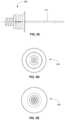
- FIG. 6is a perspective view of one embodiment of the present sternal locators.
- FIG. 7is an exploded view of the sternal locator of FIG. 6 .
- FIG. 8 Ais a top perspective view of one embodiment of the present stabilizers for use in at least some embodiments of the present sternal locators, such as, for example, as shown in the sternal locator of FIG. 6 .
- FIG. 8 Bis a bottom perspective view of the stabilizer of FIG. 8 A .
- FIG. 9is a top view of the stabilizer of FIG. 8 A .
- FIG. 10is a bottom view of the stabilizer of FIG. 8 A .
- FIG. 11is a cross-sectional view of the stabilizer of FIG. 8 A taken along line X-X′ in FIG. 9 .
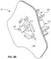
- FIGS. 12 A- 12 Cdepict various views of another embodiment of the present sternal locators.
- FIGS. 12 D- 12 Hdepict various views of top sheets, adhesive members, and/or removable liners of the sternal locator of FIGS. 12 A- 12 C .
- FIGS. 12 I- 12 Ndepict various views of another embodiment of the present stabilizers shown with probes and for use in at least some embodiments of the present sternal locators, such as, for example, as shown in the sternal locator of FIGS. 12 A- 12 C .
- FIGS. 13 A- 13 Bdepict one embodiment of the present probes for use with at least some embodiments of the present stabilizers, such as, for example, with the stabilizer of FIG. 8 A .
- FIGS. 14 A- 14 Bdepict another embodiment of the present probes for use with at least some embodiments of the present stabilizers, such as, for example, with the stabilizer of FIG. 12 I .
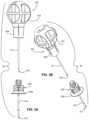
- FIG. 15 Ais a perspective view of the IO device of FIG. 3 A coupled to a sternal locator.
- FIG. 15 Bshows the assembly of FIG. 15 A in cross section and in use with a human subject.
- FIG. 15 Cdepicts a cross-sectional view of the outer penetrator and associated hub of an IO device following its insertion into an IO space in the sternum and ready to be attached to a fluid source.
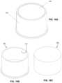
- FIG. 16 Ais a top perspective view of one of the present open containers holding one of the present penetrable materials.
- FIG. 16 Bis a top perspective view of the open container shown in FIG. 16 A .
- FIG. 16 Cis a top perspective view of the penetrable material shown in FIG. 16 A .
- FIGS. 17 A- 17 Ddepict various views of another embodiment of the present open containers.
- FIGS. 17 E- 17 Gdepict the open container of FIG. 17 A coupled to the sternal locator of FIG. 6 .
- FIG. 18 Ais a cross-sectional view of one of the present removal tools.
- FIG. 18 Bis a perspective view of the removal tool shown of FIG. 18 A coupled to the outer penetrator hub of IO device of FIG. 3 A in use with the sternal locator of FIG. 6 .
- FIGS. 19 A- 19 Ddepict various views of another embodiment of the present removal tools.
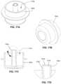
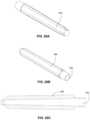
- FIGS. 20 A- 20 Cdepict various views of an embodiment of a removable cover configured to be coupled to an outer penetrator hub of the present IO devices to cover at least one of an inner penetrator and an outer penetrator of the IO device.
- proximal and distalare used in relation to the orientation of a given feature relative to a user of the disclosed devices, rather than to the subject (e.g., the patient) on which those devices are used.
- FIG. 1depicts a schematic view of the ribcage of a human 100 .
- the sternum 102is a flat, narrow bone between the ribs 106 comprising three segments: the manubrium, the body, and the xiphoid process.
- the sternumalso comprises a sternal notch 104 (also called the “suprasternal notch” or the “jugular notch”), which is a U-shaped anatomical feature located above the sternum, below the throat, and between the clavicles.
- FIG. 2shows a cross-sectional view of a portion of the sternum 100 .
- Skin 110overlays a layer of subcutaneous tissue 112 , which in turn overlays bone 114 .
- Bone 114includes an intraosseous space 116 bounded by anterior compact bone (anterior cortex, in the depicted embodiment) 115 and posterior compact bone (posterior cortex, in the depicted embodiment) 117 .
- Intraosseous space 116is the region between the anterior and posterior cortex.
- Bone marrowincludes blood, blood forming cells, and connective tissue found in the intraosseous space.
- Anterior compact bone 115 and posterior compact bone 117are each approximately 2.0 millimeters (mm) thick and intraosseous space 116 is approximately 10.0 mm thick in about 95% of adult patients. Thus, the total thickness of bone 114 is approximately 14.0 mm.
- the target zone within the intraosseous space 116is the center, which is approximately 7.0 mm from the upper surface of anterior compact bone 115 in 95% of adult patients.
- Intraosseous space 116may be accessed by an IO device.
- the term “intraosseous (IO) device” in this applicationincludes any hollow needle, hollow drill bit, penetrator assembly, bone penetrator, catheter, cannula, trocar, inner penetrator, outer penetrator, needle or needle set operable to provide access to an intraosseous space or interior portions of a bone.
- IOintraosseous
- a wide variety of trocars, spindles and/or shaftsmay be disposed within a cannula during insertion at a selected insertion site. Such trocars, spindles and shafts may also be characterized as inner penetrators.
- Inner penetratorscan comprise various lengths including, but not limited to, 20 to 50 millimeters (e.g., between 35 and 40 mm, 38.5 mm, and/or the like).
- a catheter, cannula, hollow needle or hollow drill bitmay sometimes be characterized as an outer penetrator.
- FIGS. 3 A- 5 Eillustrate an embodiment of an IO device and its components, the IO device configured for manual insertion into a subject's intraosseous space, the IO device comprising a penetrator.
- Intraosseous device 90comprises a manual driver 901 that includes a handle or grip 910 (which can also be termed a driver), which is coupled (more specifically, attached) to inner penetrator hub 908 , which is attached to inner penetrator 911 , which, for example, may take the form of any suitable stylet or trocar.
- Inner penetrator 911can have, for example, notch 912 configured to assist in coupling inner penetrator hub 908 to inner penetrator 911 (e.g., such that inner penetrator hub 908 can be overmolded over inner penetrator 911 the material from which the inner penetrator hub may be molded to extend into notch 912 ).
- IO device 90also includes an outer penetrator hub 906 that is coupled (more specifically, attached) to outer penetrator 913 , which, may, for example, take the form of a hollow tube, such as cannula (e.g., a metal cannula), or a hollow drill bit, and which may be configured (e.g., to possess sufficient rigidity) such that outer penetrator 913 will not buckle or otherwise be damaged as it is inserted through anterior compact bone together with inner penetrator 911 .
- Outer penetrator hub 906includes proximal end 907 and distal end 909 that is configured with a flange in the depicted embodiment.
- Proximal end 907 of outer penetrator hub 906 and distal end 916 of inner penetrator hub 908may be configured as complimentary connectors (with, for example, distal end 916 being configured as a male Luer connector and proximal end 907 being configured as a female Luer connector, though these configurations could be reversed in other embodiments) to allow manual driver 901 to be removably coupled to outer penetrator 913 .
- outer penetrator hub 906(and, more specifically, proximal end 907 of outer penetrator hub 906 ) may include an external surface 907 t that is threaded and that is proximate an inwardly-tapered passageway 907 p that is in fluid communication with the passageway of outer penetrator 913 (see FIG.
- inner penetrator hub 908(and, more specifically, distal end 916 of inner penetrator hub 908 ) may include an internal surface that is threaded to mate with the threaded, external surface of hub 906 and that is proximate a male projection that is tapered to match the taper of the inwardly-tapered passageway of hub 906 (these surfaces are shown but not labeled in FIG. 3 L ).
- IO device 90comprises a removable cover 990 (also depicted in FIGS. 20 A- 20 C ), the proximal end of which can be coupled through a friction fit to hub 906 via groove 914 in hub 906 .
- driver 901 and outer penetrator 913are coupled to each other, as shown in FIGS. 3 A- 5 , inner penetrator 911 of driver 901 is disposed within the passageway of outer penetrator 913 , and tip 902 of inner penetrator 911 extends beyond the distal end 917 of outer penetrator 913 .
- inner penetrator 911 and/or outer penetrator 913can be disposed within removable cover 990 (e.g., through opening 992 , as shown in FIGS. 20 B- 20 C ).
- removable cover 990When removable cover 990 is coupled to outer penetrator hub 906 , the removable cover will protect a user or operator of IO device 90 (as well as a subject on which the device will be used) from being inadvertently stuck by tip 902 of inner penetrator 911 .
- grip 910 and hub 908are attached to each other through a bond created through an ultraviolet (UV)-curable adhesive.
- grip 910 and hub 908may be integral with each other (such as through injection molding), force coupled, or otherwise adhered to one another, while in other embodiments, grip 910 and hub 908 may be removably coupled to each other such that they can be separated without destroying, damaging or otherwise impairing the function of either for re-use.
- grip 910may be coupled directly to outer penetrator hub 906 such that there is no intervening inner penetrator hub 908 (with inner penetrator 911 being attached directly to grip 910 in such embodiments).
- Tip 902 of inner penetrator 911is pointed and configured to allow IO device 90 to be driven into an intraosseous space, such as intraosseous space 116 .
- Inner penetrator 911fits closely within outer penetrator 913 such that inner penetrator 911 prevents outer penetrator 913 from becoming clogged with tissue (e.g., skin, bone) as IO device 90 is driven into a subject (e.g., a patient).
- Tip 902 and distal end 917 of outer penetrator 913can, in some embodiments where both inner penetrator 911 and outer penetrator 913 are made of a suitable metal, be ground together.
- manual driver 901can be disengaged from outer penetrator hub 906 such that proximal end 907 (which may take the form of a male Luer lock) is exposed and a conduit is formed from outer penetrator hub 906 through outer penetrator 913 to intraosseous space 116 , as shown in FIG. 5 B (adhesive member 50 and top layer 40 have been omitted from FIG. 5 B for clarity).
- a fluid source(not shown) may then be coupled to proximal end 907 to deliver fluid through outer penetrator 913 into intraosseous space 116 .
- IO device 90Any suitable configuration for IO device 90 may be used (adjusted to address the depth penetration issues discussed in this disclosure), including, for example, the IO devices shown in FIGS. 5C and 6D of U.S. Patent Application Publication No. US 2007/0270775 A1, which is incorporated by reference.
- FIGS. 6 - 12 Ndepict various views of embodiments of the present sternal locators (e.g., sternal locator 10 , sternal locator 10 a , etc.) or components of the present sternal locators.
- FIGS. 6 - 11depict various views a first embodiment 10 of the present sternal locators and components thereof.
- sternal locator 10comprises stabilizer 20 , a flange portion of which is located between and coupled to a top sheet 40 and an adhesive member 50 .
- Top sheet 40 and adhesive member 50are coupled to each other in this embodiment.
- Adhesive member 50comprises an adhesive configured to adhere sternal locator 10 to a subject during use (e.g., to the skin on the chest of a human patient).
- Stabilizer 20comprises a circumferential collar 210 and a flange 230 projecting from the circumferential collar 210 .
- Flange 230comprises a top surface 232 and an underside 236 .
- Flange 230also comprises an alignment feature 234 .
- circumferential collar 210comprises a collar contact surface 212 and a cylindrical protrusion 213 having a passageway 214 extending through the stabilizer, as well as three (longitudinally-oriented) tabs 216 that are spaced apart from each other, such as circumferentially-spaced apart from each other at 120 degree intervals (as shown in FIG. 9 ).
- Passageway 214extends from collar contact surface 212 to underside 236 .
- Collar contact surface 212is an example of a surface configured to contact a portion of an IO device to impede further insertion of the IO device.
- Collar contact surface 212is also an example of a proximal-facing surface adjacent a passageway configured to receive a penetrator of an IO device.
- top sheet 40comprises single-sided tape, such as 3 M 1526 polyethylene single coated tape.
- top sheet 40is oriented such that the adhesive side of the tape couples top sheet 40 to top surface 232 of flange 230 and to adhesive member 50 .
- Adhesive member 50may comprise any standard medical grade adhesive.
- the adhesive membercomprises double-sided tape, such as 3 M 1522 transparent polyethylene double coated tape.
- one side of adhesive patch 50is coupled both to underside 236 of flange 230 and to top sheet 40 , while the other side of adhesive member 50 is coupled to at least one liner (e.g., a release liner). As shown in FIGS.
- adhesive member 50is coupled to a removable first liner 62 and a removable second liner 64 .
- Removable liners 62 , 64cover the bottom adhesive side of adhesive member 50 (e.g., to prevent sternal locator 10 from undesired sticking).
- liners 62 , 64can be removed by a user and sternal locator 10 can be placed on, for example, the chest of a patient.
- sternal locatorsmay not include top sheet 40 or adhesive member 50 .
- sternal locator 10may lack any adhesive features for coupling the template to the chest of a patient.
- underside 236 of flange 230may be coated with an adhesive directly applied to stabilizer 20 (that is, without requiring a tape layer as discussed above).
- one or more linersmay be coupled directly to stabilizer 20 to prevent undesired sticking.
- FIGS. 8 - 11illustrate one of the present embodiments of stabilizer 20 .
- Sternal locator 10is configured to be placed on the chest of a subject (e.g., a human patient) at a location near sternum 114 and aligned with sternal notch 104 .
- Sternal locator 10is also configured to ensure proper placement of an IO device in intraosseous space 116 .
- Collar 210is, and more specifically the one or more tabs 216 of collar 210 are configured to couple (e.g., secure) stabilizer 20 to an IO device.
- each tab 216has an inwardly-projecting portion 216 i that, in the depicted embodiment, includes a surface 216 s that is configured to overlie a portion of hub 906 (and, more specifically, the flange portion of distal end 909 of outer penetrator hub 906 ) of IO device 90 . At least a portion of each surface 216 s may be oriented at a non-zero (e.g., perpendicular) angle to the direction of insertion of IO device 90 .
- a non-zeroe.g., perpendicular
- each surface 216 smay be configured with a shape that complements the shape of the portion of distal end 909 of outer penetrator hub 906 it will contact after IO device 90 is inserted, which portion may be on a proximally-facing surface of outer penetrator hub 906 .
- surfaces 216 sare configured to resist or impede travel of outer penetrator 913 after outer penetrator 913 is inserted into intraosseous space.
- each tab 216(and, more specifically, each vertical component 216 v of each tab 216 ) is configured to flex outward away from the center of stabilizer 20 as inwardly-tapered exterior surface 216 t of portion 216 i contacts a distally-facing surface of the flanged portion of distal end 909 of outer penetrator hub 906 , then snap inward as surface 216 s passes over that flanged portion, locking IO device 90 in place.
- the number of tabs usedmay be adjusted to best suit the shape of the IO device being used.
- Collar 210also includes longitudinally-oriented elements 256 that have inwardly-tapered surfaces 256 t and curved inner surfaces (which are shaped like the inside of a cylinder) 256 s .
- Each element 256includes multiple longitudinally-oriented ribs 258 that serve to increase the rigidity (and tendency to resist lateral bending) of element 256 , the middle rib of which includes a lower portion 258 p that is enlarged because it surrounds a portion of probe 30 (discussed below).
- alignment feature (or notch) 234 of stabilizer 20is an arc-shaped portion of flange 230 .
- Alignment feature 234is configured to approximate the shape of sternal notch 104 of a human patient and is configured to indicate proper placement of sternal locator 10 .
- the sternal locator depicted in the figuresis properly placed on the chest of a patient when the sternal notch is visible and at least partially (and, preferably, completely) bounded by alignment feature 234 and the stabilizer is placed over the sternum.
- the most inwardly-curved portion of alignment feature 234is spaced a distance D A from the center of hole 214 (that is, D A is the shortest distance between hole 214 and alignment feature 234 ).
- D Ais about 21 mm.
- D Amay range from about 10 mm to about 35 mm.
- the outer edge of flange 230may be 7 mm from the nearest location on the closest tab 216 , such that distance D F may be 7 mm.
- D Fmay range from 0 to 15 mm.
- stabilizer 20comprises multiple (specifically, three in the depicted embodiment) openings 238 in underside 236 .
- a recess 239extends from each opening 238 that is configured to receive a probe 30 .
- Other embodimentsmay comprise more or fewer recesses (and associated openings) configured to receive more or fewer probes 30 .
- FIGS. 12 A- 12 Ndepict various views of a second embodiment 10 a of the present sternal locators and various components.
- Sternal locator 10 ais similar in many respects to sternal locator 10 , described above.
- sternal locator 10 acomprises stabilizer 20 a (which is also similar in many respects to stabilizer 20 ), a flange portion of which is located between and coupled to a top sheet 40 a (similar to top sheet 40 ) and an adhesive member 50 a (similar to adhesive member 50 ).
- top sheet 40 and adhesive member 50top sheet 40 a and adhesive member 50 a are coupled to each other in this embodiment.
- sternal locator 10 ais configured to be placed on the chest of a subject (e.g., a human patient) at a location near sternum 114 and aligned with sternal notch 104 .
- Sternal locator 10 ais also configured to ensure proper placement of an IO device in intraosseous space 116 .
- Collar 210 ais, and more specifically the one or more tabs 216 a of collar 210 a are, configured to couple (e.g., secure) stabilizer 20 a to an IO device.
- tabs 216 aare similar to tabs 216 of collar 210 .
- the rigidity of tabs 216 aserves to stabilize the IO device to which the sternal locator is coupled, both by resisting any outward longitudinal movement of the IO device (meaning movement out of the intraosseous space along the direction of insertion) as well as any movement that would otherwise result from the IO device canting from side-to-side or otherwise moving laterally.
- collar 210 aalso includes longitudinally-oriented elements 256 a that are similar to elements 256 .
- elements 256 aare taller than tabs 216 a and function to guide the IO device to the proper location as it enters the space bounded by collar 210 a , which also helps to prevent damage to tabs 216 a , and they help to resist any lateral pitching or movement of the IO device.
- Each element 256 aincludes a pair of longitudinally-oriented ribs 258 a on opposing sides of the element that serve to increase the rigidity (and tendency to resist lateral bending) of element 256 a , the ribs each being hollow to receive and surround a portion of a probe 30 a .
- alignment feature (or notch) 234 a of stabilizer 20 ais an arc-shaped portion of flange 230 a , which is similar to alignment feature 234 .
- Stabilizer 20 aprimarily differs from stabilizer 20 in that stabilizer 20 a comprises six openings 238 a in underside 236 a .
- a recess 239 aextends from each opening 238 a and is configured to receive a probe 30 a , as illustrated in FIG. 12 K .
- Other embodimentsmay comprise more or fewer recesses (and associated openings) configured to receive more or fewer probes 30 a.
- FIGS. 13 A- 13 Bdepict a first embodiment 30 of the present probes that are suitable for use in at least some embodiments of the present sternal locators (e.g., sternal locator 10 ).
- probe 30comprises a pointed tip 302 , a notch 304 , and a proximal end 306 , where notch 304 is closer to proximal end 306 than to tip 302 .
- probes 30comprise stainless steel, though other suitable sterile materials (or materials capable of being made sterile before use on a patient) may be used.
- Proximal end 306is configured to be inserted into hole 238 and recess 239 of stabilizer 20 .
- probes 30are fixed to stabilizer 20 , such as by being bonded to stabilizer 20 using UV-curable adhesive applied to recess 239 and/or notch 304 and/or proximal end 306 of probe 30 .
- probe 30may be force fit to hole 238 and recess 239 such that it is held in place by friction between the probe and the material of the stabilizer against which it is in contact.
- probes 30may be fixed to stabilizer 20 as part of an injection molding process or using epoxy. Probe 30 can comprise any of various lengths and can extend, for example, 19-24 millimeters from a proximal-facing surface adjacent a passageway (e.g., from collar contact surface 212 ).
- FIGS. 14 A- 14 Bdepict a second embodiment 30 a of the present probes that are suitable for use in at least some embodiments of the present sternal locators (e.g., sternal locator 10 a ).
- probe 30 acomprises a pointed tip 302 a , a plurality of circumferential notches 304 a , and a proximal end 306 a , where notches 304 a are closer to proximal end 306 a than to tip 302 a .
- probes 30 acomprise stainless steel, though other suitable sterile materials (or materials capable of being made sterile before use on a patient) may be used.
- Proximal end 306 ais configured to be inserted into hole 238 a and recess 239 a of stabilizer 20 a .
- probes 30 aare fixed to stabilizer 20 a , such as by being bonded to stabilizer 20 a using UV-curable adhesive applied to recess 239 a and/or notches 304 a and/or proximal end 306 a of probe 30 a .
- probe 30 amay be force fit to hole 238 a and recess 239 a such that it is held in place by friction between the probe and the material of the stabilizer against which it is in contact.
- probes 30 amay be fixed to stabilizer 20 a as part of an injection molding process or using epoxy.
- Probe 30 acan comprise any of various lengths and can extend, for example, 19-24 millimeters from a proximal-facing surface adjacent a passageway (e.g., from collar contact surface 212 a ).
- FIG. 15 Adepicts a perspective view of sternal locator 10 coupled to IO device 90
- FIG. 15 Adepicts a cross-sectional view of IO device 90 coupled to sternal locator 10 in use on a human patient (adhesive member 50 and top layer 40 have been omitted for clarity). Four dimensions are shown in FIG. 15 A .
- D 1is the distance from collar contact surface 212 to top surface 232 of flange 230 .
- D 2includes the thickness of the flange and any adhesive on the underside of underside 236 or any adhesive member 50 (not shown).
- D 3is the distance from the lower of underside 236 or any adhesive or adhesive member attached to underside 236 to tip 302 of probe 30 .
- D 4is the distance from probe tip 302 to tip 902 of inner penetrator 911 . Therefore, the overall exposed length of inner penetrator 911 (the portion of inner penetrator 911 that extends beyond hub 906 ) is D 1 +D 2 +D 3 +D 4 .
- D 1is about 5.25 mm
- D 2is about 2.0 mm
- D 3is about 23.5 mm
- D 4is about 7.75 mm; therefore, about 38.5 mm of inner penetrator 911 is exposed or protrudes beyond inner penetrator hub 906 .
- About 23.5 mm of probes 30is exposed or protrudes beyond underside 236 of stabilizer 20 .
- inner penetrator 911may protrude about 1.5 mm beyond outer penetrator 913 .
- inner penetrator 911When IO device 90 is coupled to sternal locator 10 such that tabs 216 are in a “locked” position (and surfaces 216 s bear against the upper surface of the flanged portion of distal end 909 of hub 906 ), inner penetrator 911 extends about 7.0 to 8.0 mm beyond probes 30 . Depending on the application, the exposed portions of inner penetrator 911 and probes 30 may be lesser or greater than what is shown and described. For example, inner penetrator 911 and probes 30 may be shorter when the sternal locator and IO device are intended for use on infants or children (and inner penetrator 911 may extend a shorter distance beyond probes 30 ).
- inner penetrator 911 and probes 30may be longer (and inner penetrator 911 may extend a greater distance beyond probes 30 ) when the sternal locator and IO device are intended for use on obese patients, large patients, or patients with a thicker than normal sternum.
- D 1may be about 5.25 mm
- D 2may be about 1.25 mm
- D 3may be about 23.5 mm
- D 4may be about 6.0 mm; such that about 32 mm of inner penetrator 911 is exposed or protrudes beyond inner penetrator hub 906 and/or about 19.5 mm of probes 30 protrudes beyond underside 236 of stabilizer 20 . Any dimension listed as “about” may also be substantially (including exactly) equal to the given value.
- a userTo use sternal locator 10 , a user first locates sternal notch 104 of the patient by feeling for the U-shaped cavity above the sternum, below the throat, and between the clavicles. The user then aligns alignment feature 234 of sternal locator 10 with sternal notch 104 , ensuring that the balance of the sternal locator is positioned over the patient's sternum. With sternal locator 10 thus properly aligned, the user then applies pressure to sternal locator 10 until probes 30 penetrate skin 110 and muscle 112 and touch anterior compact bone 115 (the top surface of the sternum).
- Probes 30may penetrate into anterior compact bone 115 by some distance, such as about 0.5 mm to about 1.0 mm (which accounts for the difference between the illustrative 7.0 mm length that inner penetrator 911 extends beyond probes 30 and the illustrative value of 7.75 mm for D 4 ), though preferably penetrate no more than 0.5 mm, and in no case should probes 30 penetrate into intraosseous space 116 .
- the userthen removes removable liners 62 , 64 and presses adhesive member 50 against skin 110 , ensuring that adhesive member 50 is adhered to skin 110 of the patient.
- the thickness of skin 110 and subcutaneous tissue 112are equal in thickness to D 3 , the exposed length of probes 30 .
- the thickness of skin 110 and subcutaneous tissue 112can vary widely depending on the patient.
- length of probes 30will exceed the tissue thickness such that stabilizer 20 is not flush with skin 110 and portions of probes 30 are exposed.
- adhesive layer 50provides an additional stabilizing effect by allowing sternal locator 10 to be affixed to the patient's chest.
- IO device 90which includes portions of outer penetrator 913 and driver 901 ) into passageway 214 of sternal locator 10 .
- the userapplies pressure and twists or reciprocates IO device 90 (back and forth, but not necessarily all the way around, such that the driving movement may be characterized as reciprocating, twisting, or non-rotational (meaning one complete revolution is not utilized)) until inner penetrator 911 and outer penetrator 913 pierce skin 110 , subcutaneous tissue 112 , and anterior compact bone 115 .
- IO device 90is properly positioned when surfaces 216 s of tabs 216 fully engage (or are in contact with) the flanged portion of distal end 909 of hub 906 .
- an audible sounde.g., a click
- tabs 216pass over the flanged portion of distal end 909 of inner penetrator hub 906 and snap into place.
- the userwill feel the IO device passing tabs 216 because the force required to advance the device will be reduced (thus, the user will feel the IO device “snap” into place).
- Introducing IO device 90 into the patient in this mannermay be described as non-surgically introducing (or inserting) the IO device, or introducing (or inserting) the IO device without first making an incision for the IO device with a different structure (such as a scalpel).
- a different structuresuch as a scalpel.
- Driver 901may then be removed from IO device 90 by, in the depicted embodiment, rotating grip 910 in a counterclockwise direction to uncouple inner penetrator hub 908 from outer penetrator hub 906 . This will withdraw inner penetrator 911 from outer penetrator 913 .
- the removal of the inner penetratormay differ.
- some embodiments of IO devicesmay include a closed-tip needle with a side port located sufficiently close to the distal-most end of the closed-tip needle for the intended IO application, such that no inner penetrator 911 is used.
- Outer penetrator 913remains coupled to stabilizer 20 of sternal locator 10 .
- a conduitis thus formed from open, proximal end 907 of outer penetrator hub 906 through distal opening 917 of outer penetrator 913 , which is in direct fluid communication with intraosseous space 116 , as shown in FIG. 5 B .
- a fluid sourcemay then be coupled to proximal end 907 of outer penetrator hub 906 for delivery of fluid (e.g., blood or medicine) to intraosseous space 116 .
- the sternal locator and IO devicemay be withdrawn from the patient's chest, and the probes and penetrator of the IO device may be inserted into penetrable material 400 (see FIG. 16 C ), which may be disposed in some embodiments in a reservoir (e.g., reservoir 510 of open container 500 as depicted in FIGS. 16 A- 16 C , reservoir 510 a of open container 500 a as depicted in FIGS. 17 A- 17 D , or the like).
- open container 500 and penetrable material 400may be used as a sharps container for the assembly comprising the sternal locator and the IO device.
- Penetrable material 400may be held to open container 500 through an adhesive member (not visible), a friction fit, or through any other suitable means.
- Other embodiments, such as open container 500 a of FIGS. 17 A- 17 Dmay not include penetrable material, and may instead include an opening 514 a configured to receive and engage protrusion 213 or 213 a of stabilizer 20 or 20 a , respectively (shown in FIGS. 17 E- 17 F engaged with 213 a of stabilizer 20 a of sternal locator 10 a ) to couple hollow container 500 a to the sternal locator to cover the probes and penetrators of the sternal locators.
- hollow containercomprises a central, hollow stem 518 a with opening 514 a defined in a proximal end of the stem, as shown.
- central stem 518 afurther includes a proximal surface 522 a tapering the proximal end of opening 514 a to facilitate insertion of protrusion 213 a into opening 514 a.
- kitsmay include a package (e.g., a flexible package (e.g., such as one that does not include a tray, such as a rigid plastic tray)) that contains at least one of the present sternal locators, one of the present sharps containers, and, in more specific embodiments, one of the disclosed IO devices and/or instructions for use, which instructions may be on the outside of the package, on the sternal locator, and/or on an insert contained within the package.
- a packagee.g., a flexible package (e.g., such as one that does not include a tray, such as a rigid plastic tray)) that contains at least one of the present sternal locators, one of the present sharps containers, and, in more specific embodiments, one of the disclosed IO devices and/or instructions for use, which instructions may be on the outside of the package, on the sternal locator, and/or on an insert contained within the package.
- Some embodiments of the present methodsare training methods, and include placing sternal locator 10 into penetrable material 400 , then inserting at least the outer penetrator of IO device 90 (and, in some embodiments, all of IO device 90 ) into collar 210 of stabilizer 20 until stabilizer 20 is engaged with IO device 90 (as described above).
- the release linersmay be removed or left in place as part of the training method.
- IO device 90may then be removed from engagement with the sternal locator using one of the present removal tools, such as removal tool 600 shown in FIGS. 18 A and 18 B , or removal tool 600 a depicted in FIGS. 19 A- 19 D .
- Removal tool 600includes open distal end 610 that includes recess 612 , which is sized to receive outer penetrator hub 906 , and an enlarged gripping section 620 .
- a usermay press and hold the sternal locator and the outer penetrator into container 500 such that the distal end of the outer penetrator contacts the bottom of reservoir 510 and the top surface of the flange of outer penetrator hub 906 contacts surfaces 216 s of tabs 216 .
- a usermay then slide or twist removal tool 600 over outer penetrator hub 906 and press the tool against tabs 216 with enough force to the inwardly-projecting portions 216 i of the tabs.
- a removal tool(e.g., removal tool 600 a ) can include a recess 612 a with threads 614 a (e.g., female threads) configured to be coupled to outer penetrator hub 906 (e.g., via complimentary male threads).
- threads 614 ae.g., female threads
- a usermay continue pushing on or twisting the removal tool, which will push the stabilizer downward relative to the outer penetrator because the prongs of the stabilizer will not have reached the bottom of the reservoir while the outer penetrator, in contrast, will be in contact with the bottom of the reservoir, such that at least a portion of the tabs of the stabilizer move sufficiently distal past the flange of the distal end of the outer penetrator hub that the outer penetrator can be removed.
- a usercan then remove the removal tool and the outer penetrator (e.g., simultaneously). While movement of the outer penetrator can be impeded by the bottom of the reservoir of the container (which is a type of sharps container), any surface or technique for allowing the removal tool to push the stabilizer distal relative to the outer penetrator can be used to disengage the outer penetrator from the stabilizer (e.g., a user may contact the distal end of the outer penetrator against any suitable surface that will impede distal movement of the outer penetrator as the tab or tabs of the stabilizer are spread apart and the stabilizer pushed distally relative to the outer penetrator).
- Non-limiting examples of suitable materials for some embodiments of the present stabilizers, the present grips, and the present hubs of the disclosed IO devicesinclude injection moldable plastics, such as Bayer RX2530 polycarbonate (USP grade VI, gamma stable).
- a non-limiting example of a suitable material for some embodiments of the present probesis stainless steel, such as 304V stainless steel straightened wire that is spring tempered in accordance with ASTM-A313 with tensile strength of 265 to 293 PSI.
- a non-limiting example of a suitable material for some embodiments of the present open containersis medical grade plastic, such as white DELRIN.
- a non-limiting example of a suitable material for some embodiments of the present penetrable materialsis 3 ⁇ 4-inch thick white polyethylene foam with an adhesive backing member (McMaster-Carr P/N 8865K521).
- top layer 40may include a depiction of a portion of a subject's anatomy to help a user determine whether to place the sternal locator in use.
- the sternal locatormay include a protective cover (comparable to removable cover 990 of IO device 90 ) coupled to the stabilizer prior to use to prevent probes 30 from sticking things inadvertently.
- the probe or probes that are usedmay comprise coring needles rather than solid material.
Landscapes
- Health & Medical Sciences (AREA)
- Surgery (AREA)
- Life Sciences & Earth Sciences (AREA)
- Animal Behavior & Ethology (AREA)
- Public Health (AREA)
- Engineering & Computer Science (AREA)
- Biomedical Technology (AREA)
- Heart & Thoracic Surgery (AREA)
- Medical Informatics (AREA)
- Molecular Biology (AREA)
- Veterinary Medicine (AREA)
- General Health & Medical Sciences (AREA)
- Nuclear Medicine, Radiotherapy & Molecular Imaging (AREA)
- Orthopedic Medicine & Surgery (AREA)
- Pathology (AREA)
- Dentistry (AREA)
- Oral & Maxillofacial Surgery (AREA)
- Surgical Instruments (AREA)
- Infusion, Injection, And Reservoir Apparatuses (AREA)
- Prostheses (AREA)
- Percussion Or Vibration Massage (AREA)
- Media Introduction/Drainage Providing Device (AREA)
- Accommodation For Nursing Or Treatment Tables (AREA)
Abstract
Description
Claims (20)
Priority Applications (1)
| Application Number | Priority Date | Filing Date | Title |
|---|---|---|---|
| US15/643,707US11771462B2 (en) | 2011-07-11 | 2017-07-07 | Sternal locators and associated systems and methods |
Applications Claiming Priority (3)
| Application Number | Priority Date | Filing Date | Title |
|---|---|---|---|
| US201161506316P | 2011-07-11 | 2011-07-11 | |
| US13/546,894US9730729B2 (en) | 2011-07-11 | 2012-07-11 | Sternal locators and associated systems and methods |
| US15/643,707US11771462B2 (en) | 2011-07-11 | 2017-07-07 | Sternal locators and associated systems and methods |
Related Parent Applications (1)
| Application Number | Title | Priority Date | Filing Date |
|---|---|---|---|
| US13/546,894DivisionUS9730729B2 (en) | 2011-07-11 | 2012-07-11 | Sternal locators and associated systems and methods |
Publications (2)
| Publication Number | Publication Date |
|---|---|
| US20170303963A1 US20170303963A1 (en) | 2017-10-26 |
| US11771462B2true US11771462B2 (en) | 2023-10-03 |
Family
ID=47506899
Family Applications (2)
| Application Number | Title | Priority Date | Filing Date |
|---|---|---|---|
| US13/546,894Active2032-08-18US9730729B2 (en) | 2011-07-11 | 2012-07-11 | Sternal locators and associated systems and methods |
| US15/643,707Active2033-09-28US11771462B2 (en) | 2011-07-11 | 2017-07-07 | Sternal locators and associated systems and methods |
Family Applications Before (1)
| Application Number | Title | Priority Date | Filing Date |
|---|---|---|---|
| US13/546,894Active2032-08-18US9730729B2 (en) | 2011-07-11 | 2012-07-11 | Sternal locators and associated systems and methods |
Country Status (8)
| Country | Link |
|---|---|
| US (2) | US9730729B2 (en) |
| EP (1) | EP2731521B1 (en) |
| JP (3) | JP6126091B2 (en) |
| CN (2) | CN104080412B (en) |
| BR (1) | BR112014000796A2 (en) |
| HK (1) | HK1202790A1 (en) |
| RU (1) | RU2014104585A (en) |
| WO (1) | WO2013009901A2 (en) |
Cited By (1)
| Publication number | Priority date | Publication date | Assignee | Title |
|---|---|---|---|---|
| US20220110658A1 (en)* | 2019-06-22 | 2022-04-14 | Teleflex Life Sciences Limited | Bone-penetrating manual driver and stabilizer assembly for intraosseous access |
Families Citing this family (47)
| Publication number | Priority date | Publication date | Assignee | Title |
|---|---|---|---|---|
| AR070764A1 (en)* | 2007-12-07 | 2010-05-05 | Pyng Medical Corp | APPLIANCES AND METHODS TO ENTER OSEOS PORTALS |
| WO2013009901A2 (en) | 2011-07-11 | 2013-01-17 | Vidacare Corporation | Sternal locators and associated systems and methods |
| CN104379207A (en) | 2011-12-28 | 2015-02-25 | 克里尔医疗有限公司 | System and method for blood filtering and/or treatment |
| US10293128B2 (en) | 2012-07-23 | 2019-05-21 | University Of Maryland, Baltimore | System and method for emergency apneic oxygenation |
| US10556117B2 (en) | 2013-05-06 | 2020-02-11 | Medtronic, Inc. | Implantable cardioverter-defibrillator (ICD) system including substernal pacing lead |
| US9717923B2 (en) | 2013-05-06 | 2017-08-01 | Medtronic, Inc. | Implantable medical device system having implantable cardioverter-defibrillator (ICD) system and substernal leadless pacing device |
| US10532203B2 (en) | 2013-05-06 | 2020-01-14 | Medtronic, Inc. | Substernal electrical stimulation system |
| US10471267B2 (en) | 2013-05-06 | 2019-11-12 | Medtronic, Inc. | Implantable cardioverter-defibrillator (ICD) system including substernal lead |
| US20140330287A1 (en) | 2013-05-06 | 2014-11-06 | Medtronic, Inc. | Devices and techniques for anchoring an implantable medical device |
| DK3188793T3 (en) | 2014-09-04 | 2020-04-06 | Atacor Medical Inc | PACEMAKER CABLE CONTACT |
| US9636505B2 (en) | 2014-11-24 | 2017-05-02 | AtaCor Medical, Inc. | Cardiac pacing sensing and control |
| US10328268B2 (en) | 2014-09-04 | 2019-06-25 | AtaCor Medical, Inc. | Cardiac pacing |
| US10743960B2 (en) | 2014-09-04 | 2020-08-18 | AtaCor Medical, Inc. | Cardiac arrhythmia treatment devices and delivery |
| US9636512B2 (en) | 2014-11-05 | 2017-05-02 | Medtronic, Inc. | Implantable cardioverter-defibrillator (ICD) system having multiple common polarity extravascular defibrillation electrodes |
| US11097109B2 (en) | 2014-11-24 | 2021-08-24 | AtaCor Medical, Inc. | Cardiac pacing sensing and control |
| US9939923B2 (en) | 2015-06-19 | 2018-04-10 | Microsoft Technology Licensing, Llc | Selecting events based on user input and current context |
| US11357546B2 (en)* | 2015-07-24 | 2022-06-14 | IOMetry, Inc. | Device for enabling placement of intra-osseous infusion tools in the upper extremity |
| US20170135722A1 (en)* | 2015-11-15 | 2017-05-18 | Waismed Ltd. | Apparatus for use in conjunction with an intraosseous device |
| WO2017186794A1 (en)* | 2016-04-28 | 2017-11-02 | Prometheus Delta Tech Ltd | An intraosseous device |
| GB2551257A (en)* | 2016-04-28 | 2017-12-13 | Prometheus Delta Tech Ltd | An intraosseous device |
| EP3528723B1 (en) | 2016-10-27 | 2023-08-16 | C. R. Bard, Inc. | Intraosseous access device |
| USD828653S1 (en) | 2016-12-14 | 2018-09-11 | Brandon Penland | Treatment applicator |
| US10569069B2 (en) | 2016-12-14 | 2020-02-25 | Combat Comb, Llc | Applicator for treatments applied to animal skin |
| US11304709B2 (en) | 2018-01-25 | 2022-04-19 | Medtronic Holdings Company Sarl | Adaptor and drill for use with a driver and a cannula for drilling into bone |
| US10980587B2 (en) | 2018-01-25 | 2021-04-20 | Medtronic Holding Company Sàrl | Adaptor for use with a driver, a drill, and a cannula for drilling into bone |
| WO2020150314A1 (en)* | 2019-01-17 | 2020-07-23 | Medtronic Holding Company Sarl | Adaptor and drill for use with a driver and a cannula for drilling into bone |
| WO2020172280A1 (en)* | 2019-02-21 | 2020-08-27 | Glw, Inc. | Hybrid bone fixation wire |
| EP4527449A3 (en) | 2019-05-29 | 2025-04-30 | Atacor Medical, Inc. | Implantable electrical leads and associated delivery systems |
| WO2020261070A1 (en)* | 2019-06-22 | 2020-12-30 | Teleflex Medical Devices S.A.R.L. | Bone-penetrating intraosseous access device |
| WO2020260992A1 (en)* | 2019-06-22 | 2020-12-30 | Teleflex Medical Devices S.A.R.L. | Intraosseous access device and locator assembly |
| CN212879457U (en) | 2019-09-27 | 2021-04-06 | 巴德阿克塞斯系统股份有限公司 | Self-advancing intraosseous access device and intraosseous access device |
| US11759235B2 (en) | 2019-09-27 | 2023-09-19 | Bard Access Systems, Inc. | Constant-torque intraosseous access devices and methods thereof |
| WO2021062215A1 (en) | 2019-09-27 | 2021-04-01 | Bard Access Systems, Inc. | Step needle for intraosseous access device |
| CN212879505U (en) | 2019-09-27 | 2021-04-06 | 巴德阿克塞斯系统股份有限公司 | Intraosseous access device |
| US12295556B2 (en) | 2019-09-27 | 2025-05-13 | Merit Medical Systems, Inc. | Rotation biopsy system and handle |
| US12150627B2 (en) | 2019-12-11 | 2024-11-26 | Merit Medical Systems, Inc. | Bone biopsy device and related methods |
| EP4110206A4 (en)* | 2020-02-26 | 2023-11-01 | The Seaberg Company, Inc. | APPARATUS AND METHODS FOR INTRA-osseous DEVICE STABILIZATION AND FLUID TRANSFER |
| CN113317840A (en) | 2020-02-28 | 2021-08-31 | 巴德阿克塞斯系统股份有限公司 | Flexible intra-osseous obturator |
| WO2021216521A1 (en) | 2020-04-21 | 2021-10-28 | Bard Access Systems , Inc. | Reusable push-activated intraosseous access device |
| US11666771B2 (en) | 2020-05-29 | 2023-06-06 | AtaCor Medical, Inc. | Implantable electrical leads and associated delivery systems |
| CN113749724A (en) | 2020-06-03 | 2021-12-07 | 巴德阿克塞斯系统股份有限公司 | Intraosseous device including sensing obturator |
| CN216167681U (en) | 2020-07-17 | 2022-04-05 | 巴德阿克塞斯系统股份有限公司 | Safety mechanism |
| CN216628654U (en) | 2020-08-25 | 2022-05-31 | 巴德阿克塞斯系统股份有限公司 | Angled intraosseous access system |
| CN215839325U (en) | 2020-09-09 | 2022-02-18 | 巴德阿克塞斯系统股份有限公司 | Suction device for an intraosseous access system |
| CN217960227U (en) | 2021-02-08 | 2022-12-06 | 巴德阿克塞斯系统股份有限公司 | Intraosseous access system |
| EP4319658A1 (en) | 2021-04-06 | 2024-02-14 | GLW, Inc. | Bone fixation devices, systems, kits, and methods |
| CN113180789A (en)* | 2021-04-21 | 2021-07-30 | 重庆市公共卫生医疗救治中心 | Auxiliary fixing device suitable for chest puncture of patient with thin chest wall |
Citations (91)
| Publication number | Priority date | Publication date | Assignee | Title |
|---|---|---|---|---|
| US2001638A (en) | 1932-11-14 | 1935-05-14 | Res Foundation Inc | Surgical needle |
| FR853349A (en) | 1939-04-22 | 1940-03-15 | Improvements to devices for removing pieces of tissue from human or animal organs | |
| US2317648A (en) | 1941-07-08 | 1943-04-27 | Ivar E Siqveland | Process and apparatus for producing intraosseous anesthesia |
| US3815605A (en)* | 1971-05-19 | 1974-06-11 | Philips Corp | Device and holder therefor for inserting a hollow coupling member into bone marrow |
| US3991765A (en) | 1975-04-09 | 1976-11-16 | Howard Cohen | Cricothyrotomy apparatus |
| US4142517A (en) | 1976-07-23 | 1979-03-06 | Contreras Guerrero De Stavropo | Apparatus for extracting bone marrow specimens |
| US4170993A (en) | 1978-03-13 | 1979-10-16 | Marcial Alvarez | Sliding I.V. needle carrier assembly |
| FR2457105A1 (en) | 1979-05-22 | 1980-12-19 | Villette Alain | Penetrating compact materials with injection syringe - rotary needle, used esp. for anaesthesia in dentistry |
| US4646731A (en) | 1985-05-20 | 1987-03-03 | Brower Arthur B | Self adhesive suture and bandage |
| US4659329A (en) | 1984-07-27 | 1987-04-21 | The Kendall Company | Liquid drainage system |
| US4758225A (en) | 1985-11-08 | 1988-07-19 | Pharmacia Limited | Devices for sampling, drainage or infusion of liquids from or to the human or animal body |
| US4772261A (en) | 1987-01-29 | 1988-09-20 | Board Of Regents, The University Of Texas System | Intramedullary catheter |
| US4969870A (en) | 1989-06-07 | 1990-11-13 | The Regents Of The University Of California | Method and apparatus for intraosseous infusions |
| US5057085A (en) | 1989-11-24 | 1991-10-15 | Medical Device Technologies, Inc. | Stabilized aspiration biopsy needle assembly |
| US5116324A (en) | 1991-07-15 | 1992-05-26 | Brierley Carol L | Protector for IV site |
| US5120312A (en) | 1990-04-20 | 1992-06-09 | Regents Of The University Of Minnesota | Method and apparatus for catheterization |
| US5122114A (en) | 1991-02-01 | 1992-06-16 | Board Of Regents, University Of Texas System | Method of using intramedullary catheter |
| US5195985A (en) | 1990-05-25 | 1993-03-23 | Hall John E | Syringe having a retractable needle |
| US5203056A (en) | 1991-06-07 | 1993-04-20 | Joka Kathetertechnik Gmbh | Hose clamp for medical application |
| US5312364A (en)* | 1993-08-06 | 1994-05-17 | Pyng | Intraosseous infusion device |
| US5332398A (en) | 1992-02-01 | 1994-07-26 | Board Of Regents, The University Of Texas System | Intramedullary catheter |
| JPH06508773A (en) | 1991-04-29 | 1994-10-06 | クレイマー,ジョージ・シー | System and method for rapid intravascular drug injection |
| US5372583A (en) | 1992-11-25 | 1994-12-13 | Cardiopulmonary Specialities, Inc. | Bone marrow infuser and method of use |
| US5385553A (en) | 1991-07-18 | 1995-01-31 | Applied Medical Resources Corporation | Trocar with floating septum seal |
| US5423824A (en) | 1992-03-23 | 1995-06-13 | Radi Medical Systems Ab | Method of accessing hard tissue |
| JPH07171165A (en) | 1993-11-06 | 1995-07-11 | Taguchi:Kk | Infundibular chest therapy device |
| US5431655A (en) | 1988-10-24 | 1995-07-11 | Cook Incorporated | Intraosseous needle |
| US5451210A (en) | 1991-04-29 | 1995-09-19 | Lifequest Medical, Inc. | System and method for rapid vascular drug delivery |
| CA2138842A1 (en) | 1994-12-22 | 1996-06-23 | David E. Gibbs | Catheterized intra-osseus delivery system |
| US5591188A (en) | 1994-04-12 | 1997-01-07 | Wais-Med Lmt, A Subsidiary Company Of Teic Technion Enterpreneurial Incubator Ltd. | Surgical instrument for impact insertion of an intraosseous trocar-needle |
| US5601559A (en) | 1988-10-24 | 1997-02-11 | Cook Incorporated | Intraosseous needle |
| WO1998006337A1 (en) | 1996-08-15 | 1998-02-19 | Cyberdent, Inc. | Intraosseous drug delivery device and method |
| US5733262A (en) | 1996-04-18 | 1998-03-31 | Paul; Kamaljit S. | Blood vessel cannulation device |
| US5769086A (en) | 1995-12-06 | 1998-06-23 | Biopsys Medical, Inc. | Control system and method for automated biopsy device |
| US5817052A (en) | 1995-12-26 | 1998-10-06 | Pyng Medical Corp. | Apparatus for intraosseous infusion or aspiration |
| US5858005A (en) | 1997-08-27 | 1999-01-12 | Science Incorporated | Subcutaneous infusion set with dynamic needle |
| US5868711A (en) | 1991-04-29 | 1999-02-09 | Board Of Regents, The University Of Texas System | Implantable intraosseous device for rapid vascular access |
| US6018094A (en) | 1995-02-06 | 2000-01-25 | Biomedical Enterprises, Inc. | Implant and insert assembly for bone and uses thereof |
| WO2001093931A1 (en) | 2000-06-06 | 2001-12-13 | Becton, Dickinson And Company | Method and apparatus for enhancing penetration of a puncturing member into the intradermal space |
| US6458117B1 (en)* | 2000-01-19 | 2002-10-01 | Kevin Daniel Pollins, Sr. | Intraosseous infusion assembly and method for intraosseous infusion |
| WO2002096497A1 (en) | 2001-05-29 | 2002-12-05 | David George Noble | Intraosseous method and apparatus |
| CA2454600A1 (en) | 2001-08-09 | 2003-02-27 | Japan Immunoresearch Laboratories Co., Ltd. | Bone marrow harvesting set and bone marrow harvesting needle |
| US20030225344A1 (en) | 2002-05-31 | 2003-12-04 | Vidacare Corporation | Apparatus and method to access the bone marrow for oncology and stem cell applications |
| US20040064136A1 (en) | 2002-09-30 | 2004-04-01 | Paula Papineau | Novel device for advancing a functional element through tissue |
| US6761726B1 (en)* | 1998-05-15 | 2004-07-13 | Pyng Medical Corp. | Method and apparatus for the intraosseous introduction of a device such as an infusion tube |
| US20040220497A1 (en) | 2000-03-02 | 2004-11-04 | Findlay Judith M. | Patch for locating a target zone for penetration |
| CN2664675Y (en) | 2003-11-21 | 2004-12-22 | 中国人民解放军第三军医大学野战外科研究所 | Incorporated breast bone transfusion device |
| US20050027210A1 (en) | 2000-11-06 | 2005-02-03 | Miller Michael E. | Biopsy apparatus |
| US20050040060A1 (en) | 2001-09-07 | 2005-02-24 | Andersen Birthe Vestbo | Package for an ostomy applicance |
| US20050131345A1 (en) | 2002-05-31 | 2005-06-16 | Larry Miller | Apparatus and method for accessing the bone marrow of the sternum |
| US20050148940A1 (en) | 2002-05-31 | 2005-07-07 | Larry Miller | Apparatus and method for accessing the bone marrow |
| US20050165404A1 (en) | 2002-05-31 | 2005-07-28 | Miller Larry J. | Manual interosseous device |
| US20050165403A1 (en) | 2004-01-26 | 2005-07-28 | Miller Larry J. | Impact-driven intraosseous needle |
| EP0984809B1 (en) | 1997-05-16 | 2005-08-03 | Pyng Medical Corporation | Apparatus for the intraosseous introduction of a device such as an infusion tube |
| US20050182420A1 (en) | 2004-02-13 | 2005-08-18 | Schulte Gregory T. | Low profile apparatus for securing a therapy delivery device within a burr hole |
| US20050228309A1 (en) | 2002-12-31 | 2005-10-13 | Fisher John S | Sealant Plug Delivery Methods |
| US20050261693A1 (en) | 2002-05-31 | 2005-11-24 | Miller Larry J | Apparatus and method to inject fluids into bone marrow and other target sites |
| WO2005112800A2 (en) | 2004-05-17 | 2005-12-01 | Tiax Llc | Intraosseous infusion device |
| US20050273076A1 (en)* | 2004-06-07 | 2005-12-08 | C.R. Bard, Inc. | Subcutaneous infusion devices |
| US20060030815A1 (en)* | 2004-07-23 | 2006-02-09 | Roland Csincsura | Coupling mechanism for connecting a catheter to a medical infusion line |
| US7008383B1 (en) | 2000-03-06 | 2006-03-07 | Fonar Corporation | Method of conducting a needle biopsy procedure |
| US20060184063A1 (en) | 2005-02-15 | 2006-08-17 | Miller Michael E | Single motor handheld biopsy device |
| US7137985B2 (en) | 2003-09-24 | 2006-11-21 | N Spine, Inc. | Marking and guidance method and system for flexible fixation of a spine |
| US20070016100A1 (en) | 2002-05-31 | 2007-01-18 | Miller Larry J | Apparatus and Methods to Harvest Bone and Bone Marrow |
| CN1913833A (en) | 2004-01-26 | 2007-02-14 | 维达保健公司 | Manual intraosseous instrument |
| US20070049945A1 (en) | 2002-05-31 | 2007-03-01 | Miller Larry J | Apparatus and methods to install, support and/or monitor performance of intraosseous devices |
| US7207949B2 (en) | 2003-09-25 | 2007-04-24 | Nuvasive, Inc. | Surgical access system and related methods |
| US20070149920A1 (en) | 2005-12-28 | 2007-06-28 | Smiths Medical Md, Inc. | Portal access device with removable sharps protection |
| US20070270775A1 (en) | 2004-11-12 | 2007-11-22 | Miller Larry J | Intraosseous Device And Methods For Accessing Bone Marrow In The Sternum And Other Target Areas |
| US20080045857A1 (en) | 2002-05-31 | 2008-02-21 | Miller Larry J | Bone Marrow Aspiration Devices and Related Methods |
| US20080045861A1 (en) | 2002-05-31 | 2008-02-21 | Miller Larry J | Medical Procedures Trays And Related Methods |
| US20080045965A1 (en) | 2002-05-31 | 2008-02-21 | Miller Larry J | Apparatus and Methods for Biopsy and Aspiration of Bone Marrow |
| US20080071215A1 (en)* | 2004-11-05 | 2008-03-20 | Traxtal Technologies Inc. | Access System |
| WO2008054894A2 (en) | 2006-10-30 | 2008-05-08 | Vidacare Corporation | Intraosseous device supports and fluid communication means |
| WO2008081438A1 (en) | 2006-12-31 | 2008-07-10 | Gil Shetrit | Vascular access system and method |
| US20080215056A1 (en) | 2002-05-31 | 2008-09-04 | Miller Larry J | Powered Drivers, Intraosseous Devices And Methods To Access Bone Marrow |
| US20080221580A1 (en) | 2003-05-30 | 2008-09-11 | Miller Larry J | Powered Driver |
| US7481830B2 (en) | 1999-07-07 | 2009-01-27 | Children's Hospital Medical Center | Spinal correction system |
| WO2009070896A1 (en) | 2007-12-07 | 2009-06-11 | Pyng Medical Corp. | Apparatus and methods for introducing portals in bone |
| US20090204024A1 (en)* | 2002-05-31 | 2009-08-13 | Miller Larry J | Apparatus and Method to Access the Bone Marrow |
| US7615043B2 (en) | 2003-08-20 | 2009-11-10 | Boston Scientific Scimed, Inc. | Medical device incorporating a polymer blend |
| WO2010020606A1 (en) | 2008-08-19 | 2010-02-25 | Corporació Sanitària Parc Taulí | Device for use in surgical treatment of funnel chest and method of treatment |
| US20100152616A1 (en) | 2007-11-20 | 2010-06-17 | Niyazi Beyhan | Devices and methods for safely accessing bone marrow and other tissues |
| US7850620B2 (en) | 2002-05-31 | 2010-12-14 | Vidacare Corporation | Biopsy devices and related methods |
| US7899528B2 (en) | 2007-05-17 | 2011-03-01 | Vidacare Corporation | Method and apparatus to monitor patients and treat with intraosseous fluids |
| WO2011070593A1 (en) | 2009-12-11 | 2011-06-16 | Secretary, Department Of Biotechnology | Device for vascular access |
| US8217561B2 (en) | 2007-09-17 | 2012-07-10 | Ngk Spark Plug Co., Ltd. | Spark plug having laminated ground electrode |
| WO2013009901A2 (en) | 2011-07-11 | 2013-01-17 | Vidacare Corporation | Sternal locators and associated systems and methods |
| US8944069B2 (en) | 2006-09-12 | 2015-02-03 | Vidacare Corporation | Assemblies for coupling intraosseous (IO) devices to powered drivers |
| US9072543B2 (en) | 2002-05-31 | 2015-07-07 | Vidacare LLC | Vascular access kits and methods |
| US9839740B2 (en)* | 2010-02-02 | 2017-12-12 | Teleflex Medical Devices S.À R.L | Intraosseous-needle stabilizer and methods |
Family Cites Families (1)
| Publication number | Priority date | Publication date | Assignee | Title |
|---|---|---|---|---|
| JP2011011000A (en)* | 2009-07-06 | 2011-01-20 | Terumo Corp | Needle tube, medical instrument and method for manufacturing medical instrument |
- 2012
- 2012-07-11WOPCT/US2012/046294patent/WO2013009901A2/enactiveApplication Filing
- 2012-07-11RURU2014104585/14Apatent/RU2014104585A/ennot_activeApplication Discontinuation
- 2012-07-11EPEP12811090.5Apatent/EP2731521B1/enactiveActive
- 2012-07-11USUS13/546,894patent/US9730729B2/enactiveActive
- 2012-07-11BRBR112014000796Apatent/BR112014000796A2/ennot_activeIP Right Cessation
- 2012-07-11HKHK15103311.9Apatent/HK1202790A1/enunknown
- 2012-07-11JPJP2014520284Apatent/JP6126091B2/enactiveActive
- 2012-07-11CNCN201280043008.5Apatent/CN104080412B/enactiveActive
- 2012-07-11CNCN201710931617.9Apatent/CN107684451B/enactiveActive
- 2017
- 2017-04-06JPJP2017075764Apatent/JP6417441B2/enactiveActive
- 2017-07-07USUS15/643,707patent/US11771462B2/enactiveActive
- 2018
- 2018-10-05JPJP2018189623Apatent/JP6909194B2/enactiveActive
Patent Citations (141)
| Publication number | Priority date | Publication date | Assignee | Title |
|---|---|---|---|---|
| US2001638A (en) | 1932-11-14 | 1935-05-14 | Res Foundation Inc | Surgical needle |
| FR853349A (en) | 1939-04-22 | 1940-03-15 | Improvements to devices for removing pieces of tissue from human or animal organs | |
| US2317648A (en) | 1941-07-08 | 1943-04-27 | Ivar E Siqveland | Process and apparatus for producing intraosseous anesthesia |
| US3815605A (en)* | 1971-05-19 | 1974-06-11 | Philips Corp | Device and holder therefor for inserting a hollow coupling member into bone marrow |
| US3991765A (en) | 1975-04-09 | 1976-11-16 | Howard Cohen | Cricothyrotomy apparatus |
| US4142517A (en) | 1976-07-23 | 1979-03-06 | Contreras Guerrero De Stavropo | Apparatus for extracting bone marrow specimens |
| US4170993A (en) | 1978-03-13 | 1979-10-16 | Marcial Alvarez | Sliding I.V. needle carrier assembly |
| FR2457105A1 (en) | 1979-05-22 | 1980-12-19 | Villette Alain | Penetrating compact materials with injection syringe - rotary needle, used esp. for anaesthesia in dentistry |
| US4659329A (en) | 1984-07-27 | 1987-04-21 | The Kendall Company | Liquid drainage system |
| US4646731A (en) | 1985-05-20 | 1987-03-03 | Brower Arthur B | Self adhesive suture and bandage |
| US4758225A (en) | 1985-11-08 | 1988-07-19 | Pharmacia Limited | Devices for sampling, drainage or infusion of liquids from or to the human or animal body |
| US4772261A (en) | 1987-01-29 | 1988-09-20 | Board Of Regents, The University Of Texas System | Intramedullary catheter |
| US5431655A (en) | 1988-10-24 | 1995-07-11 | Cook Incorporated | Intraosseous needle |
| US5601559A (en) | 1988-10-24 | 1997-02-11 | Cook Incorporated | Intraosseous needle |
| US5484442A (en) | 1988-10-24 | 1996-01-16 | Cook Incorporated | Intraosseous needle |
| US4969870A (en) | 1989-06-07 | 1990-11-13 | The Regents Of The University Of California | Method and apparatus for intraosseous infusions |
| US5057085A (en) | 1989-11-24 | 1991-10-15 | Medical Device Technologies, Inc. | Stabilized aspiration biopsy needle assembly |
| US5120312A (en) | 1990-04-20 | 1992-06-09 | Regents Of The University Of Minnesota | Method and apparatus for catheterization |
| US5195985A (en) | 1990-05-25 | 1993-03-23 | Hall John E | Syringe having a retractable needle |
| US5122114A (en) | 1991-02-01 | 1992-06-16 | Board Of Regents, University Of Texas System | Method of using intramedullary catheter |
| US5451210A (en) | 1991-04-29 | 1995-09-19 | Lifequest Medical, Inc. | System and method for rapid vascular drug delivery |
| US5868711A (en) | 1991-04-29 | 1999-02-09 | Board Of Regents, The University Of Texas System | Implantable intraosseous device for rapid vascular access |
| JPH06508773A (en) | 1991-04-29 | 1994-10-06 | クレイマー,ジョージ・シー | System and method for rapid intravascular drug injection |
| US5960797A (en) | 1991-04-29 | 1999-10-05 | Board Of Regents, The University Of Texas System | Implantable intraosseous device for rapid vascular access |
| US5203056A (en) | 1991-06-07 | 1993-04-20 | Joka Kathetertechnik Gmbh | Hose clamp for medical application |
| US5116324A (en) | 1991-07-15 | 1992-05-26 | Brierley Carol L | Protector for IV site |
| US5385553A (en) | 1991-07-18 | 1995-01-31 | Applied Medical Resources Corporation | Trocar with floating septum seal |
| US5332398A (en) | 1992-02-01 | 1994-07-26 | Board Of Regents, The University Of Texas System | Intramedullary catheter |
| US6228088B1 (en) | 1992-02-01 | 2001-05-08 | Board Of Regents, The University Of Texas System | Combination drill bit and intrametullary catheter and method of using same |
| US5423824A (en) | 1992-03-23 | 1995-06-13 | Radi Medical Systems Ab | Method of accessing hard tissue |
| US5372583A (en) | 1992-11-25 | 1994-12-13 | Cardiopulmonary Specialities, Inc. | Bone marrow infuser and method of use |
| US5312364A (en)* | 1993-08-06 | 1994-05-17 | Pyng | Intraosseous infusion device |
| JPH07171165A (en) | 1993-11-06 | 1995-07-11 | Taguchi:Kk | Infundibular chest therapy device |
| US5591188A (en) | 1994-04-12 | 1997-01-07 | Wais-Med Lmt, A Subsidiary Company Of Teic Technion Enterpreneurial Incubator Ltd. | Surgical instrument for impact insertion of an intraosseous trocar-needle |
| CA2138842A1 (en) | 1994-12-22 | 1996-06-23 | David E. Gibbs | Catheterized intra-osseus delivery system |
| US6018094A (en) | 1995-02-06 | 2000-01-25 | Biomedical Enterprises, Inc. | Implant and insert assembly for bone and uses thereof |
| US5769086A (en) | 1995-12-06 | 1998-06-23 | Biopsys Medical, Inc. | Control system and method for automated biopsy device |
| US5817052A (en) | 1995-12-26 | 1998-10-06 | Pyng Medical Corp. | Apparatus for intraosseous infusion or aspiration |
| US5733262A (en) | 1996-04-18 | 1998-03-31 | Paul; Kamaljit S. | Blood vessel cannulation device |
| US5779708A (en) | 1996-08-15 | 1998-07-14 | Cyberdent, Inc. | Intraosseous drug delivery device and method |
| WO1998006337A1 (en) | 1996-08-15 | 1998-02-19 | Cyberdent, Inc. | Intraosseous drug delivery device and method |
| EP0984809B1 (en) | 1997-05-16 | 2005-08-03 | Pyng Medical Corporation | Apparatus for the intraosseous introduction of a device such as an infusion tube |
| US5858005A (en) | 1997-08-27 | 1999-01-12 | Science Incorporated | Subcutaneous infusion set with dynamic needle |
| US6761726B1 (en)* | 1998-05-15 | 2004-07-13 | Pyng Medical Corp. | Method and apparatus for the intraosseous introduction of a device such as an infusion tube |
| US8486027B2 (en) | 1998-05-15 | 2013-07-16 | Pyng Medical Corp. | Bone-penetrating member for intraosseous infusion and aspiration devices |
| US20080208136A1 (en) | 1998-05-15 | 2008-08-28 | Pyng Medical Corp. | Bone-penetrating member for intraosseous infusion and aspiration devices |
| US7481830B2 (en) | 1999-07-07 | 2009-01-27 | Children's Hospital Medical Center | Spinal correction system |
| US6458117B1 (en)* | 2000-01-19 | 2002-10-01 | Kevin Daniel Pollins, Sr. | Intraosseous infusion assembly and method for intraosseous infusion |
| US7347840B2 (en)* | 2000-03-02 | 2008-03-25 | Pyng Medical Corp. | Patch for locating a target zone for penetration |
| US20040220497A1 (en) | 2000-03-02 | 2004-11-04 | Findlay Judith M. | Patch for locating a target zone for penetration |
| US7008383B1 (en) | 2000-03-06 | 2006-03-07 | Fonar Corporation | Method of conducting a needle biopsy procedure |
| WO2001093931A1 (en) | 2000-06-06 | 2001-12-13 | Becton, Dickinson And Company | Method and apparatus for enhancing penetration of a puncturing member into the intradermal space |
| US20050027210A1 (en) | 2000-11-06 | 2005-02-03 | Miller Michael E. | Biopsy apparatus |
| WO2002096497A1 (en) | 2001-05-29 | 2002-12-05 | David George Noble | Intraosseous method and apparatus |
| US20040215102A1 (en) | 2001-08-09 | 2004-10-28 | Susumu Ikehara | Marrow fluid sampling set and marrow needle |
| CA2454600A1 (en) | 2001-08-09 | 2003-02-27 | Japan Immunoresearch Laboratories Co., Ltd. | Bone marrow harvesting set and bone marrow harvesting needle |
| US20050040060A1 (en) | 2001-09-07 | 2005-02-24 | Andersen Birthe Vestbo | Package for an ostomy applicance |
| US20060167379A1 (en) | 2002-05-31 | 2006-07-27 | Miller Larry J | Apparatus and method to access the bone marrow for oncology and stem cell applications |
| US20090204024A1 (en)* | 2002-05-31 | 2009-08-13 | Miller Larry J | Apparatus and Method to Access the Bone Marrow |
| US20050165404A1 (en) | 2002-05-31 | 2005-07-28 | Miller Larry J. | Manual interosseous device |
| US20050171504A1 (en) | 2002-05-31 | 2005-08-04 | Vidacare Corporation | Apparatus and method to provide emergency access to bone marrow |
| US8038664B2 (en) | 2002-05-31 | 2011-10-18 | Vidacare Corporation | Apparatus and method to inject fluids into bone marrow and other target sites |
| US7850620B2 (en) | 2002-05-31 | 2010-12-14 | Vidacare Corporation | Biopsy devices and related methods |
| US20050261693A1 (en) | 2002-05-31 | 2005-11-24 | Miller Larry J | Apparatus and method to inject fluids into bone marrow and other target sites |
| US8142365B2 (en)* | 2002-05-31 | 2012-03-27 | Vidacare Corporation | Apparatus and method for accessing the bone marrow of the sternum |
| US8308693B2 (en) | 2002-05-31 | 2012-11-13 | Vidacare Corporation | Bone penetrating needle with angled ports |
| US7811260B2 (en)* | 2002-05-31 | 2010-10-12 | Vidacare Corporation | Apparatus and method to inject fluids into bone marrow and other target sites |
| US20060036212A1 (en) | 2002-05-31 | 2006-02-16 | Miller Larry J | Apparatus and method to access bone marrow |
| US20050148940A1 (en) | 2002-05-31 | 2005-07-07 | Larry Miller | Apparatus and method for accessing the bone marrow |
| US20060052790A1 (en) | 2002-05-31 | 2006-03-09 | Vidacare Corporation | Apparatus and method to access bone marrow |
| US20050131345A1 (en) | 2002-05-31 | 2005-06-16 | Larry Miller | Apparatus and method for accessing the bone marrow of the sternum |
| US20060167378A1 (en) | 2002-05-31 | 2006-07-27 | Miller Larry J | Apparatus and method to access the bone marrow for oncology and stem cell applications |
| US9439667B2 (en)* | 2002-05-31 | 2016-09-13 | Vidacare LLC | Apparatus and methods to install, support and/or monitor performance of intraosseous devices |
| US8480632B2 (en) | 2002-05-31 | 2013-07-09 | Vidacare Corporation | Cartridge apparatus for injecting fluids into bone |
| US20070016100A1 (en) | 2002-05-31 | 2007-01-18 | Miller Larry J | Apparatus and Methods to Harvest Bone and Bone Marrow |
| US7699850B2 (en) | 2002-05-31 | 2010-04-20 | Vidacare Corporation | Apparatus and method to access bone marrow |
| US20070049945A1 (en) | 2002-05-31 | 2007-03-01 | Miller Larry J | Apparatus and methods to install, support and/or monitor performance of intraosseous devices |
| US7670328B2 (en) | 2002-05-31 | 2010-03-02 | Vidacare Corporation | Apparatus and method to provide emergency access to bone marrow |
| US9078637B2 (en) | 2002-05-31 | 2015-07-14 | Vidacare LLC | Apparatus and methods to harvest bone and bone marrow |
| US20030225344A1 (en) | 2002-05-31 | 2003-12-04 | Vidacare Corporation | Apparatus and method to access the bone marrow for oncology and stem cell applications |
| US9072543B2 (en) | 2002-05-31 | 2015-07-07 | Vidacare LLC | Vascular access kits and methods |
| US20080045857A1 (en) | 2002-05-31 | 2008-02-21 | Miller Larry J | Bone Marrow Aspiration Devices and Related Methods |
| US20080045861A1 (en) | 2002-05-31 | 2008-02-21 | Miller Larry J | Medical Procedures Trays And Related Methods |
| US20080045965A1 (en) | 2002-05-31 | 2008-02-21 | Miller Larry J | Apparatus and Methods for Biopsy and Aspiration of Bone Marrow |
| US8506568B2 (en) | 2002-05-31 | 2013-08-13 | Vidacare Corporation | Apparatus and method to access bone marrow |
| US8641715B2 (en) | 2002-05-31 | 2014-02-04 | Vidacare Corporation | Manual intraosseous device |
| US8876826B2 (en) | 2002-05-31 | 2014-11-04 | Vidacare Corporation | Apparatus and method to access bone marrow |
| US7951089B2 (en) | 2002-05-31 | 2011-05-31 | Vidacare Corporation | Apparatus and methods to harvest bone and bone marrow |
| US8715287B2 (en) | 2002-05-31 | 2014-05-06 | Vidacare Corporation | Apparatus and method to provide emergency access to bone marrow |
| US8656929B2 (en) | 2002-05-31 | 2014-02-25 | Vidacare Corporation | Medical procedures trays and related methods |
| US20080215056A1 (en) | 2002-05-31 | 2008-09-04 | Miller Larry J | Powered Drivers, Intraosseous Devices And Methods To Access Bone Marrow |
| US8668698B2 (en) | 2002-05-31 | 2014-03-11 | Vidacare Corporation | Assembly for coupling powered driver with intraosseous device |
| US8690791B2 (en) | 2002-05-31 | 2014-04-08 | Vidacare Corporation | Apparatus and method to access the bone marrow |
| US8684978B2 (en) | 2002-05-31 | 2014-04-01 | Vidacare Corporation | Apparatus and method to inject fluids into bone marrow and other target sites |
| US20030225411A1 (en) | 2002-05-31 | 2003-12-04 | Vidacare Corporation | Apparatus and method to access bone marrow |
| US20040064136A1 (en) | 2002-09-30 | 2004-04-01 | Paula Papineau | Novel device for advancing a functional element through tissue |
| US20050228309A1 (en) | 2002-12-31 | 2005-10-13 | Fisher John S | Sealant Plug Delivery Methods |
| US20080221580A1 (en) | 2003-05-30 | 2008-09-11 | Miller Larry J | Powered Driver |
| US7615043B2 (en) | 2003-08-20 | 2009-11-10 | Boston Scientific Scimed, Inc. | Medical device incorporating a polymer blend |
| US7137985B2 (en) | 2003-09-24 | 2006-11-21 | N Spine, Inc. | Marking and guidance method and system for flexible fixation of a spine |
| US7207949B2 (en) | 2003-09-25 | 2007-04-24 | Nuvasive, Inc. | Surgical access system and related methods |
| CN2664675Y (en) | 2003-11-21 | 2004-12-22 | 中国人民解放军第三军医大学野战外科研究所 | Incorporated breast bone transfusion device |
| CN1913833A (en) | 2004-01-26 | 2007-02-14 | 维达保健公司 | Manual intraosseous instrument |
| US20050165403A1 (en) | 2004-01-26 | 2005-07-28 | Miller Larry J. | Impact-driven intraosseous needle |
| US7815642B2 (en) | 2004-01-26 | 2010-10-19 | Vidacare Corporation | Impact-driven intraosseous needle |
| US20100298784A1 (en) | 2004-01-26 | 2010-11-25 | Miller Larry J | Manual Intraosseous Device |
| US8870872B2 (en) | 2004-01-26 | 2014-10-28 | Vidacare Corporation | Impact-driven intraosseous needle |
| US20050182420A1 (en) | 2004-02-13 | 2005-08-18 | Schulte Gregory T. | Low profile apparatus for securing a therapy delivery device within a burr hole |
| WO2005112800A2 (en) | 2004-05-17 | 2005-12-01 | Tiax Llc | Intraosseous infusion device |
| US20050273076A1 (en)* | 2004-06-07 | 2005-12-08 | C.R. Bard, Inc. | Subcutaneous infusion devices |
| US20060030815A1 (en)* | 2004-07-23 | 2006-02-09 | Roland Csincsura | Coupling mechanism for connecting a catheter to a medical infusion line |
| US20080071215A1 (en)* | 2004-11-05 | 2008-03-20 | Traxtal Technologies Inc. | Access System |
| US20070270775A1 (en) | 2004-11-12 | 2007-11-22 | Miller Larry J | Intraosseous Device And Methods For Accessing Bone Marrow In The Sternum And Other Target Areas |
| US20100004626A1 (en)* | 2004-11-12 | 2010-01-07 | Miller Larry J | Intraosseous device and methods for accessing bone marrow in the sternum and other target areas |
| US8998848B2 (en) | 2004-11-12 | 2015-04-07 | Vidacare LLC | Intraosseous device and methods for accessing bone marrow in the sternum and other target areas |
| US8419683B2 (en) | 2004-11-12 | 2013-04-16 | Vidacare Corporation | Intraosseous device and methods for accessing bone marrow in the sternum and other target areas |
| US20060184063A1 (en) | 2005-02-15 | 2006-08-17 | Miller Michael E | Single motor handheld biopsy device |
| US20070149920A1 (en) | 2005-12-28 | 2007-06-28 | Smiths Medical Md, Inc. | Portal access device with removable sharps protection |
| CN101325914A (en) | 2006-06-29 | 2008-12-17 | 维达保健公司 | Apparatus and methods to harvest bone and bone marrow |
| WO2008016757A2 (en) | 2006-08-02 | 2008-02-07 | Vidacare Corporation | Means to achieve and monitor intraosseous infusion |
| CN101325984A (en) | 2006-08-02 | 2008-12-17 | 维达保健公司 | Apparatus and methods for intraosseous device installation, support and/or performance monitoring |
| US8944069B2 (en) | 2006-09-12 | 2015-02-03 | Vidacare Corporation | Assemblies for coupling intraosseous (IO) devices to powered drivers |
| CN101360526A (en) | 2006-10-30 | 2009-02-04 | 维达保健公司 | Intraosseous device support and fluid communication device |
| US8974410B2 (en) | 2006-10-30 | 2015-03-10 | Vidacare LLC | Apparatus and methods to communicate fluids and/or support intraosseous devices |
| WO2008054894A2 (en) | 2006-10-30 | 2008-05-08 | Vidacare Corporation | Intraosseous device supports and fluid communication means |
| US20080140014A1 (en) | 2006-10-30 | 2008-06-12 | Miller Larry J | Apparatus And Methods To Communicate Fluids And/Or Support Intraosseous Devices |
| WO2008081438A1 (en) | 2006-12-31 | 2008-07-10 | Gil Shetrit | Vascular access system and method |
| CN101541370A (en) | 2007-01-08 | 2009-09-23 | 维达保健公司 | Intraosseous device and methods for accessing bone marrow in the sternum and other target areas |
| US8812101B2 (en) | 2007-05-17 | 2014-08-19 | Vidacare Corporation | Method and apparatus to monitor patients and treat with intraosseous fluids |
| US7899528B2 (en) | 2007-05-17 | 2011-03-01 | Vidacare Corporation | Method and apparatus to monitor patients and treat with intraosseous fluids |
| US8217561B2 (en) | 2007-09-17 | 2012-07-10 | Ngk Spark Plug Co., Ltd. | Spark plug having laminated ground electrode |
| US20100152616A1 (en) | 2007-11-20 | 2010-06-17 | Niyazi Beyhan | Devices and methods for safely accessing bone marrow and other tissues |
| WO2009070896A1 (en) | 2007-12-07 | 2009-06-11 | Pyng Medical Corp. | Apparatus and methods for introducing portals in bone |
| US8333769B2 (en)* | 2007-12-07 | 2012-12-18 | Pyng Medical Corp. | Apparatus and methods for introducing portals in bone |
| US20100298831A1 (en)* | 2007-12-07 | 2010-11-25 | Pyng Medical Corp. | Apparatus for introducing portals in bone having movable bone probe |
| US20100312246A1 (en) | 2007-12-07 | 2010-12-09 | Pyng Medical Corp. | Apparatus and methods for introducing portals in bone |
| WO2010020606A1 (en) | 2008-08-19 | 2010-02-25 | Corporació Sanitària Parc Taulí | Device for use in surgical treatment of funnel chest and method of treatment |
| WO2011070593A1 (en) | 2009-12-11 | 2011-06-16 | Secretary, Department Of Biotechnology | Device for vascular access |
| US9839740B2 (en)* | 2010-02-02 | 2017-12-12 | Teleflex Medical Devices S.À R.L | Intraosseous-needle stabilizer and methods |
| WO2013009901A2 (en) | 2011-07-11 | 2013-01-17 | Vidacare Corporation | Sternal locators and associated systems and methods |
| US20130041345A1 (en)* | 2011-07-11 | 2013-02-14 | Christopher Brian Kilcoin | Sternal locators and associated systems and methods |
Non-Patent Citations (29)
| Title |
|---|
| "Proven reliability for quality bone marrow samples," Special Procedures, Cardinal Health, 6 pages (2003). |
| Astrom, K. G., "Automatic Biopsy Instruments Used Through a Coaxial Bone Biopsy System with an Eccentric Drill Tip," Acta Radiological, 1995; 36:237-242 (May 1995). |
| Astrom, K. G., "CT-guided Transsternal Core Biopsy of Anterior Mediastinal Masses," Radiology 1996; 199:564-567 (May 1996). |
| BioAccess.com, "Single Use Small Bone Power Tool—How it Works," 1 pg (Jun. 9, 2008). |
| Buckley et al., "CT-guided bone biopsy: Initial experience with commercially available handheld Black and Decker drill," European Journal of Radiology 61, pp. 176-180 (2007). |
| Cummins, Richard O., et al, "ACLS—Principles and Practice," ACLS—The Reference Textbook, American Heart Association, pp. 214-218 (2003). |
| European Search Report for European Patent Application No. 03756317.8, dated Jan. 21, 2015. |
| Extended European Search Report in EP Application No. 12811090.5, dated Jan. 21, 2015. |
| F.A.S.T. 1 Intraosseous Infusion System with Depth-Control Mechanism Brochure, 6 pages (2000). |
| Gunal et al., "Compartment Syndrome After Intraosseous Infusion: An Experimental Study in Dogs," Journal of Pediatric Surgery, vol. 31, No. 11, pp. 1491-1493 (Nov. 1996). |
| Hakan et al., "CT-guided Bone Biopsy Performed by Means of Coaxial Biopsy System with an Eccentric Drill," Radiology, pp. 549-552 (Aug. 1993). |
| International Preliminary Report on Patentability in PCT Application No. PCT/US2012/046294, dated Jan. 23, 2014. |
| Liakat A. Parapia, "Trepanning or trephines: a history of bone marrow biopsy," British Journal of Haematology, pp. 14-19 (2007). |
| Michael Trotty, "Technology (A Special Report)—The Wall Street Journal 2008 Technology Innovation Awards—This years winners include: an IV alternative, a better way to make solar panels, a cheap, fuel efficient car and a better way to see in the dark," The Wall Street Journal, Factiva, 5 pages (2008). |
| Notice of Allowance in U.S. Appl. No. 11/380,340 dated Aug. 22, 2014. |
| Notice of Allowance in U.S. Appl. No. 11/619,390 dated Jul. 3, 2014. |
| Notice of Allowance in U.S. Appl. No. 11/619,390 dated Nov. 6, 2014. |
| Notice of Allowance in U.S. Appl. No. 12/259,745 dated Nov. 7, 2014. |
| Notice of Allowance in U.S. Appl. No. 12/718,638, dated Aug. 3, 2015. |
| Notice of Allowance in U.S. Appl. No. 13/546,894 dated Apr. 10, 2017. |
| Notice of Allowance in U.S. Appl. No. 13/966,104, dated Aug. 17, 2015. |
| Notice of Allowance in U.S. Appl. No. 14/721,144 dated Jul. 22, 2014. |
| Notice of Reasons for Rejection for Japanese Patent Application No. 2014-520284, dated May 30, 2016. |
| Office Communication for Chinese Patent Application No. 201280043008.5, dated Jan. 15, 2016. |
| Office Communication for European Patent Application No. 03756317.8, dated Oct. 2, 2007. |
| Office Communication for Russian Patent Application No. 2014104585, dated Jun. 14, 2016. |
| Pediatrics, "2005 American Heart Association Guidelines for Cardiopulmonary Resuscitation and Emergency Cardiovascular Care of Pediatric and Neonatal Patients: Pediatric Advanced Life Support," www.pediatrics.org, Official Journal of the American Academy of Pediatrics, 26 pages (Feb. 21, 2007). |
| Riley et al., "A Pathologists Perspective on Bone Marrow Aspiration Biopsy: I. Performing a Bone Marrow Examination," Journal of Clinical Laboratory Analysis 18, pp. 70-90 (2004). |
| Vidacare Corporation, Comments to Intraosseous Vascular Access Position Paper, Infusion Nurses Society, 6 pages (May 4, 2009). |
Cited By (1)
| Publication number | Priority date | Publication date | Assignee | Title |
|---|---|---|---|---|
| US20220110658A1 (en)* | 2019-06-22 | 2022-04-14 | Teleflex Life Sciences Limited | Bone-penetrating manual driver and stabilizer assembly for intraosseous access |
Also Published As
| Publication number | Publication date |
|---|---|
| US20130041345A1 (en) | 2013-02-14 |
| JP6417441B2 (en) | 2018-11-07 |
| HK1202790A1 (en) | 2015-10-09 |
| CN107684451B (en) | 2021-07-06 |
| EP2731521B1 (en) | 2018-07-11 |
| CN104080412B (en) | 2017-11-14 |
| JP2019037793A (en) | 2019-03-14 |
| RU2014104585A (en) | 2015-08-20 |
| CN104080412A (en) | 2014-10-01 |
| BR112014000796A2 (en) | 2017-03-01 |
| US9730729B2 (en) | 2017-08-15 |
| CN107684451A (en) | 2018-02-13 |
| JP2014524808A (en) | 2014-09-25 |
| WO2013009901A3 (en) | 2013-04-04 |
| JP2017119190A (en) | 2017-07-06 |
| US20170303963A1 (en) | 2017-10-26 |
| JP6909194B2 (en) | 2021-07-28 |
| EP2731521A2 (en) | 2014-05-21 |
| EP2731521A4 (en) | 2015-02-18 |
| WO2013009901A2 (en) | 2013-01-17 |
| JP6126091B2 (en) | 2017-05-10 |
Similar Documents
| Publication | Publication Date | Title |
|---|---|---|
| US11771462B2 (en) | Sternal locators and associated systems and methods | |
| US8998848B2 (en) | Intraosseous device and methods for accessing bone marrow in the sternum and other target areas | |
| US5425717A (en) | Epidural catheter system utilizing splittable needle | |
| CN113473926A (en) | Intraosseous access device and method of accessing bone marrow | |
| US20250235238A1 (en) | Angled Intraosseous Access System | |
| US20220110658A1 (en) | Bone-penetrating manual driver and stabilizer assembly for intraosseous access | |
| US20220104849A1 (en) | Bone-penetrating intraosseous access device | |
| US12357324B2 (en) | Intraosseous access device and locator assembly | |
| WO2021173134A1 (en) | Apparatus and methods for intraosseous device stabilization and fluid transfer |
Legal Events
| Date | Code | Title | Description |
|---|---|---|---|
| AS | Assignment | Owner name:VIDACARE CORPORATION, TEXAS Free format text:ASSIGNMENT OF ASSIGNORS INTEREST;ASSIGNORS:KILCOIN, CHRISTOPHER BRIAN;MORGAN III, JOHN FRANK;MILLER, LARRY;AND OTHERS;SIGNING DATES FROM 20131024 TO 20131025;REEL/FRAME:043184/0352 Owner name:TELEFLEX MEDICAL DEVICES S.A R.L., LUXEMBOURG Free format text:ASSIGNMENT OF ASSIGNORS INTEREST;ASSIGNOR:VIDACARE LLC;REEL/FRAME:043000/0535 Effective date:20170213 Owner name:VIDACARE LLC, TEXAS Free format text:CHANGE OF NAME;ASSIGNOR:VIDACARE CORPORATION;REEL/FRAME:043000/0477 Effective date:20140327 | |
| STPP | Information on status: patent application and granting procedure in general | Free format text:DOCKETED NEW CASE - READY FOR EXAMINATION | |
| STPP | Information on status: patent application and granting procedure in general | Free format text:NON FINAL ACTION MAILED | |
| STPP | Information on status: patent application and granting procedure in general | Free format text:RESPONSE TO NON-FINAL OFFICE ACTION ENTERED AND FORWARDED TO EXAMINER | |
| STPP | Information on status: patent application and granting procedure in general | Free format text:FINAL REJECTION MAILED | |
| AS | Assignment | Owner name:TELEFLEX LIFE SCIENCES LIMITED, MALTA Free format text:ASSIGNMENT OF ASSIGNORS INTEREST;ASSIGNOR:TELEFLEX MEDICAL DEVICES S.A R.L.;REEL/FRAME:051580/0212 Effective date:20191230 | |
| STPP | Information on status: patent application and granting procedure in general | Free format text:DOCKETED NEW CASE - READY FOR EXAMINATION | |
| STPP | Information on status: patent application and granting procedure in general | Free format text:NON FINAL ACTION MAILED | |
| STPP | Information on status: patent application and granting procedure in general | Free format text:RESPONSE TO NON-FINAL OFFICE ACTION ENTERED AND FORWARDED TO EXAMINER | |
| STPP | Information on status: patent application and granting procedure in general | Free format text:FINAL REJECTION MAILED | |
| STPP | Information on status: patent application and granting procedure in general | Free format text:DOCKETED NEW CASE - READY FOR EXAMINATION | |
| STPP | Information on status: patent application and granting procedure in general | Free format text:NON FINAL ACTION MAILED | |
| STPP | Information on status: patent application and granting procedure in general | Free format text:RESPONSE TO NON-FINAL OFFICE ACTION ENTERED AND FORWARDED TO EXAMINER | |
| STCB | Information on status: application discontinuation | Free format text:ABANDONMENT FOR FAILURE TO CORRECT DRAWINGS/OATH/NONPUB REQUEST | |
| STPP | Information on status: patent application and granting procedure in general | Free format text:PUBLICATIONS -- ISSUE FEE PAYMENT VERIFIED | |
| STCF | Information on status: patent grant | Free format text:PATENTED CASE | |
| AS | Assignment | Owner name:TELEFLEX LIFE SCIENCES II LLC, DELAWARE Free format text:ASSIGNMENT OF ASSIGNORS INTEREST;ASSIGNOR:TELEFLEX LIFE SCIENCES LIMITED;REEL/FRAME:066616/0701 Effective date:20231211 Owner name:TELEFLEX TECHNOLOGIES LLC, DELAWARE Free format text:MERGER;ASSIGNOR:TELEFLEX LIFE SCIENCES II LLC;REEL/FRAME:066621/0946 Effective date:20231218 Owner name:TELEFLEX LIFE SCIENCES II LLC, DELAWARE Free format text:CHANGE OF NAME;ASSIGNOR:TELEFLEX TECHNOLOGIES LLC;REEL/FRAME:066621/0882 Effective date:20231219 | |
| AS | Assignment | Owner name:JPMORGAN CHASE BANK, N.A., AS ADMINISTRATIVE AGENT, ILLINOIS Free format text:SECURITY INTEREST;ASSIGNOR:TELEFLEX LIFE SCIENCES II LLC;REEL/FRAME:066723/0376 Effective date:20240301 |