US11771363B2 - Ipsilateral ulcer and pre-ulcer detection method and apparatus - Google Patents
Ipsilateral ulcer and pre-ulcer detection method and apparatusDownload PDFInfo
- Publication number
- US11771363B2 US11771363B2US16/653,456US201916653456AUS11771363B2US 11771363 B2US11771363 B2US 11771363B2US 201916653456 AUS201916653456 AUS 201916653456AUS 11771363 B2US11771363 B2US 11771363B2
- Authority
- US
- United States
- Prior art keywords
- temperature
- foot
- ulcer
- detection system
- platform
- Prior art date
- Legal status (The legal status is an assumption and is not a legal conclusion. Google has not performed a legal analysis and makes no representation as to the accuracy of the status listed.)
- Active, expires
Links
Images


Classifications
- A—HUMAN NECESSITIES
- A61—MEDICAL OR VETERINARY SCIENCE; HYGIENE
- A61B—DIAGNOSIS; SURGERY; IDENTIFICATION
- A61B5/00—Measuring for diagnostic purposes; Identification of persons
- A61B5/44—Detecting, measuring or recording for evaluating the integumentary system, e.g. skin, hair or nails
- A61B5/441—Skin evaluation, e.g. for skin disorder diagnosis
- A61B5/447—Skin evaluation, e.g. for skin disorder diagnosis specially adapted for aiding the prevention of ulcer or pressure sore development, i.e. before the ulcer or sore has developed
- A—HUMAN NECESSITIES
- A61—MEDICAL OR VETERINARY SCIENCE; HYGIENE
- A61B—DIAGNOSIS; SURGERY; IDENTIFICATION
- A61B5/00—Measuring for diagnostic purposes; Identification of persons
- A61B5/01—Measuring temperature of body parts ; Diagnostic temperature sensing, e.g. for malignant or inflamed tissue
- A61B5/015—By temperature mapping of body part
- A—HUMAN NECESSITIES
- A61—MEDICAL OR VETERINARY SCIENCE; HYGIENE
- A61B—DIAGNOSIS; SURGERY; IDENTIFICATION
- A61B5/00—Measuring for diagnostic purposes; Identification of persons
- A61B5/48—Other medical applications
- A61B5/4842—Monitoring progression or stage of a disease
- A—HUMAN NECESSITIES
- A61—MEDICAL OR VETERINARY SCIENCE; HYGIENE
- A61B—DIAGNOSIS; SURGERY; IDENTIFICATION
- A61B5/00—Measuring for diagnostic purposes; Identification of persons
- A61B5/70—Means for positioning the patient in relation to the detecting, measuring or recording means
- A—HUMAN NECESSITIES
- A61—MEDICAL OR VETERINARY SCIENCE; HYGIENE
- A61B—DIAGNOSIS; SURGERY; IDENTIFICATION
- A61B5/00—Measuring for diagnostic purposes; Identification of persons
- A61B5/72—Signal processing specially adapted for physiological signals or for diagnostic purposes
- A61B5/7271—Specific aspects of physiological measurement analysis
- A61B5/7275—Determining trends in physiological measurement data; Predicting development of a medical condition based on physiological measurements, e.g. determining a risk factor
- A—HUMAN NECESSITIES
- A61—MEDICAL OR VETERINARY SCIENCE; HYGIENE
- A61B—DIAGNOSIS; SURGERY; IDENTIFICATION
- A61B5/00—Measuring for diagnostic purposes; Identification of persons
- A61B5/72—Signal processing specially adapted for physiological signals or for diagnostic purposes
- A61B5/7271—Specific aspects of physiological measurement analysis
- A61B5/7282—Event detection, e.g. detecting unique waveforms indicative of a medical condition
- G—PHYSICS
- G16—INFORMATION AND COMMUNICATION TECHNOLOGY [ICT] SPECIALLY ADAPTED FOR SPECIFIC APPLICATION FIELDS
- G16H—HEALTHCARE INFORMATICS, i.e. INFORMATION AND COMMUNICATION TECHNOLOGY [ICT] SPECIALLY ADAPTED FOR THE HANDLING OR PROCESSING OF MEDICAL OR HEALTHCARE DATA
- G16H50/00—ICT specially adapted for medical diagnosis, medical simulation or medical data mining; ICT specially adapted for detecting, monitoring or modelling epidemics or pandemics
- G16H50/30—ICT specially adapted for medical diagnosis, medical simulation or medical data mining; ICT specially adapted for detecting, monitoring or modelling epidemics or pandemics for calculating health indices; for individual health risk assessment
- A—HUMAN NECESSITIES
- A61—MEDICAL OR VETERINARY SCIENCE; HYGIENE
- A61B—DIAGNOSIS; SURGERY; IDENTIFICATION
- A61B2560/00—Constructional details of operational features of apparatus; Accessories for medical measuring apparatus
- A61B2560/02—Operational features
- A61B2560/0242—Operational features adapted to measure environmental factors, e.g. temperature, pollution
- A61B2560/0247—Operational features adapted to measure environmental factors, e.g. temperature, pollution for compensation or correction of the measured physiological value
- A61B2560/0252—Operational features adapted to measure environmental factors, e.g. temperature, pollution for compensation or correction of the measured physiological value using ambient temperature
- A—HUMAN NECESSITIES
- A61—MEDICAL OR VETERINARY SCIENCE; HYGIENE
- A61B—DIAGNOSIS; SURGERY; IDENTIFICATION
- A61B2562/00—Details of sensors; Constructional details of sensor housings or probes; Accessories for sensors
- A61B2562/02—Details of sensors specially adapted for in-vivo measurements
- A61B2562/0271—Thermal or temperature sensors
- A—HUMAN NECESSITIES
- A61—MEDICAL OR VETERINARY SCIENCE; HYGIENE
- A61B—DIAGNOSIS; SURGERY; IDENTIFICATION
- A61B5/00—Measuring for diagnostic purposes; Identification of persons
- A61B5/0002—Remote monitoring of patients using telemetry, e.g. transmission of vital signals via a communication network
- A61B5/0004—Remote monitoring of patients using telemetry, e.g. transmission of vital signals via a communication network characterised by the type of physiological signal transmitted
- A61B5/0008—Temperature signals
- A—HUMAN NECESSITIES
- A61—MEDICAL OR VETERINARY SCIENCE; HYGIENE
- A61B—DIAGNOSIS; SURGERY; IDENTIFICATION
- A61B5/00—Measuring for diagnostic purposes; Identification of persons
- A61B5/0059—Measuring for diagnostic purposes; Identification of persons using light, e.g. diagnosis by transillumination, diascopy, fluorescence
- A61B5/0075—Measuring for diagnostic purposes; Identification of persons using light, e.g. diagnosis by transillumination, diascopy, fluorescence by spectroscopy, i.e. measuring spectra, e.g. Raman spectroscopy, infrared absorption spectroscopy
- A—HUMAN NECESSITIES
- A61—MEDICAL OR VETERINARY SCIENCE; HYGIENE
- A61B—DIAGNOSIS; SURGERY; IDENTIFICATION
- A61B5/00—Measuring for diagnostic purposes; Identification of persons
- A61B5/103—Measuring devices for testing the shape, pattern, colour, size or movement of the body or parts thereof, for diagnostic purposes
- A61B5/107—Measuring physical dimensions, e.g. size of the entire body or parts thereof
- A61B5/1074—Foot measuring devices
Definitions
- Various embodiments of the inventiongenerally relate to ulcers on living beings and, more particularly, various embodiments of the invention relate to systems for evaluating portions of living beings for ulcers.
- a foot ulcer detection systemhas a body with a base having a top surface.
- the top surface of the basehas a receiving region configured to receive the bottom of a single foot.
- the basemay be in the form of an open platform or a closed platform.
- the systemalso has a set of one or more temperature sensors in communication with the top surface of the receiving region of the platform.
- the set of temperature sensorsare spaced apart within the receiving region and configured to activate after receipt of a stimulus (e.g., receipt of a foot or a power signal energizing the sensors) applied to one or both the platform and the set of temperature sensors.
- the set of temperature sensorsare configured to communicate with the bottom of the foot in the receiving region to ascertain a current temperature at each of a set of different spaced apart locations of the bottom of the foot. Accordingly, the set of temperature sensors are configured to produce a set of temperature values and thus, each location has one associated temperature value.
- the systemalso has a comparator operatively coupled with the set of temperature sensors.
- the comparatoris configured to determine a distribution of temperature values using the set of temperature values.
- the distributionhas an interpercentile range between or including the zero percentile and the one hundred percentile of the set of temperature values (i.e., some or all of those temperature values, or one or more other temperature values within some range between the endpoints of the set of temperature values—those temperature values in the interpercentile may include number(s) not in the set of temperature values).
- the comparatorfurther is configured to compare the interpercentile range to a threshold value.
- the systemfurther has an output, operatively coupled with the comparator, that is configured to produce ulcer information relating to the emergence of an ulcer or pre-ulcer when the interpercentile range equals or exceeds the threshold value.
- the outputmay be coupled with the body, or may be remote from the body (e.g., at a remote site across a network). Ulcer information may include data requiring further processing to indicate the emergence of an ulcer or pre-ulcer, or it may have information ready to present to a user in an understandable format. In a corresponding manner, the output and comparator may be spaced from and remote from the body.
- the set of temperature valuesincludes a maximum temperature value and a minimum temperature value.
- the interpercentile rangehas the minimum temperature value at the zero percentile and the maximum temperature value at the one hundredth percentile.
- the interpercentile rangemay be between the zero percentile and the one hundredth percentile, or between one or two other percentiles.
- the interpercentile range sizemay have a lowest temperature value greater than the zero percentile or a highest temperature value less than the one hundredth percentile.
- the interpercentile rangemay have less than all of the temperature values in the set of temperature values (e.g., where the endpoints of the interpercentile range are not the minimum or maximum temperature values in the set of temperature values, or where only one of the noted endpoints is a minimum or maximum temperature value in the set of temperature values).
- the thresholdmay be between approximately 1 degree C. and approximately 4 degrees C. (e.g., between approximately 1.4 degrees C. and approximately 2.8 degrees C.).
- Those skilled in the artmay set the different locations to meet the application.
- the set of different locationsmay be between four and one hundred locations (e.g., 4-6 locations) that relate to corresponding locations on the bottom of the foot.
- the systemalso may have a second comparator operably coupled with the output.
- the second comparatoris configured to determine a tendency statistic (i.e., one of mean, median, and mode) from the set of temperature values.
- the second comparatoralso may be configured to produce a given value as a function of the tendency statistic and ambient temperature, and then compare the given value to a second threshold value.
- the outputis configured to produce the ulcer information also as a function of the comparison of the given value to the second threshold value.
- the comparatormay be configured to produce the given value by determining the difference between the tendency statistic and the ambient temperature.
- the comparatormay also be configured to produce the given value by determining the difference between the tendency statistic and some range value.
- the comparatoralso may be configured to compare two of the sets of the temperature values to produce a comparison value, and then determine the difference between at least the comparison value and a third threshold value.
- the outputis configured to produce the ulcer information as a function of the difference between the comparison value and the third threshold value.
- a method of detecting emergence of a foot ulcer or a foot pre-ulcercommunicates the bottom of a single foot with a modality (e.g., a closed platform, open platform, or a thermal camera).
- the closed or open platformincludes a body having a base with a top surface having a receiving region configured to receive the bottom of a single foot.
- the receiving regionhas a set of temperature sensors in communication with (e.g., thermal or visual communication) the top surface of the receiving region, and the set of temperature sensors are spaced apart within the receiving region.
- the methodactivates the temperature sensors of the closed or open platform, and ascertains a current temperature at each of a set of different locations of the bottom of the foot after the foot is positioned in the receiving region of the base and in contact with the top surface of the base. Accordingly, this act produces a set of temperature values with each location having one associated temperature value.
- the methodthen produces a distribution of temperature values using the set of temperature values. The distribution has an interpercentile range comprising at least two of the set of temperature values.
- the methodcompares the interpercentile range of temperatures to a threshold value, and produces electronic output information having information relating to the emergence of an ulcer or pre-ulcer when the interpercentile range size equals or exceeds the threshold value.
- Illustrative embodiments of the inventionare implemented as a computer program product having a computer usable medium with computer readable program code thereon.
- the computer readable codemay be read and utilized by a computer system in accordance with conventional processes.
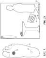
- FIG. 1schematically shows a foot having a prominent foot ulcer and a pre-ulcer.
- FIG. 2A schematically shows one use and form factor that may be implemented in accordance with illustrative embodiments of the invention.
- FIG. 2 Bschematically shows an open platform that may be configured in accordance with illustrative embodiments of the invention. This figure also shows use by an amputee with a single foot.
- FIG. 3A schematically shows an exploded view of one type of open platform that may be configured in accordance with illustrative embodiments of the invention.
- FIG. 3 Bschematically shows a close-up view of the platform with details of the pads and temperature sensors in the foot receiving region.
- FIG. 4schematically shows a network implementing illustrative embodiments of the invention.
- FIG. 5schematically shows an overview of various components of illustrative embodiments of the invention.
- FIG. 6schematically shows details of a data processing module in accordance with illustrative embodiments of the invention.
- FIG. 7schematically shows a comparator configured in accordance with illustrative embodiments of the invention.
- FIG. 8shows a process of identifying potential ulcers and pre-ulcers for a single foot only in accordance with illustrative embodiments of the invention.
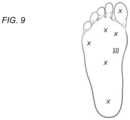
- FIG. 9schematically shows the bottom of a single foot and regions of that foot to receive temperature information in accordance with illustrative embodiments of the invention.
- a systemeffectively determines the existence of ulcers and pre-ulcers of patients with a single foot (e.g., amputees or patients with access to a single foot only, such as patients with a full foot and another partial foot).
- an ulcer detection systemdetermines a interpercentile temperature range as a function of a distribution of temperature values across prescribed parts of a single foot, and then compares that range size to a threshold value. Next, the system produces output information indicating the emergence of an ulcer or pre-ulcer when the interpercentile temperature range size equals or exceeds the threshold value. Details of illustrative embodiments are discussed below.
- illustrative embodimentsaim to solve these problems by analyzing the temperatures of a single foot to determine various pathologies related to inflammation in the foot, such as diabetic foot ulcers, Charcot syndrome, claudication, and embolism.
- some patientsmay have only one foot available for foot temperature monitoring due to ongoing treatment of a wound to one foot or some other reason. As is well known by those skilled in the art, such treatment may require bandaging, casting, or use of a boot. These patients also are unable to rely on traditional approaches for foot temperature monitoring using prior art techniques known to the inventors.
- illustrative embodimentsanalyze a patient's foot to determine the risk of an ulcer emerging on its underside (i.e., on its sole). This permits patients, their healthcare providers, and/or their caregivers to intervene earlier, reducing the risk of more serious complications.
- a temperature detection modalitye.g., an open or closed platform
- the modalitymay use any of a variety of different processes, discussed in detail below, such as comparing one or more portions of the foot, or an interpercentile range of temperatures, to some prescribed other value, such as the environmental/ambient temperature, a prescribed threshold, or the temperature of another portion of the foot.
- various embodimentsproduce output information indicating whether an ulcer or pre-ulcer will/has emerged, and/or the progression of a known ulcer or pre-ulcer.
- FIG. 1schematically shows a bottom view of a patient's foot 10 that, undesirably, has an ulcer 12 and a pre-ulcer 14 (described below and shown in phantom since pre-ulcers 14 do not break through the skin).
- an ulcer 12 on this part of the foot 10typically is referred to as a “foot ulcer 12 .”
- an ulceris an open sore on a surface of the body generally caused by a breakdown in the skin or mucous membrane.
- Diabeticsoften develop foot ulcers 12 on the soles of their feet 10 as part of their disease. In this setting, foot ulcers 12 often begin as a localized inflammation that may progress to skin breakdown and infection.
- diabetes and diabeticsare but one example and used here simply for illustrative purposes only. Accordingly, various embodiments apply to other types of diseases (e.g., stroke, deconditioning, sepsis, friction, coma, etc.) and other types of ulcers—such embodiments may apply generally where there is a compression or friction on the living being's body over an extended period of time. For example, various embodiments also apply to ulcers formed on different parts of the body, such as on the back (e.g., bedsores), inside of prosthetic sockets, or on the buttocks (e.g., a patient in a wheelchair). Moreover, some embodiments apply to other types of living beings beyond human beings, such as other mammals (e.g., horses or dogs). Accordingly, discussion of diabetic human patients having foot ulcers 12 is for simplicity only and not intended to limit all embodiments of the invention.
- diseasese.g., stroke, deconditioning, sepsis, friction, coma, etc.
- other types of ulcers
- illustrative embodimentsimplement an ulcer monitoring system in any of a variety of forms—preferably in an easy to use form factor or modality that facilitates and encourages regular use.
- One such modality/form factorinvolves a platform having a base and receiving region for receiving the foot (both discussed in greater detail below).
- FIGS. 2 A and 2 Bschematically show one form factor, in which a patient/user steps on an open platform 16 that gathers data about that user's foot (or feet 10 ).
- the patienthas only one natural foot with which to gather data for making an assessment.
- the other footin this embodiment, is a prosthetic.
- Other embodimentsmay operate without a prosthetic foot, or even with only a single foot that itself has amputations (e.g., a single foot with only three toes).
- the open platform 16is in the form of a base implemented as a floor mat placed in a location where he the patient regularly stands, such as in front of a bathroom sink, next to a bed, in front of a shower, on a footrest, or integrated into a mattress.
- the patientsimply may step on the top sensing surface 13 of the platform 16 (e.g., using a prosthetic where the other foot would have been, or supported by some object) to initiate the process. Accordingly, this and other form factors often do not require that the patient affirmatively decide to interact with the platform 16 . Instead, many expected form factors are configured to be used in areas where the patient frequently stands during the course of their day without a foot covering.
- the open platform 16may be moved to directly contact the feet 10 of a patient that cannot stand. For example, if the patient is bedridden, then the platform 16 may be brought into contact with the patient's feet 10 while in bed. In this example, the patient's foot may be placed into a receiving region of the platform 16 to begin foot analysis.
- a bathroom mat or rugare but two of a wide variety of different potential form factors. Others may include a platform 16 resembling a scale, a stand, a footrest, a console, a tile built into the floor, or a more portable mechanism that receives at least one of the feet 10 .
- the implementation shown in FIGS. 2 A and 2 Bhas a top surface area that is larger than the surface area of the foot 10 of the patient. In preferred embodiments, the receiving region is large enough to receive the foot 10 . This enables a caregiver to obtain a complete view of the patient's entire sole, providing a more complete view of the foot 10 .
- the open platform 16 of various embodimentsalso has some indicia or display 18 on its top surface 13 that can have any of a number of functions.
- the indicia/display 18can turn a different color or sound an alarm after the readings are complete, show the progression of the process, or display results of the process.
- the indicia or display 18can be at any location other than on the top surface 13 of the open platform 16 , such as on the side, or a separate component that communicates with the open platform 16 .
- the platform 16may have other types of indicia, such as tactile indicia/feedback, our thermal indicia.
- alternative embodimentsmay be implemented as a closed platform 16 , such as a shoe, shoe insert, insole, slipper or sock that can be regularly worn by a patient, or worn on an as-needed basis.
- the insole of the patient's shoe or bootmay have the functionality for detecting the emergence of a pre-ulcer 14 or ulcer 12 , and/or monitoring a pre-ulcer 14 or ulcer 12 .
- Positioning the foot appropriately in such a platform to the receiving regionthus should be easier since the closed platform 16 may include features that guide the foot to the appropriate location (e.g., the natural outside of the platform 16 , specialized extra elements, or other apparatus).
- FIG. 3schematically shows an exploded view of the open platform 16 configured and arranged in accordance with one embodiment of the invention.
- this embodimentis but one of a number of potential implementation and, like other features, is discussed by example only.
- the platform 16is formed as a stack of functional layers sandwiched between a cover 20 and a rigid base 22 .
- the base 22preferably has rubberized or has other non-skid features on its bottom side.
- FIG. 3 Ashows one embodiment of this non-skid feature as a non-skid base 24 .
- the platform 16preferably has relatively thin profile to avoid tripping the patient and making it easy to use.
- the platform 16has a receiving region 17 on the top platform surface for receiving the foot 10 .
- This receiving region 17is specially configured to communicate with the underside of the foot 1 10 .
- the receiving region 17has an array, matrix, or other prescribed arrangement of temperature sensors 26 fixed in place directly underneath the cover 20 . More specifically, the temperature sensors 26 are positioned on a relatively large printed circuit board 28 .
- the sensors 26preferably are laid out in a two-dimensional array/matrix of stationary contact sensors on the printed circuit board 28 . In some embodiments, the pitch or distance between the preferably may be relatively small, thus permitting more temperature sensors 26 on the array.
- the temperature sensors 26may include temperature sensitive resistors (e.g., printed or discrete components mounted onto the circuit board 28 ), graphene temperature sensors, thermocouples, fiberoptic temperature sensors, or a thermochromic film. Accordingly, when used with temperature sensors 26 that require direct contact, illustrative embodiments form the cover 20 with a thin material having a relatively high thermal conductivity.
- the platform 16also may use temperature sensors 26 that can still detect temperature through a patient's socks.
- noncontact temperature sensors 26such as infrared detectors.
- the cover 20may have openings to provide a line of sight from the sensors 26 to the sole of the foot 10 . Accordingly, discussion of contact sensors is by example only and not intended to limit various embodiments.
- the plurality of sensors 26generate a plurality of corresponding temperature data values for a plurality of portions/spots on the patient's foot 10 to monitor the health of the foot 10 .
- Some embodimentsmay have a smaller number of temperature sensors 26 that are spaced apart (e.g., the distance between the sensors 26 is many times the largest dimension of the sensors 26 themselves, such as ten times or more).
- some embodiments of the receiving region 17may have as few as four or six sensors 26 spaced apart at prescribed portions of the platform (e.g., see FIG. 9 , discussed below).
- Use of fewer temperature sensors 26may be assisted by indicia or other means for directing a patient on the appropriate location for their foot to contact the top surface 13 of the cover 20 —to align the foot with the appropriate sensors 26 .
- Illustrative embodiments with a larger array of temperature sensors 26may not require such assistance. Instead, such latter embodiments may determine the orientation and location of specific sensors to determine the desired smaller number of temperature values required (see below processes for further information on this process).
- Some embodimentsthus also may use pressure sensors for various functions, such as to determine the orientation of the feet 10 and/or to automatically begin the measurement process.
- the pressure sensorsmay include piezoelectric, resistive, capacitive, or fiber-optic pressure sensors.
- This layer of the platform 16also may have additional sensor modalities beyond temperature sensors 26 and pressure sensors, such as positioning sensors, GPS sensors, accelerometers, gyroscopes, and others known by those skilled in the art.
- illustrative embodiments for performing thermal analysis of a footmay obtain temperature input from a variety of sensor types, including thermal cameras, open platforms with contact or non-contact temperature sensors, socks, shoes, insoles, bandages, wraps, individual point temperature measurements by hand.
- Temperature sensorsmay include infrared photodiodes, phototransistors, resistive temperature detectors, thermistors, thermocouples, fiberoptic, thermochromic sensors.
- Those skilled in the artshould understand that these temperature sensing modalities and sensor types are examples of options available for use, and that some or all of the analysis methods described below are not dependent on the sensor modality employed in the system.
- FIG. 3 Bschematically shows a small portion of the array of temperature sensors 26 showing four temperature sensors 26 and their pads 30 .
- the temperature sensors 26are drawn in phantom because they preferably are covered by the pads 30 . Some embodiments do not cover the sensors 26 , however, and simply thermally connect the sensors 26 with the pads 26 .
- each temperature sensor 26 in this embodimenthas an associated heat conducting pad 30 that channels heat from one two-dimensional portion of the foot 10 (considered a two dimensional area although the foot may have some depth dimensionality) directly to its exposed surface 13 .
- the array of conducting pads 30preferably takes up the substantial majority of the total surface area of the printed circuit board 28 . The distance between the pads 30 thermally isolates them from one another, thus eliminating thermal short-circuits.
- each pad 30may have a square shape with each side having a length of between about 0.1 and 1.0 inches. In the larger sensor arrays, the pitch between pads 30 thus is less than that amount. Accordingly, as a further detailed example, some embodiments may space the temperature sensors 26 about 0.4 inches apart with 0.25 inch (per side) square pads 30 oriented so that each sensor 26 is at the center of the square pads 30 . This leaves an open region (i.e., a pitch) of about 0.15 inches between the square pads 30 .
- the pads 30may be formed from a film of thermally conductive metal, such as a copper. Some embodiments that use fewer sensors 26 , such as those that use six sensors to align with prescribed portions of the foot (e.g., see FIG. 9 , discussed below), may space the pads farther apart to gather data about one specific sector/portion of the foot 10 .
- some embodimentsdo not use an array of temperature sensors 26 .
- a single temperature sensor 26that can obtain a temperature reading of most or all of the sole.
- a single sheet of a heat reactive materialsuch as a thermochromic film (noted above), or similar apparatus should suffice.
- a thermochromic filmbased on liquid crystal technology, has internal liquid crystals that reorient to produce an apparent change in color in response to a temperature change, typically above the ambient temperature.
- one or more individual temperature sensors 26such as thermocouples or temperature sensor resistors, may be movable to take repeated temperature readings across the bottom of the foot 10 .
- thermochromic filmmay have a plurality of temperature sensors 26 that provide enough data to form a thermogram.
- specific locations of interestmay be used to perform various comparisons and analyses.
- a thermal cameraalso may be integrated into one of the noted modalities, used in conjunction with another of those modalities (e.g., an open or closed platform in that case may not use temperature sensors 26 in that case), or used with the relevant system components in place of one of the noted modalities.
- the base 22 of the platform/modalitymay include other similar structure that supports various other components, such as, in some cases, temperature sensors 26 .
- the base 22may include the insole.
- the open platform 16should be configured so that its top surface 13 contacts substantially the entire sole of the patient's foot 10 .
- the platform 16has a flexible and movable layer of foam 32 or other material that at least generally conforms to the user's foot 10 .
- this layershould conform to the arch of the foot 10 .
- the sensors 26 , printed circuit board 28 , and cover 20also may be similarly flexible and yet robust to conform to the foot 10 in a corresponding manner.
- the printed circuit board 28preferably is formed largely from a flexible material that supports the circuit.
- the printed circuit board 28may be formed primarily from a flex circuit that supports the temperature sensors 26 , or it may be formed from strips of material that individually flex when receiving feet. Alternative embodiments may not have such flexibility (e.g., formed from conventional printed circuit board material, such as FR-4) and thus, produce less effective data.
- the rigid base 22 positioned between the foam 32 and the non-skid base 24provides rigidity to the overall base structure.
- the rigid base 22is contoured to receive a motherboard 34 , a battery pack 36 , a circuit housing 38 , and additional circuit components that provide further functionality.
- the motherboard 34may contain integrated circuits and microprocessors that control the functionality of the platform 16 .
- the motherboard 34also may have a user interface/indicia display 18 as discussed above, and a communication interface to connect to a larger network 44 , such as the Internet.
- the communication interfacemay connect wirelessly or through a wired connection with the larger network 44 , implementing any of a variety of different data communication protocols, such as Ethernet.
- the communication interface 40can communicate through an embedded Bluetooth or other short range wireless radio that communicates with a cellular telephone network 44 (e.g., a 3G or 4G network).
- the platform 16also may have edging 42 and other surface features that improve its aesthetic appearance and feel to the patient.
- the layersmay be secured together using one or more of an adhesive, snaps, nuts, bolts, or other fastening devices.
- the platform 16may also be tapered at its edges to prevent the platform 16 from being a tripping hazard to the user.
- FIG. 4schematically shows one way in which the platform 16 can communicate with a larger data network 44 in accordance with various embodiments the invention.
- the platform 16may connect with the Internet through a local router, through its local area network, or directly without an intervening device.
- This larger data network 44e.g., the Internet
- the platform 16may communicate with an analysis engine 46 that analyzes the thermal data from the platform 16 and determines the health of the patient's foot 10 .
- the platform 16also may communicate directly with a healthcare provider 48 , such as a doctor, nurse, relative, and/or organization charged with managing the patient's care.
- a healthcare provider 48such as a doctor, nurse, relative, and/or organization charged with managing the patient's care.
- the platform 16also can communicate with the patient, such as through text message, telephone call, e-mail communication, or other modalities as the system permits.
- FIG. 5schematically shows a block diagram of a foot monitoring system, showing the platform 16 and the network 44 with its interconnected components in more detail.
- the patientcommunicates with the platform 16 by standing on or being received in some manner by the receiving region 17 having the sensors 26 , which is represented in this figure as a “sensor matrix 52 ” (although other embodiments of the sensors 26 are not arranged as a matrix).
- a data acquisition block 54implemented by, for example, the motherboard 34 and circuitry shown in FIG. 3 , controls acquisition of the temperature and other data for storage in a data storage device 56 .
- the data storage device 56can be a volatile or nonvolatile storage medium, such as a hard drive, high-speed random-access-memory (“RAM”), or solid-state memory.
- the input/output interface port 58also controlled by the motherboard 34 and other electronics on the platform 16 , selectively transmits or forwards the acquired data from the storage device to the analysis engine 46 on a remote computing device, such as a server 60 .
- the data acquisition block 54also may control the user indicators/displays 18 , which provide feedback to the user through the above mentioned indicia (e.g., audible, visual, or tactile).
- the analysis engine 46on the remote server 60 , analyzes the data received from the platform 16 in conjunction with a health data analytics module 62 .
- a server output interface 64forwards the processed output information/data from the analysis engine 46 and health data analytics module 62 toward others across the network 44 , such as to a provider, a web display, or to the user via a phone, e-mail alert, text alert, or other similar way.
- This output messagemay have the output information in its relatively raw form for further processing.
- this output messagemay have the output information formatted in a high-level manner for easy review by automated logic or a person viewing the data.
- the output messagemay indicate the actual emergence of an ulcer 12 or a pre-ulcer 14 , the risk of the emergence of an ulcer 12 or a pre-ulcer 14 , or simply that the foot 10 is healthy and has no risks of ulcer 12 or pre-ulcer 14 .
- this output messagealso may have information that helps an end-user or healthcare provider 48 monitor an ulcer 12 or pre-ulcer 14 .
- Using a distributed processing arrangement like that shown in FIG. 5has a number of benefits. Among other things, it permits the platform 16 to have relatively simple and inexpensive components that are unobtrusive to the patient. Moreover, this permits a “software-as-a-service” business model (“SAAS model”), which, among other things, permits more flexibility in the functionality, typically easier patient monitoring, and more rapid functional updates. In addition, the SAAS model facilitates accumulation of patient data to improve analytic capability.
- SAAS modelsoftware-as-a-service business model
- Some embodimentsmay distribute and physically position the functional components in a different manner.
- the platform 16may have the analysis engine 46 on its local motherboard 34 .
- some embodimentsprovide the functionality entirely on the platform 16 and/or within other components in the local vicinity of the platform 16 .
- all of those functional elementse.g., the analysis engine 46 and other functional elements
- FIG. 6shows several functional blocks that, with other functional blocks, may be configured to perform the functions of the analysis engine 46 . This figure simply shows the blocks and is illustrative of one way of implementing various embodiments.
- the analysis engine 46 of FIG. 6may have a thermogram generator 66 configured to form a thermogram of the patient's foot 10 or feet 10 (if a thermogram is to be used in the analysis) based on a plurality of temperature readings from the bottom of the foot 10 , and a pattern recognition system 68 configured to determine whether the thermogram presents any of a number of different prescribed patterns. Pattern data and other information may be stored in a local memory 76 . As discussed below, if the thermogram and/or the plurality of temperature readings presents any of these prescribed patterns, then the foot 10 may be unhealthy in some manner (e.g., having a pre-ulcer 14 or an ulcer 12 ).
- the analysis engine 46also has an analyzer 70 configured to produce the above noted output information, which indicates any of a number of different conditions of the foot 10 .
- the output informationmay indicate the risk that an ulcer 12 will emerge, the emergence of a pre-ulcer 14 (i.e., the first indication of a pre-ulcer 14 ), the progression of a known ulcer 12 , or the emergence of a new ulcer 12 (i.e., the first indication of any given ulcer 12 to the patient and associated support).
- FIGS. 5 and 6only schematically show each of the noted components and a single embodiment.
- the analyzer 70may be implemented using a plurality of microprocessors executing firmware.
- the analyzer 70may be implemented using one or more application specific integrated circuits (i.e., “ASICs”) and related software, or a combination of ASICs, discrete electronic components (e.g., transistors), and microprocessors.
- ASICsapplication specific integrated circuits
- the representation of the analyzer 70 and other components in a single box of FIG. 5is for simplicity purposes only.
- the analyzer 70 of FIG. 5is distributed across a plurality of different machines—not necessarily within the same housing or chassis.
- Illustrative embodimentsuse one or combinations of various methods/processes/techniques, along with prescribed physical modalities, to assess and make determinations about foot health using a single foot only. Specifically, illustrative embodiments may use one or combinations of one or more methods/techniques to make ipsilateral temperature comparisons. To make those assessments and determinations, illustrative embodiments use a comparator 80 , such as that shown in FIG. 7 . As previously noted, the comparator 80 can be used as part of the system of FIG. 5 (e.g., part of the analysis engine 46 or other component of the analysis engine 46 ), as a separate component local to or remote from the platform 16 , or as an adjunct with the system of FIG. 5 .
- FIG. 7simply shows a bus 79 communicating each the components.
- bus 79communicating each the components.
- FIG. 7only schematically shows each of these components. Accordingly, in a similar manner, those skilled in the art should understand that each of these components can be implemented in a variety of conventional manners, such as by using hardware, software, or a combination of hardware and software, across one or more other functional components.
- a distribution processor 86may be implemented using a plurality of microprocessors executing firmware.
- the distribution processor 86may be implemented using one or more application specific integrated circuits (i.e., “ASICs”) and related software, or a combination of ASICs, discrete electronic components (e.g., transistors), and microprocessors. Accordingly, the representation of the distribution processor 86 and other components in a single box of FIG. 7 is for simplicity purposes only. In fact, in some embodiments, the distribution processor 86 is distributed across a plurality of different machines—not necessarily within the same housing or chassis.
- FIG. 7is a simplified representation of an actual comparator. Those skilled in the art should understand that such a device may have many other physical and functional components, such as central processing units, other data processing modules, and short-term memory. Accordingly, this discussion is in no way intended to suggest that FIG. 7 represents all of the elements of a comparator.
- the comparator 80has an input 82 for receiving data and an output 84 for processing and/or forwarding processed data.
- the output 84 and other componentsmay be part of the same physical device (e.g., coupled with the platform 16 or base 22 ), or separate (e.g., components across the Internet or other network).
- the output datamay have additional functionality to, either alone or with other components, produce ulcer information relating to the emergence of an ulcer or pre-ulcer.
- the comparator 80also has a distribution processor 86 configured to determine the distribution of temperature values produced by the temperature sensors 26 , and a tendency processor 88 to determine tendency data from the temperature values (e.g., the mean, median, and/or mode).
- the comparator 80also has a comparison processor 90 configured to compare various values.
- the comparison processor 90may effectively form one or more comparison processors 90 to compare various items, such as an interpercentile range to a threshold value, or to compare a tendency statistic to another threshold value.
- the comparison processor 90may have the functionality to make other comparisons. Accordingly, as noted above, representation of the comparison processor 90 as a single box in the figure is merely schematic and not intended to imply a single comparison processor 90 with a single function.
- the systemdetermines an interpercentile range of temperatures at prescribed portions of the single foot using a temperature distribution, and compares the that range with a prescribed threshold value. If size of the range is equal to or exceeds the threshold value, then the system may indicate that the single foot may require further assistance due to a potential ulcer or pre-ulcer. In fact, the results in some embodiments may also indicate a potentially ischemic condition with the single foot.
- a temperature distribution in this contextincludes a statistical function that describes the possible temperatures values and likelihoods of those values sampled on the foot.
- the temperature distributionalso may comprise a finite set of specific temperature values, including a set having the measured temperature values only, or a set having the measured temperature values and other temperature values derived from the measured temperature values. Some of the data in the distribution may be calculated and/or some of the data in the distribution may be actual (e.g., actual temperature detected by a temperature sensor 26 ).
- the data in a temperature distributionis considered to form a plurality of percentiles. For example, if the distribution has 100 different temperature values, each temperature value would by definition be in a different percentile—from the zero percentile to the one hundredth percentile (in this case, each would be a whole number percentile). Illustrative embodiments take advantage of a range of these percentiles, known as the “interpercentile range” (discussed above and below) to determine foot health. In particular, the interpercentile range is the difference of temperature values at two different percentiles in the dynamic range.
- some embodimentsmay determine the difference between the end-point percentiles (e.g., the zero percentile and the one hundred percentile values), while others may determine the difference between temperature values (either estimated/interpolated/calculated or actual) between other percentiles. Still other embodiments may use temperature values at one of the end-point percentiles and some other non-end-point percentile (e.g., between the zero percentile and the ninetieth percentile). Those skilled in the art can select the appropriate interpercentile range.
- FIG. 8shows a process of identifying potential ulcers and pre-ulcers for a single foot only in accordance with illustrative embodiments of the invention. It should be noted that this process (and others discussed below) is substantially simplified from a longer process that normally would be used to identify potential ulcers and pre-ulcers. Accordingly, the process can have other steps that those skilled in the art likely would use. In addition, some of the steps may be performed in a different order than that shown, or at the same time. Those skilled in the art therefore can modify the process as appropriate.
- the process of FIG. 8begins at step 800 , in which the foot communicates with the receiving region 17 of the platform 16 .
- the patientmay step onto the top surface 13 of the open platform 16 .
- the single, natural foot 10 of the patientpreferably stands on the receiving region 17 of the platform 16 , such as the portion having the spaced apart temperature sensors 26 .
- the patientmay insert their foot into a shoe, sock or similar device and contact the foot receiving region 17 in that modality.
- the temperature sensors 26may directly or indirectly conductively contact the foot, or may contact the foot in other ways, such as using optics to take non-contact temperature measurements at the specific foot locations.
- the top surface 13may be considered to act at least in part as the input 82 to the comparator 80 of FIG. 7
- FIG. 9schematically shows the general positions of the temperature sensors 26 relative to the bottom of the foot, when the foot 10 is properly positioned in the receiving region 17 , in illustrative embodiments of the invention. Indeed, some embodiments may have six sensors 26 , while others may have more or fewer (e.g., four sensors, six sensors, one hundred sensors, or a range between two of those numbers). The sensor locations in this figure are shown generically with an “X.”
- step 802which activates the temperature sensors 26 .
- the temperature sensors 26may be activated manually, automatically, or virtually before, during, or after the patient communicates their foot to the platform 16 .
- powermay be applied to the temperature sensors 26 by manually selecting or switching a power switch to an on position, virtually switching on the power via a software application, or automatically by logic or contact sensor (not shown) on the platform 16 sensing the foot 10 in the receiving region 17 .
- the distribution processor 86produces a distribution of the temperatures detected by the temperature sensors 26 ( 804 ) and, using that distribution, forms the interpercentile range (step 806 ).
- the distribution processor 86may determine the percentiles of the data from the temperature distribution, and then determine which two percentiles to use to form the interpercentile range. That may be a simple process of simply taking the difference between the maximum and minimum temperature values (i.e., the end-points of the temperature range). Other embodiments, however, may be configured, either manually or automatically (e.g., using a database), to select some other percentile within the temperature range.
- the interpercentile rangemay use temperature values between the first percentile and the ninety-ninth percentile.
- these valuesmay be actual values or calculated from the set of temperature values used to form the temperature distribution.
- Using one or more non-end-point percentilesmay advantageously reduce noise (e.g., the lowest temperature data point may have not adequately communicated with its temperature sensor 26 and therefore, appears much colder than its actual temperature.
- the distributionmay simply include actual temperature values or a relatively small set of temperature values that are both actual and calculated. Step 806 therefore may simply select any two of these values to effectively form the interpercentile range without affirmatively calculating the percentiles.
- the distribution processor 86compares the interpercentile range temperature value (i.e., a temperature difference) against a prescribed or other threshold value (i.e., another temperature value). That threshold value should be carefully chosen and be consistent with the percentiles selected and other known information (e.g., patient information, modality information, etc.).
- a threshold valuefrom about 1 to about 4 degrees C. should provide satisfactory results.
- the inventorsdiscovered that a value between about 1.4 degrees C. and about 2.8 degrees C. produced even better results.
- the patient's footmay have a health issue, such as an ulcer or pre-ulcer.
- a health issuesuch as an ulcer or pre-ulcer.
- the inventorswere surprised to discover that this comparison produced accurate results a significant proportion of the time when using the discussed modalities (e.g., the platforms 16 with the receiving region 17 , sensors 26 that actuate as required, etc.).
- results of this typecan often be dominated by noise producing a high or low end of the range that is well beyond those of the actual end points without the noise.
- the inventorswere concerned that a toe may not sufficiently contact a contact temperature sensor 26 , thus appearing cold and producing a much lower low end of the range. They recognized, however, that with closed platforms 16 , as well as with open platforms 16 , these noise based extremes were less of an issue than originally expected. The platform 16 and its receiving region 17 therefore may obviate these issues.
- this comparisonalso can signal an ischemic condition in the foot 10 that requires treatment. Accordingly, this process may alert a patient and/or caregiver to two potentially common dangerous and life threatening conditions for diabetics—foot ischemia and foot ulcers/pre-ulcers. Accordingly, the range of a set of foot temperature data captures both abnormally warm locations and abnormally cool locations and conveniently presents it as a single statistic that can be easily compared to a threshold.
- some embodimentsmay measure the temperature of a continuous region on the foot. If necessary, this embodiment may exclude the data within a margin from the edges of the foot. After measuring that temperature, this embodiment calculates the range of temperatures within the region and compares the range to a predetermined threshold to determine if the temperature pattern is indicative of some pathology. This alternative embodiments also effectively performs steps 804 - 808 .
- step 810which considers whether the foot requires further processing to provide even more accurate results. This may be required in certain applications, or be unnecessary.
- Some embodimentshave a selectable user interface to augment steps 800 - 808 with one of the below listed processes. Specifically, the method may execute further processes that include one or more of the following (step 812 ):
- the temperatures at any two locations on the foot 10may be compared.
- the heelmay serve as a stable reference point due to its relative temperature stability over time compared to more distal portions of the foot 10 .
- Individual locationsmay be compared to a statistic that summarizes the temperatures over the whole foot 10 instead of relying on a single location for comparison, which may present with unstable temperature patterns over time.
- the absolute temperature at a given timeis not as informative as the change in temperatures over time.
- Chronic conditionsmay present as slow changes over a long time and acute conditions may present as fast onset or short-lived patterns.
- Comparing foot temperature with ambient temperatureprovides an opportunity to detect inflammation in the foot 10 in cases where there may be no spatial variation within the foot 10 although the entire foot 10 is inflamed and at elevated temperature.
- This methodis similar to Process 4, but less susceptible to intermittent or irregular fluctuations in ambient temperature due to changing environmental conditions. Comparing foot temperature with body temperature may provide a more accurate basis for detecting pathology by accounting for external variables that affect foot temperature.
- the size of a region of elevated temperaturemay be more informative than the specific temperature of that region for certain pathologies, such as monitoring wound healing.
- step 814which produces electronic output information, using the output 84 , having data relating to the analysis.
- this datamay be in a form that is readily human understandable and/or storable, or may be in a format that needs further processing.
- This output informationthus may include ulcer information relating to the emergence of an ulcer or pre-ulcer when the percentage of the range size equals or exceeds the threshold value.
- the output informationmay have information indicating the presence of a pre-ulcer and the data around the steps performed and the temperature values, ranges, and/or differences, depending on the steps performed.
- This output informationalso may have information relating to an ischemic foot condition.
- the output informationalternatively may have information indicating that the foot 10 is healthy and has no maladies (e.g., if the percentage of the range size is less than the threshold value. Indeed, the output information also may have information relating to one or more of the additional processes noted above.
- resultsmay have an accuracy that may be higher or lower depending on the configuration of the system.
- the systemmay be 90 percent accurate, for example, it is not perfect and may have some false positives and false negatives.
- the platform 16 , base, receiving region 17 , sensors 26 , etc.can be configured to optimize performance.
- some of the above noted process options and their variantsmay detect one distinct type of pathology in the foot 10 and can be optimized to detect that pathology with a high degree of sensitivity and specificity.
- just using one methodmay not generalize to other types of pathologies. For example, comparing the temperature of the hallux with the heel is beneficial to determine if the hallux may have localized inflammation. However, if the whole foot 10 is inflamed, the temperature difference between those locations will not be significant and may therefore not detect the systemic inflammation.
- the inventorsdiscovered that combining this with another method, such as comparing the heel temperature with ambient temperature to detect systemic inflammation, may improve the probability of detecting either pathological condition.
- illustrative embodimentsmay combine two or more of noted processes and/or their variants. For example, two or more of those methods may be combined with simple logical terms or in linear combinations to provide a more accurate prediction. For example, some embodiments combine two of the processes, three of the processes, four of the processes, five of the processes, six of the processes, seven of the processes, or one or more of the processes with another process not discussed.
- two or more of the above noted processesare combined with OR statements. For example, if Process 1 is true OR Process 2 is true, then the probability of pathology is high. This combination has the benefit of allowing specialization of the processes to detect certain types of pathologies and naturally increases the sensitivity of the detection system across multiple pathologies.
- processesmay be combined with AND statements. For example, if Process 1 is true AND Process 2 is true, then the probability of pathology is high. This combination thus may create a highly specific detection process.
- processesmay be combined as a linear combination of continuous or categorical outputs.
- the combined formulationmay multiply each process variable by a coefficient in order to obtain a final result which may then be used to determine the probability of a pathology.
- thresholdsmay be done on a per-process basis or for a set of processes in whatever combinations are used to optimize the sensitivity and specificity of the combined set of processes.
- the magnitude of any of the metrics given in the discussed processescan also be informative of risk. For example, a large difference in the temperature difference described in Process 1 may indicate higher risk than a lower magnitude temperature difference.
- embodiments of the inventionmay be implemented at least in part in any conventional computer programming language. For example, some embodiments may be implemented in a procedural programming language (e.g., “C”), or in an object oriented programming language (e.g., “C++”). Other embodiments of the invention may be implemented as preprogrammed hardware elements (e.g., application specific integrated circuits, FPGAs, and digital signal processors), or other related components.
- Cprocedural programming language
- object oriented programming languagee.g., “C++”.
- preprogrammed hardware elementse.g., application specific integrated circuits, FPGAs, and digital signal processors
- the disclosed apparatus and methodsmay be implemented as a computer program product (or in a computer process) for use with a computer system.
- Such implementationmay include a series of computer instructions fixed either on a tangible medium, such as a computer readable medium (e.g., a diskette, CD-ROM, ROM, or fixed disk) or transmittable to a computer system, via a modem or other interface device, such as a communications adapter connected to a network over a medium.
- the mediummay be either a tangible medium (e.g., optical or analog communications lines) or a medium implemented with wireless techniques (e.g., WIFI, microwave, infrared or other transmission techniques).
- the mediumalso may be a non-transient medium.
- the series of computer instructionscan embody all or part of the functionality previously described herein with respect to the system.
- the processes described hereinare merely exemplary and it is understood that various alternatives, mathematical equivalents, or derivations thereof fall within the scope of the present invention.
- Such computer instructionscan be written in a number of programming languages for use with many computer architectures or operating systems.
- such instructionsmay be stored in any memory device, such as semiconductor, magnetic, optical or other memory devices, and may be transmitted using any communications technology, such as optical, infrared, microwave, or other transmission technologies.
- such a computer program productmay be distributed as a removable medium with accompanying printed or electronic documentation (e.g., shrink wrapped software), preloaded with a computer system (e.g., on system ROM or fixed disk), or distributed from a server or electronic bulletin board over the larger network (e.g., the Internet or World Wide Web).
- a computer systeme.g., on system ROM or fixed disk
- a server or electronic bulletin boardover the larger network
- some embodiments of the inventionmay be implemented as a combination of both software (e.g., a computer program product) and hardware. Still other embodiments of the invention are implemented as entirely hardware, or entirely software.
Landscapes
- Health & Medical Sciences (AREA)
- Life Sciences & Earth Sciences (AREA)
- Engineering & Computer Science (AREA)
- Medical Informatics (AREA)
- Public Health (AREA)
- General Health & Medical Sciences (AREA)
- Pathology (AREA)
- Biomedical Technology (AREA)
- Animal Behavior & Ethology (AREA)
- Heart & Thoracic Surgery (AREA)
- Molecular Biology (AREA)
- Surgery (AREA)
- Biophysics (AREA)
- Physics & Mathematics (AREA)
- Veterinary Medicine (AREA)
- Physiology (AREA)
- Computer Vision & Pattern Recognition (AREA)
- Artificial Intelligence (AREA)
- Psychiatry (AREA)
- Signal Processing (AREA)
- Dermatology (AREA)
- Computer Networks & Wireless Communication (AREA)
- Data Mining & Analysis (AREA)
- Databases & Information Systems (AREA)
- Epidemiology (AREA)
- Primary Health Care (AREA)
- Measuring And Recording Apparatus For Diagnosis (AREA)
Abstract
Description
- U.S. Pat. No. 9,271,672, issued on Mar. 1, 2016, entitled, “METHOD AND APPARATUS FOR INDICATING EMERGENCE OF AN ULCER,” and naming David Robert Linders, Jonathan David Bloom, Jeffrey Mark Engler, Brian Jude Petersen, Adam Geboff, and David Charles Kale, and as inventors.
- Variant A: Absolute value above certain threshold.
- Measure the temperature at two locations, calculate the absolute value of the difference between the two locations, and compare the difference to a predetermined threshold (e.g., two degrees C.) to determine if the temperature pattern is indicative of some pathology.
- Variant B: Asymmetric threshold.
- Measure the temperature at two locations on the
foot 10. Subtract the temperature a Location1 from a Location2 and compare the difference to a Threshold A. Then subtract Location2 from Location1 and compare it to Threshold B, where Threshold A is different from Threshold B. Then determine if either of the differences exceed the two different predetermined thresholds. This variant has the advantage of enabling detection of pathologies that result in an abnormally warm region as well as pathologies that may result in an abnormally cool region where the definition of abnormal is dependent on whether the region is warmer or cooler than another region. - Variant C: Unique thresholds for different locations.
- Measure the temperature at three locations on the
foot 10. Subtract Location1 from Location2 and compare it to Threshold A. Then subtract Location3 from Location2 and compare it to Threshold B. Then determine if either of the differences exceed the two different predetermined thresholds. This variant enables optimizing accuracy for various anatomical locations. For example, the toes may require a higher threshold than the heel because of the greater temperature variation at more distal regions of thefoot 10.
- Variant A: Comparison to a central tendency statistic (such as the mean or median).
- Measure the temperature over a plurality of discrete locations or over a continuous portion of the
foot 10 and use thetendency processor 88 to calculate the mean or median temperature. Measure the temperature of another location either within the region of the average or outside of it. Then subtract the average from the temperature in the location of interest and compare it to a threshold. - Variant B: Comparison to the minimum.
- Calculate the minimum temperature among a set of discrete temperature values or from within a continuous portion of the
foot 10. If using a continuous portion of thefoot 10, the region may exclude the data within a certain margin from the edges of thefoot 10. Measure the temperature of another location either within the region of the average or outside of it. Then subtract the minimum from the temperature in the location of interest and compare it to a threshold. - Variant C: Comparison to a percentile.
- Similar to Variant B, except instead of calculating the minimum temperature value for comparison, calculate a predetermined percentile, such as the 10th percentile. This approach avoids extremes in the distribution of temperature at the low or the high side, which may result in inaccurate analyses.
- Variant D: Comparison with a statistical distribution.
- Compute a statistical distribution of the temperatures among a set of discrete temperature values or from within a continuous portion of the
foot 10. Measure the temperature of another location either within the region of the average or outside of it. Then determine if the location of interest is within the distribution using common statistical methods.
- Variant A: Simple threshold above a baseline.
- Illustrative embodiments measure and store the foot temperature at a baseline time reference. Then for a later time t, this embodiment measures the foot temperature again and compares the temperatures at time t with the temperatures at baseline and determines if any location has changed in temperature from the baseline more than a predetermined threshold. Alternatively, this embodiment may measure the difference in temperatures between locations on the
foot 10 and compare the spatial differences with the baseline spatial differences. This method has the advantage of personalizing the analysis to an individual's idiosyncratic foot temperature patterns. However, it assumes that the baseline temperatures are a healthy reference location, which may not be true for individuals healing from a recent wound or with other active pathology. - Variant B: Moving average baseline.
- In a related embodiment, the baseline temperatures may be calculated as a moving average or a filtered resultant from a time series of multiple sets of temperature data from various locations in time. The average may be taken from a small number of samples to optimize for detecting acute changes in foot temperatures or from a large number of samples to optimize for detecting subtle changes or chronic conditions.
- Variant C: Integral of temperature change over time.
- In yet another embodiment, the foot temperatures may be compared to a baseline reference or a static threshold for each set of data values in a time series of samples. These comparisons may then be summed, integrated, or otherwise aggregated to generate a summary statistic for the change over time. This approach has an advantage of emphasizing persistent changes over time while filtering out noisy or inconsistent temperature fluctuations.
- Variant D: Change in temperature as a response to a stimulus.
- In yet another embodiment, the foot's response to a stimulus may be monitored over time. For example, when a foot is placed on a cold or room temperature platform, its response to that exposure over several seconds to several minutes may indicate the vascular health of the foot and the ability of the blood vessels to supply fresh blood to warm the foot. In another example, a foot's thermal response to exercise or other physical activity such as walking may indicate its neurological or vascular health. For example, a foot that becomes abnormally warm during physical activity may lack the physiological mechanisms to thermoregulate.
- Variant A: Compare a central tendency statistic to ambient. This embodiment measure the ambient temperature using either background signal from the temperature sensor26 (e.g., the background of a thermal camera image or non-foot region from a 2D temperature scan) or from a
separate temperature sensor 26 that is not measuring foot temperature. This embodiment also measures the temperature across thefoot 10 and calculates a central tendency statistic (e.g., mean, median, mode). Next, this embodiment compares the central tendency statistic to the ambient temperature and determines if the difference exceeds a predetermined threshold. - Variant B: Compare a specific location to ambient.
- A related embodiment measures ambient temperature, and then measures the foot temperature at a specific location or region on the
foot 10. It then compares the temperature at that location to ambient temperature and determines if the difference exceeds a predetermined threshold. This variant has a benefit of allowing the clinician or researcher to select a consistent location on thefoot 10 with relatively stable temperatures that is not as susceptible to environmental or other temporary perturbations as other locations. - Variant C: Compare the maximum to ambient.
- Another related embodiment measures ambient temperature, and then measures the foot temperatures over the
whole foot 10 and calculates the maximum temperature of thefoot 10. It then compares the maximum to ambient temperature and determines if the difference exceeds a predetermined threshold. This variant is expected to provide good sensitivity in cases where the warmest portion of thefoot 10 may move from scan to scan.
- Variant A: Compare a central tendency statistic to ambient. This embodiment measure the ambient temperature using either background signal from the temperature sensor26 (e.g., the background of a thermal camera image or non-foot region from a 2D temperature scan) or from a
- Variant A: Comparing to internal body temperature.
- This embodiment measures internal body temperature either at the core or preferably at the limb closest to the surface measurement location. It then compares the surface foot temperature measurements to the internal body temperature and determine if the difference exceeds a predetermined threshold.
- Variant B: limb surface temperature.
- This embodiment measures the surface temperature of the limb preferably close to the foot measurement location (e.g., ankle or leg). It then compares the surface foot temperature measurements to the surface limb temperature and determines if the difference exceeds a predetermined threshold. This variant is easier to acquire than internal body temperature as
surface temperature sensors 26 may be adhered to the skin to collect surface temperature. This approach has the added benefit of limiting the effects of ambient temperature, physical activity, and vascularity, which would affect the limb as well as thefoot 10.
- Variant A: Comparing an isothermal area.
- This embodiment chooses a comparison from any of the processes described above and calculates the difference between each location in the foot temperature data set and the comparison value. It then determines which locations, pixels, or regions are above a predetermined threshold. Next, it calculates the area of the region that exceeds that threshold in number of points, pixels, or area (e.g., cm2). It determines if the area of elevated temperature exceeds a predetermined threshold.
- Variant B: Monitoring isothermal area over time.
- This is similar to Method6, Variant A except that the determination is made as to whether the isothermal area has changed in size over time.
Claims (12)
Priority Applications (2)
| Application Number | Priority Date | Filing Date | Title |
|---|---|---|---|
| US16/653,456US11771363B2 (en) | 2018-10-15 | 2019-10-15 | Ipsilateral ulcer and pre-ulcer detection method and apparatus |
| US18/235,217US12285265B2 (en) | 2018-10-15 | 2023-08-17 | Ipsilateral ulcer and pre-ulcer detection method and apparatus |
Applications Claiming Priority (3)
| Application Number | Priority Date | Filing Date | Title |
|---|---|---|---|
| US201862745925P | 2018-10-15 | 2018-10-15 | |
| US201862752589P | 2018-10-30 | 2018-10-30 | |
| US16/653,456US11771363B2 (en) | 2018-10-15 | 2019-10-15 | Ipsilateral ulcer and pre-ulcer detection method and apparatus |
Related Child Applications (1)
| Application Number | Title | Priority Date | Filing Date |
|---|---|---|---|
| US18/235,217ContinuationUS12285265B2 (en) | 2018-10-15 | 2023-08-17 | Ipsilateral ulcer and pre-ulcer detection method and apparatus |
Publications (2)
| Publication Number | Publication Date |
|---|---|
| US20200113510A1 US20200113510A1 (en) | 2020-04-16 |
| US11771363B2true US11771363B2 (en) | 2023-10-03 |
Family
ID=70161261
Family Applications (2)
| Application Number | Title | Priority Date | Filing Date |
|---|---|---|---|
| US16/653,456Active2041-06-16US11771363B2 (en) | 2018-10-15 | 2019-10-15 | Ipsilateral ulcer and pre-ulcer detection method and apparatus |
| US18/235,217ActiveUS12285265B2 (en) | 2018-10-15 | 2023-08-17 | Ipsilateral ulcer and pre-ulcer detection method and apparatus |
Family Applications After (1)
| Application Number | Title | Priority Date | Filing Date |
|---|---|---|---|
| US18/235,217ActiveUS12285265B2 (en) | 2018-10-15 | 2023-08-17 | Ipsilateral ulcer and pre-ulcer detection method and apparatus |
Country Status (5)
| Country | Link |
|---|---|
| US (2) | US11771363B2 (en) |
| EP (1) | EP3866675A4 (en) |
| CN (1) | CN113226156B (en) |
| CA (1) | CA3113079A1 (en) |
| WO (1) | WO2020081563A1 (en) |
Cited By (1)
| Publication number | Priority date | Publication date | Assignee | Title |
|---|---|---|---|---|
| US20230389858A1 (en)* | 2018-10-15 | 2023-12-07 | Podimetrics, Inc. | Ipsilateral ulcer and pre-ulcer detection method and apparatus |
Families Citing this family (5)
| Publication number | Priority date | Publication date | Assignee | Title |
|---|---|---|---|---|
| US11529094B2 (en) | 2020-03-06 | 2022-12-20 | Diabetis | System, method, and apparatus for temperature asymmetry measurement of body parts |
| US10993625B1 (en)* | 2020-03-06 | 2021-05-04 | Uab Diabetis | System, method, and apparatus for temperature asymmetry measurement of body parts |
| US11950883B2 (en) | 2020-03-06 | 2024-04-09 | Uab Diabetis | System, method, and apparatus for temperature asymmetry measurement of body parts |
| US11857303B2 (en) | 2021-12-06 | 2024-01-02 | Podimetrics, Inc. | Apparatus and method of measuring blood flow in the foot |
| DE102023204316A1 (en)* | 2023-05-10 | 2024-11-14 | Markus Geffe | Device for measuring the temperature of a human body part |
Citations (81)
| Publication number | Priority date | Publication date | Assignee | Title |
|---|---|---|---|---|
| JPS5571919A (en) | 1978-11-24 | 1980-05-30 | Toshiba Corp | Measurement of temperature |
| US4574359A (en) | 1982-12-21 | 1986-03-04 | Terumo Kabushiki Kaisha | Electronic clinical thermometer, and method of measuring body temperature |
| US4592000A (en) | 1982-06-24 | 1986-05-27 | Terumo Corporation | Electronic clinical thermometer, and method of measuring body temperature |
| US4629336A (en) | 1982-06-24 | 1986-12-16 | Terumo Corp. | Electronic clinical thermometer, and method of measuring body temperature |
| US4647918A (en) | 1985-01-16 | 1987-03-03 | Goforth William P | Multi-event notification system for monitoring critical pressure points on persons with diminished sensation of the feet |
| US4648055A (en) | 1982-12-21 | 1987-03-03 | Terumo Corporation | Electronic clinical thermometer, and method of measuring body temperature |
| US4669472A (en) | 1984-11-28 | 1987-06-02 | Wolfgang Eisenmenger | Contactless comminution of concrements in the body of a living being |
| US4843577A (en) | 1986-03-04 | 1989-06-27 | Terumo Kabushiki Kaisha | Electronic clinical thermometer |
| US4866621A (en) | 1986-11-05 | 1989-09-12 | Citizen Watch Co., Ltd. | Predictive operation type electronic clinical thermometer |
| US4878184A (en) | 1986-02-10 | 1989-10-31 | Omron Tateisi Electronics Co. | Electronic thermometer with predicting means |
| US5011294A (en) | 1986-11-19 | 1991-04-30 | Terumo Kabushiki Kaisha | Electronic clinical thermometer |
| US5015102A (en) | 1986-12-24 | 1991-05-14 | Terumo Kabushiki Kaisha | Method and apparatus for measuring temperature of a living body |
| US5066141A (en) | 1989-10-05 | 1991-11-19 | Terumo Kabushiki Kaisha | Electronic clinical thermometer |
| JPH03275039A (en) | 1990-03-23 | 1991-12-05 | Aichi Tokei Denki Co Ltd | System that detects resident behavior |
| US5070932A (en) | 1991-02-20 | 1991-12-10 | Lennox Industries Inc. | Thermostat with enhanced outdoor temperature anticipation |
| US5259389A (en) | 1990-10-24 | 1993-11-09 | Terumo Kabushiki Kaisha | Electronic clincal thermometer |
| US5352039A (en) | 1990-08-06 | 1994-10-04 | Ortomedic | Remote temperature and/or temperature difference measuring device |
| US5473629A (en) | 1986-08-07 | 1995-12-05 | Terumo Kabushiki Kaisha | Electronic clinical thermometer |
| US5642096A (en) | 1992-03-20 | 1997-06-24 | Paromed Medizintechnik Gmbh | Device for prevention of ulcers in the feet of diabetes patients |
| US5678566A (en) | 1995-09-13 | 1997-10-21 | Diagnostic Thermographics, Inc. | Method and apparatus of thermographic evaluation of the plantar surface of feet |
| EP0885587A1 (en) | 1997-06-17 | 1998-12-23 | David Keith Harrison | Thermal imaging method and apparatus |
| US5929332A (en) | 1997-08-15 | 1999-07-27 | Brown; Norma | Sensor shoe for monitoring the condition of a foot |
| US6090050A (en) | 1998-07-16 | 2000-07-18 | Salix Medical, Inc. | Thermometric apparatus and method |
| US6195921B1 (en) | 1999-09-28 | 2001-03-06 | Vinncente Hoa Gia Truong | Virtual intelligence shoe with a podiatric analysis system |
| CN1308225A (en) | 2001-01-03 | 2001-08-15 | 张智华 | Fast prediction thermometer based on new temperature measuring principle |
| US6398740B1 (en) | 2000-05-25 | 2002-06-04 | Salix Medical, Inc. | Apparatus and method for monitoring the temperatures on the plantar aspects of a human foot and other vital health information |
| US20020082486A1 (en) | 2000-05-25 | 2002-06-27 | Lavery Lawrence A. | Foot temperature and health monitoring system |
| JP2002269231A (en) | 2001-03-12 | 2002-09-20 | Teijin Ltd | Clinical data analysis processing method, system, computer program and medium |
| US6631287B2 (en) | 2001-04-03 | 2003-10-07 | Welch Allyn, Inc. | Infrared thermometer |
| NZ514340A (en)* | 1999-03-22 | 2004-01-30 | Allan L Schaefer | Early detection of inflammation and infection using infrared thermography |
| US6807869B2 (en) | 2001-11-29 | 2004-10-26 | Koninklijke Philips Electronics N.V. | Shoe based force sensor and equipment for use with the same |
| US6963772B2 (en) | 2002-04-17 | 2005-11-08 | The Board Of Trustees Of The Leland Stanford Junior University | User-retainable temperature and impedance monitoring methods and devices |
| JP2005533543A (en) | 2002-06-12 | 2005-11-10 | メダヴィンチ デベロップメント ビー.ブイ. | Diabetic foot testing device and method |
| US20060021261A1 (en) | 2004-07-19 | 2006-02-02 | Face Bradbury R | Footwear incorporating piezoelectric energy harvesting system |
| US20060030783A1 (en) | 2004-08-08 | 2006-02-09 | Tsai Ching C | Weight and body fat measurement device with temperature measuring capability |
| US7052472B1 (en) | 2002-12-18 | 2006-05-30 | Dsp Diabetes Sentry Products, Inc. | Systems and methods for detecting symptoms of hypoglycemia |
| US7167734B2 (en) | 2001-04-13 | 2007-01-23 | Abbott Laboratories | Method for optical measurements of tissue to determine disease state or concentration of an analyte |
| US20070038273A1 (en) | 2005-08-10 | 2007-02-15 | Maurice Bales | Method and apparatus for improved photon irradiation therapy and treatment of pain |
| US20070039211A1 (en) | 2005-08-17 | 2007-02-22 | Thomas Pichler | Orthotic insert having recess for therapeutic patch |
| US20070043408A1 (en) | 2005-05-13 | 2007-02-22 | Winnett Richard D | Temperature treatment off-loading device |
| US7206718B2 (en) | 2004-09-21 | 2007-04-17 | Diapedic, L.L.C. | Method for design and manufacture of insoles |
| WO2007114768A1 (en) | 2006-03-30 | 2007-10-11 | Anders Carlsson | Device and method for measuring temperature over an area |
| US7318004B2 (en) | 2005-04-01 | 2008-01-08 | Cardinal Health 303, Inc. | Temperature prediction system and method |
| US20080109183A1 (en) | 2006-11-06 | 2008-05-08 | Colorado Seminary, Which Owns And Operates The University Of Denver | Smart Insole for Diabetic Patients |
| US20080214962A1 (en) | 2006-12-11 | 2008-09-04 | Scott Kantro | System and method for monitoring plantar temperature of the foot |
| US20080234943A1 (en)* | 2007-03-20 | 2008-09-25 | Pinaki Ray | Computer program for diabetes management |
| WO2009005373A1 (en) | 2007-06-29 | 2009-01-08 | Zephyr Technology Limited | Footwear for prevention of foot ulceration |
| CN201312800Y (en) | 2008-11-21 | 2009-09-23 | 李梓鸿 | Electronic scales to monitor diabetic feet |
| JP2009539454A (en) | 2006-06-09 | 2009-11-19 | ユニヴェルシテ ジョセフ フーリエ | Method and apparatus for detecting and preventing sole ulcers |
| US20090306801A1 (en) | 2006-11-27 | 2009-12-10 | Northeastern University | Patient specific ankle-foot orthotic device |
| US7637657B2 (en) | 2005-03-29 | 2009-12-29 | Citizen Holdings Co., Ltd. | Electronic thermometer |
| US20100004566A1 (en) | 2008-01-11 | 2010-01-07 | Esoles, L,L.C. | Intelligent orthotic insoles |
| US20100041998A1 (en) | 2008-08-18 | 2010-02-18 | Postel Olivier B | Method for Detecting and/or Monitoring a Wound Using Infrared Thermal Imaging |
| US7726206B2 (en) | 2006-11-02 | 2010-06-01 | The Regents Of The University Of California | Foot pressure alert and sensing system |
| US7758523B2 (en) | 2004-05-24 | 2010-07-20 | Kineteks Corporation | Remote sensing shoe insert apparatus, method and system |
| US20100268111A1 (en) | 2004-09-02 | 2010-10-21 | Philometron, Inc. | Monitoring platform for wound and ulcer monitoring and detection |
| US20100324455A1 (en) | 2009-05-23 | 2010-12-23 | Lasercure Sciences, Inc. | Devices for management of foot injuries and methods of use and manufacture thereof |
| US20110015498A1 (en) | 2007-08-22 | 2011-01-20 | Commonwealth Scientific And Industrial Research Or | System, garment and method |
| DE202010013176U1 (en) | 2010-12-21 | 2011-02-24 | Medizinische Fakultät Otto-von-Guericke-Universität Magdeburg | Protective device for the diabetic foot |
| KR101027367B1 (en) | 2009-12-18 | 2011-04-08 | 한국생산기술연구원 | Bed sores risk measurement system |
| US20110214501A1 (en) | 2008-05-28 | 2011-09-08 | Janice Marie Ross | Sensor device and method for monitoring physical stresses placed on a user |
| RU2433783C2 (en) | 2009-12-08 | 2011-11-20 | Государственное образовательное учреждение высшего профессионального образования "Красноярский государственный медицинский университет имени профессора В.Ф. Войно-Ясенецкого Министерства здравоохранения и социального развития Российской Федерации" | Method of estimating risk of diabetic foot syndrome |
| US20110313314A1 (en) | 2009-02-12 | 2011-12-22 | Ramot At Tel-Aviv University Ltd. | Method and system for detecting neuropathy |
| WO2012051394A1 (en) | 2010-10-14 | 2012-04-19 | The Arizona Board Of Regents On Behalf Of The University Of Arizona | Methods and apparatus for imaging detecting, and monitoring surficial and subdermal inflammation |
| US20120109013A1 (en) | 2010-10-29 | 2012-05-03 | Orpyx Medical Technologies, Inc. | Peripheral Sensory And Supersensory Replacement System |
| CN202263087U (en) | 2011-07-29 | 2012-06-06 | 中山市汇宝电子衡器有限公司 | Electronic scales to monitor diabetic feet |
| WO2012084814A1 (en) | 2010-12-21 | 2012-06-28 | Otto-Von-Guericke-Universität Magdeburg Medizinische Fakultät | Protective device for a diabetic foot and method for protecting the diabetic foot from lack of circulation |
| US20120190989A1 (en) | 2009-08-17 | 2012-07-26 | The Regents Of The University Of California | Distributed external and internal wireless sensor systems for characterization of surface and subsurface biomedical structure and condition |
| US20120221286A1 (en) | 2006-10-06 | 2012-08-30 | Covidien Ag | Electronic Thermometer with Selectable Modes |
| US20130019503A1 (en) | 2011-05-20 | 2013-01-24 | Brian James Vogt | Method and apparatus for cooling footwear |
| US20130211281A1 (en) | 2011-03-24 | 2013-08-15 | MedHab, LLC | Sensor system for monitoring a foot during treatment and rehabilitation |
| US20130261494A1 (en) | 2012-04-02 | 2013-10-03 | Podimetrics, Inc. | Method and Apparatus for Indicating the Risk of an Emerging Ulcer |
| DE202014105408U1 (en) | 2014-11-11 | 2014-11-19 | Otto-Von-Guericke-Universität Magdeburg Medizinische Fakultät | Device for the diagnosis of circulatory disorders and developing inflammation in the feet of patients with diabetes |
| US20150057562A1 (en) | 2013-08-26 | 2015-02-26 | Podimetrics, Inc. | Apparatus for measuring temperature distribution across the sole of the foot |
| WO2015143218A1 (en) | 2014-03-21 | 2015-09-24 | Podimetrics, Inc. | Method and apparatus of monitoring foot inflammation |
| US20150359457A1 (en) | 2012-12-17 | 2015-12-17 | Reflx Labs, Inc. | Foot-mounted sensor systems for tracking body movement |
| US20160100790A1 (en) | 2014-10-08 | 2016-04-14 | Revealix, Inc. | Automated systems and methods for skin assessment and early detection of a latent pathogenic bio-signal anomaly |
| US20170127999A1 (en) | 2015-11-06 | 2017-05-11 | Podimetrics, Inc. | Footwear System for Ulcer or Pre-Ulcer Detection |
| US20180014734A1 (en) | 2014-08-11 | 2018-01-18 | The Board Of Trustees Of The University Of Illinois | Epidermal Devices for Analysis of Temperature and Thermal Transport Characteristics |
| US20180144815A1 (en)* | 2016-11-23 | 2018-05-24 | Sas Institute Inc. | Computer system to identify anomalies based on computer generated results |
| WO2018175787A1 (en)* | 2017-03-22 | 2018-09-27 | Modulated Imaging, Inc. | Method and apparatus for assessing diabetic circulatory complications |
Family Cites Families (37)
| Publication number | Priority date | Publication date | Assignee | Title |
|---|---|---|---|---|
| US3970074A (en) | 1974-08-22 | 1976-07-20 | Spitalul Clinic Filantropia Bucuresti | Method of and apparatus for making medical thermographs |
| US4374384A (en) | 1980-08-28 | 1983-02-15 | Westinghouse Electric Corp. | Matrix encoder for resistive sensor arrays |
| US4849885A (en) | 1984-02-16 | 1989-07-18 | Stillwagon W Glenn | Thermograph with computer display |
| US5546955A (en) | 1992-06-18 | 1996-08-20 | Wilk; Peter J. | Medical stocking for temperature detection |
| US6077228A (en) | 1998-11-04 | 2000-06-20 | Schonberger; Milton | Breast temperature scanner |
| US6821249B2 (en) | 1999-03-08 | 2004-11-23 | Board Of Regents, The University Of Texas | Temperature monitoring of congestive heart failure patients as an indicator of worsening condition |
| US6547746B1 (en) | 2001-08-27 | 2003-04-15 | Andrew A. Marino | Method and apparatus for determining response thresholds |
| WO2003079882A2 (en) | 2002-03-25 | 2003-10-02 | Ramot At Tel Aviv University Ltd. | Method and system for determining a risk of ulcer onset |
| US20070225614A1 (en) | 2004-05-26 | 2007-09-27 | Endothelix, Inc. | Method and apparatus for determining vascular health conditions |
| WO2004055624A2 (en) | 2002-12-02 | 2004-07-01 | Conair Corporation | Weight scale control system and pad |
| US20070173727A1 (en) | 2004-07-06 | 2007-07-26 | Endothelix Inc. | Method and apparatus for isolating the vascular component in digital temerature monitoring |
| US20060126085A1 (en) | 2004-12-10 | 2006-06-15 | Owen Robert A | Non-linear colorization for imaging systems |
| US20090143843A1 (en) | 2005-08-10 | 2009-06-04 | Maurice Bales | Method and apparatus for improved photon irradiation therapy and treatment of pain |
| US7563024B2 (en) | 2006-09-28 | 2009-07-21 | Intel Corporation | Method and apparatus for measurement of electronics device skin temperature |
| US8116852B2 (en) | 2006-09-29 | 2012-02-14 | Nellcor Puritan Bennett Llc | System and method for detection of skin wounds and compartment syndromes |
| US20080172072A1 (en) | 2007-01-11 | 2008-07-17 | Ellipse Technologies, Inc. | Internal sensors for use with gastric restriction devices |
| US8299919B2 (en) | 2007-03-06 | 2012-10-30 | American Messaging Services, Llc | System and method of remotely monitoring a plurality of individuals |
| US7854703B2 (en) | 2007-09-25 | 2010-12-21 | Intel Corporation | Peripheral neuropathy detection |
| US8620041B2 (en) | 2007-12-31 | 2013-12-31 | Real Imaging Ltd. | Method apparatus and system for analyzing thermal images |
| US9462844B2 (en) | 2008-06-13 | 2016-10-11 | Nike, Inc. | Footwear having sensor system |
| PT104357A (en) | 2009-01-26 | 2010-07-26 | Inocam Solua Es De Manufactura | ACTUATOR SYSTEM FOR ACTIVE CONTROL AND TEMPERATURE AUTO NUMBER INSIDE CALIBER |
| US20110054359A1 (en) | 2009-02-20 | 2011-03-03 | The Regents of the University of Colorado , a body corporate | Footwear-based body weight monitor and postural allocation, physical activity classification, and energy expenditure calculator |
| CA2662431A1 (en) | 2009-02-24 | 2010-08-24 | The Business Accelerators Inc. | Biometric characterizing system and method and apparel linking system and method |
| US8599264B2 (en) | 2009-11-20 | 2013-12-03 | Fluke Corporation | Comparison of infrared images |
| US20110215930A1 (en) | 2010-03-05 | 2011-09-08 | Lee Cooper G | Method and system for interpreting medical image data |
| JP6192032B2 (en) | 2010-04-22 | 2017-09-06 | リーフ ヘルスケア インコーポレイテッド | A system for monitoring a patient's physiological status |
| KR20120007154A (en) | 2010-07-14 | 2012-01-20 | 주식회사 엘유티 | Fever shoes |
| EP2596455A1 (en) | 2010-07-20 | 2013-05-29 | Lockheed Martin Corporation | Image analysis systems using non-linear data processing techniques and methods using same |
| US8628485B2 (en) | 2010-08-06 | 2014-01-14 | Covenant Ministries Of Benevolence Inc. | Gait analysis system and methods |
| CN104185780A (en) | 2012-01-30 | 2014-12-03 | Pst传感器(私人)有限公司 | thermal imaging sensor |
| JP5831497B2 (en) | 2013-05-14 | 2015-12-09 | Dic株式会社 | Method for producing resol type phenolic resin |
| US9256937B2 (en) | 2014-01-22 | 2016-02-09 | Xerox Corporation | Assessing peripheral vascular disease from a thermal image |
| US10993654B2 (en) | 2015-09-15 | 2021-05-04 | Arizona Board Of Regents On Behalf Of The University Of Arizona | Smart textile to predict risk of diabetic foot ulcer |
| US10602932B2 (en) | 2015-12-16 | 2020-03-31 | Siren Care, Inc. | System and method for detecting inflammation in a foot |
| US20170188964A1 (en) | 2016-01-05 | 2017-07-06 | Tosense, Inc. | Physiological monitoring system featuring floormat and handheld sensor |
| US20180132730A1 (en)* | 2016-11-11 | 2018-05-17 | Podimetrics, Inc. | Ulcer Detection Apparatus and Method with Varying Thresholds |
| CA3113079A1 (en)* | 2018-10-15 | 2020-04-23 | Podimetrics, Inc. | Ipsilateral ulcer and pre-ulcer detection method and apparatus |
- 2019
- 2019-10-15CACA3113079Apatent/CA3113079A1/enactivePending
- 2019-10-15WOPCT/US2019/056325patent/WO2020081563A1/ennot_activeCeased
- 2019-10-15USUS16/653,456patent/US11771363B2/enactiveActive
- 2019-10-15CNCN201980066405.6Apatent/CN113226156B/enactiveActive
- 2019-10-15EPEP19874565.5Apatent/EP3866675A4/enactivePending
- 2023
- 2023-08-17USUS18/235,217patent/US12285265B2/enactiveActive
Patent Citations (97)
| Publication number | Priority date | Publication date | Assignee | Title |
|---|---|---|---|---|
| JPS5571919A (en) | 1978-11-24 | 1980-05-30 | Toshiba Corp | Measurement of temperature |
| US4592000A (en) | 1982-06-24 | 1986-05-27 | Terumo Corporation | Electronic clinical thermometer, and method of measuring body temperature |
| US4629336A (en) | 1982-06-24 | 1986-12-16 | Terumo Corp. | Electronic clinical thermometer, and method of measuring body temperature |
| US4574359A (en) | 1982-12-21 | 1986-03-04 | Terumo Kabushiki Kaisha | Electronic clinical thermometer, and method of measuring body temperature |
| US4648055A (en) | 1982-12-21 | 1987-03-03 | Terumo Corporation | Electronic clinical thermometer, and method of measuring body temperature |
| US4669472A (en) | 1984-11-28 | 1987-06-02 | Wolfgang Eisenmenger | Contactless comminution of concrements in the body of a living being |
| US4647918A (en) | 1985-01-16 | 1987-03-03 | Goforth William P | Multi-event notification system for monitoring critical pressure points on persons with diminished sensation of the feet |
| US4878184A (en) | 1986-02-10 | 1989-10-31 | Omron Tateisi Electronics Co. | Electronic thermometer with predicting means |
| US4843577A (en) | 1986-03-04 | 1989-06-27 | Terumo Kabushiki Kaisha | Electronic clinical thermometer |
| US5473629A (en) | 1986-08-07 | 1995-12-05 | Terumo Kabushiki Kaisha | Electronic clinical thermometer |
| US4866621A (en) | 1986-11-05 | 1989-09-12 | Citizen Watch Co., Ltd. | Predictive operation type electronic clinical thermometer |
| US5011294A (en) | 1986-11-19 | 1991-04-30 | Terumo Kabushiki Kaisha | Electronic clinical thermometer |
| US5015102A (en) | 1986-12-24 | 1991-05-14 | Terumo Kabushiki Kaisha | Method and apparatus for measuring temperature of a living body |
| US5066141A (en) | 1989-10-05 | 1991-11-19 | Terumo Kabushiki Kaisha | Electronic clinical thermometer |
| JPH03275039A (en) | 1990-03-23 | 1991-12-05 | Aichi Tokei Denki Co Ltd | System that detects resident behavior |
| US5352039A (en) | 1990-08-06 | 1994-10-04 | Ortomedic | Remote temperature and/or temperature difference measuring device |
| US5259389A (en) | 1990-10-24 | 1993-11-09 | Terumo Kabushiki Kaisha | Electronic clincal thermometer |
| US5070932A (en) | 1991-02-20 | 1991-12-10 | Lennox Industries Inc. | Thermostat with enhanced outdoor temperature anticipation |
| US5642096A (en) | 1992-03-20 | 1997-06-24 | Paromed Medizintechnik Gmbh | Device for prevention of ulcers in the feet of diabetes patients |
| US5678566A (en) | 1995-09-13 | 1997-10-21 | Diagnostic Thermographics, Inc. | Method and apparatus of thermographic evaluation of the plantar surface of feet |
| EP0885587A1 (en) | 1997-06-17 | 1998-12-23 | David Keith Harrison | Thermal imaging method and apparatus |
| US5929332A (en) | 1997-08-15 | 1999-07-27 | Brown; Norma | Sensor shoe for monitoring the condition of a foot |
| US6090050A (en) | 1998-07-16 | 2000-07-18 | Salix Medical, Inc. | Thermometric apparatus and method |
| NZ514340A (en)* | 1999-03-22 | 2004-01-30 | Allan L Schaefer | Early detection of inflammation and infection using infrared thermography |
| US6195921B1 (en) | 1999-09-28 | 2001-03-06 | Vinncente Hoa Gia Truong | Virtual intelligence shoe with a podiatric analysis system |
| US6398740B1 (en) | 2000-05-25 | 2002-06-04 | Salix Medical, Inc. | Apparatus and method for monitoring the temperatures on the plantar aspects of a human foot and other vital health information |
| US20020082486A1 (en) | 2000-05-25 | 2002-06-27 | Lavery Lawrence A. | Foot temperature and health monitoring system |
| US6767330B2 (en) | 2000-05-25 | 2004-07-27 | Salix Medical, Inc. | Foot temperature and health monitoring system |
| CN1308225A (en) | 2001-01-03 | 2001-08-15 | 张智华 | Fast prediction thermometer based on new temperature measuring principle |
| JP2002269231A (en) | 2001-03-12 | 2002-09-20 | Teijin Ltd | Clinical data analysis processing method, system, computer program and medium |
| JP2004528085A (en) | 2001-04-03 | 2004-09-16 | ウェルチ・アリン・インコーポレーテッド | Infrared thermometer |
| US6631287B2 (en) | 2001-04-03 | 2003-10-07 | Welch Allyn, Inc. | Infrared thermometer |
| US7167734B2 (en) | 2001-04-13 | 2007-01-23 | Abbott Laboratories | Method for optical measurements of tissue to determine disease state or concentration of an analyte |
| US6807869B2 (en) | 2001-11-29 | 2004-10-26 | Koninklijke Philips Electronics N.V. | Shoe based force sensor and equipment for use with the same |
| US6963772B2 (en) | 2002-04-17 | 2005-11-08 | The Board Of Trustees Of The Leland Stanford Junior University | User-retainable temperature and impedance monitoring methods and devices |
| JP2005533543A (en) | 2002-06-12 | 2005-11-10 | メダヴィンチ デベロップメント ビー.ブイ. | Diabetic foot testing device and method |
| EP1511419B1 (en) | 2002-06-12 | 2008-08-20 | Medavinci Development B.V. | Method for checking a diabetic foot |
| US7052472B1 (en) | 2002-12-18 | 2006-05-30 | Dsp Diabetes Sentry Products, Inc. | Systems and methods for detecting symptoms of hypoglycemia |
| US7758523B2 (en) | 2004-05-24 | 2010-07-20 | Kineteks Corporation | Remote sensing shoe insert apparatus, method and system |
| US20060021261A1 (en) | 2004-07-19 | 2006-02-02 | Face Bradbury R | Footwear incorporating piezoelectric energy harvesting system |
| US20060030783A1 (en) | 2004-08-08 | 2006-02-09 | Tsai Ching C | Weight and body fat measurement device with temperature measuring capability |
| US20100268111A1 (en) | 2004-09-02 | 2010-10-21 | Philometron, Inc. | Monitoring platform for wound and ulcer monitoring and detection |
| US7206718B2 (en) | 2004-09-21 | 2007-04-17 | Diapedic, L.L.C. | Method for design and manufacture of insoles |
| US7637657B2 (en) | 2005-03-29 | 2009-12-29 | Citizen Holdings Co., Ltd. | Electronic thermometer |
| US7318004B2 (en) | 2005-04-01 | 2008-01-08 | Cardinal Health 303, Inc. | Temperature prediction system and method |
| US20070043408A1 (en) | 2005-05-13 | 2007-02-22 | Winnett Richard D | Temperature treatment off-loading device |
| US20070038273A1 (en) | 2005-08-10 | 2007-02-15 | Maurice Bales | Method and apparatus for improved photon irradiation therapy and treatment of pain |
| US20070039211A1 (en) | 2005-08-17 | 2007-02-22 | Thomas Pichler | Orthotic insert having recess for therapeutic patch |
| WO2007114768A1 (en) | 2006-03-30 | 2007-10-11 | Anders Carlsson | Device and method for measuring temperature over an area |
| US20090219972A1 (en) | 2006-03-30 | 2009-09-03 | Anders Carlsson | Device and method for measuring temperature over an area |
| US20100198022A1 (en) | 2006-06-09 | 2010-08-05 | Universite Joseph Fourier | Method and device for detecting and preventing plantar ulcers |
| JP2009539454A (en) | 2006-06-09 | 2009-11-19 | ユニヴェルシテ ジョセフ フーリエ | Method and apparatus for detecting and preventing sole ulcers |
| US20120221286A1 (en) | 2006-10-06 | 2012-08-30 | Covidien Ag | Electronic Thermometer with Selectable Modes |
| US7726206B2 (en) | 2006-11-02 | 2010-06-01 | The Regents Of The University Of California | Foot pressure alert and sensing system |
| US7716005B2 (en) | 2006-11-06 | 2010-05-11 | Colorado Seminary, Which Owns And Operates The University Of Denver | Smart insole for diabetic patients |
| US20080109183A1 (en) | 2006-11-06 | 2008-05-08 | Colorado Seminary, Which Owns And Operates The University Of Denver | Smart Insole for Diabetic Patients |
| WO2008058051A2 (en) | 2006-11-06 | 2008-05-15 | Colorado Seminary, Which Owns And Operates The University Of Denver | Smart insole for diabetic patients |
| US20090306801A1 (en) | 2006-11-27 | 2009-12-10 | Northeastern University | Patient specific ankle-foot orthotic device |
| US20080214962A1 (en) | 2006-12-11 | 2008-09-04 | Scott Kantro | System and method for monitoring plantar temperature of the foot |
| US8360987B2 (en) | 2006-12-11 | 2013-01-29 | Scott Kantro | System and method for monitoring plantar temperature of the foot |
| US20080234943A1 (en)* | 2007-03-20 | 2008-09-25 | Pinaki Ray | Computer program for diabetes management |
| WO2009005373A1 (en) | 2007-06-29 | 2009-01-08 | Zephyr Technology Limited | Footwear for prevention of foot ulceration |
| US20110015498A1 (en) | 2007-08-22 | 2011-01-20 | Commonwealth Scientific And Industrial Research Or | System, garment and method |
| US20100004566A1 (en) | 2008-01-11 | 2010-01-07 | Esoles, L,L.C. | Intelligent orthotic insoles |
| US20110275956A1 (en) | 2008-01-11 | 2011-11-10 | Es2 Llc | Intelligent Orthotic Insoles |
| US20110214501A1 (en) | 2008-05-28 | 2011-09-08 | Janice Marie Ross | Sensor device and method for monitoring physical stresses placed on a user |
| US20100041998A1 (en) | 2008-08-18 | 2010-02-18 | Postel Olivier B | Method for Detecting and/or Monitoring a Wound Using Infrared Thermal Imaging |
| WO2010021932A2 (en) | 2008-08-18 | 2010-02-25 | Oxyband Technologies, Inc. | Method for detecting and/or monitoring a wound using infrared thermal imaging |
| CN201312800Y (en) | 2008-11-21 | 2009-09-23 | 李梓鸿 | Electronic scales to monitor diabetic feet |
| US20110313314A1 (en) | 2009-02-12 | 2011-12-22 | Ramot At Tel-Aviv University Ltd. | Method and system for detecting neuropathy |
| US20100324455A1 (en) | 2009-05-23 | 2010-12-23 | Lasercure Sciences, Inc. | Devices for management of foot injuries and methods of use and manufacture thereof |
| US20120190989A1 (en) | 2009-08-17 | 2012-07-26 | The Regents Of The University Of California | Distributed external and internal wireless sensor systems for characterization of surface and subsurface biomedical structure and condition |
| RU2433783C2 (en) | 2009-12-08 | 2011-11-20 | Государственное образовательное учреждение высшего профессионального образования "Красноярский государственный медицинский университет имени профессора В.Ф. Войно-Ясенецкого Министерства здравоохранения и социального развития Российской Федерации" | Method of estimating risk of diabetic foot syndrome |
| KR101027367B1 (en) | 2009-12-18 | 2011-04-08 | 한국생산기술연구원 | Bed sores risk measurement system |
| WO2012051394A1 (en) | 2010-10-14 | 2012-04-19 | The Arizona Board Of Regents On Behalf Of The University Of Arizona | Methods and apparatus for imaging detecting, and monitoring surficial and subdermal inflammation |
| US20120109013A1 (en) | 2010-10-29 | 2012-05-03 | Orpyx Medical Technologies, Inc. | Peripheral Sensory And Supersensory Replacement System |
| DE202010013176U1 (en) | 2010-12-21 | 2011-02-24 | Medizinische Fakultät Otto-von-Guericke-Universität Magdeburg | Protective device for the diabetic foot |
| WO2012084814A1 (en) | 2010-12-21 | 2012-06-28 | Otto-Von-Guericke-Universität Magdeburg Medizinische Fakultät | Protective device for a diabetic foot and method for protecting the diabetic foot from lack of circulation |
| US20130211281A1 (en) | 2011-03-24 | 2013-08-15 | MedHab, LLC | Sensor system for monitoring a foot during treatment and rehabilitation |
| US20130019503A1 (en) | 2011-05-20 | 2013-01-24 | Brian James Vogt | Method and apparatus for cooling footwear |
| CN202263087U (en) | 2011-07-29 | 2012-06-06 | 中山市汇宝电子衡器有限公司 | Electronic scales to monitor diabetic feet |
| US20160192844A1 (en) | 2012-04-02 | 2016-07-07 | Podimetrics, Inc. | Method and Apparatus for Indicating the Emergence of an Ulcer |
| US20130261494A1 (en) | 2012-04-02 | 2013-10-03 | Podimetrics, Inc. | Method and Apparatus for Indicating the Risk of an Emerging Ulcer |
| US9326723B2 (en) | 2012-04-02 | 2016-05-03 | Podimetrics, Inc. | Method and apparatus of monitoring foot inflammation |
| US9095305B2 (en) | 2012-04-02 | 2015-08-04 | Podimetrics, Inc. | Method and apparatus for indicating the emergence of a pre-ulcer and its progression |
| US9271672B2 (en) | 2012-04-02 | 2016-03-01 | Podimetrics, Inc. | Method and apparatus for indicating the emergence of an ulcer |
| US9259178B2 (en) | 2012-04-02 | 2016-02-16 | Podimetrics, Inc. | Method and apparatus for indicating the risk of an emerging ulcer |
| US20150359457A1 (en) | 2012-12-17 | 2015-12-17 | Reflx Labs, Inc. | Foot-mounted sensor systems for tracking body movement |
| US20160256056A1 (en) | 2013-03-13 | 2016-09-08 | Podimetrics, Inc. | Method and Apparatus of Monitoring Foot Inflammation |
| US20150057562A1 (en) | 2013-08-26 | 2015-02-26 | Podimetrics, Inc. | Apparatus for measuring temperature distribution across the sole of the foot |
| WO2015143218A1 (en) | 2014-03-21 | 2015-09-24 | Podimetrics, Inc. | Method and apparatus of monitoring foot inflammation |
| US20180014734A1 (en) | 2014-08-11 | 2018-01-18 | The Board Of Trustees Of The University Of Illinois | Epidermal Devices for Analysis of Temperature and Thermal Transport Characteristics |
| US20160100790A1 (en) | 2014-10-08 | 2016-04-14 | Revealix, Inc. | Automated systems and methods for skin assessment and early detection of a latent pathogenic bio-signal anomaly |
| DE202014105408U1 (en) | 2014-11-11 | 2014-11-19 | Otto-Von-Guericke-Universität Magdeburg Medizinische Fakultät | Device for the diagnosis of circulatory disorders and developing inflammation in the feet of patients with diabetes |
| US20170127999A1 (en) | 2015-11-06 | 2017-05-11 | Podimetrics, Inc. | Footwear System for Ulcer or Pre-Ulcer Detection |
| US20180144815A1 (en)* | 2016-11-23 | 2018-05-24 | Sas Institute Inc. | Computer system to identify anomalies based on computer generated results |
| WO2018175787A1 (en)* | 2017-03-22 | 2018-09-27 | Modulated Imaging, Inc. | Method and apparatus for assessing diabetic circulatory complications |
Non-Patent Citations (53)
| Title |
|---|
| Ammer et al. Thermal Imaging of Skin Changes on the Feet of Type II Diabetics, 2001 Conference Proceedings of the 23rd Annual International Conference of the IEEE Engineering in Medicine and Biology Society, Istanbul, Turkey, Oct. 25-28, 2001, 4 pages. |
| Armstrong et al. Monitoring Healing of Acute Charcot's Arthropathy with Infrared Dermal Thermometry, Journal of Rehabilitation Research and Development, vol. 34, No. 3, Jul. 1997, pp. 317-321. |
| Bagavathiappan, S., et al., "Correlation between Plantar Foot Temperature and Diabetic Neuropathy: A Case Study by Using an Infrared Thermal Imaging Technique," Journal of Diabetes Science and Technology, vol. 4, Issue 6, Nov. 2010, 7 pages. |
| Balbinot, L., et al., "Plantar Thermography is Useful in the Early Diagnosis of Diabetic Neuropathy," 2012 CLINICS, pp. 1419-1425, 7 pages. |
| Balbinot, L., et al., "Repeatability of Infrared Plantar Thermography in Diabetes Patients: A Pilot Study," Journal of Diabetes Science Technology, vol. 7, Issue 5, Sep. 2013, pp. 1130-1137, 9 pages. |
| Bharara et al. "Coming events cast their shadows before: detecting inflammation in the acute diabetic foot and the foot in remission," Diabetes/Metabolism Research and Reviews, 2012, vol. 28, pp. 15-20. |
| Brioschi et al. "Automated Computer Diagnosis of IR Medical Imaging," FLIR Technical Series, Application Note for Research & Science, FLIR Systems, Inc., 2011. |
| Caselli, M.D. et al. "The Forefoot-to-Rearfoot Plantar Pressure Ratio is Increased in Severe Diabetic Neurpathy and Can Predict Foot Ulceration," Diabetes Care, vol. 25, No. 6, Jun. 2002, pp. 1066-1071. |
| Cavalheiro, A., et al., Thermographic Analysis and Autonomic Response in the Hands of Patients with Leprosy, An Bras Dermatol, 2016, 274-283, 10 pages. |
| Chen et al. "Development of a Thermal and Hyperspectrial Imaging System for Wound Characterization and Metabolic Correlation," John Hopkins Apl Technical Digest, vol. 26, No. 1, 2005, pp. 67-74. |
| Chien et al. "Selection and ordering of feature observations in a pattern recognition system." Info and Control 12, No. 5. 1968, pp. 394-414. |
| Dabiri et al. "Electronic Orthotics Shoe: Preventing Ulceration in Diabetic Patients," 30th Annual International IEEE EMBS Conference, Aug. 2008, pp. 771-774. |
| Engler. "Rock Health Presentation" of Aug. 24, 2012, 19 pages. |
| Engler. Declaration of Jeffrey M. Engler under 37 CFR § 1.56, Feb. 28, 2016, 2 pages. |
| Evans, A.L., et al.,"Thermography in Lower Limb Arterial Disease," Clin. Radiol. (1976) vol. 27, 6 pages. |
| Frykberg et al. Feasibility and Efficacy of a Smart Mat Technology to Predict Development of Diabetic Plantar Ulcers, Diabetes Care, vol. 40, Jul. 2017, pp. 973-980. |
| Gatt, A., et al., "Establishing Differences in Thermographic Patterns between the Various Complications in Diabetic Foot Disease," Hindawi International Journal of Endocrinology, vol. 2018, Article ID 98208295, Mar. 12, 2018, 8 pages. |
| Gatt, A., et al., "The Application of Medical Thermography to Discriminate Neuroischemic Toe Ulceration in the Diabetic Foot," The International Journal of Lower Extremity Wounds, 2018, 4 pages. |
| Gatt, A., et al., "The Identification of Higher Forefoot Temperatures Associated with Peripheral Arterial Disease in Type 2 Diabetes Mellitus as Detected by Thermography," Primary Care Diabetes, 2018, 7 pages. |
| Hauer, J., "Hand Skin Blood Flow in Diabetic Patients With Automatic Neuropathy and Microangiopathy," Diabetes Care, vol. 14, No. 10, Oct. 1991, 6 pages. |
| Ilo, A., et al., "Infrared Thermography and Vascular Disorders in Diabetic Feet," Journal of Diabetes Science and Technology, 2019, 9 pages. |
| Ilo, A., et al., "Infrared Thermography and Vascular Disorders in Diabetic Feet," Journal of Diabetes Science and Technology, 2020, vol. 14, 9 pages. |
| International Preliminary Report on Patentabilty for International Application No. PCT/US2019/056325 dated Dec. 23, 2019, 13 pages [3891-12502]. |
| International Search Report and Written Opinion for International Application No. PCT/US2013/030997, dated Jul. 8, 2013, 13 pages. |
| International Search Report and Written Opinion for International Application No. PCT/US2016/060638 dated Mar. 2, 2017, 11 pages. |
| International Search Report and Written Opinion for International Application No. PCT/US2019/056325, dated Dec. 23, 2019. |
| International Search Report and Written Opinion for International Application No. PCT/US2021/012698 dated Apr. 2, 2021, 19 pages. |
| Isaac et al. "Angiosomal Interpretation of Dermal Thermometry in Patients at High Risk for Diabetic Foot Ulcers." in 2018 Diabetic Limb Salvage Conference, 1 page. |
| Kaabouch et al. "Predicting neurpathic ulceration: analysis of static temperature distributions in thermal images," Journal of biomedical Optics, vol. 15, Sec. 6, 2010, pp. 061715-1-061715-6. |
| Lavery et al. Unilateral remote temperature monitoring to predict future ulceration for the diabetic foot in remission. BMJ Open Diabetes Research and Care, 7(1), 2019, 7 pages. |
| Lin, P, et al., "Assessment of Lower Extremity Ischemia Using Smartphone Thermographic Imaging", Journal of Vascular Surgery Cases and Innovative Techniques, Dec. 2017, 4 pages. |
| Liu et al. "Infrared Dermal Thermography on Diabetic Feet Soles to Predict Ulcerations: a Case Study," Proc. Of SPIE, vol. 8572, 2013, pp. 85720N-1-85720N-9. |
| Liu et al. "Statistical analysis of spectrial data: a methodology for designing an intelligent monitoring system for the diabetic foot," Predicting neuropathic ulceration: analysis of static temperature distributions in thermal images, Journal of Biomedical Opitcs, vol. 18(12), Dec. 2013, pp. 126004-1-126004-11. |
| Liu et al., "Automatic detection of diabetic foot complications with infrared thermography by asymmetric analysis," Journal of Biomedical Optics, 20(2), 2015, 11 pages. |
| McLoughlin, G., et al., "Thermography in the Diagnosis of Occlusive Vascular Disease of the Lower Limb," Brit. J. Surg., Aug. 1973, vol. 60, No. 8, 2 pages. |
| Medgadget.com "TempTouch for Foot Ulcer Detection," Xilas, Inc., Apr. 19, 2005, 2 pages. |
| Morley et al. "In Shoe-Multisensory Data Acquisition System," IEEE Transactions on Biomedical Engineering, vol. 48, No. 7, Jul. 2001, pp. 815-820. |
| Najafi B, Wrobel JS, Grewal G, Menzies RA, Talal TK, Zirie M, and Armstrong DG, Plantar Temperature Response to Walking in Diabetes with and without Acute Charcot: The Charcot Activity Response Test, J of Aging Res, Jun. 25, 2012, Hindawi Pub Corp, vol. 2012, doi:10.1155/2012/140968 (Year: 2012).* |
| Notice of Opposition to a European Patent—European Patent No. 2833783B1, dated May 31, 2018, 8 pages. |
| Park, E., et al., "Comparison of Sympathetic Skin Response and Digital Infrared Thermographic Imaging in Peripheral Neuropathy," Yonsei Medical Journal, vol. 35, No. 4, 1994, 9 pages. |
| Peleki, A., et al., "Novel Use of Smartphone-based Infrared Imaging in the Detection of Acute Limb Ischaemia," EJVES Short Reports (2016) 32, 3 pages. |
| Roback "An overview of temperature monitoring devices for early detection of diabetic foot disorders," Linkoping University Post Print, 2010, 18 pages. |
| Sagaidachnyi, A., et al., "Thermography-based Blood Flow Imaging in Human Skin of the Hands and Feet: A Spectrum Filtering Approach," Institute of Physics and Engineering in Medicine, Physiol Meas. 38 (2017), 18 pages. |
| Schmidt, B., et al., "Describing Normative Foot Temperatures in Patients With Diabetes-Related Peripheral Neuropathy," Journal of Diabetes Science and Technology 2020, vol. 14, 6 pages. |
| Sebastian, A. et al., "Clinical Features, Radiological Characteristics and Offloading Modalities in Stage0 Acute Charcot's Neuroarthropathy—A Single Centre Experience from South India," Diabetes & Metabolic Syndrome: Clinical Research & Review, 13 (2019), 5 pages. |
| Siren Care "Siren Care—Best Diabetic Socks Tracking Your Foot Health," http://siren.care/how-it-works, Jan. 6, 2017, 4 pages. |
| Staffa, E., "Infrared Thermography as Option for Evaluating the Treatment Effect of Percutaneous Transluminal Angioplasty by Patients with Peripheral Arterial Disease," Vascular Online, first published on Mar. 17, 2016, 8 pages. |
| Supplementary European Search Report for Application No. EP 13772800, dated Jun. 26, 2015, 7 pages. |
| Supplementary European Search Report for Application No. PCT/US2019056325, No. 19874565.5, dated Jun. 9, 2022 (7 pages) [3891-12506]. |
| Supplementary European Search Report for European Patent Application No. 16863080, dated Apr. 30, 2019, 12 pages. |
| Theuma, F., et al., The Use of Smartphone-attached Thermography Camera in Diagnosis of Acute Lower Limb Ischemia, Society for Vascular Surgery, Submitted Feb. 19, 2017; Accepted Feb. 23, 2017, 1 page. |
| Van Netten et al. "Infrared Thermal Imaging for Automated Detection of Daibetic Foot Complications" Journal of Diabetes Sceince and Technology, vol. 7, Issue 5, Sep. 2013, pp. 1122-1129. |
| Wallace, G., et al., "The Use of Smart Phone Thermal Imaging for Assessment of Peripheral Perfusion in Vascular Patients" Annals of Vascular Surgery (accepted manuscript) 2017, 18 pages. |
Cited By (2)
| Publication number | Priority date | Publication date | Assignee | Title |
|---|---|---|---|---|
| US20230389858A1 (en)* | 2018-10-15 | 2023-12-07 | Podimetrics, Inc. | Ipsilateral ulcer and pre-ulcer detection method and apparatus |
| US12285265B2 (en)* | 2018-10-15 | 2025-04-29 | Podimetrics, Inc. | Ipsilateral ulcer and pre-ulcer detection method and apparatus |
Also Published As
| Publication number | Publication date |
|---|---|
| US20230389858A1 (en) | 2023-12-07 |
| CA3113079A1 (en) | 2020-04-23 |
| US20200113510A1 (en) | 2020-04-16 |
| CN113226156A (en) | 2021-08-06 |
| US12285265B2 (en) | 2025-04-29 |
| CN113226156B (en) | 2024-10-01 |
| EP3866675A1 (en) | 2021-08-25 |
| WO2020081563A1 (en) | 2020-04-23 |
| EP3866675A4 (en) | 2022-07-06 |
Similar Documents
| Publication | Publication Date | Title |
|---|---|---|
| US11627883B2 (en) | Method and apparatus for indicating the emergence of an ulcer | |
| US12285265B2 (en) | Ipsilateral ulcer and pre-ulcer detection method and apparatus | |
| US11395622B2 (en) | Footwear system for ulcer or pre-ulcer detection | |
| US11304608B2 (en) | Method and apparatus of monitoring foot inflammation | |
| US20150057562A1 (en) | Apparatus for measuring temperature distribution across the sole of the foot | |
| CN110049716B (en) | Ulcer detection apparatus and method with varying threshold | |
| US20240374147A1 (en) | Method and apparatus of monitoring foot inflammation | |
| US20210212628A1 (en) | Apparatus and Method for Monitoring Peripheral Diabetic Neuropathy and/or Peripheral Arterial Disease |
Legal Events
| Date | Code | Title | Description |
|---|---|---|---|
| FEPP | Fee payment procedure | Free format text:ENTITY STATUS SET TO UNDISCOUNTED (ORIGINAL EVENT CODE: BIG.); ENTITY STATUS OF PATENT OWNER: SMALL ENTITY | |
| FEPP | Fee payment procedure | Free format text:ENTITY STATUS SET TO SMALL (ORIGINAL EVENT CODE: SMAL); ENTITY STATUS OF PATENT OWNER: SMALL ENTITY | |
| STPP | Information on status: patent application and granting procedure in general | Free format text:DOCKETED NEW CASE - READY FOR EXAMINATION | |
| AS | Assignment | Owner name:PODIMETRICS, INC., MASSACHUSETTS Free format text:ASSIGNMENT OF ASSIGNORS INTEREST;ASSIGNORS:PETERSON, BRIAN;LINDERS, DAVID R.;REEL/FRAME:052110/0068 Effective date:20191104 | |
| STPP | Information on status: patent application and granting procedure in general | Free format text:NON FINAL ACTION MAILED | |
| STPP | Information on status: patent application and granting procedure in general | Free format text:RESPONSE TO NON-FINAL OFFICE ACTION ENTERED AND FORWARDED TO EXAMINER | |
| STPP | Information on status: patent application and granting procedure in general | Free format text:NON FINAL ACTION MAILED | |
| AS | Assignment | Owner name:CANADIAN IMPERIAL BANK OF COMMERCE, CANADA Free format text:SECURITY INTEREST;ASSIGNOR:PODIMETRICS, INC.;REEL/FRAME:060744/0614 Effective date:20220805 | |
| STPP | Information on status: patent application and granting procedure in general | Free format text:RESPONSE TO NON-FINAL OFFICE ACTION ENTERED AND FORWARDED TO EXAMINER | |
| STPP | Information on status: patent application and granting procedure in general | Free format text:FINAL REJECTION MAILED | |
| STPP | Information on status: patent application and granting procedure in general | Free format text:NOTICE OF ALLOWANCE MAILED -- APPLICATION RECEIVED IN OFFICE OF PUBLICATIONS | |
| STPP | Information on status: patent application and granting procedure in general | Free format text:PUBLICATIONS -- ISSUE FEE PAYMENT VERIFIED | |
| STCF | Information on status: patent grant | Free format text:PATENTED CASE |