US11770452B2 - Battery powered end point device for IoT applications - Google Patents
Battery powered end point device for IoT applicationsDownload PDFInfo
- Publication number
- US11770452B2 US11770452B2US17/446,557US202117446557AUS11770452B2US 11770452 B2US11770452 B2US 11770452B2US 202117446557 AUS202117446557 AUS 202117446557AUS 11770452 B2US11770452 B2US 11770452B2
- Authority
- US
- United States
- Prior art keywords
- end point
- facility
- fixture
- data
- point device
- Prior art date
- Legal status (The legal status is an assumption and is not a legal conclusion. Google has not performed a legal analysis and makes no representation as to the accuracy of the status listed.)
- Active, expires
Links
- 230000006855networkingEffects0.000claimsabstractdescription25
- 238000012544monitoring processMethods0.000claimsabstractdescription21
- 238000000034methodMethods0.000claimsabstractdescription20
- 230000005540biological transmissionEffects0.000claimsabstractdescription10
- XLYOFNOQVPJJNP-UHFFFAOYSA-NwaterSubstancesOXLYOFNOQVPJJNP-UHFFFAOYSA-N0.000claimsdescription17
- 230000004044responseEffects0.000claimsdescription15
- QVFWZNCVPCJQOP-UHFFFAOYSA-NchloralodolChemical compoundCC(O)(C)CC(C)OC(O)C(Cl)(Cl)ClQVFWZNCVPCJQOP-UHFFFAOYSA-N0.000claimsdescription10
- 238000004891communicationMethods0.000description30
- 239000000344soapSubstances0.000description6
- 238000001514detection methodMethods0.000description4
- 238000012423maintenanceMethods0.000description4
- 230000001960triggered effectEffects0.000description4
- 230000004913activationEffects0.000description3
- 238000001994activationMethods0.000description3
- 238000009434installationMethods0.000description3
- 230000008569processEffects0.000description3
- 238000012545processingMethods0.000description3
- 230000009471actionEffects0.000description2
- 238000004140cleaningMethods0.000description2
- 238000010586diagramMethods0.000description2
- 239000000945fillerSubstances0.000description2
- 238000011010flushing procedureMethods0.000description2
- 239000000446fuelSubstances0.000description2
- 230000006870functionEffects0.000description2
- HBBGRARXTFLTSG-UHFFFAOYSA-NLithium ionChemical compound[Li+]HBBGRARXTFLTSG-UHFFFAOYSA-N0.000description1
- 239000012190activatorSubstances0.000description1
- 230000001413cellular effectEffects0.000description1
- 238000010276constructionMethods0.000description1
- 230000001419dependent effectEffects0.000description1
- 239000003651drinking waterSubstances0.000description1
- 235000020188drinking waterNutrition0.000description1
- 239000011521glassSubstances0.000description1
- 229910001416lithium ionInorganic materials0.000description1
- 238000005457optimizationMethods0.000description1
- 238000009428plumbingMethods0.000description1
- 238000009420retrofittingMethods0.000description1
- 238000011144upstream manufacturingMethods0.000description1
Images


Classifications
- H—ELECTRICITY
- H04—ELECTRIC COMMUNICATION TECHNIQUE
- H04L—TRANSMISSION OF DIGITAL INFORMATION, e.g. TELEGRAPHIC COMMUNICATION
- H04L67/00—Network arrangements or protocols for supporting network services or applications
- H04L67/01—Protocols
- H04L67/12—Protocols specially adapted for proprietary or special-purpose networking environments, e.g. medical networks, sensor networks, networks in vehicles or remote metering networks
- H—ELECTRICITY
- H04—ELECTRIC COMMUNICATION TECHNIQUE
- H04L—TRANSMISSION OF DIGITAL INFORMATION, e.g. TELEGRAPHIC COMMUNICATION
- H04L67/00—Network arrangements or protocols for supporting network services or applications
- H04L67/50—Network services
- H04L67/535—Tracking the activity of the user
- H—ELECTRICITY
- H04—ELECTRIC COMMUNICATION TECHNIQUE
- H04L—TRANSMISSION OF DIGITAL INFORMATION, e.g. TELEGRAPHIC COMMUNICATION
- H04L67/00—Network arrangements or protocols for supporting network services or applications
- H04L67/50—Network services
- H04L67/56—Provisioning of proxy services
- H04L67/563—Data redirection of data network streams
- H—ELECTRICITY
- H04—ELECTRIC COMMUNICATION TECHNIQUE
- H04L—TRANSMISSION OF DIGITAL INFORMATION, e.g. TELEGRAPHIC COMMUNICATION
- H04L67/00—Network arrangements or protocols for supporting network services or applications
- H04L67/50—Network services
- H04L67/56—Provisioning of proxy services
- H04L67/565—Conversion or adaptation of application format or content
- H—ELECTRICITY
- H02—GENERATION; CONVERSION OR DISTRIBUTION OF ELECTRIC POWER
- H02J—CIRCUIT ARRANGEMENTS OR SYSTEMS FOR SUPPLYING OR DISTRIBUTING ELECTRIC POWER; SYSTEMS FOR STORING ELECTRIC ENERGY
- H02J7/00—Circuit arrangements for charging or depolarising batteries or for supplying loads from batteries
- H02J7/0063—Circuit arrangements for charging or depolarising batteries or for supplying loads from batteries with circuits adapted for supplying loads from the battery
- H—ELECTRICITY
- H04—ELECTRIC COMMUNICATION TECHNIQUE
- H04L—TRANSMISSION OF DIGITAL INFORMATION, e.g. TELEGRAPHIC COMMUNICATION
- H04L67/00—Network arrangements or protocols for supporting network services or applications
- H04L67/01—Protocols
- H04L67/10—Protocols in which an application is distributed across nodes in the network
Definitions
- Embodimentsrelate to monitoring and managing a facility having a plurality of end point devices, and, more particularly, to a smart and connected modular battery powered end point device for internet-of-things (“IoT”) applications.
- IoTinternet-of-things
- restroom fixturessuch as, for example, faucets, flush valves, hand dryers, floor drains, air or room quality sensors, backflow preventers, bottle fillers, pressure sensors, leak detection sensors, occupancy detection sensors, resource dispensers (for example, a soap dispenser, a sanitizer dispenser, a room deodorizer dispenser, a paper tower dispenser), and the like.
- a building managermay want to monitor water usage or consumption for one or more restroom facilities within the building. Such monitoring may be performed for predictive maintenance, alerting, for collecting data on usage of the restroom(s), or the like.
- monitoringmay indicate that there is a certain percentage of life remaining for a flush valve (or a component of the flush valve) based on a rated life of flushes and a number of flush operations performed by the flush valve.
- monitoringmay generate alerts, such as a low soap alert, a backflow discharge in progress alert, a drain clogged alert, and the like.
- alertssuch as a low soap alert, a backflow discharge in progress alert, a drain clogged alert, and the like.
- these applicationsare typically in locations that are not serviced by mains power, are difficult to reach, and are limited in size, which, ultimately, limits the size of batteries that may be used. Therefore, there is a need for a battery-powered solution that provides a low power consumption solution while also accommodating the limited size constraints.
- the embodiments described hereinprovide methods and systems for monitoring and managing a facility (e.g., a building or one or more rooms within a building) using a plurality of smart and connected modular battery powered end point devices.
- Embodiments described hereinenable a quick and simple sensor input customization while maintaining a common connectivity architecture to support data reporting to a central cloud-based database (for example, for various IoT applications).
- embodimentsmay be implemented with hardware and industrial designs engineered such that the assembly process is easy, and, ultimately, makes the field serviceability of the product straight-forward.
- the hardware electronicsmay be designed to intake various analog and digital inputs which provide the product great flexibility.
- the battery lifemay be monitored using various indicators, such as a graphical representation of a fuel gauge.
- embodimentsmay generate alerts and warnings in response to detecting an end of battery life scenario, a battery replacement scenario, and the like.
- one embodimentprovides an end point device associated with a facility.
- the end point deviceincludes a first energy source.
- the end point devicealso includes an electronic processor communicatively coupled to the first energy source and powered by the first energy source.
- the electronic processoris configured to receive data from at least one electro-mechanical element of a fixture associated with the facility, the data related to an operation of the fixture.
- the electronic processoris also configured to convert the data pursuant to a networking protocol.
- the electronic processoris also configured to enable, over a network associated with the networking protocol, transmission of the converted data to a remote device for virtual processing.
- Another embodimentprovides a system for monitoring and managing a facility including a plurality of end point devices.
- the systemincludes an end point device including an electronic processor, the electronic processor powered by an energy source local to the end point device.
- the electronic processoris configured to receive data from at least one electro-mechanical element of a fixture associated with the facility, the data related to an operation of the fixture.
- the electronic processoris also configured to convert the data pursuant to a networking protocol.
- the electronic processoris also configured to enable, over a network associated with the networking protocol, transmission of the converted data for virtual processing.
- Yet another embodimentprovides a method for monitoring and managing a facility.
- the methodincludes providing an end point device powered by an energy source, the energy source local to the end point device.
- the methodalso includes powering, with the energy source, one or more components of the end point device.
- the methodalso includes receiving, with an electronic processor of the end point device, data from at least one electro-mechanical elements of a fixture associated with the facility, wherein the data is associated with an operation of the fixture.
- the methodalso includes, in response to receiving the data, converting, with the electronic processor, the data pursuant to a networking protocol and transmitting, over a network associated with the networking protocol with the electronic processor, the converted data for virtual processing.
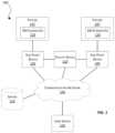
- FIG. 1schematically illustrates a system for monitoring and managing a facility having a plurality of end point devices according to some embodiments.
- FIG. 2schematically illustrates an end point device included in the system of FIG. 1 according to some embodiments.
- FIGS. 3 A- 3 Cillustrate an example electronics housing for an end point device according to some embodiments.
- FIGS. 4 A- 4 Cillustrate an example circuit diagram for electronics of an end point device according to some embodiments.
- FIG. 5schematically illustrates a facility device included in the system of FIG. 1 according to some embodiments.
- FIG. 6is a flowchart illustrating a method for monitoring and managing a facility having a plurality of end point devices using the system of FIG. 1 according to some embodiments.
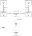
- FIG. 7schematically illustrates communication between components of the system of FIG. 1 according to some embodiments.
- embodimentsmay include hardware, software, and electronic components or modules that, for purposes of discussion, may be illustrated and described as if the majority of the components were implemented solely in hardware.
- electronic based aspects of the embodimentsmay be implemented in software (for example, stored on non-transitory computer-readable medium) executable by one or more processors.
- FIG. 1illustrates a system 100 for monitoring and managing a facility (e.g., a building or one or more rooms within a building) according to some embodiments.
- the system 100includes a plurality of end point devices 105 (collectively referred to herein as “the end point devices 105 ” and individually as “an end point device 105 ”), a plurality of fixtures 107 (collectively referred to herein as “the fixtures 107 ” and individually as “a fixture 107 ”), a facility device 110 (e.g., a gateway), a server 115 (e.g., cloud server), and a user device 120 .
- the system 100includes fewer, additional, or different components than illustrated in FIG. 1 in various configurations.
- the system 100may include multiple facility devices 110 , servers, 115 , user devices 120 , or a combination thereof. Additionally, the system 100 may include any number of end point devices 105 and/or fixtures 107 and the two endpoint devices and fixtures illustrated in FIG. 1 are purely for illustrative purposes. Also, in some embodiments, one or more of the components of the system 100 may be distributed among multiple devices, combined within a single device, or a combination thereof. As one example, in some embodiments, one or more of the end point devices 105 may be incorporated within a fixture 107 as a single device. Accordingly, in some embodiments, the functionality described as being performed by the end point device 105 (or a portion thereof) may be performed by a fixture 107 (including built-in or attached similar hardware and software components as the end point device 105 ).
- Portions of the communication networks 140may be implemented using a wide area network (“WAN”), such as the Internet or a LoRa system, a local area network (“LAN”), such as a BluetoothTM network or Wi-Fi, and combinations or derivatives thereof.
- WANwide area network
- LANlocal area network
- components of the system 100may be configured to communicate via Bluetooth, Wi-Fi, Zigbee, LTE/Cellular, wired ethernet, RS485/RS232, or the like.
- the end point devices 105may communicate via LoRa with the facility device 110 .
- one or more components of the system 100communicate directly as compared to through the communication network 140 .
- the end point devices 105communicate directly with the facility device 110 .
- the components of the system 100communicate through one or more intermediary devices not illustrated in FIG. 1 .
- one or more components of the system 100communicate using LoRa or LoRaWAN networking protocols (for example, the end point device 105 and the facility device 110 ).
- LoRa or LoRaWAN networking protocolsfor example, the end point device 105 and the facility device 110 .
- Using such networking protocolsprovides for secure, encrypted communication of data without use of a customer or building network. Accordingly, use of such networking protocols may completely isolate an end point device 105 (or other component of the system 100 ) from a customer or building network.
- a fixture 107may include, for example, a faucet, a flushometer, a flush valve, a soap dispenser, a handwashing system, a water service line monitor, a backflow preventer, a floor drain, a hand dryer, a pressure sensor, a water use sensor, a flow sensor, a valve sensor, a lavatory, a toilet, a urinal, a water closet, a bottle and glass filler, a drain, a drinking water fountain, an air or room quality sensor (e.g., may include a service request or product replenishment request button or other suitable activator), a backflow preventer, a leak detection sensor, an occupancy detection sensor, and a resource dispenser (for example, a soap dispenser, a sanitizer dispenser, a room deodorizer dispenser, a paper tower dispenser), and the like.
- a faucetfor example, a faucet, a flushometer, a flush valve, a soap dispenser, a handwashing system, a water service line monitor, a backflow
- the fixture 107provides a water management solution.
- each of the fixtures 107is associated with one or more electro-mechanical (“EM”) elements 125 .
- the EM elements 125are configured to monitor and/or influence the operation of the fixture 107 .
- An EM element 125may include, but is not limited to, an actuator, a flow sensor, a position sensor, a proximity sensor, a thermocouple, and the like. It is contemplated that the EM elements 125 may include an electrical only element, a mechanical only element, or a combination of an electrical and a mechanical element(s).
- the EM elements 125may include a single-piece component or multiple components.
- the fixture 107is a faucet having a sensor (for example, as a first EM element 125 ) configured to detect the presence of a person within a specified zone.
- a sensorfor example, as a first EM element 125
- the sensorsends an “ON” signal to an actuator (as a second EM element 125 ) (for example, a valve actuating solenoid) thereby allowing water to selectively flow through the faucet.
- an actuatorfor example, a valve actuating solenoid
- the sensorsends an “OFF” signal to the actuator to stop water flow through the faucet.
- the actuatoris configured to maintain the faucet in an open position for a predetermined period of time in response to receiving an “ON” signal.
- the predetermined period of timemay be set by a user or facility entity via, for example, the facility device 110 , the user device 120 , another component of the system 100 , or a combination thereof.
- the fixture 107is a flush valve having a sensor (for example, as a first EM element 125 ) configured to detect the presence of a person within a specified zone.
- a sensorfor example, as a first EM element 125
- the sensorsends an “ON” signal to the actuator (as a second EM element 125 ) (for example, a valve actuating solenoid) to actuate a valve and initiate a flow of water for a flushing event.
- the flush valvewill then remain open for a predetermined period of time (for example, 5 seconds, 10 seconds, and the like) at least partially dependent upon an operating parameter set by the user via, for example, the facility device 110 , the user device 120 , another component of the system 100 , or a combination thereof.
- a predetermined period of timefor example, 5 seconds, 10 seconds, and the like
- the fixture 107is a resource dispenser (such as a soap dispenser, a hand towel dispenser, and the like) having a sensor (for example, as a first EM element 125 ) configured to detect the presence of a person within a specified zone.
- a sensorfor example, as a first EM element 125
- the sensorsends an “ON” signal to an actuator (for example, as a second EM element 125 ) to trigger a resource dispensing event (for example, actuation of a gear, a valve, or solenoid, and the like to initiate dispensing of a resource).
- the resource dispenseris configured to allow a predetermined volume or amount of a resource to be dispensed for each activation. In such embodiments, the volume or amount or timing of a resource to be dispensed may be set and adjusted by the user via, for example, the facility device 110 , the user device 120 , another component of the system 100 , or a combination thereof.
- the resource dispensermay also include a second sensor (for example, as a third EM element 125 ) to monitor the level or amount of resource remaining in a reservoir or receptacle.
- the second sensordetects a current level or amount of resource in the reservoir or receptacle at a given moment in time.
- the second sensormay detect when the resource falls below a predetermined amount or level.
- the fixture 107is a water service line monitor.
- the water service line monitorincludes a sensor (for example, as a first EM element 125 ) configured to be retrofit onto an existing water service line and is configured to monitor the flow-rate of water therethrough, the presence of a backflow event, or a combination thereof. More specifically, the sensor may be configured to detect a flow rate, a presence of a backflow event, and the like.
- an end point device 105generally includes a communication link with at least one fixture 107 .
- the end point devices 105may span multiple facilities, locations, rooms, and the like.
- each of the end point devices 105is associated with (located within) the same facility (for example, a restroom facility).
- the end point devices 105are associated with multiple facilities.
- a first end point devicemay be associated with a first facility
- a second end point devicemay be associated with a second different facility that is either in the same building as the first facility or in an entirely different building.
- each of the end point devices 105is associated with the same type of restroom fixture (for example, the fixture 107 ).
- the end point devices 105are associated with multiple different types of restroom fixtures (for example, the fixture 107 ).
- a first end point devicemay be associated with a faucet (as a first fixture 107 ) and a second end point device may be associated with a soap dispenser (as a second fixture 107 ).
- FIG. 2illustrates an end point device 105 according to some embodiments.
- the end point device 105includes an electronic processor 200 , a memory 205 , a communication interface 210 , and an energy source 220 .
- the electronic processor 200 , the memory 205 , the communication interface 210 , and the energy source 220communicate wirelessly, over one or more communication lines or buses, or a combination thereof.
- one or more components of the end point device 105may be distributed among multiple devices, integrated into a single device, or a combination thereof.
- the end point device 105may perform additional functionality other than the functionality described herein.
- the end point device 105may include additional, different, or fewer components than those illustrated in FIG.
- the end point device 105includes multiple energy sources 220 .
- the end point device 105includes one or more expansion ports allowing for future expansion of the end point device 105 .
- additional electro-mechanical (EM) elements of a fixture 107may be connected to the end point device 105 via the one or more of the expansion ports.
- the communication interface 210allows the end point device 105 to communicate with devices external to the end point device 105 .
- the end point device 105may communicate with the fixture 107 (or an EM element 125 thereof), the facility device 110 , the server 115 , the user device 120 , or a combination thereof through the communication interface 210 .
- the communication interface 210may include a port for receiving a wired connection to an external device (for example, a universal serial bus (“USB”) cable and the like), a transceiver for establishing a wireless connection to an external device (for example, over one or more communication networks 140 , such as the Internet, LAN, a WAN, such as a LoRa network or system, and the like), or a combination thereof.
- the communication interface 210includes a port for receiving a wired connection between the facility device 110 and an EM element 125 of a corresponding fixture 107 .
- the communication interface 210includes a radio or transceiver for establishing a wireless connection, over a LoRa system or network, between the end point device 105 and the facility device 110 .
- the electronic processor 200includes a microprocessor, an application-specific integrated circuit (“ASIC”), or another suitable electronic device for processing data, and the memory 205 includes a non-transitory, computer-readable storage medium.
- the electronic processor 200is configured to access and execute computer-readable instructions (“software”) stored in the memory 205 .
- the softwaremay include firmware, one or more applications, program data, filters, rules, one or more program modules, and other executable instructions.
- the softwaremay include instructions and associated data for performing a set of functions, including the methods described herein.
- the electronic processor 200is configured to enable management and/or monitoring of the operation of the corresponding fixture 107 either directly or indirectly (for example, via the EM element(s) 125 of the corresponding fixture 107 ).
- the electronic processor 200enables management and/or monitoring of the operation of a corresponding fixture 107 by receiving fixture data from the fixtures 107 , converting the fixture data for transmission, and enabling transmission of the converted data to, for example, the facility device 110 , the server 115 , the user device 120 , another component of the system 100 , or a combination thereof.
- the electronic processor 200is configured to interact with and collect data regarding an operation of a fixture 107 (as fixture data) via the EM elements 215 either directly or indirectly.
- the end point device 105is configured to remain in a sleep mode (or deep sleep mode) until an action or operation is detected with respect to a fixture 107 associated with the end point device 105 (for example, detecting the presence of a user).
- the end point device 105may then wake-up to receive fixture data, convert the fixture data for transmission, and transmit the fixture data (in a minimum power consumption mode) to, for example, the facility device 110 , the server 115 , the user device 120 , another component of the system 100 , or a combination thereof.
- the end point device 105transmits the converted fixture data (for example, as one or more data packets) to the facility device 110 , the transmission may occur through adaptable data rate, which automatically selects the most easily available channel such that the right channel does not have to be searched for, which further aids in the optimization of power.
- the end point device 105also includes the energy source 220 .
- the energy source 220powers one or more components of the end point device 105 , such as the electronic processor 200 .
- the energy source 220may be a battery, such as an energy efficient battery, a re-chargeable battery, a lithium-ion battery, a replaceable battery, or the like.
- the energy source 220is a standard battery (for example, AAA, AA, C, D sized batteries).
- the end point device 105includes multiple energy sources 220 (for example, a first energy source, a second energy source, and the like). In such embodiments, the multiple energy sources 220 may be of the same type, different types, or a combination thereof.
- the end point device 105may include three AA batteries as the energy sources 220 .
- one or more components of the system 100may already be present in a completed fixture 107 (for example, a proximity sensor and an actuator in an automated faucet).
- additional componentsmay be retro-fit onto the existing fixture 107 .
- the end point device 105(or components thereof) may be retro-fit onto or into the existing fixture 107 .
- a transmitter, a receiver, a transceiver, or a combination thereof(as part of the communication interface 210 ), the electronic processor 200 , the energy source 220 , or a combination thereof may be mounted in the plumbing immediately upstream of a particular fixture 107 .
- the retro-fitmay include updating firmware in the already existing device.
- the retro-fitmay include integrating elements into a previously existing fixture 107 .
- FIGS. 3 A- 3 Cillustrate an example electronics housing 305 for an end point device 105 according to some embodiments.
- the end point device 105may include one or more wires or cables 310 extending from the housing 305 .
- the wires 310may provide a direct or indirect wired connection to, for example, one or more of the EM elements 125 of a fixture 107 associated with the end point device 105 .
- the housing 305includes a battery holder 315 (for example, an energy source holder) for receiving one or more batteries (for example, as the energy sources 220 ).
- the housing 305may include a lid portion 307 .
- FIGS. 3 B- 3 Calso illustrates a circuit board 320 enclosed within the housing 305 (for example, one or more electronical components of the end point device 105 , such as the electronic processor 200 ).
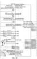
- FIGS. 4 A- 4 Cillustrate an example circuit diagram 400 for the circuit board 320 of the end point device 105 according to some embodiments.
- one or more components of the system 100may be retro-fit onto or into an existing fixture 107 .
- the electronics housing 305 (and the components therein)may be retro-fit to an existing fixture 107 .
- the end point device 105may be mounted to a fixture 107 and communicatively connect the fixture 107 to the end point device 105 (for example, by connecting EM elements 125 of the fixture 107 to the end point device 105 directly or indirectly via one or more of the wires or cables 310 ).
- one or more components of the end point device 105are designed as discrete, self-enclosed, add-on components or devices capable of retro-fitting to an existing installation of a fixture 107 .
- FIG. 5illustrates the facility device 110 according to some embodiments.
- the facility device 110includes a facility electronic processor 500 , a facility memory 505 , and a facility communication interface 510 .
- the facility electronic processor 500 , the facility memory 505 , and the facility communication interface 510communicate wirelessly, over one or more communication lines or buses, or a combination thereof.
- the facility device 110may include additional, different, or fewer components than those illustrated in FIG. 5 in various configurations.
- the facility device 110includes a human-machine interface for interacting with a user.
- the human machine interfacemay include one or more input devices, one or more output devices, or a combination thereof.
- one or more components of the facility device 110may be distributed among multiple devices, integrated into a single device, or a combination thereof.
- the facility device 110may perform additional functionality other than the functionality described herein.
- the functionality (or a portion thereof) described herein as being performed by the facility device 110may be distributed among multiple devices.
- the facility communication interface 510allows the facility device 110 to communicate with devices external to the facility device 110 .
- the facility device 110may communicate with the end point devices 105 , the fixtures 107 , the server 115 , the user device 120 , or a combination thereof through the facility communication interface 510 .
- the facility communication interface 510may include a port for receiving a wired connection to an external device (for example, a USB cable and the like), a transceiver for establishing a wireless connection to an external device (for example, over one or more communication networks 140 , such as the Internet, a LAN, a WAN, such as a LoRa system, and the like), or a combination thereof.
- the facility electronic processor 500is configured to access and execute computer-readable instructions (“software”) stored in the facility memory 505 .
- the softwaremay include firmware, one or more applications, program data, filters, rules, one or more program modules, and other executable instructions.
- the softwaremay include instructions and associated data for performing a set of functions, including the methods described herein.
- the facility device 110serves as a gateway or intermediary device that receives data (for example, the fixture data) from the electronic processors 200 of one or more of the end point devices 105 and forwards the collected data to another component for processing, such as the server 115 , the user device 120 , or a combination thereof.
- the facility device 110forwards the data to a remote server (for example, the server 115 ) for virtual processing.
- a remote serverfor example, the server 115
- the functionality (or a portion thereof) described as being performed by the facility device 110may be performed by another remote device or server (not shown).
- the server 115 and the user device 120are computing devices, such as a desktop computer, a laptop computer, a tablet computer, a terminal, a smart telephone, a smart television, a smart wearable, or another suitable computing device that interfaces with a user.
- the server 115 and the user device 120may include similar components as the facility device 110 , such as an electronic processor (for example, a microprocessor, an ASIC, or another suitable electronic device), a memory (for example, a non-transitory, computer-readable storage medium), a communication interface, such as a transceiver, for communicating over the communication network 140 and, optionally, one or more additional communication networks or connections, and one or more human machine interfaces.
- an electronic processorfor example, a microprocessor, an ASIC, or another suitable electronic device
- a memoryfor example, a non-transitory, computer-readable storage medium
- a communication interfacesuch as a transceiver, for communicating over the communication network 140 and, optionally, one or more additional communication networks or connections
- the server 115may include multiple electronic processors, multiple memory modules, multiple communication interfaces, or a combination thereof. Also, it should be understood that the functionality described herein as being performed by the server 115 may be performed in a distributed nature by a plurality of computers located in various geographic locations. For example, the functionality described herein as being performed by the server 115 may be performed by a plurality of computers included in a cloud computing environment.
- the server 115is configured to monitor and manage one or more facilities (e.g., individual restrooms or entire buildings), including the fixtures 107 therein.
- the server 115(via an electronic processor of the server 115 ) may receive fixture data from the facility device 110 .
- the server 115may process the fixture data in order to determine usage information or patterns associated with the one or more facilities, including the fixtures 107 thereof.
- the server 115may store the usage information or patterns in, for example, a memory of the server 115 .
- the server 115may transmit the usage information or patterns to a remote device for storage.
- a usermay interact with and access data associated with one or more facilities, such as one or more of the fixtures 107 therein (for example, the usage information or patterns determined by the server 115 ).
- the user device 120may be used by an end user, such as a facility entity, to monitor and manage a facility (a single restroom or multiple restrooms in a building), one or more fixtures 107 of a facility, or a combination thereof.
- a usermay access and interact with the data determined by the server 115 to view and understand usage patterns, which may allow a facility entity or maintainer insights into, for example, how to optimize cleaning and maintenance schedules, whether there is a need for additional facilities, end point devices, or a combination thereof.
- the user device 120may store a browser application or a dedicated software application executable by an electronic processor for interacting with the server 115 .
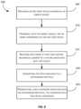
- FIG. 6is a flowchart illustrating a method 600 for monitoring and managing a facility according to some embodiments. The method 600 will be described with reference to FIG. 7 .
- FIG. 7schematically illustrates communication between components of the system 100 according to some embodiments.
- the method 600includes providing an end point device 105 powered by the energy source 220 (at block 605 ).
- the energy source 220is local to the end point device 105 .
- the end point device 105is provided or mounted to a wall in a facility or to a pre-existing installation of a fixture 107 .
- the end point device 105is provided to or mounted to the fixture 107 prior to or during installation of the fixture 107 within a facility.
- the electronic housing 305 of FIGS. 3 A- 3 Care provided or mounted to a wall in a facility or to the fixture 107 .
- the energy source 220then powers one or more components of the end point device 105 (at block 610 ).
- the energy source 220may power the electronic processor 200 .
- the electronic processor 20receives data (for example, the fixture data) from at least one EM element 125 (a first EM element) included in a set of EM elements 125 (at block 615 ).
- the data received from the first EM element 125may be associated with an operation of the fixture 107 .
- the fixtures 107(the EM elements 125 thereof) transmit fixture data to the end point devices 105 .
- the electronic processor 200in response to receiving the data (at block 615 ), the electronic processor 200 converts the data pursuant to a networking protocol (at block 620 ). In some embodiments, the electronic processor 200 may convert the data pursuant to specific networking protocol consistent with a network connection between the end point device 105 and the facility device 110 . As one example, the electronic processor 200 may convert the data pursuant to LoRa networking protocols for transmission over a LoRa connection between the end point device 105 and the facility device 110 .
- the electronic processor 200also transmits the data for remote or virtual processing (at block 625 ). In some embodiments, the electronic processor 200 transmits the converted data for virtual processing over a network associated with the networking protocol. As described above, the electronic processor 200 may transmit the data to the facility device 110 (as a gateway device). For example, as illustrated in FIG. 7 , the end point devices 105 transmit the converted fixture data to the facility device 110 . In some embodiments, the end point device 105 (for example, the electronic processor 200 ) maintains a backlog of data packets (for example, the converted data) until a connection to, for example, the facility device 110 is available (for example, in the event that a connection to the facility device 110 is temporarily unavailable).
- the facility device 110may then forward the data to a remote device, server, or database for virtual processing in the cloud, such as, for example, the server 115 , the user device 120 , or a combination thereof (as seen in FIG. 7 ).
- a usermay use the user device 120 (or another remote device) to access and interact with the data.
- the usermay view and interact with usage patterns, which may allow a facility entity or maintainer insights into, for example, how to optimize cleaning and maintenance schedules (for example, for preventative or predicted maintenance), whether there is a need for additional facilities, end point devices, or a combination thereof, and the like.
- the server 115is configured to monitoring and managing one or more facilities, including the fixtures 107 therein.
- the server 115may receive fixture data from the facility device 110 . In response to receiving the fixture data, the server 115 may process the fixture data in order to determine usage information or patterns associated with the one or more facilities, including the fixtures 107 thereof. Alternatively or in addition, in some embodiments, the server 115 may monitor or track a battery or power level (for example, as a battery condition or characteristic) associated with the end point device 105 .
- a battery or power levelfor example, as a battery condition or characteristic
- the server 115may analyze the fixture data to monitor the communications between the EM elements 125 of a fixture 107 (for example, a sensor and an actuator) to track, among other things, the number of “ON” and “OFF” signals (or activations). Alternatively or in addition, the server 115 may analyze the fixture data to detect the flow of water by monitoring temperature data from a temperature sensor (as an EM element 125 of the fixture 107 ) either positioned within the drain or the faucet itself.
- a temperature sensoras an EM element 125 of the fixture 107
- the server 115may analyze the fixture data to determine when a run-on condition has occurred in response to determine that a predetermined period of time set by a user is exceeded and the faucet did not return to an “OFF” condition or water flow is still detected.
- the server 115may analyze the fixture data to calculate water usage indirectly based at least in part on a duration of time that the valve of the faucet remains open and an estimated water flow rate.
- the server 115may analyze the fixture data to monitor a magnitude of a voltage and/or current supplied to the EM element 125 (for example, an actuator) of the fixture 107 to track when a flushing event has been initiated.
- the server 115may analyze the fixture data to determine when an “ON” signal is provided (for example, a person is detected) but no corresponding movement of the valve occurs.
- the server 115may generate and provide an error signal such that an alert may be generated via, for example, the facility device 110 , the user device 120 , another component of the system 100 , or a combination thereof.
- Such faultsmay be detected by detecting an elevated voltage or current rate (for example, motor is bound).
- the server 115may analyze the fixture data to determine a length of time a person is detected using the fixture 107 on any given instance.
- the server 115may analyze the fixture data to monitor a magnitude of a voltage and/or current supplied to an EM element 125 (for example, an actuator) of a fixture 107 to track when a resource dispensing event has occurred. Alternatively or in addition, the server 115 may analyze the fixture data to monitor a level or amount of resource remaining in a reservoir of the fixture 107 . The server 115 may calculate an amount of resource remaining in a reservoir of the fixture 107 by subtracting a predetermined volume or amount of resource discharged during a resource dispensing event for each detected activation.
- the server 115may generate and provide an error signal such that an alert may be generated via, for example, the facility device 110 , the user device 120 , another component of the system 100 , or a combination thereof.
- the battery life(for example, an energy level or energy usage) may be monitored using various indicators, such as a graphical representation of a fuel gauge.
- the server 115(an electronic processor thereof) may generate alerts and warnings in response to detecting a predetermined energy level, where the predetermined energy level indicates an end of battery life scenario, an energy source replacement scenario, and the like.
- the electronic processor of the server 115may generate and transmit a low energy level alert to a user of the user device 120 (via, for example, a display device of the user device 120 ).
- the embodimentsprovide, among other things, to methods and systems for monitoring and managing a facility having a plurality of end point device.
Landscapes
- Engineering & Computer Science (AREA)
- Computer Networks & Wireless Communication (AREA)
- Signal Processing (AREA)
- Health & Medical Sciences (AREA)
- Computing Systems (AREA)
- General Health & Medical Sciences (AREA)
- Medical Informatics (AREA)
- Computer Hardware Design (AREA)
- General Engineering & Computer Science (AREA)
- Telephonic Communication Services (AREA)
- Management, Administration, Business Operations System, And Electronic Commerce (AREA)
- Alarm Systems (AREA)
Abstract
Description
Claims (19)
Priority Applications (2)
| Application Number | Priority Date | Filing Date | Title |
|---|---|---|---|
| US17/446,557US11770452B2 (en) | 2020-07-27 | 2021-08-31 | Battery powered end point device for IoT applications |
| US18/451,570US20240048618A1 (en) | 2020-07-27 | 2023-08-17 | Battery powered end point device for iot applications |
Applications Claiming Priority (3)
| Application Number | Priority Date | Filing Date | Title |
|---|---|---|---|
| US202063057116P | 2020-07-27 | 2020-07-27 | |
| US16/953,101US11108865B1 (en) | 2020-07-27 | 2020-11-19 | Battery powered end point device for IoT applications |
| US17/446,557US11770452B2 (en) | 2020-07-27 | 2021-08-31 | Battery powered end point device for IoT applications |
Related Parent Applications (1)
| Application Number | Title | Priority Date | Filing Date |
|---|---|---|---|
| US16/953,101ContinuationUS11108865B1 (en) | 2020-07-27 | 2020-11-19 | Battery powered end point device for IoT applications |
Related Child Applications (1)
| Application Number | Title | Priority Date | Filing Date |
|---|---|---|---|
| US18/451,570ContinuationUS20240048618A1 (en) | 2020-07-27 | 2023-08-17 | Battery powered end point device for iot applications |
Publications (2)
| Publication Number | Publication Date |
|---|---|
| US20220030068A1 US20220030068A1 (en) | 2022-01-27 |
| US11770452B2true US11770452B2 (en) | 2023-09-26 |
Family
ID=77464956
Family Applications (3)
| Application Number | Title | Priority Date | Filing Date |
|---|---|---|---|
| US16/953,101ActiveUS11108865B1 (en) | 2020-07-27 | 2020-11-19 | Battery powered end point device for IoT applications |
| US17/446,557Active2040-12-11US11770452B2 (en) | 2020-07-27 | 2021-08-31 | Battery powered end point device for IoT applications |
| US18/451,570PendingUS20240048618A1 (en) | 2020-07-27 | 2023-08-17 | Battery powered end point device for iot applications |
Family Applications Before (1)
| Application Number | Title | Priority Date | Filing Date |
|---|---|---|---|
| US16/953,101ActiveUS11108865B1 (en) | 2020-07-27 | 2020-11-19 | Battery powered end point device for IoT applications |
Family Applications After (1)
| Application Number | Title | Priority Date | Filing Date |
|---|---|---|---|
| US18/451,570PendingUS20240048618A1 (en) | 2020-07-27 | 2023-08-17 | Battery powered end point device for iot applications |
Country Status (1)
| Country | Link |
|---|---|
| US (3) | US11108865B1 (en) |
Families Citing this family (12)
| Publication number | Priority date | Publication date | Assignee | Title |
|---|---|---|---|---|
| US12301661B2 (en) | 2019-12-06 | 2025-05-13 | Zurn Water, Llc | Water management system and user interface |
| WO2021252008A1 (en) | 2020-06-08 | 2021-12-16 | Zurn Industries, Llc | Cloud-connected occupancy lights and status indication |
| US11108865B1 (en) | 2020-07-27 | 2021-08-31 | Zurn Industries, Llc | Battery powered end point device for IoT applications |
| US11153945B1 (en) | 2020-12-14 | 2021-10-19 | Zurn Industries, Llc | Facility occupancy detection with thermal grid sensor |
| US11316908B1 (en) | 2021-02-01 | 2022-04-26 | Zurn Industries, Llc | BACnet conversion of water management data for building management solutions |
| CN112969171B (en)* | 2021-02-26 | 2023-02-28 | 徐逸轩 | Floating communication device, networking communication method thereof and data transmission method |
| US11594119B2 (en) | 2021-05-21 | 2023-02-28 | Zurn Industries, Llc | System and method for providing a connection status of a battery powered end point device |
| US11221601B1 (en) | 2021-05-24 | 2022-01-11 | Zurn Industries, Llc | Various IoT sensory products and cloud-purge for commercial building solutions utilizing LoRa to BACnet conversion for efficient data management and monitoring |
| US11573539B1 (en)* | 2021-09-03 | 2023-02-07 | Zurn Industries, Llc | Managing edge devices in building management systems |
| US11543791B1 (en) | 2022-02-10 | 2023-01-03 | Zurn Industries, Llc | Determining operations for a smart fixture based on an area status |
| US11514679B1 (en) | 2022-02-18 | 2022-11-29 | Zurn Industries, Llc | Smart method for noise rejection in spatial human detection systems for a cloud connected occupancy sensing network |
| US11555734B1 (en) | 2022-02-18 | 2023-01-17 | Zurn Industries, Llc | Smart and cloud connected detection mechanism and real-time internet of things (IoT) system management |
Citations (111)
| Publication number | Priority date | Publication date | Assignee | Title |
|---|---|---|---|---|
| US4563780A (en) | 1983-06-29 | 1986-01-14 | Pollack Simcha Z | Automated bathroom |
| US4805247A (en) | 1987-04-08 | 1989-02-21 | Coyne & Delany Co. | Apparatus for preventing unwanted operation of sensor activated flush valves |
| US5175892A (en) | 1988-06-27 | 1993-01-05 | Bauer Industries, Inc. | Fresh water control system and method |
| US5217035A (en) | 1992-06-09 | 1993-06-08 | International Sanitary Ware Mfg. Cy, S.A. | System for automatic control of public washroom fixtures |
| US5438714A (en) | 1989-10-31 | 1995-08-08 | Bauer Industries, Inc. | Fresh water manifold distribution system and method |
| WO1996041058A1 (en) | 1995-06-07 | 1996-12-19 | Sloan Valve Company | Wash stations and method of operation |
| US5612890A (en) | 1995-05-19 | 1997-03-18 | F C Systems, Inc. | System and method for controlling product dispensation utilizing metered valve apparatus and electronic interconnection map corresponding to plumbing interconnections |
| US5655961A (en) | 1994-10-12 | 1997-08-12 | Acres Gaming, Inc. | Method for operating networked gaming devices |
| US5838258A (en) | 1996-11-08 | 1998-11-17 | Saar; David A. | System for monitoring the use of heat energy in water devices in an individual unit of a multi-unit building |
| US5844808A (en) | 1994-03-30 | 1998-12-01 | Konsmo; +527 Ystein | Apparatus and methods for monitoring and communicating with a plurality of networked remote vending machines |
| US6018827A (en) | 1989-07-20 | 2000-02-01 | Sloan Valve Company | Push button assembly for control of plumbing fixtures in prisons and the like |
| US6038519A (en) | 1997-12-31 | 2000-03-14 | Sloan Valve Company | Control board for controlling and monitoring usage of water |
| US6189163B1 (en) | 1996-02-28 | 2001-02-20 | Karel Carl Van Marcke | Device for controlling a series of washroom appliances |
| US6236953B1 (en) | 1994-07-12 | 2001-05-22 | Compliance Control, Inc. | System for monitoring compliance with apparatuses having predetermined operating parameters |
| US6337635B1 (en) | 1998-01-31 | 2002-01-08 | Orbit Irrigation Products, Inc. | Remotely controllable programmable hose faucet valve system |
| JP2002021149A (en) | 2000-07-05 | 2002-01-23 | Toto Ltd | Toilet using state display device and toilet device |
| US6347414B2 (en) | 2000-02-04 | 2002-02-19 | Waterbury Companies, Inc. | Intelligent demand-based dispensing system |
| US6411920B1 (en) | 1999-06-23 | 2002-06-25 | Kimberly-Clark Worldwide, Inc. | System and method for collecting data on product consumption |
| WO2002056540A2 (en) | 2001-01-12 | 2002-07-18 | Novar Controls Corp | Small building automation control system |
| US20020099454A1 (en) | 2001-01-23 | 2002-07-25 | Gerrity Daniel W. | Network-embedded device controller with local database |
| US20020190868A1 (en) | 2001-06-07 | 2002-12-19 | Dell Products, L.P. | System and method for displaying computer system status information |
| US6583720B1 (en) | 1999-02-22 | 2003-06-24 | Early Warning Corporation | Command console for home monitoring system |
| US6694177B2 (en) | 2001-04-23 | 2004-02-17 | Cardionet, Inc. | Control of data transmission between a remote monitoring unit and a central unit |
| US6691724B2 (en) | 2002-04-11 | 2004-02-17 | Michael Brent Ford | Method and system for controlling a household water supply |
| US6701194B2 (en) | 1997-12-31 | 2004-03-02 | Sloan Valve Company | Control board for controlling and monitoring usage of water |
| US6749122B1 (en) | 1990-05-25 | 2004-06-15 | Broadcom Corporation | Multi-level hierarchial radio-frequency system communication system |
| US6766221B1 (en) | 1999-11-25 | 2004-07-20 | S Rain Control As | Two-wire controlling and monitoring system for irrigation of localized areas of soil |
| US6769443B2 (en) | 2002-04-29 | 2004-08-03 | I-Con Systems, Inc. | Plumbing control system with signal recognition |
| US6802084B2 (en) | 2002-02-05 | 2004-10-12 | Ghertner Automation, Inc. | Tank leak detection and reporting system |
| US6853958B1 (en) | 2000-06-30 | 2005-02-08 | Integrex | System and method for collecting and disseminating household information and for coordinating repair and maintenance services |
| US6854053B2 (en) | 2000-10-25 | 2005-02-08 | Signet Scientific Company | Method for identifying and communicating with a plurality of slaves in a master-slave system |
| US6956498B1 (en) | 2000-11-02 | 2005-10-18 | Sloan Valve Company | System for remote operation of a personal hygiene or sanitary appliance |
| US6967565B2 (en) | 2003-06-27 | 2005-11-22 | Hx Lifespace, Inc. | Building automation system |
| US7023341B2 (en) | 2003-02-03 | 2006-04-04 | Ingrid, Inc. | RFID reader for a security network |
| US7053767B2 (en) | 1998-06-22 | 2006-05-30 | Statsignal Systems, Inc. | System and method for monitoring and controlling remote devices |
| US7058457B2 (en) | 2003-03-04 | 2006-06-06 | Noritz Corporation | Hot water supply system |
| US20060208862A1 (en) | 2005-03-14 | 2006-09-21 | Lahr Jeremy A | Post-trip bus inspection alert system |
| US7119658B2 (en) | 2003-02-03 | 2006-10-10 | Ingrid, Inc. | Device enrollment in a security system |
| US7143007B2 (en) | 2003-10-17 | 2006-11-28 | Hydralift Amclyde, Inc. | Equipment component monitoring and replacement management system |
| US7177725B2 (en) | 2004-02-02 | 2007-02-13 | Nortier Richard A | System for the monitor and control of rest rooms |
| US20070038333A1 (en) | 2005-08-15 | 2007-02-15 | Dadebo Solomon A | Model predictive control having application to distillation |
| US7222111B1 (en) | 1998-05-29 | 2007-05-22 | Budike Jr Lothar E S | Multi-utility energy control and facility automation system with dashboard having a plurality of interface gateways |
| US7304569B2 (en) | 2005-08-03 | 2007-12-04 | Sloan Valve Company | Networking of discrete plumbing devices |
| US7360413B2 (en) | 2004-12-29 | 2008-04-22 | Water Cents, Llc | Wireless water flow monitoring and leak detection system, and method |
| US20080177411A1 (en) | 2007-01-23 | 2008-07-24 | Marsh Joseph C | Method and apparatus for localizing and mapping the position of a set of points on a digital model |
| US20080228904A1 (en) | 2002-03-20 | 2008-09-18 | Daniel Crespo-Dubie | Home Gateway Architecture and State Based Distributed System and Method |
| US20080245738A1 (en) | 2007-04-03 | 2008-10-09 | Siemens Water Technologies Corp. | Method and system for providing ultrapure water |
| US20100114383A1 (en) | 2008-09-03 | 2010-05-06 | Siemens Building Technologies, Inc. | Wireless building management system and method using a building model |
| US20100164736A1 (en) | 2008-12-31 | 2010-07-01 | Cisco Technology, Inc. | Energy-saving status indicator |
| US7814582B2 (en) | 2003-12-31 | 2010-10-19 | Kimberly-Clark Worldwide, Inc. | System and method for measuring and monitoring overflow or wetness conditions in a washroom |
| US20110113360A1 (en) | 2009-11-12 | 2011-05-12 | Bank Of America Corporation | Facility monitoring and control system interface |
| US20110210077A1 (en) | 2007-04-03 | 2011-09-01 | Siemens Water Technologies Corp. | Method and system for providing ultrapure water |
| US8028355B2 (en) | 2005-11-11 | 2011-10-04 | Masco Corporation Of Indiana | Integrated bathroom electronic system |
| US20120044350A1 (en) | 2007-06-29 | 2012-02-23 | Orion Energy Systems, Inc. | Outdoor lighting fixture and camera systems |
| US8364546B2 (en) | 2007-11-05 | 2013-01-29 | Sloan Valve Company | Restroom convenience center |
| US20140236358A1 (en) | 2013-02-20 | 2014-08-21 | Panasonic Corporation | Control method for information apparatus and computer-readable recording medium |
| US20140249854A1 (en)* | 2013-03-01 | 2014-09-04 | Airstrip Ip Holdings, Llc | Systems and methods for integrating, unifying and displaying patient data across healthcare continua |
| US20150229488A1 (en) | 2014-02-13 | 2015-08-13 | Robert Bosch Gmbh | System and method for commissioning wireless building system devices |
| US9169625B2 (en) | 2011-08-30 | 2015-10-27 | Alliance Service International Corporation | Water-saving management system for sanitary facility and water-saving management method for sanitary facility |
| US20150308856A1 (en) | 2014-04-25 | 2015-10-29 | Samsung Electronics Co., Ltd. | Automatic fixture monitoring using mobile location and sensor data with smart meter data |
| US20150373482A1 (en) | 2014-06-18 | 2015-12-24 | Chris Barnard | Application framework for interactive wireless sensor networks |
| US9266136B2 (en) | 2007-10-24 | 2016-02-23 | Michael Klicpera | Apparatus for displaying, monitoring and/or controlling shower, bath or sink faucet water parameters with an audio or verbal annunciations or control means |
| US20160216706A1 (en) | 2015-01-26 | 2016-07-28 | Fisher-Rosemount Systems, Inc. | Commissioning field devices in a process control system supported by big data |
| US9429453B1 (en) | 2015-03-24 | 2016-08-30 | Symmons Industries, Inc. | Method and system for managing water usage |
| US20160261425A1 (en) | 2014-06-23 | 2016-09-08 | Google Inc. | Methods and apparatus for using smart environment devices via application program interfaces |
| US20160258144A1 (en) | 2015-03-05 | 2016-09-08 | Eva Smart Shower, LLC | Systems and methods for controlling water flow |
| US20160291841A1 (en) | 2015-04-02 | 2016-10-06 | Honeywell International Inc. | Mobile device emulating a field device display |
| US20170006051A1 (en) | 2015-06-30 | 2017-01-05 | K4Connect Inc. | Home automation system including security controller for terminating communication with abnormally operating addressable devices and related methods |
| US20170005982A1 (en) | 2015-06-30 | 2017-01-05 | K4Connect Inc. | Home automation system including hub coupled wireless radio controllers and related methods |
| US9582581B2 (en) | 2010-07-30 | 2017-02-28 | Rbm Technologies | Managing facilities |
| US20170126489A1 (en) | 2015-11-02 | 2017-05-04 | Nimbus 9, Inc. | Auto-Commissioning of Lighting Resources |
| US20170129383A1 (en) | 2015-07-31 | 2017-05-11 | Anil Singh Bika | Automated wireless securement-monitoring and feedback system |
| US20170223807A1 (en)* | 2006-03-28 | 2017-08-03 | Wireless Environment, Llc. | Cloud connected lighting system |
| US20170264731A1 (en) | 2016-03-11 | 2017-09-14 | Distech Controls Inc. | Environment controllers capable of controlling a plurality of smart light fixtures |
| US9817383B1 (en)* | 2016-07-11 | 2017-11-14 | Johnson Controls Technology Company | Systems and methods for agent interaction with building management system |
| US9830565B2 (en) | 2014-12-19 | 2017-11-28 | Gojo Industries, Inc. | Hygiene device service notification |
| US9939299B2 (en) | 2009-06-11 | 2018-04-10 | University Of Washington | Sensing events affecting liquid flow in a liquid distribution system |
| US9963863B2 (en) | 2016-09-08 | 2018-05-08 | Sdb Ip Holdings, Llc | Plumbing control system, method, and apparatus and preventing repeated use of an appliance with feedback |
| US20180198639A1 (en)* | 2015-09-08 | 2018-07-12 | Mitsubishi Electric Corporation | Control system and management apparatus |
| US20180232422A1 (en)* | 2017-02-10 | 2018-08-16 | Johnson Controls Technology Company | Building management system with declarative views of timeseries data |
| US20180262573A1 (en) | 2017-03-09 | 2018-09-13 | Johnson Controls Technology Company | Building automation system with a dynamic cloud based control framework |
| US20180354777A1 (en) | 2017-06-12 | 2018-12-13 | Gojo Industries, Inc. | Soap, sanitizer and lotion refill units management and tracking |
| US20190001863A1 (en) | 2017-06-28 | 2019-01-03 | Process4, Inc. | Security Sensor |
| US10264588B2 (en) | 2015-08-19 | 2019-04-16 | Gojo Industries, Inc. | Wireless sensor network |
| CN208922102U (en) | 2018-08-31 | 2019-05-31 | 南京尔顺科技发展有限公司 | Water tank automatic washing system control cabinet |
| US10329744B2 (en) | 2017-04-20 | 2019-06-25 | International Business Machines Corporation | Water management using water consuming behavior to control water flow |
| US10361802B1 (en) | 1999-02-01 | 2019-07-23 | Blanding Hovenweep, Llc | Adaptive pattern recognition based control system and method |
| US20190351442A1 (en) | 2014-12-30 | 2019-11-21 | Gojo Industries, Inc. | Dispensing device |
| US20190354535A1 (en) | 2018-05-17 | 2019-11-21 | Sloan Valve Company | System and method for transmitting electronic plumbing fixture data and health data to a user device for transmission over a network |
| US20190353278A1 (en) | 2015-12-15 | 2019-11-21 | Sdb Ip Holdings, Llc | System, Method, and Apparatus for Monitoring Restroom Appliances |
| US20190360184A1 (en) | 2018-05-23 | 2019-11-28 | Sloan Valve Company | Dialysate Disposal Apparatus |
| US20190359477A1 (en) | 2013-02-19 | 2019-11-28 | Gojo Industries, Inc. | Refill container labeling |
| US20190362617A1 (en) | 2016-09-28 | 2019-11-28 | Gojo Industries, Inc. | Hygiene compliance modules for dispensers, dispensers and compliance monitoring systems |
| US10504355B2 (en) | 2014-01-17 | 2019-12-10 | Gojo Industries, Inc. | Sensor configuration |
| US10529219B2 (en) | 2017-11-10 | 2020-01-07 | Ecolab Usa Inc. | Hand hygiene compliance monitoring |
| US10529167B2 (en) | 2014-12-12 | 2020-01-07 | Gojo Industries, Inc. | Dispense event verification for dispensers |
| US20200098199A1 (en) | 2018-09-24 | 2020-03-26 | Gojo Industries, Inc. | Method and system for using data packet beaconing to determine compliance with protocols |
| US20200099679A1 (en) | 2018-09-24 | 2020-03-26 | Gojo Industries, Inc. | Method and system for using data packet transmission to determine compliance with protocols |
| US20200097030A1 (en) | 2015-11-16 | 2020-03-26 | Gojo Industries, Inc. | Product reservoir validation system |
| US20200124494A1 (en) | 2018-10-18 | 2020-04-23 | Aquarius-Spectrum Ltd. | Methods Circuits Assemblies Devices Systems and Functionally Associated Machine Executable Code For Mechanical Failure Classification Condition Assessment and Remediation Recommendation |
| US20200145257A1 (en)* | 2018-11-01 | 2020-05-07 | Honeywell International Inc. | Apparatus and method for integrating long-range wireless devices in industrial wireless networks |
| US20200141773A1 (en) | 2018-11-05 | 2020-05-07 | Watts Regulator Co. | Fluid discharge event detector |
| US10655967B2 (en) | 2015-01-14 | 2020-05-19 | Gojo Industries, Inc. | Marker placement within a map interface |
| US20200232832A1 (en)* | 2017-07-31 | 2020-07-23 | Watts Regulator Co. | Plumbing control device |
| US20200358852A1 (en) | 2019-05-08 | 2020-11-12 | Watts Regulator Co. | Wireless communication system within a mechanical room |
| US20200404357A1 (en)* | 2019-06-24 | 2020-12-24 | Signify Holding B.V. | Electrical Device Control Using Passive Tags |
| US10921381B2 (en)* | 2017-07-28 | 2021-02-16 | Northstar Battery Company, Llc | Systems and methods for monitoring and presenting battery information |
| US20210144210A1 (en)* | 2019-11-08 | 2021-05-13 | Johnson Controls Technology Company | Universal gateway devices, systems and methods for integrating proprietary protocols with bms system |
| US20210225159A1 (en) | 2020-01-17 | 2021-07-22 | Dell Products L.P. | Systems And Methods For Detecting Chassis Intrusion And/Or Tampering Events In Battery-Powered Information Handling Systems |
| US11108865B1 (en) | 2020-07-27 | 2021-08-31 | Zurn Industries, Llc | Battery powered end point device for IoT applications |
| US20210376587A1 (en) | 2020-05-26 | 2021-12-02 | Abb Schweiz Ag | Modular floor box assembly |
Family Cites Families (2)
| Publication number | Priority date | Publication date | Assignee | Title |
|---|---|---|---|---|
| US11483418B2 (en)* | 2017-12-06 | 2022-10-25 | Intel Corporation | Plugin management for internet of things (IoT) network optimization |
| DE102020116358A1 (en)* | 2020-06-22 | 2021-12-23 | e.kundenservice Netz GmbH | Data processing device for receiving measurement data |
- 2020
- 2020-11-19USUS16/953,101patent/US11108865B1/enactiveActive
- 2021
- 2021-08-31USUS17/446,557patent/US11770452B2/enactiveActive
- 2023
- 2023-08-17USUS18/451,570patent/US20240048618A1/enactivePending
Patent Citations (121)
| Publication number | Priority date | Publication date | Assignee | Title |
|---|---|---|---|---|
| US4563780A (en) | 1983-06-29 | 1986-01-14 | Pollack Simcha Z | Automated bathroom |
| US4805247A (en) | 1987-04-08 | 1989-02-21 | Coyne & Delany Co. | Apparatus for preventing unwanted operation of sensor activated flush valves |
| US5175892A (en) | 1988-06-27 | 1993-01-05 | Bauer Industries, Inc. | Fresh water control system and method |
| US6018827A (en) | 1989-07-20 | 2000-02-01 | Sloan Valve Company | Push button assembly for control of plumbing fixtures in prisons and the like |
| US5438714A (en) | 1989-10-31 | 1995-08-08 | Bauer Industries, Inc. | Fresh water manifold distribution system and method |
| US6749122B1 (en) | 1990-05-25 | 2004-06-15 | Broadcom Corporation | Multi-level hierarchial radio-frequency system communication system |
| US5217035A (en) | 1992-06-09 | 1993-06-08 | International Sanitary Ware Mfg. Cy, S.A. | System for automatic control of public washroom fixtures |
| US5844808A (en) | 1994-03-30 | 1998-12-01 | Konsmo; +527 Ystein | Apparatus and methods for monitoring and communicating with a plurality of networked remote vending machines |
| US6236953B1 (en) | 1994-07-12 | 2001-05-22 | Compliance Control, Inc. | System for monitoring compliance with apparatuses having predetermined operating parameters |
| US5655961A (en) | 1994-10-12 | 1997-08-12 | Acres Gaming, Inc. | Method for operating networked gaming devices |
| US5612890A (en) | 1995-05-19 | 1997-03-18 | F C Systems, Inc. | System and method for controlling product dispensation utilizing metered valve apparatus and electronic interconnection map corresponding to plumbing interconnections |
| WO1996041058A1 (en) | 1995-06-07 | 1996-12-19 | Sloan Valve Company | Wash stations and method of operation |
| US6189163B1 (en) | 1996-02-28 | 2001-02-20 | Karel Carl Van Marcke | Device for controlling a series of washroom appliances |
| US5838258A (en) | 1996-11-08 | 1998-11-17 | Saar; David A. | System for monitoring the use of heat energy in water devices in an individual unit of a multi-unit building |
| US6038519A (en) | 1997-12-31 | 2000-03-14 | Sloan Valve Company | Control board for controlling and monitoring usage of water |
| US6701194B2 (en) | 1997-12-31 | 2004-03-02 | Sloan Valve Company | Control board for controlling and monitoring usage of water |
| US6337635B1 (en) | 1998-01-31 | 2002-01-08 | Orbit Irrigation Products, Inc. | Remotely controllable programmable hose faucet valve system |
| US7222111B1 (en) | 1998-05-29 | 2007-05-22 | Budike Jr Lothar E S | Multi-utility energy control and facility automation system with dashboard having a plurality of interface gateways |
| US7053767B2 (en) | 1998-06-22 | 2006-05-30 | Statsignal Systems, Inc. | System and method for monitoring and controlling remote devices |
| US10361802B1 (en) | 1999-02-01 | 2019-07-23 | Blanding Hovenweep, Llc | Adaptive pattern recognition based control system and method |
| US6583720B1 (en) | 1999-02-22 | 2003-06-24 | Early Warning Corporation | Command console for home monitoring system |
| US6411920B1 (en) | 1999-06-23 | 2002-06-25 | Kimberly-Clark Worldwide, Inc. | System and method for collecting data on product consumption |
| US6766221B1 (en) | 1999-11-25 | 2004-07-20 | S Rain Control As | Two-wire controlling and monitoring system for irrigation of localized areas of soil |
| US6347414B2 (en) | 2000-02-04 | 2002-02-19 | Waterbury Companies, Inc. | Intelligent demand-based dispensing system |
| US6853958B1 (en) | 2000-06-30 | 2005-02-08 | Integrex | System and method for collecting and disseminating household information and for coordinating repair and maintenance services |
| JP2002021149A (en) | 2000-07-05 | 2002-01-23 | Toto Ltd | Toilet using state display device and toilet device |
| US6854053B2 (en) | 2000-10-25 | 2005-02-08 | Signet Scientific Company | Method for identifying and communicating with a plurality of slaves in a master-slave system |
| US6956498B1 (en) | 2000-11-02 | 2005-10-18 | Sloan Valve Company | System for remote operation of a personal hygiene or sanitary appliance |
| WO2002056540A2 (en) | 2001-01-12 | 2002-07-18 | Novar Controls Corp | Small building automation control system |
| US20020099454A1 (en) | 2001-01-23 | 2002-07-25 | Gerrity Daniel W. | Network-embedded device controller with local database |
| US6694177B2 (en) | 2001-04-23 | 2004-02-17 | Cardionet, Inc. | Control of data transmission between a remote monitoring unit and a central unit |
| US20020190868A1 (en) | 2001-06-07 | 2002-12-19 | Dell Products, L.P. | System and method for displaying computer system status information |
| US6802084B2 (en) | 2002-02-05 | 2004-10-12 | Ghertner Automation, Inc. | Tank leak detection and reporting system |
| US20080228904A1 (en) | 2002-03-20 | 2008-09-18 | Daniel Crespo-Dubie | Home Gateway Architecture and State Based Distributed System and Method |
| US6892746B2 (en) | 2002-04-11 | 2005-05-17 | Michael Brent Ford | Method and system for controlling a household water supply incorporating motion-sensing for determining whether a house is occupied |
| US6691724B2 (en) | 2002-04-11 | 2004-02-17 | Michael Brent Ford | Method and system for controlling a household water supply |
| US6769443B2 (en) | 2002-04-29 | 2004-08-03 | I-Con Systems, Inc. | Plumbing control system with signal recognition |
| US7023341B2 (en) | 2003-02-03 | 2006-04-04 | Ingrid, Inc. | RFID reader for a security network |
| US7119658B2 (en) | 2003-02-03 | 2006-10-10 | Ingrid, Inc. | Device enrollment in a security system |
| US7058457B2 (en) | 2003-03-04 | 2006-06-06 | Noritz Corporation | Hot water supply system |
| US6967565B2 (en) | 2003-06-27 | 2005-11-22 | Hx Lifespace, Inc. | Building automation system |
| US7143007B2 (en) | 2003-10-17 | 2006-11-28 | Hydralift Amclyde, Inc. | Equipment component monitoring and replacement management system |
| US7814582B2 (en) | 2003-12-31 | 2010-10-19 | Kimberly-Clark Worldwide, Inc. | System and method for measuring and monitoring overflow or wetness conditions in a washroom |
| US7177725B2 (en) | 2004-02-02 | 2007-02-13 | Nortier Richard A | System for the monitor and control of rest rooms |
| US7360413B2 (en) | 2004-12-29 | 2008-04-22 | Water Cents, Llc | Wireless water flow monitoring and leak detection system, and method |
| US20060208862A1 (en) | 2005-03-14 | 2006-09-21 | Lahr Jeremy A | Post-trip bus inspection alert system |
| US7304569B2 (en) | 2005-08-03 | 2007-12-04 | Sloan Valve Company | Networking of discrete plumbing devices |
| US20070038333A1 (en) | 2005-08-15 | 2007-02-15 | Dadebo Solomon A | Model predictive control having application to distillation |
| US8028355B2 (en) | 2005-11-11 | 2011-10-04 | Masco Corporation Of Indiana | Integrated bathroom electronic system |
| US20170223807A1 (en)* | 2006-03-28 | 2017-08-03 | Wireless Environment, Llc. | Cloud connected lighting system |
| US20080177411A1 (en) | 2007-01-23 | 2008-07-24 | Marsh Joseph C | Method and apparatus for localizing and mapping the position of a set of points on a digital model |
| US20080245738A1 (en) | 2007-04-03 | 2008-10-09 | Siemens Water Technologies Corp. | Method and system for providing ultrapure water |
| US20110210077A1 (en) | 2007-04-03 | 2011-09-01 | Siemens Water Technologies Corp. | Method and system for providing ultrapure water |
| US20120044350A1 (en) | 2007-06-29 | 2012-02-23 | Orion Energy Systems, Inc. | Outdoor lighting fixture and camera systems |
| US9266136B2 (en) | 2007-10-24 | 2016-02-23 | Michael Klicpera | Apparatus for displaying, monitoring and/or controlling shower, bath or sink faucet water parameters with an audio or verbal annunciations or control means |
| US10430737B2 (en) | 2007-11-05 | 2019-10-01 | Sloan Valve Company | Restroom convenience center |
| US8364546B2 (en) | 2007-11-05 | 2013-01-29 | Sloan Valve Company | Restroom convenience center |
| US20100114383A1 (en) | 2008-09-03 | 2010-05-06 | Siemens Building Technologies, Inc. | Wireless building management system and method using a building model |
| US20100121613A1 (en) | 2008-09-03 | 2010-05-13 | Siemens Building Technologies, Inc. | Passive and Active Wireless Building Management System and Method |
| US20100164736A1 (en) | 2008-12-31 | 2010-07-01 | Cisco Technology, Inc. | Energy-saving status indicator |
| US9939299B2 (en) | 2009-06-11 | 2018-04-10 | University Of Washington | Sensing events affecting liquid flow in a liquid distribution system |
| US20110113360A1 (en) | 2009-11-12 | 2011-05-12 | Bank Of America Corporation | Facility monitoring and control system interface |
| US9582581B2 (en) | 2010-07-30 | 2017-02-28 | Rbm Technologies | Managing facilities |
| US9169625B2 (en) | 2011-08-30 | 2015-10-27 | Alliance Service International Corporation | Water-saving management system for sanitary facility and water-saving management method for sanitary facility |
| US20190359477A1 (en) | 2013-02-19 | 2019-11-28 | Gojo Industries, Inc. | Refill container labeling |
| US20140236358A1 (en) | 2013-02-20 | 2014-08-21 | Panasonic Corporation | Control method for information apparatus and computer-readable recording medium |
| US20140249854A1 (en)* | 2013-03-01 | 2014-09-04 | Airstrip Ip Holdings, Llc | Systems and methods for integrating, unifying and displaying patient data across healthcare continua |
| US10504355B2 (en) | 2014-01-17 | 2019-12-10 | Gojo Industries, Inc. | Sensor configuration |
| US20150229488A1 (en) | 2014-02-13 | 2015-08-13 | Robert Bosch Gmbh | System and method for commissioning wireless building system devices |
| US20150308856A1 (en) | 2014-04-25 | 2015-10-29 | Samsung Electronics Co., Ltd. | Automatic fixture monitoring using mobile location and sensor data with smart meter data |
| US20150373482A1 (en) | 2014-06-18 | 2015-12-24 | Chris Barnard | Application framework for interactive wireless sensor networks |
| US20160261425A1 (en) | 2014-06-23 | 2016-09-08 | Google Inc. | Methods and apparatus for using smart environment devices via application program interfaces |
| US10529167B2 (en) | 2014-12-12 | 2020-01-07 | Gojo Industries, Inc. | Dispense event verification for dispensers |
| US9830565B2 (en) | 2014-12-19 | 2017-11-28 | Gojo Industries, Inc. | Hygiene device service notification |
| US20190351442A1 (en) | 2014-12-30 | 2019-11-21 | Gojo Industries, Inc. | Dispensing device |
| US10655967B2 (en) | 2015-01-14 | 2020-05-19 | Gojo Industries, Inc. | Marker placement within a map interface |
| US20160216706A1 (en) | 2015-01-26 | 2016-07-28 | Fisher-Rosemount Systems, Inc. | Commissioning field devices in a process control system supported by big data |
| US20160258144A1 (en) | 2015-03-05 | 2016-09-08 | Eva Smart Shower, LLC | Systems and methods for controlling water flow |
| US20170038224A1 (en) | 2015-03-24 | 2017-02-09 | Symmons Industries, Inc. | Method and system for managing water usage |
| US9429453B1 (en) | 2015-03-24 | 2016-08-30 | Symmons Industries, Inc. | Method and system for managing water usage |
| US20160291841A1 (en) | 2015-04-02 | 2016-10-06 | Honeywell International Inc. | Mobile device emulating a field device display |
| US20170005982A1 (en) | 2015-06-30 | 2017-01-05 | K4Connect Inc. | Home automation system including hub coupled wireless radio controllers and related methods |
| US20170006051A1 (en) | 2015-06-30 | 2017-01-05 | K4Connect Inc. | Home automation system including security controller for terminating communication with abnormally operating addressable devices and related methods |
| US20170129383A1 (en) | 2015-07-31 | 2017-05-11 | Anil Singh Bika | Automated wireless securement-monitoring and feedback system |
| US10264588B2 (en) | 2015-08-19 | 2019-04-16 | Gojo Industries, Inc. | Wireless sensor network |
| US20200314866A1 (en) | 2015-08-19 | 2020-10-01 | Gojo Industries, Inc. | Wireless sensor network |
| US10687340B2 (en) | 2015-08-19 | 2020-06-16 | Gojo Industries, Inc. | Wireless sensor network |
| US20180198639A1 (en)* | 2015-09-08 | 2018-07-12 | Mitsubishi Electric Corporation | Control system and management apparatus |
| US20170126489A1 (en) | 2015-11-02 | 2017-05-04 | Nimbus 9, Inc. | Auto-Commissioning of Lighting Resources |
| US20200097030A1 (en) | 2015-11-16 | 2020-03-26 | Gojo Industries, Inc. | Product reservoir validation system |
| US10527191B2 (en) | 2015-12-15 | 2020-01-07 | Sdb Ip Holdings, Llc | System, method, and apparatus for monitoring restroom appliances |
| US10514110B2 (en) | 2015-12-15 | 2019-12-24 | Sdb Ip Holdings, Llc | System, method, and apparatus for optimizing a timing of a flush valve |
| US20190353278A1 (en) | 2015-12-15 | 2019-11-21 | Sdb Ip Holdings, Llc | System, Method, and Apparatus for Monitoring Restroom Appliances |
| US20170264731A1 (en) | 2016-03-11 | 2017-09-14 | Distech Controls Inc. | Environment controllers capable of controlling a plurality of smart light fixtures |
| US9817383B1 (en)* | 2016-07-11 | 2017-11-14 | Johnson Controls Technology Company | Systems and methods for agent interaction with building management system |
| US9963863B2 (en) | 2016-09-08 | 2018-05-08 | Sdb Ip Holdings, Llc | Plumbing control system, method, and apparatus and preventing repeated use of an appliance with feedback |
| US20190362617A1 (en) | 2016-09-28 | 2019-11-28 | Gojo Industries, Inc. | Hygiene compliance modules for dispensers, dispensers and compliance monitoring systems |
| US20180232422A1 (en)* | 2017-02-10 | 2018-08-16 | Johnson Controls Technology Company | Building management system with declarative views of timeseries data |
| US20180262573A1 (en) | 2017-03-09 | 2018-09-13 | Johnson Controls Technology Company | Building automation system with a dynamic cloud based control framework |
| US10329744B2 (en) | 2017-04-20 | 2019-06-25 | International Business Machines Corporation | Water management using water consuming behavior to control water flow |
| US20200140254A1 (en) | 2017-06-12 | 2020-05-07 | Gojo Industries, Inc. | Soap, sanitizer and lotion refill units management and tracking |
| US10532920B2 (en) | 2017-06-12 | 2020-01-14 | Gojo Industries, Inc. | Soap, sanitizer and lotion refill units management and tracking |
| US20180354777A1 (en) | 2017-06-12 | 2018-12-13 | Gojo Industries, Inc. | Soap, sanitizer and lotion refill units management and tracking |
| US20190001863A1 (en) | 2017-06-28 | 2019-01-03 | Process4, Inc. | Security Sensor |
| US10921381B2 (en)* | 2017-07-28 | 2021-02-16 | Northstar Battery Company, Llc | Systems and methods for monitoring and presenting battery information |
| US20200232832A1 (en)* | 2017-07-31 | 2020-07-23 | Watts Regulator Co. | Plumbing control device |
| US10529219B2 (en) | 2017-11-10 | 2020-01-07 | Ecolab Usa Inc. | Hand hygiene compliance monitoring |
| US20190354535A1 (en) | 2018-05-17 | 2019-11-21 | Sloan Valve Company | System and method for transmitting electronic plumbing fixture data and health data to a user device for transmission over a network |
| US20190360184A1 (en) | 2018-05-23 | 2019-11-28 | Sloan Valve Company | Dialysate Disposal Apparatus |
| CN208922102U (en) | 2018-08-31 | 2019-05-31 | 南京尔顺科技发展有限公司 | Water tank automatic washing system control cabinet |
| US20200099679A1 (en) | 2018-09-24 | 2020-03-26 | Gojo Industries, Inc. | Method and system for using data packet transmission to determine compliance with protocols |
| US20200098199A1 (en) | 2018-09-24 | 2020-03-26 | Gojo Industries, Inc. | Method and system for using data packet beaconing to determine compliance with protocols |
| US20200124494A1 (en) | 2018-10-18 | 2020-04-23 | Aquarius-Spectrum Ltd. | Methods Circuits Assemblies Devices Systems and Functionally Associated Machine Executable Code For Mechanical Failure Classification Condition Assessment and Remediation Recommendation |
| US20200145257A1 (en)* | 2018-11-01 | 2020-05-07 | Honeywell International Inc. | Apparatus and method for integrating long-range wireless devices in industrial wireless networks |
| US20200141773A1 (en) | 2018-11-05 | 2020-05-07 | Watts Regulator Co. | Fluid discharge event detector |
| US20200358852A1 (en) | 2019-05-08 | 2020-11-12 | Watts Regulator Co. | Wireless communication system within a mechanical room |
| US20200404357A1 (en)* | 2019-06-24 | 2020-12-24 | Signify Holding B.V. | Electrical Device Control Using Passive Tags |
| US20210144210A1 (en)* | 2019-11-08 | 2021-05-13 | Johnson Controls Technology Company | Universal gateway devices, systems and methods for integrating proprietary protocols with bms system |
| US20210225159A1 (en) | 2020-01-17 | 2021-07-22 | Dell Products L.P. | Systems And Methods For Detecting Chassis Intrusion And/Or Tampering Events In Battery-Powered Information Handling Systems |
| US20210376587A1 (en) | 2020-05-26 | 2021-12-02 | Abb Schweiz Ag | Modular floor box assembly |
| US11108865B1 (en) | 2020-07-27 | 2021-08-31 | Zurn Industries, Llc | Battery powered end point device for IoT applications |
Non-Patent Citations (10)
| Title |
|---|
| AcuityControls, "nLIGHT Network Lighting Control," Copyright 2014, (78 Pages). |
| AcuityControls, "SensorView Manual," Nov. 3, 2015, (123 Pages). |
| Claude A. Wiatrowski "Microprocessor Restroom Robot," Computer Design The Magazine of Digital Electronics, Apr. 1977, pp. 98-100, (3 pages). |
| Ge, "Lightsweep Lighing Control System," Product Literature, Dec. 8, 2015, (12 Pages). |
| Johnson Controls, "Metasys® for Validated Environments (MVE)," Product Bulletin, Dec. 15, 2001, (13 pages). |
| Lighting Answers, "Controlling Lighting with Building Automation Systems," vol. 4, No. 1, May 1997, <https://www.lightingassociates.org/i/u/2127806/f/tech_sheets/Lighting_Control.pdf>, (8 pages). |
| Lutron, "Quantum Unlimited Capability for High-Performance Buildings," Product Literature, P/N 367-1321, Apr. 2018, (20 Pages). |
| Lutron, "What is Lighting Control System", Product Literature 366-396h, Publicly available prior to Nov. 19, 2020, (19 Pages). |
| Trane, "Tracer™ SC System Controller for Tracer Building Automated Systems," Product Catalog, P/N BAS-PRC031-EH, Jun. 10, 2013, (27 Pages). |
| Yuri-May L. Chang and James Y. Shih, "Microprocessor Applications and Building Control Systems to Achieve Energy Conservation," U.S. Department of Commerce and National Bureau of Standards, Jul. 1980, <https://www.govinfo.gov/content/pkg/GOVPUB-C13-e5481618eda4a471a0aab647d520b129/pdf/GOVPUB-C13-e5481618eda4a471a0aab647d520b129.pdf>, (54 pages). |
Also Published As
| Publication number | Publication date |
|---|---|
| US20220030068A1 (en) | 2022-01-27 |
| US11108865B1 (en) | 2021-08-31 |
| US20240048618A1 (en) | 2024-02-08 |
Similar Documents
| Publication | Publication Date | Title |
|---|---|---|
| US11770452B2 (en) | Battery powered end point device for IoT applications | |
| US11221601B1 (en) | Various IoT sensory products and cloud-purge for commercial building solutions utilizing LoRa to BACnet conversion for efficient data management and monitoring | |
| US11805155B2 (en) | BACnet conversion of water management data for building management solutions | |
| AU2022201043B2 (en) | System, method, and apparatus for monitoring restroom appliances | |
| JP2021533291A (en) | Connected Sanitary Wear Systems and Methods | |
| US11847905B2 (en) | Cloud-connected occupancy lights and status indication | |
| EP3232882B1 (en) | System comprising a receptacle and a control system to avoid unnecessary flushing | |
| US11543791B1 (en) | Determining operations for a smart fixture based on an area status | |
| KR20240018502A (en) | connected faucet system | |
| US12216436B2 (en) | Systems and methods for determining operations of a smart fixture | |
| US20230166962A1 (en) | Cloud-connected smart sensing and measurement method for resource dispensers | |
| US11594119B2 (en) | System and method for providing a connection status of a battery powered end point device | |
| US20230254387A1 (en) | Universal gateway solution with bi-directional data transfer, management, and control from multiprotocol sensors and end-devices for various iot networks | |
| US11722248B1 (en) | Cloud communication for an edge device | |
| WO2019133787A1 (en) | Washroom monitoring system |
Legal Events
| Date | Code | Title | Description |
|---|---|---|---|
| AS | Assignment | Owner name:ZURN INDUSTRIES, LLC, WISCONSIN Free format text:ASSIGNMENT OF ASSIGNORS INTEREST;ASSIGNORS:CHAKRABORTY, ARINDAM;RYER, RICHARD;FEIL, BRANDON;SIGNING DATES FROM 20200828 TO 20200901;REEL/FRAME:057345/0714 | |
| FEPP | Fee payment procedure | Free format text:ENTITY STATUS SET TO UNDISCOUNTED (ORIGINAL EVENT CODE: BIG.); ENTITY STATUS OF PATENT OWNER: LARGE ENTITY | |
| STPP | Information on status: patent application and granting procedure in general | Free format text:DOCKETED NEW CASE - READY FOR EXAMINATION | |
| STPP | Information on status: patent application and granting procedure in general | Free format text:NON FINAL ACTION MAILED | |
| STPP | Information on status: patent application and granting procedure in general | Free format text:NOTICE OF ALLOWANCE MAILED -- APPLICATION RECEIVED IN OFFICE OF PUBLICATIONS | |
| STPP | Information on status: patent application and granting procedure in general | Free format text:PUBLICATIONS -- ISSUE FEE PAYMENT VERIFIED | |
| STCF | Information on status: patent grant | Free format text:PATENTED CASE | |
| AS | Assignment | Owner name:CREDIT SUISSE AG, CAYMAN ISLANDS BRANCH, AS ADMINISTRATIVE AGENT AND COLLATERAL AGENT, NEW YORK Free format text:PATENT SECURITY AGREEMENT;ASSIGNOR:ZURN WATER, LLC;REEL/FRAME:066293/0879 Effective date:20231215 | |
| AS | Assignment | Owner name:ZURN WATER, LLC, WISCONSIN Free format text:ASSIGNMENT OF ASSIGNORS INTEREST;ASSIGNOR:ZURN INDUSTRIES, LLC;REEL/FRAME:066337/0918 Effective date:20231208 Owner name:ZURN INDUSTRIES, LLC, WISCONSIN Free format text:CONVERSION;ASSIGNOR:ZURN INDUSTRIES, LLC;REEL/FRAME:066336/0603 Effective date:20231025 |