US11768549B2 - Vehicle interior systems having a curved cover glass and display or touch panel and methods for forming the same - Google Patents
Vehicle interior systems having a curved cover glass and display or touch panel and methods for forming the sameDownload PDFInfo
- Publication number
- US11768549B2 US11768549B2US15/860,850US201815860850AUS11768549B2US 11768549 B2US11768549 B2US 11768549B2US 201815860850 AUS201815860850 AUS 201815860850AUS 11768549 B2US11768549 B2US 11768549B2
- Authority
- US
- United States
- Prior art keywords
- glass substrate
- curved
- major surface
- curvature
- radius
- Prior art date
- Legal status (The legal status is an assumption and is not a legal conclusion. Google has not performed a legal analysis and makes no representation as to the accuracy of the status listed.)
- Active, expires
Links
Images


Classifications
- G—PHYSICS
- G06—COMPUTING OR CALCULATING; COUNTING
- G06F—ELECTRIC DIGITAL DATA PROCESSING
- G06F3/00—Input arrangements for transferring data to be processed into a form capable of being handled by the computer; Output arrangements for transferring data from processing unit to output unit, e.g. interface arrangements
- G06F3/01—Input arrangements or combined input and output arrangements for interaction between user and computer
- G06F3/03—Arrangements for converting the position or the displacement of a member into a coded form
- G06F3/041—Digitisers, e.g. for touch screens or touch pads, characterised by the transducing means
- G06F3/0412—Digitisers structurally integrated in a display
- B—PERFORMING OPERATIONS; TRANSPORTING
- B32—LAYERED PRODUCTS
- B32B—LAYERED PRODUCTS, i.e. PRODUCTS BUILT-UP OF STRATA OF FLAT OR NON-FLAT, e.g. CELLULAR OR HONEYCOMB, FORM
- B32B1/00—Layered products having a non-planar shape
- B—PERFORMING OPERATIONS; TRANSPORTING
- B32—LAYERED PRODUCTS
- B32B—LAYERED PRODUCTS, i.e. PRODUCTS BUILT-UP OF STRATA OF FLAT OR NON-FLAT, e.g. CELLULAR OR HONEYCOMB, FORM
- B32B17/00—Layered products essentially comprising sheet glass, or glass, slag, or like fibres
- B32B17/06—Layered products essentially comprising sheet glass, or glass, slag, or like fibres comprising glass as the main or only constituent of a layer, next to another layer of a specific material
- B32B17/10—Layered products essentially comprising sheet glass, or glass, slag, or like fibres comprising glass as the main or only constituent of a layer, next to another layer of a specific material of synthetic resin
- B32B17/10005—Layered products essentially comprising sheet glass, or glass, slag, or like fibres comprising glass as the main or only constituent of a layer, next to another layer of a specific material of synthetic resin laminated safety glass or glazing
- B32B17/10009—Layered products essentially comprising sheet glass, or glass, slag, or like fibres comprising glass as the main or only constituent of a layer, next to another layer of a specific material of synthetic resin laminated safety glass or glazing characterized by the number, the constitution or treatment of glass sheets
- B32B17/10036—Layered products essentially comprising sheet glass, or glass, slag, or like fibres comprising glass as the main or only constituent of a layer, next to another layer of a specific material of synthetic resin laminated safety glass or glazing characterized by the number, the constitution or treatment of glass sheets comprising two outer glass sheets
- B—PERFORMING OPERATIONS; TRANSPORTING
- B32—LAYERED PRODUCTS
- B32B—LAYERED PRODUCTS, i.e. PRODUCTS BUILT-UP OF STRATA OF FLAT OR NON-FLAT, e.g. CELLULAR OR HONEYCOMB, FORM
- B32B17/00—Layered products essentially comprising sheet glass, or glass, slag, or like fibres
- B32B17/06—Layered products essentially comprising sheet glass, or glass, slag, or like fibres comprising glass as the main or only constituent of a layer, next to another layer of a specific material
- B32B17/10—Layered products essentially comprising sheet glass, or glass, slag, or like fibres comprising glass as the main or only constituent of a layer, next to another layer of a specific material of synthetic resin
- B32B17/10005—Layered products essentially comprising sheet glass, or glass, slag, or like fibres comprising glass as the main or only constituent of a layer, next to another layer of a specific material of synthetic resin laminated safety glass or glazing
- B32B17/10807—Making laminated safety glass or glazing; Apparatus therefor
- B32B17/10816—Making laminated safety glass or glazing; Apparatus therefor by pressing
- B32B17/10825—Isostatic pressing, i.e. using non rigid pressure-exerting members against rigid parts
- B32B17/10834—Isostatic pressing, i.e. using non rigid pressure-exerting members against rigid parts using a fluid
- B32B17/10844—Isostatic pressing, i.e. using non rigid pressure-exerting members against rigid parts using a fluid using a membrane between the layered product and the fluid
- B32B17/10853—Isostatic pressing, i.e. using non rigid pressure-exerting members against rigid parts using a fluid using a membrane between the layered product and the fluid the membrane being bag-shaped
- B—PERFORMING OPERATIONS; TRANSPORTING
- B32—LAYERED PRODUCTS
- B32B—LAYERED PRODUCTS, i.e. PRODUCTS BUILT-UP OF STRATA OF FLAT OR NON-FLAT, e.g. CELLULAR OR HONEYCOMB, FORM
- B32B17/00—Layered products essentially comprising sheet glass, or glass, slag, or like fibres
- B32B17/06—Layered products essentially comprising sheet glass, or glass, slag, or like fibres comprising glass as the main or only constituent of a layer, next to another layer of a specific material
- B32B17/10—Layered products essentially comprising sheet glass, or glass, slag, or like fibres comprising glass as the main or only constituent of a layer, next to another layer of a specific material of synthetic resin
- B32B17/10005—Layered products essentially comprising sheet glass, or glass, slag, or like fibres comprising glass as the main or only constituent of a layer, next to another layer of a specific material of synthetic resin laminated safety glass or glazing
- B32B17/10807—Making laminated safety glass or glazing; Apparatus therefor
- B32B17/10889—Making laminated safety glass or glazing; Apparatus therefor shaping the sheets, e.g. by using a mould
- B—PERFORMING OPERATIONS; TRANSPORTING
- B32—LAYERED PRODUCTS
- B32B—LAYERED PRODUCTS, i.e. PRODUCTS BUILT-UP OF STRATA OF FLAT OR NON-FLAT, e.g. CELLULAR OR HONEYCOMB, FORM
- B32B38/00—Ancillary operations in connection with laminating processes
- B32B38/0012—Mechanical treatment, e.g. roughening, deforming, stretching
- B—PERFORMING OPERATIONS; TRANSPORTING
- B32—LAYERED PRODUCTS
- B32B—LAYERED PRODUCTS, i.e. PRODUCTS BUILT-UP OF STRATA OF FLAT OR NON-FLAT, e.g. CELLULAR OR HONEYCOMB, FORM
- B32B7/00—Layered products characterised by the relation between layers; Layered products characterised by the relative orientation of features between layers, or by the relative values of a measurable parameter between layers, i.e. products comprising layers having different physical, chemical or physicochemical properties; Layered products characterised by the interconnection of layers
- B32B7/04—Interconnection of layers
- B32B7/12—Interconnection of layers using interposed adhesives or interposed materials with bonding properties
- B—PERFORMING OPERATIONS; TRANSPORTING
- B60—VEHICLES IN GENERAL
- B60K—ARRANGEMENT OR MOUNTING OF PROPULSION UNITS OR OF TRANSMISSIONS IN VEHICLES; ARRANGEMENT OR MOUNTING OF PLURAL DIVERSE PRIME-MOVERS IN VEHICLES; AUXILIARY DRIVES FOR VEHICLES; INSTRUMENTATION OR DASHBOARDS FOR VEHICLES; ARRANGEMENTS IN CONNECTION WITH COOLING, AIR INTAKE, GAS EXHAUST OR FUEL SUPPLY OF PROPULSION UNITS IN VEHICLES
- B60K35/00—Instruments specially adapted for vehicles; Arrangement of instruments in or on vehicles
- B60K35/10—Input arrangements, i.e. from user to vehicle, associated with vehicle functions or specially adapted therefor
- B—PERFORMING OPERATIONS; TRANSPORTING
- B60—VEHICLES IN GENERAL
- B60K—ARRANGEMENT OR MOUNTING OF PROPULSION UNITS OR OF TRANSMISSIONS IN VEHICLES; ARRANGEMENT OR MOUNTING OF PLURAL DIVERSE PRIME-MOVERS IN VEHICLES; AUXILIARY DRIVES FOR VEHICLES; INSTRUMENTATION OR DASHBOARDS FOR VEHICLES; ARRANGEMENTS IN CONNECTION WITH COOLING, AIR INTAKE, GAS EXHAUST OR FUEL SUPPLY OF PROPULSION UNITS IN VEHICLES
- B60K35/00—Instruments specially adapted for vehicles; Arrangement of instruments in or on vehicles
- B60K35/20—Output arrangements, i.e. from vehicle to user, associated with vehicle functions or specially adapted therefor
- B60K35/21—Output arrangements, i.e. from vehicle to user, associated with vehicle functions or specially adapted therefor using visual output, e.g. blinking lights or matrix displays
- B60K35/22—Display screens
- B—PERFORMING OPERATIONS; TRANSPORTING
- B60—VEHICLES IN GENERAL
- B60K—ARRANGEMENT OR MOUNTING OF PROPULSION UNITS OR OF TRANSMISSIONS IN VEHICLES; ARRANGEMENT OR MOUNTING OF PLURAL DIVERSE PRIME-MOVERS IN VEHICLES; AUXILIARY DRIVES FOR VEHICLES; INSTRUMENTATION OR DASHBOARDS FOR VEHICLES; ARRANGEMENTS IN CONNECTION WITH COOLING, AIR INTAKE, GAS EXHAUST OR FUEL SUPPLY OF PROPULSION UNITS IN VEHICLES
- B60K35/00—Instruments specially adapted for vehicles; Arrangement of instruments in or on vehicles
- B60K35/50—Instruments characterised by their means of attachment to or integration in the vehicle
- B60K37/06—
- B—PERFORMING OPERATIONS; TRANSPORTING
- B60—VEHICLES IN GENERAL
- B60R—VEHICLES, VEHICLE FITTINGS, OR VEHICLE PARTS, NOT OTHERWISE PROVIDED FOR
- B60R1/00—Optical viewing arrangements; Real-time viewing arrangements for drivers or passengers using optical image capturing systems, e.g. cameras or video systems specially adapted for use in or on vehicles
- B—PERFORMING OPERATIONS; TRANSPORTING
- B60—VEHICLES IN GENERAL
- B60R—VEHICLES, VEHICLE FITTINGS, OR VEHICLE PARTS, NOT OTHERWISE PROVIDED FOR
- B60R11/00—Arrangements for holding or mounting articles, not otherwise provided for
- B60R11/02—Arrangements for holding or mounting articles, not otherwise provided for for radio sets, television sets, telephones, or the like; Arrangement of controls thereof
- B60R11/0229—Arrangements for holding or mounting articles, not otherwise provided for for radio sets, television sets, telephones, or the like; Arrangement of controls thereof for displays, e.g. cathodic tubes
- B60R11/0235—Arrangements for holding or mounting articles, not otherwise provided for for radio sets, television sets, telephones, or the like; Arrangement of controls thereof for displays, e.g. cathodic tubes of flat type, e.g. LCD
- C—CHEMISTRY; METALLURGY
- C03—GLASS; MINERAL OR SLAG WOOL
- C03B—MANUFACTURE, SHAPING, OR SUPPLEMENTARY PROCESSES
- C03B23/00—Re-forming shaped glass
- C03B23/02—Re-forming glass sheets
- C—CHEMISTRY; METALLURGY
- C03—GLASS; MINERAL OR SLAG WOOL
- C03B—MANUFACTURE, SHAPING, OR SUPPLEMENTARY PROCESSES
- C03B23/00—Re-forming shaped glass
- C03B23/02—Re-forming glass sheets
- C03B23/023—Re-forming glass sheets by bending
- C03B23/035—Re-forming glass sheets by bending using a gas cushion or by changing gas pressure, e.g. by applying vacuum or blowing for supporting the glass while bending
- C03B23/0352—Re-forming glass sheets by bending using a gas cushion or by changing gas pressure, e.g. by applying vacuum or blowing for supporting the glass while bending by suction or blowing out for providing the deformation force to bend the glass sheet
- C03B23/0357—Re-forming glass sheets by bending using a gas cushion or by changing gas pressure, e.g. by applying vacuum or blowing for supporting the glass while bending by suction or blowing out for providing the deformation force to bend the glass sheet by suction without blowing, e.g. with vacuum or by venturi effect
- G—PHYSICS
- G02—OPTICS
- G02F—OPTICAL DEVICES OR ARRANGEMENTS FOR THE CONTROL OF LIGHT BY MODIFICATION OF THE OPTICAL PROPERTIES OF THE MEDIA OF THE ELEMENTS INVOLVED THEREIN; NON-LINEAR OPTICS; FREQUENCY-CHANGING OF LIGHT; OPTICAL LOGIC ELEMENTS; OPTICAL ANALOGUE/DIGITAL CONVERTERS
- G02F1/00—Devices or arrangements for the control of the intensity, colour, phase, polarisation or direction of light arriving from an independent light source, e.g. switching, gating or modulating; Non-linear optics
- G02F1/01—Devices or arrangements for the control of the intensity, colour, phase, polarisation or direction of light arriving from an independent light source, e.g. switching, gating or modulating; Non-linear optics for the control of the intensity, phase, polarisation or colour
- G02F1/13—Devices or arrangements for the control of the intensity, colour, phase, polarisation or direction of light arriving from an independent light source, e.g. switching, gating or modulating; Non-linear optics for the control of the intensity, phase, polarisation or colour based on liquid crystals, e.g. single liquid crystal display cells
- G02F1/133—Constructional arrangements; Operation of liquid crystal cells; Circuit arrangements
- G02F1/1333—Constructional arrangements; Manufacturing methods
- G02F1/13338—Input devices, e.g. touch panels
- B—PERFORMING OPERATIONS; TRANSPORTING
- B32—LAYERED PRODUCTS
- B32B—LAYERED PRODUCTS, i.e. PRODUCTS BUILT-UP OF STRATA OF FLAT OR NON-FLAT, e.g. CELLULAR OR HONEYCOMB, FORM
- B32B2457/00—Electrical equipment
- B32B2457/20—Displays, e.g. liquid crystal displays, plasma displays
- B—PERFORMING OPERATIONS; TRANSPORTING
- B32—LAYERED PRODUCTS
- B32B—LAYERED PRODUCTS, i.e. PRODUCTS BUILT-UP OF STRATA OF FLAT OR NON-FLAT, e.g. CELLULAR OR HONEYCOMB, FORM
- B32B2605/00—Vehicles
- B32B2605/003—Interior finishings
- B—PERFORMING OPERATIONS; TRANSPORTING
- B32—LAYERED PRODUCTS
- B32B—LAYERED PRODUCTS, i.e. PRODUCTS BUILT-UP OF STRATA OF FLAT OR NON-FLAT, e.g. CELLULAR OR HONEYCOMB, FORM
- B32B2605/00—Vehicles
- B32B2605/08—Cars
- B—PERFORMING OPERATIONS; TRANSPORTING
- B60—VEHICLES IN GENERAL
- B60K—ARRANGEMENT OR MOUNTING OF PROPULSION UNITS OR OF TRANSMISSIONS IN VEHICLES; ARRANGEMENT OR MOUNTING OF PLURAL DIVERSE PRIME-MOVERS IN VEHICLES; AUXILIARY DRIVES FOR VEHICLES; INSTRUMENTATION OR DASHBOARDS FOR VEHICLES; ARRANGEMENTS IN CONNECTION WITH COOLING, AIR INTAKE, GAS EXHAUST OR FUEL SUPPLY OF PROPULSION UNITS IN VEHICLES
- B60K2360/00—Indexing scheme associated with groups B60K35/00 or B60K37/00 relating to details of instruments or dashboards
- B60K2360/143—Touch sensitive instrument input devices
- B60K2360/1438—Touch screens
- B—PERFORMING OPERATIONS; TRANSPORTING
- B60—VEHICLES IN GENERAL
- B60K—ARRANGEMENT OR MOUNTING OF PROPULSION UNITS OR OF TRANSMISSIONS IN VEHICLES; ARRANGEMENT OR MOUNTING OF PLURAL DIVERSE PRIME-MOVERS IN VEHICLES; AUXILIARY DRIVES FOR VEHICLES; INSTRUMENTATION OR DASHBOARDS FOR VEHICLES; ARRANGEMENTS IN CONNECTION WITH COOLING, AIR INTAKE, GAS EXHAUST OR FUEL SUPPLY OF PROPULSION UNITS IN VEHICLES
- B60K2360/00—Indexing scheme associated with groups B60K35/00 or B60K37/00 relating to details of instruments or dashboards
- B60K2360/60—Structural details of dashboards or instruments
- B60K2360/68—Features of instruments
- B60K2360/693—Cover plate features
- B—PERFORMING OPERATIONS; TRANSPORTING
- B60—VEHICLES IN GENERAL
- B60K—ARRANGEMENT OR MOUNTING OF PROPULSION UNITS OR OF TRANSMISSIONS IN VEHICLES; ARRANGEMENT OR MOUNTING OF PLURAL DIVERSE PRIME-MOVERS IN VEHICLES; AUXILIARY DRIVES FOR VEHICLES; INSTRUMENTATION OR DASHBOARDS FOR VEHICLES; ARRANGEMENTS IN CONNECTION WITH COOLING, AIR INTAKE, GAS EXHAUST OR FUEL SUPPLY OF PROPULSION UNITS IN VEHICLES
- B60K2360/00—Indexing scheme associated with groups B60K35/00 or B60K37/00 relating to details of instruments or dashboards
- B60K2360/92—Manufacturing of instruments
- B60K2370/1438—
- B60K2370/152—
- B—PERFORMING OPERATIONS; TRANSPORTING
- B60—VEHICLES IN GENERAL
- B60R—VEHICLES, VEHICLE FITTINGS, OR VEHICLE PARTS, NOT OTHERWISE PROVIDED FOR
- B60R13/00—Elements for body-finishing, identifying, or decorating; Arrangements or adaptations for advertising purposes
- B60R13/02—Internal Trim mouldings ; Internal Ledges; Wall liners for passenger compartments; Roof liners
Definitions
- the disclosurerelates to vehicle interior systems including cover glass and methods for forming the same, and more particularly to vehicle interior systems including a display and/or touch panel with a curved cover glass and methods for forming the same.
- Vehicle interiorsinclude curved surfaces and can incorporate displays and/or touch panel.
- the materials used to form such curved surfacesare typically limited to polymers, which do not exhibit the durability and optical performance of glass.
- curved glass substratesare desirable, especially when used as covers for displays and/or touch panels.
- Existing methods of forming curved glass substrates, such as thermal forminghave drawbacks including high cost, and optical distortion and/or surface marking occurring during curving. Accordingly, there is a need for vehicle interior systems that can incorporate a curved glass substrate in a cost-effective manner and without the problems typically associated with glass thermal forming processes.
- a first aspect of this disclosurepertains to a vehicle interior system.
- the vehicle interior systemincludes a base having a curved surface, and a display disposed on the curved surface.
- a touch panelmay be substituted or used in addition to the display or display module.
- the display of one or more embodimentsincludes a cold-bent glass substrate having a first major surface, a second major surface opposing the first major surface and a minor surface connecting the first major surface and the second major surface, a thickness defined as a distance between the first major surface and the second major surface, a width defined as a first dimension of one of the first or second major surfaces orthogonal to the thickness, and a length defined as a second dimension of one of the first or second major surfaces orthogonal to both the thickness and the width, and wherein the thickness is 1.5 mm or less, and wherein the second major surface comprises a first radius of curvature of 20 mm or greater, 60 mm or greater, or 250 mm or greater.
- the curvature described hereinmay be convex, concave, or may have a combination of convex and concave portions having the same or different radii from one another.
- the displaymay include a display module attached to the second major surface of the curved glass substrate.
- the display moduleis flat, curved or flexible.
- the display(or a portion thereof such as a second glass substrate) comprises a second radius of curvature that is within 10% of the first radius of curvature.
- the first radius of curvaturemay be within 10% of the second radius of curvature or the radius of curvature of the curved substrate of the base on which the vehicle interior system is assembled.
- the displaymay further include an adhesive between the glass substrate and the display module.
- the display module of one or more embodimentsincludes a second glass substrate and an optional backlight unit, wherein the second glass substrate is disposed adjacent the first major surface and between the optional backlight unit and the first major surface, and wherein either one or both the second glass substrate and the optional backlight unit is curved to exhibit the second radius of curvature.
- the second glass substrateis curved to the second radius of curvature and the remaining portions of the display module are flat.
- a second aspect of this disclosurepertains to a method of forming a display.
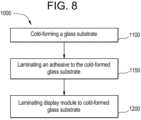
- the methodincludes cold-bending a glass substrate having a first major surface and a second major surface opposite the first major surface to a first radius of curvature as measured on the second major surface, and laminating a display module to the first major surface while maintaining the first radius of curvature in the glass substrate to form the display.
- the display module(or a portion thereof such as a second glass substrate) has a second radius of curvature that is within 10% of the first radius of curvature.
- cold-bending the glass substratemay include applying a vacuum to the second major surface to generate the first radius of curvature.
- the methodmay include laminating an adhesive to the glass substrate before laminating the display module such that the adhesive is disposed between the glass substrate and the display module.
- laminating the display modulemay include laminating a second glass substrate to the glass substrate; and attaching a backlight unit to the second glass substrate.
- the methodincludes curving either one of or both the second glass substrate and the backlight unit to the second radius of curvature. In one or more embodiments, only the second glass substrate is curved to the second radius of curvature and the remaining portions of the display module are flat (such as the backlight unit).
- the methodincludes supporting a glass substrate on a frame.
- the glass substratehas a first major surface and a second major surface opposite the first major surface, and the frame has a curved support surface.
- the first major surface of the glass substratemay face the curved support surface of the frame.
- the methodincludes applying an air pressure differential to the glass substrate while supported by the frame causing the glass substrate to bend such that the glass substrate conforms to the curved shape of the curved support surface of the frame, forming a curved glass substrate.
- the first major surface of the curved glass substrateincludes a curved section and the second major surface of the curved glass substrate includes a curved section.
- a maximum temperature of the glass substrateis less than a glass softening point of the glass substrate.
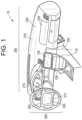
- FIG. 1is a perspective view illustration of a vehicle interior with vehicle interior systems according to one or more embodiments.
- FIG. 2is a side view illustration of a display including a curved glass substrate and a curved display module, according to one or more embodiments.
- FIG. 3is a side view illustration of the glass substrate used in the display of FIG. 2 .
- FIG. 4is a front perspective view illustration of the glass substrate of FIG. 3 .
- FIG. 5is a detailed view illustration of an embodiment of the display module of FIG. 2 .
- FIG. 6is a detailed view illustration of an alternative embodiment of a display module.
- FIG. 7is a detailed view illustration of the display of FIG. 2 .
- FIG. 8is a process flow diagram of a method for forming the display according to one or more embodiments.
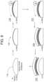
- FIG. 9is an illustration of the method described in FIG. 8 .
- FIG. 10is a flow diagram of a process for forming a display, according to another exemplary embodiment.
- FIG. 11is a flow diagram of a process for forming a display, according to another exemplary embodiment.
- FIG. 12is a detailed view of the process of FIG. 11 , according to another exemplary embodiment.
- FIG. 13is a flow diagram of a process for forming a display, according to another exemplary embodiment.
- FIG. 14is a perspective view of a display, according to an exemplary embodiment.
- FIG. 15is a side view of the display of FIG. 14 , according to an exemplary embodiment.
- FIGS. 16 A- 16 Iare side views of a kit according to one or more embodiments.
- FIGS. 17 A- 17 Iare side views of a kit according to one or more embodiments.
- FIGS. 18 A- 18 Bare side views of a kit according to one or more embodiments.
- FIGS. 19 A- 19 Eare side view schematics illustrating one or more embodiments of a method for forming a display.
- FIG. 20 Ashows a perspective view of a snap-in feature of a frame.
- FIG. 20 Bshows a front exploded view of the frame shown in FIG. 20 A before assembly with a vehicle interior system.
- FIG. 20 Cshows a back exploded view of the frame shown in FIG. 20 A before assembly with a vehicle interior system.
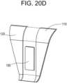
- FIG. 20 Dshows the assembled frame and vehicle interior system of FIGS. 20 B and 20 C .
- a vehicle interior systemmay include a variety of different curved surfaces that are designed to be transparent, such as display surfaces, and the present disclosure provides articles and methods for forming these curved surfaces from a glass material.
- Forming curved vehicle surfaces from a glass materialprovides a number of advantages compared to the typical curved plastic panels that are conventionally found in vehicle interiors.
- glassis typically considered to provide enhanced functionality and user experience for many curved cover material applications, such as display applications and touch screen applications, compared to plastic cover materials.
- Curved glass articlesare typically formed using hot forming processes. As discussed herein a variety of curved glass articles and processes for making the same are provided that avoid the deficiencies of the typical glass hot-forming process. For example, hot-forming processes are energy intensive and increase the cost of forming a curved glass component, relative to the cold-bending process discussed herein. In addition, hot-forming processes typically make application of coatings, such as anti-reflective coatings, significantly more difficult because many coating materials cannot be applied to a flat piece of glass material prior to the hot-forming process as the coating material typically will not survive the high temperatures of the hot-forming process. Further, application of a coating material to surfaces of a curved glass substrate after hot-bending that also meets performance requirements is substantially more difficult than application to a flat glass substrate. In addition, by avoiding the additional high temperature heating steps needed for thermal forming, the glass articles produced via the cold-bending processes and systems discussed herein may have improved optical properties and/or improved surface properties than similarly shaped glass articles made via thermal-shaping processes.
- the systems and processes disclosed hereinspecifically provide for cold-bending of thin glass substrates in an economical and efficient process.
- air pressuree.g., a vacuum or overpressure
- the systems and processes described hereinprovide for such bending and additional curing of bonding adhesive within common equipment and/or common processing steps.
- the processes and systems discussed hereinmay also allow for attachment of the display components to the glass cover substrate during bending utilizing common equipment and/or common processing steps.
- a first aspect of the instant applicationpertains to a vehicle interior system.
- vehicle interior systemmay be incorporated into vehicles such as trains, automobiles (e.g., cars, trucks, buses and the like), seacraft (boats, ships, submarines, and the like), and aircraft (e.g., drones, airplanes, jets, helicopters and the like).
- FIG. 1illustrates an exemplary vehicle interior 10 that includes three different embodiments of a vehicle interior system 100 , 200 , 300 .
- Vehicle interior system 100includes a center console base 110 with a curved surface 120 including a display 130 .
- Vehicle interior system 200includes a dashboard base 210 with a curved surface 220 including a display 230 .
- the dashboard base 210typically includes an instrument panel 215 which may also include a display.
- Vehicle interior system 300includes a dashboard steering wheel base 310 with a curved surface 320 and a display 330 .
- the vehicle interior systemmay include a base that is an arm rest, a pillar, a seat back, a floor board, a headrest, a door panel, or any portion of the interior of a vehicle that includes a curved surface.
- the curved glass substrates discussed hereinmay be used as curved cover glasses for any of the display embodiments discussed herein, including for use in vehicle interior systems 100 , 200 and/or 300 .
- the term “glass substrate”is used in its broadest sense to include any object made wholly or partly of glass. Glass substrates include laminates of glass and non-glass materials, laminates of glass and crystalline materials, and glass-ceramics (including an amorphous phase and a crystalline phase).
- the glass substratemay be transparent or opaque.
- the glass substratemay include a colorant that provides a specific color.
- the display 130includes cold-bent curved glass substrate 140 having a first radius of curvature and a display module 150 attached to the glass substrate, wherein at least a portion of the display module 150 has a second radius of curvature that approximates or matches the first radius of curvature, to provide a display with a curved glass substrate as a cover glass that can be integrated into the curved surface of a vehicle interior system.
- the glass substrate 140includes a first major surface 142 and a second major surface 144 opposite the first major surface.
- the cold-bent glass substrateexhibits the first radius of curvature as measured on the second major surface 144 .
- the terms “cold-bent,” or “cold-bending”refers to curving the glass substrate at a cold-bend temperature which is less than the softening point of the glass (as described herein).
- the term “cold-bendable”refers to the capability of a glass substrate to be cold-bent.
- a feature of a cold-bent glass substrateis asymmetric surface compressive stress between the first major surface 142 and the second major surface 144 .
- a minor surface 146connects the first major surface 142 and the second major surface 144 .
- the respective compressive stresses in the first major surface 142 and the second major surface 144 of the glass substrateare substantially equal.
- the first major surface 142 and the second major surface 144exhibit no appreciable compressive stress, prior to cold-bending.
- the first major surface 142 and the second major surface 144exhibit substantially equal compressive stress with respect to one another, prior to cold-bending.
- after cold-bendingshown, for example, in FIGS. 2 and 7 , the compressive stress on the surface having a concave shape after bending (e.g., second major surface 144 in FIGS. 2 and 7 ) increases.
- the compressive stress on the concave surfaceis greater after cold-bending than before cold-bending
- the cold-bending processincreases the compressive stress of the glass substrate being shaped to compensate for tensile stresses imparted during bending and/or forming operations.
- the cold-bending processcauses the concave surface (second major surface 144 ) to experience compressive stresses, while the surface forming a convex shape (i.e., the first major surface 142 in FIGS. 2 and 7 ) after cold-bending experiences tensile stresses.
- the tensile stress experienced by the convex (i.e., the first major surface 142 ) following cold-bendingresults in a net decrease in surface compressive stress, such that the compressive stress in convex surface (i.e., the first major surface 142 ) of a strengthened glass substrate following cold-bending is less than the compressive stress on the same surface (i.e., first major surface 142 ) when the glass substrate is flat.
- the first major surface and the second major surfacecomprise a compressive stress that is substantially equal to one another prior to cold-bending, and thus the first major surface can experience greater tensile stress during cold-bending without risking fracture. This allows for the strengthened glass substrate to conform to more tightly curved surfaces or shapes.
- the thickness of the glass substrateis tailored to allow the glass substrate to be more flexible to achieve the desired radius of curvature. Moreover, a thinner glass substrate 140 may deform more readily, which could potentially compensate for shape mismatches and gaps that may be created by the shape of the display module 150 (when curved). In one or more embodiments, a thin and strengthened glass substrate 140 exhibits greater flexibility especially during cold-bending. The greater flexibility of the glass substrates discussed herein may both allow for sufficient degrees of bending to be created via the air pressure-based bending processes as discussed herein and also for consistent bend formation without heating. In one or more embodiments, the glass substrate 140 and at least a portion of the display module 150 have substantially similar radii of curvature to provide a substantially uniform distance between the first major surface 142 and the display module 150 (which may be filled with an adhesive).
- the cold-bent glass substrate(and optionally the curved display module) may have a compound curve including a major radius and a cross curvature.
- a complexly curved cold-bent glass substrate (and optionally the curved display module) according to one or more embodimentsmay have a distinct radius of curvature in two independent directions.
- the complexly curved cold-bent glass substratemay thus be characterized as having “cross curvature,” where the cold-bent glass substrate (and optionally the curved display module) are curved along an axis (i.e., a first axis) that is parallel to a given dimension and also curved along an axis (i.e., a second axis) that is perpendicular to the same dimension.
- the curvature of the cold-bent glass substrate (and optionally the curved display module)can be even more complex when a significant minimum radius is combined with a significant cross curvature, and/or depth of bend.
- the glass substratehas a thickness (t) that is substantially constant and is defined as a distance between the first major surface 142 and the second major surface 144 .
- the thickness (t) as used hereinrefers to the maximum thickness of the glass substrate.
- the glass substrateincludes a width (W) defined as a first maximum dimension of one of the first or second major surfaces orthogonal to the thickness (t), and a length (L) defined as a second maximum dimension of one of the first or second surfaces orthogonal to both the thickness and the width.
- Wwidth
- Llength
- the dimensions discussed hereinmay be average dimensions.
- the glass substratehas a thickness (t) that is about 1.5 mm or less.
- the thicknessmay be in a range from about 0.01 mm to about 1.5 mm, 0.02 mm to about 1.5 mm, 0.03 mm to about 1.5 mm, 0.04 mm to about 1.5 mm, 0.05mm to about 1.5 mm, 0.06 mm to about 1.5 mm, 0.07 mm to about 1.5 mm, 0.08 mm to about 1.5 mm, 0.09 mm to about 1.5 mm, 0.1 mm to about 1.5 mm, from about 0.15 mm to about 1.5 mm, from about 0.2 mm to about 1.5 mm, from about 0.25 mm to about 1.5 mm, from about 0.3 mm to about 1.5 mm, from about 0.35 mm to about 1.5 mm, from about 0.4 mm to about 1.5 mm, from about 0.45 mm to about 1.5 mm, from about 0.5 mm to about 1.5 mm, from about 0.55 mm to about 1.5 mm, from about 0.6 mm to about 1.5
- the glass substratehas a width (W) in a range from about 5 cm to about 250 cm, from about 10 cm to about 250 cm, from about 15 cm to about 250 cm, from about 20 cm to about 250 cm, from about 25 cm to about 250 cm, from about 30 cm to about 250 cm, from about 35 cm to about 250 cm, from about 40 cm to about 250 cm, from about 45 cm to about 250 cm, from about 50 cm to about 250 cm, from about 55 cm to about 250 cm, from about 60 cm to about 250 cm, from about 65 cm to about 250 cm, from about 70 cm to about 250 cm, from about 75 cm to about 250 cm, from about 80 cm to about 250 cm, from about 85 cm to about 250 cm, from about 90 cm to about 250 cm, from about 95 cm to about 250 cm, from about 100 cm to about 250 cm, from about 110 cm to about 250 cm, from about 120 cm to about 250 cm, from about 130 cm to about 250 cm, from about 140 cm to about 250 cm, from about 150 cm to about 250 cm, from about 5 cm to about 240 cm
- the glass substratehas a length (L) in a range from about 5 cm to about 250 cm, from about 10 cm to about 250 cm, from about 15 cm to about 250 cm, from about 20 cm to about 250 cm, from about 25 cm to about 250 cm, from about 30 cm to about 250 cm, from about 35 cm to about 250 cm, from about 40 cm to about 250 cm, from about 45 cm to about 250 cm, from about 50 cm to about 250 cm, from about 55 cm to about 250 cm, from about 60 cm to about 250 cm, from about 65 cm to about 250 cm, from about 70 cm to about 250 cm, from about 75 cm to about 250 cm, from about 80 cm to about 250 cm, from about 85 cm to about 250 cm, from about 90 cm to about 250 cm, from about 95 cm to about 250 cm, from about 100 cm to about 250 cm, from about 110 cm to about 250 cm, from about 120 cm to about 250 cm, from about 130 cm to about 250 cm, from about 140 cm to about 250 cm, from about 150 cm to about 250 cm, from about 5 cm to about 240 cm
- the glass substratemay be strengthened.
- the glass substratemay be strengthened to include compressive stress that extends from a surface to a depth of compression (DOC).
- DOCdepth of compression
- the compressive stress regionsare balanced by a central portion exhibiting a tensile stress.
- the stresscrosses from a compressive stress to a tensile stress.
- the compressive stress and the tensile stressare provided herein as absolute values.
- the glass substratemay be strengthened mechanically by utilizing a mismatch of the coefficient of thermal expansion between portions of the article to create a compressive stress region and a central region exhibiting a tensile stress.
- the glass substratemay be strengthened thermally by heating the glass to a temperature above the glass transition point and then rapidly quenching.
- the glass substratemay be chemically strengthening by ion exchange.
- ions at or near the surface of the glass substrateare replaced by—or exchanged with—larger ions having the same valence or oxidation state.
- ions in the surface layer of the article and the larger ionsare monovalent alkali metal cations, such as Li + , Na + , K + , Rb + , and Cs + .
- monovalent cations in the surface layermay be replaced with monovalent cations other than alkali metal cations, such as Ag + or the like.
- the monovalent ions (or cations) exchanged into the glass substrategenerate a stress.
- Ion exchange processesare typically carried out by immersing a glass substrate in a molten salt bath (or two or more molten salt baths) containing the larger ions to be exchanged with the smaller ions in the glass substrate.
- a molten salt bathor two or more molten salt baths
- aqueous salt bathsmay also be utilized.
- the composition of the bath(s)may include more than one type of larger ion (e.g., Na+ and K+) or a single larger ion.
- parameters for the ion exchange processincluding, but not limited to, bath composition and temperature, immersion time, the number of immersions of the glass substrate in a salt bath (or baths), use of multiple salt baths, additional steps such as annealing, washing, and the like, are generally determined by the composition of the glass substrate (including the structure of the article and any crystalline phases present) and the desired DOC and CS of the glass substrate that results from strengthening.
- Exemplary molten bath compositionmay include nitrates, sulfates, and chlorides of the larger alkali metal ion. Typical nitrates include KNO 3 , NaNO 3 , LiNO 3 , NaSO 4 and combinations thereof.
- the temperature of the molten salt bathtypically is in a range from about 380° C. up to about 450° C., while immersion times range from about 15 minutes up to about 100 hours depending on glass substrate thickness, bath temperature and glass (or monovalent ion) diffusivity. However, temperatures and immersion times different from those described above may also be used.
- the glass substratesmay be immersed in a molten salt bath of 100% NaNO 3 , 100% KNO 3 , or a combination of NaNO 3 and KNO 3 having a temperature from about 370° C. to about 480° C.
- the glass substratemay be immersed in a molten mixed salt bath including from about 1% to about 99% KNO 3 and from about 1% to about 99% NaNO 3 .
- the glass substratemay be immersed in a second bath, after immersion in a first bath.
- the first and second bathsmay have different compositions and/or temperatures from one another.
- the immersion times in the first and second bathsmay vary. For example, immersion in the first bath may be longer than the immersion in the second bath.
- the glass substratemay be immersed in a molten, mixed salt bath including NaNO 3 and KNO 3 (e.g., 49%/51%, 50%/50%, 51%/49%) having a temperature less than about 420° C. (e.g., about 400° C. or about 380° C.). for less than about 5 hours, or even about 4 hours or less.
- a molten, mixed salt bathincluding NaNO 3 and KNO 3 (e.g., 49%/51%, 50%/50%, 51%/49%) having a temperature less than about 420° C. (e.g., about 400° C. or about 380° C.). for less than about 5 hours, or even about 4 hours or less.
- Ion exchange conditionscan be tailored to provide a “spike” or to increase the slope of the stress profile at or near the surface of the resulting glass substrate.
- the spikemay result in a greater surface CS value.
- This spikecan be achieved by single bath or multiple baths, with the bath(s) having a single composition or mixed composition, due to the unique properties of the glass compositions used in the glass substrates described herein.
- the different monovalent ionsmay exchange to different depths within the glass substrate (and generate different magnitudes stresses within the glass substrate at different depths).
- the resulting relative depths of the stress-generating ionscan be determined and cause different characteristics of the stress profile.
- CSis measured using those means known in the art, such as by surface stress meter (FSM) using commercially available instruments such as the FSM-6000, manufactured by Orihara Industrial Co., Ltd. (Japan).
- FSMsurface stress meter
- FSM-6000manufactured by Orihara Industrial Co., Ltd. (Japan).
- SOCstress optical coefficient
- SOCfiber and four point bend methods, both of which are described in ASTM standard C770-98 (2013), entitled “Standard Test Method for Measurement of Glass Stress-Optical Coefficient,” the contents of which are incorporated herein by reference in their entirety, and a bulk cylinder method.
- CSmay be the “maximum compressive stress” which is the highest compressive stress value measured within the compressive stress layer.
- the maximum compressive stressis located at the surface of the glass substrate. In other embodiments, the maximum compressive stress may occur at a depth below the surface, giving the compressive profile the appearance of a “buried peak.”
- DOCmay be measured by FSM or by a scattered light polariscope (SCALP) (such as the SCALP-04 scattered light polariscope available from Glasstress Ltd., located in Tallinn Estonia), depending on the strengthening method and conditions.
- SCALPscattered light polariscope
- FSM or SCALPmay be used depending on which ion is exchanged into the glass substrate.
- FSMis used to measure DOC.
- SCALPis used to measure DOC.
- the DOCis measured by SCALP, since it is believed the exchange depth of sodium indicates the DOC and the exchange depth of potassium ions indicates a change in the magnitude of the compressive stress (but not the change in stress from compressive to tensile); the exchange depth of potassium ions in such glass substrates is measured by FSM.
- Central tension or CTis the maximum tensile stress and is measured by SCALP.
- the glass substratemaybe strengthened to exhibit a DOC that is described a fraction of the thickness t of the glass substrate (as described herein).
- the DOCmay be equal to or greater than about 0.05 t, equal to or greater than about 0.1 t, equal to or greater than about 0.11 t, equal to or greater than about 0.12 t, equal to or greater than about 0.13 t, equal to or greater than about 0.14 t, equal to or greater than about 0.15 t, equal to or greater than about 0.16 t, equal to or greater than about 0.17 t, equal to or greater than about 0.18 t, equal to or greater than about 0.19 t, equal to or greater than about 0.2 t, equal to or greater than about 0.21 t.
- the DOCmay be in a range from about 0.08 t to about 0.25 t, from about 0.09 t to about 0.25 t, from about 0.18 t to about 0.25 t, from about 0.11 t to about 0.25 t, from about 0.12 t to about 0.25 t, from about 0.13 t to about 0.25 t, from about 0.14 t to about 0.25 t, from about 0.15 t to about 0.25 t, from about 0.08 t to about 0.24 t, from about 0.08 t to about 0.23 t, from about 0.08 t to about 0.22 t, from about 0.08 t to about 0.21 t, from about 0.08 t to about 0.2 t, from about 0.08 t to about 0.19 t, from about 0.08 t to about 0.18 t, from about 0.08 t to about 0.17 t, from about 0.08 t to about 0.16 t, or from about 0.08 t to about 0.15 t.
- the DOCmay be about 20 ⁇ m or less. In one or more embodiments, the DOC may be about 40 ⁇ m or greater (e.g., from about 40 ⁇ m to about 300 ⁇ m, from about 50 ⁇ m to about 300 ⁇ m, from about 60 ⁇ m to about 300 ⁇ m, from about 70 ⁇ m to about 300 ⁇ m, from about 80 ⁇ m to about 300 ⁇ m, from about 90 ⁇ m to about 300 ⁇ m, from about 100 ⁇ m to about 300 ⁇ m, from about 110 ⁇ m to about 300 ⁇ m, from about 120 ⁇ m to about 300 ⁇ m, from about 140 ⁇ m to about 300 ⁇ m, from about 150 ⁇ m to about 300 ⁇ m, from about 40 ⁇ m to about 290 ⁇ m, from about 40 ⁇ m to about 280 ⁇ m, from about 40 ⁇ m to about 260 ⁇ m, from about 40 ⁇ m to about 250 ⁇ m, from about 40 ⁇ m to about 240 ⁇ m, from
- the strengthened glass substratemay have a CS (which may be found at the surface or a depth within the glass substrate) of about 200 MPa or greater, 300 MPa or greater, 400 MPa or greater, about 500 MPa or greater, about 600 MPa or greater, about 700 MPa or greater, about 800 MPa or greater, about 900 MPa or greater, about 930 MPa or greater, about 1000 MPa or greater, or about 1050 MPa or greater.
- CSwhich may be found at the surface or a depth within the glass substrate
- the strengthened glass substratemay have a CS (which may be found at the surface or a depth within the glass substrate) from about 200 MPa to about 1050 MPa, from about 250 MPa to about 1050 MPa, from about 300 MPa to about 1050 MPa, from about 350 MPa to about 1050 MPa, from about 400 MPa to about 1050 MPa, from about 450 MPa to about 1050 MPa, from about 500 MPa to about 1050 MPa, from about 550 MPa to about 1050 MPa, from about 600 MPa to about 1050 MPa, from about 200 MPa to about 1000 MPa, from about 200 MPa to about 950 MPa, from about 200 MPa to about 900 MPa, from about 200 MPa to about 850 MPa, from about 200 MPa to about 800 MPa, from about 200 MPa to about 750 MPa, from about 200 MPa to about 700 MPa, from about 200 MPa to about 650 MPa, from about 200 MPa to about 600 MPa, from about 200 MPa to about 750 MPa, from
- the strengthened glass substratemay have a maximum tensile stress or central tension (CT) of about 20 MPa or greater, about 30 MPa or greater, about 40 MPa or greater, about 45 MPa or greater, about 50 MPa or greater, about 60 MPa or greater, about 70 MPa or greater, about 75 MPa or greater, about 80 MPa or greater, or about 85 MPa or greater.
- CTmaximum tensile stress or central tension
- the maximum tensile stress or central tensionmay be in a range from about 40 MPa to about 100 MPa, from about 50 MPa to about 100 MPa, from about 60 MPa to about 100 MPa, from about 70 MPa to about 100 MPa, from about 80 MPa to about 100 MPa, from about 40 MPa to about 90 MPa, from about 40 MPa to about 80 MPa, from about 40 MPa to about 70 MPa, or from about 40 MPa to about 60 MPa.
- the strengthened glass substrateexhibits a stress profile along the depth or thickness thereof that exhibits a parabolic-like shape, as described in U.S. Pat. No. 9,593,042, entitled “Glasses and glass ceramics including metal oxide concentration gradient”, which is hereby incorporated by reference in its entirety.
- Stress profilerefers to the changes in stress from the first major surface to the second major surface. The stress profile may be described in terms of MPa at a given micrometer of thickness or depth from the first major surface or the second major surface. In one or more specific embodiments, the stress profile is substantially free of a flat stress (i.e., compressive or tensile) portion or a portion that exhibits a substantially constant stress (i.e., compressive or tensile).
- the region of the glass substrate exhibiting a tensile stresshas a stress profile that is substantially free of a flat stress or free of a substantially constant stress.
- all points of the stress profile between a thicknessrange from about 0 t up to about 0.2 ⁇ t and greater than 0.8 ⁇ t (or from about 0 ⁇ t to about 0.3 ⁇ t and greater than 0.7 ⁇ t) comprise a tangent that is less than about ⁇ 0.1 MPa/micrometers or greater than about 0.1 MPa/micrometers.
- the tangentmay be less than about ⁇ 0.2 MPa/micrometers or greater than about 0.2 MPa/micrometers.
- the tangentmay be less than about ⁇ 0.3 MPa/micrometers or greater than about 0.3 MPa/micrometers. In an even more specific embodiment, the tangent may be less than about ⁇ 0.5 MPa/micrometers or greater than about 0.5 MPa/micrometers.
- the stress profile of one or more embodiments along these thickness rangesi.e., 0 ⁇ t up to about 2 ⁇ t and greater than 0.8 t, or from about Otto about 0.3 ⁇ t and 0.7 ⁇ t or greater
- stress profiles that exhibit error function or quasi-linear shapeshave points along these thickness ranges (i.e., 0 ⁇ t up to about 2 ⁇ t and greater than 0.8 ⁇ t, or from about 0 ⁇ t to about 0.3 ⁇ t and 0.7 ⁇ t or greater) that have a tangent that is from about ⁇ 0.1 MPa/micrometers to about 0.1 MPa/micrometers, from about ⁇ 0.2 MPa/micrometers to about 0.2 MPa/micrometers, from about ⁇ 0.3 MPa/micrometers to about 0.3 MPa/micrometers, or from about ⁇ 0.5 MPa/micrometers to about 0.5 MPa/micrometers (indicating a flat or zero slope stress profile along such thickness ranges, as shown in FIG. 2 , 220 ).
- the stress profiles of one or more embodiments of this disclosuredo not exhibit such a stress profile having a flat or zero slope stress profile along these thickness ranges.
- the strengthened glass substrateexhibits a stress profile a thickness range from about 0.1—t to 0.3 ⁇ t and from about 0.7 ⁇ t to 0.9 ⁇ t that comprises a maximum tangent and a minimum tangent.
- the difference between the maximum tangent and the minimum tangentis about 3.5 MPa/micrometers or less, about 3 MPa/micrometers or less, about 2.5 MPa/micrometers or less, or about 2 MPa/micrometers or less.
- the stress profile of the strengthened glass substratemay be substantially free of any linear segments that extend in a depth direction or along at least a portion of the thickness t of the glass substrate. In other words, the stress profile is substantially continuously increasing or decreasing along the thickness t. In some embodiments, the stress profile is substantially free of any linear segments in a depth or thickness direction having a length of about 10 micrometers or more, about 50 micrometers or more, or about 100 micrometers or more, or about 200 micrometers or more. As used herein, the term “linear” refers to a slope having a magnitude of less than about 5 MPa/micrometer, or less than about 2 MPa/micrometer along the linear segment.
- one or more portions of the stress profile that are substantially free of any linear segments in a depth directionare present at depths within the strengthened glass substrate of about 5 micrometers or greater (e.g., 10 micrometers or greater, or 15 micrometers or greater) from either one or both the first major surface or the second major surface.
- the stress profilemay include linear segments, but from a depth of about 5 micrometers or greater from the first surface, the stress profile may be substantially free of linear segments.
- the stress profilemay include linear segments at depths from about 0 t up to about 0.1 t and may be substantially free of linear segments at depths of about 0.1 t to about 0.4 t.
- the stress profile from a thickness in the range from about 0 t to about 0.1 tmay have a slope in the range from about 20 MPa/microns to about 200 MPa/microns.
- such embodimentsmay be formed using a single ion-exchange process by which the bath includes two or more alkali salts or is a mixed alkali salt bath or multiple (e.g., 2 or more) ion exchange processes.
- the strengthened glass substratemay be described in terms of the shape of the stress profile along the CT region or the region in the glass substrate that exhibits tensile stress.
- the stress profile along the CT region(where stress is in tension) may be approximated by equation.
- the stress (x)is the stress value at position x.
- the stressis positive (tension).
- MaxCTis the maximum central tension as a positive value in MPa.
- the parabolic-like stress profileis generated due to a non-zero concentration of a metal oxide(s) that varies along a portion of the thickness.
- the variation in concentrationmay be referred to herein as a gradient.
- the concentration of a metal oxideis non-zero and varies, both along a thickness range from about 0 ⁇ t to about 0.3 ⁇ t.
- the concentration of the metal oxideis non-zero and varies along a thickness range from about 0 ⁇ t to about 0.35 ⁇ t, from about 0 ⁇ t to about 0.4 ⁇ t, from about 0 ⁇ t to about 0.45 ⁇ t or from about 0 ⁇ t to about 0.48 ⁇ t.
- the metal oxidemay be described as generating a stress in the strengthened glass substrate.
- the variation in concentrationmay be continuous along the above-referenced thickness ranges. Variation in concentration may include a change in metal oxide concentration of about 0.2 mol % along a thickness segment of about 100 micrometers. This change may be measured by known methods in the art including microprobe.
- the metal oxide that is non-zero in concentration and varies along a portion of the thicknessmay be described as generating a stress in the strengthened glass substrate.
- the variation in concentrationmay be continuous along the above-referenced thickness ranges. In some embodiments, the variation in concentration may be continuous along thickness segments in the range from about 10 micrometers to about 30 micrometers. In some embodiments, the concentration of the metal oxide decreases from the first surface to a point between the first surface and the second surface and increases from the point to the second surface.
- the concentration of metal oxidemay include more than one metal oxide (e.g., a combination of Na 2 O and K 2 O).
- the concentration of ions having a larger radiusis greater than the concentration of ions having a smaller radius at shallow depths, while the at deeper depths, the concentration of ions having a smaller radius is greater than the concentration of ions having larger radius.
- the concentration of K+ ions in the strengthened glass substrateis greater than the concentration of Na+ ions at shallower depths, while the concentration of Na+ is greater than the concentration of K+ ions at deeper depths.
- the area at or near the surfacecomprises a greater CS due to the greater amount of larger ions at or near the surface.
- This greater CSmay be exhibited by a stress profile having a steeper slope at or near the surface (i.e., a spike in the stress profile at the surface).
- the concentration gradient or variation of one or more metal oxidesis created by chemically strengthening the glass substrate, for example, by the ion exchange processes previously described herein, in which a plurality of first metal ions in the glass substrate is exchanged with a plurality of second metal ions.
- the first ionsmay be ions of lithium, sodium, potassium, and rubidium.
- the second metal ionsmay be ions of one of sodium, potassium, rubidium, and cesium, with the proviso that the second alkali metal ion has an ionic radius greater than the ionic radius than the first alkali metal ion.
- the second metal ionis present in the glass substrate as an oxide thereof (e.g., Na 2 O, K 2 O, Rb 2 O, Cs 2 O or a combination thereof).
- the metal oxide concentration gradientextends through a substantial portion of the thickness t or the entire thickness t of the strengthened glass substrate, including the CT region. In one or more embodiments, the concentration of the metal oxide is about 0.5 mol % or greater in the CT region. In some embodiments, the concentration of the metal oxide may be about 0.5 mol % or greater (e.g., about 1 mol % or greater) along the entire thickness of the strengthened glass substrate, and is greatest at the first major surface and/or the second major surface and decreases substantially constantly to a point between the first major surface and the second major surface. At that point, the concentration of the metal oxide is the least along the entire thickness t; however the concentration is also non-zero at that point.
- the non-zero concentration of that particular metal oxideextends along a substantial portion of the thickness t (as described herein) or the entire thickness t.
- the lowest concentration in the particular metal oxideis in the CT region.
- the total concentration of the particular metal oxide in the strengthened glass substratemay be in the range from about 1 mol % to about 20 mol %.
- the strengthened glass substrateincludes a first metal oxide concentration and a second metal oxide concentration, such that the first metal oxide concentration is in the range from about 0 mol % to about 15 mol % along a first thickness range from about Ot to about 0.5 t, and the second metal oxide concentration is in the range from about 0 mol % to about 10 mol % from a second thickness range from about 0 micrometers to about 25 micrometers (or from about 0 micrometers to about 12 micrometers).
- the strengthened glass substratemay include an optional third metal oxide concentration.
- the first metal oxidemay include Na 2 O while the second metal oxide may include K2O.
- the concentration of the metal oxidemay be determined from a baseline amount of the metal oxide in the glass substrate prior to being modified to include the concentration gradient of such metal oxide.
- Suitable glass compositions for use in the glass substrateinclude soda lime glass, aluminosilicate glass, borosilicate glass, boroaluminosilicate glass, alkali-containing aluminosilicate glass, alkali-containing borosilicate glass, and alkali-containing boroaluminosilicate glass.
- the glass compositions disclosed hereinare described in mole percent (mol %) as analyzed on an oxide basis.
- the glass compositionmay include SiO 2 in an amount in a range from about 66 mol % to about 80 mol %, from about 67 mol % to about 80 mol %, from about 68 mol % to about 80 mol %, from about 69 mol % to about 80 mol %, from about 70 mol % to about 80 mol %, from about 72 mol % to about 80 mol %, from about 65 mol % to about 78 mol %, from about 65 mol % to about 76 mol %, from about 65 mol % to about 75 mol %, from about 65 mol % to about 74 mol %, from about 65 mol % to about 72 mol %, or from about 65 mol % to about 70 mol %, and all ranges and sub-ranges therebetween.
- the glass compositionincludes Al 2 O 3 in an amount greater than about 4 mol %, or greater than about 5 mol %. In one or more embodiments, the glass composition includes Al 2 O 3 in a range from greater than about 7 mol % to about 15 mol %, from greater than about 7 mol % to about 14 mol %, from about 7 mol % to about 13 mol %, from about 4 mol % to about 12 mol %, from about 7 mol % to about 11 mol %, from about 8 mol % to about 15 mol %, from 9 mol % to about 15 mol %, from about 9 mol % to about 15 mol %, from about 10 mol % to about 15 mol %, from about 11 mol % to about 15 mol %, or from about 12 mol % to about 15 mol %, and all ranges and sub-ranges therebetween. In one or more embodiments, the upper limit of Al 2 O 3 may be about
- the glass articleis described as an aluminosilicate glass article or including an aluminosilicate glass composition.
- the glass composition or article formed therefromincludes SiO 2 and Al 2 O 3 and is not a soda lime silicate glass.
- the glass composition or article formed therefromincludes Al 2 O 3 in an amount of about 2 mol % or greater, 2.25 mol % or greater, 2.5 mol % or greater, about 2.75 mol % or greater, about 3 mol % or greater.
- the glass compositioncomprises B 2 O 3 (e.g., about 0.01 mol % or greater). In one or more embodiments, the glass composition comprises B 2 O 3 in an amount in a range from about 0 mol % to about 5 mol %, from about 0 mol % to about 4 mol %, from about 0 mol % to about 3 mol %, from about 0 mol % to about 2 mol %, from about 0 mol % to about 1 mol %, from about 0 mol % to about 0.5 mol %, from about 0.1 mol % to about 5 mol %, from about 0.1 mol % to about 4 mol %, from about 0.1 mol % to about 3 mol %, from about 0.1 mol % to about 2 mol %, from about 0.1 mol % to about 1 mol %, from about 0.1 mol % to about 0.5 mol %, and all ranges and sub-range
- the phrase “substantially free” with respect to the components of the compositionmeans that the component is not actively or intentionally added to the composition during initial batching, but may be present as an impurity in an amount less than about 0.001 mol %.
- the glass compositionoptionally comprises P 2 O 5 (e.g., about 0.01 mol % or greater). In one or more embodiments, the glass composition comprises a non-zero amount of P 2 O 5 up to and including 2 mol %, 1.5 mol %, 1 mol %, or 0.5 mol %. In one or more embodiments, the glass composition is substantially free of P 2 O 5 .
- the glass compositionmay include a total amount of R 2 O (which is the total amount of alkali metal oxide such as Li 2 O, Na 2 O, K 2 O, Rb 2 O, and Cs 2 O) that is greater than or equal to about 8 mol %, greater than or equal to about 10 mol %, or greater than or equal to about 12 mol %.
- R 2 Owhich is the total amount of alkali metal oxide such as Li 2 O, Na 2 O, K 2 O, Rb 2 O, and Cs 2 O
- the glass compositionincludes a total amount of R 2 O in a range from about 8 mol % to about 20 mol %, from about 8 mol % to about 18 mol %, from about 8 mol % to about 16 mol %, from about 8 mol % to about 14 mol %, from about 8 mol % to about 12 mol %, from about 9 mol % to about 20 mol %, from about 10 mol % to about 20 mol %, from about 11 mol % to about 20 mol %, from about 12 mol % to about 20 mol %, from about 13 mol % to about 20 mol %, from about 10 mol % to about 14 mol %, or from 11 mol % to about 13 mol %, and all ranges and sub-ranges therebetween.
- the glass compositionmay be substantially free of Rb 2 O, Cs 2 O or both Rb 2 O and Cs 2 O.
- the R 2 Omay include the total amount of Li 2 O, Na 2 O and K 2 O only.
- the glass compositionmay comprise at least one alkali metal oxide selected from Li 2 O, Na 2 O and K 2 O, wherein the alkali metal oxide is present in an amount greater than about 8 mol % or greater.
- the glass compositioncomprises Na 2 O in an amount greater than or equal to about 8 mol %, greater than or equal to about 10 mol %, or greater than or equal to about 12 mol %.
- the compositionincludes Na 2 O in a range from about from about 8 mol % to about 20 mol %, from about 8 mol % to about 18 mol %, from about 8 mol % to about 16 mol %, from about 8 mol % to about 14 mol %, from about 8 mol % to about 12 mol %, from about 9 mol % to about 20 mol %, from about 10 mol % to about 20 mol %, from about 11 mol % to about 20 mol %, from about 12 mol % to about 20 mol %, from about 13 mol % to about 20 mol %, from about 10 mol % to about 14 mol %, or from 11 mol % to about 16 mol %, and all
- the glass compositionincludes less than about 4 mol % K 2 O, less than about 3 mol % K 2 O, or less than about 1 mol % K 2 O.
- the glass compositionmay include K 2 O in an amount in a range from about 0 mol % to about 4 mol %, from about 0 mol % to about 3.5 mol %, from about 0 mol % to about 3 mol %, from about 0 mol % to about 2.5 mol %, from about 0 mol % to about 2 mol %, from about 0 mol % to about 1.5 mol %, from about 0 mol % to about 1 mol %, from about 0 mol % to about 0.5 mol %, from about 0 mol % to about 0.2 mol %, from about 0 mol % to about 0.1 mol %, from about 0.5 mol % to about 4 mol %, from about 0.5 mol %
- the glass compositionis substantially free of Li 2 O.
- the amount of Na 2 O in the compositionmay be greater than the amount of Li 2 O. In some instances, the amount of Na 2 O may be greater than the combined amount of Li 2 O and K 2 O. In one or more alternative embodiments, the amount of Li 2 O in the composition may be greater than the amount of Na 2 O or the combined amount of Na 2 O and K 2 O.
- the glass compositionmay include a total amount of RO (which is the total amount of alkaline earth metal oxide such as CaO, MgO, BaO, ZnO and SrO) in a range from about 0 mol % to about 2 mol %. In some embodiments, the glass composition includes a non-zero amount of RO up to about 2 mol %.
- ROalkaline earth metal oxide
- the glass compositioncomprises RO in an amount from about 0 mol % to about 1.8 mol %, from about 0 mol % to about 1.6 mol %, from about 0 mol % to about 1.5 mol %, from about 0 mol % to about 1.4 mol %, from about 0 mol % to about 1.2 mol %, from about 0 mol % to about 1 mol %, from about 0 mol % to about 0.8 mol %, from about 0 mol % to about 0.5 mol %, and all ranges and sub-ranges therebetween.
- the glass compositionincludes CaO in an amount less than about 1 mol %, less than about 0.8 mol %, or less than about 0.5 mol %. In one or more embodiments, the glass composition is substantially free of CaO.
- the glass compositioncomprises MgO in an amount from about 0 mol % to about 7 mol %, from about 0 mol % to about 6 mol %, from about 0 mol % to about 5 mol %, from about 0 mol % to about 4 mol %, from about 0.1 mol % to about 7 mol %, from about 0.1 mol % to about 6 mol %, from about 0.1 mol % to about 5 mol %, from about 0.1 mol % to about 4 mol %, from about 1 mol % to about 7 mol %, from about 2 mol % to about 6 mol %, or from about 3 mol % to about 6 mol %, and all ranges and sub-ranges therebetween.
- the glass compositioncomprises ZrO 2 in an amount equal to or less than about 0.2 mol %, less than about 0.18 mol %, less than about 0.16 mol %, less than about 0.15 mol %, less than about 0.14 mol %, less than about 0.12 mol %.
- the glass compositioncomprises ZrO 2 in a range from about 0.01 mol % to about 0.2 mol %, from about 0.01 mol % to about 0.18 mol %, from about 0.01 mol % to about 0.16 mol %, from about 0.01 mol % to about 0.15 mol %, from about 0.01 mol % to about 0.14 mol %, from about 0.01 mol % to about 0.12 mol %, or from about 0.01 mol % to about 0.10 mol %, and all ranges and sub-ranges therebetween.
- the glass compositioncomprises SnO 2 in an amount equal to or less than about 0.2 mol %, less than about 0.18 mol %, less than about 0.16 mol %, less than about 0.15 mol %, less than about 0.14 mol %, less than about 0.12 mol %.
- the glass compositioncomprises SnO2 in a range from about 0.01 mol % to about 0.2 mol %, from about 0.01 mol % to about 0.18 mol %, from about 0.01 mol % to about 0.16 mol %, from about 0.01 mol % to about 0.15 mol %, from about 0.01 mol % to about 0.14 mol %, from about 0.01 mol % to about 0.12 mol %, or from about 0.01 mol % to about 0.10 mol %, and all ranges and sub-ranges therebetween.
- the glass compositionmay include an oxide that imparts a color or tint to the glass articles.
- the glass compositionincludes an oxide that prevents discoloration of the glass article when the glass article is exposed to ultraviolet radiation.
- oxidesinclude, without limitation oxides of. Ti, V, Cr, Mn, Fe, Co, Ni, Cu, Ce, W, and Mo.
- the glass compositionincludes Fe expressed as Fe 2 O 3 , wherein Fe is present in an amount up to (and including) about 1 mol %. In some embodiments, the glass composition is substantially free of Fe. In one or more embodiments, the glass composition comprises Fe 2 O 3 in an amount equal to or less than about 0.2 mol %, less than about 0.18 mol %, less than about 0.16 mol %, less than about 0.15 mol %, less than about 0.14 mol %, less than about 0.12 mol %.
- the glass compositioncomprises Fe 2 O 3 in a range from about 0.01 mol % to about 0.2 mol %, from about 0.01 mol % to about 0.18 mol %, from about 0.01 mol % to about 0.16 mol %, from about 0.01 mol % to about 0.15 mol %, from about 0.01 mol % to about 0.14 mol %, from about 0.01 mol % to about 0.12 mol %, or from about 0.01 mol % to about 0.10 mol %, and all ranges and sub-ranges therebetween.
- TiO 2may be present in an amount of about 5 mol % or less, about 2.5 mol % or less, about 2 mol % or less or about 1 mol % or less. In one or more embodiments, the glass composition may be substantially free of TiO 2 .
- An exemplary glass compositionincludes SiO 2 in an amount in a range from about 65 mol % to about 75 mol %, Al 2 O 3 in an amount in a range from about 8 mol % to about 14 mol %, Na 2 O in an amount in a range from about 12 mol % to about 17 mol %, K 2 O in an amount in a range of about 0 mol % to about 0.2 mol %, and MgO in an amount in a range from about 1.5 mol % to about 6 mol %.
- SnO 2may be included in the amounts otherwise disclosed herein.
- the cold-bent glass substrate 140has a curvature (first radius of curvature) that matches the curvature (second radius of curvature) of at least a portion of the display module 150 (or matches the radius of curvature of the curved surface of the base of the vehicle interior system). In one or more embodiments, at least a portion of the display module 150 is curved to approach or match the curvature of the cold-bent glass substrate 140 . In one or more embodiments, the display module 150 includes a second glass substrate, a backlight unit and other components, any of which may be flexible or may permanently exhibit a curvature. In some embodiments, the entire display module is curved to a second radius of curvature.
- the glass substrate 140is cold-bent to a curvature that approaches or matches the curvature of at least a portion of the display module 150 . In one or more embodiments, at least a portion of the display module 150 is cold-bent to a curvature that approaches or matches the curvature of the cold-bent glass substrate 140 .
- the first radius of curvature of the glass substratewhen the first radius of curvature of the glass substrate varies across its area, the first radius of curvature referred to herein is the minimum radius of curvature of the glass substrate.
- the second radius of curvature of the display modulewhen the second radius of curvature of the display module varies across its area, the second radius of curvature referred to herein is the minimum radius of curvature of the display module.
- the first radius of curvaturemay be the minimum radius of curvature adjacent to the display module (as described herein) or the touch panel.
- the location of the first radius of curvatureis the same or near the location of the second radius of curvature.
- the first radius of curvature of the curved glass substrateis measured at the same or near the same location at which the second radius of curvature is measured on the second glass substrate or the curved surface of the base in terms of width and length.
- the term “near” when used with reference to the first and second radius of curvaturemeans the first radius of curvature and the second radius of curvature are measured at locations within a distance of 10 cm, 5 cm, or 2 cm from one another.
- the glass substrate 140has a first radius of curvature of about 20 mm or greater, 40 mm or greater, 50 mm or greater, 60 mm or greater, 100 mm or greater, 250 mm or greater or 500 mm or greater.
- the first radius of curvaturemay be in a range from about 20 mm to about 1500 mm, from about 30 mm to about 1500 mm, from about 40 mm to about 1500 mm, from about 50 mm to about 1500 mm, 60 mm to about 1500 mm, from about 70 mm to about 1500 mm, from about 80 mm to about 1500 mm, from about 90 mm to about 1500 mm, from about 100 mm to about 1500 mm, from about 120 mm to about 1500 mm, from about 140 mm to about 1500 mm, from about 150 mm to about 1500 mm, from about 160 mm to about 1500 mm, from about 180 mm to about 1500 mm, from about 200 mm to about 1500 mm, from about 220 mm to about 1500 mm, from about 240 mm to about 1500 mm, from about 250 mm to about 1500 mm, from about 260 mm to about 1500 mm, from about 270 mm to about 1500 mm, from about 280 mm to about 1500 mm, from about 290 mm to
- the display module 150(or the curved surface of the base of the vehicle interior system) has a second radius of curvature of about 20 mm or greater, 40 mm or greater, 50 mm or greater, 60 mm or greater, 100 mm or greater, 250 mm or greater or 500 mm or greater.
- the second radius of curvaturemay be in a range from about 20 mm to about 1500 mm, from about 30 mm to about 1500 mm, from about 40 mm to about 1500 mm, from about 50 mm to about 1500 mm, 60 mm to about 1500 mm, from about 70 mm to about 1500 mm, from about 80 mm to about 1500 mm, from about 90 mm to about 1500 mm, from about 100 mm to about 1500 mm, from about 120 mm to about 1500 mm, from about 140 mm to about 1500 mm, from about 150 mm to about 1500 mm, from about 160 mm to about 1500 mm, from about 180 mm to about 1500 mm, from about 200 mm to about 1500 mm, from about 220 mm to about 1500 mm, from about 240 mm to about 1500 mm, from about 250 mm to about 1500 mm, from about 260 mm to about 1500 mm, from about 270 mm to about 1500 mm, from about 280 mm to about 1500 mm, from about 290 mm to
- the glass substrateis cold-bent to exhibit a first radius curvature that is within 10% (e.g., about 10% or less, about 9% or less, about 8% or less, about 7% or less, about 6% or less, or about 5% or less) of the second radius of curvature of the display module 150 (or the curved surface of the base of the vehicle interior system).
- a first radius curvaturethat is within 10% (e.g., about 10% or less, about 9% or less, about 8% or less, about 7% or less, about 6% or less, or about 5% or less) of the second radius of curvature of the display module 150 (or the curved surface of the base of the vehicle interior system).
- the glass substrateis cold-bent to have a radius of curvature in a range from about 900 mm to about 1100 mm.
- the display module 150as shown in FIG. 5 and includes a second glass substrate 152 and a backlight unit 154 .
- the second glass substrateis disposed adjacent the first major surface 142 of the glass substrate. Accordingly, the second glass substrate 152 is disposed between the backlight unit 154 and the first major surface 142 .
- the backlight unit 154is optionally curved to exhibit the second radius of curvature of the display module 150 .
- the backlight unit 154may be flexible to curve to the second radius of curvature.
- the second glass substrate 152may be curved to the second radius of curvature.
- the second glass substratemay be cold-bent to exhibit the second radius of curvature.
- the second radius of curvatureis measured on the surface of the second glass substrate 152 adjacent the glass substrate 140 .
- the display module 150(including any one or more of the backlight unit, the second glass substrate, and the frame) are permanently curved to the second radius of curvature of the display module 150 .
- the second glass substratemay be cold-bent before or during lamination.
- the backlight unitmay be attached to the curved glass substrate, the second glass substrate and/or the frame (as described herein) via an adhesive (as described herein) or by mechanical means (e.g., screws, clamps, clips and the like) known in the art.
- the second glass substratemay have a thickness greater than the thickness of the glass substrate. In one or more embodiments, the thickness is greater than 1 mm, or about 1.5 mm or greater. In one or more embodiments, the thickness of the second glass substrate may have a thickness that is substantially the same as the glass substrate.
- the second glass substratehas a thickness in a range from about 0.1 mm to about 1.5 mm, from about 0.15 mm to about 1.5 mm, from about 0.2 mm to about 1.5 mm, from about 0.25 mm to about 1.5 mm, from about 0.3 mm to about 1.5 mm, from about 0.35 mm to about 1.5 mm, from about 0.4 mm to about 1.5 mm, from about 0.45 mm to about 1.5 mm, from about 0.5 mm to about 1.5 mm, from about 0.55 mm to about 1.5 mm, from about 0.6 mm to about 1.5 mm, from about 0.65 mm to about 1.5 mm, from about 0.7 mm to about 1.5 mm, from about 0.1 mm to about 1.4 mm, from about 0.1 mm to about 1.3 mm, from about 0.1 mm to about 1.2 mm, from about 0.1 mm to about 1.1 mm, from about 0.1 mm to about 1.05 mm, from about 0.1 mm to about 1 mm, from about
- the second glass substratemay have the same glass composition as the glass substrate 140 or may differ from the glass composition used for the glass substrate 140 .
- the second glass substratemay have an alkali-free glass composition. Suitable glass compositions for use in the second glass substrate may include soda lime glass, alkali-free aluminosilicate glass, alkali-free borosilicate glass, alkali-free boroaluminosilicate glass, alkali-containing aluminosilicate glass, alkali-containing borosilicate glass, and alkali-containing boroaluminosilicate glass.
- the second glass substratemay be strengthened (as disclosed herein with respect to the glass substrate 140 ).
- the second glass substrateis unstrengthened or strengthened only by mechanical and/or thermal strengthening (i e., not strengthened by chemical strengthening).
- the second glass substratemay be annealed.
- the displaycomprises an organic light-emitting diode (OLED) display.
- OLEDorganic light-emitting diode
- the first radius of curvature of the glass substrateis within 10% of the second radius of curvature of the OLED display or the curved surface on which it is assembled (such as the base).
- the display module 150includes a frame 158 .
- the frame 158is positioned between the backlight unit 154 and the second glass substrate 152 .
- the framemay include flanges 159 extending outward from the display module 150 forming an “L” shape with respect to the frame.
- the frame 158at least partially surrounds the backlight unit 154 .
- the frameat least partially surrounds the second glass substrate 152 .
- the display modulecomprises an OLED display
- the OLED structureis between the frame and the glass substrate.
- the frame 158is associated or assembled with the glass substrate 140 , the second glass substrate 152 or another component of the display module in the case of OLED displays.
- the framecan either at least partially surrounds the minor surface 146 of the glass substrate 140 or the minor surface of the glass substrate may not be surrounded by the frame.
- the framemay include secondary flanges 157 that extend to partially surround the second glass substrate 152 , the minor surface of the glass substrate 140 , and/or another component of the display module in the case of OLED displays.
- the frame 158includes one or more snap-in features or other features that enable easy and quick installation of the display module 150 in the vehicle interiors.
- the snap-in features or other similar featurescan be used to assemble the display module with a center console base 110 with a curved surface 120 , a dashboard base 210 with a curved surface 220 or a steering wheel base 310 with a curved surface 320 .
- the snap-in featurescould be added separately on the frame or may be integral to the frame.
- the snap-in featurescould include various snap-in joints such as cantilever, torsion, annular, and the like that engage with a corresponding component after assembly.
- Such snap-in jointscan include a first component including a protruding part (such as hook, stud, etc.) that is deflected briefly during the joining process with the vehicle interior and mates with a second component including an opening or depression disposed on the vehicle interior system. After the installation process, the protruding part returns to a stress-free state.
- a protruding partsuch as hook, stud, etc.
- FIG. 20 AAn exemplary frame 158 is shown in FIG. 20 A .
- the frame 158includes a first component 156 in the form of a protruding part (specifically a cantilever snap-fit joint) and a center console base 110 with a curved surface 120 that includes a second portion 122 , in the form of an opening 123 , that mates with the first component.
- the display module 150includes the frame 158 with the first component 156 and the center console base 110 with the curved surface 120 and second portion 122 before assembly.
- FIG. 20 Dshows the display module 150 and center console base 110 after assembly.
- Such embodiments of the framethat permit ease of assembly without the use of additional parts and reduce the time for assembly and related process cost.
- the framemay be fabricated using an injection molding process in which the first component (and the snap-in features) is incorporated in the die. In one or more embodiments, the frame may be used to enable an after-market display module that can be assembled to various vehicle interiors.
- the displayincludes an adhesive or adhesive layer 160 between the glass substrate 140 and the display module 150 .
- the adhesivemay be optically clear.
- the adhesiveis disposed on a portion of the glass substrate 140 and/or the display module 150 .
- the glass substratemay include a periphery 147 adjacent the minor surface 146 defining an interior portion 148 and the adhesive may be disposed on at least a portion of the periphery.
- the thickness of the adhesivemay be tailored to ensure lamination between the display module 150 (and more particularly the second glass substrate) and the glass substrate 140 .
- the adhesivemay have a thickness of about 1 mm or less.
- the adhesivehas a thickness in a range from about 200 ⁇ m to about 500 ⁇ m, from about 225 ⁇ m to about 500 ⁇ m, from about 250 ⁇ m to about 500 ⁇ m, from about 275 ⁇ m to about 500 ⁇ m, from about 300 ⁇ m to about 500 ⁇ m, from about 325 ⁇ m to about 500 ⁇ m, from about 350 ⁇ m to about 500 ⁇ m, from about 375 ⁇ m to about 500 ⁇ m, from about 400 ⁇ m to about 500 ⁇ m, from about 200 ⁇ m to about 475 ⁇ m, from about 200 ⁇ m to about 450 ⁇ m, from about 200 ⁇ m to about 425 ⁇ m, from about 200 ⁇ m to about 400 ⁇ m, from about 200 ⁇ m to about 375 ⁇ m, from about 200 ⁇ m to about 350 ⁇ m, from about 200 ⁇ m to about 325m, from about 200 ⁇ m to about 300 ⁇ m, or from about 225 ⁇ m to about 275
- the either one of or both the first major surface 142 and the second major surface 144 of the glass substrateincludes a surface treatment.
- the surface treatmentmay cover at least a portion of the first major surface 142 and the second major surface 144 .
- Exemplary surface treatmentsinclude an easy-to-clean surface, an anti-glare surface, an anti-reflective surface, a haptic surface, and a decorative surface.
- the at least a portion of the first major surface and 142 /or the second major surface 144may include any one, any two or all three of an anti-glare surface, an anti-reflective surface, a haptic surface, and a decorative surface.
- first major surface 142may include an anti-glare surface and the second major surface 144 may include an anti-reflective surface.
- first major surface 142includes an anti-reflective surface and the second major surface 144 includes an anti-glare surface.
- the first major surface 142comprises either one of or both the anti-glare surface and the anti-reflective surface, and the second major surface 144 includes the decorative surface.
- the anti-reflective surfacemay be formed using an etching process and may exhibit a transmission haze 20% or less (e.g., about 15% or less, or about 10% or less), and a distinctiveness of image (DOI) of about 80 or less.
- transmission hazeand “haze” refer to the percentage of transmitted light scattered outside an angular cone of about ⁇ 2.5° in accordance with ASTM procedure D1003. For an optically smooth surface, transmission haze is generally near zero.
- the term “distinctness of image”is defined by method A of ASTM procedure D5767 (ASTM 5767), entitled “Standard Test Methods for Instrumental Measurements of Distinctness-of-Image Gloss of Coating Surfaces,” the contents of which are incorporated herein by reference in their entirety.
- substrate reflectance factor measurementsare made on the anti-glare surface at the specular viewing angle and at an angle slightly off the specular viewing angle. The values obtained from these measurements are combined to provide a DOI value. In particular, DOI is calculated according to the equation
- DOI[ 1 - Ros Rs ] ⁇ 100 , ( 1 ) where Ros is the relative reflection intensity average between 0.2° and 0.4 away from the specular reflection direction, and Rs is the relative reflection intensity average in the specular direction (between +0.05° and ⁇ 0.05°, centered around the specular reflection direction).
- the measurement of specular reflected light Rsis taken as an average in the range of about ⁇ 19.95° to ⁇ 20.05°
- Rosis taken as the average reflected intensity in the range of about ⁇ 20.2° to ⁇ 20.4° (or from ⁇ 19.6° to ⁇ 19.8°, or an average of both of these two ranges).
- DOI valuesshould be directly interpreted as specifying a target ratio of Ros/Rs as defined herein.
- the anti-glare surfacehas a reflected scattering profile such that >95% of the reflected optical power is contained within a cone of +/ ⁇ 10°, where the cone is centered around the specular reflection direction for any input angle.
- the resulting the anti-glare surfacemay include a textured surface with plurality of concave features having an opening facing outwardly from the surface.
- the openingmay have an average cross-sectional dimension of about 30 micrometers or less.
- the anti-glare surfaceexhibits low sparkle (in terms of low pixel power deviation reference or PPDr) such as PPDr of about 6% or less, As used herein, the terms “pixel power deviation referenced” and “PPDr” refer to the quantitative measurement for display sparkle.
- PPDris measured using a display arrangement that includes an edge-lit liquid crystal display screen (twisted nematic liquid crystal display) having a native sub-pixel pitch of 60 ⁇ m ⁇ 180 ⁇ m and a sub-pixel opening window size of about 44 ⁇ m ⁇ about 142 ⁇ m.
- the front surface of the liquid crystal display screenhad a glossy, anti-reflection type linear polarizer film.
- a screenis placed in the focal region of an “eye-simulator” camera, which approximates the parameters of the eye of a human observer.
- the camera systemincludes an aperture (or “pupil aperture”) that is inserted into the optical path to adjust the collection angle of light, and thus approximate the aperture of the pupil of the human eye.
- the iris diaphragmsubtends an angle of 18 milliradians.
- the anti-reflective surfacemay be formed by a multi-layer coating stack formed from alternating layers of a high refractive index material and a low refractive index material. Such coatings stacks may include 6 layers or more.
- the anti-reflective surfacemay exhibit a single-side average light reflectance of about 2% or less (e.g., about 1.5% or less, about 1% or less, about 0.75% or less, about 0.5% or less, or about 0.25% or less) over the optical wavelength regime in the range from about 400 nm to about 800 nm. The average reflectance is measured at an incident illumination angle greater than about 0 degrees to less than about 10 degrees.
- the decorative surfacemay include any aesthetic design formed from a pigment (e.g., ink, paint and the like) and can include a wood-grain design, a brushed metal design, a graphic design, a portrait, or a logo.
- the decorative surfaceexhibits a deadfront effect in which the decorative surface disguises or masks the underlying display from a viewer when the display is turned off but permits the display to be viewed when the display is turned on.
- the decorative surfacemay be printed onto the glass substrate.
- the anti-glare surfaceincludes an etched surface.
- the anti-reflective surfaceincludes a multi-layer coating.
- the easy-to-clean surfaceincludes an oleophobic coating that imparts anti-fingerprint properties.
- the haptic surfaceincludes a raised or recessed surface formed from depositing a polymer or glass material on the surface to provide a user with tactile feedback when touched.
- the surface treatmenti.e., the easy-to-clean surface, the anti-glare surface, the anti-reflective surface, the haptic surface and/or the decorative surface
- the surface treatmentis disposed on at least a portion of the periphery 147 and the interior portion 148 is substantially free of the surface treatment.
- the display moduleincludes touch functionality and such functionality is accessible through the glass substrate 140 .
- displayed images or content shown by the display moduleis visible through the glass substrate 140 .
- a second aspect of this disclosurepertains to various methods and systems for cold-bending a glass substrate, such as substrate 140 , and/or forming a display.
- the methods and systems discussed hereinutilize air pressure differentials to cause bending of the glass substrate.
- these systems and methodsbend the glass substrate without use of the high temperatures (e.g., temperatures greater than the glass softening point) that are typical with hot-bending/hot-forming processes.
- the methodincludes a step 1100 of cold-bending a glass substrate, such as substrate 140 , to a first radius of curvature (as described herein), and laminating a display module 150 to the first one of the major surfaces 142 or 144 (see FIGS. 2 and 3 ) while maintaining the first radius of curvature in the glass substrate to form the display.
- the display modulehas a second radius of curvature (as described herein) that is within 10% of the first radius of curvature. As shown in FIG.
- cold-bending the glass substrate 140includes applying a vacuum to the second major surface 144 of the glass substrate to generate the first radius of curvature 1120 .
- applying the vacuumincludes placing the glass substrate on a vacuum fixture 1110 before applying the vacuum to the second major surface.
- the glass substrate and subsequent assembly with the display moduleis performed while the vacuum is applied to the glass substrate to cold-bend the glass substrate to the first radius of curvature.
- the glass substrate 140is temporarily cold-bent by applying the vacuum, and subsequent lamination with the display module 150 permanently cold-bends the glass substrate and forms the display.
- the display moduleprovides the rigidity needed to permanently cold-bend the glass substrate.
- Other mechanisms to temporarily cold-bend the glass substratemay be used.
- the glass substratemay be temporarily affixed to a mold having the desired curvature to cold-bend the glass substrate.
- the glass substratemay be temporarily affixed by a pressure sensitive adhesive or other mechanism.
- the method of one or more embodimentsincludes laminating an adhesive to the first major surface 142 of the glass substrate 140 before laminating the display module to the first major surface such that the adhesive is disposed between the first major surface and the display module.
- laminating the adhesivemay include applying a layer of the adhesive and then applying a normal force using roller or other mechanism.
- Exemplary examplesinclude any suitable optically clear adhesive for bonding the glass substrate to the second glass substrate of the display module 150 .
- the adhesivemay include an optically clear adhesive available from 3M Corporation under the trade name 8215.
- the thickness of the adhesivemay be in a range as otherwise described herein (e.g., from about 200 ⁇ m to about 500 ⁇ m).
- step 1200 of laminating a display moduleincludes laminating the second glass substrate 152 to the glass substrate 140 (step 1210 in FIG. 9 ) and then attaching the backlight unit 154 to the second glass substrate (step 1220 , in FIG. 9 ).
- the methodincludes cold-bending the second glass substrate during lamination to the glass substrate.
- the second glass substrateis curved prior to lamination.
- the second glass substratemay be temporarily curved or cold-bent before lamination to exhibit the second radius of curvature.
- the second glass substratemay be permanently curved (by, for example, hot forming) to exhibit the second radius of curvature).
- the backlight unitis curved to exhibit the second radius of curvature.
- the backlight unitis flexible and is curved during lamination to the second radius of curvature.
- the backlight unitmay be curved prior to lamination.
- the backlight unitmay be temporarily curved before lamination to exhibit the second radius of curvature.
- the backlight unitmay be permanently curved to exhibit the second radius of curvature).
- step 1220includes attaching a frame to one of the backlight unit and the second glass substrate.
- the methodincludes step 1230 of removing the vacuum from the second major surface of glass substrate 140 .
- removing the vacuum from the second major surfacemay include removing the display from the vacuum fixture.
- the methodincludes disposing or assembling the display in a vehicle interior system 100 , 200 , 300 .
- the framemay be used to assemble the display to a vehicle interior system as otherwise described herein.
- FIGS. 10 - 15additional systems and methods for forming a curved glass substrate via cold-bending is shown and described.
- the curved glass substrateis utilized as a cover glass in vehicle interior system 100 , 200 , 300 . It should be understood that any of the glass substrate, frame, and display module embodiments described herein may be formed or utilized in the processes and systems discussed in relation to FIGS. 10 - 15 .
- a method 1300 for cold-bending a glass substrateis shown.
- a glass substratesuch as glass substrate 140
- the framemay be a frame of a display, such as frame 158 (as described herein) that defines a perimeter and curved shape for a vehicle display.
- the curved frameincludes a curved support surface and one of the major surfaces 142 or 144 of glass substrate 140 is placed into contact with the curved support surface of the frame.
- an air pressure differentialis applied to the glass substrate while it is supported by the frame causing the glass substrate to bend into conformity with the curved shape of the curved support surface of the frame.
- a curved glass substrateis formed from a generally flat glass substrate (see FIGS. 3 and 4 ).
- curving the flat piece of glass materialforms a curved shape on the major surface facing the frame, while also causing a corresponding (but complimentary) curve to form in the major surface of the glass substrate opposite of the frame.
- Applicanthas found that by bending the glass substrate directly on the curved frame, the need for a separate curved die or mold (typically needed in other glass bending processes) is eliminated. Further, Applicant has found that by shaping the glass substrate directly to the curved frame, a wide range of glass radii may be achieved in a low complexity manufacturing process.
- the air pressure differentialmay be generated by a vacuum fixture, such as fixture 1110 .
- the air pressure differentialis formed by applying a vacuum to an airtight enclosure surrounding the frame and the glass substrate.
- the airtight enclosureis a flexible polymer shell, such as a plastic bag or pouch.
- the air pressure differentialis formed by generating increased air pressure around the glass substrate and the frame with an overpressure device, such as an autoclave. Applicant has further found that air pressure provides a consistent and highly uniform bending force (as compared to a contact-based bending method) which further leads to a robust manufacturing process.
- the temperature of the glass substrateis maintained below the glass softening point of the material of the glass substrate during bending.
- method 1300is a cold-bending.
- the temperature of the glass substrateis maintained below 500° C., 400° C., 300° C., 200° C. or 100° C.
- the glass substrateis maintained at or below room temperature during bending.
- the glass substrateis not actively heated via a heating element, furnace, oven, etc. during bending, as is the case when hot-forming glass to a curved shape.
- the cold-bending processes discussed hereinare believed to generate curved glass substrates with a variety of properties that are superior to hot-formed glass substrates, particularly for display cover glass applications.
- Applicantbelieves that, for at least some glass materials, heating during hot-forming processes decreases optical properties of curved glass substrates, and thus, the curved glass substrates formed utilizing the cold-bending processes/systems discussed herein provide for both curved glass shape along with improved optical qualities not believed achievable with hot-bending processes.
- glass coating materialse.g., anti-reflective coatings
- deposition processessuch as sputtering processes that are typically ill-suited for coating curved glass articles.
- coating materialsalso are not able to survive the high temperatures associated with hot-bending processes.
- one or more coating materialis applied to major surface 142 and/or to major surface 144 of glass substrate 140 prior to cold-bending (when the glass substrate is flat), and the coated glass substrate is bent to a curved shape as discussed herein.
- Applicantbelieves that the processes and systems discussed herein allow for bending of glass after one or more coating material has been applied to the glass, in contrast to typical hot-forming processes.
- a process 1400 for forming a displayis shown.
- an adhesive materialis applied between a curved support surface of the frame and first major surface 142 of glass substrate 140 .
- the adhesiveis placed first onto the frame support surface, and then at step 1420 , glass substrate 140 is placed onto the adhesive coated frame.
- the adhesivemay be placed onto first major surface 142 which is then placed into contact with the support surface of the frame.
- the adhesive materialmay be applied in a variety ways.
- the adhesiveis applied using an applicator gun and mixing nozzle or premixed syringes, and spread uniformly using any of the following, for example, a roller, a brush, a doctor blade or a draw down bar.
- the adhesives discussed hereinare structural adhesives.
- the structural adhesivesmay include, but not limited to, an adhesive selected from one of more of the categories: (a) Toughened Epoxy (for example, Masterbond EP21TDCHT-LO, 3M Scotch Weld Epoxy DP460 Off-white); (b) Flexible Epoxy (for example, Masterbond EP21TDC-2LO, 3M Scotch Weld Epoxy 2216); (c) Acrylics and/or Toughened Acrylics (for example, LORD Adhesive 403, 406 or 410 Acrylic adhesives with LORD Accelerator 19 or 19GB w/ LORD AP 134 primer, LORD Adhesive 850 or 852/LORD Accelerator 25GB, Loctite HF8000, Loctite AA4800); (d) Urethanes (for example, 3M Scotch Weld Urethane DP640 Brown, Sikaflex 552 and Polyurethane (PUR) Hot Melt adhesives such as, Technomelt PUR 9622-02 UVNA, Loctit
- structural adhesives available as sheets or filmsmay be utilized.
- pressure sensitive structural adhesivessuch as 3M VHB tapes may be utilized. In such embodiments, utilizing a pressure sensitive adhesive allows for the curved glass substrate to be bonded to the frame without the need for a curing step.
- a variety of different techniques or mechanismscan be utilized to align the glass substrate with the frame. For example, tabs, markings and clamps can be utilized to align the glass substrate with the frame support surface.
- an air pressure differentialis applied to cause glass substrate 140 to bend into conformance with the shape of curved support surface of the curved frame, as discussed above regarding step 1320 .
- the now curved glass substrateis bonded to the curved frame support surface via the adhesive. Because the air pressure does not permanently deform the glass substrate, the bonding step occurs during application of the air pressure differential.
- the air pressure differentialis between 0.5 and 1.5 atmospheres of pressure (atm), specifically between 0.7 and 1.1 atm, and more specifically is 0.8 to 1 atm.
- Performance of step 1440is based upon the type of adhesive used to create the bond between the glass substrate and the frame. For example, in embodiments where increasing the temperature will accelerate the cure of the adhesive, heat is applied to cure the adhesive.
- the heat-curable adhesiveis cured by raising the temperature to the cure temperature of the adhesive but lower than the glass softening point of the glass substrate, while the glass substrate is held bent in conformance with the shape of curved support surface of the curved frame via the pressure differential.
- the heatmay be applied using an oven or a furnace.
- both heat and pressuremay be applied via an overpressure device, such as an autoclave.
- the adhesiveis a UV-curable adhesive
- UV lightis applied to cure the adhesive.
- the adhesiveis a pressure sensitive adhesive
- pressureis applied to bond the adhesive between the glass substrate and the frame.
- the adhesivemay be an optically clear adhesive, such as a liquid optically clear adhesive.
- a display modulesuch as display module 150
- the glass substrate-frame assemblymay be removed from the device applying the pressure differential, prior to attachment of the display module to the frame.
- the display moduleis attached to the frame via an adhesive such as an optically clear adhesive.
- the display modulemay be attached to the frame by a variety of mechanical coupling devices, such as screws, snap-in or snap-fit components, etc.
- LOCAliquid optically clear adhesive available from E3 Display at thickness of 125 ⁇ m is applied to bond the display module to the frame and then the adhesive is UV cured to obtain the assembled part.
- FIG. 12shows a graphical representation of process 1400 including additional steps according to an exemplary embodiment.
- the glass substrate supported on the frameis positioned within an airtight enclosure, shown as plastic vacuum bag 1426 .
- a breather clothis placed on the frame 158 /glass substrate 140 to provide connectivity of the part surface to the vacuum port. Additionally, the breather cloth helps in absorbing excess glue that may ooze out of the part during the process.
- a vacuumis drawn within vacuum bag 1426 .
- the vacuum bag 1426 with the glass substrate and frameare positioned within an autoclave 1442 which generates heat to cure the adhesive bonding the glass substrate to the frame.
- vacuum bag 1426is placed in the autoclave at 66 degrees C./90 psi for 1 hour duration to cure the adhesive.
- an assembled display assembly 1470 including the glass substrate (e.g., cover glass), display frame, and display moduleis completed with all parts attached together and is ready for mounting in a vehicle interior.
- Process 1500is substantially the same as process 1400 , except as discussed herein. Rather than attach the display module to the frame following bending and following attachment of the glass substrate to the frame, process 1500 attaches the display module to the frame beforehand, at step 1510 .
- the display moduleis bonded to frame via an adhesive that is cured during the same cure step that bonds the glass substrate to the frame.
- the display moduleis bonded to the frame during application of the air pressure differential that causes the bending of glass substrate to the frame.
- display assembly 1470is shown according to an exemplary embodiment.
- the display assemblyincludes frame 158 supporting both a display module 150 and a cover glass substrate such as glass substrate 140 .
- both display module 150 and glass substrate 140are coupled to frame 158 , and display module 150 is positioned to allow a user to view display module 150 through glass substrate 140 .
- frame 158may be formed from a variety of materials that include, but not limited to plastics such as polycarbonate (PC), polypropylene (PP), Acrylonitrile-Butadiene-Styrene (ABS), PC/ABS blends, etc.), metals (Al-alloys, Mg-alloys, Fe-alloys, etc.), glass-filled resins, fiber reinforced plastics and fiber reinforced composites.
- plasticssuch as polycarbonate (PC), polypropylene (PP), Acrylonitrile-Butadiene-Styrene (ABS), PC/ABS blends, etc.
- metalsAl-alloys, Mg-alloys, Fe-alloys, etc.
- glass-filled resinsfiber reinforced plastics and fiber reinforced composites.
- Various processessuch as casting, machining, stamping, injection molding, extrusion, pultrusion, resin transfer molding etc. may be utilized to form the curved shape of frame 158 .
- toughened epoxy adhesive(supplied by 3M under the tradename 3M Scotch Weld Epoxy DP460 Off-white) was applied to a major surface of a glass substrate or on a curved frame using an applicator gun and mixing nozzle. A roller or brush was used to spread the adhesive uniformly. The glass substrate and frame were stacked or assembled such that the adhesive layer is between the glass substrate and the frame. A high temperature resistant tape was then applied to temporarily maintain the stack alignment. The stack was then placed in a vacuum bag.
- a release cloth(optional) was placed over the stack to prevent sticking to the vacuum bag, and then a breather cloth was placed over to provide connectivity of the part surface to the vacuum port, and finally, the stack, release cloth and breather cloth assembly was placed in a vacuum bag.
- the vacuum bagwas then sealed to withstand 760 mm of Hg.
- the vacuum bagwas then deaired by drawing a vacuum during which the glass substrate was bent to conform to the curved shape of frame support surface.
- the vacuum bag with the curved glass substrate and supporting framewere placed in an autoclave at 66° C./90 pounds per square inch (psi) for 1 hour duration to cure the adhesive.
- the glass substrateis bonded to the curved frame support surface via the cured adhesive.
- a display modulemay be assembled to the stack to provide a display assembly
- the adhesivemay be applied and the cold-bent stack can be assembled with the curing of the adhesive either at room temperature or at elevated temperature or using UV depending on the cure schedule of the particular adhesive.
- pressuremay be applied, along with heat.
- heat aloneis applied to the stack.
- heatmay be applied such that the temperature of the stack is in a range from greater than room temperature (i.e., 23° C.) up to 300° C., from about 25° C. to about 300° C., from about 50° C. to about 300° C., from about 75° C. to about 300° C., from about 100° C. to about 300° C., from about 110° C. to about 300° C., from about 115° C.
- the stackmay be heated to such temperatures for a duration from about 2 seconds to about 24 hours, 10 seconds to about 24 hours, from about 30 seconds to about 24 hours, from about 1 minute to about 24 hours, from about 10 minutes to about 24 hours, from about 15 minutes to about 24 hours, from about 20 minutes to about 24 hours, from about 30 minutes to about 24 hours, from about 1 hour to about 24 hours, from about 1.5 hours to about 24 hours, from about 2 hours to about 24 hours, from about 3 hours to about 24 hours, from about 2 seconds to about 4.5 hours, from about 2 seconds to about 4 hours, from about 2 seconds to about 3 hours, from about 2 seconds to about 2 hours, from about 2 seconds to about 1.5 hours, from about 2 seconds to about 1 hour, from about 2 seconds to about 45 minutes, from about 2 seconds to about 30 minutes, from about 2 seconds to about 15 minutes, from about 2 seconds to about 10 minutes, from about 10 minutes to about 45 minutes, or from about 15 minutes to about 45 minutes.
- frame 158has a support surface 155 that has a curved shape to which glass substrate 140 is shaped to match.
- support surface 155includes a convex section 161 and a concave section 163 , and glass substrate 140 is shaped to conform to the curved shapes of sections 161 and 163 .
- first major surface 1471 of glass substrate 140is the surface in contact with frame support surface 155 , and during bending adopts the complementary shape of the frame support surface 155 , while an outer, second major surface 1472 of glass substrate 140 adopts a curved shape that generally matches the curved shape of the frame support surface 155 .
- second major surface 1472has a convex section at the position of convex section 161 of frame support surface 155 and has a concave section at the position of concave section 163 of the frame support surface 155 .
- first major surface 1471has a concave section at the position of convex section 161 of the frame support surface 155 and has a convex section at the position of concave section 163 of the frame support surface 155 .
- the radius of curvature of convex curve 161is 250 mm, and the radius of concave curve 163 is 60 mm.
- a non-curved central sectionis located between the two curved sections.
- glass substrate 14is chemically strengthened aluminosilicate glass with a thickness of 0.4 mm.
- FIGS. 14 and 15provide a specific example of a glass substrate formed with more than one curved section, but in various embodiments, the processes and systems discussed herein can be used to form a wide variety of curved substrates having more or less curved sections than shown in FIGS. 14 and 15 . Further, it should be understood that while the exemplary embodiments discussed herein are described primarily in relation to bending display cover glass, glass substrate 140 may be formed for any non-display curved glass application, such as cover glass for an instrument panel in a vehicle.
- FIGS. 16 A- 16 Ianother aspect of this disclosure pertains to kits and methods for assembling such kits to provide a display.
- FIGS. 16 A- 16 Ishow a cold-bent glass 2010 disposed between a viewer and the display, where the glass substrate has a concave curvature from the viewer's point of view.
- the curvaturemay be convex, or may have a combination of convex and concave portions having the same or different radii from one another.
- a kit 2000according to one or more embodiments includes a cold-bent glass substrate 2010 (as described herein according to one or more embodiments) and a frame 2020 .
- the cold-bent glass substrateincludes a first major surface 2012 , a second major surface 2014 opposing the first major surface and a minor surface 2016 connecting the first major surface and the second major surface, a thickness defined as a distance between the first major surface and the second major surface, a width defined as a first dimension of one of the first or second major surfaces orthogonal to the thickness, and a length defined as a second dimension of one of the first or second major surfaces orthogonal to both the thickness and the width wherein the second major surface 2014 comprises a first radius of curvature.
- the second major surfaceforms a concave surface that exhibits a greater compressive stress than the same surface exhibits prior to cold-bending.
- the second major surfaceexhibits a greater compressive stress than the first major surface.
- the frame 2020has a curved surface 2022 that is coupled to the second major surface of the cold-bent glass substrate.
- the framemay be coupled to the glass substrate via an adhesive or mechanical means.
- the curved surface 2022may have substantially the same radius of curvature as the first radius of curvature. In one or more embodiments, the curved surface 2022 has the same radius of curvature as the first radius of curvature.
- the thickness of the cold-bent glass substrateis about 1.5 mm or less.
- the width of the cold-bent glass substrateis in a range from about 5 cm to about 250 cm, and the length of the cold-bent glass substrate is from about 5 cm to about 250 cm. In one or more embodiments, the first radius of curvature is 500 nm or greater.
- the glass substratemay be strengthened as described herein.
- the kitincludes a display module.
- the display moduleincludes a display including a second glass substrate 2030 , and an optional backlight unit 2040 .
- the display moduleincludes only a display (with no backlight unit 2040 ), as shown in FIG. 16 E .
- the backlight unitmay be provided separately, and attached to the display, as shown in FIG. 16 F .
- the displaymay be liquid crystal display or an OLED display.
- the kitmay include a touch panel instead of the display module or in addition to the display module (with the touch panel positioned to be disposed between the cold-bent glass substrate and the display module).
- the display or touch panelcomprises a second glass substrate 2030 that is curved.
- the second glass substratecomprises a display surface or curved touch panel surface having a second radius of curvature that is within 10% of the first radius of curvature.
- the OLED display or the curved surface of the basehas a second radius of curvature that is within 10% of the first radius of curvature.
- the kitincludes an adhesive layer 2050 for attachment of the second glass substrate 2030 to the cold-bent glass substrate or the frame.
- the adhesive layermay be disposed on the cold-bent glass substrate on the surface thereof to be attached to the second glass substrate. In the embodiment shown in FIGS. 16 A- 16 I , the adhesive layer is disposed on the first major surface). In one or more embodiments, the adhesive layer may be disposed on the second glass substrate or both the cold-bent glass substrate and the second glass substrate.
- the adhesive 2050may be an optically clear adhesive, such as the optically clear adhesives described herein. In one or more embodiments, after the cold-bent substrate 2010 and the curved second glass substrate 2030 are laminated, it is believed that such lamination exerts lower stress on any adhesive layer disposed therein.
- the second radius of curvaturemay be within 5%, within 4%, within 3% or within 2% of the first radius of curvature.
- the cold-bent glass substrate (and corresponding frame) and the second glass substrateare substantially aligned such that less than 2% of the width, less than 2% of the length or less than 2% of both the width and the length of the cold-bent glass is unaligned with the curved second glass substrate (i.e., unaligned portions are exposed), after lamination.
- less than 5% of the surface area of the first major surface 2012is unaligned with the second glass substrate or exposed after lamination.
- the thickness of the adhesivemay be increased to enhance alignment between the cold-bent glass substrate and the second glass substrate.
- the kitmay include a second glass substrate that is attached to the first major surface 2012 .
- the second glass substrateis attached to the frame 2020 (not shown).
- the frame 2020may have the features of the frame 158 described herein.
- the second glass substrate 2030is substantially flat and is cold-bendable to a second radius of curvature that is within 10% of the first radius of curvature.
- the second glass substratemay be cold-bent to the second radius of curvature and attached to the cold-bent glass substrate or, optionally, the frame (not shown).
- the second glass substrate 2030 or the cold-bent glass substrate 2010may comprises an adhesive layer to attach the second glass substrate to the cold-bent glass substrate or the frame, as applicable.
- the first major surface 2012includes an adhesive disposed thereon.
- the adhesivemay be an optically clear adhesive that is a composite or exhibits different Young's modulus values on the surface in contact with or adjacent the first major surface, than the opposite surface that contacts or will contact the second glass substrate. It is believed that the second glass substrate may exert lower stress on the adhesive layer and thus a lower bending force may be required to cold-bend the second glass substrate to the cold-bent glass substrate.
- the cold-bent glass substrate and the second glass substrateare substantially aligned such that less than 2% of the width, less than 2% of the length or less than 2% of both the width and the length of the cold-bent glass is unaligned with the second glass substrate (i.e., unaligned portions are exposed), after lamination. In one or more embodiments, less than 5% of the surface area of the first major surface 2012 is unaligned with the second glass substrate or exposed after lamination.
- the backlight unitmay be curved.
- the backlight unitexhibits a third radius of curvature that is within 10% of the first radius of curvature, within 10% of the second radius of curvature, or within 10% of the first radius of curvature and the second radius of curvature.
- the displaycomprises a second glass substrate that is substantially flat and is attached to the first major surface.
- the second glass substrate or the cold-bent glass substratecomprises an adhesive layer 2050 that attaches the second glass substrate to the cold-bent glass substrate (i.e., either directly to the first major surface or a portion of the frame).
- the adhesiveattaches a cold-bent glass substrate to a flat second glass substrate.
- the adhesive layercomprises a first surface that is substantially flat and an opposing second surface having a second radius of curvature that is within the 10% of the first radius of curvature.
- the adhesivemay be a liquid optically clear adhesive.
- the first radius of curvatureis in a range from about 500 nm to about 1000 nm.
- an air gapmay be present between the second glass substrate and the cold-bent glass substrate (i.e., the first major surface).
- the adhesive layermay be present on only a portion of the cold-bent glass substrate and/or the second glass substrate such that there is no attachment between a portion of the cold-bent glass substrate and the second glass substrate (as there is no adhesive present to form such attachment).
- FIGS. 17 A- 17 Iillustrate various embodiments of a kit 3000 that includes a frame 3020 that is removable or is temporarily attached to a cold-bent glass substrate 3010 .
- FIGS. 17 A- 17 Ishow a convex curvature with the cold-bent glass 3010 disposed between a viewer and the display.
- the curvaturemay be concave, or may have a combination of convex and concave portions having the same or different radii from one another.
- the kitincludes a cold-bent glass substrate 3010 comprises a first major surface 3012 , a second major surface 3014 opposing the first major surface having a first radius of curvature, and a minor surface connecting the first major surface and the second major surface, a thickness defined as a distance between the first major surface and the second major surface, a width defined as a first dimension of one of the first or second major surfaces orthogonal to the thickness, and a length defined as a second dimension of one of the first or second major surfaces orthogonal to both the thickness and the width, wherein the second major surface comprises a first radius of curvature, and a removable frame 3020 removably coupled to the second major surface.
- the frame 3020may have the features of the frame 158 described herein.
- the framehas a curved surface that is coupled to the second major surface.
- the curved surface of the framemay have the same radius of curvature as the first radius of curvature.
- the second major surfaceforms a concave surface that exhibits a greater compressive stress than the same surface exhibits prior to cold-bending. In some embodiments, the second major surface exhibits a greater compressive stress than the first major surface.
- the thickness of the cold-bent glass substrateis about 1.5 mm or less. In one or more embodiments, the width of the cold-bent glass substrate is in a range from about 5 cm to about 250 cm, and the length of the cold-bent glass substrate is from about 5 cm to about 250 cm. In one or more embodiments, the first radius of curvature is 500 nm or greater.
- the glass substratemay be strengthened as described herein.
- the kitincludes a display module.
- the display moduleincludes a display including a second glass substrate 3030 , and an optional backlight unit 3040 .
- the display moduleincludes only a display (with no backlight unit 3040 ), as shown in FIG. 17 E .
- the backlight unit or other mechanism or structuremay be provided separately, and attached as shown in FIG. 17 F to maintain the curved shape of the cold-bent glass substrate and the second glass substrate after the removable frame is removed.
- the displaymay be liquid crystal display or an OLED display.
- the kitmay include a touch panel instead of the display module or in addition to the display module (with the touch panel positioned to be disposed between the cold-bent glass substrate and the display module).
- the display or touch panelcomprises a second glass substrate 3030 that is curved.
- the second glass substratecomprises a curved display surface or curved touch panel surface having a second radius of curvature that is within 10% of the first radius of curvature.
- the second glass substratemay curved and have sufficient rigidity or structure to maintain the cold-bent shape of the cold-bent glass after the removable frame is removed.
- the OLED display or the curved surface of the basehas a second radius of curvature that is within 10% of the first radius of curvature.
- the kitcomprises an adhesive layer 3050 for attachment of the second glass substrate to the cold-bent glass substrate (and specifically, the first major surface 3012 ).
- the adhesive layermay be provided on the cold-bent glass substrate (i.e., the first major surface), on the second glass substrate or both the cold-bent glass substrate and the second glass substrate.
- the adhesive 3050may be an optically clear adhesive, such as the optically clear adhesives described herein. In one or more embodiments as shown in FIGS.
- the second radius of curvaturemay be within 5%, within 4%, within 3% or within 2% of the first radius of curvature.
- the cold-bent glass substrate and the second glass substrateare substantially aligned such that less than 2% of the width, less than 2% of the length or less than 2% of both the width and the length of the cold-bent glass is unaligned with the second glass substrate (i.e., unaligned portions are exposed), after lamination. In one or more embodiments, less than 5% of the surface area of the first major surface 2012 is unaligned with the second glass substrate or exposed after lamination. In some embodiments, the thickness of the adhesive may be increased to enhance alignment between the cold-bent glass substrate and the second glass substrate.
- the kitmay include a second glass substrate that is attached to the first major surface 3012 .
- the second glass substrate 3030may be substantially flat and is cold-bendable to a second radius of curvature that is within 10% of the first radius of curvature.
- the second glass substratemay be cold-bent to the second radius of curvature and may be attached to the cold-bent glass substrate (i.e., the first major surface 3012 ).
- the second glass substrate 3030 or the cold-bent glass substrate 3010may comprises an adhesive layer to attach the second glass substrate to the cold-bent glass substrate, as applicable.
- the adhesive layermay be disposed on the first major surface.
- the adhesivemay be an optically clear adhesive that is a composite or exhibits different Young's modulus values on the surface in contact with or adjacent the first major surface, than the opposite surface that contacts or will contact the second glass substrate. It is believed that the second glass substrate may exert lower stress on the adhesive layer and thus a lower bending force is required to cold-bend the second glass substrate to the cold-bent glass substrate.
- the cold-bent glass substrate and the second glass substrateare substantially aligned such that less than 2% of the width, less than 2% of the length or less than 2% of both the width and the length of the cold-bent glass is unaligned with the second glass substrate (i.e., unaligned portions are exposed), after lamination. In one or more embodiments, less than 5% of the surface area of the first major surface 2012 is unaligned with the second glass substrate or exposed after lamination.
- a curved backlight unit 3040may be attached to the second glass substrate 3030 .
- the backlight unit 3040exhibits a third radius of curvature that is within 10% of the first radius of curvature, within 10% of the second radius of curvature, or within 10% of the first radius of curvature and the second radius of curvature.
- the backlight unit 3040provides the structure to maintain the curved shape of the cold-bent glass substrate and the second glass substrate, after the removable frame is removed, as shown in FIGS. 17 C and 17 F .
- a corresponding structureis attached to the second substrate opposite the surface that is attached or will attach to the cold-bent glass substrate.
- the displaycomprises a second glass substrate 3030 that is substantially flat and is attached to the first major surface.
- the frame 3020maintains the curved shape of the cold-bent glass substrate
- the second glass substrate 3030 or the cold-bent glass substrate 3010comprises an adhesive layer 3050 that attaches the second glass substrate to the first major surface.
- the adhesiveattaches a cold-bent glass substrate to a flat second glass substrate.
- the adhesive layercomprises a first surface that is substantially flat and an opposing second surface having a second radius of curvature that is within the 10% of the first radius of curvature.
- the adhesivemay be a liquid optically clear adhesive.
- the first radius of curvatureis in a range from about 500 nm to about 1000 nm.
- the adhesive layeris a structural adhesive that provides the structure to maintain the curved shape of the cold-bent glass substrate after the frame is removed, as shown in FIG. 17 I .
- an air gapmay be present between the second glass substrate and the cold-bent glass substrate (i.e., the first major surface).
- the adhesive layermay be present on only a portion of the cold-bent glass substrate and/or the second glass substrate such that there is no attachment between a portion of the cold-bent glass substrate and the second glass substrate (as there is no adhesive present to form such attachment).
- FIGS. 18 A- 18 Billustrate a kit that includes a flexible glass substrate 4010 that comprises a first major surface, a second major surface opposing the first major surface and a minor surface connecting the first major surface and the second major surface, a thickness defined as a distance between the first major surface and the second major surface, a width defined as a first dimension of one of the first or second major surfaces orthogonal to the thickness, and a length defined as a second dimension of one of the first or second major surfaces orthogonal to both the thickness and the width, and a curved display module 4020 or a curved touch panel having a first radius of curvature, as shown in FIG. 18 A .
- the curvaturemay be concave, or may have a combination of convex and concave portions having the same or different radii from one another.
- the thickness of the flexible glass substrate 4010is about 1.5 mm or less. In one or more embodiments, the width of the flexible glass substrate is in a range from about 5 cm to about 250 cm, and the length of the flexible glass substrate is from about 5 cm to about 250 cm. In one or more embodiments, the first radius of curvature is 500 nm or greater. In one or more embodiments, the flexible glass substrate may be strengthened as described herein.
- the display moduleincludes a display including a second glass substrate 4030 , and a backlight unit 4040 or other structure for maintaining the curved shape of the curved display module 4020 .
- the display moduleincludes only a display (with no backlight unit 4040 ), as shown in FIG. 16 E and FIG. 18 F .
- the backlight unit or other structuremay be provided separately, and attached to the display, as shown in FIG. 18 G .
- the displaymay be liquid crystal display or an OLED display.
- the displaycomprises a second glass substrate 4030 that is curved and exhibits the first radius of curvature.
- the kitincludes a curved touch panel instead of the curved display module or in addition to the curved display module (with the touch panel positioned to be disposed between the cold-bent glass substrate and the curved display module).
- the curved touch panelincludes a second glass substrate that is curved, and which may optionally provide the structural rigidity to maintain its curved shape (even after attachment to the flexible glass substrate as shown in FIG. 18 B ).
- the kitincludes an adhesive layer 4050 for attachment of the second glass substrate 4030 to the flexible glass substrate 4010 (i.e., the first major surface 4012 ).
- the adhesive layermay be provided on the flexible glass substrate (i.e., the first major surface), on the second glass substrate or both the flexible glass substrate and the second glass substrate.
- the adhesive 4050may be an optically clear adhesive, such as the optically clear adhesives described herein.
- the second major surface 4014after the flexible glass substrate is cold-bent and laminated to the curved display module or touch panel, the second major surface 4014 exhibits a second radius of curvature that is within 10%, within 5%, within 4%, within 3% or within 2% of the first radius of curvature.
- the OLED display or the curved surface of the basehas a second radius of curvature that is within 10% of the first radius of curvature.
- the second major surfaceforms a concave surface that exhibits a greater compressive stress than the same surface exhibits prior to cold-bending.
- the second major surfaceexhibits a greater compressive stress than the first major surface.
- the resulting cold-bent glass substrate (and corresponding frame) and the second glass substrateare substantially aligned such that less than 2% of the width, less than 2% of the length or less than 2% of both the width and the length of the cold-bent glass is unaligned with the second glass substrate (i.e., unaligned portions are exposed), after lamination. In one or more embodiments, less than 5% of the surface area of the first major surface 2012 is unaligned with the second glass substrate or exposed after lamination. In some embodiments, the thickness of the adhesive may be increased to enhance alignment between the cold-bent glass substrate and the second glass substrate.
- the kitincludes a bezel formed on the flexible glass substrate to reduce stress on the flexible glass substrate when cold-bending
- the second glass substrateis attached to the first major surface 4012 .
- the flexible glass substrate 4010is substantially flat and is cold-bendable to a second radius of curvature that is within 10% of the first radius of curvature.
- the flexible glass substrateis cold-bent to the second radius of curvature and attached to the second glass substrate.
- the backlight unitis curved and provides the structure to maintain the cold-bent shape of the second glass substrate and the flexible glass substrate (after it is cold-bent to the second glass substrate).
- the backlight unitexhibits a third radius of curvature that is within 10% of the first radius of curvature, within 10% of the second radius of curvature, or within 10% of the first radius of curvature and the second radius of curvature.
- the second glass substrateis curved and can maintain the curved shape of the cold-bent glass substrate with the backlight unit or other structure.
- an air gapmay be present between the second glass substrate and the cold-bent glass substrate (i.e., the first major surface).
- the adhesive layermay be present on only a portion of the cold-bent glass substrate and/or the second glass substrate such that there is no attachment between a portion of the cold-bent glass substrate and the second glass substrate (as there is no adhesive present to form such attachment).
- FIGS. 19 A- 19 Eillustrate embodiments of a method of forming a display.
- FIGS. 19 A- 19 Eshow a convex curvature; however, the curvature may be concave, or may have a combination of convex and concave portions having the same or different radii from one another.
- the method 5000includes cold-bending a stack 5001 to a first radius of curvature as measured on a first surface 5005 of the stack.
- the stackmay be a display stack, a touch panel stack or a stack that includes a touch panel and display.
- the displaymay be liquid crystal display or an OLED display. The stack is shown in FIG.
- the 19 Aincludes a first glass substrate 5010 having a first major surface 5012 forming the first surface of the display stack and a second major surface 5014 opposite the first major surface, a display and/or touch panel module disposed on the second major surface 5014 .
- the display and/or the touch panelinclude the second glass substrate 5030 .
- the stackis placed on a frame 5020 prior to and during cold-bending to maintain the cold-bent shape of the stack. It should be understood that the frame 5020 may have the features of the frame 158 described herein.
- the methodincludes laminating the display and/or touch panel module to the second major surface such that second glass substrate (or other portion of the display and/or touch panel) comprises a second radius of curvature that is within 10% of the first radius of curvature.
- the first radius of curvatureis in a range from about 20 mm to about 1500 mm.
- the second major surfaceforms a concave surface that exhibits a greater compressive stress than the same surface exhibits prior to cold-bending
- the second major surfaceexhibits a greater compressive stress than the first major surface.
- the methodincludes cold-bending the stack by applying a vacuum to the first surface to generate the first radius of curvature.
- applying the vacuumcomprises placing the stack on a vacuum fixture before applying the vacuum to the first surface.
- the methodincludes applying an adhesive layer 5050 between the second glass substrate and the first glass substrate before cold-bending the stack.
- the adhesive layeris disposed on a portion of the second glass substrate or the first glass substrate.
- the display modulemay include a cold-bendable backlight unit 5040 disposed on the second glass substrate opposite the first glass substrate.
- the moduleincludes only a display or touch panel (with no backlight unit 5040 ).
- the backlight unit or other mechanism or structuremay be provided separately, and attached to the display or touch panel, as shown in FIG. 19 E to maintain the curved shape of the display stack.
- the frame 5020may be removed if the backlight unit, second glass substrate, or other component provides adequate structure to maintain the curved shape of the cold-bent glass substrate.
- the frame and the backlight unitcooperate together to maintain the cold-bent shape.
- cold-bending and/or laminating a display stackcomprises attaching a backlight unit to the second glass substrate opposite the first glass substrate, wherein the backlight unit is optionally curved to exhibit the second radius of curvature.
- the methodincludes attaching a frame to the first glass substrate to maintain the first radius of curvature, and simultaneously cold-bending and laminating the display stack.
- the first glass substrateis strengthened. In one or more embodiments, the second glass substrate is unstrengthened. In one or more embodiments, the second glass substrate has a thickness that is greater than a thickness of the glass substrate. In one or more embodiments, the method includes disposing the display in a vehicle interior system.
- Example 1included a display formed from a 0.55 mm thick glass substrate that is chemically strengthened and exhibits a first radius of curvature of about 1000 mm.
- the glass substratewas provided flat and one major surface (the second major surface) was placed on a vacuum chuck having a radius of curvature of 1000 mm.
- the vacuumwas applied to the major surface of the glass substrate to temporarily cold-from the glass substrate to exhibit a first radius of curvature of about 1000 mm, matching the radius of curvature of the vacuum chuck. If the vacuum was removed, the glass substrate would return to being flat and would no longer be cold-bent.
- a layer of adhesive supplied by 3M corporation under the tradename 8215 having a thickness of 250 ⁇ mis applied to the first major surface of the glass substrate (i.e., the surface that is exposed and not in contact with the vacuum chuck). Normal force was applied to a roller to laminate the adhesive to the first major surface of the cold-bent glass substrate.
- the adhesive layerincluded a carrier film, which was removed after the adhesive layer was laminated to the cold-bent glass substrate.
- a second glass substrate(which was a liquid crystal display glass substrate) was disposed on the adhesive layer.
- the second glass substratewas cold-bent and laminated to adhesive layer using a roller and applying normal force. During lamination of the second glass substrate, the glass substrate continued to be temporarily cold-bent using the vacuum.
- a backlight and framewas applied to the second glass substrate.
- a double sided tapewas applied between the frame and the glass substrate.
- the double sided tapewas a double-sided acrylic foam tapes supplied by 3M Corporation under the trademark VHBTM Tapes.
- the framehad an L-shaped bezel.
- the assembly of the frame and backlight unitcompleted formation of the display.
- the vacuumwas then removed from the glass substrate and the display was removed.
- the cold-bent glass substratewas permanently cold-bent and had a first radius of curvature.
- the display module(and particularly the second glass substrate) exhibited a second radius of curvature that approached or matched the first radius of curvature.
- Aspect (1)pertains to a method of cold-bending a glass substrate comprising: supporting a glass substrate on a frame, wherein the glass substrate has a first major surface and a second major surface opposite the first major surface, wherein the frame has a curved support surface, wherein the first major surface of the glass substrate faces the curved support surface of the frame; and applying an air pressure differential to the glass substrate while supported by the frame causing the glass substrate to bend such that the glass substrate conforms to the curved shape of the curved support surface of the frame, forming a curved glass substrate, wherein the first major surface of the curved glass substrate includes a curved section and the second major surface of the curved glass substrate includes a curved section; wherein during application of the air pressure differential, a maximum temperature of the glass substrate is less than a glass softening point of the glass substrate.
- Aspect (2)pertains to the method of Aspect (1), further comprising: applying an adhesive between the curved support surface of the frame and the first major surface of the glass substrate; and bonding the first major surface of the glass substrate to the support surface of the frame with the adhesive during application of the air pressure differential.
- Aspect (3)pertains to the method of Aspect (2), wherein the adhesive is a heat-curable adhesive, wherein the bonding step comprises heating the glass substrate while supported by the frame to a temperature at or above a cure temperature of the heat-curable adhesive and less than a glass softening point of the glass substrate.
- Aspect (4)pertains to the method of any one of Aspects (1) through (3), wherein applying the air pressure differential comprises generating a vacuum around the glass substrate and the frame.
- Aspect (5)pertains to the method of Aspect (4), wherein the vacuum is generated by a vacuum fixture that supports the glass substrate on the frame.
- Aspect (6)pertains to the method of Aspect (4), further comprising surrounding the glass substrate and the frame within an airtight enclosure, wherein the vacuum is applied to the airtight enclosure.
- Aspect (7)pertains to the method of Aspect (6), wherein the airtight enclosure is a flexible polymer shell.
- Aspect (8)pertains to the method of any one of Aspects (1) through (3), wherein applying the air pressure differential comprises increasing air pressure around the glass substrate and the frame.
- Aspect (9)pertains to the method of Aspect (8), comprising surrounding the glass substrate and the frame within an overpressure device, wherein the air pressure is increased within the overpressure device.
- Aspect (10)pertains to the method of any one of Aspects (1) through (9), wherein the curved support surface of the frame comprises a concave curved section and/or a convex curved section, and wherein the glass substrate is bent such that the first major surface includes a concave curved section and/or a convex curved section.
- Aspect (11)pertains to the method of any one of Aspects (1) through (10), wherein the glass substrate is a strengthened piece of glass material such that the first major surface is under a compressive stress, CS 1 , and the second major surface is under a compressive stress, CS 2 , wherein prior to bending CS 1 equals CS 2 , and following bending CS 1 is different than CS 2 .
- Aspect (12)pertains to the method of Aspect (11), wherein the curved section of the first major surface is a concave section and the curved section of the second major surface is a convex section, wherein following bending, CS 1 is greater than CS 2 .
- Aspect (13)pertains to the method of Aspect (11) or Aspect (12), wherein the glass substrate is at least one of chemically strengthen and thermally strengthened.
- Aspect (14)pertains to the method of any one of Aspects (1) through (13), wherein a maximum thickness of the glass substrate measured between the first and second major surfaces is less than or equal to 1.5 mm.
- Aspect (15)pertains to the method of any one of Aspects (1) through (13), wherein a maximum thickness of the glass substrate measured between the first and second major surfaces is 0.3 mm to 0.7 mm.
- Aspect (16)pertains to the method of any one of Aspects (1) through (15), wherein the curved section of the first major surface is a concave section and the curved section of the second major surface a convex section, wherein the first major surface includes a second curved section having a convex shape, and the second major surface includes a second curved section having a concave shape.
- Aspect (17)pertains to the method of any one of Aspects (1) through (16), further comprising attaching a display module to the frame.
- Aspect (18)pertains to the method of Aspect (17), wherein attaching the display module comprises bonding the display module to the frame an adhesive during application of the air pressure differential.
- Aspect (19)pertains to the method of Aspect (18), wherein the adhesive bonding of the display module to the frame is an optically clear adhesive.
- Aspect (20)pertains to the method of any one of Aspects (1) through (19), wherein the temperature of the glass substrate is not raised above the glass softening point during or after bending, wherein the curved glass substrate has an optical property that is superior to the optical property of a glass substrate bent to a curved shape by heating to a temperature above the glass softening point.
- Aspect (21)pertains to a vehicle interior system comprising: a base having a curved surface; a display disposed on the curved surface, the display comprising a curved glass substrate comprises a first major surface, a second major surface opposing the first major surface and a minor surface connecting the first major surface and the second major surface, a thickness defined as a distance between the first major surface and the second major surface, a width defined as a first dimension of one of the first or second major surfaces orthogonal to the thickness, and a length defined as a second dimension of one of the first or second major surfaces orthogonal to both the thickness and the width, and wherein the thickness is 1.5 mm or less, and wherein the second major surface comprises a first radius of curvature of 20 mm or greater; and a display module attached to the second major surface and comprising a second radius of curvature, wherein the first radius of curvature is within 10% of one of or both the radius of curvature of the curved surface and the second radius of curvature.
- Aspect (22)pertains to the vehicle interior system of Aspect (21), wherein the width is in a range from about 5 cm to about 250 cm, and the length is from about 5 cm to about 250 cm.
- Aspect (23)pertains to the vehicle interior system of Aspect (21) or (22), wherein the curved glass substrate is strengthened.
- Aspect (24)pertains to the vehicle interior system of any one of Aspects (21) through (23), wherein the curved glass substrate is cold-bent.
- Aspect (25)pertains to the vehicle interior system of any one of Aspects (21) through (24), further comprising an adhesive between the glass substrate and the display module.
- Aspect (26)pertains to the vehicle interior system of Aspect (25), wherein the glass substrate comprises a periphery adjacent the minor surface, and the adhesive is disposed between the periphery of the second major surface and the display module.
- Aspect (27)pertains to the vehicle interior system of any one of Aspects (21) through (26), wherein the display module comprises a second glass substrate and a backlight unit, wherein the second glass substrate is disposed adjacent the first major surface and between the backlight unit and the first major surface, and wherein the backlight unit is optionally curved to exhibit the second radius of curvature.
- Aspect (28)pertains to the vehicle interior system of Aspect (27), wherein the second glass substrate comprises a curved second glass substrate that is optionally cold-bent.
- Aspect (29)pertains to the vehicle interior system of Aspect (27) or (28), wherein the display module further comprises a frame at least partially surrounding the backlight unit.
- Aspect (30)pertains to the vehicle interior system of Aspect (29), wherein the frame at least partially surrounds the second glass substrate.
- Aspect (31)pertains to the vehicle interior system of Aspect (29) or (30), wherein the frame at least partially surrounds the minor surface of the glass substrate.
- Aspect (32)pertains to the vehicle interior system of Aspect (29) or (30), wherein the minor surface of the glass substrate is not surrounded by the frame.
- Aspect (33)pertains to the vehicle interior system of Aspect (29), wherein the frame comprises an L-shape.
- Aspect (34)pertains to the vehicle interior system of any one of Aspects (21) through (33), wherein either one of or both the first major surface and the second major surface comprises a surface treatment.
- Aspect (35)pertains to the vehicle interior system of Aspect (34), wherein the surface treatment covers at least a portion of the first major surface and the second major surface.
- Aspect (36)pertains to the vehicle interior system of Aspect (34) or (35), wherein the surface treatment comprises any one of an easy-to-clean surface, an anti-glare surface, an anti-reflective surface, a haptic surface, and a decorative surface.
- Aspect (37)pertains to the vehicle interior system of Aspect (36), wherein the surface treatment comprises at least two of any one of an easy-to-clean surface, an anti-glare surface, an anti-reflective surface, a haptic surface, and a decorative surface.
- Aspect (38)pertains to the vehicle interior system of Aspect (37), wherein the first major surface comprises the anti-glare surface and the second major surface comprises the anti-reflective surface.
- Aspect (39)pertains to the vehicle interior system of Aspect (37), wherein the first major surface comprises the anti-reflective surface and the second major surface comprises the anti-glare surface.
- Aspect (40)pertains to the vehicle interior system of Aspect (37), wherein the first major surface comprises either one of or both the anti-glare surface and the anti-reflective surface, and the second major surface comprises the decorative surface.
- Aspect (41)pertains to the vehicle interior system of Aspect (37), wherein the decorative surface is disposed on at least a portion of the periphery and the interior portion is substantially free of the decorative surface.
- Aspect (42)pertains to the vehicle interior system of any one of Aspects (36) through (41), wherein the decorative surface comprises any one of a wood-grain design, a brushed metal design, a graphic design, a portrait, and a logo.
- Aspect (43)pertains to the vehicle interior system of any one of Aspects (36) through (42), wherein the anti-glare surface comprises an etched surface, and wherein the anti-reflective surface comprises a multi-layer coating.
- Aspect (44)pertains to the vehicle interior system of any one of Aspects (21) through (43), further comprising touch functionality.
- Aspect (45)pertains to the vehicle interior system of any one of Aspects (21) through (44), wherein the base comprises any one of a center console, a dashboard, an arm rest, a pillar, a seat back, a floor board, a headrest, a door panel, and a steering wheel.
- Aspect (46)pertains to the vehicle interior system of any one of Aspects (21) through (45), wherein the vehicle is any one of an automobile, a seacraft, and an aircraft.
- Aspect (47)pertains to a method of forming a display comprising: cold-bending a glass substrate having a first major surface and a second major surface opposite the first major surface to a first radius of curvature as measured on the second major surface; and laminating a display module to the first major surface while maintaining the first radius of curvature in the glass substrate to form the display, wherein the display module has a second radius of curvature that is within 10% of the first radius of curvature.
- Aspect (48)pertains to the method of Aspect (47), wherein cold-bending the glass substrate comprises applying a vacuum to the second major surface to generate the first radius of curvature.
- Aspect (49)pertains to the method of Aspect (48), wherein applying the vacuum comprises placing the glass substrate on a vacuum fixture before applying the vacuum to the second major surface.
- Aspect (50)pertains to the method of any one of Aspects (47) through (49), further comprising laminating an adhesive to the first major surface before laminating the display module to the first major surface such that the adhesive is disposed between the first major surface and the display module.
- Aspect (51)pertains to the method of any one of Aspects (47) through (50), wherein laminating a display module comprises laminating a second glass substrate to the glass substrate; and attaching a backlight unit to the second glass substrate, wherein the backlight unit is optionally curved to exhibit the second radius of curvature.
- Aspect (52)pertains to the method of Aspect (51), wherein laminating the second glass substrate comprises cold-bending the second glass substrate.
- Aspect (53)pertains to the method of Aspect (51) or Aspect (52), further comprising attaching a frame with the backlight unit to the second glass substrate.
- Aspect (54)pertains to the method of any one of Aspects (51) through (53), wherein the adhesive is disposed between the second glass substrate and the glass substrate.
- Aspect (55)pertains to the method of any one of Aspects (48) through (54), further comprising removing the vacuum from the second major surface.
- Aspect (56)pertains to the method of Aspect (55), wherein removing the vacuum from the second major surface comprises removing the display from the vacuum fixture.
- Aspect (57)pertains to the method of any one of Aspects (47) through (56), wherein the glass substrate has a thickness of about 1.5 mm or less.
- Aspect (58)pertains to the method of any one of Aspects (47) through (57), wherein the glass substrate is strengthened.
- Aspect (59)pertains to the method of any one of Aspects (47) through (58), wherein the second glass substrate is unstrengthened.
- Aspect (60)pertains to the method of any one of Aspects (51) through (59), wherein the second glass substrate has a thickness that is greater than a thickness of the glass substrate.
- Aspect (61)pertains to the method of any one of Aspects (47) through (60), wherein the first radius of curvature is in a range from about 20 mm to about 1500 mm.
- Aspect (62)pertains to the method of any one of Aspects (50) through (61), wherein the adhesive has a thickness of about 1 mm or less.
- Aspect (63)pertains to the method of any one of Aspects (47) through (62), further comprising disposing the display in a vehicle interior system.
- Aspect (64)pertains to a kit for providing a vehicle interior system, the kit comprising: a curved glass substrate that comprises a first major surface, a second major surface opposing the first major surface and a minor surface connecting the first major surface and the second major surface, a thickness defined as a distance between the first major surface and the second major surface, a width defined as a first dimension of one of the first or second major surfaces orthogonal to the thickness, and a length defined as a second dimension of one of the first or second major surfaces orthogonal to both the thickness and the width, and wherein the thickness is 1.5 mm or less, and wherein the second major surface comprises a first radius of curvature; and a frame having a curved surface having the first radius of curvature, wherein the curved surface is coupled to the second major surface of the curved glass substrate.
- Aspect (65)pertains to the kit of Aspect (64), wherein the first radius of curvature is 250 nm or greater and wherein the width is in a range from about 5 cm to about 250 cm, and the length is from about 5 cm to about 250 cm.
- Aspect (66)pertains to the kit of Aspect (64) or (65), wherein the curved glass substrate is cold-bent.
- Aspect (67)pertains to the kit of any one of Aspects (64) through (66), further comprising a display module, a touch panel, or a display module and a touch panel.
- Aspect (68)pertains to the kit of Aspect (67), wherein the display module comprises a display and a back-light unit.
- Aspect (69)pertains to the kit of Aspect (68), wherein the display is a liquid crystal display or an organic light-emitting diode display.
- Aspect (70)pertains to the kit of Aspect (68) or Aspect (69), wherein the display comprises a second glass substrate that is curved.
- Aspect (71)pertains to the kit of Aspect (65), wherein the touch panel comprises a second glass substrate that is curved.
- Aspect (72)pertains to the kit of Aspect (70) or Aspect (71), wherein the second glass substrate comprises a display surface having a second radius of curvature that is within 10% of the first radius of curvature.
- Aspect (73)pertains to the kit of any one of Aspects (70) through (72), wherein the second glass substrate comprises an adhesive layer for attachment to the curved glass substrate or the frame.
- Aspect (74)pertains to the kit of any one of Aspects (70) through (73), wherein the second glass substrate is attached to the first major surface or the frame, and the backlight unit is configured for attachment to the second glass substrate such that the second glass substrate is between the curved glass substrate and the backlight unit.
- Aspect (75)pertains to the kit of any one of Aspects (68) through (69), wherein the display comprises a second glass substrate that is substantially flat and is cold-bendable to a second radius of curvature that is within 10% of the first radius of curvature.
- Aspect (76)pertains to the kit of Aspect (67), wherein the touch panel comprises a second glass substrate that is substantially flat and is cold-bendable to a second radius of curvature that is within 10% of the first radius of curvature.
- Aspect (77)pertains to the kit of Aspect (75) or (76), wherein the second glass substrate comprises an adhesive layer for attachment to the cold-bent glass substrate or the frame.
- Aspect (78)pertains to the kit of any one of Aspects (75) through (77), wherein the second glass substrate is cold-bent to the second radius of curvature and attached to the cold-bent glass substrate or the frame.
- Aspect (79)pertains to the kit of any one of Aspects (68) through (69), Aspects (71) through (75) and Aspects (77) through (78), wherein the backlight unit is curved and exhibits a third radius of curvature that is within 10% of the first radius of curvature.
- Aspect (80)pertains to the kit of any one of Aspects (71) through (79), wherein the backlight unit is curved and exhibits a third radius of curvature that is within 10% of the second radius of curvature.
- Aspect (81)pertains to the kit of any one of Aspects (71) through (80), wherein the backlight unit is curved and exhibits a third radius of curvature that is within 10% of the first radius of curvature and the second radius of curvature.
- Aspect (82)pertains to the kit of Aspect (68) or (69), wherein the display comprises a second glass substrate that is substantially flat and is attached to the first major surface, and the backlight unit is configured for attachment to the second glass substrate such that the second glass substrate is between the curved glass substrate and the backlight unit.
- Aspect (83)pertains to the kit of Aspect (67), wherein the touch panel comprises a second glass substrate that is substantially flat and is attached to the first major surface.
- Aspect (84)pertains to the kit of Aspect (82) or (83), wherein the second glass substrate comprises an adhesive layer that attaches the second glass substrate to the first major surface, wherein the adhesive layer comprises a first surface that is substantially flat and an opposing second surface having a second radius of curvature that is within the 10% of the first radius of curvature.
- Aspect (85)pertains to the kit of any one of Aspects (74), and (78) through (84), further comprising an air gap disposed between the second glass substrate and the first major surface.
- Aspect (86)pertains to a kit for providing a vehicle interior system, the kit comprising: a curved glass substrate that comprises a first major surface, a second major surface opposing the first major surface and a minor surface connecting the first major surface and the second major surface, a thickness defined as a distance between the first major surface and the second major surface, a width defined as a first dimension of one of the first or second major surfaces orthogonal to the thickness, and a length defined as a second dimension of one of the first or second major surfaces orthogonal to both the thickness and the width, and wherein the thickness is 1.5 mm or less, and wherein the second major surface comprises a first radius of curvature; and a removable frame having a curved surface having the first radius of curvature, wherein the curved surface is removably coupled to the second major surface of the curved glass substrate.
- Aspect (87)pertains to the kit of Aspect (86), wherein the first radius of curvature is 250 nm or greater and wherein the width is in a range from about 5 cm to about 250 cm, and the length is from about 5 cm to about 250 cm.
- Aspect (88)pertains to the kit of Aspect (86) or (87),wherein the curved glass substrate is cold-bent.
- Aspect (89)pertains to the kit of any one of Aspects (86) through (88), further comprising a display module, a touch panel, or a display module and a touch panel.
- Aspect (90)pertains to the kit of Aspect (89), wherein the display module comprises a display and a backlight unit.
- Aspect (91)pertains to the kit of Aspect (90), wherein the display is a liquid crystal display or an organic light-emitting diode display.
- Aspect (92)pertains to the kit of Aspect (90) or (91), wherein the display comprises a second glass substrate that is curved.
- Aspect (93)pertains to the kit of Aspect (89), wherein the touch panel comprises a second glass substrate that is curved.
- Aspect (94)pertains to the kit of Aspect (92) or (93), wherein the second glass substrate comprises a display surface having a second radius of curvature that is within 10% of the first radius of curvature.
- Aspect (95)pertains to the kit of any one of Aspects (92) through (94), wherein the second glass substrate comprises an adhesive layer for attachment to the curved glass substrate.
- Aspect (96)pertains to the kit of any one of Aspects (90) through (95), wherein the second glass substrate is attached to the first major surface, and the backlight unit is configured for attachment to the second glass substrate such that the second glass substrate is between the curved glass substrate and the backlight unit.
- Aspect (97)pertains to the kit of Aspect (90) or (91), wherein the display comprises a second glass substrate that is substantially flat and is cold-bendable to a second radius of curvature that is within 10% of the first radius of curvature.
- Aspect (98)pertains to the kit of Aspect (89), wherein the touch panel comprises a second glass substrate that is substantially flat and is cold-bendable to a second radius of curvature that is within 10% of the first radius of curvature.
- Aspect (99)pertains to the kit of Aspect (97) or (98), wherein the second glass substrate comprises an adhesive layer for attachment to the curved glass substrate.
- Aspect (100)pertains to the kit of any one of Aspects (97) through (99), wherein the second glass substrate is cold-bent to the second radius of curvature and attached to the curved glass substrate, and the backlight unit is configured for attachment to the second glass substrate such that the second glass substrate is between the curved glass substrate and the backlight unit.
- Aspect (101)pertains to the kit of any one of Aspects (90) through (92), Aspects (94) through (97), and Aspects (99) through (100), wherein the backlight unit is curved and exhibits a third radius of curvature that is within 10% of the first radius of curvature.
- Aspect (102)pertains to the kit of any one of Aspects (97) through (101), wherein the backlight unit is curved and exhibits a third radius of curvature that is within 10% of the second radius of curvature.
- Aspect (103)pertains to the kit of any one of Aspects (97) through (102), wherein the backlight unit is curved and exhibits a third radius of curvature that is within 10% of the first radius of curvature and the second radius of curvature.
- Aspect (104)pertains to the kit of Aspect (90) or (91), wherein the display comprises a second glass substrate that is substantially flat and is attached to the first major surface, and the backlight unit is configured for attachment to the second glass substrate such that the second glass substrate is between the curved glass substrate and the backlight unit.
- Aspect (105)pertains to the kit of Aspect (89), wherein the touch panel comprises a second glass substrate that is substantially flat and is attached to the first major surface.
- Aspect (106)pertains to the kit of Aspect (104) or (105), wherein the second glass substrate comprises an adhesive layer that attaches the second glass substrate to the first major surface.
- Aspect (107)pertains to the kit of Aspect (106), wherein the adhesive layer comprises a first surface having that is substantially flat and an opposing second surface having a second radius of curvature that is within the 10% of the first radius of curvature.
- Aspect (108)pertains to the kit of any one of Aspect (96) and Aspects (100) through (107), further comprising an air gap disposed between the second glass substrate and the first major surface.
- Aspect (109)pertains to a kit for providing a vehicle interior system, the kit comprising: a flexible glass substrate that comprises a first major surface, a second major surface opposing the first major surface and a minor surface connecting the first major surface and the second major surface, a thickness defined as a distance between the first major surface and the second major surface, a width defined as a first dimension of one of the first or second major surfaces orthogonal to the thickness, and a length defined as a second dimension of one of the first or second major surfaces orthogonal to both the thickness and the width, and wherein the thickness is 1.5 mm or less; and a curved display module or curved touch panel having a first radius of curvature.
- Aspect (110)pertains to the kit of Aspect (109), wherein the first radius of curvature is 500 nm or greater.
- Aspect (111)pertains to the kit of Aspect (109) or (110), wherein the width is in a range from about 5 cm to about 250 cm, and the length is from about 5 cm to about 250 cm.
- Aspect (112)pertains to the kit of any one of Aspects (109) through (111), wherein the display module comprises a display and a backlight unit.
- Aspect (113)pertains to the kit of Aspect (112), wherein the display is a liquid crystal display or an organic light-emitting diode display.
- Aspect (114)pertains to the kit of any one of Aspects (112) through (113), wherein the display module comprises a second glass substrate with a second glass surface, the second glass surface comprises the first radius of curvature.
- Aspect (115)pertains to the kit of any one of Aspects (109) through (111), wherein the touch panel comprises a second glass substrate with a second glass surface, the second glass surface comprises the first radius of curvature.
- Aspect (116)pertains to the kit of Aspect (114) or (115), wherein the flexible glass substrate is cold-bent and the second major surface of the flexible glass substrate comprises a second radius of curvature that is within 10% of the first radius of curvature.
- Aspect (117)pertains to the kit of any one of Aspects (114) through (116), wherein either one of or both the first major surface and the second glass surface comprises an adhesive layer for attachment of the flexible glass substrate and the second glass substrate.
- Aspect (118)pertains to the kit of any one of Aspects (114) through (117), wherein the second glass substrate is attached to the first major surface, and the backlight unit is configured for attachment to the second glass substrate such that the second glass substrate is between the curved glass substrate and the backlight unit.
- Aspect (119)pertains to the kit of any one of Aspects (112) through (114) and Aspects (116) through (118), wherein the backlight unit is curved and exhibits a third radius of curvature that is within 10% of the first radius of curvature.
- Aspect (120)pertains to the kit of any one of Aspects (116) through (119), wherein the backlight unit is curved and exhibits a third radius of curvature that is within 10% of the second radius of curvature.
- Aspect (121)pertains to the kit of any one of Aspects (116) through (120), wherein the backlight unit is curved and exhibits a third radius of curvature that is within 10% of the first radius of curvature and the second radius of curvature.
- Aspect (122)pertains to the kit of any one of Aspects (118) through (121), further comprising an air gap disposed between the second glass substrate and the first major surface.
- Aspect (123)pertains to a method of forming a display comprising: cold-bending a stack to a first radius of curvature as measured on a first surface, the stack comprising a first glass substrate having a first major surface forming the first surface of the stack and a second major surface opposite the first major surface, a display module or touch panel comprising a second glass substrate disposed on the second major surface, wherein the second glass substrate is adjacent the second major surface; and laminating the display module or touch panel to the second major surface such that second glass substrate comprises a second radius of curvature that is within 10% of the first radius of curvature.
- Aspect (124)pertains to the method of Aspect (123), wherein cold-bending the stack comprises applying a vacuum to the first surface to generate the first radius of curvature.
- Aspect (125)pertains to the method of Aspect (124), wherein applying the vacuum comprises placing the stack on a vacuum fixture before applying the vacuum to the first surface.
- Aspect (126)pertains to the method of any one of Aspects (123) through (125), further comprising applying an adhesive layer between the second glass substrate and the first glass substrate before cold-bending the stack.
- Aspect (127)pertains to the method of Aspect (126), wherein the adhesive layer is disposed on a portion of the second glass substrate or the first glass substrate.
- Aspect (128)pertains to the method of any one of Aspects (123) through (127), wherein the display module comprises a cold-bendable backlight unit disposed on the second glass substrate opposite the first glass substrate.
- Aspect (129)pertains to the method of any one of Aspects (123) through (127), wherein laminating a display module comprises attaching a backlight unit to the second glass substrate opposite the first glass substrate, wherein the backlight unit is optionally curved to exhibit the second radius of curvature.
- Aspect (130)pertains to the method of any one of Aspects (123) through (128), further comprising attaching a frame to the first glass substrate to maintain the first radius of curvature.
- Aspect (131)pertains to the method of any one of Aspects (123) through (130), wherein the first glass substrate has a thickness of about 1.5 mm or less.
- Aspect (132)pertains to the method of any one of Aspects (123) through (131), wherein the first glass substrate is strengthened.
- Aspect (133)pertains to the method of any one of Aspects (123) through (132), wherein the second glass substrate is unstrengthened.
- Aspect (134)pertains to the method of any one of Aspects (123) through (133), wherein the second glass substrate has a thickness that is greater than a thickness of the glass substrate.
- Aspect (135)pertains to the method of any one of Aspects (123) through (134), wherein the first radius of curvature is in a range from about 20 mm to about 1500 mm.
- Aspect (136)pertains to the method of any one of Aspects (123) through (135), further comprising disposing the display in a vehicle interior system.
Landscapes
- Engineering & Computer Science (AREA)
- Chemical & Material Sciences (AREA)
- Mechanical Engineering (AREA)
- Physics & Mathematics (AREA)
- Combustion & Propulsion (AREA)
- Transportation (AREA)
- General Engineering & Computer Science (AREA)
- Theoretical Computer Science (AREA)
- General Physics & Mathematics (AREA)
- Nonlinear Science (AREA)
- Organic Chemistry (AREA)
- Materials Engineering (AREA)
- Human Computer Interaction (AREA)
- Crystallography & Structural Chemistry (AREA)
- Mathematical Physics (AREA)
- Optics & Photonics (AREA)
- Multimedia (AREA)
- Surface Treatment Of Glass (AREA)
- Devices For Indicating Variable Information By Combining Individual Elements (AREA)
- Laminated Bodies (AREA)
- Instrument Panels (AREA)
- Re-Forming, After-Treatment, Cutting And Transporting Of Glass Products (AREA)
- Joining Of Glass To Other Materials (AREA)
Abstract
Description
Stress(x)=MaxCT·(((MaxCT·(n+1))/0.5n)·|(x/t)−0.5|n) (1)
In equation (1), the stress (x) is the stress value at position x. Here the stress is positive (tension). MaxCT is the maximum central tension as a positive value in MPa. The value x is position along the thickness (t) in micrometers, with a range from 0 to t; x=0 is one surface (302, in
where Ros is the relative reflection intensity average between 0.2° and 0.4 away from the specular reflection direction, and Rs is the relative reflection intensity average in the specular direction (between +0.05° and −0.05°, centered around the specular reflection direction). If the input light source angle is +20° from the sample surface normal (as it is throughout this disclosure), and the surface normal to the sample is taken as 0°, then the measurement of specular reflected light Rs is taken as an average in the range of about −19.95° to −20.05°, and Ros is taken as the average reflected intensity in the range of about −20.2° to −20.4° (or from −19.6° to −19.8°, or an average of both of these two ranges). As used herein, DOI values should be directly interpreted as specifying a target ratio of Ros/Rs as defined herein. In some embodiments, the anti-glare surface has a reflected scattering profile such that >95% of the reflected optical power is contained within a cone of +/−10°, where the cone is centered around the specular reflection direction for any input angle.
Claims (30)
Priority Applications (27)
| Application Number | Priority Date | Filing Date | Title |
|---|---|---|---|
| US15/860,850US11768549B2 (en) | 2017-01-03 | 2018-01-03 | Vehicle interior systems having a curved cover glass and display or touch panel and methods for forming the same |
| US15/877,724US10175802B2 (en) | 2017-01-03 | 2018-01-23 | Vehicle interior systems having a curved cover glass and display or touch panel and methods for forming the same |
| KR1020237008119AKR20230039762A (en) | 2017-07-07 | 2018-07-06 | Vehicle interior systems having a curved cover glass and a display or touch panel and methods for forming the same |
| MX2019012173AMX2019012173A (en) | 2017-07-07 | 2018-07-06 | Vehicle interior systems having a curved cover glass and a display or touch panel and methods for forming the same. |
| KR1020247001262AKR20240011877A (en) | 2017-07-07 | 2018-07-06 | Vehicle interior systems having a curved cover glass and a display or touch panel and methods for forming the same |
| PCT/US2018/041062WO2019010401A1 (en) | 2017-07-07 | 2018-07-06 | Vehicle interior systems having a curved cover glass and a display or touch panel and methods for forming the same |
| JP2019552104AJP7594858B2 (en) | 2017-07-07 | 2018-07-06 | Vehicle interior system having curved cover glass and display or touch panel and method of forming same |
| EP18753478.9AEP3595895B1 (en) | 2017-07-07 | 2018-07-06 | Vehicle interior systems having a curved cover glass and a display or touch panel and methods for forming the same |
| CN201880024436.0ACN110494286A (en) | 2017-07-07 | 2018-07-06 | With bending cover glass and display or the vehicle interior system of touch panel and forming method thereof |
| CN201911214433.6ACN111116021A (en) | 2017-07-07 | 2018-07-06 | Vehicle interior system with curved cover glass and display or touch panel and method of forming the same |
| US16/028,901US10712850B2 (en) | 2017-01-03 | 2018-07-06 | Vehicle interior systems having a curved cover glass and a display or touch panel and methods for forming the same |
| US16/028,859US11016590B2 (en) | 2017-01-03 | 2018-07-06 | Vehicle interior systems having a curved cover glass and display or touch panel and methods for forming the same |
| KR1020197031560AKR20200027462A (en) | 2017-07-07 | 2018-07-06 | Vehicle interior system with curved cover glass and display or touch panel and method of forming the same |
| TW112103578ATWI853430B (en) | 2017-07-07 | 2018-07-09 | Vehicle interior systems having a curved cover glass and display or touch panel and methods for forming the same |
| TW107123694ATWI753187B (en) | 2017-07-07 | 2018-07-09 | Vehicle interior systems having a curved cover glass and display or touch panel and methods for forming the same |
| TW110146529ATWI795121B (en) | 2017-07-07 | 2018-07-09 | Vehicle interior systems having a curved cover glass and display or touch panel and methods for forming the same |
| US16/150,619US11586306B2 (en) | 2017-01-03 | 2018-10-03 | Vehicle interior systems having a curved cover glass and display or touch panel and methods for forming the same |
| US16/150,701US10866665B2 (en) | 2017-01-03 | 2018-10-03 | Vehicle interior systems having a curved cover glass and display or touch panel and methods for forming the same |
| US16/418,551US11009983B2 (en) | 2017-01-03 | 2019-05-21 | Vehicle interior systems having a curved cover glass and a display or touch panel and methods for forming the same |
| US16/504,966US10606395B2 (en) | 2017-01-03 | 2019-07-08 | Vehicle interior systems having a curved cover glass and a display or touch panel and methods for forming the same |
| US16/507,772US10732753B2 (en) | 2017-01-03 | 2019-07-10 | Vehicle interior systems having a curved cover glass and a display or touch panel and methods for forming the same |
| US17/218,646US11899865B2 (en) | 2017-01-03 | 2021-03-31 | Vehicle interior systems having a curved cover glass and a display or touch panel and methods for forming the same |
| US18/104,521US12386446B2 (en) | 2017-01-03 | 2023-02-01 | Vehicle interior systems having a curved cover glass and display or touch panel and methods for forming the same |
| JP2023086021AJP7558339B2 (en) | 2017-07-07 | 2023-05-25 | Vehicle interior system having curved cover glass and display or touch panel and method of forming same |
| JP2023086020AJP7649814B2 (en) | 2017-07-07 | 2023-05-25 | Vehicle interior system having curved cover glass and display or touch panel and method of forming same |
| US18/242,257US20230409136A1 (en) | 2017-01-03 | 2023-09-05 | Vehicle interior systems having a curved cover glass and display or touch panel and methods for forming the same |
| US18/400,014US20240134473A1 (en) | 2017-07-07 | 2023-12-29 | Vehicle interior systems having a curved cover glass and a display or touch panel and methods for forming the same |
Applications Claiming Priority (6)
| Application Number | Priority Date | Filing Date | Title |
|---|---|---|---|
| US201762441651P | 2017-01-03 | 2017-01-03 | |
| US201762529782P | 2017-07-07 | 2017-07-07 | |
| US201762530579P | 2017-07-10 | 2017-07-10 | |
| US201762548026P | 2017-08-21 | 2017-08-21 | |
| US201762599928P | 2017-12-18 | 2017-12-18 | |
| US15/860,850US11768549B2 (en) | 2017-01-03 | 2018-01-03 | Vehicle interior systems having a curved cover glass and display or touch panel and methods for forming the same |
Related Child Applications (3)
| Application Number | Title | Priority Date | Filing Date |
|---|---|---|---|
| US15/877,724ContinuationUS10175802B2 (en) | 2017-01-03 | 2018-01-23 | Vehicle interior systems having a curved cover glass and display or touch panel and methods for forming the same |
| US16/028,901Continuation-In-PartUS10712850B2 (en) | 2017-01-03 | 2018-07-06 | Vehicle interior systems having a curved cover glass and a display or touch panel and methods for forming the same |
| US18/242,257ContinuationUS20230409136A1 (en) | 2017-01-03 | 2023-09-05 | Vehicle interior systems having a curved cover glass and display or touch panel and methods for forming the same |
Publications (2)
| Publication Number | Publication Date |
|---|---|
| US20180188869A1 US20180188869A1 (en) | 2018-07-05 |
| US11768549B2true US11768549B2 (en) | 2023-09-26 |
Family
ID=61189508
Family Applications (8)
| Application Number | Title | Priority Date | Filing Date |
|---|---|---|---|
| US15/860,850Active2039-07-10US11768549B2 (en) | 2017-01-03 | 2018-01-03 | Vehicle interior systems having a curved cover glass and display or touch panel and methods for forming the same |
| US15/877,724ActiveUS10175802B2 (en) | 2017-01-03 | 2018-01-23 | Vehicle interior systems having a curved cover glass and display or touch panel and methods for forming the same |
| US16/150,619ActiveUS11586306B2 (en) | 2017-01-03 | 2018-10-03 | Vehicle interior systems having a curved cover glass and display or touch panel and methods for forming the same |
| US16/150,701ActiveUS10866665B2 (en) | 2017-01-03 | 2018-10-03 | Vehicle interior systems having a curved cover glass and display or touch panel and methods for forming the same |
| US16/418,551ActiveUS11009983B2 (en) | 2017-01-03 | 2019-05-21 | Vehicle interior systems having a curved cover glass and a display or touch panel and methods for forming the same |
| US16/504,966ActiveUS10606395B2 (en) | 2017-01-03 | 2019-07-08 | Vehicle interior systems having a curved cover glass and a display or touch panel and methods for forming the same |
| US18/104,521ActiveUS12386446B2 (en) | 2017-01-03 | 2023-02-01 | Vehicle interior systems having a curved cover glass and display or touch panel and methods for forming the same |
| US18/242,257PendingUS20230409136A1 (en) | 2017-01-03 | 2023-09-05 | Vehicle interior systems having a curved cover glass and display or touch panel and methods for forming the same |
Family Applications After (7)
| Application Number | Title | Priority Date | Filing Date |
|---|---|---|---|
| US15/877,724ActiveUS10175802B2 (en) | 2017-01-03 | 2018-01-23 | Vehicle interior systems having a curved cover glass and display or touch panel and methods for forming the same |
| US16/150,619ActiveUS11586306B2 (en) | 2017-01-03 | 2018-10-03 | Vehicle interior systems having a curved cover glass and display or touch panel and methods for forming the same |
| US16/150,701ActiveUS10866665B2 (en) | 2017-01-03 | 2018-10-03 | Vehicle interior systems having a curved cover glass and display or touch panel and methods for forming the same |
| US16/418,551ActiveUS11009983B2 (en) | 2017-01-03 | 2019-05-21 | Vehicle interior systems having a curved cover glass and a display or touch panel and methods for forming the same |
| US16/504,966ActiveUS10606395B2 (en) | 2017-01-03 | 2019-07-08 | Vehicle interior systems having a curved cover glass and a display or touch panel and methods for forming the same |
| US18/104,521ActiveUS12386446B2 (en) | 2017-01-03 | 2023-02-01 | Vehicle interior systems having a curved cover glass and display or touch panel and methods for forming the same |
| US18/242,257PendingUS20230409136A1 (en) | 2017-01-03 | 2023-09-05 | Vehicle interior systems having a curved cover glass and display or touch panel and methods for forming the same |
Country Status (8)
| Country | Link |
|---|---|
| US (8) | US11768549B2 (en) |
| EP (6) | EP3686004B1 (en) |
| JP (1) | JP2020518495A (en) |
| KR (6) | KR102606798B1 (en) |
| CN (4) | CN113157125A (en) |
| MX (1) | MX2019004737A (en) |
| TW (2) | TWI771357B (en) |
| WO (1) | WO2018129065A2 (en) |
Cited By (4)
| Publication number | Priority date | Publication date | Assignee | Title |
|---|---|---|---|---|
| US20220229465A1 (en)* | 2019-05-28 | 2022-07-21 | Behr-Hella Thermocontrol Gmbh | Display device for a vehicle |
| US20230185394A1 (en)* | 2017-01-03 | 2023-06-15 | Corning Incorporated | Vehicle interior systems having a curved cover glass and display or touch panel and methods for forming the same |
| US12012354B2 (en) | 2017-09-12 | 2024-06-18 | Corning Incorporated | Deadfront for displays including a touch panel on decorative glass and related methods |
| US12122236B2 (en) | 2017-07-18 | 2024-10-22 | Corning Incorporated | Cold forming of complexly curved glass articles |
Families Citing this family (87)
| Publication number | Priority date | Publication date | Assignee | Title |
|---|---|---|---|---|
| FR3077895B1 (en) | 2018-02-09 | 2020-02-28 | Sas Woodoo | TACTILE DETECTION DEVICE WITH TACTILE INTERFACE IN COMPOSITE MATERIAL |
| KR20180121568A (en) | 2016-03-09 | 2018-11-07 | 코닝 인코포레이티드 | Cold Forming of Composite Curved Glass Products |
| JP7051720B2 (en) | 2016-06-28 | 2022-04-11 | コーニング インコーポレイテッド | Laminating thin tempered glass on curved molded plastic surfaces for decorative and display cover applications |
| KR102597034B1 (en) | 2016-07-05 | 2023-11-01 | 코닝 인코포레이티드 | Cold-formed glass article and assembly process thereof |
| US10969681B2 (en)* | 2016-08-29 | 2021-04-06 | Canon Kabushiki Kaisha | Method for forming color filter array and method for manufacturing electronic device |
| US10953644B2 (en) | 2016-10-20 | 2021-03-23 | Corning Incorporated | Cold formed 3D cover glass articles and forming process to make the same |
| WO2018081068A1 (en) | 2016-10-25 | 2018-05-03 | Corning Incorporated | Cold-form glass lamination to a display |
| EP3562712A1 (en) | 2016-12-30 | 2019-11-06 | Corning Incorporated | Glass-covered vehicle interior system and method for forming the same |
| US10712850B2 (en) | 2017-01-03 | 2020-07-14 | Corning Incorporated | Vehicle interior systems having a curved cover glass and a display or touch panel and methods for forming the same |
| US11016590B2 (en) | 2017-01-03 | 2021-05-25 | Corning Incorporated | Vehicle interior systems having a curved cover glass and display or touch panel and methods for forming the same |
| EP3572477A4 (en)* | 2017-01-17 | 2020-10-07 | Sekisui Chemical Co., Ltd. | MATERIAL FOR FILLING JOINT, PROTECTIVE FILM WITH MATERIAL FOR INFILLING JOINT, LAMINATED BODY, OPTICAL DEVICE AND PROTECTIVE PLATE FOR OPTICAL DEVICE |
| JP7357546B2 (en) | 2017-05-15 | 2023-10-06 | コーニング インコーポレイテッド | Contoured glass article and method for making the same |
| FR3067275B1 (en) | 2017-06-07 | 2022-08-12 | Timothee Boitouzet | PROCESS FOR PARTIAL DELIGNIFICATION BY SUPERCRITICAL OR SUBCRITICAL ROUTE AND FILLING OF A LIGNO-CELLULOSIC MATERIAL |
| US11065960B2 (en) | 2017-09-13 | 2021-07-20 | Corning Incorporated | Curved vehicle displays |
| TWI873668B (en) | 2017-09-13 | 2025-02-21 | 美商康寧公司 | Light guide-based deadfront for display, related methods and vehicle interior systems |
| TWI888167B (en) | 2017-10-10 | 2025-06-21 | 美商康寧公司 | Vehicle interior systems having a curved cover glass with improved reliability and methods for forming the same |
| KR102015035B1 (en)* | 2017-11-08 | 2019-08-27 | 엘지전자 주식회사 | Instrument Panel for vehicle |
| KR102553983B1 (en)* | 2017-11-20 | 2023-07-11 | 현대자동차주식회사 | Curved surface display device and manufacturing method thereof |
| US11768369B2 (en) | 2017-11-21 | 2023-09-26 | Corning Incorporated | Aspheric mirror for head-up display system and methods for forming the same |
| TWI789463B (en) | 2017-11-30 | 2023-01-11 | 美商康寧公司 | Vacuum mold apparatus, systems, and methods for forming curved mirrors |
| WO2019108016A1 (en) | 2017-11-30 | 2019-06-06 | Corning Precision Materials Co., Ltd. | Systems and methods for vacuum-forming aspheric mirrors |
| CN111936891B (en) | 2018-03-02 | 2023-03-24 | 康宁公司 | Anti-reflective coating and article and method of forming the same |
| US11718071B2 (en) | 2018-03-13 | 2023-08-08 | Corning Incorporated | Vehicle interior systems having a crack resistant curved cover glass and methods for forming the same |
| CN112672984B (en) | 2018-07-12 | 2023-03-10 | 康宁公司 | Non-electric plate configured for color comparison |
| WO2020018301A1 (en)* | 2018-07-16 | 2020-01-23 | Corning Incorporated | Display with localized brightness adjustment and related methods |
| JP2021531187A (en)* | 2018-07-16 | 2021-11-18 | コーニング インコーポレイテッド | Vehicle interior system with cold bent glass substrate and its formation method |
| WO2020023234A1 (en) | 2018-07-23 | 2020-01-30 | Corning Incorporated | Automotive interiors and cover glass articles with improved headform impact performance and post-breakage visibility |
| JP2020015223A (en)* | 2018-07-25 | 2020-01-30 | 株式会社デンソー | Antireflection film and display device for vehicle |
| CN112638692B (en) | 2018-07-26 | 2025-08-01 | 康宁公司 | Cold-formed bent glass article and method of making same |
| WO2020041015A1 (en)* | 2018-08-20 | 2020-02-27 | Corning Incorporated | Cover glass with reinforcement for display or touch panels |
| EA202190849A1 (en)* | 2018-09-25 | 2021-07-05 | Агк Гласс Юроп | VEHICLE CONTROL DEVICE AND METHOD OF ITS MANUFACTURING |
| EP3867057A1 (en)* | 2018-10-18 | 2021-08-25 | Corning Incorporated | Method of adhesive selection for cold forming product and process |
| KR102703638B1 (en)* | 2018-10-18 | 2024-09-05 | 코닝 인코포레이티드 | Frame for automotive interior display panel |
| TWI866931B (en)* | 2018-10-18 | 2024-12-21 | 美商康寧公司 | Strengthened glass articles exhibiting improved headform impact performance and automotive interior systems incorporating the same |
| CN113165334B (en) | 2018-11-01 | 2023-12-22 | 康宁公司 | Method for uniform adhesive bond line control for 3D cold formed curved laminates |
| JP2022507157A (en)* | 2018-11-16 | 2022-01-18 | コーニング インコーポレイテッド | Glass-ceramic devices and methods with adjustable infrared transmittance |
| WO2020106413A1 (en)* | 2018-11-20 | 2020-05-28 | Corning Incorporated | Cold-formed glass article having dual adhesive system and process for cold-forming glass articles |
| CN116553809A (en) | 2018-11-21 | 2023-08-08 | 康宁公司 | Low storage tensile energy cut glass and preferential crack initiation |
| EP3887326B1 (en)* | 2018-11-29 | 2024-05-22 | Corning Incorporated | Adhering glass cover sheet to a frame |
| EP3888077B1 (en)* | 2018-11-29 | 2025-06-25 | Corning Incorporated | Dynamically adjustable display system and methods of dynamically adjusting a display |
| WO2020112435A1 (en)* | 2018-11-30 | 2020-06-04 | Corning Incorporated | Cold-formed glass article with thermally matched system and process for forming the same |
| US12091357B2 (en) | 2021-08-05 | 2024-09-17 | Corning Incorporated | Dynamically bendable automotive interior display systems |
| CN214083864U (en)* | 2018-12-10 | 2021-08-31 | 康宁公司 | Automobile interior display system capable of being bent dynamically |
| USD922303S1 (en)* | 2018-12-19 | 2021-06-15 | Lg Electronics Inc. | Center console for automobile |
| KR102639878B1 (en)* | 2019-01-04 | 2024-02-26 | 삼성디스플레이 주식회사 | Vacuum thermoforming apparatus and manufacturing method of display device using the same |
| WO2020142602A1 (en)* | 2019-01-04 | 2020-07-09 | Corning Incorporated | Three-dimensional cold formed curved composites |
| WO2020147905A1 (en)* | 2019-01-14 | 2020-07-23 | Vkr Holding A/S | A frame assembly comprising a vacuum insulated glass unit fixed to a frame by means of a structural adhesive |
| EP3953170A1 (en)* | 2019-04-11 | 2022-02-16 | Corning Incorporated | Improved edge strength using cte mismatch |
| US12030802B2 (en) | 2019-04-11 | 2024-07-09 | Corning Incorporated | Edge stress using differential cooling |
| CN113825730A (en)* | 2019-05-03 | 2021-12-21 | 康宁公司 | Combined cold and hot forming process for increased design flexibility |
| FR3095875B1 (en)* | 2019-05-07 | 2021-06-04 | Commissariat Energie Atomique | TOUCH INTERFACE OFFERING A VIBROTACTILE FEEDBACK WITH IMPROVED LOCATION |
| EP3980263A1 (en)* | 2019-06-07 | 2022-04-13 | Corning Incorporated | Frame on carrier for auto interior cover glass applications |
| EP3998242A4 (en)* | 2019-07-10 | 2023-08-09 | Agc Inc. | GLASS SUBSTRATE, COVER GLASS, ASSEMBLY, ASSEMBLY MANUFACTURING METHOD, IN-VEHICLE DISPLAY DEVICE AND MANUFACTURING METHOD FOR AN IN-VEHICLE DISPLAY DEVICE |
| CN114245887B (en)* | 2019-07-15 | 2024-11-29 | 上海延锋金桥汽车饰件系统有限公司 | Vehicle interior component |
| EP3771695A1 (en)* | 2019-07-31 | 2021-02-03 | Corning Incorporated | Method and system for cold-forming glass |
| CN114555352A (en)* | 2019-08-09 | 2022-05-27 | 康宁公司 | Lamination method for automotive interiors with reduced bending stress and improved crash performance |
| CN114341073B (en) | 2019-09-03 | 2024-02-02 | Agc株式会社 | Glass base unit, cover glass assembly, and vehicle-mounted display device |
| CN110481045B (en)* | 2019-09-16 | 2024-11-22 | 江苏铁锚玻璃股份有限公司 | Weight-reduced transparent display touch screen bonding structure and manufacturing method thereof |
| WO2021076280A1 (en)* | 2019-10-17 | 2021-04-22 | Corning Incorporated | Perimeter adhesive for improved reliability and reduced stress mura in curved displays with cover glass |
| WO2021086554A1 (en)* | 2019-10-29 | 2021-05-06 | Corning Incorporated | Methods for forming curved glass articles |
| FR3107477B1 (en)* | 2020-02-26 | 2024-03-01 | Valeo Comfort & Driving Assistance | Method for obtaining a curved interface panel, curved interface panel and associated curved interface device |
| US11952304B2 (en) | 2020-03-12 | 2024-04-09 | Corning Incorporated | Apparatuses, systems and methods for cold forming glass |
| EP3882221B1 (en)* | 2020-03-18 | 2025-04-16 | Corning Incorporated | Vacuum chuck having elongate grooves and method of cold-forming curved glass articles using same |
| CN111462627A (en)* | 2020-03-24 | 2020-07-28 | 精电(河源)显示技术有限公司 | Curved surface display screen manufacturing method and curved surface display screen |
| US11491735B2 (en)* | 2020-04-02 | 2022-11-08 | Corning Incorporated | Apparatus and methods for cold-shaping glass sheets |
| US11772361B2 (en) | 2020-04-02 | 2023-10-03 | Corning Incorporated | Curved glass constructions and methods for forming same |
| CN111430377B (en)* | 2020-04-10 | 2022-12-06 | 武汉华星光电半导体显示技术有限公司 | A display panel, its display method, and display device |
| EP4139130A1 (en)* | 2020-04-23 | 2023-03-01 | Corning Incorporated | Glass article having frame configured for minimal shape deviation and having small bezel width |
| CN113562962B (en)* | 2020-04-28 | 2023-09-22 | 广州汽车集团股份有限公司 | A display panel bonding method, device and glass display panel |
| CN111415592B (en)* | 2020-04-29 | 2022-04-15 | 京东方科技集团股份有限公司 | Method for attaching flexible display panel and cover glass and display device |
| JP2023526071A (en)* | 2020-05-15 | 2023-06-20 | コーニング インコーポレイテッド | OLED display device for vehicle interior system |
| EP4185465A1 (en) | 2020-07-23 | 2023-05-31 | Corning Incorporated | Glass article including flexible mid-frame for joining a bent glass sheet to a rigid frame |
| US20220024798A1 (en)* | 2020-07-24 | 2022-01-27 | Corning Incorporated | Method, system, and chuck for forming tight bend radius glass shapes |
| CN116194830A (en)* | 2020-08-19 | 2023-05-30 | 康宁公司 | Glass article for vehicle interior system with flexible display unit |
| KR20230061483A (en)* | 2020-09-01 | 2023-05-08 | 코닝 인코포레이티드 | Automotive interior glass products with improved headform impact test performance |
| JP2023550348A (en)* | 2020-11-20 | 2023-12-01 | コーニング インコーポレイテッド | Magnetic bending frame for cold forming thin glass sheets |
| EP4259585A1 (en)* | 2020-12-08 | 2023-10-18 | Corning Incorporated | Optimized shape for improved performance and reliability for glass articles made with cold form method |
| FR3117953B1 (en)* | 2020-12-17 | 2022-11-04 | Valeo Comfort & Driving Assistance | Curved display device |
| KR20230164692A (en)* | 2021-03-26 | 2023-12-04 | 코닝 인코포레이티드 | Method and system for managing electrical connections during assembly of glass articles having displays |
| US20240411167A1 (en) | 2021-10-08 | 2024-12-12 | Alphamicron Incorporated | Multicurved optical devices, and methods for making same |
| KR102645292B1 (en) | 2021-12-08 | 2024-03-12 | (주)코텍 | Panel for displaying apparatus, method for fabricating the same, and panel assembly with the panel for displaying apparatus |
| WO2023191547A1 (en)* | 2022-03-30 | 2023-10-05 | 주식회사 엘지화학 | Optical device |
| WO2023200591A1 (en)* | 2022-04-12 | 2023-10-19 | Corning Incorporated | Cold-formed glass articles with overmolded carriers and methods of fabricating the same |
| US12181740B1 (en) | 2022-06-29 | 2024-12-31 | Apple Inc. | Curved devices |
| IT202200022662A1 (en)* | 2022-11-04 | 2024-05-04 | Ferrari Spa | ROAD VEHICLE EQUIPPED WITH A CONCAVE CONTENT DISPLAY DEVICE |
| CN219295323U (en)* | 2022-11-23 | 2023-07-04 | 精电(河源)显示技术有限公司 | A smart surface, a center console of a vehicle, and a vehicle |
| CN116580643A (en)* | 2023-05-16 | 2023-08-11 | 深圳秋田微电子股份有限公司 | Manufacturing method of curved surface display module, curved surface display module and curved display screen |
Citations (174)
| Publication number | Priority date | Publication date | Assignee | Title |
|---|---|---|---|---|
| US3582456A (en) | 1969-05-23 | 1971-06-01 | Monsanto Co | Cold-formable composites |
| GB2011316A (en) | 1977-12-29 | 1979-07-11 | Bfg Glassgroup | A Windscreen Comprising A Chemically Toughened Silicate Glass Inner Pane |
| US4455338A (en) | 1980-03-28 | 1984-06-19 | Gebr. Happich Gmbh | Reinforced foam body for vehicle dashboards, or the like |
| US4899507A (en) | 1987-02-27 | 1990-02-13 | Glaceries De Saint - Roch S.A. | Curved glazed panels |
| US4969966A (en) | 1989-06-26 | 1990-11-13 | Water Bonnet Manufacturing, Inc. | Method of producing curved laminated glass panels |
| US4985099A (en) | 1988-06-15 | 1991-01-15 | Glaverbel | Process for increasing resistance to penetration through a glazed opening |
| DE4415878A1 (en) | 1994-05-05 | 1995-11-09 | Bayerische Motoren Werke Ag | Compound vehicle window glass |
| WO1998001649A1 (en) | 1996-07-08 | 1998-01-15 | Holland Railconsult B.V. | Method for the production of curved glazing |
| JP3059337U (en) | 1998-11-25 | 1999-07-09 | 太陽科学株式会社 | Simple pocket chief |
| US6086983A (en) | 1997-08-06 | 2000-07-11 | Nippon Sheet Glass Co., Ltd. | Laminated glass and automobile window |
| US6274219B1 (en) | 1997-08-02 | 2001-08-14 | Sommer Allibert-Lignotock Gmbh | Multilayer formed part and method of manufacturing same |
| US6332690B1 (en) | 1997-10-22 | 2001-12-25 | Yazaki Corporation | Liquid crystal display with curved liquid crystal screen |
| US20020039229A1 (en) | 2000-09-29 | 2002-04-04 | Nissan Motor Co., Ltd. | Display device with screen having curved surface |
| US6582799B1 (en) | 1999-06-02 | 2003-06-24 | Ppg Industries Ohio, Inc. | Laminated transparency |
| DE102004022008A1 (en) | 2003-05-01 | 2004-12-16 | Europtec Gmbh | Glass for a tachometer cover in a vehicle comprises a solid composite of laminated layers consisting of a layer with a first thin flat glass, a layer with a flexible film, and a layer with a second thin flat glass |
| US20040258929A1 (en) | 2001-09-21 | 2004-12-23 | Walther Glaubitt | Glass comprising a porous anti-reflection surface coating and method for producing one such glass |
| DE102004002208A1 (en) | 2004-01-15 | 2005-08-18 | Rudolf Gmbh & Co. Kg Chemische Fabrik | Preparations based on organopolysiloxane-polyammonium block copolymers and their use on textile substrates |
| EP1647663A1 (en) | 2004-10-13 | 2006-04-19 | Alfons Oberhofer | Fastener for a panel element |
| US20070195419A1 (en) | 2006-02-22 | 2007-08-23 | Central Glass Co., Ltd. | Anti-glare glass substrate |
| US20070223121A1 (en) | 2006-03-23 | 2007-09-27 | Centre Luxembourgeois De Recherches Pour Le Verre Et La Ceramique S.A. (C.R.V.C.) | Method of making reflector for solar collector or the like and corresponding product |
| WO2007108861A1 (en) | 2006-03-23 | 2007-09-27 | Guardian Industries Corp. | Parabolic trough or dish reflector for use in concentrating solar power apparatus and method of making same |
| US20070221313A1 (en) | 2006-03-23 | 2007-09-27 | Centre Luxembourgeois De Recherches Pour Le Verre Et La Ceramique S.A. (C.R.V.C.) | Method of making reflector for solar collector or the like and corresponding product |
| US7375782B2 (en) | 1995-02-16 | 2008-05-20 | Semiconductor Energy Laboratory Co., Ltd. | Method of manufacturing a semiconductor device |
| US20080303976A1 (en) | 2007-06-05 | 2008-12-11 | Hitachi Displays, Ltd. | Liquid Crystal Display Device |
| WO2008153484A1 (en) | 2007-06-15 | 2008-12-18 | Scania Cv Ab (Publ) | Method for fastening a windowpane |
| US7478930B2 (en) | 2006-01-12 | 2009-01-20 | Samsung Corning Precision Glass Co., Ltd. | Backlight unit with an oxide compound-laminated optical layer |
| US20090179840A1 (en)* | 2006-07-27 | 2009-07-16 | Sharp Kabushiki Kaisha | Display device |
| US20090185127A1 (en) | 2006-07-27 | 2009-07-23 | Sharp Kabushiki Kaisha | Display device |
| US20100031590A1 (en) | 2007-02-06 | 2010-02-11 | Saint-Gobain Glass France | Insulating glazing unit comprising a curved pane |
| US20100065342A1 (en)* | 2008-09-15 | 2010-03-18 | Thin Film Devices, Inc. | Touch screen having reduced reflection |
| US20110057465A1 (en) | 2008-05-06 | 2011-03-10 | Faurecia Interieur Industrie | Motor-vehicle lining panel comprising a sharply back-lit pictogram |
| WO2011144359A1 (en) | 2010-05-21 | 2011-11-24 | Faurecia Innenraum Systeme Gmbh | Method for bending over an edge section of a preform, and removal device for holding a preform, and device for producing decorative parts |
| US20120050975A1 (en) | 2010-08-24 | 2012-03-01 | Garelli Adam T | Electronic device display module |
| WO2012058084A2 (en) | 2010-10-28 | 2012-05-03 | Corning Incorporated | Video screen cover glass illumination |
| CN102566841A (en) | 2008-10-31 | 2012-07-11 | 宸鸿光电科技股份有限公司 | Structure of Curved Capacitive Touch Panel |
| US20120202030A1 (en) | 2009-10-20 | 2012-08-09 | Asahi Glass Company, Limited | Glass laminate, display device panel with supporting body, display device panel, display device, method for producing glass laminate, method for producing display device panel with supporting body, and method for producing display device panel |
| US20120218640A1 (en) | 2011-02-28 | 2012-08-30 | Jacques Gollier | Glass having antiglare surface with low display sparkle |
| US8344369B2 (en) | 2001-12-28 | 2013-01-01 | Semiconductor Energy Laboratory Co., Ltd. | Vehicle that includes a display panel having a curved surface |
| US20130088441A1 (en)* | 2011-10-07 | 2013-04-11 | Young Optics Inc. | Touch display apparatus |
| US8521955B2 (en) | 2005-09-13 | 2013-08-27 | Lsi Corporation | Aligned data storage for network attached media streaming systems |
| US8549885B2 (en) | 2011-11-23 | 2013-10-08 | Corning Incorporated | Process and system for precision glass sheet bending |
| FR2918411B1 (en) | 2007-07-06 | 2013-10-18 | Faurecia Sys Echappement | THERMOEXPANSIBLE HOLDING TABLE. |
| US20130279188A1 (en)* | 2010-12-06 | 2013-10-24 | Daimler Ag | Interior component and method for producing same |
| US20140065374A1 (en) | 2011-04-01 | 2014-03-06 | Asahi Glass Company, Limited | Laminated glass and its production process |
| US8692787B2 (en) | 2010-03-17 | 2014-04-08 | Japan Display West Inc. | Touch panel and manufacturing method therefor |
| US20140168546A1 (en) | 2012-12-13 | 2014-06-19 | 3M Innovative Properties Company | Curved Automatic-Darkening Filter |
| US20140168153A1 (en) | 2012-12-17 | 2014-06-19 | Corning Incorporated | Touch screen systems and methods based on touch location and touch force |
| WO2014107640A1 (en) | 2013-01-07 | 2014-07-10 | Corning Incorporated | Strengthened laminated glass structures |
| CN203825589U (en) | 2014-04-10 | 2014-09-10 | 上海博泰悦臻电子设备制造有限公司 | Curved touch display screen |
| US8833106B2 (en) | 2012-09-18 | 2014-09-16 | Corning Incorporated | Thermo-mechanical reforming method and system and mechanical reforming tool |
| WO2014172237A2 (en) | 2013-04-19 | 2014-10-23 | Corning Incorporated | Methods of forming laminated glass structures |
| US20140333848A1 (en) | 2013-05-09 | 2014-11-13 | Henghao Technology Co. Ltd | Touch electrode device |
| US20140340609A1 (en) | 2013-05-14 | 2014-11-20 | Joseph Taylor | Methods for producing a glass-based non planar digital display |
| US8912447B2 (en) | 2011-10-18 | 2014-12-16 | Fischer Technology Pte. Ltd. | Method of moulding |
| CN204111583U (en) | 2014-08-15 | 2015-01-21 | 福耀集团(上海)汽车玻璃有限公司 | The outer press-moulding die of a kind of follow-on automobile sandwich-glass stove |
| DE102013214108A1 (en) | 2013-07-18 | 2015-02-19 | Bayerische Motoren Werke Aktiengesellschaft | Spatially curved glass molded body and method for its production |
| WO2015031594A2 (en) | 2013-08-29 | 2015-03-05 | Corning Incorporated | Thin glass laminate structures |
| EP2852502A2 (en) | 2012-05-21 | 2015-04-01 | Peugeot Citroën Automobiles SA | Windshield comprising a window provided with an in-built coupling inlay of a shape mated to that of the bodywork upright |
| US9007226B2 (en) | 2011-11-23 | 2015-04-14 | Samsung Electronics Co., Ltd. | Flexible display device and method for sensing bending deformation |
| WO2015055583A1 (en) | 2013-10-15 | 2015-04-23 | Velcro Industries B.V. | Forming longitudinally pleated products |
| JP2015092422A (en) | 2015-02-20 | 2015-05-14 | 株式会社ミクロ技術研究所 | Curved touch panel |
| CN104679341A (en) | 2015-01-19 | 2015-06-03 | 欧浦登(顺昌)光学有限公司 | Fully-laminated curved touch display screen and manufacturing process for same |
| US20150168768A1 (en) | 2012-06-29 | 2015-06-18 | Sony Corporation | Display device |
| US9061934B2 (en) | 2011-10-10 | 2015-06-23 | Corning Incorporated | Apparatus and method for tight bending thin glass sheets |
| CN204463066U (en) | 2015-01-19 | 2015-07-08 | 欧浦登(顺昌)光学有限公司 | A full-fit curved touch display |
| US20150210588A1 (en) | 2014-01-29 | 2015-07-30 | Corning Incorporated | Bendable glass stack assemblies, articles and methods of making the same |
| CN104843976A (en) | 2015-04-01 | 2015-08-19 | 桂林电子科技大学 | 3D Curved ultrathin glass bending and forming device and manufacturing method |
| US20150246507A1 (en) | 2012-10-05 | 2015-09-03 | Corning Incorporated | Glass/metal laminated structures and methods of manufacturing laminated structures |
| WO2015141966A1 (en) | 2014-03-17 | 2015-09-24 | Lg Innotek Co., Ltd. | Touch device |
| US20150351272A1 (en)* | 2012-12-21 | 2015-12-03 | Continental Automotive Gmbh | Electro-Optical Display With A Transparent Cover |
| US20160052241A1 (en) | 2014-08-20 | 2016-02-25 | Corning Incorporated | Large thin glass/metal laminates |
| US20160066463A1 (en) | 2014-08-27 | 2016-03-03 | Innolux Corporation | Curved electronic device |
| JP2016031696A (en) | 2014-07-30 | 2016-03-07 | 豊田合成株式会社 | Touch panel device and touch pane manufacturing method |
| US9278500B2 (en) | 2014-05-06 | 2016-03-08 | Faurecia Interior Systems, Inc. | Vehicle interior panels with sealed stitching |
| US9278655B2 (en) | 2011-08-08 | 2016-03-08 | Faurecia Interior Systems, Inc. | Foldable substrates for motor vehicles and methods for making the same |
| US20160081204A1 (en) | 2014-09-12 | 2016-03-17 | Samsung Electronics Co., Ltd. | Electronic device including flexible display element |
| WO2016044360A1 (en) | 2014-09-17 | 2016-03-24 | Corning Incorporated | Curved liquid crystal display panel and process of manufacture |
| CN105511127A (en) | 2016-01-26 | 2016-04-20 | 深圳市华星光电技术有限公司 | Curved display bonding equipment |
| US20160113135A1 (en) | 2014-10-20 | 2016-04-21 | Samsung Electronics Co., Ltd. | Electronic device and method of fabricating exterior member for the same |
| CN205239166U (en) | 2015-12-24 | 2016-05-18 | 深圳市柔宇科技有限公司 | Accuse platform and control panel in car |
| JP2016130810A (en) | 2015-01-15 | 2016-07-21 | 株式会社Nsc | Substrate for liquid crystal display panel |
| JP5976561B2 (en) | 2013-02-04 | 2016-08-23 | 株式会社東海理化電機製作所 | Operating device |
| US9446723B2 (en) | 2013-10-29 | 2016-09-20 | Faurecia Interior Systems, Inc. | Interior panels for motor vehicles and methods for making the interior panels |
| JP2016173794A (en) | 2015-03-18 | 2016-09-29 | 小島プレス工業株式会社 | Vehicle-mounted touch sensor and manufacturing method thereof |
| US20160297176A1 (en) | 2013-12-06 | 2016-10-13 | Corning Corporation | Methods for forming patterns in thin glass laminate structures |
| US20160306451A1 (en) | 2015-04-20 | 2016-10-20 | Hosiden Corporation | Touch panel and method of its manufacturing |
| KR101674060B1 (en) | 2014-11-10 | 2016-11-09 | 주식회사 다이아벨 | Bending Hinge Apparatus and Electronic Device having it |
| US20160355901A1 (en) | 2009-05-07 | 2016-12-08 | Nisshin Steel Co., Ltd. | High-strength stainless steel pipe |
| WO2016196546A1 (en) | 2015-06-02 | 2016-12-08 | Corning Incorporated | Glass laminate with pane having glass-glass laminate structure |
| US20160355091A1 (en)* | 2015-06-05 | 2016-12-08 | Lg Display Co., Ltd. | Bar type display apparatus and vehicle comprising the same |
| US20160354996A1 (en) | 2015-06-03 | 2016-12-08 | Precision Glass Bending Corporation | Bent, veneer-encapsulated heat-treated safety glass panels and methods of manufacture |
| WO2016196531A1 (en) | 2015-06-02 | 2016-12-08 | Corning Incorporated | Light-responsive thin glass laminates |
| JP2016203609A (en) | 2015-04-27 | 2016-12-08 | 三星ディスプレイ株式會社Samsung Display Co.,Ltd. | Joint device and production method of curved display device using the same |
| WO2016202605A1 (en) | 2015-06-18 | 2016-12-22 | Agc Glass Europe | High luminous transmittance glass sheet with achromatic edges |
| CN106256794A (en) | 2015-06-19 | 2016-12-28 | Hoya株式会社 | Glass blank for press molding, method for producing same, and method for producing optical element |
| US20160375808A1 (en) | 2015-06-29 | 2016-12-29 | Faurecia Sieges D'automobile | Forming of a cover element for a motor vehicle seat or the interior of a motor vehicle |
| US20170008377A1 (en) | 2015-07-10 | 2017-01-12 | Corning Incorporated | Cold formed laminates |
| CN205905907U (en) | 2016-07-12 | 2017-01-25 | 同济大学 | Can be automatic or display screen mechanism of manual flexible upset |
| WO2017015392A1 (en) | 2015-07-21 | 2017-01-26 | The Arizona Obard Of Regents On Behalf Of The University Of Arizona | Systems and methods for analyzing healthcare data |
| US20170021661A1 (en) | 2014-02-03 | 2017-01-26 | Holdham | Fact sheet intended for being inserted between two pages of a stationery product, such as a notebook |
| US20170066223A1 (en) | 2015-09-07 | 2017-03-09 | Asahi Glass Company, Limited | Laminated glass |
| US9593042B2 (en) | 2014-10-08 | 2017-03-14 | Corning Incorporated | Glasses and glass ceramics including a metal oxide concentration gradient |
| US9606625B2 (en) | 2014-10-13 | 2017-03-28 | Immersion Corporation | Haptically-enabled deformable device with rigid component |
| US20170094039A1 (en) | 2015-09-26 | 2017-03-30 | Liwei Lu | Touch screen protector |
| US20170115944A1 (en) | 2015-10-22 | 2017-04-27 | Samsung Electronics Co., Ltd | Electronic device having bended display and control method thereof |
| US20170185289A1 (en) | 2015-12-28 | 2017-06-29 | Samsung Electronics Co., Ltd | Electronic device having flexible display and method for operating the electronic device |
| US20170190152A1 (en) | 2016-01-05 | 2017-07-06 | Asahi Glass Company, Limited | Laminated plate |
| US20170213872A1 (en) | 2016-01-27 | 2017-07-27 | Semiconductor Energy Laboratory Co., Ltd. | Display device |
| US9720450B2 (en) | 2014-11-21 | 2017-08-01 | Samsung Electronics Co., Ltd. | Foldable electronic device |
| US20170217290A1 (en) | 2014-08-07 | 2017-08-03 | Semiconductor Energy Laboratory Co., Ltd. | Display device and driving support system |
| US20170262057A1 (en) | 2014-11-03 | 2017-09-14 | Audi Ag | Method for operating a display, display device for a motor vehicle, and motor vehicle having a display device |
| US20170263690A1 (en) | 2016-03-14 | 2017-09-14 | Samsung Display Co., Ltd. | Display device |
| WO2017155932A1 (en) | 2016-03-09 | 2017-09-14 | Corning Incorporated | Cold forming of complexly curved glass articles |
| US20170285227A1 (en) | 2014-10-31 | 2017-10-05 | Corning Incorporated | Anti-glare substrates with a uniform textured surface and low sparkle and methods of making the same |
| US9802485B2 (en) | 2013-04-26 | 2017-10-31 | Yazaki Corporation | Display apparatus for use in vehicle |
| US20170327402A1 (en) | 2015-02-05 | 2017-11-16 | Asahi Glass Company, Limited | Curved surface cover glass, method for manufacturing same, and in-vehicle display member |
| US9821509B2 (en) | 2013-07-29 | 2017-11-21 | Faurecia Innenraum Systeme Gmbh | Method and device for producing an interior covering part |
| US20170349473A1 (en) | 2015-02-25 | 2017-12-07 | Asahi Glass Company, Limited | Curved cover glass and method for manufacturing same, and glass member, display device, and curved glass |
| WO2018005646A1 (en) | 2016-06-28 | 2018-01-04 | Corning Incorporated | Laminating thin strengthened glass to curved molded plastic surface for decorative and display cover application |
| WO2018009504A1 (en) | 2016-07-05 | 2018-01-11 | Corning Incorporated | Cold-formed glass article and assembly process thereof |
| WO2018015392A1 (en) | 2016-07-20 | 2018-01-25 | Agc Glass Europe | Glass sheet approaching neutrality irrespective of its thickness |
| US20180050948A1 (en) | 2016-08-18 | 2018-02-22 | Faurecia Innenraum Systeme Gmbh | Method for fabricating a vehicle interior trim part and vehicle interior trim part |
| US9902640B2 (en) | 2012-06-28 | 2018-02-27 | Corning Incorporated | Process and system tuning precision glass sheet bending |
| US20180069053A1 (en) | 2016-09-08 | 2018-03-08 | Samsung Display Co., Ltd. | Display device |
| US20180072022A1 (en) | 2016-09-14 | 2018-03-15 | Innolux Corporation | Curved stack structures, manufacturing methods thereof and curved electronic devices |
| US9933820B2 (en) | 2014-11-03 | 2018-04-03 | Audi Ag | Display device for a motor vehicle, method for operating a display device, and motor vehicle having a display device |
| US20180103132A1 (en) | 2016-10-10 | 2018-04-12 | Samsung Electronics Co., Ltd. | Electronic device having flexible display |
| US9947882B2 (en) | 2015-09-25 | 2018-04-17 | Apple Inc. | Electronic devices with robust flexible displays |
| WO2018075853A1 (en) | 2016-10-20 | 2018-04-26 | Corning Incorporated | Cold formed 3d cover glass articles and forming process to make the same |
| US20180111569A1 (en) | 2016-09-29 | 2018-04-26 | Faurecia Innenraum Systeme Gmbh | Panel for a vehicle interior |
| US9957190B2 (en) | 2016-01-12 | 2018-05-01 | Corning Incorporated | Thin thermally and chemically strengthened glass-based articles |
| WO2018081068A1 (en) | 2016-10-25 | 2018-05-03 | Corning Incorporated | Cold-form glass lamination to a display |
| US20180122863A1 (en) | 2016-11-02 | 2018-05-03 | Samsung Display Co., Ltd. | Display device |
| US20180125228A1 (en) | 2015-06-16 | 2018-05-10 | Amx Llc | Retractable display |
| US9972645B2 (en) | 2015-12-31 | 2018-05-15 | Lg Display Co., Ltd. | Flexible display device |
| US20180134232A1 (en) | 2015-04-25 | 2018-05-17 | Audi Ag | Display apparatus for a motor vehicle, method for operating a display apparatus, and motor vehicle having a display apparatus |
| US9975801B2 (en) | 2014-07-31 | 2018-05-22 | Corning Incorporated | High strength glass having improved mechanical characteristics |
| US20180141850A1 (en) | 2016-11-22 | 2018-05-24 | Corning Incorporated | Automotive and architectural glass articles and laminates |
| US20180147985A1 (en) | 2015-06-02 | 2018-05-31 | Corning Incorporated | Vehicle projection system |
| US20180149907A1 (en) | 2015-06-02 | 2018-05-31 | Corning Incorporated | Aesthetic surface and display device with such a surface |
| US20180149777A1 (en) | 2015-05-11 | 2018-05-31 | Corning Incorporated | Surface display units with opaque screen |
| US9992888B2 (en) | 2016-09-13 | 2018-06-05 | Samsung Electronics Co., Ltd. | Flexible display electronic device |
| US20180164850A1 (en) | 2016-12-08 | 2018-06-14 | Samsung Electronics Co., Ltd. | Electronic device having bended display and method for controlling the same |
| US10005246B2 (en) | 2013-08-22 | 2018-06-26 | Faurecia Interior Systems, Inc. | Methods for making interior panels for motor vehicles |
| WO2018125683A1 (en) | 2016-12-30 | 2018-07-05 | Corning Incorporated | Glass-covered vehicle interior system and method for forming the same |
| US20180210118A1 (en) | 2015-06-02 | 2018-07-26 | Corning Incorporated | Multi-functional material system for surface display unit |
| US10042391B2 (en) | 2014-05-26 | 2018-08-07 | Samsung Electronics Co., Ltd. | Electronic device with foldable display and method of operating the same |
| US20180245125A1 (en) | 2017-02-24 | 2018-08-30 | KeMyth Biotech Co., Ltd. | Antibiotic testing and screening system |
| US10074824B2 (en) | 2016-09-30 | 2018-09-11 | Lg Display Co., Ltd. | Flexible display device |
| CN108519831A (en) | 2018-03-05 | 2018-09-11 | 努比亚技术有限公司 | A kind of bending telescoping mechanism |
| CN108550587A (en) | 2018-06-05 | 2018-09-18 | 京东方科技集团股份有限公司 | Flexible display substrates and preparation method thereof, flexible display apparatus |
| US10086762B2 (en) | 2014-12-10 | 2018-10-02 | Lg Electronics Inc. | Vehicle display device and vehicle comprising same |
| US20180324964A1 (en) | 2017-05-02 | 2018-11-08 | Samsung Electronics Co., Ltd. | Electronic device including flexible display |
| US10140018B2 (en) | 2015-04-30 | 2018-11-27 | Samsung Electronics Co., Ltd. | Flexible device |
| US10153337B2 (en) | 2016-12-28 | 2018-12-11 | Lg Display Co., Ltd. | Flexible display device and method for manufacturing the same |
| US20180364760A1 (en) | 2015-12-01 | 2018-12-20 | Samsung Electronics Co., Ltd. | Electronic device comprising curved display |
| US20180374906A1 (en) | 2015-12-28 | 2018-12-27 | 3M Innovative Properties Company | Flexible electronic device with fluid cavity design |
| KR20190001864A (en) | 2017-06-28 | 2019-01-07 | 엘지디스플레이 주식회사 | Foldable display apparatus |
| US10175802B2 (en) | 2017-01-03 | 2019-01-08 | Corning Incorporated | Vehicle interior systems having a curved cover glass and display or touch panel and methods for forming the same |
| US10211416B2 (en) | 2016-12-28 | 2019-02-19 | Shanghai Tianma AM-OLED Co., Ltd. | Flexible display panel, fabrication method, and flexible display apparatus |
| US20190069451A1 (en) | 2017-08-28 | 2019-02-28 | Apple Inc. | Electronic Devices With Flexible Displays |
| US10222825B2 (en) | 2015-03-02 | 2019-03-05 | Samsung Display Co., Ltd. | Automotive display device |
| US20190077337A1 (en) | 2016-03-17 | 2019-03-14 | Agc Glass Europe | Exterior glass trim element for vehicle |
| CN109743421A (en) | 2018-12-29 | 2019-05-10 | Oppo广东移动通信有限公司 | Electronic device |
| US20190152831A1 (en) | 2017-11-20 | 2019-05-23 | Hyundai Motor Company | Curved display device and manufacturing method thereof |
| US10303223B2 (en) | 2016-07-21 | 2019-05-28 | Samsung Electronics Co., Ltd | Electronic device including hinge structure |
| US10303315B2 (en) | 2016-04-22 | 2019-05-28 | Samsung Display Co., Ltd. | Flexible display device |
| US10326101B2 (en) | 2016-12-28 | 2019-06-18 | Lg Display Co., Ltd. | Flexible display device and method of manufacturing the same |
| US10328865B2 (en) | 2016-01-27 | 2019-06-25 | Panasonic Automotive Systems Company Of America, Division Of Panasonic Corporation Of North America | Flexible display framework for cars |
| KR20190081264A (en) | 2017-12-29 | 2019-07-09 | 엘지디스플레이 주식회사 | Display device |
| US10347700B2 (en) | 2016-03-25 | 2019-07-09 | Samsung Display Co., Ltd. | Flexible display device |
| WO2019151618A1 (en) | 2018-01-30 | 2019-08-08 | 삼성전자 주식회사 | Foldable electronic device and method for controlling screen by using gesture |
| US20190295494A1 (en) | 2018-03-22 | 2019-09-26 | Boe Technology Group Co., Ltd. | Flexible display device and method for driving the same |
| US10500958B2 (en) | 2017-04-19 | 2019-12-10 | Lg Electronics Inc. | Vehicle control device mounted on vehicle and method for controlling the vehicle |
Family Cites Families (494)
| Publication number | Priority date | Publication date | Assignee | Title |
|---|---|---|---|---|
| US2068030A (en) | 1934-10-02 | 1937-01-19 | Leo F Lieser | Spark plug |
| US2352957A (en) | 1942-03-06 | 1944-07-04 | Corning Glass Works | Method of forming glass articles |
| US2403060A (en) | 1943-04-23 | 1946-07-02 | Pittsburgh Plate Glass Co | Installation for laminated glass |
| BE538214A (en) | 1947-10-09 | 1955-06-15 | Libbey Owens Ford Glass Co | MOLD FOR BENDING GLASS PLATES |
| GB805770A (en) | 1955-06-13 | 1958-12-10 | Du Pont | Reinforced glass-containing articles based on polypyromellitimides |
| BE618736A (en) | 1961-06-12 | |||
| GB991867A (en) | 1962-06-21 | 1965-05-12 | Pirna Guss & Farbenglaswerke | Method of and apparatus for the continuous production of a bar of glass of predetermined profile |
| US3197903A (en) | 1963-05-28 | 1965-08-03 | Gerald A Walley | Dead front display |
| US3338696A (en) | 1964-05-06 | 1967-08-29 | Corning Glass Works | Sheet forming apparatus |
| US3674589A (en) | 1969-02-28 | 1972-07-04 | Ncr Co | Method of fabrication and reinforcing high solids-containing materials |
| BE757057A (en) | 1969-10-06 | 1971-04-05 | Corning Glass Works | METHOD AND APPARATUS FOR CHECKING THE THICKNESS OF A NEWLY STRETCHED SHEET OF GLASS |
| BE758410A (en) | 1969-11-06 | 1971-05-03 | Kalle Ag | COMPLEX, COMPOSED OF GLASS AND PLASTIC MATERIAL |
| GB1309333A (en) | 1970-01-19 | 1973-03-07 | Glaverbel | Process for bending glass |
| US3737212A (en) | 1970-12-14 | 1973-06-05 | Gen Electric | Diffraction optics head up display |
| GB1359165A (en) | 1971-05-21 | 1974-07-10 | Glaverbel | Panels incorporating a glass sheet and the manufacture thereof |
| US3881043A (en) | 1971-06-21 | 1975-04-29 | Ppg Industries Inc | Laminated safety windshields |
| US3778335A (en) | 1971-09-02 | 1973-12-11 | Corning Glass Works | Sodium aluminosilicate glass article strengthened by a surface compressive stress layer |
| US4052236A (en) | 1974-04-11 | 1977-10-04 | Pandel-Bradford, Inc. | Method of preparing imitation sheet material |
| US4147527A (en) | 1975-03-28 | 1979-04-03 | Bystrov Nikolai M | Glass sheet molding assembly |
| FR2338229A1 (en) | 1976-01-14 | 1977-08-12 | Bfg Glassgroup | PROCESS FOR BENDING GLASS SHEETS, DEVICE AND INSTALLATION FOR IMPLEMENTING THE PROCESS |
| JPS53147708A (en) | 1977-05-30 | 1978-12-22 | Central Glass Co Ltd | Apparatus for producing curved plate glass |
| US4238265A (en) | 1978-10-27 | 1980-12-09 | The Boeing Company | Method of manufacturing a glass parabolic-cylindrical solar collector |
| JPS55154329A (en) | 1979-05-18 | 1980-12-01 | Nec Kagoshima Ltd | Manufacture of cover glass for display tube |
| US4289520A (en) | 1979-12-17 | 1981-09-15 | Advanced Glass Systems Corporation | Method and apparatus for bending glass sheets |
| JPS5748082A (en) | 1980-08-30 | 1982-03-19 | Yoshida Kanamono Kk | Criminal unlocking preventer |
| US4400419A (en) | 1980-11-14 | 1983-08-23 | Antoni Laczynski | Decal assembly for inside-outside application having a reflectorized surface |
| DE3140366C2 (en) | 1981-10-10 | 1985-02-14 | Metzeler Kautschuk GmbH, 8000 München | Method and device for producing a built-in part, consisting of a disk and a sealing and holding frame |
| US4445953A (en) | 1982-02-25 | 1984-05-01 | Ppg Industries, Inc. | Method of forming shaped laminates |
| JPS58194751A (en) | 1982-05-04 | 1983-11-12 | Asahi Glass Co Ltd | Device for bending glass plates |
| JPS5976561A (en) | 1982-10-25 | 1984-05-01 | Toshiba Corp | Centrifuge |
| US4470837A (en) | 1982-11-22 | 1984-09-11 | Ppg Industries, Inc. | Split ring-like support member of adjustable length for shaping glass sheets |
| DE3400428A1 (en) | 1984-01-09 | 1985-07-18 | VEGLA Vereinigte Glaswerke GmbH, 5100 Aachen | CAR GLASS PANEL FOR DIRECT GLAZING, AND METHOD FOR INSERTING A CAR GLASS PANEL IN THE WINDOW OPENING OF A VEHICLE BODY |
| US4508556A (en) | 1984-06-04 | 1985-04-02 | Ppg Industries, Inc. | Method and apparatus for bending glass sheets to complicated shapes including an S-shaped transverse bend |
| GB2171990B (en) | 1985-03-08 | 1988-12-07 | Central Glass Co Ltd | Method of strengthening glass article formed of float glass by ion exchange and strengthened glass article |
| FR2596751B1 (en) | 1986-04-08 | 1988-06-03 | Saint Gobain Vitrage | GLASS FORMING DEVICE |
| US4802903A (en) | 1986-09-25 | 1989-02-07 | Saint-Gobain Vitrage | Method and apparatus for curving a glass sheet |
| JPS6389317A (en) | 1986-10-03 | 1988-04-20 | Nissan Motor Co Ltd | Molding of automotive window weather strip |
| US4746348A (en) | 1986-12-29 | 1988-05-24 | Ppg Industries, Inc. | Horizontal press bending apparatus and method |
| JPH0755841B2 (en) | 1987-02-03 | 1995-06-14 | 旭硝子株式会社 | Bending method of glass plate for laminated glass |
| CN1013957B (en) | 1987-02-20 | 1991-09-18 | 詹姆斯·阿瑟·艾伯特·希克曼 | Fire-resistant safety glass |
| FR2623126B1 (en) | 1987-11-12 | 1990-02-16 | Saint Gobain Vitrage | DEVICE FOR ASSEMBLING SHEET WINDOWS |
| EP0347049A3 (en) | 1988-06-15 | 1990-06-13 | Dow Corning Corporation | Improved primer compositions |
| US4979977A (en) | 1989-09-18 | 1990-12-25 | Ppg Industries, Inc. | Bending iron having member to effect reverse bend and method of using same |
| JPH0359337U (en) | 1989-10-12 | 1991-06-11 | ||
| JPH03131539A (en) | 1989-10-17 | 1991-06-05 | Asahi Glass Co Ltd | Bending-forming press die, glass plate bending-forming method, and its equipment |
| FR2657046B1 (en) | 1990-01-16 | 1992-04-30 | Saint Gobain Vitrage Int | DEVICE FOR THE ASSEMBLY BY PRESSING OF SHEET GLASS. |
| JPH03228840A (en) | 1990-02-02 | 1991-10-09 | Nippon Sheet Glass Co Ltd | Molding method for glass vessel |
| FR2658808B1 (en) | 1990-02-21 | 1993-05-14 | Saint Gobain Vitrage Int | OVEN FOR BOMBING GLASS SHEETS BY COLLAPSE ON A BOMBING FRAME AND ITS APPLICATION TO THE PRODUCTION OF GLAZES OF COMPLEX FORM. |
| JPH04119931A (en) | 1990-09-06 | 1992-04-21 | Asahi Glass Co Ltd | Glass plate bending method |
| US5250146A (en) | 1990-11-05 | 1993-10-05 | Horvath Steven J | Apparatus for applying anti-lacerative film to glass |
| US5106671A (en) | 1990-12-10 | 1992-04-21 | Ford Motor Company | Transparent anti-reflective coating |
| US5245468A (en) | 1990-12-14 | 1993-09-14 | Ford Motor Company | Anti-reflective transparent coating |
| JP2930147B2 (en) | 1991-06-24 | 1999-08-03 | 日本板硝子株式会社 | Press roll device |
| US5279635A (en) | 1992-01-08 | 1994-01-18 | Libbey-Owens-Ford Co. | Method and apparatus for controlling the temperature of glass sheets in press bending |
| US5264058A (en) | 1992-08-24 | 1993-11-23 | Monsanto | Forming a shaped prelaminate and bilayer glazing of glass and plastic |
| US5589248A (en) | 1992-09-18 | 1996-12-31 | Suntec Corporation | Shaped glass sheet and a process for the preparation thereof |
| ES2177848T3 (en) | 1993-01-16 | 2002-12-16 | Saint Gobain | PROCEDURE AND DEVICE FOR THE MANUFACTURE OF A PREEQUIPADO CAR CRYSTAL FOR ADHESION AT AN OPENING. |
| GB9306444D0 (en) | 1993-03-27 | 1993-05-19 | Pilkington Aerospace Ltd | Glass component |
| AU6777094A (en) | 1993-05-03 | 1994-11-21 | Geon Company, The | Dimensionally stable reinforced thermoplastic pvc articles |
| JPH06340029A (en) | 1993-06-03 | 1994-12-13 | Asahi Chem Ind Co Ltd | Laminate consisting of glass film and resin |
| FR2707283B1 (en) | 1993-07-09 | 1995-09-22 | Saint Gobain Vitrage Int | Method and device for forming glass plates and application of this method to obtaining glazings of complex shapes. |
| DE4426344C2 (en) | 1993-09-07 | 1998-02-26 | Ford Motor Co | Display instrument |
| DE4337559C1 (en) | 1993-11-04 | 1995-03-23 | Ver Glaswerke Gmbh | Process for bending glass sheets in pairs |
| SG44545A1 (en) | 1993-12-28 | 1997-12-19 | Nissha Printing | Apparatus and method for producing patterned molding articles |
| IT1267986B1 (en) | 1994-01-19 | 1997-02-20 | Fiat Auto Spa | PROCEDURE FOR THE FORMING OF AN ELEMENT OF COMPOSITE MATERIAL AND ELEMENT OF COMPOSITE MATERIAL THAT CAN BE USED IN THIS PROCEDURE. |
| JP3246828B2 (en) | 1994-03-18 | 2002-01-15 | 本田技研工業株式会社 | Glass holding structure for vehicles |
| US5668663A (en) | 1994-05-05 | 1997-09-16 | Donnelly Corporation | Electrochromic mirrors and devices |
| DE4415787A1 (en) | 1994-05-05 | 1995-11-09 | Tadeusz Tumalski | LED or LCD dummy thermometer for baby, infant body temp. determn. |
| JP2694920B2 (en) | 1994-07-28 | 1997-12-24 | 大日本印刷株式会社 | Injection molding simultaneous painting method and apparatus |
| US7489303B1 (en) | 2001-02-22 | 2009-02-10 | Pryor Timothy R | Reconfigurable instrument panels |
| DE19503314C1 (en) | 1995-02-02 | 1996-06-20 | Sekurit Saint Gobain Deutsch | Glass screen, esp. for use in motor vehicles |
| GB9600247D0 (en) | 1996-01-06 | 1996-03-06 | Contra Vision Ltd | Panel with light permeable images |
| CA2243573A1 (en) | 1996-04-15 | 1997-10-23 | Lord Corporation | Free radical polymerizable compositions including para-halogenated aniline derivatives |
| EP0816064A1 (en) | 1996-06-25 | 1998-01-07 | Saint-Gobain Vitrage | Laminated glass from glass and plastic and process to determinate the optimal geometric parameters of this glass |
| FR2750075B1 (en) | 1996-06-25 | 1998-08-21 | Saint Gobain Vitrage | SHEET GLASS AND MANUFACTURING METHOD THEREOF, MOLD FOR MANUFACTURING SAME AND ASSEMBLY INCORPORATING SUCH GLAZING |
| JP3879152B2 (en) | 1996-08-12 | 2007-02-07 | 旭硝子株式会社 | Glass plate bending apparatus, bending mold and manufacturing method thereof |
| US5916600A (en) | 1996-09-06 | 1999-06-29 | Donnelly Corporation | Mold assembly for holding a sheet of glass during molding |
| JP3753526B2 (en) | 1996-12-18 | 2006-03-08 | サクラ精機株式会社 | Method and apparatus for attaching microscope cover glass |
| JPH10218630A (en) | 1997-02-04 | 1998-08-18 | A F C Ceramic:Kk | Mirror finished surface forming mold |
| SE508831C2 (en) | 1997-04-29 | 1998-11-09 | Ovako Steel Ab | nitriding |
| JP4010467B2 (en) | 1997-05-12 | 2007-11-21 | マツダ株式会社 | Convertible top assembly, and method and apparatus for manufacturing the same |
| JP3220058B2 (en) | 1997-08-11 | 2001-10-22 | 東海興業株式会社 | Wind panel with molding and method of manufacturing the same |
| US6287674B1 (en) | 1997-10-24 | 2001-09-11 | Agfa-Gevaert | Laminate comprising a thin borosilicate glass substrate as a constituting layer |
| US6514621B1 (en) | 1997-12-24 | 2003-02-04 | Ppg Industries Ohio, Inc. | Patterned coated articles and methods for producing the same |
| CA2228057C (en) | 1998-01-28 | 2001-07-31 | Craft Originators Inc. | Composite panelling materials for displaying back-lit graphics and colours |
| EP0945254B1 (en) | 1998-03-17 | 2004-12-22 | Chi Mei Optoelectronics Corporation | Material comprising an anti-reflective coating on a flexible glass substrate |
| US6066218A (en) | 1998-04-23 | 2000-05-23 | 3M Innovative Properties Company | Method and apparatus for assembling an optical recording medium |
| JP2000068295A (en) | 1998-08-25 | 2000-03-03 | Tomoegawa Paper Co Ltd | Adhesive film for electronic parts |
| US6170956B1 (en) | 1998-10-14 | 2001-01-09 | Gentex Corporation | Rearview mirror with display |
| FR2787440B1 (en) | 1998-12-21 | 2001-12-07 | Saint Gobain Vitrage | TRANSPARENT SUBSTRATE HAVING AN ANTI-REFLECTIVE COATING |
| DE69923155T2 (en) | 1999-01-27 | 2006-01-05 | Ford Global Technologies, LLC, Dearborn | Process for the production of lightweight glazings using multilayer glass / plastic composites |
| DE19906989A1 (en) | 1999-02-19 | 2000-09-14 | Roehm Gmbh | Noise barrier segment |
| JP2000260330A (en) | 1999-03-08 | 2000-09-22 | Fujitsu Ltd | Plasma display panel and method for forming phosphor layer thereof |
| DE19917426A1 (en) | 1999-04-19 | 2000-10-26 | Weidemann Unternehmensgruppe G | Process for the production of curved laminated glass |
| US6263566B1 (en) | 1999-05-03 | 2001-07-24 | Micron Technology, Inc. | Flexible semiconductor interconnect fabricated by backslide thinning |
| WO2001057833A1 (en) | 2000-02-01 | 2001-08-09 | Mitsui Chemicals Inc. | Filter for displaying, display unit and production method therefor |
| KR100789205B1 (en) | 2000-03-29 | 2007-12-31 | 신에쯔 한도타이 가부시키가이샤 | Method for manufacturing silicon wafer and SOH wafer, and SOH wafer |
| US6420800B1 (en) | 2000-05-25 | 2002-07-16 | Gentex Corporation | Rearview mirror with buttons incorporating display |
| US6359737B1 (en) | 2000-07-28 | 2002-03-19 | Generals Motors Corporation | Combined head-up display |
| JP2002255574A (en) | 2001-02-23 | 2002-09-11 | Canon Inc | Press molding method for glass optical element |
| WO2002075090A1 (en) | 2001-03-19 | 2002-09-26 | Nippon Cable System Inc. | Curved glass support structure and wind regulator |
| US6816225B2 (en) | 2001-06-26 | 2004-11-09 | International Business Machines Corporation | LCD cell construction by mechanical thinning of a color filter substrate |
| KR20030012506A (en) | 2001-08-01 | 2003-02-12 | 삼성코닝 주식회사 | Anti-reflective and anti-static multi-layer thin film for display device |
| TWI264121B (en) | 2001-11-30 | 2006-10-11 | Semiconductor Energy Lab | A display device, a method of manufacturing a semiconductor device, and a method of manufacturing a display device |
| US6903871B2 (en) | 2002-01-09 | 2005-06-07 | Derrick John Page | Reconfigurable surface |
| JP2003281959A (en) | 2002-03-25 | 2003-10-03 | Toyota Motor Corp | Input device |
| JP2003276571A (en) | 2002-03-25 | 2003-10-02 | Jidosha Denki Kogyo Co Ltd | Wiper device |
| JP4132949B2 (en) | 2002-05-02 | 2008-08-13 | ハイテックエンジニアリング株式会社 | Method and apparatus for producing bent glass |
| US20040026021A1 (en) | 2002-05-31 | 2004-02-12 | Groh A. Anthony | Method of manufacturing a metal-reinforced plastic panel |
| JP2004045529A (en) | 2002-07-09 | 2004-02-12 | Fuji Mark Kk | Illuminating display unit |
| US6791065B2 (en) | 2002-07-24 | 2004-09-14 | Ppg Industries Ohio, Inc. | Edge sealing of a laminated transparency |
| US6904771B2 (en) | 2002-07-25 | 2005-06-14 | Visteon Global Technologies, Inc. | Method of forming and transporting curved glass |
| DE10238607B4 (en) | 2002-08-16 | 2006-04-27 | Schott Ag | Method for shaping glass or glass ceramic and its use |
| JP4259829B2 (en) | 2002-09-06 | 2009-04-30 | スリーエム イノベイティブ プロパティズ カンパニー | Image display |
| JP4158471B2 (en) | 2002-09-30 | 2008-10-01 | 株式会社村田製作所 | Variable capacitor |
| US20040069770A1 (en) | 2002-10-11 | 2004-04-15 | Schott Corporation | Glass/metal laminate for appliances |
| JP4331475B2 (en) | 2002-12-27 | 2009-09-16 | ポリマテック株式会社 | Method for producing decorative resin molding |
| US7221363B2 (en)* | 2003-02-12 | 2007-05-22 | Gentex Corporation | Vehicle information displays |
| JP2004284839A (en) | 2003-03-19 | 2004-10-14 | Nippon Sheet Glass Co Ltd | Laminated glass |
| FR2852951B1 (en) | 2003-03-26 | 2007-02-16 | Saint Gobain | METHOD FOR BOMBING GLASS SHEETS BY PRESSING AND SUCTION |
| DE10314408A1 (en) | 2003-03-28 | 2004-10-07 | Pilkington Automotive Deutschland Gmbh | Device for generating a gas cushion |
| WO2004110747A1 (en) | 2003-06-12 | 2004-12-23 | Pilkington Italia S.P.A. | Process for the production of a curved laminated glass pane |
| FR2858816B1 (en) | 2003-08-13 | 2006-11-17 | Saint Gobain | TRANSPARENT SUBSTRATE HAVING ANTIREFLECTION COATING |
| US7237408B2 (en) | 2003-08-29 | 2007-07-03 | Ppg Industries, Ohio, Inc. | Flexible surface mold and method of use |
| DE10344444B4 (en) | 2003-09-25 | 2007-10-31 | Schott Ag | Process for the partial forming of glass plates, glass or glass ceramic plate with partially formed partial areas and use of this plate |
| US7297040B2 (en) | 2003-10-30 | 2007-11-20 | Industrial Technology Research Institute | Method for manufacturing a flexible panel for a flat panel display |
| US7065909B2 (en) | 2003-11-05 | 2006-06-27 | Highly Graphic, Inc. | Portable animated illuminated panel display device |
| US8294992B2 (en) | 2003-11-18 | 2012-10-23 | Merlin Technologies, Inc. | Projection-receiving surface |
| EP1574537B2 (en) | 2004-03-12 | 2014-12-24 | Dow Global Technologies LLC | Epoxy adhesive composition |
| GB0407951D0 (en) | 2004-04-08 | 2004-05-12 | Pilkington Plc | Vehicle glazing |
| US7437892B2 (en) | 2004-04-21 | 2008-10-21 | Ppg Industries Ohio, Inc. | Apparatus having vacuum applying facilities and method of using vacuum to bend and/or shape one or more sheets |
| JP2007535144A (en) | 2004-04-22 | 2007-11-29 | オスラム オプト セミコンダクターズ ゲゼルシャフト ミット ベシュレンクテル ハフツング | Encapsulation for organic electronic devices, fabrication method of encapsulation and use of encapsulation |
| CN1305793C (en) | 2004-07-01 | 2007-03-21 | 赵雁 | Double curved toughened glass cooling forming device |
| JP4590258B2 (en) | 2004-12-28 | 2010-12-01 | 共和成型 株式会社 | Glass shelf frame forming method |
| KR100761477B1 (en) | 2005-01-20 | 2007-09-27 | 삼성전자주식회사 | Liquid crystal panel scribing method and apparatus and liquid crystal panel manufacturing method |
| US20060191625A1 (en) | 2005-02-28 | 2006-08-31 | Ferro Corporation | Method of decorating laminated glass |
| BE1016540A3 (en) | 2005-03-10 | 2007-01-09 | Glaverbel | Automotive glass selective distribution. |
| JP4891554B2 (en) | 2005-03-11 | 2012-03-07 | セイコーエプソン株式会社 | Display panel, mobile display module using the same, and electronic device |
| US20060227125A1 (en) | 2005-03-29 | 2006-10-12 | Intel Corporation | Dynamic backlight control |
| JP4758139B2 (en) | 2005-05-19 | 2011-08-24 | 株式会社ブリヂストン | Particles for display medium and method for producing the same |
| JP5042032B2 (en) | 2005-11-18 | 2012-10-03 | Hoya株式会社 | Method for manufacturing molded product, glass material, and method for determining surface shape of glass material and mold |
| JP2007197288A (en) | 2006-01-30 | 2007-08-09 | Nippon Sheet Glass Co Ltd | Laminated glass and glass window structure using the same |
| JP4797696B2 (en) | 2006-02-28 | 2011-10-19 | 日本精機株式会社 | Display device |
| US8814372B2 (en) | 2006-03-23 | 2014-08-26 | Guardian Industries Corp. | Stiffening members for reflectors used in concentrating solar power apparatus, and method of making same |
| US20070291384A1 (en) | 2006-06-14 | 2007-12-20 | Guardian Industries Corp. | Method of making reflector for solar collector or the like, and corresponding product, including reflective coating designed for improved adherence to laminating layer |
| US20070236798A1 (en) | 2006-04-05 | 2007-10-11 | Shelestak Larry J | Antireflective coating and substrates coated therewith |
| US20080031991A1 (en) | 2006-08-02 | 2008-02-07 | Moya International Co., Ltd. | Injection mold for glass encapsulation |
| CN201044013Y (en) | 2006-08-23 | 2008-04-02 | 浦比俊引特艾克堤夫科技公司 | Midair display system with low cost plastic rubber mirror |
| KR20080023888A (en) | 2006-09-12 | 2008-03-17 | 코리아 오토글라스 주식회사 | Anti-reflective functional coated glass |
| WO2008032781A1 (en) | 2006-09-14 | 2008-03-20 | Nippon Electric Glass Co., Ltd. | Sheet glass laminate structure and multiple sheet glass laminate structure |
| JP4593545B2 (en) | 2006-09-26 | 2010-12-08 | 日本板硝子株式会社 | Method for manufacturing laminated glass for vehicle and laminated glass for vehicle |
| US8077142B2 (en) | 2006-09-27 | 2011-12-13 | Tred Displays Corporation | Reflective, bi-stable magneto optical display architectures |
| US20080085415A1 (en) | 2006-10-04 | 2008-04-10 | Chengtao Li | Decorated plastic glazing assembly via a film insert molding process |
| US20080093753A1 (en) | 2006-10-19 | 2008-04-24 | Schuetz Mark | Process for thermo-molding convex mirrors |
| US8058977B2 (en) | 2006-10-24 | 2011-11-15 | Donnelly Corporation | Exterior mirror having a display that can be viewed by a host driver or drivers of other vehicles |
| US7786559B2 (en) | 2006-11-08 | 2010-08-31 | Corning Incorporated | Bezel packaging of frit-sealed OLED devices |
| JP5349751B2 (en) | 2006-12-26 | 2013-11-20 | 日東電工株式会社 | Light shielding adhesive sheet and liquid crystal display device |
| JP5052143B2 (en) | 2007-01-16 | 2012-10-17 | 矢崎総業株式会社 | Display plate and display device including the display plate |
| US8776548B2 (en) | 2007-01-30 | 2014-07-15 | Corning Incorporated | Ultra thin glass drawing and blowing |
| US7750821B1 (en) | 2007-03-30 | 2010-07-06 | Yazaki North America, Inc. | System and method for instrument panel with color graphical display |
| CN101563643B (en) | 2007-03-30 | 2012-05-09 | 夏普株式会社 | Apparatus and method for manufacturing display panel, and display panel manufactured by the method |
| US8394477B2 (en) | 2007-06-04 | 2013-03-12 | Contra Vision Ltd. | Vision control panel assembly with a contrasting colored liner |
| WO2008149509A1 (en) | 2007-06-06 | 2008-12-11 | Sharp Kabushiki Kaisha | Liquid crystal display device |
| JP5094250B2 (en) | 2007-07-10 | 2012-12-12 | 株式会社ジャパンディスプレイイースト | Display device |
| JP5179113B2 (en) | 2007-08-09 | 2013-04-10 | 株式会社ジャパンディスプレイイースト | Liquid crystal display |
| US8169587B2 (en) | 2007-08-16 | 2012-05-01 | Apple Inc. | Methods and systems for strengthening LCD modules |
| US20090096937A1 (en) | 2007-08-16 | 2009-04-16 | Bauer Frederick T | Vehicle Rearview Assembly Including a Display for Displaying Video Captured by a Camera and User Instructions |
| JP4920530B2 (en) | 2007-09-10 | 2012-04-18 | 信越ポリマー株式会社 | Display member and pushbutton switch member using the same |
| JP5213407B2 (en) | 2007-10-10 | 2013-06-19 | 株式会社ジャパンディスプレイイースト | Liquid crystal display device and organic EL display device |
| GB2455061A (en) | 2007-10-30 | 2009-06-03 | Sharp Kk | Liquid Crystal Device with three sets of electrodes for controlling tilt and azimuth angles |
| US20090117332A1 (en) | 2007-11-03 | 2009-05-07 | Solfocus, Inc. | Monolithic glass array |
| CN105776849B (en) | 2007-11-29 | 2020-04-14 | 康宁股份有限公司 | Glass with improved toughness and scratch resistance |
| CN101883739B (en) | 2007-12-04 | 2013-06-05 | 旭硝子株式会社 | Glass plate bending method and glass plate bending apparatus |
| JP5343862B2 (en) | 2008-01-25 | 2013-11-13 | 旭硝子株式会社 | Method for producing glass resin composite |
| US9637926B2 (en) | 2008-04-10 | 2017-05-02 | Velcro BVBA | Membrane roofing |
| DE102008025613A1 (en) | 2008-05-28 | 2009-12-03 | Bayer Materialscience Ag | Hydrophilic polyurethane coatings |
| US9010153B2 (en) | 2008-07-02 | 2015-04-21 | Corning Incorporated | Method of making shaped glass articles |
| US7542302B1 (en) | 2008-07-14 | 2009-06-02 | International Business Machines Corporation | Minimizing thickness of deadfronted display assemblies |
| TWI384434B (en) | 2008-08-28 | 2013-02-01 | Au Optronics Corp | Flexible display panel, manufacturing method thereof, photoelectric device and manufacturing method thereof |
| CN101684032A (en) | 2008-09-27 | 2010-03-31 | 深圳市三鑫特种玻璃技术股份有限公司石岩生产中心 | Glass cold-bending method |
| TW201017499A (en) | 2008-10-27 | 2010-05-01 | Tpk Touch Solutions Inc | Manufacturing method and structure of curved-surface capacitive touch panel |
| KR101511189B1 (en) | 2008-11-18 | 2015-04-13 | 삼성디스플레이 주식회사 | Method of driving a light source, light-source apparatus for performing the method and display apparatus having the light-source appatus |
| JP2010145731A (en)* | 2008-12-18 | 2010-07-01 | Sharp Corp | Display device |
| JP2010156784A (en) | 2008-12-26 | 2010-07-15 | Sharp Corp | Liquid crystal display apparatus |
| US8341976B2 (en) | 2009-02-19 | 2013-01-01 | Corning Incorporated | Method of separating strengthened glass |
| FR2942793B1 (en) | 2009-03-05 | 2012-03-23 | Saint Gobain | FORMING A GLAZING COMPRISING AN OPENING |
| KR20100108044A (en) | 2009-03-27 | 2010-10-06 | 삼성전자주식회사 | Keypad for electronic equipment and manufacturing method thereof |
| JP2010257562A (en) | 2009-03-30 | 2010-11-11 | Hoya Corp | Substrate for magnetic disk and method for manufacturing the same |
| JP2010256769A (en) | 2009-04-28 | 2010-11-11 | Nippon Seiki Co Ltd | Luminescent display device |
| DE112010001807T5 (en) | 2009-04-30 | 2012-06-21 | Mitsubishi Electric Corporation | Display device and method for its production |
| DE102009021938A1 (en) | 2009-05-19 | 2010-11-25 | Nyssen, Siegfried, Dr. | Laminated glass pane useful as motor vehicle glass pane or wall cladding, comprises a plastic plate made of transparent plastic, and a glass layer that is tightly connected with the plastic plate |
| US9555516B2 (en) | 2009-07-24 | 2017-01-31 | Corning Incorporated | Method for processing an edge of a glass plate |
| EP2475938A1 (en) | 2009-09-08 | 2012-07-18 | Siemens Concentrated Solar Power Ltd. | Method for manufacturing a bended glass sheet, manufacturing system for executing the method, bended mirror assembly with the bended mirror and use of the bended mirror or the assembly with the bended mirror |
| CN102131743A (en) | 2009-10-09 | 2011-07-20 | 株式会社微龙技术研究所 | Process for producing flexible glass substrate, and flexible glass substrate |
| KR101320501B1 (en) | 2009-11-23 | 2013-10-23 | 엘지디스플레이 주식회사 | Flexible display device and manufacturing method thereof |
| US20110148267A1 (en) | 2009-12-18 | 2011-06-23 | Mcdaniel Aaron Matthew | Slumped glass spill proof shelf for an appliance and method of manufacturing a shelf |
| PL2526346T3 (en) | 2010-01-19 | 2021-04-06 | Guardian Glass, LLC | Methods of making improved secondary reflector panel (srp) with heat-treatable coating for concentrated solar power applications |
| DE102010007204A1 (en) | 2010-02-05 | 2011-08-11 | Daimler AG, 70327 | Gas cap for identifying level of fuel e.g. petrol in tank of hybrid vehicle e.g. motor car, has transparent window which is provided with signature that is more viewable during behind shining by source of light |
| US8673186B2 (en) | 2010-03-02 | 2014-03-18 | Microsoft Corporation | Fabrication of an optical wedge |
| KR101113289B1 (en) | 2010-03-04 | 2012-02-24 | 주식회사 토비스 | Method for forming display panel with curved shape, display panel with curved shape using the method, and multi-layer image display device using the display panel |
| US8878843B2 (en) | 2010-03-11 | 2014-11-04 | Toyota Jidosha Kabushiki Kaisha | Image position adjustment device |
| KR20110103730A (en) | 2010-03-15 | 2011-09-21 | (주)탑나노시스 | Touch sensor assembly and manufacturing method |
| JP5585147B2 (en) | 2010-03-23 | 2014-09-10 | 凸版印刷株式会社 | Bezel decoration |
| JP5418781B2 (en) | 2010-03-24 | 2014-02-19 | 日本精機株式会社 | Lighting device |
| BR112012024020A2 (en) | 2010-03-25 | 2016-08-30 | Asahi Glass Co Ltd | method for making vehicle glazing element |
| US9595960B2 (en) | 2010-05-04 | 2017-03-14 | Whirlpool Corporation | Dead-front user interface |
| DE102010020439A1 (en) | 2010-05-12 | 2011-11-17 | Schott Ag | Process for producing shaped glass articles and use of the glass articles produced according to the method |
| WO2011153369A2 (en) | 2010-06-02 | 2011-12-08 | University Of Washington Through Its Center For Commercialization | Porous glass articles formed using cold work process |
| WO2011152380A1 (en) | 2010-06-02 | 2011-12-08 | 日本電気硝子株式会社 | Glass film laminate |
| WO2011155403A1 (en) | 2010-06-10 | 2011-12-15 | 日本電気硝子株式会社 | Method for manufacturing curved glass-resin laminate |
| JP2013189320A (en) | 2010-07-06 | 2013-09-26 | Asahi Glass Co Ltd | Method for increasing strength of glass substrate |
| US8923693B2 (en) | 2010-07-30 | 2014-12-30 | Apple Inc. | Electronic device having selectively strengthened cover glass |
| CN201989544U (en) | 2010-08-02 | 2011-09-28 | 吕孟龙 | Glass composite decorative sheet |
| TWI457880B (en)* | 2010-09-30 | 2014-10-21 | E Ink Holdings Inc | Curved display module and display device |
| US20120111056A1 (en) | 2010-11-04 | 2012-05-10 | Christopher Prest | Enhanced strengthening of glass |
| CN102464456B (en) | 2010-11-16 | 2015-12-09 | 信义汽车玻璃(东莞)有限公司 | Anti-reflection automobile glass and preparation method thereof |
| JP2012111661A (en) | 2010-11-24 | 2012-06-14 | Nippon Electric Glass Co Ltd | Glass substrate and method for production thereof |
| US9346703B2 (en) | 2010-11-30 | 2016-05-24 | Corning Incorporated | Ion exchangable glass with deep compressive layer and high damage threshold |
| US8778496B2 (en) | 2010-11-30 | 2014-07-15 | Corning Incorporated | Anti-glare glass sheet having compressive stress equipoise and methods thereof |
| CN102557402B (en) | 2010-12-11 | 2014-07-09 | 富泰华工业(深圳)有限公司 | Forming method of curved glass plate and adopted mould thereof |
| BR112013013260B1 (en) | 2010-12-13 | 2020-07-14 | Saint-Gobain Glass France | MOTOR VEHICLE GLASS |
| EP2463247A1 (en) | 2010-12-13 | 2012-06-13 | Saint-Gobain Glass France | Method and device for bending discs |
| TW201226347A (en) | 2010-12-21 | 2012-07-01 | Chunghwa Picture Tubes Ltd | Method of thinning glass substrate |
| US20120196110A1 (en) | 2011-01-19 | 2012-08-02 | Takashi Murata | Tempered glass and tempered glass sheet |
| ES2704463T3 (en) | 2011-03-31 | 2019-03-18 | Think Labs Kk | System for displaying information and printed material with a plot of points |
| KR101636765B1 (en) | 2011-05-03 | 2016-07-20 | 삼성전자주식회사 | Apparatus and method for controlling brightness in potable terminal |
| US20120280368A1 (en) | 2011-05-06 | 2012-11-08 | Sean Matthew Garner | Laminated structure for semiconductor devices |
| US9140543B1 (en) | 2011-05-25 | 2015-09-22 | Corning Incorporated | Systems and methods for measuring the stress profile of ion-exchanged glass |
| TWI547369B (en) | 2011-05-27 | 2016-09-01 | 康寧公司 | Glass-plastic laminate device, processing line and methods therefor |
| DE202011110029U1 (en) | 2011-06-06 | 2012-10-08 | Schott Ag | display device |
| TWI591039B (en) | 2011-07-01 | 2017-07-11 | 康寧公司 | Ion exchangeable glass with high compressive stress |
| BE1020051A3 (en) | 2011-07-04 | 2013-04-02 | Agc Glass Europe | AUTOMOBILE GLAZING. |
| KR20130005776A (en) | 2011-07-07 | 2013-01-16 | 블루리버 주식회사 | Receiver terminal capable of playing cid contentstmt, server and method for providing cid contents service |
| WO2013011588A1 (en) | 2011-07-21 | 2013-01-24 | トヨタ自動車株式会社 | Vehicle information transmitting apparatus |
| US9169988B2 (en) | 2011-08-02 | 2015-10-27 | Lg Innotek Co., Ltd. | Light emitting module and head lamp including the same |
| CN103764586B (en) | 2011-08-29 | 2016-12-14 | 旭硝子株式会社 | Glass plate |
| KR20140063610A (en) | 2011-08-29 | 2014-05-27 | 아사히 가라스 가부시키가이샤 | Glass plate and glass plate manufacturing method |
| MX2014003554A (en) | 2011-09-27 | 2014-06-05 | Koninkl Philips Nv | APPARATUS AND METHOD FOR TRANSFORMATION IN THE DYNAMIC MARGIN. |
| CN103030262A (en) | 2011-09-30 | 2013-04-10 | 富泰华工业(深圳)有限公司 | Shaping method of curved-surface glass plate and shaping equipment adopted in shaping method |
| JP6310393B2 (en) | 2011-10-10 | 2018-04-11 | コーニング インコーポレイテッド | Reforming thin glass sheets |
| JP5831974B2 (en) | 2011-11-08 | 2015-12-16 | Mipox株式会社 | Sheet glass having edge polished by polishing tape, and method and apparatus for polishing sheet glass edge |
| WO2013074779A1 (en) | 2011-11-16 | 2013-05-23 | Corning Incorporated | Ion exchangeable glass with high crack initiation threshold |
| US20130120850A1 (en) | 2011-11-16 | 2013-05-16 | Delphi Technologies, Inc. | Heads-up display system |
| FR2982855B1 (en) | 2011-11-17 | 2013-11-08 | Saint Gobain | COLD BOMBAGE OF LAMINATED GLAZING |
| US8776550B2 (en) | 2011-11-23 | 2014-07-15 | Corning Incorporated | Method and system for making glass articles |
| EP3696293A1 (en) | 2011-11-30 | 2020-08-19 | Corning Incorporated | Optical coating method, apparatus and product |
| JP2013117665A (en) | 2011-12-05 | 2013-06-13 | Fujitsu Ltd | Flexible display element and manufacturing method thereof |
| US8528366B2 (en) | 2011-12-22 | 2013-09-10 | Sunpower Corporation | Heat-regulating glass bending apparatus and method |
| KR20140118998A (en) | 2011-12-26 | 2014-10-08 | 아사히 가라스 가부시키가이샤 | Method for reducing warping of glass substrate caused by chemically toughening treatment, and method for producing chemically toughened glass substrate |
| EP2617690B1 (en) | 2012-01-19 | 2017-11-22 | Corning Incorporated | Method of decorating chemically strengthened glass |
| EP2620806B1 (en) | 2012-01-30 | 2018-08-01 | Samsung Electronics Co., Ltd. | Display apparatus with detachable glass panel |
| US20130209824A1 (en) | 2012-02-15 | 2013-08-15 | Rti International Metals, Inc. | Titanium alloys |
| CN104203860B (en) | 2012-03-26 | 2016-09-28 | 旭硝子株式会社 | Glass plate capable of reducing warpage during chemical strengthening |
| WO2013146441A1 (en) | 2012-03-26 | 2013-10-03 | 旭硝子株式会社 | Glass sheet capable of being inhibited from warping through chemical strengthening |
| JP5883333B2 (en) | 2012-04-02 | 2016-03-15 | 日東電工株式会社 | Transparent sheet and method for producing the same |
| JP2015121567A (en) | 2012-04-11 | 2015-07-02 | シャープ株式会社 | Display controller and display device |
| US9223162B2 (en) | 2012-04-11 | 2015-12-29 | Apple Inc. | Display having a flexured element |
| US20130314642A1 (en) | 2012-05-23 | 2013-11-28 | Conopco, Inc., D/B/A Unilever | Non-black dead front display |
| US8967834B2 (en) | 2012-05-23 | 2015-03-03 | Iluminage Beauty, Ltd. | Curved dead front display |
| WO2013176150A1 (en) | 2012-05-25 | 2013-11-28 | 旭硝子株式会社 | Chemically strengthened glass plate, cover glass, chemically strengthened glass with touch sensor, and display device |
| US9517967B2 (en) | 2012-05-31 | 2016-12-13 | Corning Incorporated | Ion exchangeable glass with high damage resistance |
| US8962084B2 (en) | 2012-05-31 | 2015-02-24 | Corning Incorporated | Methods of applying a layer of material to a non-planar glass sheet |
| US9611165B2 (en) | 2012-06-08 | 2017-04-04 | Corning Incorporated | Method and apparatus for bending a glass sheet and an electronic device casing |
| US9120187B2 (en) | 2012-06-08 | 2015-09-01 | Nokia Technologies Oy | Multilayer 3D glass window with embedded functions |
| CN104364207B (en) | 2012-06-14 | 2017-12-08 | 日本电气硝子株式会社 | The manufacture method of glass plate with bending section and the glass plate with bending section |
| KR20140002470A (en) | 2012-06-29 | 2014-01-08 | 삼성디스플레이 주식회사 | Display device, manufacturing method of the same and manufacturing device of the same |
| CN104661976A (en) | 2012-07-12 | 2015-05-27 | 康宁股份有限公司 | Textured glass surface and methods of making |
| US20140014260A1 (en) | 2012-07-12 | 2014-01-16 | Dipakbin Qasem Chowdhury | Laminated structures and methods of manufacturing laminated structures |
| CN202806307U (en) | 2012-07-23 | 2013-03-20 | 长春光景科技有限公司 | Automotive front windshield with flexible display screens |
| EP2883091B1 (en) | 2012-08-13 | 2021-04-14 | Covestro Deutschland AG | Illumination device for a liquid crystal display |
| US9028296B2 (en) | 2012-08-30 | 2015-05-12 | Corning Incorporated | Glass sheets and methods of shaping glass sheets |
| WO2014045809A1 (en) | 2012-09-20 | 2014-03-27 | 旭硝子株式会社 | Method for producing chemically strengthened glass |
| JP5999340B2 (en) | 2012-10-05 | 2016-09-28 | 日本電気硝子株式会社 | Glass film laminate for touch panel, touch panel, and method for producing glass film laminate for touch panel |
| JP5796561B2 (en) | 2012-10-23 | 2015-10-21 | 株式会社デンソー | In-vehicle electronic control unit |
| KR102050434B1 (en) | 2012-10-31 | 2019-11-29 | 엘지디스플레이 주식회사 | Flexible organic electroluminescent device and method for fabricating the same |
| JP2014139121A (en) | 2012-11-07 | 2014-07-31 | Nippon Electric Glass Co Ltd | Method and device for manufacturing cover glass for display |
| JP2014139122A (en) | 2012-11-07 | 2014-07-31 | Nippon Electric Glass Co Ltd | Method and device for manufacturing cover glass for display |
| TWI468789B (en) | 2012-11-09 | 2015-01-11 | Au Optronics Corp | Display device |
| CN105246850B (en) | 2012-11-29 | 2018-01-30 | 康宁股份有限公司 | Pass through the method for laser damage and etching manufacture glassware |
| JP2014126564A (en) | 2012-12-25 | 2014-07-07 | Nippon Electric Glass Co Ltd | Cover glass for display device, display device and method for manufacturing cover glass for display device |
| EP2754524B1 (en) | 2013-01-15 | 2015-11-25 | Corning Laser Technologies GmbH | Method of and apparatus for laser based processing of flat substrates being wafer or glass element using a laser beam line |
| US9701564B2 (en) | 2013-01-15 | 2017-07-11 | Corning Incorporated | Systems and methods of glass cutting by inducing pulsed laser perforations into glass articles |
| JP6136286B2 (en) | 2013-01-17 | 2017-05-31 | 大日本印刷株式会社 | Front protective plate for display device and display device |
| DE102013001785A1 (en) | 2013-01-31 | 2014-07-31 | erfis GmbH | parabolic mirror |
| KR102157751B1 (en) | 2013-02-20 | 2020-09-21 | 코닝 인코포레이티드 | Method and apparatus for forming shaped glass articles |
| US9187365B2 (en) | 2013-02-25 | 2015-11-17 | Corning Incorporated | Methods for measuring the asymmetry of a glass-sheet manufacturing process |
| CN105121156B (en) | 2013-02-26 | 2019-10-15 | 康宁股份有限公司 | Method of forming a shape-retaining flexible glass-polymer laminate |
| US9308714B2 (en) | 2013-03-05 | 2016-04-12 | International Business Machines Corporation | Method for improving surface quality of spalled substrates |
| KR20140111403A (en) | 2013-03-11 | 2014-09-19 | 엘지전자 주식회사 | Apparatus and method for making shaped glass |
| US9690032B1 (en) | 2013-03-12 | 2017-06-27 | Flex Lighting Ii Llc | Lightguide including a film with one or more bends |
| JP2014189478A (en) | 2013-03-28 | 2014-10-06 | Hamamatsu Photonics Kk | Method for processing tempered glass plate |
| WO2014157014A1 (en) | 2013-03-29 | 2014-10-02 | 株式会社クリエイティブ テクノロジー | Chuck apparatus |
| CN105121379A (en) | 2013-05-24 | 2015-12-02 | 日本电气硝子株式会社 | Method for producing toughened glass plate |
| CN105164081B (en) | 2013-05-24 | 2019-07-26 | 日本电气硝子株式会社 | The manufacturing method of strengthening glass sheets |
| KR101701247B1 (en) | 2013-05-27 | 2017-02-02 | 삼성디스플레이 주식회사 | Laminating device and Laminating method using the same |
| US9109881B2 (en) | 2013-06-17 | 2015-08-18 | Corning Incorporated | Prism coupling methods with improved mode spectrum contrast for double ion-exchanged glass |
| US9114625B2 (en) | 2013-06-26 | 2015-08-25 | Nike, Inc. | Additive color printing |
| JP6105412B2 (en)* | 2013-07-03 | 2017-03-29 | 早川ゴム株式会社 | Adhesive tape for flat panel display |
| JP6394110B2 (en) | 2013-07-08 | 2018-09-26 | 日本電気硝子株式会社 | Method for producing tempered glass |
| DE102013011690B4 (en)* | 2013-07-12 | 2022-04-21 | e.solutions GmbH | Glass surface composite for arrangement in front of an optical display, a control panel and/or for use as a decorative element, in particular in a motor vehicle |
| KR20160034330A (en) | 2013-07-24 | 2016-03-29 | 블루 큐브 아이피 엘엘씨 | Curable compositions |
| US9573843B2 (en) | 2013-08-05 | 2017-02-21 | Corning Incorporated | Polymer edge-covered glass articles and methods for making and using same |
| US9522837B2 (en) | 2013-08-08 | 2016-12-20 | Corning Incorporated | Method of making glass articles |
| JP6274537B2 (en) | 2013-08-29 | 2018-02-07 | 国立大学法人神戸大学 | PRESSURE MOLDING GLASS BODY AND ITS MANUFACTURING METHOD, MICRO-PROCESSED GLASS BODY AND ITS MANUFACTURING METHOD |
| DE102013109443B4 (en) | 2013-08-30 | 2017-06-22 | Schott Ag | Process for drawing glass ribbons |
| JP2015060174A (en) | 2013-09-20 | 2015-03-30 | 日本精機株式会社 | Display device |
| KR102079556B1 (en) | 2013-09-25 | 2020-02-20 | 엘지디스플레이 주식회사 | Curved display device and method for forming a curved surface the same |
| CN104516562B (en) | 2013-09-29 | 2017-10-27 | 宏碁股份有限公司 | Touch panel and its manufacturing method |
| KR102302163B1 (en) | 2013-10-14 | 2021-09-15 | 코닝 인코포레이티드 | Ion Exchange Processes and Chemically Strengthened Glass Substrates Resulting Therefrom |
| FR3012073A1 (en) | 2013-10-23 | 2015-04-24 | Saint Gobain | ASYMMETRIC SHEET GLAZING |
| KR102108362B1 (en) | 2013-10-25 | 2020-05-11 | 삼성디스플레이 주식회사 | Flexible display device |
| KR101499431B1 (en) | 2013-11-04 | 2015-03-06 | 코닝정밀소재 주식회사 | Apparatus for forming glass substrate |
| KR101550292B1 (en) | 2013-11-04 | 2015-09-04 | 코닝정밀소재 주식회사 | Apparatus for forming glass substrate |
| JP6127923B2 (en) | 2013-11-06 | 2017-05-17 | 株式会社デンソー | Head-up display device |
| CN103587161A (en) | 2013-11-06 | 2014-02-19 | 徐林波 | Glass-metal composite plate as well as manufacturing method and application thereof |
| EP2874024A1 (en) | 2013-11-15 | 2015-05-20 | The Swatch Group Research and Development Ltd. | Mother-of-pearl dial for concealed display |
| WO2015085283A1 (en) | 2013-12-06 | 2015-06-11 | General Plasma Inc. | Durable anti-reflective coated substrates for use in electronic-devices displays and other related technology |
| TWI485432B (en) | 2013-12-12 | 2015-05-21 | Au Optronics Corp | Display module and head up display |
| US9815730B2 (en) | 2013-12-17 | 2017-11-14 | Corning Incorporated | Processing 3D shaped transparent brittle substrate |
| US20150165560A1 (en) | 2013-12-17 | 2015-06-18 | Corning Incorporated | Laser processing of slots and holes |
| CN108594342B (en) | 2013-12-19 | 2020-09-25 | 康宁股份有限公司 | Textured Surfaces for Display Applications |
| EP3083509B1 (en) | 2013-12-20 | 2019-01-16 | Corning Incorporated | Mold assembly with concentric tubes for leakproof supply of fluid and vacuum |
| KR102145191B1 (en) | 2014-01-24 | 2020-08-19 | 엘지전자 주식회사 | Mobile terminal |
| US9452948B2 (en) | 2014-02-06 | 2016-09-27 | Glasstech, Inc. | Three stage forming station and method for forming a hot glass sheet with transverse curvature |
| US9724727B2 (en) | 2014-02-13 | 2017-08-08 | Corning Incorporated | Methods for printing on glass |
| JP6348302B2 (en) | 2014-02-28 | 2018-06-27 | 株式会社デンソーテン | Image display device |
| KR101550833B1 (en) | 2014-03-10 | 2015-09-07 | 이지스코 주식회사 | Adhesive rubber type chucking device, substrates adhesion apparatus having the same and fabrication method thereof |
| US9240437B2 (en) | 2014-03-17 | 2016-01-19 | Cbrite Inc. | Flexible TFT backpanel by glass substrate removal |
| US20150274585A1 (en) | 2014-03-26 | 2015-10-01 | Apple Inc. | Asymmetric chemical strengthening |
| KR102254593B1 (en) | 2014-03-27 | 2021-05-21 | 니혼 이타가라스 가부시키가이샤 | Method for reducing warpage developing in glass plate due to chemical strengthening treatment, method for producing glass plate for chemical strengthening, and method for producing chemically strengthened glass plate |
| KR102353766B1 (en) | 2014-04-15 | 2022-01-20 | 삼성전자 주식회사 | Apparatus and method for controlling display |
| TWI649277B (en) | 2014-05-07 | 2019-02-01 | 美商康寧公司 | Formed glass article and method of forming same |
| US11267973B2 (en) | 2014-05-12 | 2022-03-08 | Corning Incorporated | Durable anti-reflective articles |
| JP6760060B2 (en) | 2014-05-15 | 2020-09-23 | Agc株式会社 | Interior assembly for transport aircraft |
| KR102203104B1 (en) | 2014-06-05 | 2021-01-15 | 삼성디스플레이 주식회사 | Flexible display device |
| KR102331876B1 (en) | 2014-07-10 | 2021-11-29 | 코닝 인코포레이티드 | Cold formed glass applique |
| MX2017000440A (en) | 2014-07-11 | 2017-08-16 | Corning Inc | Systems and methods of glass cutting by inducing pulsed laser perforations into glass articles. |
| CN105481236A (en) | 2014-07-14 | 2016-04-13 | 康宁股份有限公司 | System and method for cutting laminated structures |
| CN208586209U (en) | 2014-07-14 | 2019-03-08 | 康宁股份有限公司 | A system for forming contoured multiple defects in a workpiece |
| US9617180B2 (en) | 2014-07-14 | 2017-04-11 | Corning Incorporated | Methods and apparatuses for fabricating glass articles |
| EP3174834A1 (en) | 2014-07-30 | 2017-06-07 | Corning Incorporated | Method and apparatus for reforming ultra-thin glass sheets |
| DE102014110920C5 (en) | 2014-07-31 | 2023-08-03 | Schott Ag | Shaped glass article with predetermined geometry |
| US11097974B2 (en) | 2014-07-31 | 2021-08-24 | Corning Incorporated | Thermally strengthened consumer electronic glass and related systems and methods |
| JP6086954B2 (en) | 2014-08-08 | 2017-03-01 | Japan 3D Devices株式会社 | Optical bent glass plate and method for producing the same |
| WO2016028542A1 (en) | 2014-08-19 | 2016-02-25 | Corning Incorporated | Bendable glass stack assemblies and methods of making the same |
| CN106573819A (en) | 2014-08-20 | 2017-04-19 | 康宁股份有限公司 | Method and apparatus for producing high edge strength in cutting flexible thin glass |
| WO2016027812A1 (en) | 2014-08-22 | 2016-02-25 | 旭硝子株式会社 | On-board display apparatus |
| US20160091645A1 (en) | 2014-09-30 | 2016-03-31 | Continental Automotive Systems, Inc. | Dead-front lens for interior vehicle display |
| EP3201685A4 (en) | 2014-10-03 | 2018-05-30 | 3M Innovative Properties Company | Methods for managing the scattering of incident light and articles created therefrom |
| CN107075337B (en) | 2014-10-23 | 2021-02-09 | Sika技术股份公司 | Adhesive system with highly reactive pretreatment |
| US9477334B2 (en) | 2014-10-31 | 2016-10-25 | Buwon Precision Sciences Co., Ltd. | Curved touch panel and method for fabricating the same |
| JP6849591B2 (en) | 2014-11-04 | 2021-03-24 | コーニング インコーポレイテッド | Flexible glass articles with non-alkali glass elements |
| JP6711824B2 (en) | 2014-11-05 | 2020-06-17 | コーニング インコーポレイテッド | Glass articles having non-planar structural features and alkali-free glass elements |
| TWI564766B (en) | 2014-11-09 | 2017-01-01 | 財團法人工業技術研究院 | Mesh electrode, sensing device, and electrode layer |
| DE102014116798A1 (en) | 2014-11-17 | 2016-05-19 | Schott Ag | Chemically toughened or toughened glass and process for its production |
| DE102014119064A1 (en) | 2014-12-18 | 2016-06-23 | Schott Ag | Glass film with specially formed edge, process for its production and its use |
| JP6511810B2 (en) | 2014-12-26 | 2019-05-15 | Agc株式会社 | Front glass for display device and device with display device |
| CN113725235A (en) | 2015-01-14 | 2021-11-30 | 康宁股份有限公司 | Glass substrate and display device including the same |
| CN204439971U (en) | 2015-01-15 | 2015-07-01 | 合肥惠科金扬科技有限公司 | The super-thin frame module of curved surface liquid crystal display |
| CN104656999B (en) | 2015-01-19 | 2017-10-24 | 欧浦登(顺昌)光学有限公司 | One kind bending touching display screen and its manufacturing process |
| JP6442294B2 (en) | 2015-01-19 | 2018-12-19 | 株式会社Screenホールディングス | Image data generation method, image recording method, image data generation device, and image recording device |
| KR102309386B1 (en) | 2015-01-20 | 2021-10-06 | 삼성디스플레이 주식회사 | Apparatus for processing glass window of display |
| TW201627964A (en) | 2015-01-26 | 2016-08-01 | 廣達電腦股份有限公司 | Electronic device being able to show light pattern |
| JP6447193B2 (en) | 2015-01-30 | 2019-01-09 | ヤマハ株式会社 | Speaker unit |
| KR102291662B1 (en)* | 2015-02-02 | 2021-08-20 | 삼성디스플레이 주식회사 | Display device |
| CN107531135A (en) | 2015-02-26 | 2018-01-02 | 康宁股份有限公司 | The thin layer stack structure of acoustical behavior with reinforcing |
| DE202015008937U1 (en) | 2015-02-26 | 2016-03-16 | Schott Ag | Coated glass or glass ceramic article |
| JP2016169143A (en) | 2015-03-10 | 2016-09-23 | 旭硝子株式会社 | Chemically strengthened glass |
| CN106033283B (en) | 2015-03-20 | 2019-12-13 | 南昌欧菲光学技术有限公司 | Display screen, terminal and display screen manufacturing method |
| WO2016154214A1 (en) | 2015-03-23 | 2016-09-29 | Intematix Corporation | Photoluminescence color display |
| KR101738413B1 (en) | 2015-04-03 | 2017-05-23 | (주)대호테크 | The mold device for glass molding which doesn't make any adsorption molding marks during vacuum molding |
| US10109228B2 (en) | 2015-04-10 | 2018-10-23 | Samsung Display Co., Ltd. | Method and apparatus for HDR on-demand attenuation control |
| CN104851889A (en) | 2015-04-10 | 2015-08-19 | 京东方科技集团股份有限公司 | Foldable substrate, manufacturing method thereof, and flexible display device |
| JP2016207200A (en) | 2015-04-20 | 2016-12-08 | ホシデン株式会社 | Touch panel and manufacturing method thereof |
| US20160318790A1 (en) | 2015-04-30 | 2016-11-03 | Rofin-Sinar Technologies Inc. | Method and system for scribing heat processed transparent materials |
| JP6491532B2 (en) | 2015-05-11 | 2019-03-27 | 日本精機株式会社 | Vehicle display device |
| US9528696B2 (en) | 2015-05-12 | 2016-12-27 | Haier U.S. Appliance Solutions, Inc. | Appliance with dead front user interface |
| JP6536164B2 (en) | 2015-05-18 | 2019-07-03 | 日本精機株式会社 | Head-up display device |
| EP3303952A1 (en) | 2015-06-02 | 2018-04-11 | Arçelik Anonim Sirketi | A refrigerator wherein ice is obtained quickly |
| KR102098208B1 (en) | 2015-06-03 | 2020-04-07 | 삼성전자주식회사 | Display system for enhancing visibility and methods thereof |
| KR102411046B1 (en) | 2015-06-05 | 2022-06-20 | 엘지디스플레이 주식회사 | Bar type display apparatus and vehicle comprising the same |
| JP6332559B2 (en) | 2015-06-05 | 2018-05-30 | 旭硝子株式会社 | In-vehicle display device |
| KR20170000208A (en) | 2015-06-23 | 2017-01-02 | 코닝정밀소재 주식회사 | Mold and method for vacuum forming of substrate |
| WO2016209902A1 (en) | 2015-06-26 | 2016-12-29 | Corning Incorporated | Apparatus and method for reforming sheet material |
| WO2017011705A1 (en) | 2015-07-16 | 2017-01-19 | The Regents Of The University Of California | Method for fabricating two-dimensional protein crystals |
| EP3118175A1 (en) | 2015-07-17 | 2017-01-18 | AGC Glass Europe | Trim element for interior vehicle |
| EP3118174A1 (en) | 2015-07-17 | 2017-01-18 | AGC Glass Europe | Center console for vehicle |
| JP2017026694A (en) | 2015-07-17 | 2017-02-02 | 三菱電機株式会社 | Display device housing |
| US9701569B2 (en) | 2015-07-21 | 2017-07-11 | Corning Incorporated | Glass articles exhibiting improved fracture performance |
| US9573349B1 (en) | 2015-07-30 | 2017-02-21 | Eastman Kodak Company | Multilayered structure with water-impermeable substrate |
| CN108431726A (en) | 2015-07-30 | 2018-08-21 | 康宁公司 | Hot-reinforced glass and related system and method |
| JP2018529611A (en) | 2015-07-30 | 2018-10-11 | コーニング インコーポレイテッド | Heat tempered automotive glass |
| JP2018531203A (en) | 2015-07-31 | 2018-10-25 | コーニング インコーポレイテッド | Tempered asymmetric laminated glass |
| JP2018536177A (en) | 2015-09-14 | 2018-12-06 | コーニング インコーポレイテッド | High light transmittance and scratch resistant anti-reflective article |
| US10343944B2 (en) | 2015-09-21 | 2019-07-09 | Apple Inc. | Glass structure having 3D shape and uniform thickness |
| US10712614B2 (en) | 2015-09-30 | 2020-07-14 | Samsung Display Co., Ltd. | Color conversion panel and display device including the same |
| CN105118391B (en) | 2015-10-12 | 2017-10-17 | 武汉华星光电技术有限公司 | Assembly method and device for display panel and cover plate |
| EP3156286A1 (en) | 2015-10-16 | 2017-04-19 | AGC Glass Europe | Method for fixing a glass interior trim element into a motor vehicle |
| KR102438886B1 (en) | 2015-10-22 | 2022-09-01 | 삼성디스플레이 주식회사 | Array substrate and display device including same |
| JP2018533507A (en) | 2015-10-27 | 2018-11-15 | コーニング インコーポレイテッド | Method of laminating an ultrathin glass substrate to a non-glass substrate |
| KR102396460B1 (en) | 2015-10-29 | 2022-05-11 | 엘지디스플레이 주식회사 | Curved display device and electronic device comprising the same |
| JP6106247B2 (en) | 2015-10-30 | 2017-03-29 | ミネベアミツミ株式会社 | Input device |
| US9927650B1 (en) | 2015-11-17 | 2018-03-27 | Amazon Technologies, Inc. | Display assembly with an opaque layer |
| TWI758263B (en) | 2015-11-19 | 2022-03-21 | 美商康寧公司 | Display screen protector |
| WO2017094727A1 (en) | 2015-12-02 | 2017-06-08 | 旭硝子株式会社 | Glass manufacturing method |
| KR20180095570A (en) | 2015-12-16 | 2018-08-27 | 코닝 인코포레이티드 | Asymmetric glass laminate |
| EP3395777B1 (en) | 2015-12-21 | 2021-04-07 | AGC Inc. | Laminate |
| EP3408092A1 (en) | 2016-01-29 | 2018-12-05 | SABIC Global Technologies B.V. | Cover assembly for an electronic device, method of its manufacture, and device comprising the cover assembly |
| US11097973B2 (en) | 2016-04-05 | 2021-08-24 | Corning Incorporated | Mold stack for forming 3D glass-based articles |
| JP6340029B2 (en) | 2016-04-06 | 2018-06-06 | 太平洋精工株式会社 | FUSE UNIT AND FUSE UNIT MANUFACTURING METHOD |
| FR3054217B1 (en) | 2016-07-25 | 2020-02-21 | Saint-Gobain Glass France | SUCTION GLASS SUPPORT |
| US11453612B2 (en) | 2016-04-20 | 2022-09-27 | Corning Incorporated | Glass-based articles including a metal oxide concentration gradient |
| KR102625286B1 (en) | 2016-04-22 | 2024-01-17 | 삼성디스플레이 주식회사 | Flexible display device |
| JP6824254B2 (en) | 2016-04-26 | 2021-02-03 | 日東電工株式会社 | Adhesive sheet for modeling stage and laminated modeling equipment |
| CN112034652A (en) | 2016-04-29 | 2020-12-04 | 群创光电股份有限公司 | Display device |
| US10209563B2 (en) | 2016-05-12 | 2019-02-19 | Google Llc | Non-black dead front display assembly |
| TWI655160B (en) | 2016-05-19 | 2019-04-01 | 美商蘋果公司 | Asymmetric chemical strengthening |
| JP2017222316A (en) | 2016-06-17 | 2017-12-21 | ヤマハ発動機株式会社 | Jet propulsion boat and jet propulsion assembly |
| KR102038740B1 (en) | 2016-07-19 | 2019-10-31 | (주)화이트스톤 | Glass protective film for covering a curved surface of a portable display, device of adhering the glass protective films to the curved surface of the portable display, and method of adhering the glass protective film to the curved surface using the device |
| WO2018022413A1 (en) | 2016-07-29 | 2018-02-01 | Corning Incorporated | Single mode optical fiber with chlorine doped core and low bend loss |
| CN106132141A (en) | 2016-08-03 | 2016-11-16 | 南昌欧菲光学技术有限公司 | Electronic product, glass shell and manufacture equipment thereof and method |
| CN106293221B (en) | 2016-08-05 | 2018-07-06 | 歌尔股份有限公司 | Touch pressure control method and equipment |
| US11073715B2 (en) | 2016-09-27 | 2021-07-27 | AGC Inc. | Method for producing glass article, and glass article |
| JP6752667B2 (en) | 2016-09-27 | 2020-09-09 | キヤノン株式会社 | Image processing equipment and image processing methods and programs |
| CN206114956U (en) | 2016-09-27 | 2017-04-19 | 东莞市银特丰光学玻璃科技有限公司 | An improved curved surface display light guide plate |
| CN206114596U (en) | 2016-09-28 | 2017-04-19 | 济南图科电子有限公司 | A small blind zone ultrasonic probe |
| WO2018074335A1 (en) | 2016-10-18 | 2018-04-26 | 旭硝子株式会社 | Glass for chemical strengthening, chemically strengthened glass and method for manufacturing chemically strengthened glass |
| KR102329159B1 (en) | 2016-10-31 | 2021-11-23 | 엘지디스플레이 주식회사 | Thin Film Transistor Substrate Having Bi-Layer Oxide Semiconductor |
| EP3548445A1 (en) | 2016-11-29 | 2019-10-09 | Corning Incorporated | Strengthened glass-based articles and methods for reducing warp in strengthened glass-based articles |
| FR3059318B1 (en) | 2016-11-30 | 2021-04-02 | Saint Gobain | THIN GLASS BOMBAGE |
| US20210116706A1 (en) | 2016-12-12 | 2021-04-22 | Konica Minolta, Inc. | Combiner, head-up display device, and method for manufacturing combiner |
| WO2018122767A1 (en) | 2016-12-30 | 2018-07-05 | Agp America S.A. | Method and apparatus for bending thin glass |
| US11016590B2 (en) | 2017-01-03 | 2021-05-25 | Corning Incorporated | Vehicle interior systems having a curved cover glass and display or touch panel and methods for forming the same |
| US10712850B2 (en) | 2017-01-03 | 2020-07-14 | Corning Incorporated | Vehicle interior systems having a curved cover glass and a display or touch panel and methods for forming the same |
| TWI755486B (en) | 2017-02-16 | 2022-02-21 | 美商康寧公司 | Backlight unit with one dimensional dimming |
| FR3063287B1 (en) | 2017-02-27 | 2021-09-24 | Saint Gobain | GLASS WITH REDUCED EXTENSION STRESS |
| US10752542B2 (en) | 2017-03-02 | 2020-08-25 | Corning Incorporated | Asymmetric stress profiles for low warp and high damage resistance glass articles |
| KR20180109292A (en) | 2017-03-27 | 2018-10-08 | (주)화이트스톤 | Display part protector for a smart device, device of adhering the display part protector to the surface of the display, and method of adhering the display part protector to the surface using the device |
| JP7155582B2 (en) | 2017-04-04 | 2022-10-19 | Agc株式会社 | Method for manufacturing opening member, method for manufacturing processed member, and plate-like member |
| EP3615483A1 (en) | 2017-04-25 | 2020-03-04 | Corning Incorporated | 3d laser perforation thermal sagging process |
| TW201843115A (en) | 2017-04-26 | 2018-12-16 | 美商康寧公司 | Three dimensional glass article and methods of making |
| DE102017207452A1 (en) | 2017-05-03 | 2018-11-08 | Faurecia Innenraum Systeme Gmbh | Method and mold for producing a component for use in a vehicle interior |
| CN108863031B (en) | 2017-05-12 | 2023-07-07 | Agc株式会社 | Method for manufacturing curved base material and curved base material |
| JP7357546B2 (en) | 2017-05-15 | 2023-10-06 | コーニング インコーポレイテッド | Contoured glass article and method for making the same |
| CN107298528B (en) | 2017-06-30 | 2019-08-30 | 东旭科技集团有限公司 | Aluminium borosilicate glass and its preparation method and application |
| CN117962601A (en) | 2017-07-18 | 2024-05-03 | 康宁公司 | Cold forming of complex curved glass articles |
| US10649267B2 (en) | 2017-07-19 | 2020-05-12 | Innolux Corporation | Display device and manufacturing method thereof |
| KR101882939B1 (en) | 2017-09-08 | 2018-07-27 | 코닝정밀소재 주식회사 | Mold and method for vacuum forming of substrate |
| KR102574235B1 (en) | 2017-09-12 | 2023-09-11 | 코닝 인코포레이티드 | Tactile elements for deadfront glass and methods for manufacturing the same |
| US11065960B2 (en) | 2017-09-13 | 2021-07-20 | Corning Incorporated | Curved vehicle displays |
| WO2019071181A1 (en) | 2017-10-06 | 2019-04-11 | Corning Incorporated | Cold-formability of glass laminate article utilizing stress prediction analysis and related methods |
| WO2019074800A1 (en) | 2017-10-09 | 2019-04-18 | Corning Incorporated | Methods for fixturing and printing curved substrates |
| TWI888167B (en) | 2017-10-10 | 2025-06-21 | 美商康寧公司 | Vehicle interior systems having a curved cover glass with improved reliability and methods for forming the same |
| JP6992422B2 (en) | 2017-11-09 | 2022-01-13 | Agc株式会社 | Molding mold, molding equipment, and manufacturing method of molded body |
| US11768369B2 (en) | 2017-11-21 | 2023-09-26 | Corning Incorporated | Aspheric mirror for head-up display system and methods for forming the same |
| TWI789463B (en) | 2017-11-30 | 2023-01-11 | 美商康寧公司 | Vacuum mold apparatus, systems, and methods for forming curved mirrors |
| WO2019108016A1 (en) | 2017-11-30 | 2019-06-06 | Corning Precision Materials Co., Ltd. | Systems and methods for vacuum-forming aspheric mirrors |
| CN112349762B (en) | 2017-12-15 | 2023-04-07 | 京东方科技集团股份有限公司 | Substrate, preparation method thereof and display panel |
| CN109996052B (en) | 2018-01-02 | 2021-10-22 | 京东方科技集团股份有限公司 | Vehicle-mounted display device, vehicle-mounted display method, storage medium and vehicle |
| WO2019163368A1 (en) | 2018-02-21 | 2019-08-29 | ソニーセミコンダクタソリューションズ株式会社 | Distance measuring system and light receiving module |
| JP7268673B2 (en) | 2018-02-27 | 2023-05-08 | Agc株式会社 | Three-dimensional crystallized glass, three-dimensional chemically strengthened glass, and methods for producing the same |
| KR102563802B1 (en) | 2018-03-07 | 2023-08-07 | 삼성전자주식회사 | Electronic device for compensating color of display |
| US11025892B1 (en) | 2018-04-04 | 2021-06-01 | James Andrew Aman | System and method for simultaneously providing public and private images |
| CN112638692B (en) | 2018-07-26 | 2025-08-01 | 康宁公司 | Cold-formed bent glass article and method of making same |
| CN109135605A (en) | 2018-08-09 | 2019-01-04 | 安徽天念材料科技有限公司 | A kind of automobile decoration anti-one's water breaks hot melt adhesive film and preparation method thereof |
| EP3867057A1 (en) | 2018-10-18 | 2021-08-25 | Corning Incorporated | Method of adhesive selection for cold forming product and process |
| TWI866931B (en)* | 2018-10-18 | 2024-12-21 | 美商康寧公司 | Strengthened glass articles exhibiting improved headform impact performance and automotive interior systems incorporating the same |
| KR102589499B1 (en) | 2018-10-31 | 2023-10-13 | 엘지디스플레이 주식회사 | Flexible display apparatus and electronic device comprising the same |
| WO2020106413A1 (en) | 2018-11-20 | 2020-05-28 | Corning Incorporated | Cold-formed glass article having dual adhesive system and process for cold-forming glass articles |
| CN116553809A (en) | 2018-11-21 | 2023-08-08 | 康宁公司 | Low storage tensile energy cut glass and preferential crack initiation |
| TWI839412B (en) | 2018-11-27 | 2024-04-21 | 美商康寧公司 | Head-up display mirror with improved surface and edge quality and methods for forming the same |
| CN111352262A (en) | 2018-12-21 | 2020-06-30 | 群创光电股份有限公司 | Electronic device |
| DE112018007688T5 (en) | 2018-12-28 | 2021-06-17 | Sanko Seikosho Co., Ltd. | Thermoplastic sheet bending method, machining fixture and thermoplastic concave sheet |
| DE102019106505A1 (en) | 2019-03-14 | 2020-09-17 | Carl Zeiss Jena Gmbh | Method and device for applying a material to a carrier |
| KR102249690B1 (en) | 2019-03-14 | 2021-05-10 | 삼성전자 주식회사 | Electronic apparatus and controlling method thereof |
| CN111722426A (en) | 2019-03-20 | 2020-09-29 | 群创光电股份有限公司 | Flexible liquid crystal display device |
| FR3094363A1 (en) | 2019-03-29 | 2020-10-02 | Saint-Gobain Glass France | CONVEYING SHEETS OF GLASS BY CONFORMING ROLLERS |
| FR3094364A1 (en) | 2019-03-29 | 2020-10-02 | Saint-Gobain Glass France | CONVEYING SHEETS OF GLASS BY BENT ROLLERS |
| US20200325057A1 (en) | 2019-04-15 | 2020-10-15 | Corning Incorporated | Glass forming furnace |
| CN113825730A (en) | 2019-05-03 | 2021-12-21 | 康宁公司 | Combined cold and hot forming process for increased design flexibility |
| WO2020226939A1 (en) | 2019-05-03 | 2020-11-12 | Corning Incorporated | Glass article with a living hinge |
| JP7571057B2 (en) | 2019-05-17 | 2024-10-22 | キョーセラ・エイブイエックス・コンポーネンツ・コーポレーション | Solid Electrolytic Capacitor |
| CN113950461B (en) | 2019-06-11 | 2024-08-06 | 旭硝子欧洲玻璃公司 | Decorative glass element and method for producing same |
| EP3771700A1 (en) | 2019-08-02 | 2021-02-03 | Corning Incorporated | Cold-formed glass assemblies and methods of making |
| CN112415794B (en) | 2019-08-21 | 2024-01-26 | 群创光电股份有限公司 | display screen |
| KR102769167B1 (en) | 2019-09-09 | 2025-02-19 | 삼성전자주식회사 | Glass member and electronic device including the same |
| MX2022003557A (en) | 2019-09-24 | 2022-06-14 | Huawei Tech Co Ltd | Ols for multiview scalability. |
| US11491735B2 (en) | 2020-04-02 | 2022-11-08 | Corning Incorporated | Apparatus and methods for cold-shaping glass sheets |
| KR102187114B1 (en) | 2020-06-17 | 2020-12-04 | 주식회사 한화 | Apparatus of manufacturing shell for resonators by using a laser |
| EP4185465A1 (en) | 2020-07-23 | 2023-05-31 | Corning Incorporated | Glass article including flexible mid-frame for joining a bent glass sheet to a rigid frame |
| US20220024798A1 (en) | 2020-07-24 | 2022-01-27 | Corning Incorporated | Method, system, and chuck for forming tight bend radius glass shapes |
| JP2025048082A (en) | 2023-09-22 | 2025-04-03 | ソフトバンクグループ株式会社 | system |
| JP2025073681A (en) | 2023-10-27 | 2025-05-13 | Juki株式会社 | Sewing System |
| JP2025076561A (en) | 2023-11-02 | 2025-05-16 | 株式会社東芝 | Vacuum valve |
- 2018
- 2018-01-03CNCN202110101286.2Apatent/CN113157125A/enactivePending
- 2018-01-03MXMX2019004737Apatent/MX2019004737A/enactiveIP Right Grant
- 2018-01-03CNCN202110101137.6Apatent/CN112987966A/enactivePending
- 2018-01-03KRKR1020227032006Apatent/KR102606798B1/enactiveActive
- 2018-01-03USUS15/860,850patent/US11768549B2/enactiveActive
- 2018-01-03CNCN201880004298.XApatent/CN110520293B/enactiveActive
- 2018-01-03JPJP2019518105Apatent/JP2020518495A/enactivePending
- 2018-01-03EPEP20156137.0Apatent/EP3686004B1/enactiveActive
- 2018-01-03WOPCT/US2018/012215patent/WO2018129065A2/ennot_activeCeased
- 2018-01-03KRKR1020237040126Apatent/KR102796337B1/enactiveActive
- 2018-01-03TWTW107100170Apatent/TWI771357B/enactive
- 2018-01-03TWTW111126596Apatent/TWI839775B/enactive
- 2018-01-03EPEP21204264.2Apatent/EP3981590A1/enactivePending
- 2018-01-03EPEP18704324.5Apatent/EP3507092A2/enactivePending
- 2018-01-03EPEP21204755.9Apatent/EP4032699A1/enactivePending
- 2018-01-03KRKR1020207003714Apatent/KR20200017001A/ennot_activeCeased
- 2018-01-03KRKR1020217038244Apatent/KR102445875B1/enactiveActive
- 2018-01-03CNCN202110101438.9Apatent/CN113157126A/enactivePending
- 2018-01-03KRKR1020197013896Apatent/KR102077696B1/enactiveActive
- 2018-01-03KRKR1020217008331Apatent/KR20210034683A/ennot_activeCeased
- 2018-01-03EPEP21202900.3Apatent/EP3978236A1/enactivePending
- 2018-01-03EPEP21203426.8Apatent/EP3978237A1/enactivePending
- 2018-01-23USUS15/877,724patent/US10175802B2/enactiveActive
- 2018-10-03USUS16/150,619patent/US11586306B2/enactiveActive
- 2018-10-03USUS16/150,701patent/US10866665B2/enactiveActive
- 2019
- 2019-05-21USUS16/418,551patent/US11009983B2/enactiveActive
- 2019-07-08USUS16/504,966patent/US10606395B2/enactiveActive
- 2023
- 2023-02-01USUS18/104,521patent/US12386446B2/enactiveActive
- 2023-09-05USUS18/242,257patent/US20230409136A1/enactivePending
Patent Citations (185)
| Publication number | Priority date | Publication date | Assignee | Title |
|---|---|---|---|---|
| US3582456A (en) | 1969-05-23 | 1971-06-01 | Monsanto Co | Cold-formable composites |
| GB2011316A (en) | 1977-12-29 | 1979-07-11 | Bfg Glassgroup | A Windscreen Comprising A Chemically Toughened Silicate Glass Inner Pane |
| US4455338A (en) | 1980-03-28 | 1984-06-19 | Gebr. Happich Gmbh | Reinforced foam body for vehicle dashboards, or the like |
| US4899507A (en) | 1987-02-27 | 1990-02-13 | Glaceries De Saint - Roch S.A. | Curved glazed panels |
| US4985099A (en) | 1988-06-15 | 1991-01-15 | Glaverbel | Process for increasing resistance to penetration through a glazed opening |
| US4969966A (en) | 1989-06-26 | 1990-11-13 | Water Bonnet Manufacturing, Inc. | Method of producing curved laminated glass panels |
| DE4415878A1 (en) | 1994-05-05 | 1995-11-09 | Bayerische Motoren Werke Ag | Compound vehicle window glass |
| US7375782B2 (en) | 1995-02-16 | 2008-05-20 | Semiconductor Energy Laboratory Co., Ltd. | Method of manufacturing a semiconductor device |
| WO1998001649A1 (en) | 1996-07-08 | 1998-01-15 | Holland Railconsult B.V. | Method for the production of curved glazing |
| US6274219B1 (en) | 1997-08-02 | 2001-08-14 | Sommer Allibert-Lignotock Gmbh | Multilayer formed part and method of manufacturing same |
| US6086983A (en) | 1997-08-06 | 2000-07-11 | Nippon Sheet Glass Co., Ltd. | Laminated glass and automobile window |
| US6332690B1 (en) | 1997-10-22 | 2001-12-25 | Yazaki Corporation | Liquid crystal display with curved liquid crystal screen |
| JP3059337U (en) | 1998-11-25 | 1999-07-09 | 太陽科学株式会社 | Simple pocket chief |
| US6582799B1 (en) | 1999-06-02 | 2003-06-24 | Ppg Industries Ohio, Inc. | Laminated transparency |
| US20020039229A1 (en) | 2000-09-29 | 2002-04-04 | Nissan Motor Co., Ltd. | Display device with screen having curved surface |
| US20040258929A1 (en) | 2001-09-21 | 2004-12-23 | Walther Glaubitt | Glass comprising a porous anti-reflection surface coating and method for producing one such glass |
| US8344369B2 (en) | 2001-12-28 | 2013-01-01 | Semiconductor Energy Laboratory Co., Ltd. | Vehicle that includes a display panel having a curved surface |
| DE102004022008A1 (en) | 2003-05-01 | 2004-12-16 | Europtec Gmbh | Glass for a tachometer cover in a vehicle comprises a solid composite of laminated layers consisting of a layer with a first thin flat glass, a layer with a flexible film, and a layer with a second thin flat glass |
| DE102004002208A1 (en) | 2004-01-15 | 2005-08-18 | Rudolf Gmbh & Co. Kg Chemische Fabrik | Preparations based on organopolysiloxane-polyammonium block copolymers and their use on textile substrates |
| EP1647663A1 (en) | 2004-10-13 | 2006-04-19 | Alfons Oberhofer | Fastener for a panel element |
| US8521955B2 (en) | 2005-09-13 | 2013-08-27 | Lsi Corporation | Aligned data storage for network attached media streaming systems |
| US7478930B2 (en) | 2006-01-12 | 2009-01-20 | Samsung Corning Precision Glass Co., Ltd. | Backlight unit with an oxide compound-laminated optical layer |
| US20070195419A1 (en) | 2006-02-22 | 2007-08-23 | Central Glass Co., Ltd. | Anti-glare glass substrate |
| US20070223121A1 (en) | 2006-03-23 | 2007-09-27 | Centre Luxembourgeois De Recherches Pour Le Verre Et La Ceramique S.A. (C.R.V.C.) | Method of making reflector for solar collector or the like and corresponding product |
| WO2007108861A1 (en) | 2006-03-23 | 2007-09-27 | Guardian Industries Corp. | Parabolic trough or dish reflector for use in concentrating solar power apparatus and method of making same |
| US20070221313A1 (en) | 2006-03-23 | 2007-09-27 | Centre Luxembourgeois De Recherches Pour Le Verre Et La Ceramique S.A. (C.R.V.C.) | Method of making reflector for solar collector or the like and corresponding product |
| US20090179840A1 (en)* | 2006-07-27 | 2009-07-16 | Sharp Kabushiki Kaisha | Display device |
| US20090185127A1 (en) | 2006-07-27 | 2009-07-23 | Sharp Kabushiki Kaisha | Display device |
| US20100031590A1 (en) | 2007-02-06 | 2010-02-11 | Saint-Gobain Glass France | Insulating glazing unit comprising a curved pane |
| US20080303976A1 (en) | 2007-06-05 | 2008-12-11 | Hitachi Displays, Ltd. | Liquid Crystal Display Device |
| WO2008153484A1 (en) | 2007-06-15 | 2008-12-18 | Scania Cv Ab (Publ) | Method for fastening a windowpane |
| FR2918411B1 (en) | 2007-07-06 | 2013-10-18 | Faurecia Sys Echappement | THERMOEXPANSIBLE HOLDING TABLE. |
| US20110057465A1 (en) | 2008-05-06 | 2011-03-10 | Faurecia Interieur Industrie | Motor-vehicle lining panel comprising a sharply back-lit pictogram |
| US20100065342A1 (en)* | 2008-09-15 | 2010-03-18 | Thin Film Devices, Inc. | Touch screen having reduced reflection |
| CN102566841B (en) | 2008-10-31 | 2015-04-15 | 宸美(厦门)光电有限公司 | Structure of curved capacitive touch control panel |
| CN102566841A (en) | 2008-10-31 | 2012-07-11 | 宸鸿光电科技股份有限公司 | Structure of Curved Capacitive Touch Panel |
| US20160355901A1 (en) | 2009-05-07 | 2016-12-08 | Nisshin Steel Co., Ltd. | High-strength stainless steel pipe |
| US20120202030A1 (en) | 2009-10-20 | 2012-08-09 | Asahi Glass Company, Limited | Glass laminate, display device panel with supporting body, display device panel, display device, method for producing glass laminate, method for producing display device panel with supporting body, and method for producing display device panel |
| US8692787B2 (en) | 2010-03-17 | 2014-04-08 | Japan Display West Inc. | Touch panel and manufacturing method therefor |
| WO2011144359A1 (en) | 2010-05-21 | 2011-11-24 | Faurecia Innenraum Systeme Gmbh | Method for bending over an edge section of a preform, and removal device for holding a preform, and device for producing decorative parts |
| US20120050975A1 (en) | 2010-08-24 | 2012-03-01 | Garelli Adam T | Electronic device display module |
| WO2012058084A2 (en) | 2010-10-28 | 2012-05-03 | Corning Incorporated | Video screen cover glass illumination |
| US20130279188A1 (en)* | 2010-12-06 | 2013-10-24 | Daimler Ag | Interior component and method for producing same |
| US20120218640A1 (en) | 2011-02-28 | 2012-08-30 | Jacques Gollier | Glass having antiglare surface with low display sparkle |
| US20140065374A1 (en) | 2011-04-01 | 2014-03-06 | Asahi Glass Company, Limited | Laminated glass and its production process |
| US9278655B2 (en) | 2011-08-08 | 2016-03-08 | Faurecia Interior Systems, Inc. | Foldable substrates for motor vehicles and methods for making the same |
| US20130088441A1 (en)* | 2011-10-07 | 2013-04-11 | Young Optics Inc. | Touch display apparatus |
| US9061934B2 (en) | 2011-10-10 | 2015-06-23 | Corning Incorporated | Apparatus and method for tight bending thin glass sheets |
| US8912447B2 (en) | 2011-10-18 | 2014-12-16 | Fischer Technology Pte. Ltd. | Method of moulding |
| US9007226B2 (en) | 2011-11-23 | 2015-04-14 | Samsung Electronics Co., Ltd. | Flexible display device and method for sensing bending deformation |
| US8549885B2 (en) | 2011-11-23 | 2013-10-08 | Corning Incorporated | Process and system for precision glass sheet bending |
| EP2852502A2 (en) | 2012-05-21 | 2015-04-01 | Peugeot Citroën Automobiles SA | Windshield comprising a window provided with an in-built coupling inlay of a shape mated to that of the bodywork upright |
| US9902640B2 (en) | 2012-06-28 | 2018-02-27 | Corning Incorporated | Process and system tuning precision glass sheet bending |
| US20150168768A1 (en) | 2012-06-29 | 2015-06-18 | Sony Corporation | Display device |
| US8833106B2 (en) | 2012-09-18 | 2014-09-16 | Corning Incorporated | Thermo-mechanical reforming method and system and mechanical reforming tool |
| US20150246507A1 (en) | 2012-10-05 | 2015-09-03 | Corning Incorporated | Glass/metal laminated structures and methods of manufacturing laminated structures |
| US20140168546A1 (en) | 2012-12-13 | 2014-06-19 | 3M Innovative Properties Company | Curved Automatic-Darkening Filter |
| US20140168153A1 (en) | 2012-12-17 | 2014-06-19 | Corning Incorporated | Touch screen systems and methods based on touch location and touch force |
| US9955602B2 (en) | 2012-12-21 | 2018-04-24 | Continental Automotive Gmbh | Electro-optical display with a transparent cover |
| US20150351272A1 (en)* | 2012-12-21 | 2015-12-03 | Continental Automotive Gmbh | Electro-Optical Display With A Transparent Cover |
| WO2014107640A1 (en) | 2013-01-07 | 2014-07-10 | Corning Incorporated | Strengthened laminated glass structures |
| US10131118B2 (en) | 2013-01-07 | 2018-11-20 | Corning Incorporated | Strengthened laminated glass structures |
| JP5976561B2 (en) | 2013-02-04 | 2016-08-23 | 株式会社東海理化電機製作所 | Operating device |
| US20160083282A1 (en) | 2013-04-19 | 2016-03-24 | Corning Incorporated | Methods of forming laminated glass structures |
| WO2014172237A2 (en) | 2013-04-19 | 2014-10-23 | Corning Incorporated | Methods of forming laminated glass structures |
| US9802485B2 (en) | 2013-04-26 | 2017-10-31 | Yazaki Corporation | Display apparatus for use in vehicle |
| US20140333848A1 (en) | 2013-05-09 | 2014-11-13 | Henghao Technology Co. Ltd | Touch electrode device |
| US20140340609A1 (en) | 2013-05-14 | 2014-11-20 | Joseph Taylor | Methods for producing a glass-based non planar digital display |
| DE102013214108A1 (en) | 2013-07-18 | 2015-02-19 | Bayerische Motoren Werke Aktiengesellschaft | Spatially curved glass molded body and method for its production |
| US9821509B2 (en) | 2013-07-29 | 2017-11-21 | Faurecia Innenraum Systeme Gmbh | Method and device for producing an interior covering part |
| US10005246B2 (en) | 2013-08-22 | 2018-06-26 | Faurecia Interior Systems, Inc. | Methods for making interior panels for motor vehicles |
| WO2015031594A2 (en) | 2013-08-29 | 2015-03-05 | Corning Incorporated | Thin glass laminate structures |
| US20160207290A1 (en)* | 2013-08-29 | 2016-07-21 | Corning Incorporated | Thin glass laminate structures |
| WO2015055583A1 (en) | 2013-10-15 | 2015-04-23 | Velcro Industries B.V. | Forming longitudinally pleated products |
| US9446723B2 (en) | 2013-10-29 | 2016-09-20 | Faurecia Interior Systems, Inc. | Interior panels for motor vehicles and methods for making the interior panels |
| US20160297176A1 (en) | 2013-12-06 | 2016-10-13 | Corning Corporation | Methods for forming patterns in thin glass laminate structures |
| US9931817B2 (en) | 2013-12-06 | 2018-04-03 | Corning Incorporated | Methods for forming patterns in thin glass laminate structures |
| US20150210588A1 (en) | 2014-01-29 | 2015-07-30 | Corning Incorporated | Bendable glass stack assemblies, articles and methods of making the same |
| US20170021661A1 (en) | 2014-02-03 | 2017-01-26 | Holdham | Fact sheet intended for being inserted between two pages of a stationery product, such as a notebook |
| WO2015141966A1 (en) | 2014-03-17 | 2015-09-24 | Lg Innotek Co., Ltd. | Touch device |
| CN203825589U (en) | 2014-04-10 | 2014-09-10 | 上海博泰悦臻电子设备制造有限公司 | Curved touch display screen |
| US9278500B2 (en) | 2014-05-06 | 2016-03-08 | Faurecia Interior Systems, Inc. | Vehicle interior panels with sealed stitching |
| US10042391B2 (en) | 2014-05-26 | 2018-08-07 | Samsung Electronics Co., Ltd. | Electronic device with foldable display and method of operating the same |
| JP2016031696A (en) | 2014-07-30 | 2016-03-07 | 豊田合成株式会社 | Touch panel device and touch pane manufacturing method |
| US9975801B2 (en) | 2014-07-31 | 2018-05-22 | Corning Incorporated | High strength glass having improved mechanical characteristics |
| US20170217290A1 (en) | 2014-08-07 | 2017-08-03 | Semiconductor Energy Laboratory Co., Ltd. | Display device and driving support system |
| CN204111583U (en) | 2014-08-15 | 2015-01-21 | 福耀集团(上海)汽车玻璃有限公司 | The outer press-moulding die of a kind of follow-on automobile sandwich-glass stove |
| US20160052241A1 (en) | 2014-08-20 | 2016-02-25 | Corning Incorporated | Large thin glass/metal laminates |
| US20160066463A1 (en) | 2014-08-27 | 2016-03-03 | Innolux Corporation | Curved electronic device |
| US20160081204A1 (en) | 2014-09-12 | 2016-03-17 | Samsung Electronics Co., Ltd. | Electronic device including flexible display element |
| WO2016044360A1 (en) | 2014-09-17 | 2016-03-24 | Corning Incorporated | Curved liquid crystal display panel and process of manufacture |
| US9593042B2 (en) | 2014-10-08 | 2017-03-14 | Corning Incorporated | Glasses and glass ceramics including a metal oxide concentration gradient |
| US9606625B2 (en) | 2014-10-13 | 2017-03-28 | Immersion Corporation | Haptically-enabled deformable device with rigid component |
| US20160113135A1 (en) | 2014-10-20 | 2016-04-21 | Samsung Electronics Co., Ltd. | Electronic device and method of fabricating exterior member for the same |
| US20170285227A1 (en) | 2014-10-31 | 2017-10-05 | Corning Incorporated | Anti-glare substrates with a uniform textured surface and low sparkle and methods of making the same |
| US20170262057A1 (en) | 2014-11-03 | 2017-09-14 | Audi Ag | Method for operating a display, display device for a motor vehicle, and motor vehicle having a display device |
| US9933820B2 (en) | 2014-11-03 | 2018-04-03 | Audi Ag | Display device for a motor vehicle, method for operating a display device, and motor vehicle having a display device |
| KR101674060B1 (en) | 2014-11-10 | 2016-11-09 | 주식회사 다이아벨 | Bending Hinge Apparatus and Electronic Device having it |
| US9720450B2 (en) | 2014-11-21 | 2017-08-01 | Samsung Electronics Co., Ltd. | Foldable electronic device |
| US10086762B2 (en) | 2014-12-10 | 2018-10-02 | Lg Electronics Inc. | Vehicle display device and vehicle comprising same |
| JP2016130810A (en) | 2015-01-15 | 2016-07-21 | 株式会社Nsc | Substrate for liquid crystal display panel |
| CN204463066U (en) | 2015-01-19 | 2015-07-08 | 欧浦登(顺昌)光学有限公司 | A full-fit curved touch display |
| CN104679341A (en) | 2015-01-19 | 2015-06-03 | 欧浦登(顺昌)光学有限公司 | Fully-laminated curved touch display screen and manufacturing process for same |
| US20170327402A1 (en) | 2015-02-05 | 2017-11-16 | Asahi Glass Company, Limited | Curved surface cover glass, method for manufacturing same, and in-vehicle display member |
| JP2015092422A (en) | 2015-02-20 | 2015-05-14 | 株式会社ミクロ技術研究所 | Curved touch panel |
| US20170349473A1 (en) | 2015-02-25 | 2017-12-07 | Asahi Glass Company, Limited | Curved cover glass and method for manufacturing same, and glass member, display device, and curved glass |
| US10222825B2 (en) | 2015-03-02 | 2019-03-05 | Samsung Display Co., Ltd. | Automotive display device |
| JP2016173794A (en) | 2015-03-18 | 2016-09-29 | 小島プレス工業株式会社 | Vehicle-mounted touch sensor and manufacturing method thereof |
| CN104843976A (en) | 2015-04-01 | 2015-08-19 | 桂林电子科技大学 | 3D Curved ultrathin glass bending and forming device and manufacturing method |
| US20160306451A1 (en) | 2015-04-20 | 2016-10-20 | Hosiden Corporation | Touch panel and method of its manufacturing |
| US20180134232A1 (en) | 2015-04-25 | 2018-05-17 | Audi Ag | Display apparatus for a motor vehicle, method for operating a display apparatus, and motor vehicle having a display apparatus |
| JP2016203609A (en) | 2015-04-27 | 2016-12-08 | 三星ディスプレイ株式會社Samsung Display Co.,Ltd. | Joint device and production method of curved display device using the same |
| US10140018B2 (en) | 2015-04-30 | 2018-11-27 | Samsung Electronics Co., Ltd. | Flexible device |
| US20180149777A1 (en) | 2015-05-11 | 2018-05-31 | Corning Incorporated | Surface display units with opaque screen |
| US20180147985A1 (en) | 2015-06-02 | 2018-05-31 | Corning Incorporated | Vehicle projection system |
| US20180149907A1 (en) | 2015-06-02 | 2018-05-31 | Corning Incorporated | Aesthetic surface and display device with such a surface |
| US20180210118A1 (en) | 2015-06-02 | 2018-07-26 | Corning Incorporated | Multi-functional material system for surface display unit |
| WO2016196531A1 (en) | 2015-06-02 | 2016-12-08 | Corning Incorporated | Light-responsive thin glass laminates |
| WO2016196546A1 (en) | 2015-06-02 | 2016-12-08 | Corning Incorporated | Glass laminate with pane having glass-glass laminate structure |
| US20160354996A1 (en) | 2015-06-03 | 2016-12-08 | Precision Glass Bending Corporation | Bent, veneer-encapsulated heat-treated safety glass panels and methods of manufacture |
| US9895975B2 (en) | 2015-06-05 | 2018-02-20 | Lg Display Co., Ltd. | Bar type display apparatus and vehicle comprising the same |
| US20160355091A1 (en)* | 2015-06-05 | 2016-12-08 | Lg Display Co., Ltd. | Bar type display apparatus and vehicle comprising the same |
| US20180125228A1 (en) | 2015-06-16 | 2018-05-10 | Amx Llc | Retractable display |
| WO2016202605A1 (en) | 2015-06-18 | 2016-12-22 | Agc Glass Europe | High luminous transmittance glass sheet with achromatic edges |
| CN106256794A (en) | 2015-06-19 | 2016-12-28 | Hoya株式会社 | Glass blank for press molding, method for producing same, and method for producing optical element |
| US20160375808A1 (en) | 2015-06-29 | 2016-12-29 | Faurecia Sieges D'automobile | Forming of a cover element for a motor vehicle seat or the interior of a motor vehicle |
| US10017033B2 (en) | 2015-07-10 | 2018-07-10 | Corning Incorporated | Cold formed laminates |
| US20170008377A1 (en) | 2015-07-10 | 2017-01-12 | Corning Incorporated | Cold formed laminates |
| WO2017015392A1 (en) | 2015-07-21 | 2017-01-26 | The Arizona Obard Of Regents On Behalf Of The University Of Arizona | Systems and methods for analyzing healthcare data |
| US20170066223A1 (en) | 2015-09-07 | 2017-03-09 | Asahi Glass Company, Limited | Laminated glass |
| US9947882B2 (en) | 2015-09-25 | 2018-04-17 | Apple Inc. | Electronic devices with robust flexible displays |
| US20170094039A1 (en) | 2015-09-26 | 2017-03-30 | Liwei Lu | Touch screen protector |
| US20170115944A1 (en) | 2015-10-22 | 2017-04-27 | Samsung Electronics Co., Ltd | Electronic device having bended display and control method thereof |
| US20180364760A1 (en) | 2015-12-01 | 2018-12-20 | Samsung Electronics Co., Ltd. | Electronic device comprising curved display |
| CN205239166U (en) | 2015-12-24 | 2016-05-18 | 深圳市柔宇科技有限公司 | Accuse platform and control panel in car |
| US20180374906A1 (en) | 2015-12-28 | 2018-12-27 | 3M Innovative Properties Company | Flexible electronic device with fluid cavity design |
| US20170185289A1 (en) | 2015-12-28 | 2017-06-29 | Samsung Electronics Co., Ltd | Electronic device having flexible display and method for operating the electronic device |
| US9972645B2 (en) | 2015-12-31 | 2018-05-15 | Lg Display Co., Ltd. | Flexible display device |
| US20170190152A1 (en) | 2016-01-05 | 2017-07-06 | Asahi Glass Company, Limited | Laminated plate |
| US9957190B2 (en) | 2016-01-12 | 2018-05-01 | Corning Incorporated | Thin thermally and chemically strengthened glass-based articles |
| CN105511127A (en) | 2016-01-26 | 2016-04-20 | 深圳市华星光电技术有限公司 | Curved display bonding equipment |
| US20170213872A1 (en) | 2016-01-27 | 2017-07-27 | Semiconductor Energy Laboratory Co., Ltd. | Display device |
| US10328865B2 (en) | 2016-01-27 | 2019-06-25 | Panasonic Automotive Systems Company Of America, Division Of Panasonic Corporation Of North America | Flexible display framework for cars |
| US20190039935A1 (en) | 2016-03-09 | 2019-02-07 | Corning Incorporated | Cold forming of complexly curved glass articles |
| WO2017155932A1 (en) | 2016-03-09 | 2017-09-14 | Corning Incorporated | Cold forming of complexly curved glass articles |
| US20170263690A1 (en) | 2016-03-14 | 2017-09-14 | Samsung Display Co., Ltd. | Display device |
| US20190077337A1 (en) | 2016-03-17 | 2019-03-14 | Agc Glass Europe | Exterior glass trim element for vehicle |
| US10347700B2 (en) | 2016-03-25 | 2019-07-09 | Samsung Display Co., Ltd. | Flexible display device |
| US10303315B2 (en) | 2016-04-22 | 2019-05-28 | Samsung Display Co., Ltd. | Flexible display device |
| WO2018005646A1 (en) | 2016-06-28 | 2018-01-04 | Corning Incorporated | Laminating thin strengthened glass to curved molded plastic surface for decorative and display cover application |
| WO2018009504A1 (en) | 2016-07-05 | 2018-01-11 | Corning Incorporated | Cold-formed glass article and assembly process thereof |
| CN205905907U (en) | 2016-07-12 | 2017-01-25 | 同济大学 | Can be automatic or display screen mechanism of manual flexible upset |
| WO2018015392A1 (en) | 2016-07-20 | 2018-01-25 | Agc Glass Europe | Glass sheet approaching neutrality irrespective of its thickness |
| US10303223B2 (en) | 2016-07-21 | 2019-05-28 | Samsung Electronics Co., Ltd | Electronic device including hinge structure |
| US20180050948A1 (en) | 2016-08-18 | 2018-02-22 | Faurecia Innenraum Systeme Gmbh | Method for fabricating a vehicle interior trim part and vehicle interior trim part |
| US20180069053A1 (en) | 2016-09-08 | 2018-03-08 | Samsung Display Co., Ltd. | Display device |
| US9992888B2 (en) | 2016-09-13 | 2018-06-05 | Samsung Electronics Co., Ltd. | Flexible display electronic device |
| US20180072022A1 (en) | 2016-09-14 | 2018-03-15 | Innolux Corporation | Curved stack structures, manufacturing methods thereof and curved electronic devices |
| US20180111569A1 (en) | 2016-09-29 | 2018-04-26 | Faurecia Innenraum Systeme Gmbh | Panel for a vehicle interior |
| US10074824B2 (en) | 2016-09-30 | 2018-09-11 | Lg Display Co., Ltd. | Flexible display device |
| US20180103132A1 (en) | 2016-10-10 | 2018-04-12 | Samsung Electronics Co., Ltd. | Electronic device having flexible display |
| WO2018075853A1 (en) | 2016-10-20 | 2018-04-26 | Corning Incorporated | Cold formed 3d cover glass articles and forming process to make the same |
| WO2018081068A1 (en) | 2016-10-25 | 2018-05-03 | Corning Incorporated | Cold-form glass lamination to a display |
| US20180122863A1 (en) | 2016-11-02 | 2018-05-03 | Samsung Display Co., Ltd. | Display device |
| US20180141850A1 (en) | 2016-11-22 | 2018-05-24 | Corning Incorporated | Automotive and architectural glass articles and laminates |
| US20180164850A1 (en) | 2016-12-08 | 2018-06-14 | Samsung Electronics Co., Ltd. | Electronic device having bended display and method for controlling the same |
| US10326101B2 (en) | 2016-12-28 | 2019-06-18 | Lg Display Co., Ltd. | Flexible display device and method of manufacturing the same |
| US10153337B2 (en) | 2016-12-28 | 2018-12-11 | Lg Display Co., Ltd. | Flexible display device and method for manufacturing the same |
| US10211416B2 (en) | 2016-12-28 | 2019-02-19 | Shanghai Tianma AM-OLED Co., Ltd. | Flexible display panel, fabrication method, and flexible display apparatus |
| WO2018125683A1 (en) | 2016-12-30 | 2018-07-05 | Corning Incorporated | Glass-covered vehicle interior system and method for forming the same |
| US20180186674A1 (en) | 2016-12-30 | 2018-07-05 | Corning Incorporated | Glass-covered vehicle interior systems and methods for forming the same |
| US10606395B2 (en) | 2017-01-03 | 2020-03-31 | Corning Incorporated | Vehicle interior systems having a curved cover glass and a display or touch panel and methods for forming the same |
| US10175802B2 (en) | 2017-01-03 | 2019-01-08 | Corning Incorporated | Vehicle interior systems having a curved cover glass and display or touch panel and methods for forming the same |
| US20180245125A1 (en) | 2017-02-24 | 2018-08-30 | KeMyth Biotech Co., Ltd. | Antibiotic testing and screening system |
| US10500958B2 (en) | 2017-04-19 | 2019-12-10 | Lg Electronics Inc. | Vehicle control device mounted on vehicle and method for controlling the vehicle |
| US20180324964A1 (en) | 2017-05-02 | 2018-11-08 | Samsung Electronics Co., Ltd. | Electronic device including flexible display |
| KR20190001864A (en) | 2017-06-28 | 2019-01-07 | 엘지디스플레이 주식회사 | Foldable display apparatus |
| US20190069451A1 (en) | 2017-08-28 | 2019-02-28 | Apple Inc. | Electronic Devices With Flexible Displays |
| US20190152831A1 (en) | 2017-11-20 | 2019-05-23 | Hyundai Motor Company | Curved display device and manufacturing method thereof |
| KR20190081264A (en) | 2017-12-29 | 2019-07-09 | 엘지디스플레이 주식회사 | Display device |
| WO2019151618A1 (en) | 2018-01-30 | 2019-08-08 | 삼성전자 주식회사 | Foldable electronic device and method for controlling screen by using gesture |
| CN108519831A (en) | 2018-03-05 | 2018-09-11 | 努比亚技术有限公司 | A kind of bending telescoping mechanism |
| US20190295494A1 (en) | 2018-03-22 | 2019-09-26 | Boe Technology Group Co., Ltd. | Flexible display device and method for driving the same |
| CN108550587A (en) | 2018-06-05 | 2018-09-18 | 京东方科技集团股份有限公司 | Flexible display substrates and preparation method thereof, flexible display apparatus |
| CN109743421A (en) | 2018-12-29 | 2019-05-10 | Oppo广东移动通信有限公司 | Electronic device |
Non-Patent Citations (20)
| Title |
|---|
| Author Unknown; "Stress Optics Laboratory Practice Guide" 2012; 11 Pages. |
| Belis et al; "Cold Bending of Laminated Glass Panels"; Heron vol. 52 (2007) No. 1/2; 24 Pages. |
| Doyle et al; "Manual on Experimental Stress Analysis"; Fifth Edition, Society for Experimental Mechanics; Unknown Year; 31 Pages. |
| Elziere; "Laminated Glass: Dynamic Rupture of Adhesion"; Polymers; Universite Pierre Et Marie Curie—Paris VI, 2016. English; 181 Pages. |
| Fildhuth et al; "Considerations Using Curved, Heat or Cold Bent Glass for Assembling Full Glass Shells", Engineered Transparency, International Conference at Glasstec, Dusseldorf, Germany, Oct. 25 and 26, 2012; 11 Pages. |
| Fildhuth et al; "Interior Stress Monitoring of Laminated Cold Bent Glass With Fibre Bragg Sensors", Challenging Glass 4 & Cost Action TU0905 Final Conference Louter, Bos & Belis (Eds), 2014; 8 Pages. |
| Fildhuth et al; "Layout Strategies and Optimisation of Joint Patterns in Full Glass Shells", Challenging Glass 3—Conference on Architectural and Structural Applications of Glass, Bos, Louter, Nijsse, Veer (EDS.), Tu Delft, Jun. 2012; 13 Pages. |
| Fildhuth et al; "Recovery Behaviour of Laminated Cold Bent Glass—Numerical Analysis and Testing"; Challenging Glass 4 & Cost Action TU0905 Final Conference—Louter, Bos & Belis (EDS) (2014); 9 Pages. |
| Fildhuth; "Design and Monitoring of Cold Bent Lamination—Stabilised Glass"; ITKE 39 (2015) 270 Pages. |
| Galuppi et al; "Cold-Lamination-Bending of Glass: Sinusoidal is Better Than Circular", Composites Part B 79 (2015) 285-300. |
| Galuppi et al; "Optical Cold Bending of Laminated Glass"; Internaitonal Journal of Solids and Structures, 67-68 (2015) pp. 231-243. |
| International Search Report and Written Opinion of the International Searching Authority; PCT/US2018/012215 dated Aug. 1, 2018; 21 Pgs; European Patent Office. |
| International Search Report and Written Opinion of the International Searching Authority; PCT/US2018/041062 dated Nov. 13, 2018; 15 Pgs; European Patent Office. |
| Invitation to Pay Additional Fees of the International Searching Authority; PCT/US2018/012215; dated May 11, 2018; 13 Pages; European Patent Office. |
| Japanese Patent Application No. 2019518105; English Translation of the Office Action dated Jan. 8, 2020; Japan Patent Office; 6 Pgs. |
| Millard; "Bending Glass in the Parametric Age"; ENCLOS; (2015); pp. 1-6; http://www.enclos.com/site-info/news/bending-glass-in-the-parametric-age. |
| Neugebauer et al; "Let Thin Glass in the Faade Move Thin Glass-New Possibilities for Glass in the Faade", Conference Paper Jun. 2018; 12 Pages. |
| Vakar et al; "Cold Bendable, Laminated Glass—New Possibilities in Design"; Structural Engineering International, Feb. 2004 pp. 95-97. |
| Weijde; "Graduation Plan"; Jan. 2017; 30 Pages. |
| Werner; "Display Materials and Processes," Information Display; May 2015; 8 Pages. |
Cited By (7)
| Publication number | Priority date | Publication date | Assignee | Title |
|---|---|---|---|---|
| US20230185394A1 (en)* | 2017-01-03 | 2023-06-15 | Corning Incorporated | Vehicle interior systems having a curved cover glass and display or touch panel and methods for forming the same |
| US20230409136A1 (en)* | 2017-01-03 | 2023-12-21 | Corning Incorporated | Vehicle interior systems having a curved cover glass and display or touch panel and methods for forming the same |
| US12386446B2 (en)* | 2017-01-03 | 2025-08-12 | Corning Incorporated | Vehicle interior systems having a curved cover glass and display or touch panel and methods for forming the same |
| US12122236B2 (en) | 2017-07-18 | 2024-10-22 | Corning Incorporated | Cold forming of complexly curved glass articles |
| US12012354B2 (en) | 2017-09-12 | 2024-06-18 | Corning Incorporated | Deadfront for displays including a touch panel on decorative glass and related methods |
| US20220229465A1 (en)* | 2019-05-28 | 2022-07-21 | Behr-Hella Thermocontrol Gmbh | Display device for a vehicle |
| US11966253B2 (en)* | 2019-05-28 | 2024-04-23 | Behr-Hella Thermocontrol Gmbh | Display device for a vehicle |
Also Published As
Similar Documents
| Publication | Publication Date | Title |
|---|---|---|
| US12386446B2 (en) | Vehicle interior systems having a curved cover glass and display or touch panel and methods for forming the same | |
| US11899865B2 (en) | Vehicle interior systems having a curved cover glass and a display or touch panel and methods for forming the same | |
| US10732753B2 (en) | Vehicle interior systems having a curved cover glass and a display or touch panel and methods for forming the same | |
| EP3595895B1 (en) | Vehicle interior systems having a curved cover glass and a display or touch panel and methods for forming the same | |
| US20240134473A1 (en) | Vehicle interior systems having a curved cover glass and a display or touch panel and methods for forming the same |
Legal Events
| Date | Code | Title | Description |
|---|---|---|---|
| FEPP | Fee payment procedure | Free format text:ENTITY STATUS SET TO UNDISCOUNTED (ORIGINAL EVENT CODE: BIG.); ENTITY STATUS OF PATENT OWNER: LARGE ENTITY | |
| STPP | Information on status: patent application and granting procedure in general | Free format text:DOCKETED NEW CASE - READY FOR EXAMINATION | |
| AS | Assignment | Owner name:CORNING INCORPORATED, NEW YORK Free format text:ASSIGNMENT OF ASSIGNORS INTEREST;ASSIGNORS:BOGGS, JORDON THOMAS;BRENNAN, MICHAEL TIMOTHY;KUMAR, ATUL;AND OTHERS;SIGNING DATES FROM 20171215 TO 20181026;REEL/FRAME:047458/0645 | |
| STPP | Information on status: patent application and granting procedure in general | Free format text:NON FINAL ACTION MAILED | |
| STPP | Information on status: patent application and granting procedure in general | Free format text:NON FINAL ACTION MAILED | |
| STPP | Information on status: patent application and granting procedure in general | Free format text:RESPONSE TO NON-FINAL OFFICE ACTION ENTERED AND FORWARDED TO EXAMINER | |
| STPP | Information on status: patent application and granting procedure in general | Free format text:FINAL REJECTION MAILED | |
| STPP | Information on status: patent application and granting procedure in general | Free format text:ADVISORY ACTION MAILED | |
| STPP | Information on status: patent application and granting procedure in general | Free format text:DOCKETED NEW CASE - READY FOR EXAMINATION | |
| STPP | Information on status: patent application and granting procedure in general | Free format text:NON FINAL ACTION MAILED | |
| STPP | Information on status: patent application and granting procedure in general | Free format text:RESPONSE TO NON-FINAL OFFICE ACTION ENTERED AND FORWARDED TO EXAMINER | |
| STPP | Information on status: patent application and granting procedure in general | Free format text:FINAL REJECTION MAILED | |
| STPP | Information on status: patent application and granting procedure in general | Free format text:RESPONSE AFTER FINAL ACTION FORWARDED TO EXAMINER | |
| STPP | Information on status: patent application and granting procedure in general | Free format text:ADVISORY ACTION MAILED | |
| STCV | Information on status: appeal procedure | Free format text:NOTICE OF APPEAL FILED | |
| STCV | Information on status: appeal procedure | Free format text:APPEAL BRIEF (OR SUPPLEMENTAL BRIEF) ENTERED AND FORWARDED TO EXAMINER | |
| STCV | Information on status: appeal procedure | Free format text:EXAMINER'S ANSWER TO APPEAL BRIEF MAILED | |
| STCV | Information on status: appeal procedure | Free format text:APPEAL READY FOR REVIEW | |
| STCV | Information on status: appeal procedure | Free format text:ON APPEAL -- AWAITING DECISION BY THE BOARD OF APPEALS | |
| STPP | Information on status: patent application and granting procedure in general | Free format text:NOTICE OF ALLOWANCE MAILED -- APPLICATION RECEIVED IN OFFICE OF PUBLICATIONS | |
| STPP | Information on status: patent application and granting procedure in general | Free format text:PUBLICATIONS -- ISSUE FEE PAYMENT VERIFIED | |
| STCF | Information on status: patent grant | Free format text:PATENTED CASE | |
| CC | Certificate of correction |