US11766552B2 - Conduit connectors and fluid assemblies for enteral feed pumps, and methods thereof - Google Patents
Conduit connectors and fluid assemblies for enteral feed pumps, and methods thereofDownload PDFInfo
- Publication number
- US11766552B2 US11766552B2US16/943,654US202016943654AUS11766552B2US 11766552 B2US11766552 B2US 11766552B2US 202016943654 AUS202016943654 AUS 202016943654AUS 11766552 B2US11766552 B2US 11766552B2
- Authority
- US
- United States
- Prior art keywords
- fluid
- bridge
- conduit connector
- tubing element
- fluid inlet
- Prior art date
- Legal status (The legal status is an assumption and is not a legal conclusion. Google has not performed a legal analysis and makes no representation as to the accuracy of the status listed.)
- Active, expires
Links
Images


Classifications
- A—HUMAN NECESSITIES
- A61—MEDICAL OR VETERINARY SCIENCE; HYGIENE
- A61M—DEVICES FOR INTRODUCING MEDIA INTO, OR ONTO, THE BODY; DEVICES FOR TRANSDUCING BODY MEDIA OR FOR TAKING MEDIA FROM THE BODY; DEVICES FOR PRODUCING OR ENDING SLEEP OR STUPOR
- A61M39/00—Tubes, tube connectors, tube couplings, valves, access sites or the like, specially adapted for medical use
- A61M39/10—Tube connectors; Tube couplings
- A61M39/12—Tube connectors; Tube couplings for joining a flexible tube to a rigid attachment
- A—HUMAN NECESSITIES
- A61—MEDICAL OR VETERINARY SCIENCE; HYGIENE
- A61J—CONTAINERS SPECIALLY ADAPTED FOR MEDICAL OR PHARMACEUTICAL PURPOSES; DEVICES OR METHODS SPECIALLY ADAPTED FOR BRINGING PHARMACEUTICAL PRODUCTS INTO PARTICULAR PHYSICAL OR ADMINISTERING FORMS; DEVICES FOR ADMINISTERING FOOD OR MEDICINES ORALLY; BABY COMFORTERS; DEVICES FOR RECEIVING SPITTLE
- A61J15/00—Feeding-tubes for therapeutic purposes
- A61J15/0026—Parts, details or accessories for feeding-tubes
- A61J15/0076—Feeding pumps
- A—HUMAN NECESSITIES
- A61—MEDICAL OR VETERINARY SCIENCE; HYGIENE
- A61M—DEVICES FOR INTRODUCING MEDIA INTO, OR ONTO, THE BODY; DEVICES FOR TRANSDUCING BODY MEDIA OR FOR TAKING MEDIA FROM THE BODY; DEVICES FOR PRODUCING OR ENDING SLEEP OR STUPOR
- A61M5/00—Devices for bringing media into the body in a subcutaneous, intra-vascular or intramuscular way; Accessories therefor, e.g. filling or cleaning devices, arm-rests
- A61M5/14—Infusion devices, e.g. infusing by gravity; Blood infusion; Accessories therefor
- A61M5/1414—Hanging-up devices
- A61M5/1418—Clips, separators or the like for supporting tubes or leads
- A—HUMAN NECESSITIES
- A61—MEDICAL OR VETERINARY SCIENCE; HYGIENE
- A61M—DEVICES FOR INTRODUCING MEDIA INTO, OR ONTO, THE BODY; DEVICES FOR TRANSDUCING BODY MEDIA OR FOR TAKING MEDIA FROM THE BODY; DEVICES FOR PRODUCING OR ENDING SLEEP OR STUPOR
- A61M5/00—Devices for bringing media into the body in a subcutaneous, intra-vascular or intramuscular way; Accessories therefor, e.g. filling or cleaning devices, arm-rests
- A61M5/14—Infusion devices, e.g. infusing by gravity; Blood infusion; Accessories therefor
- A61M5/142—Pressure infusion, e.g. using pumps
- A61M5/14212—Pumping with an aspiration and an expulsion action
- A61M5/14228—Pumping with an aspiration and an expulsion action with linear peristaltic action, i.e. comprising at least three pressurising members or a helical member
Definitions
- This disclosurerelates generally to pumps that are used to deliver fluids to patients, and more particularly, to conduit connectors for enteral feeding pumps.
- Enteral feeding pumpsare used to deliver a controlled amount of water or fluid nutrition to patients who are unable to eat, such as through a patient's nose or mouth.
- Example enteral feeding pumps and accessories thereforare described U.S. patent application Ser. No. 16/458,900 entitled “Feeding Set and Enteral Feeding Pump Assembly,” filed Jul. 1, 2019, the contents of which are incorporated by reference in their entirety.
- the pumping systemmay include a positive displacement pump, such as a peristaltic pump that advances the fluid through disposable tubing.
- a positive displacement pumpsuch as a peristaltic pump that advances the fluid through disposable tubing.
- the tubing setstypically connect the containers or bags of fluid to the pump and then the patient.
- Enteral feeding pumpstypically employ either a rotary or a linear pump.
- the pumpsgenerally have a housing with a motor therein and an actuator device, such as a pump rotor, roller, or platens used to advance the fluid through the tubing.
- an actuator devicesuch as a pump rotor, roller, or platens used to advance the fluid through the tubing.
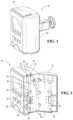
- FIG. 1is a perspective view of an enteral feeding pump.
- FIG. 2is a perspective view of the enteral feeding pump with a door in an open position.
- FIG. 3is a right side elevation view of the enteral feeding pump with a clamp and the door omitted for clarity, and further showing a feed assembly installed in the enteral feeding pump.
- FIG. 4is a right side elevation view of the enteral feeding pump similar to FIG. 3 , and further showing a flush assembly installed in the enteral feeding pump.
- FIG. 5is a perspective view of the feed conduit connector of the feed assembly shown in FIG. 3 .
- FIG. 6is a cross section view taken along the line 6 - 6 of FIG. 5 .
- FIG. 7is a front elevation view of the feed conduit connector.
- FIG. 8is a rear elevation view of the feed conduit connector.
- FIG. 9is a top plan view of the feed conduit connector.
- FIG. 10is a bottom plan view of the feed conduit connector.
- FIG. 11is a left side elevation view of the feed conduit connector.
- FIG. 12is a right side elevation view of the feed conduit connector.
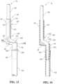
- FIG. 13is a perspective view of a portion of the feed assembly depicted in FIG. 3 .
- FIG. 14is a cross section view taken along the line 14 - 14 of FIG. 13 .
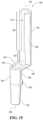
- FIG. 15is a perspective view of the flush conduit connector of the flush assembly shown in FIG. 4 .
- FIG. 16is a front elevation view of the flush conduit connector.
- FIG. 17is a rear elevation view of the flush conduit connector.
- FIG. 18is a top plan view of the flush conduit connector.
- FIG. 18is a bottom plan view of the flush conduit connector.
- FIG. 20is a left side elevation view of the flush conduit connector.
- FIG. 21is a right side elevation view of the flush conduit connector.
- a fluid assemblymay be a “feed only” fluid assembly that includes nutritional liquid, or “flush only” fluid assembly that includes hydrating liquid.
- a fluid assemblyincludes a conduit connector sized for placement within the enteral feeding pump, and an elastomeric peristaltic tubing element fluidly connected to an exit of the conduit connector.
- methods of providing an enteral feeding pump for use with a fluid assemblycomprising attaching a conduit connector of the fluid assembly to a panel of the pump.
- the panelmay be an internal panel of the pump, and the method may include opening a pump door to expose the internal panel and closing the pump door.
- the enteral feeding pump 10is shown with a pump door 12 in a closed position.
- the enteral feeding pump 10has a pump door 12 that is hingedly attached to a housing body 14 .
- the pump door 12is movable from a first position to a second position. In the first position, shown in FIG. 1 , the pump door 12 is in a closed configuration and in the second position, shown in FIG. 2 , the pump door 12 is in an open configuration. In the open configuration, a user may install or uninstall a fluid assembly, as discussed in greater detail below.
- the enteral feeding pump 10is configured to receive one or more fluid sets or assemblies having enteral feeding pump conduit connectors.
- conduit connectorsmay be received within a depression or groove 20 formed in an internal panel 22 of the enteral feeding pump 10 and/or within a depression or groove 24 formed in an internal wall 26 of the pump door 12 .
- the groove 20 formed in the internal panel 22includes a first upper channel 30 , a second upper channel 32 , and a transverse channel 34 that extends between the first upper channel 30 and the second upper channel 32 .
- Groove 20also includes an elongated channel or peristaltic tube channel 36 that extends from the transverse channel 34 .
- the channels 30 , 32 , 34 , 36are configured to receive tubing elements and/or conduit connectors of a fluid assembly therein, as discussed in greater detail below.
- the groove 24 formed in the internal wall 26 of the pump door 12may include opposing and complementary channels for receiving tubing elements and/or conduit connectors of the fluid assembly when the pump door 12 is in the closed position.
- the enteral feeding pump 10also includes a peristaltic pump 40 proximate a groove (e.g., groove 20 ).
- the peristaltic pump 40may be a linear peristaltic pump that includes keys 42 for pressing or pinching a peristaltic tubing element between the keys 42 and a pump surface 44 of the pump door 12 to advance the fluid therein via peristaltic action. More particularly, the keys 42 act on the peristaltic tubing element within the peristaltic tube channel 36 at right angles relative to the direction of fluid flow. Successive actuation of the keys 42 drives fluid through the peristaltic tubing.
- the peristaltic pumpalternatively may be a rotary peristaltic pump.
- the enteral feeding pump 10may also include one or more sensors proximate the grooves 20 , 24 .
- the enteral feeding pump 10may include one or more set detection sensors 50 , 50 ′ disposed within the first upper channel 30 and/or the second upper channel 32 .
- the set detection sensors 50 , 50 ′are engaged or disengaged respectively when the feed or flush assembly is installed.
- the sensorsmay be push-button momentary switches that are configured to be depressed when a conduit connector of a fluid assembly is disposed in the first upper channel 30 and/or the second upper channel 32 .
- the status of the set detection sensors 50 , 50 ′may be indicative of the presence of a fluid assembly within the groove 20 , as well as the type of fluid assembly received within the groove 20 .
- the enteral feeding pump 10e.g., at a processor of the enteral feeding pump 10 ) may determine that a “feed only” fluid assembly has been received in the groove 20 .
- the enteral feeding pump 10may determine that a “flush only” fluid assembly has been received in the groove 20 . If set detection sensor 50 and set detection sensor 50 ′ are both depressed and the pump door 12 is closed, the enteral feeding pump 10 may determine that a “feed and flush” fluid assembly has been received in the groove 20 .
- the enteral feeding pump 10may also include one or both of an air sensor 52 and an occlusion sensor 54 proximate the grooves 20 , 24 .
- the air sensor 52may be disposed within the peristaltic tube channel 36 upstream of the peristaltic pump 40 .
- the air sensor 52may be an ultrasonic sensor that detects air within a peristaltic tubing element.
- the air sensor 52may detect a volume of air over a predetermined threshold, which may be an instantaneous air volume (e.g., a 3 millimeter air bubble) or a volume of air within a predefined period of time (e.g., 10 millimeters of air within the period of time).
- the enteral feeding pump 10may stop the pumping operation of the peristaltic pump 40 , and/or may output an error indicator at a user interface.
- the occlusion sensor 54may be disposed within the peristaltic tube channel 36 downstream of the peristaltic pump 40 .
- the occlusion sensor 54is configured to detect a deformation (e.g., “ballooning”) in the peristaltic tubing element that may be indicative of an occlusion within the peristaltic tubing element (e.g., downstream from the occlusion sensor 54 ).
- the enteral feeding pump 10may stop the pumping operation of the peristaltic pump 40 , and/or may output an error message at the user interface.
- the enteral feeding pump 10may receive a feed set or assembly 70 for connecting a first container, such as a nutrition or feed container 72 to a patient.
- the feed assembly 70includes a feed conduit connector 80 having a fluid inlet portion 82 , a fluid outlet portion 84 , and a bridge portion 86 that extends between and connects the fluid inlet portion 82 and the fluid outlet portion 84 .
- the feed assembly 70further includes a first tubing element, which may be a flexible tubing element 100 in fluidic communication with the fluid inlet portion 82 .
- the flexible tubing element 100may be connected at a first end to the feed container 72 , and may extend at a second end opposite the first end within at least a portion of the feed conduit connector 80 .
- the feed assembly 70further includes a second tubing element, which may be a peristaltic tubing element 102 in fluidic communication with the fluid outlet portion 84 .
- the peristaltic tubing element 102may be connected at a first end to the feed conduit connector 80 (e.g., at the fluid outlet portion 84 ), and is connected at a second end opposite the first end to a patient coupling 110 that permits the feed assembly 70 to be in fluid communication with a patient.
- the fluid inlet portion 82is received at least partially within the first upper channel 30
- the bridge portion 86is received at least partially within the transverse channel 34
- the fluid outlet portion 84is at least partially received in the peristaltic tubing channel 36 .
- the fluid inlet portion 82is received within the first upper channel 30 such that set detection sensor 50 is depressed and set detection sensor 50 ′ is not depressed.
- this configuration of sensors 50 , 50 ′is indicative of a “feed only” feed assembly 70 being installed within the enteral feeding pump 10 .
- the fluid inlet portion 82may extend beyond a top edge 120 of the internal panel 22 .
- the flexible tubing element 100extends through the fluid in the fluid inlet portion 82 , within the bridge portion 86 , and within at least a portion of the fluid outlet portion 84 .
- the peristaltic tubing element 102is connected to the fluid outlet portion 84 , and extends within the peristaltic tubing channel 36 , across the keys 42 of the peristaltic pump 40 , and beyond a bottom edge 122 of the internal panel 22 to the patient coupling 110 .
- the feed container 72is fluidly coupled to the patient coupling 110 such that fluid from the feed container 72 may be passed through the enteral feeding pump 10 to a patient.
- the enteral feeding pump 10may receive a flush set or assembly 170 for connecting a second container, such as a hydration or flush container 172 to a patient.
- the flush assembly 170includes a flush conduit connector 180 having a fluid inlet portion 182 , a fluid outlet portion 184 , and a bridge portion 186 that extends between and connects the fluid inlet portion 182 and the fluid outlet portion 184 .
- the flush assembly 170further includes a first tubing element, which may be a flexible tubing element 100 ′ in fluidic communication with the fluid inlet portion 182 .
- the flexible tubing element 100 ′may be connected at a first end to the flush container 172 , and may extend at a second end opposite the first end within at least a portion of the flush conduit connector 180 .
- the flush assembly 170further includes a second tubing element, which may be a peristaltic tubing element 102 ′ in fluidic communication with the fluid outlet portion 184 .
- the peristaltic tubing element 102 ′may be connected at a first end to the flush conduit connector 180 (e.g., at the fluid outlet portion 184 ), and is connected at a second end opposite the first end to a patient coupling 110 ′ that permits the flush assembly 170 to be in fluid communication with a patient.
- the fluid inlet portion 182is received at least partially within the second upper channel 32
- the bridge portion 186is received at least partially within the transverse channel 34
- the fluid outlet portion 184is at least partially received in the peristaltic tubing channel 36 .
- the fluid inlet portion 182is received within the second upper channel 32 such that set detection sensor 50 ′ is depressed and set detection sensor 50 is not depressed.
- this configuration of sensors 50 , 50 ′is indicative of a “flush only” flush assembly 170 being installed within the enteral feeding pump 10 .
- the cross-sectional area of the feed assembly 70 and/or flush assembly 170 at the engagement point with the sensors 50 , 50 ′may be less than or equal to 32 mm ⁇ circumflex over ( ) ⁇ 2.
- the durometer of the feed assembly 70 and/or flush assembly 170 componentmay be greater than or equal to 50 A.
- the fluid inlet portion 182may extend beyond a top edge 120 of the internal panel 22 .
- the flexible tubing element 100 ′extends through the fluid in the fluid inlet portion 182 , within the bridge portion 186 , and within at least a portion of the fluid outlet portion 184 .
- the peristaltic tubing element 102 ′is connected to the fluid outlet portion 184 , and extends within the peristaltic tubing channel 36 , across the keys 42 of the peristaltic pump 40 , and beyond a bottom edge 122 of the internal panel 22 to the patient coupling 110 ′.
- the flush container 172is fluidly coupled to the patient coupling 110 ′ such that fluid from the flush container 172 may be passed through the enteral feeding pump 10 to a patient.
- a feed conduit connector 80includes a fluid inlet portion 82 , a fluid outlet portion 84 , and a bridge portion 86 that extends between and connects the fluid inlet portion 82 and the fluid outlet portion 84 .
- the fluid inlet portion 82extends a first longitudinal direction from the bridge portion 86
- the fluid outlet portion 84extends a second longitudinal direction from the bridge portion 86 that is opposite the first longitudinal direction.
- the fluid inlet portion 82 , the fluid outlet portion 84 , and the bridge portion 86may be integrally formed (e.g., injection molded) such that the feed conduit connector 80 is a unitary (i.e., one-piece) body.
- the fluid inlet portion 82 and the fluid outlet portion 84have curved wall portions that extend about axes. More particularly, the fluid inlet portion 82 includes curved wall portions 200 that extend about an inlet axis 202 , and the fluid outlet portion 84 includes curved wall portions 204 that extend about an outlet axis 206 .
- the outlet axis 206is parallel to and laterally offset from the inlet axis 202 .
- the fluid inlet portion 82includes a slot 210 for receiving tubing through the slot 210 . More particularly, the curved wall portions 200 of the fluid inlet portion 82 define an elongated side slot 210 that extends parallel to the inlet axis 202 . The elongated side slot 210 may extend along substantially an entire longitudinal length of the fluid inlet portion 82 . In one approach, the curved wall portions 200 have opposing tube-receiving longitudinal ends 212 , as shown in FIG. 9 , such that the fluid inlet portion 82 has a generally C-shaped cross section in a plane orthogonal to the inlet axis 202 . Referring to FIGS.
- the fluid inlet portion 82may include an upper wall region 220 that extends angularly a first degree about the inlet axis 202 , and a lower wall region 222 that extends angularly a second degree that is different than (e.g., less than) the first degree about the inlet axis 202 .
- the upper wall region 220may form a tube retaining region
- the lower wall region 222may form at least part of a cutout or relief region 224 .
- the relief region 224permits the tubing to transition gradually between the fluid inlet portion 82 and the fluid outlet portion 84 .
- the bridge portion 86extends between and connects the fluid inlet portion 82 and the fluid outlet portion 84 .
- the bridge portion 86extends generally orthogonal to the inlet axis 202 and/or the outlet axis 206 .
- the bridge portion 86has a generally U-shaped cross section. In this way, end portions 230 of the generally U-shaped cross section may define an upper bridge slot 232 .
- the upper bridge slot 232 and the lower wall region 222cooperate to form at least part of the relief region 224 .
- the fluid outlet portion 84includes a generally cylindrical portion 240 that extends from the bridge portion 86 , and a generally frustoconical portion 242 that extends from the generally cylindrical portion 240 .
- the generally frustoconical portion 242may be sized to receive a tubing element such as peristaltic tubing element 102 about an outer surface of the generally frustoconical portion 242 .
- the fluid outlet portion 84further includes a stop member 250 that protrudes from an exterior surface of the curved wall portion 204 the fluid outlet portion 84 .
- the stop member 250protrudes in a generally lateral direction opposite the fluid inlet portion 82 .
- the stop member 250may include side walls 252 that extend generally parallel to the bridge portion 86 , and a curved wall 254 that extends between the side walls 252 .
- the stop member 250may be disposed at the intersection of the generally cylindrical portion 240 and the generally frustoconical portion 242 . In this way, the stop member 250 may limit longitudinal travel of a tubing element (e.g., peristaltic tubing element 102 ) that is received about an outer surface of the fluid outlet portion 84 .
- a tubing elemente.g., peristaltic tubing element 102
- a feed assembly 70may be assembled by inserting an end portion 270 of a flexible tubing element 100 through the upper bridge slot 232 and into the fluid outlet portion 84 (e.g., into the generally cylindrical portion 240 ).
- the end portion 270may be secured to an internal wall of the fluid outlet portion 84 .
- the end portion 270may be press-fit, glued, or fastened to the internal wall of the fluid outlet portion 84 .
- a body portion 272 of the flexible tubing element 100may then be moved into the fluid inlet portion 82 .
- the body portion 272may be laterally passed between the opposing tube-receiving longitudinal ends 212 of the curved wall portion 200 of the fluid inlet portion 82 .
- the curved wall portion 200may be made of a material is sufficiently flexible to the curved wall portion 200 to flex to allow passage of the body portion 272 between the opposing tube-receiving longitudinal ends 212 , while sufficiently resilient to return to original position upon receiving the body portion 272 within the fluid inlet portion 82 . In the original position, the curved wall portion 200 retains the body portion 272 of the flexible tubing element 100 to inhibit movement of the body portion 272 radially away from the inlet axis 202 .
- the flexible tubing element 100forms a curved transition portion 274 between the end portion 270 and the body portion 272 .
- the curved transition portion 274protrudes through the relief region 224 .
- the curved transition portion 274extends away from the fluid inlet portion 82 and through the lower wall region 222 of the slot 210 of the fluid inlet portion 82 .
- the curved transition portion 274further extends across the bridge portion 86 at least partially through the upper bridge slot 232 .
- the flexible tubing element 100may be spaced apart from at least part of the bridge portion 86 at the curved transition portion 274 .
- the curved transition portion 274further curves into the fluid outlet portion 84 to be at least partially received internally within the fluid outlet portion 84 . In this way, the curved transition portion 274 may form a generally S-shaped curved transition portion.
- a flush conduit connector 180includes a fluid inlet portion 182 , a fluid outlet portion 184 , and a bridge portion 186 that extends between and connects the fluid inlet portion 182 and the fluid outlet portion 184 .
- the fluid inlet portion 182extends a first longitudinal direction from the bridge portion 186
- the fluid outlet portion 184extends a second longitudinal direction from the bridge portion 186 that is opposite the first longitudinal direction.
- the fluid inlet portion 182 , the fluid outlet portion 184 , and the bridge portion 186may be integrally formed (e.g., injection molded) such that the flush conduit connector 180 is a unitary (i.e., one-piece) body.
- the fluid inlet portion 182 and the fluid outlet portion 184have curved wall portions that extend about axes. More particularly, the fluid inlet portion 182 includes curved wall portions 300 that extend about an inlet axis 302 , and the fluid outlet portion 184 includes curved wall portions 304 that extend about an outlet axis 306 .
- the outlet axis 306is parallel to and laterally offset from the inlet axis 302 .
- the fluid inlet portion 182includes a slot 310 for receiving tubing through the slot 310 .
- the curved wall portions 300 of the fluid inlet portion 182define an elongated side slot 310 that extends parallel to the inlet axis 302 .
- the elongated side slot 310may extend along substantially an entire longitudinal length of the fluid inlet portion 182 .
- the curved wall portions 300have opposing tube-receiving longitudinal ends 312 , as shown in FIG. 18 , such that the fluid inlet portion 182 has a generally C-shaped cross section in a plane orthogonal to the inlet axis 302 . Referring to FIG.
- the fluid inlet portion 182may include an upper wall region 320 that extends angularly a first degree about the inlet axis 302 , and a lower wall region 322 that extends angularly a second degree that is different than (e.g., less than) the first degree about the inlet axis 302 .
- the upper wall region 320may form a tube retaining region
- the lower wall region 322may form at least part of a relief region 324 .
- the bridge portion 186extends between and connects the fluid inlet portion 182 and the fluid outlet portion 184 .
- the bridge portion 186extends generally orthogonal to the inlet axis 302 and/or the outlet axis 306 .
- the bridge portion 186has a generally U-shaped cross section. In this way, end portions 330 of the generally U-shaped cross section may define an upper bridge slot 332 .
- the upper bridge slot 332 and the lower wall region 322cooperate to form at least part of the cutout or relief region 324 .
- the fluid outlet portion 184includes a generally cylindrical portion 340 that extends from the bridge portion 186 , and a generally frustoconical portion 342 that extends from the generally cylindrical portion 340 .
- the generally frustoconical portion 342may be sized to receive a tubing element such as peristaltic tubing element 102 about an outer surface of the generally frustoconical portion 342 .
- the fluid outlet portion 184further includes a stop member 350 that protrudes from an exterior surface of the curved wall portion 304 the fluid outlet portion 184 .
- the stop member 350protrudes in a generally lateral direction toward the fluid inlet portion 182 .
- the stop member 350may include side walls 352 that extend generally parallel to the bridge portion 186 , and a curved wall 354 that extends between the side walls 352 .
- the stop member 350may be disposed at the intersection of the generally cylindrical portion 340 and the generally frustoconical portion 342 . In this way, the stop member 350 may limit longitudinal travel of a tubing element (e.g., peristaltic tubing element 102 ) that is received about an outer surface of the fluid outlet portion 184 .
- a tubing elemente.g., peristaltic tubing element 102
- the flush conduit connector 180may receive tubing (e.g., flexible tubing element 100 and peristaltic tubing element 102 ) in a similar manner as the feed conduit connector discussed above.
- tubinge.g., flexible tubing element 100 and peristaltic tubing element 102
- a method of assembling a fluid assemblyincludes inserting a first end (e.g., end portion 270 of FIG. 14 ) of a flexible tubing element 100 into a fluid outlet portion 84 , 184 of a conduit connector 80 , 180 .
- the methodmay further include laterally passing a body portion 272 of the flexible tubing element 100 through an elongated side slot 210 , 310 of a fluid inlet portion 82 , 182 of the conduit connector 80 , 180 to secure the flexible tubing element 100 within the fluid inlet portion 82 , 182 .
- the methodmay further include securing a peristaltic tubing element 102 to an outer surface of the fluid outlet portion 84 , 184 .
- the fluid inlet portion 82 , 182 and the fluid outlet portion 84 , 184may be parallel and laterally offset by a bridge portion 86 , 186 that extends between the fluid inlet portion 82 , 182 and the fluid outlet portion 84 , 184 .
- Laterally passing the body portion 272 of the flexible tubing element 100 through the elongated side slot 210 , 310 of the fluid inlet portion 82 , 182 of the conduit connector 80 , 180may include bending the flexible tubing element proximate the bridge portion 86 , 186 to form a curved transition portion 274 of the flexible tubing element 100 . At least a portion of the curved transition portion 274 of the flexible tubing element 100 may be spaced apart from the bridge portion 86 , 186 , and may protrude through a relief region 224 , 324 of the conduit connector 80 , 180 .
- a method of installing a fluid assembly, such as feed assembly 70 or flush assembly 170 , at an enteral feed pump 10includes inserting a conduit connector 80 , 180 of the fluid assembly at an internal panel 22 of the enteral feeding pump 10 .
- the methodmay further include inserting a peristaltic tubing element 102 of the fluid assembly within a peristaltic tube channel 36 of the internal panel 22 .
- the internal panel 22may include at least two set detection sensors (e.g., sensors 50 , 50 ′) that are configured to be pressed upon disposing the fluid assembly at the internal panel 22 .
- disposing the fluid assembly at the internal paneldepresses a first detection sensors (e.g., sensor 50 or sensor 50 ′) and not a second detection sensor (e.g., the other of sensor 50 or sensor 50 ′).
- the enteral feeding pump 10e.g., at a processor of the enteral feeding pump 10 ) may determine that a “feed only” fluid assembly has been received at the internal panel 22 , or that a “flush only” fluid assembly has been received at the internal panel 22 .
Landscapes
- Health & Medical Sciences (AREA)
- Heart & Thoracic Surgery (AREA)
- Animal Behavior & Ethology (AREA)
- General Health & Medical Sciences (AREA)
- Public Health (AREA)
- Veterinary Medicine (AREA)
- Life Sciences & Earth Sciences (AREA)
- Engineering & Computer Science (AREA)
- Anesthesiology (AREA)
- Biomedical Technology (AREA)
- Hematology (AREA)
- Pulmonology (AREA)
- Vascular Medicine (AREA)
- Infusion, Injection, And Reservoir Apparatuses (AREA)
Abstract
Description
Claims (21)
Priority Applications (4)
| Application Number | Priority Date | Filing Date | Title |
|---|---|---|---|
| US16/943,654US11766552B2 (en) | 2020-07-30 | 2020-07-30 | Conduit connectors and fluid assemblies for enteral feed pumps, and methods thereof |
| EP21849595.0AEP4178523A4 (en) | 2020-07-30 | 2021-07-13 | Conduit connectors and fluid assemblies for enteral feed pumps, and methods thereof |
| CA3184078ACA3184078A1 (en) | 2020-07-30 | 2021-07-13 | Conduit connectors and fluid assemblies for enteral feed pumps, and methods thereof |
| PCT/US2021/041373WO2022026167A1 (en) | 2020-07-30 | 2021-07-13 | Conduit connectors and fluid assemblies for enteral feed pumps, and methods thereof |
Applications Claiming Priority (1)
| Application Number | Priority Date | Filing Date | Title |
|---|---|---|---|
| US16/943,654US11766552B2 (en) | 2020-07-30 | 2020-07-30 | Conduit connectors and fluid assemblies for enteral feed pumps, and methods thereof |
Publications (2)
| Publication Number | Publication Date |
|---|---|
| US20220032030A1 US20220032030A1 (en) | 2022-02-03 |
| US11766552B2true US11766552B2 (en) | 2023-09-26 |
Family
ID=80003997
Family Applications (1)
| Application Number | Title | Priority Date | Filing Date |
|---|---|---|---|
| US16/943,654Active2042-05-07US11766552B2 (en) | 2020-07-30 | 2020-07-30 | Conduit connectors and fluid assemblies for enteral feed pumps, and methods thereof |
Country Status (4)
| Country | Link |
|---|---|
| US (1) | US11766552B2 (en) |
| EP (1) | EP4178523A4 (en) |
| CA (1) | CA3184078A1 (en) |
| WO (1) | WO2022026167A1 (en) |
Families Citing this family (2)
| Publication number | Priority date | Publication date | Assignee | Title |
|---|---|---|---|---|
| USD977093S1 (en) | 2020-07-30 | 2023-01-31 | Medline Industries, Lp | Conduit |
| US20250172223A1 (en)* | 2023-11-28 | 2025-05-29 | Laborie Medical Technologies Corp. | Fluid pump with integral tubing retention device and related methods |
Citations (54)
| Publication number | Priority date | Publication date | Assignee | Title |
|---|---|---|---|---|
| US2236802A (en) | 1939-03-13 | 1941-04-01 | Albert P Mcdonald | Vitreous clay conduit section |
| US3169528A (en) | 1963-05-24 | 1965-02-16 | Iii Francis S Knox | Coronary sinus sucker |
| US3558163A (en)* | 1969-01-06 | 1971-01-26 | Dover Corp | Swivel connecter for tubing |
| US4405316A (en)* | 1978-04-03 | 1983-09-20 | Baxter Travenol Laboratories, Inc. | Injection site with check valve inlet |
| US4585399A (en) | 1984-06-19 | 1986-04-29 | Richard Wolf Gmbh | Hose pump |
| US4804206A (en)* | 1987-10-13 | 1989-02-14 | Dover Corporation | Swivel construction and method of making the same |
| US5057076A (en) | 1989-11-28 | 1991-10-15 | Fresenius Ag | Infusion apparatus |
| US5201711A (en) | 1987-09-30 | 1993-04-13 | Sherwood Medical Company | Safety interlock system for medical fluid pumps |
| US5213483A (en) | 1991-06-19 | 1993-05-25 | Strato Medical Corporation | Peristaltic infusion pump with removable cassette and mechanically keyed tube set |
| US5242279A (en) | 1991-08-07 | 1993-09-07 | B. Braun Melsungen Ag | Pump hose for a peristaltic pump |
| US5312334A (en) | 1992-01-06 | 1994-05-17 | Sharp Kabushiki Kaisha | Peristaltic pump apparatus having an improved misloaded IV tube detecting circuit |
| USD348097S (en) | 1992-03-16 | 1994-06-21 | General Plastics, Inc. | Pipe coupling |
| US5569026A (en) | 1992-06-18 | 1996-10-29 | Storz Endoskop Gmbh | Tube pump in which tube can be inserted only in one direction |
| US5772255A (en) | 1995-09-21 | 1998-06-30 | Abbott Laboratories | Tubing connector |
| US5876371A (en) | 1997-08-29 | 1999-03-02 | Yokoyama; Lisa D. | Intravenous tube holder |
| US20030212381A1 (en) | 2002-05-09 | 2003-11-13 | Whitehead Clarence Mark | Enteral tube feeding device with in-operation cleaning capability |
| USD488545S1 (en) | 2003-04-30 | 2004-04-13 | Tutomu Takamatu | Pipe |
| US20050165304A1 (en) | 2002-03-28 | 2005-07-28 | Roberto Albertelli | Ventilation apparatus for pulmonary scinitigraphy |
| US7462170B2 (en) | 2004-05-25 | 2008-12-09 | Covidien Ag | Administration feeding set and valve mechanism |
| US20090139530A1 (en) | 2007-11-29 | 2009-06-04 | Mergenet Medical, Inc. | Artificial airway interfaces and methods thereof |
| US20090214365A1 (en) | 2008-02-22 | 2009-08-27 | Norman Gerould W | Method and system for loading of tubing into a pumping device |
| US7722573B2 (en) | 2006-03-02 | 2010-05-25 | Covidien Ag | Pumping apparatus with secure loading features |
| US7722562B2 (en) | 2006-03-02 | 2010-05-25 | Tyco Healthcare Group Lp | Pump set with safety interlock |
| US7758551B2 (en) | 2006-03-02 | 2010-07-20 | Covidien Ag | Pump set with secure loading features |
| US7763005B2 (en) | 2006-03-02 | 2010-07-27 | Covidien Ag | Method for using a pump set having secure loading features |
| USD625805S1 (en) | 2009-10-27 | 2010-10-19 | Robert Hereford | Needle guide |
| US7846131B2 (en) | 2005-09-30 | 2010-12-07 | Covidien Ag | Administration feeding set and flow control apparatus with secure loading features |
| US20110004143A1 (en) | 2009-07-01 | 2011-01-06 | Michael James Beiriger | Drug Delivery Devices And Related Systems And Methods |
| WO2011008624A2 (en) | 2009-07-13 | 2011-01-20 | Nestec S.A. | Cassettes and methods of using same |
| US7927304B2 (en) | 2006-03-02 | 2011-04-19 | Tyco Healthcare Group Lp | Enteral feeding pump and feeding set therefor |
| US20110315611A1 (en) | 2007-09-13 | 2011-12-29 | Barry Neil Fulkerson | Portable Dialysis Machine |
| USD676941S1 (en) | 2012-01-11 | 2013-02-26 | Bill Kluss | Elbow pipe coupling |
| KR20130099127A (en) | 2010-10-01 | 2013-09-05 | 제벡스, 아이엔씨. | Anti-free-flow mechanism for enteral feeding pumps |
| US20150021909A1 (en) | 2011-08-10 | 2015-01-22 | Fisher & Paykel Healthcare Limited | Conduit connector for a patient breathing device |
| US9192709B2 (en) | 2007-12-21 | 2015-11-24 | Gambro Lundia Ab | Disposable extracorporeal blood circuit and apparatus for the extracorporeal treatment of blood |
| US20160121096A1 (en) | 2014-10-30 | 2016-05-05 | Q-Core Medical Ltd. | Apparatus and systems for medical devices and corresponding interface units and methods for producing and operating the same |
| US20160235938A1 (en) | 2015-02-16 | 2016-08-18 | Babak KHABIRI | Oxygen delivery and ventilation monitoring systems |
| US9468714B2 (en) | 2013-03-14 | 2016-10-18 | Carefusion 303, Inc. | Memory and identification associated with IV set |
| USD783786S1 (en) | 2015-11-02 | 2017-04-11 | Brewnique LLC | Faucet tube |
| USD783784S1 (en) | 2015-01-30 | 2017-04-11 | Criser, S.A. De C.V. | Nozzle for a drain hose |
| USD799638S1 (en) | 2016-02-05 | 2017-10-10 | Robert S. Janton | Bulb duster tip |
| US9814819B2 (en) | 2015-06-15 | 2017-11-14 | Fresenius Medical Care Holdings, Inc. | Dialysis machines with integral salt solution chambers and related methods |
| US20180056024A1 (en) | 2015-03-05 | 2018-03-01 | Resmed Limited | Humidifier for a respiratory therapy device |
| US20180133667A1 (en) | 2016-11-16 | 2018-05-17 | Zyno Medical, Llc | Isolatable Automatic Drug Compounding System |
| US20180207389A1 (en) | 2015-07-20 | 2018-07-26 | Fisher & Paykel Healthcare Limited | Exhalation port |
| USD866748S1 (en) | 2016-02-16 | 2019-11-12 | Babak KHABIRI | Airway connector |
| US20200000682A1 (en) | 2018-06-29 | 2020-01-02 | Generica Medical International, Inc. | Enteral Feeding Systems and Methods |
| US20200018306A1 (en) | 2018-07-12 | 2020-01-16 | St. Jude Medical, Cardiology Division, Inc. | Sensor for Peristaltic Pump and Associated Methods |
| US20200054823A1 (en) | 2018-08-16 | 2020-02-20 | Deka Products Limited Partnership | Medical Pump |
| US20200085695A1 (en)* | 2018-09-19 | 2020-03-19 | Christopher O'Keefe | Connectors for infusion pump feeding sets |
| US20200179592A1 (en) | 2016-06-16 | 2020-06-11 | Smiths Medical Asd, Inc. | Assemblies and methods for infusion pump system administration sets |
| USD920504S1 (en) | 2019-07-01 | 2021-05-25 | Medline Industries, Inc. | Valve |
| US20210316106A1 (en) | 2020-04-10 | 2021-10-14 | Jerome Canady Research Institute for Advanced Biological and Technological Sciences | Method for treatment of respiratory infections and cancers of the respiratory system using cold atmospheric plasma |
| US11185646B2 (en) | 2014-09-26 | 2021-11-30 | Lainomedical, S.L. | Nebuliser device |
Family Cites Families (3)
| Publication number | Priority date | Publication date | Assignee | Title |
|---|---|---|---|---|
| EP1525400B1 (en)* | 2002-07-09 | 2006-08-02 | Gambro Lundia AB | A support element for an extracorporeal fluid transport line |
| DK2294318T3 (en)* | 2008-05-30 | 2012-09-10 | Nestec Sa | PIPE HOLDER FOR FLUID DEVICES |
| PL3826698T3 (en)* | 2018-07-25 | 2024-07-08 | Acist Medical Systems, Inc. | Improved injection system and day set assembly therefor |
- 2020
- 2020-07-30USUS16/943,654patent/US11766552B2/enactiveActive
- 2021
- 2021-07-13WOPCT/US2021/041373patent/WO2022026167A1/ennot_activeCeased
- 2021-07-13EPEP21849595.0Apatent/EP4178523A4/enactivePending
- 2021-07-13CACA3184078Apatent/CA3184078A1/enactivePending
Patent Citations (65)
| Publication number | Priority date | Publication date | Assignee | Title |
|---|---|---|---|---|
| US2236802A (en) | 1939-03-13 | 1941-04-01 | Albert P Mcdonald | Vitreous clay conduit section |
| US3169528A (en) | 1963-05-24 | 1965-02-16 | Iii Francis S Knox | Coronary sinus sucker |
| US3558163A (en)* | 1969-01-06 | 1971-01-26 | Dover Corp | Swivel connecter for tubing |
| US4405316A (en)* | 1978-04-03 | 1983-09-20 | Baxter Travenol Laboratories, Inc. | Injection site with check valve inlet |
| US4585399A (en) | 1984-06-19 | 1986-04-29 | Richard Wolf Gmbh | Hose pump |
| US5201711A (en) | 1987-09-30 | 1993-04-13 | Sherwood Medical Company | Safety interlock system for medical fluid pumps |
| US4804206A (en)* | 1987-10-13 | 1989-02-14 | Dover Corporation | Swivel construction and method of making the same |
| US5057076A (en) | 1989-11-28 | 1991-10-15 | Fresenius Ag | Infusion apparatus |
| US5213483A (en) | 1991-06-19 | 1993-05-25 | Strato Medical Corporation | Peristaltic infusion pump with removable cassette and mechanically keyed tube set |
| US5242279A (en) | 1991-08-07 | 1993-09-07 | B. Braun Melsungen Ag | Pump hose for a peristaltic pump |
| US5312334A (en) | 1992-01-06 | 1994-05-17 | Sharp Kabushiki Kaisha | Peristaltic pump apparatus having an improved misloaded IV tube detecting circuit |
| USD348097S (en) | 1992-03-16 | 1994-06-21 | General Plastics, Inc. | Pipe coupling |
| US5569026A (en) | 1992-06-18 | 1996-10-29 | Storz Endoskop Gmbh | Tube pump in which tube can be inserted only in one direction |
| US5772255A (en) | 1995-09-21 | 1998-06-30 | Abbott Laboratories | Tubing connector |
| US5876371A (en) | 1997-08-29 | 1999-03-02 | Yokoyama; Lisa D. | Intravenous tube holder |
| US20050165304A1 (en) | 2002-03-28 | 2005-07-28 | Roberto Albertelli | Ventilation apparatus for pulmonary scinitigraphy |
| US20030212381A1 (en) | 2002-05-09 | 2003-11-13 | Whitehead Clarence Mark | Enteral tube feeding device with in-operation cleaning capability |
| USD488545S1 (en) | 2003-04-30 | 2004-04-13 | Tutomu Takamatu | Pipe |
| US7462170B2 (en) | 2004-05-25 | 2008-12-09 | Covidien Ag | Administration feeding set and valve mechanism |
| US8361024B2 (en) | 2004-05-25 | 2013-01-29 | Covidien Ag | Administration feeding set |
| US8034028B2 (en) | 2004-05-25 | 2011-10-11 | Covidien Ag | Administration feeding set |
| US7753883B2 (en) | 2004-05-25 | 2010-07-13 | Covidien Ag | Administration feeding set |
| US7753881B2 (en) | 2004-05-25 | 2010-07-13 | Covidien Ag | Administration feeding set |
| US7846131B2 (en) | 2005-09-30 | 2010-12-07 | Covidien Ag | Administration feeding set and flow control apparatus with secure loading features |
| US7927304B2 (en) | 2006-03-02 | 2011-04-19 | Tyco Healthcare Group Lp | Enteral feeding pump and feeding set therefor |
| US7722573B2 (en) | 2006-03-02 | 2010-05-25 | Covidien Ag | Pumping apparatus with secure loading features |
| US7763005B2 (en) | 2006-03-02 | 2010-07-27 | Covidien Ag | Method for using a pump set having secure loading features |
| US7758551B2 (en) | 2006-03-02 | 2010-07-20 | Covidien Ag | Pump set with secure loading features |
| US7722562B2 (en) | 2006-03-02 | 2010-05-25 | Tyco Healthcare Group Lp | Pump set with safety interlock |
| US8142399B2 (en) | 2006-03-02 | 2012-03-27 | Tyco Healthcare Group Lp | Pump set with safety interlock |
| US9402789B2 (en) | 2006-03-02 | 2016-08-02 | Covidien Ag | Pump set having secure loading features |
| US8142404B2 (en) | 2006-03-02 | 2012-03-27 | Covidien Ag | Controller for pumping apparatus |
| US8052642B2 (en) | 2006-03-02 | 2011-11-08 | Covidien Ag | Pumping apparatus with secure loading features |
| US8052643B2 (en) | 2006-03-02 | 2011-11-08 | Tyco Healthcare Group Lp | Enteral feeding set and interlock device therefor |
| US20110315611A1 (en) | 2007-09-13 | 2011-12-29 | Barry Neil Fulkerson | Portable Dialysis Machine |
| US20090139530A1 (en) | 2007-11-29 | 2009-06-04 | Mergenet Medical, Inc. | Artificial airway interfaces and methods thereof |
| US9192709B2 (en) | 2007-12-21 | 2015-11-24 | Gambro Lundia Ab | Disposable extracorporeal blood circuit and apparatus for the extracorporeal treatment of blood |
| US20090214365A1 (en) | 2008-02-22 | 2009-08-27 | Norman Gerould W | Method and system for loading of tubing into a pumping device |
| US20110004143A1 (en) | 2009-07-01 | 2011-01-06 | Michael James Beiriger | Drug Delivery Devices And Related Systems And Methods |
| WO2011008624A2 (en) | 2009-07-13 | 2011-01-20 | Nestec S.A. | Cassettes and methods of using same |
| USD625805S1 (en) | 2009-10-27 | 2010-10-19 | Robert Hereford | Needle guide |
| KR20130099127A (en) | 2010-10-01 | 2013-09-05 | 제벡스, 아이엔씨. | Anti-free-flow mechanism for enteral feeding pumps |
| US20150021909A1 (en) | 2011-08-10 | 2015-01-22 | Fisher & Paykel Healthcare Limited | Conduit connector for a patient breathing device |
| USD676941S1 (en) | 2012-01-11 | 2013-02-26 | Bill Kluss | Elbow pipe coupling |
| US9468714B2 (en) | 2013-03-14 | 2016-10-18 | Carefusion 303, Inc. | Memory and identification associated with IV set |
| US11185646B2 (en) | 2014-09-26 | 2021-11-30 | Lainomedical, S.L. | Nebuliser device |
| US20160121096A1 (en) | 2014-10-30 | 2016-05-05 | Q-Core Medical Ltd. | Apparatus and systems for medical devices and corresponding interface units and methods for producing and operating the same |
| USD783784S1 (en) | 2015-01-30 | 2017-04-11 | Criser, S.A. De C.V. | Nozzle for a drain hose |
| US20160235938A1 (en) | 2015-02-16 | 2016-08-18 | Babak KHABIRI | Oxygen delivery and ventilation monitoring systems |
| US20180056024A1 (en) | 2015-03-05 | 2018-03-01 | Resmed Limited | Humidifier for a respiratory therapy device |
| US9814819B2 (en) | 2015-06-15 | 2017-11-14 | Fresenius Medical Care Holdings, Inc. | Dialysis machines with integral salt solution chambers and related methods |
| US10518015B2 (en) | 2015-06-15 | 2019-12-31 | Fresenius Medical Care Holdings, Inc. | Dialysis machines with integral salt solution chambers and related methods |
| US20180207389A1 (en) | 2015-07-20 | 2018-07-26 | Fisher & Paykel Healthcare Limited | Exhalation port |
| USD783786S1 (en) | 2015-11-02 | 2017-04-11 | Brewnique LLC | Faucet tube |
| USD799638S1 (en) | 2016-02-05 | 2017-10-10 | Robert S. Janton | Bulb duster tip |
| USD866748S1 (en) | 2016-02-16 | 2019-11-12 | Babak KHABIRI | Airway connector |
| US20200179592A1 (en) | 2016-06-16 | 2020-06-11 | Smiths Medical Asd, Inc. | Assemblies and methods for infusion pump system administration sets |
| US10596532B2 (en) | 2016-11-16 | 2020-03-24 | Zyno Medical, Llc | Isolatable automatic drug compounding system |
| US20180133667A1 (en) | 2016-11-16 | 2018-05-17 | Zyno Medical, Llc | Isolatable Automatic Drug Compounding System |
| US20200000682A1 (en) | 2018-06-29 | 2020-01-02 | Generica Medical International, Inc. | Enteral Feeding Systems and Methods |
| US20200018306A1 (en) | 2018-07-12 | 2020-01-16 | St. Jude Medical, Cardiology Division, Inc. | Sensor for Peristaltic Pump and Associated Methods |
| US20200054823A1 (en) | 2018-08-16 | 2020-02-20 | Deka Products Limited Partnership | Medical Pump |
| US20200085695A1 (en)* | 2018-09-19 | 2020-03-19 | Christopher O'Keefe | Connectors for infusion pump feeding sets |
| USD920504S1 (en) | 2019-07-01 | 2021-05-25 | Medline Industries, Inc. | Valve |
| US20210316106A1 (en) | 2020-04-10 | 2021-10-14 | Jerome Canady Research Institute for Advanced Biological and Technological Sciences | Method for treatment of respiratory infections and cancers of the respiratory system using cold atmospheric plasma |
Non-Patent Citations (3)
| Title |
|---|
| DFC—Double-wall Flexible Gas Vent Connector, Hart Cooley, [Post date: May 18, 2013], [Site seen: Apr. 21, 2022], Seen at URL: https://www.hartandcooley.com/products/dfc/double-wall-flexible-gas-vent-connector (Year: 2013); 2 pages. |
| International Search Report and Written Opinion for International Application No. PCT/US21/41373 dated Nov. 1, 2021. |
| Vyaire Medical 3215, Airlife® Connector, 1/EA (243789_EA) 32151900, Air Life, Clean it Supply.com, [Post Date: unknown], [Site seen Apr. 21, 2022], Seen at URL: https://www.cleanitsupply.com/p-134650/vyaire-medical-3215-airlife-connector-1-ea-243789_ea-32151900.aspx (Year: 2022). |
Also Published As
| Publication number | Publication date |
|---|---|
| EP4178523A1 (en) | 2023-05-17 |
| WO2022026167A1 (en) | 2022-02-03 |
| EP4178523A4 (en) | 2024-01-17 |
| CA3184078A1 (en) | 2022-02-03 |
| US20220032030A1 (en) | 2022-02-03 |
Similar Documents
| Publication | Publication Date | Title |
|---|---|---|
| US11766552B2 (en) | Conduit connectors and fluid assemblies for enteral feed pumps, and methods thereof | |
| JP3064014B2 (en) | Fluid guide segment | |
| US5568912A (en) | Sliding flow controller having channel with variable size groove | |
| US12403242B2 (en) | Pump systems with positioning features | |
| US11097069B2 (en) | Air in-line sensing system for IV infusion lines | |
| US9062672B2 (en) | Pump module, pump base module and pump system | |
| KR101686871B1 (en) | Fluid delivery set and pump system for anti-free-flow | |
| US10335541B2 (en) | Pump cassettes with flow stop and infusion pump systems | |
| CN102292117B (en) | Infusion pump cassette with anti-free-flow valve mechanism | |
| US12102600B2 (en) | Feeding set and enteral feeding pump assembly | |
| JPH10502455A (en) | Pressure vessel preloaded for sensors | |
| US20160317735A1 (en) | Device for transferring a fluid | |
| US5603613A (en) | Fluid delivery system having an air bubble ejector | |
| JP7738574B2 (en) | Liquid transfer pump, adapter, and liquid transfer set with adapter | |
| JPH0953736A (en) | Check valve |
Legal Events
| Date | Code | Title | Description |
|---|---|---|---|
| FEPP | Fee payment procedure | Free format text:ENTITY STATUS SET TO UNDISCOUNTED (ORIGINAL EVENT CODE: BIG.); ENTITY STATUS OF PATENT OWNER: LARGE ENTITY | |
| AS | Assignment | Owner name:MEDLINE INDUSTRIES, INC., ILLINOIS Free format text:ASSIGNMENT OF ASSIGNORS INTEREST;ASSIGNORS:URIDIL, MORGAN;TURTURRO, MICHAEL;KAYVANI, BAHRAM KEVIN;AND OTHERS;SIGNING DATES FROM 20200812 TO 20200817;REEL/FRAME:053525/0727 | |
| AS | Assignment | Owner name:MEDLINE INDUSTRIES, LP, ILLINOIS Free format text:CHANGE OF NAME;ASSIGNOR:MEDLINE INDUSTRIES, INC.;REEL/FRAME:057858/0721 Effective date:20210907 | |
| AS | Assignment | Owner name:WILMINGTON TRUST, NATIONAL ASSOCIATION, MINNESOTA Free format text:SECURITY INTEREST;ASSIGNOR:MEDLINE INDUSTRIES, LP;REEL/FRAME:057927/0091 Effective date:20211021 Owner name:BANK OF AMERICA, N.A., TEXAS Free format text:SECURITY INTEREST;ASSIGNOR:MEDLINE INDUSTRIES, LP;REEL/FRAME:058040/0001 Effective date:20211021 | |
| STPP | Information on status: patent application and granting procedure in general | Free format text:NOTICE OF ALLOWANCE MAILED -- APPLICATION RECEIVED IN OFFICE OF PUBLICATIONS | |
| STPP | Information on status: patent application and granting procedure in general | Free format text:PUBLICATIONS -- ISSUE FEE PAYMENT VERIFIED | |
| STCF | Information on status: patent grant | Free format text:PATENTED CASE | |
| AS | Assignment | Owner name:WILMINGTON TRUST, NATIONAL ASSOCIATION, AS NOTES COLLATERAL AGENT, MINNESOTA Free format text:PATENT SECURITY AGREEMENT;ASSIGNOR:MEDLINE INDUSTRIES, LP;REEL/FRAME:071672/0100 Effective date:20240327 |