US11766257B2 - Surgical instrument comprising a display - Google Patents
Surgical instrument comprising a displayDownload PDFInfo
- Publication number
- US11766257B2 US11766257B2US17/217,043US202117217043AUS11766257B2US 11766257 B2US11766257 B2US 11766257B2US 202117217043 AUS202117217043 AUS 202117217043AUS 11766257 B2US11766257 B2US 11766257B2
- Authority
- US
- United States
- Prior art keywords
- shaft
- drive
- firing
- assembly
- end effector
- Prior art date
- Legal status (The legal status is an assumption and is not a legal conclusion. Google has not performed a legal analysis and makes no representation as to the accuracy of the status listed.)
- Active
Links
Images


Classifications
- A—HUMAN NECESSITIES
- A61—MEDICAL OR VETERINARY SCIENCE; HYGIENE
- A61B—DIAGNOSIS; SURGERY; IDENTIFICATION
- A61B17/00—Surgical instruments, devices or methods
- A61B17/068—Surgical staplers, e.g. containing multiple staples or clamps
- A61B17/072—Surgical staplers, e.g. containing multiple staples or clamps for applying a row of staples in a single action, e.g. the staples being applied simultaneously
- A—HUMAN NECESSITIES
- A61—MEDICAL OR VETERINARY SCIENCE; HYGIENE
- A61B—DIAGNOSIS; SURGERY; IDENTIFICATION
- A61B17/00—Surgical instruments, devices or methods
- A61B17/00234—Surgical instruments, devices or methods for minimally invasive surgery
- A—HUMAN NECESSITIES
- A61—MEDICAL OR VETERINARY SCIENCE; HYGIENE
- A61B—DIAGNOSIS; SURGERY; IDENTIFICATION
- A61B17/00—Surgical instruments, devices or methods
- A61B17/068—Surgical staplers, e.g. containing multiple staples or clamps
- A—HUMAN NECESSITIES
- A61—MEDICAL OR VETERINARY SCIENCE; HYGIENE
- A61B—DIAGNOSIS; SURGERY; IDENTIFICATION
- A61B17/00—Surgical instruments, devices or methods
- A61B17/068—Surgical staplers, e.g. containing multiple staples or clamps
- A61B17/0682—Surgical staplers, e.g. containing multiple staples or clamps for applying U-shaped staples or clamps, e.g. without a forming anvil
- A61B17/0686—Surgical staplers, e.g. containing multiple staples or clamps for applying U-shaped staples or clamps, e.g. without a forming anvil having a forming anvil staying below the tissue during stapling
- A—HUMAN NECESSITIES
- A61—MEDICAL OR VETERINARY SCIENCE; HYGIENE
- A61B—DIAGNOSIS; SURGERY; IDENTIFICATION
- A61B17/00—Surgical instruments, devices or methods
- A61B17/068—Surgical staplers, e.g. containing multiple staples or clamps
- A61B17/072—Surgical staplers, e.g. containing multiple staples or clamps for applying a row of staples in a single action, e.g. the staples being applied simultaneously
- A61B17/07207—Surgical staplers, e.g. containing multiple staples or clamps for applying a row of staples in a single action, e.g. the staples being applied simultaneously the staples being applied sequentially
- A—HUMAN NECESSITIES
- A61—MEDICAL OR VETERINARY SCIENCE; HYGIENE
- A61B—DIAGNOSIS; SURGERY; IDENTIFICATION
- A61B17/00—Surgical instruments, devices or methods
- A61B17/10—Surgical instruments, devices or methods for applying or removing wound clamps, e.g. containing only one clamp or staple; Wound clamp magazines
- A61B17/105—Wound clamp magazines
- A—HUMAN NECESSITIES
- A61—MEDICAL OR VETERINARY SCIENCE; HYGIENE
- A61B—DIAGNOSIS; SURGERY; IDENTIFICATION
- A61B17/00—Surgical instruments, devices or methods
- A61B17/11—Surgical instruments, devices or methods for performing anastomosis; Buttons for anastomosis
- A61B17/115—Staplers for performing anastomosis, e.g. in a single operation
- A61B17/1155—Circular staplers comprising a plurality of staples
- A—HUMAN NECESSITIES
- A61—MEDICAL OR VETERINARY SCIENCE; HYGIENE
- A61B—DIAGNOSIS; SURGERY; IDENTIFICATION
- A61B17/00—Surgical instruments, devices or methods
- A61B17/32—Surgical cutting instruments
- A—HUMAN NECESSITIES
- A61—MEDICAL OR VETERINARY SCIENCE; HYGIENE
- A61B—DIAGNOSIS; SURGERY; IDENTIFICATION
- A61B17/00—Surgical instruments, devices or methods
- A61B17/32—Surgical cutting instruments
- A61B17/3209—Incision instruments
- A61B17/3211—Surgical scalpels, knives; Accessories therefor
- A—HUMAN NECESSITIES
- A61—MEDICAL OR VETERINARY SCIENCE; HYGIENE
- A61B—DIAGNOSIS; SURGERY; IDENTIFICATION
- A61B17/00—Surgical instruments, devices or methods
- A61B17/064—Surgical staples, i.e. penetrating the tissue
- A61B17/0644—Surgical staples, i.e. penetrating the tissue penetrating the tissue, deformable to closed position
- A—HUMAN NECESSITIES
- A61—MEDICAL OR VETERINARY SCIENCE; HYGIENE
- A61B—DIAGNOSIS; SURGERY; IDENTIFICATION
- A61B17/00—Surgical instruments, devices or methods
- A61B17/068—Surgical staplers, e.g. containing multiple staples or clamps
- A61B17/072—Surgical staplers, e.g. containing multiple staples or clamps for applying a row of staples in a single action, e.g. the staples being applied simultaneously
- A61B17/07292—Reinforcements for staple line, e.g. pledgets
- A—HUMAN NECESSITIES
- A61—MEDICAL OR VETERINARY SCIENCE; HYGIENE
- A61B—DIAGNOSIS; SURGERY; IDENTIFICATION
- A61B17/00—Surgical instruments, devices or methods
- A61B17/28—Surgical forceps
- A61B17/29—Forceps for use in minimally invasive surgery
- A—HUMAN NECESSITIES
- A61—MEDICAL OR VETERINARY SCIENCE; HYGIENE
- A61B—DIAGNOSIS; SURGERY; IDENTIFICATION
- A61B17/00—Surgical instruments, devices or methods
- A61B17/32—Surgical cutting instruments
- A61B17/320068—Surgical cutting instruments using mechanical vibrations, e.g. ultrasonic
- A61B17/320092—Surgical cutting instruments using mechanical vibrations, e.g. ultrasonic with additional movable means for clamping or cutting tissue, e.g. with a pivoting jaw
- A—HUMAN NECESSITIES
- A61—MEDICAL OR VETERINARY SCIENCE; HYGIENE
- A61B—DIAGNOSIS; SURGERY; IDENTIFICATION
- A61B17/00—Surgical instruments, devices or methods
- A61B2017/00017—Electrical control of surgical instruments
- A—HUMAN NECESSITIES
- A61—MEDICAL OR VETERINARY SCIENCE; HYGIENE
- A61B—DIAGNOSIS; SURGERY; IDENTIFICATION
- A61B17/00—Surgical instruments, devices or methods
- A61B2017/00017—Electrical control of surgical instruments
- A61B2017/00022—Sensing or detecting at the treatment site
- A—HUMAN NECESSITIES
- A61—MEDICAL OR VETERINARY SCIENCE; HYGIENE
- A61B—DIAGNOSIS; SURGERY; IDENTIFICATION
- A61B17/00—Surgical instruments, devices or methods
- A61B2017/00017—Electrical control of surgical instruments
- A61B2017/00115—Electrical control of surgical instruments with audible or visual output
- A61B2017/00128—Electrical control of surgical instruments with audible or visual output related to intensity or progress of surgical action
- A—HUMAN NECESSITIES
- A61—MEDICAL OR VETERINARY SCIENCE; HYGIENE
- A61B—DIAGNOSIS; SURGERY; IDENTIFICATION
- A61B17/00—Surgical instruments, devices or methods
- A61B2017/00017—Electrical control of surgical instruments
- A61B2017/00199—Electrical control of surgical instruments with a console, e.g. a control panel with a display
- A—HUMAN NECESSITIES
- A61—MEDICAL OR VETERINARY SCIENCE; HYGIENE
- A61B—DIAGNOSIS; SURGERY; IDENTIFICATION
- A61B17/00—Surgical instruments, devices or methods
- A61B17/00234—Surgical instruments, devices or methods for minimally invasive surgery
- A61B2017/00292—Surgical instruments, devices or methods for minimally invasive surgery mounted on or guided by flexible, e.g. catheter-like, means
- A61B2017/003—Steerable
- A61B2017/00305—Constructional details of the flexible means
- A—HUMAN NECESSITIES
- A61—MEDICAL OR VETERINARY SCIENCE; HYGIENE
- A61B—DIAGNOSIS; SURGERY; IDENTIFICATION
- A61B17/00—Surgical instruments, devices or methods
- A61B2017/00367—Details of actuation of instruments, e.g. relations between pushing buttons, or the like, and activation of the tool, working tip, or the like
- A61B2017/00398—Details of actuation of instruments, e.g. relations between pushing buttons, or the like, and activation of the tool, working tip, or the like using powered actuators, e.g. stepper motors, solenoids
- A—HUMAN NECESSITIES
- A61—MEDICAL OR VETERINARY SCIENCE; HYGIENE
- A61B—DIAGNOSIS; SURGERY; IDENTIFICATION
- A61B17/00—Surgical instruments, devices or methods
- A61B2017/00367—Details of actuation of instruments, e.g. relations between pushing buttons, or the like, and activation of the tool, working tip, or the like
- A61B2017/00407—Ratchet means
- A—HUMAN NECESSITIES
- A61—MEDICAL OR VETERINARY SCIENCE; HYGIENE
- A61B—DIAGNOSIS; SURGERY; IDENTIFICATION
- A61B17/00—Surgical instruments, devices or methods
- A61B2017/0042—Surgical instruments, devices or methods with special provisions for gripping
- A61B2017/00424—Surgical instruments, devices or methods with special provisions for gripping ergonomic, e.g. fitting in fist
- A—HUMAN NECESSITIES
- A61—MEDICAL OR VETERINARY SCIENCE; HYGIENE
- A61B—DIAGNOSIS; SURGERY; IDENTIFICATION
- A61B17/00—Surgical instruments, devices or methods
- A61B2017/0046—Surgical instruments, devices or methods with a releasable handle; with handle and operating part separable
- A—HUMAN NECESSITIES
- A61—MEDICAL OR VETERINARY SCIENCE; HYGIENE
- A61B—DIAGNOSIS; SURGERY; IDENTIFICATION
- A61B17/00—Surgical instruments, devices or methods
- A61B2017/0046—Surgical instruments, devices or methods with a releasable handle; with handle and operating part separable
- A61B2017/00464—Surgical instruments, devices or methods with a releasable handle; with handle and operating part separable for use with different instruments
- A—HUMAN NECESSITIES
- A61—MEDICAL OR VETERINARY SCIENCE; HYGIENE
- A61B—DIAGNOSIS; SURGERY; IDENTIFICATION
- A61B17/00—Surgical instruments, devices or methods
- A61B2017/0046—Surgical instruments, devices or methods with a releasable handle; with handle and operating part separable
- A61B2017/00473—Distal part, e.g. tip or head
- A—HUMAN NECESSITIES
- A61—MEDICAL OR VETERINARY SCIENCE; HYGIENE
- A61B—DIAGNOSIS; SURGERY; IDENTIFICATION
- A61B17/00—Surgical instruments, devices or methods
- A61B2017/00477—Coupling
- A—HUMAN NECESSITIES
- A61—MEDICAL OR VETERINARY SCIENCE; HYGIENE
- A61B—DIAGNOSIS; SURGERY; IDENTIFICATION
- A61B17/00—Surgical instruments, devices or methods
- A61B2017/00681—Aspects not otherwise provided for
- A61B2017/00734—Aspects not otherwise provided for battery operated
- A—HUMAN NECESSITIES
- A61—MEDICAL OR VETERINARY SCIENCE; HYGIENE
- A61B—DIAGNOSIS; SURGERY; IDENTIFICATION
- A61B17/00—Surgical instruments, devices or methods
- A61B2017/00743—Type of operation; Specification of treatment sites
- A61B2017/00818—Treatment of the gastro-intestinal system
- A—HUMAN NECESSITIES
- A61—MEDICAL OR VETERINARY SCIENCE; HYGIENE
- A61B—DIAGNOSIS; SURGERY; IDENTIFICATION
- A61B17/00—Surgical instruments, devices or methods
- A61B2017/00831—Material properties
- A61B2017/00946—Material properties malleable
- A—HUMAN NECESSITIES
- A61—MEDICAL OR VETERINARY SCIENCE; HYGIENE
- A61B—DIAGNOSIS; SURGERY; IDENTIFICATION
- A61B17/00—Surgical instruments, devices or methods
- A61B2017/00831—Material properties
- A61B2017/00964—Material properties composite
- A—HUMAN NECESSITIES
- A61—MEDICAL OR VETERINARY SCIENCE; HYGIENE
- A61B—DIAGNOSIS; SURGERY; IDENTIFICATION
- A61B17/00—Surgical instruments, devices or methods
- A61B17/068—Surgical staplers, e.g. containing multiple staples or clamps
- A61B17/072—Surgical staplers, e.g. containing multiple staples or clamps for applying a row of staples in a single action, e.g. the staples being applied simultaneously
- A61B2017/07214—Stapler heads
- A61B2017/07221—Stapler heads curved
- A—HUMAN NECESSITIES
- A61—MEDICAL OR VETERINARY SCIENCE; HYGIENE
- A61B—DIAGNOSIS; SURGERY; IDENTIFICATION
- A61B17/00—Surgical instruments, devices or methods
- A61B17/068—Surgical staplers, e.g. containing multiple staples or clamps
- A61B17/072—Surgical staplers, e.g. containing multiple staples or clamps for applying a row of staples in a single action, e.g. the staples being applied simultaneously
- A61B2017/07214—Stapler heads
- A61B2017/07228—Arrangement of the staples
- A—HUMAN NECESSITIES
- A61—MEDICAL OR VETERINARY SCIENCE; HYGIENE
- A61B—DIAGNOSIS; SURGERY; IDENTIFICATION
- A61B17/00—Surgical instruments, devices or methods
- A61B17/068—Surgical staplers, e.g. containing multiple staples or clamps
- A61B17/072—Surgical staplers, e.g. containing multiple staples or clamps for applying a row of staples in a single action, e.g. the staples being applied simultaneously
- A61B2017/07214—Stapler heads
- A61B2017/07235—Stapler heads containing different staples, e.g. staples of different shapes, sizes or materials
- A—HUMAN NECESSITIES
- A61—MEDICAL OR VETERINARY SCIENCE; HYGIENE
- A61B—DIAGNOSIS; SURGERY; IDENTIFICATION
- A61B17/00—Surgical instruments, devices or methods
- A61B17/068—Surgical staplers, e.g. containing multiple staples or clamps
- A61B17/072—Surgical staplers, e.g. containing multiple staples or clamps for applying a row of staples in a single action, e.g. the staples being applied simultaneously
- A61B2017/07214—Stapler heads
- A61B2017/07242—Stapler heads achieving different staple heights during the same shot, e.g. using an anvil anvil having different heights or staples of different sizes
- A—HUMAN NECESSITIES
- A61—MEDICAL OR VETERINARY SCIENCE; HYGIENE
- A61B—DIAGNOSIS; SURGERY; IDENTIFICATION
- A61B17/00—Surgical instruments, devices or methods
- A61B17/068—Surgical staplers, e.g. containing multiple staples or clamps
- A61B17/072—Surgical staplers, e.g. containing multiple staples or clamps for applying a row of staples in a single action, e.g. the staples being applied simultaneously
- A61B2017/07214—Stapler heads
- A61B2017/07257—Stapler heads characterised by its anvil
- A61B2017/07264—Stapler heads characterised by its anvil characterised by its staple forming cavities, e.g. geometry or material
- A—HUMAN NECESSITIES
- A61—MEDICAL OR VETERINARY SCIENCE; HYGIENE
- A61B—DIAGNOSIS; SURGERY; IDENTIFICATION
- A61B17/00—Surgical instruments, devices or methods
- A61B17/068—Surgical staplers, e.g. containing multiple staples or clamps
- A61B17/072—Surgical staplers, e.g. containing multiple staples or clamps for applying a row of staples in a single action, e.g. the staples being applied simultaneously
- A61B2017/07214—Stapler heads
- A61B2017/07271—Stapler heads characterised by its cartridge
- A—HUMAN NECESSITIES
- A61—MEDICAL OR VETERINARY SCIENCE; HYGIENE
- A61B—DIAGNOSIS; SURGERY; IDENTIFICATION
- A61B17/00—Surgical instruments, devices or methods
- A61B17/068—Surgical staplers, e.g. containing multiple staples or clamps
- A61B17/072—Surgical staplers, e.g. containing multiple staples or clamps for applying a row of staples in a single action, e.g. the staples being applied simultaneously
- A61B2017/07214—Stapler heads
- A61B2017/07278—Stapler heads characterised by its sled or its staple holder
- A—HUMAN NECESSITIES
- A61—MEDICAL OR VETERINARY SCIENCE; HYGIENE
- A61B—DIAGNOSIS; SURGERY; IDENTIFICATION
- A61B17/00—Surgical instruments, devices or methods
- A61B17/068—Surgical staplers, e.g. containing multiple staples or clamps
- A61B17/072—Surgical staplers, e.g. containing multiple staples or clamps for applying a row of staples in a single action, e.g. the staples being applied simultaneously
- A61B2017/07214—Stapler heads
- A61B2017/07285—Stapler heads characterised by its cutter
- A—HUMAN NECESSITIES
- A61—MEDICAL OR VETERINARY SCIENCE; HYGIENE
- A61B—DIAGNOSIS; SURGERY; IDENTIFICATION
- A61B17/00—Surgical instruments, devices or methods
- A61B17/28—Surgical forceps
- A61B17/29—Forceps for use in minimally invasive surgery
- A61B2017/2901—Details of shaft
- A61B2017/2902—Details of shaft characterized by features of the actuating rod
- A61B2017/2903—Details of shaft characterized by features of the actuating rod transferring rotary motion
- A—HUMAN NECESSITIES
- A61—MEDICAL OR VETERINARY SCIENCE; HYGIENE
- A61B—DIAGNOSIS; SURGERY; IDENTIFICATION
- A61B17/00—Surgical instruments, devices or methods
- A61B17/28—Surgical forceps
- A61B17/29—Forceps for use in minimally invasive surgery
- A61B2017/2901—Details of shaft
- A61B2017/2905—Details of shaft flexible
- A—HUMAN NECESSITIES
- A61—MEDICAL OR VETERINARY SCIENCE; HYGIENE
- A61B—DIAGNOSIS; SURGERY; IDENTIFICATION
- A61B17/00—Surgical instruments, devices or methods
- A61B17/28—Surgical forceps
- A61B17/29—Forceps for use in minimally invasive surgery
- A61B17/2909—Handles
- A61B2017/291—Handles the position of the handle being adjustable with respect to the shaft
- A—HUMAN NECESSITIES
- A61—MEDICAL OR VETERINARY SCIENCE; HYGIENE
- A61B—DIAGNOSIS; SURGERY; IDENTIFICATION
- A61B17/00—Surgical instruments, devices or methods
- A61B17/28—Surgical forceps
- A61B17/29—Forceps for use in minimally invasive surgery
- A61B17/2909—Handles
- A61B2017/2912—Handles transmission of forces to actuating rod or piston
- A61B2017/2919—Handles transmission of forces to actuating rod or piston details of linkages or pivot points
- A61B2017/292—Handles transmission of forces to actuating rod or piston details of linkages or pivot points connection of actuating rod to handle, e.g. ball end in recess
- A—HUMAN NECESSITIES
- A61—MEDICAL OR VETERINARY SCIENCE; HYGIENE
- A61B—DIAGNOSIS; SURGERY; IDENTIFICATION
- A61B17/00—Surgical instruments, devices or methods
- A61B17/28—Surgical forceps
- A61B17/29—Forceps for use in minimally invasive surgery
- A61B17/2909—Handles
- A61B2017/2912—Handles transmission of forces to actuating rod or piston
- A61B2017/2919—Handles transmission of forces to actuating rod or piston details of linkages or pivot points
- A61B2017/2922—Handles transmission of forces to actuating rod or piston details of linkages or pivot points toggle linkages
- A—HUMAN NECESSITIES
- A61—MEDICAL OR VETERINARY SCIENCE; HYGIENE
- A61B—DIAGNOSIS; SURGERY; IDENTIFICATION
- A61B17/00—Surgical instruments, devices or methods
- A61B17/28—Surgical forceps
- A61B17/29—Forceps for use in minimally invasive surgery
- A61B17/2909—Handles
- A61B2017/2912—Handles transmission of forces to actuating rod or piston
- A61B2017/2923—Toothed members, e.g. rack and pinion
- A—HUMAN NECESSITIES
- A61—MEDICAL OR VETERINARY SCIENCE; HYGIENE
- A61B—DIAGNOSIS; SURGERY; IDENTIFICATION
- A61B17/00—Surgical instruments, devices or methods
- A61B17/28—Surgical forceps
- A61B17/29—Forceps for use in minimally invasive surgery
- A61B2017/2926—Details of heads or jaws
- A61B2017/2927—Details of heads or jaws the angular position of the head being adjustable with respect to the shaft
- A—HUMAN NECESSITIES
- A61—MEDICAL OR VETERINARY SCIENCE; HYGIENE
- A61B—DIAGNOSIS; SURGERY; IDENTIFICATION
- A61B17/00—Surgical instruments, devices or methods
- A61B17/28—Surgical forceps
- A61B17/29—Forceps for use in minimally invasive surgery
- A61B2017/2926—Details of heads or jaws
- A61B2017/2932—Transmission of forces to jaw members
- A—HUMAN NECESSITIES
- A61—MEDICAL OR VETERINARY SCIENCE; HYGIENE
- A61B—DIAGNOSIS; SURGERY; IDENTIFICATION
- A61B17/00—Surgical instruments, devices or methods
- A61B17/28—Surgical forceps
- A61B17/29—Forceps for use in minimally invasive surgery
- A61B2017/2946—Locking means
- A—HUMAN NECESSITIES
- A61—MEDICAL OR VETERINARY SCIENCE; HYGIENE
- A61B—DIAGNOSIS; SURGERY; IDENTIFICATION
- A61B90/00—Instruments, implements or accessories specially adapted for surgery or diagnosis and not covered by any of the groups A61B1/00 - A61B50/00, e.g. for luxation treatment or for protecting wound edges
- A61B90/03—Automatic limiting or abutting means, e.g. for safety
- A61B2090/033—Abutting means, stops, e.g. abutting on tissue or skin
- A61B2090/034—Abutting means, stops, e.g. abutting on tissue or skin abutting on parts of the device itself
- A—HUMAN NECESSITIES
- A61—MEDICAL OR VETERINARY SCIENCE; HYGIENE
- A61B—DIAGNOSIS; SURGERY; IDENTIFICATION
- A61B90/00—Instruments, implements or accessories specially adapted for surgery or diagnosis and not covered by any of the groups A61B1/00 - A61B50/00, e.g. for luxation treatment or for protecting wound edges
- A61B90/08—Accessories or related features not otherwise provided for
- A61B2090/0801—Prevention of accidental cutting or pricking
- A61B2090/08021—Prevention of accidental cutting or pricking of the patient or his organs
- A—HUMAN NECESSITIES
- A61—MEDICAL OR VETERINARY SCIENCE; HYGIENE
- A61B—DIAGNOSIS; SURGERY; IDENTIFICATION
- A61B90/00—Instruments, implements or accessories specially adapted for surgery or diagnosis and not covered by any of the groups A61B1/00 - A61B50/00, e.g. for luxation treatment or for protecting wound edges
- A61B90/08—Accessories or related features not otherwise provided for
- A61B2090/0807—Indication means
- A61B2090/0808—Indication means for indicating correct assembly of components, e.g. of the surgical apparatus
- A—HUMAN NECESSITIES
- A61—MEDICAL OR VETERINARY SCIENCE; HYGIENE
- A61B—DIAGNOSIS; SURGERY; IDENTIFICATION
- A61B90/00—Instruments, implements or accessories specially adapted for surgery or diagnosis and not covered by any of the groups A61B1/00 - A61B50/00, e.g. for luxation treatment or for protecting wound edges
- A61B90/08—Accessories or related features not otherwise provided for
- A61B2090/0807—Indication means
- A61B2090/0811—Indication means for the position of a particular part of an instrument with respect to the rest of the instrument, e.g. position of the anvil of a stapling instrument
- A—HUMAN NECESSITIES
- A61—MEDICAL OR VETERINARY SCIENCE; HYGIENE
- A61B—DIAGNOSIS; SURGERY; IDENTIFICATION
- A61B90/00—Instruments, implements or accessories specially adapted for surgery or diagnosis and not covered by any of the groups A61B1/00 - A61B50/00, e.g. for luxation treatment or for protecting wound edges
- A61B90/08—Accessories or related features not otherwise provided for
- A61B2090/0814—Preventing re-use
- A—HUMAN NECESSITIES
- A61—MEDICAL OR VETERINARY SCIENCE; HYGIENE
- A61B—DIAGNOSIS; SURGERY; IDENTIFICATION
- A61B90/00—Instruments, implements or accessories specially adapted for surgery or diagnosis and not covered by any of the groups A61B1/00 - A61B50/00, e.g. for luxation treatment or for protecting wound edges
- A61B90/36—Image-producing devices or illumination devices not otherwise provided for
- A61B90/37—Surgical systems with images on a monitor during operation
Definitions
- the present inventionrelates to surgical instruments and, in various arrangements, to surgical stapling and cutting instruments and staple cartridges for use therewith that are designed to staple and cut tissue.
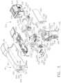
- FIG. 1is a perspective view of a surgical instrument including an interchangeable surgical tool assembly in accordance with at least one embodiment
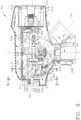
- FIG. 2is another perspective view of a handle assembly of the surgical instrument of FIG. 1 , with a portion of the handle housing omitted to expose components housed therein;
- FIG. 3is an exploded assembly view of portions of the handle assembly of the surgical instrument of FIGS. 1 and 2 ;
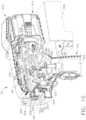
- FIG. 4is a cross-sectional perspective view of the handle assembly of FIGS. 2 and 3 ;
- FIG. 5is a partial cross-sectional side view of the handle assembly of FIGS. 2 - 4 with a grip portion of the handle assembly shown in solid lines in one position relative to a primary housing portion and in phantom lines in another position relative to the primary housing portion of the handle assembly;
- FIG. 6is an end cross-sectional view of the handle assembly of FIGS. 2 - 5 taken along line 6 - 6 in FIG. 5 ;
- FIG. 7is another end cross-sectional view of the handle assembly of FIGS. 2 - 6 taken along line 7 - 7 in FIG. 5 ;
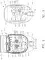
- FIG. 8is another end cross-sectional view of the handle assembly of FIGS. 2 - 7 showing a shifter gear in meshing engagement with a drive gear on a rotary drive socket;
- FIG. 9is another end cross-sectional view of the handle assembly of FIGS. 2 - 8 showing the position of a shifter solenoid when the shifter gear is in meshing engagement with the drive gear on the rotary drive socket;
- FIG. 10is another perspective view of the handle assembly of FIGS. 2 - 9 with certain portions thereof shown in cross-section and with an access panel portion thereof shown in phantom;
- FIG. 11is a top view of the handle assembly of FIGS. 2 - 11 with a bailout system shown in an actuatable position;
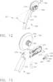
- FIG. 12is a perspective view of a bailout handle of the bailout system depicted in FIGS. 2 - 11 ;
- FIG. 13is an exploded assembly view of portions of the bailout handle of FIG. 12 with portions thereof shown in cross-section;
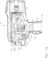
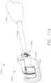
- FIG. 14is a cross-sectional elevation view of the handle assembly of FIG. 11 ;
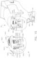
- FIG. 15is a perspective view of the handle assembly of FIGS. 2 - 11 and a tool attachment module portion of the interchangeable surgical tool assembly of FIG. 1 ;
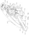
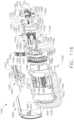
- FIG. 16is a partial cross-sectional perspective view of the tool attachment module portion of FIG. 15 ;
- FIG. 17is an exploded assembly view of portions of the interchangeable surgical tool assembly of FIG. 16 ;
- FIG. 18is an exploded assembly view of the tool attachment module of FIG. 16 ;
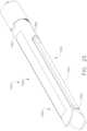
- FIG. 19is a perspective view of one form of a shaft coupler release assembly
- FIG. 20is a side cross-sectional view of the tool attachment module of FIGS. 16 and 18 being aligned for installation on a tool mounting portion of the handle assembly of FIG. 1 ;
- FIG. 21is another side cross-sectional view of the tool attachment module of FIG. 20 being initially inserted into tool mounting portion of the handle assembly of FIG. 1 ;
- FIG. 22is another side cross-sectional view of the tool attachment module of FIGS. 20 and 21 attached to the tool mounting portion of the handle assembly of FIG. 1 ;
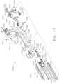
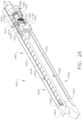
- FIG. 23is a perspective view of the interchangeable surgical tool assembly of FIG. 1 ;
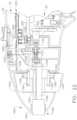
- FIG. 24is a cross-sectional perspective view the interchangeable surgical tool assembly of FIG. 23 ;
- FIG. 25is a perspective view of a surgical end effector portion of the interchangeable surgical tool assembly of FIG. 23 ;
- FIG. 26is a cross-sectional perspective view of the surgical end effector of FIG. 25 ;
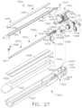
- FIG. 27is an exploded assembly view of the surgical end effector of FIG. 25 ;
- FIG. 28is a partial rear cross-sectional view of the surgical end effector of FIG. 25 ;
- FIG. 29is a cross-sectional perspective view of a firing member or cutting member in accordance with at least one embodiment
- FIG. 30is a cross-sectional elevational view of an articulation joint in accordance with at least one embodiment
- FIG. 31is a cross-sectional view of the surgical end effector of FIG. 25 with the firing member of FIG. 29 in a firing position;
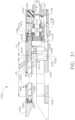
- FIG. 32is another cross-sectional view of the surgical end effector of FIG. 25 with the firing member FIG. 29 in an ending position;
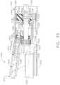
- FIG. 33is another cross-sectional view of a portion of the surgical end effector of FIG. 25 with an anvil assembly in an open position;
- FIG. 34is another cross-sectional view of a portion of the surgical end effector of FIG. 25 with the firing member of FIG. 29 in a pre-firing position;
- FIG. 35is another cross-sectional view of a portion of the surgical end effector of FIG. 34 wherein the firing member has been returned to a starting position to thereby urge the internally threaded closure nut into threaded engagement with the closure thread segment on the distal power shaft;
- FIG. 36is a perspective view of a bearing spring in accordance with at least one embodiment
- FIG. 37is an exploded assembly view of the articulation joint of FIG. 30 ;
- FIG. 38is a top view of the articulation joint of FIG. 30 with the surgical end effector of FIG. 25 in an unarticulated orientation;
- FIG. 39is another top view of the articulation joint of FIG. 30 with the surgical end effector in a maximum articulated orientation
- FIG. 40is a perspective view of a portion of the elongate shaft assembly of FIG. 23 showing the articulation joint of FIG. 30 and portions of a surgical end effector rotary locking system embodiment;
- FIG. 40 Ais a partial exploded perspective view of an articulation joint and end effector illustrating one arrangement for facilitating the supply of electrical signals to the end effector around the articulation joint in accordance with at least one embodiment
- FIG. 40 Bis a side elevational view of the articulation joint and end effector of FIG. 40 A with some components thereof shown in cross-section;
- FIG. 41is a partial cross-sectional perspective view of the surgical end effector rotary locking system of FIG. 40 in an unlocked orientation
- FIG. 42is another partial cross-sectional perspective view of the surgical end effector rotary locking system of FIGS. 40 and 41 in an unlocked orientation;
- FIG. 43is a top view of the surgical end effector rotary locking system of FIGS. 40 - 42 in a locked orientation
- FIG. 44is a top view of the surgical end effector rotary locking system of FIGS. 40 - 43 in an unlocked orientation
- FIG. 45illustrates an exploded view of an interchangeable tool assembly in accordance with at least one embodiment
- FIG. 46is a perspective view of the interchangeable tool assembly of FIG. 45 ;
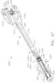
- FIG. 47is a cross-sectional perspective view of the interchangeable tool assembly of FIG. 45 ;
- FIG. 48is a cross-sectional exploded view of the interchangeable tool assembly of FIG. 45 ;
- FIG. 49is a perspective view of an articulation block of the interchangeable tool assembly of FIG. 45 ;
- FIG. 50is a cross-sectional perspective view of an articulation joint of the interchangeable tool assembly of FIG. 45 including the articulation block of FIG. 49 ;
- FIG. 51is another cross-sectional perspective view of the articulation joint of FIG. 50 ;
- FIG. 52is a partial exploded view of the interchangeable tool assembly of FIG. 45 ;
- FIG. 53is another partial exploded view of the interchangeable tool assembly of FIG. 45 ;
- FIG. 54is a partial exploded view of the articulation joint of FIG. 50 ;
- FIG. 55is a cross-sectional perspective view of the proximal end of the interchangeable tool assembly of FIG. 45 ;
- FIG. 56is an end view of the interchangeable tool assembly of FIG. 45 ;
- FIG. 57is a cross-sectional view of an end effector of the interchangeable tool assembly of FIG. 45 taken along line 57 - 57 in FIG. 56 illustrating the end effector in a clamped, but unfired condition;
- FIG. 58is a cross-sectional view of an end effector of the interchangeable tool assembly of FIG. 45 taken along line 58 - 58 in FIG. 56 illustrating the end effector in a clamped, but unfired condition;
- FIG. 59is a cross-sectional view of the end effector of the interchangeable tool assembly of FIG. 45 taken along line 59 - 59 in FIG. 56 illustrating the end effector in a clamped, but unfired condition;
- FIG. 60is a cross-sectional view of the end effector of the interchangeable tool assembly of FIG. 45 illustrated in a disassembled condition
- FIG. 61illustrates the end effector of the interchangeable tool assembly of FIG. 45 articulated in a first direction
- FIG. 62illustrates the end effector of the interchangeable tool assembly of FIG. 45 articulated in a second direction
- FIG. 63is a perspective view of a cartridge body of the interchangeable tool assembly of FIG. 45 ;
- FIG. 64is a perspective view of a cartridge body in accordance with at least one alternative embodiment
- FIG. 65is an exploded view of an end effector of an interchangeable tool assembly in accordance with at least one alternative embodiment
- FIG. 66is a disassembled view of the end effector of FIG. 65 ;
- FIG. 67is a disassembled view of an end effector of an interchangeable tool assembly in accordance with at least one alternative embodiment
- FIG. 68is a disassembled view of an end effector of an interchangeable tool assembly in accordance with at least one alternative embodiment
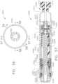
- FIG. 69is a perspective view illustrating a staple cartridge and a shaft of a surgical stapling instrument in accordance with at least one embodiment
- FIG. 70is a partial cross-sectional view of the staple cartridge assembled to the stapling instrument of FIG. 69 ;
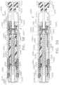
- FIG. 71is a partial cross-sectional view of a surgical stapling instrument comprising a closure drive, an anvil, and a lockout configured to prevent the anvil from being assembled to the closure drive if the closure drive is not in a fully-extended position;
- FIG. 72is a partial cross-sectional view of the surgical stapling instrument of FIG. 71 illustrating the anvil attached to the closure drive;
- FIG. 73is a partial perspective view of a surgical stapling instrument comprising a staple cartridge and a closure drive configured to move an anvil relative to the staple cartridge;
- FIG. 74is a partial cross-sectional view of the stapling instrument of FIG. 73 illustrating a lockout configured to prevent the closure drive from being retracted without the anvil being attached to the closure drive;
- FIG. 75is a partial cross-sectional view of the stapling instrument of FIG. 74 illustrating the anvil attached to the closure drive and the lockout disengaged from the closure drive;
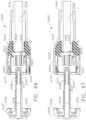
- FIG. 76is a partial cross-sectional view of a surgical stapling instrument comprising a staple cartridge including staples removable stored therein, an anvil, a closure drive configured to move the anvil relative to the staple cartridge, and a firing drive configured to eject the staples from the staple cartridge;
- FIG. 77is a detail view of a lockout configured to prevent the firing drive from being actuated prior to the anvil being moved into a closed position;
- FIG. 78is a detail view of the lockout of FIG. 77 disengaged from the firing drive
- FIG. 79is a partial perspective view of a surgical stapling instrument comprising a staple cartridge including staples removable stored therein, an anvil, a closure drive configured to move the anvil relative to the staple cartridge, and a firing drive configured to eject the staples from the staple cartridge;
- FIG. 80is a detail view of a lockout of the surgical stapling instrument of FIG. 79 configured to prevent the firing drive from being actuated prior to the anvil applying a sufficient pressure to tissue captured between the anvil and the staple cartridge;
- FIG. 81is a detail view of the lockout of FIG. 80 disengaged from the firing drive
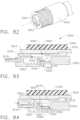
- FIG. 82is a partial perspective view of a surgical stapling instrument comprising a staple cartridge including staples removable stored therein, an anvil, a closure drive configured to move the anvil relative to the staple cartridge, and a firing drive configured to eject the staples from the staple cartridge;
- FIG. 83is a detail view of a lockout of the surgical stapling instrument of FIG. 82 configured to prevent the anvil from being detached from the closure drive while a cutting member of the firing drive is exposed above the staple cartridge;
- FIG. 84is a detail view of the lockout of FIG. 83 disengaged from the anvil after the firing drive has been sufficiently retracted after a firing stroke;
- FIG. 85is a partial cross-sectional view of a surgical stapling instrument comprising a staple cartridge including staples removable stored therein, an anvil, a closure drive configured to move the anvil relative to the staple cartridge, and a firing drive configured to eject the staples from the staple cartridge;
- FIG. 86is a partial cross-sectional view of the surgical stapling instrument of FIG. 85 illustrating the closure drive in a clamped configuration and the firing drive in an unfired configuration, wherein the firing drive is holding a lockout in an unreleased configuration;
- FIG. 87is a partial cross-sectional view of the surgical stapling instrument of FIG. 85 illustrating the firing drive in an at least partially-fired configuration and the lockout of FIG. 86 in a released configuration;
- FIG. 88is a partial cross-sectional view of the surgical stapling instrument of FIG. 85 illustrating the closure drive in an extended, or open, configuration and the lockout of FIG. 86 engaged with the closure drive to prevent the closure drive from being re-clamped;
- FIG. 89is a cross-sectional view of a surgical stapling instrument comprising a staple cartridge including staples removable stored therein, an anvil, a closure drive configured to move the anvil relative to the staple cartridge, and a firing drive configured to eject the staples from the staple cartridge which is illustrated in a disabled, or locked out, configuration;
- FIG. 89 Ais a cross-sectional end view of the surgical stapling instrument of FIG. 89 taken along line 89 A- 89 A in FIG. 89 ;
- FIG. 90is a cross-sectional view of the surgical stapling instrument of FIG. 89 illustrated in a clamped configuration in which the firing drive has been enabled;
- FIG. 90 Ais a cross-sectional end view of the surgical stapling instrument of FIG. 89 taken along line 90 A- 90 A in FIG. 90 ;
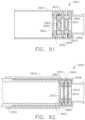
- FIG. 91is a partial cross-sectional view of a surgical stapling instrument comprising a staple cartridge including staples removable stored therein, an anvil, a closure drive configured to move the anvil relative to the staple cartridge, and a firing drive configured to eject the staples from the staple cartridge, wherein the closure drive is illustrated in an unclamped configuration and the firing drive is illustrated in an inoperable configuration;
- FIG. 92is a partial cross-sectional view of the surgical stapling instrument of FIG. 91 with the closure drive illustrated in a clamped configuration and the firing drive is illustrated in an operable configuration;
- FIG. 93is a perspective view of a rotatable intermediate drive member of the firing drive of the surgical instrument of FIG. 91 ;
- FIG. 94is a partial perspective view of a rotatable firing shaft of the firing drive of the surgical instrument of FIG. 91 ;
- FIG. 95is an elevational view of a spring system configured to bias the firing shaft of FIG. 94 out of engagement with the intermediate drive member of FIG. 93 ;
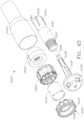
- FIG. 96is an exploded view of an end effector of a surgical stapling instrument comprising a staple cartridge in accordance with at least one embodiment
- FIG. 97is a partial cross-sectional view of the end effector of FIG. 96 illustrating a lockout configured to prevent the end effector from being operated if the staple cartridge is not fully assembled to the stapling instrument;
- FIG. 98is a partial cross-sectional view of the end effector of FIG. 96 illustrating the lockout in an unlocked configuration
- FIG. 99is an exploded view of an end effector of a surgical stapling instrument comprising a staple cartridge in accordance with at least one embodiment
- FIG. 100is a partial cross-sectional view of the end effector of FIG. 99 illustrating a lock configured to releasably hold the staple cartridge to the stapling instrument;
- FIG. 101is a partial cross-sectional view of the end effector of FIG. 99 illustrating the lock in an unlocked configuration
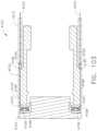
- FIG. 102illustrates a shaft of a surgical stapling instrument configured to be used with a staple cartridge selected from a plurality of circular staple cartridges;
- FIG. 103is a cross-sectional view of a distal end of the stapling instrument of FIG. 102 ;
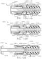
- FIG. 104is a partial cross-sectional view of a surgical stapling instrument comprising an unfired staple cartridge and a lockout system configured to prevent the staple cartridge from being re-fired after it has been previously fired by a firing drive of the surgical instrument;
- FIG. 105is a partial cross-sectional view of the stapling instrument of FIG. 104 illustrated in a clamped configuration and the firing drive in a fired configuration;
- FIG. 106is a partial cross-sectional view of the stapling instrument of FIG. 104 illustrated in an unclamped configuration and the firing drive in a retracted configuration;
- FIG. 107is an end view of the firing drive and a frame of the stapling instrument of FIG. 104 illustrating the firing drive in an unfired configuration
- FIG. 108is an end view of the firing drive and the frame of the stapling instrument of FIG. 104 illustrating the firing drive in a retracted configuration
- FIG. 109is an end view of an alternative staple cartridge design that is usable with the stapling instrument of FIG. 104 ;
- FIG. 110is an end view of an alternative staple cartridge design that is usable with the stapling instrument of FIG. 104 ;
- FIG. 111is a perspective view of a surgical stapling instrument comprising a flexible shaft in accordance with at least one embodiment
- FIG. 112is a schematic of a surgical instrument kit comprising a plurality of end effectors in accordance with at least one embodiment
- FIG. 112 Ais a schematic of a robotic surgical instrument system comprising a plurality of attachable end effectors in accordance with at least one embodiment
- FIG. 113is a perspective view of several end effectors depicted in FIG. 112 ;
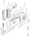
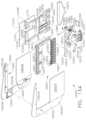
- FIG. 114is a perspective view of a surgical stapling attachment comprising an attachment portion, a shaft assembly, an articulation joint, and an end effector assembly;
- FIG. 115is a partial perspective view of a staple cartridge assembly, the end effector assembly, and the articulation joint of the surgical stapling attachment of FIG. 114 ;
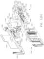
- FIG. 116is a partial exploded view of the end effector assembly, the articulation joint, and the shaft assembly of the surgical stapling attachment of FIG. 114 ;
- FIG. 117is a partial perspective view of the attachment portion and the shaft assembly of the surgical stapling attachment of FIG. 114 ;
- FIG. 118is a partial perspective view of the end effector assembly, the articulation joint, and the shaft assembly of the surgical stapling attachment of FIG. 114 , wherein the shaft assembly comprises a shifting assembly configured to shift between the drivability of a closure drive and a firing drive, and wherein the shifting assembly is illustrated in a position to drive the firing drive;
- FIG. 119is a partial perspective view of the end effector assembly, the articulation joint, and the shaft assembly of the surgical stapling attachment of FIG. 114 , wherein the shifting assembly is illustrated in a position to drive the closure drive;
- FIG. 120is a perspective view of a closure frame of the end effector assembly of the surgical stapling attachment of FIG. 114 , wherein the closure frame comprises corresponding slots to engage a tissue-retention pin mechanism of the end effector assembly and corresponding driving tabs to engage the staple cartridge assembly;
- FIG. 121is a bottom view of the closure frame shown in FIG. 120 ;
- FIG. 122is a side view of the closure frame shown in FIG. 120 ;
- FIG. 123is a partial perspective view of the end effector assembly, the articulation joint, and the shaft assembly of the surgical stapling attachment of FIG. 114 , wherein the shifting assembly is illustrated in a position to drive the closure drive;
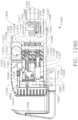
- FIG. 124is a longitudinal cross-sectional view of the end effector assembly, the articulation joint, and the shaft assembly of the surgical stapling attachment of FIG. 114 , wherein the shifting assembly is in a first position to drive the closure drive and the end effector assembly is in an open configuration;
- FIG. 125is a longitudinal cross-sectional view of the end effector assembly, the articulation joint, and the shaft assembly of the surgical stapling attachment of FIG. 114 , wherein the shifting assembly is in the first position and the end effector assembly is in a partially closed configuration;
- FIG. 126is a longitudinal cross-sectional view of the end effector assembly, the articulation joint, and the shaft assembly of the surgical stapling attachment of FIG. 114 , wherein the shifting assembly is in the first position and the end effector assembly is in a fully clamped configuration;
- FIG. 127is a longitudinal cross-sectional view of the end effector assembly, the articulation joint, and the shaft assembly of the surgical stapling attachment of FIG. 114 , wherein the shifting assembly has shifted from the first position to a second position to drive the firing drive and the end effector assembly is in the fully clamped configuration;
- FIG. 128is a longitudinal cross-sectional view of the end effector assembly, the articulation joint, and the shaft assembly of the surgical stapling attachment of FIG. 114 , wherein the shifting assembly is in the second position and the surgical stapling attachment is in a fully fired configuration;
- FIG. 129is a longitudinal cross-sectional view of the end effector assembly, the articulation joint, and the shaft assembly of the surgical stapling attachment of FIG. 114 , wherein the shifting assembly has shifted from the second position to a third position to drive the firing drive and the closure drive simultaneously, and wherein the surgical stapling attachment is in the fully fired configuration;
- FIG. 129 Ais a perspective view of a shaft assembly comprising a staple cartridge in accordance with at least one embodiment
- FIG. 129 Bis a partial perspective view of the shaft assembly of FIG. 129 A illustrating the staple cartridge detached from the shaft assembly;
- FIG. 129 Cis a partial exploded view of the shaft assembly of FIG. 129 A ;
- FIG. 129 Dis a partial cross-sectional view of the shaft assembly of FIG. 129 A illustrated in an open, unclamped configuration
- FIG. 129 Eis a partial cross-sectional view of the shaft assembly of FIG. 129 A illustrated in a closed, clamped configuration
- FIG. 129 Fis a partial cross-sectional view of the shaft assembly of FIG. 129 A illustrated in a fired configuration
- FIG. 129 Gis a partial cross-sectional view of the shaft assembly of FIG. 129 A illustrating a power harvesting system in accordance with at least one embodiment
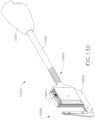
- FIG. 131is a partial perspective view of the articulation joint and the end effector assembly of the instrument of FIG. 130 , wherein the end effector assembly comprises an end effector frame, a closure frame, and a staple cartridge assembly;
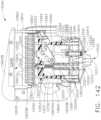
- FIG. 132is a partial perspective view of the shaft assembly, the articulation joint, and the end effector assembly of the instrument of FIG. 130 illustrating the staple cartridge assembly installed within the end effector assembly;
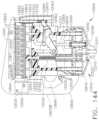
- FIG. 134is an exploded view of the end effector assembly and the shaft assembly of the instrument of FIG. 130 ;
- FIG. 136is a partial perspective view of the end effector assembly and the shaft assembly of the instrument of FIG. 130 , wherein portions of the end effector assembly are fully or partially removed to expose a drive system, multiple lock arrangements, and a tissue-retention pin mechanism of the end effector assembly;
- FIG. 138is a partial, cross-sectional elevational view of the end effector assembly of the instrument of FIG. 130 illustrated in an uncaptured, unclamped, unfired, unlocked configuration;
- FIG. 139is a partial, cross-sectional elevational view of the end effector assembly of the instrument of FIG. 130 illustrated in the uncaptured, unclamped, unfired, unlocked configuration of FIG. 138 ;
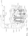
- FIG. 143is a partial, cross-sectional elevational view of the end effector assembly of the instrument of FIG. 130 illustrated in a fully-clamped, unfired configuration;
- FIG. 147is a partial, cross-sectional elevational view of the end effector assembly of the instrument of FIG. 130 illustrated in the fully-retracted, locked configuration of FIG. 46 , wherein an unspent staple cartridge assembly is ready to be installed within the end effector assembly;
- FIG. 148is a partial, cross-sectional elevational view of the end effector assembly of the instrument of FIG. 130 illustrated in a fully-clamped, partially-fired configuration, wherein the staple cartridge assembly comprises a firing status indicator system and the firing status indicator system indicates that the instrument is in the fully-clamped, partially-fired configuration;
- FIG. 149is a partial, cross-sectional elevational view of the end effector assembly of the instrument of FIG. 130 illustrated in a fully-clamped, fully-fired configuration, wherein the firing status indicator system indicates that the instrument is in the fully-clamped, fully-fired configuration;
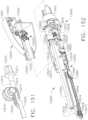
- FIG. 151is a partial perspective view of an articulation transmission of the attachment portion of the instrument of FIG. 150 ;
- FIG. 152is a perspective cross-sectioned view of the end effector assembly of the instrument of FIG. 150 , wherein some portions of the instrument are removed to expose inner portions of the instrument;
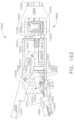
- FIG. 153is a partial exploded view of the instrument of FIG. 150 ;
- FIG. 155is a partial exploded view of the attachment portion, the shaft assembly, and the articulation joint of the instrument of FIG. 150 ;
- FIG. 156is a partial cross-sectioned perspective view of the articulation joint of the instrument of FIG. 150 ;
- FIG. 157is a perspective view of the articulation joint and the end effector assembly of the instrument of FIG. 150 , wherein the end effector assembly comprises a pair of moveable jaws, a staple cartridge, and a drive system;
- FIG. 158is a cross-sectional elevational view of the instrument of FIG. 150 illustrated in a clamped, unfired configuration
- FIG. 159is a cross-sectional elevational view of the end effector assembly of the instrument of FIG. 150 illustrated in a clamped, fully stapled configuration;
- FIG. 160is a cross-sectional elevational view of the end effector assembly of the instrument of FIG. 150 illustrated in a retracted configuration
- FIG. 163is a partial, cross-sectional elevational view of the end effector assembly of the instrument of FIG. 150 illustrated in an unclamped, or open, configuration;
- FIG. 164is a partial, top view of the end effector assembly, the articulation joint, and the shaft assembly of the instrument of FIG. 150 illustrated in a clamped, unarticulated configuration;
- FIG. 165is a partial, top view of the end effector assembly, the articulation joint, and the shaft assembly of the instrument of FIG. 150 illustrated in an unclamped, articulated configuration;
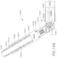
- FIG. 166is a partial, top view of the end effector assembly, the articulation joint, and the shaft assembly of the instrument of FIG. 150 illustrated in a clamped, articulated configuration;
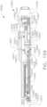
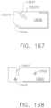
- FIG. 167is a cross-sectional elevational view of a closure frame of the end effector assembly of the instrument of FIG. 150 ;
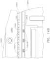
- FIG. 168is a cross-sectional elevational view of an end effector frame of the instrument of FIG. 150 ;
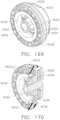
- FIG. 169is a perspective view of an anvil in accordance with at least one embodiment
- FIG. 170is a cross-sectional view of the anvil of FIG. 169 ;
- FIG. 171is a partial cross-sectional view of an end effector including the anvil of FIG. 169 illustrated in a fired configuration
- FIG. 172is a perspective view of an anvil in accordance with at least one embodiment
- FIG. 173is a plan view of the anvil of FIG. 172 ;
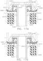
- FIG. 174is a cross-sectional view of an end effector in accordance with at least one embodiment illustrated in a clamped, unfired configuration
- FIG. 175is a cross-sectional view of the end effector of FIG. 174 illustrated in a fired configuration
- FIG. 176is a cross-sectional view of an end effector in accordance with at least one alternative embodiment illustrated in a clamped, unfired configuration
- FIG. 177is a cross-sectional view of the end effector of FIG. 176 illustrated in a fired configuration
- FIG. 178is a cross-sectional view of an end effector in accordance with at least one alternative embodiment illustrated in a clamped, unfired configuration
- FIG. 179is a cross-sectional view of the end effector of FIG. 176 illustrated in a fired configuration
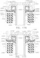
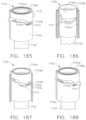
- FIG. 180is a perspective view of a staple forming pocket in accordance with at least one embodiment
- FIG. 181is a cross-sectional view of the staple forming pocket of FIG. 180 ;
- FIG. 182is an exploded view of an end effector in accordance with at least one embodiment configured to sequentially deploy a first annular row of staples and a second annular row of staples;
- FIG. 183is a partial cross-sectional view of the end effector of FIG. 182 illustrating a firing driver deploying a staple in the first row of staples;
- FIG. 184is a partial cross-sectional view of the end effector of FIG. 182 illustrating the firing driver of FIG. 183 deploying a staple in the second row of staples;
- FIG. 185is a partial perspective view of a firing drive configured to sequentially drive a first driver for firing a first row of staples, a second driver for firing a second row of staples, and then a third driver for driving a cutting member;
- FIG. 186is a partial perspective view of the firing drive of FIG. 185 illustrating the first driver in a fired position
- FIG. 187is a partial perspective view of the firing drive of FIG. 185 illustrating the second driver in a fired position
- FIG. 188is a partial perspective view of the firing drive of FIG. 185 illustrating the third driver in a fired position
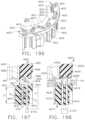
- FIG. 189is an exploded view of the firing drive of FIG. 185 ;
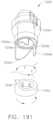
- FIG. 190is a partial perspective view of the firing drive of FIG. 185 in the configuration of FIG. 188 ;
- FIG. 191is an exploded view of a firing drive in accordance with at least one alternative embodiment
- FIG. 192is a perspective view of a portion of a surgical staple cartridge for use with a circular surgical stapling instrument in accordance with at least one embodiment
- FIG. 193depicts a pair of staples in accordance with at least one embodiment in unformed and formed configurations
- FIG. 194is a cross-sectional view of a portion of an anvil in relation to a portion of the surgical staple cartridge of FIG. 192 prior to actuation of the staple forming process;
- FIG. 195is another cross-sectional view of the anvil of FIG. 194 and the staple cartridge of FIG. 192 after the staples have been formed;
- FIG. 196is a perspective view of a portion of a surgical staple cartridge for use with a circular surgical stapling instrument in accordance with at least one embodiment
- FIG. 197is a cross-sectional view of a portion of an anvil in relation to a portion of the surgical staple cartridge of FIG. 196 prior to actuation of the staple forming process;
- FIG. 198is another cross-sectional view of the anvil and staple cartridge of FIG. 197 after the staples have been formed;
- FIG. 199is a top view of a staple cartridge in accordance with at least one embodiment
- FIG. 200is a bottom view of an anvil in accordance with at least one embodiment
- FIG. 201is a cross-sectional view of a portion of an anvil in relation to a portion of a surgical staple cartridge
- FIG. 202depicts three unformed surgical staples
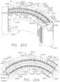
- FIG. 203is a perspective view of a portion of a surgical stapling device according to at least one embodiment
- FIG. 204is a top view of a surgical staple cartridge of the stapling device of FIG. 203 ;
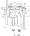
- FIG. 205is a perspective view of a portion of the surgical stapling device of FIG. 203 ;
- FIG. 206is a side elevational view of a staple driver assembly according to at least one embodiment
- FIG. 207is a bottom view of an anvil according to at least one embodiment
- FIG. 208is a side elevational cross-sectional view of a portion of a surgical stapling device employing the anvil of FIG. 207 ;
- FIG. 209is an enlarged view of staple forming pockets of the anvil of FIG. 207 with a corresponding formed staple;
- FIG. 210depicts staples in accordance with at least one embodiment in unformed and formed configurations
- FIG. 211is a side elevational cross-sectional view of a portion of a surgical stapling device according to at least one embodiment
- FIG. 212depicts staples in accordance with at least one embodiment in unformed and formed configurations
- FIG. 213is a side elevational cross-sectional view of a portion of a surgical stapling device according to at least one embodiment
- FIG. 214is a top view of a portion of a surgical stapling device according to at least one embodiment
- FIG. 215is a bottom view of an anvil in accordance with at least one embodiment that may be used in connection with the surgical stapling device of FIG. 214 ;
- FIG. 216is a top view of a staple cavity according to at least one embodiment and a corresponding staple;
- FIG. 217depicts unformed staples according to at least one embodiment
- FIG. 218is a top view of a surgical stapling device according to at least one embodiment
- FIG. 219is a top view of a staple cavity according to at least one embodiment and a corresponding staple;
- FIG. 220is a bottom view of an anvil according to at least one embodiment that may be employed in connection with the surgical stapling device of FIG. 218 ;
- FIG. 221is an enlarged view of staple forming pockets of the anvil of FIG. 220 with a corresponding formed staple;
- FIG. 222is a partial cross-sectional view of a surgical stapling device according to at least one embodiment
- FIG. 223depicts unformed staples according to at least one embodiment
- FIG. 224is a top plan view of a staple cartridge according to at least one embodiment
- FIG. 225is a top view of a staple cavity according to at least one embodiment and a corresponding staple;
- FIG. 226is a bottom view of a surgical stapling device anvil according to at least one embodiment
- FIG. 227is a top view of a pair of staple cavities according to at least one embodiment and a corresponding staple;
- FIG. 228is a cross-sectional view of an anvil assembly of a surgical stapler in accordance with at least one embodiment
- FIG. 229is a cross-sectional view of an anvil modification member of the anvil assembly of FIG. 228 ;
- FIG. 230is a top view of an anvil modification member of the anvil assembly of FIG. 228 ;
- FIG. 231is a top view of an anvil assembly of a surgical stapler in accordance with at least one embodiment
- FIG. 232is a top view of a staple cartridge of the surgical stapler of FIG. 231 ;
- FIG. 233illustrates a forming pocket of an anvil modification member and a staple formed by the forming pocket
- FIG. 234illustrates a staple cavity of the surgical stapler of FIG. 231 and an unformed staple
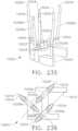
- FIG. 235is a perspective of a staple driver supporting three staples of the surgical stapler of FIG. 231 ;
- FIG. 236is a top view of the staple driver of FIG. 235 ;
- FIG. 237illustrates a cross-sectional view of an end effector including a staple cartridge, an anvil, and an anvil modification member in accordance with at least one alternative embodiment
- FIG. 238illustrates three staples in unformed configurations and formed configurations in accordance with at least one embodiment
- FIG. 239illustrates a partial cross-sectional view of a staple cartridge of a circular stapler in accordance with at least one embodiment
- FIG. 240illustrates a partial perspective view of a staple cartridge of a circular stapler in accordance with at least one embodiment.
- proximal and distalare used herein with reference to a clinician manipulating the handle portion of the surgical instrument.
- proximalrefers to the portion closest to the clinician and the term “distal” refers to the portion located away from the clinician.
- distalrefers to the portion located away from the clinician.
- spatial termssuch as “vertical”, “horizontal”, “up”, and “down” may be used herein with respect to the drawings.
- surgical instrumentsare used in many orientations and positions, and these terms are not intended to be limiting and/or absolute.
- Various exemplary devices and methodsare provided for performing laparoscopic and minimally invasive surgical procedures.
- the various methods and devices disclosed hereincan be used in numerous surgical procedures and applications including, for example, in connection with open surgical procedures.
- the various instruments disclosed hereincan be inserted into a body in any way, such as through a natural orifice, through an incision or puncture hole formed in tissue, etc.
- the working portions or end effector portions of the instrumentscan be inserted directly into a patient's body or can be inserted through an access device that has a working channel through which the end effector and elongate shaft of a surgical instrument can be advanced.
- a surgical stapling systemcan comprise a shaft and an end effector extending from the shaft.
- the end effectorcomprises a first jaw and a second jaw.
- the first jawcomprises a staple cartridge.
- the staple cartridgeis insertable into and removable from the first jaw; however, other embodiments are envisioned in which a staple cartridge is not removable from, or at least readily replaceable from, the first jaw.
- the second jawcomprises an anvil configured to deform staples ejected from the staple cartridge.
- the second jawis pivotable relative to the first jaw about a closure axis; however, other embodiments are envisioned in which first jaw is pivotable relative to the second jaw.
- the surgical stapling systemfurther comprises an articulation joint configured to permit the end effector to be rotated, or articulated, relative to the shaft.
- the end effectoris rotatable about an articulation axis extending through the articulation joint. Other embodiments are envisioned which do not include an articulation joint.
- the staple cartridgecomprises a cartridge body.
- the cartridge bodyincludes a proximal end, a distal end, and a deck extending between the proximal end and the distal end.
- the staple cartridgeis positioned on a first side of the tissue to be stapled and the anvil is positioned on a second side of the tissue.
- the anvilis moved toward the staple cartridge to compress and clamp the tissue against the deck.
- staples removably stored in the cartridge bodycan be deployed into the tissue.
- the cartridge bodyincludes staple cavities defined therein wherein staples are removably stored in the staple cavities.
- the staple cavitiesare arranged in six longitudinal rows. Three rows of staple cavities are positioned on a first side of a longitudinal slot and three rows of staple cavities are positioned on a second side of the longitudinal slot. Other arrangements of staple cavities and staples may be possible.
- the staplesare supported by staple drivers in the cartridge body.
- the driversare movable between a first, or unfired position, and a second, or fired, position to eject the staples from the staple cavities.
- the driversare retained in the cartridge body by a retainer which extends around the bottom of the cartridge body and includes resilient members configured to grip the cartridge body and hold the retainer to the cartridge body.
- the driversare movable between their unfired positions and their fired positions by a sled.
- the sledis movable between a proximal position adjacent the proximal end and a distal position adjacent the distal end.
- the sledcomprises a plurality of ramped surfaces configured to slide under the drivers and lift the drivers, and the staples supported thereon, toward the anvil.
- the sledis moved distally by a firing member.
- the firing memberis configured to contact the sled and push the sled toward the distal end.
- the longitudinal slot defined in the cartridge bodyis configured to receive the firing member.
- the anvilalso includes a slot configured to receive the firing member.
- the firing memberfurther comprises a first cam which engages the first jaw and a second cam which engages the second jaw. As the firing member is advanced distally, the first cam and the second cam can control the distance, or tissue gap, between the deck of the staple cartridge and the anvil.
- the firing memberalso comprises a knife configured to incise the tissue captured intermediate the staple cartridge and the anvil. It is desirable for the knife to be positioned at least partially proximal to the ramped surfaces such that the staples are ejected ahead of the knife.
- FIG. 1depicts a motor-driven surgical system 10 that may be used to perform a variety of different surgical procedures.
- the motor driven surgical system 10comprises a selectively reconfigurable housing or handle assembly 20 that is attached to one form of an interchangeable surgical tool assembly 1000 .
- the system 10 that is depicted in FIG. 1includes an interchangeable surgical tool assembly 1000 that comprises a surgical cutting and fastening instrument which may be referred to as an endocutter.
- the interchangeable surgical tool assembliesmay include end effectors that are adapted to support different sizes and types of staple cartridges and, have different shaft lengths, sizes, and types, etc. Such arrangements, for example, may utilize any suitable fastener, or fasteners, to fasten tissue.
- a fastener cartridgecomprising a plurality of fasteners removably stored therein can be removably inserted into and/or attached to the end effector of a surgical tool assembly.
- Other surgical tool assembliesmay be interchangeably employed with the handle assembly 20 .
- the interchangeable surgical tool assembly 1000may be detached from the handle assembly 20 and replaced with a different surgical tool assembly that is configured to perform other surgical procedures.
- the surgical tool assemblymay not be interchangeable with other surgical tool assemblies and essentially comprise a dedicated shaft that is non-removably affixed or coupled to the handle assembly 20 , for example.
- the surgical tool assembliesmay also be referred to as elongate shaft assemblies.
- the surgical tool assembliesmay be reusable or, in other configurations, the surgical tool assemblies may be designed to be disposed of after a single use.
- housingand “housing assembly” may also encompass a housing or similar portion of a robotic system that houses or otherwise operably supports at least one drive system that is configured to generate and apply at least one control motion which could be used to actuate the elongate shaft assemblies disclosed herein and their respective equivalents.
- framemay refer to a portion of a handheld surgical instrument.
- framemay also represent a portion of a robotically controlled surgical instrument and/or a portion of the robotic system that may be used to operably control a surgical instrument.
- the surgical tool assemblies disclosed hereinmay be employed with various robotic systems, instruments, components and methods such as, but not limited to, those disclosed in U.S. patent application Ser. No. 13/118,241, entitled SURGICAL STAPLING INSTRUMENTS WITH ROTATABLE STAPLE DEPLOYMENT ARRANGEMENTS, now U.S. Patent Application Publication No. 2012/0298719 which is hereby incorporated by reference herein in its entirety.
- the housing assembly or handle assembly 20comprises a primary housing portion 30 that may be formed from a pair of housing segments 40 , 70 that may be fabricated from plastic, polymer materials, metal, etc. and be joined together by an appropriate fastener arrangement such as, for example, adhesive, screws, press-fit features, snap-fit features, latches, etc.
- the primary housing portion 30operably supports a plurality of drive systems therein that are configured to generate and apply various control motions to corresponding portions of the interchangeable surgical tool assembly that is operably attached thereto.
- the handle assembly 20further comprises a grip portion 100 that is movably coupled to the primary housing portion 30 and is configured to be gripped and manipulated by the clinician in various positions relative to the primary housing portion 30 .
- the grip portion 100may be fabricated from a pair of grip segments 110 , 120 that may be fabricated from plastic, polymer materials, metal, etc. and are joined together by an appropriate fastener arrangement such as, for example, adhesive, screws, press-fit features, snap-fit features, latches, etc. for assembly and maintenance purposes.
- the grip portion 100comprises a grip housing 130 that defines a hollow cavity 132 that is configured to operably support a drive motor and gearbox which will be discussed in further detail below.
- the upper portion 134 of the grip housing 130is configured to extend through an opening 80 in the primary housing portion 30 and be pivotally journaled on a pivot shaft 180 .
- the pivot shaft 180defines a pivot axis designated as “PA”. See FIG. 3 .
- the handle assembly 20defines a handle axis designated as “HA” that may be parallel to the shaft axis “SA” of the elongate shaft assembly of the interchangeable surgical tool that is operably attached to the handle assembly 20 .
- the pivot axis PAis transverse to the handle axis HA. See FIG.
- the grip housing 130defines a grip axis, generally designated as “GA”. See FIG. 2 .
- the clinicianmight want to position the grip portion 100 relative to the primary housing portion 30 such that the grip axis GA is perpendicular or approximately perpendicular (angle “H 1 ”) to the handle axis HA (referred to herein as a “first grip position”). See FIG. 5 .
- the clinicianmay wish to pivot the grip portion 100 relative to the primary housing portion 30 to a position wherein the grip axis GA is at a forty-five degree or approximately forty-five degree angle or other suitable acute angle (angle “H 2 ”) relative to the handle axis HA.
- This positionis referred to herein as a “second grip position”.
- FIG. 5illustrates the grip portion 100 in phantom lines in the second grip position.
- the handle assembly 20also includes a grip locking system, generally designated as 150 , for selectively locking the grip portion 100 in the desired orientation relative to the primary housing portion 30 .
- the grip locking system 150comprises an arcuate series 152 of pointed teeth 154 .
- the teeth 154are spaced from each other and form a locking groove 156 therebetween.
- Each locking groove 156corresponds to a particular angular locking position for the grip portion 100 .
- the teeth 154 and locking grooves or “locking locations” 156are arranged to permit the grip portion 100 to be locked at 10-15 degree intervals between the first grip position and the second grip position.
- the arrangementmay employ two stop positions which are tailored to the type of instrument (shaft arrangement) employed. For example, for an endocutter shaft arrangement, it may be approximately around ninety degrees to the shaft and for a circular stapler arrangement, the angle may be approximately forty-five degrees to the shaft while being swept forward towards the surgeon.
- the grip locking system 150further includes a locking button 160 that has a locking portion that is configured to lockingly engage the locking grooves 156 .
- the locking button 160is pivotally mounted in the primary handle portion 30 on a pivot pin 131 to permit the locking button 160 to pivot into engagement with a corresponding locking groove 156 .
- a locking spring 164serves to bias the locking button 160 into an engaged or locked position with the corresponding locking groove 156 .
- the locking portion and the teeth configurationsserve to enable the teeth 154 to slide past the locking portion when the clinician depresses the locking button 160 .
- the cliniciandepresses the locking button 160 and then pivots the grip portion 100 to the desired angular position. Once the grip portion 100 has been moved to the desired position, the clinician releases the locking button 160 .
- the locking spring 164will then bias the locking button 160 toward the series of teeth 154 so that the locking portion enters the corresponding locking groove 156 to retain the grip portion 100 in that position during use.
- the handle assembly 20operably supports a first rotary drive system 300 , a second rotary drive system 320 and a third axial drive system 400 .
- the rotary drive systems 300 , 320are each powered by a motor 200 that is operably supported in the grip portion 100 .
- the motor 200is supported within the cavity 132 in the grip portion 100 and has a gear box assembly 202 that has an output drive shaft 204 protruding therefrom.
- the motor 200may be a DC brushed driving motor having a maximum rotation of, approximately, 25,000 RPM, for example.
- the motormay include a brushless motor, a cordless motor, a synchronous motor, a stepper motor, or any other suitable electric motor.
- the motor 200may be powered by a power source 210 that, in one form, may comprise a removable power pack 212 .
- the power source 210may comprise, for example, anyone of the various power source arrangements disclosed in further detail in U.S. Patent Application Publication No. 2015/0272575 and entitled SURGICAL INSTRUMENT COMPRISING A SENSOR SYSTEM, the entire disclosure of which is hereby incorporated by reference herein.
- the power pack 212may comprise a proximal housing portion 214 that is configured for attachment to a distal housing portion 216 .
- the proximal housing portion 214 and the distal housing portion 216are configured to operably support a plurality of batteries 218 therein.
- Batteries 218may each comprise, for example, a Lithium Ion (“LI”) or other suitable battery.
- the distal housing portion 216is configured for removable operable attachment to a handle circuit board assembly 220 which is also operably coupled to the motor 200 .
- the handle circuit board assembly 220may also be generally referred to herein as the “control system or CPU 224 ”.
- a number of batteries 218may be connected in series may be used as the power source for the handle assembly 20 .
- the power source 210may be replaceable and/or rechargeable.
- the surgical instrument 10may be powered by alternating current (AC) for example.
- the motor 200may be controlled by a rocker switch 206 that is mounted to the grip portion 100 .
- the motor 200is operably coupled to a gear box assembly 202 that includes an output drive shaft 204 .
- Attached to the output drive shaft 204is a driver bevel gear 230 .
- the motor 200 , the gear box assembly 202 , the output drive shaft 204 and the driver bevel gear 230may also be collectively referred to herein as a “motor assembly 231 ”.
- the driver bevel gear 230interfaces with a driven bevel gear 234 that is attached to a system drive shaft 232 as well as a pivot bevel gear 238 that is journaled on the pivot shaft 180 .
- the driven bevel gear 234is axially movable on the system drive shaft 232 between an engaged position wherein the driven bevel gear 234 is in meshing engagement with the driver bevel gear 230 ( FIG. 5 ) and a disengaged position wherein the driven bevel gear 234 is out of meshing engagement with the drive bevel gear 230 ( FIG. 14 ).
- a drive system spring 235is journaled between the driven bevel gear 234 and a proximal end flange 236 that is formed on a proximal portion of the system drive shaft 232 . See FIGS. 4 and 14 .
- the drive system spring 235serves to bias the driven bevel gear 234 out of meshing engagement with the driver bevel gear 230 as will be discussed in further detail below.
- the pivot bevel gear 238facilitates pivotal travel of the output drive shaft 204 and driver bevel gear 230 with the grip portion 100 relative to the primary handle portion 30 .
- the system drive shaft 232interfaces with a rotary drive selector system, generally designated as 240 .
- the rotary drive selector system 240comprises a shifter gear 250 that is selectively movable between the first rotary drive system 300 and the second rotary drive system 320 .
- the drive selector system 240comprises a shifter mounting plate 242 that is non-movably mounted within primary handle portion 30 .
- the shifter mounting plate 242may be frictionally retained between mounting lugs (not shown) formed in the housing segments 40 , 70 or be otherwise retained therein by screws, adhesive, etc. Still referring to FIGS.
- the system drive shaft 232extends through a hole in the shifter mounting plate 242 and has the central, or system, drive gear 237 non-rotatably attached thereto.
- the central drive gear 237may be attached to the system drive shaft 232 by a keyway arrangement 233 . See FIGS. 6 - 9 .
- the system drive shaft 232may be rotatably supported in the shifter mounting plate 242 by a corresponding bearing (not shown) that is mounted thereto. In any event, rotation of the system drive shaft 232 will result in rotation of the central drive gear 234 .
- the first drive system 300includes a first drive socket 302 that is rotatably supported in a distal wall 32 formed in the primary handle portion 30 .
- the first drive socket 302may comprise a first body portion 304 that has a splined socket formed therein.
- a first driven gear 306is formed on or is non-movably attached to the first body portion 304 .
- the first body portion 304may be rotatably supported in a corresponding hole or passage provided the distal wall 32 or it may be rotatably supported in a corresponding bearing (not shown) that is mounted in the distal wall 32 .
- the second rotary drive system 320includes a second drive socket 322 that is also rotatably supported in the distal wall 32 of the primary handle portion 30 .
- the second drive socket 322may comprise a second body portion 324 that has a splined socket formed therein.
- a second driven gear 326is formed on or is non-rotatably mounted to the second body portion 324 .
- the second body portion 324may be rotatably supported in a corresponding hole or passage provided the distal wall 32 or it may be rotatably supported in a corresponding bearing (not shown) that is mounted in the distal wall 32 .
- the first and second drive sockets 302 , 322are spaced from each other on each lateral side of the handle axis HA. See FIG. 4 , for example.
- the rotary drive selector system 240includes a shifter gear 250 .
- the shifter gear 250is rotatably mounted on an idler shaft 252 that is movably supported in an arcuate slot 244 in the shifter mounting plate 242 .
- the shifter gear 250is mounted so as to freely rotate on the idler shaft 252 and remain in meshing engagement with the central drive gear 234 .
- the idler shaft 252is coupled to an end of a shaft 262 of a shifter solenoid 260 .
- the shifter solenoid 260is pinned or otherwise mounted with the primary handle housing 30 such that when the shifter solenoid 260 is actuated, the shifter gear 250 is moved into meshing engagement with one of the first driven gear 306 or the second driven gear 326 .
- the shifter gear 250is in meshing engagement with the central drive gear 234 and the first driven gear 306 such that actuation of the motor 200 will result in rotation of the first drive socket 302 .
- a shifter spring 266may be employed to bias the shifter gear 250 into that first actuation position.
- the shifter spring 266will automatically bias the shifter gear 250 into the first position.
- the shifter gear 250is in that position, subsequent actuation of the motor 200 will result in rotation of the first drive socket 302 of the first rotary drive system 300 .
- the shifter solenoidis actuated, the shifter gear 250 is moved into meshing engagement with the second driven gear 326 on the second drive socket 322 . Thereafter, actuation of the motor 200 will result in actuation or rotation of the second drive socket 322 of the second rotary drive system 320 .
- the first and second rotary drive systems 300 , 320may be used to power various component portions of the interchangeable surgical tool assembly that is coupled thereto.
- the shifter spring 266will bias the shifter gear 250 to the first position.
- the handle assembly 20 of the illustrated exampleemploys a manually actuatable “bailout” system, generally designated as 330 , for manually applying a rotary drive motion to the first rotary drive system 300 in the above described scenario, for example.
- the illustrated bailout system 330comprises a bailout drive train 332 that includes a planetary gear assembly 334 .
- the planetary gear assembly 334includes a planetary gear housing 336 that houses a planetary gear arrangement (not shown) that includes a planetary bevel gear 338 .
- the planetary gear assembly 334includes a bailout drive shaft 340 that is operably coupled to the planetary gear arrangement within the planetary gear housing 336 . Rotation of the planetary bevel gear 338 rotates the planetary gear arrangement which ultimately rotates the bailout drive shaft 340 .
- a bailout drive gear 342is journaled on the bailout drive shaft 340 so that the bailout drive gear 342 can move axially on the bailout drive shaft 340 , yet rotate therewith.
- the bailout drive gear 342is movable between a spring stop flange 344 that is formed on the bailout drive shaft 340 and a shaft end stop 346 that is formed on the distal end of the bailout drive shaft 340 .
- a bailout shaft spring 348is journaled on the bailout drive shaft 340 between the bailout drive gear 342 and the spring stop flange 344 .
- the bailout shaft spring 348biases the bailout drive gear 342 distally on the bailout drive shaft 340 .
- the bailout system 330includes a bailout actuator assembly or bailout handle assembly 360 that facilitates the manual application of a bailout drive motion to the bailout drive train 332 .
- the bailout handle assembly 360includes a bailout bevel gear assembly 362 that comprises a bailout bevel gear 364 and a ratchet gear 366 .
- the bailout handle assembly 360further includes a bailout handle 370 that is movably coupled to the bailout bevel gear assembly 362 by a pivot yoke 372 that is pivotally mounted on the ratchet gear 366 .
- the bailout handle 370is pivotally coupled to the pivot yoke 372 by a pin 374 for selective pivotal travel between a stored position “SP” and an actuation position “AP”. See FIG. 12 .
- a handle spring 376is employed to bias the bailout handle 370 into the actuation position AP.
- the angle between the axis SP representing the stored position and the axis AP representing the actuation positionmay be approximately thirty degrees, for example. See FIG. 13 .
- the bailout handle assembly 360further includes a ratchet pawl 378 that is rotatably mounted in a cavity or hole 377 in the pivot yoke 372 .
- the ratchet pawl 378is configured to meshingly engage the ratchet gear 366 when rotated in an actuation direction “AD” and then rotate out of meshing engagement when rotated in the opposite direction.
- a ratchet spring 384 and ball member 386are movably supported in a cavity 379 in the pivot yoke 372 and serve to lockingly engage detents 380 , 382 in the ratchet pawl 378 as the bailout handle 370 is actuated (ratcheted).
- the bailout system 330further includes a bailout access panel 390 that is maneuverable between an open position and a closed position.
- the bailout access panel 390is configured to be removably coupled to the housing segment 70 of the primary housing portion 30 .
- the bailout access panel 390when the bailout access panel 390 is removed or detached from the primary housing portion 30 , it is said to be in an “open” position and when the bailout access panel 390 is attached to the primary housing portion 30 as illustrated, it is said to be in a “closed” position.
- Other embodimentsare contemplated, however, wherein the access panel is movably coupled to the primary housing portion such that when the access panel is in the open position, it remains attached thereto.
- the access panelmay be pivotally attached to the primary housing portion or slidably attached to the primary housing portion and be maneuverable between an open position and a closed position.
- the bailout access panel 390is configured to snappingly engage corresponding portions of the housing segment 70 to removably retain it in a “closed” position.
- Other forms of mechanical fastenerssuch as screws, pins, etc. could also be used.
- the bailout access panel 390includes a drive system locking member or yoke 392 and a bailout locking member or yoke 396 that each protrudes out from the backside thereof or are otherwise formed thereon.
- the drive system locking yoke 392includes a drive shaft notch 394 that is configured to receive a portion of the system drive shaft 232 therein when the bailout access panel 390 is installed in the primary housing portion 30 (i.e., the bailout access panel is in the “closed” position).
- the drive system locking yoke 392serves to bias the driven bevel gear 234 into meshing engagement with the driver bevel gear 230 (against the bias of the drive system spring 235 ).
- the bailout locking yoke 396includes a bailout drive shaft notch 397 that is configured to receive a portion of the bailout drive shaft 340 therein when the bailout access panel 390 is installed or positioned in the closed position.
- the bailout locking yoke 396also serves to bias the bailout drive gear 342 out of meshing engagement with the bailout driven gear 350 (against the bias of the bailout shaft spring 348 ).
- the bailout locking yoke 396prevents the bailout drive gear 342 from interfering with rotation of the system drive shaft 232 when the bailout access panel 390 is installed or in the closed position.
- the bailout locking yoke 396includes a handle notch 398 for engaging the bailout handle 370 and retaining it in the stored position SP.
- FIGS. 4 , 5 and 10illustrate the configurations of the drive system components and the bailout system components when the bailout access panel 390 is installed or is in the closed position.
- the drive system locking member 392biases the driven bevel gear 234 into meshing engagement with the driver bevel gear 230 .
- actuation of the motor 200will result in the rotation of the driver bevel gear 230 and ultimately the system drive shaft 232 .
- the bailout locking yoke 396serves to bias the bailout drive gear 342 out of meshing engagement with the bailout driven gear 350 on the system drive shaft 232 .
- the drive systemis actuatable by the motor 200 and the bailout system 330 is disconnected or prevented from applying any actuation motion to the system drive shaft 232 .
- the clinicianfirst removes the bailout access panel 390 or otherwise moves the bailout access panel 390 to the open position. This action removes the drive system locking member 392 from engagement with the driven bevel gear 234 which thereby permits the drive system spring 235 to bias the driven bevel gear 234 out of meshing engagement with the driver bevel gear 230 .
- the cliniciancan manually ratchet the bailout handle 370 in the ratchet directions RD which results in the rotation of the ratchet bevel gear 364 (in a clockwise direction in FIG. 14 , for example) which ultimately results in the application of a retraction rotary motion to the system drive shaft 232 through the bailout drive train 332 .
- the clinicianmay ratchet the bailout handle 370 a number of times until the system drive shaft 232 has been sufficiently rotated a number of times to retract a component of the surgical end effector portion of the surgical tool assembly that is attached to the handle assembly 20 .
- the clinicianmay then replace the bailout access panel 390 (i.e., return the bailout access panel 390 to the closed position) to thereby cause the drive system locking member 392 to bias the driven bevel gear 234 into meshing engagement with the driver bevel gear 230 and the bailout locking yoke 396 to bias the bailout drive gear 342 out of meshing engagement with the bailout driven gear 350 .
- the shifter spring 266will bias the shifter solenoid 260 into the first actuation position. As such, actuation of the bailout system 330 will result in the application of reversing or retraction motions to the first rotary drive system 300 .
- a surgical stapling instrumentcan comprise a manually-actuated bailout system configured to retract a staple firing drive, for example.
- the bailout systemmay need to be operated and/or cranked more than one time to fully retract the staple firing drive.
- the user of the stapling instrumentmay lose track of how many times they have cranked the bailout and/or otherwise become confused as to how much further the firing drive needs to be retracted.
- the stapling instrumentcomprises a system configured to detect the position of a firing member of the firing drive, determine the distance in which the firing member needs to be retracted, and display that distance to the user of the surgical instrument.
- a surgical stapling instrumentcomprises one or more sensors configured to detect the position of the firing member.
- the sensorscomprise Hall Effect sensors, for example, and can be positioned in a shaft and/or end effector of the stapling instrument.
- the sensorsare in signal communication with a controller of the surgical stapling instrument which is, in turn, in signal communication with a display on the surgical stapling instrument.
- the controllercomprises a microprocessor configured to compare the actual position of the firing member to a datum, or reference, position—which comprises a fully retracted position of the firing member—and calculate the distance, i.e., the remaining distance, between the actual position of the firing member and the reference position.
- the displaycomprises an electronic display, for example, and the controller is configured to display the remaining distance on the electronic display in any suitable manner.
- the controllerdisplays a progress bar on the display.
- an empty progress barcan represent that the firing member is at the end of its firing stroke and a full progress bar can represent that the firing member has been fully retracted, for example.
- 0%can represent that the firing member is at the end of its firing stroke and 100% can represent that the firing member has been fully retracted, for example.
- the controlleris configured to display how many actuations of the bailout mechanism are required to retract the firing member to its fully retracted position on the display.
- the actuation of the bailout mechanismcan operably disconnect a battery, or power source, of the surgical stapling instrument from an electric motor of the firing drive.
- the actuation of the bailout mechanismflips a switch which electrically decouples the battery from the electric motor. Such a system would prevent the electric motor from resisting the manual retraction of the firing member.
- the illustrated handle assembly 20also supports a third axial drive system that is generally designated as 400 .
- the third axial drive system 400in at least one form, comprises a solenoid 402 that has a third drive actuator member or rod 410 protruding therefrom.
- the distal end 412 of the third drive actuator member 410has a third drive cradle or socket 414 formed therein for receiving a corresponding portion of a drive system component of an interchangeable surgical tool assembly that is operably attached thereto.
- the solenoid 402is wired to or otherwise communicates with the handle circuit board assembly 220 and the control system or CPU 224 .
- the solenoid 402is “spring loaded” such that when the solenoid 402 is unactuated, the spring component thereof biases the third drive actuator 410 back to an unactuated starting position.
- the reconfigurable handle assembly 20may be advantageously employed to actuate a variety of different interchangeable surgical tool assemblies.
- the handle assembly 20includes a tool mounting portion that is generally designated as 500 for operably coupling an interchangeable surgical tool assembly thereto.
- the tool mounting portion 500includes two inwardly facing dovetail receiving slots 502 that are configured to engage corresponding portions of a tool attachment module portion of the interchangeable surgical tool assembly.
- Each dovetail receiving slot 502may be tapered or, stated another way, be somewhat V-shaped.
- the dovetail receiving slots 502are configured to releasably receive corresponding tapered attachment or lug portions that are formed on a portion of the tool attachment nozzle portion of the interchangeable surgical tool assembly.
- Each interchangeable surgical tool assemblymay also be equipped with a latching system that is configured to releasable engage corresponding retention pockets 504 that are formed in the tool mounting portion 500 of the handle assembly 20 .
- the various interchangeable surgical tool assembliesmay have a “primary” rotary drive system that is configured to be operably coupled to or interface with the first rotary drive system 310 as well as a “secondary” rotary drive system that is configured to be operably coupled to or interface with the second rotary drive system 320 .
- the primary and secondary rotary drive systemsmay be configured to provide various rotary motions to portions of the particular type of surgical end effector that comprises a portion of the interchangeable surgical tool assembly.
- the tool mounting portion 500 of the handle assembly 20also includes a pair of insertion ramps 506 that are configured to bias portions of the primary and secondary rotary drive systems of the interchangeable surgical tool assembly distally during the coupling process so as to facilitate alignment and operable coupling of the primary rotary drive system to the first rotary drive system 300 on the handle assembly 20 and the secondary rotary drive system to the second rotary drive system 320 on the handle assembly 20 .
- the interchangeable surgical tool assemblymay also include a “tertiary” axial drive system for applying axial motion(s) to corresponding portions of the surgical end effector of the interchangeable surgical tool assembly.
- a “tertiary” axial drive systemfor applying axial motion(s) to corresponding portions of the surgical end effector of the interchangeable surgical tool assembly.
- the third drive actuator member 410is provided with a socket 414 that is configured to operably receive a lug or other portion of the tertiary axial drive system therein.
- FIG. 15illustrates use of an interchangeable surgical tool assembly 1000 that may be used in connection with the handle assembly 20 .
- the interchangeable surgical tool assembly 1000includes a tool attachment module 1010 that is configured for operable and removable attachment to the tool mounting portion 500 of the handle assembly 20 .
- the tool attachment module 1010 in the illustrated arrangementincludes a nozzle frame 1020 .
- the interchangeable surgical tool assembly 1000includes a primary rotary drive system 1100 and a secondary rotary drive system 1200 .
- the primary rotary drive system 1100is configured to operably interface with the first rotary drive system 300 on the handle assembly 20 and apply rotary firing motions to the surgical end effector 1500 attached thereto as will be discussed in further detail below.
- the secondary rotary drive system 1200is configured to operably interface with the second rotary drive system 320 on the handle assembly 20 and apply articulation control motions to an articulation system 1700 .
- the articulation system 1700couples the surgical end effector 1500 to an elongate shaft assembly 1400 that is coupled to the nozzle frame 1020 .
- the interchangeable surgical tool assembly 1000further includes a tertiary drive system 1300 that is configured to operably interface with the third axial drive system 400 in the handle assembly 20 .
- the tertiary axial drive system 1300 of the surgical tool assemblycomprises a tertiary actuation shaft 1302 that has a shaft attachment lug 1306 formed on the proximal end 1304 thereof.
- the shaft attachment lug 1306is received in the shaft attachment socket 414 on the distal end 412 of the third drive actuator member 410 .
- the tool mounting portion 500 of the handle assembly 20includes two inwardly facing dovetail receiving slots 502 .
- Each dovetail receiving slot 502may be tapered or, stated another way, be somewhat V-shaped.
- the dovetail receiving slots 502are configured to releasably receive corresponding tapered attachment or lug portions 1022 formed on the nozzle frame 1020 .
- the tool attachment module 1010is removably latched to the tool mounting portion 500 of the handle assembly 20 by a latching system generally designated as 1030 .
- the latching system 1030comprises a lock yoke 1032 that includes a pair of inwardly extending pivot pins 1034 (only one is shown in FIG. 18 ) that are received in corresponding pivot holes (not shown) in the nozzle frame 1020 .
- Such arrangementserves to pivotally or movably couple the lock yoke 1032 to the nozzle frame 1020 .
- the lock yoke 1032further includes a pair of retention lugs or hook formations 1036 (only one can be seen in FIG. 18 ) that are configured to be hookingly or otherwise retainingly received in corresponding retention pockets 504 that are formed in the tool mounting portion 500 of the handle assembly 20 .
- the lock yoke 1032may be pivoted out of retaining engagement by applying an unlocking motion (represented by arrow 1041 in FIGS. 18 , 20 and 21 ) to a release button 1038 that is attached to the lock yoke 1032 .
- a lock yoke spring 1040is received on a spring lug 1039 that is formed on the lock yoke 1032 and a spring mounting lug 1021 that is formed on the nozzle frame 1020 .
- the lock yoke spring 1040serves to bias the lock yoke 1032 into the locked position.
- the latching system 1030 of the illustrated examplefurther comprises a shaft coupler release assembly 1031 for releasably engaging the primary rotary drive system 1100 to the first rotary drive system 300 as well as the secondary rotary drive system 1200 to the second rotary drive system 320 on the handle assembly 20 .
- the primary rotary drive system 1100includes a primary drive key 1102 that is configured to be axially received within the first drive socket 302 of the first rotary drive system 300 .
- the primary drive key 1102is slidably received on a primary transfer shaft 1104 that is rotatably supported by a bulkhead 1023 that is formed in the nozzle frame 1020 .
- the primary drive key 1102also movably extends through a hole 1025 in another bulkhead 1024 that is formed in the nozzle frame 1020 . See FIG. 18 .
- the primary transfer shaft 1104is splined so that the primary drive key 1102 is free to axially move on the primary transfer shaft 1104 but not rotate relative thereto such that rotation of the primary drive key 1102 results in rotation of the primary transfer shaft 1104 .
- the primary drive key 1102includes an attachment flange 1106 that is received within a cavity 1044 in a coupler release tab 1042 .
- the primary drive key 1102 and the coupler release tab 1042move as a unit.
- a primary transfer spring 1108is journaled on the primary transfer shaft 1104 and extends between the bulkhead 1023 and the coupler release tab 1042 to bias the coupler release tab 1042 and the primary drive key 1102 in the proximal direction “PD” on the primary transfer shaft 1104 .
- the secondary rotary drive system 1200includes a secondary drive key 1202 that is configured to be axially received within the second drive socket 322 of the second rotary drive system 320 .
- the secondary drive key 1202is slidably received on a secondary transfer shaft 1204 that is rotatably supported by the bulkhead 1023 .
- the secondary drive key 1202also movably extends through a hole 1026 in bulkhead 1024 .
- the secondary transfer shaft 1204is splined so that the secondary drive key 1202 is free to axially move on the secondary transfer shaft 1204 but not rotate relative thereto such that rotation of the secondary drive key 1202 results in rotation of the secondary transfer shaft 1204 .
- the secondary drive key 1202includes an attachment flange (not shown) that is received within a cavity (not shown) in the coupler release tab 1042 .
- a secondary transfer spring 1208is journaled on the secondary transfer shaft 1204 and extends between the bulkhead 1023 and the coupler release tab 1042 to bias the coupler release tab 1042 and the secondary drive key 1202 in the proximal direction PD on the secondary transfer shaft 1204 .
- the coupler release tab 1042is formed with two upstanding actuator portions 1046 that correspond to inwardly extending coupler release tabs 1048 formed on the lock yoke 1032 .
- FIG. 20illustrates the beginning of the coupling process wherein the interchangeable surgical tool assembly 1000 is moved in the installation direction “ID” relative to the handle assembly 20 .
- the clinicianaligns the tapered attachment lugs 1022 on the nozzle frame 1020 with their corresponding dovetail slot 502 on the tool mounting portion 500 of the handle assembly 20 and moves the interchangeable surgical tool assembly 1000 in the insertion direction ID relative to the handle assembly 20 .
- Insertion and movement of the tapered attachment lugs 1022 in their respective dovetail slot 502serves to align the shaft attachment lug 1306 on the tertiary actuation shaft 1302 with the shaft attachment socket 414 on the distal end 412 of the third drive actuator member 410 .
- the primary drive key 1102 and the secondary drive key 1202are each aligned for contact with corresponding insertion ramps 506 that are formed on the tool mounting portion 500 of the handle assembly 20 .
- FIG. 21illustrates contact between the primary drive key 1102 and the corresponding insertion ramp 506 with it being understood that the secondary drive key 1202 would be in a similar position with its corresponding insertion ramp 506 .
- the primary drive key 1102has contacted the insertion ramp 506 and continued advancement of the interchangeable surgical tool assembly 1000 in the installation direction ID causes the insertion ramp 506 to bias the primary drive key 1102 in the distal direction DD on the primary transfer shaft 1104 .
- the secondary drive key 1202would similarly move in the distal direction DD on the secondary transfer shaft 1204 .
- This movementmay be further achieved by pushing the release button 1038 in the direction represented by arrow 1041 which causes the lock yoke 1032 to contact the coupler release tab 1042 and move it in the distal direction DD against the biasing force of the first and second transfer springs 1108 , 1208 .
- the clinicianmay maintain the pressure on the release button 1038 so that once the primary drive key 1102 and secondary drive key 1202 clear their corresponding insertion ramps 506 , the primary drive key 1102 and secondary drive key 1202 can move into alignment with the corresponding first and second drive sockets 302 , 322 , respectively.
- the primary drive key 1102is axially aligned with the first drive socket 302 and the secondary drive key 1202 is axially aligned with the second drive socket 322 , such that when the clinician releases the release button 1038 , the primary drive key 1102 enters the first drive socket 302 and the secondary drive key 1202 enters the second drive socket 322 . See FIG. 22 .
- rotation of the first drive socket 302will result in rotation of the primary drive key 1102 and the primary transfer shaft 1104 and rotation of the second drive socket 322 will result in rotation of the secondary drive key 1202 and the secondary transfer shaft 1204 .
- the interchangeable surgical tool assembly 1000further includes an onboard “tool” circuit board 1060 that has a connector portion 1062 that is configured to mate with a corresponding connector 222 on the handle circuit board 220 .
- the tool circuit board 1060When the tool circuit board 1060 is coupled to the handle circuit board 220 , the tool circuit board provides an identification signal to the control system or CPU 224 so that the control system or CPU 224 can select the appropriate control actions for the type of interchangeable surgical tool assembly that is being employed.
- the interchangeable surgical tool assembly 1000includes a surgical end effector 1500 that is configured to cut and fasten tissue.
- the surgical end effector 1500is operably coupled to an elongate shaft assembly 1400 by an articulation joint 1702 .
- the elongate shaft assembly 1400is operably coupled to the tool attachment module 1010 and comprises portions of the primary rotary drive system 1100 , the secondary rotary drive system 1200 and the tertiary axial drive system 1300 .
- the surgical end effector 1500includes an elongate channel 1520 that is configured to operably support a surgical staple cartridge 1550 therein.
- the surgical staple cartridge 1550may comprise a compressible or implantable staple cartridge that has a body portion 1552 that consists of a compressible hemostat material such as, for example, oxidized regenerated cellulose (“ORC”) or a bio-absorbable foam in which lines of unformed metal staples or other forms of fasteners are supported.
- a compressible hemostat materialsuch as, for example, oxidized regenerated cellulose (“ORC”) or a bio-absorbable foam in which lines of unformed metal staples or other forms of fasteners are supported.
- the entire cartridgemay be coated and/or wrapped in a biodegradable film such as a polydioxanon film, sold under the trademark PDS®, a polyglycerol sebacate (PGS) film, and/or other biodegradable films formed from PGA (polyglycolic acid), PCL (polycaprolactone), PLA or PLLA (polylactic acid), PHA (polyhydroxyalkanoate), PGCL (poliglecaprone 25) and/or a composite of PGA, PCL, PLA, PDS, for example, that would be impermeable until ruptured.
- a biodegradable filmsuch as a polydioxanon film, sold under the trademark PDS®, a polyglycerol sebacate (PGS) film, and/or other biodegradable films formed from PGA (polyglycolic acid), PCL (polycaprolactone), PLA or PLLA (polylactic acid), PHA (polyhydroxyalkanoate), PGCL
- the cartridge body portion 1552 of surgical staple cartridge 1550is sized to be removably supported within the elongate channel 1520 .
- the elongate channel 1520 and surgical staple cartridge 1550 installed thereinmay also be referred to herein a “first jaw” 1502 .
- the surgical end effector 1500also includes a second jaw 1504 in the form of an anvil assembly 1560 that is supported for movable travel relative to the first jaw. Stated another way, the first and second jaws 1502 and 1504 may be configured for movable travel relative to each other between open positions and closed positions.
- the anvil assembly 1560comprises an anvil body portion or anvil frame 1562 .
- the anvil frame 1562includes a proximal anvil portion 1570 that has a pair of trunnion pins 1572 extending laterally therefrom.
- the trunnion pins 1572are movably received in pivot slots 1526 that are formed in corresponding upstanding walls 1524 of a channel mounting portion 1522 of the elongate channel 1520 . See FIGS. 27 and 28 .
- the anvil frame 1562in at least one form, includes a pair of downwardly extending tissue stops 1564 that serve to limit the distance in which the target tissue may extend proximally between the first and second jaws 1502 , 1504 so that when the target tissue is severed, the fasteners are properly positioned to fasten the cut tissue.
- tissue stops 1564are outside of the upstanding walls 1524 of the channel mounting portion 1522 and the proximal anvil portion 1570 is located between the upstanding walls 1524 . See FIG. 28 .
- the anvil assembly 1560operably supports an anvil concentric drive member 1600 for operably driving a firing member 1620 through the end effector 1500 .
- the anvil concentric drive member 1600may, for example, be centrally disposed within the anvil frame 1562 and substantially extend the length thereof.
- the anvil concentric drive member 1600 in the illustrated embodimentcomprises an anvil drive shaft 1610 that includes a distal bearing lug 1611 and a proximal bearing lug 1612 .
- the distal bearing lug 1611is rotatably housed in a distal bearing housing 1580 that is supported in a bearing pocket in the anvil frame 1562 .
- the proximal bearing lug 1612is rotatably supported in the anvil assembly 1560 by a floating bearing housing 1582 that is movably supported in a bearing pocket 1574 that is formed in the proximal anvil portion 1570 . See FIG. 27 .
- the proximal and distal bearing housing arrangementsmay serve to prevent or at least minimize an occurrence of compressive forces on the anvil drive shaft 1610 which might otherwise cause the anvil drive shaft 1610 to buckle under high force conditions.
- the anvil drive shaft 1610further includes a driven firing gear 1614 , a proximal threaded or helix section 1616 and a distal threaded or helix section 1618 .
- the proximal threaded section 1616has a first length “FL” and the distal threaded section 1618 has a distal length “DL” that is greater than the first length FL.
- the first length FLmay be approximately 3-5 threads per inch using only one acme thread lead and the distal length DL may be approximately 9-15 threads per inch with 2-4 acme thread leads for more power.
- the proximal threaded section 1616 and the distal threaded section 1618may have other lengths. See FIG. 31 .
- the pitch of the distal threaded section 1618is greater than the pitch of the proximal threaded section 1616 .
- the lead of the distal threaded section 1618is greater than the lead of the proximal threaded section 1616 .
- the lead of the distal threaded section 1618may be approximately twice as large as the lead of the proximal threaded section 1616 .
- a dead space 1617may be provided between the proximal threaded section 1616 and the distal threaded section 1618 .
- the anvil drive shaft 1610may be fabricated in one piece from extruded gear stock.
- the anvil assembly 1560includes an anvil cap 1563 that may be attached to the anvil frame 1562 by welding, snap features, etc.
- the anvil assembly 1560includes a pair of anvil plates or staple forming plates 1568 that may contain various patterns of staple forming pockets or forming pockets on the bottom surfaces thereof that correspond to the staple arrangements in the surgical staple cartridge 1550 that is supported in the elongate channel 1520 .
- the staple forming plates 1568may be made of a metal or similar material and be welded to or otherwise attached to the anvil frame 1562 .
- a single anvil plate that has a slot therein to accommodate a firing membermay also be employed.
- Such anvil plate or combination of platesmay serve to improve the overall stiffness of the anvil assembly.
- the anvil plate(s)may be flat and have the staple forming pockets or forming pockets “coined” therein, for example.
- FIG. 29illustrates one form of a firing member 1620 that includes a body portion 1622 that has a knife nut portion 1624 formed thereon or otherwise attached thereto.
- the knife nut portion 1624is configured to be received on the anvil drive shaft 1610 .
- a distal thread nodule 1626 and a proximal thread nodule 1628 that are configured to engage the proximal threaded section 1616 and the distal threaded section 1618are formed in the knife nut portion 1624 .
- the distal thread nodule 1626is spaced from the proximal thread nodule 1628 relative to the length of the dead space 1617 such that when the knife nut portion 1624 spans across the dead space 1617 , the distal thread nodule 1626 is in threaded engagement with the distal threaded section 1618 and the proximal thread nodule 1628 is in threaded engagement with the proximal threaded section 1616 .
- an anvil engaging tab 1630protrudes laterally from opposite lateral portions of the knife nut 1624 and is oriented to engage the corresponding staple forming plate 1568 that are attached to the anvil frame 1562 .
- the firing member 1620further includes a channel engaging tab 1632 that protrudes from each lateral side of the body portion 1622 to engage portions of the elongate channel 1520 as will be discussed in further detail below.
- the firing member 1620also includes a tissue cutting surface 1634 .
- Rotation of the anvil drive shaft 1610 in a first rotary directionwill result in the axial movement of the firing member 1620 from a starting position ( FIG. 35 ) to an ending position ( FIG. 32 ).
- rotation of the anvil drive shaft 1610 in a second rotary directionwill result in the axial retraction of the firing member 1620 from the ending position back to the starting position.
- the anvil drive shaft 1610ultimately obtains rotary motion from a proximal drive shaft 1120 that operably interfaces with the primary transfer shaft 1104 .
- a proximal drive gear 1110is mounted to the primary transfer shaft 1104 and is supported in meshing engagement with a power driven gear 1122 that is mounted to a proximal end of the proximal drive shaft 1120 .
- the proximal drive shaft 1120is rotatably supported within a power shaft support tube 1124 and has a power bevel gear 1126 attached to its distal end. See FIG. 30 .
- the illustrated interchangeable surgical tool assembly 1000includes an articulation joint 1702 that facilitates articulation of the surgical end effector 1500 . In at least one embodiment as illustrated in FIG.
- the articulation joint 1702comprises an articulation shaft 1704 that is mounted to a distal end of an outer spine tube 1402 of the elongate shaft assembly.
- the outer spine tube 1402includes a pair of distally protruding pivot tabs 1404 , 1406 that are attached to the corresponding ends of the articulation shaft 1704 such that the articulation shaft 1704 defines an articulation axis “A-A” that is transverse to a shaft axis “SA-SA” defined by the elongate shaft assembly 1400 .
- the power bevel gear 1126is in meshing engagement with a centrally disposed power transfer gear 1128 that is rotatably journaled on the articulation shaft 1704 .
- the primary rotary drive system 1100 of the illustrated embodimentfurther includes a distal power shaft 1130 that has a distal driven gear 1132 attached to the proximal end thereof by a screw or other fastener 1133 .
- the distal power shaft 1130may also be referred to herein as a rotary output drive shaft.
- the distal driven gear 1132is in meshing engagement with the centrally disposed power transfer gear 1128 .
- a distal drive gear 1134is attached to the distal end of the distal power shaft 1130 .
- the distal drive gear 1134is configured for meshing engagement with the driven firing gear 1614 on the anvil drive shaft 1610 when the anvil assembly 1560 is in the closed position as shown in FIGS. 31 and 32 .
- the anvil drive shaft 1610is said to be “separate and distinct” from the distal power shaft 1130 . That is, at least in the illustrated arrangement for example, the anvil drive shaft 1610 is not coaxially aligned with the distal power shaft 1130 and does not form a part of the distal power shaft 1130 .
- the anvil drive shaft 1610is movable relative to the distal power shaft 1130 , for example, when the anvil assembly 1560 is moved between open and closed positions.
- FIG. 31illustrates the anvil assembly 1560 in a closed position and the firing member 1620 in a pre-firing position.
- the distal thread nodule 1626 in the knife nut 1624 of the firing member 1620is engaged with the distal threaded portion 1618 such that rotation of the anvil drive shaft 1610 drives (fires) the firing member 1620 to the end position illustrated in FIG. 32 . Further details regarding the operation of the firing member 1620 are provided below.
- the anvil assembly 1560is closed by distally advancing a closure tube 1410 that is a portion of the elongate shaft assembly 1400 .
- the closure tube 1410includes an internally threaded closure nut 1412 that is configured for threaded engagement with a closure thread segment 1136 that is formed on the distal power shaft 1130 .
- FIG. 33illustrates the anvil assembly 1560 in an open position.
- the proximal bearing lug 1612is rotatably supported in the anvil assembly 1560 by a floating bearing housing 1582 that is movably supported in a bearing pocket 1574 in the proximal anvil portion 1570 .
- a bearing spring 1584is journaled on the distal power shaft 1130 and is configured to apply a biasing force to the bearing housing 1582 during opening and closing of the anvil assembly 1560 . Such biasing force serves to urge the anvil assembly 1560 into the open position.
- the bearing spring 1584comprises an assembly of plates 1586 fabricated from, for example, 17-4, 416 or 304 stainless steel that are laminated together by a more annealed stainless steel material and which have a hole 1588 for receiving the distal power shaft 1130 therethrough. See FIG. 36 .
- the surgical end effector 1500also includes an anvil spring assembly 1590 for managing the magnitude of the tissue gap between the staple forming plates 1568 and the upper surface of the surgical staple cartridge 1550 . As can be most particularly seen in FIG.
- the anvil spring assembly 1590 in the illustrated exampleincludes a bearing mount 1592 that is mounted between the upstanding walls 1524 of the elongate channel 1520 .
- the bearing mount 1592has a somewhat U-shaped bearing cavity 1594 therein that is configured to operably receive therein a shaft bearing 1138 as well as a bearing stop flange 1140 that is formed on or otherwise attached to the distal power shaft 1130 .
- Such arrangementserves to rotatably support the distal power shaft 1130 within the proximal end portion or channel mounting portion 1522 of the elongate channel 1520 .
- Two spring tabs 1596extend from the bearing mount 1592 and are oriented to apply a downward biasing force to the proximal anvil portion 1570 . See FIG. 32 .
- Such biasing forceserves to bias the proximal anvil portion 1570 downward such that the anvil trunnion pins 1572 are biased downward within their corresponding vertical pivot slots 1526 and enable the anvil assembly 1560 to vertically move to accommodate different thicknesses of tissue.
- the staplesmay be formed in several discreet lines through the staple cartridge body and the clamped tissue. For example, there may be a total of six lines of staples (three lines of staple on each side of a central area through which the firing member 1620 may pass). In at least one arrangement, for example, the staples in one line may be offset or staggered from the staples in adjacent lines.
- the closure thread segment 1136 on the distal power shaft 1130remains in threaded engagement with the closure nut 1412 .
- the firing member 1620is located in its proximal-most or starting position on the proximal threaded portion 1616 of the anvil drive shaft 1610 .
- the channel engagement tabs 1632 on the firing memberare able to clear the channel ledges 1528 formed in the elongate channel 1520 to enable the firing member 1620 to pivot with the anvil assembly 1560 to the open position.
- the driver firing gear 1614When in that position (which may also be referred to as a “fully open position”), the driver firing gear 1614 may remain in contact with the distal drive gear 1134 , but it is not in meshing engagement therewith. Thus, rotation of the distal power shaft 1130 will not result in rotation of the anvil drive shaft 1610 .
- the distal power shaft 1130is rotated in a first rotary direction. This initial rotation of the distal power shaft 1130 causes the closure tube 1410 to move in the distal direction DD by virtue of the threaded engagement between the closure thread segment 1136 on the distal power shaft 1130 and the internally threaded closure nut 1412 . As the closure tube 1410 moves distally, a closure tab 1414 that is formed on the distal end of the closure tube 1410 contacts the proximal anvil portion 1570 and moves into camming contact therewith to cause the anvil assembly 1560 to pivot to an initial closed position.
- a closure spring 1416serves to bias the closure tube 1410 distally to retain the internally threaded closure nut 1412 out of threaded engagement with the closure thread segment 1136 .
- FIG. 34illustrates the position of the firing member 1620 just prior to engagement between the distal thread nodule 1626 and the distal threaded portion 1618 of the firing drive shaft.
- FIG. 31illustrates the position of the firing member 1620 after the distal thread nodule 1626 has initially threadably engaged the distal threaded portion 1618 of the anvil drive shaft 1610 .
- the anvil engaging tabs 1630 on the firing member 1620have engaged the corresponding staple forming plates 1568 that are attached to the anvil frame 1562 and the channel engaging tabs 1632 have engaged the corresponding ledges 1528 on the elongate channel 1520 to maintain a desired spacing between the anvil assembly 1560 and the elongate channel 1520 .
- the firing member 1620will move at a “firing speed” that is faster than a “pre-firing speed” that the firing member 1620 moves when threadably engaged with the proximal threaded portion 1616 of the anvil drive shaft 1610 .
- This speed differenceis due to the differences in the thread leads of the proximal and distal threaded portions 1616 , 1618 .
- the tissue cutting surface 1634passes between the staple forming plates 1568 and cuts through the tissue that has been clamped between the anvil assembly 1560 and the surgical staple cartridge 1550 .
- the tissueis first stapled when the anvil assembly 1560 is moved to the fully closed position.
- the tissueis thereafter cut when the firing member is distally advanced through the end effector 1500 .
- the staple forming processmay “separate and distinct” from the tissue cutting process.
- FIG. 32illustrates the position of the firing member 1620 at the end firing position or near the end firing position.
- the distal power shaft 1130may be rotated in a second rotary direction or “retraction direction” which also causes the anvil drive shaft 1610 to rotate in the opposite direction. Rotation of the anvil drive shaft 1610 in the second rotary direction will cause the firing member 1620 to move proximally to the position shown in FIG. 35 .
- the closure tube 1410is fitted with a closure tube reset spring 1418 that extends distally from a lug 1413 on the closure nut 1412 .
- the firing member 1620is formed with a proximally extending reset tab 1636 that is configured to contact and apply a proximal compression force to the closure tube reset spring 1418 when the firing member 1620 returns to the starting position.
- proximal compression forceserves to urge the closure tube 1410 and, more particularly, the internally threaded closure nut 1412 against the closure thread segment 1136 on the distal power shaft 1130 so that the closure nut threads threadably re-engage the closure thread segment 1136 on the distal power shaft 1130 .
- the interaction between the closure thread segment 1136 and the closure nut 1412causes the closure tube 1410 to move proximally so that the closure tab 1414 moves out of camming contact with the proximal anvil portion 1570 to thereby permit the bearing spring 1584 to urge the anvil assembly 1560 to the open position ( FIG. 33 ).
- the tissue contained between the anvil assembly 1560 and the elongate channel 1520may also serve to urge the anvil assembly 1560 to the open position wherein the tissue may be removed therefrom.
- the illustrated exampleincludes an articulation system 1700 that facilitates articulation of the surgical end effector 1500 about the articulation axis AA that is transverse to the shaft axis SA.
- the surgical end effector 1500is also capable of being selectively rotated about the shaft axis SA distal to the articulation joint 1702 as represented by arrow 1703 in FIG. 24 .
- the articulation system 1700is actuated by the second rotary drive system 320 in the handle assembly 20 .
- the interchangeable surgical tool assembly 1000includes a secondary rotary drive system 1220 that is configured to operably interface with a second rotary drive system 320 on the handle assembly.
- the secondary rotary drive 1220comprises a portion of the articulation system 1700 .
- the articulation system 1700comprises an articulation drive shaft 1706 that is rotatably supported on the power shaft support tube 1124 .
- the proximal drive shaft 1120rotatably extends through the power shaft support tube 1124 .
- the proximal drive shaft 1120is coaxially aligned on the shaft axis SA.
- the power shaft support tube 1124is configured such that the articulation drive shaft 1706 is not coaxially aligned on the shaft axis SA.
- the articulation drive shaft 1706has an articulation drive shaft axis “ADA” that is offset from the shaft axis SA when the articulation drive shaft 1706 is mounted on the power shaft support tube 1124 . See FIG. 30 .
- ADAarticulation drive shaft axis
- Such arrangementfacilitates the formation of a relatively compact nested gear arrangement in the vicinity of the articulation joint 1702 as can be seen in FIG. 38 - 42 .
- a proximal articulation driven gear 1708is mounted to the proximal end of the articulation drive shaft 1706 . See FIG. 19 .
- the proximal articulation driven gear 1708is arranged in meshing engagement with a secondary drive gear 1206 that is mounted to a distal end of the secondary transfer shaft 1204 . Rotation of the secondary transfer shaft 1204 and the secondary drive gear 1206 will result in the rotation of the proximal articulation driven gear 1708 as well as of the articulation drive shaft 1706 .
- a distal articulation drive gear 1710is attached to the distal end of the articulation drive shaft 1706 .
- the distal articulation drive gear 1710is supported in meshing engagement with a channel articulation gear 1538 that is formed on a channel mounting fixture 1530 .
- the channel mounting fixture 1530comprises a disc-like body portion 1532 that has a lower shaft attachment tab 1534 and an upper shaft attachment tab 1536 formed thereon.
- the articulation shaft 1704extends through corresponding holes in the lower and upper shaft attachment tabs 1536 , 1534 to be attached to the pivot tabs 1404 , 1406 in the outer spine tube 1402 .
- Such arrangementserves to permit the channel mounting fixture 1530 to rotate about the articulation axis AA relative to the outer shaft spine tube 1402 .
- the channel articulation gear 1538is formed on the lower shaft attachment tab 1534 and is retained in meshing engagement with distal articulation drive gear 1710 . Referring now to FIG.
- the channel mounting portion 1522 of the elongate channel 1520includes an upstanding proximal wall 1523 that has a mounting hub 1525 proximally protruding therefrom.
- a shaft hole 1527extends through the mounting hub 1525 and upstanding proximal wall 1523 that is configured to permit the distal power shaft 1130 to extend therethrough.
- the channel mounting fixture 1530is frictionally mounted on the mounting hub 1525 to complete the coupling of the end effector 1500 to the articulation joint 1702 . See FIG. 30 .
- FIGS. 30 , 38 and 39best illustrate operation of the articulation joint 1702 .
- Rotation of the articulation drive shaft 1704 in a first rotary direction by the second rotary drive system 320will result in rotation or articulation of the surgical end effector 1500 in an articulation angle 1711 ( FIG. 39 ) relative to the shaft axis SA.
- the articulation angle 1711may be between 0°-90°, for example.
- Rotation of the articulation drive shaft 1704 in an opposite rotary directionwill result in the articulation of the surgical end effector 1500 in an opposite articulation direction.
- gears 306 and 326may be locked in place.
- gear 252 engages these gearsthe shifting mechanism that engages gear 252 with gear 306 can disengage the lock. This can be accomplished with a simple cam surface that disengages the locking means when the gear 252 moves to engage.
- the illustrated interchangeable surgical tool assembly 1000is configured to employ the primary rotary drive system 1100 to selectively rotate the surgical end effector 1500 about the shaft axis SA.
- the tertiary axial drive system 1300is configured to selectively lock the surgical end effector 1500 in the desired rotary orientation.
- the elongate shaft assembly 1400includes an elongate shaft support tube 1420 that extends from the tool mounting portion 1010 to just proximal of the articulation joint 1702 .
- the elongate shaft support tube 1420includes an “off-axis” passageway 1422 for rotatably supporting the articulation drive shaft 1706 therethrough.
- the elongate shaft support tube 1420further includes a distal end 1424 that has a gear cavity 1426 and a gear axle 1428 formed therein for accommodating a locking gear assembly 1430 therein. See FIG. 37 .
- the locking gear assembly 1430includes drive gear 1432 that is received within the gear cavity 1426 in the elongate shaft support tube 1420 .
- the locking gear assembly 1430has a smaller driven gear 1434 attached thereto.
- the tertiary axial drive system 1300includes a tertiary actuation shaft 1302 that is also referred to herein as a locking control rod 1302 .
- the locking control rod 1302has a shaft attachment lug 1306 formed on the proximal end 1304 thereof.
- the shaft attachment lug 1306is received in the shaft attachment socket 414 on the distal end 412 of the third drive actuator member 410 .
- actuation of the third axial drive 400will result in the axial movement of the locking control rod 1302 .
- the axially movable locking control rod 1302has a gear rack 1308 formed in its distal end that is configured for meshing engagement with the driven gear 1434 .
- Axial movement of the locking control rod 1302will result in rotation of the locking gear assembly 1430 in a first rotary direction about the gear axle 1428 and axial movement of the locking control rod 1302 in the proximal direction will result in rotation of the locking gear assembly 1430 in a second rotary direction.
- the tertiary drive system 1300is configured to operably interface with an end effector rotary locking system 1310 .
- the end effector rotary locking system 1310comprises a rotation locking disc 1320 that includes a disc-like body 1322 that has a hollow mounting stem 1324 protruding therefrom.
- the mounting stem 1324extends through the shaft hole 1527 in the mounting hub 1525 .
- the distal end of the mounting stem 1324includes an annular groove 1326 that is configured to receive an inwardly extending fastener flange 1598 that is formed on the bearing housing 1592 of the anvil spring assembly 1590 .
- the proximal-facing surface of the disc-like body 1322 of the rotation locking disc 1320has a plurality of lock detents 1328 radially arranged thereon.
- the lock detents 1328are arranged to be frictionally engaged by a lock member that, in at least one form comprises a lock lug 1332 that is formed on a lock gear 1330 that is journaled on the articulation shaft 1704 . See FIGS. 43 and 44 .
- the lock gear 1330is supported in meshing engagement with drive gear 1432 of the locking gear assembly 1430 . Actuation of the tertiary actuation shaft 1302 by the tertiary drive system 1300 will result in rotation of the locking gear assembly 1430 .
- Actuation of the locking gear assembly 1430will result in the rotation of the lock gear 1330 about the articulation shaft 1704 .
- the lock lug 1332 on the lock gear 1330is in engagement with a lock detent 1328 , the rotation locking disc 1320 , as well as the end effector 1500 , is prevented from rotating about the shaft axis SA.
- the lock lug 1332frictionally engages the corresponding lock detent 1328 and serves to urge the rotation locking disc 1320 into further frictional engagement with the body portion 1532 of the channel mounting fixture 1530 .
- Such frictional engagement between those two componentsserves to prevent the locking disc 1320 as well as the elongate channel 1520 from rotating about the shaft axis SA.
- FIG. 43illustrates the lock lug 1332 in locking engagement with one of the lock detents 1328
- FIG. 44illustrates the lock lug 1332 in an unlocked orientation whereby the locking disc 1320 is free to rotate about the shaft axis SA.
- rotation of the end effector 1500 about the shaft axis SAis controlled by a remote rotation dial 1340 that is rotatably supported on the nozzle frame 1020 .
- the remote rotation dial 1340operably interfaces with a rheostat mounting assembly 1350 that is mounted within the nozzle frame 1020 .
- the remote rotation dial 1340includes a plurality of scallops 1341 around its perimeter and is accessible on both sides of the nozzle frame 1020 . Such arrangement may enable the user to engage and rotate the remote rotation dial 1340 with a finger of the same hand that is gripping the handle assembly 20 or the remote rotation dial may be engaged with the user's other hand as well. Referring to FIGS.
- the rheostat mounting assembly 1350includes a hollow mounting hub 1352 that has an annular groove 1354 for receiving a corresponding mounting bulkhead 1028 that is formed in the nozzle frame 1020 .
- the mounting hub 1352includes an annular retention detent 1356 that is configured to retain the remote rotation dial 1340 on the hollow mounting hub 1352 while permitting the remote rotation dial 1340 to rotate relative thereto.
- the rheostat mounting assembly 1350includes a radially extending flange portion 1358 that supports a collection of stationary contacts 1360 thereon. See FIG. 18 . The flange portion 1358 is received within a rheostat cavity 1342 in the remote rotation dial 1340 .
- a rotary contact assembly 1344is mounted within the rheostat cavity 1342 and is configured to interface with the stationary contacts 1360 as the remote rotation dial 1340 is rotated on the rheostat mounting assembly 1350 .
- the rheostat mounting assemblyis wired to or is otherwise in communication with the tool circuit board 1060 .
- rotation of the surgical end effector 1500 about the shaft axis SAis commenced by rotating the remote rotation dial 1340 .
- the control system or CPU 224is configured to rotate the surgical end effector 1500 in the same rotary direction as the remote rotation dial 1340 is rotated. Initial rotation of the remote rotation dial 1340 will cause the control system or CPU 224 in the handle assembly 20 to activate the third axial drive system 400 in the handle assembly 20 .
- the control system or CPU 224actuates the solenoid 402 which results in the axial movement of the third actuator member 410 .
- Axial movement of the third actuator member 410results in the axial movement of the tertiary actuation shaft or locking control rod 1302 which is operably coupled thereto.
- Axial movement of the locking control rod 1302results in the rotation of the locking gear assembly 1430 .
- Rotation of the locking gear assembly 1430will cause the lock gear 1330 to rotate to the unlocked position ( FIG. 44 ).
- the control system or CPU 224will then activate the first rotary drive system 300 .
- the readerwill appreciate that because the lock lug 1332 has rotated out of engagement with the corresponding lock detent 1328 on the rotation locking disc 1320 that the rotation locking disc 1320 is now capable of rotating about the shaft axis SA. However, friction between the rotation locking disc 1320 and the mounting hub 1525 on the channel mounting portion 1522 may temporarily prevent the surgical end effector 1500 from rotating.
- Actuation of the first rotary drive system 300will result in the application of rotary drive motion to the first drive socket 302 because the shifter solenoid 260 has not been actuated and shifter spring 166 has biased the shifter gear 250 into meshing engagement with the first driven gear 306 on the first drive socket 302 . See FIGS. 6 and 7 .
- Rotation of the first drive socket 302will result in rotation of the primary transfer shaft 1104 which is in operable engagement with the first drive socket 302 .
- Rotation of the primary transfer shaft 1104will result in the rotation of the proximal drive gear 1110 that is attached to the primary transfer shaft 1104 . Because the proximal drive gear 1110 is in meshing engagement with the power driven gear 1122 that is attached to the proximal drive shaft 1120 , the proximal drive shaft 1120 is also rotated. See FIG. 19 .
- rotation of the proximal drive shaft 1120will ultimately result in the rotation of the distal driven gear 1132 that is attached to the distal power shaft 1130 .
- Rotation of the distal driven gear 1132will result in rotation of the distal power shaft 1130 .
- second amount of frictionis greater than the friction between the mounting hub portion 1525 of the elongate channel 1520 and the channel mounting fixture 1530 , as well as the friction between the rotation locking disc 1320 and the channel mounting fixture 1530 in total (“first amount of friction”) so as to permit the elongate channel 1520 and closure tube 1410 to rotate with the distal power shaft 1130 relative to the channel mounting fixture 1530 about the shaft axis SA.
- the rotary position of the remote rotation dial 1340will, through the control system or CPU 224 , determine the rotary position of the distal power shaft 1130 and ultimately the surgical end effector 1500 .
- the control system or CPU 224will discontinue power to the first rotary drive system 300 as well as to the third axial drive system 400 .
- the solenoid 402is “spring loaded” such that upon deactivation, the spring component thereof will bias the third drive actuator member 410 distally which will result in the proximal movement of the locking control rod 1302 .
- the third axial drive system 400is employed to unlock the end effector locking system 1310 and the first rotary drive system 300 is employed to rotate the surgical end effector 1500 relative to the elongate shaft assembly 1400 .
- the readerwill appreciate that such rotation of the surgical end effector 1500 is completely distal to the articulation joint 1702 .
- the outer spine tube 1402as well as the articulation joint 1702 , remain stationary during the rotation process.
- FIG. 1illustrates the surgical instrument 10 after the interchangeable surgical tool assembly 1000 has been operably attached to the handle assembly 20 .
- coupling the tool attachment module portion 1010 of the interchangeable surgical tool assembly 1000 to the tool attachment portion 500 of the handle assembly 20causes the tool circuit board 1060 to be coupled to or otherwise communicate with the handle circuit board 220 that comprises the control system or CPU 224 .
- the tool circuit board 1060may provide specific software to the control system or CPU 224 that is unique to that particular interchangeable surgical tool assembly.
- the clinicianmay also position the grip portion 100 of the handle assembly 20 in the desired position relative to the primary housing portion 30 that may be best suited for the type of interchangeable surgical tool assembly being used.
- the illustrated handle assembly 20includes right and left control button assemblies 270 R, 270 L that interface with the control system or CPU 224 .
- each control button assembly 270 R, 270 Lincludes a first button 272 , a second button 274 and a third button 276 that each interface with the control system or CPU 224 .
- the control button 272 on the right control button assembly 270 Rmay perform the same control function as the control button 272 on the left control button assembly 270 L.
- the control button 274 on the right control button assembly 270 Rmay perform the same control function as the control button 274 on the left control button assembly 270 L.
- control button 276 on the right control button assembly 270 Rmay perform the same control function as the control button 276 on the left control button assembly 270 L.
- control buttons 272 , 274 , 276comprise “Hall Effect” sensors or linear sensors so actuation of the buttons can indicate the intensity of the user's request as well as the speed desired, for example.
- the first and second control buttons 272 , 274may be used to control operation of the articulation system 1700 .
- the control button 272may be used to initiate articulation of the surgical end effector 1500 about the articulation axis AA to the right (arrow “R” in FIG. 1 ).
- the control system or CPU 224activates the shifter solenoid 260 of the rotary drive selector system 240 to move the shifter gear 250 into meshing engagement with the second driven gear 326 on the second drive socket 322 .
- control system 224 or CPUactuates the motor 200 to apply rotary motion to the second rotary drive system 320 in the rotary direction necessary to cause the articulation system 1700 to articulate the surgical end effector to the right (arrow R).
- the amount of depression or actuation force applied to the control buttonmay dictate the speed at which the motor rotates.
- the clinicianmay also depress the rocker switch 206 to affect the motor rotation speed.
- the spring component of the shifter solenoid 260moves the shifter gear 250 into meshing engagement with the first driven gear 306 on the first drive socket 302 .
- further actuation of the motor 200will result in actuation of the first rotary drive 300 .
- Actuation of the second control button 274will operate in the same manner, but will result in rotation of the motor 200 so as to cause the articulation system 1700 to articulate the surgical end effector 1500 to the left (arrow L in FIG. 1 ).
- the surgical end effector 1500may also be rotated about the shaft axis relative to the articulation joint 1702 .
- the clinicianrotates the remote rotational dial 1340 in the rotary direction in which he or she intends the surgical end effector 1500 to rotate.
- Rotation of the remote rotation dial 1340causes the control system or CPU 224 to actuate the third axial drive system 400 .
- the solenoid 402is actuated to axially move the third drive actuator member 410 and the locking control rod 1302 in the proximal direction.
- the gear rack 1308causes the locking gear assembly 1430 to rotate the lock gear 1330 so as to disengage the lock lug 1332 from the corresponding lock detent 1328 in the rotation locking disc 1320 . See FIGS. 41 and 42 .
- the control system or CPUretains the solenoid 402 in that actuated orientation and then activates the motor 200 to apply rotary motion to the first rotary drive system 300 in the direction necessary to rotate the surgical end effector 1500 in the desired rotary direction. Actuation of the first rotary drive system 300 will result in rotation of the distal drive shaft 1130 which will result in rotation of the surgical end effector 1500 about the shaft axis SA.
- the third buttons 276may comprise a “home state” button that communicates with the control system or CPU 224 to return the surgical end effector 1500 to a home state wherein the surgical end effector is unarticulated and also rotated back to an in initial rotary orientation.
- the CPUmay unlock the end effector rotary locking system 1310 by actuating the solenoid 402 to cause the lock lug 1332 to disengage from the rotation locking disc 1320 and then actuate the first rotary drive system 300 to cause the surgical end effector to rotate back to a starting rotary position.
- the solenoid 402is de-actuated to cause the lock lug 1332 to re-engage the rotation locking disc to lock the surgical end effector 1500 in that rotary orientation.
- the control system or CPU 224may then actuate the shifter solenoid 260 to bring the shifter gear 250 into meshing engagement with the second driven gear 326 on the second drive socket 322 .
- the control system or CPU 224may then actuate the motor 200 to return the surgical end effector 1500 to the unarticulated position.
- discontinuing actuation of the articulation system 1700 as well discontinuing rotation of the remote rotation dial 1340will result in the motor 200 being operably engaged with the first rotary drive system 300 in the manner discussed herein.
- the clinicianmay then manipulate the surgical end effector 1500 so as to position the target tissue between the anvil assembly 1560 and the surgical staple cartridge 1550 .
- the clinicianmay commence the closing and firing processes by actuating the rocker switch 206 . Actuation of the rocker switch 206 will cause the control system or CPU 224 to actuate the motor 200 to cause the motor to apply a rotary control motion in a first rotary direction to the first rotary drive system 300 .
- Rotation of the first rotary drive system 300will cause the distal power shaft 1130 to rotate and commence the closing process in the manner described above.
- the control system or CPU 224may stop the motor 200 and provide the clinician with an indication (sound, vibration, notice on a display screen, etc.) that the anvil is fully closed. This may happen regardless of whether the rocker switch 206 remains actuated or not.
- the clinicianmay then re-actuate the rocker switch 206 to start the motor and cause the firing member to be distally driven through the end effector in the above-described manner.
- the rocker switch 206may be configured such that the speed in which the motor rotates is proportional to the distance that the rocker switch is depressed or otherwise actuated.
- the control system or CPU 224may not stop the motor between the closure and firing sequences.
- Various forms of sensors and/or encodersmay be employed to monitor the position of the firing member during the firing process. Once the firing member has reach the ending position, the rotary direction of the motor is reversed by the control system or CPU 224 until the firing member as returned to the starting position wherein the anvil assembly 1560 is biased to the open position in the above described manner.
- FIGS. 40 A and 40 Billustrate one example arrangement for supplying electrical signals from the circuit board 1060 in the tool attachment module portion 1010 to the end effector attached thereto while enabling the end effector to be selectively articulated and rotated in the various manners described herein.
- conductors (wires) 1401 A, 1401 Bextend along the exterior of the outer spine tube 1402 of the elongate shaft assembly.
- the conductors 1401 A, 1401 Bextend from the tool attachment module 1010 along the spine tube 1402 and enter a hole 1531 in the channel mounting fixture 1530 .
- a loop 1403may be provided in the conductors 1401 A, 1401 B to provide a sufficient amount of slack therein.
- Conductor 1401 Aextends into the channel mounting fixture 1530 and has a proximally-facing contact 1405 A attached thereto.
- conductor 1401 Bextends into the channel mounting fixture 1530 and has a proximally-facing contact 1405 B attached thereto.
- These contacts 1405 A, 1405 Bcorrespond to conductive tracks 1325 A, 1325 B, respectively that are mounted on the distal surface 1323 of the disc-like body 1322 of the rotation locking disc 1320 .
- contact 1405 AWhen assembled together, contact 1405 A is in rotational electrical contact with track 1325 A and contact 1405 B is in rotational electrical contact with track 1325 B.
- Such arrangementpermits relative rotation of the channel mounting fixture 1530 and the rotation locking disc 1320 while facilitating electrical contact between the conductors 1401 A, 1401 B and the tracks 1325 A, 1325 B.
- End effector wires 1327 A, 1327 Bare attached to the tracks 1325 A, 1325 B, respectively and extend through the hollow mounting stem 1324 of the rotation locking disc 1320 .
- the end effector wires 1327 A, 1327 Bmay then be attached to sensors, lights, etc. in the end effector.
- Such arrangementserves to supply electrical power to the end effector from the tool attachment module 1010 while facilitating articulation and rotation of the end effector.
- FIG. 45An interchangeable tool assembly 2000 is illustrated in FIG. 45 .
- the interchangeable tool assembly 2000is similar to the interchangeable tool assembly 1000 in many respects, but is different than the interchangeable tool assembly 1000 in certain other respects.
- the interchangeable assembly 2000is a circular stapling assembly.
- the circular stapling assembly 2000comprises a shaft portion 2100 and an end effector 2200 .
- the shaft portion 2100comprises a proximal portion which is releasably attachable to the handle assembly 20 , for example.
- the end effector 2200comprises a first portion 2210 rotatably attached to the shaft portion 2100 about an articulation joint 2300 .
- the end effector 2200further comprises a second portion 2220 releasably attached to the first portion 2210 .
- the second portion 2220comprises a cartridge portion 2222 including an annular array of staple cavities 2224 defined therein and a staple stored in each staple cavity 2224 .
- the second portion 2220further comprises an anvil 2230 including a tissue compression surface 2232 and an annular array of forming pockets or forming pockets 2234 ( FIG. 57 ) registered with the staple cavities 2224 which are configured to deform the staples when the staples are ejected from the staple cavities 2224 .
- the second portion 2220 of the end effector 2200is selectively attachable to and selectively detachable from the first portion 2210 of the end effector 2200 .
- the second portion 2220comprises an outer housing 2227 including a proximal connector 2229 which is configured to be received within an aperture, or chamber, 2218 defined in a housing 2217 of the first portion 2210 .
- the fit between the connector 2229 of the housing 2227 and the housing 2217 of the first portion 2210is snug.
- a compression fit between the connector 2229 and the housing 2217can prevent the second portion 2220 from being accidentally displaced longitudinally and/or rotationally relative to the first portion 2210 .
- a detent membercan be utilized to releasably secure the second portion 2220 to the first portion 2210 of the end effector 2200 .
- the second portion 2220 of the end effector 2200is interchangeable with other second portions such as a second portion 2220 ′, a second portion 2220 ′′, a second portion 2220 ′′′, and/or another second portion 2220 , for example.
- the second portions 2220 ′, 2220 ′′, and 2220 ′′′are similar to the second portion 2220 in many respects.
- each second portion 2220 , 2220 ′, 2220 ′′, and 2220 ′′′includes a central aperture 2226 defined therein. That said, the second portions 2220 ′, 2220 ′′, and 2220 ′′′ are different than the second portion 2220 in other respects.
- the second portion 2220 ′has a larger diameter than the second portion 2220 .
- the annular array of staple cavities 2224 defined in the second portion 2220 ′has a larger circumference than the annular array of staple cavities 2224 defined in the second portion 2220 .
- the second portion 2220 ′′has a larger diameter than the second portion 2220 ′ and the annular array of staple cavities 2224 defined in the second portion 2220 ′′ has a larger circumference than the annular array of staple cavities 2224 defined in the second portion 2220 ′.
- the second portion 2220 ′′′has a larger diameter than the second portion 2220 ′′ and the annular array of staple cavities 2224 defined in the second portion 2220 ′′′ has a larger circumference than the annular array of staple cavities 2224 defined in the second portion 2220 ′′.
- the anvil 2230is interchangeable with other anvils such as an anvil 2230 ′, an anvil 2230 ′′, an anvil 2230 ′′′ ‘, and/or another anvil 2230 , for example.
- the anvils 2230 ’, 2230 ′′, and 2230 ′′′are similar to the anvil 2230 in many respects.
- each anvil 2230 , 2230 ′, 2230 ′′, and 2230 ′′′comprises a longitudinal shaft 2236 including connecting flanges 2238 . That said, the anvils 2230 ′, 2230 ′′, and 2230 ′′′ are different than the anvil 2230 in other respects.
- the anvil 2230 ′has a larger diameter than the anvil 2230 .
- the annular array of the forming pockets 2234 defined in the anvil 2230 ′has a larger circumference than the annular array of forming pockets 2234 defined in the anvil 2230 such that the forming pockets 2234 remain registered with the staple cavities 2224 defined in the second portion 2220 ′.
- the anvil 2230 ′′has a larger diameter than the anvil 2230 ′ and the annular array of forming pockets 2234 defined in the anvil 2230 ′′ has a larger circumference than the annular array of forming pockets 2234 defined in the anvil 2230 ′ such that the forming pockets 2234 remain registered with the staple cavities 2224 defined in the second portion 2220 ′′.
- the anvil 2230 ′′′has a larger diameter than the anvil 2230 ′′ and the annular array of forming pockets 2234 defined in the second portion 2220 ′′′ has a larger circumference than the annular array of forming pockets 2234 defined in the anvil 2230 ′′ such that the forming pockets 2234 remain registered with the staple cavities 2224 defined in the second portion 2220 ′′.
- the shaft portion 2100comprises a proximal connector 2120 and an elongate shaft portion 2110 extending distally from the proximal connector 2120 .
- the proximal connector 2120comprises a first input 2318 and a second input 2418 .
- the first input 2318is operably connected to an end effector articulation system and the second input 2418 is operably connected to an end effector clamping and staple firing system.
- the first input 2318 and the second input 2418can be operated in any suitable order. For instance, the first input 2318 can be rotated in a first direction to articulate the end effector 2200 in a first direction and, correspondingly, rotated in a second direction to articulate the end effector 2200 in a second direction.
- the second input 2428can then be rotated to close the anvil 2230 and clamp tissue against the cartridge portion 2222 of the end effector 2200 .
- the second input 2428can then be operated to fire the staples from the staple cavities 2224 and incise tissue captured within the end effector 2200 .
- the first input 2318 and the second input 2328can be operated in any suitable order and/or at the same time.
- the first input 2318is mounted to a proximal end of an articulation shaft 2310 which is rotatably mounted in the shaft portion 2010 .
- the rotatable articulation shaft 2310comprises a distal end and a worm gear 2312 mounted to the distal end.
- the worm gear 2312is threadably engaged with an articulation slide 2320 .
- the articulation slide 2320comprises a threaded aperture 2322 defined therein and the worm gear 2312 is threadably mated with the threaded aperture 2322 .
- the worm gear 2312pulls the articulation slide 2320 proximally ( FIG. 61 ).
- the articulation slide 2320is slidably supported by an articulation block 2112 fixedly mounted in the distal end of the elongate shaft portion 2110 .
- the movement of the articulation slide 2320is limited to proximal and distal movement by the articulation block 2112 by a guide slot 2315 defined in the articulation block 2112 .
- the articulation slide 2320further comprises a longitudinal key 2326 extending therefrom which is closely received in a longitudinal keyway 2116 defined in the bottom of the guide slot 2315 which limits the relative movement between the articulation slide 2320 and the articulation block 2112 to a longitudinal path.
- the articulation slide 2320is coupled to an articulation link 2330 .
- the articulation slide 2320comprises a drive pin 2324 extending therefrom which is positioned within a proximal aperture 2334 defined in the articulation link 2330 .
- the drive pin 2324is closely received within the aperture 2334 such that the drive pin 2324 and the sidewalls of the aperture 2334 co-operate to define an axis of rotation between the articulation slide 2320 and the articulation link 2330 .
- the articulation link 2330is also coupled to the housing 2217 of the end effector 2200 .
- the articulation link 2330further comprises a distal aperture 2335 defined therein and the housing 2217 comprises a pin 2215 positioned in the distal aperture 2335 .
- the pin 2215is closely received within the aperture 2335 such that the pin 2215 and the sidewalls of the aperture 2335 co-operate to define an axis of rotation between the articulation link 2330 and the housing 2217 .
- the end effector 2200is rotatably coupled to the articulation block 2112 of the shaft 2100 about the articulation joint 2300 .
- the housing 2217 of the end effector 2200comprises apertures 2213 defined in opposite sides thereof and the articulation block 2112 comprises projections 2113 extending from opposite sides thereof which are positioned in the apertures 2213 .
- the projections 2113are closely received within the apertures 2213 such that the projections 2113 and the sidewalls of the apertures 2213 co-operate to define an articulation axis about which the end effector 2200 can be articulated.
- the articulation slide 2320drives the proximal end of the articulation link 2330 distally.
- the articulation link 2330rotates about the drive pin 2324 which rotates the end effector 2200 about the articulation joint 2300 .
- the articulation slide 2320pulls the proximal end of the articulation link 2330 proximally.
- the articulation link 2330In response to the proximal movement of the proximal end of the articulation link 2330 , the articulation link 2330 rotates about the drive pin 2324 which rotates the end effector 2200 about the articulation joint 2300 .
- the articulation link 2330provides at least one degree of freedom between the articulation slide 2320 and the housing 2217 . As a result, the articulation link 2330 permits the end effector 2200 to be articulated through a wide range of articulation angles.
- the proximal connector 2120 of the interchangeable tool assembly 2000comprises a second input 2418 .
- the second input 2418comprises a drive gear 2417 which is meshingly engaged with a drive gear 2416 mounted on a proximal end of a drive shaft 2410 .
- the drive shaft 2410extends through the shaft portion 2110 and an aperture 2114 defined in the articulation block 2112 , as illustrated in FIG. 49 .
- the aperture 2114comprises a bearing and rotatably supports the drive shaft 2410 .
- the aperture 2114can comprise a clearance aperture. In either event, referring primarily to FIG.
- the drive shaft 2410extends through the articulation joint 2300 and into the chamber 2218 defined in the end effector housing 2217 .
- the drive shaft 2410is rotatably supported by a bearing 2414 mounted to the drive shaft 2410 which is captured within a recess 2214 defined in the housing 2217 of the end effector 2200 .
- the drive shaft 2410further comprises an output gear 2412 mounted to the distal end thereof such that the rotation of the drive shaft 2410 is transmitted to the output gear 2412 .
- the output gear 2412 of the drive shaft 2410is operably engaged with a transmission 2420 .
- the transmission 2420is configured to shift the end effector 2200 between a first operating mode in which the drive shaft 2410 moves the anvil 2230 relative to the cartridge body 2222 and a second operating mode in which the drive shaft 2410 fires the staples from the staple cavities 2224 and incises the tissue captured between the anvil 2230 and the cartridge body 2222 .
- the transmission 2420comprises an orbit drive comprising a planetary plate 2421 and four planetary gears 2424 rotatably mounted to the planetary plate 2421 .
- the planetary plate 2421comprises a clearance aperture extending through the center thereof and the drive shaft 2410 extends through the clearance aperture.
- the planetary plate 2421 and the planetary gears 2424are positioned in a chamber 2219 defined in the end effector housing 2217 .
- Each planetary gear 2424is rotatable about a gear pin 2423 extending from the planetary plate 2421 .
- the gear pins 2423are positioned along a circumference surrounding the clearance aperture.
- the output gear 2412is meshingly engaged with the planetary gears 2424 and, as described in greater detail below, the drive shaft 2410 drives the planetary gears 2424 .
- the drive shaft 2410extends trough the articulation joint 2300 .
- the drive shaft 2410is flexible.
- the drive shaft 2410is comprised of plastic, for example.
- the transmission 2420comprises a first operating mode and a second operating mode.
- the interchangeable tool assembly 2000further comprises a shifter 2600 movable between a first position and a second position to switch the transmission 2420 between its first operating mode and its second operating mode.
- the shifter 2600is in its first position, as illustrated in FIGS. 58 - 60 , the shifter 2600 is not engaged with the planetary plate 2421 of the transmission 2420 and, as a result, the planetary plate 2421 and the planetary gears 2424 are rotated by the drive shaft 2410 .
- the drive shaft 2410rotates the planetary gears 2424 about their respective gear pins 2423 and the planetary gears 2424 rotate the planetary plate 2421 owing to reactionary forces between the planetary gears 2424 and an annular ring of teeth 2534 which extends around the planetary gears 2424 , as described in greater detail further below.
- the planetary plate 2421is operably coupled with an output coupling 2430 such that the rotation of the planetary plate 2421 is transmitted to the output coupling 2430 . Referring primarily to FIG.
- the output coupling 2430comprises an array of apertures 2433 extending around the outer perimeter thereof wherein the gear pins 2423 extending from the planetary plate 2421 extend into, and are closely received by, the apertures 2433 defined in the output coupling 2430 such that there is little, if any, relative movement between the planetary plate 2421 and the output coupling 2430 .
- the output coupling 2430comprises a drive socket 2432 .
- the drive socket 2432comprises a substantially hexagonal aperture, for example; however, any suitable configuration could be utilized.
- the drive socket 2432is configured to receive a closure shaft 2440 extending through the second portion 2220 of the end effector 2200 .
- the closure shaft 2440comprises a proximal drive end 2442 which has a substantially-hexagonal shape that is closely received within the drive socket 2432 such that the rotation of the drive shaft 2410 is transferrable to the closure shaft 2440 .
- the closure shaft 2440is rotatably supported within the housing 2227 of the second portion 2220 by a bearing 2444 .
- the bearing 2444comprises a thrust bearing, for example; however, the bearing 2444 may comprise any suitable bearing.
- the closure shaft 2440comprises a threaded portion 2446 that is threadably engaged with a threaded aperture 2456 defined in a trocar 2450 .
- the anvil 2230is attachable to the trocar 2450 which can be translated to move the anvil 2230 toward and/or away from the cartridge body 2222 .
- the trocar 2450comprises at least one longitudinal key slot 2459 defined therein which is configured to co-operate with at least one longitudinal key extending from an inner surface 2546 of the drive sleeve 2540 .
- the drive sleeve 2540is part of the staple firing system, discussed further below, and the reader should understand that the trocar 2450 and the drive sleeve 2540 , one, slide relative to one another, and, two, co-operatively inhibit relative rotational movement therebetween.
- the closure shaft 2440can displace, or translate, the trocar 2450 distally when the closure shaft 2440 is rotated in a first direction and, correspondingly, displace, or translate, the trocar 2450 proximally when the closure shaft 2440 is rotated in a second, or opposite, direction.
- the anvil 2230is attachable to the trocar 2450 .
- the anvil 2230comprises connecting flanges 2238 which are configured to engage and grip the trocar 2450 .
- the connecting flanges 2238comprise cantilever beams which are connected to the shaft portion 2236 of the anvil 2230 .
- the trocar 2450comprises retention notches, or recesses, 2458 which are configured to releasably receive the connecting flanges 2238 when the anvil 2230 is assembled to the trocar 2450 .
- the retention notches 2458 and the connecting flanges 2238are configured to resist the inadvertent detachment of the anvil 2230 from the trocar 2450 .
- the connecting flanges 2238are separated by longitudinal slots 2237 .
- the longitudinal slots 2237are configured to receive longitudinal ribs 2457 extending from the trocar 2450 when the anvil 2230 is assembled to the trocar 2450 .
- the ribs 2457are closely received within the slots 2237 and, as a result, the anvil 2230 is inhibited from rotating relative to the trocar 2450 .
- the shifter 2600comprises an electrically-actuated motor, for example, which is utilized to shift the transmission 2420 of the end effector 2200 .
- the shifter 2600can comprise any suitable device which is electrically and/or manually actuated.
- the shifter 2600is in signal communication with a processor of the surgical stapling instrument and in power communication with a battery of the surgical stapling instrument.
- insulated electrical wiresextend between the shifter 2600 and a handle of the surgical instrument such that the processor can communicate with the shifter 2600 and the battery can supply power to the shifter 2600 .
- the shifter 2600can comprise a wireless signal receiver and the processor can communicate wirelessly with the shifter 2600 .
- powercan be supplied wirelessly to the shifter 2600 , such as through an inductive circuit, for example.
- the shifter 2600can comprise its own power source.
- the shifter 2600comprises a housing mounted in the chamber 2218 defined in the proximal end of the end effector 2200 .
- the shifter 2600comprises a clutch key, or toggle, 2602 and an output shaft 2604 movable between a first position and a second position relative to the shifter housing.
- the clutch key 2602comprises a first lock tooth 2608 and a second lock tooth 2609 and, when the clutch key 2602 is in its first position, the first lock tooth 2608 is engaged with a firing tube 2530 of the staple firing system and, concurrently, the second lock tooth 2609 is disengaged from the planetary plate 2421 of the transmission 2420 .
- the first lock tooth 2608is positioned in an aperture 2538 , which is part of an annular array of apertures 2538 defined around the firing tube 2530
- the second lock tooth 2609is not positioned in an aperture 2429 , which is part of an annular array of apertures 2429 defined around the planetary plate 2421 .
- the shifter 2600prevents the firing tube 2530 from rotating and, accordingly, locks out the staple firing system when the clutch key 2602 is in its first position.
- the staple firing systemhas been locked out by the shifter 2600 when the clutch key 2602 is in its first position, the drive shaft 2410 can rotate the planetary plate 2421 and operate the anvil closure system, as discussed above.
- the firing tube 2530comprises an inner annular rack of teeth 2534 defined in an inner sidewall 2532 thereof.
- the planetary gears 2424are operably intermeshed with the rack of teeth 2534 .
- the shifter 2600is in its first position, as illustrated in FIG. 58 , the firing tube 2530 is held in position by the shifter 2600 and the planetary gears 2424 are rotatable relative to the firing tube 2530 and the rack of teeth 2534 by the drive shaft 2410 .
- the planetary gears 2424are rotated about a longitudinal drive axis defined by the drive shaft 2410 and, at the same time, rotated about axes defined by their respective gear pins 2423 .
- the planetary gears 2424are directly driven by the drive shaft 2410 and, owing to reactionary forces created between the planetary gears 2424 and the firing tube 2530 , the planetary gears 2424 drive and rotate the planetary plate 2421 .
- the shifter 2600is actuated to move the clutch key 2602 into its second position, the first lock tooth 2608 is disengaged from the firing tube 2530 and, concurrently, the second lock tooth 2609 is engaged with the planetary plate 2421 .
- the planetary plate 2421is held in position by the shifter 2600 when the clutch key 2602 is in its second position and, as a result, the closure drive has been locked out and cannot be operated to move the anvil 2230 .
- the output gear 2412drives and rotates the planetary gears 2424 relative to the planetary plate 2421 about their respective gear pins 2423 .
- the planetary gears 2424drive the firing tube 2530 via the rack of teeth 2534 and rotate the firing tube 2530 about its longitudinal axis.
- the firing tube 2530is operably coupled with the drive sleeve 2540 of the staple firing system. More specifically, the inner sidewall 2532 of the firing tube 2530 comprises longitudinal slots 2535 defined therein which are configured to closely receive longitudinal ribs 2545 defined on the drive sleeve 2540 such that the drive sleeve 2540 rotates with the firing tube 2530 .
- the drive sleeve 2540further comprises a threaded distal end 2542 which is threadably engaged with a drive collar 2550 . More specifically, the drive collar 2550 comprises a threaded aperture 2552 which is threadably engaged with the threaded distal end 2542 .
- the drive collar 2550is positioned in an aperture 2228 defined in the housing of the end effector 2200 and is prevented from rotating within the aperture 2228 by a longitudinal rib and groove arrangement, for example.
- the rotation of the drive sleeve 2540translates the drive collar 2550 longitudinally.
- the drive collar 2550is advanced distally if the drive sleeve 2540 is rotated in a first direction and retracted proximally if the drive sleeve 2540 is rotated in a second, or opposite, direction.
- the drive collar 2550When the drive collar 2550 is pushed distally, as discussed above, the drive collar 2550 pushes a staple driver block 2560 and a cutting member 2570 , such as a knife, for example, distally during a firing stroke of the staple firing system.
- a staple driver block 2560When the drive collar 2550 is pushed distally, as discussed above, the drive collar 2550 pushes a staple driver block 2560 and a cutting member 2570 , such as a knife, for example, distally during a firing stroke of the staple firing system.
- the drive collar 2550pushes the staple driver block 2560 and the cutting member 2570 between a proximal, unfired position in which the staples are positioned in the staple cavities 2224 defined in the cartridge body portion 2222 and the cutting member 2570 is recessed below the deck surface of the cartridge body portion 2222 and a distal, fired position in which the staples have been deformed against the anvil 2230 and the tissue captured between the anvil 2230 and the cartridge body portion 2222 has been transected by the cutting member 2570 .
- the drive collar 2550comprises a drive recess 2554 which is configured to abut the staple driver block 2560 and the cutting member 2570 as the drive collar 2550 is advanced distally.
- the staple driver block 2560comprises a plurality of staple cradles defined therein wherein each staple cradle is configured to support the base of a staple.
- the staple cradlesare aligned with the staple cavities 2224 defined in the cartridge body portion 2222 and are arranged in at least two concentric rows.
- the staple driver block 2560 and the cutting member 2570are attached to the drive collar 2550 such that, when the drive collar 2550 is moved proximally away from the anvil 2230 , the staple driver block 2560 and the cutting member 2570 are pulled proximally by the drive collar 2550 .
- the staple driver block 2560 and the cutting member 2570comprise one or more hooks which extend into apertures 2557 defined in the drive collar 2550 .
- the staple driver block 2560 and the cutting member 2570can be retracted such that they are completely retracted below the deck surface of the cartridge body portion 2222 .
- the end effector 2200is operable in a third operating mode in which the clutch key 2602 of the shifter 2600 is operably engaged with the anvil closure system and the staple firing system at the same time.
- the first lock tooth 2608is engaged with the firing tube 2530 of the staple firing system and the second lock tooth 2609 is engaged with the planetary plate 2421 of the transmission 2420 .
- the first lock tooth 2608is positioned in an aperture 2538 defined in the firing tube 2530 and the second lock tooth 2609 is positioned in an aperture 2429 defined in the planetary plate 2421 .
- the drive shaft 2410moves the anvil 2230 , the staple driver block 2560 , and the cutting member 2570 relative to the cartridge body 2222 at the same time.
- each second portioncomprises a housing connector 2229 which engages the housing 2217 of the first portion 2210 when the second portion is assembled to the first portion 2210 .
- each second portioncomprises a closure shaft 2440 which operably engages the drive socket 2432 of the first portion 2210 when the second portion is assembled to the first portion 2210 .
- each second portioncomprises a drive sleeve 2540 which operably engages the firing tube 2530 of the first portion 2210 when the second portion is assembled to the first portion 2210 .
- a tool assembly 2000 ′is interchangeable with the tool assembly 2000 .
- the tool assembly 2000 ′is similar to the tool assembly 2000 in many respects; however, the tool assembly 2000 ′ is configured to apply circular staple lines having larger diameters than the circular staple lines applied by the tool assembly 2000 .
- the tool assembly 2000 ′comprises, among other things, a wider second portion 2220 ′, staple driver 2560 ′, knife assembly 2570 ′, cartridge body 2222 ′, and anvil 2230 ′.
- a tool assembly 2000 ′′is interchangeable with the tool assembly 2000 .
- the tool assembly 2000 ′′is similar to the tool assemblies 2000 and 2000 ′ in many respects; however, the tool assembly 2000 ′′ is configured to apply circular staple lines having larger diameters than the circular staple lines applied by the tool assembly 2000 ′.
- the tool assembly 2000 ′′comprises, among other things, a wider second portion 2220 ′′, staple driver 2560 ′′, knife assembly 2570 ′′, cartridge body 2222 ′′, and anvil 2230 ′′.
- a tool assembly 2000 ′′′is interchangeable with the tool assembly 2000 .
- the tool assembly 2000 ′′′is similar to the tool assemblies 2000 , 2000 ′, and 2000 ′′ in many respects; however, the tool assembly 2000 ′′′ is configured to apply circular staple lines having larger diameters than the circular staple lines applied by the tool assembly 2000 ′′.
- the tool assembly 2000 ′′′comprises, among other things, a wider second portion 2220 ′′′, staple driver 2560 ′′′, knife assembly 2570 ′′′, cartridge body 2222 ′′′, and anvil 2230 ′′′′.
- a surgical instrumentcan have any suitable number of operating modes.
- a surgical stapling instrumentcomprises a transmission which includes a first operating mode which fires the staples, a second operating mode which deploys the cutting member, and a third operating mode which both fires the staples and deploys the cutting member at the same time.
- the first operating modethe cutting member is not deployed.
- the processor of such a surgical instrumentcan be programmed such that the instrument cannot be placed in the second operating mode without having first completed the first operating mode.
- the user of the surgical instrumentcan decide whether or not to cut the tissue after the staples have been fired.
- a cartridge body 2222 ’comprises an annular outer row of staple cavities 2224 and an annular inner row of staple cavities 2224 ′.
- the staple cavities 2224are defined in a first step of the cartridge body deck and the staple cavities 2224 ′ are defined in a second step of the cartridge body deck.
- the second stepextends above the first step. Stated another way, the first step has a first deck height and the second step has a second deck height which is taller than the first deck height.
- a deck wallseparates the first step and the second step. In various embodiments, the deck wall is sloped. In certain embodiments, the deck wall is orthogonal to the first step and/or the second step.
- the cartridge body 2222 ′further comprises cavity extensions 2229 ′ extending from the first step of the deck.
- the cavity extensions 2229 ′surround the ends of the staple cavities 2224 and extend the staple cavities 2224 above the first step.
- the cavity extensions 2229 ′can at least partially control the staples above the first step as the staples are ejected from the staple cavities 2224 .
- the cavity extensions 2229 ′are also configured to contact and compress tissue captured against the cartridge body 2222 ′.
- the cavity extensions 2229 ′can also control the flow of tissue relative to the cartridge body 2222 ′.
- the cavity extensions 2229 ′can limit the radial flow of the tissue.
- the cavity extensions 2229 ′can have any suitable configuration and can extend any suitable height from the first step. In at least one instance, the top surfaces of the cavity extensions 2229 ′ are aligned with, or have the same height as, the second step, for example. In other instances, the cavity extensions 2229 ′ can extend above or below the second step.
- the staple cavities 2224each comprise a first staple positioned therein having a first unformed height.
- the staple cavities 2224 ′each comprise a second staple positioned therein having a second unformed height which is different than the first unformed height.
- the first unformed heightis taller than the second unformed height; however, the second unformed height could be taller than the first unformed height.
- the first unformed staple height and the second unformed staple heightis the same.
- the first staplesare deformed to a first deformed height and the second staples are deformed to a second deformed height which is different than the first deformed height.
- the first deformed heightis taller than the second deformed height.
- the second deformed heightcould be taller than the first deformed height.
- Such an arrangementcould improve the pliability of the tissue along the inner transection line.
- the first deformed height and the second deformed heightis the same.
- an interchangeable tool assemblycan comprise, among other things, a shaft, an end effector, and a replaceable staple cartridge.
- the replaceable staple cartridgecomprises a closure drive configured to move open and close the end effector to capture tissue within the end effector and a firing drive configured to staple and cut the tissue captured within the end effector.
- the closure drive and the firing drive of the end effectorare operably coupled with a corresponding closure drive and firing drive of the shaft when the replaceable staple cartridge is assembled to the shaft.
- the replaceable staple cartridge and/or the shaftcan comprise a lockout which prevents the replaceable staple cartridge from being operated unless the replaceable staple cartridge is properly attached to the shaft.
- an interchangeable tool assembly 3000comprises a shaft 3010 and a replaceable staple cartridge 3020 .
- the replaceable staple cartridge 3020comprises a closure drive input and a firing drive input which are operably coupled with a closure drive output and a firing drive output, respectively, when the staple cartridge 3020 is fully seated onto the shaft 3010 .
- closure and firing systemsare not repeated herein for the sake of brevity.
- the interchangeable tool assembly 3000further comprises a lockout circuit 3090 .
- the lockout circuit 3090includes conductors 3096 and contacts 3092 .
- a first contact 3092is electrically coupled to a first conductor 3096 and a second contact 3092 is electrically coupled to a second conductor 3096 .
- the first contact 3092is not electrically coupled to the second contact 3092 prior to the staple cartridge 3020 being fully seated onto the shaft 3010 .
- the staple cartridge 3020comprises a contact bridge 3094 which engages and electrically couples the contacts 3092 when the staple cartridge 3020 is fully seated onto the shaft 3010 .
- the contacts 3092 and the contact bridge 3094are configured and arranged such that the contact bridge 3094 does not electrically couple the contacts 3092 when the staple cartridge 3020 is only partially seated onto the shaft 3010 .
- the interchangeable tool assembly 3000is usable with a surgical instrument system which includes a manually-operable handle and/or a robotic system, for example.
- the surgical instrument systemincludes an electric motor configured to drive the staple firing system of the tool assembly 3000 and, in addition, a controller configured to operate the electric motor.
- the lockout circuit of the tool assembly 3000is in communication with the controller. When the controller detects that the contact bridge 3094 is not engaged with the contacts 3092 , or that the lockout circuit is in an open condition, the controller prevents the electric motor from operating the staple firing system. In various instances, the controller is configured such that it does not supply power to the electric motor when the lockout circuit is in an open condition.
- the controlleris configured to supply power to the electric motor such that it can operate the closure system but not the firing system when the lockout circuit is in an open condition.
- the controlleroperates a transmission coupled to the electric motor such that the output of the electric motor is only directed to the closure system.
- the controllerdetects that the contact bridge 3094 is engaged with the contacts 3092 , or that the lockout circuit is in a closed condition, the controller allows the electric motor to operate the staple firing system.
- a surgical instrument systemcomprises a handle
- the controllercan actuate a trigger lock which prevents a firing trigger of the handle from being actuated when the controller detects that the lockout circuit is in an open configuration.
- the controllercan retract the trigger lock and allow the firing trigger to be actuated.
- a non-motorized firing drivecan be driven by a handcrank, for example.
- an anvil 2230can be assembled to the trocar shaft 2450 of the closure drive of the tool assembly 2000 .
- the connecting flanges 2238 of the anvil 2230are configured to engage a recess 2458 defined in the trocar shaft 2450 to connect the anvil 2230 thereto.
- the mis-assembly of the anvil 2230 to the trocar shaft 2450can frequently occur when the trocar shaft 2450 is not sufficiently extended above the deck of the staple cartridge 2222 when a clinician attempts to assemble the anvil 2230 to the trocar shaft 2450 .
- the anvil 2230is sufficiently attached to the trocar shaft 2450 such that the trocar shaft 2450 can move the anvil 2230 toward the staple cartridge 2222 but, when the anvil 2230 begins to compress the tissue against the staple cartridge 2222 , the anvil 2230 can detach from the trocar shaft 2450 .
- the tool assembly 2000comprises a cartridge body 3120 comprising a deck 3121 configured to support tissue when the tissue is compressed against the cartridge body 3120 by the anvil 2130 .
- the tool assembly 3100further comprises a closure drive configured to move the anvil 2130 relative to the cartridge body 3120 .
- the closure drivecomprises a trocar shaft 3150 which, similar to the above, includes a recess defined therein.
- the recesscomprises a distal shoulder 3158 which is configured to retain the anvil 2130 to the trocar shaft 3150 .
- the tool assembly 3100further comprises a firing drive configured to eject staples from the cartridge body 3120 .
- the firing drivecomprises a rotatable shaft 3162 and a translatable collar 3160 threadably engaged with the rotatable shaft 3162 which is configured to eject staples from the cartridge body 3120 .
- the rotatable shaft 3162comprises a longitudinal aperture 3164 defined therein and the trocar shaft 3150 extends through the aperture 3164 .
- the closure drivefurther comprises a clip 3190 mounted to the trocar shaft 3150 .
- the clip 3190comprises a base 3192 mounted within a slot defined in the trocar shaft 3150 .
- the clip 3190further comprises compliant arms, or appendages, 3198 extending from the base 3192 .
- the arms 3198are movable between an extended position ( FIG. 69 ) and a deflected position ( FIG. 70 ). When the arms 3198 are in their deflected position, as illustrated in FIG. 70 , the anvil 2130 can be locked to the trocar shaft 3150 .
- the arms 3198are held in their deflected position by the translatable collar 3160 of the firing drive when the trocar shaft 3150 has been sufficiently extended above the deck 3121 of the cartridge body 3120 , as illustrated in FIG. 70 .
- the translatable collar 3160comprises an annular shoulder 3168 configured to resiliently bias the arms 3198 inwardly when the arms 3198 are brought into contact with the shoulder 3168 .
- the arms 3198When the trocar shaft 3150 is not in a sufficiently extended position above the cartridge deck 3121 , the arms 3198 are not biased inwardly by the shoulder 3168 . In such instances, the arms 3198 are in their extended position, as illustrated in FIG. 69 . When the arms 3198 are in their extended position, the arms 3198 prevent the anvil 2130 from being attached to the trocar shaft 3150 . More specifically, the arms 3198 prevent the connecting flanges 2138 of the anvil 2130 from being seated behind the shoulder 3158 defined in the trocar shaft 3150 .
- the arms 3198prevent the anvil 2130 from being partially attached to the trocar shaft 3150 and, as a result, the clinician attempting to assemble the anvil 2130 to the trocar shaft 3150 cannot partially assemble the anvil 2130 to the trocar shaft 3150 and can avoid the issues discussed above.
- the anvil 2130is often assembled to the trocar shaft 3150 in situ, or within a patient, and the proper assembly of the anvil 2130 to the trocar shaft 3150 expedites the completion of the surgical technique being used.
- the system discussed aboveprovides a lockout which prevents a partially assembled anvil from being compressed against the tissue.
- an interchangeable tool assembly 3200comprises a lockout configured to prevent a closure drive from being retracted without an anvil attached thereto, as discussed in greater detail below.
- the tool assembly 3200comprises a shaft 3210 and an end effector 3220 .
- the end effector 3220includes an outer housing 3227 , a cartridge body 3222 , and a longitudinal aperture 3226 defined therethrough.
- the tool assembly 3200further comprises a closure drive including a trocar shaft 3250 and an anvil 3230 attachable to the trocar shaft 3250 . Similar to the above, the closure drive is configured to move the anvil 3230 toward and away from the cartridge body 3222 .
- the trocar shaft 3250is movable between an extended position and a retracted position.
- FIGS. 72 and 73both illustrate the trocar shaft 3250 in its extended position.
- the tool assembly 3200further comprises a retraction lock 3290 configured to prevent the trocar shaft 3250 from being moved from its extended position ( FIGS. 72 and 73 ) toward its retracted position when the anvil 3230 is not assembled to the trocar shaft 3250 .
- the retraction lock 3290comprises a lock arm 3292 rotatably mounted to the housing 3227 about a projection, or pin, 3294 .
- the retraction lock 3290further comprises a spring 3296 engaged with the lock arm 3292 which is configured to bias the lock arm 3292 toward the trocar shaft 3250 .
- the trocar shaft 3250comprises a lock shoulder 3258 and, when the anvil 3230 is not assembled to the trocar shaft 3250 as illustrated in FIG.
- the lock arm 3292is configured to catch the lock shoulder 3258 and prevent the trocar shaft 3250 from being moved proximally. More specifically, the lock arm 3292 comprises a catch 3298 configured to slide under the lock shoulder 3258 .
- the anvil 3230When the anvil 3230 is assembled to the trocar shaft 3250 , as illustrated in FIG. 73 , the anvil 3230 contacts the lock arm 3292 and displaces the lock arm 3292 away from the lock shoulder 3258 . At such point, the trocar shaft 3250 has been unlocked and can be moved toward the cartridge body 3222 into its retracted position.
- an interchangeable tool assembly 3300comprises a closure drive, a staple firing drive, and a lockout configured to prevent the staple firing drive from being operated until the anvil of the closure drive has been set to a proper tissue gap, as discussed in greater detail below.
- the tool assembly 3300comprises a shaft 3310 and an end effector 3320 .
- the end effector 3320includes an inner frame 3329 , an outer housing 3327 , and a cartridge body 3322 .
- the closure driveincludes a trocar shaft 3350 and an anvil 2230 attachable to the trocar shaft 3350 . Also similar to the above, the trocar shaft 3350 is movable between an extended position ( FIG.
- the firing driveincludes a rotatable shaft 3360 which is configured to displace a firing drive distally to eject the staples stored in the cartridge body 3322 .
- the end effector 3320comprises a firing drive lock 3390 movably mounted to the inner frame 3329 .
- the firing drive lock 3390comprises a lock pin 3394 and a lock spring 3398 positioned around the lock pin 3394 .
- the lock pin 3394comprises a head 3392 and a stop 3396 .
- the lock spring 3398is positioned intermediate the stop 3396 and a sidewall of a cavity 3328 defined in the inner frame 3329 .
- the lock spring 3398biases the lock pin 3394 into a lock aperture 3364 defined in the rotatable shaft 3360 of the staple firing drive.
- the interaction between the lock pin 3394 and the sidewalls of the lock aperture 3364prevent the shaft 3360 from being rotated to fire the staples from the cartridge body 3322 .
- the trocar shaft 3350engages the head 3392 of the lock pin 3394 .
- the head 3392comprises a cam surface defined thereon which is configured to be engaged by the trocar shaft 3350 to move the firing drive lock 3390 between a locked configuration ( FIG. 75 ) and an unlocked configuration ( FIG. 76 ).
- the drive lock 3390is in its unlocked configuration, the shaft 3360 of the firing drive can be rotated.
- the firing drive lockout of the tool assembly 3300requires the anvil 2230 to be moved into a predetermined position, or within a range of predetermined positions, before the staples can be fired. Moreover, the firing drive lockout of the tool assembly 3300 requires the tissue gap between the anvil 2230 and the cartridge body 3322 to be less than a certain distance before the staples can be fired. As a result, the position of the anvil 2230 and/or the closure system deactivates the staple firing lockout. Such an arrangement can assist in preventing the malformation of the staples and/or the undercompression of the tissue, among other things.
- an interchangeable tool assembly 3400comprises a closure drive configured to clamp tissue, a staple firing drive, and a firing drive lockout 3490 configured to prevent the staple firing drive from being operated prior to the closure drive applying a sufficient clamping pressure to the tissue.
- the closure drivecomprises a trocar shaft 3450 and an anvil, such as anvil 2230 , for example, attached to the trocar shaft 3450 . Similar to the above, the trocar shaft 3450 is movable from an extended position ( FIG. 78 ) to a retracted position ( FIG. 79 ) to compress tissue against a cartridge body of the tool assembly 3400 .
- the firing drivecomprises a rotatable shaft 3460 configured to displace a staple driver distally and eject staples from the cartridge body.
- the firing drive lockout 3490is positioned intermediate the trocar shaft 3450 of the closure drive and the rotatable shaft 3460 of the firing drive.
- the firing drive lockout 3490comprises a distal plate 3492 , a proximal plate 3494 , and a spring 3493 positioned intermediate the distal plate 3492 and the proximal plate 3494 .
- the firing drive lockout 3490further comprises a lock pin 3498 movable between a locked configuration ( FIG. 78 ) in which the lock pin 3498 is engaged with the shaft 3460 and an unlocked configuration ( FIG. 79 ) in which the lock pin 3498 is disengaged from the shaft 3460 .
- the lock pin 3498is positioned in a pin chamber 3496 defined between the distal plate 3492 and the proximal plate 3494 . More specifically, the lock pin 3498 comprises a beveled head positioned intermediate a cam 3495 defined on the distal plate 3492 and a cam 3495 defined on the proximal plate 3494 .
- the trocar shaft 3450pushes the distal plate 3492 proximally and the cam 3495 defined on the distal plate 3492 engages the head of the lock pin 3498 .
- the cam 3495 defined on the distal plate 3492in co-operation with the cam 3495 defined on the proximal plate 3494 , displace the lock pin 3498 into its unlocked configuration, as illustrated in FIG. 79 .
- the cams 3495 of the firing drive lockout 3490squeeze the head of the lock pin 3498 as the distal plate 3492 is moved toward the proximal plate 3494 by the trocar shaft 3450 . More specifically, the cams 3495 drive the lock pin 3498 inwardly and out of engagement with the rotatable shaft 3460 .
- the lock pin 3498is positioned in a lock aperture 3468 defined in the shaft 3460 when the lock pin 3498 is in its locked configuration and, owing to the interaction between the lock pin 3498 and the sidewalls of the lock aperture 3468 , the lock pin 3498 prevents the shaft 3460 from rotating. As a result, the staples cannot be fired from the cartridge body by the firing drive.
- the shaft 3460can include a circumferential array of lock apertures 3468 defined in the shaft 3460 , each of which is configured to receive the lock pin 3498 and lockout the firing drive.
- the firing drive lockout 3490further comprises a biasing member, such as a spring 3499 , for example, which is configured to bias the lock pin 3498 into a lock aperture 3468 .
- the spring 3493 of the firing drive lockout 3490is configured to resist the proximal movement of the trocar shaft 3450 .
- the spring 3493is a linear coil spring; however, any suitable spring could be used. Moreover, more than one spring could be used.
- the spring 3493or spring system, has a stiffness which applies a spring force to the distal plate 3492 of the firing drive lockout 3490 as the trocar shaft 3450 is retracted. Stated another way, the force applied to the distal plate 3492 by the spring 3493 increases in proportion to the distance in which the trocar shaft 3450 is displaced proximally. The spring force generated by the spring 3493 opposes the clamping force that the anvil 2230 is applying to the tissue.
- the clamping forcemust overcome a certain, or predetermined, spring force being generated by the spring 3493 in order to sufficiently displace the distal plate 3492 and unlock the firing drive.
- the tissue clamping forcemust meet a predetermined threshold before the firing drive lockout 3490 can be deactivated and the staple firing drive can be actuated.
- a staple firing drivedrives staples against an anvil to deform the staples to a desired formed height.
- the staple firing driveis also configured to push a cutting member, such as a knife, for example, distally to cut tissue captured between the cartridge body and the anvil.
- a cutting membersuch as a knife
- the knifeis exposed above the deck of the cartridge body. That said, the anvil is positioned in close relationship to the cartridge body when the anvil is in its closed, or clamped, position and the knife is, for the most part, covered by the anvil even though the knife is exposed above the cartridge body.
- FIGS. 82 - 84A tool assembly 3500 is illustrated in FIGS. 82 - 84 which comprises a lockout 3590 configured to prevent the anvil from being moved into its open position while the knife is exposed above the cartridge deck.
- the tool assembly 3500comprises a closure drive and a firing drive.
- the closure drivecomprises a trocar shaft 3550 and an anvil 3530 releasably attachable to the trocar shaft 3550 .
- the trocar shaft 3550is translatable proximally and distally by a rotatable closure shaft 2440 threadably engaged with the trocar shaft 3550 .
- the firing drivecomprises a rotatable shaft 3562 and a translatable collar 3560 threadably engaged with the rotatable shaft 3562 .
- the collar 3560is translatable proximally and distally when the shaft 3562 is rotated in first and second directions, respectively.
- the collar 3560 of the firing driveis configured to advance and retract an array of staple drivers and a knife assembly 2570 toward and away from the anvil 3530 .
- the lockout 3590comprises a lock arm 3592 rotatably mounted to the shaft 3562 of the firing drive about a pivot 3594 .
- the lockout 3590further comprises a biasing member, or spring, 3599 engaged with the lock arm 3592 which is configured to bias the lock arm 3592 into contact with the anvil 3530 .
- the anvil 3530is assembled to the trocar shaft 3550 and the trocar shaft 3550 is then retracted to position the anvil 3530 in its closed, or clamped, position relative to the cartridge body.
- the lock arm 3592 of the lockout 3590slides against the outer surface of the anvil 3530 until the lock arm 3592 is aligned with a lock recess 3532 defined in the anvil 3530 .
- the spring 3599biases the lock arm 3592 into the lock recess 3532 , as illustrated in FIG. 83 .
- the lock arm 3592is positioned behind a lock shoulder which defines the lock recess 3532 .
- the firing drivecan then be operated to fire the staples and cut the tissue. In such instances, the cutting edge of the knife assembly 2570 is exposed above the cartridge body and, owing to the lockout 3590 , the closure drive is locked out, or prevented from being opened, until the cutting edge of the knife assembly 2570 is no longer exposed.
- the lock arm 3592further comprises a reset tab 3593 extending therefrom.
- the collar 3560 of the firing drivefurther comprises a cam 3563 configured to engage the reset tab 3593 when the collar 3560 and the knife assembly 2570 are retracted proximally by the firing drive.
- the cam 3563is configured to rotate the lock arm 3592 downwardly out of engagement with the lock shoulder defined in the lock recess 3532 and unlock the closure drive.
- the cam 3563is configured to unlock the closure drive when the cutting edge of the knife assembly 2570 has been retracted below the cartridge deck; however, in other embodiments, the cam 3563 can unlock the closure drive when the cutting edge is flush with, or at least substantially flush with, the cartridge deck.
- the closure drivemay not be unlocked until the knife assembly 2570 has been completely retracted. Once the closure drive has been unlocked, the closure drive can be operated to move the anvil 3530 to an open, or unclamped, position once again.
- a tool assemblycan include a lockout configured to prevent the tool assembly from being re-clamped onto tissue after it has been used to staple tissue.
- an interchangeable tool assembly 3600comprises a closure drive configured to position an anvil, such as anvil 2230 , for example, relative to a staple cartridge and a firing drive configured to drive staples from the staple cartridge Similar to the above, the anvil 2230 is attachable to a translatable trocar shaft 3650 of the closure drive.
- the firing drivecomprises a rotatable shaft 3660 , a translatable collar 2550 threadably engaged with the rotatable shaft 3660 , and a staple firing driver 2560 displaceable by the rotatable shaft 3660 .
- the closure driveis operable to position the anvil 2230 in a clamped position relative to the staple cartridge and the firing driver is then operable to fire the staples into tissue captured between the anvil 2230 and the staple cartridge. Thereafter, the closure drive is operated to open the anvil 2230 and release the tissue.
- the tool assembly 3600comprises a lockout 3690 configured to prevent the anvil 2230 from being reclamped onto the tissue.
- the lockout 3690comprises a lock arm 3692 rotatably mounted to the rotatable shaft 3660 which is held in an unlocked configuration by the firing drive as the closure drive moves the anvil 2230 between an open, unclamped position ( FIG. 83 ) and a closed, clamped position ( FIG. 84 ).
- the lock arm 3692is held in its unlocked configuration between the rotatable shaft 3660 and the translatable collar 2550 as the trocar shaft 3650 and the anvil 2230 are moved relative to the firing drive to position the anvil 2230 relative to the staple cartridge.
- the arm 3692is held in its unlocked configuration until the firing drive is operated, as illustrated in FIG. 85 .
- the shaft 3460is rotated in a first direction, the collar 2550 is displaced distally and a spring 3699 of the lockout 3690 can bias the lock arm 3692 against the trocar shaft 3650 .
- the trocar shaft 3650rotates relative to the lock arm 3692 as the collar 2550 is displaced distally to fire the staples and then retracted proximally.
- the closure drivecan then be operated to re-open the anvil 2230 to unclamp the tissue and/or detach the anvil 2230 from the trocar shaft 3650 .
- the spring 3699biases the lock arm 3692 into a lock recess 3652 defined in the trocar shaft 3650 and/or anvil 2230 .
- the lock arm 3692prevents the trocar shaft 3650 from being retracted proximally.
- the lock arm 3692will abut a lock shoulder defined in the lock recess 3652 and prevent the retraction of the trocar shaft 3650 and anvil 2230 .
- the lockout 3690prevents the anvil 2230 from being re-clamped onto tissue after the tool assembly 3600 has undergone, or at least partially undergone, a firing cycle and the tool assembly 3600 cannot be used again. Moreover, the lockout 3690 can serve as a spent cartridge lockout.
- a tool assembly 3700comprises a staple cartridge 3720 and an anvil 3730 .
- the tool assembly 3700further comprises a closure system configured to move the anvil 3730 toward the staple cartridge 3720 and, in addition, a firing system configured to eject, or fire, staples removably stored in the staple cartridge 3720 .
- the anvil 3730comprises a longitudinal shaft portion 3736 and attachment arms 3738 extending from the shaft portion 3736 which are configured to resiliently grip a closure actuator, or trocar, 3734 of the closure system.
- the closure actuator 3734is retractable proximally by a closure drive to move the trocar 3734 between an open, unclamped position ( FIG. 89 ) and a closed, clamped position ( FIG. 90 ).
- the closure systemis in its open configuration, as illustrated in FIG. 89 , the staple firing system is disabled and cannot be actuated to fire the staples stored in the staple cartridge 3720 , as described in greater detail below.
- the staple firing systemcomprises a rotatable firing shaft 3750 comprising a threaded distal end and, in addition, a translatable firing nut 2550 comprising a threaded aperture configured to receive the threaded distal end of the firing shaft 3750 .
- a gapis present between the threaded distal end of the firing shaft 3750 and the threaded aperture defined in the firing nut 2550 when the anvil 3730 is in its open position.
- the firing shaft 3750cannot displace the firing nut 2550 distally until the firing shaft 3750 is threadably engaged with the firing nut 2550 .
- the attachment arms 3738 of the anvil 3730are configured to engage the firing shaft 3750 and deflect the firing shaft 3750 outwardly when the anvil 3730 is moved into its closed position.
- the attachment arms 3738are configured to engage inwardly-extending projections 3758 defined on the firing shaft 3750 and push the projections 3758 and the perimeter of the firing shaft 3750 outwardly.
- the threaded distal end of the firing shaft 3750is pushed into operative engagement with the threaded aperture of the firing nut 2550 at a thread interface 3790 and, at such point, the firing shaft 3750 can displace the firing nut 2550 distally to eject the staples from the staple cartridge 3720 when the firing shaft 3750 is rotated by a firing drive.
- the firing shaft 3750will return to its original configuration and become operably disengaged from the firing nut 2550 .
- the tool assembly 3700comprises a lockout which prevents the staples from being fired if the anvil 3730 is not attached to the closure system, if the anvil 3730 is improperly attached to the closure system, and/or if the anvil 3730 is not sufficiently closed.
- a tool assembly 3800comprises a replaceable staple cartridge including staples removably stored therein, an anvil configured to deform the staples, a closure drive system configured to move the anvil relative to the staple cartridge, and a firing system configured to eject the staples from the staple cartridge.
- the tool assembly 3800further comprises a lockout configured to prevent the firing system from being operated unless the staple cartridge is fully seated onto the tool assembly 3800 .
- the staple cartridgecomprises a cartridge frame 3820 configured to engage a shaft frame 3810 of the tool assembly 3800 .
- the staple cartridgefurther comprises a drive shaft 3830 which is inserted into the shaft frame 3810 when the staple cartridge is assembled to the tool assembly 3800 .
- the drive shaft 3830comprises a proximal end 3832 including an annular gear portion 3833 which is configured to engage and compress a transmission 3860 of the firing system when the staple cartridge is assembled to the tool assembly 3800 .
- the transmission 3860comprises a first portion 3862 , a second portion 3864 , and a third portion 3868 which, when pushed into operative engagement with each other, are able to transmit a rotary input motion to the drive shaft 3830 .
- the annular gear portion 3833 of the drive shaft 3830is configured to engage a corresponding gear portion 3863 defined on the distal side of the first transmission portion 3862 and, when the first transmission portion 3862 is pushed proximally by the drive shaft 3830 , the first transmission portion 3862 can operably engage the second transmission portion 3864 .
- the first transmission portion 3862comprises a proximal gear portion 3865 which engages a distal gear portion 3866 of the second transmission portion 3864 and, concurrently, pushes the second transmission portion 3864 proximally when the first transmission portion 3862 is pushed proximally by the drive shaft 3830 .
- the second transmission portion 3864can operably engage the third transmission portion 3868 .
- the second transmission portion 3862comprises a proximal gear portion 3867 which engages a distal gear portion 3869 of the third transmission portion 3864 when the first transmission portion 3862 and the second transmission portion 3864 are pushed proximally by the drive shaft 3830 .
- the third transmission portion 3868is operably coupled to an input shaft and supported from being displaced proximally by the input shaft and/or the shaft housing 3810 .
- the transmission 3860further comprises at least one spring member 3870 positioned intermediate the first transmission portion 3862 and the second transmission portion 3864 .
- the spring member 3870can comprise one or more wave springs, for example.
- the spring member 3870is configured to bias the first transmission portion 3862 and the second transmission portion 3864 apart from one another.
- the transmission 3860further comprises at least one spring member 3870 positioned intermediate the second transmission portion 3864 and the third transmission portion 3868 which, similar to the above, is configured to bias the second transmission portion 3864 and the third transmission portion 3868 apart from one another.
- each spring member 3870comprises two disc springs 3872 which are configured to deflect when a compressive force is applied thereto; however, the springs members 3870 can comprise any suitable configuration.
- the input shaft of the tool assembly 3800can rotate the third transmission portion 3868 ; however, the rotation of the third transmission portion 3868 cannot be transmitted to the second transmission portion 3864 unless the spring member 3870 positioned intermediate the second transmission portion 3864 and the third transmission portion 3868 has been sufficiently compressed to connect the proximal gear portion 3867 of the second transmission portion 3864 with the distal gear portion 3869 of the third transmission portion 3868 .
- the second transmission portion 3864cannot transmit rotary motion to the first transmission portion 3862 unless the spring member 3870 positioned intermediate the first transmission portion 3862 and the second transmission portion 3864 has been sufficiently compressed to connect the proximal gear portion 3865 of the first transmission portion 3862 and the distal gear portion 3866 of the second transmission portion 3864 .
- the drive shaft 3830engages the first transmission portion 3862 with the second transmission portion 3864 and engages the second transmission portion 3864 with the third transmission portion 3868 when the staple cartridge is fully seated onto the shaft frame 3810 , as illustrated in FIG. 92 . In such instances, the rotation of the input shaft can be transmitted to the drive shaft 3830 .
- the tool assembly 3800assures that the staples stored within the staple cartridge cannot be ejected from the staple cartridge unless the staple cartridge is fully seated onto the shaft frame 3810 .
- a tool assembly 3900comprises a shaft 3910 and a replaceable staple cartridge 3920 .
- the replaceable staple cartridge 3920comprises a closure drive configured to move an anvil relative to the staple cartridge 3920 and, in addition, a firing drive comprising a rotatable firing shaft 3930 configured to eject staples removably stored in the staple cartridge 3920 .
- the tool assembly 3900comprises a lockout configured to prevent the firing drive from ejecting the staples from the staple cartridge 3920 unless the staple cartridge 3920 is fully, or sufficiently, seated onto the shaft 3910 .
- the lockoutprevents the firing shaft 3930 from rotating within the staple cartridge 3920 unless the staple cartridge 3920 is fully, or sufficiently, seated onto the shaft 3910 .
- the firing shaft 3930comprises an annular array of lock apertures 3939 defined in the outer perimeter thereof and the staple cartridge 3920 comprises at least one lock 3929 configured to releasably engage a lock aperture 3939 defined in the shaft 3930 .
- the lock 3929comprises a proximally-extending cantilever beam; however, any suitable configuration could be utilized.
- the lock 3929further comprises a locking projection that extends into the lock aperture 3939 and prevents the firing shaft 3930 from rotating, or at least substantially rotating, relative to the body of the staple cartridge 3920 .
- the lock 3929is configured such that it is biased into engagement with a lock aperture 3939 defined in the firing shaft 3930 until the lock 3929 is lifted out of the lock aperture 3939 when the staple cartridge 3920 is fully, or sufficiently, assembled to the shaft 3910 , as illustrated in FIG. 98 .
- the outer housing of the shaft 3910comprises a wedge 3919 configured to lift the lock 3929 away from the firing shaft 3930 and disengage the lock 3929 from the lock aperture 3939 .
- the wedge 3919is configured such that it does not disengage the lock 3929 from the firing shaft 3930 unless the staple cartridge 3920 has been fully, or sufficiently, seated onto the shaft 3910 , as illustrated in FIG. 98 .
- FIG. 97illustrates a scenario where the staple cartridge 3920 has not been fully, or sufficiently, seated onto the shaft 3910 .
- a tool assembly 4000comprises a shaft 4010 and a replaceable staple cartridge 4020 .
- the replaceable staple cartridge 4020comprises a closure drive configured to move an anvil relative to the staple cartridge 4020 and, in addition, a firing drive comprising a rotatable firing shaft 3930 configured to eject staples removably stored in the staple cartridge 4020 .
- the staple cartridge 4020comprises a lock 4029 configured to releasably connect the staple cartridge 4020 to the shaft 4010 .
- the lock 4029comprises a proximally-extending cantilever and a lock shoulder 4028 extending therefrom.
- the lock 4029is configured to deflect inwardly within the shaft 4010 as the staple cartridge 4020 is assembled to the shaft 4010 and then resiliently return to, or at least toward, its undeflected state when the lock shoulder 4028 of the lock 4029 becomes aligned with a window 4019 defined in the outer housing of the shaft 4010 .
- the lock shoulder 4028enters into the window 4019 when the staple cartridge 4020 has been fully, or sufficiently, seated on the shaft 4010 , as illustrated in FIG. 100 .
- a cliniciancan insert a tool or their finger, for example, into the window and depress the lock 4029 away from the window 4019 .
- the staple cartridge 4020can be removed from the shaft 4010 and, if the clinician so desires, and attach a new staple cartridge to the shaft 4010 .
- a surgical stapling systemcan comprise an electrical lockout configured to prevent the closure drive of the stapling system from clamping the anvil onto the tissue and/or prevent the firing drive from performing its firing stroke when a staple cartridge has not been fully, or sufficiently, seated onto the shaft of the stapling system.
- the stapling systemcan comprise a sensor configured to detect whether a staple cartridge has been fully, or sufficiently, seated on the shaft and, in addition, an electrical motor configured to operate the firing drive. In the event that the sensor detects that a staple cartridge has not been fully, or sufficiently, attached to the shaft, the motor can be electrically de-activated.
- the stapling systemcomprises a controller, such as a microprocessor, for example, which is in communication with the sensor and the electric motor.
- the controlleris configured to, one, permit the electric motor to be operated if the sensor detects a properly seated staple cartridge on the shaft and, two, prevent the electric motor from being operated if the sensor detects an improperly seated staple cartridge on the shaft.
- a tool assembly kit 4100comprises a shaft 4110 and a plurality of staple cartridges, such as 4120 , 4120 ′, 4120 ′′, and 4120 ′′′, for example.
- Each staple cartridge 4120 , 4120 ′, 4120 ′′, and 4120 ′′′is configured to apply circular rows of staples having a different diameter.
- the staple cartridge 4120 ′′′is configured to apply staples in a pattern having a large diameter while the staple cartridge 4120 is configured to apply staples in a pattern having a small diameter.
- different staple cartridgescan deploy staples having different unformed heights.
- staple cartridges that apply staples in larger patternsdeploy staples having a larger undeformed height while staple cartridges that apply staples in smaller patterns deploy staples having a smaller undeformed height.
- a staple cartridgecan deploy staples having two or more unformed heights.
- a staple cartridge selected from the plurality of staple cartridgescan be assembled to the shaft 4110 .
- the tool assembly 4100comprises a detection circuit 4190 configured to detect whether a staple cartridge is fully, or sufficiently, attached to the shaft 4110 .
- the detection circuit 4190is not entirely contained within the shaft 4110 ; rather, a staple cartridge must be properly assembled to the shaft 4110 to complete the detection circuit 4190 .
- the detection circuit 4190comprises conductors 4193 that extend through a passage 4192 defined in the frame of the shaft 4110 and/or along the outer housing of the shaft 4110 . Referring primarily to FIG. 103 , each conductor 4193 is electrically coupled to an electrical contact 4194 defined in the distal end of the housing.
- the staple cartridge 4120for example, comprises corresponding electrical contacts 4195 which are positioned and arranged on the body 4122 of the staple cartridge 4120 such that the contacts 4195 engage the contacts 4194 on the shaft 4110 .
- the staple cartridge 4120further comprises conductors 4196 extending through and/or along the cartridge body 4122 . Each conductor 4196 is electrically coupled with a contact 4195 . In certain instances, the conductors 4196 are directly coupled to one another and, in such instances, the detection circuit 4190 is closed once the staple cartridge 4120 is properly assembled to the shaft 4110 .
- the detection circuit 4190 of the tool assembly 4100extends through a deck portion 4124 of the staple cartridge 4120 .
- the deck portion 4124is movably attached to the cartridge body 4122 .
- spring members 4198are positioned intermediate the cartridge body 4122 and the deck portion 4124 and are configured to permit the deck portion 4124 to move, or float, relative to the cartridge body 4122 when tissue is compressed against the deck portion 4124 .
- the spring members 4198comprise one or more wave springs, for example.
- the spring members 4198also form an electrically conductive pathway between the cartridge body 4122 and the deck portion 4124 .
- the spring members 4198are positioned intermediate electrical contacts 4197 and 4199 defined on the cartridge body 4122 and the deck portion 4124 , respectively.
- the conductors 4196are electrically coupled to electrical contacts 4197 defined on the distal end of the cartridge body 4122 and the electrical contacts 4199 are electrically coupled to one another through a conductor in the deck portion 4125 .
- the detection circuit 4190is closed once the staple cartridge 4120 is properly assembled to the shaft 4110 .
- a tool assembly 4200comprises a lockout configured to prevent a replaceable circular staple cartridge from being fired more than once, as described in greater detail further below.
- a replaceable circular staple cartridge 4220is assembled to a shaft 4210 of the tool assembly 4200 .
- the tool assembly 4200is then positioned in the surgical site and an anvil 2230 is assembled to the trocar 2450 of the closure drive.
- the closure driveis then used to move the anvil 2230 toward the staple cartridge 4220 to clamp the patient's tissue against the staple cartridge 4220 until the anvil 2230 reaches a closed, or clamped, position. This position of the anvil 2230 is illustrated in FIG. 104 .
- the firing drivecan be operated to deploy the staples removably stored in the staple cartridge 4220 .
- the firing drivecomprises, among other things, a rotatable drive shaft 4230 which is threadably engaged with a drive collar 4240 and, in addition, a staple firing driver 2560 .
- the drive collar 4240 and the firing driver 2560comprise separate components; however, the drive collar 4240 and the firing driver 2560 could be integrally formed in alternative embodiments.
- the firing driveis rotatable in a first direction during a firing stroke to push the drive collar 4240 and the staple firing driver 2560 distally between an unfired position ( FIG. 104 ) and a fired position ( FIG. 105 ) to eject the staples from the staple cartridge 4220 .
- the drive collar 4240 and the staple driver 2560are prevented from rotating within the staple cartridge 4220 and, as a result, the drive shaft 4230 rotates relative to the drive collar 4240 and the staple driver 2560 .
- the drive collar 4240comprises one or more lockouts 4290 extending proximally therefrom.
- Each lockout 4290comprises a lockout pin 4292 slidably positioned within a pin aperture 4293 defined in the drive collar 4240 .
- Each lockout 4290further comprises a biasing member, such as a spring 4294 , for example, configured to bias the pins 4292 proximally.
- the lockouts 4290are not engaged with the rotatable drive shaft 4230 and/or the frame 4222 of the staple cartridge 4220 .
- the lockout pins 4292move away from the drive shaft 4230 , as illustrated in FIG. 105 .
- the drive shaft 4230is rotated in an opposite direction to pull the drive collar 4240 and the staple driver 4260 proximally during a retraction stroke.
- the lockouts 4290are moved toward the drive shaft 4230 .
- the retraction strokeis longer than the firing stroke and, as a result, the drive collar 4240 is moved proximally with respect to its original unfired position into a retracted position, as illustrated in FIG. 106 .
- each lockout 4290has become engaged with the drive shaft 4230 and the frame 4222 of the staple cartridge 4220 . More specifically, each lockout 4290 has entered into a lockout aperture defined between the drive shaft 4230 and the cartridge frame 4222 . Referring now to FIG. 108 , each lockout aperture is defined by an aperture wall 4295 in the drive shaft 4230 and an aperture wall 4296 in the frame 4222 . Once the lockout pins 4292 have entered the lockout apertures, the drive collar 4240 cannot be rotated by the drive shaft 4230 and the firing system of the staple cartridge 4220 has become locked out. As a result, that particular staple cartridge 4220 cannot be used again and must be replaced with a new staple cartridge in order for the tool assembly 4200 to be used again.
- lockout pins 4292may or may not be partially positioned in the lockout apertures when the firing drive is in its unfired configuration as illustrated in FIG. 104 . To the extent, however, that the lockout pins 4292 are partially positioned in the lockout apertures, in such instances, the pins 4292 can displace distally within the pin apertures 4293 defined in the drive collar 4240 when the firing drive shaft 4230 is rotated.
- lockout pins 4292are seated deeply enough into the lockout apertures defined in the drive shaft 4230 when the drive collar 4240 is moved into its retracted position so as to prevent the pins 4292 from being displaced distally out of the lockout apertures if the firing drive shaft 4230 is rotated in its first direction once again.
- the sidewalls 4295 and 4296 of the lockout aperturesare aligned with one another when the drive collar 4240 is in its retracted position.
- the sidewalls 4295 defined in the drive shaft 4230will rotate out of alignment with the sidewalls 4296 defined in the cartridge frame 4222 .
- the sidewalls 4295may momentarily rotate into re-alignment with the sidewalls 4296 as the firing drive 4230 is rotated.
- the sidewalls 4295are not aligned with the sidewalls 4296 when the firing system is in its unfired configuration.
- the lockout pins 4292cannot enter into the lockout apertures when the firing system is in its unfired configuration and the staple cartridge 4220 cannot become unintentionally locked out.
- one or more lockout apertures 4295 ′′can be exclusively defined in a drive shaft 4230 ′′ of a tool assembly 4200 ′′.
- the drive collar 4240would not be able to rotate relative to the drive shaft 4230 ′′ once the lockout pins 4292 entered into the lockout apertures 4295 ′′.
- the drive collar 4240 and the drive shaft 4230 ′′would become synchronously locked together, but not necessarily locked to the frame of the tool assembly 4200 ′′, which would prevent the drive shaft 4230 ′′ from rotating relative to the drive collar 2440 and displacing the drive collar 2440 distally.
- each of the firing drive lockoutshas a different configuration such that each lockout pin is uniquely indexed with its corresponding lockout aperture.
- the tool assembly 4200 ′comprises a first lockout pin configured to enter a first lockout aperture defined by sidewalls 4295 and 4296 and a second lockout pin configured to enter a second lockout aperture defined by sidewalls 4295 ′ and 4296 ′.
- the first lockout pin of the tool assembly 4200 ′is sized and configured such that it cannot enter into the second lockout aperture and, correspondingly, the second lockout pin is sized and configured such that it cannot enter into the first lockout aperture.
- neither the first lockout pin nor the second lockout pincan enter an aperture formed by a combination of sidewalls 4295 and 4296 ′ or an aperture formed by a combination of sidewalls 4295 ′ and 4296 .
- a stapling instrument configured to deploy circular rows of staplescan comprise an articulation joint.
- the articulation jointis configured to permit an end effector of the stapling instrument to articulate relative to a shaft of the stapling instrument.
- Such a stapling instrumentcan assist a surgeon in positioning the end effector within the rectum and/or colon of a patient.
- a stapling instrument configured to deploy circular rows of staplessuch as stapling instrument 9000 , for example, can be can comprise a contourable or adjustable frame 9010 .
- the frame 9010can be configured to be permanently deformed during use.
- the frame 9010is comprised of a malleable metal, such as silver, platinum, palladium, nickel, gold, and/or copper, for example.
- the frame 9010is comprised of a malleable plastic, for example.
- the frameis comprised of a polymer including metal ions bonded with the polymer chains, such as ionic polymer-metal composites (IPMCs), for example.
- IPMCsionic polymer-metal composites
- a voltage potential, or potentialscan be applied to the IPMC material in order to defect the shaft in a desired manner.
- the shaftis contourable along one radius of curvature while, in other instances, the shaft is contourable along more than one radius of curvature.
- the voltage potential, or potentials,can be modified to contour the shaft while the shaft is within the patient, for example.
- the contourable portion of the framecomprises a plurality of pivotable links.
- the contourable portion of the frameis comprised of a visco-elastic material.
- the stapling instrumentcan further comprise a lock configured to releasably hold the contourable portion of the stapling instrument frame in its contoured configuration.
- the stapling instrument framecomprises articulatable frame links and one or more longitudinal tension cables which can pull the frame links proximally and lock the frame links together.
- each frame linkcan comprise a longitudinal aperture extending therethrough which is configured to receive a distally movable rod. The rod is sufficiently flexible to pass through the longitudinal apertures, which may not be completely aligned with one another when the contourable portion has been contoured, yet sufficiently rigid to hold the stapling instrument in its contoured configuration.
- a surgical instrumentcan be comprised of a plurality of modules that are assembled to one another.
- a surgical instrumentcomprises a first module including a handle and a second module including a shaft assembly.
- the shaft assemblycomprises an end effector configured to staple and/or incise the tissue of a patient; however, the shaft assembly can comprise any suitable end effector.
- the end effectorcomprises a third module attachable to the shaft assembly.
- a handlesuch as the handle 20 , for example, comprises a controller and a display 10000 in communication with the controller.
- the controlleris configured to display data regarding the operation of the surgical instrument on the display 10000 .
- the data displayed on the display 10000relates information to a surgeon regarding at least one operating parameter of the first module and/or at least one operating parameter of the second module.
- the controllercan display data on the display 10000 regarding the progress of the staple firing stroke.
- the shaft assemblycomprises a second display.
- the shaft assembly 2000comprises a display 10100 ; however, any of the shaft assemblies disclosed herein can comprise a display such as display 10100 , for example.
- the second modulecomprises its own controller configured to display data regarding the operation of the surgical instrument on the display 10100 . Similar to the above, the data displayed on the display 10100 relates information regarding at least one operating parameter of the first module and/or at least one operating parameter of the second module.
- the controller of the second moduleis in signal communication with the controller of the first module; however, in other embodiments, the second module controller can operate independently of the first module controller. In certain alternative embodiments, the second module does not comprise a controller. In such embodiments, the controller of the first module is in signal communication with the first display 10000 and the second display 10100 and controls the data displayed on the first display 10000 and the second display 10100 .
- the tool assembly 2000comprises an anvil and a staple cartridge.
- the handle 20comprises an actuation system configured to move the anvil relative to the staple cartridge.
- the anvilis positionable in a range of positions relative to the staple cartridge to control the distance, or gap, between the anvil and the staple cartridge and, as a result, control the forming height of the staples when the staples are ejected from the staple cartridge. For instance, the anvil is positioned closer to the staple cartridge to deform the staples to a shorter formed height and positioned further away from the staple cartridge to deform the staples to a taller formed height.
- the second display 10100 of the tool assembly 2000is configured to display the position of the anvil relative to the staple cartridge and/or display the height in which the staples will be or have been formed.
- a shaft assemblycan comprise an actuator configured to control a function of the end effector and a display which displays data regarding the end effector function which is adjacent to the actuator.
- the tool assembly 1500comprises a shaft and an end effector extending from the shaft.
- the shaftcomprises a shaft frame a longitudinal shaft axis.
- the end effectorcomprises an end effector frame and a longitudinal end effector axis.
- the end effectorfurther comprises a distal head and a rotation joint which permits the distal head to rotate relative to the end effector frame about the longitudinal end effector axis.
- the distal headcomprises a first jaw and a second jaw.
- the first jawcomprises a staple cartridge including staples removably stored therein, or a channel configured to receive such a staple cartridge
- the second jawcomprises an anvil configured to deform the staples.
- the second jawis movable relative to the first jaw between an open position and a closed position; however, other embodiments are envisioned in which the first jaw is movable relative to the second jaw and/or both the first jaw and the second jaw are movable relative to each other.
- a tool assemblycan comprise an articulation joint in addition to the rotation joint.
- the rotation jointis distal with respect to the articulation joint.
- the rotation of the distal headdoes not affect the angle in which the end effector has been articulated. That said, other embodiments are envisioned in which the articulation joint is distal with respect to the rotation joint. Such embodiments can provide a wide sweep of the distal head.
- the longitudinal end effector axisis movable relative to the longitudinal shaft axis. In at least one instance, the longitudinal end effector axis is movable between a position in which it is collinear with the longitudinal shaft axis to a position in which it is transverse to the longitudinal shaft axis.
- the distal head of the tool assembly 1500is rotatable between an initial position and a rotated position. In at least one instance, the distal head is rotatable between a zero, or top-dead-center, position and a second position. In certain instances, the distal head is rotatable through an at least 360 degree range of motion. In other instances, the distal head is rotatable through a less than 360 degree range of rotation. In either event, the tool assembly 1500 and/or the handle 20 is configured to track the rotational position of the distal head.
- the tool assembly 1500 and/or the handle 20comprises an electric motor operably coupled with the distal head of the end effector and, in addition, an encoder configured to directly track the rotation of the distal head and/or indirectly track the rotation of the distal head by evaluating the rotational position of the shaft of the electric motor, for example.
- the controller of the handle 20is in signal communication with the encoder and is configured to display the rotational position of the distal head on the display 10000 , for example.
- the orientation and the arrangement of the data displayed on the display 10000is static while the distal head of the end effector rotates.
- the data displayed on the display 10000 in such an embodimentwould be updated by the surgical instrument controller; however the data display is not re-oriented and/or re-arranged as the distal head rotates.
- the data field on the display 10000is dynamic.
- dynamicmeans more than the data being updated on the display 10000 ; rather, the term dynamic means that the data is re-oriented and/or re-arranged on the display 10000 as the distal head is rotated.
- the orientation of the datatracks the orientation of the distal head. For example, if the distal head is rotated 30 degrees, the data field on the display 10000 is rotated 30 degrees. In various instances, the distal head is rotatable 360 degrees and the data field is rotatable 360 degrees.
- the data fieldcan be oriented in any orientation that matches the orientation of the distal head.
- the controllerorients the data field in an orientation selected from an array of discrete positions that most closely matches the orientation of the distal head. For instance, if the distal head has been rotated 27 degrees and the selectable discrete data field positions are 15 degrees apart, the controller can re-orient the data field 30 degrees from a datum orientation. Similarly, for example, if the distal head has been rotated 17 degrees and the selectable discrete data field positions are 5 degrees apart, the controller can re-orient the data field 15 degrees from the datum orientation.
- the datum orientationis aligned with a feature of the surgical instrument itself.
- the datum orientation of the handle 20is aligned with an axis extending through a grip of the handle 20 .
- the controllercan disregard the orientation of the handle 20 with respect to its environment.
- the datum orientationis aligned with respect to the gravitational axis, for example.
- the controlleris configured to re-orient the entire data field displayed on the display 10000 with respect to the orientation of the distal head. In other embodiments, the controller is configured to re-orient only a portion of the data field displaced on the display 10000 with respect to the orientation of the distal head. In such an embodiment, a portion of the data field is held static with respect to the datum orientation while another portion of the data field is rotated with respect to the datum orientation. In certain embodiments, a first portion of the data field is rotated a first angle of rotation and a second portion of the data field is rotated a second angle of rotation in the same direction. For instance, the second portion can be rotated less than the first portion. In various embodiments, a first portion of the data field is rotated in a first direction and a second portion of the data field is rotated in a second, or opposite, direction.
- the data fieldis re-oriented and/or re-arranged in real time, or at least substantially in real time, with the rotation of the distal head.
- Such an embodimentprovides a very responsive data display.
- the re-orientation and/or re-arrangement of the data fieldcan lag the rotation of the distal head.
- Such embodimentscan provide a data display with less jitter.
- a first portion of the data fieldis re-oriented and/or re-arranged at a first speed and a second portion of the data field is re-oriented and/or re-arranged at a second, or different, speed. For instance, the second potion can be rotated at a slower speed.
- the data field on the display 10000is rotated as the distal head of the end effector is rotated.
- the data field, or a portion of the data fieldis translated as the distal head is rotated.
- the controller of the surgical instrumentis configured to re-orient and/or re-arrange the data field on the handle display 10000 .
- the controller of the surgical instrumentcan re-orient and/or re-arrange the data field on a second display, such as a shaft display, for example.
- the tool assembly 2000comprises an actuator 10200 configured to actuate the articulation drive system of the tool assembly 2000 .
- the actuator 10200is rotatable about a longitudinal axis which is parallel to, or at least substantially parallel to, a longitudinal axis of the shaft 2100 , for example.
- the actuator 10200is operably coupled to a rheostat, for example, which is in signal communication with a controller of the handle 20 .
- the rheostatdetects the rotation of the actuator 10200 and the controller operates the electric motor to articulate the end effector 2200 in a first direction.
- the rheostatdetects the rotation of the actuator 10200 and the controller operates the electric motor to articulate the end effector 2200 in a second, or opposite, direction.
- the end effector 2200can be articulated approximately 30 degrees from a longitudinal axis in a first direction and/or articulated approximately 30 degrees from the longitudinal axis in a second, or opposite, direction, for example.
- the tool assembly 2000does not have an on-board electric motor configured to operate the articulation drive system; rather, the electric motor of the articulation drive system is in the handle, such as handle 20 , for example, to which the tool assembly 2000 is attached.
- an actuator on the detachable shaft assemblycontrols the operation of the handle.
- the electric motor of the articulation driver systemcan be in the tool assembly 2000 .
- the display 10100is configured to display, in at least some manner, the articulation of the end effector 2200 .
- the display 10100is adjacent the actuator 10200 and, as a result, the surgeon is able to easily view the input and the output of the articulation drive system at the same time.
- a surgical tool assemblycomprising a contourable shaft, further to the above, can be advantageously shaped to fit within the rectum or colon of a patient, for example.
- a contourable shaftcannot bear a significant amount of tensile and/or compressive loads.
- only rotatable drive systemsmay extend through the contourable portion of the shaft.
- the shaftneed only resist the rotational reaction forces generated by the rotatable drive systems.
- the rotational motion of the drive systemscan be converted to linear motion, if necessary, distally with respect to the contourable shaft portion.
- Such longitudinal motionscan generate tensile and/or compressive forces; however, such forces can be resolved, or balanced out, within the end effector, i.e., distally with respect to the contourable shaft portion.
- Such embodimentscan also utilize an articulation joint positioned distally with respect to the contourable shaft portion.
- the tool assemblymay not utilize push-pull drive systems which traverse the contourable shaft portion.
- FIGS. 114 - 129A surgical stapling tool assembly, or attachment, 11100 is depicted in FIGS. 114 - 129 .
- the tool assembly 11100is configured to capture, clamp, staple, and cut tissue during a surgical procedure.
- the tool assembly 11100comprises an attachment portion 11200 , a shaft assembly 11300 , an articulation joint 11400 , and an end effector assembly 11500 .
- the tool assembly 11100is configured to be attached to an instrument interface by way of the attachment portion 11200 .
- the instrument interfacecan comprise a surgical instrument handle such as those disclosed herein.
- Other embodimentsare envisioned where the tool assembly 11100 is not readily attachable to and detachable from an instrument interface and, instead, is part of a unitary instrument.
- the attachment portion 11200is configured to receive rotary control motions from the instrument interface to which the tool assembly 11100 is attached and transfer the rotary control motions to the shaft assembly 11300 .
- the shaft assembly 11300communicates these rotary control motions to the end effector assembly 11500 through the articulation joint 11400 .
- the attachment portion 11200is configured to be attached to an instrument interface to provide the rotary control motions generated by the instrument interface to the shaft assembly 11300 .
- the attachment portion 11200comprises a primary attachment interface 11210 and a secondary attachment interface 11220 supported by an attachment portion housing 11201 .
- the attachment interfaces 11210 , 11220are configured to be mated, or coupled, with corresponding attachment interfaces of the instrument interface.
- the corresponding attachment interfaces of a surgical instrument handlefor example, can comprise of gear trains configured to be rotated by one or more motors when actuated by a user which, when rotated, rotates the primary attachment interface 11210 and the secondary attachment interface 11220 .
- the usermay choose to rotate both interfaces 11210 , 11220 simultaneously or, in the alternative, to rotate the interfaces 11210 , 11220 independently.
- the primary attachment interface 11210is configured to rotate an input drive shaft 11211 and an input drive gear 11213 mounted thereto.
- the input drive shaft 11211comprises a housing bearing 11212 configured to abut the housing 11201 and prevent the shaft 11211 from translating distally.
- the input drive gear 11213is operably intermeshed with a transfer gear 11313 of the shaft assembly 11300 which is mounted to a main drive shaft 11311 . As a result, the rotation of interface 11210 is transferred to shaft 11311 .
- a similar arrangementis used for the secondary attachment interface 11220 .
- the secondary attachment interface 11220is configured to rotate an input drive shaft 11221 and an input drive gear 11223 mounted thereto.
- the input drive shaft 11221comprises a housing bearing 11222 configured to abut the housing 11201 and prevent the shaft 11221 from translating distally.
- the input drive gear 11223is operably intermeshed with a transfer gear 11323 of the shaft assembly 11300 which is mounted to a secondary drive shaft 11321 .
- the rotation of interface 11220is transferred to shaft 11321 .
- the main drive shaft 11311is housed within a shaft assembly housing 11301 .
- the drive shaft 11311transfers the rotary control motions from the attachment interface 11210 to the end effector assembly 11500 through the articulation joint 11400 .
- the secondary drive shaft 11321is also housed within the shaft assembly housing 11301 .
- the secondary drive shaft 11321transfers the rotary control motions from the attachment interface 11220 to the end effector assembly 11500 through the articulation joint 11400 .
- the articulation joint 11400permits the end effector assembly 11500 to be passively articulated relative to the shaft assembly housing 11301 .
- the articulation joint 11400comprises a proximal yoke 11410 attached to the shaft housing 11301 , a distal yoke 11430 attached to the end effector assembly 11500 , and an articulation pin 11420 pivotably coupling the proximal yoke 11410 and the distal yoke 11430 .
- the articulation pin 11420is rotatably received within proximal yoke apertures 11411 and distal yoke apertures 11431 defined in the proximal yoke 11410 and the distal yoke 11430 , respectively.
- the end effector assembly 11500is configured to be articulated about an articulation axis AA defined by the articulation pin 11420 in directions transverse to a longitudinal tool axis LT defined by the tool assembly 11100 and, more specifically, the shaft housing 11301 .
- the proximal yoke 11410comprises an aperture 11419 extending longitudinally therethrough permitting the concentric main drive shaft 11311 and the secondary drive shaft 11321 to extend therethrough.
- the articulation pin 11420also comprises an aperture 11421 extending longitudinally therethrough permitting the secondary drive shaft 11321 to extend through the articulation pin 11420 .
- the articulation joint 11400utilizes a passive articulation system comprising an articulation lock 11440 and detents 11413 .
- a usermay manually pivot the end effector assembly 11500 about the articulation pin 11420 causing the distal yoke 11430 to move the articulation lock 11440 .
- the articulation lock 11440moves relative to the proximal yoke 11410 and rotates about the articulation pin 11420 , the articulation lock 11440 is configured to grip, or incrementally lock with, detents 11413 defined in the proximal yoke 11410 to lock the distal yoke 11430 in position and, as a result, lock the end effector assembly 11500 into place.
- the passive articulation systemupon rotating the end effector assembly 11500 about the articulation pin 11420 , the passive articulation system facilitates incremental articulation of the end effector assembly 11500 about the articulation axis AA.
- the articulation joint 11400is further configured to transfer, or communicate, rotation of the main drive shaft 11311 to the end effector assembly 11500 .
- the articulation joint 11400further comprises an intermeshed gear train comprising an input bevel gear 11415 attached to the main drive shaft 11311 , an idler bevel gear 11416 rotatable about the articulation pin 11420 , and an output bevel gear 11417 attached to an input drive shaft 11518 .
- the input bevel gear 11415rotates which rotates the idler bevel gear 11416 .
- Rotation of the idler bevel gear 11416rotates the output bevel gear 11417 thus rotating the input drive shaft 11518 to which the output bevel gear 11417 is coupled.
- This arrangementpermits the output bevel gear 11417 to rotate about the articulation pin 11420 when the end effector assembly 11500 is articulated while maintaining driving engagement with the main input drive shaft 11518 .
- a main input drive gear 11519is attached to the main input drive shaft 11518 and is rotated when the main input drive shaft 11518 is rotated.
- the main input drive gear 11519is configured to act as the single rotary input of the drive system 11510 which is discussed in greater detail below.
- the articulation joint 11400is further configured to permit the secondary drive shaft 11321 to pass therethrough so that a drive screw 11325 of the secondary drive shaft 11321 may engage a shifting assembly 11550 of the drive system 11510 discussed in greater detail below.
- the input bevel gear 11415 , the output bevel gear 11417 , and the main input drive shaft 11518each comprise apertures configured to permit the secondary drive shaft 11321 to extend therethrough.
- the secondary drive shaft 11321can be flexible, for example, to bend as the end effector assembly 11500 is articulated about the articulation axis AA.
- a thrust bearing 11326is mounted to the secondary drive shaft 11321 to prevent the secondary drive shaft 11321 from being pulled through the main input drive shaft 11518 when the end effector assembly 11500 is articulated.
- the bearing 11326abuts, or is bounded by, the main input drive gear 11519 .
- the articulation joint 11400supports the end effector frame 11600 by attaching the proximal jaw 11610 of the end effector frame 11600 to the distal yoke 11430 .
- the distal yoke 11430comprises a sleeve portion 11433 having an outer surface and an inner surface where the outer surface is engaged by the end effector frame 11600 and the inner surface is configured to slidably support the shifting assembly 11550 .
- the end effector assembly 11500comprises a drive system 11510 , an end effector frame 11600 , a closure frame 11700 moveable relative to the end effector frame 11600 , and a replaceable staple cartridge assembly 11800 configured to be installed into the end effector frame 11600 .
- the drive system 11510comprises a single rotary input which is configured to receive the rotary control motions from the shaft assembly 11300 and the articulation joint 11400 to selectively drive a closure drive 11530 and a firing drive 11540 of the drive system 11510 .
- the closure drive 11530is configured to interact with the closure frame 11700 and portions of the staple cartridge assembly 11800 to move the closure frame 11700 and the staple cartridge assembly 11800 relative to the end effector frame 11600 into a capture stage position in order to capture tissue within the end effector assembly 11500 .
- the capture stageinvolves automatically deploying a tissue-retention pin mechanism 11870 having a tissue-retention pin 11871 .
- the closure drivecan then be used to move the closure frame 11700 to a clamp stage position to clamp tissue with the staple cartridge assembly 11800 .
- the firing drive 11540can be operated to eject a plurality of staples 11880 from the staple cartridge assembly 11800 and deploy a knife 11840 from a staple cartridge body 11810 of the staple cartridge assembly to staple and cut tissue captured and clamped by the staple cartridge assembly 11800 .
- the shifting assembly 11550provides a user the ability to shift between the drivability of the closure drive 11530 , the drivability of the firing drive 11540 , and the simultaneous drivability of both the closure drive 11530 and the firing drive 11540 .
- the staple cartridge assembly 11800is configured to be replaceable.
- the staple cartridge assembly 11800can be installed within the end effector frame 11600 such that, upon installation, the staple cartridge assembly 11800 is operably engaged with the closure frame 11700 and the drive system 11510 .
- the end effector frame 11600comprises a proximal jaw 11610 , a distal jaw 11630 , and a connecting portion 11620 connecting the proximal jaw 11610 and the distal jaw 11630 .
- the proximal jaw 11610operably supports the drive system 11510 and the closure frame 11700 and is configured to slidably receive and moveably support the staple cartridge body 11810 .
- the distal jaw 11630is configured to slidably receive and fixedly support an anvil portion 11830 of the staple cartridge assembly 11800 .
- the anvil portion 11830comprises a staple forming surface 11831 configured to form the staples 11880 and a knife slot 11835 configured to at least partially receive the knife 11840 therein.
- the connecting portion 11620is configured to receive and support an anvil frame 11820 of the staple cartridge assembly 11800 having a locator pin arrangement 11821 .
- the locating pin arrangement 11821can allow for quicker and/or easier loading of the staple cartridge assembly 11800 into the end effector assembly 11500 .
- the locating pin feature 11821corresponds to a locating pin indentation in the connecting portion 11620 of the end effector frame 11600 .
- the staple cartridge assembly 11800further comprises a guide pin 11823 .
- the cartridge body 11810is configured to move relative to the end effector frame 11600 using the knife and cartridge guide pin 11823 for support and guiding purposes.
- the cartridge body 11810comprises a cartridge deck 11811 having a plurality of staple cavities 11818 configured to removably store the staples 11880 , a knife slot 11815 within which the knife 11840 is movably positioned, and a pair of pin slots 11812 configured to receive the pins 11823 and 11871 therein.
- the cartridge deck 11811further comprises a closure stop 11813 that is configured to abut the anvil portion 11830 when the cartridge body 11810 is advanced toward the staple forming surface 11831 .
- the closure stop 11813defines a minimum distance achievable between the deck 11811 and the staple forming surface 11831 when the closure stop is abutted against the staple forming surface 11831 . That said, it is envisioned that the closure stop 11813 may not contact the staple forming surface 11831 when thick tissue is being stapled, for example.
- the closure frame 11700comprises cartridge driving tabs 11701 and cartridge grasping recesses, or features, 11703 configured to engage the cartridge body 11810 and permit the closure frame 11700 to push the cartridge body 11810 toward the distal jaw 11630 and retract the cartridge body 11810 away from the distal jaw 11630 .
- the cartridge driving tabs 11701engage driving surfaces 11801 of the staple cartridge body 11810 such that the closure frame 11700 can push, or drive, the cartridge body 11810 toward the anvil portion 11830 when the closure frame 11700 is moved distally by the closure drive 11530 .
- the cartridge grasping features 11703act as hooks, or arms, and are configured to pull the cartridge 11810 proximally when the closure frame 11700 is moved proximally by the closure drive 11530 .
- the staple cartridge assembly 11800further comprises a plurality of drivers 11851 supported by a staple driver base 11850 .
- the drivers 11851are configured to support the staples 11880 and push the staples 11880 out of their respective staple cavities 11818 .
- the staple driver base 11850 and the knife 11840are driven by a main driver 11860 which interacts with a firing bar 11560 of the drive system 11510 .
- the knife 11840is attached to the main driver 11860 by the knife supports 11843 .
- the firing drive 11540interacts with the main driver 11860 such that, when the firing drive 11540 is actuated, the firing bar 11560 pushes the main driver 11860 distally and ultimately ejects the staples 11880 from the staple cartridge assembly 11800 and deploys the knife 11840 .
- the firing drive 11540can be operated to retract the firing bar 11560 which retracts the main driver 11860 using a knife retraction arm 11561 engaged with the firing bar 11560 and the main driver 11860 .
- the main driver 11860comprises a slot 11863 configured to receive the knife retraction arm 11561 and, in addition, a firing bar guide pin 11865 configured to act as an alignment interface between the firing bar 11560 and the main driver 11860 .
- the drive system 11510 of the end effector assembly 11500is engaged with the single rotary input, or the main input drive gear 11519 , to effect multiple functions of the tool assembly 11100 .
- the drive system 11510comprises a closure drive 11530 , a firing drive 11540 , and the shifting assembly 11550 to selectively shift between the drivability of the closure drive 11530 , the drivability of the firing drive 11540 , and the simultaneous drivability of both the closure drive 11530 and the firing drive 11540 .
- the interface 11220can be selectively rotated to operate the shaft 11321 .
- the shaft 11321comprises a threaded portion, or drive screw, 11325 which is threadably engaged with the shifting assembly 11550 .
- the shifting assembly 11550is moveable longitudinally along the longitudinal tool axis LT using the drive screw 11325 of the secondary drive shaft 11321 .
- the shifting assembly 11550moves relative to the distal yoke 11430 .
- a motor and/or solenoidis positioned within the end effector assembly 11500 in lieu of the shaft 11321 to move the shifting assembly 11550 between the described positions.
- the closure drive 11530comprises an input drive shaft having an input drive gear 11539 and an input splined portion 11538 .
- the input drive gear 11539is operably intermeshed with the main input drive gear 11519 .
- the closure drive 11530further comprises an output shaft having an output splined portion 11537 and a threaded portion 11536 .
- the output shaft of the closure drive 11530is aligned with the input drive shaft of the closure drive 11530 .
- the main input drive gear 11519is rotated, the output shaft of the closure drive 11530 is rotated in unison with the input drive shaft of the closure drive 11530 only when the splined portions 11538 , 11537 are coupled by the shifting assembly 11550 .
- the threaded portion 11536 of the output shaft of the closure drive 11530is threadably received by a threaded bore 11736 of the closure frame 11700 .
- the closure frame 11700moves relative to the end effector frame 11600 causing the staple cartridge body 11810 to be advanced distally toward the anvil portion 11830 to clamp tissue within the end effector assembly 11500 .
- the firing drive 11540also comprises an input drive shaft having the input drive gear 11549 and an input splined portion 11548 .
- the input drive gear 11549is also operably intermeshed with the main input drive gear 11519 .
- the firing drive 11540further comprises an output shaft having an output splined portion 11547 and an input splined portion 11546 .
- the output shaft of the firing drive 11540further comprises a tubular firing shaft 11545 which receives the input splined portion 11546 within a firing shaft bore 11545 B.
- the tubular firing shaft 11545is rotatably engaged with a rib 11546 S of the input splined portion 11546 so that the tubular firing shaft 11545 can move longitudinally relative to the input splined portion 11546 while maintaining a rotating, drivable relationship with the input splined portion 11546 .
- the output shaft of the firing drive 11540is aligned with the input drive shaft of the firing drive 11540 .
- the main input drive gear 11519is rotated, the output shaft of the firing drive 11540 is rotated in unison with the input drive shaft of the firing drive 11540 only when the splined portions 11548 , 11547 are coupled by the shifting assembly 11550 .
- the tubular firing shaft 11545further comprises a firing shaft ground 11544 and, in addition, a threaded output shaft 11543 threadably received by the firing bar 11560 .
- the closure frame 11700pushes the firing bar 11560 distally.
- the tubular firing shaft 11545is pulled distally relative to the input splined portion 11546 by the firing bar 11560 owing to at least the threaded engagement of the threaded output shaft 11543 and the firing bar 11560 .
- the tubular firing shaft 11545is journably received by a firing bore 11745 defined in the closure frame 11700 to permit rotation of the tubular firing shaft 11545 within the closure frame 11700 .
- the tubular firing shaft 11545 of the firing drive 11540is rotated by the input splined portion 11546 and, also, the firing shaft ground 11544 of the tubular firing shaft 11545 pushes against the firing ledge 11744 of the closure frame 11700 .
- the tubular firing shaft 11545drives the firing bar 11560 distally, by the threaded output shaft 11543 , thus deploying the knife 11840 and ejecting the staples 11880 from the staple cavities 11818 .
- the shifting assembly 11550permits the user to shift between the drivability options discussed above by coupling and uncoupling the sets of splined portions 11537 , 11538 and 11547 , 11548 .
- the shifting assembly 11550comprises a threaded aperture 11555 threadably receiving the drive screw 11325 of the secondary drive shaft 11321 such that, when the drive screw 11325 is rotated, the shifter assembly 11550 moves longitudinally relative to the sets of splined portions 11537 , 11538 and 11547 , 11548 .
- the shifting assembly 11550further comprises a splined closure coupling, or clutch ring, 11553 corresponding to the closure drive 11530 and a splined firing coupling, or clutch ring, 11554 corresponding to the firing drive 11540 .
- the splined couplings 11553 , 11554are cylindrical, tube-like couplings journably supported within the shifting assembly 11550 and are permitted to rotate within the shifting assembly 11550 .
- the splined couplings 11553 , 11554each have inner shells comprising a splined configuration such that the couplings 11553 , 11554 can couple, or mate, the sets of splined shaft portions 11537 , 11538 and 11547 , 11548 , respectively.
- the shifting assembly 11550is shifted to place the end effector assembly 11500 in a tissue clamping configuration
- the closure coupling 11553is engaged with the splined portions 11537 , 11538 .
- the closure coupling 11553transfers the rotation of the splined shaft portion 11538 to the splined shaft portion 11537 , thus rotating the output shaft of the closure drive 11530 .
- the firing coupling 11554When the shifting assembly 11550 is shifted to place the end effector assembly 11500 in a tissue cutting and stapling configuration, the firing coupling 11554 is engaged with the splined portions 11547 , 11548 .
- the firing coupling 11554transfers the rotation of the input splined portion 11548 to the output splined portion 11547 , thus rotating the output shaft of the firing drive 11540 .
- the shifting assembly 11550also comprises a cylindrical recess 11556 permitting the shifting assembly 11550 to nest against the thrust bearing 11326 of the secondary drive shaft 11321 when moved proximally to the second position.
- the user of the tool assembly 11100can shift the tool assembly 11100 between a clamping condition and a staple forming condition depending on what function they wish to perform via a controller onboard the tool assembly 11100 and/or the instrument interface to which the tool assembly 11100 is attached.
- the controllerwould communicate to a motor to actuate either the primary attachment interface 11210 , the secondary attachment interface 11220 , or both the primary attachment interface 11210 and the secondary attachment interface 11220 simultaneously.
- FIGS. 124 - 129the interaction and engagement between the drive system 11510 and the end effector assembly 11500 will now be discussed in relation to the capable functions of the tool assembly 11100 including capturing, clamping, stapling, and cutting tissue.
- FIG. 124illustrates the tool assembly 11100 in an open, or initial, configuration.
- the shifting assembly 11550is in a first position where the closure coupling 11553 couples the splined shaft portions 11538 , 11537 of the closure drive 11530 enabling the output shaft of the closure drive 11530 to be driven upon rotation of the main input drive gear 11519 .
- the firing coupling 11554is in a position where it is only mated with the output shaft of the firing drive 11540 . In this instance, the firing coupling 11554 is not a position configured to mate the splined shaft portions 11538 , 11537 . In this position, the firing coupling 11554 does not rotate within the shifting assembly 11550 because the output shaft of the firing drive 11540 is not driven upon rotation of the main input drive gear 11519 .
- the actuation of the closure drive 11530performs two functions; pin (capture) tissue within the end effector assembly 11500 and clamp the tissue within the end effector assembly 11500 .
- the primary attachment interface 11210is actuated while the shifting assembly 11550 is in the first position.
- the main input drive gear 11519is driven and, because the closure coupling is engaged with both splined portions 11538 , 11537 of the closure drive 11530 , the output shaft of the closure drive 11530 is rotated advancing the closure frame 11700 distally. This initial, distal movement of the closure frame 11700 automatically deploys the tissue-retention pin mechanism 11870 with a lever 11770 .
- a coupler portion 11873 having a coupler recess 11876is configured to receive a lever tip 11774 extending from a pair of lever arms 11772 to couple the tissue-retention pin mechanism 11870 and the lever 11770 .
- a cartridge cap 11878 having a cap window 11877 and cap base 11875permits the lever 11770 to engage the staple cartridge assembly 11800 to interact with the pin mechanism 11870 .
- the cap base 11875defines a ground position for pin the coupler portion 11873 and, thus, the pin mechanism 11870 .
- the lever 11770comprises a ground pin 11771 supported within a frame aperture 11671 of the end effector frame 11600 and a frame slot 11741 of the closure frame 11700 .
- the ground pin 11771defines a lever rotating axis.
- the lever 11770also comprises lever arms 11772 having actuation tines 11773 configured for engagement with a closure frame cam slot 11743 of the closure frame 11700 .
- the leverfurther comprises a lever tip 11774 configured for engagement with the coupler portion 11873 of the pin mechanism 11870 .
- the closure frame cam slot 11743 of the closure frame 11700comprises an initial cam slot portion 11743 A configured to drive the actuation tines 11773 distally causing the lever 11770 to rotate about the lever rotating axis thus lifting the lever tip 11774 to drive the pin 11871 out of its corresponding pin slot 11812 and toward the distal jaw 11630 .
- the closure frame cam slot 11743also comprises a final cam slot portion 11743 B to permit clearance in the closure frame 11700 for the actuation tines 11773 during the clamping stage discussed in greater detail below.
- the actuation tines 11773abut the final cam slot portion 11743 B during the clamping stage to prevent the tissue-retention pin 11871 from retracting, or opening during the clamping and/or firing/stapling stage.
- the frame slot 11741also provides clearance but for the ground pin 11771 during the clamping stage.
- This initial actuation stage of the closure drive 11530completes an initial capture stage in which the tissue-retention pin 11871 is deployed into engagement with the distal jaw 11630 and/or anvil portion 11830 of the staple cartridge assembly 11800 .
- This initial capture stageseen in FIG. 125 , can be sufficient to capture tissue with the tool assembly 11100 .
- the closure frame 11700also advances portions of the staple cartridge assembly 11800 and the firing bar 11560 toward the distal jaw 11630 .
- the cartridge driving tabs 11701drive the cartridge body 11810 and the closure frame 11700 drives the tubular firing shaft 11545 and the firing bar 11560 .
- Other, and/or additional, contact pointsmay be provided between the closure frame 11700 , the firing drive 11540 , and the staple cartridge assembly 11800 to aid in the advancement of certain parts of the end effector assembly 11500 .
- the tubular firing shaft 11545 and the input splined portion 11546 of the output shaft of the firing drive 11540can move longitudinally relative to each other while maintaining a rotatable driving relationship. This facilitates the extension of the output shaft of the firing drive 11540 so that the tubular firing shaft 11545 may be driven when the input splined portion 11546 is driven after the closure frame 11700 is advanced.
- FIG. 126illustrates the tool assembly 11100 in a fully clamped configuration after a final actuation stage of the closure drive 11530 .
- the closure stop 11813is bounded by the anvil portion 11830 and the tissue-retention pin mechanism 11870 is fully deployed.
- the closure frame cam slot 11743comprises a final cam slot end 11743 C to advance the actuation tines 11773 to a final position.
- This configuration of the tool assembly 11100is considered to be a fully clamped position.
- the usermay decide to actuate the closure drive in an opposite direction to retract the closure drive and thus unclamp and uncapture the tissue, or, the user may decide to shift the shifting assembly to a second position, shown in FIG. 127 , to fire the tool assembly 11100 .
- the usercan actuate the secondary attachment interface 11220 thus rotating the drive screw 11325 to move the shifting assembly 11550 proximally to the second position.
- the shifting assembly 11550is configured to nest against the thrust bearing 11326 upon moving to the second position.
- the firing coupling 11554 of the shifting assembly 11550couples the splined shaft portions 11548 , 11547 of the firing drive 11540 enabling the output shaft of the firing drive 11540 to be driven upon rotation of the main input drive gear 11519 .
- Moving the shifting assembly 11550 to the second positionalso decouples the splined shaft portions 11538 , 11537 of the closure drive 11530 .
- the closure coupling 11553rotates within the shifting assembly 11550 when the main input drive gear 11519 is driven but, because the closure coupling 11553 is only mated to the input splined portion 11548 , the output shaft of the closure drive 11530 will not rotate.
- the usercan now actuate the firing drive 11540 by driving the primary attachment interface 11210 to drive the main drive shaft 11311 .
- Actuation of the firing drive 11540rotates the output splined portion 11546 thus rotating the tubular firing shaft 11545 .
- the tubular firing shaft 11545rotates within the firing bore 11745 of the closure frame 11700 .
- the firing shaft ground 11544 of the tubular firing shaft 11545pushes off of, or is grounded by, the firing ledge 11744 of the closure frame 11700 .
- Rotation of the tubular firing shaft 11545rotates the threaded output shaft 11543 thus driving the firing bar 11560 distally.
- the distal movement of the firing bar 11560deploys the knife 11840 out of the cartridge body 11810 and drives the staples 11880 out of the staple cavities 11818 with the staple drivers 11851 and driver base 11850 .
- the knife 11840cuts the tissue clamped with the end effector assembly 11500 and the staples 11880 staple the tissue clamped with the end effector assembly.
- a usercan retract the firing bar 11560 by actuating the primary attachment interface 11210 in an opposite direction thus pulling the drive bar 11560 and the knife 11840 proximally.
- the firing bar 11560comprises an aperture 11565 configured to journably support the firing bar guide pin 11865 to maintain alignment of the firing bar 11560 and the main driver 11860 during movement of the firing bar 11560 and the main driver 11860 .
- the firing bar 11560also comprises a slot 11563 configured to receive the knife retraction arm 11561 such that when the firing bar 11560 is moved proximally, the firing bar 11560 can pull, or retract, the knife 11840 proximally.
- Another option for the usercan involve shifting the shifting assembly 11550 to a third position which is intermediate the first position and the second position by actuating the secondary attachment interface 11220 .
- This third positionillustrated in FIG. 129 , places both of the couplings 11553 , 11554 into coupling engagement with their respective sets of splined portions 11538 , 11537 and 11548 , 11547 .
- the usercan then actuate the primary attachment interface 11210 in a reversing direction to actuate the main input drive gear 11519 and drive both the output shaft of the closure drive 11530 and the output shaft of the firing drive 11540 simultaneously.
- a usermay desire this simultaneous drivability at any point during use of the tool assembly 11100 to provide a quick retraction method in the event the user wants to withdraw the tool assembly 11100 from a surgical site.
- the controller onboard the instrument interfacecan be programmed to automatically shift the shifting assembly 11550 to the third position and reverse the main input drive gear 11519 by simultaneously actuating both attachment interfaces 11210 , 11220 .
- FIGS. 129 A- 129 GA tool assembly 11100 ′ is illustrated in FIGS. 129 A- 129 G .
- the tool assembly 11100 ′is similar to the tool assembly 11100 in many respects.
- the tool assembly 11100 ′comprises an attachment portion 11200 , a shaft 11300 extending from the attachment portion 11200 , an end effector 11500 ′, and an articulation joint 11400 ′ connecting the end effector 11500 ′ to the shaft 11300 .
- the end effector 11500 ′comprises an end effector frame 11600 ′, a staple cartridge 11800 ′ which is insertable into and removable from the end effector frame 11600 ′, and an anvil jaw 11630 ′.
- the staple cartridge 11800 ′comprises a cartridge body 11810 ′ which is slidable relative to the anvil jaw 11630 ′ between an open, unclamped position ( FIG. 129 D ) and a closed, clamped position ( FIG. 129 E ).
- the tool assembly 11100 ′comprises a closure drive 11530 ′ configured to move the cartridge body 11810 ′ between its unclamped and clamped positions.
- the tool assembly 11100 ′also comprises a firing drive 11540 ′ configured to eject staples removably stored in the staple cartridge 11800 ′ after the cartridge body 11810 ′ has been moved into its clamped position, which is also described in greater detail below.
- the articulation joint 11400comprises a proximal yoke 11410 and a distal yoke 11430 which are rotatably connected by a pin 11420 .
- the articulation joint 11400 ′comprises a similar arrangement including a proximal yoke 11410 ′ and a distal yoke 11430 ′.
- the articulation joint 11400comprises bevel gears 11415 , 11416 , and 11417 which are operably intermeshed to transmit the rotation of a drive shaft 11311 to a drive system 11510 .
- the articulation joint 11400 ′comprises a similar arrangement of bevel gears configured to transmit the rotary motion of shaft 11311 to a drive system 11510 ′. Moreover, the articulation joint 11400 ′ comprises a second set of intermeshed bevel gears 11495 ′ and 11496 ′ nested with the bevel gears 11415 , 11416 , and 11417 which are configured to articulate the end effector 11500 ′ relative to the shaft 11300 .
- the bevel gear 11495 ′is rotatably supported by the proximal yoke 11410 ′ and is operably engaged with an articulation input shaft 11391 ′ ( FIG. 129 D ) and the bevel gear 11496 ′.
- the bevel gear 11496 ′is fixedly mounted to the distal yoke 11430 ′. A portion of the bevel gear 11496 ′ extends into a notch 11439 ′ of the distal yoke 11430 ′.
- Rotation of the input shaft 11391 ′ in a first directionrotates the end effector 11500 ′ in a first direction and, similarly, rotation of the input shaft 11391 ′ in a second, or opposite, direction rotates the end effector 11500 ′ in a second, or opposite, direction.
- the tool assembly 11100 ′may be actuated by an electric motor of the instrument interface to which the assembly 11100 ′ is attached to rotate the input shaft 11391 ′; however, the tool assembly 11100 ′ can be actuated by any suitable means.
- the drive system 11510 ′ of the end effector 11500 ′comprises an input gear 11519 which is operably engaged with the bevel gear 11417 and operably intermeshed with a drive gear 11539 of the closure drive 11530 ′ and a drive gear 11549 of the firing drive 11540 ′.
- the drive system 11510 ′comprises a shifter block, or assembly, 11550 ′ movable between a first position ( FIGS. 129 D and 129 E ) and a second position ( FIG. 129 F ) to shift the shaft assembly 11100 ′ between a closing, or clamping, operating mode and a firing operating mode, respectively.
- the drive gear 11539is mounted to a spline shaft 11538 ′ and, when the shifter block 11550 ′ is in its first position ( FIGS. 129 D and 129 E ), the spline shaft 11538 ′ is rotatably coupled to a spline shaft 11537 ′ of the closure drive 11530 ′.
- the spline shaft 11537 ′comprises a threaded distal end 11536 threadably engaged with a closure frame 11700 ′ and, when the spline shaft 11537 ′ is rotated by the spline shaft 11538 ′ in a first direction, the closure frame 11700 ′ and the cartridge body 11810 ′ are displaced distally as illustrated in FIG.
- the rotation of the drive gear 11549 of the firing drive 11540 ′is not transmitted through the shifter block 11550 ′ to the distal portion of the firing drive 11540 ′ when the shifter block 11550 ′ is in its first position.
- the closure drive 11530 ′operates independently of the firing drive 11540 ′ and, moreover, the firing drive 11540 ′ cannot be operated until the shifter block 11550 ′ is shifted into its second position.
- the drive gear 11549is mounted to a spline shaft 11548 ′ and, when the shifter block 11550 ′ is in its second position ( FIG. 129 F ), the shifter block 11550 ′ rotatably couples the spline shaft 11548 ′ to a spline shaft 11547 ′ of the firing drive 11540 ′.
- the spline shaft 11547 ′comprises a distal end 11546 keyed to a rotatable drive shaft 11545 of the firing drive 11540 ′ such that the spline shaft 11547 ′ and the drive shaft 11545 rotate together.
- the drive shaft 11545includes a threaded distal end 11543 threadably engaged with a firing block 11560 ′ wherein, when the spline shaft 11547 ′ is rotated by the spline shaft 11548 ′ in a first direction, the firing block 11560 ′ is displaced distally to fire the staples from the staple cartridge 11800 ′ and cut the tissue captured between the staple cartridge body 11810 ′ and the anvil jaw 11630 ′ Similar to the firing drive 11540 , described above, the firing drive 11540 ′ comprises a staple driver 11850 ′, a knife block 11860 ′, and a knife 11840 ′ which are pushed distally by the firing block 11560 ′ during a firing stroke of the firing drive 11540 ′.
- the rotation of the drive gear 11539 of the closure drive 11530 ′is not transmitted through the shifter block 11550 ′ to the distal portion of the closure drive 11530 ′ when the shifter block 11550 ′ is its second position.
- the firing drive 11540 ′operates independently of the closure drive 11530 ′.
- the firing drive 11540 ′extends, or telescopes, when the closure drive 11530 ′ is operated to close the end effector 11550 ′.
- the distal end 11546 of the spline shaft 11547 ′remains rotatably engaged with the drive shaft 11545 .
- the closure frame 11700 ′comprises a hook 11744 ′ configured to abut a collar 11544 defined on the drive shaft 11545 and pull the drive shaft 11545 distally when the closure frame 11700 ′ is driven distally to close the end effector 11550 ′.
- the closure drive 11530 ′is operated to re-open the end effector 11500 ′, as described below, the drive shaft 11545 is pushed proximally to collapse the firing drive 11540 ′.
- the spline shaft 11548 ′is rotated in a second, or opposite, direction to pull the firing block 11560 ′, the knife block 11860 ′, and the knife 11840 ′ proximally.
- the staple driver 11850 ′is not retracted with the firing block 11560 ′; however, the staple driver 11850 ′ could be retracted in other embodiments.
- the shifter block 11550 ′can be shifted back into its first position to operably decouple the firing drive 11540 ′ from the drive shaft 11311 and, also, operably recouple the closure drive 11530 ′ with the drive shaft 11311 .
- the spline shaft 11538 ′can be rotated in a second, or opposite, direction to pull the cartridge body 11810 ′ and the closure frame 11700 ′ proximally and re-open the end effector 11500 ′.
- the end effector 11500 ′comprises a motor 11322 ′ configured to move the shifter block 11550 ′ between its first and second positions, as described above.
- the motor 11322 ′comprises a housing positioned within a motor support 11329 ′ mounted in the closure frame 11700 ′.
- the housing of the motor 11322 ′is fixedly mounted within the motor support 11329 ′ such that the housing does not move relative to the motor support 11329 ′.
- the motor 11322 ′further comprises a rotatable output shaft 11325 ′ which is threadably engaged with a threaded aperture 11555 defined in the shifter block 11550 ′.
- a battery and controller system 11324 ′is configured to communicate with and power the motor 11322 ′.
- a signalis wirelessly sent to the battery and controller system 11324 , for example.
- the signalcan be communicated to the system 11324 ′ via conductor. This signal is then communicated to the motor 11322 ′ to activate the motor 11322 ′.
- a solenoidcan be utilized to shift the shifter block 11550 ′.
- the instrument 11100 ′is configured to harvest kinetic energy during various stages of operation.
- the instrument 11100 ′comprises an energy-harvesting system that can convert the movement of the drive system 11510 ′ to electrical energy and story that energy in the battery.
- the energy-harvesting systemcomprises a coil 11327 ′ housed with the distal yoke 11430 ′ and positioned near a proximal portion of the closure drive 11530 ′.
- the coil 11327 ′is electrically coupled to the battery and controller system 11324 ′ via conductors 11326 ′.
- a shaft extending proximally from the drive gear 11539comprises a magnetic disc 11328 ′ mounted thereon. As the closure drive 11530 ′ is rotated, the magnetic disc 11328 ′ rotates in close proximity with the coil 11327 ′ to generate a current within the energy-harvesting system.
- the energy-harvesting systemcan act as a generator when the shifter block 11550 ′ is in a neutral position ( FIG. 129 G ). In this neutral position, the splined coupling 11554 is meshed only with the spline shaft 11547 ′ and, similarly, the splined coupling 11553 is meshed only with the spline shaft 11537 ′. Thus, when the drive input 11519 is rotated, the energy-harvesting system is configured to generate energy to recharge the battery though not performing any instrument functions. Notably, the energy-harvesting system can also act as a generator when the shifter block 11550 ′ is in its first position and its second position.
- the magnetic disc 11328 ′is rotated by the input 11539 regardless of which instrument function is being actuated.
- the energy harvestedmay be supplied to the battery and/or the motor 11322 ′ during the clamping and/or firing operations of the end effector 11500 ′.
- FIGS. 130 - 149A surgical stapling attachment, or tool assembly, 12100 is depicted in FIGS. 130 - 149 .
- the tool assembly, or instrument, 12100is configured to capture, clamp, and staple tissue during a surgical procedure.
- the tool assembly 12100comprises an attachment portion 12200 , a shaft assembly 12300 , an articulation joint 12400 , and an end effector assembly 12500 .
- the tool assembly 12100is configured to be attached to an instrument interface by way of the attachment portion 12200 .
- the instrument interfacecan comprise a surgical instrument handle such as those disclosed herein.
- Other embodimentsare envisioned where the tool assembly 12100 is not readily attachable to and detachable from an instrument interface and, instead, is part of a unitary instrument.
- the attachment portion 12200is configured to receive rotary control motions from the instrument interface to which the tool assembly 12100 is attached and transfer the rotary control motions to the shaft assembly 12300 .
- the shaft assembly 12300communicates these rotary control motions through the articulation joint 12400 and to the end effector assembly 12500 .
- the attachment portion 12200comprises a transmission system 12210 .
- the transmission system 12210housed within an attachment portion housing 12201 , comprises an attachment interface 12220 comprising a coupler portion 12223 .
- the coupler portion 12223is configured to be operably coupled to an instrument interface.
- the transmissionfurther comprises a housing bearing 12221 , an input shaft 12211 coupled to the coupler portion 12223 , and an input drive gear 12213 attached to the input shaft 12211 .
- the input drive gear 12213drives a main drive shaft gear 12313 to drive a main drive shaft 12311 attached to the main drive shaft gear 12313 .
- the end effector assembly 12500comprises a drive system 12510 , an end effector frame 12600 , a closure frame 12700 moveable relative to the end effector frame 12600 , and a replaceable staple cartridge assembly 12800 configured to be installed into the end effector frame 12600 .
- the drive system 12510comprises a single rotary input which is configured to receive the rotary control motions from the shaft assembly 12300 and drive a main drive 12520 to clamp tissue with the tool assembly 12100 .
- the main drive 12520is configured to interact with the end effector assembly 12500 to move the closure frame 12700 and, as a result, the staple cartridge assembly 12800 distally.
- Distal movement of the closure frame 12700also results in an automatic deployment of a tissue-retention pin 12860 of the staple cartridge assembly 12800 to capture tissue.
- the main drive 12520is further configured to fire the tool assembly 12100 once the tool assembly 12100 attains a fully clamped configuration. Firing the tool assembly 12100 includes deploying a plurality of staples from the staple cartridge assembly 12800 to staple tissue captured and clamped by the tool assembly 12100 .
- the end effector frame 12600houses the various components of the end effector assembly 12500 .
- the end effector frame 12600houses the closure frame 12700 and the staple cartridge assembly 12800 . Relative movement of the closure frame 12700 and the staple cartridge assembly 12800 within the end effector frame 12600 is permitted.
- the end effector frame 12600comprises a proximal neck portion 12610 , a first side frame 12620 A, and a second side frame 12620 B.
- the proximal neck portion 12610is attached, or coupled, to the articulation joint 12400 .
- the articulation joint 12400comprises a flexible neck 12401 configured to permit a user of the tool assembly 12100 to passively articulate the end effector assembly 12500 relative to a shaft housing 12301 .
- the tool assembly 12100does not comprise an articulation joint and the proximal neck portion 12610 is attached directly to the shaft housing 12301 of the shaft assembly 12300 .
- the proximal neck portion 12610 and the first and second side frames 12620 A, 12620 Bhouse certain components of the end effector assembly 12500 including the drive system 12510 .
- the first and second side frames 12620 A, 12620 Beach comprise a proximal jaw portion 12621 A, 12621 B, an intermediate jaw portion 12622 A, 12622 B, and a distal jaw portion 12623 A, 12623 B, respectively.
- the distal jaw portions 12623 A, 12623 Bare held together at least by an anvil 12640 having a staple forming surface 12641 .
- Bolts, screws, and/or rivet configurationscan be used to attach the side frames 12620 A, 12620 B to each other.
- the end effector frame 12600further comprises a spacer member 12630 positioned between the intermediate jaw portions 12622 A, 12622 B to provide a gap for a portion or portions of the staple cartridge assembly 12800 to slide between the intermediate portions 12622 A, 12622 B of the side frames 12620 A, 12620 B upon moving relative to the end effector frame 12600 .
- the closure frame 12700is configured to push the staple cartridge assembly 12800 distally toward the anvil 12640 upon actuation of the main drive 12510 .
- the closure frame 12700comprises cartridge body driving surfaces 12708 to contact and drive a staple cartridge body 12810 of the staple cartridge assembly 12800 .
- the staple cartridge body 12810comprises a deck 12811 , a plurality of staple cavities 12813 , and a closure stop 12815 .
- the staple cartridge assembly 12800also comprises a plurality staples 12830 removably stored within the staple cavities 12813 .
- the plurality of staples 12830are configured to be formed against the staple forming surface 12641 .
- the tool assembly 12100is assumed to have reached a fully-clamped configuration when the closure stop 12815 abuts the staple forming surface 12641 and/or is seated within a recess defined in the anvil 12640 .
- the closure stop 12815never reaches the anvil 12640 or the staple forming surface 12641 and, instead, is positioned adjacent to the staple forming surface 12641 when the staple cartridge assembly 12800 reaches its fully clamped position. Controlling the distance between the deck 12811 and the staple forming surface 12641 in fully-clamped configuration can be accomplished using the drive system 12510 discussed in greater detailed below.
- the end effector assembly 12500is illustrated in an unlocked configuration prior to actuation of the drive system 12510 .
- the end effector assembly 12500is configured to utilize the rotary motions provided by the main drive shaft 12311 to capture, clamp, and staple tissue with the tool assembly 12100 .
- the closure frame 12700is advanced, or actuated, to actuate the pin actuation mechanism 12560 .
- Actuation of the pin actuation mechanism 12560deploys a tissue-retention pin 12860 of the staple cartridge assembly 12800 .
- the pin actuation mechanism 12560comprises a pin lever 12561 and a ground pin 12565 extending fixedly from the end effector frame 12600 .
- the ground pin 12565defines a retaining pin axis about which the pin lever 12561 rotates.
- the closure frame 12700comprises a pair of ground pin slots 12706 defined on opposite sides thereof to provide clearance for the ground pin 12565 so that the closure frame 12700 can move relative to the ground pin 12565 .
- the pin lever 12561comprises a pair of lever arms 12562 comprising a pair of actuation projections, or tines, 12563 received within a pair of cam slots 12702 defined in the closure frame 12700 .
- the cam slots 12702are configured to displace the actuation projections 12563 distally and laterally as the closure frame 12700 moves longitudinally within the end effector frame 12600 to rotate the pin actuation mechanism 12560 about the retaining pin axis.
- the pin lever 12561further comprises a lever tip 12564 extending from the lever arms 12562 .
- the lever tip 12564extends into a coupler portion 12861 of the tissue-retention pin 12860 to couple the pin actuation mechanism 12560 to the pin 12860 .
- the tissue-retention pin 12860further comprises a pin shaft, or rod, 12863 and manual override knobs 12865 .
- the manual override knobs 12865 of the pin 12860are configured to permit a user of the tool assembly 12100 to manually retract the pin shaft 12863 back into the staple cartridge assembly 12800 in the event that the drive system 12510 jams or there is a loss of power, for example.
- the actuation projections 12563may be comprised of a more fragile material and/or geometry than the lever arms 12562 in order to provide the user with the ability to shear the projections 12563 from the lever arms 12562 and therefore allow the pin lever 12561 to freely rotate about the ground pin 12565 .
- the coupler portion 12861is permitted to be moved proximally relative to the staple cartridge body 12810 with out much, if any, resistance, therefore permitting the pin shaft 12863 to be retracted manually.
- the actuation projections 12563may comprise of a substantially thin configuration, or profile, which permits the lever arms 12562 to collapse, or bend, inward when pulling the manual override knobs 12865 proximally thus urging the actuation projections 12563 inward and out of the cam slots 12702 to provide the free rotation discussed above.
- the main drive 12520can be actuated.
- the end effector assembly 12500comprises one or more lockouts that are defeated when an unspent staple cartridge is inserted into the end effector assembly 12500 .
- the main drive 12520is responsible for moving the closure frame 12700 and the staple cartridge assembly 12800 toward the anvil 12640 to capture and clamp tissue with the end effector assembly 12500 as well as the firing the tool assembly 12100 to staple tissue.
- the main drive 12520comprises an input drive gear 12521 drivably intermeshed with a main input gear 12310 .
- the input drive gear 12521is mounted to a main drive shaft 12523 comprising a drive screw portion 12525 .
- the main drive 12520also comprises a thrust bearing configuration 12524 configured to support the shaft 12523 .
- the drive screw portion 12525is threadably received within a threaded aperture 12531 of a closure nut tube, or closure drive, 12530 .
- the closure nut tube 12530is moveably supported within a frame bore 12653 of the interior frame structure 12650 and comprises a plurality of tabs 12533 received within a plurality of longitudinally extending slots 12653 S within the frame bore 12653 which prevent the closure nut tube 12530 from rotating with the drive screw portion 12525 .
- the illustrated embodimentcontains four tabs 12533 , only one tab 12533 and corresponding slot 12653 S may be sufficient.
- the closure nut tube 12530moves, or slides, longitudinally within the frame bore 12653 but does not rotate within the frame bore 12653 .
- a ledge 12537 of the closure nut tube 12530pushes on the closure frame 12700 causing the closure frame 12700 to move distally.
- the drive screw portion 12525is rotated in a second direction, the drive screw portion 12525 pulls the closure nut tube 12530 proximally.
- the tabs 12533enter a distal annular recess 12653 AD defined in the closure tube 12530 .
- the annular recess 12653 ADprovides clearance for the tabs 12533 .
- the tabs 12533no longer prevent the rotation of the closure nut tube 12530 .
- rotation of the drive screw portion 12525 when the closure nut tube 12530 has reached this distal-most positionresults in rotation of both the closure nut tube 12530 and the drive screw portion 12525 simultaneously.
- the drive system 12510may make this transition from clamping to firing continuously without interruption.
- the tool assembly 12100may be configured to interrupt actuation of the drive system 12510 when the closure nut tube 12530 reaches its distal-most position. In either event, the tool assembly 12100 is configured to be fired after the drive system 12510 has moved the cartridge assembly 12800 into the fully clamped position.
- the closure nut tube 12530further comprises a firing screw portion, or firing drive, 12535 threadably received by a firing nut portion 12555 of the driver bar 12550 .
- the driver bar 12550pushes a staple cartridge driver 12820 distally thus ejecting the staples 12830 from the staple cartridge assembly 12800 .
- the staple driver 12820supports the plurality of staples 12830 with a plurality of staple drivers 12823 each having a support cradle 12824 .
- the staple driver 12820moves distally within the staple cartridge body 12810 toward the anvil 12640 to eject the staples 12830 out of the staple cavities 12813 toward the stapling forming surface 12641 . Although only two rows of staples are illustrated, any suitable number of rows may be employed.
- the driver bar 12550is guided by the closure frame 12700 using guide pins 12553 and corresponding guide pin slots 12703 .
- the main drive 12520is actuated to capture and clamp tissue within the end effector assembly 12500 by advancing the closure frame 12700 and then staple tissue by advancing the driver bar 12550 distally.
- the main drive 12520can not be actuated until an unspent staple cartridge assembly is installed within the end effector assembly 12500 .
- a lockout drive 12540is provided to provide this type of locking arrangement. As discussed in greater detail below, the lockout drive 12540 utilizes the same input as the main drive 12520 , and, if the lockout drive 12540 is in a locked configuration, the main drive 12520 is prevented from being driven. If the lockout drive 12540 is in an unlocked configuration, the main drive 12520 is permitted to be driven.
- the lockout drive 12540comprises an outer drive gear 12541 operably intermeshed with the main input gear, or common drive input, 12310 attached to the main drive shaft 12311 .
- the lockout drive 12540further comprises a shaft 12542 , a spring-loaded interference gear 12545 grounded against an interior frame structure 12650 of the end effector frame 12600 , and a distal lock portion 12547 configured to be engaged by a key portion 12817 of the staple cartridge assembly 12800 .
- the closure frame 12700comprises a window 12707 ( FIG. 134 ) to permit relative movement between the closure frame 12700 and the distal lock portion 12547 .
- the outer drive gear 12541comprises an inner splined, or toothed, portion 12541 S configured to slidably support and mesh with an inner drive gear 12543 attached to the shaft 12542 .
- This configurationpermits relative, longitudinal movement between the shaft 12542 and the outer drive gear 12541 while maintaining a driving relationship between the inner drive gear 12543 and the outer drive gear 12541 .
- the interference gear 12545having a press fit relationship with the shaft 12542 , for example, is spring-loaded against the interior frame structure 12650 of the end effector frame 12600 by a spring 12544 .
- the spring 12544may comprise of a compression spring, for example.
- the shaft 12542is always urged distally by the spring 12544 urging the interference gear 12545 toward a lockout slot 12704 S of a lockout window 12704 in the closure frame 12700 .
- the shaft 12542is in the locked configuration.
- This locked configurationprevents the shaft 12542 from rotating thus preventing the outer drive gear 12541 from being driven.
- Preventing the outer drive gear 12541 from being drivenprevents the drive system 12510 from being actuated.
- the drive system 12510may be in a binding state, for example.
- a controller of an instrument handle and/or an onboard controllermay sense a binding relationship by measuring an energy spike, for example, and then, upon reaching an energy threshold, seize power delivery to the motor.
- a staple cartridge assemblymust be installed within the end effector assembly 12500 .
- the key portion 12817 of the staple cartridge assembly 12800is configured to contact a ramp surface 12548 of the distal lock portion 12547 to push the distal lock portion 12547 proximally. Pushing the distal lock portion 12547 proximally causes the shaft 12542 to be urged proximally. Pushing the shaft 12542 proximally moves the interference gear 12545 out of the lockout slot 12704 S and into a freely rotating position within the lockout window 12704 . When the interference gear 12545 is permitted to rotate freely, the shaft 12542 is permitted to rotate.
- the lockout drive 12540When the shaft 12542 is permitted to rotate, the lockout drive 12540 is in an unlocked configuration allowing the input gear 12310 to drive the main drive 12520 and the lockout drive 12540 simultaneously. In the unlocked configuration, the drive system 12510 is no longer in a binding state.
- the distal lock portion 12547is pinned to the shaft 12542 by a pin 12547 P.
- the pin 12547 Pis received within a shaft aperture 12549 P of the shaft 12542 such that the shaft 12542 and the pin 12547 P rotate together owing to an interference fit, for example, when the lockout drive 12540 is driven.
- the pin 12547 Pcan rotate within the distal lock portion 12547 .
- the distal lock portion 12547will push a pin head of the pin 12547 P distally, resulting in the distal lock portion 12547 pulling the shaft 12542 distally as well (see FIG. 140 ).
- the distal lock portion 12547is sandwiched, or nested, between the lever arms 12562 .
- the driver bar 12550comprises a clearance slot 12557 for the distal lock portion 12547 .
- a spent cartridge lockout member, or cartridge driver engagement arm, 12660is positioned between the side frames 12620 A, 12620 B.
- the lockout member 12660comprises a spring member 12661 and a driver bar catch feature, or hook, 12663 .
- the lockout member 12660is illustrated in the unlocked configuration in FIGS. 134 - 137 .
- the staple cartridge assembly 12800 installed within the end effector assembly 12500is unspent in FIGS. 134 - 136 .
- An unspent cartridgecontains a staple driver 12820 which has not been fired and is in its proximal-most position.
- a staple driversuch as the staple driver 12820 is not retracted after being fired, a staple driver in a spent cartridge remains in a distal-most position it achieves when fired.
- the lockout member 12660is urged by the spring member 12661 to catch the driver bar 12550 in the absence of a staple driver whether the absence is due to the absence of a staple cartridge assembly altogether or is due to a spent cartridge being present.
- the drive system 12510is prevented from being actuated. This lockout configuration also puts the drive system 12510 in a binding state.
- the tool assembly 12100is illustrated in the uncaptured, unclamped, unfired, unlocked configuration in FIGS. 138 - 140 .
- the tool assembly 12100is unlocked because the unspent staple cartridge assembly 12800 is installed within the end effector assembly 12500 .
- the interference gear 12545is pushed out of the lockout slot 12704 S and is free to rotate within the lockout window 12704 and the lockout window, or cavity, 12655 of the interior frame structure 12650 .
- the lockout member 12660is pushed away from the driver bar 12550 by the staple driver 12820 of the unspent staple cartridge assembly 12800 thus providing an unobstructed path for the driver bar 12550 to travel.
- the actuation tines 12563 of the pin actuation mechanism 12560are in a first portion of the cam slots 12702 .
- a user of the instrumentmay now place tissue between the cartridge deck 12811 and the anvil 12640 of the instrument to prepare for capturing of the tissue.
- the drive system 12510has been actuated to capture tissue with the tool assembly 12100 .
- the closure frame 12700automatically deployed the pin actuation mechanism 12560 and pin 12860 by caroming the actuation projections 12563 with the cam slots 12702 .
- the pin 12860contacts the anvil 12640 defining a completed tissue capture stage.
- the closure frame 12700has also advanced the staple cartridge assembly 12800 distally toward the anvil.
- the tool assembly 12100may continuously actuate the main drive 12520 to proceed to fully clamping the tissue.
- the usermay actuate the drive system 12510 in a reverse direction to reverse the drive system 12510 thereby rotating the pin actuation mechanism 12560 about the pin retaining axis to retract the pin shaft 12863 .
- the instrumentmay be fitted with a sensor to detect when the pin shaft 12863 reaches a fully deployed position, for example. Detecting full deployment of the pin may result in a temporary pause in actuation to allow the user to determine if the tissue captured at this stage is the tissue to be clamped and, eventually, stapled.
- the usermay trigger further actuation of the main drive system 12510 to proceed to the clamping stage.
- the shaft 12542 of the lockout drive 12540sprung back to its original position upon losing contact with its biasing member, the key portion 12817 of the staple cartridge body 12810 .
- the spring 12544is in its neutral, or uncompressed, state.
- the interference gear 12545is still in a freely rotating position due to, one, the lockout window 12655 of the interior frame structure 12650 and, two, the distal movement of the closure frame 12700 .
- the inner drive gear 12543has moved longitudinally within but maintained a meshing relationship with the inner splined portion 12541 S permitting the lockout drive 12540 to rotate when the drive system 12510 is actuated.
- the tabs 12533 of the closure nut tube 12530are positioned within the slots 12653 S causing the closure nut tube 12530 to translate within the frame bore 12653 as the drive screw portion 12525 rotates.
- FIG. 143the tool assembly 12100 is illustrated in the fully clamped configuration.
- the tabs 12533 of the closure nut tube 12530have reached their distal most position now permitting the closure nut tube 12530 to be rotated.
- the tool assembly 12100may be further configured to temporarily pause actuation of the main drive 12510 upon reaching the fully clamped position so that the user of the tool assembly 12100 can check if the captured, and now clamped, tissue is the target tissue to be stapled.
- the drive system 12510may be reversed to place the tabs 12533 of the closure nut tube 12530 back within the slots 12653 S of the bore 12653 so that the drive screw portion 12525 may pull the closure nut tube 12530 and, as a result, the closure frame 12700 proximally. If the user decides that the captured, and now clamped, tissue is the target tissue to be stapled, the user may trigger further actuation of the main drive 12510 to fire the tool assembly 12100 .
- FIG. 144illustrates the tool assembly 12100 in a fully fired configuration.
- the firing screw portion 12535has been rotated to advance the driver bar 12550 toward the anvil 12640 pushing the staple driver 12820 distally within the staple cartridge body 12810 .
- This distal advancement of the staple driver 12820results in the deployment of the staples 12830 from the staple cavities 12813 .
- the guide pins 12553have been partially advanced out of their respective guide pin slots 12703 in the closure frame 12700 .
- the tool assembly 12100may automatically reverse the drive system 12510 to retract the staple cartridge assembly 12800 to unclamp and uncapture the tissue that has just been stapled.
- This automatic retractionmay be due to any suitable sensor configuration to identify that the staples 12830 have been fully fired, for example.
- full actuation of the driver bar 12550may be detected.
- the firing screw portion 12535can be configured to rotate a set number of rotations to advance the staple driver a set distance; upon completing the set number of rotations, the tool assembly 12100 and/or instrument interface to which the tool assembly 12100 is attached, may initialize the automatic retraction. This may be advantageous when different staple cartridge assemblies are used and the distance that the driver bar 12550 is required to travel changes to accommodate different staple heights, for example.
- the tool assembly 12100is illustrated in an uncaptured, unclamped, fully-fired configuration.
- the lock member 12660has been pushed outwardly by the driver bar 12550 .
- the lock member 12660has also nudged its catch feature 12663 directly under the staple driver 12820 .
- the catch feature 12663may, alone, prevent the staple driver 12820 of the now spent staple cartridge assembly 12800 from being moved proximally for any reason.
- the tabs 12533 of the closure nut tube 12530are in their proximal most position. This proximal most position puts the tabs 12533 within a proximal annular recess 12653 AP within the firing bore 12653 .
- the annular recess 12653 APpermits the closure tube to rotate simultaneously with the drive screw portion 12525 to retract the driver bar 12550 .
- FIG. 146illustrates the tool assembly 12100 with the staple cartridge assembly 12800 uninstalled within the end effector assembly 12500 .
- the catch feature 12663 of the lock member 12660was urged inward by the spring member 12661 to catch the driver bar 12550 .
- the drive system 12510is in a binding state since the driver bar 12550 can not be advanced.
- the lock member 12660remains in this position when the spent staple cartridge assembly 12800 is removed from the tool assembly 12100 .
- the lockout drive 12540initiates its locking function upon removal of the staple cartridge assembly 12800 .
- the lockout member 12660 and lockout drive 12540provide two actuation prevention devices, or mechanisms, to prevent the drive system 12510 from being actuated.
- a base portion 12821 of the staple driver 12820is configured to unlock the lock member 12660 by contacting the catch feature 12663 and pushing the catch feature 12663 away from the driver bar 12550 .
- the key portion 12817is configured to engage the ramp surface 12548 of the distal lock portion 12547 to push the interference gear 12545 out of the lockout slot 12704 S and into a freely rotating position.
- the staple cartridge assembly 12800further comprises a status indicator system to visually indicate to a user of the tool assembly 12100 the status of the staples 12830 .
- a status indicator systemto visually indicate to a user of the tool assembly 12100 the status of the staples 12830 .
- FIGS. 148 and 149the staple cartridge assembly 12800 is illustrated in a fully clamped, partially fired configuration where the staple drivers 12823 of the staple driver 12820 are extended partially above the deck 12811 of the cartridge body 12810 .
- a cartridge window 12853is provided within the staple cartridge body 12810 for displaying the movement of the staple drivers 12823 .
- the movement of the staple driversis indicated by visual indicia 12823 A, 12823 B on the staple drivers 12823 themselves.
- the visual indicia 12823 A, 12823 Bmay comprise a single color varying in intensity, or shade, for example, to illustrate the progression of the staple drivers 12823 within the cartridge body 12810 .
- a greater intensitymay indicate that the staple drivers 12823 are approaching, or have reached, a fully fired position.
- the staple drivers 12823may comprise two colors; a first color 12823 A, such as blue, for example, to indicate that the staple drivers 12823 are in mid progression, and, a second color 12823 B, such as red, for example, to indicate that the staple drivers 12823 have reached the fully fired position.
- FIGS. 150 - 168A surgical stapling attachment, or tool assembly, 13100 is depicted in FIGS. 150 - 168 .
- the tool assembly, or instrument, 13100is configured to clamp, staple, and cut tissue during a surgical procedure.
- the tool assembly 13100comprises an attachment portion 13200 , a shaft assembly 13300 , an articulation joint 13400 , and an end effector assembly 13500 .
- the attachment portion 13200is configured to be attached to an interface of a surgical instrument.
- the instrument interfacecan comprise a handle such as those disclosed herein for example.
- Other embodimentsare envisioned where the tool assembly 13100 is not readily attachable to and detachable from an instrument interface and, instead, is part of a unitary instrument.
- the attachment portion 13200is configured to receive rotary control motions from the instrument interface to which the tool assembly 13100 is attached and transfer the rotary control motions to the shaft assembly 13300 . As discussed in greater detail below, the shaft assembly 13300 communicates these rotary control motions to the end effector assembly 13500 through the articulation joint 13400 .
- the attachment portion 13200comprises a housing 13201 and a transmission 13205 including an articulation transmission and, in addition, an end effector transmission.
- the articulation transmissioncomprises a articulation drive coupler 13210 ( FIG. 151 ) configured to receive rotary motion from the instrument, an input shaft 13212 , and a housing bearing 13211 .
- the bearing 13211rotatably supports the input shaft 13212 .
- the input shaft 13212comprises a worm gear portion 13213 meshed with a worm wheel 13214 .
- the worm wheel 13214is coupled with a translation, or pinion, gear 13215 to actuate an articulation shaft, or rod, 13320 of the shaft assembly 13300 .
- the gear 13215rotates with the worm wheel 13214 .
- the articulation shaft 13320comprises a rack 13325 disposed on a proximal portion thereof which is meshed with the pinion gear 13215 such that, when the pinion gear 13215 is rotated by the input shaft 13212 , the articulation shaft, or link, 13320 is moved longitudinally to articulate the end effector assembly 13500 .
- the end effector assembly 13500is illustrated in an unarticulated, or neutral, configuration in FIG. 164 .
- the articulation shaft 13320can be pushed distally to articulate the end effector 13500 in a first direction.
- the articulation shaft 13320can be pulled proximally to articulate the end effector 13500 in a second, or opposite, direction.
- the articulation shaft 13320is not directly attached to the end effector 13500 ; rather, the articulation shaft 13320 is attached to the end effector 13500 via an articulation link 13324 .
- the articulation link 13324extends from a region proximal to the articulation axis A-A to a region distal to the articulation axis A-A. Also, in the neutral configuration of the end effector 13500 , the articulation link 13324 is positioned only one side of a longitudinal axis LA defined by the tool assembly 13100 and/or shaft housing 13301 .
- the articulation link 13324comprises a curved configuration configured to encourage the end effector assembly 13500 to articulate about the articulation axis A-A when the articulation shaft, or drive, 13320 is translated proximally and/or distally by the articulation transmission.
- the end effector assembly 13500comprises a frame, or spine, 13501 extending distally from the articulation joint 13400 .
- the articulation joint 13400comprises a proximal yoke 13401 fixedly attached to the shaft housing 13301 , a lower, distal yoke arm 13402 fixedly attached to the end effector spine 13501 , and an upper, distal yoke arm 13403 also fixedly attached to the end effector spine 13501 .
- the yoke arms 13402 , 13403are configured to be rotated relative to the yoke 13401 about an articulation axis A-A.
- a pin or rodmay be positioned along the articulation axis A-A for the proximal yoke 13401 and the yoke arms 13402 , 13403 to pivot about.
- the articulation link 13324is coupled to the upper, distal yoke arm 13403 by a pin 13404 so that, when the articulation shaft 13320 is moved longitudinally relative to the shaft housing 13301 , the articulation shaft 13320 can push or pull the upper yoke arm 13403 to articulate the end effector assembly 13500 about the articulation axis A-A.
- the end effector transmission of the transmission 13205comprises a drive input, or primary drive coupler, 13220 configured to receive rotary motion from the instrument interface.
- the end effector transmissionfurther comprises an input shaft 13222 and a housing bearing 13221 which rotatably supports the input shaft 13222 .
- the input shaft 13222comprises a closure drive gear 13223 journably supported thereon, a firing drive gear 13224 journably supported thereon, and a splined shaft portion 13225 disposed between the closure drive gear 13223 and the firing drive gear 13224 .
- the closure drive gear 13223is meshed with a corresponding output closure drive gear 13333 of the shaft assembly 13300 while the firing drive gear 13224 is meshed with a corresponding output firing drive gear 13344 of the shaft assembly 13300 .
- a shifter mechanism 13230 of the end effector transmissionis capable of shifting between the drivability of the closure drive gear 13223 and the drivability of the firing drive gear 13224 .
- the closure drive gear 13223 and the firing drive gear 13224do not rotate unless engaged by the shifter mechanism 13230 .
- the closure drive gear 13223comprises a set of teeth, or projections, 13226 disposed on a side of the closure drive gear 13223 which faces the firing drive gear 13224 .
- the firing drive gear 13224comprises a set of teeth, or projections, 13227 disposed on a side of the firing drive gear 13224 which faces the closure drive gear 13223 .
- a shifter body, or disk, 13235comprises teeth, or projections, 13236 disposed on a first side of the disk 13235 that faces the closure drive gear 13223 and teeth, or projections, 13237 disposed on a second side of the disk 13235 that faces the firing drive gear 13224 .
- the shift disk 13235is meshed with and slidable relative to the splined shaft portion 13225 .
- the shift disk 13235is held by a shifter arm 13233 actuatable by a shift solenoid 13231 to move the shifter arm 13233 between a first position in which the disk 13235 is in meshing engagement with the closure drive gear 13223 and a second position in which the disk 13235 is in meshing engagement with the firing drive gear 13224 .
- Activating the shift solenoid 13231may be achieved through an onboard controller 13203 configured to receive signals from the instrument interface and transmit these signals to the shift solenoid 13231 .
- the articulation joint 13400is configured to receive rotary control motions from the shaft assembly 13300 and transmit, or communicate, these rotary control motions to the end effector assembly 13500 .
- the articulation joint 13400comprises an arrangement of bevel gears.
- the firing shaft 13340comprises an input bevel gear 13441 attached to a distal end of the firing shaft 13340 , an idler bevel gear 13442 meshed with the input bevel gear 13441 , and an output bevel gear 13443 meshed with the idler bevel gear 13442 and attached to the firing shaft 13540 of the drive system of the end effector assembly 13500 .
- the idler bevel gear 13442has a rotation axis common to the articulation axis A-A.
- the closure shaft 13330comprises an input bevel gear 13431 attached to a distal end of the closure shaft 13330 , an idler bevel gear 13432 having a rotation axis common to the articulation axis A-A and meshed with the input bevel gear 13431 , and an output bevel gear 13433 meshed with the idler bevel gear 13432 and attached to a closure shaft 13530 of the drive system of the end effector assembly 13500 .
- the bevel gears 13441 , 13442 , 13443are in a nested configuration within the bevel gears 13431 , 13432 , 13433 such that the (inner) firing bevel gears 13441 , 13442 , 13443 can rotate relative to the (outer) closure bevel gears 13431 , 13432 , 13433 and vice-versa.
- the output bevel gears 13433 , 13443are rotatable about the articulation axis A-A. As the end effector assembly 13500 is articulated, the output bevel gears 13433 , 13443 can be configured to back rotate both idler bevel gears 13432 , 13442 . Back rotation of the idler bevel gears 13432 , 13442 will cause back rotation of the input bevel gears 13431 , 13441 and thus, cause rotation of the closure shaft 13330 and the firing shaft 13340 .
- the onboard controller 13203 of the attachment portion 13200may signal the shift solenoid 13231 to place the shift disk 13235 in a neutral position where the shift disk 13235 is not engaged with either journably supported drive gears 13223 , 13224 when the user actuates the articulation drive coupler 13210 .
- the drive gears 13223 , 13224will rotate freely relative to the input shaft therefore diffusing the rotation of bevel gear assembly due to articulation.
- the end effector assembly 13500further comprises a first jaw 13510 and a second jaw 13520 which are movable relative to one another.
- the end effector assembly 13500comprises a closure system configured to move the jaws 13510 , 13520 between open and closed positions.
- the closure systemcomprises a closure frame 13535 having a closure nut 13536 threadably engaged with a closure screw portion 13531 of the closure shaft 13530 .
- the closure frame 13535is moveable relative to the end effector frame 13501 upon actuation, or rotation, of the closure shaft 13530 . Rotation of the closure shaft 13530 in a first rotational direction causes distal movement of the frame 13501 .
- Rotation of the closure shaft 13530 in a second rotational direction opposite the first rotational directioncauses proximal movement of the frame 13501 .
- a thrust bearing 13533 positioned at a distal end of the closure shaft 13530is supported within a frame support 13503 of the end effector frame 13501 .
- the end effector assembly 13500also comprises a firing system 13550 actuated by a firing drive gear 13541 of the firing shaft 13540 .
- the closure shaft 13530 and the firing shaft 13540are configured to rotate independently of each other.
- FIG. 163is a partial view of the end effector assembly 13500 in an open, or unclamped, configuration.
- both jaws 13510 , 13520are moved from open positions to closed positions by actuation of the closure drive 13530 .
- Rotation of the closure drive 13530rotates the closure screw portion 13531 .
- Rotation of the closure screw portion 13531causes the closure nut 13536 , and thus, the closure frame 13535 to translate relative to the end effector frame 13501 .
- the closure nut 13536is configured to be received within a recess defined between the yoke arms 13402 , 13403 .
- the end effector frame 13501is positioned at least partially within the closure frame 13535 such that two lateral sides of the end effector frame 13501 are received within corresponding slots of the closure frame 13535 . Such an arrangement permits the end effector frame 13501 to extend through the closure frame 13535 and permits the closure frame 13535 to move relative to the end effector frame 13501 .
- the end effector assembly 13500further comprises an anvil portion 13521 disposed on the jaw 13520 configured to form staples 13575 .
- the jaw 13520is at least partially positioned within the end effector frame 13501 .
- the jaw 13520comprises a pair of actuation pins 13527 movable within a pair of closure frame slots 13537 defined in the closure frame 13535 and a pair of end effector frame slots 13507 defined in the end effector frame 13501 .
- the jaw 13520further comprises a proximal hook portion 13522 comprising a pair of slots 13522 S positioned therein.
- the proximal hook portion 13522is configured to be hooked, or latched, on a frame pin 13502 of the end effector frame 13501 .
- the jaw 13520is pivotable about the frame pin 13502 .
- the open slot configuration of the hook portion 13522permits the jaw 13520 to be removed from the end effector assembly 13500 in the event that a user would like to replace the jaw 13520 for any reason.
- the jaw 13520grounded by and rotatable about the pin 13502 , is rotated to a closed position by advancing the closure frame 13535 distally causing a pair of closure cam surfaces 13537 C of the closure frame slot 13537 to cam the pins 13527 of the jaw 13520 toward the jaw 13510 .
- the jaw 13510grounded by the pins 13515 and rotatable about the pin axis defined by the pins 13515 , is moved to a rotated position by advancing the closure frame 13535 distally causing a closure cam surface 13532 of the closure frame 13535 to cam a bottom surface 13512 of the jaw 13510 toward the jaw 13520 .
- the jaw 13520is moved to an open position by moving the closure frame 13535 proximally causing a pair of opening cam surfaces 135370 (see FIG. 167 ) of the closure frame slot 13537 to cam the pins 13527 of the jaw 13520 upward.
- the end effector frame slots 13507are clearance slots for the pins 13527 as the pins 13527 are cammed upward and downward relative to the frame 13501 .
- the jaw 13510is moved to an open position by moving the closure frame 13535 proximally causing the closure cam surface 13532 to be moved proximally permitting the jaw 13510 to fall open relative to the frame 13501 .
- the jaw 13510comprises a pair of curved recesses 13517 to provide clearance for the pins 13527 .
- the axis about which the jaw 13510 rotates and the axis about which the jaw 13520 rotatesare not identical.
- the axesare vertically and horizontally offset from each other.
- the axis about which the jaw 13510 rotatesis distal with respect to the axis about which the jaw 13520 rotates.
- the vertical distance between the axesmay define a predetermined tissue gap distance and/or clamp distance between the cartridge 13570 and the anvil 13521 .
- the closure nut 13536When the tool assembly 13100 is in an unclamped configuration ( FIG. 165 ), further to the above, the closure nut 13536 is in its proximal-most position which is a recess defined between the yoke arms 13402 , 13403 . In the unclamped configuration, a top surface of the jaw 13520 is completely exposed permitting a user of the tool assembly 13100 to remove the jaw 13520 from the instrument. This provides a readily replaceable anvil configuration.
- the end effector frame 13501supports the firing system 13550 which is configured to staple and/or cut tissue clamped with the tool assembly 13100 .
- the firing system 13550is configured to be actuated by the firing drive gear 13541 of the firing shaft 13540 .
- the jaw, or cartridge support channel, 13510comprises a pair pivot pins 13515 extending outwardly with respect to the jaw 13510 configured to be received within a pair of corresponding frame apertures 13505 permitting the jaw 13510 , and as a result, the staple cartridge 13570 to pivot about a pivot axis defined by the pins 13515 relative to the end effector frame 13501 .
- the firing system 13550comprises a drive gear 13551 meshed with the firing drive gear 13541 .
- the drive gear 13551is positioned on a proximal firing shaft 13552 which is rotatably supported by a frame support 13504 of the end effector frame 13501 .
- the firing system 13550further comprises a firing screw shaft 13555 comprising a proximal thrust bearing 13554 supported within a thrust bearing support 13514 of the jaw 13510 and a distal thrust bearing 13556 supported within a top and bottom bushing assembly 13573 .
- the bushing assembly 13573is positioned within a distal cartridge cavity 13572 .
- the firing system 13550further comprises a U-joint 13553 operably coupling the firing shaft 13552 and the firing screw shaft 13555 .
- the U-joint 13553permits the jaw 13510 to be rotated about the pivot axis defined by the pins 13515 while maintaining a driving relationship between the proximal firing shaft 13552 and the firing screw shaft 13555 .
- the U-joint 13553is positioned at the axis defined by the pivot pins 13515 ; however, the U-joint 13553 may be located at any suitable location.
- the firing system 13550further comprises a firing member, or sled, 13560 .
- the sled 13560comprises a threaded aperture extending therethrough which is threadably engaged with the firing screw shaft 13555 .
- the sled 13560is constrained from rotating, or at least substantially rotating, with the firing screw shaft 13555 and, as a result, the firing screw shaft 13555 displaces the sled 13560 longitudinally when the firing screw shaft 13555 is rotated about its longitudinal axis.
- the sled 13560is displaced distally when the firing screw shaft 13555 is rotated in a first direction and displaced proximally when the firing screw shaft 13555 is rotated in a second direction.
- the sled 13560is displaced distally between an unfired position ( FIG. 158 ) and a fired position ( FIG. 159 ) during a staple firing stroke to eject the staples 13575 from the staple cartridge 13570 and staple the tissue captured between the anvil portion 13521 and the staple cartridge 13570 .
- the sled 13560comprises a knife, or cutting member, 13561 which remains in an undeployed, or lowered, position during the staple firing stroke. After the staple firing stroke has been completed, referring now to FIG. 160 , the sled 13560 is retracted proximally.
- the sled 13560is retracted proximally until the cutting member 13561 contacts a pin, or cam, 13516 extending from the frame of the staple cartridge 13570 .
- the cutting member 13561is rotatably mounted to the sled 13560 and, when the cutting member 13561 contacts the pin 13516 , the cutting member 13561 rotates upwardly into a deployed position. At such point, the sled 13560 can be advanced distally once again to cut the stapled tissue during a cutting stroke, as illustrated in FIG. 162 .
- the cutting member 13561moves within a longitudinal slot 13571 defined in the staple cartridge 13570 .
- the pin 13516extends from the thrust bearing support 13514 and is aligned with the longitudinal slot 13571 .
- the cutting member 13561is not in contact with the pin 13516 ; however, when the sled 13560 is retracted proximally relative to its unfired position, as illustrated in FIG. 160 , the cutting member 13561 contacts the pin 13516 and is rotated into its deployed position. More specifically, a cam arm 13566 of the cutting member 13561 engages the pin 13516 and rotates upwardly from its non-cutting position to its cutting position.
- FIG. 158illustrates the tool assembly 13100 in an unfired, or initial, configuration.
- the sled 13560is in its unfired position and the cutting member 13561 in its non-cutting position.
- the tool assembly 13100can be configured to detect whether the sled 13560 is in its unfired position and/or whether the cutting member 13561 is in its non-cutting position.
- the staple cartridge 13570can comprise a first sensor configured to detect the presence of the sled 13560 if the sled 13560 is in its unfired position.
- the staple cartridge 13570can comprise a second sensor configured to detect the presence of the cutting member 13561 if the cutting member 13561 is in its cutting position.
- the first sensor and the second sensorcan comprise proximity sensors, for example, and can be in signal communication with a controller of the tool assembly 13100 .
- a sensoris disposed at a distal end of the end effector assembly which is configured to detect whether the sled 13560 has reached its distal-most position.
- the sensormay comprise a proximity sensor, for example, in signal communication with a controller of the tool assembly 13100 .
- the instrument controllercan signal to the user that the firing stroke has been completed.
- the usercan operate the tool assembly 13100 to retract the sled 13560 in order to prepare the tool assembly 13100 for the cutting portion of the procedure.
- the tool assembly 13100can be configured to automatically retract the sled 13560 after the firing stroke has been completed.
- FIG. 160illustrates the tool assembly 13100 in a configuration in which all of the staples have been fired and the firing member has been retracted to a proximal-most, or mode-switching, position.
- this mode-switching positionpermits the pin 13516 to engage the cam arm 13566 of the cutting member 13561 and rotate the cutting member 13561 to its cutting position.
- the sled 13560may be prevented from reaching this mode-switching position until the instrument controller has received a signal that the staple firing stroke has been completed.
- the instrument controllercan interrupt the electrical power supply to the motor of the firing drive once the sled 13560 has reached its unfired position in the event that the instrument controller does not receive a signal from the end-of-firing-stroke sensor confirming that the firing stroke was completed.
- the instrument controllercan permit the sled 13560 to be retracted proximally beyond its unfired position into its mode-switching position.
- the instrument controllercan permit the sled 13560 to be advanced distally once again.
- the instrumentcan comprise a tissue-cutting switch which, when depressed, can actuate the firing drive 13540 once again to drive the sled 13560 through the staple cartridge 13570 through a second, or cutting, stroke.
- the cutting member 13561will incise the stapled tissue.
- the tool assembly 13100is configured to lower the cutting member 13561 to its non-cutting position after the sled 13560 has completed its tissue cutting stroke. More specifically, referring primarily to FIG. 162 , the cam portion 13566 of the cutting member 13561 is configured to contact a distal pin, or cam, 13574 at the end of the tissue cutting stroke wherein such interaction rotates the cutting member 13561 downwardly into its noncutting position. As a result, the sled 13560 can be retracted without the cutting member 13561 being exposed to the tissue. Also, as a result, the jaws 13510 , 13520 can be unclamped from the tissue after the cutting stroke without the cutting member 13561 being exposed. The reader should appreciate that the cutting member 13561 does not interact with the distal pin 13574 at the end of the firing stroke because the cutting member 13561 is already in its lowered position during the firing stroke.
- the tool assembly 13100is configured to prohibit the cutting of tissue clamped by the tool assembly 13100 until all of the staples 13575 have been fired, or fully formed. As also outlined above, this bifurcation of functions is possible as the cutting member 13561 is pivotable between a non-cutting position and a cutting position.
- FIGS. 169 and 170An anvil 6020 of a circular stapling instrument is illustrated in FIGS. 169 and 170 .
- the anvil 6020comprises a tissue compression surface 6022 and an annular array of staple forming pockets 6024 defined in the tissue compression surface 6022 .
- the anvil 6020further comprises a frame 6028 , an attachment mount 6026 , and a stem extending from the attachment mount 6026 .
- the stemis configured to be releasably attached to a closure drive of the circular stapling instrument so that the anvil 6020 can be moved toward and away from a staple cartridge of the circular stapling instrument.
- the compression surface 6022 , the attachment mount 6026 , and the frame 6028are comprised of stainless steel, for example; however, any suitable material, or materials, could be used.
- the anvil 6020comprises a tissue support 6030 .
- the tissue support 6030is positioned within an annular aperture defined within the tissue support surface 6022 .
- the tissue support 6030is snugly secured within the anvil 6020 such that there is little, if any, relative movement therebetween.
- the tissue support 6030comprises an annular tissue support surface 6032 which is adjacent to the annular tissue compression surface 6022 of the anvil 6020 .
- the tissue support 6030further comprises an inner annular wall 6036 defined therein and, in addition, a bottom wall 6038 positioned adjacent the anvil frame 6028 of the anvil 6020 .
- the circular stapling instrumentcomprises a staple cartridge 6040 including a first annular row of staples 6070 , a second annular row of staples 6080 , and a firing drive configured to eject the staples 6070 and 6080 from the staple cartridge 6040 during a firing stroke of the firing drive.
- the staples 6070 and 6080are deformed by the forming pockets 6024 as they are ejected from the staple cartridge 6040 .
- the staples 6070 and the staples 6080are deformed to the same height while, in other instances, the staples 6070 and the staples 6080 are deformed to different heights.
- the staples 6070can be deformed to a shorter deformed height than the staples 6080 .
- the staples 6080are deformed to a shorter height than the staples 6070 .
- the staples 6070 and the staples 6080can have different unformed heights.
- the staples 6070can have a shorter unformed height than the staples 6080 .
- the staples 6080have a shorter unformed height than the staples 6070 .
- the staples 6070 and the staples 6080have the same unformed height.
- the stapling instrumentcan incise the tissue T.
- the firing drivewhich ejects the staples from their staple cavities, drives a cutting member 6050 toward the tissue T and the anvil 6020 .
- the distal edge of the cutting member 6050transects the tissue T and then slides along the inner sidewall 6036 of the tissue support 6030 without transecting the inner sidewall 6036 .
- the cutting edge of the cutting member 6050is annular and it is aligned with the annular inner wall 6036 of the tissue support 6030 .
- the cutting member 6050is advanced into the anvil 6020 until the cutting member 6050 transects the bottom wall 6038 , as illustrated in FIG. 171 .
- the firing driveexperiences various loads when driving the staples 6070 and 6080 against the anvil 6020 and/or cutting the tissue.
- the firing drivemay experience an increased load when transecting tissue that has been previously stapled, such as with staples 6090 ( FIG. 171 ), for example.
- the transection of the bottom wall 6038 by the cutting member 6050creates a sudden change or impulse in the force transmitted through the firing drive. This sudden change by the force can be sensed by the clinician using the surgical stapler and/or an electronic sensor system configured to detect load changes in the firing drive.
- the tissue support 6030can be comprised of a material that can snap when the cutting member 6050 applies a load to the bottom wall 6038 . In at least one instance, the tissue support 6030 is comprised of plastic, for example. In any event, the transection of the bottom wall 6038 can be detected and, once detected, the clinician and/or the electronic sensor system can determine that the cutting process has been completed.
- the firing drivedeforms the staples 6070 , 6080 and incises the tissue with the cutting member 6050 at the same time; however, it is contemplated that the staple forming and tissue cutting steps could be staggered. In at least one instance, the tissue cutting step does not begin until the staple forming step has been completed.
- the cutting member 6050can push the tissue T into the cavity defined between the inner wall 6036 of the tissue support 6030 and the attachment mount 6026 when the cutting member 6050 is moved toward the bottom wall 6038 . Stated another way, the cutting member 6050 can drag the tissue T along the wall 6036 before finally cutting it. In such instances, the incision made by the cutting member 6050 may not be precise. Discussed below are improvements to the embodiment disclosed in FIG. 171 .
- the tissue support 6130comprises a first, or outer, annular wall 6131 and a second, or inner, annular wall 6133 .
- the inner wall 6133defines an aperture 6136 configured to closely receive the attachment mount 6026 .
- the outer wall 6131 and the inner wall 6133are connected by lateral walls 6132 .
- the lateral walls 6132extend radially around a center of the tissue support 6130 between the inner wall 6133 and the outer wall 6131 .
- the lateral walls 6132are evenly spaced apart from one another; however, alternative embodiments are contemplated in which the lateral walls 6132 are not evenly spaced apart from one another.
- each cavity 6134can be enclosed on every side but the side facing the tissue, for example. In other instances, the side of the cavity facing the tissue can be enclosed.
- the outer wall 6131 and the inner wall 6133 of the tissue support 6130are configured to support the tissue as the tissue is being transected by the cutting member 6050 .
- the lateral walls 6132also support the tissue and, in addition, block or resist the tissue from sliding relative to the outer wall 6131 and the inner wall 6133 as the tissue is being transected. It should be understood that the tissue can enter the cavities 6134 when the tissue is being transected; however, the relative movement between the tissue and the sidewalls can be greatly reduced.
- the composition and arrangement of the lateral walls 6132can be selected to provide more support to the tissue or less support to the tissue depending on the amount of support that is desired. For instance, thicker lateral walls 6132 can provide more tissue support than thinner lateral walls 6132 . Similarly, more lateral walls 6132 can provide more tissue support than thinner lateral walls 6132 .
- the cutting member 6050cuts the tissue and transects the lateral walls 6132 .
- the cutting member 6050is annular and transects the lateral walls 6132 adjacent the outer wall 6131 ; however, a cutting member could transect the walls 6132 at any suitable location.
- the lateral walls 6132support the tissue before, during, and after the tissue is cut and prevent, or at least reduce the possibility of, the tissue being dragged along the outer wall 6131 and/or the inner wall 6133 .
- the tissue support 6130comprises a bottom wall 6138 that is transected at the end of the cutting stroke.
- a surgical staplercomprising a staple cartridge 6240 and an anvil 6220 is disclosed in FIGS. 174 and 175 .
- the staple cartridge 6240is similar to the staple cartridge 6040 in many respects.
- the anvil 6220is similar to the anvil 6020 and the anvil 6120 in many respects.
- the anvil 6220comprises an attachment stem 6226 and an annular tissue support 6230 positioned around the attachment stem 6226 .
- the tissue support 6230comprises a central aperture configured to closely receive the stem 6226 .
- the tissue support 6230further comprises an annular outer wall 6231 positioned adjacent the tissue compression surface of the anvil 6220 and, in addition, lateral walls 6232 extending radially from the outer wall 6231 .
- the tissue support 6230does not comprise an inner annual wall and the inner ends of the lateral walls 6232 are free to deflect.
- the tissue support 6230further comprises a bottom wall 6238 which is incised by the cutting member 6050 , similar to the
- FIGS. 176 and 177A surgical stapler comprising the staple cartridge 6240 and the anvil 6220 is illustrated in FIGS. 176 and 177 .
- the tissue support 6230 of the anvil 6220has been replaced with a tissue support 6330 .
- the tissue support 6330comprises an annular central aperture configured to closely receive the stem 6226 .
- the tissue support 6330further comprises a top wall 6332 , a bottom wall 6338 , and sidewalls 6336 extending between the top wall 6332 and the bottom wall 6338 .
- the top wall 6332 and the bottom wall 6338are parallel, or at least substantial parallel; however, embodiments are envisioned in which the walls 6332 and 6338 are not parallel.
- the sidewalls 6336are parallel, or at least substantial parallel; however, embodiments are envisioned in which the sidewalls 6336 are not parallel.
- the walls 6332 , 6336 , and 6338define an annular cavity 6334 therebetween.
- the cavity 6334is enclosed, or at least substantially enclosed, on all sides.
- the cavity 6334extends uninterrupted around the stem 6226 ; however, other embodiments are envisioned in which the cavity 6334 is interrupted by sidewalls and/or changes in geometry, for example.
- the tissue support 6330is configured to support the tissue as the tissue is being transected by the cutting member 6050 .
- the tissue support 6330is closely received within the anvil 6220 such that the tissue support 6330 does not move, or at least substantially move, relative to the anvil 6220 .
- the tissue support 6330comprises a rigid box-shaped cross-section such that the deflection of the tissue support 6330 is minimized or insubstantial while the cutting member 6050 is transecting the tissue.
- a gapis present between the bottom wall 6338 and the inner side wall 6336 . Such a gap can provide some flexibility in the tissue support 6330 ; however, other embodiments are envisioned in which no such gaps are present.
- the tissue support 6330is comprised of plastic, for example; however, in various embodiments, the tissue support 6330 can be comprised of a flexible and/or elastomeric material, for example.
- the cutting member 6050transects the tissue support 6330 during its cutting stroke. As illustrated in FIG. 177 , the cutting member 6050 transects the top wall 6332 after transecting the tissue and then enters into the cavity 6334 .
- the top wall 6332comprises an annular notch 6333 defined therein which is aligned with the annular cutting edge of the cutting member 6050 .
- the notch 6333reduces the cross-section of the top wall 6332 and facilitates the incision of the top wall 6332 .
- the cutting member 6050can also transect the bottom wall 6338 during its cutting stroke.
- the transection of the top wall 6332 and the bottom wall 6338 of the tissue support 6330can create force pulses in the firing drive of the stapling instrument.
- the top wall 6332 and the bottom wall 6338can be structurally configured to provide different pulses so that the clinician and/or electronic sensor system of the surgical instrument can discern the difference between the pulses and not incorrectly interpret the incision of the top wall 6332 as the end of the firing/cutting stroke.
- the top wall 6332 of the tissue support 6330is aligned, or at least substantially aligned, with the tissue compression surface 6022 of the anvil 6220 .
- the top wall 6332can be recessed with respect to the tissue compression surface 6022 and/or extend above the tissue compression surface 6022 .
- the top wall 6332 of the tissue supportextends above the forming surfaces 6024 of the anvil 6220 .
- the top wall 6332can be recessed with respect to the forming surfaces 6024 and/or aligned with the forming surfaces 6024 .
- FIGS. 178 and 179A surgical stapler comprising the staple cartridge 6240 and the anvil 6220 is illustrated in FIGS. 178 and 179 .
- the tissue support 6230 of the anvil 6220has been replaced with a tissue support 6430 .
- the tissue support 6430comprises an annular central aperture configured to closely receive the stem 6226 .
- the tissue support 6430further comprises a top wall 6432 , a bottom wall 6438 , and sidewalls 6436 extending between the top wall 6432 and the bottom wall 6438 .
- the walls 6432 , 6436 , and 6438define an annular cavity 6434 therebetween.
- the cavity 6434is enclosed, or at least substantially enclosed, on all sides.
- the cavity 6434extends uninterrupted around the stem 6226 ; however, other embodiments are envisioned in which the cavity 6434 is interrupted by sidewalls and/or changes in geometry, for example.
- the tissue support 6430is configured to support the tissue as the tissue is being transected by the cutting member 6050 .
- the tissue support 6430is closely received within the anvil 6220 such that the tissue support 6430 does not move, or at least substantially move, relative to the anvil 6220 .
- the tissue support 6430comprises a rigid polygonal cross-section such that the deflection of the tissue support 6430 is minimized or insubstantial while the cutting member 6050 is transecting the tissue.
- a gapis present between the bottom wall 6438 and the inner side wall 6436 . Such a gap can provide some flexibility in the tissue support 6430 ; however, other embodiments are envisioned in which no such gaps are present.
- the tissue support 6430is comprised of plastic, for example; however, in various embodiments, the tissue support 6430 can be comprised of a flexible and/or elastomeric material, for example.
- the inner sidewall 6436is shorter than the outer sidewall 3436 ; however, other embodiments are envisioned in which the outer sidewall 6436 is shorter than the inner sidewall 6436 .
- the top wall 6432is not parallel to the bottom wall 6438 . More specifically, the top wall 6432 comprises an inclined portion which extends transversely to the bottom wall 6438 and/or other portions of the top wall 6432 .
- the cutting member 6050transects the tissue support 6430 during its cutting stroke. As illustrated in FIG. 179 , the cutting member 6050 transects the top wall 6432 after transecting the tissue and then enters into the cavity 6434 . The cutting member 6050 can also transect the bottom wall 6438 during its cutting stroke.
- the tissue supports disclosed hereinare configured to support tissue as the tissue is being incised by a cutting member.
- the tissue being incised by the cutting memberhas been previously stapled, i.e., stapled during an earlier step in the surgical procedure, for example.
- staplesmay also be incised by the cutting member even though they are comprised of metal, such as titanium and/or stainless steel, for example.
- such staplesmay not be incised by the cutting member; rather, they may be pushed into the material comprising the tissue support.
- the tissue supports disclosed hereincomprise a sufficient strength and/or stiffness that prevents a staple trapped against the tissue support by the cutting member from creating more than localized plastic deformation in the tissue support.
- the localized plastic deformationis limited to less than one characteristic length (CL) of the staple in any direction with respect to the staple.
- the material of the tissue supportcan be selected such that the staple trapped against the tissue support may only create a zone of plastic deformation in the tissue support that has a diameter of less than 2*CL, for example.
- the material of the tissue supportcan be selected such that the staple trapped against the tissue support may only create a zone of plastic deformation in the tissue support that has a diameter of less than 1.5*CL, for example.
- a characteristic length of a staplecan be the width of the staple crown, or backspan, and/or the formed height of the staple legs in their deformed configuration, for example.
- the tissue supports disclosed hereincan be comprised of a material which is sufficiently hard enough to support the staples as they are being incised by the cutting member. In at least one instance, the hardness of the material comprising the tissue support is equal to or greater than the hardness of the material comprising the staples being incised against the tissue support.
- the hardness of the material comprising the tissue supportis less than the hardness of the material comprising the staples being incised; however, the structural design of the tissue support is sufficient to prevent the tissue support from plastically stretching beyond an acceptable zone of plastic deformation.
- the energy needed to incise the tissue and the formed staples in the tissueis less than the energy needed to incise the tissue support.
- the material comprising the tissue supportmay be resistant to being gouged by the staples.
- a biocompatible lubricantmay be placed on and/or impregnated within the tissue support to prevent the staples from catching on the tissue support.
- the tissue compression surface of an anvil and the tissue contacting surface of a tissue supportare flat, or at least substantially flat. Such an arrangement can distribute the force applied by the anvil onto the tissue over a large area. Other embodiments are envisioned in which the tissue compression surface of the anvil and/or the tissue contacting surface of the tissue support are not flat.
- the tissue compression surface of an anvil and/or the tissue contacting surface of a tissue supportcomprise tissue gripping members, or spikes, extending therefrom which are configured to engage and grip tissue. Such tissue gripping members can reduce relative movement, or slipping, between the tissue and the anvil, for example.
- the density of the tissue gripping members on the tissue compression surface of the anvil and the tissue contacting surface of the tissue supportis the same. In other instances, the density of the tissue gripping members on the tissue contacting surface of the tissue support is higher than the density of the tissue gripping members on the compression surface of the anvil. As the tissue support is positioned radially inwardly with respect to the compression surface of the anvil, the tissue gripping members can prevent the tissue from flowing or sliding radially inwardly in such an instance.
- the anvil 6520comprises a tissue compression surface 6522 and, in addition, forming pockets defined in the tissue compression surface 6522 which are configured to deform staples into a desired configuration when the staples are ejected from their staple cartridge.
- Each forming pocketcomprises a pair of cups, wherein each pair of cups is configured to deform the legs of a staple.
- a pair of forming cupscan include a first forming cup 6530 a configured to deform the first leg of a staple and a second forming cup 6530 b configured to deform the second leg of the staple.
- the first forming cup 6530 a and the second forming cup 6530 bare mirror images of one another with respect an axis 6531 extending between the first forming cup 6530 a and the second forming cup 6530 b ; however, other arrangements can be utilized.
- the first forming cup 6530 acomprises a first, or outer, end 6532 and a second, or inner, end 6534 .
- the first forming cup 6530 afurther comprises a bottom, or bathtub, surface 6536 extending between the outer end 6532 and the inner end 6534 .
- the first end 6532is configured to receive the leg of a staple and begin the forming process of the leg.
- the first end 6532comprises a curved surface configured to deflect the staple leg toward the second end 6534 .
- the bottom surface 6536comprises a curved, or concave, surface configured to at least partially turn the staple leg back toward the staple cartridge.
- the second end 6534comprises a curved surface which is configured to guide the staple leg out of the forming cup 6530 a.
- the second forming cup 6530 bcomprises a similar construction to that of the first forming cup 6530 a and is configured to deform a second leg of the staple.
- the first forming cup 6530 aguides the first leg of the staple toward the second leg and the second forming cup 6530 b guides the second leg of the staple toward the first leg.
- the first forming cup 6530 a and the second forming cup 6530 bco-operate to deform the staple into a B-shaped configuration, for example; however, the forming cups can be configured to deform a staple into any suitable configuration.
- each forming cup 6530( 6530 a and 6530 b ) comprises a first lateral sidewall 6537 and a second lateral sidewall 6539 extending between the first end 6532 and the second end 6534 .
- the first lateral sidewall 6537 and the second lateral sidewall 6539are mirror images of one another with respect to a longitudinal axis 6533 extending through the center of the forming cup 6530 .
- the first lateral sidewall 6537 and the second lateral sidewall 6539are not mirror images of each other.
- the sidewalls 6537 , 6539are sloped or inclined so as to guide the staple leg toward the center of the forming cup, i.e., toward the axis 6533 , for example.
- Each forming cup 6530comprises a groove or channel 6538 defined in the bottom surface 6536 thereof.
- the groove 6538extends longitudinally between the first end 6532 and the second end 6534 of the forming cup 6530 .
- the groove 6538extends parallel to, and laterally offset with respect to, a central longitudinal axis 6535 of the forming cup 6530 .
- the groove 6538is wider than the leg of the staple that is deformed by the forming cup 6530 ; however, other embodiments are envisioned in which the groove 6538 is narrower than the leg of the staple. In either event, the groove 6538 is configured to guide the staple leg along a predetermined path within the forming cup 6530 .
- the grooves of the forming cups 6530are configured to twist the legs of the staple while the legs are being deformed.
- a stapleis planar, or at least substantially planar, before it is deformed.
- the legs and the base of the staplelie in the same plane which is aligned with the longitudinal axis 6535 when the staple is ejected from the staple cartridge.
- the first ends 6532 and the bottom surfaces 6536are sloped and/or otherwise configured to guide the legs toward the grooves 6538 when the staple legs enter into the forming cups 6530 .
- the grooves 6538will twist the staple legs out of plane with the base of the staple.
- the unformed staple configurationis planar but the formed staple configuration is non-planar
- Other embodimentsare envisioned, however, in which a staple has a non-planar configuration before and after it has been deformed.
- the grooves 6538 of the forming cups 6530are positioned on the same side of the longitudinal axis 6535 and are configured to twist both of the staple legs to the same side of the staple base.
- Other embodiments, however,are envisioned in which a first staple leg is twisted to one side of the staple base and a second staple leg is twisted to another side of the staple base.
- a first groove 6538is positioned on a first side of the longitudinal axis 6535 that is configured to twist a first staple leg to a first side of the staple base while a second groove 6538 is positioned on a second side of the longitudinal axis 6535 that is configured to twist a second staple leg to a second side of the staple base.
- the grooves 6538 of the forming cups 6530are collinear, or at least substantially collinear. Other embodiments, however, are envisioned in which the grooves 6538 are positioned on the same side of the longitudinal axis 6535 but are not collinear with each other. In at least one such instance, the grooves 6538 are parallel to each other while, in other such instances, the grooves 6538 are not parallel to each other.
- the groove 6538is deeper than the bottom surface 6536 of the forming cup 6530 .
- Other embodiments, however,are envisioned in which the groove and the bottom surface of a forming cup have the same depth.
- the forming cups 6530are arranged in longitudinal rows when the anvil 6520 is part of a longitudinal end effector configured to apply longitudinal rows of staples.
- the grooves 6538 of the forming cupsare arranged such all of the staples deployed by the end effector are bent out of plane in the same direction.
- the grooves 6538are arranged in a first longitudinal row of forming cups 6530 to bend the staple legs in a first direction and a second longitudinal row of forming cups 6530 to bend the staple legs in a second, or different, direction.
- the grooves 6538are arranged to bend the legs of a first staple in a staple row in a first direction and a second staple in the staple row in a second, or opposite, direction.
- the forming cups 6530are arranged in annular rows when the anvil 6520 is part of an annular end effector configured to apply annular rows of staples.
- the grooves 6538are positioned radially outwardly with respect to the center longitudinal axes 6535 of the forming cups 6530 .
- the grooves 6538are positioned radially inwardly with respect to the center longitudinal axes 6535 of the forming cups 6530 .
- the grooves 6538are positioned radially outwardly in a first annular row of forming cups 6530 and radially inwardly in a second annular row of forming cups 6530 .
- a forming pocket of an anvilcan comprise any suitable configuration.
- a forming pocketcan comprise two forming cups which are mirror images of each other with respect to a central axis.
- Each forming cupcomprises a triangular configuration having an outer end and an inner end. The inner ends of a pair of forming cups are adjacent to each other. The outer ends of the forming cups are wider than the inner ends and are configured to receive the legs of a staple.
- Each forming cupfurther comprises a bottom, or bathtub, surface extending between the outer end and the inner end and, in addition, a longitudinal groove defined in the bottom surface configured to guide the staple leg within the forming cup. In at least one instance, the longitudinal groove is centered in the bottom surface of the forming cup.
- FIGS. 182 - 184An end effector 7000 of a circular stapling assembly is disclosed in FIGS. 182 - 184 .
- the end effector 7000comprises a staple cartridge including a deck 7030 and a cartridge body 7040 .
- the deck 7030comprises a tissue compression surface 7031 and staple cavities 7032 defined in the compression surface 7031 .
- the staple cavities 7032are arranged in a first, or inner, annular row and a second, or outer, annular row.
- Each staple cavity 7032 in the inner rowcomprises a first staple 7070 a removably stored therein and each staple cavity 7032 in the outer row comprises a second staple 7070 b removably stored therein.
- the end effector 7000further comprises staple drivers which are configured to push the staples out of the staple cartridge.
- the staple cartridgecomprises a first annular row of staple drivers 7060 a configured to eject the first row of staples 7070 a and a second annular row of staple drivers 7060 b configured to eject the second row of staples 7070 b cartridge body 7040 .
- the staple drivers 7060 a and 7060 bare positioned within and/or aligned with the staple cavities 7032 defined in the deck 7030 .
- the staple drivers 7060 a and 7060 bare slidable within the staple cavities 7032 to eject the staples 7070 a and 7070 b , respectively, from the staple cavities 7032 .
- the end effector 7000further comprises an anvil 7020 .
- the anvil 7020comprises a tissue compression surface 7021 and staple forming pockets 7022 defined in the compression surface 7021 .
- the staple forming pockets 7022are arranged in a first, or inner, annular row and a second, or outer, annular row.
- the staple forming pockets 7022are aligned with the staple cavities 7032 such that the staples 7070 a , 7070 b contact the staple forming pockets 7022 when the staples 7070 a , 7070 b are ejected from the staple cavities 7032 .
- the end effector 7000further comprises a firing member 7056 configured to lift the staple drivers 7060 a and 7060 b within the staple cavities 7032 to eject the staples 7070 a and 7070 b , respectively, from the staple cavities 7032 .
- the firing member 7056comprises a base 7054 and a ramp 7055 .
- the base 7054is slidably positioned within a recess 7052 defined in a firing drive 7050 .
- the ramp 7055is slidably positioned within a slot 7041 defined in the cartridge body 7040 . As described in greater detail below, the ramp 7055 is configured to slide within the slot 7041 and progressively contact the staple drivers 7060 a , 7060 b to eject the staples 7070 a , 7070 b from the staple cavities 7032 .
- the firing member 7056is movable through a firing stroke to eject the staples 7070 a , 7070 b from the staple cavities 7032 .
- the firing member 7056is moved along a curved, or arcuate, path which is defined by the slot 7041 .
- the slot 7041comprises a first end 7042 and a second end 7049 and a continuous path therebetween.
- the ramp 7055 of the firing member 7056is positioned in the first end 7042 at the beginning of the firing stroke and the second end 7049 at the end of the firing stroke.
- the first end 7042 of the slot 7041is aligned with the inner row of staple cavities 7032 and the second end 7049 of the slot 7041 is aligned with the outer row of staple cavities 7032 .
- the slot 7041further comprises a first circumferential portion 7043 that extends around a central longitudinal axis 7090 extending through the end effector 7000 .
- the first circumferential portion 7043 of the slot 7041is aligned with and extends under the staple drivers 7060 a in the inner row of staple cavities 7032 .
- the ramp 7055 of the firing membersequentially engages the staple drivers 7060 a to sequentially fire the staples 7070 a as the firing member 7056 moves through the first circumferential portion 7043 of the slot 7041 .
- the first circumferential portion 7043is defined by a constant, or at least substantially constant, radius of curvature about the longitudinal axis 7090 ; however, other embodiments are envisioned in which the radius of curvature of the first circumferential portion 7043 is not constant. In at least one such instance, the first circumferential portion 7043 comprises a spiral. Stated another way, in such an instance, the first circumferential portion 7043 recedes away from the longitudinal axis 7090 as it extends around the longitudinal axis 7090 .
- the second circumferential portion 7045 of the slot 7041is aligned with and extends under the staple drivers 7060 b in the outer row of staple cavities 7032 .
- the ramp 7055 of the firing membersequentially engages the staple drivers 7060 b to sequentially fire the staples 7070 b as the firing member 7056 moves through the second circumferential portion 7045 of the slot 7041 .
- the second circumferential portion 7045is defined by a constant, or at least substantially constant, radius of curvature about the longitudinal axis 7090 ; however, other embodiments are envisioned in which the radius of curvature of the second circumferential portion 7045 is not constant. In at least one such instance, the second circumferential portion 7045 comprises a spiral. Stated another way, in such an instance, the second circumferential portion 7045 recedes away from the longitudinal axis 7090 as it extends around the longitudinal axis 7090 .
- the slot 7041comprises a transition portion 7044 intermediate the first circumferential portion 7043 and the second circumferential portion 7045 .
- the ramp 7055slides sequentially through the first circumferential portion 7043 , the transition portion 7044 , and then the second circumferential portion 7045 .
- the transition portion 7044permits the firing member 7056 to shift between the first radius of curvature of the first staple row and the second radius of curvature of the second staple row.
- a transition portion 7044 between the first circumferential portion 7043 and the second circumferential portion 7045may be unnecessary.
- first circumferential portion 7043can comprise a first spiral configuration and the second circumferential portion 7045 can comprise a second spiral configuration which is aligned such that the end of the first spiral configuration is aligned with the beginning of the second spiral configuration, for example.
- the firing member 7056is driven along its firing path by a firing drive 7050 .
- the firing drive 7050is driven about the longitudinal axis 7090 by a handcrank and/or electric motor, for example.
- the firing drive 7050comprises a drive recess 7052 defined therein.
- the base 7054 of the firing member 7056is positioned in the drive recess 7052 .
- the drive recess 7052is larger than the base 7054 of the firing member 7056 such that the base 7054 can move, or float, within the drive recess 7052 .
- the drive recess 7052is defined by sidewalls which limit the movement of the base 7054 within the recess 7052 .
- the firing drive 7050When the firing drive 7050 is rotated about the longitudinal axis 7090 , a sidewall of the drive recess 7052 contacts the base 7054 and pushes the drive member 7056 through the slot 7051 .
- the slot 7051has one or more changes in its radius of curvature and, when the firing member 7056 moves through such changes, the base 7054 of the firing member 7056 can slide within the drive recess.
- the staples in the first, or inner, row of staplesare deployed sequentially and, then, the staples in the second, or outer, row of staples are deployed sequentially.
- Such an embodimentcan control the inner periphery of the colon before stapling outwardly, for example.
- the staples in the outer row of staplesare deployed sequentially and, then, the staples in the inner row of staples are deployed sequentially.
- Such an embodimentcan establish a boundary in the colon tissue before stapling inwardly, for example.
- the first staples 7070 a and the second staples 7070 bhave the same unformed height.
- the first staples 7070 a and the second staples 7070 bare formed to the same formed height.
- the first staples 7070 aare formed to a first formed height and the second staples 7070 b can be formed to a second formed height which is different than the first formed height.
- the first formed height of the inner row of staplesis shorter than the second formed height of the outer row of staples.
- the first formed height of the inner row of staplesis taller than the second formed height of the outer row of staples.
- Such an arrangementcan allow the innermost tissue of a stapled bowel, for example, to be more flexible, for example.
- the first staples 7070 ahave a first unformed height and the second staples 7070 b have a second unformed height which is different than the first unformed height.
- the first staples 7070 a and the second staples 7070 bare formed to the same formed height.
- the first staples 7070 aare formed to a first formed height and the second staples 7070 b are formed to a second formed height which is different than the first formed height.
- the end effector 7000has two annular rows of staples; however, an end effector can have any suitable number of annular staple rows.
- an end effectorcan have three annular rows of staples.
- the staples in a first annular rowcan have a first unformed staple height
- the staples in a second annular rowcan have a second unformed staple height
- the third staples in a third annular rowcan have a third unformed staple height.
- the staples in a first annular rowcan have a first deformed staple height
- the staples in a second annular rowcan have a second deformed staple height
- the third staples in a third annular rowcan have a third deformed staple height.
- a firing drive 7150is depicted in FIGS. 185 - 190 .
- the firing drive 7150comprises a rotatable drive shaft 7152 that is rotatable about a longitudinal axis.
- the firing drive 7150further comprises a three-stage sequential driver assembly comprising a first, or inner, driver 7154 a , a second, or intermediate, driver 7154 b , and a third, or outer, driver 7154 c .
- the drive shaft 7152comprises a drive pin 7151 extending therefrom.
- the drive pin 7151extends through a drive slot in each of the drivers 7154 a , 7154 b , and 7154 c .
- the first driver 7154 acomprises a first drive slot 7153 a defined therein
- the second driver 7154 bcomprises a second drive slot 7153 b defined therein
- the third driver 7154 ccomprises a third drive slot 7153 c defined therein.
- the drive slots 7153 a , 7153 b , and 7153 cdo not have the same configuration; however, the drive slots 7153 a , 7153 b , and 7153 c have overlapping configurations that are aligned, or at least substantially aligned, with each other at the drive pin 7151 .
- the drive pin 7151is in an unfired position in FIG. 185 and the drive slots 7153 a , 7153 b , and 7153 c are aligned with the drive pin 7151 .
- FIG. 185illustrates drivers 7154 a , 7154 b , and 7154 c in an unfired position.
- the drive shaft 7152is rotated through a first portion of its firing stroke
- the drive pin 7151is rotated through a circumferential path where the drive pin 7151 engages a sidewall of the drive slot 7153 a and pushes, or cams, the first driver 7154 a distally.
- the drive pin 7151has not driven the drivers 7154 b and 7154 c distally during the first portion of the firing stroke.
- FIG. 186illustrates drivers 7154 a , 7154 b , and 7154 c in an unfired position.
- the drive slots 7153 b and 7153 care aligned with the circumferential path of the drive pin 7151 throughout the first portion of the firing stroke.
- the first driver 7154 ais configured to fire a first annular row of staples when the first driver 7154 a is displaced distally.
- the drive pin 7151is rotated through a circumferential path where the drive pin 7151 engages a sidewall of the drive slot 7153 b and pushes, or cams, the second driver 7154 b distally.
- the drive pin 7151has not driven the driver 7154 c distally during the second portion of the firing stroke
- the drive slots 7153 a and 7153 care aligned with the circumferential path of the drive pin 7151 throughout the second portion of the firing stroke.
- the second driver 7154 bis configured to fire a second annular row of staples when the second driver 7154 b is displaced distally.
- the drive pin 7151is rotated through a circumferential path where the drive pin 7151 engages a sidewall of the drive slot 7153 c and pushes, or cams, the third driver 7154 c distally Similar to the above, the drive slots 7153 a and 7153 b are aligned with the circumferential path of the drive pin 7151 throughout the third portion of the firing stroke.
- the third driver 7154 cis configured to deploy a cutting member when the third driver 7154 c is displaced distally; however, in certain embodiments, the third driver 7154 c can deploy a third row of staples, for example.
- first staple firing stagethere is no overlap between the first staple firing stage, the second staple firing stage, and the tissue cutting stage. They are timed sequentially. Accordingly, the forces required to deform the staples and cut the tissue are spread out throughout the firing stroke. Moreover, the firing drive 7150 cannot cut the tissue until the tissue has been stapled.
- first staple firing stagethere is some overlap between the first staple firing stage, the second staple firing stage, and/or the tissue cutting stage.
- the configurations of the drive slots 7153 a , 7153 b , and 7153 ccan be adapted such that there is a partial overlap in the movement of the first driver 7154 a and the second driver 7154 b and/or a partial overlap in the movement of the second driver 7154 b and the third driver 7154 c.
- the drivers 7154 a , 7154 b , and 7154 ccomprise co-operating features which prevent, or at least inhibit, the drivers 7154 a , 7154 b , and 7154 c from rotating relative to one another.
- the first driver 7154 acomprises a longitudinal key 7155 a positioned in a longitudinal slot 7156 b defined in the second driver 7154 b .
- the key 7155 a and the slot 7156 bare configured to permit the first driver 7154 a to slide longitudinally relative to the second driver 7154 b but block rotational movement between the first driver 7154 a and the second driver 7154 b .
- the second driver 7154 bcomprises a longitudinal key 7155 b positioned in a longitudinal slot 7156 c defined in the third driver 7154 c .
- the key 7155 b and the slot 7156 care configured to permit the second driver 7154 b to slide longitudinally relative to the third driver 7154 c but block rotational movement between the second driver 7154 b and the third driver 7154 c.
- the drive shaft 7152In order to retract the drivers 7154 a , 7154 b , and 7154 c , the drive shaft 7152 is rotated in an opposite direction. In such instances, the drive shaft 7152 sequentially engages a sidewall of the drive slot 7153 c , a sidewall of the drive slot 7153 b , and then a sidewall of the drive slot 7153 a to return the third driver 7154 c , the second driver 7154 b , and the first driver 7154 a back to their unfired positions ( FIG. 185 ).
- a firing drive 7250is illustrated in FIG. 191 .
- the firing drive 7250operates in a similar manner to that of the firing drive 7150 .
- the firing drive 7250comprises a drive shaft 7252 which is rotatable about a longitudinal axis.
- the drive shaft 7252comprises a cam surface, or ramp, 7256 which is rotated through several stages of a firing stroke.
- the firing drive 7250further comprises a first driver 7254 a , a second driver 7254 b , and a third driver 7254 c which are engaged by the cam 7256 of the drive shaft 7252 when the firing drive 7250 is rotated.
- the cam 7256engages a cam surface 7255 a defined on the first driver 7254 a and drives the first driver 7254 a distally.
- the cam 7256engages a cam surface 7255 b defined on the second driver 7254 b and drives the second driver 7254 b distally and, in the third stage of the firing stroke, the cam 7256 engages a cam surface 7255 c defined on the third driver 7254 c and drives the third driver 7254 c distally.
- the first cam surface 7255 ais shorter than the second cam surface 7255 b and, as a result, the first driver 7254 a has a shorter firing stroke than the second driver 7254 b .
- the second cam surface 7255 bis shorter than the third cam surface 7255 c and, as a result, the second driver 7254 b has a shorter firing stroke than the third driver 7254 c .
- Such an arrangementmay be useful to form different rows of staples to different formed heights, for example.
- the drivers 7254 a , 7254 b , and 7254 cmay have any suitable firing stroke.
- the drivers 7254 a , 7254 b , and 7254 chave the same firing stroke, for example. Such an arrangement may be useful to form different rows of staples to the same formed height, for example.
- FIG. 192is a perspective view of a portion of a staple cartridge 4410 for use with a circular surgical stapling instrument in accordance with at least one embodiment.
- a variety of circular surgical stapling instrumentsare known.
- U.S. patent application Ser. No. 14/836,110filed Aug. 26, 2015, entitled SURGICAL STAPLING CONFIGURATIONS FOR CURVED AND CIRCULAR STAPLING INSTRUMENTS, which is hereby incorporated by reference in its entirety, discloses various circular surgical stapling instrument arrangements.
- U.S. patent application Ser. No. 14/498,070filed Sep.
- a circular surgical staplergenerally comprises a frame assembly that comprises an attachment portion that is configured to operably couple an anvil to the circular surgical stapler.
- the anvilincludes an anvil head that supports an annular line or lines of staple-forming pockets.
- An anvil stem or trocar portionis attached to the anvil head and is configured to be removably coupled to the anvil attachment portion of the circular stapling instrument.
- Various circular surgical stapling instrumentsinclude means for selectively moving the anvil toward and away from the surgical staple cartridge such that the target tissue may be clamped between the anvil and the deck of the surgical staple cartridge.
- the surgical staple cartridgeremovably stores a plurality of surgical staples therein that are arranged in one or more annular arrays that correspond to the arrangement of staple forming pockets provided in the anvil.
- the staplesare removably stored within corresponding staple cavities that are formed in the staple cartridge and are supported on corresponding portions of a selectively movable pusher assembly that is operably received within the circular stapler.
- the circular staplerfurther includes an annular knife or cutting member that is configured to incise the tissue that is clamped between the anvil and the staple cartridge.
- the staple cartridge 4410comprises a cartridge body 4411 that defines an annular cartridge deck surface 4412 .
- the cartridge body 4411comprises an inner annular row 4420 of spaced inner staple cavities 4422 and an outer annular row 4440 of spaced outer staple cavities 4442 .
- the inner staple cavities 4422are staggered relative to the outer spaced staple cavities 4442 as can be seen in FIG. 192 .
- Supported within each inner staple cavity 4422is an inner surgical staple 4430 and supported within each outer staple cavity 4442 is an outer surgical staple 4450 .
- the outer staples 4450 in the outer annular row 4440may have different characteristics than the inner staples 4430 in the inner annular row 4420 . For example, as illustrated in the embodiment of FIG.
- each outer staple 4450has an unformed “gullwing” configuration.
- each outer staple 4450includes a pair of legs 4454 , 4464 that extend from a staple crown 4452 .
- Each leg 4454 , 4464includes a vertical portion 4456 , 4466 , respectively that extends from the crown 4452 .
- the vertical portions 4456 , 4466may be parallel to each other in one embodiment. However, in the illustrated arrangement, the vertical portions 4456 , 4466 are not parallel to each other. For example, the angle A 1 between the crown 4452 and the vertical portions 4456 , 4466 in the illustrated arrangement is greater than ninety degrees. See FIG. 193 . Further details regarding the staple configuration may be found in U.S.
- At least one leg 4454 , 4464includes an inwardly extending end portion.
- each leg 4454 , 4464includes an inwardly extending leg portion.
- leg portion 4458extends inwardly from the vertical leg portion 4456 and the leg portion 4468 extends inwardly from the vertical leg portion 4466 .
- the leg portion 4458is shorter than the leg portion 4468 .
- the distance H A between the staple crown 4452 and the point where the leg portion 4458 angles inward from the vertical leg portion 4456is greater than the distance H C between the staple crown 4452 and the point where the leg portion 4468 angles inward from the vertical leg portion 4466 .
- distance H B in at least one embodimentis shorter than the length H D .
- the angle A 2 at which the leg portion 4458 angles relative to the vertical leg portion 4556may be equal to the angle A 3 at which the leg portion 4468 angles relative to the vertical leg portion 4466 or angles A 2 and A 3 may be different from each other. Further details regarding the staple configuration may be found in U.S. patent application Ser. No. 14/319,008, filed Jun. 30, 2014, entitled FASTENER CARTRIDGE COMPRISING NON-UNIFORM FASTENERS, U.S. Patent Application Publication No. 2015/0297232, which has been herein incorporated by reference.
- each inner surgical staple 4430may have the configuration illustrated in FIG. 193 .
- the inner surgical staple 4430has a crown 4432 and two vertical legs 4434 , 4436 extending therefrom.
- the vertical legs 4434 , 4436may extend relatively perpendicularly from the crown 4432 or they may extend at angles A 4 that may be greater than ninety degrees. Such arrangement may assist in the temporary retention of the staples 4430 within their corresponding staple cavity 4422 .
- vertical legs 4434 , 4436may extend from the crown 4432 at different angles. In some embodiments, angles A 4 are equal to each other. In other embodiments, angles A 4 are different from each other.
- the inner staples 4430 and the outer staples 4450each have the same unformed height UFH.
- the inner and outer staples 4430 , 4450are formed from conventional surgical staple wire.
- the diameter of the staple wire used to form the outer staples 4450is greater than the diameter of the staple wire used to form the inner staples 4430 .
- the inner and outer staplesmay have the same diameters and be formed from wires with other diameters.
- the inner and outer staplesmay be formed from the same type of staple wire. Thus, in such arrangement, the wire diameters of the inner and outer staples would be the same.
- the inner and outer staplesmay have the same unformed shapes/configurations, yet be formed from two different staple wires that have different wire diameters.
- the crown width CW 0 of each outer staple 4450is larger than the crown width CW 1 of each inner staple 4430 .
- Further details regarding the staple configurationmay be found in U.S. patent application Ser. No. 14/319,008, filed Jun. 30, 2014, entitled FAS TUNER CARTRIDGE COMPRISING NON-UNIFORM FAS TUNERS, U.S. Patent Application Publication No. 2015/0297232, which has been herein incorporated by reference.
- the staple cartridge 4410includes an outer rim 4414 that extends above the deck surface 4412 .
- the cliniciancan adjust the location of the anvil relative to the cartridge of a circular stapler.
- the staple cartridge 4410further comprises deck features 4416 and 4418 that extend from the deck surface 4412 .
- a series of inner deck features 4416are provided between the inner row 4420 of staple cavities 4422 and a centrally-disposed knife opening 4413 through which the knife or cutting member will pass during the firing process.
- the deck features 4416may be shaped and located relative to the inner staple cavities and opening 4413 as shown in FIGS. 192 , 194 and 195 .
- each inner deck feature 4416may have a flat wall portion 4415 that is coextensive with the wall of the knife opening 4413 and a conical or sloping body portion 4417 that is adjacent to the row of inner staple cavities 4422 . See FIGS. 194 and 195 .
- the deck features 4416are oriented in the gap between two adjacent inner staple cavities 4422 and are staggered between pairs of staple cavities 4422 as shown.
- the cavity extension arrangements or deck features in this systemmay serve to lower pressure that is commonly encountered in flat deck cartridges. This disclosed arrangement may also help to mitigate tissue movement and slippage. Since slippage of the tissue is generally undesirable, the outside diameter holding features may be bigger and more numerous.
- the internal diameter featuresmay serve to increase tissue tension/shear as the blade passes next to the inside internal diameter which may make the system cut better.
- the deck features 4416may have different shapes and configurations and may be located in different locations on the deck surface 4412 .
- every other outer staple cavity 4442includes an outer deck feature 4418 that is associated with each end thereof.
- Outer deck features 4418extend above the deck surface 4412 and guide the outer staples 4450 toward the anvil when the staples 4450 are being ejected from the staple cartridge 4410 .
- the outer staples 4450may not extend above the outer deck features 4418 until they are moved toward the anvil by the firing member.
- the outer deck features 4418do not extend around the entirety of the corresponding outer staple cavity 4442 .
- a first outer deck feature 4418is positioned adjacent a first end of a corresponding outer cavity 4442 and a second outer deck feature 4418 is positioned adjacent a second end of the outer cavity 4442 .
- the outer deck features 4418are associated with every other one of the outer staple cavities 4442 . Such arrangement may serve to lower overall pressure and minimize tissue stretch and movement.
- first and second outer deck features 4418may be associated with every one of the outer staple cavities 4442 , however.
- an outer deck featuremay extend around the entire perimeter of a corresponding outer cavity.
- the inner deck features 4416are shorter than the outer deck features 4418 .
- each inner deck featureprotrudes above the deck surface 4412 a distance that is less than the distance that each outer deck feature 4418 protrudes above the deck surface 4412 .
- Each outer deck featuremay protrude above the deck surface 4412 the same distance that the outer rim 4414 protrudes above the deck surface 4412 .
- each outer deck feature 4418has a generally conical or tapered outer profile which may help to prevent tissue from snagging on the deck features during insertion of the stapler head through a patient's colon and rectum.
- the upstanding outer rimmay help to prevent tissue from sliding across the cartridge deck.
- This upstanding rimcould also comprise a repeating pattern of highs and lows rather than being one continuous lip formation.
- the inside upstanding featuresmay also help to retain the tissue adjacent to the blade and lead to improved cutting.
- the inside deck featurescould be between every cavity or in alternative arrangements, the deck feature(s) may comprise one continuous upstanding lip. It may be desirable to balance the number of deck features to minimize the number of high force/compression zones while attaining a desired amount of tissue immobilization.
- the cavity concentric featuresmay serve the additional purpose of minimization of tissue flow in the areas where the staple legs project from.
- Such arrangementsalso facilitate desirable staple formation as the staple legs eject and transition to the receiving anvil pocket which may consist of corresponding forming pockets.
- Such localized pocket featuresincrease the low compression zones while facilitating leg support from the cartridge as the staple exits the cartridge. This arrangement thereby minimizes the distance that the staple must “jump” before it meets the anvil pocket. Tissue flow tends to increase going from the center of the cartridge radially outward.
- the improved standing outside row extensionshave a tendency to stage tissue as they are inserted up through the colon because it is a tube.
- FIGS. 194 and 195illustrate use of the surgical staple cartridge 4410 in connection with an anvil 4480 .
- the anvil 4480comprises an anvil head portion 4482 that operably supports a staple forming insert or portion 4484 and a knife washer 4490 .
- the knife washer 4490is supported in confronting relationship to the knife 4492 that is supported in the stapler head.
- the staple forming insert 4484is fabricated from, for example, steel, stainless steel, etc. and contains an inner row of inner staple forming pockets 4486 and an outer row of outer staple forming pockets 4488 .
- Each inner staple forming pocket 4486corresponds to one of the inner staple cavities 4422 and each outer staple forming pocket 4488 corresponds to one of the outer staple cavities 4442 .
- the inner staple forming pockets 4486are closer to the cartridge deck surface 4412 than are the outer staple forming pockets 4488 .
- the first gap g 1 or first staple forming distance between a first staple forming portion 4485 and the cartridge deck surface 4412is less than the second gap g 2 or second staple forming distance between a second staple forming portion 4487 and the cartridge deck surface 4412 .
- the inner staples 4430are each supported within their corresponding inner staple cavity 4422 on a corresponding inner driver portion 4502 of a pusher assembly 4500 and each of the outer staples 4450 are supported within their corresponding outer staple cavity 4442 on a corresponding outer driver portion 4504 .
- Advancement of the pusher assembly 4500 toward the anvil 4480will cause the inner and outer staples 4430 , 4450 to be driven into forming contact with their respective corresponding staple forming pockets 4486 , 4488 as shown in FIG. 195 .
- the knife 4492is advanced distally through the tissue that is clamped between the anvil 4480 and the deck surface 4412 and through a frangible bottom 4491 of the knife washer 4490 .
- Such arrangementserves to provide the outer staples 4450 with a formed height FH O that is larger than the formed height FR of the inner staples 4430 .
- the outer row 4440 of outer staples 4450are formed into a larger “B” formation resulting in a greater capture volume and/or taller staple forming height to alleviate high tissue compression near the outer row of staples 4440 .
- a larger B formationmay also improve blood flow toward the inner rows.
- the outer row 4440 of outer staples 4450comprise a greater resistance to unfolding by utilizing a larger staple crown, staple leg widths, and/or staple leg thicknesses.
- the quantity of staples used in each row of staplescan vary. In one embodiment, for example, there are more outer staples 4450 than there are inner staples 4430 . Another embodiment employs more inner staples 4430 than outer staples 4450 . In various instances, the wire diameter of the outer staples 4450 is larger than the wire diameter of the inner staples 4430 .
- the inner and outer staples 4430 , 4450may have the same unformed heights UFH.
- the crown widths CW O in the outer row 4440 of outer staples 4450are larger than the crown widths CW I of the inner row 4420 of inner staples 4430 .
- the gullwing configuration of the outer staples 4450employs bends that are located at different distances from their respective crown. Use of the stepped anvil configuration with a flat (unstepped) cartridge deck surface 4412 with uniform driver or pusher travel yield staples with different formed heights.
- FIG. 196illustrates another staple cartridge embodiment 4610 .
- the staple cartridge 4610includes a cartridge deck 4612 that includes an inner annular row 4620 of spaced inner staple cavities 4622 and an outer annular row 4640 of outer spaced staple cavities 4642 .
- the inner staple cavities 4622are staggered relative to the outer spaced staple cavities 4642 as can be seen in FIG. 196 .
- Supported within each inner staple cavity 4622is an inner surgical staple 4630 and supported within each outer staple cavity 4642 is an outer surgical staple 4650 .
- an outer rim 4614extends above the deck surface 4612 .
- the staples 4630 , 4650do not protrude above the deck surface 4612 until they are moved toward the anvil by the firing member. Such embodiments may frequently utilize small staples relative to the depth of their respective staple cavity in which they are stored. In other embodiments, the legs of the staples protrude above the deck surface 4612 when the staples are in their unfired positions.
- the staple cartridge 4610further comprises deck features 4616 and 4618 that extend from the deck surface 4612 .
- every other inner staple cavity 4622includes an inner deck feature 4616 that is associated with each end thereof.
- Inner deck features 4616extend above the deck surface 4612 and guide the corresponding inner staples 4630 toward the anvil when the corresponding inner staples 4630 are being ejected from the staple cartridge 4610 .
- the inner staples 4630may not extend above the inner deck features 4616 until they are moved toward the anvil by the firing member.
- the inner deck features 4616do not extend around the entirety of the corresponding inner staple cavity 4622 .
- a first inner deck feature 4616is positioned adjacent a first end of a corresponding inner cavity 4622 and a second inner deck feature 4616 is positioned adjacent a second end of the inner cavity 4622 .
- the inner deck features 4416may be associated with every one of the inner staple cavities 4622 , however.
- an inner deck featuremay extend around the entire perimeter of a corresponding inner staple cavity.
- each outer staple cavity 4642includes an outer deck feature 4618 that is associated with each end thereof.
- Outer deck features 4618extend above the deck surface 4612 and guide the outer staples 4650 toward the anvil when the staples 4650 are being ejected from the staple cartridge 4610 .
- the outer staples 4650may not extend above the outer deck features 4618 until they are moved toward the anvil by the firing member.
- the outer deck features 4618do not extend around the entirety of the corresponding outer staple cavity 4642 .
- a first outer deck feature 4618is positioned adjacent a first end of a corresponding outer cavity 4642 and a second outer deck feature 4618 is positioned adjacent a second end of the outer cavity 4642 .
- outer deck features 4618are associated with every one of the outer staple cavities 4642 .
- first and second outer deck features 4618may be associated with every other one of the outer staple cavities 4642 , however.
- an outer deck featuremay extend around the entire perimeter of a corresponding outer cavity.
- the inner deck features 4616 and the outer deck features 4618extend above the deck surface 4612 the same distance. Stated another way, they have the same heights.
- each inner deck feature 4416 and each outer deck feature 4618has a generally conical or tapered outer profile which may help to prevent tissue from snagging on the deck features during insertion of the stapler head through a patient's colon and rectum.
- FIGS. 197 and 198illustrate use of the surgical staple cartridge 4610 in connection with an anvil 4680 .
- the anvil 4680comprises an anvil head portion 4682 that operably supports a staple forming insert or portion 4684 and a knife washer 4690 .
- the knife washer 4690is supported in confronting relationship to a knife 4692 that is supported in the stapler head.
- the staple forming insert 4684is fabricated from, for example, steel, stainless steel, etc. and contains an inner row of inner staple forming pockets 4686 and an outer row of outer staple forming pockets 4688 .
- Each inner staple forming pocket 4686corresponds to one of the inner staple cavities 4622 and each outer staple forming pocket 4688 corresponds to one of the outer staple cavities 4642 .
- the inner staple forming pockets 4686are located the same distance g 1 from the deck surface 4612 as are the outer staple forming pockets 4688 .
- an inner staple 4630is supported within a corresponding inner staple cavity 4622 on a corresponding inner driver portion 4702 of a pusher assembly 4700 .
- An outer staple 4650is supported within a corresponding outer staple cavity 4642 on a corresponding outer driver portion 4704 .
- Advancement of the pusher assembly 4700 toward the anvil 4680will cause the inner and outer staples 4630 , 4650 to be driven into forming contact with their respective corresponding staple forming pockets 4686 , 4688 as shown in FIG. 198 .
- the knife 4692is advanced distally through the tissue that is clamped between the anvil 4680 and the deck surface 4612 and through a frangible bottom 4691 of the knife washer 4690 .
- each inner staple 4630is formed from a first staple wire that has a first wire diameter D 1 and has a first unformed height L 1 .
- the first wire diameter D 1may be approximately 0.0079′′-0.015′′ (increments are usually 0.0089′′, 0.0094′′, and 0.00145′′) and the first unformed height L 1 may be approximately 0.198′′-0.250′′.
- Each outer staple 4650is formed from a second staple wire that has a second wire diameter D 2 and has a second unformed height L 2 . In the embodiment depicted in FIGS. 197 and 198 , D 1 ⁇ D 2 and L 1 ⁇ L 2 . However, as can be seen in FIG.
- the inner and outer staples 4630 , 4650are formed with the same formed heights FH's.
- the thicker wire staples on the outsidetend to provide high tear and burst strengths as compared to the inside row of smaller diameter staples which tend to hold better hemostatically. Stated another way, the tighter inside rows of staples may hold better hemostatically while the outer rows of less compressed staples may facilitate better healing and blood flow.
- the staples with longer legseven when formed at the same heights as staples with shorter legs, may ensure more B-bending which may make the longer legged staples stronger and more likely to be properly formed enough to hold in high load conditions.
- the quantity of staples used in each row of staplescan vary.
- the inner row 4620has the same number of inner staples 4630 as does the outer row 4640 of outer staples 4650 .
- the crown widths of the staples 4650is larger than the crown widths of the inner staples 4630 .
- the staples 4630 , 4650may have identical crown widths.
- the staples 4630 , 4650may be of the gullwing design described above.
- at least one leg of the staplemay include an end portion that is bent inwardly or both legs may include end portions that are bent inwardly toward each other.
- Such staplesmay be employed in the inner annular row or the outer annular row or in both of the inner and outer annular rows.
- FIG. 199illustrates another circular staple cartridge embodiment 4810 that includes a cartridge deck 4812 that includes three annular rows 4820 , 4840 , 4860 of spaced staple cavities.
- the inner or first row 4820contains a first plurality of inner or first staple cavities 4822 that are each arranged at a first angle.
- Each inner staple cavity 4822operably supports a corresponding inner or first staple 4830 therein.
- the inner cavities 4822orient the first staples 4830 at the same uniform angle relative to the tangential direction.
- each inner staple 4830is formed from a first staple wire that has a first staple diameter D 1 .
- each inner staple 4830includes a first crown 4832 and two first legs 4834 .
- the first crownhas a first crown width C 1 and each first leg 4834 has a first unformed leg length L 1
- the first crown width C 1may be approximately 0.100′′-0.300′′ and the first unformed leg length L 1 may be approximately 0.198′′-0.250′′.
- the first legs 4834may be each arranged at an angle A 1 relative to the first staple crown 4832 .
- the angle A 1may be approximately 90° or it may be slightly greater than 90° such that the first legs 4834 are slightly splayed outward to assist in retaining the first staple 4830 in its corresponding first staple cavity 4822 .
- the staple cartridge 4810is intended to be used in connection with an anvil 4900 that includes two inner or first rows 4902 of staggered or angled first pairs 4903 of first staple forming pockets 4904 .
- Each first pair 4903 of first staple forming pockets 4904correspond to one first staple 4830 .
- One first staple forming pocket 4904corresponds to one first staple leg 4834 and the other first staple forming pocket 4904 of the pair 4903 corresponds to the other first staple leg 4834 .
- Such arrangementserves to establish a formed staple configuration wherein the first staple legs 4834 of a first staple 4830 are formed out of plane with the first crown 4832 of that particular first staple 4830 such that one first leg 4834 is formed on one side of the first crown 4832 and the other first leg 4834 is formed on the other side of the first crown 4832 .
- This “three-dimensional” formed staple configurationis shown with respect to some of the first staple forming pockets 4904 in FIG. 200 .
- the cartridge deck 4812is of “stepped” construction.
- the cartridge deck 4812includes an inner or first cartridge deck portion 4814 that corresponds to the inner or first annular row 4820 of inner or first staple cavities 4822 .
- the portion of the anvil 4900 containing the first staple forming pockets 4904is spaced from the deck portion 4814 a first gap distance g 1 .
- the middle or second row 4840contains a second plurality of middle or second staple cavities 4842 that are each arranged at a second angle.
- Each middle staple cavity 4842operably supports a corresponding middle or second staple 4850 therein.
- the middle cavities 4842orient the middle or second staples 4850 at the same uniform second angle relative to the tangential direction. However, the second angle differs from the first angle. Stated another way, when the first and second staples are supported in their respective first and second cavities, the axis of the first crown of each first staple 4830 , when extended, would ultimately intersect the extended axis of the second crown of an adjacent second staple 4850 . As can be seen in FIGS.
- each second or middle staple 4850comprises a second staple crown or base 4852 and two second legs 4854 .
- the staple base 4852may have a somewhat rectangular cross-sectional shape and be formed from a flat sheet of material.
- the second staple legs 4854may have a round cross-sectional profile, for example.
- the second or middle staplesmay comprise various staple configurations disclosed in, for example, U.S. patent application Ser. No. 14/836,110, filed Aug. 26, 2015, entitled SURGICAL STAPLING CONFIGURATIONS FOR CURVED AND CIRCULAR STAPLING INSTRUMENTS, which has been herein incorporated by reference in its entirety.
- the second staple 4850comprises bend portions 4856 where the staple legs 4854 extend from the staple base portion 4852 .
- the bend portions 4856may comprise a substantially square cross-sectional profile.
- the square profile and the rectangular profile of the bend portions 4856 and the staple base portion 4852respectively, provide a stiff connection and backbone to the round staple legs 4854 .
- the round staple legs 4854eliminate preferential bending planes that staple legs with a square, rectangular, or any shape with vertices or a non-uniform shape, cross-sections could have.
- Each of the second staple legs 4854has a second diameter D 2 .
- the second base or crown 4852has a second crown width C 2 .
- the second legs 4854may be each arranged at an angle A 2 relative to the second base or crown 4852 .
- the angle A 2may be approximately 90° or it may be slightly greater than 90° such that the second legs 4854 are slightly splayed outward to assist in retaining the second staple 4850 in its corresponding second staple cavity 4842 .
- the anvil 4900further comprises two middle or second rows 4912 of staggered or angled second pairs 4913 of second staple forming pockets 4914 .
- Each second pair 4913 of second staple forming pockets 4914correspond to one second staple 4850 .
- One second staple forming pocket 4914corresponds to one second staple leg 4854 and the other second staple forming pocket 4914 of the pair 4913 corresponds to the other second staple leg 4854 .
- Such arrangementserves to establish a formed staple configuration wherein the second legs 4854 are formed out of plane with the second base 4852 of the particular second staple 4850 .
- This “three-dimensional” formed staple configurationis shown with respect to some of the second staple forming pockets 4914 in FIG. 200 .
- the cartridge deck 4812further comprises a second cartridge deck portion 4816 that corresponds to the middle or second annular row 4840 of middle or second staple cavities 4842 .
- the portion of the anvil 4900 containing the second staple forming pockets 4914is spaced from the deck portion 4816 a second gap distance g 2 .
- g 2>g 1 .
- the outside or third row 4860contains a third plurality of outside or third staple cavities 4862 that are sized relative to the second staple cavities 4842 such that each outer or third staple cavity 4862 spans a distance between two adjacent second cavities 4842 .
- Each outer staple cavity 4862operably supports a corresponding outer or third staple 4870 therein.
- the outer cavities 4862orient the outer or third staples 4870 tangent to the circumferential direction.
- each third or outer staple 4870comprises a third staple crown or base 4872 and two third legs 4874 .
- the staple base 4872may have a somewhat rectangular cross-sectional shape and be formed from a flat sheet of material.
- the third staple legs 4874may have a round cross-sectional profile, for example.
- the third or outer staples 4870may comprise various staple configurations disclosed in, for example, U.S. patent application Ser. No. 14/836,110, filed Aug. 26, 2015, entitled SURGICAL STAPLING CONFIGURATIONS FOR CURVED AND CIRCULAR STAPLING INSTRUMENTS, which has been herein incorporated by reference in its entirety. Having round staple legs that extend from a staple base portion having the rectangular cross-sectional profile can provide a staple base portion and staple legs with no preferential bending planes.
- the third staple 4870comprises bend portions 4876 where the staple legs 4874 extend from the staple base portion 4872 .
- the bend portions 4876may comprise a substantially square cross-sectional profile.
- the square profile and the rectangular profile of the bend portions 4876 and the staple base portion 4872provide a stiff connection and backbone to the round staple legs 4874 .
- the round staple legs 4874eliminate preferential bending planes that staple legs with a square, rectangular, or any shape with vertices or a non-uniform shape, cross-sections could have.
- D 3 >D 2The third base or crown 4872 has a third crown width C 3 and each third leg 4874 has a third unformed leg length L 3
- the third legs 4874may be each arranged at an angle A 3 relative to the third base or crown 4872 .
- the angle A 3may be approximately 90° or it may be slightly greater than 90° such that the third legs 4874 are slightly splayed outward to assist in retaining the third staple 4870 in its corresponding third staple cavity 4862 .
- the anvil 4900further comprises an outer row 4916 of outer or third staple forming pockets 4918 .
- Each third staple forming pocket 4918corresponds to one third staple 4870 .
- the cartridge deck 4812further comprises a third cartridge deck portion 4818 that corresponds to the outer or third row 4860 of outer or third staple cavities 4862 .
- the portion of the anvil 4900 containing the third staple forming pockets 4918is spaced from the deck portion 4818 a third gap distance g 3 . In the illustrated example, g 3 >g 2 .
- FIG. g 3>g 2 .
- a tissue thickness compensator 4920is employed in connection with each outer or third staple 4870 .
- the tissue thickness compensatormay comprise a woven material that is embedded with oxidized regenerated cellulose (ORC) to promote hemostasis.
- the tissue thickness compensator 4920may comprise any of the various tissue thickness compensator arrangements disclosed in U.S. patent application Ser. No. 14/187,389, filed Feb. 24, 2014, entitled IMPLANTABLE LAYER ASSEMBLIES, U.S. Patent Application Publication No. 2015/0238187, the entire disclosure of which is hereby incorporated by reference herein.
- the tissue thickness compensator 4920has a thickness designated as “a”.
- the tissue thickness compensatorhas a thickness of approximately 0.015′′-0.045′′. However, other thicknesses may be employed.
- the staple cartridge 4810may employ a different number of staples in each of the three rows of staples.
- the inner row of staplescomprises conventional staples with the smallest wire diameter and the shortest unformed leg length.
- Each first staplehas the shortest crown width and each first staple is oriented at a uniform angle relative to the tangential direction.
- the middle stapleshave a configuration that differs from the first staple configuration.
- Each leg of the middle staplescomprises a moderate wire diameter and unformed leg length.
- Each middle staplehas a slightly larger crown width than the crown widths of the inner staples and each middle staple is oriented at a uniform angle relative to the tangential direction, but at a different angle relative to the inner row of inner staples.
- Each outer staplehas a configuration that is similar to the configuration of the middle staples.
- Each of the third legs of each outer staplecomprises the largest wire diameter as compared to the wire diameters of the legs of the inner and middle staples.
- the crown width of each outer stapleis significantly larger than the crown widths of the inner and middle staples.
- Each outer stapleis oriented tangentially to the circumferential direction of the cartridge.
- the outer row of staplesemploys woven tissue thickness compensators (spacer fabric) that is embedded with ORC to promote hemostasis.
- the stepped anvil and the stepped cartridge deckyield different formed staple heights with the staples having the shortest formed heights being in the inner row and the staples having the longest formed heights being in the outer row.
- the anvil pockets corresponding to the inner and middle rows of staplesare “tilted” to create three dimensional staples in the inner and middle rows. “Bathtub-type” anvil pockets correspond to the outer row of staples.
- the staplesmay be sequentially fired. For example, the staples in the inner and middle rows may be fired first and the staples in the outer row fired thereafter. The annular knife cuts the clamped tissue during the firing process.
- FIGS. 203 - 206depict portions of a curved stapling instrument 5000 in accordance with at least one embodiment configured to capture, incise, and staple tissue.
- the curved stapling instrument 5000comprises a frame assembly 5010 , a staple cartridge 5020 , and an anvil (not shown) that is configured to be supported in confronting relationship relative to the deck of the staple cartridge.
- anvil(not shown) that is configured to be supported in confronting relationship relative to the deck of the staple cartridge.
- the staple cartridge 5020upon receiving a first actuation force, the staple cartridge 5020 is driven toward the anvil to capture tissue therebetween.
- the curved stapling instrument 5000further comprises a knife assembly comprising a cutting member (not shown) that is configured to incise the tissue captured between the staple cartridge 5020 and the anvil.
- the staple cartridge 5020comprises a deck 5022 comprising a cutting slot 5024 that is configured to receive the cutting member, a plurality of staple cavities 5030 A and 5030 B, and a plurality of staples 5040 ( FIG. 206 ) removably stored within the staple cavities 5030 A, 5030 B.
- the curved stapling instrument 5000further comprises a driver assembly 5100 comprising a main driver 5102 that is configured for axial displacement within the frame assembly 5010 . Upon actuation of the firing system, the main driver 5102 moves axially in a direction toward the anvil. In at least one arrangement, the axial movement of the main driver 5102 will also advance the cutting member out of the cutting slot 5024 to cut the tissue clamped between the cartridge 5020 and the anvil.
- the cartridge 5020is divided longitudinally into three sections: the “high” section 5030 , the “medium” section 5050 , and the “low” section 5070 .
- the cutting slot 5024bifurcates each of the high, medium and low sections 5030 , 5050 , 5070 such that two rows of staple cavities are located on each side of the cutting slot 5024 .
- the staple cartridge 5020comprises two inner rows 5080 A, 5080 B of inner staple cavities 5082 and two outer rows 5090 A, 5090 B of outer staple cavities 5092 .
- the staple cartridge 5020further comprises a plurality of deck features extending from the deck 5022 . For example, referring to FIGS.
- the outer rows 5090 A, 5090 B of staple cavities 5092have a collection of deck features associated therewith.
- those staple cavities 5092 associated with the high section 5030include deck features 5032 that extend above the deck surface 5022 a feature height H h .
- Those staple cavities 5092 associated with the medium section 5050include deck features 5052 that extend above the deck surface 5022 a feature height H m .
- Those staple cavities 5092 associated with the low section 5070include deck features 5072 that extend above the deck surface 5022 a feature height H L .
- H hmay be approximately 0.020′′
- H mmay be approximately 0.015′′
- H Lmay be approximately 0.010′′.
- the deck features 5032 , 5052 , and 5072may be molded into the deck surface 5022 .
- the deck features 5032 , 5052 , 5072are separate portions configured to be attached to the deck surface 5022 .
- the deck features 5032 , 5052 , and 5072can be extensions of the staple cavities 5092 in order to support, guide, and/or control the staples, while loading the staples into the cartridge 5020 , while housing, or supporting, the staples 5112 before ejecting the staples 5112 , and/or while ejecting the staples from the cartridge 5020 .
- a single deck feature 5032 , 5052 , 5072supports two different staple legs of neighboring staples 5112 .
- the deck features 5032 , 5052 , and 5072can comprise multiple support walls configured to support one or more sides, faces, and/or edges of each staple leg.
- the deck features 5032 , 5052 , 5072 on the outer staple rows 5090 A, 5090 Bonly correlate with every other staple cavity 5092 in each outer row 5090 A, 5090 B.
- the staple cavities 5082 of inner rows 5080 A, 5080 Beach have deck features associated therewith.
- those staple cavities 5082 associated with the high section 5030include deck features 5034 that extend above the deck surface 5022 a feature height H h .
- Those staple cavities 5082 associated with the medium section 5050include deck features 5054 that extend above the deck surface 5022 a feature height H m .
- Those staple cavities 5082 associated with the low section 5070include deck features 5074 that extend above the deck surface 5022 a feature height H L .
- the staple cartridge 5020includes a driver assembly 5100 that is configured to drive the staples supported within the staple cavities 5082 , 5092 toward the anvil upon the application of an actuation force.
- the driver assembly 5100includes a main driver 5102 that is configured to move toward the anvil upon application of an actuation motion thereto and away from anvil upon application of a retraction motion thereto.
- the driver assembly 5100further comprises a pair of high driver portions 5104 (one on each side of the cutting slot 5024 ), a pair of medium driver portions 5106 (one on each side of the cutting slot 5024 ), and a pair of low driver portions 5108 (one on each side of the cutting slot 5024 ).
- Each of the driver portions 5104 , 5106 , 5108has a plurality of staple support drivers 5110 associated therewith.
- a staple support driver 5110is supported in each of the staple cavities 5082 , 5092 and supports a staple 5112 thereon. See, e.g., FIG. 206 .
- the staples 5112may be formed with different formed staple heights.
- the formed heights of the staples 5112 associated with the high section 5030may have a formed height that is shorter than the formed height of those staples associated with the medium section 5050 and the formed height of the staples 5112 associated with the medium section 5050 may be shorter than the formed height of the staples 5112 associated with the low section 5070 .
- FIGS. 207 - 210illustrate various portions of another curved stapling instrument 5200 in accordance with at least one embodiment configured to capture, incise, and staple tissue.
- the curved stapling instrument 5200comprises a frame assembly 5210 , a staple cartridge 5220 , and an anvil 5260 that is configured to be supported in confronting relationship relative to the deck 5222 of the staple cartridge 5220 .
- the curved stapling instrument 5200further comprises a knife assembly comprising a cutting member (not shown) that is configured to incise the tissue captured between the staple cartridge 5220 and the anvil 5260 .
- a cutting membernot shown
Landscapes
- Health & Medical Sciences (AREA)
- Life Sciences & Earth Sciences (AREA)
- Surgery (AREA)
- Heart & Thoracic Surgery (AREA)
- Engineering & Computer Science (AREA)
- Biomedical Technology (AREA)
- Nuclear Medicine, Radiotherapy & Molecular Imaging (AREA)
- Medical Informatics (AREA)
- Molecular Biology (AREA)
- Animal Behavior & Ethology (AREA)
- General Health & Medical Sciences (AREA)
- Public Health (AREA)
- Veterinary Medicine (AREA)
- Surgical Instruments (AREA)
Abstract
Description
Claims (18)
Priority Applications (5)
| Application Number | Priority Date | Filing Date | Title |
|---|---|---|---|
| US17/217,043US11766257B2 (en) | 2016-04-01 | 2021-03-30 | Surgical instrument comprising a display |
| US17/484,526US20220079586A1 (en) | 2016-04-01 | 2021-09-24 | Method for operating a surgical stapling system |
| US17/838,598US20220387026A1 (en) | 2016-04-01 | 2022-06-13 | Method for operating a surgical stapling system |
| US18/143,680US20230320727A1 (en) | 2016-04-01 | 2023-05-05 | Method for operating a surgical stapling system |
| US18/369,509US20240000453A1 (en) | 2016-04-01 | 2023-09-18 | Staple cartridge having a projection |
Applications Claiming Priority (16)
| Application Number | Priority Date | Filing Date | Title |
|---|---|---|---|
| US15/089,284US20170281186A1 (en) | 2016-04-01 | 2016-04-01 | Surgical stapling system comprising a contourable shaft |
| US15/089,295US10856867B2 (en) | 2016-04-01 | 2016-04-01 | Surgical stapling system comprising a tissue compression lockout |
| US15/089,336US10709446B2 (en) | 2016-04-01 | 2016-04-01 | Staple cartridges with atraumatic features |
| US15/089,325US11045191B2 (en) | 2016-04-01 | 2016-04-01 | Method for operating a surgical stapling system |
| US15/089,349US10682136B2 (en) | 2016-04-01 | 2016-04-01 | Circular stapling system comprising load control |
| US15/089,203US10542991B2 (en) | 2016-04-01 | 2016-04-01 | Surgical stapling system comprising a jaw attachment lockout |
| US15/089,321US10271851B2 (en) | 2016-04-01 | 2016-04-01 | Modular surgical stapling system comprising a display |
| US15/089,210US10478190B2 (en) | 2016-04-01 | 2016-04-01 | Surgical stapling system comprising a spent cartridge lockout |
| US15/089,312US11284890B2 (en) | 2016-04-01 | 2016-04-01 | Circular stapling system comprising an incisable tissue support |
| US15/089,300US10456140B2 (en) | 2016-04-01 | 2016-04-01 | Surgical stapling system comprising an unclamping lockout |
| US15/089,196US10568632B2 (en) | 2016-04-01 | 2016-04-01 | Surgical stapling system comprising a jaw closure lockout |
| US15/089,278US10420552B2 (en) | 2016-04-01 | 2016-04-01 | Surgical stapling system configured to provide selective cutting of tissue |
| US15/089,326US10433849B2 (en) | 2016-04-01 | 2016-04-01 | Surgical stapling system comprising a display including a re-orientable display field |
| US15/089,258US10342543B2 (en) | 2016-04-01 | 2016-04-01 | Surgical stapling system comprising a shiftable transmission |
| US15/089,309US10675021B2 (en) | 2016-04-01 | 2016-04-01 | Circular stapling system comprising rotary firing system |
| US17/217,043US11766257B2 (en) | 2016-04-01 | 2021-03-30 | Surgical instrument comprising a display |
Related Parent Applications (1)
| Application Number | Title | Priority Date | Filing Date |
|---|---|---|---|
| US15/089,325ContinuationUS11045191B2 (en) | 2016-04-01 | 2016-04-01 | Method for operating a surgical stapling system |
Related Child Applications (3)
| Application Number | Title | Priority Date | Filing Date |
|---|---|---|---|
| US17/484,526ContinuationUS20220079586A1 (en) | 2016-04-01 | 2021-09-24 | Method for operating a surgical stapling system |
| US17/838,598ContinuationUS20220387026A1 (en) | 2016-04-01 | 2022-06-13 | Method for operating a surgical stapling system |
| US18/143,680ContinuationUS20230320727A1 (en) | 2016-04-01 | 2023-05-05 | Method for operating a surgical stapling system |
Publications (2)
| Publication Number | Publication Date |
|---|---|
| US20210282774A1 US20210282774A1 (en) | 2021-09-16 |
| US11766257B2true US11766257B2 (en) | 2023-09-26 |
Family
ID=68069424
Family Applications (16)
| Application Number | Title | Priority Date | Filing Date |
|---|---|---|---|
| US15/089,278Active2036-10-28US10420552B2 (en) | 2016-04-01 | 2016-04-01 | Surgical stapling system configured to provide selective cutting of tissue |
| US15/089,349Active2037-12-14US10682136B2 (en) | 2016-04-01 | 2016-04-01 | Circular stapling system comprising load control |
| US15/089,326Active2037-08-21US10433849B2 (en) | 2016-04-01 | 2016-04-01 | Surgical stapling system comprising a display including a re-orientable display field |
| US15/089,325Active2037-04-27US11045191B2 (en) | 2016-04-01 | 2016-04-01 | Method for operating a surgical stapling system |
| US15/089,284AbandonedUS20170281186A1 (en) | 2016-04-01 | 2016-04-01 | Surgical stapling system comprising a contourable shaft |
| US15/089,210Active2038-01-01US10478190B2 (en) | 2016-04-01 | 2016-04-01 | Surgical stapling system comprising a spent cartridge lockout |
| US15/089,196Active2038-06-05US10568632B2 (en) | 2016-04-01 | 2016-04-01 | Surgical stapling system comprising a jaw closure lockout |
| US15/089,321Active2037-07-27US10271851B2 (en) | 2016-04-01 | 2016-04-01 | Modular surgical stapling system comprising a display |
| US15/089,300Active2037-05-08US10456140B2 (en) | 2016-04-01 | 2016-04-01 | Surgical stapling system comprising an unclamping lockout |
| US15/089,336Active2037-10-18US10709446B2 (en) | 2016-04-01 | 2016-04-01 | Staple cartridges with atraumatic features |
| US15/089,203Active2037-10-17US10542991B2 (en) | 2016-04-01 | 2016-04-01 | Surgical stapling system comprising a jaw attachment lockout |
| US15/089,258Active2037-07-15US10342543B2 (en) | 2016-04-01 | 2016-04-01 | Surgical stapling system comprising a shiftable transmission |
| US15/089,295Active2038-09-15US10856867B2 (en) | 2016-04-01 | 2016-04-01 | Surgical stapling system comprising a tissue compression lockout |
| US15/089,309Active2038-07-21US10675021B2 (en) | 2016-04-01 | 2016-04-01 | Circular stapling system comprising rotary firing system |
| US16/161,763Active2036-05-17US11058421B2 (en) | 2016-04-01 | 2018-10-16 | Modular surgical stapling system comprising a display |
| US17/217,043ActiveUS11766257B2 (en) | 2016-04-01 | 2021-03-30 | Surgical instrument comprising a display |
Family Applications Before (15)
| Application Number | Title | Priority Date | Filing Date |
|---|---|---|---|
| US15/089,278Active2036-10-28US10420552B2 (en) | 2016-04-01 | 2016-04-01 | Surgical stapling system configured to provide selective cutting of tissue |
| US15/089,349Active2037-12-14US10682136B2 (en) | 2016-04-01 | 2016-04-01 | Circular stapling system comprising load control |
| US15/089,326Active2037-08-21US10433849B2 (en) | 2016-04-01 | 2016-04-01 | Surgical stapling system comprising a display including a re-orientable display field |
| US15/089,325Active2037-04-27US11045191B2 (en) | 2016-04-01 | 2016-04-01 | Method for operating a surgical stapling system |
| US15/089,284AbandonedUS20170281186A1 (en) | 2016-04-01 | 2016-04-01 | Surgical stapling system comprising a contourable shaft |
| US15/089,210Active2038-01-01US10478190B2 (en) | 2016-04-01 | 2016-04-01 | Surgical stapling system comprising a spent cartridge lockout |
| US15/089,196Active2038-06-05US10568632B2 (en) | 2016-04-01 | 2016-04-01 | Surgical stapling system comprising a jaw closure lockout |
| US15/089,321Active2037-07-27US10271851B2 (en) | 2016-04-01 | 2016-04-01 | Modular surgical stapling system comprising a display |
| US15/089,300Active2037-05-08US10456140B2 (en) | 2016-04-01 | 2016-04-01 | Surgical stapling system comprising an unclamping lockout |
| US15/089,336Active2037-10-18US10709446B2 (en) | 2016-04-01 | 2016-04-01 | Staple cartridges with atraumatic features |
| US15/089,203Active2037-10-17US10542991B2 (en) | 2016-04-01 | 2016-04-01 | Surgical stapling system comprising a jaw attachment lockout |
| US15/089,258Active2037-07-15US10342543B2 (en) | 2016-04-01 | 2016-04-01 | Surgical stapling system comprising a shiftable transmission |
| US15/089,295Active2038-09-15US10856867B2 (en) | 2016-04-01 | 2016-04-01 | Surgical stapling system comprising a tissue compression lockout |
| US15/089,309Active2038-07-21US10675021B2 (en) | 2016-04-01 | 2016-04-01 | Circular stapling system comprising rotary firing system |
| US16/161,763Active2036-05-17US11058421B2 (en) | 2016-04-01 | 2018-10-16 | Modular surgical stapling system comprising a display |
Country Status (6)
| Country | Link |
|---|---|
| US (16) | US10420552B2 (en) |
| EP (23) | EP3225184B1 (en) |
| JP (2) | JP6938532B2 (en) |
| CN (2) | CN109310417B (en) |
| BR (2) | BR112018069861B1 (en) |
| WO (15) | WO2017172584A1 (en) |
Cited By (27)
| Publication number | Priority date | Publication date | Assignee | Title |
|---|---|---|---|---|
| US11925354B2 (en) | 2010-09-30 | 2024-03-12 | Cilag Gmbh International | Staple cartridge comprising staples positioned within a compressible portion thereof |
| US11931028B2 (en) | 2016-04-15 | 2024-03-19 | Cilag Gmbh International | Surgical instrument with multiple program responses during a firing motion |
| US11944308B2 (en) | 2015-09-30 | 2024-04-02 | Cilag Gmbh International | Compressible adjunct with crossing spacer fibers |
| US11974746B2 (en) | 2014-04-16 | 2024-05-07 | Cilag Gmbh International | Anvil for use with a surgical stapling assembly |
| US12004741B2 (en) | 2014-10-16 | 2024-06-11 | Cilag Gmbh International | Staple cartridge comprising a tissue thickness compensator |
| US12023026B2 (en) | 2021-03-22 | 2024-07-02 | Cilag Gmbh International | Staple cartridge comprising a firing lockout |
| US12064107B2 (en) | 2020-07-28 | 2024-08-20 | Cilag Gmbh International | Articulatable surgical instruments with articulation joints comprising flexible exoskeleton arrangements |
| US12076018B2 (en) | 2015-02-27 | 2024-09-03 | Cilag Gmbh International | Modular stapling assembly |
| US12076011B2 (en) | 2017-10-30 | 2024-09-03 | Cilag Gmbh International | Surgical stapler knife motion controls |
| US12076096B2 (en) | 2017-12-19 | 2024-09-03 | Cilag Gmbh International | Method for determining the position of a rotatable jaw of a surgical instrument attachment assembly |
| US12121234B2 (en) | 2012-03-28 | 2024-10-22 | Cilag Gmbh International | Staple cartridge assembly comprising a compensator |
| US12161329B2 (en) | 2006-01-31 | 2024-12-10 | Cilag Gmbh International | Surgical systems comprising a control circuit including a timer |
| US12178429B2 (en) | 2013-04-16 | 2024-12-31 | Cilag Gmbh International | Surgical instruments having modular end effector selectively coupleable to housing assembly |
| US12178432B2 (en) | 2010-09-30 | 2024-12-31 | Cilag Gmbh International | Tissue thickness compensator comprising laterally offset layers |
| US12213671B2 (en) | 2008-02-14 | 2025-02-04 | Cilag Gmbh International | Motorized system having a plurality of power sources |
| US12245901B2 (en) | 2015-09-25 | 2025-03-11 | Cilag Gmbh International | Implantable layer comprising boundary indicators |
| US12262888B2 (en) | 2018-08-20 | 2025-04-01 | Cilag Gmbh International | Surgical instruments with progressive jaw closure arrangements |
| US12279769B1 (en) | 2023-10-13 | 2025-04-22 | Cilag Gmbh International | Staple cartridge comprising a sled having a driver lift cam |
| US12295576B2 (en) | 2023-10-13 | 2025-05-13 | Cilag Gmbh International | Zoned algorithm adaptive changes based on correlation of cooperative compression contributions of tissue |
| US12295578B2 (en) | 2023-10-13 | 2025-05-13 | Cilag Gmbh International | Adjuncts for use with surgical stapling instruments |
| US12310583B2 (en) | 2023-10-13 | 2025-05-27 | Cilag Gmbh International | Staple cartridges comprising trace retention features |
| US12324581B2 (en) | 2017-06-28 | 2025-06-10 | Cilag Gmbh International | Surgical instrument comprising selectively actuatable rotatable couplers |
| US12349904B2 (en) | 2023-10-13 | 2025-07-08 | Cilag Gmbh International | Staple cartridges comprising staple retention features |
| US12357302B2 (en) | 2023-10-13 | 2025-07-15 | Cilag Gmbh International | Integral cartridge stiffening features to reduce cartridge deflection |
| US12357308B2 (en) | 2023-10-13 | 2025-07-15 | Cilag Gmbh International | Pan-less staple cartridge assembly comprising retention features for holding staple drivers and sled |
| US12419637B2 (en) | 2016-04-01 | 2025-09-23 | Cilag Gmbh International | Surgical stapling instrument |
| US12440208B2 (en) | 2023-08-23 | 2025-10-14 | Cilag Gmbh International | Powered surgical instrument |
Families Citing this family (762)
| Publication number | Priority date | Publication date | Assignee | Title |
|---|---|---|---|---|
| US9060770B2 (en) | 2003-05-20 | 2015-06-23 | Ethicon Endo-Surgery, Inc. | Robotically-driven surgical instrument with E-beam driver |
| US20070084897A1 (en) | 2003-05-20 | 2007-04-19 | Shelton Frederick E Iv | Articulating surgical stapling instrument incorporating a two-piece e-beam firing mechanism |
| US11998198B2 (en) | 2004-07-28 | 2024-06-04 | Cilag Gmbh International | Surgical stapling instrument incorporating a two-piece E-beam firing mechanism |
| US8215531B2 (en) | 2004-07-28 | 2012-07-10 | Ethicon Endo-Surgery, Inc. | Surgical stapling instrument having a medical substance dispenser |
| US9072535B2 (en) | 2011-05-27 | 2015-07-07 | Ethicon Endo-Surgery, Inc. | Surgical stapling instruments with rotatable staple deployment arrangements |
| US11890012B2 (en) | 2004-07-28 | 2024-02-06 | Cilag Gmbh International | Staple cartridge comprising cartridge body and attached support |
| US11246590B2 (en) | 2005-08-31 | 2022-02-15 | Cilag Gmbh International | Staple cartridge including staple drivers having different unfired heights |
| US11484312B2 (en) | 2005-08-31 | 2022-11-01 | Cilag Gmbh International | Staple cartridge comprising a staple driver arrangement |
| US7669746B2 (en) | 2005-08-31 | 2010-03-02 | Ethicon Endo-Surgery, Inc. | Staple cartridges for forming staples having differing formed staple heights |
| US9237891B2 (en) | 2005-08-31 | 2016-01-19 | Ethicon Endo-Surgery, Inc. | Robotically-controlled surgical stapling devices that produce formed staples having different lengths |
| US10159482B2 (en) | 2005-08-31 | 2018-12-25 | Ethicon Llc | Fastener cartridge assembly comprising a fixed anvil and different staple heights |
| US7934630B2 (en) | 2005-08-31 | 2011-05-03 | Ethicon Endo-Surgery, Inc. | Staple cartridges for forming staples having differing formed staple heights |
| US20070106317A1 (en) | 2005-11-09 | 2007-05-10 | Shelton Frederick E Iv | Hydraulically and electrically actuated articulation joints for surgical instruments |
| US20110024477A1 (en) | 2009-02-06 | 2011-02-03 | Hall Steven G | Driven Surgical Stapler Improvements |
| US8708213B2 (en) | 2006-01-31 | 2014-04-29 | Ethicon Endo-Surgery, Inc. | Surgical instrument having a feedback system |
| US11224427B2 (en) | 2006-01-31 | 2022-01-18 | Cilag Gmbh International | Surgical stapling system including a console and retraction assembly |
| US8186555B2 (en) | 2006-01-31 | 2012-05-29 | Ethicon Endo-Surgery, Inc. | Motor-driven surgical cutting and fastening instrument with mechanical closure system |
| US7845537B2 (en) | 2006-01-31 | 2010-12-07 | Ethicon Endo-Surgery, Inc. | Surgical instrument having recording capabilities |
| US7753904B2 (en) | 2006-01-31 | 2010-07-13 | Ethicon Endo-Surgery, Inc. | Endoscopic surgical instrument with a handle that can articulate with respect to the shaft |
| US20120292367A1 (en) | 2006-01-31 | 2012-11-22 | Ethicon Endo-Surgery, Inc. | Robotically-controlled end effector |
| US11278279B2 (en) | 2006-01-31 | 2022-03-22 | Cilag Gmbh International | Surgical instrument assembly |
| US20110295295A1 (en) | 2006-01-31 | 2011-12-01 | Ethicon Endo-Surgery, Inc. | Robotically-controlled surgical instrument having recording capabilities |
| US8820603B2 (en) | 2006-01-31 | 2014-09-02 | Ethicon Endo-Surgery, Inc. | Accessing data stored in a memory of a surgical instrument |
| US8992422B2 (en) | 2006-03-23 | 2015-03-31 | Ethicon Endo-Surgery, Inc. | Robotically-controlled endoscopic accessory channel |
| EP2018248B1 (en) | 2006-05-19 | 2015-11-04 | Applied Medical Resources Corporation | Surgical stapler |
| US8322455B2 (en) | 2006-06-27 | 2012-12-04 | Ethicon Endo-Surgery, Inc. | Manually driven surgical cutting and fastening instrument |
| US10568652B2 (en) | 2006-09-29 | 2020-02-25 | Ethicon Llc | Surgical staples having attached drivers of different heights and stapling instruments for deploying the same |
| US7506791B2 (en) | 2006-09-29 | 2009-03-24 | Ethicon Endo-Surgery, Inc. | Surgical stapling instrument with mechanical mechanism for limiting maximum tissue compression |
| US11980366B2 (en) | 2006-10-03 | 2024-05-14 | Cilag Gmbh International | Surgical instrument |
| US8733614B2 (en)* | 2006-10-06 | 2014-05-27 | Covidien Lp | End effector identification by mechanical features |
| US8684253B2 (en) | 2007-01-10 | 2014-04-01 | Ethicon Endo-Surgery, Inc. | Surgical instrument with wireless communication between a control unit of a robotic system and remote sensor |
| US8632535B2 (en) | 2007-01-10 | 2014-01-21 | Ethicon Endo-Surgery, Inc. | Interlock and surgical instrument including same |
| US11291441B2 (en) | 2007-01-10 | 2022-04-05 | Cilag Gmbh International | Surgical instrument with wireless communication between control unit and remote sensor |
| US8652120B2 (en) | 2007-01-10 | 2014-02-18 | Ethicon Endo-Surgery, Inc. | Surgical instrument with wireless communication between control unit and sensor transponders |
| US20080169333A1 (en) | 2007-01-11 | 2008-07-17 | Shelton Frederick E | Surgical stapler end effector with tapered distal end |
| US11039836B2 (en) | 2007-01-11 | 2021-06-22 | Cilag Gmbh International | Staple cartridge for use with a surgical stapling instrument |
| US7673782B2 (en) | 2007-03-15 | 2010-03-09 | Ethicon Endo-Surgery, Inc. | Surgical stapling instrument having a releasable buttress material |
| US8893946B2 (en) | 2007-03-28 | 2014-11-25 | Ethicon Endo-Surgery, Inc. | Laparoscopic tissue thickness and clamp load measuring devices |
| US11564682B2 (en) | 2007-06-04 | 2023-01-31 | Cilag Gmbh International | Surgical stapler device |
| US8931682B2 (en) | 2007-06-04 | 2015-01-13 | Ethicon Endo-Surgery, Inc. | Robotically-controlled shaft based rotary drive systems for surgical instruments |
| US7753245B2 (en) | 2007-06-22 | 2010-07-13 | Ethicon Endo-Surgery, Inc. | Surgical stapling instruments |
| US11849941B2 (en) | 2007-06-29 | 2023-12-26 | Cilag Gmbh International | Staple cartridge having staple cavities extending at a transverse angle relative to a longitudinal cartridge axis |
| US7819298B2 (en) | 2008-02-14 | 2010-10-26 | Ethicon Endo-Surgery, Inc. | Surgical stapling apparatus with control features operable with one hand |
| US9179912B2 (en) | 2008-02-14 | 2015-11-10 | Ethicon Endo-Surgery, Inc. | Robotically-controlled motorized surgical cutting and fastening instrument |
| US7866527B2 (en) | 2008-02-14 | 2011-01-11 | Ethicon Endo-Surgery, Inc. | Surgical stapling apparatus with interlockable firing system |
| JP5410110B2 (en) | 2008-02-14 | 2014-02-05 | エシコン・エンド−サージェリィ・インコーポレイテッド | Surgical cutting / fixing instrument with RF electrode |
| US11986183B2 (en) | 2008-02-14 | 2024-05-21 | Cilag Gmbh International | Surgical cutting and fastening instrument comprising a plurality of sensors to measure an electrical parameter |
| US8758391B2 (en) | 2008-02-14 | 2014-06-24 | Ethicon Endo-Surgery, Inc. | Interchangeable tools for surgical instruments |
| US8573465B2 (en) | 2008-02-14 | 2013-11-05 | Ethicon Endo-Surgery, Inc. | Robotically-controlled surgical end effector system with rotary actuated closure systems |
| US9585657B2 (en) | 2008-02-15 | 2017-03-07 | Ethicon Endo-Surgery, Llc | Actuator for releasing a layer of material from a surgical end effector |
| US11648005B2 (en) | 2008-09-23 | 2023-05-16 | Cilag Gmbh International | Robotically-controlled motorized surgical instrument with an end effector |
| US9386983B2 (en) | 2008-09-23 | 2016-07-12 | Ethicon Endo-Surgery, Llc | Robotically-controlled motorized surgical instrument |
| US9005230B2 (en) | 2008-09-23 | 2015-04-14 | Ethicon Endo-Surgery, Inc. | Motorized surgical instrument |
| US8210411B2 (en) | 2008-09-23 | 2012-07-03 | Ethicon Endo-Surgery, Inc. | Motor-driven surgical cutting instrument |
| US8608045B2 (en) | 2008-10-10 | 2013-12-17 | Ethicon Endo-Sugery, Inc. | Powered surgical cutting and stapling apparatus with manually retractable firing system |
| US8517239B2 (en) | 2009-02-05 | 2013-08-27 | Ethicon Endo-Surgery, Inc. | Surgical stapling instrument comprising a magnetic element driver |
| RU2525225C2 (en) | 2009-02-06 | 2014-08-10 | Этикон Эндо-Серджери, Инк. | Improvement of drive surgical suturing instrument |
| US8444036B2 (en) | 2009-02-06 | 2013-05-21 | Ethicon Endo-Surgery, Inc. | Motor driven surgical fastener device with mechanisms for adjusting a tissue gap within the end effector |
| US8663220B2 (en) | 2009-07-15 | 2014-03-04 | Ethicon Endo-Surgery, Inc. | Ultrasonic surgical instruments |
| US11090104B2 (en) | 2009-10-09 | 2021-08-17 | Cilag Gmbh International | Surgical generator for ultrasonic and electrosurgical devices |
| US8851354B2 (en) | 2009-12-24 | 2014-10-07 | Ethicon Endo-Surgery, Inc. | Surgical cutting instrument that analyzes tissue thickness |
| US8220688B2 (en) | 2009-12-24 | 2012-07-17 | Ethicon Endo-Surgery, Inc. | Motor-driven surgical cutting instrument with electric actuator directional control assembly |
| US8783543B2 (en) | 2010-07-30 | 2014-07-22 | Ethicon Endo-Surgery, Inc. | Tissue acquisition arrangements and methods for surgical stapling devices |
| US8360296B2 (en) | 2010-09-09 | 2013-01-29 | Ethicon Endo-Surgery, Inc. | Surgical stapling head assembly with firing lockout for a surgical stapler |
| US11298125B2 (en) | 2010-09-30 | 2022-04-12 | Cilag Gmbh International | Tissue stapler having a thickness compensator |
| US9351730B2 (en) | 2011-04-29 | 2016-05-31 | Ethicon Endo-Surgery, Llc | Tissue thickness compensator comprising channels |
| US9629814B2 (en) | 2010-09-30 | 2017-04-25 | Ethicon Endo-Surgery, Llc | Tissue thickness compensator configured to redistribute compressive forces |
| US9386988B2 (en) | 2010-09-30 | 2016-07-12 | Ethicon End-Surgery, LLC | Retainer assembly including a tissue thickness compensator |
| US11812965B2 (en) | 2010-09-30 | 2023-11-14 | Cilag Gmbh International | Layer of material for a surgical end effector |
| US9016542B2 (en) | 2010-09-30 | 2015-04-28 | Ethicon Endo-Surgery, Inc. | Staple cartridge comprising compressible distortion resistant components |
| US9364233B2 (en) | 2010-09-30 | 2016-06-14 | Ethicon Endo-Surgery, Llc | Tissue thickness compensators for circular surgical staplers |
| US12213666B2 (en) | 2010-09-30 | 2025-02-04 | Cilag Gmbh International | Tissue thickness compensator comprising layers |
| US9788834B2 (en) | 2010-09-30 | 2017-10-17 | Ethicon Llc | Layer comprising deployable attachment members |
| US8998061B2 (en)* | 2010-10-01 | 2015-04-07 | Covidien Lp | Surgical fastener applying apparatus |
| US8695866B2 (en) | 2010-10-01 | 2014-04-15 | Ethicon Endo-Surgery, Inc. | Surgical instrument having a power control circuit |
| US9211122B2 (en) | 2011-03-14 | 2015-12-15 | Ethicon Endo-Surgery, Inc. | Surgical access devices with anvil introduction and specimen retrieval structures |
| AU2012250197B2 (en) | 2011-04-29 | 2017-08-10 | Ethicon Endo-Surgery, Inc. | Staple cartridge comprising staples positioned within a compressible portion thereof |
| US11207064B2 (en) | 2011-05-27 | 2021-12-28 | Cilag Gmbh International | Automated end effector component reloading system for use with a robotic system |
| US9044230B2 (en) | 2012-02-13 | 2015-06-02 | Ethicon Endo-Surgery, Inc. | Surgical cutting and fastening instrument with apparatus for determining cartridge and firing motion status |
| MX358135B (en) | 2012-03-28 | 2018-08-06 | Ethicon Endo Surgery Inc | Tissue thickness compensator comprising a plurality of layers. |
| JP6224070B2 (en) | 2012-03-28 | 2017-11-01 | エシコン・エンド−サージェリィ・インコーポレイテッドEthicon Endo−Surgery,Inc. | Retainer assembly including tissue thickness compensator |
| US9439668B2 (en) | 2012-04-09 | 2016-09-13 | Ethicon Endo-Surgery, Llc | Switch arrangements for ultrasonic surgical instruments |
| US11871901B2 (en) | 2012-05-20 | 2024-01-16 | Cilag Gmbh International | Method for situational awareness for surgical network or surgical network connected device capable of adjusting function based on a sensed situation or usage |
| US9101358B2 (en) | 2012-06-15 | 2015-08-11 | Ethicon Endo-Surgery, Inc. | Articulatable surgical instrument comprising a firing drive |
| US12383267B2 (en) | 2012-06-28 | 2025-08-12 | Cilag Gmbh International | Robotically powered surgical device with manually-actuatable reversing system |
| US9282974B2 (en) | 2012-06-28 | 2016-03-15 | Ethicon Endo-Surgery, Llc | Empty clip cartridge lockout |
| BR112014032776B1 (en) | 2012-06-28 | 2021-09-08 | Ethicon Endo-Surgery, Inc | SURGICAL INSTRUMENT SYSTEM AND SURGICAL KIT FOR USE WITH A SURGICAL INSTRUMENT SYSTEM |
| US9289256B2 (en) | 2012-06-28 | 2016-03-22 | Ethicon Endo-Surgery, Llc | Surgical end effectors having angled tissue-contacting surfaces |
| US20140005718A1 (en) | 2012-06-28 | 2014-01-02 | Ethicon Endo-Surgery, Inc. | Multi-functional powered surgical device with external dissection features |
| US20140001231A1 (en) | 2012-06-28 | 2014-01-02 | Ethicon Endo-Surgery, Inc. | Firing system lockout arrangements for surgical instruments |
| US9408606B2 (en) | 2012-06-28 | 2016-08-09 | Ethicon Endo-Surgery, Llc | Robotically powered surgical device with manually-actuatable reversing system |
| US11278284B2 (en) | 2012-06-28 | 2022-03-22 | Cilag Gmbh International | Rotary drive arrangements for surgical instruments |
| US20140005705A1 (en) | 2012-06-29 | 2014-01-02 | Ethicon Endo-Surgery, Inc. | Surgical instruments with articulating shafts |
| JP6290201B2 (en) | 2012-06-28 | 2018-03-07 | エシコン・エンド−サージェリィ・インコーポレイテッドEthicon Endo−Surgery,Inc. | Lockout for empty clip cartridge |
| US9408622B2 (en) | 2012-06-29 | 2016-08-09 | Ethicon Endo-Surgery, Llc | Surgical instruments with articulating shafts |
| US9393037B2 (en) | 2012-06-29 | 2016-07-19 | Ethicon Endo-Surgery, Llc | Surgical instruments with articulating shafts |
| US9445816B2 (en)* | 2012-12-17 | 2016-09-20 | Ethicon Endo-Surgery, Llc | Circular stapler with selectable motorized and manual control |
| BR112015021082B1 (en) | 2013-03-01 | 2022-05-10 | Ethicon Endo-Surgery, Inc | surgical instrument |
| RU2672520C2 (en) | 2013-03-01 | 2018-11-15 | Этикон Эндо-Серджери, Инк. | Hingedly turnable surgical instruments with conducting ways for signal transfer |
| EP2967564B1 (en) | 2013-03-14 | 2018-09-12 | Applied Medical Resources Corporation | Surgical stapler with partial pockets |
| US9808244B2 (en) | 2013-03-14 | 2017-11-07 | Ethicon Llc | Sensor arrangements for absolute positioning system for surgical instruments |
| US9629629B2 (en) | 2013-03-14 | 2017-04-25 | Ethicon Endo-Surgey, LLC | Control systems for surgical instruments |
| KR102526549B1 (en) | 2013-03-15 | 2023-04-27 | 어플라이드 메디컬 리소시스 코포레이션 | Surgical stapler having actuation mechanism with rotatable shaft |
| US9820742B2 (en) | 2013-03-15 | 2017-11-21 | Applied Medical Resources Corporation | Surgical stapler with expandable jaw |
| US9826976B2 (en) | 2013-04-16 | 2017-11-28 | Ethicon Llc | Motor driven surgical instruments with lockable dual drive shafts |
| US9775609B2 (en) | 2013-08-23 | 2017-10-03 | Ethicon Llc | Tamper proof circuit for surgical instrument battery pack |
| MX369362B (en) | 2013-08-23 | 2019-11-06 | Ethicon Endo Surgery Llc | Firing member retraction devices for powered surgical instruments. |
| US10709452B2 (en) | 2013-09-23 | 2020-07-14 | Ethicon Llc | Methods and systems for performing circular stapling |
| US10980542B2 (en) | 2016-11-14 | 2021-04-20 | Ethicon Llc | Circular surgical stapler with recessed deck |
| FR3013206B1 (en)* | 2013-11-18 | 2015-12-11 | Galiana Jean Marc | MULTIFUNCTIONAL RECHARGEABLE AND DISPOSABLE SURGICAL DEVICE |
| US9839428B2 (en) | 2013-12-23 | 2017-12-12 | Ethicon Llc | Surgical cutting and stapling instruments with independent jaw control features |
| US9724092B2 (en) | 2013-12-23 | 2017-08-08 | Ethicon Llc | Modular surgical instruments |
| US20150173756A1 (en) | 2013-12-23 | 2015-06-25 | Ethicon Endo-Surgery, Inc. | Surgical cutting and stapling methods |
| US20150173749A1 (en) | 2013-12-23 | 2015-06-25 | Ethicon Endo-Surgery, Inc. | Surgical staples and staple cartridges |
| US9962161B2 (en) | 2014-02-12 | 2018-05-08 | Ethicon Llc | Deliverable surgical instrument |
| US10013049B2 (en) | 2014-03-26 | 2018-07-03 | Ethicon Llc | Power management through sleep options of segmented circuit and wake up control |
| BR112016021943B1 (en) | 2014-03-26 | 2022-06-14 | Ethicon Endo-Surgery, Llc | SURGICAL INSTRUMENT FOR USE BY AN OPERATOR IN A SURGICAL PROCEDURE |
| US10004497B2 (en) | 2014-03-26 | 2018-06-26 | Ethicon Llc | Interface systems for use with surgical instruments |
| US20150272580A1 (en) | 2014-03-26 | 2015-10-01 | Ethicon Endo-Surgery, Inc. | Verification of number of battery exchanges/procedure count |
| US12232723B2 (en) | 2014-03-26 | 2025-02-25 | Cilag Gmbh International | Systems and methods for controlling a segmented circuit |
| AU2015241193B2 (en)* | 2014-03-29 | 2020-01-02 | Standard Bariatrics, Inc. | End effectors surgical stapling devices, and methods of using same |
| US9737355B2 (en) | 2014-03-31 | 2017-08-22 | Ethicon Llc | Controlling impedance rise in electrosurgical medical devices |
| CN106163445B (en) | 2014-03-31 | 2019-11-29 | 直观外科手术操作公司 | Surgical instruments with switchable drives |
| US20150297225A1 (en) | 2014-04-16 | 2015-10-22 | Ethicon Endo-Surgery, Inc. | Fastener cartridges including extensions having different configurations |
| US10470768B2 (en) | 2014-04-16 | 2019-11-12 | Ethicon Llc | Fastener cartridge including a layer attached thereto |
| US10327764B2 (en) | 2014-09-26 | 2019-06-25 | Ethicon Llc | Method for creating a flexible staple line |
| CN106456159B (en) | 2014-04-16 | 2019-03-08 | 伊西康内外科有限责任公司 | Fastener Cartridge Assembly and Nail Retainer Cover Arrangement |
| CN106456176B (en) | 2014-04-16 | 2019-06-28 | 伊西康内外科有限责任公司 | Fastener Cartridge Including Extensions With Different Configurations |
| ES2861258T3 (en) | 2014-06-11 | 2021-10-06 | Applied Med Resources | Circumferential Shot Surgical Stapler |
| US9730694B2 (en)* | 2014-07-01 | 2017-08-15 | Covidien Lp | Loading unit including shipping assembly |
| BR112017004361B1 (en) | 2014-09-05 | 2023-04-11 | Ethicon Llc | ELECTRONIC SYSTEM FOR A SURGICAL INSTRUMENT |
| US10135242B2 (en) | 2014-09-05 | 2018-11-20 | Ethicon Llc | Smart cartridge wake up operation and data retention |
| US11311294B2 (en) | 2014-09-05 | 2022-04-26 | Cilag Gmbh International | Powered medical device including measurement of closure state of jaws |
| KR102773368B1 (en) | 2014-09-15 | 2025-02-27 | 어플라이드 메디컬 리소시스 코포레이션 | Surgical stapler with self-adjusting staple height |
| US10105142B2 (en) | 2014-09-18 | 2018-10-23 | Ethicon Llc | Surgical stapler with plurality of cutting elements |
| US11523821B2 (en) | 2014-09-26 | 2022-12-13 | Cilag Gmbh International | Method for creating a flexible staple line |
| CN107427300B (en) | 2014-09-26 | 2020-12-04 | 伊西康有限责任公司 | Surgical suture buttresses and auxiliary materials |
| US10076325B2 (en) | 2014-10-13 | 2018-09-18 | Ethicon Llc | Surgical stapling apparatus comprising a tissue stop |
| US11141153B2 (en) | 2014-10-29 | 2021-10-12 | Cilag Gmbh International | Staple cartridges comprising driver arrangements |
| US10517594B2 (en) | 2014-10-29 | 2019-12-31 | Ethicon Llc | Cartridge assemblies for surgical staplers |
| US11504192B2 (en) | 2014-10-30 | 2022-11-22 | Cilag Gmbh International | Method of hub communication with surgical instrument systems |
| US9844376B2 (en) | 2014-11-06 | 2017-12-19 | Ethicon Llc | Staple cartridge comprising a releasable adjunct material |
| US10736636B2 (en) | 2014-12-10 | 2020-08-11 | Ethicon Llc | Articulatable surgical instrument system |
| US9844375B2 (en) | 2014-12-18 | 2017-12-19 | Ethicon Llc | Drive arrangements for articulatable surgical instruments |
| US9844374B2 (en) | 2014-12-18 | 2017-12-19 | Ethicon Llc | Surgical instrument systems comprising an articulatable end effector and means for adjusting the firing stroke of a firing member |
| US9943309B2 (en) | 2014-12-18 | 2018-04-17 | Ethicon Llc | Surgical instruments with articulatable end effectors and movable firing beam support arrangements |
| US9987000B2 (en) | 2014-12-18 | 2018-06-05 | Ethicon Llc | Surgical instrument assembly comprising a flexible articulation system |
| US10085748B2 (en) | 2014-12-18 | 2018-10-02 | Ethicon Llc | Locking arrangements for detachable shaft assemblies with articulatable surgical end effectors |
| MX389118B (en) | 2014-12-18 | 2025-03-20 | Ethicon Llc | SURGICAL INSTRUMENT WITH AN ANVIL THAT CAN BE SELECTIVELY MOVED ON A DISCRETE, NON-MOBILE AXIS RELATIVE TO A STAPLE CARTRIDGE. |
| US10548504B2 (en) | 2015-03-06 | 2020-02-04 | Ethicon Llc | Overlaid multi sensor radio frequency (RF) electrode system to measure tissue compression |
| US9993248B2 (en) | 2015-03-06 | 2018-06-12 | Ethicon Endo-Surgery, Llc | Smart sensors with local signal processing |
| US9924961B2 (en) | 2015-03-06 | 2018-03-27 | Ethicon Endo-Surgery, Llc | Interactive feedback system for powered surgical instruments |
| US10687806B2 (en) | 2015-03-06 | 2020-06-23 | Ethicon Llc | Adaptive tissue compression techniques to adjust closure rates for multiple tissue types |
| US9901342B2 (en) | 2015-03-06 | 2018-02-27 | Ethicon Endo-Surgery, Llc | Signal and power communication system positioned on a rotatable shaft |
| US10245033B2 (en) | 2015-03-06 | 2019-04-02 | Ethicon Llc | Surgical instrument comprising a lockable battery housing |
| US10441279B2 (en) | 2015-03-06 | 2019-10-15 | Ethicon Llc | Multiple level thresholds to modify operation of powered surgical instruments |
| JP2020121162A (en) | 2015-03-06 | 2020-08-13 | エシコン エルエルシーEthicon LLC | Time dependent evaluation of sensor data to determine stability element, creep element and viscoelastic element of measurement |
| US10617412B2 (en) | 2015-03-06 | 2020-04-14 | Ethicon Llc | System for detecting the mis-insertion of a staple cartridge into a surgical stapler |
| US9808246B2 (en) | 2015-03-06 | 2017-11-07 | Ethicon Endo-Surgery, Llc | Method of operating a powered surgical instrument |
| US10433844B2 (en) | 2015-03-31 | 2019-10-08 | Ethicon Llc | Surgical instrument with selectively disengageable threaded drive systems |
| US10405855B2 (en)* | 2015-06-26 | 2019-09-10 | Ethicon Llc | Firing circuit for surgical stapler |
| US11154300B2 (en) | 2015-07-30 | 2021-10-26 | Cilag Gmbh International | Surgical instrument comprising separate tissue securing and tissue cutting systems |
| US10194913B2 (en)* | 2015-07-30 | 2019-02-05 | Ethicon Llc | Surgical instrument comprising systems for assuring the proper sequential operation of the surgical instrument |
| EP3331455B1 (en) | 2015-08-06 | 2019-10-09 | Applied Medical Resources Corporation | Surgical stapler having locking articulation joint |
| US10835249B2 (en) | 2015-08-17 | 2020-11-17 | Ethicon Llc | Implantable layers for a surgical instrument |
| US10980538B2 (en) | 2015-08-26 | 2021-04-20 | Ethicon Llc | Surgical stapling configurations for curved and circular stapling instruments |
| MX2022009705A (en) | 2015-08-26 | 2022-11-07 | Ethicon Llc | Surgical staples comprising hardness variations for improved fastening of tissue. |
| RU2725081C2 (en) | 2015-08-26 | 2020-06-29 | ЭТИКОН ЭлЭлСи | Strips with surgical staples allowing the presence of staples with variable properties and providing simple loading of the cartridge |
| MX2018002392A (en) | 2015-08-26 | 2018-08-01 | Ethicon Llc | Staple cartridge assembly comprising various tissue compression gaps and staple forming gaps. |
| US10238390B2 (en) | 2015-09-02 | 2019-03-26 | Ethicon Llc | Surgical staple cartridges with driver arrangements for establishing herringbone staple patterns |
| MX2022006189A (en) | 2015-09-02 | 2022-06-16 | Ethicon Llc | Surgical staple configurations with camming surfaces located between portions supporting surgical staples. |
| US10327769B2 (en) | 2015-09-23 | 2019-06-25 | Ethicon Llc | Surgical stapler having motor control based on a drive system component |
| US10238386B2 (en) | 2015-09-23 | 2019-03-26 | Ethicon Llc | Surgical stapler having motor control based on an electrical parameter related to a motor current |
| US10105139B2 (en) | 2015-09-23 | 2018-10-23 | Ethicon Llc | Surgical stapler having downstream current-based motor control |
| US10478188B2 (en) | 2015-09-30 | 2019-11-19 | Ethicon Llc | Implantable layer comprising a constricted configuration |
| US10194973B2 (en) | 2015-09-30 | 2019-02-05 | Ethicon Llc | Generator for digitally generating electrical signal waveforms for electrosurgical and ultrasonic surgical instruments |
| US10433846B2 (en) | 2015-09-30 | 2019-10-08 | Ethicon Llc | Compressible adjunct with crossing spacer fibers |
| US10980539B2 (en) | 2015-09-30 | 2021-04-20 | Ethicon Llc | Implantable adjunct comprising bonded layers |
| US10595930B2 (en) | 2015-10-16 | 2020-03-24 | Ethicon Llc | Electrode wiping surgical device |
| US10542992B2 (en)* | 2015-10-19 | 2020-01-28 | Covidien Lp | Loading unit with stretchable bushing |
| US10952726B2 (en) | 2015-12-10 | 2021-03-23 | Covidien Lp | Handheld electromechanical surgical instruments |
| US10265068B2 (en) | 2015-12-30 | 2019-04-23 | Ethicon Llc | Surgical instruments with separable motors and motor control circuits |
| US10292704B2 (en) | 2015-12-30 | 2019-05-21 | Ethicon Llc | Mechanisms for compensating for battery pack failure in powered surgical instruments |
| US10368865B2 (en) | 2015-12-30 | 2019-08-06 | Ethicon Llc | Mechanisms for compensating for drivetrain failure in powered surgical instruments |
| US12193698B2 (en) | 2016-01-15 | 2025-01-14 | Cilag Gmbh International | Method for self-diagnosing operation of a control switch in a surgical instrument system |
| US11229471B2 (en) | 2016-01-15 | 2022-01-25 | Cilag Gmbh International | Modular battery powered handheld surgical instrument with selective application of energy based on tissue characterization |
| US11051840B2 (en) | 2016-01-15 | 2021-07-06 | Ethicon Llc | Modular battery powered handheld surgical instrument with reusable asymmetric handle housing |
| US11129670B2 (en) | 2016-01-15 | 2021-09-28 | Cilag Gmbh International | Modular battery powered handheld surgical instrument with selective application of energy based on button displacement, intensity, or local tissue characterization |
| BR112018016098B1 (en) | 2016-02-09 | 2023-02-23 | Ethicon Llc | SURGICAL INSTRUMENT |
| US11213293B2 (en) | 2016-02-09 | 2022-01-04 | Cilag Gmbh International | Articulatable surgical instruments with single articulation link arrangements |
| US10413291B2 (en) | 2016-02-09 | 2019-09-17 | Ethicon Llc | Surgical instrument articulation mechanism with slotted secondary constraint |
| US10349937B2 (en)* | 2016-02-10 | 2019-07-16 | Covidien Lp | Surgical stapler with articulation locking mechanism |
| US11224426B2 (en) | 2016-02-12 | 2022-01-18 | Cilag Gmbh International | Mechanisms for compensating for drivetrain failure in powered surgical instruments |
| US10448948B2 (en) | 2016-02-12 | 2019-10-22 | Ethicon Llc | Mechanisms for compensating for drivetrain failure in powered surgical instruments |
| CN109219405B (en)* | 2016-04-01 | 2022-05-24 | 伊西康有限责任公司 | Surgical Suture System |
| US10617413B2 (en) | 2016-04-01 | 2020-04-14 | Ethicon Llc | Closure system arrangements for surgical cutting and stapling devices with separate and distinct firing shafts |
| US10531874B2 (en) | 2016-04-01 | 2020-01-14 | Ethicon Llc | Surgical cutting and stapling end effector with anvil concentric drive member |
| US10413297B2 (en) | 2016-04-01 | 2019-09-17 | Ethicon Llc | Surgical stapling system configured to apply annular rows of staples having different heights |
| US11284890B2 (en) | 2016-04-01 | 2022-03-29 | Cilag Gmbh International | Circular stapling system comprising an incisable tissue support |
| US10420552B2 (en) | 2016-04-01 | 2019-09-24 | Ethicon Llc | Surgical stapling system configured to provide selective cutting of tissue |
| AU2017250206B2 (en) | 2016-04-12 | 2022-03-24 | Applied Medical Resources Corporation | Surgical stapler having a powered handle |
| WO2017180706A1 (en) | 2016-04-12 | 2017-10-19 | Applied Medical Resources Corporation | Surgical stapler having articulation mechanism |
| KR102388183B1 (en) | 2016-04-12 | 2022-04-19 | 어플라이드 메디컬 리소시스 코포레이션 | Reload Shaft Assembly for Surgical Stapler |
| US10405859B2 (en) | 2016-04-15 | 2019-09-10 | Ethicon Llc | Surgical instrument with adjustable stop/start control during a firing motion |
| US10828028B2 (en) | 2016-04-15 | 2020-11-10 | Ethicon Llc | Surgical instrument with multiple program responses during a firing motion |
| US11607239B2 (en) | 2016-04-15 | 2023-03-21 | Cilag Gmbh International | Systems and methods for controlling a surgical stapling and cutting instrument |
| US10426467B2 (en) | 2016-04-15 | 2019-10-01 | Ethicon Llc | Surgical instrument with detection sensors |
| US10456137B2 (en) | 2016-04-15 | 2019-10-29 | Ethicon Llc | Staple formation detection mechanisms |
| US10492783B2 (en) | 2016-04-15 | 2019-12-03 | Ethicon, Llc | Surgical instrument with improved stop/start control during a firing motion |
| US11179150B2 (en) | 2016-04-15 | 2021-11-23 | Cilag Gmbh International | Systems and methods for controlling a surgical stapling and cutting instrument |
| US10335145B2 (en) | 2016-04-15 | 2019-07-02 | Ethicon Llc | Modular surgical instrument with configurable operating mode |
| US10363037B2 (en) | 2016-04-18 | 2019-07-30 | Ethicon Llc | Surgical instrument system comprising a magnetic lockout |
| US20170296173A1 (en) | 2016-04-18 | 2017-10-19 | Ethicon Endo-Surgery, Llc | Method for operating a surgical instrument |
| US11317917B2 (en) | 2016-04-18 | 2022-05-03 | Cilag Gmbh International | Surgical stapling system comprising a lockable firing assembly |
| US10456193B2 (en) | 2016-05-03 | 2019-10-29 | Ethicon Llc | Medical device with a bilateral jaw configuration for nerve stimulation |
| US10736637B2 (en)* | 2016-05-10 | 2020-08-11 | Covidien Lp | Brake for adapter assemblies for surgical devices |
| JP6957532B2 (en) | 2016-06-24 | 2021-11-02 | エシコン エルエルシーEthicon LLC | Staple cartridges including wire staples and punched staples |
| US10893863B2 (en) | 2016-06-24 | 2021-01-19 | Ethicon Llc | Staple cartridge comprising offset longitudinal staple rows |
| USD850617S1 (en) | 2016-06-24 | 2019-06-04 | Ethicon Llc | Surgical fastener cartridge |
| JP6980705B2 (en) | 2016-06-24 | 2021-12-15 | エシコン エルエルシーEthicon LLC | Stapling system for use with wire staples and punched staples |
| USD847989S1 (en) | 2016-06-24 | 2019-05-07 | Ethicon Llc | Surgical fastener cartridge |
| USD826405S1 (en) | 2016-06-24 | 2018-08-21 | Ethicon Llc | Surgical fastener |
| US10376305B2 (en) | 2016-08-05 | 2019-08-13 | Ethicon Llc | Methods and systems for advanced harmonic energy |
| US10500000B2 (en) | 2016-08-16 | 2019-12-10 | Ethicon Llc | Surgical tool with manual control of end effector jaws |
| USD830550S1 (en) | 2016-11-14 | 2018-10-09 | Ethicon Llc | Surgical stapler |
| USD833608S1 (en) | 2016-11-14 | 2018-11-13 | Ethicon Llc | Stapling head feature for surgical stapler |
| US10542981B2 (en) | 2016-11-14 | 2020-01-28 | Ethicon Llc | Atraumatic stapling head features for circular surgical stapler |
| USD837373S1 (en) | 2016-11-14 | 2019-01-01 | Ethicon Llc | Surgical stapler |
| US10603041B2 (en)* | 2016-11-14 | 2020-03-31 | Ethicon Llc | Circular surgical stapler with angularly asymmetric deck features |
| US11266430B2 (en) | 2016-11-29 | 2022-03-08 | Cilag Gmbh International | End effector control and calibration |
| JP7010957B2 (en) | 2016-12-21 | 2022-01-26 | エシコン エルエルシー | Shaft assembly with lockout |
| MX2019007295A (en) | 2016-12-21 | 2019-10-15 | Ethicon Llc | Surgical instrument system comprising an end effector lockout and a firing assembly lockout. |
| JP7010956B2 (en) | 2016-12-21 | 2022-01-26 | エシコン エルエルシー | How to staple tissue |
| JP2020501815A (en) | 2016-12-21 | 2020-01-23 | エシコン エルエルシーEthicon LLC | Surgical stapling system |
| US11134942B2 (en) | 2016-12-21 | 2021-10-05 | Cilag Gmbh International | Surgical stapling instruments and staple-forming anvils |
| US10758229B2 (en) | 2016-12-21 | 2020-09-01 | Ethicon Llc | Surgical instrument comprising improved jaw control |
| US10426471B2 (en) | 2016-12-21 | 2019-10-01 | Ethicon Llc | Surgical instrument with multiple failure response modes |
| CN110087565A (en) | 2016-12-21 | 2019-08-02 | 爱惜康有限责任公司 | Surgical stapling system |
| US20180168625A1 (en) | 2016-12-21 | 2018-06-21 | Ethicon Endo-Surgery, Llc | Surgical stapling instruments with smart staple cartridges |
| US10945727B2 (en) | 2016-12-21 | 2021-03-16 | Ethicon Llc | Staple cartridge with deformable driver retention features |
| US20180168615A1 (en) | 2016-12-21 | 2018-06-21 | Ethicon Endo-Surgery, Llc | Method of deforming staples from two different types of staple cartridges with the same surgical stapling instrument |
| US10813638B2 (en) | 2016-12-21 | 2020-10-27 | Ethicon Llc | Surgical end effectors with expandable tissue stop arrangements |
| US10568625B2 (en) | 2016-12-21 | 2020-02-25 | Ethicon Llc | Staple cartridges and arrangements of staples and staple cavities therein |
| US11090048B2 (en) | 2016-12-21 | 2021-08-17 | Cilag Gmbh International | Method for resetting a fuse of a surgical instrument shaft |
| US10980536B2 (en) | 2016-12-21 | 2021-04-20 | Ethicon Llc | No-cartridge and spent cartridge lockout arrangements for surgical staplers |
| US10973516B2 (en) | 2016-12-21 | 2021-04-13 | Ethicon Llc | Surgical end effectors and adaptable firing members therefor |
| US10582928B2 (en) | 2016-12-21 | 2020-03-10 | Ethicon Llc | Articulation lock arrangements for locking an end effector in an articulated position in response to actuation of a jaw closure system |
| US10485543B2 (en) | 2016-12-21 | 2019-11-26 | Ethicon Llc | Anvil having a knife slot width |
| US20180168648A1 (en) | 2016-12-21 | 2018-06-21 | Ethicon Endo-Surgery, Llc | Durability features for end effectors and firing assemblies of surgical stapling instruments |
| US11419606B2 (en) | 2016-12-21 | 2022-08-23 | Cilag Gmbh International | Shaft assembly comprising a clutch configured to adapt the output of a rotary firing member to two different systems |
| JP6983893B2 (en) | 2016-12-21 | 2021-12-17 | エシコン エルエルシーEthicon LLC | Lockout configuration for surgical end effectors and replaceable tool assemblies |
| US10898186B2 (en) | 2016-12-21 | 2021-01-26 | Ethicon Llc | Staple forming pocket arrangements comprising primary sidewalls and pocket sidewalls |
| US10687810B2 (en) | 2016-12-21 | 2020-06-23 | Ethicon Llc | Stepped staple cartridge with tissue retention and gap setting features |
| US11684367B2 (en) | 2016-12-21 | 2023-06-27 | Cilag Gmbh International | Stepped assembly having and end-of-life indicator |
| US10993715B2 (en) | 2016-12-21 | 2021-05-04 | Ethicon Llc | Staple cartridge comprising staples with different clamping breadths |
| US10695055B2 (en) | 2016-12-21 | 2020-06-30 | Ethicon Llc | Firing assembly comprising a lockout |
| US10542982B2 (en) | 2016-12-21 | 2020-01-28 | Ethicon Llc | Shaft assembly comprising first and second articulation lockouts |
| USD833010S1 (en)* | 2017-02-17 | 2018-11-06 | Ethicon Llc | Stapling head feature for a surgical stapler |
| US10342534B2 (en) | 2017-03-23 | 2019-07-09 | Covidien Lp | Surgical stapling device with releasable knife carrier |
| US10433842B2 (en)* | 2017-04-07 | 2019-10-08 | Lexington Medical, Inc. | Surgical handle assembly |
| US11596400B2 (en) | 2017-06-09 | 2023-03-07 | Covidien Lp | Handheld electromechanical surgical system |
| US10932784B2 (en)* | 2017-06-09 | 2021-03-02 | Covidien Lp | Handheld electromechanical surgical system |
| US11045199B2 (en) | 2017-06-09 | 2021-06-29 | Covidien Lp | Handheld electromechanical surgical system |
| US10881396B2 (en) | 2017-06-20 | 2021-01-05 | Ethicon Llc | Surgical instrument with variable duration trigger arrangement |
| USD879809S1 (en) | 2017-06-20 | 2020-03-31 | Ethicon Llc | Display panel with changeable graphical user interface |
| US11517325B2 (en) | 2017-06-20 | 2022-12-06 | Cilag Gmbh International | Closed loop feedback control of motor velocity of a surgical stapling and cutting instrument based on measured displacement distance traveled over a specified time interval |
| US10307170B2 (en) | 2017-06-20 | 2019-06-04 | Ethicon Llc | Method for closed loop control of motor velocity of a surgical stapling and cutting instrument |
| US11090046B2 (en) | 2017-06-20 | 2021-08-17 | Cilag Gmbh International | Systems and methods for controlling displacement member motion of a surgical stapling and cutting instrument |
| US10888321B2 (en) | 2017-06-20 | 2021-01-12 | Ethicon Llc | Systems and methods for controlling velocity of a displacement member of a surgical stapling and cutting instrument |
| US10813639B2 (en) | 2017-06-20 | 2020-10-27 | Ethicon Llc | Closed loop feedback control of motor velocity of a surgical stapling and cutting instrument based on system conditions |
| US11653914B2 (en) | 2017-06-20 | 2023-05-23 | Cilag Gmbh International | Systems and methods for controlling motor velocity of a surgical stapling and cutting instrument according to articulation angle of end effector |
| US10881399B2 (en) | 2017-06-20 | 2021-01-05 | Ethicon Llc | Techniques for adaptive control of motor velocity of a surgical stapling and cutting instrument |
| US10646220B2 (en) | 2017-06-20 | 2020-05-12 | Ethicon Llc | Systems and methods for controlling displacement member velocity for a surgical instrument |
| USD890784S1 (en) | 2017-06-20 | 2020-07-21 | Ethicon Llc | Display panel with changeable graphical user interface |
| US10624633B2 (en) | 2017-06-20 | 2020-04-21 | Ethicon Llc | Systems and methods for controlling motor velocity of a surgical stapling and cutting instrument |
| US10327767B2 (en) | 2017-06-20 | 2019-06-25 | Ethicon Llc | Control of motor velocity of a surgical stapling and cutting instrument based on angle of articulation |
| US11382638B2 (en) | 2017-06-20 | 2022-07-12 | Cilag Gmbh International | Closed loop feedback control of motor velocity of a surgical stapling and cutting instrument based on measured time over a specified displacement distance |
| US10779820B2 (en) | 2017-06-20 | 2020-09-22 | Ethicon Llc | Systems and methods for controlling motor speed according to user input for a surgical instrument |
| USD879808S1 (en) | 2017-06-20 | 2020-03-31 | Ethicon Llc | Display panel with graphical user interface |
| US11071554B2 (en) | 2017-06-20 | 2021-07-27 | Cilag Gmbh International | Closed loop feedback control of motor velocity of a surgical stapling and cutting instrument based on magnitude of velocity error measurements |
| US10980537B2 (en) | 2017-06-20 | 2021-04-20 | Ethicon Llc | Closed loop feedback control of motor velocity of a surgical stapling and cutting instrument based on measured time over a specified number of shaft rotations |
| US10368864B2 (en) | 2017-06-20 | 2019-08-06 | Ethicon Llc | Systems and methods for controlling displaying motor velocity for a surgical instrument |
| US10912560B2 (en) | 2017-06-23 | 2021-02-09 | Lexington Medical, Inc. | Surgical reloadable cartridge assembly |
| US11324503B2 (en) | 2017-06-27 | 2022-05-10 | Cilag Gmbh International | Surgical firing member arrangements |
| US10772629B2 (en) | 2017-06-27 | 2020-09-15 | Ethicon Llc | Surgical anvil arrangements |
| US10888324B2 (en) | 2017-06-27 | 2021-01-12 | Ethicon Llc | Powered surgical instrument with independent selectively applied rotary and linear drivetrains |
| US11071548B2 (en)* | 2017-06-27 | 2021-07-27 | Cilag Gmbh International | Powered circular stapler with reciprocating drive member to provide independent stapling and cutting of tissue |
| US10856869B2 (en) | 2017-06-27 | 2020-12-08 | Ethicon Llc | Surgical anvil arrangements |
| US10828029B2 (en)* | 2017-06-27 | 2020-11-10 | Ethicon Llc | Surgical stapler with independently actuated drivers to provide varying staple heights |
| USD835785S1 (en) | 2017-06-27 | 2018-12-11 | Ethicon Llc | Handle for surgical stapler |
| US11266405B2 (en) | 2017-06-27 | 2022-03-08 | Cilag Gmbh International | Surgical anvil manufacturing methods |
| US11090049B2 (en) | 2017-06-27 | 2021-08-17 | Cilag Gmbh International | Staple forming pocket arrangements |
| US10993716B2 (en) | 2017-06-27 | 2021-05-04 | Ethicon Llc | Surgical anvil arrangements |
| USD869655S1 (en) | 2017-06-28 | 2019-12-10 | Ethicon Llc | Surgical fastener cartridge |
| US11484310B2 (en) | 2017-06-28 | 2022-11-01 | Cilag Gmbh International | Surgical instrument comprising a shaft including a closure tube profile |
| USD854151S1 (en) | 2017-06-28 | 2019-07-16 | Ethicon Llc | Surgical instrument shaft |
| US10758232B2 (en) | 2017-06-28 | 2020-09-01 | Ethicon Llc | Surgical instrument with positive jaw opening features |
| US10765427B2 (en) | 2017-06-28 | 2020-09-08 | Ethicon Llc | Method for articulating a surgical instrument |
| US10903685B2 (en) | 2017-06-28 | 2021-01-26 | Ethicon Llc | Surgical shaft assemblies with slip ring assemblies forming capacitive channels |
| USD906355S1 (en) | 2017-06-28 | 2020-12-29 | Ethicon Llc | Display screen or portion thereof with a graphical user interface for a surgical instrument |
| US10716614B2 (en) | 2017-06-28 | 2020-07-21 | Ethicon Llc | Surgical shaft assemblies with slip ring assemblies with increased contact pressure |
| US11259805B2 (en) | 2017-06-28 | 2022-03-01 | Cilag Gmbh International | Surgical instrument comprising firing member supports |
| US11246592B2 (en) | 2017-06-28 | 2022-02-15 | Cilag Gmbh International | Surgical instrument comprising an articulation system lockable to a frame |
| US11564686B2 (en) | 2017-06-28 | 2023-01-31 | Cilag Gmbh International | Surgical shaft assemblies with flexible interfaces |
| US11298128B2 (en) | 2017-06-28 | 2022-04-12 | Cilag Gmbh International | Surgical system couplable with staple cartridge and radio frequency cartridge, and method of using same |
| US10398434B2 (en) | 2017-06-29 | 2019-09-03 | Ethicon Llc | Closed loop velocity control of closure member for robotic surgical instrument |
| US10898183B2 (en) | 2017-06-29 | 2021-01-26 | Ethicon Llc | Robotic surgical instrument with closed loop feedback techniques for advancement of closure member during firing |
| US10932772B2 (en) | 2017-06-29 | 2021-03-02 | Ethicon Llc | Methods for closed loop velocity control for robotic surgical instrument |
| US11007022B2 (en) | 2017-06-29 | 2021-05-18 | Ethicon Llc | Closed loop velocity control techniques based on sensed tissue parameters for robotic surgical instrument |
| US11944300B2 (en) | 2017-08-03 | 2024-04-02 | Cilag Gmbh International | Method for operating a surgical system bailout |
| US11974742B2 (en) | 2017-08-03 | 2024-05-07 | Cilag Gmbh International | Surgical system comprising an articulation bailout |
| US11471155B2 (en) | 2017-08-03 | 2022-10-18 | Cilag Gmbh International | Surgical system bailout |
| US11304695B2 (en) | 2017-08-03 | 2022-04-19 | Cilag Gmbh International | Surgical system shaft interconnection |
| NZ761369A (en)* | 2017-08-10 | 2022-07-01 | Pro Dex Inc | Articulating tool for endoscopic placement of fasteners |
| US10966720B2 (en) | 2017-09-01 | 2021-04-06 | RevMedica, Inc. | Surgical stapler with removable power pack |
| US11331099B2 (en) | 2017-09-01 | 2022-05-17 | Rev Medica, Inc. | Surgical stapler with removable power pack and interchangeable battery pack |
| US11058428B2 (en)* | 2017-09-27 | 2021-07-13 | Cilag Gmbh International | Circular stapling instrument with asymmetric molded shroud components |
| US10765429B2 (en) | 2017-09-29 | 2020-09-08 | Ethicon Llc | Systems and methods for providing alerts according to the operational state of a surgical instrument |
| USD907648S1 (en) | 2017-09-29 | 2021-01-12 | Ethicon Llc | Display screen or portion thereof with animated graphical user interface |
| US11399829B2 (en) | 2017-09-29 | 2022-08-02 | Cilag Gmbh International | Systems and methods of initiating a power shutdown mode for a surgical instrument |
| US10796471B2 (en) | 2017-09-29 | 2020-10-06 | Ethicon Llc | Systems and methods of displaying a knife position for a surgical instrument |
| USD907647S1 (en) | 2017-09-29 | 2021-01-12 | Ethicon Llc | Display screen or portion thereof with animated graphical user interface |
| US10729501B2 (en) | 2017-09-29 | 2020-08-04 | Ethicon Llc | Systems and methods for language selection of a surgical instrument |
| USD917500S1 (en) | 2017-09-29 | 2021-04-27 | Ethicon Llc | Display screen or portion thereof with graphical user interface |
| US10743872B2 (en) | 2017-09-29 | 2020-08-18 | Ethicon Llc | System and methods for controlling a display of a surgical instrument |
| US11911045B2 (en) | 2017-10-30 | 2024-02-27 | Cllag GmbH International | Method for operating a powered articulating multi-clip applier |
| US11311342B2 (en) | 2017-10-30 | 2022-04-26 | Cilag Gmbh International | Method for communicating with surgical instrument systems |
| US10987104B2 (en)* | 2017-10-30 | 2021-04-27 | Covidien Lp | Apparatus for endoscopic procedures |
| US11564756B2 (en) | 2017-10-30 | 2023-01-31 | Cilag Gmbh International | Method of hub communication with surgical instrument systems |
| EP3476307B1 (en)* | 2017-10-30 | 2024-04-24 | Ethicon LLC | Surgical instruments comprising a biased shifting mechanism |
| US10932804B2 (en) | 2017-10-30 | 2021-03-02 | Ethicon Llc | Surgical instrument with sensor and/or control systems |
| US11801098B2 (en) | 2017-10-30 | 2023-10-31 | Cilag Gmbh International | Method of hub communication with surgical instrument systems |
| US11229436B2 (en) | 2017-10-30 | 2022-01-25 | Cilag Gmbh International | Surgical system comprising a surgical tool and a surgical hub |
| US11090075B2 (en) | 2017-10-30 | 2021-08-17 | Cilag Gmbh International | Articulation features for surgical end effector |
| US11317919B2 (en) | 2017-10-30 | 2022-05-03 | Cilag Gmbh International | Clip applier comprising a clip crimping system |
| US11026687B2 (en) | 2017-10-30 | 2021-06-08 | Cilag Gmbh International | Clip applier comprising clip advancing systems |
| US10736616B2 (en) | 2017-10-30 | 2020-08-11 | Ethicon Llc | Surgical instrument with remote release |
| WO2019089305A1 (en)* | 2017-10-30 | 2019-05-09 | Ethicon Llc | Surgical suturing instrument configured to manipulate tissue using mechanical and electrical power |
| US11510741B2 (en) | 2017-10-30 | 2022-11-29 | Cilag Gmbh International | Method for producing a surgical instrument comprising a smart electrical system |
| US11129634B2 (en) | 2017-10-30 | 2021-09-28 | Cilag Gmbh International | Surgical instrument with rotary drive selectively actuating multiple end effector functions |
| US11925373B2 (en) | 2017-10-30 | 2024-03-12 | Cilag Gmbh International | Surgical suturing instrument comprising a non-circular needle |
| US11291510B2 (en) | 2017-10-30 | 2022-04-05 | Cilag Gmbh International | Method of hub communication with surgical instrument systems |
| US10842490B2 (en) | 2017-10-31 | 2020-11-24 | Ethicon Llc | Cartridge body design with force reduction based on firing completion |
| US10779903B2 (en) | 2017-10-31 | 2020-09-22 | Ethicon Llc | Positive shaft rotation lock activated by jaw closure |
| US11666399B2 (en)* | 2017-11-30 | 2023-06-06 | Covidien Lp | Robotic surgical instrument including instrument rotation based on translation position |
| US11033267B2 (en) | 2017-12-15 | 2021-06-15 | Ethicon Llc | Systems and methods of controlling a clamping member firing rate of a surgical instrument |
| US10779826B2 (en)* | 2017-12-15 | 2020-09-22 | Ethicon Llc | Methods of operating surgical end effectors |
| US11197670B2 (en) | 2017-12-15 | 2021-12-14 | Cilag Gmbh International | Surgical end effectors with pivotal jaws configured to touch at their respective distal ends when fully closed |
| US10743874B2 (en) | 2017-12-15 | 2020-08-18 | Ethicon Llc | Sealed adapters for use with electromechanical surgical instruments |
| US10779825B2 (en) | 2017-12-15 | 2020-09-22 | Ethicon Llc | Adapters with end effector position sensing and control arrangements for use in connection with electromechanical surgical instruments |
| US10743875B2 (en) | 2017-12-15 | 2020-08-18 | Ethicon Llc | Surgical end effectors with jaw stiffener arrangements configured to permit monitoring of firing member |
| US11071543B2 (en) | 2017-12-15 | 2021-07-27 | Cilag Gmbh International | Surgical end effectors with clamping assemblies configured to increase jaw aperture ranges |
| US11006955B2 (en) | 2017-12-15 | 2021-05-18 | Ethicon Llc | End effectors with positive jaw opening features for use with adapters for electromechanical surgical instruments |
| US10869666B2 (en) | 2017-12-15 | 2020-12-22 | Ethicon Llc | Adapters with control systems for controlling multiple motors of an electromechanical surgical instrument |
| US10687813B2 (en) | 2017-12-15 | 2020-06-23 | Ethicon Llc | Adapters with firing stroke sensing arrangements for use in connection with electromechanical surgical instruments |
| US10966718B2 (en) | 2017-12-15 | 2021-04-06 | Ethicon Llc | Dynamic clamping assemblies with improved wear characteristics for use in connection with electromechanical surgical instruments |
| US10828033B2 (en) | 2017-12-15 | 2020-11-10 | Ethicon Llc | Handheld electromechanical surgical instruments with improved motor control arrangements for positioning components of an adapter coupled thereto |
| US10729509B2 (en) | 2017-12-19 | 2020-08-04 | Ethicon Llc | Surgical instrument comprising closure and firing locking mechanism |
| USD910847S1 (en) | 2017-12-19 | 2021-02-16 | Ethicon Llc | Surgical instrument assembly |
| US10716565B2 (en) | 2017-12-19 | 2020-07-21 | Ethicon Llc | Surgical instruments with dual articulation drivers |
| US11045270B2 (en) | 2017-12-19 | 2021-06-29 | Cilag Gmbh International | Robotic attachment comprising exterior drive actuator |
| US11020112B2 (en) | 2017-12-19 | 2021-06-01 | Ethicon Llc | Surgical tools configured for interchangeable use with different controller interfaces |
| US11311290B2 (en) | 2017-12-21 | 2022-04-26 | Cilag Gmbh International | Surgical instrument comprising an end effector dampener |
| US12336705B2 (en) | 2017-12-21 | 2025-06-24 | Cilag Gmbh International | Continuous use self-propelled stapling instrument |
| US11129680B2 (en) | 2017-12-21 | 2021-09-28 | Cilag Gmbh International | Surgical instrument comprising a projector |
| US11076853B2 (en) | 2017-12-21 | 2021-08-03 | Cilag Gmbh International | Systems and methods of displaying a knife position during transection for a surgical instrument |
| US11179151B2 (en) | 2017-12-21 | 2021-11-23 | Cilag Gmbh International | Surgical instrument comprising a display |
| CN111683606B (en)* | 2017-12-21 | 2024-07-05 | 爱惜康有限责任公司 | Surgical instrument including synchronous drive system |
| US11666331B2 (en) | 2017-12-28 | 2023-06-06 | Cilag Gmbh International | Systems for detecting proximity of surgical end effector to cancerous tissue |
| US11529187B2 (en) | 2017-12-28 | 2022-12-20 | Cilag Gmbh International | Surgical evacuation sensor arrangements |
| US11109866B2 (en) | 2017-12-28 | 2021-09-07 | Cilag Gmbh International | Method for circular stapler control algorithm adjustment based on situational awareness |
| US11304763B2 (en) | 2017-12-28 | 2022-04-19 | Cilag Gmbh International | Image capturing of the areas outside the abdomen to improve placement and control of a surgical device in use |
| US11304720B2 (en) | 2017-12-28 | 2022-04-19 | Cilag Gmbh International | Activation of energy devices |
| US11786245B2 (en) | 2017-12-28 | 2023-10-17 | Cilag Gmbh International | Surgical systems with prioritized data transmission capabilities |
| US10849697B2 (en) | 2017-12-28 | 2020-12-01 | Ethicon Llc | Cloud interface for coupled surgical devices |
| US11832840B2 (en) | 2017-12-28 | 2023-12-05 | Cilag Gmbh International | Surgical instrument having a flexible circuit |
| US11056244B2 (en) | 2017-12-28 | 2021-07-06 | Cilag Gmbh International | Automated data scaling, alignment, and organizing based on predefined parameters within surgical networks |
| US11257589B2 (en) | 2017-12-28 | 2022-02-22 | Cilag Gmbh International | Real-time analysis of comprehensive cost of all instrumentation used in surgery utilizing data fluidity to track instruments through stocking and in-house processes |
| US12396806B2 (en) | 2017-12-28 | 2025-08-26 | Cilag Gmbh International | Adjustment of a surgical device function based on situational awareness |
| US11446052B2 (en) | 2017-12-28 | 2022-09-20 | Cilag Gmbh International | Variation of radio frequency and ultrasonic power level in cooperation with varying clamp arm pressure to achieve predefined heat flux or power applied to tissue |
| US12376855B2 (en) | 2017-12-28 | 2025-08-05 | Cilag Gmbh International | Safety systems for smart powered surgical stapling |
| US11589888B2 (en) | 2017-12-28 | 2023-02-28 | Cilag Gmbh International | Method for controlling smart energy devices |
| US11633237B2 (en) | 2017-12-28 | 2023-04-25 | Cilag Gmbh International | Usage and technique analysis of surgeon / staff performance against a baseline to optimize device utilization and performance for both current and future procedures |
| US20190201142A1 (en) | 2017-12-28 | 2019-07-04 | Ethicon Llc | Automatic tool adjustments for robot-assisted surgical platforms |
| US10892899B2 (en) | 2017-12-28 | 2021-01-12 | Ethicon Llc | Self describing data packets generated at an issuing instrument |
| US11432885B2 (en) | 2017-12-28 | 2022-09-06 | Cilag Gmbh International | Sensing arrangements for robot-assisted surgical platforms |
| US11076921B2 (en) | 2017-12-28 | 2021-08-03 | Cilag Gmbh International | Adaptive control program updates for surgical hubs |
| US11311306B2 (en) | 2017-12-28 | 2022-04-26 | Cilag Gmbh International | Surgical systems for detecting end effector tissue distribution irregularities |
| US12127729B2 (en) | 2017-12-28 | 2024-10-29 | Cilag Gmbh International | Method for smoke evacuation for surgical hub |
| US10892995B2 (en) | 2017-12-28 | 2021-01-12 | Ethicon Llc | Surgical network determination of prioritization of communication, interaction, or processing based on system or device needs |
| US11896322B2 (en) | 2017-12-28 | 2024-02-13 | Cilag Gmbh International | Sensing the patient position and contact utilizing the mono-polar return pad electrode to provide situational awareness to the hub |
| US11696760B2 (en) | 2017-12-28 | 2023-07-11 | Cilag Gmbh International | Safety systems for smart powered surgical stapling |
| US11304745B2 (en) | 2017-12-28 | 2022-04-19 | Cilag Gmbh International | Surgical evacuation sensing and display |
| US11069012B2 (en) | 2017-12-28 | 2021-07-20 | Cilag Gmbh International | Interactive surgical systems with condition handling of devices and data capabilities |
| US11132462B2 (en) | 2017-12-28 | 2021-09-28 | Cilag Gmbh International | Data stripping method to interrogate patient records and create anonymized record |
| US11419667B2 (en) | 2017-12-28 | 2022-08-23 | Cilag Gmbh International | Ultrasonic energy device which varies pressure applied by clamp arm to provide threshold control pressure at a cut progression location |
| US11540855B2 (en) | 2017-12-28 | 2023-01-03 | Cilag Gmbh International | Controlling activation of an ultrasonic surgical instrument according to the presence of tissue |
| US12062442B2 (en) | 2017-12-28 | 2024-08-13 | Cilag Gmbh International | Method for operating surgical instrument systems |
| US11284936B2 (en) | 2017-12-28 | 2022-03-29 | Cilag Gmbh International | Surgical instrument having a flexible electrode |
| US10966791B2 (en) | 2017-12-28 | 2021-04-06 | Ethicon Llc | Cloud-based medical analytics for medical facility segmented individualization of instrument function |
| US11423007B2 (en) | 2017-12-28 | 2022-08-23 | Cilag Gmbh International | Adjustment of device control programs based on stratified contextual data in addition to the data |
| US11678881B2 (en) | 2017-12-28 | 2023-06-20 | Cilag Gmbh International | Spatial awareness of surgical hubs in operating rooms |
| US11376002B2 (en) | 2017-12-28 | 2022-07-05 | Cilag Gmbh International | Surgical instrument cartridge sensor assemblies |
| US11832899B2 (en) | 2017-12-28 | 2023-12-05 | Cilag Gmbh International | Surgical systems with autonomously adjustable control programs |
| US11202570B2 (en) | 2017-12-28 | 2021-12-21 | Cilag Gmbh International | Communication hub and storage device for storing parameters and status of a surgical device to be shared with cloud based analytics systems |
| US11602393B2 (en) | 2017-12-28 | 2023-03-14 | Cilag Gmbh International | Surgical evacuation sensing and generator control |
| US10918310B2 (en) | 2018-01-03 | 2021-02-16 | Biosense Webster (Israel) Ltd. | Fast anatomical mapping (FAM) using volume filling |
| US11410259B2 (en) | 2017-12-28 | 2022-08-09 | Cilag Gmbh International | Adaptive control program updates for surgical devices |
| US11419630B2 (en) | 2017-12-28 | 2022-08-23 | Cilag Gmbh International | Surgical system distributed processing |
| US11896443B2 (en) | 2017-12-28 | 2024-02-13 | Cilag Gmbh International | Control of a surgical system through a surgical barrier |
| US11100631B2 (en) | 2017-12-28 | 2021-08-24 | Cilag Gmbh International | Use of laser light and red-green-blue coloration to determine properties of back scattered light |
| US11179208B2 (en) | 2017-12-28 | 2021-11-23 | Cilag Gmbh International | Cloud-based medical analytics for security and authentication trends and reactive measures |
| US11179175B2 (en) | 2017-12-28 | 2021-11-23 | Cilag Gmbh International | Controlling an ultrasonic surgical instrument according to tissue location |
| US11857152B2 (en) | 2017-12-28 | 2024-01-02 | Cilag Gmbh International | Surgical hub spatial awareness to determine devices in operating theater |
| US11317937B2 (en) | 2018-03-08 | 2022-05-03 | Cilag Gmbh International | Determining the state of an ultrasonic end effector |
| US11969142B2 (en) | 2017-12-28 | 2024-04-30 | Cilag Gmbh International | Method of compressing tissue within a stapling device and simultaneously displaying the location of the tissue within the jaws |
| US11266468B2 (en) | 2017-12-28 | 2022-03-08 | Cilag Gmbh International | Cooperative utilization of data derived from secondary sources by intelligent surgical hubs |
| US11559307B2 (en) | 2017-12-28 | 2023-01-24 | Cilag Gmbh International | Method of robotic hub communication, detection, and control |
| US11234756B2 (en) | 2017-12-28 | 2022-02-01 | Cilag Gmbh International | Powered surgical tool with predefined adjustable control algorithm for controlling end effector parameter |
| US10758310B2 (en) | 2017-12-28 | 2020-09-01 | Ethicon Llc | Wireless pairing of a surgical device with another device within a sterile surgical field based on the usage and situational awareness of devices |
| US11659023B2 (en) | 2017-12-28 | 2023-05-23 | Cilag Gmbh International | Method of hub communication |
| US11096693B2 (en)* | 2017-12-28 | 2021-08-24 | Cilag Gmbh International | Adjustment of staple height of at least one row of staples based on the sensed tissue thickness or force in closing |
| US11253315B2 (en) | 2017-12-28 | 2022-02-22 | Cilag Gmbh International | Increasing radio frequency to create pad-less monopolar loop |
| US11160605B2 (en) | 2017-12-28 | 2021-11-02 | Cilag Gmbh International | Surgical evacuation sensing and motor control |
| US11903601B2 (en) | 2017-12-28 | 2024-02-20 | Cilag Gmbh International | Surgical instrument comprising a plurality of drive systems |
| US11304699B2 (en) | 2017-12-28 | 2022-04-19 | Cilag Gmbh International | Method for adaptive control schemes for surgical network control and interaction |
| US11576677B2 (en) | 2017-12-28 | 2023-02-14 | Cilag Gmbh International | Method of hub communication, processing, display, and cloud analytics |
| US20190206569A1 (en) | 2017-12-28 | 2019-07-04 | Ethicon Llc | Method of cloud based data analytics for use with the hub |
| US10898622B2 (en) | 2017-12-28 | 2021-01-26 | Ethicon Llc | Surgical evacuation system with a communication circuit for communication between a filter and a smoke evacuation device |
| US11464535B2 (en) | 2017-12-28 | 2022-10-11 | Cilag Gmbh International | Detection of end effector emersion in liquid |
| US11273001B2 (en) | 2017-12-28 | 2022-03-15 | Cilag Gmbh International | Surgical hub and modular device response adjustment based on situational awareness |
| US12096916B2 (en) | 2017-12-28 | 2024-09-24 | Cilag Gmbh International | Method of sensing particulate from smoke evacuated from a patient, adjusting the pump speed based on the sensed information, and communicating the functional parameters of the system to the hub |
| US11424027B2 (en) | 2017-12-28 | 2022-08-23 | Cilag Gmbh International | Method for operating surgical instrument systems |
| US10987178B2 (en) | 2017-12-28 | 2021-04-27 | Ethicon Llc | Surgical hub control arrangements |
| US11937769B2 (en) | 2017-12-28 | 2024-03-26 | Cilag Gmbh International | Method of hub communication, processing, storage and display |
| US11464559B2 (en) | 2017-12-28 | 2022-10-11 | Cilag Gmbh International | Estimating state of ultrasonic end effector and control system therefor |
| US10932872B2 (en) | 2017-12-28 | 2021-03-02 | Ethicon Llc | Cloud-based medical analytics for linking of local usage trends with the resource acquisition behaviors of larger data set |
| US20190201039A1 (en) | 2017-12-28 | 2019-07-04 | Ethicon Llc | Situational awareness of electrosurgical systems |
| US20190201090A1 (en) | 2017-12-28 | 2019-07-04 | Ethicon Llc | Capacitive coupled return path pad with separable array elements |
| US11051876B2 (en) | 2017-12-28 | 2021-07-06 | Cilag Gmbh International | Surgical evacuation flow paths |
| US20190201034A1 (en) | 2017-12-28 | 2019-07-04 | Ethicon Llc | Powered stapling device configured to adjust force, advancement speed, and overall stroke of cutting member based on sensed parameter of firing or clamping |
| US11166772B2 (en) | 2017-12-28 | 2021-11-09 | Cilag Gmbh International | Surgical hub coordination of control and communication of operating room devices |
| US10943454B2 (en) | 2017-12-28 | 2021-03-09 | Ethicon Llc | Detection and escalation of security responses of surgical instruments to increasing severity threats |
| US11308075B2 (en) | 2017-12-28 | 2022-04-19 | Cilag Gmbh International | Surgical network, instrument, and cloud responses based on validation of received dataset and authentication of its source and integrity |
| US11969216B2 (en) | 2017-12-28 | 2024-04-30 | Cilag Gmbh International | Surgical network recommendations from real time analysis of procedure variables against a baseline highlighting differences from the optimal solution |
| US10755813B2 (en) | 2017-12-28 | 2020-08-25 | Ethicon Llc | Communication of smoke evacuation system parameters to hub or cloud in smoke evacuation module for interactive surgical platform |
| US11013563B2 (en) | 2017-12-28 | 2021-05-25 | Ethicon Llc | Drive arrangements for robot-assisted surgical platforms |
| US20190201112A1 (en) | 2017-12-28 | 2019-07-04 | Ethicon Llc | Computer implemented interactive surgical systems |
| US11324557B2 (en) | 2017-12-28 | 2022-05-10 | Cilag Gmbh International | Surgical instrument with a sensing array |
| US11026751B2 (en) | 2017-12-28 | 2021-06-08 | Cilag Gmbh International | Display of alignment of staple cartridge to prior linear staple line |
| US10944728B2 (en) | 2017-12-28 | 2021-03-09 | Ethicon Llc | Interactive surgical systems with encrypted communication capabilities |
| US11559308B2 (en) | 2017-12-28 | 2023-01-24 | Cilag Gmbh International | Method for smart energy device infrastructure |
| US11786251B2 (en) | 2017-12-28 | 2023-10-17 | Cilag Gmbh International | Method for adaptive control schemes for surgical network control and interaction |
| US11291495B2 (en) | 2017-12-28 | 2022-04-05 | Cilag Gmbh International | Interruption of energy due to inadvertent capacitive coupling |
| US11571234B2 (en) | 2017-12-28 | 2023-02-07 | Cilag Gmbh International | Temperature control of ultrasonic end effector and control system therefor |
| US11864728B2 (en) | 2017-12-28 | 2024-01-09 | Cilag Gmbh International | Characterization of tissue irregularities through the use of mono-chromatic light refractivity |
| US11744604B2 (en) | 2017-12-28 | 2023-09-05 | Cilag Gmbh International | Surgical instrument with a hardware-only control circuit |
| US11998193B2 (en) | 2017-12-28 | 2024-06-04 | Cilag Gmbh International | Method for usage of the shroud as an aspect of sensing or controlling a powered surgical device, and a control algorithm to adjust its default operation |
| US11389164B2 (en) | 2017-12-28 | 2022-07-19 | Cilag Gmbh International | Method of using reinforced flexible circuits with multiple sensors to optimize performance of radio frequency devices |
| US11818052B2 (en) | 2017-12-28 | 2023-11-14 | Cilag Gmbh International | Surgical network determination of prioritization of communication, interaction, or processing based on system or device needs |
| WO2019133144A1 (en) | 2017-12-28 | 2019-07-04 | Ethicon Llc | Detection and escalation of security responses of surgical instruments to increasing severity threats |
| US11278281B2 (en) | 2017-12-28 | 2022-03-22 | Cilag Gmbh International | Interactive surgical system |
| US11147607B2 (en) | 2017-12-28 | 2021-10-19 | Cilag Gmbh International | Bipolar combination device that automatically adjusts pressure based on energy modality |
| US10695081B2 (en) | 2017-12-28 | 2020-06-30 | Ethicon Llc | Controlling a surgical instrument according to sensed closure parameters |
| US11612444B2 (en) | 2017-12-28 | 2023-03-28 | Cilag Gmbh International | Adjustment of a surgical device function based on situational awareness |
| US11364075B2 (en) | 2017-12-28 | 2022-06-21 | Cilag Gmbh International | Radio frequency energy device for delivering combined electrical signals |
| KR20250038836A (en) | 2018-02-27 | 2025-03-19 | 어플라이드 메디컬 리소시스 코포레이션 | Surgical stapler having a powered handle |
| US12303159B2 (en) | 2018-03-08 | 2025-05-20 | Cilag Gmbh International | Methods for estimating and controlling state of ultrasonic end effector |
| US11986233B2 (en) | 2018-03-08 | 2024-05-21 | Cilag Gmbh International | Adjustment of complex impedance to compensate for lost power in an articulating ultrasonic device |
| US11534196B2 (en) | 2018-03-08 | 2022-12-27 | Cilag Gmbh International | Using spectroscopy to determine device use state in combo instrument |
| US11259830B2 (en) | 2018-03-08 | 2022-03-01 | Cilag Gmbh International | Methods for controlling temperature in ultrasonic device |
| US11497501B2 (en)* | 2018-03-26 | 2022-11-15 | Covidien Lp | Circular stapling device with A-frame splines |
| US11207067B2 (en) | 2018-03-28 | 2021-12-28 | Cilag Gmbh International | Surgical stapling device with separate rotary driven closure and firing systems and firing member that engages both jaws while firing |
| US11090047B2 (en) | 2018-03-28 | 2021-08-17 | Cilag Gmbh International | Surgical instrument comprising an adaptive control system |
| US11096688B2 (en) | 2018-03-28 | 2021-08-24 | Cilag Gmbh International | Rotary driven firing members with different anvil and channel engagement features |
| US11213294B2 (en) | 2018-03-28 | 2022-01-04 | Cilag Gmbh International | Surgical instrument comprising co-operating lockout features |
| US11471156B2 (en) | 2018-03-28 | 2022-10-18 | Cilag Gmbh International | Surgical stapling devices with improved rotary driven closure systems |
| US11278280B2 (en) | 2018-03-28 | 2022-03-22 | Cilag Gmbh International | Surgical instrument comprising a jaw closure lockout |
| US11219453B2 (en) | 2018-03-28 | 2022-01-11 | Cilag Gmbh International | Surgical stapling devices with cartridge compatible closure and firing lockout arrangements |
| US20190298353A1 (en) | 2018-03-28 | 2019-10-03 | Ethicon Llc | Surgical stapling devices with asymmetric closure features |
| US11589865B2 (en) | 2018-03-28 | 2023-02-28 | Cilag Gmbh International | Methods for controlling a powered surgical stapler that has separate rotary closure and firing systems |
| US10973520B2 (en) | 2018-03-28 | 2021-04-13 | Ethicon Llc | Surgical staple cartridge with firing member driven camming assembly that has an onboard tissue cutting feature |
| US11051841B2 (en) | 2018-04-12 | 2021-07-06 | Ethicon Llc | Mechanical lockout for ultrasonic surgical instrument |
| US11076881B2 (en) | 2018-04-12 | 2021-08-03 | Cilag Gmbh International | Electrical lockout for ultrasonic surgical instrument |
| US11160578B2 (en) | 2018-04-12 | 2021-11-02 | Cilag Gmbh International | Mechanical lockout for ultrasonic surgical instrument |
| US10945755B2 (en) | 2018-04-12 | 2021-03-16 | Ethicon Llc | Mechanical lockout for ultrasonic surgical instrument |
| US11160556B2 (en)* | 2018-04-23 | 2021-11-02 | Covidien Lp | Threaded trocar for adapter assemblies |
| US11896230B2 (en)* | 2018-05-07 | 2024-02-13 | Covidien Lp | Handheld electromechanical surgical device including load sensor having spherical ball pivots |
| US20190388074A1 (en)* | 2018-06-22 | 2019-12-26 | Boston Scientific Scimed, Inc. | Tissue removal devices and related methods |
| US11497490B2 (en)* | 2018-07-09 | 2022-11-15 | Covidien Lp | Powered surgical devices including predictive motor control |
| US11045192B2 (en) | 2018-08-20 | 2021-06-29 | Cilag Gmbh International | Fabricating techniques for surgical stapler anvils |
| US10779821B2 (en) | 2018-08-20 | 2020-09-22 | Ethicon Llc | Surgical stapler anvils with tissue stop features configured to avoid tissue pinch |
| US10856870B2 (en) | 2018-08-20 | 2020-12-08 | Ethicon Llc | Switching arrangements for motor powered articulatable surgical instruments |
| US11039834B2 (en)* | 2018-08-20 | 2021-06-22 | Cilag Gmbh International | Surgical stapler anvils with staple directing protrusions and tissue stability features |
| US11324501B2 (en) | 2018-08-20 | 2022-05-10 | Cilag Gmbh International | Surgical stapling devices with improved closure members |
| US11083458B2 (en) | 2018-08-20 | 2021-08-10 | Cilag Gmbh International | Powered surgical instruments with clutching arrangements to convert linear drive motions to rotary drive motions |
| US11207065B2 (en) | 2018-08-20 | 2021-12-28 | Cilag Gmbh International | Method for fabricating surgical stapler anvils |
| US11253256B2 (en) | 2018-08-20 | 2022-02-22 | Cilag Gmbh International | Articulatable motor powered surgical instruments with dedicated articulation motor arrangements |
| US10912559B2 (en) | 2018-08-20 | 2021-02-09 | Ethicon Llc | Reinforced deformable anvil tip for surgical stapler anvil |
| USD914878S1 (en) | 2018-08-20 | 2021-03-30 | Ethicon Llc | Surgical instrument anvil |
| US10842492B2 (en) | 2018-08-20 | 2020-11-24 | Ethicon Llc | Powered articulatable surgical instruments with clutching and locking arrangements for linking an articulation drive system to a firing drive system |
| US11291440B2 (en) | 2018-08-20 | 2022-04-05 | Cilag Gmbh International | Method for operating a powered articulatable surgical instrument |
| US11564691B2 (en)* | 2018-08-24 | 2023-01-31 | Covidien Lp | Powered circular stapling device |
| US11141163B2 (en) | 2018-10-04 | 2021-10-12 | Covidien Lp | Circular stapling device with anvil rotation locking structure |
| US11051819B2 (en)* | 2018-10-15 | 2021-07-06 | Cilag Gmbh International | Latch to prevent back-driving of circular surgical stapler |
| US11090051B2 (en) | 2018-10-23 | 2021-08-17 | Covidien Lp | Surgical stapling device with floating staple cartridge |
| US11147561B2 (en)* | 2018-11-28 | 2021-10-19 | Covidien Lp | Reload assembly for a circular stapling device |
| US11202628B2 (en) | 2018-12-28 | 2021-12-21 | Cilag Gmbh International | Surgical stapler with tissue engagement features around tissue containment pin |
| US11701109B2 (en) | 2018-12-28 | 2023-07-18 | Cilag Gmbh International | Surgical stapler with sloped staple deck for varying tissue compression |
| US10856871B2 (en) | 2019-01-16 | 2020-12-08 | Lexington Medical, Inc. | Advancing a toothed rack of a surgical handle assembly |
| US11357503B2 (en) | 2019-02-19 | 2022-06-14 | Cilag Gmbh International | Staple cartridge retainers with frangible retention features and methods of using same |
| US11317915B2 (en) | 2019-02-19 | 2022-05-03 | Cilag Gmbh International | Universal cartridge based key feature that unlocks multiple lockout arrangements in different surgical staplers |
| US11464511B2 (en) | 2019-02-19 | 2022-10-11 | Cilag Gmbh International | Surgical staple cartridges with movable authentication key arrangements |
| US11369377B2 (en) | 2019-02-19 | 2022-06-28 | Cilag Gmbh International | Surgical stapling assembly with cartridge based retainer configured to unlock a firing lockout |
| US11331100B2 (en) | 2019-02-19 | 2022-05-17 | Cilag Gmbh International | Staple cartridge retainer system with authentication keys |
| EP3930588B1 (en) | 2019-02-27 | 2025-09-03 | Applied Medical Resources Corporation | Surgical stapling instrument having a two-position lockout mechanism |
| USD916283S1 (en)* | 2019-03-08 | 2021-04-13 | Ethicon Llc | Surgical stapler washer |
| USD916285S1 (en)* | 2019-03-08 | 2021-04-13 | Ethicon Llc | Surgical stapler washer |
| USD916286S1 (en)* | 2019-03-08 | 2021-04-13 | Ethicon Llc | Surgical stapler washer |
| USD916284S1 (en)* | 2019-03-08 | 2021-04-13 | Ethicon Llc | Surgical stapler washer |
| US11376000B2 (en)* | 2019-03-13 | 2022-07-05 | Covidien Lp | Surgical stapler anvil with directionally biased staple pockets |
| US11147551B2 (en) | 2019-03-25 | 2021-10-19 | Cilag Gmbh International | Firing drive arrangements for surgical systems |
| US11696761B2 (en) | 2019-03-25 | 2023-07-11 | Cilag Gmbh International | Firing drive arrangements for surgical systems |
| US11147553B2 (en) | 2019-03-25 | 2021-10-19 | Cilag Gmbh International | Firing drive arrangements for surgical systems |
| US11172929B2 (en) | 2019-03-25 | 2021-11-16 | Cilag Gmbh International | Articulation drive arrangements for surgical systems |
| KR20210145248A (en) | 2019-03-29 | 2021-12-01 | 어플라이드 메디컬 리소시스 코포레이션 | Reload cover for surgical stapling system |
| CN109981851B (en)* | 2019-04-03 | 2021-06-04 | 维沃移动通信有限公司 | Mobile terminal and control method of mobile terminal |
| US11419631B2 (en)* | 2019-04-16 | 2022-08-23 | Covidien Lp | Trocar assemblies for adapter assemblies for surgical stapling instruments |
| US11317945B2 (en)* | 2019-04-16 | 2022-05-03 | Covidien Lp | Trocar assemblies for adapter assemblies for surgical stapling instruments |
| US11660116B2 (en) | 2019-04-16 | 2023-05-30 | Covidien Lp | Trocar assemblies for adapter assemblies for surgical stapling instruments |
| US11344330B2 (en) | 2019-04-16 | 2022-05-31 | Covidien Lp | Trocar assemblies for adapter assemblies for surgical stapling instruments |
| US11701136B2 (en)* | 2019-04-16 | 2023-07-18 | Cilag Gmbh International | Unclamp lockout mechanism for a surgical tool |
| CN109998617A (en)* | 2019-04-29 | 2019-07-12 | 上海博洽医疗器械有限公司 | Multiduty hysteroscope surgical instruments |
| US11432816B2 (en) | 2019-04-30 | 2022-09-06 | Cilag Gmbh International | Articulation pin for a surgical instrument |
| US11426251B2 (en) | 2019-04-30 | 2022-08-30 | Cilag Gmbh International | Articulation directional lights on a surgical instrument |
| US20200345357A1 (en) | 2019-04-30 | 2020-11-05 | Ethicon Llc | Intelligent firing associated with a surgical instrument |
| US11903581B2 (en) | 2019-04-30 | 2024-02-20 | Cilag Gmbh International | Methods for stapling tissue using a surgical instrument |
| US11471157B2 (en) | 2019-04-30 | 2022-10-18 | Cilag Gmbh International | Articulation control mapping for a surgical instrument |
| US11452528B2 (en) | 2019-04-30 | 2022-09-27 | Cilag Gmbh International | Articulation actuators for a surgical instrument |
| US20200345356A1 (en) | 2019-04-30 | 2020-11-05 | Ethicon Llc | Intelligent firing associated with a surgical instrument |
| US11648009B2 (en) | 2019-04-30 | 2023-05-16 | Cilag Gmbh International | Rotatable jaw tip for a surgical instrument |
| US11253254B2 (en) | 2019-04-30 | 2022-02-22 | Cilag Gmbh International | Shaft rotation actuator on a surgical instrument |
| US20200345359A1 (en) | 2019-04-30 | 2020-11-05 | Ethicon Llc | Tissue stop for a surgical instrument |
| USD950728S1 (en) | 2019-06-25 | 2022-05-03 | Cilag Gmbh International | Surgical staple cartridge |
| USD964564S1 (en) | 2019-06-25 | 2022-09-20 | Cilag Gmbh International | Surgical staple cartridge retainer with a closure system authentication key |
| USD952144S1 (en) | 2019-06-25 | 2022-05-17 | Cilag Gmbh International | Surgical staple cartridge retainer with firing system authentication key |
| EP3756827A1 (en)* | 2019-06-27 | 2020-12-30 | Hilti Aktiengesellschaft | Machine tool and method for operating a machine tool |
| US11361176B2 (en) | 2019-06-28 | 2022-06-14 | Cilag Gmbh International | Surgical RFID assemblies for compatibility detection |
| US11426167B2 (en) | 2019-06-28 | 2022-08-30 | Cilag Gmbh International | Mechanisms for proper anvil attachment surgical stapling head assembly |
| US11627959B2 (en) | 2019-06-28 | 2023-04-18 | Cilag Gmbh International | Surgical instruments including manual and powered system lockouts |
| US11259803B2 (en) | 2019-06-28 | 2022-03-01 | Cilag Gmbh International | Surgical stapling system having an information encryption protocol |
| US12004740B2 (en) | 2019-06-28 | 2024-06-11 | Cilag Gmbh International | Surgical stapling system having an information decryption protocol |
| US11291451B2 (en) | 2019-06-28 | 2022-04-05 | Cilag Gmbh International | Surgical instrument with battery compatibility verification functionality |
| US11853835B2 (en) | 2019-06-28 | 2023-12-26 | Cilag Gmbh International | RFID identification systems for surgical instruments |
| US11638587B2 (en) | 2019-06-28 | 2023-05-02 | Cilag Gmbh International | RFID identification systems for surgical instruments |
| US11497492B2 (en) | 2019-06-28 | 2022-11-15 | Cilag Gmbh International | Surgical instrument including an articulation lock |
| US11553971B2 (en) | 2019-06-28 | 2023-01-17 | Cilag Gmbh International | Surgical RFID assemblies for display and communication |
| US11224497B2 (en) | 2019-06-28 | 2022-01-18 | Cilag Gmbh International | Surgical systems with multiple RFID tags |
| US11399837B2 (en) | 2019-06-28 | 2022-08-02 | Cilag Gmbh International | Mechanisms for motor control adjustments of a motorized surgical instrument |
| US11660163B2 (en) | 2019-06-28 | 2023-05-30 | Cilag Gmbh International | Surgical system with RFID tags for updating motor assembly parameters |
| US11298132B2 (en) | 2019-06-28 | 2022-04-12 | Cilag GmbH Inlernational | Staple cartridge including a honeycomb extension |
| US11246678B2 (en) | 2019-06-28 | 2022-02-15 | Cilag Gmbh International | Surgical stapling system having a frangible RFID tag |
| US11051807B2 (en) | 2019-06-28 | 2021-07-06 | Cilag Gmbh International | Packaging assembly including a particulate trap |
| US11523822B2 (en) | 2019-06-28 | 2022-12-13 | Cilag Gmbh International | Battery pack including a circuit interrupter |
| US11241235B2 (en) | 2019-06-28 | 2022-02-08 | Cilag Gmbh International | Method of using multiple RFID chips with a surgical assembly |
| US11376098B2 (en) | 2019-06-28 | 2022-07-05 | Cilag Gmbh International | Surgical instrument system comprising an RFID system |
| US11464601B2 (en) | 2019-06-28 | 2022-10-11 | Cilag Gmbh International | Surgical instrument comprising an RFID system for tracking a movable component |
| US11478241B2 (en) | 2019-06-28 | 2022-10-25 | Cilag Gmbh International | Staple cartridge including projections |
| US11684434B2 (en) | 2019-06-28 | 2023-06-27 | Cilag Gmbh International | Surgical RFID assemblies for instrument operational setting control |
| US11219455B2 (en) | 2019-06-28 | 2022-01-11 | Cilag Gmbh International | Surgical instrument including a lockout key |
| US11771419B2 (en) | 2019-06-28 | 2023-10-03 | Cilag Gmbh International | Packaging for a replaceable component of a surgical stapling system |
| US11298127B2 (en) | 2019-06-28 | 2022-04-12 | Cilag GmbH Interational | Surgical stapling system having a lockout mechanism for an incompatible cartridge |
| US20200405306A1 (en)* | 2019-06-28 | 2020-12-31 | Ethicon Llc | Surgical instrument including a firing system bailout |
| US12357307B2 (en) | 2022-05-13 | 2025-07-15 | RevMedica, Inc. | Power pack for activating surgical instruments and providing user feedback |
| CN212089645U (en)* | 2019-07-31 | 2020-12-08 | 柯惠有限合伙公司 | Handle unit and electric hand-held surgical instrument |
| US11185324B2 (en)* | 2019-09-18 | 2021-11-30 | Cilag Gmbh International | Anvil retention and release features for powered circular surgical stapler |
| US11123068B2 (en)* | 2019-11-08 | 2021-09-21 | Covidien Lp | Surgical staple cartridge |
| US11607219B2 (en) | 2019-12-19 | 2023-03-21 | Cilag Gmbh International | Staple cartridge comprising a detachable tissue cutting knife |
| US11529139B2 (en) | 2019-12-19 | 2022-12-20 | Cilag Gmbh International | Motor driven surgical instrument |
| US11504122B2 (en) | 2019-12-19 | 2022-11-22 | Cilag Gmbh International | Surgical instrument comprising a nested firing member |
| US11529137B2 (en) | 2019-12-19 | 2022-12-20 | Cilag Gmbh International | Staple cartridge comprising driver retention members |
| US12035913B2 (en) | 2019-12-19 | 2024-07-16 | Cilag Gmbh International | Staple cartridge comprising a deployable knife |
| US11234698B2 (en) | 2019-12-19 | 2022-02-01 | Cilag Gmbh International | Stapling system comprising a clamp lockout and a firing lockout |
| US11844520B2 (en) | 2019-12-19 | 2023-12-19 | Cilag Gmbh International | Staple cartridge comprising driver retention members |
| US11911032B2 (en) | 2019-12-19 | 2024-02-27 | Cilag Gmbh International | Staple cartridge comprising a seating cam |
| US11291447B2 (en) | 2019-12-19 | 2022-04-05 | Cilag Gmbh International | Stapling instrument comprising independent jaw closing and staple firing systems |
| US11931033B2 (en) | 2019-12-19 | 2024-03-19 | Cilag Gmbh International | Staple cartridge comprising a latch lockout |
| US11701111B2 (en) | 2019-12-19 | 2023-07-18 | Cilag Gmbh International | Method for operating a surgical stapling instrument |
| US11576672B2 (en) | 2019-12-19 | 2023-02-14 | Cilag Gmbh International | Surgical instrument comprising a closure system including a closure member and an opening member driven by a drive screw |
| US11559304B2 (en) | 2019-12-19 | 2023-01-24 | Cilag Gmbh International | Surgical instrument comprising a rapid closure mechanism |
| US11446029B2 (en) | 2019-12-19 | 2022-09-20 | Cilag Gmbh International | Staple cartridge comprising projections extending from a curved deck surface |
| US11304696B2 (en) | 2019-12-19 | 2022-04-19 | Cilag Gmbh International | Surgical instrument comprising a powered articulation system |
| US11464512B2 (en) | 2019-12-19 | 2022-10-11 | Cilag Gmbh International | Staple cartridge comprising a curved deck surface |
| US12343063B2 (en) | 2019-12-30 | 2025-07-01 | Cilag Gmbh International | Multi-layer clamp arm pad for enhanced versatility and performance of a surgical device |
| US11786291B2 (en) | 2019-12-30 | 2023-10-17 | Cilag Gmbh International | Deflectable support of RF energy electrode with respect to opposing ultrasonic blade |
| US11696776B2 (en) | 2019-12-30 | 2023-07-11 | Cilag Gmbh International | Articulatable surgical instrument |
| US11937863B2 (en) | 2019-12-30 | 2024-03-26 | Cilag Gmbh International | Deflectable electrode with variable compression bias along the length of the deflectable electrode |
| US11684412B2 (en) | 2019-12-30 | 2023-06-27 | Cilag Gmbh International | Surgical instrument with rotatable and articulatable surgical end effector |
| US12114912B2 (en) | 2019-12-30 | 2024-10-15 | Cilag Gmbh International | Non-biased deflectable electrode to minimize contact between ultrasonic blade and electrode |
| US11944366B2 (en) | 2019-12-30 | 2024-04-02 | Cilag Gmbh International | Asymmetric segmented ultrasonic support pad for cooperative engagement with a movable RF electrode |
| US11779387B2 (en) | 2019-12-30 | 2023-10-10 | Cilag Gmbh International | Clamp arm jaw to minimize tissue sticking and improve tissue control |
| US12053224B2 (en) | 2019-12-30 | 2024-08-06 | Cilag Gmbh International | Variation in electrode parameters and deflectable electrode to modify energy density and tissue interaction |
| US11911063B2 (en) | 2019-12-30 | 2024-02-27 | Cilag Gmbh International | Techniques for detecting ultrasonic blade to electrode contact and reducing power to ultrasonic blade |
| US11452525B2 (en) | 2019-12-30 | 2022-09-27 | Cilag Gmbh International | Surgical instrument comprising an adjustment system |
| US11660089B2 (en) | 2019-12-30 | 2023-05-30 | Cilag Gmbh International | Surgical instrument comprising a sensing system |
| US11786294B2 (en) | 2019-12-30 | 2023-10-17 | Cilag Gmbh International | Control program for modular combination energy device |
| US12064109B2 (en) | 2019-12-30 | 2024-08-20 | Cilag Gmbh International | Surgical instrument comprising a feedback control circuit |
| US11950797B2 (en) | 2019-12-30 | 2024-04-09 | Cilag Gmbh International | Deflectable electrode with higher distal bias relative to proximal bias |
| US11937866B2 (en) | 2019-12-30 | 2024-03-26 | Cilag Gmbh International | Method for an electrosurgical procedure |
| US20210196362A1 (en) | 2019-12-30 | 2021-07-01 | Ethicon Llc | Electrosurgical end effectors with thermally insulative and thermally conductive portions |
| US12023086B2 (en) | 2019-12-30 | 2024-07-02 | Cilag Gmbh International | Electrosurgical instrument for delivering blended energy modalities to tissue |
| US20210196357A1 (en) | 2019-12-30 | 2021-07-01 | Ethicon Llc | Electrosurgical instrument with asynchronous energizing electrodes |
| US12082808B2 (en) | 2019-12-30 | 2024-09-10 | Cilag Gmbh International | Surgical instrument comprising a control system responsive to software configurations |
| US12262937B2 (en) | 2019-12-30 | 2025-04-01 | Cilag Gmbh International | User interface for surgical instrument with combination energy modality end-effector |
| US11812957B2 (en) | 2019-12-30 | 2023-11-14 | Cilag Gmbh International | Surgical instrument comprising a signal interference resolution system |
| US12336747B2 (en) | 2019-12-30 | 2025-06-24 | Cilag Gmbh International | Method of operating a combination ultrasonic / bipolar RF surgical device with a combination energy modality end-effector |
| US11779329B2 (en) | 2019-12-30 | 2023-10-10 | Cilag Gmbh International | Surgical instrument comprising a flex circuit including a sensor system |
| US11986201B2 (en) | 2019-12-30 | 2024-05-21 | Cilag Gmbh International | Method for operating a surgical instrument |
| US12076006B2 (en) | 2019-12-30 | 2024-09-03 | Cilag Gmbh International | Surgical instrument comprising an orientation detection system |
| US11963711B2 (en) | 2019-12-31 | 2024-04-23 | Applied Medical Resources Corporation | Electrosurgical system with tissue and maximum current identification |
| CN113162307B (en)* | 2020-01-07 | 2023-04-07 | 桂林智神信息技术股份有限公司 | Motor lock structure for eliminating locking clearance, motor and stabilizer |
| US11298131B2 (en) | 2020-01-15 | 2022-04-12 | Lexington Medical, Inc. | Multidirectional apparatus |
| CN115243628A (en)* | 2020-03-12 | 2022-10-25 | 柯惠有限合伙公司 | Systems and methods for operating surgical devices |
| US11116501B1 (en) | 2020-04-10 | 2021-09-14 | Lexington Medical, Inc. | Surgical handle articulation assemblies |
| US11191537B1 (en)* | 2020-05-12 | 2021-12-07 | Covidien Lp | Stapling device with continuously parallel jaws |
| WO2021245763A1 (en)* | 2020-06-01 | 2021-12-09 | オリンパス株式会社 | Treatment instrument |
| USD976401S1 (en) | 2020-06-02 | 2023-01-24 | Cilag Gmbh International | Staple cartridge |
| USD967421S1 (en) | 2020-06-02 | 2022-10-18 | Cilag Gmbh International | Staple cartridge |
| USD975278S1 (en) | 2020-06-02 | 2023-01-10 | Cilag Gmbh International | Staple cartridge |
| USD975850S1 (en) | 2020-06-02 | 2023-01-17 | Cilag Gmbh International | Staple cartridge |
| USD974560S1 (en) | 2020-06-02 | 2023-01-03 | Cilag Gmbh International | Staple cartridge |
| USD975851S1 (en) | 2020-06-02 | 2023-01-17 | Cilag Gmbh International | Staple cartridge |
| USD966512S1 (en) | 2020-06-02 | 2022-10-11 | Cilag Gmbh International | Staple cartridge |
| US20220015766A1 (en)* | 2020-07-16 | 2022-01-20 | Covidien Lp | Systems and methods for clamping and stapling to a pressure by a surgical stapling instrument |
| US20220015840A1 (en)* | 2020-07-17 | 2022-01-20 | Auris Health, Inc. | Modular robotic surgical systems |
| US11877744B2 (en) | 2020-08-14 | 2024-01-23 | Covidien Lp | Low-cost powered stapler with end stop selection |
| US11918195B2 (en)* | 2020-09-29 | 2024-03-05 | Cilag Gmbh International | Decoupling mechanisms for surgical tools |
| US11517390B2 (en) | 2020-10-29 | 2022-12-06 | Cilag Gmbh International | Surgical instrument comprising a limited travel switch |
| US11452526B2 (en) | 2020-10-29 | 2022-09-27 | Cilag Gmbh International | Surgical instrument comprising a staged voltage regulation start-up system |
| US11717289B2 (en) | 2020-10-29 | 2023-08-08 | Cilag Gmbh International | Surgical instrument comprising an indicator which indicates that an articulation drive is actuatable |
| EP4236819A1 (en) | 2020-10-29 | 2023-09-06 | Applied Medical Resources Corporation | Material combinations and processing methods for a surgical instrument |
| US11931025B2 (en) | 2020-10-29 | 2024-03-19 | Cilag Gmbh International | Surgical instrument comprising a releasable closure drive lock |
| KR20230096077A (en) | 2020-10-29 | 2023-06-29 | 어플라이드 메디컬 리소시스 코포레이션 | Working Shaft Retaining Mechanism for Surgical Stapler |
| US11896217B2 (en) | 2020-10-29 | 2024-02-13 | Cilag Gmbh International | Surgical instrument comprising an articulation lock |
| USD980425S1 (en) | 2020-10-29 | 2023-03-07 | Cilag Gmbh International | Surgical instrument assembly |
| US11617577B2 (en) | 2020-10-29 | 2023-04-04 | Cilag Gmbh International | Surgical instrument comprising a sensor configured to sense whether an articulation drive of the surgical instrument is actuatable |
| US12053175B2 (en) | 2020-10-29 | 2024-08-06 | Cilag Gmbh International | Surgical instrument comprising a stowed closure actuator stop |
| US11779330B2 (en) | 2020-10-29 | 2023-10-10 | Cilag Gmbh International | Surgical instrument comprising a jaw alignment system |
| US11534259B2 (en) | 2020-10-29 | 2022-12-27 | Cilag Gmbh International | Surgical instrument comprising an articulation indicator |
| US11730475B2 (en) | 2020-10-29 | 2023-08-22 | Applied Medical Resources Corporation | Surgical stapler having a powered handle |
| USD1013170S1 (en) | 2020-10-29 | 2024-01-30 | Cilag Gmbh International | Surgical instrument assembly |
| US20220133303A1 (en) | 2020-10-29 | 2022-05-05 | Ethicon Llc | Surgical instrument comprising sealable interface |
| US11844518B2 (en) | 2020-10-29 | 2023-12-19 | Cilag Gmbh International | Method for operating a surgical instrument |
| CN114552277A (en)* | 2020-11-24 | 2022-05-27 | 台达电子工业股份有限公司 | charging gun |
| US11744581B2 (en) | 2020-12-02 | 2023-09-05 | Cilag Gmbh International | Powered surgical instruments with multi-phase tissue treatment |
| US11890010B2 (en) | 2020-12-02 | 2024-02-06 | Cllag GmbH International | Dual-sided reinforced reload for surgical instruments |
| US11653915B2 (en) | 2020-12-02 | 2023-05-23 | Cilag Gmbh International | Surgical instruments with sled location detection and adjustment features |
| US11627960B2 (en) | 2020-12-02 | 2023-04-18 | Cilag Gmbh International | Powered surgical instruments with smart reload with separately attachable exteriorly mounted wiring connections |
| US11653920B2 (en) | 2020-12-02 | 2023-05-23 | Cilag Gmbh International | Powered surgical instruments with communication interfaces through sterile barrier |
| US11678882B2 (en) | 2020-12-02 | 2023-06-20 | Cilag Gmbh International | Surgical instruments with interactive features to remedy incidental sled movements |
| US11849943B2 (en) | 2020-12-02 | 2023-12-26 | Cilag Gmbh International | Surgical instrument with cartridge release mechanisms |
| US11737751B2 (en) | 2020-12-02 | 2023-08-29 | Cilag Gmbh International | Devices and methods of managing energy dissipated within sterile barriers of surgical instrument housings |
| US11944296B2 (en) | 2020-12-02 | 2024-04-02 | Cilag Gmbh International | Powered surgical instruments with external connectors |
| CN112617941B (en)* | 2020-12-04 | 2022-01-28 | 苏州贝诺医疗器械有限公司 | Fine-tuning mechanism capable of reducing loss of anastomat |
| US11759206B2 (en)* | 2021-01-05 | 2023-09-19 | Covidien Lp | Surgical stapling device with firing lockout mechanism |
| US12279767B2 (en) | 2021-01-14 | 2025-04-22 | Applied Medical Resources Corporation | Surgical stapler having shaft recognition mechanism |
| US11864757B2 (en) | 2021-01-15 | 2024-01-09 | Lexington, Medical, Inc. | Reloadable cartridge assembly |
| US11925349B2 (en) | 2021-02-26 | 2024-03-12 | Cilag Gmbh International | Adjustment to transfer parameters to improve available power |
| US11812964B2 (en) | 2021-02-26 | 2023-11-14 | Cilag Gmbh International | Staple cartridge comprising a power management circuit |
| US11723657B2 (en) | 2021-02-26 | 2023-08-15 | Cilag Gmbh International | Adjustable communication based on available bandwidth and power capacity |
| US11696757B2 (en) | 2021-02-26 | 2023-07-11 | Cilag Gmbh International | Monitoring of internal systems to detect and track cartridge motion status |
| US11701113B2 (en) | 2021-02-26 | 2023-07-18 | Cilag Gmbh International | Stapling instrument comprising a separate power antenna and a data transfer antenna |
| US11730473B2 (en) | 2021-02-26 | 2023-08-22 | Cilag Gmbh International | Monitoring of manufacturing life-cycle |
| US11749877B2 (en) | 2021-02-26 | 2023-09-05 | Cilag Gmbh International | Stapling instrument comprising a signal antenna |
| US11950779B2 (en) | 2021-02-26 | 2024-04-09 | Cilag Gmbh International | Method of powering and communicating with a staple cartridge |
| US11751869B2 (en) | 2021-02-26 | 2023-09-12 | Cilag Gmbh International | Monitoring of multiple sensors over time to detect moving characteristics of tissue |
| US11950777B2 (en) | 2021-02-26 | 2024-04-09 | Cilag Gmbh International | Staple cartridge comprising an information access control system |
| US11793514B2 (en) | 2021-02-26 | 2023-10-24 | Cilag Gmbh International | Staple cartridge comprising sensor array which may be embedded in cartridge body |
| US11744583B2 (en) | 2021-02-26 | 2023-09-05 | Cilag Gmbh International | Distal communication array to tune frequency of RF systems |
| US12324580B2 (en) | 2021-02-26 | 2025-06-10 | Cilag Gmbh International | Method of powering and communicating with a staple cartridge |
| US11980362B2 (en) | 2021-02-26 | 2024-05-14 | Cilag Gmbh International | Surgical instrument system comprising a power transfer coil |
| US12108951B2 (en) | 2021-02-26 | 2024-10-08 | Cilag Gmbh International | Staple cartridge comprising a sensing array and a temperature control system |
| US11759202B2 (en) | 2021-03-22 | 2023-09-19 | Cilag Gmbh International | Staple cartridge comprising an implantable layer |
| US11826042B2 (en) | 2021-03-22 | 2023-11-28 | Cilag Gmbh International | Surgical instrument comprising a firing drive including a selectable leverage mechanism |
| US11717291B2 (en) | 2021-03-22 | 2023-08-08 | Cilag Gmbh International | Staple cartridge comprising staples configured to apply different tissue compression |
| US11826012B2 (en) | 2021-03-22 | 2023-11-28 | Cilag Gmbh International | Stapling instrument comprising a pulsed motor-driven firing rack |
| US11737749B2 (en) | 2021-03-22 | 2023-08-29 | Cilag Gmbh International | Surgical stapling instrument comprising a retraction system |
| US11806011B2 (en) | 2021-03-22 | 2023-11-07 | Cilag Gmbh International | Stapling instrument comprising tissue compression systems |
| US11793516B2 (en) | 2021-03-24 | 2023-10-24 | Cilag Gmbh International | Surgical staple cartridge comprising longitudinal support beam |
| US11857183B2 (en) | 2021-03-24 | 2024-01-02 | Cilag Gmbh International | Stapling assembly components having metal substrates and plastic bodies |
| US11896219B2 (en) | 2021-03-24 | 2024-02-13 | Cilag Gmbh International | Mating features between drivers and underside of a cartridge deck |
| US11849944B2 (en) | 2021-03-24 | 2023-12-26 | Cilag Gmbh International | Drivers for fastener cartridge assemblies having rotary drive screws |
| US12102323B2 (en) | 2021-03-24 | 2024-10-01 | Cilag Gmbh International | Rotary-driven surgical stapling assembly comprising a floatable component |
| US11832816B2 (en) | 2021-03-24 | 2023-12-05 | Cilag Gmbh International | Surgical stapling assembly comprising nonplanar staples and planar staples |
| US11744603B2 (en) | 2021-03-24 | 2023-09-05 | Cilag Gmbh International | Multi-axis pivot joints for surgical instruments and methods for manufacturing same |
| US11903582B2 (en) | 2021-03-24 | 2024-02-20 | Cilag Gmbh International | Leveraging surfaces for cartridge installation |
| US11786239B2 (en) | 2021-03-24 | 2023-10-17 | Cilag Gmbh International | Surgical instrument articulation joint arrangements comprising multiple moving linkage features |
| US11849945B2 (en) | 2021-03-24 | 2023-12-26 | Cilag Gmbh International | Rotary-driven surgical stapling assembly comprising eccentrically driven firing member |
| US11786243B2 (en) | 2021-03-24 | 2023-10-17 | Cilag Gmbh International | Firing members having flexible portions for adapting to a load during a surgical firing stroke |
| US11944336B2 (en) | 2021-03-24 | 2024-04-02 | Cilag Gmbh International | Joint arrangements for multi-planar alignment and support of operational drive shafts in articulatable surgical instruments |
| US11896218B2 (en) | 2021-03-24 | 2024-02-13 | Cilag Gmbh International | Method of using a powered stapling device |
| US11622764B2 (en) | 2021-04-27 | 2023-04-11 | Lexington Medical, Inc. | Surgical handle assembly |
| US20220346859A1 (en) | 2021-04-30 | 2022-11-03 | Cilag Gmbh International | Surgical instrument comprising independently activatable segmented electrodes |
| US20220346781A1 (en) | 2021-04-30 | 2022-11-03 | Cilag Gmbh International | Staple cartridge comprising staple drivers and stability supports |
| US20220346785A1 (en) | 2021-04-30 | 2022-11-03 | Cilag Gmbh International | Surgical instrument comprising end effector with energy sensitive resistance elements |
| US20220346784A1 (en) | 2021-04-30 | 2022-11-03 | Cilag Gmbh International | Surgical instrument comprising a closure bar and a firing bar |
| US11918275B2 (en) | 2021-04-30 | 2024-03-05 | Cilag Gmbh International | Electrosurgical adaptation techniques of energy modality for combination electrosurgical instruments based on shorting or tissue impedance irregularity |
| US20220346787A1 (en) | 2021-04-30 | 2022-11-03 | Cilag Gmbh International | Interchangeable end effector reloads |
| US20220346773A1 (en) | 2021-04-30 | 2022-11-03 | Cilag Gmbh International | Surgical staple for use with combination electrosurgical instruments |
| US11944295B2 (en) | 2021-04-30 | 2024-04-02 | Cilag Gmbh International | Surgical instrument comprising end effector with longitudinal sealing step |
| US11931035B2 (en) | 2021-04-30 | 2024-03-19 | Cilag Gmbh International | Articulation system for surgical instrument |
| US20220346786A1 (en) | 2021-04-30 | 2022-11-03 | Cilag Gmbh International | Shaft system for surgical instrument |
| US12232796B2 (en) | 2021-04-30 | 2025-02-25 | Cilag Gmbh International | Electrosurgical techniques for sealing, short circuit detection, and system determination of power level |
| US20220346860A1 (en) | 2021-04-30 | 2022-11-03 | Cilag Gmbh International | Surgical systems configured to control therapeutic energy application to tissue based on cartridge and tissue parameters |
| US20220346861A1 (en) | 2021-04-30 | 2022-11-03 | Cilag Gmbh International | Surgical systems configured to cooperatively control end effector function and application of therapeutic energy |
| US11826043B2 (en) | 2021-04-30 | 2023-11-28 | Cilag Gmbh International | Staple cartridge comprising formation support features |
| US11857184B2 (en) | 2021-04-30 | 2024-01-02 | Cilag Gmbh International | Surgical instrument comprising a rotation-driven and translation-driven tissue cutting knife |
| US20220370065A1 (en) | 2021-05-10 | 2022-11-24 | Cilag Gmbh International | Dissimilar staple cartridges with different bioabsorbable components |
| US20220354487A1 (en) | 2021-05-10 | 2022-11-10 | Cilag Gmbh International | Method for implementing a staple system |
| WO2022238841A2 (en) | 2021-05-10 | 2022-11-17 | Cilag Gmbh International | Packaging assemblies for surgical staple cartridges containing bioabsorbable staples |
| EP4188238A1 (en) | 2021-05-10 | 2023-06-07 | Cilag GmbH International | Bioabsorbable staple comprising mechanisms for slowing the absorption of the staple |
| EP4178458A1 (en) | 2021-05-10 | 2023-05-17 | Cilag GmbH International | System of surgical staple cartridges comprising absorbable staples |
| BR112023023389A2 (en) | 2021-05-10 | 2024-01-23 | Cilag Gmbh Int | ABSORBABLE SURGICAL CLIP COMPRISING A COATING |
| CN113288276B (en)* | 2021-05-25 | 2022-07-19 | 常州安康医疗器械有限公司 | Endoscope anastomat with adjustable nail anvil structure |
| EP4167872A1 (en) | 2021-05-28 | 2023-04-26 | Cilag GmbH International | Stapling instrument comprising jaw mounts |
| US11826047B2 (en) | 2021-05-28 | 2023-11-28 | Cilag Gmbh International | Stapling instrument comprising jaw mounts |
| WO2022249094A1 (en) | 2021-05-28 | 2022-12-01 | Cilag Gmbh International | Stapling instrument comprising a control system that controls a firiing stroke length |
| BR112023022500A2 (en) | 2021-05-28 | 2024-01-16 | Cilag Gmbh Int | CLIPPING INSTRUMENT COMPRISING A SHOT LOCK |
| JP2024520515A (en) | 2021-05-28 | 2024-05-24 | シラグ・ゲーエムベーハー・インターナショナル | Stapling instrument with articulation control display - Patents.com |
| BR112023023286A2 (en) | 2021-05-28 | 2024-01-30 | Cilag Gmbh Int | CLIPPING INSTRUMENT COMPRISING A MOUNTED DRIVE AXIS ORIENTATION SENSOR |
| WO2022249088A1 (en) | 2021-05-28 | 2022-12-01 | Cilag Gmbh International | Stapling instrument comprising a staple cartridge insertion stop |
| US12343009B2 (en) | 2021-06-07 | 2025-07-01 | Lexington Medical, Inc. | Motorized surgical handle assembly |
| US11744592B2 (en) | 2021-08-05 | 2023-09-05 | Covidien Lp | Handheld electromechanical stapler with tissue thickness detection |
| US11819208B2 (en) | 2021-08-05 | 2023-11-21 | Covidien Lp | Handheld electromechanical surgical device with strain gauge drift detection |
| US11666339B2 (en)* | 2021-08-13 | 2023-06-06 | Cilag Gmbh International | Circular surgical stapler for forming cross-pattern of staples |
| US11998209B2 (en) | 2021-08-13 | 2024-06-04 | Cilag Gmbh International | Staple forming features for circular surgical stapler |
| US11653926B2 (en)* | 2021-08-13 | 2023-05-23 | Cilag Gmbh International | Circular surgical stapler for forming pattern of non-tangential staples |
| US12201301B2 (en)* | 2021-08-13 | 2025-01-21 | Cilag Gmbh International | Circular surgical stapler end effector having staple line alignment feature |
| US11911039B2 (en) | 2021-08-13 | 2024-02-27 | Cilag Gmbh International | Circular surgical stapler having staples with expandable crowns |
| US11944310B2 (en) | 2021-08-13 | 2024-04-02 | Cilag Gmbh International | Non-circular end effector features for surgical stapler |
| US12256934B2 (en) | 2021-08-13 | 2025-03-25 | Cilag Gmbh International | Methods of forming an anastomosis between organs with an expandable pattern |
| US11576671B1 (en)* | 2021-08-20 | 2023-02-14 | Covidien Lp | Small diameter linear surgical stapling apparatus |
| WO2023034616A1 (en) | 2021-09-03 | 2023-03-09 | Lexington Medical, Inc. | Staple line surgical buttress |
| US12004744B2 (en) | 2021-09-27 | 2024-06-11 | Cilag Gmbh International | Staple and staple-forming pocket arrangements for surgical staplers |
| US12239317B2 (en) | 2021-10-18 | 2025-03-04 | Cilag Gmbh International | Anvil comprising an arrangement of forming pockets proximal to tissue stop |
| US11980363B2 (en) | 2021-10-18 | 2024-05-14 | Cilag Gmbh International | Row-to-row staple array variations |
| US11957337B2 (en) | 2021-10-18 | 2024-04-16 | Cilag Gmbh International | Surgical stapling assembly with offset ramped drive surfaces |
| US11877745B2 (en) | 2021-10-18 | 2024-01-23 | Cilag Gmbh International | Surgical stapling assembly having longitudinally-repeating staple leg clusters |
| US20230138314A1 (en) | 2021-10-28 | 2023-05-04 | Cilag Gmbh International | Surgical device with internal communication that combines multiple signals per wire |
| US12089841B2 (en) | 2021-10-28 | 2024-09-17 | Cilag CmbH International | Staple cartridge identification systems |
| US20230134883A1 (en) | 2021-10-28 | 2023-05-04 | Cilag Gmbh International | Alternate means to establish resistive load force |
| US20230135811A1 (en) | 2021-10-28 | 2023-05-04 | Cilag Gmbh International | Surgical instrument cartridge with unique resistor for surgical instrument identification |
| US12432790B2 (en) | 2021-10-28 | 2025-09-30 | Cilag Gmbh International | Method and device for transmitting UART communications over a security short range wireless communication |
| US11937816B2 (en) | 2021-10-28 | 2024-03-26 | Cilag Gmbh International | Electrical lead arrangements for surgical instruments |
| US11896232B2 (en)* | 2021-11-24 | 2024-02-13 | Cilag Gmbh International | Tissue stabilizing features for circular surgical stapler |
| JP2025522467A (en) | 2022-06-17 | 2025-07-15 | シラグ・ゲーエムベーハー・インターナショナル | Smart Circular Stapler |
| US12426880B2 (en) | 2023-05-19 | 2025-09-30 | Cilag Gmbh International | Surgical stapler cartridge having intermediate raised tissue engagement protrusions |
| US20250120712A1 (en) | 2023-10-13 | 2025-04-17 | Cilag Gmbh International | Control surfaces on a staple driver of a surgical staple cartridge |
| WO2025094130A1 (en)* | 2023-11-02 | 2025-05-08 | Cilag Gmbh International | Linear surgical stapler |
| US12310587B2 (en) | 2023-11-07 | 2025-05-27 | Cilag Gmbh International | Composite interconnected anvil for medical stapler |
| WO2025155666A1 (en)* | 2024-01-16 | 2025-07-24 | Intuitive Surgical Operations, Inc. | Circular stapling instrument |
| WO2025155683A1 (en)* | 2024-01-16 | 2025-07-24 | Intuitive Surgical Operations, Inc. | Circular stapling instrument |
Citations (1911)
| Publication number | Priority date | Publication date | Assignee | Title |
|---|---|---|---|---|
| SU328636A1 (en) | А. А. Стрекопытов, Л. К. Богуш, Н. А. Супер Файнштейн, | THE DEVICE FOR SEWING OF RIBS AND KEYS WITH A CONNECTED SEAM | ||
| US357351A (en) | 1887-02-08 | Pocket-clasp | ||
| US768658A (en) | 1904-01-09 | 1904-08-30 | Joseph Dongille | Hair-holding device. |
| US811742A (en) | 1905-06-19 | 1906-02-06 | Margaret Petrie | Drip attachment for bottles. |
| US971519A (en) | 1909-11-02 | 1910-10-04 | Charles A Brannen | Hair-holder. |
| FR459743A (en) | 1912-09-14 | 1913-11-12 | Bariquant Et Marre Des Atel | Flexible transmission |
| DE273689C (en) | 1913-08-07 | 1914-05-08 | ||
| US2224882A (en) | 1939-08-01 | 1940-12-17 | Herbert G Peck | Umbrella |
| US2445071A (en) | 1947-02-07 | 1948-07-13 | Kovacs Stella | Hairdressing ring |
| US2457274A (en) | 1947-04-24 | 1948-12-28 | Louis L Rifken | Towel or cloth holder |
| US2547295A (en) | 1948-11-12 | 1951-04-03 | Weeks Wendy | Hair retaining device |
| FR999646A (en) | 1949-11-16 | 1952-02-04 | Cable clamp device | |
| US2718894A (en) | 1953-04-14 | 1955-09-27 | Tip Top Products Company | Ring comb |
| FR1112936A (en) | 1954-10-20 | 1956-03-20 | Electric motor and three-speed control enclosed in a sheath | |
| US2742955A (en) | 1951-01-13 | 1956-04-24 | Richard A Dominguez | Collapsible seat structure |
| US2853074A (en) | 1956-06-15 | 1958-09-23 | Edward A Olson | Stapling instrument for surgical purposes |
| US2975788A (en) | 1959-02-05 | 1961-03-21 | Ardelyan Michael | Hair ornament |
| US3080564A (en) | 1959-09-10 | 1963-03-12 | Strekopitov Alexey Alexeevich | Instrument for stitching hollow organs |
| US3096960A (en) | 1961-07-03 | 1963-07-09 | Thurlow R Kinney | Implement holder |
| GB939929A (en) | 1959-10-30 | 1963-10-16 | Vasilii Fedotovich Goodov | Instrument for stitching blood vessels, intestines, bronchi and other soft tissues |
| US3166072A (en) | 1962-10-22 | 1965-01-19 | Jr John T Sullivan | Barbed clips |
| US3170213A (en) | 1962-07-31 | 1965-02-23 | Jr Fred G Thomas | Clasping devices |
| US3266494A (en) | 1963-08-26 | 1966-08-16 | Possis Machine Corp | Powered forceps |
| US3348595A (en) | 1967-03-15 | 1967-10-24 | Walter Landor | Bag closure structure |
| US3357070A (en) | 1966-03-11 | 1967-12-12 | Harriet L Soloan | Accessories for hairdos and articles of apparel |
| US3359978A (en) | 1964-10-26 | 1967-12-26 | Jr Raymond M Smith | Guide needle for flexible catheters |
| US3490675A (en) | 1966-10-10 | 1970-01-20 | United States Surgical Corp | Instrument for placing lateral gastrointestinal anastomoses |
| US3494533A (en) | 1966-10-10 | 1970-02-10 | United States Surgical Corp | Surgical stapler for stitching body organs |
| GB1210522A (en) | 1966-10-10 | 1970-10-28 | United States Surgical Corp | Instrument for placing lateral gastro-intestinal anastomoses |
| GB1217159A (en) | 1967-12-05 | 1970-12-31 | Coventry Gauge & Tool Co Ltd | Torque limiting device |
| US3551987A (en) | 1968-09-12 | 1971-01-05 | Jack E Wilkinson | Stapling clamp for gastrointestinal surgery |
| DE1775926A1 (en) | 1968-08-28 | 1972-01-27 | Ver Deutsche Metallwerke Ag | Verfaerkungen for plastic Bowden cable guide hoses without wire reinforcement |
| US3643851A (en) | 1969-08-25 | 1972-02-22 | United States Surgical Corp | Skin stapler |
| JPS4711908Y1 (en) | 1968-01-18 | 1972-05-02 | ||
| US3662939A (en) | 1970-02-26 | 1972-05-16 | United States Surgical Corp | Surgical stapler for skin and fascia |
| US3717294A (en) | 1970-12-14 | 1973-02-20 | Surgical Corp | Cartridge and powering instrument for stapling skin and fascia |
| US3744495A (en) | 1970-01-02 | 1973-07-10 | M Johnson | Method of securing prolapsed vagina in cattle |
| US3746002A (en) | 1971-04-29 | 1973-07-17 | J Haller | Atraumatic surgical clamp |
| GB1339394A (en) | 1972-04-06 | 1973-12-05 | Vnii Khirurgicheskoi Apparatur | Dies for surgical stapling instruments |
| US3819100A (en) | 1972-09-29 | 1974-06-25 | United States Surgical Corp | Surgical stapling instrument |
| US3863639A (en) | 1974-04-04 | 1975-02-04 | Richard N Kleaveland | Disposable visceral retainer |
| JPS5033988U (en) | 1973-07-21 | 1975-04-11 | ||
| US3918920A (en) | 1974-01-07 | 1975-11-11 | Beckman Instruments Inc | Holder for sample containers of different sizes |
| US3962757A (en) | 1975-03-17 | 1976-06-15 | Gedney John F | Fabric fastener |
| USRE28932E (en) | 1972-09-29 | 1976-08-17 | United States Surgical Corporation | Surgical stapling instrument |
| US4111206A (en) | 1975-05-04 | 1978-09-05 | Vishnevsky Alexandr A | Surgical instrument for applying metal staples to organs and tissues and for simultaneous division thereof |
| JPS53148190A (en) | 1977-05-26 | 1978-12-23 | United States Surgical Corp | Suture operating instrument |
| US4138055A (en) | 1977-09-01 | 1979-02-06 | Harrison Howard M | Periodical holder |
| EP0000756A1 (en) | 1977-08-05 | 1979-02-21 | Charles H. Klieman | Surgical stapler |
| SU674747A1 (en) | 1976-11-24 | 1979-07-25 | Всесоюзный научно-исследовательский и испытательный институт медицинской техники | Apparatus for mechanical suturing of tissues |
| GB2024012A (en) | 1978-04-10 | 1980-01-09 | Johnson & Johnson | Oxygen-generating surgical dressing |
| US4190042A (en) | 1978-03-16 | 1980-02-26 | Manfred Sinnreich | Surgical retractor for endoscopes |
| US4198982A (en) | 1978-03-31 | 1980-04-22 | Memorial Hospital For Cancer And Allied Diseases | Surgical stapling instrument and method |
| US4203180A (en) | 1979-03-09 | 1980-05-20 | Striplin Charles D | Holder for vegetables such as broccoli |
| US4207898A (en) | 1978-03-27 | 1980-06-17 | Senco Products, Inc. | Intralumenal anastomosis surgical stapling instrument |
| US4267995A (en) | 1979-10-09 | 1981-05-19 | Mcmillan Ronald R | Wire holder |
| US4272002A (en) | 1979-07-23 | 1981-06-09 | Lawrence M. Smith | Internal surgical stapler |
| US4274398A (en) | 1979-05-14 | 1981-06-23 | Scott Jr Frank B | Surgical retractor utilizing elastic tubes frictionally held in spaced notches |
| JPS56112235A (en) | 1980-02-07 | 1981-09-04 | Vnii Ispytatel Med Tech | Surgical suturing implement for suturing staple |
| US4289133A (en) | 1980-02-28 | 1981-09-15 | Senco Products, Inc. | Cut-through backup washer for the scalpel of an intraluminal surgical stapling instrument |
| US4304236A (en) | 1977-05-26 | 1981-12-08 | United States Surgical Corporation | Stapling instrument having an anvil-carrying part of particular geometric shape |
| US4305539A (en) | 1979-03-26 | 1981-12-15 | Korolkov Ivan A | Surgical suturing instrument for application of a staple suture |
| DE3036217A1 (en) | 1980-09-25 | 1982-04-08 | Siemens AG, 1000 Berlin und 8000 München | Infrared beam appts. for medical examinations - incorporates three transmission units, one on each face of console containing accumulator and mounted on stand |
| US4331277A (en) | 1980-05-23 | 1982-05-25 | United States Surgical Corporation | Self-contained gas powered surgical stapler |
| USD265877S (en) | 1980-06-23 | 1982-08-24 | Silver Street, Incorporated | Drumstick holder |
| SU1009439A1 (en) | 1981-03-24 | 1983-04-07 | Предприятие П/Я Р-6094 | Surgical suturing device for application of anastomosis on digestive tract |
| US4379457A (en) | 1981-02-17 | 1983-04-12 | United States Surgical Corporation | Indicator for surgical stapler |
| US4383634A (en) | 1981-05-26 | 1983-05-17 | United States Surgical Corporation | Surgical stapler apparatus with pivotally mounted actuator assemblies |
| GB2109241A (en) | 1981-09-11 | 1983-06-02 | Fuji Photo Optical Co Ltd | Endoscope together with another medical appliance |
| US4396139A (en) | 1980-02-15 | 1983-08-02 | Technalytics, Inc. | Surgical stapling system, apparatus and staple |
| US4397311A (en) | 1979-12-20 | 1983-08-09 | Vesesojuzny Nauchnoissledovatelsky I Ispytatelny Institut | Surgical instrument for staple suturing of hollow organs |
| US4402445A (en) | 1981-10-09 | 1983-09-06 | United States Surgical Corporation | Surgical fastener and means for applying same |
| DE3210466A1 (en) | 1982-03-22 | 1983-09-29 | Peter Dipl.-Kfm. Dr. 6230 Frankfurt Gschaider | Method and device for carrying out handling processes |
| US4408692A (en) | 1982-04-12 | 1983-10-11 | The Kendall Company | Sterile cover for instrument |
| US4415112A (en) | 1981-10-27 | 1983-11-15 | United States Surgical Corporation | Surgical stapling assembly having resiliently mounted anvil |
| US4417890A (en) | 1981-08-17 | 1983-11-29 | Baxter Travenol Laboratories, Inc. | Antibacterial closure |
| US4429695A (en) | 1980-02-05 | 1984-02-07 | United States Surgical Corporation | Surgical instruments |
| US4434796A (en) | 1981-04-07 | 1984-03-06 | Vsesojuzny Nauchno-Issledovatelsky I Ispytatelny Institut Meditsinskoi Tekhniki | Surgical staple, a method of and forceps for its removal |
| US4438659A (en) | 1981-07-09 | 1984-03-27 | Tractel S.A. | Release mechanism for a traction apparatus acting on a cable which passes therethrough |
| US4439884A (en) | 1981-04-07 | 1984-04-03 | Gastone Giorni | Container with bristles for cleaning instruments |
| US4470180A (en) | 1981-05-26 | 1984-09-11 | Minnesota Mining And Manufacturing Company | Device for restraining an object or objects therein |
| US4473077A (en) | 1982-05-28 | 1984-09-25 | United States Surgical Corporation | Surgical stapler apparatus with flexible shaft |
| US4475679A (en) | 1981-08-07 | 1984-10-09 | Fleury Jr George J | Multi-staple cartridge for surgical staplers |
| EP0122046A1 (en) | 1983-03-11 | 1984-10-17 | Ethicon, Inc. | Absorbable fastening device with internal locking means |
| US4483455A (en) | 1982-08-20 | 1984-11-20 | The Carousel Group, Inc. | Food storage container system |
| US4489875A (en) | 1980-10-17 | 1984-12-25 | United States Surgical Corporation | Self-centering surgical staple and stapler for applying the same |
| US4500024A (en) | 1980-11-19 | 1985-02-19 | Ethicon, Inc. | Multiple clip applier |
| US4505414A (en) | 1983-10-12 | 1985-03-19 | Filipi Charles J | Expandable anvil surgical stapler |
| US4505273A (en) | 1982-02-10 | 1985-03-19 | Intermedicat Gmbh | Surgical staple |
| US4505272A (en) | 1982-02-23 | 1985-03-19 | Vsesojozny Naucho-Issledovatelsky i Ispytatelny Institut Meditsinskoi Tekhniki | Surgical suturing instrument for performing anastomoses between structures of the digestive tract |
| US4506671A (en) | 1983-03-30 | 1985-03-26 | United States Surgical Corporation | Apparatus for applying two-part surgical fasteners |
| US4520817A (en) | 1980-02-05 | 1985-06-04 | United States Surgical Corporation | Surgical instruments |
| US4522327A (en) | 1983-05-18 | 1985-06-11 | United States Surgical Corporation | Surgical fastener applying apparatus |
| US4527724A (en) | 1983-06-10 | 1985-07-09 | Senmed, Inc. | Disposable linear surgical stapling instrument |
| US4530453A (en) | 1983-10-04 | 1985-07-23 | United States Surgical Corporation | Surgical fastener applying apparatus |
| US4566620A (en) | 1984-10-19 | 1986-01-28 | United States Surgical Corporation | Articulated surgical fastener applying apparatus |
| US4573468A (en) | 1977-05-26 | 1986-03-04 | United States Surgical Corporation | Hollow body organ stapling instrument and disposable cartridge employing relief vents |
| US4573622A (en) | 1984-10-19 | 1986-03-04 | United States Surgical Corporation | Surgical fastener applying apparatus with variable fastener arrays |
| US4576167A (en) | 1981-09-03 | 1986-03-18 | United States Surgical Corporation | Surgical stapler apparatus with curved shaft |
| US4580712A (en) | 1984-10-19 | 1986-04-08 | United States Surgical Corporation | Surgical fastener applying apparatus with progressive application of fastener |
| US4585153A (en) | 1984-07-16 | 1986-04-29 | Ethicon, Inc. | Surgical instrument for applying two-piece fasteners comprising frictionally held U-shaped staples and receivers (Case III) |
| US4605001A (en) | 1984-10-19 | 1986-08-12 | Senmed, Inc. | Surgical stapling instrument with dual staple height mechanism |
| US4605004A (en) | 1984-07-16 | 1986-08-12 | Ethicon, Inc. | Surgical instrument for applying fasteners said instrument including force supporting means (case IV) |
| US4608981A (en) | 1984-10-19 | 1986-09-02 | Senmed, Inc. | Surgical stapling instrument with staple height adjusting mechanism |
| US4610383A (en) | 1983-10-14 | 1986-09-09 | Senmed, Inc. | Disposable linear surgical stapler |
| US4612933A (en) | 1984-03-30 | 1986-09-23 | Senmed, Inc. | Multiple-load cartridge assembly for a linear surgical stapling instrument |
| US4619391A (en) | 1984-04-18 | 1986-10-28 | Acme United Corporation | Surgical stapling instrument |
| US4619262A (en) | 1984-07-10 | 1986-10-28 | Syncare, Inc. | Surgical stapling device |
| US4629107A (en) | 1983-08-16 | 1986-12-16 | Vsesojuzny Nauchno-Issledovatelsky I Ispytatelny Institute Meditsinskoi Tekhniki | Ligating instrument |
| US4631783A (en) | 1983-06-21 | 1986-12-30 | Kitagawa Industries Co., Ltd. | Holding unit |
| US4632290A (en) | 1981-08-17 | 1986-12-30 | United States Surgical Corporation | Surgical stapler apparatus |
| US4633874A (en) | 1984-10-19 | 1987-01-06 | Senmed, Inc. | Surgical stapling instrument with jaw latching mechanism and disposable staple cartridge |
| US4634419A (en) | 1985-12-13 | 1987-01-06 | Cooper Lasersonics, Inc. | Angulated ultrasonic surgical handpieces and method for their production |
| US4644610A (en) | 1984-09-06 | 1987-02-24 | Fish Ivan L | Disc shaped holder with an expandable center hole |
| US4652820A (en) | 1983-03-23 | 1987-03-24 | North American Philips Corporation | Combined position sensor and magnetic motor or bearing |
| US4654028A (en) | 1985-03-14 | 1987-03-31 | Hisayoshi Suma | Incision opening expansion holder for inosculation |
| US4655222A (en) | 1984-07-30 | 1987-04-07 | Ethicon, Inc. | Coated surgical staple |
| US4662555A (en) | 1986-03-11 | 1987-05-05 | Edward Weck & Company, Inc. | Surgical stapler |
| US4664305A (en) | 1982-05-04 | 1987-05-12 | Blake Joseph W Iii | Surgical stapler |
| US4669647A (en) | 1983-08-26 | 1987-06-02 | Technalytics, Inc. | Surgical stapler |
| US4671445A (en) | 1984-08-09 | 1987-06-09 | Baxter Travenol Laboratories, Inc. | Flexible surgical stapler assembly |
| US4684051A (en) | 1985-09-10 | 1987-08-04 | Akopov Ernest M | Surgical instrument |
| SU1333319A2 (en) | 1985-12-10 | 1987-08-30 | Петрозаводский государственный университет им.О.В.Куусинена | Suture appliance for hollow organs |
| US4697312A (en) | 1985-06-27 | 1987-10-06 | Haagexport, B.V. | Device for carrying and closing bags |
| US4700703A (en) | 1986-03-27 | 1987-10-20 | Semion Resnick | Cartridge assembly for a surgical stapling instrument |
| JPS62170011U (en) | 1986-04-16 | 1987-10-28 | ||
| EP0129442B1 (en) | 1983-06-20 | 1987-11-25 | Ethicon, Inc. | Method and apparatus for applying a fastener to tissue with a pair of hollow needles |
| FR2598905A1 (en) | 1986-05-22 | 1987-11-27 | Chevalier Jean Michel | Device for interrupting the flow of a fluid in a duct with a flexible wall, in particular a hollow viscus and clamp assembly comprising this device |
| US4715520A (en) | 1985-10-10 | 1987-12-29 | United States Surgical Corporation | Surgical fastener applying apparatus with tissue edge control |
| US4719917A (en) | 1987-02-17 | 1988-01-19 | Minnesota Mining And Manufacturing Company | Surgical staple |
| US4727308A (en) | 1986-08-28 | 1988-02-23 | International Business Machines Corporation | FET power converter with reduced switching loss |
| SU1377053A1 (en) | 1985-10-02 | 1988-02-28 | В. Г. Сахаутдинов, Р. А. Талипов, Р. М. Халиков и 3. X. Гарифуллин | Surgical suturing apparatus |
| US4728020A (en) | 1985-08-30 | 1988-03-01 | United States Surgical Corporation | Articulated surgical fastener applying apparatus |
| US4744363A (en) | 1986-07-07 | 1988-05-17 | Hasson Harrith M | Intra-abdominal organ stabilizer, retractor and tissue manipulator |
| US4747820A (en) | 1986-04-09 | 1988-05-31 | Cooper Lasersonics, Inc. | Irrigation/aspiration manifold and fittings for ultrasonic surgical aspiration system |
| US4750902A (en) | 1985-08-28 | 1988-06-14 | Sonomed Technology, Inc. | Endoscopic ultrasonic aspirators |
| US4752024A (en) | 1986-10-17 | 1988-06-21 | Green David T | Surgical fastener and surgical stapling apparatus |
| US4754909A (en) | 1984-08-09 | 1988-07-05 | Barker John M | Flexible stapler |
| US4767044A (en) | 1984-10-19 | 1988-08-30 | United States Surgical Corporation | Surgical fastener applying apparatus |
| US4773420A (en) | 1987-06-22 | 1988-09-27 | U.S. Surgical Corporation | Purse string applicator |
| DE3709067A1 (en) | 1987-03-19 | 1988-09-29 | Ewald Hensler | Medical, especially surgical, instrument |
| US4805823A (en) | 1988-03-18 | 1989-02-21 | Ethicon, Inc. | Pocket configuration for internal organ staplers |
| US4809695A (en) | 1981-10-21 | 1989-03-07 | Owen M. Gwathmey | Suturing assembly and method |
| US4818121A (en) | 1987-07-23 | 1989-04-04 | Volk Henry J | Carrying handle |
| US4817847A (en) | 1986-04-21 | 1989-04-04 | Finanzaktiengesellschaft Globe Control | Instrument and a procedure for performing an anastomosis |
| US4819853A (en) | 1987-12-31 | 1989-04-11 | United States Surgical Corporation | Surgical fastener cartridge |
| US4821939A (en) | 1987-09-02 | 1989-04-18 | United States Surgical Corporation | Staple cartridge and an anvilless surgical stapler |
| US4827911A (en) | 1986-04-02 | 1989-05-09 | Cooper Lasersonics, Inc. | Method and apparatus for ultrasonic surgical fragmentation and removal of tissue |
| US4844068A (en) | 1987-06-05 | 1989-07-04 | Ethicon, Inc. | Bariatric surgical instrument |
| US4848637A (en) | 1987-06-11 | 1989-07-18 | Pruitt J Crayton | Staple device for use on the mesenteries of the abdomen |
| US4865030A (en) | 1987-01-21 | 1989-09-12 | American Medical Systems, Inc. | Apparatus for removal of objects from body passages |
| SU1509051A1 (en) | 1987-09-14 | 1989-09-23 | Институт прикладной физики АН СССР | Appliance for suturing organs |
| US4869415A (en) | 1988-09-26 | 1989-09-26 | Ethicon, Inc. | Energy storage means for a surgical stapler |
| US4873977A (en) | 1987-02-11 | 1989-10-17 | Odis L. Avant | Stapling method and apparatus for vesicle-urethral re-anastomosis following retropubic prostatectomy and other tubular anastomosis |
| US4892244A (en) | 1988-11-07 | 1990-01-09 | Ethicon, Inc. | Surgical stapler cartridge lockout device |
| US4893622A (en) | 1986-10-17 | 1990-01-16 | United States Surgical Corporation | Method of stapling tubular body organs |
| US4896678A (en) | 1986-12-12 | 1990-01-30 | Olympus Optical Co., Ltd. | Endoscopic treating tool |
| US4903697A (en) | 1986-03-27 | 1990-02-27 | Semion Resnick | Cartridge assembly for a surgical stapling instrument |
| US4909789A (en) | 1986-03-28 | 1990-03-20 | Olympus Optical Co., Ltd. | Observation assisting forceps |
| US4914789A (en) | 1988-10-18 | 1990-04-10 | Pedersen Oliver L | Closure clip member for flexible bags and the like |
| US4921479A (en) | 1987-10-02 | 1990-05-01 | Joseph Grayzel | Catheter sheath with longitudinal seam |
| SU1561964A1 (en) | 1986-04-24 | 1990-05-07 | Благовещенский государственный медицинский институт | Surgical suturing apparatus |
| US4931047A (en) | 1987-09-30 | 1990-06-05 | Cavitron, Inc. | Method and apparatus for providing enhanced tissue fragmentation and/or hemostasis |
| US4930674A (en) | 1989-02-24 | 1990-06-05 | Abiomed, Inc. | Surgical stapler |
| US4938408A (en) | 1988-01-15 | 1990-07-03 | Ethicon, Inc. | Surgical stapler safety and sequencing mechanisms |
| US4941623A (en) | 1987-05-12 | 1990-07-17 | United States Surgical Corporation | Stapling process and device for use on the mesentery of the abdomen |
| US4944443A (en) | 1988-04-22 | 1990-07-31 | Innovative Surgical Devices, Inc. | Surgical suturing instrument and method |
| US4973302A (en) | 1988-09-16 | 1990-11-27 | Playtex Family Products Corporation | Compact tampon applicator |
| US4978333A (en) | 1988-12-20 | 1990-12-18 | Valleylab, Inc. | Resonator for surgical handpiece |
| US4984564A (en) | 1989-09-27 | 1991-01-15 | Frank Yuen | Surgical retractor device |
| US4986808A (en) | 1988-12-20 | 1991-01-22 | Valleylab, Inc. | Magnetostrictive transducer |
| US5002553A (en) | 1984-05-14 | 1991-03-26 | Surgical Systems & Instruments, Inc. | Atherectomy system with a clutch |
| US5014899A (en) | 1990-03-30 | 1991-05-14 | United States Surgical Corporation | Surgical stapling apparatus |
| US5015227A (en) | 1987-09-30 | 1991-05-14 | Valleylab Inc. | Apparatus for providing enhanced tissue fragmentation and/or hemostasis |
| US5016575A (en) | 1989-06-30 | 1991-05-21 | Gordon Richard A | Animal collar |
| EP0169044B1 (en) | 1984-07-16 | 1991-06-05 | Ethicon, Inc. | "w" shaped staples and slotted receivers |
| US5027834A (en) | 1987-06-11 | 1991-07-02 | United States Surgical Corporation | Stapling process for use on the mesenteries of the abdomen |
| US5038109A (en) | 1988-10-13 | 1991-08-06 | Gyrus Medical Limited | Screening and monitoring instrument |
| USD319903S (en) | 1988-08-05 | 1991-09-10 | Barner Edward L | Stocking holder |
| US5065929A (en) | 1991-04-01 | 1991-11-19 | Ethicon, Inc. | Surgical stapler with locking means |
| US5071430A (en) | 1988-11-11 | 1991-12-10 | United States Surgical Corporation | Surgical instrument |
| US5074454A (en) | 1990-06-04 | 1991-12-24 | Peters Ronald L | Surgical stapler |
| US5080088A (en) | 1987-11-09 | 1992-01-14 | Minnesota Scientific, Inc. | Flexible retractor |
| US5082005A (en) | 1990-12-18 | 1992-01-21 | New England Deaconess Hospital | Surgical access device |
| US5084057A (en) | 1989-07-18 | 1992-01-28 | United States Surgical Corporation | Apparatus and method for applying surgical clips in laparoscopic or endoscopic procedures |
| SU1708312A1 (en) | 1989-05-16 | 1992-01-30 | Всесоюзный научно-исследовательский и испытательный институт медицинской техники | Surgical apparatus for suturing bone tissue |
| US5088997A (en) | 1990-03-15 | 1992-02-18 | Valleylab, Inc. | Gas coagulation device |
| US5098360A (en) | 1988-12-26 | 1992-03-24 | Tochigifujisangyo Kabushiki Kaisha | Differential gear with limited slip and locking mechanism |
| SU1722476A1 (en) | 1990-04-02 | 1992-03-30 | Свердловский Филиал Научно-Производственного Объединения "Фтизиопульмонология" | Appliance for temporary occlusion of tubular organs |
| US5104397A (en) | 1989-04-14 | 1992-04-14 | Codman & Shurtleff, Inc. | Multi-position latching mechanism for forceps |
| US5104025A (en) | 1990-09-28 | 1992-04-14 | Ethicon, Inc. | Intraluminal anastomotic surgical stapler with detached anvil |
| US5108368A (en) | 1990-01-04 | 1992-04-28 | Pilot Cardiovascular System, Inc. | Steerable medical device |
| US5116349A (en) | 1990-05-23 | 1992-05-26 | United States Surgical Corporation | Surgical fastener apparatus |
| US5119983A (en) | 1987-05-26 | 1992-06-09 | United States Surgical Corporation | Surgical stapler apparatus |
| US5122156A (en) | 1990-12-14 | 1992-06-16 | United States Surgical Corporation | Apparatus for securement and attachment of body organs |
| US5129570A (en) | 1990-11-30 | 1992-07-14 | Ethicon, Inc. | Surgical stapler |
| JPH04215747A (en) | 1990-02-13 | 1992-08-06 | Ethicon Inc | Head rotation type skin stapler |
| SU1752361A1 (en) | 1990-07-10 | 1992-08-07 | Производственное Объединение "Челябинский Тракторный Завод Им.В.И.Ленина" | Surgical sutural material |
| US5137198A (en) | 1991-05-16 | 1992-08-11 | Ethicon, Inc. | Fast closure device for linear surgical stapling instrument |
| US5139513A (en) | 1989-10-17 | 1992-08-18 | Bieffe Medital S.A. | Apparatus and method for suturing |
| US5141144A (en) | 1990-12-18 | 1992-08-25 | Minnesota Mining And Manufacturing Company | Stapler and firing device |
| US5156609A (en) | 1989-12-26 | 1992-10-20 | Nakao Naomi L | Endoscopic stapling device and method |
| US5156315A (en) | 1990-09-17 | 1992-10-20 | United States Surgical Corporation | Arcuate apparatus for applying two-part surgical fasteners |
| US5158567A (en) | 1987-09-02 | 1992-10-27 | United States Surgical Corporation | One-piece surgical staple |
| JPH04131860U (en) | 1991-05-24 | 1992-12-04 | 三洋電機株式会社 | battery device |
| US5170925A (en) | 1991-03-18 | 1992-12-15 | Ethicon, Inc. | Laparoscopic stapler with knife means |
| US5171249A (en) | 1991-04-04 | 1992-12-15 | Ethicon, Inc. | Endoscopic multiple ligating clip applier |
| US5171247A (en) | 1991-04-04 | 1992-12-15 | Ethicon, Inc. | Endoscopic multiple ligating clip applier with rotating shaft |
| US5190517A (en) | 1991-06-06 | 1993-03-02 | Valleylab Inc. | Electrosurgical and ultrasonic surgical system |
| US5195505A (en) | 1990-12-27 | 1993-03-23 | United States Surgical Corporation | Surgical retractor |
| US5197649A (en) | 1991-10-29 | 1993-03-30 | The Trustees Of Columbia University In The City Of New York | Gastrointestinal endoscoptic stapler |
| JPH0584252A (en) | 1991-02-19 | 1993-04-06 | Ethicon Inc | Surgical stapler inserted into tissue |
| US5205459A (en) | 1991-08-23 | 1993-04-27 | Ethicon, Inc. | Surgical anastomosis stapling instrument |
| SU1814161A1 (en) | 1991-03-19 | 1993-05-07 | Penzen Nii Elektronno Mekh Pri | Electric motor |
| US5211655A (en) | 1992-05-08 | 1993-05-18 | Hasson Harrith M | Multiple use forceps for endoscopy |
| US5211649A (en) | 1987-02-10 | 1993-05-18 | Vaso Products Australia Pty. Limited | Venous cuff applicator, cartridge and cuff |
| JPH05123325A (en) | 1991-11-01 | 1993-05-21 | Olympus Optical Co Ltd | Treating tool |
| JPH05144479A (en) | 1991-11-15 | 1993-06-11 | Casio Comput Co Ltd | Battery status display mechanism |
| US5221036A (en) | 1991-06-11 | 1993-06-22 | Haruo Takase | Surgical stapler |
| US5221281A (en) | 1992-06-30 | 1993-06-22 | Valleylab Inc. | Electrosurgical tubular trocar |
| US5222945A (en) | 1992-10-13 | 1993-06-29 | Basnight Robert W | Hypodermic syringe with protective shield |
| US5222963A (en) | 1991-01-17 | 1993-06-29 | Ethicon, Inc. | Pull-through circular anastomosic intraluminal stapler with absorbable fastener means |
| US5222975A (en) | 1992-07-13 | 1993-06-29 | Lawrence Crainich | Surgical staples |
| EP0548998A1 (en) | 1989-02-22 | 1993-06-30 | United States Surgical Corporation | Skin fastener |
| US5234447A (en) | 1990-08-28 | 1993-08-10 | Robert L. Kaster | Side-to-end vascular anastomotic staple apparatus |
| US5236440A (en) | 1992-04-14 | 1993-08-17 | American Cyanamid Company | Surgical fastener |
| WO1993015648A1 (en) | 1992-02-07 | 1993-08-19 | Wilk Peter J | Endoscope with disposable insertion member |
| US5239981A (en) | 1989-11-16 | 1993-08-31 | Effner Biomet Gmbh | Film covering to protect a surgical instrument and an endoscope to be used with the film covering |
| US5240163A (en) | 1991-10-30 | 1993-08-31 | American Cyanamid Company | Linear surgical stapling instrument |
| US5258012A (en) | 1992-06-30 | 1993-11-02 | Ethicon, Inc. | Surgical fasteners |
| US5258009A (en) | 1992-06-30 | 1993-11-02 | American Cyanamid Company | Malleable, bioabsorbable,plastic staple having a knotted configuration; and method and apparatus for deforming such staple |
| US5263937A (en) | 1993-02-11 | 1993-11-23 | Shipp John I | Trocar with profile to reduce insertion force |
| US5263629A (en) | 1992-06-29 | 1993-11-23 | Ethicon, Inc. | Method and apparatus for achieving hemostasis along a staple line |
| GR930100110A (en) | 1992-03-30 | 1993-11-30 | Ethicon Inc | Surgical staple for insertion into tissue. |
| US5271543A (en) | 1992-02-07 | 1993-12-21 | Ethicon, Inc. | Surgical anastomosis stapling instrument with flexible support shaft and anvil adjusting mechanism |
| US5281216A (en) | 1992-03-31 | 1994-01-25 | Valleylab, Inc. | Electrosurgical bipolar treating apparatus |
| US5282829A (en) | 1991-08-15 | 1994-02-01 | United States Surgical Corporation | Hollow body implants |
| US5282806A (en) | 1992-08-21 | 1994-02-01 | Habley Medical Technology Corporation | Endoscopic surgical instrument having a removable, rotatable, end effector assembly |
| JPH0630945A (en) | 1992-05-19 | 1994-02-08 | Olympus Optical Co Ltd | Suturing apparatus |
| US5284128A (en) | 1992-01-24 | 1994-02-08 | Applied Medical Resources Corporation | Surgical manipulator |
| RU2008830C1 (en) | 1990-07-13 | 1994-03-15 | Константин Алексеевич Додонов | Electrosurgical apparatus |
| US5304204A (en) | 1993-02-09 | 1994-04-19 | Ethicon, Inc. | Receiverless surgical fasteners |
| EP0594148A1 (en) | 1992-10-21 | 1994-04-27 | United States Surgical Corporation | Bioabsorbable foam pledgets |
| US5309927A (en) | 1992-10-22 | 1994-05-10 | Ethicon, Inc. | Circular stapler tissue retention spring method |
| US5309896A (en) | 1991-05-29 | 1994-05-10 | Origin Medsystems, Inc. | Retraction methods using endoscopic inflatable retraction devices |
| GB2272159A (en) | 1992-11-10 | 1994-05-11 | Andreas G Constantinides | Surgical/diagnostic aid |
| US5312023A (en) | 1991-10-18 | 1994-05-17 | United States Surgical Corporation | Self contained gas powered surgical apparatus |
| US5312329A (en) | 1993-04-07 | 1994-05-17 | Valleylab Inc. | Piezo ultrasonic and electrosurgical handpiece |
| US5314445A (en) | 1991-02-15 | 1994-05-24 | Heidmueller Elke | Surgical instrument |
| US5330502A (en) | 1992-10-09 | 1994-07-19 | Ethicon, Inc. | Rotational endoscopic mechanism with jointed drive mechanism |
| US5333772A (en) | 1991-09-12 | 1994-08-02 | Ethicon, Inc. | Multiple fire endoscopic stapling mechanism |
| US5333773A (en) | 1991-08-23 | 1994-08-02 | Ethicon, Inc. | Sealing means for endoscopic surgical anastomosis stapling instrument |
| US5336232A (en) | 1991-03-14 | 1994-08-09 | United States Surgical Corporation | Approximating apparatus for surgical jaw structure and method of using the same |
| US5342385A (en) | 1991-02-05 | 1994-08-30 | Norelli Robert A | Fluid-expandable surgical retractor |
| US5342396A (en) | 1993-03-02 | 1994-08-30 | Cook Melvin S | Staples |
| US5342395A (en) | 1990-07-06 | 1994-08-30 | American Cyanamid Co. | Absorbable surgical repair devices |
| JPH06237937A (en) | 1993-02-12 | 1994-08-30 | Olympus Optical Co Ltd | Suturing device for surgery |
| US5346115A (en) | 1991-03-29 | 1994-09-13 | Eric Perouse | Surgical staple inserter |
| US5346504A (en) | 1992-11-19 | 1994-09-13 | Ethicon, Inc. | Intraluminal manipulator with a head having articulating links |
| WO1994020030A1 (en) | 1993-03-02 | 1994-09-15 | Cook Melvin S | Improved staples |
| US5350400A (en) | 1991-10-30 | 1994-09-27 | American Cyanamid Company | Malleable, bioabsorbable, plastic staple; and method and apparatus for deforming such staple |
| US5350104A (en) | 1991-08-23 | 1994-09-27 | Ethicon, Inc. | Sealing means for endoscopic surgical anastomosis stapling instrument |
| US5354250A (en) | 1992-04-15 | 1994-10-11 | Christensen Jane N | Apparatus for training the muscles of the female pelvic diaphragm |
| US5354303A (en) | 1991-01-09 | 1994-10-11 | Endomedix Corporation | Devices for enclosing, manipulating, debulking and removing tissue through minimal incisions |
| US5358506A (en) | 1991-03-14 | 1994-10-25 | United States Surgical Corporation | Approximating apparatus for surgical jaw structure |
| US5364001A (en) | 1991-10-18 | 1994-11-15 | United States Surgical Corporation | Self contained gas powered surgical apparatus |
| US5366479A (en) | 1991-10-18 | 1994-11-22 | United States Surgical Corporation | Surgical staple for attaching an object to body tissue |
| US5366134A (en) | 1991-10-18 | 1994-11-22 | United States Surgical Corporation | Surgical fastening apparatus |
| JPH06327684A (en) | 1993-05-19 | 1994-11-29 | Olympus Optical Co Ltd | Surgical suture instrument |
| US5370645A (en) | 1993-04-19 | 1994-12-06 | Valleylab Inc. | Electrosurgical processor and method of use |
| US5372596A (en) | 1993-07-27 | 1994-12-13 | Valleylab Inc. | Apparatus for leakage control and method for its use |
| US5374277A (en) | 1992-10-09 | 1994-12-20 | Ethicon, Inc. | Surgical instrument |
| US5375588A (en) | 1992-08-17 | 1994-12-27 | Yoon; Inbae | Method and apparatus for use in endoscopic procedures |
| US5382247A (en) | 1994-01-21 | 1995-01-17 | Valleylab Inc. | Technique for electrosurgical tips and method of manufacture and use |
| US5381588A (en) | 1993-05-11 | 1995-01-17 | Nelson; Jeffrey A. | Retaining and display device |
| US5383895A (en) | 1993-02-10 | 1995-01-24 | Unisurge, Inc. | Endoscopic surgical grasper and method |
| US5383888A (en) | 1992-02-12 | 1995-01-24 | United States Surgical Corporation | Articulating endoscopic surgical apparatus |
| US5383880A (en) | 1992-01-17 | 1995-01-24 | Ethicon, Inc. | Endoscopic surgical system with sensing means |
| US5389104A (en) | 1992-11-18 | 1995-02-14 | Symbiosis Corporation | Arthroscopic surgical instruments |
| US5389102A (en) | 1990-09-13 | 1995-02-14 | United States Surgical Corporation | Apparatus and method for subcuticular stapling of body tissue |
| US5391180A (en) | 1991-08-05 | 1995-02-21 | United States Surgical Corporation | Articulating endoscopic surgical apparatus |
| US5395033A (en) | 1993-05-24 | 1995-03-07 | Ethicon, Inc. | Endoscopic surgical instrument with electromagnetic sensor |
| US5395384A (en) | 1992-12-30 | 1995-03-07 | Duthoit; Francois R. | Instrument for the extraction of patho-logical vein sections such as varices |
| US5395030A (en) | 1992-06-04 | 1995-03-07 | Olympus Optical Co., Ltd. | Surgical device for stapling and fastening body tissues |
| US5397324A (en) | 1993-03-10 | 1995-03-14 | Carroll; Brendan J. | Surgical stapler instrument and method for vascular hemostasis |
| US5403312A (en) | 1993-07-22 | 1995-04-04 | Ethicon, Inc. | Electrosurgical hemostatic device |
| EP0646357A1 (en) | 1993-09-30 | 1995-04-05 | Ethicon, Inc. | Surgical instrument having improved manipulating means |
| US5405344A (en) | 1993-09-30 | 1995-04-11 | Ethicon, Inc. | Articulable socket joint assembly for an endoscopic instrument for surgical fastner track therefor |
| US5405073A (en) | 1993-12-06 | 1995-04-11 | Ethicon, Inc. | Flexible support shaft assembly |
| US5405072A (en) | 1991-10-17 | 1995-04-11 | United States Surgical Corporation | Anvil for surgical staplers |
| US5405360A (en) | 1992-02-24 | 1995-04-11 | United States Surgical Corporation | Resilient arm mesh deployer |
| US5404870A (en) | 1993-05-28 | 1995-04-11 | Ethicon, Inc. | Method of using a transanal inserter |
| US5413573A (en) | 1991-05-24 | 1995-05-09 | Onesys Oy | Device for surgical procedures |
| US5413267A (en) | 1991-05-14 | 1995-05-09 | United States Surgical Corporation | Surgical stapler with spent cartridge sensing and lockout means |
| US5413272A (en) | 1991-05-07 | 1995-05-09 | United States Surgical Corporation | Surgical fastening device |
| US5415334A (en) | 1993-05-05 | 1995-05-16 | Ethicon Endo-Surgery | Surgical stapler and staple cartridge |
| JPH07124166A (en) | 1993-11-02 | 1995-05-16 | Olympus Optical Co Ltd | Suture device |
| US5417361A (en) | 1993-05-05 | 1995-05-23 | Ethicon Endo-Surgery, Inc. | Staple cartridge for a surgical stapler |
| US5419766A (en) | 1993-09-28 | 1995-05-30 | Critikon, Inc. | Catheter with stick protection |
| US5422567A (en) | 1993-12-27 | 1995-06-06 | Valleylab Inc. | High frequency power measurement |
| US5421829A (en) | 1992-11-30 | 1995-06-06 | Valleylab Inc. | Ultrasonic surgical handpiece and an energy initiator |
| US5423809A (en) | 1992-01-21 | 1995-06-13 | Valleylab Inc. | Electrosurgical control for a trocar |
| US5423471A (en) | 1992-10-02 | 1995-06-13 | United States Surgical Corporation | Apparatus for applying two-part surgical fasteners in laparoscopic or endoscopic procedures |
| US5425745A (en) | 1989-05-26 | 1995-06-20 | United States Surgical Corporation | Apparatus and method for placing staples in laparoscopic or endoscopic procedures |
| WO1995017855A1 (en) | 1993-12-30 | 1995-07-06 | Valleylab, Inc. | Bipolar ultrasonic surgery |
| US5431668A (en) | 1993-04-29 | 1995-07-11 | Ethicon, Inc. | Ligating clip applier |
| US5433721A (en) | 1992-01-17 | 1995-07-18 | Ethicon, Inc. | Endoscopic instrument having a torsionally stiff drive shaft for applying fasteners to tissue |
| US5438302A (en) | 1993-07-12 | 1995-08-01 | Gyrus Medical Limited | Electrosurgical radiofrequency generator having regulated voltage across switching device |
| WO1995020360A1 (en) | 1994-01-31 | 1995-08-03 | Valleylab, Inc. | Telescoping bipolar electrode for non-invasive medical procedures |
| US5441483A (en) | 1992-11-16 | 1995-08-15 | Avitall; Boaz | Catheter deflection control |
| US5441494A (en) | 1993-07-29 | 1995-08-15 | Ethicon, Inc. | Manipulable hand for laparoscopy |
| US5445644A (en) | 1992-04-16 | 1995-08-29 | Ethicon, Inc. | Pyloroplasty/pylorectomy shield |
| EP0669104A1 (en) | 1994-02-25 | 1995-08-30 | Ethicon Endo-Surgery | Anvil pockets for surgical stapler |
| US5447265A (en) | 1993-04-30 | 1995-09-05 | Minnesota Mining And Manufacturing Company | Laparoscopic surgical instrument with a mechanism for preventing its entry into the abdominal cavity once it is depleted and removed from the abdominal cavity |
| US5447417A (en) | 1993-08-31 | 1995-09-05 | Valleylab Inc. | Self-adjusting pump head and safety manifold cartridge for a peristaltic pump |
| US5449355A (en) | 1993-11-24 | 1995-09-12 | Valleylab Inc. | Retrograde tissue splitter and method |
| US5449365A (en) | 1992-09-02 | 1995-09-12 | United States Surgical Corporation | Surgical clamp apparatus |
| US5452836A (en) | 1994-02-07 | 1995-09-26 | Ethicon Endo-Surgery, Inc. | Surgical stapling instrument with improved jaw closure and staple firing actuator mechanism |
| US5452837A (en) | 1994-01-21 | 1995-09-26 | Ethicon Endo-Surgery, Inc. | Surgical stapler with tissue gripping ridge |
| JPH07255735A (en) | 1994-03-17 | 1995-10-09 | Terumo Corp | Surgical appliance |
| US5458279A (en) | 1991-05-14 | 1995-10-17 | Minnesota Mining And Manufacturing Company | Surgical stapler with safety feature |
| US5462215A (en) | 1991-10-18 | 1995-10-31 | United States Surgical Corporation | Locking device for an apparatus for applying surgical fasteners |
| JPH07285089A (en) | 1994-04-14 | 1995-10-31 | Mitsubishi Heavy Ind Ltd | Pentadactylic hand arm mechanism |
| US5465894A (en) | 1993-12-06 | 1995-11-14 | Ethicon, Inc. | Surgical stapling instrument with articulated stapling head assembly on rotatable and flexible support shaft |
| US5465819A (en) | 1992-09-29 | 1995-11-14 | Borg-Warner Automotive, Inc. | Power transmitting assembly |
| US5465896A (en) | 1991-11-07 | 1995-11-14 | United States Surgical Corporation | Linear surgical stapling instrument |
| US5466020A (en) | 1994-12-30 | 1995-11-14 | Valleylab Inc. | Bayonet connector for surgical handpiece |
| US5470006A (en) | 1990-12-06 | 1995-11-28 | United States Surgical Corporation | Surgical fastening apparatus with locking mechanism |
| US5470009A (en) | 1990-12-06 | 1995-11-28 | United States Surgical Corporation | Surgical fastening apparatus with locking mechanism |
| US5472442A (en) | 1994-03-23 | 1995-12-05 | Valleylab Inc. | Moveable switchable electrosurgical handpiece |
| US5474057A (en) | 1993-02-22 | 1995-12-12 | Valleylab Inc. | Laparoscopic dissection tension retractor device and method |
| US5474566A (en) | 1994-05-05 | 1995-12-12 | United States Surgical Corporation | Self-contained powered surgical apparatus |
| US5476479A (en) | 1991-09-26 | 1995-12-19 | United States Surgical Corporation | Handle for endoscopic surgical instruments and jaw structure |
| US5478354A (en) | 1993-07-14 | 1995-12-26 | United States Surgical Corporation | Wound closing apparatus and method |
| US5480089A (en) | 1994-08-19 | 1996-01-02 | United States Surgical Corporation | Surgical stapler apparatus with improved staple pockets |
| US5480409A (en) | 1994-05-10 | 1996-01-02 | Riza; Erol D. | Laparoscopic surgical instrument |
| US5482197A (en) | 1991-10-18 | 1996-01-09 | United States Surgical Corporation | Articulating surgical cartridge assembly |
| US5484398A (en) | 1994-03-17 | 1996-01-16 | Valleylab Inc. | Methods of making and using ultrasonic handpiece |
| US5484095A (en) | 1992-03-31 | 1996-01-16 | United States Surgical Corporation | Apparatus for endoscopically applying staples individually to body tissue |
| US5483952A (en) | 1991-09-26 | 1996-01-16 | United States Surgical Corporation | Handle for surgical instruments |
| US5484451A (en) | 1992-05-08 | 1996-01-16 | Ethicon, Inc. | Endoscopic surgical instrument and staples for applying purse string sutures |
| US5485947A (en) | 1992-07-20 | 1996-01-23 | Ethicon, Inc. | Linear stapling mechanism with cutting means |
| US5485952A (en) | 1992-09-23 | 1996-01-23 | United States Surgical Corporation | Apparatus for applying surgical fasteners |
| RU2052979C1 (en) | 1994-03-22 | 1996-01-27 | Товарищество с ограниченной ответственностью "Дипы" ЛТД | Apparatus for application of clamping clips and magazine for suturing staples or clamping clips |
| US5487499A (en) | 1993-10-08 | 1996-01-30 | United States Surgical Corporation | Surgical apparatus for applying surgical fasteners including a counter |
| US5487500A (en) | 1994-02-03 | 1996-01-30 | Ethicon Endo-Surgery, Inc. | Surgical stapler instrument |
| US5489058A (en) | 1994-05-02 | 1996-02-06 | Minnesota Mining And Manufacturing Company | Surgical stapler with mechanisms for reducing the firing force |
| US5490819A (en) | 1991-08-05 | 1996-02-13 | United States Surgical Corporation | Articulating endoscopic surgical apparatus |
| US5496312A (en) | 1993-10-07 | 1996-03-05 | Valleylab Inc. | Impedance and temperature generator control |
| US5496317A (en) | 1993-05-04 | 1996-03-05 | Gyrus Medical Limited | Laparoscopic surgical instrument |
| US5498201A (en) | 1994-06-06 | 1996-03-12 | Volk Enterprises, Inc. | Retainer for poultry hocks |
| US5497933A (en) | 1991-10-18 | 1996-03-12 | United States Surgical Corporation | Apparatus and method for applying surgical staples to attach an object to body tissue |
| US5503635A (en) | 1993-11-12 | 1996-04-02 | United States Surgical Corporation | Apparatus and method for performing compressional anastomoses |
| US5503320A (en) | 1993-08-19 | 1996-04-02 | United States Surgical Corporation | Surgical apparatus with indicator |
| US5505363A (en) | 1989-05-26 | 1996-04-09 | United States Surgical Corporation | Surgical staples with plated anvils |
| EP0705571A1 (en) | 1994-10-07 | 1996-04-10 | United States Surgical Corporation | Self-contained powered surgical apparatus |
| US5507426A (en) | 1994-08-05 | 1996-04-16 | United States Surgical Corporation | Apparatus for applying surgical fasteners |
| US5509596A (en) | 1991-10-18 | 1996-04-23 | United States Surgical Corporation | Apparatus for applying surgical fasteners |
| US5509916A (en) | 1994-08-12 | 1996-04-23 | Valleylab Inc. | Laser-assisted electrosurgery system |
| US5511564A (en) | 1992-07-29 | 1996-04-30 | Valleylab Inc. | Laparoscopic stretching instrument and associated method |
| US5513885A (en) | 1994-08-15 | 1996-05-07 | Joffe; Diane | Bottle grip |
| US5514157A (en) | 1992-02-12 | 1996-05-07 | United States Surgical Corporation | Articulating endoscopic surgical apparatus |
| US5520678A (en) | 1993-11-30 | 1996-05-28 | Richard Wolf Gmbh | Manipulator arm with proximal and distal control balls |
| US5520700A (en) | 1992-11-13 | 1996-05-28 | Technion Research & Development Foundation, Ltd. | Stapler device particularly useful in medical suturing |
| EP0528478B1 (en) | 1991-08-09 | 1996-05-29 | Skil Nederland B.V. | Cordless power tool |
| US5527264A (en) | 1991-05-29 | 1996-06-18 | Origin Medsystem, Inc. | Methods of using endoscopic inflatable retraction devices |
| US5529235A (en) | 1994-04-28 | 1996-06-25 | Ethicon Endo-Surgery, Inc. | Identification device for surgical instrument |
| JPH08164141A (en) | 1994-12-13 | 1996-06-25 | Olympus Optical Co Ltd | Treating tool |
| US5531856A (en) | 1991-05-29 | 1996-07-02 | Origin Medsystems, Inc. | Endoscopic inflatable retraction devices |
| US5541376A (en) | 1994-03-28 | 1996-07-30 | Valleylab Inc | Switch and connector |
| US5540375A (en) | 1993-04-20 | 1996-07-30 | United States Surgical Corporation | Endoscopic stapler |
| US5542594A (en) | 1993-10-06 | 1996-08-06 | United States Surgical Corporation | Surgical stapling apparatus with biocompatible surgical fabric |
| WO1996023448A1 (en) | 1995-02-03 | 1996-08-08 | Valleylab, Inc. | Electrosurgical aspirator combined with a pencil |
| US5547117A (en) | 1994-03-30 | 1996-08-20 | Ethicon Endo-Surgery | Handle actuator for surgical instrument having clamp lock and emergency release |
| US5549621A (en) | 1993-05-14 | 1996-08-27 | Byron C. Sutherland | Apparatus and method for performing vertical banded gastroplasty |
| US5549637A (en) | 1994-11-10 | 1996-08-27 | Crainich; Lawrence | Articulated medical instrument |
| US5551622A (en) | 1994-07-13 | 1996-09-03 | Yoon; Inbae | Surgical stapler |
| US5553765A (en) | 1995-04-28 | 1996-09-10 | Ethicon Endo-Surgery, Inc. | Surgical stapler with improved operating lever mounting arrangement |
| JPH08229050A (en) | 1994-12-22 | 1996-09-10 | Ethicon Endo Surgery Inc | Electric surgical device,electric surgical method,electric surgical processing method of tissue and electric surgical impedance feedback controller |
| US5556918A (en) | 1994-01-12 | 1996-09-17 | Basf Magnetics Gmbh | Polymeric materials suitable as dispersing resins |
| US5556416A (en) | 1993-10-12 | 1996-09-17 | Valleylab, Inc. | Endoscopic instrument |
| US5558665A (en) | 1994-06-24 | 1996-09-24 | Archimedes Surgical, Inc. | Surgical instrument and method for intraluminal retraction of an anatomic structure |
| US5560530A (en) | 1994-04-07 | 1996-10-01 | United States Surgical Corporation | Graduated anvil for surgical stapling instruments |
| US5560532A (en) | 1993-10-08 | 1996-10-01 | United States Surgical Corporation | Apparatus and method for applying surgical staples to body tissue |
| US5562690A (en) | 1993-11-12 | 1996-10-08 | United States Surgical Corporation | Apparatus and method for performing compressional anastomoses |
| US5562241A (en) | 1994-02-03 | 1996-10-08 | Ethicon Endo-Surgery, Inc. | Surgical stapler instrument |
| US5562701A (en) | 1994-02-18 | 1996-10-08 | Ethicon Endo-Surgery, Inc. | Cable-actuated jaw assembly for surgical instruments |
| US5562682A (en) | 1993-10-08 | 1996-10-08 | Richard-Allan Medical Industries, Inc. | Surgical Instrument with adjustable arms |
| US5564615A (en) | 1992-10-09 | 1996-10-15 | Ethicon, Inc. | Surgical instrument |
| USD374758S (en) | 1995-03-31 | 1996-10-22 | Vincent Armenta | Headgear accessory |
| US5571116A (en) | 1994-10-02 | 1996-11-05 | United States Surgical Corporation | Non-invasive treatment of gastroesophageal reflux disease |
| US5571285A (en) | 1991-02-19 | 1996-11-05 | Ethicon, Inc. | Surgical staple for insertion into tissue |
| WO1996035464A1 (en) | 1995-05-12 | 1996-11-14 | Perkins Rodney C | Translumenal circumferential injector |
| US5575803A (en) | 1994-02-10 | 1996-11-19 | Bio-Vascular, Inc. | Soft tissue stapling buttress |
| US5575805A (en) | 1994-10-07 | 1996-11-19 | Li Medical Technologies, Inc. | Variable tip-pressure surgical grasper |
| US5575799A (en) | 1995-03-30 | 1996-11-19 | United States Surgical Corporation | Articulating surgical apparatus |
| US5579978A (en) | 1991-10-18 | 1996-12-03 | United States Surgical Corporation | Apparatus for applying surgical fasteners |
| WO1996039088A1 (en) | 1995-06-06 | 1996-12-12 | Valleylab Inc. | Digital waveform generation for electrosurgical generators |
| WO1996039086A1 (en) | 1995-06-06 | 1996-12-12 | Valleylab Inc. | Power control for an electrosurgical generator |
| US5584425A (en) | 1991-10-18 | 1996-12-17 | United States Surgical Corporation | Lockout mechanism for surgical apparatus |
| US5588579A (en) | 1994-08-25 | 1996-12-31 | United States Surgical Corporation | Anvil for circular stapler |
| US5597107A (en) | 1994-02-03 | 1997-01-28 | Ethicon Endo-Surgery, Inc. | Surgical stapler instrument |
| US5599344A (en) | 1995-06-06 | 1997-02-04 | Valleylab Inc. | Control apparatus for electrosurgical generator power output |
| US5605272A (en) | 1996-03-12 | 1997-02-25 | Ethicon Endo-Surgery, Inc. | Trigger mechanism for surgical instruments |
| US5607095A (en) | 1992-10-09 | 1997-03-04 | Ethicon, Inc. | Endoscopic surgical instrument with pivotable and rotatable staple cartridge |
| US5609601A (en) | 1994-09-23 | 1997-03-11 | United States Surgical Corporation | Endoscopic surgical apparatus with rotation lock |
| US5611709A (en) | 1995-08-10 | 1997-03-18 | Valleylab Inc | Method and assembly of member and terminal |
| US5613966A (en) | 1994-12-21 | 1997-03-25 | Valleylab Inc | System and method for accessory rate control |
| US5613937A (en) | 1993-02-22 | 1997-03-25 | Heartport, Inc. | Method of retracting heart tissue in closed-chest heart surgery using endo-scopic retraction |
| US5615820A (en) | 1993-10-07 | 1997-04-01 | United States Surgical Corporation | Cartridge surgical fastener applying apparatus |
| US5618307A (en) | 1995-04-03 | 1997-04-08 | Heartport, Inc. | Clamp assembly and method of use |
| US5618303A (en) | 1992-07-02 | 1997-04-08 | Marlow Surgical Technologies, Inc. | Endoscopic instrument system and method |
| US5619992A (en) | 1995-04-06 | 1997-04-15 | Guthrie; Robert B. | Methods and apparatus for inhibiting contamination of reusable pulse oximetry sensors |
| US5620452A (en) | 1994-12-22 | 1997-04-15 | Yoon; Inbae | Surgical clip with ductile tissue penetrating members |
| US5624452A (en) | 1995-04-07 | 1997-04-29 | Ethicon Endo-Surgery, Inc. | Hemostatic surgical cutting or stapling instrument |
| EP0770355A1 (en) | 1995-10-27 | 1997-05-02 | United States Surgical Corporation | Surgical stapler having interchangeable loading units |
| US5628743A (en) | 1994-12-21 | 1997-05-13 | Valleylab Inc. | Dual mode ultrasonic surgical apparatus |
| US5628446A (en) | 1994-05-05 | 1997-05-13 | United States Surgical Corporation | Self-contained powered surgical apparatus |
| US5628745A (en) | 1995-06-06 | 1997-05-13 | Bek; Robin B. | Exit spark control for an electrosurgical generator |
| US5630539A (en) | 1994-05-02 | 1997-05-20 | United States Surgical Corporation | Laparoscopic stapler with overload sensor and interlock |
| US5630259A (en) | 1995-07-05 | 1997-05-20 | Ricketts; E. Randall | Neckerchief slide |
| US5630540A (en) | 1995-05-24 | 1997-05-20 | United States Surgical Corporation | Surgical staple and staple drive member |
| US5632432A (en) | 1994-12-19 | 1997-05-27 | Ethicon Endo-Surgery, Inc. | Surgical instrument |
| US5636780A (en) | 1991-10-18 | 1997-06-10 | United States Surgical Corporation | Self contained gas powered surgical apparatus |
| US5636779A (en) | 1994-12-13 | 1997-06-10 | United States Surgical Corporation | Apparatus for applying surgical fasteners |
| US5644799A (en) | 1995-03-31 | 1997-07-08 | Armenta; Vincent | Headgear accessory |
| US5645209A (en) | 1991-10-18 | 1997-07-08 | United States Surgical Corporation | Self contained gas powered surgical apparatus |
| WO1997024073A1 (en) | 1995-12-29 | 1997-07-10 | Gyrus Medical Limited | An electrosurgical instrument and an electrosurgical electrode assembly |
| US5647869A (en) | 1994-06-29 | 1997-07-15 | Gyrus Medical Limited | Electrosurgical apparatus |
| US5649937A (en) | 1992-06-04 | 1997-07-22 | Olympus Optical Co., Ltd. | Tissue-fixing surgical device, and method of fixing tissues |
| US5651762A (en) | 1993-07-09 | 1997-07-29 | Bridges; Doye R. | Apparatus for holding intestines out of an operative field |
| US5651491A (en) | 1995-10-27 | 1997-07-29 | United States Surgical Corporation | Surgical stapler having interchangeable loading units |
| US5653721A (en) | 1995-10-19 | 1997-08-05 | Ethicon Endo-Surgery, Inc. | Override mechanism for an actuator on a surgical instrument |
| US5653373A (en) | 1990-09-17 | 1997-08-05 | United States Surgical Corporation | Arcuate apparatus for applying two-part surgical fasteners |
| US5653374A (en) | 1994-08-05 | 1997-08-05 | United States Surgical Corporation | Self-contained powered surgical apparatus |
| US5667526A (en) | 1995-09-07 | 1997-09-16 | Levin; John M. | Tissue retaining clamp |
| US5669907A (en) | 1995-02-10 | 1997-09-23 | Valleylab Inc. | Plasma enhanced bipolar electrosurgical system |
| US5669918A (en) | 1995-03-16 | 1997-09-23 | Deutsche Forschungsanstalt Fur Luft-Und Raumfahrt E.V. | Surgical instrument for preparing an anastomosis in minimally invasive surgery |
| US5669904A (en) | 1995-03-07 | 1997-09-23 | Valleylab Inc. | Surgical gas plasma ignition apparatus and method |
| WO1997034533A1 (en) | 1996-03-21 | 1997-09-25 | S.A. Development Of Advanced Medical Products Ltd. | Surgical stapler and method of surgical fastening |
| US5681341A (en) | 1995-03-14 | 1997-10-28 | Origin Medsystems, Inc. | Flexible lifting apparatus |
| US5680983A (en) | 1990-12-18 | 1997-10-28 | United States Surgical Corporation | Safety device for a surgical stapler cartridge |
| US5680981A (en) | 1994-05-05 | 1997-10-28 | United States Surgical Corporation | Self-contained powered surgical apparatus |
| CN1163558A (en) | 1994-10-11 | 1997-10-29 | 查尔斯·H·克利曼 | Endoscopic instrument with detachable end effector |
| US5685826A (en) | 1990-11-05 | 1997-11-11 | General Surgical Innovations, Inc. | Mechanically expandable arthroscopic retractors and method of using the same |
| US5685474A (en) | 1994-10-04 | 1997-11-11 | United States Surgical Corporation | Tactile indicator for surgical instrument |
| US5688270A (en) | 1993-07-22 | 1997-11-18 | Ethicon Endo-Surgery,Inc. | Electrosurgical hemostatic device with recessed and/or offset electrodes |
| EP0625335B1 (en) | 1993-04-20 | 1997-11-19 | United States Surgical Corporation | Surgical stapler |
| US5693020A (en) | 1994-07-28 | 1997-12-02 | Loctite Europa E.E.I.G. (E.W.I.V.) | Hose pump for the exact dosing of small quantities of liquids |
| US5695494A (en) | 1994-12-22 | 1997-12-09 | Valleylab Inc | Rem output stage topology |
| US5695524A (en) | 1994-04-05 | 1997-12-09 | Tracor Aerospace, Inc. | Constant width, adjustable grip, staple apparatus and method |
| US5695504A (en) | 1995-02-24 | 1997-12-09 | Heartport, Inc. | Devices and methods for performing a vascular anastomosis |
| RU2098025C1 (en) | 1993-10-11 | 1997-12-10 | Аркадий Вениаминович Дубровский | Rotary device |
| US5697543A (en) | 1996-03-12 | 1997-12-16 | Ethicon Endo-Surgery, Inc. | Linear stapler with improved firing stroke |
| US5700270A (en) | 1995-10-20 | 1997-12-23 | United States Surgical Corporation | Surgical clip applier |
| US5702387A (en) | 1995-09-27 | 1997-12-30 | Valleylab Inc | Coated electrosurgical electrode |
| US5702409A (en) | 1995-07-21 | 1997-12-30 | W. L. Gore & Associates, Inc. | Device and method for reinforcing surgical staples |
| US5702408A (en) | 1996-07-17 | 1997-12-30 | Ethicon Endo-Surgery, Inc. | Articulating surgical instrument |
| US5704534A (en) | 1994-12-19 | 1998-01-06 | Ethicon Endo-Surgery, Inc. | Articulation assembly for surgical instruments |
| US5707392A (en) | 1995-09-29 | 1998-01-13 | Symbiosis Corporation | Hermaphroditic stamped forceps jaw for disposable endoscopic biopsy forceps and method of making the same |
| US5706998A (en) | 1995-07-17 | 1998-01-13 | United States Surgical Corporation | Surgical stapler with alignment pin locking mechanism |
| US5709680A (en) | 1993-07-22 | 1998-01-20 | Ethicon Endo-Surgery, Inc. | Electrosurgical hemostatic device |
| US5709706A (en) | 1994-06-28 | 1998-01-20 | Aesculap Ag | Surgical instrument |
| US5711472A (en) | 1991-10-18 | 1998-01-27 | United States Surgical Corporation | Self contained gas powered surgical apparatus |
| US5713505A (en) | 1996-05-13 | 1998-02-03 | Ethicon Endo-Surgery, Inc. | Articulation transmission mechanism for surgical instruments |
| US5713895A (en) | 1994-12-30 | 1998-02-03 | Valleylab Inc | Partially coated electrodes |
| US5715604A (en) | 1995-06-15 | 1998-02-10 | Eis Instruments | Force-developing device for cutting forceps |
| US5715987A (en) | 1994-04-05 | 1998-02-10 | Tracor Incorporated | Constant width, adjustable grip, staple apparatus and method |
| US5718359A (en) | 1995-08-14 | 1998-02-17 | United States Of America Surgical Corporation | Surgical stapler with lockout mechanism |
| US5718360A (en) | 1992-09-08 | 1998-02-17 | United States Surgical Corporation | Surgical apparatus and detachable anvil rod therefor |
| US5718624A (en) | 1996-11-01 | 1998-02-17 | Volk Enterprises, Inc. | Support structure for storing poultry retainers |
| US5720744A (en) | 1995-06-06 | 1998-02-24 | Valleylab Inc | Control system for neurosurgery |
| US5725536A (en) | 1996-02-20 | 1998-03-10 | Richard-Allen Medical Industries, Inc. | Articulated surgical instrument with improved articulation control mechanism |
| US5725554A (en) | 1993-10-08 | 1998-03-10 | Richard-Allan Medical Industries, Inc. | Surgical staple and stapler |
| US5728121A (en) | 1996-04-17 | 1998-03-17 | Teleflex Medical, Inc. | Surgical grasper devices |
| US5730758A (en) | 1996-09-12 | 1998-03-24 | Allgeyer; Dean O. | Staple and staple applicator for use in skin fixation of catheters |
| US5732872A (en) | 1994-06-17 | 1998-03-31 | Heartport, Inc. | Surgical stapling instrument |
| US5735874A (en) | 1996-06-21 | 1998-04-07 | Ethicon Endo-Surgery, Inc. | Variable position handle locking mechanism |
| US5738228A (en) | 1996-05-24 | 1998-04-14 | Bittinger; Andrew H. | Object holder |
| US5741271A (en) | 1991-11-05 | 1998-04-21 | Nakao; Naomi L. | Surgical retrieval assembly and associated method |
| US5743456A (en) | 1993-12-16 | 1998-04-28 | Stryker Corporation | Hand actuable surgical handpiece |
| US5749778A (en) | 1996-12-23 | 1998-05-12 | Volk Enterprises, Inc. | Hinged poultry hock retainer |
| US5749889A (en) | 1996-02-13 | 1998-05-12 | Imagyn Medical, Inc. | Method and apparatus for performing biopsy |
| JPH10118090A (en) | 1996-10-18 | 1998-05-12 | Kaijirushi Hamono Kaihatsu Center:Kk | Processing tool for endoscope |
| US5749893A (en) | 1993-04-30 | 1998-05-12 | United States Surgical Corporation | Surgical instrument having an articulated jaw structure and a detachable knife |
| US5752970A (en) | 1995-02-03 | 1998-05-19 | Yoon; Inbae | Cannula with distal end valve |
| US5752644A (en) | 1995-07-11 | 1998-05-19 | United States Surgical Corporation | Disposable loading unit for surgical stapler |
| US5752965A (en) | 1996-10-21 | 1998-05-19 | Bio-Vascular, Inc. | Apparatus and method for producing a reinforced surgical fastener suture line |
| US5762256A (en) | 1995-08-28 | 1998-06-09 | United States Surgical Corporation | Surgical stapler |
| US5762255A (en) | 1996-02-20 | 1998-06-09 | Richard-Allan Medical Industries, Inc. | Surgical instrument with improvement safety lockout mechanisms |
| JPH10151137A (en) | 1996-11-25 | 1998-06-09 | Olympus Optical Co Ltd | Treatment appliance for endoscope |
| US5766188A (en) | 1995-05-08 | 1998-06-16 | Kabushikikaisha Igaki Iryo Sekkei | Medical suturing material |
| US5769892A (en) | 1996-10-22 | 1998-06-23 | Mitroflow International Inc. | Surgical stapler sleeve for reinforcing staple lines |
| US5772659A (en) | 1995-09-26 | 1998-06-30 | Valleylab Inc. | Electrosurgical generator power control circuit and method |
| US5776130A (en) | 1995-09-19 | 1998-07-07 | Valleylab, Inc. | Vascular tissue sealing pressure control |
| US5779130A (en) | 1994-08-05 | 1998-07-14 | United States Surgical Corporation | Self-contained powered surgical apparatus |
| US5779131A (en) | 1995-10-19 | 1998-07-14 | Ethicon Endo-Surgery, Inc. | Endoscopic surgical stapler with compact profile |
| US5782397A (en) | 1994-01-04 | 1998-07-21 | Alpha Surgical Technologies, Inc. | Stapling device |
| US5782396A (en) | 1995-08-28 | 1998-07-21 | United States Surgical Corporation | Surgical stapler |
| US5782748A (en) | 1996-07-10 | 1998-07-21 | Symbiosis Corporation | Endoscopic surgical instruments having detachable proximal and distal portions |
| US5785232A (en) | 1996-04-17 | 1998-07-28 | Vir Engineering | Surgical stapler |
| US5785647A (en) | 1996-07-31 | 1998-07-28 | United States Surgical Corporation | Surgical instruments useful for spinal surgery |
| US5792135A (en) | 1996-05-20 | 1998-08-11 | Intuitive Surgical, Inc. | Articulated surgical instrument for performing minimally invasive surgery with enhanced dexterity and sensitivity |
| US5797537A (en) | 1996-02-20 | 1998-08-25 | Richard-Allan Medical Industries, Inc. | Articulated surgical instrument with improved firing mechanism |
| US5797959A (en) | 1995-09-21 | 1998-08-25 | United States Surgical Corporation | Surgical apparatus with articulating jaw structure |
| US5797538A (en) | 1994-10-05 | 1998-08-25 | United States Surgical Corporation | Articulating apparatus for applying surgical fasteners to body tissue |
| US5800379A (en) | 1996-02-23 | 1998-09-01 | Sommus Medical Technologies, Inc. | Method for ablating interior sections of the tongue |
| US5799857A (en) | 1993-10-07 | 1998-09-01 | United States Surgical Corporation | Circular anastomosis device |
| US5807376A (en) | 1994-06-24 | 1998-09-15 | United States Surgical Corporation | Apparatus and method for performing surgical tasks during laparoscopic procedures |
| US5807378A (en) | 1995-06-07 | 1998-09-15 | Sri International | Surgical manipulator for a telerobotic system |
| US5810721A (en) | 1996-03-04 | 1998-09-22 | Heartport, Inc. | Soft tissue retractor and method for providing surgical access |
| US5810811A (en) | 1993-07-22 | 1998-09-22 | Ethicon Endo-Surgery, Inc. | Electrosurgical hemostatic device |
| US5810855A (en) | 1995-07-21 | 1998-09-22 | Gore Enterprise Holdings, Inc. | Endoscopic device and method for reinforcing surgical staples |
| US5814057A (en) | 1994-06-03 | 1998-09-29 | Gunze Limited | Supporting element for staple region |
| US5814055A (en) | 1995-09-19 | 1998-09-29 | Ethicon Endo-Surgery, Inc. | Surgical clamping mechanism |
| US5817093A (en) | 1993-07-22 | 1998-10-06 | Ethicon Endo-Surgery, Inc. | Impedance feedback monitor with query electrode for electrosurgical instrument |
| US5817084A (en) | 1993-05-14 | 1998-10-06 | Sri International | Remote center positioning device with flexible drive |
| US5820009A (en) | 1996-02-20 | 1998-10-13 | Richard-Allan Medical Industries, Inc. | Articulated surgical instrument with improved jaw closure mechanism |
| US5827298A (en) | 1995-11-17 | 1998-10-27 | Innovasive Devices, Inc. | Surgical fastening system and method for using the same |
| US5827271A (en) | 1995-09-19 | 1998-10-27 | Valleylab | Energy delivery system for vessel sealing |
| US5830598A (en) | 1996-08-15 | 1998-11-03 | Ericsson Inc. | Battery pack incorporating battery pack contact assembly and method |
| US5829662A (en) | 1992-10-09 | 1998-11-03 | Ethicon, Inc. | Endoscopic surgical stapling instrument with pivotable and rotatable staple cartridge |
| US5833695A (en) | 1994-07-13 | 1998-11-10 | Yoon; Inbae | Surgical stapling system and method of applying staples from multiple staple cartridges |
| US5836503A (en) | 1996-04-22 | 1998-11-17 | United States Surgical Corporation | Insertion device for surgical apparatus |
| US5839369A (en) | 1995-10-20 | 1998-11-24 | Eastman Kodak Company | Method of controlled laser imaging of zirconia alloy ceramic lithographic member to provide localized melting in exposed areas |
| US5839639A (en) | 1995-08-17 | 1998-11-24 | Lasersurge, Inc. | Collapsible anvil assembly and applicator instrument |
| EP0879742A1 (en) | 1997-05-20 | 1998-11-25 | TRW Occupant Restraint Systems GmbH & Co. KG | Method of manufacturing a cable portion with a fastening member for a vehicle occupant restraint system and cable portion manufactured by using the method |
| US5843021A (en) | 1994-05-09 | 1998-12-01 | Somnus Medical Technologies, Inc. | Cell necrosis apparatus |
| US5843096A (en) | 1995-05-08 | 1998-12-01 | Igaki; Keiji | Medical suturing material |
| US5855583A (en) | 1996-02-20 | 1999-01-05 | Computer Motion, Inc. | Method and apparatus for performing minimally invasive cardiac procedures |
| FR2765794A1 (en) | 1997-07-11 | 1999-01-15 | Joel Bardeau | DRAINAGE DEVICE, PARTICULARLY FOR COVERING |
| USD404525S (en) | 1996-11-19 | 1999-01-19 | Deichmann & Co., Ltd. | Hair rib |
| US5860975A (en) | 1994-12-21 | 1999-01-19 | Gyrus Medical Limited | Electrosurgical instrument |
| US5860581A (en) | 1994-03-24 | 1999-01-19 | United States Surgical Corporation | Anvil for circular stapler |
| WO1999003409A1 (en) | 1997-07-18 | 1999-01-28 | Gyrus Medical Limited | An electrosurgical instrument |
| WO1999003407A1 (en) | 1997-07-18 | 1999-01-28 | Gyrus Medical Limited | An electrosurgical instrument |
| US5865361A (en) | 1997-09-23 | 1999-02-02 | United States Surgical Corporation | Surgical stapling apparatus |
| US5868760A (en) | 1994-12-07 | 1999-02-09 | Mcguckin, Jr.; James F. | Method and apparatus for endolumenally resectioning tissue |
| US5868790A (en) | 1996-05-06 | 1999-02-09 | Physio-Control Corporation | Keyed self-latching battery pack for a portable defibrillator |
| US5876401A (en) | 1993-07-22 | 1999-03-02 | Ethicon Endo Surgery, Inc. | Electrosurgical hemostatic device with adaptive electrodes |
| US5878937A (en) | 1991-10-18 | 1999-03-09 | United States Surgical Corporation | Apparatus for applying surgical fasteners |
| EP0650701B1 (en) | 1993-11-01 | 1999-03-24 | Gyrus Medical Limited | Electrosurgical apparatus for laporoscopy and similar interventions |
| US5891558A (en) | 1994-11-22 | 1999-04-06 | Tissue Engineering, Inc. | Biopolymer foams for use in tissue repair and reconstruction |
| US5893506A (en) | 1994-03-01 | 1999-04-13 | United States Surgical Corporation | Surgical stapler with anvil sensor and lockout |
| US5897552A (en) | 1991-11-08 | 1999-04-27 | Ep Technologies, Inc. | Electrode and associated systems using thermally insulated temperature sensing elements |
| US5901895A (en) | 1994-10-05 | 1999-05-11 | United States Surgical Corporation | Articulating apparatus for applying surgical fasteners to body tissue |
| US5902312A (en) | 1995-07-03 | 1999-05-11 | Frater; Dirk A. | System for mounting bolster material on tissue staplers |
| US5906577A (en) | 1997-04-30 | 1999-05-25 | University Of Massachusetts | Device, surgical access port, and method of retracting an incision into an opening and providing a channel through the incision |
| US5906625A (en) | 1992-06-04 | 1999-05-25 | Olympus Optical Co., Ltd. | Tissue-fixing surgical instrument, tissue-fixing device, and method of fixing tissue |
| US5908402A (en) | 1997-02-03 | 1999-06-01 | Valleylab | Method and apparatus for detecting tube occlusion in argon electrosurgery system |
| EP0923907A1 (en) | 1997-12-19 | 1999-06-23 | Gyrus Medical Limited | An electrosurgical instrument |
| US5915616A (en) | 1991-10-18 | 1999-06-29 | United States Surgical Corporation | Surgical fastener applying apparatus |
| US5919198A (en) | 1997-04-17 | 1999-07-06 | Ethicon Endo-Surgery, Inc. | Disposable cartridge with drivers |
| US5931853A (en) | 1995-08-25 | 1999-08-03 | Mcewen; James A. | Physiologic tourniquet with safety circuit |
| US5937867A (en) | 1998-04-07 | 1999-08-17 | Williams; Ella J. | Hairpiece and method of using same |
| US5937951A (en) | 1997-07-18 | 1999-08-17 | Ethicon Endo-Surgery, Inc. | Skin stapler with rack and pinion staple feed mechanism |
| US5941442A (en) | 1995-10-27 | 1999-08-24 | United States Surgical | Surgical stapler |
| US5944715A (en) | 1996-06-20 | 1999-08-31 | Gyrus Medical Limited | Electrosurgical instrument |
| US5947996A (en) | 1997-06-23 | 1999-09-07 | Medicor Corporation | Yoke for surgical instrument |
| US5947984A (en) | 1997-10-10 | 1999-09-07 | Ethicon Endo-Surger, Inc. | Ultrasonic clamp coagulator apparatus having force limiting clamping mechanism |
| US5951576A (en) | 1998-03-02 | 1999-09-14 | Wakabayashi; Akio | End-to-side vascular anastomosing stapling device |
| US5951552A (en) | 1997-06-30 | 1999-09-14 | Ethicon Endo-Surgery, Inc. | Capacitively coupled cordless electrosurgical instrument |
| WO1999048430A1 (en) | 1998-03-26 | 1999-09-30 | Gyrus Medical Limited | An electrosurgical instrument |
| US5960973A (en) | 1997-06-12 | 1999-10-05 | Markson Rosenthal & Company | Beverage container clip for snack package |
| GB2336214A (en) | 1998-01-16 | 1999-10-13 | David William Taylor | Preventionof multiple use of limited use devices |
| RU2141279C1 (en) | 1998-03-11 | 1999-11-20 | Кондратюк Георгий Константинович | Multipurpose attachment |
| US5997552A (en) | 1995-10-20 | 1999-12-07 | United States Surgical Corporation | Meniscal fastener applying device |
| US5997528A (en) | 1996-08-29 | 1999-12-07 | Bausch & Lomb Surgical, Inc. | Surgical system providing automatic reconfiguration |
| US6003517A (en) | 1998-04-30 | 1999-12-21 | Ethicon Endo-Surgery, Inc. | Method for using an electrosurgical device on lung tissue |
| US6004319A (en) | 1995-06-23 | 1999-12-21 | Gyrus Medical Limited | Electrosurgical instrument |
| US6010054A (en) | 1996-02-20 | 2000-01-04 | Imagyn Medical Technologies | Linear stapling instrument with improved staple cartridge |
| DE19851291A1 (en) | 1998-11-06 | 2000-01-05 | Siemens Ag | Data input unit suitable for use in operating theatre |
| US6012494A (en) | 1995-03-16 | 2000-01-11 | Deutsche Forschungsanstalt Fur Luft- Und Raumfahrt E.V. | Flexible structure |
| JP2000014632A (en) | 1998-07-02 | 2000-01-18 | Olympus Optical Co Ltd | Endoscope system |
| US6015406A (en) | 1996-01-09 | 2000-01-18 | Gyrus Medical Limited | Electrosurgical instrument |
| US6017356A (en) | 1997-09-19 | 2000-01-25 | Ethicon Endo-Surgery Inc. | Method for using a trocar for penetration and skin incision |
| RU2144791C1 (en) | 1997-04-14 | 2000-01-27 | Дубровский Аркадий Вениаминович | Gently sloping turning device |
| JP2000033071A (en) | 1998-07-17 | 2000-02-02 | Olympus Optical Co Ltd | Endoscope therapeutic device |
| US6024748A (en) | 1996-07-23 | 2000-02-15 | United States Surgical Corporation | Singleshot anastomosis instrument with detachable loading unit and method |
| US6024741A (en) | 1993-07-22 | 2000-02-15 | Ethicon Endo-Surgery, Inc. | Surgical tissue treating device with locking mechanism |
| US6027501A (en) | 1995-06-23 | 2000-02-22 | Gyrus Medical Limited | Electrosurgical instrument |
| US6033399A (en) | 1997-04-09 | 2000-03-07 | Valleylab, Inc. | Electrosurgical generator with adaptive power control |
| US6032849A (en) | 1995-08-28 | 2000-03-07 | United States Surgical | Surgical stapler |
| US6039734A (en) | 1995-10-24 | 2000-03-21 | Gyrus Medical Limited | Electrosurgical hand-held battery-operated instrument |
| US6050472A (en) | 1996-04-26 | 2000-04-18 | Olympus Optical Co., Ltd. | Surgical anastomosis stapler |
| US6050996A (en) | 1997-11-12 | 2000-04-18 | Sherwood Services Ag | Bipolar electrosurgical instrument with replaceable electrodes |
| US6050172A (en) | 1997-04-04 | 2000-04-18 | Emhart Glass S.A. | Pneumatically operated mechanism |
| JP2000112002A (en) | 1998-10-01 | 2000-04-21 | Fuji Photo Film Co Ltd | Film unit equipped with lens and built-in data imprinting device |
| US6053390A (en) | 1992-05-19 | 2000-04-25 | United States Surgical | Anvil for surgical stapler |
| US6056735A (en) | 1996-04-04 | 2000-05-02 | Olympus Optical Co., Ltd. | Ultrasound treatment system |
| WO2000024322A1 (en) | 1998-10-23 | 2000-05-04 | Applied Medical Resources Corporation | Surgical grasper with inserts and method of using same |
| WO2000024330A1 (en) | 1998-10-23 | 2000-05-04 | Sherwood Services Ag | Open vessel sealing forceps with disposable electrodes |
| US6063025A (en) | 1993-07-09 | 2000-05-16 | Bioenterics Corporation | Apparatus for holding intestines out of an operative field |
| US6066132A (en) | 1998-06-30 | 2000-05-23 | Ethicon, Inc. | Articulating endometrial ablation device |
| USRE36720E (en) | 1990-12-13 | 2000-05-30 | United States Surgical Corporation | Apparatus and method for applying latchless surgical clips |
| US6068627A (en) | 1997-12-10 | 2000-05-30 | Valleylab, Inc. | Smart recognition apparatus and method |
| US6074401A (en) | 1997-01-09 | 2000-06-13 | Coalescent Surgical, Inc. | Pinned retainer surgical fasteners, instruments and methods for minimally invasive vascular and endoscopic surgery |
| JP2000166932A (en) | 1998-12-11 | 2000-06-20 | Johnson & Johnson Medical Kk | Automatic anastomosis device and guide balloon attachable to the anastomosis device |
| JP2000171730A (en) | 1998-12-08 | 2000-06-23 | Olympus Optical Co Ltd | Battery type portable endoscopic device |
| US6083234A (en) | 1996-07-23 | 2000-07-04 | Surgical Dynamics, Inc. | Anastomosis instrument and method |
| US6083241A (en) | 1998-11-23 | 2000-07-04 | Ethicon Endo-Surgery, Inc. | Method of use of a circular stapler for hemorrhoidal procedure |
| US6083191A (en) | 1992-02-07 | 2000-07-04 | Sherwood Services Ag | Ultrasonic surgical apparatus |
| US6083242A (en) | 1999-02-17 | 2000-07-04 | Holobeam, Inc. | Surgical staples with deformation zones of non-uniform cross section |
| EP0484677B2 (en) | 1990-10-05 | 2000-07-05 | United States Surgical Corporation | Apparatus for placing staples in laparoscopic or endoscopic procedures |
| US6086600A (en) | 1997-11-03 | 2000-07-11 | Symbiosis Corporation | Flexible endoscopic surgical instrument for invagination and fundoplication |
| US6093186A (en) | 1996-12-20 | 2000-07-25 | Gyrus Medical Limited | Electrosurgical generator and system |
| US6099551A (en) | 1998-03-12 | 2000-08-08 | Shelhigh, Inc. | Pericardial strip and stapler assembly for dividing and sealing visceral tissues and method of use thereof |
| US6102271A (en) | 1998-11-23 | 2000-08-15 | Ethicon Endo-Surgery, Inc. | Circular stapler for hemorrhoidal surgery |
| US6109500A (en) | 1996-10-04 | 2000-08-29 | United States Surgical Corporation | Lockout mechanism for a surgical stapler |
| US6117158A (en) | 1999-07-07 | 2000-09-12 | Ethicon Endo-Surgery, Inc. | Ratchet release mechanism for hand held instruments |
| US6117148A (en) | 1997-10-17 | 2000-09-12 | Ravo; Biagio | Intraluminal anastomotic device |
| EP1034748A1 (en) | 1999-03-05 | 2000-09-13 | Gyrus Medical Limited | UHF electrosurgery system |
| EP1034747A1 (en) | 1999-03-05 | 2000-09-13 | Gyrus Medical Limited | Electrosurgery system and instrument |
| WO2000053112A2 (en) | 1999-03-05 | 2000-09-14 | Gyrus Medical Limited | Dual frequency electrosurgery system |
| US6119913A (en) | 1996-06-14 | 2000-09-19 | Boston Scientific Corporation | Endoscopic stapler |
| US6126058A (en) | 1998-06-19 | 2000-10-03 | Scimed Life Systems, Inc. | Method and device for full thickness resectioning of an organ |
| USH1904H (en) | 1997-05-14 | 2000-10-03 | Ethicon Endo-Surgery, Inc. | Electrosurgical hemostatic method and device |
| WO2000057796A1 (en) | 1999-03-31 | 2000-10-05 | Rosenblatt Peter L | Systems and methods for soft tissue reconstruction |
| US6131790A (en) | 1998-09-02 | 2000-10-17 | Piraka; Hadi A. | Surgical stapler and cartridge |
| JP2000287987A (en) | 1999-04-01 | 2000-10-17 | Olympus Optical Co Ltd | Chargeable battery type medical treatment apparatus |
| US6142933A (en) | 1998-11-23 | 2000-11-07 | Ethicon Endo-Surgery, Inc. | Anoscope for hemorrhoidal surgery |
| US6149660A (en) | 1996-04-22 | 2000-11-21 | Vnus Medical Technologies, Inc. | Method and apparatus for delivery of an appliance in a vessel |
| EP1053719A1 (en) | 1999-05-21 | 2000-11-22 | Gyrus Medical Limited | Electrosurgery system and instrument |
| JP2000325303A (en) | 1999-05-17 | 2000-11-28 | Olympus Optical Co Ltd | Endoscopic therapeutic device |
| EP1055399A1 (en) | 1999-05-28 | 2000-11-29 | Gyrus Medical Limited | An electrosurgical generator and system |
| EP1055400A1 (en) | 1999-05-28 | 2000-11-29 | Gyrus Medical Limited | An electrosurgical instrument |
| DE19924311A1 (en) | 1999-05-27 | 2000-11-30 | Walter A Rau | Clip cutting device to cut body tissue and place staple on at least one side of cut line; has clamp head with staples and pressure plate part, with collagen and fibrin fleece underlay covering staples |
| US6155473A (en) | 1989-05-26 | 2000-12-05 | United States Surgical Corporation | Locking mechanism for a surgical fastening apparatus |
| US6156056A (en) | 1998-01-09 | 2000-12-05 | Ethicon, Inc. | Suture buttress |
| US6159200A (en) | 1996-11-18 | 2000-12-12 | Smith & Nephew | Systems, methods, and instruments for minimally invasive surgery |
| US6159146A (en) | 1999-03-12 | 2000-12-12 | El Gazayerli; Mohamed Mounir | Method and apparatus for minimally-invasive fundoplication |
| US6162208A (en) | 1997-09-11 | 2000-12-19 | Genzyme Corporation | Articulating endoscopic implant rotator surgical apparatus and method for using same |
| US6161263A (en) | 1997-06-25 | 2000-12-19 | Anderson; Paul | Sock pair retention apparatus |
| US6165188A (en) | 1996-12-02 | 2000-12-26 | Angiotrax, Inc. | Apparatus for percutaneously performing myocardial revascularization having controlled cutting depth and methods of use |
| US6171330B1 (en) | 1997-12-15 | 2001-01-09 | Sofradim Production | Pneumatic surgical instrument for the distribution and placement of connecting or fastening means |
| US6174318B1 (en) | 1998-04-23 | 2001-01-16 | Scimed Life Systems, Inc. | Basket with one or more moveable legs |
| WO2001005702A1 (en) | 1999-07-16 | 2001-01-25 | Memc Electronic Materials, Inc. | An acidic ozone solution having a high ozone content, a method for preparing the solution, and a cleaning method using the solution |
| US6187003B1 (en) | 1997-11-12 | 2001-02-13 | Sherwood Services Ag | Bipolar electrosurgical instrument for sealing vessels |
| DE20016423U1 (en) | 1999-10-28 | 2001-02-15 | Forschungszentrum Karlsruhe GmbH, 76133 Karlsruhe | Clamping device that can be used endoscopically |
| US6193129B1 (en) | 2000-01-24 | 2001-02-27 | Ethicon Endo-Surgery, Inc. | Cutting blade for a surgical anastomosis stapling instrument |
| EP1080694A1 (en) | 1999-06-11 | 2001-03-07 | Gyrus Medical Limited | An electrosurgical generator. |
| JP2001087272A (en) | 1999-09-24 | 2001-04-03 | Motoko Iwabuchi | Automatic suturing unit for excising living body tissue |
| US6210403B1 (en) | 1993-10-07 | 2001-04-03 | Sherwood Services Ag | Automatic control for energy from an electrosurgical generator |
| US6214020B1 (en) | 1992-05-20 | 2001-04-10 | C. R. Bard, Inc. | Implantable prosthesis and method and apparatus for loading and delivering an implantable prosthesis |
| US6214028B1 (en) | 1997-05-01 | 2001-04-10 | Inbae Yoon | Surgical instrument with multiple rotatably mounted offset end effectors and method of using the same |
| US6213999B1 (en) | 1995-03-07 | 2001-04-10 | Sherwood Services Ag | Surgical gas plasma ignition apparatus and method |
| EP1090592A1 (en) | 1999-10-05 | 2001-04-11 | Ethicon Endo-Surgery | Surgical stapler having two staple forming surfaces |
| US6216698B1 (en) | 1999-02-16 | 2001-04-17 | Milex Products, Inc. | Flexible pessary |
| US6221007B1 (en) | 1996-05-03 | 2001-04-24 | Philip S. Green | System and method for endoscopic imaging and endosurgery |
| EP1095627A1 (en) | 1999-10-27 | 2001-05-02 | Everest Medical Corporation | Electrosurgical probe for surface treatment |
| US6228081B1 (en) | 1999-05-21 | 2001-05-08 | Gyrus Medical Limited | Electrosurgery system and method |
| US6228083B1 (en) | 1997-11-14 | 2001-05-08 | Sherwood Services Ag | Laparoscopic bipolar electrosurgical instrument |
| US6231565B1 (en) | 1997-06-18 | 2001-05-15 | United States Surgical Corporation | Robotic arm DLUs for performing surgical tasks |
| US6234178B1 (en) | 1996-01-09 | 2001-05-22 | Gyrus Medical Limited | Electrosurgical instrument |
| US6241723B1 (en) | 1997-10-15 | 2001-06-05 | Team Medical Llc | Electrosurgical system |
| US6248117B1 (en) | 1999-04-16 | 2001-06-19 | Vital Access Corp | Anastomosis apparatus for use in intraluminally directed vascular anastomosis |
| US6250532B1 (en) | 1991-10-18 | 2001-06-26 | United States Surgical Corporation | Surgical stapling apparatus |
| US6254534B1 (en) | 1999-10-14 | 2001-07-03 | Atropos Limited | Retractor |
| US6258107B1 (en) | 1998-08-17 | 2001-07-10 | DEUTSCHES ZENTRUM FüR LUFT-UND RAUMFAHRT E.V. | Apparatus for connecting a variety of surgical instruments to an operating control device |
| US6261286B1 (en) | 1995-06-23 | 2001-07-17 | Gyrus Medical Limited | Electrosurgical generator and system |
| US6264087B1 (en) | 1999-07-12 | 2001-07-24 | Powermed, Inc. | Expanding parallel jaw device for use with an electromechanical driver device |
| USD445980S1 (en) | 2000-06-20 | 2001-07-31 | Sockpro, Inc. | Sock holder |
| WO2001054594A1 (en) | 2000-01-24 | 2001-08-02 | Ethicon Endo-Surgery (Europe) Gmbh | Surgical stapling instrument |
| US6273897B1 (en) | 2000-02-29 | 2001-08-14 | Ethicon, Inc. | Surgical bettress and surgical stapling apparatus |
| WO2001058371A1 (en) | 2000-02-08 | 2001-08-16 | Gyrus Medical Limited | An electrosurgical instrument and an electrosurgery system including such an instrument |
| US6277114B1 (en) | 1998-04-03 | 2001-08-21 | Gyrus Medical Limited | Electrode assembly for an electrosurical instrument |
| WO2001062164A2 (en) | 2000-02-22 | 2001-08-30 | Power Medical Interventions, Inc. | An electromechanical driver and remote surgical instrument attachment having computer assisted control capabilities |
| WO2001062169A2 (en) | 2000-02-22 | 2001-08-30 | Gyrus Medical Limited | Plasma device for tissue resurfacing |
| JP2001514541A (en) | 1997-03-05 | 2001-09-11 | ザ トラスティーズ オブ コロンビア ユニバーシティー イン ザ シティー オブ ニューヨーク | Electrothermal device for sealing and bonding or cutting tissue |
| US6293927B1 (en) | 1997-07-24 | 2001-09-25 | Rex Medical | Stationary central tunnel dialysis catheter with optional separable sheath |
| US20010025183A1 (en) | 2000-02-25 | 2001-09-27 | Ramin Shahidi | Methods and apparatuses for maintaining a trajectory in sterotaxi for tracking a target inside a body |
| DE20112837U1 (en) | 2001-08-02 | 2001-10-04 | Aesculap AG & Co. KG, 78532 Tuttlingen | Forceps or tweezers shaped surgical instrument |
| JP2001276091A (en) | 2000-03-29 | 2001-10-09 | Toshiba Corp | Medical manipulator |
| US6309403B1 (en) | 1998-06-01 | 2001-10-30 | Board Of Trustees Operating Michigan State University | Dexterous articulated linkage for surgical applications |
| US6315184B1 (en) | 1999-06-02 | 2001-11-13 | Powermed, Inc. | Stapling device for use with an electromechanical driver device for use with anastomosing, stapling, and resecting instruments |
| US6322494B1 (en) | 1998-04-03 | 2001-11-27 | Gyrus Medical Limited | Endoscope |
| US6325805B1 (en) | 1999-04-23 | 2001-12-04 | Sdgi Holdings, Inc. | Shape memory alloy staple |
| US6325799B1 (en) | 1997-04-24 | 2001-12-04 | Gyrus Medical Limited | Electrosurgical instrument |
| US6325810B1 (en) | 1999-06-30 | 2001-12-04 | Ethicon, Inc. | Foam buttress for stapling apparatus |
| WO2001091646A1 (en) | 2000-05-30 | 2001-12-06 | Ethicon Endo-Surgery (Europe) Gmbh | Surgical stapling instrument |
| US6331181B1 (en) | 1998-12-08 | 2001-12-18 | Intuitive Surgical, Inc. | Surgical robotic tools, data architecture, and use |
| US6334861B1 (en) | 1997-09-10 | 2002-01-01 | Sherwood Services Ag | Biopolar instrument for vessel sealing |
| US6336926B1 (en) | 1999-01-15 | 2002-01-08 | Gyrus Medical Limited | Electrosurgical system |
| US6338737B1 (en) | 1997-07-17 | 2002-01-15 | Haviv Toledano | Flexible annular stapler for closed surgery of hollow organs |
| US6346077B1 (en) | 1996-02-20 | 2002-02-12 | Cardiothoracic Systems, Inc. | Surgical instrument for stabilizing the beating heart during coronary artery bypass graft surgery |
| JP2002051974A (en) | 2000-08-14 | 2002-02-19 | Fuji Photo Optical Co Ltd | Endoscope manipulator |
| US6352503B1 (en) | 1998-07-17 | 2002-03-05 | Olympus Optical Co., Ltd. | Endoscopic surgery apparatus |
| US6354325B1 (en) | 2000-10-23 | 2002-03-12 | 3 Dimensional Contracting, Inc. | Underground access conduit |
| WO2002019932A1 (en) | 2000-09-05 | 2002-03-14 | Gyrus Medical Limited | Electrosurgery system |
| US6358224B1 (en) | 1999-09-24 | 2002-03-19 | Tyco Healthcare Group Lp | Irrigation system for endoscopic surgery |
| JP2002085415A (en) | 2000-09-19 | 2002-03-26 | Inprest Co Ltd | Surgical stapler |
| US6364888B1 (en) | 1996-09-09 | 2002-04-02 | Intuitive Surgical, Inc. | Alignment of master and slave in a minimally invasive surgical apparatus |
| WO2002026143A1 (en) | 2000-09-27 | 2002-04-04 | Applied Medical Resources | Surgical apparatus with detachable handle assembly |
| RU2181566C2 (en) | 2000-01-10 | 2002-04-27 | Дубровский Аркадий Вениаминович | Controllable pivoting mechanism |
| CN2488482Y (en) | 2001-07-05 | 2002-05-01 | 天津市华志计算机应用有限公司 | Joint locking mechanism for mechanical arm |
| FR2815842A1 (en) | 2000-10-31 | 2002-05-03 | Assist Publ Hopitaux De Paris | MECHANICAL STAPLER FOR RECTUM SURGERY |
| WO2002036028A1 (en) | 2000-10-31 | 2002-05-10 | Gyrus Medical Limited | An electrosurgical system |
| US6387113B1 (en) | 1999-02-02 | 2002-05-14 | Biomet, Inc. | Method and apparatus for repairing a torn meniscus |
| JP2002143078A (en) | 2000-11-08 | 2002-05-21 | Olympus Optical Co Ltd | Outside tube for endoscope |
| US6391038B2 (en) | 1999-07-28 | 2002-05-21 | Cardica, Inc. | Anastomosis system and method for controlling a tissue site |
| US6402780B2 (en) | 1996-02-23 | 2002-06-11 | Cardiovascular Technologies, L.L.C. | Means and method of replacing a heart valve in a minimally invasive manner |
| US6402766B2 (en) | 1999-07-23 | 2002-06-11 | Ethicon, Inc. | Graft fixation device combination |
| USH2037H1 (en) | 1997-05-14 | 2002-07-02 | David C. Yates | Electrosurgical hemostatic device including an anvil |
| US20020087101A1 (en)* | 2000-01-04 | 2002-07-04 | Barrick Earl Frederick | System and method for automatic shape registration and instrument tracking |
| US20020095175A1 (en) | 1998-02-24 | 2002-07-18 | Brock David L. | Flexible instrument |
| US20020103494A1 (en) | 2001-01-31 | 2002-08-01 | Pacey John Allen | Percutaneous cannula delvery system for hernia patch |
| US6436110B2 (en) | 1999-07-23 | 2002-08-20 | Ethicon, Inc. | Method of securing a graft using a graft fixation device |
| US6436107B1 (en) | 1996-02-20 | 2002-08-20 | Computer Motion, Inc. | Method and apparatus for performing minimally invasive surgical procedures |
| US6436122B1 (en) | 1999-03-17 | 2002-08-20 | Karl Storz Gmbh & Co. Kg | Handle for a medical instrument |
| RU2187249C2 (en) | 2000-04-27 | 2002-08-20 | Общество с ограниченной ответственностью "ЭНДОМЕДИУМ+" | Surgical instrument |
| US6440146B2 (en) | 1996-07-23 | 2002-08-27 | United States Surgical Corporation | Anastomosis instrument and method |
| US6439446B1 (en) | 2000-12-01 | 2002-08-27 | Stephen J. Perry | Safety lockout for actuator shaft |
| WO2002065933A2 (en) | 2001-02-15 | 2002-08-29 | Endovia Medical Inc. | Surgical master/slave system |
| US6443973B1 (en) | 1999-06-02 | 2002-09-03 | Power Medical Interventions, Inc. | Electromechanical driver device for use with anastomosing, stapling, and resecting instruments |
| US6447523B1 (en) | 1989-08-16 | 2002-09-10 | Medtronic, Inc. | Method of manipulating matter in a mammalian body |
| US6450391B1 (en) | 1998-07-10 | 2002-09-17 | United States Surgical Corporation | Apparatus and method for surgical fastening |
| US6458077B1 (en) | 1999-07-29 | 2002-10-01 | Richard Wolf Gmbh | Medical instrument, in particular a rectoscope |
| JP2002314298A (en) | 2001-04-18 | 2002-10-25 | Matsushita Electric Ind Co Ltd | Electronic component mounting equipment |
| US6478210B2 (en) | 2000-10-25 | 2002-11-12 | Scimed Life Systems, Inc. | Method and device for full thickness resectioning of an organ |
| US6488659B1 (en) | 1999-08-05 | 2002-12-03 | Biocardia, Inc. | System and method for delivering thermally sensitive and reverse-thermal gelation materials |
| US6488196B1 (en) | 1999-06-30 | 2002-12-03 | Axya Medical, Inc. | Surgical stapler and method of applying plastic staples to body tissue |
| US6488197B1 (en) | 2000-02-22 | 2002-12-03 | Power Medical Interventions, Inc. | Fluid delivery device for use with anastomosing resecting and stapling instruments |
| US6491690B1 (en) | 1997-07-18 | 2002-12-10 | Gyrus Medical Limited | Electrosurgical instrument |
| US6491267B1 (en) | 2000-08-25 | 2002-12-10 | Linda Feldman | Blow dryer holder |
| US6491201B1 (en) | 2000-02-22 | 2002-12-10 | Power Medical Interventions, Inc. | Fluid delivery mechanism for use with anastomosing, stapling, and resecting instruments |
| US6494885B1 (en) | 2001-01-17 | 2002-12-17 | Avtar S. Dhindsa | Endoscopic stone extraction device with rotatable basket |
| US6502711B1 (en) | 2001-04-20 | 2003-01-07 | Kerry J. C. Mc Rae | Container holding apparatus |
| US6503259B2 (en) | 2000-12-27 | 2003-01-07 | Ethicon, Inc. | Expandable anastomotic device |
| US6503257B2 (en) | 2001-05-07 | 2003-01-07 | Ethicon Endo-Surgery, Inc. | Method for releasing buttress material attached to a surgical fastening device |
| US20030009193A1 (en) | 2001-05-02 | 2003-01-09 | Santi Corsaro | Surgical instrument |
| US6510854B2 (en) | 2000-03-16 | 2003-01-28 | Gyrus Medical Limited | Method of treatment of prostatic adenoma |
| US6517566B1 (en) | 1998-05-11 | 2003-02-11 | Surgical Connections, Inc. | Devices and methods for treating e.g. urinary stress incontinence |
| US6517528B1 (en) | 2000-04-13 | 2003-02-11 | Scimed Life Systems, Inc. | Magnetic catheter drive shaft clutch |
| US6517565B1 (en) | 1999-06-02 | 2003-02-11 | Power Medical Interventions, Inc. | Carriage assembly for controlling a steering wire steering mechanism within a flexible shaft |
| EP1284120A1 (en) | 2001-08-09 | 2003-02-19 | Ingo F. Prof. Dr. Herrmann | Disposable endoscope sheath |
| US20030039689A1 (en) | 2001-04-26 | 2003-02-27 | Jianbing Chen | Polymer-based, sustained release drug delivery system |
| US6533157B1 (en) | 2000-02-22 | 2003-03-18 | Power Medical Interventions, Inc. | Tissue stapling attachment for use with an electromechanical driver device |
| US6540737B2 (en) | 1998-12-28 | 2003-04-01 | Karl Storz Gmbh & Co. Kg | Handle for a medical instrument |
| US6543456B1 (en) | 2002-05-31 | 2003-04-08 | Ethicon Endo-Surgery, Inc. | Method for minimally invasive surgery in the digestive system |
| DE20121753U1 (en) | 2001-06-15 | 2003-04-17 | BEMA GmbH + Co. KG Endochirurgische Instrumente, 78576 Emmingen-Liptingen | Handle for a surgical instrument comprises a locking device having a sliding element attached to one handle part and axially moving in a clamping housing attached to the other handle part |
| US6551333B2 (en) | 2000-10-19 | 2003-04-22 | Ethicon Endo-Surgery, Inc. | Method for attaching hernia mesh |
| US6558379B1 (en) | 1999-11-18 | 2003-05-06 | Gyrus Medical Limited | Electrosurgical system |
| JP2003135473A (en) | 2001-11-01 | 2003-05-13 | Mizuho Co Ltd | Active forceps for endoscopic surgery |
| US20030090239A1 (en) | 2000-04-13 | 2003-05-15 | Kazuyuki Sakakibara | Adapter for battery charger |
| US20030096158A1 (en) | 2001-11-21 | 2003-05-22 | Hitachi Koki Co., Ltd. | Battery pack and cordless power tool using the same as power source |
| US6569171B2 (en) | 2001-02-28 | 2003-05-27 | Microline, Inc. | Safety locking mechanism for a medical clip device |
| US6569085B2 (en) | 2001-08-16 | 2003-05-27 | Syntheon, Llc | Methods and apparatus for delivering a medical instrument over an endoscope while the endoscope is in a body lumen |
| US6578751B2 (en) | 2001-09-26 | 2003-06-17 | Scimed Life Systems, Inc. | Method of sequentially firing staples using springs and a rotary or linear shutter |
| US6585144B2 (en) | 1998-06-19 | 2003-07-01 | Acimed Life Systems, Inc. | Integrated surgical staple retainer for a full thickness resectioning device |
| US6589118B1 (en) | 1999-06-04 | 2003-07-08 | Alps Electric Co., Ltd. | Analog input device to input multi directional signals |
| WO2003055402A1 (en) | 2001-12-27 | 2003-07-10 | Gyrus Group Plc | A surgical instrument |
| US6592597B2 (en) | 2001-05-07 | 2003-07-15 | Ethicon Endo-Surgery, Inc. | Adhesive for attaching buttress material to a surgical fastening device |
| US6601749B2 (en) | 1998-06-19 | 2003-08-05 | Scimed Life Systems, Inc. | Multi fire full thickness resectioning device |
| US6605078B2 (en) | 2001-11-26 | 2003-08-12 | Scimed Life Systems, Inc. | Full thickness resection device |
| US20030150158A1 (en) | 2000-04-19 | 2003-08-14 | Wright Dale Kathleen | Flower arranging apparatus |
| US6607475B2 (en) | 2000-07-20 | 2003-08-19 | Tiva Medical, Inc. | Hand-actuated articulating surgical tool |
| US6616686B2 (en) | 2000-09-08 | 2003-09-09 | James Coleman | Surgical staples and methods for stapling |
| US20030181900A1 (en) | 2002-03-25 | 2003-09-25 | Long Gary L. | Endoscopic ablation system with a plurality of electrodes |
| WO2003079909A2 (en) | 2002-03-19 | 2003-10-02 | Tyco Healthcare Group, Lp | Surgical fastener applying apparatus |
| US6629988B2 (en) | 2001-08-28 | 2003-10-07 | Ethicon, Inc. | Composite staple for completing an anastomosis |
| US6629630B2 (en) | 1998-06-19 | 2003-10-07 | Scimed Life Systems, Inc. | Non-circular resection device and endoscope |
| US20030190584A1 (en) | 2001-04-05 | 2003-10-09 | Heasley John Martin | Rubber Dams With Operative Inserts Which Isolate Anatomical Structures by Effectively Resisting External Vector Forces of Displacement |
| RU32984U1 (en) | 2003-04-30 | 2003-10-10 | Институт экспериментальной ветеринарии Сибири и Дальнего Востока СО РАСХН | CUTIMETER |
| US6638297B1 (en) | 2002-05-30 | 2003-10-28 | Ethicon Endo-Surgery, Inc. | Surgical staple |
| US6638285B2 (en) | 2001-04-16 | 2003-10-28 | Shlomo Gabbay | Biological tissue strip and system and method to seal tissue |
| US6645201B1 (en) | 1998-02-19 | 2003-11-11 | Curon Medical, Inc. | Systems and methods for treating dysfunctions in the intestines and rectum |
| US6648901B2 (en) | 1998-06-10 | 2003-11-18 | Converge Medical, Inc. | Anastomosis systems |
| WO2003094747A1 (en) | 2002-05-13 | 2003-11-20 | Tyco Healthcare Group, Lp | Surgical stapler and disposable loading unit having different size staples |
| US6656514B1 (en) | 2002-11-13 | 2003-12-02 | Venita Tubbs | Spill-proof lid and container |
| US6655390B2 (en) | 2000-06-28 | 2003-12-02 | L'oreal | Device for applying a substance to the eyelashes or the eyebrows |
| US6666854B1 (en) | 1999-06-25 | 2003-12-23 | La Precision | Endoscopic surgical instrument |
| US20030236505A1 (en) | 2000-07-21 | 2003-12-25 | Frank Bonadio | Cannula |
| US6670806B2 (en) | 2001-02-23 | 2003-12-30 | Koninklijke Philips Electronics N.V. | Magnetic position sensor for measuring linear displacement |
| EP1374788A1 (en) | 2002-06-27 | 2004-01-02 | Gyrus Medical Limited | Electrosurgical system |
| US6676660B2 (en) | 2002-01-23 | 2004-01-13 | Ethicon Endo-Surgery, Inc. | Feedback light apparatus and method for use with an electrosurgical instrument |
| US6682528B2 (en) | 1998-10-23 | 2004-01-27 | Sherwood Services Ag | Endoscopic bipolar electrosurgical forceps |
| US6692507B2 (en) | 2001-08-23 | 2004-02-17 | Scimed Life Systems, Inc. | Impermanent biocompatible fastener |
| US6699235B2 (en) | 2001-06-29 | 2004-03-02 | Intuitive Surgical, Inc. | Platform link wrist mechanism |
| RU2225170C2 (en) | 2001-12-25 | 2004-03-10 | Дубровский Аркадий Вениаминович | Instrument having rotation device |
| WO2004019803A1 (en) | 2002-08-28 | 2004-03-11 | Heribert Schmid | Dental treatment system |
| US20040054353A1 (en) | 2001-10-20 | 2004-03-18 | Scott Taylor | Sealed surgical access device |
| US6716233B1 (en) | 1999-06-02 | 2004-04-06 | Power Medical Interventions, Inc. | Electromechanical driver and remote surgical instrument attachment having computer assisted control capabilities |
| US6716232B1 (en) | 1993-04-30 | 2004-04-06 | United States Surgical Corporation | Surgical instrument having an articulated jaw structure and a detachable knife |
| US20040068224A1 (en) | 2002-10-02 | 2004-04-08 | Couvillon Lucien Alfred | Electroactive polymer actuated medication infusion pumps |
| US20040068161A1 (en) | 2002-10-02 | 2004-04-08 | Couvillon Lucien Alfred | Thrombolysis catheter |
| EP1407719A2 (en) | 2002-10-08 | 2004-04-14 | Gyrus Medical Limited | A surgical instrument |
| US6723109B2 (en) | 2001-02-07 | 2004-04-20 | Karl Storz Endoscopy-America, Inc. | Deployable surgical clamp with delivery/retrieval device and actuator |
| US6723087B2 (en) | 2001-12-14 | 2004-04-20 | Medtronic, Inc. | Apparatus and method for performing surgery on a patient |
| WO2004032783A1 (en) | 2002-09-27 | 2004-04-22 | Aesculap Ag & Co. Kg | Set of instruments for performing a surgical operation |
| US6736825B2 (en) | 1999-12-14 | 2004-05-18 | Integrated Vascular Interventional Technologies, L C (Ivit Lc) | Paired expandable anastomosis devices and related methods |
| US20040098040A1 (en) | 2002-07-30 | 2004-05-20 | Olympus Optical Co., Ltd. | Surgical instrument |
| JP2004147701A (en) | 2002-10-28 | 2004-05-27 | Top:Kk | Handle structure for surgical instrument |
| US20040102783A1 (en) | 2002-11-27 | 2004-05-27 | Sutterlin Chester E. | Powered Kerrison-like Rongeur system |
| JP2004162035A (en) | 2002-10-02 | 2004-06-10 | Eamex Co | Method for producing conductive polymer, conductive polymer, conductive polymer molding and conductive molymer, laminate and apparatus using them |
| WO2004047626A1 (en) | 2002-11-22 | 2004-06-10 | Jiang, Shoumei | Endoscope assembly with disposable sheath |
| WO2004047653A2 (en) | 2002-11-26 | 2004-06-10 | Stephan Koscher | Surgical instrument |
| US6749560B1 (en) | 1999-10-26 | 2004-06-15 | Circon Corporation | Endoscope shaft with slotted tube |
| US6749600B1 (en) | 2000-11-15 | 2004-06-15 | Impulse Dynamics N.V. | Braided splittable catheter sheath |
| US6752816B2 (en) | 1996-08-15 | 2004-06-22 | Stryker Corporation | Powered surgical handpiece with removable control switch |
| US6755338B2 (en) | 2001-08-29 | 2004-06-29 | Cerebral Vascular Applications, Inc. | Medical instrument |
| WO2004056277A1 (en) | 2002-12-23 | 2004-07-08 | Gyrus Medical Limited | Electrosurgical method and apparatus |
| US6761685B2 (en) | 1999-03-12 | 2004-07-13 | Scimed Life Systems, Inc. | Controllable endoscopic sheath apparatus and related method of use |
| US6763955B2 (en) | 2000-02-01 | 2004-07-20 | Raaco International A/S | Holder for receiving and retaining tools |
| US20040147909A1 (en) | 2002-12-20 | 2004-07-29 | Gyrus Ent L.L.C. | Surgical instrument |
| US6769594B2 (en) | 2002-05-31 | 2004-08-03 | Tyco Healthcare Group, Lp | End-to-end anastomosis instrument and method for performing same |
| US6769590B2 (en) | 2001-04-02 | 2004-08-03 | Susan E. Vresh | Luminal anastomotic device and method |
| US6773438B1 (en) | 2000-10-19 | 2004-08-10 | Ethicon Endo-Surgery | Surgical instrument having a rotary lockout mechanism |
| US20040158261A1 (en) | 2002-05-15 | 2004-08-12 | Vu Dinh Q. | Endoscopic device for spill-proof laparoscopic ovarian cystectomy |
| US20040158230A1 (en) | 2001-04-06 | 2004-08-12 | Disetronic Licensing Ag, A Swiss Corporation | Soft Cannula |
| JP2004229976A (en) | 2003-01-31 | 2004-08-19 | Nippon Zeon Co Ltd | Forceps type electric treatment instrument |
| US6780151B2 (en) | 1999-10-26 | 2004-08-24 | Acmi Corporation | Flexible ureteropyeloscope |
| US20040167572A1 (en) | 2003-02-20 | 2004-08-26 | Roth Noah M. | Coated medical devices |
| US20040164123A1 (en) | 2000-10-13 | 2004-08-26 | Racenet David C. | Surgical stapling device |
| US6786896B1 (en) | 1997-09-19 | 2004-09-07 | Massachusetts Institute Of Technology | Robotic apparatus |
| US6786382B1 (en) | 2003-07-09 | 2004-09-07 | Ethicon Endo-Surgery, Inc. | Surgical stapling instrument incorporating an articulation joint for a firing bar track |
| WO2004078051A2 (en) | 2001-08-27 | 2004-09-16 | Gyrus Medial Limited | Electrosurgical system |
| WO2004078050A2 (en) | 2003-03-05 | 2004-09-16 | Gyrus Medical Limited | Electrosurgical generator and system |
| US6793652B1 (en) | 1999-06-02 | 2004-09-21 | Power Medical Interventions, Inc. | Electro-mechanical surgical device |
| US6793661B2 (en) | 2000-10-30 | 2004-09-21 | Vision Sciences, Inc. | Endoscopic sheath assemblies having longitudinal expansion inhibiting mechanisms |
| US20040193189A1 (en) | 2003-03-25 | 2004-09-30 | Kortenbach Juergen A. | Passive surgical clip |
| US20040199181A1 (en) | 2003-04-02 | 2004-10-07 | Knodel Bryan D. | Surgical device for anastomosis |
| US6805273B2 (en) | 2002-11-04 | 2004-10-19 | Federico Bilotti | Surgical stapling instrument |
| DE10314072A1 (en) | 2003-03-28 | 2004-10-21 | Aesculap Ag & Co. Kg | Surgical instrument e.g. surgical pliers, clamping tool, cutting tool, has rotation lock that has indentation bar engaging indentation return to fix movable handles of surgical instrument in closed position |
| WO2004096015A2 (en) | 2003-04-25 | 2004-11-11 | Applied Medical Resources Corporation | Steerable kink-resistant sheath |
| US20040225186A1 (en) | 2003-01-29 | 2004-11-11 | Horne Guy E. | Composite flexible endoscope insertion shaft with tubular substructure |
| US6817974B2 (en) | 2001-06-29 | 2004-11-16 | Intuitive Surgical, Inc. | Surgical tool having positively positionable tendon-actuated multi-disk wrist joint |
| US6821284B2 (en) | 2003-01-22 | 2004-11-23 | Novare Surgical Systems, Inc. | Surgical clamp inserts with micro-tractive surfaces |
| US20040236352A1 (en) | 1997-09-22 | 2004-11-25 | Yulun Wang | Method and apparatus for performing minimally invasive cardiac procedures |
| US20040232201A1 (en) | 2001-10-05 | 2004-11-25 | Thomas Wenchell | Surgical stapling device |
| US20040243151A1 (en) | 2003-04-29 | 2004-12-02 | Demmy Todd L. | Surgical stapling device with dissecting tip |
| US20040243147A1 (en) | 2001-07-03 | 2004-12-02 | Lipow Kenneth I. | Surgical robot and robotic controller |
| US6830174B2 (en) | 2000-08-30 | 2004-12-14 | Cerebral Vascular Applications, Inc. | Medical instrument |
| EP1486172A1 (en) | 2003-04-01 | 2004-12-15 | Tuebingen Scientific Surgical Products GmbH | Surgical instrument |
| US20040254566A1 (en) | 2003-01-31 | 2004-12-16 | Gianni Plicchi | Apparatus for the maneuvering of flexible catheters in the human cardiovascular system |
| RU42750U1 (en) | 2004-07-26 | 2004-12-20 | Альбертин Сергей Викторович | DEVICE FOR DOSED SUBMISSION OF SUBSTANCES |
| US20040260315A1 (en) | 2003-06-17 | 2004-12-23 | Dell Jeffrey R. | Expandable tissue support member and method of forming the support member |
| US6835336B2 (en) | 1997-10-03 | 2004-12-28 | Ethicon, Inc. | Methods for making biopolymer sponge tubes |
| US6835199B2 (en) | 2001-01-31 | 2004-12-28 | Rex Medical, L.P. | Apparatus and method for resectioning gastro-esophageal tissue |
| US20040267310A1 (en) | 2000-10-20 | 2004-12-30 | Racenet David C | Directionally biased staple and anvil assembly for forming the staple |
| US20050033226A1 (en) | 2002-04-09 | 2005-02-10 | Jae-Hwang Kim | Indwelling fecal diverting device |
| US6858005B2 (en) | 2000-04-03 | 2005-02-22 | Neo Guide Systems, Inc. | Tendon-driven endoscope and methods of insertion |
| USRE38708E1 (en) | 1995-07-11 | 2005-03-01 | United States Surgical Corporation | Disposable loading unit for surgical stapler |
| US20050051163A1 (en) | 2000-03-04 | 2005-03-10 | Deem Mark E. | Methods and devices for use in performing pulmonary procedures |
| US20050059997A1 (en) | 2003-09-17 | 2005-03-17 | Bauman Ann M. | Circular stapler buttress |
| CN2686539Y (en) | 2003-11-24 | 2005-03-23 | 翁志强 | Anastomotic nail for digestive tract anastomat |
| US6872214B2 (en) | 2000-11-20 | 2005-03-29 | Medigus Ltd. | Stapler for endoscopes |
| JP2005080702A (en) | 2003-09-04 | 2005-03-31 | Johnson & Johnson Kk | Stapling device |
| US20050070929A1 (en) | 2003-09-30 | 2005-03-31 | Dalessandro David A. | Apparatus and method for attaching a surgical buttress to a stapling apparatus |
| US6878106B1 (en) | 1999-02-15 | 2005-04-12 | Ingo F. Herrmann | Deformable fiberscope with a displaceable supplementary device |
| US20050080342A1 (en) | 2001-01-11 | 2005-04-14 | Gilreath Mark G. | Device and system for in-vivo procedures |
| US20050085693A1 (en) | 2000-04-03 | 2005-04-21 | Amir Belson | Activated polymer articulated instruments and methods of insertion |
| US20050103819A1 (en)* | 2003-10-17 | 2005-05-19 | Racenet David C. | Surgical stapling device with independent tip rotation |
| JP2005131211A (en) | 2003-10-31 | 2005-05-26 | Olympus Corp | Externally mounted channel for endoscope |
| JP2005131173A (en) | 2003-10-31 | 2005-05-26 | Olympus Corp | Externally mounted channel for endoscope |
| JP2005131164A (en) | 2003-10-31 | 2005-05-26 | Olympus Corp | External channel for endoscope |
| JP2005131212A (en) | 2003-10-31 | 2005-05-26 | Olympus Corp | External channel for endoscope and endoscope device |
| JP2005131163A (en) | 2003-10-31 | 2005-05-26 | Olympus Corp | External channel for endoscope |
| JP2005137423A (en) | 2003-11-04 | 2005-06-02 | Olympus Corp | External channel for endoscope and branch member for external channel |
| US6905057B2 (en) | 2003-09-29 | 2005-06-14 | Ethicon Endo-Surgery, Inc. | Surgical stapling instrument incorporating a firing mechanism having a linked rack transmission |
| US20050125897A1 (en) | 2003-11-18 | 2005-06-16 | Maquet Gmbh & Co. Kg | Method for the preparation of apparatuses to be used for the performance of medical or surgical operations |
| US20050131457A1 (en) | 2003-12-15 | 2005-06-16 | Ethicon, Inc. | Variable stiffness shaft |
| US20050131390A1 (en) | 2002-04-25 | 2005-06-16 | Russell Heinrich | Surgical instruments including mems devices |
| US6908472B2 (en) | 2000-10-20 | 2005-06-21 | Ethicon Endo-Surgery, Inc. | Apparatus and method for altering generator functions in an ultrasonic surgical system |
| US20050143756A1 (en) | 2002-04-15 | 2005-06-30 | Jankowski Bruce K. | Instrument introducer |
| US20050139636A1 (en) | 2003-12-30 | 2005-06-30 | Schwemberger Richard F. | Replaceable cartridge module for a surgical stapling and cutting instrument |
| US20050143759A1 (en) | 2003-12-30 | 2005-06-30 | Kelly William D. | Curved cutter stapler shaped for male pelvis |
| US6913613B2 (en) | 1999-09-09 | 2005-07-05 | Tuebingen Scientific Surgical Products Ohg | Surgical instrument for minimally invasive surgical interventions |
| US6913608B2 (en) | 2000-10-23 | 2005-07-05 | Viacor, Inc. | Automated annular plication for mitral valve repair |
| CN1634601A (en) | 2003-12-26 | 2005-07-06 | 吉林省中立实业有限公司 | Method for sterilizing medical appliance |
| US20050154406A1 (en) | 1999-07-28 | 2005-07-14 | Cardica, Inc. | Method for anastomosing vessels |
| CN2716900Y (en) | 2004-08-09 | 2005-08-10 | 陈永 | Novel feeling mouse |
| US20050177181A1 (en) | 2002-11-01 | 2005-08-11 | Jonathan Kagan | Devices and methods for treating morbid obesity |
| US6929223B2 (en) | 2002-12-17 | 2005-08-16 | Stearns Inc. | Air cushioned grippers for article holders |
| US20050182298A1 (en) | 2002-12-06 | 2005-08-18 | Intuitive Surgical Inc. | Cardiac tissue ablation instrument with flexible wrist |
| US6932810B2 (en) | 1997-09-09 | 2005-08-23 | Sherwood Services Ag | Apparatus and method for sealing and cutting tissue |
| US20050184121A1 (en) | 2002-04-16 | 2005-08-25 | Russell Heinrich | Surgical stapler and method |
| US6936042B2 (en) | 1999-01-22 | 2005-08-30 | Intuitive Surgical | Surgical tools for use in minimally invasive telesurgical applications |
| US6939358B2 (en) | 2001-12-20 | 2005-09-06 | Gore Enterprise Holdings, Inc. | Apparatus and method for applying reinforcement material to a surgical stapler |
| US20050203550A1 (en) | 2004-03-11 | 2005-09-15 | Laufer Michael D. | Surgical fastener |
| US6945444B2 (en) | 2001-04-03 | 2005-09-20 | Tyco Healthcare Group, Lp | Surgical stapling device for performing circular anastomoses |
| US6953138B1 (en) | 2004-02-18 | 2005-10-11 | Frank W. Dworak | Surgical stapler anvil with nested staple forming pockets |
| US20050228224A1 (en) | 2004-04-13 | 2005-10-13 | Olympus Corporation | Endoscope therapeutic device |
| US6958035B2 (en) | 2002-10-15 | 2005-10-25 | Dusa Pharmaceuticals, Inc | Medical device sheath apparatus and method of making and using same |
| EP0880338B1 (en) | 1996-02-13 | 2005-10-26 | ConMed Corporation | Surgical access device |
| US20050236459A1 (en) | 2002-07-31 | 2005-10-27 | Gresham Richard D | Tool member cover and cover deployment device |
| US6959852B2 (en) | 2003-09-29 | 2005-11-01 | Ethicon Endo-Surgery, Inc. | Surgical stapling instrument with multistroke firing incorporating an anti-backup mechanism |
| US6960220B2 (en) | 2003-01-22 | 2005-11-01 | Cardia, Inc. | Hoop design for occlusion device |
| US6959851B2 (en) | 2003-07-16 | 2005-11-01 | Tyco Healthcare Group Lp | Surgical stapling device with tissue tensioner |
| US20050245965A1 (en) | 2002-06-17 | 2005-11-03 | Orban Iii Joseph P | Annular support structures |
| EP1344498B1 (en) | 1996-01-09 | 2005-11-09 | Gyrus Medical Limited | An electrosurgical instrument |
| CN2738962Y (en) | 2004-11-15 | 2005-11-09 | 胡建坤 | Electric shaver and electric shaver with charger |
| US6964363B2 (en) | 2003-07-09 | 2005-11-15 | Ethicon Endo-Surgery, Inc. | Surgical stapling instrument having articulation joint support plates for supporting a firing bar |
| US20050252923A1 (en) | 2004-05-13 | 2005-11-17 | Woolf Mary P | Spill proof container for non-liquid materials |
| US20050256452A1 (en) | 2002-11-15 | 2005-11-17 | Demarchi Thomas | Steerable vascular sheath |
| US6969395B2 (en) | 2002-08-07 | 2005-11-29 | Boston Scientific Scimed, Inc. | Electroactive polymer actuated medical devices |
| JP2005328882A (en) | 2004-05-18 | 2005-12-02 | Olympus Corp | Treatment instrument for endoscope, and endoscopic system |
| US6971988B2 (en) | 2003-03-17 | 2005-12-06 | Tyco Healthcare Group, Lp | Endoscopic tissue removal apparatus and method |
| EP1330989B1 (en) | 1996-01-09 | 2005-12-07 | Gyrus Medical Limited | An electrosurgical instrument |
| JP2005335432A (en) | 2004-05-24 | 2005-12-08 | Nissan Motor Co Ltd | Rear wheel steering control device |
| JP2005342267A (en) | 2004-06-03 | 2005-12-15 | Olympus Medical Systems Corp | Surgical instrument |
| US20050283188A1 (en) | 1998-05-29 | 2005-12-22 | By-Pass, Inc. | Vascular closure device |
| US6978922B2 (en) | 2001-11-28 | 2005-12-27 | Ethicon Endo-Surgery (Europe) G.M.B.H. | Surgical stapling instrument |
| US6978921B2 (en) | 2003-05-20 | 2005-12-27 | Ethicon Endo-Surgery, Inc. | Surgical stapling instrument incorporating an E-beam firing mechanism |
| US6981628B2 (en) | 2003-07-09 | 2006-01-03 | Ethicon Endo-Surgery, Inc. | Surgical instrument with a lateral-moving articulation control |
| US6981978B2 (en) | 2002-08-30 | 2006-01-03 | Satiety, Inc. | Methods and devices for maintaining a space occupying device in a relatively fixed location within a stomach |
| US6984231B2 (en) | 2001-08-27 | 2006-01-10 | Gyrus Medical Limited | Electrosurgical system |
| US6988650B2 (en) | 2003-12-30 | 2006-01-24 | Ethicon Endo-Surgery, Inc. | Retaining pin lever advancement mechanism for a curved cutter stapler |
| US6988649B2 (en) | 2003-05-20 | 2006-01-24 | Ethicon Endo-Surgery, Inc. | Surgical stapling instrument having a spent cartridge lockout |
| US20060020258A1 (en) | 2004-07-20 | 2006-01-26 | Medtronic, Inc. | Surgical apparatus with a manually actuatable assembly and a method of operating same |
| US20060025812A1 (en) | 2004-07-28 | 2006-02-02 | Ethicon Endo-Surgery, Inc. | Surgical instrument incorporating an electrically actuated pivoting articulation mechanism |
| US6995729B2 (en) | 2004-01-09 | 2006-02-07 | Biosense Webster, Inc. | Transponder with overlapping coil antennas on a common core |
| US6997931B2 (en) | 2001-02-02 | 2006-02-14 | Lsi Solutions, Inc. | System for endoscopic suturing |
| US7001408B2 (en) | 2002-09-20 | 2006-02-21 | Ethicon Endo-Surgery,Inc. | Surgical device with expandable member |
| US7000819B2 (en) | 2003-09-29 | 2006-02-21 | Ethicon Endo-Surgery, Inc. | Surgical stapling instrument having multistroke firing incorporating a traction-biased ratcheting mechanism |
| US20060041188A1 (en) | 2003-03-25 | 2006-02-23 | Dirusso Carlo A | Flexible endoscope |
| US7004179B1 (en) | 2003-05-01 | 2006-02-28 | Sandra Lunde | Hair styling article |
| US7008435B2 (en) | 2001-08-09 | 2006-03-07 | Christy Cummins | Surgical stapling device and method |
| US20060052825A1 (en) | 2003-06-16 | 2006-03-09 | Ransick Mark H | Surgical implant alloy |
| US20060052669A1 (en) | 2003-01-24 | 2006-03-09 | Hart Charles C | Internal tissue retractor |
| US7018357B2 (en) | 2001-02-27 | 2006-03-28 | Tyco Healthcare Group Lp | External mixer assembly |
| US7032799B2 (en) | 2001-10-05 | 2006-04-25 | Tyco Healthcare Group Lp | Surgical stapling apparatus and method |
| US7032798B2 (en) | 1999-06-02 | 2006-04-25 | Power Medical Interventions, Inc. | Electro-mechanical surgical device |
| WO2006044581A2 (en) | 2004-10-13 | 2006-04-27 | Medtronic, Inc. | Single-use transurethral needle ablation device |
| US20060089535A1 (en) | 2002-07-11 | 2006-04-27 | Dan Raz | Piston-actuated endoscopic steering system |
| US7037314B2 (en) | 2001-01-09 | 2006-05-02 | Armstrong David N | Multiple band ligator and anoscope system and method for using same |
| EP1082944B1 (en) | 1995-06-23 | 2006-05-03 | Gyrus Medical Limited | An electrosurgical generator and system |
| US7044352B2 (en) | 2003-05-20 | 2006-05-16 | Ethicon Endo-Surgery, Inc. | Surgical stapling instrument having a single lockout mechanism for prevention of firing |
| WO2006051252A1 (en) | 2004-11-12 | 2006-05-18 | Gyrus Medical Limited | Electrosurgical generator and system |
| US7052494B2 (en) | 2001-09-21 | 2006-05-30 | Gyrus Medical Limited | Surgical system and method |
| US7055731B2 (en) | 2003-07-09 | 2006-06-06 | Ethicon Endo-Surgery Inc. | Surgical stapling instrument incorporating a tapered firing bar for increased flexibility around the articulation joint |
| US7056330B2 (en) | 2002-05-31 | 2006-06-06 | Ethicon Endo-Surgery, Inc. | Method for applying tissue fastener |
| WO2006059067A1 (en) | 2004-12-03 | 2006-06-08 | Gyrus Medical Limited | An electrosurgical generator |
| US7059508B2 (en) | 2004-06-30 | 2006-06-13 | Ethicon Endo-Surgery, Inc. | Surgical stapling instrument incorporating an uneven multistroke firing mechanism having a rotary transmission |
| US7063712B2 (en) | 2001-04-27 | 2006-06-20 | Cardica, Inc. | Anastomosis method |
| US7070083B2 (en) | 2002-04-11 | 2006-07-04 | Tyco Healthcare Group Lp | Surgical stapling apparatus including an anvil and cartridge each having cooperating mating surfaces |
| JP2006187649A (en) | 2006-04-03 | 2006-07-20 | Olympus Corp | Suturing/ligaturing implement applier |
| US20060161185A1 (en) | 2005-01-14 | 2006-07-20 | Usgi Medical Inc. | Methods and apparatus for transmitting force to an end effector over an elongate member |
| US20060161050A1 (en) | 2003-10-15 | 2006-07-20 | John Butler | A surgical sealing device |
| US7083626B2 (en) | 2002-10-04 | 2006-08-01 | Applied Medical Resources Corporation | Surgical access device with pendent valve |
| US7083075B2 (en) | 2003-09-29 | 2006-08-01 | Ethicon Endo-Surgery, Inc. | Multi-stroke mechanism with automatic end of stroke retraction |
| US20060173470A1 (en) | 2005-01-31 | 2006-08-03 | Oray B N | Surgical fastener buttress material |
| US7090673B2 (en) | 2001-04-06 | 2006-08-15 | Sherwood Services Ag | Vessel sealer and divider |
| US7090683B2 (en) | 1998-02-24 | 2006-08-15 | Hansen Medical, Inc. | Flexible instrument |
| WO2006085389A1 (en) | 2005-02-09 | 2006-08-17 | Johnson & Johnson Kabushiki Kaisha | Stapling instrument |
| US7094247B2 (en) | 2002-07-22 | 2006-08-22 | Niti Medical Technologies Ltd. | Intussusception and anastomosis apparatus |
| US20060185682A1 (en) | 2004-02-17 | 2006-08-24 | Tyco Healthcare Group Lp | Surgical stapling apparatus with locking mechanism |
| US7097644B2 (en) | 2001-03-30 | 2006-08-29 | Ethicon Endo-Surgery, Inc. | Medical device with improved wall construction |
| US7100808B2 (en) | 1999-12-14 | 2006-09-05 | Stearns Inc. | Multiple use base holder system |
| US20060201989A1 (en) | 2005-03-11 | 2006-09-14 | Ojeda Herminio F | Surgical anvil and system for deploying the same |
| US7108709B2 (en) | 2001-06-07 | 2006-09-19 | Christy Cummins | Surgical staple |
| US7108701B2 (en) | 2001-09-28 | 2006-09-19 | Ethicon, Inc. | Drug releasing anastomosis devices and methods for treating anastomotic sites |
| US20060211919A1 (en) | 2005-03-18 | 2006-09-21 | Wilk Patent. Llc | Intra-abdominal medical device and associated method |
| US7111769B2 (en) | 2003-07-09 | 2006-09-26 | Ethicon Endo-Surgery, Inc. | Surgical instrument incorporating an articulation mechanism having rotation about the longitudinal axis |
| US7119534B2 (en) | 2002-12-18 | 2006-10-10 | Koninklijke Philips Electronics N.V. | Magnetic position sensor |
| US7118582B1 (en) | 1996-02-20 | 2006-10-10 | Computer Motion, Inc. | Method and apparatus for performing minimally invasive cardiac procedures |
| US7121446B2 (en) | 2004-12-13 | 2006-10-17 | Niti Medical Technologies Ltd. | Palm-size surgical stapler for single hand operation |
| US7122028B2 (en) | 2001-12-19 | 2006-10-17 | Allegiance Corporation | Reconfiguration surgical apparatus |
| US20060235368A1 (en) | 2002-09-30 | 2006-10-19 | Sightline Technologies Ltd. | Piston-actuated endoscopic tool |
| JP2006281405A (en) | 2005-04-04 | 2006-10-19 | Hitachi Koki Co Ltd | Cordless power tool |
| US20060241651A1 (en) | 2005-04-22 | 2006-10-26 | Wilk Patent, Llc | Surgical port device and associated method |
| US7128254B2 (en) | 2004-09-07 | 2006-10-31 | Ethicon Endo-Surgery, Inc. | Surgical stapling instrument incorporating a multistroke firing mechanism having a rotary slip-clutch transmission |
| US7128748B2 (en) | 2002-03-26 | 2006-10-31 | Synovis Life Technologies, Inc. | Circular stapler buttress combination |
| US7133601B2 (en) | 2003-02-18 | 2006-11-07 | Black & Decker Inc. | Amperage control for protection of battery over current in power tools |
| US7131445B2 (en) | 2002-12-23 | 2006-11-07 | Gyrus Medical Limited | Electrosurgical method and apparatus |
| US20060252993A1 (en) | 2005-03-23 | 2006-11-09 | Freed David I | Medical devices and systems |
| US7134587B2 (en) | 2003-12-30 | 2006-11-14 | Ethicon Endo-Surgery, Inc. | Knife retraction arm for a curved cutter stapler |
| US20060258904A1 (en) | 2005-05-13 | 2006-11-16 | David Stefanchik | Feeding tube and track |
| US20060259073A1 (en) | 2004-03-10 | 2006-11-16 | Manabu Miyamoto | Surgical instrument |
| US7137981B2 (en) | 2002-03-25 | 2006-11-21 | Ethicon Endo-Surgery, Inc. | Endoscopic ablation system with a distally mounted image sensor |
| US7140528B2 (en) | 2003-05-20 | 2006-11-28 | Ethicon Endo-Surgery, Inc. | Surgical stapling instrument having an electroactive polymer actuated single lockout mechanism for prevention of firing |
| US7140527B2 (en) | 2000-10-13 | 2006-11-28 | Tyco Healthcare Group Lp | Surgical fastener applying apparatus |
| US20060271102A1 (en) | 2005-05-25 | 2006-11-30 | Gyrus Medical, Inc. | Surgical instrument construction |
| US7143925B2 (en) | 2004-07-28 | 2006-12-05 | Ethicon Endo-Surgery, Inc. | Surgical instrument incorporating EAP blocking lockout mechanism |
| US7143923B2 (en) | 2003-05-20 | 2006-12-05 | Ethicon Endo-Surgery, Inc. | Surgical stapling instrument having a firing lockout for an unclosed anvil |
| US7143924B2 (en) | 2004-02-17 | 2006-12-05 | Tyco Healthcare Group Lp | Surgical stapling apparatus with locking mechanism |
| US7143926B2 (en) | 2005-02-07 | 2006-12-05 | Ethicon Endo-Surgery, Inc. | Surgical stapling instrument incorporating a multi-stroke firing mechanism with return spring rotary manual retraction system |
| US7147637B2 (en) | 2003-12-09 | 2006-12-12 | Gyrus Group Plc | Surgical instrument |
| US7147138B2 (en) | 2004-07-28 | 2006-12-12 | Ethicon Endo-Surgery, Inc. | Surgical stapling instrument having an electroactive polymer actuated buttress deployment mechanism |
| US7147139B2 (en) | 2003-12-30 | 2006-12-12 | Ethicon Endo-Surgery, Inc | Closure plate lockout for a curved cutter stapler |
| US7147650B2 (en) | 2003-10-30 | 2006-12-12 | Woojin Lee | Surgical instrument |
| EP1285633B1 (en) | 2001-08-07 | 2006-12-13 | Universitair Medisch Centrum Utrecht | Device for connecting a surgical instrument to a stable basis |
| US7150748B2 (en) | 2004-06-18 | 2006-12-19 | Gyrus Medical Limited | Bipolar coagulating instrument |
| US20060287576A1 (en) | 2004-03-02 | 2006-12-21 | Olympus Corporation | Endoscope |
| US20060289602A1 (en) | 2005-06-23 | 2006-12-28 | Ethicon Endo-Surgery, Inc. | Surgical instrument with articulating shaft with double pivot closure and single pivot frame ground |
| JP2006346445A (en) | 2005-05-17 | 2006-12-28 | Ethicon Endo Surgery Inc | Surgical stapler having aluminum head |
| US20060291981A1 (en) | 2005-06-02 | 2006-12-28 | Viola Frank J | Expandable backspan staple |
| US7156863B2 (en) | 2000-03-16 | 2007-01-02 | Medigus Ltd. | Fundoplication apparatus and method |
| US7160299B2 (en) | 2003-05-01 | 2007-01-09 | Sherwood Services Ag | Method of fusing biomaterials with radiofrequency energy |
| US7159750B2 (en) | 2003-06-17 | 2007-01-09 | Tyco Healtcare Group Lp | Surgical stapling device |
| US7168604B2 (en) | 2003-06-20 | 2007-01-30 | Tyco Healthcare Group Lp | Surgical stapling device |
| US20070027468A1 (en) | 2005-08-01 | 2007-02-01 | Wales Kenneth S | Surgical instrument with an articulating shaft locking mechanism |
| US7172104B2 (en) | 2004-02-17 | 2007-02-06 | Tyco Healthcare Group Lp | Surgical stapling apparatus |
| CN2868212Y (en) | 2005-11-11 | 2007-02-14 | 钟李宽 | Random-replaceable laparoscope surgical forceps |
| US7179267B2 (en) | 2000-03-06 | 2007-02-20 | Tyco Healthcare Group Lp | Apparatus and method for performing a bypass procedure in a digestive system |
| US20070043387A1 (en) | 1999-05-18 | 2007-02-22 | Cardica, Inc. | Surgical method for treating a vessel wall |
| US7182239B1 (en) | 2004-08-27 | 2007-02-27 | Myers Stephan R | Segmented introducer device for a circular surgical stapler |
| RU61114U1 (en) | 2005-12-23 | 2007-02-27 | Мирзакарим Санакулович Норбеков | DEVICE FOR THE DEVELOPMENT OF BRAIN ACTIVITY |
| US20070051375A1 (en) | 2005-09-06 | 2007-03-08 | Milliman Keith L | Instrument introducer |
| EP1767163A1 (en) | 2005-09-22 | 2007-03-28 | Sherwood Services AG | Bipolar forceps with multiple electrode array end effector assembly |
| US20070073341A1 (en) | 2005-07-26 | 2007-03-29 | Kms Medical Llc | Method for operating a surgical stapling and cutting device |
| US7199537B2 (en) | 2002-01-16 | 2007-04-03 | Toyota Jidosha Kabushiki Kaisha | Voltage converter control apparatus, and method |
| US20070078484A1 (en) | 2005-10-03 | 2007-04-05 | Joseph Talarico | Gentle touch surgical instrument and method of using same |
| US20070080188A1 (en) | 2003-12-23 | 2007-04-12 | Mitralign, Inc. | Tissue fastening systems and methods |
| US20070080814A1 (en) | 2005-09-09 | 2007-04-12 | Vector Products, Inc. | Dynamo operated portable device having an alert radio |
| US7204835B2 (en) | 2004-02-02 | 2007-04-17 | Gyrus Medical, Inc. | Surgical instrument |
| US7204404B2 (en) | 2003-12-30 | 2007-04-17 | Ethicon Endo-Surgery, Inc. | Slotted pins guiding knife in a curved cutter stapler |
| US20070084897A1 (en) | 2003-05-20 | 2007-04-19 | Shelton Frederick E Iv | Articulating surgical stapling instrument incorporating a two-piece e-beam firing mechanism |
| US7207471B2 (en) | 2002-05-10 | 2007-04-24 | Tyco Healthcare Group Lp | Electrosurgical stapling apparatus |
| US7208005B2 (en) | 2001-08-06 | 2007-04-24 | The Penn State Research Foundation | Multifunctional tool and method for minimally invasive surgery |
| US7207472B2 (en) | 2003-12-30 | 2007-04-24 | Ethicon Endo-Surgery, Inc. | Cartridge with locking knife for a curved cutter stapler |
| US20070093869A1 (en) | 2003-06-20 | 2007-04-26 | Medtronic Vascular, Inc. | Device, system, and method for contracting tissue in a mammalian body |
| US7211081B2 (en) | 2003-01-09 | 2007-05-01 | Gyrus Medical Limited | Electrosurgical generator |
| US7210609B2 (en) | 2004-07-30 | 2007-05-01 | Tools For Surgery, Llc | Stapling apparatus having a curved anvil and driver |
| US7213736B2 (en) | 2003-07-09 | 2007-05-08 | Ethicon Endo-Surgery, Inc. | Surgical stapling instrument incorporating an electroactive polymer actuated firing bar track through an articulation joint |
| US20070106317A1 (en) | 2005-11-09 | 2007-05-10 | Shelton Frederick E Iv | Hydraulically and electrically actuated articulation joints for surgical instruments |
| US20070102472A1 (en) | 2005-11-04 | 2007-05-10 | Ethicon Endo-Surgery, Inc. | Electrosurgical stapling instrument with disposable severing / stapling unit |
| US7225963B2 (en) | 2004-02-17 | 2007-06-05 | Tyco Healthcare Group Lp | Surgical stapling apparatus with locking mechanism |
| US7229408B2 (en) | 2004-06-30 | 2007-06-12 | Ethicon, Inc. | Low profile surgical retractor |
| US20070135803A1 (en) | 2005-09-14 | 2007-06-14 | Amir Belson | Methods and apparatus for performing transluminal and other procedures |
| US20070134251A1 (en) | 2004-08-06 | 2007-06-14 | Genentech, Inc. | Assays and methods using biomarkers |
| DE202007003114U1 (en) | 2006-06-13 | 2007-06-21 | Olympus Winter & Ibe Gmbh | Medical forceps has a removable tool that fits into a retaining sleeve that has a snap action element that prevents rotation |
| US7235089B1 (en) | 1994-12-07 | 2007-06-26 | Boston Scientific Corporation | Surgical apparatus and method |
| US7238195B2 (en) | 2002-05-10 | 2007-07-03 | Tyco Healthcare Group Lp | Wound closure material applicator and stapler |
| WO2007074430A1 (en) | 2005-12-28 | 2007-07-05 | Given Imaging Ltd. | Device, system and method for activation of an in vivo device |
| US7241289B2 (en) | 2003-04-01 | 2007-07-10 | Marcus Braun | Surgical instrument |
| US7241288B2 (en) | 2003-04-01 | 2007-07-10 | Marcus Braun | Surgical instrument |
| US7246734B2 (en) | 2005-12-05 | 2007-07-24 | Ethicon Endo-Surgery, Inc. | Rotary hydraulic pump actuated multi-stroke surgical instrument |
| US7247161B2 (en) | 2002-03-22 | 2007-07-24 | Gyrus Ent L.L.C. | Powered surgical apparatus, method of manufacturing powered surgical apparatus, and method of using powered surgical apparatus |
| US20070173687A1 (en) | 2003-05-29 | 2007-07-26 | Kiyoteru Shima | External forceps channel device for endoscope |
| US20070173813A1 (en) | 2006-01-24 | 2007-07-26 | Sherwood Services Ag | System and method for tissue sealing |
| US20070170225A1 (en) | 2005-11-10 | 2007-07-26 | Ethicon Endo-Surgery, Inc. | Disposable loading unit and surgical instruments including same |
| US20070175951A1 (en) | 2006-01-31 | 2007-08-02 | Shelton Frederick E Iv | Gearing selector for a powered surgical cutting and fastening instrument |
| US20070175955A1 (en) | 2006-01-31 | 2007-08-02 | Shelton Frederick E Iv | Surgical cutting and fastening instrument with closure trigger locking mechanism |
| US20070175950A1 (en) | 2006-01-31 | 2007-08-02 | Shelton Frederick E Iv | Disposable staple cartridge having an anvil with tissue locator for use with a surgical cutting and fastening instrument and modular end effector system therefor |
| US7252660B2 (en) | 2001-09-25 | 2007-08-07 | Reiner Kunz | Multifunctional instrument for use in microinvasive surgery |
| US7258546B2 (en) | 2001-06-07 | 2007-08-21 | Kaltenbach & Voigt Gmbh & Co. Kg | Medical or dental instrument and/or supply unit and/or care unit and/or system for the medical or dental instrument |
| US20070194079A1 (en) | 2005-08-31 | 2007-08-23 | Hueil Joseph C | Surgical stapling device with staple drivers of different height |
| US20070203510A1 (en) | 2006-02-28 | 2007-08-30 | Bettuchi Michael J | Annular disk for reduction of anastomotic tension and methods of using the same |
| US20070208359A1 (en) | 2006-03-01 | 2007-09-06 | Hoffman Douglas B | Method for stapling tissue |
| US7267679B2 (en) | 1999-09-13 | 2007-09-11 | Rex Medical, L.P | Vascular hole closure device |
| EP1837041A1 (en) | 2006-03-20 | 2007-09-26 | Tissuemed Limited | Tissue-adhesive materials |
| US20070225562A1 (en) | 2006-03-23 | 2007-09-27 | Ethicon Endo-Surgery, Inc. | Articulating endoscopic accessory channel |
| US7278563B1 (en) | 2006-04-25 | 2007-10-09 | Green David T | Surgical instrument for progressively stapling and incising tissue |
| US7282048B2 (en) | 2001-08-27 | 2007-10-16 | Gyrus Medical Limited | Electrosurgical generator and system |
| EP0922435B1 (en) | 1997-03-31 | 2007-10-17 | Kabushikikaisha Igaki Iryo Sekkei | Suture retaining member for use in medical treatment |
| US20070244471A1 (en) | 2005-10-21 | 2007-10-18 | Don Malackowski | System and method for managing the operation of a battery powered surgical tool and the battery used to power the tool |
| US20070246505A1 (en) | 2006-04-24 | 2007-10-25 | Medical Ventures Inc. | Surgical buttress assemblies and methods of uses thereof |
| US7287474B2 (en) | 2003-09-22 | 2007-10-30 | Spitdog Resources, Llc | Consumer pyrotechnics support apparatus |
| US7296722B2 (en) | 2003-10-17 | 2007-11-20 | Tyco Healthcare Group Lp | Surgical fastener applying apparatus with controlled beam deflection |
| US7297149B2 (en) | 2005-04-14 | 2007-11-20 | Ethicon Endo-Surgery, Inc. | Surgical clip applier methods |
| US7300450B2 (en) | 2001-09-03 | 2007-11-27 | Vleugels Holding B.V. | Surgical instrument |
| WO2007137304A2 (en) | 2006-05-19 | 2007-11-29 | Ethicon Endo-Surgery, Inc. | Electrical surgical instrument |
| US20070276409A1 (en) | 2006-05-25 | 2007-11-29 | Ethicon Endo-Surgery, Inc. | Endoscopic gastric restriction methods and devices |
| US7303106B2 (en) | 2002-10-04 | 2007-12-04 | Tyco Healthcare Group Lp | Surgical stapling device with visual indicator |
| US7303108B2 (en) | 2003-09-29 | 2007-12-04 | Ethicon Endo-Surgery, Inc. | Surgical stapling instrument incorporating a multi-stroke firing mechanism with a flexible rack |
| US20070279011A1 (en) | 2004-02-11 | 2007-12-06 | Pa Consulting Services Limited | Power Supply Systems For Electrical Devices |
| WO2007142625A2 (en) | 2006-06-02 | 2007-12-13 | Tyco Healthcare Group Lp | Surgical stapler with timer and feedback display |
| US7326203B2 (en) | 2002-09-30 | 2008-02-05 | Depuy Acromed, Inc. | Device for advancing a functional element through tissue |
| US20080029574A1 (en) | 2006-08-02 | 2008-02-07 | Shelton Frederick E | Pneumatically powered surgical cutting and fastening instrument with actuator at distal end |
| US20080029570A1 (en) | 2006-08-02 | 2008-02-07 | Shelton Frederick E | Pneumatically powered surgical cutting and fastening instrument with improved volume storage |
| US7328828B2 (en) | 2005-11-04 | 2008-02-12 | Ethicon Endo-Surgery, Inc, | Lockout mechanisms and surgical instruments including same |
| US7328829B2 (en) | 2004-12-13 | 2008-02-12 | Niti Medical Technologies Ltd. | Palm size surgical stapler for single hand operation |
| US7331969B1 (en) | 1999-06-21 | 2008-02-19 | Micromuscle Ab | Micro tools |
| US7331340B2 (en) | 2003-03-04 | 2008-02-19 | Ivax Corporation | Medicament dispensing device with a display indicative of the state of an internal medicament reservoir |
| WO2008021969A2 (en) | 2006-08-09 | 2008-02-21 | Coherex Medical, Inc. | Methods, systems and devices for reducing the size of an internal tissue opening |
| US7336048B2 (en) | 2005-05-02 | 2008-02-26 | Robert Bosch Gmbh | Method for operating a power tool |
| US7334717B2 (en) | 2001-10-05 | 2008-02-26 | Tyco Healthcare Group Lp | Surgical fastener applying apparatus |
| US7334718B2 (en) | 2000-11-30 | 2008-02-26 | Boston Scientific Scimed, Inc. | Stapling and cutting in resectioning for full thickness resection devices |
| US7338513B2 (en) | 2003-10-30 | 2008-03-04 | Cambridge Endoscopic Devices, Inc. | Surgical instrument |
| US7338505B2 (en) | 2002-01-09 | 2008-03-04 | Neoguide Systems, Inc. | Apparatus and method for endoscopic colectomy |
| US7343920B2 (en) | 2002-12-20 | 2008-03-18 | Toby E Bruce | Connective tissue repair system |
| US20080082125A1 (en) | 2006-09-29 | 2008-04-03 | Murray Michael A | Surgical staple having a deformable member with a non-circular cross-sectional geometry |
| US20080082114A1 (en) | 2006-09-29 | 2008-04-03 | Mckenna Robert H | Adhesive Mechanical Fastener for Lumen Creation Utilizing Tissue Necrosing Means |
| US20080086078A1 (en) | 2006-10-06 | 2008-04-10 | Powell Darrel M | Devices for reduction of post operative ileus |
| US7357287B2 (en) | 2005-09-29 | 2008-04-15 | Ethicon Endo-Surgery, Inc. | Surgical stapling instrument having preloaded firing assistance mechanism |
| US7357806B2 (en) | 2001-12-06 | 2008-04-15 | Ethicon Endo-Surgery, Inc. | Clip ejector for endoscopic clip applier |
| US20080091072A1 (en) | 2006-10-13 | 2008-04-17 | Terumo Kabushiki Kaisha | Manipulator |
| US7364060B2 (en) | 2003-10-17 | 2008-04-29 | Tyco Healthcare Group Lp | Surgical stapling device with tiltable anvil head |
| US7364061B2 (en) | 2003-09-29 | 2008-04-29 | Ethicon Endo-Surgery, Inc. | Surgical stapling instrument incorporating a multistroke firing position indicator and retraction mechanism |
| US20080108443A1 (en) | 2006-11-06 | 2008-05-08 | Terumo Kabushiki Kaisha | Manipulator |
| US7377928B2 (en) | 2002-04-15 | 2008-05-27 | Cook Biotech Incorporated | Apparatus and method for producing a reinforced surgical staple line |
| US7380696B2 (en) | 2003-05-20 | 2008-06-03 | Ethicon Endo-Surgery, Inc. | Articulating surgical stapling instrument incorporating a two-piece E-beam firing mechanism |
| US7380695B2 (en) | 2003-05-20 | 2008-06-03 | Ethicon Endo-Surgery, Inc. | Surgical stapling instrument having a single lockout mechanism for prevention of firing |
| US20080135600A1 (en) | 2004-09-15 | 2008-06-12 | Max Co., Ltd. | Medical Stapler |
| US20080140115A1 (en) | 2004-08-17 | 2008-06-12 | Stopek Joshua B | Stapling Support Structures |
| US20080154299A1 (en) | 2006-12-08 | 2008-06-26 | Steve Livneh | Forceps for performing endoscopic surgery |
| US20080154335A1 (en) | 2004-02-12 | 2008-06-26 | Ndi Medical, Llc | Portable assemblies, systems and methods for providing functional or therapeutic neuromuscular stimulation |
| US7396356B2 (en) | 2002-01-03 | 2008-07-08 | Starion Instruments Corporation | Combined dissecting, cauterizing, and stapling device |
| US7398908B2 (en) | 2005-08-15 | 2008-07-15 | Tyco Healthcare Group Lp | Surgical stapling instruments including a cartridge having multiple staple sizes |
| US20080169333A1 (en) | 2007-01-11 | 2008-07-17 | Shelton Frederick E | Surgical stapler end effector with tapered distal end |
| US20080169328A1 (en) | 2007-01-11 | 2008-07-17 | Shelton Frederick E | Buttress material for use with a surgical stapler |
| US20080172087A1 (en) | 2000-06-28 | 2008-07-17 | Alexander Von Fuchs | Anti-slip protection device for a housing head of medical instruments |
| US7401721B2 (en) | 2005-08-15 | 2008-07-22 | Tyco Healthcare Group Lp | Surgical stapling instruments including a cartridge having multiple staple sizes |
| WO2008089404A2 (en) | 2007-01-19 | 2008-07-24 | Synovis Life Technologies, Inc. | Circular stapler anvil introducer |
| US7404822B2 (en) | 2001-10-30 | 2008-07-29 | Orthotec, Llc | Surgical instrument |
| US7404509B2 (en) | 2004-07-28 | 2008-07-29 | Ethicon Endo-Surgery, Inc. | Electroactive polymer-based articulation mechanism for linear stapler |
| US7407076B2 (en) | 2000-10-13 | 2008-08-05 | Tyco Healthcare Group Lp | Surgical stapling device |
| US7407075B2 (en) | 2005-08-15 | 2008-08-05 | Tyco Healthcare Group Lp | Staple cartridge having multiple staple sizes for a surgical stapling instrument |
| US7407074B2 (en) | 2004-07-28 | 2008-08-05 | Ethicon Endo-Surgery, Inc. | Electroactive polymer-based actuation mechanism for multi-fire surgical fastening instrument |
| US7407078B2 (en) | 2005-09-21 | 2008-08-05 | Ehthicon Endo-Surgery, Inc. | Surgical stapling instrument having force controlled spacing end effector |
| US7410086B2 (en) | 2004-07-28 | 2008-08-12 | Ethicon Endo-Surgery, Inc. | Electroactive polymer-based actuation mechanism for circular stapler |
| US20080190989A1 (en) | 2005-10-03 | 2008-08-14 | Crews Samuel T | Endoscopic plication device and method |
| US20080197167A1 (en) | 2005-06-03 | 2008-08-21 | Tyco Healthcare Group Lp | Surgical stapler with timer and feedback display |
| US20080200762A1 (en) | 2007-02-16 | 2008-08-21 | Stokes Michael J | Flexible endoscope shapelock |
| US20080200933A1 (en) | 2007-02-15 | 2008-08-21 | Bakos Gregory J | Surgical devices and methods for forming an anastomosis between organs by gaining access thereto through a natural orifice in the body |
| US7416101B2 (en) | 2006-01-31 | 2008-08-26 | Ethicon Endo-Surgery, Inc. | Motor-driven surgical cutting and fastening instrument with loading force feedback |
| WO2008102392A1 (en) | 2007-02-28 | 2008-08-28 | Ethicon Endo-Surgery, Inc. | An indicator device for indicating features of surgical staples corresponding to an adjustable staple height |
| US7419321B2 (en) | 2005-01-05 | 2008-09-02 | Misha Tereschouk | Hand applicator of encapsulated liquids |
| US7422136B1 (en) | 2007-03-15 | 2008-09-09 | Tyco Healthcare Group Lp | Powered surgical stapling device |
| US7422138B2 (en) | 2006-02-01 | 2008-09-09 | Ethicon Endo-Surgery, Inc. | Elliptical intraluminal surgical stapler for anastomosis |
| US7422139B2 (en) | 2006-01-31 | 2008-09-09 | Ethicon Endo-Surgery, Inc. | Motor-driven surgical cutting fastening instrument with tactile position feedback |
| US7427607B2 (en) | 2002-02-20 | 2008-09-23 | Next21 K.K. | Drug administration method |
| US20080242939A1 (en) | 2007-04-02 | 2008-10-02 | William Johnston | Retractor system for internal in-situ assembly during laparoscopic surgery |
| US7431730B2 (en) | 2002-05-10 | 2008-10-07 | Tyco Healthcare Group Lp | Surgical stapling apparatus having a wound closure material applicator assembly |
| US7431694B2 (en) | 2003-05-16 | 2008-10-07 | Ethicon Endo-Surgery, Inc. | Method of guiding medical devices |
| US7431188B1 (en) | 2007-03-15 | 2008-10-07 | Tyco Healthcare Group Lp | Surgical stapling apparatus with powered articulation |
| US20080249536A1 (en) | 2007-02-15 | 2008-10-09 | Hansen Medical, Inc. | Interface assembly for controlling orientation of robotically controlled medical instrument |
| US7434715B2 (en) | 2003-09-29 | 2008-10-14 | Ethicon Endo-Surgery, Inc. | Surgical stapling instrument having multistroke firing with opening lockout |
| US20080255413A1 (en) | 2007-04-13 | 2008-10-16 | Michael Zemlok | Powered surgical instrument |
| US7438209B1 (en) | 2007-03-15 | 2008-10-21 | Ethicon Endo-Surgery, Inc. | Surgical stapling instruments having a releasable staple-forming pocket |
| US7438718B2 (en) | 2001-01-24 | 2008-10-21 | Tyco Healthcare Group Lp | Anastomosis instrument and method for performing same |
| US20080257889A1 (en) | 2007-02-27 | 2008-10-23 | Pressix Technologies, Llc | Container assemblies with bag engaging member |
| US20080262654A1 (en) | 2006-10-25 | 2008-10-23 | Terumo Kabushiki Kaisha | Manipulator system |
| US7441685B1 (en) | 2007-06-22 | 2008-10-28 | Ethicon Endo-Surgery, Inc. | Surgical stapling instrument with a return mechanism |
| US7451904B2 (en) | 2005-09-26 | 2008-11-18 | Ethicon Endo-Surgery, Inc. | Surgical stapling instrument having end effector gripping surfaces |
| US7455682B2 (en) | 2004-10-18 | 2008-11-25 | Tyco Healthcare Group Lp | Structure containing wound treatment material |
| US7455208B2 (en) | 2005-02-18 | 2008-11-25 | Ethicon Endo-Surgery, Inc. | Surgical instrument with articulating shaft with rigid firing bar supports |
| US20080294179A1 (en) | 2007-05-12 | 2008-11-27 | Balbierz Daniel J | Devices and methods for stomach partitioning |
| US20080296346A1 (en) | 2007-05-31 | 2008-12-04 | Shelton Iv Frederick E | Pneumatically powered surgical cutting and fastening instrument with electrical control and recording mechanisms |
| US7461767B2 (en) | 2005-06-03 | 2008-12-09 | Tyco Healthcare Group Lp | Battery powered surgical instrument |
| US7464849B2 (en) | 2006-01-31 | 2008-12-16 | Ethicon Endo-Surgery, Inc. | Electro-mechanical surgical instrument with closure system and anvil alignment components |
| US7464846B2 (en) | 2006-01-31 | 2008-12-16 | Ethicon Endo-Surgery, Inc. | Surgical instrument having a removable battery |
| US20080308603A1 (en) | 2007-06-18 | 2008-12-18 | Shelton Frederick E | Cable driven surgical stapling and cutting instrument with improved cable attachment arrangements |
| US7467740B2 (en) | 2005-09-21 | 2008-12-23 | Ethicon Endo-Surgery, Inc. | Surgical stapling instruments having flexible channel and anvil features for adjustable staple heights |
| US20080315829A1 (en) | 2005-02-11 | 2008-12-25 | Stuart Micheal Ruan Jones | Power Supply Systems for Electrical Devices |
| US7473221B2 (en) | 2000-10-19 | 2009-01-06 | Applied Medical Resources Corporation | Surgical access apparatus and method |
| US7473253B2 (en) | 2001-04-06 | 2009-01-06 | Covidien Ag | Vessel sealer and divider with non-conductive stop members |
| US7481348B2 (en) | 2006-10-06 | 2009-01-27 | Tyco Healthcare Group Lp | Surgical instrument with articulating tool assembly |
| US7481347B2 (en) | 2002-10-04 | 2009-01-27 | Tyco Healthcare Group Lp | Pneumatic powered surgical stapling device |
| US7481824B2 (en) | 2005-12-30 | 2009-01-27 | Ethicon Endo-Surgery, Inc. | Surgical instrument with bending articulation controlled articulation pivot joint |
| US7485124B2 (en) | 2000-10-19 | 2009-02-03 | Ethicon Endo-Surgery, Inc. | Surgical instrument having a fastener delivery mechanism |
| US7487899B2 (en) | 2004-07-28 | 2009-02-10 | Ethicon Endo-Surgery, Inc. | Surgical instrument incorporating EAP complete firing system lockout mechanism |
| US7490749B2 (en) | 2007-03-28 | 2009-02-17 | Ethicon Endo-Surgery, Inc. | Surgical stapling and cutting instrument with manually retractable firing member |
| US7491232B2 (en) | 1998-09-18 | 2009-02-17 | Aptus Endosystems, Inc. | Catheter-based fastener implantation apparatus and methods with implantation force resolution |
| US20090048589A1 (en) | 2007-08-14 | 2009-02-19 | Tomoyuki Takashino | Treatment device and treatment method for living tissue |
| US7494039B2 (en) | 2003-06-17 | 2009-02-24 | Tyco Healthcare Group Lp | Surgical stapling device |
| US7494499B2 (en) | 2002-02-15 | 2009-02-24 | Olympus Corporation | Surgical therapeutic instrument |
| JP2009507526A (en) | 2005-07-26 | 2009-02-26 | エシコン エンド−サージェリー,インク. | Surgical stapling and cutting device and method of using the device |
| US20090057369A1 (en)* | 2005-07-26 | 2009-03-05 | Smith Kevin W | Electrically Self-Powered Surgical Instrument With Manual Release |
| US7500979B2 (en) | 2005-08-31 | 2009-03-10 | Ethicon Endo-Surgery, Inc. | Surgical stapling device with multiple stacked actuator wedge cams for driving staple drivers |
| US7506790B2 (en) | 2004-07-28 | 2009-03-24 | Ethicon Endo-Surgery, Inc. | Surgical instrument incorporating an electrically actuated articulation mechanism |
| EP2039302A2 (en) | 2007-09-18 | 2009-03-25 | Ethicon Endo-Surgery, Inc. | Devices for reduction of post operative ileus |
| US20090078736A1 (en) | 2004-07-26 | 2009-03-26 | Van Lue Stephen J | Surgical stapler with magnetically secured components |
| US7513408B2 (en) | 2004-07-28 | 2009-04-07 | Ethicon Endo-Surgery, Inc. | Multiple firing stroke surgical instrument incorporating electroactive polymer anti-backup mechanism |
| US20090090763A1 (en) | 2007-10-05 | 2009-04-09 | Tyco Healthcare Group Lp | Powered surgical stapling device |
| US20090099876A1 (en) | 2001-06-20 | 2009-04-16 | Whitman Michael P | Method and system for integrated medical tracking |
| US7527632B2 (en) | 2003-03-31 | 2009-05-05 | Cordis Corporation | Modified delivery device for coated medical devices |
| US7530984B2 (en) | 2006-06-05 | 2009-05-12 | Medigus Ltd. | Transgastric method for carrying out a partial fundoplication |
| WO2009067649A2 (en) | 2007-11-21 | 2009-05-28 | Ethicon Endo-Surgery, Inc. | Bipolar forceps having a cutting element |
| EP1719461B1 (en) | 2002-06-17 | 2009-06-03 | Tyco Healthcare Group Lp | Annular support structures |
| US7547312B2 (en) | 2003-09-17 | 2009-06-16 | Gore Enterprise Holdings, Inc. | Circular stapler buttress |
| US20090157093A1 (en)* | 2007-12-18 | 2009-06-18 | Van Dalen Johan T W | Surgical apparatus |
| US7549563B2 (en) | 2003-12-30 | 2009-06-23 | Ethicon Endo-Surgery, Inc. | Rotating curved cutter stapler |
| US7549998B2 (en) | 2003-04-01 | 2009-06-23 | Tuebingen Scientific Surgical Product Gmbh | Surgical instrument comprising an instrument handle and zero point adjustment |
| US7549564B2 (en) | 2007-06-22 | 2009-06-23 | Ethicon Endo-Surgery, Inc. | Surgical stapling instrument with an articulating end effector |
| US7556647B2 (en) | 2003-10-08 | 2009-07-07 | Arbor Surgical Technologies, Inc. | Attachment device and methods of using the same |
| US7556185B2 (en) | 2007-08-15 | 2009-07-07 | Tyco Healthcare Group Lp | Surgical instrument with flexible drive mechanism |
| US7559452B2 (en) | 2005-02-18 | 2009-07-14 | Ethicon Endo-Surgery, Inc. | Surgical instrument having fluid actuated opposing jaws |
| US7559449B2 (en) | 2003-03-26 | 2009-07-14 | Tyco Healthcare Group Lp | Energy stored in spring with controlled release |
| WO2009091497A2 (en) | 2008-01-16 | 2009-07-23 | John Hyoung Kim | Minimally invasive surgical instrument |
| US20090188964A1 (en) | 2006-06-01 | 2009-07-30 | Boris Orlov | Membrane augmentation, such as of for treatment of cardiac valves, and fastening devices for membrane augmentation |
| US7568603B2 (en) | 2006-01-31 | 2009-08-04 | Ethicon Endo-Surgery, Inc. | Motor-driven surgical cutting and fastening instrument with articulatable end effector |
| US20090198272A1 (en) | 2008-02-06 | 2009-08-06 | Lawrence Kerver | Method and apparatus for articulating the wrist of a laparoscopic grasping instrument |
| US20090204108A1 (en) | 2006-06-21 | 2009-08-13 | Rudolf Steffen | Device for introducing and positioning surgical instruments and corresponding method |
| US7575144B2 (en) | 2006-01-31 | 2009-08-18 | Ethicon Endo-Surgery, Inc. | Surgical fastener and cutter with single cable actuator |
| US20090206139A1 (en) | 2008-02-15 | 2009-08-20 | Ethicon Endo-Surgery, Inc. | Buttress material for a surgical instrument |
| US20090206137A1 (en) | 2008-02-15 | 2009-08-20 | Ethicon Endo-Surgery, Inc. | Disposable loading units for a surgical cutting and stapling instrument |
| US20090206133A1 (en) | 2008-02-14 | 2009-08-20 | Ethicon Endo-Surgery, Inc. | Articulatable loading units for surgical stapling and cutting instruments |
| US20090206131A1 (en) | 2008-02-15 | 2009-08-20 | Ethicon Endo-Surgery, Inc. | End effector coupling arrangements for a surgical cutting and stapling instrument |
| US20090206132A1 (en)* | 2008-02-15 | 2009-08-20 | Ethicon Endo-Surgery, Inc. | Feedback and lockout mechanism for surgical instrument |
| USD599074S1 (en) | 2006-06-19 | 2009-08-25 | Edison Nation, Llc | Liner engaging member for a trashcan |
| JP2009189838A (en) | 2008-02-14 | 2009-08-27 | Ethicon Endo Surgery Inc | Motorized cutting and fastening device with control circuit to optimize battery use |
| US7588177B2 (en) | 2002-10-04 | 2009-09-15 | Tyco Healthcare Group Lp | Tool assembly for surgical stapling device |
| US20090242610A1 (en) | 2008-03-26 | 2009-10-01 | Shelton Iv Frederick E | Disposable loading unit and surgical instruments including same |
| US7597229B2 (en) | 2007-06-22 | 2009-10-06 | Ethicon Endo-Surgery, Inc. | End effector closure system for a surgical stapling instrument |
| US7600663B2 (en) | 2007-07-05 | 2009-10-13 | Green David T | Apparatus for stapling and incising tissue |
| US7601903B1 (en) | 2008-06-13 | 2009-10-13 | Elmer Monk | Drum stick holder |
| US20090255974A1 (en) | 2008-04-14 | 2009-10-15 | Tyco Healthcare Group Lp | Single loop surgical fastener apparatus for applying variable compression |
| US20090255550A1 (en) | 2008-04-11 | 2009-10-15 | Shyh-Ming Shyu | Hair barrette changeable inside out |
| US7604150B2 (en) | 2007-06-22 | 2009-10-20 | Ethicon Endo-Surgery, Inc. | Surgical stapling instrument with an anti-back up mechanism |
| US7607557B2 (en) | 2005-11-04 | 2009-10-27 | Ethicon Endo-Surgery, Inc. | Surgical stapling instruments structured for pump-assisted delivery of medical agents |
| US7615067B2 (en) | 2006-06-05 | 2009-11-10 | Cambridge Endoscopic Devices, Inc. | Surgical instrument |
| US7625370B2 (en) | 2002-02-13 | 2009-12-01 | Applied Medical Resources Corporation | Tissue fusion/welder apparatus and method |
| US7624902B2 (en) | 2007-08-31 | 2009-12-01 | Tyco Healthcare Group Lp | Surgical stapling apparatus |
| US20090308907A1 (en) | 2008-06-12 | 2009-12-17 | Nalagatla Anil K | Partially reusable surgical stapler |
| US7635074B2 (en) | 2005-10-04 | 2009-12-22 | Tyco Healthcare Group Lp | Staple drive assembly |
| US7638958B2 (en) | 2005-06-28 | 2009-12-29 | Stryker Corporation | Powered surgical tool with control module that contains a sensor for remotely monitoring the tool power generating unit |
| US7641091B2 (en) | 2005-10-04 | 2010-01-05 | Tyco Healthcare Group Lp | Staple drive assembly |
| US7641095B2 (en) | 2006-12-21 | 2010-01-05 | Tyco Healthcare Group Lp | Staple driver for articulating surgical stapler |
| US7641835B2 (en) | 2005-08-11 | 2010-01-05 | Edison Nation, Llc | Trashcan having improved bag retention member |
| US7641092B2 (en) | 2005-08-05 | 2010-01-05 | Ethicon Endo - Surgery, Inc. | Swing gate for device lockout in a curved cutter stapler |
| US7645230B2 (en) | 2003-02-11 | 2010-01-12 | Olympus Corporation | Over-tube, method of manufacturing over-tube, method of disposing over-tube, and method of treatment in abdominal cavity |
| US7644848B2 (en) | 2006-01-31 | 2010-01-12 | Ethicon Endo-Surgery, Inc. | Electronic lockouts and surgical instrument including same |
| US7648519B2 (en) | 2006-09-13 | 2010-01-19 | Cambridge Endoscopic Devices, Inc. | Surgical instrument |
| US7651017B2 (en) | 2005-11-23 | 2010-01-26 | Ethicon Endo-Surgery, Inc. | Surgical stapler with a bendable end effector |
| US7654431B2 (en) | 2005-02-18 | 2010-02-02 | Ethicon Endo-Surgery, Inc. | Surgical instrument with guided laterally moving articulation member |
| US7658311B2 (en) | 2007-06-22 | 2010-02-09 | Ethicon Endo-Surgery, Inc. | Surgical stapling instrument with a geared return mechanism |
| US7662161B2 (en) | 1999-09-13 | 2010-02-16 | Rex Medical, L.P | Vascular hole closure device |
| US7665646B2 (en) | 2007-06-18 | 2010-02-23 | Tyco Healthcare Group Lp | Interlocking buttress material retention system |
| US7669746B2 (en) | 2005-08-31 | 2010-03-02 | Ethicon Endo-Surgery, Inc. | Staple cartridges for forming staples having differing formed staple heights |
| US7670334B2 (en) | 2006-01-10 | 2010-03-02 | Ethicon Endo-Surgery, Inc. | Surgical instrument having an articulating end effector |
| US7673783B2 (en) | 2005-11-04 | 2010-03-09 | Ethicon Endo-Surgery, Inc. | Surgical stapling instruments structured for delivery of medical agents |
| US7673780B2 (en) | 2005-11-09 | 2010-03-09 | Ethicon Endo-Surgery, Inc. | Articulation joint with improved moment arm extension for articulating an end effector of a surgical instrument |
| US7677525B2 (en) | 2006-08-14 | 2010-03-16 | Martin Solario Sanchez | Vegetation attachment device |
| US20100069942A1 (en) | 2008-09-18 | 2010-03-18 | Ethicon Endo-Surgery, Inc. | Surgical instrument with apparatus for measuring elapsed time between actions |
| US7682686B2 (en) | 2002-12-20 | 2010-03-23 | The Procter & Gamble Company | Tufted fibrous web |
| US7686201B2 (en) | 2003-09-01 | 2010-03-30 | Tyco Healthcare Group Lp | Circular stapler for hemorrhoid operations |
| US7686826B2 (en) | 2003-10-30 | 2010-03-30 | Cambridge Endoscopic Devices, Inc. | Surgical instrument |
| JP2010069310A (en) | 2008-09-19 | 2010-04-02 | Ethicon Endo Surgery Inc | Surgical stapling instrument with cutting member arrangement |
| US20100087713A1 (en) | 2006-09-08 | 2010-04-08 | Chaim Eliash | Shapeable pad |
| US7695485B2 (en) | 2001-11-30 | 2010-04-13 | Power Medical Interventions, Llc | Surgical device |
| US7694864B2 (en) | 2004-07-14 | 2010-04-13 | Olympus Corporation | Tissue stapler with positioning mechanism |
| US20100089970A1 (en)* | 2008-10-10 | 2010-04-15 | Ethicon Endo-Surgery, Inc. | Powered surgical cutting and stapling apparatus with manually retractable firing system |
| US7699859B2 (en) | 1999-07-28 | 2010-04-20 | Cardica, Inc. | Method of performing anastomosis |
| US7699846B2 (en) | 2005-03-04 | 2010-04-20 | Gyrus Ent L.L.C. | Surgical instrument and method |
| US7699856B2 (en) | 2002-06-27 | 2010-04-20 | Van Wyk Robert A | Method, apparatus, and kit for thermal suture cutting |
| US7703653B2 (en) | 2007-09-28 | 2010-04-27 | Tyco Healthcare Group Lp | Articulation mechanism for surgical instrument |
| JP2010098844A (en) | 2008-10-16 | 2010-04-30 | Toyota Motor Corp | Power supply system of vehicle |
| US7708181B2 (en) | 2008-03-18 | 2010-05-04 | Barosense, Inc. | Endoscopic stapling devices and methods |
| US7708182B2 (en) | 2007-04-17 | 2010-05-04 | Tyco Healthcare Group Lp | Flexible endoluminal surgical instrument |
| US7708180B2 (en) | 2006-11-09 | 2010-05-04 | Ethicon Endo-Surgery, Inc. | Surgical fastening device with initiator impregnation of a matrix or buttress to improve adhesive application |
| US7708758B2 (en) | 2006-08-16 | 2010-05-04 | Cambridge Endoscopic Devices, Inc. | Surgical instrument |
| US7717313B2 (en) | 2004-10-18 | 2010-05-18 | Tyco Healthcare Group Lp | Surgical apparatus and structure for applying sprayable wound treatment material |
| US7717312B2 (en) | 2005-06-03 | 2010-05-18 | Tyco Healthcare Group Lp | Surgical instruments employing sensors |
| US7717873B2 (en) | 2002-06-14 | 2010-05-18 | Mcneil-Ppc, Inc. | Applicator device for suppositories and the like |
| US7717846B2 (en) | 2002-09-06 | 2010-05-18 | C.R. Bard, Inc. | External endoscopic accessory control system |
| US7721936B2 (en) | 2007-01-10 | 2010-05-25 | Ethicon Endo-Surgery, Inc. | Interlock and surgical instrument including same |
| US7721930B2 (en) | 2006-11-10 | 2010-05-25 | Thicon Endo-Surgery, Inc. | Disposable cartridge with adhesive for use with a stapling device |
| US7721931B2 (en) | 2007-01-10 | 2010-05-25 | Ethicon Endo-Surgery, Inc. | Prevention of cartridge reuse in a surgical instrument |
| US7721885B2 (en) | 2003-05-28 | 2010-05-25 | Conklin William M | Portable dispensers for articles |
| US7726537B2 (en) | 2002-10-04 | 2010-06-01 | Tyco Healthcare Group Lp | Surgical stapler with universal articulation and tissue pre-clamp |
| US20100133317A1 (en) | 2006-09-29 | 2010-06-03 | Shelton Iv Frederick E | Motor-Driven Surgical Cutting And Fastening Instrument with Tactile Position Feedback |
| US7738971B2 (en) | 2007-01-10 | 2010-06-15 | Ethicon Endo-Surgery, Inc. | Post-sterilization programming of surgical instruments |
| US7736306B2 (en) | 2005-10-14 | 2010-06-15 | Applied Medical Resources Corporation | Hand access laparoscopic device |
| EP1769754B1 (en) | 2005-09-30 | 2010-06-16 | Ethicon Endo-Surgery, Inc. | Electroactive polymer-based actuation mechanism for linear surgical stapler |
| US20100147921A1 (en) | 2008-12-16 | 2010-06-17 | Lee Olson | Surgical Apparatus Including Surgical Buttress |
| US7740159B2 (en) | 2006-08-02 | 2010-06-22 | Ethicon Endo-Surgery, Inc. | Pneumatically powered surgical cutting and fastening instrument with a variable control of the actuating rate of firing with mechanical power assist |
| US7744624B2 (en) | 2004-10-18 | 2010-06-29 | Tyco Healthcare Group Lp | Extraluminal sealant applicator and method |
| US7743960B2 (en) | 2002-06-14 | 2010-06-29 | Power Medical Interventions, Llc | Surgical device |
| US7751870B2 (en) | 2002-01-30 | 2010-07-06 | Power Medical Interventions, Llc | Surgical imaging device |
| US7753245B2 (en) | 2007-06-22 | 2010-07-13 | Ethicon Endo-Surgery, Inc. | Surgical stapling instruments |
| US7753904B2 (en) | 2006-01-31 | 2010-07-13 | Ethicon Endo-Surgery, Inc. | Endoscopic surgical instrument with a handle that can articulate with respect to the shaft |
| US7758612B2 (en) | 2004-04-27 | 2010-07-20 | Tyco Healthcare Group Lp | Surgery delivery device and mesh anchor |
| US7766210B2 (en) | 2006-01-31 | 2010-08-03 | Ethicon Endo-Surgery, Inc. | Motor-driven surgical cutting and fastening instrument with user feedback system |
| US7766207B2 (en) | 2003-12-30 | 2010-08-03 | Ethicon Endo-Surgery, Inc. | Articulating curved cutter stapler |
| US7766209B2 (en) | 2008-02-13 | 2010-08-03 | Ethicon Endo-Surgery, Inc. | Surgical stapling instrument with improved firing trigger arrangement |
| US7766821B2 (en) | 2004-06-08 | 2010-08-03 | Henke-Sass, Wolf Gmbh | Bendable portion of an insertion tube of an endoscope and method of producing it |
| US20100193566A1 (en) | 2009-02-05 | 2010-08-05 | Ethicon Endo-Surgery, Inc. | Surgical stapling instrument |
| US7770773B2 (en) | 2005-07-27 | 2010-08-10 | Power Medical Interventions, Llc | Surgical device |
| US7770776B2 (en) | 2005-01-26 | 2010-08-10 | Suzhou Touchstone International Medical Science Co., Ltd | Rotatable stapling head of a surgical stapler |
| US7770775B2 (en) | 2006-01-31 | 2010-08-10 | Ethicon Endo-Surgery, Inc. | Motor-driven surgical cutting and fastening instrument with adaptive user feedback |
| US7780055B2 (en) | 2005-04-06 | 2010-08-24 | Tyco Healthcare Group Lp | Loading unit having drive assembly locking mechanism |
| US7780685B2 (en) | 2006-11-09 | 2010-08-24 | Ethicon Endo-Surgery, Inc. | Adhesive and mechanical fastener |
| US7780054B2 (en) | 2005-02-18 | 2010-08-24 | Ethicon Endo-Surgery, Inc. | Surgical instrument with laterally moved shaft actuator coupled to pivoting articulation joint |
| US7784662B2 (en) | 2005-02-18 | 2010-08-31 | Ethicon Endo-Surgery, Inc. | Surgical instrument with articulating shaft with single pivot closure and double pivot frame ground |
| US7784663B2 (en) | 2005-03-17 | 2010-08-31 | Ethicon Endo-Surgery, Inc. | Surgical stapling instrument having load sensing control circuitry |
| US7793812B2 (en) | 2008-02-14 | 2010-09-14 | Ethicon Endo-Surgery, Inc. | Disposable motor-driven loading unit for use with a surgical cutting and stapling apparatus |
| US7798386B2 (en) | 2007-05-30 | 2010-09-21 | Ethicon Endo-Surgery, Inc. | Surgical instrument articulation joint cover |
| US7799039B2 (en) | 2005-11-09 | 2010-09-21 | Ethicon Endo-Surgery, Inc. | Surgical instrument having a hydraulically actuated end effector |
| US20100237212A1 (en) | 2007-11-09 | 2010-09-23 | Dino Arcaro | Retaining means |
| US7803151B2 (en) | 2001-12-04 | 2010-09-28 | Power Medical Interventions, Llc | System and method for calibrating a surgical instrument |
| US7806891B2 (en) | 1998-11-20 | 2010-10-05 | Intuitive Surgical Operations, Inc. | Repositioning and reorientation of master/slave relationship in minimally invasive telesurgery |
| US7810690B2 (en) | 2004-09-10 | 2010-10-12 | Ethicon Endo-Surgery, Inc. | Surgical stapling instrument |
| US7810693B2 (en) | 2007-05-30 | 2010-10-12 | Ethicon Endo-Surgery, Inc. | Surgical stapling and cutting instrument with articulatable end effector |
| US7810691B2 (en) | 2007-05-16 | 2010-10-12 | The Invention Science Fund I, Llc | Gentle touch surgical stapler |
| US7810692B2 (en) | 2008-02-14 | 2010-10-12 | Ethicon Endo-Surgery, Inc. | Disposable loading unit with firing indicator |
| US7815092B2 (en) | 2005-07-27 | 2010-10-19 | Power Medical Interventions, Llc | Staple pocket arrangement for surgical stapler |
| US7819296B2 (en) | 2008-02-14 | 2010-10-26 | Ethicon Endo-Surgery, Inc. | Surgical stapling apparatus with retractable firing systems |
| US7819297B2 (en) | 2008-02-14 | 2010-10-26 | Ethicon Endo-Surgery, Inc. | Surgical stapling apparatus with reprocessible handle assembly |
| US7819299B2 (en) | 2007-06-04 | 2010-10-26 | Ethicon Endo-Surgery, Inc. | Surgical instrument having a common trigger for actuating an end effector closing system and a staple firing system |
| US7819298B2 (en) | 2008-02-14 | 2010-10-26 | Ethicon Endo-Surgery, Inc. | Surgical stapling apparatus with control features operable with one hand |
| US7823592B2 (en) | 2004-10-18 | 2010-11-02 | Tyco Healthcare Group Lp | Annular adhesive structure |
| US7823760B2 (en) | 2007-05-01 | 2010-11-02 | Tyco Healthcare Group Lp | Powered surgical stapling device platform |
| US7828808B2 (en) | 2004-06-07 | 2010-11-09 | Novare Surgical Systems, Inc. | Link systems and articulation mechanisms for remote manipulation of surgical or diagnostic tools |
| US7832612B2 (en) | 2008-09-19 | 2010-11-16 | Ethicon Endo-Surgery, Inc. | Lockout arrangement for a surgical stapler |
| US7832611B2 (en) | 2007-05-16 | 2010-11-16 | The Invention Science Fund I, Llc | Steerable surgical stapler |
| US7833234B2 (en) | 2004-10-06 | 2010-11-16 | Sofradim Production | Appliance for storing, distributing and placing surgical fasteners |
| US7832408B2 (en) | 2007-06-04 | 2010-11-16 | Ethicon Endo-Surgery, Inc. | Surgical instrument having a directional switching mechanism |
| US20100292540A1 (en) | 2009-05-12 | 2010-11-18 | Hess Christopher J | Surgical retractor and method |
| US7837694B2 (en) | 2005-04-28 | 2010-11-23 | Warsaw Orthopedic, Inc. | Method and apparatus for surgical instrument identification |
| US7837080B2 (en) | 2008-09-18 | 2010-11-23 | Ethicon Endo-Surgery, Inc. | Surgical stapling instrument with device for indicating when the instrument has cut through tissue |
| US7842028B2 (en) | 2005-04-14 | 2010-11-30 | Cambridge Endoscopic Devices, Inc. | Surgical instrument guide device |
| EP1627605B1 (en) | 2004-07-28 | 2010-12-01 | Ethicon Endo-Surgery, Inc. | Surgical stapling instrument having a medicament dispenser |
| US7845537B2 (en) | 2006-01-31 | 2010-12-07 | Ethicon Endo-Surgery, Inc. | Surgical instrument having recording capabilities |
| US7845533B2 (en) | 2007-06-22 | 2010-12-07 | Tyco Healthcare Group Lp | Detachable buttress material retention systems for use with a surgical stapling device |
| US7845536B2 (en) | 2004-10-18 | 2010-12-07 | Tyco Healthcare Group Lp | Annular adhesive structure |
| US7845535B2 (en) | 2006-10-06 | 2010-12-07 | Tyco Healthcare Group Lp | Surgical instrument having a plastic surface |
| US20100312261A1 (en) | 2007-11-30 | 2010-12-09 | Sumitomo Bakelite Co., Ltd. | Sheath for gastrostoma, sheathed dilator, sheath for gastrostoma with insertion aid, gastrostomy catheter kit, and method of splitting sheath for gastrostoma |
| US7854736B2 (en) | 2005-03-04 | 2010-12-21 | Gyrus Ent, L.L.C. | Surgical instrument and method |
| US7857185B2 (en) | 2008-02-14 | 2010-12-28 | Ethicon Endo-Surgery, Inc. | Disposable loading unit for surgical stapling apparatus |
| US7857183B2 (en) | 2004-07-28 | 2010-12-28 | Ethicon Endo-Surgery, Inc. | Surgical instrument incorporating an electrically actuated articulation mechanism |
| US7862502B2 (en) | 2006-10-20 | 2011-01-04 | Ellipse Technologies, Inc. | Method and apparatus for adjusting a gastrointestinal restriction device |
| US7861906B2 (en) | 2008-02-14 | 2011-01-04 | Ethicon Endo-Surgery, Inc. | Surgical stapling apparatus with articulatable components |
| KR20110003229A (en) | 2009-07-03 | 2011-01-11 | 주식회사 이턴 | Hybrid Surgical Robot System and Surgical Robot Control Method |
| US7866527B2 (en) | 2008-02-14 | 2011-01-11 | Ethicon Endo-Surgery, Inc. | Surgical stapling apparatus with interlockable firing system |
| US7866525B2 (en) | 2006-10-06 | 2011-01-11 | Tyco Healthcare Group Lp | Surgical instrument having a plastic surface |
| US20110006101A1 (en) | 2009-02-06 | 2011-01-13 | EthiconEndo-Surgery, Inc. | Motor driven surgical fastener device with cutting member lockout arrangements |
| US7871418B2 (en) | 2006-10-06 | 2011-01-18 | Ethicon Endo-Surgery, Inc. | Applier for fastener for single lumen access anastomosis |
| WO2011008672A2 (en) | 2009-07-15 | 2011-01-20 | Ethicon Endo-Surgery, Inc. | Electrosurgery generator for ultrasonic surgical instruments |
| US20110011916A1 (en) | 2009-07-16 | 2011-01-20 | New York University | Anastomosis device |
| US20110017801A1 (en)* | 2007-10-05 | 2011-01-27 | Tyco Healthcare Group Lp | Internal backbone structural chassis for a surgical device |
| US20110022032A1 (en) | 2007-10-05 | 2011-01-27 | Tyco Healthcare Group Lp | Battery ejection design for a surgical device |
| US7879070B2 (en) | 2004-07-28 | 2011-02-01 | Ethicon Endo-Surgery, Inc. | Electroactive polymer-based actuation mechanism for grasper |
| US20110024478A1 (en) | 2009-02-06 | 2011-02-03 | Shelton Iv Frederick E | Driven Surgical Stapler Improvements |
| US20110024477A1 (en) | 2009-02-06 | 2011-02-03 | Hall Steven G | Driven Surgical Stapler Improvements |
| US20110023904A1 (en) | 2009-07-30 | 2011-02-03 | Shih-Ling Hsu | Resilient hair clip |
| US7886951B2 (en) | 2008-11-24 | 2011-02-15 | Tyco Healthcare Group Lp | Pouch used to deliver medication when ruptured |
| US7886953B2 (en) | 2005-08-18 | 2011-02-15 | Ethicon Endo-Surgery, Inc. | Fired device lockout for a curved cutter stapler with a free moving trigger |
| US7886952B2 (en) | 2004-02-17 | 2011-02-15 | Tyco Healthcare Group Lp | Surgical stapling apparatus with locking mechanism |
| US20110036891A1 (en) | 2009-08-11 | 2011-02-17 | Tyco Healthcare Group Lp | Surgical stapler with visual positional indicator |
| US7893586B2 (en) | 2006-02-20 | 2011-02-22 | Black & Decker Inc. | DC motor with dual commutator bar set and selectable series and parallel connected coils |
| US7892245B2 (en) | 2002-11-29 | 2011-02-22 | Liddicoat John R | Apparatus and method for manipulating tissue |
| US7891531B1 (en) | 2006-01-31 | 2011-02-22 | Ward Gary L | Sub-miniature surgical staple cartridge |
| US7896214B2 (en) | 2008-09-23 | 2011-03-01 | Tyco Healthcare Group Lp | Tissue stop for surgical instrument |
| US7896897B2 (en) | 2002-11-22 | 2011-03-01 | Tyco Healthcare Group Lp | Sheath introduction apparatus and method |
| US7896877B2 (en) | 2004-05-20 | 2011-03-01 | Gyrus Medical Limited | Surgical instrument |
| US7900805B2 (en) | 2007-01-10 | 2011-03-08 | Ethicon Endo-Surgery, Inc. | Surgical instrument with enhanced battery performance |
| US7905380B2 (en) | 2007-06-04 | 2011-03-15 | Ethicon Endo-Surgery, Inc. | Surgical instrument having a multiple rate directional switching mechanism |
| US7905889B2 (en) | 2005-05-20 | 2011-03-15 | Neotract, Inc. | Integrated handle assembly for anchor delivery system |
| US7905902B2 (en) | 2003-06-16 | 2011-03-15 | Ethicon Endo-Surgery, Inc. | Surgical implant with preferential corrosion zone |
| US7909220B2 (en) | 2007-10-05 | 2011-03-22 | Tyco Healthcare Group Lp | Surgical stapler having an articulation mechanism |
| US7909039B2 (en) | 2004-09-10 | 2011-03-22 | Inha-Industry Partnership Institute | Operating staple and intraluminal stapler for operation having the operating staple |
| US20110068145A1 (en)* | 2008-02-13 | 2011-03-24 | Ethicon Endo-Surgery, Inc. | Surgical stapling instrument with improved firing trigger arrangement |
| US20110071356A1 (en) | 2009-09-24 | 2011-03-24 | Gyrus Ent, L.L.C. | Repeatably flexible surgical instrument |
| US7913891B2 (en) | 2008-02-14 | 2011-03-29 | Ethicon Endo-Surgery, Inc. | Disposable loading unit with user feedback features and surgical instrument for use therewith |
| US7914543B2 (en) | 2003-10-14 | 2011-03-29 | Satiety, Inc. | Single fold device for tissue fixation |
| US7918376B1 (en) | 2009-03-09 | 2011-04-05 | Cardica, Inc. | Articulated surgical instrument |
| US7918377B2 (en) | 2008-10-16 | 2011-04-05 | Ethicon Endo-Surgery, Inc. | Surgical stapling instrument with apparatus for providing anvil position feedback |
| US7918845B2 (en) | 2003-01-15 | 2011-04-05 | Usgi Medical, Inc. | Endoluminal tool deployment system |
| US7918230B2 (en) | 2007-09-21 | 2011-04-05 | Tyco Healthcare Group Lp | Surgical device having a rotatable jaw portion |
| US7922061B2 (en) | 2008-05-21 | 2011-04-12 | Ethicon Endo-Surgery, Inc. | Surgical instrument with automatically reconfigurable articulating end effector |
| US7922743B2 (en) | 2004-10-18 | 2011-04-12 | Tyco Healthcare Group Lp | Structure for applying sprayable wound treatment material |
| US7922063B2 (en) | 2007-10-31 | 2011-04-12 | Tyco Healthcare Group, Lp | Powered surgical instrument |
| US20110087276A1 (en) | 2009-10-09 | 2011-04-14 | Ethicon Endo-Surgery, Inc. | Method for forming a staple |
| WO2011044343A2 (en) | 2009-10-09 | 2011-04-14 | Ethicon Endo-Surgery, Inc. | Surgical instrument |
| US7926691B2 (en) | 2008-04-14 | 2011-04-19 | Tyco Healthcare Group, L.P. | Variable compression surgical fastener cartridge |
| US20110091515A1 (en) | 2008-06-12 | 2011-04-21 | Ramot At Tel-Aviv University Ltd. | Drug-eluting medical devices |
| US7931660B2 (en) | 2007-05-10 | 2011-04-26 | Tyco Healthcare Group Lp | Powered tacker instrument |
| US7931877B2 (en) | 2005-05-19 | 2011-04-26 | Sage Products, Inc. | Needleless hub disinfection device |
| US7934631B2 (en) | 2008-11-10 | 2011-05-03 | Barosense, Inc. | Multi-fire stapling systems and methods for delivering arrays of staples |
| US7934630B2 (en) | 2005-08-31 | 2011-05-03 | Ethicon Endo-Surgery, Inc. | Staple cartridges for forming staples having differing formed staple heights |
| US7935773B2 (en) | 2004-08-19 | 2011-05-03 | Tyco Healthcare Group Lp | Water-swellable copolymers and articles and coatings made therefrom |
| EP2316345A1 (en) | 2001-06-22 | 2011-05-04 | Tyco Healthcare Group LP | Electro-mechanical surgical device |
| US7938307B2 (en) | 2004-10-18 | 2011-05-10 | Tyco Healthcare Group Lp | Support structures and methods of using the same |
| US7942303B2 (en) | 2008-06-06 | 2011-05-17 | Tyco Healthcare Group Lp | Knife lockout mechanisms for surgical instrument |
| US7942890B2 (en) | 2005-03-15 | 2011-05-17 | Tyco Healthcare Group Lp | Anastomosis composite gasket |
| US20110114697A1 (en) | 2009-11-19 | 2011-05-19 | Ethicon Endo-Surgery, Inc. | Circular stapler introducer with multi-lumen sheath |
| US20110118706A1 (en) | 2007-08-30 | 2011-05-19 | Proxy Biomedical Limited | Device Suitable for Use During Deployment of a Medical Device |
| US20110118748A1 (en)* | 2009-11-13 | 2011-05-19 | Intuitive Surgical, Inc. | Patient-side surgeon interface for a minimally invasive, teleoperated surgical instrument |
| US20110125176A1 (en) | 2008-02-14 | 2011-05-26 | Ethicon Endo-Surgery, Inc. | Motorized surgical cutting and fastening instrument |
| US7950561B2 (en) | 2007-06-18 | 2011-05-31 | Tyco Healthcare Group Lp | Structure for attachment of buttress material to anvils and cartridges of surgical staplers |
| US7951071B2 (en) | 1999-06-02 | 2011-05-31 | Tyco Healthcare Group Lp | Moisture-detecting shaft for use with an electro-mechanical surgical device |
| US7950560B2 (en) | 2007-04-13 | 2011-05-31 | Tyco Healthcare Group Lp | Powered surgical instrument |
| US7955253B2 (en) | 2002-12-24 | 2011-06-07 | Usgi Medical, Inc. | Apparatus and methods for achieving endoluminal access |
| US7954682B2 (en) | 2007-01-10 | 2011-06-07 | Ethicon Endo-Surgery, Inc. | Surgical instrument with elements to communicate between control unit and end effector |
| US7955257B2 (en) | 2006-01-05 | 2011-06-07 | Depuy Spine, Inc. | Non-rigid surgical retractor |
| US7954687B2 (en) | 2007-11-06 | 2011-06-07 | Tyco Healthcare Group Lp | Coated surgical staples and an illuminated staple cartridge for a surgical stapling instrument |
| US7959051B2 (en) | 2008-02-15 | 2011-06-14 | Ethicon Endo-Surgery, Inc. | Closure systems for a surgical cutting and stapling instrument |
| US7963432B2 (en) | 2007-09-06 | 2011-06-21 | Cardica, Inc. | Driverless surgical stapler |
| US7963433B2 (en) | 2007-09-21 | 2011-06-21 | Tyco Healthcare Group Lp | Surgical device having multiple drivers |
| US7967839B2 (en) | 2002-05-20 | 2011-06-28 | Rocky Mountain Biosystems, Inc. | Electromagnetic treatment of tissues and cells |
| US7967791B2 (en) | 2007-07-23 | 2011-06-28 | Ethicon Endo-Surgery, Inc. | Surgical access device |
| US7967181B2 (en) | 2007-08-29 | 2011-06-28 | Tyco Healthcare Group Lp | Rotary knife cutting systems |
| US7972298B2 (en) | 2004-03-05 | 2011-07-05 | Hansen Medical, Inc. | Robotic catheter system |
| US20110163146A1 (en) | 2006-03-23 | 2011-07-07 | Ortiz Mark S | Surgical Stapling And Cuttting Device |
| US7976563B2 (en) | 2006-07-11 | 2011-07-12 | Karl Storz Gmbh & Co. Kg | Medical instrument |
| US20110172495A1 (en) | 2010-03-26 | 2011-07-14 | Armstrong David N | Surgical retractor |
| US7980443B2 (en) | 2008-02-15 | 2011-07-19 | Ethicon Endo-Surgery, Inc. | End effectors for a surgical cutting and stapling instrument |
| US7981132B2 (en) | 1993-03-05 | 2011-07-19 | Tyco Healthcare Group Lp | Self-conforming surgical seal |
| US20110174861A1 (en) | 2007-01-10 | 2011-07-21 | Shelton Iv Frederick E | Surgical Instrument With Wireless Communication Between Control Unit and Remote Sensor |
| US7988028B2 (en) | 2008-09-23 | 2011-08-02 | Tyco Healthcare Group Lp | Surgical instrument having an asymmetric dynamic clamping member |
| US7988027B2 (en) | 2009-03-31 | 2011-08-02 | Tyco Healthcare Group Lp | Crimp and release of suture holding buttress material |
| US7988779B2 (en) | 2003-10-30 | 2011-08-02 | Mcneil-Ppc, Inc. | Absorbent articles comprising nanoparticles |
| US7992757B2 (en) | 2006-05-03 | 2011-08-09 | Raptor Ridge Llc | Systems and methods of tissue closure |
| US8002696B2 (en) | 2004-03-23 | 2011-08-23 | Olympus Corporation | Endoscope system |
| US8006885B2 (en) | 2007-04-09 | 2011-08-30 | Tyco Healthcare Group Lp | Surgical stapling apparatus with powered retraction |
| US8011551B2 (en) | 2008-07-01 | 2011-09-06 | Tyco Healthcare Group Lp | Retraction mechanism with clutch-less drive for use with a surgical apparatus |
| US8011555B2 (en) | 2007-03-06 | 2011-09-06 | Tyco Healthcare Group Lp | Surgical stapling apparatus |
| US8011550B2 (en) | 2009-03-31 | 2011-09-06 | Tyco Healthcare Group Lp | Surgical stapling apparatus |
| US8016177B2 (en) | 2007-05-25 | 2011-09-13 | Tyco Healthcare Group Lp | Staple buttress retention system |
| US8016176B2 (en) | 2008-06-04 | 2011-09-13 | Tyco Healthcare Group, Lp | Surgical stapling instrument with independent sequential firing |
| US8016855B2 (en) | 2002-01-08 | 2011-09-13 | Tyco Healthcare Group Lp | Surgical device |
| US8016849B2 (en) | 2004-10-18 | 2011-09-13 | Tyco Healthcare Group Lp | Apparatus for applying wound treatment material using tissue-penetrating needles |
| US8016178B2 (en) | 2009-03-31 | 2011-09-13 | Tyco Healthcare Group Lp | Surgical stapling apparatus |
| US8021389B2 (en) | 2006-05-17 | 2011-09-20 | Warsaw Orthopedic, Inc. | Surgical staple assembly |
| US8020743B2 (en) | 2008-10-15 | 2011-09-20 | Ethicon Endo-Surgery, Inc. | Powered articulatable surgical cutting and fastening instrument with flexible drive member |
| US8025199B2 (en) | 2004-02-23 | 2011-09-27 | Tyco Healthcare Group Lp | Surgical cutting and stapling device |
| US8028885B2 (en) | 2006-05-19 | 2011-10-04 | Ethicon Endo-Surgery, Inc. | Electric surgical instrument with optimized power supply and drive |
| US8028884B2 (en) | 2008-04-22 | 2011-10-04 | Tyco Healthcare Group Lp | Cartridge for applying varying amounts of tissue compression |
| US8028883B2 (en) | 2006-10-26 | 2011-10-04 | Tyco Healthcare Group Lp | Methods of using shape memory alloys for buttress attachment |
| US8035487B2 (en) | 2001-08-08 | 2011-10-11 | Stryker Corporation | Method for assembling, identifying and controlling a powered surgical tool assembly assembled from multiple components |
| US8033438B2 (en) | 2005-10-14 | 2011-10-11 | Tyco Healthcare Group Lp | Surgical stapling device |
| US8047236B2 (en) | 2008-09-12 | 2011-11-01 | Boston Scientific Scimed, Inc. | Flexible conduit with locking element |
| US20110275901A1 (en) | 2010-05-07 | 2011-11-10 | Ethicon Endo-Surgery, Inc. | Laparoscopic devices with articulating end effectors |
| US20110276083A1 (en) | 2010-05-07 | 2011-11-10 | Ethicon Endo-Surgery, Inc. | Bendable shaft for handle positioning |
| US8056787B2 (en) | 2007-03-28 | 2011-11-15 | Ethicon Endo-Surgery, Inc. | Surgical stapling and cutting instrument with travel-indicating retraction member |
| US20110278343A1 (en) | 2009-01-29 | 2011-11-17 | Cardica, Inc. | Clamping of Hybrid Surgical Instrument |
| US8062330B2 (en) | 2007-06-27 | 2011-11-22 | Tyco Healthcare Group Lp | Buttress and surgical stapling apparatus |
| US8061558B2 (en) | 2005-12-13 | 2011-11-22 | Oneglove, Llc | Dispenser and gloves |
| US8066167B2 (en) | 2009-03-23 | 2011-11-29 | Ethicon Endo-Surgery, Inc. | Circular surgical stapling instrument with anvil locking system |
| US20110293690A1 (en) | 2010-05-27 | 2011-12-01 | Tyco Healthcare Group Lp | Biodegradable Polymer Encapsulated Microsphere Particulate Film and Method of Making Thereof |
| US20110290856A1 (en) | 2006-01-31 | 2011-12-01 | Ethicon Endo-Surgery, Inc. | Robotically-controlled surgical instrument with force-feedback capabilities |
| USD650074S1 (en) | 2010-10-01 | 2011-12-06 | Ethicon Endo-Surgery, Inc. | Surgical instrument |
| US8075476B2 (en) | 2004-07-27 | 2011-12-13 | Intuitive Surgical Operations, Inc. | Cannula system and method of use |
| US8074858B2 (en) | 2008-07-17 | 2011-12-13 | Tyco Healthcare Group Lp | Surgical retraction mechanism |
| US8083120B2 (en) | 2008-09-18 | 2011-12-27 | Ethicon Endo-Surgery, Inc. | End effector for use with a surgical cutting and stapling instrument |
| US8092932B2 (en) | 2005-10-31 | 2012-01-10 | Black & Decker Inc. | Battery pack and internal component arrangement within the battery pack for cordless power tool system |
| US8091756B2 (en) | 2008-05-09 | 2012-01-10 | Tyco Healthcare Group Lp | Varying tissue compression using take-up component |
| WO2012006306A2 (en) | 2010-07-08 | 2012-01-12 | Ethicon Endo-Surgery, Inc. | Surgical instrument comprising an articulatable end effector |
| US8096457B1 (en) | 2009-05-05 | 2012-01-17 | Cardica, Inc. | Articulation mechanisms for surgical instrument |
| US8097017B2 (en) | 2004-10-18 | 2012-01-17 | Tyco Healthcare Group Lp | Surgical fasteners coated with wound treatment materials |
| US20120016413A1 (en) | 2010-07-14 | 2012-01-19 | Ethicon Endo-Surgery, Inc. | Surgical fastening devices comprising rivets |
| US8100310B2 (en) | 2008-04-14 | 2012-01-24 | Tyco Healthcare Group Lp | Variable compression surgical fastener apparatus |
| US8105350B2 (en) | 2006-05-23 | 2012-01-31 | Cambridge Endoscopic Devices, Inc. | Surgical instrument |
| US20120029272A1 (en) | 2010-07-30 | 2012-02-02 | Shelton Iv Frederick E | Apparatus and methods for protecting adjacent structures during the insertion of a surgical instrument into a tubular organ |
| US8109426B2 (en) | 2008-08-12 | 2012-02-07 | Tyco Healthcare Group Lp | Surgical tilt anvil assembly |
| US8114100B2 (en) | 2006-12-06 | 2012-02-14 | Ethicon Endo-Surgery, Inc. | Safety fastener for tissue apposition |
| US8113405B2 (en) | 2008-09-03 | 2012-02-14 | Tyco Healthcare Group, Lp | Surgical instrument with indicator |
| EP1962711B1 (en) | 2005-12-20 | 2012-02-29 | Intuitive Surgical Operations, Inc. | Instrument interface of a robotic surgical system |
| US8128559B2 (en) | 2007-11-26 | 2012-03-06 | Ethicon Endo-Surgery, Inc. | Tissue retractors |
| US8127976B2 (en) | 2009-05-08 | 2012-03-06 | Tyco Healthcare Group Lp | Stapler cartridge and channel interlock |
| US8132706B2 (en) | 2009-06-05 | 2012-03-13 | Tyco Healthcare Group Lp | Surgical stapling apparatus having articulation mechanism |
| US8132703B2 (en) | 2008-09-03 | 2012-03-13 | Tyco Healthcare Group, Lp | Surgical instrument with indicator |
| US8140417B2 (en) | 2007-05-10 | 2012-03-20 | Sharp Kabushiki Kaisha | Data transmission system and data transmitting method |
| US8136713B2 (en) | 2008-03-25 | 2012-03-20 | Tyco Healthcare Group Lp | Surgical stapling instrument having transducer effecting vibrations |
| US8136712B2 (en) | 2009-12-10 | 2012-03-20 | Ethicon Endo-Surgery, Inc. | Surgical stapler with discrete staple height adjustment and tactile feedback |
| US8141763B2 (en) | 2004-03-19 | 2012-03-27 | Tyco Healthcare Group Lp | Anvil assembly with improved cut ring |
| US20120074200A1 (en) | 2010-09-24 | 2012-03-29 | Ethicon Endo-Surgery, Inc. | Surgical instrument with selectively articulatable end effector |
| US8146790B2 (en) | 2009-07-11 | 2012-04-03 | Tyco Healthcare Group Lp | Surgical instrument with safety mechanism |
| US8147456B2 (en) | 2007-06-22 | 2012-04-03 | Medical Components, Inc. | Hub for tearaway sheath assembly |
| WO2012044606A2 (en) | 2010-10-01 | 2012-04-05 | Ethicon Endo-Surgery, Inc. | Surgical instrument with jaw member |
| US20120080344A1 (en) | 2010-09-30 | 2012-04-05 | Ethicon Endo-Surgery, Inc. | Implantable fastener cartridge comprising a support retainer |
| US20120080498A1 (en) | 2010-09-30 | 2012-04-05 | Ethicon Endo-Surgery, Inc. | Curved end effector for a stapling instrument |
| US20120080336A1 (en) | 2010-09-30 | 2012-04-05 | Ethicon Endo-Surgery, Inc. | Staple cartridge comprising staples positioned within a compressible portion thereof |
| US8152041B2 (en) | 2009-10-14 | 2012-04-10 | Tyco Healthcare Group Lp | Varying tissue compression aided by elastic members |
| US8152756B2 (en) | 2005-11-15 | 2012-04-10 | The Johns Hopkins University | Active cannula for bio-sensing and surgical intervention |
| US8152773B2 (en) | 2008-03-14 | 2012-04-10 | Applied Medical Resources Corporation | Instrument seal |
| US8157145B2 (en) | 2007-05-31 | 2012-04-17 | Ethicon Endo-Surgery, Inc. | Pneumatically powered surgical cutting and fastening instrument with electrical feedback |
| US8162933B2 (en) | 2000-04-27 | 2012-04-24 | Medtronic, Inc. | Vibration sensitive ablation device and method |
| US8161977B2 (en) | 2006-01-31 | 2012-04-24 | Ethicon Endo-Surgery, Inc. | Accessing data stored in a memory of a surgical instrument |
| US20120109186A1 (en) | 2010-10-29 | 2012-05-03 | Parrott David A | Articulating laparoscopic surgical instruments |
| US8172120B2 (en) | 2007-05-16 | 2012-05-08 | The Invention Science Fund I, Llc | Maneuverable surgical stapler |
| US8177797B2 (en) | 2003-07-17 | 2012-05-15 | Gunze Limited | Suture reinforement material for automatic suturing device |
| US20120125792A1 (en) | 2008-09-08 | 2012-05-24 | Mayo Foundation For Medical Education And Research | Devices, kits and methods for surgical fastening |
| US8186555B2 (en) | 2006-01-31 | 2012-05-29 | Ethicon Endo-Surgery, Inc. | Motor-driven surgical cutting and fastening instrument with mechanical closure system |
| US20120139480A1 (en) | 2010-06-08 | 2012-06-07 | Honda Motor Co., Ltd. | Charger and charging system |
| US8205780B2 (en) | 2007-03-22 | 2012-06-26 | Tyco Healthcare Group Lp | Apparatus for forming variable height surgical fasteners |
| US8214019B2 (en) | 2004-02-23 | 2012-07-03 | Biosense Webster, Inc. | Robotically guided catheter |
| US8211125B2 (en) | 2008-08-15 | 2012-07-03 | Ethicon Endo-Surgery, Inc. | Sterile appliance delivery device for endoscopic procedures |
| US8210411B2 (en) | 2008-09-23 | 2012-07-03 | Ethicon Endo-Surgery, Inc. | Motor-driven surgical cutting instrument |
| US8215531B2 (en) | 2004-07-28 | 2012-07-10 | Ethicon Endo-Surgery, Inc. | Surgical stapling instrument having a medical substance dispenser |
| CN202313540U (en) | 2011-07-27 | 2012-07-11 | 吴伟敏 | Three-ring nail groove nail supporting base for digestive tract anastomat |
| US20120175398A1 (en) | 2010-11-22 | 2012-07-12 | Mayo Foundation For Medical Education And Research | Stapling apparatus and methods of assembling or operating the same |
| US8220688B2 (en) | 2009-12-24 | 2012-07-17 | Ethicon Endo-Surgery, Inc. | Motor-driven surgical cutting instrument with electric actuator directional control assembly |
| US8226553B2 (en) | 2009-03-31 | 2012-07-24 | Ethicon Endo-Surgery, Inc. | Access device with insert |
| US8231042B2 (en) | 2008-11-06 | 2012-07-31 | Tyco Healthcare Group Lp | Surgical stapler |
| US8231040B2 (en) | 2008-04-14 | 2012-07-31 | Tyco Healthcare Group Lp | Variable compression surgical fastener cartridge |
| US8235272B2 (en) | 2009-11-20 | 2012-08-07 | Tyco Healthcare Group Lp | Surgical stapling device with captive anvil |
| US20120199602A1 (en) | 2009-10-13 | 2012-08-09 | Earl Jordan | Dispenser and gloves |
| US8241308B2 (en) | 2002-04-24 | 2012-08-14 | Boston Scientific Scimed, Inc. | Tissue fastening devices and processes that promote tissue adhesion |
| US8241322B2 (en) | 2005-07-27 | 2012-08-14 | Tyco Healthcare Group Lp | Surgical device |
| US8241271B2 (en) | 2005-06-30 | 2012-08-14 | Intuitive Surgical Operations, Inc. | Robotic surgical instruments with a fluid flow control system for irrigation, aspiration, and blowing |
| US8246637B2 (en) | 2006-10-05 | 2012-08-21 | Tyco Healthcare Group Lp | Flexible endoscopic stitching devices |
| US8245899B2 (en) | 2009-02-06 | 2012-08-21 | Ethicon Endo-Surgery, Inc. | Driven surgical stapler improvements |
| US8257251B2 (en) | 2009-04-08 | 2012-09-04 | Ethicon Endo-Surgery, Inc. | Methods and devices for providing access into a body cavity |
| US8267300B2 (en) | 2009-12-30 | 2012-09-18 | Ethicon Endo-Surgery, Inc. | Dampening device for endoscopic surgical stapler |
| US20120234895A1 (en) | 2011-03-15 | 2012-09-20 | Ethicon Endo-Surgery, Inc. | Surgical staple cartridges and end effectors with vessel measurement arrangements |
| US8276802B2 (en) | 2009-07-11 | 2012-10-02 | Tyco Healthcare Group Lp | Surgical instrument with double cartridge and anvil assemblies |
| US8276801B2 (en) | 2011-02-01 | 2012-10-02 | Tyco Healthcare Group Lp | Surgical stapling apparatus |
| US20120248169A1 (en) | 2010-09-30 | 2012-10-04 | Ethicon Endo-Surgery, Inc. | Methods for forming tissue thickness compensator arrangements for surgical staplers |
| US8287561B2 (en) | 2002-06-28 | 2012-10-16 | Boston Scientific Scimed, Inc. | Balloon-type actuator for surgical applications |
| US8286845B2 (en) | 2000-11-27 | 2012-10-16 | Boston Scientific Scimed, Inc. | Full thickness resection device control handle |
| US8292888B2 (en) | 2001-04-20 | 2012-10-23 | Tyco Healthcare Group Lp | Bipolar or ultrasonic surgical device |
| US8292151B2 (en) | 2002-10-04 | 2012-10-23 | Tyco Healthcare Group Lp | Tool assembly for surgical stapling device |
| EP2517638A1 (en) | 2011-04-29 | 2012-10-31 | Tyco Healthcare Group LP | Surgical stapling apparatus |
| US8302798B2 (en) | 2001-09-04 | 2012-11-06 | Moss Christine K | Anti-spill container |
| US8308040B2 (en) | 2007-06-22 | 2012-11-13 | Ethicon Endo-Surgery, Inc. | Surgical stapling instrument with an articulatable end effector |
| US8308043B2 (en) | 2009-05-19 | 2012-11-13 | Covidien Lp | Recognition of interchangeable component of a device |
| US20120289979A1 (en) | 2007-10-08 | 2012-11-15 | Sherif Eskaros | Apparatus for Supplying Surgical Staple Line Reinforcement |
| US8313496B2 (en) | 2001-02-02 | 2012-11-20 | Lsi Solutions, Inc. | System for endoscopic suturing |
| US8313507B2 (en) | 2006-03-13 | 2012-11-20 | Mini-Lap Technologies, Inc. | Minimally invasive rake retractor and method for using same |
| US20120292367A1 (en)* | 2006-01-31 | 2012-11-22 | Ethicon Endo-Surgery, Inc. | Robotically-controlled end effector |
| US8317744B2 (en) | 2008-03-27 | 2012-11-27 | St. Jude Medical, Atrial Fibrillation Division, Inc. | Robotic catheter manipulator assembly |
| US8317071B1 (en) | 2009-03-09 | 2012-11-27 | Cardica, Inc. | Endocutter with auto-feed buttress |
| US8322590B2 (en) | 2009-10-28 | 2012-12-04 | Covidien Lp | Surgical stapling instrument |
| US8322455B2 (en) | 2006-06-27 | 2012-12-04 | Ethicon Endo-Surgery, Inc. | Manually driven surgical cutting and fastening instrument |
| US8328064B2 (en) | 2009-05-06 | 2012-12-11 | Covidien Lp | Pin locking mechanism for a surgical instrument |
| US8328802B2 (en) | 2008-03-19 | 2012-12-11 | Covidien Ag | Cordless medical cauterization and cutting device |
| US8328062B2 (en) | 2009-07-21 | 2012-12-11 | Covidien Lp | Surgical instrument with curvilinear tissue-contacting surfaces |
| US8333764B2 (en) | 2004-05-12 | 2012-12-18 | Medtronic, Inc. | Device and method for determining tissue thickness and creating cardiac ablation lesions |
| US8333691B2 (en) | 2004-02-05 | 2012-12-18 | Polydiagnost Gmbh | Endoscope comprising a flexible probe |
| US8338993B2 (en) | 2007-12-28 | 2012-12-25 | Kyushu Institute Of Technology | Actuator using magnetic force, and drive device and sensor using the same |
| US8348130B2 (en) | 2010-12-10 | 2013-01-08 | Covidien Lp | Surgical apparatus including surgical buttress |
| US8348127B2 (en) | 2010-04-07 | 2013-01-08 | Covidien Lp | Surgical fastener applying apparatus |
| US8348837B2 (en) | 2008-12-09 | 2013-01-08 | Covidien Lp | Anoscope |
| US8348972B2 (en) | 2007-07-11 | 2013-01-08 | Covidien Lp | Surgical staple with augmented compression area |
| US8357142B2 (en) | 2008-10-13 | 2013-01-22 | Covidien Lp | Connector hub assembly |
| US8360299B2 (en) | 2009-08-11 | 2013-01-29 | Covidien Lp | Surgical stapling apparatus |
| US8360298B2 (en) | 2008-09-23 | 2013-01-29 | Covidien Lp | Surgical instrument and loading unit for use therewith |
| US8360296B2 (en) | 2010-09-09 | 2013-01-29 | Ethicon Endo-Surgery, Inc. | Surgical stapling head assembly with firing lockout for a surgical stapler |
| US20130026209A1 (en) | 2011-07-27 | 2013-01-31 | Patrick Mozdzierz | Surgical Fastener Applying Apparatus |
| US20130030253A1 (en) | 2010-04-13 | 2013-01-31 | Augustine Titus | Surgical device and methods |
| US8365975B1 (en) | 2009-05-05 | 2013-02-05 | Cardica, Inc. | Cam-controlled knife for surgical instrument |
| US8365973B1 (en) | 2009-06-03 | 2013-02-05 | Cardica, Inc. | D-shaped surgical staples |
| US8371492B2 (en) | 2007-03-06 | 2013-02-12 | Covidien Lp | Surgical stapling apparatus |
| US8372094B2 (en) | 2004-10-15 | 2013-02-12 | Covidien Lp | Seal element for anastomosis |
| US8377029B2 (en) | 2003-04-23 | 2013-02-19 | Otsuka Pharmaceutical Factory, Inc. | Drug solution filling plastic ampoule and process for producing the same |
| JP2013038956A (en) | 2011-08-09 | 2013-02-21 | Canon Inc | Actuator and method of manufacturing the same |
| US8397971B2 (en) | 2009-02-05 | 2013-03-19 | Ethicon Endo-Surgery, Inc. | Sterilizable surgical instrument |
| US8398633B2 (en) | 2009-10-30 | 2013-03-19 | Covidien Lp | Jaw roll joint |
| US8403945B2 (en) | 2010-02-25 | 2013-03-26 | Covidien Lp | Articulating endoscopic surgical clip applier |
| US8409079B2 (en) | 2008-05-14 | 2013-04-02 | Olympus Medical Systems Corp. | Electric bending operation device and medical treatment system including electric bending operation device |
| US20130085339A1 (en) | 2011-10-04 | 2013-04-04 | Cook Medical Technologies Llc | Surgical retractor |
| US8413870B2 (en) | 2006-07-07 | 2013-04-09 | Ethicon Endo-Surgery, Inc. | Surgical stapling instrument |
| US8413872B2 (en) | 2009-10-28 | 2013-04-09 | Covidien Lp | Surgical fastening apparatus |
| US8414577B2 (en) | 2009-02-05 | 2013-04-09 | Ethicon Endo-Surgery, Inc. | Surgical instruments and components for use in sterile environments |
| US8424737B2 (en) | 2006-09-11 | 2013-04-23 | Covidien Lp | Rotating knob locking mechanism for surgical stapling device |
| US20130098970A1 (en) | 2011-10-25 | 2013-04-25 | David Racenet | Surgical Apparatus and Method for Endoluminal Surgery |
| US8439246B1 (en) | 2010-07-20 | 2013-05-14 | Cardica, Inc. | Surgical stapler with cartridge-adjustable clamp gap |
| US8444036B2 (en) | 2009-02-06 | 2013-05-21 | Ethicon Endo-Surgery, Inc. | Motor driven surgical fastener device with mechanisms for adjusting a tissue gap within the end effector |
| US8453904B2 (en) | 2007-10-08 | 2013-06-04 | W. L. Gore & Associates, Inc. | Apparatus for supplying surgical staple line reinforcement |
| US8453864B2 (en) | 2008-01-31 | 2013-06-04 | Brad D. Krueger | Spill inhibitors for containers |
| US8459525B2 (en) | 2008-02-14 | 2013-06-11 | Ethicon Endo-Sugery, Inc. | Motorized surgical cutting and fastening instrument having a magnetic drive train torque limiting device |
| US8459520B2 (en) | 2007-01-10 | 2013-06-11 | Ethicon Endo-Surgery, Inc. | Surgical instrument with wireless communication between control unit and remote sensor |
| US8465515B2 (en) | 2007-08-29 | 2013-06-18 | Ethicon Endo-Surgery, Inc. | Tissue retractors |
| US8464922B2 (en) | 2008-05-09 | 2013-06-18 | Covidien Lp | Variable compression surgical fastener cartridge |
| US8464925B2 (en) | 2010-05-11 | 2013-06-18 | Ethicon Endo-Surgery, Inc. | Methods and apparatus for delivering tissue treatment compositions to stapled tissue |
| WO2013087092A1 (en) | 2011-12-13 | 2013-06-20 | Ethicon Endo-Surgery, Inc. | An applier and a method for anchoring a lining to a hollow organ |
| US20130153641A1 (en) | 2008-02-15 | 2013-06-20 | Ethicon Endo-Surgery, Inc. | Releasable layer of material and surgical end effector having the same |
| US8469973B2 (en) | 2006-01-27 | 2013-06-25 | Endoevolution, Llc | Apparatus and method for sternotomy closure |
| US8470355B2 (en) | 2009-10-01 | 2013-06-25 | Covidien Lp | Mesh implant |
| US8475457B2 (en) | 2006-02-11 | 2013-07-02 | Majid Shano | Clip-like implant for osteosynthesis |
| US8475454B1 (en) | 2012-03-01 | 2013-07-02 | Hasan M. Sh. Sh. Alshemari | Electrosurgical midline clamping scissors |
| US8479969B2 (en) | 2007-01-10 | 2013-07-09 | Ethicon Endo-Surgery, Inc. | Drive interface for operably coupling a manipulatable surgical tool to a robot |
| US8480703B2 (en) | 2010-11-19 | 2013-07-09 | Covidien Lp | Surgical device |
| AU2012200178B2 (en) | 2005-03-15 | 2013-07-11 | Covidien Lp | Anastomosis composite gasket |
| US8485970B2 (en) | 2008-09-30 | 2013-07-16 | Ethicon Endo-Surgery, Inc. | Surgical access device |
| US8485413B2 (en) | 2009-02-05 | 2013-07-16 | Ethicon Endo-Surgery, Inc. | Surgical stapling instrument comprising an articulation joint |
| US8491603B2 (en) | 2006-06-14 | 2013-07-23 | MacDonald Dettwiller and Associates Inc. | Surgical manipulator |
| US8506555B2 (en) | 2006-02-03 | 2013-08-13 | The European Atomic Energy Community (Euratom) | Robotic surgical system for performing minimally invasive medical procedures |
| US8517931B2 (en) | 2007-11-26 | 2013-08-27 | Ethicon Endo-Surgery, Inc. | Tissue retractors |
| US8517241B2 (en) | 2010-04-16 | 2013-08-27 | Covidien Lp | Hand-held surgical devices |
| US8517239B2 (en) | 2009-02-05 | 2013-08-27 | Ethicon Endo-Surgery, Inc. | Surgical stapling instrument comprising a magnetic element driver |
| US8523043B2 (en) | 2010-12-07 | 2013-09-03 | Immersion Corporation | Surgical stapler having haptic feedback |
| US8523881B2 (en) | 2010-07-26 | 2013-09-03 | Valtech Cardio, Ltd. | Multiple anchor delivery tool |
| US8534528B2 (en) | 2007-06-04 | 2013-09-17 | Ethicon Endo-Surgery, Inc. | Surgical instrument having a multiple rate directional switching mechanism |
| US8540131B2 (en) | 2011-03-15 | 2013-09-24 | Ethicon Endo-Surgery, Inc. | Surgical staple cartridges with tissue tethers for manipulating divided tissue and methods of using same |
| US8540133B2 (en) | 2008-09-19 | 2013-09-24 | Ethicon Endo-Surgery, Inc. | Staple cartridge |
| US20130256380A1 (en) | 2011-04-29 | 2013-10-03 | Ethicon Endo-Surgery, Inc. | Layer of material for a surgical end effector |
| US20130256373A1 (en) | 2012-03-28 | 2013-10-03 | Ethicon Endo-Surgery, Inc. | Devices and methods for attaching tissue thickness compensating materials to surgical stapling instruments |
| US8550984B2 (en) | 2003-11-27 | 2013-10-08 | Olympus Corporation | Insertion auxiliary implement |
| US8556151B2 (en) | 2007-09-11 | 2013-10-15 | Covidien Lp | Articulating joint for surgical instruments |
| EP2649949A1 (en) | 2012-04-09 | 2013-10-16 | Covidien LP | Surgical fastener applying apparatus |
| EP2649948A1 (en) | 2012-04-11 | 2013-10-16 | Covidien LP | Apparatus for endoscopic procedures |
| US8561870B2 (en) | 2008-02-13 | 2013-10-22 | Ethicon Endo-Surgery, Inc. | Surgical stapling instrument |
| US8561873B2 (en) | 2009-10-15 | 2013-10-22 | Covidien Lp | Staple line reinforcement for anvil and cartridge |
| US8567655B2 (en) | 2011-05-19 | 2013-10-29 | Ethicon Endo-Surgery, Inc. | Circular stapler with automatic locking mechanism |
| US8568425B2 (en) | 2010-11-01 | 2013-10-29 | Covidien Lp | Wire spool for passing of wire through a rotational coupling |
| US8573465B2 (en) | 2008-02-14 | 2013-11-05 | Ethicon Endo-Surgery, Inc. | Robotically-controlled surgical end effector system with rotary actuated closure systems |
| US8573464B2 (en) | 2011-05-19 | 2013-11-05 | Ethicon Endo-Surgery, Inc. | Circular stapling instrument having a breakaway washer attachment member |
| US8573461B2 (en) | 2008-02-14 | 2013-11-05 | Ethicon Endo-Surgery, Inc. | Surgical stapling instruments with cam-driven staple deployment arrangements |
| US8579178B2 (en) | 2005-08-15 | 2013-11-12 | Covidien Lp | Surgical stapling instruments including a cartridge having multiple staples sizes |
| US8584919B2 (en) | 2008-02-14 | 2013-11-19 | Ethicon Endo-Sugery, Inc. | Surgical stapling apparatus with load-sensitive firing mechanism |
| US8590760B2 (en) | 2004-05-25 | 2013-11-26 | Abbott Vascular Inc. | Surgical stapler |
| US8590764B2 (en) | 2003-12-24 | 2013-11-26 | Boston Scientific Scimed, Inc. | Circumferential full thickness resectioning device |
| US8603089B2 (en) | 2011-01-19 | 2013-12-10 | Covidien Lp | Surgical instrument including inductively coupled accessory |
| US8602288B2 (en) | 2008-09-23 | 2013-12-10 | Ethicon Endo-Surgery. Inc. | Robotically-controlled motorized surgical end effector system with rotary actuated closure systems having variable actuation speeds |
| US8608046B2 (en) | 2010-01-07 | 2013-12-17 | Ethicon Endo-Surgery, Inc. | Test device for a surgical tool |
| US20130334285A1 (en) | 2005-08-31 | 2013-12-19 | Ethicon Endo-Surgery, Inc. | Fastener cartridge assembly comprising a movable cartridge and a staple driver arrangement |
| US8616431B2 (en) | 2007-06-04 | 2013-12-31 | Ethicon Endo-Surgery, Inc. | Shiftable drive interface for robotically-controlled surgical tool |
| US20140000411A1 (en)* | 2012-06-28 | 2014-01-02 | Ethicon Endo-Surgery, Inc. | Differential locking arrangements for rotary powered surgical instruments |
| US20140005678A1 (en) | 2012-06-28 | 2014-01-02 | Ethicon Endo-Surgery, Inc. | Rotary drive arrangements for surgical instruments |
| US20140005718A1 (en) | 2012-06-28 | 2014-01-02 | Ethicon Endo-Surgery, Inc. | Multi-functional powered surgical device with external dissection features |
| US20140001231A1 (en) | 2012-06-28 | 2014-01-02 | Ethicon Endo-Surgery, Inc. | Firing system lockout arrangements for surgical instruments |
| US20140005640A1 (en) | 2012-06-28 | 2014-01-02 | Ethicon Endo-Surgery, Inc. | Surgical end effector jaw and electrode configurations |
| US8622274B2 (en) | 2008-02-14 | 2014-01-07 | Ethicon Endo-Surgery, Inc. | Motorized cutting and fastening instrument having control circuit for optimizing battery usage |
| US8627993B2 (en) | 2007-02-12 | 2014-01-14 | Ethicon Endo-Surgery, Inc. | Active braking electrical surgical instrument and method for braking such an instrument |
| US8627995B2 (en) | 2006-05-19 | 2014-01-14 | Ethicon Endo-Sugery, Inc. | Electrically self-powered surgical instrument with cryptographic identification of interchangeable part |
| US20140014704A1 (en) | 2013-09-16 | 2014-01-16 | Ethicon Endo-Surgery, Inc. | Medical Device Having An Improved Coating |
| US8632535B2 (en) | 2007-01-10 | 2014-01-21 | Ethicon Endo-Surgery, Inc. | Interlock and surgical instrument including same |
| US8632462B2 (en) | 2011-03-14 | 2014-01-21 | Ethicon Endo-Surgery, Inc. | Trans-rectum universal ports |
| US8632563B2 (en) | 2003-05-08 | 2014-01-21 | Olympus Corporation | Surgical instrument |
| US8632525B2 (en) | 2010-09-17 | 2014-01-21 | Ethicon Endo-Surgery, Inc. | Power control arrangements for surgical instruments and batteries |
| US8636191B2 (en) | 2003-05-09 | 2014-01-28 | Covidien Lp | Anastomotic staple with capillary which expels a bonding agent upon deformation |
| US8636736B2 (en) | 2008-02-14 | 2014-01-28 | Ethicon Endo-Surgery, Inc. | Motorized surgical cutting and fastening instrument |
| US8640788B2 (en) | 2009-11-13 | 2014-02-04 | Intuitive Surgical Operations, Inc. | Motor interface for parallel drive shafts within an independently rotating member |
| US8640940B2 (en) | 2008-04-30 | 2014-02-04 | Educational Foundation Jichi Medical University | Surgical system and surgical method for natural orifice transluminal endoscopic surgery (NOTES) |
| US20140039549A1 (en) | 2011-04-21 | 2014-02-06 | Novogate Medical Ltd | Tissue closure device and method of deliver and uses thereof |
| US8652120B2 (en) | 2007-01-10 | 2014-02-18 | Ethicon Endo-Surgery, Inc. | Surgical instrument with wireless communication between control unit and sensor transponders |
| US20140048580A1 (en) | 2012-08-20 | 2014-02-20 | Covidien Lp | Buttress attachment features for surgical stapling apparatus |
| US8672206B2 (en) | 2011-10-25 | 2014-03-18 | Covidien Lp | Apparatus for endoscopic procedures |
| US8679154B2 (en) | 2007-01-12 | 2014-03-25 | Ethicon Endo-Surgery, Inc. | Adjustable compression staple and method for stapling with adjustable compression |
| US8678263B2 (en) | 2007-09-24 | 2014-03-25 | Covidien Lp | Materials delivery system for stapling device |
| US8695866B2 (en) | 2010-10-01 | 2014-04-15 | Ethicon Endo-Surgery, Inc. | Surgical instrument having a power control circuit |
| US8701959B2 (en) | 2008-06-06 | 2014-04-22 | Covidien Lp | Mechanically pivoting cartridge channel for surgical instrument |
| US8708210B2 (en) | 2006-10-05 | 2014-04-29 | Covidien Lp | Method and force-limiting handle mechanism for a surgical instrument |
| US8708213B2 (en) | 2006-01-31 | 2014-04-29 | Ethicon Endo-Surgery, Inc. | Surgical instrument having a feedback system |
| US8714429B2 (en) | 2003-04-29 | 2014-05-06 | Covidien Lp | Dissecting tip for surgical stapler |
| US8714430B2 (en) | 2009-12-31 | 2014-05-06 | Covidien Lp | Indicator for surgical stapler |
| CA2795323A1 (en) | 2012-11-09 | 2014-05-09 | Covidien Lp | Multi-use loading unit |
| US8721630B2 (en) | 2006-03-23 | 2014-05-13 | Ethicon Endo-Surgery, Inc. | Methods and devices for controlling articulation |
| US8727961B2 (en) | 2003-05-22 | 2014-05-20 | Kimberly-Clark Worldwide, Inc. | Apparatus for the prevention of urinary incontinence in females |
| US8727199B2 (en) | 2008-01-03 | 2014-05-20 | Covidien Lp | Surgical stapler |
| US8734336B2 (en) | 1998-12-01 | 2014-05-27 | Atropos Limited | Wound retractor device |
| US8733612B2 (en) | 2009-08-17 | 2014-05-27 | Covidien Lp | Safety method for powered surgical instruments |
| US8733613B2 (en) | 2010-09-29 | 2014-05-27 | Ethicon Endo-Surgery, Inc. | Staple cartridge |
| US8740970B2 (en) | 2009-12-02 | 2014-06-03 | Castlewood Surgical, Inc. | System and method for attaching a vessel in a vascular environment |
| US8747238B2 (en) | 2012-06-28 | 2014-06-10 | Ethicon Endo-Surgery, Inc. | Rotary drive shaft assemblies for surgical instruments with articulatable end effectors |
| US8746533B2 (en) | 2011-01-14 | 2014-06-10 | New Hope Ventures, Lp | Surgical stapling device and method |
| US8752749B2 (en) | 2008-02-14 | 2014-06-17 | Ethicon Endo-Surgery, Inc. | Robotically-controlled disposable motor-driven loading unit |
| US20140166725A1 (en) | 2014-02-24 | 2014-06-19 | Ethicon Endo-Surgery, Inc. | Staple cartridge including a barbed staple. |
| US8758235B2 (en) | 2011-07-13 | 2014-06-24 | Cook Medical Technologies Llc | Foldable surgical retractor |
| US8758391B2 (en) | 2008-02-14 | 2014-06-24 | Ethicon Endo-Surgery, Inc. | Interchangeable tools for surgical instruments |
| US8763879B2 (en) | 2006-01-31 | 2014-07-01 | Ethicon Endo-Surgery, Inc. | Accessing data stored in a memory of surgical instrument |
| US8764773B2 (en) | 2008-04-09 | 2014-07-01 | Novogi Ltd. | Surgical port for notes procedures |
| US20140188159A1 (en) | 2011-07-11 | 2014-07-03 | Agile Endosurgery, Inc. | Surgical tool |
| US8770460B2 (en) | 2008-12-23 | 2014-07-08 | George E. Belzer | Shield for surgical stapler and method of use |
| US20140200561A1 (en)* | 2013-01-16 | 2014-07-17 | Covidien Lp | Hand held electromechanical surgical system including battery compartment diagnostic display |
| US8783541B2 (en) | 2003-05-20 | 2014-07-22 | Frederick E. Shelton, IV | Robotically-controlled surgical end effector system |
| US8783543B2 (en) | 2010-07-30 | 2014-07-22 | Ethicon Endo-Surgery, Inc. | Tissue acquisition arrangements and methods for surgical stapling devices |
| US8789537B2 (en) | 2011-12-27 | 2014-07-29 | Mirza Loredo | Double hair clip and method of use |
| US8789737B2 (en) | 2011-04-27 | 2014-07-29 | Covidien Lp | Circular stapler and staple line reinforcement material |
| US8789740B2 (en) | 2010-07-30 | 2014-07-29 | Ethicon Endo-Surgery, Inc. | Linear cutting and stapling device with selectively disengageable cutting member |
| US8789739B2 (en) | 2011-09-06 | 2014-07-29 | Ethicon Endo-Surgery, Inc. | Continuous stapling instrument |
| US8795308B2 (en) | 2008-05-09 | 2014-08-05 | Elmer Valin | Laparoscopic gastric and intestinal trocar |
| US8800837B2 (en) | 2007-04-13 | 2014-08-12 | Covidien Lp | Powered surgical instrument |
| US8800838B2 (en) | 2005-08-31 | 2014-08-12 | Ethicon Endo-Surgery, Inc. | Robotically-controlled cable-based surgical end effectors |
| US8801752B2 (en) | 2008-08-04 | 2014-08-12 | Covidien Lp | Articulating surgical device |
| US8800841B2 (en) | 2011-03-15 | 2014-08-12 | Ethicon Endo-Surgery, Inc. | Surgical staple cartridges |
| US20140224857A1 (en) | 2013-02-08 | 2014-08-14 | Ethicon Endo-Surgery, Inc. | Staple cartridge comprising a compressible portion |
| US8806973B2 (en) | 2009-12-02 | 2014-08-19 | Covidien Lp | Adapters for use between surgical handle assembly and surgical end effector |
| US8814788B2 (en) | 2010-05-13 | 2014-08-26 | Livac Pty Ltd | Suction retractor |
| US8820603B2 (en) | 2006-01-31 | 2014-09-02 | Ethicon Endo-Surgery, Inc. | Accessing data stored in a memory of a surgical instrument |
| US20140249557A1 (en) | 2013-03-01 | 2014-09-04 | Ethicon Endo-Surgery, Inc. | Thumbwheel switch arrangements for surgical instruments |
| US8827134B2 (en) | 2009-06-19 | 2014-09-09 | Covidien Lp | Flexible surgical stapler with motor in the head |
| US8834464B2 (en) | 1999-04-05 | 2014-09-16 | Mark T. Stewart | Ablation catheters and associated systems and methods |
| US20140263554A1 (en)* | 2013-03-14 | 2014-09-18 | Ethicon Endo-Surgery, Inc. | Multi-function motor for a surgical instrument |
| US20140266006A1 (en) | 2013-03-15 | 2014-09-18 | Hok-Sum Horace Luke | Modular system for collection and distribution of electric storage devices |
| US20140263552A1 (en) | 2013-03-13 | 2014-09-18 | Ethicon Endo-Surgery, Inc. | Staple cartridge tissue thickness sensor system |
| US20140291383A1 (en) | 2006-03-23 | 2014-10-02 | Ethicon Endo-Surgery, Inc. | Robotically-controlled surgical instrument with selectively articulatable end effector |
| US20140291379A1 (en) | 2013-03-27 | 2014-10-02 | Ethicon Endo-Surgery, Inc. | Tissue thickness compensator comprising a cutting member path |
| US8851354B2 (en) | 2009-12-24 | 2014-10-07 | Ethicon Endo-Surgery, Inc. | Surgical cutting instrument that analyzes tissue thickness |
| US8857693B2 (en) | 2011-03-15 | 2014-10-14 | Ethicon Endo-Surgery, Inc. | Surgical instruments with lockable articulating end effector |
| US8858538B2 (en) | 2009-02-27 | 2014-10-14 | Modular Sugical, Inc. | Apparatus and methods for hybrid endoscopic and laparoscopic surgery |
| US20140305988A1 (en)* | 2013-04-16 | 2014-10-16 | Ethicon Endo-Surgery, Inc. | Surgical instrument shaft including switches for controlling the operation of the surgical instrument |
| US8870911B2 (en) | 2010-09-09 | 2014-10-28 | Queen Mary & Westfield College | Forceps comprising a trocar tip |
| US8876857B2 (en) | 2009-11-13 | 2014-11-04 | Intuitive Surgical Operations, Inc. | End effector with redundant closing mechanisms |
| US8888695B2 (en) | 2007-03-30 | 2014-11-18 | Covidien Lp | Laparoscopic port assembly |
| US8894647B2 (en) | 2012-01-13 | 2014-11-25 | Covidien Lp | System and method for performing surgical procedures with a reusable instrument module |
| US8893949B2 (en) | 2010-09-30 | 2014-11-25 | Ethicon Endo-Surgery, Inc. | Surgical stapler with floating anvil |
| US8893946B2 (en) | 2007-03-28 | 2014-11-25 | Ethicon Endo-Surgery, Inc. | Laparoscopic tissue thickness and clamp load measuring devices |
| US8899462B2 (en) | 2011-10-25 | 2014-12-02 | Covidien Lp | Apparatus for endoscopic procedures |
| US8905977B2 (en) | 2004-07-28 | 2014-12-09 | Ethicon Endo-Surgery, Inc. | Surgical stapling instrument having an electroactive polymer actuated medical substance dispenser |
| US8920443B2 (en) | 2004-02-17 | 2014-12-30 | Cook Biotech Incorporated | Medical devices and methods useful for applying bolster material |
| US8920433B2 (en) | 2009-07-31 | 2014-12-30 | Dexterite Surgical | Ergonomic and semi-automatic manipulator, and applications to instruments for minimally invasive surgery |
| US8926598B2 (en) | 2011-03-15 | 2015-01-06 | Ethicon Endo-Surgery, Inc. | Surgical instruments with articulatable and rotatable end effector |
| US8926506B2 (en) | 2009-03-06 | 2015-01-06 | Ethicon Endo-Surgery, Inc. | Methods and devices for providing access into a body cavity |
| US20150012006A1 (en) | 2013-07-02 | 2015-01-08 | Cardica, Inc. | Anastomosis stapling/clipping devices, systems and methods |
| US8931242B1 (en) | 2012-06-05 | 2015-01-13 | Louis Sardo | Stretchable gift wrap system |
| US20150025549A1 (en)* | 2013-03-15 | 2015-01-22 | Sri International | Hyperdexterous surgical system |
| US8945163B2 (en) | 2009-04-01 | 2015-02-03 | Ethicon Endo-Surgery, Inc. | Methods and devices for cutting and fastening tissue |
| US8955732B2 (en) | 2009-08-11 | 2015-02-17 | Covidien Lp | Surgical stapling apparatus |
| US8956390B2 (en) | 2008-05-21 | 2015-02-17 | Cook Biotech Incorporated | Devices and methods for applying bolster materials to surgical fastening apparatuses |
| US8960519B2 (en) | 1999-06-02 | 2015-02-24 | Covidien Lp | Shaft, e.g., for an electro-mechanical surgical device |
| US8961541B2 (en) | 2007-12-03 | 2015-02-24 | Cardio Vascular Technologies Inc. | Vascular closure devices, systems, and methods of use |
| US20150053737A1 (en) | 2013-08-23 | 2015-02-26 | Ethicon Endo-Surgery, Inc. | End effector detection systems for surgical instruments |
| US8967448B2 (en) | 2011-12-14 | 2015-03-03 | Covidien Lp | Surgical stapling apparatus including buttress attachment via tabs |
| US8967446B2 (en) | 2008-05-09 | 2015-03-03 | Covidien Lp | Variable compression surgical fastener cartridge |
| US8967443B2 (en) | 2007-10-05 | 2015-03-03 | Covidien Lp | Method and apparatus for determining parameters of linear motion in a surgical instrument |
| US8974440B2 (en) | 2007-08-15 | 2015-03-10 | Board Of Regents Of The University Of Nebraska | Modular and cooperative medical devices and related systems and methods |
| US8973805B2 (en) | 2012-05-25 | 2015-03-10 | Covidien Lp | Surgical fastener applying apparatus including a knife guard |
| US9005238B2 (en) | 2007-08-23 | 2015-04-14 | Covidien Lp | Endoscopic surgical devices |
| US9005230B2 (en) | 2008-09-23 | 2015-04-14 | Ethicon Endo-Surgery, Inc. | Motorized surgical instrument |
| US9016541B2 (en) | 2008-05-09 | 2015-04-28 | Covidien Lp | Varying tissue compression with an anvil configuration |
| US9028495B2 (en) | 2010-06-23 | 2015-05-12 | Covidien Lp | Surgical instrument with a separable coaxial joint |
| US9028494B2 (en) | 2012-06-28 | 2015-05-12 | Ethicon Endo-Surgery, Inc. | Interchangeable end effector coupling arrangement |
| US9028519B2 (en) | 2008-09-23 | 2015-05-12 | Ethicon Endo-Surgery, Inc. | Motorized surgical instrument |
| US9044230B2 (en) | 2012-02-13 | 2015-06-02 | Ethicon Endo-Surgery, Inc. | Surgical cutting and fastening instrument with apparatus for determining cartridge and firing motion status |
| US9044229B2 (en) | 2011-03-15 | 2015-06-02 | Ethicon Endo-Surgery, Inc. | Surgical fastener instruments |
| US9050084B2 (en) | 2011-09-23 | 2015-06-09 | Ethicon Endo-Surgery, Inc. | Staple cartridge including collapsible deck arrangement |
| US9050120B2 (en) | 2007-09-30 | 2015-06-09 | Intuitive Surgical Operations, Inc. | Apparatus and method of user interface with alternate tool mode for robotic surgical tools |
| US9055942B2 (en) | 2005-10-03 | 2015-06-16 | Boston Scienctific Scimed, Inc. | Endoscopic plication devices and methods |
| US9055944B2 (en) | 2011-03-10 | 2015-06-16 | Covidien Lp | Surgical instrument buttress attachment |
| US9055945B2 (en) | 2009-05-12 | 2015-06-16 | Ethicon, Inc. | Surgical fasteners having articulating joints and deflectable tips |
| US9060894B2 (en) | 2008-12-03 | 2015-06-23 | C. R. Bard, Inc. | Catheter sheath for implant delivery |
| US9072523B2 (en) | 2010-11-05 | 2015-07-07 | Ethicon Endo-Surgery, Inc. | Medical device with feature for sterile acceptance of non-sterile reusable component |
| US9072535B2 (en) | 2011-05-27 | 2015-07-07 | Ethicon Endo-Surgery, Inc. | Surgical stapling instruments with rotatable staple deployment arrangements |
| US9078653B2 (en) | 2012-03-26 | 2015-07-14 | Ethicon Endo-Surgery, Inc. | Surgical stapling device with lockout system for preventing actuation in the absence of an installed staple cartridge |
| US9084602B2 (en) | 2011-01-26 | 2015-07-21 | Covidien Lp | Buttress film with hemostatic action for surgical stapling apparatus |
| US9089352B2 (en) | 2008-10-31 | 2015-07-28 | Chang Wook Jeong | Surgical robot system having tool for minimally invasive surgery |
| US9089326B2 (en) | 2011-10-07 | 2015-07-28 | Ethicon Endo-Surgery, Inc. | Dual staple cartridge for surgical stapler |
| US9095340B2 (en) | 2012-01-05 | 2015-08-04 | Ethicon Endo-Surgery, Inc. | Tissue stapler safety switch feature to prevent premature jaw opening |
| US9095362B2 (en) | 2010-11-15 | 2015-08-04 | Intutitive Surgical Operations, Inc. | Method for passively decoupling torque applied by a remote actuator into an independently rotating member |
| US9101358B2 (en) | 2012-06-15 | 2015-08-11 | Ethicon Endo-Surgery, Inc. | Articulatable surgical instrument comprising a firing drive |
| US9101385B2 (en) | 2012-06-28 | 2015-08-11 | Ethicon Endo-Surgery, Inc. | Electrode connections for rotary driven surgical tools |
| US9119657B2 (en) | 2012-06-28 | 2015-09-01 | Ethicon Endo-Surgery, Inc. | Rotary actuatable closure arrangement for surgical end effector |
| US9119957B2 (en) | 2002-06-28 | 2015-09-01 | Cochlear Limited | Cochlear implant system component having multiple electrode assemblies |
| US9125662B2 (en) | 2012-06-28 | 2015-09-08 | Ethicon Endo-Surgery, Inc. | Multi-axis articulating and rotating surgical tools |
| US9147825B2 (en) | 2012-03-07 | 2015-09-29 | Board of Regents of the Nevada System of Higher Education on behalf of the University of Nevado, Reno | Methods of fabricating multi-degree of freedom shaped electroactive polymer actuators/sensors for catheters |
| US20150272580A1 (en) | 2014-03-26 | 2015-10-01 | Ethicon Endo-Surgery, Inc. | Verification of number of battery exchanges/procedure count |
| US20150272557A1 (en) | 2014-03-26 | 2015-10-01 | Ethicon Endo-Surgery, Inc. | Modular surgical instrument system |
| US9149276B2 (en) | 2011-03-21 | 2015-10-06 | Abbott Cardiovascular Systems, Inc. | Clip and deployment apparatus for tissue closure |
| US9155536B1 (en) | 2011-04-26 | 2015-10-13 | Cardica, Inc. | Circular stapler |
| US20150297225A1 (en) | 2014-04-16 | 2015-10-22 | Ethicon Endo-Surgery, Inc. | Fastener cartridges including extensions having different configurations |
| US20150297228A1 (en) | 2014-04-16 | 2015-10-22 | Ethicon Endo-Surgery, Inc. | Fastener cartridges including extensions having different configurations |
| US9173978B2 (en) | 2010-09-22 | 2015-11-03 | Ethicon, Inc. | Bioabsorbable polymeric compositions, processing methods, and medical devices therefrom |
| US20150313594A1 (en) | 2010-09-30 | 2015-11-05 | Ethicon Endo-Surgery, Inc. | Retainer assembly including a tissue thickness compensator |
| WO2015165729A1 (en) | 2014-04-28 | 2015-11-05 | Universite De Liege | Surgical stapling apparatus and use thereof |
| US9186148B2 (en) | 2012-01-05 | 2015-11-17 | Ethicon Endo-Surgery, Inc. | Tissue stapler anvil feature to prevent premature jaw opening |
| US9198662B2 (en) | 2012-03-28 | 2015-12-01 | Ethicon Endo-Surgery, Inc. | Tissue thickness compensator having improved visibility |
| US9204880B2 (en) | 2012-03-28 | 2015-12-08 | Ethicon Endo-Surgery, Inc. | Tissue thickness compensator comprising capsules defining a low pressure environment |
| US9204830B2 (en) | 2005-04-15 | 2015-12-08 | Surgisense Corporation | Surgical instruments with sensors for detecting tissue properties, and system using such instruments |
| US9220501B2 (en) | 2010-09-30 | 2015-12-29 | Ethicon Endo-Surgery, Inc. | Tissue thickness compensators |
| US9220500B2 (en) | 2010-09-30 | 2015-12-29 | Ethicon Endo-Surgery, Inc. | Tissue thickness compensator comprising structure to produce a resilient load |
| US9220559B2 (en) | 2010-09-24 | 2015-12-29 | Ethicon Endo-Surgery, Inc. | Articulation joint features for articulating surgical device |
| US9232941B2 (en) | 2010-09-30 | 2016-01-12 | Ethicon Endo-Surgery, Inc. | Tissue thickness compensator comprising a reservoir |
| US9237891B2 (en) | 2005-08-31 | 2016-01-19 | Ethicon Endo-Surgery, Inc. | Robotically-controlled surgical stapling devices that produce formed staples having different lengths |
| US20160030071A1 (en) | 2013-08-21 | 2016-02-04 | Olympus Corporation | Treatment device and treatment system |
| US9265581B2 (en) | 2013-04-21 | 2016-02-23 | Gyrus Acmi, Inc. | Relay based tool control |
| US9271753B2 (en) | 2002-08-08 | 2016-03-01 | Atropos Limited | Surgical device |
| US9272406B2 (en) | 2010-09-30 | 2016-03-01 | Ethicon Endo-Surgery, Llc | Fastener cartridge comprising a cutting member for releasing a tissue thickness compensator |
| US20160066913A1 (en) | 2014-09-05 | 2016-03-10 | Ethicon Endo-Surgery, Inc. | Local display of tissue parameter stabilization |
| US9282974B2 (en) | 2012-06-28 | 2016-03-15 | Ethicon Endo-Surgery, Llc | Empty clip cartridge lockout |
| US9282963B2 (en) | 2010-11-02 | 2016-03-15 | Covidien Lp | Adapter for powered surgical devices |
| US9289211B2 (en) | 2013-03-13 | 2016-03-22 | Covidien Lp | Surgical stapling apparatus |
| US9289256B2 (en) | 2012-06-28 | 2016-03-22 | Ethicon Endo-Surgery, Llc | Surgical end effectors having angled tissue-contacting surfaces |
| US9289212B2 (en) | 2010-09-17 | 2016-03-22 | Ethicon Endo-Surgery, Inc. | Surgical instruments and batteries for surgical instruments |
| US9295784B2 (en) | 2011-05-25 | 2016-03-29 | Sanofi-Aventis Deutschland Gmbh | Medicament delivery device with cap |
| US9295463B2 (en) | 2009-10-08 | 2016-03-29 | Covidien Lp | Shape memory fasteners and method of use |
| US9301763B2 (en) | 2010-03-08 | 2016-04-05 | B.J.Zh.F. Panther Medical Equipment Co., Ltd. | Tiltable and respositionable anvil assembly for stapler and stapler comprising the same |
| US9301752B2 (en) | 2010-09-30 | 2016-04-05 | Ethicon Endo-Surgery, Llc | Tissue thickness compensator comprising a plurality of capsules |
| US9307989B2 (en) | 2012-03-28 | 2016-04-12 | Ethicon Endo-Surgery, Llc | Tissue stapler having a thickness compensator incorportating a hydrophobic agent |
| US9314246B2 (en) | 2010-09-30 | 2016-04-19 | Ethicon Endo-Surgery, Llc | Tissue stapler having a thickness compensator incorporating an anti-inflammatory agent |
| US9320523B2 (en) | 2012-03-28 | 2016-04-26 | Ethicon Endo-Surgery, Llc | Tissue thickness compensator comprising tissue ingrowth features |
| US9320522B2 (en) | 2000-12-07 | 2016-04-26 | Integrated Vascular Systems, Inc. | Closure device and methods for making and using them |
| US20160117857A1 (en)* | 2014-10-02 | 2016-04-28 | Inneroptic Technology, Inc. | Affected region display |
| US9326812B2 (en) | 2012-01-25 | 2016-05-03 | Covidien Lp | Portable surgical instrument |
| US9333082B2 (en) | 2007-07-10 | 2016-05-10 | Warsaw Orthopedic, Inc. | Delivery system attachment |
| US9332974B2 (en) | 2010-09-30 | 2016-05-10 | Ethicon Endo-Surgery, Llc | Layered tissue thickness compensator |
| US9332984B2 (en) | 2013-03-27 | 2016-05-10 | Ethicon Endo-Surgery, Llc | Fastener cartridge assemblies |
| US20160135796A1 (en)* | 2014-11-14 | 2016-05-19 | Access Closure, Inc. | Apparatus and method for sealing a vascular puncture |
| US9351734B2 (en) | 2012-06-19 | 2016-05-31 | Covidien Lp | Spring loaded anvil retainer |
| US9351724B2 (en) | 2013-01-11 | 2016-05-31 | Covidien Lp | Circular stapling instrument |
| US9364217B2 (en) | 2012-10-16 | 2016-06-14 | Covidien Lp | In-situ loaded stapler |
| US9364233B2 (en) | 2010-09-30 | 2016-06-14 | Ethicon Endo-Surgery, Llc | Tissue thickness compensators for circular surgical staplers |
| US9371226B2 (en) | 2011-02-02 | 2016-06-21 | Battelle Energy Alliance, Llc | Methods for forming particles |
| US20160184050A1 (en)* | 2014-12-24 | 2016-06-30 | Ingram Chodorow | Disposable surgical intervention guides, methods, and kits |
| US9381058B2 (en) | 2010-11-05 | 2016-07-05 | Ethicon Endo-Surgery, Llc | Recharge system for medical devices |
| US20160192960A1 (en) | 2013-09-06 | 2016-07-07 | Raphael Bueno | System and method for a tissue resection margin measurement device |
| US9386985B2 (en) | 2012-10-15 | 2016-07-12 | Ethicon Endo-Surgery, Llc | Surgical cutting instrument |
| US9386984B2 (en) | 2013-02-08 | 2016-07-12 | Ethicon Endo-Surgery, Llc | Staple cartridge comprising a releasable cover |
| US9421060B2 (en) | 2011-10-24 | 2016-08-23 | Ethicon Endo-Surgery, Llc | Litz wire battery powered device |
| US9427223B2 (en) | 2007-04-09 | 2016-08-30 | Creative Surgical, Llc | Frame device |
| US20160249910A1 (en) | 2015-02-27 | 2016-09-01 | Ethicon Endo-Surgery, Llc | Surgical charging system that charges and/or conditions one or more batteries |
| US9433420B2 (en) | 2013-01-23 | 2016-09-06 | Covidien Lp | Surgical apparatus including surgical buttress |
| US20160256184A1 (en)* | 2015-03-06 | 2016-09-08 | Ethicon Endo-Surgery, Llc | Powered surgical instrument |
| US9445816B2 (en) | 2012-12-17 | 2016-09-20 | Ethicon Endo-Surgery, Llc | Circular stapler with selectable motorized and manual control |
| US9451980B2 (en) | 2010-12-20 | 2016-09-27 | Covidien Lp | Hand access device |
| US20160278778A1 (en)* | 2015-03-25 | 2016-09-29 | Ethicon Endo-Surgery, Llc | Naturally derived bioabsorbable polymer gel adhesive for releasably attaching a staple buttress to a surgical stapler |
| US9463260B2 (en) | 2009-06-29 | 2016-10-11 | Covidien Lp | Self-sealing compositions |
| US9463022B2 (en) | 2012-12-17 | 2016-10-11 | Ethicon Endo-Surgery, Llc | Motor driven rotary input circular stapler with lockable flexible shaft |
| US9486302B2 (en) | 2009-02-11 | 2016-11-08 | Nanyang Technological University | Multi-layered surgical prosthesis |
| US9486200B2 (en) | 2013-01-09 | 2016-11-08 | Cook Medical Technologies Llc | Abdominal retractor |
| US9486213B2 (en) | 2011-11-14 | 2016-11-08 | Thd Lap Ltd. | Drive mechanism for articulating tacker |
| US9486132B2 (en) | 2013-01-17 | 2016-11-08 | Abbott Cardiovascular Systems, Inc. | Access device for accessing tissue |
| US9492189B2 (en) | 2013-03-13 | 2016-11-15 | Covidien Lp | Apparatus for endoscopic procedures |
| US9492170B2 (en) | 2011-08-10 | 2016-11-15 | Ethicon Endo-Surgery, Inc. | Device for applying adjunct in endoscopic procedure |
| US9510925B2 (en) | 2010-02-02 | 2016-12-06 | Covidien Lp | Surgical meshes |
| US9517070B2 (en) | 2013-11-13 | 2016-12-13 | Covidien Lp | Anvil assembly and delivery system |
| US9521996B2 (en) | 2011-07-13 | 2016-12-20 | Cook Medical Technologies Llc | Surgical retractor device |
| US9549738B2 (en) | 2012-01-05 | 2017-01-24 | Ethicon Endo-Surgery, Llc | Ratcheting feature on tissue staple trigger to prevent premature jaw opening |
| US9554796B2 (en) | 2012-07-18 | 2017-01-31 | Covidien Lp | Multi-fire surgical stapling apparatus including safety lockout and visual indicator |
| US9561045B2 (en) | 2006-06-13 | 2017-02-07 | Intuitive Surgical Operations, Inc. | Tool with rotation lock |
| US9561038B2 (en) | 2012-06-28 | 2017-02-07 | Ethicon Endo-Surgery, Llc | Interchangeable clip applier |
| US9572573B2 (en) | 2012-12-04 | 2017-02-21 | Ethicon Endo-Surgery, Llc | Trans-oral circular anvil introduction system with dilation feature |
| US9572577B2 (en) | 2013-03-27 | 2017-02-21 | Ethicon Endo-Surgery, Llc | Fastener cartridge comprising a tissue thickness compensator including openings therein |
| US9572592B2 (en) | 2012-05-31 | 2017-02-21 | Ethicon Endo-Surgery, Llc | Surgical instrument with orientation sensing |
| US9585550B2 (en) | 2003-06-26 | 2017-03-07 | University Of Dundee | Rectal expander |
| US9597080B2 (en) | 2007-09-24 | 2017-03-21 | Covidien Lp | Insertion shroud for surgical instrument |
| US9597081B2 (en) | 2012-12-17 | 2017-03-21 | Ethicon Endo-Surgery, Llc | Motor driven rotary input circular stapler with modular end effector |
| US9603599B2 (en) | 2011-12-16 | 2017-03-28 | Ethicon Endo-Surgery, Llc | Feature to reengage safety switch of tissue stapler |
| US9615825B2 (en)* | 2013-01-18 | 2017-04-11 | Covidien Lp | Release tool for an end effector of a surgical stapling apparatus |
| US9615892B2 (en) | 2008-12-04 | 2017-04-11 | MRI Interventions, Inc. | Surgical drapes with patches to provide ports |
| US9629631B2 (en) | 2014-07-01 | 2017-04-25 | Covidien Lp | Composite drive beam for surgical stapling |
| US9629626B2 (en) | 2006-02-02 | 2017-04-25 | Covidien Lp | Mechanically tuned buttress material to assist with proper formation of surgical element in diseased tissue |
| US9629628B2 (en) | 2013-03-13 | 2017-04-25 | Covidien Lp | Surgical stapling apparatus |
| US9629814B2 (en) | 2010-09-30 | 2017-04-25 | Ethicon Endo-Surgery, Llc | Tissue thickness compensator configured to redistribute compressive forces |
| US9629629B2 (en) | 2013-03-14 | 2017-04-25 | Ethicon Endo-Surgey, LLC | Control systems for surgical instruments |
| US9636112B2 (en) | 2013-08-16 | 2017-05-02 | Covidien Lp | Chip assembly for reusable surgical instruments |
| US9649096B2 (en) | 2011-03-22 | 2017-05-16 | Human Extensions Ltd. | Motorized surgical instruments |
| US9662116B2 (en) | 2006-05-19 | 2017-05-30 | Ethicon, Llc | Electrically self-powered surgical instrument with cryptographic identification of interchangeable part |
| US9662131B2 (en) | 2007-10-31 | 2017-05-30 | Karl Storz Gmbh & Co. Kg | Manipulator for medical use |
| US9675375B2 (en) | 2006-03-29 | 2017-06-13 | Ethicon Llc | Ultrasonic surgical system and method |
| US9681870B2 (en) | 2013-12-23 | 2017-06-20 | Ethicon Llc | Articulatable surgical instruments with separate and distinct closing and firing systems |
| US9690362B2 (en) | 2014-03-26 | 2017-06-27 | Ethicon Llc | Surgical instrument control circuit having a safety processor |
| US9700326B2 (en) | 2004-04-21 | 2017-07-11 | Acclarent, Inc. | Shapeable guide catheters and related methods |
| US9724100B2 (en) | 2012-12-04 | 2017-08-08 | Ethicon Llc | Circular anvil introduction system with alignment feature |
| US20170224332A1 (en) | 2016-02-09 | 2017-08-10 | Ethicon Endo-Surgery, Llc | Surgical instruments with non-symmetrical articulation arrangements |
| US20170231628A1 (en) | 2016-02-12 | 2017-08-17 | Ethicon Endo-Surgery, Llc | Mechanisms for compensating for drivetrain failure in powered surgical instruments |
| US9750502B2 (en) | 2010-10-01 | 2017-09-05 | Covidien Lp | Surgical stapling device for performing circular anastomosis and surgical staples for use therewith |
| US9750503B2 (en) | 2013-07-11 | 2017-09-05 | Covidien Lp | Methods and devices for performing a surgical anastomosis |
| US9757133B2 (en) | 2014-07-09 | 2017-09-12 | Covidien Lp | Methods and devices for performing a surgical anastomosis |
| US20170258540A1 (en) | 2016-03-08 | 2017-09-14 | Eric D. Blatt | Control system for elongate instrument |
| US20170281186A1 (en) | 2016-04-01 | 2017-10-05 | Ethicon Endo-Surgery, Llc | Surgical stapling system comprising a contourable shaft |
| US9782190B2 (en) | 2014-08-04 | 2017-10-10 | Olympus Corporation | Surgical instrument |
| US9782217B2 (en) | 2008-11-13 | 2017-10-10 | Covidien Ag | Radio frequency generator and method for a cordless medical cauterization and cutting device |
| US9782173B2 (en) | 2013-03-07 | 2017-10-10 | Covidien Lp | Circular stapling device including buttress release mechanism |
| US9795384B2 (en) | 2013-03-27 | 2017-10-24 | Ethicon Llc | Fastener cartridge comprising a tissue thickness compensator and a gap setting element |
| US9814463B2 (en) | 2013-03-13 | 2017-11-14 | Covidien Lp | Surgical stapling apparatus |
| US9815213B2 (en) | 2013-02-25 | 2017-11-14 | Benchmade Knife Co., Inc. | Knife with ambidextrous actuators and locking mechanism |
| US9839421B2 (en) | 2013-02-28 | 2017-12-12 | Ethicon Llc | Jaw closure feature for end effector of surgical instrument |
| US9839428B2 (en) | 2013-12-23 | 2017-12-12 | Ethicon Llc | Surgical cutting and stapling instruments with independent jaw control features |
| US9844374B2 (en) | 2014-12-18 | 2017-12-19 | Ethicon Llc | Surgical instrument systems comprising an articulatable end effector and means for adjusting the firing stroke of a firing member |
| US9844375B2 (en) | 2014-12-18 | 2017-12-19 | Ethicon Llc | Drive arrangements for articulatable surgical instruments |
| US9861382B2 (en) | 2007-12-03 | 2018-01-09 | Covidien Ag | Cordless hand-held ultrasonic cautery cutting device |
| US9861359B2 (en) | 2006-01-31 | 2018-01-09 | Ethicon Llc | Powered surgical instruments with firing system lockout arrangements |
| US9877722B2 (en) | 2014-09-02 | 2018-01-30 | Ethicon Llc | Devices and methods for guiding surgical fasteners |
| US9888924B2 (en) | 2007-03-06 | 2018-02-13 | Covidien Lp | Wound closure material |
| US9895148B2 (en) | 2015-03-06 | 2018-02-20 | Ethicon Endo-Surgery, Llc | Monitoring speed control and precision incrementing of motor for powered surgical instruments |
| US9901342B2 (en) | 2015-03-06 | 2018-02-27 | Ethicon Endo-Surgery, Llc | Signal and power communication system positioned on a rotatable shaft |
| US9907600B2 (en) | 2013-11-15 | 2018-03-06 | Ethicon Llc | Ultrasonic anastomosis instrument with piezoelectric sealing head |
| US9913642B2 (en) | 2014-03-26 | 2018-03-13 | Ethicon Llc | Surgical instrument comprising a sensor system |
| US9913646B2 (en) | 2014-06-10 | 2018-03-13 | Ethicon Llc | Devices for sealing staples in tissue |
| US9924941B2 (en) | 2011-10-26 | 2018-03-27 | Intuitive Surgical Operations, Inc. | Surgical instrument with integral knife blade |
| US9924961B2 (en) | 2015-03-06 | 2018-03-27 | Ethicon Endo-Surgery, Llc | Interactive feedback system for powered surgical instruments |
| US9924944B2 (en) | 2014-10-16 | 2018-03-27 | Ethicon Llc | Staple cartridge comprising an adjunct material |
| US9943309B2 (en) | 2014-12-18 | 2018-04-17 | Ethicon Llc | Surgical instruments with articulatable end effectors and movable firing beam support arrangements |
| US20180132953A1 (en)* | 2015-01-19 | 2018-05-17 | Technische Universität Darmstadt | Telesurgical system with intrinsic haptic feedback by dynamic characteristic line adaptation for gripping force and end effector coordinates |
| US9980630B2 (en) | 2006-06-13 | 2018-05-29 | Intuitive Surgical Operations, Inc. | Minimally invasive surgical system |
| US9987001B2 (en) | 2015-06-12 | 2018-06-05 | Covidien Lp | Surgical anastomosis apparatus |
| US9987000B2 (en) | 2014-12-18 | 2018-06-05 | Ethicon Llc | Surgical instrument assembly comprising a flexible articulation system |
| US9993258B2 (en) | 2015-02-27 | 2018-06-12 | Ethicon Llc | Adaptable surgical instrument handle |
| US9993248B2 (en) | 2015-03-06 | 2018-06-12 | Ethicon Endo-Surgery, Llc | Smart sensors with local signal processing |
| US9999408B2 (en) | 2011-09-14 | 2018-06-19 | Ethicon Endo-Surgery, Inc. | Surgical instrument with fluid fillable buttress |
| US20180168742A1 (en)* | 1999-04-07 | 2018-06-21 | Intuitive Surgical Operations, Inc. | Display of Computer Generated Image of an Out-of-View Portion of a Medical Device Adjacent a Real-Time Image of an In-View Portion of the Medical Device |
| US10045776B2 (en) | 2015-03-06 | 2018-08-14 | Ethicon Llc | Control techniques and sub-processor contained within modular shaft with select control processing from handle |
| US10052044B2 (en) | 2015-03-06 | 2018-08-21 | Ethicon Llc | Time dependent evaluation of sensor data to determine stability, creep, and viscoelastic elements of measures |
| US10052102B2 (en) | 2015-06-18 | 2018-08-21 | Ethicon Llc | Surgical end effectors with dual cam actuated jaw closing features |
| US10085748B2 (en) | 2014-12-18 | 2018-10-02 | Ethicon Llc | Locking arrangements for detachable shaft assemblies with articulatable surgical end effectors |
| US10085806B2 (en) | 2012-05-09 | 2018-10-02 | DEUTSCHES ZENTRUM FüR LUFT-UND RAUMFAHRT E.V. | Minimally invasive instrument for robotic surgery |
| US10092292B2 (en) | 2013-02-28 | 2018-10-09 | Ethicon Llc | Staple forming features for surgical stapling instrument |
| US10105142B2 (en) | 2014-09-18 | 2018-10-23 | Ethicon Llc | Surgical stapler with plurality of cutting elements |
| US10117649B2 (en) | 2014-12-18 | 2018-11-06 | Ethicon Llc | Surgical instrument assembly comprising a lockable articulation system |
| US10130359B2 (en) | 2006-09-29 | 2018-11-20 | Ethicon Llc | Method for forming a staple |
| US20180343997A1 (en) | 2017-05-30 | 2018-12-06 | Jacinth Grant | Hair barrette ring |
| US10149682B2 (en) | 2010-09-30 | 2018-12-11 | Ethicon Llc | Stapling system including an actuation system |
| US10172617B2 (en) | 2015-03-25 | 2019-01-08 | Ethicon Llc | Malleable bioabsorbable polymer adhesive for releasably attaching a staple buttress to a surgical stapler |
| US10172611B2 (en) | 2014-06-10 | 2019-01-08 | Ethicon Llc | Adjunct materials and methods of using same in surgical methods for tissue sealing |
| US10180463B2 (en) | 2015-02-27 | 2019-01-15 | Ethicon Llc | Surgical apparatus configured to assess whether a performance parameter of the surgical apparatus is within an acceptable performance band |
| US10188394B2 (en) | 2015-08-26 | 2019-01-29 | Ethicon Llc | Staples configured to support an implantable adjunct |
| US10188385B2 (en) | 2014-12-18 | 2019-01-29 | Ethicon Llc | Surgical instrument system comprising lockable systems |
| US10194913B2 (en) | 2015-07-30 | 2019-02-05 | Ethicon Llc | Surgical instrument comprising systems for assuring the proper sequential operation of the surgical instrument |
| US10194992B2 (en) | 2011-02-15 | 2019-02-05 | Intuitive Surgical Operations, Inc. | Indicator for knife location in a stapling or vessel sealing instrument |
| US10245058B2 (en) | 2006-10-25 | 2019-04-02 | Karl Storz Se & Co. Kg | Manipulator for medical use |
| US10245033B2 (en) | 2015-03-06 | 2019-04-02 | Ethicon Llc | Surgical instrument comprising a lockable battery housing |
| US10258331B2 (en) | 2016-02-12 | 2019-04-16 | Ethicon Llc | Mechanisms for compensating for drivetrain failure in powered surgical instruments |
| US10265065B2 (en) | 2013-12-23 | 2019-04-23 | Ethicon Llc | Surgical staples and staple cartridges |
| US10265068B2 (en) | 2015-12-30 | 2019-04-23 | Ethicon Llc | Surgical instruments with separable motors and motor control circuits |
| US10282064B2 (en) | 2012-06-20 | 2019-05-07 | Koninklijke Philips N.V. | Graphical user interface for medical instruments |
| US10285705B2 (en) | 2016-04-01 | 2019-05-14 | Ethicon Llc | Surgical stapling system comprising a grooved forming pocket |
| US10292704B2 (en) | 2015-12-30 | 2019-05-21 | Ethicon Llc | Mechanisms for compensating for battery pack failure in powered surgical instruments |
| US10292743B2 (en) | 2012-03-01 | 2019-05-21 | Wright Medical Technology, Inc. | Surgical staple |
| US10307157B2 (en) | 2015-06-26 | 2019-06-04 | Ethicon Llc | Surgical stapler with anvil seating detection |
| US10307159B2 (en) | 2016-04-01 | 2019-06-04 | Ethicon Llc | Surgical instrument handle assembly with reconfigurable grip portion |
| US10307160B2 (en) | 2015-09-30 | 2019-06-04 | Ethicon Llc | Compressible adjunct assemblies with attachment layers |
| US10314588B2 (en) | 2015-10-29 | 2019-06-11 | Ethicon Llc | Fluid penetrable buttress assembly for a surgical stapler |
| US10327776B2 (en) | 2014-04-16 | 2019-06-25 | Ethicon Llc | Surgical stapling buttresses and adjunct materials |
| US10335237B2 (en)* | 2008-04-03 | 2019-07-02 | Brainlab Ag | Visual orientation aid for medical instruments |
| US10357248B2 (en) | 2015-10-29 | 2019-07-23 | Ethicon Llc | Extensible buttress assembly for surgical stapler |
| US10368860B2 (en) | 2014-11-21 | 2019-08-06 | Ethicon, Inc. | Absorbable surgical fasteners for securing prosthetic devices to tissue |
| US10368865B2 (en) | 2015-12-30 | 2019-08-06 | Ethicon Llc | Mechanisms for compensating for drivetrain failure in powered surgical instruments |
| US10383629B2 (en) | 2009-08-10 | 2019-08-20 | Covidien Lp | System and method for preventing reprocessing of a powered surgical instrument |
| US10390838B1 (en)* | 2014-08-20 | 2019-08-27 | Pneumrx, Inc. | Tuned strength chronic obstructive pulmonary disease treatment |
| US10420665B2 (en) | 2010-06-13 | 2019-09-24 | W. L. Gore & Associates, Inc. | Intragastric device for treating obesity |
| US10433839B2 (en) | 2015-10-29 | 2019-10-08 | Ethicon Llc | Surgical stapler buttress assembly with gel adhesive retainer |
| US10441286B2 (en) | 2015-10-29 | 2019-10-15 | Ethicon Llc | Multi-layer surgical stapler buttress assembly |
| US10441279B2 (en) | 2015-03-06 | 2019-10-15 | Ethicon Llc | Multiple level thresholds to modify operation of powered surgical instruments |
| US10448948B2 (en) | 2016-02-12 | 2019-10-22 | Ethicon Llc | Mechanisms for compensating for drivetrain failure in powered surgical instruments |
| US10463365B2 (en) | 2013-10-17 | 2019-11-05 | Covidien Lp | Chip assembly for surgical instruments |
| US10478189B2 (en) | 2015-06-26 | 2019-11-19 | Ethicon Llc | Method of applying an annular array of staples to tissue |
| US10499918B2 (en) | 2015-10-29 | 2019-12-10 | Ethicon Llc | Surgical stapler buttress assembly with features to interact with movable end effector components |
| US10507039B2 (en) | 2015-09-25 | 2019-12-17 | Covidien Lp | Adapter assembly including a removable trocar assembly |
| US10517594B2 (en) | 2014-10-29 | 2019-12-31 | Ethicon Llc | Cartridge assemblies for surgical staplers |
| US10524797B2 (en) | 2016-01-13 | 2020-01-07 | Covidien Lp | Adapter assembly including a removable trocar assembly |
| US10542978B2 (en) | 2011-05-27 | 2020-01-28 | Covidien Lp | Method of internally potting or sealing a handheld medical device |
| US10568659B2 (en) | 2015-04-23 | 2020-02-25 | Applied Medical Resources Corporation | Systems and methods for tissue removal |
| US10569071B2 (en) | 2015-08-31 | 2020-02-25 | Ethicon Llc | Medicant eluting adjuncts and methods of using medicant eluting adjuncts |
| US20200077762A1 (en) | 2018-09-07 | 2020-03-12 | Stephanie Chang | Hair holder |
| US10617412B2 (en) | 2015-03-06 | 2020-04-14 | Ethicon Llc | System for detecting the mis-insertion of a staple cartridge into a surgical stapler |
| US10617413B2 (en) | 2016-04-01 | 2020-04-14 | Ethicon Llc | Closure system arrangements for surgical cutting and stapling devices with separate and distinct firing shafts |
| US10687806B2 (en) | 2015-03-06 | 2020-06-23 | Ethicon Llc | Adaptive tissue compression techniques to adjust closure rates for multiple tissue types |
| US10695055B2 (en) | 2016-12-21 | 2020-06-30 | Ethicon Llc | Firing assembly comprising a lockout |
| US10772632B2 (en) | 2015-10-28 | 2020-09-15 | Covidien Lp | Surgical stapling device with triple leg staples |
| US10806444B2 (en) | 2012-06-06 | 2020-10-20 | Laprotx Llc | Multiple leg surgical fastener |
| US10881448B2 (en) | 2010-11-05 | 2021-01-05 | Ethicon Llc | Cam driven coupling between ultrasonic transducer and waveguide in surgical instrument |
| US11154300B2 (en) | 2015-07-30 | 2021-10-26 | Cilag Gmbh International | Surgical instrument comprising separate tissue securing and tissue cutting systems |
| US11213293B2 (en) | 2016-02-09 | 2022-01-04 | Cilag Gmbh International | Articulatable surgical instruments with single articulation link arrangements |
| US20220000479A1 (en) | 2016-04-01 | 2022-01-06 | Cilag Gmbh International | Surgical stapling instrument |
| US11224426B2 (en) | 2016-02-12 | 2022-01-18 | Cilag Gmbh International | Mechanisms for compensating for drivetrain failure in powered surgical instruments |
| US20220079586A1 (en) | 2016-04-01 | 2022-03-17 | Cilag Gmbh International | Method for operating a surgical stapling system |
| US11284890B2 (en) | 2016-04-01 | 2022-03-29 | Cilag Gmbh International | Circular stapling system comprising an incisable tissue support |
Family Cites Families (17)
| Publication number | Priority date | Publication date | Assignee | Title |
|---|---|---|---|---|
| US803193A (en) | 1905-01-27 | 1905-10-31 | Emily H Richards | Appliance for surgical beds. |
| SU143738A1 (en) | 1960-06-15 | 1960-11-30 | А.А. Стрекопытов | Method of suturing lung tissue by double-sided immersion sutures |
| US3187308A (en) | 1961-07-03 | 1965-06-01 | Gen Electric | Information storage system for microwave computer |
| US3157308A (en) | 1961-09-05 | 1964-11-17 | Clark Mfg Co J L | Canister type container and method of making the same |
| JPH0415747A (en) | 1990-04-29 | 1992-01-21 | Nippon Syst Design Kk | System and device for automatic stock control |
| JPH087708A (en) | 1994-06-27 | 1996-01-12 | Ichikoh Ind Ltd | 4-way switch device |
| US8216254B2 (en)* | 2005-05-20 | 2012-07-10 | Neotract, Inc. | Anchor delivery system with replaceable cartridge |
| JP2008264538A (en) | 2007-03-23 | 2008-11-06 | Hiroshi Kuwajima | Evacuation apparatus |
| US8231041B2 (en) | 2008-04-14 | 2012-07-31 | Tyco Healthcare Group Lp | Variable compression surgical fastener cartridge |
| US8523041B2 (en)* | 2008-12-25 | 2013-09-03 | Senko Medical Instruments Mfg. Co., Ltd. | Clamp member, clamp and anastomotic apparatus |
| RU2606316C2 (en)* | 2011-04-29 | 2017-01-10 | Этикон Эндо-Серджери, Инк. | Staple cartridge with implanted compressed part and cap for introduction |
| AU2012250194B2 (en)* | 2011-04-29 | 2017-08-03 | Ethicon Endo-Surgery, Inc. | Surgical stapler anvil comprising a plurality of forming pockets |
| CN202526241U (en)* | 2011-12-23 | 2012-11-14 | 瑞奇外科器械(中国)有限公司 | Operation cutting and stitching apparatus and drive unit thereof |
| CN104321025B (en)* | 2012-03-28 | 2017-09-22 | 伊西康内外科公司 | Tissue thickness compensation part including elastic component |
| US9265585B2 (en)* | 2012-10-23 | 2016-02-23 | Covidien Lp | Surgical instrument with rapid post event detection |
| CN104042292A (en)* | 2013-03-15 | 2014-09-17 | 柯惠Lp公司 | Surgical anastomosis device comprising assemblies capable of being repeatedly utilized |
| CN106163444B (en)* | 2014-04-01 | 2019-06-28 | 直观外科手术操作公司 | Control Input Accuracy of Teleoperated Surgical Instruments |
- 2016
- 2016-04-01USUS15/089,278patent/US10420552B2/enactiveActive
- 2016-04-01USUS15/089,349patent/US10682136B2/enactiveActive
- 2016-04-01USUS15/089,326patent/US10433849B2/enactiveActive
- 2016-04-01USUS15/089,325patent/US11045191B2/enactiveActive
- 2016-04-01USUS15/089,284patent/US20170281186A1/ennot_activeAbandoned
- 2016-04-01USUS15/089,210patent/US10478190B2/enactiveActive
- 2016-04-01USUS15/089,196patent/US10568632B2/enactiveActive
- 2016-04-01USUS15/089,321patent/US10271851B2/enactiveActive
- 2016-04-01USUS15/089,300patent/US10456140B2/enactiveActive
- 2016-04-01USUS15/089,336patent/US10709446B2/enactiveActive
- 2016-04-01USUS15/089,203patent/US10542991B2/enactiveActive
- 2016-04-01USUS15/089,258patent/US10342543B2/enactiveActive
- 2016-04-01USUS15/089,295patent/US10856867B2/enactiveActive
- 2016-04-01USUS15/089,309patent/US10675021B2/enactiveActive
- 2017
- 2017-03-27WOPCT/US2017/024252patent/WO2017172584A1/ennot_activeCeased
- 2017-03-27WOPCT/US2017/024258patent/WO2017172587A1/ennot_activeCeased
- 2017-03-27WOPCT/US2017/024255patent/WO2017172585A1/ennot_activeCeased
- 2017-03-27WOPCT/US2017/024262patent/WO2017172589A1/ennot_activeCeased
- 2017-03-27WOPCT/US2017/024250patent/WO2017172582A1/ennot_activeCeased
- 2017-03-28WOPCT/US2017/024474patent/WO2017172716A1/ennot_activeCeased
- 2017-03-28JPJP2018551128Apatent/JP6938532B2/enactiveActive
- 2017-03-28CNCN201780034196.8Apatent/CN109310417B/enactiveActive
- 2017-03-28WOPCT/US2017/024465patent/WO2017172708A1/ennot_activeCeased
- 2017-03-28WOPCT/US2017/024457patent/WO2017172704A2/ennot_activeCeased
- 2017-03-28WOPCT/US2017/024515patent/WO2017172751A1/ennot_activeCeased
- 2017-03-28BRBR112018069861-0Apatent/BR112018069861B1/enactiveIP Right Grant
- 2017-03-28WOPCT/US2017/024459patent/WO2017172705A1/ennot_activeCeased
- 2017-03-28JPJP2018551093Apatent/JP6882327B2/enactiveActive
- 2017-03-29WOPCT/US2017/024733patent/WO2017172904A1/ennot_activeCeased
- 2017-03-29WOPCT/US2017/024740patent/WO2017172910A1/ennot_activeCeased
- 2017-03-29WOPCT/US2017/024721patent/WO2017172896A1/ennot_activeCeased
- 2017-03-29WOPCT/US2017/024761patent/WO2017172926A1/ennot_activeCeased
- 2017-03-29BRBR112018069832-6Apatent/BR112018069832B1/enactiveIP Right Grant
- 2017-03-29CNCN201780034152.5Apatent/CN109310416B/enactiveActive
- 2017-03-29WOPCT/US2017/024727patent/WO2017172900A1/ennot_activeCeased
- 2017-03-31EPEP17164408.1Apatent/EP3225184B1/enactiveActive
- 2017-03-31EPEP17164394.3Apatent/EP3225199B1/enactiveActive
- 2017-03-31EPEP21153563.8Apatent/EP3834745B1/enactiveActive
- 2017-03-31EPEP20176510.4Apatent/EP3718487B1/enactiveActive
- 2017-03-31EPEP23202093.3Apatent/EP4299018A3/enactivePending
- 2017-03-31EPEP21214545.2Apatent/EP3988035B1/enactiveActive
- 2017-03-31EPEP17164433.9Apatent/EP3238639B1/enactiveActive
- 2017-03-31EPEP17164412.3Apatent/EP3225185B1/enactiveActive
- 2017-03-31EPEP17164294.5Apatent/EP3225194B1/enactiveActive
- 2017-03-31EPEP23199750.3Apatent/EP4275626A3/ennot_activeWithdrawn
- 2017-03-31EPEP20150529.4Apatent/EP3656315B1/enactiveActive
- 2017-03-31EPEP17164317.4Apatent/EP3225195B1/enactiveActive
- 2017-03-31EPEP18208037.4Apatent/EP3461424A1/ennot_activeWithdrawn
- 2017-03-31EPEP17164361.2Apatent/EP3225197B1/enactiveActive
- 2017-03-31EPEP17164088.1Apatent/EP3225176B1/enactiveActive
- 2017-03-31EPEP19217086.8Apatent/EP3656316A3/ennot_activeWithdrawn
- 2017-03-31EPEP17164120.2Apatent/EP3225180A1/ennot_activeWithdrawn
- 2017-03-31EPEP17164426.3Apatent/EP3228261B1/enactiveActive
- 2017-03-31EPEP17164216.8Apatent/EP3225193B1/enactiveActive
- 2017-03-31EPEP19203275.3Apatent/EP3616630B1/enactiveActive
- 2017-03-31EPEP17164325.7Apatent/EP3225182A1/ennot_activeWithdrawn
- 2017-03-31EPEP17164075.8Apatent/EP3238638B1/enactiveActive
- 2017-03-31EPEP17164406.5Apatent/EP3225198B1/enactiveActive
- 2018
- 2018-10-16USUS16/161,763patent/US11058421B2/enactiveActive
- 2021
- 2021-03-30USUS17/217,043patent/US11766257B2/enactiveActive
Patent Citations (2694)
| Publication number | Priority date | Publication date | Assignee | Title |
|---|---|---|---|---|
| SU328636A1 (en) | А. А. Стрекопытов, Л. К. Богуш, Н. А. Супер Файнштейн, | THE DEVICE FOR SEWING OF RIBS AND KEYS WITH A CONNECTED SEAM | ||
| SU189517A1 (en) | ||||
| US357351A (en) | 1887-02-08 | Pocket-clasp | ||
| US768658A (en) | 1904-01-09 | 1904-08-30 | Joseph Dongille | Hair-holding device. |
| US811742A (en) | 1905-06-19 | 1906-02-06 | Margaret Petrie | Drip attachment for bottles. |
| US971519A (en) | 1909-11-02 | 1910-10-04 | Charles A Brannen | Hair-holder. |
| FR459743A (en) | 1912-09-14 | 1913-11-12 | Bariquant Et Marre Des Atel | Flexible transmission |
| DE273689C (en) | 1913-08-07 | 1914-05-08 | ||
| US2224882A (en) | 1939-08-01 | 1940-12-17 | Herbert G Peck | Umbrella |
| US2445071A (en) | 1947-02-07 | 1948-07-13 | Kovacs Stella | Hairdressing ring |
| US2457274A (en) | 1947-04-24 | 1948-12-28 | Louis L Rifken | Towel or cloth holder |
| US2547295A (en) | 1948-11-12 | 1951-04-03 | Weeks Wendy | Hair retaining device |
| FR999646A (en) | 1949-11-16 | 1952-02-04 | Cable clamp device | |
| US2742955A (en) | 1951-01-13 | 1956-04-24 | Richard A Dominguez | Collapsible seat structure |
| US2718894A (en) | 1953-04-14 | 1955-09-27 | Tip Top Products Company | Ring comb |
| FR1112936A (en) | 1954-10-20 | 1956-03-20 | Electric motor and three-speed control enclosed in a sheath | |
| US2853074A (en) | 1956-06-15 | 1958-09-23 | Edward A Olson | Stapling instrument for surgical purposes |
| US2975788A (en) | 1959-02-05 | 1961-03-21 | Ardelyan Michael | Hair ornament |
| US3080564A (en) | 1959-09-10 | 1963-03-12 | Strekopitov Alexey Alexeevich | Instrument for stitching hollow organs |
| GB939929A (en) | 1959-10-30 | 1963-10-16 | Vasilii Fedotovich Goodov | Instrument for stitching blood vessels, intestines, bronchi and other soft tissues |
| US3096960A (en) | 1961-07-03 | 1963-07-09 | Thurlow R Kinney | Implement holder |
| US3170213A (en) | 1962-07-31 | 1965-02-23 | Jr Fred G Thomas | Clasping devices |
| US3166072A (en) | 1962-10-22 | 1965-01-19 | Jr John T Sullivan | Barbed clips |
| US3266494A (en) | 1963-08-26 | 1966-08-16 | Possis Machine Corp | Powered forceps |
| US3359978A (en) | 1964-10-26 | 1967-12-26 | Jr Raymond M Smith | Guide needle for flexible catheters |
| US3357070A (en) | 1966-03-11 | 1967-12-12 | Harriet L Soloan | Accessories for hairdos and articles of apparel |
| US3490675A (en) | 1966-10-10 | 1970-01-20 | United States Surgical Corp | Instrument for placing lateral gastrointestinal anastomoses |
| US3494533A (en) | 1966-10-10 | 1970-02-10 | United States Surgical Corp | Surgical stapler for stitching body organs |
| GB1210522A (en) | 1966-10-10 | 1970-10-28 | United States Surgical Corp | Instrument for placing lateral gastro-intestinal anastomoses |
| US3348595A (en) | 1967-03-15 | 1967-10-24 | Walter Landor | Bag closure structure |
| GB1217159A (en) | 1967-12-05 | 1970-12-31 | Coventry Gauge & Tool Co Ltd | Torque limiting device |
| JPS4711908Y1 (en) | 1968-01-18 | 1972-05-02 | ||
| DE1775926A1 (en) | 1968-08-28 | 1972-01-27 | Ver Deutsche Metallwerke Ag | Verfaerkungen for plastic Bowden cable guide hoses without wire reinforcement |
| US3551987A (en) | 1968-09-12 | 1971-01-05 | Jack E Wilkinson | Stapling clamp for gastrointestinal surgery |
| US3643851A (en) | 1969-08-25 | 1972-02-22 | United States Surgical Corp | Skin stapler |
| US3744495A (en) | 1970-01-02 | 1973-07-10 | M Johnson | Method of securing prolapsed vagina in cattle |
| US3662939A (en) | 1970-02-26 | 1972-05-16 | United States Surgical Corp | Surgical stapler for skin and fascia |
| US3717294A (en) | 1970-12-14 | 1973-02-20 | Surgical Corp | Cartridge and powering instrument for stapling skin and fascia |
| US3746002A (en) | 1971-04-29 | 1973-07-17 | J Haller | Atraumatic surgical clamp |
| GB1339394A (en) | 1972-04-06 | 1973-12-05 | Vnii Khirurgicheskoi Apparatur | Dies for surgical stapling instruments |
| US3819100A (en) | 1972-09-29 | 1974-06-25 | United States Surgical Corp | Surgical stapling instrument |
| USRE28932E (en) | 1972-09-29 | 1976-08-17 | United States Surgical Corporation | Surgical stapling instrument |
| JPS5033988U (en) | 1973-07-21 | 1975-04-11 | ||
| US3918920A (en) | 1974-01-07 | 1975-11-11 | Beckman Instruments Inc | Holder for sample containers of different sizes |
| US3863639A (en) | 1974-04-04 | 1975-02-04 | Richard N Kleaveland | Disposable visceral retainer |
| US3962757A (en) | 1975-03-17 | 1976-06-15 | Gedney John F | Fabric fastener |
| US4111206A (en) | 1975-05-04 | 1978-09-05 | Vishnevsky Alexandr A | Surgical instrument for applying metal staples to organs and tissues and for simultaneous division thereof |
| SU674747A1 (en) | 1976-11-24 | 1979-07-25 | Всесоюзный научно-исследовательский и испытательный институт медицинской техники | Apparatus for mechanical suturing of tissues |
| JPS53148190A (en) | 1977-05-26 | 1978-12-23 | United States Surgical Corp | Suture operating instrument |
| US4573468A (en) | 1977-05-26 | 1986-03-04 | United States Surgical Corporation | Hollow body organ stapling instrument and disposable cartridge employing relief vents |
| US4304236A (en) | 1977-05-26 | 1981-12-08 | United States Surgical Corporation | Stapling instrument having an anvil-carrying part of particular geometric shape |
| EP0000756A1 (en) | 1977-08-05 | 1979-02-21 | Charles H. Klieman | Surgical stapler |
| US4138055A (en) | 1977-09-01 | 1979-02-06 | Harrison Howard M | Periodical holder |
| US4190042A (en) | 1978-03-16 | 1980-02-26 | Manfred Sinnreich | Surgical retractor for endoscopes |
| US4207898A (en) | 1978-03-27 | 1980-06-17 | Senco Products, Inc. | Intralumenal anastomosis surgical stapling instrument |
| US4198982A (en) | 1978-03-31 | 1980-04-22 | Memorial Hospital For Cancer And Allied Diseases | Surgical stapling instrument and method |
| GB2024012A (en) | 1978-04-10 | 1980-01-09 | Johnson & Johnson | Oxygen-generating surgical dressing |
| US4203180A (en) | 1979-03-09 | 1980-05-20 | Striplin Charles D | Holder for vegetables such as broccoli |
| US4305539A (en) | 1979-03-26 | 1981-12-15 | Korolkov Ivan A | Surgical suturing instrument for application of a staple suture |
| US4274398A (en) | 1979-05-14 | 1981-06-23 | Scott Jr Frank B | Surgical retractor utilizing elastic tubes frictionally held in spaced notches |
| US4272002A (en) | 1979-07-23 | 1981-06-09 | Lawrence M. Smith | Internal surgical stapler |
| US4267995A (en) | 1979-10-09 | 1981-05-19 | Mcmillan Ronald R | Wire holder |
| US4397311A (en) | 1979-12-20 | 1983-08-09 | Vesesojuzny Nauchnoissledovatelsky I Ispytatelny Institut | Surgical instrument for staple suturing of hollow organs |
| US4429695A (en) | 1980-02-05 | 1984-02-07 | United States Surgical Corporation | Surgical instruments |
| US4520817A (en) | 1980-02-05 | 1985-06-04 | United States Surgical Corporation | Surgical instruments |
| JPS56112235A (en) | 1980-02-07 | 1981-09-04 | Vnii Ispytatel Med Tech | Surgical suturing implement for suturing staple |
| US4396139A (en) | 1980-02-15 | 1983-08-02 | Technalytics, Inc. | Surgical stapling system, apparatus and staple |
| US4289133A (en) | 1980-02-28 | 1981-09-15 | Senco Products, Inc. | Cut-through backup washer for the scalpel of an intraluminal surgical stapling instrument |
| US4331277A (en) | 1980-05-23 | 1982-05-25 | United States Surgical Corporation | Self-contained gas powered surgical stapler |
| USD265877S (en) | 1980-06-23 | 1982-08-24 | Silver Street, Incorporated | Drumstick holder |
| DE3036217A1 (en) | 1980-09-25 | 1982-04-08 | Siemens AG, 1000 Berlin und 8000 München | Infrared beam appts. for medical examinations - incorporates three transmission units, one on each face of console containing accumulator and mounted on stand |
| US4489875A (en) | 1980-10-17 | 1984-12-25 | United States Surgical Corporation | Self-centering surgical staple and stapler for applying the same |
| US4500024A (en) | 1980-11-19 | 1985-02-19 | Ethicon, Inc. | Multiple clip applier |
| US4379457A (en) | 1981-02-17 | 1983-04-12 | United States Surgical Corporation | Indicator for surgical stapler |
| SU1009439A1 (en) | 1981-03-24 | 1983-04-07 | Предприятие П/Я Р-6094 | Surgical suturing device for application of anastomosis on digestive tract |
| US4439884A (en) | 1981-04-07 | 1984-04-03 | Gastone Giorni | Container with bristles for cleaning instruments |
| US4434796A (en) | 1981-04-07 | 1984-03-06 | Vsesojuzny Nauchno-Issledovatelsky I Ispytatelny Institut Meditsinskoi Tekhniki | Surgical staple, a method of and forceps for its removal |
| US4470180A (en) | 1981-05-26 | 1984-09-11 | Minnesota Mining And Manufacturing Company | Device for restraining an object or objects therein |
| US4383634A (en) | 1981-05-26 | 1983-05-17 | United States Surgical Corporation | Surgical stapler apparatus with pivotally mounted actuator assemblies |
| US4438659A (en) | 1981-07-09 | 1984-03-27 | Tractel S.A. | Release mechanism for a traction apparatus acting on a cable which passes therethrough |
| US4475679A (en) | 1981-08-07 | 1984-10-09 | Fleury Jr George J | Multi-staple cartridge for surgical staplers |
| US4632290A (en) | 1981-08-17 | 1986-12-30 | United States Surgical Corporation | Surgical stapler apparatus |
| US4417890A (en) | 1981-08-17 | 1983-11-29 | Baxter Travenol Laboratories, Inc. | Antibacterial closure |
| US4576167A (en) | 1981-09-03 | 1986-03-18 | United States Surgical Corporation | Surgical stapler apparatus with curved shaft |
| GB2109241A (en) | 1981-09-11 | 1983-06-02 | Fuji Photo Optical Co Ltd | Endoscope together with another medical appliance |
| US4402445A (en) | 1981-10-09 | 1983-09-06 | United States Surgical Corporation | Surgical fastener and means for applying same |
| US4809695A (en) | 1981-10-21 | 1989-03-07 | Owen M. Gwathmey | Suturing assembly and method |
| US4415112A (en) | 1981-10-27 | 1983-11-15 | United States Surgical Corporation | Surgical stapling assembly having resiliently mounted anvil |
| US4505273A (en) | 1982-02-10 | 1985-03-19 | Intermedicat Gmbh | Surgical staple |
| US4505272A (en) | 1982-02-23 | 1985-03-19 | Vsesojozny Naucho-Issledovatelsky i Ispytatelny Institut Meditsinskoi Tekhniki | Surgical suturing instrument for performing anastomoses between structures of the digestive tract |
| DE3210466A1 (en) | 1982-03-22 | 1983-09-29 | Peter Dipl.-Kfm. Dr. 6230 Frankfurt Gschaider | Method and device for carrying out handling processes |
| US4408692A (en) | 1982-04-12 | 1983-10-11 | The Kendall Company | Sterile cover for instrument |
| US4664305A (en) | 1982-05-04 | 1987-05-12 | Blake Joseph W Iii | Surgical stapler |
| US4473077A (en) | 1982-05-28 | 1984-09-25 | United States Surgical Corporation | Surgical stapler apparatus with flexible shaft |
| US4483455A (en) | 1982-08-20 | 1984-11-20 | The Carousel Group, Inc. | Food storage container system |
| EP0122046A1 (en) | 1983-03-11 | 1984-10-17 | Ethicon, Inc. | Absorbable fastening device with internal locking means |
| US4652820A (en) | 1983-03-23 | 1987-03-24 | North American Philips Corporation | Combined position sensor and magnetic motor or bearing |
| US4506671A (en) | 1983-03-30 | 1985-03-26 | United States Surgical Corporation | Apparatus for applying two-part surgical fasteners |
| US4522327A (en) | 1983-05-18 | 1985-06-11 | United States Surgical Corporation | Surgical fastener applying apparatus |
| US4527724A (en) | 1983-06-10 | 1985-07-09 | Senmed, Inc. | Disposable linear surgical stapling instrument |
| EP0129442B1 (en) | 1983-06-20 | 1987-11-25 | Ethicon, Inc. | Method and apparatus for applying a fastener to tissue with a pair of hollow needles |
| US4631783A (en) | 1983-06-21 | 1986-12-30 | Kitagawa Industries Co., Ltd. | Holding unit |
| US4629107A (en) | 1983-08-16 | 1986-12-16 | Vsesojuzny Nauchno-Issledovatelsky I Ispytatelny Institute Meditsinskoi Tekhniki | Ligating instrument |
| US4669647A (en) | 1983-08-26 | 1987-06-02 | Technalytics, Inc. | Surgical stapler |
| US4530453A (en) | 1983-10-04 | 1985-07-23 | United States Surgical Corporation | Surgical fastener applying apparatus |
| US4505414A (en) | 1983-10-12 | 1985-03-19 | Filipi Charles J | Expandable anvil surgical stapler |
| US4610383A (en) | 1983-10-14 | 1986-09-09 | Senmed, Inc. | Disposable linear surgical stapler |
| US4612933A (en) | 1984-03-30 | 1986-09-23 | Senmed, Inc. | Multiple-load cartridge assembly for a linear surgical stapling instrument |
| US4619391A (en) | 1984-04-18 | 1986-10-28 | Acme United Corporation | Surgical stapling instrument |
| US5002553A (en) | 1984-05-14 | 1991-03-26 | Surgical Systems & Instruments, Inc. | Atherectomy system with a clutch |
| US4619262A (en) | 1984-07-10 | 1986-10-28 | Syncare, Inc. | Surgical stapling device |
| US4605004A (en) | 1984-07-16 | 1986-08-12 | Ethicon, Inc. | Surgical instrument for applying fasteners said instrument including force supporting means (case IV) |
| EP0169044B1 (en) | 1984-07-16 | 1991-06-05 | Ethicon, Inc. | "w" shaped staples and slotted receivers |
| US4585153A (en) | 1984-07-16 | 1986-04-29 | Ethicon, Inc. | Surgical instrument for applying two-piece fasteners comprising frictionally held U-shaped staples and receivers (Case III) |
| US4655222A (en) | 1984-07-30 | 1987-04-07 | Ethicon, Inc. | Coated surgical staple |
| US4754909A (en) | 1984-08-09 | 1988-07-05 | Barker John M | Flexible stapler |
| US4671445A (en) | 1984-08-09 | 1987-06-09 | Baxter Travenol Laboratories, Inc. | Flexible surgical stapler assembly |
| US4644610A (en) | 1984-09-06 | 1987-02-24 | Fish Ivan L | Disc shaped holder with an expandable center hole |
| US4605001A (en) | 1984-10-19 | 1986-08-12 | Senmed, Inc. | Surgical stapling instrument with dual staple height mechanism |
| US4580712A (en) | 1984-10-19 | 1986-04-08 | United States Surgical Corporation | Surgical fastener applying apparatus with progressive application of fastener |
| US4573622A (en) | 1984-10-19 | 1986-03-04 | United States Surgical Corporation | Surgical fastener applying apparatus with variable fastener arrays |
| US4767044A (en) | 1984-10-19 | 1988-08-30 | United States Surgical Corporation | Surgical fastener applying apparatus |
| US4633874A (en) | 1984-10-19 | 1987-01-06 | Senmed, Inc. | Surgical stapling instrument with jaw latching mechanism and disposable staple cartridge |
| US4566620A (en) | 1984-10-19 | 1986-01-28 | United States Surgical Corporation | Articulated surgical fastener applying apparatus |
| US4608981A (en) | 1984-10-19 | 1986-09-02 | Senmed, Inc. | Surgical stapling instrument with staple height adjusting mechanism |
| US4654028A (en) | 1985-03-14 | 1987-03-31 | Hisayoshi Suma | Incision opening expansion holder for inosculation |
| US4697312A (en) | 1985-06-27 | 1987-10-06 | Haagexport, B.V. | Device for carrying and closing bags |
| US4750902A (en) | 1985-08-28 | 1988-06-14 | Sonomed Technology, Inc. | Endoscopic ultrasonic aspirators |
| US4869414A (en) | 1985-08-30 | 1989-09-26 | United States Surgical Corporation | Articulated surgical fastener applying apparatus |
| US4728020A (en) | 1985-08-30 | 1988-03-01 | United States Surgical Corporation | Articulated surgical fastener applying apparatus |
| US4684051A (en) | 1985-09-10 | 1987-08-04 | Akopov Ernest M | Surgical instrument |
| SU1377053A1 (en) | 1985-10-02 | 1988-02-28 | В. Г. Сахаутдинов, Р. А. Талипов, Р. М. Халиков и 3. X. Гарифуллин | Surgical suturing apparatus |
| US4715520A (en) | 1985-10-10 | 1987-12-29 | United States Surgical Corporation | Surgical fastener applying apparatus with tissue edge control |
| SU1333319A2 (en) | 1985-12-10 | 1987-08-30 | Петрозаводский государственный университет им.О.В.Куусинена | Suture appliance for hollow organs |
| US4634419A (en) | 1985-12-13 | 1987-01-06 | Cooper Lasersonics, Inc. | Angulated ultrasonic surgical handpieces and method for their production |
| US4662555A (en) | 1986-03-11 | 1987-05-05 | Edward Weck & Company, Inc. | Surgical stapler |
| US4903697A (en) | 1986-03-27 | 1990-02-27 | Semion Resnick | Cartridge assembly for a surgical stapling instrument |
| US4700703A (en) | 1986-03-27 | 1987-10-20 | Semion Resnick | Cartridge assembly for a surgical stapling instrument |
| US4909789A (en) | 1986-03-28 | 1990-03-20 | Olympus Optical Co., Ltd. | Observation assisting forceps |
| US4827911A (en) | 1986-04-02 | 1989-05-09 | Cooper Lasersonics, Inc. | Method and apparatus for ultrasonic surgical fragmentation and removal of tissue |
| US4747820A (en) | 1986-04-09 | 1988-05-31 | Cooper Lasersonics, Inc. | Irrigation/aspiration manifold and fittings for ultrasonic surgical aspiration system |
| JPS62170011U (en) | 1986-04-16 | 1987-10-28 | ||
| US4817847A (en) | 1986-04-21 | 1989-04-04 | Finanzaktiengesellschaft Globe Control | Instrument and a procedure for performing an anastomosis |
| SU1561964A1 (en) | 1986-04-24 | 1990-05-07 | Благовещенский государственный медицинский институт | Surgical suturing apparatus |
| FR2598905A1 (en) | 1986-05-22 | 1987-11-27 | Chevalier Jean Michel | Device for interrupting the flow of a fluid in a duct with a flexible wall, in particular a hollow viscus and clamp assembly comprising this device |
| US4744363A (en) | 1986-07-07 | 1988-05-17 | Hasson Harrith M | Intra-abdominal organ stabilizer, retractor and tissue manipulator |
| US4727308A (en) | 1986-08-28 | 1988-02-23 | International Business Machines Corporation | FET power converter with reduced switching loss |
| US4752024A (en) | 1986-10-17 | 1988-06-21 | Green David T | Surgical fastener and surgical stapling apparatus |
| US4893622A (en) | 1986-10-17 | 1990-01-16 | United States Surgical Corporation | Method of stapling tubular body organs |
| US4896678A (en) | 1986-12-12 | 1990-01-30 | Olympus Optical Co., Ltd. | Endoscopic treating tool |
| US4865030A (en) | 1987-01-21 | 1989-09-12 | American Medical Systems, Inc. | Apparatus for removal of objects from body passages |
| US5211649A (en) | 1987-02-10 | 1993-05-18 | Vaso Products Australia Pty. Limited | Venous cuff applicator, cartridge and cuff |
| US4873977A (en) | 1987-02-11 | 1989-10-17 | Odis L. Avant | Stapling method and apparatus for vesicle-urethral re-anastomosis following retropubic prostatectomy and other tubular anastomosis |
| US4719917A (en) | 1987-02-17 | 1988-01-19 | Minnesota Mining And Manufacturing Company | Surgical staple |
| DE3709067A1 (en) | 1987-03-19 | 1988-09-29 | Ewald Hensler | Medical, especially surgical, instrument |
| US4941623A (en) | 1987-05-12 | 1990-07-17 | United States Surgical Corporation | Stapling process and device for use on the mesentery of the abdomen |
| US5119983A (en) | 1987-05-26 | 1992-06-09 | United States Surgical Corporation | Surgical stapler apparatus |
| US4844068A (en) | 1987-06-05 | 1989-07-04 | Ethicon, Inc. | Bariatric surgical instrument |
| US4848637A (en) | 1987-06-11 | 1989-07-18 | Pruitt J Crayton | Staple device for use on the mesenteries of the abdomen |
| US5027834A (en) | 1987-06-11 | 1991-07-02 | United States Surgical Corporation | Stapling process for use on the mesenteries of the abdomen |
| US4773420A (en) | 1987-06-22 | 1988-09-27 | U.S. Surgical Corporation | Purse string applicator |
| US4818121A (en) | 1987-07-23 | 1989-04-04 | Volk Henry J | Carrying handle |
| US4821939A (en) | 1987-09-02 | 1989-04-18 | United States Surgical Corporation | Staple cartridge and an anvilless surgical stapler |
| US5158567A (en) | 1987-09-02 | 1992-10-27 | United States Surgical Corporation | One-piece surgical staple |
| SU1509051A1 (en) | 1987-09-14 | 1989-09-23 | Институт прикладной физики АН СССР | Appliance for suturing organs |
| US4931047A (en) | 1987-09-30 | 1990-06-05 | Cavitron, Inc. | Method and apparatus for providing enhanced tissue fragmentation and/or hemostasis |
| US5015227A (en) | 1987-09-30 | 1991-05-14 | Valleylab Inc. | Apparatus for providing enhanced tissue fragmentation and/or hemostasis |
| US4921479A (en) | 1987-10-02 | 1990-05-01 | Joseph Grayzel | Catheter sheath with longitudinal seam |
| US5080088A (en) | 1987-11-09 | 1992-01-14 | Minnesota Scientific, Inc. | Flexible retractor |
| US4819853A (en) | 1987-12-31 | 1989-04-11 | United States Surgical Corporation | Surgical fastener cartridge |
| US4938408A (en) | 1988-01-15 | 1990-07-03 | Ethicon, Inc. | Surgical stapler safety and sequencing mechanisms |
| US4805823A (en) | 1988-03-18 | 1989-02-21 | Ethicon, Inc. | Pocket configuration for internal organ staplers |
| US4944443A (en) | 1988-04-22 | 1990-07-31 | Innovative Surgical Devices, Inc. | Surgical suturing instrument and method |
| USD319903S (en) | 1988-08-05 | 1991-09-10 | Barner Edward L | Stocking holder |
| US4973302A (en) | 1988-09-16 | 1990-11-27 | Playtex Family Products Corporation | Compact tampon applicator |
| US4869415A (en) | 1988-09-26 | 1989-09-26 | Ethicon, Inc. | Energy storage means for a surgical stapler |
| US5038109A (en) | 1988-10-13 | 1991-08-06 | Gyrus Medical Limited | Screening and monitoring instrument |
| US4914789A (en) | 1988-10-18 | 1990-04-10 | Pedersen Oliver L | Closure clip member for flexible bags and the like |
| US4892244A (en) | 1988-11-07 | 1990-01-09 | Ethicon, Inc. | Surgical stapler cartridge lockout device |
| US4892244B1 (en) | 1988-11-07 | 1991-08-27 | Ethicon Inc | |
| US5071430A (en) | 1988-11-11 | 1991-12-10 | United States Surgical Corporation | Surgical instrument |
| US4978333A (en) | 1988-12-20 | 1990-12-18 | Valleylab, Inc. | Resonator for surgical handpiece |
| US4986808A (en) | 1988-12-20 | 1991-01-22 | Valleylab, Inc. | Magnetostrictive transducer |
| US5098360A (en) | 1988-12-26 | 1992-03-24 | Tochigifujisangyo Kabushiki Kaisha | Differential gear with limited slip and locking mechanism |
| EP0548998A1 (en) | 1989-02-22 | 1993-06-30 | United States Surgical Corporation | Skin fastener |
| US4930674A (en) | 1989-02-24 | 1990-06-05 | Abiomed, Inc. | Surgical stapler |
| US5104397A (en) | 1989-04-14 | 1992-04-14 | Codman & Shurtleff, Inc. | Multi-position latching mechanism for forceps |
| SU1708312A1 (en) | 1989-05-16 | 1992-01-30 | Всесоюзный научно-исследовательский и испытательный институт медицинской техники | Surgical apparatus for suturing bone tissue |
| US5425745A (en) | 1989-05-26 | 1995-06-20 | United States Surgical Corporation | Apparatus and method for placing staples in laparoscopic or endoscopic procedures |
| US5554169A (en) | 1989-05-26 | 1996-09-10 | United States Surgical Corporation | Method for placing staples in laparoscopic or endoscopic procedures |
| US6155473A (en) | 1989-05-26 | 2000-12-05 | United States Surgical Corporation | Locking mechanism for a surgical fastening apparatus |
| US5505363A (en) | 1989-05-26 | 1996-04-09 | United States Surgical Corporation | Surgical staples with plated anvils |
| US5016575A (en) | 1989-06-30 | 1991-05-21 | Gordon Richard A | Animal collar |
| US5084057A (en) | 1989-07-18 | 1992-01-28 | United States Surgical Corporation | Apparatus and method for applying surgical clips in laparoscopic or endoscopic procedures |
| US6447523B1 (en) | 1989-08-16 | 2002-09-10 | Medtronic, Inc. | Method of manipulating matter in a mammalian body |
| US4984564A (en) | 1989-09-27 | 1991-01-15 | Frank Yuen | Surgical retractor device |
| US5139513A (en) | 1989-10-17 | 1992-08-18 | Bieffe Medital S.A. | Apparatus and method for suturing |
| US5239981A (en) | 1989-11-16 | 1993-08-31 | Effner Biomet Gmbh | Film covering to protect a surgical instrument and an endoscope to be used with the film covering |
| US5156609A (en) | 1989-12-26 | 1992-10-20 | Nakao Naomi L | Endoscopic stapling device and method |
| US5108368A (en) | 1990-01-04 | 1992-04-28 | Pilot Cardiovascular System, Inc. | Steerable medical device |
| JPH04215747A (en) | 1990-02-13 | 1992-08-06 | Ethicon Inc | Head rotation type skin stapler |
| US5088997A (en) | 1990-03-15 | 1992-02-18 | Valleylab, Inc. | Gas coagulation device |
| US5014899A (en) | 1990-03-30 | 1991-05-14 | United States Surgical Corporation | Surgical stapling apparatus |
| SU1722476A1 (en) | 1990-04-02 | 1992-03-30 | Свердловский Филиал Научно-Производственного Объединения "Фтизиопульмонология" | Appliance for temporary occlusion of tubular organs |
| US5116349A (en) | 1990-05-23 | 1992-05-26 | United States Surgical Corporation | Surgical fastener apparatus |
| US5074454A (en) | 1990-06-04 | 1991-12-24 | Peters Ronald L | Surgical stapler |
| US5342395A (en) | 1990-07-06 | 1994-08-30 | American Cyanamid Co. | Absorbable surgical repair devices |
| SU1752361A1 (en) | 1990-07-10 | 1992-08-07 | Производственное Объединение "Челябинский Тракторный Завод Им.В.И.Ленина" | Surgical sutural material |
| RU2008830C1 (en) | 1990-07-13 | 1994-03-15 | Константин Алексеевич Додонов | Electrosurgical apparatus |
| US5234447A (en) | 1990-08-28 | 1993-08-10 | Robert L. Kaster | Side-to-end vascular anastomotic staple apparatus |
| US5389102A (en) | 1990-09-13 | 1995-02-14 | United States Surgical Corporation | Apparatus and method for subcuticular stapling of body tissue |
| US5156315A (en) | 1990-09-17 | 1992-10-20 | United States Surgical Corporation | Arcuate apparatus for applying two-part surgical fasteners |
| US5653373A (en) | 1990-09-17 | 1997-08-05 | United States Surgical Corporation | Arcuate apparatus for applying two-part surgical fasteners |
| US5104025A (en) | 1990-09-28 | 1992-04-14 | Ethicon, Inc. | Intraluminal anastomotic surgical stapler with detached anvil |
| EP0484677B2 (en) | 1990-10-05 | 2000-07-05 | United States Surgical Corporation | Apparatus for placing staples in laparoscopic or endoscopic procedures |
| US5685826A (en) | 1990-11-05 | 1997-11-11 | General Surgical Innovations, Inc. | Mechanically expandable arthroscopic retractors and method of using the same |
| US5129570A (en) | 1990-11-30 | 1992-07-14 | Ethicon, Inc. | Surgical stapler |
| US5470009A (en) | 1990-12-06 | 1995-11-28 | United States Surgical Corporation | Surgical fastening apparatus with locking mechanism |
| US5470006A (en) | 1990-12-06 | 1995-11-28 | United States Surgical Corporation | Surgical fastening apparatus with locking mechanism |
| USRE36720E (en) | 1990-12-13 | 2000-05-30 | United States Surgical Corporation | Apparatus and method for applying latchless surgical clips |
| US5122156A (en) | 1990-12-14 | 1992-06-16 | United States Surgical Corporation | Apparatus for securement and attachment of body organs |
| US5082005A (en) | 1990-12-18 | 1992-01-21 | New England Deaconess Hospital | Surgical access device |
| US5680983A (en) | 1990-12-18 | 1997-10-28 | United States Surgical Corporation | Safety device for a surgical stapler cartridge |
| US5141144A (en) | 1990-12-18 | 1992-08-25 | Minnesota Mining And Manufacturing Company | Stapler and firing device |
| US5195505A (en) | 1990-12-27 | 1993-03-23 | United States Surgical Corporation | Surgical retractor |
| US5354303A (en) | 1991-01-09 | 1994-10-11 | Endomedix Corporation | Devices for enclosing, manipulating, debulking and removing tissue through minimal incisions |
| US5222963A (en) | 1991-01-17 | 1993-06-29 | Ethicon, Inc. | Pull-through circular anastomosic intraluminal stapler with absorbable fastener means |
| US5342385A (en) | 1991-02-05 | 1994-08-30 | Norelli Robert A | Fluid-expandable surgical retractor |
| US5314445A (en) | 1991-02-15 | 1994-05-24 | Heidmueller Elke | Surgical instrument |
| JPH0584252A (en) | 1991-02-19 | 1993-04-06 | Ethicon Inc | Surgical stapler inserted into tissue |
| US5571285A (en) | 1991-02-19 | 1996-11-05 | Ethicon, Inc. | Surgical staple for insertion into tissue |
| EP0505036B1 (en) | 1991-02-19 | 1995-05-03 | Ethicon, Inc. | Surgical staple cartridge |
| US5358506A (en) | 1991-03-14 | 1994-10-25 | United States Surgical Corporation | Approximating apparatus for surgical jaw structure |
| US5336232A (en) | 1991-03-14 | 1994-08-09 | United States Surgical Corporation | Approximating apparatus for surgical jaw structure and method of using the same |
| US5170925A (en) | 1991-03-18 | 1992-12-15 | Ethicon, Inc. | Laparoscopic stapler with knife means |
| SU1814161A1 (en) | 1991-03-19 | 1993-05-07 | Penzen Nii Elektronno Mekh Pri | Electric motor |
| US5346115A (en) | 1991-03-29 | 1994-09-13 | Eric Perouse | Surgical staple inserter |
| US5065929A (en) | 1991-04-01 | 1991-11-19 | Ethicon, Inc. | Surgical stapler with locking means |
| US5171249A (en) | 1991-04-04 | 1992-12-15 | Ethicon, Inc. | Endoscopic multiple ligating clip applier |
| US5171247A (en) | 1991-04-04 | 1992-12-15 | Ethicon, Inc. | Endoscopic multiple ligating clip applier with rotating shaft |
| US5413272A (en) | 1991-05-07 | 1995-05-09 | United States Surgical Corporation | Surgical fastening device |
| US5458279A (en) | 1991-05-14 | 1995-10-17 | Minnesota Mining And Manufacturing Company | Surgical stapler with safety feature |
| US5413267A (en) | 1991-05-14 | 1995-05-09 | United States Surgical Corporation | Surgical stapler with spent cartridge sensing and lockout means |
| US5137198A (en) | 1991-05-16 | 1992-08-11 | Ethicon, Inc. | Fast closure device for linear surgical stapling instrument |
| US5413573A (en) | 1991-05-24 | 1995-05-09 | Onesys Oy | Device for surgical procedures |
| JPH04131860U (en) | 1991-05-24 | 1992-12-04 | 三洋電機株式会社 | battery device |
| US5520609A (en) | 1991-05-29 | 1996-05-28 | Origin Medsystems, Inc. | Apparatus and method for peritoneal retraction |
| US5531856A (en) | 1991-05-29 | 1996-07-02 | Origin Medsystems, Inc. | Endoscopic inflatable retraction devices |
| US5527264A (en) | 1991-05-29 | 1996-06-18 | Origin Medsystem, Inc. | Methods of using endoscopic inflatable retraction devices |
| US5738629A (en) | 1991-05-29 | 1998-04-14 | Origin Medsystems, Inc. | Self-retracting endoscope |
| US5309896A (en) | 1991-05-29 | 1994-05-10 | Origin Medsystems, Inc. | Retraction methods using endoscopic inflatable retraction devices |
| US5190517A (en) | 1991-06-06 | 1993-03-02 | Valleylab Inc. | Electrosurgical and ultrasonic surgical system |
| US5221036A (en) | 1991-06-11 | 1993-06-22 | Haruo Takase | Surgical stapler |
| US5391180A (en) | 1991-08-05 | 1995-02-21 | United States Surgical Corporation | Articulating endoscopic surgical apparatus |
| US5490819A (en) | 1991-08-05 | 1996-02-13 | United States Surgical Corporation | Articulating endoscopic surgical apparatus |
| EP0528478B1 (en) | 1991-08-09 | 1996-05-29 | Skil Nederland B.V. | Cordless power tool |
| US5282829A (en) | 1991-08-15 | 1994-02-01 | United States Surgical Corporation | Hollow body implants |
| US5350104A (en) | 1991-08-23 | 1994-09-27 | Ethicon, Inc. | Sealing means for endoscopic surgical anastomosis stapling instrument |
| US5333773A (en) | 1991-08-23 | 1994-08-02 | Ethicon, Inc. | Sealing means for endoscopic surgical anastomosis stapling instrument |
| US5285945A (en) | 1991-08-23 | 1994-02-15 | Ethicon, Inc. | Surgical anastomosis stapling instrument |
| US5533661A (en) | 1991-08-23 | 1996-07-09 | Ethicon, Inc. | Sealing means for endoscopic surgical anastomosis stapling instrument |
| US5205459A (en) | 1991-08-23 | 1993-04-27 | Ethicon, Inc. | Surgical anastomosis stapling instrument |
| US5275322A (en) | 1991-08-23 | 1994-01-04 | Ethicon, Inc. | Surgical anastomosis stapling instrument |
| US5333772A (en) | 1991-09-12 | 1994-08-02 | Ethicon, Inc. | Multiple fire endoscopic stapling mechanism |
| US5476479A (en) | 1991-09-26 | 1995-12-19 | United States Surgical Corporation | Handle for endoscopic surgical instruments and jaw structure |
| US5483952A (en) | 1991-09-26 | 1996-01-16 | United States Surgical Corporation | Handle for surgical instruments |
| US5405072A (en) | 1991-10-17 | 1995-04-11 | United States Surgical Corporation | Anvil for surgical staplers |
| US6644532B2 (en) | 1991-10-18 | 2003-11-11 | United States Surtical Corporation | Surgical stapling apparatus |
| US6619529B2 (en) | 1991-10-18 | 2003-09-16 | United States Surgical Corporation | Surgical stapling apparatus |
| US5711472A (en) | 1991-10-18 | 1998-01-27 | United States Surgical Corporation | Self contained gas powered surgical apparatus |
| US5364001A (en) | 1991-10-18 | 1994-11-15 | United States Surgical Corporation | Self contained gas powered surgical apparatus |
| US5366479A (en) | 1991-10-18 | 1994-11-22 | United States Surgical Corporation | Surgical staple for attaching an object to body tissue |
| US5366134A (en) | 1991-10-18 | 1994-11-22 | United States Surgical Corporation | Surgical fastening apparatus |
| US5706997A (en) | 1991-10-18 | 1998-01-13 | United States Surgical Corporation | Apparatus for applying surgical fasteners |
| US5584425A (en) | 1991-10-18 | 1996-12-17 | United States Surgical Corporation | Lockout mechanism for surgical apparatus |
| US6877647B2 (en) | 1991-10-18 | 2005-04-12 | United States Surgical Corporation | Surgical stapling apparatus |
| US20020117534A1 (en) | 1991-10-18 | 2002-08-29 | Green David T. | Apparatus and method for applying surgical staples to attach an object to body tissue |
| US7296724B2 (en) | 1991-10-18 | 2007-11-20 | United States Surgical Corporation | Surgical stapling apparatus |
| US5645209A (en) | 1991-10-18 | 1997-07-08 | United States Surgical Corporation | Self contained gas powered surgical apparatus |
| US5482197A (en) | 1991-10-18 | 1996-01-09 | United States Surgical Corporation | Articulating surgical cartridge assembly |
| US5509596A (en) | 1991-10-18 | 1996-04-23 | United States Surgical Corporation | Apparatus for applying surgical fasteners |
| US5462215A (en) | 1991-10-18 | 1995-10-31 | United States Surgical Corporation | Locking device for an apparatus for applying surgical fasteners |
| US5647526A (en) | 1991-10-18 | 1997-07-15 | United States Surgical Corporation | Self contained gas powered surgical apparatus |
| US5312023A (en) | 1991-10-18 | 1994-05-17 | United States Surgical Corporation | Self contained gas powered surgical apparatus |
| US6250532B1 (en) | 1991-10-18 | 2001-06-26 | United States Surgical Corporation | Surgical stapling apparatus |
| US5915616A (en) | 1991-10-18 | 1999-06-29 | United States Surgical Corporation | Surgical fastener applying apparatus |
| US5636780A (en) | 1991-10-18 | 1997-06-10 | United States Surgical Corporation | Self contained gas powered surgical apparatus |
| US5579978A (en) | 1991-10-18 | 1996-12-03 | United States Surgical Corporation | Apparatus for applying surgical fasteners |
| US7624903B2 (en) | 1991-10-18 | 2009-12-01 | Green David T | Apparatus for applying surgical fastners to body tissue |
| US5497933A (en) | 1991-10-18 | 1996-03-12 | United States Surgical Corporation | Apparatus and method for applying surgical staples to attach an object to body tissue |
| US5878937A (en) | 1991-10-18 | 1999-03-09 | United States Surgical Corporation | Apparatus for applying surgical fasteners |
| US5411508A (en) | 1991-10-29 | 1995-05-02 | The Trustees Of Columbia University In The City Of New York | Gastrointestinal approximating and tissue attaching device |
| US5197649A (en) | 1991-10-29 | 1993-03-30 | The Trustees Of Columbia University In The City Of New York | Gastrointestinal endoscoptic stapler |
| US5350400A (en) | 1991-10-30 | 1994-09-27 | American Cyanamid Company | Malleable, bioabsorbable, plastic staple; and method and apparatus for deforming such staple |
| US5240163A (en) | 1991-10-30 | 1993-08-31 | American Cyanamid Company | Linear surgical stapling instrument |
| JPH05123325A (en) | 1991-11-01 | 1993-05-21 | Olympus Optical Co Ltd | Treating tool |
| US5741271A (en) | 1991-11-05 | 1998-04-21 | Nakao; Naomi L. | Surgical retrieval assembly and associated method |
| US5465896A (en) | 1991-11-07 | 1995-11-14 | United States Surgical Corporation | Linear surgical stapling instrument |
| US5897552A (en) | 1991-11-08 | 1999-04-27 | Ep Technologies, Inc. | Electrode and associated systems using thermally insulated temperature sensing elements |
| JPH05144479A (en) | 1991-11-15 | 1993-06-11 | Casio Comput Co Ltd | Battery status display mechanism |
| US5433721A (en) | 1992-01-17 | 1995-07-18 | Ethicon, Inc. | Endoscopic instrument having a torsionally stiff drive shaft for applying fasteners to tissue |
| US5667517A (en) | 1992-01-17 | 1997-09-16 | Ethicon, Inc. | Endoscopic surgical system with sensing means |
| US5383880A (en) | 1992-01-17 | 1995-01-24 | Ethicon, Inc. | Endoscopic surgical system with sensing means |
| US5518163A (en) | 1992-01-17 | 1996-05-21 | Ethicon, Inc. | Endoscopic surgical system with sensing means |
| US5518164A (en) | 1992-01-17 | 1996-05-21 | Ethicon, Inc. | Endoscopic surgical system with sensing means |
| US5423809A (en) | 1992-01-21 | 1995-06-13 | Valleylab Inc. | Electrosurgical control for a trocar |
| US5284128A (en) | 1992-01-24 | 1994-02-08 | Applied Medical Resources Corporation | Surgical manipulator |
| US5271543A (en) | 1992-02-07 | 1993-12-21 | Ethicon, Inc. | Surgical anastomosis stapling instrument with flexible support shaft and anvil adjusting mechanism |
| US5632433A (en) | 1992-02-07 | 1997-05-27 | Ethicon, Inc. | Surgical anastomosis stapling instrument with flexible support shaft and anvil adjusting mechanism |
| US5609285A (en) | 1992-02-07 | 1997-03-11 | Ethicon, Inc. | Surgical anastomosis stapling instrument with flexible support shaft and anvil adjusting mechanism |
| US6083191A (en) | 1992-02-07 | 2000-07-04 | Sherwood Services Ag | Ultrasonic surgical apparatus |
| WO1993015648A1 (en) | 1992-02-07 | 1993-08-19 | Wilk Peter J | Endoscope with disposable insertion member |
| US7087071B2 (en) | 1992-02-12 | 2006-08-08 | United States Surgical Corporation | Articulating endoscopic surgical apparatus |
| US5766205A (en) | 1992-02-12 | 1998-06-16 | United States Surgical Corporation | Articulating endoscopic surgical apparatus |
| US5782859A (en) | 1992-02-12 | 1998-07-21 | United States Surgical Corporation | Articulating endoscopic surgical apparatus |
| US5514157A (en) | 1992-02-12 | 1996-05-07 | United States Surgical Corporation | Articulating endoscopic surgical apparatus |
| US5383888A (en) | 1992-02-12 | 1995-01-24 | United States Surgical Corporation | Articulating endoscopic surgical apparatus |
| US5607450A (en) | 1992-02-12 | 1997-03-04 | United States Surgical Corporation | Articulating endoscopic surgical apparatus |
| US5405360A (en) | 1992-02-24 | 1995-04-11 | United States Surgical Corporation | Resilient arm mesh deployer |
| GR930100110A (en) | 1992-03-30 | 1993-11-30 | Ethicon Inc | Surgical staple for insertion into tissue. |
| US5281216A (en) | 1992-03-31 | 1994-01-25 | Valleylab, Inc. | Electrosurgical bipolar treating apparatus |
| US5484095A (en) | 1992-03-31 | 1996-01-16 | United States Surgical Corporation | Apparatus for endoscopically applying staples individually to body tissue |
| US5236440A (en) | 1992-04-14 | 1993-08-17 | American Cyanamid Company | Surgical fastener |
| US5354250A (en) | 1992-04-15 | 1994-10-11 | Christensen Jane N | Apparatus for training the muscles of the female pelvic diaphragm |
| US5445644A (en) | 1992-04-16 | 1995-08-29 | Ethicon, Inc. | Pyloroplasty/pylorectomy shield |
| US5484451A (en) | 1992-05-08 | 1996-01-16 | Ethicon, Inc. | Endoscopic surgical instrument and staples for applying purse string sutures |
| US5211655A (en) | 1992-05-08 | 1993-05-18 | Hasson Harrith M | Multiple use forceps for endoscopy |
| JPH0630945A (en) | 1992-05-19 | 1994-02-08 | Olympus Optical Co Ltd | Suturing apparatus |
| US6053390A (en) | 1992-05-19 | 2000-04-25 | United States Surgical | Anvil for surgical stapler |
| US6214020B1 (en) | 1992-05-20 | 2001-04-10 | C. R. Bard, Inc. | Implantable prosthesis and method and apparatus for loading and delivering an implantable prosthesis |
| US6267772B1 (en) | 1992-05-20 | 2001-07-31 | C. R. Bard, Inc. | Implantable prosthesis |
| US5649937A (en) | 1992-06-04 | 1997-07-22 | Olympus Optical Co., Ltd. | Tissue-fixing surgical device, and method of fixing tissues |
| US5906625A (en) | 1992-06-04 | 1999-05-25 | Olympus Optical Co., Ltd. | Tissue-fixing surgical instrument, tissue-fixing device, and method of fixing tissue |
| US5395030A (en) | 1992-06-04 | 1995-03-07 | Olympus Optical Co., Ltd. | Surgical device for stapling and fastening body tissues |
| US5263629A (en) | 1992-06-29 | 1993-11-23 | Ethicon, Inc. | Method and apparatus for achieving hemostasis along a staple line |
| US5258012A (en) | 1992-06-30 | 1993-11-02 | Ethicon, Inc. | Surgical fasteners |
| US5258009A (en) | 1992-06-30 | 1993-11-02 | American Cyanamid Company | Malleable, bioabsorbable,plastic staple having a knotted configuration; and method and apparatus for deforming such staple |
| US5221281A (en) | 1992-06-30 | 1993-06-22 | Valleylab Inc. | Electrosurgical tubular trocar |
| US5618303A (en) | 1992-07-02 | 1997-04-08 | Marlow Surgical Technologies, Inc. | Endoscopic instrument system and method |
| US5222975A (en) | 1992-07-13 | 1993-06-29 | Lawrence Crainich | Surgical staples |
| US5485947A (en) | 1992-07-20 | 1996-01-23 | Ethicon, Inc. | Linear stapling mechanism with cutting means |
| US5511564A (en) | 1992-07-29 | 1996-04-30 | Valleylab Inc. | Laparoscopic stretching instrument and associated method |
| US5375588A (en) | 1992-08-17 | 1994-12-27 | Yoon; Inbae | Method and apparatus for use in endoscopic procedures |
| US5282806A (en) | 1992-08-21 | 1994-02-01 | Habley Medical Technology Corporation | Endoscopic surgical instrument having a removable, rotatable, end effector assembly |
| US5449365A (en) | 1992-09-02 | 1995-09-12 | United States Surgical Corporation | Surgical clamp apparatus |
| US5718360A (en) | 1992-09-08 | 1998-02-17 | United States Surgical Corporation | Surgical apparatus and detachable anvil rod therefor |
| US5485952A (en) | 1992-09-23 | 1996-01-23 | United States Surgical Corporation | Apparatus for applying surgical fasteners |
| US5465819A (en) | 1992-09-29 | 1995-11-14 | Borg-Warner Automotive, Inc. | Power transmitting assembly |
| US5423471A (en) | 1992-10-02 | 1995-06-13 | United States Surgical Corporation | Apparatus for applying two-part surgical fasteners in laparoscopic or endoscopic procedures |
| US5374277A (en) | 1992-10-09 | 1994-12-20 | Ethicon, Inc. | Surgical instrument |
| US5577654A (en) | 1992-10-09 | 1996-11-26 | Ethicon Endo-Surgery, Inc. | Surgical instrument |
| US5330502A (en) | 1992-10-09 | 1994-07-19 | Ethicon, Inc. | Rotational endoscopic mechanism with jointed drive mechanism |
| US5797536A (en) | 1992-10-09 | 1998-08-25 | Ethicon, Inc. | Endoscopic surgical instrument with pivotable and rotatable staple cartridge |
| US5634584A (en) | 1992-10-09 | 1997-06-03 | Ethicon Endo-Surgery, Inc. | Surgical instrument |
| US5564615A (en) | 1992-10-09 | 1996-10-15 | Ethicon, Inc. | Surgical instrument |
| US5607095A (en) | 1992-10-09 | 1997-03-04 | Ethicon, Inc. | Endoscopic surgical instrument with pivotable and rotatable staple cartridge |
| US5588580A (en) | 1992-10-09 | 1996-12-31 | Ethicon Endo-Surgery, Inc. | Surgical instrument |
| US5829662A (en) | 1992-10-09 | 1998-11-03 | Ethicon, Inc. | Endoscopic surgical stapling instrument with pivotable and rotatable staple cartridge |
| US5588581A (en) | 1992-10-09 | 1996-12-31 | Ethicon Endo-Surgery, Inc. | Surgical instrument |
| US5601224A (en) | 1992-10-09 | 1997-02-11 | Ethicon, Inc. | Surgical instrument |
| US5222945A (en) | 1992-10-13 | 1993-06-29 | Basnight Robert W | Hypodermic syringe with protective shield |
| EP0594148A1 (en) | 1992-10-21 | 1994-04-27 | United States Surgical Corporation | Bioabsorbable foam pledgets |
| US5309927A (en) | 1992-10-22 | 1994-05-10 | Ethicon, Inc. | Circular stapler tissue retention spring method |
| GB2272159A (en) | 1992-11-10 | 1994-05-11 | Andreas G Constantinides | Surgical/diagnostic aid |
| US5520700A (en) | 1992-11-13 | 1996-05-28 | Technion Research & Development Foundation, Ltd. | Stapler device particularly useful in medical suturing |
| US5441483A (en) | 1992-11-16 | 1995-08-15 | Avitall; Boaz | Catheter deflection control |
| US5389104A (en) | 1992-11-18 | 1995-02-14 | Symbiosis Corporation | Arthroscopic surgical instruments |
| US5346504A (en) | 1992-11-19 | 1994-09-13 | Ethicon, Inc. | Intraluminal manipulator with a head having articulating links |
| US5421829A (en) | 1992-11-30 | 1995-06-06 | Valleylab Inc. | Ultrasonic surgical handpiece and an energy initiator |
| US5395384A (en) | 1992-12-30 | 1995-03-07 | Duthoit; Francois R. | Instrument for the extraction of patho-logical vein sections such as varices |
| US5304204A (en) | 1993-02-09 | 1994-04-19 | Ethicon, Inc. | Receiverless surgical fasteners |
| US5383895A (en) | 1993-02-10 | 1995-01-24 | Unisurge, Inc. | Endoscopic surgical grasper and method |
| US5263937A (en) | 1993-02-11 | 1993-11-23 | Shipp John I | Trocar with profile to reduce insertion force |
| JPH06237937A (en) | 1993-02-12 | 1994-08-30 | Olympus Optical Co Ltd | Suturing device for surgery |
| US5613937A (en) | 1993-02-22 | 1997-03-25 | Heartport, Inc. | Method of retracting heart tissue in closed-chest heart surgery using endo-scopic retraction |
| US5683349A (en) | 1993-02-22 | 1997-11-04 | Valleylab Inc | Laparoscopic dissection tension retractor device and method |
| US5474057A (en) | 1993-02-22 | 1995-12-12 | Valleylab Inc. | Laparoscopic dissection tension retractor device and method |
| US5342396A (en) | 1993-03-02 | 1994-08-30 | Cook Melvin S | Staples |
| WO1994020030A1 (en) | 1993-03-02 | 1994-09-15 | Cook Melvin S | Improved staples |
| US5667527A (en) | 1993-03-02 | 1997-09-16 | Holobeam, Inc. | Staples |
| JPH08507708A (en) | 1993-03-02 | 1996-08-20 | ホロビーム インコーポレイティド | Improved staple |
| US7981132B2 (en) | 1993-03-05 | 2011-07-19 | Tyco Healthcare Group Lp | Self-conforming surgical seal |
| US5397324A (en) | 1993-03-10 | 1995-03-14 | Carroll; Brendan J. | Surgical stapler instrument and method for vascular hemostasis |
| US5312329A (en) | 1993-04-07 | 1994-05-17 | Valleylab Inc. | Piezo ultrasonic and electrosurgical handpiece |
| US5370645A (en) | 1993-04-19 | 1994-12-06 | Valleylab Inc. | Electrosurgical processor and method of use |
| US5540375A (en) | 1993-04-20 | 1996-07-30 | United States Surgical Corporation | Endoscopic stapler |
| US5690269A (en) | 1993-04-20 | 1997-11-25 | United States Surgical Corporation | Endoscopic stapler |
| EP0625335B1 (en) | 1993-04-20 | 1997-11-19 | United States Surgical Corporation | Surgical stapler |
| US5431668A (en) | 1993-04-29 | 1995-07-11 | Ethicon, Inc. | Ligating clip applier |
| US8066168B2 (en) | 1993-04-30 | 2011-11-29 | Tyco Healthcare Group Lp | Surgical instrument having an articulated jaw structure and a detachable knife |
| US6716232B1 (en) | 1993-04-30 | 2004-04-06 | United States Surgical Corporation | Surgical instrument having an articulated jaw structure and a detachable knife |
| US5749893A (en) | 1993-04-30 | 1998-05-12 | United States Surgical Corporation | Surgical instrument having an articulated jaw structure and a detachable knife |
| US5447265A (en) | 1993-04-30 | 1995-09-05 | Minnesota Mining And Manufacturing Company | Laparoscopic surgical instrument with a mechanism for preventing its entry into the abdominal cavity once it is depleted and removed from the abdominal cavity |
| US7658312B2 (en) | 1993-04-30 | 2010-02-09 | Vidal Claude A | Surgical instrument having an articulated jaw structure and a detachable knife |
| US5496317A (en) | 1993-05-04 | 1996-03-05 | Gyrus Medical Limited | Laparoscopic surgical instrument |
| US5871135A (en) | 1993-05-05 | 1999-02-16 | Ethicon Endo-Surgery | Surgical stapler and staple cartridge |
| US5417361A (en) | 1993-05-05 | 1995-05-23 | Ethicon Endo-Surgery, Inc. | Staple cartridge for a surgical stapler |
| US5415334A (en) | 1993-05-05 | 1995-05-16 | Ethicon Endo-Surgery | Surgical stapler and staple cartridge |
| US5381588A (en) | 1993-05-11 | 1995-01-17 | Nelson; Jeffrey A. | Retaining and display device |
| US5817084A (en) | 1993-05-14 | 1998-10-06 | Sri International | Remote center positioning device with flexible drive |
| US5549621A (en) | 1993-05-14 | 1996-08-27 | Byron C. Sutherland | Apparatus and method for performing vertical banded gastroplasty |
| JPH06327684A (en) | 1993-05-19 | 1994-11-29 | Olympus Optical Co Ltd | Surgical suture instrument |
| US5395033A (en) | 1993-05-24 | 1995-03-07 | Ethicon, Inc. | Endoscopic surgical instrument with electromagnetic sensor |
| US5404870A (en) | 1993-05-28 | 1995-04-11 | Ethicon, Inc. | Method of using a transanal inserter |
| US5651762A (en) | 1993-07-09 | 1997-07-29 | Bridges; Doye R. | Apparatus for holding intestines out of an operative field |
| US6063025A (en) | 1993-07-09 | 2000-05-16 | Bioenterics Corporation | Apparatus for holding intestines out of an operative field |
| US5438302A (en) | 1993-07-12 | 1995-08-01 | Gyrus Medical Limited | Electrosurgical radiofrequency generator having regulated voltage across switching device |
| US5478354A (en) | 1993-07-14 | 1995-12-26 | United States Surgical Corporation | Wound closing apparatus and method |
| US6024741A (en) | 1993-07-22 | 2000-02-15 | Ethicon Endo-Surgery, Inc. | Surgical tissue treating device with locking mechanism |
| US5817093A (en) | 1993-07-22 | 1998-10-06 | Ethicon Endo-Surgery, Inc. | Impedance feedback monitor with query electrode for electrosurgical instrument |
| US5810811A (en) | 1993-07-22 | 1998-09-22 | Ethicon Endo-Surgery, Inc. | Electrosurgical hemostatic device |
| US5688270A (en) | 1993-07-22 | 1997-11-18 | Ethicon Endo-Surgery,Inc. | Electrosurgical hemostatic device with recessed and/or offset electrodes |
| US5876401A (en) | 1993-07-22 | 1999-03-02 | Ethicon Endo Surgery, Inc. | Electrosurgical hemostatic device with adaptive electrodes |
| US5709680A (en) | 1993-07-22 | 1998-01-20 | Ethicon Endo-Surgery, Inc. | Electrosurgical hemostatic device |
| US5403312A (en) | 1993-07-22 | 1995-04-04 | Ethicon, Inc. | Electrosurgical hemostatic device |
| US5372596A (en) | 1993-07-27 | 1994-12-13 | Valleylab Inc. | Apparatus for leakage control and method for its use |
| US5441494A (en) | 1993-07-29 | 1995-08-15 | Ethicon, Inc. | Manipulable hand for laparoscopy |
| US7237708B1 (en) | 1993-08-19 | 2007-07-03 | United States Surgical Corp. | Surgical apparatus with indicator |
| US5503320A (en) | 1993-08-19 | 1996-04-02 | United States Surgical Corporation | Surgical apparatus with indicator |
| US5447417A (en) | 1993-08-31 | 1995-09-05 | Valleylab Inc. | Self-adjusting pump head and safety manifold cartridge for a peristaltic pump |
| US5419766A (en) | 1993-09-28 | 1995-05-30 | Critikon, Inc. | Catheter with stick protection |
| US5405344A (en) | 1993-09-30 | 1995-04-11 | Ethicon, Inc. | Articulable socket joint assembly for an endoscopic instrument for surgical fastner track therefor |
| EP0646357A1 (en) | 1993-09-30 | 1995-04-05 | Ethicon, Inc. | Surgical instrument having improved manipulating means |
| US6045560A (en) | 1993-10-06 | 2000-04-04 | United States Surgical Corporation | Surgical stapling apparatus with biocompatible surgical fabric |
| US5542594A (en) | 1993-10-06 | 1996-08-06 | United States Surgical Corporation | Surgical stapling apparatus with biocompatible surgical fabric |
| US5908427A (en) | 1993-10-06 | 1999-06-01 | United States Surgical Corporation | Surgical stapling apparatus and method |
| US5964774A (en) | 1993-10-06 | 1999-10-12 | United States Surgical Corporation | Surgical stapling apparatus and method with surgical fabric |
| US5615820A (en) | 1993-10-07 | 1997-04-01 | United States Surgical Corporation | Cartridge surgical fastener applying apparatus |
| US5496312A (en) | 1993-10-07 | 1996-03-05 | Valleylab Inc. | Impedance and temperature generator control |
| US6210403B1 (en) | 1993-10-07 | 2001-04-03 | Sherwood Services Ag | Automatic control for energy from an electrosurgical generator |
| US5799857A (en) | 1993-10-07 | 1998-09-01 | United States Surgical Corporation | Circular anastomosis device |
| US5487499A (en) | 1993-10-08 | 1996-01-30 | United States Surgical Corporation | Surgical apparatus for applying surgical fasteners including a counter |
| US5709334A (en) | 1993-10-08 | 1998-01-20 | United States Surgical Corporation | Surgical apparatus for applying surgical fasteners |
| US5562682A (en) | 1993-10-08 | 1996-10-08 | Richard-Allan Medical Industries, Inc. | Surgical Instrument with adjustable arms |
| US5725554A (en) | 1993-10-08 | 1998-03-10 | Richard-Allan Medical Industries, Inc. | Surgical staple and stapler |
| US5918791A (en) | 1993-10-08 | 1999-07-06 | United States Surgical Corporation | Surgical apparatus for applying surgical fasteners |
| US5560532A (en) | 1993-10-08 | 1996-10-01 | United States Surgical Corporation | Apparatus and method for applying surgical staples to body tissue |
| RU2098025C1 (en) | 1993-10-11 | 1997-12-10 | Аркадий Вениаминович Дубровский | Rotary device |
| US5556416A (en) | 1993-10-12 | 1996-09-17 | Valleylab, Inc. | Endoscopic instrument |
| EP0650701B1 (en) | 1993-11-01 | 1999-03-24 | Gyrus Medical Limited | Electrosurgical apparatus for laporoscopy and similar interventions |
| JPH07124166A (en) | 1993-11-02 | 1995-05-16 | Olympus Optical Co Ltd | Suture device |
| US5697943A (en) | 1993-11-12 | 1997-12-16 | United States Surgical Corporation | Apparatus and method for performing compressional anastomoses |
| US5503635A (en) | 1993-11-12 | 1996-04-02 | United States Surgical Corporation | Apparatus and method for performing compressional anastomoses |
| US5562690A (en) | 1993-11-12 | 1996-10-08 | United States Surgical Corporation | Apparatus and method for performing compressional anastomoses |
| US5449355A (en) | 1993-11-24 | 1995-09-12 | Valleylab Inc. | Retrograde tissue splitter and method |
| US5520678A (en) | 1993-11-30 | 1996-05-28 | Richard Wolf Gmbh | Manipulator arm with proximal and distal control balls |
| US5603443A (en) | 1993-12-06 | 1997-02-18 | Ethicon, Inc. | Surgical stapling instrument with articulated stapling head assembly on rotatable and flexible support shaft |
| US5607094A (en) | 1993-12-06 | 1997-03-04 | Ethicon, Inc. | Surgical stapling instrument with articulated stapling head assembly on rotatable and flexible support shaft |
| US5732871A (en) | 1993-12-06 | 1998-03-31 | Ethicon, Inc. | Surgical stapling instrument with articulated stapling head assembly on rotatable and flexible support shaft |
| US5405073A (en) | 1993-12-06 | 1995-04-11 | Ethicon, Inc. | Flexible support shaft assembly |
| US5465894A (en) | 1993-12-06 | 1995-11-14 | Ethicon, Inc. | Surgical stapling instrument with articulated stapling head assembly on rotatable and flexible support shaft |
| US5743456A (en) | 1993-12-16 | 1998-04-28 | Stryker Corporation | Hand actuable surgical handpiece |
| US5422567A (en) | 1993-12-27 | 1995-06-06 | Valleylab Inc. | High frequency power measurement |
| WO1995017855A1 (en) | 1993-12-30 | 1995-07-06 | Valleylab, Inc. | Bipolar ultrasonic surgery |
| US5782397A (en) | 1994-01-04 | 1998-07-21 | Alpha Surgical Technologies, Inc. | Stapling device |
| US5556918A (en) | 1994-01-12 | 1996-09-17 | Basf Magnetics Gmbh | Polymeric materials suitable as dispersing resins |
| US5382247A (en) | 1994-01-21 | 1995-01-17 | Valleylab Inc. | Technique for electrosurgical tips and method of manufacture and use |
| US5452837A (en) | 1994-01-21 | 1995-09-26 | Ethicon Endo-Surgery, Inc. | Surgical stapler with tissue gripping ridge |
| WO1995020360A1 (en) | 1994-01-31 | 1995-08-03 | Valleylab, Inc. | Telescoping bipolar electrode for non-invasive medical procedures |
| US5487500A (en) | 1994-02-03 | 1996-01-30 | Ethicon Endo-Surgery, Inc. | Surgical stapler instrument |
| US5562241A (en) | 1994-02-03 | 1996-10-08 | Ethicon Endo-Surgery, Inc. | Surgical stapler instrument |
| US5662258A (en) | 1994-02-03 | 1997-09-02 | Ethicon Endo-Surgery, Inc. | Surgical stapler instrument |
| US5597107A (en) | 1994-02-03 | 1997-01-28 | Ethicon Endo-Surgery, Inc. | Surgical stapler instrument |
| US5452836A (en) | 1994-02-07 | 1995-09-26 | Ethicon Endo-Surgery, Inc. | Surgical stapling instrument with improved jaw closure and staple firing actuator mechanism |
| US5575803A (en) | 1994-02-10 | 1996-11-19 | Bio-Vascular, Inc. | Soft tissue stapling buttress |
| US5562701A (en) | 1994-02-18 | 1996-10-08 | Ethicon Endo-Surgery, Inc. | Cable-actuated jaw assembly for surgical instruments |
| US5562702A (en) | 1994-02-18 | 1996-10-08 | Ethicon Endo-Surgery, Inc. | Cable-actuated jaw assembly for surgical instruments |
| JPH0833642A (en) | 1994-02-25 | 1996-02-06 | Ethicon Endo Surgery Inc | Improved anvil receiving port for surgical stapler |
| EP0669104A1 (en) | 1994-02-25 | 1995-08-30 | Ethicon Endo-Surgery | Anvil pockets for surgical stapler |
| US5894979A (en) | 1994-03-01 | 1999-04-20 | United States Surgical Corporation | Surgical stapler with anvil sensor and lockout |
| US5893506A (en) | 1994-03-01 | 1999-04-13 | United States Surgical Corporation | Surgical stapler with anvil sensor and lockout |
| US5484398A (en) | 1994-03-17 | 1996-01-16 | Valleylab Inc. | Methods of making and using ultrasonic handpiece |
| JPH07255735A (en) | 1994-03-17 | 1995-10-09 | Terumo Corp | Surgical appliance |
| RU2052979C1 (en) | 1994-03-22 | 1996-01-27 | Товарищество с ограниченной ответственностью "Дипы" ЛТД | Apparatus for application of clamping clips and magazine for suturing staples or clamping clips |
| US5472442A (en) | 1994-03-23 | 1995-12-05 | Valleylab Inc. | Moveable switchable electrosurgical handpiece |
| US5860581A (en) | 1994-03-24 | 1999-01-19 | United States Surgical Corporation | Anvil for circular stapler |
| US5541376A (en) | 1994-03-28 | 1996-07-30 | Valleylab Inc | Switch and connector |
| US5855311A (en) | 1994-03-30 | 1999-01-05 | Ethicon Endo-Surgery | Reloadable surgical instrument |
| US5794834A (en) | 1994-03-30 | 1998-08-18 | Ethicon Endo-Surgery | Surgical stapling instrument with remotely articulated stapling head assembly on rotatable support shaft |
| US5605273A (en) | 1994-03-30 | 1997-02-25 | Ethicon Endo-Surgery | Surgical instrument having staple head adapted for rib insertion |
| US5547117A (en) | 1994-03-30 | 1996-08-20 | Ethicon Endo-Surgery | Handle actuator for surgical instrument having clamp lock and emergency release |
| US5580067A (en) | 1994-03-30 | 1996-12-03 | Ethicon Endo Surgery | Handle actuator for surgical instrument having flexible cable |
| US5695524A (en) | 1994-04-05 | 1997-12-09 | Tracor Aerospace, Inc. | Constant width, adjustable grip, staple apparatus and method |
| US5715987A (en) | 1994-04-05 | 1998-02-10 | Tracor Incorporated | Constant width, adjustable grip, staple apparatus and method |
| US5560530A (en) | 1994-04-07 | 1996-10-01 | United States Surgical Corporation | Graduated anvil for surgical stapling instruments |
| JPH07285089A (en) | 1994-04-14 | 1995-10-31 | Mitsubishi Heavy Ind Ltd | Pentadactylic hand arm mechanism |
| US5693042A (en) | 1994-04-28 | 1997-12-02 | Ethicon Endo-Surgery, Inc. | Identification device for surgical instrument |
| US5529235A (en) | 1994-04-28 | 1996-06-25 | Ethicon Endo-Surgery, Inc. | Identification device for surgical instrument |
| US5535937A (en) | 1994-04-28 | 1996-07-16 | Ethicon Endo-Surgery, Inc. | Identification device for surgical instrument |
| US5535934A (en) | 1994-04-28 | 1996-07-16 | Ethicon Endo-Surgery, Inc. | Identification device for surgical instrument |
| US5562239A (en) | 1994-04-28 | 1996-10-08 | Ethicon Endo-Surgery, Inc. | Identification device for surgical instrument |
| US5489058A (en) | 1994-05-02 | 1996-02-06 | Minnesota Mining And Manufacturing Company | Surgical stapler with mechanisms for reducing the firing force |
| US5535935A (en) | 1994-05-02 | 1996-07-16 | United States Surgical Corporation | Surgical stapler with mechanisms for reducing the firing force |
| US5586711A (en) | 1994-05-02 | 1996-12-24 | United States Surgical Corporation | Surgical stapler with mechanisms for reducing the firing force |
| US5630539A (en) | 1994-05-02 | 1997-05-20 | United States Surgical Corporation | Laparoscopic stapler with overload sensor and interlock |
| US5474566A (en) | 1994-05-05 | 1995-12-12 | United States Surgical Corporation | Self-contained powered surgical apparatus |
| US5680981A (en) | 1994-05-05 | 1997-10-28 | United States Surgical Corporation | Self-contained powered surgical apparatus |
| US5628446A (en) | 1994-05-05 | 1997-05-13 | United States Surgical Corporation | Self-contained powered surgical apparatus |
| US5843021A (en) | 1994-05-09 | 1998-12-01 | Somnus Medical Technologies, Inc. | Cell necrosis apparatus |
| US5480409A (en) | 1994-05-10 | 1996-01-02 | Riza; Erol D. | Laparoscopic surgical instrument |
| US5814057A (en) | 1994-06-03 | 1998-09-29 | Gunze Limited | Supporting element for staple region |
| US6063097A (en) | 1994-06-03 | 2000-05-16 | Gunze Limited | Supporting element for staple region |
| US5498201A (en) | 1994-06-06 | 1996-03-12 | Volk Enterprises, Inc. | Retainer for poultry hocks |
| US6588643B2 (en) | 1994-06-17 | 2003-07-08 | Hearport, Inc. | Surgical stapling instrument and method thereof |
| US5732872A (en) | 1994-06-17 | 1998-03-31 | Heartport, Inc. | Surgical stapling instrument |
| US5787897A (en) | 1994-06-24 | 1998-08-04 | Archimedes Surgical, Inc. | Surgical method for intraluminally plicating a fundus of a patient |
| US5558665A (en) | 1994-06-24 | 1996-09-24 | Archimedes Surgical, Inc. | Surgical instrument and method for intraluminal retraction of an anatomic structure |
| US5807376A (en) | 1994-06-24 | 1998-09-15 | United States Surgical Corporation | Apparatus and method for performing surgical tasks during laparoscopic procedures |
| US5709706A (en) | 1994-06-28 | 1998-01-20 | Aesculap Ag | Surgical instrument |
| US5647869A (en) | 1994-06-29 | 1997-07-15 | Gyrus Medical Limited | Electrosurgical apparatus |
| US5551622A (en) | 1994-07-13 | 1996-09-03 | Yoon; Inbae | Surgical stapler |
| US5833695A (en) | 1994-07-13 | 1998-11-10 | Yoon; Inbae | Surgical stapling system and method of applying staples from multiple staple cartridges |
| US5662260A (en) | 1994-07-13 | 1997-09-02 | Yoon; Inbae | Surgical staple cartridge |
| US5655698A (en) | 1994-07-13 | 1997-08-12 | Yoon; Inbae | Surgical stapler with curved jaws |
| US5693020A (en) | 1994-07-28 | 1997-12-02 | Loctite Europa E.E.I.G. (E.W.I.V.) | Hose pump for the exact dosing of small quantities of liquids |
| US5657921A (en) | 1994-08-05 | 1997-08-19 | United States Surgical Corporation | Apparatus for applying surgical fasteners |
| US5779130A (en) | 1994-08-05 | 1998-07-14 | United States Surgical Corporation | Self-contained powered surgical apparatus |
| US5653374A (en) | 1994-08-05 | 1997-08-05 | United States Surgical Corporation | Self-contained powered surgical apparatus |
| US5507426A (en) | 1994-08-05 | 1996-04-16 | United States Surgical Corporation | Apparatus for applying surgical fasteners |
| US5954259A (en) | 1994-08-05 | 1999-09-21 | United States Surgical Corporation | Self-contained powered surgical apparatus for applying surgical fasteners |
| US5509916A (en) | 1994-08-12 | 1996-04-23 | Valleylab Inc. | Laser-assisted electrosurgery system |
| US5513885A (en) | 1994-08-15 | 1996-05-07 | Joffe; Diane | Bottle grip |
| US5480089A (en) | 1994-08-19 | 1996-01-02 | United States Surgical Corporation | Surgical stapler apparatus with improved staple pockets |
| US5588579A (en) | 1994-08-25 | 1996-12-31 | United States Surgical Corporation | Anvil for circular stapler |
| US5639008A (en) | 1994-08-25 | 1997-06-17 | The United States Surgical Corporation | Anvil for circular stapler |
| US5758814A (en) | 1994-08-25 | 1998-06-02 | United States Surgical Corporation | Anvil for circular stapler |
| US5609601A (en) | 1994-09-23 | 1997-03-11 | United States Surgical Corporation | Endoscopic surgical apparatus with rotation lock |
| US5897562A (en) | 1994-10-02 | 1999-04-27 | United States Surgical Corporation | Non-invasive apparatus for treatment of gastroesophageal reflux disease |
| US5571116A (en) | 1994-10-02 | 1996-11-05 | United States Surgical Corporation | Non-invasive treatment of gastroesophageal reflux disease |
| US5685474A (en) | 1994-10-04 | 1997-11-11 | United States Surgical Corporation | Tactile indicator for surgical instrument |
| US5901895A (en) | 1994-10-05 | 1999-05-11 | United States Surgical Corporation | Articulating apparatus for applying surgical fasteners to body tissue |
| US5797538A (en) | 1994-10-05 | 1998-08-25 | United States Surgical Corporation | Articulating apparatus for applying surgical fasteners to body tissue |
| EP0705571A1 (en) | 1994-10-07 | 1996-04-10 | United States Surgical Corporation | Self-contained powered surgical apparatus |
| JPH08182684A (en) | 1994-10-07 | 1996-07-16 | United States Surgical Corp | Surgical device with self driving power to attach surgical fastener |
| US5575805A (en) | 1994-10-07 | 1996-11-19 | Li Medical Technologies, Inc. | Variable tip-pressure surgical grasper |
| CN1163558A (en) | 1994-10-11 | 1997-10-29 | 查尔斯·H·克利曼 | Endoscopic instrument with detachable end effector |
| US5549637A (en) | 1994-11-10 | 1996-08-27 | Crainich; Lawrence | Articulated medical instrument |
| US5891558A (en) | 1994-11-22 | 1999-04-06 | Tissue Engineering, Inc. | Biopolymer foams for use in tissue repair and reconstruction |
| US6264086B1 (en) | 1994-12-07 | 2001-07-24 | Mcguckin, Jr. James F. | Surgical apparatus and method |
| US7235089B1 (en) | 1994-12-07 | 2007-06-26 | Boston Scientific Corporation | Surgical apparatus and method |
| US5868760A (en) | 1994-12-07 | 1999-02-09 | Mcguckin, Jr.; James F. | Method and apparatus for endolumenally resectioning tissue |
| US5636779A (en) | 1994-12-13 | 1997-06-10 | United States Surgical Corporation | Apparatus for applying surgical fasteners |
| JPH08164141A (en) | 1994-12-13 | 1996-06-25 | Olympus Optical Co Ltd | Treating tool |
| US5692668A (en) | 1994-12-19 | 1997-12-02 | Ethicon Endo-Surgery, Inc. | Surgical instrument |
| US5669544A (en) | 1994-12-19 | 1997-09-23 | Ethicon Endo-Surgery, Inc. | Surgical instrument |
| US5680982A (en) | 1994-12-19 | 1997-10-28 | Ethicon Endo-Surgery, Inc. | Surgical instrument |
| US5673840A (en) | 1994-12-19 | 1997-10-07 | Ethicon Endo-Surgery, Inc. | Surgical instrument |
| US5673841A (en) | 1994-12-19 | 1997-10-07 | Ethicon Endo-Surgery, Inc. | Surgical instrument |
| US5632432A (en) | 1994-12-19 | 1997-05-27 | Ethicon Endo-Surgery, Inc. | Surgical instrument |
| US5826776A (en) | 1994-12-19 | 1998-10-27 | Ethicon Endo-Surgery, Inc. | Surgical instrument |
| US5704534A (en) | 1994-12-19 | 1998-01-06 | Ethicon Endo-Surgery, Inc. | Articulation assembly for surgical instruments |
| US5613966A (en) | 1994-12-21 | 1997-03-25 | Valleylab Inc | System and method for accessory rate control |
| US5860975A (en) | 1994-12-21 | 1999-01-19 | Gyrus Medical Limited | Electrosurgical instrument |
| US5628743A (en) | 1994-12-21 | 1997-05-13 | Valleylab Inc. | Dual mode ultrasonic surgical apparatus |
| US5620452A (en) | 1994-12-22 | 1997-04-15 | Yoon; Inbae | Surgical clip with ductile tissue penetrating members |
| EP1157666B1 (en) | 1994-12-22 | 2005-09-07 | Ethicon Endo-Surgery, Inc. | Impedance feedback monitor for electrosurgical instrument |
| JPH08229050A (en) | 1994-12-22 | 1996-09-10 | Ethicon Endo Surgery Inc | Electric surgical device,electric surgical method,electric surgical processing method of tissue and electric surgical impedance feedback controller |
| US5695494A (en) | 1994-12-22 | 1997-12-09 | Valleylab Inc | Rem output stage topology |
| US5713895A (en) | 1994-12-30 | 1998-02-03 | Valleylab Inc | Partially coated electrodes |
| US5466020A (en) | 1994-12-30 | 1995-11-14 | Valleylab Inc. | Bayonet connector for surgical handpiece |
| EP0806914B1 (en) | 1995-02-03 | 2001-09-19 | Sherwood Services AG | Electrosurgical aspirator combined with a pencil |
| US5752970A (en) | 1995-02-03 | 1998-05-19 | Yoon; Inbae | Cannula with distal end valve |
| WO1996023448A1 (en) | 1995-02-03 | 1996-08-08 | Valleylab, Inc. | Electrosurgical aspirator combined with a pencil |
| US5669907A (en) | 1995-02-10 | 1997-09-23 | Valleylab Inc. | Plasma enhanced bipolar electrosurgical system |
| US5695504A (en) | 1995-02-24 | 1997-12-09 | Heartport, Inc. | Devices and methods for performing a vascular anastomosis |
| US6213999B1 (en) | 1995-03-07 | 2001-04-10 | Sherwood Services Ag | Surgical gas plasma ignition apparatus and method |
| US5669904A (en) | 1995-03-07 | 1997-09-23 | Valleylab Inc. | Surgical gas plasma ignition apparatus and method |
| US5681341A (en) | 1995-03-14 | 1997-10-28 | Origin Medsystems, Inc. | Flexible lifting apparatus |
| US5669918A (en) | 1995-03-16 | 1997-09-23 | Deutsche Forschungsanstalt Fur Luft-Und Raumfahrt E.V. | Surgical instrument for preparing an anastomosis in minimally invasive surgery |
| US6012494A (en) | 1995-03-16 | 2000-01-11 | Deutsche Forschungsanstalt Fur Luft- Und Raumfahrt E.V. | Flexible structure |
| US5575799A (en) | 1995-03-30 | 1996-11-19 | United States Surgical Corporation | Articulating surgical apparatus |
| USD374758S (en) | 1995-03-31 | 1996-10-22 | Vincent Armenta | Headgear accessory |
| US5644799A (en) | 1995-03-31 | 1997-07-08 | Armenta; Vincent | Headgear accessory |
| US5618307A (en) | 1995-04-03 | 1997-04-08 | Heartport, Inc. | Clamp assembly and method of use |
| US5619992A (en) | 1995-04-06 | 1997-04-15 | Guthrie; Robert B. | Methods and apparatus for inhibiting contamination of reusable pulse oximetry sensors |
| US5716366A (en) | 1995-04-07 | 1998-02-10 | Ethicon Endo-Surgery, Inc. | Hemostatic surgical cutting or stapling instrument |
| US5624452A (en) | 1995-04-07 | 1997-04-29 | Ethicon Endo-Surgery, Inc. | Hemostatic surgical cutting or stapling instrument |
| US5553765A (en) | 1995-04-28 | 1996-09-10 | Ethicon Endo-Surgery, Inc. | Surgical stapler with improved operating lever mounting arrangement |
| US5766188A (en) | 1995-05-08 | 1998-06-16 | Kabushikikaisha Igaki Iryo Sekkei | Medical suturing material |
| US5843096A (en) | 1995-05-08 | 1998-12-01 | Igaki; Keiji | Medical suturing material |
| WO1996035464A1 (en) | 1995-05-12 | 1996-11-14 | Perkins Rodney C | Translumenal circumferential injector |
| US5630540A (en) | 1995-05-24 | 1997-05-20 | United States Surgical Corporation | Surgical staple and staple drive member |
| WO1996039086A1 (en) | 1995-06-06 | 1996-12-12 | Valleylab Inc. | Power control for an electrosurgical generator |
| US5720744A (en) | 1995-06-06 | 1998-02-24 | Valleylab Inc | Control system for neurosurgery |
| WO1996039088A1 (en) | 1995-06-06 | 1996-12-12 | Valleylab Inc. | Digital waveform generation for electrosurgical generators |
| US5599344A (en) | 1995-06-06 | 1997-02-04 | Valleylab Inc. | Control apparatus for electrosurgical generator power output |
| US5628745A (en) | 1995-06-06 | 1997-05-13 | Bek; Robin B. | Exit spark control for an electrosurgical generator |
| US5807378A (en) | 1995-06-07 | 1998-09-15 | Sri International | Surgical manipulator for a telerobotic system |
| US5715604A (en) | 1995-06-15 | 1998-02-10 | Eis Instruments | Force-developing device for cutting forceps |
| US6261286B1 (en) | 1995-06-23 | 2001-07-17 | Gyrus Medical Limited | Electrosurgical generator and system |
| US6004319A (en) | 1995-06-23 | 1999-12-21 | Gyrus Medical Limited | Electrosurgical instrument |
| EP1082944B1 (en) | 1995-06-23 | 2006-05-03 | Gyrus Medical Limited | An electrosurgical generator and system |
| US6027501A (en) | 1995-06-23 | 2000-02-22 | Gyrus Medical Limited | Electrosurgical instrument |
| US5902312A (en) | 1995-07-03 | 1999-05-11 | Frater; Dirk A. | System for mounting bolster material on tissue staplers |
| US5630259A (en) | 1995-07-05 | 1997-05-20 | Ricketts; E. Randall | Neckerchief slide |
| US5752644A (en) | 1995-07-11 | 1998-05-19 | United States Surgical Corporation | Disposable loading unit for surgical stapler |
| USRE38708E1 (en) | 1995-07-11 | 2005-03-01 | United States Surgical Corporation | Disposable loading unit for surgical stapler |
| US5911353A (en) | 1995-07-11 | 1999-06-15 | United States Surgical Corporation | Disposable loading unit for surgical stapler |
| US5706998A (en) | 1995-07-17 | 1998-01-13 | United States Surgical Corporation | Surgical stapler with alignment pin locking mechanism |
| US5810855A (en) | 1995-07-21 | 1998-09-22 | Gore Enterprise Holdings, Inc. | Endoscopic device and method for reinforcing surgical staples |
| US5702409A (en) | 1995-07-21 | 1997-12-30 | W. L. Gore & Associates, Inc. | Device and method for reinforcing surgical staples |
| US5611709A (en) | 1995-08-10 | 1997-03-18 | Valleylab Inc | Method and assembly of member and terminal |
| US5718359A (en) | 1995-08-14 | 1998-02-17 | United States Of America Surgical Corporation | Surgical stapler with lockout mechanism |
| US5839639A (en) | 1995-08-17 | 1998-11-24 | Lasersurge, Inc. | Collapsible anvil assembly and applicator instrument |
| US5931853A (en) | 1995-08-25 | 1999-08-03 | Mcewen; James A. | Physiologic tourniquet with safety circuit |
| US7891532B2 (en) | 1995-08-28 | 2011-02-22 | Tyco Healthcare Group Lp | Surgical stapler |
| US8162197B2 (en) | 1995-08-28 | 2012-04-24 | Tyco Healthcare Group Lp | Surgical stapler |
| US7044353B2 (en) | 1995-08-28 | 2006-05-16 | United States Surgical Corporation | Surgical stapler |
| US8272553B2 (en) | 1995-08-28 | 2012-09-25 | Tyco Healthcare Group Lp | Surgical stapler |
| US8056788B2 (en) | 1995-08-28 | 2011-11-15 | Tyco Healthcare Group Lp | Surgical stapler |
| US7308998B2 (en) | 1995-08-28 | 2007-12-18 | United States Surgical Corporation | Surgical stapler |
| US7472814B2 (en) | 1995-08-28 | 2009-01-06 | United States Surgical Corporation | Surgical stapler |
| US6986451B1 (en) | 1995-08-28 | 2006-01-17 | United States Surgical Corporation | Surgical stapler |
| US8011553B2 (en) | 1995-08-28 | 2011-09-06 | Mastri Dominick L | Surgical stapler |
| US5762256A (en) | 1995-08-28 | 1998-06-09 | United States Surgical Corporation | Surgical stapler |
| US8453912B2 (en) | 1995-08-28 | 2013-06-04 | Covidien Lp | Surgical stapler |
| USRE40514E1 (en) | 1995-08-28 | 2008-09-23 | United States Surgical Corporation | Surgical stapler |
| US5782396A (en) | 1995-08-28 | 1998-07-21 | United States Surgical Corporation | Surgical stapler |
| US7258262B2 (en) | 1995-08-28 | 2007-08-21 | Tyco Healthcare Group Lp | Surgical stapler |
| US7278562B2 (en) | 1995-08-28 | 2007-10-09 | United States Surgical Corporation | Surgical stapler |
| US7225964B2 (en) | 1995-08-28 | 2007-06-05 | Tyco Healthcare Group Lp | Surgical stapler |
| US7128253B2 (en) | 1995-08-28 | 2006-10-31 | United States Surgical Corporation | Surgical stapler |
| US7770774B2 (en) | 1995-08-28 | 2010-08-10 | Tyco Healthcare Group Lp | Surgical stapler |
| US7913893B2 (en) | 1995-08-28 | 2011-03-29 | Tyco Healthcare Group Lp | Surgical stapler |
| US6032849A (en) | 1995-08-28 | 2000-03-07 | United States Surgical | Surgical stapler |
| US5667526A (en) | 1995-09-07 | 1997-09-16 | Levin; John M. | Tissue retaining clamp |
| US5827271A (en) | 1995-09-19 | 1998-10-27 | Valleylab | Energy delivery system for vessel sealing |
| US5814055A (en) | 1995-09-19 | 1998-09-29 | Ethicon Endo-Surgery, Inc. | Surgical clamping mechanism |
| US5776130A (en) | 1995-09-19 | 1998-07-07 | Valleylab, Inc. | Vascular tissue sealing pressure control |
| US5797959A (en) | 1995-09-21 | 1998-08-25 | United States Surgical Corporation | Surgical apparatus with articulating jaw structure |
| US5772659A (en) | 1995-09-26 | 1998-06-30 | Valleylab Inc. | Electrosurgical generator power control circuit and method |
| US5702387A (en) | 1995-09-27 | 1997-12-30 | Valleylab Inc | Coated electrosurgical electrode |
| US5707392A (en) | 1995-09-29 | 1998-01-13 | Symbiosis Corporation | Hermaphroditic stamped forceps jaw for disposable endoscopic biopsy forceps and method of making the same |
| US5779132A (en) | 1995-10-19 | 1998-07-14 | Ethicon Endo-Surgery, Inc. | Endoscopic surgical stapler with compact profile |
| US5779131A (en) | 1995-10-19 | 1998-07-14 | Ethicon Endo-Surgery, Inc. | Endoscopic surgical stapler with compact profile |
| US5653721A (en) | 1995-10-19 | 1997-08-05 | Ethicon Endo-Surgery, Inc. | Override mechanism for an actuator on a surgical instrument |
| US5700270A (en) | 1995-10-20 | 1997-12-23 | United States Surgical Corporation | Surgical clip applier |
| US5938667A (en) | 1995-10-20 | 1999-08-17 | United States Surgical Corporation | Surgical clip applier |
| US5839369A (en) | 1995-10-20 | 1998-11-24 | Eastman Kodak Company | Method of controlled laser imaging of zirconia alloy ceramic lithographic member to provide localized melting in exposed areas |
| US5997552A (en) | 1995-10-20 | 1999-12-07 | United States Surgical Corporation | Meniscal fastener applying device |
| US6039734A (en) | 1995-10-24 | 2000-03-21 | Gyrus Medical Limited | Electrosurgical hand-held battery-operated instrument |
| EP0770355A1 (en) | 1995-10-27 | 1997-05-02 | United States Surgical Corporation | Surgical stapler having interchangeable loading units |
| US5941442A (en) | 1995-10-27 | 1999-08-24 | United States Surgical | Surgical stapler |
| US5651491A (en) | 1995-10-27 | 1997-07-29 | United States Surgical Corporation | Surgical stapler having interchangeable loading units |
| US6817509B2 (en) | 1995-10-27 | 2004-11-16 | United States Surgical Corporation | Surgical stapler |
| US6681978B2 (en) | 1995-10-27 | 2004-01-27 | United States Surgical Corporation | Surgical stapler |
| US6202914B1 (en) | 1995-10-27 | 2001-03-20 | United States Surgical Corporation | Surgical stapler |
| US5827298A (en) | 1995-11-17 | 1998-10-27 | Innovasive Devices, Inc. | Surgical fastening system and method for using the same |
| WO1997024073A1 (en) | 1995-12-29 | 1997-07-10 | Gyrus Medical Limited | An electrosurgical instrument and an electrosurgical electrode assembly |
| EP0869742B1 (en) | 1995-12-29 | 2003-05-21 | Gyrus Medical Limited | An electrosurgical instrument and an electrosurgical electrode assembly |
| EP1330989B1 (en) | 1996-01-09 | 2005-12-07 | Gyrus Medical Limited | An electrosurgical instrument |
| US6015406A (en) | 1996-01-09 | 2000-01-18 | Gyrus Medical Limited | Electrosurgical instrument |
| EP1344498B1 (en) | 1996-01-09 | 2005-11-09 | Gyrus Medical Limited | An electrosurgical instrument |
| US6234178B1 (en) | 1996-01-09 | 2001-05-22 | Gyrus Medical Limited | Electrosurgical instrument |
| EP0880338B1 (en) | 1996-02-13 | 2005-10-26 | ConMed Corporation | Surgical access device |
| US5749889A (en) | 1996-02-13 | 1998-05-12 | Imagyn Medical, Inc. | Method and apparatus for performing biopsy |
| US5855583A (en) | 1996-02-20 | 1999-01-05 | Computer Motion, Inc. | Method and apparatus for performing minimally invasive cardiac procedures |
| US5762255A (en) | 1996-02-20 | 1998-06-09 | Richard-Allan Medical Industries, Inc. | Surgical instrument with improvement safety lockout mechanisms |
| US5725536A (en) | 1996-02-20 | 1998-03-10 | Richard-Allen Medical Industries, Inc. | Articulated surgical instrument with improved articulation control mechanism |
| US5820009A (en) | 1996-02-20 | 1998-10-13 | Richard-Allan Medical Industries, Inc. | Articulated surgical instrument with improved jaw closure mechanism |
| US6436107B1 (en) | 1996-02-20 | 2002-08-20 | Computer Motion, Inc. | Method and apparatus for performing minimally invasive surgical procedures |
| US7118582B1 (en) | 1996-02-20 | 2006-10-10 | Computer Motion, Inc. | Method and apparatus for performing minimally invasive cardiac procedures |
| US6010054A (en) | 1996-02-20 | 2000-01-04 | Imagyn Medical Technologies | Linear stapling instrument with improved staple cartridge |
| US5797537A (en) | 1996-02-20 | 1998-08-25 | Richard-Allan Medical Industries, Inc. | Articulated surgical instrument with improved firing mechanism |
| US6346077B1 (en) | 1996-02-20 | 2002-02-12 | Cardiothoracic Systems, Inc. | Surgical instrument for stabilizing the beating heart during coronary artery bypass graft surgery |
| US5800379A (en) | 1996-02-23 | 1998-09-01 | Sommus Medical Technologies, Inc. | Method for ablating interior sections of the tongue |
| US6402780B2 (en) | 1996-02-23 | 2002-06-11 | Cardiovascular Technologies, L.L.C. | Means and method of replacing a heart valve in a minimally invasive manner |
| US5810721A (en) | 1996-03-04 | 1998-09-22 | Heartport, Inc. | Soft tissue retractor and method for providing surgical access |
| US5697543A (en) | 1996-03-12 | 1997-12-16 | Ethicon Endo-Surgery, Inc. | Linear stapler with improved firing stroke |
| US5605272A (en) | 1996-03-12 | 1997-02-25 | Ethicon Endo-Surgery, Inc. | Trigger mechanism for surgical instruments |
| WO1997034533A1 (en) | 1996-03-21 | 1997-09-25 | S.A. Development Of Advanced Medical Products Ltd. | Surgical stapler and method of surgical fastening |
| US6056735A (en) | 1996-04-04 | 2000-05-02 | Olympus Optical Co., Ltd. | Ultrasound treatment system |
| US5728121A (en) | 1996-04-17 | 1998-03-17 | Teleflex Medical, Inc. | Surgical grasper devices |
| US5785232A (en) | 1996-04-17 | 1998-07-28 | Vir Engineering | Surgical stapler |
| US5836503A (en) | 1996-04-22 | 1998-11-17 | United States Surgical Corporation | Insertion device for surgical apparatus |
| US6149660A (en) | 1996-04-22 | 2000-11-21 | Vnus Medical Technologies, Inc. | Method and apparatus for delivery of an appliance in a vessel |
| US6050472A (en) | 1996-04-26 | 2000-04-18 | Olympus Optical Co., Ltd. | Surgical anastomosis stapler |
| US6221007B1 (en) | 1996-05-03 | 2001-04-24 | Philip S. Green | System and method for endoscopic imaging and endosurgery |
| US5868790A (en) | 1996-05-06 | 1999-02-09 | Physio-Control Corporation | Keyed self-latching battery pack for a portable defibrillator |
| US5713505A (en) | 1996-05-13 | 1998-02-03 | Ethicon Endo-Surgery, Inc. | Articulation transmission mechanism for surgical instruments |
| US5792135A (en) | 1996-05-20 | 1998-08-11 | Intuitive Surgical, Inc. | Articulated surgical instrument for performing minimally invasive surgery with enhanced dexterity and sensitivity |
| US5738228A (en) | 1996-05-24 | 1998-04-14 | Bittinger; Andrew H. | Object holder |
| US6119913A (en) | 1996-06-14 | 2000-09-19 | Boston Scientific Corporation | Endoscopic stapler |
| US6302311B1 (en) | 1996-06-14 | 2001-10-16 | Boston Scientific Corporation | Endoscopic stapler |
| US5944715A (en) | 1996-06-20 | 1999-08-31 | Gyrus Medical Limited | Electrosurgical instrument |
| US5735874A (en) | 1996-06-21 | 1998-04-07 | Ethicon Endo-Surgery, Inc. | Variable position handle locking mechanism |
| US5782748A (en) | 1996-07-10 | 1998-07-21 | Symbiosis Corporation | Endoscopic surgical instruments having detachable proximal and distal portions |
| US5702408A (en) | 1996-07-17 | 1997-12-30 | Ethicon Endo-Surgery, Inc. | Articulating surgical instrument |
| US6024748A (en) | 1996-07-23 | 2000-02-15 | United States Surgical Corporation | Singleshot anastomosis instrument with detachable loading unit and method |
| US6083234A (en) | 1996-07-23 | 2000-07-04 | Surgical Dynamics, Inc. | Anastomosis instrument and method |
| US6440146B2 (en) | 1996-07-23 | 2002-08-27 | United States Surgical Corporation | Anastomosis instrument and method |
| US6726697B2 (en) | 1996-07-23 | 2004-04-27 | United States Surgical Corporation | Anastomosis instrument and method |
| US5785647A (en) | 1996-07-31 | 1998-07-28 | United States Surgical Corporation | Surgical instruments useful for spinal surgery |
| US5830598A (en) | 1996-08-15 | 1998-11-03 | Ericsson Inc. | Battery pack incorporating battery pack contact assembly and method |
| US6752816B2 (en) | 1996-08-15 | 2004-06-22 | Stryker Corporation | Powered surgical handpiece with removable control switch |
| US5997528A (en) | 1996-08-29 | 1999-12-07 | Bausch & Lomb Surgical, Inc. | Surgical system providing automatic reconfiguration |
| US6364888B1 (en) | 1996-09-09 | 2002-04-02 | Intuitive Surgical, Inc. | Alignment of master and slave in a minimally invasive surgical apparatus |
| US5730758A (en) | 1996-09-12 | 1998-03-24 | Allgeyer; Dean O. | Staple and staple applicator for use in skin fixation of catheters |
| USRE37814E1 (en) | 1996-09-12 | 2002-08-06 | Dean Allgeyer, M.D., Inc. | Staple and staple applicator for use in skin fixation of catheters |
| US6109500A (en) | 1996-10-04 | 2000-08-29 | United States Surgical Corporation | Lockout mechanism for a surgical stapler |
| JPH10118090A (en) | 1996-10-18 | 1998-05-12 | Kaijirushi Hamono Kaihatsu Center:Kk | Processing tool for endoscope |
| US5752965A (en) | 1996-10-21 | 1998-05-19 | Bio-Vascular, Inc. | Apparatus and method for producing a reinforced surgical fastener suture line |
| US5769892A (en) | 1996-10-22 | 1998-06-23 | Mitroflow International Inc. | Surgical stapler sleeve for reinforcing staple lines |
| US5718624A (en) | 1996-11-01 | 1998-02-17 | Volk Enterprises, Inc. | Support structure for storing poultry retainers |
| US6159200A (en) | 1996-11-18 | 2000-12-12 | Smith & Nephew | Systems, methods, and instruments for minimally invasive surgery |
| USD404525S (en) | 1996-11-19 | 1999-01-19 | Deichmann & Co., Ltd. | Hair rib |
| JPH10151137A (en) | 1996-11-25 | 1998-06-09 | Olympus Optical Co Ltd | Treatment appliance for endoscope |
| US6165188A (en) | 1996-12-02 | 2000-12-26 | Angiotrax, Inc. | Apparatus for percutaneously performing myocardial revascularization having controlled cutting depth and methods of use |
| US6866671B2 (en) | 1996-12-12 | 2005-03-15 | Intuitive Surgical, Inc. | Surgical robotic tools, data architecture, and use |
| US6093186A (en) | 1996-12-20 | 2000-07-25 | Gyrus Medical Limited | Electrosurgical generator and system |
| US5749778A (en) | 1996-12-23 | 1998-05-12 | Volk Enterprises, Inc. | Hinged poultry hock retainer |
| US6074401A (en) | 1997-01-09 | 2000-06-13 | Coalescent Surgical, Inc. | Pinned retainer surgical fasteners, instruments and methods for minimally invasive vascular and endoscopic surgery |
| US5908402A (en) | 1997-02-03 | 1999-06-01 | Valleylab | Method and apparatus for detecting tube occlusion in argon electrosurgery system |
| JP2001514541A (en) | 1997-03-05 | 2001-09-11 | ザ トラスティーズ オブ コロンビア ユニバーシティー イン ザ シティー オブ ニューヨーク | Electrothermal device for sealing and bonding or cutting tissue |
| EP1011494B1 (en) | 1997-03-05 | 2007-01-03 | The Trustees Of Columbia University In The City Of New York | Electrothermal device for sealing and joining or cutting tissue |
| EP0922435B1 (en) | 1997-03-31 | 2007-10-17 | Kabushikikaisha Igaki Iryo Sekkei | Suture retaining member for use in medical treatment |
| US6050172A (en) | 1997-04-04 | 2000-04-18 | Emhart Glass S.A. | Pneumatically operated mechanism |
| US6033399A (en) | 1997-04-09 | 2000-03-07 | Valleylab, Inc. | Electrosurgical generator with adaptive power control |
| RU2144791C1 (en) | 1997-04-14 | 2000-01-27 | Дубровский Аркадий Вениаминович | Gently sloping turning device |
| US5919198A (en) | 1997-04-17 | 1999-07-06 | Ethicon Endo-Surgery, Inc. | Disposable cartridge with drivers |
| US6325799B1 (en) | 1997-04-24 | 2001-12-04 | Gyrus Medical Limited | Electrosurgical instrument |
| US5906577A (en) | 1997-04-30 | 1999-05-25 | University Of Massachusetts | Device, surgical access port, and method of retracting an incision into an opening and providing a channel through the incision |
| US6214028B1 (en) | 1997-05-01 | 2001-04-10 | Inbae Yoon | Surgical instrument with multiple rotatably mounted offset end effectors and method of using the same |
| USH1904H (en) | 1997-05-14 | 2000-10-03 | Ethicon Endo-Surgery, Inc. | Electrosurgical hemostatic method and device |
| USH2037H1 (en) | 1997-05-14 | 2002-07-02 | David C. Yates | Electrosurgical hemostatic device including an anvil |
| EP0879742A1 (en) | 1997-05-20 | 1998-11-25 | TRW Occupant Restraint Systems GmbH & Co. KG | Method of manufacturing a cable portion with a fastening member for a vehicle occupant restraint system and cable portion manufactured by using the method |
| US5960973A (en) | 1997-06-12 | 1999-10-05 | Markson Rosenthal & Company | Beverage container clip for snack package |
| US6827712B2 (en) | 1997-06-18 | 2004-12-07 | United States Surgical Corporation | Robotic arm DLUs for performing surgical tasks |
| US6231565B1 (en) | 1997-06-18 | 2001-05-15 | United States Surgical Corporation | Robotic arm DLUs for performing surgical tasks |
| US5947996A (en) | 1997-06-23 | 1999-09-07 | Medicor Corporation | Yoke for surgical instrument |
| US6161263A (en) | 1997-06-25 | 2000-12-19 | Anderson; Paul | Sock pair retention apparatus |
| US5951552A (en) | 1997-06-30 | 1999-09-14 | Ethicon Endo-Surgery, Inc. | Capacitively coupled cordless electrosurgical instrument |
| FR2765794A1 (en) | 1997-07-11 | 1999-01-15 | Joel Bardeau | DRAINAGE DEVICE, PARTICULARLY FOR COVERING |
| US6338737B1 (en) | 1997-07-17 | 2002-01-15 | Haviv Toledano | Flexible annular stapler for closed surgery of hollow organs |
| WO1999003407A1 (en) | 1997-07-18 | 1999-01-28 | Gyrus Medical Limited | An electrosurgical instrument |
| US6491690B1 (en) | 1997-07-18 | 2002-12-10 | Gyrus Medical Limited | Electrosurgical instrument |
| US5937951A (en) | 1997-07-18 | 1999-08-17 | Ethicon Endo-Surgery, Inc. | Skin stapler with rack and pinion staple feed mechanism |
| WO1999003409A1 (en) | 1997-07-18 | 1999-01-28 | Gyrus Medical Limited | An electrosurgical instrument |
| EP0996378B1 (en) | 1997-07-18 | 2004-06-30 | Gyrus Medical Limited | An electrosurgical instrument |
| US6293927B1 (en) | 1997-07-24 | 2001-09-25 | Rex Medical | Stationary central tunnel dialysis catheter with optional separable sheath |
| US6932810B2 (en) | 1997-09-09 | 2005-08-23 | Sherwood Services Ag | Apparatus and method for sealing and cutting tissue |
| US6334861B1 (en) | 1997-09-10 | 2002-01-01 | Sherwood Services Ag | Biopolar instrument for vessel sealing |
| US6162208A (en) | 1997-09-11 | 2000-12-19 | Genzyme Corporation | Articulating endoscopic implant rotator surgical apparatus and method for using same |
| US20090012534A1 (en) | 1997-09-19 | 2009-01-08 | Massachusetts Institute Of Technology | Robotic apparatus |
| US6786896B1 (en) | 1997-09-19 | 2004-09-07 | Massachusetts Institute Of Technology | Robotic apparatus |
| US6017356A (en) | 1997-09-19 | 2000-01-25 | Ethicon Endo-Surgery Inc. | Method for using a trocar for penetration and skin incision |
| US20040236352A1 (en) | 1997-09-22 | 2004-11-25 | Yulun Wang | Method and apparatus for performing minimally invasive cardiac procedures |
| US7303107B2 (en) | 1997-09-23 | 2007-12-04 | United States Surgical Corporation | Surgical stapling apparatus |
| US6953139B2 (en) | 1997-09-23 | 2005-10-11 | United States Surgical Corporation | Surgical stapling apparatus |
| US8083118B2 (en) | 1997-09-23 | 2011-12-27 | Tyco Healthcare Group Lp | Surgical stapling apparatus |
| US5865361A (en) | 1997-09-23 | 1999-02-02 | United States Surgical Corporation | Surgical stapling apparatus |
| US20060049229A1 (en) | 1997-09-23 | 2006-03-09 | Milliman Keith L | Surgical stapling apparatus |
| US6079606A (en) | 1997-09-23 | 2000-06-27 | United States Surgical Corporation | Surgical stapling apparatus |
| US6669073B2 (en) | 1997-09-23 | 2003-12-30 | United States Surgical Corporation | Surgical stapling apparatus |
| US8210416B2 (en) | 1997-09-23 | 2012-07-03 | Tyco Healthcare Group Lp | Surgical stapling apparatus |
| US7565993B2 (en) | 1997-09-23 | 2009-07-28 | Milliman Keith L | Surgical stapling apparatus |
| US6330965B1 (en) | 1997-09-23 | 2001-12-18 | United States Surgical Corporation | Surgical stapling apparatus |
| US20040108357A1 (en) | 1997-09-23 | 2004-06-10 | Milliman Keith L. | Surgical stapling apparatus |
| US6241139B1 (en) | 1997-09-23 | 2001-06-05 | Keith L. Milliman | Surgical stapling apparatus |
| US6835336B2 (en) | 1997-10-03 | 2004-12-28 | Ethicon, Inc. | Methods for making biopolymer sponge tubes |
| US5947984A (en) | 1997-10-10 | 1999-09-07 | Ethicon Endo-Surger, Inc. | Ultrasonic clamp coagulator apparatus having force limiting clamping mechanism |
| US6241723B1 (en) | 1997-10-15 | 2001-06-05 | Team Medical Llc | Electrosurgical system |
| US6117148A (en) | 1997-10-17 | 2000-09-12 | Ravo; Biagio | Intraluminal anastomotic device |
| US6086600A (en) | 1997-11-03 | 2000-07-11 | Symbiosis Corporation | Flexible endoscopic surgical instrument for invagination and fundoplication |
| US6187003B1 (en) | 1997-11-12 | 2001-02-13 | Sherwood Services Ag | Bipolar electrosurgical instrument for sealing vessels |
| US6050996A (en) | 1997-11-12 | 2000-04-18 | Sherwood Services Ag | Bipolar electrosurgical instrument with replaceable electrodes |
| US6228083B1 (en) | 1997-11-14 | 2001-05-08 | Sherwood Services Ag | Laparoscopic bipolar electrosurgical instrument |
| US6068627A (en) | 1997-12-10 | 2000-05-30 | Valleylab, Inc. | Smart recognition apparatus and method |
| US6171330B1 (en) | 1997-12-15 | 2001-01-09 | Sofradim Production | Pneumatic surgical instrument for the distribution and placement of connecting or fastening means |
| EP0923907A1 (en) | 1997-12-19 | 1999-06-23 | Gyrus Medical Limited | An electrosurgical instrument |
| US6156056A (en) | 1998-01-09 | 2000-12-05 | Ethicon, Inc. | Suture buttress |
| GB2336214A (en) | 1998-01-16 | 1999-10-13 | David William Taylor | Preventionof multiple use of limited use devices |
| US6645201B1 (en) | 1998-02-19 | 2003-11-11 | Curon Medical, Inc. | Systems and methods for treating dysfunctions in the intestines and rectum |
| US20020095175A1 (en) | 1998-02-24 | 2002-07-18 | Brock David L. | Flexible instrument |
| US7090683B2 (en) | 1998-02-24 | 2006-08-15 | Hansen Medical, Inc. | Flexible instrument |
| US5951576A (en) | 1998-03-02 | 1999-09-14 | Wakabayashi; Akio | End-to-side vascular anastomosing stapling device |
| RU2141279C1 (en) | 1998-03-11 | 1999-11-20 | Кондратюк Георгий Константинович | Multipurpose attachment |
| US6099551A (en) | 1998-03-12 | 2000-08-08 | Shelhigh, Inc. | Pericardial strip and stapler assembly for dividing and sealing visceral tissues and method of use thereof |
| WO1999048430A1 (en) | 1998-03-26 | 1999-09-30 | Gyrus Medical Limited | An electrosurgical instrument |
| US6277114B1 (en) | 1998-04-03 | 2001-08-21 | Gyrus Medical Limited | Electrode assembly for an electrosurical instrument |
| US6322494B1 (en) | 1998-04-03 | 2001-11-27 | Gyrus Medical Limited | Endoscope |
| US5937867A (en) | 1998-04-07 | 1999-08-17 | Williams; Ella J. | Hairpiece and method of using same |
| US6174318B1 (en) | 1998-04-23 | 2001-01-16 | Scimed Life Systems, Inc. | Basket with one or more moveable legs |
| US6003517A (en) | 1998-04-30 | 1999-12-21 | Ethicon Endo-Surgery, Inc. | Method for using an electrosurgical device on lung tissue |
| US6517566B1 (en) | 1998-05-11 | 2003-02-11 | Surgical Connections, Inc. | Devices and methods for treating e.g. urinary stress incontinence |
| US20050283188A1 (en) | 1998-05-29 | 2005-12-22 | By-Pass, Inc. | Vascular closure device |
| US6309403B1 (en) | 1998-06-01 | 2001-10-30 | Board Of Trustees Operating Michigan State University | Dexterous articulated linkage for surgical applications |
| US6648901B2 (en) | 1998-06-10 | 2003-11-18 | Converge Medical, Inc. | Anastomosis systems |
| US6179195B1 (en) | 1998-06-19 | 2001-01-30 | Scimed Life Systems, Inc. | Method and device for full thickness resectioning of an organ |
| US6585144B2 (en) | 1998-06-19 | 2003-07-01 | Acimed Life Systems, Inc. | Integrated surgical staple retainer for a full thickness resectioning device |
| US6126058A (en) | 1998-06-19 | 2000-10-03 | Scimed Life Systems, Inc. | Method and device for full thickness resectioning of an organ |
| US6827246B2 (en) | 1998-06-19 | 2004-12-07 | Scimed Life Systems, Inc. | Multi fire full thickness resectioning device |
| US6629630B2 (en) | 1998-06-19 | 2003-10-07 | Scimed Life Systems, Inc. | Non-circular resection device and endoscope |
| US8043207B2 (en) | 1998-06-19 | 2011-10-25 | Boston Scientific Scimed, Inc. | Non-circular resection device and endoscope |
| US6866178B2 (en) | 1998-06-19 | 2005-03-15 | Boston Scientific Scimed, Inc. | Integrated surgical staple retainer for a full thickness resectioning device |
| US6601749B2 (en) | 1998-06-19 | 2003-08-05 | Scimed Life Systems, Inc. | Multi fire full thickness resectioning device |
| US8006889B2 (en) | 1998-06-19 | 2011-08-30 | Boston Scientific Scimed, Inc. | Method and device for full thickness resectioning of an organ |
| US7059331B2 (en) | 1998-06-19 | 2006-06-13 | Boston Scientific Scimed, Inc. | Method and device for full thickness resectioning of an organ |
| US6241140B1 (en) | 1998-06-19 | 2001-06-05 | Scimed Life Systems, Inc. | Method and device for full-thickness resectioning of an organ |
| US6840423B2 (en) | 1998-06-19 | 2005-01-11 | Scimed Life Systems, Inc. | Integrated surgical staple retainer for a full thickness resectioning device |
| US6695198B2 (en) | 1998-06-19 | 2004-02-24 | Scimed Life Systems, Inc. | Integrated surgical staple retainer for a full thickness resectioning device |
| US7896215B2 (en) | 1998-06-19 | 2011-03-01 | Boston Scientific Scimed, Inc. | Device for full thickness resectioning of an organ |
| US7546939B2 (en) | 1998-06-19 | 2009-06-16 | Boston Scientific Scimed, Inc. | Method and device for full thickness resectioning of an organ |
| US6343731B1 (en) | 1998-06-19 | 2002-02-05 | Scimed Life Systems, Inc. | Method and device for full thickness resectioning of an organ |
| US6820791B2 (en) | 1998-06-19 | 2004-11-23 | Scimed Life Systems, Inc. | Non-circular resection device and endoscope |
| US6874669B2 (en) | 1998-06-19 | 2005-04-05 | Boston Scientific Scimed, Inc. | Integrated surgical staple retainer for a full thickness resectioning device |
| US6066132A (en) | 1998-06-30 | 2000-05-23 | Ethicon, Inc. | Articulating endometrial ablation device |
| JP2000014632A (en) | 1998-07-02 | 2000-01-18 | Olympus Optical Co Ltd | Endoscope system |
| US6450391B1 (en) | 1998-07-10 | 2002-09-17 | United States Surgical Corporation | Apparatus and method for surgical fastening |
| JP2000033071A (en) | 1998-07-17 | 2000-02-02 | Olympus Optical Co Ltd | Endoscope therapeutic device |
| US6352503B1 (en) | 1998-07-17 | 2002-03-05 | Olympus Optical Co., Ltd. | Endoscopic surgery apparatus |
| US6258107B1 (en) | 1998-08-17 | 2001-07-10 | DEUTSCHES ZENTRUM FüR LUFT-UND RAUMFAHRT E.V. | Apparatus for connecting a variety of surgical instruments to an operating control device |
| US6131790A (en) | 1998-09-02 | 2000-10-17 | Piraka; Hadi A. | Surgical stapler and cartridge |
| US7491232B2 (en) | 1998-09-18 | 2009-02-17 | Aptus Endosystems, Inc. | Catheter-based fastener implantation apparatus and methods with implantation force resolution |
| JP2000112002A (en) | 1998-10-01 | 2000-04-21 | Fuji Photo Film Co Ltd | Film unit equipped with lens and built-in data imprinting device |
| JP2002528161A (en) | 1998-10-23 | 2002-09-03 | アプライド メディカル リソーシーズ コーポレイション | Surgical gripping device using insert and method of using the same |
| WO2000024330A1 (en) | 1998-10-23 | 2000-05-04 | Sherwood Services Ag | Open vessel sealing forceps with disposable electrodes |
| WO2000024322A1 (en) | 1998-10-23 | 2000-05-04 | Applied Medical Resources Corporation | Surgical grasper with inserts and method of using same |
| US6682528B2 (en) | 1998-10-23 | 2004-01-27 | Sherwood Services Ag | Endoscopic bipolar electrosurgical forceps |
| DE19851291A1 (en) | 1998-11-06 | 2000-01-05 | Siemens Ag | Data input unit suitable for use in operating theatre |
| US7806891B2 (en) | 1998-11-20 | 2010-10-05 | Intuitive Surgical Operations, Inc. | Repositioning and reorientation of master/slave relationship in minimally invasive telesurgery |
| US6142933A (en) | 1998-11-23 | 2000-11-07 | Ethicon Endo-Surgery, Inc. | Anoscope for hemorrhoidal surgery |
| US6102271A (en) | 1998-11-23 | 2000-08-15 | Ethicon Endo-Surgery, Inc. | Circular stapler for hemorrhoidal surgery |
| US6083241A (en) | 1998-11-23 | 2000-07-04 | Ethicon Endo-Surgery, Inc. | Method of use of a circular stapler for hemorrhoidal procedure |
| US8734336B2 (en) | 1998-12-01 | 2014-05-27 | Atropos Limited | Wound retractor device |
| JP2000171730A (en) | 1998-12-08 | 2000-06-23 | Olympus Optical Co Ltd | Battery type portable endoscopic device |
| US6491701B2 (en) | 1998-12-08 | 2002-12-10 | Intuitive Surgical, Inc. | Mechanical actuator interface system for robotic surgical tools |
| US6331181B1 (en) | 1998-12-08 | 2001-12-18 | Intuitive Surgical, Inc. | Surgical robotic tools, data architecture, and use |
| US7524320B2 (en) | 1998-12-08 | 2009-04-28 | Intuitive Surgical, Inc. | Mechanical actuator interface system for robotic surgical tools |
| JP2000166932A (en) | 1998-12-11 | 2000-06-20 | Johnson & Johnson Medical Kk | Automatic anastomosis device and guide balloon attachable to the anastomosis device |
| US6540737B2 (en) | 1998-12-28 | 2003-04-01 | Karl Storz Gmbh & Co. Kg | Handle for a medical instrument |
| US6336926B1 (en) | 1999-01-15 | 2002-01-08 | Gyrus Medical Limited | Electrosurgical system |
| US6936042B2 (en) | 1999-01-22 | 2005-08-30 | Intuitive Surgical | Surgical tools for use in minimally invasive telesurgical applications |
| US6387113B1 (en) | 1999-02-02 | 2002-05-14 | Biomet, Inc. | Method and apparatus for repairing a torn meniscus |
| US6878106B1 (en) | 1999-02-15 | 2005-04-12 | Ingo F. Herrmann | Deformable fiberscope with a displaceable supplementary device |
| US6216698B1 (en) | 1999-02-16 | 2001-04-17 | Milex Products, Inc. | Flexible pessary |
| US6083242A (en) | 1999-02-17 | 2000-07-04 | Holobeam, Inc. | Surgical staples with deformation zones of non-uniform cross section |
| EP1158917B1 (en) | 1999-03-05 | 2005-11-09 | Gyrus Medical Limited | Dual frequency electrosurgery system |
| WO2000053112A2 (en) | 1999-03-05 | 2000-09-14 | Gyrus Medical Limited | Dual frequency electrosurgery system |
| EP1034747A1 (en) | 1999-03-05 | 2000-09-13 | Gyrus Medical Limited | Electrosurgery system and instrument |
| EP1034748A1 (en) | 1999-03-05 | 2000-09-13 | Gyrus Medical Limited | UHF electrosurgery system |
| US6761685B2 (en) | 1999-03-12 | 2004-07-13 | Scimed Life Systems, Inc. | Controllable endoscopic sheath apparatus and related method of use |
| US6159146A (en) | 1999-03-12 | 2000-12-12 | El Gazayerli; Mohamed Mounir | Method and apparatus for minimally-invasive fundoplication |
| US6436122B1 (en) | 1999-03-17 | 2002-08-20 | Karl Storz Gmbh & Co. Kg | Handle for a medical instrument |
| WO2000057796A1 (en) | 1999-03-31 | 2000-10-05 | Rosenblatt Peter L | Systems and methods for soft tissue reconstruction |
| JP2000287987A (en) | 1999-04-01 | 2000-10-17 | Olympus Optical Co Ltd | Chargeable battery type medical treatment apparatus |
| US8834464B2 (en) | 1999-04-05 | 2014-09-16 | Mark T. Stewart | Ablation catheters and associated systems and methods |
| US20180168742A1 (en)* | 1999-04-07 | 2018-06-21 | Intuitive Surgical Operations, Inc. | Display of Computer Generated Image of an Out-of-View Portion of a Medical Device Adjacent a Real-Time Image of an In-View Portion of the Medical Device |
| US6248117B1 (en) | 1999-04-16 | 2001-06-19 | Vital Access Corp | Anastomosis apparatus for use in intraluminally directed vascular anastomosis |
| US6325805B1 (en) | 1999-04-23 | 2001-12-04 | Sdgi Holdings, Inc. | Shape memory alloy staple |
| JP2000325303A (en) | 1999-05-17 | 2000-11-28 | Olympus Optical Co Ltd | Endoscopic therapeutic device |
| US20070043387A1 (en) | 1999-05-18 | 2007-02-22 | Cardica, Inc. | Surgical method for treating a vessel wall |
| US6228081B1 (en) | 1999-05-21 | 2001-05-08 | Gyrus Medical Limited | Electrosurgery system and method |
| EP1053719A1 (en) | 1999-05-21 | 2000-11-22 | Gyrus Medical Limited | Electrosurgery system and instrument |
| DE19924311A1 (en) | 1999-05-27 | 2000-11-30 | Walter A Rau | Clip cutting device to cut body tissue and place staple on at least one side of cut line; has clamp head with staples and pressure plate part, with collagen and fibrin fleece underlay covering staples |
| EP1055400A1 (en) | 1999-05-28 | 2000-11-29 | Gyrus Medical Limited | An electrosurgical instrument |
| EP1055399A1 (en) | 1999-05-28 | 2000-11-29 | Gyrus Medical Limited | An electrosurgical generator and system |
| US6517565B1 (en) | 1999-06-02 | 2003-02-11 | Power Medical Interventions, Inc. | Carriage assembly for controlling a steering wire steering mechanism within a flexible shaft |
| US8357144B2 (en) | 1999-06-02 | 2013-01-22 | Covidien, LP | Electro-mechanical surgical device |
| US9364200B2 (en) | 1999-06-02 | 2016-06-14 | Covidien Lp | Electro-mechanical surgical device |
| US8960519B2 (en) | 1999-06-02 | 2015-02-24 | Covidien Lp | Shaft, e.g., for an electro-mechanical surgical device |
| US6793652B1 (en) | 1999-06-02 | 2004-09-21 | Power Medical Interventions, Inc. | Electro-mechanical surgical device |
| US6716233B1 (en) | 1999-06-02 | 2004-04-06 | Power Medical Interventions, Inc. | Electromechanical driver and remote surgical instrument attachment having computer assisted control capabilities |
| US7951071B2 (en) | 1999-06-02 | 2011-05-31 | Tyco Healthcare Group Lp | Moisture-detecting shaft for use with an electro-mechanical surgical device |
| US6443973B1 (en) | 1999-06-02 | 2002-09-03 | Power Medical Interventions, Inc. | Electromechanical driver device for use with anastomosing, stapling, and resecting instruments |
| US7032798B2 (en) | 1999-06-02 | 2006-04-25 | Power Medical Interventions, Inc. | Electro-mechanical surgical device |
| US8016858B2 (en) | 1999-06-02 | 2011-09-13 | Tyco Healthcare Group Ip | Electromechanical driver and remote surgical instrument attachment having computer assisted control capabilities |
| US7077856B2 (en) | 1999-06-02 | 2006-07-18 | Power Medical Interventions, Inc. | Electromechanical driver and remote surgical instrument attachment having computer assisted control capabilities |
| US6843403B2 (en) | 1999-06-02 | 2005-01-18 | Power Medical Interventions, Inc. | Surgical clamping, cutting and stapling device |
| US6846309B2 (en) | 1999-06-02 | 2005-01-25 | Power Medical Interventions, Inc. | Electro-mechanical surgical device |
| US10335143B2 (en) | 1999-06-02 | 2019-07-02 | Covidien Lp | Surgical cutting and stapling device |
| US6846307B2 (en) | 1999-06-02 | 2005-01-25 | Power Medical Interventions, Inc. | Electro-mechanical surgical device |
| US6846308B2 (en) | 1999-06-02 | 2005-01-25 | Power Medical Interventions, Inc. | Electro-mechanical surgical device |
| US6849071B2 (en) | 1999-06-02 | 2005-02-01 | Power Medical Interventions, Inc. | Electro-mechanical surgical device |
| US6315184B1 (en) | 1999-06-02 | 2001-11-13 | Powermed, Inc. | Stapling device for use with an electromechanical driver device for use with anastomosing, stapling, and resecting instruments |
| US6589118B1 (en) | 1999-06-04 | 2003-07-08 | Alps Electric Co., Ltd. | Analog input device to input multi directional signals |
| EP1080694A1 (en) | 1999-06-11 | 2001-03-07 | Gyrus Medical Limited | An electrosurgical generator. |
| US7331969B1 (en) | 1999-06-21 | 2008-02-19 | Micromuscle Ab | Micro tools |
| US6666854B1 (en) | 1999-06-25 | 2003-12-23 | La Precision | Endoscopic surgical instrument |
| US6325810B1 (en) | 1999-06-30 | 2001-12-04 | Ethicon, Inc. | Foam buttress for stapling apparatus |
| US6488196B1 (en) | 1999-06-30 | 2002-12-03 | Axya Medical, Inc. | Surgical stapler and method of applying plastic staples to body tissue |
| US6722552B2 (en) | 1999-06-30 | 2004-04-20 | Axya Medical, Inc. | Surgical stapler and method of applying plastic staples to body tissue |
| US6117158A (en) | 1999-07-07 | 2000-09-12 | Ethicon Endo-Surgery, Inc. | Ratchet release mechanism for hand held instruments |
| US6698643B2 (en) | 1999-07-12 | 2004-03-02 | Power Medical Interventions, Inc. | Expanding parallel jaw device for use with an electromechanical driver device |
| US7114642B2 (en) | 1999-07-12 | 2006-10-03 | Power Medical Interventions, Inc. | Expanding parallel jaw device for use with an electromechanical driver device |
| US6264087B1 (en) | 1999-07-12 | 2001-07-24 | Powermed, Inc. | Expanding parallel jaw device for use with an electromechanical driver device |
| US6505768B2 (en) | 1999-07-12 | 2003-01-14 | Power Medical Interventions, Inc. | Expanding parallel jaw device for use with an electromechanical driver device |
| US7699844B2 (en) | 1999-07-14 | 2010-04-20 | Mederi Therapeutics, Inc. | Method for treating fecal incontinence |
| WO2001005702A1 (en) | 1999-07-16 | 2001-01-25 | Memc Electronic Materials, Inc. | An acidic ozone solution having a high ozone content, a method for preparing the solution, and a cleaning method using the solution |
| US6402766B2 (en) | 1999-07-23 | 2002-06-11 | Ethicon, Inc. | Graft fixation device combination |
| US6436110B2 (en) | 1999-07-23 | 2002-08-20 | Ethicon, Inc. | Method of securing a graft using a graft fixation device |
| US6391038B2 (en) | 1999-07-28 | 2002-05-21 | Cardica, Inc. | Anastomosis system and method for controlling a tissue site |
| US20050154406A1 (en) | 1999-07-28 | 2005-07-14 | Cardica, Inc. | Method for anastomosing vessels |
| US6398797B2 (en) | 1999-07-28 | 2002-06-04 | Cardica, Inc. | Tissue bonding system and method for controlling a tissue site during anastomosis |
| US7699859B2 (en) | 1999-07-28 | 2010-04-20 | Cardica, Inc. | Method of performing anastomosis |
| US6458077B1 (en) | 1999-07-29 | 2002-10-01 | Richard Wolf Gmbh | Medical instrument, in particular a rectoscope |
| US6488659B1 (en) | 1999-08-05 | 2002-12-03 | Biocardia, Inc. | System and method for delivering thermally sensitive and reverse-thermal gelation materials |
| US6913613B2 (en) | 1999-09-09 | 2005-07-05 | Tuebingen Scientific Surgical Products Ohg | Surgical instrument for minimally invasive surgical interventions |
| US7267679B2 (en) | 1999-09-13 | 2007-09-11 | Rex Medical, L.P | Vascular hole closure device |
| US7662161B2 (en) | 1999-09-13 | 2010-02-16 | Rex Medical, L.P | Vascular hole closure device |
| US6358224B1 (en) | 1999-09-24 | 2002-03-19 | Tyco Healthcare Group Lp | Irrigation system for endoscopic surgery |
| JP2001087272A (en) | 1999-09-24 | 2001-04-03 | Motoko Iwabuchi | Automatic suturing unit for excising living body tissue |
| EP1090592A1 (en) | 1999-10-05 | 2001-04-11 | Ethicon Endo-Surgery | Surgical stapler having two staple forming surfaces |
| US6254534B1 (en) | 1999-10-14 | 2001-07-03 | Atropos Limited | Retractor |
| US6582364B2 (en) | 1999-10-14 | 2003-06-24 | Atropos Limited | Retractor and method for use |
| US6749560B1 (en) | 1999-10-26 | 2004-06-15 | Circon Corporation | Endoscope shaft with slotted tube |
| US6780151B2 (en) | 1999-10-26 | 2004-08-24 | Acmi Corporation | Flexible ureteropyeloscope |
| EP1095627A1 (en) | 1999-10-27 | 2001-05-02 | Everest Medical Corporation | Electrosurgical probe for surface treatment |
| DE20016423U1 (en) | 1999-10-28 | 2001-02-15 | Forschungszentrum Karlsruhe GmbH, 76133 Karlsruhe | Clamping device that can be used endoscopically |
| US6558379B1 (en) | 1999-11-18 | 2003-05-06 | Gyrus Medical Limited | Electrosurgical system |
| US6736825B2 (en) | 1999-12-14 | 2004-05-18 | Integrated Vascular Interventional Technologies, L C (Ivit Lc) | Paired expandable anastomosis devices and related methods |
| US7100808B2 (en) | 1999-12-14 | 2006-09-05 | Stearns Inc. | Multiple use base holder system |
| US20020087101A1 (en)* | 2000-01-04 | 2002-07-04 | Barrick Earl Frederick | System and method for automatic shape registration and instrument tracking |
| RU2181566C2 (en) | 2000-01-10 | 2002-04-27 | Дубровский Аркадий Вениаминович | Controllable pivoting mechanism |
| WO2001054594A1 (en) | 2000-01-24 | 2001-08-02 | Ethicon Endo-Surgery (Europe) Gmbh | Surgical stapling instrument |
| US6193129B1 (en) | 2000-01-24 | 2001-02-27 | Ethicon Endo-Surgery, Inc. | Cutting blade for a surgical anastomosis stapling instrument |
| JP2003521301A (en) | 2000-01-24 | 2003-07-15 | エシコン・エンド−サージェリィ・(ヨーロッパ)・ゲーエムベーハー | Surgical stapling instrument |
| US6763955B2 (en) | 2000-02-01 | 2004-07-20 | Raaco International A/S | Holder for receiving and retaining tools |
| WO2001058371A1 (en) | 2000-02-08 | 2001-08-16 | Gyrus Medical Limited | An electrosurgical instrument and an electrosurgery system including such an instrument |
| EP1253866B1 (en) | 2000-02-08 | 2006-07-19 | Gyrus Medical Limited | An electrosurgical instrument and an electrosurgery system including such an instrument |
| US6533157B1 (en) | 2000-02-22 | 2003-03-18 | Power Medical Interventions, Inc. | Tissue stapling attachment for use with an electromechanical driver device |
| WO2001062164A2 (en) | 2000-02-22 | 2001-08-30 | Power Medical Interventions, Inc. | An electromechanical driver and remote surgical instrument attachment having computer assisted control capabilities |
| US6681979B2 (en) | 2000-02-22 | 2004-01-27 | Power Medical Interventions, Inc. | Fluid delivery device for use with anastomosing stapling, and resecting instruments |
| US6695199B2 (en) | 2000-02-22 | 2004-02-24 | Power Medical Interventions, Inc. | Fluid delivery mechanism for use with anastomosing, stapling, and resecting instruments |
| WO2001062169A2 (en) | 2000-02-22 | 2001-08-30 | Gyrus Medical Limited | Plasma device for tissue resurfacing |
| US6488197B1 (en) | 2000-02-22 | 2002-12-03 | Power Medical Interventions, Inc. | Fluid delivery device for use with anastomosing resecting and stapling instruments |
| US6491201B1 (en) | 2000-02-22 | 2002-12-10 | Power Medical Interventions, Inc. | Fluid delivery mechanism for use with anastomosing, stapling, and resecting instruments |
| US20010025183A1 (en) | 2000-02-25 | 2001-09-27 | Ramin Shahidi | Methods and apparatuses for maintaining a trajectory in sterotaxi for tracking a target inside a body |
| US6273897B1 (en) | 2000-02-29 | 2001-08-14 | Ethicon, Inc. | Surgical bettress and surgical stapling apparatus |
| US20050051163A1 (en) | 2000-03-04 | 2005-03-10 | Deem Mark E. | Methods and devices for use in performing pulmonary procedures |
| US7179267B2 (en) | 2000-03-06 | 2007-02-20 | Tyco Healthcare Group Lp | Apparatus and method for performing a bypass procedure in a digestive system |
| US6510854B2 (en) | 2000-03-16 | 2003-01-28 | Gyrus Medical Limited | Method of treatment of prostatic adenoma |
| US7156863B2 (en) | 2000-03-16 | 2007-01-02 | Medigus Ltd. | Fundoplication apparatus and method |
| JP2001276091A (en) | 2000-03-29 | 2001-10-09 | Toshiba Corp | Medical manipulator |
| US6858005B2 (en) | 2000-04-03 | 2005-02-22 | Neo Guide Systems, Inc. | Tendon-driven endoscope and methods of insertion |
| US20050085693A1 (en) | 2000-04-03 | 2005-04-21 | Amir Belson | Activated polymer articulated instruments and methods of insertion |
| US20030090239A1 (en) | 2000-04-13 | 2003-05-15 | Kazuyuki Sakakibara | Adapter for battery charger |
| US6517528B1 (en) | 2000-04-13 | 2003-02-11 | Scimed Life Systems, Inc. | Magnetic catheter drive shaft clutch |
| US20030150158A1 (en) | 2000-04-19 | 2003-08-14 | Wright Dale Kathleen | Flower arranging apparatus |
| US8162933B2 (en) | 2000-04-27 | 2012-04-24 | Medtronic, Inc. | Vibration sensitive ablation device and method |
| RU2187249C2 (en) | 2000-04-27 | 2002-08-20 | Общество с ограниченной ответственностью "ЭНДОМЕДИУМ+" | Surgical instrument |
| USRE40237E1 (en) | 2000-05-30 | 2008-04-15 | Ethicon Endo-Surgery, Inc. | Surgical stapling instrument |
| WO2001091646A1 (en) | 2000-05-30 | 2001-12-06 | Ethicon Endo-Surgery (Europe) Gmbh | Surgical stapling instrument |
| USD445980S1 (en) | 2000-06-20 | 2001-07-31 | Sockpro, Inc. | Sock holder |
| US6655390B2 (en) | 2000-06-28 | 2003-12-02 | L'oreal | Device for applying a substance to the eyelashes or the eyebrows |
| US20080172087A1 (en) | 2000-06-28 | 2008-07-17 | Alexander Von Fuchs | Anti-slip protection device for a housing head of medical instruments |
| US6607475B2 (en) | 2000-07-20 | 2003-08-19 | Tiva Medical, Inc. | Hand-actuated articulating surgical tool |
| US20030236505A1 (en) | 2000-07-21 | 2003-12-25 | Frank Bonadio | Cannula |
| JP2002051974A (en) | 2000-08-14 | 2002-02-19 | Fuji Photo Optical Co Ltd | Endoscope manipulator |
| US6491267B1 (en) | 2000-08-25 | 2002-12-10 | Linda Feldman | Blow dryer holder |
| US7503474B2 (en) | 2000-08-30 | 2009-03-17 | Cerebral Vascular Applications, Inc. | Medical instrument |
| US6830174B2 (en) | 2000-08-30 | 2004-12-14 | Cerebral Vascular Applications, Inc. | Medical instrument |
| US8647363B2 (en) | 2000-08-30 | 2014-02-11 | Richard A. Hillstead, Inc. | Robotically controlled hydraulic end effector system |
| WO2002019932A1 (en) | 2000-09-05 | 2002-03-14 | Gyrus Medical Limited | Electrosurgery system |
| US6616686B2 (en) | 2000-09-08 | 2003-09-09 | James Coleman | Surgical staples and methods for stapling |
| JP2002085415A (en) | 2000-09-19 | 2002-03-26 | Inprest Co Ltd | Surgical stapler |
| WO2002026143A1 (en) | 2000-09-27 | 2002-04-04 | Applied Medical Resources | Surgical apparatus with detachable handle assembly |
| US7140527B2 (en) | 2000-10-13 | 2006-11-28 | Tyco Healthcare Group Lp | Surgical fastener applying apparatus |
| US20050263563A1 (en) | 2000-10-13 | 2005-12-01 | Racenet David C | Surgical stapling device |
| US7419081B2 (en) | 2000-10-13 | 2008-09-02 | Tyco Healthcare Group Lp | Surgical fastener applying apparatus |
| US7721933B2 (en) | 2000-10-13 | 2010-05-25 | Tyco Healthcare Group Lp | Surgical fastener applying apparatus |
| US6817508B1 (en) | 2000-10-13 | 2004-11-16 | Tyco Healthcare Group, Lp | Surgical stapling device |
| US7568604B2 (en) | 2000-10-13 | 2009-08-04 | Tyco Healthcare Group Lp | Surgical fastener applying apparatus |
| US20040164123A1 (en) | 2000-10-13 | 2004-08-26 | Racenet David C. | Surgical stapling device |
| US7407076B2 (en) | 2000-10-13 | 2008-08-05 | Tyco Healthcare Group Lp | Surgical stapling device |
| US8672839B2 (en) | 2000-10-19 | 2014-03-18 | Applied Medical Resource Corporation | Surgical access apparatus and method |
| US6773438B1 (en) | 2000-10-19 | 2004-08-10 | Ethicon Endo-Surgery | Surgical instrument having a rotary lockout mechanism |
| US7485124B2 (en) | 2000-10-19 | 2009-02-03 | Ethicon Endo-Surgery, Inc. | Surgical instrument having a fastener delivery mechanism |
| US6551333B2 (en) | 2000-10-19 | 2003-04-22 | Ethicon Endo-Surgery, Inc. | Method for attaching hernia mesh |
| US7473221B2 (en) | 2000-10-19 | 2009-01-06 | Applied Medical Resources Corporation | Surgical access apparatus and method |
| US7611038B2 (en) | 2000-10-20 | 2009-11-03 | Tyco Healthcare Group Lp | Directionally biased staple and anvil assembly for forming the staple |
| US20040267310A1 (en) | 2000-10-20 | 2004-12-30 | Racenet David C | Directionally biased staple and anvil assembly for forming the staple |
| US6908472B2 (en) | 2000-10-20 | 2005-06-21 | Ethicon Endo-Surgery, Inc. | Apparatus and method for altering generator functions in an ultrasonic surgical system |
| US7398907B2 (en) | 2000-10-20 | 2008-07-15 | Tyco Healthcare Group Lp | Directionally biased staple and anvil assembly for forming the staple |
| US7824426B2 (en) | 2000-10-20 | 2010-11-02 | Tyco Healthcare Group, Lp | Directionally biased staples and cartridge having directionally biased staples |
| US6354325B1 (en) | 2000-10-23 | 2002-03-12 | 3 Dimensional Contracting, Inc. | Underground access conduit |
| US6913608B2 (en) | 2000-10-23 | 2005-07-05 | Viacor, Inc. | Automated annular plication for mitral valve repair |
| US6478210B2 (en) | 2000-10-25 | 2002-11-12 | Scimed Life Systems, Inc. | Method and device for full thickness resectioning of an organ |
| US6793661B2 (en) | 2000-10-30 | 2004-09-21 | Vision Sciences, Inc. | Endoscopic sheath assemblies having longitudinal expansion inhibiting mechanisms |
| WO2002036028A1 (en) | 2000-10-31 | 2002-05-10 | Gyrus Medical Limited | An electrosurgical system |
| EP1330201B1 (en) | 2000-10-31 | 2008-06-04 | Gyrus Medical Limited | An electrosurgical system |
| FR2815842A1 (en) | 2000-10-31 | 2002-05-03 | Assist Publ Hopitaux De Paris | MECHANICAL STAPLER FOR RECTUM SURGERY |
| JP2002143078A (en) | 2000-11-08 | 2002-05-21 | Olympus Optical Co Ltd | Outside tube for endoscope |
| US6749600B1 (en) | 2000-11-15 | 2004-06-15 | Impulse Dynamics N.V. | Braided splittable catheter sheath |
| US6872214B2 (en) | 2000-11-20 | 2005-03-29 | Medigus Ltd. | Stapler for endoscopes |
| US8128645B2 (en) | 2000-11-20 | 2012-03-06 | Medigus Ltd. | Stapler for endoscopes |
| US8286845B2 (en) | 2000-11-27 | 2012-10-16 | Boston Scientific Scimed, Inc. | Full thickness resection device control handle |
| US7334718B2 (en) | 2000-11-30 | 2008-02-26 | Boston Scientific Scimed, Inc. | Stapling and cutting in resectioning for full thickness resection devices |
| US6439446B1 (en) | 2000-12-01 | 2002-08-27 | Stephen J. Perry | Safety lockout for actuator shaft |
| US9320522B2 (en) | 2000-12-07 | 2016-04-26 | Integrated Vascular Systems, Inc. | Closure device and methods for making and using them |
| US6503259B2 (en) | 2000-12-27 | 2003-01-07 | Ethicon, Inc. | Expandable anastomotic device |
| US7037314B2 (en) | 2001-01-09 | 2006-05-02 | Armstrong David N | Multiple band ligator and anoscope system and method for using same |
| US20050080342A1 (en) | 2001-01-11 | 2005-04-14 | Gilreath Mark G. | Device and system for in-vivo procedures |
| US6494885B1 (en) | 2001-01-17 | 2002-12-17 | Avtar S. Dhindsa | Endoscopic stone extraction device with rotatable basket |
| US7438718B2 (en) | 2001-01-24 | 2008-10-21 | Tyco Healthcare Group Lp | Anastomosis instrument and method for performing same |
| US6835199B2 (en) | 2001-01-31 | 2004-12-28 | Rex Medical, L.P. | Apparatus and method for resectioning gastro-esophageal tissue |
| US8424741B2 (en) | 2001-01-31 | 2013-04-23 | Rex Medical, L.P. | Apparatus and method for resectioning gastro-esophageal tissue |
| US7090684B2 (en) | 2001-01-31 | 2006-08-15 | Rex Medical, Lp | Apparatus and method for resectioning gastro-esophageal tissue |
| US20020103494A1 (en) | 2001-01-31 | 2002-08-01 | Pacey John Allen | Percutaneous cannula delvery system for hernia patch |
| US6997931B2 (en) | 2001-02-02 | 2006-02-14 | Lsi Solutions, Inc. | System for endoscopic suturing |
| US8313496B2 (en) | 2001-02-02 | 2012-11-20 | Lsi Solutions, Inc. | System for endoscopic suturing |
| US6723109B2 (en) | 2001-02-07 | 2004-04-20 | Karl Storz Endoscopy-America, Inc. | Deployable surgical clamp with delivery/retrieval device and actuator |
| WO2002065933A2 (en) | 2001-02-15 | 2002-08-29 | Endovia Medical Inc. | Surgical master/slave system |
| US6670806B2 (en) | 2001-02-23 | 2003-12-30 | Koninklijke Philips Electronics N.V. | Magnetic position sensor for measuring linear displacement |
| US7018357B2 (en) | 2001-02-27 | 2006-03-28 | Tyco Healthcare Group Lp | External mixer assembly |
| US6569171B2 (en) | 2001-02-28 | 2003-05-27 | Microline, Inc. | Safety locking mechanism for a medical clip device |
| US20040222268A1 (en) | 2001-03-29 | 2004-11-11 | Federico Bilotti | Surgical stapling instrument |
| US7097644B2 (en) | 2001-03-30 | 2006-08-29 | Ethicon Endo-Surgery, Inc. | Medical device with improved wall construction |
| US7080769B2 (en) | 2001-04-02 | 2006-07-25 | Vresh Susan E | Luminal anastomotic device |
| US6769590B2 (en) | 2001-04-02 | 2004-08-03 | Susan E. Vresh | Luminal anastomotic device and method |
| US6945444B2 (en) | 2001-04-03 | 2005-09-20 | Tyco Healthcare Group, Lp | Surgical stapling device for performing circular anastomoses |
| US7234624B2 (en) | 2001-04-03 | 2007-06-26 | Tyco Healthcare Group Lp | Surgical stapling device for performing circular anastomoses |
| US8464924B2 (en) | 2001-04-03 | 2013-06-18 | Covidien Lp | Surgical stapling device for performing circular anastomoses |
| US9307994B2 (en) | 2001-04-03 | 2016-04-12 | Covidien Lp | Surgical stapling device for performing circular anastomoses |
| US20030190584A1 (en) | 2001-04-05 | 2003-10-09 | Heasley John Martin | Rubber Dams With Operative Inserts Which Isolate Anatomical Structures by Effectively Resisting External Vector Forces of Displacement |
| US7473253B2 (en) | 2001-04-06 | 2009-01-06 | Covidien Ag | Vessel sealer and divider with non-conductive stop members |
| US20040158230A1 (en) | 2001-04-06 | 2004-08-12 | Disetronic Licensing Ag, A Swiss Corporation | Soft Cannula |
| US7090673B2 (en) | 2001-04-06 | 2006-08-15 | Sherwood Services Ag | Vessel sealer and divider |
| US20080033399A1 (en) | 2001-04-06 | 2008-02-07 | Disetronic Licensing Ag | Soft cannula |
| US6638285B2 (en) | 2001-04-16 | 2003-10-28 | Shlomo Gabbay | Biological tissue strip and system and method to seal tissue |
| JP2002314298A (en) | 2001-04-18 | 2002-10-25 | Matsushita Electric Ind Co Ltd | Electronic component mounting equipment |
| US6502711B1 (en) | 2001-04-20 | 2003-01-07 | Kerry J. C. Mc Rae | Container holding apparatus |
| US8292888B2 (en) | 2001-04-20 | 2012-10-23 | Tyco Healthcare Group Lp | Bipolar or ultrasonic surgical device |
| US20030039689A1 (en) | 2001-04-26 | 2003-02-27 | Jianbing Chen | Polymer-based, sustained release drug delivery system |
| US7063712B2 (en) | 2001-04-27 | 2006-06-20 | Cardica, Inc. | Anastomosis method |
| US20030009193A1 (en) | 2001-05-02 | 2003-01-09 | Santi Corsaro | Surgical instrument |
| US6656193B2 (en) | 2001-05-07 | 2003-12-02 | Ethicon Endo-Surgery, Inc. | Device for attachment of buttress material to a surgical fastening device |
| US6503257B2 (en) | 2001-05-07 | 2003-01-07 | Ethicon Endo-Surgery, Inc. | Method for releasing buttress material attached to a surgical fastening device |
| US6592597B2 (en) | 2001-05-07 | 2003-07-15 | Ethicon Endo-Surgery, Inc. | Adhesive for attaching buttress material to a surgical fastening device |
| US7108709B2 (en) | 2001-06-07 | 2006-09-19 | Christy Cummins | Surgical staple |
| US7258546B2 (en) | 2001-06-07 | 2007-08-21 | Kaltenbach & Voigt Gmbh & Co. Kg | Medical or dental instrument and/or supply unit and/or care unit and/or system for the medical or dental instrument |
| DE20121753U1 (en) | 2001-06-15 | 2003-04-17 | BEMA GmbH + Co. KG Endochirurgische Instrumente, 78576 Emmingen-Liptingen | Handle for a surgical instrument comprises a locking device having a sliding element attached to one handle part and axially moving in a clamping housing attached to the other handle part |
| US20090099876A1 (en) | 2001-06-20 | 2009-04-16 | Whitman Michael P | Method and system for integrated medical tracking |
| EP2316345A1 (en) | 2001-06-22 | 2011-05-04 | Tyco Healthcare Group LP | Electro-mechanical surgical device |
| US7691098B2 (en) | 2001-06-29 | 2010-04-06 | Intuitive Surgical, Inc. | Platform link wrist mechanism |
| US6817974B2 (en) | 2001-06-29 | 2004-11-16 | Intuitive Surgical, Inc. | Surgical tool having positively positionable tendon-actuated multi-disk wrist joint |
| US6699235B2 (en) | 2001-06-29 | 2004-03-02 | Intuitive Surgical, Inc. | Platform link wrist mechanism |
| US20040243147A1 (en) | 2001-07-03 | 2004-12-02 | Lipow Kenneth I. | Surgical robot and robotic controller |
| CN2488482Y (en) | 2001-07-05 | 2002-05-01 | 天津市华志计算机应用有限公司 | Joint locking mechanism for mechanical arm |
| DE20112837U1 (en) | 2001-08-02 | 2001-10-04 | Aesculap AG & Co. KG, 78532 Tuttlingen | Forceps or tweezers shaped surgical instrument |
| US7208005B2 (en) | 2001-08-06 | 2007-04-24 | The Penn State Research Foundation | Multifunctional tool and method for minimally invasive surgery |
| EP1285633B1 (en) | 2001-08-07 | 2006-12-13 | Universitair Medisch Centrum Utrecht | Device for connecting a surgical instrument to a stable basis |
| US8035487B2 (en) | 2001-08-08 | 2011-10-11 | Stryker Corporation | Method for assembling, identifying and controlling a powered surgical tool assembly assembled from multiple components |
| EP1284120A1 (en) | 2001-08-09 | 2003-02-19 | Ingo F. Prof. Dr. Herrmann | Disposable endoscope sheath |
| US7008435B2 (en) | 2001-08-09 | 2006-03-07 | Christy Cummins | Surgical stapling device and method |
| US6569085B2 (en) | 2001-08-16 | 2003-05-27 | Syntheon, Llc | Methods and apparatus for delivering a medical instrument over an endoscope while the endoscope is in a body lumen |
| US7442201B2 (en) | 2001-08-23 | 2008-10-28 | Boston Scientific Scimed, Inc. | Impermanent biocompatible fastener |
| US6692507B2 (en) | 2001-08-23 | 2004-02-17 | Scimed Life Systems, Inc. | Impermanent biocompatible fastener |
| WO2004078051A2 (en) | 2001-08-27 | 2004-09-16 | Gyrus Medial Limited | Electrosurgical system |
| US7282048B2 (en) | 2001-08-27 | 2007-10-16 | Gyrus Medical Limited | Electrosurgical generator and system |
| US6984231B2 (en) | 2001-08-27 | 2006-01-10 | Gyrus Medical Limited | Electrosurgical system |
| US7220272B2 (en) | 2001-08-28 | 2007-05-22 | Ethicon, Inc. | Composite staple and method for using same |
| US6629988B2 (en) | 2001-08-28 | 2003-10-07 | Ethicon, Inc. | Composite staple for completing an anastomosis |
| US6755338B2 (en) | 2001-08-29 | 2004-06-29 | Cerebral Vascular Applications, Inc. | Medical instrument |
| US8043328B2 (en) | 2001-08-29 | 2011-10-25 | Richard A. Hillstead, Inc. | Medical instrument |
| US7300450B2 (en) | 2001-09-03 | 2007-11-27 | Vleugels Holding B.V. | Surgical instrument |
| US8302798B2 (en) | 2001-09-04 | 2012-11-06 | Moss Christine K | Anti-spill container |
| US7052494B2 (en) | 2001-09-21 | 2006-05-30 | Gyrus Medical Limited | Surgical system and method |
| US7252660B2 (en) | 2001-09-25 | 2007-08-07 | Reiner Kunz | Multifunctional instrument for use in microinvasive surgery |
| US6578751B2 (en) | 2001-09-26 | 2003-06-17 | Scimed Life Systems, Inc. | Method of sequentially firing staples using springs and a rotary or linear shutter |
| US7108701B2 (en) | 2001-09-28 | 2006-09-19 | Ethicon, Inc. | Drug releasing anastomosis devices and methods for treating anastomotic sites |
| US7631793B2 (en) | 2001-10-05 | 2009-12-15 | Tyco Healthcare Group Lp | Surgical fastener applying apparatus |
| US8033440B2 (en) | 2001-10-05 | 2011-10-11 | Tyco Healthcare Group Lp | Surgical stapling device |
| US7188758B2 (en) | 2001-10-05 | 2007-03-13 | Tyco Healthcare Group Lp | Surgical stapling apparatus and method |
| US7334717B2 (en) | 2001-10-05 | 2008-02-26 | Tyco Healthcare Group Lp | Surgical fastener applying apparatus |
| US7032799B2 (en) | 2001-10-05 | 2006-04-25 | Tyco Healthcare Group Lp | Surgical stapling apparatus and method |
| US7631794B2 (en) | 2001-10-05 | 2009-12-15 | Tyco Healthcare Group Lp | Surgical fastener applying apparatus |
| US8281973B2 (en) | 2001-10-05 | 2012-10-09 | Tyco Healthcare Group Lp | Surgical stapling device |
| US20040232201A1 (en) | 2001-10-05 | 2004-11-25 | Thomas Wenchell | Surgical stapling device |
| US20060149306A1 (en) | 2001-10-20 | 2006-07-06 | Applied Medical Resources Corporation | Sealed surgical access device |
| US20040054353A1 (en) | 2001-10-20 | 2004-03-18 | Scott Taylor | Sealed surgical access device |
| US7052454B2 (en) | 2001-10-20 | 2006-05-30 | Applied Medical Resources Corporation | Sealed surgical access device |
| US7404822B2 (en) | 2001-10-30 | 2008-07-29 | Orthotec, Llc | Surgical instrument |
| JP2003135473A (en) | 2001-11-01 | 2003-05-13 | Mizuho Co Ltd | Active forceps for endoscopic surgery |
| US20030096158A1 (en) | 2001-11-21 | 2003-05-22 | Hitachi Koki Co., Ltd. | Battery pack and cordless power tool using the same as power source |
| US6605078B2 (en) | 2001-11-26 | 2003-08-12 | Scimed Life Systems, Inc. | Full thickness resection device |
| US6978922B2 (en) | 2001-11-28 | 2005-12-27 | Ethicon Endo-Surgery (Europe) G.M.B.H. | Surgical stapling instrument |
| US7695485B2 (en) | 2001-11-30 | 2010-04-13 | Power Medical Interventions, Llc | Surgical device |
| US7803151B2 (en) | 2001-12-04 | 2010-09-28 | Power Medical Interventions, Llc | System and method for calibrating a surgical instrument |
| US7357806B2 (en) | 2001-12-06 | 2008-04-15 | Ethicon Endo-Surgery, Inc. | Clip ejector for endoscopic clip applier |
| US6723087B2 (en) | 2001-12-14 | 2004-04-20 | Medtronic, Inc. | Apparatus and method for performing surgery on a patient |
| US7122028B2 (en) | 2001-12-19 | 2006-10-17 | Allegiance Corporation | Reconfiguration surgical apparatus |
| US6939358B2 (en) | 2001-12-20 | 2005-09-06 | Gore Enterprise Holdings, Inc. | Apparatus and method for applying reinforcement material to a surgical stapler |
| RU2225170C2 (en) | 2001-12-25 | 2004-03-10 | Дубровский Аркадий Вениаминович | Instrument having rotation device |
| WO2003055402A1 (en) | 2001-12-27 | 2003-07-10 | Gyrus Group Plc | A surgical instrument |
| US7396356B2 (en) | 2002-01-03 | 2008-07-08 | Starion Instruments Corporation | Combined dissecting, cauterizing, and stapling device |
| US8016855B2 (en) | 2002-01-08 | 2011-09-13 | Tyco Healthcare Group Lp | Surgical device |
| US7338505B2 (en) | 2002-01-09 | 2008-03-04 | Neoguide Systems, Inc. | Apparatus and method for endoscopic colectomy |
| US7199537B2 (en) | 2002-01-16 | 2007-04-03 | Toyota Jidosha Kabushiki Kaisha | Voltage converter control apparatus, and method |
| US6676660B2 (en) | 2002-01-23 | 2004-01-13 | Ethicon Endo-Surgery, Inc. | Feedback light apparatus and method for use with an electrosurgical instrument |
| US7751870B2 (en) | 2002-01-30 | 2010-07-06 | Power Medical Interventions, Llc | Surgical imaging device |
| US7625370B2 (en) | 2002-02-13 | 2009-12-01 | Applied Medical Resources Corporation | Tissue fusion/welder apparatus and method |
| US7494499B2 (en) | 2002-02-15 | 2009-02-24 | Olympus Corporation | Surgical therapeutic instrument |
| US7427607B2 (en) | 2002-02-20 | 2008-09-23 | Next21 K.K. | Drug administration method |
| WO2003079909A2 (en) | 2002-03-19 | 2003-10-02 | Tyco Healthcare Group, Lp | Surgical fastener applying apparatus |
| WO2003079909A3 (en) | 2002-03-19 | 2004-03-04 | Tyco Healthcare | Surgical fastener applying apparatus |
| US7247161B2 (en) | 2002-03-22 | 2007-07-24 | Gyrus Ent L.L.C. | Powered surgical apparatus, method of manufacturing powered surgical apparatus, and method of using powered surgical apparatus |
| US20030181900A1 (en) | 2002-03-25 | 2003-09-25 | Long Gary L. | Endoscopic ablation system with a plurality of electrodes |
| US7137981B2 (en) | 2002-03-25 | 2006-11-21 | Ethicon Endo-Surgery, Inc. | Endoscopic ablation system with a distally mounted image sensor |
| US7776060B2 (en) | 2002-03-26 | 2010-08-17 | Synovis Life Technologies, Inc. | Circular stapler buttress combination |
| US7128748B2 (en) | 2002-03-26 | 2006-10-31 | Synovis Life Technologies, Inc. | Circular stapler buttress combination |
| US20050033226A1 (en) | 2002-04-09 | 2005-02-10 | Jae-Hwang Kim | Indwelling fecal diverting device |
| US8398669B2 (en) | 2002-04-09 | 2013-03-19 | Jae-Hwang Kim | Indwelling fecal diverting device |
| US8800840B2 (en) | 2002-04-11 | 2014-08-12 | Covidien Lp | Surgical stapling apparatus including an anvil and cartridge each having cooperating mating surfaces |
| US8393513B2 (en) | 2002-04-11 | 2013-03-12 | Covidien Lp | Surgical stapling apparatus including an anvil and cartridge each having cooperating mating surfaces |
| US7070083B2 (en) | 2002-04-11 | 2006-07-04 | Tyco Healthcare Group Lp | Surgical stapling apparatus including an anvil and cartridge each having cooperating mating surfaces |
| US7846149B2 (en) | 2002-04-15 | 2010-12-07 | Tyco Healthcare Group Lp | Instrument introducer |
| US7789889B2 (en) | 2002-04-15 | 2010-09-07 | Cook Biotech Incorporated | Apparatus and method for producing a reinforced surgical staple line |
| US7377928B2 (en) | 2002-04-15 | 2008-05-27 | Cook Biotech Incorporated | Apparatus and method for producing a reinforced surgical staple line |
| US20050143756A1 (en) | 2002-04-15 | 2005-06-30 | Jankowski Bruce K. | Instrument introducer |
| US20050184121A1 (en) | 2002-04-16 | 2005-08-25 | Russell Heinrich | Surgical stapler and method |
| US7517356B2 (en) | 2002-04-16 | 2009-04-14 | Tyco Healthcare Group Lp | Surgical stapler and method |
| US8241308B2 (en) | 2002-04-24 | 2012-08-14 | Boston Scientific Scimed, Inc. | Tissue fastening devices and processes that promote tissue adhesion |
| US20050131390A1 (en) | 2002-04-25 | 2005-06-16 | Russell Heinrich | Surgical instruments including mems devices |
| US8808311B2 (en) | 2002-04-25 | 2014-08-19 | Covidien Lp | Surgical instruments including MEMS devices |
| US7238195B2 (en) | 2002-05-10 | 2007-07-03 | Tyco Healthcare Group Lp | Wound closure material applicator and stapler |
| US7431730B2 (en) | 2002-05-10 | 2008-10-07 | Tyco Healthcare Group Lp | Surgical stapling apparatus having a wound closure material applicator assembly |
| US7744628B2 (en) | 2002-05-10 | 2010-06-29 | Tyco Healthcare Group Lp | Surgical stapling apparatus having a wound closure material applicator assembly |
| US7207471B2 (en) | 2002-05-10 | 2007-04-24 | Tyco Healthcare Group Lp | Electrosurgical stapling apparatus |
| WO2003094747A1 (en) | 2002-05-13 | 2003-11-20 | Tyco Healthcare Group, Lp | Surgical stapler and disposable loading unit having different size staples |
| US20040158261A1 (en) | 2002-05-15 | 2004-08-12 | Vu Dinh Q. | Endoscopic device for spill-proof laparoscopic ovarian cystectomy |
| US7967839B2 (en) | 2002-05-20 | 2011-06-28 | Rocky Mountain Biosystems, Inc. | Electromagnetic treatment of tissues and cells |
| US6638297B1 (en) | 2002-05-30 | 2003-10-28 | Ethicon Endo-Surgery, Inc. | Surgical staple |
| US6769594B2 (en) | 2002-05-31 | 2004-08-03 | Tyco Healthcare Group, Lp | End-to-end anastomosis instrument and method for performing same |
| US6543456B1 (en) | 2002-05-31 | 2003-04-08 | Ethicon Endo-Surgery, Inc. | Method for minimally invasive surgery in the digestive system |
| US7056330B2 (en) | 2002-05-31 | 2006-06-06 | Ethicon Endo-Surgery, Inc. | Method for applying tissue fastener |
| US8540733B2 (en) | 2002-06-14 | 2013-09-24 | Covidien Lp | Surgical method and device having a first jaw and a second jaw in opposed correspondence for clamping, cutting, and stapling tissue |
| US7717873B2 (en) | 2002-06-14 | 2010-05-18 | Mcneil-Ppc, Inc. | Applicator device for suppositories and the like |
| US7743960B2 (en) | 2002-06-14 | 2010-06-29 | Power Medical Interventions, Llc | Surgical device |
| US20050245965A1 (en) | 2002-06-17 | 2005-11-03 | Orban Iii Joseph P | Annular support structures |
| EP1719461B1 (en) | 2002-06-17 | 2009-06-03 | Tyco Healthcare Group Lp | Annular support structures |
| US7744627B2 (en) | 2002-06-17 | 2010-06-29 | Tyco Healthcare Group Lp | Annular support structures |
| US7699856B2 (en) | 2002-06-27 | 2010-04-20 | Van Wyk Robert A | Method, apparatus, and kit for thermal suture cutting |
| EP1374788A1 (en) | 2002-06-27 | 2004-01-02 | Gyrus Medical Limited | Electrosurgical system |
| US9119957B2 (en) | 2002-06-28 | 2015-09-01 | Cochlear Limited | Cochlear implant system component having multiple electrode assemblies |
| US8287561B2 (en) | 2002-06-28 | 2012-10-16 | Boston Scientific Scimed, Inc. | Balloon-type actuator for surgical applications |
| US20060089535A1 (en) | 2002-07-11 | 2006-04-27 | Dan Raz | Piston-actuated endoscopic steering system |
| US7094247B2 (en) | 2002-07-22 | 2006-08-22 | Niti Medical Technologies Ltd. | Intussusception and anastomosis apparatus |
| US20040098040A1 (en) | 2002-07-30 | 2004-05-20 | Olympus Optical Co., Ltd. | Surgical instrument |
| US8579937B2 (en) | 2002-07-31 | 2013-11-12 | Covidien Lp | Tool member cover and cover deployment device |
| US20050236459A1 (en) | 2002-07-31 | 2005-10-27 | Gresham Richard D | Tool member cover and cover deployment device |
| US6969395B2 (en) | 2002-08-07 | 2005-11-29 | Boston Scientific Scimed, Inc. | Electroactive polymer actuated medical devices |
| US9737335B2 (en) | 2002-08-08 | 2017-08-22 | Atropos Limited | Device |
| US9271753B2 (en) | 2002-08-08 | 2016-03-01 | Atropos Limited | Surgical device |
| WO2004019803A1 (en) | 2002-08-28 | 2004-03-11 | Heribert Schmid | Dental treatment system |
| US6981978B2 (en) | 2002-08-30 | 2006-01-03 | Satiety, Inc. | Methods and devices for maintaining a space occupying device in a relatively fixed location within a stomach |
| US7717846B2 (en) | 2002-09-06 | 2010-05-18 | C.R. Bard, Inc. | External endoscopic accessory control system |
| US7001408B2 (en) | 2002-09-20 | 2006-02-21 | Ethicon Endo-Surgery,Inc. | Surgical device with expandable member |
| WO2004032783A1 (en) | 2002-09-27 | 2004-04-22 | Aesculap Ag & Co. Kg | Set of instruments for performing a surgical operation |
| US7326203B2 (en) | 2002-09-30 | 2008-02-05 | Depuy Acromed, Inc. | Device for advancing a functional element through tissue |
| US20060235368A1 (en) | 2002-09-30 | 2006-10-19 | Sightline Technologies Ltd. | Piston-actuated endoscopic tool |
| US20040068224A1 (en) | 2002-10-02 | 2004-04-08 | Couvillon Lucien Alfred | Electroactive polymer actuated medication infusion pumps |
| JP2004162035A (en) | 2002-10-02 | 2004-06-10 | Eamex Co | Method for producing conductive polymer, conductive polymer, conductive polymer molding and conductive molymer, laminate and apparatus using them |
| US20040068161A1 (en) | 2002-10-02 | 2004-04-08 | Couvillon Lucien Alfred | Thrombolysis catheter |
| US7588177B2 (en) | 2002-10-04 | 2009-09-15 | Tyco Healthcare Group Lp | Tool assembly for surgical stapling device |
| US7481347B2 (en) | 2002-10-04 | 2009-01-27 | Tyco Healthcare Group Lp | Pneumatic powered surgical stapling device |
| US8292151B2 (en) | 2002-10-04 | 2012-10-23 | Tyco Healthcare Group Lp | Tool assembly for surgical stapling device |
| US7083626B2 (en) | 2002-10-04 | 2006-08-01 | Applied Medical Resources Corporation | Surgical access device with pendent valve |
| US7546940B2 (en) | 2002-10-04 | 2009-06-16 | Tyco Healthcare Group Lp | Pivoting anvil assembly for surgical stapling device |
| US8408442B2 (en) | 2002-10-04 | 2013-04-02 | Covidien Lp | Tool assembly for a surgical stapling device |
| US7726537B2 (en) | 2002-10-04 | 2010-06-01 | Tyco Healthcare Group Lp | Surgical stapler with universal articulation and tissue pre-clamp |
| US7303106B2 (en) | 2002-10-04 | 2007-12-04 | Tyco Healthcare Group Lp | Surgical stapling device with visual indicator |
| EP1407719A2 (en) | 2002-10-08 | 2004-04-14 | Gyrus Medical Limited | A surgical instrument |
| US6958035B2 (en) | 2002-10-15 | 2005-10-25 | Dusa Pharmaceuticals, Inc | Medical device sheath apparatus and method of making and using same |
| JP2004147701A (en) | 2002-10-28 | 2004-05-27 | Top:Kk | Handle structure for surgical instrument |
| US20050177181A1 (en) | 2002-11-01 | 2005-08-11 | Jonathan Kagan | Devices and methods for treating morbid obesity |
| US20090149871A9 (en) | 2002-11-01 | 2009-06-11 | Jonathan Kagan | Devices and methods for treating morbid obesity |
| US6805273B2 (en) | 2002-11-04 | 2004-10-19 | Federico Bilotti | Surgical stapling instrument |
| US6656514B1 (en) | 2002-11-13 | 2003-12-02 | Venita Tubbs | Spill-proof lid and container |
| US20050256452A1 (en) | 2002-11-15 | 2005-11-17 | Demarchi Thomas | Steerable vascular sheath |
| US7896897B2 (en) | 2002-11-22 | 2011-03-01 | Tyco Healthcare Group Lp | Sheath introduction apparatus and method |
| WO2004047626A1 (en) | 2002-11-22 | 2004-06-10 | Jiang, Shoumei | Endoscope assembly with disposable sheath |
| WO2004047653A2 (en) | 2002-11-26 | 2004-06-10 | Stephan Koscher | Surgical instrument |
| US20040102783A1 (en) | 2002-11-27 | 2004-05-27 | Sutterlin Chester E. | Powered Kerrison-like Rongeur system |
| US7892245B2 (en) | 2002-11-29 | 2011-02-22 | Liddicoat John R | Apparatus and method for manipulating tissue |
| US20050182298A1 (en) | 2002-12-06 | 2005-08-18 | Intuitive Surgical Inc. | Cardiac tissue ablation instrument with flexible wrist |
| US6929223B2 (en) | 2002-12-17 | 2005-08-16 | Stearns Inc. | Air cushioned grippers for article holders |
| US7119534B2 (en) | 2002-12-18 | 2006-10-10 | Koninklijke Philips Electronics N.V. | Magnetic position sensor |
| US7343920B2 (en) | 2002-12-20 | 2008-03-18 | Toby E Bruce | Connective tissue repair system |
| US7682686B2 (en) | 2002-12-20 | 2010-03-23 | The Procter & Gamble Company | Tufted fibrous web |
| US20040147909A1 (en) | 2002-12-20 | 2004-07-29 | Gyrus Ent L.L.C. | Surgical instrument |
| US7131445B2 (en) | 2002-12-23 | 2006-11-07 | Gyrus Medical Limited | Electrosurgical method and apparatus |
| WO2004056277A1 (en) | 2002-12-23 | 2004-07-08 | Gyrus Medical Limited | Electrosurgical method and apparatus |
| US7955253B2 (en) | 2002-12-24 | 2011-06-07 | Usgi Medical, Inc. | Apparatus and methods for achieving endoluminal access |
| US7211081B2 (en) | 2003-01-09 | 2007-05-01 | Gyrus Medical Limited | Electrosurgical generator |
| US7918845B2 (en) | 2003-01-15 | 2011-04-05 | Usgi Medical, Inc. | Endoluminal tool deployment system |
| US6821284B2 (en) | 2003-01-22 | 2004-11-23 | Novare Surgical Systems, Inc. | Surgical clamp inserts with micro-tractive surfaces |
| US6960220B2 (en) | 2003-01-22 | 2005-11-01 | Cardia, Inc. | Hoop design for occlusion device |
| US8308638B2 (en) | 2003-01-24 | 2012-11-13 | Applied Medical Resources Corporation | Internal tissue retractor |
| US20060052669A1 (en) | 2003-01-24 | 2006-03-09 | Hart Charles C | Internal tissue retractor |
| US20040225186A1 (en) | 2003-01-29 | 2004-11-11 | Horne Guy E. | Composite flexible endoscope insertion shaft with tubular substructure |
| JP2004229976A (en) | 2003-01-31 | 2004-08-19 | Nippon Zeon Co Ltd | Forceps type electric treatment instrument |
| US20040254566A1 (en) | 2003-01-31 | 2004-12-16 | Gianni Plicchi | Apparatus for the maneuvering of flexible catheters in the human cardiovascular system |
| US8784304B2 (en) | 2003-02-11 | 2014-07-22 | Olympus Corporation | Over-tube, method of manufacturing over-tube, method of disposing over-tube, and method of treatment in abdominal cavity |
| US7645230B2 (en) | 2003-02-11 | 2010-01-12 | Olympus Corporation | Over-tube, method of manufacturing over-tube, method of disposing over-tube, and method of treatment in abdominal cavity |
| US7133601B2 (en) | 2003-02-18 | 2006-11-07 | Black & Decker Inc. | Amperage control for protection of battery over current in power tools |
| US20040167572A1 (en) | 2003-02-20 | 2004-08-26 | Roth Noah M. | Coated medical devices |
| US7331340B2 (en) | 2003-03-04 | 2008-02-19 | Ivax Corporation | Medicament dispensing device with a display indicative of the state of an internal medicament reservoir |
| EP1632191A2 (en) | 2003-03-05 | 2006-03-08 | Gyrus Medical Limited | Electrosurgical generator and system |
| WO2004078050A2 (en) | 2003-03-05 | 2004-09-16 | Gyrus Medical Limited | Electrosurgical generator and system |
| EP1599146B1 (en) | 2003-03-05 | 2007-10-03 | Gyrus Medical Limited | Electrosurgical generator and system |
| US6971988B2 (en) | 2003-03-17 | 2005-12-06 | Tyco Healthcare Group, Lp | Endoscopic tissue removal apparatus and method |
| US20040193189A1 (en) | 2003-03-25 | 2004-09-30 | Kortenbach Juergen A. | Passive surgical clip |
| US20060041188A1 (en) | 2003-03-25 | 2006-02-23 | Dirusso Carlo A | Flexible endoscope |
| US7559449B2 (en) | 2003-03-26 | 2009-07-14 | Tyco Healthcare Group Lp | Energy stored in spring with controlled release |
| DE10314072A1 (en) | 2003-03-28 | 2004-10-21 | Aesculap Ag & Co. Kg | Surgical instrument e.g. surgical pliers, clamping tool, cutting tool, has rotation lock that has indentation bar engaging indentation return to fix movable handles of surgical instrument in closed position |
| US7527632B2 (en) | 2003-03-31 | 2009-05-05 | Cordis Corporation | Modified delivery device for coated medical devices |
| US7241288B2 (en) | 2003-04-01 | 2007-07-10 | Marcus Braun | Surgical instrument |
| US7674255B2 (en) | 2003-04-01 | 2010-03-09 | Tuebingen Scientific Surgical Products, GmbH | Surgical instrument |
| EP1486172A1 (en) | 2003-04-01 | 2004-12-15 | Tuebingen Scientific Surgical Products GmbH | Surgical instrument |
| US7549998B2 (en) | 2003-04-01 | 2009-06-23 | Tuebingen Scientific Surgical Product Gmbh | Surgical instrument comprising an instrument handle and zero point adjustment |
| US7241289B2 (en) | 2003-04-01 | 2007-07-10 | Marcus Braun | Surgical instrument |
| US20040199181A1 (en) | 2003-04-02 | 2004-10-07 | Knodel Bryan D. | Surgical device for anastomosis |
| US8377029B2 (en) | 2003-04-23 | 2013-02-19 | Otsuka Pharmaceutical Factory, Inc. | Drug solution filling plastic ampoule and process for producing the same |
| WO2004096015A2 (en) | 2003-04-25 | 2004-11-11 | Applied Medical Resources Corporation | Steerable kink-resistant sheath |
| US8348123B2 (en) | 2003-04-29 | 2013-01-08 | Covidien Lp | Surgical stapling device with dissecting tip |
| US20050216055A1 (en) | 2003-04-29 | 2005-09-29 | Tyco Healthcare Group Lp | Surgical stapling device with dissecting tip |
| US8714429B2 (en) | 2003-04-29 | 2014-05-06 | Covidien Lp | Dissecting tip for surgical stapler |
| US20040243151A1 (en) | 2003-04-29 | 2004-12-02 | Demmy Todd L. | Surgical stapling device with dissecting tip |
| RU32984U1 (en) | 2003-04-30 | 2003-10-10 | Институт экспериментальной ветеринарии Сибири и Дальнего Востока СО РАСХН | CUTIMETER |
| US7160299B2 (en) | 2003-05-01 | 2007-01-09 | Sherwood Services Ag | Method of fusing biomaterials with radiofrequency energy |
| US7004179B1 (en) | 2003-05-01 | 2006-02-28 | Sandra Lunde | Hair styling article |
| US8632563B2 (en) | 2003-05-08 | 2014-01-21 | Olympus Corporation | Surgical instrument |
| US8636191B2 (en) | 2003-05-09 | 2014-01-28 | Covidien Lp | Anastomotic staple with capillary which expels a bonding agent upon deformation |
| US7431694B2 (en) | 2003-05-16 | 2008-10-07 | Ethicon Endo-Surgery, Inc. | Method of guiding medical devices |
| US7380695B2 (en) | 2003-05-20 | 2008-06-03 | Ethicon Endo-Surgery, Inc. | Surgical stapling instrument having a single lockout mechanism for prevention of firing |
| US6978921B2 (en) | 2003-05-20 | 2005-12-27 | Ethicon Endo-Surgery, Inc. | Surgical stapling instrument incorporating an E-beam firing mechanism |
| US7380696B2 (en) | 2003-05-20 | 2008-06-03 | Ethicon Endo-Surgery, Inc. | Articulating surgical stapling instrument incorporating a two-piece E-beam firing mechanism |
| US8783541B2 (en) | 2003-05-20 | 2014-07-22 | Frederick E. Shelton, IV | Robotically-controlled surgical end effector system |
| US7140528B2 (en) | 2003-05-20 | 2006-11-28 | Ethicon Endo-Surgery, Inc. | Surgical stapling instrument having an electroactive polymer actuated single lockout mechanism for prevention of firing |
| US20110147433A1 (en) | 2003-05-20 | 2011-06-23 | Ethicon Endo-Surgery, Inc. | Articulating surgical stapling instrument incorporating a two-piece e-beam firing mechanism |
| US7044352B2 (en) | 2003-05-20 | 2006-05-16 | Ethicon Endo-Surgery, Inc. | Surgical stapling instrument having a single lockout mechanism for prevention of firing |
| US20070084897A1 (en) | 2003-05-20 | 2007-04-19 | Shelton Frederick E Iv | Articulating surgical stapling instrument incorporating a two-piece e-beam firing mechanism |
| US7143923B2 (en) | 2003-05-20 | 2006-12-05 | Ethicon Endo-Surgery, Inc. | Surgical stapling instrument having a firing lockout for an unclosed anvil |
| US7000818B2 (en) | 2003-05-20 | 2006-02-21 | Ethicon, Endo-Surger, Inc. | Surgical stapling instrument having separate distinct closing and firing systems |
| US6988649B2 (en) | 2003-05-20 | 2006-01-24 | Ethicon Endo-Surgery, Inc. | Surgical stapling instrument having a spent cartridge lockout |
| US9060770B2 (en) | 2003-05-20 | 2015-06-23 | Ethicon Endo-Surgery, Inc. | Robotically-driven surgical instrument with E-beam driver |
| US20060180634A1 (en) | 2003-05-20 | 2006-08-17 | Shelton Frederick E Iv | Surgical stapling instrument incorporating an e-beam firing mechanism |
| US8727961B2 (en) | 2003-05-22 | 2014-05-20 | Kimberly-Clark Worldwide, Inc. | Apparatus for the prevention of urinary incontinence in females |
| US7721885B2 (en) | 2003-05-28 | 2010-05-25 | Conklin William M | Portable dispensers for articles |
| US20070173687A1 (en) | 2003-05-29 | 2007-07-26 | Kiyoteru Shima | External forceps channel device for endoscope |
| US7905902B2 (en) | 2003-06-16 | 2011-03-15 | Ethicon Endo-Surgery, Inc. | Surgical implant with preferential corrosion zone |
| US20060052825A1 (en) | 2003-06-16 | 2006-03-09 | Ransick Mark H | Surgical implant alloy |
| US20080041917A1 (en)* | 2003-06-17 | 2008-02-21 | Racenet David C | Surgical stapling device |
| US7424965B2 (en) | 2003-06-17 | 2008-09-16 | Tyco Healthcare Group Lp | Surgical stapling device |
| US7159750B2 (en) | 2003-06-17 | 2007-01-09 | Tyco Healtcare Group Lp | Surgical stapling device |
| US7494039B2 (en) | 2003-06-17 | 2009-02-24 | Tyco Healthcare Group Lp | Surgical stapling device |
| US20040260315A1 (en) | 2003-06-17 | 2004-12-23 | Dell Jeffrey R. | Expandable tissue support member and method of forming the support member |
| US20070093869A1 (en) | 2003-06-20 | 2007-04-26 | Medtronic Vascular, Inc. | Device, system, and method for contracting tissue in a mammalian body |
| US7168604B2 (en) | 2003-06-20 | 2007-01-30 | Tyco Healthcare Group Lp | Surgical stapling device |
| US9585550B2 (en) | 2003-06-26 | 2017-03-07 | University Of Dundee | Rectal expander |
| US6964363B2 (en) | 2003-07-09 | 2005-11-15 | Ethicon Endo-Surgery, Inc. | Surgical stapling instrument having articulation joint support plates for supporting a firing bar |
| US7111769B2 (en) | 2003-07-09 | 2006-09-26 | Ethicon Endo-Surgery, Inc. | Surgical instrument incorporating an articulation mechanism having rotation about the longitudinal axis |
| US7213736B2 (en) | 2003-07-09 | 2007-05-08 | Ethicon Endo-Surgery, Inc. | Surgical stapling instrument incorporating an electroactive polymer actuated firing bar track through an articulation joint |
| US6981628B2 (en) | 2003-07-09 | 2006-01-03 | Ethicon Endo-Surgery, Inc. | Surgical instrument with a lateral-moving articulation control |
| US6786382B1 (en) | 2003-07-09 | 2004-09-07 | Ethicon Endo-Surgery, Inc. | Surgical stapling instrument incorporating an articulation joint for a firing bar track |
| US7055731B2 (en) | 2003-07-09 | 2006-06-06 | Ethicon Endo-Surgery Inc. | Surgical stapling instrument incorporating a tapered firing bar for increased flexibility around the articulation joint |
| US6959851B2 (en) | 2003-07-16 | 2005-11-01 | Tyco Healthcare Group Lp | Surgical stapling device with tissue tensioner |
| US8177797B2 (en) | 2003-07-17 | 2012-05-15 | Gunze Limited | Suture reinforement material for automatic suturing device |
| US7686201B2 (en) | 2003-09-01 | 2010-03-30 | Tyco Healthcare Group Lp | Circular stapler for hemorrhoid operations |
| JP2005080702A (en) | 2003-09-04 | 2005-03-31 | Johnson & Johnson Kk | Stapling device |
| US8123767B2 (en) | 2003-09-17 | 2012-02-28 | Gore Enterprise Holdings, Inc. | Circular stapler buttress |
| US7547312B2 (en) | 2003-09-17 | 2009-06-16 | Gore Enterprise Holdings, Inc. | Circular stapler buttress |
| US20050059997A1 (en) | 2003-09-17 | 2005-03-17 | Bauman Ann M. | Circular stapler buttress |
| US8556918B2 (en) | 2003-09-17 | 2013-10-15 | W. L. Gore & Associates, Inc. | Circular stapler buttress |
| US7287474B2 (en) | 2003-09-22 | 2007-10-30 | Spitdog Resources, Llc | Consumer pyrotechnics support apparatus |
| US6905057B2 (en) | 2003-09-29 | 2005-06-14 | Ethicon Endo-Surgery, Inc. | Surgical stapling instrument incorporating a firing mechanism having a linked rack transmission |
| US7303108B2 (en) | 2003-09-29 | 2007-12-04 | Ethicon Endo-Surgery, Inc. | Surgical stapling instrument incorporating a multi-stroke firing mechanism with a flexible rack |
| US6959852B2 (en) | 2003-09-29 | 2005-11-01 | Ethicon Endo-Surgery, Inc. | Surgical stapling instrument with multistroke firing incorporating an anti-backup mechanism |
| US7364061B2 (en) | 2003-09-29 | 2008-04-29 | Ethicon Endo-Surgery, Inc. | Surgical stapling instrument incorporating a multistroke firing position indicator and retraction mechanism |
| US7083075B2 (en) | 2003-09-29 | 2006-08-01 | Ethicon Endo-Surgery, Inc. | Multi-stroke mechanism with automatic end of stroke retraction |
| US7434715B2 (en) | 2003-09-29 | 2008-10-14 | Ethicon Endo-Surgery, Inc. | Surgical stapling instrument having multistroke firing with opening lockout |
| US7000819B2 (en) | 2003-09-29 | 2006-02-21 | Ethicon Endo-Surgery, Inc. | Surgical stapling instrument having multistroke firing incorporating a traction-biased ratcheting mechanism |
| US20050070929A1 (en) | 2003-09-30 | 2005-03-31 | Dalessandro David A. | Apparatus and method for attaching a surgical buttress to a stapling apparatus |
| US7556647B2 (en) | 2003-10-08 | 2009-07-07 | Arbor Surgical Technologies, Inc. | Attachment device and methods of using the same |
| US7914543B2 (en) | 2003-10-14 | 2011-03-29 | Satiety, Inc. | Single fold device for tissue fixation |
| US20060161050A1 (en) | 2003-10-15 | 2006-07-20 | John Butler | A surgical sealing device |
| US7556186B2 (en) | 2003-10-17 | 2009-07-07 | Tyco Healthcare Group Lp | Surgical stapling device having trigger lock and associated lockout mechanism |
| US8770459B2 (en) | 2003-10-17 | 2014-07-08 | Covidien Lp | Surgical stapling device with independent tip rotation |
| US20050103819A1 (en)* | 2003-10-17 | 2005-05-19 | Racenet David C. | Surgical stapling device with independent tip rotation |
| US7296722B2 (en) | 2003-10-17 | 2007-11-20 | Tyco Healthcare Group Lp | Surgical fastener applying apparatus with controlled beam deflection |
| US8424739B2 (en) | 2003-10-17 | 2013-04-23 | Covidien Lp | Surgical stapling device with independent tip rotation |
| US7364060B2 (en) | 2003-10-17 | 2008-04-29 | Tyco Healthcare Group Lp | Surgical stapling device with tiltable anvil head |
| US8123103B2 (en) | 2003-10-17 | 2012-02-28 | Tyco Healthcare Group Lp | Adaptor for anvil delivery |
| US7147650B2 (en) | 2003-10-30 | 2006-12-12 | Woojin Lee | Surgical instrument |
| US7686826B2 (en) | 2003-10-30 | 2010-03-30 | Cambridge Endoscopic Devices, Inc. | Surgical instrument |
| US7338513B2 (en) | 2003-10-30 | 2008-03-04 | Cambridge Endoscopic Devices, Inc. | Surgical instrument |
| US7988779B2 (en) | 2003-10-30 | 2011-08-02 | Mcneil-Ppc, Inc. | Absorbent articles comprising nanoparticles |
| JP2005131173A (en) | 2003-10-31 | 2005-05-26 | Olympus Corp | Externally mounted channel for endoscope |
| JP2005131164A (en) | 2003-10-31 | 2005-05-26 | Olympus Corp | External channel for endoscope |
| JP2005131211A (en) | 2003-10-31 | 2005-05-26 | Olympus Corp | Externally mounted channel for endoscope |
| JP2005131212A (en) | 2003-10-31 | 2005-05-26 | Olympus Corp | External channel for endoscope and endoscope device |
| JP2005131163A (en) | 2003-10-31 | 2005-05-26 | Olympus Corp | External channel for endoscope |
| JP2005137423A (en) | 2003-11-04 | 2005-06-02 | Olympus Corp | External channel for endoscope and branch member for external channel |
| US20050125897A1 (en) | 2003-11-18 | 2005-06-16 | Maquet Gmbh & Co. Kg | Method for the preparation of apparatuses to be used for the performance of medical or surgical operations |
| CN2686539Y (en) | 2003-11-24 | 2005-03-23 | 翁志强 | Anastomotic nail for digestive tract anastomat |
| US8550984B2 (en) | 2003-11-27 | 2013-10-08 | Olympus Corporation | Insertion auxiliary implement |
| US7147637B2 (en) | 2003-12-09 | 2006-12-12 | Gyrus Group Plc | Surgical instrument |
| US20050131457A1 (en) | 2003-12-15 | 2005-06-16 | Ethicon, Inc. | Variable stiffness shaft |
| US20070080188A1 (en) | 2003-12-23 | 2007-04-12 | Mitralign, Inc. | Tissue fastening systems and methods |
| US8590764B2 (en) | 2003-12-24 | 2013-11-26 | Boston Scientific Scimed, Inc. | Circumferential full thickness resectioning device |
| CN1634601A (en) | 2003-12-26 | 2005-07-06 | 吉林省中立实业有限公司 | Method for sterilizing medical appliance |
| US7134587B2 (en) | 2003-12-30 | 2006-11-14 | Ethicon Endo-Surgery, Inc. | Knife retraction arm for a curved cutter stapler |
| US20050139636A1 (en) | 2003-12-30 | 2005-06-30 | Schwemberger Richard F. | Replaceable cartridge module for a surgical stapling and cutting instrument |
| US6988650B2 (en) | 2003-12-30 | 2006-01-24 | Ethicon Endo-Surgery, Inc. | Retaining pin lever advancement mechanism for a curved cutter stapler |
| US7147139B2 (en) | 2003-12-30 | 2006-12-12 | Ethicon Endo-Surgery, Inc | Closure plate lockout for a curved cutter stapler |
| US20050246881A1 (en) | 2003-12-30 | 2005-11-10 | Kelly William D | Method for making a surgical stapler |
| US7549563B2 (en) | 2003-12-30 | 2009-06-23 | Ethicon Endo-Surgery, Inc. | Rotating curved cutter stapler |
| US7207472B2 (en) | 2003-12-30 | 2007-04-24 | Ethicon Endo-Surgery, Inc. | Cartridge with locking knife for a curved cutter stapler |
| US20050143759A1 (en) | 2003-12-30 | 2005-06-30 | Kelly William D. | Curved cutter stapler shaped for male pelvis |
| US7204404B2 (en) | 2003-12-30 | 2007-04-17 | Ethicon Endo-Surgery, Inc. | Slotted pins guiding knife in a curved cutter stapler |
| US7766207B2 (en) | 2003-12-30 | 2010-08-03 | Ethicon Endo-Surgery, Inc. | Articulating curved cutter stapler |
| US6995729B2 (en) | 2004-01-09 | 2006-02-07 | Biosense Webster, Inc. | Transponder with overlapping coil antennas on a common core |
| US7204835B2 (en) | 2004-02-02 | 2007-04-17 | Gyrus Medical, Inc. | Surgical instrument |
| US8333691B2 (en) | 2004-02-05 | 2012-12-18 | Polydiagnost Gmbh | Endoscope comprising a flexible probe |
| US20070279011A1 (en) | 2004-02-11 | 2007-12-06 | Pa Consulting Services Limited | Power Supply Systems For Electrical Devices |
| US20080154335A1 (en) | 2004-02-12 | 2008-06-26 | Ndi Medical, Llc | Portable assemblies, systems and methods for providing functional or therapeutic neuromuscular stimulation |
| US7143924B2 (en) | 2004-02-17 | 2006-12-05 | Tyco Healthcare Group Lp | Surgical stapling apparatus with locking mechanism |
| US7225963B2 (en) | 2004-02-17 | 2007-06-05 | Tyco Healthcare Group Lp | Surgical stapling apparatus with locking mechanism |
| US7172104B2 (en) | 2004-02-17 | 2007-02-06 | Tyco Healthcare Group Lp | Surgical stapling apparatus |
| US7967180B2 (en) | 2004-02-17 | 2011-06-28 | Tyco Healthcare Group Lp | Surgical stapling apparatus with locking mechanism |
| US7097089B2 (en) | 2004-02-17 | 2006-08-29 | Tyco Healthcare Group Lp | Surgical stapling apparatus with locking mechanism |
| US7694865B2 (en) | 2004-02-17 | 2010-04-13 | Tyco Healthcare Group Lp | Surgical stapling apparatus with locking mechanism |
| US8920443B2 (en) | 2004-02-17 | 2014-12-30 | Cook Biotech Incorporated | Medical devices and methods useful for applying bolster material |
| US7886952B2 (en) | 2004-02-17 | 2011-02-15 | Tyco Healthcare Group Lp | Surgical stapling apparatus with locking mechanism |
| US20060185682A1 (en) | 2004-02-17 | 2006-08-24 | Tyco Healthcare Group Lp | Surgical stapling apparatus with locking mechanism |
| US8157148B2 (en) | 2004-02-17 | 2012-04-17 | Tyco Healthcare Group Lp | Surgical stapling apparatus with locking mechanism |
| US6953138B1 (en) | 2004-02-18 | 2005-10-11 | Frank W. Dworak | Surgical stapler anvil with nested staple forming pockets |
| US8214019B2 (en) | 2004-02-23 | 2012-07-03 | Biosense Webster, Inc. | Robotically guided catheter |
| US8025199B2 (en) | 2004-02-23 | 2011-09-27 | Tyco Healthcare Group Lp | Surgical cutting and stapling device |
| US20060287576A1 (en) | 2004-03-02 | 2006-12-21 | Olympus Corporation | Endoscope |
| US7972298B2 (en) | 2004-03-05 | 2011-07-05 | Hansen Medical, Inc. | Robotic catheter system |
| US20060259073A1 (en) | 2004-03-10 | 2006-11-16 | Manabu Miyamoto | Surgical instrument |
| US20050203550A1 (en) | 2004-03-11 | 2005-09-15 | Laufer Michael D. | Surgical fastener |
| US20060100643A1 (en) | 2004-03-11 | 2006-05-11 | Laufer Michael D | Surgical fastening system |
| US7066944B2 (en) | 2004-03-11 | 2006-06-27 | Laufer Michael D | Surgical fastening system |
| US8141763B2 (en) | 2004-03-19 | 2012-03-27 | Tyco Healthcare Group Lp | Anvil assembly with improved cut ring |
| US8002696B2 (en) | 2004-03-23 | 2011-08-23 | Olympus Corporation | Endoscope system |
| US20050228224A1 (en) | 2004-04-13 | 2005-10-13 | Olympus Corporation | Endoscope therapeutic device |
| US9700326B2 (en) | 2004-04-21 | 2017-07-11 | Acclarent, Inc. | Shapeable guide catheters and related methods |
| US7758612B2 (en) | 2004-04-27 | 2010-07-20 | Tyco Healthcare Group Lp | Surgery delivery device and mesh anchor |
| US8333764B2 (en) | 2004-05-12 | 2012-12-18 | Medtronic, Inc. | Device and method for determining tissue thickness and creating cardiac ablation lesions |
| US20050252923A1 (en) | 2004-05-13 | 2005-11-17 | Woolf Mary P | Spill proof container for non-liquid materials |
| JP2005328882A (en) | 2004-05-18 | 2005-12-02 | Olympus Corp | Treatment instrument for endoscope, and endoscopic system |
| US7896877B2 (en) | 2004-05-20 | 2011-03-01 | Gyrus Medical Limited | Surgical instrument |
| JP2005335432A (en) | 2004-05-24 | 2005-12-08 | Nissan Motor Co Ltd | Rear wheel steering control device |
| US8590760B2 (en) | 2004-05-25 | 2013-11-26 | Abbott Vascular Inc. | Surgical stapler |
| JP2005342267A (en) | 2004-06-03 | 2005-12-15 | Olympus Medical Systems Corp | Surgical instrument |
| US7828808B2 (en) | 2004-06-07 | 2010-11-09 | Novare Surgical Systems, Inc. | Link systems and articulation mechanisms for remote manipulation of surgical or diagnostic tools |
| US7766821B2 (en) | 2004-06-08 | 2010-08-03 | Henke-Sass, Wolf Gmbh | Bendable portion of an insertion tube of an endoscope and method of producing it |
| US7150748B2 (en) | 2004-06-18 | 2006-12-19 | Gyrus Medical Limited | Bipolar coagulating instrument |
| US7059508B2 (en) | 2004-06-30 | 2006-06-13 | Ethicon Endo-Surgery, Inc. | Surgical stapling instrument incorporating an uneven multistroke firing mechanism having a rotary transmission |
| US7229408B2 (en) | 2004-06-30 | 2007-06-12 | Ethicon, Inc. | Low profile surgical retractor |
| US7694864B2 (en) | 2004-07-14 | 2010-04-13 | Olympus Corporation | Tissue stapler with positioning mechanism |
| US20060020258A1 (en) | 2004-07-20 | 2006-01-26 | Medtronic, Inc. | Surgical apparatus with a manually actuatable assembly and a method of operating same |
| US20090078736A1 (en) | 2004-07-26 | 2009-03-26 | Van Lue Stephen J | Surgical stapler with magnetically secured components |
| RU42750U1 (en) | 2004-07-26 | 2004-12-20 | Альбертин Сергей Викторович | DEVICE FOR DOSED SUBMISSION OF SUBSTANCES |
| US8075476B2 (en) | 2004-07-27 | 2011-12-13 | Intuitive Surgical Operations, Inc. | Cannula system and method of use |
| US8215531B2 (en) | 2004-07-28 | 2012-07-10 | Ethicon Endo-Surgery, Inc. | Surgical stapling instrument having a medical substance dispenser |
| US7506790B2 (en) | 2004-07-28 | 2009-03-24 | Ethicon Endo-Surgery, Inc. | Surgical instrument incorporating an electrically actuated articulation mechanism |
| US8317074B2 (en) | 2004-07-28 | 2012-11-27 | Ethicon Endo-Surgery, Inc. | Electroactive polymer-based articulation mechanism for circular stapler |
| US7143925B2 (en) | 2004-07-28 | 2006-12-05 | Ethicon Endo-Surgery, Inc. | Surgical instrument incorporating EAP blocking lockout mechanism |
| US7879070B2 (en) | 2004-07-28 | 2011-02-01 | Ethicon Endo-Surgery, Inc. | Electroactive polymer-based actuation mechanism for grasper |
| US7407077B2 (en) | 2004-07-28 | 2008-08-05 | Ethicon Endo-Surgery, Inc. | Electroactive polymer-based actuation mechanism for linear surgical stapler |
| US8905977B2 (en) | 2004-07-28 | 2014-12-09 | Ethicon Endo-Surgery, Inc. | Surgical stapling instrument having an electroactive polymer actuated medical substance dispenser |
| US20140151433A1 (en) | 2004-07-28 | 2014-06-05 | Ethicon Endo-Surgery, Inc. | Surgical stapling instrument |
| US7407074B2 (en) | 2004-07-28 | 2008-08-05 | Ethicon Endo-Surgery, Inc. | Electroactive polymer-based actuation mechanism for multi-fire surgical fastening instrument |
| US9282966B2 (en) | 2004-07-28 | 2016-03-15 | Ethicon Endo-Surgery, Inc. | Surgical stapling instrument |
| US7404509B2 (en) | 2004-07-28 | 2008-07-29 | Ethicon Endo-Surgery, Inc. | Electroactive polymer-based articulation mechanism for linear stapler |
| US7147138B2 (en) | 2004-07-28 | 2006-12-12 | Ethicon Endo-Surgery, Inc. | Surgical stapling instrument having an electroactive polymer actuated buttress deployment mechanism |
| US7857183B2 (en) | 2004-07-28 | 2010-12-28 | Ethicon Endo-Surgery, Inc. | Surgical instrument incorporating an electrically actuated articulation mechanism |
| US20060025812A1 (en) | 2004-07-28 | 2006-02-02 | Ethicon Endo-Surgery, Inc. | Surgical instrument incorporating an electrically actuated pivoting articulation mechanism |
| EP1627605B1 (en) | 2004-07-28 | 2010-12-01 | Ethicon Endo-Surgery, Inc. | Surgical stapling instrument having a medicament dispenser |
| US7410086B2 (en) | 2004-07-28 | 2008-08-12 | Ethicon Endo-Surgery, Inc. | Electroactive polymer-based actuation mechanism for circular stapler |
| US8517244B2 (en) | 2004-07-28 | 2013-08-27 | Ethicon Endo-Surgery, Inc. | Surgical stapling instrument having a medical substance dispenser |
| US7487899B2 (en) | 2004-07-28 | 2009-02-10 | Ethicon Endo-Surgery, Inc. | Surgical instrument incorporating EAP complete firing system lockout mechanism |
| US7513408B2 (en) | 2004-07-28 | 2009-04-07 | Ethicon Endo-Surgery, Inc. | Multiple firing stroke surgical instrument incorporating electroactive polymer anti-backup mechanism |
| US9603991B2 (en) | 2004-07-28 | 2017-03-28 | Ethicon Endo-Surgery, Llc | Surgical stapling instrument having a medical substance dispenser |
| US7210609B2 (en) | 2004-07-30 | 2007-05-01 | Tools For Surgery, Llc | Stapling apparatus having a curved anvil and driver |
| US20070134251A1 (en) | 2004-08-06 | 2007-06-14 | Genentech, Inc. | Assays and methods using biomarkers |
| CN2716900Y (en) | 2004-08-09 | 2005-08-10 | 陈永 | Novel feeling mouse |
| US20080140115A1 (en) | 2004-08-17 | 2008-06-12 | Stopek Joshua B | Stapling Support Structures |
| US7935773B2 (en) | 2004-08-19 | 2011-05-03 | Tyco Healthcare Group Lp | Water-swellable copolymers and articles and coatings made therefrom |
| US7182239B1 (en) | 2004-08-27 | 2007-02-27 | Myers Stephan R | Segmented introducer device for a circular surgical stapler |
| US7128254B2 (en) | 2004-09-07 | 2006-10-31 | Ethicon Endo-Surgery, Inc. | Surgical stapling instrument incorporating a multistroke firing mechanism having a rotary slip-clutch transmission |
| US7810690B2 (en) | 2004-09-10 | 2010-10-12 | Ethicon Endo-Surgery, Inc. | Surgical stapling instrument |
| US7909039B2 (en) | 2004-09-10 | 2011-03-22 | Inha-Industry Partnership Institute | Operating staple and intraluminal stapler for operation having the operating staple |
| US20080135600A1 (en) | 2004-09-15 | 2008-06-12 | Max Co., Ltd. | Medical Stapler |
| US7833234B2 (en) | 2004-10-06 | 2010-11-16 | Sofradim Production | Appliance for storing, distributing and placing surgical fasteners |
| WO2006044581A2 (en) | 2004-10-13 | 2006-04-27 | Medtronic, Inc. | Single-use transurethral needle ablation device |
| US8372094B2 (en) | 2004-10-15 | 2013-02-12 | Covidien Lp | Seal element for anastomosis |
| US7845536B2 (en) | 2004-10-18 | 2010-12-07 | Tyco Healthcare Group Lp | Annular adhesive structure |
| US8225799B2 (en) | 2004-10-18 | 2012-07-24 | Tyco Healthcare Group Lp | Support structures and methods of using the same |
| US7699204B2 (en) | 2004-10-18 | 2010-04-20 | Tyco Healthcare Group Lp | Structure containing wound treatment material |
| US8097017B2 (en) | 2004-10-18 | 2012-01-17 | Tyco Healthcare Group Lp | Surgical fasteners coated with wound treatment materials |
| US7717313B2 (en) | 2004-10-18 | 2010-05-18 | Tyco Healthcare Group Lp | Surgical apparatus and structure for applying sprayable wound treatment material |
| US7922743B2 (en) | 2004-10-18 | 2011-04-12 | Tyco Healthcare Group Lp | Structure for applying sprayable wound treatment material |
| US7455682B2 (en) | 2004-10-18 | 2008-11-25 | Tyco Healthcare Group Lp | Structure containing wound treatment material |
| US7823592B2 (en) | 2004-10-18 | 2010-11-02 | Tyco Healthcare Group Lp | Annular adhesive structure |
| US8490853B2 (en) | 2004-10-18 | 2013-07-23 | Covidien Lp | Surgical apparatus and structure for applying sprayable wound treatment material |
| US7938307B2 (en) | 2004-10-18 | 2011-05-10 | Tyco Healthcare Group Lp | Support structures and methods of using the same |
| US7744624B2 (en) | 2004-10-18 | 2010-06-29 | Tyco Healthcare Group Lp | Extraluminal sealant applicator and method |
| US8016849B2 (en) | 2004-10-18 | 2011-09-13 | Tyco Healthcare Group Lp | Apparatus for applying wound treatment material using tissue-penetrating needles |
| US8485414B2 (en) | 2004-10-18 | 2013-07-16 | Covidien Lp | Surgical apparatus and structure for applying sprayable wound treatment material |
| WO2006051252A1 (en) | 2004-11-12 | 2006-05-18 | Gyrus Medical Limited | Electrosurgical generator and system |
| CN2738962Y (en) | 2004-11-15 | 2005-11-09 | 胡建坤 | Electric shaver and electric shaver with charger |
| WO2006059067A1 (en) | 2004-12-03 | 2006-06-08 | Gyrus Medical Limited | An electrosurgical generator |
| US7121446B2 (en) | 2004-12-13 | 2006-10-17 | Niti Medical Technologies Ltd. | Palm-size surgical stapler for single hand operation |
| US7328829B2 (en) | 2004-12-13 | 2008-02-12 | Niti Medical Technologies Ltd. | Palm size surgical stapler for single hand operation |
| US7419321B2 (en) | 2005-01-05 | 2008-09-02 | Misha Tereschouk | Hand applicator of encapsulated liquids |
| US20060161185A1 (en) | 2005-01-14 | 2006-07-20 | Usgi Medical Inc. | Methods and apparatus for transmitting force to an end effector over an elongate member |
| US7770776B2 (en) | 2005-01-26 | 2010-08-10 | Suzhou Touchstone International Medical Science Co., Ltd | Rotatable stapling head of a surgical stapler |
| US20060173470A1 (en) | 2005-01-31 | 2006-08-03 | Oray B N | Surgical fastener buttress material |
| US7143926B2 (en) | 2005-02-07 | 2006-12-05 | Ethicon Endo-Surgery, Inc. | Surgical stapling instrument incorporating a multi-stroke firing mechanism with return spring rotary manual retraction system |
| WO2006085389A1 (en) | 2005-02-09 | 2006-08-17 | Johnson & Johnson Kabushiki Kaisha | Stapling instrument |
| US20080315829A1 (en) | 2005-02-11 | 2008-12-25 | Stuart Micheal Ruan Jones | Power Supply Systems for Electrical Devices |
| US7780054B2 (en) | 2005-02-18 | 2010-08-24 | Ethicon Endo-Surgery, Inc. | Surgical instrument with laterally moved shaft actuator coupled to pivoting articulation joint |
| US7559450B2 (en) | 2005-02-18 | 2009-07-14 | Ethicon Endo-Surgery, Inc. | Surgical instrument incorporating a fluid transfer controlled articulation mechanism |
| US7784662B2 (en) | 2005-02-18 | 2010-08-31 | Ethicon Endo-Surgery, Inc. | Surgical instrument with articulating shaft with single pivot closure and double pivot frame ground |
| US7654431B2 (en) | 2005-02-18 | 2010-02-02 | Ethicon Endo-Surgery, Inc. | Surgical instrument with guided laterally moving articulation member |
| US7455208B2 (en) | 2005-02-18 | 2008-11-25 | Ethicon Endo-Surgery, Inc. | Surgical instrument with articulating shaft with rigid firing bar supports |
| US7559452B2 (en) | 2005-02-18 | 2009-07-14 | Ethicon Endo-Surgery, Inc. | Surgical instrument having fluid actuated opposing jaws |
| US7699846B2 (en) | 2005-03-04 | 2010-04-20 | Gyrus Ent L.L.C. | Surgical instrument and method |
| US7854736B2 (en) | 2005-03-04 | 2010-12-21 | Gyrus Ent, L.L.C. | Surgical instrument and method |
| US20060201989A1 (en) | 2005-03-11 | 2006-09-14 | Ojeda Herminio F | Surgical anvil and system for deploying the same |
| US8167895B2 (en) | 2005-03-15 | 2012-05-01 | Tyco Healthcare Group Lp | Anastomosis composite gasket |
| US7942890B2 (en) | 2005-03-15 | 2011-05-17 | Tyco Healthcare Group Lp | Anastomosis composite gasket |
| AU2012200178B2 (en) | 2005-03-15 | 2013-07-11 | Covidien Lp | Anastomosis composite gasket |
| US7784663B2 (en) | 2005-03-17 | 2010-08-31 | Ethicon Endo-Surgery, Inc. | Surgical stapling instrument having load sensing control circuitry |
| US20060211919A1 (en) | 2005-03-18 | 2006-09-21 | Wilk Patent. Llc | Intra-abdominal medical device and associated method |
| US20060252993A1 (en) | 2005-03-23 | 2006-11-09 | Freed David I | Medical devices and systems |
| JP2006281405A (en) | 2005-04-04 | 2006-10-19 | Hitachi Koki Co Ltd | Cordless power tool |
| US7780055B2 (en) | 2005-04-06 | 2010-08-24 | Tyco Healthcare Group Lp | Loading unit having drive assembly locking mechanism |
| US7297149B2 (en) | 2005-04-14 | 2007-11-20 | Ethicon Endo-Surgery, Inc. | Surgical clip applier methods |
| US7842028B2 (en) | 2005-04-14 | 2010-11-30 | Cambridge Endoscopic Devices, Inc. | Surgical instrument guide device |
| US9204830B2 (en) | 2005-04-15 | 2015-12-08 | Surgisense Corporation | Surgical instruments with sensors for detecting tissue properties, and system using such instruments |
| US20060241651A1 (en) | 2005-04-22 | 2006-10-26 | Wilk Patent, Llc | Surgical port device and associated method |
| US7837694B2 (en) | 2005-04-28 | 2010-11-23 | Warsaw Orthopedic, Inc. | Method and apparatus for surgical instrument identification |
| US7336048B2 (en) | 2005-05-02 | 2008-02-26 | Robert Bosch Gmbh | Method for operating a power tool |
| US20060258904A1 (en) | 2005-05-13 | 2006-11-16 | David Stefanchik | Feeding tube and track |
| JP2006346445A (en) | 2005-05-17 | 2006-12-28 | Ethicon Endo Surgery Inc | Surgical stapler having aluminum head |
| US7931877B2 (en) | 2005-05-19 | 2011-04-26 | Sage Products, Inc. | Needleless hub disinfection device |
| US7905889B2 (en) | 2005-05-20 | 2011-03-15 | Neotract, Inc. | Integrated handle assembly for anchor delivery system |
| US20060271102A1 (en) | 2005-05-25 | 2006-11-30 | Gyrus Medical, Inc. | Surgical instrument construction |
| US20060291981A1 (en) | 2005-06-02 | 2006-12-28 | Viola Frank J | Expandable backspan staple |
| US20080197167A1 (en) | 2005-06-03 | 2008-08-21 | Tyco Healthcare Group Lp | Surgical stapler with timer and feedback display |
| US7717312B2 (en) | 2005-06-03 | 2010-05-18 | Tyco Healthcare Group Lp | Surgical instruments employing sensors |
| US7464847B2 (en) | 2005-06-03 | 2008-12-16 | Tyco Healthcare Group Lp | Surgical stapler with timer and feedback display |
| US7909221B2 (en) | 2005-06-03 | 2011-03-22 | Tyco Healthcare Group Lp | Battery powered surgical instrument |
| US7845534B2 (en) | 2005-06-03 | 2010-12-07 | Tyco Healthcare Group Lp | Surgical stapler with timer and feedback display |
| US8002795B2 (en) | 2005-06-03 | 2011-08-23 | Tyco Healthcare Group, L.P. | Surgical instruments employing sensors |
| US7870989B2 (en) | 2005-06-03 | 2011-01-18 | Tyco Healthcare Group Lp | Surgical stapler with timer and feedback display |
| US7461767B2 (en) | 2005-06-03 | 2008-12-09 | Tyco Healthcare Group Lp | Battery powered surgical instrument |
| US20060289602A1 (en) | 2005-06-23 | 2006-12-28 | Ethicon Endo-Surgery, Inc. | Surgical instrument with articulating shaft with double pivot closure and single pivot frame ground |
| US7638958B2 (en) | 2005-06-28 | 2009-12-29 | Stryker Corporation | Powered surgical tool with control module that contains a sensor for remotely monitoring the tool power generating unit |
| US8241271B2 (en) | 2005-06-30 | 2012-08-14 | Intuitive Surgical Operations, Inc. | Robotic surgical instruments with a fluid flow control system for irrigation, aspiration, and blowing |
| US20090057369A1 (en)* | 2005-07-26 | 2009-03-05 | Smith Kevin W | Electrically Self-Powered Surgical Instrument With Manual Release |
| US20070073341A1 (en) | 2005-07-26 | 2007-03-29 | Kms Medical Llc | Method for operating a surgical stapling and cutting device |
| US8672951B2 (en) | 2005-07-26 | 2014-03-18 | Ethicon Endo-Surgery, Inc. | Electrically self-powered surgical instrument with manual release |
| US8245898B2 (en) | 2005-07-26 | 2012-08-21 | Ethicon Endo-Surgery, Inc. | Surgical stapling and cutting device |
| JP2009507526A (en) | 2005-07-26 | 2009-02-26 | エシコン エンド−サージェリー,インク. | Surgical stapling and cutting device and method of using the device |
| US9848872B2 (en) | 2005-07-26 | 2017-12-26 | Ethicon Llc | Surgical stapling and cutting device |
| US7419080B2 (en) | 2005-07-26 | 2008-09-02 | Ethicon Endo-Surgery, Inc. | Surgical stapling and cutting device with dual actuating control knob |
| US8920435B2 (en) | 2005-07-26 | 2014-12-30 | Ethicon Endo-Surgery, Inc. | Method for operating a surgial stapling and cutting device |
| US8579176B2 (en) | 2005-07-26 | 2013-11-12 | Ethicon Endo-Surgery, Inc. | Surgical stapling and cutting device and method for using the device |
| US8034077B2 (en) | 2005-07-26 | 2011-10-11 | Ethicon Endo-Surgery, Inc. | Method for surgical stapling and cutting device with dual actuating control knob |
| US7404508B2 (en) | 2005-07-26 | 2008-07-29 | Ethicon Endo-Surgery, Inc. | Surgical stapling and cutting device |
| US8241322B2 (en) | 2005-07-27 | 2012-08-14 | Tyco Healthcare Group Lp | Surgical device |
| US7770773B2 (en) | 2005-07-27 | 2010-08-10 | Power Medical Interventions, Llc | Surgical device |
| US7815092B2 (en) | 2005-07-27 | 2010-10-19 | Power Medical Interventions, Llc | Staple pocket arrangement for surgical stapler |
| US20070027468A1 (en) | 2005-08-01 | 2007-02-01 | Wales Kenneth S | Surgical instrument with an articulating shaft locking mechanism |
| US7641092B2 (en) | 2005-08-05 | 2010-01-05 | Ethicon Endo - Surgery, Inc. | Swing gate for device lockout in a curved cutter stapler |
| US7641835B2 (en) | 2005-08-11 | 2010-01-05 | Edison Nation, Llc | Trashcan having improved bag retention member |
| US8157152B2 (en) | 2005-08-15 | 2012-04-17 | Tyco Healthcare Group Lp | Surgical stapling instruments including a cartridge having multiple staples sizes |
| US7398908B2 (en) | 2005-08-15 | 2008-07-15 | Tyco Healthcare Group Lp | Surgical stapling instruments including a cartridge having multiple staple sizes |
| US7481349B2 (en) | 2005-08-15 | 2009-01-27 | Tyco Healthcare Group Lp | Surgical stapling instruments including a cartridge having multiple staple sizes |
| US7726538B2 (en) | 2005-08-15 | 2010-06-01 | Tyco Healthcare Group Lp | Surgical stapling instruments including a cartridge having multiple staple sizes |
| US7828189B2 (en) | 2005-08-15 | 2010-11-09 | Tyco Healthcare Group Lp | Surgical stapling instruments including a cartridge having multiple staple sizes |
| US7472816B2 (en) | 2005-08-15 | 2009-01-06 | Tyco Healthcare Group Lp | Surgical stapling instruments including a cartridge having multiple staple sizes |
| US8579178B2 (en) | 2005-08-15 | 2013-11-12 | Covidien Lp | Surgical stapling instruments including a cartridge having multiple staples sizes |
| US7401721B2 (en) | 2005-08-15 | 2008-07-22 | Tyco Healthcare Group Lp | Surgical stapling instruments including a cartridge having multiple staple sizes |
| US7837081B2 (en) | 2005-08-15 | 2010-11-23 | Tyco Healthcare Group Lp | Surgical stapling instruments including a cartridge having multiple staple sizes |
| US7837079B2 (en) | 2005-08-15 | 2010-11-23 | Tyco Healthcare Group Lp | Surgical stapling instruments including a cartridge having multiple staple sizes |
| US7588174B2 (en) | 2005-08-15 | 2009-09-15 | Tyco Healthcare Group Lp | Surgical stapling instruments including a cartridge having multiple staples sizes |
| US7455676B2 (en) | 2005-08-15 | 2008-11-25 | Tyco Healthcare Group Lp | Surgical stapling instruments including a cartridge having multiple staple sizes |
| US7407075B2 (en) | 2005-08-15 | 2008-08-05 | Tyco Healthcare Group Lp | Staple cartridge having multiple staple sizes for a surgical stapling instrument |
| US7886953B2 (en) | 2005-08-18 | 2011-02-15 | Ethicon Endo-Surgery, Inc. | Fired device lockout for a curved cutter stapler with a free moving trigger |
| US9844373B2 (en) | 2005-08-31 | 2017-12-19 | Ethicon Llc | Fastener cartridge assembly comprising a driver row arrangement |
| US20130334283A1 (en) | 2005-08-31 | 2013-12-19 | Ethicon Enco-Surgery, Inc. | Fastener cartridge assembly comprising a fixed anvil |
| US20070194079A1 (en) | 2005-08-31 | 2007-08-23 | Hueil Joseph C | Surgical stapling device with staple drivers of different height |
| US7669746B2 (en) | 2005-08-31 | 2010-03-02 | Ethicon Endo-Surgery, Inc. | Staple cartridges for forming staples having differing formed staple heights |
| US8464923B2 (en) | 2005-08-31 | 2013-06-18 | Ethicon Endo-Surgery, Inc. | Surgical stapling devices for forming staples with different formed heights |
| US7934630B2 (en) | 2005-08-31 | 2011-05-03 | Ethicon Endo-Surgery, Inc. | Staple cartridges for forming staples having differing formed staple heights |
| US10159482B2 (en) | 2005-08-31 | 2018-12-25 | Ethicon Llc | Fastener cartridge assembly comprising a fixed anvil and different staple heights |
| US8636187B2 (en) | 2005-08-31 | 2014-01-28 | Ethicon Endo-Surgery, Inc. | Surgical stapling systems that produce formed staples having different lengths |
| US8567656B2 (en) | 2005-08-31 | 2013-10-29 | Ethicon Endo-Surgery, Inc. | Staple cartridges for forming staples having differing formed staple heights |
| US7500979B2 (en) | 2005-08-31 | 2009-03-10 | Ethicon Endo-Surgery, Inc. | Surgical stapling device with multiple stacked actuator wedge cams for driving staple drivers |
| US9326768B2 (en) | 2005-08-31 | 2016-05-03 | Ethicon Endo-Surgery, Llc | Staple cartridges for forming staples having differing formed staple heights |
| US9848873B2 (en) | 2005-08-31 | 2017-12-26 | Ethicon Llc | Fastener cartridge assembly comprising a driver and staple cavity arrangement |
| US9307988B2 (en) | 2005-08-31 | 2016-04-12 | Ethicon Endo-Surgery, Llc | Staple cartridges for forming staples having differing formed staple heights |
| US9592052B2 (en) | 2005-08-31 | 2017-03-14 | Ethicon Endo-Surgery, Llc | Stapling assembly for forming different formed staple heights |
| US9561032B2 (en) | 2005-08-31 | 2017-02-07 | Ethicon Endo-Surgery, Llc | Staple cartridge comprising a staple driver arrangement |
| US20130334285A1 (en) | 2005-08-31 | 2013-12-19 | Ethicon Endo-Surgery, Inc. | Fastener cartridge assembly comprising a movable cartridge and a staple driver arrangement |
| US8317070B2 (en) | 2005-08-31 | 2012-11-27 | Ethicon Endo-Surgery, Inc. | Surgical stapling devices that produce formed staples having different lengths |
| US20070194082A1 (en) | 2005-08-31 | 2007-08-23 | Morgan Jerome R | Surgical stapling device with anvil having staple forming pockets of varying depths |
| US9839427B2 (en) | 2005-08-31 | 2017-12-12 | Ethicon Llc | Fastener cartridge assembly comprising a fixed anvil and a staple driver arrangement |
| US8800838B2 (en) | 2005-08-31 | 2014-08-12 | Ethicon Endo-Surgery, Inc. | Robotically-controlled cable-based surgical end effectors |
| US7673781B2 (en) | 2005-08-31 | 2010-03-09 | Ethicon Endo-Surgery, Inc. | Surgical stapling device with staple driver that supports multiple wire diameter staples |
| US9795382B2 (en) | 2005-08-31 | 2017-10-24 | Ethicon Llc | Fastener cartridge assembly comprising a cam and driver arrangement |
| US9237891B2 (en) | 2005-08-31 | 2016-01-19 | Ethicon Endo-Surgery, Inc. | Robotically-controlled surgical stapling devices that produce formed staples having different lengths |
| US20070051375A1 (en) | 2005-09-06 | 2007-03-08 | Milliman Keith L | Instrument introducer |
| US20070080814A1 (en) | 2005-09-09 | 2007-04-12 | Vector Products, Inc. | Dynamo operated portable device having an alert radio |
| US20070135803A1 (en) | 2005-09-14 | 2007-06-14 | Amir Belson | Methods and apparatus for performing transluminal and other procedures |
| US7407078B2 (en) | 2005-09-21 | 2008-08-05 | Ehthicon Endo-Surgery, Inc. | Surgical stapling instrument having force controlled spacing end effector |
| US7467740B2 (en) | 2005-09-21 | 2008-12-23 | Ethicon Endo-Surgery, Inc. | Surgical stapling instruments having flexible channel and anvil features for adjustable staple heights |
| US7472815B2 (en) | 2005-09-21 | 2009-01-06 | Ethicon Endo-Surgery, Inc. | Surgical stapling instruments with collapsible features for controlling staple height |
| EP1767163A1 (en) | 2005-09-22 | 2007-03-28 | Sherwood Services AG | Bipolar forceps with multiple electrode array end effector assembly |
| US7451904B2 (en) | 2005-09-26 | 2008-11-18 | Ethicon Endo-Surgery, Inc. | Surgical stapling instrument having end effector gripping surfaces |
| US7357287B2 (en) | 2005-09-29 | 2008-04-15 | Ethicon Endo-Surgery, Inc. | Surgical stapling instrument having preloaded firing assistance mechanism |
| EP1769754B1 (en) | 2005-09-30 | 2010-06-16 | Ethicon Endo-Surgery, Inc. | Electroactive polymer-based actuation mechanism for linear surgical stapler |
| US20080190989A1 (en) | 2005-10-03 | 2008-08-14 | Crews Samuel T | Endoscopic plication device and method |
| US9055942B2 (en) | 2005-10-03 | 2015-06-16 | Boston Scienctific Scimed, Inc. | Endoscopic plication devices and methods |
| US20070078484A1 (en) | 2005-10-03 | 2007-04-05 | Joseph Talarico | Gentle touch surgical instrument and method of using same |
| US7641091B2 (en) | 2005-10-04 | 2010-01-05 | Tyco Healthcare Group Lp | Staple drive assembly |
| US7997469B2 (en) | 2005-10-04 | 2011-08-16 | Tyco Healthcare Group Lp | Staple drive assembly |
| US8336753B2 (en) | 2005-10-04 | 2012-12-25 | Covidien Lp | Staple drive assembly |
| US8127975B2 (en) | 2005-10-04 | 2012-03-06 | Tyco Healthcare Group Lp | Staple drive assembly |
| US7635074B2 (en) | 2005-10-04 | 2009-12-22 | Tyco Healthcare Group Lp | Staple drive assembly |
| US9364219B2 (en) | 2005-10-04 | 2016-06-14 | Covidien Lp | Staple drive assembly |
| US8033438B2 (en) | 2005-10-14 | 2011-10-11 | Tyco Healthcare Group Lp | Surgical stapling device |
| US7883461B2 (en) | 2005-10-14 | 2011-02-08 | Applied Medical Resources | Wound retractor with gel cap |
| US9474519B2 (en) | 2005-10-14 | 2016-10-25 | Applied Medical Resources Corporation | Hand access laparoscopic device |
| US7736306B2 (en) | 2005-10-14 | 2010-06-15 | Applied Medical Resources Corporation | Hand access laparoscopic device |
| US20070244471A1 (en) | 2005-10-21 | 2007-10-18 | Don Malackowski | System and method for managing the operation of a battery powered surgical tool and the battery used to power the tool |
| US8092932B2 (en) | 2005-10-31 | 2012-01-10 | Black & Decker Inc. | Battery pack and internal component arrangement within the battery pack for cordless power tool system |
| US20070102472A1 (en) | 2005-11-04 | 2007-05-10 | Ethicon Endo-Surgery, Inc. | Electrosurgical stapling instrument with disposable severing / stapling unit |
| US7328828B2 (en) | 2005-11-04 | 2008-02-12 | Ethicon Endo-Surgery, Inc, | Lockout mechanisms and surgical instruments including same |
| US7673783B2 (en) | 2005-11-04 | 2010-03-09 | Ethicon Endo-Surgery, Inc. | Surgical stapling instruments structured for delivery of medical agents |
| US7607557B2 (en) | 2005-11-04 | 2009-10-27 | Ethicon Endo-Surgery, Inc. | Surgical stapling instruments structured for pump-assisted delivery of medical agents |
| US7673780B2 (en) | 2005-11-09 | 2010-03-09 | Ethicon Endo-Surgery, Inc. | Articulation joint with improved moment arm extension for articulating an end effector of a surgical instrument |
| US8858571B2 (en) | 2005-11-09 | 2014-10-14 | Ethicon Endo-Surgery, Inc. | Hydraulically and electrically actuated articulation joints for surgical instruments |
| US20070106317A1 (en) | 2005-11-09 | 2007-05-10 | Shelton Frederick E Iv | Hydraulically and electrically actuated articulation joints for surgical instruments |
| US7799039B2 (en) | 2005-11-09 | 2010-09-21 | Ethicon Endo-Surgery, Inc. | Surgical instrument having a hydraulically actuated end effector |
| US20070170225A1 (en) | 2005-11-10 | 2007-07-26 | Ethicon Endo-Surgery, Inc. | Disposable loading unit and surgical instruments including same |
| US7354447B2 (en) | 2005-11-10 | 2008-04-08 | Ethicon Endo-Surgery, Inc. | Disposable loading unit and surgical instruments including same |
| CN2868212Y (en) | 2005-11-11 | 2007-02-14 | 钟李宽 | Random-replaceable laparoscope surgical forceps |
| US8152756B2 (en) | 2005-11-15 | 2012-04-10 | The Johns Hopkins University | Active cannula for bio-sensing and surgical intervention |
| US7651017B2 (en) | 2005-11-23 | 2010-01-26 | Ethicon Endo-Surgery, Inc. | Surgical stapler with a bendable end effector |
| US7246734B2 (en) | 2005-12-05 | 2007-07-24 | Ethicon Endo-Surgery, Inc. | Rotary hydraulic pump actuated multi-stroke surgical instrument |
| US8061558B2 (en) | 2005-12-13 | 2011-11-22 | Oneglove, Llc | Dispenser and gloves |
| EP1962711B1 (en) | 2005-12-20 | 2012-02-29 | Intuitive Surgical Operations, Inc. | Instrument interface of a robotic surgical system |
| RU61114U1 (en) | 2005-12-23 | 2007-02-27 | Мирзакарим Санакулович Норбеков | DEVICE FOR THE DEVELOPMENT OF BRAIN ACTIVITY |
| WO2007074430A1 (en) | 2005-12-28 | 2007-07-05 | Given Imaging Ltd. | Device, system and method for activation of an in vivo device |
| US7481824B2 (en) | 2005-12-30 | 2009-01-27 | Ethicon Endo-Surgery, Inc. | Surgical instrument with bending articulation controlled articulation pivot joint |
| US7955257B2 (en) | 2006-01-05 | 2011-06-07 | Depuy Spine, Inc. | Non-rigid surgical retractor |
| US7670334B2 (en) | 2006-01-10 | 2010-03-02 | Ethicon Endo-Surgery, Inc. | Surgical instrument having an articulating end effector |
| US20070173813A1 (en) | 2006-01-24 | 2007-07-26 | Sherwood Services Ag | System and method for tissue sealing |
| US20090292283A1 (en) | 2006-01-24 | 2009-11-26 | Tyco Healthcare Group Lp | System and method for tissue sealing |
| US8469973B2 (en) | 2006-01-27 | 2013-06-25 | Endoevolution, Llc | Apparatus and method for sternotomy closure |
| US20130023861A1 (en) | 2006-01-31 | 2013-01-24 | Ethicon Endo-Surgery, Inc. | Surgical instrument |
| US10010322B2 (en) | 2006-01-31 | 2018-07-03 | Ethicon Llc | Surgical instrument |
| US7464849B2 (en) | 2006-01-31 | 2008-12-16 | Ethicon Endo-Surgery, Inc. | Electro-mechanical surgical instrument with closure system and anvil alignment components |
| US7753904B2 (en) | 2006-01-31 | 2010-07-13 | Ethicon Endo-Surgery, Inc. | Endoscopic surgical instrument with a handle that can articulate with respect to the shaft |
| US10335144B2 (en) | 2006-01-31 | 2019-07-02 | Ethicon Llc | Surgical instrument |
| US7464846B2 (en) | 2006-01-31 | 2008-12-16 | Ethicon Endo-Surgery, Inc. | Surgical instrument having a removable battery |
| US20110290856A1 (en) | 2006-01-31 | 2011-12-01 | Ethicon Endo-Surgery, Inc. | Robotically-controlled surgical instrument with force-feedback capabilities |
| US9743928B2 (en) | 2006-01-31 | 2017-08-29 | Ethicon Endo-Surgery, Inc. | Surgical instrument having a feedback system |
| US20110295295A1 (en) | 2006-01-31 | 2011-12-01 | Ethicon Endo-Surgery, Inc. | Robotically-controlled surgical instrument having recording capabilities |
| US9113874B2 (en) | 2006-01-31 | 2015-08-25 | Ethicon Endo-Surgery, Inc. | Surgical instrument system |
| US9451958B2 (en) | 2006-01-31 | 2016-09-27 | Ethicon Endo-Surgery, Llc | Surgical instrument with firing actuator lockout |
| US8746529B2 (en) | 2006-01-31 | 2014-06-10 | Ethicon Endo-Surgery, Inc. | Accessing data stored in a memory of a surgical instrument |
| US10342533B2 (en) | 2006-01-31 | 2019-07-09 | Ethicon Llc | Surgical instrument |
| US8752747B2 (en) | 2006-01-31 | 2014-06-17 | Ethicon Endo-Surgery, Inc. | Surgical instrument having recording capabilities |
| US7416101B2 (en) | 2006-01-31 | 2008-08-26 | Ethicon Endo-Surgery, Inc. | Motor-driven surgical cutting and fastening instrument with loading force feedback |
| US7845537B2 (en) | 2006-01-31 | 2010-12-07 | Ethicon Endo-Surgery, Inc. | Surgical instrument having recording capabilities |
| US8763879B2 (en) | 2006-01-31 | 2014-07-01 | Ethicon Endo-Surgery, Inc. | Accessing data stored in a memory of surgical instrument |
| US8292155B2 (en) | 2006-01-31 | 2012-10-23 | Ethicon Endo-Surgery, Inc. | Motor-driven surgical cutting and fastening instrument with tactile position feedback |
| US7644848B2 (en) | 2006-01-31 | 2010-01-12 | Ethicon Endo-Surgery, Inc. | Electronic lockouts and surgical instrument including same |
| US7721934B2 (en) | 2006-01-31 | 2010-05-25 | Ethicon Endo-Surgery, Inc. | Articulatable drive shaft arrangements for surgical cutting and fastening instruments |
| US7891531B1 (en) | 2006-01-31 | 2011-02-22 | Ward Gary L | Sub-miniature surgical staple cartridge |
| US9289225B2 (en) | 2006-01-31 | 2016-03-22 | Ethicon Endo-Surgery, Llc | Endoscopic surgical instrument with a handle that can articulate with respect to the shaft |
| US7770775B2 (en) | 2006-01-31 | 2010-08-10 | Ethicon Endo-Surgery, Inc. | Motor-driven surgical cutting and fastening instrument with adaptive user feedback |
| US20070175950A1 (en) | 2006-01-31 | 2007-08-02 | Shelton Frederick E Iv | Disposable staple cartridge having an anvil with tissue locator for use with a surgical cutting and fastening instrument and modular end effector system therefor |
| US9370358B2 (en) | 2006-01-31 | 2016-06-21 | Ethicon Endo-Surgery, Llc | Motor-driven surgical cutting and fastening instrument with tactile position feedback |
| US20120292367A1 (en)* | 2006-01-31 | 2012-11-22 | Ethicon Endo-Surgery, Inc. | Robotically-controlled end effector |
| US20070175955A1 (en) | 2006-01-31 | 2007-08-02 | Shelton Frederick E Iv | Surgical cutting and fastening instrument with closure trigger locking mechanism |
| US8157153B2 (en) | 2006-01-31 | 2012-04-17 | Ethicon Endo-Surgery, Inc. | Surgical instrument with force-feedback capabilities |
| US8820603B2 (en) | 2006-01-31 | 2014-09-02 | Ethicon Endo-Surgery, Inc. | Accessing data stored in a memory of a surgical instrument |
| US9517068B2 (en) | 2006-01-31 | 2016-12-13 | Ethicon Endo-Surgery, Llc | Surgical instrument with automatically-returned firing member |
| US9861359B2 (en) | 2006-01-31 | 2018-01-09 | Ethicon Llc | Powered surgical instruments with firing system lockout arrangements |
| US8161977B2 (en) | 2006-01-31 | 2012-04-24 | Ethicon Endo-Surgery, Inc. | Accessing data stored in a memory of a surgical instrument |
| US9439649B2 (en) | 2006-01-31 | 2016-09-13 | Ethicon Endo-Surgery, Llc | Surgical instrument having force feedback capabilities |
| US7575144B2 (en) | 2006-01-31 | 2009-08-18 | Ethicon Endo-Surgery, Inc. | Surgical fastener and cutter with single cable actuator |
| US8167185B2 (en) | 2006-01-31 | 2012-05-01 | Ethicon Endo-Surgery, Inc. | Surgical instrument having recording capabilities |
| US20070175951A1 (en) | 2006-01-31 | 2007-08-02 | Shelton Frederick E Iv | Gearing selector for a powered surgical cutting and fastening instrument |
| US20140303645A1 (en) | 2006-01-31 | 2014-10-09 | Ethicon Endo-Surgery, Inc. | Robotically-controlled end effector |
| US8172124B2 (en) | 2006-01-31 | 2012-05-08 | Ethicon Endo-Surgery, Inc. | Surgical instrument having recording capabilities |
| US10004498B2 (en) | 2006-01-31 | 2018-06-26 | Ethicon Llc | Surgical instrument comprising a plurality of articulation joints |
| US8186555B2 (en) | 2006-01-31 | 2012-05-29 | Ethicon Endo-Surgery, Inc. | Motor-driven surgical cutting and fastening instrument with mechanical closure system |
| US8708213B2 (en) | 2006-01-31 | 2014-04-29 | Ethicon Endo-Surgery, Inc. | Surgical instrument having a feedback system |
| US7568603B2 (en) | 2006-01-31 | 2009-08-04 | Ethicon Endo-Surgery, Inc. | Motor-driven surgical cutting and fastening instrument with articulatable end effector |
| US8210415B2 (en) | 2006-01-31 | 2012-07-03 | Ward Gary L | Sub-miniature surgical staple cartridge |
| US7766210B2 (en) | 2006-01-31 | 2010-08-03 | Ethicon Endo-Surgery, Inc. | Motor-driven surgical cutting and fastening instrument with user feedback system |
| US20130020376A1 (en) | 2006-01-31 | 2013-01-24 | Ethicon Endo-Surgery, Inc. | Surgical instrument |
| US20130020375A1 (en) | 2006-01-31 | 2013-01-24 | Ethicon Endo-Surgery, Inc. | Surgical instrument |
| US10052099B2 (en) | 2006-01-31 | 2018-08-21 | Ethicon Llc | Surgical instrument system comprising a firing system including a rotatable shaft and first and second actuation ramps |
| US20130026208A1 (en) | 2006-01-31 | 2013-01-31 | Ethicon Endo-Surgery, Inc. | Surgical instrument for acting on tissue |
| US10052100B2 (en) | 2006-01-31 | 2018-08-21 | Ethicon Llc | Surgical instrument system configured to detect resistive forces experienced by a tissue cutting implement |
| US20140284371A1 (en) | 2006-01-31 | 2014-09-25 | Ethicon Endo-Surgery, Inc. | Robotically-controlled end effector |
| US8844789B2 (en) | 2006-01-31 | 2014-09-30 | Ethicon Endo-Surgery, Inc. | Automated end effector component reloading system for use with a robotic system |
| US20130116669A1 (en) | 2006-01-31 | 2013-05-09 | Ethicon Endo-Surgery, Inc. | A surgical method using feedback capabilities. |
| US10058963B2 (en)* | 2006-01-31 | 2018-08-28 | Ethicon Llc | Automated end effector component reloading system for use with a robotic system |
| US20120199630A1 (en)* | 2006-01-31 | 2012-08-09 | Ethicon Endo-Surgery, Inc. | Robotically-controlled surgical instrument with force-feedback capabilities |
| US9326770B2 (en) | 2006-01-31 | 2016-05-03 | Ethicon Endo-Surgery, Llc | Surgical instrument |
| US7422139B2 (en) | 2006-01-31 | 2008-09-09 | Ethicon Endo-Surgery, Inc. | Motor-driven surgical cutting fastening instrument with tactile position feedback |
| US20130087597A1 (en) | 2006-01-31 | 2013-04-11 | Ethicon Endo-Surgery, Inc. | Surgical instrument |
| US9326769B2 (en) | 2006-01-31 | 2016-05-03 | Ethicon Endo-Surgery, Llc | Surgical instrument |
| US20130026210A1 (en) | 2006-01-31 | 2013-01-31 | Ethicon Endo-Surgery, Inc. | Surgical instrument |
| US7422138B2 (en) | 2006-02-01 | 2008-09-09 | Ethicon Endo-Surgery, Inc. | Elliptical intraluminal surgical stapler for anastomosis |
| US9629626B2 (en) | 2006-02-02 | 2017-04-25 | Covidien Lp | Mechanically tuned buttress material to assist with proper formation of surgical element in diseased tissue |
| US8506555B2 (en) | 2006-02-03 | 2013-08-13 | The European Atomic Energy Community (Euratom) | Robotic surgical system for performing minimally invasive medical procedures |
| US8475457B2 (en) | 2006-02-11 | 2013-07-02 | Majid Shano | Clip-like implant for osteosynthesis |
| US7893586B2 (en) | 2006-02-20 | 2011-02-22 | Black & Decker Inc. | DC motor with dual commutator bar set and selectable series and parallel connected coils |
| US20070203510A1 (en) | 2006-02-28 | 2007-08-30 | Bettuchi Michael J | Annular disk for reduction of anastomotic tension and methods of using the same |
| US20070208359A1 (en) | 2006-03-01 | 2007-09-06 | Hoffman Douglas B | Method for stapling tissue |
| US8313507B2 (en) | 2006-03-13 | 2012-11-20 | Mini-Lap Technologies, Inc. | Minimally invasive rake retractor and method for using same |
| EP1837041A1 (en) | 2006-03-20 | 2007-09-26 | Tissuemed Limited | Tissue-adhesive materials |
| US9402626B2 (en) | 2006-03-23 | 2016-08-02 | Ethicon Endo-Surgery, Llc | Rotary actuatable surgical fastener and cutter |
| US9149274B2 (en) | 2006-03-23 | 2015-10-06 | Ethicon Endo-Surgery, Inc. | Articulating endoscopic accessory channel |
| US20070225562A1 (en) | 2006-03-23 | 2007-09-27 | Ethicon Endo-Surgery, Inc. | Articulating endoscopic accessory channel |
| US20140291383A1 (en) | 2006-03-23 | 2014-10-02 | Ethicon Endo-Surgery, Inc. | Robotically-controlled surgical instrument with selectively articulatable end effector |
| US20110163146A1 (en) | 2006-03-23 | 2011-07-07 | Ortiz Mark S | Surgical Stapling And Cuttting Device |
| US9492167B2 (en) | 2006-03-23 | 2016-11-15 | Ethicon Endo-Surgery, Llc | Articulatable surgical device with rotary driven cutting member |
| US9301759B2 (en) | 2006-03-23 | 2016-04-05 | Ethicon Endo-Surgery, Llc | Robotically-controlled surgical instrument with selectively articulatable end effector |
| US8992422B2 (en) | 2006-03-23 | 2015-03-31 | Ethicon Endo-Surgery, Inc. | Robotically-controlled endoscopic accessory channel |
| US8236010B2 (en) | 2006-03-23 | 2012-08-07 | Ethicon Endo-Surgery, Inc. | Surgical fastener and cutter with mimicking end effector |
| US8721630B2 (en) | 2006-03-23 | 2014-05-13 | Ethicon Endo-Surgery, Inc. | Methods and devices for controlling articulation |
| US8911471B2 (en) | 2006-03-23 | 2014-12-16 | Ethicon Endo-Surgery, Inc. | Articulatable surgical device |
| US9675375B2 (en) | 2006-03-29 | 2017-06-13 | Ethicon Llc | Ultrasonic surgical system and method |
| JP2006187649A (en) | 2006-04-03 | 2006-07-20 | Olympus Corp | Suturing/ligaturing implement applier |
| US20070246505A1 (en) | 2006-04-24 | 2007-10-25 | Medical Ventures Inc. | Surgical buttress assemblies and methods of uses thereof |
| US7278563B1 (en) | 2006-04-25 | 2007-10-09 | Green David T | Surgical instrument for progressively stapling and incising tissue |
| US7992757B2 (en) | 2006-05-03 | 2011-08-09 | Raptor Ridge Llc | Systems and methods of tissue closure |
| US8021389B2 (en) | 2006-05-17 | 2011-09-20 | Warsaw Orthopedic, Inc. | Surgical staple assembly |
| US9681873B2 (en) | 2006-05-19 | 2017-06-20 | Ethicon Llc | Electrical surgical stapling instrument with tissue compressive force control |
| US8038046B2 (en) | 2006-05-19 | 2011-10-18 | Ethicon Endo-Surgery, Inc. | Electrical surgical instrument with optimized power supply and drive |
| US8028885B2 (en) | 2006-05-19 | 2011-10-04 | Ethicon Endo-Surgery, Inc. | Electric surgical instrument with optimized power supply and drive |
| US8286846B2 (en) | 2006-05-19 | 2012-10-16 | Ethicon Endo-Surgery, Inc. | Method for operating an electrical surgical instrument with optimal tissue compression |
| US8292157B2 (en) | 2006-05-19 | 2012-10-23 | Ethicon Endo-Surgery, Inc. | Electrical surgical instrument with optimized power supply and drive |
| EP2486862A2 (en) | 2006-05-19 | 2012-08-15 | Ethicon Endo-Surgery, Inc. | Electrical surgical instrument |
| US9439651B2 (en) | 2006-05-19 | 2016-09-13 | Ethicon Endo-Surgery, Llc | Methods for cryptographic identification of interchangeable parts for surgical instruments |
| US9662116B2 (en) | 2006-05-19 | 2017-05-30 | Ethicon, Llc | Electrically self-powered surgical instrument with cryptographic identification of interchangeable part |
| US8627995B2 (en) | 2006-05-19 | 2014-01-14 | Ethicon Endo-Sugery, Inc. | Electrically self-powered surgical instrument with cryptographic identification of interchangeable part |
| US8573462B2 (en) | 2006-05-19 | 2013-11-05 | Ethicon Endo-Surgery, Inc. | Electrical surgical instrument with optimized power supply and drive |
| JP2009539420A (en) | 2006-05-19 | 2009-11-19 | エシコン エンド−サージェリー,インク. | Electric surgical instrument |
| WO2007137304A2 (en) | 2006-05-19 | 2007-11-29 | Ethicon Endo-Surgery, Inc. | Electrical surgical instrument |
| US8573459B2 (en) | 2006-05-19 | 2013-11-05 | Ethicon Endo-Surgery, Inc | Optimal tissue compression electrical surgical instrument |
| US8105350B2 (en) | 2006-05-23 | 2012-01-31 | Cambridge Endoscopic Devices, Inc. | Surgical instrument |
| US20070276409A1 (en) | 2006-05-25 | 2007-11-29 | Ethicon Endo-Surgery, Inc. | Endoscopic gastric restriction methods and devices |
| US20090188964A1 (en) | 2006-06-01 | 2009-07-30 | Boris Orlov | Membrane augmentation, such as of for treatment of cardiac valves, and fastening devices for membrane augmentation |
| WO2007142625A2 (en) | 2006-06-02 | 2007-12-13 | Tyco Healthcare Group Lp | Surgical stapler with timer and feedback display |
| US7615067B2 (en) | 2006-06-05 | 2009-11-10 | Cambridge Endoscopic Devices, Inc. | Surgical instrument |
| US7530984B2 (en) | 2006-06-05 | 2009-05-12 | Medigus Ltd. | Transgastric method for carrying out a partial fundoplication |
| DE202007003114U1 (en) | 2006-06-13 | 2007-06-21 | Olympus Winter & Ibe Gmbh | Medical forceps has a removable tool that fits into a retaining sleeve that has a snap action element that prevents rotation |
| US9980630B2 (en) | 2006-06-13 | 2018-05-29 | Intuitive Surgical Operations, Inc. | Minimally invasive surgical system |
| US9561045B2 (en) | 2006-06-13 | 2017-02-07 | Intuitive Surgical Operations, Inc. | Tool with rotation lock |
| US8491603B2 (en) | 2006-06-14 | 2013-07-23 | MacDonald Dettwiller and Associates Inc. | Surgical manipulator |
| USD599074S1 (en) | 2006-06-19 | 2009-08-25 | Edison Nation, Llc | Liner engaging member for a trashcan |
| US20090204108A1 (en) | 2006-06-21 | 2009-08-13 | Rudolf Steffen | Device for introducing and positioning surgical instruments and corresponding method |
| US9320521B2 (en) | 2006-06-27 | 2016-04-26 | Ethicon Endo-Surgery, Llc | Surgical instrument |
| US8322455B2 (en) | 2006-06-27 | 2012-12-04 | Ethicon Endo-Surgery, Inc. | Manually driven surgical cutting and fastening instrument |
| US8413870B2 (en) | 2006-07-07 | 2013-04-09 | Ethicon Endo-Surgery, Inc. | Surgical stapling instrument |
| US7976563B2 (en) | 2006-07-11 | 2011-07-12 | Karl Storz Gmbh & Co. Kg | Medical instrument |
| US7448525B2 (en) | 2006-08-02 | 2008-11-11 | Ethicon Endo-Surgery, Inc. | Pneumatically powered surgical cutting and fastening instrument with manually operated retraction apparatus |
| US7431189B2 (en) | 2006-08-02 | 2008-10-07 | Ethicon Endo-Surgery, Inc. | Pneumatically powered surgical cutting and fastening instrument with mechanical linkage coupling end effector and trigger motion |
| US20080029574A1 (en) | 2006-08-02 | 2008-02-07 | Shelton Frederick E | Pneumatically powered surgical cutting and fastening instrument with actuator at distal end |
| US7441684B2 (en) | 2006-08-02 | 2008-10-28 | Ethicon Endo-Surgery, Inc. | Pneumatically powered surgical cutting and fastening instrument with audible and visual feedback features |
| US20080029570A1 (en) | 2006-08-02 | 2008-02-07 | Shelton Frederick E | Pneumatically powered surgical cutting and fastening instrument with improved volume storage |
| US20080029573A1 (en) | 2006-08-02 | 2008-02-07 | Shelton Frederick E | Pneumatically powered surgical cutting and fastening instrument with replaceable power sources |
| US20080029575A1 (en) | 2006-08-02 | 2008-02-07 | Shelton Frederick E | Surgical cutting and fastening instrument with distally mounted pneumatically powered rotary drive member |
| US8631987B2 (en) | 2006-08-02 | 2014-01-21 | Ethicon Endo-Surgery, Inc. | Pneumatically powered surgical cutting and fastening instrument with a variable control of the actuating rate of firing with mechanical power assist |
| US7740159B2 (en) | 2006-08-02 | 2010-06-22 | Ethicon Endo-Surgery, Inc. | Pneumatically powered surgical cutting and fastening instrument with a variable control of the actuating rate of firing with mechanical power assist |
| WO2008021969A2 (en) | 2006-08-09 | 2008-02-21 | Coherex Medical, Inc. | Methods, systems and devices for reducing the size of an internal tissue opening |
| US7677525B2 (en) | 2006-08-14 | 2010-03-16 | Martin Solario Sanchez | Vegetation attachment device |
| US7708758B2 (en) | 2006-08-16 | 2010-05-04 | Cambridge Endoscopic Devices, Inc. | Surgical instrument |
| US20100087713A1 (en) | 2006-09-08 | 2010-04-08 | Chaim Eliash | Shapeable pad |
| US8424737B2 (en) | 2006-09-11 | 2013-04-23 | Covidien Lp | Rotating knob locking mechanism for surgical stapling device |
| US7648519B2 (en) | 2006-09-13 | 2010-01-19 | Cambridge Endoscopic Devices, Inc. | Surgical instrument |
| US9706991B2 (en) | 2006-09-29 | 2017-07-18 | Ethicon Endo-Surgery, Inc. | Staple cartridge comprising staples including a lateral base |
| US7665647B2 (en) | 2006-09-29 | 2010-02-23 | Ethicon Endo-Surgery, Inc. | Surgical cutting and stapling device with closure apparatus for limiting maximum tissue compression force |
| US20080082125A1 (en) | 2006-09-29 | 2008-04-03 | Murray Michael A | Surgical staple having a deformable member with a non-circular cross-sectional geometry |
| US9603595B2 (en) | 2006-09-29 | 2017-03-28 | Ethicon Endo-Surgery, Llc | Surgical instrument comprising an adjustable system configured to accommodate different jaw heights |
| US20080082126A1 (en) | 2006-09-29 | 2008-04-03 | Murray Michael A | Surgical staple having a deformable member with a non-circular cross-sectional geometry |
| US9179911B2 (en) | 2006-09-29 | 2015-11-10 | Ethicon Endo-Surgery, Inc. | End effector for use with a surgical fastening instrument |
| US8485412B2 (en) | 2006-09-29 | 2013-07-16 | Ethicon Endo-Surgery, Inc. | Surgical staples having attached drivers and stapling instruments for deploying the same |
| US8499993B2 (en) | 2006-09-29 | 2013-08-06 | Ethicon Endo-Surgery, Inc. | Surgical staple cartridge |
| US7966799B2 (en) | 2006-09-29 | 2011-06-28 | Ethicon Endo-Surgery, Inc. | Method of manufacturing staples |
| US20080082114A1 (en) | 2006-09-29 | 2008-04-03 | Mckenna Robert H | Adhesive Mechanical Fastener for Lumen Creation Utilizing Tissue Necrosing Means |
| US9408604B2 (en) | 2006-09-29 | 2016-08-09 | Ethicon Endo-Surgery, Llc | Surgical instrument comprising a firing system including a compliant portion |
| US8720766B2 (en) | 2006-09-29 | 2014-05-13 | Ethicon Endo-Surgery, Inc. | Surgical stapling instruments and staples |
| US8899465B2 (en) | 2006-09-29 | 2014-12-02 | Ethicon Endo-Surgery, Inc. | Staple cartridge comprising drivers for deploying a plurality of staples |
| US20130233906A1 (en) | 2006-09-29 | 2013-09-12 | Ethicon Endo-Surgery, Inc. | Surgical staples having attached drivers and stapling instruments deploying the same |
| US10130359B2 (en) | 2006-09-29 | 2018-11-20 | Ethicon Llc | Method for forming a staple |
| US7794475B2 (en) | 2006-09-29 | 2010-09-14 | Ethicon Endo-Surgery, Inc. | Surgical staples having compressible or crushable members for securing tissue therein and stapling instruments for deploying the same |
| US8348131B2 (en) | 2006-09-29 | 2013-01-08 | Ethicon Endo-Surgery, Inc. | Surgical stapling instrument with mechanical indicator to show levels of tissue compression |
| US8763875B2 (en) | 2006-09-29 | 2014-07-01 | Ethicon Endo-Surgery, Inc. | End effector for use with a surgical fastening instrument |
| US20080078802A1 (en) | 2006-09-29 | 2008-04-03 | Hess Christopher J | Surgical staples and stapling instruments |
| US20120298722A1 (en) | 2006-09-29 | 2012-11-29 | Ethicon Endo-Surgery, Inc. | Surgical staples having attached drivers and stapling instruments for deploying the same |
| US8365976B2 (en) | 2006-09-29 | 2013-02-05 | Ethicon Endo-Surgery, Inc. | Surgical staples having dissolvable, bioabsorbable or biofragmentable portions and stapling instruments for deploying the same |
| US20120234897A1 (en) | 2006-09-29 | 2012-09-20 | Ethicon Endo-Surgery, Inc. | Surgical cutting and stapling instrument with self adjusting anvil |
| US20100133317A1 (en) | 2006-09-29 | 2010-06-03 | Shelton Iv Frederick E | Motor-Driven Surgical Cutting And Fastening Instrument with Tactile Position Feedback |
| US8973804B2 (en) | 2006-09-29 | 2015-03-10 | Ethicon Endo-Surgery, Inc. | Cartridge assembly having a buttressing member |
| US8220690B2 (en) | 2006-09-29 | 2012-07-17 | Ethicon Endo-Surgery, Inc. | Connected surgical staples and stapling instruments for deploying the same |
| US20110060363A1 (en) | 2006-09-29 | 2011-03-10 | Ethicon Endo-Surgery, Inc. | Surgical staples having compressible or crushable members for securing tissue therein and stapling instruments for deploying the same |
| US8808325B2 (en) | 2006-09-29 | 2014-08-19 | Ethicon Endo-Surgery, Inc. | Surgical stapling instrument with staples having crown features for increasing formed staple footprint |
| US8360297B2 (en) | 2006-09-29 | 2013-01-29 | Ethicon Endo-Surgery, Inc. | Surgical cutting and stapling instrument with self adjusting anvil |
| US7506791B2 (en) | 2006-09-29 | 2009-03-24 | Ethicon Endo-Surgery, Inc. | Surgical stapling instrument with mechanical mechanism for limiting maximum tissue compression |
| US20140299648A1 (en) | 2006-10-03 | 2014-10-09 | Ethicon Endo-Surgery, Inc. | Robotically-controlled surgical end effector system |
| US10206678B2 (en) | 2006-10-03 | 2019-02-19 | Ethicon Llc | Surgical stapling instrument with lockout features to prevent advancement of a firing assembly unless an unfired surgical staple cartridge is operably mounted in an end effector portion of the instrument |
| US8246637B2 (en) | 2006-10-05 | 2012-08-21 | Tyco Healthcare Group Lp | Flexible endoscopic stitching devices |
| US8708210B2 (en) | 2006-10-05 | 2014-04-29 | Covidien Lp | Method and force-limiting handle mechanism for a surgical instrument |
| US20080086078A1 (en) | 2006-10-06 | 2008-04-10 | Powell Darrel M | Devices for reduction of post operative ileus |
| US8608043B2 (en) | 2006-10-06 | 2013-12-17 | Covidien Lp | Surgical instrument having a multi-layered drive beam |
| US7871418B2 (en) | 2006-10-06 | 2011-01-18 | Ethicon Endo-Surgery, Inc. | Applier for fastener for single lumen access anastomosis |
| US8245900B2 (en) | 2006-10-06 | 2012-08-21 | Tyco Healthcare Group Lp | Surgical instrument having a plastic surface |
| US7866525B2 (en) | 2006-10-06 | 2011-01-11 | Tyco Healthcare Group Lp | Surgical instrument having a plastic surface |
| US7481348B2 (en) | 2006-10-06 | 2009-01-27 | Tyco Healthcare Group Lp | Surgical instrument with articulating tool assembly |
| US8191752B2 (en) | 2006-10-06 | 2012-06-05 | Tyco Healthcare Group Lp | Surgical instrument having a plastic surface |
| US8770458B2 (en) | 2006-10-06 | 2014-07-08 | Covidien Lp | Surgical instrument having a plastic surface |
| US7845535B2 (en) | 2006-10-06 | 2010-12-07 | Tyco Healthcare Group Lp | Surgical instrument having a plastic surface |
| US20080091072A1 (en) | 2006-10-13 | 2008-04-17 | Terumo Kabushiki Kaisha | Manipulator |
| US7862502B2 (en) | 2006-10-20 | 2011-01-04 | Ellipse Technologies, Inc. | Method and apparatus for adjusting a gastrointestinal restriction device |
| US20080262654A1 (en) | 2006-10-25 | 2008-10-23 | Terumo Kabushiki Kaisha | Manipulator system |
| US10245058B2 (en) | 2006-10-25 | 2019-04-02 | Karl Storz Se & Co. Kg | Manipulator for medical use |
| US8245901B2 (en) | 2006-10-26 | 2012-08-21 | Tyco Healthcare Group Lp | Methods of using shape memory alloys for buttress attachment |
| US8028883B2 (en) | 2006-10-26 | 2011-10-04 | Tyco Healthcare Group Lp | Methods of using shape memory alloys for buttress attachment |
| US20080108443A1 (en) | 2006-11-06 | 2008-05-08 | Terumo Kabushiki Kaisha | Manipulator |
| US7780685B2 (en) | 2006-11-09 | 2010-08-24 | Ethicon Endo-Surgery, Inc. | Adhesive and mechanical fastener |
| US7708180B2 (en) | 2006-11-09 | 2010-05-04 | Ethicon Endo-Surgery, Inc. | Surgical fastening device with initiator impregnation of a matrix or buttress to improve adhesive application |
| US7721930B2 (en) | 2006-11-10 | 2010-05-25 | Thicon Endo-Surgery, Inc. | Disposable cartridge with adhesive for use with a stapling device |
| US8114100B2 (en) | 2006-12-06 | 2012-02-14 | Ethicon Endo-Surgery, Inc. | Safety fastener for tissue apposition |
| US20080154299A1 (en) | 2006-12-08 | 2008-06-26 | Steve Livneh | Forceps for performing endoscopic surgery |
| US7641095B2 (en) | 2006-12-21 | 2010-01-05 | Tyco Healthcare Group Lp | Staple driver for articulating surgical stapler |
| US7900805B2 (en) | 2007-01-10 | 2011-03-08 | Ethicon Endo-Surgery, Inc. | Surgical instrument with enhanced battery performance |
| US9757123B2 (en) | 2007-01-10 | 2017-09-12 | Ethicon Llc | Powered surgical instrument having a transmission system |
| US8517243B2 (en) | 2007-01-10 | 2013-08-27 | Ethicon Endo-Surgery, Inc. | Surgical instrument with wireless communication between control unit and remote sensor |
| US8632535B2 (en) | 2007-01-10 | 2014-01-21 | Ethicon Endo-Surgery, Inc. | Interlock and surgical instrument including same |
| US8479969B2 (en) | 2007-01-10 | 2013-07-09 | Ethicon Endo-Surgery, Inc. | Drive interface for operably coupling a manipulatable surgical tool to a robot |
| US7721936B2 (en) | 2007-01-10 | 2010-05-25 | Ethicon Endo-Surgery, Inc. | Interlock and surgical instrument including same |
| US7721931B2 (en) | 2007-01-10 | 2010-05-25 | Ethicon Endo-Surgery, Inc. | Prevention of cartridge reuse in a surgical instrument |
| US10433918B2 (en) | 2007-01-10 | 2019-10-08 | Ethicon Llc | Surgical instrument system configured to evaluate the load applied to a firing member at the initiation of a firing stroke |
| US10441369B2 (en) | 2007-01-10 | 2019-10-15 | Ethicon Llc | Articulatable surgical instrument configured for detachable use with a robotic system |
| US8652120B2 (en) | 2007-01-10 | 2014-02-18 | Ethicon Endo-Surgery, Inc. | Surgical instrument with wireless communication between control unit and sensor transponders |
| US8459520B2 (en) | 2007-01-10 | 2013-06-11 | Ethicon Endo-Surgery, Inc. | Surgical instrument with wireless communication between control unit and remote sensor |
| US8684253B2 (en) | 2007-01-10 | 2014-04-01 | Ethicon Endo-Surgery, Inc. | Surgical instrument with wireless communication between a control unit of a robotic system and remote sensor |
| US20100222901A1 (en) | 2007-01-10 | 2010-09-02 | Swayze Jeffrey S | Post-Sterilization Programming of Surgical Instruments |
| US20110174861A1 (en) | 2007-01-10 | 2011-07-21 | Shelton Iv Frederick E | Surgical Instrument With Wireless Communication Between Control Unit and Remote Sensor |
| US7954682B2 (en) | 2007-01-10 | 2011-06-07 | Ethicon Endo-Surgery, Inc. | Surgical instrument with elements to communicate between control unit and end effector |
| US8840603B2 (en) | 2007-01-10 | 2014-09-23 | Ethicon Endo-Surgery, Inc. | Surgical instrument with wireless communication between control unit and sensor transponders |
| US8746530B2 (en) | 2007-01-10 | 2014-06-10 | Ethicon Endo-Surgery, Inc. | Surgical instrument with wireless communication between control unit and remote sensor |
| US7738971B2 (en) | 2007-01-10 | 2010-06-15 | Ethicon Endo-Surgery, Inc. | Post-sterilization programming of surgical instruments |
| US9775613B2 (en) | 2007-01-11 | 2017-10-03 | Ethicon Llc | Surgical stapling device with a curved end effector |
| US20080169333A1 (en) | 2007-01-11 | 2008-07-17 | Shelton Frederick E | Surgical stapler end effector with tapered distal end |
| US8827133B2 (en) | 2007-01-11 | 2014-09-09 | Ethicon Endo-Surgery, Inc. | Surgical stapling device having supports for a flexible drive mechanism |
| US9603598B2 (en) | 2007-01-11 | 2017-03-28 | Ethicon Endo-Surgery, Llc | Surgical stapling device with a curved end effector |
| US9700321B2 (en) | 2007-01-11 | 2017-07-11 | Ethicon Llc | Surgical stapling device having supports for a flexible drive mechanism |
| US20080169328A1 (en) | 2007-01-11 | 2008-07-17 | Shelton Frederick E | Buttress material for use with a surgical stapler |
| US9724091B2 (en) | 2007-01-11 | 2017-08-08 | Ethicon Llc | Surgical stapling device |
| US9675355B2 (en) | 2007-01-11 | 2017-06-13 | Ethicon Llc | Surgical stapling device with a curved end effector |
| US8540128B2 (en) | 2007-01-11 | 2013-09-24 | Ethicon Endo-Surgery, Inc. | Surgical stapling device with a curved end effector |
| US9730692B2 (en) | 2007-01-11 | 2017-08-15 | Ethicon Llc | Surgical stapling device with a curved staple cartridge |
| US7434717B2 (en) | 2007-01-11 | 2008-10-14 | Ethicon Endo-Surgery, Inc. | Apparatus for closing a curved anvil of a surgical stapling device |
| US9655624B2 (en) | 2007-01-11 | 2017-05-23 | Ethicon Llc | Surgical stapling device with a curved end effector |
| US20080169332A1 (en) | 2007-01-11 | 2008-07-17 | Shelton Frederick E | Surgical stapling device with a curved cutting member |
| US8701958B2 (en) | 2007-01-11 | 2014-04-22 | Ethicon Endo-Surgery, Inc. | Curved end effector for a surgical stapling device |
| US20130341374A1 (en) | 2007-01-11 | 2013-12-26 | Ethicon Endo-Surgery, Inc. | Surgical stapling device with a curved cutting member |
| US8679154B2 (en) | 2007-01-12 | 2014-03-25 | Ethicon Endo-Surgery, Inc. | Adjustable compression staple and method for stapling with adjustable compression |
| US8679156B2 (en) | 2007-01-12 | 2014-03-25 | Ethicon Endo-Surgery, Inc. | Adjustable compression staple and method for stapling with adjustable compression |
| WO2008089404A2 (en) | 2007-01-19 | 2008-07-24 | Synovis Life Technologies, Inc. | Circular stapler anvil introducer |
| US8627993B2 (en) | 2007-02-12 | 2014-01-14 | Ethicon Endo-Surgery, Inc. | Active braking electrical surgical instrument and method for braking such an instrument |
| US20080249536A1 (en) | 2007-02-15 | 2008-10-09 | Hansen Medical, Inc. | Interface assembly for controlling orientation of robotically controlled medical instrument |
| US20080200933A1 (en) | 2007-02-15 | 2008-08-21 | Bakos Gregory J | Surgical devices and methods for forming an anastomosis between organs by gaining access thereto through a natural orifice in the body |
| US20080200762A1 (en) | 2007-02-16 | 2008-08-21 | Stokes Michael J | Flexible endoscope shapelock |
| US20080257889A1 (en) | 2007-02-27 | 2008-10-23 | Pressix Technologies, Llc | Container assemblies with bag engaging member |
| US9757130B2 (en) | 2007-02-28 | 2017-09-12 | Ethicon Llc | Stapling assembly for forming different formed staple heights |
| WO2008102392A1 (en) | 2007-02-28 | 2008-08-28 | Ethicon Endo-Surgery, Inc. | An indicator device for indicating features of surgical staples corresponding to an adjustable staple height |
| US8231043B2 (en) | 2007-03-06 | 2012-07-31 | Tyco Healthcare Group Lp | Surgical stapling apparatus |
| US8371493B2 (en) | 2007-03-06 | 2013-02-12 | Covidien Lp | Surgical stapling apparatus |
| US8011555B2 (en) | 2007-03-06 | 2011-09-06 | Tyco Healthcare Group Lp | Surgical stapling apparatus |
| US9888924B2 (en) | 2007-03-06 | 2018-02-13 | Covidien Lp | Wound closure material |
| US8371492B2 (en) | 2007-03-06 | 2013-02-12 | Covidien Lp | Surgical stapling apparatus |
| US8413871B2 (en) | 2007-03-06 | 2013-04-09 | Covidien Lp | Surgical stapling apparatus |
| US20090001130A1 (en) | 2007-03-15 | 2009-01-01 | Hess Christopher J | Surgical procedure using a cutting and stapling instrument having releasable staple-forming pockets |
| US7438209B1 (en) | 2007-03-15 | 2008-10-21 | Ethicon Endo-Surgery, Inc. | Surgical stapling instruments having a releasable staple-forming pocket |
| US8991676B2 (en) | 2007-03-15 | 2015-03-31 | Ethicon Endo-Surgery, Inc. | Surgical staple having a slidable crown |
| US7604151B2 (en) | 2007-03-15 | 2009-10-20 | Ethicon Endo-Surgery, Inc. | Surgical stapling systems and staple cartridges for deploying surgical staples with tissue compression features |
| US8727197B2 (en) | 2007-03-15 | 2014-05-20 | Ethicon Endo-Surgery, Inc. | Staple cartridge cavity configuration with cooperative surgical staple |
| US8672208B2 (en) | 2007-03-15 | 2014-03-18 | Ethicon Endo-Surgery, Inc. | Surgical stapling instrument having a releasable buttress material |
| US8668130B2 (en) | 2007-03-15 | 2014-03-11 | Ethicon Endo-Surgery, Inc. | Surgical stapling systems and staple cartridges for deploying surgical staples with tissue compression features |
| US7431188B1 (en) | 2007-03-15 | 2008-10-07 | Tyco Healthcare Group Lp | Surgical stapling apparatus with powered articulation |
| US7422136B1 (en) | 2007-03-15 | 2008-09-09 | Tyco Healthcare Group Lp | Powered surgical stapling device |
| US7673782B2 (en) | 2007-03-15 | 2010-03-09 | Ethicon Endo-Surgery, Inc. | Surgical stapling instrument having a releasable buttress material |
| US20140175152A1 (en) | 2007-03-15 | 2014-06-26 | Ethicon Endo-Surgery, Inc. | Surgical stapling systems and staple cartridges for deploying surgical staples with tissue compression features |
| US8186560B2 (en) | 2007-03-15 | 2012-05-29 | Ethicon Endo-Surgery, Inc. | Surgical stapling systems and staple cartridges for deploying surgical staples with tissue compression features |
| US7637409B2 (en) | 2007-03-15 | 2009-12-29 | Tyco Healthcare Group Lp | Powered surgical stapling device |
| US20110192882A1 (en) | 2007-03-15 | 2011-08-11 | Ethicon Endo-Surgery, Inc. | Surgical staple having an expandable portion |
| US20090005809A1 (en) | 2007-03-15 | 2009-01-01 | Hess Christopher J | Surgical staple having a slidable crown |
| US8020742B2 (en) | 2007-03-15 | 2011-09-20 | Tyco Healthcare Group Lp | Powered surgical stapling device |
| US8590762B2 (en) | 2007-03-15 | 2013-11-26 | Ethicon Endo-Surgery, Inc. | Staple cartridge cavity configurations |
| US20090001121A1 (en) | 2007-03-15 | 2009-01-01 | Hess Christopher J | Surgical staple having an expandable portion |
| US8925788B2 (en) | 2007-03-15 | 2015-01-06 | Ethicon Endo-Surgery, Inc. | End effectors for surgical stapling instruments |
| US7669747B2 (en) | 2007-03-15 | 2010-03-02 | Ethicon Endo-Surgery, Inc. | Washer for use with a surgical stapling instrument |
| US7735703B2 (en) | 2007-03-15 | 2010-06-15 | Ethicon Endo-Surgery, Inc. | Re-loadable surgical stapling instrument |
| US8403198B2 (en) | 2007-03-22 | 2013-03-26 | Covidien Lp | Apparatus for forming variable height surgical fasteners |
| US8205780B2 (en) | 2007-03-22 | 2012-06-26 | Tyco Healthcare Group Lp | Apparatus for forming variable height surgical fasteners |
| US8893946B2 (en) | 2007-03-28 | 2014-11-25 | Ethicon Endo-Surgery, Inc. | Laparoscopic tissue thickness and clamp load measuring devices |
| US7490749B2 (en) | 2007-03-28 | 2009-02-17 | Ethicon Endo-Surgery, Inc. | Surgical stapling and cutting instrument with manually retractable firing member |
| US8056787B2 (en) | 2007-03-28 | 2011-11-15 | Ethicon Endo-Surgery, Inc. | Surgical stapling and cutting instrument with travel-indicating retraction member |
| US8888695B2 (en) | 2007-03-30 | 2014-11-18 | Covidien Lp | Laparoscopic port assembly |
| US20080242939A1 (en) | 2007-04-02 | 2008-10-02 | William Johnston | Retractor system for internal in-situ assembly during laparoscopic surgery |
| US8006885B2 (en) | 2007-04-09 | 2011-08-30 | Tyco Healthcare Group Lp | Surgical stapling apparatus with powered retraction |
| US8479967B2 (en) | 2007-04-09 | 2013-07-09 | Covidien Lp | Surgical stapling apparatus with powered retraction |
| US9427223B2 (en) | 2007-04-09 | 2016-08-30 | Creative Surgical, Llc | Frame device |
| US8800837B2 (en) | 2007-04-13 | 2014-08-12 | Covidien Lp | Powered surgical instrument |
| US7950560B2 (en) | 2007-04-13 | 2011-05-31 | Tyco Healthcare Group Lp | Powered surgical instrument |
| US20080255413A1 (en) | 2007-04-13 | 2008-10-16 | Michael Zemlok | Powered surgical instrument |
| US7708182B2 (en) | 2007-04-17 | 2010-05-04 | Tyco Healthcare Group Lp | Flexible endoluminal surgical instrument |
| US7823760B2 (en) | 2007-05-01 | 2010-11-02 | Tyco Healthcare Group Lp | Powered surgical stapling device platform |
| US7931660B2 (en) | 2007-05-10 | 2011-04-26 | Tyco Healthcare Group Lp | Powered tacker instrument |
| US8140417B2 (en) | 2007-05-10 | 2012-03-20 | Sharp Kabushiki Kaisha | Data transmission system and data transmitting method |
| US20080294179A1 (en) | 2007-05-12 | 2008-11-27 | Balbierz Daniel J | Devices and methods for stomach partitioning |
| US7832611B2 (en) | 2007-05-16 | 2010-11-16 | The Invention Science Fund I, Llc | Steerable surgical stapler |
| US8172120B2 (en) | 2007-05-16 | 2012-05-08 | The Invention Science Fund I, Llc | Maneuverable surgical stapler |
| US7810691B2 (en) | 2007-05-16 | 2010-10-12 | The Invention Science Fund I, Llc | Gentle touch surgical stapler |
| US8016177B2 (en) | 2007-05-25 | 2011-09-13 | Tyco Healthcare Group Lp | Staple buttress retention system |
| US8210414B2 (en) | 2007-05-25 | 2012-07-03 | Tyco Healthcare Group Lp | Staple buttress retention system |
| US8038045B2 (en) | 2007-05-25 | 2011-10-18 | Tyco Healthcare Group Lp | Staple buttress retention system |
| US8256654B2 (en) | 2007-05-25 | 2012-09-04 | Tyco Healthcare Group Lp | Staple buttress retention system |
| US7810693B2 (en) | 2007-05-30 | 2010-10-12 | Ethicon Endo-Surgery, Inc. | Surgical stapling and cutting instrument with articulatable end effector |
| US7798386B2 (en) | 2007-05-30 | 2010-09-21 | Ethicon Endo-Surgery, Inc. | Surgical instrument articulation joint cover |
| US20080296346A1 (en) | 2007-05-31 | 2008-12-04 | Shelton Iv Frederick E | Pneumatically powered surgical cutting and fastening instrument with electrical control and recording mechanisms |
| US8157145B2 (en) | 2007-05-31 | 2012-04-17 | Ethicon Endo-Surgery, Inc. | Pneumatically powered surgical cutting and fastening instrument with electrical feedback |
| US8424740B2 (en) | 2007-06-04 | 2013-04-23 | Ethicon Endo-Surgery, Inc. | Surgical instrument having a directional switching mechanism |
| US8931682B2 (en) | 2007-06-04 | 2015-01-13 | Ethicon Endo-Surgery, Inc. | Robotically-controlled shaft based rotary drive systems for surgical instruments |
| US7819299B2 (en) | 2007-06-04 | 2010-10-26 | Ethicon Endo-Surgery, Inc. | Surgical instrument having a common trigger for actuating an end effector closing system and a staple firing system |
| US8534528B2 (en) | 2007-06-04 | 2013-09-17 | Ethicon Endo-Surgery, Inc. | Surgical instrument having a multiple rate directional switching mechanism |
| US9186143B2 (en) | 2007-06-04 | 2015-11-17 | Ethicon Endo-Surgery, Inc. | Robotically-controlled shaft based rotary drive systems for surgical instruments |
| US7832408B2 (en) | 2007-06-04 | 2010-11-16 | Ethicon Endo-Surgery, Inc. | Surgical instrument having a directional switching mechanism |
| US8196796B2 (en) | 2007-06-04 | 2012-06-12 | Ethicon Endo-Surgery, Inc. | Shaft based rotary drive system for surgical instruments |
| US7905380B2 (en) | 2007-06-04 | 2011-03-15 | Ethicon Endo-Surgery, Inc. | Surgical instrument having a multiple rate directional switching mechanism |
| US8616431B2 (en) | 2007-06-04 | 2013-12-31 | Ethicon Endo-Surgery, Inc. | Shiftable drive interface for robotically-controlled surgical tool |
| US8308046B2 (en) | 2007-06-18 | 2012-11-13 | Tyco Healthcare Group Lp | Interlocking buttress material retention system |
| US20080308603A1 (en) | 2007-06-18 | 2008-12-18 | Shelton Frederick E | Cable driven surgical stapling and cutting instrument with improved cable attachment arrangements |
| US7588176B2 (en) | 2007-06-18 | 2009-09-15 | Ethicon Endo-Surgery, Inc. | Surgical cutting instrument with improved closure system |
| US20080308602A1 (en) | 2007-06-18 | 2008-12-18 | Timm Richard W | Surgical stapling and cutting instruments |
| US7950561B2 (en) | 2007-06-18 | 2011-05-31 | Tyco Healthcare Group Lp | Structure for attachment of buttress material to anvils and cartridges of surgical staplers |
| US7588175B2 (en)* | 2007-06-18 | 2009-09-15 | Ethicon Endo-Surgery, Inc. | Surgical stapling and cutting instrument with improved firing system |
| US7510107B2 (en) | 2007-06-18 | 2009-03-31 | Ethicon Endo-Surgery, Inc. | Cable driven surgical stapling and cutting instrument with apparatus for preventing inadvertent cable disengagement |
| US7665646B2 (en) | 2007-06-18 | 2010-02-23 | Tyco Healthcare Group Lp | Interlocking buttress material retention system |
| US7731072B2 (en) | 2007-06-18 | 2010-06-08 | Ethicon Endo-Surgery, Inc. | Surgical stapling and cutting instrument with improved anvil opening features |
| US8083119B2 (en) | 2007-06-18 | 2011-12-27 | Tyco Healthcare Group Lp | Interlocking buttress material retention system |
| US8308042B2 (en) | 2007-06-18 | 2012-11-13 | Tyco Healthcare Group Lp | Structure for attachment of buttress material to anvils and cartridges of surgical stapler |
| US8333313B2 (en) | 2007-06-22 | 2012-12-18 | Ethicon Endo-Surgery, Inc. | Surgical stapling instrument with a firing member return mechanism |
| US7954684B2 (en) | 2007-06-22 | 2011-06-07 | Ehticon Endo-Surgery, Inc. | Surgical stapling instrument with a firing member return mechanism |
| US7549564B2 (en) | 2007-06-22 | 2009-06-23 | Ethicon Endo-Surgery, Inc. | Surgical stapling instrument with an articulating end effector |
| US7658311B2 (en) | 2007-06-22 | 2010-02-09 | Ethicon Endo-Surgery, Inc. | Surgical stapling instrument with a geared return mechanism |
| US8298189B2 (en) | 2007-06-22 | 2012-10-30 | Medical Components, Inc. | Hemostasis valve |
| US7604150B2 (en) | 2007-06-22 | 2009-10-20 | Ethicon Endo-Surgery, Inc. | Surgical stapling instrument with an anti-back up mechanism |
| US7597229B2 (en) | 2007-06-22 | 2009-10-06 | Ethicon Endo-Surgery, Inc. | End effector closure system for a surgical stapling instrument |
| US7753245B2 (en) | 2007-06-22 | 2010-07-13 | Ethicon Endo-Surgery, Inc. | Surgical stapling instruments |
| US8353437B2 (en) | 2007-06-22 | 2013-01-15 | Ethicon Endo-Surgery, Inc. | Surgical stapling instrument with a geared return mechanism |
| US8322589B2 (en) | 2007-06-22 | 2012-12-04 | Ethicon Endo-Surgery, Inc. | Surgical stapling instruments |
| US7845533B2 (en) | 2007-06-22 | 2010-12-07 | Tyco Healthcare Group Lp | Detachable buttress material retention systems for use with a surgical stapling device |
| US7441685B1 (en) | 2007-06-22 | 2008-10-28 | Ethicon Endo-Surgery, Inc. | Surgical stapling instrument with a return mechanism |
| US8308040B2 (en) | 2007-06-22 | 2012-11-13 | Ethicon Endo-Surgery, Inc. | Surgical stapling instrument with an articulatable end effector |
| US8408439B2 (en) | 2007-06-22 | 2013-04-02 | Ethicon Endo-Surgery, Inc. | Surgical stapling instrument with an articulatable end effector |
| US8147456B2 (en) | 2007-06-22 | 2012-04-03 | Medical Components, Inc. | Hub for tearaway sheath assembly |
| US9138225B2 (en) | 2007-06-22 | 2015-09-22 | Ethicon Endo-Surgery, Inc. | Surgical stapling instrument with an articulatable end effector |
| US8062330B2 (en) | 2007-06-27 | 2011-11-22 | Tyco Healthcare Group Lp | Buttress and surgical stapling apparatus |
| US9005243B2 (en) | 2007-06-27 | 2015-04-14 | Covidien Lp | Buttress and surgical stapling apparatus |
| US7600663B2 (en) | 2007-07-05 | 2009-10-13 | Green David T | Apparatus for stapling and incising tissue |
| US9333082B2 (en) | 2007-07-10 | 2016-05-10 | Warsaw Orthopedic, Inc. | Delivery system attachment |
| US8348972B2 (en) | 2007-07-11 | 2013-01-08 | Covidien Lp | Surgical staple with augmented compression area |
| US7967791B2 (en) | 2007-07-23 | 2011-06-28 | Ethicon Endo-Surgery, Inc. | Surgical access device |
| US20090048589A1 (en) | 2007-08-14 | 2009-02-19 | Tomoyuki Takashino | Treatment device and treatment method for living tissue |
| US8974440B2 (en) | 2007-08-15 | 2015-03-10 | Board Of Regents Of The University Of Nebraska | Modular and cooperative medical devices and related systems and methods |
| US7556185B2 (en) | 2007-08-15 | 2009-07-07 | Tyco Healthcare Group Lp | Surgical instrument with flexible drive mechanism |
| US9005238B2 (en) | 2007-08-23 | 2015-04-14 | Covidien Lp | Endoscopic surgical devices |
| US8215533B2 (en) | 2007-08-29 | 2012-07-10 | Tyco Healthcare Group Lp | Rotary knife cutting systems |
| US7967181B2 (en) | 2007-08-29 | 2011-06-28 | Tyco Healthcare Group Lp | Rotary knife cutting systems |
| US8465515B2 (en) | 2007-08-29 | 2013-06-18 | Ethicon Endo-Surgery, Inc. | Tissue retractors |
| US20110118706A1 (en) | 2007-08-30 | 2011-05-19 | Proxy Biomedical Limited | Device Suitable for Use During Deployment of a Medical Device |
| US7624902B2 (en) | 2007-08-31 | 2009-12-01 | Tyco Healthcare Group Lp | Surgical stapling apparatus |
| US7988026B2 (en) | 2007-09-06 | 2011-08-02 | Cardica, Inc. | Endocutter with staple feed |
| US7963432B2 (en) | 2007-09-06 | 2011-06-21 | Cardica, Inc. | Driverless surgical stapler |
| US8556151B2 (en) | 2007-09-11 | 2013-10-15 | Covidien Lp | Articulating joint for surgical instruments |
| EP2039302A2 (en) | 2007-09-18 | 2009-03-25 | Ethicon Endo-Surgery, Inc. | Devices for reduction of post operative ileus |
| US7963433B2 (en) | 2007-09-21 | 2011-06-21 | Tyco Healthcare Group Lp | Surgical device having multiple drivers |
| US7918230B2 (en) | 2007-09-21 | 2011-04-05 | Tyco Healthcare Group Lp | Surgical device having a rotatable jaw portion |
| US9597080B2 (en) | 2007-09-24 | 2017-03-21 | Covidien Lp | Insertion shroud for surgical instrument |
| US8678263B2 (en) | 2007-09-24 | 2014-03-25 | Covidien Lp | Materials delivery system for stapling device |
| US7703653B2 (en) | 2007-09-28 | 2010-04-27 | Tyco Healthcare Group Lp | Articulation mechanism for surgical instrument |
| US9050120B2 (en) | 2007-09-30 | 2015-06-09 | Intuitive Surgical Operations, Inc. | Apparatus and method of user interface with alternate tool mode for robotic surgical tools |
| US8967443B2 (en) | 2007-10-05 | 2015-03-03 | Covidien Lp | Method and apparatus for determining parameters of linear motion in a surgical instrument |
| US20110017801A1 (en)* | 2007-10-05 | 2011-01-27 | Tyco Healthcare Group Lp | Internal backbone structural chassis for a surgical device |
| US20110022032A1 (en) | 2007-10-05 | 2011-01-27 | Tyco Healthcare Group Lp | Battery ejection design for a surgical device |
| US20090090763A1 (en) | 2007-10-05 | 2009-04-09 | Tyco Healthcare Group Lp | Powered surgical stapling device |
| US7909220B2 (en) | 2007-10-05 | 2011-03-22 | Tyco Healthcare Group Lp | Surgical stapler having an articulation mechanism |
| US8453904B2 (en) | 2007-10-08 | 2013-06-04 | W. L. Gore & Associates, Inc. | Apparatus for supplying surgical staple line reinforcement |
| US20120289979A1 (en) | 2007-10-08 | 2012-11-15 | Sherif Eskaros | Apparatus for Supplying Surgical Staple Line Reinforcement |
| US8201721B2 (en) | 2007-10-31 | 2012-06-19 | Tyco Healthcare Group Lp | Powered surgical instrument |
| US9662131B2 (en) | 2007-10-31 | 2017-05-30 | Karl Storz Gmbh & Co. Kg | Manipulator for medical use |
| US7922063B2 (en) | 2007-10-31 | 2011-04-12 | Tyco Healthcare Group, Lp | Powered surgical instrument |
| US7954687B2 (en) | 2007-11-06 | 2011-06-07 | Tyco Healthcare Group Lp | Coated surgical staples and an illuminated staple cartridge for a surgical stapling instrument |
| US20100237212A1 (en) | 2007-11-09 | 2010-09-23 | Dino Arcaro | Retaining means |
| WO2009067649A2 (en) | 2007-11-21 | 2009-05-28 | Ethicon Endo-Surgery, Inc. | Bipolar forceps having a cutting element |
| US8517931B2 (en) | 2007-11-26 | 2013-08-27 | Ethicon Endo-Surgery, Inc. | Tissue retractors |
| US8128559B2 (en) | 2007-11-26 | 2012-03-06 | Ethicon Endo-Surgery, Inc. | Tissue retractors |
| US20100312261A1 (en) | 2007-11-30 | 2010-12-09 | Sumitomo Bakelite Co., Ltd. | Sheath for gastrostoma, sheathed dilator, sheath for gastrostoma with insertion aid, gastrostomy catheter kit, and method of splitting sheath for gastrostoma |
| US9861382B2 (en) | 2007-12-03 | 2018-01-09 | Covidien Ag | Cordless hand-held ultrasonic cautery cutting device |
| US8961541B2 (en) | 2007-12-03 | 2015-02-24 | Cardio Vascular Technologies Inc. | Vascular closure devices, systems, and methods of use |
| US20090157093A1 (en)* | 2007-12-18 | 2009-06-18 | Van Dalen Johan T W | Surgical apparatus |
| US8338993B2 (en) | 2007-12-28 | 2012-12-25 | Kyushu Institute Of Technology | Actuator using magnetic force, and drive device and sensor using the same |
| US8727199B2 (en) | 2008-01-03 | 2014-05-20 | Covidien Lp | Surgical stapler |
| WO2009091497A2 (en) | 2008-01-16 | 2009-07-23 | John Hyoung Kim | Minimally invasive surgical instrument |
| US8453864B2 (en) | 2008-01-31 | 2013-06-04 | Brad D. Krueger | Spill inhibitors for containers |
| US20090198272A1 (en) | 2008-02-06 | 2009-08-06 | Lawrence Kerver | Method and apparatus for articulating the wrist of a laparoscopic grasping instrument |
| US8540129B2 (en) | 2008-02-13 | 2013-09-24 | Ethicon Endo-Surgery, Inc. | Surgical stapling instrument with improved firing trigger arrangement |
| US9687231B2 (en) | 2008-02-13 | 2017-06-27 | Ethicon Llc | Surgical stapling instrument |
| US20140014705A1 (en) | 2008-02-13 | 2014-01-16 | Ethicon Endo-Surgery, Inc. | Surgical stapling instrument |
| US8561870B2 (en) | 2008-02-13 | 2013-10-22 | Ethicon Endo-Surgery, Inc. | Surgical stapling instrument |
| US7766209B2 (en) | 2008-02-13 | 2010-08-03 | Ethicon Endo-Surgery, Inc. | Surgical stapling instrument with improved firing trigger arrangement |
| US20110068145A1 (en)* | 2008-02-13 | 2011-03-24 | Ethicon Endo-Surgery, Inc. | Surgical stapling instrument with improved firing trigger arrangement |
| US20110125176A1 (en) | 2008-02-14 | 2011-05-26 | Ethicon Endo-Surgery, Inc. | Motorized surgical cutting and fastening instrument |
| US9522029B2 (en) | 2008-02-14 | 2016-12-20 | Ethicon Endo-Surgery, Llc | Motorized surgical cutting and fastening instrument having handle based power source |
| US7810692B2 (en) | 2008-02-14 | 2010-10-12 | Ethicon Endo-Surgery, Inc. | Disposable loading unit with firing indicator |
| US8758391B2 (en) | 2008-02-14 | 2014-06-24 | Ethicon Endo-Surgery, Inc. | Interchangeable tools for surgical instruments |
| US8752749B2 (en) | 2008-02-14 | 2014-06-17 | Ethicon Endo-Surgery, Inc. | Robotically-controlled disposable motor-driven loading unit |
| US8196795B2 (en) | 2008-02-14 | 2012-06-12 | Ethicon Endo-Surgery, Inc. | Disposable motor-driven loading unit for use with a surgical cutting and stapling apparatus |
| US7913891B2 (en) | 2008-02-14 | 2011-03-29 | Ethicon Endo-Surgery, Inc. | Disposable loading unit with user feedback features and surgical instrument for use therewith |
| US7793812B2 (en) | 2008-02-14 | 2010-09-14 | Ethicon Endo-Surgery, Inc. | Disposable motor-driven loading unit for use with a surgical cutting and stapling apparatus |
| US9084601B2 (en) | 2008-02-14 | 2015-07-21 | Ethicon Endo-Surgery, Inc. | Detachable motor powered surgical instrument |
| US9072515B2 (en) | 2008-02-14 | 2015-07-07 | Ethicon Endo-Surgery, Inc. | Surgical stapling apparatus |
| US9498219B2 (en) | 2008-02-14 | 2016-11-22 | Ethicon Endo-Surgery, Llc | Detachable motor powered surgical instrument |
| US7819297B2 (en) | 2008-02-14 | 2010-10-26 | Ethicon Endo-Surgery, Inc. | Surgical stapling apparatus with reprocessible handle assembly |
| US7857185B2 (en) | 2008-02-14 | 2010-12-28 | Ethicon Endo-Surgery, Inc. | Disposable loading unit for surgical stapling apparatus |
| US8875971B2 (en) | 2008-02-14 | 2014-11-04 | Ethicon Endo-Surgery, Inc. | Surgical stapling apparatus with interlockable firing system |
| US8540130B2 (en) | 2008-02-14 | 2013-09-24 | Ethicon Endo-Surgery, Inc. | Disposable motor-driven loading unit for use with a surgical cutting and stapling apparatus |
| US7861906B2 (en) | 2008-02-14 | 2011-01-04 | Ethicon Endo-Surgery, Inc. | Surgical stapling apparatus with articulatable components |
| US9872684B2 (en) | 2008-02-14 | 2018-01-23 | Ethicon Llc | Surgical stapling apparatus including firing force regulation |
| US8622274B2 (en) | 2008-02-14 | 2014-01-07 | Ethicon Endo-Surgery, Inc. | Motorized cutting and fastening instrument having control circuit for optimizing battery usage |
| US7866527B2 (en) | 2008-02-14 | 2011-01-11 | Ethicon Endo-Surgery, Inc. | Surgical stapling apparatus with interlockable firing system |
| US7819296B2 (en) | 2008-02-14 | 2010-10-26 | Ethicon Endo-Surgery, Inc. | Surgical stapling apparatus with retractable firing systems |
| US9867618B2 (en) | 2008-02-14 | 2018-01-16 | Ethicon Llc | Surgical stapling apparatus including firing force regulation |
| US10660640B2 (en) | 2008-02-14 | 2020-05-26 | Ethicon Llc | Motorized surgical cutting and fastening instrument |
| US9095339B2 (en) | 2008-02-14 | 2015-08-04 | Ethicon Endo-Surgery, Inc. | Detachable motor powered surgical instrument |
| US7819298B2 (en) | 2008-02-14 | 2010-10-26 | Ethicon Endo-Surgery, Inc. | Surgical stapling apparatus with control features operable with one hand |
| US9179912B2 (en) | 2008-02-14 | 2015-11-10 | Ethicon Endo-Surgery, Inc. | Robotically-controlled motorized surgical cutting and fastening instrument |
| US8657178B2 (en) | 2008-02-14 | 2014-02-25 | Ethicon Endo-Surgery, Inc. | Surgical stapling apparatus |
| US8657174B2 (en) | 2008-02-14 | 2014-02-25 | Ethicon Endo-Surgery, Inc. | Motorized surgical cutting and fastening instrument having handle based power source |
| JP2009189838A (en) | 2008-02-14 | 2009-08-27 | Ethicon Endo Surgery Inc | Motorized cutting and fastening device with control circuit to optimize battery use |
| US8973803B2 (en) | 2008-02-14 | 2015-03-10 | Ethicon Endo-Surgery, Inc. | Surgical stapling apparatus with control features operable with one hand |
| US8573465B2 (en) | 2008-02-14 | 2013-11-05 | Ethicon Endo-Surgery, Inc. | Robotically-controlled surgical end effector system with rotary actuated closure systems |
| US8459525B2 (en) | 2008-02-14 | 2013-06-11 | Ethicon Endo-Sugery, Inc. | Motorized surgical cutting and fastening instrument having a magnetic drive train torque limiting device |
| US8573461B2 (en) | 2008-02-14 | 2013-11-05 | Ethicon Endo-Surgery, Inc. | Surgical stapling instruments with cam-driven staple deployment arrangements |
| US8113410B2 (en) | 2008-02-14 | 2012-02-14 | Ethicon Endo-Surgery, Inc. | Surgical stapling apparatus with control features |
| US20090206133A1 (en) | 2008-02-14 | 2009-08-20 | Ethicon Endo-Surgery, Inc. | Articulatable loading units for surgical stapling and cutting instruments |
| US8636736B2 (en) | 2008-02-14 | 2014-01-28 | Ethicon Endo-Surgery, Inc. | Motorized surgical cutting and fastening instrument |
| US8991677B2 (en) | 2008-02-14 | 2015-03-31 | Ethicon Endo-Surgery, Inc. | Detachable motor powered surgical instrument |
| US8584919B2 (en) | 2008-02-14 | 2013-11-19 | Ethicon Endo-Sugery, Inc. | Surgical stapling apparatus with load-sensitive firing mechanism |
| US8998058B2 (en) | 2008-02-14 | 2015-04-07 | Ethicon Endo-Surgery, Inc. | Detachable motor powered surgical instrument |
| US10682141B2 (en)* | 2008-02-14 | 2020-06-16 | Ethicon Llc | Surgical device including a control system |
| US20140243865A1 (en) | 2008-02-14 | 2014-08-28 | Ethicon Endo-Surgery, Inc. | Interchangeable tools for surgical instruments |
| US20090206131A1 (en) | 2008-02-15 | 2009-08-20 | Ethicon Endo-Surgery, Inc. | End effector coupling arrangements for a surgical cutting and stapling instrument |
| US20090206125A1 (en) | 2008-02-15 | 2009-08-20 | Ethicon Endo-Surgery, Inc. | Packaging for attaching buttress material to a surgical stapling instrument |
| US20090206137A1 (en) | 2008-02-15 | 2009-08-20 | Ethicon Endo-Surgery, Inc. | Disposable loading units for a surgical cutting and stapling instrument |
| US8875972B2 (en) | 2008-02-15 | 2014-11-04 | Ethicon Endo-Surgery, Inc. | End effector coupling arrangements for a surgical cutting and stapling instrument |
| US9585657B2 (en) | 2008-02-15 | 2017-03-07 | Ethicon Endo-Surgery, Llc | Actuator for releasing a layer of material from a surgical end effector |
| US8371491B2 (en) | 2008-02-15 | 2013-02-12 | Ethicon Endo-Surgery, Inc. | Surgical end effector having buttress retention features |
| US20090206126A1 (en) | 2008-02-15 | 2009-08-20 | Ethicon Endo-Surgery, Inc. | Buttress material with alignment and retention features for use with surgical end effectors |
| US20130153641A1 (en) | 2008-02-15 | 2013-06-20 | Ethicon Endo-Surgery, Inc. | Releasable layer of material and surgical end effector having the same |
| US7959051B2 (en) | 2008-02-15 | 2011-06-14 | Ethicon Endo-Surgery, Inc. | Closure systems for a surgical cutting and stapling instrument |
| US20090206132A1 (en)* | 2008-02-15 | 2009-08-20 | Ethicon Endo-Surgery, Inc. | Feedback and lockout mechanism for surgical instrument |
| US7980443B2 (en) | 2008-02-15 | 2011-07-19 | Ethicon Endo-Surgery, Inc. | End effectors for a surgical cutting and stapling instrument |
| US10390823B2 (en) | 2008-02-15 | 2019-08-27 | Ethicon Llc | End effector comprising an adjunct |
| US20090206142A1 (en) | 2008-02-15 | 2009-08-20 | Ethicon Endo-Surgery, Inc. | Buttress material for a surgical stapling instrument |
| US9770245B2 (en) | 2008-02-15 | 2017-09-26 | Ethicon Llc | Layer arrangements for surgical staple cartridges |
| US20090206139A1 (en) | 2008-02-15 | 2009-08-20 | Ethicon Endo-Surgery, Inc. | Buttress material for a surgical instrument |
| US20090206141A1 (en) | 2008-02-15 | 2009-08-20 | Ethicon Endo-Surgery, Inc. | Buttress material having an activatable adhesive |
| US8152773B2 (en) | 2008-03-14 | 2012-04-10 | Applied Medical Resources Corporation | Instrument seal |
| US7708181B2 (en) | 2008-03-18 | 2010-05-04 | Barosense, Inc. | Endoscopic stapling devices and methods |
| US8328802B2 (en) | 2008-03-19 | 2012-12-11 | Covidien Ag | Cordless medical cauterization and cutting device |
| US8136713B2 (en) | 2008-03-25 | 2012-03-20 | Tyco Healthcare Group Lp | Surgical stapling instrument having transducer effecting vibrations |
| US20090242610A1 (en) | 2008-03-26 | 2009-10-01 | Shelton Iv Frederick E | Disposable loading unit and surgical instruments including same |
| US8317744B2 (en) | 2008-03-27 | 2012-11-27 | St. Jude Medical, Atrial Fibrillation Division, Inc. | Robotic catheter manipulator assembly |
| US10335237B2 (en)* | 2008-04-03 | 2019-07-02 | Brainlab Ag | Visual orientation aid for medical instruments |
| US8764773B2 (en) | 2008-04-09 | 2014-07-01 | Novogi Ltd. | Surgical port for notes procedures |
| US20090255550A1 (en) | 2008-04-11 | 2009-10-15 | Shyh-Ming Shyu | Hair barrette changeable inside out |
| US7926691B2 (en) | 2008-04-14 | 2011-04-19 | Tyco Healthcare Group, L.P. | Variable compression surgical fastener cartridge |
| US20090255974A1 (en) | 2008-04-14 | 2009-10-15 | Tyco Healthcare Group Lp | Single loop surgical fastener apparatus for applying variable compression |
| US8100310B2 (en) | 2008-04-14 | 2012-01-24 | Tyco Healthcare Group Lp | Variable compression surgical fastener apparatus |
| US8231040B2 (en) | 2008-04-14 | 2012-07-31 | Tyco Healthcare Group Lp | Variable compression surgical fastener cartridge |
| US8496156B2 (en) | 2008-04-22 | 2013-07-30 | Covidien Lp | Cartridge for applying varying amounts of tissue compression |
| US8256655B2 (en) | 2008-04-22 | 2012-09-04 | Tyco Healthcare Group Lp | Cartridge for applying varying amounts of tissue compression |
| US8028884B2 (en) | 2008-04-22 | 2011-10-04 | Tyco Healthcare Group Lp | Cartridge for applying varying amounts of tissue compression |
| US8640940B2 (en) | 2008-04-30 | 2014-02-04 | Educational Foundation Jichi Medical University | Surgical system and surgical method for natural orifice transluminal endoscopic surgery (NOTES) |
| US8464922B2 (en) | 2008-05-09 | 2013-06-18 | Covidien Lp | Variable compression surgical fastener cartridge |
| US8795308B2 (en) | 2008-05-09 | 2014-08-05 | Elmer Valin | Laparoscopic gastric and intestinal trocar |
| US8967446B2 (en) | 2008-05-09 | 2015-03-03 | Covidien Lp | Variable compression surgical fastener cartridge |
| US8091756B2 (en) | 2008-05-09 | 2012-01-10 | Tyco Healthcare Group Lp | Varying tissue compression using take-up component |
| US9016541B2 (en) | 2008-05-09 | 2015-04-28 | Covidien Lp | Varying tissue compression with an anvil configuration |
| US8409079B2 (en) | 2008-05-14 | 2013-04-02 | Olympus Medical Systems Corp. | Electric bending operation device and medical treatment system including electric bending operation device |
| US8956390B2 (en) | 2008-05-21 | 2015-02-17 | Cook Biotech Incorporated | Devices and methods for applying bolster materials to surgical fastening apparatuses |
| US7922061B2 (en) | 2008-05-21 | 2011-04-12 | Ethicon Endo-Surgery, Inc. | Surgical instrument with automatically reconfigurable articulating end effector |
| US8172122B2 (en) | 2008-06-04 | 2012-05-08 | Tyco Healthcare Group Lp | Surgical stapling instrument with independent sequential firing |
| US8016176B2 (en) | 2008-06-04 | 2011-09-13 | Tyco Healthcare Group, Lp | Surgical stapling instrument with independent sequential firing |
| US7942303B2 (en) | 2008-06-06 | 2011-05-17 | Tyco Healthcare Group Lp | Knife lockout mechanisms for surgical instrument |
| US8701959B2 (en) | 2008-06-06 | 2014-04-22 | Covidien Lp | Mechanically pivoting cartridge channel for surgical instrument |
| US20110091515A1 (en) | 2008-06-12 | 2011-04-21 | Ramot At Tel-Aviv University Ltd. | Drug-eluting medical devices |
| US20090308907A1 (en) | 2008-06-12 | 2009-12-17 | Nalagatla Anil K | Partially reusable surgical stapler |
| US7601903B1 (en) | 2008-06-13 | 2009-10-13 | Elmer Monk | Drum stick holder |
| US8011551B2 (en) | 2008-07-01 | 2011-09-06 | Tyco Healthcare Group Lp | Retraction mechanism with clutch-less drive for use with a surgical apparatus |
| US8074858B2 (en) | 2008-07-17 | 2011-12-13 | Tyco Healthcare Group Lp | Surgical retraction mechanism |
| US8801752B2 (en) | 2008-08-04 | 2014-08-12 | Covidien Lp | Articulating surgical device |
| US8109426B2 (en) | 2008-08-12 | 2012-02-07 | Tyco Healthcare Group Lp | Surgical tilt anvil assembly |
| US8328063B2 (en) | 2008-08-12 | 2012-12-11 | Covidien Lp | Surgical tilt anvil assembly |
| US8211125B2 (en) | 2008-08-15 | 2012-07-03 | Ethicon Endo-Surgery, Inc. | Sterile appliance delivery device for endoscopic procedures |
| US8132703B2 (en) | 2008-09-03 | 2012-03-13 | Tyco Healthcare Group, Lp | Surgical instrument with indicator |
| US8113405B2 (en) | 2008-09-03 | 2012-02-14 | Tyco Healthcare Group, Lp | Surgical instrument with indicator |
| US20120125792A1 (en) | 2008-09-08 | 2012-05-24 | Mayo Foundation For Medical Education And Research | Devices, kits and methods for surgical fastening |
| US8047236B2 (en) | 2008-09-12 | 2011-11-01 | Boston Scientific Scimed, Inc. | Flexible conduit with locking element |
| US7837080B2 (en) | 2008-09-18 | 2010-11-23 | Ethicon Endo-Surgery, Inc. | Surgical stapling instrument with device for indicating when the instrument has cut through tissue |
| US8083120B2 (en) | 2008-09-18 | 2011-12-27 | Ethicon Endo-Surgery, Inc. | End effector for use with a surgical cutting and stapling instrument |
| US20100069942A1 (en) | 2008-09-18 | 2010-03-18 | Ethicon Endo-Surgery, Inc. | Surgical instrument with apparatus for measuring elapsed time between actions |
| JP2010069310A (en) | 2008-09-19 | 2010-04-02 | Ethicon Endo Surgery Inc | Surgical stapling instrument with cutting member arrangement |
| US8540133B2 (en) | 2008-09-19 | 2013-09-24 | Ethicon Endo-Surgery, Inc. | Staple cartridge |
| US8205781B2 (en) | 2008-09-19 | 2012-06-26 | Ethicon Endo-Surgery, Inc. | Surgical stapler with apparatus for adjusting staple height |
| US7832612B2 (en) | 2008-09-19 | 2010-11-16 | Ethicon Endo-Surgery, Inc. | Lockout arrangement for a surgical stapler |
| US7857186B2 (en) | 2008-09-19 | 2010-12-28 | Ethicon Endo-Surgery, Inc. | Surgical stapler having an intermediate closing position |
| US9326771B2 (en) | 2008-09-19 | 2016-05-03 | Ethicon Endo-Surgery, Llc | Staple cartridge |
| US7954686B2 (en) | 2008-09-19 | 2011-06-07 | Ethicon Endo-Surgery, Inc. | Surgical stapler with apparatus for adjusting staple height |
| US7905381B2 (en) | 2008-09-19 | 2011-03-15 | Ethicon Endo-Surgery, Inc. | Surgical stapling instrument with cutting member arrangement |
| US9289210B2 (en) | 2008-09-19 | 2016-03-22 | Ethicon Endo-Surgery, Llc | Surgical stapler with apparatus for adjusting staple height |
| US8210411B2 (en) | 2008-09-23 | 2012-07-03 | Ethicon Endo-Surgery, Inc. | Motor-driven surgical cutting instrument |
| US8602287B2 (en) | 2008-09-23 | 2013-12-10 | Ethicon Endo-Surgery, Inc. | Motor driven surgical cutting instrument |
| US9386983B2 (en) | 2008-09-23 | 2016-07-12 | Ethicon Endo-Surgery, Llc | Robotically-controlled motorized surgical instrument |
| US20130175317A1 (en) | 2008-09-23 | 2013-07-11 | Ethicon Endo-Surgery, Inc. | Motor-driven surgical cutting instrument |
| US7896214B2 (en) | 2008-09-23 | 2011-03-01 | Tyco Healthcare Group Lp | Tissue stop for surgical instrument |
| US8602288B2 (en) | 2008-09-23 | 2013-12-10 | Ethicon Endo-Surgery. Inc. | Robotically-controlled motorized surgical end effector system with rotary actuated closure systems having variable actuation speeds |
| US9028519B2 (en) | 2008-09-23 | 2015-05-12 | Ethicon Endo-Surgery, Inc. | Motorized surgical instrument |
| US7988028B2 (en) | 2008-09-23 | 2011-08-02 | Tyco Healthcare Group Lp | Surgical instrument having an asymmetric dynamic clamping member |
| US9549732B2 (en) | 2008-09-23 | 2017-01-24 | Ethicon Endo-Surgery, Llc | Motor-driven surgical cutting instrument |
| US8360298B2 (en) | 2008-09-23 | 2013-01-29 | Covidien Lp | Surgical instrument and loading unit for use therewith |
| US9655614B2 (en) | 2008-09-23 | 2017-05-23 | Ethicon Endo-Surgery, Llc | Robotically-controlled motorized surgical instrument with an end effector |
| US9050083B2 (en) | 2008-09-23 | 2015-06-09 | Ethicon Endo-Surgery, Inc. | Motorized surgical instrument |
| US9005230B2 (en) | 2008-09-23 | 2015-04-14 | Ethicon Endo-Surgery, Inc. | Motorized surgical instrument |
| US9131835B2 (en) | 2008-09-30 | 2015-09-15 | Ethicon Endo-Surgery, Inc. | Surgical access device |
| US8485970B2 (en) | 2008-09-30 | 2013-07-16 | Ethicon Endo-Surgery, Inc. | Surgical access device |
| US20100089970A1 (en)* | 2008-10-10 | 2010-04-15 | Ethicon Endo-Surgery, Inc. | Powered surgical cutting and stapling apparatus with manually retractable firing system |
| US20130184718A1 (en)* | 2008-10-10 | 2013-07-18 | Ethicon Endo-Surgery, Inc. | Powered surgical cutting and stapling apparatus with manually retractable firing system |
| US8357142B2 (en) | 2008-10-13 | 2013-01-22 | Covidien Lp | Connector hub assembly |
| US8020743B2 (en) | 2008-10-15 | 2011-09-20 | Ethicon Endo-Surgery, Inc. | Powered articulatable surgical cutting and fastening instrument with flexible drive member |
| US7918377B2 (en) | 2008-10-16 | 2011-04-05 | Ethicon Endo-Surgery, Inc. | Surgical stapling instrument with apparatus for providing anvil position feedback |
| JP2010098844A (en) | 2008-10-16 | 2010-04-30 | Toyota Motor Corp | Power supply system of vehicle |
| US9089352B2 (en) | 2008-10-31 | 2015-07-28 | Chang Wook Jeong | Surgical robot system having tool for minimally invasive surgery |
| US8231042B2 (en) | 2008-11-06 | 2012-07-31 | Tyco Healthcare Group Lp | Surgical stapler |
| US7934631B2 (en) | 2008-11-10 | 2011-05-03 | Barosense, Inc. | Multi-fire stapling systems and methods for delivering arrays of staples |
| US9782217B2 (en) | 2008-11-13 | 2017-10-10 | Covidien Ag | Radio frequency generator and method for a cordless medical cauterization and cutting device |
| US7886951B2 (en) | 2008-11-24 | 2011-02-15 | Tyco Healthcare Group Lp | Pouch used to deliver medication when ruptured |
| US9060894B2 (en) | 2008-12-03 | 2015-06-23 | C. R. Bard, Inc. | Catheter sheath for implant delivery |
| US9615892B2 (en) | 2008-12-04 | 2017-04-11 | MRI Interventions, Inc. | Surgical drapes with patches to provide ports |
| US8348837B2 (en) | 2008-12-09 | 2013-01-08 | Covidien Lp | Anoscope |
| US8668129B2 (en) | 2008-12-16 | 2014-03-11 | Covidien Lp | Surgical apparatus including surgical buttress |
| US20100147921A1 (en) | 2008-12-16 | 2010-06-17 | Lee Olson | Surgical Apparatus Including Surgical Buttress |
| US20100147922A1 (en) | 2008-12-16 | 2010-06-17 | Tyco Healthcare Group Lp | Surgical Apparatus Including Surgical Buttress |
| US8770460B2 (en) | 2008-12-23 | 2014-07-08 | George E. Belzer | Shield for surgical stapler and method of use |
| US20110278343A1 (en) | 2009-01-29 | 2011-11-17 | Cardica, Inc. | Clamping of Hybrid Surgical Instrument |
| US20100193566A1 (en) | 2009-02-05 | 2010-08-05 | Ethicon Endo-Surgery, Inc. | Surgical stapling instrument |
| US8414577B2 (en) | 2009-02-05 | 2013-04-09 | Ethicon Endo-Surgery, Inc. | Surgical instruments and components for use in sterile environments |
| US8485413B2 (en) | 2009-02-05 | 2013-07-16 | Ethicon Endo-Surgery, Inc. | Surgical stapling instrument comprising an articulation joint |
| US8517239B2 (en) | 2009-02-05 | 2013-08-27 | Ethicon Endo-Surgery, Inc. | Surgical stapling instrument comprising a magnetic element driver |
| US20130270322A1 (en) | 2009-02-05 | 2013-10-17 | Ethicon Endo-Surgery, Inc. | Articulatable surgical instrument comprising a firing drive |
| US8397971B2 (en) | 2009-02-05 | 2013-03-19 | Ethicon Endo-Surgery, Inc. | Sterilizable surgical instrument |
| US20110024478A1 (en) | 2009-02-06 | 2011-02-03 | Shelton Iv Frederick E | Driven Surgical Stapler Improvements |
| US20110024477A1 (en) | 2009-02-06 | 2011-02-03 | Hall Steven G | Driven Surgical Stapler Improvements |
| US8245899B2 (en) | 2009-02-06 | 2012-08-21 | Ethicon Endo-Surgery, Inc. | Driven surgical stapler improvements |
| US20110006101A1 (en) | 2009-02-06 | 2011-01-13 | EthiconEndo-Surgery, Inc. | Motor driven surgical fastener device with cutting member lockout arrangements |
| US8444036B2 (en) | 2009-02-06 | 2013-05-21 | Ethicon Endo-Surgery, Inc. | Motor driven surgical fastener device with mechanisms for adjusting a tissue gap within the end effector |
| US8453907B2 (en) | 2009-02-06 | 2013-06-04 | Ethicon Endo-Surgery, Inc. | Motor driven surgical fastener device with cutting member reversing mechanism |
| US9393015B2 (en) | 2009-02-06 | 2016-07-19 | Ethicon Endo-Surgery, Llc | Motor driven surgical fastener device with cutting member reversing mechanism |
| US9486214B2 (en) | 2009-02-06 | 2016-11-08 | Ethicon Endo-Surgery, Llc | Motor driven surgical fastener device with switching system configured to prevent firing initiation until activated |
| US9486302B2 (en) | 2009-02-11 | 2016-11-08 | Nanyang Technological University | Multi-layered surgical prosthesis |
| US8858538B2 (en) | 2009-02-27 | 2014-10-14 | Modular Sugical, Inc. | Apparatus and methods for hybrid endoscopic and laparoscopic surgery |
| US8926506B2 (en) | 2009-03-06 | 2015-01-06 | Ethicon Endo-Surgery, Inc. | Methods and devices for providing access into a body cavity |
| US8317071B1 (en) | 2009-03-09 | 2012-11-27 | Cardica, Inc. | Endocutter with auto-feed buttress |
| US7918376B1 (en) | 2009-03-09 | 2011-04-05 | Cardica, Inc. | Articulated surgical instrument |
| US8066167B2 (en) | 2009-03-23 | 2011-11-29 | Ethicon Endo-Surgery, Inc. | Circular surgical stapling instrument with anvil locking system |
| US8011550B2 (en) | 2009-03-31 | 2011-09-06 | Tyco Healthcare Group Lp | Surgical stapling apparatus |
| US8226553B2 (en) | 2009-03-31 | 2012-07-24 | Ethicon Endo-Surgery, Inc. | Access device with insert |
| US8016178B2 (en) | 2009-03-31 | 2011-09-13 | Tyco Healthcare Group Lp | Surgical stapling apparatus |
| US7988027B2 (en) | 2009-03-31 | 2011-08-02 | Tyco Healthcare Group Lp | Crimp and release of suture holding buttress material |
| US8945163B2 (en) | 2009-04-01 | 2015-02-03 | Ethicon Endo-Surgery, Inc. | Methods and devices for cutting and fastening tissue |
| US8257251B2 (en) | 2009-04-08 | 2012-09-04 | Ethicon Endo-Surgery, Inc. | Methods and devices for providing access into a body cavity |
| US8365975B1 (en) | 2009-05-05 | 2013-02-05 | Cardica, Inc. | Cam-controlled knife for surgical instrument |
| US8096457B1 (en) | 2009-05-05 | 2012-01-17 | Cardica, Inc. | Articulation mechanisms for surgical instrument |
| US8328064B2 (en) | 2009-05-06 | 2012-12-11 | Covidien Lp | Pin locking mechanism for a surgical instrument |
| US8127976B2 (en) | 2009-05-08 | 2012-03-06 | Tyco Healthcare Group Lp | Stapler cartridge and channel interlock |
| US9055945B2 (en) | 2009-05-12 | 2015-06-16 | Ethicon, Inc. | Surgical fasteners having articulating joints and deflectable tips |
| US20100292540A1 (en) | 2009-05-12 | 2010-11-18 | Hess Christopher J | Surgical retractor and method |
| US8308043B2 (en) | 2009-05-19 | 2012-11-13 | Covidien Lp | Recognition of interchangeable component of a device |
| US8365973B1 (en) | 2009-06-03 | 2013-02-05 | Cardica, Inc. | D-shaped surgical staples |
| US8132706B2 (en) | 2009-06-05 | 2012-03-13 | Tyco Healthcare Group Lp | Surgical stapling apparatus having articulation mechanism |
| US8827134B2 (en) | 2009-06-19 | 2014-09-09 | Covidien Lp | Flexible surgical stapler with motor in the head |
| US9463260B2 (en) | 2009-06-29 | 2016-10-11 | Covidien Lp | Self-sealing compositions |
| KR20110003229A (en) | 2009-07-03 | 2011-01-11 | 주식회사 이턴 | Hybrid Surgical Robot System and Surgical Robot Control Method |
| US8276802B2 (en) | 2009-07-11 | 2012-10-02 | Tyco Healthcare Group Lp | Surgical instrument with double cartridge and anvil assemblies |
| US8146790B2 (en) | 2009-07-11 | 2012-04-03 | Tyco Healthcare Group Lp | Surgical instrument with safety mechanism |
| US8631993B2 (en) | 2009-07-11 | 2014-01-21 | Covidien Lp | Surgical instrument with double cartridge and anvil assemblies |
| WO2011008672A2 (en) | 2009-07-15 | 2011-01-20 | Ethicon Endo-Surgery, Inc. | Electrosurgery generator for ultrasonic surgical instruments |
| US20110011916A1 (en) | 2009-07-16 | 2011-01-20 | New York University | Anastomosis device |
| US8328062B2 (en) | 2009-07-21 | 2012-12-11 | Covidien Lp | Surgical instrument with curvilinear tissue-contacting surfaces |
| US20110023904A1 (en) | 2009-07-30 | 2011-02-03 | Shih-Ling Hsu | Resilient hair clip |
| US8920433B2 (en) | 2009-07-31 | 2014-12-30 | Dexterite Surgical | Ergonomic and semi-automatic manipulator, and applications to instruments for minimally invasive surgery |
| US10383629B2 (en) | 2009-08-10 | 2019-08-20 | Covidien Lp | System and method for preventing reprocessing of a powered surgical instrument |
| US8360299B2 (en) | 2009-08-11 | 2013-01-29 | Covidien Lp | Surgical stapling apparatus |
| US8955732B2 (en) | 2009-08-11 | 2015-02-17 | Covidien Lp | Surgical stapling apparatus |
| US20110036891A1 (en) | 2009-08-11 | 2011-02-17 | Tyco Healthcare Group Lp | Surgical stapler with visual positional indicator |
| US8733612B2 (en) | 2009-08-17 | 2014-05-27 | Covidien Lp | Safety method for powered surgical instruments |
| US20110071356A1 (en) | 2009-09-24 | 2011-03-24 | Gyrus Ent, L.L.C. | Repeatably flexible surgical instrument |
| US8470355B2 (en) | 2009-10-01 | 2013-06-25 | Covidien Lp | Mesh implant |
| US9295463B2 (en) | 2009-10-08 | 2016-03-29 | Covidien Lp | Shape memory fasteners and method of use |
| US8141762B2 (en) | 2009-10-09 | 2012-03-27 | Ethicon Endo-Surgery, Inc. | Surgical stapler comprising a staple pocket |
| WO2011044343A2 (en) | 2009-10-09 | 2011-04-14 | Ethicon Endo-Surgery, Inc. | Surgical instrument |
| US20110087276A1 (en) | 2009-10-09 | 2011-04-14 | Ethicon Endo-Surgery, Inc. | Method for forming a staple |
| US8348129B2 (en) | 2009-10-09 | 2013-01-08 | Ethicon Endo-Surgery, Inc. | Surgical stapler having a closure mechanism |
| US20120199602A1 (en) | 2009-10-13 | 2012-08-09 | Earl Jordan | Dispenser and gloves |
| US8152041B2 (en) | 2009-10-14 | 2012-04-10 | Tyco Healthcare Group Lp | Varying tissue compression aided by elastic members |
| US8561873B2 (en) | 2009-10-15 | 2013-10-22 | Covidien Lp | Staple line reinforcement for anvil and cartridge |
| US8413872B2 (en) | 2009-10-28 | 2013-04-09 | Covidien Lp | Surgical fastening apparatus |
| US8322590B2 (en) | 2009-10-28 | 2012-12-04 | Covidien Lp | Surgical stapling instrument |
| US8398633B2 (en) | 2009-10-30 | 2013-03-19 | Covidien Lp | Jaw roll joint |
| US8640788B2 (en) | 2009-11-13 | 2014-02-04 | Intuitive Surgical Operations, Inc. | Motor interface for parallel drive shafts within an independently rotating member |
| US8876857B2 (en) | 2009-11-13 | 2014-11-04 | Intuitive Surgical Operations, Inc. | End effector with redundant closing mechanisms |
| US20110118748A1 (en)* | 2009-11-13 | 2011-05-19 | Intuitive Surgical, Inc. | Patient-side surgeon interface for a minimally invasive, teleoperated surgical instrument |
| US8622275B2 (en) | 2009-11-19 | 2014-01-07 | Ethicon Endo-Surgery, Inc. | Circular stapler introducer with rigid distal end portion |
| US8899466B2 (en) | 2009-11-19 | 2014-12-02 | Ethicon Endo-Surgery, Inc. | Devices and methods for introducing a surgical circular stapling instrument into a patient |
| US20110114697A1 (en) | 2009-11-19 | 2011-05-19 | Ethicon Endo-Surgery, Inc. | Circular stapler introducer with multi-lumen sheath |
| US8353438B2 (en) | 2009-11-19 | 2013-01-15 | Ethicon Endo-Surgery, Inc. | Circular stapler introducer with rigid cap assembly configured for easy removal |
| US8353439B2 (en) | 2009-11-19 | 2013-01-15 | Ethicon Endo-Surgery, Inc. | Circular stapler introducer with radially-openable distal end portion |
| US8235272B2 (en) | 2009-11-20 | 2012-08-07 | Tyco Healthcare Group Lp | Surgical stapling device with captive anvil |
| US8740970B2 (en) | 2009-12-02 | 2014-06-03 | Castlewood Surgical, Inc. | System and method for attaching a vessel in a vascular environment |
| US8806973B2 (en) | 2009-12-02 | 2014-08-19 | Covidien Lp | Adapters for use between surgical handle assembly and surgical end effector |
| US8136712B2 (en) | 2009-12-10 | 2012-03-20 | Ethicon Endo-Surgery, Inc. | Surgical stapler with discrete staple height adjustment and tactile feedback |
| US8220688B2 (en) | 2009-12-24 | 2012-07-17 | Ethicon Endo-Surgery, Inc. | Motor-driven surgical cutting instrument with electric actuator directional control assembly |
| US9675372B2 (en) | 2009-12-24 | 2017-06-13 | Ethicon Llc | Motor-driven surgical cutting instrument with electric actuator directional control assembly |
| US8851354B2 (en) | 2009-12-24 | 2014-10-07 | Ethicon Endo-Surgery, Inc. | Surgical cutting instrument that analyzes tissue thickness |
| US8453914B2 (en) | 2009-12-24 | 2013-06-04 | Ethicon Endo-Surgery, Inc. | Motor-driven surgical cutting instrument with electric actuator directional control assembly |
| US8267300B2 (en) | 2009-12-30 | 2012-09-18 | Ethicon Endo-Surgery, Inc. | Dampening device for endoscopic surgical stapler |
| US8714430B2 (en) | 2009-12-31 | 2014-05-06 | Covidien Lp | Indicator for surgical stapler |
| US9585660B2 (en) | 2010-01-07 | 2017-03-07 | Ethicon Endo-Surgery, Llc | Method for testing a surgical tool |
| US8608046B2 (en) | 2010-01-07 | 2013-12-17 | Ethicon Endo-Surgery, Inc. | Test device for a surgical tool |
| US9510925B2 (en) | 2010-02-02 | 2016-12-06 | Covidien Lp | Surgical meshes |
| US8403945B2 (en) | 2010-02-25 | 2013-03-26 | Covidien Lp | Articulating endoscopic surgical clip applier |
| US9301763B2 (en) | 2010-03-08 | 2016-04-05 | B.J.Zh.F. Panther Medical Equipment Co., Ltd. | Tiltable and respositionable anvil assembly for stapler and stapler comprising the same |
| US20110172495A1 (en) | 2010-03-26 | 2011-07-14 | Armstrong David N | Surgical retractor |
| US8348127B2 (en) | 2010-04-07 | 2013-01-08 | Covidien Lp | Surgical fastener applying apparatus |
| US20130030253A1 (en) | 2010-04-13 | 2013-01-31 | Augustine Titus | Surgical device and methods |
| US8517241B2 (en) | 2010-04-16 | 2013-08-27 | Covidien Lp | Hand-held surgical devices |
| US20110276083A1 (en) | 2010-05-07 | 2011-11-10 | Ethicon Endo-Surgery, Inc. | Bendable shaft for handle positioning |
| US20110275901A1 (en) | 2010-05-07 | 2011-11-10 | Ethicon Endo-Surgery, Inc. | Laparoscopic devices with articulating end effectors |
| US8464925B2 (en) | 2010-05-11 | 2013-06-18 | Ethicon Endo-Surgery, Inc. | Methods and apparatus for delivering tissue treatment compositions to stapled tissue |
| US8814788B2 (en) | 2010-05-13 | 2014-08-26 | Livac Pty Ltd | Suction retractor |
| US20110293690A1 (en) | 2010-05-27 | 2011-12-01 | Tyco Healthcare Group Lp | Biodegradable Polymer Encapsulated Microsphere Particulate Film and Method of Making Thereof |
| US20120139480A1 (en) | 2010-06-08 | 2012-06-07 | Honda Motor Co., Ltd. | Charger and charging system |
| US10420665B2 (en) | 2010-06-13 | 2019-09-24 | W. L. Gore & Associates, Inc. | Intragastric device for treating obesity |
| US9028495B2 (en) | 2010-06-23 | 2015-05-12 | Covidien Lp | Surgical instrument with a separable coaxial joint |
| WO2012006306A2 (en) | 2010-07-08 | 2012-01-12 | Ethicon Endo-Surgery, Inc. | Surgical instrument comprising an articulatable end effector |
| US20120016413A1 (en) | 2010-07-14 | 2012-01-19 | Ethicon Endo-Surgery, Inc. | Surgical fastening devices comprising rivets |
| US8439246B1 (en) | 2010-07-20 | 2013-05-14 | Cardica, Inc. | Surgical stapler with cartridge-adjustable clamp gap |
| US8523881B2 (en) | 2010-07-26 | 2013-09-03 | Valtech Cardio, Ltd. | Multiple anchor delivery tool |
| US8672207B2 (en) | 2010-07-30 | 2014-03-18 | Ethicon Endo-Surgery, Inc. | Transwall visualization arrangements and methods for surgical circular staplers |
| US8783543B2 (en) | 2010-07-30 | 2014-07-22 | Ethicon Endo-Surgery, Inc. | Tissue acquisition arrangements and methods for surgical stapling devices |
| US9597075B2 (en) | 2010-07-30 | 2017-03-21 | Ethicon Endo-Surgery, Inc. | Tissue acquisition arrangements and methods for surgical stapling devices |
| US8789740B2 (en) | 2010-07-30 | 2014-07-29 | Ethicon Endo-Surgery, Inc. | Linear cutting and stapling device with selectively disengageable cutting member |
| US20120029272A1 (en) | 2010-07-30 | 2012-02-02 | Shelton Iv Frederick E | Apparatus and methods for protecting adjacent structures during the insertion of a surgical instrument into a tubular organ |
| US8801734B2 (en) | 2010-07-30 | 2014-08-12 | Ethicon Endo-Surgery, Inc. | Circular stapling instruments with secondary cutting arrangements and methods of using same |
| US8801735B2 (en) | 2010-07-30 | 2014-08-12 | Ethicon Endo-Surgery, Inc. | Surgical circular stapler with tissue retention arrangements |
| US9232945B2 (en) | 2010-09-09 | 2016-01-12 | Ethicon Endo-Surgery, Inc. | Surgical stapling head assembly with firing lockout for a surgical stapler |
| US8794497B2 (en) | 2010-09-09 | 2014-08-05 | Ethicon Endo-Surgery, Inc. | Surgical stapling head assembly with firing lockout for a surgical stapler |
| US10675035B2 (en) | 2010-09-09 | 2020-06-09 | Ethicon Llc | Surgical stapling head assembly with firing lockout for a surgical stapler |
| US8360296B2 (en) | 2010-09-09 | 2013-01-29 | Ethicon Endo-Surgery, Inc. | Surgical stapling head assembly with firing lockout for a surgical stapler |
| US8870911B2 (en) | 2010-09-09 | 2014-10-28 | Queen Mary & Westfield College | Forceps comprising a trocar tip |
| US10492787B2 (en) | 2010-09-17 | 2019-12-03 | Ethicon Llc | Orientable battery for a surgical instrument |
| US9289212B2 (en) | 2010-09-17 | 2016-03-22 | Ethicon Endo-Surgery, Inc. | Surgical instruments and batteries for surgical instruments |
| US10188393B2 (en) | 2010-09-17 | 2019-01-29 | Ethicon Llc | Surgical instrument battery comprising a plurality of cells |
| US10039529B2 (en) | 2010-09-17 | 2018-08-07 | Ethicon Llc | Power control arrangements for surgical instruments and batteries |
| US8632525B2 (en) | 2010-09-17 | 2014-01-21 | Ethicon Endo-Surgery, Inc. | Power control arrangements for surgical instruments and batteries |
| US9173978B2 (en) | 2010-09-22 | 2015-11-03 | Ethicon, Inc. | Bioabsorbable polymeric compositions, processing methods, and medical devices therefrom |
| US8789741B2 (en) | 2010-09-24 | 2014-07-29 | Ethicon Endo-Surgery, Inc. | Surgical instrument with trigger assembly for generating multiple actuation motions |
| US9220559B2 (en) | 2010-09-24 | 2015-12-29 | Ethicon Endo-Surgery, Inc. | Articulation joint features for articulating surgical device |
| US20120074200A1 (en) | 2010-09-24 | 2012-03-29 | Ethicon Endo-Surgery, Inc. | Surgical instrument with selectively articulatable end effector |
| US10130363B2 (en) | 2010-09-29 | 2018-11-20 | Ethicon Llc | Staple cartridge |
| US9131940B2 (en) | 2010-09-29 | 2015-09-15 | Ethicon Endo-Surgery, Inc. | Staple cartridge |
| US8733613B2 (en) | 2010-09-29 | 2014-05-27 | Ethicon Endo-Surgery, Inc. | Staple cartridge |
| US9592053B2 (en) | 2010-09-30 | 2017-03-14 | Ethicon Endo-Surgery, Llc | Staple cartridge comprising multiple regions |
| US9833236B2 (en) | 2010-09-30 | 2017-12-05 | Ethicon Llc | Tissue thickness compensator for surgical staplers |
| US20120080344A1 (en) | 2010-09-30 | 2012-04-05 | Ethicon Endo-Surgery, Inc. | Implantable fastener cartridge comprising a support retainer |
| US9113862B2 (en) | 2010-09-30 | 2015-08-25 | Ethicon Endo-Surgery, Inc. | Surgical stapling instrument with a variable staple forming system |
| US20120080498A1 (en) | 2010-09-30 | 2012-04-05 | Ethicon Endo-Surgery, Inc. | Curved end effector for a stapling instrument |
| US20120080478A1 (en) | 2010-09-30 | 2012-04-05 | Ethicon Endo-Surgery, Inc. | Surgical staple cartridges with detachable support structures and surgical stapling instruments with systems for preventing actuation motions when a cartridge is not present |
| US9113864B2 (en) | 2010-09-30 | 2015-08-25 | Ethicon Endo-Surgery, Inc. | Surgical cutting and fastening instruments with separate and distinct fastener deployment and tissue cutting systems |
| US9113865B2 (en) | 2010-09-30 | 2015-08-25 | Ethicon Endo-Surgery, Inc. | Staple cartridge comprising a layer |
| US20120080336A1 (en) | 2010-09-30 | 2012-04-05 | Ethicon Endo-Surgery, Inc. | Staple cartridge comprising staples positioned within a compressible portion thereof |
| US10405854B2 (en) | 2010-09-30 | 2019-09-10 | Ethicon Llc | Surgical stapling cartridge with layer retention features |
| US9345477B2 (en) | 2010-09-30 | 2016-05-24 | Ethicon Endo-Surgery, Llc | Tissue stapler having a thickness compensator comprising incorporating a hemostatic agent |
| US8899463B2 (en) | 2010-09-30 | 2014-12-02 | Ethicon Endo-Surgery, Inc. | Surgical staple cartridges supporting non-linearly arranged staples and surgical stapling instruments with common staple-forming pockets |
| US9358005B2 (en) | 2010-09-30 | 2016-06-07 | Ethicon Endo-Surgery, Llc | End effector layer including holding features |
| US8893949B2 (en) | 2010-09-30 | 2014-11-25 | Ethicon Endo-Surgery, Inc. | Surgical stapler with floating anvil |
| US8925782B2 (en) | 2010-09-30 | 2015-01-06 | Ethicon Endo-Surgery, Inc. | Implantable fastener cartridge comprising multiple layers |
| US9364233B2 (en) | 2010-09-30 | 2016-06-14 | Ethicon Endo-Surgery, Llc | Tissue thickness compensators for circular surgical staplers |
| US20120248169A1 (en) | 2010-09-30 | 2012-10-04 | Ethicon Endo-Surgery, Inc. | Methods for forming tissue thickness compensator arrangements for surgical staplers |
| US10258330B2 (en) | 2010-09-30 | 2019-04-16 | Ethicon Llc | End effector including an implantable arrangement |
| US10213198B2 (en) | 2010-09-30 | 2019-02-26 | Ethicon Llc | Actuator for releasing a tissue thickness compensator from a fastener cartridge |
| US9386988B2 (en) | 2010-09-30 | 2016-07-12 | Ethicon End-Surgery, LLC | Retainer assembly including a tissue thickness compensator |
| US8864007B2 (en) | 2010-09-30 | 2014-10-21 | Ethicon Endo-Surgery, Inc. | Implantable fastener cartridge having a non-uniform arrangement |
| US10149682B2 (en) | 2010-09-30 | 2018-12-11 | Ethicon Llc | Stapling system including an actuation system |
| US10136890B2 (en) | 2010-09-30 | 2018-11-27 | Ethicon Llc | Staple cartridge comprising a variable thickness compressible portion |
| US8393514B2 (en) | 2010-09-30 | 2013-03-12 | Ethicon Endo-Surgery, Inc. | Selectively orientable implantable fastener cartridge |
| US10123798B2 (en) | 2010-09-30 | 2018-11-13 | Ethicon Llc | Tissue thickness compensator comprising controlled release and expansion |
| US8474677B2 (en) | 2010-09-30 | 2013-07-02 | Ethicon Endo-Surgery, Inc. | Fastener system comprising a retention matrix and a cover |
| US8864009B2 (en) | 2010-09-30 | 2014-10-21 | Ethicon Endo-Surgery, Inc. | Tissue thickness compensator for a surgical stapler comprising an adjustable anvil |
| US9433419B2 (en) | 2010-09-30 | 2016-09-06 | Ethicon Endo-Surgery, Inc. | Tissue thickness compensator comprising a plurality of layers |
| US8529600B2 (en) | 2010-09-30 | 2013-09-10 | Ethicon Endo-Surgery, Inc. | Fastener system comprising a retention matrix |
| US9883861B2 (en) | 2010-09-30 | 2018-02-06 | Ethicon Llc | Retainer assembly including a tissue thickness compensator |
| US9861361B2 (en) | 2010-09-30 | 2018-01-09 | Ethicon Llc | Releasable tissue thickness compensator and fastener cartridge having the same |
| US9168038B2 (en) | 2010-09-30 | 2015-10-27 | Ethicon Endo-Surgery, Inc. | Staple cartridge comprising a tissue thickness compensator |
| US9320518B2 (en) | 2010-09-30 | 2016-04-26 | Ethicon Endo-Surgery, Llc | Tissue stapler having a thickness compensator incorporating an oxygen generating agent |
| US20150313594A1 (en) | 2010-09-30 | 2015-11-05 | Ethicon Endo-Surgery, Inc. | Retainer assembly including a tissue thickness compensator |
| US9314246B2 (en) | 2010-09-30 | 2016-04-19 | Ethicon Endo-Surgery, Llc | Tissue stapler having a thickness compensator incorporating an anti-inflammatory agent |
| US9848875B2 (en) | 2010-09-30 | 2017-12-26 | Ethicon Llc | Anvil layer attached to a proximal end of an end effector |
| US8857694B2 (en) | 2010-09-30 | 2014-10-14 | Ethicon Endo-Surgery, Inc. | Staple cartridge loading assembly |
| US9844372B2 (en) | 2010-09-30 | 2017-12-19 | Ethicon Llc | Retainer assembly including a tissue thickness compensator |
| US9839420B2 (en) | 2010-09-30 | 2017-12-12 | Ethicon Llc | Tissue thickness compensator comprising at least one medicament |
| US9301752B2 (en) | 2010-09-30 | 2016-04-05 | Ethicon Endo-Surgery, Llc | Tissue thickness compensator comprising a plurality of capsules |
| US9808247B2 (en) | 2010-09-30 | 2017-11-07 | Ethicon Llc | Stapling system comprising implantable layers |
| US9788834B2 (en) | 2010-09-30 | 2017-10-17 | Ethicon Llc | Layer comprising deployable attachment members |
| US8840003B2 (en) | 2010-09-30 | 2014-09-23 | Ethicon Endo-Surgery, Inc. | Surgical stapling instrument with compact articulation control arrangement |
| US9044228B2 (en) | 2010-09-30 | 2015-06-02 | Ethicon Endo-Surgery, Inc. | Fastener system comprising a plurality of fastener cartridges |
| US8657176B2 (en) | 2010-09-30 | 2014-02-25 | Ethicon Endo-Surgery, Inc. | Tissue thickness compensator for a surgical stapler |
| US9480476B2 (en) | 2010-09-30 | 2016-11-01 | Ethicon Endo-Surgery, Llc | Tissue thickness compensator comprising resilient members |
| US9700317B2 (en) | 2010-09-30 | 2017-07-11 | Ethicon Endo-Surgery, Llc | Fastener cartridge comprising a releasable tissue thickness compensator |
| US9220501B2 (en) | 2010-09-30 | 2015-12-29 | Ethicon Endo-Surgery, Inc. | Tissue thickness compensators |
| US9220500B2 (en) | 2010-09-30 | 2015-12-29 | Ethicon Endo-Surgery, Inc. | Tissue thickness compensator comprising structure to produce a resilient load |
| US9332974B2 (en) | 2010-09-30 | 2016-05-10 | Ethicon Endo-Surgery, Llc | Layered tissue thickness compensator |
| US8740038B2 (en) | 2010-09-30 | 2014-06-03 | Ethicon Endo-Surgery, Inc. | Staple cartridge comprising a releasable portion |
| US9232941B2 (en) | 2010-09-30 | 2016-01-12 | Ethicon Endo-Surgery, Inc. | Tissue thickness compensator comprising a reservoir |
| US8740034B2 (en) | 2010-09-30 | 2014-06-03 | Ethicon Endo-Surgery, Inc. | Surgical stapling instrument with interchangeable staple cartridge arrangements |
| US9044227B2 (en) | 2010-09-30 | 2015-06-02 | Ethicon Endo-Surgery, Inc. | Collapsible fastener cartridge |
| US8740037B2 (en) | 2010-09-30 | 2014-06-03 | Ethicon Endo-Surgery, Inc. | Compressible fastener cartridge |
| US8814024B2 (en) | 2010-09-30 | 2014-08-26 | Ethicon Endo-Surgery, Inc. | Fastener system comprising a plurality of connected retention matrix elements |
| US8746535B2 (en) | 2010-09-30 | 2014-06-10 | Ethicon Endo-Surgery, Inc. | Tissue thickness compensator comprising detachable portions |
| US8752699B2 (en) | 2010-09-30 | 2014-06-17 | Ethicon Endo-Surgery, Inc. | Implantable fastener cartridge comprising bioabsorbable layers |
| US9629814B2 (en) | 2010-09-30 | 2017-04-25 | Ethicon Endo-Surgery, Llc | Tissue thickness compensator configured to redistribute compressive forces |
| US9272406B2 (en) | 2010-09-30 | 2016-03-01 | Ethicon Endo-Surgery, Llc | Fastener cartridge comprising a cutting member for releasing a tissue thickness compensator |
| US9277919B2 (en) | 2010-09-30 | 2016-03-08 | Ethicon Endo-Surgery, Llc | Tissue thickness compensator comprising fibers to produce a resilient load |
| US9615826B2 (en) | 2010-09-30 | 2017-04-11 | Ethicon Endo-Surgery, Llc | Multiple thickness implantable layers for surgical stapling devices |
| US9033203B2 (en) | 2010-09-30 | 2015-05-19 | Ethicon Endo-Surgery, Inc. | Fastening instrument for deploying a fastener system comprising a retention matrix |
| US8757465B2 (en) | 2010-09-30 | 2014-06-24 | Ethicon Endo-Surgery, Inc. | Fastener system comprising a retention matrix and an alignment matrix |
| US9282962B2 (en) | 2010-09-30 | 2016-03-15 | Ethicon Endo-Surgery, Llc | Adhesive film laminate |
| US9307965B2 (en) | 2010-09-30 | 2016-04-12 | Ethicon Endo-Surgery, Llc | Tissue stapler having a thickness compensator incorporating an anti-microbial agent |
| US8763877B2 (en) | 2010-09-30 | 2014-07-01 | Ethicon Endo-Surgery, Inc. | Surgical instruments with reconfigurable shaft segments |
| US8777004B2 (en) | 2010-09-30 | 2014-07-15 | Ethicon Endo-Surgery, Inc. | Compressible staple cartridge comprising alignment members |
| US9016542B2 (en) | 2010-09-30 | 2015-04-28 | Ethicon Endo-Surgery, Inc. | Staple cartridge comprising compressible distortion resistant components |
| US9592050B2 (en) | 2010-09-30 | 2017-03-14 | Ethicon Endo-Surgery, Llc | End effector comprising a distal tissue abutment member |
| US8978954B2 (en) | 2010-09-30 | 2015-03-17 | Ethicon Endo-Surgery, Inc. | Staple cartridge comprising an adjustable distal portion |
| US8783542B2 (en) | 2010-09-30 | 2014-07-22 | Ethicon Endo-Surgery, Inc. | Fasteners supported by a fastener cartridge support |
| US9572574B2 (en) | 2010-09-30 | 2017-02-21 | Ethicon Endo-Surgery, Llc | Tissue thickness compensators comprising therapeutic agents |
| US9295464B2 (en) | 2010-09-30 | 2016-03-29 | Ethicon Endo-Surgery, Inc. | Surgical stapler anvil comprising a plurality of forming pockets |
| US8978956B2 (en) | 2010-09-30 | 2015-03-17 | Ethicon Endo-Surgery, Inc. | Jaw closure arrangements for surgical instruments |
| US9301753B2 (en) | 2010-09-30 | 2016-04-05 | Ethicon Endo-Surgery, Llc | Expandable tissue thickness compensator |
| US9566061B2 (en) | 2010-09-30 | 2017-02-14 | Ethicon Endo-Surgery, Llc | Fastener cartridge comprising a releasably attached tissue thickness compensator |
| US9301755B2 (en) | 2010-09-30 | 2016-04-05 | Ethicon Endo-Surgery, Llc | Compressible staple cartridge assembly |
| US9687236B2 (en) | 2010-10-01 | 2017-06-27 | Ethicon Endo-Surgery, Inc. | Surgical instrument having a power control circuit |
| USD650074S1 (en) | 2010-10-01 | 2011-12-06 | Ethicon Endo-Surgery, Inc. | Surgical instrument |
| WO2012044606A2 (en) | 2010-10-01 | 2012-04-05 | Ethicon Endo-Surgery, Inc. | Surgical instrument with jaw member |
| US8695866B2 (en) | 2010-10-01 | 2014-04-15 | Ethicon Endo-Surgery, Inc. | Surgical instrument having a power control circuit |
| US9750502B2 (en) | 2010-10-01 | 2017-09-05 | Covidien Lp | Surgical stapling device for performing circular anastomosis and surgical staples for use therewith |
| US20120109186A1 (en) | 2010-10-29 | 2012-05-03 | Parrott David A | Articulating laparoscopic surgical instruments |
| US8568425B2 (en) | 2010-11-01 | 2013-10-29 | Covidien Lp | Wire spool for passing of wire through a rotational coupling |
| US9282963B2 (en) | 2010-11-02 | 2016-03-15 | Covidien Lp | Adapter for powered surgical devices |
| US9072523B2 (en) | 2010-11-05 | 2015-07-07 | Ethicon Endo-Surgery, Inc. | Medical device with feature for sterile acceptance of non-sterile reusable component |
| US10881448B2 (en) | 2010-11-05 | 2021-01-05 | Ethicon Llc | Cam driven coupling between ultrasonic transducer and waveguide in surgical instrument |
| US9381058B2 (en) | 2010-11-05 | 2016-07-05 | Ethicon Endo-Surgery, Llc | Recharge system for medical devices |
| US9095362B2 (en) | 2010-11-15 | 2015-08-04 | Intutitive Surgical Operations, Inc. | Method for passively decoupling torque applied by a remote actuator into an independently rotating member |
| US8480703B2 (en) | 2010-11-19 | 2013-07-09 | Covidien Lp | Surgical device |
| US20120175398A1 (en) | 2010-11-22 | 2012-07-12 | Mayo Foundation For Medical Education And Research | Stapling apparatus and methods of assembling or operating the same |
| US8523043B2 (en) | 2010-12-07 | 2013-09-03 | Immersion Corporation | Surgical stapler having haptic feedback |
| US8348130B2 (en) | 2010-12-10 | 2013-01-08 | Covidien Lp | Surgical apparatus including surgical buttress |
| US9451980B2 (en) | 2010-12-20 | 2016-09-27 | Covidien Lp | Hand access device |
| US8746533B2 (en) | 2011-01-14 | 2014-06-10 | New Hope Ventures, Lp | Surgical stapling device and method |
| US8603089B2 (en) | 2011-01-19 | 2013-12-10 | Covidien Lp | Surgical instrument including inductively coupled accessory |
| US9084602B2 (en) | 2011-01-26 | 2015-07-21 | Covidien Lp | Buttress film with hemostatic action for surgical stapling apparatus |
| US8276801B2 (en) | 2011-02-01 | 2012-10-02 | Tyco Healthcare Group Lp | Surgical stapling apparatus |
| US9371226B2 (en) | 2011-02-02 | 2016-06-21 | Battelle Energy Alliance, Llc | Methods for forming particles |
| US10194992B2 (en) | 2011-02-15 | 2019-02-05 | Intuitive Surgical Operations, Inc. | Indicator for knife location in a stapling or vessel sealing instrument |
| US20120283707A1 (en) | 2011-03-01 | 2012-11-08 | Giordano James R | Surgical instrument with wireless communication between control unit and remote sensor |
| US9055944B2 (en) | 2011-03-10 | 2015-06-16 | Covidien Lp | Surgical instrument buttress attachment |
| US10045769B2 (en) | 2011-03-14 | 2018-08-14 | Ethicon Llc | Circular surgical staplers with foldable anvil assemblies |
| US20220330933A1 (en) | 2011-03-14 | 2022-10-20 | Cilag Gmbh International | Anvil assemblies with collapsible frames for circular staplers |
| US9125654B2 (en) | 2011-03-14 | 2015-09-08 | Ethicon Endo-Surgery, Inc. | Multiple part anvil assemblies for circular surgical stapling devices |
| US9211122B2 (en) | 2011-03-14 | 2015-12-15 | Ethicon Endo-Surgery, Inc. | Surgical access devices with anvil introduction and specimen retrieval structures |
| US10987094B2 (en) | 2011-03-14 | 2021-04-27 | Ethicon Llc | Surgical bowel retractor devices |
| US10898177B2 (en) | 2011-03-14 | 2021-01-26 | Ethicon Llc | Collapsible anvil plate assemblies for circular surgical stapling devices |
| US9113884B2 (en) | 2011-03-14 | 2015-08-25 | Ethicon Endo-Surgery, Inc. | Modular surgical tool systems |
| US10588612B2 (en) | 2011-03-14 | 2020-03-17 | Ethicon Llc | Collapsible anvil plate assemblies for circular surgical stapling devices |
| US9918704B2 (en) | 2011-03-14 | 2018-03-20 | Ethicon Llc | Surgical instrument |
| US8734478B2 (en) | 2011-03-14 | 2014-05-27 | Ethicon Endo-Surgery, Inc. | Rectal manipulation devices |
| US10130352B2 (en) | 2011-03-14 | 2018-11-20 | Ethicon Llc | Surgical bowel retractor devices |
| US9089330B2 (en) | 2011-03-14 | 2015-07-28 | Ethicon Endo-Surgery, Inc. | Surgical bowel retractor devices |
| US9033204B2 (en) | 2011-03-14 | 2015-05-19 | Ethicon Endo-Surgery, Inc. | Circular stapling devices with tissue-puncturing anvil features |
| US9980713B2 (en) | 2011-03-14 | 2018-05-29 | Ethicon Llc | Anvil assemblies with collapsible frames for circular staplers |
| US8632462B2 (en) | 2011-03-14 | 2014-01-21 | Ethicon Endo-Surgery, Inc. | Trans-rectum universal ports |
| US20210000462A1 (en) | 2011-03-14 | 2021-01-07 | Ethicon Llc | Surgical bowel retractor devices |
| US9113883B2 (en) | 2011-03-14 | 2015-08-25 | Ethicon Endo-Surgery, Inc. | Collapsible anvil plate assemblies for circular surgical stapling devices |
| US8858590B2 (en) | 2011-03-14 | 2014-10-14 | Ethicon Endo-Surgery, Inc. | Tissue manipulation devices |
| US8978955B2 (en) | 2011-03-14 | 2015-03-17 | Ethicon Endo-Surgery, Inc. | Anvil assemblies with collapsible frames for circular staplers |
| US10751040B2 (en) | 2011-03-14 | 2020-08-25 | Ethicon Llc | Anvil assemblies with collapsible frames for circular staplers |
| US20210137512A1 (en) | 2011-03-14 | 2021-05-13 | Ethicon Llc | Anvil assemblies with collapsible frames for circular staplers |
| US8827903B2 (en) | 2011-03-14 | 2014-09-09 | Ethicon Endo-Surgery, Inc. | Modular tool heads for use with circular surgical instruments |
| US9974529B2 (en) | 2011-03-14 | 2018-05-22 | Ethicon Llc | Surgical instrument |
| US8857693B2 (en) | 2011-03-15 | 2014-10-14 | Ethicon Endo-Surgery, Inc. | Surgical instruments with lockable articulating end effector |
| US20120234895A1 (en) | 2011-03-15 | 2012-09-20 | Ethicon Endo-Surgery, Inc. | Surgical staple cartridges and end effectors with vessel measurement arrangements |
| US8540131B2 (en) | 2011-03-15 | 2013-09-24 | Ethicon Endo-Surgery, Inc. | Surgical staple cartridges with tissue tethers for manipulating divided tissue and methods of using same |
| US8800841B2 (en) | 2011-03-15 | 2014-08-12 | Ethicon Endo-Surgery, Inc. | Surgical staple cartridges |
| US8926598B2 (en) | 2011-03-15 | 2015-01-06 | Ethicon Endo-Surgery, Inc. | Surgical instruments with articulatable and rotatable end effector |
| US9044229B2 (en) | 2011-03-15 | 2015-06-02 | Ethicon Endo-Surgery, Inc. | Surgical fastener instruments |
| US9149276B2 (en) | 2011-03-21 | 2015-10-06 | Abbott Cardiovascular Systems, Inc. | Clip and deployment apparatus for tissue closure |
| US9649096B2 (en) | 2011-03-22 | 2017-05-16 | Human Extensions Ltd. | Motorized surgical instruments |
| US20140039549A1 (en) | 2011-04-21 | 2014-02-06 | Novogate Medical Ltd | Tissue closure device and method of deliver and uses thereof |
| US9155536B1 (en) | 2011-04-26 | 2015-10-13 | Cardica, Inc. | Circular stapler |
| US8789737B2 (en) | 2011-04-27 | 2014-07-29 | Covidien Lp | Circular stapler and staple line reinforcement material |
| US9241714B2 (en) | 2011-04-29 | 2016-01-26 | Ethicon Endo-Surgery, Inc. | Tissue thickness compensator and method for making the same |
| EP2517638A1 (en) | 2011-04-29 | 2012-10-31 | Tyco Healthcare Group LP | Surgical stapling apparatus |
| US9351730B2 (en) | 2011-04-29 | 2016-05-31 | Ethicon Endo-Surgery, Llc | Tissue thickness compensator comprising channels |
| US20130256380A1 (en) | 2011-04-29 | 2013-10-03 | Ethicon Endo-Surgery, Inc. | Layer of material for a surgical end effector |
| US9211120B2 (en) | 2011-04-29 | 2015-12-15 | Ethicon Endo-Surgery, Inc. | Tissue thickness compensator comprising a plurality of medicaments |
| US8567655B2 (en) | 2011-05-19 | 2013-10-29 | Ethicon Endo-Surgery, Inc. | Circular stapler with automatic locking mechanism |
| US8573464B2 (en) | 2011-05-19 | 2013-11-05 | Ethicon Endo-Surgery, Inc. | Circular stapling instrument having a breakaway washer attachment member |
| US8910847B2 (en) | 2011-05-19 | 2014-12-16 | Ethicon Endo-Surgery, Inc. | Low cost anvil assembly for a circular stapler |
| US9295784B2 (en) | 2011-05-25 | 2016-03-29 | Sanofi-Aventis Deutschland Gmbh | Medicament delivery device with cap |
| US9271799B2 (en) | 2011-05-27 | 2016-03-01 | Ethicon Endo-Surgery, Llc | Robotic surgical system with removable motor housing |
| US10071452B2 (en) | 2011-05-27 | 2018-09-11 | Ethicon Llc | Automated end effector component reloading system for use with a robotic system |
| US10542978B2 (en) | 2011-05-27 | 2020-01-28 | Covidien Lp | Method of internally potting or sealing a handheld medical device |
| US9072535B2 (en) | 2011-05-27 | 2015-07-07 | Ethicon Endo-Surgery, Inc. | Surgical stapling instruments with rotatable staple deployment arrangements |
| US10130366B2 (en) | 2011-05-27 | 2018-11-20 | Ethicon Llc | Automated reloading devices for replacing used end effectors on robotic surgical systems |
| US20140188159A1 (en) | 2011-07-11 | 2014-07-03 | Agile Endosurgery, Inc. | Surgical tool |
| US8758235B2 (en) | 2011-07-13 | 2014-06-24 | Cook Medical Technologies Llc | Foldable surgical retractor |
| US9521996B2 (en) | 2011-07-13 | 2016-12-20 | Cook Medical Technologies Llc | Surgical retractor device |
| US20130026209A1 (en) | 2011-07-27 | 2013-01-31 | Patrick Mozdzierz | Surgical Fastener Applying Apparatus |
| CN202313540U (en) | 2011-07-27 | 2012-07-11 | 吴伟敏 | Three-ring nail groove nail supporting base for digestive tract anastomat |
| JP2013038956A (en) | 2011-08-09 | 2013-02-21 | Canon Inc | Actuator and method of manufacturing the same |
| US9492170B2 (en) | 2011-08-10 | 2016-11-15 | Ethicon Endo-Surgery, Inc. | Device for applying adjunct in endoscopic procedure |
| US9198661B2 (en) | 2011-09-06 | 2015-12-01 | Ethicon Endo-Surgery, Inc. | Stapling instrument comprising a plurality of staple cartridges stored therein |
| US8833632B2 (en) | 2011-09-06 | 2014-09-16 | Ethicon Endo-Surgery, Inc. | Firing member displacement system for a stapling instrument |
| US8789739B2 (en) | 2011-09-06 | 2014-07-29 | Ethicon Endo-Surgery, Inc. | Continuous stapling instrument |
| US9107663B2 (en) | 2011-09-06 | 2015-08-18 | Ethicon Endo-Surgery, Inc. | Stapling instrument comprising resettable staple drivers |
| US9999408B2 (en) | 2011-09-14 | 2018-06-19 | Ethicon Endo-Surgery, Inc. | Surgical instrument with fluid fillable buttress |
| US9216019B2 (en) | 2011-09-23 | 2015-12-22 | Ethicon Endo-Surgery, Inc. | Surgical stapler with stationary staple drivers |
| US9055941B2 (en) | 2011-09-23 | 2015-06-16 | Ethicon Endo-Surgery, Inc. | Staple cartridge including collapsible deck |
| US9592054B2 (en) | 2011-09-23 | 2017-03-14 | Ethicon Endo-Surgery, Llc | Surgical stapler with stationary staple drivers |
| US9050084B2 (en) | 2011-09-23 | 2015-06-09 | Ethicon Endo-Surgery, Inc. | Staple cartridge including collapsible deck arrangement |
| US20130085339A1 (en) | 2011-10-04 | 2013-04-04 | Cook Medical Technologies Llc | Surgical retractor |
| US9089326B2 (en) | 2011-10-07 | 2015-07-28 | Ethicon Endo-Surgery, Inc. | Dual staple cartridge for surgical stapler |
| US9421060B2 (en) | 2011-10-24 | 2016-08-23 | Ethicon Endo-Surgery, Llc | Litz wire battery powered device |
| US8672206B2 (en) | 2011-10-25 | 2014-03-18 | Covidien Lp | Apparatus for endoscopic procedures |
| US8899462B2 (en) | 2011-10-25 | 2014-12-02 | Covidien Lp | Apparatus for endoscopic procedures |
| US20130098970A1 (en) | 2011-10-25 | 2013-04-25 | David Racenet | Surgical Apparatus and Method for Endoluminal Surgery |
| US9924941B2 (en) | 2011-10-26 | 2018-03-27 | Intuitive Surgical Operations, Inc. | Surgical instrument with integral knife blade |
| US9486213B2 (en) | 2011-11-14 | 2016-11-08 | Thd Lap Ltd. | Drive mechanism for articulating tacker |
| WO2013087092A1 (en) | 2011-12-13 | 2013-06-20 | Ethicon Endo-Surgery, Inc. | An applier and a method for anchoring a lining to a hollow organ |
| US8967448B2 (en) | 2011-12-14 | 2015-03-03 | Covidien Lp | Surgical stapling apparatus including buttress attachment via tabs |
| US9603599B2 (en) | 2011-12-16 | 2017-03-28 | Ethicon Endo-Surgery, Llc | Feature to reengage safety switch of tissue stapler |
| US8789537B2 (en) | 2011-12-27 | 2014-07-29 | Mirza Loredo | Double hair clip and method of use |
| US9549738B2 (en) | 2012-01-05 | 2017-01-24 | Ethicon Endo-Surgery, Llc | Ratcheting feature on tissue staple trigger to prevent premature jaw opening |
| US9186148B2 (en) | 2012-01-05 | 2015-11-17 | Ethicon Endo-Surgery, Inc. | Tissue stapler anvil feature to prevent premature jaw opening |
| US9095340B2 (en) | 2012-01-05 | 2015-08-04 | Ethicon Endo-Surgery, Inc. | Tissue stapler safety switch feature to prevent premature jaw opening |
| US8894647B2 (en) | 2012-01-13 | 2014-11-25 | Covidien Lp | System and method for performing surgical procedures with a reusable instrument module |
| US9326812B2 (en) | 2012-01-25 | 2016-05-03 | Covidien Lp | Portable surgical instrument |
| US9044230B2 (en) | 2012-02-13 | 2015-06-02 | Ethicon Endo-Surgery, Inc. | Surgical cutting and fastening instrument with apparatus for determining cartridge and firing motion status |
| US10292743B2 (en) | 2012-03-01 | 2019-05-21 | Wright Medical Technology, Inc. | Surgical staple |
| US8475454B1 (en) | 2012-03-01 | 2013-07-02 | Hasan M. Sh. Sh. Alshemari | Electrosurgical midline clamping scissors |
| US9147825B2 (en) | 2012-03-07 | 2015-09-29 | Board of Regents of the Nevada System of Higher Education on behalf of the University of Nevado, Reno | Methods of fabricating multi-degree of freedom shaped electroactive polymer actuators/sensors for catheters |
| US9078653B2 (en) | 2012-03-26 | 2015-07-14 | Ethicon Endo-Surgery, Inc. | Surgical stapling device with lockout system for preventing actuation in the absence of an installed staple cartridge |
| US10166025B2 (en) | 2012-03-26 | 2019-01-01 | Ethicon Llc | Surgical stapling device with lockout system for preventing actuation in the absence of an installed staple cartridge |
| US9320523B2 (en) | 2012-03-28 | 2016-04-26 | Ethicon Endo-Surgery, Llc | Tissue thickness compensator comprising tissue ingrowth features |
| US9314247B2 (en) | 2012-03-28 | 2016-04-19 | Ethicon Endo-Surgery, Llc | Tissue stapler having a thickness compensator incorporating a hydrophilic agent |
| US9517063B2 (en) | 2012-03-28 | 2016-12-13 | Ethicon Endo-Surgery, Llc | Movable member for use with a tissue thickness compensator |
| US9204880B2 (en) | 2012-03-28 | 2015-12-08 | Ethicon Endo-Surgery, Inc. | Tissue thickness compensator comprising capsules defining a low pressure environment |
| US9414838B2 (en) | 2012-03-28 | 2016-08-16 | Ethicon Endo-Surgery, Llc | Tissue thickness compensator comprised of a plurality of materials |
| US20130256373A1 (en) | 2012-03-28 | 2013-10-03 | Ethicon Endo-Surgery, Inc. | Devices and methods for attaching tissue thickness compensating materials to surgical stapling instruments |
| US9198662B2 (en) | 2012-03-28 | 2015-12-01 | Ethicon Endo-Surgery, Inc. | Tissue thickness compensator having improved visibility |
| US9307989B2 (en) | 2012-03-28 | 2016-04-12 | Ethicon Endo-Surgery, Llc | Tissue stapler having a thickness compensator incorportating a hydrophobic agent |
| EP2649949A1 (en) | 2012-04-09 | 2013-10-16 | Covidien LP | Surgical fastener applying apparatus |
| EP2649948A1 (en) | 2012-04-11 | 2013-10-16 | Covidien LP | Apparatus for endoscopic procedures |
| US10085806B2 (en) | 2012-05-09 | 2018-10-02 | DEUTSCHES ZENTRUM FüR LUFT-UND RAUMFAHRT E.V. | Minimally invasive instrument for robotic surgery |
| US8973805B2 (en) | 2012-05-25 | 2015-03-10 | Covidien Lp | Surgical fastener applying apparatus including a knife guard |
| US9572592B2 (en) | 2012-05-31 | 2017-02-21 | Ethicon Endo-Surgery, Llc | Surgical instrument with orientation sensing |
| US8931242B1 (en) | 2012-06-05 | 2015-01-13 | Louis Sardo | Stretchable gift wrap system |
| US10806444B2 (en) | 2012-06-06 | 2020-10-20 | Laprotx Llc | Multiple leg surgical fastener |
| US9101358B2 (en) | 2012-06-15 | 2015-08-11 | Ethicon Endo-Surgery, Inc. | Articulatable surgical instrument comprising a firing drive |
| US10064621B2 (en) | 2012-06-15 | 2018-09-04 | Ethicon Llc | Articulatable surgical instrument comprising a firing drive |
| US9351734B2 (en) | 2012-06-19 | 2016-05-31 | Covidien Lp | Spring loaded anvil retainer |
| US10282064B2 (en) | 2012-06-20 | 2019-05-07 | Koninklijke Philips N.V. | Graphical user interface for medical instruments |
| US10258333B2 (en) | 2012-06-28 | 2019-04-16 | Ethicon Llc | Surgical fastening apparatus with a rotary end effector drive shaft for selective engagement with a motorized drive system |
| US9408606B2 (en) | 2012-06-28 | 2016-08-09 | Ethicon Endo-Surgery, Llc | Robotically powered surgical device with manually-actuatable reversing system |
| US9119657B2 (en) | 2012-06-28 | 2015-09-01 | Ethicon Endo-Surgery, Inc. | Rotary actuatable closure arrangement for surgical end effector |
| US9226751B2 (en) | 2012-06-28 | 2016-01-05 | Ethicon Endo-Surgery, Inc. | Surgical instrument system including replaceable end effectors |
| US9364230B2 (en) | 2012-06-28 | 2016-06-14 | Ethicon Endo-Surgery, Llc | Surgical stapling instruments with rotary joint assemblies |
| US20140001234A1 (en) | 2012-06-28 | 2014-01-02 | Ethicon Endo-Surgery, Inc. | Coupling arrangements for attaching surgical end effectors to drive systems therefor |
| US8747238B2 (en) | 2012-06-28 | 2014-06-10 | Ethicon Endo-Surgery, Inc. | Rotary drive shaft assemblies for surgical instruments with articulatable end effectors |
| US20140000411A1 (en)* | 2012-06-28 | 2014-01-02 | Ethicon Endo-Surgery, Inc. | Differential locking arrangements for rotary powered surgical instruments |
| US9125662B2 (en) | 2012-06-28 | 2015-09-08 | Ethicon Endo-Surgery, Inc. | Multi-axis articulating and rotating surgical tools |
| US9561038B2 (en) | 2012-06-28 | 2017-02-07 | Ethicon Endo-Surgery, Llc | Interchangeable clip applier |
| US9204879B2 (en) | 2012-06-28 | 2015-12-08 | Ethicon Endo-Surgery, Inc. | Flexible drive member |
| US20140001231A1 (en) | 2012-06-28 | 2014-01-02 | Ethicon Endo-Surgery, Inc. | Firing system lockout arrangements for surgical instruments |
| US20140005678A1 (en) | 2012-06-28 | 2014-01-02 | Ethicon Endo-Surgery, Inc. | Rotary drive arrangements for surgical instruments |
| US9649111B2 (en) | 2012-06-28 | 2017-05-16 | Ethicon Endo-Surgery, Llc | Replaceable clip cartridge for a clip applier |
| US9282974B2 (en) | 2012-06-28 | 2016-03-15 | Ethicon Endo-Surgery, Llc | Empty clip cartridge lockout |
| US9101385B2 (en) | 2012-06-28 | 2015-08-11 | Ethicon Endo-Surgery, Inc. | Electrode connections for rotary driven surgical tools |
| US20140005718A1 (en) | 2012-06-28 | 2014-01-02 | Ethicon Endo-Surgery, Inc. | Multi-functional powered surgical device with external dissection features |
| US9289256B2 (en) | 2012-06-28 | 2016-03-22 | Ethicon Endo-Surgery, Llc | Surgical end effectors having angled tissue-contacting surfaces |
| US20140005640A1 (en) | 2012-06-28 | 2014-01-02 | Ethicon Endo-Surgery, Inc. | Surgical end effector jaw and electrode configurations |
| US9028494B2 (en) | 2012-06-28 | 2015-05-12 | Ethicon Endo-Surgery, Inc. | Interchangeable end effector coupling arrangement |
| US9554796B2 (en) | 2012-07-18 | 2017-01-31 | Covidien Lp | Multi-fire surgical stapling apparatus including safety lockout and visual indicator |
| US20140048580A1 (en) | 2012-08-20 | 2014-02-20 | Covidien Lp | Buttress attachment features for surgical stapling apparatus |
| US9386985B2 (en) | 2012-10-15 | 2016-07-12 | Ethicon Endo-Surgery, Llc | Surgical cutting instrument |
| US9364217B2 (en) | 2012-10-16 | 2016-06-14 | Covidien Lp | In-situ loaded stapler |
| CA2795323A1 (en) | 2012-11-09 | 2014-05-09 | Covidien Lp | Multi-use loading unit |
| US9572573B2 (en) | 2012-12-04 | 2017-02-21 | Ethicon Endo-Surgery, Llc | Trans-oral circular anvil introduction system with dilation feature |
| US9724100B2 (en) | 2012-12-04 | 2017-08-08 | Ethicon Llc | Circular anvil introduction system with alignment feature |
| US9445816B2 (en) | 2012-12-17 | 2016-09-20 | Ethicon Endo-Surgery, Llc | Circular stapler with selectable motorized and manual control |
| US9597081B2 (en) | 2012-12-17 | 2017-03-21 | Ethicon Endo-Surgery, Llc | Motor driven rotary input circular stapler with modular end effector |
| US9463022B2 (en) | 2012-12-17 | 2016-10-11 | Ethicon Endo-Surgery, Llc | Motor driven rotary input circular stapler with lockable flexible shaft |
| US9486200B2 (en) | 2013-01-09 | 2016-11-08 | Cook Medical Technologies Llc | Abdominal retractor |
| US9492154B2 (en) | 2013-01-09 | 2016-11-15 | Cook Medical Technologies Llc | Abdominal retractor |
| US9351724B2 (en) | 2013-01-11 | 2016-05-31 | Covidien Lp | Circular stapling instrument |
| US20140200561A1 (en)* | 2013-01-16 | 2014-07-17 | Covidien Lp | Hand held electromechanical surgical system including battery compartment diagnostic display |
| US10265090B2 (en) | 2013-01-16 | 2019-04-23 | Covidien Lp | Hand held electromechanical surgical system including battery compartment diagnostic display |
| US9486132B2 (en) | 2013-01-17 | 2016-11-08 | Abbott Cardiovascular Systems, Inc. | Access device for accessing tissue |
| US9615825B2 (en)* | 2013-01-18 | 2017-04-11 | Covidien Lp | Release tool for an end effector of a surgical stapling apparatus |
| US9433420B2 (en) | 2013-01-23 | 2016-09-06 | Covidien Lp | Surgical apparatus including surgical buttress |
| US20140224857A1 (en) | 2013-02-08 | 2014-08-14 | Ethicon Endo-Surgery, Inc. | Staple cartridge comprising a compressible portion |
| US9386984B2 (en) | 2013-02-08 | 2016-07-12 | Ethicon Endo-Surgery, Llc | Staple cartridge comprising a releasable cover |
| US9815213B2 (en) | 2013-02-25 | 2017-11-14 | Benchmade Knife Co., Inc. | Knife with ambidextrous actuators and locking mechanism |
| US9839421B2 (en) | 2013-02-28 | 2017-12-12 | Ethicon Llc | Jaw closure feature for end effector of surgical instrument |
| US10092292B2 (en) | 2013-02-28 | 2018-10-09 | Ethicon Llc | Staple forming features for surgical stapling instrument |
| US9782169B2 (en) | 2013-03-01 | 2017-10-10 | Ethicon Llc | Rotary powered articulation joints for surgical instruments |
| US9326767B2 (en) | 2013-03-01 | 2016-05-03 | Ethicon Endo-Surgery, Llc | Joystick switch assemblies for surgical instruments |
| US9468438B2 (en) | 2013-03-01 | 2016-10-18 | Eticon Endo-Surgery, LLC | Sensor straightened end effector during removal through trocar |
| US9307986B2 (en) | 2013-03-01 | 2016-04-12 | Ethicon Endo-Surgery, Llc | Surgical instrument soft stop |
| US9700309B2 (en) | 2013-03-01 | 2017-07-11 | Ethicon Llc | Articulatable surgical instruments with conductive pathways for signal communication |
| US20140246475A1 (en) | 2013-03-01 | 2014-09-04 | Ethicon Endo-Surgery, Inc. | Control methods for surgical instruments with removable implement portions |
| US9398911B2 (en) | 2013-03-01 | 2016-07-26 | Ethicon Endo-Surgery, Llc | Rotary powered surgical instruments with multiple degrees of freedom |
| US20140249557A1 (en) | 2013-03-01 | 2014-09-04 | Ethicon Endo-Surgery, Inc. | Thumbwheel switch arrangements for surgical instruments |
| US9358003B2 (en) | 2013-03-01 | 2016-06-07 | Ethicon Endo-Surgery, Llc | Electromechanical surgical device with signal relay arrangement |
| US9554794B2 (en) | 2013-03-01 | 2017-01-31 | Ethicon Endo-Surgery, Llc | Multiple processor motor control for modular surgical instruments |
| US9782173B2 (en) | 2013-03-07 | 2017-10-10 | Covidien Lp | Circular stapling device including buttress release mechanism |
| US9814463B2 (en) | 2013-03-13 | 2017-11-14 | Covidien Lp | Surgical stapling apparatus |
| US9289211B2 (en) | 2013-03-13 | 2016-03-22 | Covidien Lp | Surgical stapling apparatus |
| US9629628B2 (en) | 2013-03-13 | 2017-04-25 | Covidien Lp | Surgical stapling apparatus |
| US20140263552A1 (en) | 2013-03-13 | 2014-09-18 | Ethicon Endo-Surgery, Inc. | Staple cartridge tissue thickness sensor system |
| US9492189B2 (en) | 2013-03-13 | 2016-11-15 | Covidien Lp | Apparatus for endoscopic procedures |
| US9345481B2 (en) | 2013-03-13 | 2016-05-24 | Ethicon Endo-Surgery, Llc | Staple cartridge tissue thickness sensor system |
| US9888919B2 (en) | 2013-03-14 | 2018-02-13 | Ethicon Llc | Method and system for operating a surgical instrument |
| US9351727B2 (en) | 2013-03-14 | 2016-05-31 | Ethicon Endo-Surgery, Llc | Drive train control arrangements for modular surgical instruments |
| US9629623B2 (en) | 2013-03-14 | 2017-04-25 | Ethicon Endo-Surgery, Llc | Drive system lockout arrangements for modular surgical instruments |
| US9351726B2 (en) | 2013-03-14 | 2016-05-31 | Ethicon Endo-Surgery, Llc | Articulation control system for articulatable surgical instruments |
| US20140263541A1 (en) | 2013-03-14 | 2014-09-18 | Ethicon Endo-Surgery, Inc. | Articulatable surgical instrument comprising an articulation lock |
| US9629629B2 (en) | 2013-03-14 | 2017-04-25 | Ethicon Endo-Surgey, LLC | Control systems for surgical instruments |
| US9808244B2 (en) | 2013-03-14 | 2017-11-07 | Ethicon Llc | Sensor arrangements for absolute positioning system for surgical instruments |
| US9687230B2 (en) | 2013-03-14 | 2017-06-27 | Ethicon Llc | Articulatable surgical instrument comprising a firing drive |
| US20140263554A1 (en)* | 2013-03-14 | 2014-09-18 | Ethicon Endo-Surgery, Inc. | Multi-function motor for a surgical instrument |
| US9332987B2 (en) | 2013-03-14 | 2016-05-10 | Ethicon Endo-Surgery, Llc | Control arrangements for a drive member of a surgical instrument |
| US9883860B2 (en) | 2013-03-14 | 2018-02-06 | Ethicon Llc | Interchangeable shaft assemblies for use with a surgical instrument |
| US20150025549A1 (en)* | 2013-03-15 | 2015-01-22 | Sri International | Hyperdexterous surgical system |
| US20140266006A1 (en) | 2013-03-15 | 2014-09-18 | Hok-Sum Horace Luke | Modular system for collection and distribution of electric storage devices |
| US9795384B2 (en) | 2013-03-27 | 2017-10-24 | Ethicon Llc | Fastener cartridge comprising a tissue thickness compensator and a gap setting element |
| US20140291379A1 (en) | 2013-03-27 | 2014-10-02 | Ethicon Endo-Surgery, Inc. | Tissue thickness compensator comprising a cutting member path |
| US9332984B2 (en) | 2013-03-27 | 2016-05-10 | Ethicon Endo-Surgery, Llc | Fastener cartridge assemblies |
| US9572577B2 (en) | 2013-03-27 | 2017-02-21 | Ethicon Endo-Surgery, Llc | Fastener cartridge comprising a tissue thickness compensator including openings therein |
| US9867612B2 (en) | 2013-04-16 | 2018-01-16 | Ethicon Llc | Powered surgical stapler |
| US20140309666A1 (en)* | 2013-04-16 | 2014-10-16 | Ethicon Endo-Surgery, Inc. | Powered linear surgical stapler |
| US10149680B2 (en) | 2013-04-16 | 2018-12-11 | Ethicon Llc | Surgical instrument comprising a gap setting system |
| US9801626B2 (en) | 2013-04-16 | 2017-10-31 | Ethicon Llc | Modular motor driven surgical instruments with alignment features for aligning rotary drive shafts with surgical end effector shafts |
| US9814460B2 (en) | 2013-04-16 | 2017-11-14 | Ethicon Llc | Modular motor driven surgical instruments with status indication arrangements |
| US9649110B2 (en) | 2013-04-16 | 2017-05-16 | Ethicon Llc | Surgical instrument comprising a closing drive and a firing drive operated from the same rotatable output |
| US9844368B2 (en) | 2013-04-16 | 2017-12-19 | Ethicon Llc | Surgical system comprising first and second drive systems |
| US20140305988A1 (en)* | 2013-04-16 | 2014-10-16 | Ethicon Endo-Surgery, Inc. | Surgical instrument shaft including switches for controlling the operation of the surgical instrument |
| US9826976B2 (en) | 2013-04-16 | 2017-11-28 | Ethicon Llc | Motor driven surgical instruments with lockable dual drive shafts |
| US10136887B2 (en) | 2013-04-16 | 2018-11-27 | Ethicon Llc | Drive system decoupling arrangement for a surgical instrument |
| US9265581B2 (en) | 2013-04-21 | 2016-02-23 | Gyrus Acmi, Inc. | Relay based tool control |
| US20150012006A1 (en) | 2013-07-02 | 2015-01-08 | Cardica, Inc. | Anastomosis stapling/clipping devices, systems and methods |
| US9750503B2 (en) | 2013-07-11 | 2017-09-05 | Covidien Lp | Methods and devices for performing a surgical anastomosis |
| US9636112B2 (en) | 2013-08-16 | 2017-05-02 | Covidien Lp | Chip assembly for reusable surgical instruments |
| US20160030071A1 (en) | 2013-08-21 | 2016-02-04 | Olympus Corporation | Treatment device and treatment system |
| US20150053737A1 (en) | 2013-08-23 | 2015-02-26 | Ethicon Endo-Surgery, Inc. | End effector detection systems for surgical instruments |
| US20160192960A1 (en) | 2013-09-06 | 2016-07-07 | Raphael Bueno | System and method for a tissue resection margin measurement device |
| US20140014704A1 (en) | 2013-09-16 | 2014-01-16 | Ethicon Endo-Surgery, Inc. | Medical Device Having An Improved Coating |
| US10463365B2 (en) | 2013-10-17 | 2019-11-05 | Covidien Lp | Chip assembly for surgical instruments |
| US9517070B2 (en) | 2013-11-13 | 2016-12-13 | Covidien Lp | Anvil assembly and delivery system |
| US9907600B2 (en) | 2013-11-15 | 2018-03-06 | Ethicon Llc | Ultrasonic anastomosis instrument with piezoelectric sealing head |
| US9681870B2 (en) | 2013-12-23 | 2017-06-20 | Ethicon Llc | Articulatable surgical instruments with separate and distinct closing and firing systems |
| US10265065B2 (en) | 2013-12-23 | 2019-04-23 | Ethicon Llc | Surgical staples and staple cartridges |
| US9839428B2 (en) | 2013-12-23 | 2017-12-12 | Ethicon Llc | Surgical cutting and stapling instruments with independent jaw control features |
| US20140166725A1 (en) | 2014-02-24 | 2014-06-19 | Ethicon Endo-Surgery, Inc. | Staple cartridge including a barbed staple. |
| US9884456B2 (en) | 2014-02-24 | 2018-02-06 | Ethicon Llc | Implantable layers and methods for altering one or more properties of implantable layers for use with fastening instruments |
| US9775608B2 (en) | 2014-02-24 | 2017-10-03 | Ethicon Llc | Fastening system comprising a firing member lockout |
| US20140166724A1 (en) | 2014-02-24 | 2014-06-19 | Ethicon Endo-Surgery, Inc. | Staple cartridge including a barbed staple |
| US20140166726A1 (en) | 2014-02-24 | 2014-06-19 | Ethicon Endo-Surgery, Inc. | Staple cartridge including a barbed staple |
| US9693777B2 (en) | 2014-02-24 | 2017-07-04 | Ethicon Llc | Implantable layers comprising a pressed region |
| US9839422B2 (en) | 2014-02-24 | 2017-12-12 | Ethicon Llc | Implantable layers and methods for altering implantable layers for use with surgical fastening instruments |
| US9839423B2 (en) | 2014-02-24 | 2017-12-12 | Ethicon Llc | Implantable layers and methods for modifying the shape of the implantable layers for use with a surgical fastening instrument |
| US9757124B2 (en) | 2014-02-24 | 2017-09-12 | Ethicon Llc | Implantable layer assemblies |
| US9690362B2 (en) | 2014-03-26 | 2017-06-27 | Ethicon Llc | Surgical instrument control circuit having a safety processor |
| US9733663B2 (en) | 2014-03-26 | 2017-08-15 | Ethicon Llc | Power management through segmented circuit and variable voltage protection |
| US20150272580A1 (en) | 2014-03-26 | 2015-10-01 | Ethicon Endo-Surgery, Inc. | Verification of number of battery exchanges/procedure count |
| US10013049B2 (en) | 2014-03-26 | 2018-07-03 | Ethicon Llc | Power management through sleep options of segmented circuit and wake up control |
| US20150272557A1 (en) | 2014-03-26 | 2015-10-01 | Ethicon Endo-Surgery, Inc. | Modular surgical instrument system |
| US20150272571A1 (en) | 2014-03-26 | 2015-10-01 | Ethicon Endo-Surgery, Inc. | Surgical instrument utilizing sensor adaptation |
| US10028761B2 (en) | 2014-03-26 | 2018-07-24 | Ethicon Llc | Feedback algorithms for manual bailout systems for surgical instruments |
| US9913642B2 (en) | 2014-03-26 | 2018-03-13 | Ethicon Llc | Surgical instrument comprising a sensor system |
| US9804618B2 (en) | 2014-03-26 | 2017-10-31 | Ethicon Llc | Systems and methods for controlling a segmented circuit |
| US20150272582A1 (en) | 2014-03-26 | 2015-10-01 | Ethicon Endo-Surgery, Inc. | Power management control systems for surgical instruments |
| US20150280384A1 (en)* | 2014-03-26 | 2015-10-01 | Ethicon Endo-Surgery, Inc. | Surgical instrument comprising a rotatable shaft |
| US9826977B2 (en) | 2014-03-26 | 2017-11-28 | Ethicon Llc | Sterilization verification circuit |
| US20150272572A1 (en)* | 2014-03-26 | 2015-10-01 | Ethicon Endo-Surgery, Inc. | Interface systems for use with surgical instruments |
| US9820738B2 (en) | 2014-03-26 | 2017-11-21 | Ethicon Llc | Surgical instrument comprising interactive systems |
| US9750499B2 (en) | 2014-03-26 | 2017-09-05 | Ethicon Llc | Surgical stapling instrument system |
| US9743929B2 (en) | 2014-03-26 | 2017-08-29 | Ethicon Llc | Modular powered surgical instrument with detachable shaft assemblies |
| US20150297225A1 (en) | 2014-04-16 | 2015-10-22 | Ethicon Endo-Surgery, Inc. | Fastener cartridges including extensions having different configurations |
| US10327776B2 (en) | 2014-04-16 | 2019-06-25 | Ethicon Llc | Surgical stapling buttresses and adjunct materials |
| US9844369B2 (en) | 2014-04-16 | 2017-12-19 | Ethicon Llc | Surgical end effectors with firing element monitoring arrangements |
| US20150297222A1 (en) | 2014-04-16 | 2015-10-22 | Ethicon Endo-Surgery, Inc. | Fastener cartridges including extensions having different configurations |
| US10470768B2 (en) | 2014-04-16 | 2019-11-12 | Ethicon Llc | Fastener cartridge including a layer attached thereto |
| US10299792B2 (en) | 2014-04-16 | 2019-05-28 | Ethicon Llc | Fastener cartridge comprising non-uniform fasteners |
| US9877721B2 (en) | 2014-04-16 | 2018-01-30 | Ethicon Llc | Fastener cartridge comprising tissue control features |
| US10561422B2 (en) | 2014-04-16 | 2020-02-18 | Ethicon Llc | Fastener cartridge comprising deployable tissue engaging members |
| US10010324B2 (en) | 2014-04-16 | 2018-07-03 | Ethicon Llc | Fastener cartridge compromising fastener cavities including fastener control features |
| US20150297228A1 (en) | 2014-04-16 | 2015-10-22 | Ethicon Endo-Surgery, Inc. | Fastener cartridges including extensions having different configurations |
| US11185330B2 (en) | 2014-04-16 | 2021-11-30 | Cilag Gmbh International | Fastener cartridge assemblies and staple retainer cover arrangements |
| US10542988B2 (en) | 2014-04-16 | 2020-01-28 | Ethicon Llc | End effector comprising an anvil including projections extending therefrom |
| US20150297223A1 (en) | 2014-04-16 | 2015-10-22 | Ethicon Endo-Surgery, Inc. | Fastener cartridges including extensions having different configurations |
| US9833241B2 (en) | 2014-04-16 | 2017-12-05 | Ethicon Llc | Surgical fastener cartridges with driver stabilizing arrangements |
| WO2015165729A1 (en) | 2014-04-28 | 2015-11-05 | Universite De Liege | Surgical stapling apparatus and use thereof |
| US9913646B2 (en) | 2014-06-10 | 2018-03-13 | Ethicon Llc | Devices for sealing staples in tissue |
| US10172611B2 (en) | 2014-06-10 | 2019-01-08 | Ethicon Llc | Adjunct materials and methods of using same in surgical methods for tissue sealing |
| US9629631B2 (en) | 2014-07-01 | 2017-04-25 | Covidien Lp | Composite drive beam for surgical stapling |
| US9757133B2 (en) | 2014-07-09 | 2017-09-12 | Covidien Lp | Methods and devices for performing a surgical anastomosis |
| US9782190B2 (en) | 2014-08-04 | 2017-10-10 | Olympus Corporation | Surgical instrument |
| US10390838B1 (en)* | 2014-08-20 | 2019-08-27 | Pneumrx, Inc. | Tuned strength chronic obstructive pulmonary disease treatment |
| US9877722B2 (en) | 2014-09-02 | 2018-01-30 | Ethicon Llc | Devices and methods for guiding surgical fasteners |
| US20160066913A1 (en) | 2014-09-05 | 2016-03-10 | Ethicon Endo-Surgery, Inc. | Local display of tissue parameter stabilization |
| US10016199B2 (en) | 2014-09-05 | 2018-07-10 | Ethicon Llc | Polarity of hall magnet to identify cartridge type |
| US9788836B2 (en) | 2014-09-05 | 2017-10-17 | Ethicon Llc | Multiple motor control for powered medical device |
| US10111679B2 (en) | 2014-09-05 | 2018-10-30 | Ethicon Llc | Circuitry and sensors for powered medical device |
| US9757128B2 (en) | 2014-09-05 | 2017-09-12 | Ethicon Llc | Multiple sensors with one sensor affecting a second sensor's output or interpretation |
| US9724094B2 (en) | 2014-09-05 | 2017-08-08 | Ethicon Llc | Adjunct with integrated sensors to quantify tissue compression |
| US9737301B2 (en) | 2014-09-05 | 2017-08-22 | Ethicon Llc | Monitoring device degradation based on component evaluation |
| US10135242B2 (en) | 2014-09-05 | 2018-11-20 | Ethicon Llc | Smart cartridge wake up operation and data retention |
| US10105142B2 (en) | 2014-09-18 | 2018-10-23 | Ethicon Llc | Surgical stapler with plurality of cutting elements |
| US10426476B2 (en) | 2014-09-26 | 2019-10-01 | Ethicon Llc | Circular fastener cartridges for applying radially expandable fastener lines |
| US10426477B2 (en) | 2014-09-26 | 2019-10-01 | Ethicon Llc | Staple cartridge assembly including a ramp |
| US20160117857A1 (en)* | 2014-10-02 | 2016-04-28 | Inneroptic Technology, Inc. | Affected region display |
| US9924944B2 (en) | 2014-10-16 | 2018-03-27 | Ethicon Llc | Staple cartridge comprising an adjunct material |
| US10517594B2 (en) | 2014-10-29 | 2019-12-31 | Ethicon Llc | Cartridge assemblies for surgical staplers |
| US20160135796A1 (en)* | 2014-11-14 | 2016-05-19 | Access Closure, Inc. | Apparatus and method for sealing a vascular puncture |
| US10368860B2 (en) | 2014-11-21 | 2019-08-06 | Ethicon, Inc. | Absorbable surgical fasteners for securing prosthetic devices to tissue |
| US9987000B2 (en) | 2014-12-18 | 2018-06-05 | Ethicon Llc | Surgical instrument assembly comprising a flexible articulation system |
| US10245027B2 (en) | 2014-12-18 | 2019-04-02 | Ethicon Llc | Surgical instrument with an anvil that is selectively movable about a discrete non-movable axis relative to a staple cartridge |
| US10004501B2 (en) | 2014-12-18 | 2018-06-26 | Ethicon Llc | Surgical instruments with improved closure arrangements |
| US9943309B2 (en) | 2014-12-18 | 2018-04-17 | Ethicon Llc | Surgical instruments with articulatable end effectors and movable firing beam support arrangements |
| US9968355B2 (en) | 2014-12-18 | 2018-05-15 | Ethicon Llc | Surgical instruments with articulatable end effectors and improved firing beam support arrangements |
| US10117649B2 (en) | 2014-12-18 | 2018-11-06 | Ethicon Llc | Surgical instrument assembly comprising a lockable articulation system |
| US9844374B2 (en) | 2014-12-18 | 2017-12-19 | Ethicon Llc | Surgical instrument systems comprising an articulatable end effector and means for adjusting the firing stroke of a firing member |
| US9844375B2 (en) | 2014-12-18 | 2017-12-19 | Ethicon Llc | Drive arrangements for articulatable surgical instruments |
| US10085748B2 (en) | 2014-12-18 | 2018-10-02 | Ethicon Llc | Locking arrangements for detachable shaft assemblies with articulatable surgical end effectors |
| US10188385B2 (en) | 2014-12-18 | 2019-01-29 | Ethicon Llc | Surgical instrument system comprising lockable systems |
| US20160184050A1 (en)* | 2014-12-24 | 2016-06-30 | Ingram Chodorow | Disposable surgical intervention guides, methods, and kits |
| US20180132953A1 (en)* | 2015-01-19 | 2018-05-17 | Technische Universität Darmstadt | Telesurgical system with intrinsic haptic feedback by dynamic characteristic line adaptation for gripping force and end effector coordinates |
| US20160249910A1 (en) | 2015-02-27 | 2016-09-01 | Ethicon Endo-Surgery, Llc | Surgical charging system that charges and/or conditions one or more batteries |
| US9993258B2 (en) | 2015-02-27 | 2018-06-12 | Ethicon Llc | Adaptable surgical instrument handle |
| US10045779B2 (en) | 2015-02-27 | 2018-08-14 | Ethicon Llc | Surgical instrument system comprising an inspection station |
| US10182816B2 (en) | 2015-02-27 | 2019-01-22 | Ethicon Llc | Charging system that enables emergency resolutions for charging a battery |
| US9931118B2 (en) | 2015-02-27 | 2018-04-03 | Ethicon Endo-Surgery, Llc | Reinforced battery for a surgical instrument |
| US10226250B2 (en) | 2015-02-27 | 2019-03-12 | Ethicon Llc | Modular stapling assembly |
| US10245028B2 (en) | 2015-02-27 | 2019-04-02 | Ethicon Llc | Power adapter for a surgical instrument |
| US10180463B2 (en) | 2015-02-27 | 2019-01-15 | Ethicon Llc | Surgical apparatus configured to assess whether a performance parameter of the surgical apparatus is within an acceptable performance band |
| US10159483B2 (en) | 2015-02-27 | 2018-12-25 | Ethicon Llc | Surgical apparatus configured to track an end-of-life parameter |
| US10321907B2 (en) | 2015-02-27 | 2019-06-18 | Ethicon Llc | System for monitoring whether a surgical instrument needs to be serviced |
| US10617412B2 (en) | 2015-03-06 | 2020-04-14 | Ethicon Llc | System for detecting the mis-insertion of a staple cartridge into a surgical stapler |
| US9895148B2 (en) | 2015-03-06 | 2018-02-20 | Ethicon Endo-Surgery, Llc | Monitoring speed control and precision incrementing of motor for powered surgical instruments |
| US10548504B2 (en) | 2015-03-06 | 2020-02-04 | Ethicon Llc | Overlaid multi sensor radio frequency (RF) electrode system to measure tissue compression |
| US10052044B2 (en) | 2015-03-06 | 2018-08-21 | Ethicon Llc | Time dependent evaluation of sensor data to determine stability, creep, and viscoelastic elements of measures |
| US9993248B2 (en) | 2015-03-06 | 2018-06-12 | Ethicon Endo-Surgery, Llc | Smart sensors with local signal processing |
| US20160256184A1 (en)* | 2015-03-06 | 2016-09-08 | Ethicon Endo-Surgery, Llc | Powered surgical instrument |
| US10441279B2 (en) | 2015-03-06 | 2019-10-15 | Ethicon Llc | Multiple level thresholds to modify operation of powered surgical instruments |
| US9901342B2 (en) | 2015-03-06 | 2018-02-27 | Ethicon Endo-Surgery, Llc | Signal and power communication system positioned on a rotatable shaft |
| US10045776B2 (en) | 2015-03-06 | 2018-08-14 | Ethicon Llc | Control techniques and sub-processor contained within modular shaft with select control processing from handle |
| US10245033B2 (en) | 2015-03-06 | 2019-04-02 | Ethicon Llc | Surgical instrument comprising a lockable battery housing |
| US9924961B2 (en) | 2015-03-06 | 2018-03-27 | Ethicon Endo-Surgery, Llc | Interactive feedback system for powered surgical instruments |
| US10687806B2 (en) | 2015-03-06 | 2020-06-23 | Ethicon Llc | Adaptive tissue compression techniques to adjust closure rates for multiple tissue types |
| US10172617B2 (en) | 2015-03-25 | 2019-01-08 | Ethicon Llc | Malleable bioabsorbable polymer adhesive for releasably attaching a staple buttress to a surgical stapler |
| US20160278778A1 (en)* | 2015-03-25 | 2016-09-29 | Ethicon Endo-Surgery, Llc | Naturally derived bioabsorbable polymer gel adhesive for releasably attaching a staple buttress to a surgical stapler |
| US10568659B2 (en) | 2015-04-23 | 2020-02-25 | Applied Medical Resources Corporation | Systems and methods for tissue removal |
| US9987001B2 (en) | 2015-06-12 | 2018-06-05 | Covidien Lp | Surgical anastomosis apparatus |
| US10178992B2 (en) | 2015-06-18 | 2019-01-15 | Ethicon Llc | Push/pull articulation drive systems for articulatable surgical instruments |
| US10368861B2 (en) | 2015-06-18 | 2019-08-06 | Ethicon Llc | Dual articulation drive system arrangements for articulatable surgical instruments |
| US10182818B2 (en) | 2015-06-18 | 2019-01-22 | Ethicon Llc | Surgical end effectors with positive jaw opening arrangements |
| US10405863B2 (en) | 2015-06-18 | 2019-09-10 | Ethicon Llc | Movable firing beam support arrangements for articulatable surgical instruments |
| US10052102B2 (en) | 2015-06-18 | 2018-08-21 | Ethicon Llc | Surgical end effectors with dual cam actuated jaw closing features |
| US10335149B2 (en) | 2015-06-18 | 2019-07-02 | Ethicon Llc | Articulatable surgical instruments with composite firing beam structures with center firing support member for articulation support |
| US10307157B2 (en) | 2015-06-26 | 2019-06-04 | Ethicon Llc | Surgical stapler with anvil seating detection |
| US10478189B2 (en) | 2015-06-26 | 2019-11-19 | Ethicon Llc | Method of applying an annular array of staples to tissue |
| US10194913B2 (en) | 2015-07-30 | 2019-02-05 | Ethicon Llc | Surgical instrument comprising systems for assuring the proper sequential operation of the surgical instrument |
| US10420558B2 (en) | 2015-07-30 | 2019-09-24 | Ethicon Llc | Surgical instrument comprising a system for bypassing an operational step of the surgical instrument |
| US11154300B2 (en) | 2015-07-30 | 2021-10-26 | Cilag Gmbh International | Surgical instrument comprising separate tissue securing and tissue cutting systems |
| US10524795B2 (en) | 2015-07-30 | 2020-01-07 | Ethicon Llc | Surgical instrument comprising systems for permitting the optional transection of tissue |
| US10470769B2 (en) | 2015-08-26 | 2019-11-12 | Ethicon Llc | Staple cartridge assembly comprising staple alignment features on a firing member |
| US10357251B2 (en) | 2015-08-26 | 2019-07-23 | Ethicon Llc | Surgical staples comprising hardness variations for improved fastening of tissue |
| US10980538B2 (en) | 2015-08-26 | 2021-04-20 | Ethicon Llc | Surgical stapling configurations for curved and circular stapling instruments |
| US10390829B2 (en) | 2015-08-26 | 2019-08-27 | Ethicon Llc | Staples comprising a cover |
| US10188394B2 (en) | 2015-08-26 | 2019-01-29 | Ethicon Llc | Staples configured to support an implantable adjunct |
| US10569071B2 (en) | 2015-08-31 | 2020-02-25 | Ethicon Llc | Medicant eluting adjuncts and methods of using medicant eluting adjuncts |
| US10507039B2 (en) | 2015-09-25 | 2019-12-17 | Covidien Lp | Adapter assembly including a removable trocar assembly |
| US10307160B2 (en) | 2015-09-30 | 2019-06-04 | Ethicon Llc | Compressible adjunct assemblies with attachment layers |
| US10772632B2 (en) | 2015-10-28 | 2020-09-15 | Covidien Lp | Surgical stapling device with triple leg staples |
| US10357248B2 (en) | 2015-10-29 | 2019-07-23 | Ethicon Llc | Extensible buttress assembly for surgical stapler |
| US10499918B2 (en) | 2015-10-29 | 2019-12-10 | Ethicon Llc | Surgical stapler buttress assembly with features to interact with movable end effector components |
| US10441286B2 (en) | 2015-10-29 | 2019-10-15 | Ethicon Llc | Multi-layer surgical stapler buttress assembly |
| US10314588B2 (en) | 2015-10-29 | 2019-06-11 | Ethicon Llc | Fluid penetrable buttress assembly for a surgical stapler |
| US10433839B2 (en) | 2015-10-29 | 2019-10-08 | Ethicon Llc | Surgical stapler buttress assembly with gel adhesive retainer |
| US10292704B2 (en) | 2015-12-30 | 2019-05-21 | Ethicon Llc | Mechanisms for compensating for battery pack failure in powered surgical instruments |
| US10368865B2 (en) | 2015-12-30 | 2019-08-06 | Ethicon Llc | Mechanisms for compensating for drivetrain failure in powered surgical instruments |
| US10265068B2 (en) | 2015-12-30 | 2019-04-23 | Ethicon Llc | Surgical instruments with separable motors and motor control circuits |
| US10524797B2 (en) | 2016-01-13 | 2020-01-07 | Covidien Lp | Adapter assembly including a removable trocar assembly |
| US10588625B2 (en) | 2016-02-09 | 2020-03-17 | Ethicon Llc | Articulatable surgical instruments with off-axis firing beam arrangements |
| US10413291B2 (en) | 2016-02-09 | 2019-09-17 | Ethicon Llc | Surgical instrument articulation mechanism with slotted secondary constraint |
| US10653413B2 (en) | 2016-02-09 | 2020-05-19 | Ethicon Llc | Surgical instruments with an end effector that is highly articulatable relative to an elongate shaft assembly |
| US11213293B2 (en) | 2016-02-09 | 2022-01-04 | Cilag Gmbh International | Articulatable surgical instruments with single articulation link arrangements |
| US10245029B2 (en) | 2016-02-09 | 2019-04-02 | Ethicon Llc | Surgical instrument with articulating and axially translatable end effector |
| US10433837B2 (en) | 2016-02-09 | 2019-10-08 | Ethicon Llc | Surgical instruments with multiple link articulation arrangements |
| US10470764B2 (en) | 2016-02-09 | 2019-11-12 | Ethicon Llc | Surgical instruments with closure stroke reduction arrangements |
| US20170224332A1 (en) | 2016-02-09 | 2017-08-10 | Ethicon Endo-Surgery, Llc | Surgical instruments with non-symmetrical articulation arrangements |
| US10245030B2 (en) | 2016-02-09 | 2019-04-02 | Ethicon Llc | Surgical instruments with tensioning arrangements for cable driven articulation systems |
| US20170231628A1 (en) | 2016-02-12 | 2017-08-17 | Ethicon Endo-Surgery, Llc | Mechanisms for compensating for drivetrain failure in powered surgical instruments |
| US10258331B2 (en) | 2016-02-12 | 2019-04-16 | Ethicon Llc | Mechanisms for compensating for drivetrain failure in powered surgical instruments |
| US11224426B2 (en) | 2016-02-12 | 2022-01-18 | Cilag Gmbh International | Mechanisms for compensating for drivetrain failure in powered surgical instruments |
| US10448948B2 (en) | 2016-02-12 | 2019-10-22 | Ethicon Llc | Mechanisms for compensating for drivetrain failure in powered surgical instruments |
| US20170258540A1 (en) | 2016-03-08 | 2017-09-14 | Eric D. Blatt | Control system for elongate instrument |
| US10307159B2 (en) | 2016-04-01 | 2019-06-04 | Ethicon Llc | Surgical instrument handle assembly with reconfigurable grip portion |
| US10314582B2 (en) | 2016-04-01 | 2019-06-11 | Ethicon Llc | Surgical instrument comprising a shifting mechanism |
| US10456140B2 (en) | 2016-04-01 | 2019-10-29 | Ethicon Llc | Surgical stapling system comprising an unclamping lockout |
| US10617413B2 (en) | 2016-04-01 | 2020-04-14 | Ethicon Llc | Closure system arrangements for surgical cutting and stapling devices with separate and distinct firing shafts |
| US10568632B2 (en) | 2016-04-01 | 2020-02-25 | Ethicon Llc | Surgical stapling system comprising a jaw closure lockout |
| US10285705B2 (en) | 2016-04-01 | 2019-05-14 | Ethicon Llc | Surgical stapling system comprising a grooved forming pocket |
| US10271851B2 (en) | 2016-04-01 | 2019-04-30 | Ethicon Llc | Modular surgical stapling system comprising a display |
| US10675021B2 (en) | 2016-04-01 | 2020-06-09 | Ethicon Llc | Circular stapling system comprising rotary firing system |
| US11337694B2 (en) | 2016-04-01 | 2022-05-24 | Cilag Gmbh International | Surgical cutting and stapling end effector with anvil concentric drive member |
| US10682136B2 (en) | 2016-04-01 | 2020-06-16 | Ethicon Llc | Circular stapling system comprising load control |
| US11064997B2 (en) | 2016-04-01 | 2021-07-20 | Cilag Gmbh International | Surgical stapling instrument |
| US10485542B2 (en) | 2016-04-01 | 2019-11-26 | Ethicon Llc | Surgical stapling instrument comprising multiple lockouts |
| US10709446B2 (en) | 2016-04-01 | 2020-07-14 | Ethicon Llc | Staple cartridges with atraumatic features |
| US10413293B2 (en) | 2016-04-01 | 2019-09-17 | Ethicon Llc | Interchangeable surgical tool assembly with a surgical end effector that is selectively rotatable about a shaft axis |
| US10413297B2 (en) | 2016-04-01 | 2019-09-17 | Ethicon Llc | Surgical stapling system configured to apply annular rows of staples having different heights |
| US20220387026A1 (en) | 2016-04-01 | 2022-12-08 | Cilag Gmbh International | Method for operating a surgical stapling system |
| US10856867B2 (en) | 2016-04-01 | 2020-12-08 | Ethicon Llc | Surgical stapling system comprising a tissue compression lockout |
| US10420552B2 (en) | 2016-04-01 | 2019-09-24 | Ethicon Llc | Surgical stapling system configured to provide selective cutting of tissue |
| US20170281172A1 (en)* | 2016-04-01 | 2017-10-05 | Ethicon Endo-Surgery, Llc | Surgical stapling system comprising a display including a re-orientable display field |
| US10342543B2 (en) | 2016-04-01 | 2019-07-09 | Ethicon Llc | Surgical stapling system comprising a shiftable transmission |
| US10433849B2 (en) | 2016-04-01 | 2019-10-08 | Ethicon Llc | Surgical stapling system comprising a display including a re-orientable display field |
| US10376263B2 (en) | 2016-04-01 | 2019-08-13 | Ethicon Llc | Anvil modification members for surgical staplers |
| US10542991B2 (en) | 2016-04-01 | 2020-01-28 | Ethicon Llc | Surgical stapling system comprising a jaw attachment lockout |
| US11058421B2 (en) | 2016-04-01 | 2021-07-13 | Cilag Gmbh International | Modular surgical stapling system comprising a display |
| US10531874B2 (en) | 2016-04-01 | 2020-01-14 | Ethicon Llc | Surgical cutting and stapling end effector with anvil concentric drive member |
| US20170281186A1 (en) | 2016-04-01 | 2017-10-05 | Ethicon Endo-Surgery, Llc | Surgical stapling system comprising a contourable shaft |
| US20170281171A1 (en)* | 2016-04-01 | 2017-10-05 | Ethicon Endo-Surgery, Llc | Method for operating a surgical stapling system |
| US10357246B2 (en) | 2016-04-01 | 2019-07-23 | Ethicon Llc | Rotary powered surgical instrument with manually actuatable bailout system |
| US20220000479A1 (en) | 2016-04-01 | 2022-01-06 | Cilag Gmbh International | Surgical stapling instrument |
| US10478190B2 (en) | 2016-04-01 | 2019-11-19 | Ethicon Llc | Surgical stapling system comprising a spent cartridge lockout |
| US20220079586A1 (en) | 2016-04-01 | 2022-03-17 | Cilag Gmbh International | Method for operating a surgical stapling system |
| US11284890B2 (en) | 2016-04-01 | 2022-03-29 | Cilag Gmbh International | Circular stapling system comprising an incisable tissue support |
| US10695055B2 (en) | 2016-12-21 | 2020-06-30 | Ethicon Llc | Firing assembly comprising a lockout |
| US20180343997A1 (en) | 2017-05-30 | 2018-12-06 | Jacinth Grant | Hair barrette ring |
| US20200077762A1 (en) | 2018-09-07 | 2020-03-12 | Stephanie Chang | Hair holder |
Non-Patent Citations (43)
| Title |
|---|
| ASTM procedure D2240-00, "Standard Test Method for Rubber Property-Durometer Hardness," (Published Aug. 2000). |
| ASTM procedure D2240-05, "Standard Test Method for Rubber Property-Durometer Hardness," (Published Apr. 2010). |
| B.R. Coolman, DVM, MS et al., "Comparison of Skin Staples With Sutures for Anastomosis of the Small Intestine in Dogs," Abstract; http://www.blackwell-synergy.com/doi/abs/10.1053/jvet.2000.7539?cookieSet=1&journalCode=vsu which redirects to http://www3.interscience.wiley.com/journal/119040681/abstract?CRETRY=1&SRETRY=0; [online] accessed: Sep. 22, 2008 (2 pages). |
| Batista et al.; "Evaluation of Weather Influence on Mechanical and Viscoelastic Properties of Polyetherimide/Carbon Fiber Composites"; Apr. 30, 2013 (Year: 2013). |
| Biomedical Coatings, Fort Wayne Metals, Research Products Corporation, obtained online at www.fwmetals.com on Jun. 21, 2010 (1 page). |
| Breedveld et al., "A New, Easily Miniaturized Sterrable Endoscope," IEEE Engineering in Medicine and Biology Magazine (Nov./Dec. 2005). |
| Byrne et al., "Molecular Imprinting Within Hydrogels," Advanced Drug Delivery Reviews, 54 (2002) pp. 149-161. |
| C.C. Thompson et al., "Peroral Endoscopic Reduction of Dilated Gastrojejunal Anastomosis After Roux-en-Y Gastric Bypass: A Possible New Option for Patients with Weight Regain," Surg Endosc (2006) vol. 20., pp. 1744-1748. |
| Chen et al., "Elastomeric Biomaterials for Tissue Engineering," Progress in Polymer Science 38 (2013), pp. 584-671. |
| Covidien "iDrive™ Ultra Powered Stapling System, A Guide for Surgeons," (6 pages). |
| Covidien "iDrive™ Ultra Powered Stapling System, Cleaning and Sterilization Guide," (2 pages). |
| Covidien Brochure "iDrive™ Ultra Powered Stapling System," (6 pages). |
| Covidien Brochure, "Endo GIA™ Black Reload with Tri-Staple™ Technology," (2012), 2 pages. |
| Covidien Brochure, "Endo GIA™ Curved Tip Reload with Tri-Staple™ Technology," (2012), 2 pages. |
| Covidien Brochure, "Endo GIA™ Reloads with Tri-Staple™ Technology and Endo GIA™ Ultra Universal Staplers," (2010), 2 pages. |
| Covidien Brochure, "Endo GIA™ Reloads with Tri-Staple™ Technology," (2010), 1 page. |
| Covidien Brochure, "Endo GIA™ Reloads with Tri-Staple™ Technology," (2010), 2 pages. |
| Covidien Brochure, "Endo GIA™ Ultra Universal Stapler," (2010), 2 pages. |
| Covidien iDrive™ Ultra in Service Reference Card, "iDrive™ Ultra Powered Stapling Device," (4 pages). |
| Covidien iDrive™ Ultra Powered Stapling System ibrochure, "The Power of iDrive™ Ultra Powered Stapling System and Tri-Staple™ Technology," (23 pages). |
| D. Tuite, Ed., "Get the Lowdown on Ultracapacitors," Nov. 15, 2007; [online] URL: http://electronicdesign.com/Articles/Print.cfm?ArticleID=17465, accessed Jan. 15, 2008 (5 pages). |
| Datasheet for Panasonic TK Relays Ultra Low Profile 2 A Polarized Relay, Copyright Matsushita Electric Works, Ltd. (Known of at least as early as Aug. 17, 2010), 5 pages. |
| Disclosed Anonymously, "Motor-Driven Surgical Stapler Improvements," Research Disclosure Database No. 526041, Published: Feb. 2008. |
| Ebara, "Carbohydrate-Derived Hydrogels and Microgels," Engineered Carbohydrate-Based Materials for Biomedical Applications: Polymers, Surfaes, Dendrimers, Nanoparticles, and Hydrogels, Edited by Ravin Narain, 2011, pp. 337-345. |
| Hoffman, "Hydrogels for Biomedical Applications," Advanced Drug Delivery Reviews, 43 (2002) pp. 3-12. |
| Hoffman, "Hydrogels for Biomedical Applications," Advanced Drug Delivery Reviews, 54 (2002) pp. 3-12. |
| http://ninpgan.net/publications/51-100/89.pdf; 2004, Ning Pan, On Uniqueness of Fibrous Materials, Design & Nature II. Eds: Colins, M. and Brebbia, C. WIT Press, Boston, 493-504. |
| Indian Standard: Automotive Vehicles—Brakes and Braking Systems (IS 11852-1:2001), Mar. 1, 2001. |
| Jeong et al., "Thermosensitive Sol-Gel Reversible Hydrogels," Advanced Drug Delivery Reviews, 54 (2002) pp. 37-51. |
| L. Edward Parkman, III; "Viscoelastic Effects on a Polyetherimide Cylinder with Constant Radial Deformation"; May 2015; (Year: 2015). |
| Matsuda, "Thermodynamics of Formation of Porous Polymeric Membrane from Solutions," Polymer Journal, vol. 23, No. 5, pp. 435-444 (1991). |
| Miyata et al., "Biomolecule-Sensitive Hydrogels," Advanced Drug Delivery Reviews, 54 (2002) pp. 79-98. |
| Peppas, "Physiologically Responsive Hydrogels," Journal of Bioactive and Compatible Polymers, vol. 6 (Jul. 1991) pp. 241-246. |
| Peppas, Editor "Hydrogels in Medicine and Pharmacy," vol. I, Fundamentals, CRC Press, 1986. |
| Pitt et al., "Attachment of Hyaluronan to Metallic Surfaces," J. Biomed. Mater. Res. 68A: pp. 95-106, 2004. |
| Qiu et al., "Environment-Sensitive Hydrogels for Drug Delivery," Advanced Drug Delivery Reviews, 53 (2001) pp. 321-339. |
| Schellhammer et al., "Poly-Lactic-Acid for Coating of Endovascular Stents: Preliminary Results in Canine Experimental Av-Fistulae," Mat.-wiss. u. Werkstofftech., 32, pp. 193-199 (2001). |
| Seils et al., Covidien Summary: Clinical Study "UCONN Biodynamics: Final Report on Results," (2 pages). |
| Solorio et al., "Gelatin Microspheres Crosslinked with Genipin for Local Delivery of Growth Factors," J. Tissue Eng. Regen. Med. (2010), 4(7): pp. 514-523. |
| The Sodem Aseptic Battery Transfer Kit, Sodem Systems, 2000, 3 pages. |
| Van Meer et al., "A Disposable Plastic Compact Wrist for Smart Minimally Invasive Surgical Tools," LAAS/CNRS (Aug. 2005). |
| Young, "Microcellular foams via phase separation," Journal of Vacuum Science & Technology A 4(3), (May/Jun. 1986). |
| Zhang et al.; "Viscoelastic Properties of Wood Materials Characterized by Nanoindentation Experiments"; Dec. 20, 2011 (Year: 2011). |
Cited By (27)
| Publication number | Priority date | Publication date | Assignee | Title |
|---|---|---|---|---|
| US12161329B2 (en) | 2006-01-31 | 2024-12-10 | Cilag Gmbh International | Surgical systems comprising a control circuit including a timer |
| US12213671B2 (en) | 2008-02-14 | 2025-02-04 | Cilag Gmbh International | Motorized system having a plurality of power sources |
| US12178432B2 (en) | 2010-09-30 | 2024-12-31 | Cilag Gmbh International | Tissue thickness compensator comprising laterally offset layers |
| US11925354B2 (en) | 2010-09-30 | 2024-03-12 | Cilag Gmbh International | Staple cartridge comprising staples positioned within a compressible portion thereof |
| US12121234B2 (en) | 2012-03-28 | 2024-10-22 | Cilag Gmbh International | Staple cartridge assembly comprising a compensator |
| US12178429B2 (en) | 2013-04-16 | 2024-12-31 | Cilag Gmbh International | Surgical instruments having modular end effector selectively coupleable to housing assembly |
| US11974746B2 (en) | 2014-04-16 | 2024-05-07 | Cilag Gmbh International | Anvil for use with a surgical stapling assembly |
| US12004741B2 (en) | 2014-10-16 | 2024-06-11 | Cilag Gmbh International | Staple cartridge comprising a tissue thickness compensator |
| US12076018B2 (en) | 2015-02-27 | 2024-09-03 | Cilag Gmbh International | Modular stapling assembly |
| US12245901B2 (en) | 2015-09-25 | 2025-03-11 | Cilag Gmbh International | Implantable layer comprising boundary indicators |
| US11944308B2 (en) | 2015-09-30 | 2024-04-02 | Cilag Gmbh International | Compressible adjunct with crossing spacer fibers |
| US12419637B2 (en) | 2016-04-01 | 2025-09-23 | Cilag Gmbh International | Surgical stapling instrument |
| US11931028B2 (en) | 2016-04-15 | 2024-03-19 | Cilag Gmbh International | Surgical instrument with multiple program responses during a firing motion |
| US12324581B2 (en) | 2017-06-28 | 2025-06-10 | Cilag Gmbh International | Surgical instrument comprising selectively actuatable rotatable couplers |
| US12076011B2 (en) | 2017-10-30 | 2024-09-03 | Cilag Gmbh International | Surgical stapler knife motion controls |
| US12076096B2 (en) | 2017-12-19 | 2024-09-03 | Cilag Gmbh International | Method for determining the position of a rotatable jaw of a surgical instrument attachment assembly |
| US12262888B2 (en) | 2018-08-20 | 2025-04-01 | Cilag Gmbh International | Surgical instruments with progressive jaw closure arrangements |
| US12064107B2 (en) | 2020-07-28 | 2024-08-20 | Cilag Gmbh International | Articulatable surgical instruments with articulation joints comprising flexible exoskeleton arrangements |
| US12023026B2 (en) | 2021-03-22 | 2024-07-02 | Cilag Gmbh International | Staple cartridge comprising a firing lockout |
| US12440208B2 (en) | 2023-08-23 | 2025-10-14 | Cilag Gmbh International | Powered surgical instrument |
| US12295576B2 (en) | 2023-10-13 | 2025-05-13 | Cilag Gmbh International | Zoned algorithm adaptive changes based on correlation of cooperative compression contributions of tissue |
| US12295578B2 (en) | 2023-10-13 | 2025-05-13 | Cilag Gmbh International | Adjuncts for use with surgical stapling instruments |
| US12310583B2 (en) | 2023-10-13 | 2025-05-27 | Cilag Gmbh International | Staple cartridges comprising trace retention features |
| US12279769B1 (en) | 2023-10-13 | 2025-04-22 | Cilag Gmbh International | Staple cartridge comprising a sled having a driver lift cam |
| US12349904B2 (en) | 2023-10-13 | 2025-07-08 | Cilag Gmbh International | Staple cartridges comprising staple retention features |
| US12357302B2 (en) | 2023-10-13 | 2025-07-15 | Cilag Gmbh International | Integral cartridge stiffening features to reduce cartridge deflection |
| US12357308B2 (en) | 2023-10-13 | 2025-07-15 | Cilag Gmbh International | Pan-less staple cartridge assembly comprising retention features for holding staple drivers and sled |
Also Published As
Similar Documents
| Publication | Publication Date | Title |
|---|---|---|
| US11766257B2 (en) | Surgical instrument comprising a display | |
| US20240000453A1 (en) | Staple cartridge having a projection | |
| US12419637B2 (en) | Surgical stapling instrument | |
| US10285705B2 (en) | Surgical stapling system comprising a grooved forming pocket | |
| US11284890B2 (en) | Circular stapling system comprising an incisable tissue support |
Legal Events
| Date | Code | Title | Description |
|---|---|---|---|
| FEPP | Fee payment procedure | Free format text:ENTITY STATUS SET TO UNDISCOUNTED (ORIGINAL EVENT CODE: BIG.); ENTITY STATUS OF PATENT OWNER: LARGE ENTITY | |
| AS | Assignment | Owner name:CILAG GMBH INTERNATIONAL, SWITZERLAND Free format text:ASSIGNMENT OF ASSIGNORS INTEREST;ASSIGNOR:ETHICON LLC;REEL/FRAME:056983/0569 Effective date:20210405 | |
| STPP | Information on status: patent application and granting procedure in general | Free format text:DOCKETED NEW CASE - READY FOR EXAMINATION | |
| AS | Assignment | Owner name:CILAG GMBH INTERNATIONAL, SWITZERLAND Free format text:ASSIGNMENT OF ASSIGNORS INTEREST;ASSIGNOR:ETHICON LLC;REEL/FRAME:059541/0077 Effective date:20210405 Owner name:ETHICON LLC, PUERTO RICO Free format text:CHANGE OF NAME;ASSIGNOR:ETHICON ENDO-SURGERY, LLC;REEL/FRAME:059429/0060 Effective date:20161230 Owner name:ETHICON ENDO-SURGERY, LLC, PUERTO RICO Free format text:ASSIGNMENT OF ASSIGNORS INTEREST;ASSIGNORS:SHELTON, FREDERICK E., IV;HARRIS, JASON L.;HENSEL, ADAM D.;SIGNING DATES FROM 20160407 TO 20160421;REEL/FRAME:059428/0874 | |
| STPP | Information on status: patent application and granting procedure in general | Free format text:FINAL REJECTION MAILED | |
| STPP | Information on status: patent application and granting procedure in general | Free format text:RESPONSE AFTER FINAL ACTION FORWARDED TO EXAMINER | |
| STPP | Information on status: patent application and granting procedure in general | Free format text:ADVISORY ACTION MAILED | |
| STPP | Information on status: patent application and granting procedure in general | Free format text:NOTICE OF ALLOWANCE MAILED -- APPLICATION RECEIVED IN OFFICE OF PUBLICATIONS | |
| STPP | Information on status: patent application and granting procedure in general | Free format text:PUBLICATIONS -- ISSUE FEE PAYMENT RECEIVED | |
| STPP | Information on status: patent application and granting procedure in general | Free format text:PUBLICATIONS -- ISSUE FEE PAYMENT VERIFIED | |
| STCF | Information on status: patent grant | Free format text:PATENTED CASE |