US11765250B2 - Devices and methods for managing network traffic for a distributed cache - Google Patents
Devices and methods for managing network traffic for a distributed cacheDownload PDFInfo
- Publication number
- US11765250B2 US11765250B2US16/914,206US202016914206AUS11765250B2US 11765250 B2US11765250 B2US 11765250B2US 202016914206 AUS202016914206 AUS 202016914206AUS 11765250 B2US11765250 B2US 11765250B2
- Authority
- US
- United States
- Prior art keywords
- cache
- programmable switch
- messages
- queue
- message
- Prior art date
- Legal status (The legal status is an assumption and is not a legal conclusion. Google has not performed a legal analysis and makes no representation as to the accuracy of the status listed.)
- Active
Links
Images


Classifications
- H—ELECTRICITY
- H04—ELECTRIC COMMUNICATION TECHNIQUE
- H04L—TRANSMISSION OF DIGITAL INFORMATION, e.g. TELEGRAPHIC COMMUNICATION
- H04L67/00—Network arrangements or protocols for supporting network services or applications
- H04L67/01—Protocols
- H04L67/10—Protocols in which an application is distributed across nodes in the network
- H04L67/1097—Protocols in which an application is distributed across nodes in the network for distributed storage of data in networks, e.g. transport arrangements for network file system [NFS], storage area networks [SAN] or network attached storage [NAS]
- H—ELECTRICITY
- H04—ELECTRIC COMMUNICATION TECHNIQUE
- H04L—TRANSMISSION OF DIGITAL INFORMATION, e.g. TELEGRAPHIC COMMUNICATION
- H04L67/00—Network arrangements or protocols for supporting network services or applications
- H04L67/50—Network services
- H04L67/56—Provisioning of proxy services
- H04L67/568—Storing data temporarily at an intermediate stage, e.g. caching
- G—PHYSICS
- G06—COMPUTING OR CALCULATING; COUNTING
- G06F—ELECTRIC DIGITAL DATA PROCESSING
- G06F12/00—Accessing, addressing or allocating within memory systems or architectures
- G06F12/02—Addressing or allocation; Relocation
- G06F12/08—Addressing or allocation; Relocation in hierarchically structured memory systems, e.g. virtual memory systems
- G06F12/0802—Addressing of a memory level in which the access to the desired data or data block requires associative addressing means, e.g. caches
- G06F12/0806—Multiuser, multiprocessor or multiprocessing cache systems
- G06F12/0815—Cache consistency protocols
- G06F12/0817—Cache consistency protocols using directory methods
- G06F12/0824—Distributed directories, e.g. linked lists of caches
- G—PHYSICS
- G06—COMPUTING OR CALCULATING; COUNTING
- G06F—ELECTRIC DIGITAL DATA PROCESSING
- G06F9/00—Arrangements for program control, e.g. control units
- G06F9/06—Arrangements for program control, e.g. control units using stored programs, i.e. using an internal store of processing equipment to receive or retain programs
- G06F9/46—Multiprogramming arrangements
- G06F9/54—Interprogram communication
- G06F9/546—Message passing systems or structures, e.g. queues
- H—ELECTRICITY
- H04—ELECTRIC COMMUNICATION TECHNIQUE
- H04L—TRANSMISSION OF DIGITAL INFORMATION, e.g. TELEGRAPHIC COMMUNICATION
- H04L43/00—Arrangements for monitoring or testing data switching networks
- H04L43/06—Generation of reports
- H04L43/062—Generation of reports related to network traffic
- H—ELECTRICITY
- H04—ELECTRIC COMMUNICATION TECHNIQUE
- H04L—TRANSMISSION OF DIGITAL INFORMATION, e.g. TELEGRAPHIC COMMUNICATION
- H04L43/00—Arrangements for monitoring or testing data switching networks
- H04L43/08—Monitoring or testing based on specific metrics, e.g. QoS, energy consumption or environmental parameters
- H04L43/0852—Delays
- H—ELECTRICITY
- H04—ELECTRIC COMMUNICATION TECHNIQUE
- H04L—TRANSMISSION OF DIGITAL INFORMATION, e.g. TELEGRAPHIC COMMUNICATION
- H04L43/00—Arrangements for monitoring or testing data switching networks
- H04L43/16—Threshold monitoring
- H—ELECTRICITY
- H04—ELECTRIC COMMUNICATION TECHNIQUE
- H04L—TRANSMISSION OF DIGITAL INFORMATION, e.g. TELEGRAPHIC COMMUNICATION
- H04L45/00—Routing or path finding of packets in data switching networks
- H04L45/38—Flow based routing
- H—ELECTRICITY
- H04—ELECTRIC COMMUNICATION TECHNIQUE
- H04L—TRANSMISSION OF DIGITAL INFORMATION, e.g. TELEGRAPHIC COMMUNICATION
- H04L47/00—Traffic control in data switching networks
- H04L47/10—Flow control; Congestion control
- H04L47/30—Flow control; Congestion control in combination with information about buffer occupancy at either end or at transit nodes
- H—ELECTRICITY
- H04—ELECTRIC COMMUNICATION TECHNIQUE
- H04L—TRANSMISSION OF DIGITAL INFORMATION, e.g. TELEGRAPHIC COMMUNICATION
- H04L47/00—Traffic control in data switching networks
- H04L47/50—Queue scheduling
- H04L47/62—Queue scheduling characterised by scheduling criteria
- H04L47/6215—Individual queue per QOS, rate or priority
- H—ELECTRICITY
- H04—ELECTRIC COMMUNICATION TECHNIQUE
- H04L—TRANSMISSION OF DIGITAL INFORMATION, e.g. TELEGRAPHIC COMMUNICATION
- H04L47/00—Traffic control in data switching networks
- H04L47/50—Queue scheduling
- H04L47/62—Queue scheduling characterised by scheduling criteria
- H04L47/622—Queue service order
- H04L47/623—Weighted service order
- G—PHYSICS
- G06—COMPUTING OR CALCULATING; COUNTING
- G06F—ELECTRIC DIGITAL DATA PROCESSING
- G06F12/00—Accessing, addressing or allocating within memory systems or architectures
- G06F12/02—Addressing or allocation; Relocation
- G06F12/08—Addressing or allocation; Relocation in hierarchically structured memory systems, e.g. virtual memory systems
- G06F12/0802—Addressing of a memory level in which the access to the desired data or data block requires associative addressing means, e.g. caches
- G06F12/0806—Multiuser, multiprocessor or multiprocessing cache systems
- G06F12/0815—Cache consistency protocols
- G06F12/0817—Cache consistency protocols using directory methods
- G—PHYSICS
- G06—COMPUTING OR CALCULATING; COUNTING
- G06F—ELECTRIC DIGITAL DATA PROCESSING
- G06F2212/00—Indexing scheme relating to accessing, addressing or allocation within memory systems or architectures
- G06F2212/15—Use in a specific computing environment
- G06F2212/154—Networked environment
- H—ELECTRICITY
- H04—ELECTRIC COMMUNICATION TECHNIQUE
- H04L—TRANSMISSION OF DIGITAL INFORMATION, e.g. TELEGRAPHIC COMMUNICATION
- H04L43/00—Arrangements for monitoring or testing data switching networks
- H04L43/08—Monitoring or testing based on specific metrics, e.g. QoS, energy consumption or environmental parameters
- H04L43/0805—Monitoring or testing based on specific metrics, e.g. QoS, energy consumption or environmental parameters by checking availability
- H04L43/0817—Monitoring or testing based on specific metrics, e.g. QoS, energy consumption or environmental parameters by checking availability by checking functioning
Definitions
- GPUsGraphics Processing Units
- CPUsCentral Processing Units
- GPUsmay request cache lines from a distributed cache at a rate that is 100 to 10,000 times greater than the cache line request rate of Central Processing Units (CPUs).
- CPUsCentral Processing Units
- GPUsmay monopolize network bandwidth or other network resources, thereby causing cache message loss or significant delay for applications executed by the CPUs.
- data intensive, distributed computing applicationssuch as Hadoop or MapReduce may effectively block out less heavy cache demands for scatter-gather applications like web services by, for example, overloading the queues of network switches.
- Such conventional approaches for resource sharing in a distributed cacheare generally not scalable to meet the demands of today's larger and more diverse data centers.
- Such conventional approachescan include, for example, a static flow scheduling, such as a hash-based flow scheduling, in a tightly time-synchronized environment.
- Such conventional approaches of network resource sharingare typically not practical for widely varying cache demands caused by different types of processing nodes and different types of applications executed by the processing nodes.
- heterogeneous processing nodesusually have difficulty remaining synchronized and following an assigned remote memory access schedule for fair network bandwidth allocation.
- Conventional static flow schedulingis typically based on a maximum data rate of the devices, and the devices often continue to send data despite network bottlenecks and queue overflow at network switches.
- conventional hash-based flow scheduling with non-uniform communicationcan result in hash collisions, which reduce network bandwidth utilization. Accordingly, there is a need for an improved management of network traffic for large-scale distributed caches.
- FIG. 1illustrates a system environment for implementing a distributed cache according to one or more embodiments.
- FIG. 2is a block diagram of example components included in the system environment of FIG. 1 according to one or more embodiments.
- FIG. 3illustrates example operations performed in a pipeline of a programmable switch according to one or more embodiments.
- FIG. 4illustrates an example of queue management according to one or more embodiments.
- FIG. 5 Adepicts an example Ethernet packet format according to one or more embodiments.
- FIG. 5 Bdepicts an example 802.1Q tag format in the Ethernet packet format of FIG. 5 A according to one or more embodiments.
- FIG. 5 Cdepicts an example custom header format in the Ethernet packet format of FIG. 5 A according to one or more embodiments.
- FIG. 6is an example sequence diagram for cache message management according to one or more embodiments.
- FIG. 7is a flowchart for a queue occupancy information process according to one or more embodiments.
- FIG. 8is a flowchart for a cache request information process according to one or more embodiments.
- FIG. 9is a flowchart for a network traffic management process according to one or more embodiments.
- FIG. 10is a flowchart for a network traffic estimation process according to one or more embodiments
- FIG. 11is a flowchart for a queue occupancy control process according to one or more embodiments.
- FIG. 12is a flowchart for a queue identification process according to one or more embodiments.
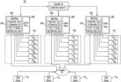
- FIG. 1illustrates an example system environment for implementing a distributed cache according to one or more embodiments.
- client devices 114 1 , 114 2 , 114 3 , and 114 4 , and server racks 101 A, 1016 , and 101 Care connected to network 112 in system 100 .
- Client devices 114can include, for example, servers or processing nodes on network 112 , that share memory devices 110 of server racks 101 for use as an external main memory of the client devices 114 .
- data stored in or retrieved from memory devices 110can include byte-addressable data (i.e., cache lines) to be loaded into a local main memory or processor cache (e.g., L1, L2, or L3 cache) of a client device 114 .
- main memory or processor cachee.g., L1, L2, or L3 cache
- the system environment of FIG. 1may be used as part of a data center and/or for distributed processing, such as for distributed machine learning or big data analysis.
- Network 112can include, for example, a Storage Area Network (SAN), a Local Area Network (LAN), and/or a Wide Area Network (WAN), such as the Internet.
- SANStorage Area Network
- LANLocal Area Network
- WANWide Area Network
- client devices 114 , controller 102 , and/or one or more of server racks 101may not be physically co-located.
- Server racks 101 , controller 102 , and client devices 114may communicate using one or more standards such as, for example, Ethernet, Fibre Channel, and/or InfiniBand.
- each of server racks 101 A, 101 B, and 101 Cis connected to programmable switches 104 A, 104 B, and 104 C, respectively, and includes six memory devices 110 .
- Programmable switches 104 A, 104 B, and 104 Cmay, for example, serve as Top of Rack (ToR) switches for their respective server racks 101 .
- each server rack 101may include a backup programmable switch 104 for redundancy.
- Controller 102communicates with each of the programmable switches 104 in system 100 .
- controller 102can include a Software Defined Networking (SDN) controller.
- SDNSoftware Defined Networking
- controller 102can manage network traffic for system 100 with the use of programmable switches 104 based on information provided to controller 102 from programmable switches 104 .
- controller 102in some implementations may also maintain a global cache directory for coherence in the permissions and states of cache lines stored in the distributed cache.
- system 100 shown in FIG. 1is for the purposes of illustration, and those of ordinary skill in the art will appreciate that system 100 may include many more memory devices 110 , racks 101 , client devices 114 , and programmable switches 104 than shown in the example of FIG. 1 .
- Programmable switches 104 A, 104 B, and 104 Croute cache messages, such as put requests, get requests, and other communications between client devices 114 and memory devices 110 .
- cache messagesmay include a get request for a specific memory address or a permission level request for a client device to modify a cache line requested from a memory device.
- permission levelscan be used to maintain the coherency of data across devices in the system.
- programmable switches 104can include, for example, a switch that can be programmed to handle different custom protocols. As discussed in more detail below with reference to FIG. 3 , programmable switches 104 can include programmable match-action pipelines to provide a configurable data plane and customized packet processing capability. Examples of such programmable switches can be found in co-pending U.S. application Ser. Nos. 16/548,116, 16/697,019, and 16/916,730, which are incorporated by reference above.
- Data planes 106 of programmable switches 104 in the example of FIG. 1can control point-to-point packet forwarding behavior of the programmable switch, such as with L1/L2 Ethernet packet switching modules 10 and packet admission control and scheduling modules 13 .
- data planes 106include local cache directories 12 that can be updated by programmable switches 104 to maintain data coherency of cache lines stored in memory devices 110 .
- Each cache directory 12can track modifications and storage locations for a given cache line stored in a memory device 110 housed in the server rack 101 corresponding to the programmable switch 104 .
- Data planes 106 of programmable switches 104are programmable and separate from higher-level control planes 108 that determine end-to-end routes for packets between devices in system 100 .
- control planes 108may be used for handling different processes, such as the processes in FIGS. 7 , 8 , 11 , and 12 discussed in more detail below.
- programmable switches 104can be 64 port ToR P4 programmable switches, such as a Barefoot Networks Tofino Application Specific Integrated Circuit (ASIC) with ports configured to provide 40 Gigabit Ethernet (GE) frame rates.
- ASICBarefoot Networks Tofino Application Specific Integrated Circuit
- GEGigabit Ethernet
- Other types of programmable switches that can be used as a programmable switch 104can include, for example, a Cavium Xpliant programmable switch or a Broadcom Trident 3 programmable switch.
- Programmable switches 104allow for a protocol-independent switch architecture and the use of off-the-shelf switches, as opposed to specially designed Networks on a Chip (NoCs), for coherence of data across system 100 .
- NoCsNetworks on a Chip
- Controller 102 using global flow control 15can provide global traffic flow control by, for example, determining cache message transmission rates for client devices 114 and/or weights for queues used by programmable switches 104 in determining an order for sending cache messages.
- each programmable switch 104can provide controller 102 with cache request information extracted from cache messages received from the programmable switch.
- the extracted cache request informationcan include, for example, at least one of a cache message request rate for a client device 114 , a number of pending cache requests at a client device 114 or memory device 110 , a ratio between cache read requests and cache write requests for a client device 114 or memory device 110 , and a capacity to receive cache messages at the client device 114 or memory device 110 .
- such cache request information extracted by programmable switch 104can allow controller 102 to dynamically estimate network traffic load and better determine cache message transmission rates for client devices 114 and/or weights for the queues used by programmable switches 104 in sending cache messages.
- the relative locations of programmable switches 104 in system 100 between client devices 114 , memory devices 110 , and controller 102can ordinarily provide controller 102 with more current network traffic conditions to better estimate network traffic and adjust cache message transmission rates and/or weights for the queues used by programmable switches.
- Such adjustment of network bandwidth usage and queue controlcan ordinarily improve the allocation of network resources among diverse types of client devices (e.g., GPUs and CPUs) and among diverse types of applications executed by the client devices (e.g., Hadoop and web services).
- each programmable switch 104can provide controller 102 with queue occupancy information based on the occupancies of its queues.
- queue occupancy informationcan indicate, for example, an amount or level of pending cache messages in one or more queues used by the programmable switch 104 .
- the queue occupancy informationmay indicate an average fullness, such as an average queue occupancy percentage, or availability of the queue to receive messages over a period of time.
- the queue occupancy informationmay indicate a number of times the queue reached a predetermined threshold level over a period of time. The adjustment of the weights used by programmable switches 104 can ordinarily help ensure that less data intensive applications do not lose cache messages due to more data intensive applications overflowing the queue.
- the in-line position of programmable switches 104can provide a more centralized collection of information and management of network traffic, as compared to conventional network traffic management may occur at the end points of the client device 114 and the memory device 110 . This can ordinarily provide for less software overhead at the end points, as compared to the use of Remote Direct Memory Access (RDMA).
- RDMARemote Direct Memory Access
- the processing resources of programmable switchessuch as the use of Content Addressable Memory (CAM) or Ternary CAM (TCAM) tables, or other types of match-action tables, can ordinarily provide faster processing of such traffic information than can occur at the end points of the client device 114 or the memory device 110 .
- memory devices 110can include, for example, Storage Class Memories (SCMs) or other types of memory, such as Dynamic Random Access Memory (DRAM) or Static RAM (SRAM), that can store and retrieve data at a byte-addressable size or cache line size, as opposed to a page or block size, as in storage devices such as Solid-State Drives (SSDs) or Hard Disk Drives (HDDs).
- SCMsStorage Class Memories
- DRAMDynamic Random Access Memory
- SRAMStatic RAM
- SSDsSolid-State Drives
- HDDsHard Disk Drives
- SCMscan include, for example, Chalcogenide RAM (C-RAM), Phase Change Memory (PCM), Programmable Metallization Cell RAM (PMC-RAM or PMCm), Ovonic Unified Memory (OUM), Resistive RAM (RRAM), Ferroelectric Memory (FeRAM), Magnetoresistive RAM (MRAM), 3D-XPoint memory, and/or other types of solid-state memory.
- C-RAMChalcogenide RAM
- PCMPhase Change Memory
- PMC-RAM or PMCmProgrammable Metallization Cell RAM
- OFUMOvonic Unified Memory
- RRAMResistive RAM
- FeRAMFerroelectric Memory
- MRAMMagnetoresistive RAM
- 3D-XPoint memory3D-XPoint memory
- Recently developed SCMscan provide non-volatile storage with a fine granularity of access (i.e., byte-addressable or cache line level) and a shorter data access latency, as compared to storage devices, such as an SSD using conventional flash memory or an HDD using a
- system 100may include additional devices or a different number of devices than shown in the example of FIG. 1 .
- some implementationsmay include a different number of client devices 114 , racks 101 , switches 104 , controllers 102 , or memory devices 110 .
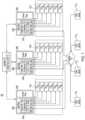
- FIG. 2is a block diagram of example components included in system 100 of FIG. 1 according to one or more embodiments.
- client device 114 1includes processor 116 1 , memory 118 1 , storage device 120 1 , and interface 122 1 for communicating on network 112 .
- client device 114 1is shown in the example of FIG. 2
- clients 114 2 , 114 3 , and 114 4 from FIG. 1may have similar or different components as client device 114 1 .
- Processor 116 1can execute instructions, such as instructions from distributed cache module 16 1 , and application(s) 18 1 , which may include an Operating System (OS) and/or other applications used by client device 114 1 .
- Processor 116 1can include circuitry such as a Central Processing Unit (CPU), a Graphics Processing Unit (GPU), a microcontroller, a Digital Signal Processor (DSP), an Application-Specific Integrated Circuit (ASIC), a Field Programmable Gate Array (FPGA), hard-wired logic, analog circuitry and/or a combination thereof.
- processor 116 1can include a System on a Chip (SoC), which may be combined with one or both of memory 118 1 and interface 122 1 .
- SoCSystem on a Chip
- Processor 116 1can include one or more cache levels (e.g., L1, L2, and/or L3 caches) where data is loaded from or flushed into memory 118 1 , or loaded from or flushed into memory devices 110 , such as memory device 110 1A in FIG. 2 , via programmable switch 104 A.
- cache levelse.g., L1, L2, and/or L3 caches
- Such datacan include, for example, portions of code and related data being processed by processor 116 1 .
- the data accessed by processor 116 1is referred to herein as cache lines that have a particular cache line size, such as 64 bytes, for example.
- Memory 118 1can include, for example, a volatile RAM such as SRAM, DRAM, a non-volatile RAM, or other solid-state memory that is used by processor 116 1 as an internal main memory to store data.
- Data stored in memory 118 1can include data read from storage device 120 1 , data to be stored in storage device 120 1 , instructions loaded from distributed cache module 16 1 or application(s) 18 1 for execution by processor 116 1 , and/or data used in executing such applications.
- processor 116 1also loads data from memory devices 110 as an external main memory or distributed cache. Such data may also be flushed after modification by processor 116 1 or evicted without modification back into internal main memory 118 1 or an external main memory device 110 via programmable switch 104 A.
- memory 118 1stores distributed cache module 16 1 , which can provide instructions for retrieving, storing, or maintaining coherency of cache lines stored in memory devices 110 in system 100 .
- Such instructionscan include setting a cache message transmission rate for sending cache messages from interface 122 1 and/or collecting cache request information for inclusion in cache messages received by programmable switch 104 A.
- distributed cache module 16 1can also implement a protocol for maintaining coherency of data (e.g., cache lines) stored on different devices of system 100 and handling communications with programmable switches 104 .
- distributed cache module 16 1can include a driver used by an OS of client device 114 A.
- Storage device 120 1serves as secondary storage that can include, for example, one or more rotating magnetic disks or non-volatile solid-state memory, such as flash memory. While the description herein refers to solid-state memory generally, it is understood that solid-state memory may comprise one or more of various types of memory devices such as flash integrated circuits, NAND memory (e.g., single-level cell (SLC) memory, multi-level cell (MLC) memory (i.e., two or more levels), or any combination thereof), NOR memory, EEPROM, other discrete Non-Volatile Memory (NVM) chips, or any combination thereof.
- NAND memorye.g., single-level cell (SLC) memory, multi-level cell (MLC) memory (i.e., two or more levels), or any combination thereof
- NOR memoryNOR memory
- EEPROMother discrete Non-Volatile Memory (NVM) chips, or any combination thereof.
- internal main memory 118 1 and external memory devices 110typically provide faster data access and can provide more granular data
- Interface 122 1is configured to interface client device 114 1 with other devices in system 100 , such as programmable switch 104 A and memory devices 110 .
- Interface 122 1may communicate using a standard such as, for example, Ethernet, Fibre Channel, or InfiniBand.
- client device 114 1 , programmable switch 104 A, controller 102 , and memory device 110 1Amay not be physically co-located and may communicate over a network such as a LAN or a WAN.
- interface 122 1can be included as part of processor 116 1 .
- Programmable switch 104 A in some implementationscan be a ToR switch for server rack 101 A including memory device 110 1A .
- programmable switch 104 Aincludes ports 130 A, circuitry 132 A, and memory 134 A.
- Ports 130 Aprovide a connection to the network and are configured to communicate with devices, such as client devices 114 in FIG. 1 , controller 102 , and memory devices 110 in server rack 101 A.
- ports 130may include Ethernet, Fibre Channel, or InfiniBand ports.
- Circuitry 132 Acan include circuitry such an ASIC, a microcontroller, a DSP, an FPGA, hard-wired logic, analog circuitry and/or a combination thereof.
- circuitry 132 Acan include an SoC, which may be combined with memory 134 A.
- Memory 134 A of programmable switch 104 Acan include, for example, a volatile RAM such as DRAM, or a non-volatile RAM or other solid-state memory such as register arrays that are used by circuitry 132 A to execute instructions loaded from switch cache module 26 A or firmware of programmable switch 104 A, and/or data used in executing such instructions, such as cache directory 12 A, queue information 27 A, and extracted cache request information 33 A.
- switch cache module 26 Acan include instructions for implementing processes such as those discussed with reference to FIGS. 7 , 8 , 11 , and 12 below to manage network traffic for the distributed cache.
- memory device 110 1Aincludes SCM 138 1A that allows cache lines to be retrieved from and stored in shared cache 28 1A for use by client devices 114 .
- shared cache 28 1Ais shown as being stored in an SCM, other implementations may include a different type of memory for storing shared cache 28 1A .
- SCM 138 1Aalso stores cache memory module 30 1A , which provides instructions for controller 136 1A to implement cache message transmission rates and/or the inclusion of cache request information in cache messages sent to programmable switch 104 A.
- cache memory module 30 1Amay also be used to implement cache coherency processes and a communication protocol for interfacing with programmable switch 104 A.
- Controller 136 1Acontrols operation of memory device 110 1A , and can include circuitry such as a microcontroller, a DSP, an FPGA, an ASIC, hard-wired logic, analog circuitry and/or a combination thereof.
- controller 136 1Acan include an SoC, which may be combined with interface 140 1A , and/or SCM 138 1A .
- Interface 140 1Ais configured to interface with at least one port of programmable switch 104 A, and may interface according to a standard, such as Ethernet, Fibre Channel, or InfiniBand.
- Controller 102 in the example of FIG. 2maintains global cache request information 23 and global queue information 24 .
- controller 102receives queue occupancy information and cache request information from programmable switches 104 .
- Controller 102may execute global flow control 15 to use the collected or aggregated queue occupancy information and/or the cache request information to estimate and manage network traffic for the distributed cache.
- controller 102may determine one or more weights for queues used by programmable switches 104 based at least in part on the collected queue occupancy information.
- programmable switches 104can use such weights to determine an order for sending cache messages from the programmable switch.
- Controller 102may periodically, or in response to changes in global cache request information 23 and/or global queue information 24 , send one or more assigned weights to one or more of programmable switches 104 to adjust the switch's handling of cache messages.
- controller 102may use the collected global cache request information 23 and/or global queue information 24 to determine cache message transmission rates to regulate or control the rates at which client devices 114 and/or memory devices 110 send cache messages to programmable switches 104 .
- controller 102may also maintain a global cache directory used for ensuring coherence of the data stored in the distributed cache. Controller 102 may periodically, or in response to changes in global cache request information 23 and/or global queue information 24 , send one or more cache message transmission rates to one or more client devices 114 and/or memory devices 110 via a programmable switch 104 to adjust the rate at which the devices send cache messages.
- Processor 124 of controller 102executes global flow control 15 to adjust queue weights and cache message transmission rates, as needed.
- Processor 124also executes cache controller module 22 , which in some embodiments, may be used maintain a global cache directory or perform other processes for maintaining coherency of data in the distributed cache.
- global flow control 15may form part of cache controller module 22 .
- controller 102may be considered an SDN controller in some implementations.
- Processor 124can include circuitry such as a CPU, a GPU, a microcontroller, a DSP, an ASIC, an FPGA, hard-wired logic, analog circuitry and/or a combination thereof.
- processor 124can include an SoC, which may be combined with one or both of memory 126 and interface 128 .
- Memory 126can include, for example, a volatile RAM such as DRAM, a non-volatile RAM, or other solid-state memory that is used by processor 124 to store data.
- Controller 102communicates with programmable switches 104 via interface 128 , which is configured to interface with ports of programmable switches 104 , and may interface according to a standard, such as Ethernet, Fibre Channel, or InfiniBand.
- client device 114 1may not include storage device 120 1 or SCM 138 1A may be replaced by a DRAM.
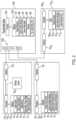
- FIG. 3depicts example operations performed in a pipeline of programmable switch 104 A according to one or more embodiments.
- the pipeline for programmable switch 104 Acan include parser 36 1 , ingress stages 36 2 and 36 3 , traffic manager 38 , egress stages 40 1 and 40 2 , and deparser 40 3 .
- Each of these modulesmay be programmed, such as by using P4, to handle a custom packet header and protocol, in addition to priority indicators and cache request information included in the packet.
- the example modules of programmable switch 104 A shown in FIG. 3can be implemented by circuitry 132 A and memory 134 A in FIG. 2 , which is capable of parallel processing of packets in sequential stages.
- cache messagesare received from client device 114 and memory devices 110 as packets by parser module 36 1 of programmable switch 104 A.
- parser module 36 1is configured to extract packet headers and values from the packet headers, such as a destination address, operation type, source address, priority indicator, or cache request information for match-action operations performed by the ingress and egress stages.
- the extracted valuesare fed into the ingress pipeline that includes stages 36 2 and 36 3 .
- the extracted cache request informationmay include information provided by a client device 114 or a memory device 110 to indicate a level of usage of the distributed cache by a client device 114 or a level of usage of a memory device 110 as part of the distributed cache.
- the cache request informationcan include, for example, at least one of a cache message request rate for the device, a number of pending cache requests at the device, a ratio between cache read requests and cache write requests for the device, and a capacity to receive cache messages at the device.
- the priority indicator extracted by parser module 36 1may include an indication of a type of the message or a class of service for the message.
- parser module 36 1may extract a priority indicator of an 802.1Q tag from an Ethernet packet having the format shown in the example of FIG. 5 A discussed below.
- the extracted priority indicator or valuemay indicate that the packet is a cache message for the distributed cache.
- Programmable switch 104 Amay then prioritize the packet for handling in a particular queue that is served more frequently than other queues for the same port 130 A based on the extracted priority indicator.
- different prioritiesmay be used to classify different types of cache messages for handling by different queues of programmable switch 104 A.
- web services applications needing relatively low latency access to the distributed cachemay be assigned a first priority indicator by the client device sending the message for a time sensitive Quality of Service (QoS).
- QoSQuality of Service
- Programmable switch 104 Amay then classify or add such packets to a first type of egress queue that serves or sends more packets per round or clock cycle than another type of queue.
- more data intensive applicationssuch as distributed computing applications (e.g., Hadoop or MapReduce) may be assigned a second priority indicator for a data intensive service class so that programmable switch 104 A classifies or adds such packets to a second type of egress queue that serves less packets per round or clock cycle that are part of a larger data flow.
- controller 102may dynamically adjust the priority indicators used by client devices 114 during operation to help ensure smaller data flows are not blocked by larger data flows.
- certain applicationsmay use a priority indicator for a class of service associated with a greater reliability.
- programmable switch 104 Amay classify or add such packets to a relatively large egress queue that is less likely to overflow and drop packets. This is in contrast to a traditional First In First Out (FIFO) handling of packets by network switches that does not account for the size of data flows.
- FIFOFirst In First Out
- stages 36 2 and 36 3 of the ingress pipelinecan perform a cache directory lookup for match-action switching and packet classification.
- stages 36 2 and 36 3may use CAM or TCAM to quickly identify ports 30 A associated with a destination address extracted from the packet by parser 36 1 .
- Stages 36 2 and 36 3may also classify the packet as a cache message for the distributed cache based on the extracted priority indicator or an indication of the message type in a header of the packet.
- stages 36 2 and 36 3in some implementations may further classify different types or handling of cache messages based on the extracted priority indicator.
- the priority indicatormay distinguish between a cache line request message or a data coherency message.
- the priority indicatormay distinguish among different expected QoS in terms of latency or reliability, such as in the example provided above for web services applications versus distributed computing applications.
- the extracted priority indicatorcan then be used by the ingress stages 36 2 and 36 3 to classify the cache message for queuing in a particular egress queue fora port 130 A.
- cache messagescan have a custom packet format so that programmable switch 104 A can distinguish cache messages, such as messages for cache line addressed data, from other network traffic, such as messages for page addressed data.
- the indication of a cache messagesuch as a cache line request to put or get cache line data, causes circuitry 132 A of programmable switch 104 A to handle the packet differently from other packets that are not indicated as being a cache message.
- the custom packet formatfits into a standard 802.3 Layer 1 frame format, which can allow the packets to operate with existing and forthcoming programmable switches, such as a Barefoot Tofino ASIC switch, for example.
- the preamble, start frame delimiter, and interpacket gapmay follow the standard 802.3 Layer 1 frame format, but portions in Layer 2 are replaced with custom fields that can be parsed by programmable switch 104 A.
- a payload of a packet for a cache messagecan include one or more memory addresses for one or more cache lines being requested by a client or being returned to a client, and may include data for the cache line or lines.
- the payload of the packetmay include additional information, such as cache request information from the device sending the packet.
- Stages 36 2 and 36 3can include, for example programmable Arithmetic Logic Units (ALUs) and one or more memories that store match-action tables for matching extracted values from the headers and performing different corresponding actions based on the values, such as performing particular updates to cache directory 12 A stored in memory 134 A of programmable switch 104 A or forwarding extracted cache request information to controller 102 .
- ALUsArithmetic Logic Units
- the stages of the ingress pipeline and the egress pipelinemay share a single memory, such as memory 134 A in FIG. 2 .
- the matches and corresponding actionsare made according to predefined rules and the extracted values. As discussed in more detail in related application Ser. No.
- the ingress pipelinein some implementations may calculate offsets for additional cache lines to be prefetched based on the parsed header fields, and then generate corresponding additional cache messages for prefetching the additional cache lines using a packet generation engine of programmable switch 104 A.
- Traffic manager 38routes the cache line messages to appropriate ports of programmable switch 104 A. As shown in FIG. 3 , traffic manager 38 implements packet reception rate controls and manages the queues for queuing cache messages for transmission from programmable switch 104 A. As discussed in more detail below with reference to the queue occupancy control process of FIG. 11 , traffic manager 38 may use a first or soft queue occupancy threshold value for determining when to send a pause frame to at least one client device 114 to temporarily stop the at least one client device 114 from sending additional cache messages. In some implementations, traffic manager 38 may further determine that the queue occupancy has reached an additional or hard threshold value, and send a pause frame to one or more additional client devices 114 to temporarily stop the one or more additional client devices 114 from sending additional cache messages. By using such queue occupancy thresholds, programmable switch 104 A can ordinarily prevent a queue from overflowing and resulting packet loss.
- a first queue occupancy threshold valuecan allow programmable switch 104 A to absorb additional cache messages that may be in transit following a lowering of the cache transmission rate of a client device 114 by controller 102 .
- traffic manager 38 of programmable switch 104 Amay also monitor the packet reception rate for different egress queues, and send a pause frame to a client device 114 that has exceeded its assigned cache message transmission rate from controller 102 or a maximum bandwidth set by programmable switch 104 or controller 102 for the client device 114 .
- Traffic manager 38 in the example of FIG. 3also performs queue scheduling for determining the order in which cache messages or packets are sent from ports 130 A of programmable switch 104 A.
- traffic manager 38may use weights assigned to different queues for a port that determine a number of packets or cache messages sent from the port in a given round, as in a weighted round-robin scheduling algorithm.
- the weightsmay be received from controller 102 as part of its network traffic management.
- Programmable switch 104may send controller 102 queue occupancy information periodically, or under certain conditions such as when reaching a queue occupancy threshold value.
- Such queue occupancy informationmay indicate, for example, an average queue occupancy percentage over a period of time, a number of times a queue occupancy threshold value has been reached, or relative average occupancies of the queues used by a port for sending cache messages.
- the egress pipelineincludes stages 40 1 and 40 2 that can each include ALUs and memories, or portions of memory 134 A that can be used for performing additional match-actions for an outgoing cache message.
- stages 40 1 and 40 2also update a local cache directory used by programmable switch 104 A for the memory devices 110 in rack 101 A.
- the framesare then assembled in packets by deparser 40 3 for the outbound cache messages before leaving programmable switch 104 A by, for example, merging processed headers and a payload.
- implementationsmay include a different arrangement of modules for a programmable switch.
- implementationsmay include more or less stages as part of the ingress or egress pipeline.
- FIG. 4illustrates an example of queue management that may be performed by a programmable switch according to one or more embodiments.
- the programmable switchuses three queues A, B, and C to schedule cache messages for transmission from a port of the programmable switch.
- the number of cache messages that each queue can holdvaries.
- each queuemay represent a separate buffer stored in a memory of the programmable switch (e.g., queues 29 stored in memory 134 A in FIG. 2 ) with different sizes depending on the size of the corresponding queue.
- queue Bmay be used for queuing cache messages that are more time sensitive, while the larger size of queue A may be used for queuing cache messages that have a greater need for reliability.
- the programmable switchmay send more cache messages or packets from queue B per round than from queues A and C to prioritize the cache messages queued in queue B.
- queue Bmay have a weight of 2, while queues A and C each have weights of 1. This may mean that two cache messages are sent from queue B in each round, while one cache message is sent from each of queues A and C in each round.
- queue Cmay be reserved for cache messages identified as part of a message flow that is above a threshold size.
- message flows greater than a threshold sizemay be queued in a separate queue, such as queue C in FIG. 4 , to prevent smaller sized message flows from being significantly delayed or blocked by the larger message flows.
- Information included in the cache messages of the message flowmay indicate that the cache messages belong to the same message flow, or programmable switch 104 may identify the cache messages as belonging to the same message flow by the receipt of multiple cache messages within a relatively short time frame from the same sending device to be sent to the same destination device. Programmable switch 104 may, for example, keep track of the number of cache messages received from the same sending device that are to be sent to the same destination device within a predetermined window of time to update a message count indicating the size of the message flow.
- each queuehas, for example, a first threshold value 48 and a second threshold value 50 .
- the threshold valuesmay, for example, correspond to a number of cache messages pending in the queue, a number of remaining cache messages that can be queued, a percentage of queue fullness, or other indicator of queue occupancy.
- programmable switch 104sends a pause frame to at least one client device 114 to temporarily stop the at least one client device 114 from sending additional cache messages.
- the packet reception rate control of traffic manager 38may identify a client device 114 filling the queue that has the greatest packet reception rate or that has exceeded a maximum bandwidth guarantee.
- traffic manager 38may send pause frames to each of the client devices 114 that have cache messages already queued in the queue.
- Programmable switch 104may use, for example, an 802.1Qbb pause frame of a Priority-Based Flow Control (PFC) that may have an associated timer for how long the client device 114 should stop sending additional packets to the programmable switch 104 , depending on the priority indicator of the packets.
- PFCPriority-Based Flow Control
- programmable switch 104may use the priority indicators to identify cache messages and client devices 114 filling queues that have reached a threshold value.
- the pause time for the different types of data traffic indicated by the priority indicatorscan correspond to times typically associated with clearing a queue or reducing the queued cache messages below a threshold value (e.g., threshold value 48 ).
- a threshold valuee.g., threshold value 48.
- the use of different pause times for different priority indicatorscan facilitate better management of the queues based on the particular types of data flow, types of client devices 114 , classes of service, and/or the sizes of the queues.
- different priority indicatorsmay be associated with different applications via the distributed cache modules 16 executed by client devices 114 .
- a valuemay be used in an 802.1Q tag to indicate a particular class of service that may be assigned to a particular type of client device 114 , such as an FPGA, ASIC, CPU, or GPU, and/or that may be assigned to a particular type of application responsible for the cache message, such as a web services application or distributed computing application, for example.
- programmable switch 104may send one or more additional pause frames to other client devices 114 responsible for filling the queue, or may send pause frames to all client devices 114 responsible for filling the queue to prevent overflow in the queue and the resulting loss of cache messages.
- the second threshold value 50may still allow for a few additional cache messages to be added to the queue after the additional threshold value 50 has been reached as a further protection against the loss of cache messages that may have been in transit when the pause frame was sent.
- each of queues A and Bhave reached the first threshold value 48 , leading programmable switch 104 to send at least one pause frame to a client device 114 that has sent cache messages for the queue.
- Queue Ahas reached its second threshold value 50 A, causing programmable switch 104 to send one or more additional pause frames to one or more additional client devices 114 that have sent cache messages for queue A.
- the thresholds values 48 and 50may initially be set by programmable switch 104 or controller 102 based on considerations such as, for example, a maximum cache message size, a buffer size for temporarily storing data of the queued cache messages, a bit rate of the port associated with the queue, a measured or estimated network latency for transmitting messages between a client device 114 and programmable switch 104 , and a cache message processing latency of programmable switch 104 .
- Programmable switch 104 or controller 102may adjust threshold values 48 and 50 over time based on such considerations and/or the tendency of particular queues to reach one or both of threshold values 48 and 50 , or to completely fill up.
- queues managed by programmable switch 104may vary. For example, other implementations may use a different number of queues for a port, queues of all equal size, or only a different number of threshold values for sending pause frames, such as a single threshold value.
- FIG. 5 Adepicts an example Ethernet packet format according to one or more embodiments.
- the packet formatfits into a standard 802.3 Layer 1 frame format, which can allow the packets to operate with existing and forthcoming programmable switches, such as a Barefoot Tofino ASIC switch, for example.
- the preamble, start frame delimiter, Medium Access Control (MAC) destination and source addresses, and interpacket gapfollow the standard 802.3 Layer 1 frame format, but portions of the data payload in Layer 2 are replaced with coherence message fields of custom header 62 and cache request information 64 that can be parsed by programmable switch 104 .
- MACMedium Access Control
- the payload of the example frame shown in FIG. 5 Acan include, for example, one or more cache lines that have been requested from a memory device 110 or one or more modified cache lines that are being flushed back to a memory device 110 , in addition to custom header 62 and cache request information 64 .
- the payloadcan include, for example, an address or addresses for one or more cache lines that are requested from a memory device 110 or may include an address or addresses for one or more cache lines being returned to a client device 114 from a memory device 110 via a programmable switch 104 .
- the payloadcan include, for example, an address or addresses for one or more cache lines that are requested from a memory device 110 or may include an address or addresses for one or more cache lines being returned to a client device 114 from a memory device 110 via a programmable switch 104 .
- programmable ingress pipelines of a programmable switch 104can identify cache line addresses included in the packet and perform match-actions to identify a memory device 110 storing the requested cache lines.
- the payloadalso includes a frame check sequence for ensuring the integrity of the data included in the payload. Such error checking may be performed by programmable switch 104 , memory device 110 , and/or client device 114 to help ensure that the received data is correct.
- cache request information 64may not be present in every cache message packet received by programmable switch.
- client devices 114 and/or memory devices 110may only send cache request information 64 at a particular interval, or when a particular condition is reached, such as when a queue of the client device 114 or memory device 110 reaches a threshold.
- a memory device 110may include cache request information when a queue for performing write requests or a queue for performing read requests reaches a threshold indicating a delay in performing the write or read requests. If a cache message from the memory device 110 includes cache request information 64 that, for example, indicates a low read to write ratio and a full read request queue, controller 102 after receiving the cache request information may lower a cache message transmission rate for a client device 114 that has been sending cache write requests to the memory device 110 to allow the memory device 110 to perform more cache read requests. As another example, a client device 114 may include cache request information 64 in an outgoing packet when its queue for sending cache messages reaches a high threshold. Controller 102 may then increase the cache message transmission rate for that client device 114 after receiving the cache request information from programmable switch 104 .
- cache request information 64may be included in every packet to provide a current view of the state of system 100 .
- Programmable switch 104may accumulate the cache request information to send to controller 102 in batches or may selectively send the extracted cache request information to controller 102 based on detected packet reception rates and/or queue occupancies.
- controller 102may perform network sniffing or otherwise retrieve the cache request information 64 included in the packets.
- the Ethernet packet format in the example of FIG. 5 Aalso includes priority indicator 60 as an 802.1Q tag.
- FIG. 5 Bdepicts an example 802.1Q tag format for priority indicator 60 .
- priority indicator 60includes a tag protocol identifier, a Priority Code Point (PCP), a Drop Eligible Indicator (DEI), and a Virtual LAN Identifier (VLAN ID).
- the tag protocol identifiercan indicate that that the packet includes an 802.1Q field.
- the PCP fieldcan indicate the class of service.
- the class of servicecan have one of eight values, which programmable switch 104 can use to determine a queue for the cache message.
- a second 802.1Q tagcan be included in the packet format for cache messages to double the number of classes of service or priority values to sixteen.
- the example of FIG. 5 Balso includes a DEI field.
- the DEI fieldcan indicate whether the packet may be dropped when there is congestion or a traffic bottleneck, such as when a queue at programmable switch 104 becomes full or reaches a high threshold value (e.g., threshold values 48 or 50 in FIG. 4 ). In such cases, programmable switch 104 may remove cache messages from the queue that indicate that such packets can be dropped based on the DEI for the packet.
- the example format of FIG. 5 Balso includes a VLAN ID, which may be used to indicate a virtual LAN to which the packet belongs.
- each client device 114 and memory device 110may use a particular value indicating membership in the distributed cache.
- the memory devices 110 of a particular rack 101may have their own VID that may be a variant of a VID used for system 100 as a whole. The use of the VID, however, may be optional.
- the priority indicatorcan be used by programmable switch 104 to determine a queue for the cache message among a plurality of queues for transmission via a particular port of programmable switch 104 .
- the 802.1Q tagcan provide eight different values for different classes of service.
- Client devices 114may use these classes of service to associate cache messages from different applications that are responsible for the cache messages.
- this classificationmay be performed system wide with controller 102 informing client devices 114 of which applications should have a particular priority indicator value.
- the priority indicatorsmay be adjusted over time through the use of global flow control 15 executed at controller 102 , in conjunction with the distributed cache modules 16 and switch cache modules 26 executed at client devices 114 and programmable switches 104 , respectively.
- priority indicator 60can be used to indicate different types of client devices 114 .
- client devices 114such as FPGAs, CPUs, GPUs, or ASICs may be assigned a value for all of its priority indicators 60 or a range of values depending on the types of applications executed by the client device 114 .
- the use of priority indicators across system 100 for the distributed cachecan ordinarily allow for a more diverse or heterogenous use of different client devices 114 , and a wider variety of applications that may have different demands on the distributed cache in terms of reliability, the rate of cache messages, and the size of message flows.
- FIG. 5 Cdepicts an example custom header format for custom header 62 according to one or more embodiments.
- the combination of fields in custom header 62encodes information for coherence operations.
- a format field in header 62can indicate a custom header type, such as by including a code indicating an OmniXtend or other custom header type. This format field may also indicate that the packet is for a cache message, as opposed to another type of message, such as to read or write data in units of a block size or page size, as opposed to a cache line size.
- the OpCode fieldcan indicate an operation type for an intended operation to be performed using a requested cache line or cache lines, such as an acquire to read or an acquire to read and write. In other cases, the OpCode field can indicate whether the packet is a probe to change the permission level of a client device 114 with respect to a cache line, or a probe acknowledgment to indicate that a permission level has been changed. In this regard, the parameter field of custom header 30 can indicate a current or requested permission level from the device sending the packet.
- the size field of header 30can indicate the size of the data requested (e.g., a number of cache lines or a size in bytes) or the size of the data provided in payload 32 .
- the domain field in FIG. 5 Ccan provide coherence message ordering guarantees within a subset of messages, and the source field can indicate a source identifier or other identifier for the device that issued the request.
- the domain and/or source fieldsmay be used by programmable switch 104 in some implementations to identify a cache message as belonging to a particular message flow.
- programmable switches 104for cache messages.
- other implementationsmay include the priority indicator in the payload, as opposed to a separate 802.1Q tag.
- FIG. 6is an example sequence diagram for cache message handling in system 100 according to one or more embodiments.
- cache messagesare sent from devices, such as client devices 114 or memory devices 110 , to a programmable switch 104 .
- the programmable switch 104may extract cache request information from the cache message, such as by parsing the cache message and identifying the cache request information in a payload or other field of the cache message.
- the cache request informationcan indicate a usage of the distributed cache, such as by, for example, indicating at least one of a cache message request rate for cache messages sent from a client device 114 or cache messages received by a memory device 110 , a number of pending cache requests waiting to be sent from the client device 114 or waiting to be performed by the memory device 110 , a ratio between cache read requests and cache write requests sent by the client device 114 or received by the memory device 110 , and a capacity to receive cache messages at the client device 114 or at the memory devices, such as an available queue size or queue occupancy for received cache messages.
- the received cache messagesare queued by the programmable switch 104 in egress queues before being sent out via a port of the programmable switch.
- the cache messagesmay be queued based on information included in the cache message, such as a priority indicator or the size of a current data flow that includes the cache message.
- Programmable switch 104sends the extracted cache request information to controller 102 .
- programmable switch 104may send all of the extracted cache request information to controller 102 for each cache message, such as by mirroring the extracted cache request information received by programmable switch to one or more ports used to communicate with controller 102 .
- programmable switch 104may accumulate extracted cache request information until reaching a certain amount of cache request information or until receiving a request from controller 102 for the cache request information.
- controller 102may perform network sniffing to check on the cache request information stored at programmable switch 104 .
- programmable switch 104generates queue occupancy information to send to controller 102 .
- the programmable switch 104can monitor the queue occupancies to provide queue occupancy information to controller 102 for adjusting the weights used for determining an order for servicing the queues.
- the queue occupancy informationcan indicate an average queue occupancy for the queues used by programmable switch 104 or may indicate how often certain threshold levels of queue occupancy were reached by the queues, such as thresholds values 48 and 50 in the example of FIG. 4 discussed above.
- Programmable switch 104may periodically provide queue occupancy information to controller 102 , or upon reaching a storage limit for maintaining queue occupancy information.
- controller 102may perform network sniffing or otherwise request queue occupancy information from programmable switch 104 .
- controller 102determines at least one of one or more cache message transmission rates for at least one client device 114 , and/or determines one or more weights for the queues used by programmable switch 104 in determining an order for sending cache messages.
- the determination of cache message transmission rates or weights for the queuesmay be based on one of or both of the received cache request information and queue occupancy information.
- controller 102may collect or aggregate cache request information and/or queue occupancy information from multiple programmable switches 104 in system 100 to estimate network traffic demand and avoid potential bottlenecks by proactively adjusting cache message transmission rates and/or queue weights during runtime.
- Controller 102sends the determined queue weights to programmable switch 104 .
- programmable switch 104adjusts the weights used for servicing its queues based on the received weights from controller 102 .
- the weightsmay indicate a certain number of cache messages serviced from each queue in a given round, as in a weighted round robin scheduling. In other implementations, the weights may indicate an order in which queues are serviced.
- Controller 102also sends the one or more determined cache message transmission rates to programmable switch 104 for forwarding to client devices 114 .
- the cache message transmission ratesmay be adjusted dynamically as the client devices 114 operate. In this regard, the change to a cache message transmission rate may be temporary to quickly react (e.g., within microseconds) to network congestion and avoid a queue overflow.
- the sequence of operations shown in FIG. 6may vary in other implementations.
- the order in which cache request information and queue occupancy information is sent to controller 102may differ, such that queue occupancy information is sent to controller 102 before the cache request information.
- the cache request information and the queue occupancy informationmay be sent together to controller 102 , or controller 102 may retrieve or receive one or both of queue occupancy information and cache request information at a different frequency, such as with each cache message received by programmable switch 104 .
- the order of determining weights and cache message transmission rates by controller 102or the order in which controller 102 sends the determined weights and cache message transmission rates to programmable switch 104 may differ from what is shown in FIG. 6 .
- FIG. 7is a flowchart for a queue occupancy information process according to one or more embodiments. The process of FIG. 7 can be performed by, for example, circuitry 132 of programmable switch 104 executing switch cache module 26 .
- programmable switch 104receives cache messages for a distributed cache.
- programmable switch 104can identify the cache messages as being for the distributed cache by, for example, parsing a header (e.g., header 62 in FIG. 5 A ) or a priority indicator (e.g., priority indicator 60 in FIG. 5 A ) from the cache message.
- the cache messagemay be received from a client device 114 or from a memory device 110 , and may include one or more cache lines that have been requested by the client device 114 or cache lines that have been modified by the client device 114 for storage in the memory device 110 .
- the received cache messagesare queued in queues for sending the cache messages from ports of programmable switch 104 .
- the cache messagesmay first be routed by match-action stages of the programmable switch to specific ports based on, for example, a MAC address for the destination client device 114 or destination memory device 110 .
- a priority indicator extracted from the cache messagemay be used to assign the cache message to a queue that is serviced by the port.
- the priority indicatormay be used to dynamically assign (e.g., during operation of the client device 114 ) the message flows of a particular application to the same class of service, which can help reduce completion time for the application.
- message flowsmay be dynamically mapped based on the size or an expected size of the message flow. For example, a heavy message flow may be identified by controller 102 via cache request information received from programmable switch 104 , and controller 102 may then send the client device 114 responsible for the heavy message flow a lower cache message transmission rate or a new priority indicator for the client device 114 .
- Such dynamic traffic flow controlcan ordinarily better balance the use of network resources to help prevent smaller message flows or sole cache messages from being blocked by heavier message flows.
- programmable switch 104generates queue occupancy information based on its monitoring of the queue occupancies of the queues.
- the queue occupancy informationmay indicate, for example, an average queue occupancy over a period of time or may indicate a number of low and high threshold values reached over the period of time.
- the queue occupancy informationcan include a relative scoring of the occupancies of the queues.
- programmable switch 104sends the generated queue occupancy information to controller 102 .
- the queue occupancy informationis used by controller 102 , such as by global flow control 15 in FIGS. 1 and 2 , to determine at least one of one or more weights for the queues, and one or more cache message transmission rates for at least one client device 114 .
- controller 102may only determine weights for the queues with the queue occupancy information.
- controller 102may instead change the cache transmission rates for at least one client device 114 based on the queue occupancy information.
- the determined weights and/or cache message transmission ratescan then be sent to programmable switch 104 for adjusting the operation of the queues and/or the transmission rates of cache messages.
- the monitored queue occupancy information from programmable switch 104can therefore allow system 100 to adjust to varying workloads on the fly to help reduce packet loss and congestion that may occur due to the overflow of queues at programmable switch 104 .
- FIG. 8is a flowchart for a cache request information process according to one or more embodiments. The process of FIG. 8 can be performed by, for example, circuitry 132 of programmable switch 104 executing switch cache module 26 .
- programmable switch 104receives a cache message from a client device 114 or from a memory device 110 .
- the cache messagemay be received from a client device 114 to obtain one or more cache lines stored in the distributed cache, or from a memory device 110 to provide a client device 114 with one or more cache lines.
- the cache messagemay include one or more cache lines that have been modified by the client device 114 for storage at a memory device 110 .
- the cache messagemay include a coherency message, such as an acknowledgment of an operation or a request for a permission level to modify one or more cache lines.
- programmable switch 104extracts cache request information from the cache message.
- the cache request informationmay be extracted by ingress stages of the programmable switch (e.g., stages 36 2 and 36 3 in FIG. 3 ).
- the cache request informationmay be extracted from, for example, a payload of the cache message or from another field in the message.
- the cache request informationcan indicate a usage of the distributed cache, such as at least one of a cache message request rate for the device, a number of pending cache requests at the device, a ratio between cache read requests and cache write requests for the device, and a capacity to receive cache messages at the device.
- programmable switch 104sends the extracted cache request information to controller 102 to determine at least one of one or more cache message transmission rates for client devices 114 and one or more queue weights used by programmable switch 104 .
- the determined weights and/or cache message transmission ratescan then be sent to programmable switch 104 for adjusting the operation of the queues and/or the transmission rates of cache messages.
- the cache request information process of FIG. 8can allow system 100 to better adjust to varying workloads on the fly to help reduce packet loss and congestion that may occur due to the overflow of queues at programmable switch 104 .
- FIG. 9is a flowchart for a network traffic management process according to one or more embodiments. The process of FIG. 9 can be performed by, for example, processor 124 of controller 102 executing global flow control 15 .
- controller 102receives queue occupancy information from at least one programmable switch 104 .
- controller 102may receive queue occupancy information from multiple programmable switches 104 , such as from each of programmable switches 104 in the example of FIG. 1 .
- the queue occupancy informationindicates an occupancy of queues used by the programmable switch or switches for sending cache messages.
- controller 102may request the queue occupancy information from the programmable switch or switches.
- the programmable switch or switches 104may send the queue occupancy information to controller 102 without receiving a request from controller 102 , such as on a schedule or upon reaching a particular condition or threshold level in one or more queues.
- controller 102receives cache request information from at least one programmable switch 104 .
- controller 102may receive cache request information from multiple programmable switches 104 , such as from each programmable switch 104 in the example of FIG. 1 .
- the cache request informationindicates a usage of the distributed cache by one or more devices, such as client devices 114 and/or memory devices 110 .
- the cache request informationhas been extracted from cache messages received by the programmable switch or switches 104 .
- client devices 114 and/or memory devices 110may send cache request information separately from other cache messages, such that the cache request information forms its own cache message.
- controller 102may request cache request information that may be stored at a programmable switch or switches 104 , or programmable switch or switches 104 may send the cache request information to controller 102 without a request from controller 102 based on a schedule or in response to a condition being reached by the programmable switch, such as a threshold level of incoming packets or a threshold queue occupancy.
- controller 102determines at least one of one or more cache message transmission rates for one or more client devices 114 , and one or more queue weights for one or more programmable switches 104 based at least in part on the received queue occupancy information and/or the received cache request information.
- the collection of such information by controller 102 during operation of system 100can ordinarily allow controller 102 to adjust the network traffic for the distributed cache to reduce network traffic congestion and improve the reliability of the distributed cache by avoiding queue overflow. In some cases, this can facilitate the use of Transmission Control Protocol (TCP) in large scale data centers that may provide less synchronization among devices and can have non-uniform or scatter-gather traffic flows.
- TCPTransmission Control Protocol
- FIG. 9may be performed in a different than shown in the example of FIG. 9 .
- other implementationsmay separately determine queue weights after receiving queue occupancy information in block 902 , rather than following the receipt of cache request information in block 904 .
- the order of blocks 902 and 904may be switched in other implementations.
- one of blocks 902 or 904can be omitted such that the determination in block 906 is only based on received queue occupancy information or received cache request information.
- FIG. 10is a flowchart for a network traffic estimation process according to one or more embodiments.
- the process of FIG. 9can be performed by, for example, processor 124 of controller 102 executing global flow control 15 .
- controller 102collects or aggregates at least one of queue occupancy information and cache request information that is received from at least one programmable switch 104 .
- the collection or aggregation of queue occupancy information and/or cache request informationmay be through one or more programmable switches 104 periodically sending the information based on a schedule or in response to certain conditions at the programmable switch, such as a level of incoming cache messages or the level of occupancy of one or more queues used by the programmable switch for sending cache messages.
- controller 102may alternatively or additionally receive the information from one or more programmable switches through network sniffing to access the information stored at the programmable switch or by mirroring packets received at the programmable switch 104 to controller 102 .
- the collected or aggregated cache request informationmay be stored in a data structure in a memory of controller 102 , such as in global cache request information 23 in memory 126 in the example of FIG. 2 .
- the collected or aggregated queue occupancy informationmay be stored in a data structure in a memory of the controller 102 , such as in global queue occupancy information 24 in memory 126 in the example of FIG. 2 .
- controller 102estimates network traffic based on the information collected in block 1002 .
- Controller 102may collect or aggregate the information for a particular period of time, such as for the previous five minutes or over a period of days, for example. In other implementations, the collection or aggregation of information may be only for the most recent, or a predetermined set of the most recent cache request information and/or queue occupancy information received from each programmable switch 104 in system 100 .
- controller 102may use both the queue occupancy information and the cache request information received from a programmable switch 104 to estimate network traffic for the programmable switch 104 that sent the information.
- controller 102may use the estimated network traffic to remap message or data flows in system 100 .
- controller 102may use a global cache directory stored at controller 102 to identify copies of cache lines stored in different racks 101 . Controller 102 may then reconfigure a programmable switch 104 of the higher traffic rack 101 to reroute cache request messages for cache lines to their copies in a lower traffic rack 101 , or inform one or more client devices 114 of the address for the memory device 110 in the lower traffic rack 101 that stores the copy.
- FIG. 11is a flowchart for a queue occupancy control process according to one or more embodiments.
- the process of FIG. 11can be performed by, for example, circuitry 132 of programmable switch 104 executing switch cache module 26 .
- the process of FIG. 11may be an ongoing process that is performed for each queue while programmable switch 104 operates.
- programmable switch 104determines threshold values for one or more queues used by the programmable switch for sending cache messages from one or more ports. As indicated by the dashed line following block 1102 , the determination of threshold values in block 1102 may be performed at a different time than the performance of blocks 1104 to 1112 . The determination of the threshold values can be based on at least one of a maximum cache message size, a buffer size for storing data from queued cache messages, a bit rate for one or more ports of programmable switch 104 , a network latency for transmitting messages between at least one client device 114 and programmable switch 104 , and a cache message processing latency of programmable switch 104 .
- one or more default valuesmay be set based on some or all of the foregoing factors as part of an initialization process of programmable switch 104 .
- the threshold valuesmay then be adjusted during operation of the programmable switch based on updated values for some or all of the foregoing factors.
- programmable switch 104determines whether a queue occupancy threshold value has been reached. With reference to the example of queues A, B, and C discussed above for FIG. 4 , programmable switch 104 may determine whether the occupancy or number of queued cache messages has reached first threshold value 48 . If not, the process of FIG. 11 continues to receive cache messages in block 1106 .
- programmable switch 104 in block 1108sends a pause frame to at least one client device 114 to temporarily stop the at least one client device 114 from sending additional cache messages to programmable switch 104 .
- the pause framemay be sent to a client device 114 that is responsible for filling the queue that has the greatest incoming packet reception rate or that has exceeded a reception rate allocated to the client device 114 .
- the pause framemay include an indication of how long the at least one client device 114 should stop sending additional cache messages, which may be associated with specific priority indicators or the particular queue that has reached the threshold value.
- all pause frames sent by programmable switch 104may cause the client device 114 to stop sending additional cache messages for the same amount of time, regardless of the queue or priority indicator.
- the pause framemay include, for example, an 802.1Qbb pause frame.
- programmable switch 104determines whether the queue occupancy for the queue has reached an additional threshold hold value. With reference to the example of FIG. 4 , programmable switch 104 may determine whether the occupancy or number of queued cache messages has reached second threshold value 50 . If not, the process of FIG. 11 continues to receive cache messages in block 1106 .
- programmable switch 104 in block 1112sends a pause frame to one or more additional client devices 114 to temporarily stop the one or more additional client devices 114 from sending additional cache messages to programmable switch 104 .
- the pause framemay be sent to all the remaining client devices 114 responsible for filling the queue, or in some implementations, to the client device 114 or a predetermined number of client devices 114 that currently have the greatest incoming packet reception rate, or that have exceeded a reception rate allocated to the client device or devices 114 .
- the foregoing queue occupancy control processcan ordinarily allow programmable switch 104 to quickly react to prevent the loss of packets or cache messages due to overflow of its queues.
- the implementation of such network traffic control from the centralized location of programmable switch 104 between client devices 114 and memory devices 110further allows for a faster and more dynamic control of data flows and congestion than conventional, lossy Ethernet flow control that may be performed by the end nodes (e.g., client devices 114 and memory devices 110 ).
- the use of programmable switch 104 for such flow controlcan also free up processing resources at the end nodes, while providing a faster response time.
- implementationsmay have a different order of blocks than shown in FIG. 11 .
- other implementationsmay not include a second or additional threshold value, such that blocks 1110 and 1112 are omitted.
- a queuemay fill so quickly that block 1108 is skipped, and pause frames are sent to one or more client devices in block 1112 based on the queue occupancy reaching the second threshold value.
- FIG. 12is a flowchart for a queue identification process according to one or more embodiments. The process of FIG. 12 can be performed by, for example, circuitry 132 of programmable switch 104 executing switch cache module 26 .
- programmable switch 104receives a cache message from a device, such as a client device 114 or a memory device 110 .
- the cache messagemay indicate a destination address, such as a MAC address for a destination client device 114 or destination memory device 110 .
- one or more ingress stagese.g., ingress stage 36 2 or 36 3 in FIG. 3 ) can route the cache message to a port used by programmable switch 104 for communication with the destination device.
- programmable switch 104determines whether a size of a message flow including the cache message is greater than a threshold size.
- Information included in cache messages of the message flowmay indicate that the cache messages belong to the same message flow, or programmable switch 104 may identify the cache messages as belonging to the same cache flow by the receipt of a predetermined number of cache messages within a predetermined time window from the same sending device to be sent to the same destination device.
- Programmable switch 104may keep track of the number of cache messages received from the same sending device that are to be sent to the same destination device within a predetermined window of time to update a message count indicating the size of the message flow.
- programmable switch 104 in block 1206identifies a queue that is used for larger message flows from among a plurality of queues for the port.
- a larger queue or corresponding buffermay be used to queue cache messages for larger message flows.
- programmable switch 104 in block 1208extracts a priority indicator from the cache message.
- the priority indicatormay include an 802.1Qbb priority tag that may indicate a class of service for the cache message.
- Other implementationsmay include a different type of priority indicator.
- programmable switch 104identifies a queue associated with the value of the priority indicator from among multiple queues used for the port.
- cache messages with priority indicators indicating a higher priority or class of servicemay be queued in a queue such as queue B from which more packets are sent in a given round or clock cycle.
- Other priority indicatorsmay be used to represent cache messages for applications that may require a higher degree of reliability or lower tolerance for packet loss.
- the queues associated with such priority indicatorsmay, for example, have a larger size to help reduce the likelihood of an overflow of the queue.
- the use of different priority indicators for cache messagescan allow programmable switch 104 to treat different cache messages differently to better utilize the bandwidth of the network.
- the priority indicatorsmay be adjusted over time to better accommodate changes in traffic patterns, client devices 114 , or applications that use the distributed cache.
- queue identification process of FIG. 12may vary. For example, other implementations may omit blocks 1204 and 1206 if the size of message flows is not considered in identifying a queue. As another example variation, blocks 1208 and 1210 may precede blocks 1204 and 1206 in other implementations that may first consider the priority indicator before the size of a message flow for queue identification.
- a centralized programmable switche.g., programmable switch 104
- centralized controllere.g., controller 102
- the use of the programmable switches, controller, and processes discussed abovecan ordinarily provide faster responses that prevent overflowing a queue and the resulting packet or cache message loss, while not incurring additional computational penalty at the end nodes (e.g., client devices 114 or memory devices 110 ).
- a general purpose processormay be a microprocessor, but in the alternative, the processor may be any conventional processor, controller, microcontroller, or state machine.
- Processor or controller circuitrymay also be implemented as a combination of computing devices, e.g., a combination of a DSP and a microprocessor, a plurality of microprocessors, an SoC, one or more microprocessors in conjunction with a DSP core, or any other such configuration.
- a software modulemay reside in RAM memory, flash memory, ROM memory, EPROM memory, EEPROM memory, registers, hard disk, a removable media, an optical media, or any other form of storage medium known in the art.
- An exemplary storage mediumis coupled to processor or controller circuitry such that the processor or controller circuitry can read information from, and write information to, the storage medium.
- the storage mediummay be integral to processor or controller circuitry.
- the processor or controller circuitry and the storage mediummay reside in an ASIC or an SoC.
Landscapes
- Engineering & Computer Science (AREA)
- Computer Networks & Wireless Communication (AREA)
- Signal Processing (AREA)
- Theoretical Computer Science (AREA)
- Physics & Mathematics (AREA)
- General Engineering & Computer Science (AREA)
- General Physics & Mathematics (AREA)
- Software Systems (AREA)
- Environmental & Geological Engineering (AREA)
- Data Exchanges In Wide-Area Networks (AREA)
Abstract
Description
Claims (18)
Priority Applications (1)
| Application Number | Priority Date | Filing Date | Title |
|---|---|---|---|
| US16/914,206US11765250B2 (en) | 2020-06-26 | 2020-06-26 | Devices and methods for managing network traffic for a distributed cache |
Applications Claiming Priority (1)
| Application Number | Priority Date | Filing Date | Title |
|---|---|---|---|
| US16/914,206US11765250B2 (en) | 2020-06-26 | 2020-06-26 | Devices and methods for managing network traffic for a distributed cache |
Publications (2)
| Publication Number | Publication Date |
|---|---|
| US20210409506A1 US20210409506A1 (en) | 2021-12-30 |
| US11765250B2true US11765250B2 (en) | 2023-09-19 |
Family
ID=79030663
Family Applications (1)
| Application Number | Title | Priority Date | Filing Date |
|---|---|---|---|
| US16/914,206ActiveUS11765250B2 (en) | 2020-06-26 | 2020-06-26 | Devices and methods for managing network traffic for a distributed cache |
Country Status (1)
| Country | Link |
|---|---|
| US (1) | US11765250B2 (en) |
Cited By (1)
| Publication number | Priority date | Publication date | Assignee | Title |
|---|---|---|---|---|
| US20240264773A1 (en)* | 2021-09-23 | 2024-08-08 | Huawei Technologies Co., Ltd. | Data Prefetching Method, Computing Node, and Storage System |
Families Citing this family (13)
| Publication number | Priority date | Publication date | Assignee | Title |
|---|---|---|---|---|
| US12250163B2 (en)* | 2020-09-26 | 2025-03-11 | Intel Corporation | Deterministic packet scheduling and DMA for time sensitive networking |
| US12314596B2 (en) | 2020-11-09 | 2025-05-27 | Intel Corporation | End-to-end data plane offloading for distributed storage using protocol hardware and PISA devices |
| US20210194828A1 (en)* | 2020-12-07 | 2021-06-24 | Intel Corporation | Architecture for smart switch centered next generation cloud infrastructure |
| US11604731B2 (en)* | 2020-12-21 | 2023-03-14 | Seagate Technology Llc | Systems and methods for maintaining cache coherency |
| US11995004B2 (en)* | 2020-12-30 | 2024-05-28 | Pensando Systems Inc. | Methods and systems for using a packet processing pipeline to accelerate InfiniBand administrative operations |
| US11657112B2 (en)* | 2021-04-21 | 2023-05-23 | Dell Products L.P. | Artificial intelligence-based cache distribution |
| US12323482B2 (en) | 2021-04-23 | 2025-06-03 | Intel Corporation | Service mesh offload to network devices |
| US12335141B2 (en) | 2021-04-23 | 2025-06-17 | Intel Corporation | Pooling of network processing resources |
| US11681627B1 (en)* | 2021-10-18 | 2023-06-20 | Meta Platforms Technologies, Llc | Distributed temporal cache for Systems on a Chip |
| US12375415B2 (en)* | 2022-04-20 | 2025-07-29 | Oracle International Corporation | Network device level optimizations for latency sensitive RDMA traffic |
| US12177107B2 (en)* | 2023-02-07 | 2024-12-24 | Keysight Technologies, Inc. | Methods, systems and computer readable media for non-intrusive queue analysis |
| CN118784600A (en)* | 2023-03-31 | 2024-10-15 | 深圳市中兴微电子技术有限公司 | Switching network chip, shared cache management method, electronic equipment and medium |
| CN120017614A (en)* | 2024-10-17 | 2025-05-16 | 上海芯力基半导体有限公司 | A low-latency switch, data transmission method and system |
Citations (149)
| Publication number | Priority date | Publication date | Assignee | Title |
|---|---|---|---|---|
| US6044438A (en) | 1997-07-10 | 2000-03-28 | International Business Machiness Corporation | Memory controller for controlling memory accesses across networks in distributed shared memory processing systems |
| US6078997A (en) | 1996-12-09 | 2000-06-20 | Intel Corporation | Directory-based coherency system for maintaining coherency in a dual-ported memory system |
| US6108737A (en) | 1997-10-24 | 2000-08-22 | Compaq Computer Corporation | Method and apparatus for reducing latency of inter-reference ordering in a multiprocessor system |
| US6209065B1 (en) | 1997-10-24 | 2001-03-27 | Compaq Computer Corporation | Mechanism for optimizing generation of commit-signals in a distributed shared-memory system |
| US6230243B1 (en) | 1999-02-19 | 2001-05-08 | International Business Machines Corporation | Method, system and program products for managing changed data of castout classes |
| US6263404B1 (en) | 1997-11-21 | 2001-07-17 | International Business Machines Corporation | Accessing data from a multiple entry fully associative cache buffer in a multithread data processing system |
| US6298418B1 (en) | 1996-11-29 | 2001-10-02 | Hitachi, Ltd. | Multiprocessor system and cache coherency control method |
| US6343346B1 (en) | 1997-07-10 | 2002-01-29 | International Business Machines Corporation | Cache coherent network adapter for scalable shared memory processing systems |
| US20030009637A1 (en) | 2001-06-21 | 2003-01-09 | International Business Machines Corporation | Decentralized global coherency management in a multi-node computer system |
| US20030028819A1 (en) | 2001-05-07 | 2003-02-06 | International Business Machines Corporation | Method and apparatus for a global cache directory in a storage cluster |
| US20030158999A1 (en) | 2002-02-21 | 2003-08-21 | International Business Machines Corporation | Method and apparatus for maintaining cache coherency in a storage system |
| US20040044850A1 (en) | 2002-08-28 | 2004-03-04 | George Robert T. | Method and apparatus for the synchronization of distributed caches |
| US20040073699A1 (en) | 2002-09-09 | 2004-04-15 | Hong Kang Woon | Dynamic routing method for multistage bus networks in distributed shared memory environment |
| US6775804B1 (en) | 2000-11-28 | 2004-08-10 | Nortel Networks Limited | Determining integrity of a packet |
| US6829683B1 (en) | 2000-07-20 | 2004-12-07 | Silicon Graphics, Inc. | System and method for transferring ownership of data in a distributed shared memory system |
| US20040260883A1 (en) | 2003-01-28 | 2004-12-23 | Sun Microsystems, Inc. | Computer system employing bundled prefetching |
| US6868439B2 (en) | 2002-04-04 | 2005-03-15 | Hewlett-Packard Development Company, L.P. | System and method for supervising use of shared storage by multiple caching servers physically connected through a switching router to said shared storage via a robust high speed connection |
| US20050058149A1 (en) | 1998-08-19 | 2005-03-17 | Howe Wayne Richard | Time-scheduled and time-reservation packet switching |
| US6954844B2 (en) | 1991-07-08 | 2005-10-11 | Seiko Epson Corporation | Microprocessor architecture capable of supporting multiple heterogeneous processors |
| US6993630B1 (en) | 2002-09-26 | 2006-01-31 | Unisys Corporation | Data pre-fetch system and method for a cache memory |
| US7032078B2 (en) | 2001-05-01 | 2006-04-18 | Sun Microsystems, Inc. | Shared memory multiprocessing system employing mixed broadcast snooping and directory based coherency protocols |
| US20060265568A1 (en) | 2003-05-16 | 2006-11-23 | Burton David A | Methods and systems of cache memory management and snapshot operations |
| US20070067382A1 (en) | 2005-08-30 | 2007-03-22 | Xian-He Sun | Memory server |
| US20080010409A1 (en) | 2006-07-05 | 2008-01-10 | Cisco Technology, Inc. | Dynamic, on-demand storage area network (SAN) cache |
| US7376799B2 (en) | 2005-07-21 | 2008-05-20 | Hewlett-Packard Development Company, L.P. | System for reducing the latency of exclusive read requests in a symmetric multi-processing system |
| US20090240869A1 (en) | 2008-03-20 | 2009-09-24 | Schooner Information Technology, Inc. | Sharing Data Fabric for Coherent-Distributed Caching of Multi-Node Shared-Distributed Flash Memory |
| US20090240664A1 (en) | 2008-03-20 | 2009-09-24 | Schooner Information Technology, Inc. | Scalable Database Management Software on a Cluster of Nodes Using a Shared-Distributed Flash Memory |
| US20090313503A1 (en) | 2004-06-01 | 2009-12-17 | Rajeev Atluri | Systems and methods of event driven recovery management |
| US20100008260A1 (en) | 2006-12-04 | 2010-01-14 | Sun Cheul Kim | Method for configuring control tunnel and direct tunnel in ipv4 network-based ipv6 service providing system |
| US7673090B2 (en) | 2001-12-19 | 2010-03-02 | Intel Corporation | Hot plug interface control method and apparatus |
| US7716425B1 (en) | 2006-09-27 | 2010-05-11 | Hewlett-Packard Development Company, L.P. | Prefetching data in distributed storage systems |
| US20100223322A1 (en) | 2009-02-27 | 2010-09-02 | Sun Microsystems, Inc. | Server based framework for improving ajax performance |
| US20110004729A1 (en) | 2007-12-19 | 2011-01-06 | 3Leaf Systems, Inc. | Block Caching for Cache-Coherent Distributed Shared Memory |
| US20110093925A1 (en) | 2009-10-20 | 2011-04-21 | Thomson Reuters (Markets) Llc | Entitled Data Cache Management |
| US7975025B1 (en) | 2008-07-08 | 2011-07-05 | F5 Networks, Inc. | Smart prefetching of data over a network |
| US20110238923A1 (en) | 2010-03-29 | 2011-09-29 | Via Technologies, Inc. | Combined l2 cache and l1d cache prefetcher |
| US8166251B2 (en) | 2009-04-20 | 2012-04-24 | Oracle America, Inc. | Data prefetcher that adjusts prefetch stream length based on confidence |
| US20120110108A1 (en) | 2010-10-28 | 2012-05-03 | Xiaozhou Li | Computer System with Cooperative Cache |
| US20120155264A1 (en)* | 2010-12-21 | 2012-06-21 | Puneet Sharma | Dynamic Balancing Priority Queue Assignments for Quality-of-Service Network Flows |
| US8281075B2 (en) | 2009-04-14 | 2012-10-02 | International Business Machines Corporation | Processor system and methods of triggering a block move using a system bus write command initiated by user code |
| US20130254325A1 (en) | 2012-03-21 | 2013-09-26 | Nhn Corporation | Cache system and cache service providing method using network switch |
| US20130263249A1 (en) | 2012-03-30 | 2013-10-03 | Futurewei Technologies, Inc. | Enhancing IPSEC Performance and Security Against Eavesdropping |
| US20140219284A1 (en) | 2011-10-04 | 2014-08-07 | Pismo Labs Technologies Limited | Method and system for reduction of time variance of packets received from bonded communication links |
| US20140241361A1 (en) | 2013-02-28 | 2014-08-28 | Texas Instruments Incorporated | Packet processing match and action unit with configurable memory allocation |
| US20140269413A1 (en) | 2013-03-15 | 2014-09-18 | Cisco Technology, Inc. | Cycle-free multi-topology routing |
| US20140278575A1 (en) | 2013-03-15 | 2014-09-18 | State Farm Mutual Automobile Insurance Company | Systems And Methods Of Processing Insurance Data Using A Web-Scale Data Fabric |
| US20140269716A1 (en) | 2013-03-15 | 2014-09-18 | Cisco Technology, Inc. | Extended tag networking |
| US20140331001A1 (en) | 2013-05-02 | 2014-11-06 | Lsi Corporation | Command Barrier for a Solid State Drive Controller |
| US20140362709A1 (en) | 2013-06-06 | 2014-12-11 | Dell Products L.P. | System and method for base topology selection |
| US20150195216A1 (en) | 2014-01-06 | 2015-07-09 | Cisco Technology, Inc. | Using learning machine-based prediction in multi-hopping networks |
| US9088592B1 (en) | 2011-11-08 | 2015-07-21 | Alacritech, Inc. | Network cache accelerator |
| US20150301949A1 (en) | 2012-08-02 | 2015-10-22 | Oracle International Corporation | Using broadcast-based tlb sharing to reduce address-translation latency in a shared-memory system with optical interconnect |
| US20150319243A1 (en) | 2014-05-02 | 2015-11-05 | Cavium, Inc. | Systems and methods for supporting hot plugging of remote storage devices accessed over a network via nvme controller |
| US20150378919A1 (en) | 2014-06-30 | 2015-12-31 | Aravindh V. Anantaraman | Selective prefetching for a sectored cache |
| US20160050150A1 (en) | 2014-08-12 | 2016-02-18 | Arista Networks, Inc. | Method and system for tracking and managing network flows |
| US20160099872A1 (en) | 2014-10-06 | 2016-04-07 | Barefoot Networks, Inc. | Fast adjusting load balancer |
| US9313604B1 (en)* | 2010-06-22 | 2016-04-12 | Amazon Technologies, Inc. | Network service request throttling system |
| US20160127492A1 (en) | 2014-11-04 | 2016-05-05 | Pavilion Data Systems, Inc. | Non-volatile memory express over ethernet |
| US20160156558A1 (en) | 2014-11-27 | 2016-06-02 | Inventec (Pudong) Technology Corp. | Data Center Network Flow Migration Method and System Thereof |
| US20160216913A1 (en) | 2015-01-27 | 2016-07-28 | Barefoot Networks, Inc. | Dynamic memory reallocation for match-action packet processing |
| US20160246535A1 (en) | 2015-02-23 | 2016-08-25 | Barefoot Networks, Inc. | Coding Scheme for Indirect Addressing of Multiple Action Memories |
| US9442850B1 (en) | 2008-03-25 | 2016-09-13 | Blue Coat Systems, Inc. | Efficient directory refresh operations in wide area file systems |
| US20160294451A1 (en)* | 2015-04-01 | 2016-10-06 | Samsung Electronics Co., Ltd. | Apparatus and method for managing radio link in wireless communication system |
| US20160315964A1 (en) | 2015-04-24 | 2016-10-27 | Dell Products L.P. | System and method for authorizing devices joining a network fabric |
| US20160323189A1 (en)* | 2013-10-28 | 2016-11-03 | Kt Corporation | Method for controlling qos by handling traffic depending on service |
| US20170026292A1 (en) | 2015-07-20 | 2017-01-26 | Schweitzer Engineering Laboratories, Inc. | Communication link failure detection in a software defined network |
| US20170054619A1 (en) | 2015-08-21 | 2017-02-23 | Barefoot Networks, Inc. | Fast detection and identification of lost packets |
| US20170063690A1 (en) | 2015-08-26 | 2017-03-02 | Barefoot Networks, Inc. | Packet header field extraction |
| US20170064047A1 (en) | 2015-08-26 | 2017-03-02 | Barefoot Networks, Inc. | Configuring a switch for extracting packet header fields |
| US20170093987A1 (en) | 2015-09-24 | 2017-03-30 | Barefoot Networks, Inc. | Data-plane stateful processing units in packet processing pipelines |
| US20170093707A1 (en) | 2015-09-24 | 2017-03-30 | Barefoot Networks, Inc. | Data-plane stateful processing units in packet processing pipelines |
| US20170093986A1 (en) | 2015-09-24 | 2017-03-30 | Barefoot Networks, Inc. | Data-plane stateful processing units in packet processing pipelines |
| US20170187846A1 (en)* | 2015-12-29 | 2017-06-29 | Amazon Technologies, Inc. | Reliable, out-of-order receipt of packets |
| US9712381B1 (en) | 2014-07-31 | 2017-07-18 | Google Inc. | Systems and methods for targeted probing to pinpoint failures in large scale networks |
| US20170214599A1 (en) | 2016-01-21 | 2017-07-27 | Hyundai Motor Company | Operation mode transition method in network |
| US20170286363A1 (en) | 2016-04-04 | 2017-10-05 | Marvell World Trade Ltd. | Methods and systems for accessing host memory through non-volatile memory over fabric bridging with direct target access |
| US20170371790A1 (en) | 2016-06-24 | 2017-12-28 | Qualcomm Incorporated | Next line prefetchers employing initial high prefetch prediction confidence states for throttling next line prefetches in a processor-based system |
| US20180034740A1 (en) | 2015-02-11 | 2018-02-01 | Telefonaktiebolaget Lm Ericsson (Publ) | Ethernet congestion control and prevention |
| US20180060136A1 (en) | 2015-02-20 | 2018-03-01 | Intel Corporation | Techniques to dynamically allocate resources of configurable computing resources |
| US20180176324A1 (en) | 2016-12-16 | 2018-06-21 | Karthik Kumar | Prefetcher in multi-tiered memory systems |
| US10038624B1 (en) | 2016-04-05 | 2018-07-31 | Barefoot Networks, Inc. | Flexible packet replication and filtering for multicast/broadcast |
| US10050854B1 (en) | 2016-02-08 | 2018-08-14 | Barefoot Networks, Inc. | Packet generation-based bidirectional forwarding detection |
| US20180242191A1 (en)* | 2015-10-19 | 2018-08-23 | Huawei Technologies Co., Ltd. | Methods and devices in a communication network |
| US10063638B2 (en) | 2013-06-26 | 2018-08-28 | Cnex Labs, Inc. | NVM express controller for remote access of memory and I/O over ethernet-type networks |
| US10063407B1 (en) | 2016-02-08 | 2018-08-28 | Barefoot Networks, Inc. | Identifying and marking failed egress links in data plane |
| US10067967B1 (en) | 2015-01-27 | 2018-09-04 | Barefoot Networks, Inc. | Hash table storing reduced search key |
| US20180260330A1 (en) | 2017-03-13 | 2018-09-13 | International Business Machines Corporation | Dynamically allocating cache in a multi-tenant processing infrastructure |
| US20180262459A1 (en) | 2017-03-10 | 2018-09-13 | Nicira, Inc. | Suppressing arp broadcasting in a hypervisor |
| US10084687B1 (en) | 2016-11-17 | 2018-09-25 | Barefoot Networks, Inc. | Weighted-cost multi-pathing using range lookups |
| US20180285275A1 (en) | 2017-03-31 | 2018-10-04 | Intel Corporation | Apparatus, computer program product, and method to perform cache operations in a solid state drive |
| US10127983B1 (en) | 2016-11-08 | 2018-11-13 | Barefoot Networks, Inc. | Error handling for match action unit memory of a forwarding element |
| US20180329818A1 (en) | 2017-05-11 | 2018-11-15 | Western Digital Technologies, Inc. | Preserving data upon a power shutdown |
| US20180335953A1 (en) | 2017-05-16 | 2018-11-22 | Dell Products L.P. | Systems and methods for hardware-based raid acceleration for variable-length and out-of-order transactions |
| US10146527B2 (en) | 2016-10-12 | 2018-12-04 | Samsung Electronics Co., Ltd. | Method and apparatus for using BMC as proxy for NVME over fabrics device firmware upgrade |
| US20180349285A1 (en) | 2017-05-31 | 2018-12-06 | Seagate Technology Llc | Managing Multiple Namespaces in a Non-Volatile Memory (NVM) |
| US20180349163A1 (en) | 2017-05-30 | 2018-12-06 | Nicira, Inc. | Port mirroring in a virtualized computing environment |
| US10158573B1 (en) | 2017-05-01 | 2018-12-18 | Barefoot Networks, Inc. | Forwarding element with a data plane load balancer |
| US10164829B1 (en) | 2017-03-20 | 2018-12-25 | Barefoot Networks, Inc. | Incremental update of the data plane of a hardware forwarding element |
| US10169108B2 (en) | 2017-03-16 | 2019-01-01 | International Business Machines Corporation | Speculative execution management in a coherent accelerator architecture |
| US20190012278A1 (en) | 2017-07-10 | 2019-01-10 | Fungible, Inc. | Data processing unit for compute nodes and storage nodes |
| US20190044878A1 (en) | 2018-03-30 | 2019-02-07 | Intel IP Corporation | Technologies for managing tcp/ip packet delivery |
| US20190050333A1 (en) | 2018-06-29 | 2019-02-14 | Gino CHACON | Adaptive granularity for reducing cache coherence overhead |
| US10230810B1 (en) | 2016-03-18 | 2019-03-12 | Barefoot Networks, Inc. | Storing packet data in mirror buffer |
| US10237206B1 (en) | 2017-03-05 | 2019-03-19 | Barefoot Networks, Inc. | Equal cost multiple path group failover for multicast |
| US20190087341A1 (en) | 2017-09-19 | 2019-03-21 | Intel Corporation | Method and system for coordinating baseline and secondary prefetchers |
| US10257122B1 (en) | 2016-10-12 | 2019-04-09 | Barefoot Networks, Inc. | Distributing key-value pairs to forwarding elements for caching |
| US10268634B1 (en) | 2014-10-06 | 2019-04-23 | Barefoot Networks, Inc. | Proxy hash table |
| US10298456B1 (en)* | 2016-11-28 | 2019-05-21 | Barefoot Networks, Inc. | Dynamically reconfiguring data plane of forwarding element to account for power consumption |
| US20190196987A1 (en) | 2017-12-21 | 2019-06-27 | Advanced Micro Devices, Inc. | Dynamic per-bank and all-bank refresh |
| US20190220429A1 (en) | 2018-01-17 | 2019-07-18 | Western Digital Technologies, Inc. | Host bus adaptor with configurable interface |
| US20190227921A1 (en) | 2018-01-19 | 2019-07-25 | Micron Technology, Inc. | Management of Storage Resources Allocated from Non-volatile Memory Devices to Users |
| US20190342785A1 (en) | 2017-01-23 | 2019-11-07 | Huawei Technologies Co., Ltd. | Data packet transmission method, sending device, and receiving device |
| US20190354402A1 (en) | 2018-05-17 | 2019-11-21 | International Business Machines Corporation | Optimizing dynamical resource allocations for cache-friendly workloads in disaggregated data centers |
| US10496566B2 (en) | 2016-12-20 | 2019-12-03 | Samsung Electronics Co., Ltd. | Method and apparatus for data recovering during a board replacement |
| US20190370176A1 (en) | 2018-06-01 | 2019-12-05 | Qualcomm Incorporated | Adaptively predicting usefulness of prefetches generated by hardware prefetch engines in processor-based devices |
| US20190391928A1 (en) | 2018-06-22 | 2019-12-26 | Silicon Motion, Inc. | Method and apparatus for performing operations to namespaces of a flash memory device |
| US20190394261A1 (en) | 2013-12-10 | 2019-12-26 | International Business Machines Corporation | Software-defined networking single-source enterprise workload manager |
| US20200007408A1 (en) | 2018-06-29 | 2020-01-02 | Vmware, Inc. | Methods and apparatus to proactively self-heal workload domains in hyperconverged infrastructures |
| US20200065269A1 (en) | 2018-08-24 | 2020-02-27 | Samsung Electronics Co., Ltd. | NVMeoF Messages Between a Host and a Target |
| US20200068014A1 (en)* | 2018-08-23 | 2020-02-27 | Arrcus Inc. | Independent Datastore In A Network Routing Environment |
| US20200089619A1 (en) | 2018-09-14 | 2020-03-19 | Silicon Motion, Inc. | Data storage device and method of deleting namespace thereof |
| US20200097212A1 (en) | 2018-09-24 | 2020-03-26 | Cisco Technology, Inc. | INCREASING THROUGHPUT OF NON-VOLATILE MEMORY EXPRESS OVER FABRIC (NVMEoF) VIA PERIPHERAL COMPONENT INTERCONNECT EXPRESS (PCIe) INTERFACE |
| US10628353B2 (en) | 2014-03-08 | 2020-04-21 | Diamanti, Inc. | Enabling use of non-volatile media-express (NVMe) over a network |
| US10635316B2 (en) | 2014-03-08 | 2020-04-28 | Diamanti, Inc. | Methods and systems for data storage using solid state drives |
| US20200151104A1 (en) | 2018-11-12 | 2020-05-14 | H3 Platform, Inc. | System having persistent memory |
| US20200213156A1 (en) | 2018-12-28 | 2020-07-02 | Alibaba Group Holding Limited | Offload controller control of programmable switch |
| US20200226068A1 (en) | 2019-01-16 | 2020-07-16 | International Business Machines Corporation | Storing data into a memory |
| US20200250099A1 (en) | 2019-02-05 | 2020-08-06 | International Business Machines Corporation | Virtual Cache Synonym Detection Using Alias Tags |
| US10761995B2 (en) | 2018-04-28 | 2020-09-01 | International Business Machines Corporation | Integrated circuit and data processing system having a configurable cache directory for an accelerator |
| US20200293499A1 (en) | 2019-03-15 | 2020-09-17 | Fungible, Inc. | Providing scalable and concurrent file systems |
| US20200313999A1 (en) | 2019-03-29 | 2020-10-01 | Barefoot Networks, Inc. | Network testing using a programmable packet engine |
| KR102163279B1 (en) | 2019-09-09 | 2020-10-08 | 주식회사 맥데이타 | Performance diagnosis method, apparatus and system for 5g based network |
| US10812388B2 (en) | 2019-02-07 | 2020-10-20 | Cisco Technology, Inc. | Preventing damage to flows in an SDN fabric by predicting failures using machine learning |
| US20200349080A1 (en) | 2019-05-03 | 2020-11-05 | Western Digital Technologies, Inc. | Distributed cache with in-network prefetch |
| US20200379668A1 (en) | 2019-03-22 | 2020-12-03 | Hitachi, Ltd. | Storage system and data transfer method |
| US10880204B1 (en) | 2017-09-26 | 2020-12-29 | Amazon Technologies, Inc. | Low latency access for storage using multiple paths |
| US20210034250A1 (en) | 2019-08-02 | 2021-02-04 | Hitachi, Ltd. | Storage device |
| US20210034270A1 (en) | 2019-07-29 | 2021-02-04 | EMC IP Holding Company LLC | Volume migration in a federated storage array with non-volatile memory express over fabric (nvmeof) host attachment |
| US20210049078A1 (en) | 2019-08-15 | 2021-02-18 | Cisco Technology, Inc. | Dynamic hardware resource shadowing and memory error protection |
| US20210051751A1 (en) | 2019-08-12 | 2021-02-18 | T-Mobile Usa, Inc. | Base station sleeping cell recovery |
| US20210073086A1 (en) | 2019-09-11 | 2021-03-11 | Hewlett Packard Enterprise Development Lp | Fault management in nvme systems |
| US20210149807A1 (en) | 2019-11-18 | 2021-05-20 | International Business Machines Corporation | Storing metadata in heterogeneous cache to improve i/o performance |
| US20210173589A1 (en) | 2017-12-19 | 2021-06-10 | Western Digital Technologies, Inc. | Coherent access to persistent memory region range |
| US20210194828A1 (en) | 2020-12-07 | 2021-06-24 | Intel Corporation | Architecture for smart switch centered next generation cloud infrastructure |
| US20210218623A1 (en) | 2020-01-14 | 2021-07-15 | Vmware, Inc. | Common connection tracker across multiple logical switches |
| US20210247935A1 (en) | 2020-02-07 | 2021-08-12 | Samsung Electronics Co., Ltd. | Remote direct attached multiple storage function storage device |
| US20210266219A1 (en) | 2017-01-31 | 2021-08-26 | Barefoot Networks, Inc. | Messaging between remote controller and forwarding element |
| US20210294506A1 (en) | 2020-03-17 | 2021-09-23 | Kioxia Corporation | Memory system and method of controlling nonvolatile memory |
| US20210318828A1 (en) | 2018-09-13 | 2021-10-14 | Blancco Technology Group IP Oy | Methods and apparatus for use in sanitizing a network of non-volatile memory express devices |
- 2020
- 2020-06-26USUS16/914,206patent/US11765250B2/enactiveActive
Patent Citations (174)
| Publication number | Priority date | Publication date | Assignee | Title |
|---|---|---|---|---|
| US6954844B2 (en) | 1991-07-08 | 2005-10-11 | Seiko Epson Corporation | Microprocessor architecture capable of supporting multiple heterogeneous processors |
| US6298418B1 (en) | 1996-11-29 | 2001-10-02 | Hitachi, Ltd. | Multiprocessor system and cache coherency control method |
| US6078997A (en) | 1996-12-09 | 2000-06-20 | Intel Corporation | Directory-based coherency system for maintaining coherency in a dual-ported memory system |
| US6343346B1 (en) | 1997-07-10 | 2002-01-29 | International Business Machines Corporation | Cache coherent network adapter for scalable shared memory processing systems |
| US6044438A (en) | 1997-07-10 | 2000-03-28 | International Business Machiness Corporation | Memory controller for controlling memory accesses across networks in distributed shared memory processing systems |
| US6108737A (en) | 1997-10-24 | 2000-08-22 | Compaq Computer Corporation | Method and apparatus for reducing latency of inter-reference ordering in a multiprocessor system |
| US6209065B1 (en) | 1997-10-24 | 2001-03-27 | Compaq Computer Corporation | Mechanism for optimizing generation of commit-signals in a distributed shared-memory system |
| US6263404B1 (en) | 1997-11-21 | 2001-07-17 | International Business Machines Corporation | Accessing data from a multiple entry fully associative cache buffer in a multithread data processing system |
| US20050058149A1 (en) | 1998-08-19 | 2005-03-17 | Howe Wayne Richard | Time-scheduled and time-reservation packet switching |
| US6230243B1 (en) | 1999-02-19 | 2001-05-08 | International Business Machines Corporation | Method, system and program products for managing changed data of castout classes |
| US6829683B1 (en) | 2000-07-20 | 2004-12-07 | Silicon Graphics, Inc. | System and method for transferring ownership of data in a distributed shared memory system |
| US6775804B1 (en) | 2000-11-28 | 2004-08-10 | Nortel Networks Limited | Determining integrity of a packet |
| US7032078B2 (en) | 2001-05-01 | 2006-04-18 | Sun Microsystems, Inc. | Shared memory multiprocessing system employing mixed broadcast snooping and directory based coherency protocols |
| US20030028819A1 (en) | 2001-05-07 | 2003-02-06 | International Business Machines Corporation | Method and apparatus for a global cache directory in a storage cluster |
| US20030009637A1 (en) | 2001-06-21 | 2003-01-09 | International Business Machines Corporation | Decentralized global coherency management in a multi-node computer system |
| US7673090B2 (en) | 2001-12-19 | 2010-03-02 | Intel Corporation | Hot plug interface control method and apparatus |
| US20030158999A1 (en) | 2002-02-21 | 2003-08-21 | International Business Machines Corporation | Method and apparatus for maintaining cache coherency in a storage system |
| US6868439B2 (en) | 2002-04-04 | 2005-03-15 | Hewlett-Packard Development Company, L.P. | System and method for supervising use of shared storage by multiple caching servers physically connected through a switching router to said shared storage via a robust high speed connection |
| US20040044850A1 (en) | 2002-08-28 | 2004-03-04 | George Robert T. | Method and apparatus for the synchronization of distributed caches |
| US20040073699A1 (en) | 2002-09-09 | 2004-04-15 | Hong Kang Woon | Dynamic routing method for multistage bus networks in distributed shared memory environment |
| US6993630B1 (en) | 2002-09-26 | 2006-01-31 | Unisys Corporation | Data pre-fetch system and method for a cache memory |
| US20040260883A1 (en) | 2003-01-28 | 2004-12-23 | Sun Microsystems, Inc. | Computer system employing bundled prefetching |
| US20060265568A1 (en) | 2003-05-16 | 2006-11-23 | Burton David A | Methods and systems of cache memory management and snapshot operations |
| US20090313503A1 (en) | 2004-06-01 | 2009-12-17 | Rajeev Atluri | Systems and methods of event driven recovery management |
| US7376799B2 (en) | 2005-07-21 | 2008-05-20 | Hewlett-Packard Development Company, L.P. | System for reducing the latency of exclusive read requests in a symmetric multi-processing system |
| US20070067382A1 (en) | 2005-08-30 | 2007-03-22 | Xian-He Sun | Memory server |
| US20080010409A1 (en) | 2006-07-05 | 2008-01-10 | Cisco Technology, Inc. | Dynamic, on-demand storage area network (SAN) cache |
| US7716425B1 (en) | 2006-09-27 | 2010-05-11 | Hewlett-Packard Development Company, L.P. | Prefetching data in distributed storage systems |
| US20100008260A1 (en) | 2006-12-04 | 2010-01-14 | Sun Cheul Kim | Method for configuring control tunnel and direct tunnel in ipv4 network-based ipv6 service providing system |
| US20110004729A1 (en) | 2007-12-19 | 2011-01-06 | 3Leaf Systems, Inc. | Block Caching for Cache-Coherent Distributed Shared Memory |
| US20090240869A1 (en) | 2008-03-20 | 2009-09-24 | Schooner Information Technology, Inc. | Sharing Data Fabric for Coherent-Distributed Caching of Multi-Node Shared-Distributed Flash Memory |
| US20090240664A1 (en) | 2008-03-20 | 2009-09-24 | Schooner Information Technology, Inc. | Scalable Database Management Software on a Cluster of Nodes Using a Shared-Distributed Flash Memory |
| US9442850B1 (en) | 2008-03-25 | 2016-09-13 | Blue Coat Systems, Inc. | Efficient directory refresh operations in wide area file systems |
| US7975025B1 (en) | 2008-07-08 | 2011-07-05 | F5 Networks, Inc. | Smart prefetching of data over a network |
| US20100223322A1 (en) | 2009-02-27 | 2010-09-02 | Sun Microsystems, Inc. | Server based framework for improving ajax performance |
| US8281075B2 (en) | 2009-04-14 | 2012-10-02 | International Business Machines Corporation | Processor system and methods of triggering a block move using a system bus write command initiated by user code |
| US8166251B2 (en) | 2009-04-20 | 2012-04-24 | Oracle America, Inc. | Data prefetcher that adjusts prefetch stream length based on confidence |
| US20110093925A1 (en) | 2009-10-20 | 2011-04-21 | Thomson Reuters (Markets) Llc | Entitled Data Cache Management |
| US20110238923A1 (en) | 2010-03-29 | 2011-09-29 | Via Technologies, Inc. | Combined l2 cache and l1d cache prefetcher |
| US9313604B1 (en)* | 2010-06-22 | 2016-04-12 | Amazon Technologies, Inc. | Network service request throttling system |
| US20120110108A1 (en) | 2010-10-28 | 2012-05-03 | Xiaozhou Li | Computer System with Cooperative Cache |
| US20120155264A1 (en)* | 2010-12-21 | 2012-06-21 | Puneet Sharma | Dynamic Balancing Priority Queue Assignments for Quality-of-Service Network Flows |
| US20140219284A1 (en) | 2011-10-04 | 2014-08-07 | Pismo Labs Technologies Limited | Method and system for reduction of time variance of packets received from bonded communication links |
| US9088592B1 (en) | 2011-11-08 | 2015-07-21 | Alacritech, Inc. | Network cache accelerator |
| US20130254325A1 (en) | 2012-03-21 | 2013-09-26 | Nhn Corporation | Cache system and cache service providing method using network switch |
| US20130263249A1 (en) | 2012-03-30 | 2013-10-03 | Futurewei Technologies, Inc. | Enhancing IPSEC Performance and Security Against Eavesdropping |
| US20150301949A1 (en) | 2012-08-02 | 2015-10-22 | Oracle International Corporation | Using broadcast-based tlb sharing to reduce address-translation latency in a shared-memory system with optical interconnect |
| US20140241361A1 (en) | 2013-02-28 | 2014-08-28 | Texas Instruments Incorporated | Packet processing match and action unit with configurable memory allocation |
| US20140269413A1 (en) | 2013-03-15 | 2014-09-18 | Cisco Technology, Inc. | Cycle-free multi-topology routing |
| US20140278575A1 (en) | 2013-03-15 | 2014-09-18 | State Farm Mutual Automobile Insurance Company | Systems And Methods Of Processing Insurance Data Using A Web-Scale Data Fabric |
| US20140269716A1 (en) | 2013-03-15 | 2014-09-18 | Cisco Technology, Inc. | Extended tag networking |
| US20140331001A1 (en) | 2013-05-02 | 2014-11-06 | Lsi Corporation | Command Barrier for a Solid State Drive Controller |
| US20140362709A1 (en) | 2013-06-06 | 2014-12-11 | Dell Products L.P. | System and method for base topology selection |
| US10063638B2 (en) | 2013-06-26 | 2018-08-28 | Cnex Labs, Inc. | NVM express controller for remote access of memory and I/O over ethernet-type networks |
| US20160323189A1 (en)* | 2013-10-28 | 2016-11-03 | Kt Corporation | Method for controlling qos by handling traffic depending on service |
| US20190394261A1 (en) | 2013-12-10 | 2019-12-26 | International Business Machines Corporation | Software-defined networking single-source enterprise workload manager |
| US20150195216A1 (en) | 2014-01-06 | 2015-07-09 | Cisco Technology, Inc. | Using learning machine-based prediction in multi-hopping networks |
| US10635316B2 (en) | 2014-03-08 | 2020-04-28 | Diamanti, Inc. | Methods and systems for data storage using solid state drives |
| US10628353B2 (en) | 2014-03-08 | 2020-04-21 | Diamanti, Inc. | Enabling use of non-volatile media-express (NVMe) over a network |
| US20150319243A1 (en) | 2014-05-02 | 2015-11-05 | Cavium, Inc. | Systems and methods for supporting hot plugging of remote storage devices accessed over a network via nvme controller |
| US9819739B2 (en) | 2014-05-02 | 2017-11-14 | Cavium, Inc. | Systems and methods for supporting hot plugging of remote storage devices accessed over a network via NVME controller |
| US20150378919A1 (en) | 2014-06-30 | 2015-12-31 | Aravindh V. Anantaraman | Selective prefetching for a sectored cache |
| US9712381B1 (en) | 2014-07-31 | 2017-07-18 | Google Inc. | Systems and methods for targeted probing to pinpoint failures in large scale networks |
| US20160050150A1 (en) | 2014-08-12 | 2016-02-18 | Arista Networks, Inc. | Method and system for tracking and managing network flows |
| US10268634B1 (en) | 2014-10-06 | 2019-04-23 | Barefoot Networks, Inc. | Proxy hash table |
| US20180337860A1 (en) | 2014-10-06 | 2018-11-22 | Barefoot Networks, Inc. | Fast adjusting load balancer |
| US10063479B2 (en) | 2014-10-06 | 2018-08-28 | Barefoot Networks, Inc. | Fast adjusting load balancer |
| US20160099872A1 (en) | 2014-10-06 | 2016-04-07 | Barefoot Networks, Inc. | Fast adjusting load balancer |
| US9936024B2 (en) | 2014-11-04 | 2018-04-03 | Pavilion Data Systems, Inc. | Storage sever with hot plug and unplug capabilities |
| US20160127492A1 (en) | 2014-11-04 | 2016-05-05 | Pavilion Data Systems, Inc. | Non-volatile memory express over ethernet |
| US9467380B2 (en) | 2014-11-27 | 2016-10-11 | Inventec (Pudong) Technology Corp. | Data center network flow migration method and system thereof |
| US20160156558A1 (en) | 2014-11-27 | 2016-06-02 | Inventec (Pudong) Technology Corp. | Data Center Network Flow Migration Method and System Thereof |
| US20160216913A1 (en) | 2015-01-27 | 2016-07-28 | Barefoot Networks, Inc. | Dynamic memory reallocation for match-action packet processing |
| US10067967B1 (en) | 2015-01-27 | 2018-09-04 | Barefoot Networks, Inc. | Hash table storing reduced search key |
| US10078463B1 (en) | 2015-01-27 | 2018-09-18 | Barefoot Networks, Inc. | Dynamic memory reallocation for match-action packet processing |
| US9880768B2 (en) | 2015-01-27 | 2018-01-30 | Barefoot Networks, Inc. | Dynamic memory reallocation for match-action packet processing |
| US20180034740A1 (en) | 2015-02-11 | 2018-02-01 | Telefonaktiebolaget Lm Ericsson (Publ) | Ethernet congestion control and prevention |
| US20180060136A1 (en) | 2015-02-20 | 2018-03-01 | Intel Corporation | Techniques to dynamically allocate resources of configurable computing resources |
| US9910615B2 (en) | 2015-02-23 | 2018-03-06 | Barefoot Networks, Inc. | Coding scheme for indirect addressing of multiple action memories |
| US9940056B2 (en) | 2015-02-23 | 2018-04-10 | Barefoot Networks, Inc. | Coding scheme for identifying location of action entries |
| US20160246535A1 (en) | 2015-02-23 | 2016-08-25 | Barefoot Networks, Inc. | Coding Scheme for Indirect Addressing of Multiple Action Memories |
| US20160246507A1 (en) | 2015-02-23 | 2016-08-25 | Barefoot Networks, Inc. | Coding Scheme for Identifying Location of Action Entries |
| US20180173448A1 (en) | 2015-02-23 | 2018-06-21 | Barefoot Networks, Inc. | Coding Scheme for Identifying Location of Action Entites |
| US20180239551A1 (en) | 2015-02-23 | 2018-08-23 | Barefoot Networks, Inc. | Coding Scheme for Indirect Addressing of Multiple Action Memories |
| US10133499B2 (en) | 2015-02-23 | 2018-11-20 | Barefoot Networks, Inc. | Coding scheme for identifying location of action entries |
| US20160294451A1 (en)* | 2015-04-01 | 2016-10-06 | Samsung Electronics Co., Ltd. | Apparatus and method for managing radio link in wireless communication system |
| US20160315964A1 (en) | 2015-04-24 | 2016-10-27 | Dell Products L.P. | System and method for authorizing devices joining a network fabric |
| US20170026292A1 (en) | 2015-07-20 | 2017-01-26 | Schweitzer Engineering Laboratories, Inc. | Communication link failure detection in a software defined network |
| US20170054619A1 (en) | 2015-08-21 | 2017-02-23 | Barefoot Networks, Inc. | Fast detection and identification of lost packets |
| US20170054618A1 (en) | 2015-08-21 | 2017-02-23 | Barefoot Networks, Inc. | Fast detection and identification of lost packets |
| US10110454B2 (en) | 2015-08-21 | 2018-10-23 | Barefoot Networks, Inc. | Fast detection and identification of lost packets |
| US10044583B2 (en) | 2015-08-21 | 2018-08-07 | Barefoot Networks, Inc. | Fast detection and identification of lost packets |
| US20190058646A1 (en) | 2015-08-21 | 2019-02-21 | Barefoot Networks, Inc. | Fast detection and identification of lost packets |
| US20170063690A1 (en) | 2015-08-26 | 2017-03-02 | Barefoot Networks, Inc. | Packet header field extraction |
| US9826071B2 (en) | 2015-08-26 | 2017-11-21 | Barefoot Networks, Inc. | Configuring a switch for extracting packet header fields |
| US9825862B2 (en) | 2015-08-26 | 2017-11-21 | Barefoot Networks, Inc. | Packet header field extraction |
| US10225381B1 (en) | 2015-08-26 | 2019-03-05 | Barefoot Networks, Inc. | Configuring a switch for extracting packet header fields |
| US20170064047A1 (en) | 2015-08-26 | 2017-03-02 | Barefoot Networks, Inc. | Configuring a switch for extracting packet header fields |
| US20180234340A1 (en) | 2015-09-24 | 2018-08-16 | Barefoot Networks, Inc. | Data-plane stateful processing units in packet processing pipelines |
| US9912610B2 (en) | 2015-09-24 | 2018-03-06 | Barefoot Networks, Inc. | Data-plane stateful processing units in packet processing pipelines |
| US20170093987A1 (en) | 2015-09-24 | 2017-03-30 | Barefoot Networks, Inc. | Data-plane stateful processing units in packet processing pipelines |
| US20180234355A1 (en) | 2015-09-24 | 2018-08-16 | Barefoot Networks, Inc. | Data-plane stateful processing units in packet processing pipelines |
| US20170093986A1 (en) | 2015-09-24 | 2017-03-30 | Barefoot Networks, Inc. | Data-plane stateful processing units in packet processing pipelines |
| US20170093707A1 (en) | 2015-09-24 | 2017-03-30 | Barefoot Networks, Inc. | Data-plane stateful processing units in packet processing pipelines |
| US9923816B2 (en) | 2015-09-24 | 2018-03-20 | Barefoot Networks, Inc. | Data-plane stateful processing units in packet processing pipelines |
| US20180242191A1 (en)* | 2015-10-19 | 2018-08-23 | Huawei Technologies Co., Ltd. | Methods and devices in a communication network |
| US20170187846A1 (en)* | 2015-12-29 | 2017-06-29 | Amazon Technologies, Inc. | Reliable, out-of-order receipt of packets |
| US20170214599A1 (en) | 2016-01-21 | 2017-07-27 | Hyundai Motor Company | Operation mode transition method in network |
| US10075567B1 (en) | 2016-02-08 | 2018-09-11 | Barefoot Networks, Inc. | Packet generation in the data plane of a forwarding element |
| US10063407B1 (en) | 2016-02-08 | 2018-08-28 | Barefoot Networks, Inc. | Identifying and marking failed egress links in data plane |
| US10050854B1 (en) | 2016-02-08 | 2018-08-14 | Barefoot Networks, Inc. | Packet generation-based bidirectional forwarding detection |
| US10230810B1 (en) | 2016-03-18 | 2019-03-12 | Barefoot Networks, Inc. | Storing packet data in mirror buffer |
| US20170286363A1 (en) | 2016-04-04 | 2017-10-05 | Marvell World Trade Ltd. | Methods and systems for accessing host memory through non-volatile memory over fabric bridging with direct target access |
| US10038624B1 (en) | 2016-04-05 | 2018-07-31 | Barefoot Networks, Inc. | Flexible packet replication and filtering for multicast/broadcast |
| US20170371790A1 (en) | 2016-06-24 | 2017-12-28 | Qualcomm Incorporated | Next line prefetchers employing initial high prefetch prediction confidence states for throttling next line prefetches in a processor-based system |
| US10146527B2 (en) | 2016-10-12 | 2018-12-04 | Samsung Electronics Co., Ltd. | Method and apparatus for using BMC as proxy for NVME over fabrics device firmware upgrade |
| US10257122B1 (en) | 2016-10-12 | 2019-04-09 | Barefoot Networks, Inc. | Distributing key-value pairs to forwarding elements for caching |
| US10127983B1 (en) | 2016-11-08 | 2018-11-13 | Barefoot Networks, Inc. | Error handling for match action unit memory of a forwarding element |
| US10084687B1 (en) | 2016-11-17 | 2018-09-25 | Barefoot Networks, Inc. | Weighted-cost multi-pathing using range lookups |
| US10298456B1 (en)* | 2016-11-28 | 2019-05-21 | Barefoot Networks, Inc. | Dynamically reconfiguring data plane of forwarding element to account for power consumption |
| US20180176324A1 (en) | 2016-12-16 | 2018-06-21 | Karthik Kumar | Prefetcher in multi-tiered memory systems |
| US10496566B2 (en) | 2016-12-20 | 2019-12-03 | Samsung Electronics Co., Ltd. | Method and apparatus for data recovering during a board replacement |
| US20190342785A1 (en) | 2017-01-23 | 2019-11-07 | Huawei Technologies Co., Ltd. | Data packet transmission method, sending device, and receiving device |
| US20210266219A1 (en) | 2017-01-31 | 2021-08-26 | Barefoot Networks, Inc. | Messaging between remote controller and forwarding element |
| US10237206B1 (en) | 2017-03-05 | 2019-03-19 | Barefoot Networks, Inc. | Equal cost multiple path group failover for multicast |
| US20180262459A1 (en) | 2017-03-10 | 2018-09-13 | Nicira, Inc. | Suppressing arp broadcasting in a hypervisor |
| US20180260330A1 (en) | 2017-03-13 | 2018-09-13 | International Business Machines Corporation | Dynamically allocating cache in a multi-tenant processing infrastructure |
| US10169108B2 (en) | 2017-03-16 | 2019-01-01 | International Business Machines Corporation | Speculative execution management in a coherent accelerator architecture |
| US10164829B1 (en) | 2017-03-20 | 2018-12-25 | Barefoot Networks, Inc. | Incremental update of the data plane of a hardware forwarding element |
| US20180285275A1 (en) | 2017-03-31 | 2018-10-04 | Intel Corporation | Apparatus, computer program product, and method to perform cache operations in a solid state drive |
| US10158573B1 (en) | 2017-05-01 | 2018-12-18 | Barefoot Networks, Inc. | Forwarding element with a data plane load balancer |
| US20180329818A1 (en) | 2017-05-11 | 2018-11-15 | Western Digital Technologies, Inc. | Preserving data upon a power shutdown |
| US20180335953A1 (en) | 2017-05-16 | 2018-11-22 | Dell Products L.P. | Systems and methods for hardware-based raid acceleration for variable-length and out-of-order transactions |
| US20180349163A1 (en) | 2017-05-30 | 2018-12-06 | Nicira, Inc. | Port mirroring in a virtualized computing environment |
| US20180349285A1 (en) | 2017-05-31 | 2018-12-06 | Seagate Technology Llc | Managing Multiple Namespaces in a Non-Volatile Memory (NVM) |
| US20190012278A1 (en) | 2017-07-10 | 2019-01-10 | Fungible, Inc. | Data processing unit for compute nodes and storage nodes |
| US20190087341A1 (en) | 2017-09-19 | 2019-03-21 | Intel Corporation | Method and system for coordinating baseline and secondary prefetchers |
| US10880204B1 (en) | 2017-09-26 | 2020-12-29 | Amazon Technologies, Inc. | Low latency access for storage using multiple paths |
| US20210173589A1 (en) | 2017-12-19 | 2021-06-10 | Western Digital Technologies, Inc. | Coherent access to persistent memory region range |
| US20190196987A1 (en) | 2017-12-21 | 2019-06-27 | Advanced Micro Devices, Inc. | Dynamic per-bank and all-bank refresh |
| US20190220429A1 (en) | 2018-01-17 | 2019-07-18 | Western Digital Technologies, Inc. | Host bus adaptor with configurable interface |
| US20190227921A1 (en) | 2018-01-19 | 2019-07-25 | Micron Technology, Inc. | Management of Storage Resources Allocated from Non-volatile Memory Devices to Users |
| US20190044878A1 (en) | 2018-03-30 | 2019-02-07 | Intel IP Corporation | Technologies for managing tcp/ip packet delivery |
| US10761995B2 (en) | 2018-04-28 | 2020-09-01 | International Business Machines Corporation | Integrated circuit and data processing system having a configurable cache directory for an accelerator |
| US20190354402A1 (en) | 2018-05-17 | 2019-11-21 | International Business Machines Corporation | Optimizing dynamical resource allocations for cache-friendly workloads in disaggregated data centers |
| US20190370176A1 (en) | 2018-06-01 | 2019-12-05 | Qualcomm Incorporated | Adaptively predicting usefulness of prefetches generated by hardware prefetch engines in processor-based devices |
| US20190391928A1 (en) | 2018-06-22 | 2019-12-26 | Silicon Motion, Inc. | Method and apparatus for performing operations to namespaces of a flash memory device |
| US20200007408A1 (en) | 2018-06-29 | 2020-01-02 | Vmware, Inc. | Methods and apparatus to proactively self-heal workload domains in hyperconverged infrastructures |
| US20190050333A1 (en) | 2018-06-29 | 2019-02-14 | Gino CHACON | Adaptive granularity for reducing cache coherence overhead |
| US20200068014A1 (en)* | 2018-08-23 | 2020-02-27 | Arrcus Inc. | Independent Datastore In A Network Routing Environment |
| US20200065269A1 (en) | 2018-08-24 | 2020-02-27 | Samsung Electronics Co., Ltd. | NVMeoF Messages Between a Host and a Target |
| US20210318828A1 (en) | 2018-09-13 | 2021-10-14 | Blancco Technology Group IP Oy | Methods and apparatus for use in sanitizing a network of non-volatile memory express devices |
| US20200089619A1 (en) | 2018-09-14 | 2020-03-19 | Silicon Motion, Inc. | Data storage device and method of deleting namespace thereof |
| US20200097212A1 (en) | 2018-09-24 | 2020-03-26 | Cisco Technology, Inc. | INCREASING THROUGHPUT OF NON-VOLATILE MEMORY EXPRESS OVER FABRIC (NVMEoF) VIA PERIPHERAL COMPONENT INTERCONNECT EXPRESS (PCIe) INTERFACE |
| US20200151104A1 (en) | 2018-11-12 | 2020-05-14 | H3 Platform, Inc. | System having persistent memory |
| US20200213156A1 (en) | 2018-12-28 | 2020-07-02 | Alibaba Group Holding Limited | Offload controller control of programmable switch |
| US20200226068A1 (en) | 2019-01-16 | 2020-07-16 | International Business Machines Corporation | Storing data into a memory |
| US20200250099A1 (en) | 2019-02-05 | 2020-08-06 | International Business Machines Corporation | Virtual Cache Synonym Detection Using Alias Tags |
| US10812388B2 (en) | 2019-02-07 | 2020-10-20 | Cisco Technology, Inc. | Preventing damage to flows in an SDN fabric by predicting failures using machine learning |
| US20200293499A1 (en) | 2019-03-15 | 2020-09-17 | Fungible, Inc. | Providing scalable and concurrent file systems |
| US20200379668A1 (en) | 2019-03-22 | 2020-12-03 | Hitachi, Ltd. | Storage system and data transfer method |
| US20200313999A1 (en) | 2019-03-29 | 2020-10-01 | Barefoot Networks, Inc. | Network testing using a programmable packet engine |
| US20200349080A1 (en) | 2019-05-03 | 2020-11-05 | Western Digital Technologies, Inc. | Distributed cache with in-network prefetch |
| US20210034270A1 (en) | 2019-07-29 | 2021-02-04 | EMC IP Holding Company LLC | Volume migration in a federated storage array with non-volatile memory express over fabric (nvmeof) host attachment |
| US20210034250A1 (en) | 2019-08-02 | 2021-02-04 | Hitachi, Ltd. | Storage device |
| US20210051751A1 (en) | 2019-08-12 | 2021-02-18 | T-Mobile Usa, Inc. | Base station sleeping cell recovery |
| US20210049078A1 (en) | 2019-08-15 | 2021-02-18 | Cisco Technology, Inc. | Dynamic hardware resource shadowing and memory error protection |
| KR102163279B1 (en) | 2019-09-09 | 2020-10-08 | 주식회사 맥데이타 | Performance diagnosis method, apparatus and system for 5g based network |
| US20210073086A1 (en) | 2019-09-11 | 2021-03-11 | Hewlett Packard Enterprise Development Lp | Fault management in nvme systems |
| US20210149807A1 (en) | 2019-11-18 | 2021-05-20 | International Business Machines Corporation | Storing metadata in heterogeneous cache to improve i/o performance |
| US20210218623A1 (en) | 2020-01-14 | 2021-07-15 | Vmware, Inc. | Common connection tracker across multiple logical switches |
| US20210247935A1 (en) | 2020-02-07 | 2021-08-12 | Samsung Electronics Co., Ltd. | Remote direct attached multiple storage function storage device |
| US20210294506A1 (en) | 2020-03-17 | 2021-09-23 | Kioxia Corporation | Memory system and method of controlling nonvolatile memory |
| US20210194828A1 (en) | 2020-12-07 | 2021-06-24 | Intel Corporation | Architecture for smart switch centered next generation cloud infrastructure |
Non-Patent Citations (40)
| Title |
|---|
| Botelho et al.; "On the Design of Practical Fault-Tolerant SDN Controllers"; Sep. 2014; 6 pages; available at: http://www.di.fc.ul.pt/˜bessani/publications/ewsdn14-ftcontroller.pdf. |
| Cisco White Paper; "Intelligent Buffer Management on Cisco Nexus 9000 Series Switches"; Jun. 6, 2017; 22 pages; available at: https://www.cisco.com/c/en/us/products/collateral/switches/nexus-9000-series-switches/white-paper-c11-738488.html. |
| Eisley et al.; "In-Network Cache Coherence"; 2006; pp. 321-332; Proceedings of the 39th Annual IEEE/ACM International Symposium on Microarchitecture. |
| Hashemi et al.; "Learning Memory Access Patters"; 15 pages; Mar. 6, 2018; available at https://arxiv.org/pdf/1803.02329.pdf. |
| Huynh Tu Dang; "Consensus Protocols Exploiting Network Programmability"; Mar. 2019; 154 pages; available at: https://doc.rero.ch/record/324312/files/2019INFO003.pdf. |
| Ibrar et al.; "PrePass-Flow: A Machine Learning based Technique to Minimize ACL Policy Violation Due to Links Failure in Hybrid SDN"; Nov. 20, 2020; Computer Networks; available at https://doi.org/10.1016/j.comnet.2020.107706. |
| Intel Corporation; "In-Band Network Telemetry Detects Network Performance Issues"; White Paper, Dec. 18, 2020; available at: https://builders.intel.com/docs/networkbuilders/in-band-network-telemetry-detects-network-performance-issues.pdf. |
| International Search Report and Written Opinion dated Jul. 7, 2022 from International Application No. PCT/US2022/017633, 7 pages. |
| International Search Report and Written Opinion dated Jun. 1, 2022 from International Application No. PCT/US2022/017608, 7 pages. |
| International Search Report and Written Opinion dated Oct. 28, 2021 from International Application No. PCT/US2021/039070, 7 pages. |
| Ivan Pepelnjak; Introduction to 802.1Qbb (Priority-based Flow Control—PFC); accessed on Jun. 25, 2020; available at: https://gestaltit.com/syndicated/ivan/introduction-802-1qbb-priority-based-flow-control-pfc/. |
| Jialin Li; "Co-Designing Distributed Systems with Programmable Network Hardware"; 2019; 205 pages; available at: https://digital.lib.washington.edu/researchworks/bitstream/handle/1773/44770/Li_washington_0250E_20677.pdf?sequence=1&isAllowed=y. |
| Jin et al.; "NetCache: Balancing Key-Value Stores with Fast In-Network Caching"; Oct. 28, 2017; pp. 121-136; Proceedings of the 26th Symposium on Operating Systems Principles. |
| Juniper Networks Inc.; Configuring Priority-Based Flow Control for an EX Series Switch (CLI Procedure); Sep. 25, 2019; available at: https://www.juniper.net/documentation/en_US/junos/topics/task/configuration/cos-priority-flow-control-cli-ex-series.html. |
| Kim, et al.; "A Framework for Data Prefetching using Off-line Training of Markovian Predictors"; Sep. 18, 2002; 8 pages; available at https://www.comp.nus.edu.sg/˜wongwf/papers/ICCD2002.pdf. |
| Leslie Lamport; "Paxos Made Simple"; Nov. 1, 2001; available at: https://lamport.azurewebsites.net/pubs/paxos-simple.pdf. |
| Li et al.; "Pegasus: Load-Aware Selective Replication with an In-Network Coherence Directory"; Dec. 2018; 15 pages; Technical Report UW-CSE-18-12-01, University of Washington CSE, Seattle, WA. |
| Liu et al.; "Circuit Switching Under the Radar with REACToR"; Apr. 2-4, 2014; 16 pages; USENIX; available at: https://www.usenix.org/system/files/conference/nsdi14/nsdi14-paper-liu_he.pdf. |
| Liu et al.; "DistCache: provable load balancing for large-scale storage systems with distributed caching"; FAST '19: Proceedings of the 17th USENIX Conference on File and Storage Technologies; Feb. 2019; pp. 143-157 (Year 2019). |
| Liu et al.; "DistCache: Provable Load Balancing for Large-Scale Storage Systems with Distributed Caching"; Feb. 2019; Proceedings of the 17th USENIX Conference on File and Storage Technologies; available at: https://www.usenix.org/conference/fast19/presentation/liu. |
| Liu et al.; "IncBricks: Toward In-Network Computation with an In-Network Cache"; Apr. 2017; pp. 795-809; ACM SIGOPS Operating Systems Review 51, Jul. 26, No. 2. |
| Mahmood et al.; "Efficient Caching through Stateful SDN in Named Data Networking"; Dec. 14, 2017; Transactions on Emerging Telecommunications Technologies; vol. 29, issue 1; available at: https://onlinelibrary.wiley.com/doi/abs/10.1002/ett.3271. |
| Paul Krzyzanowski; "Understanding Paxos"; PK.org; Distributed Systems; Nov. 1, 2018; available at: https://www.cs.rutgers.edu/˜pxk/417/notes/paxos.html. |
| Pending U.S. Appl. No. 16/548,116, filed Aug. 22, 2019, entitled "Distributed Cache With In-Network Prefetch", Marjan Radi et al. |
| Pending U.S. Appl. No. 16/697,019, filed Nov. 26, 2019, entitled "Fault Tolerant Data Coherence in Large-Scale Distributed Cache Systems", Marjan Radi et al. |
| Pending U.S. Appl. No. 16/916,730, filed Jun. 30, 2020, entitled "Devices and Methods for Failure Detection and Recovery for a Distributed Cache", Marjan Radi et al. |
| Pending U.S. Appl. No. 17/174,681, filed Feb. 12, 2021, entitled "Devices and Methods for Network Message Sequencing", Marjan Radi et al. |
| Pending U.S. Appl. No. 17/175,449, filed Feb. 12, 2021, entitled "Management of Non-Volatile Memory Express Nodes", Marjan Radi et al. |
| Pending U.S. Appl. No. 17/331,453, filed May 26, 2021, entitled "Distributed Cache Management", Marjan Radi et al. |
| Pending U.S. Appl. No. 17/353,781, filed Jun. 21, 2021, entitled "In-Network Failure Indication and Recovery", Marjan Radi et al. |
| Radi et al.; "OmniXtend: direct to caches over commodity fabric"; 2019 IEEE Symposium on High-Performance Interconnects (HOTI); Santa Clara, CA; Aug. 2019; pp. 59-62 (Year 2019). |
| Sabella et al.; "Using eBPF for network traffic analysis"; available at: Year: 2018; https://www.ntop.org/wp-content/uploads/2018/10/Sabella.pdf. |
| Saif et al.; "IOscope: A Flexible I/O Tracer for Workloads' I/O Pattern Characterization"; Jan. 25, 2019; International Conference on High Performance Computing; available at https://doi.org/10.1007/978-3-030-02465-9_7. |
| Stefanovici et al.; "Software-Defined Caching: Managing Caches in Multi-Tenant Data Centers"; Aug. 2015; pp. 174-181; SoCC '15: Proceedings of the Sixth ACM Symposium on Cloud Computing; available at: http://dx.doi.org/10.1145/2806777.2806933. |
| Vestin et al.; "FastReact: In-Network Control and Caching for Industrial Control Networks using Programmable Data Planes"; Aug. 21, 2018; pp. 219-226; IEEE 23rd International Conference on Emerging Technologies and Factory Automation (ETFA). vol. 1. |
| Wang et al.; "Concordia: Distributed Shared Memory with In-Network Cache Coherence"; 19th USENIX Conference on File and Storage Technologies; pp. 277-292; Feb. 2021. |
| Wikipedia; Paxos (computer science); accessed on Jun. 27, 2020; available at: https://en.wikipedia.org/wiki/Paxos_ (computer_science). |
| Written Opinion dated Apr. 27, 2020 from International Application No. PCT/US2019/068269, 3 pages. |
| Written Opinion dated Feb. 20, 2020 from International Application No. PCT/US2019/068360, 4 pages. |
| Zhang et al.; "PreFix Switch Failure Prediction in Datacenter Networks"; Mar. 2018; Proceedings of the ACM on the Measurement and Analysis of Computing Systems; available at: https://doi.org/10.1145/3179405. |
Cited By (1)
| Publication number | Priority date | Publication date | Assignee | Title |
|---|---|---|---|---|
| US20240264773A1 (en)* | 2021-09-23 | 2024-08-08 | Huawei Technologies Co., Ltd. | Data Prefetching Method, Computing Node, and Storage System |
Also Published As
| Publication number | Publication date |
|---|---|
| US20210409506A1 (en) | 2021-12-30 |
Similar Documents
| Publication | Publication Date | Title |
|---|---|---|
| US11765250B2 (en) | Devices and methods for managing network traffic for a distributed cache | |
| US12273270B2 (en) | Congestion management techniques | |
| US12355670B2 (en) | Receiver-based precision congestion control | |
| EP4082157B1 (en) | Storage management in a data management platform for cloud-native workloads | |
| US20220303217A1 (en) | Data Forwarding Method, Data Buffering Method, Apparatus, and Related Device | |
| US11736417B2 (en) | Devices and methods for network message sequencing | |
| US9608937B2 (en) | Methods and systems for managing distributed media access control address tables | |
| US9680714B2 (en) | Methods, systems, and fabrics implementing a distributed network operating system | |
| US9729469B2 (en) | Servers, switches, and systems with virtual interface to external network connecting hardware and integrated networking driver | |
| US9742697B2 (en) | Integrated server with switching capabilities and network operating system | |
| US8031729B2 (en) | System and method for receive queue provisioning | |
| US20220078119A1 (en) | Network interface device with flow control capability | |
| US8248930B2 (en) | Method and apparatus for a network queuing engine and congestion management gateway | |
| US9160668B2 (en) | Servers, switches, and systems with switching module implementing a distributed network operating system | |
| US10581734B2 (en) | Methods, systems, and fabrics implementing a distributed network operating system | |
| US10193831B2 (en) | Device and method for packet processing with memories having different latencies | |
| US9304782B2 (en) | Network switch, systems, and servers implementing boot image delivery | |
| US10419370B2 (en) | Hierarchical packet buffer system | |
| US11675706B2 (en) | Devices and methods for failure detection and recovery for a distributed cache | |
| US12301690B2 (en) | Allocation of distributed cache | |
| US20250007854A1 (en) | Data transmission scheduling for disaggregated memory systems | |
| US20250004812A1 (en) | Disaggregated memory management for virtual machines | |
| US12386648B2 (en) | Resource allocation in virtualized environments |
Legal Events
| Date | Code | Title | Description |
|---|---|---|---|
| FEPP | Fee payment procedure | Free format text:ENTITY STATUS SET TO UNDISCOUNTED (ORIGINAL EVENT CODE: BIG.); ENTITY STATUS OF PATENT OWNER: LARGE ENTITY | |
| STPP | Information on status: patent application and granting procedure in general | Free format text:NON FINAL ACTION MAILED | |
| AS | Assignment | Owner name:WESTERN DIGITAL TECHNOLOGIES, INC., CALIFORNIA Free format text:RELEASE OF SECURITY INTEREST AT REEL 053926 FRAME 0446;ASSIGNOR:JPMORGAN CHASE BANK, N.A.;REEL/FRAME:058966/0321 Effective date:20220203 | |
| STPP | Information on status: patent application and granting procedure in general | Free format text:FINAL REJECTION MAILED | |
| STPP | Information on status: patent application and granting procedure in general | Free format text:RESPONSE AFTER FINAL ACTION FORWARDED TO EXAMINER | |
| STPP | Information on status: patent application and granting procedure in general | Free format text:ADVISORY ACTION MAILED | |
| STPP | Information on status: patent application and granting procedure in general | Free format text:DOCKETED NEW CASE - READY FOR EXAMINATION | |
| STPP | Information on status: patent application and granting procedure in general | Free format text:NON FINAL ACTION MAILED | |
| STPP | Information on status: patent application and granting procedure in general | Free format text:FINAL REJECTION MAILED | |
| STPP | Information on status: patent application and granting procedure in general | Free format text:NOTICE OF ALLOWANCE MAILED -- APPLICATION RECEIVED IN OFFICE OF PUBLICATIONS | |
| STPP | Information on status: patent application and granting procedure in general | Free format text:PUBLICATIONS -- ISSUE FEE PAYMENT VERIFIED | |
| AS | Assignment | Owner name:JPMORGAN CHASE BANK, N.A., ILLINOIS Free format text:PATENT COLLATERAL AGREEMENT - A&R LOAN AGREEMENT;ASSIGNOR:WESTERN DIGITAL TECHNOLOGIES, INC.;REEL/FRAME:064715/0001 Effective date:20230818 Owner name:JPMORGAN CHASE BANK, N.A., ILLINOIS Free format text:PATENT COLLATERAL AGREEMENT - DDTL LOAN AGREEMENT;ASSIGNOR:WESTERN DIGITAL TECHNOLOGIES, INC.;REEL/FRAME:067045/0156 Effective date:20230818 | |
| STCF | Information on status: patent grant | Free format text:PATENTED CASE |