US11761123B2 - Switching ribbons for textiles - Google Patents
Switching ribbons for textilesDownload PDFInfo
- Publication number
- US11761123B2 US11761123B2US16/986,317US202016986317AUS11761123B2US 11761123 B2US11761123 B2US 11761123B2US 202016986317 AUS202016986317 AUS 202016986317AUS 11761123 B2US11761123 B2US 11761123B2
- Authority
- US
- United States
- Prior art keywords
- fiber
- ribbon
- epd
- electro
- electrode layer
- Prior art date
- Legal status (The legal status is an assumption and is not a legal conclusion. Google has not performed a legal analysis and makes no representation as to the accuracy of the status listed.)
- Active, expires
Links
Images


Classifications
- D—TEXTILES; PAPER
- D02—YARNS; MECHANICAL FINISHING OF YARNS OR ROPES; WARPING OR BEAMING
- D02G—CRIMPING OR CURLING FIBRES, FILAMENTS, THREADS, OR YARNS; YARNS OR THREADS
- D02G3/00—Yarns or threads, e.g. fancy yarns; Processes or apparatus for the production thereof, not otherwise provided for
- D02G3/44—Yarns or threads characterised by the purpose for which they are designed
- D02G3/441—Yarns or threads with antistatic, conductive or radiation-shielding properties
- B—PERFORMING OPERATIONS; TRANSPORTING
- B32—LAYERED PRODUCTS
- B32B—LAYERED PRODUCTS, i.e. PRODUCTS BUILT-UP OF STRATA OF FLAT OR NON-FLAT, e.g. CELLULAR OR HONEYCOMB, FORM
- B32B27/00—Layered products comprising a layer of synthetic resin
- B32B27/36—Layered products comprising a layer of synthetic resin comprising polyesters
- B32B27/365—Layered products comprising a layer of synthetic resin comprising polyesters comprising polycarbonates
- D—TEXTILES; PAPER
- D01—NATURAL OR MAN-MADE THREADS OR FIBRES; SPINNING
- D01F—CHEMICAL FEATURES IN THE MANUFACTURE OF ARTIFICIAL FILAMENTS, THREADS, FIBRES, BRISTLES OR RIBBONS; APPARATUS SPECIALLY ADAPTED FOR THE MANUFACTURE OF CARBON FILAMENTS
- D01F8/00—Conjugated, i.e. bi- or multicomponent, artificial filaments or the like; Manufacture thereof
- D01F8/04—Conjugated, i.e. bi- or multicomponent, artificial filaments or the like; Manufacture thereof from synthetic polymers
- G—PHYSICS
- G02—OPTICS
- G02F—OPTICAL DEVICES OR ARRANGEMENTS FOR THE CONTROL OF LIGHT BY MODIFICATION OF THE OPTICAL PROPERTIES OF THE MEDIA OF THE ELEMENTS INVOLVED THEREIN; NON-LINEAR OPTICS; FREQUENCY-CHANGING OF LIGHT; OPTICAL LOGIC ELEMENTS; OPTICAL ANALOGUE/DIGITAL CONVERTERS
- G02F1/00—Devices or arrangements for the control of the intensity, colour, phase, polarisation or direction of light arriving from an independent light source, e.g. switching, gating or modulating; Non-linear optics
- G02F1/01—Devices or arrangements for the control of the intensity, colour, phase, polarisation or direction of light arriving from an independent light source, e.g. switching, gating or modulating; Non-linear optics for the control of the intensity, phase, polarisation or colour
- G02F1/165—Devices or arrangements for the control of the intensity, colour, phase, polarisation or direction of light arriving from an independent light source, e.g. switching, gating or modulating; Non-linear optics for the control of the intensity, phase, polarisation or colour based on translational movement of particles in a fluid under the influence of an applied field
- G02F1/166—Devices or arrangements for the control of the intensity, colour, phase, polarisation or direction of light arriving from an independent light source, e.g. switching, gating or modulating; Non-linear optics for the control of the intensity, phase, polarisation or colour based on translational movement of particles in a fluid under the influence of an applied field characterised by the electro-optical or magneto-optical effect
- G02F1/167—Devices or arrangements for the control of the intensity, colour, phase, polarisation or direction of light arriving from an independent light source, e.g. switching, gating or modulating; Non-linear optics for the control of the intensity, phase, polarisation or colour based on translational movement of particles in a fluid under the influence of an applied field characterised by the electro-optical or magneto-optical effect by electrophoresis
- H—ELECTRICITY
- H01—ELECTRIC ELEMENTS
- H01B—CABLES; CONDUCTORS; INSULATORS; SELECTION OF MATERIALS FOR THEIR CONDUCTIVE, INSULATING OR DIELECTRIC PROPERTIES
- H01B7/00—Insulated conductors or cables characterised by their form
- H01B7/08—Flat or ribbon cables
- D—TEXTILES; PAPER
- D10—INDEXING SCHEME ASSOCIATED WITH SUBLASSES OF SECTION D, RELATING TO TEXTILES
- D10B—INDEXING SCHEME ASSOCIATED WITH SUBLASSES OF SECTION D, RELATING TO TEXTILES
- D10B2401/00—Physical properties
- D10B2401/16—Physical properties antistatic; conductive
- D—TEXTILES; PAPER
- D10—INDEXING SCHEME ASSOCIATED WITH SUBLASSES OF SECTION D, RELATING TO TEXTILES
- D10B—INDEXING SCHEME ASSOCIATED WITH SUBLASSES OF SECTION D, RELATING TO TEXTILES
- D10B2401/00—Physical properties
- D10B2401/20—Physical properties optical
Definitions
- This inventionrelates to electro-optic ribbons. More specifically, in one aspect this invention relates to ribbon-like materials having an electrically switchable optical property, such as a color, and methods of making the ribbon-like materials.
- color changing clothingexamples include adjustable camouflage and sportswear. For example, a baseball team would no longer require two different uniforms, the color could be changed depending upon whether the team was home or away. In another example, the color and/or contrast of camouflage hunting gear may be adjusted by a user depending on the color of the surrounding foliage, the type of season, or the time of day.
- thermochromic dyeswhich change color when exposed to different temperatures
- photochromic dyeswhich change color when exposed to sunlight
- integrated LEDswhich can be illuminated on demand
- liquid crystal inkswhich allow different colors to be shown (or not) with the presence of a supplied electric field.
- thermochromic dyeshave been highlighted in various prototypes, but only the thermochromic dyes have been widely incorporated into clothing. See “Hypercolor” t-shirts sold by Generra Sportswear.
- the thermochromic clothingis heat sensitive, the color patterns are variable and, in some cases embarrassing. For example, the underarms may be consistently a different shade when the t-shirt is worn. Also, after prolonged exposure to intense heat in a household dryer the clothing would no longer switch colors.
- a fiberthat is capable of switching optical states.
- the fibercomprises a laminate having a cross-sectional width greater than a thickness of the laminate, the laminate comprising a first electrode layer, a second electrode layer, and an electro-optic material between the first and second electrode layers, at least one of the first and second electrode layers being light-transmissive; and a sheath surrounding the laminate.
- the fibermay have a ribbon-like structure, i.e. a width that is substantially greater than its thickness.
- the electro-optic mediummay be an encapsulated electrophoretic medium.
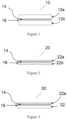
- FIG. 1is a cross-sectional view of a schematic illustration of a ribbon according to a first embodiment of the present invention.
- FIG. 2is a cross-sectional view of a schematic illustration of a ribbon according to a second embodiment of the present invention.
- FIG. 3is a cross-sectional view of a schematic illustration of a ribbon according to a third embodiment of the present invention.
- FIG. 4is a cross-sectional view of a schematic illustration of a ribbon according to a fourth embodiment of the present invention.
- FIG. 5is a cross-sectional view of a schematic illustration of a ribbon according to a fifth embodiment of the present invention.
- FIG. 6is a cross-sectional view of a schematic illustration of a ribbon according to a sixth embodiment of the present invention.
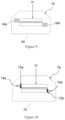
- FIG. 7is a cross-sectional view of the ribbon of FIG. 1 within a protective structure according to a seventh embodiment of the present invention.
- FIG. 8is a cross-sectional view of the ribbon of FIG. 1 within a protective structure according to an eighth embodiment of the present invention.
- FIG. 9is a cross-sectional view of the ribbon of FIG. 1 within a protective structure according to a ninth embodiment of the present invention.
- FIG. 10is a cross-sectional view of the ribbon of FIG. 1 within a protective structure according to a tenth embodiment of the present invention.
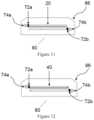
- FIG. 11is a cross-sectional view of the ribbon of FIG. 2 within a protective structure according to an eleventh embodiment of the present invention.
- FIG. 12is a cross-sectional view of the ribbon of FIG. 4 within a protective structure according to a twelfth embodiment of the present invention.
- FIG. 13is a cross-sectional view of the ribbon of FIG. 5 within a protective structure according to a thirteenth embodiment of the present invention.
- FIG. 14is a cross-sectional view of the ribbon of FIG. 6 within a protective structure according to a fourteenth embodiment of the present invention.
- FIG. 15is a cross-sectional view of the ribbon of FIG. 6 within a protective structure according to a fifteenth embodiment of the present invention.
- FIG. 16is an exterior view of an embodiment of a fiber of the invention including a lead wire that allows an electrical connection from the exterior of the fiber to an interior conductive material.
- an encapsulated bistable electro-optic mediumpreferably an electrophoretic dispersion is incorporated into a secondary ribbon structure.
- the ribbonmay be formed by first producing a laminate containing the electro-optic medium in a roll-to-roll process and then converting the laminate into narrow ribbons. This ribbon may then be pulled into a protective outer structure that provides additional mechanical and environmental protection and includes highly conductive structures along the length of the ribbon to provide proper electrical driving for ribbons of very large aspect ratios (e.g. ribbons that are many meters long and only a few mm wide or less).
- the structure of the ribbons and the protective outer structurescan be varied in geometry and composition to accommodate many different weaves and applications of the ribbons and fabrics.
- the ribbonmay comprise an outer fiber formed from a material capable of mechanically holding the internal electro-optic medium and wires of the device.
- the outer fibermay have a substantially rectangular cross-section and have an inner internal cavity with a substantially rectangular cross-section for housing the electro-optic medium and wires that may also be configured in the form of a ribbon-like structure.
- the dimensions of the outer fiberare selected such that the ribbon may be woven into sheets, while the width of each ribbon is large enough to provide a sufficient viewing surface.
- the dimensionsmay be selected to provide a cavity that is as large as possible relative to the thickness of the surrounding fiber to maximize the overall contrast ratio while maintaining sufficient mechanical strength of the fiber.
- the cavityis at least about 300 microns ⁇ 100 microns, and preferred thickness of the outer fiber surrounding the cavity is at least about 10 microns, more preferably at least about 50 microns.
- the internal cavity of the ribbonmay be large enough to accommodate a structure comprising the electro-optic medium and wires that is about 1 to 2 mm in width for improved aperture ratio and less seams between ribbons.
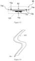
- the fiberis flexible, that is the fiber can be bent to a radius and returned to flat without breaking, cracking, shorting, leaking, etc.
- a fiber of the inventioncan be bent to a radius of 10 mm, e.g., 5 mm, e.g., 3 mm radius without losing functionality.
- At least two conductive wire electrodesmay run lengthwise along the fiber close to the cavity.
- the electro-optic medium and wire electrodespreferably fill the entire cavity.
- One wire or set of wiresmay be on the viewing side of the cavity and the other wire or set of wires may be located on the opposite side of the cavity.
- an electric fieldmay be applied across the cavity to cause a change in the optical state of the electro-optic medium.
- the wiresmay extend outside of the sheath or other protective shell in which the electro-optic material is contained, thereby allowing external connections.
- the wiresdo not extend outside the sheath, but a hole or slice is created in the sheath or other protective shell to provide an electrical connection to the exterior.
- the electrode wiresmay be made from any conductive material, preferably a conductive metal, such as copper or tungsten.
- the diameter of the wiresis preferably as small as is possible while maintaining enough mechanical strength to withstand the fiber making process.
- the wiresare preferably about 100 microns or less in diameter and more preferably about 50 microns or less.
- the fraction fis preferably less than 40%, more preferably less than 20%.
- the wires of individual fibersmay be interconnected, e.g., in series, or in parallel.
- the electro-optic medium and wiresmay be configured in a ribbon-like structure (“EPD ribbon”) and contained within the central cavity of the fiber.
- the electro-optic mediummay be in electrical contact with the conductive wire or wires at multiple points along the length of the fiber.
- EPD ribbonmay include one or more of the following features in various combinations.
- the EPD ribbonmay include a viewing side electrode comprising a light-transmissive substrate material and a light-transmissive conductor.
- the transparent conductoris preferably located adjacent the electro-optic medium.
- the transparent substratemay be made from a one or materials, such as PET, polycarbonate, polyolefins, PMMA, PDMS, PI or other light-transmissive polymeric materials.
- the EPD ribbonmay further comprise an optically switchable layer that preferably contains an encapsulated electrophoretic medium that is capable of changing multiple optical states.
- This layercan be a bichromal (e.g., black and white, e.g., a non-black non-white color and white, e.g., a non-black non-white color and black, or two different non-black non-white colors) or the layer may include a full-color medium.
- the electrophoretic mediummay comprise a dispersion containing a plurality of charged particles within a liquid solvent, and the dispersion is preferably encapsulated within compartments smaller than the width of the fiber.
- Encapsulated electrophoretic mediacomprise numerous small capsules, each of which itself comprises an internal phase containing electrophoretically-mobile particles in a fluid medium, and a capsule wall surrounding the internal phase. Typically, the capsules are themselves held within a polymeric binder to form a coherent layer positioned between two electrodes.
- the charged particles and the fluidare not encapsulated within microcapsules but instead are retained within a plurality of cavities formed within a carrier medium, typically a polymeric film.
- the technologies described in these patents and applicationsinclude:
- Electrophoretic particles, fluids and fluid additivessee for example U.S. Pat. Nos. 7,002,728 and 7,679,814;
- Non-electrophoretic displaysas described in U.S. Pat. No. 6,241,921 and U.S. Patent Application Publication No. 2015/0277160; and applications of encapsulation and macrocell technology other than displays; see for example U.S. Patent Application Publications Nos. 2015/0005720 and 2016/0012710.
- the EPD ribbonmay optionally comprise a removable secondary electrode on the non-viewing side of the electro-optic medium.
- the secondary electrodemay be removed before integration into the fiber structure.
- the secondary electrodemay be attached to the electro-optic medium with an adhesive material of controlled electrical properties.
- Materials for forming the secondary electrodeinclude, but are not limited to, ITO, carbon ink of various types including screen printing inks, CNT and graphene on flexible substrates (e.g. PET).
- the secondary electrodedoes not need to be light transmissive; therefore, other materials for forming the secondary electrode include thin metal foils (e.g. aluminum, copper, tin, gold, silver, stainless steel) with or without an additional support substrate for the metal.
- the secondary electrodemay made of a coatable material such as a carbon or silver ink that is coated directed over the layer of electro-optic medium.
- the secondary electrode materialmay be a conductive release material attached to the electro-optic medium with an adhesive of controlled electrical properties. This conductive release material may be used for protection and testing of the electro-optic medium and then removed before integration into the secondary fiber structure.
- the EPD ribbon 10may comprise a top electrode layer 12 a and a bottom electrode layer 12 b .
- Each electrode layer 12 a , 12 bmay be a transparent conductor on a polymer substrate, such as a 100 to 125 micron thick PET/ITO film, wherein the polymer substrate of the electrode layer is located on the top and bottom sides of the EPD ribbon 10 .
- the thickness of the PET/ITO filmmay be reduced to 12.5 to 50 microns for increased flexibility, such as the electrode layers 22 a , 22 b of the EPD ribbon 20 of FIG. 2 .
- the electro-optic medium 14is preferably a microencapsulated electrophoretic medium in a polymeric binder that is coated to the conductor side of the top electrode layer 12 a .
- the layer of lamination adhesive 16may be used to adhere the layer of electro-optic medium 14 to the conductor side of the bottom electrode layer 12 b .
- the adhesiveis preferably a polymeric material that has been doped with tetrabutylammonium hexafluorophosphate or other materials as described in U.S. Pat. Nos. 7,012,735 and 7,173,752.
- the EPD ribbon 30includes a top electrode layer 22 a , similar to the embodiment of FIG. 2 ; however, the bottom electrode layer has been replaced with the removable secondary electrode 32 .
- the secondary electrode 32may comprise a conductive release material that may be removed prior to integration into the fiber structure.
- the conductive release materialmay be a metallized PET, for example, that is about 50 to 125 microns in thickness. The conductive release material may be used to test the optical switching properties of the electro-optic medium layer 14 prior to integration into the fiber structure.
- the electrical contacts along the length of the EPD ribbonmay be improved by the inclusion of one or more gaps 42 a , 42 b in conductive portion of the top and bottom electrode layers 22 a , 22 b .
- the gapsmay be obtained by kiss-cutting the opposing sides of the electrode layers 22 a , 22 b with a laser.
- the gapsare preferably along the length of the EPD ribbon and located near the edge of the EPD ribbon 40 to avoid loss of optical performance, preferably within 100 microns.
- the gapsmay be used to eliminate a portion of the ITO conductor of either electrode layer 22 a , 22 b , for example, without damaging the polymer substrates and other structures of the EPD ribbon.
- the gapswill prevent potential shorting the electrode layers of the EPD ribbon, as will be described in greater detail below.
- the electrode layers 22 a , 22 bmay be offset, as illustrated in the EPD ribbon 50 of FIG. 5 , so that a portion of each electrode layer 22 a , 22 b extends out beyond the edge of electro-optic material 14 and/or adhesive 16 .
- the EPD ribbonmay be laminated in a way that provides for the overhang on either side, or a portion of each side of the electrode layers 22 a , 22 b may be removed after lamination and the portion of the electro-optic material 14 and adhesive 16 may be cleaned away along each edge to expose the ITO of each electrode layer 22 a , 22 b .
- This overhang structuremay obviate the need for the kiss-cuts described in the embodiment of FIG. 4 ; however, both the kiss-cuts and the overhang may be used together in some embodiments.
- the bottom electrode of an EPD ribbon 60may be replaced with a solid electrode material that is not light transmissive.
- the solid electrode materialmay be made for a conductive material 62 that is coated or laminated to the lamination adhesive 16 ; however, the width of the solid conductor 62 is narrower than either the layer of electro-optic material 14 or the lamination adhesive 16 to avoid shorting.
- the EPD ribbonmay then be incorporated into a fiber structure by various methods.
- the preferred methodis a drawing process, such as the process disclosed in U.S. Patent Application Pub. No. 2018/0364518 wherein a polymeric structure with a cavity is drawn down to integrate wires or in this case an EPD ribbon into a complex micro scale fiber cross section.
- the EPD ribbon as previously described and illustrated in FIG. 1may be incorporated into a ribbon fiber structure as illustrated in FIG. 7 .
- the outer sheath of the fiber 64may be made from a preform comprising a polymeric material, such as a polycarbonate or polyolefin, that is preferably light-transmissive when drawn down to the dimensions of the final fiber structure.
- the preform having a similar cross-sectional shape as the ribbon 64 illustrated in FIG. 7includes a central cavity into which one end of the EPD ribbon 7 is inserted.
- the central cavitymay have an approximately rectangular cross section to accommodate the EPD ribbon 10 .
- the length of the EPD ribbon 10may be longer than the outer sheath, such that the EPD ribbon 10 is exposed at one or both ends.
- One or both ends of the EPD ribbon 10may then be cut or punctured to access an electrode layer.
- a section of the top electrode layer, electro-optic material, and lamination adhesivemay be removed at one end of the ribbon 10 to expose the bottom electrode layer, and a section of the bottom electrode, electro-optic material, and lamination adhesive may be removed from the opposite end of the ribbon 10 to expose the top electrode layer.
- the outer sheath of the fibersmay also include chamfered edges 76 , 86 on at least the viewing side of the fiber to provide a lensing effect.
- conductive materialmay be incorporated into the preform.
- the preform which forms the outer sheathmay be loaded with an electrically conductive solder-like low-melting metallic alloy.
- the solder-like materialis preferably solid at room temperature and is incorporated into the preform structure on either side of the cavity that receives the internal EPD ribbon. At draw temperatures, the solder melts, flows and draws down together with the outer sheath to form a fiber, such as fiber 66 of FIG. 8 .
- the solder-like material 67 a , 67 bcan make electrical contact with the electrode layers within the EPD ribbon 10 .
- the solder-like materialmay be loaded into the preform on either side of the internal cavity, such that when the preform is drawn, the solder-like material 67 b on one side of the cavity contacts only the edge of the conductive layer of the bottom electrode, while the solder-like material 67 a on the other side of the cavity contacts the opposing edge of the electrode layer of the top electrode only.
- the solder-like materialmay be at first fully surrounded by the polymeric material of the outer sheath.
- the polymeric material separating the solder material from the internal cavityis provided in the form of a thin membrane that is configured to further decrease in thickness and/or break during the drawing process, so that an electrical contact will form between the solder-like material 67 a , 67 b and the electrode layers of the internal EPD ribbon 10 .
- the solder material 67 a , 67 b present at the end faces of the ribbon 66provide a larger contact area for electrical connection to a power source and/or controller.
- the previously described solder-like materialmay be replaced with a conductive polymer, such as a carbon-filled polymer.
- the conductive polymerpreferably has the same physical properties as the materials of the outer sheath, so that the conductive polymer may be pre-loaded into a preform and drawn to form a fiber.
- the conductive polymer 69 a , 69 bmay in some embodiments occupy a majority of the annular thickness of the outer sheath of the ribbon 68 to facilitate connection to a power source and/or controller.
- connections to the conductive polymer 69 a , 69 bmay be accomplished through the outer sheath with a connector similar to an insulation displacement connector.
- the ribbons made according to the various embodiments of the present inventionmay also include wires or leads, such as the embodiment illustrated in FIG. 10 .
- two wires 74 a and 74 bmay be inserted into a preform, wherein one wire 74 a contacts the conductive filled polymer 72 a on one side of the cavity and the other wire 74 b contacts the conductive filled polymer 72 b on the other side of the cavity.
- the conductive filled polymeris incorporated into the preform such that the conductive filled polymer on each side of the cavity makes electrical contact with the edge of the EPD ribbon.
- one or more wiresmay extend through the fiber 120 , and extend beyond the fiber 120 to provide easier external electrical connectivity.
- the thickness of the fibermay be reduced with the use of a thinner internal EPD ribbon.
- the fiber 80 of FIG. 11includes a thinner EPD ribbon, such as EPD ribbon 20 of FIG. 2 , but otherwise has all of the same features as the previously described fiber 70 .
- the EPD ribbon 40 of FIG. 4may be incorporated into the ribbon structure, such as fiber 90 of FIG. 12 .
- the structure of the fiber 90is essentially the same as ribbon 80 in FIG. 11 , except for the inclusion of the previously described gaps in the ITO portions of the top and bottom electrodes.
- the gapsprevent potential shorts if the one or both of the conductive filled polymer 72 a , 72 b or wires 74 a , 74 b happen to contact the ITO of both the top and bottom electrode layer on one side of the EPD ribbon 40 .
- the gaptherefore, is preferably wide enough, such that a current is unable to cross the gap; thereby, providing an electrical break to prevent a short in the EPD ribbon 40 , i.e. electrically isolating the top electrode layer from the bottom electrode layer within the EPD ribbon 40 .
- the fibermay include an internal EPD ribbon structure similar to EPD ribbon 50 , as illustrated in FIG. 13 .
- the overhang on either side of the EPD ribbon 50is preferably sufficiently wide, such that the conductive filled polymer 72 a , 72 b will only contact one of the top or bottom electrode layer of the EPD ribbon 50 .
- the ribbon 50may further include gaps in the ITO layer of the top and bottom electrode layers to further reduce the likelihood of a short; however, this is optional.
- an EPD ribbon 60 having only a single light-transmissive top electrodemay be incorporated into a fiber structure.
- an EPD ribbon 60 having a light transmissive top electrode layer along with two wires 74 a and 74 bmay be incorporated into a preform, wherein the preform includes a conductive filled polymer 72 a , 72 b .
- the conductive filled polymer 72 a , 72 bis configured, such that when the preform is drawn, the conductive filled polymer 72 a , 72 b provides an electrical contact along each edge of the EPD ribbon 60 between the ITO portion of the top electrode layer and one of the two wires 74 a , 74 b . This may increase the number of electrical connections with the top electrode within the EPD ribbon 60 .
- the EPD ribbon 60may include an optional releasable layer that is removed to reveal the adhesive layer of the EPD ribbon 60 .
- a solid conductoris applied to the adhesive layer.
- the solid conductormay be coated or laminated to the bottom of adhesive layer and preferably has a width that is less than the width of the EPD ribbon 60 , so that the solid conductor does not contact either the conductive filled polymer 72 a , 72 b on the sides of the EPD ribbon 60 or the top electrode wires 74 a , 74 b ; thereby avoiding a potential short.
- An additional wire 74 cmay be inserted into the preform prior to drawing the preform, so that the wire 74 c is in electrical contact with the solid conductor along the length of the fiber 110 .
- the solid conductormay comprise a metal foil or other conductive material.
- a conductive filled polymer 72 csimilar to the other conductive filled polymer, may be applied between the solid conductor and the wire 74 c , such as the fiber 120 illustrated in FIG. 15 .
- thismay result in a thick fiber.
- the conductive filled polymer 72 c on the bottom of the EPD ribbon 60may be used by itself, instead of applying a solid conductor.
- the electrical properties of the adhesive layermay be controlled to allow the ink to bloom and facilitate optical switching of the electro-optic material along the edges of the EPD ribbon 60 .
- “blooming”means the area of the electro-optic layer which changes optical state in response to a change of voltage is larger than the area of the electrode, in this case area of the solid conductor, which is in contact with the adhesive layer. Again, this blooming phenomenon may be controlled by incorporating certain dopants in the polymeric material of the adhesive.
Landscapes
- Engineering & Computer Science (AREA)
- Physics & Mathematics (AREA)
- Textile Engineering (AREA)
- Mechanical Engineering (AREA)
- Chemical & Material Sciences (AREA)
- Chemical Kinetics & Catalysis (AREA)
- Nonlinear Science (AREA)
- Health & Medical Sciences (AREA)
- Electrochemistry (AREA)
- Molecular Biology (AREA)
- Life Sciences & Earth Sciences (AREA)
- General Chemical & Material Sciences (AREA)
- General Physics & Mathematics (AREA)
- Optics & Photonics (AREA)
- Electrochromic Elements, Electrophoresis, Or Variable Reflection Or Absorption Elements (AREA)
Abstract
Description
Claims (14)
Priority Applications (1)
| Application Number | Priority Date | Filing Date | Title |
|---|---|---|---|
| US16/986,317US11761123B2 (en) | 2019-08-07 | 2020-08-06 | Switching ribbons for textiles |
Applications Claiming Priority (2)
| Application Number | Priority Date | Filing Date | Title |
|---|---|---|---|
| US201962883699P | 2019-08-07 | 2019-08-07 | |
| US16/986,317US11761123B2 (en) | 2019-08-07 | 2020-08-06 | Switching ribbons for textiles |
Publications (2)
| Publication Number | Publication Date |
|---|---|
| US20210040654A1 US20210040654A1 (en) | 2021-02-11 |
| US11761123B2true US11761123B2 (en) | 2023-09-19 |
Family
ID=74498056
Family Applications (1)
| Application Number | Title | Priority Date | Filing Date |
|---|---|---|---|
| US16/986,317Active2041-11-25US11761123B2 (en) | 2019-08-07 | 2020-08-06 | Switching ribbons for textiles |
Country Status (1)
| Country | Link |
|---|---|
| US (1) | US11761123B2 (en) |
Citations (156)
| Publication number | Priority date | Publication date | Assignee | Title |
|---|---|---|---|---|
| US3009348A (en) | 1957-11-12 | 1961-11-21 | Lawrence L Colbert | Combined bicycle pedal and lock |
| US3852401A (en) | 1971-06-29 | 1974-12-03 | Japan Exlan Co Ltd | Method for producing artificial fibers containing microcapsules |
| US4659619A (en) | 1981-06-11 | 1987-04-21 | Thalatta, Inc. | Color changeable fabric |
| US4756958A (en) | 1987-08-31 | 1988-07-12 | Triangle Research And Development Corporation | Fiber with reversible enhanced thermal storage properties and fabrics made therefrom |
| US4815355A (en) | 1988-01-14 | 1989-03-28 | Cavaness Jack D | Color changeable guitar body |
| US4917920A (en) | 1988-02-02 | 1990-04-17 | Kanebo, Ltd. | Fibrous structures having a durable fragrance and a process for preparing the same |
| US5760761A (en) | 1995-12-15 | 1998-06-02 | Xerox Corporation | Highlight color twisting ball display |
| US5777782A (en) | 1996-12-24 | 1998-07-07 | Xerox Corporation | Auxiliary optics for a twisting ball display |
| US5808783A (en) | 1996-06-27 | 1998-09-15 | Xerox Corporation | High reflectance gyricon display |
| US5930026A (en) | 1996-10-25 | 1999-07-27 | Massachusetts Institute Of Technology | Nonemissive displays and piezoelectric power supplies therefor |
| US5961804A (en) | 1997-03-18 | 1999-10-05 | Massachusetts Institute Of Technology | Microencapsulated electrophoretic display |
| US6017584A (en) | 1995-07-20 | 2000-01-25 | E Ink Corporation | Multi-color electrophoretic displays and materials for making the same |
| US6055091A (en) | 1996-06-27 | 2000-04-25 | Xerox Corporation | Twisting-cylinder display |
| US6054071A (en) | 1998-01-28 | 2000-04-25 | Xerox Corporation | Poled electrets for gyricon-based electric-paper displays |
| US6067185A (en) | 1997-08-28 | 2000-05-23 | E Ink Corporation | Process for creating an encapsulated electrophoretic display |
| US6072619A (en) | 1999-03-22 | 2000-06-06 | Visson Ip, Llc | Electro-optical light modulating device |
| US6097531A (en) | 1998-11-25 | 2000-08-01 | Xerox Corporation | Method of making uniformly magnetized elements for a gyricon display |
| US6120588A (en) | 1996-07-19 | 2000-09-19 | E Ink Corporation | Electronically addressable microencapsulated ink and display thereof |
| US6120839A (en) | 1995-07-20 | 2000-09-19 | E Ink Corporation | Electro-osmotic displays and materials for making the same |
| US6128124A (en) | 1998-10-16 | 2000-10-03 | Xerox Corporation | Additive color electric paper without registration or alignment of individual elements |
| US6130774A (en) | 1998-04-27 | 2000-10-10 | E Ink Corporation | Shutter mode microencapsulated electrophoretic display |
| US6137467A (en) | 1995-01-03 | 2000-10-24 | Xerox Corporation | Optically sensitive electric paper |
| US6147791A (en) | 1998-11-25 | 2000-11-14 | Xerox Corporation | Gyricon displays utilizing rotating elements and magnetic latching |
| US6229827B1 (en)* | 1998-12-04 | 2001-05-08 | Cidra Corporation | Compression-tuned bragg grating and laser |
| US6241921B1 (en) | 1998-05-15 | 2001-06-05 | Massachusetts Institute Of Technology | Heterogeneous display elements and methods for their fabrication |
| US6249271B1 (en) | 1995-07-20 | 2001-06-19 | E Ink Corporation | Retroreflective electrophoretic displays and materials for making the same |
| US6262706B1 (en) | 1995-07-20 | 2001-07-17 | E Ink Corporation | Retroreflective electrophoretic displays and materials for making the same |
| US6262833B1 (en) | 1998-10-07 | 2001-07-17 | E Ink Corporation | Capsules for electrophoretic displays and methods for making the same |
| US20010009352A1 (en) | 1999-04-26 | 2001-07-26 | Moore Chad Byron | Reflective electro-optic fiber-based displays |
| US6301038B1 (en) | 1997-02-06 | 2001-10-09 | University College Dublin | Electrochromic system |
| US6300932B1 (en) | 1997-08-28 | 2001-10-09 | E Ink Corporation | Electrophoretic displays with luminescent particles and materials for making the same |
| US6323989B1 (en) | 1996-07-19 | 2001-11-27 | E Ink Corporation | Electrophoretic displays using nanoparticles |
| US6327072B1 (en) | 1999-04-06 | 2001-12-04 | E Ink Corporation | Microcell electrophoretic displays |
| US6377387B1 (en) | 1999-04-06 | 2002-04-23 | E Ink Corporation | Methods for producing droplets for use in capsule-based electrophoretic displays |
| US6392786B1 (en) | 1999-07-01 | 2002-05-21 | E Ink Corporation | Electrophoretic medium provided with spacers |
| US6459418B1 (en) | 1995-07-20 | 2002-10-01 | E Ink Corporation | Displays combining active and non-active inks |
| US6515649B1 (en) | 1995-07-20 | 2003-02-04 | E Ink Corporation | Suspended particle displays and materials for making the same |
| US6538801B2 (en) | 1996-07-19 | 2003-03-25 | E Ink Corporation | Electrophoretic displays using nanoparticles |
| US6542284B2 (en) | 2000-10-11 | 2003-04-01 | Canon Kabushiki Kaisha | Display device and manufacturing method therefor |
| US6580545B2 (en) | 2001-04-19 | 2003-06-17 | E Ink Corporation | Electrochromic-nanoparticle displays |
| US20030194578A1 (en) | 2001-12-20 | 2003-10-16 | Honeywell International, Inc. | Security articles comprising multi-responsive physical colorants |
| US6693620B1 (en) | 1999-05-03 | 2004-02-17 | E Ink Corporation | Threshold addressing of electrophoretic displays |
| JP2004070206A (en) | 2002-08-09 | 2004-03-04 | Toyo Ink Mfg Co Ltd | Electrophoretic display |
| US6721083B2 (en) | 1996-07-19 | 2004-04-13 | E Ink Corporation | Electrophoretic displays using nanoparticles |
| US6727881B1 (en) | 1995-07-20 | 2004-04-27 | E Ink Corporation | Encapsulated electrophoretic displays and methods and materials for making the same |
| US6756120B2 (en) | 1995-09-28 | 2004-06-29 | Honeywell International Inc. | Colored articles and compositions and methods for their fabrication |
| US6822782B2 (en) | 2001-05-15 | 2004-11-23 | E Ink Corporation | Electrophoretic particles and processes for the production thereof |
| US6839158B2 (en) | 1997-08-28 | 2005-01-04 | E Ink Corporation | Encapsulated electrophoretic displays having a monolayer of capsules and materials and methods for making the same |
| US20050012980A1 (en) | 2003-05-02 | 2005-01-20 | E Ink Corporation | Electrophoretic displays with controlled amounts of pigment |
| US6866760B2 (en) | 1998-08-27 | 2005-03-15 | E Ink Corporation | Electrophoretic medium and process for the production thereof |
| US6870661B2 (en) | 2001-05-15 | 2005-03-22 | E Ink Corporation | Electrophoretic displays containing magnetic particles |
| US6870657B1 (en) | 1999-10-11 | 2005-03-22 | University College Dublin | Electrochromic device |
| US20050156340A1 (en) | 2004-01-20 | 2005-07-21 | E Ink Corporation | Preparation of capsules |
| US6922276B2 (en) | 2002-12-23 | 2005-07-26 | E Ink Corporation | Flexible electro-optic displays |
| US6950220B2 (en) | 2002-03-18 | 2005-09-27 | E Ink Corporation | Electro-optic displays, and methods for driving same |
| US6958848B2 (en) | 2002-05-23 | 2005-10-25 | E Ink Corporation | Capsules, materials for use therein and electrophoretic media and displays containing such capsules |
| US6982178B2 (en) | 2002-06-10 | 2006-01-03 | E Ink Corporation | Components and methods for use in electro-optic displays |
| US6987603B2 (en) | 2003-01-31 | 2006-01-17 | E Ink Corporation | Construction of electrophoretic displays |
| US7002728B2 (en) | 1997-08-28 | 2006-02-21 | E Ink Corporation | Electrophoretic particles, and processes for the production thereof |
| US7006063B2 (en) | 2002-01-31 | 2006-02-28 | Oji Paper Co., Ltd. | Display unit and display device |
| US7012735B2 (en) | 2003-03-27 | 2006-03-14 | E Ink Corporaiton | Electro-optic assemblies, and materials for use therein |
| US7012600B2 (en) | 1999-04-30 | 2006-03-14 | E Ink Corporation | Methods for driving bistable electro-optic displays, and apparatus for use therein |
| US7038655B2 (en) | 1999-05-03 | 2006-05-02 | E Ink Corporation | Electrophoretic ink composed of particles with field dependent mobilities |
| US7072095B2 (en) | 2002-10-31 | 2006-07-04 | Sipix Imaging, Inc. | Electrophoretic display and novel process for its manufacture |
| US7071913B2 (en) | 1995-07-20 | 2006-07-04 | E Ink Corporation | Retroreflective electrophoretic displays and materials for making the same |
| US7075502B1 (en) | 1998-04-10 | 2006-07-11 | E Ink Corporation | Full color reflective display with multichromatic sub-pixels |
| US7079305B2 (en) | 2001-03-19 | 2006-07-18 | E Ink Corporation | Electrophoretic medium and process for the production thereof |
| CN1807707A (en) | 2006-01-13 | 2006-07-26 | 清华大学 | Core-shell composite micron/nano fiber and preparation method thereof |
| US7109968B2 (en) | 1995-07-20 | 2006-09-19 | E Ink Corporation | Non-spherical cavity electrophoretic displays and methods and materials for making the same |
| US7110164B2 (en) | 2002-06-10 | 2006-09-19 | E Ink Corporation | Electro-optic displays, and processes for the production thereof |
| US7116318B2 (en) | 2002-04-24 | 2006-10-03 | E Ink Corporation | Backplanes for display applications, and components for use therein |
| US7144942B2 (en) | 2001-06-04 | 2006-12-05 | Sipix Imaging, Inc. | Composition and process for the sealing of microcups in roll-to-roll display manufacturing |
| US7170670B2 (en) | 2001-04-02 | 2007-01-30 | E Ink Corporation | Electrophoretic medium and display with improved image stability |
| US7173752B2 (en) | 2003-11-05 | 2007-02-06 | E Ink Corporation | Electro-optic displays, and materials for use therein |
| US7184197B2 (en) | 2003-01-30 | 2007-02-27 | Sipix Imaging, Inc. | High performance capsules for electrophoretic displays |
| US20070091417A1 (en) | 2005-10-25 | 2007-04-26 | E Ink Corporation | Electrophoretic media and displays with improved binder |
| US7230750B2 (en) | 2001-05-15 | 2007-06-12 | E Ink Corporation | Electrophoretic media and processes for the production thereof |
| US7230751B2 (en) | 2005-01-26 | 2007-06-12 | E Ink Corporation | Electrophoretic displays using gaseous fluids |
| US7236290B1 (en) | 2000-07-25 | 2007-06-26 | E Ink Corporation | Electrophoretic medium with improved stability |
| US7236291B2 (en) | 2003-04-02 | 2007-06-26 | Bridgestone Corporation | Particle use for image display media, image display panel using the particles, and image display device |
| US7242513B2 (en) | 1997-08-28 | 2007-07-10 | E Ink Corporation | Encapsulated electrophoretic displays having a monolayer of capsules and materials and methods for making the same |
| US7247379B2 (en) | 1997-08-28 | 2007-07-24 | E Ink Corporation | Electrophoretic particles, and processes for the production thereof |
| US20070197115A1 (en) | 2003-12-20 | 2007-08-23 | Koninklijke Philips Electronic, N.V. | Woven material and display device constructed therefrom |
| CN101070672A (en) | 2006-05-12 | 2007-11-14 | 中国科学院化学研究所 | Super-hydrophobic conductive fiber, fabric and preparing method and use |
| US7304634B2 (en) | 1995-07-20 | 2007-12-04 | E Ink Corporation | Rear electrode structures for electrophoretic displays |
| US7312916B2 (en) | 2002-08-07 | 2007-12-25 | E Ink Corporation | Electrophoretic media containing specularly reflective particles |
| US7312784B2 (en) | 2001-03-13 | 2007-12-25 | E Ink Corporation | Apparatus for displaying drawings |
| US7321459B2 (en) | 2002-03-06 | 2008-01-22 | Bridgestone Corporation | Image display device and method |
| US7339715B2 (en) | 2003-03-25 | 2008-03-04 | E Ink Corporation | Processes for the production of electrophoretic displays |
| US20080130092A1 (en) | 2004-03-23 | 2008-06-05 | E Ink Corporation | Light modulators |
| US20080158651A1 (en)* | 2006-12-28 | 2008-07-03 | Seiko Epson Corporation | Electrophoretic display sheet, electrophoretic display device, and electronic apparatus |
| US7411719B2 (en) | 1995-07-20 | 2008-08-12 | E Ink Corporation | Electrophoretic medium and process for the production thereof |
| US7420549B2 (en) | 2003-10-08 | 2008-09-02 | E Ink Corporation | Electro-wetting displays |
| US7453445B2 (en) | 2004-08-13 | 2008-11-18 | E Ink Corproation | Methods for driving electro-optic displays |
| US20080316580A1 (en) | 2004-09-11 | 2008-12-25 | Koninklijke Philips Electronics, N.V. | Fibre, Flexible Display Device Manufactured Thereform and Corresponding Manufacturing Methods |
| US20090009852A1 (en) | 2001-05-15 | 2009-01-08 | E Ink Corporation | Electrophoretic particles and processes for the production thereof |
| US7477444B2 (en) | 2006-09-22 | 2009-01-13 | E Ink Corporation & Air Products And Chemical, Inc. | Electro-optic display and materials for use therein |
| TW200916620A (en) | 2007-10-04 | 2009-04-16 | Taiwan Textile Res Inst | Light-emitting yarn and light-emitting taxtile having the same |
| US7531235B2 (en) | 2003-12-20 | 2009-05-12 | Koninklijke Philips Electronics N.V. | Fibre or filament |
| US20090122389A1 (en) | 2007-11-14 | 2009-05-14 | E Ink Corporation | Electro-optic assemblies, and adhesives and binders for use therein |
| US7535624B2 (en) | 2001-07-09 | 2009-05-19 | E Ink Corporation | Electro-optic display and materials for use therein |
| US7561324B2 (en) | 2002-09-03 | 2009-07-14 | E Ink Corporation | Electro-optic displays |
| US7579078B2 (en) | 2001-09-21 | 2009-08-25 | Outlast Technologies, Inc. | Temperature regulating cellulosic fibers and applications thereof |
| US7679814B2 (en) | 2001-04-02 | 2010-03-16 | E Ink Corporation | Materials for use in electrophoretic displays |
| US7715088B2 (en) | 2000-03-03 | 2010-05-11 | Sipix Imaging, Inc. | Electrophoretic display |
| US20100148385A1 (en) | 2001-05-15 | 2010-06-17 | E Ink Corporation | Electrophoretic media and processes for the production thereof |
| US7839564B2 (en) | 2002-09-03 | 2010-11-23 | E Ink Corporation | Components and methods for use in electro-optic displays |
| US7848006B2 (en) | 1995-07-20 | 2010-12-07 | E Ink Corporation | Electrophoretic displays with controlled amounts of pigment |
| US7903319B2 (en) | 2006-07-11 | 2011-03-08 | E Ink Corporation | Electrophoretic medium and display with improved image stability |
| US7910175B2 (en) | 2003-03-25 | 2011-03-22 | E Ink Corporation | Processes for the production of electrophoretic displays |
| US20110073353A1 (en) | 2009-09-29 | 2011-03-31 | Tex-Ray Industrial Co., Ltd. | Conductive fabric and method for forming the same |
| US7952790B2 (en) | 2006-03-22 | 2011-05-31 | E Ink Corporation | Electro-optic media produced using ink jet printing |
| US8018640B2 (en) | 2006-07-13 | 2011-09-13 | E Ink Corporation | Particles for use in electrophoretic displays |
| US8035886B2 (en) | 1996-07-19 | 2011-10-11 | E Ink Corporation | Electronically addressable microencapsulated ink and display thereof |
| US8047681B2 (en) | 2008-12-16 | 2011-11-01 | Royal Pacific Limited | Flexible light emitting array |
| US8107153B2 (en) | 2009-03-31 | 2012-01-31 | The University Of Connecticut | Flexible electrochromic devices, electrodes therefor, and methods of manufacture |
| US8115729B2 (en) | 1999-05-03 | 2012-02-14 | E Ink Corporation | Electrophoretic display element with filler particles |
| US8129655B2 (en) | 2002-09-03 | 2012-03-06 | E Ink Corporation | Electrophoretic medium with gaseous suspending fluid |
| TW201211339A (en) | 2010-09-09 | 2012-03-16 | Asiatic Fiber Corp | Manufacturing method of fabric and its fabric product |
| US8207511B2 (en) | 2008-06-05 | 2012-06-26 | Performance Indicator, Llc | Photoluminescent fibers, compositions and fabrics made therefrom |
| US8270064B2 (en) | 2009-02-09 | 2012-09-18 | E Ink Corporation | Electrophoretic particles, and processes for the production thereof |
| US8282232B2 (en) | 2009-04-08 | 2012-10-09 | Fu-biau Hsu | Illuminating textile article |
| US20120274616A1 (en) | 2011-04-27 | 2012-11-01 | Southwest Research Institute | Electrophoretic Display Using Fibers Containing a Nanoparticle Suspension |
| US8305341B2 (en) | 1995-07-20 | 2012-11-06 | E Ink Corporation | Dielectrophoretic displays |
| US8319759B2 (en) | 2003-10-08 | 2012-11-27 | E Ink Corporation | Electrowetting displays |
| US8390918B2 (en) | 2001-04-02 | 2013-03-05 | E Ink Corporation | Electrophoretic displays with controlled amounts of pigment |
| US8446664B2 (en) | 2010-04-02 | 2013-05-21 | E Ink Corporation | Electrophoretic media, and materials for use therein |
| US8582196B2 (en) | 2001-05-15 | 2013-11-12 | E Ink Corporation | Electrophoretic particles and processes for the production thereof |
| US20140011913A1 (en) | 2011-02-03 | 2014-01-09 | Sipix Imaging, Inc. | Electrophoretic fluid |
| US20140093731A1 (en) | 2011-03-07 | 2014-04-03 | Alma Mater Studiorum - Universita` Di Bologna | Conductive fiber materials |
| US8717664B2 (en) | 2012-10-02 | 2014-05-06 | Sipix Imaging, Inc. | Color display device |
| US8769836B2 (en) | 2010-06-22 | 2014-07-08 | Nike, Inc. | Article of footwear with color change portion and method of changing color |
| US8822782B1 (en) | 2012-02-21 | 2014-09-02 | Pioneer Hi-Bred International, Inc. | Maize hybrid X13C764 |
| US20150005720A1 (en) | 2006-07-18 | 2015-01-01 | E Ink California, Llc | Electrophoretic display |
| US20160012710A1 (en) | 2014-07-10 | 2016-01-14 | Sipix Technology Inc. | Smart medication device |
| US9244326B2 (en) | 2012-01-17 | 2016-01-26 | Hewlett-Packard Development Company, L.P. | Inks including graft copolymer surface-modified pigments via azide chemistry |
| US9279906B2 (en) | 2012-08-31 | 2016-03-08 | E Ink California, Llc | Microstructure film |
| US9366935B2 (en) | 2011-02-03 | 2016-06-14 | E Ink California, Llc | Electrophoretic fluid |
| US9372380B2 (en) | 2011-02-03 | 2016-06-21 | E Ink California, Llc | Electrophoretic fluid |
| US9441122B2 (en) | 2012-01-26 | 2016-09-13 | Hewlett-Packard Development Company, L.P. | Inks including segment copolymer grafted pigments via azide chemistry |
| TWM531957U (en) | 2016-07-19 | 2016-11-11 | Huang-Shan Huang | Core-sheath composite luminescent yarn structure |
| US9633579B2 (en) | 2014-06-27 | 2017-04-25 | Eastman Chemical Company | Fibers with physical features used for coding |
| CN106705829A (en) | 2015-08-21 | 2017-05-24 | 中国科学院上海硅酸盐研究所 | Flexible wearable conductive fiber sensor and preparation method and application thereof |
| US9733541B2 (en) | 2012-09-05 | 2017-08-15 | Sony Corporation | Electrophoresis device, display unit, and electronic apparatus |
| US9777201B2 (en) | 2015-07-23 | 2017-10-03 | E Ink Corporation | Polymer formulations for use with electro-optic media |
| US20170342601A1 (en)* | 2014-12-08 | 2017-11-30 | Jnc Corporation | Conjugate fibers with encapsulated liquid crystal and conjugate fiber aggregate |
| US9863920B2 (en) | 2014-06-27 | 2018-01-09 | Eastman Chemical Company | Fibers with chemical markers and physical features used for coding |
| KR20180013007A (en) | 2016-07-28 | 2018-02-07 | 부산대학교 산학협력단 | Manufacturing process for electrochromic fibers |
| US9921451B2 (en) | 2014-09-10 | 2018-03-20 | E Ink Corporation | Colored electrophoretic displays |
| US20180271180A1 (en) | 2015-10-02 | 2018-09-27 | Samsung Electronics Co., Ltd | Smart garment, user terminal, system including same, and method of changing design of smart garment |
| US20180364518A1 (en) | 2017-06-16 | 2018-12-20 | Advanced Functional Fabrics Of America | Switching fibers for textiles |
| US20180363173A1 (en) | 2017-06-14 | 2018-12-20 | Apple Inc. | Fabric Items Having Strands of Adjustable Appearance |
| US10174232B2 (en) | 2015-09-30 | 2019-01-08 | E Ink Corporation | Polyurethane adhesive layers for electro-optic assemblies |
| US20190146299A1 (en) | 2016-04-27 | 2019-05-16 | Sony Corporation | Fiber assembly, display unit, and electronic apparatus |
| US10372008B2 (en) | 2011-05-21 | 2019-08-06 | E Ink Corporation | Electro-optic displays |
| US10444553B2 (en) | 2014-03-25 | 2019-10-15 | E Ink California, Llc | Magnetophoretic display assembly and driving scheme |
- 2020
- 2020-08-06USUS16/986,317patent/US11761123B2/enactiveActive
Patent Citations (175)
| Publication number | Priority date | Publication date | Assignee | Title |
|---|---|---|---|---|
| US3009348A (en) | 1957-11-12 | 1961-11-21 | Lawrence L Colbert | Combined bicycle pedal and lock |
| US3852401A (en) | 1971-06-29 | 1974-12-03 | Japan Exlan Co Ltd | Method for producing artificial fibers containing microcapsules |
| US4659619A (en) | 1981-06-11 | 1987-04-21 | Thalatta, Inc. | Color changeable fabric |
| US4756958A (en) | 1987-08-31 | 1988-07-12 | Triangle Research And Development Corporation | Fiber with reversible enhanced thermal storage properties and fabrics made therefrom |
| US4815355A (en) | 1988-01-14 | 1989-03-28 | Cavaness Jack D | Color changeable guitar body |
| US4917920A (en) | 1988-02-02 | 1990-04-17 | Kanebo, Ltd. | Fibrous structures having a durable fragrance and a process for preparing the same |
| US6137467A (en) | 1995-01-03 | 2000-10-24 | Xerox Corporation | Optically sensitive electric paper |
| US6262706B1 (en) | 1995-07-20 | 2001-07-17 | E Ink Corporation | Retroreflective electrophoretic displays and materials for making the same |
| US7109968B2 (en) | 1995-07-20 | 2006-09-19 | E Ink Corporation | Non-spherical cavity electrophoretic displays and methods and materials for making the same |
| US6515649B1 (en) | 1995-07-20 | 2003-02-04 | E Ink Corporation | Suspended particle displays and materials for making the same |
| US6459418B1 (en) | 1995-07-20 | 2002-10-01 | E Ink Corporation | Displays combining active and non-active inks |
| US6017584A (en) | 1995-07-20 | 2000-01-25 | E Ink Corporation | Multi-color electrophoretic displays and materials for making the same |
| US6727881B1 (en) | 1995-07-20 | 2004-04-27 | E Ink Corporation | Encapsulated electrophoretic displays and methods and materials for making the same |
| US8593718B2 (en) | 1995-07-20 | 2013-11-26 | E Ink Corporation | Electro-osmotic displays and materials for making the same |
| US8305341B2 (en) | 1995-07-20 | 2012-11-06 | E Ink Corporation | Dielectrophoretic displays |
| US7071913B2 (en) | 1995-07-20 | 2006-07-04 | E Ink Corporation | Retroreflective electrophoretic displays and materials for making the same |
| US6249271B1 (en) | 1995-07-20 | 2001-06-19 | E Ink Corporation | Retroreflective electrophoretic displays and materials for making the same |
| US7304634B2 (en) | 1995-07-20 | 2007-12-04 | E Ink Corporation | Rear electrode structures for electrophoretic displays |
| US6120839A (en) | 1995-07-20 | 2000-09-19 | E Ink Corporation | Electro-osmotic displays and materials for making the same |
| US7848007B2 (en) | 1995-07-20 | 2010-12-07 | E Ink Corporation | Electrophoretic medium and process for the production thereof |
| US7848006B2 (en) | 1995-07-20 | 2010-12-07 | E Ink Corporation | Electrophoretic displays with controlled amounts of pigment |
| US7391555B2 (en) | 1995-07-20 | 2008-06-24 | E Ink Corporation | Non-spherical cavity electrophoretic displays and materials for making the same |
| US7746544B2 (en) | 1995-07-20 | 2010-06-29 | E Ink Corporation | Electro-osmotic displays and materials for making the same |
| US7411719B2 (en) | 1995-07-20 | 2008-08-12 | E Ink Corporation | Electrophoretic medium and process for the production thereof |
| US6756120B2 (en) | 1995-09-28 | 2004-06-29 | Honeywell International Inc. | Colored articles and compositions and methods for their fabrication |
| US5760761A (en) | 1995-12-15 | 1998-06-02 | Xerox Corporation | Highlight color twisting ball display |
| US6055091A (en) | 1996-06-27 | 2000-04-25 | Xerox Corporation | Twisting-cylinder display |
| US5808783A (en) | 1996-06-27 | 1998-09-15 | Xerox Corporation | High reflectance gyricon display |
| US6538801B2 (en) | 1996-07-19 | 2003-03-25 | E Ink Corporation | Electrophoretic displays using nanoparticles |
| US20110286081A1 (en) | 1996-07-19 | 2011-11-24 | E Ink Corporation | Electronically addressable microencapsulated ink and display thereof |
| US6323989B1 (en) | 1996-07-19 | 2001-11-27 | E Ink Corporation | Electrophoretic displays using nanoparticles |
| US8035886B2 (en) | 1996-07-19 | 2011-10-11 | E Ink Corporation | Electronically addressable microencapsulated ink and display thereof |
| US6120588A (en) | 1996-07-19 | 2000-09-19 | E Ink Corporation | Electronically addressable microencapsulated ink and display thereof |
| US6721083B2 (en) | 1996-07-19 | 2004-04-13 | E Ink Corporation | Electrophoretic displays using nanoparticles |
| US6652075B2 (en) | 1996-07-19 | 2003-11-25 | E Ink Corporation | Electronically addressable microencapsulated ink and display thereof |
| US5930026A (en) | 1996-10-25 | 1999-07-27 | Massachusetts Institute Of Technology | Nonemissive displays and piezoelectric power supplies therefor |
| US5777782A (en) | 1996-12-24 | 1998-07-07 | Xerox Corporation | Auxiliary optics for a twisting ball display |
| US6301038B1 (en) | 1997-02-06 | 2001-10-09 | University College Dublin | Electrochromic system |
| US5961804A (en) | 1997-03-18 | 1999-10-05 | Massachusetts Institute Of Technology | Microencapsulated electrophoretic display |
| US7247379B2 (en) | 1997-08-28 | 2007-07-24 | E Ink Corporation | Electrophoretic particles, and processes for the production thereof |
| US6300932B1 (en) | 1997-08-28 | 2001-10-09 | E Ink Corporation | Electrophoretic displays with luminescent particles and materials for making the same |
| US7002728B2 (en) | 1997-08-28 | 2006-02-21 | E Ink Corporation | Electrophoretic particles, and processes for the production thereof |
| US6067185A (en) | 1997-08-28 | 2000-05-23 | E Ink Corporation | Process for creating an encapsulated electrophoretic display |
| US7242513B2 (en) | 1997-08-28 | 2007-07-10 | E Ink Corporation | Encapsulated electrophoretic displays having a monolayer of capsules and materials and methods for making the same |
| US6839158B2 (en) | 1997-08-28 | 2005-01-04 | E Ink Corporation | Encapsulated electrophoretic displays having a monolayer of capsules and materials and methods for making the same |
| US6392785B1 (en) | 1997-08-28 | 2002-05-21 | E Ink Corporation | Non-spherical cavity electrophoretic displays and materials for making the same |
| US6054071A (en) | 1998-01-28 | 2000-04-25 | Xerox Corporation | Poled electrets for gyricon-based electric-paper displays |
| US7075502B1 (en) | 1998-04-10 | 2006-07-11 | E Ink Corporation | Full color reflective display with multichromatic sub-pixels |
| US6130774A (en) | 1998-04-27 | 2000-10-10 | E Ink Corporation | Shutter mode microencapsulated electrophoretic display |
| US6172798B1 (en) | 1998-04-27 | 2001-01-09 | E Ink Corporation | Shutter mode microencapsulated electrophoretic display |
| US6241921B1 (en) | 1998-05-15 | 2001-06-05 | Massachusetts Institute Of Technology | Heterogeneous display elements and methods for their fabrication |
| US6866760B2 (en) | 1998-08-27 | 2005-03-15 | E Ink Corporation | Electrophoretic medium and process for the production thereof |
| US6262833B1 (en) | 1998-10-07 | 2001-07-17 | E Ink Corporation | Capsules for electrophoretic displays and methods for making the same |
| US6128124A (en) | 1998-10-16 | 2000-10-03 | Xerox Corporation | Additive color electric paper without registration or alignment of individual elements |
| US6097531A (en) | 1998-11-25 | 2000-08-01 | Xerox Corporation | Method of making uniformly magnetized elements for a gyricon display |
| US6147791A (en) | 1998-11-25 | 2000-11-14 | Xerox Corporation | Gyricon displays utilizing rotating elements and magnetic latching |
| US6229827B1 (en)* | 1998-12-04 | 2001-05-08 | Cidra Corporation | Compression-tuned bragg grating and laser |
| US6072619A (en) | 1999-03-22 | 2000-06-06 | Visson Ip, Llc | Electro-optical light modulating device |
| US6327072B1 (en) | 1999-04-06 | 2001-12-04 | E Ink Corporation | Microcell electrophoretic displays |
| US6377387B1 (en) | 1999-04-06 | 2002-04-23 | E Ink Corporation | Methods for producing droplets for use in capsule-based electrophoretic displays |
| US20010009352A1 (en) | 1999-04-26 | 2001-07-26 | Moore Chad Byron | Reflective electro-optic fiber-based displays |
| US7012600B2 (en) | 1999-04-30 | 2006-03-14 | E Ink Corporation | Methods for driving bistable electro-optic displays, and apparatus for use therein |
| US7038655B2 (en) | 1999-05-03 | 2006-05-02 | E Ink Corporation | Electrophoretic ink composed of particles with field dependent mobilities |
| US6693620B1 (en) | 1999-05-03 | 2004-02-17 | E Ink Corporation | Threshold addressing of electrophoretic displays |
| US8115729B2 (en) | 1999-05-03 | 2012-02-14 | E Ink Corporation | Electrophoretic display element with filler particles |
| US6392786B1 (en) | 1999-07-01 | 2002-05-21 | E Ink Corporation | Electrophoretic medium provided with spacers |
| US6870657B1 (en) | 1999-10-11 | 2005-03-22 | University College Dublin | Electrochromic device |
| US7715088B2 (en) | 2000-03-03 | 2010-05-11 | Sipix Imaging, Inc. | Electrophoretic display |
| US7236290B1 (en) | 2000-07-25 | 2007-06-26 | E Ink Corporation | Electrophoretic medium with improved stability |
| US6542284B2 (en) | 2000-10-11 | 2003-04-01 | Canon Kabushiki Kaisha | Display device and manufacturing method therefor |
| US7312784B2 (en) | 2001-03-13 | 2007-12-25 | E Ink Corporation | Apparatus for displaying drawings |
| US7079305B2 (en) | 2001-03-19 | 2006-07-18 | E Ink Corporation | Electrophoretic medium and process for the production thereof |
| US8390918B2 (en) | 2001-04-02 | 2013-03-05 | E Ink Corporation | Electrophoretic displays with controlled amounts of pigment |
| US7679814B2 (en) | 2001-04-02 | 2010-03-16 | E Ink Corporation | Materials for use in electrophoretic displays |
| US7170670B2 (en) | 2001-04-02 | 2007-01-30 | E Ink Corporation | Electrophoretic medium and display with improved image stability |
| US7180649B2 (en) | 2001-04-19 | 2007-02-20 | E Ink Corporation | Electrochromic-nanoparticle displays |
| US6580545B2 (en) | 2001-04-19 | 2003-06-17 | E Ink Corporation | Electrochromic-nanoparticle displays |
| US6870661B2 (en) | 2001-05-15 | 2005-03-22 | E Ink Corporation | Electrophoretic displays containing magnetic particles |
| US20090009852A1 (en) | 2001-05-15 | 2009-01-08 | E Ink Corporation | Electrophoretic particles and processes for the production thereof |
| US7532388B2 (en) | 2001-05-15 | 2009-05-12 | E Ink Corporation | Electrophoretic media and processes for the production thereof |
| US7411720B2 (en) | 2001-05-15 | 2008-08-12 | E Ink Corporation | Electrophoretic particles and processes for the production thereof |
| US20100148385A1 (en) | 2001-05-15 | 2010-06-17 | E Ink Corporation | Electrophoretic media and processes for the production thereof |
| US7230750B2 (en) | 2001-05-15 | 2007-06-12 | E Ink Corporation | Electrophoretic media and processes for the production thereof |
| US7375875B2 (en) | 2001-05-15 | 2008-05-20 | E Ink Corporation | Electrophoretic media and processes for the production thereof |
| US20090206499A1 (en) | 2001-05-15 | 2009-08-20 | E Ink Corporation | Electrophoretic media and processes for the production thereof |
| US8582196B2 (en) | 2001-05-15 | 2013-11-12 | E Ink Corporation | Electrophoretic particles and processes for the production thereof |
| US6822782B2 (en) | 2001-05-15 | 2004-11-23 | E Ink Corporation | Electrophoretic particles and processes for the production thereof |
| US7144942B2 (en) | 2001-06-04 | 2006-12-05 | Sipix Imaging, Inc. | Composition and process for the sealing of microcups in roll-to-roll display manufacturing |
| US7535624B2 (en) | 2001-07-09 | 2009-05-19 | E Ink Corporation | Electro-optic display and materials for use therein |
| US7579078B2 (en) | 2001-09-21 | 2009-08-25 | Outlast Technologies, Inc. | Temperature regulating cellulosic fibers and applications thereof |
| US20030194578A1 (en) | 2001-12-20 | 2003-10-16 | Honeywell International, Inc. | Security articles comprising multi-responsive physical colorants |
| US7006063B2 (en) | 2002-01-31 | 2006-02-28 | Oji Paper Co., Ltd. | Display unit and display device |
| US7321459B2 (en) | 2002-03-06 | 2008-01-22 | Bridgestone Corporation | Image display device and method |
| US6950220B2 (en) | 2002-03-18 | 2005-09-27 | E Ink Corporation | Electro-optic displays, and methods for driving same |
| US7116318B2 (en) | 2002-04-24 | 2006-10-03 | E Ink Corporation | Backplanes for display applications, and components for use therein |
| US7202991B2 (en) | 2002-05-23 | 2007-04-10 | E Ink Corporation | Capsules, materials for use therein and electrophoretic media and displays containing such capsules |
| US6958848B2 (en) | 2002-05-23 | 2005-10-25 | E Ink Corporation | Capsules, materials for use therein and electrophoretic media and displays containing such capsules |
| US7061663B2 (en) | 2002-05-23 | 2006-06-13 | E Ink Corporation | Capsules, materials for use therein and electrophoretic media and displays containing such capsules |
| US6982178B2 (en) | 2002-06-10 | 2006-01-03 | E Ink Corporation | Components and methods for use in electro-optic displays |
| US7110164B2 (en) | 2002-06-10 | 2006-09-19 | E Ink Corporation | Electro-optic displays, and processes for the production thereof |
| US7312916B2 (en) | 2002-08-07 | 2007-12-25 | E Ink Corporation | Electrophoretic media containing specularly reflective particles |
| JP2004070206A (en) | 2002-08-09 | 2004-03-04 | Toyo Ink Mfg Co Ltd | Electrophoretic display |
| US7561324B2 (en) | 2002-09-03 | 2009-07-14 | E Ink Corporation | Electro-optic displays |
| US7839564B2 (en) | 2002-09-03 | 2010-11-23 | E Ink Corporation | Components and methods for use in electro-optic displays |
| US8129655B2 (en) | 2002-09-03 | 2012-03-06 | E Ink Corporation | Electrophoretic medium with gaseous suspending fluid |
| US20090225398A1 (en) | 2002-09-03 | 2009-09-10 | E Ink Corporation | Electro-optic displays |
| US7072095B2 (en) | 2002-10-31 | 2006-07-04 | Sipix Imaging, Inc. | Electrophoretic display and novel process for its manufacture |
| US6922276B2 (en) | 2002-12-23 | 2005-07-26 | E Ink Corporation | Flexible electro-optic displays |
| US7184197B2 (en) | 2003-01-30 | 2007-02-27 | Sipix Imaging, Inc. | High performance capsules for electrophoretic displays |
| US7955532B2 (en) | 2003-01-30 | 2011-06-07 | Sipix Imaging, Inc. | High performance capsules for electrophoretic displays |
| US6987603B2 (en) | 2003-01-31 | 2006-01-17 | E Ink Corporation | Construction of electrophoretic displays |
| US7910175B2 (en) | 2003-03-25 | 2011-03-22 | E Ink Corporation | Processes for the production of electrophoretic displays |
| US7339715B2 (en) | 2003-03-25 | 2008-03-04 | E Ink Corporation | Processes for the production of electrophoretic displays |
| US7012735B2 (en) | 2003-03-27 | 2006-03-14 | E Ink Corporaiton | Electro-optic assemblies, and materials for use therein |
| US7236291B2 (en) | 2003-04-02 | 2007-06-26 | Bridgestone Corporation | Particle use for image display media, image display panel using the particles, and image display device |
| US20050012980A1 (en) | 2003-05-02 | 2005-01-20 | E Ink Corporation | Electrophoretic displays with controlled amounts of pigment |
| US8319759B2 (en) | 2003-10-08 | 2012-11-27 | E Ink Corporation | Electrowetting displays |
| US7420549B2 (en) | 2003-10-08 | 2008-09-02 | E Ink Corporation | Electro-wetting displays |
| US7173752B2 (en) | 2003-11-05 | 2007-02-06 | E Ink Corporation | Electro-optic displays, and materials for use therein |
| US7531235B2 (en) | 2003-12-20 | 2009-05-12 | Koninklijke Philips Electronics N.V. | Fibre or filament |
| US20070197115A1 (en) | 2003-12-20 | 2007-08-23 | Koninklijke Philips Electronic, N.V. | Woven material and display device constructed therefrom |
| US9005494B2 (en) | 2004-01-20 | 2015-04-14 | E Ink Corporation | Preparation of capsules |
| US20050156340A1 (en) | 2004-01-20 | 2005-07-21 | E Ink Corporation | Preparation of capsules |
| US20080130092A1 (en) | 2004-03-23 | 2008-06-05 | E Ink Corporation | Light modulators |
| US7453445B2 (en) | 2004-08-13 | 2008-11-18 | E Ink Corproation | Methods for driving electro-optic displays |
| US20080316580A1 (en) | 2004-09-11 | 2008-12-25 | Koninklijke Philips Electronics, N.V. | Fibre, Flexible Display Device Manufactured Thereform and Corresponding Manufacturing Methods |
| US7230751B2 (en) | 2005-01-26 | 2007-06-12 | E Ink Corporation | Electrophoretic displays using gaseous fluids |
| US20070091417A1 (en) | 2005-10-25 | 2007-04-26 | E Ink Corporation | Electrophoretic media and displays with improved binder |
| CN1807707A (en) | 2006-01-13 | 2006-07-26 | 清华大学 | Core-shell composite micron/nano fiber and preparation method thereof |
| US7952790B2 (en) | 2006-03-22 | 2011-05-31 | E Ink Corporation | Electro-optic media produced using ink jet printing |
| CN101070672A (en) | 2006-05-12 | 2007-11-14 | 中国科学院化学研究所 | Super-hydrophobic conductive fiber, fabric and preparing method and use |
| US7903319B2 (en) | 2006-07-11 | 2011-03-08 | E Ink Corporation | Electrophoretic medium and display with improved image stability |
| US8018640B2 (en) | 2006-07-13 | 2011-09-13 | E Ink Corporation | Particles for use in electrophoretic displays |
| US8199395B2 (en) | 2006-07-13 | 2012-06-12 | E Ink Corporation | Particles for use in electrophoretic displays |
| US20150005720A1 (en) | 2006-07-18 | 2015-01-01 | E Ink California, Llc | Electrophoretic display |
| US7477444B2 (en) | 2006-09-22 | 2009-01-13 | E Ink Corporation & Air Products And Chemical, Inc. | Electro-optic display and materials for use therein |
| US20080158651A1 (en)* | 2006-12-28 | 2008-07-03 | Seiko Epson Corporation | Electrophoretic display sheet, electrophoretic display device, and electronic apparatus |
| TW200916620A (en) | 2007-10-04 | 2009-04-16 | Taiwan Textile Res Inst | Light-emitting yarn and light-emitting taxtile having the same |
| US20090122389A1 (en) | 2007-11-14 | 2009-05-14 | E Ink Corporation | Electro-optic assemblies, and adhesives and binders for use therein |
| US8207511B2 (en) | 2008-06-05 | 2012-06-26 | Performance Indicator, Llc | Photoluminescent fibers, compositions and fabrics made therefrom |
| US8047681B2 (en) | 2008-12-16 | 2011-11-01 | Royal Pacific Limited | Flexible light emitting array |
| US8270064B2 (en) | 2009-02-09 | 2012-09-18 | E Ink Corporation | Electrophoretic particles, and processes for the production thereof |
| US8107153B2 (en) | 2009-03-31 | 2012-01-31 | The University Of Connecticut | Flexible electrochromic devices, electrodes therefor, and methods of manufacture |
| US8282232B2 (en) | 2009-04-08 | 2012-10-09 | Fu-biau Hsu | Illuminating textile article |
| US20110073353A1 (en) | 2009-09-29 | 2011-03-31 | Tex-Ray Industrial Co., Ltd. | Conductive fabric and method for forming the same |
| US8446664B2 (en) | 2010-04-02 | 2013-05-21 | E Ink Corporation | Electrophoretic media, and materials for use therein |
| US8769836B2 (en) | 2010-06-22 | 2014-07-08 | Nike, Inc. | Article of footwear with color change portion and method of changing color |
| TW201211339A (en) | 2010-09-09 | 2012-03-16 | Asiatic Fiber Corp | Manufacturing method of fabric and its fabric product |
| US9372380B2 (en) | 2011-02-03 | 2016-06-21 | E Ink California, Llc | Electrophoretic fluid |
| US20140011913A1 (en) | 2011-02-03 | 2014-01-09 | Sipix Imaging, Inc. | Electrophoretic fluid |
| US9366935B2 (en) | 2011-02-03 | 2016-06-14 | E Ink California, Llc | Electrophoretic fluid |
| US20140093731A1 (en) | 2011-03-07 | 2014-04-03 | Alma Mater Studiorum - Universita` Di Bologna | Conductive fiber materials |
| US20120274616A1 (en) | 2011-04-27 | 2012-11-01 | Southwest Research Institute | Electrophoretic Display Using Fibers Containing a Nanoparticle Suspension |
| US10372008B2 (en) | 2011-05-21 | 2019-08-06 | E Ink Corporation | Electro-optic displays |
| US9244326B2 (en) | 2012-01-17 | 2016-01-26 | Hewlett-Packard Development Company, L.P. | Inks including graft copolymer surface-modified pigments via azide chemistry |
| US9441122B2 (en) | 2012-01-26 | 2016-09-13 | Hewlett-Packard Development Company, L.P. | Inks including segment copolymer grafted pigments via azide chemistry |
| US8822782B1 (en) | 2012-02-21 | 2014-09-02 | Pioneer Hi-Bred International, Inc. | Maize hybrid X13C764 |
| US9279906B2 (en) | 2012-08-31 | 2016-03-08 | E Ink California, Llc | Microstructure film |
| US9733541B2 (en) | 2012-09-05 | 2017-08-15 | Sony Corporation | Electrophoresis device, display unit, and electronic apparatus |
| US8717664B2 (en) | 2012-10-02 | 2014-05-06 | Sipix Imaging, Inc. | Color display device |
| US10444553B2 (en) | 2014-03-25 | 2019-10-15 | E Ink California, Llc | Magnetophoretic display assembly and driving scheme |
| US9863920B2 (en) | 2014-06-27 | 2018-01-09 | Eastman Chemical Company | Fibers with chemical markers and physical features used for coding |
| US9633579B2 (en) | 2014-06-27 | 2017-04-25 | Eastman Chemical Company | Fibers with physical features used for coding |
| US20160012710A1 (en) | 2014-07-10 | 2016-01-14 | Sipix Technology Inc. | Smart medication device |
| US9921451B2 (en) | 2014-09-10 | 2018-03-20 | E Ink Corporation | Colored electrophoretic displays |
| US20170342601A1 (en)* | 2014-12-08 | 2017-11-30 | Jnc Corporation | Conjugate fibers with encapsulated liquid crystal and conjugate fiber aggregate |
| US9777201B2 (en) | 2015-07-23 | 2017-10-03 | E Ink Corporation | Polymer formulations for use with electro-optic media |
| CN106705829A (en) | 2015-08-21 | 2017-05-24 | 中国科学院上海硅酸盐研究所 | Flexible wearable conductive fiber sensor and preparation method and application thereof |
| US10174232B2 (en) | 2015-09-30 | 2019-01-08 | E Ink Corporation | Polyurethane adhesive layers for electro-optic assemblies |
| US20180271180A1 (en) | 2015-10-02 | 2018-09-27 | Samsung Electronics Co., Ltd | Smart garment, user terminal, system including same, and method of changing design of smart garment |
| US20190146299A1 (en) | 2016-04-27 | 2019-05-16 | Sony Corporation | Fiber assembly, display unit, and electronic apparatus |
| TWM531957U (en) | 2016-07-19 | 2016-11-11 | Huang-Shan Huang | Core-sheath composite luminescent yarn structure |
| KR20180013007A (en) | 2016-07-28 | 2018-02-07 | 부산대학교 산학협력단 | Manufacturing process for electrochromic fibers |
| US20180363173A1 (en) | 2017-06-14 | 2018-12-20 | Apple Inc. | Fabric Items Having Strands of Adjustable Appearance |
| US20180364518A1 (en) | 2017-06-16 | 2018-12-20 | Advanced Functional Fabrics Of America | Switching fibers for textiles |
Non-Patent Citations (6)
| Title |
|---|
| Bach, Udo. et al., "Nanomaterials-Based Electrochromics for Paper-Quality Displays", Adv. Mater, vol. 14, No. 11, pp. 845-848, (Jun. 5, 2002). |
| Hayes, R.A. et al., "Video-Speed Electronic Paper Based on Electrowetting", Nature, vol. 425, No. 25, pp. 383-385 (Sep. 2003). |
| Kitamura, T. et al., "Electrical toner movement for electronic paper-like display", Asia Display/IDW '01, pp. 1517-1520, Paper HCS1-1 (2001). |
| O'Regan, B. et al., "A Low Cost, High-efficiency Solar Cell Based on Dye-sensitized colloidal TiO2 Films", Nature, vol. 353, pp. 737-740 (Oct. 24, 1991). |
| Wood, D., "An Electrochromic Renaissance?" Information Display, 18(3), 24 (Mar. 2002). |
| Yamaguchi, Y. et al., "Toner display using insulative particles charged triboelectrically", Asia Display/IDW '01, pp. 1729-1730, Paper AMD4-4 (2001). |
Also Published As
| Publication number | Publication date |
|---|---|
| US20210040654A1 (en) | 2021-02-11 |
Similar Documents
| Publication | Publication Date | Title |
|---|---|---|
| US10962816B2 (en) | Flexible color-changing fibers and fabrics | |
| Zhou et al. | Multicolor electrochromic fibers with helix‐patterned electrodes | |
| US11656525B2 (en) | Electro-optic fiber and methods of making the same | |
| KR102031943B1 (en) | Electrochromic device, display device and driving method thereof | |
| US20140078024A1 (en) | Protection of electro-optic displays against thermal effects | |
| KR20180078295A (en) | Electrooptic gas barrier | |
| US7990602B2 (en) | Display medium and display device | |
| TWI807369B (en) | An electro-optic device comprising integrated conductive edge seal and a method of production of the same | |
| US20070121194A1 (en) | Manufacturing method of electrophoretic display sheet, manufacturing method of electrophoretic display device, electrophoretic display device, and electronic apparatus | |
| US11761123B2 (en) | Switching ribbons for textiles | |
| JP2019158940A (en) | Electrochromic device | |
| KR20130091608A (en) | Electrowetting device | |
| CN102854690B (en) | Color electrophoretic display | |
| US12007630B2 (en) | Switching fibers for textiles | |
| US20210018813A1 (en) | Light-transmissive conductor with directional conductivity | |
| KR102503275B1 (en) | Electrophoresis display apparatus and microcapsule for electrophoresis display apparatus | |
| TWI857562B (en) | Display material including patterned areas of encapsulated electrophoretic media | |
| TWI892089B (en) | Piezoelectric films including ionic liquids and methods of making piezoelectric films including ionic liquids | |
| US20240158945A1 (en) | Color-changing electrophoretic threads and fibers, and methods and apparatuses for making the same | |
| WO2018174440A1 (en) | Electrochromic device | |
| Khaldi et al. | Development of multi-layer electrochromic polymer display for remotely tunable green-cyan contact lens | |
| TW202514235A (en) | Backplanes for segmented electro-optic displays and methods of manufacturing same | |
| WO2025072227A1 (en) | An electro-optic device comprising a barrier layer | |
| CN115691329A (en) | Optical stealth equipment and preparation method | |
| HK40064669A (en) | Light-transmissive conductor with directional conductivity |
Legal Events
| Date | Code | Title | Description |
|---|---|---|---|
| FEPP | Fee payment procedure | Free format text:ENTITY STATUS SET TO UNDISCOUNTED (ORIGINAL EVENT CODE: BIG.); ENTITY STATUS OF PATENT OWNER: LARGE ENTITY | |
| AS | Assignment | Owner name:E INK CORPORATION, MASSACHUSETTS Free format text:ASSIGNMENT OF ASSIGNORS INTEREST;ASSIGNORS:PAOLINI, RICHARD J., JR.;BULL, STEPHEN;ANSETH, JAY WILLIAM;REEL/FRAME:053768/0095 Effective date:20190917 Owner name:ADVANCED FUNCTIONAL FABRICS OF AMERICA, INC., MASSACHUSETTS Free format text:ASSIGNMENT OF ASSIGNORS INTEREST;ASSIGNOR:IBANESCU, MIHAI;REEL/FRAME:053772/0802 Effective date:20191108 | |
| STPP | Information on status: patent application and granting procedure in general | Free format text:DOCKETED NEW CASE - READY FOR EXAMINATION | |
| AS | Assignment | Owner name:BANKPROV, MASSACHUSETTS Free format text:SECURITY INTEREST;ASSIGNOR:ADVANCED FUNCTIONAL FABRICS OF AMERICA, INC.;REEL/FRAME:061273/0009 Effective date:20220930 | |
| STPP | Information on status: patent application and granting procedure in general | Free format text:NON FINAL ACTION MAILED | |
| STPP | Information on status: patent application and granting procedure in general | Free format text:NOTICE OF ALLOWANCE MAILED -- APPLICATION RECEIVED IN OFFICE OF PUBLICATIONS | |
| STPP | Information on status: patent application and granting procedure in general | Free format text:PUBLICATIONS -- ISSUE FEE PAYMENT VERIFIED | |
| STCF | Information on status: patent grant | Free format text:PATENTED CASE |