US11760233B2 - Ultra-compact power length adjuster with anti-back drive capability and pinion-rack output for a vehicle seat - Google Patents
Ultra-compact power length adjuster with anti-back drive capability and pinion-rack output for a vehicle seatDownload PDFInfo
- Publication number
- US11760233B2 US11760233B2US16/787,420US202016787420AUS11760233B2US 11760233 B2US11760233 B2US 11760233B2US 202016787420 AUS202016787420 AUS 202016787420AUS 11760233 B2US11760233 B2US 11760233B2
- Authority
- US
- United States
- Prior art keywords
- gear
- pinion
- teeth
- rack
- conical
- Prior art date
- Legal status (The legal status is an assumption and is not a legal conclusion. Google has not performed a legal analysis and makes no representation as to the accuracy of the status listed.)
- Active, expires
Links
Images


Classifications
- B—PERFORMING OPERATIONS; TRANSPORTING
- B60—VEHICLES IN GENERAL
- B60N—SEATS SPECIALLY ADAPTED FOR VEHICLES; VEHICLE PASSENGER ACCOMMODATION NOT OTHERWISE PROVIDED FOR
- B60N2/00—Seats specially adapted for vehicles; Arrangement or mounting of seats in vehicles
- B60N2/02—Seats specially adapted for vehicles; Arrangement or mounting of seats in vehicles the seat or part thereof being movable, e.g. adjustable
- B60N2/04—Seats specially adapted for vehicles; Arrangement or mounting of seats in vehicles the seat or part thereof being movable, e.g. adjustable the whole seat being movable
- B60N2/06—Seats specially adapted for vehicles; Arrangement or mounting of seats in vehicles the seat or part thereof being movable, e.g. adjustable the whole seat being movable slidable
- B60N2/067—Seats specially adapted for vehicles; Arrangement or mounting of seats in vehicles the seat or part thereof being movable, e.g. adjustable the whole seat being movable slidable by linear actuators, e.g. linear screw mechanisms
- B—PERFORMING OPERATIONS; TRANSPORTING
- B60—VEHICLES IN GENERAL
- B60N—SEATS SPECIALLY ADAPTED FOR VEHICLES; VEHICLE PASSENGER ACCOMMODATION NOT OTHERWISE PROVIDED FOR
- B60N2/00—Seats specially adapted for vehicles; Arrangement or mounting of seats in vehicles
- B60N2/02—Seats specially adapted for vehicles; Arrangement or mounting of seats in vehicles the seat or part thereof being movable, e.g. adjustable
- B60N2/0224—Non-manual adjustments, e.g. with electrical operation
- B60N2/02246—Electric motors therefor
- B60N2/02253—Electric motors therefor characterised by the transmission between the electric motor and the seat or seat parts
- B—PERFORMING OPERATIONS; TRANSPORTING
- B60—VEHICLES IN GENERAL
- B60N—SEATS SPECIALLY ADAPTED FOR VEHICLES; VEHICLE PASSENGER ACCOMMODATION NOT OTHERWISE PROVIDED FOR
- B60N2/00—Seats specially adapted for vehicles; Arrangement or mounting of seats in vehicles
- B60N2/02—Seats specially adapted for vehicles; Arrangement or mounting of seats in vehicles the seat or part thereof being movable, e.g. adjustable
- B60N2/04—Seats specially adapted for vehicles; Arrangement or mounting of seats in vehicles the seat or part thereof being movable, e.g. adjustable the whole seat being movable
- B60N2/06—Seats specially adapted for vehicles; Arrangement or mounting of seats in vehicles the seat or part thereof being movable, e.g. adjustable the whole seat being movable slidable
- B60N2/08—Seats specially adapted for vehicles; Arrangement or mounting of seats in vehicles the seat or part thereof being movable, e.g. adjustable the whole seat being movable slidable characterised by the locking device
- B60N2/0812—Location of the latch
- B60N2/0825—Location of the latch outside the rail
Definitions
- the present disclosuregenerally relates to automotive seat adjuster drives. More specifically, rack and pinion type automotive seat adjuster drives are disclosed.
- electrical actuatorsare often utilized to power vehicle seats and provide various modes of seat adjustment. Electrical actuators are driven by electric motors, the size of which is selected according to the torque it must provide to produce the required motion. Thus, if a reasonably high reduction gear ratio can be achieved in a very limited space, smaller and faster electric motors can be used to provide the same level of mechanical power needed for the required motion.
- automotive seat adjuster drivesare gear drives that provide fore and aft seat adjustment in automotive vehicles.
- Automotive seat adjuster drivesserve to reduce the electric motor input speed while increasing the input torque.
- Some of the most important requirements for automotive seat adjuster drivesinclude: the range of reduction ratio, the range of output torque, size, weight, efficiency, the level of noise produced by the automotive seat adjuster drive, shock load capability, cost, durability, packaging size, and the amount of backlash.
- anti-back drive capabilityis also required.
- Anti-back drive capabilitymay also be referred to as “non-back drive capability,” “self-locking capability,” or “anti-regression capability.”
- Gear drivestransfer the high speed and low torque rotation of an electric motor input shaft to low speed and high torque rotation of an output shaft, in either, a clockwise (CW) or a counter-clockwise (CCW) direction of rotation.
- CWclockwise
- CCWcounter-clockwise
- any attempt to transfer torque from the output shaft back to the input shaft by applying an external load (e.g. external reaction forces in the case of a crash accident, etc.) to the output shaftis prevented. This protects against damage to the electric motor and ensures that the vehicle seat maintains its position when the electric motor is not energized.
- an external loade.g. external reaction forces in the case of a crash accident, etc.
- Worm and worm-wheel gear driveshave been used successfully for many years as a safety or self-locking device. Worm and worm-wheel gear drives avoid the need for an external brake or clutch mechanism.
- the disadvantages of worm and worm-wheel gear drivesis that the required offset distance between the worm axis and the pinion axis results in a larger packaging size.
- worm and worm-wheel gear drivesmake them unsuitable for certain applications, including for example, in applications where both the seat tracks (e.g., right and left tracks) and the seat adjuster drives are packaged beneath the floor of the passenger compartment of the vehicle.
- Packaging constraintsare further complicated in such applications where long track lengths (i.e., long seat travel lengths) and high-speed actuation modes are desired. Accordingly, there remains a need for seat adjuster drives with reduced packaging dimensions and particularly reduced height that can operate in slow and high-speed actuation modes with anti-back drive capability.
- the subject disclosuredescribes several seat adjuster drives for a vehicle, such as an automobile, with reduced packaging dimensions and anti-back drive functionality.
- the seat adjuster drivesinclude a stationary track that is fixed to the vehicle floor and a sliding track that is arranged in sliding engagement with the stationary track for movement in fore and aft directions, relative to the stationary track.
- the seat adjuster drivesare therefore configured to have a vehicle seat mounted to the sliding track and a gear box mounted to the sliding track.
- the seat adjuster drivesfurther include a rack and pinion drive assembly.
- the rack and pinion drive assemblyincludes a rack, which extends longitudinally along the stationary track, and a pinion.
- the pinionincludes a pinion shaft and a gear toothed portion.
- the pinion shaftextends into the gear box along a pinion shaft axis.
- the gear toothed portionis arranged in meshing engagement with the rack teeth of the rack and pinion drive assembly such that rotation of the pinion drives the sliding track in the fore and aft directions.
- An electric motoris mounted to the gear box.
- the electric motorhas an output shaft.
- the gear boxincludes a gear box housing that defines a gear box cavity therein, which houses a conical spiral gear set and one or more planetary gear sets.
- the conical spiral gear setincludes a conical pinion gear and a conical spiral gear.
- the conical pinion gearis coupled to the output shaft of the electric motor such that the conical pinion gear rotates about a conical pinion gear axis.
- the conical spiral gearis arranged in meshing engagement with the conical pinion gear.
- the conical spiral gearis carried on the pinion shaft in a sliding fit.
- the one or more planetary gear setsrotatably couple the conical spiral gear and the pinion through a gear reduction.
- the conical spiral gear setis arranged within the gear box such that the conical pinion gear axis intersects the pinion shaft axis, being orthogonally disposed relative to each other.
- this arrangementgives the seat adjuster drives an ultra-compact packaging size, particularly in the vertical direction (i.e., along the z-axis). This reduced height allows the seat adjuster drives of the present disclosure to be installed below the floor of the passenger compartment of the vehicle.
- the rack and pinion drive assemblyallows the seat adjuster drives disclosed herein to be used in applications requiring long track lengths with seat travel lengths of up to 1200 millimeters in the fore and aft direction.
- the seat adjuster drives of the present disclosurecan be equipped with double commutator electric motors to provide a low speed (i.e., comfort) actuation mode of 11 to 26 millimeters per second and a high speed actuation mode of 45 to 60 millimeters per second.
- Double commutator electric motorstypically have longer overall lengths making them difficult to package between the right and left tracks of seat adjuster drives.
- the present disclosureprovides seat adjuster drives with anti-back drive capability without the need for an external brake.
- the seat adjuster drives of the present disclosurehave reasonable weight, good durability, quiet operation, are easy to assemble, and have competitive manufacturing costs.
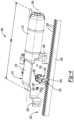
- FIG. 1is a side perspective view of an exemplary seat adjuster drive that has been constructed in accordance with the present disclosure where stationary and sliding tracks of the seat adjuster drive have been shown;
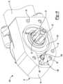
- FIG. 2is an opposite side perspective view of the seat adjuster drive shown in FIG. 1 where the stationary and sliding tracks of the seat adjuster drive have been hidden from view;
- FIG. 3is a side perspective view of another exemplary seat adjuster drive that has been constructed in accordance with the present disclosure where the stationary and sliding tracks of the seat adjuster drive have been shown;
- FIG. 4is an opposite side perspective view of the seat adjuster drive shown in FIG. 3 where the stationary and sliding tracks of the seat adjuster drive have been hidden from view;
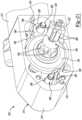
- FIG. 5is a rear elevation view of the seat adjuster drive shown in FIG. 1 ;
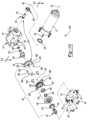
- FIG. 6is an exploded perspective view of the seat adjuster drive shown in FIG. 1 ;
- FIG. 7is an enlarged section view of the seat adjuster drive shown in FIG. 1 , taken along the line 7 - 7 in FIG. 6 ;
- FIG. 8is another enlarged section view of the seat adjuster shown in FIG. 1 , taken along the line 8 - 8 in FIG. 7 ;
- FIG. 9is an enlarged side perspective view of the seat adjuster drive shown in FIG. 1 with the gear box cover removed;
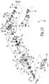
- FIG. 10is an exploded perspective view of another exemplary seat adjuster drive that has been constructed in accordance with the present disclosure.
- FIG. 11is an enlarged section view of the seat adjuster drive shown in FIG. 10 , taken along the line 11 - 11 in FIG. 10 ;
- FIG. 12is another enlarged section view of the seat adjuster shown in FIG. 10 , taken along the line 12 - 12 in FIG. 11 ;
- FIG. 13is an enlarged side perspective view of the seat adjuster drive shown in FIG. 10 with the gear box cover removed;
- FIG. 14is an exploded perspective view of another exemplary seat adjuster drive that has been constructed in accordance with the present disclosure.
- FIG. 15is an enlarged section view of the seat adjuster drive shown in FIG. 14 , taken along the line 15 - 15 in FIG. 14 ;
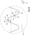
- FIG. 16is another enlarged section view of the seat adjuster shown in FIG. 14 , taken along the line 16 - 16 in FIG. 14 ;
- FIG. 17is an enlarged side perspective view of the seat adjuster drive shown in FIG. 14 with the gear box cover removed;
- FIG. 18is an exploded perspective view of another exemplary seat adjuster drive that has been constructed in accordance with the present disclosure.
- FIG. 19is an enlarged section view of the seat adjuster drive shown in FIG. 18 , taken along the line 19 - 19 in FIG. 18 ;
- FIG. 20is another enlarged section view of the seat adjuster shown in FIG. 18 , taken along the line 20 - 20 in FIG. 18 ;
- FIG. 21is an enlarged side perspective view of the seat adjuster drive shown in FIG. 18 with the gear box cover removed;
- FIG. 22is an enlarged rear elevation view of another exemplary seat adjuster drive that includes a different rack and pinion drive assembly mated to the gear box of the exemplary seat adjuster drive shown in FIG. 5 ;
- FIG. 23is an enlarged side elevation view of the exemplary seat adjuster drive shown in FIG. 22 ;
- FIG. 24is an enlarged rear elevation view of another exemplary seat adjuster drive that includes a different rack and pinion drive assembly mated to the gear box of the exemplary seat adjuster drive shown in FIG. 5 , which includes a two-part rack mesh;
- FIG. 25is an enlarged side elevation view of the exemplary seat adjuster drive shown in FIG. 24 ;
- FIG. 26is an enlarged side elevation view of the two-part rack mesh exemplary seat adjuster drive shown in FIG. 24 ;
- FIG. 27is an enlarged rear elevation view of another exemplary seat adjuster drive that includes a different rack and pinion drive assembly mated to the gear box of the exemplary seat adjuster drive shown in FIG. 5 , which includes a three-part rack mesh;
- FIG. 28is an enlarged side elevation view of the exemplary seat adjuster drive shown in FIG. 27 ;
- FIG. 29is an enlarged side elevation view of the three-part rack mesh exemplary seat adjuster drive shown in FIG. 27 .
- Example embodimentsare provided so that this disclosure will be thorough, and will fully convey the scope to those who are skilled in the art. Numerous specific details are set forth such as examples of specific components, devices, and methods, to provide a thorough understanding of embodiments of the present disclosure. It will be apparent to those skilled in the art that specific details need not be employed, that example embodiments may be embodied in many different forms and that neither should be construed to limit the scope of the disclosure. In some example embodiments, well-known processes, well-known device structures, and well-known technologies are not described in detail.
- first, second, third, etc.may be used herein to describe various elements, components, regions, layers and/or sections, these elements, components, regions, layers and/or sections should not be limited by these terms. These terms may be only used to distinguish one element, component, region, layer or section from another region, layer or section. Terms such as “first,” “second,” and other numerical terms when used herein do not imply a sequence or order unless clearly indicated by the context. Thus, a first element, component, region, layer or section discussed below could be termed a second element, component, region, layer or section without departing from the teachings of the example embodiments.
- Spatially relative termssuch as “inner,” “outer,” “beneath,” “below,” “lower,” “above,” “upper,” and the like, may be used herein for ease of description to describe one element or feature's relationship to another element(s) or feature(s) as illustrated in the figures. Spatially relative terms may be intended to encompass different orientations of the device in use or operation in addition to the orientation depicted in the figures. For example, if the device in the figures is turned over, elements described as “below” or “beneath” other elements or features would then be oriented “above” the other elements or features. Thus, the example term “below” can encompass both an orientation of above and below. The device may be otherwise oriented (rotated 90 degrees or at other orientations) and the spatially relative descriptors used herein interpreted accordingly.
- the automotive seat adjuster drive 100includes an electric motor 12 that is mounted to a gear box 14 .
- the gear box 14includes a gear box housing 16 and a gear box cover 18 .
- a pinion 20extends out of the gear box 14 through the gear box cover 18 .
- the pinion 20includes a gear toothed portion 22 and an optional pinion bearing 24 .
- the gear toothed portion 22 of the pinion 20is arranged in meshing engagement with a rack 26 , which includes a plurality of rack teeth 28 . Together, the pinion 20 and the rack 26 comprise a rack and pinion drive assembly 30 .
- the seat adjuster drive 10also includes a stationary track 32 that is configured to be fixed to a sub-floor 34 of a vehicle (see FIG. 5 ), such as an automobile, and a sliding track 36 that is arranged in sliding engagement with the stationary track 32 for movement in fore and aft directions 38 (i.e., towards the front of the vehicle and towards the rear of the vehicle).
- the stationary track 32includes a bottom wall 40 and first and second side walls 42 , 43 that extend upwardly from the bottom wall 40 to define a track channel 44 that receives at least part of the sliding track 36 .
- the pinion bearing 24is received in a slot 46 in the first side wall 42 of the stationary track 32 , which helps support the pinion 20 and resists pinion deflection.
- FIGS. 5a vehicle
- a sliding track 36that is arranged in sliding engagement with the stationary track 32 for movement in fore and aft directions 38 (i.e., towards the front of the vehicle and towards the rear of the vehicle).
- the stationary track 32includes
- the rack 26 of the rack and pinion drive assembly 30extends longitudinally along the stationary track 32 at a position that is external to the track channel 44 and directly adjacent to the first side wall 42 .
- the gear box 14is mounted to the sliding track 36 by a pair of mounting studs 48 .
- Each of the mounting studs 48includes a fastener 50 that is received inside an outer sleeve 52 .
- Rotational power from the electric motor 12is transferred through the gear box 14 to rotate the pinion 20 , which operates to drive the electric motor 12 , gear box 14 , and sliding track 36 in the fore and aft directions 38 relative to the stationary track 32 .
- the automotive seat adjuster drive 200includes an electric motor 212 that is mounted to a gear box 214 .
- the gear box 214includes a gear box housing 216 and a gear box cover 218 .
- a pinion 220extends out of the gear box 214 through the gear box cover 218 .
- the pinion 220includes a gear toothed portion 222 and an optional pinion bearing 224 .
- the gear toothed portion 222 of the pinion 220is arranged in meshing engagement with a rack 226 , which includes a plurality of rack teeth 228 . Together, the pinion 220 and the rack 226 comprise a rack and pinion drive assembly 230 .
- the seat adjuster drive 200includes a stationary track 232 that is configured to be fixed to the sub-floor 34 of a vehicle, such as an automobile, and a sliding track 236 that is arranged in sliding engagement with the stationary track 232 for movement in fore and aft directions 38 that are arranged parallel to an x-axis 54 of the vehicle (i.e., longitudinal movement towards the front of the vehicle and towards the rear of the vehicle).
- the stationary track 232includes a bottom wall 240 and first and second side walls 242 , 243 that extend upwardly from the bottom wall 240 to define a track channel 244 that receives at least part of the sliding track 236 .
- the pinion bearing 224is received in a slot (not shown) in the second side wall 243 of the stationary track 232 , which helps support the pinion 220 and resists pinion deflection.
- the rack 226 of the rack and pinion drive assembly 230extends longitudinally along the bottom wall 240 of the stationary track 232 at a position that is inside the track channel 244 .
- the pinion 220 in this embodimentis elongated to reach into the track channel 244 .
- a clearance groove 256may be cut into the pinion 220 at a position that is aligned with the first side wall 242 to provide additional clearance between the pinion 220 and the first side wall 242 of the stationary track 232 .
- the gear box cover 218includes a pair of L-shaped flanges 258 that are mounted to the sliding track 236 by a pair of fasteners (not shown).
- rotational power from the electric motor 212is transferred through the gear box 214 to rotate the pinion 220 , which operates to drive the electric motor 212 , gear box 214 , and sliding track 236 in the fore and aft directions 38 relative to the stationary track 232 .
- the rack and pinion drive assemblies 30 , 232allow the seat adjuster drives 100 , 200 disclosed herein to be used in applications requiring long track lengths with seat travel lengths of up to 1200 millimeters in the fore and aft direction 38 .
- Such applicationsmay include, but are not limited to, use of the seat adjuster drives 100 , 200 in vehicles such as vans, mini-vans, sport utility vehicles, and cross-over vehicles.
- the seat adjuster drives 100 , 200are configured such that a vehicle seat (not shown) is mounted to the sliding track 36 , 236 .
- two of the seat adjuster drives 100 of the first embodiment, two of the seat adjuster drives 200 of the second embodiment, or a seat adjuster drive 100 of the first embodiment in combination with the seat adjuster drive 200 of the second embodimentmay be used for each vehicle seat.
- the gear boxes 14 , 214 disclosed hereinallow the electric motors 12 , 212 of the seat adjuster drives 100 , 200 to be mounted longitudinally instead of in a transverse orientation relative to the tracks 32 , 36 , 232 , 236 .
- Each electric motor 12 , 212has a centerline axis 64 , 264 and an overall length 66 , 266 .
- the centerline axis 64 , 264 of each electric motor 12 , 212is parallel to the x-axis 54 of the vehicle and is therefore parallel with the tracks 32 , 36 , 232 , 236 .
- each electric motor 12 , 212is therefore not as critical a packaging constraint as it would be if the electric motors 12 , 212 were mounted in a transverse orientation (i.e., along the y-axis 62 of the vehicle).
- the seat adjuster drives 100 , 200 of the present disclosurecan be equipped with double commutator electric motors 12 , 212 to provide a low speed (i.e., comfort) actuation mode of 11 to 26 millimeters per second and a high speed actuation mode of 45 to 60 millimeters per second.
- Double commutator electric motors 12 , 212typically have longer overall lengths 66 , 266 making them difficult to package between the right and left tracks 32 , 36 , 232 , 236 of the seat adjuster drives 100 , 200 .
- the centerline axis 64 , 264 of the electric motors 12 , 212in the longitudinal direction (i.e., parallel with the x-axis 54 ) instead of in the transverse direction (i.e., parallel with the y-axis 62 )
- the normal packaging constraints limiting the use of double commutator electric motors 12 , 212are eliminated.
- the gear toothed portion 22 , 222 of the pinions 20 , 220may include integrally formed or rigidly connected pinion teeth 68 , 268 that are configured to engage the rack teeth 28 , 228 .
- the number of pinion teeth 68 , 268can significantly affect the electric motor speed required to move the sliding tracks 36 , 236 at a desired rate. For example, in embodiments of the present disclosure where 7 pinion teeth 68 , 268 are provided, electric motor speeds of 3,300 to 4,200 rpm are required to move the sliding tracks 36 , 236 at comfort speeds (15.6 to 20 millimeters per second) and electric motor speeds of 10,000 to 12,700 rpm are required to move the sliding tracks 36 , 236 at high speeds (48 to 61 millimeters per second).
- electric motor speeds of 3,100 to 4,000 rpmare required to move the sliding tracks 36 , 236 at comfort speeds (19.3 to 25 millimeters per second) and electric motor speeds of 7,500 to 9,900 rpm are required to move the sliding tracks 36 , 236 at high speeds (58.6 to 75.4 millimeters per second).
- Vehiclessuch as vans, mini-vans, sport utility vehicles, and cross-over vehicles typically have a passenger compartment 60 with a floor 70 that is relatively flat over large sections of the passenger compartment 60 .
- FIG. 5an end view of the seat adjuster drive 100 shown in FIGS. 1 and 2 is illustrated. It should be appreciated that the end view of the seat adjuster drive 200 shown in FIGS. 3 and 4 would look similar. For this view, it can be appreciated that an overall height 72 of the seat adjuster drive 100 , which extends parallel to z-axis 74 , is small. For example, the illustrated embodiments have an overall height 72 that is less than 50 millimeters.
- the seat adjuster drives 100 , 200 hereincan be installed beneath the floor 70 of the passenger compartment 60 of the vehicle.
- the stationary tracks 32 , 232 , the sliding tracks 36 , 236 , the gear boxes 14 , 214 , and the electric motors 12 , 212 of the seat adjuster drives 100 , 200can be installed under the floor 70 in the space between the floor 70 of the passenger compartment 60 and the sub-floor 34 of the vehicle, which can provide improved safety and aesthetics.
- FIGS. 6 - 9are detailed views of the seat adjuster drive 100 shown in FIGS. 1 and 2 .
- the electric motor 12 and the gear box cover 18are mounted to the gear box housing 16 by screws 76 .
- Locating pins 78may also be provided on the gear box housing 16 to help position the gear box cover 18 in proper alignment with the gear box housing 16 .
- the gear box housing 16 and the gear box cover 18define a gear box cavity 80 inside the gear box 14 .
- the pinion 20includes a pinion shaft 82 that extends through the gear box cover 18 and into the gear box cavity 80 along a pinion shaft axis 84 .
- the pinion shaft 82may be made from a metal such as steel.
- the pinion shaft 82is received in a tubular support 86 formed in the gear box housing 16 opposite the gear box cover 18 in a sliding fit such that the pinion shaft 82 can rotate freely relative to the gear box housing 16 .
- the gear box housing 16 and the gear box cover 18may be made from a variety of different materials.
- the gear box housing 16 and the gear box cover 18may be made from a rigid material such as plastic.
- the gear box cavity 80houses a conical spiral gear set 88 and a planetary gear set 90 .
- the conical spiral gear set 88includes a conical pinion gear 92 and a conical spiral gear 94 , which create a first stage gear reduction.
- the electric motor 12has a motor shaft 96 that is coupled to an output shaft 98 .
- the output shaft 98may be configured in a number of different arrangements, such as a flex shaft.
- the conical pinion gear 92is coupled to the output shaft 98 such that the conical pinion gear 92 is driven by the electric motor 12 and rotates about a conical pinion gear axis 99 .
- the conical pinion gear axis 99is aligned with the centerline axis 64 of the electric motor 12 .
- the conical spiral gear 94is arranged in meshing engagement with the conical pinion gear 92 and is carried on the pinion shaft 82 in a sliding fit. As a result, the conical spiral gear 94 is free to rotate at a different rotational speed than the pinion shaft 82 .
- the conical pinion gear 92has a conical shape, spiral cut gear teeth 102 , and is preferably made of metal.
- the conical spiral gear 94preferably includes a hub portion 104 that is made of powdered metal and a toothed portion 106 that is made of over-molded plastic.
- the toothed portion 106 of the conical spiral gear 94has spiral cut gear teeth 103 and is shaped to mesh with the conical pinion gear 92 . This arrangement allows the conical pinion gear 92 to be driven at high speeds in excess of 10,000 rpm without producing excess noise.
- the conical spiral gear set 88is arranged within the gear box 14 such that the conical pinion gear axis 99 intersects the pinion shaft axis 84 .
- the conical pinion gear axis 99intersects the pinion shaft axis 84 at a perpendicular angle at point A.
- the conical pinion gear axis 99is spaced from and runs parallel to the stationary track 32 and the pinion shaft axis 84 is perpendicular to the stationary track 32 . This configuration reduces the overall height 72 of the seat adjuster drive 100 because there is no offset spacing between the conical pinion gear axis 99 and the pinion shaft axis 84 .
- the conical pinion gear 92is supported within the gear box housing 16 by a ball bearing assembly 108 .
- the ball bearing assembly 108includes an inner race 110 , an outer race 112 , and a plurality of ball bearings 114 positioned radially between the inner and outer races 110 , 112 .
- the inner race 110 of the ball bearing assembly 108extends annularly about and contacts a barrel portion 116 of the conical pinion gear 92 .
- the barrel portion 116includes a terminal end 118 , which is bent in an outward flare during assembly to hold the inner race 110 in place on the barrel portion 116 of the conical pinion gear 92 .
- the outer race 112 of the ball bearing assembly 108abuts a shoulder 120 formed in the gear box housing 16 .
- the outer race 112is held in contact with the shoulder 120 by a star ring 122 , which is press fit into the gear box housing 16 during assembly. These features hold the conical pinion gear 92 and the ball bearing assembly 108 in place and prevent the conical pinion gear 92 from moving axially relative to the output shaft 98 .
- the conical spiral gear 94is held in place by a bushing shim 124 and a spacer ring 126 that extend annularly about the pinion shaft 82 and are positioned between the conical spiral gear 94 and the tubular support 86 of the gear box housing 16 .
- the planetary gear set 90 in the gear box 14rotatably couples the conical spiral gear 94 and the pinion 20 through a second stage gear reduction.
- the planetary gear set 90includes an eccentric lobe 128 that is formed on the hub portion 104 of the conical spiral gear 94 , a first gear 130 with internal teeth 132 that is rotatably coupled to the pinion shaft 82 , and a second gear 134 with external teeth 136 that is carried on and driven by the eccentric lobe 128 .
- the internal teeth 132 of the first gear 130are arranged in meshing engagement with the external teeth 136 of the second gear 134 such that rotation of the second gear 134 drives rotation of the first gear 130 and the pinion shaft 82 .
- the eccentric lobe 128is fixed to and rotates with the conical spiral gear 94 of the conical spiral gear set 88 .
- the eccentric lobe 128may be made from powdered metal.
- the first gear 130 of the planetary gear set 90is rotatably coupled to the pinion shaft 82 .
- the first gear 130may be rotatably coupled to the pinion shaft 82 in a number of different ways, in the illustrated example, the first gear 130 is rotatably coupled to the pinion shaft 82 by splines 138 .
- the eccentric lobe 128has a first bearing surface 140 that is eccentric relative to the pinion shaft axis 84 .
- the first bearing surface 140has a first radius R 1 .
- the second gear 134is rotatably supported on the first bearing surface 140 of the eccentric lobe 128 .
- the second gear 134has a central bore 142 .
- the first bearing surface 140 of the eccentric lobe 128extends through and contacts the central bore 142 of the second gear 134 . There is a slip fit between the first bearing surface 140 of the eccentric lobe 128 and the central bore 142 of the second gear 134 such that the second gear 134 can freely rotate on the first bearing surface 140 of the eccentric lobe 128 .
- the first and second gears 130 , 134are meshingly engaged in a planetary arrangement where the second gear 134 travels in a planetary, wobbling motion within the first gear 130 .
- the internal and external teeth 132 , 136 of the first and second gears 130 , 134may have a cycloid profile.
- the first and second gears 130 , 134may be made of a variety of different materials.
- the first and second gears 130 , 134may be made of metal or powdered metal.
- the hub portion 104 of the conical spiral gear 94has a second bearing surface 144 that is cylindrical and co-axially arranged with the pinion shaft axis 84 .
- the second bearing surface 144has a second radius R 2 that is smaller than the first radius R 1 of the first bearing surface 140 . Due to the size difference between R 1 and R 2 and the eccentric (i.e. off-set) arrangement of the first bearing surface 140 , a hub slot 146 is formed in the hub portion 104 between the toothed portion 106 of the conical spiral gear 94 and the eccentric lobe 128 on which a locking plate 148 is sliding supported and guided. The second bearing surface 144 and thus the hub slot 146 are not aligned with (i.e.
- the locking plate 148is longitudinally offset relative to the internal and external teeth 132 , 136 of the first and second gears 130 , 134 and does not contact or otherwise engage the internal or external teeth 132 , 136 of the first and second gears 130 , 134 .
- the first bearing surface 140 of the eccentric lobe 128may have an inset region (not shown) in the form of an arc-shaped cut-out to reduce the surface area of the first bearing surface 140 and minimize friction.
- the second gear 134has first and second pins 150 , 151 that extend longitudinally (i.e. parallel to the pinion shaft axis 84 ) from the second gear 134 .
- the first and second pins 150 , 151are cylindrical in shape and are rigidly connected to one of the side faces of the second gear 134 .
- the locking plate 148has a fork-like shape and can be made from a variety of different materials. By way of example and without limitation, the locking plate 148 may be made of stamped steel.
- the locking plate 148is transverse to the pinion shaft axis 84 .
- the locking plate 148has four slot cutouts 152 , 154 , 156 , 157 .
- the first slot cutout 152is rectangular in shape and is closed on all four sides.
- the second, third, and fourth slot cutouts 154 , 156 , 157have U-like shapes and are open on one side.
- a support pin 158is rigidly fixed to the gear box housing 16 .
- the support pin 158is spaced from and extends parallel to the pinion shaft axis 84 .
- the locking plate 148is supported on and guided by the first and second pins 150 , 151 on the second gear 134 , the support pin 158 , and the second bearing surface 144 of the hub portion 104 .
- the support pin 158is received in and extends through the first slot cutout 152 in the locking plate 148 .
- the second slot cutout 154 in the locking plate 148bears against the second bearing surface 144 of the hub portion 104 .
- the first and second pins 150 , 151 on the second gear 134are received in and extend through the third and fourth slot cutouts 156 , 157 in the locking plate 148 , respectively.
- the interfaces between the first and second pins 150 , 151 on the second gear 134 and the third and fourth slot cutouts 156 , 157 in the locking plate 148restrict the movement of the second gear 134 to a planetary, wobbling motion and prevent the second gear 134 from rotating 360 degrees.
- the interaction between the locking plate 148 and the first and second pins 150 , 151 on the second gear 134 , the support pin 158 , and the second bearing surface 144 of the hub portion 104also prevent the pinion shaft 82 from rotating in either direction (i.e. clockwise or counter-clockwise) when the conical spiral gear 94 is not being driven by the conical pinion gear 92 and therefore provides anti-back drive capability.
- a first roller sleeve 160may be fitted over the support pin 158 .
- second and third roller sleeves 162 , 163may optionally be fitted over the first and second pins 150 , 151 on the second gear 134 .
- the first, second, and third roller sleeves 160 , 162 , 163may be sized to provide a slip fit between the support pin 158 and the first roller sleeve 160 and between the first and second pins 150 , 151 on the second gear 134 and the second and third roller sleeves 162 , 163 such that the first, second, and third roller sleeves 160 , 162 , 163 may be free to rotate on the support pin 158 and the first and second pins 150 , 151 on the second gear 134 .
- the first support pin 164may optionally include knurled end 166 that is pressed into the gear box housing 16 such that the first support pin 164 is fixed and does not rotate relative to the gear box housing 16 .
- An opposite end 168 of the first support pin 164extends through the gear box cover 18 .
- the first roller sleeve 160may include a barrel 170 and a flange portion 172 and a thin metal shim 174 may be arranged between the flange portion 172 of the first roller sleeve 160 and the gear box housing 16 . This arrangement therefore reduces friction losses, wear, and noise during operation of the seat adjuster drive 100 .
- first, second, and third roller sleeves 160 , 162 , 163may be made of a variety of different materials, in one non-limiting example, the first, second, and third roller sleeves 160 , 162 , 163 are made from a self-lubricated plastic material or from a plastic material resistant to high temperature such as PEEK.
- first, third, and fourth slot cutouts 152 , 154 , 156 , 157 in the locking plate 148may be covered by self-lubricated plastic sleeves (not shown) while the support pin 158 and the first and second pins 150 , 151 on the second gear 134 slide along the self-lubricated plastic sleeves with or without the use of the first, second, and third roller sleeves 160 , 162 , 163 .
- first, second, and third roller sleeves 160 , 162 , 163 or some other alternativeare utilized, it should be appreciated that the geometry of the support pin 158 and the first and second pins 150 , 151 on the second gear 134 significantly reduces friction losses.
- the cylindrical shape of the support pin 158 and the first and second pins 150 , 151 on the second gear 134minimizes the contact area between the support pin 158 and the first slot cutout 152 and between the first and second pins 150 , 151 on the second gear 134 and the third and fourth slot cutouts 156 , 157 in the locking plate 148 to either line or point contacts. This improves the mechanical efficiency of the gear box 14 .
- the interfaces between the locking plate 148 , the first and second pins 150 , 151 on the second gear 134 , the support pin 158 , and the second bearing surface 144 of the eccentric lobe 128synchronize the reciprocating motion of the locking plate 148 with the planetary, wobbling motion of the second gear 134 .
- the planetary, wobbling motion of the second gear 134follows a circular path where the external teeth 136 of the second gear 134 mesh with the internal teeth 132 of the first gear 130 , forcing the first gear 130 and therefore the pinion shaft 82 to rotate with a uniform rotational speed about the pinion shaft axis 84 in the same direction of rotation as the direction of rotation of the eccentric lobe 128 .
- the planetary gear set 90has only one, single-stage of gear reduction, which is the gear reduction between the first gear 130 and the second gear 134 .
- the planetary gear set 90has a gear ratio (a reduction ratio) that is dictated by the difference between the number of internal teeth 132 on the first gear 130 and the number of external teeth 136 on the second gear 134 .
- the gear ratio of the planetary gear set 90is defined by Equation 1 below:
- Gear ⁇ ⁇ Ratio+ N 2 N 2 - N 1 ( Equation ⁇ ⁇ 1 )
- N 1is the number of external teeth 136 on the second gear 134
- N 2is the number of internal teeth 132 on the first gear 130 .
- the gear ratio of the planetary gear set 90is a positive number, indicating that the direction of rotation at the pinion 20 is the same as the direction of rotation that the eccentric lobe 128 is being driven in by the electric motor 12 .
- a spring plate assembly 178is provided on the pinion shaft 82 longitudinally between the eccentric lobe 128 and the first gear 130 .
- the spring plate assembly 178includes a washer cup 180 and an O-ring 182 .
- the O-ring 182is made of a resilient material, such as rubber, which can expand and compress to dampen small longitudinal movements of the conical spiral gear 94 on the pinion shaft 82 .
- a bearing sleeve 176is positioned on the opposite side of the first gear 130 and radially between a portion of the first gear 130 and the gear box cover 18 .
- the bearing sleeve 176is made from a low-friction material such as a self-lubricated plastic material and therefore permits the first gear 130 to rotate within the gear box cavity 80 with minimal wear to the gear box cover 18 .
- any attempt of the first gear 130 to back-drive the second gear 134 due to an external torque load acting on the pinion 20is prevented through a reaction moment created by contact forces acting between the first slot cutout 152 of the locking plate 148 and the support pin 158 , the second slot cutout 154 and the second bearing surface 144 of the hub portion 104 , and the third and fourth slot cutouts 156 , 157 of the locking plate 148 and the first and second pins 150 , 151 of the second gear 134 .
- FIGS. 10 - 13illustrate another seat adjuster drive 100 ′ that shares many of the same components as the seat adjuster drive 100 shown in FIGS. 6 - 9 .
- Components shared between these two embodimentshave like reference numbers, while the components that are different in the seat adjuster drive 100 ′ shown in FIGS. 10 - 13 are designated with an apostrophe (′) after the reference number.
- ′apostrophe
- the seat adjuster drive 100 ′includes first and second support pins 164 ′, 165 ′ that are fixed relative to gear box housing 16 ′ of gear box 14 ′.
- the first and second support pins 164 ′, 165 ′are spaced from and extend parallel to the pinion shaft axis 84 .
- the first support pin 164 ′extends between a first support pin end 186 ′ and a second support pin end 188 ′.
- the second support pin 165 ′extends between a third support pin end 190 ′ and a fourth support pin end 192 ′.
- the first and second support pins 164 ′, 165 ′are rigidly fixed within the gear box housing 16 ′ at the first and third support pin ends 186 ′, 190 ′ and are rigidly fixed within holes 194 ′ in the gear box cover 18 ′ at the second and fourth support pin ends 188 ′, 192 ′.
- Second gear 134 ′includes an external flange 196 ′ that is provided with first and second guide holes 198 ′, 199 ′.
- the external flange 196 ′extends outwardly from the external teeth 136 ′ of the second gear 134 ′ in a plane that is transverse to the pinion shaft axis 84 .
- the external flange 196 ′may be integrally formed as part of the second gear 134 ′ or may be a separately formed component that is rotatably fixed to the part of the second gear 134 ′ that includes the external teeth 136 ′.
- the first and second guide holes 198 ′, 199 ′extend through the external flange 196 ′ of the second gear 134 ′.
- the first and second support pins 164 ′, 165 ′are received in and extend through the first and second guide holes 198 ′, 199 ′ in the external flange 196 ′ of the second gear 134 ′, respectively.
- the first and second guide holes 198 ′, 199 ′have first and second guide hole radii and the first and second support pins 164 ′, 165 ′ have first and second support pin radii that are smaller than the first and second guide hole radii.
- the first guide hole radiusmay equal the sum of the first support pin radius and the eccentricity of the eccentric lobe 128 and the second guide hole radius may equal the sum of the second support pin radius and the eccentricity eccentric lobe 128 .
- the size relationship between the first and second guide hole radii and the first and second support pin radiipermits the second gear 134 ′ to move freely in a planetary, wobbling movement relative to the pinion shaft axis 84 when the eccentric lobe 128 is rotatably driven.
- contact between the first bearing surface 140 of the eccentric lobe 128 and the second gear 134 ′, the first support pin 164 ′ and the first guide hole 198 ′ in the external flange 196 ′, and the second support pin 184 ′ and the second guide hole 199 ′ in the external flange 196 ′prevents the first gear 130 from back-driving rotation of the second gear 134 ′.
- the first and second support pins 164 ′, 165 ′ and the first and second guide holes 198 ′, 199 ′ of the external flange 196 ′form two crank-rocker type parallelogram mechanisms about the pinion shaft axis 84 .
- the interfaces between the first and second support pins 164 ′, 165 ′ on the second gear 134 ′ and the first and second guide holes 198 ′, 199 ′ in the external flange 196 ′restrict the movement of the second gear 134 ′ to a planetary, wobbling motion and prevent the second gear 134 ′ from rotating 360 degrees.
- first and second support pins 164 ′, 165 ′ and the first and second guide holes 198 ′, 199 ′ in the external flange 196 ′ of the second gear 134 ′ and the interaction of the first bearing surface 140 of the eccentric lobe 128 and the second gear 134 ′prevents the pinion shaft 82 from rotating in either direction (i.e. clockwise or counter-clockwise) when the eccentric lobe 128 is not being driven by the electric motor 12 and therefore provides anti-back drive capability.
- first and second roller sleeves 160 ′, 162 ′may be fitted over the first and second support pins 164 ′, 165 ′.
- the first and second roller sleeves 160 ′, 162 ′may be sized to provide a slip fit between the first and second support pins 164 ′, 165 ′ and the first and second roller sleeves 160 ′, 162 ′ such that the first and second roller sleeves 160 ′, 162 ′ are free to rotate on the first and second support pins 164 ′, 165 ′.
- This arrangementtherefore reduces friction losses, wear, and noise during operation of the seat adjuster drive 100 ′.
- first and second roller sleeves 160 ′, 162 ′may be made of a variety of different materials, in one non-limiting example, the first and second roller sleeves 160 ′, 162 ′ are made from a self-lubricated plastic material or from a plastic material resistant to high temperature such as PEEK.
- first and second guide holes 198 ′, 199 ′ in the external flange 196 ′ of the second gear 134 ′may be covered by self-lubricated plastic sleeves (not shown) while the first and second support pins 164 ′, 165 ′ slide along the self-lubricated plastic sleeves with or without the use of the first and second roller sleeves 160 ′, 162 ′.
- first and second roller sleeves 160 ′, 162 ′Regardless of whether the first and second roller sleeves 160 ′, 162 ′ or some other alternative are utilized, it should be appreciated that the geometry of the first and second support pins 164 ′, 165 ′ and the first and second guide holes 198 ′, 199 ′ in the external flange 196 ′ of the second gear 134 ′ significantly reduces friction losses.
- the cylindrical shape of the first and second support pins 164 ′, 165 ′minimizes the contact area between the first and second support pins 164 ′, 165 ′ and the first and second guide holes 198 ′, 199 ′ to either line or point contacts. This results in improved mechanical efficiency.
- the second gear 134 ′moves in a planetary, wobbling motion within gear box cavity 80 ′ along a circular eccentric path where the second gear 134 ′ does not rotate about its own centerline.
- the external teeth 136 ′ of the second gear 134 ′mesh with the internal teeth 132 of the first gear 130 , forcing the first gear 130 and the pinion shaft 82 to rotate with an uniform rotational speed about the pinion shaft axis 84 in the same direction of rotation as the direction of rotation of the eccentric lobe 128 .
- the second gear 134 ′is held on its eccentric path relative to the pinion shaft axis 84 through the engagement of the external teeth 136 ′ of the second gear 134 ′ with the internal teeth 132 of the first gear 130 .
- FIGS. 14 - 17are detailed views of the seat adjuster drive 200 shown in FIGS. 3 and 4 .
- the gear box 214 of the seat adjuster drive 200includes a gear box housing 216 .
- the gear box housing 216may be made from a rigid material such as plastic.
- the electric motor 212 and the gear box cover 218are mounted to the gear box housing 216 by screws 276 .
- Locating pins 278may also be provided on the gear box housing 216 to help position the gear box cover 218 in proper alignment with the gear box housing 216 .
- the gear box housing 216 and the gear box cover 218define a gear box cavity 280 inside the gear box 214 .
- the pinion 220includes a pinion shaft 282 that extends through the gear box cover 218 and into the gear box cavity 280 along a pinion shaft axis 284 .
- the pinion shaft 282may be made from a metal such as steel.
- the pinion shaft 282is received in a tubular support 286 formed in the gear box housing 216 opposite the gear box cover 218 in a sliding fit such that the pinion shaft 282 can rotate freely relative to the gear box housing 216 .
- the gear box cavity 280houses a conical spiral gear set 288 , a first planetary gear set 290 , and a second planetary gear set 291 .
- the conical spiral gear set 288includes a conical pinion gear 292 and a conical spiral gear 294 , which provides a first stage gear reduction.
- the electric motor 212has a motor shaft 296 that is coupled to an output shaft 298 .
- the conical pinion gear 292is coupled to the output shaft 298 such that the conical pinion gear 292 is driven by the electric motor 212 and rotates about a conical pinion gear axis 299 .
- the conical pinion gear axis 299is aligned with the centerline axis 264 of the electric motor 212 .
- the conical spiral gear 294is arranged in meshing engagement with the conical pinion gear 292 and is carried on the pinion shaft 282 in a sliding fit. As a result, the conical spiral gear 294 is free to rotate at a different rotational speed than the pinion shaft 282 .
- the conical pinion gear 292has a conical shape, spiral cut gear teeth 302 , and is preferably made of metal.
- the conical spiral gear 294preferably includes a hub portion 304 that is made of powered metal and a toothed portion 306 that is made of over-molded plastic.
- the toothed portion 306 of the conical spiral gear 294has spiral cut gear teeth 303 and is shaped to mesh with the conical pinion gear 292 . This arrangement allows the conical pinion gear 292 to be driven at high speeds in excess of 10,000 rpm without producing excess noise.
- the conical spiral gear set 288is arranged within the gear box 214 such that the conical pinion gear axis 299 intersects the pinion shaft axis 284 .
- the conical pinion gear axis 299intersects the pinion shaft axis 284 at a perpendicular angle at point B.
- the conical pinion gear axis 299is spaced from and runs parallel to the stationary track 232 and the pinion shaft axis 284 is perpendicular to the stationary track 232 . This configuration reduces the overall height 72 of the seat adjuster drive 200 because there is no offset spacing between the conical pinion gear axis 299 and the pinion shaft axis 284 .
- the conical pinion gear 292is supported within the gear box housing 216 by two ball bearing assemblies 308 , 309 and a cassette 204 .
- Each ball bearing assembly 308 , 309includes an inner race 310 , an outer race 312 , and a plurality of ball bearings 314 positioned radially between the inner and outer races 310 , 312 .
- the inner races 310 of the ball bearing assemblies 308 , 309extend annularly about and contact a barrel portion 316 of the conical pinion gear 292 .
- the outer races 312 of the ball bearing assemblies 308 , 309contact the cassette 204 , which holds the outer races 312 and therefore the ball bearing assemblies 308 , 309 in a spaced apart relationship within the gear box housing 216 .
- the cassette 204is held in the gear box housing 216 by a star ring 322 , which is press fit into the gear box housing 216 during assembly. These features hold the conical pinion gear 292 in place and prevent the conical pinion gear 292 from moving axially relative to the output shaft 298 .
- the conical spiral gear 294is held in place by a bushing shim 324 and a metal ring 326 that extend annularly about the pinion shaft 282 and are positioned between the conical spiral gear 294 and the tubular support 286 in the gear box housing 216 .
- the first and second planetary gear sets 290 , 291 in the gear box 214rotatably couple the conical spiral gear 294 and the pinion 220 through a second stage gear reduction and a third stage gear reduction.
- the first planetary gear set 290includes an eccentric lobe 328 , a first gear 330 with internal teeth 332 that is rotatably coupled to the pinion shaft 282 , and a second gear 334 with external teeth 336 that is carried on and driven by the eccentric lobe 328 .
- the internal teeth 332 of the first gear 330are arranged in meshing engagement with the external teeth 336 of the second gear 334 such that rotation of the second gear 334 drives rotation of the first gear 330 and the pinion shaft 282 .
- the first gear 330is rotatably coupled to the pinion shaft 282 by splines 338 .
- the eccentric lobe 328has a first bearing surface 340 that is eccentric relative to the pinion shaft axis 284 .
- the first bearing surface 340has a first radius R 1 .
- the second gear 334is rotatably supported on the first bearing surface 340 of the eccentric lobe 328 .
- the second gear 334has a central bore 342 .
- the first bearing surface 340 of the eccentric lobe 328extends through and contacts the central bore 342 of the second gear 334 .
- the first and second gears 330 , 334are meshingly engaged in a planetary arrangement where the second gear 334 travels in a planetary, wobbling motion within the first gear 330 .
- the internal and external teeth 332 , 336 of the first and second gears 330 , 334may have a cycloid profile.
- the first and second gears 330 , 334may be made of a variety of different materials.
- the first and second gears 330 , 334may be made of metal or powdered metal.
- the second planetary gear set 291includes a sun gear 206 , a ring gear 208 , and a plurality of planet gears 210 .
- the sun gear 206that is fixed to and rotates with the conical spiral gear 294 of the conical spiral gear set 288 . More specifically, the sun gear 206 is formed in the hub portion 304 and is therefore made of powdered metal in the illustrated embodiment.
- the ring gear 208is fixed to the gear box housing 216 by one or more fasteners 250 .
- the ring gear 208has an outer perimeter 211 with a non-circular shape.
- the fasteners 250together with the complimentary, non-cylindrical shape of the gear box cavity 280 prevent the ring gear 208 from rotating within the gear box housing 216 .
- the gear box housing 216may include one or more centering ramps 213 that help to properly center the ring gear 208 in the gear box housing 216 during assembly of the gear box 214 .
- the planet gears 210are disposed radially between and arranged in meshing engagement with the sun gear 206 and the ring gear 208 .
- the planet gears 210are supported on a carrier 215 that is fixed to and rotates with the eccentric lobe 328 of the first planetary gear set 290 .
- the carrier 215includes a plurality of pins 217 .
- the planet gears 210are carried on and rotate about these pins 217 . When the sun gear 206 rotates, the planet gears 210 travel around inside the ring gear 208 in a circular path, which causes the carrier 215 to rotate and therefore drives rotation of the eccentric lobe 328 .
- the carrier 215has a second bearing surface 344 that is cylindrical and co-axially arranged with the pinion shaft axis 284 .
- the second bearing surface 344has a second radius R 2 that is smaller than the first radius R 1 of the first bearing surface 340 . Due to the size difference between R 1 and R 2 and the eccentric (i.e. off-set) arrangement of the first bearing surface 340 , a hub slot 346 is formed in the carrier 215 on which a locking plate 348 is sliding supported and guided.
- the second bearing surface 344 and thus the hub slot 346are not aligned with (i.e. are longitudinally offset relative to) the internal and external teeth 332 , 336 of the first and second gears 330 , 334 .
- the locking plate 348is longitudinally offset relative to the internal and external teeth 332 , 336 of the first and second gears 330 , 334 and does not contact or otherwise engage the internal or external teeth 332 , 336 of the first and second gears 330 , 334 .
- the first bearing surface 340 of the eccentric lobe 328made have an inset region (not shown) that extends in an arc-shape reduce the surface area of the first bearing surface 340 and minimize friction.
- the second gear 334has first and second pins 350 , 351 that extend longitudinally (i.e. parallel to the pinion shaft axis 284 ) from the second gear 334 .
- the first and second pins 350 , 351are cylindrical in shape and are rigidly connected to one of the side faces of the second gear 334 .
- the locking plate 348has a fork-like shape and can be made from a variety of different materials. By way of example and without limitation, the locking plate 348 may be made of stamped steel.
- the locking plate 348is transverse to the pinion shaft axis 284 .
- the locking plate 348has four slot cutouts 352 , 354 , 356 , 357 .
- the first slot cutout 352is rectangular in shape and is closed on all four sides.
- the second, third, and fourth slot cutouts 354 , 356 , 357have U-like shapes and are open on one side.
- a support pin 358is rigidly fixed to the gear box housing 216 .
- the support pin 358is spaced from and extends parallel to the pinion shaft axis 284 .
- the locking plate 348is supported on and guided by the first and second pins 350 , 351 on the second gear 334 , the support pin 358 , and the second bearing surface 344 of the carrier 215 .
- the support pin 358is received in and extends through the first slot cutout 352 in the locking plate 348 .
- the second slot cutout 354 in the locking plate 348bears against the second bearing surface 344 of the carrier 215 .
- the interfaces between the support pin 358 and the first slot cutout 352 and the second bearing surface 344 of the carrier 215 and the second slot cutout 354restrict the locking plate 348 to a limited range of movement.
- the first and second pins 350 , 351 on the second gear 334are received in and extend through the third and fourth slot cutouts 356 , 357 in the locking plate 348 , respectively.
- the interfaces between the first and second pins 350 , 351 on the second gear 334 and the third and fourth slot cutouts 356 , 357 in the locking plate 348restrict the movement of the second gear 334 to a planetary, wobbling motion and prevent the second gear 334 from rotating degrees.
- the interaction between the locking plate 348 and the first and second pins 350 , 351 on the second gear 334 , the support pin 358 , and the second bearing surface 344 of the carrier 215also prevent the pinion shaft 282 from rotating in either direction (i.e. clockwise or counter-clockwise) when the conical spiral gear 294 is not being driven by the conical pinion gear 292 and therefore provides anti-back drive capability.
- a first roller sleeve 360may be fitted over the support pin 358 .
- second and third roller sleeves 362 , 363may optionally be fitted over the first and second pins 350 , 351 on the second gear 334 .
- the first, second, and third roller sleeves 360 , 362 , 363may be sized to provide a slip fit between the support pin 358 and the first roller sleeve 360 and between the first and second pins 350 , 351 on the second gear 334 and the second and third roller sleeves 362 , 363 such that the first, second, and third roller sleeves 360 , 362 , 363 may be free to rotate on the support pin 358 and the first and second pins 350 , 351 on the second gear 334 .
- the first support pin 364may optionally include knurled end 366 that is pressed into the gear box housing 216 such that the first support pin 364 is fixed and does not rotate relative to the gear box housing 216 .
- An opposite end 368 of the first support pin 364extends through the gear box cover 218 .
- the first roller sleeve 360may include a barrel 370 and a flange portion 372 and a thin metal shim 374 may be arranged between the flange portion 372 of the first roller sleeve 360 and the gear box housing 216 . This arrangement therefore reduces friction losses, wear, and noise during operation of the seat adjuster drive 200 .
- first, second, and third roller sleeves 360 , 362 , 363may be made of a variety of different materials, in one non-limiting example, the first, second, and third roller sleeves 360 , 362 , 363 are made from a self-lubricated plastic material or from a plastic material resistant to high temperature such as PEEK.
- first, third, and fourth slot cutouts 352 , 354 , 356 , 357 in the locking plate 348may be covered by self-lubricated plastic sleeves (not shown) while the support pin 358 and the first and second pins 350 , 351 on the second gear 334 slide along the self-lubricated plastic sleeves with or without the use of the first, second, and third roller sleeves 360 , 362 , 363 .
- first, second, and third roller sleeves 360 , 362 , 363 or some other alternativeis utilized, it should be appreciated that the geometry of the support pin 358 and the first and second pins 350 , 351 on the second gear 334 significantly reduces friction losses.
- the cylindrical shape of the support pin 358 and the first and second pins 350 , 351 on the second gear 334minimizes the contact area between the support pin 358 and the first slot cutout 352 and between the first and second pins 350 , 351 on the second gear 334 and the third and fourth slot cutouts 356 , 357 in the locking plate 348 to either line or point contacts. This improves the mechanical efficiency of the gear box 214 .
- the interfaces between the locking plate 348 , the first and second pins 350 , 351 on the second gear 334 , the support pin 358 , and the second bearing surface 344 of the carrier 215synchronize the reciprocating motion of the locking plate 348 with the planetary, wobbling motion of the second gear 334 .
- the planetary, wobbling motion of the second gear 334follows a circular path where the external teeth 336 of the second gear 334 mesh with the internal teeth 332 of the first gear 330 , forcing the first gear 330 and therefore the pinion shaft 282 to rotate with a uniform rotational speed about the pinion shaft axis 284 in the same direction of rotation as the direction of rotation of the eccentric lobe 328 .
- a spring plate assembly 378is provided on the pinion shaft 282 longitudinally between the eccentric lobe 328 and the first gear 330 .
- the spring plate assembly 378includes a washer cup 380 and an O-ring 382 .
- the O-ring 382is made of a resilient material, such as rubber, which can expand and compress to dampen small longitudinal movements of the conical spiral gear 294 on the pinion shaft 282 .
- a bearing sleeve 376is positioned on the opposite side of the first gear 330 and radially between a portion of the first gear 330 and the gear box cover 218 .
- the bearing sleeve 376is made from a low-friction material such as a self-lubricated plastic material and therefore permits the first gear 330 to rotate within the gear box cavity 280 with minimal wear to the gear box cover 218 .
- FIGS. 18 - 21illustrate another seat adjuster drive 200 ′ that shares many of the same components as the seat adjuster drive 200 shown in FIGS. 14 - 17 .
- Components shared between these two embodimentshave like reference numbers, while the components that are different in the seat adjuster drive 200 ′ shown in FIGS. 18 - 21 are designated with an apostrophe (′) after the reference number.
- the description set forth aboveapplies equally to all components shared between the seat adjuster drive 200 shown in FIGS. 14 - 17 and the seat adjuster drive 200 ′ shown in FIGS. 18 - 21 ; however, in the later, the locking plate 348 has been eliminated.
- the seat adjuster drive 200 ′includes first and second support pins 364 ′, 365 ′ that are fixed relative to gear box housing 216 ′ of gear box 214 ′.
- the first and second support pins 364 ′, 365 ′are spaced from and extend parallel to the pinion shaft axis 284 .
- the first support pin 364 ′extends between a first support pin end 386 ′ and a second support pin end 388 ′.
- the second support pin 365 ′extends between a third support pin end 390 ′ and a fourth support pin end 392 ′.
- the first and second support pins 364 ′, 365 ′are rigidly fixed within the gear box housing 216 at the first and third support pin ends 386 ′, 390 ′ and are rigidly fixed within holes 394 ′ in the gear box cover 218 ′ at the second and fourth support pin ends 388 ′, 392 ′.
- Second gear 334 ′includes an external flange 396 ′ that is provided with first and second guide holes 398 ′, 399 ′.
- the external flange 396 ′extends outwardly from the external teeth 336 ′ of the second gear 334 ′ in a plane that is transverse to the pinion shaft axis 284 .
- the external flange 396 ′may be integrally formed as part of the second gear 334 ′ or may be a separately formed component that is rotatably fixed to the part of the second gear 334 ′ that includes the external teeth 336 ′.
- the first and second guide holes 398 ′, 399 ′extend through the external flange 396 ′ of the second gear 334 ′.
- the first and second support pins 364 ′, 365 ′are received in and extend through the first and second guide holes 398 ′, 399 ′ in the external flange 396 ′ of the second gear 334 ′, respectively.
- the first and second guide holes 398 ′, 399 ′have first and second guide hole radii and the first and second support pins 364 ′, 365 ′ have first and second support pin radii that are smaller than the first and second guide hole radii.
- the first guide hole radiusmay equal the sum of the first support pin radius and the eccentricity of the eccentric lobe 328 and the second guide hole radius may equal the sum of the second support pin radius and the eccentricity eccentric lobe 328 .
- the size relationship between the first and second guide hole radii and the first and second support pin radiipermits the second gear 334 ′ to move freely in a planetary, wobbling movement relative to the pinion shaft axis 284 when the eccentric lobe 328 is rotatably driven.
- contact between the first bearing surface 340 of the eccentric lobe 328 and the second gear 334 ′, the first support pin 364 ′ and the first guide hole 398 ′ in the external flange 396 ′, and the second support pin 365 ′ and the second guide hole 399 ′ in the external flange 396 ′prevents the first gear 330 from back-driving rotation of the second gear 334 .
- the first and second support pins 364 ′, 365 ′ and the first and second guide holes 398 ′, 399 ′ of the external flange 396 ′form two crank-rocker type parallelogram mechanisms about the pinion shaft axis 284 .
- the interfaces between the first and second support pins 364 ′, 365 ′ on the second gear 334 and the first and second guide holes 398 ′, 399 ′ in the external flange 396 ′restrict the movement of the second gear 334 to a planetary, wobbling motion and prevent the second gear 334 from rotating 360 degrees.
- first and second support pins 364 ′, 365 ′ and the first and second guide holes 398 ′, 399 ′ in the external flange 396 ′ of the second gear 334 and the interaction of the first bearing surface 340 of the eccentric lobe 328 and the second gear 334 ′prevents the pinion shaft 282 from rotating in either direction (i.e. clockwise or counter-clockwise) when the eccentric lobe 328 is not being driven by the electric motor 212 and therefore provides anti-back drive capability.
- first and second roller sleeves 360 ′, 362 ′may be fitted over the first and second support pins 364 ′, 365 ′.
- the first and second roller sleeves 360 ′, 362 ′may be sized to provide a slip fit between the first and second support pins 364 ′, 365 ′ and the first and second roller sleeves 360 ′, 362 ′ such that the first and second roller sleeves 360 ′, 362 ′ are free to rotate on the first and second support pins 364 ′, 365 ′.
- This arrangementtherefore reduces friction losses, wear, and noise during operation of the seat adjuster drive 200 ′.
- first and second roller sleeves 360 ′, 362 ′may be made of a variety of different materials, in one non-limiting example, the first and second roller sleeves 360 ′, 362 ′ are made from a self-lubricated plastic material or from a plastic material resistant to high temperature such as PEEK.
- first and second guide holes 398 ′, 399 ′ in the external flange 396 ′ of the second gear 334 ′may be covered by self-lubricated plastic sleeves (not shown) while the first and second support pins 364 ′, 365 ′ slide along the self-lubricated plastic sleeves with or without the use of the first and second roller sleeves 360 ′, 362 ′.
- first and second roller sleeves 360 ′, 362 ′ or some other alternativeare utilized, it should be appreciated that the geometry of the first and second support pins 364 ′, 365 ′ and the first and second guide holes 398 ′, 399 ′ in the external flange 396 ′ of the second gear 334 ′ significantly reduces friction losses.
- the cylindrical shape of the first and second support pins 364 ′, 365 ′minimizes the contact area between the first and second support pins 364 ′, 365 ′ and the first and second guide holes 398 ′, 399 ′ to either line or point contacts. This results in improved mechanical efficiency.
- the second gear 334 ′moves in a planetary, wobbling motion within gear box cavity 280 ′ along a circular eccentric path where the second gear 334 ′ does not rotate about its own centerline.
- the external teeth 336 ′ of the second gear 334 ′mesh with the internal teeth 332 of the first gear 330 , forcing the first gear 330 and the pinion shaft 282 to rotate with an uniform rotational speed about the pinion shaft axis 284 in the same direction of rotation as the direction of rotation of the eccentric lobe 328 .
- the second gear 334 ′is held on its eccentric path relative to the pinion shaft axis 284 through the engagement of the external teeth 336 ′ of the second gear 334 ′ with the internal teeth 332 of the first gear 330 .
- the mesh between the teeth of output pinion 20 , 220 and rack 26 , 226are designed with some amount of backlash, in order to prevent possible flank interferences due to deviation from ideal geometries, unfavourable deformations and temperature effects while in operation.
- the amount of backlashis required to be as small as possible, or ideally, zero-backlash.
- Such applicationsrequire very precisely manufactured components and an accurate assembly process, which can result in a relatively high cost.
- a zero-backlash gear systemis a gear pair that has a double-flank action.
- a double-flank action gear systemis typically mounted with an initial pre-stress and such a system only works properly if the pre-stress is small and controllable. If the pre-stress is significant and/or fluctuating, adverse functional consequences can be expected. For example, excessive or fluctuating pre-stress can result in the following problems: mesh noise caused by excessive variation of the sliding friction, excessive wear on gear components teeth, possible mesh interferences, and even the jam of components.
- FIGS. 22 and 23illustrate an alternative seat adjuster drive 400 , which is similar to the seat adjuster drive assemblies 100 , 100 ′, 200 , 200 ′ shown in FIGS. 1 - 21 , but includes a different rack and pinion drive assembly 430 that provides minimal or zero backlash.
- the rack and pinion drive assembly 430includes a pinion 420 mounted on the pinion bearing 24 .
- the pinion 420is a conical involute-type pinion that includes pinion teeth 468 that form a teeth pitch cone 470 that is arranged at an inclined angle ⁇ relative to the pinion shaft axis 84 .
- the pinion teeth 468are arranged in meshing engagement with a rack 426 .
- the rack 426has regular involute rack teeth 428 that are inclined at the same angle ⁇ relative to a rack base surface 429 , which is in a plane that is parallel to the pinion shaft axis 84 .
- the teeth pitch cone 470is defined by the line contacts, at the mesh points, between the pinion teeth 468 and the rack teeth 428 .
- the resulting rack and pinion drive assembly 430combines all benefits provided by a conical involute gear system, capable of double-flank action, with this simple assembly process.
- the rack and pinion drive assembly 430is capable of easily handling the large loads and torques encountered in vehicle seat applications and can fit into a very compact packaging space.
- FIGS. 24 - 26illustrate another alternative seat adjuster drive 500 , which is similar to the seat adjuster drive assemblies 100 , 100 ′, 200 , 200 ′ shown in FIGS. 1 - 21 , but includes a different rack and pinion drive assembly 530 that provides minimal or zero backlash.
- the rack and pinion drive assembly 530includes a pinion 520 mounted on the pinion bearing 24 .
- the pinion 520is a cylindrical involute-type pinion that includes pinion teeth 568 .
- the pinion teeth 568are arranged in meshing engagement with a rack 526 .
- the rack 526has regular involute rack teeth 528 .
- the pinion teeth 568 and the rack teeth 528are arranged in a meshing engagement where the line contacts 570 , at the mesh points, between the pinion teeth 568 and the rack teeth 528 are parallel to the pinion shaft axis 84 .
- the rack 526is a two-part assembly comprising a first rack part 527 a that defines a first set of teeth profiles 529 a and a second rack part 527 b that defines a second set of teeth profiles 529 b .
- the first and second rack parts 527 a , 527 bare arranged such that the first set of teeth profiles 529 a of the first rack part 527 a are slightly offset relative to the second set of teeth profiles 529 b of the second rack part 529 b .
- the first and second rack parts 527 a , 527 bmay be made of steel or another suitable metal.
- the first set of teeth profiles 529 adefine a root 531 a , flank 533 a , and peak 535 a for each of the rack teeth 528 .
- the second set of teeth profiles 529 bdefine another root 531 b , flank 533 b , and peak 535 b for each of the rack teeth 528 .
- each peak 535 a defined by the first set of teeth profiles 529 ais offset relative to each peak 535 b defined by the second set of teeth profiles 529 b by a peak offset distance 537 and each flank 533 a defined by the first set of teeth profiles 529 a is offset relative to each flank 533 b defined by the second set of teeth profiles 529 b by a flank offset distance 539 .
- the peak offset distance 537is measured parallel to the z-axis 74 , while the flank offset distance 539 is tangential to the flanks 533 a , 533 b and is therefore measured at an angle to both the fore-and-aft direction 38 and the z-axis 74 .
- each root 531 a defined by the first set of teeth profiles 529 ahas no (i.e., zero) offset relative to each root 531 b defined by the second set of teeth profiles 529 b .
- the offsetmay be very small.
- the peak offset distance 537may equal 0.05 millimeters (mm) and the flank offset distance 539 may equal 0.015 millimeters (mm).
- the offset arrangement between the first and second rack parts 527 a , 527 bis relatively inexpensive, takes out the play between the pinion teeth 568 and the rack teeth 528 , and assure a minimum interference in mesh.
- the offset arrangementcreates a small mesh interference between the rack 526 and the cylindrical-involute pinion 520 , resulting in a gear system that reduces or eliminates radial free-play and will work with a radial controlled pre-stress.
- FIGS. 27 - 29illustrate another alternative seat adjuster drive 600 , which is similar to the seat adjuster drive assemblies 100 , 100 ′, 200 , 200 ′ shown in FIGS. 1 - 21 , but includes a different rack and pinion drive assembly 630 that provides minimal or zero backlash.
- the rack and pinion drive assembly 630includes a pinion 620 mounted on the pinion bearing 24 .
- the pinion 620is a cylindrical involute-type pinion that includes pinion teeth 668 .
- the pinion teeth 668are arranged in meshing engagement with a rack 626 .
- the rack 626has regular involute rack teeth 628 .
- the pinion teeth 668 and the rack teeth 628are arranged in a meshing engagement where the line contacts 670 , at the mesh points, between the pinion teeth 668 and the rack teeth 628 are parallel to the pinion shaft axis 84 .
- the rack 626is a three-part assembly comprising a first rack part 627 a that defines a first set of teeth profiles 629 a , a second rack part 627 b that defines a second set of teeth profiles 629 b , and a third rack part 627 c that defines a third set of teeth profiles 629 c .
- the first and second rack parts 627 a , 627 bare arranged such that the first set of teeth profiles 629 a of the first rack part 627 a and the second set of teeth profiles 629 b of the second rack part 627 b are slightly offset relative to the third set of teeth profiles 629 c of the third rack part 627 c .
- the first and second rack parts 627 a , 627 bmay be made of steel or another suitable metal while the third rack part 627 c is made of plastic or another suitable polymer.
- the first set of teeth profiles 629 adefine a root 631 a , flank 633 a , and peak 635 a for each of the rack teeth 628 .
- the second set of teeth profiles 629 bdefine another root 631 b , flank 633 b , and peak 635 b for each of the rack teeth 628 and the third set of teeth profiles 629 c define another root 631 c , flank 633 c , and peak 635 c for each of the rack teeth 628 .
- each peak 635 a , 635 b defined by the first set of teeth profiles 629 a and the second set of teeth profiles 629 bis offset relative to each peak 635 c defined by the third set of teeth profiles 629 c by a peak offset distance 637 and each flank 633 a , 633 b defined by the first set of teeth profiles 629 a and the second set of teeth profiles 629 b is offset relative to each flank 633 c defined by the third set of teeth profiles 629 c by a flank offset distance 639 .
- each root 631 a , 631 b defined by the first set of teeth profiles 629 a and the second set of teeth profiles 629 bhas no (i.e., zero) offset relative to each root 631 c defined by the third set of teeth profiles 629 c .
- the offsetmay be very small.
- the peak offset distance 537may equal 0.05 millimeters (mm) and the flank offset distance 639 may equal 0.015 millimeters (mm).
- This arrangementtakes out the play between the pinion teeth 668 and the rack teeth 628 , assures a minimum interference in mesh, and can the reduce noise and weight of the rack and pinion drive assembly 630 .
- the offset arrangementcreates a small mesh interference between the rack 626 and the cylindrical-involute pinion 620 , resulting in a gear system that reduces or eliminates radial free-play and will work with a radial controlled pre-stress.
Landscapes
- Engineering & Computer Science (AREA)
- Aviation & Aerospace Engineering (AREA)
- Transportation (AREA)
- Mechanical Engineering (AREA)
- Seats For Vehicles (AREA)
Abstract
Description
In accordance with
Claims (19)
Priority Applications (3)
| Application Number | Priority Date | Filing Date | Title |
|---|---|---|---|
| US16/787,420US11760233B2 (en) | 2019-02-20 | 2020-02-11 | Ultra-compact power length adjuster with anti-back drive capability and pinion-rack output for a vehicle seat |
| DE102020201929.0ADE102020201929A1 (en) | 2019-02-20 | 2020-02-17 | ULTRA-COMPACT POWER-DRIVEN LENGTH ADJUSTMENT WITH ANTI-RETURN FUNCTIONALITY AND GEAR RACK OUTPUT FOR A VEHICLE SEAT |
| CN202010104705.3ACN111591176B (en) | 2019-02-20 | 2020-02-20 | Seat adjuster drive for a vehicle |
Applications Claiming Priority (2)
| Application Number | Priority Date | Filing Date | Title |
|---|---|---|---|
| US201962807983P | 2019-02-20 | 2019-02-20 | |
| US16/787,420US11760233B2 (en) | 2019-02-20 | 2020-02-11 | Ultra-compact power length adjuster with anti-back drive capability and pinion-rack output for a vehicle seat |
Publications (2)
| Publication Number | Publication Date |
|---|---|
| US20200262317A1 US20200262317A1 (en) | 2020-08-20 |
| US11760233B2true US11760233B2 (en) | 2023-09-19 |
Family
ID=72041147
Family Applications (1)
| Application Number | Title | Priority Date | Filing Date |
|---|---|---|---|
| US16/787,420Active2041-05-15US11760233B2 (en) | 2019-02-20 | 2020-02-11 | Ultra-compact power length adjuster with anti-back drive capability and pinion-rack output for a vehicle seat |
Country Status (2)
| Country | Link |
|---|---|
| US (1) | US11760233B2 (en) |
| CN (1) | CN111591176B (en) |
Cited By (6)
| Publication number | Priority date | Publication date | Assignee | Title |
|---|---|---|---|---|
| US20220161691A1 (en)* | 2019-03-14 | 2022-05-26 | Magna Seating Inc. | Long Rail Assembly With Internal Power Driving System |
| US20220281357A1 (en)* | 2021-03-04 | 2022-09-08 | Ims Gear Se & Co. Kgaa | Longitudinal seat adjustment unit, seat arrangement, and motor vehicle |
| US20230294564A1 (en)* | 2020-01-31 | 2023-09-21 | Magna Seating Inc | Spring loaded gearbox for power long rail assembly |
| US20250187735A1 (en)* | 2023-12-07 | 2025-06-12 | Textron Aviation, Inc. | Radial pawl tracking lock mechanism |
| US12351082B1 (en)* | 2024-01-04 | 2025-07-08 | Textron Innovations Inc. | Track lock mechanism |
| US12358400B2 (en)* | 2020-02-07 | 2025-07-15 | Magna Seating Inc. | Transmission system for power long rail assembly |
Families Citing this family (12)
| Publication number | Priority date | Publication date | Assignee | Title |
|---|---|---|---|---|
| US10953772B2 (en) | 2016-09-08 | 2021-03-23 | Fisher & Company, Incorporated | Open architecture power length adjuster assembly for a vehicle seat and method of manufacturing the same |
| US11273506B2 (en) | 2016-09-08 | 2022-03-15 | Fisher & Company, Incorporated | Open architecture power length adjuster assembly for a vehicle seat and method of manufacturing the same |
| US11766956B2 (en) | 2016-09-08 | 2023-09-26 | Fisher & Company, Incorporated | Open architecture power length adjuster assembly for a vehicle seat and method of manufacturing the same |
| US12151596B2 (en)* | 2018-10-19 | 2024-11-26 | Magna Seating Inc. | Removable seat used with a long rail assembly |
| CN113272172B (en) | 2019-01-09 | 2023-06-27 | 费舍尔和同伴有限公司 | Power seat track assembly |
| US11760233B2 (en)* | 2019-02-20 | 2023-09-19 | Fisher & Company, Incorporated | Ultra-compact power length adjuster with anti-back drive capability and pinion-rack output for a vehicle seat |
| US11529892B2 (en) | 2020-05-01 | 2022-12-20 | Fisher & Company, Incorporated | Gearbox for vehicle seat adjustment mechanism |
| US11485255B2 (en) | 2020-05-01 | 2022-11-01 | Fisher & Company, Incorporated | Gearbox for vehicle seat adjustment mechanism |
| CN112208400B (en)* | 2020-09-25 | 2022-04-29 | 东风汽车有限公司 | Automobile seat slide rail device |
| FR3116481B1 (en)* | 2020-11-23 | 2023-06-16 | Faurecia Sieges Dautomobile | GEAR FOR MOTOR VEHICLE SEAT MECHANISM, VEHICLE SEAT ACTUATOR COMPRISING SUCH GEAR AND VEHICLE SEAT COMPRISING SUCH ACTUATOR |
| US20240131966A1 (en)* | 2022-10-12 | 2024-04-25 | Fisher & Company, Incorporated | Vehicle Seat Adjustment Assembly With Reduced-Backlash Gear System |
| CN116878817B (en)* | 2023-06-14 | 2025-06-24 | 中国航空工业集团公司哈尔滨空气动力研究所 | Device for rapidly detecting running angle of sideslip angle mechanism of low-speed wind tunnel |
Citations (196)
| Publication number | Priority date | Publication date | Assignee | Title |
|---|---|---|---|---|
| US546249A (en) | 1895-09-10 | Power-transmitter | ||
| US657542A (en) | 1899-10-24 | 1900-09-11 | Alfred M Ingersoll | Sand-band. |
| US978371A (en) | 1910-02-18 | 1910-12-13 | William L Harrison | Mechanism for transmitting rotary motion. |
| US1192627A (en) | 1915-12-09 | 1916-07-25 | David H Hatlee | Speed-reducer. |
| US1694031A (en) | 1925-12-05 | 1928-12-04 | Matthew M Looram | Motion-picture camera |
| FR679410A (en) | 1929-07-26 | 1930-04-12 | Speed reducer | |
| US1770035A (en) | 1927-09-09 | 1930-07-08 | Heap Walter | Speed-reduction gearing |
| US2168164A (en) | 1937-11-06 | 1939-08-01 | John W Kittredge | Speed reducer |
| US2170951A (en) | 1937-12-06 | 1939-08-29 | Fred W Coffing | Continuous power eccentric dual gear speed reducer |
| US2250259A (en) | 1940-03-11 | 1941-07-22 | Jr Bradford Foote | Speed reducing gearing |
| US2475504A (en) | 1945-03-10 | 1949-07-05 | Jackson Jesse Atwater | Reduction gear |
| US2508121A (en) | 1947-05-24 | 1950-05-16 | Gen Electric | Gear transmission |
| US2609713A (en) | 1951-01-30 | 1952-09-09 | David Round & Son | Planetary gearing |
| US2972910A (en) | 1958-06-06 | 1961-02-28 | Abury H Temple | Speed reducer |
| US2995226A (en) | 1959-05-07 | 1961-08-08 | Electrical Engineering & Mfg C | Reverse torque lock mechanism |
| US3013447A (en) | 1960-02-23 | 1961-12-19 | Fichtel & Sachs Ag | Eccentric drive transmission mechanism |
| US3037400A (en) | 1959-01-14 | 1962-06-05 | Edward V Sundt | Differential gear reducer |
| US3144791A (en) | 1958-06-06 | 1964-08-18 | Aubry H Temple | Speed reducer |
| US3319482A (en) | 1965-06-15 | 1967-05-16 | Al Craft Mfg Company | Worm and wheel gearing and housing therefor |
| US3427901A (en) | 1966-10-14 | 1969-02-18 | Ernest Wildhaber | Gearing |
| US3451290A (en) | 1967-04-03 | 1969-06-24 | Ernest Wildhaber | Gear drive with axially overlapping gears |
| DE1755740A1 (en) | 1968-06-14 | 1972-01-05 | C Rob Hammersein Gmbh | Seat adjustment device with self-locking adjustment drive |
| US3965773A (en) | 1974-08-26 | 1976-06-29 | Bert George J | Power transmission unit |
| US4023441A (en) | 1974-11-15 | 1977-05-17 | Osterwalder Jean Pierre F | Speed reducing device |
| US4228739A (en) | 1977-07-01 | 1980-10-21 | The Garrett Corporation | Motorized railway truck articulated shaft housing |
| US4228698A (en) | 1978-05-08 | 1980-10-21 | Winiasz Michael E | Speed reducer |
| US4269075A (en) | 1979-04-16 | 1981-05-26 | Crist Gerald L | Coupling arrangement for detachably connecting a driven unit to a drive unit |
| DE3107455A1 (en) | 1981-02-27 | 1982-10-21 | Vdo Adolf Schindling Ag, 6000 Frankfurt | Housing |
| FR2517018A3 (en) | 1981-11-23 | 1983-05-27 | Comer Spa | Casing for right angle drive gear - has two identical pressure cast halves with housings for shaft bearings |
| US4452102A (en) | 1981-04-23 | 1984-06-05 | New Age Industries, Inc. | Epicycloidal gearing |
| WO1986006036A1 (en) | 1985-04-18 | 1986-10-23 | Equipements Automobiles Marchal | Control device for displacing an element, particularly a seat or parts of a seat of a motor vehicle with respect to a frame |
| JPS62184939A (en) | 1986-02-10 | 1987-08-13 | Mazda Motor Corp | Seat sliding device for automobile |
| US4720073A (en) | 1984-07-25 | 1988-01-19 | Brose Fahrzeugteile Gmbh & Co. Kg. | Seat longitudinal adjusting mechanism |
| US4721337A (en) | 1986-02-10 | 1988-01-26 | Mazda Motor Corporation | Motor driven seat slide mechanism |
| CN87101620A (en) | 1987-03-02 | 1988-09-14 | 苏斯洛夫国立罗斯托夫大学 | The recombination line gear transmission |
| US4805866A (en) | 1986-07-31 | 1989-02-21 | Ikeda Bussan Co., Ltd. | Powered seat slide device |
| US4884844A (en) | 1987-09-01 | 1989-12-05 | Magna International Inc. | Double stage taumel gear reduction unit |
| US4930367A (en) | 1987-04-02 | 1990-06-05 | Koito Seisakusho Co., Ltd. | Perpendicularly intersecting gear device |
| US4967615A (en) | 1987-06-23 | 1990-11-06 | Mills Ned D | Mechanical transmission |
| US5030184A (en) | 1987-01-26 | 1991-07-09 | Gustav Rennerfelt | Eccentric gear |
| EP0450324A2 (en) | 1990-03-16 | 1991-10-09 | C. Rob. Hammerstein GmbH | Rocking gearing for an adjustable vehicle seat |
| US5094420A (en) | 1988-08-29 | 1992-03-10 | Ohi Seisakusho Co., Ltd. | Power seat slide device |
| US5099717A (en) | 1989-01-31 | 1992-03-31 | Mitsuba Electric Manufacturing Co., Ltd. | Motor case end plate structure |
| US5222402A (en) | 1991-09-05 | 1993-06-29 | Rockwell International Corporation | Horizontal seat position adjuster |
| US5259257A (en) | 1991-10-31 | 1993-11-09 | Ikeda Bussan Co., Ltd. | Power slider |
| US5292164A (en) | 1992-12-23 | 1994-03-08 | Itt Corporation | Power seat adjuster with horizontal slot drive |
| US5314158A (en) | 1991-08-30 | 1994-05-24 | Ikeda Bussan Co., Ltd. | Powered seat slide device |
| EP0617213A1 (en) | 1993-01-26 | 1994-09-28 | Asmo Co., Ltd. | A motorized actuator apparatus and a base board for use therein |
| US5425683A (en) | 1992-09-25 | 1995-06-20 | Bang; Yu A. | Single-ring-gear planetary transmisssion unit with small difference between teeth of meshing gears |
| CN1109566A (en) | 1993-11-30 | 1995-10-04 | 三菱电机株式会社 | Gear device having tooth profile improved in reducing local frictional heat value and method of producing such a gear dhvice |
| US5505668A (en) | 1994-07-29 | 1996-04-09 | Ikona Gears Limited | Gear system |
| JPH08197988A (en) | 1995-01-30 | 1996-08-06 | Mazda Motor Corp | Seat device of vehicle |
| US5598746A (en) | 1993-03-12 | 1997-02-04 | Chen; Ching-Ti | Transmission assembly |
| WO1997009192A1 (en) | 1995-09-05 | 1997-03-13 | Elin Ebg Traction Gmbh | Drive for a single wheel |
| US5701783A (en) | 1995-08-29 | 1997-12-30 | Lin; Yu-Chu | Setting angle adjuster for the car headlamp |
| US5816555A (en) | 1995-12-19 | 1998-10-06 | Aisin Seiki Kabushiki Kaisha | Driving force transmitting apparatus |
| US5865506A (en) | 1994-06-20 | 1999-02-02 | Delta Kogyo Co., Ltd. | Vehicle seat lock mechanism |
| DE19815283A1 (en) | 1998-04-06 | 1999-10-14 | Brose Fahrzeugteile | Electrically-operated spindle drive for automotive sliding roof, seat-adjustment mechanism or electric window winder |
| DE19861100A1 (en) | 1998-04-06 | 2000-02-03 | Brose Fahrzeugteile | Spindle or worm drive for adjusting mechanisms in motor vehicles has push-in connections for plates forming housing of mechanism and constructed as supporting connection points taking gearing forces |
| US6032550A (en) | 1998-09-08 | 2000-03-07 | Owens-Brockway Glass Container Inc. | Right angle drive gearbox |
| DE19911432A1 (en) | 1999-03-05 | 2000-09-21 | Brose Fahrzeugteile | Automotive seat adjustment spindle drive thread has convex profile preventing rattles |
| US6138974A (en) | 1997-08-18 | 2000-10-31 | Aisin Seiki Kabushiki Kaisha | Seat slide device for vehicles |
| USD437334S1 (en) | 2000-03-01 | 2001-02-06 | Polk's Model Craft Hobbies, Inc. | Model locomotive gearbox housing |
| US6220642B1 (en) | 1998-11-26 | 2001-04-24 | Aisin Seiki Kabushiki Kaisha | Vehicular power seat slide device |
| US6260672B1 (en) | 1998-08-17 | 2001-07-17 | Ernst-Reiner Frohnhaus | Vehicle seat with an adjusting mechanism |
| US6260922B1 (en) | 1998-08-12 | 2001-07-17 | Ernst-Reiner Frohnhaus | Vehicle seat with an adjusting device provided with a spindle and an associated spindle nut |
| US6261199B1 (en) | 1998-08-10 | 2001-07-17 | Phillip E. Schlangen | Non-back drive power transmission |
| CN1309750A (en) | 1998-06-11 | 2001-08-22 | 精密产品体系有限责任公司 | Gear housing |
| US6322146B1 (en) | 2000-02-14 | 2001-11-27 | Fisher Dynamics Corporation | Linear recliner with plastic housing |
| EP1167113A1 (en) | 2000-06-30 | 2002-01-02 | Delta Kogyo Co., Ltd. | A seat elevation adjuster and an actuator mechanism for use in the same |
| DE10139631A1 (en) | 2001-08-11 | 2003-03-06 | Keiper Gmbh & Co | Longitudinal adjuster for vehicle seat, especially for motor vehicle, has second seat rail movable with respect to first rail and forming part of housing containing second gearbox element |
| US6548332B2 (en) | 2000-07-24 | 2003-04-15 | Hannstar Display Corp. | Thermal treatment process for forming thin film transistors without the use of plasma treatment to further improve the output property of the thin film transistor |
| DE10250994A1 (en) | 2002-02-13 | 2003-08-21 | Brose Fahrzeugteile | Spindle or worm drive for adjustment devices in motor vehicles |
| WO2003074209A2 (en) | 2002-03-06 | 2003-09-12 | Adcock Technology Limited | A method of manufacture of a metallic component apparatus for use in the method and method of finishing a metallic component |
| GB2389066A (en) | 2002-03-06 | 2003-12-03 | Adcock Tech Ltd | Cold working of two metal components in a die tool |
| EP1026027B1 (en) | 1999-02-02 | 2004-03-24 | ISE Innomotive Systems Europe GmbH | Electrical seat adjuster |
| DE10247204A1 (en) | 2002-10-10 | 2004-04-22 | Jan Klindworth | Adjusting system for car seat and back comprises drive shaft, on which two disks are mounted eccentrically, first flange having internal toothing which rests on disks and cooperates with teeth second flange |
| DE10203983B4 (en) | 2002-01-31 | 2004-05-27 | Sew-Eurodrive Gmbh & Co Kg | transmission |
| US6742409B2 (en) | 2001-04-03 | 2004-06-01 | France Reducteurs | Device for transmission between a primary motor shaft and an output shaft and lawn mower provided with such a device |
| EP1442923A2 (en) | 2003-01-29 | 2004-08-04 | Dura Global Technologies, Inc. | Seat track assembly and method of manufacture |
| US20040206195A1 (en) | 2003-02-24 | 2004-10-21 | C. Rob. Hammerstein Gmbh & Co. Kg | Spindle gear for an adjusting device in a motor vehicle seat |
| US20040221670A1 (en) | 2003-05-06 | 2004-11-11 | C. Rob. Hammerstein Gmbh & Co. Kg | Step down gear train for an adjusting device of an automotive vehicle seat |
| US20040254041A1 (en) | 2003-06-12 | 2004-12-16 | Burckhard Becker | Step down gear train, more specifically for an adjusting device of a motor vehicle seat |
| GB2404704A (en) | 2003-08-04 | 2005-02-09 | Adcock Tech Ltd | A method of manufacture of a gearbox. |
| US20050116132A1 (en) | 2003-11-28 | 2005-06-02 | Asmo Co., Ltd. | Seat drive motor and power seat system |
| US20050126333A1 (en) | 2002-02-13 | 2005-06-16 | Dittmar Dohles | Spindle or worm drive for adjustment devices in motor vehicles |
| US20050146174A1 (en) | 2003-12-19 | 2005-07-07 | Maddelein Michael G. | Vehicle seat adjustment system including an occupant protection adjustment |
| US6915998B2 (en) | 2002-07-06 | 2005-07-12 | Keiper Gmbh & Co. Kg | Longitudinal adjuster for a vehicle seat |
| DE102004013543A1 (en) | 2004-03-19 | 2005-10-06 | Robert Bosch Gmbh | eccentric |
| US20050253036A1 (en) | 2004-05-13 | 2005-11-17 | Faurecia Automotive Seating Canada Limited | Horizontal drive apparatus for use with a vehicle seat slide |
| US20050269478A1 (en) | 2004-03-16 | 2005-12-08 | Michael Woehrle | Drive for an adjustment device with a worm wheel having a globoid toothing with a cylindrical section |
| FR2872747A1 (en) | 2004-07-07 | 2006-01-13 | Faurecia Sieges Automobile | Slide for motor vehicle seat, has adjustment mechanism comprising damping unit interposed between projecting part of nut system and housing of movable rail to prohibit rotation of system around fixed screw and absorb vibration of system |
| US20060084547A1 (en) | 2004-10-15 | 2006-04-20 | Keiper Gmbh & Co. Kg | Geared fitting for a vehicle seat |
| US20060117885A1 (en) | 2001-12-21 | 2006-06-08 | Martin Robson | Actuator |
| FR2882975A1 (en) | 2005-03-14 | 2006-09-15 | Faurecia Sieges Automobile | Motor vehicle seat slide, has nut and screw forming adjustment mechanism to slide two sliding units, and support device fixed to one sliding unit by fastening lateral wings of sliding unit on longitudinal edges of device through stampings |
| US20060213302A1 (en) | 2003-08-08 | 2006-09-28 | Matthias Hoffmann | Adjustable mechanism for a motor vehicle |
| US20060249644A1 (en) | 2005-03-14 | 2006-11-09 | Faurecia Sieges D'automobile | Screw adjustment mechanism, slider comprising such an adjustment mechanism and seat comprising such a slider |
| US20070029893A1 (en) | 2004-04-15 | 2007-02-08 | Keiper Gmbh & Co. Kg | Adjuster for a vehicle seat |
| DE102005044467B3 (en) | 2005-09-16 | 2007-03-08 | Ims Gear Gmbh | Transmission for adjusting devices, in particular in motor vehicles |
| US7198243B2 (en) | 2001-03-05 | 2007-04-03 | Ims Gear Gmbh | Longitudinal seat adjustment device |
| US20070108360A1 (en) | 2005-11-15 | 2007-05-17 | Aisin Seiki Kabushiki Kaisha | Seat slide device |
| US20070209857A1 (en) | 2004-04-08 | 2007-09-13 | Erwin Wolf | Actuator |
| US20070241602A1 (en) | 2004-10-14 | 2007-10-18 | Keiper Gmbh & Co. Kg | Fitting for a vehicle seat |
| US7313982B2 (en) | 2004-07-14 | 2008-01-01 | Track Corp. | Multiple output transmission |
| CN101178116A (en) | 2006-11-08 | 2008-05-14 | Ims传动装置有限公司 | Longitudinal adjustment unit for a seat, in particular in a motor vehicle |
| US20080261743A1 (en) | 2007-04-19 | 2008-10-23 | Junkers John K | Eccentric gear mechanism and method of transfering turning force thereby |
| US20090045661A1 (en) | 2005-12-01 | 2009-02-19 | Veit Stoessel | Device and method for seat component adjustment, and seat |
| DE202008016335U1 (en) | 2007-12-11 | 2009-03-12 | Keiper Gmbh & Co.Kg | Motor-gear unit for actuating an adjusting element of a vehicle |
| CN101448674A (en) | 2006-03-27 | 2009-06-03 | 江森自控科技公司 | Transmission device for seat adjuster |
| KR20090071616A (en) | 2006-10-23 | 2009-07-01 | 인티어 오토모티브, 인크. | Motorized seat track drive assembly |
| WO2009092946A2 (en) | 2008-01-10 | 2009-07-30 | Faurecia Sièges d'Automobile | Slide rail for vehicle seat and vehicle seat including such slide rail |
| US7571666B2 (en) | 2003-12-08 | 2009-08-11 | Keiper Gmbh & Co. Kg | Gear case of a seat adjusting drive for a motor vehicle |
| DE102009006815A1 (en) | 2008-02-02 | 2009-08-27 | Johnson Electric S.A. | Gear motor for seat adjuster, has worm rod which is driven by motor so as to drive worm wheel fixed to eccentric wheel |
| CN201350516Y (en) | 2009-02-18 | 2009-11-25 | 宁波凯荣船用机械有限公司 | Driving mechanism of boring machine |
| US7703347B2 (en) | 2007-01-04 | 2010-04-27 | Johnson Controls Technology Company | Transmission for motorized track system |
| JP2010112553A (en) | 2008-10-09 | 2010-05-20 | Ntn Corp | Bearing device for worm gear, and worm gear for seat sliding mechanism of power seat for automobile |
| US20100139425A1 (en) | 2006-11-02 | 2010-06-10 | Johnson Control Technology Company | Adjustment device, in particular for a vehicle seat |
| US20100237216A1 (en) | 2009-03-17 | 2010-09-23 | Mircea Napau | Power seat height adjuster mechanism |
| WO2010116125A1 (en) | 2009-04-06 | 2010-10-14 | H.R. Adcock Limited | A gearbox and a driving assembly therefor |
| CN101970900A (en) | 2007-11-12 | 2011-02-09 | Hr阿德科克有限公司 | Method for manufacturing gearbox and gearbox manufactured by the method |
| US7887020B2 (en) | 2007-03-26 | 2011-02-15 | Ami Industries, Inc. | Seat track locking mechanism |
| US20110079699A1 (en) | 2009-10-05 | 2011-04-07 | Delta Kogyo Co., Ltd. | Seat slide structure for vehicle |
| WO2011098161A1 (en) | 2010-02-11 | 2011-08-18 | Brose Fahrzeugteile Gmbh & Co. Kg, Coburg | Adjusting device having an adjusting mechanism arranged on a guide rail |
| WO2011137989A1 (en) | 2010-05-05 | 2011-11-10 | Keiper Gmbh & Co. Kg | Fitting for a vehicle seat |
| US8061228B2 (en) | 2007-06-19 | 2011-11-22 | C. Rob. Hammerstein Gmbh & Co. Kg | Actuator for a motor vehicle with a gear case |
| US20110308340A1 (en) | 2009-02-11 | 2011-12-22 | Stefan Bosecker | Spindle drive for longitudinally adjusting a motor vehicle seat |
| US8087974B2 (en) | 2004-11-16 | 2012-01-03 | Nsk Ltd. | Manufacturing method for worm wheel, and worm gear reducer |
| US8113074B2 (en) | 2005-01-11 | 2012-02-14 | Ims Gear Gmbh | Gear for an adjusting device |
| US8128051B2 (en) | 2008-08-26 | 2012-03-06 | Aisin Seiki Kabushiki Kaisha | Seat sliding apparatus for vehicle |
| US8171823B2 (en) | 2008-09-11 | 2012-05-08 | Aisin Seiki Kabushiki Kaisha | Power seat driving apparatus for vehicle |
| CN102510817A (en) | 2009-09-04 | 2012-06-20 | 爱信精机株式会社 | Seat sliding apparatus for a vehicle |
| WO2012150050A1 (en) | 2011-05-03 | 2012-11-08 | Brose Fahrzeugteile Gmbh & Co. Kg, Coburg | Adjustment drive for adjustment devices of a motor vehicle seat |
| US20120325033A1 (en) | 2010-02-11 | 2012-12-27 | Stefan Bosecker | Spindle gear unit having reinforcement |
| WO2013010888A2 (en) | 2011-07-20 | 2013-01-24 | C. Rob. Hammerstein Gmbh & Co. Kg | Adjusting device for a motor vehicle seat |
| CN103095041A (en) | 2011-10-31 | 2013-05-08 | 富士机工株式会社 | Geared decelerated motor |
| CN103101455A (en) | 2013-01-22 | 2013-05-15 | 上海延锋江森座椅有限公司 | Seat electric lifting adjusting device provided with damping structure |
| US8453529B2 (en) | 2007-05-16 | 2013-06-04 | Ims Gear Gmbh | Gearing for an adjustment device with compensation for play |
| US20130180348A1 (en) | 2010-08-31 | 2013-07-18 | Christian Andres | Adjustment drive for an adjustment device of a motor vehicle seat |
| CN203146709U (en) | 2012-08-22 | 2013-08-21 | 博能传动(苏州)有限公司 | Spiral bevel gear input planetary gear case |
| DE102013009846A1 (en) | 2012-06-19 | 2013-12-19 | Faurecia Sièges d'Automobile | Adjustment mechanism for a vehicle seat, vehicle seat comprising such an adjustment mechanism |
| CN103498891A (en) | 2013-10-16 | 2014-01-08 | 上海延锋江森座椅有限公司 | Planetary transmission assembly with clearance and damping regulating function |
| DE10362326B4 (en) | 2003-08-08 | 2014-02-13 | Brose Fahrzeugteile Gmbh & Co. Kommanditgesellschaft, Coburg | Adjustment mechanism, for a vehicle seat, has a spindle nut with structured external teeth to work with a worm screw in a stable and compact structure using lightweight materials |
| US20140238188A1 (en) | 2011-10-24 | 2014-08-28 | Aisin Seiki Kabushiki Kaisha | Seat drive device |
| KR101470180B1 (en) | 2013-07-03 | 2014-12-08 | 현대다이모스(주) | Gear box |
| KR101501384B1 (en) | 2013-10-31 | 2015-03-10 | 주식회사다스 | Gear box for seat sliding device in vehicle |
| CN204226562U (en) | 2014-08-20 | 2015-03-25 | 长沙桑铼特农业机械设备有限公司 | A kind of gearbox and disk type tractor |
| CN104520140A (en) | 2013-01-30 | 2015-04-15 | 江森自控金属装置两合公司 | Spindle gear unit for adjusting mechanism in motor vehicle and vehicle seat |
| KR101518647B1 (en) | 2013-12-29 | 2015-05-11 | 현대다이모스(주) | Apparatus for supplying power of sear |
| JP2015134513A (en) | 2014-01-16 | 2015-07-27 | 矢崎総業株式会社 | Slide sheet feeding mechanism |
| CN104802666A (en) | 2014-01-29 | 2015-07-29 | 布罗泽汽车部件制造科堡有限公司 | Longitudinal adjustment device for longitudinally adjusting a vehicle seat |
| US20150283924A1 (en) | 2012-10-26 | 2015-10-08 | Faurecia Sieges D'automobile | Motor-driven hinge device for vehicle seat hinge |
| WO2015161714A1 (en) | 2014-04-24 | 2015-10-29 | 上海延锋江森座椅有限公司 | Plastic worm in horizontal electric adjustment device of automobile seat |
| CN204774722U (en) | 2015-06-27 | 2015-11-18 | 安徽工程大学 | Seat of vehicle |
| CN204774719U (en) | 2015-07-02 | 2015-11-18 | 安徽工程大学 | Vertical adjusting device of vehicle seat |
| US9205763B2 (en) | 2011-10-17 | 2015-12-08 | Fisher & Company, Incorporated | Seat-track assembly |
| US20150360587A1 (en) | 2013-01-30 | 2015-12-17 | Johnson Controls Metals and Mechanisms GmbH & Co. KG | Spindle gear unit for an adjusting mechanism in a motor vehicle and vehicle seat |
| CN105270212A (en) | 2014-06-20 | 2016-01-27 | (株)现代岱摩斯 | Electric Seat Rail Transfer Device |
| CN105599643A (en) | 2016-02-18 | 2016-05-25 | 上海胜华波汽车电器有限公司 | Novel high-strength motor mechanism for lifting seat |
| US9415713B2 (en) | 2013-01-24 | 2016-08-16 | Ford Global Technologies, Llc | Flexible seatback system |
| US20160257223A1 (en) | 2013-10-23 | 2016-09-08 | Johnson Controls Components Gmbh & Co. Kg | Electrically operated backrest adjuster and vehicle seat with such a backrest adjuster |
| DE102015205440A1 (en) | 2015-03-25 | 2016-09-29 | Brose Fahrzeugteile Gmbh & Co. Kg, Coburg | Adjusting device with a arranged on a guide rail adjustment |
| US20160341214A1 (en) | 2015-05-19 | 2016-11-24 | Rolls-Royce Plc | Alignment of flanged components |
| KR101708126B1 (en) | 2015-09-25 | 2017-02-17 | 주식회사다스 | Gear box for seat sliding device in vehicle |
| US20170059017A1 (en) | 2015-08-25 | 2017-03-02 | Fisher & Company, Incorporated | Single-stage gear reduction output mechanism with a locking fork providing anti-back drive capability for automotive seat adjuster drives |
| US9689464B2 (en) | 2014-06-30 | 2017-06-27 | Jtekt Corporation | Worm speed reducer and method for manufacturing worm wheel included in worm speed reducer |
| US9694724B2 (en) | 2014-04-18 | 2017-07-04 | Aisin Seiki Kabushiki Kaisha | Vehicular seat slide device |
| US20170203677A1 (en) | 2016-01-19 | 2017-07-20 | Fisher & Company, Incorporated | Gear assembly for a seat adjuster |
| US20170253145A1 (en) | 2014-09-19 | 2017-09-07 | Magna Seating Inc | Quick Adjust Power Adjuster |
| US20170307053A1 (en) | 2016-04-22 | 2017-10-26 | Ims Gear Se & Co. Kgaa | Gear for an adjusting device in vehicles for adjusting two vehicle parts adjustable with respect to each other |
| US9827879B2 (en) | 2013-06-16 | 2017-11-28 | Delta Tooling Co., Ltd. | Power seat slide device and vehicle seat |
| US20180065507A1 (en) | 2016-09-08 | 2018-03-08 | Fisher & Company, Incorporated | Power seat length adjuster assembly and method of manufacture |
| DE102017008036A1 (en) | 2016-09-08 | 2018-03-08 | Fisher & Company, Inc. | Assembly for electrical seat length adjustment and manufacturing processes |
| US10021991B2 (en)* | 2012-08-02 | 2018-07-17 | Dewertokin Gmbh | Electromotive furniture drive |
| US10024392B2 (en) | 2015-08-25 | 2018-07-17 | Fisher & Company, Incorporated | Single-stage gear reduction output mechanism having a locking gear with pin receiving guide holes and anti-back drive capability for automotive seat adjuster drives |
| US20180201158A1 (en) | 2015-07-09 | 2018-07-19 | Adient Luxembourg Holding S.à.r.l. | Reduction gear and gear motor |
| US20180334054A1 (en) | 2017-05-19 | 2018-11-22 | Toyota Boshoku Kabushiki Kaisha | Sliding device |
| WO2018221977A1 (en) | 2017-05-31 | 2018-12-06 | 주식회사 디에스시동탄 | Wireless power transmitting device for seat |
| JP2018203208A (en) | 2017-06-09 | 2018-12-27 | トヨタ紡織株式会社 | Power supply device for seating seat |
| CN208324966U (en) | 2018-06-22 | 2019-01-04 | 广东肇庆爱龙威机电有限公司 | For the driver of automotive seat lifting adjusting and with the automotive seat of the driver |
| US10208835B2 (en)* | 2016-06-20 | 2019-02-19 | Aisin Seiki Kabushiki Kaisha | Speed reducer |
| US10220730B2 (en) | 2016-07-29 | 2019-03-05 | Aisin Seiki Kabushiki Kaisha | Vehicle seat sliding device |
| US10220732B2 (en)* | 2016-06-23 | 2019-03-05 | Magna Seating (Germany) Gmbh | Mechanical seat position detection |
| CN109538741A (en) | 2018-11-28 | 2019-03-29 | 宁波双林汽车部件股份有限公司 | A kind of general housing dish of horizontal driver of vehicle seat gear-box |
| US20190152347A1 (en) | 2016-01-19 | 2019-05-23 | Fisher & Company, Incorporated | Gear Assembly For A Seat Adjuster |
| US20190202322A1 (en) | 2016-09-08 | 2019-07-04 | Fisher & Company, Incorporated | Open architecture power length adjuster assembly for a vehicle seat and method of manufacturing the same |
| CN110475691A (en) | 2018-03-12 | 2019-11-19 | 费舍尔和同伴有限公司 | The electronic length adjustment device assembly of open architecture formula and its manufacturing method for vehicle seat |
| US20200215936A1 (en) | 2019-01-09 | 2020-07-09 | Fisher & Company, Incorporated | Power Seat Track Assembly |
| US10737591B2 (en) | 2015-02-03 | 2020-08-11 | Aisin Seiki Kabushiki Kaisha | Seat driving device |
| US20200262317A1 (en)* | 2019-02-20 | 2020-08-20 | Fisher & Company, Incorporated | Ultra-Compact Power Length Adjuster With Anti-Back Drive Capability And Pinion-Rack Output For A Vehicle Seat |
| US10857910B2 (en)* | 2018-12-17 | 2020-12-08 | Lear Corporation | Vehicle seating system |
| US20210016375A1 (en) | 2016-09-08 | 2021-01-21 | Fisher & Company, Incorporated | Open Architecture Power Length Adjuster Assembly For A Vehicle Seat And Method Of Manufacturing The Same |
| US10933771B2 (en) | 2017-12-04 | 2021-03-02 | Ims Gear Se & Co. Kgaa | Longitudinal adjustment unit of a seat, particularly of a seat in a motor vehicle |
| US20210252997A1 (en)* | 2018-06-20 | 2021-08-19 | Brose Fahrzeugteile SE & Co. Kommanditgesellschaft, Coburg | Assembly comprising a guide rail connected to a floor assembly |
| US11180064B2 (en)* | 2018-10-02 | 2021-11-23 | Faurecia Sièges d'Automobile | Adjustment mechanism for vehicle seat, vehicle seat comprising such a mechanism |
| US11485255B2 (en) | 2020-05-01 | 2022-11-01 | Fisher & Company, Incorporated | Gearbox for vehicle seat adjustment mechanism |
| US11529892B2 (en) | 2020-05-01 | 2022-12-20 | Fisher & Company, Incorporated | Gearbox for vehicle seat adjustment mechanism |
- 2020
- 2020-02-11USUS16/787,420patent/US11760233B2/enactiveActive
- 2020-02-20CNCN202010104705.3Apatent/CN111591176B/ennot_activeExpired - Fee Related
Patent Citations (237)
| Publication number | Priority date | Publication date | Assignee | Title |
|---|---|---|---|---|
| US546249A (en) | 1895-09-10 | Power-transmitter | ||
| US657542A (en) | 1899-10-24 | 1900-09-11 | Alfred M Ingersoll | Sand-band. |
| US978371A (en) | 1910-02-18 | 1910-12-13 | William L Harrison | Mechanism for transmitting rotary motion. |
| US1192627A (en) | 1915-12-09 | 1916-07-25 | David H Hatlee | Speed-reducer. |
| US1694031A (en) | 1925-12-05 | 1928-12-04 | Matthew M Looram | Motion-picture camera |
| US1770035A (en) | 1927-09-09 | 1930-07-08 | Heap Walter | Speed-reduction gearing |
| FR679410A (en) | 1929-07-26 | 1930-04-12 | Speed reducer | |
| US2168164A (en) | 1937-11-06 | 1939-08-01 | John W Kittredge | Speed reducer |
| US2170951A (en) | 1937-12-06 | 1939-08-29 | Fred W Coffing | Continuous power eccentric dual gear speed reducer |
| US2250259A (en) | 1940-03-11 | 1941-07-22 | Jr Bradford Foote | Speed reducing gearing |
| US2475504A (en) | 1945-03-10 | 1949-07-05 | Jackson Jesse Atwater | Reduction gear |
| US2508121A (en) | 1947-05-24 | 1950-05-16 | Gen Electric | Gear transmission |
| US2609713A (en) | 1951-01-30 | 1952-09-09 | David Round & Son | Planetary gearing |
| US2972910A (en) | 1958-06-06 | 1961-02-28 | Abury H Temple | Speed reducer |
| US3144791A (en) | 1958-06-06 | 1964-08-18 | Aubry H Temple | Speed reducer |
| US3037400A (en) | 1959-01-14 | 1962-06-05 | Edward V Sundt | Differential gear reducer |
| US2995226A (en) | 1959-05-07 | 1961-08-08 | Electrical Engineering & Mfg C | Reverse torque lock mechanism |
| US3013447A (en) | 1960-02-23 | 1961-12-19 | Fichtel & Sachs Ag | Eccentric drive transmission mechanism |
| US3319482A (en) | 1965-06-15 | 1967-05-16 | Al Craft Mfg Company | Worm and wheel gearing and housing therefor |
| US3427901A (en) | 1966-10-14 | 1969-02-18 | Ernest Wildhaber | Gearing |
| US3451290A (en) | 1967-04-03 | 1969-06-24 | Ernest Wildhaber | Gear drive with axially overlapping gears |
| DE1755740A1 (en) | 1968-06-14 | 1972-01-05 | C Rob Hammersein Gmbh | Seat adjustment device with self-locking adjustment drive |
| US3965773A (en) | 1974-08-26 | 1976-06-29 | Bert George J | Power transmission unit |
| US4023441A (en) | 1974-11-15 | 1977-05-17 | Osterwalder Jean Pierre F | Speed reducing device |
| US4228739A (en) | 1977-07-01 | 1980-10-21 | The Garrett Corporation | Motorized railway truck articulated shaft housing |
| US4228698A (en) | 1978-05-08 | 1980-10-21 | Winiasz Michael E | Speed reducer |
| US4269075A (en) | 1979-04-16 | 1981-05-26 | Crist Gerald L | Coupling arrangement for detachably connecting a driven unit to a drive unit |
| DE3107455A1 (en) | 1981-02-27 | 1982-10-21 | Vdo Adolf Schindling Ag, 6000 Frankfurt | Housing |
| US4452102A (en) | 1981-04-23 | 1984-06-05 | New Age Industries, Inc. | Epicycloidal gearing |
| FR2517018A3 (en) | 1981-11-23 | 1983-05-27 | Comer Spa | Casing for right angle drive gear - has two identical pressure cast halves with housings for shaft bearings |
| US4720073A (en) | 1984-07-25 | 1988-01-19 | Brose Fahrzeugteile Gmbh & Co. Kg. | Seat longitudinal adjusting mechanism |
| WO1986006036A1 (en) | 1985-04-18 | 1986-10-23 | Equipements Automobiles Marchal | Control device for displacing an element, particularly a seat or parts of a seat of a motor vehicle with respect to a frame |
| JPS62184939A (en) | 1986-02-10 | 1987-08-13 | Mazda Motor Corp | Seat sliding device for automobile |
| US4721337A (en) | 1986-02-10 | 1988-01-26 | Mazda Motor Corporation | Motor driven seat slide mechanism |
| US4805866A (en) | 1986-07-31 | 1989-02-21 | Ikeda Bussan Co., Ltd. | Powered seat slide device |
| US5030184A (en) | 1987-01-26 | 1991-07-09 | Gustav Rennerfelt | Eccentric gear |
| CN87101620A (en) | 1987-03-02 | 1988-09-14 | 苏斯洛夫国立罗斯托夫大学 | The recombination line gear transmission |
| US4930367A (en) | 1987-04-02 | 1990-06-05 | Koito Seisakusho Co., Ltd. | Perpendicularly intersecting gear device |
| US4967615A (en) | 1987-06-23 | 1990-11-06 | Mills Ned D | Mechanical transmission |
| US4884844A (en) | 1987-09-01 | 1989-12-05 | Magna International Inc. | Double stage taumel gear reduction unit |
| US5094420A (en) | 1988-08-29 | 1992-03-10 | Ohi Seisakusho Co., Ltd. | Power seat slide device |
| US5099717A (en) | 1989-01-31 | 1992-03-31 | Mitsuba Electric Manufacturing Co., Ltd. | Motor case end plate structure |
| EP0450324A2 (en) | 1990-03-16 | 1991-10-09 | C. Rob. Hammerstein GmbH | Rocking gearing for an adjustable vehicle seat |
| US5314158A (en) | 1991-08-30 | 1994-05-24 | Ikeda Bussan Co., Ltd. | Powered seat slide device |
| US5222402A (en) | 1991-09-05 | 1993-06-29 | Rockwell International Corporation | Horizontal seat position adjuster |
| US5349878A (en) | 1991-09-05 | 1994-09-27 | Rockwell International Corporation | Horizontal seat position adjuster |
| US5259257A (en) | 1991-10-31 | 1993-11-09 | Ikeda Bussan Co., Ltd. | Power slider |
| US5425683A (en) | 1992-09-25 | 1995-06-20 | Bang; Yu A. | Single-ring-gear planetary transmisssion unit with small difference between teeth of meshing gears |
| US5292164A (en) | 1992-12-23 | 1994-03-08 | Itt Corporation | Power seat adjuster with horizontal slot drive |
| EP0617213A1 (en) | 1993-01-26 | 1994-09-28 | Asmo Co., Ltd. | A motorized actuator apparatus and a base board for use therein |
| US5598746A (en) | 1993-03-12 | 1997-02-04 | Chen; Ching-Ti | Transmission assembly |
| CN1109566A (en) | 1993-11-30 | 1995-10-04 | 三菱电机株式会社 | Gear device having tooth profile improved in reducing local frictional heat value and method of producing such a gear dhvice |
| US5865506A (en) | 1994-06-20 | 1999-02-02 | Delta Kogyo Co., Ltd. | Vehicle seat lock mechanism |
| US5505668A (en) | 1994-07-29 | 1996-04-09 | Ikona Gears Limited | Gear system |
| JPH08197988A (en) | 1995-01-30 | 1996-08-06 | Mazda Motor Corp | Seat device of vehicle |
| US5701783A (en) | 1995-08-29 | 1997-12-30 | Lin; Yu-Chu | Setting angle adjuster for the car headlamp |
| WO1997009192A1 (en) | 1995-09-05 | 1997-03-13 | Elin Ebg Traction Gmbh | Drive for a single wheel |
| EP0848672B1 (en) | 1995-09-05 | 1999-12-15 | Elin EBG Traction GmbH | Drive for a single wheel |
| US5816555A (en) | 1995-12-19 | 1998-10-06 | Aisin Seiki Kabushiki Kaisha | Driving force transmitting apparatus |
| US6138974A (en) | 1997-08-18 | 2000-10-31 | Aisin Seiki Kabushiki Kaisha | Seat slide device for vehicles |
| EP1068093A1 (en) | 1998-04-06 | 2001-01-17 | Brose Fahrzeugteile GmbH & Co. KG, Coburg | Spindle or worm drive for adjusting devices in motor vehicles |
| DE19815283A1 (en) | 1998-04-06 | 1999-10-14 | Brose Fahrzeugteile | Electrically-operated spindle drive for automotive sliding roof, seat-adjustment mechanism or electric window winder |
| US7143513B2 (en) | 1998-04-06 | 2006-12-05 | Brose Fahrzeugteile Gmbh & Co. Kg, Coburg | Method of forming a housing for gear elements |
| US20050082890A1 (en) | 1998-04-06 | 2005-04-21 | Brose Fahrzeugteile Gmbh & Co. Kg, Coburg | Spindle or worm drive for adjusting devices in motor vehicles |
| US7051986B1 (en) | 1998-04-06 | 2006-05-30 | Brose Fahrzeugteile Gmbh & Co., Kg | Spindle and worm drive for adjusting devices in motor vehicles |
| DE19861100A1 (en) | 1998-04-06 | 2000-02-03 | Brose Fahrzeugteile | Spindle or worm drive for adjusting mechanisms in motor vehicles has push-in connections for plates forming housing of mechanism and constructed as supporting connection points taking gearing forces |
| US7437962B2 (en) | 1998-04-06 | 2008-10-21 | Brose Fahrzeugteile Gmbh & Co. Kg, Coburg | Spindle or worm drive for adjusting devices in motor vehicles |
| CN1309750A (en) | 1998-06-11 | 2001-08-22 | 精密产品体系有限责任公司 | Gear housing |
| US6261199B1 (en) | 1998-08-10 | 2001-07-17 | Phillip E. Schlangen | Non-back drive power transmission |
| US6260922B1 (en) | 1998-08-12 | 2001-07-17 | Ernst-Reiner Frohnhaus | Vehicle seat with an adjusting device provided with a spindle and an associated spindle nut |
| US6260672B1 (en) | 1998-08-17 | 2001-07-17 | Ernst-Reiner Frohnhaus | Vehicle seat with an adjusting mechanism |
| US6032550A (en) | 1998-09-08 | 2000-03-07 | Owens-Brockway Glass Container Inc. | Right angle drive gearbox |
| CN1251411A (en) | 1998-09-08 | 2000-04-26 | 欧文斯-布洛克威玻璃容器有限公司 | Right-angular drive gearbox |
| EP0992711A2 (en) | 1998-09-08 | 2000-04-12 | Owens-Brockway Glass Container Inc. | Right angle drive gearbox |
| US6220642B1 (en) | 1998-11-26 | 2001-04-24 | Aisin Seiki Kabushiki Kaisha | Vehicular power seat slide device |
| EP1026027B1 (en) | 1999-02-02 | 2004-03-24 | ISE Innomotive Systems Europe GmbH | Electrical seat adjuster |
| DE19911432A1 (en) | 1999-03-05 | 2000-09-21 | Brose Fahrzeugteile | Automotive seat adjustment spindle drive thread has convex profile preventing rattles |
| US6322146B1 (en) | 2000-02-14 | 2001-11-27 | Fisher Dynamics Corporation | Linear recliner with plastic housing |
| USD437334S1 (en) | 2000-03-01 | 2001-02-06 | Polk's Model Craft Hobbies, Inc. | Model locomotive gearbox housing |
| EP1167113A1 (en) | 2000-06-30 | 2002-01-02 | Delta Kogyo Co., Ltd. | A seat elevation adjuster and an actuator mechanism for use in the same |
| US6548332B2 (en) | 2000-07-24 | 2003-04-15 | Hannstar Display Corp. | Thermal treatment process for forming thin film transistors without the use of plasma treatment to further improve the output property of the thin film transistor |
| US7198243B2 (en) | 2001-03-05 | 2007-04-03 | Ims Gear Gmbh | Longitudinal seat adjustment device |
| US6742409B2 (en) | 2001-04-03 | 2004-06-01 | France Reducteurs | Device for transmission between a primary motor shaft and an output shaft and lawn mower provided with such a device |
| DE10139631A1 (en) | 2001-08-11 | 2003-03-06 | Keiper Gmbh & Co | Longitudinal adjuster for vehicle seat, especially for motor vehicle, has second seat rail movable with respect to first rail and forming part of housing containing second gearbox element |
| US20060117885A1 (en) | 2001-12-21 | 2006-06-08 | Martin Robson | Actuator |
| DE10203983B4 (en) | 2002-01-31 | 2004-05-27 | Sew-Eurodrive Gmbh & Co Kg | transmission |
| DE10250994A1 (en) | 2002-02-13 | 2003-08-21 | Brose Fahrzeugteile | Spindle or worm drive for adjustment devices in motor vehicles |
| US20050126333A1 (en) | 2002-02-13 | 2005-06-16 | Dittmar Dohles | Spindle or worm drive for adjustment devices in motor vehicles |
| GB2389066A (en) | 2002-03-06 | 2003-12-03 | Adcock Tech Ltd | Cold working of two metal components in a die tool |
| WO2003074209A2 (en) | 2002-03-06 | 2003-09-12 | Adcock Technology Limited | A method of manufacture of a metallic component apparatus for use in the method and method of finishing a metallic component |
| US6915998B2 (en) | 2002-07-06 | 2005-07-12 | Keiper Gmbh & Co. Kg | Longitudinal adjuster for a vehicle seat |
| DE10247204A1 (en) | 2002-10-10 | 2004-04-22 | Jan Klindworth | Adjusting system for car seat and back comprises drive shaft, on which two disks are mounted eccentrically, first flange having internal toothing which rests on disks and cooperates with teeth second flange |
| EP1442923A2 (en) | 2003-01-29 | 2004-08-04 | Dura Global Technologies, Inc. | Seat track assembly and method of manufacture |
| US7048244B2 (en) | 2003-01-29 | 2006-05-23 | Dura Global Technologies, Inc. | Seat track assembly and method of manufacture |
| US7340974B2 (en) | 2003-02-24 | 2008-03-11 | C. Rob. Hammerstein Gmbh & Co. Kg | Spindle gear for an adjusting device in a motor vehicle seat |
| US20040206195A1 (en) | 2003-02-24 | 2004-10-21 | C. Rob. Hammerstein Gmbh & Co. Kg | Spindle gear for an adjusting device in a motor vehicle seat |
| US7322257B2 (en) | 2003-05-06 | 2008-01-29 | C. Rob Hammerstein Gmbh & Co. Kg | Step down gear train for an adjusting device of an automotive vehicle seat |
| US20040221670A1 (en) | 2003-05-06 | 2004-11-11 | C. Rob. Hammerstein Gmbh & Co. Kg | Step down gear train for an adjusting device of an automotive vehicle seat |
| US20040254041A1 (en) | 2003-06-12 | 2004-12-16 | Burckhard Becker | Step down gear train, more specifically for an adjusting device of a motor vehicle seat |
| US7041024B2 (en) | 2003-06-12 | 2006-05-09 | C. Rob Hammerstein Gmbh & Co. Kg | Step down gear train, more specifically for an adjusting device of a motor vehicle seat |
| DE10327103A1 (en) | 2003-06-12 | 2004-12-30 | C. Rob. Hammerstein Gmbh & Co. Kg | Reduction gear, in particular for an adjustment device of a motor vehicle seat |
| GB2404704A (en) | 2003-08-04 | 2005-02-09 | Adcock Tech Ltd | A method of manufacture of a gearbox. |
| US8826756B2 (en) | 2003-08-08 | 2014-09-09 | Brose Fahrzeugteile Gmbh & Co. Kg, Coburg | Adjustable mechanism for a motor vehicle |
| US20150020955A1 (en) | 2003-08-08 | 2015-01-22 | Brose Fahrzeugteile Gmbh & Co. Kg, Coburg | Adjustable mechanism for motor vehicle |
| US20060213302A1 (en) | 2003-08-08 | 2006-09-28 | Matthias Hoffmann | Adjustable mechanism for a motor vehicle |
| DE10362326B4 (en) | 2003-08-08 | 2014-02-13 | Brose Fahrzeugteile Gmbh & Co. Kommanditgesellschaft, Coburg | Adjustment mechanism, for a vehicle seat, has a spindle nut with structured external teeth to work with a worm screw in a stable and compact structure using lightweight materials |
| US20050116132A1 (en) | 2003-11-28 | 2005-06-02 | Asmo Co., Ltd. | Seat drive motor and power seat system |
| EP1601550B1 (en) | 2003-12-08 | 2012-10-03 | KEIPER GmbH & Co. KG | Drive housing of a seat adjusting drive for a motor vehicle |
| US7571666B2 (en) | 2003-12-08 | 2009-08-11 | Keiper Gmbh & Co. Kg | Gear case of a seat adjusting drive for a motor vehicle |
| US20050146174A1 (en) | 2003-12-19 | 2005-07-07 | Maddelein Michael G. | Vehicle seat adjustment system including an occupant protection adjustment |
| US20050269478A1 (en) | 2004-03-16 | 2005-12-08 | Michael Woehrle | Drive for an adjustment device with a worm wheel having a globoid toothing with a cylindrical section |
| US8904895B2 (en) | 2004-03-16 | 2014-12-09 | Ims Gear Gmbh | Drive for an adjustment device with a worm wheel having a globoid toothing with a cylindrical section |
| DE102004013543A1 (en) | 2004-03-19 | 2005-10-06 | Robert Bosch Gmbh | eccentric |
| US20070209857A1 (en) | 2004-04-08 | 2007-09-13 | Erwin Wolf | Actuator |
| US20070029893A1 (en) | 2004-04-15 | 2007-02-08 | Keiper Gmbh & Co. Kg | Adjuster for a vehicle seat |
| US20050253036A1 (en) | 2004-05-13 | 2005-11-17 | Faurecia Automotive Seating Canada Limited | Horizontal drive apparatus for use with a vehicle seat slide |
| FR2872747A1 (en) | 2004-07-07 | 2006-01-13 | Faurecia Sieges Automobile | Slide for motor vehicle seat, has adjustment mechanism comprising damping unit interposed between projecting part of nut system and housing of movable rail to prohibit rotation of system around fixed screw and absorb vibration of system |
| US7313982B2 (en) | 2004-07-14 | 2008-01-01 | Track Corp. | Multiple output transmission |
| US20070241602A1 (en) | 2004-10-14 | 2007-10-18 | Keiper Gmbh & Co. Kg | Fitting for a vehicle seat |
| US20060084547A1 (en) | 2004-10-15 | 2006-04-20 | Keiper Gmbh & Co. Kg | Geared fitting for a vehicle seat |
| US8087974B2 (en) | 2004-11-16 | 2012-01-03 | Nsk Ltd. | Manufacturing method for worm wheel, and worm gear reducer |
| US8113074B2 (en) | 2005-01-11 | 2012-02-14 | Ims Gear Gmbh | Gear for an adjusting device |
| FR2882975A1 (en) | 2005-03-14 | 2006-09-15 | Faurecia Sieges Automobile | Motor vehicle seat slide, has nut and screw forming adjustment mechanism to slide two sliding units, and support device fixed to one sliding unit by fastening lateral wings of sliding unit on longitudinal edges of device through stampings |
| US20060249644A1 (en) | 2005-03-14 | 2006-11-09 | Faurecia Sieges D'automobile | Screw adjustment mechanism, slider comprising such an adjustment mechanism and seat comprising such a slider |
| DE102005044467B3 (en) | 2005-09-16 | 2007-03-08 | Ims Gear Gmbh | Transmission for adjusting devices, in particular in motor vehicles |
| US20070108360A1 (en) | 2005-11-15 | 2007-05-17 | Aisin Seiki Kabushiki Kaisha | Seat slide device |
| US20090045661A1 (en) | 2005-12-01 | 2009-02-19 | Veit Stoessel | Device and method for seat component adjustment, and seat |
| CN101448674A (en) | 2006-03-27 | 2009-06-03 | 江森自控科技公司 | Transmission device for seat adjuster |
| US20100320352A1 (en) | 2006-10-23 | 2010-12-23 | Weber James L | Power seat track drive assembly |
| CN101528502B (en) | 2006-10-23 | 2012-08-08 | 英提尔汽车公司 | Power seat track drive assembly |
| CN101528502A (en) | 2006-10-23 | 2009-09-09 | 英提尔汽车公司 | Power seat track drive assembly |
| KR20090071616A (en) | 2006-10-23 | 2009-07-01 | 인티어 오토모티브, 인크. | Motorized seat track drive assembly |
| US20100139425A1 (en) | 2006-11-02 | 2010-06-10 | Johnson Control Technology Company | Adjustment device, in particular for a vehicle seat |
| CN101178116A (en) | 2006-11-08 | 2008-05-14 | Ims传动装置有限公司 | Longitudinal adjustment unit for a seat, in particular in a motor vehicle |
| US8485489B2 (en) | 2006-11-08 | 2013-07-16 | Ims Gear Gmbh | Longitudinal adjustment mechanism for seats |
| US7703347B2 (en) | 2007-01-04 | 2010-04-27 | Johnson Controls Technology Company | Transmission for motorized track system |
| US7887020B2 (en) | 2007-03-26 | 2011-02-15 | Ami Industries, Inc. | Seat track locking mechanism |
| US20080261743A1 (en) | 2007-04-19 | 2008-10-23 | Junkers John K | Eccentric gear mechanism and method of transfering turning force thereby |
| US8453529B2 (en) | 2007-05-16 | 2013-06-04 | Ims Gear Gmbh | Gearing for an adjustment device with compensation for play |
| US8061228B2 (en) | 2007-06-19 | 2011-11-22 | C. Rob. Hammerstein Gmbh & Co. Kg | Actuator for a motor vehicle with a gear case |
| CN101970900A (en) | 2007-11-12 | 2011-02-09 | Hr阿德科克有限公司 | Method for manufacturing gearbox and gearbox manufactured by the method |
| DE202008016335U1 (en) | 2007-12-11 | 2009-03-12 | Keiper Gmbh & Co.Kg | Motor-gear unit for actuating an adjusting element of a vehicle |
| WO2009092946A2 (en) | 2008-01-10 | 2009-07-30 | Faurecia Sièges d'Automobile | Slide rail for vehicle seat and vehicle seat including such slide rail |
| DE102009006815A1 (en) | 2008-02-02 | 2009-08-27 | Johnson Electric S.A. | Gear motor for seat adjuster, has worm rod which is driven by motor so as to drive worm wheel fixed to eccentric wheel |
| US8128051B2 (en) | 2008-08-26 | 2012-03-06 | Aisin Seiki Kabushiki Kaisha | Seat sliding apparatus for vehicle |
| US8171823B2 (en) | 2008-09-11 | 2012-05-08 | Aisin Seiki Kabushiki Kaisha | Power seat driving apparatus for vehicle |
| JP2010112553A (en) | 2008-10-09 | 2010-05-20 | Ntn Corp | Bearing device for worm gear, and worm gear for seat sliding mechanism of power seat for automobile |
| US8864231B2 (en) | 2008-10-09 | 2014-10-21 | Ntn Corporation | Bearing assembly for worm drive and worm gear for use in a seat sliding mechanism for an automobile power seat |
| US20110308340A1 (en) | 2009-02-11 | 2011-12-22 | Stefan Bosecker | Spindle drive for longitudinally adjusting a motor vehicle seat |
| CN201350516Y (en) | 2009-02-18 | 2009-11-25 | 宁波凯荣船用机械有限公司 | Driving mechanism of boring machine |
| US20100237216A1 (en) | 2009-03-17 | 2010-09-23 | Mircea Napau | Power seat height adjuster mechanism |
| WO2010116125A1 (en) | 2009-04-06 | 2010-10-14 | H.R. Adcock Limited | A gearbox and a driving assembly therefor |
| CN102510817A (en) | 2009-09-04 | 2012-06-20 | 爱信精机株式会社 | Seat sliding apparatus for a vehicle |
| US20110079699A1 (en) | 2009-10-05 | 2011-04-07 | Delta Kogyo Co., Ltd. | Seat slide structure for vehicle |
| US20120325033A1 (en) | 2010-02-11 | 2012-12-27 | Stefan Bosecker | Spindle gear unit having reinforcement |
| US9180795B2 (en) | 2010-02-11 | 2015-11-10 | Brose Fahrzeugteile Gmbh & Co. Kg, Coburg | Adjusting device having an adjusting mechanism arranged on a guide rail |
| US10300812B2 (en) | 2010-02-11 | 2019-05-28 | Brose Fahrzeugteile Gmbh & Co. Kg, Coburg | Adjusting device having an adjusting mechanism arranged on a guide rail |
| WO2011098161A1 (en) | 2010-02-11 | 2011-08-18 | Brose Fahrzeugteile Gmbh & Co. Kg, Coburg | Adjusting device having an adjusting mechanism arranged on a guide rail |
| WO2011137989A1 (en) | 2010-05-05 | 2011-11-10 | Keiper Gmbh & Co. Kg | Fitting for a vehicle seat |
| US9421891B2 (en)* | 2010-08-31 | 2016-08-23 | Brose Fahrzeugteile Gmbh & Co. Kommanditgesellschaft, Coburg | Adjustment drive for an adjustment device of a motor vehicle seat |
| US20130180348A1 (en) | 2010-08-31 | 2013-07-18 | Christian Andres | Adjustment drive for an adjustment device of a motor vehicle seat |
| WO2012150050A1 (en) | 2011-05-03 | 2012-11-08 | Brose Fahrzeugteile Gmbh & Co. Kg, Coburg | Adjustment drive for adjustment devices of a motor vehicle seat |
| WO2013010888A2 (en) | 2011-07-20 | 2013-01-24 | C. Rob. Hammerstein Gmbh & Co. Kg | Adjusting device for a motor vehicle seat |
| US9205763B2 (en) | 2011-10-17 | 2015-12-08 | Fisher & Company, Incorporated | Seat-track assembly |
| US20140238188A1 (en) | 2011-10-24 | 2014-08-28 | Aisin Seiki Kabushiki Kaisha | Seat drive device |
| CN103095041A (en) | 2011-10-31 | 2013-05-08 | 富士机工株式会社 | Geared decelerated motor |
| US8777794B2 (en)* | 2011-10-31 | 2014-07-15 | Fuji Kiko Co., Ltd. | Geared motor |
| US20130333496A1 (en) | 2012-06-19 | 2013-12-19 | Faurecia Sieges D'automobile | Adjustment Mechanism for Vehicle Seat, Vehicle Seat Comprising Such a Mechanism |
| DE102013009846A1 (en) | 2012-06-19 | 2013-12-19 | Faurecia Sièges d'Automobile | Adjustment mechanism for a vehicle seat, vehicle seat comprising such an adjustment mechanism |
| US10021991B2 (en)* | 2012-08-02 | 2018-07-17 | Dewertokin Gmbh | Electromotive furniture drive |
| CN203146709U (en) | 2012-08-22 | 2013-08-21 | 博能传动(苏州)有限公司 | Spiral bevel gear input planetary gear case |
| US20150283924A1 (en) | 2012-10-26 | 2015-10-08 | Faurecia Sieges D'automobile | Motor-driven hinge device for vehicle seat hinge |
| CN103101455A (en) | 2013-01-22 | 2013-05-15 | 上海延锋江森座椅有限公司 | Seat electric lifting adjusting device provided with damping structure |
| US9415713B2 (en) | 2013-01-24 | 2016-08-16 | Ford Global Technologies, Llc | Flexible seatback system |
| CN104520140A (en) | 2013-01-30 | 2015-04-15 | 江森自控金属装置两合公司 | Spindle gear unit for adjusting mechanism in motor vehicle and vehicle seat |
| US20150360587A1 (en) | 2013-01-30 | 2015-12-17 | Johnson Controls Metals and Mechanisms GmbH & Co. KG | Spindle gear unit for an adjusting mechanism in a motor vehicle and vehicle seat |
| US9827879B2 (en) | 2013-06-16 | 2017-11-28 | Delta Tooling Co., Ltd. | Power seat slide device and vehicle seat |
| KR101470180B1 (en) | 2013-07-03 | 2014-12-08 | 현대다이모스(주) | Gear box |
| CN103498891A (en) | 2013-10-16 | 2014-01-08 | 上海延锋江森座椅有限公司 | Planetary transmission assembly with clearance and damping regulating function |
| US20160257223A1 (en) | 2013-10-23 | 2016-09-08 | Johnson Controls Components Gmbh & Co. Kg | Electrically operated backrest adjuster and vehicle seat with such a backrest adjuster |
| KR101501384B1 (en) | 2013-10-31 | 2015-03-10 | 주식회사다스 | Gear box for seat sliding device in vehicle |
| KR101518647B1 (en) | 2013-12-29 | 2015-05-11 | 현대다이모스(주) | Apparatus for supplying power of sear |
| JP2015134513A (en) | 2014-01-16 | 2015-07-27 | 矢崎総業株式会社 | Slide sheet feeding mechanism |
| US20150210187A1 (en) | 2014-01-29 | 2015-07-30 | Brose Fahrzeugteile Gmbh & Co. Kommanditgesellschaft, Coburg | Longitudinal adjustment device for longitudinally adjusting a vehicle seat |
| CN104802666A (en) | 2014-01-29 | 2015-07-29 | 布罗泽汽车部件制造科堡有限公司 | Longitudinal adjustment device for longitudinally adjusting a vehicle seat |
| US9694724B2 (en) | 2014-04-18 | 2017-07-04 | Aisin Seiki Kabushiki Kaisha | Vehicular seat slide device |
| WO2015161714A1 (en) | 2014-04-24 | 2015-10-29 | 上海延锋江森座椅有限公司 | Plastic worm in horizontal electric adjustment device of automobile seat |
| CN105270212A (en) | 2014-06-20 | 2016-01-27 | (株)现代岱摩斯 | Electric Seat Rail Transfer Device |
| US9689464B2 (en) | 2014-06-30 | 2017-06-27 | Jtekt Corporation | Worm speed reducer and method for manufacturing worm wheel included in worm speed reducer |
| CN204226562U (en) | 2014-08-20 | 2015-03-25 | 长沙桑铼特农业机械设备有限公司 | A kind of gearbox and disk type tractor |
| US20170253145A1 (en) | 2014-09-19 | 2017-09-07 | Magna Seating Inc | Quick Adjust Power Adjuster |
| US10737591B2 (en) | 2015-02-03 | 2020-08-11 | Aisin Seiki Kabushiki Kaisha | Seat driving device |
| DE102015205440A1 (en) | 2015-03-25 | 2016-09-29 | Brose Fahrzeugteile Gmbh & Co. Kg, Coburg | Adjusting device with a arranged on a guide rail adjustment |
| US20160341214A1 (en) | 2015-05-19 | 2016-11-24 | Rolls-Royce Plc | Alignment of flanged components |
| CN204774722U (en) | 2015-06-27 | 2015-11-18 | 安徽工程大学 | Seat of vehicle |
| CN204774719U (en) | 2015-07-02 | 2015-11-18 | 安徽工程大学 | Vertical adjusting device of vehicle seat |
| US20180201158A1 (en) | 2015-07-09 | 2018-07-19 | Adient Luxembourg Holding S.à.r.l. | Reduction gear and gear motor |
| US10500984B2 (en)* | 2015-07-09 | 2019-12-10 | Adient Luxembourg Holding S.à.r.l. | Reduction gear and gear motor |
| US20170059017A1 (en) | 2015-08-25 | 2017-03-02 | Fisher & Company, Incorporated | Single-stage gear reduction output mechanism with a locking fork providing anti-back drive capability for automotive seat adjuster drives |
| US9902295B2 (en) | 2015-08-25 | 2018-02-27 | Fisher & Company, Incorporated | Single-stage gear reduction output mechanism with a locking fork providing anti-back drive capability for automotive seat adjuster drives |
| US10024392B2 (en) | 2015-08-25 | 2018-07-17 | Fisher & Company, Incorporated | Single-stage gear reduction output mechanism having a locking gear with pin receiving guide holes and anti-back drive capability for automotive seat adjuster drives |
| KR101708126B1 (en) | 2015-09-25 | 2017-02-17 | 주식회사다스 | Gear box for seat sliding device in vehicle |
| US10843591B2 (en) | 2016-01-19 | 2020-11-24 | Fisher & Company, Incorporated | Gear assembly for a seat adjuster |
| CN207078030U (en) | 2016-01-19 | 2018-03-09 | 费舍尔和同伴有限公司 | Gear assembly and chair regulator for chair regulator |
| US20170203677A1 (en) | 2016-01-19 | 2017-07-20 | Fisher & Company, Incorporated | Gear assembly for a seat adjuster |
| DE102017100934A1 (en) | 2016-01-19 | 2017-07-20 | Fisher & Company, Incorporated | Gear arrangement for a seat adjustment |
| US20190152347A1 (en) | 2016-01-19 | 2019-05-23 | Fisher & Company, Incorporated | Gear Assembly For A Seat Adjuster |
| US10195975B2 (en) | 2016-01-19 | 2019-02-05 | Fisher & Company, Incorporated | Gear assembly for a seat adjuster |
| CN105599643A (en) | 2016-02-18 | 2016-05-25 | 上海胜华波汽车电器有限公司 | Novel high-strength motor mechanism for lifting seat |
| US20170307053A1 (en) | 2016-04-22 | 2017-10-26 | Ims Gear Se & Co. Kgaa | Gear for an adjusting device in vehicles for adjusting two vehicle parts adjustable with respect to each other |
| US10208835B2 (en)* | 2016-06-20 | 2019-02-19 | Aisin Seiki Kabushiki Kaisha | Speed reducer |
| US10220732B2 (en)* | 2016-06-23 | 2019-03-05 | Magna Seating (Germany) Gmbh | Mechanical seat position detection |
| US10220730B2 (en) | 2016-07-29 | 2019-03-05 | Aisin Seiki Kabushiki Kaisha | Vehicle seat sliding device |
| US20180065507A1 (en) | 2016-09-08 | 2018-03-08 | Fisher & Company, Incorporated | Power seat length adjuster assembly and method of manufacture |
| US20210016375A1 (en) | 2016-09-08 | 2021-01-21 | Fisher & Company, Incorporated | Open Architecture Power Length Adjuster Assembly For A Vehicle Seat And Method Of Manufacturing The Same |
| US11273506B2 (en) | 2016-09-08 | 2022-03-15 | Fisher & Company, Incorporated | Open architecture power length adjuster assembly for a vehicle seat and method of manufacturing the same |
| US10953772B2 (en) | 2016-09-08 | 2021-03-23 | Fisher & Company, Incorporated | Open architecture power length adjuster assembly for a vehicle seat and method of manufacturing the same |
| DE102017008036A1 (en) | 2016-09-08 | 2018-03-08 | Fisher & Company, Inc. | Assembly for electrical seat length adjustment and manufacturing processes |
| CN107804196A (en) | 2016-09-08 | 2018-03-16 | 费舍尔和同伴有限公司 | Power seat length adjustment device assembly and its manufacture method |
| US20190202322A1 (en) | 2016-09-08 | 2019-07-04 | Fisher & Company, Incorporated | Open architecture power length adjuster assembly for a vehicle seat and method of manufacturing the same |
| US10486554B2 (en) | 2016-09-08 | 2019-11-26 | Fisher & Company, Inc. | Power seat length adjuster assembly and method of manufacture |
| US20180334054A1 (en) | 2017-05-19 | 2018-11-22 | Toyota Boshoku Kabushiki Kaisha | Sliding device |
| US10562411B2 (en)* | 2017-05-19 | 2020-02-18 | Toyota Boshoku Kabushiki Kaisha | Sliding device |
| CN208306408U (en) | 2017-05-19 | 2019-01-01 | 丰田纺织株式会社 | Carriage |
| WO2018221977A1 (en) | 2017-05-31 | 2018-12-06 | 주식회사 디에스시동탄 | Wireless power transmitting device for seat |
| JP2018203208A (en) | 2017-06-09 | 2018-12-27 | トヨタ紡織株式会社 | Power supply device for seating seat |
| US10933771B2 (en) | 2017-12-04 | 2021-03-02 | Ims Gear Se & Co. Kgaa | Longitudinal adjustment unit of a seat, particularly of a seat in a motor vehicle |
| CN110475691A (en) | 2018-03-12 | 2019-11-19 | 费舍尔和同伴有限公司 | The electronic length adjustment device assembly of open architecture formula and its manufacturing method for vehicle seat |
| US20210252997A1 (en)* | 2018-06-20 | 2021-08-19 | Brose Fahrzeugteile SE & Co. Kommanditgesellschaft, Coburg | Assembly comprising a guide rail connected to a floor assembly |
| CN208324966U (en) | 2018-06-22 | 2019-01-04 | 广东肇庆爱龙威机电有限公司 | For the driver of automotive seat lifting adjusting and with the automotive seat of the driver |
| US11180064B2 (en)* | 2018-10-02 | 2021-11-23 | Faurecia Sièges d'Automobile | Adjustment mechanism for vehicle seat, vehicle seat comprising such a mechanism |
| CN109538741A (en) | 2018-11-28 | 2019-03-29 | 宁波双林汽车部件股份有限公司 | A kind of general housing dish of horizontal driver of vehicle seat gear-box |
| US10857910B2 (en)* | 2018-12-17 | 2020-12-08 | Lear Corporation | Vehicle seating system |
| US20200215936A1 (en) | 2019-01-09 | 2020-07-09 | Fisher & Company, Incorporated | Power Seat Track Assembly |
| US20200262317A1 (en)* | 2019-02-20 | 2020-08-20 | Fisher & Company, Incorporated | Ultra-Compact Power Length Adjuster With Anti-Back Drive Capability And Pinion-Rack Output For A Vehicle Seat |
| US11485255B2 (en) | 2020-05-01 | 2022-11-01 | Fisher & Company, Incorporated | Gearbox for vehicle seat adjustment mechanism |
| US11529892B2 (en) | 2020-05-01 | 2022-12-20 | Fisher & Company, Incorporated | Gearbox for vehicle seat adjustment mechanism |
Non-Patent Citations (38)
| Title |
|---|
| Dicker Jr. et al., "Worms and Worm Gears." Theory of Machines and Mechanisms, 3rd ed., Oxford University Press, 2003, pp. 306-310. |
| International Search Report regarding International Application No. PCT/US2016/048634, dated Dec. 21, 2016. |
| International Search Report regarding International Application No. PCT/US2016/048649, dated Nov. 28, 2016. |
| International Search Report regarding International Application No. PCT/US2019/021870, dated Jun. 25, 2019. |
| International Search Report regarding International Application No. PCT/US2020/012857, dated Apr. 29, 2020. |
| Non-Final Office Action regarding U.S. Appl. No. 17/493,287 dated Apr. 18, 2023. |
| Notice of Allowance regarding U.S. Appl. No. 17/236,639 dated Apr. 18, 2022. |
| Office Action for U.S. Appl. No. 16/737,991, dated May 27, 2022. |
| Office Action for U.S. Appl. No. 17/062,931, dated Sep. 9, 2021. |
| Office Action regarding Chinese Patent Application No. 201710791607.X, dated Apr. 21, 2020. |
| Office Action regarding Chinese Patent Application No. 201710791607.X, dated Aug. 5, 2019. |
| Office Action regarding Chinese Patent Application No. 201710791607.X, dated Dec. 22, 2020. |
| Office Action regarding Chinese Patent Application No. 202010075280.8 dated Nov. 26, 2021. |
| Office Action regarding Chinese Patent Application No. 202010104705.3 dated Feb. 7, 2022. |
| Office Action regarding Chinese Patent Application No. 2020101047053, dated Jul. 14, 2022. |
| Office Action regarding Chinese Patent Application No. 2020101047053, dated Oct. 27, 2022. |
| Office Action regarding Chinese Patent Application No. 2020800083671, dated Dec. 5, 2022. |
| Office Action regarding Chinese Patent Application No. 2021104836972, dated Jan. 20, 2023. |
| Office Action regarding German Patent Application No. 102017008036.4, dated Apr. 5, 2018. |
| Office Action regarding German Patent Application No. 102017008036.4, dated Jul. 17, 2020. |
| Office Action regarding German Patent Application No. 1020170080364, dated May 17, 2022. |
| Office Action regarding German Patent Application No. 1020170080364, dated May 24, 2022. |
| Office Action regarding German Patent Application No. 102017100934.5, dated Jan. 27, 2021. Translation provided by Witte, Weller & Partner Patentanwälte mbB. |
| Office Action regarding German Patent Application No. 102020200205.3, dated Aug. 20, 2020. Partial translation provided by Bardehle Pagenberg Partnerschaft mbB. |
| Office Action regarding German Patent Application No. 1020202002053, dated Sep. 8, 2022. |
| Office Action regarding German Patent Application No. 112019000026.8, dated Sep. 25, 2020. Partial translation provided by Bardehle Pagenberg Partnerschaft mbB. |
| Office Action regarding Korean Patent Application No. 10-2017-0114314, dated Mar. 27, 2019. |
| Office Action regarding Korean Patent Application No. 10-2017-0114314, dated Sep. 28, 2018. |
| Office Action regarding Korean Patent Application No. 10-2017-0114314, dated Sep. 9, 2019. |
| Office Action regarding Korean Patent Application No. 10-2019-7026939, dated Feb. 19, 2021. Translation provided by Koryo IP & Law. |
| Translation of CN203146709U. (Year: 2013).* |
| U.S. Appl. No. 16/260,782, filed Jan. 29, 2019, Burckhard Becker et al. |
| U.S. Appl. No. 16/299,384, filed Mar. 12, 2019, Mircea Napau et al. |
| U.S. Appl. No. 16/737,991, filed Jan. 9, 2020, Antal Teer et al. |
| Written Opinion of the International Searching Authority regarding International Application No. PCT/US2016/048634, dated Dec. 21, 2016. |
| Written Opinion of the International Searching Authority regarding International Application No. PCT/US2016/048649, dated Nov. 28, 2016. |
| Written Opinion of the International Searching Authority regarding International Application No. PCT/US2019/021870, dated Jun. 25, 2019. |
| Written Opinion of the International Searching Authority regarding International Application No. PCT/US2020/012857, dated Apr. 29, 2020. |
Cited By (10)
| Publication number | Priority date | Publication date | Assignee | Title |
|---|---|---|---|---|
| US20220161691A1 (en)* | 2019-03-14 | 2022-05-26 | Magna Seating Inc. | Long Rail Assembly With Internal Power Driving System |
| US12071044B2 (en)* | 2019-03-14 | 2024-08-27 | Magna Seating Inc. | Long rail assembly with internal power driving system |
| US20230294564A1 (en)* | 2020-01-31 | 2023-09-21 | Magna Seating Inc | Spring loaded gearbox for power long rail assembly |
| US12043142B2 (en)* | 2020-01-31 | 2024-07-23 | Magna Seating Inc. | Spring loaded gearbox for power long rail assembly |
| US12358400B2 (en)* | 2020-02-07 | 2025-07-15 | Magna Seating Inc. | Transmission system for power long rail assembly |
| US20220281357A1 (en)* | 2021-03-04 | 2022-09-08 | Ims Gear Se & Co. Kgaa | Longitudinal seat adjustment unit, seat arrangement, and motor vehicle |
| US12240359B2 (en)* | 2021-03-04 | 2025-03-04 | Ims Gear Se & Co. Kgaa | Longitudinal seat adjustment unit, seat arrangement, and motor vehicle |
| US20250187735A1 (en)* | 2023-12-07 | 2025-06-12 | Textron Aviation, Inc. | Radial pawl tracking lock mechanism |
| US12351082B1 (en)* | 2024-01-04 | 2025-07-08 | Textron Innovations Inc. | Track lock mechanism |
| US20250222836A1 (en)* | 2024-01-04 | 2025-07-10 | Textron Aviation, Inc. | Track lock mechanism |
Also Published As
| Publication number | Publication date |
|---|---|
| CN111591176A (en) | 2020-08-28 |
| US20200262317A1 (en) | 2020-08-20 |
| CN111591176B (en) | 2023-02-10 |
Similar Documents
| Publication | Publication Date | Title |
|---|---|---|
| US11760233B2 (en) | Ultra-compact power length adjuster with anti-back drive capability and pinion-rack output for a vehicle seat | |
| US10024392B2 (en) | Single-stage gear reduction output mechanism having a locking gear with pin receiving guide holes and anti-back drive capability for automotive seat adjuster drives | |
| US9902295B2 (en) | Single-stage gear reduction output mechanism with a locking fork providing anti-back drive capability for automotive seat adjuster drives | |
| US9428085B2 (en) | Harmonic drive disc recliner for automotive vehicle seat | |
| US20100237216A1 (en) | Power seat height adjuster mechanism | |
| US7303223B2 (en) | Power seat slide device for vehicle | |
| US10195975B2 (en) | Gear assembly for a seat adjuster | |
| US20190202322A1 (en) | Open architecture power length adjuster assembly for a vehicle seat and method of manufacturing the same | |
| CN101077697B (en) | Seat recline device for vehicle | |
| US11273506B2 (en) | Open architecture power length adjuster assembly for a vehicle seat and method of manufacturing the same | |
| WO2010116125A1 (en) | A gearbox and a driving assembly therefor | |
| JP2010509962A (en) | Vehicle seat provided with a tilt adjustment device with a free turning function | |
| US5398904A (en) | Gear reducer | |
| US10106059B2 (en) | Harmonic drive disc recliner for automotive vehicle seat | |
| DE102020201929A1 (en) | ULTRA-COMPACT POWER-DRIVEN LENGTH ADJUSTMENT WITH ANTI-RETURN FUNCTIONALITY AND GEAR RACK OUTPUT FOR A VEHICLE SEAT | |
| US20220024355A1 (en) | Open Architecture Power Length Adjuster Assembly For A Vehicle Seat And Method Of manufacturing The Same | |
| US11077774B2 (en) | High torque load power rotary recliner with anti-back drive capability and reduced backlash for car seat | |
| US20220042580A1 (en) | Gear reducer and gearmotor | |
| CN117755171A (en) | Seat rotating mechanism and automobile seat | |
| US20240131966A1 (en) | Vehicle Seat Adjustment Assembly With Reduced-Backlash Gear System | |
| JP7211248B2 (en) | slide device | |
| US12188543B2 (en) | Motor with speed reducer | |
| US20250033595A1 (en) | Belt tightener having a spur gear | |
| CN119856006A (en) | Planetary roller gear device, method for producing a planetary roller gear device, and steering actuator | |
| CN120517286A (en) | Automobile seat rotating device with anti-backlash function and automobile seat thereof |
Legal Events
| Date | Code | Title | Description |
|---|---|---|---|
| FEPP | Fee payment procedure | Free format text:ENTITY STATUS SET TO UNDISCOUNTED (ORIGINAL EVENT CODE: BIG.); ENTITY STATUS OF PATENT OWNER: LARGE ENTITY | |
| AS | Assignment | Owner name:FISHER & COMPANY, INCORPORATED, MICHIGAN Free format text:ASSIGNMENT OF ASSIGNORS INTEREST;ASSIGNORS:NAPAU, MIRCEA;NAPAU, DOINA;NAPAU, ILEANA DACIA;AND OTHERS;SIGNING DATES FROM 20200212 TO 20200213;REEL/FRAME:051807/0024 | |
| STPP | Information on status: patent application and granting procedure in general | Free format text:APPLICATION DISPATCHED FROM PREEXAM, NOT YET DOCKETED | |
| STPP | Information on status: patent application and granting procedure in general | Free format text:DOCKETED NEW CASE - READY FOR EXAMINATION | |
| STPP | Information on status: patent application and granting procedure in general | Free format text:NON FINAL ACTION MAILED | |
| STPP | Information on status: patent application and granting procedure in general | Free format text:RESPONSE TO NON-FINAL OFFICE ACTION ENTERED AND FORWARDED TO EXAMINER | |
| STPP | Information on status: patent application and granting procedure in general | Free format text:NON FINAL ACTION MAILED | |
| STPP | Information on status: patent application and granting procedure in general | Free format text:DOCKETED NEW CASE - READY FOR EXAMINATION | |
| STPP | Information on status: patent application and granting procedure in general | Free format text:PUBLICATIONS -- ISSUE FEE PAYMENT VERIFIED | |
| STCF | Information on status: patent grant | Free format text:PATENTED CASE | |
| AS | Assignment | Owner name:GREAT ROCK CAPITAL MANAGEMENT, LLC, CONNECTICUT Free format text:SECURITY INTEREST;ASSIGNOR:FISHER & COMPANY, INCORPORATED;REEL/FRAME:064998/0276 Effective date:20230922 | |
| AS | Assignment | Owner name:JPMORGAN CHASE BANK, N.A., AS ADMINISTRATIVE AGENT, OHIO Free format text:SECURITY INTEREST;ASSIGNOR:FISHER & COMPANY, INCORPORATED;REEL/FRAME:065033/0126 Effective date:20230922 |