US11759979B2 - Device system and method for tissue displacement or separation - Google Patents
Device system and method for tissue displacement or separationDownload PDFInfo
- Publication number
- US11759979B2 US11759979B2US15/095,094US201615095094AUS11759979B2US 11759979 B2US11759979 B2US 11759979B2US 201615095094 AUS201615095094 AUS 201615095094AUS 11759979 B2US11759979 B2US 11759979B2
- Authority
- US
- United States
- Prior art keywords
- bladder
- tissue
- seamless
- treatment
- expanded
- Prior art date
- Legal status (The legal status is an assumption and is not a legal conclusion. Google has not performed a legal analysis and makes no representation as to the accuracy of the status listed.)
- Expired - Lifetime
Links
Images


Classifications
- A—HUMAN NECESSITIES
- A61—MEDICAL OR VETERINARY SCIENCE; HYGIENE
- A61B—DIAGNOSIS; SURGERY; IDENTIFICATION
- A61B17/00—Surgical instruments, devices or methods
- A61B17/02—Surgical instruments, devices or methods for holding wounds open, e.g. retractors; Tractors
- A61B17/0218—Surgical instruments, devices or methods for holding wounds open, e.g. retractors; Tractors for minimally invasive surgery
- B—PERFORMING OPERATIONS; TRANSPORTING
- B29—WORKING OF PLASTICS; WORKING OF SUBSTANCES IN A PLASTIC STATE IN GENERAL
- B29C—SHAPING OR JOINING OF PLASTICS; SHAPING OF MATERIAL IN A PLASTIC STATE, NOT OTHERWISE PROVIDED FOR; AFTER-TREATMENT OF THE SHAPED PRODUCTS, e.g. REPAIRING
- B29C33/00—Moulds or cores; Details thereof or accessories therefor
- B29C33/44—Moulds or cores; Details thereof or accessories therefor with means for, or specially constructed to facilitate, the removal of articles, e.g. of undercut articles
- B29C33/52—Moulds or cores; Details thereof or accessories therefor with means for, or specially constructed to facilitate, the removal of articles, e.g. of undercut articles soluble or fusible
- A—HUMAN NECESSITIES
- A61—MEDICAL OR VETERINARY SCIENCE; HYGIENE
- A61B—DIAGNOSIS; SURGERY; IDENTIFICATION
- A61B90/00—Instruments, implements or accessories specially adapted for surgery or diagnosis and not covered by any of the groups A61B1/00 - A61B50/00, e.g. for luxation treatment or for protecting wound edges
- A61B90/04—Protection of tissue around surgical sites against effects of non-mechanical surgery, e.g. laser surgery
- B—PERFORMING OPERATIONS; TRANSPORTING
- B29—WORKING OF PLASTICS; WORKING OF SUBSTANCES IN A PLASTIC STATE IN GENERAL
- B29C—SHAPING OR JOINING OF PLASTICS; SHAPING OF MATERIAL IN A PLASTIC STATE, NOT OTHERWISE PROVIDED FOR; AFTER-TREATMENT OF THE SHAPED PRODUCTS, e.g. REPAIRING
- B29C41/00—Shaping by coating a mould, core or other substrate, i.e. by depositing material and stripping-off the shaped article; Apparatus therefor
- B29C41/02—Shaping by coating a mould, core or other substrate, i.e. by depositing material and stripping-off the shaped article; Apparatus therefor for making articles of definite length, i.e. discrete articles
- B29C41/14—Dipping a core
- A—HUMAN NECESSITIES
- A61—MEDICAL OR VETERINARY SCIENCE; HYGIENE
- A61B—DIAGNOSIS; SURGERY; IDENTIFICATION
- A61B18/00—Surgical instruments, devices or methods for transferring non-mechanical forms of energy to or from the body
- A61B18/18—Surgical instruments, devices or methods for transferring non-mechanical forms of energy to or from the body by applying electromagnetic radiation, e.g. microwaves
- A61B18/20—Surgical instruments, devices or methods for transferring non-mechanical forms of energy to or from the body by applying electromagnetic radiation, e.g. microwaves using laser
- A61B18/22—Surgical instruments, devices or methods for transferring non-mechanical forms of energy to or from the body by applying electromagnetic radiation, e.g. microwaves using laser the beam being directed along or through a flexible conduit, e.g. an optical fibre; Couplings or hand-pieces therefor
- A—HUMAN NECESSITIES
- A61—MEDICAL OR VETERINARY SCIENCE; HYGIENE
- A61B—DIAGNOSIS; SURGERY; IDENTIFICATION
- A61B17/00—Surgical instruments, devices or methods
- A61B2017/00004—(bio)absorbable, (bio)resorbable or resorptive
- A—HUMAN NECESSITIES
- A61—MEDICAL OR VETERINARY SCIENCE; HYGIENE
- A61B—DIAGNOSIS; SURGERY; IDENTIFICATION
- A61B17/00—Surgical instruments, devices or methods
- A61B2017/00526—Methods of manufacturing
- A—HUMAN NECESSITIES
- A61—MEDICAL OR VETERINARY SCIENCE; HYGIENE
- A61B—DIAGNOSIS; SURGERY; IDENTIFICATION
- A61B17/00—Surgical instruments, devices or methods
- A61B2017/00535—Surgical instruments, devices or methods pneumatically or hydraulically operated
- A61B2017/00557—Surgical instruments, devices or methods pneumatically or hydraulically operated inflatable
- A—HUMAN NECESSITIES
- A61—MEDICAL OR VETERINARY SCIENCE; HYGIENE
- A61B—DIAGNOSIS; SURGERY; IDENTIFICATION
- A61B17/00—Surgical instruments, devices or methods
- A61B2017/00831—Material properties
- A—HUMAN NECESSITIES
- A61—MEDICAL OR VETERINARY SCIENCE; HYGIENE
- A61B—DIAGNOSIS; SURGERY; IDENTIFICATION
- A61B17/00—Surgical instruments, devices or methods
- A61B2017/00831—Material properties
- A61B2017/00867—Material properties shape memory effect
- A—HUMAN NECESSITIES
- A61—MEDICAL OR VETERINARY SCIENCE; HYGIENE
- A61B—DIAGNOSIS; SURGERY; IDENTIFICATION
- A61B17/00—Surgical instruments, devices or methods
- A61B2017/00831—Material properties
- A61B2017/00902—Material properties transparent or translucent
- A—HUMAN NECESSITIES
- A61—MEDICAL OR VETERINARY SCIENCE; HYGIENE
- A61B—DIAGNOSIS; SURGERY; IDENTIFICATION
- A61B17/00—Surgical instruments, devices or methods
- A61B2017/00831—Material properties
- A61B2017/00902—Material properties transparent or translucent
- A61B2017/00907—Material properties transparent or translucent for light
- A—HUMAN NECESSITIES
- A61—MEDICAL OR VETERINARY SCIENCE; HYGIENE
- A61B—DIAGNOSIS; SURGERY; IDENTIFICATION
- A61B17/00—Surgical instruments, devices or methods
- A61B2017/00831—Material properties
- A61B2017/00929—Material properties isolating electrical current
- A—HUMAN NECESSITIES
- A61—MEDICAL OR VETERINARY SCIENCE; HYGIENE
- A61B—DIAGNOSIS; SURGERY; IDENTIFICATION
- A61B17/00—Surgical instruments, devices or methods
- A61B17/32—Surgical cutting instruments
- A61B2017/320044—Blunt dissectors
- A61B2017/320048—Balloon dissectors
- A—HUMAN NECESSITIES
- A61—MEDICAL OR VETERINARY SCIENCE; HYGIENE
- A61B—DIAGNOSIS; SURGERY; IDENTIFICATION
- A61B90/00—Instruments, implements or accessories specially adapted for surgery or diagnosis and not covered by any of the groups A61B1/00 - A61B50/00, e.g. for luxation treatment or for protecting wound edges
- A61B90/04—Protection of tissue around surgical sites against effects of non-mechanical surgery, e.g. laser surgery
- A61B2090/0409—Specification of type of protection measures
- A61B2090/0427—Prevention of contact
- A—HUMAN NECESSITIES
- A61—MEDICAL OR VETERINARY SCIENCE; HYGIENE
- A61B—DIAGNOSIS; SURGERY; IDENTIFICATION
- A61B90/00—Instruments, implements or accessories specially adapted for surgery or diagnosis and not covered by any of the groups A61B1/00 - A61B50/00, e.g. for luxation treatment or for protecting wound edges
- A61B90/04—Protection of tissue around surgical sites against effects of non-mechanical surgery, e.g. laser surgery
- A61B2090/0463—Protection of tissue around surgical sites against effects of non-mechanical surgery, e.g. laser surgery against cooling or freezing
- A—HUMAN NECESSITIES
- A61—MEDICAL OR VETERINARY SCIENCE; HYGIENE
- A61B—DIAGNOSIS; SURGERY; IDENTIFICATION
- A61B90/00—Instruments, implements or accessories specially adapted for surgery or diagnosis and not covered by any of the groups A61B1/00 - A61B50/00, e.g. for luxation treatment or for protecting wound edges
- A61B90/04—Protection of tissue around surgical sites against effects of non-mechanical surgery, e.g. laser surgery
- A61B2090/0472—Protection of tissue around surgical sites against effects of non-mechanical surgery, e.g. laser surgery against ultrasound energy
- A—HUMAN NECESSITIES
- A61—MEDICAL OR VETERINARY SCIENCE; HYGIENE
- A61B—DIAGNOSIS; SURGERY; IDENTIFICATION
- A61B90/00—Instruments, implements or accessories specially adapted for surgery or diagnosis and not covered by any of the groups A61B1/00 - A61B50/00, e.g. for luxation treatment or for protecting wound edges
- A61B90/04—Protection of tissue around surgical sites against effects of non-mechanical surgery, e.g. laser surgery
- A61B2090/0481—Protection of tissue around surgical sites against effects of non-mechanical surgery, e.g. laser surgery against EM radiation, e.g. microwave
- A—HUMAN NECESSITIES
- A61—MEDICAL OR VETERINARY SCIENCE; HYGIENE
- A61B—DIAGNOSIS; SURGERY; IDENTIFICATION
- A61B90/00—Instruments, implements or accessories specially adapted for surgery or diagnosis and not covered by any of the groups A61B1/00 - A61B50/00, e.g. for luxation treatment or for protecting wound edges
- A61B90/08—Accessories or related features not otherwise provided for
- A61B2090/0801—Prevention of accidental cutting or pricking
- A61B2090/08021—Prevention of accidental cutting or pricking of the patient or his organs
- A—HUMAN NECESSITIES
- A61—MEDICAL OR VETERINARY SCIENCE; HYGIENE
- A61N—ELECTROTHERAPY; MAGNETOTHERAPY; RADIATION THERAPY; ULTRASOUND THERAPY
- A61N5/00—Radiation therapy
- A61N5/10—X-ray therapy; Gamma-ray therapy; Particle-irradiation therapy
- A61N2005/1092—Details
- A61N2005/1094—Shielding, protecting against radiation
- A—HUMAN NECESSITIES
- A61—MEDICAL OR VETERINARY SCIENCE; HYGIENE
- A61N—ELECTROTHERAPY; MAGNETOTHERAPY; RADIATION THERAPY; ULTRASOUND THERAPY
- A61N5/00—Radiation therapy
- A61N5/06—Radiation therapy using light
- A61N5/0613—Apparatus adapted for a specific treatment
- A61N5/062—Photodynamic therapy, i.e. excitation of an agent
- A—HUMAN NECESSITIES
- A61—MEDICAL OR VETERINARY SCIENCE; HYGIENE
- A61N—ELECTROTHERAPY; MAGNETOTHERAPY; RADIATION THERAPY; ULTRASOUND THERAPY
- A61N5/00—Radiation therapy
- A61N5/10—X-ray therapy; Gamma-ray therapy; Particle-irradiation therapy
- A—HUMAN NECESSITIES
- A61—MEDICAL OR VETERINARY SCIENCE; HYGIENE
- A61N—ELECTROTHERAPY; MAGNETOTHERAPY; RADIATION THERAPY; ULTRASOUND THERAPY
- A61N5/00—Radiation therapy
- A61N5/10—X-ray therapy; Gamma-ray therapy; Particle-irradiation therapy
- A61N5/1001—X-ray therapy; Gamma-ray therapy; Particle-irradiation therapy using radiation sources introduced into or applied onto the body; brachytherapy
- A61N5/1027—Interstitial radiation therapy
Definitions
- the present inventionrelates to a device, system and method for tissue displacement/separation and, more particularly, to a tissue displacement/separation device which can be used to protect healthy tissue from effects of treatment on adjacent treated tissues and yet minimize the physiological impact of displacement on the healthy tissue.
- Removal or treatment of pathological tissue such as cancer or any malignant or benign growth or tumor caused by abnormal and uncontrolled cell divisioncan be effected in any one of several well known approaches.
- radiation therapiesinclude but are not limited to external radiation beam therapy and interstitial brachytherapy, a technique in which radioactive sources are placed into the prostate gland, delivering radiation from within the prostate.
- Thermal treatment approachesinclude but are not limited to cryotherapy and thermal ablation.
- thermal ablationa balloon or catheter filled with hot water is used to ablate target tissues.
- Cryosurgeryutilizes liquid nitrogen or argon gas expansion to injure tissue and is most often used when a tumor is small and cannot be removed using surgery.
- Chemical ablation therapyincludes use of a variety of chemical agents that kill cells exposed thereto. Chemical ablation utilizes chemical agents such as ethanol or hyperosmolar saline which are capable of causing necrosis to tissue exposed thereto.
- Examples of other therapies that can be used for treatmentinclude radio frequency ablation (RFA), a technique that employs high-energy radio frequency energy to destroy inoperable tumors and High Intensity Focused Ultrasound (HIFU), or Focused Ultrasound (FUS) which can be used to rapidly kill tissue such as tumors and to stop internal bleeding by cauterizing injured organs or blood vessels.
- RFIDradio frequency ablation
- HIFUHigh Intensity Focused Ultrasound
- FUSFocused Ultrasound
- each of the above therapeutic approachescan be practiced individually or in combination as adjuvant therapy.
- each of the above therapeutic approachescarries some degree of risk of injury to healthy tissues.
- U.S. Pat. No. 5,641,505describes a material which can be used for tissue separation.
- the materialcomprises a porous flexible sheet or tube of a protein-free bioresorbable polymer having pores, which permits the passage of water and salts through the sheet or tube while restricting the passage of cells and other tissue particles.
- This deviceis limited in that use thereof in radiation or chemical therapy will lead to undesirable exposure of healthy tissue to radiation energy and chemical agents.
- U.S. Pat. No. 5,733,316discloses a method of providing thermal therapy to prostate tissue of a patient which includes inserting a mechanical separator or infusing a fluid, to separate human tissue to be treated, from non-target tissue, thereby providing thermal insulation and other beneficial effects, and applying the thermal therapy to the target tissue.
- the methodis applied by locating the fluid infusing device at a location adjacent a portion of the patient's prostate and the patient's rectum to provide passage of a volume of a fluid from the device to target location without a containment structure. This approach is limited in that it cannot be used to displace tissue rather just infuse it with a liquid.
- U.S. Pat. Application publication No. 20020147386discloses a method and a device for stabilizing and retracting tissue during surgery, in particular internal tissue. Patches of material, preferably biodegradable, are adhered to tissue surfaces, by manipulation of the patches, for example directly with forceps, or via sutures attached to the patches, tissues can be retracted or otherwise manipulated with minimal trauma to the tissues. While this approach might be useful in some cases, it does not enable rapid uniform tissue displacement.
- U.S. Pat. Application publication No. 20040094162discloses the use of a filler to space a first tissue from a second tissue. Although this application described expandable devices such as balloons and sponges, it does not describe devices which can apply uniform pressure on the displaced tissue.
- prior art tissue separation approachesare capable of physically separating healthy tissue from treated tissue, and as a result at least partially shielding healthy tissue from the harmful effects of treatment, prior art approaches suffer from several inherent limitations the most prominent of which being an inability to uniformly displace tissue or retain a stable shape throughout the medical procedure.
- tissue displacement/separation devicewhich can be utilized to protect healthy tissue from the harmful effect of treatment conducted on an adjacent pathological tissue while minimizing any harmful effects on healthy tissue that may be generated by displacement thereof.
- a tissue displacement/separation devicecomprising a bladder being expandable between a first tissue and a second tissue of a body, the bladder having an expanded shape being selected capable of displacing or separating the first tissue from the second tissue in a manner suitable for protecting the first tissue from an effect of a treatment applied to the second tissue.
- a tissue displacement systemcomprising: (a) a bladder being expandable between a first tissue and a second tissue of a body, the bladder having an expanded shape being selected capable of displacing the first tissue from the second tissue in a manner suitable for protecting the first tissue from an effect of a treatment applied to the second tissue; and (b) a guide being detachably attached to the bladder and being for introducing the bladder into a tissue.
- the bladderis designed capable of fluid expansion.
- the expanded shape of the bladderis selected from the group consisting of a pear shape, a fusiform shape, a discoid shape, a flattened shape, a triangular shape, a flattened cylindrical shape and any shape capable of displacing target tissue while minimizing injury thereto.
- the expanded shape of the bladderis selected capable of uniformly displacing or separating the first tissue from the second tissue.
- the expanded shapeis further selected so as to minimize pressure and/or contact damages imposable by the bladder to the first tissue and/or the second tissue.
- the bladderis designed expandable via fluid filling.
- the bladderis designed expandable via an element capable of assuming a coiled rigid state.
- the bladderis composed of biodegradable material.
- the bladdercomprises a thermal insulating/reflecting material.
- the bladdercomprises radiation shielding material.
- the bladdercomprises a transilluminative substance.
- a method of protecting a first tissue from an effect of a treatment applied to a second tissuecomprising: (a) positioning an expandable bladder between the first tissue and the second tissue; and (b) expanding the bladder to an expanded shape thereby displacing or separating the first tissue from the second tissue and as a result protecting the first tissue from the effect of the treatment applied to the second tissue.
- the treatmentis selected from the group consisting of thermal treatment, radiation treatment and drug treatment.
- the first tissueis selected from the group consisting of prostate, urinary bladder, rectum, vaginal wall, uterine cervix, uterus, kidney, liver, lung, mediastinum, mammary gland and the like.
- the positioningis effected via a guide.
- the expandingis effected by filling the bladder with a fluid.
- a method of forming a seamless bladdercomprising: (a) providing a bladder template produced from material soluble in a first liquid; (b) coating the template with a solution of a polymer insoluble in the first liquid to thereby generate a polymeric coat on the template; and (c) exposing the template and polymeric film to the first liquid thereby dissolving the template and releasing the polymeric film and forming the seamless bladder.
- the first liquidis a hydrophilic liquid.
- the material soluble in a first liquidis gelatin or agar.
- the polymercan be a biodegradable polyester made from hydroxyl alkanoic acids, polyorthoesters, polyphosphazenes, polyphosphate esters, polyanhydrides and copolymers and blends thereof.
- hydroxyl alkanoic acidspolyorthoesters, polyphosphazenes, polyphosphate esters, polyanhydrides and copolymers and blends thereof.
- homo and copolyestersmade from lactic acid, glycolic acid and caprolactone.
- the preferred polymersare those that are in clinical use that have already shown to be safe with predictable biodegradability, i.e. polylactide, poly(lactide-glycolide), poly(lactide-caprolactone) and polycaprolactone.
- the present inventionsuccessfully addresses the shortcomings of the presently known configurations by providing a device system and method which can be easily used in separating/displacing and thus protecting healthy tissues from the harmful effects of treatment applied to adjacent pathological tissue.
- FIG. 1 aillustrates one embodiment of the tissue displacement/separation device of the present invention.
- FIG. 1 bis a side view of the device of FIG. 1 , showing the bladder in a collapsed (rolled) state.
- FIG. 1 cis a side view of the device of FIG. 1 , showing the bladder in an expanded state.
- FIG. 1 dillustrates an embodiment of the tissue displacement/separation device of the present invention in which the bladder is expanded using an elongated member capable of assuming a coiled state.
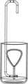
- FIG. 1 eillustrates the tissue displacement/separation system of the present invention.
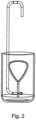
- FIG. 2illustrates the dipping method used to fabricate the seamless bladder utilized by the device of the present invention.
- FIGS. 3 a - cillustrate prostate-rectal tissue ( FIG. 3 a ) and an embodiment of the device of the present invention ( FIG. 3 b -front view; FIG. 3 c -side view) particularly suitable for use in a treatment procedure applied within this tissue region (noted by arrow).
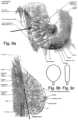
- FIGS. 4 a - cillustrate liver/gallbladder tissue ( FIG. 4 a ) and an embodiment of the device of the present invention ( FIG. 4 b -front view; FIG. 4 c -side view) particularly suitable for use in a treatment procedure applied within this tissue region (noted by arrows).
- FIGS. 5 a - cillustrate colorectal tissue ( FIG. 5 a ) and an embodiment of the device of the present invention ( FIG. 5 b -front view; FIG. 5 c -side view) particularly suitable for use in a treatment procedure applied within this tissue region (noted by arrow).
- FIGS. 6 a - eillustrate uterine tissue ( FIG. 6 a ) and an embodiment of the device of the present invention ( FIG. 6 b, d -front view; FIG. 6 c, e -side view) particularly suitable for use in a treatment procedure applied within this tissue region (noted by arrows).
- FIGS. 7 a - cillustrate rectal tissue ( FIG. 7 a ) and an embodiment of the device of the present invention ( FIG. 7 b -front view; FIG. 7 c -side view) particularly suitable for use in a treatment procedure applied within this tissue region (noted by arrow).
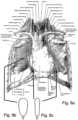
- FIGS. 8 a - cillustrate thoracic tissue ( FIG. 8 a ) and an embodiment of the device of the present invention ( FIG. 8 b -front view; FIG. 8 c -side view) particularly suitable for use in a treatment procedure applied within this tissue region (noted by arrows).
- FIGS. 9 a - cillustrate breast tissue ( FIG. 9 a ) and an embodiment of the device of the present invention ( FIG. 9 b -front view; FIG. 9 c -side view) particularly suitable for use in a treatment procedure applied within this tissue region (noted by arrows).
- the present inventionis of a device system and method which can be used to protect a first tissue from the effect of treatment conducted on a second and adjacent tissue.
- Treatment of body tissue via local release of chemical substances or provision of a radiation doseresults in chemical/radiation gradient between the treated tissue and normal tissue. Therefore, the total radiation or chemical dose which can be applied to a tissue is limited by the dose that is inevitably transmitted to normal adjacent tissues.
- a tissue displacement/separation devicewhich can be utilized to protect a body tissue from the harmful effects of treatment, such as thermal or radiation treatment.
- displacement/separationrefers to either moving one tissue away from another or by filling a void between tissues with a physical barrier.
- the device of the present inventionincludes a bladder which is expandable between a first tissue and a second tissue of a body of a subject (preferably human).
- first tissue and second tissuecan denote two tissue types (for example, prostate-rectum, uterus-rectum, uterus-small bowels, urinary bladder-uterus, ovary-bowels uterus-urinary bladder, liver-gallbladder, lung-mediastinum, mediastinum-lung, mammary gland-thoracic wall, esophagus-spine, thyroid—blood vessels, thyroid-pharynx and larynx, small bowels and large bowels-retroperitoneum, kidney-liver, pancreas-stomach, pancreas-spine, stomach—liver, stomach—spine, etc) or different tissue regions of the same tissue type. It will be appreciated that in the latter case, the two tissue regions can be naturally adjacent and attached by fibroconjunctive tissue (e
- the device of the present inventionis designed such that an expanded shape thereof is selected capable of displacing the first tissue from the second tissue.
- Such physical separationoptionally combined with a barrier effect of the device protects the first tissue from an effect of a treatment applied to the second tissue.
- treatmentwhen used in context of the first and second tissues denotes any treatment which can be harmful to the untreated tissue (e.g. first tissue).
- treatmentsinclude radiation treatment, such as, for example, external radiation therapy using gamma irradiation, high energy photon beam therapy, electron beam therapy, proton beam therapy, neutron beam therapy, heavy particle beam therapy, conformal 3 d radiation therapy, intensity modulated radiation therapy (IMRT), interstitial brachytherapy or any combination thereof.
- Treatmentcan also include drug treatment (local) such as alcohol tissue ablation or hyperosmolar ablation using NaCl crystals or hyperosmolar solution or physical tissue manipulation (e.g. dissection).
- the present inventionprovides a device which is useful in protecting tissue from the harmful effects of various types of treatments including, but not limited to, externally provided radiation therapy such as, ionizing radiation, or non-ionizing radiation (microwave therapy, radiofrequency therapy, high intensity focused ultrasound therapy, etc), or interstitial therapy such as, for example, interstitial brachytherapy, interstitial thermal ablation, contact thermal ablation by hot liquid, high intensity focused ultrasound, termoregulated rods, interstitial laser therapy with or without photodynamic agents, cryotherapy, interstitial chemical ablation, localized chemotherapy, etc.
- radiation therapysuch as, ionizing radiation, or non-ionizing radiation (microwave therapy, radiofrequency therapy, high intensity focused ultrasound therapy, etc)
- interstitial therapysuch as, for example, interstitial brachytherapy, interstitial thermal ablation, contact thermal ablation by hot liquid, high intensity focused ultrasound, termoregulated rods, interstitial laser therapy with or without photodynamic agents, cryotherapy, interstitial chemical ablation, localized chemotherapy, etc.
- any number of the present devicecan be utilized to fill complex spaces in order to displace one tissue from another.
- the devicesmight be interconnected in order to maintain a functional protective structure.
- Multi-device structuresmight be suitable for physical separation in the peritoneal cavity wherein some of the interconnected devices serve as anchors to the body wall preventing movement and migration of the structure.
- FIGS. 1 a - cillustrates one embodiment of the device of the present invention which is referred to herein as device 10 .
- FIGS. 1 a - cillustrate a flat balloon shape having an expanded state length L ( FIG. 1 a e.g. from 1 to 20 cm), an expanded state width W ( FIG. 1 a e.g. from 1 to 20 cm) and an expanded state thickness T ( FIG. 1 c e.g. from 1 to 10 cm), it will be appreciated that bladder 10 can be fabricated in any shape suitable for uniform tissue displacement thus minimizing any localized pressure on the displaced tissue.
- Examples of bladder 12 shapesinclude, but are not limited to, a pear shape, a fusiform shape, a discoid shape, a flattened shape, a triangular shape and a flattened cylindrical shape.
- Device 10can be constructed from any biocompatible material including, but are not limited to polymers, such as, biodegradable polyesters made from hydroxyl alkanoic acids, polyorthoesters, polyphosphazenes, polyphosphate esters, polyanhydrides and copolymers and blends thereof. Of particular interest are homo and copolyesters made from lactic acid, glycolic acid and caprolactone.
- the preferred polymersare those that are in clinical use and have already shown to be safe with predictable biodegradability, i.e. polylactide, poly(lactide-glycolide), poly(lactide-caprolactone) and polycaprolactone.
- the selected polymersshould fit the desired mechanical and physical stability of bladder 12 in vivo.
- a biodegradable polymer that retains its mechanical and physical properties when designed as a thin layer bladder, for at least 2 monthsis utilized to produce a bladder which needs to retain its mechanical and physical properties for two months in the body.
- the polymersshould be film forming and flexible enough to enable folding of bladder 12 into a compact configuration that can be inserted within a tube that serves as dispenser for device 10 in vivo.
- the properties of the polymer compositionscan be tailored to fit any requirements by either blending various polymers or mixing the polymer with hydrophobic or hydrophilic additives that alter the polymer properties.
- Such additivescan be plasticizers that increase the flexibility of bladder 12 , hydrophilic components such as poly(ethylene glycol) and minerals that increase hydrophilicity and serve as pore making agents.
- Hydrophobic componentscan be triglycerides, fatty acids and esters and other biodegradable polymers.
- the polymer structure and molecular weightplay a significant role in designing the desired properties of the polymer composition.
- FIG. 1 billustrates bladder 12 in a collapsed (e.g. rolled) state which is suitable for delivery using minimally invasive techniques (further described hereinbelow).
- FIG. 1 cillustrates bladder 12 in an expanded state which is capable of effecting tissue displacement or separation.
- bladder 12is constructed as a seamless structure by dipping a water soluble expanded bladder template in an organic polymeric solution and removing the formed polymeric bladder from the template by dissolving the template in water.
- Device 10can include a bioadhesive coating or any other physical mechanism which can decrease its mobility within the insertion site. This feature is important to minimize movement of device 10 from the site of application and thus guarantee optimal protection for the non-treated tissue.
- Suitable bioadhesivesinclude as carboxymethyl cellulose (CMC) and similar bioadhesive that are allowed for use in humans.
- CMCmay be applied as dry film onto bladder 12 . Following insertion and absorption of water such a film develops adhesive properties towards tissue.
- Bladder 12can be configured with various surface structures such as pimples, grooves, bumps, microhooks, ridges or any combination thereof such that when expanded a friction between bladder 12 surface and displaced tissue is increased without affecting the functionality of the device.
- Expansion of bladder 12is conducted in-tissue following insertion and positioning of device 10 .
- insertion and positioningcan be effected by using a guide (a suitable guide is further described hereinbelow with respect to FIG. 1 d ).
- a guidea suitable guide is further described hereinbelow with respect to FIG. 1 d .
- Following expansionsuch a guide can be kept attached to device 10 during short term procedures in which treatment is provided over a course of hours (e.g. thermal ablation) or it can be detached therefrom during longer procedures in which treatment is provided over a course of days, weeks or even months (e.g. long term radiation or interstitial procedures).
- device 10is preferably constructed from a biodegradable material such that device 10 degrades and is absorbed by the body over a predetermined time period or following absorption of a predetermined dose amount of treatment (e.g., radiation).
- a predetermined dose amount of treatmente.g., radiation
- device 10is constructed from polymers which are biocompatible and bioabsorbable, and yet posses mechanical properties suitable for maintaining the desired in-tissue shape.
- Such polymerscan be prepared by synthetic or natural methods as long as the polymer is provided in a sufficiently pure form suitable for use in body tissues.
- the polymersmay be prepared from any combination of monomeric units or from natural semi-synthetic and synthetic biodegradable polymers and compositions. These units must, however, be capable of biodegrading in vivo to non-toxic components, which can be excreted or further metabolized.
- the combination of units in the polymermust also be biocompatible, and not elicit an undesirable biological response upon implantation of device 10 .
- the polymermay be biodegraded in vivo via hydrolysis, enzymatic cleavage, cell-mediated degradation, or by any other biologically mediated process. Since the need for tissue displacement may vary depending on the type and duration of treatment, it is desirable to have polymers with a range of degradation rates as well as a range of different properties. Generally, however, preferred polymers will degrade in a matter of weeks to months, preferably less than one year.
- biodegradable polymerswhich can be used to fabricate device 10 include, but are not limited to, biodegradable polyesters such as, polylactide, poly(lactide-glycolide), poly(lactide-caprolactone) and polycaprolactone.
- the polymeris a polyester constructed from a hydroxy acid monomers.
- the hydroxy acidmay optionally contain other functional groups and be substituted at any position, including heteroatoms between the hydroxy and acid groups.
- These hydroxy acidsmay be polymerized using synthetic methods or preferably using biological methods. In the latter case, the hydroxy acids may be derived in vivo from a non-hydroxy acid source. Suitable methods for preparing polyesters are described in Williams, S. F. and Peoples, O. P. CHEMTECH, 26:38-44 (1996), Hocking, P. J. and Marchessault, R. H. “Biopolyesters”, G. J. L. Griffin, Ed., “Chemistry and Technology of Bioabsorbable Polymers,” Chapman and Hall, London, 1994, pp. 48-96.
- the polyestercan include one or more non-ester linkages in the main polymer chain which can be configured susceptible to cleavage in vivo.
- Suitable non-ester linkagesmay include amides, urethanes, carbonates, iminocarbonates, oxalates, oxamates, orthoesters, anhydrides, phosphazenes, glycosides, and ethers. Incorporation of such linkages can be used to alter biodegradation rates, tailor mechanical, surface, or other properties of the polymer, improve processing and handling of the materials, and/or to provide methods for attachment of other compounds to the polymers (e.g., contrasting or treatment agents described below).
- a typical polymer suitable for fabricating bladder 12can include: D,L-polylactide, lactide-glycolide copolymers, PEG-PLA copolymers, and polyesters and polyamides and other biodegradable compositions that form a strong film that can maintain an expanded state for extended time periods.
- the time required for a polymer to degradecan be defined by selecting appropriate monomers. Differences in crystalline structure also alter degradation rates. Actual mass loss initiates when the polymer matrix degrades to oligomeric fragments that are small enough to be water soluble. Hence, initial polymer molecular weight influences the degradation rate.
- Degradable polymers containing water-soluble polymer elementshave been previously described, see, for example, Sawhney et al., (1990) “Rapidly degraded terpolymers of dl-lactide, glycolide, and ⁇ -caprolactone with increased hydrophilicity by copolymerization with polyethers,” J. Biomed. Mater. Res. 24:1397-1411.
- Degradation rate and thus polymer selectionis determined according to the use of device 10 . For example, during cryotherapy and thermal ablation a polymer with a degradation time period of a few hours to one or two weeks is selected, during external beam radiation a polymer with a degradation time period of 5 to 6 weeks is selected, while during brachytherapy a polymer with a degradation time period of a few months is selected.
- permanent implantationpreferably of a degradable device
- a device designed capable of such permanent implantationis particularly useful in cases where a treated individual is subjected to several treatment sessions (e.g., radiation) over an extended time period (e.g. weeks). In such a case, repeated implantation of a tissue protective device and thus repeated discomfort to the individual can be avoided by using device 10 of the present invention.
- device 10displaces or separates one tissue from another when bladder 12 is expanded.
- Bladder 10can be expanded using one of several approaches.
- device 10preferably includes a port 14 through which bladder 12 can be expanded or collapsed.
- Port 14is preferably a small diameter port with a diameter which is 1 ⁇ 5 to 1/100, preferably 1 ⁇ 5 to 1/20 of the expanded thickness or width of expanded bladder 12 .
- Port 14can be a fluid filling port, in which case bladder 12 can be expanded by using a gas or a liquid and collapsed via emptying.
- port 14can be utilized to introduce a solid yet elastic element that can fill bladder 12 such that it assumes a semi rigid expanded state. As is shown in FIG. 1 d , such a solid element can be, for example, an elongated member 15 (e.g.
- a wire or thread 3-5 mm in diameterthat can be forced into a linear state 17 and thus can be introduced into bladder 12 through port 14 , but when released naturally assumes a coiled structure 19 that forces bladder 12 to assume an expanded state.
- a wirecan have a circular, elliptic, triangular rectangular or stellate profile and can be solid or hollow. The profile can be uniform along the entire length of the wire or it can change intermittently in order to permit easier folding inside bladder 12 .
- Bladder 12can also be filled with beads that can optionally be interconnected by a thread or wire. It will be appreciated that such wire or bead expansion traverses the need for bladder sealing.
- Elongated member 15can be made from a biocompatible and optionally biodegradable elastic material such as, for example, polylactide, poly(lactide-glycolide), poly(lactide-caprolactone) and polycaprolactone or a Shape Memory Polymer (SMP) made for example from multi block copolymers of lactide and caprolactone which can assume an elongated state when heated and a coiled state when cooled to body temperature.
- a biocompatible and optionally biodegradable elastic materialsuch as, for example, polylactide, poly(lactide-glycolide), poly(lactide-caprolactone) and polycaprolactone or a Shape Memory Polymer (SMP) made for example from multi block copolymers of lactide and caprolactone which can assume an elongated state when heated and a coiled state when cooled to body temperature.
- SMPShape Memory Polymer
- a liquidprovides several advantages. It enables bladder 12 to conform to the tissue displaced and thus apply uniform pressure thereupon. It enables introduction of useful agents, such as contrasting agents or treatment agents into bladder 12 and it can serve as an excellent physical barrier against heat, or radiation by introducing substances that absorb radiation such as iodinated agents or fluorocarbons.
- any liquidcan be utilized to expand bladder 12 , preferably the liquid utilized is biocompatible and physiological such as 0.9% saline, Ringer solution or Hartman solution.
- a physiological liquidis particularly advantageous in that it provides a good sonographic window which is essential in procedures that necessitate ultrasound guidance for introduction of the balloon or for local therapy or follow up (e.g. trans rectal ultrasound for therapy of the prostate). Additionally, in case of side effects such as pain or discomfort or local infection the balloon can be easily collapsed using a thin needle.
- bladder 12is preferably constructed from a fluid impermeable material such that an expanded state thereof can be retained following filling.
- suitable liquidsinclude, but are not limited to, water, saline and the like.
- the liquidcan include agents that can be useful in imaging, radiation and/or thermal treatment modalities.
- the liquid in bladder 12can include imaging contrast agents such as iodinated or baritated substances or various fluorocarbons, which are useful in fluoroscopy or CT scanning; echogenic or anechoic substances which are useful in ultrasound imaging, MRI contrasts agents such godolinium, radioactive isotopic substances for SPECT, or PET scanning.
- imaging contrast agentssuch as iodinated or baritated substances or various fluorocarbons, which are useful in fluoroscopy or CT scanning; echogenic or anechoic substances which are useful in ultrasound imaging, MRI contrasts agents such godolinium, radioactive isotopic substances for SPECT, or PET scanning.
- agentssuch as iodinated substances, baritated substances, fluorocarbons, and the like can be included in the liquid.
- Agents active in tissue healing/repaircan also be added to the liquid in which case, bladder 12 is preferably constructed so as to enable release of such agents to the tissue. It will be appreciated that the above described agents can alternatively be added or incorporated into the material of
- Port 14can be constructed with a plurality of channels so as to enable circulation of a liquid with expanded bladder 12 .
- circulation of liquidenables tissue cooling or heating when necessary.
- cooling of non-treated tissuecan be effected via circulation of cold water.
- bladder 12is preferably constructed such that the cooled side (facing non-treated tissue) is more thermally conductive then the side of bladder 12 facing treated tissues.
- Port 14can include additional channels that enable introduction of a viewing device such as endoscope or an ultrasonic transducer, which can be to assess the effect of treatment, or to introduce therapeutic probes such as radiofrequency, or high intensity ultrasound probe or to introduce optical fibers which can be used for probing or for transillumination.
- a viewing devicesuch as endoscope or an ultrasonic transducer
- therapeutic probessuch as radiofrequency, or high intensity ultrasound probe
- optical fiberswhich can be used for probing or for transillumination.
- gelling liquidscan also be utilized to expand bladder 12 .
- Such gelling liquidscan be used to further enhance the tissue protective qualities of bladder 12 by providing a physical cushion capable of further protecting the displaced/separated tissue from physical trauma which can result from displacement or treatment.
- Gelling materialsare also advantageous in that in case of rupture, the gel will be locally retained and will not dissipate.
- gelling liquidsthat can be utilized to expand device 10 of the present invention include, but are not limited to, absorbable haemostatic agents such as, gelatin, cellulose, bovine collagen and biodegradable synthetic adhesives such as, poly ethylene glycol (PEG).
- the liquid utilized to expand bladder 12can also include a fluorophore or any other trans-illuminative substance which can emit or reflect light which can be used to guide a procedure performed on the treated tissue. Alternatively such a light reflecting/emitting substance can be incorporated into the material of bladder 12 .
- device 10 of the present inventionis preferably inserted and positioned within tissue using a guide.
- Such a systemincludes device 10 and a guide which is detachably attached to device 10 .
- the guideserves to insert and position device 10 and to expand bladder 12 when in position.
- the guidecan be a thin catheter or a blunt tip needle (canula), of about 1-5 mm in diameter, preferably 2-3 mm in diameter.
- the guideposses a lumen through which a bladder-expanding fluid (or rigid element) can be conducted from a device such as a syringe (in the case of fluid) to bladder 12 .
- Bladder expansioncan be monitored by using different imaging technique such as: direct view, transillumination, fluoroscopy, endoscopic or laparoscopic US, US, CT scan, MRI, endoscopic view, etc.
- the guideis preferably constructed from biomedical grade elastomer such as PVC or polyurethane.
- the guideis detached from the device 10 which preferably remains inflated by self sealing of port 14 .
- self-sealingcan be effected by a one way valve incorporated into port 14 , by viscosity of a bladder expanding liquid (e.g. one that forms a gel) or by a biodegradable sealing mechanism such as that described below with respect to FIG. 1 e .
- a cutting catheter made from bio-compatible material and having a sharp edgemay be used to detach device 10 from the guide if necessary.
- FIG. 1 eillustrates one embodiment of the system for tissue displacement or separation which is referred to herein as system 100 .
- System 100includes device 10 which is shown in a collapsed (rolled) state.
- System 100also includes a guide 20 which includes a needle 22 for attaching to port 14 of device 10 , a packaging sheath 28 for holding device 10 and a dilator sheath 26 for holding packaging sheath 28 .
- Needle 22 and dilator sheath 26are used in a manner similar to the well known Seldinger technique (The Seldinger technique. Reprint from Acta Radiologica 1953; AJR Am J Roentgenol. 1984 January; 142(1):5-7).
- This minimally invasive techniqueis used to provide a device or substance access to a specific location in the body through a dilator sheath.
- positioning of dilator sheath 26 within a body tissueenable delivery of device 10 (rolled or folded inside packaging sheath 28 ) to a specific body location.
- device 12is deployed by retracting both sheaths and expanding bladder 12 (via for example syringe connected to port 34 of needle 22 ) at the proper location and orientation.
- Device 10is then sealed to prevent deflation by using the one way valve or self sealing mechanism described above.
- port 14 of device 10can be sealed by using a biodegradable plug 30 which is forcefully stuck into a non resilient biodegradable tube 32 attachable at port 14 .
- sealingcan be performed by external compression of port 14 with an elastic constricting ring or by knotting of port 14 .
- needle 22 of guide 20When used in long term procedures, needle 22 of guide 20 is detached from expanded and sealed device 10 and removed from the body, otherwise, following procedure, needle 22 with attached device 10 are removed from the body along with dilator sheath 26 and packaging sheath 28 .
- the present inventionprovides a device and system which can be utilized in protecting tissue from the harmful effects of treatment.
- one of the notable features of the present deviceis its ability to uniformly displace/separate tissues in a manner which minimizes tissue damage, while being implantable and optionally biodegradable thus enabling repeated treatment to a tissue region without necessitating repeated in-tissue positioning procedures.
- the bladder of the present deviceis its ability to retain a predetermined shape once expanded. This feature is critical for optimal tissue displacement/separation and minimization of localized tissue pressure. For the same reason, the bladder of the present device is preferably fabricated with a smooth seamless external surface. To facilitate these requirements, a unique production process was formulated. The process combines two production concepts, a permutation of “lost wax” casting and dip molding.
- Dip moldingis used to “build” the bladder walls by dipping a pre-shaped model of the bladder in a solution made of a polymer dissolved in organic solvent.
- the pre-shaped modelis made of materials that are later extracted from the internal volume of the bladder through its orifice.
- waxcannot be used since it dissolves in organic solvents such as alcohols, chlorinated hydrocarbons, alkanones, acetonitrile, dialkyl ethers, cyclic ethers, acetate alkyl esters, and common aromatic solvents.
- Typical solventsinclude butanol, dichloromethane, chloroform, butanone, acetone, acetonitrile, disiopropyl ether, tetrahydrofurane, dioxane, ethyl and butyl acetate, and toluene.
- the only casting agents that can be usedare hydrophilic in nature and include protein, polysaccharides and various synthetic and semisynthetic polymers. Examples include, but are not limited to, gelatin, agar, alginate, hydroxypropylcellulose, poly(acrylic acid-co-methylmethacrylate), chitosan, dextran, and arabinogalactane.
- alloys with a low melting temperaturecan be used for the casts. These casts are heated and melted and extracted at a temperature lower than the melting temperature of the coating polymer.
- the bladder shapeis based on the anatomy of the target location and is designed to achieve an optimal separation with minimal local pressure on the surrounding tissues/organs.
- step (v)Repeat step (iv) several (e.g. six) times until required coating thickness is acquired.
- the bladderwhen the bladder is filled with a biodegradable fiber, it can be alternatively fabricated by welding or gluing together of two films of the bladder material. “Pressure forming”, “film extrusion” or “blown film” methods are used to prepare the films. The films are then welded along the bladder external path using an accurate and controlled ultrasonic energy or glued using an accurate deposit of organic solvent along the gluing path.
- Prostate canceris the most common malignancy in men; 220,000 new cases are diagnosed each year in US and 50,000 patients undergo radical prostatectomy each year in the U.S. During the last few years there is an increasing trend to perform this surgery via minimally invasive techniques such as laparoscopic radical prostatectomy.
- the device of the present inventionis inserted into the space between the rectum and prostate (see FIG. 3 a ) using the transperineal approach which is guided by trans-rectal ultrasound. Initially a thin 22 to 18 gauge needle is introduced into this space under trans-rectal ultrasound guidance and this virtual space is enlarged by injecting 5 to 20 cc of physiological liquid such as, for example, 0.9% sterile saline.
- a guide wireis inserted through the needle into this space; the needle is removed and a dilator is used to enlarge the tract; an introducer sheath is passed over the dilator and the dilator and the guide wire are removed; the folded device with its sheath measuring between 2 and 3 mm in diameter are introduced through the introducer sheath and the bladder component is deployed and expanded in the space between the rectum and prostate in the proper orientation.
- a pear shaped non distensible bladder 3 to 5 cm length, 3 to 5 cm width and 1 to 2 cm heightis preferably used. Upon expansion with either a biodegradable material or physiological solution, the bladder thickness will range between 10 to 20 mm.
- a specific bladder size corresponding to the size of the prostate in that particular patientwill be used. Thereafter, an optic fiber can be introduced into the bladder through the needle and the needle can be removed. During the dissection of the prostate from the rectum the optical fiber is used for illumination and the inflated space between the rectum and prostate is viewed through the laparoscope by transillumination. Using such an approach, the borders of the prostate can be clearly seen and the prostate can be safely and rapidly dissected from the rectum and from the erectile nerves laying on the rectal side.
- the device bladderis preferably filled with a gel, in which case puncturing of the bladder wall with a surgical instrument or damage thereto caused by thermal energy will not lead to loss of tissue displacement. Following the procedure, the bladder and the gel are removed using suction and laparoscopic instruments.
- the device of the present inventionis preferably a pear shaped bladder 3 to 5 cm in length, 3 to 5 cm in width and 1-2 cm in thickness when expanded.
- the bladderis inserted into the correct space between the rectum and prostate as described above under local anesthesia.
- the bladderis then deployed and filled with physiological liquid or gel to its final dimensions and in the proper orientation.
- the catheteris then detached from the inflated bladder and the bladder is sealed in order to prevent deflation.
- Such sealingmay be performed by using a biodegradable plug as described above or by tying of the biodegradable feeding tube.
- the bladderis sealed for the duration of the radiation therapy thus preventing its collapse.
- Patientsundergo 30 to 40 sessions of radiation to the prostate 70 to 84 Gy on an ambulatory basis over a period of 5 to 6 weeks. Therefore, the bladder and/or the gel are chosen in such way so as to degrade following this period of time.
- a radiation barrier in the form of a iodinated substance or fluorocarbonsmight be introduced into the bladder and/or the gel in order to further reduce exposure of the rectal wall, erectile nerves and bladder base to radiation and therefore permit use of a higher radiation dose (e.g. more than 80 Gy or 8000 rads).
- a radiotracercan optionally be used in order to enable delineation of the prostate during radiotherapy.
- the urinary bladder and external urinary sphincterscan be additionally protected by using additional spacers on the anterior surface of the prostate at its base and between the sphincter and prostate apex. Moreover, since these spacers compress the prostate and separate adjacent tissues, the respiratory movements of the prostate are reduced permitting a more accurate dose delivery to the prostate.
- the device of the present inventioncan also be used in prostate cancer cryotherapy.
- a transperineally positioned device having thermal insulation and additional ports for hot water circulation or a device provided with thermal inducible meansis utilized.
- the devicecan incorporate a thermal inducible gel or carbon particles that can be heated via a remote radiofrequency source situated in the rectal lumen for example, or by using a magnetic field.
- a similar devicecan be used in thermal ablation treatment of prostate tumors or benign hyperplasia of the prostate.
- intermittent or continuous liquid circulationmight be used for cooling the rectal wall and erectile nerves.
- a heat reflective coating on the side facing the prostatemight be used to reflect the radiation energy away from the rectum and back towards the prostate.
- Tissue displacementcan also be performed during laparoscopic cholecystectomy. Approximately 400,000 such cases are performed each year in U.S. mostly for cholelithasis.
- the bladderis preferably an elongated (5 to 7 cm long, 3 to 5 cm wide and 1 to 2 cm thick) shape (See FIGS. 4 b - c ).
- the deviceis preferably introduced between the gallbladder and liver in order to separate these organs and facilitate dissection (see FIG. 4 a ).
- the bladderis folded in an encasing sheath and connected to a feeding catheter and the device is introduced through a 5 mm port within the peritoneal cavity. Initially minimal hydro-dissection is performed between these organs to create a space, then the device folded within the encasing sheath is introduced into this space, the sheath is removed and the bladder is expanded with a liquid or a gel. The catheter is then detached from the expanded bladder and the bladder is sealed in order to prevent deflation. Catheter detachment enables introduction of surgical instruments through the catheter port and dissection of the gallbladder from the liver.
- a haemostatic agentsuch as fibrin, thrombin, alginate, gelatin or cyanacrylate (optionally incorporated into the bladder) enables homeostasis of the bleeding regions.
- Tissue displacementcan also be performed during laparoscopic colectomy. Approximately 300,000 such cases are performed each year in USA mostly for large bowel tumors.
- an elongated bladder 10 to 20 cm long, 3 to 7 cm wide and 1-3 cm thick (when expanded)is preferably used (see FIGS. 5 b - c ).
- the bladder in its encasing sheathis introduced between the right colon and retroperitoneum or between the left colon and retroperitoneum or between the rectum and sacrum or rectum and urinary bladder in order to separate these tissues and facilitate dissection (see FIG. 5 a ). Initially minimal hydro-dissection is performed between these organs to create a space, then the device in its encasing sheath is introduced within this space, the sheath is removed and the bladder is expanded using a liquid or a gel in the proper orientation.
- the catheteris then detached from the expanded bladder and the bladder is sealed in order to prevent collapse.
- Catheter detachmentenables introduction of surgical instruments through the catheter port and dissection of tumor tissue.
- Cancer of the uterine cervixis one of the most common tumors in women, accounting for more then 100,000 of cases annually in the U.S. Most of these cases are treated by cavitary radiation therapy. During this therapy, radiation may injure the rectum, bladder and small bowels.
- the device of the present inventionis inserted between the rectum and posterior vaginal wall/uterine cervix through posterior vaginal wall or through the perineum (see FIG. 6 a ) under trans rectal or trans vaginal ultrasound guidance.
- An extension of the bladder into the Douglas pouch or an additional devicemay be provided to push up the bowels.
- the folded device and sheath measuring between 2 and 3 mm in diameterare introduced through the introducer sheath and the bladder is deployed and expanded in the proper orientation in a space created (as described above) between the rectum and vagina/uterine cervix.
- An elongated bladder 3 to 10 cm in length, 3 to 5 cm in width and having a variable (expanded) thickness of 1 cm in the inter-rectal vaginal space to 5 cm in the distal Douglas pouch positionsee FIGS. 6 b - e ).
- Patients with Stage IB to IVB squamous cell carcinoma of the cervixare treated with a combination of external beam radiotherapy (EBRT) and high-dose rate intracavitary brachytherapy (HDR-ICBT).
- EBRTexternal beam radiotherapy
- HDR-ICBThigh-dose rate intracavitary brachytherapy
- 20 gray (Gy) of EBRTare delivered to the whole pelvis, followed by 24 Gy (in 4 fractions) of HDR-ICBT and 30 Gy of central-shielding EBRT.
- 20-40 Gy of whole pelvic EBRTare administered, followed by 24 Gy (in 4 fractions) of ICBT and 30-10 Gy of central-shielding EBRT.
- the overall treatment timeis approximately 6 weeks.
- Rectal canceris a common tumor accounting for 145,000 new cases each year in the U.S. alone. Thirty to forty percent of cases undergo preoperative or postoperative external beam irradiation. This treatment may cause injury to the urinary bladder, vagina and small bowels.
- the device of the present inventionis positioned between the urinary bladder and sacrum or between the rectum and urinary bladder (see FIG. 7 a ) with an extension or an additional device in the Douglas pouch through the perineum using trans rectal, trans vaginal ultrasound guidance or CT guidance.
- An extension of the bladder into the Douglas pouchmay be provided to push up the bowels.
- the folded device and sheath measuring between 2 and 3 mm in diameterare introduced through the introducer sheath and the bladder component is deployed and expanded in a space between the rectum and urinary bladder which is prepared as described above.
- a elongated bladder of 3 to 10 cm in length, 3 to 5 cm in width and having a variable thickness (when expanded) of 1 cm in the intervesical-rectal space to 5 cm height in the distal Douglas pouch position(see FIGS. 7 b - c ) is used.
- Radiotherapycan also be administered following surgery in an adjuvant setting. In the latter case, the prescribed radiation dose is 50.4 Gy which is provided in 28 fractions.
- the device of the present inventioncan also be used during radiation therapy to pulmonary tumors or to lymphomas situated in the mediastinum.
- the bladderis preferably positioned between the lung and mediastinum containing: great blood vessels, heart, spine with the spinal cord, and lymphatic vessels and nodes, in order to separate a possible medial tumor from healthy tissues.
- lymphomasthe device is preferably positioned between the enlarged lymph nodes situated in the superior mediastinum and the heart and great vessels, spine and lung tissue.
- the deviceis preferably positioned under CT guidance.
- the bladderis preferably 5 to 10 cm in length; 3 to 5 cm in width and 1 to 2 cm in thickness when expanded (see FIGS. 8 b - c ). A number of smaller sized bladders can also be used to efficiently cover this complex space.
- the folded device with its sheath measuring between 2 and 3 mm in diameterare introduced through the introducer sheath and the bladder component is deployed and inflated in the mediastinal space (see FIG. 8 a ) in the proper orientation.
- radiotherapyis administered as either 45 Gy over 15 sessions up to 70 Gy over 70 sessions over a period between 3 to 10 weeks according to type of tumor and stage.
- Such radiation therapyis typically administered in combination with chemotherapy.
- mediastinal lymphomas chemotherapyis administered followed by consolidation radiotherapy at a dose of 36 Gy over 4 to 6 weeks to bulky mediastinal disease.
- Another applicationmay be for radiation treatment of breast cancer.
- This tumoris the most prevalent tumor in women account for 300,000 new cases in US every year. Most patients undergo lumpectomy. In the majority of cases irradiation is given to the nearby breast tissue and case of tumors situated near the chest wall the thoracic wall and lung receive a significant dose of irradiation.
- the folded device and sheath measuring between 2 and 5 mm in diameterare introduced through the introducer sheath and the bladder component is deployed and expanded in the space between the breast and abdominal wall (see FIG. 9 a ).
- a circular flat bladder 5 to 15 cm in diameter, and 1 to 3 cm in thicknessis preferably used in this procedure.
- RTradiotherapy
- BCSbreast conserving surgery
Landscapes
- Health & Medical Sciences (AREA)
- Surgery (AREA)
- Life Sciences & Earth Sciences (AREA)
- Engineering & Computer Science (AREA)
- General Health & Medical Sciences (AREA)
- Biomedical Technology (AREA)
- Heart & Thoracic Surgery (AREA)
- Medical Informatics (AREA)
- Molecular Biology (AREA)
- Animal Behavior & Ethology (AREA)
- Nuclear Medicine, Radiotherapy & Molecular Imaging (AREA)
- Public Health (AREA)
- Veterinary Medicine (AREA)
- Mechanical Engineering (AREA)
- Oral & Maxillofacial Surgery (AREA)
- Pathology (AREA)
- Materials For Medical Uses (AREA)
- Surgical Instruments (AREA)
- Ultra Sonic Daignosis Equipment (AREA)
- External Artificial Organs (AREA)
- Radiation-Therapy Devices (AREA)
Abstract
Description
Claims (22)
Priority Applications (1)
| Application Number | Priority Date | Filing Date | Title |
|---|---|---|---|
| US15/095,094US11759979B2 (en) | 2004-06-23 | 2016-04-10 | Device system and method for tissue displacement or separation |
Applications Claiming Priority (5)
| Application Number | Priority Date | Filing Date | Title |
|---|---|---|---|
| US58176904P | 2004-06-23 | 2004-06-23 | |
| PCT/IL2005/000672WO2006001009A2 (en) | 2004-06-23 | 2005-06-23 | Device system and method for tissue displacement or separation |
| US63025706A | 2006-12-21 | 2006-12-21 | |
| US13/495,087US9314944B2 (en) | 2004-06-23 | 2012-06-13 | Method of forming a seamless bladder |
| US15/095,094US11759979B2 (en) | 2004-06-23 | 2016-04-10 | Device system and method for tissue displacement or separation |
Related Parent Applications (1)
| Application Number | Title | Priority Date | Filing Date |
|---|---|---|---|
| US13/495,087ContinuationUS9314944B2 (en) | 2004-06-23 | 2012-06-13 | Method of forming a seamless bladder |
Publications (2)
| Publication Number | Publication Date |
|---|---|
| US20160338793A1 US20160338793A1 (en) | 2016-11-24 |
| US11759979B2true US11759979B2 (en) | 2023-09-19 |
Family
ID=35064921
Family Applications (3)
| Application Number | Title | Priority Date | Filing Date |
|---|---|---|---|
| US11/630,257Active2028-06-20US8221442B2 (en) | 2004-06-23 | 2005-06-23 | Device system and method for tissue displacement or separation |
| US13/495,087Expired - LifetimeUS9314944B2 (en) | 2004-06-23 | 2012-06-13 | Method of forming a seamless bladder |
| US15/095,094Expired - LifetimeUS11759979B2 (en) | 2004-06-23 | 2016-04-10 | Device system and method for tissue displacement or separation |
Family Applications Before (2)
| Application Number | Title | Priority Date | Filing Date |
|---|---|---|---|
| US11/630,257Active2028-06-20US8221442B2 (en) | 2004-06-23 | 2005-06-23 | Device system and method for tissue displacement or separation |
| US13/495,087Expired - LifetimeUS9314944B2 (en) | 2004-06-23 | 2012-06-13 | Method of forming a seamless bladder |
Country Status (9)
| Country | Link |
|---|---|
| US (3) | US8221442B2 (en) |
| EP (2) | EP3689256A3 (en) |
| JP (3) | JP4880593B2 (en) |
| CN (3) | CN102499729B (en) |
| AU (1) | AU2005257050A1 (en) |
| CA (1) | CA2571304A1 (en) |
| ES (1) | ES2760995T3 (en) |
| IL (1) | IL180270A (en) |
| WO (1) | WO2006001009A2 (en) |
Families Citing this family (69)
| Publication number | Priority date | Publication date | Assignee | Title |
|---|---|---|---|---|
| CN102499729B (en) | 2004-06-23 | 2015-07-22 | 直空间有限公司 | Device system and method for tissue displacement or separation |
| US20060222596A1 (en) | 2005-04-01 | 2006-10-05 | Trivascular, Inc. | Non-degradable, low swelling, water soluble radiopaque hydrogel polymer |
| US7955339B2 (en)* | 2005-05-24 | 2011-06-07 | Kyphon Sarl | Low-compliance expandable medical device |
| US8328792B2 (en) | 2005-10-27 | 2012-12-11 | C. R. Bard, Inc. | Enhanced pre-wetted intermittent catheter with lubricious coating |
| US20070173798A1 (en)* | 2006-01-23 | 2007-07-26 | Adams Mark L | Minimally invasive methods for thermal treatment |
| US7872068B2 (en)* | 2006-05-30 | 2011-01-18 | Incept Llc | Materials formable in situ within a medical device |
| US7771339B2 (en)* | 2006-05-31 | 2010-08-10 | Ab Mimator | Method and system for radiotherapy treatment |
| PL2124831T3 (en)* | 2007-03-15 | 2017-03-31 | Ortho-Space Ltd. | Prosthetic devices |
| AU2008249584A1 (en) | 2007-05-14 | 2008-11-20 | Bioprotect Ltd. | Delivery device for delivering bioactive agents to internal tissue in a body |
| MX2010008003A (en)* | 2008-01-29 | 2010-09-24 | Milux Holding Sa | Apparatus for treating obesity. |
| US8366758B2 (en)* | 2008-02-11 | 2013-02-05 | The Regents Of The University Of California | Hypothermia for improving rate of functional recovery following pelvic surgeries |
| WO2009103298A2 (en)* | 2008-02-18 | 2009-08-27 | Mohammed Mourad Youssif | Soliman-mourad intra-abdominal balloon device |
| US20100152825A1 (en)* | 2008-11-10 | 2010-06-17 | Schulman Norman H | Absorbable Pacing Lead Assemblies |
| US20110295379A1 (en) | 2009-02-06 | 2011-12-01 | Ortho-Space Ltd. | Expandable joint implant |
| WO2010144402A2 (en)* | 2009-06-08 | 2010-12-16 | Surgivision, Inc. | Mri-guided surgical systems with preset scan planes |
| CN102625670B (en)* | 2009-06-16 | 2015-07-15 | 核磁共振成像介入技术有限公司 | MRI-guided devices and MRI-guided interventional systems that can track and generate dynamic visualizations of the devices in near real time |
| WO2011014201A1 (en) | 2009-07-29 | 2011-02-03 | C. R. Bard, Inc. | Catheter having improved drainage and/or a retractable sleeve and method of using the same |
| WO2011019359A1 (en) | 2009-08-13 | 2011-02-17 | C. R. Bard, Inc. | Catheter having internal hydrating fluid storage and/or catheter package using the same and method of making and/or using the same |
| US20110137412A1 (en)* | 2009-12-04 | 2011-06-09 | Nyte Christopher P | Delivery device for breast implant surgery |
| EP3960215B1 (en) | 2009-12-15 | 2024-10-16 | Incept, LLC | Implants and biodegradable fiducial markers |
| US10912917B2 (en) | 2009-12-23 | 2021-02-09 | C. R. Bard, Inc. | Catheter assembly/package utilizing a hydrating/hydrogel sleeve and method of making and using the same |
| US10201325B2 (en) | 2010-01-07 | 2019-02-12 | Bioprotect Ltd. | Controlled tissue dissection systems and methods |
| EP2542291A4 (en) | 2010-03-04 | 2013-08-07 | Bard Inc C R | CATHETER ASSEMBLY / PACKAGE USING MOISTURIZER / HYDROGEL SLEEVE AND EXTERNAL SHEET LAYER AND METHOD OF MANUFACTURING AND USING THE SAME |
| US10271889B2 (en)* | 2010-06-27 | 2019-04-30 | Sunnybrook Health Sciences Centre | Apparatus and method for cooling a tissue volume during thermal therapy treatment |
| WO2012017438A1 (en) | 2010-08-04 | 2012-02-09 | Ortho-Space Ltd. | Shoulder implant |
| US9289307B2 (en) | 2011-10-18 | 2016-03-22 | Ortho-Space Ltd. | Prosthetic devices and methods for using same |
| JP5285792B1 (en)* | 2012-03-29 | 2013-09-11 | 日立アロカメディカル株式会社 | Ultrasound medical system |
| US8734337B2 (en) | 2012-04-12 | 2014-05-27 | Coloplast A/S | Surgical device for internally manipulating an organ |
| US8808175B2 (en) | 2012-04-12 | 2014-08-19 | Coloplast A/S | Vaginal manipulator including light source |
| US8814789B2 (en) | 2012-04-12 | 2014-08-26 | Coloplast A/S | Vaginal manipulator including expansion plate and door |
| TWI636771B (en)* | 2012-05-29 | 2018-10-01 | 鄭孝胥 | Human tissue radiation protector and auxiliary method of radiation therapy |
| US20150040008A1 (en) | 2013-08-02 | 2015-02-05 | Gamer Parents Inc. | Interactive overlay for video applications |
| US8690893B2 (en) | 2012-08-16 | 2014-04-08 | Coloplast A/S | Vaginal manipulator head with tissue index and head extender |
| US11938287B2 (en) | 2012-10-26 | 2024-03-26 | Urotronic, Inc. | Drug-coated balloon catheters for body lumens |
| US10898700B2 (en) | 2012-10-26 | 2021-01-26 | Urotronic, Inc. | Balloon catheters for body lumens |
| WO2014066085A1 (en) | 2012-10-26 | 2014-05-01 | Lixiao Wang | Drug coated balloon catheters for nonvascular strictures |
| US11504450B2 (en) | 2012-10-26 | 2022-11-22 | Urotronic, Inc. | Drug-coated balloon catheters for body lumens |
| US10806830B2 (en) | 2012-10-26 | 2020-10-20 | Urotronic, Inc. | Drug-coated balloon catheters for body lumens |
| US10850076B2 (en) | 2012-10-26 | 2020-12-01 | Urotronic, Inc. | Balloon catheters for body lumens |
| US10881839B2 (en) | 2012-10-26 | 2021-01-05 | Urotronic, Inc. | Drug-coated balloon catheters for body lumens |
| US8998882B2 (en) | 2013-03-13 | 2015-04-07 | C. R. Bard, Inc. | Enhanced pre-wetted intermittent catheter with lubricious coating |
| US9345577B2 (en)* | 2013-03-14 | 2016-05-24 | Microaire Surgical Instruments Llc | Balloon implant device |
| US10010404B2 (en) | 2013-10-18 | 2018-07-03 | William T. MCCLELLAN | Tissue expander improvements |
| USD745148S1 (en) | 2014-03-28 | 2015-12-08 | Coloplast A/S | Vaginal manipulator |
| USD745149S1 (en) | 2014-03-28 | 2015-12-08 | Coloplast A/S | Vaginal manipulator |
| USD745150S1 (en) | 2014-03-28 | 2015-12-08 | Coloplast A/S | Vaginal manipulator |
| USD745674S1 (en) | 2014-03-28 | 2015-12-15 | Coloplast A/S | Vaginal manipulator |
| USD753824S1 (en) | 2014-03-28 | 2016-04-12 | Coloplast A/S | Vaginal manipulator |
| CN107635593A (en) | 2015-04-24 | 2018-01-26 | 优敦力公司 | Drug-Coated Balloon Catheters for Non-Stenosis |
| US11904072B2 (en) | 2015-04-24 | 2024-02-20 | Urotronic, Inc. | Drug coated balloon catheters for nonvascular strictures |
| US20170000471A1 (en)* | 2015-07-02 | 2017-01-05 | Mayo Foundation For Medical Education And Research | Tissue Displacement Apparatus For Medical Procedures |
| CN108601597A (en)* | 2016-02-26 | 2018-09-28 | 波士顿科学国际有限公司 | Cone-type spiral coil bronchus flap film |
| CN105997161A (en)* | 2016-04-27 | 2016-10-12 | 凌安东 | Water bag intestine pad applied to laparoscopic operation |
| CN109414528B (en)* | 2017-05-05 | 2022-06-24 | 优敦力公司 | Drug-coated balloon catheter for body cavities |
| US11559670B2 (en) | 2017-05-23 | 2023-01-24 | Ortho-Space Ltd. | Bladder rolling machine |
| US11039898B2 (en) | 2018-02-08 | 2021-06-22 | William T. MCCLELLAN | MRI safe tissue expander port |
| CN108338844B (en)* | 2018-02-09 | 2021-05-11 | 苏州纳晶医药技术有限公司 | Degradable skin expander |
| US11207149B2 (en) | 2018-05-17 | 2021-12-28 | William T. MCCLELLAN | Thermal MRI safe tissue expander port |
| CN109528319B (en)* | 2018-12-29 | 2024-06-18 | 天津美电医疗科技有限公司 | Natural cavity protection sleeve |
| CN109675123A (en)* | 2019-01-30 | 2019-04-26 | 温州市人民医院 | A kind of alimentary canal sharppointed article taking-up external member based on protective film and package spray technology |
| AU2020222065B2 (en) | 2019-02-13 | 2021-07-15 | Joseph A. Abboud | Joint spacers |
| CN113727750B (en) | 2019-02-22 | 2024-09-17 | 优敦力公司 | Drug-coated balloon catheter for body cavities |
| CN111467660A (en)* | 2020-05-28 | 2020-07-31 | 浙江海圣医疗器械有限公司 | Automatic sacculus soaking equipment |
| WO2022178218A1 (en) | 2021-02-19 | 2022-08-25 | Mevion Medical Systems, Inc. | Gantry for a particle therapy system |
| JP7749932B2 (en)* | 2021-03-30 | 2025-10-07 | 株式会社ジェイ・エム・エス | Radiation therapy spacer |
| US20250177027A1 (en)* | 2022-05-13 | 2025-06-05 | Bioprotect Ltd. | Apparatus and method for protecting biological tissue during cryotherapy |
| WO2024039394A1 (en)* | 2022-08-16 | 2024-02-22 | Bard Peripheral Vascular, Inc. | Radiation spacer devices, delivery systems, and methods for the prevention of collateral radiation |
| US11730976B1 (en)* | 2022-11-01 | 2023-08-22 | Ip Liberty Corporation | Applicator with a radiation source within a module for treating tissue having enhanced visualization and radiation shielding capabilities |
| CN116440428B (en)* | 2023-06-12 | 2023-08-22 | 北京普朗盾医疗科技有限公司 | An implantable tissue isolation device that can be recharged and discharged repeatedly in the body |
Citations (120)
| Publication number | Priority date | Publication date | Assignee | Title |
|---|---|---|---|---|
| US4513058A (en) | 1984-04-17 | 1985-04-23 | Wilson Sporting Goods Co. | Impact resistant high air retention bladders |
| US4908011A (en)* | 1986-05-22 | 1990-03-13 | Ballobes Aps | Method and device for performing a puncturing work on an inflated balloon-like object implanted in a patient |
| EP0507645A1 (en) | 1991-04-03 | 1992-10-07 | Jean-Claude Bouvet | Joint endoprosthesis |
| US5163949A (en) | 1990-03-02 | 1992-11-17 | Bonutti Peter M | Fluid operated retractors |
| US5176692A (en) | 1991-12-09 | 1993-01-05 | Wilk Peter J | Method and surgical instrument for repairing hernia |
| WO1993004727A1 (en) | 1991-08-30 | 1993-03-18 | American Medical Systems | Balloon-catheter |
| US5222970A (en)* | 1991-09-06 | 1993-06-29 | William A. Cook Australia Pty. Ltd. | Method of and system for mounting a vascular occlusion balloon on a delivery catheter |
| US5318586A (en) | 1993-01-19 | 1994-06-07 | Erkan Ereren | Laparoscopic and thoracoscopic expandable instruments |
| US5334210A (en) | 1993-04-09 | 1994-08-02 | Cook Incorporated | Vascular occlusion assembly |
| US5336252A (en) | 1992-06-22 | 1994-08-09 | Cohen Donald M | System and method for implanting cardiac electrical leads |
| US5458612A (en) | 1994-01-06 | 1995-10-17 | Origin Medsystems, Inc. | Prostatic ablation method and apparatus for perineal approach |
| WO1995033502A1 (en) | 1994-06-03 | 1995-12-14 | Creative Biomolecules, Inc. | Manufacture of autogenous replacement body parts |
| US5514153A (en)* | 1990-03-02 | 1996-05-07 | General Surgical Innovations, Inc. | Method of dissecting tissue layers |
| US5516522A (en) | 1994-03-14 | 1996-05-14 | Board Of Supervisors Of Louisiana State University | Biodegradable porous device for long-term drug delivery with constant rate release and method of making the same |
| US5547472A (en) | 1994-01-20 | 1996-08-20 | Terumo Kabushiki Kaisha | Catheter with medicament injection pores |
| US5641505A (en) | 1988-06-27 | 1997-06-24 | Astra Tech Aktiebolag | Porous flexible sheet for tissue separation |
| US5653758A (en) | 1992-11-18 | 1997-08-05 | Lipomatrix, Incorporated | Method of using a radiolucent organ displacement device for radiation therapy |
| US5702454A (en)* | 1993-04-21 | 1997-12-30 | Sulzer Orthopadie Ag | Process for implanting an invertebral prosthesis |
| US5720762A (en) | 1996-06-24 | 1998-02-24 | Bass; Lawrence S. | Device and method for surgical flap dissection |
| US5733316A (en) | 1995-10-27 | 1998-03-31 | Dornier Medical Systems, Inc. | Organ separation for thermal therapy |
| US5766151A (en)* | 1991-07-16 | 1998-06-16 | Heartport, Inc. | Endovascular system for arresting the heart |
| US5769884A (en) | 1996-06-27 | 1998-06-23 | Cordis Corporation | Controlled porosity endovascular implant |
| WO1999012602A1 (en) | 1997-09-10 | 1999-03-18 | General Surgical Innovations, Inc. | Balloon dissecting instruments |
| JPH11319102A (en) | 1998-05-11 | 1999-11-24 | Toray Ind Inc | Manufacture of dilated balloon for catheter |
| US6015382A (en) | 1997-10-16 | 2000-01-18 | General Surgical Innovations, Inc. | Inflatable manipulator for organ positioning during surgery and method of use |
| US6019781A (en) | 1998-10-16 | 2000-02-01 | Worland; Richard L. | Rotator cuff needle |
| US6102928A (en) | 1990-03-02 | 2000-08-15 | General Surgical Innovations, Inc. | Method of dissecting tissue layers |
| WO2000072760A1 (en) | 1999-05-28 | 2000-12-07 | General Surgical Innovations, Inc. | Specially shaped balloon device for use in surgery and method of use |
| US6214045B1 (en) | 1997-10-10 | 2001-04-10 | John D. Corbitt, Jr. | Bioabsorbable breast implant |
| US6248131B1 (en) | 1994-05-06 | 2001-06-19 | Advanced Bio Surfaces, Inc. | Articulating joint repair |
| US20010041936A1 (en) | 1997-10-10 | 2001-11-15 | Corbitt John D. | Bioabsorbable breast implant |
| US6319264B1 (en) | 1998-04-03 | 2001-11-20 | Bionx Implants Oy | Hernia mesh |
| US20020016626A1 (en) | 1999-04-01 | 2002-02-07 | Boston Scientific Corporation | Intraluminal lining |
| US6361543B1 (en) | 1991-05-29 | 2002-03-26 | Sherwood Services Ag | Inflatable devices for separating layers of tissue, and methods of using |
| US20020052653A1 (en) | 1998-07-06 | 2002-05-02 | Russell Durgin | Implant system and method for bulking tissue |
| US20020055757A1 (en)* | 2000-11-03 | 2002-05-09 | Torre Roger De La | Method and device for use in minimally invasive placement of intragastric devices |
| US20020058947A1 (en) | 2000-02-28 | 2002-05-16 | Stephen Hochschuler | Method and apparatus for treating a vertebral body |
| US20020147386A1 (en) | 1997-03-20 | 2002-10-10 | Poff Bradley C. | Biodegradable tissue retractor |
| JP2002360700A (en) | 2001-06-04 | 2002-12-17 | Japan Lifeline Co Ltd | Method of manufacturing balloon catheter and balloon for balloon catheter |
| US6514286B1 (en) | 1996-12-03 | 2003-02-04 | Osteobiologics, Inc. | Biodegradable polymeric film |
| US20030028196A1 (en)* | 2000-01-14 | 2003-02-06 | Bonutti Peter M. | Method of performing surgery |
| US20030036728A1 (en) | 1998-08-06 | 2003-02-20 | Samson Wilfred J. | Aortic catheter with porous aortic arch balloon |
| US6527693B2 (en) | 2001-01-30 | 2003-03-04 | Implant Sciences Corporation | Methods and implants for providing radiation to a patient |
| US20030055470A1 (en) | 2001-09-18 | 2003-03-20 | John Mon | Device and method for treatment of tissue adjacent a bodily conduit by thermocompression |
| US20030078602A1 (en) | 2001-10-19 | 2003-04-24 | Ethicon, Inc. | Absorbable mesh device |
| US20030105469A1 (en) | 2001-05-09 | 2003-06-05 | Regene Ex Ltd. | Bioresorbable inflatable devices, incision tool and methods for tissue expansion and tissue regeneration |
| US20030114878A1 (en) | 2001-12-14 | 2003-06-19 | The Regents Of The University Of California | Catheter based balloon for therapy modification and positioning of tissue |
| US20030195628A1 (en) | 1994-05-06 | 2003-10-16 | Qi-Bin Bao | Method of making an intervertebral disc prosthesis |
| JP2003325685A (en) | 2002-03-06 | 2003-11-18 | Minoru Uematsu | Balloon type spacer and applicator for radiating radioactive ray in cervical cancer lumen |
| US20030220666A1 (en)* | 2002-05-24 | 2003-11-27 | Scimed Life Systems, Inc. | Solid embolic material with variable expansion |
| US6663646B1 (en)* | 2000-10-24 | 2003-12-16 | Tilak M. Shah | Isotropically expansible balloon articles useful in in vivo lumenal procedures, and method of making such balloon articles |
| US6673290B1 (en)* | 1998-11-12 | 2004-01-06 | Scimed Life Systems, Inc. | Electrode structure for heating and ablating tissue and method for making and assembling the same |
| US20040034366A1 (en) | 1999-11-08 | 2004-02-19 | Ev3 Sunnyvale, Inc., A California Corporation | Device for containing embolic material in the LAA having a plurality of tissue retention structures |
| US20040038874A1 (en) | 2002-08-22 | 2004-02-26 | Osemwota Omoigui | Method of treatment of persistent pain |
| US20040049223A1 (en) | 1997-10-01 | 2004-03-11 | Scimed Life Systems, Inc. | Dilation systems and related methods |
| US20040093004A1 (en) | 1998-12-18 | 2004-05-13 | Schultz Leonard S. | Instruments and method for performing percutaneous surgery |
| US20040094162A1 (en) | 2002-06-24 | 2004-05-20 | Noyes William R. | Fillers and methods for displacing tissues to improve radiological outcomes |
| US20040127932A1 (en)* | 2002-09-12 | 2004-07-01 | Shah Tilak M. | Dip-molded polymeric medical devices with reverse thickness gradient, and method of making same |
| US20040133280A1 (en) | 2002-11-21 | 2004-07-08 | Trieu Hai H. | Systems and techniques for interbody spinal stabilization with expandable devices |
| US20040172048A1 (en) | 2001-03-30 | 2004-09-02 | James Browning | Surgical implant |
| US20040215054A1 (en) | 2003-04-24 | 2004-10-28 | Siegel Steven W. | Male urethral prosthesis |
| US20040254625A1 (en) | 2003-06-13 | 2004-12-16 | Trivascular, Inc. | Inflatable implant |
| US20040267315A1 (en) | 2003-06-25 | 2004-12-30 | Wolf Bradley R. | Braided gold suture and method of use |
| US6852095B1 (en) | 1997-07-09 | 2005-02-08 | Charles D. Ray | Interbody device and method for treatment of osteoporotic vertebral collapse |
| US20050171569A1 (en) | 2000-04-25 | 2005-08-04 | Impres Medical, Inc. | Method and apparatus for creating intrauterine adhesions |
| US6932834B2 (en) | 2002-06-27 | 2005-08-23 | Ethicon, Inc. | Suture anchor |
| US20050187624A1 (en) | 1997-10-10 | 2005-08-25 | Corbitt John D.Jr. | Tissue marking implant |
| US20050216042A1 (en) | 2004-03-23 | 2005-09-29 | Michael Gertner | Percutaneous gastroplasty |
| US20050245938A1 (en) | 2004-04-28 | 2005-11-03 | Kochan Jeffrey P | Method and apparatus for minimally invasive repair of intervertebral discs and articular joints |
| US20050251245A1 (en) | 2004-05-05 | 2005-11-10 | Karl Sieradzki | Methods and apparatus with porous materials |
| WO2005105172A1 (en) | 2004-04-20 | 2005-11-10 | Genzyme Corporation | Surgical mesh-like implant |
| US20050273075A1 (en) | 2004-06-08 | 2005-12-08 | Peter Krulevitch | Method for delivering drugs to the adventitia using device having microprojections |
| US20050278025A1 (en) | 2004-06-10 | 2005-12-15 | Salumedica Llc | Meniscus prosthesis |
| WO2006001009A2 (en) | 2004-06-23 | 2006-01-05 | Bioprotect Ltd. | Device system and method for tissue displacement or separation |
| US20060058829A1 (en) | 2003-03-19 | 2006-03-16 | Sampson Douglas C | Intragastric volume-occupying device |
| US20060064059A1 (en) | 2004-09-21 | 2006-03-23 | Mark Gelfand | Treatment of infarct expansion by partially occluding vena cava |
| US7041050B1 (en) | 2004-07-19 | 2006-05-09 | Ronald Medical Ltd. | System for performing a surgical procedure inside a body |
| US20060100629A1 (en) | 2004-11-09 | 2006-05-11 | Lee James M | Method and apparatus for repair of torn rotator cuff tendons |
| US20060106361A1 (en) | 2004-04-21 | 2006-05-18 | Acclarent, Inc. | Devices and methods for delivering therapeutic substances for the treatment of sinusitis and other disorders |
| WO2006055516A2 (en) | 2004-11-15 | 2006-05-26 | Scandius Biomedical, Inc. | Method and apparatus for the repair of a rotator cuff (rtc) tendon or ligament |
| US20060147492A1 (en) | 2003-11-10 | 2006-07-06 | Angiotech International Ag | Medical implants and anti-scarring agents |
| US20060149380A1 (en) | 2004-12-01 | 2006-07-06 | Lotz Jeffrey C | Systems, devices and methods for treatment of intervertebral disorders |
| WO2006074879A1 (en) | 2005-01-12 | 2006-07-20 | Acrostak Corp. | A positioning device and a procedure for treating the walls of a resection cavity |
| US20060182780A1 (en) | 2005-02-16 | 2006-08-17 | Riley Susan L | Resorbable hollow devices for implantation and delivery of therapeutic agents |
| JP2006247257A (en) | 2005-03-14 | 2006-09-21 | Medgel Corp | Bone cement injector |
| US20060233852A1 (en) | 2005-04-19 | 2006-10-19 | Promethean Surgical Devices | Prosthetic for tissue reinforcement |
| US20060241766A1 (en) | 2005-04-20 | 2006-10-26 | Sdgi Holdings, Inc. | Method and apparatus for preventing articulation in an artificial joint |
| US7144398B2 (en) | 2003-03-21 | 2006-12-05 | Cana Lab Corporation | Method for forming a hardened cement in a bone cavity |
| WO2007002561A1 (en) | 2005-06-24 | 2007-01-04 | Smith & Nephew, Inc. | Tissue repair |
| US20070038292A1 (en) | 2005-08-09 | 2007-02-15 | Moise Danielpour | Bio-absorbable stent |
| US20070060814A1 (en) | 2005-08-30 | 2007-03-15 | Abbott Diabetes Care, Inc. | Analyte sensor introducer and methods of use |
| US20070078477A1 (en) | 2005-02-04 | 2007-04-05 | Heneveld Scott H Sr | Anatomical spacer and method to deploy |
| WO2007054934A2 (en) | 2005-11-10 | 2007-05-18 | T.A.G. Medical Products A Limited Partnership | Medical implement particularly useful in arthroscopic surgical procedures |
| US20070118218A1 (en) | 2005-11-22 | 2007-05-24 | Hooper David M | Facet joint implant and procedure |
| WO2007075375A2 (en) | 2005-12-20 | 2007-07-05 | Vertiflex, Inc. | Systems and methods for posterior dynamic stabilization of the spine |
| US20070198022A1 (en) | 2001-05-25 | 2007-08-23 | Conformis, Inc. | Patient Selectable Joint Arthroplasty Devices and Surgical Tools |
| WO2007125060A1 (en) | 2006-04-28 | 2007-11-08 | Zimmer Gmbh | Implant |
| US20080065229A1 (en) | 2006-09-12 | 2008-03-13 | Adams Jason P | Inflatable hernia patch |
| US20080097506A1 (en) | 2002-10-04 | 2008-04-24 | Tyco Healthcare Group Lp | Balloon dissector with cannula |
| US20080097509A1 (en)* | 2003-12-15 | 2008-04-24 | Mordechay Beyar | Biodegradable Closure Device |
| US20080111078A1 (en) | 2006-09-18 | 2008-05-15 | Jiangang Sun | Method for thermal tomography of thermal effusivity from pulsed thermal imaging |
| US7404791B2 (en) | 2002-09-27 | 2008-07-29 | Nucletron B.V. | Device for radiation treatment of proliferative tissue surrounding a cavity in an animal body |
| WO2008111078A2 (en) | 2007-03-15 | 2008-09-18 | Bioprotect Ltd. | Soft tissue fixation devices |
| WO2008111073A2 (en) | 2007-03-15 | 2008-09-18 | Bioprotect Ltd. | Prosthetic devices and methods for using same |
| DE102007018341A1 (en) | 2007-04-13 | 2008-10-16 | Genrich, Heiner, Dipl.-Ing. (FH) | Surgical bone implant for hip joint has thick inner zone tapering to thinner outer zone |
| US20080269897A1 (en) | 2007-04-26 | 2008-10-30 | Abhijeet Joshi | Implantable device and methods for repairing articulating joints for using the same |
| WO2008139473A2 (en) | 2007-05-14 | 2008-11-20 | Bioprotect Ltd. | Delivery device for delivering bioactive agents to internal tissue in a body |
| US20090048537A1 (en) | 2006-01-31 | 2009-02-19 | Angiotech Biocoatings Corp. | Lubricious coatings |
| US20090088789A1 (en) | 2007-09-28 | 2009-04-02 | O'neil Michael J | Balloon With Shape Control For Spinal Procedures |
| US20090112214A1 (en) | 2007-10-30 | 2009-04-30 | Hipco, Inc. | Device and Method for Hip Distention and Access |
| DE102007051782A1 (en) | 2007-10-30 | 2009-05-20 | Aesculap Ag | Implant for replacing facet joint surface comprises thin plastic sheet which is fitted directly on surface and is fastened in place with screws, pins or sutures |
| US20090156891A1 (en) | 2007-12-12 | 2009-06-18 | Ams Research Corporation | Prolapse and Perineal Repair Concepts |
| US20090182368A1 (en) | 1991-05-29 | 2009-07-16 | Covidien Ag | Method and inflatable chamber apparatus for separating layers of tissue |
| US7601113B2 (en) | 2002-09-10 | 2009-10-13 | Cianna Medical, Inc. | Brachytherapy apparatus and methods of using same |
| US20090299401A1 (en)* | 2008-06-02 | 2009-12-03 | Loma Vista Medical, Inc. | Inflatable medical devices |
| US20100069947A1 (en) | 2006-11-27 | 2010-03-18 | Surgical Structure Ltd. | Device especially useful for hernia repair surgeries and methods thereof |
| WO2011083474A2 (en) | 2010-01-07 | 2011-07-14 | Bioprotect Ltd. | Controlled tissue dissection systems and methods |
| WO2012017438A1 (en) | 2010-08-04 | 2012-02-09 | Ortho-Space Ltd. | Shoulder implant |
| US20120179251A1 (en) | 1997-10-10 | 2012-07-12 | Senorx, Inc. | Tissue marking implant |
| US20130338761A1 (en) | 2012-06-19 | 2013-12-19 | Emil PLOWIECKI | Stent for bifurcation, a system for intravascular implantation of the stent for bifurcation and a method of implantation of the stent for bifurcation |
Family Cites Families (1)
| Publication number | Priority date | Publication date | Assignee | Title |
|---|---|---|---|---|
| US20060074879A1 (en)* | 2004-09-30 | 2006-04-06 | Microsoft Corporation | Easy-to-use data context filtering |
- 2005
- 2005-06-23CNCN201110320313.1Apatent/CN102499729B/ennot_activeExpired - Lifetime
- 2005-06-23WOPCT/IL2005/000672patent/WO2006001009A2/enactiveApplication Filing
- 2005-06-23JPJP2007517651Apatent/JP4880593B2/ennot_activeExpired - Lifetime
- 2005-06-23EPEP19211343.9Apatent/EP3689256A3/enactivePending
- 2005-06-23CNCN201510407629.2Apatent/CN105147342B/ennot_activeExpired - Lifetime
- 2005-06-23EPEP05754685.5Apatent/EP1763320B8/ennot_activeExpired - Lifetime
- 2005-06-23CNCN2005800286845Apatent/CN101048106B/ennot_activeExpired - Lifetime
- 2005-06-23ESES05754685Tpatent/ES2760995T3/ennot_activeExpired - Lifetime
- 2005-06-23USUS11/630,257patent/US8221442B2/enactiveActive
- 2005-06-23AUAU2005257050Apatent/AU2005257050A1/ennot_activeAbandoned
- 2005-06-23CACA002571304Apatent/CA2571304A1/ennot_activeAbandoned
- 2006
- 2006-12-24ILIL180270Apatent/IL180270A/enactiveIP Right Grant
- 2011
- 2011-09-09JPJP2011197342Apatent/JP2012035086A/enactivePending
- 2012
- 2012-06-13USUS13/495,087patent/US9314944B2/ennot_activeExpired - Lifetime
- 2014
- 2014-04-16JPJP2014084622Apatent/JP2014208012A/ennot_activeWithdrawn
- 2016
- 2016-04-10USUS15/095,094patent/US11759979B2/ennot_activeExpired - Lifetime
Patent Citations (160)
| Publication number | Priority date | Publication date | Assignee | Title |
|---|---|---|---|---|
| US4513058A (en) | 1984-04-17 | 1985-04-23 | Wilson Sporting Goods Co. | Impact resistant high air retention bladders |
| US4908011A (en)* | 1986-05-22 | 1990-03-13 | Ballobes Aps | Method and device for performing a puncturing work on an inflated balloon-like object implanted in a patient |
| US5641505A (en) | 1988-06-27 | 1997-06-24 | Astra Tech Aktiebolag | Porous flexible sheet for tissue separation |
| US5163949A (en) | 1990-03-02 | 1992-11-17 | Bonutti Peter M | Fluid operated retractors |
| US6102928A (en) | 1990-03-02 | 2000-08-15 | General Surgical Innovations, Inc. | Method of dissecting tissue layers |
| US6187023B1 (en) | 1990-03-02 | 2001-02-13 | General Surgical Innovations, Inc. | Method of dissecting tissue layers |
| US20040143285A1 (en) | 1990-03-02 | 2004-07-22 | Bonutti Peter M. | Fluid operated retractors |
| US20030181939A1 (en) | 1990-03-02 | 2003-09-25 | Bonutti Peter M. | Active cannulas |
| US20040097794A1 (en) | 1990-03-02 | 2004-05-20 | Bonutti Peter M. | Fluid operated retractors |
| US5514153A (en)* | 1990-03-02 | 1996-05-07 | General Surgical Innovations, Inc. | Method of dissecting tissue layers |
| EP0507645A1 (en) | 1991-04-03 | 1992-10-07 | Jean-Claude Bouvet | Joint endoprosthesis |
| US20090182368A1 (en) | 1991-05-29 | 2009-07-16 | Covidien Ag | Method and inflatable chamber apparatus for separating layers of tissue |
| US6361543B1 (en) | 1991-05-29 | 2002-03-26 | Sherwood Services Ag | Inflatable devices for separating layers of tissue, and methods of using |
| US5766151A (en)* | 1991-07-16 | 1998-06-16 | Heartport, Inc. | Endovascular system for arresting the heart |
| WO1993004727A1 (en) | 1991-08-30 | 1993-03-18 | American Medical Systems | Balloon-catheter |
| JPH06510450A (en) | 1991-08-30 | 1994-11-24 | アメリカン・メディカル・システムズ | Surgical equipment and its use |
| US5222970A (en)* | 1991-09-06 | 1993-06-29 | William A. Cook Australia Pty. Ltd. | Method of and system for mounting a vascular occlusion balloon on a delivery catheter |
| US5176692A (en) | 1991-12-09 | 1993-01-05 | Wilk Peter J | Method and surgical instrument for repairing hernia |
| US5336252A (en) | 1992-06-22 | 1994-08-09 | Cohen Donald M | System and method for implanting cardiac electrical leads |
| US5653758A (en) | 1992-11-18 | 1997-08-05 | Lipomatrix, Incorporated | Method of using a radiolucent organ displacement device for radiation therapy |
| US5318586A (en) | 1993-01-19 | 1994-06-07 | Erkan Ereren | Laparoscopic and thoracoscopic expandable instruments |
| US5334210A (en) | 1993-04-09 | 1994-08-02 | Cook Incorporated | Vascular occlusion assembly |
| US5702454A (en)* | 1993-04-21 | 1997-12-30 | Sulzer Orthopadie Ag | Process for implanting an invertebral prosthesis |
| US5458612A (en) | 1994-01-06 | 1995-10-17 | Origin Medsystems, Inc. | Prostatic ablation method and apparatus for perineal approach |
| US5547472A (en) | 1994-01-20 | 1996-08-20 | Terumo Kabushiki Kaisha | Catheter with medicament injection pores |
| US5516522A (en) | 1994-03-14 | 1996-05-14 | Board Of Supervisors Of Louisiana State University | Biodegradable porous device for long-term drug delivery with constant rate release and method of making the same |
| US7766965B2 (en) | 1994-05-06 | 2010-08-03 | Disc Dynamics, Inc. | Method of making an intervertebral disc prosthesis |
| US7077865B2 (en) | 1994-05-06 | 2006-07-18 | Disc Dynamics, Inc. | Method of making an intervertebral disc prosthesis |
| US20060253200A1 (en) | 1994-05-06 | 2006-11-09 | Disc Dynamics, Inc. | Method of making an intervertebral disc prosthesis |
| US20070038300A1 (en) | 1994-05-06 | 2007-02-15 | Disc Dynamics, Inc. | Intervertebral disc prosthesis |
| US20030195628A1 (en) | 1994-05-06 | 2003-10-16 | Qi-Bin Bao | Method of making an intervertebral disc prosthesis |
| US20030220649A1 (en) | 1994-05-06 | 2003-11-27 | Qi-Bin Bao | Intervertebral disc prosthesis |
| US7001431B2 (en) | 1994-05-06 | 2006-02-21 | Disc Dynamics, Inc. | Intervertebral disc prosthesis |
| US6248131B1 (en) | 1994-05-06 | 2001-06-19 | Advanced Bio Surfaces, Inc. | Articulating joint repair |
| US7713301B2 (en) | 1994-05-06 | 2010-05-11 | Disc Dynamics, Inc. | Intervertebral disc prosthesis |
| JPH10504202A (en) | 1994-06-03 | 1998-04-28 | クリエイティブ バイオモレキュールズ, インコーポレイテッド | Production of autogenic replacement body parts |
| WO1995033502A1 (en) | 1994-06-03 | 1995-12-14 | Creative Biomolecules, Inc. | Manufacture of autogenous replacement body parts |
| US5733316A (en) | 1995-10-27 | 1998-03-31 | Dornier Medical Systems, Inc. | Organ separation for thermal therapy |
| US5720762A (en) | 1996-06-24 | 1998-02-24 | Bass; Lawrence S. | Device and method for surgical flap dissection |
| US5769884A (en) | 1996-06-27 | 1998-06-23 | Cordis Corporation | Controlled porosity endovascular implant |
| US6514286B1 (en) | 1996-12-03 | 2003-02-04 | Osteobiologics, Inc. | Biodegradable polymeric film |
| US20020147386A1 (en) | 1997-03-20 | 2002-10-10 | Poff Bradley C. | Biodegradable tissue retractor |
| US6852095B1 (en) | 1997-07-09 | 2005-02-08 | Charles D. Ray | Interbody device and method for treatment of osteoporotic vertebral collapse |
| WO1999012602A1 (en) | 1997-09-10 | 1999-03-18 | General Surgical Innovations, Inc. | Balloon dissecting instruments |
| US20040049223A1 (en) | 1997-10-01 | 2004-03-11 | Scimed Life Systems, Inc. | Dilation systems and related methods |
| US20110082547A1 (en) | 1997-10-10 | 2011-04-07 | Senorx, Inc. | Tissue marking implant |
| US20120179251A1 (en) | 1997-10-10 | 2012-07-12 | Senorx, Inc. | Tissue marking implant |
| US7637948B2 (en) | 1997-10-10 | 2009-12-29 | Senorx, Inc. | Tissue marking implant |
| US20050187624A1 (en) | 1997-10-10 | 2005-08-25 | Corbitt John D.Jr. | Tissue marking implant |
| US20100121445A1 (en) | 1997-10-10 | 2010-05-13 | Senorx, Inc. | Tissue marking implant |
| US20010041936A1 (en) | 1997-10-10 | 2001-11-15 | Corbitt John D. | Bioabsorbable breast implant |
| US6881226B2 (en) | 1997-10-10 | 2005-04-19 | John D. Corbitt, Jr. | Bioabsorbable breast implant |
| US7871438B2 (en) | 1997-10-10 | 2011-01-18 | Senorx, Inc. | Tissue marking implant |
| US6638308B2 (en) | 1997-10-10 | 2003-10-28 | John D. Corbitt, Jr. | Bioabsorbable breast implant |
| US6214045B1 (en) | 1997-10-10 | 2001-04-10 | John D. Corbitt, Jr. | Bioabsorbable breast implant |
| US20040049269A1 (en) | 1997-10-10 | 2004-03-11 | Corbitt John D. | Bioabsorbable breast implant |
| US6015382A (en) | 1997-10-16 | 2000-01-18 | General Surgical Innovations, Inc. | Inflatable manipulator for organ positioning during surgery and method of use |
| US6319264B1 (en) | 1998-04-03 | 2001-11-20 | Bionx Implants Oy | Hernia mesh |
| JPH11319102A (en) | 1998-05-11 | 1999-11-24 | Toray Ind Inc | Manufacture of dilated balloon for catheter |
| US20020052653A1 (en) | 1998-07-06 | 2002-05-02 | Russell Durgin | Implant system and method for bulking tissue |
| US20030036728A1 (en) | 1998-08-06 | 2003-02-20 | Samson Wilfred J. | Aortic catheter with porous aortic arch balloon |
| US6019781A (en) | 1998-10-16 | 2000-02-01 | Worland; Richard L. | Rotator cuff needle |
| US6673290B1 (en)* | 1998-11-12 | 2004-01-06 | Scimed Life Systems, Inc. | Electrode structure for heating and ablating tissue and method for making and assembling the same |
| US20040093004A1 (en) | 1998-12-18 | 2004-05-13 | Schultz Leonard S. | Instruments and method for performing percutaneous surgery |
| US20020016626A1 (en) | 1999-04-01 | 2002-02-07 | Boston Scientific Corporation | Intraluminal lining |
| WO2000072760A1 (en) | 1999-05-28 | 2000-12-07 | General Surgical Innovations, Inc. | Specially shaped balloon device for use in surgery and method of use |
| US20040034366A1 (en) | 1999-11-08 | 2004-02-19 | Ev3 Sunnyvale, Inc., A California Corporation | Device for containing embolic material in the LAA having a plurality of tissue retention structures |
| US20030028196A1 (en)* | 2000-01-14 | 2003-02-06 | Bonutti Peter M. | Method of performing surgery |
| US20020058947A1 (en) | 2000-02-28 | 2002-05-16 | Stephen Hochschuler | Method and apparatus for treating a vertebral body |
| US20050171569A1 (en) | 2000-04-25 | 2005-08-04 | Impres Medical, Inc. | Method and apparatus for creating intrauterine adhesions |
| US6663646B1 (en)* | 2000-10-24 | 2003-12-16 | Tilak M. Shah | Isotropically expansible balloon articles useful in in vivo lumenal procedures, and method of making such balloon articles |
| US20020055757A1 (en)* | 2000-11-03 | 2002-05-09 | Torre Roger De La | Method and device for use in minimally invasive placement of intragastric devices |
| US6527693B2 (en) | 2001-01-30 | 2003-03-04 | Implant Sciences Corporation | Methods and implants for providing radiation to a patient |
| US20040172048A1 (en) | 2001-03-30 | 2004-09-02 | James Browning | Surgical implant |
| US20030105469A1 (en) | 2001-05-09 | 2003-06-05 | Regene Ex Ltd. | Bioresorbable inflatable devices, incision tool and methods for tissue expansion and tissue regeneration |
| US20070198022A1 (en) | 2001-05-25 | 2007-08-23 | Conformis, Inc. | Patient Selectable Joint Arthroplasty Devices and Surgical Tools |
| US20040232589A1 (en) | 2001-06-04 | 2004-11-25 | Takashi Kawabata | Balloon catheter and process for producing balloon for balloon catheters |
| JP2002360700A (en) | 2001-06-04 | 2002-12-17 | Japan Lifeline Co Ltd | Method of manufacturing balloon catheter and balloon for balloon catheter |
| US20030055470A1 (en) | 2001-09-18 | 2003-03-20 | John Mon | Device and method for treatment of tissue adjacent a bodily conduit by thermocompression |
| CN1408451A (en) | 2001-09-18 | 2003-04-09 | 效思因公司 | Device and method for hot press therapy for internal conduit adjacent tissue |
| US6800082B2 (en) | 2001-10-19 | 2004-10-05 | Ethicon, Inc. | Absorbable mesh device |
| US20030078602A1 (en) | 2001-10-19 | 2003-04-24 | Ethicon, Inc. | Absorbable mesh device |
| US6746465B2 (en) | 2001-12-14 | 2004-06-08 | The Regents Of The University Of California | Catheter based balloon for therapy modification and positioning of tissue |
| US20090171157A1 (en) | 2001-12-14 | 2009-07-02 | The Regents Of The University Of California | Catheter based balloon for therapy modification and positioning of tissue |
| US20030114878A1 (en) | 2001-12-14 | 2003-06-19 | The Regents Of The University Of California | Catheter based balloon for therapy modification and positioning of tissue |
| JP2003325685A (en) | 2002-03-06 | 2003-11-18 | Minoru Uematsu | Balloon type spacer and applicator for radiating radioactive ray in cervical cancer lumen |
| US20030220666A1 (en)* | 2002-05-24 | 2003-11-27 | Scimed Life Systems, Inc. | Solid embolic material with variable expansion |
| US20040094162A1 (en) | 2002-06-24 | 2004-05-20 | Noyes William R. | Fillers and methods for displacing tissues to improve radiological outcomes |
| US6932834B2 (en) | 2002-06-27 | 2005-08-23 | Ethicon, Inc. | Suture anchor |
| US20040038874A1 (en) | 2002-08-22 | 2004-02-26 | Osemwota Omoigui | Method of treatment of persistent pain |
| US7601113B2 (en) | 2002-09-10 | 2009-10-13 | Cianna Medical, Inc. | Brachytherapy apparatus and methods of using same |
| US20040127932A1 (en)* | 2002-09-12 | 2004-07-01 | Shah Tilak M. | Dip-molded polymeric medical devices with reverse thickness gradient, and method of making same |
| US7404791B2 (en) | 2002-09-27 | 2008-07-29 | Nucletron B.V. | Device for radiation treatment of proliferative tissue surrounding a cavity in an animal body |
| US20080097506A1 (en) | 2002-10-04 | 2008-04-24 | Tyco Healthcare Group Lp | Balloon dissector with cannula |
| US20040133280A1 (en) | 2002-11-21 | 2004-07-08 | Trieu Hai H. | Systems and techniques for interbody spinal stabilization with expandable devices |
| US20060058829A1 (en) | 2003-03-19 | 2006-03-16 | Sampson Douglas C | Intragastric volume-occupying device |
| US7144398B2 (en) | 2003-03-21 | 2006-12-05 | Cana Lab Corporation | Method for forming a hardened cement in a bone cavity |
| US20040215054A1 (en) | 2003-04-24 | 2004-10-28 | Siegel Steven W. | Male urethral prosthesis |
| US20040254625A1 (en) | 2003-06-13 | 2004-12-16 | Trivascular, Inc. | Inflatable implant |
| US20040267315A1 (en) | 2003-06-25 | 2004-12-30 | Wolf Bradley R. | Braided gold suture and method of use |
| US20060147492A1 (en) | 2003-11-10 | 2006-07-06 | Angiotech International Ag | Medical implants and anti-scarring agents |
| US20080097509A1 (en)* | 2003-12-15 | 2008-04-24 | Mordechay Beyar | Biodegradable Closure Device |
| US20050216042A1 (en) | 2004-03-23 | 2005-09-29 | Michael Gertner | Percutaneous gastroplasty |
| WO2005105172A1 (en) | 2004-04-20 | 2005-11-10 | Genzyme Corporation | Surgical mesh-like implant |
| US20060106361A1 (en) | 2004-04-21 | 2006-05-18 | Acclarent, Inc. | Devices and methods for delivering therapeutic substances for the treatment of sinusitis and other disorders |
| US20050245938A1 (en) | 2004-04-28 | 2005-11-03 | Kochan Jeffrey P | Method and apparatus for minimally invasive repair of intervertebral discs and articular joints |
| US20050251245A1 (en) | 2004-05-05 | 2005-11-10 | Karl Sieradzki | Methods and apparatus with porous materials |
| US20050273075A1 (en) | 2004-06-08 | 2005-12-08 | Peter Krulevitch | Method for delivering drugs to the adventitia using device having microprojections |
| US20050278025A1 (en) | 2004-06-10 | 2005-12-15 | Salumedica Llc | Meniscus prosthesis |
| WO2006001009A2 (en) | 2004-06-23 | 2006-01-05 | Bioprotect Ltd. | Device system and method for tissue displacement or separation |
| US8221442B2 (en) | 2004-06-23 | 2012-07-17 | Bioprotect Ltd. | Device system and method for tissue displacement or separation |
| US9314944B2 (en) | 2004-06-23 | 2016-04-19 | Bioprotect Ltd. | Method of forming a seamless bladder |
| US20080033471A1 (en) | 2004-06-23 | 2008-02-07 | Bioprotect Ltd. | Device System And Method For Tissue Displacement Or Separation |
| US20120253097A1 (en) | 2004-06-23 | 2012-10-04 | Bioprotect Ltd. | Device system and method for tissue displacement or separation |
| US7041050B1 (en) | 2004-07-19 | 2006-05-09 | Ronald Medical Ltd. | System for performing a surgical procedure inside a body |
| US20060064059A1 (en) | 2004-09-21 | 2006-03-23 | Mark Gelfand | Treatment of infarct expansion by partially occluding vena cava |
| US20060100629A1 (en) | 2004-11-09 | 2006-05-11 | Lee James M | Method and apparatus for repair of torn rotator cuff tendons |
| WO2006055516A2 (en) | 2004-11-15 | 2006-05-26 | Scandius Biomedical, Inc. | Method and apparatus for the repair of a rotator cuff (rtc) tendon or ligament |
| US20060149380A1 (en) | 2004-12-01 | 2006-07-06 | Lotz Jeffrey C | Systems, devices and methods for treatment of intervertebral disorders |
| WO2006074879A1 (en) | 2005-01-12 | 2006-07-20 | Acrostak Corp. | A positioning device and a procedure for treating the walls of a resection cavity |
| US20070078477A1 (en) | 2005-02-04 | 2007-04-05 | Heneveld Scott H Sr | Anatomical spacer and method to deploy |
| US20060182780A1 (en) | 2005-02-16 | 2006-08-17 | Riley Susan L | Resorbable hollow devices for implantation and delivery of therapeutic agents |
| JP2006247257A (en) | 2005-03-14 | 2006-09-21 | Medgel Corp | Bone cement injector |
| US20060233852A1 (en) | 2005-04-19 | 2006-10-19 | Promethean Surgical Devices | Prosthetic for tissue reinforcement |
| US20060241766A1 (en) | 2005-04-20 | 2006-10-26 | Sdgi Holdings, Inc. | Method and apparatus for preventing articulation in an artificial joint |
| WO2007002561A1 (en) | 2005-06-24 | 2007-01-04 | Smith & Nephew, Inc. | Tissue repair |
| US20070038292A1 (en) | 2005-08-09 | 2007-02-15 | Moise Danielpour | Bio-absorbable stent |
| US20070060814A1 (en) | 2005-08-30 | 2007-03-15 | Abbott Diabetes Care, Inc. | Analyte sensor introducer and methods of use |
| WO2007054934A2 (en) | 2005-11-10 | 2007-05-18 | T.A.G. Medical Products A Limited Partnership | Medical implement particularly useful in arthroscopic surgical procedures |
| US20070118218A1 (en) | 2005-11-22 | 2007-05-24 | Hooper David M | Facet joint implant and procedure |
| WO2007075375A2 (en) | 2005-12-20 | 2007-07-05 | Vertiflex, Inc. | Systems and methods for posterior dynamic stabilization of the spine |
| US20090048537A1 (en) | 2006-01-31 | 2009-02-19 | Angiotech Biocoatings Corp. | Lubricious coatings |
| WO2007125060A1 (en) | 2006-04-28 | 2007-11-08 | Zimmer Gmbh | Implant |
| US20080065229A1 (en) | 2006-09-12 | 2008-03-13 | Adams Jason P | Inflatable hernia patch |
| US7544213B2 (en) | 2006-09-12 | 2009-06-09 | Adams Jason P | Inflatable hernia patch |
| US20080111078A1 (en) | 2006-09-18 | 2008-05-15 | Jiangang Sun | Method for thermal tomography of thermal effusivity from pulsed thermal imaging |
| US20100069947A1 (en) | 2006-11-27 | 2010-03-18 | Surgical Structure Ltd. | Device especially useful for hernia repair surgeries and methods thereof |
| US20210315562A1 (en) | 2007-03-15 | 2021-10-14 | Bioprotect Ltd. | Soft tissue fixation devices |
| WO2008111073A2 (en) | 2007-03-15 | 2008-09-18 | Bioprotect Ltd. | Prosthetic devices and methods for using same |
| US20100023127A1 (en) | 2007-03-15 | 2010-01-28 | Ortho-Space Ltd. | Prosthetic devices and methods for using same |
| WO2008111078A2 (en) | 2007-03-15 | 2008-09-18 | Bioprotect Ltd. | Soft tissue fixation devices |
| US20100137999A1 (en) | 2007-03-15 | 2010-06-03 | Bioprotect Led. | Soft tissue fixation devices |
| US10987092B2 (en) | 2007-03-15 | 2021-04-27 | Bioprotect Ltd. | Soft tissue fixation devices |
| US20170065265A1 (en) | 2007-03-15 | 2017-03-09 | Bioprotect Ltd. | Soft tissue fixation devices |
| DE102007018341A1 (en) | 2007-04-13 | 2008-10-16 | Genrich, Heiner, Dipl.-Ing. (FH) | Surgical bone implant for hip joint has thick inner zone tapering to thinner outer zone |
| US20080269897A1 (en) | 2007-04-26 | 2008-10-30 | Abhijeet Joshi | Implantable device and methods for repairing articulating joints for using the same |
| US20110295226A1 (en) | 2007-05-14 | 2011-12-01 | Bioprotect Ltd. | Delivery device for delivering bioactive agents to internal tissue in a body |
| WO2008139473A2 (en) | 2007-05-14 | 2008-11-20 | Bioprotect Ltd. | Delivery device for delivering bioactive agents to internal tissue in a body |
| US8480647B2 (en) | 2007-05-14 | 2013-07-09 | Bioprotect Ltd. | Delivery device for delivering bioactive agents to internal tissue in a body |
| US20090088789A1 (en) | 2007-09-28 | 2009-04-02 | O'neil Michael J | Balloon With Shape Control For Spinal Procedures |
| DE102007051782A1 (en) | 2007-10-30 | 2009-05-20 | Aesculap Ag | Implant for replacing facet joint surface comprises thin plastic sheet which is fitted directly on surface and is fastened in place with screws, pins or sutures |
| US20090112214A1 (en) | 2007-10-30 | 2009-04-30 | Hipco, Inc. | Device and Method for Hip Distention and Access |
| US20090156891A1 (en) | 2007-12-12 | 2009-06-18 | Ams Research Corporation | Prolapse and Perineal Repair Concepts |
| US20090299401A1 (en)* | 2008-06-02 | 2009-12-03 | Loma Vista Medical, Inc. | Inflatable medical devices |
| US10201325B2 (en) | 2010-01-07 | 2019-02-12 | Bioprotect Ltd. | Controlled tissue dissection systems and methods |
| US20190239849A1 (en) | 2010-01-07 | 2019-08-08 | Bioprotect Ltd. | Controlled tissue dissection systems and methods |
| US20120330340A1 (en) | 2010-01-07 | 2012-12-27 | Bioprotect Ltd. | Controlled tissue dissection systems and methods |
| WO2011083474A2 (en) | 2010-01-07 | 2011-07-14 | Bioprotect Ltd. | Controlled tissue dissection systems and methods |
| WO2012017438A1 (en) | 2010-08-04 | 2012-02-09 | Ortho-Space Ltd. | Shoulder implant |
| US20130338761A1 (en) | 2012-06-19 | 2013-12-19 | Emil PLOWIECKI | Stent for bifurcation, a system for intravascular implantation of the stent for bifurcation and a method of implantation of the stent for bifurcation |
Non-Patent Citations (68)
| Title |
|---|
| Anderson, "Biological Responses to Materials," Annu. Rev. Mater. Res., 2001, 31:81-110. |
| Communication Pursuant to Article 94(3) EPC dated Dec. 1, 2011 From the European Patent Office Re. Application No. 05754685.5. |
| Communication Pursuant to Article 94(3) EPC dated Feb. 16, 2012 From the European Patent Office Re. Application No. 08738353.5. |
| Communication Pursuant to Rules 70(2) and 70a(2) EPC dated Jun. 24, 2011 From the European Patent Office Re. Application No. 08738353.5. |
| Communication Relating to the Results of the Partial International Search dated Nov. 18, 2005 From the International Searching Authority Re.: Application No. PCT/IL2005/000672. |
| Communication Relating to the Results of the Partial International Search dated Nov. 3, 2011 From the International Searching Authority Re. Application No. PCT/IL2011/000637. |
| English translation of Examined Japanese claims for JP 2011-197342 (divisional of Japanese patent 4880593 which is a national phase of PCT/IL2005/000672) filed Sep. 9, 2011. |
| English Translation of Office action for JP 2011-197342 (office action prepared by JPO dated Jan. 4, 2013). |
| European Office Action for EP2005754685 (regional phase of PCT/IL2005/000672)—office action dated May 12, 2015. |
| Examiner's Report dated Apr. 28, 2010 From the Australian Government, IP Australia Re. Application No. 2005257050. |
| Extended European Search Report in European Appln. No. 19211343.9, dated Oct. 7, 2020, 8 pages. |
| International Preliminary Report on Patentability dated Jan. 21, 2010 From the International Bureau of WIPO Re.: Application No. PCT/IL2008/000347. |
| International Preliminary Report on Patentability dated Jan. 21, 2010 From the International Bureau of WIPO Re.: Application No. PCT/IL2008/000662. |
| International Preliminary Report on Patentability dated Jul. 27, 2006 From the International Preliminary Examining Authority Re.: Application No. PCT/IL2005/000672. |
| International Preliminary Report on Patentability dated Oct. 22, 2009 From the International Bureau of WIPO Re.: Application No. PCT/IL2008/000354. |
| International Search Report and the Written Opinion dated Jan. 9, 2012 From the International Searching Authority Re. Application No. PCT/IL2011/000637. |
| International Search Report and the Written Opinion dated Oct. 23, 2008 From the International Searching Authority Re.: Application No. PCT/IL2008/000662. |
| International Search Report dated Feb. 22, 2006 From the International Searching Authority Re.: Application No. PCT/IL2005/000672. |
| International Search Report dated Nov. 20, 2008 From the International Searching Authority Re.: Application No. PCT/IL2008/000347. |
| International Search Report dated Nov. 26, 2008 From the International Searching Authority Re.: Application No. PCT/IL2008/000354. |
| Invitation to Pay Additional Fees dated Sep. 17, 2008 From the International Searching Authority Re.: Application No. PCT/IL2008/000354. |
| Invitation to Pay Additional Fees dated Sep. 23, 2008 From the International Searching Authority Re.: Application No. PCT/IL08/00347. |
| Lenz, "Biodegradable polymers," Biopolymers I: Advances in Polymer Science, 1993, 107:1-40. |
| Miyamoto et al., "Tissue biocompatibility of cellulose and its derivatives," J. Biomed. Mater. Res., Jan. 1989, 23(1):125-133. |
| Notice of Allowance dated Mar. 14, 2012 From the US Patent and Trademark Office Re.: U.S. Appl. No. 11/630,257. |
| Notification of Publication of Patent Application for Invention and Entering the Substantive Examination Proceeding dated Jul. 28, 2010 From the Patent Office of the People's Republic of China Re. Application No. 200880024447.5 and Its Translation Into English. |
| Notification of Publication of Patent Application for Invention and Entering the Substantive Examination Proceeding dated Oct. 13, 2010 From the Patent Office of the People's Republic of China Re. Application No. 200880015430.3. |
| Office Action dated Nov. 18, 2012 From the Israel Patent Office Re.: Application No. 180270 and Its Translation Into English. |
| Office Action dated Nov. 20, 2012 From the Israel Patent Office Re.: Application No. 200939 and Its Translation Into English. |
| Office Action dated Oct. 27, 2009 From the Israel Patent Office Re.: Application No. 180270 and Its Translation Into English. |
| Official Action dated Apr. 14, 2010 From the US Patent and Trademark Office Re.: U.S. Appl. No. 11/630,257. |
| Official Action dated Aug. 19, 2009 From the US Patent and Trademark Office Re.: U.S. Appl. No. 11/630,257. |
| Official Action dated Jun. 8, 2009 From the US Patent and Trademark Office Re.: U.S. Appl. No. 11/630,257. |
| Partial European Search Report in European Appln. No. 19211343.9, dated Jul. 3, 2020, 8 pages. |
| Patent Examination Report dated Jul. 13, 2012 From the Australian Government, IP Australia Re. Application No. 2008224435. |
| Patentability Search on Expandable Prostheses Particularly Useful for Rotator Cuff Protection Dated Oct. 31, 2007 Effectuated by Sol Scheinbein. |
| Request for Reconsideration Filed With an RCE dated Aug. 9, 2010 to Official Action dated Apr. 14, 2010 From the US Patent and Trademark Office Re.: U.S. Appl. No. 11/630,257. |
| Response dated Apr. 21, 2011 to Notice of Reason for Rejection dated Nov. 5, 2010 From the Japanese Patent Office Re. Application No. 2007-517651. |
| Response dated Dec. 22, 2009 to Official Action dated Aug. 19, 2009 From the US Patent and Trademark Office Re.: U.S. Appl. No. 11/630,257. |
| Response dated Dec. 28, 2011 to Supplementary European Search Report and the European Search Opinion dated Jun. 6, 2011 From the European Patent Office Re. Application No. 08738353.5. |
| Response dated Dec. 30, 2011 to the Communication Pursuant to Rules 70(2) and 70a(2) EPC dated Jun. 24, 2011 From the European Patent Office Re. Application No. 08738353.5. |
| Response dated Feb. 27, 2011 to Office Action dated Oct. 27, 2009 From the Israel Patent Office Re.: Application No. 180270. |
| Response dated Jan. 4, 2010 to Decision of Rejection dated Oct. 16, 2009 From the State Intellectual Property Office of the People's Republic of China Re.: Application No. 200580028684.5. |
| Response dated Jan. 6, 2011 to Notification of Publication of Patent Application for Invention and Entering the Substantive Examination Proceeding dated Oct. 13, 2010 From the Patent Office of the People's Republic of China Re. Application No. 200880015430.3. |
| Response dated May 12, 2011 to Office Action dated Jan. 11, 2011 From the State Intellectual Property Office of the People's Republic of China Re. Application No. 200580028684.5. |
| Response dated May 12, 2011 to Office Action dated Jan. 11, 2011 From the State Intellectual Property Office of the People's Republic of China Re. Application No. 200580028684.5. & Replacement Set of (Amended) Claims. |
| Response dated Oct. 20, 2010 to Notification of Publication of Patent Application for Invention and Entering the Substantive Examination Proceeding dated Jul. 28, 2010 From the Patent Office of the People's Republic of China Re. Application No. 200880024447.5. |
| Restriction Official Action dated Dec. 12, 2011 From the US Patent and Trademark Office Re. U.S. Appl. No. 12/531,073. |
| Restriction Official Action dated Feb. 6, 2012 From the US Patent and Trademark Office Re. U.S. Appl. No. 12/531,073. |
| Sawhney et al., "Rapidly degraded terpolymers of DL-lactide, glycolide, and ϵ-caprolactone with increased hydrophilicity by copolymerization with polyethers," J. Biomed. Mater. Res., Oct. 1990, 24(10):1397-1411. |
| Seldinger, "Catheter Replacement of the Needle in Percutaneous Arteriography: A New Technique," Acta Radiologica, 1953, 39(5):368-376. |
| Supplementary European Search Report and the European Search Opinion dated Jun. 6, 2011 From the European Patent Office Re. Application No. 08738353.5. |
| Third Party Submission Under 37 CFR §1.99 Dated Mar. 26, 2010 in the US Patent and Trademark Office Re.: U.S. Appl. No. 12/531,332. |
| Translation of Decision on Rejection dated Oct. 16, 2009 From the State Intellectual Property Office of the People's Republic of China Re.: Application No. 200580028684.5. |
| Translation of Notice of Payment of the Restoration Fee for Unity of Invention dated Jul. 26, 2011 From the State Intellectual Property Office of the People's Republic of China Re. Application No. 200880014369.0. |
| Translation of Notice of Reason for Rejection dated Nov. 27, 2012 From the Japanese Patent Office Re. Application No. 2009-553278. |
| Translation of Notice of Reason for Rejection dated Nov. 5, 2010 From the Japanese Patent Office Re. Application No. 2007-517651. |
| Translation of Office Action dated Feb. 17, 2012 From the State Intellectual Property Office of the People's Republic of China Re. Application No. 200880015430.3. |
| Translation of Office Action dated Jan. 11, 2011 From the State Intellectual Property Office of the People's Republic of China Re. Application No. 200580028684.5. |
| Translation of Office Action dated Jul. 3, 2009 From the State Intellectual Property Office of the People's Republic of China Re.: Application No. 200580028684.5. |
| Translation of Office Action dated Mar. 28, 2012 From the State Intellectual Property Office of the People's Republic of China Re. Application No. 200880014369.0. |
| Translation of Office Action dated Mar. 30, 2012 From the State Intellectual Property Office of the People's Republic of China Re. Application No. 200880024447.5. |
| Translation of Office Action dated Oct. 19, 2011 From the State Intellectual Property Office of the People's Republic of China Re. Application No. 200880014369.0. |
| Translation of Office Action dated Oct. 31, 2008 From the State Intellectual Property Office of the People's Republic of China Re.: Application No. 200580028684.5. |
| Translation of Official Decision of Rejection dated Jun. 7, 2011 From the Japanese Patent Office Re. Application No. 2007-517651. |
| Whitten Opinion dated Nov. 26, 2008 From the International Searching Authority Re.: Application No. PCT/IL08/00354. |
| Written Opinion dated Feb. 22, 2006 From the International Searching Authority Re.: Application No. PCT/IL2005/000672. |
| Written Opinion dated Nov. 20, 2008 From the International Searching Authority Re.: Application No. PCT/IL08/00347. |
Also Published As
| Publication number | Publication date |
|---|---|
| EP1763320A2 (en) | 2007-03-21 |
| JP2008503308A (en) | 2008-02-07 |
| ES2760995T3 (en) | 2020-05-18 |
| CN105147342B (en) | 2018-04-17 |
| CN102499729B (en) | 2015-07-22 |
| CA2571304A1 (en) | 2006-01-05 |
| AU2005257050A1 (en) | 2006-01-05 |
| IL180270A (en) | 2016-12-29 |
| CN102499729A (en) | 2012-06-20 |
| EP3689256A2 (en) | 2020-08-05 |
| EP1763320B1 (en) | 2019-11-27 |
| US8221442B2 (en) | 2012-07-17 |
| JP4880593B2 (en) | 2012-02-22 |
| WO2006001009A2 (en) | 2006-01-05 |
| US20120253097A1 (en) | 2012-10-04 |
| JP2012035086A (en) | 2012-02-23 |
| CN105147342A (en) | 2015-12-16 |
| CN101048106A (en) | 2007-10-03 |
| CN101048106B (en) | 2011-12-14 |
| US9314944B2 (en) | 2016-04-19 |
| US20080033471A1 (en) | 2008-02-07 |
| WO2006001009A3 (en) | 2006-04-13 |
| IL180270A0 (en) | 2007-07-04 |
| EP1763320B8 (en) | 2020-01-01 |
| EP3689256A3 (en) | 2020-11-04 |
| US20160338793A1 (en) | 2016-11-24 |
| JP2014208012A (en) | 2014-11-06 |
Similar Documents
| Publication | Publication Date | Title |
|---|---|---|
| US11759979B2 (en) | Device system and method for tissue displacement or separation | |
| US20240164743A1 (en) | Controlled Tissue Dissection Systems and Methods | |
| US8172770B2 (en) | System and method for minimally invasive disease therapy | |
| US8696545B2 (en) | System and method for minimally invasive disease therapy | |
| US20090171157A1 (en) | Catheter based balloon for therapy modification and positioning of tissue | |
| US7815561B2 (en) | Brachytherapy applicator | |
| WO2015175446A1 (en) | Cryotherapy device with cryoprotection and methods for performing cryotherapy with cryoprotection | |
| JP2009504269A (en) | How to inflate and space the skin | |
| WO2006078770A2 (en) | Creating temporary space between body tissues | |
| HK1113300A (en) | Device system and method for tissue displacement or separation | |
| ES2358879T3 (en) | BIOPSY LOCATION DEVICE. | |
| Kuerer | Surgical Consideration for Accelerated Partial Breast Irradiation | |
| MXPA06005352A (en) | Drug eluting brachytherapy methods and apparatus |
Legal Events
| Date | Code | Title | Description |
|---|---|---|---|
| STPP | Information on status: patent application and granting procedure in general | Free format text:FINAL REJECTION MAILED | |
| STCV | Information on status: appeal procedure | Free format text:NOTICE OF APPEAL FILED | |
| STPP | Information on status: patent application and granting procedure in general | Free format text:DOCKETED NEW CASE - READY FOR EXAMINATION | |
| STCV | Information on status: appeal procedure | Free format text:NOTICE OF APPEAL FILED | |
| STPP | Information on status: patent application and granting procedure in general | Free format text:DOCKETED NEW CASE - READY FOR EXAMINATION | |
| STPP | Information on status: patent application and granting procedure in general | Free format text:NON FINAL ACTION MAILED | |
| STCV | Information on status: appeal procedure | Free format text:NOTICE OF APPEAL FILED | |
| STPP | Information on status: patent application and granting procedure in general | Free format text:DOCKETED NEW CASE - READY FOR EXAMINATION | |
| AS | Assignment | Owner name:BIOPROTECT LTD., ISRAEL Free format text:ASSIGNMENT OF ASSIGNORS INTEREST;ASSIGNORS:SHOHAT, SHAUL;DOMB, ABRAHAM JACKOB;PAZ, ADRIAN;SIGNING DATES FROM 20120610 TO 20120612;REEL/FRAME:060405/0949 | |
| STPP | Information on status: patent application and granting procedure in general | Free format text:NON FINAL ACTION MAILED | |
| AS | Assignment | Owner name:KREOS CAPITAL VII AGGREGATOR SCSP, LUXEMBOURG Free format text:SECURITY INTEREST;ASSIGNOR:BIOPROTECT LTD;REEL/FRAME:061667/0401 Effective date:20221023 | |
| STPP | Information on status: patent application and granting procedure in general | Free format text:NOTICE OF ALLOWANCE MAILED -- APPLICATION RECEIVED IN OFFICE OF PUBLICATIONS | |
| STPP | Information on status: patent application and granting procedure in general | Free format text:PUBLICATIONS -- ISSUE FEE PAYMENT VERIFIED | |
| STCF | Information on status: patent grant | Free format text:PATENTED CASE | |
| AS | Assignment | Owner name:BIOPROTECT LTD., ISRAEL Free format text:RELEASE BY SECURED PARTY;ASSIGNOR:KREOS CAPITAL VII AGGREGATOR SCSP;REEL/FRAME:069924/0697 Effective date:20250113 |