US11759190B2 - Lock for medical devices, and related systems and methods - Google Patents
Lock for medical devices, and related systems and methodsDownload PDFInfo
- Publication number
- US11759190B2 US11759190B2US17/070,442US202017070442AUS11759190B2US 11759190 B2US11759190 B2US 11759190B2US 202017070442 AUS202017070442 AUS 202017070442AUS 11759190 B2US11759190 B2US 11759190B2
- Authority
- US
- United States
- Prior art keywords
- spacer
- lock
- medical device
- dilator
- hub
- Prior art date
- Legal status (The legal status is an assumption and is not a legal conclusion. Google has not performed a legal analysis and makes no representation as to the accuracy of the status listed.)
- Active, expires
Links
- 238000000034methodMethods0.000titledescription27
- 125000006850spacer groupChemical group0.000claimsabstractdescription169
- 230000000916dilatatory effectEffects0.000claimsdescription24
- 239000012530fluidSubstances0.000claimsdescription16
- 239000000203mixtureSubstances0.000description8
- 210000005245right atriumAnatomy0.000description7
- 210000003484anatomyAnatomy0.000description4
- 210000003191femoral veinAnatomy0.000description4
- 210000003157atrial septumAnatomy0.000description3
- 238000013459approachMethods0.000description2
- 238000002594fluoroscopyMethods0.000description2
- 230000000747cardiac effectEffects0.000description1
- 238000012512characterization methodMethods0.000description1
- 230000010339dilationEffects0.000description1
- 210000005246left atriumAnatomy0.000description1
- 239000000463materialSubstances0.000description1
- 238000004806packaging method and processMethods0.000description1
- 230000001681protective effectEffects0.000description1
Images


Classifications
- A—HUMAN NECESSITIES
- A61—MEDICAL OR VETERINARY SCIENCE; HYGIENE
- A61B—DIAGNOSIS; SURGERY; IDENTIFICATION
- A61B17/00—Surgical instruments, devices or methods
- A61B17/0057—Implements for plugging an opening in the wall of a hollow or tubular organ, e.g. for sealing a vessel puncture or closing a cardiac septal defect
- A—HUMAN NECESSITIES
- A61—MEDICAL OR VETERINARY SCIENCE; HYGIENE
- A61B—DIAGNOSIS; SURGERY; IDENTIFICATION
- A61B17/00—Surgical instruments, devices or methods
- A61B17/34—Trocars; Puncturing needles
- A61B17/3478—Endoscopic needles, e.g. for infusion
- A—HUMAN NECESSITIES
- A61—MEDICAL OR VETERINARY SCIENCE; HYGIENE
- A61B—DIAGNOSIS; SURGERY; IDENTIFICATION
- A61B17/00—Surgical instruments, devices or methods
- A61B17/34—Trocars; Puncturing needles
- A61B17/3417—Details of tips or shafts, e.g. grooves, expandable, bendable; Multiple coaxial sliding cannulas, e.g. for dilating
- A—HUMAN NECESSITIES
- A61—MEDICAL OR VETERINARY SCIENCE; HYGIENE
- A61B—DIAGNOSIS; SURGERY; IDENTIFICATION
- A61B17/00—Surgical instruments, devices or methods
- A61B17/34—Trocars; Puncturing needles
- A61B17/3494—Trocars; Puncturing needles with safety means for protection against accidental cutting or pricking, e.g. limiting insertion depth, pressure sensors
- A—HUMAN NECESSITIES
- A61—MEDICAL OR VETERINARY SCIENCE; HYGIENE
- A61B—DIAGNOSIS; SURGERY; IDENTIFICATION
- A61B17/00—Surgical instruments, devices or methods
- A61B17/00234—Surgical instruments, devices or methods for minimally invasive surgery
- A61B2017/00238—Type of minimally invasive operation
- A61B2017/00243—Type of minimally invasive operation cardiac
- A—HUMAN NECESSITIES
- A61—MEDICAL OR VETERINARY SCIENCE; HYGIENE
- A61B—DIAGNOSIS; SURGERY; IDENTIFICATION
- A61B17/00—Surgical instruments, devices or methods
- A61B2017/0046—Surgical instruments, devices or methods with a releasable handle; with handle and operating part separable
- A—HUMAN NECESSITIES
- A61—MEDICAL OR VETERINARY SCIENCE; HYGIENE
- A61B—DIAGNOSIS; SURGERY; IDENTIFICATION
- A61B17/00—Surgical instruments, devices or methods
- A61B2017/0046—Surgical instruments, devices or methods with a releasable handle; with handle and operating part separable
- A61B2017/00469—Surgical instruments, devices or methods with a releasable handle; with handle and operating part separable for insertion of instruments, e.g. guide wire, optical fibre
- A—HUMAN NECESSITIES
- A61—MEDICAL OR VETERINARY SCIENCE; HYGIENE
- A61B—DIAGNOSIS; SURGERY; IDENTIFICATION
- A61B17/00—Surgical instruments, devices or methods
- A61B17/0057—Implements for plugging an opening in the wall of a hollow or tubular organ, e.g. for sealing a vessel puncture or closing a cardiac septal defect
- A61B2017/00575—Implements for plugging an opening in the wall of a hollow or tubular organ, e.g. for sealing a vessel puncture or closing a cardiac septal defect for closure at remote site, e.g. closing atrial septum defects
- A61B2017/00584—Clips
- A—HUMAN NECESSITIES
- A61—MEDICAL OR VETERINARY SCIENCE; HYGIENE
- A61B—DIAGNOSIS; SURGERY; IDENTIFICATION
- A61B17/00—Surgical instruments, devices or methods
- A61B17/0057—Implements for plugging an opening in the wall of a hollow or tubular organ, e.g. for sealing a vessel puncture or closing a cardiac septal defect
- A61B2017/00575—Implements for plugging an opening in the wall of a hollow or tubular organ, e.g. for sealing a vessel puncture or closing a cardiac septal defect for closure at remote site, e.g. closing atrial septum defects
- A61B2017/00619—Locking means for locking the implement in expanded state
- A—HUMAN NECESSITIES
- A61—MEDICAL OR VETERINARY SCIENCE; HYGIENE
- A61B—DIAGNOSIS; SURGERY; IDENTIFICATION
- A61B90/00—Instruments, implements or accessories specially adapted for surgery or diagnosis and not covered by any of the groups A61B1/00 - A61B50/00, e.g. for luxation treatment or for protecting wound edges
- A61B90/03—Automatic limiting or abutting means, e.g. for safety
- A61B2090/033—Abutting means, stops, e.g. abutting on tissue or skin
- A61B2090/034—Abutting means, stops, e.g. abutting on tissue or skin abutting on parts of the device itself
- A61B2090/035—Abutting means, stops, e.g. abutting on tissue or skin abutting on parts of the device itself preventing further rotation
- A—HUMAN NECESSITIES
- A61—MEDICAL OR VETERINARY SCIENCE; HYGIENE
- A61B—DIAGNOSIS; SURGERY; IDENTIFICATION
- A61B90/00—Instruments, implements or accessories specially adapted for surgery or diagnosis and not covered by any of the groups A61B1/00 - A61B50/00, e.g. for luxation treatment or for protecting wound edges
- A61B90/08—Accessories or related features not otherwise provided for
- A61B2090/0801—Prevention of accidental cutting or pricking
- A61B2090/08021—Prevention of accidental cutting or pricking of the patient or his organs
Definitions
- This documentrelates to locks for medical devices. More specifically, this document relates to locks for maintaining the position of medical devices with respect to each other, and related systems and methods.
- kits of parts for a system for transseptal perforationincludes a first medical device.
- the first medical devicehas a first medical device proximal end and a first medical device distal tip.
- the kitfurther includes a second medical device has a second medical device proximal and a second medical device distal tip.
- the second medical device proximal endcomprises a hub.
- the first medical deviceis receivable and advanceable through the second medical device from the hub towards the second medical device distal tip to a shrouded position in which the first medical device distal tip is shrouded within the second medical device, and to an in-use position in which the first medical device distal tip is proud of the second medical device distal tip.
- the kitfurther includes a lock for releasably preventing advancement of the first medical device from the shrouded position to the in-use position.
- the lockincludes an elongate spacer positionable in a lock position proximal of the hub to abut the hub and prevent movement of the first medical device to the in-use position, and a clip for securing the lock to the first medical device with the spacer in the lock position.
- the first medical deviceis a transseptal perforation device.
- the transseptal perforation deviceincludes an elongate needle.
- the second medical devicecomprises a dilator with a dilator hub and elongate dilator body.
- the transseptal perforation deviceincludes a handle, and the needle proximal end is secured to the handle.
- the handleIn the shrouded position, the handle can be spaced from the dilator hub, and in the in-use position, the handle can be moved towards the dilator hub.
- the spacerIn the lock position, the spacer can be positioned between the dilator hub and the handle to abut the dilator hub and the handle and prevent movement of the handle towards the dilator hub.
- the spaceris movable from the lock position to an unlock position.
- the spacerIn the unlock position, the spacer is moved clear of the dilator hub to allow movement of the handle towards the dilator hub and allow movement of the needle to the in-use position.
- the spacercan be securable in the unlock position by the clip.
- the clipincludes a tongue extending orthogonally from the spacer and defining a slot for receiving at least a portion of the handle.
- the handleincludes a rib
- the tongueincludes a first detent engageable with the rib to maintain the spacer in the unlock position, and a second detent spaced from the first detent and engageable with the rib to maintain the spacer in the lock position.
- the clipis slidable in a direction transverse to a longitudinal axis of the spacer, to move the spacer between the lock position and the unlock position.
- the lockfurther includes a rotary stop for fixing the rotational position of the first medical device.
- the rotary stopfixes the rotational position of the first medical device relative to the second medical device.
- the kitfurther includes a sheath having a sheath hub including a radially extending fluid port, an elongate sheath body extending longitudinally from the sheath hub and having a sheath body proximal end adjacent the sheath hub and a sheath body distal end spaced from the sheath hub, and a sheath lumen extending longitudinally through the sheath from the sheath hub to the sheath body distal end.
- the dilator bodycan be advanced through the sheath lumen to position the dilator body within the sheath body with the dilator hub adjacent the sheath hub and the dilating tip proud of the sheath body distal end.
- the clipcan further include a rotary stop for releasably fixing the rotational position of the transseptal perforation device with respect to the sheath.
- the rotary stopcan include a pair of arms defining a space therebetween for receiving a curved indicator.
- the curve indicatorcomprises a fluid port.
- the kitfurther includes a sensor for detecting when the spacer is in the lock position.
- a lock for positioning a first medical device with respect to a second medical deviceis also disclosed.
- the lockincludes a spacer for allowing partial advancement of the first medical device towards the second medical device.
- the spaceris elongate and has a first abutment surface and a second abutment surface spaced apart along a longitudinal axis of the spacer.
- the spaceris movable between a lock position and an unlock position. In the lock position, the spacer is moved transverse to the longitudinal axis with respect to the unlock position.
- the lockfurther includes a rotary stop integral with the spacer for fixing the rotational position of the first medical device with respect to the second medical device.
- the rotary stopincludes a pair of arms offset from the longitudinal axis and defining a space therebetween for receiving a portion of the second medical device.
- the lockfurther includes a clip integral with the spacer and removably securable to the first medical device in a first position to secure the spacer in the unlock position, and removably securable to the first medical device in a second position to secure the spacer in the lock position.
- the armsextend distally beyond the first abutment surface of the spacer.
- the armsare positioned to receive the portion of the second medical device when the spacer is in the lock position and when the spacer is in the unlock position.
- the clipincludes a tongue extending orthogonally from the spacer and defining a slot for receiving a portion of the first medical device.
- the tongueincludes a first detent engageable with the portion of the first medical device to secure the spacer in the unlock position, and a second detent spaced from the first detent and engageable with the portion of the first medical device to maintain the spacer in the lock position.
- the clipis slidable transverse to the longitudinal axis between the first position and the second position.
- the lockincludes a spacer for allowing partial advancement of the first medical device towards the second medical device.
- the spaceris elongate and has a first abutment surface and a second abutment surface spaced apart along a longitudinal axis of the spacer.
- the spaceris movable between a lock position and an unlock position. In the lock position the spacer is moved transverse to the longitudinal axis with respect to the unlock position.
- a clipis integral with the spacer and is removably securable to the first medical device in a first position to secure the spacer in the unlock position, and removably securable to the first medical device in a second position to secure the spacer in the lock position.
- the clipincludes a tongue extending orthogonally from the spacer and defining a slot for receiving a portion of the first medical device.
- the tongueincludes a first detent engageable with the portion of the first medical device to secure the spacer in the unlock position, and a second detent spaced from the first detent and engageable with the portion of the first medical device to maintain the spacer in the lock position.
- the clipis slidable transverse to the longitudinal axis between the first position and the second position.
- the lockfurther includes a rotary stop integral with the spacer for fixing the rotational position of the first medical device with respect to the second medical device.
- the rotary stopcan include a pair of arms offset from the longitudinal axis and defining a space therebetween for receiving a portion of the second medical device.
- the armscan extend distally beyond the first abutment surface of the spacer. The arms can be positioned to receive the portion of the second medical device when the spacer is in the lock position and when the spacer is in the unlock position.
- the kit of partsincludes a transseptal perforation device including an elongate needle.
- the needlehas a needle proximal end and a needle distal end including a perforating tip.
- the kitfurther includes a dilator including a dilator hub and an elongate dilator body having a dilator lumen extending therethrough.
- the dilator bodyhas a dilator body proximal end secured to the dilator hub and a dilator body distal end including a dilating tip.
- the needleis advanceable through the dilator from the dilator hub towards the dilating tip to a shrouded position in which the perforating tip is shrouded within the dilator, and to an in-use position in which the perforating tip is proud of the dilating tip.
- the kitfurther includes a lock for releasably preventing advancement of the needle from the shrouded position to the in-use position.
- the lockincludes an elongate spacer positionable in a lock position proximal of the dilator hub to abut the dilator hub and prevent movement of the needle to the in-use position, and a clip for securing the lock to the transseptal perforation device with the spacer in the lock position.
- a method for carrying out a cardiac procedureincludes a. securing a lock to a transseptal perforation device and positioning a spacer of the lock in a lock position; b. with the lock in the lock position, advancing the transseptal perforation device into a dilator having a dilator hub, whereby when in the lock position, the spacer is positioned proximal of the dilator hub to abut the dilator hub and limit advancement of the transseptal perforation device into the dilator and thereby prevent advancement of a perforating tip of the transseptal perforation device proud of a dilating tip of the dilator; c.
- dilating tippositioning the dilating tip adjacent a target location in a patient's heart; d. removing the spacer from the lock position to clear the spacer of the dilator hub; e. advancing the transseptal perforation device further into the dilator to position the perforating tip proud of the dilating tip; and f. using the perforating tip to perforate the target location.
- step a.includes engaging a clip of the lock with a handle of the transseptal perforation device. In some examples, step a. includes engaging a first detent of the clip with a rib of the handle to secure the lock to the transseptal perforation device with the spacer in an unlock position, snapping the first detent out of engagement with the rib and sliding the clip along the handle, and snapping a second detent of the clip into engagement with the rib of the handle to position the spacer of the lock in the lock position.
- step d.includes moving the spacer from the lock position to an unlock position, whereby in the unlock position, the clip is secured to the transseptal perforation device with the spacer clear of the hub of the dilator.
- moving the spacer from the lock position to the unlock positionfurther includes snapping a second detent of the clip out of engagement with a rib of the handle, sliding the clip along the handle, and snapping a first detent of the clip into engagement with the rib of the handle.
- the methodfurther includes, prior to step c., advancing the dilator into a sheath having a sheath hub to position the dilator hub adjacent the sheath hub.
- Step b.can include engaging a rotary stop of the lock with the sheath hub to fix the rotational position of the transseptal perforation device with respect to the sheath.
- the methodincludes maintaining the engagement of the rotary stop and the sheath hub during steps d. and e.
- the methodincludes using a sensor to detect when the spacer is in the lock position, and automatically preventing energizing of the transseptal perforation device when the sensor detects that the spacer is in the lock position.
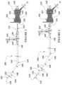
- FIG. 1is a side view of an example system for transseptal perforation, with a needle of the system in a shrouded position, and with a lock of the system not shown;
- FIG. 2is a side view of the system of FIG. 1 , with the needle of the system in an in-use position, and with the lock of the system not shown;
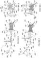
- FIG. 3is a side view of the system of FIG. 1 , with the needle of the system in the shrouded position, and with the lock of the system shown;
- FIG. 4is partial perspective view of the system of FIG. 1 , with the needle of the system in the shrouded position, and with the lock of the system shown;
- FIG. 5is a side view of the system of FIG. 1 , with the needle of the system in the in-use position, and with the lock of the system shown;
- FIG. 6is a partial perspective view of the system of FIG. 1 , with the needle of the system in the in-use position, and with the lock of the system shown;
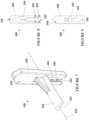
- FIG. 7is a perspective view of the lock of FIGS. 3 to 6 ;
- FIG. 8is a rear view of the lock of FIGS. 3 to 6 ;
- FIG. 9is a front view of the lock of FIGS. 3 to 6 ;
- FIG. 10is a perspective view of another example lock
- FIG. 11is a side view of the lock of FIG. 10 ;
- FIG. 12is a top view of the lock of FIG. 10 ;
- FIG. 13is a front view of the lock of FIG. 10 ;
- FIG. 14is a rear view of the lock of FIG. 10 ;
- FIG. 15is a partial perspective view of another system for transseptal perforation, showing a needle of the system in a shrouded position, and including the lock of FIGS. 10 to 14 ;
- FIG. 16is a partial perspective view of the system for transseptal perforation of FIG. 15 , showing the needle of the system in an in-use position, and including the lock of FIGS. 10 to 15 ;
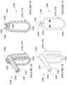
- FIG. 17is a partial perspective view of another system for transseptal perforation, with a needle of the system in a shrouded position, and including another example lock;
- FIG. 18is a perspective view of the lock of FIG. 17 , with the lock in a released state;
- FIG. 19is a front view of the lock of FIG. 17 , with the lock in the released state;
- FIG. 20is a perspective view of the lock of FIG. 17 , with the lock in a clamped state;
- FIG. 21is a perspective view of the lock of FIG. 17 , with the lock in the clamped state.
- FIG. 22is a perspective view of another example lock
- FIG. 23is a partial perspective view of another system for transseptal perforation including the lock of FIG. 22 .
- FIG. 24a partial perspective view of the system for transseptal perforation, showing a needle of the system in a shrouded position, and including the lock of FIG. 22 to 23 .
- FIG. 25a partial perspective view of the system for transseptal perforation, showing a needle of the system in an in-use position, and including the lock of FIG. 22 to 24 .
- locks for medical devicesMore specifically, disclosed herein are various examples of a lock that can be used to maintain the position a first medical device with respect to a second medical device, or to facilitate the positioning of a first medical device with respect to a second medical device, to facilitate ease of use and enhance patient safety.
- the locks disclosed hereincan be used as part of a system for transseptal perforation, which can further include a dilator, a sheath, and a transseptal perforation device.
- the sheathcan be advanced to the right atrium of a patient's heart via the femoral vein and positioned adjacent a target location in the right atrium, for example the fossa ovalis of the atrial septum.
- the transseptal perforation devicee.g. a radiofrequency (RF) perforation device
- RFradiofrequency
- the transseptal perforation devicecan be advanced out of the dilator and used to create a perforation in the target location.
- the dilatorcan then be advanced through the perforation to dilate the perforation.
- Such procedurescan be carried out, for example, as a medical treatment, or to gain access to the left atrium for a subsequent medical treatment.
- the locks as disclosed hereincan be used to prevent the perforating tip of the transseptal perforation device from being prematurely advanced out of the dilator.
- the locks as described hereincan maintain the perforating tip shrouded within the dilator until the operator of the system is ready to advance the transseptal perforation device out of the dilator. Furthermore, the locks as described herein can fix the rotational position of the transseptal perforation device with respect to the sheath and/or dilator, to facilitate curving of the transseptal perforation device in a desired direction, so that upon advancement, the transseptal perforation device is advanced towards the target location.
- the system 100includes a transseptal perforation device 102 , a dilator 104 , a sheath 106 , and a lock 108 .
- the system 100is shown without the lock 108 in FIGS. 1 and 2 , and with the lock 108 in FIGS. 3 to 6 .
- the sheathmay be omitted, and a dilator may serve as both a sheath and a dilator.
- Such dilatorsare sold by Baylis Medical Company Inc. (Montreal, Canada) under the brand name ExpanSureTM Transseptal Dilation System.
- the transseptal perforation device 102has a handle 110 and an elongate needle 112 , which is generally flexible.
- the needle 112has a needle proximal end 114 (shown in FIG. 1 ) secured to the handle 110 and a needle distal end 116 including a perforating tip 118 (shown in FIG. 2 ).
- the perforating tip 118can be, for example, a radiofrequency perforating tip, or a mechanical perforating tip.
- the handle 110includes several ribs, including an outer rib 120 extending around the perimeter of the handle 110 .
- the outer rib 120includes an upper section 122 , a lower section 124 , a front section 126 , and a rear section 128 .
- the 104 dilatorhas a dilator hub 130 , and an elongate dilator body 132 .
- the dilator body 132has a dilator lumen (not shown) extending therethrough, a dilator body proximal end 134 secured to the dilator hub 130 and a dilator body distal end 136 including a dilating tip 138 .
- the sheath 106has a sheath hub 140 including a radially extending fluid port 142 , and an elongate sheath body 144 extending longitudinally from the sheath hub 140 .
- the fluid port 142may be indicative of the direction of curvature of the sheath 106 .
- the fluid port 142may be replaced by a curve indicator (not shown).
- the sheath body 144has a sheath body proximal end 146 adjacent the sheath hub 140 , and a sheath body distal end 148 spaced from the sheath hub 140 .
- a sheath lumen(not shown) extends longitudinally through the sheath from the sheath hub 140 to the sheath body distal end 148 .
- the dilator body 132is advanceable through the sheath lumen to position the dilator body 132 within the sheath body 144 , with the dilator hub 130 adjacent the sheath hub 140 and the dilating tip 138 proud of the sheath body distal end 148 . Furthermore, the needle 112 of the transseptal perforation device 102 is advanceable through the dilator 104 to a shrouded position, shown in FIG. 1 , in which the perforating tip 118 (not visible in FIG.
- the needle 112is in the shrouded position, the patient's anatomy is protected from contact with the perforating tip 118 , as the perforating tip is shrouded within the dilator 104 .
- the perforating tip 118is exposed, and can perforate anatomical structures.
- the lock 108can be used to prevent advancement of the needle 112 from the shrouded position (shown in FIGS. 3 and 4 ) to the in-use position (shown in FIGS. 4 and 5 ), until such advancement is desired by the operator.
- the lock 108can be used up until the operator of the system is ready to perforate a target location within a patient's heart, for example during advancement of the dilator 104 and transseptal perforation device 102 through the sheath 106 towards the target location, and during any preliminary tests, in order to prevent inadvertent contact between the perforating tip 118 and non-target locations within a patient's body, and prevent inadvertent damage to such non-target locations.
- the lock 108includes an elongate spacer 150 .
- the spacer 150has a first abutment surface 152 (visible in FIGS. 7 and 9 ) and a second abutment surface 154 (visible in FIG. 8 ) spaced apart along a longitudinal axis 156 of the spacer 150 .
- the lock 108further includes a clip 158 , which is integral with the spacer 150 .
- the clip 158includes a tongue 160 that extends orthogonally from the spacer 150 , and defines a slot 162 .
- the tongue 160further includes a first detent 164 and a second detent 166 spaced apart from the first detent 164 .
- the clip 158can snap onto the handle 110 of the transseptal perforation device 102 , to position the spacer 150 proximal of the dilator hub 130 , and between the dilator hub 130 and the handle 110 , so that if advancement of the needle 112 beyond the shrouded position is attempted (e.g. inadvertently), the spacer 150 will abut the dilator hub 130 to prevent movement of the needle 112 to the in-use position by preventing movement of the handle 110 towards the dilator hub 130 . More specifically, referring to FIGS. 3 and 4 , the lock 108 is shown with the spacer 150 in a lock position.
- the spacer 150is proximal of the dilator hub 130 , and between the dilator hub 130 and the handle 110 , to abut the dilator hub 130 (and also the handle 110 ) if movement of the handle 110 towards the dilator hub 130 is attempted.
- This abutmentprevents movement of the needle 112 to the in-use position, by preventing movement of the handle 110 towards the dilator hub 130 .
- the lock 108is shown with the spacer 150 in an unlock position.
- the spacer 150In the unlock position, the spacer 150 is moved radially away from the dilator hub 130 and the handle 110 , in a direction transverse to the longitudinal axis 156 of the spacer 150 , so that the spacer 150 is clear of the dilator hub 130 , to allow movement of the handle 110 towards the dilator hub 130 and therefore allow movement of the needle 112 to the in-use position.
- the clip 158serves to secure the lock 108 to the transseptal perforation device.
- the clip 158secures the lock 108 to the handle 110 with the spacer 150 in the lock position, and secures the lock 108 to the handle 110 with the spacer in the unlock position, and allows for movement of the spacer 150 between the lock and unlock positions. That is, the clip 158 is removably securable to the handle 110 in a first position, shown in FIGS. 5 and 6 , to secure the spacer 150 in the unlock position, and removably securable to the handle 110 in a second position, shown in FIGS. 3 and 4 to secure the spacer 150 in the lock position.
- the slot 162 (shown in FIGS. 7 to 9 ) of the clip 158can receive the handle 110 , particularly the front section 126 (shown in FIGS. 1 and 2 ) of the outer rib 120 of the handle 110 , which can slide into the slot 162 going in a direction transverse to the longitudinal axis 156 of the spacer 150 , from the upper section 122 of the outer rib 120 towards the lower section 124 of the outer rib 120 .
- the lower section 124will engage the first detent 164 by snapping into the first detent 164 .
- the spacer 150When the lower section 124 is engaged with the first detent 164 , the spacer 150 is secured in the unlock position, as shown in FIGS. 5 and 6 . If further force is applied to slide the front section 126 further into the slot 162 , the lower section 124 will snap out of engagement with the first detent 164 , and towards the second detent 166 . As the lower section 124 approaches the second detent 166 , the lower section 124 will engage the second detent 166 by snapping into the second detent 166 . When the lower section 124 is engaged with the second detent 166 , the spacer 150 is secured in the lock position, as shown in FIGS. 3 and 4 .
- the spacer 150can be moved between the lock and unlock positions by sliding the clip 158 into and out of engagement with the first detent 164 and second detent 166 .
- the configuration of the clip 158can advantageously allow for one-handed operation of the lock 108 .
- the sheath 106 and dilator 104can be advanced to the right atrium of a patient's heart via the femoral vein and the dilating tip 138 can be positioned adjacent a target location in the right atrium, for example the fossa ovalis of the atrial septum.
- the lock 108Prior to or after advancement of the sheath 106 and dilator 104 , the lock 108 can be secured to the transseptal perforation device 102 , and the spacer 150 of the lock 108 can be positioned the lock position, as shown in FIGS. 3 and 4 .
- the clip 158can be engaged with the handle 110 of the transseptal perforation device 102 , by sliding the front section 126 of the outer rib 120 into the slot 162 , and engaging the first detent 164 with the lower section 124 of the outer rib 120 , to secure the lock to the transseptal perforation device 102 with the spacer 150 in an unlock position. Force can continue to be applied, to snap the first detent 164 out of engagement with the outer rib 120 , and to slide the clip 158 further towards the handle 110 , to snap the second detent 166 into engagement with the lower section 124 of the outer rib 120 . When the clip 158 is in this position (i.e.
- the spacer 150is in the lock position, as shown in FIGS. 3 and 4 .
- the transseptal perforation device 102can be advanced into the dilator 104 .
- the spacer 150in the lock position, is positioned between the dilator hub 130 and the handle 110 of the transseptal perforation device 102 , to abut the dilator hub 130 and the handle 110 and limit advancement of the transseptal perforation device 102 into the dilator 104 , and thereby prevent advancement of a perforating tip 118 of the transseptal perforation device 102 proud of a dilating tip 138 of the dilator 104 , to the in-use position.
- various optional procedurescan be carried out, including procedures to confirm the position of the dilating tip 138 (e.g. using fluoroscopy).
- the spacer 150can be removed from the lock position, to clear the spacer 150 of the dilator hub 130 .
- the spacer 150can be moved from the lock position to the unlock position, by snapping the second detent 166 out of engagement with the lower section 124 of the outer rib 120 , sliding the clip 158 along the handle, transversely away from the needle 112 , and snapping the first detent 166 into engagement with the lower section 124 of the outer rib 120 (as shown in FIGS. 5 and 6 ).
- the transseptal perforation device 102can then be advanced further into the dilator 104 to position the perforating tip 118 proud of the dilating tip 138 , in the in-use position.
- the perforating tip 118can then be used to perforate the target anatomy.
- FIGS. 22 to 24another example lock is shown.
- Features of the lock 2208 that are like features of the lock 108will be referred to with like reference numerals, incremented by 2100.
- the lock 2208includes an elongate spacer 2250 .
- the spacer 2250has a first abutment surface 2252 (visible in FIG. 23 ) which, in the locked position, contacts the dilator hub 130 (as illustrated in FIG. 24 ).
- the lock 2208further includes a clip 2258 , which is integral with the spacer 2250 .
- the clip 2258includes a tongue 2260 that extends orthogonally from the spacer 2250 and defines a slot 2262 .
- the tongue 2260further defines a second abutment surface 2254 which provides an abutment surface between the lock 2208 and the handle 110 when positioned on the handle 110 .
- the tongue 2260further comprises a bottom face 2282 which provides the user with a pushing surface.
- the bottom face 2282may include a smooth finish, providing the user with a better pushing surface during use.
- the tongue 2260further includes a first detent 2264 and a second detent 2266 spaced apart from the first detent 2264 . As this lock 2208 is small and compact, less material is used which results in a reduction in cost and packaging space.
- the lock 2208can be used to prevent advancement of the needle 112 from the shrouded position (shown in FIG. 24 ) to the in-use position (shown in FIG. 25 ), until such advancement is desired by the operator.
- the lock 2208can be used up until the operator of the system is ready to perforate a target location within a patient's heart, for example during advancement of the dilator 104 and transseptal perforation device 102 through the sheath (shown in FIGS. 1 and 2 ) towards the target location, and during any preliminary tests, in order to prevent inadvertent contact between the perforating tip (shown in FIGS. 1 and 2 ) and non-target locations within a patient's body, and prevent inadvertent damage to such non-target locations.
- the clip 2258can snap onto the handle 110 of the transseptal perforation device 102 , to position the spacer 2250 proximal of the dilator hub 130 , and between the dilator hub 130 and the handle 110 , so that if advancement of the needle 112 beyond the shrouded position is attempted (e.g. inadvertently), the spacer 2250 will abut the dilator hub 130 to prevent movement of the needle 112 to the in-use position by preventing movement of the handle 110 towards the dilator hub 130 . More specifically, referring to FIG. 24 , the lock 2208 is shown with the spacer 2250 in a lock position.
- the spacer 2250is proximal of the dilator hub 130 , and between the dilator hub 130 and the handle 110 , to abut the dilator hub 130 if movement of the handle 110 towards the dilator hub 130 is attempted.
- This abutmentprovided by the first abutment surface 2252 (visible in FIG. 23 ) prevents movement of the needle 112 to the in-use position, by preventing movement of the handle 110 towards the dilator hub 130 .
- the lock 2208is shown with the spacer 2250 in an unlock position.
- the spacer 2250In the unlock position, the spacer 2250 is moved radially away from the dilator hub 130 and the handle 110 , in a direction T transverse to the longitudinal axis of the spacer 2250 , so that the spacer 2250 is clear of the dilator hub 130 , to allow movement of the handle 110 towards the dilator hub 130 and therefore allow movement of the needle 112 to the in-use position.
- the clip 2258serves to secure the lock 2208 to the transseptal perforation device.
- the clip 2258secures the lock 2208 to the handle 110 with the spacer 2250 in the lock position, and to secures the lock 2208 to the handle 110 with the spacer in the unlock position, and allows for movement of the spacer 2250 between the lock and unlock positions. That is, the clip 2258 is removably securable to the handle 110 in a first position, shown in FIG. 24 , to secure the spacer 150 in the locked position, and removably securable to the handle 110 in a second position, shown in FIG. 25 to secure the spacer 2250 in the unlock position.
- the lock 2208can remain in either the locked or unlocked positions such that it may be used multiple times throughout the procedure.
- the slot 2262 (shown in FIG. 22 ) of the clip 2258can receive the handle 110 , particularly the front section 126 (shown in FIGS. 23 to 25 ) of the outer rib 120 of the handle 110 , which can slide into the slot 2262 going in a direction T transverse to the longitudinal axis of the spacer 2250 (as illustrated in FIG. 25 ), from the lower section 124 of the outer rib 120 towards the upper section 122 of the outer rib 120 .
- the lock 2208may be positioned in the opposite configuration.
- the clip 2258can receive the front section 126 of the outer rib 120 of the handle 110 , sliding into the slot 2262 in the opposite direction, moving from the upper section 122 of the outer rib 120 towards the lower section 124 of the outer rib 120 .
- the outer rib 120 of the upper section 122engages with the outer edge 2290 (visible in FIG. 22 ).
- the lower section 124will engage the second detent 2266 by snapping into the second detent 2266 (as seen in FIG. 24 ).
- the spacer 150is secured in the locked position, as shown in FIG. 24 . If further force is applied to the bottom face 2282 of the lock 2280 , the clip 2258 slides along the front section 126 which moves further into the slot 2262 . The lower section 124 will snap out of engagement with the second detent 2266 .
- the outer rib 120 of the upper section 122then engages with the first detent 2264 by snapping into the first detent 2264 (as seen in FIG. 25 ).
- the spacer 2250is secured in the unlock position, as shown in FIG. 25 . Accordingly, the spacer 2250 can move from the lock and unlock position by sliding the clip 2258 into and out of engagements with the first 2264 and second detent 2266 .
- the configuration of the clip 2258can advantageously allow for one-handed operation of the lock 2208 throughout the procedure.
- the sheath 106 and dilator 104can be advanced to the right atrium of a patient's heart via the femoral vein and the dilating tip 138 can be positioned adjacent a target location in the right atrium, for example the fossa ovalis of the atrial septum.
- the lock 2208Prior to or after advancement of the sheath 106 and dilator 104 , the lock 2208 can be secured to the transseptal perforation device 102 , and the spacer 2250 of the lock 2208 can be positioned the lock position, as shown in FIG. 24 .
- the clip 2258can be engaged with the handle 110 of the transseptal perforation device 102 , by sliding the front section 126 into the slot 2262 , and engaging the second detent 2266 with the lower section 124 , to secure the lock 2208 to the transseptal perforation device 102 with the spacer 2250 in a lock position. With the spacer 2250 in the lock position, the transseptal perforation device 102 can be advanced into the dilator 104 .
- the spacer 2250is positioned between the dilator hub 130 and the handle 110 of the transseptal perforation device 102 , to abut the dilator hub 130 and the handle 110 and limit advancement of the transseptal perforation device 102 into the dilator 104 , and thereby prevent advancement of a perforating tip 118 of the transseptal perforation device 102 proud of a dilating tip 138 of the dilator 104 , to the in-use position.
- various optional procedurescan be carried out, including procedures to confirm the position of the dilating tip 138 (e.g. using fluoroscopy).
- the spacer 2250can be removed from the lock position, to clear the spacer 150 of the dilator hub 130 . That is, the spacer 2250 can be moved from the lock position to the unlock position, by applying force to the bottom face 2282 which will move the lock 2208 along the front section 126 of the handle 110 . This will result in the second detent 2266 out of engagement with the lower section 124 , sliding the clip 2258 along the front section 126 of the handle 110 . The first detent 2264 then snaps into engagement with the outer rib 120 of the upper section 122 (as shown in FIG. 25 ), causing the spacer 2250 to move into the unlock position.
- the transseptal perforation device 102can then be advanced further into the dilator 104 to position the perforating tip 118 proud of the dilating tip 138 , in the in-use position.
- the perforating tip 118can then be used to perforate the target anatomy.
- FIGS. 10 to 16another example lock is shown.
- the lock 1008 of FIGS. 10 to 16is similar to the lock of FIGS. 3 to 9 , and features of the lock 1008 that are like features of the lock 108 will be referred to with like reference numerals, incremented by 900.
- the lock 1008includes a spacer 1050 and a clip 1058 that are similar to the spacer 150 and clip 158 of FIGS. 10 to 16 ; however, the lock 1008 further includes a rotary stop 1068 for releasably fixing the rotational position of the transseptal perforation device 102 with respect to the dilator 104 . That is, referring back to FIGS. 1 and 2 , the sheath 106 includes a curved region 170 (also referred to herein as a ‘sheath curved region’), which is shaped to allow the dilating tip 138 to reach the heart when advanced towards the heart from the femoral vein.
- a curved region 170also referred to herein as a ‘sheath curved region’
- the dilator 104includes a curved region (also referred to herein as a ‘dilator curved region’), and the needle includes a curved region (also referred to as a ‘needle curved region’).
- the dilator curved region and needle curved regionare within the sheath curved region 170 in FIGS. 1 and 2 , and are not visible.
- the dilator 104 and needle 112are generally positioned within the sheath 106 with the dilator curved region, needle curved region, and sheath curved region 170 generally curved in the same direction, as shown in FIGS. 1 and 2 (i.e. curved upwardly in FIGS. 1 and 2 , as opposed to downwardly).
- the needle 112due to the flexibility of the needle 112 , it is possible to inadvertently advance the needle 112 through the dilator 104 and sheath 106 with the needle curved region curved in a different direction from the dilator curved region and sheath curved region 170 (e.g. with the needle 112 rotated about it's longitudinal axis by 180 degrees, so that it is curved downwardly). In such instances, when the perforating tip 118 is advanced from the dilator 104 , it can curve away from the target location. In the example of FIGS.
- the rotary stop 1068 of the lock 1008can be used to avoid or prevent or mitigate this issue, by fixing the rotational position of the transseptal perforation device 102 with respect to the sheath 106 with the needle curved region curved in the same direction as the sheath curved region 170 .
- the rotary stop 1068includes a pair of arms 1072 , 1074 .
- the arms 1072 , 1074are generally parallel to the spacer 1050 , are offset from the longitudinal axis 1056 of the spacer 1050 , and extend distally beyond the first abutment surface 1052 of the spacer 1050 .
- the arms 1072 , 1074define a space 1076 therebetween for receiving the fluid port 142 of the sheath hub 140 .
- the curved region of the needleis curved in the same direction as the curved region 170 of the sheath 106 . That is, engagement of the rotary stop 1068 of the lock 1008 with the sheath hub 140 fixes the rotational position of the transseptal perforation device 102 with respect to the sheath 106 .
- a curve indicator(not shown) may be present, replacing the fluid port 142 .
- the curve indicatormay comprise an arm extending from the hub of the sheath hub 140 , wherein the curve indicator denoting the direction of the curved region.
- the curve indicatormay then be received in the space 1076 between the arms 1072 , 1074 ; this engagement of the rotary stop 1068 of the lock 1008 with the curve indicator of the sheath hub 140 fixes the rotational position of the transseptal perforation device 102 with respect to the sheath 106 .
- the handle 110 of the transseptal perforation device 102can be rotated to align the space 1076 with the fluid port 142 , so that the fluid port 142 is received in the space 1076 .
- the spacer 1050can be moved to the unlock position, and the handle can be advanced to move the transseptal perforation device 102 to the in-use position, as shown in FIG. 16 .
- the fluid port 142is slid further into the space 1076 between the arms 1072 , 1074 . That is, the engagement of the rotary stop 1068 and the sheath hub 140 is maintained during advancement of the transseptal perforation device 102 to the in-use position, as well as during use of the transseptal perforation device 102 .
- the engagement of the fluid port 142 and the arms 1072 , 1074fixes the rotational position of the transseptal perforation device 102 with respect to the sheath 106 , and prevents rotation of the transseptal perforation device 102 about its longitudinal axis, which ensures that the curved region of the needle is curved in the same direction as the curved region 170 of the sheath 104 (or facilitates curving of the curved region of the needle in the same direction as the curved region 170 of the sheath 104 ).
- a similar methodmay be used for the embodiment where a curve indicator is used instead of a fluid port 142 .
- FIGS. 17 to 21another example lock is shown.
- Features of the lock 1708 that are like features of the lock 108will be referred to with like reference numerals, incremented by 1600.
- the spacer 1750is similar to the spacer of FIGS. 3 to 9 ; however, the clip 1758 is in the form of a clamp 1778 that can be releasably secured to the needle proximal end 114 of the transseptal perforation device 102 , as shown in FIG. 17 (the needle 112 is not visible in FIG. 17 ).
- the spacer 1750includes a first side 1780 and a second side 1782 , and the first side includes a groove 1784 (labelled only in FIGS. 18 , 19 , and 20 ) for receiving a portion of the needle 112 .
- the clamp 1778includes an arm 1786 that is generally U-shaped and resiliently flexible, and that extends from the spacer 1750 generally downwardly, laterally in a first direction, back upwardly, and laterally in a second direction opposite the first direction.
- a head 1788is at the end of the arm 1786 , and is positioned proximate the first side 1780 of the spacer 1750 .
- the clamp 1778is biased towards a clamped state, shown in FIGS. 20 and 21 , in which due to the resiliency of the arm 1786 , the head 1788 presses against the first side 1780 of the spacer 1750 .
- the clamp 1778is movable to a released state, shown in FIGS.
- the spacer 1750can be secured in the lock position by clamping the needle 112 between the head 1788 and the spacer 1750 .
- the clamp 1778can be squeezed and the lock 1708 can be removed from the transseptal perforation device 102 .
- the systemcan include a sensor for detecting when the spacer is in the lock position.
- the sensorcan be used to detect when the spacer is in the lock position, and energizing of the transseptal perforation device can be automatically prevented when the sensor detects that the spacer is in the lock position.
- the parts of the systemcan be provided separately, or can be provided together as a kit of parts.
- the locksare described with respect to a transseptal perforation system.
- the locksmay be used with other medical devices and for other purposes, for example for positioning a first medical device with respect to a second medical device.
- the lockinstead of engaging with a handle and needle of a transseptal perforation device and with a hub of a dilator or sheath, the lock may engage with various parts or portions of the first and second medical devices.
- a transseptal perforation deviceincluding handle and a needle
- a simple guidewirecould be used for transseptal perforation (e.g.
- a locke.g. lock 1708
- a desired positioni.e. a position proximal of the dilator hub, to abut the dilator hub as the guidewire is advanced through the dilator.
Landscapes
- Health & Medical Sciences (AREA)
- Surgery (AREA)
- Life Sciences & Earth Sciences (AREA)
- Medical Informatics (AREA)
- Nuclear Medicine, Radiotherapy & Molecular Imaging (AREA)
- Engineering & Computer Science (AREA)
- Biomedical Technology (AREA)
- Heart & Thoracic Surgery (AREA)
- Molecular Biology (AREA)
- Animal Behavior & Ethology (AREA)
- General Health & Medical Sciences (AREA)
- Public Health (AREA)
- Veterinary Medicine (AREA)
- Pathology (AREA)
- Cardiology (AREA)
- Surgical Instruments (AREA)
Abstract
Description
Claims (19)
Priority Applications (1)
| Application Number | Priority Date | Filing Date | Title |
|---|---|---|---|
| US17/070,442US11759190B2 (en) | 2019-10-18 | 2020-10-14 | Lock for medical devices, and related systems and methods |
Applications Claiming Priority (2)
| Application Number | Priority Date | Filing Date | Title |
|---|---|---|---|
| US201962923051P | 2019-10-18 | 2019-10-18 | |
| US17/070,442US11759190B2 (en) | 2019-10-18 | 2020-10-14 | Lock for medical devices, and related systems and methods |
Publications (2)
| Publication Number | Publication Date |
|---|---|
| US20210113198A1 US20210113198A1 (en) | 2021-04-22 |
| US11759190B2true US11759190B2 (en) | 2023-09-19 |
Family
ID=75492743
Family Applications (1)
| Application Number | Title | Priority Date | Filing Date |
|---|---|---|---|
| US17/070,442Active2041-08-17US11759190B2 (en) | 2019-10-18 | 2020-10-14 | Lock for medical devices, and related systems and methods |
Country Status (1)
| Country | Link |
|---|---|
| US (1) | US11759190B2 (en) |
Families Citing this family (1)
| Publication number | Priority date | Publication date | Assignee | Title |
|---|---|---|---|---|
| JPWO2022260120A1 (en)* | 2021-06-09 | 2022-12-15 |
Citations (284)
| Publication number | Priority date | Publication date | Assignee | Title |
|---|---|---|---|---|
| US175254A (en) | 1876-03-28 | Improvement in game apparatus | ||
| US827626A (en) | 1905-02-15 | 1906-07-31 | Alexis F Gillet | Game apparatus. |
| US848711A (en) | 1906-06-28 | 1907-04-02 | Daniel Weaver | Game apparatus. |
| US1072954A (en) | 1913-03-29 | 1913-09-09 | Frank B Junn | Game apparatus. |
| US1279654A (en) | 1916-04-14 | 1918-09-24 | Horace M Charlesworth | Game apparatus. |
| US1918094A (en) | 1931-04-04 | 1933-07-11 | Demetrius G Geekas | Game device |
| US1996986A (en) | 1932-05-13 | 1935-04-09 | Weinberg Alexander | Game apparatus |
| US2021989A (en) | 1931-12-08 | 1935-11-26 | Master Matthew J De | Ball tossing game |
| US2146636A (en) | 1937-01-09 | 1939-02-07 | Walter F Lipchow | Baseball game |
| US3429574A (en) | 1965-08-12 | 1969-02-25 | Charles L Williams | Game with ball-receiving spaced divider members |
| US3448739A (en) | 1966-08-22 | 1969-06-10 | Edwards Lab Inc | Double lumen diagnostic balloon catheter |
| US3575415A (en) | 1968-05-17 | 1971-04-20 | Franklin G Fulp | Pocketed ball-receiving target |
| US3595239A (en) | 1969-04-04 | 1971-07-27 | Roy A Petersen | Catheter with electrical cutting means |
| US4129129A (en) | 1977-03-18 | 1978-12-12 | Sarns, Inc. | Venous return catheter and a method of using the same |
| US4244362A (en) | 1978-11-29 | 1981-01-13 | Anderson Charles C | Endotracheal tube control device |
| US4401124A (en) | 1981-08-13 | 1983-08-30 | Technicare Corporation | Reflection enhancement of a biopsy needle |
| US4639252A (en) | 1985-04-05 | 1987-01-27 | Research Medical, Inc. | Venous return catheter |
| US4641649A (en) | 1985-10-30 | 1987-02-10 | Rca Corporation | Method and apparatus for high frequency catheter ablation |
| US4669467A (en) | 1985-03-22 | 1987-06-02 | Massachusetts Institute Of Technology | Mode mixer for a laser catheter |
| US4682596A (en) | 1984-05-22 | 1987-07-28 | Cordis Corporation | Electrosurgical catheter and method for vascular applications |
| US4790809A (en) | 1985-08-29 | 1988-12-13 | Medical Engineering Corporation | Ureteral stent |
| US4790311A (en) | 1986-06-03 | 1988-12-13 | Ruiz Oscar F | Radio frequency angioplasty catheter system |
| US4793350A (en) | 1987-01-06 | 1988-12-27 | Advanced Cardiovascular Systems, Inc. | Liquid filled low profile dilatation catheter |
| US4807620A (en) | 1987-05-22 | 1989-02-28 | Advanced Interventional Systems, Inc. | Apparatus for thermal angioplasty |
| US4832048A (en) | 1987-10-29 | 1989-05-23 | Cordis Corporation | Suction ablation catheter |
| US4840622A (en) | 1987-10-06 | 1989-06-20 | Menlo Care, Inc. | Kink resistant catheter |
| US4863441A (en) | 1987-07-17 | 1989-09-05 | Minnesota Mining And Manufacturing Company | Venous return catheter |
| US4884567A (en) | 1987-12-03 | 1989-12-05 | Dimed Inc. | Method for transvenous implantation of objects into the pericardial space of patients |
| US4892104A (en) | 1988-09-02 | 1990-01-09 | Nihon Kohden Corp. | Apparatus for inspecting an electrically stimulated heart |
| US4896671A (en) | 1988-08-01 | 1990-01-30 | C. R. Bard, Inc. | Catheter with contoured ablation electrode |
| US4928693A (en) | 1989-03-13 | 1990-05-29 | Schneider (Usa), Inc. | Pressure monitor catheter |
| US4936281A (en) | 1989-04-13 | 1990-06-26 | Everest Medical Corporation | Ultrasonically enhanced RF ablation catheter |
| US4960410A (en) | 1989-03-31 | 1990-10-02 | Cordis Corporation | Flexible tubular member for catheter construction |
| US4966587A (en)* | 1988-04-29 | 1990-10-30 | Rainer Baumgart | Medical intromission kit |
| US4977897A (en) | 1988-08-17 | 1990-12-18 | Robert Hurwitz | Amniocentesis needle with improved sonographic visibility |
| US4998933A (en) | 1988-06-10 | 1991-03-12 | Advanced Angioplasty Products, Inc. | Thermal angioplasty catheter and method |
| US5006119A (en) | 1989-05-25 | 1991-04-09 | Engineering & Research Associates, Inc. | Hollow core coaxial catheter |
| US5019076A (en) | 1986-09-12 | 1991-05-28 | Yamanashi William S | Radio frequency surgical tool and method |
| US5047026A (en) | 1989-09-29 | 1991-09-10 | Everest Medical Corporation | Electrosurgical implement for tunneling through tissue |
| US5081997A (en) | 1989-03-09 | 1992-01-21 | Vance Products Incorporated | Echogenic devices, material and method |
| US5098431A (en) | 1989-04-13 | 1992-03-24 | Everest Medical Corporation | RF ablation catheter |
| US5112048A (en) | 1990-11-05 | 1992-05-12 | Kienle Robert N | Garage roof party game |
| US5154724A (en) | 1990-05-14 | 1992-10-13 | Andrews Winston A | Atherectomy catheter |
| US5201756A (en) | 1990-06-20 | 1993-04-13 | Danforth Biomedical, Inc. | Radially-expandable tubular elements for use in the construction of medical devices |
| US5209741A (en) | 1991-07-08 | 1993-05-11 | Endomedix Corporation | Surgical access device having variable post-insertion cross-sectional geometry |
| US5211183A (en) | 1987-05-13 | 1993-05-18 | Wilson Bruce C | Steerable memory alloy guide wires |
| US5221256A (en) | 1992-02-10 | 1993-06-22 | Mahurkar Sakharam D | Multiple-lumen catheter |
| US5222974A (en)* | 1991-11-08 | 1993-06-29 | Kensey Nash Corporation | Hemostatic puncture closure system and method of use |
| US5230349A (en) | 1988-11-25 | 1993-07-27 | Sensor Electronics, Inc. | Electrical heating catheter |
| US5242410A (en)* | 1991-04-15 | 1993-09-07 | University Of Florida | Wireless high flow intravascular sheath introducer and method |
| US5281216A (en) | 1992-03-31 | 1994-01-25 | Valleylab, Inc. | Electrosurgical bipolar treating apparatus |
| US5300068A (en) | 1992-04-21 | 1994-04-05 | St. Jude Medical, Inc. | Electrosurgical apparatus |
| US5300069A (en) | 1992-08-12 | 1994-04-05 | Daniel Hunsberger | Electrosurgical apparatus for laparoscopic procedures and method of use |
| US5314418A (en) | 1990-09-21 | 1994-05-24 | Toyo Boseki Kabushiki Kaisha | Cannula |
| US5318525A (en) | 1992-04-10 | 1994-06-07 | Medtronic Cardiorhythm | Steerable electrode catheter |
| US5327905A (en) | 1992-02-14 | 1994-07-12 | Boaz Avitall | Biplanar deflectable catheter for arrhythmogenic tissue ablation |
| US5364393A (en) | 1990-07-02 | 1994-11-15 | Heart Technology, Inc. | Tissue dissipative recanalization catheter |
| US5372596A (en) | 1993-07-27 | 1994-12-13 | Valleylab Inc. | Apparatus for leakage control and method for its use |
| US5380304A (en) | 1991-08-07 | 1995-01-10 | Cook Incorporated | Flexible, kink-resistant, introducer sheath and method of manufacture |
| US5397304A (en) | 1992-04-10 | 1995-03-14 | Medtronic Cardiorhythm | Shapable handle for steerable electrode catheter |
| US5403338A (en) | 1992-01-21 | 1995-04-04 | Scanlan International, Inc. | Punch for opening passages between two compartments |
| US5423809A (en) | 1992-01-21 | 1995-06-13 | Valleylab Inc. | Electrosurgical control for a trocar |
| US5425382A (en) | 1993-09-14 | 1995-06-20 | University Of Washington | Apparatus and method for locating a medical tube in the body of a patient |
| US5490859A (en) | 1992-11-13 | 1996-02-13 | Scimed Life Systems, Inc. | Expandable intravascular occlusion material removal devices and methods of use |
| US5497774A (en) | 1993-11-03 | 1996-03-12 | Daig Corporation | Guiding introducer for left atrium |
| US5507751A (en) | 1988-11-09 | 1996-04-16 | Cook Pacemaker Corporation | Locally flexible dilator sheath |
| US5509411A (en) | 1993-01-29 | 1996-04-23 | Cardima, Inc. | Intravascular sensing device |
| US5540681A (en) | 1992-04-10 | 1996-07-30 | Medtronic Cardiorhythm | Method and system for radiofrequency ablation of tissue |
| US5545200A (en) | 1993-07-20 | 1996-08-13 | Medtronic Cardiorhythm | Steerable electrophysiology catheter |
| US5555618A (en) | 1993-10-12 | 1996-09-17 | Arrow International Investment Corp. | Method of making electrode-carrying catheter |
| US5571088A (en) | 1993-07-01 | 1996-11-05 | Boston Scientific Corporation | Ablation catheters |
| US5575766A (en) | 1993-11-03 | 1996-11-19 | Daig Corporation | Process for the nonsurgical mapping and treatment of atrial arrhythmia using catheters guided by shaped guiding introducers |
| US5599347A (en) | 1991-02-13 | 1997-02-04 | Applied Medical Resources Corporation | Surgical trocar with cutoff circuit |
| US5605162A (en) | 1991-10-15 | 1997-02-25 | Advanced Cardiovascular Systems, Inc. | Method for using a variable stiffness guidewire |
| US5617878A (en) | 1996-05-31 | 1997-04-08 | Taheri; Syde A. | Stent and method for treatment of aortic occlusive disease |
| US5624430A (en) | 1994-11-28 | 1997-04-29 | Eton; Darwin | Magnetic device to assist transcorporeal guidewire placement |
| US5667488A (en) | 1992-08-12 | 1997-09-16 | Vidamed, Inc. | Transurethral needle ablation device and method for the treatment of the prostate |
| US5673695A (en) | 1995-08-02 | 1997-10-07 | Ep Technologies, Inc. | Methods for locating and ablating accessory pathways in the heart |
| US5674208A (en) | 1993-08-18 | 1997-10-07 | Scimed Life Systems, Inc. | Thin-walled catheter |
| US5683366A (en) | 1992-01-07 | 1997-11-04 | Arthrocare Corporation | System and method for electrosurgical tissue canalization |
| US5720744A (en) | 1995-06-06 | 1998-02-24 | Valleylab Inc | Control system for neurosurgery |
| US5741249A (en) | 1996-10-16 | 1998-04-21 | Fidus Medical Technology Corporation | Anchoring tip assembly for microwave ablation catheter |
| US5766135A (en) | 1995-03-08 | 1998-06-16 | Terwilliger; Richard A. | Echogenic needle tip |
| US5779688A (en) | 1994-10-28 | 1998-07-14 | Intella Interventional Systems, Inc. | Low profile balloon-on-a-wire catheter with shapeable and/or deflectable tip and method |
| US5830214A (en) | 1994-11-08 | 1998-11-03 | Heartport, Inc. | Fluid-evacuating electrosurgical device |
| US5836875A (en) | 1995-10-06 | 1998-11-17 | Cordis Webster, Inc. | Split tip electrode catheter |
| US5849011A (en) | 1995-06-19 | 1998-12-15 | Vidamed, Inc. | Medical device with trigger actuation assembly |
| US5851210A (en) | 1997-03-21 | 1998-12-22 | Torossian; Richard | Stent delivery system and method |
| US5885227A (en) | 1997-03-25 | 1999-03-23 | Radius Medical Technologies, Inc. | Flexible guidewire with radiopaque plastic tip |
| US5888201A (en) | 1996-02-08 | 1999-03-30 | Schneider (Usa) Inc | Titanium alloy self-expanding stent |
| US5893885A (en) | 1996-11-01 | 1999-04-13 | Cordis Webster, Inc. | Multi-electrode ablation catheter |
| US5893848A (en) | 1996-10-24 | 1999-04-13 | Plc Medical Systems, Inc. | Gauging system for monitoring channel depth in percutaneous endocardial revascularization |
| US5904679A (en) | 1989-01-18 | 1999-05-18 | Applied Medical Resources Corporation | Catheter with electrosurgical cutter |
| US5916210A (en) | 1990-01-26 | 1999-06-29 | Intraluminal Therapeutics, Inc. | Catheter for laser treatment of atherosclerotic plaque and other tissue abnormalities |
| US5921957A (en) | 1994-07-12 | 1999-07-13 | Scimed Life Systems, Inc. | Intravascular dilation catheter |
| US5931818A (en) | 1997-08-29 | 1999-08-03 | Stereotaxis, Inc. | Method of and apparatus for intraparenchymal positioning of medical devices |
| US5944023A (en) | 1995-12-07 | 1999-08-31 | Sims Deltec, Inc. | Systems and methods for determining the location of an implanted device including a magnet |
| US5951482A (en) | 1997-10-03 | 1999-09-14 | Intraluminal Therapeutics, Inc. | Assemblies and methods for advancing a guide wire through body tissue |
| US5957842A (en) | 1994-01-27 | 1999-09-28 | Cardima, Inc. | High resolution intravascular signal detection |
| US5964757A (en) | 1997-09-05 | 1999-10-12 | Cordis Webster, Inc. | Steerable direct myocardial revascularization catheter |
| US5967976A (en) | 1994-08-19 | 1999-10-19 | Novoste Corporation | Apparatus and methods for procedures related to the electrophysiology of the heart |
| US5989276A (en) | 1996-11-08 | 1999-11-23 | Advanced Bypass Technologies, Inc. | Percutaneous bypass graft and securing system |
| US6007555A (en) | 1997-04-25 | 1999-12-28 | Surgical Design Corp | Ultrasonic needle for surgical emulsification |
| US6009877A (en) | 1994-06-24 | 2000-01-04 | Edwards; Stuart D. | Method for treating a sphincter |
| US6013072A (en) | 1997-07-09 | 2000-01-11 | Intraluminal Therapeutics, Inc. | Systems and methods for steering a catheter through body tissue |
| US6018676A (en) | 1993-08-31 | 2000-01-25 | Medtronic, Inc. | Ultrasound biopsy needle |
| US6017340A (en) | 1994-10-03 | 2000-01-25 | Wiltek Medical Inc. | Pre-curved wire guided papillotome having a shape memory tip for controlled bending and orientation |
| US6030380A (en) | 1996-12-09 | 2000-02-29 | Bsc Northwest Technology Center, Inc. | Radio frequency transmyocardial revascularization |
| US6048349A (en) | 1997-07-09 | 2000-04-11 | Intraluminal Therapeutics, Inc. | Systems and methods for guiding a medical instrument through a body |
| US6053904A (en) | 1996-04-05 | 2000-04-25 | Robert M. Scribner | Thin wall catheter introducer system |
| US6053870A (en) | 1997-11-08 | 2000-04-25 | Angiodynamics, Inc. | Ultrasonic visible surgical needle |
| US6056747A (en) | 1997-08-04 | 2000-05-02 | Gynecare, Inc. | Apparatus and method for treatment of body tissues |
| US6093185A (en) | 1998-03-05 | 2000-07-25 | Scimed Life Systems, Inc. | Expandable PMR device and method |
| US6106520A (en) | 1997-09-30 | 2000-08-22 | Hearten Medical, Inc. | Endocardial device for producing reversible damage to heart tissue |
| US6106515A (en) | 1998-08-13 | 2000-08-22 | Intraluminal Therapeutics, Inc. | Expandable laser catheter |
| US6117131A (en) | 1995-06-09 | 2000-09-12 | Engineering & Research Associates, Inc. | Multi-electrode probe for thermal ablation |
| US6142992A (en) | 1993-05-10 | 2000-11-07 | Arthrocare Corporation | Power supply for limiting power in electrosurgery |
| US6146380A (en) | 1998-01-09 | 2000-11-14 | Radionics, Inc. | Bent tip electrical surgical probe |
| US6156031A (en) | 1995-08-09 | 2000-12-05 | Eclipse Surgical Technologies | Transmyocardial revascularization using radiofrequency energy |
| US6155264A (en) | 1997-03-06 | 2000-12-05 | Scimed Life Systems, Inc. | Percutaneous bypass by tunneling through vessel wall |
| US6171305B1 (en) | 1998-05-05 | 2001-01-09 | Cardiac Pacemakers, Inc. | RF ablation apparatus and method having high output impedance drivers |
| US6179824B1 (en) | 1993-05-10 | 2001-01-30 | Arthrocare Corporation | System and methods for electrosurgical restenosis of body lumens |
| US6193676B1 (en) | 1997-10-03 | 2001-02-27 | Intraluminal Therapeutics, Inc. | Guide wire assembly |
| US6193715B1 (en) | 1999-03-19 | 2001-02-27 | Medical Scientific, Inc. | Device for converting a mechanical cutting device to an electrosurgical cutting device |
| US6210408B1 (en) | 1999-02-24 | 2001-04-03 | Scimed Life Systems, Inc. | Guide wire system for RF recanalization of vascular blockages |
| US6217575B1 (en) | 1999-02-24 | 2001-04-17 | Scimed Life Systems, Inc. | PMR catheter |
| US6221061B1 (en) | 1993-05-12 | 2001-04-24 | Target Therapeutics, Inc. | Lubricious catheters |
| US6228076B1 (en) | 1999-01-09 | 2001-05-08 | Intraluminal Therapeutics, Inc. | System and method for controlling tissue ablation |
| US6245054B1 (en) | 1998-11-09 | 2001-06-12 | Kristine B. Fuimaono | Guiding sheath exchange system |
| US6267758B1 (en) | 1994-01-18 | 2001-07-31 | Esc Medical Systems Ltd. | Apparatus for in situ saphenous vein bypass and less-invasive varicose vein treatment |
| US6283983B1 (en) | 1995-10-13 | 2001-09-04 | Transvascular, Inc. | Percutaneous in-situ coronary bypass method and apparatus |
| US20010021867A1 (en) | 1993-03-16 | 2001-09-13 | Kordis Thomas F. | Cardiac mapping and ablation systems |
| US6292678B1 (en) | 1999-05-13 | 2001-09-18 | Stereotaxis, Inc. | Method of magnetically navigating medical devices with magnetic fields and gradients, and medical devices adapted therefor |
| US6293945B1 (en) | 2000-03-06 | 2001-09-25 | Everest Medical Corporation | Electrosurgical instrument with suction capability |
| US6296615B1 (en) | 1999-03-05 | 2001-10-02 | Data Sciences International, Inc. | Catheter with physiological sensor |
| US6304769B1 (en) | 1997-10-16 | 2001-10-16 | The Regents Of The University Of California | Magnetically directable remote guidance systems, and methods of use thereof |
| US6302898B1 (en) | 1994-06-24 | 2001-10-16 | Advanced Closure Systems, Inc. | Devices for sealing punctures in body vessels |
| US6315777B1 (en) | 1998-07-07 | 2001-11-13 | Medtronic, Inc. | Method and apparatus for creating a virtual electrode used for the ablation of tissue |
| US6328699B1 (en) | 2000-01-11 | 2001-12-11 | Cedars-Sinai Medical Center | Permanently implantable system and method for detecting, diagnosing and treating congestive heart failure |
| US20020019644A1 (en) | 1999-07-12 | 2002-02-14 | Hastings Roger N. | Magnetically guided atherectomy |
| US20020022781A1 (en) | 1998-11-06 | 2002-02-21 | Gregory Mclntire | Products and methods for brachytherapy |
| US20020022836A1 (en) | 1999-03-05 | 2002-02-21 | Gyrus Medical Limited | Electrosurgery system |
| US20020035361A1 (en) | 1999-06-25 | 2002-03-21 | Houser Russell A. | Apparatus and methods for treating tissue |
| US6364877B1 (en) | 1995-06-23 | 2002-04-02 | Gyrus Medical Limited | Electrosurgical generator and system |
| US6385472B1 (en) | 1999-09-10 | 2002-05-07 | Stereotaxis, Inc. | Magnetically navigable telescoping catheter and method of navigating telescoping catheter |
| US6395002B1 (en) | 2000-01-18 | 2002-05-28 | Alan G. Ellman | Electrosurgical instrument for ear surgery |
| US6394976B1 (en) | 2000-01-31 | 2002-05-28 | Intraluminal Therapeutics, Inc. | Catheter for controlling the advancement of a guide wire |
| US20020087153A1 (en) | 1999-08-05 | 2002-07-04 | Broncus Technologies, Inc. | Devices for creating collateral channels |
| US20020087156A1 (en) | 1997-07-08 | 2002-07-04 | Maguire Mark A. | Medical device with sensor cooperating with expandable member |
| US6419674B1 (en) | 1996-11-27 | 2002-07-16 | Cook Vascular Incorporated | Radio frequency dilator sheath |
| US6428551B1 (en) | 1999-03-30 | 2002-08-06 | Stereotaxis, Inc. | Magnetically navigable and/or controllable device for removing material from body lumens and cavities |
| US20020111618A1 (en) | 1999-04-05 | 2002-08-15 | Stewart Mark T. | Ablation catheter assembly with radially decreasing helix and method of use |
| US20020123749A1 (en) | 2001-03-01 | 2002-09-05 | Jain Mudit K. | Ablation catheter with transducer for providing one or more of pressure, temperature and fluid flow data for use in controlling ablation therapy |
| US6450989B2 (en) | 1998-04-27 | 2002-09-17 | Artemis Medical, Inc. | Dilating and support apparatus with disease inhibitors and methods for use |
| US20020147485A1 (en) | 2000-11-15 | 2002-10-10 | George Mamo | Minimally invasive apparatus for implanting a sacral stimulation lead |
| US6475214B1 (en) | 2000-05-01 | 2002-11-05 | Biosense Webster, Inc. | Catheter with enhanced ablation electrode |
| US20020169377A1 (en) | 2000-04-13 | 2002-11-14 | Khairkhahan Alexander K. | Method and apparatus for accessing the left atrial appendage |
| US20020188302A1 (en) | 1998-11-06 | 2002-12-12 | St. Jude Medical Atg, Inc. | Minimally invasive revascularization apparatus and methods |
| US20020198521A1 (en) | 1997-07-08 | 2002-12-26 | Maguire Mark A. | Circumferential ablation device assembly and methods of use and manufacture providing an ablative circumferential band along an expandable member |
| US6508754B1 (en) | 1997-09-23 | 2003-01-21 | Interventional Therapies | Source wire for radiation treatment |
| US20030032929A1 (en) | 1998-12-09 | 2003-02-13 | Mcguckin James F. | Hollow curved superelastic medical needle and method |
| US6524303B1 (en) | 2000-09-08 | 2003-02-25 | Stereotaxis, Inc. | Variable stiffness magnetic catheter |
| US20030040742A1 (en) | 1998-02-20 | 2003-02-27 | Arthrocare Corporation | Systems and methods for electrosurgical spine surgery |
| US6530923B1 (en) | 1998-02-10 | 2003-03-11 | Artemis Medical, Inc. | Tissue removal methods and apparatus |
| US6554827B2 (en) | 2000-12-11 | 2003-04-29 | Scimed Life Systems, Inc. | Radio frequency ablation system |
| US6562049B1 (en) | 2000-03-01 | 2003-05-13 | Cook Vascular Incorporated | Medical introducer apparatus |
| US6565562B1 (en) | 1997-06-27 | 2003-05-20 | Baylis Medical Company Inc. | Method for the radio frequency perforation and the enlargement of a body tissue |
| US20030144658A1 (en) | 2002-01-31 | 2003-07-31 | Yitzhack Schwartz | Radio frequency pulmonary vein isolation |
| US6607529B1 (en) | 1995-06-19 | 2003-08-19 | Medtronic Vidamed, Inc. | Electrosurgical device |
| US20030158480A1 (en) | 2000-05-15 | 2003-08-21 | Audun Tornes | Grooved medical devices with enhanced ultrasound visibility |
| US20030163153A1 (en) | 2002-02-28 | 2003-08-28 | Scheib Mark S. | Retractable dilator needle |
| US6632222B1 (en) | 1993-11-08 | 2003-10-14 | Rita Medical Systems, Inc. | Tissue ablation apparatus |
| US6639999B1 (en) | 1999-11-04 | 2003-10-28 | Eastman Kodak Company | Apparatus for assessing overall quality of hardcopy images |
| US6650923B1 (en) | 2000-04-13 | 2003-11-18 | Ev3 Sunnyvale, Inc. | Method for accessing the left atrium of the heart by locating the fossa ovalis |
| US6651672B2 (en) | 1993-02-22 | 2003-11-25 | Heartport, Inc. | Devices for less-invasive intracardiac interventions |
| US20030225392A1 (en) | 2002-05-31 | 2003-12-04 | Kimberly-Clark Worldwide, Inc. | Low profile transpyloric jejunostomy system and method to enable |
| US6662034B2 (en) | 2000-11-15 | 2003-12-09 | Stereotaxis, Inc. | Magnetically guidable electrophysiology catheter |
| US20040015162A1 (en) | 2002-07-22 | 2004-01-22 | Medtronic Vidamed, Inc. | Method for treating tissue with a wet electrode and apparatus for using same |
| US20040024396A1 (en) | 1999-12-27 | 2004-02-05 | Eggers Philip E. | Electrosurgical accessing of tissue with controlled collateral thermal phenomena |
| US20040030328A1 (en) | 2001-07-12 | 2004-02-12 | Eggers Philip E. | Electrosurgical generator |
| US20040044350A1 (en) | 1999-04-09 | 2004-03-04 | Evalve, Inc. | Steerable access sheath and methods of use |
| US6709444B1 (en) | 1996-02-02 | 2004-03-23 | Transvascular, Inc. | Methods for bypassing total or near-total obstructions in arteries or other anatomical conduits |
| US20040073243A1 (en) | 2000-06-29 | 2004-04-15 | Concentric Medical, Inc., A Delaware Corporation | Systems, methods and devices for removing obstructions from a blood vessel |
| US6723052B2 (en) | 2001-06-07 | 2004-04-20 | Stanley L. Mills | Echogenic medical device |
| US20040077948A1 (en) | 1996-11-06 | 2004-04-22 | Sts Biopolymers, Inc. | Echogenic coatings with overcoat |
| US6733511B2 (en) | 1998-10-02 | 2004-05-11 | Stereotaxis, Inc. | Magnetically navigable and/or controllable device for removing material from body lumens and cavities |
| US20040116851A1 (en) | 2002-12-16 | 2004-06-17 | Intraluminal Therapeutics, Inc. | Deflecting catheter |
| US6752800B1 (en) | 2000-02-18 | 2004-06-22 | Intraluminal Therapeutics Inc. | Catheter handle for controlling the advancement of a guide wire |
| US6755816B2 (en) | 1999-10-04 | 2004-06-29 | Stereotaxis, Inc. | Method for safely and efficiently navigating magnetic devices in the body |
| US20040127963A1 (en) | 1999-01-25 | 2004-07-01 | Uchida Andy H. | Intervertebral decompression |
| US20040133113A1 (en) | 2002-08-24 | 2004-07-08 | Krishnan Subramaniam C. | Method and apparatus for locating the fossa ovalis and performing transseptal puncture |
| US20040133130A1 (en) | 2003-01-06 | 2004-07-08 | Ferry Steven J. | Magnetically navigable medical guidewire |
| US20040143256A1 (en) | 2003-01-21 | 2004-07-22 | Bednarek Michael C. | Ablation catheter and electrode |
| US20040147950A1 (en) | 2003-01-24 | 2004-07-29 | Mueller Richard L. | Atraumatic dilator for human mammary duct |
| US20040181213A1 (en) | 2003-03-11 | 2004-09-16 | Masakatsu Gondo | Electrode rod for treating biological tissue |
| US6811544B2 (en) | 1999-05-11 | 2004-11-02 | Alan K. Schaer | Catheter positioning system |
| US20040230188A1 (en) | 2003-05-12 | 2004-11-18 | Iulian Cioanta | Treatment catheters with thermally insulated regions |
| US6820614B2 (en) | 2000-12-02 | 2004-11-23 | The Bonutti 2003 Trust -A | Tracheal intubination |
| US6834201B2 (en) | 2001-01-29 | 2004-12-21 | Stereotaxis, Inc. | Catheter navigation within an MR imaging device |
| US6842639B1 (en) | 1997-10-03 | 2005-01-11 | Intraluminal Therapeutics, Inc. | Method and apparatus for determining neovascular flow through tissue in a vessel |
| US20050010208A1 (en) | 2002-06-11 | 2005-01-13 | Winston Thomas R. | Radio frequency guide wire assembly with optical coherence reflectometry guidance |
| US6855143B2 (en) | 1997-06-13 | 2005-02-15 | Arthrocare Corporation | Electrosurgical systems and methods for recanalization of occluded body lumens |
| US6860856B2 (en) | 2002-01-11 | 2005-03-01 | Scimed Life Systems, Inc. | Echogenic surface for enhanced ultasonic visibility |
| US20050049628A1 (en) | 2002-08-29 | 2005-03-03 | Medical Components, Inc. | Releasably locking dilator and sheath assembly |
| US20050059966A1 (en) | 2002-02-12 | 2005-03-17 | Mcclurken Michael E. | Fluid-assisted medical devices, systems and methods |
| US20050065507A1 (en) | 2003-09-19 | 2005-03-24 | Baylis Medical Company Inc. | Surgical perforation device with curve |
| US20050085806A1 (en) | 2002-06-06 | 2005-04-21 | Map Technologies, Llc | Methods and devices for electrosurgery |
| US20050096529A1 (en) | 1999-08-05 | 2005-05-05 | Broncus Technologies, Inc. | Methods for treating chronic obstructive pulmonary disease |
| US20050101984A1 (en) | 2003-11-06 | 2005-05-12 | Nmt Medical, Inc. | Transseptal puncture apparatus |
| US20050137527A1 (en) | 2003-12-23 | 2005-06-23 | Medical Components, Inc. | Graduated sheath and dilator assembly |
| US20050149012A1 (en) | 2000-02-22 | 2005-07-07 | Gyrus Medical Limited | Tissue resurfacing |
| US20050203507A1 (en) | 2004-03-12 | 2005-09-15 | Surgrx, Inc. | Electrosurgical instrument and method of use |
| US20050203504A1 (en) | 1998-10-23 | 2005-09-15 | Wham Robert H. | Method and system for controlling output of RF medical generator |
| US6951555B1 (en) | 1998-03-16 | 2005-10-04 | Chase Medical, L.P. | Catheter having integral expandable/collapsible lumen |
| US20050261607A1 (en) | 2003-04-10 | 2005-11-24 | Intraluminal Therapeutics, Inc. | Shapeable intraluminal device and method therefor |
| US6980843B2 (en) | 2003-05-21 | 2005-12-27 | Stereotaxis, Inc. | Electrophysiology catheter |
| US20050288631A1 (en) | 1998-02-03 | 2005-12-29 | Lewis Brian D | Methods and systems for treating ischemia |
| US20060041253A1 (en) | 2004-08-17 | 2006-02-23 | Newton David W | System and method for performing an electrosurgical procedure |
| US20060074398A1 (en) | 2004-09-30 | 2006-04-06 | Whiting James S | Transmembrane access systems and methods |
| US20060079769A1 (en) | 2004-09-30 | 2006-04-13 | Whiting James S | Transmembrane access systems and methods |
| US20060079884A1 (en) | 2004-10-08 | 2006-04-13 | Intuitive Surgical Inc. | Robotic tool with wristed monopolar electrosurgical end effectors |
| US7029470B2 (en) | 2001-04-26 | 2006-04-18 | Medtronic, Inc. | Ablation system and method of use |
| US20060085054A1 (en) | 2004-09-09 | 2006-04-20 | Zikorus Arthur W | Methods and apparatus for treatment of hollow anatomical structures |
| US20060089638A1 (en) | 2004-10-27 | 2006-04-27 | Yuval Carmel | Radio-frequency device for passivation of vascular plaque and method of using same |
| US20060106375A1 (en) | 2004-11-15 | 2006-05-18 | Werneth Randell L | Ablation system with feedback |
| US20060135962A1 (en) | 2004-09-09 | 2006-06-22 | Kick George F | Expandable trans-septal sheath |
| US20060142756A1 (en) | 2003-01-21 | 2006-06-29 | Baylis Medical Company Inc. | Method of surgical perforation via the delivery of energy |
| US7083566B2 (en) | 2000-05-15 | 2006-08-01 | Ge Healthcare Limited | Grooved brachytherapy sources |
| US20060189972A1 (en) | 2005-02-02 | 2006-08-24 | Gynesonics, Inc. | Method and device for uterine fibroid treatment |
| US7112197B2 (en) | 2003-01-21 | 2006-09-26 | Baylis Medical Company Inc. | Surgical device with pressure monitoring ability |
| US20060241586A1 (en) | 2005-04-22 | 2006-10-26 | Wilk Patent, Llc | Intra-abdominal medical device and associated method |
| US20060247672A1 (en) | 2005-04-27 | 2006-11-02 | Vidlund Robert M | Devices and methods for pericardial access |
| US20060264927A1 (en) | 2005-03-04 | 2006-11-23 | Gyrus Ent, L.L.C. | Surgical instrument and method |
| US20060276710A1 (en) | 2005-03-03 | 2006-12-07 | Krishnan Subramaniam C | Method and apparatus for locating the fossa ovalis, creating a virtual fossa ovalis and performing transseptal puncture |
| US20070060879A1 (en) | 2001-02-15 | 2007-03-15 | Hansen Medical, Inc. | Coaxial catheter system |
| US20070066975A1 (en) | 2003-01-21 | 2007-03-22 | Christine Wong | Method for creating a channel through an occlusion and apparatus therefor |
| US20070118099A1 (en) | 2005-08-15 | 2007-05-24 | Trout Hugh H Iii | Method and apparatus for endovascular graft cutting |
| US20070123964A1 (en) | 2003-01-21 | 2007-05-31 | Baylis Medical Company | Magnetically guidable energy delivery apparatus and method of using same |
| US20070167775A1 (en) | 2005-12-15 | 2007-07-19 | Galil Medical Ltd. | Method and apparatus for protecting the rectal wall during cryoablation |
| US20070208256A1 (en) | 2006-03-03 | 2007-09-06 | Medtronic Vascular, Inc. | Multiple Branch Tubular Prosthesis and Methods |
| US20070225681A1 (en) | 2006-03-21 | 2007-09-27 | Medtronic Vascular | Catheter Having a Selectively Formable Distal Section |
| US20070270791A1 (en) | 2006-05-16 | 2007-11-22 | Huisun Wang | Ablation electrode assembly and methods for improved control of temperature and minimization of coagulation and tissue damage |
| US20080039865A1 (en) | 2006-08-08 | 2008-02-14 | Maasal Shaher | Maasal cervical dilator |
| US20080042360A1 (en) | 2006-08-15 | 2008-02-21 | Veikley Aaron M | Hybrid bag toss and card game |
| US7335197B2 (en) | 2004-10-13 | 2008-02-26 | Medtronic, Inc. | Transurethral needle ablation system with flexible catheter tip |
| US20080086120A1 (en) | 2006-09-29 | 2008-04-10 | Mahmood Mirza | Radiofrequency perforation apparatus |
| US20080097213A1 (en) | 2004-10-14 | 2008-04-24 | Cook Incorporated | Echogenic Medical Device and Method of Forming Echogenic Surface |
| US20080108987A1 (en) | 2006-11-07 | 2008-05-08 | Medtronic Vascular, Inc. | Cutting Radio Frequency Catheter for Creating Fenestrations in Graft Cloth |
| US20080146918A1 (en) | 2005-02-08 | 2008-06-19 | Magnin Paul A | Apparatus and methods for low-cost intravascular ultrasound imaging and for crossing severe vascular occlusions |
| US20080171934A1 (en) | 2007-01-12 | 2008-07-17 | Medtronic Vascular, Inc. | Vessel Position and Configuration Imaging Apparatus and Methods |
| US20080208121A1 (en) | 2006-09-29 | 2008-08-28 | Biadillah Youssef | Method for creating a channel through a foreign material |
| US20080275439A1 (en) | 2002-01-25 | 2008-11-06 | David Francischelli | Cardiac ablation and electrical interface system and instrument |
| US20090105742A1 (en) | 2007-10-19 | 2009-04-23 | Pressure Products Medical Supplies Inc. | Transseptal guidewire |
| US20090138009A1 (en) | 2007-11-05 | 2009-05-28 | Viswanathan Raju R | Magnetically guided energy delivery apparatus |
| US20090163850A1 (en) | 2006-05-23 | 2009-06-25 | Vertech, Inc. | Radiofrequency Catheter without Needle for Effectuating RF Treatment |
| US20090177114A1 (en) | 2007-12-13 | 2009-07-09 | Yem Chin | Echogenic needle aspiration device |
| US20090264977A1 (en) | 2008-04-21 | 2009-10-22 | Medtronic Vascular, Inc. | Family of Electrodes for Use in Performing in Situ Fenestration Using a Plasma RF Catheter |
| US7651492B2 (en) | 2006-04-24 | 2010-01-26 | Covidien Ag | Arc based adaptive control system for an electrosurgical unit |
| US7678081B2 (en) | 2004-07-12 | 2010-03-16 | Pacesetter, Inc. | Methods and devices for transseptal access |
| US7682360B2 (en) | 2006-12-07 | 2010-03-23 | Tyco Healthcare Group Lp | Bipolar tissue debrider and method |
| US20100087789A1 (en) | 2008-08-29 | 2010-04-08 | AUST Development, LLC | Apparatus and methods for making coated liners and tubular devices including such liners |
| US20100125282A1 (en) | 2008-11-14 | 2010-05-20 | Medtronic Vascular, Inc. | Robotically Steered RF Catheter |
| US20100168684A1 (en) | 2008-12-30 | 2010-07-01 | Shawn Ryan | Echogenic Enhancement for a Needle |
| US20100179632A1 (en) | 2009-01-12 | 2010-07-15 | Medtronic Vascular, Inc. | Robotic Fenestration Device Having Impedance Measurement |
| US20100191142A1 (en) | 2008-12-29 | 2010-07-29 | Saurav Paul | Anatomical thermal sensing device and method |
| US20100194047A1 (en) | 2009-02-05 | 2010-08-05 | Sauerwine Dean N | Weighted bag toss game |
| US20110046619A1 (en) | 2009-08-19 | 2011-02-24 | Wilson-Cook Medical Inc. | Echogenic Electrosurgical Device |
| US7900928B2 (en) | 2007-01-29 | 2011-03-08 | Sapo U.S.A. Corp. | Target game |
| US20110152716A1 (en) | 2009-12-23 | 2011-06-23 | Rafal Chudzik | Biopsy probe mechanism having multiple echogenic features |
| US20110160592A1 (en) | 2008-07-29 | 2011-06-30 | Coco Research PTY Ltd. | Echogenic medical needle |
| US20110190763A1 (en) | 2010-01-29 | 2011-08-04 | Medtronic, Inc. | Needle Design for Recording Monophasic Action Potential and Delivery of Therapy |
| US8257323B2 (en) | 2005-08-03 | 2012-09-04 | Medtronic, Inc. | Cannula system and method |
| US20120265055A1 (en) | 2011-04-15 | 2012-10-18 | Melsheimer Jeffry S | Tubular feeding device having shapeable distal end |
| US20120330156A1 (en) | 2010-12-31 | 2012-12-27 | Volcano Corporation | Pulmonary Embolism Therapeutic Methods Using Therapeutic Ablation Devices and Systems |
| US20130184735A1 (en) | 2012-01-12 | 2013-07-18 | Fischell Innovations Llc | Carotid sheath with entry and tracking rapid exchange dilators and method of use |
| US20130184551A1 (en) | 2012-01-13 | 2013-07-18 | Jude V. Paganelli | Neuromonitoring dilator |
| US8500697B2 (en) | 2007-10-19 | 2013-08-06 | Pressure Products Medical Supplies, Inc. | Transseptal guidewire |
| US20130282084A1 (en) | 2004-09-10 | 2013-10-24 | Vessix Vascular, Inc. | Apparatus and Method for Treatment of In-Stent Restenosis |
| US20140206987A1 (en) | 2003-01-21 | 2014-07-24 | Baylis Medical Company Inc. | Medical apparatus for fluid communication |
| US20140296769A1 (en) | 2013-03-28 | 2014-10-02 | Silk Road Medical, Inc. | Methods and Systems for Establishing Retrograde Carotid Arterial Blood Flow |
| US20160220741A1 (en) | 2014-03-21 | 2016-08-04 | Route 92 Medical, Inc. | Rapid aspiration thrombectomy system and method |
| US20190021763A1 (en) | 2017-07-20 | 2019-01-24 | Terumo Kabushiki Kaisha | Introducer sheath and introducer |
| US20190247035A1 (en) | 2016-10-25 | 2019-08-15 | Muffin Incorporated | Vascular anchoring introducer sheath |
| US11339579B1 (en) | 2017-05-17 | 2022-05-24 | Kenneth W Stearns | Electrically powered pool vacuum cleaner |
- 2020
- 2020-10-14USUS17/070,442patent/US11759190B2/enactiveActive
Patent Citations (315)
| Publication number | Priority date | Publication date | Assignee | Title |
|---|---|---|---|---|
| US175254A (en) | 1876-03-28 | Improvement in game apparatus | ||
| US827626A (en) | 1905-02-15 | 1906-07-31 | Alexis F Gillet | Game apparatus. |
| US848711A (en) | 1906-06-28 | 1907-04-02 | Daniel Weaver | Game apparatus. |
| US1072954A (en) | 1913-03-29 | 1913-09-09 | Frank B Junn | Game apparatus. |
| US1279654A (en) | 1916-04-14 | 1918-09-24 | Horace M Charlesworth | Game apparatus. |
| US1918094A (en) | 1931-04-04 | 1933-07-11 | Demetrius G Geekas | Game device |
| US2021989A (en) | 1931-12-08 | 1935-11-26 | Master Matthew J De | Ball tossing game |
| US1996986A (en) | 1932-05-13 | 1935-04-09 | Weinberg Alexander | Game apparatus |
| US2146636A (en) | 1937-01-09 | 1939-02-07 | Walter F Lipchow | Baseball game |
| US3429574A (en) | 1965-08-12 | 1969-02-25 | Charles L Williams | Game with ball-receiving spaced divider members |
| US3448739A (en) | 1966-08-22 | 1969-06-10 | Edwards Lab Inc | Double lumen diagnostic balloon catheter |
| US3575415A (en) | 1968-05-17 | 1971-04-20 | Franklin G Fulp | Pocketed ball-receiving target |
| US3595239A (en) | 1969-04-04 | 1971-07-27 | Roy A Petersen | Catheter with electrical cutting means |
| US4129129A (en) | 1977-03-18 | 1978-12-12 | Sarns, Inc. | Venous return catheter and a method of using the same |
| US4244362A (en) | 1978-11-29 | 1981-01-13 | Anderson Charles C | Endotracheal tube control device |
| US4401124A (en) | 1981-08-13 | 1983-08-30 | Technicare Corporation | Reflection enhancement of a biopsy needle |
| US4682596A (en) | 1984-05-22 | 1987-07-28 | Cordis Corporation | Electrosurgical catheter and method for vascular applications |
| US4669467A (en) | 1985-03-22 | 1987-06-02 | Massachusetts Institute Of Technology | Mode mixer for a laser catheter |
| US4639252A (en) | 1985-04-05 | 1987-01-27 | Research Medical, Inc. | Venous return catheter |
| US4790809A (en) | 1985-08-29 | 1988-12-13 | Medical Engineering Corporation | Ureteral stent |
| US4641649A (en) | 1985-10-30 | 1987-02-10 | Rca Corporation | Method and apparatus for high frequency catheter ablation |
| US4790311A (en) | 1986-06-03 | 1988-12-13 | Ruiz Oscar F | Radio frequency angioplasty catheter system |
| US5019076A (en) | 1986-09-12 | 1991-05-28 | Yamanashi William S | Radio frequency surgical tool and method |
| US4793350A (en) | 1987-01-06 | 1988-12-27 | Advanced Cardiovascular Systems, Inc. | Liquid filled low profile dilatation catheter |
| US5211183A (en) | 1987-05-13 | 1993-05-18 | Wilson Bruce C | Steerable memory alloy guide wires |
| US4807620A (en) | 1987-05-22 | 1989-02-28 | Advanced Interventional Systems, Inc. | Apparatus for thermal angioplasty |
| US4863441A (en) | 1987-07-17 | 1989-09-05 | Minnesota Mining And Manufacturing Company | Venous return catheter |
| US4840622A (en) | 1987-10-06 | 1989-06-20 | Menlo Care, Inc. | Kink resistant catheter |
| US4832048A (en) | 1987-10-29 | 1989-05-23 | Cordis Corporation | Suction ablation catheter |
| US4884567A (en) | 1987-12-03 | 1989-12-05 | Dimed Inc. | Method for transvenous implantation of objects into the pericardial space of patients |
| US4966587A (en)* | 1988-04-29 | 1990-10-30 | Rainer Baumgart | Medical intromission kit |
| US4998933A (en) | 1988-06-10 | 1991-03-12 | Advanced Angioplasty Products, Inc. | Thermal angioplasty catheter and method |
| US4896671A (en) | 1988-08-01 | 1990-01-30 | C. R. Bard, Inc. | Catheter with contoured ablation electrode |
| US4977897A (en) | 1988-08-17 | 1990-12-18 | Robert Hurwitz | Amniocentesis needle with improved sonographic visibility |
| US4892104A (en) | 1988-09-02 | 1990-01-09 | Nihon Kohden Corp. | Apparatus for inspecting an electrically stimulated heart |
| US5507751A (en) | 1988-11-09 | 1996-04-16 | Cook Pacemaker Corporation | Locally flexible dilator sheath |
| US5230349A (en) | 1988-11-25 | 1993-07-27 | Sensor Electronics, Inc. | Electrical heating catheter |
| US5904679A (en) | 1989-01-18 | 1999-05-18 | Applied Medical Resources Corporation | Catheter with electrosurgical cutter |
| US5081997A (en) | 1989-03-09 | 1992-01-21 | Vance Products Incorporated | Echogenic devices, material and method |
| US4928693A (en) | 1989-03-13 | 1990-05-29 | Schneider (Usa), Inc. | Pressure monitor catheter |
| US4960410A (en) | 1989-03-31 | 1990-10-02 | Cordis Corporation | Flexible tubular member for catheter construction |
| US4936281A (en) | 1989-04-13 | 1990-06-26 | Everest Medical Corporation | Ultrasonically enhanced RF ablation catheter |
| US5098431A (en) | 1989-04-13 | 1992-03-24 | Everest Medical Corporation | RF ablation catheter |
| US5006119A (en) | 1989-05-25 | 1991-04-09 | Engineering & Research Associates, Inc. | Hollow core coaxial catheter |
| US5047026A (en) | 1989-09-29 | 1991-09-10 | Everest Medical Corporation | Electrosurgical implement for tunneling through tissue |
| US5916210A (en) | 1990-01-26 | 1999-06-29 | Intraluminal Therapeutics, Inc. | Catheter for laser treatment of atherosclerotic plaque and other tissue abnormalities |
| US5154724A (en) | 1990-05-14 | 1992-10-13 | Andrews Winston A | Atherectomy catheter |
| US5201756A (en) | 1990-06-20 | 1993-04-13 | Danforth Biomedical, Inc. | Radially-expandable tubular elements for use in the construction of medical devices |
| US5364393A (en) | 1990-07-02 | 1994-11-15 | Heart Technology, Inc. | Tissue dissipative recanalization catheter |
| US5314418A (en) | 1990-09-21 | 1994-05-24 | Toyo Boseki Kabushiki Kaisha | Cannula |
| US5112048A (en) | 1990-11-05 | 1992-05-12 | Kienle Robert N | Garage roof party game |
| US5599347A (en) | 1991-02-13 | 1997-02-04 | Applied Medical Resources Corporation | Surgical trocar with cutoff circuit |
| US5242410A (en)* | 1991-04-15 | 1993-09-07 | University Of Florida | Wireless high flow intravascular sheath introducer and method |
| US5209741A (en) | 1991-07-08 | 1993-05-11 | Endomedix Corporation | Surgical access device having variable post-insertion cross-sectional geometry |
| US5380304A (en) | 1991-08-07 | 1995-01-10 | Cook Incorporated | Flexible, kink-resistant, introducer sheath and method of manufacture |
| US5605162A (en) | 1991-10-15 | 1997-02-25 | Advanced Cardiovascular Systems, Inc. | Method for using a variable stiffness guidewire |
| US5222974A (en)* | 1991-11-08 | 1993-06-29 | Kensey Nash Corporation | Hemostatic puncture closure system and method of use |
| US6032674A (en) | 1992-01-07 | 2000-03-07 | Arthrocare Corporation | Systems and methods for myocardial revascularization |
| US5810764A (en) | 1992-01-07 | 1998-09-22 | Arthrocare Corporation | Resecting loop electrode and method for electrosurgical cutting and ablation |
| US5683366A (en) | 1992-01-07 | 1997-11-04 | Arthrocare Corporation | System and method for electrosurgical tissue canalization |
| US5403338A (en) | 1992-01-21 | 1995-04-04 | Scanlan International, Inc. | Punch for opening passages between two compartments |
| US5423809A (en) | 1992-01-21 | 1995-06-13 | Valleylab Inc. | Electrosurgical control for a trocar |
| US5221256A (en) | 1992-02-10 | 1993-06-22 | Mahurkar Sakharam D | Multiple-lumen catheter |
| US5327905A (en) | 1992-02-14 | 1994-07-12 | Boaz Avitall | Biplanar deflectable catheter for arrhythmogenic tissue ablation |
| US5281216A (en) | 1992-03-31 | 1994-01-25 | Valleylab, Inc. | Electrosurgical bipolar treating apparatus |
| US5397304A (en) | 1992-04-10 | 1995-03-14 | Medtronic Cardiorhythm | Shapable handle for steerable electrode catheter |
| US5318525A (en) | 1992-04-10 | 1994-06-07 | Medtronic Cardiorhythm | Steerable electrode catheter |
| US5540681A (en) | 1992-04-10 | 1996-07-30 | Medtronic Cardiorhythm | Method and system for radiofrequency ablation of tissue |
| US5300068A (en) | 1992-04-21 | 1994-04-05 | St. Jude Medical, Inc. | Electrosurgical apparatus |
| US5300069A (en) | 1992-08-12 | 1994-04-05 | Daniel Hunsberger | Electrosurgical apparatus for laparoscopic procedures and method of use |
| US5667488A (en) | 1992-08-12 | 1997-09-16 | Vidamed, Inc. | Transurethral needle ablation device and method for the treatment of the prostate |
| US5490859A (en) | 1992-11-13 | 1996-02-13 | Scimed Life Systems, Inc. | Expandable intravascular occlusion material removal devices and methods of use |
| US5509411A (en) | 1993-01-29 | 1996-04-23 | Cardima, Inc. | Intravascular sensing device |
| US6651672B2 (en) | 1993-02-22 | 2003-11-25 | Heartport, Inc. | Devices for less-invasive intracardiac interventions |
| US20010021867A1 (en) | 1993-03-16 | 2001-09-13 | Kordis Thomas F. | Cardiac mapping and ablation systems |
| US6360128B2 (en) | 1993-03-16 | 2002-03-19 | Ep Technologies, Inc. | Cardiac mapping and ablation systems |
| US6179824B1 (en) | 1993-05-10 | 2001-01-30 | Arthrocare Corporation | System and methods for electrosurgical restenosis of body lumens |
| US6142992A (en) | 1993-05-10 | 2000-11-07 | Arthrocare Corporation | Power supply for limiting power in electrosurgery |
| US6221061B1 (en) | 1993-05-12 | 2001-04-24 | Target Therapeutics, Inc. | Lubricious catheters |
| US5575772A (en) | 1993-07-01 | 1996-11-19 | Boston Scientific Corporation | Albation catheters |
| US5571088A (en) | 1993-07-01 | 1996-11-05 | Boston Scientific Corporation | Ablation catheters |
| US5545200A (en) | 1993-07-20 | 1996-08-13 | Medtronic Cardiorhythm | Steerable electrophysiology catheter |
| US5372596A (en) | 1993-07-27 | 1994-12-13 | Valleylab Inc. | Apparatus for leakage control and method for its use |
| US5674208A (en) | 1993-08-18 | 1997-10-07 | Scimed Life Systems, Inc. | Thin-walled catheter |
| US6018676A (en) | 1993-08-31 | 2000-01-25 | Medtronic, Inc. | Ultrasound biopsy needle |
| US5622169A (en) | 1993-09-14 | 1997-04-22 | University Of Washington | Apparatus and method for locating a medical tube in the body of a patient |
| US5425382A (en) | 1993-09-14 | 1995-06-20 | University Of Washington | Apparatus and method for locating a medical tube in the body of a patient |
| US5555618A (en) | 1993-10-12 | 1996-09-17 | Arrow International Investment Corp. | Method of making electrode-carrying catheter |
| US5814028A (en) | 1993-11-03 | 1998-09-29 | Daig Corporation | Curved guiding introducers for cardiac access |
| US5575766A (en) | 1993-11-03 | 1996-11-19 | Daig Corporation | Process for the nonsurgical mapping and treatment of atrial arrhythmia using catheters guided by shaped guiding introducers |
| US5497774A (en) | 1993-11-03 | 1996-03-12 | Daig Corporation | Guiding introducer for left atrium |
| US6632222B1 (en) | 1993-11-08 | 2003-10-14 | Rita Medical Systems, Inc. | Tissue ablation apparatus |
| US6267758B1 (en) | 1994-01-18 | 2001-07-31 | Esc Medical Systems Ltd. | Apparatus for in situ saphenous vein bypass and less-invasive varicose vein treatment |
| US5957842A (en) | 1994-01-27 | 1999-09-28 | Cardima, Inc. | High resolution intravascular signal detection |
| US6296636B1 (en) | 1994-05-10 | 2001-10-02 | Arthrocare Corporation | Power supply and methods for limiting power in electrosurgery |
| US6009877A (en) | 1994-06-24 | 2000-01-04 | Edwards; Stuart D. | Method for treating a sphincter |
| US6302898B1 (en) | 1994-06-24 | 2001-10-16 | Advanced Closure Systems, Inc. | Devices for sealing punctures in body vessels |
| US5921957A (en) | 1994-07-12 | 1999-07-13 | Scimed Life Systems, Inc. | Intravascular dilation catheter |
| US5967976A (en) | 1994-08-19 | 1999-10-19 | Novoste Corporation | Apparatus and methods for procedures related to the electrophysiology of the heart |
| US6017340A (en) | 1994-10-03 | 2000-01-25 | Wiltek Medical Inc. | Pre-curved wire guided papillotome having a shape memory tip for controlled bending and orientation |
| US5779688A (en) | 1994-10-28 | 1998-07-14 | Intella Interventional Systems, Inc. | Low profile balloon-on-a-wire catheter with shapeable and/or deflectable tip and method |
| US5830214A (en) | 1994-11-08 | 1998-11-03 | Heartport, Inc. | Fluid-evacuating electrosurgical device |
| US5624430A (en) | 1994-11-28 | 1997-04-29 | Eton; Darwin | Magnetic device to assist transcorporeal guidewire placement |
| US5766135A (en) | 1995-03-08 | 1998-06-16 | Terwilliger; Richard A. | Echogenic needle tip |
| US5720744A (en) | 1995-06-06 | 1998-02-24 | Valleylab Inc | Control system for neurosurgery |
| US6117131A (en) | 1995-06-09 | 2000-09-12 | Engineering & Research Associates, Inc. | Multi-electrode probe for thermal ablation |
| US6607529B1 (en) | 1995-06-19 | 2003-08-19 | Medtronic Vidamed, Inc. | Electrosurgical device |
| US5849011A (en) | 1995-06-19 | 1998-12-15 | Vidamed, Inc. | Medical device with trigger actuation assembly |
| US6364877B1 (en) | 1995-06-23 | 2002-04-02 | Gyrus Medical Limited | Electrosurgical generator and system |
| US5673695A (en) | 1995-08-02 | 1997-10-07 | Ep Technologies, Inc. | Methods for locating and ablating accessory pathways in the heart |
| US6156031A (en) | 1995-08-09 | 2000-12-05 | Eclipse Surgical Technologies | Transmyocardial revascularization using radiofrequency energy |
| US5836875A (en) | 1995-10-06 | 1998-11-17 | Cordis Webster, Inc. | Split tip electrode catheter |
| US6283983B1 (en) | 1995-10-13 | 2001-09-04 | Transvascular, Inc. | Percutaneous in-situ coronary bypass method and apparatus |
| US5944023A (en) | 1995-12-07 | 1999-08-31 | Sims Deltec, Inc. | Systems and methods for determining the location of an implanted device including a magnet |
| US6709444B1 (en) | 1996-02-02 | 2004-03-23 | Transvascular, Inc. | Methods for bypassing total or near-total obstructions in arteries or other anatomical conduits |
| US5888201A (en) | 1996-02-08 | 1999-03-30 | Schneider (Usa) Inc | Titanium alloy self-expanding stent |
| US6053904A (en) | 1996-04-05 | 2000-04-25 | Robert M. Scribner | Thin wall catheter introducer system |
| US5617878A (en) | 1996-05-31 | 1997-04-08 | Taheri; Syde A. | Stent and method for treatment of aortic occlusive disease |
| US5741249A (en) | 1996-10-16 | 1998-04-21 | Fidus Medical Technology Corporation | Anchoring tip assembly for microwave ablation catheter |
| US5893848A (en) | 1996-10-24 | 1999-04-13 | Plc Medical Systems, Inc. | Gauging system for monitoring channel depth in percutaneous endocardial revascularization |
| US5893885A (en) | 1996-11-01 | 1999-04-13 | Cordis Webster, Inc. | Multi-electrode ablation catheter |
| US20040077948A1 (en) | 1996-11-06 | 2004-04-22 | Sts Biopolymers, Inc. | Echogenic coatings with overcoat |
| US5989276A (en) | 1996-11-08 | 1999-11-23 | Advanced Bypass Technologies, Inc. | Percutaneous bypass graft and securing system |
| US6419674B1 (en) | 1996-11-27 | 2002-07-16 | Cook Vascular Incorporated | Radio frequency dilator sheath |
| US6030380A (en) | 1996-12-09 | 2000-02-29 | Bsc Northwest Technology Center, Inc. | Radio frequency transmyocardial revascularization |
| US6155264A (en) | 1997-03-06 | 2000-12-05 | Scimed Life Systems, Inc. | Percutaneous bypass by tunneling through vessel wall |
| US5851210A (en) | 1997-03-21 | 1998-12-22 | Torossian; Richard | Stent delivery system and method |
| US5885227A (en) | 1997-03-25 | 1999-03-23 | Radius Medical Technologies, Inc. | Flexible guidewire with radiopaque plastic tip |
| US6007555A (en) | 1997-04-25 | 1999-12-28 | Surgical Design Corp | Ultrasonic needle for surgical emulsification |
| US6855143B2 (en) | 1997-06-13 | 2005-02-15 | Arthrocare Corporation | Electrosurgical systems and methods for recanalization of occluded body lumens |
| US6565562B1 (en) | 1997-06-27 | 2003-05-20 | Baylis Medical Company Inc. | Method for the radio frequency perforation and the enlargement of a body tissue |
| US20020198521A1 (en) | 1997-07-08 | 2002-12-26 | Maguire Mark A. | Circumferential ablation device assembly and methods of use and manufacture providing an ablative circumferential band along an expandable member |
| US20020087156A1 (en) | 1997-07-08 | 2002-07-04 | Maguire Mark A. | Medical device with sensor cooperating with expandable member |
| US6869431B2 (en) | 1997-07-08 | 2005-03-22 | Atrionix, Inc. | Medical device with sensor cooperating with expandable member |
| US6663621B1 (en) | 1997-07-09 | 2003-12-16 | Intraluminal Therapeutics, Inc. | Systems and methods for steering a catheter through body tissue |
| US6970732B2 (en) | 1997-07-09 | 2005-11-29 | Intraluminal Therapeutics, Inc. | Method for guiding a medical instrument through a body |
| US6063093A (en) | 1997-07-09 | 2000-05-16 | Intraluminal Therapeutics, Inc. | Systems and methods for guiding a medical instrument through a body |
| US6013072A (en) | 1997-07-09 | 2000-01-11 | Intraluminal Therapeutics, Inc. | Systems and methods for steering a catheter through body tissue |
| US6048349A (en) | 1997-07-09 | 2000-04-11 | Intraluminal Therapeutics, Inc. | Systems and methods for guiding a medical instrument through a body |
| US6056747A (en) | 1997-08-04 | 2000-05-02 | Gynecare, Inc. | Apparatus and method for treatment of body tissues |
| US5931818A (en) | 1997-08-29 | 1999-08-03 | Stereotaxis, Inc. | Method of and apparatus for intraparenchymal positioning of medical devices |
| US5964757A (en) | 1997-09-05 | 1999-10-12 | Cordis Webster, Inc. | Steerable direct myocardial revascularization catheter |
| US6508754B1 (en) | 1997-09-23 | 2003-01-21 | Interventional Therapies | Source wire for radiation treatment |
| US6106520A (en) | 1997-09-30 | 2000-08-22 | Hearten Medical, Inc. | Endocardial device for producing reversible damage to heart tissue |
| US5951482A (en) | 1997-10-03 | 1999-09-14 | Intraluminal Therapeutics, Inc. | Assemblies and methods for advancing a guide wire through body tissue |
| US6842639B1 (en) | 1997-10-03 | 2005-01-11 | Intraluminal Therapeutics, Inc. | Method and apparatus for determining neovascular flow through tissue in a vessel |
| US6193676B1 (en) | 1997-10-03 | 2001-02-27 | Intraluminal Therapeutics, Inc. | Guide wire assembly |
| US6304769B1 (en) | 1997-10-16 | 2001-10-16 | The Regents Of The University Of California | Magnetically directable remote guidance systems, and methods of use thereof |
| US6053870A (en) | 1997-11-08 | 2000-04-25 | Angiodynamics, Inc. | Ultrasonic visible surgical needle |
| US6146380A (en) | 1998-01-09 | 2000-11-14 | Radionics, Inc. | Bent tip electrical surgical probe |
| US20050288631A1 (en) | 1998-02-03 | 2005-12-29 | Lewis Brian D | Methods and systems for treating ischemia |
| US6530923B1 (en) | 1998-02-10 | 2003-03-11 | Artemis Medical, Inc. | Tissue removal methods and apparatus |
| US20030040742A1 (en) | 1998-02-20 | 2003-02-27 | Arthrocare Corporation | Systems and methods for electrosurgical spine surgery |
| US6093185A (en) | 1998-03-05 | 2000-07-25 | Scimed Life Systems, Inc. | Expandable PMR device and method |
| US6951555B1 (en) | 1998-03-16 | 2005-10-04 | Chase Medical, L.P. | Catheter having integral expandable/collapsible lumen |
| US6450989B2 (en) | 1998-04-27 | 2002-09-17 | Artemis Medical, Inc. | Dilating and support apparatus with disease inhibitors and methods for use |
| US6171305B1 (en) | 1998-05-05 | 2001-01-09 | Cardiac Pacemakers, Inc. | RF ablation apparatus and method having high output impedance drivers |
| US6315777B1 (en) | 1998-07-07 | 2001-11-13 | Medtronic, Inc. | Method and apparatus for creating a virtual electrode used for the ablation of tissue |
| US6485485B1 (en) | 1998-08-13 | 2002-11-26 | Intraluminal Therapeutics, Inc. | Expandable laser catheter |
| US6106515A (en) | 1998-08-13 | 2000-08-22 | Intraluminal Therapeutics, Inc. | Expandable laser catheter |
| US20050004585A1 (en) | 1998-10-02 | 2005-01-06 | Hall Andrew F. | Magnetically navigable and/or controllable device for removing material from body lumens and cavities |
| US6733511B2 (en) | 1998-10-02 | 2004-05-11 | Stereotaxis, Inc. | Magnetically navigable and/or controllable device for removing material from body lumens and cavities |
| US6740103B2 (en) | 1998-10-02 | 2004-05-25 | Stereotaxis, Inc. | Magnetically navigable and/or controllable device for removing material from body lumens and cavities |
| US20050203504A1 (en) | 1998-10-23 | 2005-09-15 | Wham Robert H. | Method and system for controlling output of RF medical generator |
| US20020022781A1 (en) | 1998-11-06 | 2002-02-21 | Gregory Mclntire | Products and methods for brachytherapy |
| US20020188302A1 (en) | 1998-11-06 | 2002-12-12 | St. Jude Medical Atg, Inc. | Minimally invasive revascularization apparatus and methods |
| US6245054B1 (en) | 1998-11-09 | 2001-06-12 | Kristine B. Fuimaono | Guiding sheath exchange system |
| US20030032929A1 (en) | 1998-12-09 | 2003-02-13 | Mcguckin James F. | Hollow curved superelastic medical needle and method |
| US6228076B1 (en) | 1999-01-09 | 2001-05-08 | Intraluminal Therapeutics, Inc. | System and method for controlling tissue ablation |
| US20040127963A1 (en) | 1999-01-25 | 2004-07-01 | Uchida Andy H. | Intervertebral decompression |
| US20010012934A1 (en) | 1999-02-24 | 2001-08-09 | Scimed Life Systems, Inc. | Guide wire system for RF recanalization of vascular blockages |
| US6562031B2 (en) | 1999-02-24 | 2003-05-13 | Scime Life Systems, Inc. | Guide wire system for RF recanalization of vascular blockages |
| US6210408B1 (en) | 1999-02-24 | 2001-04-03 | Scimed Life Systems, Inc. | Guide wire system for RF recanalization of vascular blockages |
| US6217575B1 (en) | 1999-02-24 | 2001-04-17 | Scimed Life Systems, Inc. | PMR catheter |
| US20020022836A1 (en) | 1999-03-05 | 2002-02-21 | Gyrus Medical Limited | Electrosurgery system |
| US6296615B1 (en) | 1999-03-05 | 2001-10-02 | Data Sciences International, Inc. | Catheter with physiological sensor |
| US6193715B1 (en) | 1999-03-19 | 2001-02-27 | Medical Scientific, Inc. | Device for converting a mechanical cutting device to an electrosurgical cutting device |
| US6428551B1 (en) | 1999-03-30 | 2002-08-06 | Stereotaxis, Inc. | Magnetically navigable and/or controllable device for removing material from body lumens and cavities |
| US6702811B2 (en) | 1999-04-05 | 2004-03-09 | Medtronic, Inc. | Ablation catheter assembly with radially decreasing helix and method of use |
| US20020111618A1 (en) | 1999-04-05 | 2002-08-15 | Stewart Mark T. | Ablation catheter assembly with radially decreasing helix and method of use |
| US20040044350A1 (en) | 1999-04-09 | 2004-03-04 | Evalve, Inc. | Steerable access sheath and methods of use |
| US6811544B2 (en) | 1999-05-11 | 2004-11-02 | Alan K. Schaer | Catheter positioning system |
| US6292678B1 (en) | 1999-05-13 | 2001-09-18 | Stereotaxis, Inc. | Method of magnetically navigating medical devices with magnetic fields and gradients, and medical devices adapted therefor |
| US20020035361A1 (en) | 1999-06-25 | 2002-03-21 | Houser Russell A. | Apparatus and methods for treating tissue |
| US20020019644A1 (en) | 1999-07-12 | 2002-02-14 | Hastings Roger N. | Magnetically guided atherectomy |
| US6911026B1 (en) | 1999-07-12 | 2005-06-28 | Stereotaxis, Inc. | Magnetically guided atherectomy |
| US20020087153A1 (en) | 1999-08-05 | 2002-07-04 | Broncus Technologies, Inc. | Devices for creating collateral channels |
| US20050096529A1 (en) | 1999-08-05 | 2005-05-05 | Broncus Technologies, Inc. | Methods for treating chronic obstructive pulmonary disease |
| US6385472B1 (en) | 1999-09-10 | 2002-05-07 | Stereotaxis, Inc. | Magnetically navigable telescoping catheter and method of navigating telescoping catheter |
| US6755816B2 (en) | 1999-10-04 | 2004-06-29 | Stereotaxis, Inc. | Method for safely and efficiently navigating magnetic devices in the body |
| US6639999B1 (en) | 1999-11-04 | 2003-10-28 | Eastman Kodak Company | Apparatus for assessing overall quality of hardcopy images |
| US20040024396A1 (en) | 1999-12-27 | 2004-02-05 | Eggers Philip E. | Electrosurgical accessing of tissue with controlled collateral thermal phenomena |
| US6328699B1 (en) | 2000-01-11 | 2001-12-11 | Cedars-Sinai Medical Center | Permanently implantable system and method for detecting, diagnosing and treating congestive heart failure |
| US6395002B1 (en) | 2000-01-18 | 2002-05-28 | Alan G. Ellman | Electrosurgical instrument for ear surgery |
| US6394976B1 (en) | 2000-01-31 | 2002-05-28 | Intraluminal Therapeutics, Inc. | Catheter for controlling the advancement of a guide wire |
| US6752800B1 (en) | 2000-02-18 | 2004-06-22 | Intraluminal Therapeutics Inc. | Catheter handle for controlling the advancement of a guide wire |
| US20050149012A1 (en) | 2000-02-22 | 2005-07-07 | Gyrus Medical Limited | Tissue resurfacing |
| US6562049B1 (en) | 2000-03-01 | 2003-05-13 | Cook Vascular Incorporated | Medical introducer apparatus |
| US6293945B1 (en) | 2000-03-06 | 2001-09-25 | Everest Medical Corporation | Electrosurgical instrument with suction capability |
| US7056294B2 (en) | 2000-04-13 | 2006-06-06 | Ev3 Sunnyvale, Inc | Method and apparatus for accessing the left atrial appendage |
| US20020169377A1 (en) | 2000-04-13 | 2002-11-14 | Khairkhahan Alexander K. | Method and apparatus for accessing the left atrial appendage |
| US6650923B1 (en) | 2000-04-13 | 2003-11-18 | Ev3 Sunnyvale, Inc. | Method for accessing the left atrium of the heart by locating the fossa ovalis |
| US6475214B1 (en) | 2000-05-01 | 2002-11-05 | Biosense Webster, Inc. | Catheter with enhanced ablation electrode |
| US7083566B2 (en) | 2000-05-15 | 2006-08-01 | Ge Healthcare Limited | Grooved brachytherapy sources |
| US20030158480A1 (en) | 2000-05-15 | 2003-08-21 | Audun Tornes | Grooved medical devices with enhanced ultrasound visibility |
| US20040073243A1 (en) | 2000-06-29 | 2004-04-15 | Concentric Medical, Inc., A Delaware Corporation | Systems, methods and devices for removing obstructions from a blood vessel |
| US6524303B1 (en) | 2000-09-08 | 2003-02-25 | Stereotaxis, Inc. | Variable stiffness magnetic catheter |
| US20020147485A1 (en) | 2000-11-15 | 2002-10-10 | George Mamo | Minimally invasive apparatus for implanting a sacral stimulation lead |
| US6662034B2 (en) | 2000-11-15 | 2003-12-09 | Stereotaxis, Inc. | Magnetically guidable electrophysiology catheter |
| US6820614B2 (en) | 2000-12-02 | 2004-11-23 | The Bonutti 2003 Trust -A | Tracheal intubination |
| US6554827B2 (en) | 2000-12-11 | 2003-04-29 | Scimed Life Systems, Inc. | Radio frequency ablation system |
| US20050119556A1 (en) | 2001-01-29 | 2005-06-02 | Gillies George T. | Catheter navigation within an MR imaging device |
| US6834201B2 (en) | 2001-01-29 | 2004-12-21 | Stereotaxis, Inc. | Catheter navigation within an MR imaging device |
| US20070060879A1 (en) | 2001-02-15 | 2007-03-15 | Hansen Medical, Inc. | Coaxial catheter system |
| US6955675B2 (en) | 2001-03-01 | 2005-10-18 | Cardiac Pacemakers, Inc. | Ablation catheter with transducer for providing one or more of pressure, temperature and fluid flow data for use in controlling ablation therapy |
| US20020123749A1 (en) | 2001-03-01 | 2002-09-05 | Jain Mudit K. | Ablation catheter with transducer for providing one or more of pressure, temperature and fluid flow data for use in controlling ablation therapy |
| US7029470B2 (en) | 2001-04-26 | 2006-04-18 | Medtronic, Inc. | Ablation system and method of use |
| US6723052B2 (en) | 2001-06-07 | 2004-04-20 | Stanley L. Mills | Echogenic medical device |
| US20040030328A1 (en) | 2001-07-12 | 2004-02-12 | Eggers Philip E. | Electrosurgical generator |
| US6860856B2 (en) | 2002-01-11 | 2005-03-01 | Scimed Life Systems, Inc. | Echogenic surface for enhanced ultasonic visibility |
| US20080275439A1 (en) | 2002-01-25 | 2008-11-06 | David Francischelli | Cardiac ablation and electrical interface system and instrument |
| US6814733B2 (en) | 2002-01-31 | 2004-11-09 | Biosense, Inc. | Radio frequency pulmonary vein isolation |
| US20030144658A1 (en) | 2002-01-31 | 2003-07-31 | Yitzhack Schwartz | Radio frequency pulmonary vein isolation |
| US20050059966A1 (en) | 2002-02-12 | 2005-03-17 | Mcclurken Michael E. | Fluid-assisted medical devices, systems and methods |
| US7618430B2 (en) | 2002-02-28 | 2009-11-17 | Biosense Webster, Inc. | Retractable dilator needle |
| US20030163153A1 (en) | 2002-02-28 | 2003-08-28 | Scheib Mark S. | Retractable dilator needle |
| US20030225392A1 (en) | 2002-05-31 | 2003-12-04 | Kimberly-Clark Worldwide, Inc. | Low profile transpyloric jejunostomy system and method to enable |
| US20050085806A1 (en) | 2002-06-06 | 2005-04-21 | Map Technologies, Llc | Methods and devices for electrosurgery |
| US6852109B2 (en) | 2002-06-11 | 2005-02-08 | Intraluminal Therapeutics, Inc. | Radio frequency guide wire assembly with optical coherence reflectometry guidance |
| US20050010208A1 (en) | 2002-06-11 | 2005-01-13 | Winston Thomas R. | Radio frequency guide wire assembly with optical coherence reflectometry guidance |
| US20040015162A1 (en) | 2002-07-22 | 2004-01-22 | Medtronic Vidamed, Inc. | Method for treating tissue with a wet electrode and apparatus for using same |
| US20040133113A1 (en) | 2002-08-24 | 2004-07-08 | Krishnan Subramaniam C. | Method and apparatus for locating the fossa ovalis and performing transseptal puncture |
| US20050049628A1 (en) | 2002-08-29 | 2005-03-03 | Medical Components, Inc. | Releasably locking dilator and sheath assembly |
| US20040116851A1 (en) | 2002-12-16 | 2004-06-17 | Intraluminal Therapeutics, Inc. | Deflecting catheter |
| US6951554B2 (en) | 2002-12-16 | 2005-10-04 | Intraluminal Therapeutics Inc. | Deflecting catheter |
| US20040133130A1 (en) | 2003-01-06 | 2004-07-08 | Ferry Steven J. | Magnetically navigable medical guidewire |
| US20060142756A1 (en) | 2003-01-21 | 2006-06-29 | Baylis Medical Company Inc. | Method of surgical perforation via the delivery of energy |
| US7112197B2 (en) | 2003-01-21 | 2006-09-26 | Baylis Medical Company Inc. | Surgical device with pressure monitoring ability |
| US7828796B2 (en) | 2003-01-21 | 2010-11-09 | Baylis Medical Company Inc. | Method for creating a channel through an occlusion and apparatus therefor |
| US20140206987A1 (en) | 2003-01-21 | 2014-07-24 | Baylis Medical Company Inc. | Medical apparatus for fluid communication |
| US20070123964A1 (en) | 2003-01-21 | 2007-05-31 | Baylis Medical Company | Magnetically guidable energy delivery apparatus and method of using same |
| US20070066975A1 (en) | 2003-01-21 | 2007-03-22 | Christine Wong | Method for creating a channel through an occlusion and apparatus therefor |
| US20040143256A1 (en) | 2003-01-21 | 2004-07-22 | Bednarek Michael C. | Ablation catheter and electrode |
| US20040147950A1 (en) | 2003-01-24 | 2004-07-29 | Mueller Richard L. | Atraumatic dilator for human mammary duct |
| US20040181213A1 (en) | 2003-03-11 | 2004-09-16 | Masakatsu Gondo | Electrode rod for treating biological tissue |
| US20050261607A1 (en) | 2003-04-10 | 2005-11-24 | Intraluminal Therapeutics, Inc. | Shapeable intraluminal device and method therefor |
| US20040230188A1 (en) | 2003-05-12 | 2004-11-18 | Iulian Cioanta | Treatment catheters with thermally insulated regions |
| US6980843B2 (en) | 2003-05-21 | 2005-12-27 | Stereotaxis, Inc. | Electrophysiology catheter |
| US20050065507A1 (en) | 2003-09-19 | 2005-03-24 | Baylis Medical Company Inc. | Surgical perforation device with curve |
| US7666203B2 (en) | 2003-11-06 | 2010-02-23 | Nmt Medical, Inc. | Transseptal puncture apparatus |
| US20050101984A1 (en) | 2003-11-06 | 2005-05-12 | Nmt Medical, Inc. | Transseptal puncture apparatus |
| US20050137527A1 (en) | 2003-12-23 | 2005-06-23 | Medical Components, Inc. | Graduated sheath and dilator assembly |
| US20050203507A1 (en) | 2004-03-12 | 2005-09-15 | Surgrx, Inc. | Electrosurgical instrument and method of use |
| US7678081B2 (en) | 2004-07-12 | 2010-03-16 | Pacesetter, Inc. | Methods and devices for transseptal access |
| US20060041253A1 (en) | 2004-08-17 | 2006-02-23 | Newton David W | System and method for performing an electrosurgical procedure |
| US20060135962A1 (en) | 2004-09-09 | 2006-06-22 | Kick George F | Expandable trans-septal sheath |
| US20060085054A1 (en) | 2004-09-09 | 2006-04-20 | Zikorus Arthur W | Methods and apparatus for treatment of hollow anatomical structures |
| US20130282084A1 (en) | 2004-09-10 | 2013-10-24 | Vessix Vascular, Inc. | Apparatus and Method for Treatment of In-Stent Restenosis |
| US20060079787A1 (en) | 2004-09-30 | 2006-04-13 | Whiting James S | Transmembrane access systems and methods |
| US20060079769A1 (en) | 2004-09-30 | 2006-04-13 | Whiting James S | Transmembrane access systems and methods |
| US20060074398A1 (en) | 2004-09-30 | 2006-04-06 | Whiting James S | Transmembrane access systems and methods |
| US20060079884A1 (en) | 2004-10-08 | 2006-04-13 | Intuitive Surgical Inc. | Robotic tool with wristed monopolar electrosurgical end effectors |
| US7335197B2 (en) | 2004-10-13 | 2008-02-26 | Medtronic, Inc. | Transurethral needle ablation system with flexible catheter tip |
| US20080097213A1 (en) | 2004-10-14 | 2008-04-24 | Cook Incorporated | Echogenic Medical Device and Method of Forming Echogenic Surface |
| US20060089638A1 (en) | 2004-10-27 | 2006-04-27 | Yuval Carmel | Radio-frequency device for passivation of vascular plaque and method of using same |
| US20060106375A1 (en) | 2004-11-15 | 2006-05-18 | Werneth Randell L | Ablation system with feedback |
| US20060189972A1 (en) | 2005-02-02 | 2006-08-24 | Gynesonics, Inc. | Method and device for uterine fibroid treatment |
| US20080146918A1 (en) | 2005-02-08 | 2008-06-19 | Magnin Paul A | Apparatus and methods for low-cost intravascular ultrasound imaging and for crossing severe vascular occlusions |
| US20060276710A1 (en) | 2005-03-03 | 2006-12-07 | Krishnan Subramaniam C | Method and apparatus for locating the fossa ovalis, creating a virtual fossa ovalis and performing transseptal puncture |
| US20060264927A1 (en) | 2005-03-04 | 2006-11-23 | Gyrus Ent, L.L.C. | Surgical instrument and method |
| US20060241586A1 (en) | 2005-04-22 | 2006-10-26 | Wilk Patent, Llc | Intra-abdominal medical device and associated method |
| US20060247672A1 (en) | 2005-04-27 | 2006-11-02 | Vidlund Robert M | Devices and methods for pericardial access |
| US8257323B2 (en) | 2005-08-03 | 2012-09-04 | Medtronic, Inc. | Cannula system and method |
| US20070118099A1 (en) | 2005-08-15 | 2007-05-24 | Trout Hugh H Iii | Method and apparatus for endovascular graft cutting |
| US20070167775A1 (en) | 2005-12-15 | 2007-07-19 | Galil Medical Ltd. | Method and apparatus for protecting the rectal wall during cryoablation |
| US20070208256A1 (en) | 2006-03-03 | 2007-09-06 | Medtronic Vascular, Inc. | Multiple Branch Tubular Prosthesis and Methods |
| US20070225681A1 (en) | 2006-03-21 | 2007-09-27 | Medtronic Vascular | Catheter Having a Selectively Formable Distal Section |
| US7651492B2 (en) | 2006-04-24 | 2010-01-26 | Covidien Ag | Arc based adaptive control system for an electrosurgical unit |
| US20070270791A1 (en) | 2006-05-16 | 2007-11-22 | Huisun Wang | Ablation electrode assembly and methods for improved control of temperature and minimization of coagulation and tissue damage |
| US20090163850A1 (en) | 2006-05-23 | 2009-06-25 | Vertech, Inc. | Radiofrequency Catheter without Needle for Effectuating RF Treatment |
| US20080039865A1 (en) | 2006-08-08 | 2008-02-14 | Maasal Shaher | Maasal cervical dilator |
| US20080042360A1 (en) | 2006-08-15 | 2008-02-21 | Veikley Aaron M | Hybrid bag toss and card game |
| US20080208121A1 (en) | 2006-09-29 | 2008-08-28 | Biadillah Youssef | Method for creating a channel through a foreign material |
| US20080086120A1 (en) | 2006-09-29 | 2008-04-10 | Mahmood Mirza | Radiofrequency perforation apparatus |
| US20120232546A1 (en) | 2006-09-29 | 2012-09-13 | Baylis Medical Company | Radiofrequency Perforation Apparatus |
| US8192425B2 (en) | 2006-09-29 | 2012-06-05 | Baylis Medical Company Inc. | Radiofrequency perforation apparatus |
| US20080108987A1 (en) | 2006-11-07 | 2008-05-08 | Medtronic Vascular, Inc. | Cutting Radio Frequency Catheter for Creating Fenestrations in Graft Cloth |
| US7682360B2 (en) | 2006-12-07 | 2010-03-23 | Tyco Healthcare Group Lp | Bipolar tissue debrider and method |
| US20080171934A1 (en) | 2007-01-12 | 2008-07-17 | Medtronic Vascular, Inc. | Vessel Position and Configuration Imaging Apparatus and Methods |
| US7900928B2 (en) | 2007-01-29 | 2011-03-08 | Sapo U.S.A. Corp. | Target game |
| US8500697B2 (en) | 2007-10-19 | 2013-08-06 | Pressure Products Medical Supplies, Inc. | Transseptal guidewire |
| US20090105742A1 (en) | 2007-10-19 | 2009-04-23 | Pressure Products Medical Supplies Inc. | Transseptal guidewire |
| US20090138009A1 (en) | 2007-11-05 | 2009-05-28 | Viswanathan Raju R | Magnetically guided energy delivery apparatus |
| US20090177114A1 (en) | 2007-12-13 | 2009-07-09 | Yem Chin | Echogenic needle aspiration device |
| US20090264977A1 (en) | 2008-04-21 | 2009-10-22 | Medtronic Vascular, Inc. | Family of Electrodes for Use in Performing in Situ Fenestration Using a Plasma RF Catheter |
| US20110160592A1 (en) | 2008-07-29 | 2011-06-30 | Coco Research PTY Ltd. | Echogenic medical needle |
| US20100087789A1 (en) | 2008-08-29 | 2010-04-08 | AUST Development, LLC | Apparatus and methods for making coated liners and tubular devices including such liners |
| US20100125282A1 (en) | 2008-11-14 | 2010-05-20 | Medtronic Vascular, Inc. | Robotically Steered RF Catheter |
| US8388549B2 (en) | 2008-12-29 | 2013-03-05 | St. Jude Medical, Atrial Fibrillation Division, Inc. | Anatomical thermal sensing device and method |
| US20100191142A1 (en) | 2008-12-29 | 2010-07-29 | Saurav Paul | Anatomical thermal sensing device and method |
| US20100168684A1 (en) | 2008-12-30 | 2010-07-01 | Shawn Ryan | Echogenic Enhancement for a Needle |
| US20100179632A1 (en) | 2009-01-12 | 2010-07-15 | Medtronic Vascular, Inc. | Robotic Fenestration Device Having Impedance Measurement |
| US20100194047A1 (en) | 2009-02-05 | 2010-08-05 | Sauerwine Dean N | Weighted bag toss game |
| US20110046619A1 (en) | 2009-08-19 | 2011-02-24 | Wilson-Cook Medical Inc. | Echogenic Electrosurgical Device |
| US20110152716A1 (en) | 2009-12-23 | 2011-06-23 | Rafal Chudzik | Biopsy probe mechanism having multiple echogenic features |
| US20110190763A1 (en) | 2010-01-29 | 2011-08-04 | Medtronic, Inc. | Needle Design for Recording Monophasic Action Potential and Delivery of Therapy |
| US20120330156A1 (en) | 2010-12-31 | 2012-12-27 | Volcano Corporation | Pulmonary Embolism Therapeutic Methods Using Therapeutic Ablation Devices and Systems |
| US20120265055A1 (en) | 2011-04-15 | 2012-10-18 | Melsheimer Jeffry S | Tubular feeding device having shapeable distal end |
| US20130184735A1 (en) | 2012-01-12 | 2013-07-18 | Fischell Innovations Llc | Carotid sheath with entry and tracking rapid exchange dilators and method of use |
| US20130184551A1 (en) | 2012-01-13 | 2013-07-18 | Jude V. Paganelli | Neuromonitoring dilator |
| US20140296769A1 (en) | 2013-03-28 | 2014-10-02 | Silk Road Medical, Inc. | Methods and Systems for Establishing Retrograde Carotid Arterial Blood Flow |
| US20160220741A1 (en) | 2014-03-21 | 2016-08-04 | Route 92 Medical, Inc. | Rapid aspiration thrombectomy system and method |
| US20190247035A1 (en) | 2016-10-25 | 2019-08-15 | Muffin Incorporated | Vascular anchoring introducer sheath |
| US11339579B1 (en) | 2017-05-17 | 2022-05-24 | Kenneth W Stearns | Electrically powered pool vacuum cleaner |
| US20190021763A1 (en) | 2017-07-20 | 2019-01-24 | Terumo Kabushiki Kaisha | Introducer sheath and introducer |
Also Published As
| Publication number | Publication date |
|---|---|
| US20210113198A1 (en) | 2021-04-22 |
Similar Documents
| Publication | Publication Date | Title |
|---|---|---|
| US11565089B2 (en) | Catheter insertion device including retractable needle | |
| EP0169704B1 (en) | Intravascular device including a clip for use in preventing needle retraction | |
| US5693030A (en) | Catheter and method of introduction | |
| EP1450713B1 (en) | Apparatus for positioning and maintaining the position of endoscopic instruments | |
| EP0428645B1 (en) | A method and system for inserting spinal catheters | |
| EP1110571B1 (en) | Needle safety device | |
| US5810769A (en) | Cannula for the subcutaneous deposition of an object | |
| US11123481B2 (en) | Stabilization and guide apparatus for access to an implanted access port and related methods | |
| JP2014158931A (en) | Safety needle device | |
| JPH0838601A (en) | Needle protective sheath | |
| JPS5875541A (en) | Trocar needle | |
| US11759190B2 (en) | Lock for medical devices, and related systems and methods | |
| US10376279B2 (en) | Device and method for improved surgical incisions | |
| US6299602B1 (en) | Apparatus and method for catheterization of blood vessels | |
| US10813665B1 (en) | Cutting device and related systems and methods | |
| US20200060712A1 (en) | Device and method for improved surgical incisions | |
| US10603071B1 (en) | Cutting device and related systems and methods | |
| JP6347888B1 (en) | Protector and medical needle assembly | |
| KR102098251B1 (en) | Penetration needle device and assistant device therefor | |
| JP2022123290A (en) | trapping balloon catheter | |
| EP3104929B1 (en) | Insertion tool | |
| WO2024249259A1 (en) | Cutting device and related systems and methods | |
| US20240197297A1 (en) | Exchangeable Needle Safety Mechanism | |
| WO2018053633A1 (en) | Catheter advancement device | |
| CN106388906A (en) | Skin breaking device |
Legal Events
| Date | Code | Title | Description |
|---|---|---|---|
| AS | Assignment | Owner name:BAYLIS MEDICAL COMPANY INC., CANADA Free format text:ASSIGNMENT OF ASSIGNORS INTEREST;ASSIGNORS:ARNETT, JEFFERY;DAVIES, GARETH;SIGNING DATES FROM 20200130 TO 20200210;REEL/FRAME:054055/0190 | |
| FEPP | Fee payment procedure | Free format text:ENTITY STATUS SET TO UNDISCOUNTED (ORIGINAL EVENT CODE: BIG.); ENTITY STATUS OF PATENT OWNER: LARGE ENTITY | |
| STPP | Information on status: patent application and granting procedure in general | Free format text:APPLICATION DISPATCHED FROM PREEXAM, NOT YET DOCKETED | |
| STPP | Information on status: patent application and granting procedure in general | Free format text:DOCKETED NEW CASE - READY FOR EXAMINATION | |
| AS | Assignment | Owner name:BOSTON SCIENTIFIC MEDICAL DEVICE LIMITED, IRELAND Free format text:ASSIGNMENT OF ASSIGNORS INTEREST;ASSIGNOR:BAYLIS MEDICAL COMPANY INC.;REEL/FRAME:060938/0731 Effective date:20220601 | |
| STPP | Information on status: patent application and granting procedure in general | Free format text:NOTICE OF ALLOWANCE MAILED -- APPLICATION RECEIVED IN OFFICE OF PUBLICATIONS | |
| STPP | Information on status: patent application and granting procedure in general | Free format text:PUBLICATIONS -- ISSUE FEE PAYMENT VERIFIED | |
| STCF | Information on status: patent grant | Free format text:PATENTED CASE |