US11754063B2 - Negative pressure wound therapy device with silent piezoelectric pump - Google Patents
Negative pressure wound therapy device with silent piezoelectric pumpDownload PDFInfo
- Publication number
- US11754063B2 US11754063B2US16/957,679US201816957679AUS11754063B2US 11754063 B2US11754063 B2US 11754063B2US 201816957679 AUS201816957679 AUS 201816957679AUS 11754063 B2US11754063 B2US 11754063B2
- Authority
- US
- United States
- Prior art keywords
- piezoelectric pump
- control signal
- pump
- temperature
- change
- Prior art date
- Legal status (The legal status is an assumption and is not a legal conclusion. Google has not performed a legal analysis and makes no representation as to the accuracy of the status listed.)
- Active, expires
Links
- 238000009581negative-pressure wound therapyMethods0.000titleclaimsabstractdescription51
- 230000008859changeEffects0.000claimsabstractdescription69
- 206010052428WoundDiseases0.000claimsdescription58
- 208000027418Wounds and injuryDiseases0.000claimsdescription58
- 238000000034methodMethods0.000claimsdescription42
- 238000013021overheatingMethods0.000claimsdescription15
- 230000000007visual effectEffects0.000claimsdescription4
- 230000005540biological transmissionEffects0.000claimsdescription3
- 230000000977initiatory effectEffects0.000claimsdescription2
- 238000002560therapeutic procedureMethods0.000description31
- 230000008569processEffects0.000description22
- 239000012530fluidSubstances0.000description13
- 238000004891communicationMethods0.000description12
- 238000010586diagramMethods0.000description12
- 238000005259measurementMethods0.000description7
- 238000012545processingMethods0.000description7
- 230000005428wave functionEffects0.000description7
- 210000000416exudates and transudateAnatomy0.000description6
- 230000007704transitionEffects0.000description5
- 238000009530blood pressure measurementMethods0.000description4
- 230000000694effectsEffects0.000description4
- 230000006870functionEffects0.000description4
- 230000004044responseEffects0.000description4
- 230000008901benefitEffects0.000description3
- 238000009529body temperature measurementMethods0.000description3
- 238000012986modificationMethods0.000description3
- 230000004048modificationEffects0.000description3
- 230000002829reductive effectEffects0.000description3
- 230000001413cellular effectEffects0.000description2
- 230000020169heat generationEffects0.000description2
- 239000007788liquidSubstances0.000description2
- 230000007257malfunctionEffects0.000description2
- 239000000203mixtureSubstances0.000description2
- 230000003287optical effectEffects0.000description2
- 238000005086pumpingMethods0.000description2
- 230000002441reversible effectEffects0.000description2
- 102000004506Blood ProteinsHuman genes0.000description1
- 108010017384Blood ProteinsProteins0.000description1
- RYGMFSIKBFXOCR-UHFFFAOYSA-NCopperChemical compound[Cu]RYGMFSIKBFXOCR-UHFFFAOYSA-N0.000description1
- 206010061218InflammationDiseases0.000description1
- 230000009471actionEffects0.000description1
- 239000003242anti bacterial agentSubstances0.000description1
- 238000003491arrayMethods0.000description1
- 230000001580bacterial effectEffects0.000description1
- 239000011324beadSubstances0.000description1
- 230000003115biocidal effectEffects0.000description1
- 210000004369bloodAnatomy0.000description1
- 239000008280bloodSubstances0.000description1
- 210000001772blood plateletAnatomy0.000description1
- 239000003086colorantSubstances0.000description1
- 238000010276constructionMethods0.000description1
- 229910052802copperInorganic materials0.000description1
- 239000010949copperSubstances0.000description1
- 230000003247decreasing effectEffects0.000description1
- 238000013461designMethods0.000description1
- 238000001514detection methodMethods0.000description1
- 238000011161developmentMethods0.000description1
- 238000006073displacement reactionMethods0.000description1
- 210000003743erythrocyteAnatomy0.000description1
- 230000017525heat dissipationEffects0.000description1
- 238000005338heat storageMethods0.000description1
- 230000002209hydrophobic effectEffects0.000description1
- 230000004054inflammatory processEffects0.000description1
- 230000003902lesionEffects0.000description1
- 210000000265leukocyteAnatomy0.000description1
- 230000000670limiting effectEffects0.000description1
- 239000000463materialSubstances0.000description1
- 230000036961partial effectEffects0.000description1
- 239000002245particleSubstances0.000description1
- 230000008054signal transmissionEffects0.000description1
- 239000007787solidSubstances0.000description1
- 238000006467substitution reactionMethods0.000description1
- 238000012546transferMethods0.000description1
- XLYOFNOQVPJJNP-UHFFFAOYSA-NwaterSubstancesOXLYOFNOQVPJJNP-UHFFFAOYSA-N0.000description1
- 230000029663wound healingEffects0.000description1
Images


Classifications
- F—MECHANICAL ENGINEERING; LIGHTING; HEATING; WEAPONS; BLASTING
- F04—POSITIVE - DISPLACEMENT MACHINES FOR LIQUIDS; PUMPS FOR LIQUIDS OR ELASTIC FLUIDS
- F04B—POSITIVE-DISPLACEMENT MACHINES FOR LIQUIDS; PUMPS
- F04B43/00—Machines, pumps, or pumping installations having flexible working members
- F04B43/0009—Special features
- F04B43/0081—Special features systems, control, safety measures
- A—HUMAN NECESSITIES
- A61—MEDICAL OR VETERINARY SCIENCE; HYGIENE
- A61M—DEVICES FOR INTRODUCING MEDIA INTO, OR ONTO, THE BODY; DEVICES FOR TRANSDUCING BODY MEDIA OR FOR TAKING MEDIA FROM THE BODY; DEVICES FOR PRODUCING OR ENDING SLEEP OR STUPOR
- A61M1/00—Suction or pumping devices for medical purposes; Devices for carrying-off, for treatment of, or for carrying-over, body-liquids; Drainage systems
- A61M1/71—Suction drainage systems
- A61M1/74—Suction control
- A—HUMAN NECESSITIES
- A61—MEDICAL OR VETERINARY SCIENCE; HYGIENE
- A61M—DEVICES FOR INTRODUCING MEDIA INTO, OR ONTO, THE BODY; DEVICES FOR TRANSDUCING BODY MEDIA OR FOR TAKING MEDIA FROM THE BODY; DEVICES FOR PRODUCING OR ENDING SLEEP OR STUPOR
- A61M1/00—Suction or pumping devices for medical purposes; Devices for carrying-off, for treatment of, or for carrying-over, body-liquids; Drainage systems
- A61M1/80—Suction pumps
- A61M1/82—Membrane pumps, e.g. bulbs
- A—HUMAN NECESSITIES
- A61—MEDICAL OR VETERINARY SCIENCE; HYGIENE
- A61M—DEVICES FOR INTRODUCING MEDIA INTO, OR ONTO, THE BODY; DEVICES FOR TRANSDUCING BODY MEDIA OR FOR TAKING MEDIA FROM THE BODY; DEVICES FOR PRODUCING OR ENDING SLEEP OR STUPOR
- A61M1/00—Suction or pumping devices for medical purposes; Devices for carrying-off, for treatment of, or for carrying-over, body-liquids; Drainage systems
- A61M1/90—Negative pressure wound therapy devices, i.e. devices for applying suction to a wound to promote healing, e.g. including a vacuum dressing
- A61M1/91—Suction aspects of the dressing
- A—HUMAN NECESSITIES
- A61—MEDICAL OR VETERINARY SCIENCE; HYGIENE
- A61M—DEVICES FOR INTRODUCING MEDIA INTO, OR ONTO, THE BODY; DEVICES FOR TRANSDUCING BODY MEDIA OR FOR TAKING MEDIA FROM THE BODY; DEVICES FOR PRODUCING OR ENDING SLEEP OR STUPOR
- A61M1/00—Suction or pumping devices for medical purposes; Devices for carrying-off, for treatment of, or for carrying-over, body-liquids; Drainage systems
- A61M1/90—Negative pressure wound therapy devices, i.e. devices for applying suction to a wound to promote healing, e.g. including a vacuum dressing
- A61M1/96—Suction control thereof
- F—MECHANICAL ENGINEERING; LIGHTING; HEATING; WEAPONS; BLASTING
- F04—POSITIVE - DISPLACEMENT MACHINES FOR LIQUIDS; PUMPS FOR LIQUIDS OR ELASTIC FLUIDS
- F04B—POSITIVE-DISPLACEMENT MACHINES FOR LIQUIDS; PUMPS
- F04B43/00—Machines, pumps, or pumping installations having flexible working members
- F04B43/02—Machines, pumps, or pumping installations having flexible working members having plate-like flexible members, e.g. diaphragms
- F04B43/04—Pumps having electric drive
- F04B43/043—Micropumps
- F04B43/046—Micropumps with piezoelectric drive
- F—MECHANICAL ENGINEERING; LIGHTING; HEATING; WEAPONS; BLASTING
- F04—POSITIVE - DISPLACEMENT MACHINES FOR LIQUIDS; PUMPS FOR LIQUIDS OR ELASTIC FLUIDS
- F04B—POSITIVE-DISPLACEMENT MACHINES FOR LIQUIDS; PUMPS
- F04B49/00—Control, e.g. of pump delivery, or pump pressure of, or safety measures for, machines, pumps, or pumping installations, not otherwise provided for, or of interest apart from, groups F04B1/00 - F04B47/00
- F04B49/06—Control using electricity
- F04B49/065—Control using electricity and making use of computers
- A—HUMAN NECESSITIES
- A61—MEDICAL OR VETERINARY SCIENCE; HYGIENE
- A61M—DEVICES FOR INTRODUCING MEDIA INTO, OR ONTO, THE BODY; DEVICES FOR TRANSDUCING BODY MEDIA OR FOR TAKING MEDIA FROM THE BODY; DEVICES FOR PRODUCING OR ENDING SLEEP OR STUPOR
- A61M1/00—Suction or pumping devices for medical purposes; Devices for carrying-off, for treatment of, or for carrying-over, body-liquids; Drainage systems
- A61M1/90—Negative pressure wound therapy devices, i.e. devices for applying suction to a wound to promote healing, e.g. including a vacuum dressing
- A61M1/96—Suction control thereof
- A61M1/966—Suction control thereof having a pressure sensor on or near the dressing
- A—HUMAN NECESSITIES
- A61—MEDICAL OR VETERINARY SCIENCE; HYGIENE
- A61M—DEVICES FOR INTRODUCING MEDIA INTO, OR ONTO, THE BODY; DEVICES FOR TRANSDUCING BODY MEDIA OR FOR TAKING MEDIA FROM THE BODY; DEVICES FOR PRODUCING OR ENDING SLEEP OR STUPOR
- A61M2205/00—General characteristics of the apparatus
- A61M2205/02—General characteristics of the apparatus characterised by a particular materials
- A61M2205/0272—Electro-active or magneto-active materials
- A61M2205/0294—Piezoelectric materials
- A—HUMAN NECESSITIES
- A61—MEDICAL OR VETERINARY SCIENCE; HYGIENE
- A61M—DEVICES FOR INTRODUCING MEDIA INTO, OR ONTO, THE BODY; DEVICES FOR TRANSDUCING BODY MEDIA OR FOR TAKING MEDIA FROM THE BODY; DEVICES FOR PRODUCING OR ENDING SLEEP OR STUPOR
- A61M2205/00—General characteristics of the apparatus
- A61M2205/33—Controlling, regulating or measuring
- A61M2205/3331—Pressure; Flow
- A61M2205/3344—Measuring or controlling pressure at the body treatment site
- A—HUMAN NECESSITIES
- A61—MEDICAL OR VETERINARY SCIENCE; HYGIENE
- A61M—DEVICES FOR INTRODUCING MEDIA INTO, OR ONTO, THE BODY; DEVICES FOR TRANSDUCING BODY MEDIA OR FOR TAKING MEDIA FROM THE BODY; DEVICES FOR PRODUCING OR ENDING SLEEP OR STUPOR
- A61M2205/00—General characteristics of the apparatus
- A61M2205/33—Controlling, regulating or measuring
- A61M2205/3368—Temperature
- A61M2205/3372—Temperature compensation
- A—HUMAN NECESSITIES
- A61—MEDICAL OR VETERINARY SCIENCE; HYGIENE
- A61M—DEVICES FOR INTRODUCING MEDIA INTO, OR ONTO, THE BODY; DEVICES FOR TRANSDUCING BODY MEDIA OR FOR TAKING MEDIA FROM THE BODY; DEVICES FOR PRODUCING OR ENDING SLEEP OR STUPOR
- A61M2205/00—General characteristics of the apparatus
- A61M2205/50—General characteristics of the apparatus with microprocessors or computers
- A61M2205/502—User interfaces, e.g. screens or keyboards
- A—HUMAN NECESSITIES
- A61—MEDICAL OR VETERINARY SCIENCE; HYGIENE
- A61M—DEVICES FOR INTRODUCING MEDIA INTO, OR ONTO, THE BODY; DEVICES FOR TRANSDUCING BODY MEDIA OR FOR TAKING MEDIA FROM THE BODY; DEVICES FOR PRODUCING OR ENDING SLEEP OR STUPOR
- A61M2205/00—General characteristics of the apparatus
- A61M2205/50—General characteristics of the apparatus with microprocessors or computers
- A61M2205/52—General characteristics of the apparatus with microprocessors or computers with memories providing a history of measured variating parameters of apparatus or patient
- A—HUMAN NECESSITIES
- A61—MEDICAL OR VETERINARY SCIENCE; HYGIENE
- A61M—DEVICES FOR INTRODUCING MEDIA INTO, OR ONTO, THE BODY; DEVICES FOR TRANSDUCING BODY MEDIA OR FOR TAKING MEDIA FROM THE BODY; DEVICES FOR PRODUCING OR ENDING SLEEP OR STUPOR
- A61M2205/00—General characteristics of the apparatus
- A61M2205/58—Means for facilitating use, e.g. by people with impaired vision
- A61M2205/581—Means for facilitating use, e.g. by people with impaired vision by audible feedback
- A—HUMAN NECESSITIES
- A61—MEDICAL OR VETERINARY SCIENCE; HYGIENE
- A61M—DEVICES FOR INTRODUCING MEDIA INTO, OR ONTO, THE BODY; DEVICES FOR TRANSDUCING BODY MEDIA OR FOR TAKING MEDIA FROM THE BODY; DEVICES FOR PRODUCING OR ENDING SLEEP OR STUPOR
- A61M2205/00—General characteristics of the apparatus
- A61M2205/58—Means for facilitating use, e.g. by people with impaired vision
- A61M2205/582—Means for facilitating use, e.g. by people with impaired vision by tactile feedback
- A—HUMAN NECESSITIES
- A61—MEDICAL OR VETERINARY SCIENCE; HYGIENE
- A61M—DEVICES FOR INTRODUCING MEDIA INTO, OR ONTO, THE BODY; DEVICES FOR TRANSDUCING BODY MEDIA OR FOR TAKING MEDIA FROM THE BODY; DEVICES FOR PRODUCING OR ENDING SLEEP OR STUPOR
- A61M2205/00—General characteristics of the apparatus
- A61M2205/58—Means for facilitating use, e.g. by people with impaired vision
- A61M2205/583—Means for facilitating use, e.g. by people with impaired vision by visual feedback
- F—MECHANICAL ENGINEERING; LIGHTING; HEATING; WEAPONS; BLASTING
- F04—POSITIVE - DISPLACEMENT MACHINES FOR LIQUIDS; PUMPS FOR LIQUIDS OR ELASTIC FLUIDS
- F04B—POSITIVE-DISPLACEMENT MACHINES FOR LIQUIDS; PUMPS
- F04B2201/00—Pump parameters
- F04B2201/04—Carter parameters
- F04B2201/0403—Carter housing temperature
- F—MECHANICAL ENGINEERING; LIGHTING; HEATING; WEAPONS; BLASTING
- F04—POSITIVE - DISPLACEMENT MACHINES FOR LIQUIDS; PUMPS FOR LIQUIDS OR ELASTIC FLUIDS
- F04B—POSITIVE-DISPLACEMENT MACHINES FOR LIQUIDS; PUMPS
- F04B2201/00—Pump parameters
- F04B2201/08—Cylinder or housing parameters
- F04B2201/0801—Temperature
- F—MECHANICAL ENGINEERING; LIGHTING; HEATING; WEAPONS; BLASTING
- F04—POSITIVE - DISPLACEMENT MACHINES FOR LIQUIDS; PUMPS FOR LIQUIDS OR ELASTIC FLUIDS
- F04B—POSITIVE-DISPLACEMENT MACHINES FOR LIQUIDS; PUMPS
- F04B2201/00—Pump parameters
- F04B2201/08—Cylinder or housing parameters
- F04B2201/0806—Resonant frequency
- F—MECHANICAL ENGINEERING; LIGHTING; HEATING; WEAPONS; BLASTING
- F04—POSITIVE - DISPLACEMENT MACHINES FOR LIQUIDS; PUMPS FOR LIQUIDS OR ELASTIC FLUIDS
- F04B—POSITIVE-DISPLACEMENT MACHINES FOR LIQUIDS; PUMPS
- F04B2203/00—Motor parameters
- F04B2203/04—Motor parameters of linear electric motors
- F04B2203/0402—Voltage
- F—MECHANICAL ENGINEERING; LIGHTING; HEATING; WEAPONS; BLASTING
- F04—POSITIVE - DISPLACEMENT MACHINES FOR LIQUIDS; PUMPS FOR LIQUIDS OR ELASTIC FLUIDS
- F04B—POSITIVE-DISPLACEMENT MACHINES FOR LIQUIDS; PUMPS
- F04B2203/00—Motor parameters
- F04B2203/04—Motor parameters of linear electric motors
- F04B2203/0405—Temperature
Definitions
- the present disclosurerelates generally to wound therapy systems and devices, and more particularly to a negative pressure wound therapy device.
- Negative pressure wound therapyis a type of wound therapy that involves applying negative pressure (relative to atmosphere pressure) to a wound site to promote wound healing.
- Some NPWT systemsinclude a pump which operates to maintain the wound site at negative pressure by removing wound exudate from the wound site.
- a piezoelectric pumpis used to apply the negative pressure to the wound site.
- Piezoelectric pumpscan operate at very low noise levels (e.g., silently), which can reduce power requirements while also improving the perceived experience for a user.
- existing NPWT piezoelectric pumpsare difficult to maintain in silent operation, due to thermal loading and other inefficiencies that development over the course of use.
- the leak tolerance of the systemis determined by the capacity of the pump to maintain pressure with a leak.
- the battery capacity and life expectationsalso affect the system operation. These factors relate to the energy efficiency of the system. Piezoelectric pumps intended to operate silently may have decreasing energy efficiency as their thermal loading or required duty cycle goes up, reducing the ability of the NPWT systems to provide desired functionality.
- the NPWT deviceincludes at least one piezoelectric pump configured to apply a vacuum to a wound site, and a control circuit.
- the control circuitis configured to generate a first control signal to control operation of the at least one piezoelectric pump, the control signal having a first root mean square (RMS) voltage, transmit the first control signal to the at least one piezoelectric pump, identify at least one of a change of state of the at least one piezoelectric pump or an expiration of a duration of time associated with operation of the at least one piezoelectric pump, responsive to identifying the at least one of the change of state or the expiration of the duration of time, generate a second control signal having a second RMS voltage less than the first RMS voltage, and transmit the second control signal to the at least one piezoelectric pump.
- RMSroot mean square
- the NPWT deviceincludes a temperature sensor configured to detect a first temperature of the at least one piezoelectric pump and output the first temperature to the control circuit.
- the control circuitidentifies the change of state responsive to comparing the first temperature to a first temperature threshold and determining that the first temperature is greater than the first temperature threshold.
- the control circuitis further configured to receive a second temperature of the at least one piezoelectric pump detected by the temperature sensor subsequent to transmission of the second control signal, compare the second temperature to a second temperature threshold less than or equal to the first temperature threshold, and responsive to the second temperature being less than the second temperature threshold, transmit a third control signal to the at least one piezoelectric pump, the third control signal having a third RMS voltage equal to the first RMS voltage.
- the at least one of the change of state or the expiration of the duration of timeis associated with overheating of the at least one piezoelectric pump.
- control circuitresets the timer responsive to transmitting the second control signal.
- the NPWT deviceincludes a resonance detector configured to detect a first resonance frequency of the at least one piezoelectric pump and output the first resonance frequency to the control circuit.
- the control circuitidentifies the change of state based on the first resonance frequency.
- the NPWT deviceincludes a pressure sensor configured to detect a first pressure of at least one of the piezoelectric pump or the wound site and output the first pressure to the control circuit.
- the control circuitidentifies the change of state responsive to comparing the first pressure to a target pressure and determining that the first pressure is greater than or equal to the target pressure.
- the control circuitis further configured to count a number of identifications of the at least one of the change of state or the expiration of the duration of time while the first pressure is less than the target pressure, compare the count to a count threshold, and responsive to determining that the count is greater than the count threshold, output a notification including at least one of a visual output or an audible output.
- control circuitis coupled to the piezoelectric pump by an alternating current circuit having a first arm and a second arm, and the control circuit is configured to generate the first control signal to have the first RMS voltage by modulating a first phase angle of a first signal component associated with the first arm relative to a second phase angle of a second signal component associated with the second arm.
- control circuitgenerates the control signals as sine waves.
- the at least one piezoelectric pumpincludes at least a first piezoelectric pump and a second piezoelectric pump. Responsive to identifying the at least one of the change of state or the expiration of the duration of time, the control circuit transmits the second control signal to the first piezoelectric pump and transmits a third control signal having a third RMS voltage equal to the first RMS voltage to the second piezoelectric pump.
- the at least one piezoelectric pumpis attached to a heat sink configured to dissipate heat from the at least one piezoelectric pump.
- the methodincludes generating a first control signal having a first root mean square (RMS) voltage, transmitting the first control signal to at least one piezoelectric pump configured to apply a vacuum to a wound site, identifying at least one of a change of state of the at least one piezoelectric pump or an expiration of a duration of time associated with operation of the at least one piezoelectric pump, responsive to identifying the at least one of the change of state or the expiration of the duration of time, generating a second control signal having a second RMS voltage less than the first RMS voltage, and transmitting the second control signal to the at least one piezoelectric pump.
- RMSroot mean square
- the methodincludes receiving a first temperature of the at least one piezoelectric pump, wherein identifying the change includes comparing the first temperature to a first temperature threshold and determining that the first temperature is greater than the first temperature threshold.
- the methodincludes receiving a first temperature of the at least one piezoelectric pump, wherein identifying the change includes comparing the first temperature to a first temperature threshold and determining that the first temperature is greater than the first temperature threshold.
- the methodincludes initiating a timer responsive to transmitting the first control signal, and identifying the expiration of the duration of time using the timer.
- the methodincludes receiving a first resonance frequency of the at least one piezoelectric pump from a resonance detector and identifying the change of state based on the first resonance frequency.
- the methodincludes generating the first control signal to have the first RMS voltage by modulating a first phase angle of a first signal component associated with a first arm of an alternating current circuit coupled to the at least one piezoelectric pump relative to a second phase angle of a second signal component associated with a second arm of the alternating current circuit.
- Another implementation of the present disclosureis a non-transitory computer readable medium storing computer executable instructions which when executed by a control circuit cause the control circuit to perform a method.
- the methodincludes generating a first control signal having a first root mean square (RMS) voltage, transmitting the first control signal to at least one piezoelectric pump configured to apply a vacuum to a wound site, identifying at least one of a change of state of the at least one piezoelectric pump or an expiration of a duration of time associated with operation of the at least one piezoelectric pump, responsive to identifying the at least one of the change of state or the expiration of the duration of time, generating a second control signal having a second RMS voltage less than the first RMS voltage, and transmitting the second control signal to the at least one piezoelectric pump.
- RMSroot mean square
- the methodincludes receiving a first temperature of the at least one piezoelectric pump, wherein identifying the change includes comparing the first temperature to a first temperature threshold and determining that the first temperature is greater than the first temperature threshold.
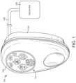
- FIG. 1is a drawing of a negative pressure wound therapy (NPWT) system including a NPWT device fluidly connected with a wound site, according to an exemplary embodiment.
- NPWTnegative pressure wound therapy
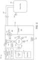
- FIG. 2is a block diagram illustrating the NPWT device of FIG. 1 in greater detail, according to an exemplary embodiment.
- FIG. 3is a block diagram of a control unit of the NPWT device of FIG. 1 , according to an exemplary embodiment.
- FIG. 4is a schematic diagram of waveforms for controlling operation of a piezoelectric pump of an NPWT device, according to an exemplary embodiment.
- FIG. 5 Ais a schematic diagram of square wave alternating current circuit waveforms for modulating voltage of a control signal for controlling operation of a piezoelectric pump of an NPWT device, according to an exemplary embodiment.
- FIG. 5 Bis a schematic diagram of sine wave alternating current circuit waveforms for modulating voltage of a control signal for controlling operation of a piezoelectric pump of an NPWT device, according to an exemplary embodiment.
- FIG. 6is a schematic diagram of sinusoidal alternating current circuit waveforms for modulating voltage of a control signal for controlling operation of a piezoelectric pump of an NPWT device, according to an exemplary embodiment.
- FIG. 7is a flowchart of a process for operating the NPWT device of FIG. 1 , according to an exemplary embodiment.
- the NPWT devicemay include at least one piezoelectric pump and a control circuit.
- the at least one piezoelectric pumpcan be configured to apply a vacuum to a wound site.
- the control circuitcan be configured to generate a first control signal to control operation of the at least one piezoelectric pump, the first control signal having a first root mean square (RMS) voltage.
- the control circuitcan transmit the first control signal to the at least one piezoelectric pump.
- the control circuitcan identify at least one of a change of state of the at least one piezoelectric pump or an expiration of a duration of time associated with operation of the at least one piezoelectric pump.
- the control circuitcan generate a second control signal having a second RMS voltage less than the first RMS voltage.
- the control circuitcan transmit the second control signal to the at least one piezoelectric pump.
- the change of state and/or the expiration of the duration of timecan indicate that the at least one piezoelectric pump has exceeded a temperature threshold or is susceptible to exceeding a temperature threshold, and thus may be susceptible to malfunctions, such as no longer running silently, or no longer applying a desired pressure to the wound site.
- the change of statemay be associated with parameters such as temperatures of the NPWT device, a resonance frequency of the at least one piezoelectric pump, or the pressure applied to the wound site.
- the control circuitgenerates and modulates the control signals in a manner which improves operation of the at least one piezoelectric pump, facilitating desired operation.
- the control circuitcan drive the control signals to have a sinusoidal waveform, which has smooth transitions between maximum and minimum values and thus may be most efficient in driving the at least one piezoelectric pump.
- the control circuitcan modulate (e.g., ramp up, ramp down) the duty cycle of the at least one piezoelectric pump by changing phase angles between signal components applied to either arm of an alternating current circuit between the control circuit and the at least one piezoelectric pump. This can enable the control circuit to modulate the control signal relatively quickly, while reducing computational requirements for calculating parameters of the control signal.
- NPWT system 100is shown to include a therapy device 102 fluidly connected to a wound site 106 via tubing 108 .
- Wound site 106may include a tissue wound as well as a wound dressing that covers the tissue wound and adheres to a patient's skin.
- wound dressingswhich can be used in combination with NPWT system 100 are described in detail in U.S. Pat. No. 7,651,484 granted Jan. 26, 2010, U.S. Pat. No. 8,394,081 granted Mar. 12, 2013, and U.S. patent application Ser. No. 14/087,418 filed Nov. 22, 2013. The entire disclosure of each of these patents and patent applications is incorporated by reference herein.
- Therapy device 102can be configured to provide negative pressure wound therapy by reducing the pressure at wound site 106 .
- Therapy device 102can draw a vacuum at wound site 106 (relative to atmospheric pressure) by removing wound exudate, air, and other fluids from wound site 106 .
- Wound exudatemay include fluid that filters from a patient's circulatory system into lesions or areas of inflammation.
- wound exudatemay include water and dissolved solutes such as blood, plasma proteins, white blood cells, platelets, and red blood cells.
- Other fluids removed from wound site 106may include instillation fluid previously delivered to wound site 106 .
- Instillation fluidcan include, for example, a cleansing fluid, a prescribed fluid, a medicated fluid, an antibiotic fluid, or any other type of fluid which can be delivered to wound site 106 during wound treatment.
- Canister 104may be a component of therapy device 102 configured to collect wound exudate and other fluids removed from wound site 106 .
- canister 104is detachable from therapy device 102 to allow canister 104 to be emptied and replaced as needed.
- a lower portion 130 of canister 104may be filled with wound exudate and other fluids removed from wound site 106 , whereas an upper portion 128 of canister 104 may be filled with air.
- Therapy device 102can be configured to draw a vacuum within canister 104 by pumping air out of canister 104 .
- the reduced pressure within canister 104can be translated to wound site 106 via tubing 108 such that wound site 106 is maintained at the same pressure as canister 104 .
- Therapy device 102is shown to include a pump 120 , a filter 122 , a valve 118 , a heat sink 116 , and a control unit 114 .
- Pump 120can be fluidly coupled to canister 104 (e.g., via conduit 134 ) and can be configured to draw a vacuum within canister 104 by pumping air out of canister 104 .
- pump 120is configured to operate in both a forward direction and a reverse direction. For example, pump 120 can operate in the forward direction to pump air out of canister 104 and decrease the pressure within canister 104 . Pump 120 can operate in the reverse direction to pump air into canister 104 and increase the pressure within canister 104 .
- Pump 120can be controlled by control unit 114 , described in greater detail below.
- Pump 120is a piezoelectric pump.
- the pump 120includes a movable member (e.g., diaphragm) which undergoes mechanical displacement based on a voltage applied to the movable member, such as by oscillating in response to receiving an alternating current. By oscillating, the movable member can push air to generate the negative pressure applied by the pump 120 .
- the movable membercan be metallic.
- Pump 120can include a copper disc with a slit which opens when pushed by the movable member. In some embodiments, the movable member oscillates at approximately 21 kHz. Under typical operational conditions, the pump 120 can operate silently or near silently. For example, noise generated by pump 120 can be less than a noise threshold which can be heard by a typical user.
- pump 120is a Vacuum Pump manufactured by Koge Micro Tech Co., Ltd.
- NPWT system 100includes a plurality of pumps 120 .
- therapy device 102may include multiple pumps 120 , each coupled to tubing 108 and controlled by control unit 114 .
- NPWT system 100may include a plurality of therapy devices 102 , each of which may include one or more pumps 120 .
- Filter 122can be positioned between canister 104 and pump 120 (e.g., along conduit 134 ) such that the air pumped out of canister 104 passes through filter 122 .
- Filter 122can be configured to prevent liquid or solid particles from entering conduit 134 and reaching pump 120 .
- Filter 122may include, for example, a bacterial filter that is hydrophobic and/or lipophilic such that aqueous and/or oily liquids will bead on the surface of filter 122 .
- Pump 120can be configured to provide sufficient airflow through filter 122 that the pressure drop across filter 122 is not substantial (e.g., such that the pressure drop will not substantially interfere with the application of negative pressure to wound site 106 from therapy device 102 ).
- Valve 118can be fluidly connected with pump 120 and filter 122 via conduit 134 .
- valve 118is configured to control airflow between conduit 134 and the environment around therapy device 102 .
- valve 118can be opened to allow airflow between conduit 134 and the environment around therapy device 102 , and closed to prevent airflow between conduit 134 and the environment around therapy device 102 .
- Valve 118can be opened and closed by control unit 114 , described in greater detail below.
- pump 120can draw a vacuum within conduit 134 and canister 104 by causing airflow through filter 122 in a first direction, as shown in FIG. 2 .
- valve 118When valve 118 is open, airflow from the environment around therapy device 102 may enter conduit 134 and fill the vacuum within conduit 134 and canister 104 .
- the airflow from conduit 134 into canister 104may pass through filter 122 in a second direction, opposite the first direction, as shown in FIG. 3 .
- FIG. 2illustrates the use of the canister 104 and filter 122
- the therapy device 102may not include either the canister 104 or the filter 122 , such that the pump 120 may be directly coupled to the wound site 106 via the tubing 108 .
- Heat sink 116may be provided to increase a rate of heat dissipation from therapy device 102 or components thereof, such as pump 120 .
- heat sink 116can be configured to have a relatively greater coefficient for convective heat transfer than other components of therapy device 102 , such as by having a relatively greater surface area to volume ratio.
- Heat sink 116may be mounted to control unit 114 , pump 120 , or a circuit board (not shown) to which control unit 114 and/or pump 120 are mounted.
- heat sink 116includes a plurality of fins.
- Control unit 114can be configured to operate pump 120 , valve 118 , and/or other controllable components of therapy device 102 .
- control unit 114is configured to operate pump 120 by transmitting a control signal to pump 120 via alternating current circuit 140 , which includes first arm 142 and second arm 144 .
- the arms 142 , 144may be associated with corresponding pump drive electrodes for pump 120 .
- therapy device 102includes a variety of sensors, which can communicate sensor measurements to control unit 114 .
- therapy device 102is shown to include a temperature sensor 124 configured to measure a temperature of pump 120 and communicate the measured temperature of pump 120 to control unit 114 .
- Temperature sensor 124may be a thermocouple.
- NPWT system 100includes a pressure sensor 126 configured to measure the pressure at wound site 106 and communicate the measured pressure to control unit 114 .
- NPWT system 100may also include a pressure sensor 132 configured to measure the pressure at the pump, and a resonance sensor 136 configured to measure a resonance of pump 120 (e.g., of the movable member of pump 120 ).
- Control unit 114can use the sensor measurements as inputs to various control operations performed by control unit 114 (described in greater detail with reference to FIGS. 4 - 7 ).
- therapy device 102includes a user interface 110 .
- User interface 110may include one or more buttons, dials, sliders, keys, or other input devices configured to receive input from a user.
- User interface 110may also include one or more display devices (e.g., LEDs, LCD displays, etc.), speakers, tactile feedback devices, or other output devices configured to provide information to a user.
- the pressure measurements recorded by pressure sensors 124 - 126 and the orientation measurements recorded by orientation sensor 132are presented to a user via user interface 110 .
- User interface 110can also display alerts generated by control unit 114 .
- therapy device 102includes a data communications interface 112 (e.g., a USB port, a wireless transceiver, etc.) configured to receive and transmit data.
- Communications interface 112may include wired or wireless communications interfaces (e.g., jacks, antennas, transmitters, receivers, transceivers, wire terminals, etc.) for conducting data communications external systems or devices.
- the communicationsmay be direct (e.g., local wired or wireless communications) or via a communications network (e.g., a WAN, the Internet, a cellular network, etc.).
- communications interface 112can include a USB port or an Ethernet card and port for sending and receiving data via an Ethernet-based communications link or network.
- communications interface 112can include a Wi-Fi transceiver for communicating via a wireless communications network or cellular or mobile phone communications transceivers.
- Control unit 114is shown to include a processing circuit 146 including a processor 148 and memory 150 .
- Processor 148may be a general purpose or specific purpose processor, an application specific integrated circuit (ASIC), one or more field programmable gate arrays (FPGAs), a group of processing components, or other suitable processing components.
- ASICapplication specific integrated circuit
- FPGAfield programmable gate arrays
- Processor 148is configured to execute computer code or instructions stored in memory 150 or received from other computer readable media (e.g., CDROM, network storage, a remote server, etc.).
- Memory 150may include one or more devices (e.g., memory units, memory devices, storage devices, etc.) for storing data and/or computer code for completing and/or facilitating the various processes described in the present disclosure.
- Memory 150may include random access memory (RAM), read-only memory (ROM), hard drive storage, temporary storage, non-volatile memory, flash memory, optical memory, or any other suitable memory for storing software objects and/or computer instructions.
- Memory 150may include database components, object code components, script components, or any other type of information structure for supporting the various activities and information structures described in the present disclosure.
- Memory 150may be communicably connected to processor 148 via processing circuit 146 and may include computer code for executing (e.g., by processor 148 ) one or more processes described herein. When processor 148 executes instructions stored in memory 150 , processor 148 generally configures control unit 114 (and more particularly processing circuit 146 ) to complete such activities.
- Control unit 114is shown to include a pump controller 152 .
- Pump controller 152generates control signals to control operation of pump 120 .
- Pump controller 152can configure parameters of the control signals, such as current, voltage, frequency, amplitude, or intermittency.
- pump controller 152generates alternating current control signals having a root mean square (RMS) voltage, and transmits the control signals to pump 120 via alternating current circuit 140 (as shown in FIG. 3 ).
- RMSroot mean square
- pump controller 152can generate the control signals to have a particular RMS voltage by modulating a first phase angle of a first signal component associated with first arm 142 relative to a second phase angle of a second signal component associated with second arm 144 .
- pump controller 152can modulate the control signals to have specified waveforms.
- pump controller 152can modulate the control signals to have square, triangular, or sinusoidal waveforms.
- Square waveformsmay result in thermal loading of pump 120 by oscillating between peak voltages of opposite signs, spending more time at peak voltage such that the transition between the peaks opposite signs is abrupt.
- Triangular waveformsmay have reduced effectiveness by having amplitudes near the peaks for a relatively low fraction of the total waveform duration.
- pump controller 152can improve operation of pump 120 by modulating the control signals to have sinusoidal waveforms (see FIG.
- the sinusoidal waveformcan be smooth, as compared to the square waveform, which can include a step function transition from a minimum value to a maximum value (see FIG. 5 A ); or a triangular waveform, which can include a sharp corner where a slope of the waveform changes sign instantaneously or near instantaneously.
- the sinusoidal waveformis based on a single sine (or cosine) wave function (as compared to a square waveform or triangular waveform, which may be generated by combining multiple sine wave functions of varying amplitudes).
- Pump controller 152can modulate the sinusoidal control signals to have particular RMS voltages by modulating the first phase angle of the first sinusoidal signal component associated with first arm 142 relative to the second phase angle of the second sinusoidal signal component associated with second arm 144 .
- pump controller 152modulates voltage of the control signal by modulating a first phase angle of a first signal component associated with first arm 142 relative to a second phase angle of a second signal component associated with second arm 144 .
- pump controller 152can initially output the control signal with the first phase angle being 180 degrees offset from the second phase angle, and increase the voltage by reducing the offset (e.g., reducing from 180 degrees towards 0 degrees).
- pump controller 152can more quickly achieve a desired voltage than by existing methods based on calculating voltage.
- pump controller 152can reduce computational burden by changing the phase angle, which can avoid either (1) requiring multiply/divide capability or (2) re-programming memory each time amplitude is changed.
- Control unit 114is shown to include a pressure monitor 154 .
- Pressure monitor 154can be configured to monitor the pressure within pump 120 and/or the pressure at wound site 106 using feedback from pressure sensors 124 - 126 .
- pressure sensors 124 - 126may provide pressure measurements to pressure monitor 152 .
- Pressure monitor 152can use the pressure measurements to determine the pressure within pump 120 and/or the pressure at wound site 106 in real-time.
- Pressure monitor 152can provide the pressure value to state monitor 162 and/or pump controller 152 for use as an input to control processes performed by such components.
- Control unit 114can include a temperature monitor 156 .
- Temperature monitor 156can monitor the temperature of pump 120 using temperature measurements from temperature sensor 124 , and use the temperature measurements to calculate the temperature of pump 120 , in real-time. Similar to pressure monitor 154 , temperature monitor 156 can provide the temperature of pump 120 to state monitor 162 and/or pump controller 152 for use as an input to control processes performed by such components.
- control unit 114includes a resonance monitor 158 .
- Resonance monitor 158can receive resonance measurements from resonance sensor 136 , and determine a resonance frequency of pump 120 , in real-time. Similar to pressure monitor 154 and temperature monitor 156 , resonance monitor 158 can transmit the determined resonance frequency to state monitor 162 and/or pump controller 152 for use as an input to control processes performed by such components.
- Control unit 114includes a timer 160 , in some embodiments.
- Control unit 114(or components thereof, such as pump controller 152 ) can initiate and/or reset timer 160 in response to various trigger conditions.
- control unit 114can initiate timer 160 responsive to pump controller 152 transmitting a control signal (e.g., a control signal having a first RMS voltage) to pump 120 .
- Control unit 114can reset timer 160 responsive to transmitting a control signal (e.g., a control signal having a second RMS voltage) to pump 120 .
- Timer 160can output a time to state monitor 162 and/or pump controller 152 for use as an input to control processes performed by such components.
- control unit 114includes a state monitor 162 .
- State monitor 162can receive sensor measurements from sensors 124 , 126 , 132 , 136 (e.g., via corresponding monitors 154 , 156 , 158 ), and execute operations using the received sensor measurements.
- State monitor 162can also receive the time outputted by state monitor 162 .
- state monitor 162is configured to determine whether a state of pump 120 indicates that pump 120 is overheating or may be susceptible to overheating, which can allow pump controller 152 to modify control of pump 120 before noise generation, overheating, or other undesired conditions of pump 120 occur.
- State monitor 162can identify at least one of a change of state of pump 120 or an expiration of a duration of time associated with operation of pump 120 . In some embodiments, state monitor 162 identifies the change of state of pump 120 based on temperature. State monitor 162 can receive the temperature of pump 120 from temperature monitor 156 . State monitor 162 can compare the temperature of pump 120 to a first temperature threshold, and identify the change of state responsive to the temperature of pump 120 being greater than the first temperature threshold. The first temperature threshold may be equal to (or slightly less) than a temperature at which pump 120 generates noise (e.g., whistling or other noise at a volume audible to a typical user), overheats, or loses efficiency.
- noisee.g., whistling or other noise at a volume audible to a typical user
- the first temperature thresholdis 63 degrees Celsius.
- the first temperature thresholdcan be greater than or equal to 50 degrees Celsius and less than or equal to 70 degrees Celsius.
- the first temperature thresholdcan be greater than or equal to 60 degrees Celsius and less than or equal to 65 degrees Celsius. It will be appreciated that the first temperature threshold may vary based on factors such as the composition, size, and/or drive voltage of pump 120 .
- State monitor 162can also identify the change of state of pump 120 based on pressure. For example, state monitor 162 can receive the pressure of pump 120 and/or wound site 106 from pressure monitor 154 . State monitor 162 can compare the pressure to a corresponding target pressure.
- the target pressurecan be a desired pressure at which NPWT system 100 is properly applying a vacuum to wound site 106 .
- State monitor 162can identify the change of state responsive to determining that the pressure is greater than or equal to the target pressure (which can indicate that pump 120 need not necessarily be driven at the instant voltage, but rather may be temporarily be driven at a lower voltage to help prevent or mitigate overheating or other undesired operation).
- the target pressureis 125 mmHg.
- the target pressuremay be greater than or equal to 100 mmHg and less than or equal to 200 mmHg.
- state monitor 162identifies the change of state of pump 120 based on resonance frequency.
- State monitor 162can receive the resonance frequency of pump 120 from resonance monitor 158 .
- State monitor 162can compare the resonance frequency to a pump curve indicating a relationship between frequency and efficiency to determine whether an efficiency difference between an instant efficiency of pump 120 and a desired or maximum efficiency is greater than a threshold efficiency difference, and identify the change of state responsive to the efficiency difference being greater than the threshold efficiency difference.
- State monitor 162can identify the expiration of the duration of time based on receiving the time from the timer 160 .
- state monitor 162can periodically receive the time from the timer 160 , compare the time to a threshold duration of time, and identify the expiration of the duration of time based on the time exceeding the duration of time.
- the threshold duration of timecan correspond to a time after which pump 120 may be expected to overheat or otherwise undergo undesired operation. In an embodiment, the threshold duration of time is 5 minutes.
- the threshold duration of timemay be greater than or equal to 1 minute and less than or equal to 20 minutes. It will be appreciated that the threshold duration of time may vary based on various factors affecting the rate of heat generation, storage, and dissipation by pump 120 , such as the composition, size, and/or drive voltage of pump 120 .
- state monitor 162outputs a notification associated with identifying the at least one of the change of state or the expiration of the duration of time.
- state monitor 162can cause user interface 110 to output at least one of a visual output or an audible output.
- state monitor 162counts a number of identifications of the at least one of the change of state or the expiration of the duration of time, compares the count to a count threshold, and responsive to determining that the count is greater than the count threshold, outputs the notification.
- the state monitor 162may count the number of identifications while the pressure of at least one of pump 120 or wound site 106 is less than the corresponding target pressure, which may indicate that the pump 120 is overheating or susceptible to overheating without being able to achieve the target pressure.
- pump controller 152can control operation of the plurality of pumps 120 .
- pump controller 152can drive a first pump of the plurality of pumps 120 at a first RMS voltage (e.g., a high or maximum RMS voltage), and drive at least one second pump 120 of the plurality of pumps 120 at a second RMS voltage less than the first RMS voltage.
- first RMS voltagee.g., a high or maximum RMS voltage
- pump controller 152can generate a control signal to drive first pump 120 at a lower RMS voltage; pump controller 152 may also generate control signal(s) to drive one or more of the at least one second pump 120 at the first RMS voltage. As such, pump controller 152 can modify operation of the plurality of pumps 120 in order to maintain the target pressure at wound site 106 while avoid overheating or other undesired effects of operating each of the plurality of pumps 120 .
- Pump 120is shown to be driven by square wave control signal 405 , with a maximum RMS voltage of 11 V rms for four minutes, alternating with a minimum RMS voltage of 9 V rms four minutes, in order to achieve a target pressure of 125 mmHg.
- the square wave control signal 405causes pump 120 to deliver a flow rate 410 of 120 cc/min when driven at 11 V rms at the target pressure, then quickly reduce to a flow rate of 80 cc/min when driven at 9 V rms , then quickly return to the flow rate of 120 cc/min.
- the continuous voltage at 11 V rmscauses temperature 415 of pump 120 to quickly increase from approximately 25 degrees Celsius (e.g., room temperature) to almost 60 degrees Celsius (at which pump 120 may be susceptible to undesired effects from overheating).
- the temperature 415may not decrease during the first 9 V rms cycle all the way to the initial temperature, indicating heat storage in pump 120 ; while not illustrated in FIG. 4 , the peak temperature 415 may continue to increase from cycle to cycle as pump 120 continues to store heat.
- FIG. 5 Aa schematic diagram illustrating alternating current control signals generated by pump controller 152 for driving pump 120 via alternating current circuit 140 is shown, according to an exemplary embodiment.
- a first arm waveform 505may be driven with a phase angle difference of 180 degrees relative to a second arm waveform 510 , resulting in an RMS voltage 515 .
- pump 120may be susceptible to overheating, such as due to the sharp changes in direction of current between the waveforms 505 , 510 .
- FIG. 5 Banother schematic diagram illustrating alternating current signals generated by pump controller 152 for driving pump 120 via alternating current circuit 140 is shown, according to an exemplary embodiment.
- a first arm waveform 520may be driven with a phase angle difference of 180 degrees relative to a second arm waveform 525 , resulting in an RMS voltage 530 .
- the first arm waveform 520 and second arm waveform 525are provided as sinusoidal signals (e.g., by using pump controller 152 to generate the control signals as sinusoidal signals).
- pump controller 152generates the first arm waveform 520 using a first sine wave function, and generates the second arm waveform 525 using a second sine wave function having a desired phase angle difference as compared to the first arm waveform 520 .
- a schematic diagram illustrating alternating current controls with sinusoidal waveforms generated by pump controller 152 for driving pump 120 via alternating circuit 140is shown, according to an exemplary embodiment.
- a first arm waveform 620is offset from a second arm waveform 625 .
- Pump controller 152can modulate the resulting RMS voltage of the control signal by shifting the phase angle of second arm waveform 625 (or first arm waveform 620 ) by phase offset 615 to modulate the resulting RMS voltage.
- shifting the phase angle of second arm waveform 625 by phase offset 615can increase the resulting RMS voltage from 8 V rms to 11 V rms .
- Process 700can be performed by one or more components of NPWT system 100 , as described with reference to FIGS. 1 - 6 .
- process 700can be performed by therapy device 102 using control unit 114 to operate pump 120 .
- Process 700is shown to include generating a first control signal having a first RMS voltage (step 702 ).
- the first control signalcan be generated by generating a first signal component associated with a first arm of an alternating current circuit for driving a piezoelectric pump to have a first phase angle, and generating a second signal component associated with a second arm of the alternating current circuit for driving the piezoelectric pump to have a second phase angle.
- the amplitude of the control signalcan be modulated by modulating the first phase angle relative to the second phase angle.
- the first control signalis generated as a sinusoidal signal, such as by generating the first signal component based on a first sine wave function and the second signal component based on a second sine wave function having a desired phase difference relative to the first sine wave function.
- Process 700is shown to include transmitting the first control signal to a piezoelectric pump to apply a vacuum to a wound site (step 704 ).
- the first control signalcan cause the piezoelectric pump to oscillate at a desired frequency, such that the piezoelectric pump draws a vacuum against the wound site.
- the first control signalis a sinusoidal signal
- heat generation by the piezoelectric pumpcan be reduced, such as due to the smooth transition between maximum and minimum values of the first control signal.
- Process 700is shown to include identifying at least one of a change of state of the piezoelectric pump or an expiration of a duration of time associated with operation of the piezoelectric pump (step 706 ).
- the identificationcan be used to avoid overheating or other undesired operational states of the piezoelectric pump.
- identifying the change of stateincludes identifying the change of state based on a temperature of the piezoelectric pump. For example, a temperature of the pump can be determined based on a temperature measurement received from a temperature sensor. The temperature of the pump can be compared to a first threshold. Responsive to determining that the first temperature is greater than the first temperature threshold, the change of state can be identified.
- Identifying the change of statemay include identifying the change of state based on a pressure of at least one of the pump or the wound site. For example, a pressure can be determined based on pressure measurements received from a pressure sensor at the pump and/or a pressure sensor at the wound site. The pressure can be compared to a target pressure, which may be associated with desired operation of the pump (e.g., desired vacuum at the wound site). Responsive to determining that the pressure is greater than the target pressure (e.g., in absolute value), the change of state can be identified. As such, if the pump is drawing a greater vacuum than the target pressure at the wound site, the change of state can be identified so that the pump may be driven at a lower voltage as described below.
- a target pressurewhich may be associated with desired operation of the pump (e.g., desired vacuum at the wound site). Responsive to determining that the pressure is greater than the target pressure (e.g., in absolute value)
- the change of statecan be identified. As such, if the pump
- Identifying the change of statemay include identifying the change of state based on a resonance frequency of the pump.
- a resonance frequency of the pumpcan be determined based on a frequency measurement from a frequency sensor.
- the change of statemay be identified based on the resonance frequency being different from a target frequency by more than a threshold difference, which can indicate that the pump is operating away from a target efficiency, and may instead be converting electrical energy from the first control signal to heat rather than mechanical movement.
- identifying the change of stateincludes retrieving a table of pump efficiency as a function of resonance frequency, and using the table to determine whether the resonance frequency differs from the target frequency.
- identifying the expiration of the duration of timeis based on a timer.
- the timermay be initiated responsive to transmitting the first control signal, which can indicate the start of operation of the pump at the first RMS voltage.
- the timercan be periodically outputted (or periodically polled), and compared to the duration of time. Responsive to the timer exceeding the duration of time, the expiration of the duration of time can be identified.
- Process 700is shown to include, responsive to identifying the at least one of the change of state or the expiration of the duration of time, generating a second control signal having a second RMS voltage less than the first RMS voltage (step 708 ).
- the second control signalcan be generated by modulating the first phase angle of the first signal component associated with the first arm of the alternating current circuit relative to the second phase angle of the second signal component associated with the second arm of the alternating circuit current.
- the timercan be reset responsive to generating (or transmitting) the second control signal. If the at least one of the change of state or the expiration of the duration of time is not identified, then a control signal having the first RMS voltage may be continued to be applied to the pump.
- Process 700is shown to include transmitting the second control signal to the pump (step 710 ).
- the second control signalBy transmitting the second control signal having the second RMS voltage less than the first RMS voltage to the pump, overheating of the pump can be avoided.
- a number of identifications of the at least one of the change of state or the expiration of the duration of timecan be counted.
- the countcan be compared to a count threshold. Responsive to determining that the count is greater than the count threshold, at least one of a visual output or an audible output can be outputted, such as to provide a notification of malfunction of the pump.
- the countis incremented while the first pressure is less than the target pressure, so that the notification is provided based on the pump being unable to achieve the target pressure.
- Process 700is shown to include identifying an additional at least one of a change of state or expiration of a duration of time ( 712 ).
- the additional at least one of the change of state or the expiration of the duration of timemay indicate that the operational mode of the second control signal (e.g., driving the pump at a lower RMS voltage) may be discontinued and/or the operational mode of the first control signal (e.g., driving the pump at a higher RMS voltage) may be reinstated. If the additional at least one of the change of state or duration of time is not identified, then the second control signal may be continued to be transmitted to the pump.
- process 700is shown to include determining whether therapy is to be discontinued ( 714 ). For example, the determination may be performed based on a user input indicating instructions to discontinue therapy, or detection of a wound condition or dressing condition indicating therapy is to be discontinued. If therapy is not to be discontinued, then process 700 may be continued, such as by generating and transmitting the first control signal (e.g., to reinstate an operational mode using a relatively higher RMS voltage). Responsive to determining that therapy is to be discontinued, process 700 may be terminated, such as by discontinuing control signal transmission to the pump (or transmitting a control signal having a nominal or zero voltage to the pump).
- a second temperature of the pumpcan be received subsequent to transmission of the second control signal.
- the second temperaturecan be compared to a second threshold that is less than or equal to the first temperature threshold.
- a third control signalcan be generated and transmitted to the pump, the third control signal having a third RMS voltage greater than the second RMS voltage (e.g., equal to the first RMS voltage).
- the amplitude of the control signal used to drive the pumpcan be increased to increase performance by the pump.
- the first and second temperature thresholdsmay be used together, such that the pump can be driven cyclically between high voltage and low voltage states to maintain performance at a relatively high level while avoiding overheating.
- the present disclosurecontemplates methods, systems and program products on any machine-readable media for accomplishing various operations.
- the embodiments of the present disclosurecan be implemented using existing computer processors, or by a special purpose computer processor for an appropriate system, incorporated for this or another purpose, or by a hardwired system.
- Embodiments within the scope of the present disclosureinclude program products comprising machine-readable media for carrying or having machine-executable instructions or data structures stored thereon.
- Such machine-readable mediacan be any available media that can be accessed by a general purpose or special purpose computer or other machine with a processor.
- machine-readable mediacan comprise RAM, ROM, EPROM, EEPROM, CD-ROM or other optical disk storage, magnetic disk storage or other magnetic storage devices, or any other medium which can be used to carry or store desired program code in the form of machine-executable instructions or data structures and which can be accessed by a general purpose or special purpose computer or other machine with a processor. Combinations of the above are also included within the scope of machine-readable media.
- Machine-executable instructionsinclude, for example, instructions and data which cause a general purpose computer, special purpose computer, or special purpose processing machines to perform a certain function or group of functions.
Landscapes
- Health & Medical Sciences (AREA)
- Engineering & Computer Science (AREA)
- Heart & Thoracic Surgery (AREA)
- Animal Behavior & Ethology (AREA)
- Anesthesiology (AREA)
- Biomedical Technology (AREA)
- Hematology (AREA)
- Life Sciences & Earth Sciences (AREA)
- Vascular Medicine (AREA)
- General Health & Medical Sciences (AREA)
- Public Health (AREA)
- Veterinary Medicine (AREA)
- Mechanical Engineering (AREA)
- General Engineering & Computer Science (AREA)
- Computer Hardware Design (AREA)
- External Artificial Organs (AREA)
Abstract
Description
Claims (14)
Priority Applications (1)
| Application Number | Priority Date | Filing Date | Title |
|---|---|---|---|
| US16/957,679US11754063B2 (en) | 2018-01-02 | 2018-12-18 | Negative pressure wound therapy device with silent piezoelectric pump |
Applications Claiming Priority (3)
| Application Number | Priority Date | Filing Date | Title |
|---|---|---|---|
| US201862612900P | 2018-01-02 | 2018-01-02 | |
| US16/957,679US11754063B2 (en) | 2018-01-02 | 2018-12-18 | Negative pressure wound therapy device with silent piezoelectric pump |
| PCT/US2018/066161WO2019135900A1 (en) | 2018-01-02 | 2018-12-18 | Negative pressure wound therapy device with silent piezoelectric pump |
Publications (2)
| Publication Number | Publication Date |
|---|---|
| US20210060216A1 US20210060216A1 (en) | 2021-03-04 |
| US11754063B2true US11754063B2 (en) | 2023-09-12 |
Family
ID=65012092
Family Applications (1)
| Application Number | Title | Priority Date | Filing Date |
|---|---|---|---|
| US16/957,679Active2040-03-12US11754063B2 (en) | 2018-01-02 | 2018-12-18 | Negative pressure wound therapy device with silent piezoelectric pump |
Country Status (3)
| Country | Link |
|---|---|
| US (1) | US11754063B2 (en) |
| EP (1) | EP3735278A1 (en) |
| WO (1) | WO2019135900A1 (en) |
Families Citing this family (8)
| Publication number | Priority date | Publication date | Assignee | Title |
|---|---|---|---|---|
| US10624794B2 (en) | 2018-02-12 | 2020-04-21 | Healyx Labs, Inc. | Negative pressure wound therapy systems, devices, and methods |
| GB2615253B (en)* | 2020-10-05 | 2025-03-12 | Smith & Nephew | Temperature monitoring and control for negative pressure wound therapy systems |
| CN112594175A (en)* | 2020-11-18 | 2021-04-02 | 江苏苏中药业集团医疗器械有限公司 | Medical vacuum negative pressure machine driving system |
| EP4294474A1 (en)* | 2021-02-18 | 2023-12-27 | KCI Manufacturing Unlimited Company | Systems and methods for detecting fluid contamination in a wound therapy system |
| US20250161550A1 (en)* | 2022-01-28 | 2025-05-22 | Solventum Intellectual Properties Company | Using a piezo electric pump to detect when a dressing is full and prevent fluid from entering tubing line |
| WO2024050523A2 (en)* | 2022-09-01 | 2024-03-07 | Convatec Technologies Inc. | Medical device audible alerts |
| TWI814604B (en)* | 2022-10-05 | 2023-09-01 | 太平洋醫材股份有限公司 | Drainage bottle system |
| FR3158455A1 (en)* | 2024-01-23 | 2025-07-25 | L'oreal | Fluid product dispensing device, associated apparatus and method |
Citations (142)
| Publication number | Priority date | Publication date | Assignee | Title |
|---|---|---|---|---|
| US1355846A (en) | 1920-02-06 | 1920-10-19 | David A Rannells | Medical appliance |
| US2547758A (en) | 1949-01-05 | 1951-04-03 | Wilmer B Keeling | Instrument for treating the male urethra |
| US2632443A (en) | 1949-04-18 | 1953-03-24 | Eleanor P Lesher | Surgical dressing |
| GB692578A (en) | 1949-09-13 | 1953-06-10 | Minnesota Mining & Mfg | Improvements in or relating to drape sheets for surgical use |
| US2682873A (en) | 1952-07-30 | 1954-07-06 | Johnson & Johnson | General purpose protective dressing |
| US2910763A (en) | 1955-08-17 | 1959-11-03 | Du Pont | Felt-like products |
| US2969057A (en) | 1957-11-04 | 1961-01-24 | Brady Co W H | Nematodic swab |
| US3066672A (en) | 1960-09-27 | 1962-12-04 | Jr William H Crosby | Method and apparatus for serial sampling of intestinal juice |
| US3367332A (en) | 1965-08-27 | 1968-02-06 | Gen Electric | Product and process for establishing a sterile area of skin |
| US3520300A (en) | 1967-03-15 | 1970-07-14 | Amp Inc | Surgical sponge and suction device |
| US3568675A (en) | 1968-08-30 | 1971-03-09 | Clyde B Harvey | Fistula and penetrating wound dressing |
| US3648692A (en) | 1970-12-07 | 1972-03-14 | Parke Davis & Co | Medical-surgical dressing for burns and the like |
| US3682180A (en) | 1970-06-08 | 1972-08-08 | Coilform Co Inc | Drain clip for surgical drain |
| US3826254A (en) | 1973-02-26 | 1974-07-30 | Verco Ind | Needle or catheter retaining appliance |
| DE2640413A1 (en) | 1976-09-08 | 1978-03-09 | Wolf Gmbh Richard | CATHETER MONITORING DEVICE |
| US4080970A (en) | 1976-11-17 | 1978-03-28 | Miller Thomas J | Post-operative combination dressing and internal drain tube with external shield and tube connector |
| US4096853A (en) | 1975-06-21 | 1978-06-27 | Hoechst Aktiengesellschaft | Device for the introduction of contrast medium into an anus praeter |
| US4139004A (en) | 1977-02-17 | 1979-02-13 | Gonzalez Jr Harry | Bandage apparatus for treating burns |
| US4165748A (en) | 1977-11-07 | 1979-08-28 | Johnson Melissa C | Catheter tube holder |
| US4184510A (en) | 1977-03-15 | 1980-01-22 | Fibra-Sonics, Inc. | Valued device for controlling vacuum in surgery |
| WO1980002182A1 (en) | 1979-04-06 | 1980-10-16 | J Moss | Portable suction device for collecting fluids from a closed wound |
| US4233969A (en) | 1976-11-11 | 1980-11-18 | Lock Peter M | Wound dressing materials |
| US4245630A (en) | 1976-10-08 | 1981-01-20 | T. J. Smith & Nephew, Ltd. | Tearable composite strip of materials |
| US4256109A (en) | 1978-07-10 | 1981-03-17 | Nichols Robert L | Shut off valve for medical suction apparatus |
| US4261363A (en) | 1979-11-09 | 1981-04-14 | C. R. Bard, Inc. | Retention clips for body fluid drains |
| US4275721A (en) | 1978-11-28 | 1981-06-30 | Landstingens Inkopscentral Lic, Ekonomisk Forening | Vein catheter bandage |
| US4284079A (en) | 1979-06-28 | 1981-08-18 | Adair Edwin Lloyd | Method for applying a male incontinence device |
| US4297995A (en) | 1980-06-03 | 1981-11-03 | Key Pharmaceuticals, Inc. | Bandage containing attachment post |
| US4333468A (en) | 1980-08-18 | 1982-06-08 | Geist Robert W | Mesentery tube holder apparatus |
| US4373519A (en) | 1981-06-26 | 1983-02-15 | Minnesota Mining And Manufacturing Company | Composite wound dressing |
| US4382441A (en) | 1978-12-06 | 1983-05-10 | Svedman Paul | Device for treating tissues, for example skin |
| US4392853A (en) | 1981-03-16 | 1983-07-12 | Rudolph Muto | Sterile assembly for protecting and fastening an indwelling device |
| US4392858A (en) | 1981-07-16 | 1983-07-12 | Sherwood Medical Company | Wound drainage device |
| US4419097A (en) | 1981-07-31 | 1983-12-06 | Rexar Industries, Inc. | Attachment for catheter tube |
| EP0100148A1 (en) | 1982-07-06 | 1984-02-08 | Dow Corning Limited | Medical-surgical dressing and a process for the production thereof |
| US4465485A (en) | 1981-03-06 | 1984-08-14 | Becton, Dickinson And Company | Suction canister with unitary shut-off valve and filter features |
| EP0117632A2 (en) | 1983-01-27 | 1984-09-05 | Johnson & Johnson Products Inc. | Adhesive film dressing |
| US4475909A (en) | 1982-05-06 | 1984-10-09 | Eisenberg Melvin I | Male urinary device and method for applying the device |
| US4480638A (en) | 1980-03-11 | 1984-11-06 | Eduard Schmid | Cushion for holding an element of grafted skin |
| US4525374A (en) | 1984-02-27 | 1985-06-25 | Manresa, Inc. | Treating hydrophobic filters to render them hydrophilic |
| US4525166A (en) | 1981-11-21 | 1985-06-25 | Intermedicat Gmbh | Rolled flexible medical suction drainage device |
| US4540412A (en) | 1983-07-14 | 1985-09-10 | The Kendall Company | Device for moist heat therapy |
| US4543100A (en) | 1983-11-01 | 1985-09-24 | Brodsky Stuart A | Catheter and drain tube retainer |
| US4548202A (en) | 1983-06-20 | 1985-10-22 | Ethicon, Inc. | Mesh tissue fasteners |
| US4551139A (en) | 1982-02-08 | 1985-11-05 | Marion Laboratories, Inc. | Method and apparatus for burn wound treatment |
| EP0161865A2 (en) | 1984-05-03 | 1985-11-21 | Smith and Nephew Associated Companies p.l.c. | Adhesive wound dressing |
| US4569348A (en) | 1980-02-22 | 1986-02-11 | Velcro Usa Inc. | Catheter tube holder strap |
| AU550575B2 (en) | 1981-08-07 | 1986-03-27 | Richard Christian Wright | Wound drainage device |
| US4605399A (en) | 1984-12-04 | 1986-08-12 | Complex, Inc. | Transdermal infusion device |
| US4608041A (en) | 1981-10-14 | 1986-08-26 | Frese Nielsen | Device for treatment of wounds in body tissue of patients by exposure to jets of gas |
| US4640688A (en) | 1985-08-23 | 1987-02-03 | Mentor Corporation | Urine collection catheter |
| US4655754A (en) | 1984-11-09 | 1987-04-07 | Stryker Corporation | Vacuum wound drainage system and lipids baffle therefor |
| US4664662A (en) | 1984-08-02 | 1987-05-12 | Smith And Nephew Associated Companies Plc | Wound dressing |
| WO1987004626A1 (en) | 1986-01-31 | 1987-08-13 | Osmond, Roger, L., W. | Suction system for wound and gastro-intestinal drainage |
| US4710165A (en) | 1985-09-16 | 1987-12-01 | Mcneil Charles B | Wearable, variable rate suction/collection device |
| US4733659A (en) | 1986-01-17 | 1988-03-29 | Seton Company | Foam bandage |
| GB2195255A (en) | 1986-09-30 | 1988-04-07 | Vacutec Uk Limited | Method and apparatus for vacuum treatment of an epidermal surface |
| US4743232A (en) | 1986-10-06 | 1988-05-10 | The Clinipad Corporation | Package assembly for plastic film bandage |
| GB2197789A (en) | 1986-11-28 | 1988-06-02 | Smiths Industries Plc | Anti-foaming disinfectants used in surgical suction apparatus |
| US4758220A (en) | 1985-09-26 | 1988-07-19 | Alcon Laboratories, Inc. | Surgical cassette proximity sensing and latching apparatus |
| US4787888A (en) | 1987-06-01 | 1988-11-29 | University Of Connecticut | Disposable piezoelectric polymer bandage for percutaneous delivery of drugs and method for such percutaneous delivery (a) |
| US4826494A (en) | 1984-11-09 | 1989-05-02 | Stryker Corporation | Vacuum wound drainage system |
| US4838883A (en) | 1986-03-07 | 1989-06-13 | Nissho Corporation | Urine-collecting device |
| US4840187A (en) | 1986-09-11 | 1989-06-20 | Bard Limited | Sheath applicator |
| US4863449A (en) | 1987-07-06 | 1989-09-05 | Hollister Incorporated | Adhesive-lined elastic condom cathether |
| US4872450A (en) | 1984-08-17 | 1989-10-10 | Austad Eric D | Wound dressing and method of forming same |
| US4878901A (en) | 1986-10-10 | 1989-11-07 | Sachse Hans Ernst | Condom catheter, a urethral catheter for the prevention of ascending infections |
| GB2220357A (en) | 1988-05-28 | 1990-01-10 | Smiths Industries Plc | Medico-surgical containers |
| US4897081A (en) | 1984-05-25 | 1990-01-30 | Thermedics Inc. | Percutaneous access device |
| US4906233A (en) | 1986-05-29 | 1990-03-06 | Terumo Kabushiki Kaisha | Method of securing a catheter body to a human skin surface |
| US4906240A (en) | 1988-02-01 | 1990-03-06 | Matrix Medica, Inc. | Adhesive-faced porous absorbent sheet and method of making same |
| US4919654A (en) | 1988-08-03 | 1990-04-24 | Kalt Medical Corporation | IV clamp with membrane |
| CA2005436A1 (en) | 1988-12-13 | 1990-06-13 | Glenda G. Kalt | Transparent tracheostomy tube dressing |
| US4941882A (en) | 1987-03-14 | 1990-07-17 | Smith And Nephew Associated Companies, P.L.C. | Adhesive dressing for retaining a cannula on the skin |
| US4953565A (en) | 1986-11-26 | 1990-09-04 | Shunro Tachibana | Endermic application kits for external medicines |
| WO1990010424A1 (en) | 1989-03-16 | 1990-09-20 | Smith & Nephew Plc | Absorbent devices and precursors therefor |
| US4969880A (en) | 1989-04-03 | 1990-11-13 | Zamierowski David S | Wound dressing and treatment method |
| US4985019A (en) | 1988-03-11 | 1991-01-15 | Michelson Gary K | X-ray marker |
| GB2235877A (en) | 1989-09-18 | 1991-03-20 | Antonio Talluri | Closed wound suction apparatus |
| US5037397A (en) | 1985-05-03 | 1991-08-06 | Medical Distributors, Inc. | Universal clamp |
| US5086170A (en) | 1989-01-16 | 1992-02-04 | Roussel Uclaf | Process for the preparation of azabicyclo compounds |
| US5092858A (en) | 1990-03-20 | 1992-03-03 | Becton, Dickinson And Company | Liquid gelling agent distributor device |
| US5100396A (en) | 1989-04-03 | 1992-03-31 | Zamierowski David S | Fluidic connection system and method |
| US5134994A (en) | 1990-02-12 | 1992-08-04 | Say Sam L | Field aspirator in a soft pack with externally mounted container |
| US5149331A (en) | 1991-05-03 | 1992-09-22 | Ariel Ferdman | Method and device for wound closure |
| US5167613A (en) | 1992-03-23 | 1992-12-01 | The Kendall Company | Composite vented wound dressing |
| US5176663A (en) | 1987-12-02 | 1993-01-05 | Pal Svedman | Dressing having pad with compressibility limiting elements |
| WO1993009727A1 (en) | 1991-11-14 | 1993-05-27 | Wake Forest University | Method and apparatus for treating tissue damage |
| US5215522A (en) | 1984-07-23 | 1993-06-01 | Ballard Medical Products | Single use medical aspirating device and method |
| US5232453A (en) | 1989-07-14 | 1993-08-03 | E. R. Squibb & Sons, Inc. | Catheter holder |
| US5261893A (en) | 1989-04-03 | 1993-11-16 | Zamierowski David S | Fastening system and method |
| US5278100A (en) | 1991-11-08 | 1994-01-11 | Micron Technology, Inc. | Chemical vapor deposition technique for depositing titanium silicide on semiconductor wafers |
| US5279550A (en) | 1991-12-19 | 1994-01-18 | Gish Biomedical, Inc. | Orthopedic autotransfusion system |
| US5298015A (en) | 1989-07-11 | 1994-03-29 | Nippon Zeon Co., Ltd. | Wound dressing having a porous structure |
| US5342376A (en) | 1993-05-03 | 1994-08-30 | Dermagraphics, Inc. | Inserting device for a barbed tissue connector |
| US5344415A (en) | 1993-06-15 | 1994-09-06 | Deroyal Industries, Inc. | Sterile system for dressing vascular access site |
| DE4306478A1 (en) | 1993-03-02 | 1994-09-08 | Wolfgang Dr Wagner | Drainage device, in particular pleural drainage device, and drainage method |
| WO1994020041A1 (en) | 1993-03-09 | 1994-09-15 | Wake Forest University | Wound treatment employing reduced pressure |
| US5358494A (en) | 1989-07-11 | 1994-10-25 | Svedman Paul | Irrigation dressing |
| US5437622A (en) | 1992-04-29 | 1995-08-01 | Laboratoire Hydrex (Sa) | Transparent adhesive dressing with reinforced starter cuts |
| US5437651A (en) | 1993-09-01 | 1995-08-01 | Research Medical, Inc. | Medical suction apparatus |
| DE29504378U1 (en) | 1995-03-15 | 1995-09-14 | MTG Medizinisch, technische Gerätebau GmbH, 66299 Friedrichsthal | Electronically controlled low-vacuum pump for chest and wound drainage |
| WO1996005873A1 (en) | 1994-08-22 | 1996-02-29 | Kinetic Concepts Inc. | Wound drainage equipment |
| US5527293A (en) | 1989-04-03 | 1996-06-18 | Kinetic Concepts, Inc. | Fastening system and method |
| US5549584A (en) | 1994-02-14 | 1996-08-27 | The Kendall Company | Apparatus for removing fluid from a wound |
| US5556375A (en) | 1994-06-16 | 1996-09-17 | Hercules Incorporated | Wound dressing having a fenestrated base layer |
| US5607388A (en) | 1994-06-16 | 1997-03-04 | Hercules Incorporated | Multi-purpose wound dressing |
| KR970005552B1 (en)* | 1994-09-27 | 1997-04-17 | 엘지전자 주식회사 | Driving control circuit for multi-pump |
| WO1997018007A1 (en) | 1995-11-14 | 1997-05-22 | Kci Medical Limited | Portable wound treatment apparatus |
| GB2329127A (en) | 1997-09-12 | 1999-03-17 | Kci Medical Ltd | Suction head and drape wound treatment assembly |
| US6071267A (en) | 1998-02-06 | 2000-06-06 | Kinetic Concepts, Inc. | Medical patient fluid management interface system and method |
| US6135116A (en) | 1997-07-28 | 2000-10-24 | Kci Licensing, Inc. | Therapeutic method for treating ulcers |
| US6241747B1 (en) | 1993-05-03 | 2001-06-05 | Quill Medical, Inc. | Barbed Bodily tissue connector |
| US6287316B1 (en) | 1999-03-26 | 2001-09-11 | Ethicon, Inc. | Knitted surgical mesh |
| US20020077661A1 (en) | 2000-12-20 | 2002-06-20 | Vahid Saadat | Multi-barbed device for retaining tissue in apposition and methods of use |
| US20020115951A1 (en) | 2001-02-22 | 2002-08-22 | Core Products International, Inc. | Ankle brace providing upper and lower ankle adjustment |
| US20020120185A1 (en) | 2000-05-26 | 2002-08-29 | Kci Licensing, Inc. | System for combined transcutaneous blood gas monitoring and vacuum assisted wound closure |
| US20020143286A1 (en) | 2001-03-05 | 2002-10-03 | Kci Licensing, Inc. | Vacuum assisted wound treatment apparatus and infection identification system and method |
| US6488643B1 (en) | 1998-10-08 | 2002-12-03 | Kci Licensing, Inc. | Wound healing foot wrap |
| US6493568B1 (en) | 1994-07-19 | 2002-12-10 | Kci Licensing, Inc. | Patient interface system |
| AU755496B2 (en) | 1997-09-12 | 2002-12-12 | Kci Licensing, Inc. | Surgical drape and suction head for wound treatment |
| US20050219288A1 (en)* | 2004-04-02 | 2005-10-06 | Jim Vogeley | Piezoelectric devices and methods and circuits for driving same |
| US20070242427A1 (en)* | 2004-02-23 | 2007-10-18 | Mitsuru Yamamoto | Drive Circuit for Piezoelectric Pump and Cooling System That Uses This Drive Circuit |
| JP4129536B2 (en) | 2000-02-24 | 2008-08-06 | ヴェネテック インターナショナル,インコーポレイテッド | Highly compatible catheter anchoring system |
| US20080200857A1 (en)* | 2007-02-20 | 2008-08-21 | Lawhorn Thomas P | System and method for distinguishing leaks from a disengaged canister condition in a reduced pressure treatment system |
| US20100310382A1 (en)* | 2009-06-09 | 2010-12-09 | Melissa Drechsel Kidd | Method of Controlling a Pump and Motor |
| US20110054810A1 (en)* | 2007-08-06 | 2011-03-03 | Smith & Nephew Plc | Determining pressure |
| US20120016323A1 (en)* | 2010-07-19 | 2012-01-19 | Kci Licensing, Inc. | Inflatable off-loading wound dressing assemblies, systems, and methods |
| US20120046674A1 (en)* | 2010-08-18 | 2012-02-23 | Allergan, Inc. | Power regulated implant |
| US20120109083A1 (en)* | 2010-10-27 | 2012-05-03 | Kci Licensing, Inc. | Reduced-pressure systems, dressings, and methods employing a wireless pump |
| US20120259299A1 (en)* | 2009-12-04 | 2012-10-11 | Bioalpha Inc. | Portable vacuum generation device, and medical suction device using same |
| US8371829B2 (en) | 2010-02-03 | 2013-02-12 | Kci Licensing, Inc. | Fluid disc pump with square-wave driver |
| US20130209279A1 (en)* | 2012-02-10 | 2013-08-15 | Christopher Brian Locke | Systems and methods for regulating the temperature of a disc pump system |
| WO2013171585A2 (en) | 2012-05-15 | 2013-11-21 | Smith & Nephew Plc | Negative pressure wound therapy apparatus |
| US20140017093A1 (en)* | 2012-07-05 | 2014-01-16 | Kci Licensing, Inc. | Systems and methods for regulating the reasonant frequency of a disc pump cavity |
| US20150250931A1 (en)* | 2008-04-04 | 2015-09-10 | 3M Innovative Properties Company | Wound dressing with micropump |
| US20170143878A1 (en)* | 2014-07-11 | 2017-05-25 | Murata Manufacturing Co., Ltd. | Suction device |
| US20170298924A1 (en)* | 2013-06-28 | 2017-10-19 | Eaton Corporation | Anti-ripple injection method and apparatus and control system of a pump |
| WO2017191149A1 (en) | 2016-05-03 | 2017-11-09 | Smith & Nephew Plc | Optimizing power transfer to negative pressure sources in negative pressure therapy systems |
| US20170368239A1 (en)* | 2014-12-22 | 2017-12-28 | Smith & Nephew Plc | Negative pressure wound therapy apparatus and methods |
| US20180209415A1 (en)* | 2017-01-23 | 2018-07-26 | Caterpillar Inc. | Pump Failure Differentiation System |
| US20200276367A1 (en)* | 2019-02-28 | 2020-09-03 | Kci Licensing, Inc. | Negative pressure wound therapy leak alarm system |
Family Cites Families (3)
| Publication number | Priority date | Publication date | Assignee | Title |
|---|---|---|---|---|
| EP1986718B1 (en) | 2006-02-06 | 2015-10-28 | KCI Licensing, Inc. | Systems for improved connection to wound dressings in conjunction with reduced pressure wound treatment systems |
| US8394081B2 (en) | 2010-01-29 | 2013-03-12 | Kci Licensing, Inc. | Wound treatment apparatuses and methods for controlled delivery of fluids to a wound |
| US9084845B2 (en)* | 2011-11-02 | 2015-07-21 | Smith & Nephew Plc | Reduced pressure therapy apparatuses and methods of using same |
- 2018
- 2018-12-18EPEP18833367.8Apatent/EP3735278A1/enactivePending
- 2018-12-18WOPCT/US2018/066161patent/WO2019135900A1/ennot_activeCeased
- 2018-12-18USUS16/957,679patent/US11754063B2/enactiveActive
Patent Citations (152)
| Publication number | Priority date | Publication date | Assignee | Title |
|---|---|---|---|---|
| US1355846A (en) | 1920-02-06 | 1920-10-19 | David A Rannells | Medical appliance |
| US2547758A (en) | 1949-01-05 | 1951-04-03 | Wilmer B Keeling | Instrument for treating the male urethra |
| US2632443A (en) | 1949-04-18 | 1953-03-24 | Eleanor P Lesher | Surgical dressing |
| GB692578A (en) | 1949-09-13 | 1953-06-10 | Minnesota Mining & Mfg | Improvements in or relating to drape sheets for surgical use |
| US2682873A (en) | 1952-07-30 | 1954-07-06 | Johnson & Johnson | General purpose protective dressing |
| US2910763A (en) | 1955-08-17 | 1959-11-03 | Du Pont | Felt-like products |
| US2969057A (en) | 1957-11-04 | 1961-01-24 | Brady Co W H | Nematodic swab |
| US3066672A (en) | 1960-09-27 | 1962-12-04 | Jr William H Crosby | Method and apparatus for serial sampling of intestinal juice |
| US3367332A (en) | 1965-08-27 | 1968-02-06 | Gen Electric | Product and process for establishing a sterile area of skin |
| US3520300A (en) | 1967-03-15 | 1970-07-14 | Amp Inc | Surgical sponge and suction device |
| US3568675A (en) | 1968-08-30 | 1971-03-09 | Clyde B Harvey | Fistula and penetrating wound dressing |
| US3682180A (en) | 1970-06-08 | 1972-08-08 | Coilform Co Inc | Drain clip for surgical drain |
| US3648692A (en) | 1970-12-07 | 1972-03-14 | Parke Davis & Co | Medical-surgical dressing for burns and the like |
| US3826254A (en) | 1973-02-26 | 1974-07-30 | Verco Ind | Needle or catheter retaining appliance |
| US4096853A (en) | 1975-06-21 | 1978-06-27 | Hoechst Aktiengesellschaft | Device for the introduction of contrast medium into an anus praeter |
| DE2640413A1 (en) | 1976-09-08 | 1978-03-09 | Wolf Gmbh Richard | CATHETER MONITORING DEVICE |
| US4245630A (en) | 1976-10-08 | 1981-01-20 | T. J. Smith & Nephew, Ltd. | Tearable composite strip of materials |
| US4233969A (en) | 1976-11-11 | 1980-11-18 | Lock Peter M | Wound dressing materials |
| US4080970A (en) | 1976-11-17 | 1978-03-28 | Miller Thomas J | Post-operative combination dressing and internal drain tube with external shield and tube connector |
| US4139004A (en) | 1977-02-17 | 1979-02-13 | Gonzalez Jr Harry | Bandage apparatus for treating burns |
| US4184510A (en) | 1977-03-15 | 1980-01-22 | Fibra-Sonics, Inc. | Valued device for controlling vacuum in surgery |
| US4165748A (en) | 1977-11-07 | 1979-08-28 | Johnson Melissa C | Catheter tube holder |
| US4256109A (en) | 1978-07-10 | 1981-03-17 | Nichols Robert L | Shut off valve for medical suction apparatus |
| US4275721A (en) | 1978-11-28 | 1981-06-30 | Landstingens Inkopscentral Lic, Ekonomisk Forening | Vein catheter bandage |
| US4382441A (en) | 1978-12-06 | 1983-05-10 | Svedman Paul | Device for treating tissues, for example skin |
| WO1980002182A1 (en) | 1979-04-06 | 1980-10-16 | J Moss | Portable suction device for collecting fluids from a closed wound |
| US4284079A (en) | 1979-06-28 | 1981-08-18 | Adair Edwin Lloyd | Method for applying a male incontinence device |
| US4261363A (en) | 1979-11-09 | 1981-04-14 | C. R. Bard, Inc. | Retention clips for body fluid drains |
| US4569348A (en) | 1980-02-22 | 1986-02-11 | Velcro Usa Inc. | Catheter tube holder strap |
| US4480638A (en) | 1980-03-11 | 1984-11-06 | Eduard Schmid | Cushion for holding an element of grafted skin |
| US4297995A (en) | 1980-06-03 | 1981-11-03 | Key Pharmaceuticals, Inc. | Bandage containing attachment post |
| US4333468A (en) | 1980-08-18 | 1982-06-08 | Geist Robert W | Mesentery tube holder apparatus |
| US4465485A (en) | 1981-03-06 | 1984-08-14 | Becton, Dickinson And Company | Suction canister with unitary shut-off valve and filter features |
| US4392853A (en) | 1981-03-16 | 1983-07-12 | Rudolph Muto | Sterile assembly for protecting and fastening an indwelling device |
| US4373519A (en) | 1981-06-26 | 1983-02-15 | Minnesota Mining And Manufacturing Company | Composite wound dressing |
| US4392858A (en) | 1981-07-16 | 1983-07-12 | Sherwood Medical Company | Wound drainage device |
| US4419097A (en) | 1981-07-31 | 1983-12-06 | Rexar Industries, Inc. | Attachment for catheter tube |
| AU550575B2 (en) | 1981-08-07 | 1986-03-27 | Richard Christian Wright | Wound drainage device |
| US4608041A (en) | 1981-10-14 | 1986-08-26 | Frese Nielsen | Device for treatment of wounds in body tissue of patients by exposure to jets of gas |
| US4525166A (en) | 1981-11-21 | 1985-06-25 | Intermedicat Gmbh | Rolled flexible medical suction drainage device |
| US4551139A (en) | 1982-02-08 | 1985-11-05 | Marion Laboratories, Inc. | Method and apparatus for burn wound treatment |
| US4475909A (en) | 1982-05-06 | 1984-10-09 | Eisenberg Melvin I | Male urinary device and method for applying the device |
| EP0100148A1 (en) | 1982-07-06 | 1984-02-08 | Dow Corning Limited | Medical-surgical dressing and a process for the production thereof |
| EP0117632A2 (en) | 1983-01-27 | 1984-09-05 | Johnson & Johnson Products Inc. | Adhesive film dressing |
| US4548202A (en) | 1983-06-20 | 1985-10-22 | Ethicon, Inc. | Mesh tissue fasteners |
| US4540412A (en) | 1983-07-14 | 1985-09-10 | The Kendall Company | Device for moist heat therapy |
| US4543100A (en) | 1983-11-01 | 1985-09-24 | Brodsky Stuart A | Catheter and drain tube retainer |
| US4525374A (en) | 1984-02-27 | 1985-06-25 | Manresa, Inc. | Treating hydrophobic filters to render them hydrophilic |
| EP0161865A2 (en) | 1984-05-03 | 1985-11-21 | Smith and Nephew Associated Companies p.l.c. | Adhesive wound dressing |
| US4897081A (en) | 1984-05-25 | 1990-01-30 | Thermedics Inc. | Percutaneous access device |
| US5215522A (en) | 1984-07-23 | 1993-06-01 | Ballard Medical Products | Single use medical aspirating device and method |
| US4664662A (en) | 1984-08-02 | 1987-05-12 | Smith And Nephew Associated Companies Plc | Wound dressing |
| US4872450A (en) | 1984-08-17 | 1989-10-10 | Austad Eric D | Wound dressing and method of forming same |
| US4655754A (en) | 1984-11-09 | 1987-04-07 | Stryker Corporation | Vacuum wound drainage system and lipids baffle therefor |
| US4826494A (en) | 1984-11-09 | 1989-05-02 | Stryker Corporation | Vacuum wound drainage system |
| US4605399A (en) | 1984-12-04 | 1986-08-12 | Complex, Inc. | Transdermal infusion device |
| US5037397A (en) | 1985-05-03 | 1991-08-06 | Medical Distributors, Inc. | Universal clamp |
| US4640688A (en) | 1985-08-23 | 1987-02-03 | Mentor Corporation | Urine collection catheter |
| US4710165A (en) | 1985-09-16 | 1987-12-01 | Mcneil Charles B | Wearable, variable rate suction/collection device |
| US4758220A (en) | 1985-09-26 | 1988-07-19 | Alcon Laboratories, Inc. | Surgical cassette proximity sensing and latching apparatus |
| US4733659A (en) | 1986-01-17 | 1988-03-29 | Seton Company | Foam bandage |
| WO1987004626A1 (en) | 1986-01-31 | 1987-08-13 | Osmond, Roger, L., W. | Suction system for wound and gastro-intestinal drainage |
| US4838883A (en) | 1986-03-07 | 1989-06-13 | Nissho Corporation | Urine-collecting device |
| US4906233A (en) | 1986-05-29 | 1990-03-06 | Terumo Kabushiki Kaisha | Method of securing a catheter body to a human skin surface |
| US4840187A (en) | 1986-09-11 | 1989-06-20 | Bard Limited | Sheath applicator |
| GB2195255A (en) | 1986-09-30 | 1988-04-07 | Vacutec Uk Limited | Method and apparatus for vacuum treatment of an epidermal surface |
| US4743232A (en) | 1986-10-06 | 1988-05-10 | The Clinipad Corporation | Package assembly for plastic film bandage |
| US4878901A (en) | 1986-10-10 | 1989-11-07 | Sachse Hans Ernst | Condom catheter, a urethral catheter for the prevention of ascending infections |
| US4953565A (en) | 1986-11-26 | 1990-09-04 | Shunro Tachibana | Endermic application kits for external medicines |
| GB2197789A (en) | 1986-11-28 | 1988-06-02 | Smiths Industries Plc | Anti-foaming disinfectants used in surgical suction apparatus |
| US4941882A (en) | 1987-03-14 | 1990-07-17 | Smith And Nephew Associated Companies, P.L.C. | Adhesive dressing for retaining a cannula on the skin |
| US4787888A (en) | 1987-06-01 | 1988-11-29 | University Of Connecticut | Disposable piezoelectric polymer bandage for percutaneous delivery of drugs and method for such percutaneous delivery (a) |
| US4863449A (en) | 1987-07-06 | 1989-09-05 | Hollister Incorporated | Adhesive-lined elastic condom cathether |
| US5176663A (en) | 1987-12-02 | 1993-01-05 | Pal Svedman | Dressing having pad with compressibility limiting elements |
| US4906240A (en) | 1988-02-01 | 1990-03-06 | Matrix Medica, Inc. | Adhesive-faced porous absorbent sheet and method of making same |
| US4985019A (en) | 1988-03-11 | 1991-01-15 | Michelson Gary K | X-ray marker |
| GB2220357A (en) | 1988-05-28 | 1990-01-10 | Smiths Industries Plc | Medico-surgical containers |
| EP0358302A2 (en) | 1988-05-28 | 1990-03-14 | Smiths Industries Public Limited Company | Medico-surgical suction container |
| US4919654A (en) | 1988-08-03 | 1990-04-24 | Kalt Medical Corporation | IV clamp with membrane |
| CA2005436A1 (en) | 1988-12-13 | 1990-06-13 | Glenda G. Kalt | Transparent tracheostomy tube dressing |
| US5086170A (en) | 1989-01-16 | 1992-02-04 | Roussel Uclaf | Process for the preparation of azabicyclo compounds |
| WO1990010424A1 (en) | 1989-03-16 | 1990-09-20 | Smith & Nephew Plc | Absorbent devices and precursors therefor |
| US4969880A (en) | 1989-04-03 | 1990-11-13 | Zamierowski David S | Wound dressing and treatment method |
| US5100396A (en) | 1989-04-03 | 1992-03-31 | Zamierowski David S | Fluidic connection system and method |
| US5261893A (en) | 1989-04-03 | 1993-11-16 | Zamierowski David S | Fastening system and method |
| US5527293A (en) | 1989-04-03 | 1996-06-18 | Kinetic Concepts, Inc. | Fastening system and method |
| US5358494A (en) | 1989-07-11 | 1994-10-25 | Svedman Paul | Irrigation dressing |
| US5298015A (en) | 1989-07-11 | 1994-03-29 | Nippon Zeon Co., Ltd. | Wound dressing having a porous structure |
| US5232453A (en) | 1989-07-14 | 1993-08-03 | E. R. Squibb & Sons, Inc. | Catheter holder |
| GB2235877A (en) | 1989-09-18 | 1991-03-20 | Antonio Talluri | Closed wound suction apparatus |
| US5134994A (en) | 1990-02-12 | 1992-08-04 | Say Sam L | Field aspirator in a soft pack with externally mounted container |
| US5092858A (en) | 1990-03-20 | 1992-03-03 | Becton, Dickinson And Company | Liquid gelling agent distributor device |
| US5149331A (en) | 1991-05-03 | 1992-09-22 | Ariel Ferdman | Method and device for wound closure |
| US5278100A (en) | 1991-11-08 | 1994-01-11 | Micron Technology, Inc. | Chemical vapor deposition technique for depositing titanium silicide on semiconductor wafers |
| WO1993009727A1 (en) | 1991-11-14 | 1993-05-27 | Wake Forest University | Method and apparatus for treating tissue damage |
| US5645081A (en) | 1991-11-14 | 1997-07-08 | Wake Forest University | Method of treating tissue damage and apparatus for same |
| US5636643A (en) | 1991-11-14 | 1997-06-10 | Wake Forest University | Wound treatment employing reduced pressure |
| US5279550A (en) | 1991-12-19 | 1994-01-18 | Gish Biomedical, Inc. | Orthopedic autotransfusion system |
| US5167613A (en) | 1992-03-23 | 1992-12-01 | The Kendall Company | Composite vented wound dressing |
| US5437622A (en) | 1992-04-29 | 1995-08-01 | Laboratoire Hydrex (Sa) | Transparent adhesive dressing with reinforced starter cuts |
| DE4306478A1 (en) | 1993-03-02 | 1994-09-08 | Wolfgang Dr Wagner | Drainage device, in particular pleural drainage device, and drainage method |
| WO1994020041A1 (en) | 1993-03-09 | 1994-09-15 | Wake Forest University | Wound treatment employing reduced pressure |
| US6241747B1 (en) | 1993-05-03 | 2001-06-05 | Quill Medical, Inc. | Barbed Bodily tissue connector |
| US5342376A (en) | 1993-05-03 | 1994-08-30 | Dermagraphics, Inc. | Inserting device for a barbed tissue connector |
| US5344415A (en) | 1993-06-15 | 1994-09-06 | Deroyal Industries, Inc. | Sterile system for dressing vascular access site |
| US5437651A (en) | 1993-09-01 | 1995-08-01 | Research Medical, Inc. | Medical suction apparatus |
| US5549584A (en) | 1994-02-14 | 1996-08-27 | The Kendall Company | Apparatus for removing fluid from a wound |
| US5607388A (en) | 1994-06-16 | 1997-03-04 | Hercules Incorporated | Multi-purpose wound dressing |
| US5556375A (en) | 1994-06-16 | 1996-09-17 | Hercules Incorporated | Wound dressing having a fenestrated base layer |
| US6493568B1 (en) | 1994-07-19 | 2002-12-10 | Kci Licensing, Inc. | Patient interface system |
| WO1996005873A1 (en) | 1994-08-22 | 1996-02-29 | Kinetic Concepts Inc. | Wound drainage equipment |
| KR970005552B1 (en)* | 1994-09-27 | 1997-04-17 | 엘지전자 주식회사 | Driving control circuit for multi-pump |
| DE29504378U1 (en) | 1995-03-15 | 1995-09-14 | MTG Medizinisch, technische Gerätebau GmbH, 66299 Friedrichsthal | Electronically controlled low-vacuum pump for chest and wound drainage |
| WO1997018007A1 (en) | 1995-11-14 | 1997-05-22 | Kci Medical Limited | Portable wound treatment apparatus |
| US6135116A (en) | 1997-07-28 | 2000-10-24 | Kci Licensing, Inc. | Therapeutic method for treating ulcers |
| EP1018967A1 (en) | 1997-09-12 | 2000-07-19 | KCI Medical Ltd. | Surgical drape and suction head for wound treatment |
| AU755496B2 (en) | 1997-09-12 | 2002-12-12 | Kci Licensing, Inc. | Surgical drape and suction head for wound treatment |
| GB2333965A (en) | 1997-09-12 | 1999-08-11 | Kci Medical Ltd | Surgical drape |
| WO1999013793A1 (en) | 1997-09-12 | 1999-03-25 | Kci Medical Limited | Surgical drape and suction head for wound treatment |
| US6814079B2 (en) | 1997-09-12 | 2004-11-09 | Kci Licensing, Inc. | Surgical drape and suction head for wound treatment |
| US6345623B1 (en) | 1997-09-12 | 2002-02-12 | Keith Patrick Heaton | Surgical drape and suction head for wound treatment |
| AU745271B2 (en) | 1997-09-12 | 2002-03-14 | Kci Licensing, Inc. | Surgical drape and suction head for wound treatment |
| US6553998B2 (en) | 1997-09-12 | 2003-04-29 | Kci Licensing, Inc. | Surgical drape and suction head for wound treatment |
| GB2329127A (en) | 1997-09-12 | 1999-03-17 | Kci Medical Ltd | Suction head and drape wound treatment assembly |
| US6071267A (en) | 1998-02-06 | 2000-06-06 | Kinetic Concepts, Inc. | Medical patient fluid management interface system and method |
| US6488643B1 (en) | 1998-10-08 | 2002-12-03 | Kci Licensing, Inc. | Wound healing foot wrap |
| US6287316B1 (en) | 1999-03-26 | 2001-09-11 | Ethicon, Inc. | Knitted surgical mesh |
| JP4129536B2 (en) | 2000-02-24 | 2008-08-06 | ヴェネテック インターナショナル,インコーポレイテッド | Highly compatible catheter anchoring system |
| US20020120185A1 (en) | 2000-05-26 | 2002-08-29 | Kci Licensing, Inc. | System for combined transcutaneous blood gas monitoring and vacuum assisted wound closure |
| US20020077661A1 (en) | 2000-12-20 | 2002-06-20 | Vahid Saadat | Multi-barbed device for retaining tissue in apposition and methods of use |
| US20020115951A1 (en) | 2001-02-22 | 2002-08-22 | Core Products International, Inc. | Ankle brace providing upper and lower ankle adjustment |
| US20020143286A1 (en) | 2001-03-05 | 2002-10-03 | Kci Licensing, Inc. | Vacuum assisted wound treatment apparatus and infection identification system and method |
| US20070242427A1 (en)* | 2004-02-23 | 2007-10-18 | Mitsuru Yamamoto | Drive Circuit for Piezoelectric Pump and Cooling System That Uses This Drive Circuit |
| US20050219288A1 (en)* | 2004-04-02 | 2005-10-06 | Jim Vogeley | Piezoelectric devices and methods and circuits for driving same |
| US20080200857A1 (en)* | 2007-02-20 | 2008-08-21 | Lawhorn Thomas P | System and method for distinguishing leaks from a disengaged canister condition in a reduced pressure treatment system |
| US20110054810A1 (en)* | 2007-08-06 | 2011-03-03 | Smith & Nephew Plc | Determining pressure |
| US20150250931A1 (en)* | 2008-04-04 | 2015-09-10 | 3M Innovative Properties Company | Wound dressing with micropump |
| US20100310382A1 (en)* | 2009-06-09 | 2010-12-09 | Melissa Drechsel Kidd | Method of Controlling a Pump and Motor |
| US20120259299A1 (en)* | 2009-12-04 | 2012-10-11 | Bioalpha Inc. | Portable vacuum generation device, and medical suction device using same |
| US8371829B2 (en) | 2010-02-03 | 2013-02-12 | Kci Licensing, Inc. | Fluid disc pump with square-wave driver |
| US20120016323A1 (en)* | 2010-07-19 | 2012-01-19 | Kci Licensing, Inc. | Inflatable off-loading wound dressing assemblies, systems, and methods |
| US20120046674A1 (en)* | 2010-08-18 | 2012-02-23 | Allergan, Inc. | Power regulated implant |
| US20120109083A1 (en)* | 2010-10-27 | 2012-05-03 | Kci Licensing, Inc. | Reduced-pressure systems, dressings, and methods employing a wireless pump |
| US20130209279A1 (en)* | 2012-02-10 | 2013-08-15 | Christopher Brian Locke | Systems and methods for regulating the temperature of a disc pump system |
| WO2013171585A2 (en) | 2012-05-15 | 2013-11-21 | Smith & Nephew Plc | Negative pressure wound therapy apparatus |
| US20140017093A1 (en)* | 2012-07-05 | 2014-01-16 | Kci Licensing, Inc. | Systems and methods for regulating the reasonant frequency of a disc pump cavity |
| US20170298924A1 (en)* | 2013-06-28 | 2017-10-19 | Eaton Corporation | Anti-ripple injection method and apparatus and control system of a pump |
| US20170143878A1 (en)* | 2014-07-11 | 2017-05-25 | Murata Manufacturing Co., Ltd. | Suction device |
| US20170368239A1 (en)* | 2014-12-22 | 2017-12-28 | Smith & Nephew Plc | Negative pressure wound therapy apparatus and methods |
| WO2017191149A1 (en) | 2016-05-03 | 2017-11-09 | Smith & Nephew Plc | Optimizing power transfer to negative pressure sources in negative pressure therapy systems |
| US20180209415A1 (en)* | 2017-01-23 | 2018-07-26 | Caterpillar Inc. | Pump Failure Differentiation System |
| US20200276367A1 (en)* | 2019-02-28 | 2020-09-03 | Kci Licensing, Inc. | Negative pressure wound therapy leak alarm system |
Non-Patent Citations (41)
| Title |
|---|
| A.A. Safronov, Dissertation Abstract, Vacuum Therapy of Trophic Ulcers of the Lower Leg with Simultaneous Autoplasty of the Skin (Central Scientific Research Institute of Traumatology and Orthopedics, Moscow, U.S.S.R. 1967) (certified translation). |
| Arnljots, Björn et al.: "Irrigation Treatment in Split-Thickness Skin Grafting of Intractable Leg Ulcers", Scand J. Plast Reconstr. Surg., No. 19, 1985, pp. 211-213. |
| C.E. Tennants, "The Use of Hypermia in the Postoperative Treatment of Lesions of the Extremities and Thorax," Journal of the American Medical Association 64 (1915), pp. 1548-1549. |
| Chariker, Mark E., M.D., et al; "Effective Management of incisional and cutaneous fistulae with closed suction wound drainage"; Contemporary Surgery, vol. 34, Jun. 1989, pp. 59-63. |
| Chinn, Steven D. et al.: "Closed Wound Suction Drainage", The Journal of Foot Surgery, vol. 24, No. 1, 1985, pp. 76-81. |
| D.E. Tribble, An Improved Sump Drain-Irrigation Device of Simple Construction, Archives of Surgery 105 (1972) pp. 511-513. |
| Dattilo, Philip P., Jr., et al; "Medical Textiles: Application of an Absorbable Barbed Bi-directional Surgical Suture" Journal of Textile and Apparel, Technology and Management, vol. 2, Issue 2, Spring 2002, pp. 1-5. |
| Davydov, Yu. A., et al; "Vacuum Therapy in the Treatment of Purulent Lactation Mastitis"; Vestnik Khirurgi, May 14, 1986, pp. 66-70, and 9 pages English translation thereof. |
| Davydov, Yu.A., et al; "Bacteriological and Cytological Assessment of Vacuum Therapy for Purulent Wounds" Vestnik Khirugi, Oct. 1988, pp. 48-52, and 8 page English translation thereof. |
| Davydov, Yu.A., et al; "Concepts for the Clinical-Biological Management of the Wound Process in the Treatment of Purulent Wounds by Means of Vacuum Therapy"; Vestnik Khirurgi, Jul. 7, 1980, pp. 132-136, and 8 page English translation thereof. |
| Egnell Minor, Instruction Book, First Edition, 300 7502, Feb. 1975, pp. 24. |
| Egnell Minor: Addition to the Users Manual Concerning Overflow Protection—Concerns all Egnell Pumps, Feb. 3, 1983, pp. 2. |
| F.E. Johnson, "An Improved Technique for Skin Graft Placement Using a Suction Drain," Surgery, Gynecology, and Obstetrics 159 (1984), pp. 584-585. |
| G. {hacek over (Z)}ivadinovi?, V. ?uki?, {hacek over (Z)}. Maksimovi?, ?. Radak, and P. Pe{hacek over (s)}ka, "Vacuum Therapy in the Treatment of Peripheral Blood Vessels," Timok Medical Journal 11 (1986), pp. 161-164 (certified translation). |
| George V. Letsou, MD., et al; "Stimulation of Adenylate Cyclase Activity in Cultured Endothelial Cells Subjected to Cyclic Stretch"; Journal of Cardiovascular Surgery, 31, 1990, pp. 634-639. |
| International Search Report and Written Opinion in International Application No. PCT/US2018/066161, dated Apr. 2, 2019. |
| International Search Report for PCT International Application PCT/GB95/01983; dated Nov. 23, 1995. |
| James H. Blackburn II, MD et al.: Negative-Pressure Dressings as a Bolster for Skin Grafts; Annals of Plastic Surgery, vol. 40, No. 5, May 1998, pp. 453-457; Lippincott Williams & Wilkins, Inc., Philidelphia, PA, USA. |
| John Masters; "Reliable, Inexpensive and Simple Suction Dressings"; Letter to the Editor, British Journal of Plastic Surgery, 1998, vol. 51 (3), p. 267; Elsevier Science/The British Association of Plastic Surgeons, UK. |
| K.F. Jeter, T.E. Tintle, and M. Chariker, "Managing Draining Wounds and Fistulae: New and Established Methods," Chronic Wound Care, edited by D. Krasner (Health Management Publications, Inc., King of Prussia, PA 1990), pp. 240-246. |
| Kostyuchenok, B.M., et al; "Vacuum Treatment in the Surgical Management of Purulent Wounds"; Vestnik Khirurgi, Sep. 1986, pp. 18-21 and 6 page English translation thereof. |
| Louis C. Argenta, MD and Michael J. Morykwas, PhD; Vacuum-Assisted Closure: A New Method for Wound Control and Treatment: Clinical Experience; Annals of Plastic Surgery; vol. 38, No. 6, Jun. 1997; pp. 563-576. |
| M. Schein, R. Saadia, J.R. Jamieson, and G.A.G. Decker, "The ‘Sandwich Technique’ in the Management of the Open Abdomen," British Journal of Surgery 73 (1986), pp. 369-370. |
| M.J. Morykwas, L.C. Argenta, E.I. Shelton-Brown, and W. McGuirt, "Vacuum-Assisted Closure: A New Method for Wound Control and Treatment: Animal Studies and Basic Foundation," Annals of Plastic Surgery 38 (1997), pp. 553-562 (Morykwas I). |
| N.A. Bagautdinov, "Variant of External Vacuum Aspiration in the Treatment of Purulent Diseases of Soft Tissues," Current Problems in Modern Clinical Surgery: Interdepartmental Collection, edited by V. Ye Volkov et al. (Chuvashia State University, Cheboksary, U.S.S.R. 1986); pp. 94-96 (certified translation). |
| Orringer, Jay, et al; "Management of Wounds in Patients with Complex Enterocutaneous Fistulas"; Surgery, Gynecology & Obstetrics, Jul. 1987, vol. 165, pp. 79-80. |
| PCT International Examination and Search Report, PCT International Application PCT/GB96/02802; dated Jan. 15, 1998 & Apr. 29, 1997. |
| PCT International Search Report for PCT International Application PCT/GB98/02713; dated Jan. 8, 1999. |
| PCT Written Opinion, PCT International Application PCT/GB96/02802; dated Sep. 3, 1997. |
| PCT Written Opinion; PCT International Application PCT/GB98/02713; dated Jun. 8, 1999. |
| S.E. Greer, et al. "The Use of Subatmospheric Pressure Dressing Therapy to Close Lymphocutaneous Fistulas of the Groin" British Journal of Plastic Surgery (2000), 53, pp. 484-487. |
| Selections from W. Meyer and V. Schmieden, Bier's Hyperemic Treatment in Surgery, Medicine, and the Specialties A Manual of Its Practical Application, (W.B. Saunders Co., Philadelphia, PA 1909), pp. 17-25, 44-64, 90-96, 167-170, and 210-211. |
| Susan Mendez-Eatmen, RN; "When wounds Won't Heal" RN Jan. 1998, vol. 61 (1); Medical Economics Company, Inc., Montvale, NJ, USA; pp. 20-24. |
| Svedman, P. et al: "A Dressing System Providing Fluid Supply and Suction Drainage Used for Continuous of Intermittent Irrigation", Annals of Plastic Surgery, vol. 17, No. 2, Aug. 1986, pp. 125-133. |
| Svedman, P.: "A Dressing Allowing Continuous Treatment of a Biosurface", IRCS Medical Science: Biomedical Technology, Clinical Medicine, Surgery and Transplantation, vol. 7, 1979, p. 221. |
| Svedman, P.: "Irrigation Treatment of Leg Ulcers", The Lancet, Sep. 3, 1983, pp. 532-534. |
| V.A. Kuznetsov & N.a. Bagautdinov, "Vacuum and Vacuum-Sorption Treatment of Open Septic Wounds," in II All-Union Conference on Wounds and Wound Infections: Presentation Abstracts, edited by B.M. Kostyuchenok et al. (Moscow, U.S.S.R. Oct. 28-29, 1986) pp. 91-92 ("Bagautdinov II"). |
| V.A. Solovev et al., Guidelines, The Method of Treatment of Immature External Fistulas in the Upper Gastrointestinal Tract, editor-in-chief Prov. V.I. Parahonyak (S.M. Kirov Gorky State Medical Institute, Gorky, U.S.S.R. 1987) ("Solovev Guidelines"). |
| V.A. Solovev, Dissertation Abstract, Treatment and Prevention of Suture Failures after Gastric Resection (S.M. Kirov Gorky State Medical Institute, Gorky, U.S.S.R. 1988) ("Solovev Abstract"). |
| V.A.C. ® Therapy Clinical Guidelines: A Reference Source for Clinicians; Jul. 2007. |
| Yusupov. Yu.N., et al; "Active Wound Drainage", Vestnki Khirurgi, vol. 138, Issue 4, 1987, and 7 page English translation thereof. |
Also Published As
| Publication number | Publication date |
|---|---|
| WO2019135900A1 (en) | 2019-07-11 |
| EP3735278A1 (en) | 2020-11-11 |
| US20210060216A1 (en) | 2021-03-04 |
Similar Documents
| Publication | Publication Date | Title |
|---|---|---|
| US11754063B2 (en) | Negative pressure wound therapy device with silent piezoelectric pump | |
| US11554206B2 (en) | Negative pressure wound therapy device using a vacuum generating pump providing audible therapy feedback | |
| US11896464B2 (en) | Method to dynamically measure apposition and patient limb movement in a negative pressure closed incision dressing | |
| EP3840794B1 (en) | System for utilizing pressure decay to determine available fluid capacity in a negative pressure dressing | |
| US12268577B2 (en) | Optimizing power transfer to negative pressure sources in negative pressure therapy systems | |
| US11141317B2 (en) | Wound therapy system with wound volume estimation | |
| US11052006B2 (en) | Aspirator or pressurizer | |
| RU2712858C2 (en) | Pump unit for breast pump | |
| US11318244B2 (en) | Negative pressure wound therapy device with automated filter purging | |
| US20240325621A1 (en) | Wound therapy system with conduit blockage detection | |
| JP2020511180A (en) | Pressure wound therapy status display via external device | |
| KR101670591B1 (en) | Ultrasonic skin firmer | |
| US20250144287A1 (en) | Dual mode negative pressure source operation for provision of negative pressure wound therapy | |
| EP4574183A1 (en) | Negative pressure wound therapy |
Legal Events
| Date | Code | Title | Description |
|---|---|---|---|
| AS | Assignment | Owner name:KCI LICENSING, INC., TEXAS Free format text:ASSIGNMENT OF ASSIGNORS INTEREST;ASSIGNORS:LOCKE, CHRISTOPHER B.;LONG, JUSTIN A.;REEL/FRAME:053031/0477 Effective date:20181218 | |
| FEPP | Fee payment procedure | Free format text:ENTITY STATUS SET TO UNDISCOUNTED (ORIGINAL EVENT CODE: BIG.); ENTITY STATUS OF PATENT OWNER: LARGE ENTITY | |
| STPP | Information on status: patent application and granting procedure in general | Free format text:APPLICATION DISPATCHED FROM PREEXAM, NOT YET DOCKETED | |
| STPP | Information on status: patent application and granting procedure in general | Free format text:DOCKETED NEW CASE - READY FOR EXAMINATION | |
| STPP | Information on status: patent application and granting procedure in general | Free format text:NON FINAL ACTION MAILED | |
| STPP | Information on status: patent application and granting procedure in general | Free format text:RESPONSE TO NON-FINAL OFFICE ACTION ENTERED AND FORWARDED TO EXAMINER | |
| STPP | Information on status: patent application and granting procedure in general | Free format text:NOTICE OF ALLOWANCE MAILED -- APPLICATION RECEIVED IN OFFICE OF PUBLICATIONS | |
| STPP | Information on status: patent application and granting procedure in general | Free format text:PUBLICATIONS -- ISSUE FEE PAYMENT VERIFIED | |
| STCF | Information on status: patent grant | Free format text:PATENTED CASE | |
| AS | Assignment | Owner name:3M INNOVATIVE PROPERTIES COMPANY, MINNESOTA Free format text:ASSIGNMENT OF ASSIGNORS INTEREST;ASSIGNOR:KCI LICENSING, INC.;REEL/FRAME:064788/0823 Effective date:20230830 | |
| AS | Assignment | Owner name:3M INNOVATIVE PROPERTIES COMPANY, MINNESOTA Free format text:CORRECTIVE ASSIGNMENT TO CORRECT THE APPLICATION LISTED ON SCHEDULE OF IP RIGHTS ATTACHED TO ASSIGNMENT AT LINES 55: 71; 89; 116-129; AND 131 NEED TO BE DELETED PREVIOUSLY RECORDED AT REEL: 064788 FRAME: 0823. ASSIGNOR(S) HEREBY CONFIRMS THE ASSIGNMENT;ASSIGNOR:KCI LICENSING, INC.;REEL/FRAME:064886/0479 Effective date:20230830 | |
| AS | Assignment | Owner name:SOLVENTUM INTELLECTUAL PROPERTIES COMPANY, MINNESOTA Free format text:ASSIGNMENT OF ASSIGNORS INTEREST;ASSIGNOR:3M INNOVATIVE PROPERTIES COMPANY;REEL/FRAME:066444/0162 Effective date:20240201 |