US11753951B2 - Rotor assembly for gas turbine engines - Google Patents
Rotor assembly for gas turbine enginesDownload PDFInfo
- Publication number
- US11753951B2 US11753951B2US17/380,397US202117380397AUS11753951B2US 11753951 B2US11753951 B2US 11753951B2US 202117380397 AUS202117380397 AUS 202117380397AUS 11753951 B2US11753951 B2US 11753951B2
- Authority
- US
- United States
- Prior art keywords
- gas turbine
- hub
- airfoil
- section
- engine
- Prior art date
- Legal status (The legal status is an assumption and is not a legal conclusion. Google has not performed a legal analysis and makes no representation as to the accuracy of the status listed.)
- Active, expires
Links
- 230000014759maintenance of locationEffects0.000claimsabstractdescription92
- 239000002131composite materialSubstances0.000claimsdescription61
- 210000003041ligamentAnatomy0.000claimsdescription54
- 230000002787reinforcementEffects0.000claimsdescription29
- 230000000712assemblyEffects0.000claimsdescription10
- 238000000429assemblyMethods0.000claimsdescription10
- 229910052799carbonInorganic materials0.000claimsdescription8
- OKTJSMMVPCPJKN-UHFFFAOYSA-NCarbonChemical group[C]OKTJSMMVPCPJKN-UHFFFAOYSA-N0.000claimsdescription7
- 239000000835fiberSubstances0.000description18
- 239000007789gasSubstances0.000description15
- 238000010276constructionMethods0.000description13
- 239000000853adhesiveSubstances0.000description10
- 230000001070adhesive effectEffects0.000description10
- 239000004744fabricSubstances0.000description7
- 239000000463materialSubstances0.000description7
- 239000007769metal materialSubstances0.000description7
- 229920005989resinPolymers0.000description7
- 239000011347resinSubstances0.000description7
- 230000004044responseEffects0.000description7
- 235000020637scallopNutrition0.000description6
- 239000000446fuelSubstances0.000description5
- 229920002635polyurethanePolymers0.000description5
- 239000004814polyurethaneSubstances0.000description5
- 230000003068static effectEffects0.000description5
- 241000237503PectinidaeSpecies0.000description4
- 230000008901benefitEffects0.000description4
- 239000011153ceramic matrix compositeSubstances0.000description3
- 229910052751metalInorganic materials0.000description3
- 238000003466weldingMethods0.000description3
- 239000002759woven fabricSubstances0.000description3
- 229920000049Carbon (fiber)Polymers0.000description2
- 239000004593EpoxySubstances0.000description2
- PXHVJJICTQNCMI-UHFFFAOYSA-NNickelChemical compound[Ni]PXHVJJICTQNCMI-UHFFFAOYSA-N0.000description2
- 241000237509Patinopecten sp.Species0.000description2
- 238000005452bendingMethods0.000description2
- 230000015572biosynthetic processEffects0.000description2
- 239000004917carbon fiberSubstances0.000description2
- 230000015556catabolic processEffects0.000description2
- 238000002485combustion reactionMethods0.000description2
- 238000013016dampingMethods0.000description2
- 238000006731degradation reactionMethods0.000description2
- 239000011152fibreglassSubstances0.000description2
- 239000002184metalSubstances0.000description2
- 229910001092metal group alloyInorganic materials0.000description2
- 230000009467reductionEffects0.000description2
- 238000012546transferMethods0.000description2
- 229920000271Kevlar®Polymers0.000description1
- 239000004698PolyethyleneSubstances0.000description1
- 229910000831SteelInorganic materials0.000description1
- RTAQQCXQSZGOHL-UHFFFAOYSA-NTitaniumChemical compound[Ti]RTAQQCXQSZGOHL-UHFFFAOYSA-N0.000description1
- 229910052782aluminiumInorganic materials0.000description1
- XAGFODPZIPBFFR-UHFFFAOYSA-NaluminiumChemical compound[Al]XAGFODPZIPBFFR-UHFFFAOYSA-N0.000description1
- 238000005219brazingMethods0.000description1
- 239000000919ceramicSubstances0.000description1
- 230000008859changeEffects0.000description1
- 239000011248coating agentSubstances0.000description1
- 238000000576coating methodMethods0.000description1
- 239000000567combustion gasSubstances0.000description1
- 238000004891communicationMethods0.000description1
- 230000006835compressionEffects0.000description1
- 238000007906compressionMethods0.000description1
- 238000007796conventional methodMethods0.000description1
- 238000012937correctionMethods0.000description1
- 230000003247decreasing effectEffects0.000description1
- 230000009977dual effectEffects0.000description1
- 229920001971elastomerPolymers0.000description1
- 125000003700epoxy groupChemical group0.000description1
- 238000007373indentationMethods0.000description1
- 238000002347injectionMethods0.000description1
- 239000007924injectionSubstances0.000description1
- 238000009434installationMethods0.000description1
- 238000004519manufacturing processMethods0.000description1
- 230000007246mechanismEffects0.000description1
- 238000000034methodMethods0.000description1
- 238000012986modificationMethods0.000description1
- 230000004048modificationEffects0.000description1
- 239000002991molded plasticSubstances0.000description1
- 229910052759nickelInorganic materials0.000description1
- 239000004033plasticSubstances0.000description1
- 229920003023plasticPolymers0.000description1
- 229920000647polyepoxidePolymers0.000description1
- -1polyethylenePolymers0.000description1
- 229920000573polyethylenePolymers0.000description1
- 239000007787solidSubstances0.000description1
- 238000001228spectrumMethods0.000description1
- 239000010935stainless steelSubstances0.000description1
- 229910001220stainless steelInorganic materials0.000description1
- 239000010959steelSubstances0.000description1
- 239000010936titaniumSubstances0.000description1
- 229910052719titaniumInorganic materials0.000description1
Images


Classifications
- F—MECHANICAL ENGINEERING; LIGHTING; HEATING; WEAPONS; BLASTING
- F01—MACHINES OR ENGINES IN GENERAL; ENGINE PLANTS IN GENERAL; STEAM ENGINES
- F01D—NON-POSITIVE DISPLACEMENT MACHINES OR ENGINES, e.g. STEAM TURBINES
- F01D5/00—Blades; Blade-carrying members; Heating, heat-insulating, cooling or antivibration means on the blades or the members
- F01D5/30—Fixing blades to rotors; Blade roots ; Blade spacers
- F01D5/3053—Fixing blades to rotors; Blade roots ; Blade spacers by means of pins
- F—MECHANICAL ENGINEERING; LIGHTING; HEATING; WEAPONS; BLASTING
- F01—MACHINES OR ENGINES IN GENERAL; ENGINE PLANTS IN GENERAL; STEAM ENGINES
- F01D—NON-POSITIVE DISPLACEMENT MACHINES OR ENGINES, e.g. STEAM TURBINES
- F01D11/00—Preventing or minimising internal leakage of working-fluid, e.g. between stages
- F01D11/005—Sealing means between non relatively rotating elements
- F01D11/006—Sealing the gap between rotor blades or blades and rotor
- F01D11/008—Sealing the gap between rotor blades or blades and rotor by spacer elements between the blades, e.g. independent interblade platforms
- F—MECHANICAL ENGINEERING; LIGHTING; HEATING; WEAPONS; BLASTING
- F01—MACHINES OR ENGINES IN GENERAL; ENGINE PLANTS IN GENERAL; STEAM ENGINES
- F01D—NON-POSITIVE DISPLACEMENT MACHINES OR ENGINES, e.g. STEAM TURBINES
- F01D5/00—Blades; Blade-carrying members; Heating, heat-insulating, cooling or antivibration means on the blades or the members
- F01D5/02—Blade-carrying members, e.g. rotors
- F—MECHANICAL ENGINEERING; LIGHTING; HEATING; WEAPONS; BLASTING
- F01—MACHINES OR ENGINES IN GENERAL; ENGINE PLANTS IN GENERAL; STEAM ENGINES
- F01D—NON-POSITIVE DISPLACEMENT MACHINES OR ENGINES, e.g. STEAM TURBINES
- F01D5/00—Blades; Blade-carrying members; Heating, heat-insulating, cooling or antivibration means on the blades or the members
- F01D5/12—Blades
- F01D5/14—Form or construction
- F01D5/147—Construction, i.e. structural features, e.g. of weight-saving hollow blades
- F—MECHANICAL ENGINEERING; LIGHTING; HEATING; WEAPONS; BLASTING
- F01—MACHINES OR ENGINES IN GENERAL; ENGINE PLANTS IN GENERAL; STEAM ENGINES
- F01D—NON-POSITIVE DISPLACEMENT MACHINES OR ENGINES, e.g. STEAM TURBINES
- F01D5/00—Blades; Blade-carrying members; Heating, heat-insulating, cooling or antivibration means on the blades or the members
- F01D5/12—Blades
- F01D5/22—Blade-to-blade connections, e.g. for damping vibrations
- F01D5/225—Blade-to-blade connections, e.g. for damping vibrations by shrouding
- F—MECHANICAL ENGINEERING; LIGHTING; HEATING; WEAPONS; BLASTING
- F01—MACHINES OR ENGINES IN GENERAL; ENGINE PLANTS IN GENERAL; STEAM ENGINES
- F01D—NON-POSITIVE DISPLACEMENT MACHINES OR ENGINES, e.g. STEAM TURBINES
- F01D5/00—Blades; Blade-carrying members; Heating, heat-insulating, cooling or antivibration means on the blades or the members
- F01D5/12—Blades
- F01D5/28—Selecting particular materials; Particular measures relating thereto; Measures against erosion or corrosion
- F01D5/282—Selecting composite materials, e.g. blades with reinforcing filaments
- F—MECHANICAL ENGINEERING; LIGHTING; HEATING; WEAPONS; BLASTING
- F01—MACHINES OR ENGINES IN GENERAL; ENGINE PLANTS IN GENERAL; STEAM ENGINES
- F01D—NON-POSITIVE DISPLACEMENT MACHINES OR ENGINES, e.g. STEAM TURBINES
- F01D5/00—Blades; Blade-carrying members; Heating, heat-insulating, cooling or antivibration means on the blades or the members
- F01D5/30—Fixing blades to rotors; Blade roots ; Blade spacers
- F01D5/3023—Fixing blades to rotors; Blade roots ; Blade spacers of radial insertion type, e.g. in individual recesses
- F01D5/303—Fixing blades to rotors; Blade roots ; Blade spacers of radial insertion type, e.g. in individual recesses in a circumferential slot
- F01D5/3038—Fixing blades to rotors; Blade roots ; Blade spacers of radial insertion type, e.g. in individual recesses in a circumferential slot the slot having inwardly directed abutment faces on both sides
- F—MECHANICAL ENGINEERING; LIGHTING; HEATING; WEAPONS; BLASTING
- F05—INDEXING SCHEMES RELATING TO ENGINES OR PUMPS IN VARIOUS SUBCLASSES OF CLASSES F01-F04
- F05D—INDEXING SCHEME FOR ASPECTS RELATING TO NON-POSITIVE-DISPLACEMENT MACHINES OR ENGINES, GAS-TURBINES OR JET-PROPULSION PLANTS
- F05D2240/00—Components
- F05D2240/20—Rotors
- F05D2240/30—Characteristics of rotor blades, i.e. of any element transforming dynamic fluid energy to or from rotational energy and being attached to a rotor
- F05D2240/301—Cross-sectional characteristics
- F—MECHANICAL ENGINEERING; LIGHTING; HEATING; WEAPONS; BLASTING
- F05—INDEXING SCHEMES RELATING TO ENGINES OR PUMPS IN VARIOUS SUBCLASSES OF CLASSES F01-F04
- F05D—INDEXING SCHEME FOR ASPECTS RELATING TO NON-POSITIVE-DISPLACEMENT MACHINES OR ENGINES, GAS-TURBINES OR JET-PROPULSION PLANTS
- F05D2240/00—Components
- F05D2240/80—Platforms for stationary or moving blades
- F—MECHANICAL ENGINEERING; LIGHTING; HEATING; WEAPONS; BLASTING
- F05—INDEXING SCHEMES RELATING TO ENGINES OR PUMPS IN VARIOUS SUBCLASSES OF CLASSES F01-F04
- F05D—INDEXING SCHEME FOR ASPECTS RELATING TO NON-POSITIVE-DISPLACEMENT MACHINES OR ENGINES, GAS-TURBINES OR JET-PROPULSION PLANTS
- F05D2260/00—Function
- F05D2260/30—Retaining components in desired mutual position
- F05D2260/31—Retaining bolts or nuts
- F—MECHANICAL ENGINEERING; LIGHTING; HEATING; WEAPONS; BLASTING
- F05—INDEXING SCHEMES RELATING TO ENGINES OR PUMPS IN VARIOUS SUBCLASSES OF CLASSES F01-F04
- F05D—INDEXING SCHEME FOR ASPECTS RELATING TO NON-POSITIVE-DISPLACEMENT MACHINES OR ENGINES, GAS-TURBINES OR JET-PROPULSION PLANTS
- F05D2300/00—Materials; Properties thereof
- F05D2300/60—Properties or characteristics given to material by treatment or manufacturing
- F05D2300/603—Composites; e.g. fibre-reinforced
- F—MECHANICAL ENGINEERING; LIGHTING; HEATING; WEAPONS; BLASTING
- F05—INDEXING SCHEMES RELATING TO ENGINES OR PUMPS IN VARIOUS SUBCLASSES OF CLASSES F01-F04
- F05D—INDEXING SCHEME FOR ASPECTS RELATING TO NON-POSITIVE-DISPLACEMENT MACHINES OR ENGINES, GAS-TURBINES OR JET-PROPULSION PLANTS
- F05D2300/00—Materials; Properties thereof
- F05D2300/70—Treatment or modification of materials
- F05D2300/702—Reinforcement
- Y—GENERAL TAGGING OF NEW TECHNOLOGICAL DEVELOPMENTS; GENERAL TAGGING OF CROSS-SECTIONAL TECHNOLOGIES SPANNING OVER SEVERAL SECTIONS OF THE IPC; TECHNICAL SUBJECTS COVERED BY FORMER USPC CROSS-REFERENCE ART COLLECTIONS [XRACs] AND DIGESTS
- Y02—TECHNOLOGIES OR APPLICATIONS FOR MITIGATION OR ADAPTATION AGAINST CLIMATE CHANGE
- Y02T—CLIMATE CHANGE MITIGATION TECHNOLOGIES RELATED TO TRANSPORTATION
- Y02T50/00—Aeronautics or air transport
- Y02T50/60—Efficient propulsion technologies, e.g. for aircraft
Definitions
- This disclosurerelates to a gas turbine engine, and more particularly to a rotor assembly including a hub that carries an array of airfoils.
- Gas turbine enginescan include a fan for propulsion air and to cool components.
- the fanalso delivers air into a core engine where it is compressed.
- the compressed airis then delivered into a combustion section, where it is mixed with fuel and ignited.
- the combustion gasexpands downstream over and drives turbine blades.
- Static vanesare positioned adjacent to the turbine blades to control the flow of the products of combustion.
- the fantypically includes an array of fan blades having dovetails that are mounted in slots of a fan hub.
- a rotor assembly for a gas turbine engineincludes a rotatable hub that has a metallic main body that extends along a longitudinal axis, and that has an array of annular flanges that extend about an outer periphery of the main body to define an array of annular channels along the longitudinal axis.
- Each of the annular channelsreceives a composite reinforcement member that extends about the outer periphery of the hub.
- a further embodiment of any of the foregoing embodimentsincludes an array of airfoils circumferentially distributed about the outer periphery.
- Each one of the airfoilshas an airfoil section that extends from a root section received in the annular channels.
- a plurality of retention pinsextends through the root section of a respective one of the airfoils and through the array of annular flanges to mechanically attach the root section to the hub.
- An array of platformsare mechanically attached to the hub and that abut against respective pairs of the airfoils radially outward of the retention pins.
- the airfoil sectionincludes a metallic sheath and a composite core.
- the coreincludes first and second ligaments at least partially received in respective internal channels defined in the sheath.
- the composite reinforcement memberincludes at least one composite layer that extends around the outer periphery.
- the composite reinforcement memberdefines a first thickness
- the hubdefines a second thickness along the outer periphery that defines a respective one of the annular channels, and the second thickness is less than the first thickness
- the at least one composite layeris a plurality of composite layers
- the composite reinforcement memberis a carbon tape wound around the outer periphery two or more times to define the composite layers.
- each of the flangesis defined by a plurality of scallops arranged in a respective row about the outer periphery of the hub.
- a rotor assembly for a gas turbine engineincludes a rotatable hub that has a main body that extends along a longitudinal axis, and that has an array of annular flanges that extend about an outer periphery of the main body to define an array of annular channels along the longitudinal axis.
- An array of airfoilsare circumferentially distributed about the outer periphery. Each one of the airfoils has an airfoil section that extends from a root section. The root section is received in the annular channels and mechanically attached to the hub.
- An array of retention membersextend outwardly from one of the annular flanges and having a contact surface dimensioned to abut against the airfoil section of a respective one of the airfoils.
- each of the retention membersincludes a retention body that has an L-shaped geometry that extends between a first end and a second end defining the contact surface such that the retention body reacts but yields to a load on a respective one of the airfoils in operation, and the retention body is integrally formed with a respective one of the annular flanges.
- the airfoil sectionis moveable between first and second positions such that the contact surface is spaced apart from the airfoil section to define a circumferential gap in the first position, but abuts against the airfoil section in the second position.
- Each of the retention membersdefines one or more cutouts in a thickness of the retention body.
- the airfoil sectionextends between a leading edge and a trailing edge in a chordwise direction and extends between a tip portion and the root section in a radial direction, and the airfoil section defines a pressure side and a suction side separated in a thickness direction.
- the contact surface of each of the retention membersis dimensioned to abut against the pressure side or the suction side of a respective one of the airfoils further including an array of platforms mechanically attached to the hub and that abut against respective pairs of the airfoils radially inward of the contact surface of each of the retention members.
- a further embodiment of any of the foregoing embodimentsincludes a plurality of retention pins.
- Each one of the retention pinsextends through the root section of a respective one of the airfoils and through the array of annular flanges to mechanically attach the root section to the hub.
- each of the retention pinsincludes a plurality of segments slideably received on an elongated carrier, and the carrier defines a curved pin axis when in an installed position.
- a gas turbine engineincludes a fan section that has a fan shaft rotatable about an engine longitudinal axis. At least one bearing assembly supports the fan shaft.
- the fan sectionincludes a rotor assembly.
- the rotor assemblyincludes a rotatable hub that has a main body mechanically attached to the fan shaft, and that has an array of annular flanges that extends about an outer periphery of the main body to define an array of annular channels along the engine longitudinal axis.
- Each of the annular channelsreceives a composite reinforcement member that extends about the outer periphery.
- An array of airfoilseach have an airfoil section that extend from a root section.
- a plurality of retention pinsextend through the root section of a respective one of the airfoils, across the annular channels, and through the annular flanges to mechanically attach the root section to the hub.
- the airfoil sectionincludes a metallic sheath and a composite core.
- the coreincludes first and second ligaments at least partially received in respective internal channels defined in the sheath.
- each one of the ligamentsincludes at least one interface portion in the root section that receives a respective one of the retention pins, and each one of the ligaments includes at least one composite layer that loops around the at least one interface portion such that opposed end portions of the at least one composite layer are joined together along the airfoil portion.
- each of the annular flangesincludes an array of retention members, and each of the retention members is integrally formed with and extends outwardly from a respective one of the annular flanges and has an L-shaped geometry defining a contact surface that is dimensioned to abut against a sidewall of the airfoil section of a respective one of the airfoils.
- the composite reinforcement memberis a carbon tape that is wound around the outer periphery two or more times.
- the composite reinforcement memberdefines a first thickness
- the hubdefines a second thickness along the outer periphery that defines a respective one of the annular channels, and the second thickness is less than the first thickness
- the at least one bearing assemblyis positioned radially outward of the outer periphery of the hub with respect to the engine longitudinal axis.
- a further embodiment of any of the foregoing embodimentsincludes a fan drive turbine that drives the fan shaft through a geared architecture.
- the at least one bearing assemblysupports the fan shaft at a position that is radially outward of the geared architecture with respect to the engine longitudinal axis.
- the fan sectiondelivers a portion of airflow into a compressor section and another portion of airflow into a bypass duct.
- FIG. 1illustrates an example turbine engine.
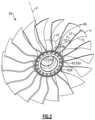
- FIG. 2illustrates a perspective view of an example rotor assembly including an array of airfoils.
- FIG. 3illustrates a perspective view of one of the airfoils of FIG. 2 secured to a hub.
- FIG. 4illustrates adjacent airfoils of the rotor assembly of FIG. 2 .
- FIG. 5 Aillustrates an exploded view of portions of the rotor assembly of FIG. 2 .
- FIG. 5 Billustrates a side view of the rotor assembly of FIG. 2 with the hub illustrated in cross-section.
- FIG. 6illustrates an end view of an airfoil section of one of the airfoils of FIG. 2 .
- FIG. 7illustrates an exploded view of the airfoil section of FIG. 6 .
- FIG. 8illustrates an exploded perspective view of an airfoil including the airfoil section of FIG. 6 .
- FIG. 9illustrates a sectional view of a composite core.
- FIG. 10illustrates a sectional view of the composite core of FIG. 9 secured to a sheath.
- FIG. 11illustrates an interface portion of the composite core of FIG. 9 .
- FIG. 12illustrates the composite core arranged relative to skins of the sheath of FIG. 10 .
- FIG. 13illustrates a sectional view of the airfoil of FIG. 10 .
- FIG. 14 Aillustrates a three-dimensional woven fabric for a composite layer.
- FIG. 14 Billustrates a plurality of braided yarns for a composite layer.
- FIG. 14 Cillustrates a two-dimensional woven fabric for a composite layer.
- FIG. 14 Dillustrates a non-crimp fabric for a composite layer.
- FIG. 14 Eillustrates a tri-axial braided fabric for a composite layer.
- FIG. 15illustrates an exploded view of an airfoil including a sheath and core according to another example.
- FIG. 16illustrates the core situated in the sheath of FIG. 15 .
- FIG. 17illustrates an airfoil including a shroud according to yet another example.
- FIG. 18illustrates an exploded view of the airfoil of FIG. 17 .
- FIG. 19illustrates a rotor assembly to another example.
- FIG. 20illustrates an exploded view of portions of the rotor assembly of FIG. 19 .
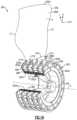
- FIG. 21illustrates an isolated view of a hub and reinforcement members of the rotor assembly of FIG. 19 .
- FIG. 22illustrates a sectional view of one of the reinforcement members taken along line 22 - 22 of FIG. 21 .
- FIG. 23illustrates a rotor assembly according to yet another example.
- FIG. 24illustrates a hub including retention members according to another example.
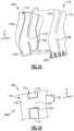
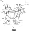
- FIG. 25illustrates the retention members of FIG. 24 positioned relative to adjacent airfoils.
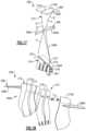
- FIG. 26illustrates the retention members of FIG. 25 and an adjacent airfoil in different positions.
- FIG. 27illustrates an example retention member
- FIG. 28illustrates a hub for a rotor assembly according to an example.
- FIG. 29illustrates a hub for a rotor assembly according to yet another example.
- FIG. 30illustrates an exploded view of the hub of FIG. 29 .
- FIG. 31illustrates a sectional view of a rotor assembly according to another example.
- FIG. 32illustrates a sectional view of the rotor assembly of FIG. 31 .
- FIG. 33illustrates an isolated view of a retention pin of the rotor assembly of FIG. 31 .
- FIG. 1schematically illustrates a gas turbine engine 20 .
- the gas turbine engine 20is disclosed herein as a two-spool turbofan that generally incorporates a fan section 22 , a compressor section 24 , a combustor section 26 and a turbine section 28 .
- the fan section 22drives air along a bypass flow path B in a bypass duct defined within a nacelle 15 , and also drives air along a core flow path C for compression and communication into the combustor section 26 then expansion through the turbine section 28 .
- the exemplary engine 20generally includes a low speed spool 30 and a high speed spool 32 mounted for rotation about an engine central longitudinal axis A relative to an engine static structure 36 via several bearing systems 38 . It should be understood that various bearing systems 38 at various locations may alternatively or additionally be provided, and the location of bearing systems 38 may be varied as appropriate to the application.
- the low speed spool 30generally includes an inner shaft 40 that interconnects, a first (or low) pressure compressor 44 and a first (or low) pressure turbine 46 .
- the inner shaft 40is connected to the fan 42 through a speed change mechanism, which in exemplary gas turbine engine 20 is illustrated as a geared architecture 48 to drive a fan 42 at a lower speed than the low speed spool 30 .
- the high speed spool 32includes an outer shaft 50 that interconnects a second (or high) pressure compressor 52 and a second (or high) pressure turbine 54 .
- a combustor 56is arranged in exemplary gas turbine 20 between the high pressure compressor 52 and the high pressure turbine 54 .
- a mid-turbine frame 57 of the engine static structure 36may be arranged generally between the high pressure turbine 54 and the low pressure turbine 46 .
- the mid-turbine frame 57further supports bearing systems 38 in the turbine section 28 .
- the inner shaft 40 and the outer shaft 50are concentric and rotate via bearing systems 38 about the engine central longitudinal axis A which is collinear with their longitudinal axes.
- the core airflowis compressed by the low pressure compressor 44 then the high pressure compressor 52 , mixed and burned with fuel in the combustor 56 , then expanded over the high pressure turbine 54 and low pressure turbine 46 .
- the mid-turbine frame 57includes airfoils 59 which are in the core airflow path C.
- the turbines 46 , 54rotationally drive the respective low speed spool 30 and high speed spool 32 in response to the expansion. It will be appreciated that each of the positions of the fan section 22 , compressor section 24 , combustor section 26 , turbine section 28 , and fan drive gear system 48 may be varied.
- gear system 48may be located aft of the low pressure compressor, or aft of the combustor section 26 or even aft of turbine section 28 , and fan 42 may be positioned forward or aft of the location of gear system 48 .
- the engine 20 in one exampleis a high-bypass geared aircraft engine.
- the engine 20 bypass ratiois greater than about six (6), with an example embodiment being greater than about ten (10)
- the geared architecture 48is an epicyclic gear train, such as a planetary gear system or other gear system, with a gear reduction ratio of greater than about 2.3
- the low pressure turbine 46has a pressure ratio that is greater than about five.
- the engine 20 bypass ratiois greater than about ten (10:1)
- the fan diameteris significantly larger than that of the low pressure compressor 44
- the low pressure turbine 46has a pressure ratio that is greater than about five 5:1.
- Low pressure turbine 46 pressure ratiois pressure measured prior to inlet of low pressure turbine 46 as related to the pressure at the outlet of the low pressure turbine 46 prior to an exhaust nozzle.
- the geared architecture 48may be an epicycle gear train, such as a planetary gear system or other gear system, with a gear reduction ratio of greater than about 2.3:1 and less than about 5:1. It should be understood, however, that the above parameters are only exemplary of one embodiment of a geared architecture engine and that the present invention is applicable to other gas turbine engines including direct drive turbofans.
- the fan section 22 of the engine 20is designed for a particular flight condition—typically cruise at about 0.8 Mach and about 35,000 feet (10,668 meters).
- ′TSFCThrust Specific Fuel Consumption
- Low fan pressure ratiois the pressure ratio across the fan blade alone, without a Fan Exit Guide Vane (“FEGV”) system.
- the low fan pressure ratio as disclosed herein according to one non-limiting embodimentis less than about 1.45.
- Low corrected fan tip speedis the actual fan tip speed in ft/sec divided by an industry standard temperature correction of [(Tram ° R)/(518.7° R)] 0.5 .
- the “Low corrected fan tip speed” as disclosed herein according to one non-limiting embodimentis less than about 1150 ft/second (350.5 meters/second).
- FIG. 2illustrates a rotor assembly 60 for a gas turbine engine according to an example.
- the rotor assembly 60can be incorporated into the fan section 12 or the compressor section 24 of the engine 20 of FIG. 1 , for example.
- the rotor assembly 60is incorporated into a multi-stage fan section of a direct drive or geared engine architecture.
- the rotor assembly 60includes a rotatable hub 62 mechanically attached or otherwise mounted to a fan shaft 64 .
- the fan shaft 64is rotatable about longitudinal axis X.
- the fan shaft 64can be rotatably coupled to the low pressure turbine 46 ( FIG. 1 ), for example.
- the rotatable hub 62includes a main body 62 A that extends along the longitudinal axis X.
- the longitudinal axis Xcan be parallel to or collinearly with the engine longitudinal axis A of FIG. 1 , for example.
- the hub 62includes an array of annular flanges 62 B that extend about an outer periphery 62 C of the main body 62 A.
- the annular flanges 62 Bdefine an array of annular channels 62 D along the longitudinal axis X.
- An array of airfoils 66are circumferentially distributed about the outer periphery 62 C of the rotatable hub 62 .
- the airfoil 66includes an airfoil section 66 A extending from a root section 66 B.
- the airfoil section 66 Aextends between a leading edge LE and a trailing edge TE in a chordwise direction C, and extends in a radial direction R between the root section 66 B and a tip portion 66 C to provide an aerodynamic surface.
- the tip portion 66 Cdefines a terminal end or radially outermost extent of the airfoil 66 to establish a clearance gap with fan case 15 ( FIG. 1 ).
- the airfoil section 66 Adefines a pressure side P ( FIG. 2 ) and a suction side S separated in a thickness direction T.
- the root section 66 Bis dimensioned to be received in each of the annular channels 62 D.
- the rotor assembly 60includes an array of platforms 70 that are separate and distinct from the airfoils 66 .
- the platforms 70are situated between and abut against adjacent pairs of airfoils 66 to define an inner boundary of a gas path along the rotor assembly 60 , as illustrated in FIG. 2 .
- the platforms 70can be mechanically attached and releasably secured to the hub 62 with one or more fasteners, for example.
- FIG. 4illustrates one of the platforms 70 abutting against the airfoil section 66 A of adjacent airfoils 66 .
- FIG. 5 Aillustrates an exploded, cutaway view of portions of the rotor assembly 60 .
- FIG. 5 Billustrates a side view of one of the airfoils 66 secured to the hub 62 .
- the rotor assembly 60includes a plurality of retention pins 68 for securing the airfoils 66 to the hub 62 (see FIG. 2 ).
- Each of the platforms 70can abut the adjacent airfoils 66 at a position radially outward of the retention pins 68 , as illustrated by FIG. 2 .
- Each of the retention pins 68is dimensioned to extend through the root section 66 B of a respective one of the airfoils 66 and to extend through each of the flanges 62 B to mechanically attach the root section 66 B of the respective airfoil 66 to the hub 62 , as illustrated by FIGS. 3 and 5 B .
- the retention pins 68react to centrifugal loads in response to rotation of the airfoils 66 .
- the hub 62can include at least three annular flanges 62 B, such five flanges 62 B as shown, and are axially spaced apart relative to the longitudinal axis X to support a length of each of the retention pins 68 .
- flanges 62 Bcan be utilized with the teachings herein. Utilizing three or more flanges 62 B can provide relatively greater surface contact area and support along a length each retention pin 68 , which can reduce bending and improve durability of the retention pin 68 .
- the airfoil 66can be a hybrid airfoil including metallic and composite portions. Referring to FIGS. 6 - 8 , with continuing reference to FIGS. 5 A- 5 B , the airfoil 66 includes a metallic sheath 72 that at least partially receives and protects a composite core 74 . In some examples, substantially all of the aerodynamic surfaces of the airfoil 66 are defined by the sheath 72 .
- the sheath 72can be dimensioned to terminate radially inward prior to the root section 66 B such that the sheath 72 is spaced apart from the respective retention pin(s) 68 , as illustrated by FIG. 5 B .
- the sheath 72includes a first skin 72 A and a second skin 72 B. The first and second skins 72 A, 72 B are joined together to define an external surface contour of the airfoil 66 including the pressure and suction sides P, S of the airfoil section 66 A.
- the core 74includes one or more ligaments 76 that define portions of the airfoil and root sections 66 A, 66 B.
- the ligament 76can define radially outermost extent or tip of the tip portion 66 C, as illustrated by FIG. 6 . In other examples, the ligaments 76 terminate prior to the tip of the airfoil section 66 A.
- the core 74includes two separate and distinct ligaments 76 A, 76 B spaced apart from each other as illustrated in FIGS. 5 B and 6 .
- the core 74can include fewer or more than two ligaments 76 , such as three to ten ligaments 76 .
- the ligaments 76 A, 76 Bextend outwardly from the root section 66 B towards the tip portion 66 C of the airfoil section 66 A, as illustrated by FIGS. 3 , 6 and 8 .
- the sheath 72defines one or more internal channels 72 C, 72 C to receive the core 74 .
- the sheath 72includes at least one rib 73 defined by the first skin 72 A that extends in the radial direction R to bound the adjacent channels 72 C, 72 D.
- the ligaments 76 A, 76 Bare received in respective internal channels 72 C, 72 D such that the skins 72 A, 72 B at least partially surround the core 74 and sandwich the ligaments 76 A, 76 B therebetween, as illustrated by FIG. 6 .
- the ligaments 76 A, 76 Breceive the common retention pin 68 such that the common retention pin 68 is slideably received through at least three, or each, of annular flanges 62 B.
- the common retention pin 68is dimensioned to extend through each and every one of the interface portions 78 of the respective airfoil 66 to mechanically attach or otherwise secure the airfoil 66 to the hub 62 .
- each of one of the ligaments 76includes at least one interface portion 78 in the root section 66 B.
- FIG. 9illustrates ligament 76 with the first and second skin 72 A, 72 B removed.
- FIG. 10illustrates the core 74 and skins 72 A, 72 B in an assembled position, with the interface portion 78 defining portions of the root section 66 B.
- the interface portion 78includes a wrapping mandrel 79 and a bushing 81 mechanically attached to the mandrel 79 with an adhesive, for example.
- the bushing 81is dimensioned to slideably receive one of the retention pins 68 ( FIG. 5 B ).
- the mandrel 79tapers from the bushing 81 to define a teardrop profile, as illustrated by FIG. 11 .
- each of the ligaments 76defines at least one slot 77 in the root section 66 B to define first and second root portions 83 A, 83 B received in the annular channels 62 D on opposed sides of the respective flange 62 B such that the root portions 83 A, 83 B are interdigitated with the flanges 62 B.
- the slots 77can decrease bending of the retention pins 68 by decreasing a distance between adjacent flanges 62 B and increase contact area and support along a length of the retention pin 68 , which can reduce contact stresses and wear.
- Each ligament 76can include a plurality of interface portions 78 (indicated as 78 A, 78 B) received in root portions 83 A, 83 B, respectively.
- the interface portions 78 A, 78 B of each ligament 76 A, 76 Breceive a common retention pin 68 to mechanically attach or otherwise secure the ligaments 76 A, 76 B to the hub 62 .
- the root section 66 Bdefines at least one bore 85 as dimension receive a retention pin 68 . In the illustrated example of FIG. 5 B , each bore 85 is defined by a respective bushing 81 .
- the first and second skins 72 A, 72 Bcomprise a metallic material such as titanium, stainless steel, nickel, a relatively ductile material such as aluminum, or another metal or metal alloy
- the core 74comprises carbon or carbon fibers, such as a ceramic matrix composite (CMC).
- CMCceramic matrix composite
- the sheath 72defines a first weight
- the composite core 74defines a second weight
- a ratio of the first weight to the second weightis at least 1:1 such that at least 50% of the weight of the airfoil 66 is made of a metallic material.
- the metal or metal alloycan provide relatively greater strength and durability under operating conditions of the engine and can provide relatively greater impact resistance to reduce damage from foreign object debris (FOD).
- the composite materialcan be relatively strong and lightweight, but may not be as ductile as metallic materials, for example.
- the hybrid construction of airfoils 66can reduce an overall weight of the rotor assembly 60 .
- each of the ligaments 76includes at least one composite layer 80 .
- Each composite layer 80can be fabricated to loop around the interface portion 78 and retention pin 68 (when in an installed position) such that opposed end portions 80 A, 80 B of the respective layer 80 are joined together along the airfoil portion 66 A.
- the composite layers 80can be dimensioned to define a substantially solid core 74 , such that substantially all of a volume of the internal cavities 72 C, 72 D of the sheath 72 are occupied by a composite material comprising carbon. In the illustrated example of FIGS.
- the composite layers 80include a first composite layer 80 C and a second composite layer 80 D between the first layer 80 C and an outer periphery of the interface portion 78 .
- the composite layers 80 C and 80 Dcan be fabricated to each loop around the interface portion 78 and the retention pin 68 .
- the layers 80can include various fiber constructions to define the core 74 .
- the first layer 80 Ccan define a first fiber construction
- the second layer 80 Dcan define a second fiber construction that differs from the first fiber construction.
- the first fiber constructioncan include one or more uni-tape plies or a fabric
- the second fiber constructioncan include at least one ply of a three-dimensional weave of fibers as illustrated by layer 80 - 1 of FIG. 14 A , for example.
- uni-tape pliesinclude a plurality of fibers oriented in the same direction (“uni-directional), and fabric includes woven or interlaced fibers, each known in the art.
- each of the first and second fiber constructionsincludes a plurality of carbon fibers.
- other materialscan be utilized for each of the fiber constructions, including fiberglass, Kevlar®, a ceramic such as NextelTM, a polyethylene such as Spectra®, and/or a combination of fibers.
- FIG. 14 Billustrates a layer 80 - 2 defined by a plurality of braided yarns.
- FIG. 14 Cillustrates a layer 80 - 3 defined by a two-dimensional woven fabric.
- FIG. 14 Dillustrates a layer 80 - 4 defined by a non-crimp fabric.
- FIG. 14 Eillustrates a layer 80 - 5 defined by a tri-axial braided fabric.
- Other example fiber constructionsinclude biaxial braids and plain or satin weaves.
- the rotor assembly 60can be constructed and assembled as follows.
- the ligaments 76 A, 76 B of core 74are situated in the respective internal channels 72 C, 72 D defined by the sheath 72 such that the ligaments 76 A, 76 B are spaced apart along the root section 66 B by one of the annular flanges 62 B and abut against opposed sides of rib 73 , as illustrated by FIGS. 5 B, 6 and 13 .
- the ligaments 76 A, 76 Bare directly bonded or otherwise mechanically attached to the surfaces of the internal channels 72 C, 72 D.
- Example bonding materialscan include polymeric adhesives such as epoxies, resins such as polyurethane and other adhesives curable at room temperature or elevated temperatures.
- the polymeric adhesivescan be relatively flexible such that ligaments 76 are moveable relative to surfaces of the internal channels 72 C, 72 D to provide damping during engine operation.
- the core 74includes a plurality of stand-offs or detents 82 that are distributed along surfaces of the ligaments 76 .
- the detents 82are dimensioned and arranged to space apart the ligaments 76 from adjacent surfaces of the internal channels 72 C, 72 D.
- Example geometries of the detents 82can include conical, hemispherical, pyramidal and complex geometries.
- the detents 82can be uniformly or non-uniformly distributed.
- the detents 82can be formed from a fiberglass fabric or scrim having raised protrusions made of rubber or resin that can be fully cured or co-cured with the ligaments 76 , for example.
- the second skin 72 Bis placed against the first skin 72 A to define an external surface contour of the airfoil 66 , as illustrated by FIGS. 6 and 13 .
- the skins 72 A, 72 Bcan be welded, brazed, riveted or otherwise mechanically attached to each other, and form a “closed loop” around the ligaments 76 .
- the detents 82can define relatively large bondline gaps between the ligaments 76 and the surfaces of the internal channels 72 C, 72 D, and a relatively flexible, weaker adhesive can be utilized to attach the sheath 72 to the ligaments 76 .
- the relatively large bondline gaps established by the detents 82can improve flow of resin or adhesive such as polyurethane and reducing formation of dry areas.
- the detents 82are dimensioned to establish bondline gap of at least a 0.020 inches, or more narrowly between 0.020 and 0.120 inches.
- the relatively large bondline gapcan accommodate manufacturing tolerances between the sheath 72 and core 74 , can ensure proper positioning during final cure and can ensure proper bond thickness.
- the relatively large bondline gapallows the metal and composite materials to thermally expand, which can reduce a likelihood of generating discontinuity stresses.
- the gaps and detents 82can also protect the composite from thermal degradation during welding or brazing of the skins 72 A, 72 B to each other.
- a resin or adhesive such as polyurethanecan be injected into gaps or spaces established by the detents 82 between the ligaments 76 and the surfaces of the internal channels 72 C, 72 D.
- a relatively weak and/or soft adhesivesuch as polyurethane is injected into the spaces.
- Utilization of relatively soft adhesives such as polyurethanecan isolate and segregate the disparate thermal expansion between metallic sheath 72 and composite core 74 , provide structural damping, isolate the delicate inner fibers of the composite core 74 from relatively extreme welding temperatures during attachment of the second skin 72 B to the first skin 72 A, and enables the ductile sheath 72 to yield during a bird strike or other FOD event, which can reduce a likelihood of degradation of the relatively brittle inner fibers of the composite core 74 .
- the composite layers 80can be simultaneously cured and bonded to each other with the injected resin, which may be referred to as “co-bonding” or “co-curing”. In other examples, the composite layers 80 can be pre-formed or pre-impregnated with resin prior to placement in the internal channels 72 C, 72 D.
- the composite core 74is cured in an oven, autoclave or by other conventional methods, with the ligaments 76 bonded to the sheath 72 , as illustrated by FIGS. 10 and 13 .
- the airfoils 66are moved in a direction D 1 ( FIGS. 5 A- 5 B ) toward the outer periphery 62 C of the hub 62 .
- a respective retention pin 68is slideably received through each bushing 81 of the interface portions 78 and each of the flanges 62 B to mechanically attach the ligaments 76 to the flanges 62 B.
- the platforms 70are then moved into abutment against respective pairs of airfoils 66 at a position radially outward of the flanges 62 B to limit circumferential movement of the airfoil sections 66 A, as illustrated by FIG. 2 .
- the rotor assembly 60also enables relatively thinner airfoils which can improve aerodynamic efficiency.
- FIGS. 15 - 16illustrate an airfoil 166 according to another example.
- like reference numeralsdesignate like elements where appropriate and reference numerals with the addition of one-hundred or multiples thereof designate modified elements that are understood to incorporate the same features and benefits of the corresponding original elements.
- a first skin 172 A of sheath 172defines internal channels 172 C, 172 D.
- the internal channels 172 C, 172 Dare adjacent to each other and are bounded by a pair of opposing ribs 173 .
- the ribs 173can extend in a radial direction R, for example, and are spaced apart along an internal gap 172 F that interconnects the internal cavities 172 C, 172 D.
- Composite core 174includes a ligament bridge 184 that interconnects an adjacent pair of ligaments 176 at a location radially outward of a common pin 168 (shown in dashed lines in FIG. 15 for illustrative purposes).
- the ligament bridge 184can be made of any of the materials disclosed herein, such as a composite material.
- the ligament bridge 184is dimensioned to be received within the gap 172 F.
- the ligament bridge 184interconnects the adjacent pair of ligaments 176 in a position along the airfoil section 166 A when in the installed position.
- the core 174may move in a direction D 2 ( FIG. 16 ) relative to the sheath 172 , which can correspond to the radial direction R, for example.
- the ligament bridge 184is dimensioned to abut against the opposing ribs 173 of the sheath 172 in response to movement in direction D 2 to react blade pull and bound radial movement of the core 174 relative to the sheath 172 .
- the ligament bridge 184serves as a fail-safe by trapping the ligaments 176 to reduce a likelihood of liberation of the ligaments 176 which may otherwise occur due to failure of the bond between the sheath 172 and ligaments 176 .
- FIGS. 17 and 18illustrate an airfoil 266 according to yet another example.
- Airfoil 266includes at least one shroud 286 that extends outwardly from pressure and suction sides P, S of airfoil section 266 A at a position radially outward of platforms 270 (shown in dashed lines in FIG. 17 for illustrative purposes).
- the shroud 286defines an external surface contour and can be utilized to tune mode(s) of the airfoil 266 by changing boundary constraints.
- the shroud 286can be made of a composite or metallic material, including any of the materials disclosed herein, or can be made of an injection molded plastic having a plastic core and a thin metallic coating, for example.
- the airfoil 266can include a second shroud 286 ′ (shown in dashed lines) to provide a dual shroud architecture, with shroud 286 arranged to divide airfoil between bypass and core flow paths B, C ( FIG. 1 ) and shroud 286 ′ for reducing a flutter condition of the airfoil 266 , for example.
- a second shroud 286 ′shown in dashed lines to provide a dual shroud architecture, with shroud 286 arranged to divide airfoil between bypass and core flow paths B, C ( FIG. 1 ) and shroud 286 ′ for reducing a flutter condition of the airfoil 266 , for example.
- the shroud 286includes first and second shroud portions 286 A, 286 B secured to the opposing pressure and suction sides P, S.
- the shroud portions 286 A, 286 Bcan be joined together with one or more inserts fasteners F that extend through the airfoil section 266 A.
- the fasteners Fcan be baked into the ligaments 276 , for example, and can be frangible to release in response to a load on either of the shroud portions 286 A, 286 B exceeding a predefined threshold.
- the airfoil 266includes only one of the shroud portions 286 A, 286 B such that the shroud 286 is on only one side of the airfoil section 266 A or is otherwise unsymmetrical.
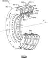
- FIGS. 19 - 21illustrate a rotor assembly 360 according to another example.
- Each annular channel 362 D of hub 362is dimensioned to receive a composite reinforcement member 388 .
- Each reinforcement member 388can have an annular geometry and is dimensioned to extend about the outer periphery 362 C of the hub 362 and to be received within a respective channel 362 D.
- each reinforcement member 388can be situated radially between the outer periphery 362 C of the hub 362 and the retention pins 368 .
- An outer diameter of the reinforcement member 388can be positioned radially inward of an innermost portion of each of the ligaments 376 of core 374 such that each reinforcement member 388 is situated radially between the outer periphery 362 C and the respective ligament 376 .
- the retention pins 368can be positioned radially outboard of the reinforcement members 388 with respect to the longitudinal axis X.
- Each reinforcement member 388can include at least one composite layer LL that is formed to extend around the outer periphery 362 C of the hub 362 .
- the reinforcement member 388can have a plurality of composite layers LL.
- Each layer LLcan include any of the composite materials and fiber constructions disclosed herein, including carbon and CMC materials.
- the reinforcement member 388can be a carbon tape 389 having uni-directional fibers and that is continuously wound around the outer periphery 362 C of the hub 362 two or more times to define the composite layers LL, such as a total of five layers LL. It should be understood that the reinforcement member 388 can have fewer or more than five layers LL.
- the tape 389can be a dry form and impregnated or injected with an epoxy or resin after formation along the hub, and then cured to fabricate the reinforcement member 388 , for example, which can reduce creep.
- the reinforcement member 388can be constructed relative to a dimension of the hub 362 to reinforce the hub 362 during engine operation.
- the reinforcement member 388can define a first thickness T 1 .
- the hub 362can define a second thickness T 2 along the outer periphery 362 C that defines a respective one of the channels 362 B.
- the second thickness T 2is less than the first thickness T 1 .
- a ratio of thickness T 2 to thickness T 1can be less than 1:2, or more narrowly less than 1:3 or 1:4, for at least some, or each, of the reinforcement member 388
- the reinforcement members 388reinforce or support the hub 362 along the outer periphery 362 C to react centrifugal forces and carry relatively high hoop loads during engine operation, and can reduce an overall weight of the hub 362 , for example.
- FIG. 23illustrates a gas turbine engine 420 including a rotor assembly 460 according to another example.
- Fan section 422delivers a portion of airflow into a core flow path C defined by compressor section 424 and another portion of airflow into a bypass flow path B defined by a bypass duct 443 of a fan case or nacelle 415 .
- the rotor assembly 460includes retention pins 468 (one shown for illustrative purposes) to releasably secure each airfoil 466 to the hub 462 .
- the rotor assembly 460can be driven by shaft 440 through geared architecture 448 .
- Geared architecture 448can be an epicyclic gear train such as a planetary or star gear system including a sun gear 448 A, intermediate gears 448 B (one shown for illustrative purposes) and ring gear 448 C.
- the sun gear 448 Ais mechanically attached or otherwise secured to the shaft 440 .
- the ring 448 Csurrounds each intermediate gear 448 B and sun gear 448 A.
- Each intermediate gear 448 Bmeshes with the sun gear 448 A and ring gear 448 C.
- the geared architecture 448includes a carrier 448 D that supports journal bearings 448 E (one shown for illustrative purposes) that each carry a respective intermediate gear 448 B.
- Carrier 448 Dcan be mechanically attached or otherwise fixedly secured to engine static structure 436 .
- Ring gear 448 Ccan be mechanically attached to fan shaft 464 , which is mechanically attached to a flange 462 B or another portion of the hub 462 .
- the shaft 440is directly attached to fan shaft 464 ′ (shown in dashed lines for illustrative purposes), and the geared architecture 448 is omitted.
- the hub 462 and fan shaft 464can be mechanically attached with one or more fasteners. Rotation of the shaft 440 causes rotation of the hub 462 to rotate each airfoil 466 .
- the engine 420can include at least one bearing assembly 438 that supports an outer diameter of the fan shaft 464 .
- Each bearing assembly 438can be mechanically attached and carried by a bearing support 439 , which is mechanically attached or otherwise secured to the engine static structure 436 .
- the engine 20includes two bearing assemblies 438 - 1 , 438 - 2 that support the fan shaft 464 at a location that is axially forward of the geared architecture 448 with respect to engine longitudinal axis A.
- Each bearing assembly 438includes at least one bearing 441 and carrier 445 that support the fan shaft 464 at a position that is radially outward a portion of the geared architecture 448 such as the ring gear 448 C with respect to the engine longitudinal axis A.
- Each bearing 441can be a ball bearing, roller bearing or taper bearing, for example.
- bearing assemblies 438 - 1 , 438 - 2are positioned radially outward of the outer periphery 462 C of the hub 462 with respect to the engine longitudinal axis A, with bearing assembly 438 - 1 being an axially forwardmost bearing assembly 438 relative to the engine longitudinal axis A.
- the bearing assemblies 438 - 1 , 438 - 2can be radially aligned or outward of the annular channels 462 D with respect to the engine longitudinal axis A.
- the arrangement of the rotor assembly 460can be utilized to increase a volume V radially inward of the hub 462 and/or fan shaft 464 , including positioning bearing assemblies 438 at a relatively further distance radially outward from the engine longitudinal axis A.
- the relatively greater volume Vcan serve to incorporate different types of bearings and support architectures for the hub 462 , for example.
- a radially outermost portion or tip 466 T of airfoil section 466 Adefines first radius R 1
- an outer diameter of the fan shaft 464defines a second radius R 2 adjacent to each respective one of the bearing assemblies 438 - 1 , 438 - 2 with respect to the engine longitudinal axis A.
- a ratio of the first radius R 1 to the second radius R 2is greater than or equal to 2:1, or more narrowly greater than or equal to 3:1 or 4:1.
- FIGS. 24 - 26illustrate a rotor assembly 560 according to another example.
- Hub 562includes an array of bumpers or retention members 590 extending outwardly from each one of the annular flanges 562 B.
- the retention members 590can be arranged in sets or rows such that each set of retention members 590 are substantially axially aligned a respective reference plane RF and support an adjacent airfoil 566 (shown in FIGS. 25 - 26 ).
- the reference plane RFcan correspond to an external surface contour or profile of the adjacent airfoil section 566 A.
- each retention member 590has a retention body 590 A having a generally L-shaped geometry that extends between a first end portion 590 B and a second end portion 590 C that defines a contact surface 590 D.
- the first end portion 590 Bis mechanically attached or otherwise secured to an outer diameter of the respective annular flange 562 B (shown in dashed lines for illustrative purposes).
- the contact surface 590 Dcan be contoured to mate with external surfaces of the airfoil section 566 A.
- Each contact surface 590 D of the retention members 590can be dimensioned to abut against a sheath 572 of an adjacent airfoil section 566 A to support the airfoil 566 and transfer loads between the airfoil section 566 A and the hub 562 during engine operation.
- the contact surface 590 Dcan be dimensioned to abut against the suction side S, or abut against the pressure side P as illustrated by retention member 590 ′ (shown in dashed lines for illustrative purposes).
- the airfoil section 566 Acan be pivotable about a respective one of the retention pins 568 .
- the airfoil section 566 Acan be moveable between first and second positions (indicated by airfoil section 566 A′ in dashed lines) such that contact surface 590 D′ is spaced apart from the airfoil section 566 A to define a circumferential gap G in the first position, but abuts against the airfoil section 566 A′ in the second position.
- Each platform 570can be dimensioned to abut against respective pairs of airfoils 566 radially inward of the contact surface 590 D of each retention member 590 .
- the contact surface 590 D of each retention members 590can be radially outward from retention pins 568 (shown in dashed lines for illustrated purposes) with respect to the longitudinal axis X.
- the combination of platforms 570 and retention members 590can cooperate to provide relatively greater support to the airfoils 566 as compared to the platforms 570 alone, and can reduce a weight of the airfoils 566 .
- each airfoil 566can experience a load or force F, such as vibratory loads, an impact from a bird strike or another FOD event that may occur during engine operation.
- Force Fmay be applied or exerted on the pressure side P of the airfoil 566 , for example, causing or otherwise urging the airfoil 566 to pivot about or otherwise move relative to retention pin 568 and lean in a circumferential or thickness direction T, as illustrated by airfoil section 566 A′′ of airfoil 566 ′′ (shown in dashed lines).
- Each retention member 590limits or otherwise opposes circumferential movement of the airfoil section 566 A of the adjacent airfoil 566 .
- Each retention member 590can have a construction such that the retention body 590 A reacts, but deflects or yields to, load or force F on the respective airfoil 466 during engine operation. Each retention member 590 can establish a spring force to oppose loads on the airfoil 566 . One or more of the retention members 590 is moveable from a first position to second position (illustrated by 590 ′′ in dashed lines) to react to the force F and oppose circumferential movement of the airfoil 566 . The retention member 590 can be constructed to yield to force F to at least partially absorb and transfer the force F from the airfoil section 566 A to the hub 562 .
- each retention member 590can be made of a metallic material and can be integrally formed with a respective one of the flanges 562 B.
- each retention member 590can be machined from an unfinished portion of the hub 562 , which can be a cast component.
- the retention member 590is a separate and distinct component that is mechanically attached or otherwise secured to the respective flange 562 B.
- each retention member 590is a frangible structure that is constructed to yield but oppose the force F in response to the force F being below a predefined limit, but is constructed to shear or break in response to the force F exceeding a predefined limit. In the illustrative example of FIG.
- each retention members 590can define one or more cutouts 692 in a thickness of the retention body 690 A to weaken selective portions of the retention member 690 .
- the cutouts 692can be apertures, grooves or indentations in the retention body 690 A, for example.
- the quantity, size and/or profile of the cutouts 692can be defined with respect to a predefined limit of an expected force or load on the respective airfoil.
- the cutouts 692can be drilled or machined to cause the retention member 690 to bend or buckle in response to a force or load exceeding the predefined limit.
- FIG. 28illustrates an annular hub 762 for a rotor assembly according to an example.
- Flanges 762 B of hub 762includes a plurality of scallops 762 F arranged in rows 762 F- 1 to 762 F- 6 about an outer periphery 762 C of main body 762 A.
- a perimeter of each scallop 762 Bcan have a generally arcuate geometry that slopes toward valleys 762 G defined between adjacent scallops 762 B such that an outer perimeter 763 of each of the rows 762 F- 1 to 762 F- 6 has a generally sinusoidal profile about longitudinal axis X.
- Each scallop 762 Bdefines at least one bore 762 E for receiving a retention pin 768 (one shown in dashed lines for illustrative purposes) to secure an airfoil to the hub 762 .
- the arrangement of scallops 762 Fcan lower stresses, which can reduce wear of the retention pins, and can also reduce installation complexity.
- FIGS. 29 and 30illustrate an annular hub 862 for a rotor assembly 860 according to another example.
- the hub 862can include hub portions 862 - 1 , 862 - 2 and 862 - 3 that are mechanically attached or otherwise secured to each other to define an assembly.
- Each of the hub portions 862 - 1 , 862 - 2 and 862 - 3includes one or more flanges 862 B to receive retention pins 868 (one shown in dashed lines in FIG. 29 for illustrative purposes).
- Each of the hub portions 862 - 1 , 862 - 2 and 862 - 3includes one or more mounting flanges 862 H that extend inwardly from a respective main body 862 A.
- Composite reinforcement members 888can be received in annular channels 862 D defined by the hub portions 862 - 1 , 862 - 2 and 862 - 3 .
- the hub portions 862 - 1 , 862 - 2 and 862 - 3can be mechanically attached or otherwise secured to each other with one or more fasteners F received through bores defined in the mounting flanges 862 H, for example.
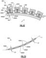
- FIGS. 31 and 32illustrates a rotor assembly 960 according to another example.
- FIG. 33illustrates an isolated view of a segmented retention pin 968 of the rotor assembly 960 .
- Each retention pin 968includes a plurality of segments 968 A linked together by an elongated carrier 968 B.
- Each of the segments 968 Ais separate and distinct and includes a main body 968 AA and a pair of end portions 968 AB that can taper from the main body 968 AA to define a substantially cone-cylinder-cone geometry.
- An outer periphery of the main body 988 AAdefines an outer diameter DP ( FIG. 33 ).
- the segments 968 Aare dimensioned such that the outer diameter DP of the segments 968 A is progressively smaller along the retention pin 968 .
- Each segment 968 Acan be made of a metallic material, such as steel, for example.
- the carrier 968 Bcan be a flexible wire, for example.
- the segments 968 Acan be slideably received onto and supported by the carrier 968 A. Although five segments 968 A are shown, fewer or more than five segments 968 A can be utilized.
- the carrier 968 Bdefines a pin axis P.
- the pin axis Pcan be substantially straight or can be curved including one or more curved portions such that the pin axis P is not parallel to the longitudinal axis X when in an installed position, as illustrated by FIG. 31 .
- the profile of the pin axis Pcan be defined with respect to a contour of a respective airfoil 466 .
- each segment 968 Ais received in a respective bore 862 E defined by a respective flange 962 B of the hub 962 and a respective ligament 976 of an airfoil 966 , as illustrated by FIGS. 32 and 33 .
- the bores 862 Ecan be defined in the flanges 962 B to establish a contour of the pin axis P.
- the arrangement of the retention pin 968 including a curved profile of the pin axis Pcan be utilized to reduce stresses in the respective ligaments 976 and can reduce a distance between adjacent retention pins 968 that may otherwise overlap with the use of substantially straight profiles, which can reduce weight and can improve tuning and aerodynamic efficiency of the airfoils.
Landscapes
- Engineering & Computer Science (AREA)
- Mechanical Engineering (AREA)
- General Engineering & Computer Science (AREA)
- Chemical & Material Sciences (AREA)
- Materials Engineering (AREA)
- Composite Materials (AREA)
- Architecture (AREA)
- Structures Of Non-Positive Displacement Pumps (AREA)
- Turbine Rotor Nozzle Sealing (AREA)
Abstract
Description
This application is a continuation in-part of U.S. patent application Ser. No. 16/163,641, filed on Oct. 18, 2018.
This disclosure relates to a gas turbine engine, and more particularly to a rotor assembly including a hub that carries an array of airfoils.
Gas turbine engines can include a fan for propulsion air and to cool components. The fan also delivers air into a core engine where it is compressed. The compressed air is then delivered into a combustion section, where it is mixed with fuel and ignited. The combustion gas expands downstream over and drives turbine blades. Static vanes are positioned adjacent to the turbine blades to control the flow of the products of combustion. The fan typically includes an array of fan blades having dovetails that are mounted in slots of a fan hub.
A rotor assembly for a gas turbine engine according to an example of the present disclosure includes a rotatable hub that has a metallic main body that extends along a longitudinal axis, and that has an array of annular flanges that extend about an outer periphery of the main body to define an array of annular channels along the longitudinal axis. Each of the annular channels receives a composite reinforcement member that extends about the outer periphery of the hub.
A further embodiment of any of the foregoing embodiments includes an array of airfoils circumferentially distributed about the outer periphery. Each one of the airfoils has an airfoil section that extends from a root section received in the annular channels. A plurality of retention pins extends through the root section of a respective one of the airfoils and through the array of annular flanges to mechanically attach the root section to the hub. An array of platforms are mechanically attached to the hub and that abut against respective pairs of the airfoils radially outward of the retention pins.
In a further embodiment of any of the foregoing embodiments, the airfoil section includes a metallic sheath and a composite core. The core includes first and second ligaments at least partially received in respective internal channels defined in the sheath.
In a further embodiment of any of the foregoing embodiments, the composite reinforcement member includes at least one composite layer that extends around the outer periphery.
In a further embodiment of any of the foregoing embodiments, the composite reinforcement member defines a first thickness, and the hub defines a second thickness along the outer periphery that defines a respective one of the annular channels, and the second thickness is less than the first thickness.
In a further embodiment of any of the foregoing embodiments, the at least one composite layer is a plurality of composite layers, and the composite reinforcement member is a carbon tape wound around the outer periphery two or more times to define the composite layers.
In a further embodiment of any of the foregoing embodiments, each of the flanges is defined by a plurality of scallops arranged in a respective row about the outer periphery of the hub.
A rotor assembly for a gas turbine engine according to an example of the present disclosure includes a rotatable hub that has a main body that extends along a longitudinal axis, and that has an array of annular flanges that extend about an outer periphery of the main body to define an array of annular channels along the longitudinal axis. An array of airfoils are circumferentially distributed about the outer periphery. Each one of the airfoils has an airfoil section that extends from a root section. The root section is received in the annular channels and mechanically attached to the hub. An array of retention members, extend outwardly from one of the annular flanges and having a contact surface dimensioned to abut against the airfoil section of a respective one of the airfoils.
In a further embodiment of any of the foregoing embodiments, each of the retention members includes a retention body that has an L-shaped geometry that extends between a first end and a second end defining the contact surface such that the retention body reacts but yields to a load on a respective one of the airfoils in operation, and the retention body is integrally formed with a respective one of the annular flanges.
In a further embodiment of any of the foregoing embodiments, the airfoil section is moveable between first and second positions such that the contact surface is spaced apart from the airfoil section to define a circumferential gap in the first position, but abuts against the airfoil section in the second position. Each of the retention members defines one or more cutouts in a thickness of the retention body.
In a further embodiment of any of the foregoing embodiments, the airfoil section extends between a leading edge and a trailing edge in a chordwise direction and extends between a tip portion and the root section in a radial direction, and the airfoil section defines a pressure side and a suction side separated in a thickness direction. The contact surface of each of the retention members is dimensioned to abut against the pressure side or the suction side of a respective one of the airfoils further including an array of platforms mechanically attached to the hub and that abut against respective pairs of the airfoils radially inward of the contact surface of each of the retention members.
A further embodiment of any of the foregoing embodiments includes a plurality of retention pins. Each one of the retention pins extends through the root section of a respective one of the airfoils and through the array of annular flanges to mechanically attach the root section to the hub.
In a further embodiment of any of the foregoing embodiments, each of the retention pins includes a plurality of segments slideably received on an elongated carrier, and the carrier defines a curved pin axis when in an installed position.
A gas turbine engine according to an example of the present disclosure includes a fan section that has a fan shaft rotatable about an engine longitudinal axis. At least one bearing assembly supports the fan shaft. The fan section includes a rotor assembly. The rotor assembly includes a rotatable hub that has a main body mechanically attached to the fan shaft, and that has an array of annular flanges that extends about an outer periphery of the main body to define an array of annular channels along the engine longitudinal axis. Each of the annular channels receives a composite reinforcement member that extends about the outer periphery. An array of airfoils each have an airfoil section that extend from a root section. A plurality of retention pins extend through the root section of a respective one of the airfoils, across the annular channels, and through the annular flanges to mechanically attach the root section to the hub.
In a further embodiment of any of the foregoing embodiments, the airfoil section includes a metallic sheath and a composite core. The core includes first and second ligaments at least partially received in respective internal channels defined in the sheath.
In a further embodiment of any of the foregoing embodiments, each one of the ligaments includes at least one interface portion in the root section that receives a respective one of the retention pins, and each one of the ligaments includes at least one composite layer that loops around the at least one interface portion such that opposed end portions of the at least one composite layer are joined together along the airfoil portion.
In a further embodiment of any of the foregoing embodiments, each of the annular flanges includes an array of retention members, and each of the retention members is integrally formed with and extends outwardly from a respective one of the annular flanges and has an L-shaped geometry defining a contact surface that is dimensioned to abut against a sidewall of the airfoil section of a respective one of the airfoils.
In a further embodiment of any of the foregoing embodiments, the composite reinforcement member is a carbon tape that is wound around the outer periphery two or more times.
In a further embodiment of any of the foregoing embodiments, the composite reinforcement member defines a first thickness, and the hub defines a second thickness along the outer periphery that defines a respective one of the annular channels, and the second thickness is less than the first thickness.
In a further embodiment of any of the foregoing embodiments, the at least one bearing assembly is positioned radially outward of the outer periphery of the hub with respect to the engine longitudinal axis.
A further embodiment of any of the foregoing embodiments includes a fan drive turbine that drives the fan shaft through a geared architecture. The at least one bearing assembly supports the fan shaft at a position that is radially outward of the geared architecture with respect to the engine longitudinal axis.
In a further embodiment of any of the foregoing embodiments, the fan section delivers a portion of airflow into a compressor section and another portion of airflow into a bypass duct.
The various features and advantages of this disclosure will become apparent to those skilled in the art from the following detailed description. The drawings that accompany the detailed description can be briefly described as follows.
Theexemplary engine 20 generally includes alow speed spool 30 and ahigh speed spool 32 mounted for rotation about an engine central longitudinal axis A relative to an enginestatic structure 36 viaseveral bearing systems 38. It should be understood that various bearingsystems 38 at various locations may alternatively or additionally be provided, and the location of bearingsystems 38 may be varied as appropriate to the application.
Thelow speed spool 30 generally includes aninner shaft 40 that interconnects, a first (or low) pressure compressor44 and a first (or low)pressure turbine 46. Theinner shaft 40 is connected to thefan 42 through a speed change mechanism, which in exemplarygas turbine engine 20 is illustrated as a gearedarchitecture 48 to drive afan 42 at a lower speed than thelow speed spool 30. Thehigh speed spool 32 includes anouter shaft 50 that interconnects a second (or high)pressure compressor 52 and a second (or high)pressure turbine 54. Acombustor 56 is arranged inexemplary gas turbine 20 between thehigh pressure compressor 52 and thehigh pressure turbine 54. Amid-turbine frame 57 of the enginestatic structure 36 may be arranged generally between thehigh pressure turbine 54 and thelow pressure turbine 46. Themid-turbine frame 57 furthersupports bearing systems 38 in theturbine section 28. Theinner shaft 40 and theouter shaft 50 are concentric and rotate via bearingsystems 38 about the engine central longitudinal axis A which is collinear with their longitudinal axes.
The core airflow is compressed by the low pressure compressor44 then thehigh pressure compressor 52, mixed and burned with fuel in thecombustor 56, then expanded over thehigh pressure turbine 54 andlow pressure turbine 46. Themid-turbine frame 57 includesairfoils 59 which are in the core airflow path C. Theturbines low speed spool 30 andhigh speed spool 32 in response to the expansion. It will be appreciated that each of the positions of thefan section 22,compressor section 24,combustor section 26,turbine section 28, and fandrive gear system 48 may be varied. For example,gear system 48 may be located aft of the low pressure compressor, or aft of thecombustor section 26 or even aft ofturbine section 28, andfan 42 may be positioned forward or aft of the location ofgear system 48.
Theengine 20 in one example is a high-bypass geared aircraft engine. In a further example, theengine 20 bypass ratio is greater than about six (6), with an example embodiment being greater than about ten (10), the gearedarchitecture 48 is an epicyclic gear train, such as a planetary gear system or other gear system, with a gear reduction ratio of greater than about 2.3 and thelow pressure turbine 46 has a pressure ratio that is greater than about five. In one disclosed embodiment, theengine 20 bypass ratio is greater than about ten (10:1), the fan diameter is significantly larger than that of the low pressure compressor44, and thelow pressure turbine 46 has a pressure ratio that is greater than about five 5:1.Low pressure turbine 46 pressure ratio is pressure measured prior to inlet oflow pressure turbine 46 as related to the pressure at the outlet of thelow pressure turbine 46 prior to an exhaust nozzle. The gearedarchitecture 48 may be an epicycle gear train, such as a planetary gear system or other gear system, with a gear reduction ratio of greater than about 2.3:1 and less than about 5:1. It should be understood, however, that the above parameters are only exemplary of one embodiment of a geared architecture engine and that the present invention is applicable to other gas turbine engines including direct drive turbofans.
A significant amount of thrust is provided by the bypass flow B due to the high bypass ratio. Thefan section 22 of theengine 20 is designed for a particular flight condition—typically cruise at about 0.8 Mach and about 35,000 feet (10,668 meters). The flight condition of 0.8 Mach and 35,000 ft (10,668 meters), with the engine at its best fuel consumption—also known as “bucket cruise Thrust Specific Fuel Consumption (′TSFC)”—is the industry standard parameter of lbm of fuel being burned divided by lbf of thrust the engine produces at that minimum point. “Low fan pressure ratio” is the pressure ratio across the fan blade alone, without a Fan Exit Guide Vane (“FEGV”) system. The low fan pressure ratio as disclosed herein according to one non-limiting embodiment is less than about 1.45. “Low corrected fan tip speed” is the actual fan tip speed in ft/sec divided by an industry standard temperature correction of [(Tram ° R)/(518.7° R)]0.5. The “Low corrected fan tip speed” as disclosed herein according to one non-limiting embodiment is less than about 1150 ft/second (350.5 meters/second).
Therotor assembly 60 includes arotatable hub 62 mechanically attached or otherwise mounted to afan shaft 64. Thefan shaft 64 is rotatable about longitudinal axis X. Thefan shaft 64 can be rotatably coupled to the low pressure turbine46 (FIG.1 ), for example. Therotatable hub 62 includes amain body 62A that extends along the longitudinal axis X. The longitudinal axis X can be parallel to or collinearly with the engine longitudinal axis A ofFIG.1 , for example. As illustrated byFIG.3 , thehub 62 includes an array ofannular flanges 62B that extend about anouter periphery 62C of themain body 62A. Theannular flanges 62B define an array ofannular channels 62D along the longitudinal axis X.
An array ofairfoils 66 are circumferentially distributed about theouter periphery 62C of therotatable hub 62. Referring toFIG.3 , with continued reference toFIG.2 , one of theairfoils 66 mounted to thehub 62 is shown for illustrative purposes. Theairfoil 66 includes anairfoil section 66A extending from aroot section 66B. Theairfoil section 66A extends between a leading edge LE and a trailing edge TE in a chordwise direction C, and extends in a radial direction R between theroot section 66B and atip portion 66C to provide an aerodynamic surface. Thetip portion 66C defines a terminal end or radially outermost extent of theairfoil 66 to establish a clearance gap with fan case15 (FIG.1 ). Theairfoil section 66A defines a pressure side P (FIG.2 ) and a suction side S separated in a thickness direction T. Theroot section 66B is dimensioned to be received in each of theannular channels 62D.
Therotor assembly 60 includes an array ofplatforms 70 that are separate and distinct from theairfoils 66. Theplatforms 70 are situated between and abut against adjacent pairs ofairfoils 66 to define an inner boundary of a gas path along therotor assembly 60, as illustrated inFIG.2 . Theplatforms 70 can be mechanically attached and releasably secured to thehub 62 with one or more fasteners, for example.FIG.4 illustrates one of theplatforms 70 abutting against theairfoil section 66A ofadjacent airfoils 66.
Each of the retention pins68 is dimensioned to extend through theroot section 66B of a respective one of theairfoils 66 and to extend through each of theflanges 62B to mechanically attach theroot section 66B of therespective airfoil 66 to thehub 62, as illustrated byFIGS.3 and5B . The retention pins68 react to centrifugal loads in response to rotation of theairfoils 66. Thehub 62 can include at least threeannular flanges 62B, such fiveflanges 62B as shown, and are axially spaced apart relative to the longitudinal axis X to support a length of each of the retention pins68. However, fewer or more than fiveflanges 62B can be utilized with the teachings herein. Utilizing three ormore flanges 62B can provide relatively greater surface contact area and support along a length eachretention pin 68, which can reduce bending and improve durability of theretention pin 68.
Theairfoil 66 can be a hybrid airfoil including metallic and composite portions. Referring toFIGS.6-8 , with continuing reference toFIGS.5A-5B , theairfoil 66 includes ametallic sheath 72 that at least partially receives and protects acomposite core 74. In some examples, substantially all of the aerodynamic surfaces of theairfoil 66 are defined by thesheath 72. Thesheath 72 can be dimensioned to terminate radially inward prior to theroot section 66B such that thesheath 72 is spaced apart from the respective retention pin(s)68, as illustrated byFIG.5B . Thesheath 72 includes afirst skin 72A and asecond skin 72B. The first andsecond skins airfoil 66 including the pressure and suction sides P, S of theairfoil section 66A.
Thecore 74 includes one ormore ligaments 76 that define portions of the airfoil androot sections ligament 76 can define radially outermost extent or tip of thetip portion 66C, as illustrated byFIG.6 . In other examples, theligaments 76 terminate prior to the tip of theairfoil section 66A. In the illustrative example ofFIGS.6-8 , thecore 74 includes two separate anddistinct ligaments FIGS.5B and6 . The core74 can include fewer or more than twoligaments 76, such as three to tenligaments 76. Theligaments root section 66B towards thetip portion 66C of theairfoil section 66A, as illustrated byFIGS.3,6 and8 .
Thesheath 72 defines one or moreinternal channels core 74. In the illustrated example ofFIGS.6-8 , thesheath 72 includes at least onerib 73 defined by thefirst skin 72A that extends in the radial direction R to bound theadjacent channels ligaments internal channels skins core 74 and sandwich theligaments FIG.6 . Theligaments common retention pin 68 such that thecommon retention pin 68 is slideably received through at least three, or each, ofannular flanges 62B. Thecommon retention pin 68 is dimensioned to extend through each and every one of theinterface portions 78 of therespective airfoil 66 to mechanically attach or otherwise secure theairfoil 66 to thehub 62.
Referring toFIGS.9-10 , with continued reference toFIGS.5A-5B and6-8 , each of one of theligaments 76 includes at least oneinterface portion 78 in theroot section 66B.FIG.9 illustratesligament 76 with the first andsecond skin FIG.10 illustrates thecore 74 andskins interface portion 78 defining portions of theroot section 66B. Theinterface portion 78 includes a wrappingmandrel 79 and abushing 81 mechanically attached to themandrel 79 with an adhesive, for example. Thebushing 81 is dimensioned to slideably receive one of the retention pins68 (FIG.5B ). Themandrel 79 tapers from thebushing 81 to define a teardrop profile, as illustrated byFIG.11 .
In the illustrative example ofFIGS.5B and8 , each of theligaments 76 defines at least oneslot 77 in theroot section 66B to define first andsecond root portions annular channels 62D on opposed sides of therespective flange 62B such that theroot portions flanges 62B. Theslots 77 can decrease bending of the retention pins68 by decreasing a distance betweenadjacent flanges 62B and increase contact area and support along a length of theretention pin 68, which can reduce contact stresses and wear.
Eachligament 76 can include a plurality of interface portions78 (indicated as78A,78B) received inroot portions interface portions ligament common retention pin 68 to mechanically attach or otherwise secure theligaments hub 62. Theroot section 66B defines at least one bore85 as dimension receive aretention pin 68. In the illustrated example ofFIG.5B , each bore85 is defined by arespective bushing 81.
Various materials can be utilized for thesheath 72 andcomposite core 74. In some examples, the first andsecond skins core 74 comprises carbon or carbon fibers, such as a ceramic matrix composite (CMC). In examples, thesheath 72 defines a first weight, thecomposite core 74 defines a second weight, and a ratio of the first weight to the second weight is at least 1:1 such that at least 50% of the weight of theairfoil 66 is made of a metallic material. The metal or metal alloy can provide relatively greater strength and durability under operating conditions of the engine and can provide relatively greater impact resistance to reduce damage from foreign object debris (FOD). The composite material can be relatively strong and lightweight, but may not be as ductile as metallic materials, for example. The hybrid construction ofairfoils 66 can reduce an overall weight of therotor assembly 60.
In the illustrative example ofFIGS.9 and10 , each of theligaments 76 includes at least onecomposite layer 80. Eachcomposite layer 80 can be fabricated to loop around theinterface portion 78 and retention pin68 (when in an installed position) such thatopposed end portions respective layer 80 are joined together along theairfoil portion 66A. The composite layers80 can be dimensioned to define a substantiallysolid core 74, such that substantially all of a volume of theinternal cavities sheath 72 are occupied by a composite material comprising carbon. In the illustrated example ofFIGS.9 and10 , thecomposite layers 80 include a firstcomposite layer 80C and a secondcomposite layer 80D between thefirst layer 80C and an outer periphery of theinterface portion 78. Thecomposite layers interface portion 78 and theretention pin 68.
Thelayers 80 can include various fiber constructions to define thecore 74. For example, thefirst layer 80C can define a first fiber construction, and thesecond layer 80D can define a second fiber construction that differs from the first fiber construction. The first fiber construction can include one or more uni-tape plies or a fabric, and the second fiber construction can include at least one ply of a three-dimensional weave of fibers as illustrated by layer80-1 ofFIG.14A , for example. It should be appreciated that uni-tape plies include a plurality of fibers oriented in the same direction (“uni-directional), and fabric includes woven or interlaced fibers, each known in the art. In examples, each of the first and second fiber constructions includes a plurality of carbon fibers. However, other materials can be utilized for each of the fiber constructions, including fiberglass, Kevlar®, a ceramic such as Nextel™, a polyethylene such as Spectra®, and/or a combination of fibers.
Other fiber constructions can be utilized to construct each of thelayers 80, including any of the layers80-2 to80-5 ofFIGS.14B-14E .FIG.14B illustrates a layer80-2 defined by a plurality of braided yarns.FIG.14C illustrates a layer80-3 defined by a two-dimensional woven fabric.FIG.14D illustrates a layer80-4 defined by a non-crimp fabric.FIG.14E illustrates a layer80-5 defined by a tri-axial braided fabric. Other example fiber constructions include biaxial braids and plain or satin weaves.
Therotor assembly 60 can be constructed and assembled as follows. Theligaments core 74 are situated in the respectiveinternal channels sheath 72 such that theligaments root section 66B by one of theannular flanges 62B and abut against opposed sides ofrib 73, as illustrated byFIGS.5B,6 and13 .
In some examples, theligaments internal channels ligaments 76 are moveable relative to surfaces of theinternal channels FIGS.9-10 and12-13 , thecore 74 includes a plurality of stand-offs ordetents 82 that are distributed along surfaces of theligaments 76. Thedetents 82 are dimensioned and arranged to space apart theligaments 76 from adjacent surfaces of theinternal channels detents 82 can include conical, hemispherical, pyramidal and complex geometries. Thedetents 82 can be uniformly or non-uniformly distributed. Thedetents 82 can be formed from a fiberglass fabric or scrim having raised protrusions made of rubber or resin that can be fully cured or co-cured with theligaments 76, for example.
Thesecond skin 72B is placed against thefirst skin 72A to define an external surface contour of theairfoil 66, as illustrated byFIGS.6 and13 . Theskins ligaments 76.
Thedetents 82 can define relatively large bondline gaps between theligaments 76 and the surfaces of theinternal channels sheath 72 to theligaments 76. The relatively large bondline gaps established by thedetents 82 can improve flow of resin or adhesive such as polyurethane and reducing formation of dry areas. In examples, thedetents 82 are dimensioned to establish bondline gap of at least a 0.020 inches, or more narrowly between 0.020 and 0.120 inches. The relatively large bondline gap can accommodate manufacturing tolerances between thesheath 72 andcore 74, can ensure proper positioning during final cure and can ensure proper bond thickness. The relatively large bondline gap allows the metal and composite materials to thermally expand, which can reduce a likelihood of generating discontinuity stresses. The gaps anddetents 82 can also protect the composite from thermal degradation during welding or brazing of theskins
For example, a resin or adhesive such as polyurethane can be injected into gaps or spaces established by thedetents 82 between theligaments 76 and the surfaces of theinternal channels metallic sheath 72 andcomposite core 74, provide structural damping, isolate the delicate inner fibers of thecomposite core 74 from relatively extreme welding temperatures during attachment of thesecond skin 72B to thefirst skin 72A, and enables theductile sheath 72 to yield during a bird strike or other FOD event, which can reduce a likelihood of degradation of the relatively brittle inner fibers of thecomposite core 74.
The composite layers80 can be simultaneously cured and bonded to each other with the injected resin, which may be referred to as “co-bonding” or “co-curing”. In other examples, thecomposite layers 80 can be pre-formed or pre-impregnated with resin prior to placement in theinternal channels composite core 74 is cured in an oven, autoclave or by other conventional methods, with theligaments 76 bonded to thesheath 72, as illustrated byFIGS.10 and13 .
Theairfoils 66 are moved in a direction D1 (FIGS.5A-5B ) toward theouter periphery 62C of thehub 62. Arespective retention pin 68 is slideably received through eachbushing 81 of theinterface portions 78 and each of theflanges 62B to mechanically attach theligaments 76 to theflanges 62B. Theplatforms 70 are then moved into abutment against respective pairs ofairfoils 66 at a position radially outward of theflanges 62B to limit circumferential movement of theairfoil sections 66A, as illustrated byFIG.2 .
Mechanically attaching theairfoils 66 withretention pins 68 can allow theairfoil 66 to flex and twist, which can reduce a likelihood of damage caused by FOD impacts by allowing theairfoil 66 to bend away from the impacts. Therotor assembly 60 also enables relatively thinner airfoils which can improve aerodynamic efficiency.
Theligament bridge 184 is dimensioned to be received within thegap 172F. Theligament bridge 184 interconnects the adjacent pair ofligaments 176 in a position along theairfoil section 166A when in the installed position. During operation, thecore 174 may move in a direction D2 (FIG.16 ) relative to thesheath 172, which can correspond to the radial direction R, for example. Theligament bridge 184 is dimensioned to abut against the opposingribs 173 of thesheath 172 in response to movement in direction D2 to react blade pull and bound radial movement of thecore 174 relative to thesheath 172. Theligament bridge 184 serves as a fail-safe by trapping theligaments 176 to reduce a likelihood of liberation of theligaments 176 which may otherwise occur due to failure of the bond between thesheath 172 andligaments 176.
Theshroud 286 includes first andsecond shroud portions shroud portions airfoil section 266A. The fasteners F can be baked into theligaments 276, for example, and can be frangible to release in response to a load on either of theshroud portions shroud portions airfoil 266, such as by an adhesive, welding or integrally forming theskins respective shroud portions airfoil 266 includes only one of theshroud portions shroud 286 is on only one side of theairfoil section 266A or is otherwise unsymmetrical.
As illustrated byFIGS.19 and20 , eachreinforcement member 388 can be situated radially between theouter periphery 362C of thehub 362 and the retention pins368. An outer diameter of thereinforcement member 388 can be positioned radially inward of an innermost portion of each of theligaments 376 ofcore 374 such that eachreinforcement member 388 is situated radially between theouter periphery 362C and therespective ligament 376. The retention pins368 can be positioned radially outboard of thereinforcement members 388 with respect to the longitudinal axis X.
Eachreinforcement member 388 can include at least one composite layer LL that is formed to extend around theouter periphery 362C of thehub 362. Referring toFIG.22 , with continued reference toFIGS.19-21 , thereinforcement member 388 can have a plurality of composite layers LL. Each layer LL can include any of the composite materials and fiber constructions disclosed herein, including carbon and CMC materials. For example, thereinforcement member 388 can be acarbon tape 389 having uni-directional fibers and that is continuously wound around theouter periphery 362C of thehub 362 two or more times to define the composite layers LL, such as a total of five layers LL. It should be understood that thereinforcement member 388 can have fewer or more than five layers LL. Thetape 389 can be a dry form and impregnated or injected with an epoxy or resin after formation along the hub, and then cured to fabricate thereinforcement member 388, for example, which can reduce creep.
Thereinforcement member 388 can be constructed relative to a dimension of thehub 362 to reinforce thehub 362 during engine operation. For example, thereinforcement member 388 can define a first thickness T1. Thehub 362 can define a second thickness T2 along theouter periphery 362C that defines a respective one of thechannels 362B. In some examples, the second thickness T2 is less than the first thickness T1. For example, a ratio of thickness T2 to thickness T1 can be less than 1:2, or more narrowly less than 1:3 or 1:4, for at least some, or each, of thereinforcement member 388 Thereinforcement members 388 reinforce or support thehub 362 along theouter periphery 362C to react centrifugal forces and carry relatively high hoop loads during engine operation, and can reduce an overall weight of thehub 362, for example.
Therotor assembly 460 can be driven byshaft 440 through gearedarchitecture 448.Geared architecture 448 can be an epicyclic gear train such as a planetary or star gear system including asun gear 448A,intermediate gears 448B (one shown for illustrative purposes) andring gear 448C. Thesun gear 448A is mechanically attached or otherwise secured to theshaft 440. Thering 448C surrounds eachintermediate gear 448B andsun gear 448A. Eachintermediate gear 448B meshes with thesun gear 448A andring gear 448C. The gearedarchitecture 448 includes acarrier 448D that supportsjournal bearings 448E (one shown for illustrative purposes) that each carry a respectiveintermediate gear 448B.
Theengine 420 can include at least onebearing assembly 438 that supports an outer diameter of thefan shaft 464. Each bearingassembly 438 can be mechanically attached and carried by abearing support 439, which is mechanically attached or otherwise secured to the enginestatic structure 436.
In the illustrated example ofFIG.23 , theengine 20 includes two bearing assemblies438-1,438-2 that support thefan shaft 464 at a location that is axially forward of the gearedarchitecture 448 with respect to engine longitudinal axis A. Each bearingassembly 438 includes at least onebearing 441 andcarrier 445 that support thefan shaft 464 at a position that is radially outward a portion of the gearedarchitecture 448 such as thering gear 448C with respect to the engine longitudinal axis A. Each bearing441 can be a ball bearing, roller bearing or taper bearing, for example. In the illustrated example ofFIG.23 , at least a portion of the bearing assemblies438-1,438-2 are positioned radially outward of theouter periphery 462C of thehub 462 with respect to the engine longitudinal axis A, with bearing assembly438-1 being an axiallyforwardmost bearing assembly 438 relative to the engine longitudinal axis A. The bearing assemblies438-1,438-2 can be radially aligned or outward of theannular channels 462D with respect to the engine longitudinal axis A.
The arrangement of therotor assembly 460 can be utilized to increase a volume V radially inward of thehub 462 and/orfan shaft 464, including positioning bearingassemblies 438 at a relatively further distance radially outward from the engine longitudinal axis A. The relatively greater volume V can serve to incorporate different types of bearings and support architectures for thehub 462, for example. A radially outermost portion ortip 466T of airfoil section466A defines first radius R1, and an outer diameter of thefan shaft 464 defines a second radius R2 adjacent to each respective one of the bearing assemblies438-1,438-2 with respect to the engine longitudinal axis A. In some examples, a ratio of the first radius R1 to the second radius R2 is greater than or equal to 2:1, or more narrowly greater than or equal to 3:1 or 4:1.
Referring toFIG.25 with continued reference toFIG.24 , eachretention member 590 has aretention body 590A having a generally L-shaped geometry that extends between afirst end portion 590B and asecond end portion 590C that defines acontact surface 590D. Thefirst end portion 590B is mechanically attached or otherwise secured to an outer diameter of the respectiveannular flange 562B (shown in dashed lines for illustrative purposes). Thecontact surface 590D can be contoured to mate with external surfaces of theairfoil section 566A.
Eachcontact surface 590D of theretention members 590 can be dimensioned to abut against asheath 572 of anadjacent airfoil section 566A to support theairfoil 566 and transfer loads between theairfoil section 566A and thehub 562 during engine operation. For example, thecontact surface 590D can be dimensioned to abut against the suction side S, or abut against the pressure side P as illustrated byretention member 590′ (shown in dashed lines for illustrative purposes). Theairfoil section 566A can be pivotable about a respective one of the retention pins568. Theairfoil section 566A can be moveable between first and second positions (indicated byairfoil section 566A′ in dashed lines) such thatcontact surface 590D′ is spaced apart from theairfoil section 566A to define a circumferential gap G in the first position, but abuts against theairfoil section 566A′ in the second position.
Eachplatform 570 can be dimensioned to abut against respective pairs ofairfoils 566 radially inward of thecontact surface 590D of eachretention member 590. Thecontact surface 590D of eachretention members 590 can be radially outward from retention pins568 (shown in dashed lines for illustrated purposes) with respect to the longitudinal axis X. The combination ofplatforms 570 andretention members 590 can cooperate to provide relatively greater support to theairfoils 566 as compared to theplatforms 570 alone, and can reduce a weight of theairfoils 566.
Referring toFIG.26 , with continued reference toFIGS.24 and25 , eachairfoil 566 can experience a load or force F, such as vibratory loads, an impact from a bird strike or another FOD event that may occur during engine operation. Force F may be applied or exerted on the pressure side P of theairfoil 566, for example, causing or otherwise urging theairfoil 566 to pivot about or otherwise move relative toretention pin 568 and lean in a circumferential or thickness direction T, as illustrated byairfoil section 566A″ ofairfoil 566″ (shown in dashed lines). Eachretention member 590 limits or otherwise opposes circumferential movement of theairfoil section 566A of theadjacent airfoil 566.
Eachretention member 590 can have a construction such that theretention body 590A reacts, but deflects or yields to, load or force F on therespective airfoil 466 during engine operation. Eachretention member 590 can establish a spring force to oppose loads on theairfoil 566. One or more of theretention members 590 is moveable from a first position to second position (illustrated by590″ in dashed lines) to react to the force F and oppose circumferential movement of theairfoil 566. Theretention member 590 can be constructed to yield to force F to at least partially absorb and transfer the force F from theairfoil section 566A to thehub 562.
Theretention body 590A of eachretention member 590 can be made of a metallic material and can be integrally formed with a respective one of theflanges 562B. For example, eachretention member 590 can be machined from an unfinished portion of thehub 562, which can be a cast component. In other examples, theretention member 590 is a separate and distinct component that is mechanically attached or otherwise secured to therespective flange 562B. In some examples, eachretention member 590 is a frangible structure that is constructed to yield but oppose the force F in response to the force F being below a predefined limit, but is constructed to shear or break in response to the force F exceeding a predefined limit. In the illustrative example ofFIG.27 , eachretention members 590 can define one ormore cutouts 692 in a thickness of theretention body 690A to weaken selective portions of theretention member 690. Thecutouts 692 can be apertures, grooves or indentations in theretention body 690A, for example. The quantity, size and/or profile of thecutouts 692 can be defined with respect to a predefined limit of an expected force or load on the respective airfoil. Thecutouts 692 can be drilled or machined to cause theretention member 690 to bend or buckle in response to a force or load exceeding the predefined limit.
Thecarrier 968B defines a pin axis P. The pin axis P can be substantially straight or can be curved including one or more curved portions such that the pin axis P is not parallel to the longitudinal axis X when in an installed position, as illustrated byFIG.31 . The profile of the pin axis P can be defined with respect to a contour of arespective airfoil 466.
During assembly, eachsegment 968A is received in a respective bore862E defined by arespective flange 962B of thehub 962 and arespective ligament 976 of anairfoil 966, as illustrated byFIGS.32 and33 . The bores862E can be defined in theflanges 962B to establish a contour of the pin axis P.
The arrangement of theretention pin 968 including a curved profile of the pin axis P can be utilized to reduce stresses in therespective ligaments 976 and can reduce a distance between adjacent retention pins968 that may otherwise overlap with the use of substantially straight profiles, which can reduce weight and can improve tuning and aerodynamic efficiency of the airfoils.
It should be understood that relative positional terms such as “forward,” “aft,” “upper,” “lower,” “above,” “below,” and the like are with reference to the normal operational attitude of the vehicle and should not be considered otherwise limiting.
Although the different examples have the specific components shown in the illustrations, embodiments of this disclosure are not limited to those particular combinations. It is possible to use some of the components or features from one of the examples in combination with features or components from another one of the examples.
Although particular step sequences are shown, described, and claimed, it should be understood that steps may be performed in any order, separated or combined unless otherwise indicated and will still benefit from the present disclosure.
The foregoing description is exemplary rather than defined by the limitations within. Various non-limiting embodiments are disclosed herein, however, one of ordinary skill in the art would recognize that various modifications and variations in light of the above teachings will fall within the scope of the appended claims. It is therefore to be understood that within the scope of the appended claims, the disclosure may be practiced other than as specifically described. For that reason the appended claims should be studied to determine true scope and content.
Claims (12)
1. A gas turbine engine comprising:
a fan section including a fan shaft rotatable about an engine longitudinal axis;
at least one bearing assembly supporting the fan shaft; and
wherein the fan section includes a rotor assembly, the rotor assembly comprising:
a rotatable hub including a main body mechanically attached to the fan shaft, and including an array of annular flanges extending about an outer periphery of the main body to define an array of annular channels along the engine longitudinal axis, wherein each of the annular channels receives a composite reinforcement member that extends about the outer periphery;
an array of airfoils each including an airfoil section extending from a root section; and
a plurality of retention pins, each of the retention pins extending through the root section of a respective one of the airfoils, across the annular channels at a position radially outward of the respective composite reinforcement member, and through the annular flanges to mechanically attach each root section to the hub; and
a fan drive turbine that drives the fan shaft through a geared architecture, wherein the at least one bearing assembly is positioned radially outward of the outer periphery of the hub with respect to the engine longitudinal axis, and the at least one bearing assembly supports the fan shaft at a position radially outward of the geared architecture with respect to the engine longitudinal axis.
2. The gas turbine engine as recited inclaim 1 , wherein the at least one bearing assembly includes a plurality of bearing assemblies distributed along the fan shaft, and a radially innermost one of the bearing assemblies supports the fan shaft at a position radially outward of the geared architecture with respect to the engine longitudinal axis.
3. The gas turbine engine as recited inclaim 1 , wherein each airfoil section includes a metallic sheath and a composite core, each core including first and second ligaments at least partially received in respective internal channels defined in the respective sheath.
4. The gas turbine engine as recited inclaim 3 , wherein, for each of the airfoils:
each one of the ligaments includes at least one interface portion in the root section that receives a respective one of the retention pins, and each one of the ligaments includes at least one composite layer that loops around the at least one interface portion such that opposed end portions of the at least one composite layer are joined together along the airfoil portion.
5. The gas turbine engine as recited inclaim 3 , wherein each of the retention pins includes a plurality of segments linked together by and slideably received on an elongated carrier, the plurality of segments includes a first set of segments and a second set of segments distributed along a pin axis of the carrier, and each segment of the first set of segments is received in a respective one of the annular flanges and each segment of the second set of segments is received in a respective one of the first and second ligaments in an installed position.
6. The gas turbine engine as recited inclaim 5 , wherein the pin axis is curved in the installed position.
7. The gas turbine engine as recited inclaim 1 , wherein each of the annular flanges includes an array of retention members distributed circumferentially about the engine longitudinal axis, and each of the retention members includes a retention body that extends outwardly from a respective one of the annular flanges and has a contact surface dimensioned to abut against a sidewall of the airfoil section of a respective one of the airfoils to oppose circumferential movement of the respective airfoil.
8. The gas turbine engine as recited inclaim 7 , wherein each of the retention members has an L-shaped geometry including a terminal end defining the contact surface.
9. The gas turbine engine as recited inclaim 1 , wherein each composite reinforcement member is a carbon tape that is wound around the outer periphery two or more times in the respective one of the annular channels.
10. The gas turbine engine as recited inclaim 9 , wherein:
the at least one bearing assembly includes a plurality of bearing assemblies distributed along the fan shaft, and a radially innermost one of the bearing assemblies supports the fan shaft at a position that is radially outward of the geared architecture with respect to the engine longitudinal axis; and
at least a portion of one of the bearing assemblies is positioned radially outward of the outer periphery of the hub with respect to the engine longitudinal axis.
11. The gas turbine engine as recited inclaim 10 , wherein each composite reinforcement member defines a first thickness, and the hub defines a second thickness along the outer periphery that defines a respective one of the annular channels, and the second thickness is less than the first thickness.
12. The gas turbine engine as recited inclaim 1 , wherein the fan section delivers a portion of airflow into a compressor section and another portion of airflow into a bypass duct.
Priority Applications (2)
| Application Number | Priority Date | Filing Date | Title |
|---|---|---|---|
| US17/380,397US11753951B2 (en) | 2018-10-18 | 2021-07-20 | Rotor assembly for gas turbine engines |
| US18/456,126US12286905B2 (en) | 2018-10-18 | 2023-08-25 | Rotor assembly for gas turbine engines |
Applications Claiming Priority (2)
| Application Number | Priority Date | Filing Date | Title |
|---|---|---|---|
| US16/163,641US11092020B2 (en) | 2018-10-18 | 2018-10-18 | Rotor assembly for gas turbine engines |
| US17/380,397US11753951B2 (en) | 2018-10-18 | 2021-07-20 | Rotor assembly for gas turbine engines |
Related Parent Applications (2)
| Application Number | Title | Priority Date | Filing Date |
|---|---|---|---|
| US16/163,641Continuation-In-PartUS11092020B2 (en) | 2018-10-18 | 2018-10-18 | Rotor assembly for gas turbine engines |
| US16/163,641ContinuationUS11092020B2 (en) | 2018-10-18 | 2018-10-18 | Rotor assembly for gas turbine engines |
Related Child Applications (1)
| Application Number | Title | Priority Date | Filing Date |
|---|---|---|---|
| US18/456,126DivisionUS12286905B2 (en) | 2018-10-18 | 2023-08-25 | Rotor assembly for gas turbine engines |
Publications (2)
| Publication Number | Publication Date |
|---|---|
| US20210348515A1 US20210348515A1 (en) | 2021-11-11 |
| US11753951B2true US11753951B2 (en) | 2023-09-12 |
Family
ID=68281223
Family Applications (3)
| Application Number | Title | Priority Date | Filing Date |
|---|---|---|---|
| US16/163,641Active2039-07-18US11092020B2 (en) | 2018-10-18 | 2018-10-18 | Rotor assembly for gas turbine engines |
| US17/380,397Active2038-12-06US11753951B2 (en) | 2018-10-18 | 2021-07-20 | Rotor assembly for gas turbine engines |
| US18/456,126ActiveUS12286905B2 (en) | 2018-10-18 | 2023-08-25 | Rotor assembly for gas turbine engines |
Family Applications Before (1)
| Application Number | Title | Priority Date | Filing Date |
|---|---|---|---|
| US16/163,641Active2039-07-18US11092020B2 (en) | 2018-10-18 | 2018-10-18 | Rotor assembly for gas turbine engines |
Family Applications After (1)
| Application Number | Title | Priority Date | Filing Date |
|---|---|---|---|
| US18/456,126ActiveUS12286905B2 (en) | 2018-10-18 | 2023-08-25 | Rotor assembly for gas turbine engines |
Country Status (2)
| Country | Link |
|---|---|
| US (3) | US11092020B2 (en) |
| EP (2) | EP4279709B1 (en) |
Cited By (1)
| Publication number | Priority date | Publication date | Assignee | Title |
|---|---|---|---|---|
| US20230399956A1 (en)* | 2018-10-18 | 2023-12-14 | Rtx Corporation | Rotor assembly for gas turbine engines |
Families Citing this family (3)
| Publication number | Priority date | Publication date | Assignee | Title |
|---|---|---|---|---|
| EP3998408A1 (en)* | 2021-02-26 | 2022-05-18 | Lilium eAircraft GmbH | Rotor assembly |
| JP2024017167A (en)* | 2022-07-27 | 2024-02-08 | 三菱重工業株式会社 | Discs for rotating machines and rotating machines |
| US12203390B1 (en)* | 2023-07-07 | 2025-01-21 | General Electric Company | Composite airfoil assembly for a turbine engine |
Citations (196)
| Publication number | Priority date | Publication date | Assignee | Title |
|---|---|---|---|---|
| GB111329A (en) | 1916-11-21 | 1917-11-21 | Charles Algernon Parsons | Improvements in Double Helical Gear Trains. |
| GB364719A (en) | 1930-10-24 | 1932-01-14 | Rover Co Ltd | Improvements in or relating to variable speed gears |
| US2067477A (en) | 1931-03-20 | 1937-01-12 | Allis Chalmers Mfg Co | Gearing |
| US2258792A (en) | 1941-04-12 | 1941-10-14 | Westinghouse Electric & Mfg Co | Turbine blading |
| FR938032A (en) | 1941-09-29 | 1948-09-02 | Cinema Television Ltd | Improvements to electrical breaking devices using thermionic lamps |
| US2684591A (en) | 1945-06-22 | 1954-07-27 | Curtiss Wright Corp | Torquemeter |
| US2734396A (en) | 1956-02-14 | Twin drive and driven power | ||
| US2823558A (en) | 1955-03-04 | 1958-02-18 | Westinghouse Electric Corp | Gearing apparatus |
| US2936655A (en) | 1955-11-04 | 1960-05-17 | Gen Motors Corp | Self-aligning planetary gearing |
| US3021731A (en) | 1951-11-10 | 1962-02-20 | Wilhelm G Stoeckicht | Planetary gear transmission |
| FR1357038A (en) | 1963-02-19 | 1964-04-03 | Rolls Royce | Motor driven fan |
| US3160026A (en) | 1961-07-06 | 1964-12-08 | Rosen Moe William | Gear transmission |
| US3194487A (en) | 1963-06-04 | 1965-07-13 | United Aircraft Corp | Noise abatement method and apparatus |
| US3287906A (en) | 1965-07-20 | 1966-11-29 | Gen Motors Corp | Cooled gas turbine vanes |
| US3352178A (en) | 1965-11-15 | 1967-11-14 | Gen Motors Corp | Planetary gearing |
| US3412560A (en) | 1966-08-03 | 1968-11-26 | Gen Motors Corp | Jet propulsion engine with cooled combustion chamber, fuel heater, and induced air-flow |
| US3554668A (en) | 1969-05-12 | 1971-01-12 | Gen Motors Corp | Turbomachine rotor |
| US3554667A (en) | 1969-08-25 | 1971-01-12 | Gen Motors Corp | Turbomachine rotor |
| US3664612A (en) | 1969-12-22 | 1972-05-23 | Boeing Co | Aircraft engine variable highlight inlet |
| US3682015A (en) | 1971-03-05 | 1972-08-08 | Falk Corp | Pinion construction |
| US3694104A (en) | 1970-10-07 | 1972-09-26 | Garrett Corp | Turbomachinery blade |
| US3747343A (en) | 1972-02-10 | 1973-07-24 | United Aircraft Corp | Low noise prop-fan |
| US3754484A (en) | 1971-01-08 | 1973-08-28 | Secr Defence | Gearing |
| US3765623A (en) | 1971-10-04 | 1973-10-16 | Mc Donnell Douglas Corp | Air inlet |
| US3820719A (en) | 1972-05-09 | 1974-06-28 | Rolls Royce 1971 Ltd | Gas turbine engines |
| US3843277A (en) | 1973-02-14 | 1974-10-22 | Gen Electric | Sound attenuating inlet duct |
| US3892358A (en) | 1971-03-17 | 1975-07-01 | Gen Electric | Nozzle seal |
| US3932058A (en) | 1974-06-07 | 1976-01-13 | United Technologies Corporation | Control system for variable pitch fan propulsor |
| US3935558A (en) | 1974-12-11 | 1976-01-27 | United Technologies Corporation | Surge detector for turbine engines |
| US3969956A (en) | 1974-08-31 | 1976-07-20 | Krauss-Maffei Aktiengesellschaft | Transmission for multiscrew extruder |
| US3988889A (en) | 1974-02-25 | 1976-11-02 | General Electric Company | Cowling arrangement for a turbofan engine |
| GB1516041A (en) | 1977-02-14 | 1978-06-28 | Secr Defence | Multistage axial flow compressor stators |
| US4130872A (en) | 1975-10-10 | 1978-12-19 | The United States Of America As Represented By The Secretary Of The Air Force | Method and system of controlling a jet engine for avoiding engine surge |
| US4220171A (en) | 1979-05-14 | 1980-09-02 | The United States Of America As Represented By The Administrator Of The National Aeronautics And Space Administration | Curved centerline air intake for a gas turbine engine |
| GB2041090A (en) | 1979-01-31 | 1980-09-03 | Rolls Royce | By-pass gas turbine engines |
| US4240250A (en) | 1977-12-27 | 1980-12-23 | The Boeing Company | Noise reducing air inlet for gas turbine engines |
| US4284174A (en) | 1979-04-18 | 1981-08-18 | Avco Corporation | Emergency oil/mist system |
| US4289360A (en) | 1979-08-23 | 1981-09-15 | General Electric Company | Bearing damper system |
| US4478551A (en) | 1981-12-08 | 1984-10-23 | United Technologies Corporation | Turbine exhaust case design |
| US4583413A (en) | 1983-03-01 | 1986-04-22 | Northern Engineering Industries Plc | Toothed gear system |
| US4612816A (en) | 1983-10-28 | 1986-09-23 | Lazar Chalik | Gear assembly |
| US4641543A (en) | 1984-10-12 | 1987-02-10 | Jessup Thurman W | Intermediate shaft thrust balance |
| US4643647A (en) | 1984-12-08 | 1987-02-17 | Rolls-Royce Plc | Rotor aerofoil blade containment |
| US4649114A (en) | 1979-10-05 | 1987-03-10 | Intermedicat Gmbh | Oxygen permeable membrane in fermenter for oxygen enrichment of broth |
| US4696156A (en) | 1986-06-03 | 1987-09-29 | United Technologies Corporation | Fuel and oil heat management system for a gas turbine engine |
| US4722357A (en) | 1986-04-11 | 1988-02-02 | United Technologies Corporation | Gas turbine engine nacelle |
| US4979362A (en) | 1989-05-17 | 1990-12-25 | Sundstrand Corporation | Aircraft engine starting and emergency power generating system |
| US5022824A (en) | 1988-10-07 | 1991-06-11 | United Technologies Corporation | Pinned airfoil propeller blade |
| US5022825A (en) | 1988-10-07 | 1991-06-11 | United Technologies Corporation | Pitch retention member |
| US5058617A (en) | 1990-07-23 | 1991-10-22 | General Electric Company | Nacelle inlet for an aircraft gas turbine engine |
| US5102379A (en) | 1991-03-25 | 1992-04-07 | United Technologies Corporation | Journal bearing arrangement |
| US5129787A (en) | 1991-02-13 | 1992-07-14 | United Technologies Corporation | Lightweight propulsor blade with internal spars and rigid base members |
| US5141400A (en) | 1991-01-25 | 1992-08-25 | General Electric Company | Wide chord fan blade |
| US5163817A (en) | 1989-10-16 | 1992-11-17 | United Technologies Corporation | Rotor blade retention |
| US5165856A (en) | 1988-06-02 | 1992-11-24 | General Electric Company | Fan blade mount |
| US5211541A (en) | 1991-12-23 | 1993-05-18 | General Electric Company | Turbine support assembly including turbine heat shield and bolt retainer assembly |
| US5242270A (en) | 1992-01-31 | 1993-09-07 | Westinghouse Electric Corp. | Platform motion restraints for freestanding turbine blades |
| US5281096A (en) | 1992-09-10 | 1994-01-25 | General Electric Company | Fan assembly having lightweight platforms |
| US5317877A (en) | 1992-08-03 | 1994-06-07 | General Electric Company | Intercooled turbine blade cooling air feed system |
| EP0607082A1 (en) | 1993-01-14 | 1994-07-20 | Societe Nationale D'etude Et De Construction De Moteurs D'aviation "Snecma" | Turbomachine rotor with blade attachment by pins |
| US5361580A (en) | 1993-06-18 | 1994-11-08 | General Electric Company | Gas turbine engine rotor support system |
| US5415595A (en) | 1993-11-03 | 1995-05-16 | Wedgtrac Corporation | Differential gearing with phase adjustment |
| US5433674A (en) | 1994-04-12 | 1995-07-18 | United Technologies Corporation | Coupling system for a planetary gear train |
| US5447411A (en) | 1993-06-10 | 1995-09-05 | Martin Marietta Corporation | Light weight fan blade containment system |
| US5464326A (en) | 1992-05-07 | 1995-11-07 | Rolls-Royce, Plc | Rotors for gas turbine engines |
| US5466198A (en) | 1993-06-11 | 1995-11-14 | United Technologies Corporation | Geared drive system for a bladed propulsor |
| US5472383A (en) | 1993-12-27 | 1995-12-05 | United Technologies Corporation | Lubrication system for a planetary gear train |
| US5485761A (en) | 1993-04-06 | 1996-01-23 | Axicon Gear Company | Articulated differential crowning |
| US5524847A (en) | 1993-09-07 | 1996-06-11 | United Technologies Corporation | Nacelle and mounting arrangement for an aircraft engine |
| US5528960A (en) | 1994-04-19 | 1996-06-25 | Fuji Jukogyo Kabushiki Kaisha | Power transmission apparatus |
| US5634767A (en) | 1996-03-29 | 1997-06-03 | General Electric Company | Turbine frame having spindle mounted liner |
| FR2742834A1 (en) | 1995-12-22 | 1997-06-27 | Technigroup | Quiet planetary reduction gear for roller blinds, shutters, etc. |
| EP0791383A1 (en) | 1996-02-26 | 1997-08-27 | Japan Gore-Tex, Inc. | An assembly for deaeration of liquids |
| US5677060A (en) | 1994-03-10 | 1997-10-14 | Societe Europeenne De Propulsion | Method for protecting products made of a refractory material against oxidation, and resulting protected products |
| JPH09317833A (en) | 1996-05-29 | 1997-12-12 | Ishikawajima Harima Heavy Ind Co Ltd | Planetary gear |
| US5778659A (en) | 1994-10-20 | 1998-07-14 | United Technologies Corporation | Variable area fan exhaust nozzle having mechanically separate sleeve and thrust reverser actuation systems |
| US5791879A (en) | 1996-05-20 | 1998-08-11 | General Electric Company | Poly-component blade for a gas turbine |
| US5815922A (en) | 1996-09-17 | 1998-10-06 | Denso Corporation | Method and apparatus for forging helical ring gear |
| US5839882A (en) | 1997-04-25 | 1998-11-24 | General Electric Company | Gas turbine blade having areas of different densities |
| US5842946A (en) | 1994-11-04 | 1998-12-01 | Zexel Corporation | Parallel-axis differential |
| US5857836A (en) | 1996-09-10 | 1999-01-12 | Aerodyne Research, Inc. | Evaporatively cooled rotor for a gas turbine engine |
| US5915917A (en) | 1994-12-14 | 1999-06-29 | United Technologies Corporation | Compressor stall and surge control using airflow asymmetry measurement |
| US5975841A (en) | 1997-10-03 | 1999-11-02 | Thermal Corp. | Heat pipe cooling for turbine stators |
| US5985470A (en) | 1998-03-16 | 1999-11-16 | General Electric Company | Thermal/environmental barrier coating system for silicon-based materials |
| US6039542A (en) | 1997-12-24 | 2000-03-21 | General Electric Company | Panel damped hybrid blade |
| US6117036A (en) | 1999-07-29 | 2000-09-12 | New Venture Gear, Inc. | Split helical planetary gear assembly |
| US6122985A (en) | 1997-05-06 | 2000-09-26 | Elasis Sistema Ricerca Fiat Nel Mezzogiorno Societa Consortile Per Azioni | Torque-dividing transmission, particularly for aircraft |
| US6183388B1 (en) | 1996-03-12 | 2001-02-06 | Allison Engine Company, Inc. | Epicyclic face gear reduction gearbox particularly for a gas turbine engine |
| US6213719B1 (en) | 1999-07-28 | 2001-04-10 | United Technologies Corporation | Bar wedge preload apparatus for a propeller blade |
| US6213720B1 (en) | 1999-06-11 | 2001-04-10 | Alliedsignal, Inc. | High strength composite reinforced turbomachinery disk |
| US6217283B1 (en) | 1999-04-20 | 2001-04-17 | General Electric Company | Composite fan platform |
| US6223616B1 (en) | 1999-12-22 | 2001-05-01 | United Technologies Corporation | Star gear system with lubrication circuit and lubrication method therefor |
| US6264138B1 (en) | 1998-09-18 | 2001-07-24 | Rolls-Royce Corporation | Propeller gearbox |
| EP1142850A1 (en) | 2000-04-06 | 2001-10-10 | General Electric Company | Thermal/environmental barrier coating for silicon-containing materials |
| US6302356B1 (en) | 1998-08-21 | 2001-10-16 | Rolls-Royce Corporation | Helicopter two stage main reduction gearbox |
| US6315815B1 (en) | 1999-12-16 | 2001-11-13 | United Technologies Corporation | Membrane based fuel deoxygenator |
| US6318070B1 (en) | 2000-03-03 | 2001-11-20 | United Technologies Corporation | Variable area nozzle for gas turbine engines driven by shape memory alloy actuators |
| EP1167692A2 (en) | 2000-06-30 | 2002-01-02 | General Electric Company | Fan blade configuration |
| WO2002008055A1 (en) | 2000-07-21 | 2002-01-31 | Sikorsky Aircraft Corporation | System for active noise reduction |
| US6387456B1 (en) | 1999-04-15 | 2002-05-14 | General Electric Company | Silicon based substrate with environmental/thermal barrier layer |
| US6517341B1 (en) | 1999-02-26 | 2003-02-11 | General Electric Company | Method to prevent recession loss of silica and silicon-containing materials in combustion gas environments |
| US6607165B1 (en) | 2002-06-28 | 2003-08-19 | General Electric Company | Aircraft engine mount with single thrust link |
| US6622473B2 (en) | 2000-12-07 | 2003-09-23 | Hispano-Suiza | Speed-reducing gear unit to absorb the axial loads generated by a turbojet fan |
| US6666102B2 (en) | 2002-05-16 | 2003-12-23 | Sikorsky Aircraft Corporation | Flexible bearing arrangement for double helical pinion |
| EP0896922B1 (en) | 1997-08-14 | 2004-01-14 | Fuji Jukogyo Kabushiki Kaisha | Helicopter transmission |
| US6709492B1 (en) | 2003-04-04 | 2004-03-23 | United Technologies Corporation | Planar membrane deoxygenator |
| US6732502B2 (en) | 2002-03-01 | 2004-05-11 | General Electric Company | Counter rotating aircraft gas turbine engine with high overall pressure ratio compressor |
| US6814541B2 (en) | 2002-10-07 | 2004-11-09 | General Electric Company | Jet aircraft fan case containment design |
| US6872340B2 (en) | 1998-07-14 | 2005-03-29 | The Boeing Company | Resin transfer molding process |
| US20050081668A1 (en) | 2003-10-15 | 2005-04-21 | Enplas Corporation | Resin double helical gear and gear train using same |
| US6883303B1 (en) | 2001-11-29 | 2005-04-26 | General Electric Company | Aircraft engine with inter-turbine engine frame |
| US6886325B2 (en) | 2002-12-30 | 2005-05-03 | United Technologies Corporation | Pulsed combustion engine |
| US20050192151A1 (en) | 2004-02-26 | 2005-09-01 | Bernard Simon | Planet pinion carrier assembly for ravigneaux gearset |
| US7021042B2 (en) | 2002-12-13 | 2006-04-04 | United Technologies Corporation | Geartrain coupling for a turbofan engine |
| US20060228206A1 (en) | 2005-04-07 | 2006-10-12 | General Electric Company | Low solidity turbofan |
| GB2426792A (en) | 2005-04-01 | 2006-12-06 | David Richard Hopkins | Fan with conical hub |
| WO2007038674A1 (en) | 2005-09-28 | 2007-04-05 | Entrotech Composites, Llc | Braid-reinforced composites and processes for their preparation |
| US7219490B2 (en) | 2000-09-05 | 2007-05-22 | D-Star Engineering | Nested core gas turbine engine |
| JP3920031B2 (en) | 2001-02-20 | 2007-05-30 | 株式会社小糸製作所 | Vehicle lighting |
| US20080003096A1 (en) | 2006-06-29 | 2008-01-03 | United Technologies Corporation | High coverage cooling hole shape |
| EP1876338A2 (en) | 2006-07-05 | 2008-01-09 | United Technologies Corporation | Oil baffle for gas turbine fan drive gear system |
| US7328580B2 (en) | 2004-06-23 | 2008-02-12 | General Electric Company | Chevron film cooled wall |
| US20080044276A1 (en) | 2006-08-15 | 2008-02-21 | Mccune Michael E | Ring gear mounting arrangement with oil scavenge scheme |
| US20080116009A1 (en) | 2006-11-22 | 2008-05-22 | United Technologies Corporation | Lubrication system with extended emergency operability |
| US20080181766A1 (en) | 2005-01-18 | 2008-07-31 | Siemens Westinghouse Power Corporation | Ceramic matrix composite vane with chordwise stiffener |
| US20080232969A1 (en) | 2007-03-21 | 2008-09-25 | Snecma | Rotary assembly for a turbomachine fan |
| US20080317588A1 (en) | 2007-06-25 | 2008-12-25 | Grabowski Zbigniew M | Managing spool bearing load using variable area flow nozzle |
| US20090047132A1 (en) | 2007-08-16 | 2009-02-19 | General Electric Company | Durable blade |
| US20090056343A1 (en) | 2007-08-01 | 2009-03-05 | Suciu Gabriel L | Engine mounting configuration for a turbofan gas turbine engine |
| US20090062058A1 (en) | 2007-08-27 | 2009-03-05 | Kimes John W | Plantary Transmission Having Double Helical Teeth |
| US7503750B1 (en) | 2005-02-07 | 2009-03-17 | Rotating Composite Technologies, Llc | Variable pitch rotor blade with double flexible retention elements |
| US20090090096A1 (en) | 2007-10-03 | 2009-04-09 | United Technologies Corporation | Epicyclic gear train for variable cycle engine |
| US20090227415A1 (en) | 2008-03-06 | 2009-09-10 | Karem Aircraft, Inc. | Torque Balancing Gearbox |
| US7591754B2 (en) | 2006-03-22 | 2009-09-22 | United Technologies Corporation | Epicyclic gear train integral sun gear coupling design |
| US20090277299A1 (en) | 2006-04-04 | 2009-11-12 | Yuriy Gmirya | Multi-path rotary wing aircraft gearbox |
| US20090285686A1 (en) | 2008-05-13 | 2009-11-19 | Rotating Composite Technologies Llc | Fan blade retention and variable pitch system |
| US20090304518A1 (en) | 2006-07-04 | 2009-12-10 | Ihi Corporation | Turbofan engine |
| US7632064B2 (en) | 2006-09-01 | 2009-12-15 | United Technologies Corporation | Variable geometry guide vane for a gas turbine engine |
| US20090314881A1 (en) | 2008-06-02 | 2009-12-24 | Suciu Gabriel L | Engine mount system for a turbofan gas turbine engine |
| US7662059B2 (en) | 2006-10-18 | 2010-02-16 | United Technologies Corporation | Lubrication of windmilling journal bearings |
| US7694505B2 (en) | 2006-07-31 | 2010-04-13 | General Electric Company | Gas turbine engine assembly and method of assembling same |
| US20100105516A1 (en) | 2006-07-05 | 2010-04-29 | United Technologies Corporation | Coupling system for a star gear train in a gas turbine engine |
| US20100105270A1 (en) | 2008-10-28 | 2010-04-29 | Chi-Tsung Peng | Fabric structure |
| US20100148396A1 (en) | 2007-04-17 | 2010-06-17 | General Electric Company | Methods of making articles having toughened and untoughened regions |
| US20100212281A1 (en) | 2009-02-26 | 2010-08-26 | United Technologies Corporation | Auxiliary pump system for fan drive gear system |
| US20100218483A1 (en) | 2009-02-27 | 2010-09-02 | United Technologies Corporation | Controlled fan stream flow bypass |
| US7806651B2 (en) | 2004-04-02 | 2010-10-05 | Mtu Aero Engines Gmbh | Method for designing a low-pressure turbine of an aircraft engine, and low-pressure turbine |
| EP2241780A2 (en) | 2009-04-14 | 2010-10-20 | Kawasaki Jukogyo Kabushiki Kaisha | Planetary reduction gear apparatus |
| US7828682B2 (en) | 2006-05-11 | 2010-11-09 | Hansen Transmissions International N.V. | Gearbox for a wind turbine |
| US7828526B2 (en) | 2007-04-11 | 2010-11-09 | General Electric Company | Metallic blade having a composite inlay |
| US20100331139A1 (en) | 2009-06-25 | 2010-12-30 | United Technologies Corporation | Epicyclic gear system with superfinished journal bearing |
| US7918644B2 (en) | 2006-04-03 | 2011-04-05 | Rolls-Royce Deutschland Ltd & Co Kg | Axial-flow compressor for a gas turbine engine |
| US7926260B2 (en) | 2006-07-05 | 2011-04-19 | United Technologies Corporation | Flexible shaft for gas turbine engine |
| US20110092331A1 (en) | 2008-04-17 | 2011-04-21 | Angle Wind As | Harmonic gear device |
| US20110105270A1 (en) | 2009-10-30 | 2011-05-05 | Kawasaki Jukogyo Kabushiki Kaisha | Planetary gear reduction system |
| US20110124461A1 (en) | 2009-11-25 | 2011-05-26 | Aisin Aw Co., Ltd. | Lubricating structure of speed change mechanism |
| EP2327859A2 (en) | 2009-11-30 | 2011-06-01 | United Technologies Corporation | Mounting system for a planetary gear train in a gas turbine engine |
| US20110143880A1 (en) | 2010-12-01 | 2011-06-16 | General Electric Company | Drivetrain for generator in wind turbine |
| US7963190B2 (en) | 2008-09-15 | 2011-06-21 | Harrier Technologies, Inc. | Helical gear sets |
| US20110159797A1 (en) | 2009-12-31 | 2011-06-30 | Willem Beltman | Quiet System Cooling Using Coupled Optimization Between Integrated Micro Porous Absorbers And Rotors |
| US7997868B1 (en) | 2008-11-18 | 2011-08-16 | Florida Turbine Technologies, Inc. | Film cooling hole for turbine airfoil |
| US20110206498A1 (en) | 2010-02-23 | 2011-08-25 | Mccooey Francis William | Epicyclic gearbox |
| EP2362066A2 (en) | 2010-02-26 | 2011-08-31 | United Technologies Corporation | Hollow fan blade |
| US8015900B2 (en) | 2003-07-16 | 2011-09-13 | Sikorsky Aircraft Corporation | Split-torque gear box |
| US8047505B2 (en) | 2002-08-30 | 2011-11-01 | Cameron International Corporation | Regulating device |
| US20110293423A1 (en) | 2010-05-28 | 2011-12-01 | General Electric Company | Articles which include chevron film cooling holes, and related processes |
| WO2012010165A2 (en) | 2010-07-16 | 2012-01-26 | Neumayer Tekfor Holding Gmbh | Spur gear, production of a torque transmission system and corresponding system |
| US20120071288A1 (en) | 2004-12-03 | 2012-03-22 | Axiom Automotive Technologies, Inc | Method for modifying an automatic transmission and gear train |
| US20120124964A1 (en) | 2007-07-27 | 2012-05-24 | Hasel Karl L | Gas turbine engine with improved fuel efficiency |
| EP2458153A2 (en) | 2010-11-29 | 2012-05-30 | United Technologies Corporation | Impact tolerant composite airfoil for a turbine engine |
| US8241003B2 (en) | 2008-01-23 | 2012-08-14 | United Technologies Corp. | Systems and methods involving localized stiffening of blades |
| US8246310B2 (en) | 2007-03-16 | 2012-08-21 | Snecma | Turbomachine fan |
| US8277186B2 (en) | 2008-05-26 | 2012-10-02 | Kabushiki Kaisha Toshiba | Turbine blade assembly and steam turbine |
| US20130039774A1 (en) | 2009-04-16 | 2013-02-14 | United Technologies Corporation | Hybrid structure airfoil |
| US20130064676A1 (en) | 2011-09-13 | 2013-03-14 | United Technologies Corporation | Composite filled metal airfoil |
| US20130167555A1 (en) | 2012-01-04 | 2013-07-04 | Frederick M. Schwarz | Aluminum fan blade construction with welded cover |
| US8496438B2 (en) | 2009-02-23 | 2013-07-30 | Airbus Operations Sas | Blade retaining device for turbo machine propeller |
| US8616849B2 (en) | 2009-02-18 | 2013-12-31 | Pratt & Whitney Canada Corp. | Fan blade platform |
| US8834125B2 (en) | 2011-05-26 | 2014-09-16 | United Technologies Corporation | Hybrid rotor disk assembly with a ceramic matrix composite airfoil for a gas turbine engine |
| US8845292B2 (en) | 2009-07-22 | 2014-09-30 | Airbus Operations S.A.S. | Blade-retaining device for turbomachine propeller |
| US9145784B2 (en) | 2011-04-14 | 2015-09-29 | Rolls-Royce Plc | Annulus filler system |
| US9228535B2 (en)* | 2012-07-24 | 2016-01-05 | United Technologies Corporation | Geared fan with inner counter rotating compressor |
| US9297268B2 (en) | 2012-09-06 | 2016-03-29 | United Technologies Corporation | Fan blade platform flap seal |
| US20160146021A1 (en) | 2014-11-20 | 2016-05-26 | Rolls-Royce North American Technologies, Inc. | Composite blades for gas turbine engines |
| US9366155B2 (en) | 2011-12-23 | 2016-06-14 | Ratier Figeac | Blade with redundant anchoring in a hub, propeller, turboprop engine and aircraft |
| EP3168424A1 (en) | 2015-11-10 | 2017-05-17 | General Electric Company | Turbine blade attachment mechanism |
| US20170138207A1 (en) | 2015-11-17 | 2017-05-18 | General Electric Company | Variable pitch fan actuator |
| US20170254207A1 (en) | 2016-03-07 | 2017-09-07 | Rolls-Royce Corporation | Turbine blade with heat shield |
| US9840921B2 (en) | 2014-05-14 | 2017-12-12 | Ratier Figeac | Blade anchored securely in radial translation, propeller, turbine engine and aircraft |
| US20180119707A1 (en) | 2016-11-02 | 2018-05-03 | United Technologies Corporation | Fan blade with cover and method for cover retention |
| US10018055B2 (en) | 2013-09-13 | 2018-07-10 | United Technologies Corporation | Fan platform |
| US10371165B2 (en) | 2013-10-30 | 2019-08-06 | United Technologies Corporation | Fan blade composite ribs |
| US10378440B2 (en)* | 2013-12-20 | 2019-08-13 | United Technologies Corporation | Geared turbofan with improved gear system maintainability |
| US20190284938A1 (en) | 2018-03-15 | 2019-09-19 | General Electric Company | Composite Airfoil Assembly with Separate Airfoil, Inner Band, and Outer Band |
| US10507518B2 (en) | 2016-02-19 | 2019-12-17 | Siemens Aktiengesellschaft | Hybrid component with cooling channels and corresponding process |
| US20200123916A1 (en) | 2018-10-18 | 2020-04-23 | United Technologies Corporation | Rotor assembly for gas turbine engines |
- 2018
- 2018-10-18USUS16/163,641patent/US11092020B2/enactiveActive
- 2019
- 2019-10-16EPEP23201468.8Apatent/EP4279709B1/enactiveActive
- 2019-10-16EPEP19203660.6Apatent/EP3643882B1/enactiveActive
- 2021
- 2021-07-20USUS17/380,397patent/US11753951B2/enactiveActive
- 2023
- 2023-08-25USUS18/456,126patent/US12286905B2/enactiveActive
Patent Citations (214)
| Publication number | Priority date | Publication date | Assignee | Title |
|---|---|---|---|---|
| US2734396A (en) | 1956-02-14 | Twin drive and driven power | ||
| GB111329A (en) | 1916-11-21 | 1917-11-21 | Charles Algernon Parsons | Improvements in Double Helical Gear Trains. |
| GB364719A (en) | 1930-10-24 | 1932-01-14 | Rover Co Ltd | Improvements in or relating to variable speed gears |
| US2067477A (en) | 1931-03-20 | 1937-01-12 | Allis Chalmers Mfg Co | Gearing |
| US2258792A (en) | 1941-04-12 | 1941-10-14 | Westinghouse Electric & Mfg Co | Turbine blading |
| FR938032A (en) | 1941-09-29 | 1948-09-02 | Cinema Television Ltd | Improvements to electrical breaking devices using thermionic lamps |
| US2684591A (en) | 1945-06-22 | 1954-07-27 | Curtiss Wright Corp | Torquemeter |
| US3021731A (en) | 1951-11-10 | 1962-02-20 | Wilhelm G Stoeckicht | Planetary gear transmission |
| US2823558A (en) | 1955-03-04 | 1958-02-18 | Westinghouse Electric Corp | Gearing apparatus |
| US2936655A (en) | 1955-11-04 | 1960-05-17 | Gen Motors Corp | Self-aligning planetary gearing |
| US3160026A (en) | 1961-07-06 | 1964-12-08 | Rosen Moe William | Gear transmission |
| FR1357038A (en) | 1963-02-19 | 1964-04-03 | Rolls Royce | Motor driven fan |
| US3194487A (en) | 1963-06-04 | 1965-07-13 | United Aircraft Corp | Noise abatement method and apparatus |
| US3287906A (en) | 1965-07-20 | 1966-11-29 | Gen Motors Corp | Cooled gas turbine vanes |
| US3352178A (en) | 1965-11-15 | 1967-11-14 | Gen Motors Corp | Planetary gearing |
| US3412560A (en) | 1966-08-03 | 1968-11-26 | Gen Motors Corp | Jet propulsion engine with cooled combustion chamber, fuel heater, and induced air-flow |
| US3554668A (en) | 1969-05-12 | 1971-01-12 | Gen Motors Corp | Turbomachine rotor |
| US3554667A (en) | 1969-08-25 | 1971-01-12 | Gen Motors Corp | Turbomachine rotor |
| US3664612A (en) | 1969-12-22 | 1972-05-23 | Boeing Co | Aircraft engine variable highlight inlet |
| US3694104A (en) | 1970-10-07 | 1972-09-26 | Garrett Corp | Turbomachinery blade |
| US3754484A (en) | 1971-01-08 | 1973-08-28 | Secr Defence | Gearing |
| US3682015A (en) | 1971-03-05 | 1972-08-08 | Falk Corp | Pinion construction |
| US3892358A (en) | 1971-03-17 | 1975-07-01 | Gen Electric | Nozzle seal |
| US3765623A (en) | 1971-10-04 | 1973-10-16 | Mc Donnell Douglas Corp | Air inlet |
| US3747343A (en) | 1972-02-10 | 1973-07-24 | United Aircraft Corp | Low noise prop-fan |
| US3820719A (en) | 1972-05-09 | 1974-06-28 | Rolls Royce 1971 Ltd | Gas turbine engines |
| US3843277A (en) | 1973-02-14 | 1974-10-22 | Gen Electric | Sound attenuating inlet duct |
| US3988889A (en) | 1974-02-25 | 1976-11-02 | General Electric Company | Cowling arrangement for a turbofan engine |
| US3932058A (en) | 1974-06-07 | 1976-01-13 | United Technologies Corporation | Control system for variable pitch fan propulsor |
| US3969956A (en) | 1974-08-31 | 1976-07-20 | Krauss-Maffei Aktiengesellschaft | Transmission for multiscrew extruder |
| US3935558A (en) | 1974-12-11 | 1976-01-27 | United Technologies Corporation | Surge detector for turbine engines |
| US4130872A (en) | 1975-10-10 | 1978-12-19 | The United States Of America As Represented By The Secretary Of The Air Force | Method and system of controlling a jet engine for avoiding engine surge |
| GB1516041A (en) | 1977-02-14 | 1978-06-28 | Secr Defence | Multistage axial flow compressor stators |
| US4240250A (en) | 1977-12-27 | 1980-12-23 | The Boeing Company | Noise reducing air inlet for gas turbine engines |
| GB2041090A (en) | 1979-01-31 | 1980-09-03 | Rolls Royce | By-pass gas turbine engines |
| US4284174A (en) | 1979-04-18 | 1981-08-18 | Avco Corporation | Emergency oil/mist system |
| US4220171A (en) | 1979-05-14 | 1980-09-02 | The United States Of America As Represented By The Administrator Of The National Aeronautics And Space Administration | Curved centerline air intake for a gas turbine engine |
| US4289360A (en) | 1979-08-23 | 1981-09-15 | General Electric Company | Bearing damper system |
| US4649114A (en) | 1979-10-05 | 1987-03-10 | Intermedicat Gmbh | Oxygen permeable membrane in fermenter for oxygen enrichment of broth |
| US4478551A (en) | 1981-12-08 | 1984-10-23 | United Technologies Corporation | Turbine exhaust case design |
| US4583413A (en) | 1983-03-01 | 1986-04-22 | Northern Engineering Industries Plc | Toothed gear system |
| US4612816A (en) | 1983-10-28 | 1986-09-23 | Lazar Chalik | Gear assembly |
| US4641543A (en) | 1984-10-12 | 1987-02-10 | Jessup Thurman W | Intermediate shaft thrust balance |
| US4643647A (en) | 1984-12-08 | 1987-02-17 | Rolls-Royce Plc | Rotor aerofoil blade containment |
| US4722357A (en) | 1986-04-11 | 1988-02-02 | United Technologies Corporation | Gas turbine engine nacelle |
| US4696156A (en) | 1986-06-03 | 1987-09-29 | United Technologies Corporation | Fuel and oil heat management system for a gas turbine engine |
| US5165856A (en) | 1988-06-02 | 1992-11-24 | General Electric Company | Fan blade mount |
| US5022824A (en) | 1988-10-07 | 1991-06-11 | United Technologies Corporation | Pinned airfoil propeller blade |
| US5022825A (en) | 1988-10-07 | 1991-06-11 | United Technologies Corporation | Pitch retention member |
| US4979362A (en) | 1989-05-17 | 1990-12-25 | Sundstrand Corporation | Aircraft engine starting and emergency power generating system |
| US5163817A (en) | 1989-10-16 | 1992-11-17 | United Technologies Corporation | Rotor blade retention |
| US5058617A (en) | 1990-07-23 | 1991-10-22 | General Electric Company | Nacelle inlet for an aircraft gas turbine engine |
| US5141400A (en) | 1991-01-25 | 1992-08-25 | General Electric Company | Wide chord fan blade |
| US5129787A (en) | 1991-02-13 | 1992-07-14 | United Technologies Corporation | Lightweight propulsor blade with internal spars and rigid base members |
| US5102379A (en) | 1991-03-25 | 1992-04-07 | United Technologies Corporation | Journal bearing arrangement |
| JPH05248267A (en) | 1991-12-23 | 1993-09-24 | General Electric Co <Ge> | Integral bolt retention and shield apparatus, gas turbine engine attaching assembly, gas turbine engine section and turbine support assembly |
| US5211541A (en) | 1991-12-23 | 1993-05-18 | General Electric Company | Turbine support assembly including turbine heat shield and bolt retainer assembly |
| US5242270A (en) | 1992-01-31 | 1993-09-07 | Westinghouse Electric Corp. | Platform motion restraints for freestanding turbine blades |
| US5464326A (en) | 1992-05-07 | 1995-11-07 | Rolls-Royce, Plc | Rotors for gas turbine engines |
| US5317877A (en) | 1992-08-03 | 1994-06-07 | General Electric Company | Intercooled turbine blade cooling air feed system |
| US5281096A (en) | 1992-09-10 | 1994-01-25 | General Electric Company | Fan assembly having lightweight platforms |
| EP0607082A1 (en) | 1993-01-14 | 1994-07-20 | Societe Nationale D'etude Et De Construction De Moteurs D'aviation "Snecma" | Turbomachine rotor with blade attachment by pins |
| US5409353A (en) | 1993-01-14 | 1995-04-25 | Societe Nationale D'etude Et De Construction De Moteurs D'aviation "Snecma" | Turbomachine rotor with blades secured by pins |
| US5485761A (en) | 1993-04-06 | 1996-01-23 | Axicon Gear Company | Articulated differential crowning |
| US5447411A (en) | 1993-06-10 | 1995-09-05 | Martin Marietta Corporation | Light weight fan blade containment system |
| US5466198A (en) | 1993-06-11 | 1995-11-14 | United Technologies Corporation | Geared drive system for a bladed propulsor |
| US5361580A (en) | 1993-06-18 | 1994-11-08 | General Electric Company | Gas turbine engine rotor support system |
| US5524847A (en) | 1993-09-07 | 1996-06-11 | United Technologies Corporation | Nacelle and mounting arrangement for an aircraft engine |
| US5415595A (en) | 1993-11-03 | 1995-05-16 | Wedgtrac Corporation | Differential gearing with phase adjustment |
| US5472383A (en) | 1993-12-27 | 1995-12-05 | United Technologies Corporation | Lubrication system for a planetary gear train |
| US5677060A (en) | 1994-03-10 | 1997-10-14 | Societe Europeenne De Propulsion | Method for protecting products made of a refractory material against oxidation, and resulting protected products |
| US5433674A (en) | 1994-04-12 | 1995-07-18 | United Technologies Corporation | Coupling system for a planetary gear train |
| US5528960A (en) | 1994-04-19 | 1996-06-25 | Fuji Jukogyo Kabushiki Kaisha | Power transmission apparatus |
| US5778659A (en) | 1994-10-20 | 1998-07-14 | United Technologies Corporation | Variable area fan exhaust nozzle having mechanically separate sleeve and thrust reverser actuation systems |
| US5842946A (en) | 1994-11-04 | 1998-12-01 | Zexel Corporation | Parallel-axis differential |
| US5915917A (en) | 1994-12-14 | 1999-06-29 | United Technologies Corporation | Compressor stall and surge control using airflow asymmetry measurement |
| FR2742834A1 (en) | 1995-12-22 | 1997-06-27 | Technigroup | Quiet planetary reduction gear for roller blinds, shutters, etc. |
| EP0791383A1 (en) | 1996-02-26 | 1997-08-27 | Japan Gore-Tex, Inc. | An assembly for deaeration of liquids |
| US6183388B1 (en) | 1996-03-12 | 2001-02-06 | Allison Engine Company, Inc. | Epicyclic face gear reduction gearbox particularly for a gas turbine engine |
| US5634767A (en) | 1996-03-29 | 1997-06-03 | General Electric Company | Turbine frame having spindle mounted liner |
| US5791879A (en) | 1996-05-20 | 1998-08-11 | General Electric Company | Poly-component blade for a gas turbine |
| JPH09317833A (en) | 1996-05-29 | 1997-12-12 | Ishikawajima Harima Heavy Ind Co Ltd | Planetary gear |
| US5857836A (en) | 1996-09-10 | 1999-01-12 | Aerodyne Research, Inc. | Evaporatively cooled rotor for a gas turbine engine |
| US5815922A (en) | 1996-09-17 | 1998-10-06 | Denso Corporation | Method and apparatus for forging helical ring gear |
| US5839882A (en) | 1997-04-25 | 1998-11-24 | General Electric Company | Gas turbine blade having areas of different densities |
| US6122985A (en) | 1997-05-06 | 2000-09-26 | Elasis Sistema Ricerca Fiat Nel Mezzogiorno Societa Consortile Per Azioni | Torque-dividing transmission, particularly for aircraft |
| EP0896922B1 (en) | 1997-08-14 | 2004-01-14 | Fuji Jukogyo Kabushiki Kaisha | Helicopter transmission |
| US5975841A (en) | 1997-10-03 | 1999-11-02 | Thermal Corp. | Heat pipe cooling for turbine stators |
| US6039542A (en) | 1997-12-24 | 2000-03-21 | General Electric Company | Panel damped hybrid blade |
| US5985470A (en) | 1998-03-16 | 1999-11-16 | General Electric Company | Thermal/environmental barrier coating system for silicon-based materials |
| US6872340B2 (en) | 1998-07-14 | 2005-03-29 | The Boeing Company | Resin transfer molding process |
| US6302356B1 (en) | 1998-08-21 | 2001-10-16 | Rolls-Royce Corporation | Helicopter two stage main reduction gearbox |
| US6264138B1 (en) | 1998-09-18 | 2001-07-24 | Rolls-Royce Corporation | Propeller gearbox |
| US6517341B1 (en) | 1999-02-26 | 2003-02-11 | General Electric Company | Method to prevent recession loss of silica and silicon-containing materials in combustion gas environments |
| US6387456B1 (en) | 1999-04-15 | 2002-05-14 | General Electric Company | Silicon based substrate with environmental/thermal barrier layer |
| US6217283B1 (en) | 1999-04-20 | 2001-04-17 | General Electric Company | Composite fan platform |
| US6213720B1 (en) | 1999-06-11 | 2001-04-10 | Alliedsignal, Inc. | High strength composite reinforced turbomachinery disk |
| US6213719B1 (en) | 1999-07-28 | 2001-04-10 | United Technologies Corporation | Bar wedge preload apparatus for a propeller blade |
| US6402654B1 (en) | 1999-07-29 | 2002-06-11 | New Venture Gear, Inc. | Compact multi-speed automatic transmission with load sharing and anti-phase gear assembly |
| US6117036A (en) | 1999-07-29 | 2000-09-12 | New Venture Gear, Inc. | Split helical planetary gear assembly |
| US6315815B1 (en) | 1999-12-16 | 2001-11-13 | United Technologies Corporation | Membrane based fuel deoxygenator |
| JP2001208146A (en) | 1999-12-22 | 2001-08-03 | United Technol Corp <Utc> | Rotary gear train and method of lubricating gear train |
| US6223616B1 (en) | 1999-12-22 | 2001-05-01 | United Technologies Corporation | Star gear system with lubrication circuit and lubrication method therefor |
| US6318070B1 (en) | 2000-03-03 | 2001-11-20 | United Technologies Corporation | Variable area nozzle for gas turbine engines driven by shape memory alloy actuators |
| EP1142850A1 (en) | 2000-04-06 | 2001-10-10 | General Electric Company | Thermal/environmental barrier coating for silicon-containing materials |
| EP1167692A2 (en) | 2000-06-30 | 2002-01-02 | General Electric Company | Fan blade configuration |
| US6422820B1 (en) | 2000-06-30 | 2002-07-23 | General Electric Company | Corner tang fan blade |
| WO2002008055A1 (en) | 2000-07-21 | 2002-01-31 | Sikorsky Aircraft Corporation | System for active noise reduction |
| US6832973B1 (en) | 2000-07-21 | 2004-12-21 | William A. Welsh | System for active noise reduction |
| US7219490B2 (en) | 2000-09-05 | 2007-05-22 | D-Star Engineering | Nested core gas turbine engine |
| US6622473B2 (en) | 2000-12-07 | 2003-09-23 | Hispano-Suiza | Speed-reducing gear unit to absorb the axial loads generated by a turbojet fan |
| JP3920031B2 (en) | 2001-02-20 | 2007-05-30 | 株式会社小糸製作所 | Vehicle lighting |
| US6883303B1 (en) | 2001-11-29 | 2005-04-26 | General Electric Company | Aircraft engine with inter-turbine engine frame |
| US6732502B2 (en) | 2002-03-01 | 2004-05-11 | General Electric Company | Counter rotating aircraft gas turbine engine with high overall pressure ratio compressor |
| US6666102B2 (en) | 2002-05-16 | 2003-12-23 | Sikorsky Aircraft Corporation | Flexible bearing arrangement for double helical pinion |
| US6607165B1 (en) | 2002-06-28 | 2003-08-19 | General Electric Company | Aircraft engine mount with single thrust link |
| US8047505B2 (en) | 2002-08-30 | 2011-11-01 | Cameron International Corporation | Regulating device |
| US6814541B2 (en) | 2002-10-07 | 2004-11-09 | General Electric Company | Jet aircraft fan case containment design |
| US7021042B2 (en) | 2002-12-13 | 2006-04-04 | United Technologies Corporation | Geartrain coupling for a turbofan engine |
| US6886325B2 (en) | 2002-12-30 | 2005-05-03 | United Technologies Corporation | Pulsed combustion engine |
| US6709492B1 (en) | 2003-04-04 | 2004-03-23 | United Technologies Corporation | Planar membrane deoxygenator |
| US8015900B2 (en) | 2003-07-16 | 2011-09-13 | Sikorsky Aircraft Corporation | Split-torque gear box |
| US20050081668A1 (en) | 2003-10-15 | 2005-04-21 | Enplas Corporation | Resin double helical gear and gear train using same |
| US20050192151A1 (en) | 2004-02-26 | 2005-09-01 | Bernard Simon | Planet pinion carrier assembly for ravigneaux gearset |
| US6986726B2 (en) | 2004-02-26 | 2006-01-17 | Ford Global Technologies, Llc | Planet pinion carrier assembly for Ravigneaux gearset |
| US7806651B2 (en) | 2004-04-02 | 2010-10-05 | Mtu Aero Engines Gmbh | Method for designing a low-pressure turbine of an aircraft engine, and low-pressure turbine |
| US7328580B2 (en) | 2004-06-23 | 2008-02-12 | General Electric Company | Chevron film cooled wall |
| US20120071288A1 (en) | 2004-12-03 | 2012-03-22 | Axiom Automotive Technologies, Inc | Method for modifying an automatic transmission and gear train |
| US20080181766A1 (en) | 2005-01-18 | 2008-07-31 | Siemens Westinghouse Power Corporation | Ceramic matrix composite vane with chordwise stiffener |
| US7503750B1 (en) | 2005-02-07 | 2009-03-17 | Rotating Composite Technologies, Llc | Variable pitch rotor blade with double flexible retention elements |
| GB2426792A (en) | 2005-04-01 | 2006-12-06 | David Richard Hopkins | Fan with conical hub |
| US20060228206A1 (en) | 2005-04-07 | 2006-10-12 | General Electric Company | Low solidity turbofan |
| US7374403B2 (en) | 2005-04-07 | 2008-05-20 | General Electric Company | Low solidity turbofan |
| WO2007038674A1 (en) | 2005-09-28 | 2007-04-05 | Entrotech Composites, Llc | Braid-reinforced composites and processes for their preparation |
| US7591754B2 (en) | 2006-03-22 | 2009-09-22 | United Technologies Corporation | Epicyclic gear train integral sun gear coupling design |
| US20090298640A1 (en) | 2006-03-22 | 2009-12-03 | United Technologies Corporation | Integral sun gear coupling |
| US20090293278A1 (en) | 2006-03-22 | 2009-12-03 | United Technologies Corporation | Method of making integral sun gear coupling |
| US7824305B2 (en) | 2006-03-22 | 2010-11-02 | United Technologies Corporation | Integral sun gear coupling |
| US7918644B2 (en) | 2006-04-03 | 2011-04-05 | Rolls-Royce Deutschland Ltd & Co Kg | Axial-flow compressor for a gas turbine engine |
| US20090277299A1 (en) | 2006-04-04 | 2009-11-12 | Yuriy Gmirya | Multi-path rotary wing aircraft gearbox |
| US7828682B2 (en) | 2006-05-11 | 2010-11-09 | Hansen Transmissions International N.V. | Gearbox for a wind turbine |
| US20080003096A1 (en) | 2006-06-29 | 2008-01-03 | United Technologies Corporation | High coverage cooling hole shape |
| US20090304518A1 (en) | 2006-07-04 | 2009-12-10 | Ihi Corporation | Turbofan engine |
| EP1876338A2 (en) | 2006-07-05 | 2008-01-09 | United Technologies Corporation | Oil baffle for gas turbine fan drive gear system |
| US20080006018A1 (en) | 2006-07-05 | 2008-01-10 | United Technologies Corporation | Oil baffle for gas turbine fan drive gear system |
| US7704178B2 (en) | 2006-07-05 | 2010-04-27 | United Technologies Corporation | Oil baffle for gas turbine fan drive gear system |
| US20100105516A1 (en) | 2006-07-05 | 2010-04-29 | United Technologies Corporation | Coupling system for a star gear train in a gas turbine engine |
| US7926260B2 (en) | 2006-07-05 | 2011-04-19 | United Technologies Corporation | Flexible shaft for gas turbine engine |
| US7694505B2 (en) | 2006-07-31 | 2010-04-13 | General Electric Company | Gas turbine engine assembly and method of assembling same |
| US20080044276A1 (en) | 2006-08-15 | 2008-02-21 | Mccune Michael E | Ring gear mounting arrangement with oil scavenge scheme |
| US20120189430A1 (en) | 2006-08-15 | 2012-07-26 | Mccune Michael E | Ring gear mounting arrangement with oil scavenge scheme |
| US7632064B2 (en) | 2006-09-01 | 2009-12-15 | United Technologies Corporation | Variable geometry guide vane for a gas turbine engine |
| US7662059B2 (en) | 2006-10-18 | 2010-02-16 | United Technologies Corporation | Lubrication of windmilling journal bearings |
| US20080116009A1 (en) | 2006-11-22 | 2008-05-22 | United Technologies Corporation | Lubrication system with extended emergency operability |
| US8246310B2 (en) | 2007-03-16 | 2012-08-21 | Snecma | Turbomachine fan |
| US20080232969A1 (en) | 2007-03-21 | 2008-09-25 | Snecma | Rotary assembly for a turbomachine fan |
| US7828526B2 (en) | 2007-04-11 | 2010-11-09 | General Electric Company | Metallic blade having a composite inlay |
| US20100148396A1 (en) | 2007-04-17 | 2010-06-17 | General Electric Company | Methods of making articles having toughened and untoughened regions |
| US20080317588A1 (en) | 2007-06-25 | 2008-12-25 | Grabowski Zbigniew M | Managing spool bearing load using variable area flow nozzle |
| US20120124964A1 (en) | 2007-07-27 | 2012-05-24 | Hasel Karl L | Gas turbine engine with improved fuel efficiency |
| US20090056343A1 (en) | 2007-08-01 | 2009-03-05 | Suciu Gabriel L | Engine mounting configuration for a turbofan gas turbine engine |
| US20090047132A1 (en) | 2007-08-16 | 2009-02-19 | General Electric Company | Durable blade |
| US20090062058A1 (en) | 2007-08-27 | 2009-03-05 | Kimes John W | Plantary Transmission Having Double Helical Teeth |
| US8205432B2 (en) | 2007-10-03 | 2012-06-26 | United Technologies Corporation | Epicyclic gear train for turbo fan engine |
| US20090090096A1 (en) | 2007-10-03 | 2009-04-09 | United Technologies Corporation | Epicyclic gear train for variable cycle engine |
| US8241003B2 (en) | 2008-01-23 | 2012-08-14 | United Technologies Corp. | Systems and methods involving localized stiffening of blades |
| US20090227415A1 (en) | 2008-03-06 | 2009-09-10 | Karem Aircraft, Inc. | Torque Balancing Gearbox |
| US8231503B2 (en) | 2008-03-06 | 2012-07-31 | Karem Aircraft | Torque balancing gearbox |
| US20110092331A1 (en) | 2008-04-17 | 2011-04-21 | Angle Wind As | Harmonic gear device |
| US20090285686A1 (en) | 2008-05-13 | 2009-11-19 | Rotating Composite Technologies Llc | Fan blade retention and variable pitch system |
| US8277186B2 (en) | 2008-05-26 | 2012-10-02 | Kabushiki Kaisha Toshiba | Turbine blade assembly and steam turbine |
| US20090314881A1 (en) | 2008-06-02 | 2009-12-24 | Suciu Gabriel L | Engine mount system for a turbofan gas turbine engine |
| US7963190B2 (en) | 2008-09-15 | 2011-06-21 | Harrier Technologies, Inc. | Helical gear sets |
| US20100105270A1 (en) | 2008-10-28 | 2010-04-29 | Chi-Tsung Peng | Fabric structure |
| US7997868B1 (en) | 2008-11-18 | 2011-08-16 | Florida Turbine Technologies, Inc. | Film cooling hole for turbine airfoil |
| US8616849B2 (en) | 2009-02-18 | 2013-12-31 | Pratt & Whitney Canada Corp. | Fan blade platform |
| US8496438B2 (en) | 2009-02-23 | 2013-07-30 | Airbus Operations Sas | Blade retaining device for turbo machine propeller |
| US20100212281A1 (en) | 2009-02-26 | 2010-08-26 | United Technologies Corporation | Auxiliary pump system for fan drive gear system |
| US20100218483A1 (en) | 2009-02-27 | 2010-09-02 | United Technologies Corporation | Controlled fan stream flow bypass |
| EP2241780A2 (en) | 2009-04-14 | 2010-10-20 | Kawasaki Jukogyo Kabushiki Kaisha | Planetary reduction gear apparatus |
| US20130039774A1 (en) | 2009-04-16 | 2013-02-14 | United Technologies Corporation | Hybrid structure airfoil |
| US20100331139A1 (en) | 2009-06-25 | 2010-12-30 | United Technologies Corporation | Epicyclic gear system with superfinished journal bearing |
| US8845292B2 (en) | 2009-07-22 | 2014-09-30 | Airbus Operations S.A.S. | Blade-retaining device for turbomachine propeller |
| US20110105270A1 (en) | 2009-10-30 | 2011-05-05 | Kawasaki Jukogyo Kabushiki Kaisha | Planetary gear reduction system |
| US20110124461A1 (en) | 2009-11-25 | 2011-05-26 | Aisin Aw Co., Ltd. | Lubricating structure of speed change mechanism |
| EP2327859A2 (en) | 2009-11-30 | 2011-06-01 | United Technologies Corporation | Mounting system for a planetary gear train in a gas turbine engine |
| US20110159797A1 (en) | 2009-12-31 | 2011-06-30 | Willem Beltman | Quiet System Cooling Using Coupled Optimization Between Integrated Micro Porous Absorbers And Rotors |
| US20110206498A1 (en) | 2010-02-23 | 2011-08-25 | Mccooey Francis William | Epicyclic gearbox |
| EP2362066A2 (en) | 2010-02-26 | 2011-08-31 | United Technologies Corporation | Hollow fan blade |
| US20110293423A1 (en) | 2010-05-28 | 2011-12-01 | General Electric Company | Articles which include chevron film cooling holes, and related processes |
| WO2012010165A2 (en) | 2010-07-16 | 2012-01-26 | Neumayer Tekfor Holding Gmbh | Spur gear, production of a torque transmission system and corresponding system |
| EP2458153A2 (en) | 2010-11-29 | 2012-05-30 | United Technologies Corporation | Impact tolerant composite airfoil for a turbine engine |
| US20110143880A1 (en) | 2010-12-01 | 2011-06-16 | General Electric Company | Drivetrain for generator in wind turbine |
| US9145784B2 (en) | 2011-04-14 | 2015-09-29 | Rolls-Royce Plc | Annulus filler system |
| US8834125B2 (en) | 2011-05-26 | 2014-09-16 | United Technologies Corporation | Hybrid rotor disk assembly with a ceramic matrix composite airfoil for a gas turbine engine |
| US20130064676A1 (en) | 2011-09-13 | 2013-03-14 | United Technologies Corporation | Composite filled metal airfoil |
| US9366155B2 (en) | 2011-12-23 | 2016-06-14 | Ratier Figeac | Blade with redundant anchoring in a hub, propeller, turboprop engine and aircraft |
| US20130167555A1 (en) | 2012-01-04 | 2013-07-04 | Frederick M. Schwarz | Aluminum fan blade construction with welded cover |
| US9228535B2 (en)* | 2012-07-24 | 2016-01-05 | United Technologies Corporation | Geared fan with inner counter rotating compressor |
| US9297268B2 (en) | 2012-09-06 | 2016-03-29 | United Technologies Corporation | Fan blade platform flap seal |
| US10018055B2 (en) | 2013-09-13 | 2018-07-10 | United Technologies Corporation | Fan platform |
| US10371165B2 (en) | 2013-10-30 | 2019-08-06 | United Technologies Corporation | Fan blade composite ribs |
| US10378440B2 (en)* | 2013-12-20 | 2019-08-13 | United Technologies Corporation | Geared turbofan with improved gear system maintainability |
| US9840921B2 (en) | 2014-05-14 | 2017-12-12 | Ratier Figeac | Blade anchored securely in radial translation, propeller, turbine engine and aircraft |
| US20160146021A1 (en) | 2014-11-20 | 2016-05-26 | Rolls-Royce North American Technologies, Inc. | Composite blades for gas turbine engines |
| EP3168424A1 (en) | 2015-11-10 | 2017-05-17 | General Electric Company | Turbine blade attachment mechanism |
| US20170138207A1 (en) | 2015-11-17 | 2017-05-18 | General Electric Company | Variable pitch fan actuator |
| US10507518B2 (en) | 2016-02-19 | 2019-12-17 | Siemens Aktiengesellschaft | Hybrid component with cooling channels and corresponding process |
| US20170254207A1 (en) | 2016-03-07 | 2017-09-07 | Rolls-Royce Corporation | Turbine blade with heat shield |
| US20180119707A1 (en) | 2016-11-02 | 2018-05-03 | United Technologies Corporation | Fan blade with cover and method for cover retention |
| US20190284938A1 (en) | 2018-03-15 | 2019-09-19 | General Electric Company | Composite Airfoil Assembly with Separate Airfoil, Inner Band, and Outer Band |
| US20200123916A1 (en) | 2018-10-18 | 2020-04-23 | United Technologies Corporation | Rotor assembly for gas turbine engines |
| US11092020B2 (en)* | 2018-10-18 | 2021-08-17 | Raytheon Technologies Corporation | Rotor assembly for gas turbine engines |
| US20210348515A1 (en)* | 2018-10-18 | 2021-11-11 | Raytheon Technologies Corporation | Rotor assembly for gas turbine engines |
Non-Patent Citations (288)
| Title |
|---|
| "Helical Gears, Double Helical Gears," DixiTech CNC, [Retrieved on Mar. 30, 2012], Retrieved from the Internet: URL: http://www.dixitechcnc.com/helical_gear.html. |
| "Special Purpose Gear units for Petroleum, Chemical, and Gas Industry Services," API Standard 613, Fourth Edition, Jun. 1995, pp. 1-73. |
| 2003 NASA seal/secondary air system workshop. (2003). NASA/CP-2004-212963/vol. 1. Sep. 1, 2004. pp. 1-408. |
| About GasTurb. Retrieved Jun. 26, 2018 from: http://gasturb.de/about-gasturb.html. |
| Adamson, A.P. (1975). Quiet Clean Short-Haul Experimental Engine (QCSEE) design rationale. Society of Automotive Engineers Air Transportation Meeting. Hartford, CT. May 6-8, 1975. pp. 1-9. |
| Aerospace Information Report. (2008). Advanced ducted propulsor in-flight thrust determination. SAE International AIR5450. Aug. 2008. p. 1-392. |
| Agarwal, B.D and Broutman, L.J. (1990). Analysis and performance of fiber composites, 2nd Edition. John Wiley & Sons, Inc. New York: New York. pp. 1 -11, 13-23, 26-33, 50-51, 56-58, 60-61, 64-71, 87-89, 324-329, 436-437. |
| AGMA Standard (1997). Design and selection of components for enclosed gear drives. lexandria, VA: American Gear Manufacturers Association. pp. 1-48. |
| AGMA Standard (1999). Flexible couplings—Mass elastic properties and other characteristics. Alexandria, VA: American Gear Manufacturers Association. pp. 1-46. |
| AGMA Standard (2006). Design manual for enclosed epicyclic gear drives. Alexandria, VA: American Gear Manufacturers Association. pp. 1-104. |
| Ahmad, F. and Mizramoghadam, A.V. (1999). Single v. two stage high pressure turbine design of modern aero engines. ASME. Prestend at the International Gast Turbine & Aeroengine Congress & Exhibition. Indianapolis, Indiana. Jun. 7-10, 1999. pp. 1-9. |
| Amezketa, M., Iriarte, X., Ros, J., and Pintor, J. (2009). Dynamic model of a helical gear pair with backlash and angle-varying mesh stiffness. Multibody Dynamics 2009, ECCOMAS Thematic Conference. 2009. pp. 1-36. |
| Anderson, N.E., Loewenthal, S.H., and Black, J.D. (1984). An analytical method to predict efficiency of aircraft gearboxes. NASA Technical Memorandum prepared for the Twentieth Joint Propulsion Conference. Cincinnati, OH. Jun. 11-13, 1984. pp. 1-25. |
| Anderson, R.D. (1985). Advanced Propfan Engine Technology (APET) definition study, single and counter-rotation gearbox/pitch change mechanism design. NASA CR-168115. Jul. 1, 1985 pp. 1-289. |
| Avco Lycoming Divison. ALF 502L Maintenance Manual. Apr. 1981. pp. 1-118. |
| Aviadvigatel D-110. Jane's Aero-engines, Aero-engines—Turbofan. Jun. 1, 2010. |
| Awker, R.W. (1986). Evaluation of propfan propulsion applied to general aviation. NASA CR-175020. Mar. 1, 1986. pp. 1-140. |
| Baker, R.W. (2000). Membrane technology and applications. New York, NY: McGraw-Hill. pp. 87-153. |
| Berton, J.J. and Guynn, M.D. (2012). Multi-objective optimization of a turbofan for an advanced, single-aisle transport. NASA/TM-2012-217428. pp. 1-26. |
| Bessarabov, D.G., Jacobs, E.P., Sanderson, R.D., and Beckman, I.N. (1996). Use of nonporous polymeric flat-sheet gas-separation membranes in a membrane-liquid contactor: experimental studies. Journal of Membrane Sciences, vol. 113. 1996. pp. 275-284. |
| Bloomer, H.E. and Loeffler, I.J. (1982). QCSEE over-the-wing engine acoustic data. NASA-TM-82708. May 1, 1982. pp. 1-558. |
| Bloomer, H.E. and Samanich, N.E. (1982). QCSEE under-the-wing engine acoustic data. NASA-TM-82691. May 1, 1982. pp. 1-28. |
| Bloomer, H.E. and Samanich, N.E. (1982). QCSEE under-the-wing enging-wing-flap aerodynamic profile characteristics. NASA-TM-82890. Sep. 1, 1982. pp. 1-48. |
| Bloomer, H.E., Loeffler, I.J., Kreim, W.J., and Coats, J.W. (1981). Comparison of NASA and contractor reslts from aeroacoustic tests of QCSEE OTW engine. NASA Technical Memorandum 81761. Apr. 1, 1981. pp. 1-30. |
| Bornstein, N. (1993). Oxidation of advanced intermetallic compounds. Journal de Physique IV, 1993, 03 (C9), pp. C9-367-C9-373. |
| Brennan, P.J. and Kroliczek, E.J. (1979). Heat pipe design handbook. Prepared for National Aeronautics and Space Administration by B & K Engineering, Inc. Jun. 1979. pp. 1-348. |
| Brines, G.L. (1990). The turbofan of tomorrow. Mechanical Engineering: The Journal of the American Society of Mechanical Engineers,108(8), 65-67. |
| Bucknell, R.L. (1973). Influence of fuels and lubricants on turbine engine design and performance, fuel and lubircant analyses. Final Technical Report, Mar. 1971-Mar. 1973. pp. 1-252. |
| Bunker, R.S. (2005). A review of shaped hole turbine film-cooling technology. Journal of Heat Transfer vol. 127. Apr. 2005. pp. 441-453. |
| Carney, K., Pereira, M. Revilock, and Matheny, P. (2003). Jet engine fan blade containment using two alternate geometries. 4th European LS-DYNA Users Conference. pp. 1-10. |
| Chapman J.W., et al., "Control Design for an Advanced Geared Turbofan Engine", AIAA Joint Propulsion Conference 2017, Jul. 10, 2017-Jul. 12, 2017, Atlanta, GA, pp. 1-12. |
| Cheryan, M. (1998). Ultrafiltration and microfiltration handbook. Lancaster, PA: Tecnomic Publishing Company, Inc. pp. 171-236. |
| Ciepluch, C. (1977). Quiet clean short-haul experimental engine (QCSEE) under-the-wing (UTW) final design report. Prepared for NASA. NASA-CP-134847. Retreived from: https://ntrs.nasa.gov/archive/nasa/casi.ntrs.nasa.gov/19800075257.pdf. |
| Clarke, D.R. and Levi, C.G. (2003). Materials design for the next generation thermal barrier coatings. Annual. Rev. Mater. Res. vol. 33. 2003. pp. 383-417. |
| Cramoisi, G. Ed. (2012). Death in the Potomac: The crash of Air Florida Flight 90. Air Crash Investigations. Accident Report NTSB/AAR-82-8. p. 45-47. |
| Cusick, M. (1981). Avco Lycoming's ALF 502 high bypass fan engine. Society of Automotive Engineers, Inc. Business Aircraft Meeting & Exposition. Wichita, Kansas. Apr. 7-10, 1981. pp. 1-9. |
| Daggett, D.L., Brown, S.T., and Kawai, R.T. (2003). Ultra-efficient engine diameter study. NASA/CR-2003-212309. May 2003. pp. 1-52. |
| Dalton, III, W.N. (2003). Ultra high bypass ratio low noise engine study. NASA/CR-2003-212523. Nov. 2003. pp. 1-187. |
| Daly, M. Ed. (2008). Jane's Aero-Engine. Issue Twenty-three. Mar. 2008. p. 707-12. |
| Daly, M. Ed. (2010). Jane's Aero-Engine. Issue Twenty-seven. Mar. 2010. p. 633-636. |
| Damerau, J. (2014) What is the mesh stiffness of gears? Screen shot of query submitted by Vahid Dabbagh, answered by Dr. Jochan Damerau, Research General Managerat Bosch Corp., Japan. Retrieved from: https://www.researchgate.net/post/What_is_the_mesh_stiffness_of_gears. |
| Darrah, S. (1987). Jet fuel deoxygenation. Interim Report for Period Mar. 1987-Jul. 1988. pp. 1-22. |
| Dassault Falcon 900EX Easy Systems Summary. Retrieved from: http://www.smartcockpit.com/docs/F900EX-Engines.pdf pp. 1-31. |
| Datasheet. CF6-80C2 high-bypass turbofan engines. Retreived from https://geaviation.com/sites/default/files/datasheet-CF6-80C2.pdf. |
| Datasheet. CFM56-5B For the Airbus A320ceo family and CFM56-7B for the Boeing 737 family. https://www.cfmaeroengines.com/. |
| Datasheet. Genx™ high bypass turbofan engines. Retreived from: https://www.geaviation.com/sites/default/files/datasheet-genx.pdf. |
| Davies, D. and Miller, D.C. (1971). A variable pitch fan for an ultra quiet demonstrator engine. 1976 Spring Convention: Seeds for Success in Civil Aircraft Design in the Next Two Decades. pp. 1-18. |
| Davis, D.G.M. (1973). Variable-pitch fans: Progress in Britain. Flight International. Apr. 19, 1973. pp. 615-617. |
| Day, P.C. (1911). Herringbone gears. American Society of Mechanical Engineers: Transaction, vol. 33. 1912. pp. 681-715. |
| Day, P.C. (1912). Herringbone gears: The design and construction of double helical gears on the Wuest System. Industrial Engineering and the Engineering Digest. Jan. 1912. pp. 27-34. |
| Decker, S. and Clough, R. (2016). GE wins shot at voiding pratt patent in jet-engine clash. Bloomberg Technology. Retrieved from: https://www.bloomberg.com/news/articles/2016-06-30/ge-wins-shot-to-invalidate-pratt-airplane-engine-patent-in-u-s. |
| Declaration of Dr. Magdy Attia, In re U.S. Pat. No. 8,313,280, Executed Oct. 21, 2016, pp. 1-88. |
| Declaration of Dr. Magdy Attia, In re U.S. Pat. No. 8,517,668, Executed Dec. 8, 2016, pp. 1-81. |
| Declaration of John Eaton, Ph.D. In re U.S. Pat. No. 8,689,568, Executed Mar. 28, 2016, pp. 1-87. |
| Declaration of Reza Abhari, In re U.S. Pat. No. 8,448,895, Executed Nov. 28, 2016, pp. 1-81. |
| Declaration of Reza Abhari, Ph.D. In re U.S. Pat. No. 8,844,265, Executed Jun. 28, 2016, pp. 1-91. |
| Declaration of Reza Abhari. In re U.S. Pat. No. 8,695,920, claims 1-4, 7-14, 17 and 19, Executed Nov. 29, 2016, pp. 1-102. |
| Declaration of Reza Abhari. In re U.S. Pat. No. 8,695,920. Executed Nov. 30, 2016, pp. 1-67. |
| Defeo, A. and Kulina, M. (1977). Quiet clean short-haul experimental engine (QCSEE) main reduction gears detailed design final report. Prepared for NASA. NASA-CR-134872 Jul. 1977. pp. 1-157. |
| Dickey, T.A. and Dobak, E.R. (1972). The evolution and development status of ALF 502 turbofan engine. National Aerospace Engineering and Manufacturing Meeting. San Diego, California. Oct. 2-5, 1972. pp. 1-12. |
| Drago R.J., "Fundamentals of Gear Design," Stoneham, MA, Butterworth Publishers, 1988, pp. 22-23. |
| Drago R.J., "Helical Gears," In J. E. Shigley & C. R. Mischke (Eds.), Standard Handbook of Machine Design, New York, NY, McGraw-Hill, 1996, pp. 35.1-35.57. |
| Drago, R.J. (1974). Heavy-lift helicopter brings up drive ideas. Power Transmission Design. Mar. 1987. pp. 1-15. |
| Drago, R.J. and Margasahayam, R.N. (1987). Stress analysis of planet gears with integral bearings; 3D finite-element model development and test validation. 1987 MSC NASTRAN World Users Conference. Los Angeles, CA. Mar. 1987. pp. 1-14. |
| Dudley, D.W., Ed. (1954). Handbook of practical gear design. Lancaster, PA: Technomic Publishing Company, Inc. pp. 3.96-102 and 8.12-18. |
| Dudley, D.W., Ed. (1962). Gear handbook. New York, NY: McGraw-Hill. pp. 14-17 (TOC, Preface, and Index). |
| Dudley, D.W., Ed. (1962). Gear handbook. New York, NY: McGraw-Hill. pp. 3.14-18 and 12.7-12.21. |
| Dudley, D.W., Ed. (1994). Practical gear design. New York, NY: McGraw-Hill. pp. 119-124. |
| Edkins, D.P., Hirschkron, R., and Lee, R. (1972). TF34 turbofan quiet engine study. Final Report prepared for NASA. NASA-CR-120914. Jan. 1, 1972. pp. 1-99. |
| Edwards, T. and Zabarnick, S. (1993). Supercritical fuel deposition mechanisms. Ind. Eng. Chem. Res. vol. 32. 1993. pp. 3117-3122. |
| El-Sayad, A.F. (2008). Aircraft propulsion and gas turbine engines. Boca Raton, FL: CRC Press. pp. 215-219 and 855-860. |
| European Search Report for Application No. EP07253078.5 dated Nov. 22, 2007. |
| European Search Report for European Patent Application No. 19203660.6 completed May 19, 2020. |
| European Search Report for European Patent Application No. 20216432.3 completed Apr. 14, 2021. |
| Extended European Search Report for European Patent Application No. 14842050.8 completed May 9, 2017. |
| Faghri, A. (1995). Heat pipe and science technology. Washington, D.C.: Taylor & Francis, pp. 1-60. |
| Falchetti, F., Quiniou, H., and Verdier, L. (1994). Aerodynamic design and 3D Navier-Stokes analysis of a high specific flow fan. ASME. Presented at the International Gas Turbine and Aeroengine Congress and Exposition. The Hague, Netherlands. Jun. 13-16, 1994. pp. 1-10. |
| File History U.S. Appl. No. 12/131,876. |
| Fisher, K., Berton, J., Guynn, M., Haller B., Thurman, D., and Tong, M. (2012). NASA's turbofan engine concept study for a next-generation single-aisle transport. Presentation to ICAO's noise technology independent expert panel. Jan. 25, 2012. pp. 1-23. |
| Fledderjohn, K.R. (1983). The TFE731-5: Evolution of a decade of business jet service. SAE Technical Paper Series. Business Aircraft Meeting & Exposition. Wichita, Kansas. Apr. 12-15, 1983. pp. 1-12. |
| Frankenfeld, J.W. and Taylor, W.F. (1980). Deposit fromation from deoxygenated hydrocarbons. 4. Studies in pure compound systems. Ind. Eng. Chem., Prod. Res. Dev., vol. 19(1). 1978 pp. 65-70. |
| Garret TFE731 Turbofan Engine (Cat C). Chapter 79: Lubrciation System. TTFE731 Issue 2. 2010. pp. 1-24. |
| Gates, D. Bombardier flies at higher market. Seattle Times. Jul. 13, 2008. pp. C6. |
| Gibala, R., Ghosh, A.K., Van Aken, D.C., Srolovitz, D.J., Basu, A., Chang, H., . . . Yang, W. (1992). Mechanical behavior and interface design of MoSi2-based alloys and composites. Materials Science and Engineering, A155, 1992. pp. 147-158. |
| Gliebe, P.R. and Janardan, B.A. (2003). Ultra-high bypass engine aeroacoustic study. NASA/CR-2003-21252. GE Aircraft Engines, Cincinnati, Ohio. Oct. 2003. pp. 1-103. |
| Gliebe, P.R., Ho, P.Y., and Mani, R. (1995). UHB engine fan and broadband noise reduction study. NASA CR-198357. Jun. 1995. pp. 1-48. |
| Grady, J.E., Weir, D.S., Lamoureux, M.C., and Martinez, M.M. (2007). Engine noise research in NASA's quiet aircraft technology project. Papers from the International Symposium on Air Breathing Engines (ISABE). 2007. |
| Gray, D.E. (1978). Energy efficient engine preliminary design and integration studies. NASA-CP-2036-PT-1. Nov. 1978. pp. 89-110. |
| Gray, D.E. (1978). Energy efficient engine preliminary design and integration studies. Prepared for NASA. NASA CR-135396. Nov. 1978. pp. 1-366. |
| Gray, D.E. and Gardner, W.B. (1983). Energy efficient engine program technology benefit/cost study—vol. 2. NASA CR-174766. Oct. 1983. pp. 1-118. |
| Greitzer, E.M., Bonnefoy, P.A., Delaroseblanco,E., Dorbian, C.S., Drela, M., Hall, D.K., Hansman, R.J., Hileman, J.I., Liebeck, R.H., Levegren, J. (2010). N+3 aircraft concept designs and trade studies, final report. vol. 1. Dec. 1, 2010. NASA/CR-2010-216794/vol. 1. pp. 1-187. |
| Griffiths, B. (2005). Composite fan blade containment case. Modern Machine Shop. Retrieved from: http://www.mmsonline.com/articles/composite-fan-blade-containment-case pp. 1-4. |
| Groweneweg, J.F. (1994). Fan noise research at NASA. NASA-TM-106512. Prepared for the 1994 National Conference on Noise Control Engineering. Fort Lauderdale, FL. May 1-4, 1994. pp. 1-10. |
| Groweneweg, J.F. (1994). Fan noise research at NASA. Noise-CON 94. Fort Lauderdale, FL. May 1-4, 1994. pp. 1-10. |
| Gunston, B. (Ed.) (2000). Jane's aero-engines, Issue seven. Coulsdon, Surrey, UK: Jane's Information Group Limited. pp. 510-512. |
| Guynn, M. D., Berton, J.J., Fisher, K. L., Haller, W.J., Tong, M. T., and Thurman, D.R. (2011). Refined exploration of turbofan design options for an advanced single-aisle transport. NASA/TM-2011-216883. pp. 1-27. |
| Guynn, M.D., Berton, J.J., Fisher, K.L., Haller, W.J., Tong, M.T., and Thurman, D.R. (2009). Engine concept study for an advanced single-aisle transport. NASA/TM-2009-215784. pp. 1-97. |
| Guynn, M.D., et al., "Analysis of turbofan design options for an advanced single-aisle transport aircraft", American Institute of Aeronautics and Astronautics, 2009, pp. 1-13. |
| Haldenbrand, R. and Norgren, W.M. (1979). Airesearch QCGAT program [quiet clean general aviation turbofan engines]. NASA-CR-159758. pp. 1-199. |
| Hall, C.A. and Crichton, D. (2007). Engine design studies for a silent aircraft. Journal of Turbomachinery, 129, 479-487. |
| Han, J., Dutta, S., and Ekkad, S.V. (2000). Gas turbine heat transfer and cooling technology. New York, NY: Taylor & Francis. pp. 1-25, 129-157, and 160-249. |
| Haque, A. and Shamsuzzoha, M., Hussain, F., and Dean, D. (2003). S20-glass/epoxy polymer nanocomposites: Manufacturing, structures, thermal and mechanical properties. Journal of Composite Materials, 37 (20), 1821-1837. |
| Hazlett, R.N. (1991). Thermal oxidation stability of aviation turbine fuels. Philadelphia, PA: ASTM. pp. 1-163. |
| Heidelberg, L.J., and Hall, D.G. (1992). Acoustic mode measurements in the inlet of a model turbofan using a continuously rotating rake. AIAA-93-0598. 31st Aerospace Sciences Meeting. Reno, NV. Jan. 11-14, 1993. pp. 1-30. |
| Heidelberg, L.J., and Hall, D.G. (1992). Acoustic mode measurements in the inlet of a model turbofan using a continuously rotating rake. NASA-TM-105989. Prepared for the 31st Aerospace Sciences Meeting. Reno, NV. Jan. 11-14, 1993. pp. 1-30. |
| Heingartner, P., MBA, D., Brown, D. (2003). Determining power losses in the helical gear mesh; Case Study. ASME 2003 Design Engineering Technical Conferences. Chicago, IL. Sep. 2-6, 2003. pp. 1-7. |
| Hemighaus, G., Boval, T., Bacha, J., Barnes, F., Franklin, M., Gibbs, L., . . . Morris, J. (2007). Aviation fuels: Techincal review. Chevron Products Company. pp. 1-94. Retrieved from: https://www.cgabusinessdesk.com/document/aviation_tech_review.pdf. |
| Hendricks, E.S. and Tong, M.T. (2012). Performance and weight estimates for an advanced open rotor engine. NASA/TM-2012-217710. pp. 1-13. |
| Hess, C. (1998). Pratt & Whitney develops geared turbofan. Flug Revue 43(7). Oct. 1998. |
| Hill, P.G., Peterson, C.R. (1965). Mechanics and thermodynamics of propulsion. Addison-Wesley Publishing Company, Inc. pp. 307-308. |
| Hill, P.G., Peterson, C.R. (1992). Mechanics and thermodynamics of propulsion, 2nd Edition. Addison-Wesley Publishing Company, Inc. pp. 400-406. |
| Holcombe, V. (2003). Aero-Propulsion Technology (APT) task V low noise ADP engine definition study. NASA CR-2003-212521. Oct. 1, 2003. pp. 1-73. |
| Honeywell Learjet 31 and 35/36 TFE731-2 to 2C Engine Upgrade Program. Sep. 2005. pp. 1-4. |
| Honeywell LF502. Jane's Aero-engines, Aero-engines—Turbofan. Aug. 17, 2016. |
| Honeywell LF502. Jane's Aero-engines, Aero-engines—Turbofan. Feb. 9, 2012. |
| Honeywell LF507. Jane's Aero-engines, Aero-engines—Turbofan. Feb. 9, 2012. |
| Honeywell Sabreliner 65 TFE731-3 to -3D Engine Upgrade Program. Oct. 2005. pp. 1-4. |
| Honeywell TFE731 Pilot Tips. pp. 1-143. |
| Honeywell TFE731. Jane's Aero-engines, Aero-engines—Turbofan. Jul. 18, 2012. |
| Honeywell TFE731-5AR to -5BR Engine Conversion Program. Sep. 2005. pp. 1-4. |
| Horikoshi, S. and Serpone, N. (2013). Introduction to nanoparticles. Microwaves in nanoparticle synthesis. Wiley-VCH Verlag GmbH & Co. KGaA. pp. 1-24. |
| Howard, D.F. (1976). QCSEE preliminary under the wing flight propulsion system analysis report. NASA CR-134868. Feb. 1, 1976. pp. 1-260. |
| Howe, D.C. and Wynosky, T.A. (1985). Energy efficient engine program advanced turbofan nacelle definition study. NASA CR-174942. May 1, 1985. pp. 174. |
| Howe, D.C., and Wynosky, T.A. (1985). Energy efficient engine program advanced turbofan nacelle definition study NASA-CR-174942. May 1985. University of Washington dated Dec. 13, 1990. pp. 1-14. |
| Howe, D.C., and Wynosky, T.A. (1985). Energy efficient engine program advanced turbofan nacelle definition study. NASA-CR-174942. May 1985. pp. 1-60. |
| Huang, H., Sobel, D.R., and Spadaccini, L.J. (2002). Endothermic heat-sink of hydrocarbon fuels for scramjet cooling. AIAA/ASME/SAE/ASEE, Jul. 2002. pp. 1-7. |
| Hughes, C. (2002). Aerodynamic performance of scale-model turbofan outlet guide vanes designed for low noise. Prepared for the 40th Aerospace Sciences Meeting and Exhibit. Reno, NV. NASA/TM-2001-211352. Jan. 14-17, 2002. pp. 1-38. |
| Hughes, C. (2010). Geared turbofan technology. NASA Environmentally Responsible Aviation Project. Green Aviation Summit. NASA Ames Research Center. Sep. 8-9, 2010. pp. 1-8. |
| International Preliminary Report on Patentability for PCT Application No. PCT/US2013/023356, dated Aug. 14, 2014, 10 pages. |
| International Preliminary Report on Patentability for PCT Application No. PCT/US2014/050614 completed Mar. 15, 2016. |
| International Search Report and Written Opinion for PCT Application No. PCT/US2013/023356 dated Oct. 22, 2013. |
| International Search Report and Written Opinion for PCT Application No. PCT/US2014/050614 completed Nov. 19, 2014. |
| Ivchenko-Progress AI-727M. Jane's Aero-engines, Aero-engines—Turbofan. Nov. 27, 2011. |
| Ivchenko-Progress D-436. Jane's Aero-engines, Aero-engines—Turbofan. Feb. 8, 2012. |
| Ivchenko-Progress D-727. Jane's Aero-engines, Aero-engines—Turbofan. Feb. 7, 2007. |
| Jacobson, N.S. (1993). Corrosion of silicon-based ceramics in combustion environments. J. Am. Ceram. Soc. 76(1). pp. 3-28. |
| Japanese Office Action for JP2007-202444 dated Aug. 3, 2010. |
| Jeng, Y.-L., Lavernia, E.J. (1994). Processing of molybdenum disilicide. J. of Mat. Sci. vol. 29. 1994. pp. 2557-2571. |
| Johnston, R.P. and Hemsworth, M.C. (1978). Energy efficient engine preliminary design and integration studies. Jun. 1, 1978. pp. 1-28. |
| Johnston, R.P., Hirschkron, R., Koch, C.C., Neitzel, R.E., and Vinson, P.W. (1978). Energy efficient engine: Preliminary design and integration study—final report. NASA CR-135444. Sep. 1978. pp. 1-401. |
| Jorgensen, P.J., Wadsworth, M.E., and Cutler, I.B. (1961). Effects of water vapor on oxidation of silicon carbide. J. Am. Ceram. Soc. 44(6). pp. 248-261. |
| Kahn, H., Tayebi, N., Ballarini, R., Mullen, R.L., Heuer, A.H. (2000). Fracture toughness of polysilicon MEMS devices. Sensors and Actuators vol. 82. 2000. pp. 274-280. |
| Kandebo, S.W. (1998). Geared-Turbofan engine design targets cost, complexity. Aviation Week & Space Technology, 148(8). p. 34-5. |
| Kandebo, S.W. (1998). Pratt & Whitney launches geared turbofan engine. Aviation Week & Space Technology, 148 (8). p. 32-4. |
| Kaplan, B., Nicke, E., Voss, C. (2006), Design of a highly efficient low-noise fan for ultra-high bypass engines. Proceedings of GT2006 for ASME Turbo Expo 2006: Power for Land, Sea and Air. Barcelona, SP. May 8-11, 2006. pp. 1-10. |
| Kasuba, R. and August, R. (1984). Gear mesh stiffness and load sharing in planetary gearing. American Society of Mechanical Engineers, Design Engineering Technical Conference, Cambridge, MA. Oct. 7-10, 1984. pp. 1-6. |
| Kerrebrock, J.L. (1977). Aircraft engines and gas turbines. Cambridge, MA: The MIT Press, p. 11. |
| Knip, Jr., G. (1987). Analysis of an advanced technology subsonic turbofan incorporating revolutionary materials. NASA Technical Memorandum. May 1987. pp. 1-23. |
| Kojima, Y., Usuki, A. Kawasumi, M., Okada, A., Fukushim, Y., Kurauchi, T., and Kamigaito, O. (1992). Mechanical properties of nylon 6-clay hybrid. Journal of Materials Research, 8(5), 1185-1189. |
| Kollar, L.P. and Springer, G.S. (2003). Mechanics of composite structures. Cambridge, UK: Cambridge University Press. p. 465. |
| Krantz, T.L. (1990). Experimental and analytical evaluation of efficiency of helicopter planetary stage. NASA Technical Paper. Nov. 1990. pp. 1-19. |
| Krenkel, W., Naslain, R., and Schneider, H. Eds. (2001). High temperature ceramic matrix composites pp. 224-229. Weinheim, DE: Wiley-VCH Verlag GmbH. |
| Kurzke, J. (2001). GasTurb 9: A program to calculate design and off-design performance of gas turbines. Retrieved from: https://www.scribd.com/document/92384867/GasTurb9Manual. |
| Kurzke, J. (2008). Preliminary Design, Aero-engine design: From state of the art turbofans towards innovative architectures. pp. 1-72. |
| Kurzke, J. (2009). Fundamental differences between conventional and geared turbofans. Proceedings of ASME Turbo Expo: Power for Land, Sea, and Air. 2009, Orlando, Florida, pp. 145-153. |
| Kurzke, J. (2012). GasTurb 12: Design and off-design performance of gas turbines. Retrieved from: https://www.scribd.com/document/153900429/GasTurb-12. |
| Langston, L. and Faghri, A. Heat pipe turbine vane cooling. Prepared for Advanced Turbine Systems Annual Program Review. Morgantown, West Virginia. Oct. 17-19, 1995. pp. 3-9. |
| Lau, K., Gu, C., and Hui, D. (2005). A critical review on nanotube and nanotube/nanoclay related polymer composite materials. Composites: Part B 37(2006) 425-436. |
| Leckie F.A., et al., "Strength and Stiffness of Engineering Systems," Mechanical Engineering Series, Springer, 2009, pp. 1-3. |
| Leckie, F.A. and Dal Bello, D.J. (2009). Strength and stiffness of engineering systems. Mechanical Engineering Series. Springer, pp. 1-10, 48-51. |
| Lee, K.N. (2000). Current status of environmental barrier coatings for Si-Based ceramics. Surface and Coatings Technology 133-134, 2000. pp. 1-7. |
| Levintan, R.M. (1975). Q-Fan demonstrator engine. Journal of Aircraft. vol. 12( 8). Aug. 1975. pp. 658-663. |
| Lewicki, D.G., Black, J.D., Savage, M., and Coy, J.J. (1985). Fatigue life analysis of a turboprop reduction gearbox. NASA Technical Memorandum. Prepared for the Design Technical Conference (ASME). Sep. 11-13, 1985. pp. 1-26. |
| Liebeck, R.H., Andrastek, D.A., Chau, J., Girvin, R., Lyon, R., Rawdon, B.K., Scott, P.W. et al. (1995). Advanced subsonic airplane design & economics studies. NASA CR-195443. Apr. 1995. pp. 1-187. |
| Litt, J.S. (2018). Sixth NASA Glenn Research Center propulsion control and diagnostics (PCD) workshop. NASA/CP-2018-219891. Apr. 1, 2018. pp. 1-400. |
| Lord, W.K., Macmartin, D.G., and Tillman, T.G. (2000). Flow control opportunities in gas turbine engines. American Institute of Aeronautics and Astronautics. pp. 1-15. |
| Lynwander, P. (1983). Gear drive systems: Design and application. New York, New York: Marcel Dekker, Inc. pp. 145, 355-358. |
| Macisaac, B. and Langston, R. (2011). Gas turbine propulsion systems. Chichester, West Sussex: John Wiley & Sons, Ltd. pp. 260-265. |
| Mancuso, J.R. and Corcoran, J.P. (2003). What are the differences in high performance flexible couplings for turbomachinery? Proceedings of the Thirty-Second Turbomachinery Symposium. 2003. pp. 189-207. |
| Manual. Student's Guide to Learning SolidWorks Software. Dassault Systemes—SolidWorks Corporation, pp. 1-156. |
| Matsumoto, T., Toshiro, U., Kishida, A., Tsutomu, F., Maruyama, I., and Akashi, M. (1996). Novel functional polymers: Poly (dimethylsiloxane)-polyamide multiblock copolymer. VII. Oxygen permeability of aramid-silicone membranes in a gas-membrane-liquid system. Journal of Applied Polymer Science, vol. 64(6). May 9, 1997. pp. 1153-1159. |
| Mattingly, J.D. (1996). Elements of gas turbine propulsion. New York, New York: McGraw-Hill, Inc. pp. 1-18, 60-62, 223-234, 462-479, 517-520, 757-767, and 862-864. |
| Mattingly, J.D. (1996). Elements of gas turbine propulsion. New York, New York: McGraw-Hill, Inc. pp. 1-18, 60-62, 85-87, 95-104, 121-123, 223-234, 242-245, 278-285, 303-309, 323-326, 462-479, 517-520, 563-565, 630-632, 668-670, 673-675, 682-685, 697-705, 726-727, 731-732, 802-805, 828-830 and appendices. |
| Mattingly, J.D. (1996). Elements of gas turbine propulsion. New York, New York: McGraw-Hill, Inc. pp. 1-18, 60-62, 85-87, 95-104, 121-123, 223-234, 242-245, 278-285, 303-309, 323-326, 462-479, 517-520, 563-565, 630-632, 673-675, 682-685, 697-699, 703-705, 802-805, 862-864, and 923-925. |
| Mattingly, J.D. (1996). Elements of gas turbine propulsion. New York, New York: McGraw-Hill, Inc. pp. 8-15. |
| Mavris, D.N., Schutte, J.S. (2016). Application of deterministic and probabilistic system design methods and enhancements of conceptual design tools for ERA project final report. NASA/CR-2016-219201. May 1, 2016. pp. 1-240. |
| Mcardle, J.G. and Moore, A.S. (1979). Static test-stand performance of the YF-102 turobfan engine with several exhaust configurations for the Quiet Short-Haul Research Aircraft (QSRA). Prepared for NASA. NASA-TP-1556. Nov. 1979. pp. 1-68. |
| Mccracken, R.C. (1979). Quiet short-haul research aircraft familiarization document. NASA-TM-81149. Nov. 1, 1979. pp. 1-76. |
| Mccune, M.E. (1993). Initial test results of 40,000 horsepower fan drive gear system for advanced ducted propulsion systems. AIAA 29th Joint Conference and Exhibit. Jun. 28-30, 1993 pp. 1-10. |
| Mcmillian, A. (2008) Material development for fan blade containment casing. Abstract. p. 1. Conference on Engineering and Physics: Synergy for Success 2006. Journal of Physics: Conference Series vol. 105. London, UK. Oct. 5, 2006. |
| Meier N. (2005) Civil Turbojet/Turbofan Specifications. Retrieved from http://jet-engine.net/civtfspec.html. |
| Merriam-Webster's collegiate dictionary, 10th Ed. (2001). p. 1125-1126. |
| Merriam-Webster's collegiate dictionary, 11th Ed. (2009). p. 824. |
| Meyer, A.G. (1988). Transmission development of Textron Lycoming's geared fan engine. Technical Paper. Oct. 1988. pp. 1-12. |
| Middleton, P. (1971). 614: VFW's jet feederliner. Flight International, Nov. 4, 1971. p. 725, 729-732. |
| Misel, O.W. (1977). QCSEE main reduction gears test program. NASA CR-134669. Mar. 1, 1977. pp. 1-222. |
| Moxon, J. How to save fuel in tomorrow's engines. Flight International. Jul. 30, 1983. 3873(124). pp. 272-273. |
| Muhlstein, C.L., Stach, E.A., and Ritchie, R.O. (2002). A reaction-layer mechanism for the delayed failure of micron-scale polycrystalline silicon structural films subjected to high-cycle fatigue loading. Acta Materialia vol. 50. 2002. pp. 3579-3595. |
| Munt, R. (1981). Aircraft technology assessment: Progress in low emissions engine. Technical Report. May 1981. pp. 1-171. |
| Nanocor Technical Data for Epoxy Nanocomposites using Nanomer 1.30E Nanoclay. Nnacor, Inc. Oct. 2004. |
| NASA Conference Publication. (1978). CTOL transport technology. NASA-CP-2036-PT-1. Jun. 1, 1978. pp. 1-531. |
| NASA Conference Publication. Quiet, powered-lift propulsion. Cleveland, Ohio. Nov. 14-15, 1978. pp. 1-420. |
| Neitzel, R., Lee, R., and Chamay, A.J. (1973). Engine and installation preliminary design. Jun. 1, 1973. pp. 1-333. |
| Neitzel, R.E., Hirschkron, R. and Johnston, R.P. (1976). Study of unconventional aircraft engines designed for low energy consumption NASA-CR-135136. Dec. 1, 1976. pp. 1-153. |
| Newton, F.C., Liebeck, R.H., Mitchell, G.H., Mooiweer, M.A., Platte, M.M., Toogood, T.L., and Wright, R.A. (1986). Multiple Application Propfan Study (MAPS): Advanced tactical transport. NASA CR-175003. Mar. 1, 1986. pp. 1-101. |
| Norton, M. and Karczub, D. (2003). Fundamentals of noise and vibration analysis for engineers. Press Syndicate of the University of Cambridge. New York: New York. p. 524. |
| Notice of Opposition for European Patent No. 2809970 (13778366.89) by Safran Aircraft Engines dated Sep. 16, 2021. [with English translation]. |
| Oates, G.C. (Ed). (1989). Aircraft propulsion systems and technology and design. Washington, D.C.: American Institute of Aeronautics, Inc. pp. 341 344. |
| Parametric study of STOL short-haul transport engine cycles and operational techniques to minimize community noise impact. NASA-CR-114759. Jun. 1, 1974. pp. 1-397. |
| Parker, R.G. and Lin, J. (2001). Modeling, modal properties, and mesh stiffness variation instabilities of planetary gears. Prepared for NASA. NASA/CR-2001-210939. May 2001. pp. 1-111. |
| Petrovic, J.J., Castro, R.G., Vaidya, R.U., Peters, M.I., Mendoza, D., Hoover, R.C., and Gallegos, D.E. (2001). Molybdenum disilicide materials for glass melting sensor sheaths. Ceramic Engineering and Science Proceedings. vol. 22(3). 2001. pp. 59-64. |
| Press release. The GE90 engine. Retreived from: https://www.geaviation.com/commercial/engines/ge90-engine; https://www.geaviation.com/press-release/ge90-engine-family/ge90-115b-fan-completing-blade-testing-schedule-first-engine-test; and https://www.geaviation.com/press-release/ge90-engine-family/ge'scomposite-fan-blade-revolution-turns-20-years-old. |
| Product Brochure. Garrett TFE731. Allied Signal. Copyright 1987. pp. 1-24. |
| Pyrograf-III Carbon Nanofiber. Product guide. Retrieved Dec. 1, 2015 from: http://pyrografproducts.com/Merchant5/merchant.mvc?Screen=cp_nanofiber. |
| QCSEE ball spline pitch-change mechanism whirligig test report. (1978). NASA-CR-135354. Sep. 1, 1978. pp. 1-57. |
| QCSEE hamilton standard cam/harmonic drive variable pitch fan actuation system derail design report. (1976). NASA-CR-134852. Mar. 1, 1976. pp. 1-172. |
| QCSEE main reduction gears bearing development program final report. (1975). NASA-CR-134890. Dec. 1, 1975. pp. 1-41. |
| QCSEE over-the-wing final design report. (1977). NASA-CR-134848. Jun. 1, 1977. pp. 1-460. |
| QCSEE over-the-wing propulsion system test report vol. III—mechanical performance. (1978). NASA-CR-135325. Feb. 1, 1978. pp. 1-112. |
| QCSEE Preliminary analyses and design report. vol. 1. (1974). NASA-CR-134838. Oct. 1, 1974. pp. 1-337. |
| QCSEE preliminary analyses and design report. Volume II. (1974). NASA-CR-134839. Oct. 1, 1974. pp. 340-630. |
| QCSEE the aerodynamic and mechanical design of the QCSEE under-the-wing fan. (1977). NASA-CR-135009. Mar. 1, 1977. pp. 1-137. |
| QCSEE the aerodynamic and preliminary mechanical design of the QCSEE OTW fan. (1975). NASA-CR-134841. Feb. 1, 1975. pp. 1-74. |
| QCSEE under-the-wing engine composite fan blade design. (1975). NASA-CR-134840. May 1, 1975. pp. 1-51. |
| QCSEE under-the-wing engine composite fan blade final design test report. (1977). NASA-CR-135046. Feb. 1, 1977. pp. 1-55. |
| QCSEE under-the-wing engine composite fan blade preliminary design test report. (1975). NASA-CR-134846. Sep. 1, 1975. pp. 1-56. |
| QCSEE under-the-wing engine digital control system design report. (1978). NASA-CR-134920. Jan. 1, 1978. pp. 1-309. |
| Quiet clean general aviation turbofan (QCGAT) technology study final report vol. I. (1975). NASA-CR-164222. Dec. 1, 1975. pp. 1-186. |
| Ramsden, J.M. (Ed). (1978). The new European airliner. Flight International, 113(3590). Jan. 7, 1978. pp. 39-43. |
| Ratna, D. (2009). Handbook of thermoset resins. Shawbury, UK: iSmithers. pp. 187-216. |
| Rauch, D. (1972). Design study of an air pump and integral lift engine ALF-504 using the Lycoming 502 core. Prepare for NASA. Jul. 1972. pp. 1-182. |
| Reshotko, M., Karchmer, A., Penko, P.F. and Mcardle, J.G. (1977). Core noise measurements on a YF-102 turbofan engine. NASA TM X-73587. Prepared for Aerospace Sciences Meeting sponsored by the American Institute of Aeronautics and Astronautics. Jan. 24-26, 2977. |
| Reynolds, C.N. (1985). Advanced prop-fan engine technology (APET) single- and counter-rotation gearbox/pitch change mechanism. Prepared for NASA. NASA CR-168114 (vol. I). Jul. 1985. pp. 1-295. |
| Riegler, C., and Bichlmaier, C. (2007). The geared turbofan technology—Opportunities, challenges and readiness status. Porceedings CEAS. Sep. 10-13, 2007. Berlin, Germany, pp. 1-12. |
| Rolls-Royce M45H. Jane's Aero-engines, Aero-engines—Turbofan. Feb. 24, 2010. |
| Rotordynamic instability problems in high-performance turbomachinery. (1986). NASA conference publication 2443. Jun. 2-4, 1986. |
| Roux, E. (2007). Turbofan and turbojet engines database handbook. Editions Elodie Roux. Blagnac: France. pp. 1-595. |
| Salemme, C.T. and Murphy, G.C. (1979). Metal spar/superhybrid shell composite fan blades. Prepared for NASA. NASA-CR-159594. Aug. 1979. pp. 1-127. |
| Sargisson, D.F. (1985). Advanced propfan engine technology (APET) and single-rotation gearbox/pitch change mechanism. NASA Contractor Report-168113. R83AEB592 Jun. 1, 1985. pp 1-476. |
| Savelle, S.A. and Garrard, G.D. (1996). Application of transient and dynamic simulations to the U.S. Army T55-L-712 helicopter engine. The American Society of Mechanical Engineers. Presented Jun. 10-13, 1996. pp. 1-8. |
| Schaefer, J.W., Sagerser, D.R., and Stakolich, E.G. (1977). Dynamics of high-bypass-engine thrust reversal using a variable-pitch fan. Technical Report prepared for NASA. NASA-TM-X-3524. May 1, 1977. pp. 1-33. |
| Seader, J.D. and Henley, E.J. (1998). Separation process principles. New York, NY: John Wiley & Sons, Inc. pp. 722-776 and 764-771. |
| Shah, D M. (1992). MoSi2 and other silicides as high temperature structural materials. Superalloys 1992. The Minerals, Metals, & Materials Society. pp. 409-422. |
| Shorter Oxford English Dictionary, 6th Edition. (2007), vol. 2, N-Z, pp. 1888. |
| Silverstein, C.C., Gottschlich, J.M., and Meininger, M. The feasibility of heat pipe turbine vane cooling. Presented at the International Gas Turbine and Aeroengine Congress and Exposition, The Hague, Netherlands. Jun. 13-16, 1994.pp. 1-7. |
| Singh, A. (2005). Application of a system level model to study the planetary load sharing behavior. Jounal of Mechanical Design. vol. 127. May 2005. pp. 469-476. |
| Singh, B. (1986). Small engine component technology (SECT) study. NASA CR-175079. Mar. 1, 1986. pp. 1-102. |
| Singh, R. and Houser, D.R. (1990). Non-linear dynamic analysis of geared systems. NASA-CR-180495. Feb. 1, 1990. pp. 1-263. |
| Smith, C.E., Hirschkron, R., and Warren, R.E. (1981). Propulsion system study for small transport aircraft technology (STAT). Final report. NASA-CR-165330. May 1, 1981. pp. 1-216. |
| Smith-Boyd, L. and Pike, J. (1986). Expansion of epicyclic gear dynamic analysis program. Prepared for NASA. NASA CR-179563. Aug. 1986. pp. 1-98. |
| Sowers, H.D. and Coward, W.E. (1978). QCSEE over-the-wing (OTW) engine acuostic design. NASA-CR-135268. Jun. 1, 1978. pp. 1-52. |
| Spadaccini, L.J., and Huang, H. (2002). On-line fuel deoxygenation for coke suppression. ASME, Jun. 2002. pp. 1-7. |
| Spadaccini, L.J., Sobel, D.R., and Huang, H. (2001). Deposit formation and mitigation in aircraft fuels. Journal of Eng. For Gas Turbine and Power, vol. 123. Oct. 2001. pp. 741-746. |
| Steczynski M.E., "Machine Design," International Textbook Company, Book III, Parts 5-6, Scranton, PA, sections 65-66. |
| Submissions in the Opposition of European Patent Application No. 2809970 (13778366.8) by Safran Aircraft Engines mailed Nov. 28, 2022. [with English translation]. |
| Sundaram, S.K., Hsu, J-Y., Speyer, R.F. (1994). Molten glass corrosion resistance of immersed combustion-heating tube materials in soda-lime-silicate glass. J. Am. Ceram. Soc. 77(6). pp. 1613-1623. |
| Sundaram, S.K., Hsu, J-Y., Speyer, R.F. (1995). Molten glass corrosion resistance of immersed combustion-heating tube materials in e-glass. J. Am. Ceram. Soc. 78(7). pp. 1940-1946. |
| Supplementary European Search Report for Application No. EP13778366.8 dated Oct. 1, 2015, 9 pages. |
| Sutliff, D. (2005). Rotating rake turbofan duct mode measurement system. NASA TM-2005-213828. Oct. 1, 2005. pp. 1-34. |
| Suzuki, Y., Morgan, P.E.D., and Niihara, K. (1998). Improvement in mechanical properties of powder-processed MoSi2 by the addition of Sc2O3 and Y2O3. J. Am. Ceram. Soci. 81(12). pp. 3141-3149. |
| Sweetman, B. and Sutton, O. (1998). Pratt & Whitney's surprise leap. Interavia Business & Technology, 53.621, p. 25. |
| Taylor, W.F. (1974). Deposit formation from deoxygenated hydrocarbons. I. General features. Ind. Eng. Chem., Prod. Res. Develop., vol. 13(2). 1974. pp. 133-138. |
| Taylor, W.F. (1974). Deposit formation from deoxygenated hydrocarbons. II. Effect of trace sulfur compounds. Ind. Eng. Chem., Prod. Res. Dev., vol. 15(1). 1974. pp. 64-68. |
| Taylor, W.F. and Frankenfeld, J.W. (1978). Deposit fromation from deoxygenated hydrocarbons. 3. Effects of trace nitrogen and oxygen compounds. Ind. Eng. Chem., Prod. Res. Dev., vol. 17(1). 1978. pp. 86-90. |
| Technical Data. Teflon. WS Hampshire Inc. Retrieved from: http://catalog.wshampshire.com/Asset/psg_teflon_ptfe.pdf. |
| Technical Report. (1975). Quiet Clean Short-haul Experimental Engine (QCSEE) UTW fan preliminary design. NASA-CR-134842. Feb. 1, 1975. pp. 1-98. |
| Technical Report. (1977). Quiet Clean Short-haul Experimental Engine (QCSEE) Under-the-Wing (UTW) final design report. NASA-CR-134847. Jun. 1, 1977 pp. 1-697. |
| Thomas, J. and Houser, D. (1992). A procedure for predicting the load distribution and transmission error characteristics of double helical gears. 3rd World Congress on Gearing and Power Transmissions. Feb. 1992. pp. 90-98. |
| Thulin, R.D., Howe, D.C., and Singer, I.D. (1982). Energy efficient engine: High pressure turbine detailed design report. Prepared for NASA. NASA CR-165608. Recevied Aug. 9, 1984. pp. 1-178. |
| Tong, M.T., Jones, S.M., Haller, W.J., and Handschuh, R.F. (2009). Engine conceptual design studies for a hybrid wing body aircraft. NASA/TM-2009-215680. Nov. 1, 2009. pp. 1-15. |
| Townsend D.P., "Dudley's gear handbook," Second Edition, New York, NY, McGraw-Hill, Inc, 1962. |
| Townsend D.P., "Gear Types and Nomenclature", Dudley's Gear Handbook, Second Edition, 1991, p. 2.7. |
| Trembley, JR., H.F. (1977). Determination of effects of ambient conditions on aircraft engine emissions. ALF 502 combustor rig testing and engine verification test. Prepared for Environmental Protection Agency. Sep. 1977. pp. 1-256. |
| Tsirlin, M., Pronin, Y.E., Florina, E.K., Mukhametov, S. Kh., Khatsernov, M.A., Yun, H.M., . . . Kroke, E. (2001). Experimental investigation of multifunctional interphase coatings on SiC fibers for non-oxide high temperature resistant CMCs. High Temperature Ceramic Matrix Composites 4th Int'l Conf, on High Temp. Ceramic Matrix Composites. Oct. 1-3, 2001. pp. 149-156. |
| Tummers, B. (2006). DataThief III. Retreived from: https://datathief.org/DatathiefManual.pdf pp. 1-52. |
| Turbomeca Aubisque. Jane's Aero-engines, Aero-engines—Turbofan. Nov. 2, 2009. |
| Turner, M. G., Norris, A., and Veres, J.P. (2004). High-fidelity three-dimensional simulation of the GE90. NASA/TM-2004-212981. pp. 1-18. |
| Type Certificate Data Sheet No. E6NE. Department of Transportation Federal Aviation Administration. Jun. 7, 2002. pp. 1-10. |
| U.S. Department of Transportation: Federal Aviation Administration Advisory Circular, Runway overrun prevention, dated: Nov. 6, 2007, p. 1-8 and Appendix 1 pp. 1-15, Appendix 2 pp. 1-6, Appendix 3 pp. 1-3, and Appendix 4 pp. 1-5. |
| U.S. Department of Transportation: Federal Aviation Administration Advisory Circular. Standard operating procedures for flight deck crewmembers, Dated: Feb. 27, 2003, p. 1-6 and Appendices. |
| U.S. Department of Transportation: Federal Aviation Administration Type Certificate Data Sheet No. E6WE. Dated May 9, 2000. p. 1-9. |
| Vasudevan, A.K. and Petrovic, J.J. (1992). A comparative overview of molybedenum disilicide composites. Materials Science and Engineering, A155, 1992. pp. 1-17. |
| Waters, M.H. and Schairer, E.T. (1977). Analysis of turbofan propulsion system weight and dimensions. NASA Technical Memorandum. Jan. 1977. pp. 1-65. |
| Webster, J.D., Westwood, M.E., Hayes, F.H., Day, R.J., Taylor, R., Duran, A., . . . Vogel, W.D. (1998). Oxidation protection coatings for C/SiC based on yttrium silicate. Journal of European Ceramic Society vol. 18. 1998. pp. 2345-2350. |
| Wendus, B.E., Stark, D.F., Holler, R.P., and Funkhouse, M.E. (2003). Follow-on technology requirement study for advanced subsonic transport. Technical Report prepared for NASA. NASA/CR-2003-212467. Aug. 1, 2003. pp. 1-47. |
| Whitaker, R. (1982). ALF 502: plugging the turbofan gap. Flight International, p. 237-241, Jan. 30, 1982. |
| Wie, Y.S., Collier, F.S., Wagner, R.D., Viken, J.K., and Pfenniger, W. (1992). Design of a hybrid laminar flow control engine nacelle. AIAA-92-0400 30th Aerospace Sciences Meeting & Exhibit Jan. 6-9, 1992. pp. 1-14. |
| Wikipedia. Stiffness. Retrieved Jun. 28, 2018 from: https://en.wikipedia.org/wiki/Stiffness. |
| Wikipedia. Torsion spring. Retreived Jun. 29, 2018 from: https://en.wikipedia.org/wiki/Torsion_spring. |
| Wilfert, G. (2008). Geared fan. Aero-Engine Design: From State of the Art Turbofans Towards Innovative Architectures, von Karman Institute for Fluid Dynamics, Belgium, Mar. 3-7, 2008. pp. 1-26. |
| Willis, W.S. (1979). Quiet clean short-haul experimental engine (QCSEE) final report. NASA/CR-159473 pp. 1-289. |
| Winn, A. (Ed). (1990). Wide Chord Fan Club. Flight International, 4217(137). May 23-29, 1990. pp. 34-38. |
| Wright, G.H. and Russell, J.G. (1990). The M.45SD-02 variable pitch geared fan engine demonstrator test and evaluation experience. Aeronautical Journal., vol. 84(836). Sep. 1980. pp. 268-277. |
| Xie, M. (2008). Intelligent engine systems: Smart case system. NASA/CR-2008-215233. pp. 1-31. |
| Xu, Y., Cheng, L., Zhang, L., Ying, H., and Zhou, W. (1999). Oxidation behavior and mechanical properties of C/SiC composites with Si—MoSi2 oxidation protection coating. J. of Mat. Sci vol. 34. 1999. pp. 6009-6014. |
| Zalud, T. (1998). Gears put a new spin on turbofan performance. Machine Design, 70(20), p. 104. |
| Zamboni, G. and Xu, L. (2009). Fan root aerodynamics for large bypass gas turbine engines: Influence on the engine performance and 3D design. Proceedings of ASME Turbo Expo 2009: Power for Land, Sea and Air. Jun. 8-12, 2009, Orlando, Florida, USA. pp. 1-12. |
| Zhao, J.C. and Westbrook, J.H. (2003). Ultrahigh-temperature materials for jet engines. MRS Bulletin. vol. 28(9). Sep. 2003. pp. 622-630. |
Cited By (2)
| Publication number | Priority date | Publication date | Assignee | Title |
|---|---|---|---|---|
| US20230399956A1 (en)* | 2018-10-18 | 2023-12-14 | Rtx Corporation | Rotor assembly for gas turbine engines |
| US12286905B2 (en)* | 2018-10-18 | 2025-04-29 | Rtx Corporation | Rotor assembly for gas turbine engines |
Also Published As
| Publication number | Publication date |
|---|---|
| EP4279709A3 (en) | 2024-01-10 |
| EP3643882A3 (en) | 2020-07-01 |
| US20230399956A1 (en) | 2023-12-14 |
| US12286905B2 (en) | 2025-04-29 |
| US20200123916A1 (en) | 2020-04-23 |
| US20210348515A1 (en) | 2021-11-11 |
| EP4279709A2 (en) | 2023-11-22 |
| EP3643882A2 (en) | 2020-04-29 |
| US11092020B2 (en) | 2021-08-17 |
| EP3643882B1 (en) | 2023-10-04 |
| EP4279709B1 (en) | 2025-06-18 |
Similar Documents
| Publication | Publication Date | Title |
|---|---|---|
| US12286905B2 (en) | Rotor assembly for gas turbine engines | |
| EP2932052B1 (en) | Fan containment case with thermally conforming liner | |
| US11306601B2 (en) | Pinned airfoil for gas turbine engines | |
| EP3447306B1 (en) | Fan containment case for gas turbine engine | |
| US11136888B2 (en) | Rotor assembly with active damping for gas turbine engines | |
| US11215054B2 (en) | Airfoil with encapsulating sheath | |
| US11466576B2 (en) | Airfoil with continuous stiffness joint | |
| US11391167B2 (en) | Hybrid airfoil for gas turbine engines | |
| EP4223980B1 (en) | Rotor assembly with structural platforms for gas turbine engines | |
| EP3913190B1 (en) | Airfoil attachment for gas turbine engines |
Legal Events
| Date | Code | Title | Description |
|---|---|---|---|
| FEPP | Fee payment procedure | Free format text:ENTITY STATUS SET TO UNDISCOUNTED (ORIGINAL EVENT CODE: BIG.); ENTITY STATUS OF PATENT OWNER: LARGE ENTITY | |
| STPP | Information on status: patent application and granting procedure in general | Free format text:DOCKETED NEW CASE - READY FOR EXAMINATION | |
| STPP | Information on status: patent application and granting procedure in general | Free format text:NON FINAL ACTION MAILED | |
| STPP | Information on status: patent application and granting procedure in general | Free format text:RESPONSE TO NON-FINAL OFFICE ACTION ENTERED AND FORWARDED TO EXAMINER | |
| STPP | Information on status: patent application and granting procedure in general | Free format text:NOTICE OF ALLOWANCE MAILED -- APPLICATION RECEIVED IN OFFICE OF PUBLICATIONS | |
| AS | Assignment | Owner name:RTX CORPORATION, CONNECTICUT Free format text:CHANGE OF NAME;ASSIGNOR:RAYTHEON TECHNOLOGIES CORPORATION;REEL/FRAME:064402/0837 Effective date:20230714 | |
| STPP | Information on status: patent application and granting procedure in general | Free format text:PUBLICATIONS -- ISSUE FEE PAYMENT VERIFIED | |
| STCF | Information on status: patent grant | Free format text:PATENTED CASE |