US11753291B2 - System and method of transporting beverage - Google Patents
System and method of transporting beverageDownload PDFInfo
- Publication number
- US11753291B2 US11753291B2US17/317,247US202117317247AUS11753291B2US 11753291 B2US11753291 B2US 11753291B2US 202117317247 AUS202117317247 AUS 202117317247AUS 11753291 B2US11753291 B2US 11753291B2
- Authority
- US
- United States
- Prior art keywords
- beverage
- tubing
- length
- valve
- orientation
- Prior art date
- Legal status (The legal status is an assumption and is not a legal conclusion. Google has not performed a legal analysis and makes no representation as to the accuracy of the status listed.)
- Active
Links
- 235000013361beverageNutrition0.000titleclaimsabstractdescription282
- 238000000034methodMethods0.000titledescription2
- 239000012530fluidSubstances0.000claimsabstractdescription33
- 239000002699waste materialSubstances0.000claimsdescription22
- 230000004044responseEffects0.000claimsdescription9
- XLYOFNOQVPJJNP-UHFFFAOYSA-NwaterSubstancesOXLYOFNOQVPJJNP-UHFFFAOYSA-N0.000description19
- 235000013405beerNutrition0.000description14
- 239000000126substanceSubstances0.000description13
- 239000013505freshwaterSubstances0.000description11
- 239000007788liquidSubstances0.000description7
- 239000000203mixtureSubstances0.000description5
- CURLTUGMZLYLDI-UHFFFAOYSA-NCarbon dioxideChemical compoundO=C=OCURLTUGMZLYLDI-UHFFFAOYSA-N0.000description4
- 230000008859changeEffects0.000description4
- 239000011521glassSubstances0.000description3
- 238000010926purgeMethods0.000description3
- 230000008901benefitEffects0.000description2
- 229910002092carbon dioxideInorganic materials0.000description2
- 239000001569carbon dioxideSubstances0.000description2
- 238000012986modificationMethods0.000description2
- 230000004048modificationEffects0.000description2
- 230000007704transitionEffects0.000description2
- 239000002351wastewaterSubstances0.000description2
- 238000004140cleaningMethods0.000description1
- 230000003111delayed effectEffects0.000description1
- 239000003651drinking waterSubstances0.000description1
- 235000020188drinking waterNutrition0.000description1
- 239000006260foamSubstances0.000description1
- 230000000977initiatory effectEffects0.000description1
- 239000008400supply waterSubstances0.000description1
Images


Classifications
- B—PERFORMING OPERATIONS; TRANSPORTING
- B67—OPENING, CLOSING OR CLEANING BOTTLES, JARS OR SIMILAR CONTAINERS; LIQUID HANDLING
- B67D—DISPENSING, DELIVERING OR TRANSFERRING LIQUIDS, NOT OTHERWISE PROVIDED FOR
- B67D1/00—Apparatus or devices for dispensing beverages on draught
- B67D1/07—Cleaning beverage-dispensing apparatus
- B—PERFORMING OPERATIONS; TRANSPORTING
- B67—OPENING, CLOSING OR CLEANING BOTTLES, JARS OR SIMILAR CONTAINERS; LIQUID HANDLING
- B67D—DISPENSING, DELIVERING OR TRANSFERRING LIQUIDS, NOT OTHERWISE PROVIDED FOR
- B67D1/00—Apparatus or devices for dispensing beverages on draught
- B67D1/0042—Details of specific parts of the dispensers
- B67D1/0081—Dispensing valves
- B67D1/0085—Dispensing valves electro-mechanical
- B—PERFORMING OPERATIONS; TRANSPORTING
- B67—OPENING, CLOSING OR CLEANING BOTTLES, JARS OR SIMILAR CONTAINERS; LIQUID HANDLING
- B67D—DISPENSING, DELIVERING OR TRANSFERRING LIQUIDS, NOT OTHERWISE PROVIDED FOR
- B67D1/00—Apparatus or devices for dispensing beverages on draught
- B67D1/04—Apparatus utilising compressed air or other gas acting directly or indirectly on beverages in storage containers
- B—PERFORMING OPERATIONS; TRANSPORTING
- B67—OPENING, CLOSING OR CLEANING BOTTLES, JARS OR SIMILAR CONTAINERS; LIQUID HANDLING
- B67D—DISPENSING, DELIVERING OR TRANSFERRING LIQUIDS, NOT OTHERWISE PROVIDED FOR
- B67D1/00—Apparatus or devices for dispensing beverages on draught
- B67D1/08—Details
- B67D1/0888—Means comprising electronic circuitry (e.g. control panels, switching or controlling means)
- B—PERFORMING OPERATIONS; TRANSPORTING
- B67—OPENING, CLOSING OR CLEANING BOTTLES, JARS OR SIMILAR CONTAINERS; LIQUID HANDLING
- B67D—DISPENSING, DELIVERING OR TRANSFERRING LIQUIDS, NOT OTHERWISE PROVIDED FOR
- B67D1/00—Apparatus or devices for dispensing beverages on draught
- B67D1/08—Details
- B67D1/12—Flow or pressure control devices or systems, e.g. valves, gas pressure control, level control in storage containers
- B67D1/1202—Flow control, e.g. for controlling total amount or mixture ratio of liquids to be dispensed
- B67D1/1234—Flow control, e.g. for controlling total amount or mixture ratio of liquids to be dispensed to determine the total amount
- B67D1/1243—Flow control, e.g. for controlling total amount or mixture ratio of liquids to be dispensed to determine the total amount comprising flow or pressure sensors, e.g. for controlling pumps
- B—PERFORMING OPERATIONS; TRANSPORTING
- B67—OPENING, CLOSING OR CLEANING BOTTLES, JARS OR SIMILAR CONTAINERS; LIQUID HANDLING
- B67D—DISPENSING, DELIVERING OR TRANSFERRING LIQUIDS, NOT OTHERWISE PROVIDED FOR
- B67D1/00—Apparatus or devices for dispensing beverages on draught
- B67D1/04—Apparatus utilising compressed air or other gas acting directly or indirectly on beverages in storage containers
- B67D1/0468—Apparatus utilising compressed air or other gas acting directly or indirectly on beverages in storage containers comprising means for the recovery of the gas acting on beverages
- B—PERFORMING OPERATIONS; TRANSPORTING
- B67—OPENING, CLOSING OR CLEANING BOTTLES, JARS OR SIMILAR CONTAINERS; LIQUID HANDLING
- B67D—DISPENSING, DELIVERING OR TRANSFERRING LIQUIDS, NOT OTHERWISE PROVIDED FOR
- B67D1/00—Apparatus or devices for dispensing beverages on draught
- B67D2001/0093—Valves
Definitions
- This disclosurerelates to transporting liquids, and more specifically to transporting and dispensing beverages via a keg system.
- a keg housing the beertypically runs out (“kicks”), and the bartender or other user is forced to stop and wait for the keg to be changed before completing the pour. This wait can take a few minutes, or, if there is no more of that particular beer available, the pour may never be completed. There may also be additional costs associated with a brand change from beer A to beer B resulting from the keg kicking.
- the volume of beer trapped in the beer linevaries per system. A typical rule of thumb is about 1 ⁇ 2 oz per foot of 3 ⁇ 8 ID beer line.
- a 30-foot beer line(which is quite short for the industry) has the equivalent of about one 16 oz beer in its line at all times. A hundred-foot line will have as much as three 16 oz beers.
- a system for transporting beverageincludes a container, an output port, a first length of tubing, a first gas source, and a valve.
- the containerhas a volume of beverage disposed therein.
- the first length of tubinghas a first end and a second end. The first end of the first length of tubing is fluidly coupled to the container. The second end of the first length of tubing is fluidly coupled to the output port.
- the first gas sourceis fluidly coupled to the container via a second length of tubing.
- the second gas sourceis fluidly coupled to the first length of tubing.
- the valvehas at least a first port and a second port. The first port of the valve is fluidly coupled to the first length of tubing.
- the second portis fluidly coupled to a clearing fluid source.
- the valveis operable between a first orientation and a second orientation.
- the first orientationfluidly connects the container and the output port via the first length of tubing.
- the second orientationfluidly connects the clearing fluid source and the output port via the first length of tubing.
- a method of transporting beverageincludes, responsive to a first input, a first gas source fluidly connected to the container causing a beverage to flow from a container through a length of tubing and out of an output port. Responsive to a second input, a clearing fluid source fluidly connected to the length of tubing causes the beverage to flow through the length of tubing and out of the output port.
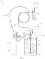
- FIG. 1illustrates a beverage transportation system that is capable of dispensing beverage from a beverage container
- FIG. 2illustrates the beverage transportation system of FIG. 1 when the beverage container runs out of beverage
- FIG. 3illustrates the beverage transportation system including a valve system wherein the valve is at a first orientation
- FIG. 4illustrates the beverage transportation system of FIG. 3 wherein the valve is at a second orientation
- FIG. 5illustrates the beverage transportation system of FIG. 3 wherein the valve is at a third orientation
- FIG. 6illustrates a beverage transportation system having two gas lines connected to a gas source.
- a beverage system 10includes a beverage container 100 (e.g., a keg), an output port 200 , and a beverage line 300 .
- the beverage line 300is fluidly coupled to the beverage container 100 at a first end, and fluidly coupled to the output port 200 at a second end.
- the beverage container 100has a volume of beverage 110 disposed therein.
- the output port 200can include a standard nozzle where the beverage 110 is dispensed from.
- the beverage 110 disposed in the beverage container 100is draft beer.
- the beginning volume of the beverage 110 in the beverage container 100is 15.5 gallons. More or less volume is also contemplated.
- the beverage system 10also includes a first gas source 400 that aids in forcing the beverage 110 into the beverage line 300 towards the output port 200 .
- the first gas source 400is fluidly coupled to the beverage container 100 via a first gas tube 420 .
- the first gas source 400is a cylinder containing pressurized gaseous substance 410 (e.g., carbon dioxide).
- the beverage system 10can include a tap handle 210 at the output port 200 .
- the tap handle 210When the tap handle 210 is activated (e.g., pulled forward), the first gas source 400 introduces the gaseous substance 410 into the beverage container 100 from the top. The gaseous substance 410 located above the beverage 110 in the beverage container 100 pushes a portion of the beverage 110 downward into an opening of a discharge tube 120 . Once the portion of the beverage 110 enters the discharge tube 120 , it travels upwards into the beverage line 300 , headed for the output port 200 (e.g., an open tap).
- the tap handle 210is deactivated (e.g., pushed backwards in the reverse direction)
- the first gas source 400stops introducing the gaseous substance 410 into the beverage container, and therefore stops the flow of the beverage 110 to the output port.
- the beverage container 100may “kick.” Prior to the beverage container 100 running out of beer, when the tap handle 210 is pulled forward, the beverage 110 is caused to flow from the beverage container 100 , through the beverage line 300 , and out of the output port 200 . When the keg kicks, the last of the beverage 110 in the beverage container 100 is forced into the discharge tube 120 , and now the gaseous substance 410 is free to enter the discharge tube 120 . Because a gaseous substance is often lighter than a liquid substance, the gaseous substance 410 rapidly filters through the beverage 110 disposed in the discharge tube 120 and in the beverage line 300 .
- the beverage 110 in the discharge tube 120 and in the beverage line 300is no longer lifted by the gaseous substance 410 and, thus, begins to settle backward.
- the gaseous substance 410reaches the output port 200 and forcefully expels the remaining amount of the beverage 110 in a geyser of foam.
- a user of the beverage system 10adds the new beverage container 100 and typically purges the remainder of the first beverage from the beverage system 10 .
- the first beverageis purged, it mixes with the second beverage.
- the usergenerally must run the system until the second beverage runs clearly. Thus, the user typically wastes a portion of the first beverage and a portion of the second beverage during the change.
- the beverage system 10further includes a second gas source 500 and a valve 600 .
- the second gas source 500is fluidly coupled to the beverage line 300 between the beverage container 100 and the output port 200 .
- the second gas source 500is fluidly coupled to the beverage line 300 in close proximity to the output port 200
- the valve 600is fluidly coupled to the beverage line 300 in close proximity to the beverage container 100 .
- the valve 600has at least a first port 610 , a second port 620 , and a third port 630 .
- the first port 610 of the valve 600is fluidly coupled to the beverage line 300 .
- the second port 620 of the valve 600is fluidly coupled to a clearing fluid source (e.g., a portable water connection).
- the third port 630 of the valve 600is fluidly coupled to a waste reservoir 650 (see FIGS. 4 and 5 ).
- the valve 600is a three-way valve that can connect the beverage line 300 to the beverage container 100 , the clearing fluid source 640 , or the waste reservoir 650 .
- the waste reservoir 650is part of a standard waste drain system.
- the third port 630can be coupled to a floor drain, for example a floor drain located in the floor of a kitchen, bathroom, laundry room, boiler room, or other suitable room.
- the third port 630can be coupled to other types of drains as well, such as sink drains or shower drains.
- the beverage/clearing fluid mixturecan be disposed of like any other type of waste water or other waste liquid in the establishment where the beverage system 10 is located.
- the third port 630can be coupled to a drain, reservoir, or other structure using an air gap valve.
- the beverage system 10includes a mechanical switch or knob that causes the valve 600 to alternate orientations.
- the beverage system 10includes one or more processing devices and one or more user input devices. The one or more processing devices and the one or more user input devices are used to control the system.
- the user input deviceis configured to receive input from the user regarding which beverage container needs replacement. The user can also indicate to the system the orientations of the valve 600 if needed.
- the processing devicescan be a laptop computer, a desktop computer, a tablet computing, a mobile phone, a personal digital assistant (PDA), a server, or any other suitable device.
- the user input devicecan generally be any of these devices as well, and may be the same or different from the processing device.
- a single computing device with a touch screenis both the processing device and the user input device.
- a single computing device with a keyboard and/or a mouseis both the processing device and the user input device.
- the processing deviceis one computing device (such as a laptop computer or a desktop computer), and the user input device is another computing device (such as a mobile telephone or a tablet computer.
- the one or more processing devices that control the beverage system 10include one or more programmable logic controllers (PLCs) that are customized to work with the beverage system 10 .
- the one or more PLCscan be operatively connected to the valve 600 and can cause the valve 600 to move between orientations.
- the one or more PLCscan also be connected to the first gas source 400 and/or the second gas source 500 in order to control the flow of the gaseous substance from the first and second gas sources 400 , 600 , into the beverage line 300 .
- the one or more PLCscan be configured to control the operation of the output port 200 , for example via actuation of the tap handle 210 .
- the one or more PLCscan control the operation of the output port 200 in other manners as well.
- the valve 600when there is still a portion of the beverage 110 disposed in the beverage container 100 , the valve 600 is at a first orientation, and the beverage container 100 is fluidly connected to the output port 200 via the beverage line 300 and the first port 610 of the valve 600 .
- the first gas source 400is configured to cause at least a portion of the volume of beverage 110 disposed within the beverage container 100 to flow from the beverage container 100 , through the beverage line 300 , passing the first port 610 of the valve 600 , and out of the output port 200 , without interruption from the clearing fluid source or the second gas source 500 .
- a user via the user input devicemay input a first signal that is indicative of the beverage container 100 being close to empty (i.e., an amount of beverage in the beverage container 100 that is equal to or less than a predetermined threshold).
- the one or more processorscan be configured to cause the valve 600 to switch to a second orientation, such that the beverage container 100 can no longer supply beverage to the beverage line 300 because the first port 610 is now closed.
- the clearing fluid source 640is fluidly connected to the output port 200 via the beverage line 300 and the second port 620 of the valve 600 .
- the clearing fluid source 640is configured to cause a portion of the volume of beverage 110 that remains in the beverage line 300 to flow through the beverage line 300 and out of the output port 200 .
- the clearing fluidis fresh water
- the clearing fluid source 640supplies fresh water into the beverage line 300 .
- the fresh waterpushes the remaining beverage in the beverage line 300 toward the output port 200 , allowing the user to complete filling an existing glass.
- the amount of remaining beverage to be displaced by the fresh watercan be calculated based at least in part on the length of the beverage line 300 , such that just enough fresh water pushes the remaining beverage toward the output port 200 without the fresh water itself reaching the output port 200 .
- the usermay be able to fill three to four pints of beverage.
- the beverage container 100can be changed without interrupting service (e.g., filling a glass of beverage).
- the remainder of the first beveragecan be served to customers, or can at least be purged without wasting any of the second beverage.
- the user via the user input devicemay input a second signal that is indicative of the beverage container 100 being close to displacing the remaining beverage in the beverage line 300 with fresh water (i.e., an amount of fresh water entering the beverage line 300 that exceeds a predetermined threshold associated with a volume capacity of the beverage line 300 ).
- the one or more processorscan be configured to cause the valve 600 to switch to a third orientation.
- the clearing fluid source 640can no longer supply water to the beverage line 300 because the second port is now closed.
- the second gas source 500is fluidly connected to the waste reservoir 650 via the beverage line 300 and the third port 630 of the valve 600 .
- the second gas source 500is a container of pressurized carbon dioxide, similar to or the same as the first gas source 400 .
- the valve 600is switched to the third orientation, the second gas source 500 pushes gaseous substance through the beverage line 300 , toward the valve 600 , and eventually into the waste reservoir 650 .
- the second gas source 500is configured to cause the remaining beverage 110 and remaining water in the beverage line 300 to flow through the beverage line 300 , passing the third port 630 of the valve 600 , and into the waste reservoir 650 , thereby cleaning at least the beverage line 300 between the second gas source 500 and the valve 600 .
- any remaining beverage in the beverage line 300(which is generally an amount too small to fill a glass) and the remainder of the clearing fluid can be disposed of along with any other waste water that may be generated and disposed of in the establishment.
- the clean beverage line 300is then ready for the next beverage container, even if a change of beverage is initiated from a first beverage to a second beverage.
- valve orientationswhen the valve 600 is in the first orientation, the beverage 110 flows out of the beverage container 100 , through the beverage line 300 , and out of the output port 200 (e.g., a nozzle).
- the beverage container 100e.g., keg
- the clearing fluid source 640e.g., water source
- the beverage line 300is connected directly to the waste reservoir 650 , and the second gas source 500 can be used to force the beverage/water mixture back down the beverage line 300 to the waste reservoir 650 .
- the one or more processing devicesare configured to cause the valve 600 to alternate between the first orientation, the second orientation, and the third orientation so that the remainder of the first beverage may be dispensed with the clearing fluid and the lines may be purged of the clearing fluid using the second gas source 500 .
- the one or more processing devicesinclude a micro-processor that is configured to sequence and protect events with delayed initiation, anti-tie down, and anti-repeat logic functions, thereby avoiding unintentional use.
- the beverage system 10can be configured to automatically expel the remainder of the first beverage and purge the lines of the clearing fluid upon receiving input from the user indicating that the beverage container has kicked.
- the beverage system 10changes the orientation of the valve 600 as needed, and awaits further input to initiate the dispensing of the remainder of the first beverage and the purging of the clearing fluid from the lines.
- the beverage system 10is an automatic system where the valve 600 alternates its orientation without manual input.
- the beverage systemmay include one or more sensors that are configured to perform the same or similar functionalities as the user input device.
- the beverage system 10includes a first sensor 150 coupled to the beverage container 100 and a second sensor 350 coupled to the beverage line 300 .
- the first sensoris configured to sense a volume of liquid in the beverage container 100 or an amount of gas in the beverage container 100 . As more beverage is poured from the beverage container 100 , the beverage container 100 is filled with more gas.
- the first sensor 150can be configured to directly sense the volume of beverage, or to indirectly measure the volume of beverage by sensing the amount of gas.
- the second sensoris configured to sense a flow rate in the beverage line 300 .
- the beverage system 10 having sensorsmay have the valve defaulted to the first orientation, where the beverage 110 flows out of the beverage container 100 , through the beverage line 300 , and out of the output port 200 (e.g., a nozzle).
- the first sensor 150senses that the volume of beverage in the beverage container 100 is equal to or less than a predetermined threshold that is indicative of the beverage container 100 being close to empty
- the one or more processorscause the valve 600 to switch to the second orientation.
- fresh water from the clearing fluid source 640forces the remaining beverage 110 in the beverage line 300 out of the output port 200 .
- the one or more processorscause the valve 600 to switch to the third orientation.
- the beverage line 300is connected directly to the waste reservoir 650 , and the beverage/water mixture is forced back down the beverage line 300 to the waste reservoir 650 .
- the beverage system 10may include a third sensor for determining when the liquid flowing past the third sensor changes from a first liquid (e.g., beer) to a second liquid (e.g., water).
- the third sensorcan be coupled to the beverage line 300 approximate the output port 200 . Once the keg has kicked and water is pushed into the beverage line 300 to empty out the rest of the beverage from the beverage line 300 , the third sensor is configured to determine when water (or a mixture of water and beverage) is flowing past the third sensor instead of the beverage alone. As such, the beverage system is configured to stop the pour.
- the beverage system 10may include an LED collar 215 near or at the tap handle 210 .
- the LED collar 215is configured to display a first color (e.g., red) that is indicative of the beverage container 100 being empty of beverage 110 and requiring changing.
- the LED collar 215is communicatively coupled to a volume sensor in the beverage container 100 .
- the volume sensorsenses a volume of beverage in the beverage container 100 being equal to or less than a predetermined threshold indicative of the beverage container 100 being close to empty
- the LED collar 215is caused to display the first color.
- the beverage system 10may further include a button or a switch. When pressed, the button or switch may cause the LED collar to display a second color (e.g., green) that is indicative of the keg change being completed and that the beverage container 100 has a sufficient amount of beverage therein.
- a second colore.g., green
- the user of the beverage system 10is given the option of continuing the pour via an input device at the tap handle 210 or switching and connecting to a new keg. If such an option to continue the pour is selected, drinking water can be introduced at a location closest to the keg into the beverage line 300 , allowing the water to lift or push the remaining beverage contained in the beverage line 300 up to the output port 200 (e.g., the tap) such that the remaining beverage can be dispensed.
- a red LED lightmay illuminate, indicating water is being introduced into the line.
- a more simplified beverage systemis also contemplated.
- the simplified beverage systemis the same as, or similar to, the beverage system 10 described above, except that the valve of the simplified beverage system only has a first port and a second port.
- the second gas source 500 and the waste reservoir 650are optional in the simplified beverage system.
- the valve of the simplified beverage systemis accordingly operable between a first orientation and a second orientation.
- the beverageflows out of the beverage container, through the beverage line, and out of the output port (e.g., nozzle).
- the beverage containere.g., keg
- the clearing fluid sourcee.g., water source
- the watercan be forced through the beverage line such that it forces the remaining beverage in the beverage line out of the nozzle.
- the valve of the simplified beverage systemmay revert back to the first orientation.
- a new beverage containermay replace the previous beverage container.
- the first gas sourceis configured to cause at least a portion of the volume of beverage disposed within the new beverage container to flow from the new beverage container through the beverage line toward the output port, thereby forcing the remaining beverage (from the previous beverage container) and remaining water in the beverage line to flow through the beverage line, passing the first port of the valve, and out of the output port.
- FIG. 6shows an additional implementation that does not include the second gas source.
- FIG. 6shows a beverage system 10 that is generally similar to the beverage system 10 illustrated in FIGS. 3 - 5 .
- the first gas sourceis fluidly coupled to the beverage container 100 via a first gas tube 420 A, and also fluidly coupled to the beverage line 300 near the output port 200 via a second gas tube 420 B.
- gasflows from the first gas source to the beverage container 100 via the first gas tube 420 A in order to push the beverage 110 through the beverage line 300 and output of the output port 200 , when the valve 600 is in the first orientation.
- the valve 600transitions to the second orientation and the clearing fluid in the clearing fluid source 640 is used to empty the remaining amount of the beverage 110 from the beverage line 300 out of the output port 200 .
- the valve 600transitions to the third orientation. Gas can then flow from the first gas source 400 , through the second gas tube 420 B. This gas enters the beverage line 300 in close proximity (e.g., within less than about five feet, less than about two and a half feet, within less than about one foot, with less than about six inches) to the output port 200 . Because the output port 200 is not activated by the tap handle 210 and the valve 600 is in the third orientation, the gas flowing from the second gas tube 420 forces any remaining amount of the beverage 110 and the clearing fluid through the beverage line 300 and into the waste reservoir 650 .
Landscapes
- Chemical & Material Sciences (AREA)
- Analytical Chemistry (AREA)
- Devices For Dispensing Beverages (AREA)
Abstract
Description
Claims (9)
Priority Applications (1)
| Application Number | Priority Date | Filing Date | Title |
|---|---|---|---|
| US17/317,247US11753291B2 (en) | 2020-05-11 | 2021-05-11 | System and method of transporting beverage |
Applications Claiming Priority (2)
| Application Number | Priority Date | Filing Date | Title |
|---|---|---|---|
| US202063023238P | 2020-05-11 | 2020-05-11 | |
| US17/317,247US11753291B2 (en) | 2020-05-11 | 2021-05-11 | System and method of transporting beverage |
Publications (2)
| Publication Number | Publication Date |
|---|---|
| US20210347626A1 US20210347626A1 (en) | 2021-11-11 |
| US11753291B2true US11753291B2 (en) | 2023-09-12 |
Family
ID=78412198
Family Applications (1)
| Application Number | Title | Priority Date | Filing Date |
|---|---|---|---|
| US17/317,247ActiveUS11753291B2 (en) | 2020-05-11 | 2021-05-11 | System and method of transporting beverage |
Country Status (1)
| Country | Link |
|---|---|
| US (1) | US11753291B2 (en) |
Cited By (1)
| Publication number | Priority date | Publication date | Assignee | Title |
|---|---|---|---|---|
| US20230166961A1 (en)* | 2021-11-30 | 2023-06-01 | Paul McGrane | Fluid line monitoring and control assembly |
Families Citing this family (2)
| Publication number | Priority date | Publication date | Assignee | Title |
|---|---|---|---|---|
| JP7407363B2 (en)* | 2019-11-01 | 2024-01-04 | アサヒビール株式会社 | Pour head and beverage server |
| US11753291B2 (en)* | 2020-05-11 | 2023-09-12 | Island Clan, Llc | System and method of transporting beverage |
Citations (50)
| Publication number | Priority date | Publication date | Assignee | Title |
|---|---|---|---|---|
| US1963784A (en)* | 1933-04-19 | 1934-06-19 | Freund Edward | Beverage dispensing apparatus |
| US2022951A (en)* | 1933-09-18 | 1935-12-03 | Beer Control Systems Inc | Beverage dispensing device |
| US2030398A (en)* | 1935-03-06 | 1936-02-11 | Lionel I Rivard | Apparatus for cleaning pipes |
| US2039006A (en)* | 1935-04-02 | 1936-04-28 | Max Apter | Apparatus for dispensing beverages |
| US2092257A (en)* | 1935-08-14 | 1937-09-07 | George A Lewis | Beer coil cleaner |
| US2098525A (en)* | 1935-10-08 | 1937-11-09 | Clarence C Smith | Beer pipe cleaning apparatus |
| US2109896A (en)* | 1936-10-02 | 1938-03-01 | Anderson | Dispensing system |
| US2167309A (en)* | 1937-07-16 | 1939-07-25 | Abraham S Levin | Beverage dispensing apparatus |
| US2175951A (en)* | 1938-08-15 | 1939-10-10 | Bulleri Natale | Device for the cleaning of beer coils and other dispensing apparatus |
| US2178559A (en)* | 1937-06-12 | 1939-11-07 | Beer Control Systems Inc | Fluid dispensing system |
| US2194681A (en)* | 1938-09-06 | 1940-03-26 | Sidney A Scobell | Liquid dispensing system |
| US2196176A (en)* | 1938-10-21 | 1940-04-09 | Protectol Company Inc | Method and means for cleaning beer lines |
| US2237014A (en)* | 1940-04-18 | 1941-04-01 | Stoehrer Carl | Beverage dispensing system |
| US2263922A (en)* | 1938-12-16 | 1941-11-25 | Guttman Milton | Receptacle for cleaning solution |
| US2331460A (en)* | 1940-10-26 | 1943-10-12 | Davis Gerrish Holding Corp | Beverage dispensing system |
| US2371188A (en)* | 1945-03-13 | Means fob clearing pipe systems | ||
| US2443550A (en)* | 1944-12-08 | 1948-06-15 | Michael J Zwosta | Beer control and pipe-cleaning apparatus |
| US2458230A (en)* | 1945-09-08 | 1949-01-04 | Frederick J Warcup | Cleaning means for beer dispensers |
| US2591985A (en)* | 1947-11-24 | 1952-04-08 | Frederick J Warcup | Automatic cleaner solution supply for beer distributing systems |
| US2619119A (en)* | 1949-10-14 | 1952-11-25 | Frederick J Warcup | Fluid pressure operated multiway valve |
| US2774229A (en)* | 1955-07-25 | 1956-12-18 | Kay Tee Corp | Draft beer dispenser |
| US2777452A (en)* | 1952-10-30 | 1957-01-15 | Michael J Zwosta | Cleaning apparatus for beer dispensing systems |
| US2827070A (en)* | 1954-12-30 | 1958-03-18 | Robert J Gatz | Beverage line cleaner |
| US2917906A (en)* | 1956-09-24 | 1959-12-22 | Woolley George Craig | Portable cooler, gasser, and dispenser for keg beer and the like |
| US3115150A (en)* | 1961-12-06 | 1963-12-24 | Burgermeister Brewing Corp | Tapping valve for beer kegs |
| US3120326A (en)* | 1960-08-26 | 1964-02-04 | Robert M Hedeman | Beverage dispenser conduit purging device |
| US3830248A (en)* | 1973-04-19 | 1974-08-20 | J Brown | Faucet and line cleaning apparatus |
| US4088245A (en)* | 1977-04-21 | 1978-05-09 | Leonard Brown | Pesticide dispenser with calibrated tubular outlet probe |
| US4572230A (en)* | 1983-06-22 | 1986-02-25 | Mirabile Paul J | Beverage tube cleaner |
| US4955100A (en)* | 1988-07-21 | 1990-09-11 | Friedrich Bersch | Apparatus for cleaning pipelines for beverages and the like |
| US5072476A (en)* | 1989-05-30 | 1991-12-17 | Friedrich Bersch | Apparatus for cleaning pipelines for beverages and the like |
| US5564602A (en)* | 1995-02-27 | 1996-10-15 | Cleland; James | Beer-dispensing system and apparatus |
| US5601101A (en)* | 1992-08-04 | 1997-02-11 | Precision Dispensing Systems Limited | Washing systems |
| US5762096A (en)* | 1997-02-12 | 1998-06-09 | Pnm, Inc. | Computer controlled portable gravity flow conduit cleaner |
| US6240952B1 (en)* | 1999-08-12 | 2001-06-05 | Lancer Partnership, Ltd. | Aseptic product dispensing system |
| US20030183249A1 (en)* | 2000-06-06 | 2003-10-02 | Jarmo Nissinen | Method and system for cleaning beverage tubes and a detector unit used in the system |
| US20040245281A1 (en)* | 2001-06-13 | 2004-12-09 | Oke Simon Fobes | Beverage line purifier |
| US20070245766A1 (en)* | 2006-04-05 | 2007-10-25 | Younkle Matthew C | In-line beverage chilling apparatus |
| US20080223410A1 (en)* | 2004-02-27 | 2008-09-18 | Cleverclear Ltd | Cleaning a Plurality of Supply Lines |
| US7757908B1 (en)* | 2005-06-13 | 2010-07-20 | Buhl Jr Thomas R | Portable container and dispenser for kegged beer |
| US20110114680A1 (en)* | 2008-03-20 | 2011-05-19 | Paul Haskayne | Beverage dispense apparatus |
| US8887961B2 (en)* | 2006-06-30 | 2014-11-18 | Heineken Supply Chain B.V. | Tapping device, beverage container, coupling device and method with cleaning element |
| US9073741B2 (en)* | 2012-11-30 | 2015-07-07 | Igusa Llc | Beverage dispensing system |
| US20180362319A1 (en)* | 2015-11-25 | 2018-12-20 | Intellactual Discovery Co., Ltd. | Cleaning module-integrated beverage dispensing head |
| US10280059B2 (en)* | 2012-05-02 | 2019-05-07 | Anheuser-Busch Inbev S.A. | Compact beverage dispensing unit |
| US10392238B2 (en)* | 2013-08-28 | 2019-08-27 | Qualflow Systems Limited | Method and system for cleaning beverage dispensing systems |
| US10464799B2 (en)* | 2012-12-19 | 2019-11-05 | Beersmart, Llc | System and method for beverage line cleaning |
| US20200247657A1 (en)* | 2017-10-27 | 2020-08-06 | Carlsberg Breweries A/S | A cleaning unit for supplying a cleaning liquid to a beverage dispensing system |
| US10815115B2 (en)* | 2018-07-02 | 2020-10-27 | Joseph Pickett | Method and apparatus for cleaning and sanitizing a dispensing installation |
| US20210347626A1 (en)* | 2020-05-11 | 2021-11-11 | Fluid Power Products, Inc. | System and method of transporting beverage |
- 2021
- 2021-05-11USUS17/317,247patent/US11753291B2/enactiveActive
Patent Citations (51)
| Publication number | Priority date | Publication date | Assignee | Title |
|---|---|---|---|---|
| US2371188A (en)* | 1945-03-13 | Means fob clearing pipe systems | ||
| US1963784A (en)* | 1933-04-19 | 1934-06-19 | Freund Edward | Beverage dispensing apparatus |
| US2022951A (en)* | 1933-09-18 | 1935-12-03 | Beer Control Systems Inc | Beverage dispensing device |
| US2030398A (en)* | 1935-03-06 | 1936-02-11 | Lionel I Rivard | Apparatus for cleaning pipes |
| US2039006A (en)* | 1935-04-02 | 1936-04-28 | Max Apter | Apparatus for dispensing beverages |
| US2092257A (en)* | 1935-08-14 | 1937-09-07 | George A Lewis | Beer coil cleaner |
| US2098525A (en)* | 1935-10-08 | 1937-11-09 | Clarence C Smith | Beer pipe cleaning apparatus |
| US2109896A (en)* | 1936-10-02 | 1938-03-01 | Anderson | Dispensing system |
| US2178559A (en)* | 1937-06-12 | 1939-11-07 | Beer Control Systems Inc | Fluid dispensing system |
| US2167309A (en)* | 1937-07-16 | 1939-07-25 | Abraham S Levin | Beverage dispensing apparatus |
| US2175951A (en)* | 1938-08-15 | 1939-10-10 | Bulleri Natale | Device for the cleaning of beer coils and other dispensing apparatus |
| US2194681A (en)* | 1938-09-06 | 1940-03-26 | Sidney A Scobell | Liquid dispensing system |
| US2196176A (en)* | 1938-10-21 | 1940-04-09 | Protectol Company Inc | Method and means for cleaning beer lines |
| US2263922A (en)* | 1938-12-16 | 1941-11-25 | Guttman Milton | Receptacle for cleaning solution |
| US2237014A (en)* | 1940-04-18 | 1941-04-01 | Stoehrer Carl | Beverage dispensing system |
| US2331460A (en)* | 1940-10-26 | 1943-10-12 | Davis Gerrish Holding Corp | Beverage dispensing system |
| US2443550A (en)* | 1944-12-08 | 1948-06-15 | Michael J Zwosta | Beer control and pipe-cleaning apparatus |
| US2458230A (en)* | 1945-09-08 | 1949-01-04 | Frederick J Warcup | Cleaning means for beer dispensers |
| US2591985A (en)* | 1947-11-24 | 1952-04-08 | Frederick J Warcup | Automatic cleaner solution supply for beer distributing systems |
| US2619119A (en)* | 1949-10-14 | 1952-11-25 | Frederick J Warcup | Fluid pressure operated multiway valve |
| US2777452A (en)* | 1952-10-30 | 1957-01-15 | Michael J Zwosta | Cleaning apparatus for beer dispensing systems |
| US2827070A (en)* | 1954-12-30 | 1958-03-18 | Robert J Gatz | Beverage line cleaner |
| US2774229A (en)* | 1955-07-25 | 1956-12-18 | Kay Tee Corp | Draft beer dispenser |
| US2917906A (en)* | 1956-09-24 | 1959-12-22 | Woolley George Craig | Portable cooler, gasser, and dispenser for keg beer and the like |
| US3120326A (en)* | 1960-08-26 | 1964-02-04 | Robert M Hedeman | Beverage dispenser conduit purging device |
| US3115150A (en)* | 1961-12-06 | 1963-12-24 | Burgermeister Brewing Corp | Tapping valve for beer kegs |
| US3830248A (en)* | 1973-04-19 | 1974-08-20 | J Brown | Faucet and line cleaning apparatus |
| US4088245A (en)* | 1977-04-21 | 1978-05-09 | Leonard Brown | Pesticide dispenser with calibrated tubular outlet probe |
| US4572230A (en)* | 1983-06-22 | 1986-02-25 | Mirabile Paul J | Beverage tube cleaner |
| US4955100A (en)* | 1988-07-21 | 1990-09-11 | Friedrich Bersch | Apparatus for cleaning pipelines for beverages and the like |
| US5072476A (en)* | 1989-05-30 | 1991-12-17 | Friedrich Bersch | Apparatus for cleaning pipelines for beverages and the like |
| US5601101A (en)* | 1992-08-04 | 1997-02-11 | Precision Dispensing Systems Limited | Washing systems |
| US5564602A (en)* | 1995-02-27 | 1996-10-15 | Cleland; James | Beer-dispensing system and apparatus |
| US5762096A (en)* | 1997-02-12 | 1998-06-09 | Pnm, Inc. | Computer controlled portable gravity flow conduit cleaner |
| US6240952B1 (en)* | 1999-08-12 | 2001-06-05 | Lancer Partnership, Ltd. | Aseptic product dispensing system |
| US6446659B2 (en)* | 1999-08-12 | 2002-09-10 | Lancer Partnership | Aseptic product dispensing system |
| US20030183249A1 (en)* | 2000-06-06 | 2003-10-02 | Jarmo Nissinen | Method and system for cleaning beverage tubes and a detector unit used in the system |
| US20040245281A1 (en)* | 2001-06-13 | 2004-12-09 | Oke Simon Fobes | Beverage line purifier |
| US20080223410A1 (en)* | 2004-02-27 | 2008-09-18 | Cleverclear Ltd | Cleaning a Plurality of Supply Lines |
| US7757908B1 (en)* | 2005-06-13 | 2010-07-20 | Buhl Jr Thomas R | Portable container and dispenser for kegged beer |
| US20070245766A1 (en)* | 2006-04-05 | 2007-10-25 | Younkle Matthew C | In-line beverage chilling apparatus |
| US8887961B2 (en)* | 2006-06-30 | 2014-11-18 | Heineken Supply Chain B.V. | Tapping device, beverage container, coupling device and method with cleaning element |
| US20110114680A1 (en)* | 2008-03-20 | 2011-05-19 | Paul Haskayne | Beverage dispense apparatus |
| US10280059B2 (en)* | 2012-05-02 | 2019-05-07 | Anheuser-Busch Inbev S.A. | Compact beverage dispensing unit |
| US9073741B2 (en)* | 2012-11-30 | 2015-07-07 | Igusa Llc | Beverage dispensing system |
| US10464799B2 (en)* | 2012-12-19 | 2019-11-05 | Beersmart, Llc | System and method for beverage line cleaning |
| US10392238B2 (en)* | 2013-08-28 | 2019-08-27 | Qualflow Systems Limited | Method and system for cleaning beverage dispensing systems |
| US20180362319A1 (en)* | 2015-11-25 | 2018-12-20 | Intellactual Discovery Co., Ltd. | Cleaning module-integrated beverage dispensing head |
| US20200247657A1 (en)* | 2017-10-27 | 2020-08-06 | Carlsberg Breweries A/S | A cleaning unit for supplying a cleaning liquid to a beverage dispensing system |
| US10815115B2 (en)* | 2018-07-02 | 2020-10-27 | Joseph Pickett | Method and apparatus for cleaning and sanitizing a dispensing installation |
| US20210347626A1 (en)* | 2020-05-11 | 2021-11-11 | Fluid Power Products, Inc. | System and method of transporting beverage |
Cited By (2)
| Publication number | Priority date | Publication date | Assignee | Title |
|---|---|---|---|---|
| US20230166961A1 (en)* | 2021-11-30 | 2023-06-01 | Paul McGrane | Fluid line monitoring and control assembly |
| US12187595B2 (en)* | 2021-11-30 | 2025-01-07 | Paul McGrane | Fluid line monitoring and control assembly |
Also Published As
| Publication number | Publication date |
|---|---|
| US20210347626A1 (en) | 2021-11-11 |
Similar Documents
| Publication | Publication Date | Title |
|---|---|---|
| US11753291B2 (en) | System and method of transporting beverage | |
| US20060186137A1 (en) | Dispensing system for beverages and method for cleaning a dispensing system | |
| CN102227370B (en) | Cleaning and flushing methods for beverage dispensing systems | |
| CN111278764B (en) | Cleaning unit for supplying cleaning liquid to a beverage dispensing system | |
| JP6678668B2 (en) | Pressurized liquid dispenser with three-way valve for venting the container | |
| EP2993132A1 (en) | Beverage dispenser for filling from the bottom | |
| WO2019102942A1 (en) | Liquid sale management device | |
| JP5980487B2 (en) | Flow path blocking device and beverage server system provided with the device | |
| US20210122622A1 (en) | Remote controlled beverage dispensing system | |
| JP7049191B2 (en) | Beverage server cleaning equipment | |
| JP7263394B2 (en) | Beverage server cleaning equipment | |
| JP2010126174A (en) | Beverage dispenser | |
| JP2003054696A (en) | Sparkling beverage detection device and sparkling beverage pouring device using the same | |
| JP7299922B2 (en) | Beverage supply system cleaning equipment | |
| JP3110486U (en) | Dispensing head | |
| EP0439397B1 (en) | Water level control in a household appliance and machine provided with such a device | |
| JP6640402B1 (en) | Beverage supply system and beverage depletion notification method | |
| JPH05319487A (en) | Beer bung out device | |
| JP7580714B2 (en) | Liquid Delivery System | |
| JP7349905B2 (en) | Beverage supply system cleaning equipment | |
| JP3112844U (en) | Dispensing head | |
| CN116746822A (en) | Induction soap-giving controller | |
| GB2423980A (en) | Beverage dispense |
Legal Events
| Date | Code | Title | Description |
|---|---|---|---|
| FEPP | Fee payment procedure | Free format text:ENTITY STATUS SET TO UNDISCOUNTED (ORIGINAL EVENT CODE: BIG.); ENTITY STATUS OF PATENT OWNER: SMALL ENTITY | |
| FEPP | Fee payment procedure | Free format text:ENTITY STATUS SET TO SMALL (ORIGINAL EVENT CODE: SMAL); ENTITY STATUS OF PATENT OWNER: SMALL ENTITY | |
| STPP | Information on status: patent application and granting procedure in general | Free format text:DOCKETED NEW CASE - READY FOR EXAMINATION | |
| STPP | Information on status: patent application and granting procedure in general | Free format text:NON FINAL ACTION MAILED | |
| AS | Assignment | Owner name:ISLAND CLAN, LLC, MASSACHUSETTS Free format text:ASSIGNMENT OF ASSIGNORS INTEREST;ASSIGNOR:CUNNEEN, BRUCE;REEL/FRAME:058480/0373 Effective date:20211224 | |
| STPP | Information on status: patent application and granting procedure in general | Free format text:RESPONSE TO NON-FINAL OFFICE ACTION ENTERED AND FORWARDED TO EXAMINER | |
| STPP | Information on status: patent application and granting procedure in general | Free format text:NON FINAL ACTION MAILED | |
| STPP | Information on status: patent application and granting procedure in general | Free format text:RESPONSE TO NON-FINAL OFFICE ACTION ENTERED AND FORWARDED TO EXAMINER | |
| STPP | Information on status: patent application and granting procedure in general | Free format text:NOTICE OF ALLOWANCE MAILED -- APPLICATION RECEIVED IN OFFICE OF PUBLICATIONS | |
| STPP | Information on status: patent application and granting procedure in general | Free format text:PUBLICATIONS -- ISSUE FEE PAYMENT VERIFIED | |
| STCF | Information on status: patent grant | Free format text:PATENTED CASE |