US11752725B2 - Box erecting machine - Google Patents
Box erecting machineDownload PDFInfo
- Publication number
- US11752725B2 US11752725B2US17/416,811US202017416811AUS11752725B2US 11752725 B2US11752725 B2US 11752725B2US 202017416811 AUS202017416811 AUS 202017416811AUS 11752725 B2US11752725 B2US 11752725B2
- Authority
- US
- United States
- Prior art keywords
- box
- folding
- erected
- flaps
- bottom flaps
- Prior art date
- Legal status (The legal status is an assumption and is not a legal conclusion. Google has not performed a legal analysis and makes no representation as to the accuracy of the status listed.)
- Active
Links
Images


Classifications
- B—PERFORMING OPERATIONS; TRANSPORTING
- B31—MAKING ARTICLES OF PAPER, CARDBOARD OR MATERIAL WORKED IN A MANNER ANALOGOUS TO PAPER; WORKING PAPER, CARDBOARD OR MATERIAL WORKED IN A MANNER ANALOGOUS TO PAPER
- B31B—MAKING CONTAINERS OF PAPER, CARDBOARD OR MATERIAL WORKED IN A MANNER ANALOGOUS TO PAPER
- B31B50/00—Making rigid or semi-rigid containers, e.g. boxes or cartons
- B31B50/002—Prebreaking
- B—PERFORMING OPERATIONS; TRANSPORTING
- B31—MAKING ARTICLES OF PAPER, CARDBOARD OR MATERIAL WORKED IN A MANNER ANALOGOUS TO PAPER; WORKING PAPER, CARDBOARD OR MATERIAL WORKED IN A MANNER ANALOGOUS TO PAPER
- B31B—MAKING CONTAINERS OF PAPER, CARDBOARD OR MATERIAL WORKED IN A MANNER ANALOGOUS TO PAPER
- B31B50/00—Making rigid or semi-rigid containers, e.g. boxes or cartons
- B31B50/74—Auxiliary operations
- B31B50/76—Opening and distending flattened articles
- B31B50/80—Pneumatically
- B—PERFORMING OPERATIONS; TRANSPORTING
- B31—MAKING ARTICLES OF PAPER, CARDBOARD OR MATERIAL WORKED IN A MANNER ANALOGOUS TO PAPER; WORKING PAPER, CARDBOARD OR MATERIAL WORKED IN A MANNER ANALOGOUS TO PAPER
- B31B—MAKING CONTAINERS OF PAPER, CARDBOARD OR MATERIAL WORKED IN A MANNER ANALOGOUS TO PAPER
- B31B50/00—Making rigid or semi-rigid containers, e.g. boxes or cartons
- B31B50/26—Folding sheets, blanks or webs
- B31B50/52—Folding sheets, blanks or webs by reciprocating or oscillating members, e.g. fingers
- B—PERFORMING OPERATIONS; TRANSPORTING
- B31—MAKING ARTICLES OF PAPER, CARDBOARD OR MATERIAL WORKED IN A MANNER ANALOGOUS TO PAPER; WORKING PAPER, CARDBOARD OR MATERIAL WORKED IN A MANNER ANALOGOUS TO PAPER
- B31B—MAKING CONTAINERS OF PAPER, CARDBOARD OR MATERIAL WORKED IN A MANNER ANALOGOUS TO PAPER
- B31B2110/00—Shape of rigid or semi-rigid containers
- B31B2110/30—Shape of rigid or semi-rigid containers having a polygonal cross section
- B—PERFORMING OPERATIONS; TRANSPORTING
- B31—MAKING ARTICLES OF PAPER, CARDBOARD OR MATERIAL WORKED IN A MANNER ANALOGOUS TO PAPER; WORKING PAPER, CARDBOARD OR MATERIAL WORKED IN A MANNER ANALOGOUS TO PAPER
- B31B—MAKING CONTAINERS OF PAPER, CARDBOARD OR MATERIAL WORKED IN A MANNER ANALOGOUS TO PAPER
- B31B2120/00—Construction of rigid or semi-rigid containers
- B31B2120/30—Construction of rigid or semi-rigid containers collapsible; temporarily collapsed during manufacturing
- B31B2120/302—Construction of rigid or semi-rigid containers collapsible; temporarily collapsed during manufacturing collapsible into a flat condition
- B—PERFORMING OPERATIONS; TRANSPORTING
- B31—MAKING ARTICLES OF PAPER, CARDBOARD OR MATERIAL WORKED IN A MANNER ANALOGOUS TO PAPER; WORKING PAPER, CARDBOARD OR MATERIAL WORKED IN A MANNER ANALOGOUS TO PAPER
- B31B—MAKING CONTAINERS OF PAPER, CARDBOARD OR MATERIAL WORKED IN A MANNER ANALOGOUS TO PAPER
- B31B50/00—Making rigid or semi-rigid containers, e.g. boxes or cartons
- B31B50/004—Closing boxes
- B—PERFORMING OPERATIONS; TRANSPORTING
- B31—MAKING ARTICLES OF PAPER, CARDBOARD OR MATERIAL WORKED IN A MANNER ANALOGOUS TO PAPER; WORKING PAPER, CARDBOARD OR MATERIAL WORKED IN A MANNER ANALOGOUS TO PAPER
- B31B—MAKING CONTAINERS OF PAPER, CARDBOARD OR MATERIAL WORKED IN A MANNER ANALOGOUS TO PAPER
- B31B50/00—Making rigid or semi-rigid containers, e.g. boxes or cartons
- B31B50/02—Feeding or positioning sheets, blanks or webs
- B31B50/04—Feeding sheets or blanks
- B31B50/06—Feeding sheets or blanks from stacks
- B31B50/066—Feeding sheets or blanks from stacks from above a magazine
- B—PERFORMING OPERATIONS; TRANSPORTING
- B31—MAKING ARTICLES OF PAPER, CARDBOARD OR MATERIAL WORKED IN A MANNER ANALOGOUS TO PAPER; WORKING PAPER, CARDBOARD OR MATERIAL WORKED IN A MANNER ANALOGOUS TO PAPER
- B31B—MAKING CONTAINERS OF PAPER, CARDBOARD OR MATERIAL WORKED IN A MANNER ANALOGOUS TO PAPER
- B31B50/00—Making rigid or semi-rigid containers, e.g. boxes or cartons
- B31B50/60—Uniting opposed surfaces or edges; Taping
- B31B50/62—Uniting opposed surfaces or edges; Taping by adhesives
- B31B50/624—Applying glue on blanks
- B—PERFORMING OPERATIONS; TRANSPORTING
- B31—MAKING ARTICLES OF PAPER, CARDBOARD OR MATERIAL WORKED IN A MANNER ANALOGOUS TO PAPER; WORKING PAPER, CARDBOARD OR MATERIAL WORKED IN A MANNER ANALOGOUS TO PAPER
- B31B—MAKING CONTAINERS OF PAPER, CARDBOARD OR MATERIAL WORKED IN A MANNER ANALOGOUS TO PAPER
- B31B50/00—Making rigid or semi-rigid containers, e.g. boxes or cartons
- B31B50/60—Uniting opposed surfaces or edges; Taping
- B31B50/68—Uniting opposed surfaces or edges; Taping by stitching, stapling or riveting
- B—PERFORMING OPERATIONS; TRANSPORTING
- B65—CONVEYING; PACKING; STORING; HANDLING THIN OR FILAMENTARY MATERIAL
- B65B—MACHINES, APPARATUS OR DEVICES FOR, OR METHODS OF, PACKAGING ARTICLES OR MATERIALS; UNPACKING
- B65B43/00—Forming, feeding, opening or setting-up containers or receptacles in association with packaging
- B65B43/12—Feeding flexible bags or carton blanks in flat or collapsed state; Feeding flat bags connected to form a series or chain
- B65B43/14—Feeding individual bags or carton blanks from piles or magazines
- B65B43/145—Feeding carton blanks from piles or magazines
- B—PERFORMING OPERATIONS; TRANSPORTING
- B65—CONVEYING; PACKING; STORING; HANDLING THIN OR FILAMENTARY MATERIAL
- B65B—MACHINES, APPARATUS OR DEVICES FOR, OR METHODS OF, PACKAGING ARTICLES OR MATERIALS; UNPACKING
- B65B43/00—Forming, feeding, opening or setting-up containers or receptacles in association with packaging
- B65B43/12—Feeding flexible bags or carton blanks in flat or collapsed state; Feeding flat bags connected to form a series or chain
- B65B43/14—Feeding individual bags or carton blanks from piles or magazines
- B65B43/16—Feeding individual bags or carton blanks from piles or magazines by grippers
- B65B43/18—Feeding individual bags or carton blanks from piles or magazines by grippers by suction-operated grippers
- B65B43/185—Feeding individual bags or carton blanks from piles or magazines by grippers by suction-operated grippers specially adapted for carton blanks
- B—PERFORMING OPERATIONS; TRANSPORTING
- B65—CONVEYING; PACKING; STORING; HANDLING THIN OR FILAMENTARY MATERIAL
- B65B—MACHINES, APPARATUS OR DEVICES FOR, OR METHODS OF, PACKAGING ARTICLES OR MATERIALS; UNPACKING
- B65B43/00—Forming, feeding, opening or setting-up containers or receptacles in association with packaging
- B65B43/26—Opening or distending bags; Opening, erecting, or setting-up boxes, cartons, or carton blanks
- B65B43/30—Opening or distending bags; Opening, erecting, or setting-up boxes, cartons, or carton blanks by grippers engaging opposed walls, e.g. suction-operated
- B65B43/305—Opening or distending bags; Opening, erecting, or setting-up boxes, cartons, or carton blanks by grippers engaging opposed walls, e.g. suction-operated specially adapted for boxes, cartons or carton blanks
- B—PERFORMING OPERATIONS; TRANSPORTING
- B65—CONVEYING; PACKING; STORING; HANDLING THIN OR FILAMENTARY MATERIAL
- B65B—MACHINES, APPARATUS OR DEVICES FOR, OR METHODS OF, PACKAGING ARTICLES OR MATERIALS; UNPACKING
- B65B51/00—Devices for, or methods of, sealing or securing package folds or closures; Devices for gathering or twisting wrappers, or necks of bags
- B65B51/02—Applying adhesives or sealing liquids
- B—PERFORMING OPERATIONS; TRANSPORTING
- B65—CONVEYING; PACKING; STORING; HANDLING THIN OR FILAMENTARY MATERIAL
- B65B—MACHINES, APPARATUS OR DEVICES FOR, OR METHODS OF, PACKAGING ARTICLES OR MATERIALS; UNPACKING
- B65B51/00—Devices for, or methods of, sealing or securing package folds or closures; Devices for gathering or twisting wrappers, or necks of bags
- B65B51/04—Applying separate sealing or securing members, e.g. clips
- B65B51/05—Stapling
- B—PERFORMING OPERATIONS; TRANSPORTING
- B65—CONVEYING; PACKING; STORING; HANDLING THIN OR FILAMENTARY MATERIAL
- B65B—MACHINES, APPARATUS OR DEVICES FOR, OR METHODS OF, PACKAGING ARTICLES OR MATERIALS; UNPACKING
- B65B51/00—Devices for, or methods of, sealing or securing package folds or closures; Devices for gathering or twisting wrappers, or necks of bags
- B65B51/04—Applying separate sealing or securing members, e.g. clips
- B65B51/06—Applying adhesive tape
- B65B51/067—Applying adhesive tape to the closure flaps of boxes
Definitions
- Exemplary embodiments of the disclosurerelate to systems, methods, and devices for erecting box templates into boxes.
- Shipping and packaging industriesfrequently use paperboard and other sheet material processing equipment that converts sheet materials into box templates.
- One advantage of such equipmentis that a shipper may prepare boxes of required sizes as needed in lieu of keeping a stock of standard, pre-made boxes of various sizes. Consequently, the shipper can eliminate the need to forecast its requirements for particular box sizes as well as to store pre-made boxes of standard sizes. Instead, the shipper may store one or more bales of fanfold material, which can be used to generate a variety of box sizes based on the specific box size requirements at the time of each shipment. This allows the shipper to reduce storage space normally required for periodically used shipping supplies as well as to reduce the waste and costs associated with the inherently inaccurate process of forecasting box size requirements since the items shipped and their respective dimensions vary from time to time.
- custom sized boxesIn addition to reducing the inefficiencies associated with storing pre-made boxes of numerous sizes, creating custom sized boxes also reduces packaging and shipping costs. In the fulfillment industry it is estimated that shipped items are typically packaged in boxes that are about 65% larger than the shipped items. Boxes that are too large for a particular item are more expensive than a box that is custom sized for the item due to the cost of the excess material used to make the larger box.
- filling materiale.g., Styrofoam, foam peanuts, paper, air pillows, etc.
- pressuree.g., when boxes are taped closed or stacked.
- Custom sized boxesalso reduce the shipping costs associated with shipping items compared to shipping the items in oversized boxes.
- a shipping vehicle filled with boxes that are 65% larger than the packaged itemsis much less cost efficient to operate than a shipping vehicle filled with boxes that are custom sized to fit the packaged items.
- a shipping vehicle filled with custom sized packagescan carry a significantly larger number of packages, which can reduce the number of shipping vehicles required to ship the same number of items. Accordingly, in addition or as an alternative to calculating shipping prices based on the weight of a package, shipping prices are often affected by the size of the shipped package. Thus, reducing the size of an item's package can reduce the price of shipping the item.
- sheet material processing machines and related equipmentcan potentially alleviate the inconveniences associated with stocking standard sized shipping supplies and reduce the amount of space required for storing such shipping supplies
- previously available machines and associated equipmenthave various drawbacks. For instance, previously available machines have had a significant footprint and have occupied a lot of floor space. The floor space occupied by these large machines and equipment could be better used for storage of goods to be shipped. In addition to the large footprint, the size of the previously available machines and related equipment makes manufacturing, transportation, installation, maintenance, repair, and replacement thereof time consuming and expensive.
- a typical box forming systemincludes a converting machine that cuts, scores, and/or creases sheet material to form a box template.
- a converting machinethat cuts, scores, and/or creases sheet material to form a box template.
- an operatorremoves the template from the converting machine and a manufacturer's joint is created in the template.
- a manufacturer's jointis where two opposing ends of the template are attached to one another. This can be accomplished manually and/or with additional machinery.
- an operatorcan apply glue (e.g., with a glue gun) to one end of the template and can fold the template to join the opposing ends together with the glue therebetween.
- the operatorcan at least partially fold the template and insert the template into a gluing machine that applies glue to one end of the template and joins the two opposing ends together. In either case, significant operator involvement is required. Additionally, using a separate gluing machine complicates the system and can significantly increase the size of the overall system.
- box forming machinesthat both create box templates (e.g., create cuts, scores, creases, etc. in sheet material) and form the manufacturer's joints
- an operatorstill has to retrieve the resulting box templates from the machine and erect the box templates into boxes. More specifically, in typical box forming processes, once the box template has been created and the manufacturer's joint has been formed (with one or multiple machines and/or manual labor), an operator manually erects the box.
- the box templateis in a flat configuration (e.g., the box template is folded in half to enable the formation of the manufacturer's joint). The operator partially opens or unfolds the box template so that the box template forms a rectangular tube.
- the operatorfolds in and secures the bottom flaps of the box template (e.g., with tape, glue, staples, etc.) to create a closed bottom of the box. Thereafter, the operator can fill the box and close and secure the top flaps.
- the box templatee.g., with tape, glue, staples, etc.
- Exemplary embodiments of the disclosurerelate to systems, methods, and devices for erecting box templates into boxes.
- a box erecting machinethat includes a transport mechanism and a box erecting assembly.
- the transport mechanismcan pivot between a rear position and a forward position to transport an un-erected box from an entry portion of the box erecting machine to a forward portion of the box erecting machine.
- the transport mechanismcan include one or more pivot arms that can pivot the transport mechanism between the rear position and the forward position.
- the transport mechanismcan also include a clamp connected to the one or more pivot arms.
- the clampcan be configured to selectively clamp onto an un-erected box and can be movable to reposition and/or reorient the un-erected box as the transport mechanism pivots between the rear and forward positions.
- the box erecting assemblycan be configured to erect the un-erected box.
- the box erecting assemblycan include first and second vacuum heads, folding bars, and a closure mechanism.
- the first vacuum headcan have one or more vacuum cups configured to selectively secure to one or more planar surfaces of the un-erected box.
- the second vacuum headcan have one or more vacuum cups configured to selectively secure to one or more other planar surfaces of the un-erected box.
- the second vacuum headcan be configured to pivot between a first position and a second position to partially open or unfold the un-erected box into a generally rectangular tube.
- the one or more folding barscan be configured to fold closed bottom flaps of the un-erected box and the closure mechanism can be configured to secure the bottom flaps in a closed configuration.
- a box erecting machineincludes a transport mechanism that can pivot between a rear position and a forward position to transport an un-erected box from an entry portion of the box erecting machine to a forward portion of the box erecting machine.
- the transport mechanismcan include one or more pivot arms that can pivot the transport mechanism between the rear position and the forward position, a track mounted on the one or more pivot arms, and a clamp movably mounted on the track.
- the clampcan be configured to selectively clamp onto an un-erected box.
- the clampis movable along the track to reposition the un-erected box along a width of the box erecting machine as the transport mechanism pivots between the rear and forward positions.
- the clampcan also be rotatable about an axis to reorient the un-erected box from a generally horizontal orientation to a generally vertical orientation.
- a box erecting machineincludes a box erecting assembly configured to erect the un-erected box.
- the box erecting assemblyincludes a first vacuum head having one or more vacuum cups configured to selectively secure to one or more planar surfaces of the un-erected box.
- the box erecting assemblyalso includes a second vacuum head having one or more vacuum cups configured to selectively secure to one or more other planar surfaces of the un-erected box.
- the second vacuum headis configured to pivot between a first position and a second position to partially open or unfold the un-erected box into a generally rectangular tube.
- the box erecting assemblycan also include one or more folding bars configured to fold closed bottom flaps of the un-erected box and a closure mechanism that is configured to secure the bottom flaps in a closed configuration.
- a method for erecting an un-erected box into a boxincludes providing an un-erected box having first, second, third, and fourth sidewall panels and first, second, third, and fourth bottom flaps extending from the corresponding first, second, third, and fourth sidewall panels.
- the un-erected boxis folded between the second and third sidewall panels and the first and fourth sidewall panels are secured to one another.
- the methodfurther includes folding one or more of the bottom flaps relative to the corresponding sidewall panels such that the one or more bottom flaps and the corresponding sidewall panel(s) form one or more angles of greater than 0°.
- the un-erected boxis arranged so that the first, second, third, and fourth sidewall panels form a generally rectangular tube while the one or more bottom flaps are oriented at an angle of greater than 0° relative to the corresponding sidewall panel(s).
- the first and third bottom flapsare folded to a closed position and then the second and fourth bottom flaps are folded to a closed position.
- a box erecting assemblyfor erecting an un-erected box into an erected box.
- the un-erected boxincludes first, second, third, and fourth sidewall panels and first, second, third, and fourth bottom flaps extending from the corresponding first, second, third, and fourth sidewall panels.
- the box erecting assemblyincludes one or more attachment heads that can selectively secure to one or more planar surfaces of the un-erected box. The one or more attachment heads can hold the un-erected box in a first configuration and open or unfold the un-erected box into a second configuration where the first, second, third, and fourth sidewall panels form a generally rectangular tube.
- the box erecting assemblyalso includes one or more folding bars that can fold bottom flaps of the un-erected box.
- the one or more folding barsare configured to fold one or more of the bottom flaps into an angled orientation.
- the one or more folding bars and the one or more attachment headscan maintain the one or more bottom flaps in an angled orientation while the one or more attachment heads open or unfold the un-erected box into the second configuration and while the one or more folding bars fold the bottom flaps to a closed configuration.
- the box erecting assemblyalso includes a closure mechanism that can secure the bottom flaps in the closed configuration.
- a method for erecting an un-erected box into a boxincludes folding one or more bottom flaps relative to corresponding sidewall panel(s) such that the one or more bottom flaps and the corresponding sidewall panel(s) form one or more angles of greater than 0°.
- the methodalso includes arranging the un-erected box so that the first, second, third, and fourth sidewall panels form a generally rectangular tube while the one or more bottom flaps are oriented at an angle of greater than 0° relative to the corresponding sidewall panel(s).
- the methodfurther includes folding the first and third bottom flaps to a closed position and folding the second and fourth bottom flaps to a closed position.
- a box erecting assemblyfor erecting an un-erected box into an erected box.
- the box erecting assemblyincludes an opening or unfolding mechanism configured to open or unfold the un-erected box from a first configuration into a second configuration where the first, second, third, and fourth sidewall panels form a generally rectangular tube.
- the assemblyalso includes a folding mechanism configured to fold bottom flaps of the un-erected box.
- the folding mechanismis configured to fold one or more of the bottom flaps into an angled orientation relative to the associated sidewall panel(s).
- the folding mechanismis also configured to maintain the one or more bottom flaps in an angled orientation while the opening or unfolding mechanism opens or unfolds the un-erected box into the second configuration.
- the assemblyalso includes a closure mechanism that is configured to secure the bottom flaps in the closed configuration.
- a box erecting machinein another embodiment, includes a transport mechanism that can pivot between a rear position and a forward position to transport an un-erected box from an entry portion of the box erecting machine to a forward portion of the box erecting machine.
- the transport mechanismincludes one or more pivot arms that can pivot the transport mechanism between the rear position and the forward position and a clamp configured to selectively clamp onto an un-erected box.
- the clampis movable to reposition the un-erected box along a width of the box erecting machine as the transport mechanism pivots between the rear and forward positions.
- the clampis rotatable about an axis. Rotation of the clamp about the axis is configured to reorient the un-erected box from a generally horizontal orientation to a generally vertical orientation.
- FIG. 1illustrates a box template forming machine as part of a system for forming boxes from sheet material
- FIG. 2 Aillustrates a box template
- FIG. 2 Billustrates the box template of FIG. 2 A folded with a manufacturer's joint formed to make an un-erected box
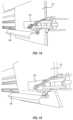
- FIGS. 11 - 23illustrate a box erecting assembly of the box erecting machine of FIG. 3 and an example manner of operation thereof;
- FIG. 24illustrates an assembly for moving a closure mechanism of the box erecting machine
- Exemplary embodiments of the disclosurerelate to systems, methods, and devices for erecting box templates into boxes. More specifically, the described embodiments relate to box erecting machines that take a previously formed box template (with the manufacturer's joint already formed) and erect a box therefrom and close at least the bottom flaps thereof with minimal or no manual labor required.
- baleshall refer to a stock of sheet material that is generally rigid in at least one direction, and may be used to make a box template.
- the balemay be formed of a continuous sheet of material or a sheet of material of any specific length, such as paperboard, corrugated cardboard, and cardboard sheet materials.
- the balemay have stock material that is substantially flat, folded, or wound onto a bobbin.
- box templateshall refer to a substantially flat stock of material that can be erected into a box-like shape.
- a box templatemay have notches, cutouts, divides, and/or creases that allow the box template to be bent and/or folded into a box.
- the notches, cutouts, divides, and/or creases in the box templatemay at least partially define various panels and/or flaps that will forms the sides, top, and bottom of a box formed from the box template.
- a box templatemay be made of any suitable material, generally known to those skilled in the art.
- cardboard or corrugated paperboardmay be used as the box template material.
- a suitable materialalso may have any thickness and weight that would permit it to be bent and/or folded into a box-like shape.
- the term “un-erected box”shall refer to a box template that has been folded one or more times and a manufacturer's joint has been formed thereon.
- a box templatemay be folded along one or more creases to bring the opposing ends of the box template together.
- a manufacturer's jointmay be formed between the opposing ends of the box template.
- the opposing ends of the box templatemay be glued, taped, or stapled together.
- creaseshall refer to a line along which the box template may be folded.
- a creasemay be an indentation in the box template material, which may aid in folding portions of the box template separated by the crease, with respect to one another.
- a suitable indentationmay be created by applying sufficient pressure to reduce the thickness of the material in the desired location and/or by removing some of the material along the desired location, such as by scoring.
- FIG. 1illustrates a perspective view of a system 100 that may be used to create un-erected boxes.
- the system 100includes bales 102 a , 102 b of sheet material 104 .
- the system 100also includes a feed assembly 106 that helps direct the sheet material 104 into a box template forming machine 108 .
- the box template forming machine 108includes a feed changer 110 , a converter assembly 112 , a fold assembly 114 , and an attachment assembly 116 .
- the feed changer 110 , converter assembly 112 , fold assembly 114 , and attachment assembly 116are mounted on or connected to a frame 117 .
- a box forming machine similar or identical to box template forming machine 108is described in U.S. patent application Ser. No. 15/616,688, filed Jun. 7, 2017, and entitled Box Forming Machine (the “'688 application”), which is incorporated herein by reference in its entirely.
- the converter assembly 112may perform one or more conversion functions on sheet material 104 to transform the sheet material into box templates.
- the conversion functionsmay include forming cuts, creases, scores, notches, or the like in the sheet material 104 .
- the fold assembly 114may fold the box template (e.g., between second and third sidewall sections thereof) to bring opposing ends of the box template together.
- the attachment assembly 116may attach the opposing ends of the box template together so as to form a manufacturer's joint. With the manufacturer's joint formed, the box template becomes an “un-erected box”.
- FIGS. 2 A and 2 Billustrate one example of a box template 120 and an un-erected box 122 formed from the box template 120 .
- the box blank 120includes first, second, third, and fourth side-by-side panels (also referred to as sidewall panels), designated as A, B, C, and D, and a glue tab T.
- the panels A-Dmay form the sidewalls of a box formed from the box template 120 .
- Panels A-D and glue tab Tare separated by creases or scores 124 (illustrated by dashed lines).
- the box blankalso includes first, second, third, and fourth top flaps A TF , B TF , C TF , D TF and first, second, third, and fourth bottom flaps A BF , B BF , C BF , D BF .
- the top and bottom flapsextend from opposing sides of their corresponding panels and are separated therefrom by creases or scores 126 (illustrated by dashed lines). Each of the flaps is separated from an adjacent flap by a cut or notch 128 (illustrated by solid lines between adjacent flaps).
- the width of the box formed with un-erected box 122corresponds to the length of each of panels A and C (e.g., the lengths of panels A, C are the distances across panels A, C between panels B, D).
- bottom flaps B BF , D BFmay each have a dimension that is equal to about half of the length of panels A, C (e.g., half of the width of the box).
- the dimension of bottom flap B BF between crease 126 and an edge of bottom flap B BF opposite panel Bmay be equal to half of the length of panels A, C or the width of the box formed with un-erected box 122 .
- the box template forming machine 108can form the cuts and creases in the sheet material 104 in order to form box template 120 . Additionally, the box template forming machine 108 can also fold the box template 120 and secure opposing ends thereof together to form un-erected box 122 . For instance, box template forming machine 108 can fold box template 120 along crease 124 between second and third panels B and C, as shown in FIG. 2 B . The box template forming machine 108 can also secure glue tab T to panel A (e.g., with glue, tape, staples, or the like) to form a manufacturer's joint.
- glue tab Te.g., with glue, tape, staples, or the like
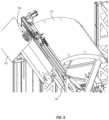
- FIGS. 3 - 31illustrate processes and a box erecting machine 150 that can reduce the amount of manual labor involved with erecting and closing an un-erected box 122 .
- an un-erected box 122may be delivered into one side of the box erecting machine 150 , move therethrough during the erecting process, and be discharged therefrom as an at least partially erected box.
- an un-erected box 122may be delivered into a rear side (rear right side in FIG. 3 ) of the machine 150 .
- the un-erected box 122may be delivered into the machine 150 by an operator or another machine, such as box template forming machine 108 .
- As the un-erected box 122 moves through machine 150it will generally follow a path indicated by arrows 152 and 154 .
- As indicated by arrow 152the un-erected box 122 will be moved from the rear side of machine 150 towards the front side thereof.
- the un-erected box 122may be moved and/or reoriented as will be described in greater detail below.
- the boxmay move in the direction of arrow 154 and be discharged out of the machine 150 .
- the boxis discharged through a discharge opening 156 in a side of the machine 150 .
- machine 150includes a transport mechanism 160 .
- Transport mechanism 160is configured to take hold of the un-erected box 122 when the un-erected box 122 is delivered to machine 150 and transport the un-erected box 122 from the rear side of the machine 150 towards the front side of the machine 150 , where the un-erected box 122 can be erected into a box.
- the transport mechanism 160includes one or more swing or pivot arms 162 with one or more clamps 164 mounted thereon.
- the transport mechanism 160can pivot, swing, or rotate between a rear position and a forward position, as indicated by arrow 165 .
- the clamp 164In the rear position, the clamp 164 is positioned near the rear of machine 150 .
- the transport mechanism 160may pivot, swing, or rotate towards the forward position near the front of the machine 150 .
- the clamp 164is mounted on a carriage 166 .
- the carriage 166can move along a track 168 between opposing sides of the machine 150 .
- the clamp 164may be pivotally mounted on the carriage 166 such that the clamp 164 may rotate or pivot about an axis A.
- axis Ais generally perpendicular to the track 168 . The movement of the carriage 166 along the track 168 and the rotation of the clamp 164 about axis A can facilitate positioning of the un-erected box 122 in a desired location and orientation for the box erecting process described in greater detail below.
- the transport mechanism 160may also include a guide plate 170 .
- guide plate 170takes the form of an arcuate or curved panel, but may take other forms in other embodiments.
- Guide plate 170is positioned below clamp 164 . As clamp 164 moves from the rear position to the forward position with the un-erected box 122 , guide plate 164 may provide support to the un-erected box 122 .
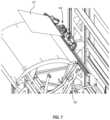
- FIGS. 6 - 10illustrate transport mechanism 160 moving an un-erected box 122 from the rear of machine 150 to the front of machine 150 in preparation for the process of erecting the un-erected box 122 .
- the pivot arm 162is pivoted towards the rear position.
- clamp 164is positioned to receive and clamp onto an un-erected box 122 when such is delivered to machine 150 .
- clamp 164Once clamp 164 has clamped onto an un-erected box 122 , transport mechanism 160 can begin to pivot towards the forward position as shown in FIGS. 7 - 10 . As best seen in FIGS. 7 - 9 , while transport mechanism 160 is pivoting towards the forward position, clamp 164 may move along track 168 and also rotate about axis A to reorient un-erected box 122 . For example, as illustrated in FIG. 7 , clamp 164 is holding onto the manufacturer's joint of un-erected box 122 so that the manufacturer's joint is oriented generally horizontally or parallel to track 168 . As a result of the rotation of clamp 164 (and the pivoting of transport mechanism 160 ) shown in FIGS.
- the un-erected box 122is reoriented so that the manufacturer's joint is oriented generally vertically or perpendicular to track 168 , as shown in FIG. 10 .
- the un-erected box 122is generally prepared to be erected into a box.
- the position of the un-erected box 122may be further refined prior to the un-erected box 122 being erected into a box.
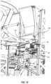
- FIGS. 11 - 13illustrate a box erecting assembly of machine 150 .
- Erecting a box from an un-erected box 122includes at least opening or unfolding the flat un-erected box 122 so that the sidewalls A, B, C, D of the un-erected box 122 are arranged into a rectangular tube and then folding closed and securing the bottom flaps A BF , B BF , C BF , D BF thereof.
- the box erecting assemblyincludes an opening or unfolding mechanism that includes, among other things, at least first and second vacuum heads 180 , 182 , a folding mechanism including first and second folding bars 184 , 186 , and a closure mechanism 188 .
- the box erecting assemblymay also include a datum surface 189 . As described in more detail below, the datum surface 189 and the second vacuum head 182 may adjust or fine-tune the position of the un-erected box 122 prior to or as part of the process of erecting un-erected box 122 into a box.
- first and second vacuum heads 180 , 182are configured to hold the un-erected box template 122 in a desired position and open or unfold the un-erected box template 122 into a rectangular tube.
- the first and second folding bars 184 , 186are configured to fold closed at least some of the bottom flaps A BF , B BF , C BF , D BF .
- the closure mechanism 188is configured to secure the bottom flaps A BF , B BF , C BF , D BF in place in the closed configuration so that the bottom flaps A BF , B BF , C BF , D BF form a bottom surface of a box.
- each of the first and second vacuum heads 180 , 182includes a plurality of vacuum cups 190 .
- the illustrated first vacuum head 180includes five vertical vacuum heads 190 and two angled vacuum heads 190 .
- the illustrated second vacuum head 182includes three vertical vacuum cups 190 and one angled vacuum cup 190 .
- the first and/or second vacuum heads 180 , 182may include fewer or more vacuum cups than illustrated.
- the arrangement of the vacuum cups 190may vary from one embodiment to another. The purpose of the orientation of the angled vacuum cups 190 will be discussed below.
- the vacuum cups 190may be connected to a compressor or other mechanism that can enable the vacuum cups 190 to suction onto planar surfaces of an un-erected box 122 . In some embodiments, at least some of the vacuum cups 190 may also direct pressurized air towards one or more planar surfaces of an un-erected box 122 to move the surface(s) in a desired direction.
- vacuum heads and vacuum cupsare merely exemplary.
- other types of gripping devicescan be used to secure to the un-erected box 122 .
- attachment headsthat include one or more needle grippers or other types of gripper devices could be used to selectively secure to portion of the un-erected box 122 . Accordingly, it will be understood that references herein to vacuum heads and vacuum cups are used generally to identify any suitable attachment head with one or more gripper devices.
- first vacuum head 180can be mounted on a track 192 .
- First vacuum head 180can move back and forth along track 192 at least partially between opposing sides of machine 150 .
- first vacuum head 180can move along track 192 in order to move a partially erected box towards closure mechanism 188 and a completed box towards discharge opening 156 (e.g., in the direction of arrow 154 , FIG. 3 ).
- track 192is generally parallel with track 168 .
- vacuum head 180(and optionally tract 192 ) may pivot or move horizontally in the directions indicated by arrow 191 .
- the vacuum head 180may pivot or move away from the transport mechanism 190 (e.g., away from the rear and towards the front of machine 150 ).
- Such movement of vacuum head 180can provide clearance for the un-erected box 122 so that the lower end thereof does not get caught on the vacuum head 122 .
- vacuum head 180can pivot or move back towards the transport mechanism 190 (e.g., towards the rear and away from the front of machine 150 ). Such movement can position (at least the vertical) vacuum cups 190 of vacuum head 180 adjacent to the un-erected box 122 .
- Second vacuum head 182can also move. More specifically, second vacuum head 182 may move in the direction indicated by arrow 193 in FIG. 10 (which can be generally parallel to track 192 ). For instance, when un-erected box 122 is brought to the position shown in FIG. 10 , second vacuum head 182 may move in the direction of arrow 193 to engage and move un-erected box 122 to a predetermined horizontal position.
- the datum surface 189may move up underneath the un-erected box 122 .
- the datum surface 189may engage the bottom edge of the un-erected box 122 and push the un-erected box 122 up to a predetermined vertical position.
- the datum surface 189may also support the un-erected box 122 from underneath during the transition from the clamp 164 to the vacuum heads 180 , 182 described below. Engagement of the datum surface 189 with the lower edge of the un-erected box 122 may also ensure that the bottom edge of the un-erected box 122 (and thus the un-erected box 122 ) is oriented horizontally.
- the securement of the un-erected box 122may transition from the clamp 164 to the vacuum heads 180 , 182 .
- the clamp 164may release its grip on the un-erected box 122 and the vacuum heads 180 , 182 may be secured to the un-erected box 122 .
- the second vacuum head 182may pivot between the first position illustrated in FIGS. 12 and 13 and the second position illustrated in FIGS. 14 - 17 . In the first position, the second vacuum head 182 is oriented generally perpendicular to first vacuum head 180 .
- the second vacuum head 182is oriented generally parallel to first vacuum head 180 .
- the vertical vacuum cups 190 of the vacuum heads 180 , 182generally face one another or face opposing directions.
- the vacuum cups 190can be activated to secure to the sidewalls of the un-erected box 122 .
- an actuator 194may pivot the second vacuum head 182 between the two noted positions.
- the actuator 194includes a piston 196 and a pivot arm 198 .
- the piston rodextends and retracts, it pushes and pulls on the pivot arm 198 .
- the pivot arm 198cooperates with rollers 200 that direct the pivot arm 198 to move through an arcuate path, which causes the second vacuum head 182 to pivot between the noted positions.
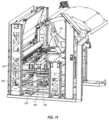
- FIGS. 14 - 23illustrate the process of erecting a box from an un-erected box 122 .
- the un-erected box 122has been delivered by the transport mechanism 160 to the box erecting assembly.
- the second vacuum head 182has been pivoted towards the un-erected box 122 so that the un-erected box 122 is disposed or sandwiched between the first and second vacuum heads 180 , 182 .
- At least some of the vacuum cups 190 of the first and second vacuum heads 180 , 182can be activated to secure the un-erected box 122 to the first and second vacuum heads 180 , 182 .
- the first folding bar 184can engage the bottom flaps of the un-erected box 122 , as shown in FIGS. 15 and 17 . More specifically, the first folding bar 184 can fold at least some of the bottom flaps (all of the bottom flaps are folded in the illustrated embodiment) relative to the side panels (e.g., along the creases 126 therebetween) in a first direction as shown in FIG. 15 . Thereafter, the first folding bar 184 can optionally fold some of the bottom flaps relative to the side panels in a second direction as shown in FIG. 17 . The second direction can be opposite the first direction.
- Folding the bottom flaps as describedcan provide various benefits. For instance, any creases or folds extending through the sidewall panels and flaps (e.g., folds from the sheet material 104 being folded into a bale 102 ) can be unfolded or flattened by folding the flaps in a direction (or about an axis that is) perpendicular to the orientation of the undesired folds. Additionally, folding the bottom flaps can bring at least some of the bottom flaps into contact with the angled vacuum cups 190 of the first and second vacuum heads 180 , 182 . For instance, when the first folding bar 184 folds the bottom flaps as shown in FIG.
- At least one of the bottom flapsengages and is secured to the angled vacuum cup 190 of the first vacuum head 180 .
- that flapcan be held in place (in an angled orientation) as shown in FIGS. 16 and 17 . Holding this bottom flap in an angled orientation can maintain the flap and associated sidewall in flat configurations and assist with the process for folding the bottom flaps closed.
- the first folding bar 184folds some or all of the remaining bottom flaps as shown in FIG. 17
- at least one of the bottom flapsengages and is secured to the angled vacuum cup 190 of the second vacuum head 182 .
- that flapcan be held in place (in an angled orientation) as shown in FIG. 17 . Holding this bottom flap in an angled orientation can maintain the flap and associated sidewall in flat configurations.
- the second vacuum head 182can then be pivoted to the orientation shown in FIG. 18 (e.g., so that the first and second vacuum heads 180 , 182 are arranged at a 90° angle relative to one another).
- the un-erected box 122is opened or unfolded as shown when the second vacuum head 182 is pivoted to the position shown. More specifically, the pivoting of the second vacuum head 182 opens or unfolds the un-erected box 122 so that the sidewalls thereof form of a generally rectangular tube, as shown in FIG. 18 .
- the first folding bar 184may remain in the position shown in FIG. 17 .
- the first folding bar 184remains engaged with the bottom leading minor flap of the un-erected box 122 (i.e., the bottom minor flap opposite to the angled bottom flap seen in FIG. 18 ). This engagement causes the bottom leading minor flap to be at least partially folded up towards a closed position.
- the first folding bar 184may move or pivot upwards to fold the bottom leading minor flap to a completely closed position (e.g., so that the flap forms a generally 90° angle with its corresponding side panel).
- the bottom trailing minor flap thereofi.e., the flaps below the second vacuum head 182
- the bottom trailing minor flap thereofcan be disengaged from the angled vacuum cup 190 thereof, as shown in FIG. 19 .
- a folding bar 201may be extended to fold the bottom trailing minor flap up to a closed or horizontal position.
- the first and second folding bars 184 , 186may then be moved (e.g., pivoted, translated, etc.) to fold the bottom major flaps up to closed or horizontal positions. More specifically, the second folding bar 186 may move towards and engage an outer surface of one of the bottom major flaps to fold the bottom major flap towards a closed position, as shown in FIGS. 20 and 21 . Additionally, the first folding bar 184 may pivot or move outside of the bottom flap that is secured to the angled vacuum cup 190 of the first vacuum head 180 .
- the angled vacuum cup 190 of the first vacuum head 180may disengage the bottom flap and the first folding bar 184 may move towards and engage an outer surface of the bottom major flap to fold the bottom major flap towards a closed position, as shown in FIGS. 20 and 21 .
- the first folding bar 184or a portion thereof, may also move or pivot upward to fully fold the bottom major flap to the closed position.
- the bottom major flapsare folded in a predetermined order, while in other embodiments the bottom major flaps are folded substantially simultaneously.
- the first and second folding bars 184 , 186can remain positioned under the box after folding the bottom major flaps closed and while the box is moved towards the closure mechanism 188 . In such positions, the first and second folding bars 184 , 186 in essence form a track on which the box 122 can move. Additionally, the first and second folding bars 184 , 186 also hold the bottom flaps in the closed position until the closure mechanism 188 has secured the bottom flaps closed.
- the closure mechanism 188is a tape head that applies tape to at least the bottom major flaps (and optionally at least a portion of opposing sides) of the box 122 to secure the bottom flaps closed.
- the closure mechanism 188may take the form of a glue applicator or stapler than can apply glue or staples to the bottom flaps to secure them closed.
- the closure mechanism 188cam be movable.
- the closure mechanismcan move at least partially between the front and rear ends of the machine 150 in order to align the closure mechanism 188 with a bottom seam on the box formed by the bottom major flaps. More specifically, the location of the bottom seam will vary depending on the width of the box. Accordingly, the position of the closure mechanism 188 is adjustable so that the closure mechanism 188 can apply tape, glue, staples, or other fasteners to the bottom seam.
- FIG. 24illustrates an example embodiment of the mechanism for adjusting the position of the closure mechanism 188 .
- the closure mechanism 188is mounted on a carriage 200 .
- the closure mechanism 188is movable relative to the carriage 200 between the front and rear ends of the carriage in the directions indicated by arrow 202 , such that the closure mechanism 188 can move closer to or further away from the front of machine 150 .
- carriage 200is also movable closer to or further away from the front of machine 150 in the directions indicated by arrow 202 .
- the position of the closure mechanism 188(and optionally the carriage 202 ) can be adjusted to allow for additional room between the closure mechanism 188 and the first vacuum head 180 and/or the track 192 .
- the closure mechanism 188may be moved towards the rear of the machine 150 to create sufficient space for the un-erected box to pass between the closure mechanism 188 and the first vacuum head 180 and/or the track 192 .
- the position of the carriage 200 and the position of the closure mechanism 188 relative to the carriage 200can be adjusted to align the closure mechanism 188 with the bottom seam of the box.
- the carriage 200can be moved to a predetermined position for a box having a particular width. For narrower boxes, the carriage is moved closer to the front of machine 150 . For wider boxes, the carriage is moved further away from the front of machine 150 .
- the closure mechanism 188can be moved to a front-most position on the carriage 202 to align the closure mechanism 188 with the bottom seam of the box.
- the second folding bar 186is connected to the closure mechanism 188 such that the two components move together.
- a single actuatorcan be used to both move the second folding bar 186 to fold one of the bottom major flaps of the box and to align the closure mechanism 188 with the bottom seam of the box.
- the first vacuum head 180can move the box to the discharge opening 156 of machine 150 .
- the first vacuum head 180can disengage the box (e.g., by deactivating the vacuum cups 190 thereof).
- the boxcan then proceed to another area to be filled and closed.
- the first vacuum head 180can move back along track 192 towards second vacuum head 182 , as shown in FIG. 23 .
- the movements of the second vacuum head 182 , the datum surface 189 , and the carriage 202are linked together.
- the second vacuum head 182 , the datum surface 189 , and the carriage 202can be linked together by a plurality of drive chains 204 (one of which is shown in FIG. 24 ).
- the plurality of drive chains 204may be connected to and driven by a single motor 206 ( FIG. 11 ).
- adjustments made to the position of the second vacuum head 182 or the datum surface 189can be made to ensure the proper positioning of an un-erected box within the machine as described herein. Because the second vacuum head 182 , the datum surface 189 , and the carriage 202 are linked together, such adjustments to one of the noted components will automatically adjust the position of the other noted components. As a result, each of the noted components will be properly positioned based on the size of the box being erected.
- FIG. 25illustrates an un-erected box 122 in a generally flap configuration, similar to that shown in FIG. 2 B .
- a manufacturer's jointis formed at the attachment interface between glue tab T and sidewall panel A.
- the bottom flaps A BF , B BF , C BF , D BFextend from the corresponding sidewall panels A-D.
- bottom flaps A BF and C BFare minor flaps that extend along the width of the erected box and bottom flaps B BF and D BF are major flaps that extend along the length of the erected box.
- all of the bottom flaps A BF , B BF , C BF , D BFare folded (relative to there respective sidewall panels A-D) in a first direction as shown in FIG. 26 .
- the bottom flaps A BF , B BF , C BF , D BFare folded to an angle of 15°, 30°, 45°, or 90°, or any angle therebetween relative to the sidewall panels A-D.
- bottom flaps A BF , B BF , C BF , D BFAfter folding all of the bottom flaps A BF , B BF , C BF , D BF in the first direction, three of the bottom flaps A BF , B BF , C BF can be folded (relative to the sidewall panels A-C) in a second direction opposite to the first direction, as shown in FIG. 27 .
- the bottom flaps A BF , B BF , C BFare folded to an angle of 15°, 30°, 45°, or 90°, or any angle therebetween relative to the sidewall panels A-C.
- bottom flap D BFis held in the angled position created from the first fold. With the bottom flaps A BF , B BF , C BF , D BF so folded, the sidewall panels A-D are maintained in straight and rigid configurations.
- the un-erected box 122can be opened or unfolded so that the sidewall panels A-D form a generally rectangular tube as shown in FIG. 28 .
- the bottom flapscan be maintained in or folded to an angled orientation relative to their associated sidewall panel(s) to maintain the sidewall panels in straight configurations. In some embodiments, it is preferable to fold or maintain two, three, or four of the bottom flaps in an angled orientation.
- bottom flap A BFcan then be folded in towards the interior of the un-erected box 122 as shown in FIG. 29 .
- bottom flap A BFis folded to form about a 90° angle with sidewall panel A.
- the bottom minor flaps A BF , C BF folded inthe bottom major flaps B BF , D BF can be folded in to close the bottom of the box.
- bottom major flap B BFis folded towards bottom minor flaps A BF , C BF .
- sidewall panel B and bottom flap B BFmay bend or fold as a result of a fanfold crease extending therethrough. Due to the straightness and rigidity of the sidewall panels A, C, D and the folded bottom flaps A BF , C BF , D BF , any such bend or fold will cause sidewall panel B and bottom flap B BF to bow outwards. Such bowing will not overly hinder the ability to fold bottom flap B BF .
- bottom flap B BFcan be readily folded to close the bottom of the box. As shown, bottom major flap B BF is folded towards bottom flap A BF , C BF . Prior to are after bottom flap B BF is folded closed, bottom flap D BF can be folded closed as shown in FIG. 31 .
- a box erecting processincludes folding and maintaining at least one flap at an angle relative to its associated sidewall panel during the erecting process.
- two, three, or four flapsmay be folded and maintained at an angle relative to their associated sidewall panels during the erecting process.
- only or at least the flaps associated with sidewall panels having fanfold creases extending therethroughare folded and maintained at an angle relative to the associated sidewall panel(s) in order to flatten and stiffen the sidewall panel(s) during the box erecting process as described herein.
- FIGS. 25 - 31illustrate and describe folding and maintaining the flaps in certain directions
- the direction of the foldsis merely exemplary.
- some of the flapscould be folded in a first direction and some other flaps could be folded in a second direction.
- at least one of flaps A BF , B BFcould be folded outward in one direction and at least one of flaps C BF , D BF could be folded outward in a second opposite direction.
- the un-erected boxcould be opened or unfolded so the sidewall panels form a rectangular tube.
- the minor flapscould then be folded in followed by folding in of the major flaps.
- bottom flaps A BF , D BFcould be folded in one direction and bottom flaps B BF , C BF could be folded in a second opposite direction. Thereafter, the un-erected box could be opened or unfolded so the sidewall panels form a rectangular tube. With this process, when the un-erected box is opened or unfolded into a rectangular tube, the minor bottom flaps A BF , C BF would already be at least partially folded inward towards the closed position. Thereafter, the folding closed of the bottom minor flaps A BF , C BF could be completed. Then the bottom major flaps D BF , B BF could be folded closed.
- erecting a box from an un-erected boxcan be done through a variety of processes, with or without machine assistance.
- one or more of the bottom flapsis folded and held at an angle or in an angled orientation relative to the corresponding sidewall panel(s) during the box erecting process.
- a single bottom panelcan be in an angled orientation during the erecting process, while in other embodiments, two, three, or four bottom panels can be held in angled orientations during the erecting process.
- the direction of the angled orientation and/or the degree of the anglemay vary from one embodiment to another.
- a method for erecting an un-erected box into a boxcomprising providing an un-erected box having first, second, third, and fourth sidewall panels and first, second, third, and fourth bottom flaps extending from the corresponding first, second, third, and fourth sidewall panels.
- the un-erected boxmay be folded between the second and third sidewall panels and the first and fourth sidewall panels may be secured to one another.
- the methodalso includes folding one or more of the bottom flaps relative to the corresponding sidewall panel(s) such that the one or more bottom flaps and the corresponding sidewall panel(s) form one or more angles of greater than 0°.
- arranging the un-erected boxincludes folding the third bottom flap to a closed position.
- the methodalso includes maintaining the fourth bottom flap in an angled orientation in a first direction while the first, second, and third bottom flaps are folded in a second direction.
- the one or more bottom flapsare maintained in a folded orientation relative to their associated sidewall panel(s) during the remainder of the method.
- folding the one or more bottom flaps relative to the corresponding sidewall panel(s)comprises folding the first and second bottom flaps and the third and fourth bottom flaps in opposite directions.
- folding one or more of the bottom flaps relative to the corresponding sidewall panel(s)comprises folding the one or more bottom flaps such that the one or more bottom flaps and the corresponding sidewall panel(s) form one or more angles of greater than 0° and less than 90°.
- At least one of the sidewall panelscomprises a crease or fold extending therethrough, and folding the one or more bottom flaps relative to the corresponding sidewall panel(s) flattens or unfolds the crease or fold extending through the at least one sidewall panel.
- a box erecting assemblyis configured to erect an un-erected box into an erected box.
- the un-erected boxcan include first, second, third, and fourth bottom flaps extending from corresponding first, second, third, and fourth sidewall panels.
- the box erecting assemblyincludes an opening or unfolding mechanism configured to open or unfold the un-erected box from a first configuration into a second configuration where the first, second, third, and fourth sidewall panels form a generally rectangular tube.
- the assemblyalso includes a folding mechanism configured to fold bottom flaps of the un-erected box. The folding mechanism can be configured to fold one or more of the bottom flaps into an angled orientation relative to the associated sidewall panel(s).
- the folding mechanismcan be configured to maintain the one or more bottom flaps in an angled orientation while the opening or unfolding mechanism opens or unfolds the un-erected box into the second configuration.
- the assemblyalso includes a closure mechanism that is configured to secure the bottom flaps in the closed configuration.
- the folding mechanismcomprises one or more pivoting folding bars configured to pivot to fold the one or more bottom flaps of the un-erected box into the angled orientation.
- At least one of the one or more pivoting folding barscomprises a pivoting upper end that is configured to pivot to fold one or more of the bottom flaps to a fully closed position.
- the opening or unfolding mechanismcomprises one or more angled gripping devices configured to selectively hold or maintain the one or more bottom flaps in the angled orientation.
- the one or more angled gripping devicesare configured to maintain the fourth bottom flap in the angled orientation while the opening or unfolding mechanism opens or unfolds the un-erected box into the second configuration.
- the one or more angled gripping devicesare configured to maintain the fourth bottom flap in the angled orientation while the folding mechanism folds the first and third bottom flaps to the closed configuration.
- the folding mechanismis configured to fold the first and second bottom flaps in a first direction and the third and fourth bottom flaps in a second direction opposite to the first direction prior to the opening or unfolding device opening or unfolding the un-erected box into the second configuration.
- the assemblyalso includes a transport mechanism that can pivot between a rear position and a forward position to transport an un-erected box from an entry portion of the box erecting assembly to a forward portion of the box erecting assembly.
- the transport mechanismcomprises one or more pivot arms that can pivot the transport mechanism between the rear position and the forward position.
- the transport mechanismalso includes a clamp connected to the one or more pivot arms, the clamp being configured to selectively clamp onto an un-erected box, the clamp being movable to reposition and/or reorient the un-erected box as the transport mechanism pivots between the rear and forward positions
- the pivoting movement of the one or more pivot arms and the movability of the clampare configured to position an un-erected box in a desired position and orientation relative to the opening or unfolding mechanism and the folding mechanism.
- At least a portion of the opening or unfolding mechanismis configured to move horizontally to engage and position the un-erected box is a predetermined position.
- the closure mechanismcomprises a tape head, a glue applicator, or a stapler.
- the closure mechanism and at least a portion of the folding mechanismare connected together such that the closure mechanism and the at least a portion of the folding mechanism move together.
- the assemblyalso comprises a datum surface configured to support and position an un-erected box in a desired position.
- the position of the datum surfaceis selectively adjustable.
- the position of the datum surfaceis linked to the position of the closure mechanism and the at least a portion of the folding mechanism.
- the positions of the closure mechanism, the at least a portion of the folding mechanism, and the datum surfaceare selectively adjustable via a common actuator.
- a box erecting machinein another embodiment, includes a transport mechanism that can pivot between a rear position and a forward position to transport an un-erected box from an entry portion of the box erecting machine to a forward portion of the box erecting machine.
- the transport mechanismcan include one or more pivot arms that can pivot the transport mechanism between the rear position and the forward position, and a clamp configured to selectively clamp onto an un-erected box.
- the clampcan be movable to reposition the un-erected box along a width of the box erecting machine as the transport mechanism pivots between the rear and forward positions.
- the clampcan be rotatable about an axis, rotation of the clamp about the axis being configured to reorient the un-erected box from a generally horizontal orientation to a generally vertical orientation.
- a method for erecting a boxincludes providing an un-erected box having a plurality of sidewall panels and a plurality of flaps extending from the plurality of sidewall panels, at least one sidewall panel of the plurality of sidewall panels having a crease or fold extending therethrough.
- the methodalso includes folding at least one flap associated with the at least sidewall panel relative to the at least one sidewall panel, wherein folding the at least one flap relative to the at least one sidewall panel flattens or unfolds the crease or fold extending through the at least one sidewall panel.
- the methodalso includes arranging the un-erected box so that the plurality of sidewall panels form a generally rectangular tube while the at least one flap is folded relative to the at least one sidewall panel.
- folding the at least one flap relative to the at least one sidewall panelcomprises folding the at least one flap such that the at least one flap and the at least one sidewall panel form an angle of greater than 0° and less than 90°.
- the methodincludes folding more than one of the flaps relative to the associated sidewall panels.
Landscapes
- Making Paper Articles (AREA)
Abstract
Description
Claims (28)
Priority Applications (1)
| Application Number | Priority Date | Filing Date | Title |
|---|---|---|---|
| US17/416,811US11752725B2 (en) | 2019-01-07 | 2020-01-07 | Box erecting machine |
Applications Claiming Priority (3)
| Application Number | Priority Date | Filing Date | Title |
|---|---|---|---|
| US201962789374P | 2019-01-07 | 2019-01-07 | |
| PCT/US2020/012519WO2020146334A1 (en) | 2019-01-07 | 2020-01-07 | Box erecting machine |
| US17/416,811US11752725B2 (en) | 2019-01-07 | 2020-01-07 | Box erecting machine |
Publications (2)
| Publication Number | Publication Date |
|---|---|
| US20220080691A1 US20220080691A1 (en) | 2022-03-17 |
| US11752725B2true US11752725B2 (en) | 2023-09-12 |
Family
ID=69528959
Family Applications (1)
| Application Number | Title | Priority Date | Filing Date |
|---|---|---|---|
| US17/416,811ActiveUS11752725B2 (en) | 2019-01-07 | 2020-01-07 | Box erecting machine |
Country Status (3)
| Country | Link |
|---|---|
| US (1) | US11752725B2 (en) |
| DE (1) | DE112020000348T5 (en) |
| WO (1) | WO2020146334A1 (en) |
Families Citing this family (6)
| Publication number | Priority date | Publication date | Assignee | Title |
|---|---|---|---|---|
| SE541921C2 (en) | 2017-03-06 | 2020-01-07 | Packsize Llc | A box erecting method and system |
| US11173685B2 (en) | 2017-12-18 | 2021-11-16 | Packsize Llc | Method for erecting boxes |
| SE543046C2 (en) | 2018-09-05 | 2020-09-29 | Packsize Llc | A box erecting method and system |
| CN112373115B (en)* | 2020-11-13 | 2021-08-10 | 江苏波司登科技有限公司 | Carton packaging forming equipment |
| CN114193830B (en)* | 2021-12-17 | 2024-05-14 | 昆山永立包装有限公司 | Full-automatic binding equipment is used in packing carton production |
| KR102740484B1 (en)* | 2022-08-09 | 2024-12-06 | 양재근 | Automatic box shaping machine |
Citations (378)
| Publication number | Priority date | Publication date | Assignee | Title |
|---|---|---|---|---|
| FR428967A (en) | 1910-07-04 | 1911-09-12 | Francois Joseph Charles Taupin | Rotary folding machine for paper and cardboard boxes |
| GB166622A (en) | 1920-03-05 | 1921-07-05 | Henry Jeffrey Poole | Improvements in machines for cutting paper, cardboard and the like |
| US1809853A (en) | 1927-08-29 | 1931-06-16 | Hoague Sprague Corp | Art of box making |
| US2077428A (en) | 1934-12-14 | 1937-04-20 | Gilman Fanfold Corp | Strip controlling attachment |
| US2083351A (en) | 1935-07-29 | 1937-06-08 | Specialty Automatic Machine Co | Manufacture of corrugated paper cartons |
| US2181117A (en) | 1938-04-09 | 1939-11-28 | Autographic Register Co | Method of making continuous manifolding stationery |
| US2217784A (en) | 1938-04-23 | 1940-10-15 | American Paper Bottle Co | Container fabricating machine |
| US2256082A (en) | 1940-02-12 | 1941-09-16 | Cons Cover Co | Paper converting machine |
| US2353419A (en) | 1942-06-11 | 1944-07-11 | Eugene S Smithson | Machine for forming box blanks |
| US2449663A (en) | 1946-09-28 | 1948-09-21 | Marcalus Nicholas | Interfolding |
| US2609736A (en) | 1948-06-03 | 1952-09-09 | Hugh E Montgomery | Machine for folding paper box blanks on a stack thereof |
| FR1020458A (en) | 1950-06-17 | 1953-02-06 | Automatic transfer machine for making one-piece cardboard boxes | |
| US2631509A (en) | 1944-07-18 | 1953-03-17 | American Viscose Corp | Method for forming tubular articles |
| US2679195A (en) | 1944-07-18 | 1954-05-25 | American Viscose Corp | Apparatus for forming tubular articles |
| US2699711A (en) | 1951-09-15 | 1955-01-18 | Bloomer Bros Co | Carton erecting machine |
| US2798582A (en) | 1948-04-15 | 1957-07-09 | Ex Cell O Corp | Web control for carton converting machine |
| US2887021A (en) | 1956-04-04 | 1959-05-19 | Ex Cell O Corp | Apparatus for feeding blanks to a container fabricating machine |
| US2904789A (en) | 1956-12-20 | 1959-09-22 | Victory Container Corp | Folding machine |
| DE1082227B (en) | 1957-07-19 | 1960-05-25 | Papierverarbeitungsmaschinenwe | Cutting machine for paper, cardboard or the like. |
| US2989903A (en) | 1958-07-30 | 1961-06-27 | Fibreboard Paper Products Corp | Carton opening apparatus and method |
| US3057267A (en)* | 1960-06-28 | 1962-10-09 | Emhart Mfg Co | Carton opening mechanism |
| US3096692A (en) | 1962-03-16 | 1963-07-09 | Fmc Corp | Box making machine |
| US3105419A (en) | 1960-09-19 | 1963-10-01 | Bombard Leon E La | Adhesive applying apparatus and method |
| US3108515A (en) | 1962-08-01 | 1963-10-29 | Anderson Bros Mfg Co | Method and apparatus for erecting flattened cartons |
| US3119547A (en) | 1962-03-16 | 1964-01-28 | Jay H Nute | Collapsible and re-usable carton |
| US3153991A (en) | 1963-03-04 | 1964-10-27 | St Regis Paper Co | Apparatus for the manufacture of composite carton blanks |
| GB983946A (en) | 1962-07-18 | 1965-02-24 | Charles Edward Palmer | Synthetic plastic container and blank and method of folding same |
| DE1212854B (en) | 1963-07-30 | 1966-03-17 | Internat Machinery Corp N V | Packing machine |
| US3242827A (en) | 1963-07-10 | 1966-03-29 | Fibreboard Paper Products Corp | Apparatus and method for opening cartons |
| US3285145A (en) | 1963-11-18 | 1966-11-15 | Somerville Ind Ltd | Carton setting up machine |
| US3288349A (en) | 1962-07-18 | 1966-11-29 | Monsanto Co | Plastic container and blank |
| US3299611A (en) | 1963-10-24 | 1967-01-24 | Cons Foods Corp | Packaging machine |
| US3303759A (en) | 1964-05-11 | 1967-02-14 | Peters Leo | Converting machine for butter patty plate |
| US3308723A (en) | 1964-08-06 | 1967-03-14 | Jr Charles J Bergh | Apparatus for slitting and scoring carton blanks |
| US3326096A (en) | 1964-12-07 | 1967-06-20 | Weyerhaeuser Co | Container folding apparatus |
| US3406611A (en) | 1965-10-13 | 1968-10-22 | Nat Packaging Products | Apparatus for producing and stacking sheetlike items |
| US3418893A (en) | 1965-12-30 | 1968-12-31 | Anderson Bros Mfg Co | Carton feeding and erecting apparatus |
| US3451318A (en) | 1965-10-27 | 1969-06-24 | Seita | Machine for forming and presenting cartons for continuous feeding to a boxing machine |
| US3469508A (en) | 1966-04-09 | 1969-09-30 | Eickhoff Geb | Apparatus for forming glued or coated folding box stock |
| US3476023A (en) | 1968-10-24 | 1969-11-04 | Herrick Waterman | Carton handling machine |
| FR1592372A (en) | 1968-11-20 | 1970-05-11 | ||
| US3511496A (en) | 1967-06-09 | 1970-05-12 | Optische Ind De Oude Delft Nv | Device for removing individual sheets from a stack |
| US3566755A (en) | 1969-01-14 | 1971-03-02 | Weyerhaeuser Co | Apparatus for erecting cartons |
| US3584434A (en) | 1968-05-16 | 1971-06-15 | M & E Machinery Corp | Carton handling and loading method and machine |
| US3611884A (en) | 1970-01-26 | 1971-10-12 | William J Hottendorf | Box making machine |
| US3618479A (en) | 1970-04-08 | 1971-11-09 | S & S Corrugated Paper Mach | Automatic positioner for hold-down means |
| US3628408A (en) | 1969-10-08 | 1971-12-21 | Xerox Corp | Stamp dispenser |
| US3646418A (en) | 1969-07-22 | 1972-02-29 | Logic Systems Inc | Positioning of multiple elements |
| US3728945A (en) | 1971-12-13 | 1973-04-24 | Container Corp | Apparatus for erecting cartons |
| US3743154A (en) | 1972-01-03 | 1973-07-03 | Minnesota Mining & Mfg | Paper guide |
| US3748972A (en) | 1971-11-01 | 1973-07-31 | Emhart Corp | Method and apparatus for erecting and bottom sealing cartons |
| US3763750A (en)* | 1972-02-01 | 1973-10-09 | Abc Packaging Machine Corp | Box forming machine |
| US3776109A (en) | 1972-04-06 | 1973-12-04 | Union Camp Corp | Folder for large box blanks |
| US3803798A (en) | 1972-09-11 | 1974-04-16 | Colgate Palmolive Co | Folded towelette guide and feed mechanism |
| US3804514A (en) | 1972-09-26 | 1974-04-16 | Xerox Corp | Dual function document stop for a caping device |
| US3807726A (en) | 1973-03-08 | 1974-04-30 | H Hope | Film receiving apparatus |
| GB1362060A (en) | 1970-11-23 | 1974-07-30 | Fmc Corp | Web handling machines |
| JPS4999239A (en) | 1973-01-25 | 1974-09-19 | ||
| US3882764A (en) | 1972-04-27 | 1975-05-13 | Simon Ltd Henry | Case making machinery |
| US3891203A (en) | 1973-12-27 | 1975-06-24 | Joseph Schiff | Office machine including flat article feeder |
| JPS5078616A (en) | 1973-11-15 | 1975-06-26 | ||
| US3912389A (en) | 1973-10-05 | 1975-10-14 | Canon Kk | Copy medium receiving tray |
| US3913464A (en) | 1974-11-22 | 1975-10-21 | S & S Corrugated Paper Mach | Positioning means for hold-down |
| JPS5127619A (en) | 1974-09-02 | 1976-03-08 | Mitsubishi Motors Corp | TASHIRINDANAINENKIKAN |
| US3949654A (en) | 1974-06-21 | 1976-04-13 | S. A. Martin | Assembly for use in a machine for processing sheet or similar material |
| US4033217A (en) | 1976-01-13 | 1977-07-05 | S&S Corrugated Paper Machinery Co., Inc. | Slitter having carrier for selective adjustment of a plurality of heads |
| US4044658A (en) | 1976-04-01 | 1977-08-30 | Union Camp Corporation | Apparatus for folding panels of carton blank |
| US4052048A (en) | 1976-03-11 | 1977-10-04 | Paper Converting Machine Company | Longitudinally interfolding device and method |
| US4056025A (en) | 1976-04-02 | 1977-11-01 | Rubel Laurence P | Strip cutting apparatus |
| US4094451A (en) | 1976-11-04 | 1978-06-13 | Granite State Machine Co., Inc. | Lottery ticket dispenser for break-resistant web material |
| DE2700004A1 (en) | 1977-01-03 | 1978-07-06 | Sick Optik Elektronik Erwin | ELECTRO-OPTICAL FOLDING MONITORING DEVICE |
| US4121506A (en) | 1977-03-23 | 1978-10-24 | The Continental Group, Inc. | Carton forming apparatus |
| US4123966A (en) | 1976-12-08 | 1978-11-07 | Nolex Corporation | Carton forming apparatus |
| GB1546789A (en) | 1976-05-28 | 1979-05-31 | Simon Container Mach Ltd | Web feeding apparatus |
| US4163414A (en) | 1977-02-23 | 1979-08-07 | Wayne Automation Corp. | Method of erecting flat folded cases |
| US4164171A (en) | 1977-10-25 | 1979-08-14 | American Can Company | Carton forming apparatus |
| US4173106A (en) | 1977-04-13 | 1979-11-06 | Mira-Pak Inc. | Carton forming method |
| US4191467A (en) | 1979-04-04 | 1980-03-04 | Xerox Corporation | Dual mode catch tray |
| JPS5557984A (en) | 1978-10-25 | 1980-04-30 | Hitachi Ltd | Ticket printing issusing machine |
| US4221373A (en) | 1977-03-18 | 1980-09-09 | Grapha-Holding Ag | Apparatus for folding paper sheets or the like |
| US4224847A (en) | 1977-10-20 | 1980-09-30 | Rengo Co., Ltd. | Tool positioning apparatus |
| US4261239A (en) | 1978-12-13 | 1981-04-14 | Nihon Electronic Industry Co., Ltd. | Positioning head for cutting and marking apparatus |
| US4264200A (en) | 1979-09-17 | 1981-04-28 | Xerox Corporation | Platen module for computer fanfold reproduction |
| EP0030366A1 (en) | 1979-12-11 | 1981-06-17 | Ab Tetra Pak | A method and an arrangement for the feed of a material web |
| US4275543A (en) | 1979-05-23 | 1981-06-30 | Augusto Marchetti | Automatic machine for closing the lower flaps of a parallelepiped box with foldable flaps and for retaining the box in a filling position |
| US4295841A (en) | 1979-10-19 | 1981-10-20 | The Ward Machinery Company | Box blank folding apparatus |
| US4320960A (en) | 1979-09-17 | 1982-03-23 | Xerox Corporation | Sensor controlling in computer fanfold reproduction |
| US4368052A (en) | 1980-08-18 | 1983-01-11 | Peerless Metal Industries, Inc. | Method and apparatus for lining bulk box blanks |
| US4373412A (en) | 1980-07-10 | 1983-02-15 | Gerber Garment Technology, Inc. | Method and apparatus for cutting sheet material with a cutting wheel |
| US4375970A (en) | 1980-10-06 | 1983-03-08 | Westvaco Corporation | Converting machine gum box |
| US4401250A (en) | 1981-02-25 | 1983-08-30 | Tetra Pak International Ab | Method and an arrangement for the forward feeding of a material web in register with a crease line pattern |
| SU1054863A1 (en) | 1981-07-02 | 1983-11-15 | Новосибирский Научно-Исследовательский,Проектно-Конструкторский И Технологический Институт Комплектного Электропривода | Ac electric drive (its versions) |
| US4414789A (en) | 1980-03-18 | 1983-11-15 | B.S.P. Packaging Systems Di Pattarozzi D. & C. S.A.S. | Apparatus for transforming blanks into corresponding containers by parallelepiped shape |
| JPS5931140A (en) | 1982-07-14 | 1984-02-20 | アクミラン・ブロ−デル・リミテツド | Method and device for manufacturing multilayer vessel using corrugated paper material |
| US4437570A (en) | 1982-07-13 | 1984-03-20 | Champion International Corporation | Shipping carton with case knife protection for inner cartons |
| US4449349A (en) | 1980-12-03 | 1984-05-22 | Involvo Ag | Packing machine with adjustable means for weakening selected portions of cardboard blanks or the like |
| JPS59176836A (en) | 1983-03-25 | 1984-10-06 | Sanyo Electric Co Ltd | Processing system for sound input data |
| SU1121156A1 (en) | 1981-10-08 | 1984-10-30 | Челябинская Обувная Фабрика "Чпоо" | Machine for making packing boxes from cardboard web |
| US4487596A (en) | 1981-01-16 | 1984-12-11 | Wilkinson Sword Limited | Method of, and apparatus for, manufacturing a flip-top box |
| DE3343523A1 (en) | 1983-12-01 | 1985-06-13 | ERO-Etikett GmbH, 7318 Lenningen | Station for a device processing concertina-folded continuous webs, in particular printer |
| US4563169A (en) | 1982-06-01 | 1986-01-07 | Virta Arthur W | Method and apparatus for folding container blanks |
| US4578054A (en) | 1983-11-17 | 1986-03-25 | Herrin Robert M | Carton erection and sealing apparatus |
| JPS61118720A (en) | 1984-11-15 | 1986-06-06 | Matsushita Electric Ind Co Ltd | Sukyana |
| USD286044S (en) | 1983-08-31 | 1986-10-07 | Canon Kabushiki Kaisha | Paper discharging tray for a facsimile |
| JPS61242837A (en) | 1985-04-18 | 1986-10-29 | マクミラン ブロ−デル リミテツド | Corrugated board vessel and manufacture |
| EP0202998A1 (en) | 1985-05-20 | 1986-11-26 | Compagnie Gervais-Danone | Method and apparatus for erecting and partially closing carton crates or boxes |
| US4638696A (en) | 1984-09-17 | 1987-01-27 | Simtek Inc. | Apparatus for dispensing strip material or the like |
| US4662150A (en) | 1986-02-28 | 1987-05-05 | Stone Container Corporation | Apparatus for erecting and loading a paperboard carton manually |
| EP0234228A2 (en)* | 1986-02-26 | 1987-09-02 | Robert Bosch Gmbh | Device for individualization and erecting collapsed boxes |
| US4695006A (en) | 1985-08-12 | 1987-09-22 | Minnesota Mining And Manufacturing | Paper converting machine |
| US4714946A (en) | 1985-11-27 | 1987-12-22 | International Business Machines Corporation | Continuous form feeder for a reproducing machine and process |
| US4743131A (en) | 1986-08-06 | 1988-05-10 | Atwell J Dwayne | Tractor feed continuous paper system for printers |
| US4749295A (en) | 1985-12-26 | 1988-06-07 | Bankier Companies, Inc. | Fan-fold paper catcher for a printer |
| US4773781A (en) | 1985-12-26 | 1988-09-27 | Bankier Companies, Inc. | Fan-fold paper catcher for a printer |
| JPH01133164A (en) | 1987-11-18 | 1989-05-25 | Nec Corp | Power supply circuit for memory testing device |
| US4838468A (en) | 1983-03-31 | 1989-06-13 | Ab Tetra Pak | Reel for registry of a material web provided with crease lines |
| US4844316A (en) | 1983-07-08 | 1989-07-04 | Molins Machine Company, Inc. | Web director |
| US4847632A (en) | 1988-06-03 | 1989-07-11 | Polaroid Corporation | Printer apparatus having foldable catcher assembly |
| US4854929A (en) | 1987-07-16 | 1989-08-08 | Louis Szuba | Adhesive-applying machine |
| US4878521A (en) | 1988-10-28 | 1989-11-07 | Mac Engineering & Equipment Company, Inc. | Apparatus for parting and pasting battery plate grids |
| US4887412A (en) | 1987-08-07 | 1989-12-19 | Fuji Pack Systems, Ltd. | Wrapping machine |
| DE3825506A1 (en) | 1988-07-27 | 1990-02-01 | Bhs Bayerische Berg | Device for punching and, if desired, embossing, flat materials |
| EP0359005A1 (en) | 1988-09-14 | 1990-03-21 | Ab Profor | An arrangement for the intermittent forward feeding of a material web provided with transverse crease lines |
| US4923188A (en) | 1988-10-26 | 1990-05-08 | Spectra-Physics | Z-fold paper sheet carrier |
| US4932930A (en) | 1988-03-22 | 1990-06-12 | Embal-Systems | Method and machine for forming cases with polygonal section made from a sheet material and cases thus obtained |
| JPH02182443A (en) | 1989-11-15 | 1990-07-17 | Nippon Furuuto Kk | Box making apparatus |
| US4979932A (en) | 1989-03-02 | 1990-12-25 | International Paper Box Machine Co., Inc. | Apparatus and method for sealing box blanks |
| JPH0370927A (en) | 1989-08-11 | 1991-03-26 | Toshiba Corp | Room heater and cooler |
| US5005816A (en) | 1988-06-13 | 1991-04-09 | Winkler & Dunnebier Maschinenfabrik Und Eisengiesserei Kg | Interfolder device with dynamic pressure section connected at the outlet side of the folding rollers |
| US5030192A (en) | 1990-09-07 | 1991-07-09 | Ncr Corporation | Programmable fan fold mechanism |
| US5039242A (en) | 1989-12-22 | 1991-08-13 | Spectra-Physics, Inc. | Z-fold paper retainer |
| US5046716A (en) | 1989-01-31 | 1991-09-10 | Eastman Kodak Company | Lighttight film box having a film clasping tray |
| US5058872A (en) | 1989-08-08 | 1991-10-22 | Didde Web Press Corp. | Chain cam |
| US5072641A (en) | 1989-11-17 | 1991-12-17 | Jagenberg Aktiengesellschaft | Apparatus for positioning devices for operating upon sheets or webs |
| US5074836A (en) | 1990-08-03 | 1991-12-24 | Storage Technology Corporation | Automated stacker for previously fan folded for continuous feed print media |
| US5081487A (en) | 1991-01-25 | 1992-01-14 | Xerox Corporation | Cut sheet and computer form document output tray unit |
| US5090281A (en) | 1990-03-08 | 1992-02-25 | Marquip, Inc. | Slitting apparatus for corrugated paperboard and the like |
| US5094660A (en) | 1988-06-15 | 1992-03-10 | Fuji Photo Film Co., Ltd. | Image recording apparatus |
| SU1718783A1 (en) | 1989-10-04 | 1992-03-15 | Молдавский научно-исследовательский институт табака | Tobacco pressing device |
| US5105600A (en) | 1990-12-11 | 1992-04-21 | Eastman Kodak Company | Flexible apparatus and method for erecting and loading cases |
| US5106359A (en) | 1991-09-16 | 1992-04-21 | Lott Michael E | Carton formation system |
| US5111252A (en) | 1989-08-23 | 1992-05-05 | Sanyo Electric Co., Ltd. | Electrophotographic copying machine with paper feeding and discharge trays |
| US5118093A (en) | 1988-09-27 | 1992-06-02 | Mita Industrial Co., Ltd. | Image-forming machine |
| US5120292A (en) | 1989-09-13 | 1992-06-09 | Shikoku Kakoki Co., Ltd. | Apparatus for forming containers |
| US5120279A (en) | 1987-07-03 | 1992-06-09 | Ina Walzlager Schaeffler Kg | Structural bearing element |
| US5120297A (en) | 1989-06-21 | 1992-06-09 | Fosber S.R.L. | Machine for creasing and cutting endless webs of cardboard and the like |
| US5123890A (en) | 1990-03-29 | 1992-06-23 | G. Fordyce Company | Apparatus and method for separating forms in a stack |
| US5123894A (en) | 1991-05-02 | 1992-06-23 | Hewlett-Packard Company | Paper guide and stacking apparatus for collecting fan fold paper for a printer or the like |
| US5137174A (en) | 1991-01-30 | 1992-08-11 | Xerox Corporation | Pivoting paper tray |
| US5137172A (en) | 1990-12-24 | 1992-08-11 | Hollymatic Corporation | Paper feed system |
| SU1756211A1 (en) | 1990-01-04 | 1992-08-23 | Проектно-Конструкторское Бюро "Пунтукас" | Method for attaching label to surface of thermoplastic container |
| US5197366A (en) | 1992-07-29 | 1993-03-30 | Marquip, Inc. | Roller assembly for paperboard slitting apparatus |
| US5241353A (en) | 1990-11-17 | 1993-08-31 | Mita Industrial Co., Ltd. | Paper-discharging tray |
| US5240243A (en) | 1990-02-28 | 1993-08-31 | Hewlett-Packard Company | Hanging bin for uniformly stacking cut sheets at the output of a plotter |
| US5263785A (en) | 1988-07-29 | 1993-11-23 | Asahi Kogaku Kogyo Kabushiki Kaisha | Sheet guide mechanism for use in an imaging device |
| USD344751S (en) | 1990-03-29 | 1994-03-01 | Artwright Marketing SDN. BHD. | Paper hopper |
| JPH0699526A (en) | 1992-09-18 | 1994-04-12 | Tokan Kogyo Co Ltd | Frame for manufacturing box |
| US5305993A (en) | 1991-05-27 | 1994-04-26 | Albert-Frankenthal Aktiengesellschaft | Folder and stitcher assembly with first and second stitching cylinders |
| CN2164350Y (en) | 1992-12-21 | 1994-05-11 | 吴火木 | Cardboard groove forming machine |
| US5321464A (en) | 1992-08-31 | 1994-06-14 | International Business Machines Corporation | Jam-free continuous-forms printer |
| US5335777A (en) | 1993-10-15 | 1994-08-09 | Jervis B. Webb Company | Method and apparatus for belt conveyor load tracking |
| US5352178A (en) | 1993-02-12 | 1994-10-04 | Douglas Machine Limited Liability Company | Collapsed, tubular carton erecting apparatus |
| US5358345A (en) | 1994-02-16 | 1994-10-25 | Output Technology Corporation | Printer outfeed paper collector for refolding and restacking fanfold paper discharged from a continuous form printer or the like |
| JPH06320648A (en) | 1993-05-11 | 1994-11-22 | Nippon Haipatsuku Kk | Apparatus for producing polygonal cylindrical object |
| US5369939A (en) | 1993-03-23 | 1994-12-06 | Moen Industries, Inc. | High speed lidder |
| US5375390A (en) | 1991-05-22 | 1994-12-27 | Technopac, Inc. | Machine for making and positioning bags made of hot-melt plastic material |
| US5393291A (en) | 1993-07-08 | 1995-02-28 | Marq Packaging Systems, Inc. | Mini case erector |
| US5411252A (en) | 1994-04-18 | 1995-05-02 | Pitney Bowes Inc. | Two way adjustable side guide device |
| EP0650827A2 (en) | 1993-10-27 | 1995-05-03 | Mercamer Oy | Package padding material and apparatus for forming package padding material |
| RU2037425C1 (en) | 1990-07-11 | 1995-06-19 | Научно-исследовательский и проектный институт химической промышленности | Automatic carton assembly machine |
| JPH07156305A (en) | 1993-12-10 | 1995-06-20 | Miyakoshi:Kk | Cardboard sheet processing equipment |
| FR2721301A1 (en) | 1994-06-17 | 1995-12-22 | Sodeme Sa | Compact folding machine with oscillating arms for sheets of cardboard |
| WO1996014773A1 (en) | 1994-11-09 | 1996-05-23 | Becher Textil- Und Stahlbau Gmbh | Shade, especially stand-up shade |
| JPH08238690A (en) | 1994-12-15 | 1996-09-17 | Griffin Automation Inc | Method and device for forming box material having slot and fold |
| DE19541061C1 (en) | 1995-11-03 | 1996-11-07 | Siemens Nixdorf Inf Syst | Electrophotographic printer with compensating device esp. ED1 printer station with web tension |
| US5584633A (en) | 1994-05-10 | 1996-12-17 | General Binding Corporation | Binder element conveying mechanism |
| JPH08333036A (en) | 1995-06-09 | 1996-12-17 | Toshiba Corp | Paper transport device |
| US5586758A (en) | 1994-03-03 | 1996-12-24 | Canon Kabushiki Kaisha | Sheet discharge apparatus and image forming apparatus having such sheet discharge apparatus |
| WO1997031773A2 (en) | 1996-02-28 | 1997-09-04 | Ranpak Corp. | Cushioning conversion machine |
| RU2089398C1 (en) | 1994-06-14 | 1997-09-10 | Александр Иванович Леляк | Method of container making |
| US5671593A (en) | 1995-12-28 | 1997-09-30 | Wrap-It-Up, Inc. | Semiautomatic package wrapping machine |
| US5716313A (en) | 1991-05-16 | 1998-02-10 | Philip Morris Incorporated | Apparatus and method for folding blanks |
| US5727725A (en) | 1996-10-22 | 1998-03-17 | Genicom Corporation | Fan-fold paper stacking receptacle with angled bottom and canted back wall |
| US5767975A (en) | 1994-03-21 | 1998-06-16 | Tetra Laval Holdings And Finance | Method and device for detecting the position for a crease line of a packaging web |
| CN1191833A (en) | 1997-02-20 | 1998-09-02 | G·D·公司 | Method and device for wrapping groups of products, in particular packets of cigarettes |
| US5836498A (en) | 1996-04-10 | 1998-11-17 | Interlott Technologies, Inc. | Lottery ticket dispenser |
| EP0903219A2 (en) | 1997-08-18 | 1999-03-24 | Ranpak Corp. | Cushioning conversion system with universal output chute |
| WO1999017923A1 (en) | 1997-10-02 | 1999-04-15 | Ranpak Corp. | Packing material product and method and apparatus for making, monitoring and controlling the same |
| FR2770455A1 (en) | 1997-10-30 | 1999-05-07 | Hobart Comp | TROLLEY WITH ADJUSTABLE CASTERS |
| FR2770445A1 (en) | 1997-11-06 | 1999-05-07 | Jean Claude Serre | METHOD AND BARREL MACHINE FOR THE VOLUME OF CASES OR THE LIKE FROM A FLAT CARDBOARD CUT |
| US5902223A (en) | 1995-10-06 | 1999-05-11 | Ranpak Corp. | Cushoning conversion machine |
| US5927702A (en) | 1996-07-11 | 1999-07-27 | Canon Kabushiki Kaisha | Sheet feeder and image forming apparatus using the same |
| US5941451A (en) | 1996-05-27 | 1999-08-24 | Dexter; William P. | Contact adhesive patterns for sheet stock precluding adhesion of facing sheets in storage |
| RU2136503C1 (en) | 1994-06-21 | 1999-09-10 | Тетра Лаваль Холдингз Энд Файнэнс С.А. | Device for and method of gripping and assembling of carton blanks |
| US5964686A (en) | 1997-11-07 | 1999-10-12 | Griffin Automation, Inc. | Method for forming slotted and creased box blanks |
| US6000525A (en) | 1997-06-16 | 1999-12-14 | Sig Pack Systems Ag | Apparatus for aligning items having an approximately rectangular footprint |
| US6071223A (en) | 1997-11-13 | 2000-06-06 | Pentax Technologies Corporation | System for directing a leading edge of continuous form paper onto a stack |
| JP2000323324A (en) | 1999-05-14 | 2000-11-24 | Yuken Kogyo Co Ltd | Electromagnetic operating device |
| US6164045A (en) | 1998-05-18 | 2000-12-26 | Focke & Co. (Gmbh & Co.) | Device for packaging groups of (Individual) packages |
| EP1065162A2 (en) | 1999-06-28 | 2001-01-03 | Engico S.r.l. | Cross-lapping machine for continuisly creasing, folding and cross-lapping corrugated board material |
| US6189933B1 (en) | 1999-06-06 | 2001-02-20 | Lyle Ely Felderman | Technique for reducing a large map into a compact paging format |
| FR2808722A1 (en) | 2000-05-09 | 2001-11-16 | Naturembal Sa | Cutting tool for cutting material in strip form, is made of two cutting blades slightly offset one with the other, fitted to blade holders driven by an electric motor via gearing and operates with a sawing operation |
| US6321650B1 (en) | 1999-06-17 | 2001-11-27 | Tokyo Kikai Seisakusho, Ltd. | Paper web feed unit used in a rotary press and equipped with a paper web traveling tension controller |
| US20020017754A1 (en) | 2000-08-10 | 2002-02-14 | Il-Kwon Kang | Output paper stacking device of a printing apparatus and method for completing the same |
| RU2180646C1 (en) | 2001-06-07 | 2002-03-20 | Ооо "Росмэн-Союз" | Package |
| FR2814393A1 (en) | 2000-09-26 | 2002-03-29 | Marcel Mary | Eight-sided cardboard box is made from single cut and folded panel on machine with shaping jig |
| US6397557B1 (en) | 2000-01-17 | 2002-06-04 | Tetra Laval Holdings & Finance S.A. | Packaging machine for producing sealed packages of pourable food products |
| US20020066683A1 (en) | 1997-04-18 | 2002-06-06 | Alpha Packinging Systems | Shipping and storage container for laptop computers |
| US20020091050A1 (en) | 2001-01-11 | 2002-07-11 | Silvano Bacciottini | Machine for the creasing, perforation or circular cutting of paper and the like |
| EP1223107A1 (en) | 2001-01-12 | 2002-07-17 | CASMATIC S.p.A. | Method and device for unloading orderly groups of rolls of paper |
| US6428000B1 (en) | 1999-12-01 | 2002-08-06 | Sharp Kabushiki Kaisha | Sheet tray of image forming apparatus |
| US20020115548A1 (en) | 2001-02-16 | 2002-08-22 | Lin Chuan Sheng | Cutting apparatus with fold-mark function |
| CN1366487A (en) | 2000-04-27 | 2002-08-28 | 里弗伍德国际公司 | Paperboard cartons with laminated reinforcing ribbons and method of making same |
| US20020125712A1 (en) | 2001-03-05 | 2002-09-12 | Felderman Lyle Ely | Technique for reducing the vertical dimension of compact paging format |
| US20020139890A1 (en) | 2001-03-29 | 2002-10-03 | Zsolt Toth | Automatic roll tensioner and material dispensing system using the same |
| JP2003079446A (en) | 2001-09-10 | 2003-03-18 | Matsushita Electric Ind Co Ltd | Elevating cooking equipment |
| US6553207B2 (en) | 2000-09-29 | 2003-04-22 | Brother Kogyo Kabushiki Kaisha | Image forming apparatus capable of single-sided and double-sided printing |
| US6568865B1 (en) | 1999-10-29 | 2003-05-27 | Seiko Epson Corporation | Ejected paper receiving unit for large printer and large printer equipped with the same |
| US20030102244A1 (en) | 1997-04-18 | 2003-06-05 | Sanders C. W. | Shipping and storage container for laptop computers |
| JP2003165167A (en) | 2001-11-30 | 2003-06-10 | Dainippon Printing Co Ltd | Blank folding device |
| WO2003089163A2 (en) | 2002-04-22 | 2003-10-30 | Ranpak Corp. | Dunnage converter system |
| US20030217628A1 (en) | 2002-05-21 | 2003-11-27 | Michalski Wayne A. | Rotary plunge slitter with clam style slotted anvil |
| US6673001B2 (en) | 2001-03-29 | 2004-01-06 | Zsolt Toth | Compact apparatus and system for creating and dispensing cushioning dunnage |
| US6690476B1 (en) | 1999-03-16 | 2004-02-10 | International Business Machines Corporation | Full form utilization feature of an image forming device |
| US20040060264A1 (en) | 2002-09-27 | 2004-04-01 | Miller Michael E. | Package wrapping method and apparatus |
| US20040082453A1 (en) | 1998-10-09 | 2004-04-29 | Emsize Ab | Apparatus for the positioning of a tool or a tool holder in a machine designed for processing a sheet material |
| US20040092374A1 (en) | 2002-11-08 | 2004-05-13 | Chiu-Fu Cheng | Processing structure for plastic film folding |
| EP1428759A2 (en) | 2002-12-09 | 2004-06-16 | Focke & Co. (GmbH & Co.) | Method and apparatus for removing flat carton blanks from a magazine and for erecting the blanks |
| US20040144555A1 (en) | 2002-11-30 | 2004-07-29 | Valere Buekers | Longitudinally activated compression sealing device for elongate members and methods for using the same |
| US20040198577A1 (en) | 2003-01-08 | 2004-10-07 | Martin Blumle | Device and process for blank separation in a machine producing pieces of flat material cut out of a web |
| US6830328B2 (en) | 2002-11-05 | 2004-12-14 | Oki Data Americas, Inc. | Combination input and output tray assembly for a printing device |
| US20040261365A1 (en) | 2003-06-30 | 2004-12-30 | White Barton J. | Vertically oriented lateral transfer system for interfolded sheets |
| US6837135B2 (en) | 2002-05-21 | 2005-01-04 | Marquip, Llc | Plunge slitter with clam style anvil rollers |
| JP2005067019A (en) | 2003-08-25 | 2005-03-17 | Rengo Co Ltd | Device for discriminating defective blank in lengthy sheet cutting line |
| US20050079965A1 (en) | 2003-10-10 | 2005-04-14 | James Moshier | Container forming machine |
| US20050103923A1 (en) | 2003-11-14 | 2005-05-19 | Niklas Pettersson | Web guide and method |
| US6910997B1 (en) | 2004-03-26 | 2005-06-28 | Free-Flow Packaging International, Inc. | Machine and method for making paper dunnage |
| DE10355544A1 (en) | 2003-11-27 | 2005-06-30 | Sig Technology Ltd. | Transfer method e.g. for transfer of packages to processing unit, involves supplying cartons in piles and cutting transverse side of cartons open with two backs pressed into carton along top side and lower surface |
| US6913568B2 (en) | 2002-12-06 | 2005-07-05 | Robert Bosch Gmbh | Apparatus for removing and erecting a folding-box blank |
| JP2005219798A (en) | 2004-02-09 | 2005-08-18 | Teraoka Seiko Co Ltd | Packaging device |
| US20050215409A1 (en) | 2004-03-23 | 2005-09-29 | Richard Abramson | Folding machine with stacking arm |
| US20050280202A1 (en) | 2004-06-16 | 2005-12-22 | Ignasi Vila | Printer having media bin and method for operation |
| US20060100079A1 (en) | 2004-11-05 | 2006-05-11 | Graham Thomas D | Methods and apparatus for forming a container |
| RU2004136918A (en) | 2003-12-17 | 2006-05-27 | Кхс Машинен-Унд Анлагенбау Аг (De) | DEVICE AND METHOD FOR PRODUCING PACKAGES FOR VESSELS |
| US20060178248A1 (en) | 2005-01-28 | 2006-08-10 | Gerard Coullery | Device for maintaining side tabs of box blanks running through a folder-gluer |
| US20060180991A1 (en) | 2004-08-24 | 2006-08-17 | Seiko Epson Corporation | Paper feeding method and paper feeder |
| US20060181008A1 (en) | 2004-11-01 | 2006-08-17 | Oce-Technologies B.V. | Sheet collecting device |
| US20060180438A1 (en) | 2005-01-31 | 2006-08-17 | Muller Martini Holding Ag | Apparatus for gathering signatures along a conveying section of a circulating conveyor |
| US7115086B1 (en) | 2004-08-20 | 2006-10-03 | Automated Solutions, Llc | Queue-based bag forming system and method |
| US7121543B2 (en) | 2002-01-22 | 2006-10-17 | Seiko Epson Corporation | Recording medium receiver and recording apparatus incorporating the same |
| JP2006289914A (en) | 2005-04-14 | 2006-10-26 | Rengo Co Ltd | Crease device |
| RU2287432C2 (en) | 2005-02-28 | 2006-11-20 | Александр Алексеевич Кизыма | Cardboard blank gluing semiautomatic machine tool |
| CN1876361A (en) | 2005-06-10 | 2006-12-13 | 鲍勃斯脱股份有限公司 | Transformation station for a packaging production machine |
| US7201089B2 (en) | 2001-10-09 | 2007-04-10 | Heidelberger Druckmaschinen Ag | Feeder, gatherer-stitcher and method for index punching |
| US20070079575A1 (en) | 2005-09-28 | 2007-04-12 | Marchesini Group S.P.A. | Method for Packaging Articles in Boxes and a Machine Which Carries Out the Method |
| US7237969B2 (en) | 2005-10-05 | 2007-07-03 | Xerox Corporation | Dual output tray |
| DE102005063193A1 (en) | 2005-12-30 | 2007-07-05 | Krones Ag | Packaged goods e.g. container, grouping device, has position detecting device to detect position of part of packaged goods with respect to transport plane and to output position signal, which is characterized for detected position of goods |
| JP2007185799A (en) | 2006-01-11 | 2007-07-26 | Rengo Co Ltd | Box forming method and folder gluer |
| US20070228119A1 (en) | 2006-03-29 | 2007-10-04 | Smurfit-Stone Container Enterprises, Inc. | Blank, apparatus and method for constructing container |
| US20070287623A1 (en) | 2006-06-10 | 2007-12-13 | Carlson Daniel L | Compact dunnage converter |
| US20080020916A1 (en) | 2006-07-12 | 2008-01-24 | Greg Magnell | System and method for making custom boxes for objects of random size or shape |
| US20080037273A1 (en) | 2006-08-04 | 2008-02-14 | Illumination Technologies, Inc. | Modular optical light line unit |
| US20080066632A1 (en) | 2006-09-19 | 2008-03-20 | Reinhard Raueiser | Device for cutting and/or embossing a pre-cut blank or a material web |
| US20080115641A1 (en) | 2005-07-25 | 2008-05-22 | Megaspirea Production | Device for longitudinally cutting a continuously conveyed width of material in order to form a strip with a variable longitudinal profile |
| US7390291B2 (en) | 2006-11-15 | 2008-06-24 | Tien Heng Machinery Co., Ltd. | Apparatus for rapidly expanding and folding cardboard boxes |
| US20080148917A1 (en) | 2005-02-25 | 2008-06-26 | Niklas Pettersson | Cutting-and Creasing-Wheel Assembly, and a Method for Cutting and Creasing a Compressible Material |
| JP2008254789A (en) | 2007-04-06 | 2008-10-23 | Ishida Co Ltd | Bag-making packaging machine |
| EP1997736A2 (en) | 2007-05-30 | 2008-12-03 | BAUMER S.r.l. | Method to form a two-piece package comprising a cover and a tray and package obtained by this method |
| US20080300120A1 (en) | 2007-05-28 | 2008-12-04 | Mitsubishi Heavy Industries, Ltd. | Creasing device for corrugated board sheet and corrugated-box making machine |
| JP2009023074A (en) | 2007-07-24 | 2009-02-05 | Toraiyaan:Kk | Cutter for plate-like member |
| US7537557B2 (en) | 2006-04-10 | 2009-05-26 | Müller Martini Holding AG | Folder feeder |
| JP2009132049A (en) | 2007-11-30 | 2009-06-18 | Tomei Kogyo Kk | Processing apparatus for corrugated cardboard sheet |
| US20090178528A1 (en) | 2004-10-12 | 2009-07-16 | Fosber S.P.A. | Device for longitudinal cutting of a continuous web material, such as corrugated cardboard |
| WO2009093936A1 (en) | 2008-01-23 | 2009-07-30 | Tetra Laval Holdings & Finance S.A. | Method for controlling the register between a printed pattern and a three-dimensional pattern on a packaging material |
| US20090199527A1 (en) | 2008-02-13 | 2009-08-13 | Mary Ann Wehr | Fanfold media dust inhibitor |
| US7641190B2 (en) | 2002-07-12 | 2010-01-05 | Oki Data Corporation | Medium tray and image recording apparatus using the same |
| US7648451B2 (en) | 2004-06-29 | 2010-01-19 | Emmeci S.P.A. | Machine for covering packaging boxes |
| US7648596B2 (en) | 2002-07-25 | 2010-01-19 | Philip Morris Usa Inc. | Continuous method of rolling a powder metallurgical metallic workpiece |
| DE102008035278A1 (en) | 2008-07-29 | 2010-02-04 | Dgr-Graphic Gmbh | Longitudinal cutter for cutting e.g. spine tape material to book block height in spine taping station of adhesive binder, has quetsch roller blade pivotable around pivoting axis and supported at holder that is movable upto height dimension |
| US20100041534A1 (en) | 2002-04-22 | 2010-02-18 | Ranpak Corp. | Dunnage converter system |
| US20100111584A1 (en) | 2008-11-05 | 2010-05-06 | Seiko Epson Corporation | Recording apparatus |
| WO2010091043A1 (en) | 2009-02-04 | 2010-08-12 | Packsize, Llc | Infeed system |
| US20100210439A1 (en) | 2007-10-12 | 2010-08-19 | Idemitsu Unitech Co., Ltd. | Device for cutting packing bag, device for producing packing bag and method for producing packing bag |
| US20100206582A1 (en) | 2009-02-11 | 2010-08-19 | Schlumberger Technology Corporation | Control line hybrid junction assembly |
| EA013852B1 (en) | 2005-09-26 | 2010-08-30 | Интер Икеа Системз Б.В. | Machine for raising packings from planar articles |
| RU2398674C1 (en) | 2008-03-21 | 2010-09-10 | Макита Корпорейшн | Desk-top cutter |
| EP2228206A1 (en) | 2008-07-01 | 2010-09-15 | Mitsubishi Heavy Industries, Ltd. | Method and device for making box of corrugated cardboard sheet |
| US20100263333A1 (en) | 2008-09-12 | 2010-10-21 | Langen H J Paul | Method and apparatus for forming containers with corrugated material |
| WO2011007237A1 (en) | 2009-07-13 | 2011-01-20 | Panotec Srl | Machine for cutting and/or pre-creasing a relatively rigid material, such as for example cardboard, a cutting and/or pre-creasing unit and the relative cutting and/or pre-creasing method |
| US20110026999A1 (en) | 2009-07-29 | 2011-02-03 | Hiroyuki Kohira | Cutter mechanism and printer with a cutter |
| US20110099782A1 (en) | 2008-05-28 | 2011-05-05 | Winkler + Duennebier Ag | Method for converting a letter envelope production machine from set-up mode into a normal production mode |
| US20110110749A1 (en) | 2008-01-17 | 2011-05-12 | Ra Corporation Pty Ltd | Notepad Forming Method and Apparatus Therefor |
| US20110171002A1 (en) | 2008-07-03 | 2011-07-14 | Niklas Pettersson | Zero velocity stacking device |
| US7997578B2 (en) | 2009-08-03 | 2011-08-16 | Seiko Epson Corporation | Recording apparatus with removable stacker |
| WO2011100078A2 (en) | 2010-02-15 | 2011-08-18 | Ranpak Corp. | Void-fill dunnage conversion machine, stock material support, and method |
| US20110229191A1 (en) | 2010-03-17 | 2011-09-22 | Fuji Xerox Co., Ltd. | Cover opening/closing unit and image forming apparatus |
| EP2377764A1 (en) | 2010-04-15 | 2011-10-19 | MSK - Verpackungs-Systeme GmbH | Carton folding device and method for folding a carton |
| WO2011135433A1 (en) | 2010-04-27 | 2011-11-03 | Panotec Srl | Machine and method for making packing boxes |
| JP2011230385A (en) | 2010-04-28 | 2011-11-17 | Rengo Co Ltd | Identifying device of poor surface blank in blanking line |
| WO2012003167A1 (en) | 2010-07-02 | 2012-01-05 | Packsize Llc | Infeed guide system |
| US20120021884A1 (en) | 2010-07-23 | 2012-01-26 | Ricoh Company, Limited | Creasing device, image forming system, and creasing method |
| US20120028776A1 (en) | 2008-11-13 | 2012-02-02 | Niklas Pettersson | Automated gluing device |
| CN102371705A (en) | 2011-10-13 | 2012-03-14 | 苏州华日金菱机械有限公司 | Equipment structure combination |
| US20120100976A1 (en) | 2010-10-26 | 2012-04-26 | Thomas Dean Graham | Methods and a machine for forming multiple types of containers |
| US20120106963A1 (en) | 2009-03-17 | 2012-05-03 | China Mobile Communications Corporation | System, Method And Relevant Device For Signal Transmission |
| US20120122646A1 (en)* | 2009-07-29 | 2012-05-17 | Sidel Participations | Process for the erection of a cardboard box blank and equipment for effecting the same |
| US20120122640A1 (en) | 2010-05-13 | 2012-05-17 | Douglas Machine Inc. | Continuous motion case former |
| US20120131888A1 (en) | 2009-04-15 | 2012-05-31 | Niklas Pettersson | Erecting Aid |
| US20120139670A1 (en) | 2009-01-21 | 2012-06-07 | Katsutoshi Yamagata | Sealed contact device |
| US20120142512A1 (en) | 2006-11-20 | 2012-06-07 | Pack-Tiger Gmbh | Machine For The Manufacture Of Paper Cushions |
| CN202412794U (en) | 2012-01-11 | 2012-09-05 | 郑如朋 | Safety grooving machine convenient to operate |
| US20120242512A1 (en) | 2003-05-28 | 2012-09-27 | Horstemeyer Scott A | Systems and Methods for a Notification System That Enable User Changes to Stop Location for Delivery and/or Pickup of Good and/or Service |
| US8277367B2 (en)* | 2006-10-20 | 2012-10-02 | Sidel Participations | Machine for shaping blanks of cardboard boxes |
| CN102753442A (en) | 2009-12-12 | 2012-10-24 | 派克赛斯有限责任公司 | Creating on-demand packaging based on custom arrangement of items |
| US20120319920A1 (en) | 2010-02-25 | 2012-12-20 | Telefonaktiebolaget L M Ericsson (Publ) | Communication system node comprising a re-configuration network |
| FR2976561A1 (en) | 2011-06-15 | 2012-12-21 | Jean Claude Serre | Sidewall dispenser for dispensing flat package formed by packaging machine, has receiving region tilted between loading and horizontal positions, and set of sidewalls of stack of set of packages supported on stop plate |
| US20120328253A1 (en) | 2011-06-22 | 2012-12-27 | Hurley William C | Multi-fiber, fiber optic cable assemblies providing constrained optical fibers within an optical fiber sub-unit, and related fiber optic components, cables, and methods |
| CN102941592A (en) | 2012-12-03 | 2013-02-27 | 温州宁泰机械有限公司 | Cutting machine |
| US20130104718A1 (en) | 2010-06-23 | 2013-05-02 | Try-Yearn Co., Ltd. | Cutter for sheet-like member |
| US20130108227A1 (en) | 2011-10-26 | 2013-05-02 | Mark Edward Conner | Composite cable breakout assembly |
| WO2013071080A1 (en) | 2011-11-10 | 2013-05-16 | Packsize, Llc | Elevated converting machine with outfeed guide |
| US20130130877A1 (en) | 2011-11-18 | 2013-05-23 | Shun-Fa Su | Paper Box Forming Machine |
| US20130146355A1 (en) | 2010-09-21 | 2013-06-13 | Huber+Suhner Ag | Environmentally sealed cable breakout assemblies |
| WO2013106180A1 (en) | 2012-01-09 | 2013-07-18 | Packsize Llc | Converting machine with an upward outfeed guide |
| WO2013114057A2 (en) | 2012-02-03 | 2013-08-08 | Otor | Method and device for forming a corrugated cardboard box around a mandrel with reference edge |
| US20130294735A1 (en) | 2012-05-02 | 2013-11-07 | Donald Andrew Burris | Cable assembly |
| US20130333538A1 (en) | 2012-06-13 | 2013-12-19 | International Paper Company | Divider Fin Assembly For Die-Cut Blanks |
| US20140078635A1 (en) | 2012-09-19 | 2014-03-20 | Mark Edward Conner | Integrated surge protection for remote radio head power cable assemblies |
| US20140091511A1 (en) | 2012-08-18 | 2014-04-03 | Sean Martin | Apparatus for Manipulating Substrates |
| WO2014048934A1 (en) | 2012-09-28 | 2014-04-03 | Kronoplus Technical Ag | Apparatus and process for applying labels to boxes |
| US20140101929A1 (en) | 2011-07-01 | 2014-04-17 | Gs Nanotech Co., Ltd. | Method for packaging a thin film battery and apparatus for manufacturing a thin film battery package |
| USD703246S1 (en) | 2012-05-02 | 2014-04-22 | Packsize Llc | Converting machine |
| US20140140671A1 (en) | 2012-11-19 | 2014-05-22 | Andrew Llc | Optical fiber / electrical composite cable assembly with sealed breakout kit |
| WO2014117816A1 (en) | 2013-01-29 | 2014-08-07 | Neopost Technologies | A method and system for automatically processing blanks for packaging boxes |
| WO2014117817A1 (en) | 2013-01-29 | 2014-08-07 | Neopost Technologies | A method and system for automatically forming packaging boxes |
| US20140357463A1 (en) | 2012-05-01 | 2014-12-04 | Horizon International Inc. | Creasing and folding machine |
| US20150019387A1 (en) | 2012-01-09 | 2015-01-15 | Packsize Llc | Box-last packaging system |
| US20150053349A1 (en) | 2013-08-26 | 2015-02-26 | Kabushiki Kaisha Isowa | Corrugated sheet manufacturing apparatus |
| US8999108B2 (en) | 2011-02-08 | 2015-04-07 | Panasonic Intellectual Property Management Co., Ltd. | Tape feeder and method of mounting tape on tape feeder |
| US20150103923A1 (en) | 2013-10-14 | 2015-04-16 | Qualcomm Incorporated | Device and method for scalable coding of video information |
| US20150148210A1 (en) | 2012-06-06 | 2015-05-28 | Services De Marketing Sibthorpe Inc. | Assembly for custom box blank preparation and method |
| US20150143777A1 (en) | 2012-06-14 | 2015-05-28 | Robert Bosch Gmbh | Packaging assembly, in particular cartoning assembly |
| US20150155697A1 (en) | 2012-03-21 | 2015-06-04 | Huber+Suhner Ag | Environmentally sealed cable breakout assemblies |
| CN104718067A (en) | 2012-08-31 | 2015-06-17 | F·L·自动化有限公司 | A method for realizing cartons for packing and an apparatus actuating the method |
| CN104812560A (en) | 2012-11-30 | 2015-07-29 | 印刷包装国际公司 | Heating Assisted Carton Forming |
| JP2015160428A (en) | 2014-02-28 | 2015-09-07 | 大日本印刷株式会社 | Device and method for making box |
| US20150273897A1 (en) | 2014-03-28 | 2015-10-01 | Seiko Epson Corporation | Recording apparatus |
| CN204773785U (en) | 2015-06-30 | 2015-11-18 | 蚌埠市振华包装机械有限责任公司 | Carton indentation cutting device |
| WO2015173744A1 (en) | 2014-05-16 | 2015-11-19 | System S.P.A. | A machine and method for making blanks for boxes to measure |
| US9199794B2 (en) | 2012-02-10 | 2015-12-01 | Mitsubishi Heavy Industries Printing & Packaging Machinery, Ltd. | Conveyor, printing device, and box making machine |
| US20150355429A1 (en) | 2014-06-04 | 2015-12-10 | Commscope Technologies Llc | Assembly for distributing hybrid cable and transitioning from trunk cable to jumper cable |
| US20150360801A1 (en) | 2013-01-29 | 2015-12-17 | Neopost Technologies | System for packaging items in a custom sized box |
| US9227373B2 (en) | 2009-12-14 | 2016-01-05 | Packsize Llc | Systems and methods for creating a manufacturer's joint and closing a box |
| US20160001441A1 (en) | 2014-05-09 | 2016-01-07 | Packsize Llc | Outfeed table |
| US9329565B2 (en) | 2014-04-16 | 2016-05-03 | Kyocera Document Solutions Inc. | Image forming apparatus and sheet conveying device |
| US20160122044A1 (en) | 2013-05-31 | 2016-05-05 | Meurer Verpackungssysteme Gmbh | Packaging machine |
| US20160184142A1 (en) | 2013-12-20 | 2016-06-30 | The Proctor& Gamble Company | Dual skid absorbent article converter |
| US20160185475A1 (en) | 2014-12-29 | 2016-06-30 | Packsize Llc | Converting machine |
| US20160241468A1 (en) | 2013-10-04 | 2016-08-18 | Telefonaktiebolaget L M Ericsson (Publ) | A Method and Apparatus For Configuring Optical Network Nodes |
| RU2600917C2 (en) | 2011-07-22 | 2016-10-27 | ПЭКСАЙЗ ЭлЭлСи | Tiling production of packaging materials |
| WO2016176271A1 (en) | 2015-04-29 | 2016-11-03 | Packsize Llc | Profiling of packaging systems |
| CN106079570A (en) | 2016-07-27 | 2016-11-09 | 江苏悦达包装储运有限公司 | A kind of packing box folding forming device |
| US20160340067A1 (en) | 2014-02-03 | 2016-11-24 | Ssi Schafer Peem Gmbh | Packaging aid, packing method and packing workplace |
| US20170080666A1 (en) | 2015-09-21 | 2017-03-23 | Westrock Shared Services, Llc | Methods and machine for forming a two-piece blank assembly |
| EP3231594A1 (en) | 2015-01-14 | 2017-10-18 | Mitsubishi Heavy Industries Printing & Packaging Machinery, Ltd. | Slotter head, slotter apparatus, and carton manufacturing machine |
| WO2017203401A1 (en) | 2016-05-24 | 2017-11-30 | F.L. Auto S.R.L. | A closing station for closing a cardboard box formed about an article and a machine for packing an article internally of a cardboard box obtained from a cardboard blank |
| US20170355166A1 (en) | 2016-06-09 | 2017-12-14 | Neopost Technologies | Creasing unit for creating fold lines in cardboard, blank forming apparatus comprising such creasing unit and method for creating fold lines in cardboard |
| WO2017218296A1 (en) | 2016-06-16 | 2017-12-21 | Packsize Llc | A box template production system and method |
| WO2017218297A1 (en) | 2016-06-16 | 2017-12-21 | Packsize Llc | Box forming machine |
| US9924502B2 (en) | 2011-11-11 | 2018-03-20 | Lg Electronics Inc. | Method and device for obtaining and receiving control information in wireless communication system |
| US20180201465A1 (en) | 2017-01-18 | 2018-07-19 | Packsize Llc | Converting machine with fold sensing mechanism |
| US20180265228A1 (en) | 2017-03-16 | 2018-09-20 | Lukas Hagestedt | Dunnage and packaging optimization |
| US20190184670A1 (en) | 2017-12-18 | 2019-06-20 | Setpoint Systems, Inc. | Apparatus, system, and method for erecting boxes |
| US20190308383A1 (en) | 2018-04-05 | 2019-10-10 | Avercon BVBA | Packaging machine infeed, separation, and creasing mechanisms |
| US20190308761A1 (en) | 2018-04-05 | 2019-10-10 | Avercon BVBA | Box template folding process and mechanisms |
| US20190389611A1 (en) | 2017-03-06 | 2019-12-26 | Packsize Llc | Box erecting method and system |
| SE1851054A1 (en) | 2018-09-05 | 2020-03-06 | Packsize Llc | A box erecting method and system |
| SE2050379A1 (en) | 2018-09-05 | 2020-04-03 | Packsize Llc | A box erecting method and system |
- 2020
- 2020-01-07DEDE112020000348.5Tpatent/DE112020000348T5/enactivePending
- 2020-01-07WOPCT/US2020/012519patent/WO2020146334A1/ennot_activeCeased
- 2020-01-07USUS17/416,811patent/US11752725B2/enactiveActive
Patent Citations (433)
| Publication number | Priority date | Publication date | Assignee | Title |
|---|---|---|---|---|
| FR428967A (en) | 1910-07-04 | 1911-09-12 | Francois Joseph Charles Taupin | Rotary folding machine for paper and cardboard boxes |
| GB166622A (en) | 1920-03-05 | 1921-07-05 | Henry Jeffrey Poole | Improvements in machines for cutting paper, cardboard and the like |
| US1809853A (en) | 1927-08-29 | 1931-06-16 | Hoague Sprague Corp | Art of box making |
| US2077428A (en) | 1934-12-14 | 1937-04-20 | Gilman Fanfold Corp | Strip controlling attachment |
| US2083351A (en) | 1935-07-29 | 1937-06-08 | Specialty Automatic Machine Co | Manufacture of corrugated paper cartons |
| US2181117A (en) | 1938-04-09 | 1939-11-28 | Autographic Register Co | Method of making continuous manifolding stationery |
| US2217784A (en) | 1938-04-23 | 1940-10-15 | American Paper Bottle Co | Container fabricating machine |
| US2256082A (en) | 1940-02-12 | 1941-09-16 | Cons Cover Co | Paper converting machine |
| US2353419A (en) | 1942-06-11 | 1944-07-11 | Eugene S Smithson | Machine for forming box blanks |
| US2631509A (en) | 1944-07-18 | 1953-03-17 | American Viscose Corp | Method for forming tubular articles |
| US2679195A (en) | 1944-07-18 | 1954-05-25 | American Viscose Corp | Apparatus for forming tubular articles |
| US2449663A (en) | 1946-09-28 | 1948-09-21 | Marcalus Nicholas | Interfolding |
| US2798582A (en) | 1948-04-15 | 1957-07-09 | Ex Cell O Corp | Web control for carton converting machine |
| US2609736A (en) | 1948-06-03 | 1952-09-09 | Hugh E Montgomery | Machine for folding paper box blanks on a stack thereof |
| FR1020458A (en) | 1950-06-17 | 1953-02-06 | Automatic transfer machine for making one-piece cardboard boxes | |
| US2699711A (en) | 1951-09-15 | 1955-01-18 | Bloomer Bros Co | Carton erecting machine |
| US2887021A (en) | 1956-04-04 | 1959-05-19 | Ex Cell O Corp | Apparatus for feeding blanks to a container fabricating machine |
| US2904789A (en) | 1956-12-20 | 1959-09-22 | Victory Container Corp | Folding machine |
| DE1082227B (en) | 1957-07-19 | 1960-05-25 | Papierverarbeitungsmaschinenwe | Cutting machine for paper, cardboard or the like. |
| US2989903A (en) | 1958-07-30 | 1961-06-27 | Fibreboard Paper Products Corp | Carton opening apparatus and method |
| US3057267A (en)* | 1960-06-28 | 1962-10-09 | Emhart Mfg Co | Carton opening mechanism |
| US3105419A (en) | 1960-09-19 | 1963-10-01 | Bombard Leon E La | Adhesive applying apparatus and method |
| US3096692A (en) | 1962-03-16 | 1963-07-09 | Fmc Corp | Box making machine |
| US3119547A (en) | 1962-03-16 | 1964-01-28 | Jay H Nute | Collapsible and re-usable carton |
| GB983946A (en) | 1962-07-18 | 1965-02-24 | Charles Edward Palmer | Synthetic plastic container and blank and method of folding same |
| US3288349A (en) | 1962-07-18 | 1966-11-29 | Monsanto Co | Plastic container and blank |
| US3108515A (en) | 1962-08-01 | 1963-10-29 | Anderson Bros Mfg Co | Method and apparatus for erecting flattened cartons |
| US3153991A (en) | 1963-03-04 | 1964-10-27 | St Regis Paper Co | Apparatus for the manufacture of composite carton blanks |
| US3242827A (en) | 1963-07-10 | 1966-03-29 | Fibreboard Paper Products Corp | Apparatus and method for opening cartons |
| DE1212854B (en) | 1963-07-30 | 1966-03-17 | Internat Machinery Corp N V | Packing machine |
| US3299611A (en) | 1963-10-24 | 1967-01-24 | Cons Foods Corp | Packaging machine |
| US3285145A (en) | 1963-11-18 | 1966-11-15 | Somerville Ind Ltd | Carton setting up machine |
| US3303759A (en) | 1964-05-11 | 1967-02-14 | Peters Leo | Converting machine for butter patty plate |
| US3308723A (en) | 1964-08-06 | 1967-03-14 | Jr Charles J Bergh | Apparatus for slitting and scoring carton blanks |
| US3326096A (en) | 1964-12-07 | 1967-06-20 | Weyerhaeuser Co | Container folding apparatus |
| US3406611A (en) | 1965-10-13 | 1968-10-22 | Nat Packaging Products | Apparatus for producing and stacking sheetlike items |
| US3451318A (en) | 1965-10-27 | 1969-06-24 | Seita | Machine for forming and presenting cartons for continuous feeding to a boxing machine |
| US3418893A (en) | 1965-12-30 | 1968-12-31 | Anderson Bros Mfg Co | Carton feeding and erecting apparatus |
| US3469508A (en) | 1966-04-09 | 1969-09-30 | Eickhoff Geb | Apparatus for forming glued or coated folding box stock |
| US3511496A (en) | 1967-06-09 | 1970-05-12 | Optische Ind De Oude Delft Nv | Device for removing individual sheets from a stack |
| US3584434A (en) | 1968-05-16 | 1971-06-15 | M & E Machinery Corp | Carton handling and loading method and machine |
| US3476023A (en) | 1968-10-24 | 1969-11-04 | Herrick Waterman | Carton handling machine |
| FR1592372A (en) | 1968-11-20 | 1970-05-11 | ||
| US3566755A (en) | 1969-01-14 | 1971-03-02 | Weyerhaeuser Co | Apparatus for erecting cartons |
| US3646418A (en) | 1969-07-22 | 1972-02-29 | Logic Systems Inc | Positioning of multiple elements |
| US3628408A (en) | 1969-10-08 | 1971-12-21 | Xerox Corp | Stamp dispenser |
| US3611884A (en) | 1970-01-26 | 1971-10-12 | William J Hottendorf | Box making machine |
| US3618479A (en) | 1970-04-08 | 1971-11-09 | S & S Corrugated Paper Mach | Automatic positioner for hold-down means |
| GB1362060A (en) | 1970-11-23 | 1974-07-30 | Fmc Corp | Web handling machines |
| US3748972A (en) | 1971-11-01 | 1973-07-31 | Emhart Corp | Method and apparatus for erecting and bottom sealing cartons |
| US3728945A (en) | 1971-12-13 | 1973-04-24 | Container Corp | Apparatus for erecting cartons |
| US3743154A (en) | 1972-01-03 | 1973-07-03 | Minnesota Mining & Mfg | Paper guide |
| US3763750A (en)* | 1972-02-01 | 1973-10-09 | Abc Packaging Machine Corp | Box forming machine |
| US3776109A (en) | 1972-04-06 | 1973-12-04 | Union Camp Corp | Folder for large box blanks |
| US3882764A (en) | 1972-04-27 | 1975-05-13 | Simon Ltd Henry | Case making machinery |
| US3803798A (en) | 1972-09-11 | 1974-04-16 | Colgate Palmolive Co | Folded towelette guide and feed mechanism |
| US3804514A (en) | 1972-09-26 | 1974-04-16 | Xerox Corp | Dual function document stop for a caping device |
| JPS4999239A (en) | 1973-01-25 | 1974-09-19 | ||
| US3807726A (en) | 1973-03-08 | 1974-04-30 | H Hope | Film receiving apparatus |
| US3912389A (en) | 1973-10-05 | 1975-10-14 | Canon Kk | Copy medium receiving tray |
| JPS5078616A (en) | 1973-11-15 | 1975-06-26 | ||
| US3891203A (en) | 1973-12-27 | 1975-06-24 | Joseph Schiff | Office machine including flat article feeder |
| US3949654A (en) | 1974-06-21 | 1976-04-13 | S. A. Martin | Assembly for use in a machine for processing sheet or similar material |
| JPS5127619A (en) | 1974-09-02 | 1976-03-08 | Mitsubishi Motors Corp | TASHIRINDANAINENKIKAN |
| US3913464A (en) | 1974-11-22 | 1975-10-21 | S & S Corrugated Paper Mach | Positioning means for hold-down |
| US4033217A (en) | 1976-01-13 | 1977-07-05 | S&S Corrugated Paper Machinery Co., Inc. | Slitter having carrier for selective adjustment of a plurality of heads |
| US4052048A (en) | 1976-03-11 | 1977-10-04 | Paper Converting Machine Company | Longitudinally interfolding device and method |
| US4044658A (en) | 1976-04-01 | 1977-08-30 | Union Camp Corporation | Apparatus for folding panels of carton blank |
| US4056025A (en) | 1976-04-02 | 1977-11-01 | Rubel Laurence P | Strip cutting apparatus |
| GB1546789A (en) | 1976-05-28 | 1979-05-31 | Simon Container Mach Ltd | Web feeding apparatus |
| US4094451A (en) | 1976-11-04 | 1978-06-13 | Granite State Machine Co., Inc. | Lottery ticket dispenser for break-resistant web material |
| US4123966A (en) | 1976-12-08 | 1978-11-07 | Nolex Corporation | Carton forming apparatus |
| DE2700004A1 (en) | 1977-01-03 | 1978-07-06 | Sick Optik Elektronik Erwin | ELECTRO-OPTICAL FOLDING MONITORING DEVICE |
| US4184770A (en) | 1977-01-03 | 1980-01-22 | Erwin Sick Gesellschaft Mit Beschrankter Haftung Optik-Elektronik | Monitoring systems |
| US4163414A (en) | 1977-02-23 | 1979-08-07 | Wayne Automation Corp. | Method of erecting flat folded cases |
| US4221373A (en) | 1977-03-18 | 1980-09-09 | Grapha-Holding Ag | Apparatus for folding paper sheets or the like |
| US4121506A (en) | 1977-03-23 | 1978-10-24 | The Continental Group, Inc. | Carton forming apparatus |
| US4173106A (en) | 1977-04-13 | 1979-11-06 | Mira-Pak Inc. | Carton forming method |
| US4224847A (en) | 1977-10-20 | 1980-09-30 | Rengo Co., Ltd. | Tool positioning apparatus |
| US4164171A (en) | 1977-10-25 | 1979-08-14 | American Can Company | Carton forming apparatus |
| JPS5557984A (en) | 1978-10-25 | 1980-04-30 | Hitachi Ltd | Ticket printing issusing machine |
| US4261239A (en) | 1978-12-13 | 1981-04-14 | Nihon Electronic Industry Co., Ltd. | Positioning head for cutting and marking apparatus |
| US4191467A (en) | 1979-04-04 | 1980-03-04 | Xerox Corporation | Dual mode catch tray |
| US4275543A (en) | 1979-05-23 | 1981-06-30 | Augusto Marchetti | Automatic machine for closing the lower flaps of a parallelepiped box with foldable flaps and for retaining the box in a filling position |
| US4264200A (en) | 1979-09-17 | 1981-04-28 | Xerox Corporation | Platen module for computer fanfold reproduction |
| US4320960A (en) | 1979-09-17 | 1982-03-23 | Xerox Corporation | Sensor controlling in computer fanfold reproduction |
| US4295841A (en) | 1979-10-19 | 1981-10-20 | The Ward Machinery Company | Box blank folding apparatus |
| JPS5689937A (en) | 1979-12-11 | 1981-07-21 | Tetra Pak Int | Method and device for feeding web material |
| US4351461A (en) | 1979-12-11 | 1982-09-28 | Tetra Pak International Ab | Method and an arrangement for the feed of a material web |
| EP0030366A1 (en) | 1979-12-11 | 1981-06-17 | Ab Tetra Pak | A method and an arrangement for the feed of a material web |
| US4414789A (en) | 1980-03-18 | 1983-11-15 | B.S.P. Packaging Systems Di Pattarozzi D. & C. S.A.S. | Apparatus for transforming blanks into corresponding containers by parallelepiped shape |
| US4373412A (en) | 1980-07-10 | 1983-02-15 | Gerber Garment Technology, Inc. | Method and apparatus for cutting sheet material with a cutting wheel |
| US4368052A (en) | 1980-08-18 | 1983-01-11 | Peerless Metal Industries, Inc. | Method and apparatus for lining bulk box blanks |
| US4375970A (en) | 1980-10-06 | 1983-03-08 | Westvaco Corporation | Converting machine gum box |
| US4449349A (en) | 1980-12-03 | 1984-05-22 | Involvo Ag | Packing machine with adjustable means for weakening selected portions of cardboard blanks or the like |
| US4487596A (en) | 1981-01-16 | 1984-12-11 | Wilkinson Sword Limited | Method of, and apparatus for, manufacturing a flip-top box |
| US4401250A (en) | 1981-02-25 | 1983-08-30 | Tetra Pak International Ab | Method and an arrangement for the forward feeding of a material web in register with a crease line pattern |
| SE450829B (en) | 1981-02-25 | 1987-08-03 | Tetra Pak Ab | SET AND DEVICE FOR PROMOTING A MATERIAL COURSE IN REGISTERED WITH A BIG LINING SAMPLE SIZE |
| SU1054863A1 (en) | 1981-07-02 | 1983-11-15 | Новосибирский Научно-Исследовательский,Проектно-Конструкторский И Технологический Институт Комплектного Электропривода | Ac electric drive (its versions) |
| SU1121156A1 (en) | 1981-10-08 | 1984-10-30 | Челябинская Обувная Фабрика "Чпоо" | Machine for making packing boxes from cardboard web |
| US4563169A (en) | 1982-06-01 | 1986-01-07 | Virta Arthur W | Method and apparatus for folding container blanks |
| US4437570A (en) | 1982-07-13 | 1984-03-20 | Champion International Corporation | Shipping carton with case knife protection for inner cartons |
| JPS5931140A (en) | 1982-07-14 | 1984-02-20 | アクミラン・ブロ−デル・リミテツド | Method and device for manufacturing multilayer vessel using corrugated paper material |
| JPS59176836A (en) | 1983-03-25 | 1984-10-06 | Sanyo Electric Co Ltd | Processing system for sound input data |
| US4838468A (en) | 1983-03-31 | 1989-06-13 | Ab Tetra Pak | Reel for registry of a material web provided with crease lines |
| US4844316A (en) | 1983-07-08 | 1989-07-04 | Molins Machine Company, Inc. | Web director |
| USD286044S (en) | 1983-08-31 | 1986-10-07 | Canon Kabushiki Kaisha | Paper discharging tray for a facsimile |
| US4578054A (en) | 1983-11-17 | 1986-03-25 | Herrin Robert M | Carton erection and sealing apparatus |
| DE3343523A1 (en) | 1983-12-01 | 1985-06-13 | ERO-Etikett GmbH, 7318 Lenningen | Station for a device processing concertina-folded continuous webs, in particular printer |
| US4638696A (en) | 1984-09-17 | 1987-01-27 | Simtek Inc. | Apparatus for dispensing strip material or the like |
| JPS61118720A (en) | 1984-11-15 | 1986-06-06 | Matsushita Electric Ind Co Ltd | Sukyana |
| JPS61242837A (en) | 1985-04-18 | 1986-10-29 | マクミラン ブロ−デル リミテツド | Corrugated board vessel and manufacture |
| US4623072A (en) | 1985-04-18 | 1986-11-18 | Macmillan Bloedel Limited | Corrugated container with foldable flaps |
| EP0202998A1 (en) | 1985-05-20 | 1986-11-26 | Compagnie Gervais-Danone | Method and apparatus for erecting and partially closing carton crates or boxes |
| US4695006A (en) | 1985-08-12 | 1987-09-22 | Minnesota Mining And Manufacturing | Paper converting machine |
| US4714946A (en) | 1985-11-27 | 1987-12-22 | International Business Machines Corporation | Continuous form feeder for a reproducing machine and process |
| US4773781A (en) | 1985-12-26 | 1988-09-27 | Bankier Companies, Inc. | Fan-fold paper catcher for a printer |
| US4749295A (en) | 1985-12-26 | 1988-06-07 | Bankier Companies, Inc. | Fan-fold paper catcher for a printer |
| EP0234228A2 (en)* | 1986-02-26 | 1987-09-02 | Robert Bosch Gmbh | Device for individualization and erecting collapsed boxes |
| US4662150A (en) | 1986-02-28 | 1987-05-05 | Stone Container Corporation | Apparatus for erecting and loading a paperboard carton manually |
| US4743131A (en) | 1986-08-06 | 1988-05-10 | Atwell J Dwayne | Tractor feed continuous paper system for printers |
| US5120279A (en) | 1987-07-03 | 1992-06-09 | Ina Walzlager Schaeffler Kg | Structural bearing element |
| US4854929A (en) | 1987-07-16 | 1989-08-08 | Louis Szuba | Adhesive-applying machine |
| US4887412A (en) | 1987-08-07 | 1989-12-19 | Fuji Pack Systems, Ltd. | Wrapping machine |
| JPH01133164A (en) | 1987-11-18 | 1989-05-25 | Nec Corp | Power supply circuit for memory testing device |
| US4932930A (en) | 1988-03-22 | 1990-06-12 | Embal-Systems | Method and machine for forming cases with polygonal section made from a sheet material and cases thus obtained |
| US4847632A (en) | 1988-06-03 | 1989-07-11 | Polaroid Corporation | Printer apparatus having foldable catcher assembly |
| US5005816A (en) | 1988-06-13 | 1991-04-09 | Winkler & Dunnebier Maschinenfabrik Und Eisengiesserei Kg | Interfolder device with dynamic pressure section connected at the outlet side of the folding rollers |
| US5094660A (en) | 1988-06-15 | 1992-03-10 | Fuji Photo Film Co., Ltd. | Image recording apparatus |
| DE3825506A1 (en) | 1988-07-27 | 1990-02-01 | Bhs Bayerische Berg | Device for punching and, if desired, embossing, flat materials |
| US5263785A (en) | 1988-07-29 | 1993-11-23 | Asahi Kogaku Kogyo Kabushiki Kaisha | Sheet guide mechanism for use in an imaging device |
| EP0359005A1 (en) | 1988-09-14 | 1990-03-21 | Ab Profor | An arrangement for the intermittent forward feeding of a material web provided with transverse crease lines |
| US5118093A (en) | 1988-09-27 | 1992-06-02 | Mita Industrial Co., Ltd. | Image-forming machine |
| US4923188A (en) | 1988-10-26 | 1990-05-08 | Spectra-Physics | Z-fold paper sheet carrier |
| US4878521A (en) | 1988-10-28 | 1989-11-07 | Mac Engineering & Equipment Company, Inc. | Apparatus for parting and pasting battery plate grids |
| US5046716A (en) | 1989-01-31 | 1991-09-10 | Eastman Kodak Company | Lighttight film box having a film clasping tray |
| US4979932A (en) | 1989-03-02 | 1990-12-25 | International Paper Box Machine Co., Inc. | Apparatus and method for sealing box blanks |
| US5120297A (en) | 1989-06-21 | 1992-06-09 | Fosber S.R.L. | Machine for creasing and cutting endless webs of cardboard and the like |
| US5058872A (en) | 1989-08-08 | 1991-10-22 | Didde Web Press Corp. | Chain cam |
| JPH0370927A (en) | 1989-08-11 | 1991-03-26 | Toshiba Corp | Room heater and cooler |
| US5111252A (en) | 1989-08-23 | 1992-05-05 | Sanyo Electric Co., Ltd. | Electrophotographic copying machine with paper feeding and discharge trays |
| US5120292A (en) | 1989-09-13 | 1992-06-09 | Shikoku Kakoki Co., Ltd. | Apparatus for forming containers |
| SU1718783A1 (en) | 1989-10-04 | 1992-03-15 | Молдавский научно-исследовательский институт табака | Tobacco pressing device |
| JPH02182443A (en) | 1989-11-15 | 1990-07-17 | Nippon Furuuto Kk | Box making apparatus |
| US5072641A (en) | 1989-11-17 | 1991-12-17 | Jagenberg Aktiengesellschaft | Apparatus for positioning devices for operating upon sheets or webs |
| US5039242A (en) | 1989-12-22 | 1991-08-13 | Spectra-Physics, Inc. | Z-fold paper retainer |
| SU1756211A1 (en) | 1990-01-04 | 1992-08-23 | Проектно-Конструкторское Бюро "Пунтукас" | Method for attaching label to surface of thermoplastic container |
| US5240243A (en) | 1990-02-28 | 1993-08-31 | Hewlett-Packard Company | Hanging bin for uniformly stacking cut sheets at the output of a plotter |
| US5090281A (en) | 1990-03-08 | 1992-02-25 | Marquip, Inc. | Slitting apparatus for corrugated paperboard and the like |
| US5123890A (en) | 1990-03-29 | 1992-06-23 | G. Fordyce Company | Apparatus and method for separating forms in a stack |
| USD344751S (en) | 1990-03-29 | 1994-03-01 | Artwright Marketing SDN. BHD. | Paper hopper |
| RU2037425C1 (en) | 1990-07-11 | 1995-06-19 | Научно-исследовательский и проектный институт химической промышленности | Automatic carton assembly machine |
| US5074836A (en) | 1990-08-03 | 1991-12-24 | Storage Technology Corporation | Automated stacker for previously fan folded for continuous feed print media |
| US5030192A (en) | 1990-09-07 | 1991-07-09 | Ncr Corporation | Programmable fan fold mechanism |
| US5241353A (en) | 1990-11-17 | 1993-08-31 | Mita Industrial Co., Ltd. | Paper-discharging tray |
| US5105600A (en) | 1990-12-11 | 1992-04-21 | Eastman Kodak Company | Flexible apparatus and method for erecting and loading cases |
| US5137172A (en) | 1990-12-24 | 1992-08-11 | Hollymatic Corporation | Paper feed system |
| US5081487A (en) | 1991-01-25 | 1992-01-14 | Xerox Corporation | Cut sheet and computer form document output tray unit |
| US5137174A (en) | 1991-01-30 | 1992-08-11 | Xerox Corporation | Pivoting paper tray |
| US5123894A (en) | 1991-05-02 | 1992-06-23 | Hewlett-Packard Company | Paper guide and stacking apparatus for collecting fan fold paper for a printer or the like |
| US5716313A (en) | 1991-05-16 | 1998-02-10 | Philip Morris Incorporated | Apparatus and method for folding blanks |
| US5375390A (en) | 1991-05-22 | 1994-12-27 | Technopac, Inc. | Machine for making and positioning bags made of hot-melt plastic material |
| US5305993A (en) | 1991-05-27 | 1994-04-26 | Albert-Frankenthal Aktiengesellschaft | Folder and stitcher assembly with first and second stitching cylinders |
| RU2015030C1 (en) | 1991-05-27 | 1994-06-30 | Альберт-Франкенталь АГ | Folding apparatus |
| US5106359A (en) | 1991-09-16 | 1992-04-21 | Lott Michael E | Carton formation system |
| US5197366A (en) | 1992-07-29 | 1993-03-30 | Marquip, Inc. | Roller assembly for paperboard slitting apparatus |
| US5321464A (en) | 1992-08-31 | 1994-06-14 | International Business Machines Corporation | Jam-free continuous-forms printer |
| JPH0699526A (en) | 1992-09-18 | 1994-04-12 | Tokan Kogyo Co Ltd | Frame for manufacturing box |
| CN2164350Y (en) | 1992-12-21 | 1994-05-11 | 吴火木 | Cardboard groove forming machine |
| US5352178A (en) | 1993-02-12 | 1994-10-04 | Douglas Machine Limited Liability Company | Collapsed, tubular carton erecting apparatus |
| US5369939A (en) | 1993-03-23 | 1994-12-06 | Moen Industries, Inc. | High speed lidder |
| JPH06320648A (en) | 1993-05-11 | 1994-11-22 | Nippon Haipatsuku Kk | Apparatus for producing polygonal cylindrical object |
| US5393291A (en) | 1993-07-08 | 1995-02-28 | Marq Packaging Systems, Inc. | Mini case erector |
| US5335777A (en) | 1993-10-15 | 1994-08-09 | Jervis B. Webb Company | Method and apparatus for belt conveyor load tracking |
| EP0650827A2 (en) | 1993-10-27 | 1995-05-03 | Mercamer Oy | Package padding material and apparatus for forming package padding material |
| JPH07156305A (en) | 1993-12-10 | 1995-06-20 | Miyakoshi:Kk | Cardboard sheet processing equipment |
| US5358345A (en) | 1994-02-16 | 1994-10-25 | Output Technology Corporation | Printer outfeed paper collector for refolding and restacking fanfold paper discharged from a continuous form printer or the like |
| US5586758A (en) | 1994-03-03 | 1996-12-24 | Canon Kabushiki Kaisha | Sheet discharge apparatus and image forming apparatus having such sheet discharge apparatus |
| US5767975A (en) | 1994-03-21 | 1998-06-16 | Tetra Laval Holdings And Finance | Method and device for detecting the position for a crease line of a packaging web |
| US5411252A (en) | 1994-04-18 | 1995-05-02 | Pitney Bowes Inc. | Two way adjustable side guide device |
| US5584633A (en) | 1994-05-10 | 1996-12-17 | General Binding Corporation | Binder element conveying mechanism |
| RU2089398C1 (en) | 1994-06-14 | 1997-09-10 | Александр Иванович Леляк | Method of container making |
| FR2721301A1 (en) | 1994-06-17 | 1995-12-22 | Sodeme Sa | Compact folding machine with oscillating arms for sheets of cardboard |
| RU2136503C1 (en) | 1994-06-21 | 1999-09-10 | Тетра Лаваль Холдингз Энд Файнэнс С.А. | Device for and method of gripping and assembling of carton blanks |
| WO1996014773A1 (en) | 1994-11-09 | 1996-05-23 | Becher Textil- Und Stahlbau Gmbh | Shade, especially stand-up shade |
| JPH08238690A (en) | 1994-12-15 | 1996-09-17 | Griffin Automation Inc | Method and device for forming box material having slot and fold |
| US5624369A (en) | 1994-12-15 | 1997-04-29 | Griffin Automation, Inc. | Method and apparatus for forming slotted and creased box blanks |
| JPH08333036A (en) | 1995-06-09 | 1996-12-17 | Toshiba Corp | Paper transport device |
| US5902223A (en) | 1995-10-06 | 1999-05-11 | Ranpak Corp. | Cushoning conversion machine |
| DE19541061C1 (en) | 1995-11-03 | 1996-11-07 | Siemens Nixdorf Inf Syst | Electrophotographic printer with compensating device esp. ED1 printer station with web tension |
| US5671593A (en) | 1995-12-28 | 1997-09-30 | Wrap-It-Up, Inc. | Semiautomatic package wrapping machine |
| EP0889779A2 (en) | 1996-02-28 | 1999-01-13 | Ranpak Corp. | Cushioning conversion machine |
| WO1997031773A2 (en) | 1996-02-28 | 1997-09-04 | Ranpak Corp. | Cushioning conversion machine |
| US5836498A (en) | 1996-04-10 | 1998-11-17 | Interlott Technologies, Inc. | Lottery ticket dispenser |
| US5941451A (en) | 1996-05-27 | 1999-08-24 | Dexter; William P. | Contact adhesive patterns for sheet stock precluding adhesion of facing sheets in storage |
| US5927702A (en) | 1996-07-11 | 1999-07-27 | Canon Kabushiki Kaisha | Sheet feeder and image forming apparatus using the same |
| US5727725A (en) | 1996-10-22 | 1998-03-17 | Genicom Corporation | Fan-fold paper stacking receptacle with angled bottom and canted back wall |
| CN1191833A (en) | 1997-02-20 | 1998-09-02 | G·D·公司 | Method and device for wrapping groups of products, in particular packets of cigarettes |
| US20030102244A1 (en) | 1997-04-18 | 2003-06-05 | Sanders C. W. | Shipping and storage container for laptop computers |
| US20020066683A1 (en) | 1997-04-18 | 2002-06-06 | Alpha Packinging Systems | Shipping and storage container for laptop computers |
| US6000525A (en) | 1997-06-16 | 1999-12-14 | Sig Pack Systems Ag | Apparatus for aligning items having an approximately rectangular footprint |
| EP0903219A2 (en) | 1997-08-18 | 1999-03-24 | Ranpak Corp. | Cushioning conversion system with universal output chute |
| WO1999017923A1 (en) | 1997-10-02 | 1999-04-15 | Ranpak Corp. | Packing material product and method and apparatus for making, monitoring and controlling the same |
| FR2770455A1 (en) | 1997-10-30 | 1999-05-07 | Hobart Comp | TROLLEY WITH ADJUSTABLE CASTERS |
| FR2770445A1 (en) | 1997-11-06 | 1999-05-07 | Jean Claude Serre | METHOD AND BARREL MACHINE FOR THE VOLUME OF CASES OR THE LIKE FROM A FLAT CARDBOARD CUT |
| US5964686A (en) | 1997-11-07 | 1999-10-12 | Griffin Automation, Inc. | Method for forming slotted and creased box blanks |
| US6071223A (en) | 1997-11-13 | 2000-06-06 | Pentax Technologies Corporation | System for directing a leading edge of continuous form paper onto a stack |
| US6164045A (en) | 1998-05-18 | 2000-12-26 | Focke & Co. (Gmbh & Co.) | Device for packaging groups of (Individual) packages |
| US6840898B2 (en) | 1998-10-09 | 2005-01-11 | Emsize Ab | Apparatus for the positioning of a tool or a tool holder in a machine designed for processing a sheet material |
| US20040082453A1 (en) | 1998-10-09 | 2004-04-29 | Emsize Ab | Apparatus for the positioning of a tool or a tool holder in a machine designed for processing a sheet material |
| US6690476B1 (en) | 1999-03-16 | 2004-02-10 | International Business Machines Corporation | Full form utilization feature of an image forming device |
| JP2000323324A (en) | 1999-05-14 | 2000-11-24 | Yuken Kogyo Co Ltd | Electromagnetic operating device |
| US6968859B1 (en) | 1999-05-14 | 2005-11-29 | Yuken Kogyo Kabushiki Kaisha | Electromagnetic operating device |
| US6189933B1 (en) | 1999-06-06 | 2001-02-20 | Lyle Ely Felderman | Technique for reducing a large map into a compact paging format |
| US6321650B1 (en) | 1999-06-17 | 2001-11-27 | Tokyo Kikai Seisakusho, Ltd. | Paper web feed unit used in a rotary press and equipped with a paper web traveling tension controller |
| EP1065162A2 (en) | 1999-06-28 | 2001-01-03 | Engico S.r.l. | Cross-lapping machine for continuisly creasing, folding and cross-lapping corrugated board material |
| US6568865B1 (en) | 1999-10-29 | 2003-05-27 | Seiko Epson Corporation | Ejected paper receiving unit for large printer and large printer equipped with the same |
| US6428000B1 (en) | 1999-12-01 | 2002-08-06 | Sharp Kabushiki Kaisha | Sheet tray of image forming apparatus |
| US6397557B1 (en) | 2000-01-17 | 2002-06-04 | Tetra Laval Holdings & Finance S.A. | Packaging machine for producing sealed packages of pourable food products |
| CN1366487A (en) | 2000-04-27 | 2002-08-28 | 里弗伍德国际公司 | Paperboard cartons with laminated reinforcing ribbons and method of making same |
| FR2808722A1 (en) | 2000-05-09 | 2001-11-16 | Naturembal Sa | Cutting tool for cutting material in strip form, is made of two cutting blades slightly offset one with the other, fitted to blade holders driven by an electric motor via gearing and operates with a sawing operation |
| US20020017754A1 (en) | 2000-08-10 | 2002-02-14 | Il-Kwon Kang | Output paper stacking device of a printing apparatus and method for completing the same |
| FR2814393A1 (en) | 2000-09-26 | 2002-03-29 | Marcel Mary | Eight-sided cardboard box is made from single cut and folded panel on machine with shaping jig |
| US6553207B2 (en) | 2000-09-29 | 2003-04-22 | Brother Kogyo Kabushiki Kaisha | Image forming apparatus capable of single-sided and double-sided printing |
| US20020091050A1 (en) | 2001-01-11 | 2002-07-11 | Silvano Bacciottini | Machine for the creasing, perforation or circular cutting of paper and the like |
| EP1223107A1 (en) | 2001-01-12 | 2002-07-17 | CASMATIC S.p.A. | Method and device for unloading orderly groups of rolls of paper |
| US20020115548A1 (en) | 2001-02-16 | 2002-08-22 | Lin Chuan Sheng | Cutting apparatus with fold-mark function |
| US20020125712A1 (en) | 2001-03-05 | 2002-09-12 | Felderman Lyle Ely | Technique for reducing the vertical dimension of compact paging format |
| US20020139890A1 (en) | 2001-03-29 | 2002-10-03 | Zsolt Toth | Automatic roll tensioner and material dispensing system using the same |
| WO2002079062A1 (en) | 2001-03-29 | 2002-10-10 | Zsolt Toth | Automatic roll tensioner and material dispending system using the same |
| EP1373112A1 (en) | 2001-03-29 | 2004-01-02 | Zsolt Toth | Automatic roll tensioner and material dispending system using the same |
| US6673001B2 (en) | 2001-03-29 | 2004-01-06 | Zsolt Toth | Compact apparatus and system for creating and dispensing cushioning dunnage |
| US6471154B2 (en) | 2001-03-29 | 2002-10-29 | Zsolt Design Engineering, Inc. | Automatic roll tensioner and material dispensing system using the same |
| RU2180646C1 (en) | 2001-06-07 | 2002-03-20 | Ооо "Росмэн-Союз" | Package |
| JP2003079446A (en) | 2001-09-10 | 2003-03-18 | Matsushita Electric Ind Co Ltd | Elevating cooking equipment |
| US7201089B2 (en) | 2001-10-09 | 2007-04-10 | Heidelberger Druckmaschinen Ag | Feeder, gatherer-stitcher and method for index punching |
| JP2003165167A (en) | 2001-11-30 | 2003-06-10 | Dainippon Printing Co Ltd | Blank folding device |
| US7121543B2 (en) | 2002-01-22 | 2006-10-17 | Seiko Epson Corporation | Recording medium receiver and recording apparatus incorporating the same |
| WO2003089163A2 (en) | 2002-04-22 | 2003-10-30 | Ranpak Corp. | Dunnage converter system |
| US20110230325A1 (en) | 2002-04-22 | 2011-09-22 | Ranpak Corp. | Dunnage converter system |
| EP1497049B1 (en) | 2002-04-22 | 2010-03-24 | Ranpak Corp. | Dunnage converter system |
| US20100041534A1 (en) | 2002-04-22 | 2010-02-18 | Ranpak Corp. | Dunnage converter system |
| US6837135B2 (en) | 2002-05-21 | 2005-01-04 | Marquip, Llc | Plunge slitter with clam style anvil rollers |
| US20030217628A1 (en) | 2002-05-21 | 2003-11-27 | Michalski Wayne A. | Rotary plunge slitter with clam style slotted anvil |
| US7641190B2 (en) | 2002-07-12 | 2010-01-05 | Oki Data Corporation | Medium tray and image recording apparatus using the same |
| US7648596B2 (en) | 2002-07-25 | 2010-01-19 | Philip Morris Usa Inc. | Continuous method of rolling a powder metallurgical metallic workpiece |
| US20040060264A1 (en) | 2002-09-27 | 2004-04-01 | Miller Michael E. | Package wrapping method and apparatus |
| US20070289253A1 (en) | 2002-09-27 | 2007-12-20 | Met-Tech Corp. | Package wrapping method and apparatus |
| US6830328B2 (en) | 2002-11-05 | 2004-12-14 | Oki Data Americas, Inc. | Combination input and output tray assembly for a printing device |
| US20040092374A1 (en) | 2002-11-08 | 2004-05-13 | Chiu-Fu Cheng | Processing structure for plastic film folding |
| US20040144555A1 (en) | 2002-11-30 | 2004-07-29 | Valere Buekers | Longitudinally activated compression sealing device for elongate members and methods for using the same |
| US6913568B2 (en) | 2002-12-06 | 2005-07-05 | Robert Bosch Gmbh | Apparatus for removing and erecting a folding-box blank |
| EP1428759A2 (en) | 2002-12-09 | 2004-06-16 | Focke & Co. (GmbH & Co.) | Method and apparatus for removing flat carton blanks from a magazine and for erecting the blanks |
| US20040198577A1 (en) | 2003-01-08 | 2004-10-07 | Martin Blumle | Device and process for blank separation in a machine producing pieces of flat material cut out of a web |
| US20120242512A1 (en) | 2003-05-28 | 2012-09-27 | Horstemeyer Scott A | Systems and Methods for a Notification System That Enable User Changes to Stop Location for Delivery and/or Pickup of Good and/or Service |
| US20040261365A1 (en) | 2003-06-30 | 2004-12-30 | White Barton J. | Vertically oriented lateral transfer system for interfolded sheets |
| JP2005067019A (en) | 2003-08-25 | 2005-03-17 | Rengo Co Ltd | Device for discriminating defective blank in lengthy sheet cutting line |
| US20050079965A1 (en) | 2003-10-10 | 2005-04-14 | James Moshier | Container forming machine |
| US20050103923A1 (en) | 2003-11-14 | 2005-05-19 | Niklas Pettersson | Web guide and method |
| US7100811B2 (en) | 2003-11-14 | 2006-09-05 | Emsize Ab | Web guide and method |
| DE10355544A1 (en) | 2003-11-27 | 2005-06-30 | Sig Technology Ltd. | Transfer method e.g. for transfer of packages to processing unit, involves supplying cartons in piles and cutting transverse side of cartons open with two backs pressed into carton along top side and lower surface |
| RU2004136918A (en) | 2003-12-17 | 2006-05-27 | Кхс Машинен-Унд Анлагенбау Аг (De) | DEVICE AND METHOD FOR PRODUCING PACKAGES FOR VESSELS |
| JP2005219798A (en) | 2004-02-09 | 2005-08-18 | Teraoka Seiko Co Ltd | Packaging device |
| US20050215409A1 (en) | 2004-03-23 | 2005-09-29 | Richard Abramson | Folding machine with stacking arm |
| US6910997B1 (en) | 2004-03-26 | 2005-06-28 | Free-Flow Packaging International, Inc. | Machine and method for making paper dunnage |
| US20050280202A1 (en) | 2004-06-16 | 2005-12-22 | Ignasi Vila | Printer having media bin and method for operation |
| US7648451B2 (en) | 2004-06-29 | 2010-01-19 | Emmeci S.P.A. | Machine for covering packaging boxes |
| US7115086B1 (en) | 2004-08-20 | 2006-10-03 | Automated Solutions, Llc | Queue-based bag forming system and method |
| US20060180991A1 (en) | 2004-08-24 | 2006-08-17 | Seiko Epson Corporation | Paper feeding method and paper feeder |
| US20090178528A1 (en) | 2004-10-12 | 2009-07-16 | Fosber S.P.A. | Device for longitudinal cutting of a continuous web material, such as corrugated cardboard |
| US20060181008A1 (en) | 2004-11-01 | 2006-08-17 | Oce-Technologies B.V. | Sheet collecting device |
| US20060100079A1 (en) | 2004-11-05 | 2006-05-11 | Graham Thomas D | Methods and apparatus for forming a container |
| US20060178248A1 (en) | 2005-01-28 | 2006-08-10 | Gerard Coullery | Device for maintaining side tabs of box blanks running through a folder-gluer |
| US7637857B2 (en) | 2005-01-28 | 2009-12-29 | Bobst, S.A. | Device for maintaining side tabs of box blanks running through a folder-gluer |
| US20060180438A1 (en) | 2005-01-31 | 2006-08-17 | Muller Martini Holding Ag | Apparatus for gathering signatures along a conveying section of a circulating conveyor |
| US20080148917A1 (en) | 2005-02-25 | 2008-06-26 | Niklas Pettersson | Cutting-and Creasing-Wheel Assembly, and a Method for Cutting and Creasing a Compressible Material |
| RU2287432C2 (en) | 2005-02-28 | 2006-11-20 | Александр Алексеевич Кизыма | Cardboard blank gluing semiautomatic machine tool |
| US20090062098A1 (en) | 2005-04-14 | 2009-03-05 | Hamada Printing Press Co., Ltd. | Creasing device |
| JP2006289914A (en) | 2005-04-14 | 2006-10-26 | Rengo Co Ltd | Crease device |
| CN1876361A (en) | 2005-06-10 | 2006-12-13 | 鲍勃斯脱股份有限公司 | Transformation station for a packaging production machine |
| US7690099B2 (en) | 2005-06-10 | 2010-04-06 | Bobst S.A. | Transformation station for a packaging production machine |
| US20080115641A1 (en) | 2005-07-25 | 2008-05-22 | Megaspirea Production | Device for longitudinally cutting a continuously conveyed width of material in order to form a strip with a variable longitudinal profile |
| EA013852B1 (en) | 2005-09-26 | 2010-08-30 | Интер Икеа Системз Б.В. | Machine for raising packings from planar articles |
| US20070079575A1 (en) | 2005-09-28 | 2007-04-12 | Marchesini Group S.P.A. | Method for Packaging Articles in Boxes and a Machine Which Carries Out the Method |
| US7237969B2 (en) | 2005-10-05 | 2007-07-03 | Xerox Corporation | Dual output tray |
| DE102005063193A1 (en) | 2005-12-30 | 2007-07-05 | Krones Ag | Packaged goods e.g. container, grouping device, has position detecting device to detect position of part of packaged goods with respect to transport plane and to output position signal, which is characterized for detected position of goods |
| JP2007185799A (en) | 2006-01-11 | 2007-07-26 | Rengo Co Ltd | Box forming method and folder gluer |
| US20070228119A1 (en) | 2006-03-29 | 2007-10-04 | Smurfit-Stone Container Enterprises, Inc. | Blank, apparatus and method for constructing container |
| US7537557B2 (en) | 2006-04-10 | 2009-05-26 | Müller Martini Holding AG | Folder feeder |
| US20070287623A1 (en) | 2006-06-10 | 2007-12-13 | Carlson Daniel L | Compact dunnage converter |
| US20080020916A1 (en) | 2006-07-12 | 2008-01-24 | Greg Magnell | System and method for making custom boxes for objects of random size or shape |
| US7647752B2 (en) | 2006-07-12 | 2010-01-19 | Greg Magnell | System and method for making custom boxes for objects of random size or shape |
| US20080037273A1 (en) | 2006-08-04 | 2008-02-14 | Illumination Technologies, Inc. | Modular optical light line unit |
| US20080066632A1 (en) | 2006-09-19 | 2008-03-20 | Reinhard Raueiser | Device for cutting and/or embossing a pre-cut blank or a material web |
| US8277367B2 (en)* | 2006-10-20 | 2012-10-02 | Sidel Participations | Machine for shaping blanks of cardboard boxes |
| US7390291B2 (en) | 2006-11-15 | 2008-06-24 | Tien Heng Machinery Co., Ltd. | Apparatus for rapidly expanding and folding cardboard boxes |
| US20120142512A1 (en) | 2006-11-20 | 2012-06-07 | Pack-Tiger Gmbh | Machine For The Manufacture Of Paper Cushions |
| JP2008254789A (en) | 2007-04-06 | 2008-10-23 | Ishida Co Ltd | Bag-making packaging machine |
| US20080300120A1 (en) | 2007-05-28 | 2008-12-04 | Mitsubishi Heavy Industries, Ltd. | Creasing device for corrugated board sheet and corrugated-box making machine |
| EP1997736A2 (en) | 2007-05-30 | 2008-12-03 | BAUMER S.r.l. | Method to form a two-piece package comprising a cover and a tray and package obtained by this method |
| JP2009023074A (en) | 2007-07-24 | 2009-02-05 | Toraiyaan:Kk | Cutter for plate-like member |
| US20100210439A1 (en) | 2007-10-12 | 2010-08-19 | Idemitsu Unitech Co., Ltd. | Device for cutting packing bag, device for producing packing bag and method for producing packing bag |
| JP2009132049A (en) | 2007-11-30 | 2009-06-18 | Tomei Kogyo Kk | Processing apparatus for corrugated cardboard sheet |
| US20110110749A1 (en) | 2008-01-17 | 2011-05-12 | Ra Corporation Pty Ltd | Notepad Forming Method and Apparatus Therefor |
| WO2009093936A1 (en) | 2008-01-23 | 2009-07-30 | Tetra Laval Holdings & Finance S.A. | Method for controlling the register between a printed pattern and a three-dimensional pattern on a packaging material |
| US20090199527A1 (en) | 2008-02-13 | 2009-08-13 | Mary Ann Wehr | Fanfold media dust inhibitor |
| RU2398674C1 (en) | 2008-03-21 | 2010-09-10 | Макита Корпорейшн | Desk-top cutter |
| JP2011520674A (en) | 2008-05-28 | 2011-07-21 | ヴィンクラー ウント デュンネビアー アクチエンゲゼルシャフト | Method for shifting envelope production machine from setup operation to normal production operation |
| US20110099782A1 (en) | 2008-05-28 | 2011-05-05 | Winkler + Duennebier Ag | Method for converting a letter envelope production machine from set-up mode into a normal production mode |
| EP2228206A1 (en) | 2008-07-01 | 2010-09-15 | Mitsubishi Heavy Industries, Ltd. | Method and device for making box of corrugated cardboard sheet |
| US20110092351A1 (en) | 2008-07-01 | 2011-04-21 | Mitsubishi Heavy Industries, Ltd. | Method and device for producing box of corrugated board sheet |
| US20110171002A1 (en) | 2008-07-03 | 2011-07-14 | Niklas Pettersson | Zero velocity stacking device |
| DE102008035278A1 (en) | 2008-07-29 | 2010-02-04 | Dgr-Graphic Gmbh | Longitudinal cutter for cutting e.g. spine tape material to book block height in spine taping station of adhesive binder, has quetsch roller blade pivotable around pivoting axis and supported at holder that is movable upto height dimension |
| US20100263333A1 (en) | 2008-09-12 | 2010-10-21 | Langen H J Paul | Method and apparatus for forming containers with corrugated material |
| US20100111584A1 (en) | 2008-11-05 | 2010-05-06 | Seiko Epson Corporation | Recording apparatus |
| RU2531785C2 (en) | 2008-11-13 | 2014-10-27 | ПЭКСАЙЗ, ЭлЭлСи | Device for sticking boxes (versions) and method of producing boxes |
| US20120129670A1 (en) | 2008-11-13 | 2012-05-24 | Niklas Pettersson | Box gluing device |
| US20120028776A1 (en) | 2008-11-13 | 2012-02-02 | Niklas Pettersson | Automated gluing device |
| US20120139670A1 (en) | 2009-01-21 | 2012-06-07 | Katsutoshi Yamagata | Sealed contact device |
| WO2010091043A1 (en) | 2009-02-04 | 2010-08-12 | Packsize, Llc | Infeed system |
| US20110319242A1 (en) | 2009-02-04 | 2011-12-29 | Packsize Llc | Infeed system |
| US20100206582A1 (en) | 2009-02-11 | 2010-08-19 | Schlumberger Technology Corporation | Control line hybrid junction assembly |
| US20120106963A1 (en) | 2009-03-17 | 2012-05-03 | China Mobile Communications Corporation | System, Method And Relevant Device For Signal Transmission |
| US20120131888A1 (en) | 2009-04-15 | 2012-05-31 | Niklas Pettersson | Erecting Aid |
| US9120284B2 (en) | 2009-07-13 | 2015-09-01 | Panotec Srl | Machine for cutting and/or pre-creasing a relatively rigid material, such as for example cardboard, a cutting and/or pre-creasing unit and the relative cutting and/or pre-creasing method |
| WO2011007237A1 (en) | 2009-07-13 | 2011-01-20 | Panotec Srl | Machine for cutting and/or pre-creasing a relatively rigid material, such as for example cardboard, a cutting and/or pre-creasing unit and the relative cutting and/or pre-creasing method |
| US20120122646A1 (en)* | 2009-07-29 | 2012-05-17 | Sidel Participations | Process for the erection of a cardboard box blank and equipment for effecting the same |
| US20110026999A1 (en) | 2009-07-29 | 2011-02-03 | Hiroyuki Kohira | Cutter mechanism and printer with a cutter |
| US7997578B2 (en) | 2009-08-03 | 2011-08-16 | Seiko Epson Corporation | Recording apparatus with removable stacker |
| CN102753442A (en) | 2009-12-12 | 2012-10-24 | 派克赛斯有限责任公司 | Creating on-demand packaging based on custom arrangement of items |
| US20130000252A1 (en) | 2009-12-12 | 2013-01-03 | Packsize, Llc | Creating on-demand packaging based on custom arrangement of items |
| US9227373B2 (en) | 2009-12-14 | 2016-01-05 | Packsize Llc | Systems and methods for creating a manufacturer's joint and closing a box |
| WO2011100078A2 (en) | 2010-02-15 | 2011-08-18 | Ranpak Corp. | Void-fill dunnage conversion machine, stock material support, and method |
| US20120319920A1 (en) | 2010-02-25 | 2012-12-20 | Telefonaktiebolaget L M Ericsson (Publ) | Communication system node comprising a re-configuration network |
| US20110229191A1 (en) | 2010-03-17 | 2011-09-22 | Fuji Xerox Co., Ltd. | Cover opening/closing unit and image forming apparatus |
| EP2377764A1 (en) | 2010-04-15 | 2011-10-19 | MSK - Verpackungs-Systeme GmbH | Carton folding device and method for folding a carton |
| US20130045847A1 (en) | 2010-04-27 | 2013-02-21 | Panotec Srl | Machine for making packing boxes |
| WO2011135433A1 (en) | 2010-04-27 | 2011-11-03 | Panotec Srl | Machine and method for making packing boxes |
| JP2011230385A (en) | 2010-04-28 | 2011-11-17 | Rengo Co Ltd | Identifying device of poor surface blank in blanking line |
| US20120122640A1 (en) | 2010-05-13 | 2012-05-17 | Douglas Machine Inc. | Continuous motion case former |
| US20130104718A1 (en) | 2010-06-23 | 2013-05-02 | Try-Yearn Co., Ltd. | Cutter for sheet-like member |
| US20130210597A1 (en) | 2010-07-02 | 2013-08-15 | Packsize, Llc | Infeed guide system |
| WO2012003167A1 (en) | 2010-07-02 | 2012-01-05 | Packsize Llc | Infeed guide system |
| US20120021884A1 (en) | 2010-07-23 | 2012-01-26 | Ricoh Company, Limited | Creasing device, image forming system, and creasing method |
| US20130146355A1 (en) | 2010-09-21 | 2013-06-13 | Huber+Suhner Ag | Environmentally sealed cable breakout assemblies |
| US20150055926A1 (en) | 2010-09-21 | 2015-02-26 | Huber+Suhner Ag | Environmentally sealed cable breakout assemblies |
| US20160049782A1 (en) | 2010-09-21 | 2016-02-18 | Huber+Suhner Ag | Environmentally sealed cable breakout assemblies |
| US20120100976A1 (en) | 2010-10-26 | 2012-04-26 | Thomas Dean Graham | Methods and a machine for forming multiple types of containers |
| US8999108B2 (en) | 2011-02-08 | 2015-04-07 | Panasonic Intellectual Property Management Co., Ltd. | Tape feeder and method of mounting tape on tape feeder |
| FR2976561A1 (en) | 2011-06-15 | 2012-12-21 | Jean Claude Serre | Sidewall dispenser for dispensing flat package formed by packaging machine, has receiving region tilted between loading and horizontal positions, and set of sidewalls of stack of set of packages supported on stop plate |
| US20120328253A1 (en) | 2011-06-22 | 2012-12-27 | Hurley William C | Multi-fiber, fiber optic cable assemblies providing constrained optical fibers within an optical fiber sub-unit, and related fiber optic components, cables, and methods |
| US20140101929A1 (en) | 2011-07-01 | 2014-04-17 | Gs Nanotech Co., Ltd. | Method for packaging a thin film battery and apparatus for manufacturing a thin film battery package |
| RU2600917C2 (en) | 2011-07-22 | 2016-10-27 | ПЭКСАЙЗ ЭлЭлСи | Tiling production of packaging materials |
| CN102371705A (en) | 2011-10-13 | 2012-03-14 | 苏州华日金菱机械有限公司 | Equipment structure combination |
| US20130108227A1 (en) | 2011-10-26 | 2013-05-02 | Mark Edward Conner | Composite cable breakout assembly |
| US9069151B2 (en) | 2011-10-26 | 2015-06-30 | Corning Cable Systems Llc | Composite cable breakout assembly |
| WO2013071080A1 (en) | 2011-11-10 | 2013-05-16 | Packsize, Llc | Elevated converting machine with outfeed guide |
| CN104169073A (en) | 2011-11-10 | 2014-11-26 | 派克赛泽有限责任公司 | Elevated conversion machine with outfeed guide |
| WO2013071073A1 (en) | 2011-11-10 | 2013-05-16 | Packsize, Llc | Converting machine |
| US20150018189A1 (en) | 2011-11-10 | 2015-01-15 | Packsize Llc | Converting machine |
| US20180178476A1 (en) | 2011-11-10 | 2018-06-28 | Packsize Llc | Converting Machine |
| US9352526B2 (en) | 2011-11-10 | 2016-05-31 | Packsize Llc | Elevated converting machine with outfeed guide |
| US9969142B2 (en) | 2011-11-10 | 2018-05-15 | Packsize Llc | Converting machine |
| US20140315701A1 (en) | 2011-11-10 | 2014-10-23 | Packsize Llc | Elevated converting machine with outfeed guide |
| CN104185538A (en) | 2011-11-10 | 2014-12-03 | 派克赛泽有限责任公司 | Converter |
| US9924502B2 (en) | 2011-11-11 | 2018-03-20 | Lg Electronics Inc. | Method and device for obtaining and receiving control information in wireless communication system |
| US20130130877A1 (en) | 2011-11-18 | 2013-05-23 | Shun-Fa Su | Paper Box Forming Machine |
| US20140336026A1 (en) | 2012-01-09 | 2014-11-13 | Packsize Llc | Converting machine with an upward outfeed guide |
| WO2013106180A1 (en) | 2012-01-09 | 2013-07-18 | Packsize Llc | Converting machine with an upward outfeed guide |
| US20150019387A1 (en) | 2012-01-09 | 2015-01-15 | Packsize Llc | Box-last packaging system |
| CN202412794U (en) | 2012-01-11 | 2012-09-05 | 郑如朋 | Safety grooving machine convenient to operate |
| WO2013114057A2 (en) | 2012-02-03 | 2013-08-08 | Otor | Method and device for forming a corrugated cardboard box around a mandrel with reference edge |
| US9199794B2 (en) | 2012-02-10 | 2015-12-01 | Mitsubishi Heavy Industries Printing & Packaging Machinery, Ltd. | Conveyor, printing device, and box making machine |
| US20150155697A1 (en) | 2012-03-21 | 2015-06-04 | Huber+Suhner Ag | Environmentally sealed cable breakout assemblies |
| US20140357463A1 (en) | 2012-05-01 | 2014-12-04 | Horizon International Inc. | Creasing and folding machine |
| US20130294735A1 (en) | 2012-05-02 | 2013-11-07 | Donald Andrew Burris | Cable assembly |
| USD703246S1 (en) | 2012-05-02 | 2014-04-22 | Packsize Llc | Converting machine |
| US20150148210A1 (en) | 2012-06-06 | 2015-05-28 | Services De Marketing Sibthorpe Inc. | Assembly for custom box blank preparation and method |
| US20130333538A1 (en) | 2012-06-13 | 2013-12-19 | International Paper Company | Divider Fin Assembly For Die-Cut Blanks |
| US20150143777A1 (en) | 2012-06-14 | 2015-05-28 | Robert Bosch Gmbh | Packaging assembly, in particular cartoning assembly |
| US20140091511A1 (en) | 2012-08-18 | 2014-04-03 | Sean Martin | Apparatus for Manipulating Substrates |
| CN104718067A (en) | 2012-08-31 | 2015-06-17 | F·L·自动化有限公司 | A method for realizing cartons for packing and an apparatus actuating the method |
| US20150224731A1 (en) | 2012-08-31 | 2015-08-13 | F.L. Auto S.R.L. | Method for realising cartons for packing and an apparatus actuating the method |
| US20140078635A1 (en) | 2012-09-19 | 2014-03-20 | Mark Edward Conner | Integrated surge protection for remote radio head power cable assemblies |
| WO2014048934A1 (en) | 2012-09-28 | 2014-04-03 | Kronoplus Technical Ag | Apparatus and process for applying labels to boxes |
| US20140140671A1 (en) | 2012-11-19 | 2014-05-22 | Andrew Llc | Optical fiber / electrical composite cable assembly with sealed breakout kit |
| CN104812560A (en) | 2012-11-30 | 2015-07-29 | 印刷包装国际公司 | Heating Assisted Carton Forming |
| CN102941592A (en) | 2012-12-03 | 2013-02-27 | 温州宁泰机械有限公司 | Cutting machine |
| US20150360801A1 (en) | 2013-01-29 | 2015-12-17 | Neopost Technologies | System for packaging items in a custom sized box |
| US20150360433A1 (en) | 2013-01-29 | 2015-12-17 | Neopost Technologies | A method and system for automatically processing blanks for packaging boxes |
| WO2014117817A1 (en) | 2013-01-29 | 2014-08-07 | Neopost Technologies | A method and system for automatically forming packaging boxes |
| WO2014117816A1 (en) | 2013-01-29 | 2014-08-07 | Neopost Technologies | A method and system for automatically processing blanks for packaging boxes |
| US20160122044A1 (en) | 2013-05-31 | 2016-05-05 | Meurer Verpackungssysteme Gmbh | Packaging machine |
| US20150053349A1 (en) | 2013-08-26 | 2015-02-26 | Kabushiki Kaisha Isowa | Corrugated sheet manufacturing apparatus |
| US20160241468A1 (en) | 2013-10-04 | 2016-08-18 | Telefonaktiebolaget L M Ericsson (Publ) | A Method and Apparatus For Configuring Optical Network Nodes |
| US20150103923A1 (en) | 2013-10-14 | 2015-04-16 | Qualcomm Incorporated | Device and method for scalable coding of video information |
| US20160184142A1 (en) | 2013-12-20 | 2016-06-30 | The Proctor& Gamble Company | Dual skid absorbent article converter |
| US20160340067A1 (en) | 2014-02-03 | 2016-11-24 | Ssi Schafer Peem Gmbh | Packaging aid, packing method and packing workplace |
| JP2015160428A (en) | 2014-02-28 | 2015-09-07 | 大日本印刷株式会社 | Device and method for making box |
| US20150273897A1 (en) | 2014-03-28 | 2015-10-01 | Seiko Epson Corporation | Recording apparatus |
| US9329565B2 (en) | 2014-04-16 | 2016-05-03 | Kyocera Document Solutions Inc. | Image forming apparatus and sheet conveying device |
| US20160001441A1 (en) | 2014-05-09 | 2016-01-07 | Packsize Llc | Outfeed table |
| US10286621B2 (en) | 2014-05-16 | 2019-05-14 | System S.P.A. | Machine and method for making blanks for boxes to measure |
| WO2015173744A1 (en) | 2014-05-16 | 2015-11-19 | System S.P.A. | A machine and method for making blanks for boxes to measure |
| US20150355429A1 (en) | 2014-06-04 | 2015-12-10 | Commscope Technologies Llc | Assembly for distributing hybrid cable and transitioning from trunk cable to jumper cable |
| US20160185475A1 (en) | 2014-12-29 | 2016-06-30 | Packsize Llc | Converting machine |
| US20190002137A1 (en) | 2014-12-29 | 2019-01-03 | Packsize Llc | Converting machine |
| US10093438B2 (en) | 2014-12-29 | 2018-10-09 | Packsize Llc | Converting machine |
| EP3231594A1 (en) | 2015-01-14 | 2017-10-18 | Mitsubishi Heavy Industries Printing & Packaging Machinery, Ltd. | Slotter head, slotter apparatus, and carton manufacturing machine |
| WO2016176271A1 (en) | 2015-04-29 | 2016-11-03 | Packsize Llc | Profiling of packaging systems |
| CN204773785U (en) | 2015-06-30 | 2015-11-18 | 蚌埠市振华包装机械有限责任公司 | Carton indentation cutting device |
| US20170080666A1 (en) | 2015-09-21 | 2017-03-23 | Westrock Shared Services, Llc | Methods and machine for forming a two-piece blank assembly |
| WO2017203401A1 (en) | 2016-05-24 | 2017-11-30 | F.L. Auto S.R.L. | A closing station for closing a cardboard box formed about an article and a machine for packing an article internally of a cardboard box obtained from a cardboard blank |
| US20170355166A1 (en) | 2016-06-09 | 2017-12-14 | Neopost Technologies | Creasing unit for creating fold lines in cardboard, blank forming apparatus comprising such creasing unit and method for creating fold lines in cardboard |
| US20190329513A1 (en) | 2016-06-16 | 2019-10-31 | Packsize Llc | A box template production system and method |
| US20170361560A1 (en) | 2016-06-16 | 2017-12-21 | Packsize Llc | Box forming machine |
| WO2017218296A1 (en) | 2016-06-16 | 2017-12-21 | Packsize Llc | A box template production system and method |
| US20210001583A1 (en) | 2016-06-16 | 2021-01-07 | Packsize Llc | Box forming machine |
| WO2017218297A1 (en) | 2016-06-16 | 2017-12-21 | Packsize Llc | Box forming machine |
| CN106079570A (en) | 2016-07-27 | 2016-11-09 | 江苏悦达包装储运有限公司 | A kind of packing box folding forming device |
| US20180201465A1 (en) | 2017-01-18 | 2018-07-19 | Packsize Llc | Converting machine with fold sensing mechanism |
| SE541921C2 (en) | 2017-03-06 | 2020-01-07 | Packsize Llc | A box erecting method and system |
| US20190389611A1 (en) | 2017-03-06 | 2019-12-26 | Packsize Llc | Box erecting method and system |
| US20220144469A1 (en) | 2017-03-06 | 2022-05-12 | Packsize Llc | Box erecting method and system |
| US20180265228A1 (en) | 2017-03-16 | 2018-09-20 | Lukas Hagestedt | Dunnage and packaging optimization |
| US20190184670A1 (en) | 2017-12-18 | 2019-06-20 | Setpoint Systems, Inc. | Apparatus, system, and method for erecting boxes |
| US20220032570A1 (en) | 2017-12-18 | 2022-02-03 | Packsize Llc | Apparatus, system, and method for erecting boxes |
| US20190308761A1 (en) | 2018-04-05 | 2019-10-10 | Avercon BVBA | Box template folding process and mechanisms |
| US20190308383A1 (en) | 2018-04-05 | 2019-10-10 | Avercon BVBA | Packaging machine infeed, separation, and creasing mechanisms |
| SE1851054A1 (en) | 2018-09-05 | 2020-03-06 | Packsize Llc | A box erecting method and system |
| SE2050379A1 (en) | 2018-09-05 | 2020-04-03 | Packsize Llc | A box erecting method and system |
| SE543046C2 (en) | 2018-09-05 | 2020-09-29 | Packsize Llc | A box erecting method and system |
| US20210283878A1 (en) | 2018-09-05 | 2021-09-16 | Packsize Llc | A box erecting method and system |
Non-Patent Citations (74)
| Title |
|---|
| CN Office Action dated Jan. 15, 2021 for CN Application No. 201880016638. |
| Final Office Action received for U.S. Appl. No. 13/147,787, dated Apr. 17, 2015. |
| Final Office Action received for U.S. Appl. No. 13/147,787, dated Feb. 16, 2016. |
| Final Office Action received for U.S. Appl. No. 13/147,787, dated Mar. 7, 2017. |
| Final Office Action received for U.S. Appl. No. 14/357,183, dated Nov. 12, 2015. |
| Final Office Action received for U.S. Appl. No. 14/357,190, dated Aug. 1, 2017. |
| Final Office Action received for U.S. Appl. No. 14/370,729, dated Jul. 12, 2017. |
| Final Office Action received for U.S. Appl. No. 15/872,770, dated Sep. 16, 2020, 17 pages. |
| Final Office Action received for U.S. Appl. No. 16/224,708, dated May 5, 2021, 24 pages. |
| Final Rejection dated May 5, 2021 for U.S. Appl. No. 16/224,708. |
| International Search Report and Wirtten Opinion for application No. PCT/US2012/070719 dated Feb. 25, 2013. |
| International Search Report and Written Opinion for application No. PCT/US2017/036603 dated Oct. 18, 2017. |
| International Search Report and Written Opinion for application No. PCT/US2017/036606 dated Oct. 24, 2017. |
| International Search Report and Written Opinion for PCT/US18/14275 dated Apr. 4, 2018. |
| International Search Report and Written Opinion for PCT/US19/62696 dated Feb. 4, 2020. |
| International Search Report and Written Opinion for PCT/US2015/67375 dated Mar. 11, 2016. |
| International Search Report and Written Opinion for PCT/US2019/049102 dated Dec. 2, 2019. |
| International Search Report and Written Opinion from International Application No. PCT/US2010/022983 dated Apr. 13, 2010. |
| International Search Report and Written Opinion issued in PCT/US2019/038142 dated Aug. 19, 2019. |
| International Search Report and Written Opinion issued in PCT/US2020/012519 dated Jun. 26, 2020. |
| International Search Report and Written Opinion PCT/IB2019/052793 dated Nov. 11, 2019. |
| International Search Report and Written Opinion PCT/IB2019/052794 dated Jun. 19, 2019. |
| International Search Report and Written Opinion received for PCT Patent Application No. PCT/US2018/020928, dated Jun. 7, 2018, 9 pages. |
| International Search Report and Written Opinion received for PCT Patent Application No. PCT/US2019/049535, dated Jun. 9, 2020, 14 pages. |
| International Search Report and Written Opinion received for PCT Patent Application No. PCT/US2020/012519, dated Jun. 26, 2020, 20 pages. |
| International Search Report and Written Opinion, PCT/US2012/064403, US Search Authority, Completed Mar. 26, 2013, dated Apr. 8, 2013. |
| International Search Report and Written Opinion, PCT/US2012/064414, US Search Authority, Completed Jan. 4, 2013, dated Jan. 25, 2013. |
| International Search Report for PCT/US2011/042096 dated Oct. 28, 2011. |
| JP Office Action dated Jan. 7, 2022 for JP Application No. 2019548058. |
| List of references cited by examiner Mailed on Aug. 5, 2021 for U.S. Appl. No. 16/491,088. |
| List of references cited by examiner Mailed on Jan. 15, 2021 for U.S. Appl. No. 16/224,708. |
| List of references cited by examiner Mailed on Jun. 7, 2021 for U.S. Appl. No. 16/491,088. |
| List of references cited by examiner Mailed on May 5, 2021 for U.S. Appl. No. 16/224,708. |
| Non-Final Office Action received for U.S. Appl. No. 15/872,770, dated Nov. 10, 2020, 24 pages. |
| Non-Final Office Action received for U.S. Appl. No. 16/224,708, dated Jan. 15, 2021, 19 pages. |
| Non-Final Office Action received for U.S. Appl. No. 16/310,406, dated Aug. 19, 2020, 22 pages. |
| Non-Final Office Action received for U.S. Appl. No. 16/491,088, dated Aug. 5, 2021, 11 pages. |
| Non-Final Office Action received for U.S. Appl. No. 17/264,808, dated Sep. 8, 2022, 8 pages. |
| Non-Final Office Action received for U.S. Appl. No. 17/586,517, dated Jan. 20, 2023, 14 pages. |
| Non-Final Rejection dated Aug. 5, 2021 for U.S. Appl. No. 16/491,088. |
| Non-Final Rejection dated Jan. 15, 2021 for U.S. Appl. No. 16/224,708. |
| Notice of Allowance and Fees Due (PTOL-85) dated Aug. 27, 2021 for U.S. Appl. No. 16/224,708. |
| Notice of Allowance and Fees Due (PTOL-85) dated Jul. 8, 2021 for U.S. Appl. No. 16/224,708. |
| Notice of Allowance and Fees Due (PTOL-85) dated Sep. 28, 2021 for U.S. Appl. No. 16/224,708. |
| Notice of Allowance and Fees Due (PTOL-85) dated Sep. 9, 2021 for U.S. Appl. No. 16/224,708. |
| Notice of Allowance received for U.S. Appl. No. 13/147,787, dated Jun. 26, 2017. |
| Notice of Allowance received for U.S. Appl. No. 13/805,602, dated Mar. 21, 2016. |
| Notice of Allowance received for U.S. Appl. No. 14/357,183, dated Jan. 29, 2016. |
| Notice of Allowance received for U.S. Appl. No. 14/357,190, dated Dec. 5, 2017. |
| Notice of Allowance received for U.S. Appl. No. 14/357,190, dated Jan. 12, 2018. |
| Notice of Allowance received for U.S. Appl. No. 14/370,729, dated May 21, 2018. |
| Notice of Allowance received for U.S. Appl. No. 14/970,224, dated Aug. 13, 2018. |
| Notice of Allowance received for U.S. Appl. No. 29/419,922, dated Nov. 29, 2013. |
| Office Action received for U.S. Appl. No. 13/147,787, dated Aug. 27, 2014. |
| Office Action received for U.S. Appl. No. 13/147,787, dated Oct. 28, 2016. |
| Office Action received for U.S. Appl. No. 13/147,787, dated Sep. 30, 2015. |
| Office Action received for U.S. Appl. No. 13/805,602, dated Dec. 2, 2015. |
| Office Action received for U.S. Appl. No. 14/357,183, dated Jul. 16, 2015. |
| Office Action received for U.S. Appl. No. 14/357,190, dated Feb. 17, 2017. |
| Office Action received for U.S. Appl. No. 14/370,729, dated Dec. 19, 2017. |
| Office Action received for U.S. Appl. No. 14/370,729, dated Jan. 26, 2017. |
| Office Action received for U.S. Appl. No. 14/970,224, dated May 30, 2018. |
| Office Action received for U.S. Appl. No. 15/616,688, dated Mar. 19, 2020. |
| Office Action received for U.S. Appl. No. 15/872,770, dated Mar. 27, 2020. |
| Office Action received for U.S. Appl. No. 15/901,089, dated Apr. 13, 2020. |
| Office Action received for U.S. Appl. No. 16/109,261, dated Apr. 28, 2020. |
| Office Action received for U.S. Appl. No. 29/419,922, dated Aug. 6, 2013. |
| Outgoing—ISA/210—International Search Report dated Jun. 26, 2020 for WO Application No. PCT/US20/012519. |
| Outgoing—ISA/210—International Search Report dated Jun. 7, 2018 for WO Application No. PCT/US18/020928. |
| Outgoing—ISA/210—International Search Report dated Jun. 9, 2020 for WO Application No. PCT/US19/049535. |
| Requirement for Restriction/Election dated Jun. 11, 2020 for U.S. Appl. No. 16/224,708. |
| RU Office Action dated Jun. 24, 2021 for RU Application No. 2019130055. |
| RU Search report dated Jun. 24, 2021 for RU Application No. 2019130055. |
| SE Search report dated Nov. 16, 2020 for SE Application No. 2050379. |
Also Published As
| Publication number | Publication date |
|---|---|
| WO2020146334A1 (en) | 2020-07-16 |
| DE112020000348T5 (en) | 2021-09-16 |
| US20220080691A1 (en) | 2022-03-17 |
Similar Documents
| Publication | Publication Date | Title |
|---|---|---|
| US11752725B2 (en) | Box erecting machine | |
| US20230348126A1 (en) | A box erecting method and system | |
| US12291365B2 (en) | Packaging machine and systems | |
| US20230373182A1 (en) | Box forming machine | |
| US7470225B2 (en) | Method for forming a double glued corner tray structure | |
| US9174407B2 (en) | Tray forming apparatus | |
| US20140326741A1 (en) | Method and apparatus for forming containers with corrugated material | |
| US11642864B2 (en) | Box erecting method and system | |
| US11731386B2 (en) | System and method for processing case and carton blanks | |
| CA2687847A1 (en) | Method and apparatus for forming containers with corrugated material | |
| US20240408837A1 (en) | Box erecting machine | |
| RU2782264C2 (en) | Box assembly system and method |
Legal Events
| Date | Code | Title | Description |
|---|---|---|---|
| FEPP | Fee payment procedure | Free format text:ENTITY STATUS SET TO UNDISCOUNTED (ORIGINAL EVENT CODE: BIG.); ENTITY STATUS OF PATENT OWNER: LARGE ENTITY | |
| FEPP | Fee payment procedure | Free format text:ENTITY STATUS SET TO SMALL (ORIGINAL EVENT CODE: SMAL); ENTITY STATUS OF PATENT OWNER: LARGE ENTITY | |
| AS | Assignment | Owner name:PACKSIZE LLC, UTAH Free format text:ASSIGNMENT OF ASSIGNORS INTEREST;ASSIGNORS:OSTERHOUT, RYAN;SJOBLOM, BRADY;ENGLEMAN, CLINTON;AND OTHERS;REEL/FRAME:058029/0441 Effective date:20191217 Owner name:PACKSIZE LLC, UTAH Free format text:ASSIGNMENT OF ASSIGNORS INTEREST;ASSIGNORS:OSTERHOUT, RYAN;SJOBLOM, BRADY;DAVIES, GEORGE;AND OTHERS;SIGNING DATES FROM 20211005 TO 20211103;REEL/FRAME:058035/0538 | |
| STPP | Information on status: patent application and granting procedure in general | Free format text:DOCKETED NEW CASE - READY FOR EXAMINATION | |
| STPP | Information on status: patent application and granting procedure in general | Free format text:NON FINAL ACTION MAILED | |
| STPP | Information on status: patent application and granting procedure in general | Free format text:RESPONSE TO NON-FINAL OFFICE ACTION ENTERED AND FORWARDED TO EXAMINER | |
| FEPP | Fee payment procedure | Free format text:ENTITY STATUS SET TO UNDISCOUNTED (ORIGINAL EVENT CODE: BIG.); ENTITY STATUS OF PATENT OWNER: LARGE ENTITY | |
| STPP | Information on status: patent application and granting procedure in general | Free format text:FINAL REJECTION MAILED | |
| STPP | Information on status: patent application and granting procedure in general | Free format text:NOTICE OF ALLOWANCE MAILED -- APPLICATION RECEIVED IN OFFICE OF PUBLICATIONS | |
| STPP | Information on status: patent application and granting procedure in general | Free format text:PUBLICATIONS -- ISSUE FEE PAYMENT VERIFIED | |
| STCF | Information on status: patent grant | Free format text:PATENTED CASE | |
| AS | Assignment | Owner name:JPMORGAN CHASE BANK, N.A., ILLINOIS Free format text:SECURITY INTEREST;ASSIGNOR:PACKSIZE LLC;REEL/FRAME:068730/0393 Effective date:20240819 | |
| AS | Assignment | Owner name:JPMORGAN CHASE BANK, N.A., ILLINOIS Free format text:SECURITY INTEREST;ASSIGNOR:PACKSIZE LLC;REEL/FRAME:071282/0082 Effective date:20250515 |