US11751942B2 - Surgical device - Google Patents
Surgical deviceDownload PDFInfo
- Publication number
- US11751942B2 US11751942B2US14/689,794US201514689794AUS11751942B2US 11751942 B2US11751942 B2US 11751942B2US 201514689794 AUS201514689794 AUS 201514689794AUS 11751942 B2US11751942 B2US 11751942B2
- Authority
- US
- United States
- Prior art keywords
- tissue treatment
- treatment assembly
- electrosurgical unit
- fluid
- radio
- Prior art date
- Legal status (The legal status is an assumption and is not a legal conclusion. Google has not performed a legal analysis and makes no representation as to the accuracy of the status listed.)
- Active, expires
Links
- 239000012530fluidSubstances0.000claimsabstractdescription307
- 239000004020conductorSubstances0.000claimsdescription32
- 238000004891communicationMethods0.000claimsdescription21
- 238000003860storageMethods0.000claimsdescription9
- 229910001220stainless steelInorganic materials0.000claimsdescription3
- 239000010935stainless steelSubstances0.000claimsdescription3
- 239000012777electrically insulating materialSubstances0.000claims3
- 210000001519tissueAnatomy0.000description111
- 238000003032molecular dockingMethods0.000description42
- 230000007246mechanismEffects0.000description40
- 210000000988bone and boneAnatomy0.000description33
- 238000000034methodMethods0.000description23
- 229920003023plasticPolymers0.000description22
- 239000004033plasticSubstances0.000description22
- 230000000740bleeding effectEffects0.000description16
- 238000005520cutting processMethods0.000description15
- 239000000463materialSubstances0.000description14
- 230000002572peristaltic effectEffects0.000description11
- 238000002271resectionMethods0.000description10
- 210000004369bloodAnatomy0.000description9
- 239000008280bloodSubstances0.000description9
- 230000006835compressionEffects0.000description9
- 238000007906compressionMethods0.000description9
- 238000001356surgical procedureMethods0.000description9
- 230000008878couplingEffects0.000description8
- 238000010168coupling processMethods0.000description8
- 238000005859coupling reactionMethods0.000description8
- 230000007423decreaseEffects0.000description8
- 239000012528membraneSubstances0.000description8
- 230000004913activationEffects0.000description7
- 238000003780insertionMethods0.000description7
- 230000037431insertionEffects0.000description7
- 238000009434installationMethods0.000description7
- 229910052751metalInorganic materials0.000description7
- 239000002184metalSubstances0.000description7
- FAPWRFPIFSIZLT-UHFFFAOYSA-MSodium chlorideChemical compound[Na+].[Cl-]FAPWRFPIFSIZLT-UHFFFAOYSA-M0.000description6
- 210000004204blood vesselAnatomy0.000description6
- 230000023597hemostasisEffects0.000description6
- 239000000853adhesiveSubstances0.000description5
- 230000001070adhesive effectEffects0.000description5
- 238000005345coagulationMethods0.000description5
- 230000015271coagulationEffects0.000description5
- 238000002224dissectionMethods0.000description5
- 210000001564haversian systemAnatomy0.000description5
- 239000010410layerSubstances0.000description5
- 210000004185liverAnatomy0.000description5
- 239000002904solventSubstances0.000description5
- 210000003462veinAnatomy0.000description5
- 210000002745epiphysisAnatomy0.000description4
- 230000006870functionEffects0.000description4
- 210000001624hipAnatomy0.000description4
- 230000013011matingEffects0.000description4
- 230000037361pathwayEffects0.000description4
- 230000037452primingEffects0.000description4
- 230000001225therapeutic effectEffects0.000description4
- 210000000689upper legAnatomy0.000description4
- 102000008186CollagenHuman genes0.000description3
- 108010035532CollagenProteins0.000description3
- 210000001367arteryAnatomy0.000description3
- 230000008901benefitEffects0.000description3
- 239000002775capsuleSubstances0.000description3
- 229920001436collagenPolymers0.000description3
- 239000000110cooling liquidSubstances0.000description3
- 239000000835fiberSubstances0.000description3
- 238000010438heat treatmentMethods0.000description3
- 238000001746injection mouldingMethods0.000description3
- 239000000615nonconductorSubstances0.000description3
- 230000000399orthopedic effectEffects0.000description3
- 238000000926separation methodMethods0.000description3
- VTYYLEPIZMXCLO-UHFFFAOYSA-LCalcium carbonateChemical compound[Ca+2].[O-]C([O-])=OVTYYLEPIZMXCLO-UHFFFAOYSA-L0.000description2
- 206010028980NeoplasmDiseases0.000description2
- PXHVJJICTQNCMI-UHFFFAOYSA-NNickelChemical compound[Ni]PXHVJJICTQNCMI-UHFFFAOYSA-N0.000description2
- 208000006735PeriostitisDiseases0.000description2
- 239000004676acrylonitrile butadiene styreneSubstances0.000description2
- 210000002565arterioleAnatomy0.000description2
- 238000011882arthroplastyMethods0.000description2
- 230000015572biosynthetic processEffects0.000description2
- 210000001736capillaryAnatomy0.000description2
- 210000002808connective tissueAnatomy0.000description2
- 238000010276constructionMethods0.000description2
- 238000001816coolingMethods0.000description2
- 230000003247decreasing effectEffects0.000description2
- 230000003111delayed effectEffects0.000description2
- 230000000694effectsEffects0.000description2
- 229920001971elastomerPolymers0.000description2
- 239000000806elastomerSubstances0.000description2
- 230000005684electric fieldEffects0.000description2
- PCHJSUWPFVWCPO-UHFFFAOYSA-NgoldChemical compound[Au]PCHJSUWPFVWCPO-UHFFFAOYSA-N0.000description2
- 229910052737goldInorganic materials0.000description2
- 239000010931goldSubstances0.000description2
- 210000003127kneeAnatomy0.000description2
- 238000013150knee replacementMethods0.000description2
- 238000002684laminectomyMethods0.000description2
- 238000004519manufacturing processMethods0.000description2
- 210000005036nerveAnatomy0.000description2
- 230000003287optical effectEffects0.000description2
- 238000010422paintingMethods0.000description2
- 210000003460periosteumAnatomy0.000description2
- BASFCYQUMIYNBI-UHFFFAOYSA-NplatinumChemical compound[Pt]BASFCYQUMIYNBI-UHFFFAOYSA-N0.000description2
- 239000004417polycarbonateSubstances0.000description2
- 229920000515polycarbonatePolymers0.000description2
- 239000004800polyvinyl chlorideSubstances0.000description2
- 238000012545processingMethods0.000description2
- 238000007789sealingMethods0.000description2
- 239000000779smokeSubstances0.000description2
- 239000011780sodium chlorideSubstances0.000description2
- 210000000115thoracic cavityAnatomy0.000description2
- 210000000264venuleAnatomy0.000description2
- 239000010963304 stainless steelSubstances0.000description1
- RYGMFSIKBFXOCR-UHFFFAOYSA-NCopperChemical compound[Cu]RYGMFSIKBFXOCR-UHFFFAOYSA-N0.000description1
- 241001269524DuraSpecies0.000description1
- 229910000589SAE 304 stainless steelInorganic materials0.000description1
- BQCADISMDOOEFD-UHFFFAOYSA-NSilverChemical compound[Ag]BQCADISMDOOEFD-UHFFFAOYSA-N0.000description1
- RTAQQCXQSZGOHL-UHFFFAOYSA-NTitaniumChemical compound[Ti]RTAQQCXQSZGOHL-UHFFFAOYSA-N0.000description1
- 230000003187abdominal effectEffects0.000description1
- 210000000588acetabulumAnatomy0.000description1
- 230000009471actionEffects0.000description1
- 230000006978adaptationEffects0.000description1
- 238000000137annealingMethods0.000description1
- 230000000712assemblyEffects0.000description1
- 238000000429assemblyMethods0.000description1
- 239000011324beadSubstances0.000description1
- 238000005452bendingMethods0.000description1
- 210000000601blood cellAnatomy0.000description1
- 238000009835boilingMethods0.000description1
- 210000002449bone cellAnatomy0.000description1
- 210000001185bone marrowAnatomy0.000description1
- 210000002805bone matrixAnatomy0.000description1
- 229910000019calcium carbonateInorganic materials0.000description1
- 239000001506calcium phosphateSubstances0.000description1
- 229910000389calcium phosphateInorganic materials0.000description1
- 235000011010calcium phosphatesNutrition0.000description1
- 230000008859changeEffects0.000description1
- 239000011248coating agentSubstances0.000description1
- 238000000576coating methodMethods0.000description1
- 238000011109contaminationMethods0.000description1
- 230000008602contractionEffects0.000description1
- 238000011217control strategyMethods0.000description1
- 229910052802copperInorganic materials0.000description1
- 239000010949copperSubstances0.000description1
- 238000005336crackingMethods0.000description1
- 208000031513cystDiseases0.000description1
- 230000006837decompressionEffects0.000description1
- 230000007812deficiencyEffects0.000description1
- 239000008367deionised waterSubstances0.000description1
- 229910021641deionized waterInorganic materials0.000description1
- 230000001419dependent effectEffects0.000description1
- 238000010586diagramMethods0.000description1
- 201000010099diseaseDiseases0.000description1
- 208000037265diseases, disorders, signs and symptomsDiseases0.000description1
- 239000006185dispersionSubstances0.000description1
- 239000012636effectorSubstances0.000description1
- 238000001125extrusionMethods0.000description1
- 210000002436femur neckAnatomy0.000description1
- 210000003811fingerAnatomy0.000description1
- 229920002457flexible plasticPolymers0.000description1
- -1for exampleSubstances0.000description1
- 238000002682general surgeryMethods0.000description1
- 201000011066hemangiomaDiseases0.000description1
- 210000001981hip boneAnatomy0.000description1
- 238000011540hip replacementMethods0.000description1
- 229910052588hydroxylapatiteInorganic materials0.000description1
- 230000002401inhibitory effectEffects0.000description1
- 238000002347injectionMethods0.000description1
- 239000007924injectionSubstances0.000description1
- 229910052500inorganic mineralInorganic materials0.000description1
- 239000012212insulatorSubstances0.000description1
- 230000001788irregularEffects0.000description1
- 210000003734kidneyAnatomy0.000description1
- 230000000670limiting effectEffects0.000description1
- 239000007788liquidSubstances0.000description1
- 230000001050lubricating effectEffects0.000description1
- 210000004072lungAnatomy0.000description1
- 230000014759maintenance of locationEffects0.000description1
- 239000011159matrix materialSubstances0.000description1
- 210000004088microvesselAnatomy0.000description1
- 239000011707mineralSubstances0.000description1
- 238000012986modificationMethods0.000description1
- 230000004048modificationEffects0.000description1
- 238000012544monitoring processMethods0.000description1
- 238000000465mouldingMethods0.000description1
- 210000003205muscleAnatomy0.000description1
- 230000007935neutral effectEffects0.000description1
- 229910052759nickelInorganic materials0.000description1
- NJPPVKZQTLUDBO-UHFFFAOYSA-NnovaluronChemical compoundC1=C(Cl)C(OC(F)(F)C(OC(F)(F)F)F)=CC=C1NC(=O)NC(=O)C1=C(F)C=CC=C1FNJPPVKZQTLUDBO-UHFFFAOYSA-N0.000description1
- 210000000056organAnatomy0.000description1
- 210000004409osteocyteAnatomy0.000description1
- 210000000496pancreasAnatomy0.000description1
- 210000004738parenchymal cellAnatomy0.000description1
- XYJRXVWERLGGKC-UHFFFAOYSA-Dpentacalcium;hydroxide;triphosphateChemical compound[OH-].[Ca+2].[Ca+2].[Ca+2].[Ca+2].[Ca+2].[O-]P([O-])([O-])=O.[O-]P([O-])([O-])=O.[O-]P([O-])([O-])=OXYJRXVWERLGGKC-UHFFFAOYSA-D0.000description1
- 238000004023plastic weldingMethods0.000description1
- 229910052697platinumInorganic materials0.000description1
- 229920000642polymerPolymers0.000description1
- 239000002243precursorSubstances0.000description1
- 230000008569processEffects0.000description1
- 230000002035prolonged effectEffects0.000description1
- 230000009467reductionEffects0.000description1
- 230000002829reductive effectEffects0.000description1
- 230000002441reversible effectEffects0.000description1
- 238000007493shaping processMethods0.000description1
- 210000002832shoulderAnatomy0.000description1
- 229910052709silverInorganic materials0.000description1
- 239000004332silverSubstances0.000description1
- 210000004872soft tissueAnatomy0.000description1
- 239000007787solidSubstances0.000description1
- 210000004003subcutaneous fatAnatomy0.000description1
- 239000000126substanceSubstances0.000description1
- 239000002344surface layerSubstances0.000description1
- 229920001169thermoplasticPolymers0.000description1
- 239000004416thermosoftening plasticSubstances0.000description1
- 210000003813thumbAnatomy0.000description1
- 210000002303tibiaAnatomy0.000description1
- 229910052719titaniumInorganic materials0.000description1
- 239000010936titaniumSubstances0.000description1
- 238000012546transferMethods0.000description1
- 230000007704transitionEffects0.000description1
- QORWJWZARLRLPR-UHFFFAOYSA-Htricalcium bis(phosphate)Chemical compound[Ca+2].[Ca+2].[Ca+2].[O-]P([O-])([O-])=O.[O-]P([O-])([O-])=OQORWJWZARLRLPR-UHFFFAOYSA-H0.000description1
- 230000000007visual effectEffects0.000description1
- XLYOFNOQVPJJNP-UHFFFAOYSA-NwaterChemical compoundOXLYOFNOQVPJJNP-UHFFFAOYSA-N0.000description1
Images


Classifications
- A—HUMAN NECESSITIES
- A61—MEDICAL OR VETERINARY SCIENCE; HYGIENE
- A61B—DIAGNOSIS; SURGERY; IDENTIFICATION
- A61B18/00—Surgical instruments, devices or methods for transferring non-mechanical forms of energy to or from the body
- A61B18/18—Surgical instruments, devices or methods for transferring non-mechanical forms of energy to or from the body by applying electromagnetic radiation, e.g. microwaves
- A—HUMAN NECESSITIES
- A61—MEDICAL OR VETERINARY SCIENCE; HYGIENE
- A61B—DIAGNOSIS; SURGERY; IDENTIFICATION
- A61B18/00—Surgical instruments, devices or methods for transferring non-mechanical forms of energy to or from the body
- A61B18/04—Surgical instruments, devices or methods for transferring non-mechanical forms of energy to or from the body by heating
- A61B18/12—Surgical instruments, devices or methods for transferring non-mechanical forms of energy to or from the body by heating by passing a current through the tissue to be heated, e.g. high-frequency current
- A61B18/14—Probes or electrodes therefor
- A—HUMAN NECESSITIES
- A61—MEDICAL OR VETERINARY SCIENCE; HYGIENE
- A61B—DIAGNOSIS; SURGERY; IDENTIFICATION
- A61B18/00—Surgical instruments, devices or methods for transferring non-mechanical forms of energy to or from the body
- A61B2018/00053—Mechanical features of the instrument of device
- A61B2018/00172—Connectors and adapters therefor
- A61B2018/00178—Electrical connectors
- A—HUMAN NECESSITIES
- A61—MEDICAL OR VETERINARY SCIENCE; HYGIENE
- A61B—DIAGNOSIS; SURGERY; IDENTIFICATION
- A61B18/00—Surgical instruments, devices or methods for transferring non-mechanical forms of energy to or from the body
- A61B2018/00571—Surgical instruments, devices or methods for transferring non-mechanical forms of energy to or from the body for achieving a particular surgical effect
- A61B2018/00589—Coagulation
- A—HUMAN NECESSITIES
- A61—MEDICAL OR VETERINARY SCIENCE; HYGIENE
- A61B—DIAGNOSIS; SURGERY; IDENTIFICATION
- A61B18/00—Surgical instruments, devices or methods for transferring non-mechanical forms of energy to or from the body
- A61B2018/00571—Surgical instruments, devices or methods for transferring non-mechanical forms of energy to or from the body for achieving a particular surgical effect
- A61B2018/00601—Cutting
- A—HUMAN NECESSITIES
- A61—MEDICAL OR VETERINARY SCIENCE; HYGIENE
- A61B—DIAGNOSIS; SURGERY; IDENTIFICATION
- A61B18/00—Surgical instruments, devices or methods for transferring non-mechanical forms of energy to or from the body
- A61B2018/00571—Surgical instruments, devices or methods for transferring non-mechanical forms of energy to or from the body for achieving a particular surgical effect
- A61B2018/0063—Sealing
- A—HUMAN NECESSITIES
- A61—MEDICAL OR VETERINARY SCIENCE; HYGIENE
- A61B—DIAGNOSIS; SURGERY; IDENTIFICATION
- A61B18/00—Surgical instruments, devices or methods for transferring non-mechanical forms of energy to or from the body
- A61B2018/00988—Means for storing information, e.g. calibration constants, or for preventing excessive use, e.g. usage, service life counter
- A—HUMAN NECESSITIES
- A61—MEDICAL OR VETERINARY SCIENCE; HYGIENE
- A61B—DIAGNOSIS; SURGERY; IDENTIFICATION
- A61B2218/00—Details of surgical instruments, devices or methods for transferring non-mechanical forms of energy to or from the body
- A61B2218/001—Details of surgical instruments, devices or methods for transferring non-mechanical forms of energy to or from the body having means for irrigation and/or aspiration of substances to and/or from the surgical site
- A61B2218/002—Irrigation
Definitions
- This inventionrelates generally to the field of medical devices, systems and methods for use upon a human body during surgery. More particularly, the invention relates to electrosurgical devices, systems and methods that provide for cutting of tissue in addition to coagulation, hemostasis, and sealing of tissue to inhibit blood and other fluid loss during surgery, such as abdominal, orthopedic, head, spine and thoracic surgery as well as general surgery of the body.
- U.S. Patent Application Publication No. 2002/0198519 A1 published Dec. 26, 2002 in the name of Qin et al.discloses an integrated device having a radio frequency generator 38, controller 52 with I/O device 54, and a fluid delivery apparatus 44 within a single housing 400. Electrical connection of a disclosed treatment device 26a/26b to the integrated device is performed by connecting an electrical connector 408 of the treatment device 26a/26b to electrical connector 402 of the integrated device. Device 26a/26b can also be connected via tubing 12 to the fluid delivery apparatus 44, to convey processing fluid for discharge by or near an operative element 36a/36b.
- the time for preparing the system for usemay be increased or delayed if one individual is preparing the system, or two individuals may be required to prepare the system if the electrical connection and fluid connection are to be preformed simultaneously.
- fluid delivery apparatus 44includes a pump rotor 428.
- the physiciancan couple the source of cooling liquid to the appropriate port on the handle of the device 26a/26b and load the tubing leading from the source of cooling liquid in the pump rotor 428.
- a tissue treatment devicecan be connected to a power delivery apparatus, such as a radio-frequency generator, and a fluid delivery apparatus, such as a pump, while overcoming the aforementioned deficiencies in the art, and may enable a single individual to connect the device to both of the power delivery apparatus and fluid delivery apparatus substantially simultaneously and without installation error to expedite use thereof.
- a power delivery apparatussuch as a radio-frequency generator
- a fluid delivery apparatussuch as a pump
- the inventionmay comprise source equipment for use with a tissue treatment device, with the source equipment comprising a power delivery apparatus to deliver power provided from a power source to the tissue treatment device and a fluid delivery apparatus to deliver a fluid provided from a fluid source to the tissue treatment device.
- the power delivery apparatusmay comprise a radio-frequency power delivery apparatus to deliver radio-frequency power from a radio-frequency power source to the tissue treatment device.
- the radio-frequency power sourcemay comprise a radio-frequency generator located in an electrosurgical unit.
- the fluid delivery apparatusmay comprise a pump, more particularly a peristaltic pump and even more particularly a rotary peristaltic pump.
- the fluid sourcemay comprise a container containing a fluid, such as a bag containing a liquid. More particularly, the fluid source may comprise an I.V. bag containing normal (physiologic or 0.9%) saline solution.
- the source equipmentmay comprise an electrosurgical unit and the tissue treatment device may comprise an electrosurgical tissue treatment device, such as a radio-frequency electrosurgical therapeutic device.
- the source equipmentmay comprise a docking assembly comprising the power delivery apparatus and the fluid delivery apparatus.
- the docking assemblymay be operable with a cartridge assembly configured to couple the tissue treatment device with the source equipment.
- the source equipment, and more particularly the docking assemblymay be configured to engage with and disengage from the cartridge assembly.
- the source equipment, and more particularly the docking assemblymay be configured to engage the cartridge assembly with an interference fit.
- the source equipmentmay include a releasable mechanical engagement mechanism configured to engage with the cartridge assembly.
- the source equipmentmay also include a releasable positioning mechanism to position the cartridge assembly.
- the power delivery apparatus and/or the fluid delivery apparatusmay be capable of being in a use position or a non-use position.
- the power delivery apparatus and/or the fluid delivery apparatusmay be movable, such as by mechanical movement, to engage with the cartridge member or disengage from the cartridge assembly.
- the power delivery apparatus and/or fluid delivery apparatusmay be movable by operation of an actuator (e.g. motor) or manually (e.g. by hand).
- the power delivery apparatus and fluid delivery apparatusmay be simultaneously and/or jointly moveable.
- the power delivery apparatus and/or the fluid delivery apparatusmay be arranged to operate with a cartridge member to be placed in a cartridge receptacle of the source equipment.
- the inventionmay comprise a cartridge assembly configured to couple a tissue treatment device with source equipment comprising a power delivery apparatus and a fluid delivery apparatus, with the cartridge assembly comprising a cartridge member which may be operable with the power delivery apparatus of the source equipment and the fluid delivery apparatus of the source equipment.
- the cartridge assemblymay comprise an electrosurgical cartridge assembly
- the source equipmentmay comprise an electrosurgical unit having a radio-frequency power delivery apparatus and a fluid delivery apparatus
- the tissue treatment devicemay comprise an electrosurgical tissue treatment device, such as a radio-frequency electrosurgical therapeutic device.
- the cartridge membermay be configured to receive a radio-frequency power output from the electrosurgical unit, which may comprise bipolar radio-frequency power or monopolar radio-frequency power.
- the cartridge membermay be electrically coupled to one or more electrodes of the tissue treatment device to provide the radio-frequency power output to the one or more electrodes.
- the cartridge membermay be configured to mate and releaseably engageable with the electrosurgical unit, wherein the cartridge member and the electrosurgical unit may be configured to engage with and configured to disengage from each other.
- the cartridge membermay be configured to engage with a releasable and/or mechanical engagement mechanism of the electrosurgical unit.
- the cartridge membermay also be configured to engage the electrosurgical unit with an interference fit.
- the cartridge membermay include a cartridge body configured to fit within and otherwise mate with a receptacle of the electrosurgical unit.
- the cartridge assemblymay include a fluid delivery passage, which may be operable with the fluid delivery apparatus of the electrosurgical unit.
- the cartridge membermay include a valve, with the valve in fluid communication with the fluid delivery passage.
- the valvemay at least partially close the fluid delivery passage when the fluid delivery apparatus is inactive.
- the valvemay comprise a check valve and more precisely a diaphragm check valve.
- the cartridge membermay include a cartridge body. At least a portion of the fluid delivery passage may be located in and/or defined by the cartridge body.
- At least a portion of the fluid delivery passagemay be defined by plastic tubing (e.g. a length of the fluid delivery passage may be defined by a length of tubing). At least a portion of the plastic tubing may be may be operable with the fluid delivery apparatus of the electrosurgical unit. More particularly, at least a portion of the plastic tubing may be configured to be compressed by the fluid delivery apparatus of the electrosurgical unit.
- At least a portion of the plastic tubingmay be located in and/or supported by the cartridge body.
- the plastic tubingmay also be located in a recess formed in an outer surface of the cartridge body.
- At least a portion of the plastic tubingmay form an enclosed loop with the cartridge body.
- a length of the plastic tubing forming the loopmay be adjustable to adjust a size (e.g. perimeter or diameter) of the loop.
- the plastic tubingmay be movable at least one of into and out of a tubular aperture which extends through the cartridge body to adjust a size of the loop.
- the loopmay expand as it extends away from the cartridge body.
- At least a portion of the plastic tubingmay be supported in an arcuate shape by the cartridge body.
- the arcuate shapemay comprise a semi-circular shape.
- the cartridge bodymay include a surface against which the plastic tubing may be compressed during an operation of the fluid delivery apparatus.
- the surfacemay comprise an arcuate surface and more particularly comprise a semi-circular surface.
- the plastic tubingmay be supported on opposing terminal ends by the cartridge body and be unsupported therebetween.
- a portion of the cartridge bodymay be located within a lumen of the plastic tubing and form an interference fit therewith to support the tubing on the opposing terminal ends.
- the cartridge membermay be configured to receive a control signal from the electrosurgical unit, as well as configured to send the control signal back to the electrosurgical unit.
- the control signalmay comprise a signal configured to control a radio-frequency power output of the electrosurgical unit.
- the cartridge membermay be electrically coupled to a radio-frequency power activation switch of the tissue treatment device (e.g. on the hand-piece) to provide the signal to the radio-frequency power activation switch.
- the cartridge assemblymay include tissue treatment device information, and may be configured provide the tissue treatment device information to the electrosurgical unit, with the tissue treatment device information in a format which may be readable by the electrosurgical unit.
- the cartridge membermay include a tangible storage medium and the tangible storage medium may be configured to store the tissue treatment device information.
- the tissue treatment device informationmay comprise at least one operating parameter operable with a use of the tissue treatment device.
- the tissue treatment device informationmay comprise at least one of a radio-frequency power delivery apparatus setting (e.g. power level) and a fluid delivery apparatus setting (e.g. flow rate) operable with a use of the tissue treatment device.
- the tissue treatment device informationmay also comprise a plurality of power radio-frequency power delivery apparatus settings operable with a use of the tissue treatment device and at least one fluid delivery apparatus setting corresponding to each of the radio-frequency power delivery apparatus settings.
- the tissue treatment device informationmay also comprise a default setting operable with a use of the tissue treatment device, a time interval operable with a use of the tissue treatment device or at least one identifier unique to the tissue treatment device.
- the cartridge membermay include a tangible storage medium.
- the tangible storage mediummay comprise an electronic memory, which may further comprise a programmable read only memory.
- the cartridge membermay comprise an electrical contact connectable with an electrical contact of the electrosurgical unit, which may be located on a printed circuit board.
- the cartridge member electrical contactmay comprise a male or female electrical connector configured to mate with a female or male electrical connector of the electrosurgical unit, respectively.
- the electrical contactmay be comprises at least one of a blade, a pad, a pin, a prong and a strip.
- the inventionmay comprise a system, such as an electrosurgical system, including any of the source equipment, tissue treatment device and cartridge assembly as set forth herein.
- the inventionmay comprise a system, such as an electrosurgical system, with the system comprising an electrosurgical unit comprising a radio-frequency power delivery apparatus and a fluid delivery apparatus; a tissue treatment device; and a cartridge assembly operable with the radio-frequency power delivery apparatus and the fluid delivery apparatus of the electrosurgical unit to provide radio-frequency power and a fluid to the tissue treatment device.
- the inventionmay comprise a method, such as a method of operating an electrosurgical system, with the method comprising providing an electrosurgical unit, with the unit comprising a radio-frequency power delivery apparatus and a fluid delivery apparatus, wherein the radio-frequency power delivery apparatus and the fluid delivery apparatus are operable with a cartridge assembly configured to couple a tissue treatment device with the electrosurgical unit; providing the cartridge assembly; engaging the cartridge assembly with the radio-frequency power delivery apparatus of the electrosurgical unit; and engaging the cartridge assembly with the fluid delivery apparatus of the electrosurgical unit.
- a methodsuch as a method of operating an electrosurgical system, with the method comprising providing an electrosurgical unit, with the unit comprising a radio-frequency power delivery apparatus and a fluid delivery apparatus, wherein the radio-frequency power delivery apparatus and the fluid delivery apparatus are operable with a cartridge assembly configured to couple a tissue treatment device with the electrosurgical unit; providing the cartridge assembly; engaging the cartridge assembly with the radio-frequency power delivery apparatus of the electrosurgical unit; and engaging the cartridge assembly with the fluid delivery apparatus of the electrosurgical unit.
- Engaging the cartridge assembly with the radio-frequency power delivery apparatus of the electrosurgical unitmay comprise contacting an electrical contact of the cartridge assembly with an electrical contact of the radio-frequency power delivery apparatus.
- Engaging the cartridge assembly with the fluid delivery apparatus of the electrosurgical unitmay comprise contacting a plastic tubing of the cartridge member with an element of the fluid delivery apparatus.
- Engaging the cartridge assembly with the radio-frequency power delivery apparatus of the electrosurgical unitmay comprise moving the radio-frequency power delivery apparatus from a non-use position to a use position, and engaging the cartridge assembly with the fluid delivery apparatus of the electrosurgical unit may comprise moving the fluid delivery apparatus from a non-use position to a use position.
- the inventionmay provide another method, such as a method of operating an electrosurgical system, with the method comprising providing an electrosurgical unit having a power delivery apparatus and a fluid delivery apparatus, wherein the power delivery apparatus and the fluid delivery apparatus are arranged to operate with a cartridge member to be placed in a cartridge receptacle of the electrosurgical unit; providing the cartridge member; placing the cartridge member in the cartridge receptacle of the electrosurgical unit; engaging the cartridge member with the power delivery apparatus of the electrosurgical unit; and engaging the cartridge member with the fluid delivery apparatus of the electrosurgical unit.
- a method of operating an electrosurgical systemcomprising providing an electrosurgical unit having a power delivery apparatus and a fluid delivery apparatus, wherein the power delivery apparatus and the fluid delivery apparatus are arranged to operate with a cartridge member to be placed in a cartridge receptacle of the electrosurgical unit; providing the cartridge member; placing the cartridge member in the cartridge receptacle of the electrosurgical unit; engaging the cartridge member with the power delivery apparatus of the electrosurgical unit; and engaging the cartridge member with the fluid delivery apparatus of
- Engaging the cartridge member with the power delivery apparatus of the electrosurgical unitmay comprise contacting an electrical contact of the cartridge member with an electrical contact of the power delivery apparatus.
- Engaging the cartridge member with the fluid delivery apparatus of the electrosurgical unitmay comprise compressing a fluid delivery tubing segment of the cartridge member with a compression element of the fluid delivery apparatus.
- Engaging the cartridge member with the power delivery apparatus of the electrosurgical unitmay comprise moving the power delivery apparatus from a non-use position to a use position; and engaging the cartridge member with the fluid delivery apparatus of the electrosurgical unit may comprise moving the fluid delivery apparatus from a non-use position to a use position.
- the power delivery apparatus and fluid delivery apparatusmay be moved simultaneously and/or jointly.
- tissue treatment deviceit may be possible for a single individual to connect a tissue treatment device to both of a power delivery apparatus and fluid delivery apparatus substantially simultaneously and without installation error to expedite use thereof.
- FIG. 1is a perspective view of an electrosurgical tissue treatment device and a cartridge assembly having a cartridge member to connect a hand-piece of the device to an electrosurgical unit according to one embodiment of the invention
- FIG. 2is a top view of the cartridge member
- FIG. 3is a bottom view of the cartridge member
- FIG. 4is a perspective view of the cartridge assembly showing the inner components of the cartridge member
- FIG. 5is a plan view of the cartridge assembly showing the inner components of the cartridge member
- FIG. 6is a plan view showing certain fluid passages of the electrosurgical tissue treatment device
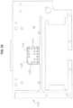
- FIG. 7is a diagram of the various electrical connections of a printed circuit board assembly provided with the cartridge member
- FIG. 8is a top plan view of the printed circuit board assembly
- FIG. 9is a bottom plan view of the printed circuit board assembly
- FIG. 10is a top view of the upper (top) layer of the printed circuit board assembly
- FIG. 11is a top view of the lower (bottom) layer of the printed circuit board assembly
- FIG. 12is a plan view showing certain electrical connections of the electrosurgical tissue treatment device
- FIG. 13is a close-up view of the shaft assembly of the device.
- FIG. 14is a close-up cross-sectional view of the electrodes of the device of FIG. 1 taken along line 14 - 14 of FIG. 13 ;
- FIG. 15is a close-up cross-sectional view of a distal end portion of the device of FIG. 1 taken perpendicular to line 14 - 14 of FIG. 13 ;
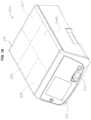
- FIG. 16is a perspective view of an electrosurgical unit according to one embodiment of the invention.
- FIG. 17is a perspective view of the electrosurgical unit with the cartridge member of the cartridge assembly installed
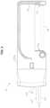
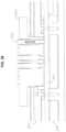
- FIG. 18is a perspective view of the electrosurgical unit
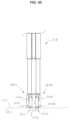
- FIG. 19is a front perspective view of the electrosurgical unit's docking assembly with a movable docking mechanism in the up (non-use) position prior to the docking mechanism engaging with the cartridge member;
- FIG. 20is a front view of the docking assembly with the docking mechanism in the up position
- FIG. 21is a right side view of the docking assembly with the docking mechanism in the up position
- FIG. 22is a left side view of the docking assembly with the docking mechanism in the up position
- FIG. 23is a rear view of the docking assembly with the docking mechanism in the up position
- FIG. 24is a top view of the docking assembly with the docking mechanism in the up position
- FIG. 25is a rear perspective view of the docking assembly with the docking mechanism in the up position
- FIG. 26is a rear perspective view of the docking assembly with the docking mechanism in the down (use) position;
- FIG. 27is a rear perspective view of a locking mechanism with the docking mechanism in the up position
- FIG. 28is rear perspective view of the locking mechanism of with the docking mechanism in the down position
- FIG. 29is an exploded view of the cartridge member, upper receptacle enclosure, lower receptacle enclosure and a fluid delivery apparatus;
- FIG. 30is a cross sectional view taken through cartridge member, upper receptacle enclosure, lower receptacle enclosure and a fluid delivery apparatus at line 30 - 30 of FIG. 24 ;
- FIG. 31is a perspective view of the upper receptacle enclosure with a radio-frequency power delivery apparatus
- FIG. 32is a side view of the upper receptacle enclosure with the radio-frequency power delivery apparatus
- FIG. 33is a bottom view of the upper receptacle enclosure with a radio-frequency power delivery apparatus
- FIG. 34is a perspective view of an electrical contact assembly for the radio-frequency power delivery apparatus comprising an electrical insulator/carrier and electrical contacts;
- FIG. 35is a cross sectional perspective view of the electrical contact assembly of FIG. 34 ;
- FIG. 36is a cross sectional view of the electrical contact assembly and cartridge member
- FIG. 37is a front view of one embodiment of a system of the present invention having electrosurgical unit in combination with a fluid source and handheld electrosurgical tissue treatment device;
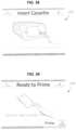
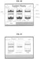
- FIG. 38is a display screen for the electrosurgical unit requesting insertion of the cartridge member
- FIG. 39is a display screen for the electrosurgical unit requesting priming of the electrosurgical tissue treatment device with fluid
- FIG. 40is a display screen for the electrosurgical unit showing the electrosurgical unit and system is ready for operation;
- FIG. 41is a display screen for the electrosurgical unit showing radio-frequency power is being provided from the unit;
- FIG. 42is an exemplary graph showing a relationship of fluid flow rate Q in units of cubic centimetres per minute (cc/min) on the Y-axis, and the RF power setting P S in units of watts on the X-axis;
- FIG. 43is an exemplary graph of the bipolar RF power output versus impedance for the electrosurgical unit
- FIG. 44is an exemplary graph of the monopolar RF power output versus impedance for the electrosurgical unit
- FIG. 45is a close-up view of a distal end portion of the device of FIG. 1 with an exemplary fluid coupling to a tissue surface of tissue;
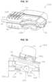
- FIG. 46is a perspective view of the device of FIG. 1 cutting tissue
- FIG. 47is a front perspective view of a cartridge assembly according to another embodiment of the invention.
- FIG. 48is a rear view of the cartridge assembly of FIG. 47 ;
- FIG. 49is a front perspective view of the cartridge assembly of FIGS. 47 - 48 prior to being engaged to an electrosurgical unit;
- FIG. 50is a close-up front view of the cartridge assembly of FIGS. 47 - 48 after being engaged to the electrosurgical unit;
- FIG. 51is a bottom perspective view of a cartridge assembly according to another embodiment of the invention.
- FIG. 52is a side view of the cartridge assembly of FIG. 51 prior to being engaged with an electrosurgical unit.
- FIG. 53is a side view of the cartridge assembly of FIG. 51 after being engaged with the electrosurgical unit.
- the inventions disclosed hereinprovide devices, systems and methods for treating tissue at a tissue treatment site during an electrosurgical procedure.
- the inventions disclosed hereinare particularly useful for procedures where it may be desirable to cut tissue, as well as shrink, coagulate and seal tissue against blood and other fluid loss, for example, by shrinking lumens of blood vessels (e.g., arteries, veins).
- blood vesselse.g., arteries, veins.
- FIG. 1showing an exemplary handheld electrosurgical device 10 to treat tissue according to one embodiment of the present invention, which may be used in conjunction with a system of the present invention.
- device 10is not intended to be limiting as to the scope of devices, particularly tissue treatment (therapeutic) devices, which can be used with the system of the invention.
- therapeutic devicespertain to devices which treat tissue to cure diseases, relieve pain or for other medical purposes.
- exemplary device 10may comprise an elongated hand-piece 12 having a handle 14 provided by mating handle portions 14 a , 14 b .
- Hand-piece 12may be slender to enable a user of device 10 to hold and manipulate device 10 between the thumb and index finger like a writing instrument such as a pen.
- Hand-piece 12may comprise a sterilizable, rigid, electrically insulative material, such as a plastic material.
- Exemplary plastic materialsmay comprise polycarbonate (PC) and acrylonitrile-butadiene-styrene (ABS).
- Device 10may be coupled to an electrosurgical unit 300 (shown in FIG. 16 ) by a cartridge assembly 16 operable with electrosurgical unit 300 .
- Cartridge assembly 16may comprise a cartridge member 18 which, as shown in FIGS. 2 and 3 , may comprise a substantially planar, elongated, rectangular cartridge body 20 comprising mating cartridge body portions 20 a , 20 b .
- cartridge body 20 amay include a directional indicator 30 to show the direction in which cartridge member 18 is to be installed in electrosurgical unit 300 , as well as which side of the cartridge member 18 is the top surface.
- cartridge body 20 amay include a protruding element 28 , shown in the form of an elongated rib, to physically prevent installation of the cartridge assembly 16 upside down.
- Cartridge body 20may be made of a sterilizable, rigid, electrically insulative material, such as a plastic material.
- Exemplary plastic materialsmay comprise polycarbonate (PC) and acrylonitrile-butadiene-styrene (ABS).
- fluid 502 from a fluid source 500may be communicated through an enclosed fluid passage provided by various structures. Fluid 502 may flow from the fluid source 500 into cartridge member 18 of cartridge assembly 16 through lumen 44 of flexible fluid delivery tubing segment 46 .
- fluid delivery tubing segment 46may particularly couple to fluid source 500 through a drip chamber 48 after the fluid source 500 may be penetrated with a spike 50 located at the end of the drip chamber 48 in a known manner. In other embodiments, drip chamber 48 may be eliminated and tubing segment 46 may be attached directly to a spike 50 .
- Fluid delivery tubing segment 46may be made of a plastic material, such as flexible polyvinyl chloride (PVC) or other flexible material such as an elastomer.
- PVCflexible polyvinyl chloride
- fluid delivery tubing segment 46may be coupled and tightly fastened with a fluid tight connection to cartridge body 20 b of cartridge member 18 via a female connector portion 60 . More particularly, fluid delivery tubing segment 46 may be coupled to cartridge body 20 b via a distal end portion of the tubing segment 46 extending into a cylindrical cavity 62 formed in cartridge body 20 b to provide a cylindrical receptacle.
- the outer surface of fluid delivery tubing segment 46may be configured to mate against and form a press (interference) fit seal with corresponding inner surfaces of connector portion 60 to provide a fluid tight seal there between.
- An adhesive or solvent bondingmay be used there between to further strengthen the seal, or in lieu of the press fit.
- the fluid passagemay extend through a through hole 64 provided at the base of cavity 62 and may be next provided and defined by an elongated enclosed channel 68 formed by overlying portions of cartridge bodies 20 a , 20 b .
- channel 68may be formed by mating a channel portion 68 a of cartridge body 20 a with a channel portion 68 b of cartridge body 20 b and forming a continuous hermetic seal there between, particularly by vibration, ultrasonic or other plastic welding method.
- a portion of the fluid delivery passagemay be located in the cartridge assembly 16 , and more particularly the cartridge member 18 (provided by tubing segment 46 and channel 68 ), and more particularly defined thereby (channel 68 ).
- fluid delivery tubing segment 78may be coupled and tightly fastened with a fluid tight connection to cartridge body 20 b of cartridge member 18 via male connector portions 74 and 82 provided by two spaced, parallel, fixed supports 84 and 86 at the opposite ends thereof. More particularly, fluid delivery tubing segment 78 may be coupled to cartridge body 20 b via male connector portions 74 and 82 which extend into the lumen 76 of delivery tubing segment 78 .
- fluid delivery tubing segment 78may be configured to mate against and form a press (interference) fit seal with corresponding outer surfaces of connector portions 74 and 82 to provide a fluid tight seal there between.
- An adhesive or solvent bondingmay be used there between to further strengthen the seal, or in lieu of the press fit.
- fluid delivery tubing segment 78may be made of a plastic material, such as flexible polyvinyl chloride (PVC) or other flexible material such as an elastomer.
- PVCflexible polyvinyl chloride
- the cartridge assembly 16supports tubing segment 78 . More specifically, tubing segment 78 is supported on opposing ends by the cartridge member 18 with the cartridge member 18 within the lumen of the tubing segment 78 .
- fluid delivery tubing segment 78may require a thicker cross-section and durability than the other fluid delivery tubing segments, such as fluid delivery tubing segment 46 .
- fluid delivery tubing segment 78may be configured to be compressed by a fluid delivery apparatus 422 contained within electrosurgical unit 300 , to force fluid 502 through the lumen 76 thereof in a known manner. In such instance, the thicker portion of the fluid delivery tubing for device 10 may be limited to fluid delivery tubing segment 78 .
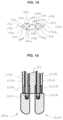
- the fluid passageextends into a cylindrical chamber 90 of a one-way (check) diaphragm valve 38 ( FIG. 1 ) provided and defined chamber portions 90 a and 90 b which are separated by a flat disc shaped plastic membrane 92 .
- valve 38fluid 502 only may flow in one direction.
- membrane 92may be positioned towards the end of chamber portion 90 a and fluid may be allowed to pass through chamber 90 and into through hole 98 to exit chamber 90 .
- membrane 92may be positioned on seat 96 in a cavity of cartridge body 20 b , which closes the fluid passage and fluid communication between the exit port provided by through hole 98 and the inlet port provided by through hole 80 . Furthermore, membrane 92 inhibits fluid 502 from flowing through valve 38 if the fluid pressure is less than about 3.5 psi.
- the cartridge assembly 16and more particularly the cartridge member 18 , may include a valve 38 in fluid communication with the fluid delivery passage.
- fluid 502may not flow through valve 38 to handpiece 12 in the event fluid 502 is introduced to the fluid passage before cassette member 18 may be installed in electrosurgical unit 300 , but rather will only open to permit flow there through when a pressure of greater than 3.5 is provided by fluid delivery apparatus 420 after cartridge member 18 has been installed in electrosurgical unit 300 .
- fluid passagemay extend into lumen 104 of fluid delivery tubing segment 106 .
- tubing segment 106may be coupled and tightly fastened with a fluid tight connection to cartridge body 20 a of cartridge member 18 via a female connector portion 110 .
- fluid delivery tubing segment 106may be coupled to cartridge body 20 a via a distal end portion of the tubing segment 106 extending into a cylindrical cavity 112 formed by cartridge body 20 a to provide a cylindrical receptacle.
- the outer surface of fluid delivery tubing segment 106may be configured to mate against and form a press (interference) fit seal with corresponding inner surfaces of connector portion 110 to provide a fluid tight seal there between.
- tubing segment 106may be molded and formed unitary with cord 40 , such as by plastic co-extrusion, to provide a single cable 42 .
- female connector portion 110may be replaced with a male connector portion 74 having a through hole 72 as previously described.
- Fluid delivery tubing segment 106may be coupled and tightly fastened with a fluid tight connection to cartridge body 20 a of cartridge member 18 via male connector portion 74 being configured to extend into the lumen 104 of delivery tubing segment 106 .
- the inner surface of lumen 104 of fluid delivery tubing segment 106may be configured to mate against and form a press (interference) fit seal with corresponding outer surfaces of connector portion 74 to provide a fluid tight seal there between.
- An adhesive or solvent bondingmay be used there between to further strengthen the seal, or in lieu of the press fit.
- fluidmay be allowed to pass through chamber 90 and into through hole 72 to exit chamber 90 and into lumen 104 of fluid delivery tubing segment 106 .
- fluid delivery tubing segment 106may enter the proximal end of hand-piece 12 of device 10 .
- fluid delivery tubing segment 106may be connected to the inlet branch of a Y-splitter 118 , which thereafter provides two outlet branches which are connected to the proximal ends of fluid delivery tubing segments 120 a , 120 b .
- the distal ends of delivery tubing segments 120 a , 120 bmay thereafter be connected to the proximal ends of shafts 124 a , 124 b .
- the lumens 122 a , 122 b of the fluid delivery tubing segments 120 a , 120 bmay be interference fit over the outside diameter of shafts 124 a , 124 b to provide an interference fit seal there between.
- An adhesive or solvent bondingmay be used there between to further strengthen the seal, or in lieu of the press fit.
- Fluid 502may then flow through the lumens 126 a , 126 b of shafts 124 a , 124 b and thereafter exit from device 10 as discussed in greater detail below.
- device 10may include an aspiration/suction tubing segment to remove fluid 502 from a tissue treatment site.
- the suction tubing segmentmay pass through cartridge member 18 and thereafter be connected to a vacuum source.
- cartridge assembly 16In addition to operating in conjunction with a fluid delivery apparatus 422 within electrosurgical unit 300 , as discussed in greater detail below, cartridge assembly 16 also operates in conjunction with a radio-frequency power delivery apparatus 440 and other electrical components and circuits within electrosurgical unit 300 . More particularly, radio-frequency power delivery apparatus 440 and fluid delivery apparatus 420 may be components of a docking assembly 340 of electrosurgical unit 300 which is operable with the cartridge assembly 16 configured to couple device 10 with electrosurgical unit 300 .
- cartridge member 18includes a two layer printed circuit board 24 , one side of which may be exposed through an aperture 32 in cartridge body 20 a of cartridge member 18 to provide an electrical communication with electrosurgical unit 300 .
- Printed circuit board 24may comprise a 0.05-0.07 inch thick base insulator with top and bottom conductive layers deposited thereon. The exposed conductive layers may comprise 2-6 microns of gold over 100-300 microns of electroless nickel over copper. Detailed drawings of printed circuit board 24 may be found in FIGS. 7 - 11 .
- printed circuit board 24includes a plurality of electrical contacts thereon, which may comprise electrical contact pads to electrically connectable with corresponding electrical contacts of electrosurgical unit 300 . Certain of these electrical contacts and their associated function will now be discussed.
- Bipolar radio-frequency power from electrosurgical unit 300may be provided from outputs BP+ and BP ⁇ thereof.
- electrical contacts J 10 /J 27may receive power from bipolar power output BP+ which may then communicated along an electrically conductive pathway to electrical contacts J 25 /J 28 .
- Electrical contacts J 11 /J 16may receive power from bipolar power output BP ⁇ which may then communicated along an electrically conductive pathway to electrical contacts J 26 /J 29 .
- Electrical contacts J 10 /J 27 and J 11 /J 16are shown in FIG. 8
- electrical contacts J 25 /J 28 and J 26 /J 29are shown in FIG. 9 .
- electrical contacts J 28 and J 29may be coupled to the proximal end of insulated wire conductors 130 a and 130 b , respectively, of electrical cord 40 .
- the distal end of insulated wire conductors 130 a , 130 bmay ultimately couple with the bipolar electrodes 180 a , 180 b of device 10 as discussed in greater detail below.
- electrosurgical unit 300may be operated in a monopolar mode with monopolar power provided through power output BP+, in which case power output BP ⁇ is no longer utilized. Rather, as shown in FIG. 12 , an additional cord 132 may be utilized to connect a ground pad dispersive electrode 134 , which is located on the patient, to the electrosurgical unit 300 using wire conductor 136 and plug 138 at the end thereof which connects to the ground pad receptacle 308 (as shown in FIGS. 16 and 17 ).
- an electrode of device 10is used in conjunction with ground pad dispersive electrode 134 which is placed on the patient (also known as a patient return electrode or neutral electrode), typically on the back or other suitable anatomical location.
- An electrical circuitmay then be formed between the electrode of device 10 and ground pad dispersive electrode 134 with electrical current flowing from the device electrode through the patient to ground pad dispersive electrode 134 in a manner known in the art.
- the ground pad electrode 134 located on the patientis not required, and a second electrode providing an electrical pole may be provided as part of device 10 .
- An alternating current electrical circuitmay then be created between the first and second electrical poles of the device. Consequently, alternating current no longer flows through the patient's body to the ground pad electrode 134 , but rather through a localized portion of tissue between the poles of the bipolar electrodes.
- Monopolar and bipolar powermay be provided from electrosurgical unit 300 in a manner known in the art.
- a control signal from electrosurgical unit 300may be provided to electrical contact J 14 , which may be configured to receive a control signal from electrosurgical unit 300 as part of a control circuit configured to control bipolar power output. The control signal may then communicated along an electrically conductive pathway to electrical contact J 23 .
- electrical contact J 23may be coupled to the proximal end of insulated wire conductor 142 of electrical cord 40 .
- the distal end of insulated wire conductor 142may be coupled to a radio-frequency power hand-switch activation assembly 146 within hand-piece 12 .
- Hand-switch assembly 146may comprise push button 148 which overlies a domed switch on a platform comprising a printed circuit board, with the construction and wiring of the hand-switch assembly 146 known in the art.
- the domed switch beneath push button 148may form a closed circuit which enables the control signal, here comprising a relatively low voltage direct current, to return and be sensed by electrosurgical unit 300 , generally via wire conductor 142 , which then accordingly provides bipolar power.
- the button 148is released, the control circuit may open and the electrosurgical unit 300 may no longer receives the control signal to activate radio-frequency power. Consequently, the electrosurgical unit 300 may then deactivate the bipolar radio-frequency power output.
- a control signal from electrosurgical unit 300may be provided to electrical contact J 15 , which may be configured to receive a control signal from electrosurgical unit 300 as part of a control circuit configured to control monopolar power output. The control signal may then communicated along an electrically conductive pathway to electrical contact J 24 . While not shown in FIG. 5 , electrical contact J 24 may be coupled to the proximal end of insulated wire conductor 144 of electrical cord 40 . As shown in FIG. 12 , the distal end of insulated wire conductor 144 may be coupled to a radio-frequency power hand-switch activation assembly 152 within hand-piece 12 .
- Hand-switch assembly 152may comprise push button 154 which may overlie a domed switch on a platform comprising a printed circuit board, with the construction and wiring of the hand-switch assembly 152 known in the art.
- the domed switch beneath push button 154may form a closed circuit which enables the control signal, here comprising a relatively low voltage direct current, to return and be sensed by electrosurgical unit 300 , generally via wire conductor 144 , which then accordingly provides monopolar power.
- the control circuitmay open and the electrosurgical unit 300 may no longer receive the control signal to activate radio-frequency power. Consequently, the electrosurgical unit 300 may then deactivate the monopolar radio-frequency power output.
- Exemplary hand switch assembliesmay be found in U.S. Publication No. 2006/0149225, published Jul. 6, 2006, and U.S. Publication No. 2005/0090816, published Apr. 28, 2005, which are assigned to the assignee of the present invention and are hereby incorporated by reference in there entirety to the extent they are consistent.
- Electrosurgical unit 300may also be configured to receive a stream of serial data including certain operating parameters and other information from cartridge assembly 16 , and more particularly cartridge member 18 , concerning the set-up and/or operation of device 10 .
- cartridge member 18may be configured to provide tissue treatment device information to the electrosurgical unit 300 from a tangible storage medium configured to store the tissue treatment device information.
- the tangible storage mediummay be in the form of an electronic memory 26 (also shown at U 1 in FIG. 7 ) located on printed circuit board 24 , and more particularly an electrically erasable programmable read only memory (EEPROM) in which to store such operating parameters and other information.
- EEPROMelectrically erasable programmable read only memory
- the tissue treatment device information provided with memory 26may include a unique identifier (e.g. model number and serial number) and a fixed time period operable with a use of device 10 (e.g. 24 hours) from the time of first radio-frequency activation which is then stored by electrosurgical unit 300 for future reference.
- Memory 26may included at least one operating parameter such as default settings operable with a use of device 10 .
- the tissue treatment device informationmay comprise at least one of a radio-frequency power delivery apparatus setting and a fluid delivery apparatus setting operable with a use of device 10 , such as radio-frequency power level setting and fluid flow level setting for device 10 .
- Tissue treatment device informationmay also comprise a plurality of radio-frequency power delivery apparatus settings operable with a use of device 10 and at least one fluid delivery apparatus setting corresponding to each of the radio-frequency power delivery apparatus settings.
- memory 26may include settings for a range of radio-frequency power levels and fluid flow levels operable with a use of device 10 , which extend from a minimum radio-frequency power level and minimum fluid flow level to a maximum radio-frequency power level and maximum fluid flow level for device 10 .
- Memory 26may also include operating parameters such as one or more relationships which relate fluid flow level to the radio-frequency power level over a range of fluid flow levels and radio-frequency power levels for device 10 . As shown in FIG. 7 , data may be received by electrosurgical unit 300 from memory 26 via electrical contacts J 1 to J 4 .
- Printed circuit board 24also may include electrical contacts J 12 and J 13 which may be configured to detect moisture or wetness on printed circuit board 24 .
- Contacts J 12 and J 13may be configured to be part of a moisture monitoring circuit provided with a predetermined impedance. If the impedance between the contacts J 12 and J 13 decreases, such as may occur if fluid 502 where to form a bridge between the contacts thus electrically coupling the contacts, electrosurgical unit 300 may cease operation until the predetermined impedance value is attained.
- Cartridge member 18and in particular printed circuit board 24 , also may include electrical contacts which are configured to receive power for additional features and accessories of device 10 including, for example a light, such as a light emitting diode (LED) or fiber optic light, to illuminate a tissue treatment site during a surgical procedure.
- a lightsuch as a light emitting diode (LED) or fiber optic light
- the LEDmay require a relatively low power, such as a magnitude of 4-5 volts DC (direct current).
- Cartridge member 18 , and in particular printed circuit board 24may also include electrical contacts which are configured to provide connection and transmit signals to a video recording source to record video, for example, of a tissue treatment site during a surgical procedure, which may be viewed by a video camera, such as a digital or fiber optic video camera, provided with device 10 .
- a video camerasuch as a digital or fiber optic video camera
- insulated wire conductors 130 a , 130 bmay be coupled to a proximal portion of shafts 124 a , 124 b of shaft assembly 128 within hand-piece 12 .
- shaft assembly 128 of device 10may comprise two parallel, self-supporting, electrically conductive hollow shafts 124 a , 124 b , which comprise metal such as stainless steel tubing. Carried by and connected to the distal ends of shafts 124 a , 124 b may be two laterally and spatially separated (by empty space) contact elements comprising electrodes 180 a , 180 b which may be configured as minor images in size and shape, and have a blunt distal end with a surface devoid of edges (to provide a uniform current density) to treat tissue.
- electrodes 180 a , 180 bmay comprise an electrically conductive metal, such as stainless steel.
- Other suitable materialsmay include titanium, gold, silver and platinum.
- one or both shafts 124 a , 124 bmay be made of electrically non-conducting material except for the portion at the distal end that comes in contact with electrodes 180 a , 180 b .
- an insulated wire conductormay extend and be joined to the electrically conducting portion of shaft 124 a , 124 b .
- shafts 124 a , 124 bmay completely comprise electrically non-conducting material, in which case an insulated wire conductor would extend and be joined directly to electrodes 180 a , 180 b.
- each electrode 180 a , 180 bmay comprise an elongated portion 182 a , 182 b .
- elongated portion 182 a , 182 bmay have a length in the range between and including 2 mm to 6 mm, and more specifically have a length of 3 mm to 5 mm.
- the spatial gap separation GS between electrodes 180 a , 180 bmay be in the range between and including 0.1 mm to 4 mm, and more specifically 1 mm to 2.5 mm, and more specifically 1.5 mm to 2.3 mm.
- opposing concave sides 192 a / 194 a of elongated portion 182 amay converge laterally to provide a wedge shaped blade portion 196 a , 196 b which terminates in a lateral cutting edge 198 a , 198 b which extends longitudinally along a length of each electrode 180 a , 180 b .
- lateral cutting edge 198 a , 198 bmay transition smoothly onto the distal end of each electrode 180 a , 180 b and forms a portion of the distal end of each electrode 180 a , 180 b.
- Lateral cutting edge 198 a , 198 bmay be configured to cut tissue electrosurgically in the presence of monopolar radio frequency energy from electrosurgical unit 300 , without any fluid 502 being provided from fluid source 500 .
- lateral cutting edge 198 a , 198 bmay be configured to cut tissue with fluid 502 being provided simultaneously from device 10 , or be configured to cut tissue mechanically without electrosurgical energy.
- two cutting edges 198 a , 1988 bare shown, only one of the edges 198 a or 198 b may be configured to cut tissue electrosurgically or mechanically. In such instance, the blade portion of one electrode may be eliminated and the elongated portion may be completely cylindrical.
- electrodes 180 a , 180 b and elongated portions 182 a , 182 bmay terminate in distal end portion 186 a , 186 b .
- the distal end portion 186 a , 186 b of electrodes 180 a , 180 bmay be configured to move and slide with painting action across a tissue surface in the presence of bipolar radio frequency energy from electrosurgical unit 300 and fluid 502 from the fluid source 500 .
- the distal end portion 186 a , 186 b of each electrode 180 a , 180 bhas a blunt, rounded shape which provides a smooth contour surface.
- distal end portion 186 a , 186 b of each electrode 180 a , 180 bmay comprise a spherical portion 190 a , 190 b .
- spherical portion 190 a , 190 bmay have a radius in the range between and including 0.5 mm to 1.5 mm, and more specifically 0.75 mm to 1.15 mm.
- each electrode 180 a , 180 bmay include a longitudinally oriented linear blind bore 200 a , 200 b and counter bore 202 a , 202 b . As shown in FIG.
- the outside diameter of a distal end portion of each shaft 124 a , 124 bmay be configured to extend into counter bore 202 a , 202 b of electrodes 180 a , 180 b and fit with the diameter of counter bore 202 a , 202 b , with the distal end of each shaft 124 a , 124 b in contact with the bottom of the counter bore.
- the electrodes 180 a , 180 b and shafts 124 a , 124 bmay then be welded together.
- the outside diameter of shafts 124 a , 124 bmay be configured to fit with the diameter of counter bore 202 a , 202 b to form a press (interference) fit to provide a secure connection.
- electrodes 180 a , 180 bmay be assembled to shafts 124 a , 124 b by threaded engagement.
- electrodes 180 a , 180 bmay be detachably assembled to shafts 124 a , 124 b such that they may be removed from the shafts 124 a , 124 b , particularly manually by human hand.
- electrodes 180 a , 180 bmay also include a through bores 204 a / 206 a and 204 b / 206 b which perpendicularly intersects bore 200 a , 200 b and perpendicularly intersect one another to provide outlets 208 a / 210 a / 212 a / 214 a and 208 b / 210 b / 212 b / 214 b for fluid 502 .
- fluid 502flows through the lumens 126 a , 126 b of shafts 124 a , 124 b , fluid 502 then flows through into the tubular passage provided by blind bore 200 a , 200 b and then into the tubular passage provided by through bores 204 a / 206 a and 204 b / 206 b where it thereafter exits device 10 from fluid outlets 208 a / 210 a / 212 a / 214 a and 208 b / 210 b / 212 b / 214 b , which are all proximal to distal end portion 186 a , 186 b of electrodes 180 a , 180 b .
- fluid outlets 208 a / 212 a and 208 b / 212 bmay be defined by the cylindrical portion 184 a , 184 b of electrodes 180 a , 180 b
- fluid outlets 210 a / 1214 a and 210 b / 214 bmay be defined by sides of 192 a / 194 a and 192 b / 194 b of blade portion 196 a , 196 b and adjacent cutting edge 198 a , 198 b.
- a portion of the lengths of shafts 124 a , 124 bmay be surrounded by and encapsulated in a common outer member 216 , which may comprise a flexible plastic material.
- Outer member 216may electrically insulate the exposed length of shafts 124 a , 124 b.
- Outer member 216may be formed by injection molding.
- a sub-assemblycomprising electrodes 180 a , 180 b and shafts 124 a , 124 b may be placed in an injection mold prior to the introduction of the plastic material. Thereafter, the mold may be closed and a thermoplastic may be injected into the unoccupied portions of the mold cavity to overmold and mold-in place portions of the sub-assembly as shown in FIG. 13 .
- retainer clips(not shown) may provide the benefit of retaining shafts 124 a , 124 b in position relative to each other to better ensure that the shafts 124 a , 124 b are centrally located within the polymer molding.
- shafts 124 a , 124 b of device 10may be malleable to provide a malleable shaft assembly 128 .
- a distal portion of shafts 124 a , 124 bmay be bendable at an angle relative to the longitudinal axis of the proximal portion of shafts 124 a , 124 b during manufacturing of device 10 so they may be provided to users of device 10 at various angles.
- anglemay range from 5 degrees to 90 degrees, and more particularly, 15 degrees to 45 degrees, and even more particularly 30 degrees.
- malleablemeans able to be shaped, particularly by bending (without a mechanical mechanism, such as a hinge or joint).
- shaft assembly 128may independently maintain the shape associated with the selected bent shape, and does not require additional components (e.g., pull wires, etc.) to maintain the selected bent shape.
- shaft assembly 128may maintain the selected shape such that when device 10 is used to treat tissue, and will not overtly deflect from the selected shape.
- shaft assembly 128may be constructed such that a user can readily re-shape the shafts back to a straight state and/or other desired bent configurations.
- Outer member 216in addition to electrically insulating shafts 124 a , 124 b from one another, has been found to be particularly useful in facilitating the hand shaping of shafts 124 a , 124 b of shaft assembly 128 simultaneously and with a similar contour without cracking and maintaining the tip spacing. In this manner, surgeons and other users of device 10 need not bend the shafts 124 a , 124 b individually.
- shafts 124 a , 124 bmay have an outer wall diameter of 0.063 inches and an inner wall diameter of 0.032 inches.
- Shafts 124 a , 124 balso are particularly made from 304 stainless steel with a temper from 1 ⁇ 2 to 3 ⁇ 4 hard, 130,000 to 150,000 psi. (pounds per square inch) tensile strength) and an elongation at break of 40%.
- Shafts 124 a , 124 b with the foregoing propertiesprovide sufficient stiffness as not to be too pliable during normal use of device 10 , while at the same time inhibiting the shafts 124 a , 124 b from kinking or breaking when shaped for application.
- shafts 124 a , 124 bmay kink, and when the wall thickness may be too thick, the shafts 124 a , 124 b may be too stiff. Furthermore, a shaft 124 a , 124 bb with a larger diameter may also kink more than a shaft of smaller diameter. Shafts 124 a , 124 b may also be malleable for a portion of the length or full length depending on application. For example, the shafts 124 a , 124 b can be made with variable stiffness along the length and be malleable only for a distal portion thereof. This may be performed by controlled annealing of the shafts 124 a , 124 b only in the area where malleability may be desired.
- electrosurgical unit 300may include a front control panel 302 .
- Front control panel 302may include a power (on/off) switch 304 and touchscreen graphical user interface (GUI) 306 .
- Front panel 302also may include a ground pad receptacle 308 as well as a cartridge receptacle 310 configured to receive cartridge member 18 of cartridge assembly 16 , which is shown installed in FIG. 17 .
- electrosurgical unit 300may include an AC power supply 320 , radio-frequency power source/generator 322 , controller 338 , including a central processing unit (CPU) and memory, and cartridge docking assembly 340 all interconnected and designed to communicate and function as an electrosurgical unit which provides radio-frequency power in a manner known in the art.
- controller 338including a central processing unit (CPU) and memory
- cartridge docking assembly 340all interconnected and designed to communicate and function as an electrosurgical unit which provides radio-frequency power in a manner known in the art.
- electrosurgical unit 300may include a docking assembly 340 with cartridge member 18 placed between upper receptacle enclosure 348 and lower receptacle enclosure 350 .
- Front, right side, left side, rear and top views of the docking assembly 340 with a moveable docking mechanism 410 in the up (non-use) position prior to engaging with cartridge member 18are shown in FIGS. 20 - 24 , respectively. Operation of the docking assembly 340 will now be discussed in greater detail, with FIGS. 20 - 24 presented as needed.
- upper receptacle enclosure 348 and lower receptacle enclosure 350have been hidden to better show the operation of docking assembly 340 .
- the distal end 22 of cartridge member 18may first interact with engagement mechanism 342 , which is to inhibit the cartridge member 18 from inadvertently sliding out of receptacle 310 and separating from electrosurgical unit 300 , as well as releaseably engage the cartridge member 18 when sufficient removal force may be applied to the engagement mechanism 342 to disengaged the cartridge member 18 and retract it from receptacle 310 .
- the engagement mechanism 342may comprise a spring loaded ball 344 which may enter a detent 34 (shown in FIG. 3 ) which may be provided as part of the lower cartridge enclosure 350 (not shown). Engagement mechanism 342 may act to hold the cartridge member 18 in a temporary fixed use position relative to the electrosurgical unit 300 . As the cartridge member 18 is inserted into receptacle 342 , the lower surface of cartridge body 20 b slides over the spring loaded ball 344 with a sufficient insertion force to overcome the bias/compression force of the spring 346 and retract the ball 344 . As the cartridge member 18 thereafter reaches its use position, the ball 344 may enter a detent 34 formed in cartridge body 20 b (shown in FIG.
- the engagement mechanism 342may provide the user with tactile feedback that the cartridge member 18 has been properly received by electrosurgical unit 300 .
- the spring 346may again be compressed and the ball 344 removed from the detent 34 to facilitate removal of the cartridge member 18 from the electrosurgical unit 300 .
- the cartridge assembly 16may be configured to engage with and configured to disengage from the electrosurgical unit 300 .
- the cartridge assembly, and particularly the cartridge member 18may be configured to engage with a releasable mechanical engagement mechanism (i.e. engagement mechanism 342 ) of the electrosurgical unit 300 .
- the cartridge assembly 16 , and particularly the cartridge member 18may be configured to engage the electrosurgical unit 300 with an interference fit. In other words, a fit made between, for example, the size or shape of two parts such that force is required for assembly or disassembly.
- the docking assembly 340is configured to engage with and configured to disengage from the cartridge assembly 16 . Furthermore, the docking assembly is configured to engage the cartridge assembly 16 with an interference fit.
- cartridge member 18may now make contact with a two position contact switch 354 which, when cartridge member 18 is absent, is in the open position.
- a two position contact switch 354which, when cartridge member 18 is absent, is in the open position.
- an electrical circuit in the electrosurgical unit 300may be closed which provides a signal to a controller 338 within electrosurgical unit 300 that a cartridge member 18 has been fully inserted into cartridge receptacle 310 .
- electrosurgical unit 300may now energize a solenoid 356 .
- solenoid 356may retract armature 358 , which may be coupled to lever 360 by pull bar 362 . Consequently, upon retraction of armature 358 , lever 360 may be rotated about pivot 364 and lever portion 366 rotates downward from its non-use (unengaged) position, as shown in FIG. 25 , to its use (engaged) position, as shown in FIG. 26 . As lever portion 366 rotates downward, pin 368 may enter cylindrical cavity 36 formed in cartridge body 20 a . Pin 368 may performs multiple functions. First, pin 368 provides a locking mechanism to prevent inadvertent removal or dislodging of cartridge member 18 while electrosurgical unit 300 is ready for operation. Pin 368 may also provides a releasable locating/positioning mechanism to further position cartridge member 18 relative to electrosurgical unit 300 in addition to engagement mechanism 342 .
- Lever 360may be pulled downward to its use (engaged) position with sufficient force to overcome the bias/compression force of spring 370 , which thereafter returns lever 360 to its non-use position when power is removed from solenoid 356 and armature 358 is free to extend.
- lever portion 376As lever 360 is rotated about pivot 364 , lever portion 376 , which is opposite lever portion 366 , may rotate upward about pivot 364 . As shown in FIG. 27 and FIG. 28 , lever portion 376 includes a catch 378 in the form of a notch into which locking pin 380 with roller 388 may enter and be captured as a result of the rotation of lever 360 .
- lever 384(shown in phantom in FIGS. 27 and 28 ), which rotates about pivot 386 , may only travel rearward based on the length of catch 378 .
- pin roller 388makes contact with the rearward surface 382 of catch 378
- lever 384may now be prevented from further rearward travel relative to lever 360 due to roller 388 contacting lever 384 .
- an optical sensormay then provide a signal to a controller within the electrosurgical unit 300 that lever 360 is in such position.
- electrosurgical unit 300may now activate electric motor 396 which turns shaft 398 via a gearbox 400 .
- Shaft 398may provide an axle for cam 402 which, as a result of the rotation of shaft 398 , contacts surface 404 of lever 384 .
- lever 384may travel rearward until roller 388 makes contact with the rearward surface 382 of catch 378 .
- surface 404now provides a fixed load bearing surface against cam 402 .
- movable docking mechanism 410may rotates downward and moves radially about pivot 412 (shown in FIG. 22 ) against the bias/tension force of spring 414 (shown in FIG. 23 ) until it reaches its use position as sensed by an optical sensor. Docking mechanism 410 is now in its use (engaged) position. In other words, ready to deliver radio-frequency power and fluid as designed. After use of electrosurgical unit 300 is complete, a user may eject cartridge member 18 from unit 300 by selecting such control on unit 300 , and the reverse of the docking procedure may be performed.
- electrosurgical unit 300may be configured to return docking mechanism 410 upward to its non-use position and allow cartridge member 18 to be removed.
- armature 358may be free to extend and lever portion 366 of lever 360 rotates upward about pivot 364 due to the force of spring 370 to remove pin 368 from cylindrical cavity 36 formed in cartridge body 20 a .
- lever portion 376 of lever 360may rotate downward about pivot 364 to disengage locking pin 380 with roller 388 from catch 378 .
- lever 384may now be free to move rearward about pivot 386 .
- the force of spring 414may then overcomes the force of spring 416 and move lever 384 rearward, releasing cam 402 from acting on surface 404 .
- cam 402releases from surface 404
- docking mechanism 410may be rotated upwards about pivot 412 due to the force of spring 414 .
- cam 402rotates back to the not in use position
- lever 384moves forward about pivot 386 due to the force of spring 416 . In this manner, locking pin 380 and roller 388 may now be positioned to be received by catch 378 .
- FIG. 29shows an exploded view of the cartridge member 18 , upper receptacle enclosure 348 , lower receptacle enclosure 350 and a fluid delivery apparatus 420 .
- Fluid delivery apparatus 420may comprise a peristaltic pump assembly 422 , and more specifically a rotary peristaltic pump assembly.
- compression elements shown as pinch rollers 424 of pump head 434rotate about shaft 426 which may be turned by motor 428 .
- rollers 424may engage and compress pump tubing segment 78 in a known manner against opposing load bearing surface 430 of semi-circular shoe or base compression member 432 to pump fluid 502 from the fluid source 500 to the hand-held device 10 .
- Fluid 502may be conveyed by peristaltic pump assembly 422 by waves of contraction placed externally on the delivery tubing segment 78 which are produced mechanically by rotating pinch rollers 424 which rotate on drive shaft 426 and intermittently compress the delivery tubing segment 78 against support surface 430 .
- Peristaltic pumpsare generally preferred, as the electro-mechanical force mechanism, here rollers 424 driven by electric motor 428 , does not make contact with the fluid 502 , thus reducing the likelihood of inadvertent contamination.
- a portion of the fluid delivery passageis defined by the delivery tubing segment 78 , and delivery tubing segment 78 may be operable with the fluid delivery apparatus 420 of the electrosurgical unit 300 . More particularly, delivery tubing segment 78 is configured to be compressed by the fluid delivery apparatus 420 of the electrosurgical unit 300 .
- drive coupling 438contacts radio-frequency power delivery apparatus 440 and pushes an electrical contact assembly 442 linearly downwards towards printed circuit board 24 of cartridge member 18 against the bias/compression force of spring 444 .
- spring 444raises electrical contact assembly 442 away from printed circuit board 24 and to its non-use position.
- both power delivery apparatus 440 and fluid delivery apparatus 420move simultaneously to save time as compared to if they were to move sequentially, as well jointly, thus requiring only one shared drive mechanism, here comprising motor 396 , rather than two separate drive mechanisms.
- electrical contact assembly 442may extend through an aperture 452 in upper receptacle enclosure 348 .
- electrical contact assembly 442may comprise a plurality of electrical contacts 446 which extend through an electrical insulator/carrier 448 .
- electrical contacts 446may be configured to mate and electrically communicate with the electrical contacts of printed circuit board 24 , as well as the electric components and circuitry of electrosurgical unit 300 in a manner known in the art.
- Electrical contacts 446may comprise a plurality of pogo (spring loaded) pins. As the pogo pins 446 make contact with printed circuit board 24 , the pins 446 retract under load in a known manner until electrical insulator/contact carrier 448 may be positioned in contact with printed circuit board 24 and the pins 446 substantially retract into carrier 448 . As shown in FIG. 36 , an end portion of electrical contact carrier 448 may be configured to fit within aperture 32 of cartridge member 18 .
- radio-frequency power delivery apparatus 440includes springs 450 which will compress upon reaching a load sufficient to overcome the bias/compression force of springs 450 , with such force being lower than the force which may damage printed circuit board 24 . In this manner, printed circuit board 24 may be protected from damage upon engagement with electrical contact assembly 442 .
- Apparatus 440also has the function of aligning contact carrier 448 to aperture 32 of cartridge member 18 .
- the springs 450 and pins 454are designed to allow the contact carrier 448 to float and align to the aperture 32 of cartridge member 18 as carrier 448 enters aperture 32 , then return the contact carrier 448 to a straight position when retracted.
- cartridge assembly 16and in particular cartridge member 18 may be operable with the radio-frequency power delivery apparatus 440 and fluid delivery apparatus 420 of electrosurgical unit 300 .
- FIG. 37shows a view of one embodiment of a system of the present invention having exemplary electrosurgical unit 300 in combination with a fluid source 500 and a handheld device 10 .
- FIG. 37shows a movable cart 504 having a support member 506 comprising a hollow cylindrical post which carries a platform 508 comprising a pedestal table to provide a flat, stable surface for location of the electrosurgical unit 300 .
- cart 504further comprises a fluid source carrying pole 510 having a height which may be adjusted by sliding the carrying pole 510 up and down within the support member 506 and thereafter secured in position with a set screw.
- a fluid source carrying pole 510On the top of the fluid source carrying pole 510 is a cross support provided with loops at the ends thereof to provide a hook for carrying fluid source 500 .
- fluid source 500may comprise a bag of fluid from which the fluid 502 flows through drip chamber 48 after the bag is penetrated with a spike 50 located at the end of the drip chamber 48 .
- drip chamber 48may be eliminated and tubing segment 46 may be attached directly to a spike 50 . Thereafter, fluid 502 flows through flexible delivery tubing segment 46 , cartridge member 18 and delivery tubing segment 106 of cable 42 to hand-piece 12 of device 10 .
- the fluid 502comprises saline solution, and even more specifically, normal (physiologic) saline.
- saline solutionand even more specifically, normal (physiologic) saline.
- other electrically conductive fluidscan be used in accordance with the invention.
- fluid 502may also comprise an electrically non-conductive fluid.
- a non-conductive fluidwhile not providing all the advantage of an electrically conductive fluid, still provides certain advantages over the use of a dry electrode including, for example, reduced occurrence of tissue sticking to the electrodes 180 a , 180 b of device 10 and cooling of the electrodes and/or tissue. Therefore, it is also within the scope of the invention to include the use of a non-conducting fluid, such as, for example, deionized water.
- electrosurgical unit 300is configured to provide both monopolar and bipolar power output.
- electrosurgical unit 300may particularly include a lock out feature which prevents both monopolar and bipolar output from being activated simultaneously.
- a number of touch control screensare presented to the user from the graphical user interface 306 to set up the use of device 10 .
- a display 312is presented to the user requesting insertion of cartridge member 18 .
- controller 338receives a signal of the presence thereof from a sensor. Controller 338 then initiates the movement of docking mechanism 410 from its non-use (unengaged) position to its use (engaged) position.
- controller 338Upon reaching its use (engaged) position, controller 338 receives another signal to indicate such from another sensor. After receiving the signal, controller 338 now may access the memory 26 of cartridge member 18 for certain information stored thereon concerning device 10 .
- electrosurgical unit 300may be configured to receive and read a stream of serial data including certain process parameters and other information from device 10 .
- Controller 338may determine if memory 26 includes a unique identifier such as a serial number for device 10 . If so, the controller 338 may read and store the serial number to its own memory. Controller 338 may also determine if a fixed time period (e.g. 24 hours) for use of device 10 is included in memory 26 . If so, controller 338 may apply the time period to an internal countdown clock, which may begin counting the time period down after the first radio-frequency power activation of unit 300 with device 10 therein. Thereafter, once the time period has expired, controller 338 may be programmed to associate the serial number with an expired device 10 and no longer operate device 10 . In this manner, use of device 10 with cartridge 18 may be limited as intended to a single use disposable to better assure patient safety.
- a fixed time periode.g. 24 hours
- a display 314is presented to the user to confirm that that fluid source 500 has been spiked, and to initiate priming of device 10 with fluid 502 . Priming is desirable to inhibit radio-frequency power activation without the presence of fluid 502 in device 10 .
- display 316is presented to the user indicating that the system is now ready for use. Additionally, display 316 presents the user with a default radio-frequency power level settings 328 and 330 numerically in watts, which may be thereafter increased or decreased by touching radio-frequency power level selectors 332 a , 334 a and 332 b , 334 b , respectively.
- RF power outputmay be set in 1 watt increments in the range of 1 to 40 watts, 5 watt increments in the range of 40 to 100 watts and 10 watt increments in the range of 100 to 300 watts.
- display 316In addition to display 316 presenting a user with a default radio-frequency power level setting, display 316 also presents the user with a plurality of fluid flow settings 336 a , 336 b and 336 c , which correspond to fluid flow settings of low (represented by one fluid droplet), medium (represented by two fluid droplets) and high (represented by three fluid droplets), respectively.
- the appropriate settingwill illuminate when selected to visual indication of such to the user, with the medium (or intermediate) setting generally being the default setting.
- Controller 338 of electrosurgical unit 300may also be programmed to obtain and read the default settings for radio-frequency power level and fluid flow level for device 10 which may be stored in memory 26 and thereafter set the unit 300 to these settings and present these default settings on display 316 .
- Controller 338 of electrosurgical unit 300may be programmed to obtain and read a maximum power level for use of device 10 which is stored in memory 26 . In this manner, electrosurgical unit 300 would not activate its radio-frequency power for device 10 should the user wish to select a radio-frequency power level greater than the maximum power level allotted.
- Controller 338 of electrosurgical unit 300may also be programmed to obtain and read data from memory 26 which relates a speed of the pump assembly 422 , and therefore the throughput of fluid 502 expelled by fluid delivery apparatus 420 , to a particular radio-frequency power level as well as a particular fluid flow setting. In this manner, the fluid flow from device 10 for a particular radio-frequency power level and fluid level may be better controlled and a greater power level would not be available for selection.
- the relationshipsmay be engineered to inhibit undesirable effects such as tissue desiccation, electrode sticking, smoke production and char formation, while at the same time not providing a fluid flow rate Q at a corresponding RF power setting P S which is so great as to provide too much electrical dispersion and cooling at the electrode/tissue interface.
- exemplary relationships Q L , Q M and Q Hare configured to increase the fluid flow rate Q linearly with an increasing radio-frequency power level setting P S for each of three fluid flow rate settings of low, medium and high, respectively.
- the relationships Q L , Q M and Q Hare configured to decrease the fluid flow rate Q linearly with a decrease RF power setting P S for each of three fluid flow rate settings of low, medium and high, respectively.
- the data stored in the memory 26 of device 10is to set a speed of the pump assembly 422 for a particular radio-frequency power level and a particular fluid flow level such that the throughput of fluid delivery apparatus 420 corresponds to the relationships provided in FIG. 42 .
- the datamay be stored in the form of equations, or as numerical data points as part of a database look-up table.
- FIG. 43An exemplary bipolar radio-frequency power output curve of electrosurgical unit 300 is shown in FIG. 43 .
- Impedance Zshown in units of ohms on the X-axis and output power P O is shown in units of watts on the Y-axis.
- the bipolar electrosurgical power (RF)is set to 300 watts.
- the output power P Owill remain constant with the set RF power P S as long as the impedance Z stays between the low impedance cut-off of 30 ohms and the high impedance cut-off of 120 ohms.
- Below an impedance Z of 30 ohmsthe output power P O will decrease as shown by the low impedance ramp. Above an impedance Z of 120 ohms, the output power P O will also decrease as shown by the high impedance ramp.
- an exemplary monopolar radio-frequency power output curve of electrosurgical unit 300is shown in FIG. 44 .
- Impedance Zshown in units of ohms on the X-axis and output power P O is shown in units of watts on the Y-axis.
- the bipolar electrosurgical power (RF)is set to 300 watts.
- the output power P Owill remain constant with the set RF power P S as long as the impedance Z stays between the low impedance cut-off of 200 ohms and the high impedance cut-off of 800 ohms.
- Below an impedance Z of 200 ohmsthe output power P O will decrease as shown by the low impedance ramp. Above an impedance Z of 800 ohms, the output power P O will also decrease as shown by the high impedance ramp.
- hand-piece 12 and electrosurgical unit 300may be connected by cartridge assembly 16 a as shown in FIG. 47 - 50 .
- electrosurgical unit 300is configured to connect with cartridge assembly 16 a , and in particular cartridge member 18 .
- cartridge member 18may again comprise a cartridge body 20 having mating cartridge body portions 20 a , 20 b .
- cartridge body 20may include a directional indicator 30 to show the direction in which cartridge member 18 is to be installed in electrosurgical unit 300 .
- fluid delivery tubing segment 46extends through a tubular aperture 52 formed in cartridge body 20 .
- Fluid delivery tubing segment 46then may be connected with a first end of fluid delivery tubing segment 78 , which is configured to operate specifically with fluid delivery apparatus 420 (which again may comprise a peristaltic pump assembly 422 , and more specifically a rotary peristaltic pump assembly), using a barbed fluid line connecter 53 at the end thereof (shown in phantom).
- the opposing end of fluid delivery tubing segment 78may be connected to fluid delivery tubing segment 106 of cable 42 using a barbed fluid line connecter 53 at the end thereof. Fluid delivery tubing segment 106 then extends through tubular aperture 54 .
- the electrical contacts for cartridge member 18now comprise male connectors 56 (e.g. pins or other type prongs as opposed to electrical contact pads) which are configured to mate with female connectors 58 (in lieu of pogo pins 446 ) located in rectangular protrusion 66 of the electrosurgical generator 300 .
- male connectors 56are located within a rectangular recess 68 formed in cartridge body 20 to better protect them and lessen their exposure to being inadvertently bent or otherwise damaged.
- Cartridge assembly 16 ais made operable with electrosurgical unit 300 by first installing cartridge body 20 with the radio-frequency power delivery apparatus 440 of electrosurgical unit 300 . More particularly, rectangular protrusion 66 is configured to mate with rectangular recess 68 , particularly using an interference fit, and connect male connectors 56 with female connectors 58 .
- tubing segment 78may be loaded into fluid delivery apparatus 420 which, as shown, may comprise a peristaltic pump assembly 422 .
- fluid delivery apparatus 420which, as shown, may comprise a peristaltic pump assembly 422 .
- the tubing segments 46 / 78 / 106form an enclosed loop 88 with cartridge body 20 .
- loop 88may then be loaded into the confines of the open pump assembly 422 between arcuate support surface 430 and the pinch rollers 424 .
- the size of the loop 88may be adjusted by moving tubing segment 46 relative to cartridge body 20 in an appropriate direction (i.e. by moving the tubing segment 46 into the tubular aperture 52 of cartridge body 20 to make loop 88 smaller or out of the cartridge body 20 to make loop 88 larger). Thereafter, once the size of loop 88 is appropriate, the anvil or compression member 432 may be lowered into its use position. In this manner, rollers 424 engage and compress pump tubing segment 78 in a known manner against opposing load bearing support surface 430 to pump fluid 502 from the fluid source 500 to the device 10 .
- cartridge assembly 16 aWith use of cartridge assembly 16 a , the electrical contacts for electrosurgical unit 300 are not movable from a non-use to a use position as with the configuration of the electrosurgical unit for use of cartridge assembly 16 , which may simplify the configuration of electrosurgical unit 300 . Also, it should be understood that cartridge member 18 of cartridge assembly 16 a may include any electrical components which may be used with cartridge member 16 , including printed circuit board 24 and memory 26 within the confines of cartridge body 20 .
- hand-piece 12 of device 10 and electrosurgical unit 300may be connected by cartridge assembly 16 b as shown in FIGS. 51 - 53 .
- electrosurgical unit 300is configured to connect with cartridge assembly 16 b , particular cartridge member 18 , and vice-versa.
- cartridge member 18may again comprise a cartridge body 20 .
- fluid delivery tubing segment 78passes through a U-shaped passage 94 formed in cartridge body 20 .
- Tubing segment 78has a U-shaped portion which may rest against arcuate support surface 430 .
- the electrical contacts for cartridge member 18now comprise metal strips or blades 110 which are configured to mate with metal strips 102 on the electrosurgical generator 300 .
- each metal strip 110is located at the based of a rectangular slot 108 formed in cartridge body 20 to better protect them and lessen their exposure to being inadvertently bent or otherwise damaged.
- Each rectangular slot 108is configured to mate with a rectangular protrusion 114 located on electrosurgical unit 300 .
- Cartridge assembly 16 bis made operable with electrosurgical unit 300 by installing cartridge body 20 with radio-frequency power delivery apparatus 440 and fluid delivery apparatus 420 of electrosurgical unit 300 . More particularly, rectangular protrusions 114 are configured to mate with rectangular slots 108 , particularly using an interference fit and connect metal strips 102 with metal strips 110 as cartridge body 20 .
- tubing segment 78is simultaneously made operable with fluid delivery apparatus 420 which, as shown, may comprise a peristaltic pump assembly 422 .
- fluid delivery apparatus 420which, as shown, may comprise a peristaltic pump assembly 422 .
- cartridge body 20is configured to form tubing segment 78 into an arcuate, here semi-circular, shape which may be supported against arcuate support surface 430 .
- rollers 424engage and compress pump tubing segment 78 in a known manner against opposing load bearing support surface 430 to pump fluid 502 from the fluid source 500 to device 10 .
- cartridge assembly 16 bWith use of cartridge assembly 16 b , the electrical contacts for electrosurgical unit 300 , as well as the fluid delivery apparatus 420 are stationary and not movable from a non-use to a use position as with the configuration of the electrosurgical unit for use of cartridge assembly 16 , which may simplify the configuration of electrosurgical unit 300 . Furthermore, with use of cartridge assembly 16 b , the electrical and fluid connections are made almost simultaneously and without manual adjustment of the fluid delivery segment 78 as with cartridge assembly 16 a.
- one way in which device 10 may be usedis with the longitudinal axis of electrodes 180 a , 180 b vertically orientated, and the distal end portion 186 a , 186 b of electrodes 180 a , 180 b laterally spaced adjacent tissue surface 522 of tissue 520 .
- electrodes 180 a , 180 bare connected to electrosurgical unit 300 and receive bipolar radio frequency power which forms an alternating current electrical field 528 in tissue 520 located between electrodes 180 a , 180 b .
- the electrodes 180 a , 180 balternate polarity between positive and negative charges with current flow from the positive to negative charge.
- heating of the tissueis performed by electrical resistance heating.
- Fluid 502in addition to providing an electrical coupling between the device 10 and tissue 520 , lubricates surface 522 of tissue 520 and facilitates the movement of electrodes 180 a , 180 b across surface 522 of tissue 520 .
- electrodes 180 a , 180 btypically slide across the surface 522 of tissue 520 .
- the user of device 10slides electrodes 180 a , 180 b across surface 522 of tissue 520 back and forth with a painting motion while using fluid 502 as, among other things, a lubricating coating.
- the thickness of the fluid 502 between the distal end portions 186 a , 186 b of electrodes 180 a , 180 b and surface 522 of tissue 520 at the outer edge of couplings 524 a , 524 bis in the range between and including 0.05 mm to 1.5 mm. Also, in certain embodiments, the distal end portion 186 a , 186 b of electrodes 180 a , 180 b may contact surface 522 of tissue 520 without any fluid 502 in between.
- fluid 502 expelled from fluid outlets 208 a / 210 a / 212 a / 214 a and 208 b / 210 b / 212 b / 214 bmay form into droplets 526 a , 526 b which flow distally on electrodes 180 a , 180 b .
- droplets 526 a , 526 bmay form at varying times from fluid 502 expelled from any one of the fluid outlets.
- fluid 502may be expelled in varying quantity from each of the fluid outlets, depending on, for example, device orientation, pressure, flow rate and varying fluid outlet sizes.
- the size of droplets 526 a , 526 bmay also vary due to changes in the surface finish of the electrodes 180 a , 180 b , for example, as a result of being contaminated by blood and tissue.
- fluid couplings 524 a , 524 bcomprise discrete, localized webs and more specifically comprise triangular shaped webs or bead portions providing a film of fluid 502 between surface 522 of tissue 520 and electrodes 180 a , 180 b .
- fluid 502is expelled from fluid outlets 208 a / 210 a / 212 a / 214 a and 208 b / 210 b / 212 b / 214 b around the surfaces of electrodes 180 a , 180 b and onto the surface 522 of the tissue 520 via couplings 524 a , 524 b .
- radio-frequency electrical energyshown by electrical field lines 528 , is provided to tissue 520 at tissue surface 522 and below tissue surface 522 into tissue 520 through fluid couplings 524 a , 524 b .
- device 10may be used to cut tissue by applying either cutting edge 198 a or 198 b to tissue 520 , depending which electrode 180 a , 180 b is utilized.
- Device 10may be used to perform a solid organ resection such as a liver resection.
- Edge 198 a or 198 bmay be first used to score the outer capsule of the liver along the planned line of resection. Thereafter, the distal end portions 186 a , 186 b of electrodes 180 a , 180 b may be moved back and forth along the line, with radio frequency power and the flow of fluid on, resulting in coagulation of the liver parenchyma beneath the scored capsule. As the tissue is coagulated under and around the electrode surfaces, the electrodes 180 a , 180 b may be used to separate and blunt dissect the coagulated parenchyma and enter the resulting crevice.
- the treated parenchymalooses integrity and becomes easier to separate, either alone or in conjunction with separation force applied by electrodes 180 a , 180 b from the user of the device.
- Blunt dissection of the coagulated parenchymais performed by continuous abrading or splitting apart of the parenchyma with substantially the same back and forth motion as coagulation and with the device 10 being held substantially in the same orientation as for coagulation of the liver parenchyma.
- blunt dissectionthe surgeon typically applies more force to the tissue.
- blunt dissectionmay be performed with or without monopolar radio frequency power (i.e., on or off) and/or with or without the presence of fluid from device 10 .
- the tissue on opposing sides of the line of resectionmay be placed into tension perpendicular to the line of resection to facilitate resection.
- resectionmay also be accomplished by sharp dissection with edge 198 a or 198 b of electrodes 180 a , 180 b .
- a surgeonmay perform a resection procedure in a number of different ways.
- blood vessels within the parenchymamay be uncovered which extend across or transverse the line of resection.
- Device 10may be used to shrink and seal these vessels by heating and shrinking the collagen contained in the walls of the vessels thus decreasing the diameter of the lumen of these vessels.
- the vesselsmay be tied with suture on each side of the line of resection and thereafter severed therebetween. If such vessels are not first uncovered by removing the surrounding parenchyma tissue and without being severed, they may bleed profusely and require much more time to stop the bleeding. Consequently, it may be desirable to avoid separation by sharp dissection in situations where large vessels are not first uncovered and exposed.
- This techniquecan also be used on other parenchymal organs such as the pancreas, the kidney, and the lung. In addition, it may also be useful on muscle tissue and subcutaneous fat. It's use can also extend to tumors, cysts or other tissue masses found in the urological or gynecological areas. It would also enable the removal of highly vascularized tumors such as hemangiomas.
- the devices disclosed hereinare particularly useful as non-coaptive devices that provide cutting of tissue, as well as coagulation, hemostasis and sealing of tissue to inhibit blood and other fluid loss during surgery.
- grasping of the tissueis not necessary to shrink, coagulate, cut and seal tissue against blood loss, for example, by shrinking collagen and associated lumens of blood vessels (e.g., arteries, veins) to provide the desired hemostasis of the tissue.
- the control system of the electrosurgical unit 300is not necessarily dependent on tissue feedback such as temperature or impedance to operate.
- the control system of electrosurgical unit 300may be open loop with respect to the tissue which simplifies use.
- Device 10 disclosed hereinare particularly useful to surgeons to achieve hemostasis after cutting through soft tissue, as part of hip or knee arthroplasty.
- the distal end portions 186 a , 186 bcan be painted over the raw, oozing surface 522 of tissue 520 to seal the tissue 520 against bleeding, or focused on individual larger bleeding vessels to stop vessel bleeding.
- device 10is also useful to stop bleeding from the surface of cut bone, or osseous, tissue as part of any orthopedic procedure that requires bone to be cut.
- boneAs is well known, bone, or osseous tissue, is a particular form of dense connective tissue consisting of bone cells (osteocytes) embedded in a matrix of calcified intercellular substance. Bone matrix mainly contains collagen fibers and the minerals calcium carbonate, calcium phosphate and hydroxyapatite. Among the many types of bone within the human body are compact bone and cancellous bone. Compact bone is hard, dense bone that forms the surface layers of bones and also the shafts of long bones. It is primarily made of haversian systems which are covered by the periosteum. Compact bone contains discrete nutrient canals through which blood vessels gain access to the haversian systems and the marrow cavity of long bones.
- Volkmann's canalswhich are small canals found in compact bone through which blood vessels pass from the periosteum and connect with the blood vessels of haversian canals or the marrow cavity.
- Devices 30 a - 30 e disclosed hereinmay be particularly useful to treat compact bone and to provide hemostasis and seal bleeding vessels (e.g. by shrinking to complete close) and other structures associated with Volkmann's canals and Haversian systems.
- cancellous boneIn contrast to compact bone, cancellous bone is spongy bone and forms the bulk of the short, flat, and irregular bones and the ends of long bones.
- the network of osseous tissue that makes up the cancellous bone structurecomprises many small trabeculae, partially enclosing many intercommunicating spaces filled with bone marrow. Consequently, due to their trabecular structure, cancellous bones are more amorphous than compact bones, and have many more channels with various blood cell precursors mixed with capillaries, venules and arterioles.
- Device 10 disclosed hereinmay be particularly useful to treat cancellous bone and to provide hemostasis and seal bleeding structures such as the above micro-vessels (i.e. capillaries, venules and arterioles) in addition to veins and arteries.
- Device 10may be particularly useful for use during orthopedic knee, hip, shoulder and spine procedures (e.g. arthroplasty).
- the condyle at the distal epiphysis of the femur and the tibial plateau at the proximal epiphysis of the tibiaare often cut and made more planer with saw devices to ultimately provide a more suitable support structure for the femoral condylar prosthesis and tibial prosthesis attached thereto, respectively.
- the cutting of these long bonesresults in bleeding from the cancellous bone at each location.
- bipolar device 10may be utilized. Thereafter, the respective prostheses may be attached.
- the head and neck of the femur at the proximal epiphysis of the femurmay be removed, typically by cutting with a saw device, and the intertrochantic region of the femur may be made more planer to provide a more suitable support structure for the femoral stem prosthesis subsequently attached thereto.
- a ball reamermay be used to ream and enlarge the acetabulum of the innominate (hip) bone to accommodate the insertion of an acetabular cup prosthesis therein, which will provide the socket into which the head of the femoral stem prosthesis fits.
- the cutting of the femur and reaming of the hip bonetypically results in bleeding from the cancellous bone at each location.
- device 10may be utilized. Thereafter, as with the knee replacement, the respective prostheses may be attached.
- Intervertebral discsare flexible pads of fibrocartilaginous tissue tightly fixed between the vertebrae of the spine.
- the discscomprise a flat, circular capsule roughly an inch in diameter and 0.25 inch thick, made of a tough, fibrous outer membrane called the annulus fibrosus, surrounding an elastic core called the nucleus pulposus.
- nucleus pulposusUnder stress, it is possible for the nucleus pulposus to swell and herniate, pushing through a weak spot in the annulus fibrosus membrane of the disc and into the spinal canal. Consequently, all or part of the nucleus pulposus material may protrude through the weak spot, causing pressure against surrounding nerves which results in pain and immobility.
- Device 10may be utilized to shrink protruding and herniated intervertebral discs which, upon shrinking towards normal size, reduces the pressure on the surrounding nerves and relieves the pain and immobility.
- Device 10may be applied via posterior spinal access under surgeon control for focal shrinking of the annulus fibrosus membrane.
- device 10may be particularly useful to seal and arrest bleeding from the cancellous bone of opposing upper and lower vertebra surfaces (e.g. the cephalad surface of the vertebral body of a superior vertebra and the caudad surface of an inferior vertebra). Where the disc is removed from the front of the patient, for example, as part of an anterior, thoracic spine procedure, device 10 may also be particularly useful to seal and arrest bleeding from segmental vessels over the vertebral body.
- upper and lower vertebra surfacese.g. the cephalad surface of the vertebral body of a superior vertebra and the caudad surface of an inferior vertebra.
- Device 10may be utilized to seal and arrest bleeding of epidural veins which bleed as a result of the removal of tissue around the dural membrane during, for example a laminectomy or other neurosurgical surgery.
- the epidural veinsmay start bleeding when the dura is retracted off of them as part of a decompression.
- device 10may be used to seal and arrest bleeding from the vertebral arch and, in particular the lamina of the vertebral arch.
- device 10 of the present inventionmay inhibit such undesirable effects of tissue desiccation, electrode sticking, char formation and smoke generation.
- the use of the disclosed devicescan result in significantly lower blood loss during surgical procedures. Such a reduction in blood loss can reduce or eliminate the need for blood transfusions, and thus the cost and negative clinical consequences associated with blood transfusions, such as prolonged hospitalization.
Landscapes
- Health & Medical Sciences (AREA)
- Surgery (AREA)
- Life Sciences & Earth Sciences (AREA)
- Engineering & Computer Science (AREA)
- Biomedical Technology (AREA)
- Molecular Biology (AREA)
- Nuclear Medicine, Radiotherapy & Molecular Imaging (AREA)
- Veterinary Medicine (AREA)
- Physics & Mathematics (AREA)
- Heart & Thoracic Surgery (AREA)
- Medical Informatics (AREA)
- Otolaryngology (AREA)
- Animal Behavior & Ethology (AREA)
- General Health & Medical Sciences (AREA)
- Public Health (AREA)
- Plasma & Fusion (AREA)
- Electromagnetism (AREA)
- Surgical Instruments (AREA)
Abstract
Description
Claims (44)
Priority Applications (1)
| Application Number | Priority Date | Filing Date | Title |
|---|---|---|---|
| US14/689,794US11751942B2 (en) | 2009-09-08 | 2015-04-17 | Surgical device |
Applications Claiming Priority (3)
| Application Number | Priority Date | Filing Date | Title |
|---|---|---|---|
| US24056209P | 2009-09-08 | 2009-09-08 | |
| US12/877,400US9345541B2 (en) | 2009-09-08 | 2010-09-08 | Cartridge assembly for electrosurgical devices, electrosurgical unit and methods of use thereof |
| US14/689,794US11751942B2 (en) | 2009-09-08 | 2015-04-17 | Surgical device |
Related Parent Applications (1)
| Application Number | Title | Priority Date | Filing Date |
|---|---|---|---|
| US12/877,400ContinuationUS9345541B2 (en) | 2009-09-08 | 2010-09-08 | Cartridge assembly for electrosurgical devices, electrosurgical unit and methods of use thereof |
Publications (2)
| Publication Number | Publication Date |
|---|---|
| US20150238256A1 US20150238256A1 (en) | 2015-08-27 |
| US11751942B2true US11751942B2 (en) | 2023-09-12 |
Family
ID=43732774
Family Applications (2)
| Application Number | Title | Priority Date | Filing Date |
|---|---|---|---|
| US12/877,400Active2034-03-16US9345541B2 (en) | 2009-09-08 | 2010-09-08 | Cartridge assembly for electrosurgical devices, electrosurgical unit and methods of use thereof |
| US14/689,794Active2034-04-18US11751942B2 (en) | 2009-09-08 | 2015-04-17 | Surgical device |
Family Applications Before (1)
| Application Number | Title | Priority Date | Filing Date |
|---|---|---|---|
| US12/877,400Active2034-03-16US9345541B2 (en) | 2009-09-08 | 2010-09-08 | Cartridge assembly for electrosurgical devices, electrosurgical unit and methods of use thereof |
Country Status (7)
| Country | Link |
|---|---|
| US (2) | US9345541B2 (en) |
| EP (1) | EP2475320B1 (en) |
| JP (2) | JP2013503723A (en) |
| CN (1) | CN102497832B (en) |
| IL (1) | IL218513A0 (en) |
| IN (1) | IN2012DN01917A (en) |
| WO (1) | WO2011031748A1 (en) |
Families Citing this family (34)
| Publication number | Priority date | Publication date | Assignee | Title |
|---|---|---|---|---|
| US9786944B2 (en) | 2008-06-12 | 2017-10-10 | Massachusetts Institute Of Technology | High energy density redox flow device |
| US9345541B2 (en) | 2009-09-08 | 2016-05-24 | Medtronic Advanced Energy Llc | Cartridge assembly for electrosurgical devices, electrosurgical unit and methods of use thereof |
| JP2013524862A (en)* | 2010-01-15 | 2013-06-20 | メドトロニック・アドヴァンスド・エナジー・エルエルシー | Electrosurgical apparatus, electrosurgical unit, and method of use thereof |
| US9138289B2 (en) | 2010-06-28 | 2015-09-22 | Medtronic Advanced Energy Llc | Electrode sheath for electrosurgical device |
| US8920417B2 (en) | 2010-06-30 | 2014-12-30 | Medtronic Advanced Energy Llc | Electrosurgical devices and methods of use thereof |
| US8528569B1 (en) | 2011-06-28 | 2013-09-10 | Kyle D. Newton | Electronic cigarette with liquid reservoir |
| US9364277B2 (en) | 2012-12-13 | 2016-06-14 | Cook Medical Technologies Llc | RF energy controller and method for electrosurgical medical devices |
| US9204921B2 (en) | 2012-12-13 | 2015-12-08 | Cook Medical Technologies Llc | RF energy controller and method for electrosurgical medical devices |
| US10631914B2 (en) | 2013-09-30 | 2020-04-28 | Covidien Lp | Bipolar electrosurgical instrument with movable electrode and related systems and methods |
| US10039321B2 (en) | 2013-11-12 | 2018-08-07 | Vmr Products Llc | Vaporizer |
| DE202014011260U1 (en) | 2013-12-23 | 2018-11-13 | Juul Labs Uk Holdco Limited | Systems for an evaporation device |
| US10076139B2 (en) | 2013-12-23 | 2018-09-18 | Juul Labs, Inc. | Vaporizer apparatus |
| US10058129B2 (en) | 2013-12-23 | 2018-08-28 | Juul Labs, Inc. | Vaporization device systems and methods |
| US12279646B2 (en) | 2014-02-06 | 2025-04-22 | Juul Labs, Inc. | Cartridge of vaporization device systems having unequal transverse cartridge dimensions |
| US10709173B2 (en) | 2014-02-06 | 2020-07-14 | Juul Labs, Inc. | Vaporizer apparatus |
| TWI761216B (en) | 2014-02-06 | 2022-04-11 | 美商尤爾實驗室有限公司 | A device for generating an inhalable aerosol and a separable cartridge for use therewith |
| US9433460B2 (en)* | 2014-05-30 | 2016-09-06 | Bipad, Llc | Electrosurgery actuator |
| USD858869S1 (en) | 2016-02-08 | 2019-09-03 | Juul Labs, Inc. | Vaporizer cartridge |
| CO2018009342A2 (en) | 2016-02-11 | 2018-09-20 | Juul Labs Inc | Secure fixing cartridges for vaporizing devices |
| EP3413960B1 (en) | 2016-02-11 | 2021-03-31 | Juul Labs, Inc. | Fillable vaporizer cartridge and method of filling |
| UA126061C2 (en) | 2016-02-25 | 2022-08-10 | Джуул Лебз, Інк. | SYSTEMS AND METHODS OF CONTROLLING THE EVAPORATION DEVICE |
| US10349968B2 (en)* | 2016-05-02 | 2019-07-16 | Covidien Lp | Devices, systems, and methods for establishing electrical and fluid connections to surgical instruments |
| US11413087B2 (en)* | 2017-08-31 | 2022-08-16 | Cilag Gmbh International | End effector for electrosurgical instrument with irrigation |
| US11648047B2 (en) | 2017-10-06 | 2023-05-16 | Vive Scientific, Llc | System and method to treat obstructive sleep apnea |
| EP3773292B1 (en)* | 2018-04-04 | 2024-08-28 | E.S.I. Novel Ltd. | Device and cartridge for skin treatment |
| US10888125B2 (en) | 2018-06-27 | 2021-01-12 | Juul Labs, Inc. | Vaporizer device with subassemblies |
| US12214562B2 (en) | 2018-07-23 | 2025-02-04 | Juul Labs, Inc. | Cartridge for vaporizer device |
| JP7055892B2 (en)* | 2018-09-13 | 2022-04-18 | オリンパス株式会社 | Endoscopic treatment tool |
| EP3876763B1 (en) | 2018-11-05 | 2022-12-28 | Juul Labs, Inc. | A cartridge for a vaporizer device |
| USD943161S1 (en) | 2019-11-14 | 2022-02-08 | Juul Labs, Inc. | Vaporizer device |
| USD943159S1 (en) | 2019-11-14 | 2022-02-08 | Juul Labs, Inc. | Component for a vaporizer cartridge |
| USD943160S1 (en) | 2019-11-14 | 2022-02-08 | Juul Labs, Inc. | Vaporizer device |
| USD943158S1 (en) | 2019-11-14 | 2022-02-08 | Juul Labs, Inc. | Vaporizer cartridge |
| EP4153366A1 (en)* | 2020-05-18 | 2023-03-29 | Bosonic AG | Ultrasonic tool and method for manufacturing the tool |
Citations (543)
| Publication number | Priority date | Publication date | Assignee | Title |
|---|---|---|---|---|
| US2888928A (en) | 1957-04-15 | 1959-06-02 | Seiger Harry Wright | Coagulating surgical instrument |
| US3223088A (en) | 1963-04-08 | 1965-12-14 | S B Power Surgical Tools Compa | Bone cutting apparatus |
| US3682130A (en) | 1965-03-19 | 1972-08-08 | Jeffers & Bailey Inc | Fusible temperature responsive trigger device |
| US3750650A (en) | 1970-12-15 | 1973-08-07 | Hewlett Packard Gmbh | Double spiral electrode for intra-cavity attachment |
| US3955284A (en) | 1975-01-02 | 1976-05-11 | Balson John E | Disposable dental drill assembly |
| US4014342A (en) | 1975-04-11 | 1977-03-29 | Concept, Inc. | Vitreous cutter |
| US4060088A (en) | 1976-01-16 | 1977-11-29 | Valleylab, Inc. | Electrosurgical method and apparatus for establishing an electrical discharge in an inert gas flow |
| US4195637A (en) | 1977-10-21 | 1980-04-01 | Schneider Medintag Ag | Catheter arrangement, method of catheterization, and method of manufacturing a dilatation element |
| US4207897A (en) | 1976-07-21 | 1980-06-17 | Spembly Limited | Cryosurgical probe |
| US4244371A (en) | 1976-10-13 | 1981-01-13 | Erbe Elektromedizin Gmbh & Co. Kg | High-frequency surgical apparatus |
| US4248224A (en) | 1978-08-01 | 1981-02-03 | Jones James W | Double venous cannula |
| US4275734A (en) | 1977-08-12 | 1981-06-30 | Valleylab, Inc. | Cryosurgical apparatus and method |
| US4276874A (en) | 1978-11-15 | 1981-07-07 | Datascope Corp. | Elongatable balloon catheter |
| US4278090A (en) | 1978-07-15 | 1981-07-14 | Erbe Elektromedizin Kg | Cryosurgical device |
| US4321931A (en) | 1978-04-10 | 1982-03-30 | Hon Edward D | Electrode structure and applicator therefor |
| US4342218A (en) | 1980-01-16 | 1982-08-03 | Forrest Fox | Method and apparatus for zeroing and calibrating an invasive blood pressure monitoring system |
| US4355642A (en) | 1980-11-14 | 1982-10-26 | Physio-Control Corporation | Multipolar electrode for body tissue |
| US4377168A (en) | 1981-02-27 | 1983-03-22 | Wallach Surgical Instruments, Inc. | Cryosurgical instrument |
| US4381007A (en) | 1981-04-30 | 1983-04-26 | The United States Of America As Represented By The United States Department Of Energy | Multipolar corneal-shaping electrode with flexible removable skirt |
| US4519389A (en) | 1980-06-11 | 1985-05-28 | Gudkin Timofei S | Thermoelectric cryoprobe |
| US4598698A (en) | 1983-01-20 | 1986-07-08 | Warner-Lambert Technologies, Inc. | Diagnostic device |
| US4601290A (en) | 1983-10-11 | 1986-07-22 | Cabot Medical Corporation | Surgical instrument for cutting body tissue from a body area having a restricted space |
| US4664110A (en) | 1985-03-18 | 1987-05-12 | University Of Southern California | Controlled rate freezing for cryorefractive surgery |
| US4671274A (en) | 1984-01-30 | 1987-06-09 | Kharkovsky Nauchno-Issledovatelsky Institut Obschei I | Bipolar electrosurgical instrument |
| JPS62204739A (en) | 1986-03-03 | 1987-09-09 | オリンパス光学工業株式会社 | Hemostatic apparatus |
| US4708126A (en) | 1985-08-09 | 1987-11-24 | Olympus Optical Co., Ltd. | Endoscopic apparatus with connecting means |
| US4736749A (en) | 1985-04-26 | 1988-04-12 | Astra-Tech Aktiebolag | Holder for medical use fixed by vacuum |
| US4779611A (en) | 1987-02-24 | 1988-10-25 | Grooters Ronald K | Disposable surgical scope guide |
| US4802475A (en) | 1987-06-22 | 1989-02-07 | Weshahy Ahmed H A G | Methods and apparatus of applying intra-lesional cryotherapy |
| US4878493A (en) | 1983-10-28 | 1989-11-07 | Ninetronix Venture I | Hand-held diathermy apparatus |
| US4919129A (en) | 1987-11-30 | 1990-04-24 | Celebration Medical Products, Inc. | Extendable electrocautery surgery apparatus and method |
| US4931047A (en) | 1987-09-30 | 1990-06-05 | Cavitron, Inc. | Method and apparatus for providing enhanced tissue fragmentation and/or hemostasis |
| US4932952A (en) | 1988-12-20 | 1990-06-12 | Alto Development Corporation | Antishock, anticlog suction coagulator |
| US4943290A (en) | 1987-06-23 | 1990-07-24 | Concept Inc. | Electrolyte purging electrode tip |
| US4950232A (en) | 1987-08-11 | 1990-08-21 | Surelab Superior Research Laboratories | Cerebrospinal fluid shunt system |
| US4985030A (en) | 1989-05-27 | 1991-01-15 | Richard Wolf Gmbh | Bipolar coagulation instrument |
| US4998933A (en) | 1988-06-10 | 1991-03-12 | Advanced Angioplasty Products, Inc. | Thermal angioplasty catheter and method |
| US5112299A (en) | 1989-10-25 | 1992-05-12 | Hall Surgical Division Of Zimmer, Inc. | Arthroscopic surgical apparatus and method |
| US5167659A (en) | 1990-05-16 | 1992-12-01 | Aloka Co., Ltd. | Blood coagulating apparatus |
| US5190541A (en) | 1990-10-17 | 1993-03-02 | Boston Scientific Corporation | Surgical instrument and method |
| US5195959A (en) | 1991-05-31 | 1993-03-23 | Paul C. Smith | Electrosurgical device with suction and irrigation |
| EP0544274A2 (en) | 1991-11-25 | 1993-06-02 | Kaltenbach & Voigt Gmbh & Co. | Medical treatment device, in particular for surgical purposes with supply conduit having the shape of a flexible tube |
| EP0544247A2 (en) | 1991-11-27 | 1993-06-02 | Texas Instruments Incorporated | Memory architecture |
| US5230704A (en) | 1992-06-26 | 1993-07-27 | Biomedical Dynamics Corporation | Suction/irrigation instrument having reusable handle with disposable fluid path |
| US5234428A (en) | 1991-06-11 | 1993-08-10 | Kaufman David I | Disposable electrocautery/cutting instrument with integral continuous smoke evacuation |
| US5246422A (en) | 1990-04-04 | 1993-09-21 | Ferton Holding | Device for continuously irrigating and draining human or animal body tissues or cavities |
| US5254117A (en) | 1992-03-17 | 1993-10-19 | Alton Dean Medical | Multi-functional endoscopic probe apparatus |
| US5275609A (en) | 1990-06-22 | 1994-01-04 | Vance Products Incorporated | Surgical cutting instrument |
| US5281215A (en) | 1992-04-16 | 1994-01-25 | Implemed, Inc. | Cryogenic catheter |
| US5309896A (en) | 1991-05-29 | 1994-05-10 | Origin Medsystems, Inc. | Retraction methods using endoscopic inflatable retraction devices |
| US5316000A (en) | 1991-03-05 | 1994-05-31 | Technomed International (Societe Anonyme) | Use of at least one composite piezoelectric transducer in the manufacture of an ultrasonic therapy apparatus for applying therapy, in a body zone, in particular to concretions, to tissue, or to bones, of a living being and method of ultrasonic therapy |
| US5317878A (en) | 1990-02-28 | 1994-06-07 | British Technology Group Ltd. | Cryogenic cooling apparatus |
| US5318525A (en) | 1992-04-10 | 1994-06-07 | Medtronic Cardiorhythm | Steerable electrode catheter |
| US5322520A (en) | 1992-11-12 | 1994-06-21 | Implemed, Inc. | Iontophoretic structure for medical devices |
| US5324255A (en) | 1991-01-11 | 1994-06-28 | Baxter International Inc. | Angioplasty and ablative devices having onboard ultrasound components and devices and methods for utilizing ultrasound to treat or prevent vasopasm |
| US5323781A (en) | 1992-01-31 | 1994-06-28 | Duke University | Methods for the diagnosis and ablation treatment of ventricular tachycardia |
| US5324286A (en) | 1993-01-21 | 1994-06-28 | Arthur A. Fowle, Inc. | Entrained cryogenic droplet transfer method and cryosurgical instrument |
| US5324284A (en) | 1992-06-05 | 1994-06-28 | Cardiac Pathways, Inc. | Endocardial mapping and ablation system utilizing a separately controlled ablation catheter and method |
| US5330521A (en) | 1992-06-29 | 1994-07-19 | Cohen Donald M | Low resistance implantable electrical leads |
| US5334193A (en) | 1992-11-13 | 1994-08-02 | American Cardiac Ablation Co., Inc. | Fluid cooled ablation catheter |
| US5334181A (en) | 1990-09-26 | 1994-08-02 | Cryomedical Sciences, Inc. | Cryosurgical system for destroying tumors by freezing |
| US5336220A (en)* | 1992-10-09 | 1994-08-09 | Symbiosis Corporation | Tubing for endoscopic electrosurgical suction-irrigation instrument |
| US5348554A (en) | 1992-12-01 | 1994-09-20 | Cardiac Pathways Corporation | Catheter for RF ablation with cooled electrode |
| US5349482A (en) | 1992-04-21 | 1994-09-20 | Daewoo Electronics Co., Ltd. | Cassette loading device for use with a video cassette recorder |
| US5352222A (en) | 1994-03-15 | 1994-10-04 | Everest Medical Corporation | Surgical scissors with bipolar coagulation feature |
| US5353783A (en) | 1991-12-09 | 1994-10-11 | Nakao Naomi L | Endoscopic method using sheath |
| US5354258A (en) | 1992-01-07 | 1994-10-11 | Edap International | Ultra-high-speed extracorporeal ultrasound hyperthermia treatment method |
| US5361752A (en) | 1991-05-29 | 1994-11-08 | Origin Medsystems, Inc. | Retraction apparatus and methods for endoscopic surgery |
| US5376078A (en) | 1992-12-10 | 1994-12-27 | Linvatec Corporation | Rotatable surgical cutting instrument with positionally adjustable window |
| US5383874A (en) | 1991-11-08 | 1995-01-24 | Ep Technologies, Inc. | Systems for identifying catheters and monitoring their use |
| US5385148A (en) | 1993-07-30 | 1995-01-31 | The Regents Of The University Of California | Cardiac imaging and ablation catheter |
| US5395312A (en) | 1991-10-18 | 1995-03-07 | Desai; Ashvin | Surgical tool |
| US5397304A (en) | 1992-04-10 | 1995-03-14 | Medtronic Cardiorhythm | Shapable handle for steerable electrode catheter |
| US5396887A (en) | 1993-09-23 | 1995-03-14 | Cardiac Pathways Corporation | Apparatus and method for detecting contact pressure |
| US5401272A (en) | 1992-09-25 | 1995-03-28 | Envision Surgical Systems, Inc. | Multimodality probe with extendable bipolar electrodes |
| US5400783A (en) | 1993-10-12 | 1995-03-28 | Cardiac Pathways Corporation | Endocardial mapping apparatus with rotatable arm and method |
| US5400770A (en) | 1992-01-15 | 1995-03-28 | Nakao; Naomi L. | Device utilizable with endoscope and related method |
| US5403311A (en) | 1993-03-29 | 1995-04-04 | Boston Scientific Corporation | Electro-coagulation and ablation and other electrotherapeutic treatments of body tissue |
| US5403309A (en) | 1992-07-31 | 1995-04-04 | Spembly Medical Limited | Cryosurgical ablation |
| US5405376A (en) | 1993-08-27 | 1995-04-11 | Medtronic, Inc. | Method and apparatus for ablation |
| US5405348A (en) | 1993-02-12 | 1995-04-11 | Anspach, Jr.; William E. | Surgical cutting instrument |
| US5409483A (en) | 1993-01-22 | 1995-04-25 | Jeffrey H. Reese | Direct visualization surgical probe |
| US5413556A (en) | 1992-02-05 | 1995-05-09 | Inventive Systems, Inc. | Phacoemulsification handpiece |
| US5417709A (en) | 1994-04-12 | 1995-05-23 | Symbiosis Corporation | Endoscopic instrument with end effectors forming suction and/or irrigation lumens |
| US5423807A (en) | 1992-04-16 | 1995-06-13 | Implemed, Inc. | Cryogenic mapping and ablation catheter |
| US5427119A (en) | 1993-11-03 | 1995-06-27 | Daig Corporation | Guiding introducer for right atrium |
| US5431649A (en) | 1993-08-27 | 1995-07-11 | Medtronic, Inc. | Method and apparatus for R-F ablation |
| US5431168A (en) | 1993-08-23 | 1995-07-11 | Cordis-Webster, Inc. | Steerable open-lumen catheter |
| US5433708A (en) | 1991-05-17 | 1995-07-18 | Innerdyne, Inc. | Method and device for thermal ablation having improved heat transfer |
| US5435308A (en) | 1992-07-16 | 1995-07-25 | Abbott Laboratories | Multi-purpose multi-parameter cardiac catheter |
| US5437651A (en) | 1993-09-01 | 1995-08-01 | Research Medical, Inc. | Medical suction apparatus |
| US5441503A (en) | 1988-09-24 | 1995-08-15 | Considine; John | Apparatus for removing tumors from hollow organs of the body |
| US5443463A (en) | 1992-05-01 | 1995-08-22 | Vesta Medical, Inc. | Coagulating forceps |
| US5443470A (en) | 1992-05-01 | 1995-08-22 | Vesta Medical, Inc. | Method and apparatus for endometrial ablation |
| US5445638A (en) | 1993-03-08 | 1995-08-29 | Everest Medical Corporation | Bipolar coagulation and cutting forceps |
| US5450843A (en) | 1991-05-29 | 1995-09-19 | Origin Medsystems, Inc. | Retraction apparatus and methods for endoscopic surgery |
| US5452582A (en) | 1994-07-06 | 1995-09-26 | Apd Cryogenics, Inc. | Cryo-probe |
| US5452733A (en) | 1993-02-22 | 1995-09-26 | Stanford Surgical Technologies, Inc. | Methods for performing thoracoscopic coronary artery bypass |
| US5460629A (en) | 1991-02-06 | 1995-10-24 | Advanced Surgical, Inc. | Electrosurgical device and method |
| US5462545A (en) | 1994-01-31 | 1995-10-31 | New England Medical Center Hospitals, Inc. | Catheter electrodes |
| US5465717A (en) | 1991-02-15 | 1995-11-14 | Cardiac Pathways Corporation | Apparatus and Method for ventricular mapping and ablation |
| US5469853A (en) | 1992-12-11 | 1995-11-28 | Tetrad Corporation | Bendable ultrasonic probe and sheath for use therewith |
| US5472876A (en) | 1991-07-08 | 1995-12-05 | The American National Red Cross | Computer controlled cryoprotectant perfusion apparatus |
| US5478330A (en) | 1992-12-01 | 1995-12-26 | Cardiac Pathways Corporation | Steerable catheter with adjustable bend location and/or radius and method |
| US5478309A (en) | 1994-05-27 | 1995-12-26 | William P. Sweezer, Jr. | Catheter system and method for providing cardiopulmonary bypass pump support during heart surgery |
| US5486193A (en) | 1992-01-22 | 1996-01-23 | C. R. Bard, Inc. | System for the percutaneous transluminal front-end loading delivery of a prosthetic occluder |
| US5487757A (en) | 1993-07-20 | 1996-01-30 | Medtronic Cardiorhythm | Multicurve deflectable catheter |
| US5487385A (en) | 1993-12-03 | 1996-01-30 | Avitall; Boaz | Atrial mapping and ablation catheter system |
| US5490819A (en) | 1991-08-05 | 1996-02-13 | United States Surgical Corporation | Articulating endoscopic surgical apparatus |
| US5492527A (en) | 1994-09-09 | 1996-02-20 | Linvatec Corporation | Arthroscopic shaver with rotatable collet and slide aspiration control valve |
| US5496271A (en) | 1990-09-14 | 1996-03-05 | American Medical Systems, Inc. | Combined hyperthermia and dilation catheter |
| US5496312A (en) | 1993-10-07 | 1996-03-05 | Valleylab Inc. | Impedance and temperature generator control |
| US5497774A (en) | 1993-11-03 | 1996-03-12 | Daig Corporation | Guiding introducer for left atrium |
| US5500012A (en) | 1992-07-15 | 1996-03-19 | Angeion Corporation | Ablation catheter system |
| US5505730A (en) | 1994-06-24 | 1996-04-09 | Stuart D. Edwards | Thin layer ablation apparatus |
| US5505500A (en) | 1995-02-22 | 1996-04-09 | Nsertaseal Corporation | Apparatus for preventing generation of fugitive emissions at a drain site |
| US5505700A (en) | 1994-06-14 | 1996-04-09 | Cordis Corporation | Electro-osmotic infusion catheter |
| US5516505A (en) | 1989-07-18 | 1996-05-14 | Mcdow; Ronald A. | Method for using cryogenic agents for treating skin lesions |
| US5520682A (en) | 1991-09-06 | 1996-05-28 | Cryomedical Sciences, Inc. | Cryosurgical instrument with vent means and method using same |
| US5522870A (en) | 1993-01-25 | 1996-06-04 | State Of Israel, Ministry Of Defense, Rafael-Armaments Development Authority | Fast changing heating-cooling device and method |
| US5536267A (en) | 1993-11-08 | 1996-07-16 | Zomed International | Multiple electrode ablation apparatus |
| US5540708A (en) | 1993-05-06 | 1996-07-30 | Linvatec Corporation | Polymeric rotatable shaver blade with interlocking cutting tip |
| US5540562A (en) | 1994-04-28 | 1996-07-30 | Ashirus Technologies, Inc. | Single-piston, multi-mode fluid displacement pump |
| US5542196A (en) | 1994-04-15 | 1996-08-06 | Donna Karan Shoe Company | Insole |
| US5542945A (en) | 1993-10-05 | 1996-08-06 | Delma Elektro-U. Medizinische Apparatebau Gesellschaft Mbh | Electro-surgical radio-frequency instrument |
| US5545200A (en) | 1993-07-20 | 1996-08-13 | Medtronic Cardiorhythm | Steerable electrophysiology catheter |
| US5545195A (en) | 1994-08-01 | 1996-08-13 | Boston Scientific Corporation | Interstitial heating of tissue |
| US5549661A (en) | 1993-10-15 | 1996-08-27 | Ep Technologies, Inc. | Systems and methods for creating complex lesion patterns in body tissue |
| US5555883A (en) | 1992-02-24 | 1996-09-17 | Avitall; Boaz | Loop electrode array mapping and ablation catheter for cardiac chambers |
| US5556397A (en) | 1994-10-26 | 1996-09-17 | Laser Centers Of America | Coaxial electrosurgical instrument |
| US5558671A (en) | 1993-07-22 | 1996-09-24 | Yates; David C. | Impedance feedback monitor for electrosurgical instrument |
| US5560362A (en) | 1994-06-13 | 1996-10-01 | Acuson Corporation | Active thermal control of ultrasound transducers |
| US5560373A (en) | 1994-04-11 | 1996-10-01 | De Santis; Stephen A. | Needle core biopsy instrument with durable or disposable cannula assembly |
| US5562720A (en) | 1992-05-01 | 1996-10-08 | Vesta Medical, Inc. | Bipolar/monopolar endometrial ablation device and method |
| US5562702A (en) | 1994-02-18 | 1996-10-08 | Ethicon Endo-Surgery, Inc. | Cable-actuated jaw assembly for surgical instruments |
| US5569254A (en) | 1995-04-12 | 1996-10-29 | Midas Rex Pneumatic Tools, Inc. | Surgical resection tool having an irrigation, lighting, suction and vision attachment |
| US5569243A (en) | 1993-07-13 | 1996-10-29 | Symbiosis Corporation | Double acting endoscopic scissors with bipolar cautery capability |
| US5571215A (en) | 1993-02-22 | 1996-11-05 | Heartport, Inc. | Devices and methods for intracardiac procedures |
| US5571088A (en) | 1993-07-01 | 1996-11-05 | Boston Scientific Corporation | Ablation catheters |
| US5573424A (en) | 1995-02-09 | 1996-11-12 | Everest Medical Corporation | Apparatus for interfacing a bipolar electrosurgical instrument to a monopolar generator |
| US5573532A (en) | 1995-01-13 | 1996-11-12 | Cryomedical Sciences, Inc. | Cryogenic surgical instrument and method of manufacturing the same |
| US5575766A (en) | 1993-11-03 | 1996-11-19 | Daig Corporation | Process for the nonsurgical mapping and treatment of atrial arrhythmia using catheters guided by shaped guiding introducers |
| US5575810A (en) | 1993-10-15 | 1996-11-19 | Ep Technologies, Inc. | Composite structures and methods for ablating tissue to form complex lesion patterns in the treatment of cardiac conditions and the like |
| US5575788A (en) | 1994-06-24 | 1996-11-19 | Stuart D. Edwards | Thin layer ablation apparatus |
| WO1996037156A1 (en) | 1995-05-22 | 1996-11-28 | Issa Muta M | Resectoscope electrode assembly with simultaneous cutting and coagulation |
| US5582609A (en) | 1993-10-14 | 1996-12-10 | Ep Technologies, Inc. | Systems and methods for forming large lesions in body tissue using curvilinear electrode elements |
| US5588432A (en) | 1988-03-21 | 1996-12-31 | Boston Scientific Corporation | Catheters for imaging, sensing electrical potentials, and ablating tissue |
| US5590657A (en) | 1995-11-06 | 1997-01-07 | The Regents Of The University Of Michigan | Phased array ultrasound system and method for cardiac ablation |
| US5595183A (en) | 1995-02-17 | 1997-01-21 | Ep Technologies, Inc. | Systems and methods for examining heart tissue employing multiple electrode structures and roving electrodes |
| US5599346A (en) | 1993-11-08 | 1997-02-04 | Zomed International, Inc. | RF treatment system |
| US5605539A (en) | 1992-09-11 | 1997-02-25 | Urohealth Systems, Inc. | Self-introducing infusion catheter |
| US5607462A (en) | 1993-09-24 | 1997-03-04 | Cardiac Pathways Corporation | Catheter assembly, catheter and multi-catheter introducer for use therewith |
| US5609573A (en) | 1996-02-28 | 1997-03-11 | Conmed Corporation | Electrosurgical suction/irrigation instrument |
| US5617854A (en) | 1994-06-22 | 1997-04-08 | Munsif; Anand | Shaped catheter device and method |
| US5620415A (en) | 1993-01-29 | 1997-04-15 | Smith & Dyonics, Inc. | Surgical instrument |
| US5620447A (en) | 1993-01-29 | 1997-04-15 | Smith & Nephew Dyonics Inc. | Surgical instrument |
| US5630837A (en) | 1993-07-01 | 1997-05-20 | Boston Scientific Corporation | Acoustic ablation |
| US5637090A (en) | 1993-10-15 | 1997-06-10 | Ep Technologies, Inc. | Multiple electrode element for mapping and ablating heart tissue |
| US5643197A (en) | 1993-12-21 | 1997-07-01 | Angeion Corporation | Fluid cooled and perfused tip for a catheter |
| WO1997023169A1 (en) | 1995-12-22 | 1997-07-03 | Advanced Closure Systems, Inc. | Resectoscope electrode assembly with simultaneous cutting and coagulation |
| US5647869A (en) | 1994-06-29 | 1997-07-15 | Gyrus Medical Limited | Electrosurgical apparatus |
| US5671747A (en) | 1996-01-24 | 1997-09-30 | Hewlett-Packard Company | Ultrasound probe having interchangeable accessories |
| US5673695A (en) | 1995-08-02 | 1997-10-07 | Ep Technologies, Inc. | Methods for locating and ablating accessory pathways in the heart |
| US5676662A (en) | 1995-03-17 | 1997-10-14 | Daig Corporation | Ablation catheter |
| US5676693A (en) | 1992-11-13 | 1997-10-14 | Scimed Life Systems, Inc. | Electrophysiology device |
| US5676692A (en) | 1996-03-28 | 1997-10-14 | Indianapolis Center For Advanced Research, Inc. | Focussed ultrasound tissue treatment method |
| US5678550A (en) | 1995-08-11 | 1997-10-21 | The United States Of America As Represented By The Secretary Of The Department Of Health And Human Services | Apparatus and method for in situ detection of areas of cardiac electrical activity |
| US5681294A (en) | 1995-09-21 | 1997-10-28 | Abbott Laboratories | Fluid delivery set |
| US5681278A (en) | 1994-06-23 | 1997-10-28 | Cormedics Corp. | Coronary vasculature treatment method |
| US5680860A (en) | 1994-07-07 | 1997-10-28 | Cardiac Pathways Corporation | Mapping and/or ablation catheter with coilable distal extremity and method for using same |
| US5681308A (en) | 1994-06-24 | 1997-10-28 | Stuart D. Edwards | Ablation apparatus for cardiac chambers |
| US5688267A (en) | 1995-05-01 | 1997-11-18 | Ep Technologies, Inc. | Systems and methods for sensing multiple temperature conditions during tissue ablation |
| US5687737A (en) | 1992-10-09 | 1997-11-18 | Washington University | Computerized three-dimensional cardiac mapping with interactive visual displays |
| US5690611A (en) | 1994-07-08 | 1997-11-25 | Daig Corporation | Process for the treatment of atrial arrhythima using a catheter guided by shaped giding introducers |
| US5697925A (en) | 1995-06-09 | 1997-12-16 | Engineering & Research Associates, Inc. | Apparatus and method for thermal ablation |
| US5697928A (en) | 1996-09-23 | 1997-12-16 | Uab Research Foundation | Cardic electrode catheter |
| US5697882A (en) | 1992-01-07 | 1997-12-16 | Arthrocare Corporation | System and method for electrosurgical cutting and ablation |
| US5697536A (en) | 1992-01-07 | 1997-12-16 | Arthrocare Corporation | System and method for electrosurgical cutting and ablation |
| US5702390A (en) | 1996-03-12 | 1997-12-30 | Ethicon Endo-Surgery, Inc. | Bioplar cutting and coagulation instrument |
| US5712543A (en) | 1995-10-31 | 1998-01-27 | Smith & Nephew Endoscopy Inc. | Magnetic switching element for controlling a surgical device |
| US5716389A (en) | 1995-11-13 | 1998-02-10 | Walinsky; Paul | Cardiac ablation catheter arrangement with movable guidewire |
| US5718701A (en) | 1993-08-11 | 1998-02-17 | Electro-Catheter Corporation | Ablation electrode |
| US5718241A (en) | 1995-06-07 | 1998-02-17 | Biosense, Inc. | Apparatus and method for treating cardiac arrhythmias with no discrete target |
| US5720775A (en) | 1996-07-31 | 1998-02-24 | Cordis Corporation | Percutaneous atrial line ablation catheter |
| US5722402A (en) | 1994-10-11 | 1998-03-03 | Ep Technologies, Inc. | Systems and methods for guiding movable electrode elements within multiple-electrode structures |
| US5730074A (en) | 1996-06-07 | 1998-03-24 | Farmer Fabrications, Inc. | Liquid dispenser for seed planter |
| US5730127A (en) | 1993-12-03 | 1998-03-24 | Avitall; Boaz | Mapping and ablation catheter system |
| US5733280A (en) | 1995-11-15 | 1998-03-31 | Avitall; Boaz | Cryogenic epicardial mapping and ablation |
| US5735290A (en) | 1993-02-22 | 1998-04-07 | Heartport, Inc. | Methods and systems for performing thoracoscopic coronary bypass and other procedures |
| US5735280A (en) | 1995-05-02 | 1998-04-07 | Heart Rhythm Technologies, Inc. | Ultrasound energy delivery system and method |
| US5743903A (en) | 1991-11-08 | 1998-04-28 | Ep Technologies, Inc. | Cardiac ablation systems and methods using tissue temperature monitoring and control |
| US5755760A (en) | 1996-03-11 | 1998-05-26 | Medtronic, Inc. | Deflectable catheter |
| US5766167A (en) | 1993-12-17 | 1998-06-16 | United States Surgical Corporation | Monopolar electrosurgical Instruments |
| US5782828A (en) | 1996-12-11 | 1998-07-21 | Irvine Biomedical, Inc. | Ablation catheter with multiple flexible curves |
| US5785706A (en) | 1996-11-18 | 1998-07-28 | Daig Corporation | Nonsurgical mapping and treatment of cardiac arrhythmia using a catheter contained within a guiding introducer containing openings |
| US5788636A (en) | 1997-02-25 | 1998-08-04 | Acuson Corporation | Method and system for forming an ultrasound image of a tissue while simultaneously ablating the tissue |
| US5792167A (en) | 1996-09-13 | 1998-08-11 | Stryker Corporation | Surgical irrigation pump and tool system |
| US5792140A (en) | 1997-05-15 | 1998-08-11 | Irvine Biomedical, Inc. | Catheter having cooled multiple-needle electrode |
| US5797960A (en) | 1993-02-22 | 1998-08-25 | Stevens; John H. | Method and apparatus for thoracoscopic intracardiac procedures |
| US5797905A (en) | 1994-08-08 | 1998-08-25 | E. P. Technologies Inc. | Flexible tissue ablation elements for making long lesions |
| US5800428A (en) | 1996-05-16 | 1998-09-01 | Angeion Corporation | Linear catheter ablation system |
| US5800482A (en) | 1996-03-06 | 1998-09-01 | Cardiac Pathways Corporation | Apparatus and method for linear lesion ablation |
| WO1998038932A1 (en) | 1997-03-07 | 1998-09-11 | Advanced Closure Systems, Inc. | Resectoscope electrode assembly with simultaneous cutting and coagulation |
| US5810809A (en) | 1997-01-13 | 1998-09-22 | Enhanced Orthopaedic Technologies, Inc. | Arthroscopic shaver incorporating electrocautery |
| US5810764A (en) | 1992-01-07 | 1998-09-22 | Arthrocare Corporation | Resecting loop electrode and method for electrosurgical cutting and ablation |
| US5810802A (en) | 1994-08-08 | 1998-09-22 | E.P. Technologies, Inc. | Systems and methods for controlling tissue ablation using multiple temperature sensing elements |
| US5814044A (en) | 1995-02-10 | 1998-09-29 | Enable Medical Corporation | Apparatus and method for morselating and removing tissue from a patient |
| US5827216A (en) | 1995-06-07 | 1998-10-27 | Cormedics Corp. | Method and apparatus for accessing the pericardial space |
| US5836947A (en) | 1994-10-07 | 1998-11-17 | Ep Technologies, Inc. | Flexible structures having movable splines for supporting electrode elements |
| US5840030A (en) | 1993-12-22 | 1998-11-24 | Sulzer Osypka Gmbh | Ultrasonic marked cardiac ablation catheter |
| US5843021A (en) | 1994-05-09 | 1998-12-01 | Somnus Medical Technologies, Inc. | Cell necrosis apparatus |
| US5844349A (en) | 1997-02-11 | 1998-12-01 | Tetrad Corporation | Composite autoclavable ultrasonic transducers and methods of making |
| US5843152A (en) | 1997-06-02 | 1998-12-01 | Irvine Biomedical, Inc. | Catheter system having a ball electrode |
| US5846191A (en) | 1996-09-13 | 1998-12-08 | Genzyme Corporation | Redo sternotomy retractor |
| US5849023A (en) | 1996-12-27 | 1998-12-15 | Mericle; Robert William | Disposable remote flexible drive cutting apparatus |
| US5849028A (en) | 1997-05-16 | 1998-12-15 | Irvine Biomedical, Inc. | Catheter and method for radiofrequency ablation of cardiac tissue |
| US5861021A (en) | 1996-06-17 | 1999-01-19 | Urologix Inc | Microwave thermal therapy of cardiac tissue |
| US5871523A (en) | 1993-10-15 | 1999-02-16 | Ep Technologies, Inc. | Helically wound radio-frequency emitting electrodes for creating lesions in body tissue |
| US5871525A (en) | 1992-04-13 | 1999-02-16 | Ep Technologies, Inc. | Steerable ablation catheter system |
| US5873845A (en) | 1997-03-17 | 1999-02-23 | General Electric Company | Ultrasound transducer with focused ultrasound refraction plate |
| US5873886A (en) | 1995-04-04 | 1999-02-23 | United States Surgical Corporation | Surgical cutting apparatus |
| US5876399A (en) | 1997-05-28 | 1999-03-02 | Irvine Biomedical, Inc. | Catheter system and methods thereof |
| US5879295A (en) | 1997-04-02 | 1999-03-09 | Medtronic, Inc. | Enhanced contact steerable bowing electrode catheter assembly |
| US5879348A (en) | 1996-04-12 | 1999-03-09 | Ep Technologies, Inc. | Electrode structures formed from flexible, porous, or woven materials |
| US5879296A (en) | 1993-11-03 | 1999-03-09 | Daig Corporation | Guiding introducers for use in the treatment of left ventricular tachycardia |
| US5881732A (en) | 1993-01-29 | 1999-03-16 | Cardima, Inc. | Intravascular method and system for treating arrhythmia |
| US5882346A (en) | 1996-07-15 | 1999-03-16 | Cardiac Pathways Corporation | Shapable catheter using exchangeable core and method of use |
| US5885278A (en) | 1994-10-07 | 1999-03-23 | E.P. Technologies, Inc. | Structures for deploying movable electrode elements |
| US5891142A (en) | 1996-12-06 | 1999-04-06 | Eggers & Associates, Inc. | Electrosurgical forceps |
| US5893848A (en) | 1996-10-24 | 1999-04-13 | Plc Medical Systems, Inc. | Gauging system for monitoring channel depth in percutaneous endocardial revascularization |
| US5895355A (en) | 1995-05-23 | 1999-04-20 | Cardima, Inc. | Over-the-wire EP catheter |
| US5895417A (en) | 1996-03-06 | 1999-04-20 | Cardiac Pathways Corporation | Deflectable loop design for a linear lesion ablation apparatus |
| US5897553A (en) | 1995-11-02 | 1999-04-27 | Medtronic, Inc. | Ball point fluid-assisted electrocautery device |
| US5897554A (en) | 1997-03-01 | 1999-04-27 | Irvine Biomedical, Inc. | Steerable catheter having a loop electrode |
| US5899898A (en) | 1997-02-27 | 1999-05-04 | Cryocath Technologies Inc. | Cryosurgical linear ablation |
| US5899915A (en) | 1996-12-02 | 1999-05-04 | Angiotrax, Inc. | Apparatus and method for intraoperatively performing surgery |
| US5904681A (en) | 1997-02-10 | 1999-05-18 | Hugh S. West, Jr. | Endoscopic surgical instrument with ability to selectively remove different tissue with mechanical and electrical energy |
| US5904711A (en) | 1996-02-08 | 1999-05-18 | Heartport, Inc. | Expandable thoracoscopic defibrillation catheter system and method |
| US5906606A (en) | 1995-12-04 | 1999-05-25 | Target Therapuetics, Inc. | Braided body balloon catheter |
| US5906580A (en) | 1997-05-05 | 1999-05-25 | Creare Inc. | Ultrasound system and method of administering ultrasound including a plurality of multi-layer transducer elements |
| US5906587A (en) | 1995-11-15 | 1999-05-25 | Zimmon; David S. | Apparatus and method for the treatment of esophageal varices and mucosal neoplasms |
| US5908029A (en) | 1997-08-15 | 1999-06-01 | Heartstent Corporation | Coronary artery bypass with reverse flow |
| US5913854A (en) | 1997-02-04 | 1999-06-22 | Medtronic, Inc. | Fluid cooled ablation catheter and method for making |
| US5916213A (en) | 1997-02-04 | 1999-06-29 | Medtronic, Inc. | Systems and methods for tissue mapping and ablation |
| US5916214A (en) | 1995-05-01 | 1999-06-29 | Medtronic Cardiorhythm | Dual curve ablation catheter |
| US5921924A (en) | 1993-12-03 | 1999-07-13 | Avitall; Boaz | Mapping and ablation catheter system utilizing multiple control elements |
| US5921982A (en) | 1993-07-30 | 1999-07-13 | Lesh; Michael D. | Systems and methods for ablating body tissue |
| US5925045A (en) | 1993-11-10 | 1999-07-20 | Mentor Corporation | Bipolar electrosurgical instrument |
| US5928191A (en) | 1993-07-30 | 1999-07-27 | E.P. Technologies, Inc. | Variable curve electrophysiology catheter |
| US5927284A (en) | 1995-09-20 | 1999-07-27 | Medtronic, Inc | Method and apparatus for temporarily immobilizing a local area of tissue |
| US5931848A (en) | 1996-12-02 | 1999-08-03 | Angiotrax, Inc. | Methods for transluminally performing surgery |
| US5931810A (en) | 1996-12-05 | 1999-08-03 | Comedicus Incorporated | Method for accessing the pericardial space |
| US5944715A (en) | 1996-06-20 | 1999-08-31 | Gyrus Medical Limited | Electrosurgical instrument |
| US5954661A (en) | 1997-03-31 | 1999-09-21 | Thomas Jefferson University | Tissue characterization and treatment using pacing |
| US5971983A (en) | 1997-05-09 | 1999-10-26 | The Regents Of The University Of California | Tissue ablation device and method of use |
| US5971980A (en) | 1995-05-02 | 1999-10-26 | Heart Rhythm Technologies, Inc. | System for controlling the energy delivered to a patient for ablation |
| US5975919A (en) | 1997-08-26 | 1999-11-02 | Lucent Technologies Inc. | Terminal housing and wire board arrangement with solderless mountable insulation displacement connector terminals |
| US5980516A (en) | 1993-08-27 | 1999-11-09 | Medtronic, Inc. | Method and apparatus for R-F ablation |
| US5989248A (en) | 1998-04-07 | 1999-11-23 | Tu; Hosheng | Medical device and methods for treating tissues |
| US5993412A (en) | 1997-05-19 | 1999-11-30 | Bioject, Inc. | Injection apparatus |
| US5993447A (en) | 1996-08-16 | 1999-11-30 | United States Surgical | Apparatus for thermal treatment of tissue |
| US6004319A (en) | 1995-06-23 | 1999-12-21 | Gyrus Medical Limited | Electrosurgical instrument |
| US6004316A (en) | 1996-10-30 | 1999-12-21 | Hearten Medical, Inc. | Method for the treatment of patent ductus arteriosus |
| US6007499A (en) | 1997-10-31 | 1999-12-28 | University Of Washington | Method and apparatus for medical procedures using high-intensity focused ultrasound |
| US6010500A (en) | 1997-07-21 | 2000-01-04 | Cardiac Pathways Corporation | Telescoping apparatus and method for linear lesion ablation |
| US6012457A (en) | 1997-07-08 | 2000-01-11 | The Regents Of The University Of California | Device and method for forming a circumferential conduction block in a pulmonary vein |
| US6015391A (en) | 1998-10-06 | 2000-01-18 | Medsol, Corp. | Biopsy needle structure |
| US6016811A (en) | 1998-09-01 | 2000-01-25 | Fidus Medical Technology Corporation | Method of using a microwave ablation catheter with a loop configuration |
| US6018676A (en) | 1993-08-31 | 2000-01-25 | Medtronic, Inc. | Ultrasound biopsy needle |
| US6019757A (en) | 1995-07-07 | 2000-02-01 | Target Therapeutics, Inc. | Endoluminal electro-occlusion detection apparatus and method |
| US6024733A (en) | 1995-06-07 | 2000-02-15 | Arthrocare Corporation | System and method for epidermal tissue ablation |
| US6030381A (en) | 1994-03-18 | 2000-02-29 | Medicor Corporation | Composite dielectric coating for electrosurgical implements |
| US6036687A (en) | 1996-03-05 | 2000-03-14 | Vnus Medical Technologies, Inc. | Method and apparatus for treating venous insufficiency |
| US6042593A (en) | 1995-11-20 | 2000-03-28 | Storz Endoskop Gmbh | Shaving or cutting instrument |
| US6042556A (en) | 1998-09-04 | 2000-03-28 | University Of Washington | Method for determining phase advancement of transducer elements in high intensity focused ultrasound |
| US6048333A (en) | 1993-08-12 | 2000-04-11 | Target Therapeutics, Inc. | Apparatus for treating aneurysms with a thermal source |
| US6053923A (en) | 1998-03-17 | 2000-04-25 | Arthrotek, Inc. | Method and apparatus for abrading tissue |
| US6056744A (en) | 1994-06-24 | 2000-05-02 | Conway Stuart Medical, Inc. | Sphincter treatment apparatus |
| US6056747A (en) | 1997-08-04 | 2000-05-02 | Gynecare, Inc. | Apparatus and method for treatment of body tissues |
| US6056745A (en) | 1994-06-27 | 2000-05-02 | Ep Technologies, Inc. | Systems and methods for obtaining desired lesion characteristics while ablating body tissue |
| US6063081A (en) | 1995-02-22 | 2000-05-16 | Medtronic, Inc. | Fluid-assisted electrocautery device |
| US6066139A (en) | 1996-05-14 | 2000-05-23 | Sherwood Services Ag | Apparatus and method for sterilization and embolization |
| US6065744A (en) | 1999-08-09 | 2000-05-23 | Lawrence; Joseph W. | Work holder precisely adjustable jaws |
| US6068653A (en) | 1992-11-13 | 2000-05-30 | Scimed Life Systems, Inc. | Electrophysiology catheter device |
| US6071279A (en) | 1996-12-19 | 2000-06-06 | Ep Technologies, Inc. | Branched structures for supporting multiple electrode elements |
| US6074386A (en) | 1995-12-29 | 2000-06-13 | Gyrus Medical Limited | Electrosurgical instrument and an electrosurgical electrode assembly |
| US6083237A (en) | 1998-10-23 | 2000-07-04 | Ethico Endo-Surgery, Inc. | Biopsy instrument with tissue penetrating spiral |
| US6086585A (en) | 1995-06-07 | 2000-07-11 | Arthrocare Corporation | System and methods for electrosurgical treatment of sleep obstructive disorders |
| US6096037A (en) | 1997-07-29 | 2000-08-01 | Medtronic, Inc. | Tissue sealing electrosurgery device and methods of sealing tissue |
| US6113592A (en) | 1995-06-09 | 2000-09-05 | Engineering & Research Associates, Inc. | Apparatus and method for controlling ablation depth |
| US6113596A (en) | 1996-12-30 | 2000-09-05 | Enable Medical Corporation | Combination monopolar-bipolar electrosurgical instrument system, instrument and cable |
| US6117101A (en) | 1997-07-08 | 2000-09-12 | The Regents Of The University Of California | Circumferential ablation device assembly |
| US6120496A (en) | 1998-05-05 | 2000-09-19 | Scimed Life Systems, Inc. | Surgical method and apparatus for positioning a diagnostic or therapeutic element within the body and coupling device for use with same |
| US6141576A (en) | 1993-01-29 | 2000-10-31 | Cardima, Inc. | Intravascular sensing device |
| US6142994A (en) | 1994-10-07 | 2000-11-07 | Ep Technologies, Inc. | Surgical method and apparatus for positioning a diagnostic a therapeutic element within the body |
| US6142993A (en) | 1998-02-27 | 2000-11-07 | Ep Technologies, Inc. | Collapsible spline structure using a balloon as an expanding actuator |
| US6149620A (en) | 1995-11-22 | 2000-11-21 | Arthrocare Corporation | System and methods for electrosurgical tissue treatment in the presence of electrically conductive fluid |
| US6152920A (en) | 1997-10-10 | 2000-11-28 | Ep Technologies, Inc. | Surgical method and apparatus for positioning a diagnostic or therapeutic element within the body |
| US6161543A (en) | 1993-02-22 | 2000-12-19 | Epicor, Inc. | Methods of epicardial ablation for creating a lesion around the pulmonary veins |
| US6165174A (en) | 1996-05-03 | 2000-12-26 | Clemens Josephus Jacobs | Instrument for interrupting conduction paths within the heart |
| US6190384B1 (en) | 1998-04-03 | 2001-02-20 | Asahi Kogaku Kogyo Kabushiki Kaisha | Endoscopic high-frequency treatment tool |
| US6193716B1 (en) | 1997-05-13 | 2001-02-27 | Malcolm L. Shannon, Jr. | Electrosurgical device for uvulopalatoplasty |
| US6212426B1 (en) | 1995-07-28 | 2001-04-03 | Scimed Life Systems, Inc. | Systems and methods for conducting electrophysiological testing using high-voltage energy pulses to stun tissue |
| US6210406B1 (en) | 1998-12-03 | 2001-04-03 | Cordis Webster, Inc. | Split tip electrode catheter and signal processing RF ablation system |
| US6210411B1 (en) | 1998-05-11 | 2001-04-03 | Gebrueder Berchtold Gmbh & Co. | High frequency surgical instrument with a fluid infeed passage |
| US6210410B1 (en) | 1996-12-12 | 2001-04-03 | Erbe Elektromedizin Gmbh | Coagulation device for coagulating biological tissues |
| US6217598B1 (en) | 1997-11-25 | 2001-04-17 | Linvatec Corporation | End-cutting shaver blade |
| US6217576B1 (en) | 1997-05-19 | 2001-04-17 | Irvine Biomedical Inc. | Catheter probe for treating focal atrial fibrillation in pulmonary veins |
| US6216704B1 (en) | 1997-08-13 | 2001-04-17 | Surx, Inc. | Noninvasive devices, methods, and systems for shrinking of tissues |
| US6217528B1 (en) | 1999-02-11 | 2001-04-17 | Scimed Life Systems, Inc. | Loop structure having improved tissue contact capability |
| US6221088B1 (en) | 1996-09-24 | 2001-04-24 | Xomed Surgical Products, Inc. | Powered handpiece and surgical blades and methods thereof |
| US6231591B1 (en) | 1991-10-18 | 2001-05-15 | 2000 Injectx, Inc. | Method of localized fluid therapy |
| US6231518B1 (en) | 1998-05-26 | 2001-05-15 | Comedicus Incorporated | Intrapericardial electrophysiological procedures |
| US6235020B1 (en) | 1993-05-10 | 2001-05-22 | Arthrocare Corporation | Power supply and methods for fluid delivery in electrosurgery |
| US6235024B1 (en) | 1999-06-21 | 2001-05-22 | Hosheng Tu | Catheters system having dual ablation capability |
| US6238387B1 (en) | 1996-08-23 | 2001-05-29 | Team Medical, L.L.C. | Electrosurgical generator |
| US6238347B1 (en) | 1994-03-11 | 2001-05-29 | Intravascular Research Limited | Ultrasonic transducer array and method of manufacturing the same |
| US6237605B1 (en) | 1996-10-22 | 2001-05-29 | Epicor, Inc. | Methods of epicardial ablation |
| US6238393B1 (en) | 1998-07-07 | 2001-05-29 | Medtronic, Inc. | Method and apparatus for creating a bi-polar virtual electrode used for the ablation of tissue |
| US6245064B1 (en) | 1997-07-08 | 2001-06-12 | Atrionix, Inc. | Circumferential ablation device assembly |
| US6245061B1 (en) | 1995-06-07 | 2001-06-12 | Ep Technologies, Inc. | Tissue heating and ablation systems and methods using self-heated electrodes |
| US6245065B1 (en) | 1998-09-10 | 2001-06-12 | Scimed Life Systems, Inc. | Systems and methods for controlling power in an electrosurgical probe |
| US6251092B1 (en) | 1997-12-30 | 2001-06-26 | Medtronic, Inc. | Deflectable guiding catheter |
| US6251110B1 (en) | 1999-03-31 | 2001-06-26 | Ethicon Endo-Surgery, Inc. | Combined radio frequency and ultrasonic surgical device |
| US6251128B1 (en) | 1998-09-01 | 2001-06-26 | Fidus Medical Technology Corporation | Microwave ablation catheter with loop configuration |
| US6258087B1 (en) | 1998-02-19 | 2001-07-10 | Curon Medical, Inc. | Expandable electrode assemblies for forming lesions to treat dysfunction in sphincters and adjoining tissue regions |
| US6264650B1 (en) | 1995-06-07 | 2001-07-24 | Arthrocare Corporation | Methods for electrosurgical treatment of intervertebral discs |
| US6266551B1 (en) | 1996-02-15 | 2001-07-24 | Biosense, Inc. | Catheter calibration and usage monitoring system |
| US6270471B1 (en) | 1997-12-23 | 2001-08-07 | Misonix Incorporated | Ultrasonic probe with isolated outer cannula |
| US6283989B1 (en) | 1997-04-07 | 2001-09-04 | Broncus Technolgies, Inc. | Method of treating a bronchial tube with a bronchial stenter having diametrically adjustable electrodes |
| US6283988B1 (en) | 1997-04-07 | 2001-09-04 | Broncus Technologies, Inc. | Bronchial stenter having expandable electrodes |
| US20010018918A1 (en) | 1999-09-07 | 2001-09-06 | Scimed Life Systems, Inc. | Systems and methods for preventing automatic identification of re-used single use devices |
| US6293943B1 (en) | 1995-06-07 | 2001-09-25 | Ep Technologies, Inc. | Tissue heating and ablation systems and methods which predict maximum tissue temperature |
| US6296619B1 (en) | 1998-12-30 | 2001-10-02 | Pharmasonics, Inc. | Therapeutic ultrasonic catheter for delivering a uniform energy dose |
| US6296638B1 (en) | 1993-05-10 | 2001-10-02 | Arthrocare Corporation | Systems for tissue ablation and aspiration |
| US6299633B1 (en) | 1997-04-07 | 2001-10-09 | Broncus Technologies, Inc. | Bronchial stenter |
| US6302880B1 (en) | 1996-04-08 | 2001-10-16 | Cardima, Inc. | Linear ablation assembly |
| US20010032002A1 (en) | 2000-03-06 | 2001-10-18 | Mcclurken Michael E. | Fluid delivery system and controller for electrosurgical devices |
| US6312383B1 (en) | 1998-05-26 | 2001-11-06 | Riverside Research Institute | Dual band ultrasonic systems |
| US6311692B1 (en) | 1996-10-22 | 2001-11-06 | Epicor, Inc. | Apparatus and method for diagnosis and therapy of electrophysiological disease |
| US20010038512A1 (en) | 1995-02-14 | 2001-11-08 | Iomega Corporation | Data cartridge marker for foreign object detection |
| US6322559B1 (en) | 1998-07-06 | 2001-11-27 | Vnus Medical Technologies, Inc. | Electrode catheter having coil structure |
| US20010047183A1 (en) | 2000-04-05 | 2001-11-29 | Salvatore Privitera | Surgical device for the collection of soft tissue |
| US6325797B1 (en) | 1999-04-05 | 2001-12-04 | Medtronic, Inc. | Ablation catheter and method for isolating a pulmonary vein |
| US6328735B1 (en) | 1998-10-30 | 2001-12-11 | E.P., Limited | Thermal ablation system |
| US6332881B1 (en) | 1999-09-01 | 2001-12-25 | Cardima, Inc. | Surgical ablation tool |
| US6352533B1 (en) | 1999-05-03 | 2002-03-05 | Alan G. Ellman | Electrosurgical handpiece for treating tissue |
| US6361531B1 (en) | 2000-01-21 | 2002-03-26 | Medtronic Xomed, Inc. | Focused ultrasound ablation devices having malleable handle shafts and methods of using the same |
| US20020038129A1 (en) | 2000-09-22 | 2002-03-28 | Gary Peters | Flexible inner tubular members and rotary tissue cutting instruments having flexible inner tubular members |
| US6364876B1 (en) | 1998-10-23 | 2002-04-02 | Afx, Inc. | Vacuum-assisted securing apparatus for a microwave ablation instrument |
| US6368275B1 (en) | 1999-10-07 | 2002-04-09 | Acuson Corporation | Method and apparatus for diagnostic medical information gathering, hyperthermia treatment, or directed gene therapy |
| US6371956B1 (en) | 1996-10-28 | 2002-04-16 | Endoscopic Concepts, Inc. | Monopolar electrosurgical end effectors |
| US6371955B1 (en) | 1999-08-10 | 2002-04-16 | Biosense Webster, Inc. | Atrial branding iron catheter and a method for treating atrial fibrillation |
| US20020049483A1 (en) | 1996-01-05 | 2002-04-25 | Knowlton Edward W. | Fluid delivery apparatus |
| US6385472B1 (en) | 1999-09-10 | 2002-05-07 | Stereotaxis, Inc. | Magnetically navigable telescoping catheter and method of navigating telescoping catheter |
| US20020058933A1 (en)* | 1998-07-07 | 2002-05-16 | Medtronic, Inc. | Apparatus and method for creating, maintaining, and controlling a virtual electrode used for the ablation of tissue |
| US20020062131A1 (en) | 1999-09-03 | 2002-05-23 | Conmed Corporation | Electrosurgical coagulating and cutting instrument |
| US6398792B1 (en) | 1999-06-21 | 2002-06-04 | O'connor Lawrence | Angioplasty catheter with transducer using balloon for focusing of ultrasonic energy and method for use |
| US6409722B1 (en) | 1998-07-07 | 2002-06-25 | Medtronic, Inc. | Apparatus and method for creating, maintaining, and controlling a virtual electrode used for the ablation of tissue |
| US20020081871A1 (en)* | 2000-10-27 | 2002-06-27 | Swayze Jeffrey S. | Connector incorporating a contact pad surface on a plane parallel to a longitudinal axis |
| US20020082643A1 (en) | 2000-12-26 | 2002-06-27 | Milla Juan G. | Implantable medical electronics using high voltage flip chip components |
| US6413254B1 (en) | 2000-01-19 | 2002-07-02 | Medtronic Xomed, Inc. | Method of tongue reduction by thermal ablation using high intensity focused ultrasound |
| US6416509B1 (en) | 1995-06-23 | 2002-07-09 | Gyrus Medical Limited | Electrosurgical generator and system |
| US6419648B1 (en) | 2000-04-21 | 2002-07-16 | Insightec-Txsonics Ltd. | Systems and methods for reducing secondary hot spots in a phased array focused ultrasound system |
| US6425867B1 (en) | 1998-09-18 | 2002-07-30 | University Of Washington | Noise-free real time ultrasonic imaging of a treatment site undergoing high intensity focused ultrasound therapy |
| US6447507B1 (en) | 1997-11-12 | 2002-09-10 | Daig Corporation | Rail catheter ablation and mapping system |
| US6461956B1 (en) | 1999-03-01 | 2002-10-08 | United Microelectronics Corp. | Method of forming package |
| US6461314B1 (en) | 1999-02-02 | 2002-10-08 | Transurgical, Inc. | Intrabody hifu applicator |
| US6464700B1 (en) | 1994-10-07 | 2002-10-15 | Scimed Life Systems, Inc. | Loop structures for positioning a diagnostic or therapeutic element on the epicardium or other organ surface |
| US6477396B1 (en) | 2000-07-07 | 2002-11-05 | Biosense Webster, Inc. | Mapping and ablation catheter |
| US20020165541A1 (en)* | 2001-04-20 | 2002-11-07 | Whitman Michael P. | Bipolar or ultrasonic surgical device |
| US20020165549A1 (en) | 2001-04-30 | 2002-11-07 | Medtronic, Inc. | Surgical instrument and attachment |
| US6478793B1 (en) | 1999-06-11 | 2002-11-12 | Sherwood Services Ag | Ablation treatment of bone metastases |
| US6488678B2 (en) | 1998-05-05 | 2002-12-03 | Cardiac Pacemakers, Inc. | RF ablation apparatus and method using unipolar and bipolar techniques |
| US6488680B1 (en) | 2000-04-27 | 2002-12-03 | Medtronic, Inc. | Variable length electrodes for delivery of irrigated ablation |
| US6494892B1 (en) | 1998-10-20 | 2002-12-17 | Suros Surgical Systems, Inc. | Disposable hub for a surgical cutting instrument |
| US6497704B2 (en) | 2001-04-04 | 2002-12-24 | Moshe Ein-Gal | Electrosurgical apparatus |
| US20020198519A1 (en) | 1999-05-04 | 2002-12-26 | Curon Medical, Inc. | Unified systems and methods for controlling use and operation of a family of different treatment devices |
| US20030004510A1 (en)* | 1999-09-30 | 2003-01-02 | Robert Wham | Vessel sealing system |
| US20030014050A1 (en) | 1997-02-12 | 2003-01-16 | Oratec Interventions, Inc., A California Corporation | Electrode for electrosurgical ablation of tissue |
| US6508815B1 (en) | 1998-05-08 | 2003-01-21 | Novacept | Radio-frequency generator for powering an ablation device |
| US6514250B1 (en) | 2000-04-27 | 2003-02-04 | Medtronic, Inc. | Suction stabilized epicardial ablation devices |
| US6517536B2 (en) | 2000-04-27 | 2003-02-11 | Atricure, Inc. | Transmural ablation device and method |
| US20030032954A1 (en) | 1997-02-12 | 2003-02-13 | Carranza J. Remberto | Electrosurgical instrument having a chamber to volatize a liquid |
| US6527767B2 (en) | 1998-05-20 | 2003-03-04 | New England Medical Center | Cardiac ablation system and method for treatment of cardiac arrhythmias and transmyocardial revascularization |
| US6537248B2 (en) | 1998-07-07 | 2003-03-25 | Medtronic, Inc. | Helical needle apparatus for creating a virtual electrode used for the ablation of tissue |
| US20030073993A1 (en) | 2001-10-09 | 2003-04-17 | Scott Ciarrocca | Self-wetting, dry-field bipolar electrodes for endoscopic surgery |
| US6558385B1 (en) | 2000-09-22 | 2003-05-06 | Tissuelink Medical, Inc. | Fluid-assisted medical device |
| US6558382B2 (en) | 2000-04-27 | 2003-05-06 | Medtronic, Inc. | Suction stabilized epicardial ablation devices |
| US20030097129A1 (en) | 1998-01-21 | 2003-05-22 | Arthrocare Corporation | Apparatus and methods for electrosurgical removal and digestion of tissue |
| US6575969B1 (en)* | 1995-05-04 | 2003-06-10 | Sherwood Services Ag | Cool-tip radiofrequency thermosurgery electrode system for tumor ablation |
| US6579288B1 (en) | 1997-10-10 | 2003-06-17 | Scimed Life Systems, Inc. | Fluid cooled apparatus for supporting diagnostic and therapeutic elements in contact with tissue |
| US6584360B2 (en) | 2000-04-27 | 2003-06-24 | Medtronic Inc. | System and method for assessing transmurality of ablation lesions |
| US20030144656A1 (en) | 2002-01-25 | 2003-07-31 | Medtronic, Inc | Fluid-assisted electrosurgical instrument with shapeable electrode |
| US6602248B1 (en) | 1995-06-07 | 2003-08-05 | Arthro Care Corp. | Methods for repairing damaged intervertebral discs |
| US6603988B2 (en) | 2001-04-13 | 2003-08-05 | Kelsey, Inc. | Apparatus and method for delivering ablative laser energy and determining the volume of tumor mass destroyed |
| US6605084B2 (en) | 2000-03-24 | 2003-08-12 | Transurgical, Inc. | Apparatus and methods for intrabody thermal treatment |
| US6610055B1 (en) | 1997-10-10 | 2003-08-26 | Scimed Life Systems, Inc. | Surgical method for positioning a diagnostic or therapeutic element on the epicardium or other organ surface |
| US6635034B1 (en) | 1996-09-13 | 2003-10-21 | Ioan Cosmescu | Multifunctional handpiece for use in open and laparoscopic laser surgery and electrosurgery |
| US20030204185A1 (en) | 2002-04-26 | 2003-10-30 | Sherman Marshall L. | System and method for monitoring use of disposable catheters |
| US6645199B1 (en) | 1999-11-22 | 2003-11-11 | Scimed Life Systems, Inc. | Loop structures for supporting diagnostic and therapeutic elements contact with body tissue and expandable push devices for use with same |
| US6645202B1 (en) | 1996-10-22 | 2003-11-11 | Epicor Medical, Inc. | Apparatus and method for ablating tissue |
| US6648883B2 (en) | 2001-04-26 | 2003-11-18 | Medtronic, Inc. | Ablation system and method of use |
| US20030216724A1 (en) | 2002-05-16 | 2003-11-20 | Jahns Scott E. | Device and method for needle-less interstitial injection of fluid for ablation of cardiac tissue |
| US6656175B2 (en) | 2001-12-11 | 2003-12-02 | Medtronic, Inc. | Method and system for treatment of atrial tachyarrhythmias |
| US6663627B2 (en) | 2001-04-26 | 2003-12-16 | Medtronic, Inc. | Ablation system and method of use |
| US6666862B2 (en) | 2001-03-01 | 2003-12-23 | Cardiac Pacemakers, Inc. | Radio frequency ablation system and method linking energy delivery with fluid flow |
| US6679882B1 (en) | 1998-06-22 | 2004-01-20 | Lina Medical Aps | Electrosurgical device for coagulating and for making incisions, a method of severing blood vessels and a method of coagulating and for making incisions in or severing tissue |
| US20040015219A1 (en) | 2002-05-16 | 2004-01-22 | Francischelli David E. | Device and method for ablation of cardiac tissue |
| US20040015106A1 (en) | 2000-01-19 | 2004-01-22 | Coleman R. Glen | Focused ultrasound ablation devices having selectively actuatable emitting elements and methods of using the same |
| US6682501B1 (en) | 1996-02-23 | 2004-01-27 | Gyrus Ent, L.L.C. | Submucosal tonsillectomy apparatus and method |
| US20040024395A1 (en) | 2001-09-13 | 2004-02-05 | Ellman Alan G. | Intelligent selection system for electrosurgical instrument |
| US6689131B2 (en) | 2001-03-08 | 2004-02-10 | Tissuelink Medical, Inc. | Electrosurgical device having a tissue reduction sensor |
| US6699240B2 (en) | 2001-04-26 | 2004-03-02 | Medtronic, Inc. | Method and apparatus for tissue ablation |
| US6702811B2 (en) | 1999-04-05 | 2004-03-09 | Medtronic, Inc. | Ablation catheter assembly with radially decreasing helix and method of use |
| US6706039B2 (en) | 1998-07-07 | 2004-03-16 | Medtronic, Inc. | Method and apparatus for creating a bi-polar virtual electrode used for the ablation of tissue |
| US20040055860A1 (en)* | 2002-09-20 | 2004-03-25 | Huseman Mark Joseph | Stepped printed circuit board for snap-domes in medical devices |
| US6716215B1 (en) | 1999-10-29 | 2004-04-06 | Image-Guided Neurologics | Cranial drill with sterile barrier |
| US20040082948A1 (en) | 1999-04-05 | 2004-04-29 | Medtronic, Inc. | Ablation catheter assembly and method for isolating a pulmonary vein |
| US20040087940A1 (en) | 2002-10-30 | 2004-05-06 | Jahns Scott E. | Electrosurgical hemostat |
| US20040111137A1 (en) | 1996-08-13 | 2004-06-10 | Oratec Interventions, Inc., A Delaware Corporation | Method of treating intervertebral disc |
| US20040116923A1 (en) | 2000-05-26 | 2004-06-17 | Kai Desinger | Electrode arrangement for surgical instrument |
| US6752816B2 (en) | 1996-08-15 | 2004-06-22 | Stryker Corporation | Powered surgical handpiece with removable control switch |
| US20040138621A1 (en) | 2003-01-14 | 2004-07-15 | Jahns Scott E. | Devices and methods for interstitial injection of biologic agents into tissue |
| US6766202B2 (en) | 1999-08-30 | 2004-07-20 | Arthrocare Corp. | Systems and methods for intradermal collagen stimulation |
| US6766817B2 (en) | 2001-07-25 | 2004-07-27 | Tubarc Technologies, Llc | Fluid conduction utilizing a reversible unsaturated siphon with tubarc porosity action |
| US6775575B2 (en) | 2001-02-26 | 2004-08-10 | D. Bommi Bommannan | System and method for reducing post-surgical complications |
| US6786906B1 (en) | 1998-06-17 | 2004-09-07 | Nuvotek Ltd. | Electrosurgical cutting tool |
| US20040186465A1 (en) | 2000-04-27 | 2004-09-23 | Francischelli David E | Vibration sensitive ablation device and method |
| US20040204679A1 (en) | 1998-01-29 | 2004-10-14 | Allegiance Healthcare Corporation | Disposable surgical suction/irrigation trumpet valve tube cassette |
| US20040202561A1 (en) | 2003-04-14 | 2004-10-14 | Stryker Instruments | Surgical irrigation pump and tool system |
| US6807968B2 (en) | 2001-04-26 | 2004-10-26 | Medtronic, Inc. | Method and system for treatment of atrial tachyarrhythmias |
| US20040220560A1 (en) | 2003-04-29 | 2004-11-04 | Briscoe Roderick E. | Endocardial dispersive electrode for use with a monopolar RF ablation pen |
| US20040243163A1 (en) | 2003-04-02 | 2004-12-02 | Gyrus Ent L.L.C | Surgical instrument |
| US6827713B2 (en) | 1998-02-19 | 2004-12-07 | Curon Medical, Inc. | Systems and methods for monitoring and controlling use of medical devices |
| US6827715B2 (en) | 2002-01-25 | 2004-12-07 | Medtronic, Inc. | System and method of performing an electrosurgical procedure |
| US6832996B2 (en) | 1995-06-07 | 2004-12-21 | Arthrocare Corporation | Electrosurgical systems and methods for treating tissue |
| US20050010095A1 (en) | 1999-04-05 | 2005-01-13 | Medtronic, Inc. | Multi-purpose catheter apparatus and method of use |
| US20050037672A1 (en) | 2002-04-22 | 2005-02-17 | Panduit Corporation | Modular cable termination plug |
| US20050069437A1 (en) | 2003-09-29 | 2005-03-31 | Michael Mittelstein | Peristaltic pump with a moveable pump head |
| US20050090815A1 (en) | 2001-04-26 | 2005-04-28 | Francischelli David E. | Ablation system and method of use |
| US20050090816A1 (en) | 2000-03-06 | 2005-04-28 | Mcclurken Michael E. | Fluid-assisted medical devices, systems and methods |
| US6915806B2 (en) | 1993-05-10 | 2005-07-12 | Arthrocare Corporation | Method for harvesting graft vessel |
| US20050171525A1 (en) | 2004-02-02 | 2005-08-04 | Rioux Robert J. | System and method for performing ablation using a balloon |
| US6936046B2 (en) | 2000-01-19 | 2005-08-30 | Medtronic, Inc. | Methods of using high intensity focused ultrasound to form an ablated tissue area containing a plurality of lesions |
| US6942661B2 (en) | 2000-08-30 | 2005-09-13 | Boston Scientific Scimed, Inc. | Fluid cooled apparatus for supporting diagnostic and therapeutic elements in contact with tissue |
| US20050203497A1 (en)* | 2004-03-12 | 2005-09-15 | Trevor Speeg | Medical apparatus and method useful for positioning energy delivery device |
| US20050209564A1 (en) | 2001-01-13 | 2005-09-22 | Medtronic, Inc. | Devices and methods for interstitial injection of biologic agents into tissue |
| US20050222566A1 (en) | 2001-03-30 | 2005-10-06 | Japan Medical Dynamic Marketing, Inc. | Electromagnetic field surgical device and method |
| US6953461B2 (en) | 2002-05-16 | 2005-10-11 | Tissuelink Medical, Inc. | Fluid-assisted medical devices, systems and methods |
| US20050277970A1 (en) | 2004-05-26 | 2005-12-15 | Medtronic Xomed, Inc. | Surgical cutting instrument |
| US20050283148A1 (en)* | 2004-06-17 | 2005-12-22 | Janssen William M | Ablation apparatus and system to limit nerve conduction |
| US6979332B2 (en) | 2003-11-04 | 2005-12-27 | Medtronic, Inc. | Surgical micro-resecting instrument with electrocautery and continuous aspiration features |
| US20060009756A1 (en) | 2004-05-14 | 2006-01-12 | Francischelli David E | Method and devices for treating atrial fibrillation by mass ablation |
| US20060009759A1 (en) | 2004-06-02 | 2006-01-12 | Chrisitian Steven C | Loop ablation apparatus and method |
| US20060064085A1 (en) | 2004-09-21 | 2006-03-23 | Schechter David A | Articulating bipolar electrosurgical instrument |
| US20060073048A1 (en)* | 2004-09-28 | 2006-04-06 | Don Malackowski | Surgical tool system with integrated pump |
| US20060095032A1 (en)* | 1999-11-16 | 2006-05-04 | Jerome Jackson | Methods and systems for determining physiologic characteristics for treatment of the esophagus |
| US20060106375A1 (en) | 2004-11-15 | 2006-05-18 | Werneth Randell L | Ablation system with feedback |
| US7048687B1 (en) | 1999-04-14 | 2006-05-23 | Ob Scientific, Inc. | Limited use medical probe |
| US20060149225A1 (en)* | 2000-03-06 | 2006-07-06 | Mcclurken Michael E | Fluid-assisted electrosurgical devices, electrosurgical unit with pump and methods of use thereof |
| US20060245964A1 (en) | 2003-04-29 | 2006-11-02 | Loren Hagen | Pulseless peristaltic pump |
| US20060264921A1 (en)* | 2004-12-29 | 2006-11-23 | Imflux Llc | Retractable Surgical Instruments |
| US20070016185A1 (en) | 2005-04-29 | 2007-01-18 | Tullis Philip J | Medical Bipolar Electrode Assembly With A Cannula Having A Bipolar Active Tip And A Separate Supply Electrode And Medical Monopolar Electrode Assembly With A Cannula Having A Monopolar Active Tip And A Separate Temperature-Transducer Post |
| US7166106B2 (en) | 2001-06-05 | 2007-01-23 | Erbe Elektromedizin Gmbh | Bipolar clamp |
| US7179255B2 (en) | 1995-06-07 | 2007-02-20 | Arthrocare Corporation | Methods for targeted electrosurgery on contained herniated discs |
| WO2007037785A1 (en) | 2005-08-18 | 2007-04-05 | Ncontact Surgical, Inc. | Vacuum coagulation probes |
| US7207471B2 (en) | 2002-05-10 | 2007-04-24 | Tyco Healthcare Group Lp | Electrosurgical stapling apparatus |
| US20070112343A1 (en) | 2006-01-20 | 2007-05-17 | Hans Mische | Surgical tip device with retractable sheath and methods for using same |
| US7232440B2 (en) | 2003-11-17 | 2007-06-19 | Sherwood Services Ag | Bipolar forceps having monopolar extension |
| US20070149965A1 (en) | 2005-12-13 | 2007-06-28 | Arthrex, Inc. | Aspirating electrosurgical probe with aspiration through electrode face |
| US7237990B2 (en) | 2002-08-08 | 2007-07-03 | Stryker Corporation | Surgical tool system with quick release coupling assembly |
| US7247161B2 (en) | 2002-03-22 | 2007-07-24 | Gyrus Ent L.L.C. | Powered surgical apparatus, method of manufacturing powered surgical apparatus, and method of using powered surgical apparatus |
| US20070173813A1 (en) | 2006-01-24 | 2007-07-26 | Sherwood Services Ag | System and method for tissue sealing |
| US7276074B2 (en) | 2004-01-21 | 2007-10-02 | Medtronic Xomed, Inc. | Angled tissue cutting instrument having variably positionable cutting window, indexing tool for use therewith and method of variably positioning a cutting window of an angled tissue cutting instrument |
| US7311708B2 (en) | 2001-12-12 | 2007-12-25 | Tissuelink Medical, Inc. | Fluid-assisted medical devices, systems and methods |
| US20080004656A1 (en) | 2006-04-28 | 2008-01-03 | Bovie Medical Corporation | Surgical instrument with detachable tool assembly |
| US7322974B2 (en) | 2004-08-10 | 2008-01-29 | Medtronic, Inc. | TUNA device with integrated saline reservoir |
| US20080058796A1 (en) | 2000-03-06 | 2008-03-06 | Tissuelink Medical, Inc. | Fluid-assisted medical devices, systems and methods |
| US20080071270A1 (en) | 2004-07-07 | 2008-03-20 | Kai Desinger | Bipolare Koagulationselektrode |
| US20080082097A1 (en)* | 2006-09-28 | 2008-04-03 | Sherwood Services Ag | Smart return electrode pad |
| US7361175B2 (en) | 2002-10-04 | 2008-04-22 | Plasma Surgical Investments Limited | Plasma surgical device |
| US20080103494A1 (en) | 2006-11-01 | 2008-05-01 | Boston Scientific Scimed, Inc. | Bipolar ablation probe having porous electrodes for delivering electrically conductive fluid |
| US20080114372A1 (en) | 2006-11-09 | 2008-05-15 | Advanced Medical Optics, Inc. | Eye treatment system with multiple pumps |
| US20080207208A1 (en) | 2003-02-06 | 2008-08-28 | Research In Motion Limited | Apparatus, and associated method, for transposing short codes used to direct a call to a service center during operation of a mobile communication |
| US20080262489A1 (en) | 2007-04-23 | 2008-10-23 | Minnow Medical, Llc | Thrombus removal |
| US7442191B2 (en) | 1995-06-07 | 2008-10-28 | Arthrocare Corporation | Systems and methods for electrosurgical treatment of turbinates |
| US20090138010A1 (en)* | 2007-11-27 | 2009-05-28 | Tyco Healthcare Group I.P | Wedge Coupling |
| US20090157075A1 (en)* | 2006-01-24 | 2009-06-18 | Covidien Ag | System and Method for Tissue Sealing |
| US20090222001A1 (en) | 2007-12-28 | 2009-09-03 | Salient Surgical Technologies, Inc. | Fluid-Assisted Electrosurgical Devices, Methods and Systems |
| US20090248007A1 (en)* | 2008-03-31 | 2009-10-01 | Applied Medical Resources Corporation | Electrosurgical system |
| US7608072B2 (en) | 2003-12-02 | 2009-10-27 | Boston Scientific Scimed, Inc. | Surgical methods and apparatus for maintaining contact between tissue and electrophysiology elements and confirming whether a therapeutic lesion has been formed |
| US20090270896A1 (en) | 2007-04-06 | 2009-10-29 | Interlace Medical, Inc. | Tissue cutter with differential hardness |
| US20090306655A1 (en) | 2008-06-09 | 2009-12-10 | Stangenes Todd R | Catheter assembly with front-loaded tip and multi-contact connector |
| US20090306639A1 (en)* | 2008-06-06 | 2009-12-10 | Galil Medical Ltd. | Cryoprobe incorporating electronic module, and system utilizing same |
| US7674263B2 (en) | 2005-03-04 | 2010-03-09 | Gyrus Ent, L.L.C. | Surgical instrument and method |
| US20100069904A1 (en) | 2008-09-15 | 2010-03-18 | Tyco Healthcare Group Lp | Electrosurgical Instrument Having a Coated Electrode Utilizing an Atomic Layer Deposition Technique |
| US7691050B2 (en) | 1997-02-13 | 2010-04-06 | Boston Scientific Scimed, Inc. | Devices for minimally invasive pelvic surgery |
| US7736361B2 (en) | 2003-02-14 | 2010-06-15 | The Board Of Trustees Of The Leland Stamford Junior University | Electrosurgical system with uniformly enhanced electric field and minimal collateral damage |
| US20100160906A1 (en) | 2008-12-23 | 2010-06-24 | Asthmatx, Inc. | Expandable energy delivery devices having flexible conductive elements and associated systems and methods |
| US20100168743A1 (en) | 2005-03-28 | 2010-07-01 | Minnow Medical, Inc. | Tuned RF energy for selective treatment of atheroma and other target tissues and/or structures |
| US20100204560A1 (en) | 2008-11-11 | 2010-08-12 | Amr Salahieh | Low profile electrode assembly |
| US20100241178A1 (en) | 2008-06-02 | 2010-09-23 | Loma Vista Medical, Inc. | Inflatable medical devices |
| US20100256624A1 (en)* | 2009-04-01 | 2010-10-07 | Vivant Medical, Inc. | Microwave Ablation System with User-Controlled Ablation Size and Method of Use |
| US20100298763A1 (en) | 2003-09-09 | 2010-11-25 | Medtronic Xomed, Inc. | Surgical micro-burring instrument and method of performing sinus surgery |
| WO2010141417A2 (en) | 2009-06-01 | 2010-12-09 | Mayo Foundation For Medical Education And Research | Systems and methods for impairing smooth muscle tissue function |
| US20110009856A1 (en) | 2009-07-08 | 2011-01-13 | Glen Jorgensen | Combination Radio Frequency Device for Electrosurgery |
| US7909820B2 (en) | 2003-03-06 | 2011-03-22 | Salient Surgical Technologies, Inc. | Electrosurgical generator and bipolar electrosurgical device adaptors |
| US7942872B2 (en) | 2006-02-27 | 2011-05-17 | Moshe Ein-Gal | Blended monopolar and bipolar application of RF energy |
| US20110125146A1 (en) | 2009-09-08 | 2011-05-26 | Salient Surgical Technologies, Inc. | Cartridge Assembly For Electrosurgical Devices, Electrosurgical Unit And Methods Of Use Thereof |
| US20110137298A1 (en) | 2001-10-11 | 2011-06-09 | St. Jude Medical, Inc. | Ultrasound ablation apparatus with discrete staggered ablation zones |
| US20110178515A1 (en) | 2010-01-15 | 2011-07-21 | Bloom Eliot F | Electrosurgical Devices, Electrosurgical Unit and Methods of Use Thereof |
| US7993337B2 (en) | 1997-05-09 | 2011-08-09 | The Regents Of The University Of California | Circumferential ablation device assembly |
| US20110196367A1 (en) | 2010-02-11 | 2011-08-11 | Arthrex, Inc. | Ablator with improved cutting tip |
| US7997278B2 (en) | 2005-11-23 | 2011-08-16 | Barrx Medical, Inc. | Precision ablating method |
| US8034071B2 (en) | 1997-08-15 | 2011-10-11 | Kyphon Sarl | Systems and methods for forming a cavity in cancellous bone |
| US20110295249A1 (en) | 2010-05-28 | 2011-12-01 | Salient Surgical Technologies, Inc. | Fluid-Assisted Electrosurgical Devices, and Methods of Manufacture Thereof |
| US20110301578A1 (en) | 2009-02-26 | 2011-12-08 | Pedro Javier Muniz-Medina | Surgical tool arrangement having a handpiece usable with multiple surgical tools |
| US20110319889A1 (en) | 2010-06-28 | 2011-12-29 | Salient Surgical Technologies, Inc. | Electrode Sheath For Electrosurgical Device |
| US20120004657A1 (en) | 2010-06-30 | 2012-01-05 | Salient Surgical Technologies, Inc. | Electrosurgical Devices with Wire Electrode And Methods of Use Thereof |
| US8105323B2 (en) | 1998-10-23 | 2012-01-31 | Covidien Ag | Method and system for controlling output of RF medical generator |
| US8109956B2 (en) | 2008-03-07 | 2012-02-07 | Medtronic Xomed, Inc. | Systems and methods for surgical removal of tissue |
| US20120071712A1 (en) | 2009-04-17 | 2012-03-22 | Kim Manwaring | Heated balloon catheter |
| US20120095461A1 (en) | 2010-04-09 | 2012-04-19 | Minnow Medical, Inc. | Power generating and control apparatus for the treatment of tissue |
| US8172828B2 (en) | 2004-04-21 | 2012-05-08 | Acclarent, Inc. | Apparatus and methods for dilating and modifying ostia of paranasal sinuses and other intranasal or paranasal structures |
| US20120116397A1 (en) | 2010-11-08 | 2012-05-10 | Bovie Medical Corporation | Electrosurgical apparatus with retractable blade |
| US8177783B2 (en) | 2006-11-02 | 2012-05-15 | Peak Surgical, Inc. | Electric plasma-mediated cutting and coagulation of tissue and surgical apparatus |
| US20120143293A1 (en) | 2010-10-25 | 2012-06-07 | Medtronic Ardian Luxembourg S.a.r.I. | Catheter apparatuses having multi-electrode arrays for renal neuromodulation and associated systems and methods |
| US20120151165A1 (en) | 2010-12-13 | 2012-06-14 | International Business Machines Corporation | Data protection technique that protects illicit copying of data Maintained in data storage |
| US20120157989A1 (en) | 2004-09-10 | 2012-06-21 | Vessix Vascular, Inc. | Tuned rf energy and electrical tissue characterization for selective treatment of target tissues |
| US8216233B2 (en) | 2007-03-23 | 2012-07-10 | Salient Surgical Technologies, Inc. | Surgical devices and methods of use thereof |
| US20120191117A1 (en) | 2011-01-25 | 2012-07-26 | Gyrus Ent L.L.C. | Surgical cutting instrument with distal suction capability |
| US20120221035A1 (en) | 2009-08-31 | 2012-08-30 | Harvey Stephen J | Surgical cutting accessory with flexible tube |
| US8323276B2 (en) | 2007-04-06 | 2012-12-04 | The Board Of Trustees Of The Leland Stanford Junior University | Method for plasma-mediated thermo-electrical ablation with low temperature electrode |
| US8388642B2 (en) | 2005-01-18 | 2013-03-05 | Acclarent, Inc. | Implantable devices and methods for treating sinusitis and other disorders |
| US20130066310A1 (en) | 2011-09-13 | 2013-03-14 | Kim H. Manwaring | Sealing and/or cutting instrument |
| US20130158535A1 (en) | 2009-04-17 | 2013-06-20 | Domain Surgical, Inc. | System and method of controlling power delivery to a surgical instrument |
| US8475455B2 (en) | 2002-10-29 | 2013-07-02 | Medtronic Advanced Energy Llc | Fluid-assisted electrosurgical scissors and methods |
| US20130197502A1 (en) | 2009-04-17 | 2013-08-01 | Domain Surgical, Inc. | Thermally adjustable surgical system and method |
| US8632533B2 (en) | 2009-02-23 | 2014-01-21 | Medtronic Advanced Energy Llc | Fluid-assisted electrosurgical device |
| US20140188105A1 (en) | 2010-06-30 | 2014-07-03 | Medtronic Advanced Energy Llc | Bipolar electrosurgical device |
| US20140276793A1 (en) | 2013-03-12 | 2014-09-18 | Medtronic Advanced Energy Llc | Handpiece for an ablation device having tool piece with multiple orientations and method for reconfiguring handpiece |
| US8979842B2 (en) | 2011-06-10 | 2015-03-17 | Medtronic Advanced Energy Llc | Wire electrode devices for tonsillectomy and adenoidectomy |
Family Cites Families (8)
| Publication number | Priority date | Publication date | Assignee | Title |
|---|---|---|---|---|
| US5542916A (en) | 1992-08-12 | 1996-08-06 | Vidamed, Inc. | Dual-channel RF power delivery system |
| US5957919A (en) | 1997-07-02 | 1999-09-28 | Laufer; Michael D. | Bleb reducer |
| US6461356B1 (en) | 1999-07-01 | 2002-10-08 | C.R. Bard, Inc. | Medical device having an incrementally displaceable electrode |
| JP2004141273A (en)* | 2002-10-22 | 2004-05-20 | Aloka Co Ltd | Electrosurgery apparatus |
| US7131860B2 (en)* | 2003-11-20 | 2006-11-07 | Sherwood Services Ag | Connector systems for electrosurgical generator |
| US20080132888A1 (en)* | 2006-12-04 | 2008-06-05 | Olympus Medical Systems Corp. | Electrosurgical instrument |
| DE102007000109A1 (en)* | 2007-02-22 | 2008-08-28 | Invendo Medical Gmbh | Electrical plug device with integrated hydraulic / pneumatic connections |
| US20120150165A1 (en) | 2010-12-10 | 2012-06-14 | Salient Surgical Technologies, Inc. | Bipolar Electrosurgical Device |
- 2010
- 2010-09-08USUS12/877,400patent/US9345541B2/enactiveActive
- 2010-09-08EPEP10816013.6Apatent/EP2475320B1/enactiveActive
- 2010-09-08JPJP2012528123Apatent/JP2013503723A/enactivePending
- 2010-09-08WOPCT/US2010/048115patent/WO2011031748A1/enactiveApplication Filing
- 2010-09-08CNCN201080039866.3Apatent/CN102497832B/enactiveActive
- 2010-09-08ININ1917DEN2012patent/IN2012DN01917A/enunknown
- 2012
- 2012-03-06ILIL218513Apatent/IL218513A0/enunknown
- 2013
- 2013-12-26JPJP2013269017Apatent/JP2014097404A/enactivePending
- 2015
- 2015-04-17USUS14/689,794patent/US11751942B2/enactiveActive
Patent Citations (669)
| Publication number | Priority date | Publication date | Assignee | Title |
|---|---|---|---|---|
| US2888928A (en) | 1957-04-15 | 1959-06-02 | Seiger Harry Wright | Coagulating surgical instrument |
| US3223088A (en) | 1963-04-08 | 1965-12-14 | S B Power Surgical Tools Compa | Bone cutting apparatus |
| US3682130A (en) | 1965-03-19 | 1972-08-08 | Jeffers & Bailey Inc | Fusible temperature responsive trigger device |
| US3750650A (en) | 1970-12-15 | 1973-08-07 | Hewlett Packard Gmbh | Double spiral electrode for intra-cavity attachment |
| US3955284A (en) | 1975-01-02 | 1976-05-11 | Balson John E | Disposable dental drill assembly |
| US4014342A (en) | 1975-04-11 | 1977-03-29 | Concept, Inc. | Vitreous cutter |
| US4060088A (en) | 1976-01-16 | 1977-11-29 | Valleylab, Inc. | Electrosurgical method and apparatus for establishing an electrical discharge in an inert gas flow |
| US4207897A (en) | 1976-07-21 | 1980-06-17 | Spembly Limited | Cryosurgical probe |
| US4244371A (en) | 1976-10-13 | 1981-01-13 | Erbe Elektromedizin Gmbh & Co. Kg | High-frequency surgical apparatus |
| US4275734A (en) | 1977-08-12 | 1981-06-30 | Valleylab, Inc. | Cryosurgical apparatus and method |
| US4195637A (en) | 1977-10-21 | 1980-04-01 | Schneider Medintag Ag | Catheter arrangement, method of catheterization, and method of manufacturing a dilatation element |
| US4321931A (en) | 1978-04-10 | 1982-03-30 | Hon Edward D | Electrode structure and applicator therefor |
| US4278090A (en) | 1978-07-15 | 1981-07-14 | Erbe Elektromedizin Kg | Cryosurgical device |
| US4248224A (en) | 1978-08-01 | 1981-02-03 | Jones James W | Double venous cannula |
| US4276874A (en) | 1978-11-15 | 1981-07-07 | Datascope Corp. | Elongatable balloon catheter |
| US4342218A (en) | 1980-01-16 | 1982-08-03 | Forrest Fox | Method and apparatus for zeroing and calibrating an invasive blood pressure monitoring system |
| US4519389A (en) | 1980-06-11 | 1985-05-28 | Gudkin Timofei S | Thermoelectric cryoprobe |
| US4355642A (en) | 1980-11-14 | 1982-10-26 | Physio-Control Corporation | Multipolar electrode for body tissue |
| US4377168A (en) | 1981-02-27 | 1983-03-22 | Wallach Surgical Instruments, Inc. | Cryosurgical instrument |
| US4381007A (en) | 1981-04-30 | 1983-04-26 | The United States Of America As Represented By The United States Department Of Energy | Multipolar corneal-shaping electrode with flexible removable skirt |
| US4598698A (en) | 1983-01-20 | 1986-07-08 | Warner-Lambert Technologies, Inc. | Diagnostic device |
| US4601290A (en) | 1983-10-11 | 1986-07-22 | Cabot Medical Corporation | Surgical instrument for cutting body tissue from a body area having a restricted space |
| US4878493A (en) | 1983-10-28 | 1989-11-07 | Ninetronix Venture I | Hand-held diathermy apparatus |
| US4671274A (en) | 1984-01-30 | 1987-06-09 | Kharkovsky Nauchno-Issledovatelsky Institut Obschei I | Bipolar electrosurgical instrument |
| US4664110A (en) | 1985-03-18 | 1987-05-12 | University Of Southern California | Controlled rate freezing for cryorefractive surgery |
| US4736749A (en) | 1985-04-26 | 1988-04-12 | Astra-Tech Aktiebolag | Holder for medical use fixed by vacuum |
| US4708126A (en) | 1985-08-09 | 1987-11-24 | Olympus Optical Co., Ltd. | Endoscopic apparatus with connecting means |
| JPS62204739A (en) | 1986-03-03 | 1987-09-09 | オリンパス光学工業株式会社 | Hemostatic apparatus |
| US4779611A (en) | 1987-02-24 | 1988-10-25 | Grooters Ronald K | Disposable surgical scope guide |
| US4802475A (en) | 1987-06-22 | 1989-02-07 | Weshahy Ahmed H A G | Methods and apparatus of applying intra-lesional cryotherapy |
| US4943290A (en) | 1987-06-23 | 1990-07-24 | Concept Inc. | Electrolyte purging electrode tip |
| US4950232A (en) | 1987-08-11 | 1990-08-21 | Surelab Superior Research Laboratories | Cerebrospinal fluid shunt system |
| US4931047A (en) | 1987-09-30 | 1990-06-05 | Cavitron, Inc. | Method and apparatus for providing enhanced tissue fragmentation and/or hemostasis |
| US4919129A (en) | 1987-11-30 | 1990-04-24 | Celebration Medical Products, Inc. | Extendable electrocautery surgery apparatus and method |
| US5588432A (en) | 1988-03-21 | 1996-12-31 | Boston Scientific Corporation | Catheters for imaging, sensing electrical potentials, and ablating tissue |
| US4998933A (en) | 1988-06-10 | 1991-03-12 | Advanced Angioplasty Products, Inc. | Thermal angioplasty catheter and method |
| US5441503A (en) | 1988-09-24 | 1995-08-15 | Considine; John | Apparatus for removing tumors from hollow organs of the body |
| US4932952A (en) | 1988-12-20 | 1990-06-12 | Alto Development Corporation | Antishock, anticlog suction coagulator |
| US4985030A (en) | 1989-05-27 | 1991-01-15 | Richard Wolf Gmbh | Bipolar coagulation instrument |
| US5516505A (en) | 1989-07-18 | 1996-05-14 | Mcdow; Ronald A. | Method for using cryogenic agents for treating skin lesions |
| US5112299A (en) | 1989-10-25 | 1992-05-12 | Hall Surgical Division Of Zimmer, Inc. | Arthroscopic surgical apparatus and method |
| US5317878A (en) | 1990-02-28 | 1994-06-07 | British Technology Group Ltd. | Cryogenic cooling apparatus |
| US5246422A (en) | 1990-04-04 | 1993-09-21 | Ferton Holding | Device for continuously irrigating and draining human or animal body tissues or cavities |
| US5167659A (en) | 1990-05-16 | 1992-12-01 | Aloka Co., Ltd. | Blood coagulating apparatus |
| US5275609A (en) | 1990-06-22 | 1994-01-04 | Vance Products Incorporated | Surgical cutting instrument |
| US5496271A (en) | 1990-09-14 | 1996-03-05 | American Medical Systems, Inc. | Combined hyperthermia and dilation catheter |
| US5334181A (en) | 1990-09-26 | 1994-08-02 | Cryomedical Sciences, Inc. | Cryosurgical system for destroying tumors by freezing |
| US5190541A (en) | 1990-10-17 | 1993-03-02 | Boston Scientific Corporation | Surgical instrument and method |
| US5324255A (en) | 1991-01-11 | 1994-06-28 | Baxter International Inc. | Angioplasty and ablative devices having onboard ultrasound components and devices and methods for utilizing ultrasound to treat or prevent vasopasm |
| US5460629A (en) | 1991-02-06 | 1995-10-24 | Advanced Surgical, Inc. | Electrosurgical device and method |
| US5465717A (en) | 1991-02-15 | 1995-11-14 | Cardiac Pathways Corporation | Apparatus and Method for ventricular mapping and ablation |
| US5316000A (en) | 1991-03-05 | 1994-05-31 | Technomed International (Societe Anonyme) | Use of at least one composite piezoelectric transducer in the manufacture of an ultrasonic therapy apparatus for applying therapy, in a body zone, in particular to concretions, to tissue, or to bones, of a living being and method of ultrasonic therapy |
| US5433708A (en) | 1991-05-17 | 1995-07-18 | Innerdyne, Inc. | Method and device for thermal ablation having improved heat transfer |
| US5450843A (en) | 1991-05-29 | 1995-09-19 | Origin Medsystems, Inc. | Retraction apparatus and methods for endoscopic surgery |
| US5309896A (en) | 1991-05-29 | 1994-05-10 | Origin Medsystems, Inc. | Retraction methods using endoscopic inflatable retraction devices |
| US5361752A (en) | 1991-05-29 | 1994-11-08 | Origin Medsystems, Inc. | Retraction apparatus and methods for endoscopic surgery |
| US5195959A (en) | 1991-05-31 | 1993-03-23 | Paul C. Smith | Electrosurgical device with suction and irrigation |
| US5234428A (en) | 1991-06-11 | 1993-08-10 | Kaufman David I | Disposable electrocautery/cutting instrument with integral continuous smoke evacuation |
| US5472876A (en) | 1991-07-08 | 1995-12-05 | The American National Red Cross | Computer controlled cryoprotectant perfusion apparatus |
| US5490819A (en) | 1991-08-05 | 1996-02-13 | United States Surgical Corporation | Articulating endoscopic surgical apparatus |
| US5520682A (en) | 1991-09-06 | 1996-05-28 | Cryomedical Sciences, Inc. | Cryosurgical instrument with vent means and method using same |
| US6231591B1 (en) | 1991-10-18 | 2001-05-15 | 2000 Injectx, Inc. | Method of localized fluid therapy |
| US5395312A (en) | 1991-10-18 | 1995-03-07 | Desai; Ashvin | Surgical tool |
| US5743903A (en) | 1991-11-08 | 1998-04-28 | Ep Technologies, Inc. | Cardiac ablation systems and methods using tissue temperature monitoring and control |
| US5383874A (en) | 1991-11-08 | 1995-01-24 | Ep Technologies, Inc. | Systems for identifying catheters and monitoring their use |
| EP0544274A2 (en) | 1991-11-25 | 1993-06-02 | Kaltenbach & Voigt Gmbh & Co. | Medical treatment device, in particular for surgical purposes with supply conduit having the shape of a flexible tube |
| EP0544247A2 (en) | 1991-11-27 | 1993-06-02 | Texas Instruments Incorporated | Memory architecture |
| US5353783A (en) | 1991-12-09 | 1994-10-11 | Nakao Naomi L | Endoscopic method using sheath |
| US5354258A (en) | 1992-01-07 | 1994-10-11 | Edap International | Ultra-high-speed extracorporeal ultrasound hyperthermia treatment method |
| US5697536A (en) | 1992-01-07 | 1997-12-16 | Arthrocare Corporation | System and method for electrosurgical cutting and ablation |
| US6224592B1 (en) | 1992-01-07 | 2001-05-01 | Arthrocare Corporation | Systems and methods for electrosurgical tissue treatment in conductive fluid |
| US5873855A (en) | 1992-01-07 | 1999-02-23 | Arthrocare Corporation | Systems and methods for electrosurgical myocardial revascularization |
| US5810764A (en) | 1992-01-07 | 1998-09-22 | Arthrocare Corporation | Resecting loop electrode and method for electrosurgical cutting and ablation |
| US5697882A (en) | 1992-01-07 | 1997-12-16 | Arthrocare Corporation | System and method for electrosurgical cutting and ablation |
| US5400770A (en) | 1992-01-15 | 1995-03-28 | Nakao; Naomi L. | Device utilizable with endoscope and related method |
| US5486193A (en) | 1992-01-22 | 1996-01-23 | C. R. Bard, Inc. | System for the percutaneous transluminal front-end loading delivery of a prosthetic occluder |
| US5323781A (en) | 1992-01-31 | 1994-06-28 | Duke University | Methods for the diagnosis and ablation treatment of ventricular tachycardia |
| US5413556A (en) | 1992-02-05 | 1995-05-09 | Inventive Systems, Inc. | Phacoemulsification handpiece |
| US5730704A (en) | 1992-02-24 | 1998-03-24 | Avitall; Boaz | Loop electrode array mapping and ablation catheter for cardiac chambers |
| US5555883A (en) | 1992-02-24 | 1996-09-17 | Avitall; Boaz | Loop electrode array mapping and ablation catheter for cardiac chambers |
| US5254117A (en) | 1992-03-17 | 1993-10-19 | Alton Dean Medical | Multi-functional endoscopic probe apparatus |
| US5318525A (en) | 1992-04-10 | 1994-06-07 | Medtronic Cardiorhythm | Steerable electrode catheter |
| US5397304A (en) | 1992-04-10 | 1995-03-14 | Medtronic Cardiorhythm | Shapable handle for steerable electrode catheter |
| US5871525A (en) | 1992-04-13 | 1999-02-16 | Ep Technologies, Inc. | Steerable ablation catheter system |
| US5281215A (en) | 1992-04-16 | 1994-01-25 | Implemed, Inc. | Cryogenic catheter |
| US5423807A (en) | 1992-04-16 | 1995-06-13 | Implemed, Inc. | Cryogenic mapping and ablation catheter |
| US5349482A (en) | 1992-04-21 | 1994-09-20 | Daewoo Electronics Co., Ltd. | Cassette loading device for use with a video cassette recorder |
| US5443470A (en) | 1992-05-01 | 1995-08-22 | Vesta Medical, Inc. | Method and apparatus for endometrial ablation |
| US5713942A (en) | 1992-05-01 | 1998-02-03 | Vesta Medical, Inc. | Body cavity ablation apparatus and model |
| US5443463A (en) | 1992-05-01 | 1995-08-22 | Vesta Medical, Inc. | Coagulating forceps |
| US5562720A (en) | 1992-05-01 | 1996-10-08 | Vesta Medical, Inc. | Bipolar/monopolar endometrial ablation device and method |
| US5578007A (en) | 1992-06-05 | 1996-11-26 | Cardiac Pathways Corporation | Endocardial mapping and ablation system utilizing a separately controlled ablation catheter and method |
| US5324284A (en) | 1992-06-05 | 1994-06-28 | Cardiac Pathways, Inc. | Endocardial mapping and ablation system utilizing a separately controlled ablation catheter and method |
| US5230704A (en) | 1992-06-26 | 1993-07-27 | Biomedical Dynamics Corporation | Suction/irrigation instrument having reusable handle with disposable fluid path |
| US5330521A (en) | 1992-06-29 | 1994-07-19 | Cohen Donald M | Low resistance implantable electrical leads |
| US5500012A (en) | 1992-07-15 | 1996-03-19 | Angeion Corporation | Ablation catheter system |
| US5435308A (en) | 1992-07-16 | 1995-07-25 | Abbott Laboratories | Multi-purpose multi-parameter cardiac catheter |
| US5403309A (en) | 1992-07-31 | 1995-04-04 | Spembly Medical Limited | Cryosurgical ablation |
| US5605539A (en) | 1992-09-11 | 1997-02-25 | Urohealth Systems, Inc. | Self-introducing infusion catheter |
| US5401272A (en) | 1992-09-25 | 1995-03-28 | Envision Surgical Systems, Inc. | Multimodality probe with extendable bipolar electrodes |
| US5687737A (en) | 1992-10-09 | 1997-11-18 | Washington University | Computerized three-dimensional cardiac mapping with interactive visual displays |
| US5336220A (en)* | 1992-10-09 | 1994-08-09 | Symbiosis Corporation | Tubing for endoscopic electrosurgical suction-irrigation instrument |
| US5498248A (en) | 1992-11-12 | 1996-03-12 | Implemed, Inc. | Iontophoretic structure for medical devices |
| US5322520A (en) | 1992-11-12 | 1994-06-21 | Implemed, Inc. | Iontophoretic structure for medical devices |
| US5334193A (en) | 1992-11-13 | 1994-08-02 | American Cardiac Ablation Co., Inc. | Fluid cooled ablation catheter |
| US6068653A (en) | 1992-11-13 | 2000-05-30 | Scimed Life Systems, Inc. | Electrophysiology catheter device |
| US5676693A (en) | 1992-11-13 | 1997-10-14 | Scimed Life Systems, Inc. | Electrophysiology device |
| US5478330A (en) | 1992-12-01 | 1995-12-26 | Cardiac Pathways Corporation | Steerable catheter with adjustable bend location and/or radius and method |
| US5423811A (en) | 1992-12-01 | 1995-06-13 | Cardiac Pathways Corporation | Method for RF ablation using cooled electrode |
| US5348554A (en) | 1992-12-01 | 1994-09-20 | Cardiac Pathways Corporation | Catheter for RF ablation with cooled electrode |
| US5658278A (en) | 1992-12-01 | 1997-08-19 | Cardiac Pathways, Inc. | Catheter for RF ablation with cooled electrode and method |
| US5656029A (en) | 1992-12-01 | 1997-08-12 | Cardiac Pathways Corporation | Steerable catheter with adjustable bend location and/or radius and method |
| US5697927A (en) | 1992-12-01 | 1997-12-16 | Cardiac Pathways Corporation | Catheter for RF ablation with cooled electrode and apparatus for use therewith |
| US5376078B1 (en) | 1992-12-10 | 1997-06-24 | Linvatec Corp | Rotatable surgical cutting instrument with positionally adjustable window |
| US5376078A (en) | 1992-12-10 | 1994-12-27 | Linvatec Corporation | Rotatable surgical cutting instrument with positionally adjustable window |
| US5469853A (en) | 1992-12-11 | 1995-11-28 | Tetrad Corporation | Bendable ultrasonic probe and sheath for use therewith |
| US5324286A (en) | 1993-01-21 | 1994-06-28 | Arthur A. Fowle, Inc. | Entrained cryogenic droplet transfer method and cryosurgical instrument |
| US5409483A (en) | 1993-01-22 | 1995-04-25 | Jeffrey H. Reese | Direct visualization surgical probe |
| US5522870A (en) | 1993-01-25 | 1996-06-04 | State Of Israel, Ministry Of Defense, Rafael-Armaments Development Authority | Fast changing heating-cooling device and method |
| US5620415A (en) | 1993-01-29 | 1997-04-15 | Smith & Dyonics, Inc. | Surgical instrument |
| US5620447A (en) | 1993-01-29 | 1997-04-15 | Smith & Nephew Dyonics Inc. | Surgical instrument |
| US5881732A (en) | 1993-01-29 | 1999-03-16 | Cardima, Inc. | Intravascular method and system for treating arrhythmia |
| US6141576A (en) | 1993-01-29 | 2000-10-31 | Cardima, Inc. | Intravascular sensing device |
| US5405348A (en) | 1993-02-12 | 1995-04-11 | Anspach, Jr.; William E. | Surgical cutting instrument |
| US5735290A (en) | 1993-02-22 | 1998-04-07 | Heartport, Inc. | Methods and systems for performing thoracoscopic coronary bypass and other procedures |
| US5571215A (en) | 1993-02-22 | 1996-11-05 | Heartport, Inc. | Devices and methods for intracardiac procedures |
| US5797960A (en) | 1993-02-22 | 1998-08-25 | Stevens; John H. | Method and apparatus for thoracoscopic intracardiac procedures |
| US6161543A (en) | 1993-02-22 | 2000-12-19 | Epicor, Inc. | Methods of epicardial ablation for creating a lesion around the pulmonary veins |
| US5452733A (en) | 1993-02-22 | 1995-09-26 | Stanford Surgical Technologies, Inc. | Methods for performing thoracoscopic coronary artery bypass |
| US5445638A (en) | 1993-03-08 | 1995-08-29 | Everest Medical Corporation | Bipolar coagulation and cutting forceps |
| US5445638B1 (en) | 1993-03-08 | 1998-05-05 | Everest Medical Corp | Bipolar coagulation and cutting forceps |
| US5403311A (en) | 1993-03-29 | 1995-04-04 | Boston Scientific Corporation | Electro-coagulation and ablation and other electrotherapeutic treatments of body tissue |
| US5540708A (en) | 1993-05-06 | 1996-07-30 | Linvatec Corporation | Polymeric rotatable shaver blade with interlocking cutting tip |
| US6235020B1 (en) | 1993-05-10 | 2001-05-22 | Arthrocare Corporation | Power supply and methods for fluid delivery in electrosurgery |
| US6915806B2 (en) | 1993-05-10 | 2005-07-12 | Arthrocare Corporation | Method for harvesting graft vessel |
| US6296638B1 (en) | 1993-05-10 | 2001-10-02 | Arthrocare Corporation | Systems for tissue ablation and aspiration |
| US5571088A (en) | 1993-07-01 | 1996-11-05 | Boston Scientific Corporation | Ablation catheters |
| US5630837A (en) | 1993-07-01 | 1997-05-20 | Boston Scientific Corporation | Acoustic ablation |
| US5569243A (en) | 1993-07-13 | 1996-10-29 | Symbiosis Corporation | Double acting endoscopic scissors with bipolar cautery capability |
| US5487757A (en) | 1993-07-20 | 1996-01-30 | Medtronic Cardiorhythm | Multicurve deflectable catheter |
| US5545200A (en) | 1993-07-20 | 1996-08-13 | Medtronic Cardiorhythm | Steerable electrophysiology catheter |
| US5558671A (en) | 1993-07-22 | 1996-09-24 | Yates; David C. | Impedance feedback monitor for electrosurgical instrument |
| US5921982A (en) | 1993-07-30 | 1999-07-13 | Lesh; Michael D. | Systems and methods for ablating body tissue |
| US5928191A (en) | 1993-07-30 | 1999-07-27 | E.P. Technologies, Inc. | Variable curve electrophysiology catheter |
| US5385148A (en) | 1993-07-30 | 1995-01-31 | The Regents Of The University Of California | Cardiac imaging and ablation catheter |
| US5718701A (en) | 1993-08-11 | 1998-02-17 | Electro-Catheter Corporation | Ablation electrode |
| US6048333A (en) | 1993-08-12 | 2000-04-11 | Target Therapeutics, Inc. | Apparatus for treating aneurysms with a thermal source |
| US5431168A (en) | 1993-08-23 | 1995-07-11 | Cordis-Webster, Inc. | Steerable open-lumen catheter |
| US5431649A (en) | 1993-08-27 | 1995-07-11 | Medtronic, Inc. | Method and apparatus for R-F ablation |
| US5405376A (en) | 1993-08-27 | 1995-04-11 | Medtronic, Inc. | Method and apparatus for ablation |
| US5980516A (en) | 1993-08-27 | 1999-11-09 | Medtronic, Inc. | Method and apparatus for R-F ablation |
| US6018676A (en) | 1993-08-31 | 2000-01-25 | Medtronic, Inc. | Ultrasound biopsy needle |
| US5437651A (en) | 1993-09-01 | 1995-08-01 | Research Medical, Inc. | Medical suction apparatus |
| US5396887A (en) | 1993-09-23 | 1995-03-14 | Cardiac Pathways Corporation | Apparatus and method for detecting contact pressure |
| US5607462A (en) | 1993-09-24 | 1997-03-04 | Cardiac Pathways Corporation | Catheter assembly, catheter and multi-catheter introducer for use therewith |
| US5542945A (en) | 1993-10-05 | 1996-08-06 | Delma Elektro-U. Medizinische Apparatebau Gesellschaft Mbh | Electro-surgical radio-frequency instrument |
| US5496312A (en) | 1993-10-07 | 1996-03-05 | Valleylab Inc. | Impedance and temperature generator control |
| US5400783A (en) | 1993-10-12 | 1995-03-28 | Cardiac Pathways Corporation | Endocardial mapping apparatus with rotatable arm and method |
| US5582609A (en) | 1993-10-14 | 1996-12-10 | Ep Technologies, Inc. | Systems and methods for forming large lesions in body tissue using curvilinear electrode elements |
| US5871523A (en) | 1993-10-15 | 1999-02-16 | Ep Technologies, Inc. | Helically wound radio-frequency emitting electrodes for creating lesions in body tissue |
| US5637090A (en) | 1993-10-15 | 1997-06-10 | Ep Technologies, Inc. | Multiple electrode element for mapping and ablating heart tissue |
| US5575810A (en) | 1993-10-15 | 1996-11-19 | Ep Technologies, Inc. | Composite structures and methods for ablating tissue to form complex lesion patterns in the treatment of cardiac conditions and the like |
| US5549661A (en) | 1993-10-15 | 1996-08-27 | Ep Technologies, Inc. | Systems and methods for creating complex lesion patterns in body tissue |
| US5575766A (en) | 1993-11-03 | 1996-11-19 | Daig Corporation | Process for the nonsurgical mapping and treatment of atrial arrhythmia using catheters guided by shaped guiding introducers |
| US5497774A (en) | 1993-11-03 | 1996-03-12 | Daig Corporation | Guiding introducer for left atrium |
| US5879296A (en) | 1993-11-03 | 1999-03-09 | Daig Corporation | Guiding introducers for use in the treatment of left ventricular tachycardia |
| US5427119A (en) | 1993-11-03 | 1995-06-27 | Daig Corporation | Guiding introducer for right atrium |
| US5536267A (en) | 1993-11-08 | 1996-07-16 | Zomed International | Multiple electrode ablation apparatus |
| US5599346A (en) | 1993-11-08 | 1997-02-04 | Zomed International, Inc. | RF treatment system |
| US5935123A (en) | 1993-11-08 | 1999-08-10 | Rita Medical Systems, Inc. | RF treatment apparatus |
| US6471698B1 (en) | 1993-11-08 | 2002-10-29 | Rita Medical Systems, Inc. | Multiple electrode ablation apparatus |
| US5925045A (en) | 1993-11-10 | 1999-07-20 | Mentor Corporation | Bipolar electrosurgical instrument |
| US5730127A (en) | 1993-12-03 | 1998-03-24 | Avitall; Boaz | Mapping and ablation catheter system |
| US5921924A (en) | 1993-12-03 | 1999-07-13 | Avitall; Boaz | Mapping and ablation catheter system utilizing multiple control elements |
| US5687723A (en) | 1993-12-03 | 1997-11-18 | Avitall; Boaz | Mapping and ablation catheter system |
| US5487385A (en) | 1993-12-03 | 1996-01-30 | Avitall; Boaz | Atrial mapping and ablation catheter system |
| US6430426B2 (en) | 1993-12-03 | 2002-08-06 | Boaz Avitall | Mapping and ablation catheter system |
| US5766167A (en) | 1993-12-17 | 1998-06-16 | United States Surgical Corporation | Monopolar electrosurgical Instruments |
| US5643197A (en) | 1993-12-21 | 1997-07-01 | Angeion Corporation | Fluid cooled and perfused tip for a catheter |
| US5840030A (en) | 1993-12-22 | 1998-11-24 | Sulzer Osypka Gmbh | Ultrasonic marked cardiac ablation catheter |
| US5462545A (en) | 1994-01-31 | 1995-10-31 | New England Medical Center Hospitals, Inc. | Catheter electrodes |
| US5562702A (en) | 1994-02-18 | 1996-10-08 | Ethicon Endo-Surgery, Inc. | Cable-actuated jaw assembly for surgical instruments |
| US6238347B1 (en) | 1994-03-11 | 2001-05-29 | Intravascular Research Limited | Ultrasonic transducer array and method of manufacturing the same |
| US5352222A (en) | 1994-03-15 | 1994-10-04 | Everest Medical Corporation | Surgical scissors with bipolar coagulation feature |
| US6030381A (en) | 1994-03-18 | 2000-02-29 | Medicor Corporation | Composite dielectric coating for electrosurgical implements |
| US5560373A (en) | 1994-04-11 | 1996-10-01 | De Santis; Stephen A. | Needle core biopsy instrument with durable or disposable cannula assembly |
| US5417709A (en) | 1994-04-12 | 1995-05-23 | Symbiosis Corporation | Endoscopic instrument with end effectors forming suction and/or irrigation lumens |
| US5542196A (en) | 1994-04-15 | 1996-08-06 | Donna Karan Shoe Company | Insole |
| US5540562A (en) | 1994-04-28 | 1996-07-30 | Ashirus Technologies, Inc. | Single-piston, multi-mode fluid displacement pump |
| US5843021A (en) | 1994-05-09 | 1998-12-01 | Somnus Medical Technologies, Inc. | Cell necrosis apparatus |
| US5478309A (en) | 1994-05-27 | 1995-12-26 | William P. Sweezer, Jr. | Catheter system and method for providing cardiopulmonary bypass pump support during heart surgery |
| US5560362A (en) | 1994-06-13 | 1996-10-01 | Acuson Corporation | Active thermal control of ultrasound transducers |
| US5505700A (en) | 1994-06-14 | 1996-04-09 | Cordis Corporation | Electro-osmotic infusion catheter |
| US5617854A (en) | 1994-06-22 | 1997-04-08 | Munsif; Anand | Shaped catheter device and method |
| US5681278A (en) | 1994-06-23 | 1997-10-28 | Cormedics Corp. | Coronary vasculature treatment method |
| US5769846A (en) | 1994-06-24 | 1998-06-23 | Stuart D. Edwards | Ablation apparatus for cardiac chambers |
| US6056744A (en) | 1994-06-24 | 2000-05-02 | Conway Stuart Medical, Inc. | Sphincter treatment apparatus |
| US5575788A (en) | 1994-06-24 | 1996-11-19 | Stuart D. Edwards | Thin layer ablation apparatus |
| US5569241A (en) | 1994-06-24 | 1996-10-29 | Vidacare, Inc. | Thin layer ablation apparatus |
| US5681308A (en) | 1994-06-24 | 1997-10-28 | Stuart D. Edwards | Ablation apparatus for cardiac chambers |
| US5505730A (en) | 1994-06-24 | 1996-04-09 | Stuart D. Edwards | Thin layer ablation apparatus |
| US6056745A (en) | 1994-06-27 | 2000-05-02 | Ep Technologies, Inc. | Systems and methods for obtaining desired lesion characteristics while ablating body tissue |
| US5647869A (en) | 1994-06-29 | 1997-07-15 | Gyrus Medical Limited | Electrosurgical apparatus |
| US5452582A (en) | 1994-07-06 | 1995-09-26 | Apd Cryogenics, Inc. | Cryo-probe |
| US5680860A (en) | 1994-07-07 | 1997-10-28 | Cardiac Pathways Corporation | Mapping and/or ablation catheter with coilable distal extremity and method for using same |
| US5690611A (en) | 1994-07-08 | 1997-11-25 | Daig Corporation | Process for the treatment of atrial arrhythima using a catheter guided by shaped giding introducers |
| US5902289A (en) | 1994-07-08 | 1999-05-11 | Daig Corporation | Precurved guiding introducer system for treatment of atrial arrhythmia |
| US5545195A (en) | 1994-08-01 | 1996-08-13 | Boston Scientific Corporation | Interstitial heating of tissue |
| US5810802A (en) | 1994-08-08 | 1998-09-22 | E.P. Technologies, Inc. | Systems and methods for controlling tissue ablation using multiple temperature sensing elements |
| US5797905A (en) | 1994-08-08 | 1998-08-25 | E. P. Technologies Inc. | Flexible tissue ablation elements for making long lesions |
| US5492527A (en) | 1994-09-09 | 1996-02-20 | Linvatec Corporation | Arthroscopic shaver with rotatable collet and slide aspiration control valve |
| US5836947A (en) | 1994-10-07 | 1998-11-17 | Ep Technologies, Inc. | Flexible structures having movable splines for supporting electrode elements |
| US6142994A (en) | 1994-10-07 | 2000-11-07 | Ep Technologies, Inc. | Surgical method and apparatus for positioning a diagnostic a therapeutic element within the body |
| US5885278A (en) | 1994-10-07 | 1999-03-23 | E.P. Technologies, Inc. | Structures for deploying movable electrode elements |
| US6464700B1 (en) | 1994-10-07 | 2002-10-15 | Scimed Life Systems, Inc. | Loop structures for positioning a diagnostic or therapeutic element on the epicardium or other organ surface |
| US5722402A (en) | 1994-10-11 | 1998-03-03 | Ep Technologies, Inc. | Systems and methods for guiding movable electrode elements within multiple-electrode structures |
| US5556397A (en) | 1994-10-26 | 1996-09-17 | Laser Centers Of America | Coaxial electrosurgical instrument |
| US5573532A (en) | 1995-01-13 | 1996-11-12 | Cryomedical Sciences, Inc. | Cryogenic surgical instrument and method of manufacturing the same |
| US5573424A (en) | 1995-02-09 | 1996-11-12 | Everest Medical Corporation | Apparatus for interfacing a bipolar electrosurgical instrument to a monopolar generator |
| US5814044A (en) | 1995-02-10 | 1998-09-29 | Enable Medical Corporation | Apparatus and method for morselating and removing tissue from a patient |
| US20010038512A1 (en) | 1995-02-14 | 2001-11-08 | Iomega Corporation | Data cartridge marker for foreign object detection |
| US5595183A (en) | 1995-02-17 | 1997-01-21 | Ep Technologies, Inc. | Systems and methods for examining heart tissue employing multiple electrode structures and roving electrodes |
| US6328736B1 (en) | 1995-02-22 | 2001-12-11 | Medtronic, Inc. | Fluid-assisted electrocautery device |
| US6063081A (en) | 1995-02-22 | 2000-05-16 | Medtronic, Inc. | Fluid-assisted electrocautery device |
| US20080015563A1 (en) | 1995-02-22 | 2008-01-17 | Hoey Michael F | Apparatus and method for creating, maintaining, and controlling a virtual electrode used for the ablation of tissue |
| US20070118114A1 (en) | 1995-02-22 | 2007-05-24 | Medtronic, Inc. | Pen-type electrosurgical instrument |
| US9770282B2 (en) | 1995-02-22 | 2017-09-26 | Medtronic, Inc. | Apparatus and method for creating, maintaining, and controlling a virtual electrode used for the ablation of tissue |
| US20040215183A1 (en) | 1995-02-22 | 2004-10-28 | Medtronic, Inc. | Apparatus and method for creating, maintaining, and controlling a virtual electrode used for the ablation of tissue |
| US5505500A (en) | 1995-02-22 | 1996-04-09 | Nsertaseal Corporation | Apparatus for preventing generation of fugitive emissions at a drain site |
| US6475216B2 (en) | 1995-02-22 | 2002-11-05 | Medtronic, Inc. | Fluid-assisted electrocautery method |
| US6358248B1 (en) | 1995-02-22 | 2002-03-19 | Medtronic, Inc. | Ball point fluid-assisted electrocautery device |
| US20070208332A1 (en) | 1995-02-22 | 2007-09-06 | Mulier Peter M | Pen-type electrosurgical instrument |
| US7364579B2 (en) | 1995-02-22 | 2008-04-29 | Medtronic, Inc. | Fluid-assisted electrosurgical device |
| US6585732B2 (en) | 1995-02-22 | 2003-07-01 | Medtronic, Inc. | Fluid-assisted electrosurgical device |
| US7247155B2 (en) | 1995-02-22 | 2007-07-24 | Medtronic, Inc. | Apparatus and method for creating, maintaining, and controlling a virtual electrode used for the ablation of tissue |
| US6949098B2 (en) | 1995-02-22 | 2005-09-27 | Medtronic, Inc. | Pen-type electrosurgical instrument |
| US6764487B2 (en) | 1995-02-22 | 2004-07-20 | Medtronic, Inc. | Fluid-assisted electrosurgical device |
| US6716211B2 (en) | 1995-02-22 | 2004-04-06 | Medtronic, Inc. | Medical device with porous metal element |
| US5676662A (en) | 1995-03-17 | 1997-10-14 | Daig Corporation | Ablation catheter |
| US5873886A (en) | 1995-04-04 | 1999-02-23 | United States Surgical Corporation | Surgical cutting apparatus |
| US5569254A (en) | 1995-04-12 | 1996-10-29 | Midas Rex Pneumatic Tools, Inc. | Surgical resection tool having an irrigation, lighting, suction and vision attachment |
| US5688267A (en) | 1995-05-01 | 1997-11-18 | Ep Technologies, Inc. | Systems and methods for sensing multiple temperature conditions during tissue ablation |
| US5916214A (en) | 1995-05-01 | 1999-06-29 | Medtronic Cardiorhythm | Dual curve ablation catheter |
| US5735280A (en) | 1995-05-02 | 1998-04-07 | Heart Rhythm Technologies, Inc. | Ultrasound energy delivery system and method |
| US5971980A (en) | 1995-05-02 | 1999-10-26 | Heart Rhythm Technologies, Inc. | System for controlling the energy delivered to a patient for ablation |
| US6575969B1 (en)* | 1995-05-04 | 2003-06-10 | Sherwood Services Ag | Cool-tip radiofrequency thermosurgery electrode system for tumor ablation |
| WO1996037156A1 (en) | 1995-05-22 | 1996-11-28 | Issa Muta M | Resectoscope electrode assembly with simultaneous cutting and coagulation |
| US5895355A (en) | 1995-05-23 | 1999-04-20 | Cardima, Inc. | Over-the-wire EP catheter |
| US6293943B1 (en) | 1995-06-07 | 2001-09-25 | Ep Technologies, Inc. | Tissue heating and ablation systems and methods which predict maximum tissue temperature |
| US7179255B2 (en) | 1995-06-07 | 2007-02-20 | Arthrocare Corporation | Methods for targeted electrosurgery on contained herniated discs |
| US6264650B1 (en) | 1995-06-07 | 2001-07-24 | Arthrocare Corporation | Methods for electrosurgical treatment of intervertebral discs |
| US6086585A (en) | 1995-06-07 | 2000-07-11 | Arthrocare Corporation | System and methods for electrosurgical treatment of sleep obstructive disorders |
| US6245061B1 (en) | 1995-06-07 | 2001-06-12 | Ep Technologies, Inc. | Tissue heating and ablation systems and methods using self-heated electrodes |
| US5827216A (en) | 1995-06-07 | 1998-10-27 | Cormedics Corp. | Method and apparatus for accessing the pericardial space |
| US6024733A (en) | 1995-06-07 | 2000-02-15 | Arthrocare Corporation | System and method for epidermal tissue ablation |
| US6832996B2 (en) | 1995-06-07 | 2004-12-21 | Arthrocare Corporation | Electrosurgical systems and methods for treating tissue |
| US7442191B2 (en) | 1995-06-07 | 2008-10-28 | Arthrocare Corporation | Systems and methods for electrosurgical treatment of turbinates |
| US6602248B1 (en) | 1995-06-07 | 2003-08-05 | Arthro Care Corp. | Methods for repairing damaged intervertebral discs |
| US5718241A (en) | 1995-06-07 | 1998-02-17 | Biosense, Inc. | Apparatus and method for treating cardiac arrhythmias with no discrete target |
| US5697925A (en) | 1995-06-09 | 1997-12-16 | Engineering & Research Associates, Inc. | Apparatus and method for thermal ablation |
| US6113592A (en) | 1995-06-09 | 2000-09-05 | Engineering & Research Associates, Inc. | Apparatus and method for controlling ablation depth |
| US6004319A (en) | 1995-06-23 | 1999-12-21 | Gyrus Medical Limited | Electrosurgical instrument |
| US6056746A (en) | 1995-06-23 | 2000-05-02 | Gyrus Medical Limited | Electrosurgical instrument |
| US6416509B1 (en) | 1995-06-23 | 2002-07-09 | Gyrus Medical Limited | Electrosurgical generator and system |
| US6019757A (en) | 1995-07-07 | 2000-02-01 | Target Therapeutics, Inc. | Endoluminal electro-occlusion detection apparatus and method |
| US6212426B1 (en) | 1995-07-28 | 2001-04-03 | Scimed Life Systems, Inc. | Systems and methods for conducting electrophysiological testing using high-voltage energy pulses to stun tissue |
| US5673695A (en) | 1995-08-02 | 1997-10-07 | Ep Technologies, Inc. | Methods for locating and ablating accessory pathways in the heart |
| US5678550A (en) | 1995-08-11 | 1997-10-21 | The United States Of America As Represented By The Secretary Of The Department Of Health And Human Services | Apparatus and method for in situ detection of areas of cardiac electrical activity |
| US5927284A (en) | 1995-09-20 | 1999-07-27 | Medtronic, Inc | Method and apparatus for temporarily immobilizing a local area of tissue |
| US5681294A (en) | 1995-09-21 | 1997-10-28 | Abbott Laboratories | Fluid delivery set |
| US5712543A (en) | 1995-10-31 | 1998-01-27 | Smith & Nephew Endoscopy Inc. | Magnetic switching element for controlling a surgical device |
| US5897553A (en) | 1995-11-02 | 1999-04-27 | Medtronic, Inc. | Ball point fluid-assisted electrocautery device |
| US5590657A (en) | 1995-11-06 | 1997-01-07 | The Regents Of The University Of Michigan | Phased array ultrasound system and method for cardiac ablation |
| US5716389A (en) | 1995-11-13 | 1998-02-10 | Walinsky; Paul | Cardiac ablation catheter arrangement with movable guidewire |
| US5906587A (en) | 1995-11-15 | 1999-05-25 | Zimmon; David S. | Apparatus and method for the treatment of esophageal varices and mucosal neoplasms |
| US5733280A (en) | 1995-11-15 | 1998-03-31 | Avitall; Boaz | Cryogenic epicardial mapping and ablation |
| US6042593A (en) | 1995-11-20 | 2000-03-28 | Storz Endoskop Gmbh | Shaving or cutting instrument |
| US6149620A (en) | 1995-11-22 | 2000-11-21 | Arthrocare Corporation | System and methods for electrosurgical tissue treatment in the presence of electrically conductive fluid |
| US5906606A (en) | 1995-12-04 | 1999-05-25 | Target Therapuetics, Inc. | Braided body balloon catheter |
| WO1997023169A1 (en) | 1995-12-22 | 1997-07-03 | Advanced Closure Systems, Inc. | Resectoscope electrode assembly with simultaneous cutting and coagulation |
| US6074386A (en) | 1995-12-29 | 2000-06-13 | Gyrus Medical Limited | Electrosurgical instrument and an electrosurgical electrode assembly |
| US20020049483A1 (en) | 1996-01-05 | 2002-04-25 | Knowlton Edward W. | Fluid delivery apparatus |
| US5671747A (en) | 1996-01-24 | 1997-09-30 | Hewlett-Packard Company | Ultrasound probe having interchangeable accessories |
| US5904711A (en) | 1996-02-08 | 1999-05-18 | Heartport, Inc. | Expandable thoracoscopic defibrillation catheter system and method |
| US6266551B1 (en) | 1996-02-15 | 2001-07-24 | Biosense, Inc. | Catheter calibration and usage monitoring system |
| US6682501B1 (en) | 1996-02-23 | 2004-01-27 | Gyrus Ent, L.L.C. | Submucosal tonsillectomy apparatus and method |
| US5609573A (en) | 1996-02-28 | 1997-03-11 | Conmed Corporation | Electrosurgical suction/irrigation instrument |
| US6036687A (en) | 1996-03-05 | 2000-03-14 | Vnus Medical Technologies, Inc. | Method and apparatus for treating venous insufficiency |
| US5895417A (en) | 1996-03-06 | 1999-04-20 | Cardiac Pathways Corporation | Deflectable loop design for a linear lesion ablation apparatus |
| US5800482A (en) | 1996-03-06 | 1998-09-01 | Cardiac Pathways Corporation | Apparatus and method for linear lesion ablation |
| US5755760A (en) | 1996-03-11 | 1998-05-26 | Medtronic, Inc. | Deflectable catheter |
| US5702390A (en) | 1996-03-12 | 1997-12-30 | Ethicon Endo-Surgery, Inc. | Bioplar cutting and coagulation instrument |
| US5676692A (en) | 1996-03-28 | 1997-10-14 | Indianapolis Center For Advanced Research, Inc. | Focussed ultrasound tissue treatment method |
| US6302880B1 (en) | 1996-04-08 | 2001-10-16 | Cardima, Inc. | Linear ablation assembly |
| US5879348A (en) | 1996-04-12 | 1999-03-09 | Ep Technologies, Inc. | Electrode structures formed from flexible, porous, or woven materials |
| US6502575B1 (en) | 1996-05-03 | 2003-01-07 | Clemens J. Jacobs | Instrument for interrupting conduction paths within the heart |
| US20030191462A1 (en) | 1996-05-03 | 2003-10-09 | Jacobs Clemens J. | Method for interrupting conduction paths within the heart |
| US6165174A (en) | 1996-05-03 | 2000-12-26 | Clemens Josephus Jacobs | Instrument for interrupting conduction paths within the heart |
| US20030045872A1 (en) | 1996-05-03 | 2003-03-06 | Jacobs Clemens J. | Instrument for interrupting conduction paths within the heart |
| US6066139A (en) | 1996-05-14 | 2000-05-23 | Sherwood Services Ag | Apparatus and method for sterilization and embolization |
| US5800428A (en) | 1996-05-16 | 1998-09-01 | Angeion Corporation | Linear catheter ablation system |
| US5730074A (en) | 1996-06-07 | 1998-03-24 | Farmer Fabrications, Inc. | Liquid dispenser for seed planter |
| US5861021A (en) | 1996-06-17 | 1999-01-19 | Urologix Inc | Microwave thermal therapy of cardiac tissue |
| US5944715A (en) | 1996-06-20 | 1999-08-31 | Gyrus Medical Limited | Electrosurgical instrument |
| US5882346A (en) | 1996-07-15 | 1999-03-16 | Cardiac Pathways Corporation | Shapable catheter using exchangeable core and method of use |
| US5720775A (en) | 1996-07-31 | 1998-02-24 | Cordis Corporation | Percutaneous atrial line ablation catheter |
| US20040111137A1 (en) | 1996-08-13 | 2004-06-10 | Oratec Interventions, Inc., A Delaware Corporation | Method of treating intervertebral disc |
| US20040111136A1 (en) | 1996-08-13 | 2004-06-10 | Oratec Interventions, Inc., A Delaware Corporation | Method for treating intervertebral discs |
| US6752816B2 (en) | 1996-08-15 | 2004-06-22 | Stryker Corporation | Powered surgical handpiece with removable control switch |
| US5993447A (en) | 1996-08-16 | 1999-11-30 | United States Surgical | Apparatus for thermal treatment of tissue |
| US6238387B1 (en) | 1996-08-23 | 2001-05-29 | Team Medical, L.L.C. | Electrosurgical generator |
| US5846187A (en) | 1996-09-13 | 1998-12-08 | Genzyme Corporation | Redo sternotomy retractor |
| US5846191A (en) | 1996-09-13 | 1998-12-08 | Genzyme Corporation | Redo sternotomy retractor |
| US6635034B1 (en) | 1996-09-13 | 2003-10-21 | Ioan Cosmescu | Multifunctional handpiece for use in open and laparoscopic laser surgery and electrosurgery |
| US5792167A (en) | 1996-09-13 | 1998-08-11 | Stryker Corporation | Surgical irrigation pump and tool system |
| US5697928A (en) | 1996-09-23 | 1997-12-16 | Uab Research Foundation | Cardic electrode catheter |
| US6221088B1 (en) | 1996-09-24 | 2001-04-24 | Xomed Surgical Products, Inc. | Powered handpiece and surgical blades and methods thereof |
| US6237605B1 (en) | 1996-10-22 | 2001-05-29 | Epicor, Inc. | Methods of epicardial ablation |
| US6484727B1 (en) | 1996-10-22 | 2002-11-26 | Epicor, Inc. | Apparatus and method for diagnosis and therapy of electrophysiological disease |
| US6645202B1 (en) | 1996-10-22 | 2003-11-11 | Epicor Medical, Inc. | Apparatus and method for ablating tissue |
| US6474340B1 (en) | 1996-10-22 | 2002-11-05 | Epicor, Inc. | Apparatus and method for diagnosis and therapy of electrophysiological disease |
| US6314963B1 (en) | 1996-10-22 | 2001-11-13 | Epicor, Inc. | Method of ablating tissue from an epicardial location |
| US6311692B1 (en) | 1996-10-22 | 2001-11-06 | Epicor, Inc. | Apparatus and method for diagnosis and therapy of electrophysiological disease |
| US6314962B1 (en) | 1996-10-22 | 2001-11-13 | Epicor, Inc. | Method of ablating tissue around the pulmonary veins |
| US5893848A (en) | 1996-10-24 | 1999-04-13 | Plc Medical Systems, Inc. | Gauging system for monitoring channel depth in percutaneous endocardial revascularization |
| US6371956B1 (en) | 1996-10-28 | 2002-04-16 | Endoscopic Concepts, Inc. | Monopolar electrosurgical end effectors |
| US6004316A (en) | 1996-10-30 | 1999-12-21 | Hearten Medical, Inc. | Method for the treatment of patent ductus arteriosus |
| US5785706A (en) | 1996-11-18 | 1998-07-28 | Daig Corporation | Nonsurgical mapping and treatment of cardiac arrhythmia using a catheter contained within a guiding introducer containing openings |
| US5899915A (en) | 1996-12-02 | 1999-05-04 | Angiotrax, Inc. | Apparatus and method for intraoperatively performing surgery |
| US5931848A (en) | 1996-12-02 | 1999-08-03 | Angiotrax, Inc. | Methods for transluminally performing surgery |
| US5931810A (en) | 1996-12-05 | 1999-08-03 | Comedicus Incorporated | Method for accessing the pericardial space |
| US5891142A (en) | 1996-12-06 | 1999-04-06 | Eggers & Associates, Inc. | Electrosurgical forceps |
| US5782828A (en) | 1996-12-11 | 1998-07-21 | Irvine Biomedical, Inc. | Ablation catheter with multiple flexible curves |
| US6210410B1 (en) | 1996-12-12 | 2001-04-03 | Erbe Elektromedizin Gmbh | Coagulation device for coagulating biological tissues |
| US6071279A (en) | 1996-12-19 | 2000-06-06 | Ep Technologies, Inc. | Branched structures for supporting multiple electrode elements |
| US5849023A (en) | 1996-12-27 | 1998-12-15 | Mericle; Robert William | Disposable remote flexible drive cutting apparatus |
| US6113596A (en) | 1996-12-30 | 2000-09-05 | Enable Medical Corporation | Combination monopolar-bipolar electrosurgical instrument system, instrument and cable |
| US5810809A (en) | 1997-01-13 | 1998-09-22 | Enhanced Orthopaedic Technologies, Inc. | Arthroscopic shaver incorporating electrocautery |
| US5916213A (en) | 1997-02-04 | 1999-06-29 | Medtronic, Inc. | Systems and methods for tissue mapping and ablation |
| US5913854A (en) | 1997-02-04 | 1999-06-22 | Medtronic, Inc. | Fluid cooled ablation catheter and method for making |
| US5904681A (en) | 1997-02-10 | 1999-05-18 | Hugh S. West, Jr. | Endoscopic surgical instrument with ability to selectively remove different tissue with mechanical and electrical energy |
| US6088894A (en) | 1997-02-11 | 2000-07-18 | Tetrad Corporation | Methods of making composite ultrasonic transducers |
| US5844349A (en) | 1997-02-11 | 1998-12-01 | Tetrad Corporation | Composite autoclavable ultrasonic transducers and methods of making |
| US20030032954A1 (en) | 1997-02-12 | 2003-02-13 | Carranza J. Remberto | Electrosurgical instrument having a chamber to volatize a liquid |
| US20030014050A1 (en) | 1997-02-12 | 2003-01-16 | Oratec Interventions, Inc., A California Corporation | Electrode for electrosurgical ablation of tissue |
| US7691050B2 (en) | 1997-02-13 | 2010-04-06 | Boston Scientific Scimed, Inc. | Devices for minimally invasive pelvic surgery |
| US5788636A (en) | 1997-02-25 | 1998-08-04 | Acuson Corporation | Method and system for forming an ultrasound image of a tissue while simultaneously ablating the tissue |
| US5899898A (en) | 1997-02-27 | 1999-05-04 | Cryocath Technologies Inc. | Cryosurgical linear ablation |
| US5899899A (en) | 1997-02-27 | 1999-05-04 | Cryocath Technologies Inc. | Cryosurgical linear ablation structure |
| US5897554A (en) | 1997-03-01 | 1999-04-27 | Irvine Biomedical, Inc. | Steerable catheter having a loop electrode |
| WO1998038932A1 (en) | 1997-03-07 | 1998-09-11 | Advanced Closure Systems, Inc. | Resectoscope electrode assembly with simultaneous cutting and coagulation |
| US5873845A (en) | 1997-03-17 | 1999-02-23 | General Electric Company | Ultrasound transducer with focused ultrasound refraction plate |
| US5954661A (en) | 1997-03-31 | 1999-09-21 | Thomas Jefferson University | Tissue characterization and treatment using pacing |
| US5879295A (en) | 1997-04-02 | 1999-03-09 | Medtronic, Inc. | Enhanced contact steerable bowing electrode catheter assembly |
| US6283989B1 (en) | 1997-04-07 | 2001-09-04 | Broncus Technolgies, Inc. | Method of treating a bronchial tube with a bronchial stenter having diametrically adjustable electrodes |
| US6283988B1 (en) | 1997-04-07 | 2001-09-04 | Broncus Technologies, Inc. | Bronchial stenter having expandable electrodes |
| US6299633B1 (en) | 1997-04-07 | 2001-10-09 | Broncus Technologies, Inc. | Bronchial stenter |
| US5906580A (en) | 1997-05-05 | 1999-05-25 | Creare Inc. | Ultrasound system and method of administering ultrasound including a plurality of multi-layer transducer elements |
| US7993337B2 (en) | 1997-05-09 | 2011-08-09 | The Regents Of The University Of California | Circumferential ablation device assembly |
| US5971983A (en) | 1997-05-09 | 1999-10-26 | The Regents Of The University Of California | Tissue ablation device and method of use |
| US6471697B1 (en) | 1997-05-09 | 2002-10-29 | The Regents Of The University Of California | Tissue ablation device and method |
| US6193716B1 (en) | 1997-05-13 | 2001-02-27 | Malcolm L. Shannon, Jr. | Electrosurgical device for uvulopalatoplasty |
| US5792140A (en) | 1997-05-15 | 1998-08-11 | Irvine Biomedical, Inc. | Catheter having cooled multiple-needle electrode |
| US5849028A (en) | 1997-05-16 | 1998-12-15 | Irvine Biomedical, Inc. | Catheter and method for radiofrequency ablation of cardiac tissue |
| US5993412A (en) | 1997-05-19 | 1999-11-30 | Bioject, Inc. | Injection apparatus |
| US6217576B1 (en) | 1997-05-19 | 2001-04-17 | Irvine Biomedical Inc. | Catheter probe for treating focal atrial fibrillation in pulmonary veins |
| US5876399A (en) | 1997-05-28 | 1999-03-02 | Irvine Biomedical, Inc. | Catheter system and methods thereof |
| US5843152A (en) | 1997-06-02 | 1998-12-01 | Irvine Biomedical, Inc. | Catheter system having a ball electrode |
| US6117101A (en) | 1997-07-08 | 2000-09-12 | The Regents Of The University Of California | Circumferential ablation device assembly |
| US6245064B1 (en) | 1997-07-08 | 2001-06-12 | Atrionix, Inc. | Circumferential ablation device assembly |
| US6383151B1 (en) | 1997-07-08 | 2002-05-07 | Chris J. Diederich | Circumferential ablation device assembly |
| US6012457A (en) | 1997-07-08 | 2000-01-11 | The Regents Of The University Of California | Device and method for forming a circumferential conduction block in a pulmonary vein |
| US6776780B2 (en) | 1997-07-18 | 2004-08-17 | Medtronic, Inc. | Tissue sealing electrosurgery device and methods of sealing tissue |
| US20040236322A1 (en) | 1997-07-18 | 2004-11-25 | Mulier Peter M.J. | Device and method for ablating tissue |
| US6010500A (en) | 1997-07-21 | 2000-01-04 | Cardiac Pathways Corporation | Telescoping apparatus and method for linear lesion ablation |
| US6613048B2 (en) | 1997-07-29 | 2003-09-02 | Medtronic, Inc. | Tissue sealing electrosurgery device and methods of sealing tissue |
| US6096037A (en) | 1997-07-29 | 2000-08-01 | Medtronic, Inc. | Tissue sealing electrosurgery device and methods of sealing tissue |
| US6755827B2 (en) | 1997-07-29 | 2004-06-29 | Medtronic, Inc. | Tissue sealing electrosurgery device and methods of sealing tissue |
| US6440130B1 (en) | 1997-07-29 | 2002-08-27 | Medtronic, Inc. | Tissue sealing electrosurgery device and methods of sealing tissue |
| US6610060B2 (en) | 1997-07-29 | 2003-08-26 | Medtronic, Inc. | Tissue sealing electrosurgery device and methods of sealing tissue |
| US6858028B2 (en) | 1997-07-29 | 2005-02-22 | Medtronic, Inc. | Tissue sealing electrosurgery device and methods of sealing tissue |
| US6443952B1 (en) | 1997-07-29 | 2002-09-03 | Medtronic, Inc. | Tissue sealing electrosurgery device and methods of sealing tissue |
| US6056747A (en) | 1997-08-04 | 2000-05-02 | Gynecare, Inc. | Apparatus and method for treatment of body tissues |
| US6216704B1 (en) | 1997-08-13 | 2001-04-17 | Surx, Inc. | Noninvasive devices, methods, and systems for shrinking of tissues |
| US8034071B2 (en) | 1997-08-15 | 2011-10-11 | Kyphon Sarl | Systems and methods for forming a cavity in cancellous bone |
| US5908029A (en) | 1997-08-15 | 1999-06-01 | Heartstent Corporation | Coronary artery bypass with reverse flow |
| US5975919A (en) | 1997-08-26 | 1999-11-02 | Lucent Technologies Inc. | Terminal housing and wire board arrangement with solderless mountable insulation displacement connector terminals |
| US6610055B1 (en) | 1997-10-10 | 2003-08-26 | Scimed Life Systems, Inc. | Surgical method for positioning a diagnostic or therapeutic element on the epicardium or other organ surface |
| US6579288B1 (en) | 1997-10-10 | 2003-06-17 | Scimed Life Systems, Inc. | Fluid cooled apparatus for supporting diagnostic and therapeutic elements in contact with tissue |
| US6152920A (en) | 1997-10-10 | 2000-11-28 | Ep Technologies, Inc. | Surgical method and apparatus for positioning a diagnostic or therapeutic element within the body |
| US6007499A (en) | 1997-10-31 | 1999-12-28 | University Of Washington | Method and apparatus for medical procedures using high-intensity focused ultrasound |
| US6447507B1 (en) | 1997-11-12 | 2002-09-10 | Daig Corporation | Rail catheter ablation and mapping system |
| US6217598B1 (en) | 1997-11-25 | 2001-04-17 | Linvatec Corporation | End-cutting shaver blade |
| US6270471B1 (en) | 1997-12-23 | 2001-08-07 | Misonix Incorporated | Ultrasonic probe with isolated outer cannula |
| US6251092B1 (en) | 1997-12-30 | 2001-06-26 | Medtronic, Inc. | Deflectable guiding catheter |
| US20030097129A1 (en) | 1998-01-21 | 2003-05-22 | Arthrocare Corporation | Apparatus and methods for electrosurgical removal and digestion of tissue |
| US20070142775A1 (en) | 1998-01-29 | 2007-06-21 | Peter Visconti | Disposable surgical suction/irrigation trumpet valve tube cassette |
| US7776014B2 (en) | 1998-01-29 | 2010-08-17 | Peter Visconti | Disposable surgical suction/irrigation trumpet valve tube cassette |
| US20040204679A1 (en) | 1998-01-29 | 2004-10-14 | Allegiance Healthcare Corporation | Disposable surgical suction/irrigation trumpet valve tube cassette |
| US6827713B2 (en) | 1998-02-19 | 2004-12-07 | Curon Medical, Inc. | Systems and methods for monitoring and controlling use of medical devices |
| US6258087B1 (en) | 1998-02-19 | 2001-07-10 | Curon Medical, Inc. | Expandable electrode assemblies for forming lesions to treat dysfunction in sphincters and adjoining tissue regions |
| US6142993A (en) | 1998-02-27 | 2000-11-07 | Ep Technologies, Inc. | Collapsible spline structure using a balloon as an expanding actuator |
| US6053923A (en) | 1998-03-17 | 2000-04-25 | Arthrotek, Inc. | Method and apparatus for abrading tissue |
| US6190384B1 (en) | 1998-04-03 | 2001-02-20 | Asahi Kogaku Kogyo Kabushiki Kaisha | Endoscopic high-frequency treatment tool |
| US5989248A (en) | 1998-04-07 | 1999-11-23 | Tu; Hosheng | Medical device and methods for treating tissues |
| US6488678B2 (en) | 1998-05-05 | 2002-12-03 | Cardiac Pacemakers, Inc. | RF ablation apparatus and method using unipolar and bipolar techniques |
| US6120496A (en) | 1998-05-05 | 2000-09-19 | Scimed Life Systems, Inc. | Surgical method and apparatus for positioning a diagnostic or therapeutic element within the body and coupling device for use with same |
| US6508815B1 (en) | 1998-05-08 | 2003-01-21 | Novacept | Radio-frequency generator for powering an ablation device |
| US6210411B1 (en) | 1998-05-11 | 2001-04-03 | Gebrueder Berchtold Gmbh & Co. | High frequency surgical instrument with a fluid infeed passage |
| US6527767B2 (en) | 1998-05-20 | 2003-03-04 | New England Medical Center | Cardiac ablation system and method for treatment of cardiac arrhythmias and transmyocardial revascularization |
| US6231518B1 (en) | 1998-05-26 | 2001-05-15 | Comedicus Incorporated | Intrapericardial electrophysiological procedures |
| US6312383B1 (en) | 1998-05-26 | 2001-11-06 | Riverside Research Institute | Dual band ultrasonic systems |
| US6786906B1 (en) | 1998-06-17 | 2004-09-07 | Nuvotek Ltd. | Electrosurgical cutting tool |
| US6679882B1 (en) | 1998-06-22 | 2004-01-20 | Lina Medical Aps | Electrosurgical device for coagulating and for making incisions, a method of severing blood vessels and a method of coagulating and for making incisions in or severing tissue |
| US6322559B1 (en) | 1998-07-06 | 2001-11-27 | Vnus Medical Technologies, Inc. | Electrode catheter having coil structure |
| US6537272B2 (en) | 1998-07-07 | 2003-03-25 | Medtronic, Inc. | Apparatus and method for creating, maintaining, and controlling a virtual electrode used for the ablation of tissue |
| US6537248B2 (en) | 1998-07-07 | 2003-03-25 | Medtronic, Inc. | Helical needle apparatus for creating a virtual electrode used for the ablation of tissue |
| US6911019B2 (en) | 1998-07-07 | 2005-06-28 | Medtronic, Inc. | Helical needle apparatus for creating a virtual electrode used for the ablation of tissue |
| US7261711B2 (en) | 1998-07-07 | 2007-08-28 | Medtronic, Inc. | Electrosurgical instrument |
| US20020058933A1 (en)* | 1998-07-07 | 2002-05-16 | Medtronic, Inc. | Apparatus and method for creating, maintaining, and controlling a virtual electrode used for the ablation of tissue |
| US9113896B2 (en) | 1998-07-07 | 2015-08-25 | Medtronic, Inc. | Method and apparatus for creating a bi-polar virtual electrode used for the ablation of tissue |
| US6706039B2 (en) | 1998-07-07 | 2004-03-16 | Medtronic, Inc. | Method and apparatus for creating a bi-polar virtual electrode used for the ablation of tissue |
| US6238393B1 (en) | 1998-07-07 | 2001-05-29 | Medtronic, Inc. | Method and apparatus for creating a bi-polar virtual electrode used for the ablation of tissue |
| US6962589B2 (en) | 1998-07-07 | 2005-11-08 | Medtronic, Inc. | Method and apparatus for creating a bi-polar virtual electrode used for the ablation of tissue |
| US7309325B2 (en) | 1998-07-07 | 2007-12-18 | Medtronic, Inc. | Helical needle apparatus for creating a virtual electrode used for the ablation of tissue |
| US20040092926A1 (en) | 1998-07-07 | 2004-05-13 | Medtronic, Inc. | Apparatus and method for creating, maintaining, and controlling a virtual electrode used for the ablation of tissue |
| US6849073B2 (en) | 1998-07-07 | 2005-02-01 | Medtronic, Inc. | Apparatus and method for creating, maintaining, and controlling a virtual electrode used for the ablation of tissue |
| US6736810B2 (en) | 1998-07-07 | 2004-05-18 | Medtronic, Inc. | Apparatus and method for creating, maintaining, and controlling a virtual electrode used for the ablation of tissue |
| US6409722B1 (en) | 1998-07-07 | 2002-06-25 | Medtronic, Inc. | Apparatus and method for creating, maintaining, and controlling a virtual electrode used for the ablation of tissue |
| US20070093808A1 (en) | 1998-07-07 | 2007-04-26 | Mulier Peter M J | Method and apparatus for creating a bi-polar virtual electrode used for the ablation of tissue |
| US7156845B2 (en) | 1998-07-07 | 2007-01-02 | Medtronic, Inc. | Method and apparatus for creating a bi-polar virtual electrode used for the ablation of tissue |
| US6251128B1 (en) | 1998-09-01 | 2001-06-26 | Fidus Medical Technology Corporation | Microwave ablation catheter with loop configuration |
| US6016811A (en) | 1998-09-01 | 2000-01-25 | Fidus Medical Technology Corporation | Method of using a microwave ablation catheter with a loop configuration |
| US6042556A (en) | 1998-09-04 | 2000-03-28 | University Of Washington | Method for determining phase advancement of transducer elements in high intensity focused ultrasound |
| US6245065B1 (en) | 1998-09-10 | 2001-06-12 | Scimed Life Systems, Inc. | Systems and methods for controlling power in an electrosurgical probe |
| US6425867B1 (en) | 1998-09-18 | 2002-07-30 | University Of Washington | Noise-free real time ultrasonic imaging of a treatment site undergoing high intensity focused ultrasound therapy |
| US6015391A (en) | 1998-10-06 | 2000-01-18 | Medsol, Corp. | Biopsy needle structure |
| US6494892B1 (en) | 1998-10-20 | 2002-12-17 | Suros Surgical Systems, Inc. | Disposable hub for a surgical cutting instrument |
| US8105323B2 (en) | 1998-10-23 | 2012-01-31 | Covidien Ag | Method and system for controlling output of RF medical generator |
| US6364876B1 (en) | 1998-10-23 | 2002-04-02 | Afx, Inc. | Vacuum-assisted securing apparatus for a microwave ablation instrument |
| US6083237A (en) | 1998-10-23 | 2000-07-04 | Ethico Endo-Surgery, Inc. | Biopsy instrument with tissue penetrating spiral |
| US6328735B1 (en) | 1998-10-30 | 2001-12-11 | E.P., Limited | Thermal ablation system |
| US6210406B1 (en) | 1998-12-03 | 2001-04-03 | Cordis Webster, Inc. | Split tip electrode catheter and signal processing RF ablation system |
| US6296619B1 (en) | 1998-12-30 | 2001-10-02 | Pharmasonics, Inc. | Therapeutic ultrasonic catheter for delivering a uniform energy dose |
| US6461314B1 (en) | 1999-02-02 | 2002-10-08 | Transurgical, Inc. | Intrabody hifu applicator |
| US6217528B1 (en) | 1999-02-11 | 2001-04-17 | Scimed Life Systems, Inc. | Loop structure having improved tissue contact capability |
| US6461956B1 (en) | 1999-03-01 | 2002-10-08 | United Microelectronics Corp. | Method of forming package |
| US6251110B1 (en) | 1999-03-31 | 2001-06-26 | Ethicon Endo-Surgery, Inc. | Combined radio frequency and ultrasonic surgical device |
| US6702811B2 (en) | 1999-04-05 | 2004-03-09 | Medtronic, Inc. | Ablation catheter assembly with radially decreasing helix and method of use |
| US20040082948A1 (en) | 1999-04-05 | 2004-04-29 | Medtronic, Inc. | Ablation catheter assembly and method for isolating a pulmonary vein |
| US6773433B2 (en) | 1999-04-05 | 2004-08-10 | Medtronic, Inc. | Ablation catheter and method for isolating a pulmonary vein |
| US6899711B2 (en) | 1999-04-05 | 2005-05-31 | Medtronic, Inc. | Ablation catheter and method for isolating a pulmonary vein |
| US6325797B1 (en) | 1999-04-05 | 2001-12-04 | Medtronic, Inc. | Ablation catheter and method for isolating a pulmonary vein |
| US20050010095A1 (en) | 1999-04-05 | 2005-01-13 | Medtronic, Inc. | Multi-purpose catheter apparatus and method of use |
| US6949097B2 (en) | 1999-04-05 | 2005-09-27 | Medtronic, Inc. | Ablation catheter and method for isolating a pulmonary vein |
| US7048687B1 (en) | 1999-04-14 | 2006-05-23 | Ob Scientific, Inc. | Limited use medical probe |
| US6352533B1 (en) | 1999-05-03 | 2002-03-05 | Alan G. Ellman | Electrosurgical handpiece for treating tissue |
| US20020198519A1 (en) | 1999-05-04 | 2002-12-26 | Curon Medical, Inc. | Unified systems and methods for controlling use and operation of a family of different treatment devices |
| US6478793B1 (en) | 1999-06-11 | 2002-11-12 | Sherwood Services Ag | Ablation treatment of bone metastases |
| US6398792B1 (en) | 1999-06-21 | 2002-06-04 | O'connor Lawrence | Angioplasty catheter with transducer using balloon for focusing of ultrasonic energy and method for use |
| US6235024B1 (en) | 1999-06-21 | 2001-05-22 | Hosheng Tu | Catheters system having dual ablation capability |
| US6065744A (en) | 1999-08-09 | 2000-05-23 | Lawrence; Joseph W. | Work holder precisely adjustable jaws |
| US6371955B1 (en) | 1999-08-10 | 2002-04-16 | Biosense Webster, Inc. | Atrial branding iron catheter and a method for treating atrial fibrillation |
| US6766202B2 (en) | 1999-08-30 | 2004-07-20 | Arthrocare Corp. | Systems and methods for intradermal collagen stimulation |
| US6332881B1 (en) | 1999-09-01 | 2001-12-25 | Cardima, Inc. | Surgical ablation tool |
| US20020062131A1 (en) | 1999-09-03 | 2002-05-23 | Conmed Corporation | Electrosurgical coagulating and cutting instrument |
| US20010018918A1 (en) | 1999-09-07 | 2001-09-06 | Scimed Life Systems, Inc. | Systems and methods for preventing automatic identification of re-used single use devices |
| US6385472B1 (en) | 1999-09-10 | 2002-05-07 | Stereotaxis, Inc. | Magnetically navigable telescoping catheter and method of navigating telescoping catheter |
| US20030004510A1 (en)* | 1999-09-30 | 2003-01-02 | Robert Wham | Vessel sealing system |
| US6368275B1 (en) | 1999-10-07 | 2002-04-09 | Acuson Corporation | Method and apparatus for diagnostic medical information gathering, hyperthermia treatment, or directed gene therapy |
| US6716215B1 (en) | 1999-10-29 | 2004-04-06 | Image-Guided Neurologics | Cranial drill with sterile barrier |
| US20060095032A1 (en)* | 1999-11-16 | 2006-05-04 | Jerome Jackson | Methods and systems for determining physiologic characteristics for treatment of the esophagus |
| US6645199B1 (en) | 1999-11-22 | 2003-11-11 | Scimed Life Systems, Inc. | Loop structures for supporting diagnostic and therapeutic elements contact with body tissue and expandable push devices for use with same |
| US6692450B1 (en) | 2000-01-19 | 2004-02-17 | Medtronic Xomed, Inc. | Focused ultrasound ablation devices having selectively actuatable ultrasound emitting elements and methods of using the same |
| US6936046B2 (en) | 2000-01-19 | 2005-08-30 | Medtronic, Inc. | Methods of using high intensity focused ultrasound to form an ablated tissue area containing a plurality of lesions |
| US20050267454A1 (en) | 2000-01-19 | 2005-12-01 | Medtronic, Inc. | Methods of using high intensity focused ultrasound to form an ablated tissue area containing a plurality of lesions |
| US6413254B1 (en) | 2000-01-19 | 2002-07-02 | Medtronic Xomed, Inc. | Method of tongue reduction by thermal ablation using high intensity focused ultrasound |
| US20040015106A1 (en) | 2000-01-19 | 2004-01-22 | Coleman R. Glen | Focused ultrasound ablation devices having selectively actuatable emitting elements and methods of using the same |
| US6361531B1 (en) | 2000-01-21 | 2002-03-26 | Medtronic Xomed, Inc. | Focused ultrasound ablation devices having malleable handle shafts and methods of using the same |
| US20050090816A1 (en) | 2000-03-06 | 2005-04-28 | Mcclurken Michael E. | Fluid-assisted medical devices, systems and methods |
| US20060149225A1 (en)* | 2000-03-06 | 2006-07-06 | Mcclurken Michael E | Fluid-assisted electrosurgical devices, electrosurgical unit with pump and methods of use thereof |
| US7604635B2 (en) | 2000-03-06 | 2009-10-20 | Salient Surgical Technologies, Inc. | Fluid-assisted medical devices, systems and methods |
| US7811282B2 (en)* | 2000-03-06 | 2010-10-12 | Salient Surgical Technologies, Inc. | Fluid-assisted electrosurgical devices, electrosurgical unit with pump and methods of use thereof |
| US7815634B2 (en) | 2000-03-06 | 2010-10-19 | Salient Surgical Technologies, Inc. | Fluid delivery system and controller for electrosurgical devices |
| US20110028965A1 (en) | 2000-03-06 | 2011-02-03 | Salient Surgical Technologies, Inc. | Fluid-Assisted Electrosurgical Devices, Electrosurgical Unit With Pump And Methods Of Use Thereof |
| US20010032002A1 (en) | 2000-03-06 | 2001-10-18 | Mcclurken Michael E. | Fluid delivery system and controller for electrosurgical devices |
| US9381061B2 (en) | 2000-03-06 | 2016-07-05 | Medtronic Advanced Energy Llc | Fluid-assisted medical devices, systems and methods |
| US8038670B2 (en) | 2000-03-06 | 2011-10-18 | Salient Surgical Technologies, Inc. | Fluid-assisted medical devices, systems and methods |
| US8048070B2 (en) | 2000-03-06 | 2011-11-01 | Salient Surgical Technologies, Inc. | Fluid-assisted medical devices, systems and methods |
| US8083736B2 (en) | 2000-03-06 | 2011-12-27 | Salient Surgical Technologies, Inc. | Fluid-assisted medical devices, systems and methods |
| US20070049920A1 (en) | 2000-03-06 | 2007-03-01 | Tissuelink Medical, Inc. | Fluid-Assisted Medical Devices, Fluid Delivery Systems and Controllers for Such Devices, and Methods |
| US6702810B2 (en) | 2000-03-06 | 2004-03-09 | Tissuelink Medical Inc. | Fluid delivery system and controller for electrosurgical devices |
| US8568409B2 (en) | 2000-03-06 | 2013-10-29 | Medtronic Advanced Energy Llc | Fluid-assisted medical devices, systems and methods |
| US20080058796A1 (en) | 2000-03-06 | 2008-03-06 | Tissuelink Medical, Inc. | Fluid-assisted medical devices, systems and methods |
| US8361068B2 (en) | 2000-03-06 | 2013-01-29 | Medtronic Advanced Energy Llc | Fluid-assisted electrosurgical devices, electrosurgical unit with pump and methods of use thereof |
| US20120101496A1 (en) | 2000-03-06 | 2012-04-26 | Salient Surgical Technologies, Inc. | Fluid-assisted medical devices, systems and methods |
| US20090264879A1 (en) | 2000-03-06 | 2009-10-22 | Salient Surgical Technologies, Inc. | Fluid-Assisted Medical Devices, Systems and Methods |
| US6605084B2 (en) | 2000-03-24 | 2003-08-12 | Transurgical, Inc. | Apparatus and methods for intrabody thermal treatment |
| US20010047183A1 (en) | 2000-04-05 | 2001-11-29 | Salvatore Privitera | Surgical device for the collection of soft tissue |
| US6419648B1 (en) | 2000-04-21 | 2002-07-16 | Insightec-Txsonics Ltd. | Systems and methods for reducing secondary hot spots in a phased array focused ultrasound system |
| US6887238B2 (en) | 2000-04-27 | 2005-05-03 | Medtronic, Inc. | Suction stabilized epicardial ablation devices |
| US6916318B2 (en) | 2000-04-27 | 2005-07-12 | Medtronic, Inc. | Variable length electrodes for delivery of irrigated ablation |
| US6558382B2 (en) | 2000-04-27 | 2003-05-06 | Medtronic, Inc. | Suction stabilized epicardial ablation devices |
| US6488680B1 (en) | 2000-04-27 | 2002-12-03 | Medtronic, Inc. | Variable length electrodes for delivery of irrigated ablation |
| US6514250B1 (en) | 2000-04-27 | 2003-02-04 | Medtronic, Inc. | Suction stabilized epicardial ablation devices |
| US6584360B2 (en) | 2000-04-27 | 2003-06-24 | Medtronic Inc. | System and method for assessing transmurality of ablation lesions |
| US20040138656A1 (en) | 2000-04-27 | 2004-07-15 | Francischelli David E. | System and method for assessing transmurality of ablation lesions |
| US6517536B2 (en) | 2000-04-27 | 2003-02-11 | Atricure, Inc. | Transmural ablation device and method |
| US20050143729A1 (en) | 2000-04-27 | 2005-06-30 | Medtronic, Inc. | Method of irrigated ablation |
| US20040186465A1 (en) | 2000-04-27 | 2004-09-23 | Francischelli David E | Vibration sensitive ablation device and method |
| US6706038B2 (en) | 2000-04-27 | 2004-03-16 | Medtronic, Inc. | System and method for assessing transmurality of ablation lesions |
| US6960205B2 (en) | 2000-04-27 | 2005-11-01 | Medtronic, Inc. | Suction stabilized epicardial ablation devices |
| US20040116923A1 (en) | 2000-05-26 | 2004-06-17 | Kai Desinger | Electrode arrangement for surgical instrument |
| US6477396B1 (en) | 2000-07-07 | 2002-11-05 | Biosense Webster, Inc. | Mapping and ablation catheter |
| US6942661B2 (en) | 2000-08-30 | 2005-09-13 | Boston Scientific Scimed, Inc. | Fluid cooled apparatus for supporting diagnostic and therapeutic elements in contact with tissue |
| US20020038129A1 (en) | 2000-09-22 | 2002-03-28 | Gary Peters | Flexible inner tubular members and rotary tissue cutting instruments having flexible inner tubular members |
| US20100100095A1 (en) | 2000-09-22 | 2010-04-22 | Salient Surgical Technologies, Inc. | Fluid-assisted medical device |
| US6558385B1 (en) | 2000-09-22 | 2003-05-06 | Tissuelink Medical, Inc. | Fluid-assisted medical device |
| US7651494B2 (en) | 2000-09-22 | 2010-01-26 | Salient Surgical Technologies, Inc. | Fluid-assisted medical device |
| US7645277B2 (en) | 2000-09-22 | 2010-01-12 | Salient Surgical Technologies, Inc. | Fluid-assisted medical device |
| US20020081871A1 (en)* | 2000-10-27 | 2002-06-27 | Swayze Jeffrey S. | Connector incorporating a contact pad surface on a plane parallel to a longitudinal axis |
| US20020082643A1 (en) | 2000-12-26 | 2002-06-27 | Milla Juan G. | Implantable medical electronics using high voltage flip chip components |
| US20050209564A1 (en) | 2001-01-13 | 2005-09-22 | Medtronic, Inc. | Devices and methods for interstitial injection of biologic agents into tissue |
| US6775575B2 (en) | 2001-02-26 | 2004-08-10 | D. Bommi Bommannan | System and method for reducing post-surgical complications |
| US6666862B2 (en) | 2001-03-01 | 2003-12-23 | Cardiac Pacemakers, Inc. | Radio frequency ablation system and method linking energy delivery with fluid flow |
| US6689131B2 (en) | 2001-03-08 | 2004-02-10 | Tissuelink Medical, Inc. | Electrosurgical device having a tissue reduction sensor |
| US20050222566A1 (en) | 2001-03-30 | 2005-10-06 | Japan Medical Dynamic Marketing, Inc. | Electromagnetic field surgical device and method |
| US6497704B2 (en) | 2001-04-04 | 2002-12-24 | Moshe Ein-Gal | Electrosurgical apparatus |
| US6603988B2 (en) | 2001-04-13 | 2003-08-05 | Kelsey, Inc. | Apparatus and method for delivering ablative laser energy and determining the volume of tumor mass destroyed |
| US20020165541A1 (en)* | 2001-04-20 | 2002-11-07 | Whitman Michael P. | Bipolar or ultrasonic surgical device |
| US6699240B2 (en) | 2001-04-26 | 2004-03-02 | Medtronic, Inc. | Method and apparatus for tissue ablation |
| US20050090815A1 (en) | 2001-04-26 | 2005-04-28 | Francischelli David E. | Ablation system and method of use |
| US20040049179A1 (en) | 2001-04-26 | 2004-03-11 | Francischelli David E. | Ablation system |
| US20040143260A1 (en) | 2001-04-26 | 2004-07-22 | Francischelli David E. | Method and apparatus for tissue ablation |
| US6663627B2 (en) | 2001-04-26 | 2003-12-16 | Medtronic, Inc. | Ablation system and method of use |
| US20050033280A1 (en) | 2001-04-26 | 2005-02-10 | Francischelli David E. | Method and system for treatment of atrial tachyarrhythmias |
| US20040044340A1 (en) | 2001-04-26 | 2004-03-04 | Francischelli David E. | Ablation system and method of use |
| US6807968B2 (en) | 2001-04-26 | 2004-10-26 | Medtronic, Inc. | Method and system for treatment of atrial tachyarrhythmias |
| US6648883B2 (en) | 2001-04-26 | 2003-11-18 | Medtronic, Inc. | Ablation system and method of use |
| US20020165549A1 (en) | 2001-04-30 | 2002-11-07 | Medtronic, Inc. | Surgical instrument and attachment |
| US7166106B2 (en) | 2001-06-05 | 2007-01-23 | Erbe Elektromedizin Gmbh | Bipolar clamp |
| US6918404B2 (en) | 2001-07-25 | 2005-07-19 | Tubarc Technologies, Llc | Irrigation and drainage based on hydrodynamic unsaturated fluid flow |
| US6766817B2 (en) | 2001-07-25 | 2004-07-27 | Tubarc Technologies, Llc | Fluid conduction utilizing a reversible unsaturated siphon with tubarc porosity action |
| US7066586B2 (en) | 2001-07-25 | 2006-06-27 | Tubarc Technologies, Llc | Ink refill and recharging system |
| US20040024395A1 (en) | 2001-09-13 | 2004-02-05 | Ellman Alan G. | Intelligent selection system for electrosurgical instrument |
| US20030073993A1 (en) | 2001-10-09 | 2003-04-17 | Scott Ciarrocca | Self-wetting, dry-field bipolar electrodes for endoscopic surgery |
| US20110137298A1 (en) | 2001-10-11 | 2011-06-09 | St. Jude Medical, Inc. | Ultrasound ablation apparatus with discrete staggered ablation zones |
| US6656175B2 (en) | 2001-12-11 | 2003-12-02 | Medtronic, Inc. | Method and system for treatment of atrial tachyarrhythmias |
| US20040078069A1 (en) | 2001-12-11 | 2004-04-22 | Francischelli David E. | Method and system for treatment of atrial tachyarrhythmias |
| US7537595B2 (en) | 2001-12-12 | 2009-05-26 | Tissuelink Medical, Inc. | Fluid-assisted medical devices, systems and methods |
| US7311708B2 (en) | 2001-12-12 | 2007-12-25 | Tissuelink Medical, Inc. | Fluid-assisted medical devices, systems and methods |
| US20030144656A1 (en) | 2002-01-25 | 2003-07-31 | Medtronic, Inc | Fluid-assisted electrosurgical instrument with shapeable electrode |
| US20040267326A1 (en) | 2002-01-25 | 2004-12-30 | Ocel Jon M | Cardiac mapping instrument with shapeable electrode |
| US6827715B2 (en) | 2002-01-25 | 2004-12-07 | Medtronic, Inc. | System and method of performing an electrosurgical procedure |
| US20050165392A1 (en) | 2002-01-25 | 2005-07-28 | Medtronic, Inc. | System and method of performing an electrosurgical procedure |
| US7998140B2 (en) | 2002-02-12 | 2011-08-16 | Salient Surgical Technologies, Inc. | Fluid-assisted medical devices, systems and methods |
| US7416539B2 (en) | 2002-03-22 | 2008-08-26 | Gyrus Ent L.L.C. | Powered surgical apparatus, method of manufacturing powered surgical apparatus, and method of using powered surgical apparatus |
| US7247161B2 (en) | 2002-03-22 | 2007-07-24 | Gyrus Ent L.L.C. | Powered surgical apparatus, method of manufacturing powered surgical apparatus, and method of using powered surgical apparatus |
| US7018241B2 (en) | 2002-04-22 | 2006-03-28 | Panduit Corp. | Modular cable termination plug |
| US20050037672A1 (en) | 2002-04-22 | 2005-02-17 | Panduit Corporation | Modular cable termination plug |
| US20030204185A1 (en) | 2002-04-26 | 2003-10-30 | Sherman Marshall L. | System and method for monitoring use of disposable catheters |
| US7207471B2 (en) | 2002-05-10 | 2007-04-24 | Tyco Healthcare Group Lp | Electrosurgical stapling apparatus |
| US20040015219A1 (en) | 2002-05-16 | 2004-01-22 | Francischelli David E. | Device and method for ablation of cardiac tissue |
| US7976544B2 (en) | 2002-05-16 | 2011-07-12 | Salient Surgical Technologies, Inc. | Fluid-assisted medical devices, systems and methods |
| US20030216724A1 (en) | 2002-05-16 | 2003-11-20 | Jahns Scott E. | Device and method for needle-less interstitial injection of fluid for ablation of cardiac tissue |
| US6953461B2 (en) | 2002-05-16 | 2005-10-11 | Tissuelink Medical, Inc. | Fluid-assisted medical devices, systems and methods |
| US7237990B2 (en) | 2002-08-08 | 2007-07-03 | Stryker Corporation | Surgical tool system with quick release coupling assembly |
| US20040055860A1 (en)* | 2002-09-20 | 2004-03-25 | Huseman Mark Joseph | Stepped printed circuit board for snap-domes in medical devices |
| US7361175B2 (en) | 2002-10-04 | 2008-04-22 | Plasma Surgical Investments Limited | Plasma surgical device |
| US8475455B2 (en) | 2002-10-29 | 2013-07-02 | Medtronic Advanced Energy Llc | Fluid-assisted electrosurgical scissors and methods |
| US20040087940A1 (en) | 2002-10-30 | 2004-05-06 | Jahns Scott E. | Electrosurgical hemostat |
| US20040138621A1 (en) | 2003-01-14 | 2004-07-15 | Jahns Scott E. | Devices and methods for interstitial injection of biologic agents into tissue |
| US20080207208A1 (en) | 2003-02-06 | 2008-08-28 | Research In Motion Limited | Apparatus, and associated method, for transposing short codes used to direct a call to a service center during operation of a mobile communication |
| US7736361B2 (en) | 2003-02-14 | 2010-06-15 | The Board Of Trustees Of The Leland Stamford Junior University | Electrosurgical system with uniformly enhanced electric field and minimal collateral damage |
| US7909820B2 (en) | 2003-03-06 | 2011-03-22 | Salient Surgical Technologies, Inc. | Electrosurgical generator and bipolar electrosurgical device adaptors |
| US20040243163A1 (en) | 2003-04-02 | 2004-12-02 | Gyrus Ent L.L.C | Surgical instrument |
| US20080015490A1 (en) | 2003-04-14 | 2008-01-17 | Stryker Corporation | Tube set for use with a surgical irrigation pump and tool system |
| US20040202561A1 (en) | 2003-04-14 | 2004-10-14 | Stryker Instruments | Surgical irrigation pump and tool system |
| US20060245964A1 (en) | 2003-04-29 | 2006-11-02 | Loren Hagen | Pulseless peristaltic pump |
| US20040220560A1 (en) | 2003-04-29 | 2004-11-04 | Briscoe Roderick E. | Endocardial dispersive electrode for use with a monopolar RF ablation pen |
| US20100298763A1 (en) | 2003-09-09 | 2010-11-25 | Medtronic Xomed, Inc. | Surgical micro-burring instrument and method of performing sinus surgery |
| US20050069437A1 (en) | 2003-09-29 | 2005-03-31 | Michael Mittelstein | Peristaltic pump with a moveable pump head |
| US7445436B2 (en) | 2003-09-29 | 2008-11-04 | Bausch & Lomb Incorporated | Peristaltic pump with a moveable pump head |
| US6979332B2 (en) | 2003-11-04 | 2005-12-27 | Medtronic, Inc. | Surgical micro-resecting instrument with electrocautery and continuous aspiration features |
| US7232440B2 (en) | 2003-11-17 | 2007-06-19 | Sherwood Services Ag | Bipolar forceps having monopolar extension |
| US7608072B2 (en) | 2003-12-02 | 2009-10-27 | Boston Scientific Scimed, Inc. | Surgical methods and apparatus for maintaining contact between tissue and electrophysiology elements and confirming whether a therapeutic lesion has been formed |
| US8202288B2 (en) | 2004-01-21 | 2012-06-19 | Medtronic Xomed, Inc. | Angled tissue cutting instrument having variably positionable cutting window and indexing tool for use therewith |
| US7276074B2 (en) | 2004-01-21 | 2007-10-02 | Medtronic Xomed, Inc. | Angled tissue cutting instrument having variably positionable cutting window, indexing tool for use therewith and method of variably positioning a cutting window of an angled tissue cutting instrument |
| US20050171525A1 (en) | 2004-02-02 | 2005-08-04 | Rioux Robert J. | System and method for performing ablation using a balloon |
| US20050203497A1 (en)* | 2004-03-12 | 2005-09-15 | Trevor Speeg | Medical apparatus and method useful for positioning energy delivery device |
| US20120184983A1 (en) | 2004-04-21 | 2012-07-19 | Acclarent, Inc. | Apparatus and Methods for Dilating and Modifying Ostia of Paranasal Sinuses and Other Intranasal or Paranasal Structures |
| US8172828B2 (en) | 2004-04-21 | 2012-05-08 | Acclarent, Inc. | Apparatus and methods for dilating and modifying ostia of paranasal sinuses and other intranasal or paranasal structures |
| US20060009756A1 (en) | 2004-05-14 | 2006-01-12 | Francischelli David E | Method and devices for treating atrial fibrillation by mass ablation |
| US20050277970A1 (en) | 2004-05-26 | 2005-12-15 | Medtronic Xomed, Inc. | Surgical cutting instrument |
| US20060009759A1 (en) | 2004-06-02 | 2006-01-12 | Chrisitian Steven C | Loop ablation apparatus and method |
| US20050283148A1 (en)* | 2004-06-17 | 2005-12-22 | Janssen William M | Ablation apparatus and system to limit nerve conduction |
| US20080071270A1 (en) | 2004-07-07 | 2008-03-20 | Kai Desinger | Bipolare Koagulationselektrode |
| US7322974B2 (en) | 2004-08-10 | 2008-01-29 | Medtronic, Inc. | TUNA device with integrated saline reservoir |
| US20120157989A1 (en) | 2004-09-10 | 2012-06-21 | Vessix Vascular, Inc. | Tuned rf energy and electrical tissue characterization for selective treatment of target tissues |
| US20060064085A1 (en) | 2004-09-21 | 2006-03-23 | Schechter David A | Articulating bipolar electrosurgical instrument |
| US20060073048A1 (en)* | 2004-09-28 | 2006-04-06 | Don Malackowski | Surgical tool system with integrated pump |
| US20060106375A1 (en) | 2004-11-15 | 2006-05-18 | Werneth Randell L | Ablation system with feedback |
| US20060264921A1 (en)* | 2004-12-29 | 2006-11-23 | Imflux Llc | Retractable Surgical Instruments |
| US8388642B2 (en) | 2005-01-18 | 2013-03-05 | Acclarent, Inc. | Implantable devices and methods for treating sinusitis and other disorders |
| US7674263B2 (en) | 2005-03-04 | 2010-03-09 | Gyrus Ent, L.L.C. | Surgical instrument and method |
| US20100168743A1 (en) | 2005-03-28 | 2010-07-01 | Minnow Medical, Inc. | Tuned RF energy for selective treatment of atheroma and other target tissues and/or structures |
| US20070016185A1 (en) | 2005-04-29 | 2007-01-18 | Tullis Philip J | Medical Bipolar Electrode Assembly With A Cannula Having A Bipolar Active Tip And A Separate Supply Electrode And Medical Monopolar Electrode Assembly With A Cannula Having A Monopolar Active Tip And A Separate Temperature-Transducer Post |
| US7918852B2 (en) | 2005-04-29 | 2011-04-05 | Stryker Corporation | Bipolar cannula for use with an electrode assembly having a separate supply electrode |
| WO2007037785A1 (en) | 2005-08-18 | 2007-04-05 | Ncontact Surgical, Inc. | Vacuum coagulation probes |
| JP2009504313A (en) | 2005-08-18 | 2009-02-05 | エヌコンタクト サージカル, インコーポレイテッド | Suction coagulation probe |
| US7997278B2 (en) | 2005-11-23 | 2011-08-16 | Barrx Medical, Inc. | Precision ablating method |
| US20070149965A1 (en) | 2005-12-13 | 2007-06-28 | Arthrex, Inc. | Aspirating electrosurgical probe with aspiration through electrode face |
| US20070112343A1 (en) | 2006-01-20 | 2007-05-17 | Hans Mische | Surgical tip device with retractable sheath and methods for using same |
| US20090157075A1 (en)* | 2006-01-24 | 2009-06-18 | Covidien Ag | System and Method for Tissue Sealing |
| US20070173813A1 (en) | 2006-01-24 | 2007-07-26 | Sherwood Services Ag | System and method for tissue sealing |
| US7942872B2 (en) | 2006-02-27 | 2011-05-17 | Moshe Ein-Gal | Blended monopolar and bipolar application of RF energy |
| US20080004656A1 (en) | 2006-04-28 | 2008-01-03 | Bovie Medical Corporation | Surgical instrument with detachable tool assembly |
| US20080082097A1 (en)* | 2006-09-28 | 2008-04-03 | Sherwood Services Ag | Smart return electrode pad |
| US20080103494A1 (en) | 2006-11-01 | 2008-05-01 | Boston Scientific Scimed, Inc. | Bipolar ablation probe having porous electrodes for delivering electrically conductive fluid |
| US8177783B2 (en) | 2006-11-02 | 2012-05-15 | Peak Surgical, Inc. | Electric plasma-mediated cutting and coagulation of tissue and surgical apparatus |
| US8414572B2 (en) | 2006-11-02 | 2013-04-09 | Medtronic Advanced Energy Llc | Electrosurgery apparatus with partially insulated electrode and exposed edge |
| US20120191084A1 (en) | 2006-11-02 | 2012-07-26 | Davison Paul O | Electrosurgery apparatus with partially insulated electrode and exposed edge |
| US20080114372A1 (en) | 2006-11-09 | 2008-05-15 | Advanced Medical Optics, Inc. | Eye treatment system with multiple pumps |
| US8348946B2 (en) | 2007-03-23 | 2013-01-08 | Medtronic Advanced Energy Llc | Surgical devices and methods of use thereof |
| US8216233B2 (en) | 2007-03-23 | 2012-07-10 | Salient Surgical Technologies, Inc. | Surgical devices and methods of use thereof |
| US20120253343A1 (en) | 2007-03-23 | 2012-10-04 | Mcclurken Michael E | Surgical Devices And Methods of Use Thereof |
| US20090270896A1 (en) | 2007-04-06 | 2009-10-29 | Interlace Medical, Inc. | Tissue cutter with differential hardness |
| US8323276B2 (en) | 2007-04-06 | 2012-12-04 | The Board Of Trustees Of The Leland Stanford Junior University | Method for plasma-mediated thermo-electrical ablation with low temperature electrode |
| US20080262489A1 (en) | 2007-04-23 | 2008-10-23 | Minnow Medical, Llc | Thrombus removal |
| US20090138010A1 (en)* | 2007-11-27 | 2009-05-28 | Tyco Healthcare Group I.P | Wedge Coupling |
| US20090222001A1 (en) | 2007-12-28 | 2009-09-03 | Salient Surgical Technologies, Inc. | Fluid-Assisted Electrosurgical Devices, Methods and Systems |
| US8882756B2 (en) | 2007-12-28 | 2014-11-11 | Medtronic Advanced Energy Llc | Fluid-assisted electrosurgical devices, methods and systems |
| US8109956B2 (en) | 2008-03-07 | 2012-02-07 | Medtronic Xomed, Inc. | Systems and methods for surgical removal of tissue |
| US20090248007A1 (en)* | 2008-03-31 | 2009-10-01 | Applied Medical Resources Corporation | Electrosurgical system |
| US8562598B2 (en) | 2008-03-31 | 2013-10-22 | Applied Medical Resources Corporation | Electrosurgical system |
| US20100241178A1 (en) | 2008-06-02 | 2010-09-23 | Loma Vista Medical, Inc. | Inflatable medical devices |
| US20090306639A1 (en)* | 2008-06-06 | 2009-12-10 | Galil Medical Ltd. | Cryoprobe incorporating electronic module, and system utilizing same |
| US20090306655A1 (en) | 2008-06-09 | 2009-12-10 | Stangenes Todd R | Catheter assembly with front-loaded tip and multi-contact connector |
| US20100069904A1 (en) | 2008-09-15 | 2010-03-18 | Tyco Healthcare Group Lp | Electrosurgical Instrument Having a Coated Electrode Utilizing an Atomic Layer Deposition Technique |
| US20100204560A1 (en) | 2008-11-11 | 2010-08-12 | Amr Salahieh | Low profile electrode assembly |
| US20100160906A1 (en) | 2008-12-23 | 2010-06-24 | Asthmatx, Inc. | Expandable energy delivery devices having flexible conductive elements and associated systems and methods |
| US9486283B2 (en) | 2009-02-23 | 2016-11-08 | Medtronic Advanced Energy Llc | Fluid-assisted electrosurgical device |
| US8632533B2 (en) | 2009-02-23 | 2014-01-21 | Medtronic Advanced Energy Llc | Fluid-assisted electrosurgical device |
| US20110301578A1 (en) | 2009-02-26 | 2011-12-08 | Pedro Javier Muniz-Medina | Surgical tool arrangement having a handpiece usable with multiple surgical tools |
| US20100256624A1 (en)* | 2009-04-01 | 2010-10-07 | Vivant Medical, Inc. | Microwave Ablation System with User-Controlled Ablation Size and Method of Use |
| US20130158535A1 (en) | 2009-04-17 | 2013-06-20 | Domain Surgical, Inc. | System and method of controlling power delivery to a surgical instrument |
| US20120071712A1 (en) | 2009-04-17 | 2012-03-22 | Kim Manwaring | Heated balloon catheter |
| US20130197502A1 (en) | 2009-04-17 | 2013-08-01 | Domain Surgical, Inc. | Thermally adjustable surgical system and method |
| WO2010141417A2 (en) | 2009-06-01 | 2010-12-09 | Mayo Foundation For Medical Education And Research | Systems and methods for impairing smooth muscle tissue function |
| US20110009856A1 (en) | 2009-07-08 | 2011-01-13 | Glen Jorgensen | Combination Radio Frequency Device for Electrosurgery |
| US20120221035A1 (en) | 2009-08-31 | 2012-08-30 | Harvey Stephen J | Surgical cutting accessory with flexible tube |
| US20110125146A1 (en) | 2009-09-08 | 2011-05-26 | Salient Surgical Technologies, Inc. | Cartridge Assembly For Electrosurgical Devices, Electrosurgical Unit And Methods Of Use Thereof |
| US20110178515A1 (en) | 2010-01-15 | 2011-07-21 | Bloom Eliot F | Electrosurgical Devices, Electrosurgical Unit and Methods of Use Thereof |
| US20110196367A1 (en) | 2010-02-11 | 2011-08-11 | Arthrex, Inc. | Ablator with improved cutting tip |
| US20120095461A1 (en) | 2010-04-09 | 2012-04-19 | Minnow Medical, Inc. | Power generating and control apparatus for the treatment of tissue |
| US20110295249A1 (en) | 2010-05-28 | 2011-12-01 | Salient Surgical Technologies, Inc. | Fluid-Assisted Electrosurgical Devices, and Methods of Manufacture Thereof |
| US20110319889A1 (en) | 2010-06-28 | 2011-12-29 | Salient Surgical Technologies, Inc. | Electrode Sheath For Electrosurgical Device |
| US8906012B2 (en) | 2010-06-30 | 2014-12-09 | Medtronic Advanced Energy Llc | Electrosurgical devices with wire electrode |
| US20140188105A1 (en) | 2010-06-30 | 2014-07-03 | Medtronic Advanced Energy Llc | Bipolar electrosurgical device |
| US20120004657A1 (en) | 2010-06-30 | 2012-01-05 | Salient Surgical Technologies, Inc. | Electrosurgical Devices with Wire Electrode And Methods of Use Thereof |
| US8920417B2 (en) | 2010-06-30 | 2014-12-30 | Medtronic Advanced Energy Llc | Electrosurgical devices and methods of use thereof |
| US9445858B2 (en) | 2010-06-30 | 2016-09-20 | Medtronic Advanced Energy Llc | Bipolar electrosurgical device |
| US20120143293A1 (en) | 2010-10-25 | 2012-06-07 | Medtronic Ardian Luxembourg S.a.r.I. | Catheter apparatuses having multi-electrode arrays for renal neuromodulation and associated systems and methods |
| US20120116397A1 (en) | 2010-11-08 | 2012-05-10 | Bovie Medical Corporation | Electrosurgical apparatus with retractable blade |
| US20120151165A1 (en) | 2010-12-13 | 2012-06-14 | International Business Machines Corporation | Data protection technique that protects illicit copying of data Maintained in data storage |
| US20120191117A1 (en) | 2011-01-25 | 2012-07-26 | Gyrus Ent L.L.C. | Surgical cutting instrument with distal suction capability |
| US8979842B2 (en) | 2011-06-10 | 2015-03-17 | Medtronic Advanced Energy Llc | Wire electrode devices for tonsillectomy and adenoidectomy |
| US20130066310A1 (en) | 2011-09-13 | 2013-03-14 | Kim H. Manwaring | Sealing and/or cutting instrument |
| US20140276793A1 (en) | 2013-03-12 | 2014-09-18 | Medtronic Advanced Energy Llc | Handpiece for an ablation device having tool piece with multiple orientations and method for reconfiguring handpiece |
Non-Patent Citations (3)
| Title |
|---|
| International Search Report and Written Opinion dated Nov. 8, 2010 for PCT Appln No. PCT/US2010/048115, filed Sep. 8, 2010, 10 pages. |
| Partial Translation of Japanese Patent Laid-Open No. S62-204739. |
| Reexam Cert 4794 for U.S. Pat. No. 5,697,536, Jun. 10, 2003, Eggers, et al. |
Also Published As
| Publication number | Publication date |
|---|---|
| US9345541B2 (en) | 2016-05-24 |
| US20150238256A1 (en) | 2015-08-27 |
| CN102497832B (en) | 2015-09-09 |
| EP2475320B1 (en) | 2018-02-21 |
| IL218513A0 (en) | 2012-07-31 |
| US20110125146A1 (en) | 2011-05-26 |
| JP2013503723A (en) | 2013-02-04 |
| IN2012DN01917A (en) | 2015-07-24 |
| JP2014097404A (en) | 2014-05-29 |
| EP2475320A1 (en) | 2012-07-18 |
| WO2011031748A1 (en) | 2011-03-17 |
| CN102497832A (en) | 2012-06-13 |
| EP2475320A4 (en) | 2013-10-30 |
Similar Documents
| Publication | Publication Date | Title |
|---|---|---|
| US11419661B2 (en) | Electrosurgical devices, electrosurgical unit and methods of use thereof | |
| US11751942B2 (en) | Surgical device | |
| EP1827275B1 (en) | Fluid-assisted electrosurgical devices | |
| US8882756B2 (en) | Fluid-assisted electrosurgical devices, methods and systems | |
| US9895191B2 (en) | Electrode sheath for electrosurgical device | |
| WO2008118777A2 (en) | Surgical devices and methods of use thereof | |
| HK1151208A (en) | Fluid-assisted electrosurgical devices, electrosurgical unit with pump and methods of use thereof |
Legal Events
| Date | Code | Title | Description |
|---|---|---|---|
| STPP | Information on status: patent application and granting procedure in general | Free format text:NON FINAL ACTION MAILED | |
| STPP | Information on status: patent application and granting procedure in general | Free format text:RESPONSE TO NON-FINAL OFFICE ACTION ENTERED AND FORWARDED TO EXAMINER | |
| STPP | Information on status: patent application and granting procedure in general | Free format text:DOCKETED NEW CASE - READY FOR EXAMINATION | |
| STPP | Information on status: patent application and granting procedure in general | Free format text:RESPONSE TO NON-FINAL OFFICE ACTION ENTERED AND FORWARDED TO EXAMINER | |
| STPP | Information on status: patent application and granting procedure in general | Free format text:ADVISORY ACTION MAILED | |
| STPP | Information on status: patent application and granting procedure in general | Free format text:DOCKETED NEW CASE - READY FOR EXAMINATION | |
| STPP | Information on status: patent application and granting procedure in general | Free format text:NON FINAL ACTION MAILED | |
| STPP | Information on status: patent application and granting procedure in general | Free format text:RESPONSE TO NON-FINAL OFFICE ACTION ENTERED AND FORWARDED TO EXAMINER | |
| STPP | Information on status: patent application and granting procedure in general | Free format text:FINAL REJECTION MAILED | |
| STPP | Information on status: patent application and granting procedure in general | Free format text:RESPONSE AFTER FINAL ACTION FORWARDED TO EXAMINER | |
| STPP | Information on status: patent application and granting procedure in general | Free format text:ADVISORY ACTION MAILED | |
| STPP | Information on status: patent application and granting procedure in general | Free format text:DOCKETED NEW CASE - READY FOR EXAMINATION | |
| STPP | Information on status: patent application and granting procedure in general | Free format text:NON FINAL ACTION MAILED | |
| AS | Assignment | Owner name:SALIENT SURGICAL TECHNOLOGIES, INC., NEW HAMPSHIRE Free format text:ASSIGNMENT OF ASSIGNORS INTEREST;ASSIGNORS:GREELEY, ROGER D.;CONLEY, BRIAN M.;FLANAGAN, DAVID J.;AND OTHERS;SIGNING DATES FROM 20110105 TO 20110126;REEL/FRAME:062274/0789 Owner name:MEDTRONIC ADVANCED ENERGY LLC, MINNESOTA Free format text:CHANGE OF NAME;ASSIGNOR:SALIENT SURGICAL TECHNOLOGIES, INC.;REEL/FRAME:062275/0051 Effective date:20120119 | |
| STPP | Information on status: patent application and granting procedure in general | Free format text:NOTICE OF ALLOWANCE MAILED -- APPLICATION RECEIVED IN OFFICE OF PUBLICATIONS | |
| STPP | Information on status: patent application and granting procedure in general | Free format text:PUBLICATIONS -- ISSUE FEE PAYMENT VERIFIED | |
| STCF | Information on status: patent grant | Free format text:PATENTED CASE |