US11751896B2 - Unitary endoscopic vessel harvesting devices - Google Patents
Unitary endoscopic vessel harvesting devicesDownload PDFInfo
- Publication number
- US11751896B2 US11751896B2US15/726,636US201715726636AUS11751896B2US 11751896 B2US11751896 B2US 11751896B2US 201715726636 AUS201715726636 AUS 201715726636AUS 11751896 B2US11751896 B2US 11751896B2
- Authority
- US
- United States
- Prior art keywords
- cannula
- cutting members
- distal end
- vessel
- conical
- Prior art date
- Legal status (The legal status is an assumption and is not a legal conclusion. Google has not performed a legal analysis and makes no representation as to the accuracy of the status listed.)
- Active, expires
Links
Images


Classifications
- A—HUMAN NECESSITIES
- A61—MEDICAL OR VETERINARY SCIENCE; HYGIENE
- A61B—DIAGNOSIS; SURGERY; IDENTIFICATION
- A61B17/00—Surgical instruments, devices or methods
- A61B17/00008—Vein tendon strippers
- A—HUMAN NECESSITIES
- A61—MEDICAL OR VETERINARY SCIENCE; HYGIENE
- A61B—DIAGNOSIS; SURGERY; IDENTIFICATION
- A61B17/00—Surgical instruments, devices or methods
- A61B17/32—Surgical cutting instruments
- A61B17/320016—Endoscopic cutting instruments, e.g. arthroscopes, resectoscopes
- A61B17/32002—Endoscopic cutting instruments, e.g. arthroscopes, resectoscopes with continuously rotating, oscillating or reciprocating cutting instruments
- A—HUMAN NECESSITIES
- A61—MEDICAL OR VETERINARY SCIENCE; HYGIENE
- A61B—DIAGNOSIS; SURGERY; IDENTIFICATION
- A61B17/00—Surgical instruments, devices or methods
- A61B17/32—Surgical cutting instruments
- A61B17/320016—Endoscopic cutting instruments, e.g. arthroscopes, resectoscopes
- A—HUMAN NECESSITIES
- A61—MEDICAL OR VETERINARY SCIENCE; HYGIENE
- A61B—DIAGNOSIS; SURGERY; IDENTIFICATION
- A61B17/00—Surgical instruments, devices or methods
- A61B17/32—Surgical cutting instruments
- A61B17/3205—Excision instruments
- A—HUMAN NECESSITIES
- A61—MEDICAL OR VETERINARY SCIENCE; HYGIENE
- A61B—DIAGNOSIS; SURGERY; IDENTIFICATION
- A61B17/00—Surgical instruments, devices or methods
- A61B17/32—Surgical cutting instruments
- A61B17/3205—Excision instruments
- A61B17/32053—Punch like cutting instruments, e.g. using a cylindrical or oval knife
- A—HUMAN NECESSITIES
- A61—MEDICAL OR VETERINARY SCIENCE; HYGIENE
- A61B—DIAGNOSIS; SURGERY; IDENTIFICATION
- A61B17/00—Surgical instruments, devices or methods
- A61B17/34—Trocars; Puncturing needles
- A61B17/3417—Details of tips or shafts, e.g. grooves, expandable, bendable; Multiple coaxial sliding cannulas, e.g. for dilating
- A—HUMAN NECESSITIES
- A61—MEDICAL OR VETERINARY SCIENCE; HYGIENE
- A61B—DIAGNOSIS; SURGERY; IDENTIFICATION
- A61B18/00—Surgical instruments, devices or methods for transferring non-mechanical forms of energy to or from the body
- A61B18/04—Surgical instruments, devices or methods for transferring non-mechanical forms of energy to or from the body by heating
- A61B18/12—Surgical instruments, devices or methods for transferring non-mechanical forms of energy to or from the body by heating by passing a current through the tissue to be heated, e.g. high-frequency current
- A61B18/14—Probes or electrodes therefor
- A61B18/148—Probes or electrodes therefor having a short, rigid shaft for accessing the inner body transcutaneously, e.g. for neurosurgery or arthroscopy
- A—HUMAN NECESSITIES
- A61—MEDICAL OR VETERINARY SCIENCE; HYGIENE
- A61B—DIAGNOSIS; SURGERY; IDENTIFICATION
- A61B18/00—Surgical instruments, devices or methods for transferring non-mechanical forms of energy to or from the body
- A61B18/04—Surgical instruments, devices or methods for transferring non-mechanical forms of energy to or from the body by heating
- A61B18/12—Surgical instruments, devices or methods for transferring non-mechanical forms of energy to or from the body by heating by passing a current through the tissue to be heated, e.g. high-frequency current
- A61B18/14—Probes or electrodes therefor
- A61B18/1482—Probes or electrodes therefor having a long rigid shaft for accessing the inner body transcutaneously in minimal invasive surgery, e.g. laparoscopy
- A—HUMAN NECESSITIES
- A61—MEDICAL OR VETERINARY SCIENCE; HYGIENE
- A61B—DIAGNOSIS; SURGERY; IDENTIFICATION
- A61B1/00—Instruments for performing medical examinations of the interior of cavities or tubes of the body by visual or photographical inspection, e.g. endoscopes; Illuminating arrangements therefor
- A61B1/00131—Accessories for endoscopes
- A61B1/00137—End pieces at either end of the endoscope, e.g. caps, seals or forceps plugs
- A—HUMAN NECESSITIES
- A61—MEDICAL OR VETERINARY SCIENCE; HYGIENE
- A61B—DIAGNOSIS; SURGERY; IDENTIFICATION
- A61B17/00—Surgical instruments, devices or methods
- A61B17/12—Surgical instruments, devices or methods for ligaturing or otherwise compressing tubular parts of the body, e.g. blood vessels or umbilical cord
- A61B17/12009—Implements for ligaturing other than by clamps or clips, e.g. using a loop with a slip knot
- A61B17/12013—Implements for ligaturing other than by clamps or clips, e.g. using a loop with a slip knot for use in minimally invasive surgery, e.g. endoscopic surgery
- A—HUMAN NECESSITIES
- A61—MEDICAL OR VETERINARY SCIENCE; HYGIENE
- A61B—DIAGNOSIS; SURGERY; IDENTIFICATION
- A61B17/00—Surgical instruments, devices or methods
- A61B17/12—Surgical instruments, devices or methods for ligaturing or otherwise compressing tubular parts of the body, e.g. blood vessels or umbilical cord
- A61B17/122—Clamps or clips, e.g. for the umbilical cord
- A—HUMAN NECESSITIES
- A61—MEDICAL OR VETERINARY SCIENCE; HYGIENE
- A61B—DIAGNOSIS; SURGERY; IDENTIFICATION
- A61B17/00—Surgical instruments, devices or methods
- A61B17/32—Surgical cutting instruments
- A61B17/3201—Scissors
- A—HUMAN NECESSITIES
- A61—MEDICAL OR VETERINARY SCIENCE; HYGIENE
- A61B—DIAGNOSIS; SURGERY; IDENTIFICATION
- A61B18/00—Surgical instruments, devices or methods for transferring non-mechanical forms of energy to or from the body
- A61B18/04—Surgical instruments, devices or methods for transferring non-mechanical forms of energy to or from the body by heating
- A61B18/08—Surgical instruments, devices or methods for transferring non-mechanical forms of energy to or from the body by heating by means of electrically-heated probes
- A61B18/082—Probes or electrodes therefor
- A61B18/085—Forceps, scissors
- A—HUMAN NECESSITIES
- A61—MEDICAL OR VETERINARY SCIENCE; HYGIENE
- A61B—DIAGNOSIS; SURGERY; IDENTIFICATION
- A61B18/00—Surgical instruments, devices or methods for transferring non-mechanical forms of energy to or from the body
- A61B18/04—Surgical instruments, devices or methods for transferring non-mechanical forms of energy to or from the body by heating
- A61B18/12—Surgical instruments, devices or methods for transferring non-mechanical forms of energy to or from the body by heating by passing a current through the tissue to be heated, e.g. high-frequency current
- A61B18/14—Probes or electrodes therefor
- A61B18/1442—Probes having pivoting end effectors, e.g. forceps
- A61B18/1445—Probes having pivoting end effectors, e.g. forceps at the distal end of a shaft, e.g. forceps or scissors at the end of a rigid rod
- A—HUMAN NECESSITIES
- A61—MEDICAL OR VETERINARY SCIENCE; HYGIENE
- A61B—DIAGNOSIS; SURGERY; IDENTIFICATION
- A61B18/00—Surgical instruments, devices or methods for transferring non-mechanical forms of energy to or from the body
- A61B18/18—Surgical instruments, devices or methods for transferring non-mechanical forms of energy to or from the body by applying electromagnetic radiation, e.g. microwaves
- A61B18/20—Surgical instruments, devices or methods for transferring non-mechanical forms of energy to or from the body by applying electromagnetic radiation, e.g. microwaves using laser
- A—HUMAN NECESSITIES
- A61—MEDICAL OR VETERINARY SCIENCE; HYGIENE
- A61B—DIAGNOSIS; SURGERY; IDENTIFICATION
- A61B17/00—Surgical instruments, devices or methods
- A61B17/00234—Surgical instruments, devices or methods for minimally invasive surgery
- A61B2017/00349—Needle-like instruments having hook or barb-like gripping means, e.g. for grasping suture or tissue
- A—HUMAN NECESSITIES
- A61—MEDICAL OR VETERINARY SCIENCE; HYGIENE
- A61B—DIAGNOSIS; SURGERY; IDENTIFICATION
- A61B17/00—Surgical instruments, devices or methods
- A61B2017/0046—Surgical instruments, devices or methods with a releasable handle; with handle and operating part separable
- A61B2017/00473—Distal part, e.g. tip or head
- A—HUMAN NECESSITIES
- A61—MEDICAL OR VETERINARY SCIENCE; HYGIENE
- A61B—DIAGNOSIS; SURGERY; IDENTIFICATION
- A61B17/00—Surgical instruments, devices or methods
- A61B2017/00743—Type of operation; Specification of treatment sites
- A61B2017/00778—Operations on blood vessels
- A—HUMAN NECESSITIES
- A61—MEDICAL OR VETERINARY SCIENCE; HYGIENE
- A61B—DIAGNOSIS; SURGERY; IDENTIFICATION
- A61B17/00—Surgical instruments, devices or methods
- A61B2017/00831—Material properties
- A61B2017/00902—Material properties transparent or translucent
- A61B2017/00907—Material properties transparent or translucent for light
- A—HUMAN NECESSITIES
- A61—MEDICAL OR VETERINARY SCIENCE; HYGIENE
- A61B—DIAGNOSIS; SURGERY; IDENTIFICATION
- A61B17/00—Surgical instruments, devices or methods
- A61B2017/00969—Surgical instruments, devices or methods used for transplantation
- A—HUMAN NECESSITIES
- A61—MEDICAL OR VETERINARY SCIENCE; HYGIENE
- A61B—DIAGNOSIS; SURGERY; IDENTIFICATION
- A61B17/00—Surgical instruments, devices or methods
- A61B17/32—Surgical cutting instruments
- A61B17/320016—Endoscopic cutting instruments, e.g. arthroscopes, resectoscopes
- A61B17/32002—Endoscopic cutting instruments, e.g. arthroscopes, resectoscopes with continuously rotating, oscillating or reciprocating cutting instruments
- A61B2017/320028—Endoscopic cutting instruments, e.g. arthroscopes, resectoscopes with continuously rotating, oscillating or reciprocating cutting instruments with reciprocating movements
- A—HUMAN NECESSITIES
- A61—MEDICAL OR VETERINARY SCIENCE; HYGIENE
- A61B—DIAGNOSIS; SURGERY; IDENTIFICATION
- A61B17/00—Surgical instruments, devices or methods
- A61B17/32—Surgical cutting instruments
- A61B2017/320064—Surgical cutting instruments with tissue or sample retaining means
- A—HUMAN NECESSITIES
- A61—MEDICAL OR VETERINARY SCIENCE; HYGIENE
- A61B—DIAGNOSIS; SURGERY; IDENTIFICATION
- A61B17/00—Surgical instruments, devices or methods
- A61B17/34—Trocars; Puncturing needles
- A61B17/3417—Details of tips or shafts, e.g. grooves, expandable, bendable; Multiple coaxial sliding cannulas, e.g. for dilating
- A61B17/3421—Cannulas
- A61B2017/3445—Cannulas used as instrument channel for multiple instruments
- A—HUMAN NECESSITIES
- A61—MEDICAL OR VETERINARY SCIENCE; HYGIENE
- A61B—DIAGNOSIS; SURGERY; IDENTIFICATION
- A61B17/00—Surgical instruments, devices or methods
- A61B17/34—Trocars; Puncturing needles
- A61B17/3417—Details of tips or shafts, e.g. grooves, expandable, bendable; Multiple coaxial sliding cannulas, e.g. for dilating
- A61B2017/3454—Details of tips
- A—HUMAN NECESSITIES
- A61—MEDICAL OR VETERINARY SCIENCE; HYGIENE
- A61B—DIAGNOSIS; SURGERY; IDENTIFICATION
- A61B18/00—Surgical instruments, devices or methods for transferring non-mechanical forms of energy to or from the body
- A61B2018/00053—Mechanical features of the instrument of device
- A61B2018/00184—Moving parts
- A61B2018/00196—Moving parts reciprocating lengthwise
- A—HUMAN NECESSITIES
- A61—MEDICAL OR VETERINARY SCIENCE; HYGIENE
- A61B—DIAGNOSIS; SURGERY; IDENTIFICATION
- A61B18/00—Surgical instruments, devices or methods for transferring non-mechanical forms of energy to or from the body
- A61B2018/00315—Surgical instruments, devices or methods for transferring non-mechanical forms of energy to or from the body for treatment of particular body parts
- A61B2018/00345—Vascular system
- A61B2018/00351—Heart
- A61B2018/00386—Coronary vessels
- A—HUMAN NECESSITIES
- A61—MEDICAL OR VETERINARY SCIENCE; HYGIENE
- A61B—DIAGNOSIS; SURGERY; IDENTIFICATION
- A61B18/00—Surgical instruments, devices or methods for transferring non-mechanical forms of energy to or from the body
- A61B2018/00315—Surgical instruments, devices or methods for transferring non-mechanical forms of energy to or from the body for treatment of particular body parts
- A61B2018/00345—Vascular system
- A61B2018/00404—Blood vessels other than those in or around the heart
- A—HUMAN NECESSITIES
- A61—MEDICAL OR VETERINARY SCIENCE; HYGIENE
- A61B—DIAGNOSIS; SURGERY; IDENTIFICATION
- A61B18/00—Surgical instruments, devices or methods for transferring non-mechanical forms of energy to or from the body
- A61B2018/00571—Surgical instruments, devices or methods for transferring non-mechanical forms of energy to or from the body for achieving a particular surgical effect
- A61B2018/00595—Cauterization
- A—HUMAN NECESSITIES
- A61—MEDICAL OR VETERINARY SCIENCE; HYGIENE
- A61B—DIAGNOSIS; SURGERY; IDENTIFICATION
- A61B18/00—Surgical instruments, devices or methods for transferring non-mechanical forms of energy to or from the body
- A61B2018/00571—Surgical instruments, devices or methods for transferring non-mechanical forms of energy to or from the body for achieving a particular surgical effect
- A61B2018/00601—Cutting
- A—HUMAN NECESSITIES
- A61—MEDICAL OR VETERINARY SCIENCE; HYGIENE
- A61B—DIAGNOSIS; SURGERY; IDENTIFICATION
- A61B18/00—Surgical instruments, devices or methods for transferring non-mechanical forms of energy to or from the body
- A61B2018/00571—Surgical instruments, devices or methods for transferring non-mechanical forms of energy to or from the body for achieving a particular surgical effect
- A61B2018/0063—Sealing
- A—HUMAN NECESSITIES
- A61—MEDICAL OR VETERINARY SCIENCE; HYGIENE
- A61B—DIAGNOSIS; SURGERY; IDENTIFICATION
- A61B18/00—Surgical instruments, devices or methods for transferring non-mechanical forms of energy to or from the body
- A61B2018/00982—Surgical instruments, devices or methods for transferring non-mechanical forms of energy to or from the body combined with or comprising means for visual or photographic inspections inside the body, e.g. endoscopes
- A—HUMAN NECESSITIES
- A61—MEDICAL OR VETERINARY SCIENCE; HYGIENE
- A61B—DIAGNOSIS; SURGERY; IDENTIFICATION
- A61B18/00—Surgical instruments, devices or methods for transferring non-mechanical forms of energy to or from the body
- A61B18/04—Surgical instruments, devices or methods for transferring non-mechanical forms of energy to or from the body by heating
- A61B18/12—Surgical instruments, devices or methods for transferring non-mechanical forms of energy to or from the body by heating by passing a current through the tissue to be heated, e.g. high-frequency current
- A61B18/14—Probes or electrodes therefor
- A61B2018/1405—Electrodes having a specific shape
- A61B2018/1412—Blade
- A61B2018/1415—Blade multiple blades
- A—HUMAN NECESSITIES
- A61—MEDICAL OR VETERINARY SCIENCE; HYGIENE
- A61B—DIAGNOSIS; SURGERY; IDENTIFICATION
- A61B18/00—Surgical instruments, devices or methods for transferring non-mechanical forms of energy to or from the body
- A61B18/04—Surgical instruments, devices or methods for transferring non-mechanical forms of energy to or from the body by heating
- A61B18/12—Surgical instruments, devices or methods for transferring non-mechanical forms of energy to or from the body by heating by passing a current through the tissue to be heated, e.g. high-frequency current
- A61B18/14—Probes or electrodes therefor
- A61B18/1442—Probes having pivoting end effectors, e.g. forceps
- A61B2018/145—Probes having pivoting end effectors, e.g. forceps wherein the effectors remain parallel during closing and opening
- A—HUMAN NECESSITIES
- A61—MEDICAL OR VETERINARY SCIENCE; HYGIENE
- A61B—DIAGNOSIS; SURGERY; IDENTIFICATION
- A61B18/00—Surgical instruments, devices or methods for transferring non-mechanical forms of energy to or from the body
- A61B18/04—Surgical instruments, devices or methods for transferring non-mechanical forms of energy to or from the body by heating
- A61B18/12—Surgical instruments, devices or methods for transferring non-mechanical forms of energy to or from the body by heating by passing a current through the tissue to be heated, e.g. high-frequency current
- A61B18/14—Probes or electrodes therefor
- A61B2018/1475—Electrodes retractable in or deployable from a housing
- A—HUMAN NECESSITIES
- A61—MEDICAL OR VETERINARY SCIENCE; HYGIENE
- A61B—DIAGNOSIS; SURGERY; IDENTIFICATION
- A61B18/00—Surgical instruments, devices or methods for transferring non-mechanical forms of energy to or from the body
- A61B18/18—Surgical instruments, devices or methods for transferring non-mechanical forms of energy to or from the body by applying electromagnetic radiation, e.g. microwaves
- A61B18/1815—Surgical instruments, devices or methods for transferring non-mechanical forms of energy to or from the body by applying electromagnetic radiation, e.g. microwaves using microwaves
- A61B2018/1869—Surgical instruments, devices or methods for transferring non-mechanical forms of energy to or from the body by applying electromagnetic radiation, e.g. microwaves using microwaves with an instrument interstitially inserted into the body, e.g. needles
- A—HUMAN NECESSITIES
- A61—MEDICAL OR VETERINARY SCIENCE; HYGIENE
- A61B—DIAGNOSIS; SURGERY; IDENTIFICATION
- A61B18/00—Surgical instruments, devices or methods for transferring non-mechanical forms of energy to or from the body
- A61B18/18—Surgical instruments, devices or methods for transferring non-mechanical forms of energy to or from the body by applying electromagnetic radiation, e.g. microwaves
- A61B18/20—Surgical instruments, devices or methods for transferring non-mechanical forms of energy to or from the body by applying electromagnetic radiation, e.g. microwaves using laser
- A61B2018/2005—Surgical instruments, devices or methods for transferring non-mechanical forms of energy to or from the body by applying electromagnetic radiation, e.g. microwaves using laser with beam delivery through an interstitially insertable device, e.g. needle
- A—HUMAN NECESSITIES
- A61—MEDICAL OR VETERINARY SCIENCE; HYGIENE
- A61N—ELECTROTHERAPY; MAGNETOTHERAPY; RADIATION THERAPY; ULTRASOUND THERAPY
- A61N7/00—Ultrasound therapy
- A61N7/02—Localised ultrasound hyperthermia
- A61N2007/025—Localised ultrasound hyperthermia interstitial
Definitions
- the presently disclosed embodimentsrelate to endoscopic cannulas and methods of their use.
- Vessel harvestingis a surgical technique that is commonly used in conjunction with coronary artery bypass surgery.
- bloodis rerouted to bypass blocked arteries to restore and improve blood flow and oxygen to the heart.
- the bloodmay be rerouted using a bypass graft, where one end of the by-pass graft is attached to a blood source upstream of the blocked area and the other end is attached downstream of the blocked area, creating a “conduit” channel or new blood flow connection bypassing the blocked area.
- a surgeonwill remove or “harvest” healthy blood vessels from another part of the body to create the bypass graft.
- the success of coronary artery bypass graft surgerymay be influenced by the quality of the conduit and how it is handled or treated during the vessel harvest and preparation steps prior to grafting.
- Vessel harvesting methodsinvolve selecting a vessel, traditionally, the great saphenous vein in the leg or the radial artery in the arm to be used as a bypass conduit sealing off and cutting smaller blood vessels that branch off the main vessel conduit and harvesting the main conduit from the body. This practice does not harm the remaining blood vessel network, which heals and maintains sufficient blood flow to the extremities, allowing the patient to return to normal function without noticeable effects.
- endoscopic vessel harvestinga procedure that requires only small incisions. While the endoscopic vessel harvesting procedure is an improvement over a traditional “open” procedure that required a single, long incision from groin to ankle, the endoscopic procedure is still cumbersome and difficult. In particular, current endoscopic harvesting systems require multiple tools, which increases the potential for injury to the bypass conduit as well as increases the duration of the procedure. Accordingly, improvements in systems and methods for endoscopic vessel harvesting are still needed.
- Unitary endoscopic vessel harvesting devicesare disclosed.
- such devicesmay comprise an elongated body having a proximal end and a distal end.
- a conical tipmay be disposed at the distal end of the elongated body.
- the surgical instrumentmay include one or more surgical instruments moveable in a longitudinal direction along an axis substantially parallel to a central longitudinal axis of the cannula from a retracted position proximally of a distal end of the tip to an advanced position toward the distal end of the tip to seal and cut a blood vessel.
- a surgical device of the present disclosuremay include an elongated body having a proximal end and a distal end, with a conical tip disposed at the distal end of the elongated body, the tip having one or more openings in a wall of the tip.
- the surgical devicemay further include a cutting unit having a first cutting portion and a second cutting portion, the first cutting portion and the second cutting portion being moveable in a longitudinal direction relative to the elongated body to capture a blood vessel between the first cutting portion and the second cutting portion, and being rotatable relative to one another circumferentially about the tip to cut the captured blood vessel.
- a method for harvesting a blood vesselmay begin by advancing a cannula having a conical dissection tip disposed at a distal tip of an elongated body along a main vessel to separate the main vessel and its branch vessels from the surrounding tissue.
- One or more surgical instrumentsmay be moved in a longitudinal direction along an axis substantially parallel to a central longitudinal axis of the cannula from a retracted position proximal of a distal end of the tip to an advanced position toward the distal end of the tip to seal and cut the branch vessel.
- FIG. 1 Aillustrates a side view of an embodiment of an endoscopic cannula of the present disclosure.
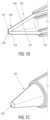
- FIG. 1 B and FIG. 1 Cillustrate an embodiment of a dissection tip of the present disclosure having an indent at the distal tip.
- FIGS. 2 A- 2 Cillustrate a dissection procedure using an endoscopic cannula of the present disclosure.
- FIG. 3 A , FIG. 3 B and FIG. 3 Cillustrate an embodiment of a cutting unit of an endoscopic cannula of the present disclosure.
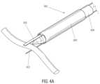
- FIGS. 4 A- 4 Dillustrates an embodiment of a cutting unit of an endoscopic cannula of the present disclosure.
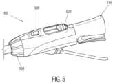
- FIG. 5illustrates an embodiment of a control handle suitable for use with an endoscopic cannula of the present disclosure.
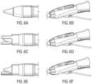
- FIGS. 6 A- 6 Fillustrate an embodiment of an endoscopic cannula of the present disclosure in operation being controlled by the control handle of FIG. 5 .
- FIGS. 7 A- 7 Billustrate an embodiment of a cutting unit of an endoscopic cannula of the present disclosure.
- FIG. 8illustrates an embodiment of a cutting unit of an endoscopic cannula of the present disclosure.
- FIG. 9 A , FIG. 9 B and FIG. 9 Cillustrate an embodiment of a cutting unit of an endoscopic cannula of the present disclosure.
- FIG. 10 A and FIG. 10 Billustrate an embodiment of a cutting unit of an endoscopic cannula of the present disclosure.
- FIGS. 11 A- 11 Cillustrate embodiments of a removable or retractable dissection tip.
- FIGS. 12 A- 12 Billustrate an embodiment of a dissection tip with optical windows.
- FIGS. 13 A- 16 Eillustrate various embodiments of a cannula of the present disclosure having one or more retractable surgical instrument.
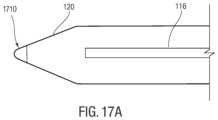
- FIGS. 17 A- 17 Billustrate an embodiment of a dissection tip with an opening at the distal tip.
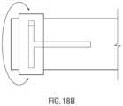
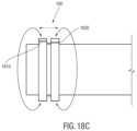
- FIGS. 18 A- 18 Cillustrate an embodiment of a control handle for use with cannulas of the present disclosure.
- the present disclosureprovides a unitary device for endoscopic vessel harvesting.
- Present systems for endoscopic vessel harvestingcontain multiple components.
- an endoscopic dissection deviceis used to isolate the main vessel from the surrounding connective tissue by dissecting the main vessel from surrounding connective tissue.
- An endoscopic cannulais then used to introduce yet another device, an endoscopic tributary sealing instrument, to seal and sever side branches. Once the side branches are sealed, yet another device is used to harvest a section of the main vessel to be used as a bypass graft.
- the unitary devices of the present disclosurecombine the dissection function, the tributary sealing and severing function, and, optionally, main vessel sealing and severing function, which can result in decreased vessel manipulation and improvement in ease of the procedure.
- the devices of the present disclosuremay also be used to extract the sealed and severed main vessel from the patient.
- Decreased vessel manipulationmay decrease the potential for injury to the graft. Repeated vessel contact with multiple passes of harvesting instrumentation increases potential vessel injury.
- a unitary devicesuch as the device of the present disclosure may dissect, i.e., separate the main vessel, from surrounding tissue, cauterize and transect the tributaries and the main vessel as the device is advanced, and the vessel may be harvested with a single passage of the device, rather than multiple device insertions and retractions.
- Such a device with a decreased diametermay be used for dissection as well as tributary ligation; graft trauma should be decreased.
- the relative smaller diameter of the present devicecan also facilitate harvesting of more tortuous vessels; for example, the internal mammary artery.
- an endoscopic cannula 100 of the present disclosureincludes an elongated body 102 having a proximal end 104 and a distal end 106 , terminating with a dissection tip 120 , which may, in some embodiments, be conical as shown in FIG. 1 A .
- a central axis 101extends between the proximal end 104 and the distal end 106 through the center of the cannula 100 .
- the cannula 100further includes an cutting unit 150 disposed about the distal end 106 for sealing and cutting a blood vessel and a control handle 160 for controlling the cutting unit 150 .
- the elongated body 102is configured for passing extravascularly through an entry incision to a vessel harvesting site.
- the elongated body 102may be sufficiently rigid axially along its length.
- the elongated body 102may be made from a biocompatible material, such as, plastic material, elastomeric material, metallic material, shape memory material, composite material or any other materials that has the desired characteristics.
- the elongated body 102may be provided with some flexibility to move radially or laterally from side to side depending on the application.
- the elongated body 102 of the cannula 100may be solid.
- the endoscopic cannula 100may include one or more lumen with lumena that accommodate advancing instruments or materials therethrough.
- the endoscopic cannula 100may include an endoscopic lumen 103 through which an endoscope 116 may be advanced for visualizing procedures performed using the cannula 100 .
- the endoscopic cannula 100may include an adapter 114 at the proximal end 104 for advancing the endoscope 116 into the endoscopic cannula 100 . Additional lumens of the cannula 100 are described below.
- the endoscopic cannula 100may include a dissection tip 120 disposed at or about the distal end 106 of the endoscopic cannula 100 .
- the viewing tip of the endoscopemay be positioned inside the dissection tip 120 .
- the dissection tip 120may include an inner cavity in fluid communication with the endoscopic lumen 103 to enable the endoscope 116 to be advanced into the dissection tip 120 .
- a chip-on-a-tip type of an endoscopemay be integrated inside the dissection tip 120 .
- the tip 120may also be transparent to allow for endoscopic viewing through the tip 120 of the procedures performed using the cannula 100 .
- the dissection tip 120in some embodiments, may be provided with any shape as long as it facilitates endoscopic viewing therethrough, and allows for necessary control during tissue dissecting, i.e. separation. In some embodiments, the dissection tip may be generally conical.
- the dissection tip 120may include a generally flat shoulder 122 , and a tapered section 124 which terminates in blunt end 126 for atraumatic separation of a vessel segment, being harvested from surrounding tissue, while minimizing or preventing tearing or puncturing of nearby vessels or tissue as the endoscopic cannula 100 is navigated along the vessel segment.
- blunt end 126may be made relatively pointed to enhance advancement of the cannula 100 .
- the dissection tip 120may be cone shaped, and may be shaped at its distal end in a manner so as to minimize the negative effects of visual distortion or blinding at the center of the endoscopic view field when viewing through an endoscope inserted into the cannula 100 , with a light source and camera system.
- Internal surface 121 of the dissection tip 120may be tapered, with a relatively constant slope toward the distal end 126 of the dissection tip 120 , terminating at an internal apex 123 , which may be a sharp point, as shown in FIG. 1 C .
- External surface 125 of the dissection tip 120may also be tapered with a constant slope toward the distal end 126 of the dissection tip 120 ; however, at the distal end 126 , a relatively rounded, blunt end may be formed to minimize tissue damage during dissection. As illustrated, at the distal end, the external surface 125 of the dissection tip 120 may be folded back on itself in a proximal direction to then terminate at an external apex 127 , maintaining the blunt exterior surface and forming an indent in the distal end of the dissection tip 120 . Both the internal apex 123 and the external apex 127 may be collinear with the central longitudinal axis of the cannula 100 and, thus, in some embodiments, the endoscope 116 .
- the centers of the internal apex 123 and the external apex 127are located on the central longitudinal axis of the cannula 100 .
- those surfaces perpendicular to the light path(which is parallel to the endoscope axis) may be eliminated, which then may eliminate light refraction from the perpendicular surface back into the camera and, thus, may minimize or eliminate the visual distortion or blinding when viewing through the endoscope 116 with a light source and camera system.
- the dissection tip 120may be radially pliable, flexible or deformable so that the dissection tip may deflect slightly under exertion of force applied to the dissection tip 120 .
- the dissection tip 120is radially compressible so that the walls of the dissection tip 120 can deform under exertion of force normal to the tip surface.
- the dissection tip 120may be formed from thin wall plastic material to enable the dissection tip to flex under load.
- Suitable materialsinclude, but are not limited to, polycarbonate, polyethylene terephthalate glycol-modified (PETG), polyethylene terephthalate (PET) and other materials that provide enough optical clarity while allowing the dissection tip to flex under load.
- the dissection tip 120may be provided with sufficient column strength in axial or longitudinal direction to allow dissection of the vessel from the surrounding connective tissue.
- blood vessels used in bypass graftinglie in the subcutaneous space, beneath the surface of the skin.
- the vessel 200is composed of a main trunk 210 , and branch vessels 220 that emanate from the vessel trunk 210 , as shown in FIG. 2 A .
- the vessel 200 and its branches 210are encased in subcutaneous fatty connective tissue 230 , and need to be dissected free of the surrounding fatty connective tissue 230 before the main vessel 200 may be harvested.
- the subcutaneous fat 230is softer than skin, muscle, fascia or other connective tissues.
- the fatty connective tissue 230forms an interface 240 with the vessel 200 that may be cleanly dissected; that is, there is a natural dissection plane between the outer layer of the vessel 200 (the adventitia), and the surrounding subcutaneous fat 230 .
- FIG. 2 Billustrates dissection of the main trunk 210 of the vessel 200 with the dissection tip 120 along the natural dissection plane, with the dissection tip 120 advanced along the adventitial surface of the vessel 200 .
- Isolation of the vessel 200 from surrounding fatty connective tissue 230 along this planetypically, does not require high dissection forces.
- the dissection tipmay 120 be provided with sufficient column strength to dissect the vessel 200 from the surrounding tissue 230 along the natural dissection plane between them.
- the dissection tip 120may catch the branch vessel 220 at a junction 250 between the branch vessel 220 and the main vessel 200 .
- Application of excessive force with the dissection tip 220may avulse the branch vessel and sever it from the trunk vessel, or may otherwise cause damage to the main vessel 200 .
- the dissection tip 120is provided with sufficient column strength to dissect the vessel 200 from the surrounding tissue 230 along the natural dissection plane between them, while being sufficiently pliable to deform or deflect from the branch vessel 220 with the application of increased force, to decrease the potential of trauma to the graft vessel during dissection around branch vessels.
- the rigidity of the dissection tip 120may be varied from fully flexible to semi-rigid to rigid, in accordance with requirements of the procedure.
- the cannula 100may further include one or more end-effectors for cauterizing or sealing and cutting a blood vessel, either a branch vessel or the main vessel.
- the cutting unit 150 of the cannula 100may include a first cutting member 302 and a second cutting member 304 , each having a cutting portion 310 , 312 extending from their respective distal ends.
- the first cutting member 302 and the second cutting member 304may be moveable in a longitudinal direction relative to the elongated body 102 of the cannula 100 .
- the cutting portions 310 , 312may be moved from an initial, retracted position during the dissection, in which the cutting portions 310 , 312 are retracted substantially proximally of the dissection tip 120 not to interfere with the dissection, to an operational or extended position for sealing and cutting, in which the cutting portions 310 , 312 may be advanced distally for the user to see the cutting portions and to provide enough capture length for the vessel.
- the cutting portions 310 , 312may at least partially extend beyond the dissection tip 120 to capture a blood vessel the cutting portions 310 , 312 .
- first cutting member 302 and the second cutting member 304may be rotatable relative to one another.
- the cutting portions 310 , 312may be moved from an open position when the cutting portions 310 , 312 are apart or spaced away from one another to capture a blood vessel therebetween, as shown in FIG. 3 B , to a closed position when the cutting portions 310 , 312 are brought towards one another around the dissection tip 120 to seal and cut the blood vessel, as shown in FIG. 3 C .
- the first cutting member 302 and the second cutting member 304are configured so both cutting portions 310 , 312 can be rotated circumferentially about the dissection tip 120 toward one another in both clockwise and counterclockwise direction depending on the location of the blood vessel to be captured between the cutting portions 310 , 312 .
- Such bi-directional, circumferential movement of the cutting portions 310 , 312may allow the user to operate on blood vessels on all sides of the cannula 100 to save time and reduce cannula manipulation during the procedure as the user does not need to be concerned about the orientation and position of the cannula 100 in relation to the blood vessel.
- one of the cutting portions 310 , 312may be stationary and the other one may rotate in both clockwise and counterclockwise toward the stationary cutting portion for easier manipulation and visualization of the cutting portions 310 , 312 .
- the stationary cutting portionmay also be moved to a desired orientation by moving the cannula 100 .
- the cutting portions of the cutting members 302 , 304may generally be elliptical or blade-like with a rounded distal tip, but any other shape that enables the cutting and sealing of a blood vessel may also be used.
- one or both of the cutting portions 310 , 312may be energized, when needed, using various sources of energy, including, but not limited to, resistive heating, ultrasound heating, and bipolar or monopolar RF energy.
- the electrodescan be controlled independently of one another.
- the cutting portions 310 , 312may be made from a material such as metal that would enable the cutting portions 310 , 312 themselves to be energized.
- energizing elementssuch as metal wires, may be disposed on the cutting portions 310 , 312 . When energized, the energizing elements may be brought in contact with the blood vessel by the cutting portions 310 , 312 to seal the blood vessel.
- one or both of the cutting members 310 , 312may include protrusions for use as spot cautery.
- one or both of the cutting members 310 , 312may have a sharpened, thin edge for concentrated application of energy to the blood vessel. Such concentrated energy application may require less energy to be applied to the side branch, thereby minimizing extension of cauterizing energy from the side branch towards the main trunk of the blood vessel, and thus eliminating potential trauma to the blood vessel.
- one of the opposing edges 318 , 320 of the cutting portions 310 , 312 between which cutting occursmay have a leveled face while the other one may be a sharpened, thin or pointed so that the tissue is not cut in a scissor-like motion but with a thin edge against a flat surface.
- both edges of the cutting members 310may be sharpened edges, while both edges of the cutting portion 312 may be flat, or vise versa.
- the cutting portions 310 , 312may have one sharp edge or blade edge and one flat edge with the sharp edge of one cutting portion facing the flat edge of the other cutting portion.
- the blood vesselmay be both sealed and cut using energy, as described above. It should of course be understood that, in some embodiments, the opposing edges the opposing edges 318 , 320 of the cutting portions 310 , 312 may both be sharpened so the tissue is cut in a scissor-like manner.
- the cutting members 302 , 304may be substantially u-shaped and disposed in the same plane relative to the cannula body 102 .
- the cutting members 302 , 304may include respective cutouts and fingers 314 , 316 along the edges to enable circumferential movement of the cutting members 302 , 304 relative to one another.
- the cutting members 302 , 304may be substantially tubular and be disposed in different planes of the cannula body 102 . As shown in FIG. 4 A , in some embodiments, the cutting member 304 may be concentrically disposed inside within the cutting member 302 . Referring to FIG. 4 B , in some embodiments, the elongated body 102 of the cannula 100 may be constructed of a series of coaxial tubes, both metal and plastic, that may act as the structural main shaft, the electrical conductive and insulative paths, and the end-effectors, i.e. cutting portions 310 , 312 .
- the innermost layermay be the inner sheath 402 (plastic) defining an internal lumen 403 .
- the inner sheath 402may be followed outwardly by the inner electrode tube 404 (metal), middle sheath 406 (plastic), outer electrode tube 408 (metal) and outer sheath 410 (plastic), and finally a shrink jacket 412 .
- the electrical insulationmay be provided using non-conductive coatings or similar means.
- the electrodes 404 , 408may be coated with polyvinyldyne flouride (PVDF), but other non-conductive coating may also be used.
- PVDFpolyvinyldyne flouride
- the inner electrode tube 404 and the outer electrode tube 408may be used to form the first cutting member 302 and the second cutting member 304 , with the cutting portions 310 , 312 being formed at the distal ends of the inner electrode tube 404 and the outer electrode tube 408 .
- the inner electrode tube 404 and the outer electrode tube 408may be slidable in the longitudinal direction relative to the cannula 100 and rotatable relative to one another. Further, because the cutting portions 310 , 312 are formed from the inner electrode tube 404 and the outer electrode tube 408 , the cutting portions 310 , 312 can be easily energized through the inner electrode 404 and the outer electrode 408 .
- the cutting portion formed from the inner electrode tube 404may be bent out of the plane of the inner electrode 404 to enable it to rotate along the same axis and be co-radial with the cutting portion formed in the outer electrode 408 (i.e. outer cutting portion 413 ).
- the inner cutting portion 411may have a flat face 416 on either side of the inner cutting portion, while the outer cutting portion 413 may have a sharpened or blade edge 418 on both sides, or vice versa.
- each cutting portion 411 , 413may have one sharpened edge and one flat edge, with the flat edge of one cutting portion facing the sharpened edge of the other cutting portion.
- the dissection tip 120may be connected to the inner sheath 402 to enable the advancement of the endoscope 116 into the dissection tip though the internal lumen 403 .
- a sleeve 414may be used to protect tissue from damage during dissection by smoothing the geometry between the dissection tip 120 and the cannula body 102 .
- the distal end of the sleeve 414may be left unattached to the dissection tip 120 to allow the cutting portions 312 , 314 to be advanced distally through the sleeve 414 , as shown in FIG. 4 D .
- the sleeve 414may be made of a flexible material so during dissection the sleeve 414 would comply with the dissection tip creating a smooth transition and also a tight seal to prevent tissue or bodily fluids from entering the cannula 100 .
- a flexible sleevewould be able to deflect and expand to allow the cutting portions 312 , 314 to be advanced out distally though the sleeve 414 .
- the surface of the sleevemay be coated with a lubricious substance to make the extension of the cutting portions 312 , 314 through the sleeve 414 easier and smoother by decreasing friction between the cutting portions 312 , 314 and the sleeve 414 .
- the thin-walled shrink tube 412may be placed over the outer surface of the cannula body for aesthetic purposes and to assist in securing the transition.
- FIG. 5illustrates an embodiment of the control handle 160 for controlling the cutting members 310 , 312 .
- the control handle 160may include a translation control 502 for advancing and retracting the cutting members 310 , 312 .
- the control handlefurther includes a rotation control 504 for rotating the cutting members with respect to one another.
- the control handle 160includes an energy control 506 for supplying energy (such as bipolar RF energy) to the cutting portions 310 , 312 .
- the adapter 114may be located at the proximal end of the control handle 500 for advancing the endoscope 116 into the endoscopic cannula 100 .
- an initial incisionmay be made in conventional manner to expose the target vessel (e.g., the saphenous vein).
- the cannula 100may be inserted into the incision and guided to the target vessel.
- the cannula 100may include a smooth tubular sheath around the elongated body 102 for sealing the cannula 102 within the port through which the cannula 102 is introduced into the patient.
- the cannula 100may then be advanced substantially along the target vessel to dissect the target vessel from the surrounding tissue.
- the cannula 100may be introduced through a sealable port used to seal the incision to allow insufflation of the space created by the dissection of the target vessel from surrounding tissues.
- the cutting portions 310 , 312 of the cutting elements 302 , 304may be kept in a retracted position so not to interfere with tissue dissection until a branch vessel is encountered. At that point, the cutting portions 310 , 312 may be advanced beyond the dissection tip 120 , as described above, to capture, seal and cut the branch vessel.
- the cutting portions 310 , 312may be moved from a retracted position, as shown in FIGS. 6 A- 6 B , in the distal direction beyond the dissection tip 120 by advancing the translational control 504 on the handle to its distal position, as shown in FIGS. 6 C- 6 D .
- the cutting portions 310 , 312may be advanced out together and enter into the field of view of the endoscope in the dissection tip 120 .
- the cutting portions 310 , 312may be rotated with respect to one another using the rotation control 504 , as shown in FIGS. 6 E- 6 F , for sealing and cutting the branch vessel.
- the cutting portions 310 , 312may be rotated around the dissection tip 120 in a circular arc motion.
- the endoscopic cannula 100may be positioned such that the target branch vessel may lay across one of the cutting portions 310 , 312 , regardless of orientation of the branch vessel in relation to the main blood vessel to be harvested.
- the endoscopic cannula 100may be designed such that the user can place the endoscopic cannula 100 and the cutting portions 310 , 312 as far away from the target main vessel as possible to avoid injury to the main vessel. Once in position, the user may rotate one of the cutting portions 310 , 312 toward the other one until the branch vessel is captured.
- the rotationis preferably always away from the main vessel, thus increasing and further maximizing the potential negative effects of lateral thermal spread.
- the usermay depresses the energy control 508 button to transfer the energy into the tributary to seal the vessel.
- the usermay continue to advance the rotation control 504 until the cutting portions 310 , 312 transect the branch vessel. The user may then retract the cutting portions 312 , 314 with the translation control 502 and advance the device to the next branch vessel until all tributaries have been successfully ligated and transected.
- the cannula 100may be advanced forward until the next branch vessel is encountered, at which point the branch vessel may be sealed and severed using the cutting unit 300 . Once all branch vessels along a desired length of the target vessel have been sealed and severed, the cannula 100 may be used to seal and cut the target vessel according to procedure similar to the procedure used to cut and seal the branch vessels. Alternatively, the cannula 100 may be withdrawn, and another surgical device may be used to seal and cut the main vessel.
- the cannula 100 of the present disclosuremay allow vessel sealing and cutting to be performed in a small cavity. Accordingly, when using the cannula 100 of the present disclosure there may not be a need to maintain the perivascular cavity in an expanded state and thus the procedure may be performed without gas insufflation of the perivascular cavity.
- the transparent dissection tip 120can deflect a vessel to one side, so that the members of the cutting unit can capture the vessel, while maintaining visualization of all components in a collapsed tissue tunnel. Vessel harvesting in a small or collapsed cavity may be useful in anatomic situations characterized by vessel tortuosity, such as the internal mammary artery and vein. Harvesting without gas insufflation may also be beneficial to the graft.
- the carbonic acid environment of a cavity maintained by carbon dioxide gas insufflationmay be detrimental to the graft vessel.
- a lower pH atmosphere surrounding the vesselmay alter the cellular viability of the graft, potentially leading to early graft failure.
- Positive pressure produced by gas insufflationmay also collapse the vessel, causing hemostasis, and may increase the potential for intraluminal clot formation. Presence of intraluminal clot may cause graft thrombosis and early graft failure.
- the cutting unit 150may include a first member 702 and a second member 704 .
- the first member 702 and second member 704may be translatable relative to the dissection tip 120 from a proximal position, during the dissection, to a more distal position to capture, seal and cut the blood vessel.
- the first member 702 and second member 704may also be moveable relative to one another so the first member 702 and second member 704 can be space away from one another capture a blood vessel therebetween and then may be compressed against one another to seal and cut the blood vessel.
- the first member 702 and second member 704may be mounted on one or more actuating rods for advancing and retracting. It should, of course, be understood that other mechanisms for translating the first member 702 and second member 704 relative to the dissection tip 120 and one another may be employed.
- the first member 702may include four circumferentially-disposed proximal electrode segments 706 for bipolar RF cutting.
- the proximal electrode segmentsmay be connected by 0.020′′ conductor.
- the second member 704may include two circumferentially-disposed distal electrode segments 708 for bipolar RF cutting.
- the distal electrode segmentsmay be connected by 0.020′′ conductor.
- the second member 704may include two segments 710 for resistive heat cautery 706 disposed distally of the distal electrode segments, and a distal ring electrode 712 for monopolar cautery.
- the actuating rodsmay be employed to energize the electrodes 706 - 712 .
- the cutting unit 150may include a first member 802 and a second member 804 .
- the first member 802 and the second member 804are translatable relative to the dissection tip and one another, as described above.
- the three electrodes 708 , 710 , and 712 of the second member 704are combined into one solid ring.
- bipolar modethe only one side of the ring may work with active proximal segment.
- monopolar modethe entire ring may work with outside returned electrode.
- two large cross-section conductorsmay also replace four electrode segments, two for RF cutting and two for resistive heat cautery, which may increase rigidity of the distal structure.
- the four electrodes 706 of the first member 702can also be combined into two hemispheric electrodes 806 , which can be individually controlled. In this manner, only two larger cross-section conductors 808 may be used instead of four small ones, as in the cutting unit illustrated in FIGS. 7 A and 7 B . Rigidity of the proximal structure may also increase by combining the four electrodes into two.
- the cutting unit 150may include a first member 902 having a proximal electrode 916 for bipolar RF cutting.
- the cutting unit 150may also include a second member 904 having a distal electrode 918 for bipolar RF cutting.
- the cutting unit 150may further include an electrode 914 for monopolar spot cautery disposed over the dissection tip 120 .
- the first member 902 and the second member 904may be made of a conductive material, with optional coating, and the electrodes 914 , 916 , 918 may be energized through the cutting member 902 , 904 .
- the first member 902 and the second member 904may be tubular, with the first member 902 slidably disposed relative to the second member 904 to enable the first member 902 and the second member 904 to be biased relative to one another in a longitudinal direction.
- the first member 902 and the second member 904may be move in a distal direction between an inactive position proximal of the dissection tip 120 , as shown in FIG. 9 A , and an active position in the field of view of the endoscope, as shown in FIG. 9 B and FIG. 9 C , for capturing, cutting and sealing the blood vessel.
- the second member 904may include one or more hooks 906 at a distal region of the second member 904 .
- the hook 906may be configured to capture the branch vessel, as shown in FIG. 9 B .
- the second member 904may include two hooks 910 and 912 , in a spaced relation to one another, so that the branch vessel may be contacted, at a minimum, by one of the hooks.
- the cannula 100may be advanced to a vessel with the first member 902 and the second member 904 of the cutting unit 150 positioned proximally to the dissection tip 120 .
- the second member 904may be extended in the distal direction to capture the branch vessel by the hook of the second member 904 .
- Spot cauterymay also be performed in this position, as desired, by a spot cautery electrode 914 .
- the first member 902may be advanced to pinch the branch vessel between the electrodes 916 , 918 of the first member 902 and the second member 904 , and the RF current may be turned on for sealing and cutting the branch vessel captured in the cutting unit 150 .
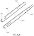
- FIG. 10 A and FIG. 10 Billustrate yet another embodiment of the cutting unit 150 having a first member 1002 and a second member 1004 .
- the second member 1004may include only a single hook 1010 on one side of the second member 1004 , as compared to two hooks 910 , 912 on the second member 904 . Removing one of hooks may improve visualization of the procedure by the endoscope 116 disposed within the cannula 100 .
- the structure and operations of this embodiment of the cutting unit 150may similar to those of the embodiment of the cutting unit 150 disclosed in FIGS. 9 A- 9 C .
- all electrodescan be energized using various sources of energy, including, but not limited to, resistive heating, ultrasound heating, and bipolar or monopolar RF energy.
- the electrodescan be controlled independently of one another.
- the electrodesmay be insulated with an insulating coating or insulating sheath.
- the endoscopic cannula 100 of the present disclosureincludes the dissection tip 120 at its distal tip that may enable dissection circumferentially about a vein or an artery.
- the dissection tip 120may cover the distal end of the cannula 100 and may allow for an endoscope of appropriate dimension to be advanced into the dissection tip from the proximal end of the cannula 100 .
- the dissection tip 120may be left on the cannula after the dissection step and throughout the entire procedure.
- the dissection tip 120may be removable from the cannula 100 or may be removably tethered to the cannula 100 to allow the user to displace the dissection tip 120 after the dissection to provide visualization without a tip.
- the dissection tip 120may be split or peeled to render the dissection tip 120 retractable over the cannula 100 during ligation.
- the dissection tip 120can be split into multiple sections 1100 .
- the sections 1100come together into a sufficiently rigid tip in a longitudinal direction to enable dissection.
- FIG. 11 Cwhen the dissection tip 120 is retracted, the sections 1100 are pulled apart, thereby creating an opening in the dissection tip 120 through which an endoscope or a surgical instrument can be advanced.
- the dissection tipmay be opened by exerting force on the dissection tip by an advancing endoscope to allow the endoscope to provide direct visualization by the endoscope.
- the dissection tip 120may include optical windows 1210 .
- windows 1210may be placed proximally to the distal end of the dissection tip 120 .
- the windows 1210may allow for visualization through an open window without the need to view through the dissection tip 120 .
- a removable cover 1212may positioned over the windows 1200 during dissection, as shown in FIG. 12 B , to prevent tissue and fluids from entering the inside of the dissection tip 120 through the windows 1210 .
- the cover 1212in some embodiments, may be retracted or otherwise removed during ligation, as shown in FIG. 12 A , to provide visualization through the windows 1210 .
- various surgical instrumentscan be provided inside the cannula 100 .
- Such surgical instrumentsmay be extended out of the cannula 100 , and retracted back inside the cannula 100 when necessary, via an activation switch on the control handle (as described below).
- the surgical instrumentsmay be translated linearly along a line off-set and parallel to the central longitudinal axis of the cannula 100 .
- the surgical instrumentsmay be extended while the dissection tip 100 remains in place at the distal tip of the cannula 100 .
- the surgical instrumentsmay be designed to be advanced when the dissection tip 120 is removed from the cannula 100 .
- such devicesmay be connected to any standard cautery source and activated via a switch or button on the handle or foot switch.
- Such devicescan also facilitate cautery through other sources of energy such as resistive heating elements or mechanical means. This source can also do the ligating without mechanical features.
- the surgical instrumentsmay be made of a shape-memory material. When extended substantially into the field of view, the surgical instruments may take an intended shape due to the shape memory material properties. In some embodiments, the end effector may take a shape that facilitates vessel sealing and/or ligation.
- the end effectormay be a wire, rod, tube, or sheet that can extend colinear to the central axis of the cannula.
- the shape memory materialmay fold into a shape to facilitate coagulation and ligation.
- the end effectormay be a wire, rod, tube, or sheet that can extend parallel to the central axis of the cannula along the periphery of the cannula.
- the shape memory materialUpon exiting the cannula into the field of view, the shape memory material can fold into a shape to facilitate coagulation and ligation.
- the end effectormay be a wire, rod, tube, or sheet that can extend out a window in the cone.
- the shape memory materialUpon exiting the cone into the field of view, the shape memory material can fold into a shape to facilitate coagulation and ligation.
- the surgical instrumentscan be used to deliver metallic, polymeric, ceramic, elastomeric, or bio-absorbable clips or ties to facilitate vessel sealing and/or ligation.
- the surgical instrumentscan be used to deliver one or more energy sources, such as RF, microwave, ultrasonic, resistive heating, and laser energy to facilitate vessel sealing and/or ligation
- energy sourcessuch as RF, microwave, ultrasonic, resistive heating, and laser energy to facilitate vessel sealing and/or ligation
- the cannula 100may include a split rotating finger 1310 , which may be housed or hidden proximal to the dissection tip 120 .
- the finger 1310may have a spring loaded actuation switch or lever on the control handle. In this manner, the finger 1310 may be actuated to spread out into two pieces, as shown in FIG. 13 B .
- the finger 1310may then be advanced over a vessel and then closed again reversing the switch/lever mechanism. Using the control handle, the finger 1310 may be energized, as discussed above, seal and cut the vessel.
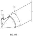
- the cannula 100may include a vessel capturing member 1410 that can be moved along an axis substantially parallel to the longitudinal axis of the cannula 100 from a retracted position inside the cannula 100 to an advanced position, as shown in FIG. 14 A .
- the vessel capturing member 1410may be provided with various configuration to facilitate vessel capturing, such as having a J hook or an L hook at its distal end.
- the vessel capturing member 1410is made of a wire with a hook at its distal end.
- the vessel capturing member 1410may be designed to supply the needed coagulation and cutting or transection of the captured vessel by energizing the vessel capturing member 1410 while exerting pressure on the captured vessel.
- the vessel capturing member 1410may work in cooperation with a cutting member 1420 .
- the vessel capturing member 1410may capture the vessel and pull the vessel against the cutting member 1420 .
- the cutting member 1420in some embodiments, may be rotatable to mate with the vessel capturing member 1410 thereby trapping the vessel and coagulating and/or cutting the captured vessel.
- the vessel capturing member 1410in addition to or instead of the rotatable cutting member, the vessel capturing member 1410 may also be rotatable, either with the cutting member 1420 or independent of the cutting member 1420 .
- the cutting member 1420may be a full ring. In other embodiments, as shown in FIG. 14 C , the cutting member 1420 may be a partial ring.
- the cannula 100may include a laser element 1510 , which may be housed proximal to the dissecting cone 120 .
- This laser element 1510may be extendable to meet the vessel, and may be used in combination with other surgical instruments.
- the laser element 1510may be connected to a laser, for example, by an optical fiber, and may be activated using the control handle or on the console of the laser.
- the laser elementmay be used to transect the vessel and then can be retracted back, allowing for further dissection or advancement of the cannula 100 within the space created.
- a window 1520may be provided in the dissection tip 120 to allow the light from the laser 1510 to reach the vessel.
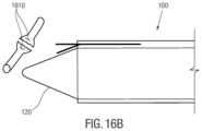
- the cannula 100may be used to deliver and place a securing mechanism 1610 , such as a vessel clip, as staple or a suture, around a vessel to interrupt blood flow through the vessel, prior to ligating the vessel by a surgical instrument 1620 .
- a securing mechanism 1610such as a vessel clip, as staple or a suture
- the securing mechanismmay be placed on the vessel to seal the vessel and a blade 1620 or other transection device may be used to cut the vessel.
- the surgical instrument 1620may be used to staple the vessel with staples 1610 to stop blood flow through the vessel prior, and the same or different surgical instrument may be used to cut the vessel in between the staples.
- the vesselmay be secured in 2 spots by 2 arms 1612 , 1614 of the securing mechanism 1610 to seal the vessel and a blade may be used to cut the vessel in between.
- a securing mechanismmay be placed around the vessel coagulate and cut the vessel. The securing mechanism can then be retracted into the cannula 100 as it moves to the next vessel to be sealed and cut.
- the cannula 100may include one or more surgical instruments, which can be retracted proximally substantially behind the field of view of the camera into and/or around the cannula 100 during dissection.
- the surgical instrumentsmay be extended substantially in front of the field of view of the camera during vessel sealing and ligation.
- the degrees of freedom of the surgical instrumentsmay include 1) rotation of one or more of the surgical instruments around an axis that is parallel or perpendicular to the central axis of the dissection cannula; 2) Rotation of one or more of the surgical instruments around an axis that is parallel or perpendicular to the axis of one of the other surgical instruments; 3) Translation of one or more of the surgical instruments along an axis that is parallel or perpendicular to the central axis of the dissection cannula; and 4) Translation of one or more of the surgical instruments along an axis that is parallel or perpendicular to the axis of one of the other surgical instruments.
- the dissection tip 120may be provided with a membrane 1710 at its distal tip. During the dissection, the membrane may be closed to facilitate dissection. On the other hand, during ligation, the endoscope may be advanced through the membrane 1710 , either by advancing the endoscope 116 or by retracting the dissection tip, to allow the endoscope 116 to penetrate the membrane 1710 for direct viewing during ligation.
- the surgical instrumentsmay be controlled by a control handle 1800 .
- the control handlemay have a first primary control 1810 moveable substantially parallel to the central axis of the cannula. Moving the first primary control 1810 distally may translate one or more surgical instruments parallel to the central axis of the cannula. In embodiments with multiple surgical instruments, the surgical instruments may be translated together by the first primary control 1810 .
- the first primary control 1810may be rotatable when fully extended, to allow for rotation the surgical instruments about the central axis of the cannula. In some embodiments, only one of the surgical instruments may be allowed to rotate with rotational movement of the first primary control.
- control handle 1800may include a second primary control in addition to the first primary control for independently controlling multiple surgical instruments.
- Each primary controlmay control one or more surgical instruments, independent of the other primary control.
- one or both of the primary controls 1810 , 1820may be rotatable, which may allow for rotation of the surgical instruments about the central axis of the cannula.
- Surgical devices of the present disclosuremay be used in a variety of medical applications.
- various embodiments of the endoscopic cannula 100 of the present disclosurecan be used for vessel harvesting.
- the cannulas of the present disclosuremay be used to endoscopically ligate perforator veins.
- an incision in the skin above the perforator in need of ligationcan be made and the perforator can be exposed.
- an endoscopic cannula 100 of the present disclosurecan be used to cauterize and cut the perforator, thereby eliminating the need for a large incision to access the target perforator.
- an endoscopic cannula 100 of the present disclosurecan be used in a femoral popliteal by-pass surgery.
- Using an endoscopic cannula 100 of the present disclosuremay allow the surgeon to dissect and isolate the targets in a minimally invasive fashion to dissect and isolate large segments of vein/artery and thereby saving an entire length of the leg incision.
- the incision pointmay be only around the actual bypass points.
- the cannulas of the present disclosuremay be used in any procedure that requires ligation, cauterization or both.
Landscapes
- Health & Medical Sciences (AREA)
- Life Sciences & Earth Sciences (AREA)
- Surgery (AREA)
- Engineering & Computer Science (AREA)
- Public Health (AREA)
- Veterinary Medicine (AREA)
- Biomedical Technology (AREA)
- Heart & Thoracic Surgery (AREA)
- Medical Informatics (AREA)
- Molecular Biology (AREA)
- Animal Behavior & Ethology (AREA)
- General Health & Medical Sciences (AREA)
- Nuclear Medicine, Radiotherapy & Molecular Imaging (AREA)
- Physics & Mathematics (AREA)
- Otolaryngology (AREA)
- Plasma & Fusion (AREA)
- Orthopedic Medicine & Surgery (AREA)
- Pathology (AREA)
- Rheumatology (AREA)
- Neurology (AREA)
- Neurosurgery (AREA)
- Surgical Instruments (AREA)
- Optics & Photonics (AREA)
- Electromagnetism (AREA)
Abstract
Description
Claims (16)
Priority Applications (3)
| Application Number | Priority Date | Filing Date | Title |
|---|---|---|---|
| US15/726,636US11751896B2 (en) | 2013-03-14 | 2017-10-06 | Unitary endoscopic vessel harvesting devices |
| US18/448,554US20230404611A1 (en) | 2013-03-14 | 2023-08-11 | Unitary Endoscopic Vessel Harvesting Devices |
| US19/023,097US20250160871A1 (en) | 2013-03-14 | 2025-01-15 | Unitary endoscopic vessel harvesting devices |
Applications Claiming Priority (5)
| Application Number | Priority Date | Filing Date | Title |
|---|---|---|---|
| US201361782034P | 2013-03-14 | 2013-03-14 | |
| US201361833814P | 2013-06-11 | 2013-06-11 | |
| US14/190,873US9498246B2 (en) | 2013-03-14 | 2014-02-26 | Unitary endoscopic vessel harvesting devices |
| US14/303,970US9814481B2 (en) | 2013-03-14 | 2014-06-13 | Unitary endoscopic vessel harvesting devices |
| US15/726,636US11751896B2 (en) | 2013-03-14 | 2017-10-06 | Unitary endoscopic vessel harvesting devices |
Related Parent Applications (1)
| Application Number | Title | Priority Date | Filing Date |
|---|---|---|---|
| US14/303,970DivisionUS9814481B2 (en) | 2013-03-14 | 2014-06-13 | Unitary endoscopic vessel harvesting devices |
Related Child Applications (1)
| Application Number | Title | Priority Date | Filing Date |
|---|---|---|---|
| US18/448,554ContinuationUS20230404611A1 (en) | 2013-03-14 | 2023-08-11 | Unitary Endoscopic Vessel Harvesting Devices |
Publications (2)
| Publication Number | Publication Date |
|---|---|
| US20180028213A1 US20180028213A1 (en) | 2018-02-01 |
| US11751896B2true US11751896B2 (en) | 2023-09-12 |
Family
ID=54834295
Family Applications (2)
| Application Number | Title | Priority Date | Filing Date |
|---|---|---|---|
| US14/303,970Active2034-11-15US9814481B2 (en) | 2013-03-14 | 2014-06-13 | Unitary endoscopic vessel harvesting devices |
| US15/726,636Active2037-01-18US11751896B2 (en) | 2013-03-14 | 2017-10-06 | Unitary endoscopic vessel harvesting devices |
Family Applications Before (1)
| Application Number | Title | Priority Date | Filing Date |
|---|---|---|---|
| US14/303,970Active2034-11-15US9814481B2 (en) | 2013-03-14 | 2014-06-13 | Unitary endoscopic vessel harvesting devices |
Country Status (2)
| Country | Link |
|---|---|
| US (2) | US9814481B2 (en) |
| WO (1) | WO2015191816A1 (en) |
Cited By (2)
| Publication number | Priority date | Publication date | Assignee | Title |
|---|---|---|---|---|
| US12064134B2 (en) | 2013-03-14 | 2024-08-20 | Saphena Medical, Inc. | Unitary endoscopic vessel harvesting devices |
| US12357285B2 (en) | 2019-04-05 | 2025-07-15 | Saphena Medical, Inc. | Unitary device for vessel harvesting and method of using same |
Families Citing this family (19)
| Publication number | Priority date | Publication date | Assignee | Title |
|---|---|---|---|---|
| US9814481B2 (en) | 2013-03-14 | 2017-11-14 | Saphena Medical, Inc. | Unitary endoscopic vessel harvesting devices |
| JP6596019B2 (en)* | 2014-12-04 | 2019-10-23 | テルモ株式会社 | Blood vessel peeling device |
| WO2016149076A1 (en) | 2015-03-13 | 2016-09-22 | The Regents Of The University Of Michigan | Tool for neuroma treatment and nerve regeneration procedures |
| US9943328B2 (en) | 2015-04-28 | 2018-04-17 | Saphena Medical, Inc. | Unitary endoscopic vessel harvesting devices with an elastic force |
| JP7166761B2 (en) | 2015-06-17 | 2022-11-08 | サフィナ・メディカル・インコーポレイテッド | single endoscope angiography device |
| EP3310277B1 (en)* | 2015-06-17 | 2021-05-26 | Saphena Medical, Inc. | Unitary endoscopic vessel harvesting devices |
| US20170105762A1 (en)* | 2015-10-15 | 2017-04-20 | Medtronic Advanced Energy Llc | Lead extraction |
| US20170189053A1 (en)* | 2015-12-31 | 2017-07-06 | Terumo Kabushiki Kaisha | Medical device and method |
| US10219791B2 (en)* | 2015-12-31 | 2019-03-05 | Terumo Kabushiki Kaisha | Medical device and method |
| US20170189051A1 (en)* | 2015-12-31 | 2017-07-06 | Terumo Kabushiki Kaisha | Medical device and method |
| WO2018055431A1 (en)* | 2016-09-20 | 2018-03-29 | Gavanescu Cosmin Adrian | Surgery device |
| EP3520727B1 (en)* | 2016-09-29 | 2022-03-30 | National University Corporation Shiga University OF Medical Science | Tissue joiner |
| US12102295B2 (en)* | 2017-09-18 | 2024-10-01 | Periwinkle Technologies Pvt. Ltd. | Digital device facilitating body cavity screening and diagnosis |
| CN108354635B (en)* | 2018-03-06 | 2024-05-31 | 万军 | Telescopic antenna type tumor puncture biopsy needle |
| US11172982B2 (en) | 2018-07-03 | 2021-11-16 | Terumo Cardiovascular Systems Corporation | Integrated grounding electrodes for electrocautery vessel harvester |
| JP2022508311A (en)* | 2018-08-09 | 2022-01-19 | オプティカル スパイン | Translucent illuminated endoscope probe |
| JP2022501121A (en) | 2018-09-21 | 2022-01-06 | サフィナ・メディカル・インコーポレイテッドSaphena Medical, Inc. | Surgical blowing and cleaning conduits and methods for their use |
| WO2020223458A1 (en) | 2019-05-01 | 2020-11-05 | Saphena Medical, Inc. | Surgical insufflation systems and methods for use |
| USD999376S1 (en)* | 2021-06-17 | 2023-09-19 | Alma Lasers Ltd. | CO2 laser application system |
Citations (114)
| Publication number | Priority date | Publication date | Assignee | Title |
|---|---|---|---|---|
| JPH0364603U (en) | 1989-10-30 | 1991-06-24 | ||
| US5209749A (en) | 1990-05-11 | 1993-05-11 | Applied Urology Inc. | Fluoroscopically alignable cutter assembly and method of using the same |
| US5350391A (en) | 1992-10-19 | 1994-09-27 | Benedetto Iacovelli | Laparoscopic instruments |
| US5373840A (en) | 1992-10-02 | 1994-12-20 | Knighton; David R. | Endoscope and method for vein removal |
| US5556408A (en) | 1995-04-27 | 1996-09-17 | Interventional Technologies Inc. | Expandable and compressible atherectomy cutter |
| US5591183A (en) | 1995-04-12 | 1997-01-07 | Origin Medsystems, Inc. | Dissection apparatus |
| US5601581A (en)* | 1995-05-19 | 1997-02-11 | General Surgical Innovations, Inc. | Methods and devices for blood vessel harvesting |
| US5676636A (en) | 1994-07-22 | 1997-10-14 | Origin Medsystems, Inc. | Method for creating a mediastinal working space |
| US5695514A (en) | 1995-07-13 | 1997-12-09 | Guidant Corporation | Method and apparatus for harvesting blood vessels |
| US5728123A (en) | 1995-04-26 | 1998-03-17 | Lemelson; Jerome H. | Balloon actuated catheter |
| US5772576A (en) | 1995-12-11 | 1998-06-30 | Embro Vascular L.L.C. | Apparatus and method for vein removal |
| US5797946A (en) | 1995-07-13 | 1998-08-25 | Origin Medsystems, Inc. | Method for arterial harvest and anastomosis for coronary bypass grafting |
| US5810805A (en) | 1996-02-09 | 1998-09-22 | Conmed Corporation | Bipolar surgical devices and surgical methods |
| US5873889A (en) | 1997-08-08 | 1999-02-23 | Origin Medsystems, Inc. | Tissue separation cannula with dissection probe and method |
| US5891141A (en) | 1997-09-02 | 1999-04-06 | Everest Medical Corporation | Bipolar electrosurgical instrument for cutting and sealing tubular tissue structures |
| US5895353A (en) | 1998-06-22 | 1999-04-20 | Origin Medsystems, Inc. | Vessel isolating retractor cannula and method |
| US5916233A (en)* | 1998-03-05 | 1999-06-29 | Origin Medsystems, Inc. | Vessel harvesting method and instrument including access port |
| US5921919A (en) | 1997-05-30 | 1999-07-13 | Origin Medsystems, Inc. | Perivascular self-retaining retractor and method |
| US5968065A (en) | 1995-07-13 | 1999-10-19 | Origin Medsystems, Inc. | Tissue separation cannula |
| US5976168A (en) | 1995-07-13 | 1999-11-02 | Origin Medsystems, Inc. | Tissue separation cannula |
| US5984937A (en) | 1997-03-31 | 1999-11-16 | Origin Medsystems, Inc. | Orbital dissection cannula and method |
| US6019771A (en)* | 1996-12-02 | 2000-02-01 | Cardiothoracic Systems, Inc. | Devices and methods for minimally invasive harvesting of a vessel especially the saphenous vein for coronary bypass grafting |
| US6030406A (en) | 1998-10-05 | 2000-02-29 | Origin Medsystems, Inc. | Method and apparatus for tissue dissection |
| US6042538A (en) | 1998-11-18 | 2000-03-28 | Emory University | Device for endoscopic vessel harvesting |
| JP2000505315A (en) | 1996-01-24 | 2000-05-09 | オリジン・メッドシステムズ,インコーポレイテッド | Tissue separation cannula with incision probe and method |
| JP2000217924A (en) | 1999-02-01 | 2000-08-08 | Kanegafuchi Chem Ind Co Ltd | Extended body for extended catheter and its manufacture |
| US6102909A (en) | 1997-08-26 | 2000-08-15 | Ethicon, Inc. | Scissorlike electrosurgical cutting instrument |
| WO2000067828A1 (en) | 1999-05-07 | 2000-11-16 | Scimed Life Systems, Inc. | Balloon catheter with lubricious coating |
| US6162173A (en) | 1998-06-22 | 2000-12-19 | Origin Medsystems, Inc. | Device and method for remote vessel ligation |
| US6176825B1 (en) | 1998-06-22 | 2001-01-23 | Origin Medsystems, Inc. | Cannula-based irrigation system and method |
| EP1120129A1 (en) | 1998-10-05 | 2001-08-01 | Kaneka Corporation | Balloon catheter and production method therefor |
| US6287304B1 (en) | 1999-10-15 | 2001-09-11 | Neothermia Corporation | Interstitial cauterization of tissue volumes with electrosurgically deployed electrodes |
| WO2002001998A2 (en) | 2000-05-16 | 2002-01-10 | Taut, Inc. | Penetrating tip for trocar assembly |
| JP3283091B2 (en) | 1993-02-27 | 2002-05-20 | 太陽誘電株式会社 | Ceramic green sheet laminating method and apparatus |
| US6402720B1 (en) | 1997-12-22 | 2002-06-11 | Cordis Corporation | Balloon catheter with elongated flexible tip |
| US6406425B1 (en) | 1998-06-22 | 2002-06-18 | Origin Medasystems | Cannula-based irrigation system and method |
| US6428539B1 (en) | 2000-03-09 | 2002-08-06 | Origin Medsystems, Inc. | Apparatus and method for minimally invasive surgery using rotational cutting tool |
| US6428556B1 (en) | 1999-08-25 | 2002-08-06 | Origin Medsystems, Inc. | Longitudinal dilator and method |
| US6432044B1 (en) | 1999-01-08 | 2002-08-13 | Origin Medsystems, Inc. | Combined vessel dissection and transection device and method |
| US6471638B1 (en) | 2000-04-28 | 2002-10-29 | Origin Medsystems, Inc. | Surgical apparatus |
| JP2003500152A (en) | 1999-05-28 | 2003-01-07 | ジェネラル サージカル イノヴェイションズ インコーポレイテッド | Specially shaped balloon device for use in surgery and method of use |
| WO2003013367A2 (en) | 2001-08-10 | 2003-02-20 | General Surgical Innovations Inc. | Vascular harvesting tool and methods |
| US6527771B1 (en) | 2001-09-28 | 2003-03-04 | Ethicon, Inc. | Surgical device for endoscopic vein harvesting |
| US6569082B1 (en) | 1999-08-10 | 2003-05-27 | Origin Medsystems, Inc. | Apparatus and methods for cardiac restraint |
| US20030229366A1 (en) | 1996-02-02 | 2003-12-11 | Transvascular, Inc. | Implantable lumen occluding devices and methods |
| US6673087B1 (en) | 2000-12-15 | 2004-01-06 | Origin Medsystems | Elongated surgical scissors |
| JP3486862B2 (en) | 1999-06-21 | 2004-01-13 | 株式会社 日立インダストリイズ | Substrate assembly method and apparatus |
| US6706052B1 (en) | 1999-08-10 | 2004-03-16 | Origin Medsystems, Inc. | Longitudinal dilator and method |
| WO2004043530A1 (en) | 2002-11-05 | 2004-05-27 | Boston Sceintific Limited | Medical device having flexible distal tip |
| US6749609B1 (en) | 2002-02-05 | 2004-06-15 | Origin Medsystems, Inc. | Electrocautery scissors |
| US20040133228A1 (en) | 2001-06-26 | 2004-07-08 | Bayer Hanspeter Robert | Conduit harvesting instrument and method |
| US20040158143A1 (en) | 1995-10-13 | 2004-08-12 | Transvascular Inc. | Stabilized tissue penetrating catheters |
| US6811546B1 (en) | 2000-08-25 | 2004-11-02 | Origin Medsystems, Inc. | Endoscopic surgical access port and method |
| US6830546B1 (en) | 1998-06-22 | 2004-12-14 | Origin Medsystems, Inc. | Device and method for remote vessel ligation |
| US20050154262A1 (en) | 2003-04-01 | 2005-07-14 | Banik Michael S. | Imaging system for video endoscope |
| US20050192613A1 (en) | 2004-03-01 | 2005-09-01 | Lindsay Erin J. | Method and apparatus for endoscopic dissection of blood vessels |
| US6951568B1 (en) | 2000-07-10 | 2005-10-04 | Origin Medsystems, Inc. | Low-profile multi-function vessel harvester and method |
| US20050272975A1 (en) | 2004-03-23 | 2005-12-08 | Mcweeney John O | In-vivo visualization system |
| US6976957B1 (en) | 1998-06-22 | 2005-12-20 | Origin Medsystems, Inc. | Cannula-based surgical instrument and method |
| US6979290B2 (en) | 2002-05-30 | 2005-12-27 | The Board Of Trustees Of The Leland Stanford Junior University | Apparatus and methods for coronary sinus access |
| US7001404B1 (en) | 1995-07-13 | 2006-02-21 | Origin Medsystems, Inc. | Tissue separation cannula and method |
| US20060095056A1 (en) | 2004-10-29 | 2006-05-04 | Peter Douglas | Device for incising a blood vessel |
| US20060271032A1 (en) | 2005-05-26 | 2006-11-30 | Chin Albert K | Ablation instruments and methods for performing abalation |
| US20070016183A1 (en) | 2005-07-01 | 2007-01-18 | Bruce Lee | Radio frequency ablation device for the destruction of tissue masses |
| US7214180B2 (en) | 1999-08-10 | 2007-05-08 | Origin Medsystems, Inc. | Method for cardiac restraint |
| US20070142711A1 (en) | 2005-12-13 | 2007-06-21 | Lex Bayer | Detachable Imaging Device, Endoscope Having A Detachable Imaging Device, And Method of Configuring Such An Endoscope |
| US7264587B2 (en) | 1999-08-10 | 2007-09-04 | Origin Medsystems, Inc. | Endoscopic subxiphoid surgical procedures |
| US7326178B1 (en) | 1998-06-22 | 2008-02-05 | Origin Medsystems, Inc. | Vessel retraction device and method |
| US7384423B1 (en) | 1995-07-13 | 2008-06-10 | Origin Medsystems, Inc. | Tissue dissection method |
| EP1935349A2 (en) | 2006-12-22 | 2008-06-25 | The Spectranetics Corporation | Retractable separating systems |
| US20080208192A1 (en)* | 2007-02-23 | 2008-08-28 | Terumo Cardiovascular Systems Corporation | Ring vessel dissector/harvester device |
| US20080255419A1 (en)* | 2007-03-22 | 2008-10-16 | Amar Kendale | Methods and devices for reducing reflection-illuminated artifacts |
| US20080306335A1 (en) | 2006-06-01 | 2008-12-11 | Origin Medsystems, Inc. | Endoscopic vessel harvesting system components |
| US20090023986A1 (en)* | 1998-08-12 | 2009-01-22 | Stewart Michael C | Vessel Harvesting |
| AU2007203086A1 (en) | 2007-07-02 | 2009-01-22 | Origin Medsystems, Inc. | Endoscopic vessel harvesting system components |
| US7485092B1 (en) | 1998-08-12 | 2009-02-03 | Maquet Cardiovascular Llc | Vessel harvesting apparatus and method |
| US20090048486A1 (en) | 2007-08-08 | 2009-02-19 | Wilson-Cook Medical Inc. | Distal Tip for an Endoscope |
| US7534243B1 (en) | 1998-08-12 | 2009-05-19 | Maquet Cardiovascular Llc | Dissection and welding of tissue |
| US20090299144A1 (en) | 2006-11-24 | 2009-12-03 | Olympus Medical Systems Corp. | Capsule endoscope |
| WO2009148809A1 (en) | 2008-06-05 | 2009-12-10 | Cardiovascular Systems, Inc. | Abrasive nose cone with expandable cutting and sanding region for rotational atherectomy device |
| US7695470B1 (en) | 1998-08-12 | 2010-04-13 | Maquet Cardiovascular Llc | Integrated vessel ligator and transector |
| US20100191057A1 (en) | 2008-07-28 | 2010-07-29 | Jansen Lex P | Penetrating member with direct visualization |
| US20100268175A1 (en) | 2009-04-21 | 2010-10-21 | Xlumena, Inc. | System and method for delivering expanding trocar through a sheath |
| US7887558B2 (en) | 2004-09-28 | 2011-02-15 | Maquet Cardiovascular Llc | Modular vessel harvesting system and method |
| US7918848B2 (en) | 2005-03-25 | 2011-04-05 | Maquet Cardiovascular, Llc | Tissue welding and cutting apparatus and method |
| US7931590B2 (en) | 2002-10-29 | 2011-04-26 | Maquet Cardiovascular Llc | Tissue stabilizer and methods of using the same |
| EP2364653A1 (en) | 2010-03-11 | 2011-09-14 | Tyco Healthcare Group LP | Insertion device and method of use |
| WO2011130399A1 (en) | 2010-04-13 | 2011-10-20 | Surgiquest, Incorporated | Visualization trocar |
| US20110295072A1 (en) | 2006-04-20 | 2011-12-01 | Boston Scientific Scimed, Inc. | Imaging assembly with transparent distal cap |
| US8083664B2 (en) | 2005-05-25 | 2011-12-27 | Maquet Cardiovascular Llc | Surgical stabilizers and methods for use in reduced-access surgical sites |
| US8097010B2 (en) | 2001-12-27 | 2012-01-17 | Terumo Kabushiki Kaisha | Treatment sheath for endoscopic blood vessel harvesting |
| US8197472B2 (en) | 2005-03-25 | 2012-06-12 | Maquet Cardiovascular, Llc | Tissue welding and cutting apparatus and method |
| US20120149983A1 (en) | 2010-09-20 | 2012-06-14 | Pavilion Medical Innovations | Endoscopic cannula and methods of using the same |
| US20120209074A1 (en)* | 2011-02-16 | 2012-08-16 | James Sidney Titus | Optical coupler for an endoscope |
| US20120232342A1 (en) | 2009-10-15 | 2012-09-13 | Boris Reydel | Disposable and reusable comlex shaped see-through endoscope |
| US20120289957A1 (en) | 2011-05-13 | 2012-11-15 | Bernd Emmerich | Electrosurgical instrument |
| US20130046138A1 (en) | 2011-08-19 | 2013-02-21 | Cook Medical Technologies Llc | Cap for Attachment to an Endoscope |
| US20130144276A1 (en) | 2011-12-03 | 2013-06-06 | Boston Scientific Scimed, Inc. | Medical device handle |
| US20130165746A1 (en) | 2011-12-23 | 2013-06-27 | Pavilion Medical Innovations, Llc | Unitary Endoscopic Vessel Harvesting Devices |
| US20130197299A1 (en) | 2011-12-23 | 2013-08-01 | Albert K. Chin | Unitary Endoscopic Vessel Harvesting Devices |
| US20130274548A1 (en) | 2010-04-23 | 2013-10-17 | W.O.M. World Of Medicine Ag | Invasive instrument for treating vessels |
| US8657818B2 (en) | 2009-08-21 | 2014-02-25 | Maquet Cardiovascular Llc | Single handled endoscopic vessel harvesting system with rotation control |
| US8676636B2 (en) | 2009-04-22 | 2014-03-18 | Parkpod Gmbh | System for managing electric energy grid-vehicle exchange devices |
| WO2014158613A1 (en) | 2013-03-14 | 2014-10-02 | Saphena Medical, Inc. | Unitary endoscopic vessel harvesting devices |
| US20140364691A1 (en) | 2013-03-28 | 2014-12-11 | Endochoice, Inc. | Circuit Board Assembly of A Multiple Viewing Elements Endoscope |
| US20140378957A1 (en) | 2013-03-14 | 2014-12-25 | Saphena Medical, Inc. | Unitary Endoscopic Vessel Harvesting Devices |
| US20150141938A1 (en) | 2006-11-22 | 2015-05-21 | Applied Medical Resources Corporation | Trocar cannula with atraumatic tip |
| US20150316046A1 (en) | 2014-05-05 | 2015-11-05 | Aavid Thermalloy, Llc | Planar coil and support for actuator of fluid mover |
| US20160174814A1 (en) | 2013-08-31 | 2016-06-23 | Morena Medical Applications Ltd. | Endoscope with shared working channel |
| EP3087927A1 (en) | 2015-04-28 | 2016-11-02 | Saphena Medical, Inc. | Unitary endoscopic vessel harvesting devices with an elastic force |
| US20160367279A1 (en) | 2015-06-17 | 2016-12-22 | Saphena Medical, Inc. | Unitary Endoscopic Vessel Harvesting Devices |
| US20170035487A1 (en)* | 2015-08-05 | 2017-02-09 | Terumo Cardiovascular Systems Corporation | Endoscopic vessel harvester with blunt and active dissection |
| EP3310277A1 (en) | 2015-06-17 | 2018-04-25 | Saphena Medical, Inc. | Unitary endoscopic vessel harvesting devices |
| US20200315650A1 (en) | 2019-04-05 | 2020-10-08 | Saphena Medical, Inc. | Unitary Device for Vessel Harvesting and Method of Using Same |
- 2014
- 2014-06-13USUS14/303,970patent/US9814481B2/enactiveActive
- 2015
- 2015-06-11WOPCT/US2015/035266patent/WO2015191816A1/enactiveApplication Filing
- 2017
- 2017-10-06USUS15/726,636patent/US11751896B2/enactiveActive
Patent Citations (173)
| Publication number | Priority date | Publication date | Assignee | Title |
|---|---|---|---|---|
| JPH0364603U (en) | 1989-10-30 | 1991-06-24 | ||
| US5209749A (en) | 1990-05-11 | 1993-05-11 | Applied Urology Inc. | Fluoroscopically alignable cutter assembly and method of using the same |
| US5941819A (en) | 1991-05-29 | 1999-08-24 | Origin Medsystems, Inc. | Apparatus for creating a mediastinal working space |
| US5373840A (en) | 1992-10-02 | 1994-12-20 | Knighton; David R. | Endoscope and method for vein removal |
| US5350391A (en) | 1992-10-19 | 1994-09-27 | Benedetto Iacovelli | Laparoscopic instruments |
| JP3283091B2 (en) | 1993-02-27 | 2002-05-20 | 太陽誘電株式会社 | Ceramic green sheet laminating method and apparatus |
| US5823946A (en) | 1994-07-22 | 1998-10-20 | Origin Medsystems, Inc. | Method for creating a mediastinal working space |
| US5676636A (en) | 1994-07-22 | 1997-10-14 | Origin Medsystems, Inc. | Method for creating a mediastinal working space |
| US5591183A (en) | 1995-04-12 | 1997-01-07 | Origin Medsystems, Inc. | Dissection apparatus |
| US6264670B1 (en) | 1995-04-12 | 2001-07-24 | Origin Medsystems, Inc. | Tissue dissection method |
| US6277137B1 (en) | 1995-04-12 | 2001-08-21 | Origin Medsystems | Tissue separation cannula with dissection probe and method |
| US5728123A (en) | 1995-04-26 | 1998-03-17 | Lemelson; Jerome H. | Balloon actuated catheter |
| US5556408A (en) | 1995-04-27 | 1996-09-17 | Interventional Technologies Inc. | Expandable and compressible atherectomy cutter |
| US5601581A (en)* | 1995-05-19 | 1997-02-11 | General Surgical Innovations, Inc. | Methods and devices for blood vessel harvesting |
| US7384423B1 (en) | 1995-07-13 | 2008-06-10 | Origin Medsystems, Inc. | Tissue dissection method |
| US5797946A (en) | 1995-07-13 | 1998-08-25 | Origin Medsystems, Inc. | Method for arterial harvest and anastomosis for coronary bypass grafting |
| US5695514A (en) | 1995-07-13 | 1997-12-09 | Guidant Corporation | Method and apparatus for harvesting blood vessels |
| US7001404B1 (en) | 1995-07-13 | 2006-02-21 | Origin Medsystems, Inc. | Tissue separation cannula and method |
| US6203557B1 (en) | 1995-07-13 | 2001-03-20 | Origin Medsystems | Tissue separation cannula and method |
| US7981133B2 (en) | 1995-07-13 | 2011-07-19 | Maquet Cardiovascular, Llc | Tissue dissection method |
| US5968065A (en) | 1995-07-13 | 1999-10-19 | Origin Medsystems, Inc. | Tissue separation cannula |
| US5976168A (en) | 1995-07-13 | 1999-11-02 | Origin Medsystems, Inc. | Tissue separation cannula |
| US5980549A (en) | 1995-07-13 | 1999-11-09 | Origin Medsystems, Inc. | Tissue separation cannula with dissection probe and method |
| US6506200B1 (en) | 1995-07-13 | 2003-01-14 | Origin Medsystems, Inc. | Tissue separation cannula and method |
| US6036714A (en) | 1995-07-13 | 2000-03-14 | Origin Medsystems, Inc. | Tissue separation method |
| US20040158143A1 (en) | 1995-10-13 | 2004-08-12 | Transvascular Inc. | Stabilized tissue penetrating catheters |
| US5772576A (en) | 1995-12-11 | 1998-06-30 | Embro Vascular L.L.C. | Apparatus and method for vein removal |
| US6428468B1 (en) | 1995-12-11 | 2002-08-06 | Cardiothoracic Systems, Inc. | Apparatus and method for vein removal |
| US7066875B2 (en) | 1995-12-11 | 2006-06-27 | Cardio Thoracic Systems, Inc. | Apparatus and method for vein removal |
| JP2000505315A (en) | 1996-01-24 | 2000-05-09 | オリジン・メッドシステムズ,インコーポレイテッド | Tissue separation cannula with incision probe and method |
| US20030229366A1 (en) | 1996-02-02 | 2003-12-11 | Transvascular, Inc. | Implantable lumen occluding devices and methods |
| US5810805A (en) | 1996-02-09 | 1998-09-22 | Conmed Corporation | Bipolar surgical devices and surgical methods |
| US6019771A (en)* | 1996-12-02 | 2000-02-01 | Cardiothoracic Systems, Inc. | Devices and methods for minimally invasive harvesting of a vessel especially the saphenous vein for coronary bypass grafting |
| US5984937A (en) | 1997-03-31 | 1999-11-16 | Origin Medsystems, Inc. | Orbital dissection cannula and method |
| US5921919A (en) | 1997-05-30 | 1999-07-13 | Origin Medsystems, Inc. | Perivascular self-retaining retractor and method |
| US5873889A (en) | 1997-08-08 | 1999-02-23 | Origin Medsystems, Inc. | Tissue separation cannula with dissection probe and method |
| US6102909A (en) | 1997-08-26 | 2000-08-15 | Ethicon, Inc. | Scissorlike electrosurgical cutting instrument |
| US5891141A (en) | 1997-09-02 | 1999-04-06 | Everest Medical Corporation | Bipolar electrosurgical instrument for cutting and sealing tubular tissue structures |
| US6402720B1 (en) | 1997-12-22 | 2002-06-11 | Cordis Corporation | Balloon catheter with elongated flexible tip |
| US5916233A (en)* | 1998-03-05 | 1999-06-29 | Origin Medsystems, Inc. | Vessel harvesting method and instrument including access port |
| US6830546B1 (en) | 1998-06-22 | 2004-12-14 | Origin Medsystems, Inc. | Device and method for remote vessel ligation |
| US7476198B1 (en) | 1998-06-22 | 2009-01-13 | Maquet Cardiovascular, Llc | Cannula-based surgical instrument |
| US6348037B1 (en) | 1998-06-22 | 2002-02-19 | Origin Medsystems, Inc. | Device and method for remote vessel ligation |
| US7867163B2 (en) | 1998-06-22 | 2011-01-11 | Maquet Cardiovascular Llc | Instrument and method for remotely manipulating a tissue structure |
| US6976957B1 (en) | 1998-06-22 | 2005-12-20 | Origin Medsystems, Inc. | Cannula-based surgical instrument and method |
| US6406425B1 (en) | 1998-06-22 | 2002-06-18 | Origin Medasystems | Cannula-based irrigation system and method |
| US7972265B1 (en) | 1998-06-22 | 2011-07-05 | Maquet Cardiovascular, Llc | Device and method for remote vessel ligation |
| US5993384A (en) | 1998-06-22 | 1999-11-30 | Origin Medsystems, Inc. | Vessel isolating retractor cannula and method |
| US5895353A (en) | 1998-06-22 | 1999-04-20 | Origin Medsystems, Inc. | Vessel isolating retractor cannula and method |
| US6752756B2 (en) | 1998-06-22 | 2004-06-22 | Origin Medsystems, Inc. | Combined vessel dissection and transection device and method |
| US6176825B1 (en) | 1998-06-22 | 2001-01-23 | Origin Medsystems, Inc. | Cannula-based irrigation system and method |
| US7326178B1 (en) | 1998-06-22 | 2008-02-05 | Origin Medsystems, Inc. | Vessel retraction device and method |
| US8241210B2 (en) | 1998-06-22 | 2012-08-14 | Maquet Cardiovascular Llc | Vessel retractor |
| US6162173A (en) | 1998-06-22 | 2000-12-19 | Origin Medsystems, Inc. | Device and method for remote vessel ligation |
| US8075559B2 (en) | 1998-08-12 | 2011-12-13 | Maquet Cardiovascular, Llc | Apparatus and method for integrated vessel ligator and transector |
| US7695470B1 (en) | 1998-08-12 | 2010-04-13 | Maquet Cardiovascular Llc | Integrated vessel ligator and transector |
| US20090023986A1 (en)* | 1998-08-12 | 2009-01-22 | Stewart Michael C | Vessel Harvesting |
| US7485092B1 (en) | 1998-08-12 | 2009-02-03 | Maquet Cardiovascular Llc | Vessel harvesting apparatus and method |
| US7938842B1 (en) | 1998-08-12 | 2011-05-10 | Maquet Cardiovascular Llc | Tissue dissector apparatus |
| US7534243B1 (en) | 1998-08-12 | 2009-05-19 | Maquet Cardiovascular Llc | Dissection and welding of tissue |
| US9730782B2 (en) | 1998-08-12 | 2017-08-15 | Maquet Cardiovascular Llc | Vessel harvester |
| US8460331B2 (en) | 1998-08-12 | 2013-06-11 | Maquet Cardiovascular, Llc | Tissue dissector apparatus and method |
| US6030406A (en) | 1998-10-05 | 2000-02-29 | Origin Medsystems, Inc. | Method and apparatus for tissue dissection |
| US6203559B1 (en) | 1998-10-05 | 2001-03-20 | Origin Medsystems | Method and apparatus for tissue dissection |
| EP1120129A1 (en) | 1998-10-05 | 2001-08-01 | Kaneka Corporation | Balloon catheter and production method therefor |
| US6042538A (en) | 1998-11-18 | 2000-03-28 | Emory University | Device for endoscopic vessel harvesting |
| US6432044B1 (en) | 1999-01-08 | 2002-08-13 | Origin Medsystems, Inc. | Combined vessel dissection and transection device and method |
| JP2000217924A (en) | 1999-02-01 | 2000-08-08 | Kanegafuchi Chem Ind Co Ltd | Extended body for extended catheter and its manufacture |
| WO2000067828A1 (en) | 1999-05-07 | 2000-11-16 | Scimed Life Systems, Inc. | Balloon catheter with lubricious coating |
| JP2002543893A (en) | 1999-05-07 | 2002-12-24 | ボストン サイエンティフィック リミテッド | Balloon catheter with lubricious coating |
| JP2003500152A (en) | 1999-05-28 | 2003-01-07 | ジェネラル サージカル イノヴェイションズ インコーポレイテッド | Specially shaped balloon device for use in surgery and method of use |
| US20040243167A1 (en) | 1999-05-28 | 2004-12-02 | Shigeru Tanaka | Specially shaped balloon device for use in surgery and mehtod of use |
| JP3486862B2 (en) | 1999-06-21 | 2004-01-13 | 株式会社 日立インダストリイズ | Substrate assembly method and apparatus |
| US7214180B2 (en) | 1999-08-10 | 2007-05-08 | Origin Medsystems, Inc. | Method for cardiac restraint |
| US6569082B1 (en) | 1999-08-10 | 2003-05-27 | Origin Medsystems, Inc. | Apparatus and methods for cardiac restraint |
| US7398781B1 (en) | 1999-08-10 | 2008-07-15 | Maquet Cardiovascular, Llc | Method for subxiphoid endoscopic access |
| US7264587B2 (en) | 1999-08-10 | 2007-09-04 | Origin Medsystems, Inc. | Endoscopic subxiphoid surgical procedures |
| US6706052B1 (en) | 1999-08-10 | 2004-03-16 | Origin Medsystems, Inc. | Longitudinal dilator and method |
| US6428556B1 (en) | 1999-08-25 | 2002-08-06 | Origin Medsystems, Inc. | Longitudinal dilator and method |
| US6607547B1 (en) | 1999-08-25 | 2003-08-19 | Origin Medsystems, Inc. | Longitudinal dilator and method |
| US6287304B1 (en) | 1999-10-15 | 2001-09-11 | Neothermia Corporation | Interstitial cauterization of tissue volumes with electrosurgically deployed electrodes |
| US6702813B1 (en) | 2000-03-09 | 2004-03-09 | Origin Medsystems, Inc. | Apparatus and method for minimally invasive surgery using rotational cutting tool |
| US6428539B1 (en) | 2000-03-09 | 2002-08-06 | Origin Medsystems, Inc. | Apparatus and method for minimally invasive surgery using rotational cutting tool |
| US7033357B2 (en) | 2000-03-09 | 2006-04-25 | Origin Medsystems, Inc. | Apparatus and method for minimally invasive surgery using rotational cutting tool |
| US6471638B1 (en) | 2000-04-28 | 2002-10-29 | Origin Medsystems, Inc. | Surgical apparatus |
| US6814696B1 (en) | 2000-04-28 | 2004-11-09 | Origin Medsystems, Inc. | Surgical apparatus |
| WO2002001998A2 (en) | 2000-05-16 | 2002-01-10 | Taut, Inc. | Penetrating tip for trocar assembly |
| US6951568B1 (en) | 2000-07-10 | 2005-10-04 | Origin Medsystems, Inc. | Low-profile multi-function vessel harvester and method |
| US6811546B1 (en) | 2000-08-25 | 2004-11-02 | Origin Medsystems, Inc. | Endoscopic surgical access port and method |
| US7276075B1 (en) | 2000-08-25 | 2007-10-02 | Origin Medsystems, Inc. | Endoscopic surgical access port and method |
| US6673087B1 (en) | 2000-12-15 | 2004-01-06 | Origin Medsystems | Elongated surgical scissors |
| US20040133228A1 (en) | 2001-06-26 | 2004-07-08 | Bayer Hanspeter Robert | Conduit harvesting instrument and method |
| US7645289B2 (en) | 2001-06-26 | 2010-01-12 | Tyco Healthcare Group Lp | Conduit harvesting instrument and method |
| WO2003013367A2 (en) | 2001-08-10 | 2003-02-20 | General Surgical Innovations Inc. | Vascular harvesting tool and methods |
| US6527771B1 (en) | 2001-09-28 | 2003-03-04 | Ethicon, Inc. | Surgical device for endoscopic vein harvesting |
| US8097010B2 (en) | 2001-12-27 | 2012-01-17 | Terumo Kabushiki Kaisha | Treatment sheath for endoscopic blood vessel harvesting |
| US7344536B1 (en) | 2002-02-05 | 2008-03-18 | Origin Medsystems, Inc. | Electrocautery surgical scissors |
| US7544195B2 (en) | 2002-02-05 | 2009-06-09 | Maquet Cardiovascular Llc | Electrocautery surgical scissors |
| US6749609B1 (en) | 2002-02-05 | 2004-06-15 | Origin Medsystems, Inc. | Electrocautery scissors |
| US6979290B2 (en) | 2002-05-30 | 2005-12-27 | The Board Of Trustees Of The Leland Stanford Junior University | Apparatus and methods for coronary sinus access |
| US7931590B2 (en) | 2002-10-29 | 2011-04-26 | Maquet Cardiovascular Llc | Tissue stabilizer and methods of using the same |
| WO2004043530A1 (en) | 2002-11-05 | 2004-05-27 | Boston Sceintific Limited | Medical device having flexible distal tip |
| US20050154262A1 (en) | 2003-04-01 | 2005-07-14 | Banik Michael S. | Imaging system for video endoscope |
| US7556633B2 (en) | 2004-03-01 | 2009-07-07 | Terumo Corporation | Method and apparatus for endoscopic dissection of blood vessels |
| US20050192613A1 (en) | 2004-03-01 | 2005-09-01 | Lindsay Erin J. | Method and apparatus for endoscopic dissection of blood vessels |
| EP1570787A1 (en) | 2004-03-01 | 2005-09-07 | Terumo Corporation | Apparatus for endoscopic dissection of blood vessels |
| JP2005246058A (en) | 2004-03-01 | 2005-09-15 | Terumo Corp | Endoscopic blood vessel collection device |
| US20050272975A1 (en) | 2004-03-23 | 2005-12-08 | Mcweeney John O | In-vivo visualization system |
| US7887558B2 (en) | 2004-09-28 | 2011-02-15 | Maquet Cardiovascular Llc | Modular vessel harvesting system and method |
| US20060095056A1 (en) | 2004-10-29 | 2006-05-04 | Peter Douglas | Device for incising a blood vessel |
| US8197472B2 (en) | 2005-03-25 | 2012-06-12 | Maquet Cardiovascular, Llc | Tissue welding and cutting apparatus and method |
| US8623003B2 (en) | 2005-03-25 | 2014-01-07 | Maquet Cardiovascular Llc | Apparatus and method for regulating tissue welder jaws |
| US7918848B2 (en) | 2005-03-25 | 2011-04-05 | Maquet Cardiovascular, Llc | Tissue welding and cutting apparatus and method |
| US8083664B2 (en) | 2005-05-25 | 2011-12-27 | Maquet Cardiovascular Llc | Surgical stabilizers and methods for use in reduced-access surgical sites |
| WO2006127241A2 (en) | 2005-05-26 | 2006-11-30 | Cardiothoracic Systems, Inc. | Ablation instruments and methods for performing abalation |
| US20060271032A1 (en) | 2005-05-26 | 2006-11-30 | Chin Albert K | Ablation instruments and methods for performing abalation |
| US20070016183A1 (en) | 2005-07-01 | 2007-01-18 | Bruce Lee | Radio frequency ablation device for the destruction of tissue masses |
| US20070142711A1 (en) | 2005-12-13 | 2007-06-21 | Lex Bayer | Detachable Imaging Device, Endoscope Having A Detachable Imaging Device, And Method of Configuring Such An Endoscope |
| US20110295072A1 (en) | 2006-04-20 | 2011-12-01 | Boston Scientific Scimed, Inc. | Imaging assembly with transparent distal cap |
| US20080306335A1 (en) | 2006-06-01 | 2008-12-11 | Origin Medsystems, Inc. | Endoscopic vessel harvesting system components |
| US20150141938A1 (en) | 2006-11-22 | 2015-05-21 | Applied Medical Resources Corporation | Trocar cannula with atraumatic tip |
| US20090299144A1 (en) | 2006-11-24 | 2009-12-03 | Olympus Medical Systems Corp. | Capsule endoscope |
| EP1935349A2 (en) | 2006-12-22 | 2008-06-25 | The Spectranetics Corporation | Retractable separating systems |
| US20080208192A1 (en)* | 2007-02-23 | 2008-08-28 | Terumo Cardiovascular Systems Corporation | Ring vessel dissector/harvester device |
| US8372096B2 (en) | 2007-02-23 | 2013-02-12 | Terumo Cardiovascular Systems | Ring vessel dissector/harvester device |
| US8414480B2 (en) | 2007-03-22 | 2013-04-09 | Maquet Cardiovascular Llc | Methods and devices for reducing reflection-illuminated artifacts |
| US20080255419A1 (en)* | 2007-03-22 | 2008-10-16 | Amar Kendale | Methods and devices for reducing reflection-illuminated artifacts |
| AU2007203086A1 (en) | 2007-07-02 | 2009-01-22 | Origin Medsystems, Inc. | Endoscopic vessel harvesting system components |
| US20090048486A1 (en) | 2007-08-08 | 2009-02-19 | Wilson-Cook Medical Inc. | Distal Tip for an Endoscope |
| WO2009148809A1 (en) | 2008-06-05 | 2009-12-10 | Cardiovascular Systems, Inc. | Abrasive nose cone with expandable cutting and sanding region for rotational atherectomy device |
| US20100191057A1 (en) | 2008-07-28 | 2010-07-29 | Jansen Lex P | Penetrating member with direct visualization |
| US20100268175A1 (en) | 2009-04-21 | 2010-10-21 | Xlumena, Inc. | System and method for delivering expanding trocar through a sheath |
| US8676636B2 (en) | 2009-04-22 | 2014-03-18 | Parkpod Gmbh | System for managing electric energy grid-vehicle exchange devices |
| US8657818B2 (en) | 2009-08-21 | 2014-02-25 | Maquet Cardiovascular Llc | Single handled endoscopic vessel harvesting system with rotation control |
| US20120232342A1 (en) | 2009-10-15 | 2012-09-13 | Boris Reydel | Disposable and reusable comlex shaped see-through endoscope |
| JP2013508034A (en) | 2009-10-15 | 2013-03-07 | インベンティオ エルエルシー | Disposable and reusable complex shape transparent endscope |
| EP2364653A1 (en) | 2010-03-11 | 2011-09-14 | Tyco Healthcare Group LP | Insertion device and method of use |
| WO2011130399A1 (en) | 2010-04-13 | 2011-10-20 | Surgiquest, Incorporated | Visualization trocar |
| US20130274548A1 (en) | 2010-04-23 | 2013-10-17 | W.O.M. World Of Medicine Ag | Invasive instrument for treating vessels |
| US20120149983A1 (en) | 2010-09-20 | 2012-06-14 | Pavilion Medical Innovations | Endoscopic cannula and methods of using the same |
| US20120209074A1 (en)* | 2011-02-16 | 2012-08-16 | James Sidney Titus | Optical coupler for an endoscope |
| US20120289957A1 (en) | 2011-05-13 | 2012-11-15 | Bernd Emmerich | Electrosurgical instrument |
| US20130046138A1 (en) | 2011-08-19 | 2013-02-21 | Cook Medical Technologies Llc | Cap for Attachment to an Endoscope |
| US20130144276A1 (en) | 2011-12-03 | 2013-06-06 | Boston Scientific Scimed, Inc. | Medical device handle |
| US20130165746A1 (en) | 2011-12-23 | 2013-06-27 | Pavilion Medical Innovations, Llc | Unitary Endoscopic Vessel Harvesting Devices |
| US20130197299A1 (en) | 2011-12-23 | 2013-08-01 | Albert K. Chin | Unitary Endoscopic Vessel Harvesting Devices |
| US9814481B2 (en) | 2013-03-14 | 2017-11-14 | Saphena Medical, Inc. | Unitary endoscopic vessel harvesting devices |
| US20170020546A1 (en) | 2013-03-14 | 2017-01-26 | Saphena Medical, Inc. | Unitary Endoscopic Vessel Harvesting Devices |
| US10537353B2 (en) | 2013-03-14 | 2020-01-21 | Saphena Medical, Inc. | Unitary endoscopic vessel harvesting devices |
| US20190076161A1 (en) | 2013-03-14 | 2019-03-14 | Saphena Medical, Inc. | Unitary Endoscopic Vessel Harvesting Devices |
| CN105188575A (en) | 2013-03-14 | 2015-12-23 | 隐静脉医疗有限公司 | Unitary endoscopic vessel harvesting devices |
| EP2967629A1 (en) | 2013-03-14 | 2016-01-20 | Saphena Medical, Inc. | Unitary endoscopic vessel harvesting devices |
| US20140378957A1 (en) | 2013-03-14 | 2014-12-25 | Saphena Medical, Inc. | Unitary Endoscopic Vessel Harvesting Devices |
| CN105188575B (en) | 2013-03-14 | 2018-03-02 | 隐静脉医疗有限公司 | Integrated endoscopic blood vessel collection device |
| US20180028213A1 (en) | 2013-03-14 | 2018-02-01 | Saphena Medical, Inc. | Unitary Endoscopic Vessel Harvesting Devices |
| US9498246B2 (en) | 2013-03-14 | 2016-11-22 | Saphena Medical, Inc. | Unitary endoscopic vessel harvesting devices |
| WO2014158613A1 (en) | 2013-03-14 | 2014-10-02 | Saphena Medical, Inc. | Unitary endoscopic vessel harvesting devices |
| US20140296847A1 (en) | 2013-03-14 | 2014-10-02 | Saphena Medical, Inc. | Unitary Endoscopic Vessel Harvesting Devices |
| US20140364691A1 (en) | 2013-03-28 | 2014-12-11 | Endochoice, Inc. | Circuit Board Assembly of A Multiple Viewing Elements Endoscope |
| US20160174814A1 (en) | 2013-08-31 | 2016-06-23 | Morena Medical Applications Ltd. | Endoscope with shared working channel |
| US20150316046A1 (en) | 2014-05-05 | 2015-11-05 | Aavid Thermalloy, Llc | Planar coil and support for actuator of fluid mover |
| WO2015191816A1 (en) | 2014-06-13 | 2015-12-17 | Saphena Medical, Inc. | Unitary endoscopic vessel harvesting devices |
| US9943328B2 (en) | 2015-04-28 | 2018-04-17 | Saphena Medical, Inc. | Unitary endoscopic vessel harvesting devices with an elastic force |
| US20160317171A1 (en) | 2015-04-28 | 2016-11-03 | Saphena Medical, Inc. | Unitary Endoscopic Vessel Harvesting Devices with an Elastic Force |
| EP3087927A1 (en) | 2015-04-28 | 2016-11-02 | Saphena Medical, Inc. | Unitary endoscopic vessel harvesting devices with an elastic force |
| EP3310277A1 (en) | 2015-06-17 | 2018-04-25 | Saphena Medical, Inc. | Unitary endoscopic vessel harvesting devices |
| JP2018518283A (en) | 2015-06-17 | 2018-07-12 | サフィナ・メディカル・インコーポレイテッドSaphena Medical, Inc. | Single endoscopic blood vessel collection device |
| US20160367279A1 (en) | 2015-06-17 | 2016-12-22 | Saphena Medical, Inc. | Unitary Endoscopic Vessel Harvesting Devices |
| US10363056B2 (en) | 2015-06-17 | 2019-07-30 | Saphena Medical, Inc. | Unitary endoscopic vessel harvesting devices |
| WO2016205514A1 (en) | 2015-06-17 | 2016-12-22 | Saphena Medical, Inc. | Unitary endoscopic vessel harvesting devices |
| US10874415B2 (en) | 2015-06-17 | 2020-12-29 | Saphena Medical, Inc. | Unitary endoscopic vessel harvesting devices |
| US20170035487A1 (en)* | 2015-08-05 | 2017-02-09 | Terumo Cardiovascular Systems Corporation | Endoscopic vessel harvester with blunt and active dissection |
| US20200315650A1 (en) | 2019-04-05 | 2020-10-08 | Saphena Medical, Inc. | Unitary Device for Vessel Harvesting and Method of Using Same |
Non-Patent Citations (14)
| Title |
|---|
| Extended European Search Report issued in European Application No. 16163921.6 dated Sep. 19, 2016. |
| Extended European Search Report issued in European Application No. 20799040.9 dated Dec. 22, 2022. |
| Extended European Search Report issued in European Patent Application No. 14773921, dated Feb. 17, 2017. |
| International Search Report in International Patent Application No. PCT/US2020/026594, dated Jun. 19, 2020. |
| International Search Report in International Patent Application No. PCT/US2020/030674, dated Aug. 4, 2020. |
| Office Action for corresponding Japanese Patent Application No. 2016-500439 dated Aug. 22, 2017. |
| Office Action in U.S. Appl. No. 14/303,970 dated Jul. 13, 2016. |
| Office Action in U.S. Appl. No. 14/303,970 dated Mar. 21, 2017. |
| Partial Supplemental European Search Report issued in European Application No. 14 77 3921.3 dated Nov. 10, 2016. |
| PCT International Search Report and Written Opinion for International Application No. PCT/US2014/018737 dated Jun. 18, 2014. |
| PCT International Search Report and Written Opinion for International Application No. PCT/US2015/035266 dated Sep. 11, 2015. |
| PCT International Search Report and Written Opinion for International Application No. PCT/US2016/037873 dated Sep. 8, 2016. |
| Supplementary European Search Report in European Application No. EP 14 77 3921 dated Feb. 10, 2017. |
| U.S. Appl. No. 14/303,970 2014-0378957, filed Jun. 13, 2014 Dec. 25, 2014, Unitary Endoscopic Vessel Harvesting Devices. |
Cited By (2)
| Publication number | Priority date | Publication date | Assignee | Title |
|---|---|---|---|---|
| US12064134B2 (en) | 2013-03-14 | 2024-08-20 | Saphena Medical, Inc. | Unitary endoscopic vessel harvesting devices |
| US12357285B2 (en) | 2019-04-05 | 2025-07-15 | Saphena Medical, Inc. | Unitary device for vessel harvesting and method of using same |
Also Published As
| Publication number | Publication date |
|---|---|
| US9814481B2 (en) | 2017-11-14 |
| WO2015191816A1 (en) | 2015-12-17 |
| US20180028213A1 (en) | 2018-02-01 |
| US20140378957A1 (en) | 2014-12-25 |
Similar Documents
| Publication | Publication Date | Title |
|---|---|---|
| US11751896B2 (en) | Unitary endoscopic vessel harvesting devices | |
| US20240252196A1 (en) | Unitary Endoscopic Vessel Harvesting Devices | |
| US10874415B2 (en) | Unitary endoscopic vessel harvesting devices | |
| EP3087927B1 (en) | Unitary endoscopic vessel harvesting devices with an elastic force | |
| US20130197299A1 (en) | Unitary Endoscopic Vessel Harvesting Devices | |
| US20250152232A1 (en) | Unitary endoscopic vessel harvesting devices with a visual cue to identify orientation of cutting elements | |
| US9119900B2 (en) | Unitary endoscopic vessel harvesting devices | |
| US20250160871A1 (en) | Unitary endoscopic vessel harvesting devices | |
| US11432839B2 (en) | Vessel harvesting apparatus and method | |
| EP3310277B1 (en) | Unitary endoscopic vessel harvesting devices |
Legal Events
| Date | Code | Title | Description |
|---|---|---|---|
| FEPP | Fee payment procedure | Free format text:ENTITY STATUS SET TO UNDISCOUNTED (ORIGINAL EVENT CODE: BIG.); ENTITY STATUS OF PATENT OWNER: SMALL ENTITY | |
| AS | Assignment | Owner name:SAPHENA MEDICAL, INC., MASSACHUSETTS Free format text:ASSIGNMENT OF ASSIGNORS INTEREST;ASSIGNORS:ORPHANOS, MARK J.;GLENNON, MICHAEL;REEL/FRAME:043891/0744 Effective date:20150605 | |
| FEPP | Fee payment procedure | Free format text:ENTITY STATUS SET TO SMALL (ORIGINAL EVENT CODE: SMAL); ENTITY STATUS OF PATENT OWNER: SMALL ENTITY | |
| STPP | Information on status: patent application and granting procedure in general | Free format text:DOCKETED NEW CASE - READY FOR EXAMINATION | |
| STPP | Information on status: patent application and granting procedure in general | Free format text:FINAL REJECTION MAILED | |
| STPP | Information on status: patent application and granting procedure in general | Free format text:RESPONSE AFTER FINAL ACTION FORWARDED TO EXAMINER | |
| STPP | Information on status: patent application and granting procedure in general | Free format text:ADVISORY ACTION MAILED | |
| STPP | Information on status: patent application and granting procedure in general | Free format text:DOCKETED NEW CASE - READY FOR EXAMINATION | |
| STPP | Information on status: patent application and granting procedure in general | Free format text:NON FINAL ACTION MAILED | |
| STPP | Information on status: patent application and granting procedure in general | Free format text:RESPONSE TO NON-FINAL OFFICE ACTION ENTERED AND FORWARDED TO EXAMINER | |
| STPP | Information on status: patent application and granting procedure in general | Free format text:FINAL REJECTION MAILED | |
| STPP | Information on status: patent application and granting procedure in general | Free format text:DOCKETED NEW CASE - READY FOR EXAMINATION | |
| STPP | Information on status: patent application and granting procedure in general | Free format text:DOCKETED NEW CASE - READY FOR EXAMINATION | |
| STPP | Information on status: patent application and granting procedure in general | Free format text:NOTICE OF ALLOWANCE MAILED -- APPLICATION RECEIVED IN OFFICE OF PUBLICATIONS | |
| STCF | Information on status: patent grant | Free format text:PATENTED CASE | |
| AS | Assignment | Owner name:BIOMET MICROFIXATION, LLC, FLORIDA Free format text:ASSIGNMENT OF ASSIGNORS INTEREST;ASSIGNOR:SAPHENA MEDICAL, INC.;REEL/FRAME:072426/0658 Effective date:20250930 |