US11751880B2 - Vaso-occlusive devices - Google Patents
Vaso-occlusive devicesDownload PDFInfo
- Publication number
- US11751880B2 US11751880B2US17/182,194US202117182194AUS11751880B2US 11751880 B2US11751880 B2US 11751880B2US 202117182194 AUS202117182194 AUS 202117182194AUS 11751880 B2US11751880 B2US 11751880B2
- Authority
- US
- United States
- Prior art keywords
- braid
- filaments
- elongate
- vaso
- occlusive device
- Prior art date
- Legal status (The legal status is an assumption and is not a legal conclusion. Google has not performed a legal analysis and makes no representation as to the accuracy of the status listed.)
- Active, expires
Links
Images


Classifications
- A—HUMAN NECESSITIES
- A61—MEDICAL OR VETERINARY SCIENCE; HYGIENE
- A61B—DIAGNOSIS; SURGERY; IDENTIFICATION
- A61B17/00—Surgical instruments, devices or methods
- A61B17/12—Surgical instruments, devices or methods for ligaturing or otherwise compressing tubular parts of the body, e.g. blood vessels or umbilical cord
- A61B17/12022—Occluding by internal devices, e.g. balloons or releasable wires
- A61B17/12131—Occluding by internal devices, e.g. balloons or releasable wires characterised by the type of occluding device
- A61B17/1214—Coils or wires
- A—HUMAN NECESSITIES
- A61—MEDICAL OR VETERINARY SCIENCE; HYGIENE
- A61B—DIAGNOSIS; SURGERY; IDENTIFICATION
- A61B17/00—Surgical instruments, devices or methods
- A61B17/12—Surgical instruments, devices or methods for ligaturing or otherwise compressing tubular parts of the body, e.g. blood vessels or umbilical cord
- A61B17/12022—Occluding by internal devices, e.g. balloons or releasable wires
- A61B17/12027—Type of occlusion
- A61B17/12031—Type of occlusion complete occlusion
- A—HUMAN NECESSITIES
- A61—MEDICAL OR VETERINARY SCIENCE; HYGIENE
- A61B—DIAGNOSIS; SURGERY; IDENTIFICATION
- A61B17/00—Surgical instruments, devices or methods
- A61B17/12—Surgical instruments, devices or methods for ligaturing or otherwise compressing tubular parts of the body, e.g. blood vessels or umbilical cord
- A61B17/12022—Occluding by internal devices, e.g. balloons or releasable wires
- A61B17/12099—Occluding by internal devices, e.g. balloons or releasable wires characterised by the location of the occluder
- A61B17/12109—Occluding by internal devices, e.g. balloons or releasable wires characterised by the location of the occluder in a blood vessel
- A61B17/12113—Occluding by internal devices, e.g. balloons or releasable wires characterised by the location of the occluder in a blood vessel within an aneurysm
- A—HUMAN NECESSITIES
- A61—MEDICAL OR VETERINARY SCIENCE; HYGIENE
- A61B—DIAGNOSIS; SURGERY; IDENTIFICATION
- A61B17/00—Surgical instruments, devices or methods
- A61B17/12—Surgical instruments, devices or methods for ligaturing or otherwise compressing tubular parts of the body, e.g. blood vessels or umbilical cord
- A61B17/12022—Occluding by internal devices, e.g. balloons or releasable wires
- A61B17/12131—Occluding by internal devices, e.g. balloons or releasable wires characterised by the type of occluding device
- A61B17/1214—Coils or wires
- A61B17/1215—Coils or wires comprising additional materials, e.g. thrombogenic, having filaments, having fibers, being coated
- A—HUMAN NECESSITIES
- A61—MEDICAL OR VETERINARY SCIENCE; HYGIENE
- A61B—DIAGNOSIS; SURGERY; IDENTIFICATION
- A61B17/00—Surgical instruments, devices or methods
- A61B17/12—Surgical instruments, devices or methods for ligaturing or otherwise compressing tubular parts of the body, e.g. blood vessels or umbilical cord
- A61B17/12022—Occluding by internal devices, e.g. balloons or releasable wires
- A61B17/12131—Occluding by internal devices, e.g. balloons or releasable wires characterised by the type of occluding device
- A61B17/12168—Occluding by internal devices, e.g. balloons or releasable wires characterised by the type of occluding device having a mesh structure
- A61B17/12172—Occluding by internal devices, e.g. balloons or releasable wires characterised by the type of occluding device having a mesh structure having a pre-set deployed three-dimensional shape
- A—HUMAN NECESSITIES
- A61—MEDICAL OR VETERINARY SCIENCE; HYGIENE
- A61F—FILTERS IMPLANTABLE INTO BLOOD VESSELS; PROSTHESES; DEVICES PROVIDING PATENCY TO, OR PREVENTING COLLAPSING OF, TUBULAR STRUCTURES OF THE BODY, e.g. STENTS; ORTHOPAEDIC, NURSING OR CONTRACEPTIVE DEVICES; FOMENTATION; TREATMENT OR PROTECTION OF EYES OR EARS; BANDAGES, DRESSINGS OR ABSORBENT PADS; FIRST-AID KITS
- A61F2/00—Filters implantable into blood vessels; Prostheses, i.e. artificial substitutes or replacements for parts of the body; Appliances for connecting them with the body; Devices providing patency to, or preventing collapsing of, tubular structures of the body, e.g. stents
- A61F2/82—Devices providing patency to, or preventing collapsing of, tubular structures of the body, e.g. stents
- A61F2/844—Devices providing patency to, or preventing collapsing of, tubular structures of the body, e.g. stents folded prior to deployment
- A—HUMAN NECESSITIES
- A61—MEDICAL OR VETERINARY SCIENCE; HYGIENE
- A61F—FILTERS IMPLANTABLE INTO BLOOD VESSELS; PROSTHESES; DEVICES PROVIDING PATENCY TO, OR PREVENTING COLLAPSING OF, TUBULAR STRUCTURES OF THE BODY, e.g. STENTS; ORTHOPAEDIC, NURSING OR CONTRACEPTIVE DEVICES; FOMENTATION; TREATMENT OR PROTECTION OF EYES OR EARS; BANDAGES, DRESSINGS OR ABSORBENT PADS; FIRST-AID KITS
- A61F2/00—Filters implantable into blood vessels; Prostheses, i.e. artificial substitutes or replacements for parts of the body; Appliances for connecting them with the body; Devices providing patency to, or preventing collapsing of, tubular structures of the body, e.g. stents
- A61F2/82—Devices providing patency to, or preventing collapsing of, tubular structures of the body, e.g. stents
- A61F2/86—Stents in a form characterised by the wire-like elements; Stents in the form characterised by a net-like or mesh-like structure
- A61F2/90—Stents in a form characterised by the wire-like elements; Stents in the form characterised by a net-like or mesh-like structure characterised by a net-like or mesh-like structure
- A—HUMAN NECESSITIES
- A61—MEDICAL OR VETERINARY SCIENCE; HYGIENE
- A61F—FILTERS IMPLANTABLE INTO BLOOD VESSELS; PROSTHESES; DEVICES PROVIDING PATENCY TO, OR PREVENTING COLLAPSING OF, TUBULAR STRUCTURES OF THE BODY, e.g. STENTS; ORTHOPAEDIC, NURSING OR CONTRACEPTIVE DEVICES; FOMENTATION; TREATMENT OR PROTECTION OF EYES OR EARS; BANDAGES, DRESSINGS OR ABSORBENT PADS; FIRST-AID KITS
- A61F2/00—Filters implantable into blood vessels; Prostheses, i.e. artificial substitutes or replacements for parts of the body; Appliances for connecting them with the body; Devices providing patency to, or preventing collapsing of, tubular structures of the body, e.g. stents
- A61F2/95—Instruments specially adapted for placement or removal of stents or stent-grafts
- A61F2/962—Instruments specially adapted for placement or removal of stents or stent-grafts having an outer sleeve
- A61F2/966—Instruments specially adapted for placement or removal of stents or stent-grafts having an outer sleeve with relative longitudinal movement between outer sleeve and prosthesis, e.g. using a push rod
- A—HUMAN NECESSITIES
- A61—MEDICAL OR VETERINARY SCIENCE; HYGIENE
- A61B—DIAGNOSIS; SURGERY; IDENTIFICATION
- A61B17/00—Surgical instruments, devices or methods
- A61B17/12—Surgical instruments, devices or methods for ligaturing or otherwise compressing tubular parts of the body, e.g. blood vessels or umbilical cord
- A61B17/12022—Occluding by internal devices, e.g. balloons or releasable wires
- A61B17/12131—Occluding by internal devices, e.g. balloons or releasable wires characterised by the type of occluding device
- A61B17/12168—Occluding by internal devices, e.g. balloons or releasable wires characterised by the type of occluding device having a mesh structure
- A—HUMAN NECESSITIES
- A61—MEDICAL OR VETERINARY SCIENCE; HYGIENE
- A61B—DIAGNOSIS; SURGERY; IDENTIFICATION
- A61B17/00—Surgical instruments, devices or methods
- A61B2017/00526—Methods of manufacturing
- A—HUMAN NECESSITIES
- A61—MEDICAL OR VETERINARY SCIENCE; HYGIENE
- A61B—DIAGNOSIS; SURGERY; IDENTIFICATION
- A61B17/00—Surgical instruments, devices or methods
- A61B2017/00831—Material properties
- A61B2017/00867—Material properties shape memory effect
- A—HUMAN NECESSITIES
- A61—MEDICAL OR VETERINARY SCIENCE; HYGIENE
- A61B—DIAGNOSIS; SURGERY; IDENTIFICATION
- A61B17/00—Surgical instruments, devices or methods
- A61B17/12—Surgical instruments, devices or methods for ligaturing or otherwise compressing tubular parts of the body, e.g. blood vessels or umbilical cord
- A61B17/12022—Occluding by internal devices, e.g. balloons or releasable wires
- A61B2017/1205—Introduction devices
- A61B2017/12054—Details concerning the detachment of the occluding device from the introduction device
- A—HUMAN NECESSITIES
- A61—MEDICAL OR VETERINARY SCIENCE; HYGIENE
- A61B—DIAGNOSIS; SURGERY; IDENTIFICATION
- A61B17/00—Surgical instruments, devices or methods
- A61B17/22—Implements for squeezing-off ulcers or the like on inner organs of the body; Implements for scraping-out cavities of body organs, e.g. bones; for invasive removal or destruction of calculus using mechanical vibrations; for removing obstructions in blood vessels, not otherwise provided for
- A61B2017/22038—Implements for squeezing-off ulcers or the like on inner organs of the body; Implements for scraping-out cavities of body organs, e.g. bones; for invasive removal or destruction of calculus using mechanical vibrations; for removing obstructions in blood vessels, not otherwise provided for with a guide wire
- A—HUMAN NECESSITIES
- A61—MEDICAL OR VETERINARY SCIENCE; HYGIENE
- A61F—FILTERS IMPLANTABLE INTO BLOOD VESSELS; PROSTHESES; DEVICES PROVIDING PATENCY TO, OR PREVENTING COLLAPSING OF, TUBULAR STRUCTURES OF THE BODY, e.g. STENTS; ORTHOPAEDIC, NURSING OR CONTRACEPTIVE DEVICES; FOMENTATION; TREATMENT OR PROTECTION OF EYES OR EARS; BANDAGES, DRESSINGS OR ABSORBENT PADS; FIRST-AID KITS
- A61F2/00—Filters implantable into blood vessels; Prostheses, i.e. artificial substitutes or replacements for parts of the body; Appliances for connecting them with the body; Devices providing patency to, or preventing collapsing of, tubular structures of the body, e.g. stents
- A61F2/82—Devices providing patency to, or preventing collapsing of, tubular structures of the body, e.g. stents
- A61F2002/823—Stents, different from stent-grafts, adapted to cover an aneurysm
- A—HUMAN NECESSITIES
- A61—MEDICAL OR VETERINARY SCIENCE; HYGIENE
- A61F—FILTERS IMPLANTABLE INTO BLOOD VESSELS; PROSTHESES; DEVICES PROVIDING PATENCY TO, OR PREVENTING COLLAPSING OF, TUBULAR STRUCTURES OF THE BODY, e.g. STENTS; ORTHOPAEDIC, NURSING OR CONTRACEPTIVE DEVICES; FOMENTATION; TREATMENT OR PROTECTION OF EYES OR EARS; BANDAGES, DRESSINGS OR ABSORBENT PADS; FIRST-AID KITS
- A61F2/00—Filters implantable into blood vessels; Prostheses, i.e. artificial substitutes or replacements for parts of the body; Appliances for connecting them with the body; Devices providing patency to, or preventing collapsing of, tubular structures of the body, e.g. stents
- A61F2/95—Instruments specially adapted for placement or removal of stents or stent-grafts
- A61F2002/9505—Instruments specially adapted for placement or removal of stents or stent-grafts having retaining means other than an outer sleeve, e.g. male-female connector between stent and instrument
- A61F2002/9511—Instruments specially adapted for placement or removal of stents or stent-grafts having retaining means other than an outer sleeve, e.g. male-female connector between stent and instrument the retaining means being filaments or wires
- A—HUMAN NECESSITIES
- A61—MEDICAL OR VETERINARY SCIENCE; HYGIENE
- A61L—METHODS OR APPARATUS FOR STERILISING MATERIALS OR OBJECTS IN GENERAL; DISINFECTION, STERILISATION OR DEODORISATION OF AIR; CHEMICAL ASPECTS OF BANDAGES, DRESSINGS, ABSORBENT PADS OR SURGICAL ARTICLES; MATERIALS FOR BANDAGES, DRESSINGS, ABSORBENT PADS OR SURGICAL ARTICLES
- A61L2430/00—Materials or treatment for tissue regeneration
- A61L2430/36—Materials or treatment for tissue regeneration for embolization or occlusion, e.g. vaso-occlusive compositions or devices
Definitions
- vaso-occlusive apparatusesincluding embolic devices and systems
- method of making and using themMore specifically, disclosed and described herein are pushable and retrievable open-ended vaso-occlusive apparatuses capable of locating with a high precision and including a highly expansive braid for use in vascular and particularly neurovascular applications.
- An aneurysmis a dilation of a vessel, such as blood vessel, that may pose a risk to a patient's health due from rupture, clotting, or dissecting. For example, rupture of an aneurysm in a patient's brain may cause a stroke, and lead to brain damage and death. Cerebral aneurysms may be detected in a patient, e.g., following seizure or hemorrhage, and may be treated by applying vaso-occlusive devices, such as coils or stents.
- Coils that may be used to fill or embolize neurological aneurysmsare typically made from platinum, and tend to be small coils or springs which can be shaped into a secondary shape of a more complex curve in order to help fill the aneurysm body.
- occlusive devicesmay sometimes be difficult to position and remove, and can therefore present a risk of migration and resulting harm to the patient, particularly if they become dislodged from the site of insertion.
- One type of neurovascular embolization stent coil devicethat has been proposed includes a central coil (e.g., metal coil) with a woven and/or braid material connected to the device.
- a central coile.g., metal coil
- a woven and/or braid materialconnected to the device.
- the '242 patentdescribes an expanding vaso-occlusive device including an expandable member attached to a central inner member on both ends of the expandable member but includes an internal “stop” attached to the central inner member.
- U.S. Pat. No. 5,382,259(“the '259 patent”) describes vasoocclusion devices that may include a fibrous, woven or braided covering.
- Both the '259 patent and the '242 patentrequire that the woven, expandable outer members be relatively short and limited in expandability, otherwise they are difficult (if not impossible) to push and/or retrieve to/from a cannula.
- small (short) coilsare often less desirable, as aneurysms with larger mouths are very difficult to treat, particularly with small and relatively thin coils. The coils may slip back out of the aneurysm sack.
- procedures using such small, thin, coilsmay require a longer and more involved procedure. For example, a 7 mm diameter neurological aneurysm may typically be filled with five to seven individual spring shaped coils, resulting in a longer and more complicated procedure than if the number of devices was reduced.
- U.S. Pat. No. 9,011,482discloses and describes braid-stent coil structures in which an expandable braided portion (which may be very long, e.g., 5 cm and longer) is connected to a pushable/pullable metal coil; the metal coil may provide a pushable core that may be used to position the braided expandable member.
- the tubular braided regionmay be fixed to the metal coil at only a single position, and be of great length and have an expanded diameter that is much larger than the diameter of the push coil, while still allowing the device to be pushed to insert from a catheter and pulled to retrieve into a catheter.
- vaso-occlusive devicesthat include one or more soft and expandable braid on a coil that maybe pushed, with the open distal-facing end forward, for insertion from within an aneurism using a delivery catheter and pulled proximally to retrieve.
- a treatment system including these devicesmay include a delivery catheter extending from a proximal end to a distal end.
- the devicesmay be configured as a vaso-occlusive device within the delivery catheter, wherein the vaso-occlusive device is adapted to be pushed out of, and retrieved back into, the distal end of the delivery catheter.
- the vaso-occlusive devicecomprising: an elongate inner member (e.g., coil) having a length and a diameter; and one or more (e.g., a plurality of) distally-open, adjacently arranged outer braided tubular member(s) that are distally pushable out of the delivery catheter.
- a proximal end of each of the outer braided tubular membersmay be fixed to the elongate inner member but a distal end of each of the outer braided tubular members is not attached to the elongate inner member.
- Each of the outer braided tubular membersmay have a length that is greater than 5 cm, and less than the length, when deployed, of the elongate inner member.
- Each of the outer braided tubular membersmay have a collapsed configuration when held within the delivery catheter, and expands to an expanded configuration having a diameter of greater than 1.5 times the diameter of the inner member at a distal end of each of the outer braided tubular members when released from the delivery cannula.
- Each of the outer braided tubular membersmay be formed from about 24 to 36 strands (or more, e.g., 24 to 48, 24, 60, etc.) of shape memory material (e.g., Nitinol).
- shape memory materiale.g., Nitinol
- Each of the outer braided tubular membersmay have a braid angle of 35 degrees or less in the collapsed configuration within the delivery catheter.
- Additional featuresmay include, at the proximal end: an increase in the number of braided filaments (e.g., greater than 24) bound to the proximal end; an increase in the diameters of 1 or more of the braid filaments (relative to the other filaments); selectively add an additional filament(s) after or during braiding to a section near the proximal end (where it attaches to the coil); filaments could be bonded, threated, sutured, tied, etc. to the braid. Any of these modifications may create a stress relief transition between the bonded braid section where the braid is bonded to the coil, and in the adjacent proximal section of the coil.
- a thin metallic or polymeric filmmay be shrunk, bonded or attached around the transition section between the attachment portion to the coil and the expanded braid region (at the proximal end) to help reinforce the transition section.
- the filmcan cover the whole surface area of the braid or a small portion.
- An adhesivemay be added to the braid after the braid is formed on this transition region.
- Adhesive or reinforcementcan placed on the braid in any form, pattern or shape. Alternatively or additionally, the adhesive or reinforcement element can be placed anywhere along the length of the braid to aid in pushability of the braid/coil assembly.
- the distal ends of the braidwhen collapsed and expanded configuration around the inner member (coil) the distal end of each braid section can be modified from all the filaments being straight and of similar length.
- Any of the apparatuses (devices and methods) described hereinmay include one or more features, as described and illustrated in FIGS. 4 - 7 , to minimize the stiffness of the assembly, e.g., where the proximal end of the braid attaches to the coil member.
- a vaso-occlusion system for occluding an aneurysmincludes a delivery catheter having a delivery lumen extending therethrough, a pusher member at least partially extending through the delivery lumen, and a vaso-occlusive device loaded within the delivery lumen, the vaso-occlusive device comprising an expandable braid formed out of a plurality of elongate braid filaments, the elongate braid elements having respective proximal end portions that are formed into a flexible transition section having a proximal end portion attached to a distal end of the pusher member and/or to an elongate central member coupled to, and extending distally of, the pusher member.
- the proximal end portions of the elongate braid membersmay be wound into a helical formation that spirals around the pusher member and/or elongate central member.
- the respective proximal end portions of the elongate braid membersare unbraided to form straight filaments prior to being wound into the helical formation.
- the proximal end portions of the elongate braid members comprising the flexible transition sectionare heat seat into the helical formation.
- the vaso-occlusive deviceincludes an elongate central member (e.g., a coil) to which the flexible transition section is attached.
- the proximal end portion of the flexible transition sectionis preferably fused or otherwise attached to the elongate central member proximate a junction formed with the pusher member.
- the expandable braidpreferably comprises a tubular body portion, wherein the elongate central member may extend through a lumen formed by the tubular body portion, or may extend alongside the tubular body portion, in which case the elongate central member may be attached to the tubular body portion, e.g., by one or more respective elongate braid filaments, at one or more axially spaced attachment locations.
- FIG. 1depicts an exemplary pushable, distally-open, vaso-occlusive device, including a plurality of braid members adhered to an elongate central coil member, which is pushable through a delivery lumen of a delivery catheter for implantation within a vascular malformation, such as a brain aneurysm.
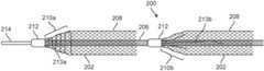
- FIG. 2depicts one embodiment of a pushable, distally-open, braided vaso-occlusive device attached to an elongate central coil member, according to one embodiment of the disclosed inventions.
- FIG. 3depicts another embodiment of a pushable, distally-open, braided vaso-occlusive device attached to an elongate central coil member, according to another embodiment of the disclosed inventions.
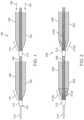
- FIG. 4depicts yet another embodiment of a pushable, distally-open, braided vaso-occlusive device attached to an elongate central coil member, according to yet another embodiment of the disclosed inventions.
- FIG. 5depicts still another embodiment of a pushable, distally-open, braided vaso-occlusive device attached to an elongate central coil member, according to yet another embodiment of the disclosed inventions.
- FIG. 6 Ais a side view of yet another embodiment of a pushable, distally-open, braided vaso-occlusive device attached to an elongate central coil member, according to yet another embodiment of the disclosed inventions.
- FIG. 6 Bis a top view of the braided vaso-occlusive device of FIG. 6 A .
- FIG. 6 Cis an end-view of the braided vaso-occlusive device of FIG. 6 A .
- FIG. 7depicts still another embodiment of a pushable, distally-open, braided vaso-occlusive device attached to an elongate central coil member, according to yet another embodiment of the disclosed inventions.
- references to a structure or feature that is disposed “adjacent” another featuremay have portions that overlap or underlie the adjacent feature.
- spatially relative termssuch as “under”, “below”, “lower”, “over”, “upper” and the like, may be used herein for ease of description to describe one element or feature's relationship to another element(s) or feature(s) as illustrated in the figures. It will be understood that the spatially relative terms are intended to encompass different orientations of the device in use or operation in addition to the orientation depicted in the figures. For example, if a device in the figures is inverted, elements described as “under” or “beneath” other elements or features would then be oriented “over” the other elements or features. Thus, the exemplary term “under” can encompass both an orientation of over and under.
- the devicemay be otherwise oriented (rotated 90 degrees or at other orientations) and the spatially relative descriptors used herein interpreted accordingly.
- terms such as “upwardly”, “downwardly”, “vertical”, “horizontal” and the likeare used herein for the purpose of explanation only unless specifically indicated otherwise.
- first and secondmay be used herein to describe various features/elements, these features/elements should not be limited by these terms, unless the context indicates otherwise. These terms may be used to distinguish one feature/element from another feature/element. Thus, a first feature/element discussed below could be termed a second feature/element, and similarly, a second feature/element discussed below could be termed a first feature/element without departing from the teachings of the disclosed inventions.
- a numeric valuemay have a value that is +/ ⁇ 0.1% of the stated value (or range of values), +/ ⁇ 1% of the stated value (or range of values), +/ ⁇ 2% of the stated value (or range of values), +/ ⁇ 5% of the stated value (or range of values), +/ ⁇ 10% of the stated value (or range of values), etc. Any numerical range recited herein is intended to include all sub-ranges subsumed therein.
- vaso-occlusive deviceshaving one or more expandable braided portions (e.g., braid 108 in FIG. 1 ), each braided portion having at least one end (typically a proximal end) bonded to an elongate central member (e.g., coil 106 in FIG. 1 ) are disclosed and described herein. It should be appreciated that various features and aspects of the disclosed embodiments will also be useful and applicable for braided vaso-occlusive devices that do not have a central member (whether in the form of a coil or otherwise). For example, employing a flexible junction for attaching one end of an expandable braid to a central member as depicted in the embodiments shown in FIGS. 4 - 7 is advantageous even if the member to which the braid is bonded does not extend beyond (or much beyond) the junction. Nor are the advantages obtained by these embodiments of a flexible joint connecting the braid limited to connections to a coil member.
- each braid piece 102when pushing (indicated by arrows 104 ) a braided occlusive device 100 through a delivery catheter (not shown), the maximum longitudinal compressive forces on each braid piece 102 will be located at a respective tapered, transition section 110 in which the respective braid 102 transitions from a bonded braid section 112 (bonded to the inner coil member 106 , which itself is attached to a pusher wire 114 ) to a main body portion 108 , in which the respective braid 102 is free to expand to its fully expanded heat-treated diameter. Therefore, when friction in the delivery catheter is high while pushing the device 100 therethrough, the respective tapered transition section 110 of each braid member 102 is most likely to be damaged, wrinkle, bunch up and/or otherwise become unstable. Also, the braid in the transition section 110 may take on a “permanent” new shape after being loading into the delivery catheter lumen, which is not conducive for being pushed through (and out) of the delivery catheter.
- design and manufacturing variations and techniquesmay be employed so that the respective braid transition section 110 is less likely to become damaged when pushing the device through a delivery catheter.
- Such design and manufacturing variations and techniquesmay include (i) improving the heat treating process to insure greater memory of the tapered braid shape in the transition section 110 ; (ii) increasing the number and/or diameters of the braided filaments to add stiffness to the transition section 110 ; (iii) selectively adding additional filament(s) to the transition section 110 after or during the braiding process, e.g., in which the additional filament(s) is/are bonded, threated, sutured, tied, etc., to the braid to create a stress relief transition between the bonded braid section 112 and expanded braid section 108 ; (iv) shrinking (e.g., as in shrink-wrap fitting), bonding, or otherwise attaching a reinforcing thin metallic or polymeric film around the transition section 110 , wherein the film may cover the whole surface area of the braid section
- FIG. 2depicts an alternative multi-braid vaso-occlusive device 200 , constructed according to one embodiment of the disclosed inventions.
- the vaso-occlusive 200has a plurality of braid members 202 , each braid member 202 including a tapered transition section ( 210 a and 210 b ) in which the respective braid member 202 transitions from a bonded braid section 212 (bonded to the inner coil member 206 , which itself is attached to a pusher wire 214 ) to a main body portion 208 , in which the respective braid 202 is free to expand to its fully expanded heat-treated diameter.
- the device 200differs from device 100 , in that the respective braid transition sections 210 a and 210 b include added adhesive reinforcement to maintain their structural rigidity when loaded into, and pushed through, the delivery lumen of a delivery catheter (not shown).
- the distal ends of the braid memberscan be modified, so that rather than having all the members (or “filaments”) being straight and of similar length, some of the filaments in the braid construction would be shorter than others to reduce the numbers of filaments at the braid distal end. For example 10%, 20, 30%, 40%, 50%, 60% or 70% of the filaments would be shorter than the longest filament.
- the shorter elementswould be 3-10 mm shorter than the longest element.
- the braid member filament ends 304could be heat set to have a relaxed configuration flare outwards or inwards in a radial fashion. Such a heat shape would reduce the stiffness of the braid member filament ends 304 .
- the braid member filament ends 304could be flipped/folded (everting or inverting) back onto the main body portion 308 of the braid 302 .
- the device 400includes at least a first braid member 402 , wherein a proximal end portion 411 of the braid 402 is attached to an inner coil member 406 using a flexible junction 410 .
- a proximal end portion 411 of the braid 402is attached to an inner coil member 406 using a flexible junction 410 .
- the respective braid filaments or wires forming the braid 402are wrapped into a helical, coil like structure 410 that extends proximally from the main body portion 408 of the braid 402 , and is fused or otherwise attached to the inner coil member 406 proximate a junction 412 formed between the coil 406 and a pusher member 414 .
- the proximal braid portion 410is formed and optionally heat set into a helical shape. To reduce the assembly diameter created by the helical braid structure 410 being wrapped around the coil 406 , the ends of the braid filaments may be unraveled (unbraided) to form straight filaments and then helically wound, as depicted in FIG. 5 .
- FIG. 5depicts a further alternative braided vaso-occlusive device 500 , including at least a first braid member 502 , wherein the individual braid filaments 516 in a proximal end portion 511 of the braid 502 are unraveled (unbraided) to form straight filaments, which are then wound into the depicted helical formation, and attached to the inner coil member 506 proximate a junction 512 formed between the coil 506 and a pusher member 514 .
- the proximal braid portion 510is formed and optionally heat set into a helical shape.
- the respective braid member 402 / 502is concentrically loaded around the respective central coil member 406 / 506 .
- the main braid section 402 / 502 , along with the respective proximal (helically wound) flexible transition section 410 / 510may be concentrically placed around the coil 406 / 506 , where the proximal portion of the respective braid member 402 / 502 is oriented so the transition section 410 / 510 is twisted around the center coil 406 / 506 in either a clockwise or counterclockwise orientation.
- the proximal end of the respective transition sectionsmay be secured to the respective coil 406 / 506 .
- the resulting, twisted helical-like braid structuresmay include some unraveled filaments, such as depicted in FIG. 5 .
- a braid member 602 of the further alternative vaso-occlusive device 600 depicted in FIGS. 6 A, 6 B and 6 Cis positioned adjacent to, and mostly parallel with, an elongate central coil 606 , and not in a concentric arrangement.
- a braid member 602 of the further alternative vaso-occlusive device 600 depicted in FIGS. 6 A, 6 B and 6 Cis positioned adjacent to, and mostly parallel with, an elongate central coil 606 , and not in a concentric arrangement.
- the braid in FIG. 6 Bmay be attached to the coil at one or more axially spaced attachment locations 605 by securing one or more braid filaments that are most proximal to the side of the coil 606 , through an adhesive, suture looped around filaments around coil 606 or other means or combination thereof.
- the proximal end 711 of the braid 702may be split into two separate bunches of filaments, bunch 703 and bunch 705 . Both bunches are formed into their own helical shape and placed around the coil element 706 .
- the maximum diameter of the device 700should be smaller than the deice 300 shown in FIG. 3 assuming the braid construction (number of filaments/ends, size of filament, braid angle . . . etc.) and the coil construction are otherwise the same.
- the embodiment shown in FIG. 3could have three or more separate bunches of filaments, wherein each bunch of filaments could be unraveled or unbraided so as to lie in parallel to each other when formed into a coil, further reducing its effective assembly diameter.
Landscapes
- Health & Medical Sciences (AREA)
- Life Sciences & Earth Sciences (AREA)
- Surgery (AREA)
- Engineering & Computer Science (AREA)
- Biomedical Technology (AREA)
- Animal Behavior & Ethology (AREA)
- Veterinary Medicine (AREA)
- Vascular Medicine (AREA)
- Public Health (AREA)
- Heart & Thoracic Surgery (AREA)
- General Health & Medical Sciences (AREA)
- Molecular Biology (AREA)
- Medical Informatics (AREA)
- Nuclear Medicine, Radiotherapy & Molecular Imaging (AREA)
- Reproductive Health (AREA)
- Cardiology (AREA)
- Oral & Maxillofacial Surgery (AREA)
- Transplantation (AREA)
- Neurosurgery (AREA)
- Surgical Instruments (AREA)
Abstract
Description
Claims (20)
Priority Applications (1)
| Application Number | Priority Date | Filing Date | Title |
|---|---|---|---|
| US17/182,194US11751880B2 (en) | 2015-05-08 | 2021-02-22 | Vaso-occlusive devices |
Applications Claiming Priority (4)
| Application Number | Priority Date | Filing Date | Title |
|---|---|---|---|
| US201562159154P | 2015-05-08 | 2015-05-08 | |
| US15/148,872US10159490B2 (en) | 2015-05-08 | 2016-05-06 | Vaso-occlusive devices |
| US16/221,808US10925612B2 (en) | 2015-05-08 | 2018-12-17 | Vaso-occlusive devices |
| US17/182,194US11751880B2 (en) | 2015-05-08 | 2021-02-22 | Vaso-occlusive devices |
Related Parent Applications (1)
| Application Number | Title | Priority Date | Filing Date |
|---|---|---|---|
| US16/221,808ContinuationUS10925612B2 (en) | 2015-05-08 | 2018-12-17 | Vaso-occlusive devices |
Publications (2)
| Publication Number | Publication Date |
|---|---|
| US20210204955A1 US20210204955A1 (en) | 2021-07-08 |
| US11751880B2true US11751880B2 (en) | 2023-09-12 |
Family
ID=56081584
Family Applications (3)
| Application Number | Title | Priority Date | Filing Date |
|---|---|---|---|
| US15/148,872Active2037-01-01US10159490B2 (en) | 2015-05-08 | 2016-05-06 | Vaso-occlusive devices |
| US16/221,808Active2036-09-05US10925612B2 (en) | 2015-05-08 | 2018-12-17 | Vaso-occlusive devices |
| US17/182,194Active2036-12-29US11751880B2 (en) | 2015-05-08 | 2021-02-22 | Vaso-occlusive devices |
Family Applications Before (2)
| Application Number | Title | Priority Date | Filing Date |
|---|---|---|---|
| US15/148,872Active2037-01-01US10159490B2 (en) | 2015-05-08 | 2016-05-06 | Vaso-occlusive devices |
| US16/221,808Active2036-09-05US10925612B2 (en) | 2015-05-08 | 2018-12-17 | Vaso-occlusive devices |
Country Status (2)
| Country | Link |
|---|---|
| US (3) | US10159490B2 (en) |
| WO (1) | WO2016182949A1 (en) |
Families Citing this family (44)
| Publication number | Priority date | Publication date | Assignee | Title |
|---|---|---|---|---|
| US11471163B2 (en) | 2008-05-01 | 2022-10-18 | Aneuclose Llc | Intrasaccular aneurysm occlusion device with net or mesh expanded by string-of-pearls embolies |
| US11357511B2 (en) | 2008-05-01 | 2022-06-14 | Aneuclose Llc | Intrasacular aneurysm occlusion device with globular first configuration and bowl-shaped second configuration |
| US11583289B2 (en) | 2008-05-01 | 2023-02-21 | Aneuclose Llc | Aneurysm-occluding mesh ribbon with a series of loops or segments having distal-to-proximal variation in size, shape, and/or orientation |
| US11484322B2 (en) | 2018-01-03 | 2022-11-01 | Aneuclose Llc | Aneurysm neck bridge with a closeable opening or lumen through which embolic material is inserted into the aneurysm sac |
| US11471164B2 (en) | 2008-05-01 | 2022-10-18 | Aneuclose Llc | Methods of occluding a cerebral aneurysm by inserting embolic members or material into an intrasacular implant |
| US11464518B2 (en) | 2008-05-01 | 2022-10-11 | Aneuclose Llc | Proximal concave neck bridge with central lumen and distal net for occluding cerebral aneurysms |
| AU2009242528B2 (en) | 2008-05-02 | 2015-12-10 | Microvention, Inc. | Filamentary devices for treatment of vascular defects |
| WO2013119332A2 (en) | 2012-02-09 | 2013-08-15 | Stout Medical Group, L.P. | Embolic device and methods of use |
| US9955976B2 (en) | 2013-08-16 | 2018-05-01 | Sequent Medical, Inc. | Filamentary devices for treatment of vascular defects |
| US9629635B2 (en) | 2014-04-14 | 2017-04-25 | Sequent Medical, Inc. | Devices for therapeutic vascular procedures |
| US10130372B2 (en) | 2014-04-30 | 2018-11-20 | Cerus Endovascular Limited | Occlusion Device |
| JP6241969B2 (en) | 2014-05-28 | 2017-12-06 | ストライカー ヨーロピアン ホールディングス I,エルエルシーStryker European Holdings I,Llc | Vascular occlusion device and method of use thereof |
| US10736730B2 (en) | 2015-01-20 | 2020-08-11 | Neurogami Medical, Inc. | Vascular implant |
| US10925611B2 (en) | 2015-01-20 | 2021-02-23 | Neurogami Medical, Inc. | Packaging for surgical implant |
| CA2972620C (en) | 2015-01-20 | 2023-08-01 | Neurogami Medical, Inc. | Micrograft for the treatment of intracranial aneurysms and method for use |
| US11484319B2 (en) | 2015-01-20 | 2022-11-01 | Neurogami Medical, Inc. | Delivery system for micrograft for treating intracranial aneurysms |
| US10857012B2 (en) | 2015-01-20 | 2020-12-08 | Neurogami Medical, Inc. | Vascular implant |
| US10159490B2 (en) | 2015-05-08 | 2018-12-25 | Stryker European Holdings I, Llc | Vaso-occlusive devices |
| US12082845B2 (en) | 2015-09-04 | 2024-09-10 | The Trustees Of The University Of Pennsylvania | Systems and methods for percutaneous removal of objects from an internal body space |
| EP4011303B1 (en) | 2015-12-07 | 2024-06-12 | Cerus Endovascular Limited | Occlusion device |
| WO2017153603A1 (en) | 2016-03-11 | 2017-09-14 | Cerus Endovascular Limited | Occlusion device |
| EP3463109A4 (en) | 2016-05-26 | 2020-01-08 | Nanostructures, Inc. | System and methods for embolized occlusion of neurovascular aneurysms |
| US10420563B2 (en) | 2016-07-08 | 2019-09-24 | Neurogami Medical, Inc. | Delivery system insertable through body lumen |
| US10857328B2 (en) | 2018-01-16 | 2020-12-08 | Daniel Ezra Walzman | Bypass catheter |
| WO2018053314A1 (en)* | 2016-09-16 | 2018-03-22 | Greg Mirigian | Occlusive implants with fiber-based release structures |
| US10857335B2 (en) | 2017-02-13 | 2020-12-08 | Daniel Ezra Walzman | Temporary bypass balloon catheter |
| JP7414710B2 (en) | 2017-08-21 | 2024-01-16 | シーラス エンドバスキュラー リミテッド | occlusion device |
| US11596438B2 (en) | 2018-01-16 | 2023-03-07 | Daniel Ezra Walzman | Bypass catheter |
| US11006996B2 (en) | 2018-01-16 | 2021-05-18 | Daniel Ezra Walzman | Torus balloon with energy emitters for intravascular lithotripsy |
| US11596769B2 (en) | 2018-01-16 | 2023-03-07 | Daniel Ezra Walzman | Bypass catheter |
| US10799674B2 (en) | 2018-01-16 | 2020-10-13 | Daniel Ezra Walzman | Bypass catheter |
| US10926061B2 (en) | 2018-01-16 | 2021-02-23 | Daniel Ezra Walzman | Bypass catheter |
| CN111936063B (en) | 2018-01-31 | 2024-08-20 | 纳米结构公司 | Vascular occlusion device utilizing thin film nitinol foil |
| US10912569B2 (en) | 2018-08-22 | 2021-02-09 | Covidien Lp | Aneurysm treatment coils and associated systems and methods of use |
| US10905432B2 (en) | 2018-08-22 | 2021-02-02 | Covidien Lp | Aneurysm treatment coils and associated systems and methods of use |
| WO2020060932A1 (en) | 2018-09-18 | 2020-03-26 | Nanostructures, Inc. | Catheter based methods and devices for obstructive blood flow restriction |
| CN113573765B (en)* | 2019-03-15 | 2024-08-13 | 美科微先股份有限公司 | Silk device for treating vascular defects |
| US11559309B2 (en) | 2019-03-15 | 2023-01-24 | Sequent Medical, Inc. | Filamentary devices for treatment of vascular defects |
| US11406404B2 (en) | 2020-02-20 | 2022-08-09 | Cerus Endovascular Limited | Clot removal distal protection methods |
| US12023034B2 (en) | 2020-03-11 | 2024-07-02 | Microvention, Inc. | Devices for treatment of vascular defects |
| US12070220B2 (en) | 2020-03-11 | 2024-08-27 | Microvention, Inc. | Devices having multiple permeable shells for treatment of vascular defects |
| US20210282789A1 (en) | 2020-03-11 | 2021-09-16 | Microvention, Inc. | Multiple layer devices for treatment of vascular defects |
| WO2022132778A1 (en)* | 2020-12-14 | 2022-06-23 | Julason Richard D | Occluding medical devices and methods of use |
| CN116077126B (en)* | 2023-02-15 | 2024-05-07 | 晨兴(南通)医疗器械有限公司 | Vascular occlusion device, manufacturing method and installation method thereof |
Citations (114)
| Publication number | Priority date | Publication date | Assignee | Title |
|---|---|---|---|---|
| US4655771A (en) | 1982-04-30 | 1987-04-07 | Shepherd Patents S.A. | Prosthesis comprising an expansible or contractile tubular body |
| US4754685A (en) | 1986-05-12 | 1988-07-05 | Raychem Corporation | Abrasion resistant braided sleeve |
| US4820298A (en) | 1987-11-20 | 1989-04-11 | Leveen Eric G | Internal vascular prosthesis |
| US4870887A (en) | 1988-03-18 | 1989-10-03 | The Bentley-Harris Manufacturing Company | Braided sleeve |
| US4994069A (en) | 1988-11-02 | 1991-02-19 | Target Therapeutics | Vaso-occlusion coil and method |
| US5186992A (en) | 1990-03-12 | 1993-02-16 | The Bentley-Harris Manufacturing Company | Braided product and method of making same |
| US5217484A (en) | 1991-06-07 | 1993-06-08 | Marks Michael P | Retractable-wire catheter device and method |
| US5304194A (en) | 1991-10-02 | 1994-04-19 | Target Therapeutics | Vasoocclusion coil with attached fibrous element(s) |
| US5382259A (en) | 1992-10-26 | 1995-01-17 | Target Therapeutics, Inc. | Vasoocclusion coil with attached tubular woven or braided fibrous covering |
| US5423849A (en) | 1993-01-15 | 1995-06-13 | Target Therapeutics, Inc. | Vasoocclusion device containing radiopaque fibers |
| US5536274A (en) | 1991-02-15 | 1996-07-16 | pfm Produkterfur Die Medizin | Spiral implant for organ pathways |
| US5639277A (en) | 1995-04-28 | 1997-06-17 | Target Therapeutics, Inc. | Embolic coils with offset helical and twisted helical shapes |
| US5690667A (en) | 1996-09-26 | 1997-11-25 | Target Therapeutics | Vasoocclusion coil having a polymer tip |
| US5690666A (en) | 1992-11-18 | 1997-11-25 | Target Therapeutics, Inc. | Ultrasoft embolism coils and process for using them |
| US5792157A (en) | 1992-11-13 | 1998-08-11 | Scimed Life Systems, Inc. | Expandable intravascular occlusion material removal devices and methods of use |
| US5888201A (en) | 1996-02-08 | 1999-03-30 | Schneider (Usa) Inc | Titanium alloy self-expanding stent |
| US5891191A (en) | 1996-04-30 | 1999-04-06 | Schneider (Usa) Inc | Cobalt-chromium-molybdenum alloy stent and stent-graft |
| WO1999039646A1 (en) | 1998-02-06 | 1999-08-12 | Aga Medical Corp. | Percutaneous catheter directed constricting occlusion device |
| US5964797A (en) | 1996-08-30 | 1999-10-12 | Target Therapeutics, Inc. | Electrolytically deployable braided vaso-occlusion device |
| US5976162A (en) | 1996-04-10 | 1999-11-02 | Target Therapeutics, Inc. | Soft-ended fibered micro vaso-occlusive devices |
| US6007574A (en)* | 1993-12-28 | 1999-12-28 | Pulnev; Sergei Appolonovich | Stent |
| US6019786A (en) | 1995-10-11 | 2000-02-01 | Schneider (Usa) Inc | Braided composite prosthesis |
| US6024754A (en) | 1996-01-18 | 2000-02-15 | Target Therapeutics Inc. | Aneurysm closure method |
| US6066158A (en) | 1996-07-25 | 2000-05-23 | Target Therapeutics, Inc. | Mechanical clot encasing and removal wire |
| US6096052A (en) | 1998-07-08 | 2000-08-01 | Ovion, Inc. | Occluding device and method of use |
| US6165178A (en) | 1997-08-29 | 2000-12-26 | Scimed Life Systems, Inc. | Fast detaching electrically isolated implant |
| US6187027B1 (en) | 1995-04-28 | 2001-02-13 | Target Therapeutics, Inc. | Vaso-occlusive devices with heat secured polymer fiber |
| US6193728B1 (en) | 1995-06-30 | 2001-02-27 | Target Therapeutics, Inc. | Stretch resistant vaso-occlusive coils (II) |
| US6203547B1 (en) | 1997-12-19 | 2001-03-20 | Target Therapeutics, Inc. | Vaso-occlusion apparatus having a manipulable mechanical detachment joint and a method for using the apparatus |
| US6238403B1 (en) | 1999-10-04 | 2001-05-29 | Microvention, Inc. | Filamentous embolic device with expansible elements |
| US6254592B1 (en) | 1995-06-06 | 2001-07-03 | Target Therapeutics, Inc. | Variable stiffness coils |
| US6287318B1 (en) | 1998-02-13 | 2001-09-11 | Target Therapeutics, Inc. | Vaso-occlusive device with attached polymeric materials |
| US6346117B1 (en) | 2000-03-02 | 2002-02-12 | Prodesco, Inc. | Bag for use in the intravascular treatment of saccular aneurysms |
| US6350270B1 (en) | 2000-01-24 | 2002-02-26 | Scimed Life Systems, Inc. | Aneurysm liner |
| US6361545B1 (en) | 1997-09-26 | 2002-03-26 | Cardeon Corporation | Perfusion filter catheter |
| US20020058992A1 (en) | 2000-10-30 | 2002-05-16 | Greenhalgh E. Skott | Woven tubular graft with regions of varying flexibility |
| US6475227B2 (en) | 1997-12-24 | 2002-11-05 | Scimed Life Systems, Inc. | Vaso-occlusion apparatus having a mechanically expandable detachment joint and a method for using the apparatus |
| US6551340B1 (en) | 1998-10-09 | 2003-04-22 | Board Of Regents The University Of Texas System | Vasoocclusion coil device having a core therein |
| US20030093111A1 (en) | 2001-10-26 | 2003-05-15 | Concentric Medical | Device for vaso-occlusion and interventional therapy |
| US6589256B2 (en) | 1998-03-13 | 2003-07-08 | B. Braun Medical Sas | Covered self-expanding vascular occlusion device |
| US6592617B2 (en) | 1996-04-30 | 2003-07-15 | Boston Scientific Scimed, Inc. | Three-dimensional braided covered stent |
| WO2003082363A1 (en) | 2002-03-28 | 2003-10-09 | Scimed Life Systems, Inc. | Method for spray-coating a tubular medical device |
| US6632241B1 (en) | 2000-03-22 | 2003-10-14 | Endovascular Technologies, Inc. | Self-expanding, pseudo-braided intravascular device |
| US6660020B2 (en) | 1996-12-30 | 2003-12-09 | Target Therapeutics, Inc. | Vaso-occlusive coil with conical end |
| US6682546B2 (en) | 1994-07-08 | 2004-01-27 | Aga Medical Corporation | Intravascular occlusion devices |
| US20040098023A1 (en) | 2002-11-15 | 2004-05-20 | Scimed Life Systems, Inc. | Embolic device made of nanofibers |
| US20040199246A1 (en) | 2003-04-02 | 2004-10-07 | Scimed Life Systems, Inc. | Expandable stent |
| US6860893B2 (en) | 1997-08-29 | 2005-03-01 | Boston Scientific Scimed, Inc. | Stable coil designs |
| US6866677B2 (en) | 2001-04-03 | 2005-03-15 | Medtronic Ave, Inc. | Temporary intraluminal filter guidewire and methods of use |
| US6872218B2 (en) | 1998-12-15 | 2005-03-29 | Micrus Corporation | Variable stiffness coil for vasoocclusive devices |
| WO2005065556A1 (en) | 2003-12-23 | 2005-07-21 | Boston Scientific Limited | Expandable embolic coil |
| US20050222605A1 (en) | 2004-03-16 | 2005-10-06 | Secant Medical, Llc | Occluding coil delivery device and method |
| US20050267510A1 (en) | 2004-05-26 | 2005-12-01 | Nasser Razack | Device for the endovascular treatment of intracranial aneurysms |
| US6974475B1 (en) | 1987-12-08 | 2005-12-13 | Wall W Henry | Angioplasty stent |
| US20050277978A1 (en) | 2004-06-09 | 2005-12-15 | Secant Medical, Llc | Three-dimensional coils for treatment of vascular aneurysms |
| US6984240B1 (en) | 1996-10-25 | 2006-01-10 | Target Therapeutics, Inc. | Detachable multidiameter vasoocclusive coil |
| US20060009799A1 (en) | 2003-05-19 | 2006-01-12 | Kleshinski Stephen J | Embolic filtering method and apparatus |
| US6994689B1 (en) | 1995-06-05 | 2006-02-07 | Medtronic Vascular, Inc. | Occlusion of a vessel |
| US20060030876A1 (en) | 2002-10-29 | 2006-02-09 | Peacock James C Iii | Embolic filter device and related systems and methods |
| US20060116709A1 (en) | 2004-11-26 | 2006-06-01 | Ivan Sepetka | Aneurysm treatment devices and methods |
| US20060116713A1 (en) | 2004-11-26 | 2006-06-01 | Ivan Sepetka | Aneurysm treatment devices and methods |
| US7066946B2 (en) | 2001-04-03 | 2006-06-27 | Medtronic Vascular, Inc | Temporary intraluminal filter guidewire |
| US7128752B2 (en) | 2002-12-23 | 2006-10-31 | Syntheon, Llc | Emboli and thrombi filter device and method of using the same |
| WO2007041624A1 (en) | 2005-10-04 | 2007-04-12 | Boston Scientific Scimed, Inc. | Self-expanding vaso-occlusive devices with regulated expansion |
| US20070233186A1 (en) | 2006-04-03 | 2007-10-04 | Jian Meng | Occlusion device with edge profile that reduces tissue damage |
| US20070233224A1 (en) | 2006-03-30 | 2007-10-04 | Alexander Leynov | Implantable medical endoprosthesis delivery system |
| WO2007123638A1 (en) | 2006-04-05 | 2007-11-01 | Boston Scientific Limited | Vaso-occlusive devices having expandable fibers |
| US7323001B2 (en) | 2003-01-30 | 2008-01-29 | Ev3 Inc. | Embolic filters with controlled pore size |
| US7326225B2 (en) | 1997-12-05 | 2008-02-05 | Micrus Endovascular Corporation | Vasoocclusive device for treatment of aneurysms |
| US20080071356A1 (en) | 2005-04-27 | 2008-03-20 | Stout Medical Group, L.P. | Expandable support device and methods of use |
| US20080097401A1 (en) | 2006-09-22 | 2008-04-24 | Trapp Benjamin M | Cerebral vasculature device |
| US20080097508A1 (en) | 2004-09-17 | 2008-04-24 | Jones Donald K | Expandable Vascular Occlusion Device |
| US20080109057A1 (en) | 2003-12-10 | 2008-05-08 | Calabria Marie F | Multiple point detacher system |
| US20090093873A1 (en) | 2007-09-28 | 2009-04-09 | The Cleveland Clinic Foundation | Vascular graft and method of use |
| US20090105748A1 (en) | 2002-11-12 | 2009-04-23 | Thomas J. Fogarty | Embolization device and a method of using the same |
| US20090112251A1 (en) | 2007-07-25 | 2009-04-30 | Aga Medical Corporation | Braided occlusion device having repeating expanded volume segments separated by articulation segments |
| US20090210047A1 (en) | 2008-02-18 | 2009-08-20 | Aga Medical Corporation | Stent graft for reinforcement of vascular abnormalities and associated method |
| US20090266366A1 (en) | 2008-04-25 | 2009-10-29 | Betsy Swann | Devices and methods for occluding a fallopian tube |
| US20090297582A1 (en) | 2004-11-26 | 2009-12-03 | Biomerix Corporation | Vascular occlusion devices and methods |
| US20100063578A1 (en) | 2008-09-05 | 2010-03-11 | Aga Medical Corporation | Bifurcated medical device for treating a target site and associated method |
| US20100152766A1 (en) | 1999-11-04 | 2010-06-17 | Concentric Medical, Inc. | Methods and devices for filtering fluid flow through a body structure |
| US7749242B2 (en) | 2004-06-21 | 2010-07-06 | Boston Scientific Scimed, Inc. | Expanding vaso-occlusive device |
| US7828816B2 (en) | 1994-07-08 | 2010-11-09 | Ev3 Inc. | Method and device for filtering body fluid |
| WO2010135352A1 (en) | 2009-05-18 | 2010-11-25 | Pneumrx, Inc. | Cross-sectional modification during deployment of an elongate lung volume reduction device |
| US7879062B2 (en) | 2003-07-22 | 2011-02-01 | Lumen Biomedical, Inc. | Fiber based embolism protection device |
| US8002789B2 (en) | 2005-05-31 | 2011-08-23 | Stryker Corporation | Stretch-resistant vaso-occlusive devices with flexible detachment junctions |
| US20110213405A1 (en) | 2005-01-12 | 2011-09-01 | Stephen Christopher Porter | Vaso-occlusive devices with attached polymer structures |
| US8016852B2 (en) | 1998-11-10 | 2011-09-13 | Stryker Corporation | Bioactive components for incorporation with vaso-occlusive members |
| CN102368963A (en) | 2009-04-06 | 2012-03-07 | 斯瑞克公司 | Delivery wire for occlusive device delivery system |
| USRE43311E1 (en) | 1997-08-29 | 2012-04-10 | Stryker Corporation | Fast-detaching electrically insulated implant |
| US8172862B2 (en) | 1999-06-04 | 2012-05-08 | Stryker Corporation | Polymer covered vaso-occlusive devices and methods of producing such devices |
| US8182506B2 (en) | 2004-08-25 | 2012-05-22 | Microvention, Inc. | Thermal detachment system for implantable devices |
| US20120158034A1 (en) | 2010-12-16 | 2012-06-21 | Wilson Thomas S | Expandable Implant and Implant System |
| US20120259404A1 (en) | 2010-12-13 | 2012-10-11 | Microvention, Inc. | Stent |
| US8361138B2 (en) | 2007-07-25 | 2013-01-29 | Aga Medical Corporation | Braided occlusion device having repeating expanded volume segments separated by articulation segments |
| US8414635B2 (en)* | 1999-02-01 | 2013-04-09 | Idev Technologies, Inc. | Plain woven stents |
| US20130112070A1 (en) | 2008-07-29 | 2013-05-09 | Aga Medical Corporation | Medical device including corrugated braid and associated method |
| US20130116722A1 (en) | 2010-09-10 | 2013-05-09 | Medina Medical | Devices and methods for the treatment of vascular defects |
| WO2013102848A2 (en) | 2012-01-04 | 2013-07-11 | Rapid Medical Ltd. | Devices and methods for assisting medical treatments |
| US8486104B2 (en) | 1997-09-30 | 2013-07-16 | Stryker Corporation | Mechanical clot treatment device with distal filter |
| WO2013119332A2 (en) | 2012-02-09 | 2013-08-15 | Stout Medical Group, L.P. | Embolic device and methods of use |
| US20130253572A1 (en) | 2012-03-23 | 2013-09-26 | Covidien Lp | Occlusive devices and methods of use |
| US20130274849A1 (en) | 2006-02-22 | 2013-10-17 | Covidien Lp | Stents having radiopaque mesh |
| US8603128B2 (en) | 1999-10-04 | 2013-12-10 | Microvention, Inc. | Filamentous embolization device with expansible elements |
| US8715317B1 (en) | 2013-07-29 | 2014-05-06 | Insera Therapeutics, Inc. | Flow diverting devices |
| US20140135827A1 (en) | 2004-03-19 | 2014-05-15 | Aga Medical Corporation | Multi-layer braided structures for occluding vascular defects |
| US20140135810A1 (en) | 2012-11-13 | 2014-05-15 | Covidien Lp | Occlusive devices |
| WO2014144980A1 (en) | 2013-03-15 | 2014-09-18 | Covidien Lp | Occlusive device |
| US20140330299A1 (en) | 2013-05-06 | 2014-11-06 | Sequent Medical, Inc. | Embolic occlusion device and method |
| US9060777B1 (en) | 2014-05-28 | 2015-06-23 | Tw Medical Technologies, Llc | Vaso-occlusive devices and methods of use |
| US20150343181A1 (en) | 2014-06-02 | 2015-12-03 | Cook Medical Technologies Llc | Occlusion device and methods of using the same |
| WO2015184075A1 (en) | 2014-05-28 | 2015-12-03 | Stryker European Holdings I, Llc | Vaso-occlusive devices and methods of use |
| US9211396B2 (en) | 2010-02-23 | 2015-12-15 | Covidien Lp | Devices and methods for vascular recanalization |
| US10159490B2 (en) | 2015-05-08 | 2018-12-25 | Stryker European Holdings I, Llc | Vaso-occlusive devices |
- 2016
- 2016-05-06USUS15/148,872patent/US10159490B2/enactiveActive
- 2016-05-06WOPCT/US2016/031323patent/WO2016182949A1/ennot_activeCeased
- 2018
- 2018-12-17USUS16/221,808patent/US10925612B2/enactiveActive
- 2021
- 2021-02-22USUS17/182,194patent/US11751880B2/enactiveActive
Patent Citations (127)
| Publication number | Priority date | Publication date | Assignee | Title |
|---|---|---|---|---|
| US4655771A (en) | 1982-04-30 | 1987-04-07 | Shepherd Patents S.A. | Prosthesis comprising an expansible or contractile tubular body |
| US4655771B1 (en) | 1982-04-30 | 1996-09-10 | Medinvent Ams Sa | Prosthesis comprising an expansible or contractile tubular body |
| US4754685A (en) | 1986-05-12 | 1988-07-05 | Raychem Corporation | Abrasion resistant braided sleeve |
| US4820298A (en) | 1987-11-20 | 1989-04-11 | Leveen Eric G | Internal vascular prosthesis |
| US6974475B1 (en) | 1987-12-08 | 2005-12-13 | Wall W Henry | Angioplasty stent |
| US4870887A (en) | 1988-03-18 | 1989-10-03 | The Bentley-Harris Manufacturing Company | Braided sleeve |
| US4994069A (en) | 1988-11-02 | 1991-02-19 | Target Therapeutics | Vaso-occlusion coil and method |
| US5186992A (en) | 1990-03-12 | 1993-02-16 | The Bentley-Harris Manufacturing Company | Braided product and method of making same |
| US5536274A (en) | 1991-02-15 | 1996-07-16 | pfm Produkterfur Die Medizin | Spiral implant for organ pathways |
| US5217484A (en) | 1991-06-07 | 1993-06-08 | Marks Michael P | Retractable-wire catheter device and method |
| US5304194A (en) | 1991-10-02 | 1994-04-19 | Target Therapeutics | Vasoocclusion coil with attached fibrous element(s) |
| US5382259A (en) | 1992-10-26 | 1995-01-17 | Target Therapeutics, Inc. | Vasoocclusion coil with attached tubular woven or braided fibrous covering |
| US5792157A (en) | 1992-11-13 | 1998-08-11 | Scimed Life Systems, Inc. | Expandable intravascular occlusion material removal devices and methods of use |
| US5690666A (en) | 1992-11-18 | 1997-11-25 | Target Therapeutics, Inc. | Ultrasoft embolism coils and process for using them |
| US6458119B1 (en) | 1992-11-18 | 2002-10-01 | Target Therapeutics, Inc. | Ultrasoft embolism devices and process for using them |
| US5423849A (en) | 1993-01-15 | 1995-06-13 | Target Therapeutics, Inc. | Vasoocclusion device containing radiopaque fibers |
| US6007574A (en)* | 1993-12-28 | 1999-12-28 | Pulnev; Sergei Appolonovich | Stent |
| US6682546B2 (en) | 1994-07-08 | 2004-01-27 | Aga Medical Corporation | Intravascular occlusion devices |
| US7828816B2 (en) | 1994-07-08 | 2010-11-09 | Ev3 Inc. | Method and device for filtering body fluid |
| US5639277A (en) | 1995-04-28 | 1997-06-17 | Target Therapeutics, Inc. | Embolic coils with offset helical and twisted helical shapes |
| US6187027B1 (en) | 1995-04-28 | 2001-02-13 | Target Therapeutics, Inc. | Vaso-occlusive devices with heat secured polymer fiber |
| US6994689B1 (en) | 1995-06-05 | 2006-02-07 | Medtronic Vascular, Inc. | Occlusion of a vessel |
| US6254592B1 (en) | 1995-06-06 | 2001-07-03 | Target Therapeutics, Inc. | Variable stiffness coils |
| US6193728B1 (en) | 1995-06-30 | 2001-02-27 | Target Therapeutics, Inc. | Stretch resistant vaso-occlusive coils (II) |
| US6019786A (en) | 1995-10-11 | 2000-02-01 | Schneider (Usa) Inc | Braided composite prosthesis |
| US6024754A (en) | 1996-01-18 | 2000-02-15 | Target Therapeutics Inc. | Aneurysm closure method |
| US5888201A (en) | 1996-02-08 | 1999-03-30 | Schneider (Usa) Inc | Titanium alloy self-expanding stent |
| US5976162A (en) | 1996-04-10 | 1999-11-02 | Target Therapeutics, Inc. | Soft-ended fibered micro vaso-occlusive devices |
| US6592617B2 (en) | 1996-04-30 | 2003-07-15 | Boston Scientific Scimed, Inc. | Three-dimensional braided covered stent |
| US5891191A (en) | 1996-04-30 | 1999-04-06 | Schneider (Usa) Inc | Cobalt-chromium-molybdenum alloy stent and stent-graft |
| US6066158A (en) | 1996-07-25 | 2000-05-23 | Target Therapeutics, Inc. | Mechanical clot encasing and removal wire |
| US5964797A (en) | 1996-08-30 | 1999-10-12 | Target Therapeutics, Inc. | Electrolytically deployable braided vaso-occlusion device |
| US5690667A (en) | 1996-09-26 | 1997-11-25 | Target Therapeutics | Vasoocclusion coil having a polymer tip |
| US6984240B1 (en) | 1996-10-25 | 2006-01-10 | Target Therapeutics, Inc. | Detachable multidiameter vasoocclusive coil |
| US6660020B2 (en) | 1996-12-30 | 2003-12-09 | Target Therapeutics, Inc. | Vaso-occlusive coil with conical end |
| USRE43311E1 (en) | 1997-08-29 | 2012-04-10 | Stryker Corporation | Fast-detaching electrically insulated implant |
| US6165178A (en) | 1997-08-29 | 2000-12-26 | Scimed Life Systems, Inc. | Fast detaching electrically isolated implant |
| US6860893B2 (en) | 1997-08-29 | 2005-03-01 | Boston Scientific Scimed, Inc. | Stable coil designs |
| US6361545B1 (en) | 1997-09-26 | 2002-03-26 | Cardeon Corporation | Perfusion filter catheter |
| US8486104B2 (en) | 1997-09-30 | 2013-07-16 | Stryker Corporation | Mechanical clot treatment device with distal filter |
| US7326225B2 (en) | 1997-12-05 | 2008-02-05 | Micrus Endovascular Corporation | Vasoocclusive device for treatment of aneurysms |
| US6203547B1 (en) | 1997-12-19 | 2001-03-20 | Target Therapeutics, Inc. | Vaso-occlusion apparatus having a manipulable mechanical detachment joint and a method for using the apparatus |
| US6475227B2 (en) | 1997-12-24 | 2002-11-05 | Scimed Life Systems, Inc. | Vaso-occlusion apparatus having a mechanically expandable detachment joint and a method for using the apparatus |
| WO1999039646A1 (en) | 1998-02-06 | 1999-08-12 | Aga Medical Corp. | Percutaneous catheter directed constricting occlusion device |
| US6287318B1 (en) | 1998-02-13 | 2001-09-11 | Target Therapeutics, Inc. | Vaso-occlusive device with attached polymeric materials |
| US6589256B2 (en) | 1998-03-13 | 2003-07-08 | B. Braun Medical Sas | Covered self-expanding vascular occlusion device |
| US6096052A (en) | 1998-07-08 | 2000-08-01 | Ovion, Inc. | Occluding device and method of use |
| US6551340B1 (en) | 1998-10-09 | 2003-04-22 | Board Of Regents The University Of Texas System | Vasoocclusion coil device having a core therein |
| US8016852B2 (en) | 1998-11-10 | 2011-09-13 | Stryker Corporation | Bioactive components for incorporation with vaso-occlusive members |
| US6872218B2 (en) | 1998-12-15 | 2005-03-29 | Micrus Corporation | Variable stiffness coil for vasoocclusive devices |
| US8414635B2 (en)* | 1999-02-01 | 2013-04-09 | Idev Technologies, Inc. | Plain woven stents |
| US8172862B2 (en) | 1999-06-04 | 2012-05-08 | Stryker Corporation | Polymer covered vaso-occlusive devices and methods of producing such devices |
| US6238403B1 (en) | 1999-10-04 | 2001-05-29 | Microvention, Inc. | Filamentous embolic device with expansible elements |
| US8603128B2 (en) | 1999-10-04 | 2013-12-10 | Microvention, Inc. | Filamentous embolization device with expansible elements |
| US20100152766A1 (en) | 1999-11-04 | 2010-06-17 | Concentric Medical, Inc. | Methods and devices for filtering fluid flow through a body structure |
| US6350270B1 (en) | 2000-01-24 | 2002-02-26 | Scimed Life Systems, Inc. | Aneurysm liner |
| US6346117B1 (en) | 2000-03-02 | 2002-02-12 | Prodesco, Inc. | Bag for use in the intravascular treatment of saccular aneurysms |
| US6632241B1 (en) | 2000-03-22 | 2003-10-14 | Endovascular Technologies, Inc. | Self-expanding, pseudo-braided intravascular device |
| US20020058992A1 (en) | 2000-10-30 | 2002-05-16 | Greenhalgh E. Skott | Woven tubular graft with regions of varying flexibility |
| US7066946B2 (en) | 2001-04-03 | 2006-06-27 | Medtronic Vascular, Inc | Temporary intraluminal filter guidewire |
| US6866677B2 (en) | 2001-04-03 | 2005-03-15 | Medtronic Ave, Inc. | Temporary intraluminal filter guidewire and methods of use |
| US20030093111A1 (en) | 2001-10-26 | 2003-05-15 | Concentric Medical | Device for vaso-occlusion and interventional therapy |
| WO2003082363A1 (en) | 2002-03-28 | 2003-10-09 | Scimed Life Systems, Inc. | Method for spray-coating a tubular medical device |
| US20060030876A1 (en) | 2002-10-29 | 2006-02-09 | Peacock James C Iii | Embolic filter device and related systems and methods |
| US20090105748A1 (en) | 2002-11-12 | 2009-04-23 | Thomas J. Fogarty | Embolization device and a method of using the same |
| US20040098023A1 (en) | 2002-11-15 | 2004-05-20 | Scimed Life Systems, Inc. | Embolic device made of nanofibers |
| WO2004045425A1 (en) | 2002-11-15 | 2004-06-03 | Boston Scientific Limted | Embolic device made of nanofibers |
| US7128752B2 (en) | 2002-12-23 | 2006-10-31 | Syntheon, Llc | Emboli and thrombi filter device and method of using the same |
| US7323001B2 (en) | 2003-01-30 | 2008-01-29 | Ev3 Inc. | Embolic filters with controlled pore size |
| US20040199246A1 (en) | 2003-04-02 | 2004-10-07 | Scimed Life Systems, Inc. | Expandable stent |
| US20060009799A1 (en) | 2003-05-19 | 2006-01-12 | Kleshinski Stephen J | Embolic filtering method and apparatus |
| US7879062B2 (en) | 2003-07-22 | 2011-02-01 | Lumen Biomedical, Inc. | Fiber based embolism protection device |
| US20080109057A1 (en) | 2003-12-10 | 2008-05-08 | Calabria Marie F | Multiple point detacher system |
| WO2005065556A1 (en) | 2003-12-23 | 2005-07-21 | Boston Scientific Limited | Expandable embolic coil |
| US20050222605A1 (en) | 2004-03-16 | 2005-10-06 | Secant Medical, Llc | Occluding coil delivery device and method |
| US20140135827A1 (en) | 2004-03-19 | 2014-05-15 | Aga Medical Corporation | Multi-layer braided structures for occluding vascular defects |
| US8777974B2 (en) | 2004-03-19 | 2014-07-15 | Aga Medical Corporation | Multi-layer braided structures for occluding vascular defects |
| US20050267510A1 (en) | 2004-05-26 | 2005-12-01 | Nasser Razack | Device for the endovascular treatment of intracranial aneurysms |
| US20050277978A1 (en) | 2004-06-09 | 2005-12-15 | Secant Medical, Llc | Three-dimensional coils for treatment of vascular aneurysms |
| US7749242B2 (en) | 2004-06-21 | 2010-07-06 | Boston Scientific Scimed, Inc. | Expanding vaso-occlusive device |
| US20100228278A1 (en) | 2004-06-21 | 2010-09-09 | Boston Scientific Scimed, Inc. | Expanding vaso-occlusive device |
| US8182506B2 (en) | 2004-08-25 | 2012-05-22 | Microvention, Inc. | Thermal detachment system for implantable devices |
| US20080097508A1 (en) | 2004-09-17 | 2008-04-24 | Jones Donald K | Expandable Vascular Occlusion Device |
| US8444668B2 (en) | 2004-09-17 | 2013-05-21 | DePuy Synthes Products, LLC | Expandable vascular occlusion device |
| US20090297582A1 (en) | 2004-11-26 | 2009-12-03 | Biomerix Corporation | Vascular occlusion devices and methods |
| US20060116709A1 (en) | 2004-11-26 | 2006-06-01 | Ivan Sepetka | Aneurysm treatment devices and methods |
| US20060116713A1 (en) | 2004-11-26 | 2006-06-01 | Ivan Sepetka | Aneurysm treatment devices and methods |
| US20110213405A1 (en) | 2005-01-12 | 2011-09-01 | Stephen Christopher Porter | Vaso-occlusive devices with attached polymer structures |
| US20080071356A1 (en) | 2005-04-27 | 2008-03-20 | Stout Medical Group, L.P. | Expandable support device and methods of use |
| US8002789B2 (en) | 2005-05-31 | 2011-08-23 | Stryker Corporation | Stretch-resistant vaso-occlusive devices with flexible detachment junctions |
| WO2007041624A1 (en) | 2005-10-04 | 2007-04-12 | Boston Scientific Scimed, Inc. | Self-expanding vaso-occlusive devices with regulated expansion |
| US20130274849A1 (en) | 2006-02-22 | 2013-10-17 | Covidien Lp | Stents having radiopaque mesh |
| US20070233224A1 (en) | 2006-03-30 | 2007-10-04 | Alexander Leynov | Implantable medical endoprosthesis delivery system |
| US20070233186A1 (en) | 2006-04-03 | 2007-10-04 | Jian Meng | Occlusion device with edge profile that reduces tissue damage |
| US20130267992A1 (en) | 2006-04-05 | 2013-10-10 | Tri D. Tran | Vaso-occlusive devices having expandable fibers |
| WO2007123638A1 (en) | 2006-04-05 | 2007-11-01 | Boston Scientific Limited | Vaso-occlusive devices having expandable fibers |
| US20080097401A1 (en) | 2006-09-22 | 2008-04-24 | Trapp Benjamin M | Cerebral vasculature device |
| US20090112251A1 (en) | 2007-07-25 | 2009-04-30 | Aga Medical Corporation | Braided occlusion device having repeating expanded volume segments separated by articulation segments |
| US8361138B2 (en) | 2007-07-25 | 2013-01-29 | Aga Medical Corporation | Braided occlusion device having repeating expanded volume segments separated by articulation segments |
| US20090093873A1 (en) | 2007-09-28 | 2009-04-09 | The Cleveland Clinic Foundation | Vascular graft and method of use |
| US20090210047A1 (en) | 2008-02-18 | 2009-08-20 | Aga Medical Corporation | Stent graft for reinforcement of vascular abnormalities and associated method |
| US20090266366A1 (en) | 2008-04-25 | 2009-10-29 | Betsy Swann | Devices and methods for occluding a fallopian tube |
| US20130112070A1 (en) | 2008-07-29 | 2013-05-09 | Aga Medical Corporation | Medical device including corrugated braid and associated method |
| US20100063578A1 (en) | 2008-09-05 | 2010-03-11 | Aga Medical Corporation | Bifurcated medical device for treating a target site and associated method |
| CN102368963A (en) | 2009-04-06 | 2012-03-07 | 斯瑞克公司 | Delivery wire for occlusive device delivery system |
| WO2010135352A1 (en) | 2009-05-18 | 2010-11-25 | Pneumrx, Inc. | Cross-sectional modification during deployment of an elongate lung volume reduction device |
| US9211396B2 (en) | 2010-02-23 | 2015-12-15 | Covidien Lp | Devices and methods for vascular recanalization |
| US20130116722A1 (en) | 2010-09-10 | 2013-05-09 | Medina Medical | Devices and methods for the treatment of vascular defects |
| US20120259404A1 (en) | 2010-12-13 | 2012-10-11 | Microvention, Inc. | Stent |
| US20120158034A1 (en) | 2010-12-16 | 2012-06-21 | Wilson Thomas S | Expandable Implant and Implant System |
| WO2013102848A2 (en) | 2012-01-04 | 2013-07-11 | Rapid Medical Ltd. | Devices and methods for assisting medical treatments |
| US9011482B2 (en) | 2012-02-09 | 2015-04-21 | Tw Medical Technologies, Llc | Vaso-occlusive devices including a friction element and methods of use |
| WO2013119332A2 (en) | 2012-02-09 | 2013-08-15 | Stout Medical Group, L.P. | Embolic device and methods of use |
| US20180250013A1 (en) | 2012-02-09 | 2018-09-06 | Stryker European Holdings I, Llc, | Vaso-occlusive devices including a friction element |
| US9907557B2 (en) | 2012-02-09 | 2018-03-06 | Stryker European Holdings I, Llc | Vaso-occlusive devices including a friction element |
| US20140277099A1 (en) | 2012-02-09 | 2014-09-18 | Michael P. Wallace | Vaso-occlusive devices including a friction element and methods of use |
| US20130253572A1 (en) | 2012-03-23 | 2013-09-26 | Covidien Lp | Occlusive devices and methods of use |
| US20140135810A1 (en) | 2012-11-13 | 2014-05-15 | Covidien Lp | Occlusive devices |
| WO2014144980A1 (en) | 2013-03-15 | 2014-09-18 | Covidien Lp | Occlusive device |
| US20140330299A1 (en) | 2013-05-06 | 2014-11-06 | Sequent Medical, Inc. | Embolic occlusion device and method |
| US8715316B1 (en) | 2013-07-29 | 2014-05-06 | Insera Therapeutics, Inc. | Offset vascular treatment devices |
| US8715317B1 (en) | 2013-07-29 | 2014-05-06 | Insera Therapeutics, Inc. | Flow diverting devices |
| US9060777B1 (en) | 2014-05-28 | 2015-06-23 | Tw Medical Technologies, Llc | Vaso-occlusive devices and methods of use |
| WO2015184075A1 (en) | 2014-05-28 | 2015-12-03 | Stryker European Holdings I, Llc | Vaso-occlusive devices and methods of use |
| US10383635B2 (en) | 2014-05-28 | 2019-08-20 | Stryker European Holdings I, Llc | Vaso-occlusive devices and methods of use |
| US20150343181A1 (en) | 2014-06-02 | 2015-12-03 | Cook Medical Technologies Llc | Occlusion device and methods of using the same |
| US10159490B2 (en) | 2015-05-08 | 2018-12-25 | Stryker European Holdings I, Llc | Vaso-occlusive devices |
Non-Patent Citations (21)
| Title |
|---|
| Decision of Rejection dated Oct. 9, 2018 for Chinese application No. 201580027802.4 in Chinese with English anguage translation provided by Chinese associate, 11 pages. |
| Examination Report dated Feb. 25, 2019 for European Application No. 15798783.5, Applicant Stryker European Holdings I, LLC, 4 pages. |
| Extended European Search Report dated Apr. 3, 2017 for EP Application No. 15798783.5, Applicant Stryker European Holdings I, LLC, 9 pages. |
| Franklin et al., Uptake of Tetracycline by Aortic Aneurysm Wall and Its Effect on Inflammation and Proteolysis, Brit. J. Surgery 86 (6), 771-775, Feb. 1999. |
| Non Final Office Action dated May 3, 2018 for U.S. Appl. No. 15/148,872, 10 pages. |
| Non Final Office Action dated Sep. 25, 2018 for U.S. Appl. No. 15/312,048, 10 pages. |
| Non-Final Office Action for U.S. Appl. No. 16/536,787 dated Apr. 28, 2022. |
| Notice of Rejection for Japanese Patent Application No. 2016-569451 dated May 30, 2017, Applicant Stryker European Holdings I, LLC, 8 pages. |
| Notification of Second Office Action dated May 31, 2018 for Chinese application No. 201580027802.4 in Chinese with English language translation provided by Chinese associate, 14 pages. |
| Notification of the First Office Action for Chinese Patent Application No. 201580027802.4, dated Sep. 26, 2017, Applicant Stryker European Holdings I, LLC, In Chinese language with translation provided by foreign associate, 17 pages. |
| Office Action dated Aug. 14, 2019 for Chinese patent application No. 2015800278024, including English translation provided by the foreign associate. |
| PCT International Search Report and Written Opinion for International Application No. PCT/US2016/031323, Applicant Stryker European Holdings I, LLC, forms PCT/ISA/210,220, and 237, dated Jul. 25, 2016 (13 pages). |
| PCT International Search Report and Written Opinion for International Appln. No. PCT/US2015/032847, Applicant TW Medical Technologies LLC, dated Sep. 3, 2015 (19 pages). |
| PCT International Search Report for International Appln. No. PCT/US2013/000033, Applicant TW Medical Technologies LLC, dated Sep. 8, 2013 (11 pages). |
| Pyo et al., "Targeted gene disruption of matrix metalloproteinase-9 (Gelatinase B) suppresses development of experimental abdominal aortic aneurysms," J. Clinical Investigation, 105(11), pp. 1641-1649, Jun. 2000. |
| Response to Extended European Search Report filed Nov. 6, 2017 for European Patent Application No. 15798783.5. |
| Response to Office Action filed Dec. 21, 2018 for U.S. Appl. No. 15/312,048, 10 pages. |
| Response to Office Action filed May 30, 2018 for U.S. Appl. No. 15/148,872, 5 pages. |
| Tambiah et al., Provocation of Experimental Aortic Inflammation and Dilatation by Inflammatory Mediators and Chlamydia Pneumoniae, Brit. J. Surgery 88 (7), 935-940, Feb. 2001. |
| Walton et al., "Inhibition of prostaglandin E2 synthesis in abdominal aortic aneurysms," Circulation, pp. 48-54, Jul. 6, 1999. |
| Xu et al., "Sp1 increases expression of cyclooxygenase-2 in hypoxic vascular endothelium," J Biological Chemistry, 275(32), pp. 24583-24589, Aug. 11, 2000. |
Also Published As
| Publication number | Publication date |
|---|---|
| WO2016182949A1 (en) | 2016-11-17 |
| US10159490B2 (en) | 2018-12-25 |
| US20190201000A1 (en) | 2019-07-04 |
| US20210204955A1 (en) | 2021-07-08 |
| US20160324668A1 (en) | 2016-11-10 |
| US10925612B2 (en) | 2021-02-23 |
Similar Documents
| Publication | Publication Date | Title |
|---|---|---|
| US11751880B2 (en) | Vaso-occlusive devices | |
| US11696843B2 (en) | Stent | |
| US11389309B2 (en) | Occlusive device | |
| JP6682571B2 (en) | Implants that affect blood flow in the area of arteriovenous malformations | |
| CN106073848B (en) | Expandable Vascular Occlusion Device with Lead Frame Coil | |
| CN101426454B (en) | Soft Vaso-Embolic Device | |
| US9314326B2 (en) | System and method for retaining vaso-occlusive devices within an aneurysm | |
| US20160242893A1 (en) | Stent And Filter | |
| JP6106762B2 (en) | Devices and methods for the treatment of vascular defects | |
| AU2016219707B2 (en) | Occlusive device with stretch resistant member and anchor filament | |
| US20050107823A1 (en) | Anchored stent and occlusive device for treatment of aneurysms | |
| JP7512497B2 (en) | Vascular Occlusion Devices | |
| JP2015523121A (en) | Aneurysm occlusion system and method | |
| US20180317933A1 (en) | Devices and Methods for Treatment of Endovascular and Non-Endovascular Defects in Humans | |
| US20180221030A1 (en) | Devices and Methods for Treatment of Endovascular and Non-Endovascular Defects in Humans Using Tandem Embolization Devices | |
| EP3092958A1 (en) | Medical assembly and device | |
| EP3160363B1 (en) | Nitinol occlusion plug | |
| CN119968165A (en) | Devices for treating vascular defects |
Legal Events
| Date | Code | Title | Description |
|---|---|---|---|
| FEPP | Fee payment procedure | Free format text:ENTITY STATUS SET TO UNDISCOUNTED (ORIGINAL EVENT CODE: BIG.); ENTITY STATUS OF PATENT OWNER: LARGE ENTITY | |
| AS | Assignment | Owner name:STRYKER EUROPEAN HOLDINGS I, LLC, MICHIGAN Free format text:ASSIGNMENT OF ASSIGNORS INTEREST;ASSIGNOR:TW MEDICAL TECHNOLOGIES, LLC;REEL/FRAME:055465/0207 Effective date:20150723 Owner name:TW MEDICAL TECHNOLOGIES, LLC, PENNSYLVANIA Free format text:ASSIGNMENT OF ASSIGNORS INTEREST;ASSIGNORS:WALLACE, MICHAEL P.;GREENHALGH, E. SKOTT;SIGNING DATES FROM 20150611 TO 20150612;REEL/FRAME:055465/0186 | |
| STPP | Information on status: patent application and granting procedure in general | Free format text:APPLICATION DISPATCHED FROM PREEXAM, NOT YET DOCKETED | |
| STPP | Information on status: patent application and granting procedure in general | Free format text:DOCKETED NEW CASE - READY FOR EXAMINATION | |
| STPP | Information on status: patent application and granting procedure in general | Free format text:NON FINAL ACTION MAILED | |
| AS | Assignment | Owner name:STRYKER EUROPEAN OPERATIONS HOLDINGS LLC, MICHIGAN Free format text:CHANGE OF NAME;ASSIGNOR:STRYKER EUROPEAN HOLDINGS III, LLC;REEL/FRAME:062634/0668 Effective date:20190226 Owner name:STRYKER EUROPEAN HOLDINGS III, LLC, DELAWARE Free format text:NUNC PRO TUNC ASSIGNMENT;ASSIGNOR:STRYKER EUROPEAN HOLDINGS I, LLC;REEL/FRAME:062634/0564 Effective date:20210219 | |
| STPP | Information on status: patent application and granting procedure in general | Free format text:NOTICE OF ALLOWANCE MAILED -- APPLICATION RECEIVED IN OFFICE OF PUBLICATIONS | |
| STPP | Information on status: patent application and granting procedure in general | Free format text:PUBLICATIONS -- ISSUE FEE PAYMENT VERIFIED | |
| STCF | Information on status: patent grant | Free format text:PATENTED CASE | |
| AS | Assignment | Owner name:STRYKER EUROPEAN OPERATIONS HOLDINGS LLC, MICHIGAN Free format text:CHANGE OF ADDRESS;ASSIGNOR:STRYKER EUROPEAN OPERATIONS HOLDINGS LLC;REEL/FRAME:069730/0754 Effective date:20241217 |