US11751854B2 - Liquid-collecting mechanism with arrayed mesh collection area and smart toilet containing same - Google Patents
Liquid-collecting mechanism with arrayed mesh collection area and smart toilet containing sameDownload PDFInfo
- Publication number
- US11751854B2 US11751854B2US16/245,760US201916245760AUS11751854B2US 11751854 B2US11751854 B2US 11751854B2US 201916245760 AUS201916245760 AUS 201916245760AUS 11751854 B2US11751854 B2US 11751854B2
- Authority
- US
- United States
- Prior art keywords
- liquid
- collection
- tube
- urine
- cavity
- Prior art date
- Legal status (The legal status is an assumption and is not a legal conclusion. Google has not performed a legal analysis and makes no representation as to the accuracy of the status listed.)
- Active, expires
Links
Images


Classifications
- A—HUMAN NECESSITIES
- A61—MEDICAL OR VETERINARY SCIENCE; HYGIENE
- A61B—DIAGNOSIS; SURGERY; IDENTIFICATION
- A61B10/00—Instruments for taking body samples for diagnostic purposes; Other methods or instruments for diagnosis, e.g. for vaccination diagnosis, sex determination or ovulation-period determination; Throat striking implements
- A61B10/0045—Devices for taking samples of body liquids
- A61B10/007—Devices for taking samples of body liquids for taking urine samples
- E—FIXED CONSTRUCTIONS
- E03—WATER SUPPLY; SEWERAGE
- E03D—WATER-CLOSETS OR URINALS WITH FLUSHING DEVICES; FLUSHING VALVES THEREFOR
- E03D9/00—Sanitary or other accessories for lavatories ; Devices for cleaning or disinfecting the toilet room or the toilet bowl; Devices for eliminating smells
- A—HUMAN NECESSITIES
- A61—MEDICAL OR VETERINARY SCIENCE; HYGIENE
- A61B—DIAGNOSIS; SURGERY; IDENTIFICATION
- A61B10/00—Instruments for taking body samples for diagnostic purposes; Other methods or instruments for diagnosis, e.g. for vaccination diagnosis, sex determination or ovulation-period determination; Throat striking implements
- A61B10/0045—Devices for taking samples of body liquids
- A61B2010/008—Interstitial fluid
Definitions
- the present disclosurerelates to the field of urine detection technologies, and more particularly, to a liquid-collecting mechanism with an arrayed mesh collection area and a smart toilet containing the same.
- a suction tube assembly in the liquid-collection deviceneeds to move continuously under the drive of a driving mechanism to search for urine, so as to collect dispersed urine.
- the urine in the cavity of the suction tube assemblyis not easy to be completely emptied, which easily leads to unclean flushing and affects the accuracy of the result.
- a technical problem to be solved by the present disclosureis to provide a liquid-collecting mechanism, which can realize liquid-collection in air with low cost and in a simple and reliable manner, so as to overcome the defects of the existing liquid-collecting mechanism device.
- a liquid-collecting mechanismwhich includes:
- liquid-collection tube headfixed at a front end of the liquid-collection tube arm, wherein a sealing spacer is arranged at a joint of the liquid-collection tube head and the liquid-collection tube arm, the liquid-collection tube head is internally provided with a liquid-collection cavity, an area of the liquid-collection tube head located above the liquid-collection cavity is a mesh collection area, and the mesh collection area is provided with a plurality of collecting holes;
- liquid-suction tubewherein an opening at one end of the liquid-suction tube is located in the liquid-collection cavity, an opening at the other end of the liquid-suction tube passes through the sealing spacer and the liquid-collection tube arm, and is used for being connected with a pump body mechanism.
- the plurality of collecting holes in the mesh collection areaare arranged in an array arrangement mode.
- liquid-collection tube headis provided with an air discharge hole or an air discharge groove communicated with the liquid-collection cavity.
- the liquid-collecting mechanismcan include a liquid-discharge tube, an opening at one end of the liquid-discharge tube is located in the liquid-collection cavity, and an opening at the other end of the liquid-discharge tube passes through the sealing spacer and the liquid-collection tube arm, and is used for being connected with the pump body mechanism.
- a portion of the tube wall of the liquid-discharge tube located in the liquid-collection cavitycan be further provided with an auxiliary liquid-discharge hole.
- a plurality of auxiliary liquid-discharge holescan be arranged in an array along an axial direction of the liquid-discharge tube.
- liquid-suction tube and the liquid-discharge tubecan be fixedly connected side by side.
- a portion of the liquid-discharge tube in the liquid-collection cavitycan be integrally formed with the liquid-collection tube head.
- a portion of the liquid-suction tube in the liquid-collection cavitycan be integrally formed with the liquid-collection tube head.
- liquid-collection tube head, the liquid-collection tube arm and the sealing spacercan be integrally formed.
- At least one of the liquid-collection tube head and the liquid-collection tube armcan be integrally formed with the sealing spacer.
- the liquid-collecting mechanismcan include a liquid level sensing unit used for monitoring a liquid volume collected in the liquid-collection cavity in real time.
- the liquid level sensing unitcan include a steel needle, a control circuit board and a wire, one end of the steel needle is arranged in the liquid-collection cavity, its end face is located at an upper portion of the liquid-collection cavity and does not exceed a vertical plane of the collecting hole closest to the liquid-collection tube arm end, and the other end of the steel needle is connected with the control circuit board through the wire.
- the present disclosurefurther provides a smart toilet, the smart toilet includes the liquid-collecting mechanism above, and when the liquid-collecting mechanism collects urine, the urine is received by the plurality of collecting holes in the mesh collection area.
- the present inventionat least has the following advantages.
- the area for collecting the urineis increased through the arrangement of the array mesh collection area, the method for moving a position of the urine-suction hole by using a driving mechanism in the prior art is replaced, so that the cost is reduced, and meanwhile, blockage caused by foreign impurities entering into the liquid-collection tube may be prevented, and the problem of splashing urine may be avoided.
- a plurality of liquid-discharge holesis arranged at different positions in the liquid-discharge tube, so that a speed of discharging cleaning liquid may be greatly increased, and the cleaning liquid at each position in the liquid-collection cavity can be discharged out.
- the air discharge hole or the air discharge grooveis arranged to prevent the liquid-collection cavity from forming an air trapping area while collecting liquid, so as to solve the problem that the liquid-collection cavity cannot be fully filled with the urine.
- the liquid-collecting mechanism of the present disclosureis simple in structure, safe and reliable, and low in manufacturing cost, and the liquid-collecting mechanism has faster liquid discharge speed and higher evacuation rate.
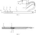
- FIG. 1is a structure diagram of a liquid-collecting mechanism according to the present invention.
- FIG. 2is a section view of the mechanism shown in FIG. 1 taken along line A-A in FIG. 1 .
- FIG. 3is a bottom view of a structure of a liquid-collection tube arm in FIG. 1 .
- FIG. 4is a section view of the structure shown in FIG. 3 taken along line B-B in FIG. 3 .
- the embodimentdescribes the liquid-collecting mechanism in detail, which shall not be construed as any limitation on the liquid-collecting mechanism.
- FIGS. 1 - 4show an embodiment of a liquid collecting mechanism that is configured as a urine-collecting mechanism having a liquid-collection tube arm 1 , a liquid-collection tube head 2 , a liquid-suction tube 4 , and a liquid-discharge tube 9 .
- the liquid-collection tube arm 1is shown as a hollow tube fitting, a front end of the liquid-collection tube arm 1 is used for fixing the liquid-collection tube head 2 , and a tail end of the liquid-collection tube arm 1 is provided with a tube running groove for leading out the liquid-suction tube 4 and the liquid-discharge tube 9 .
- the liquid-collection tube head 2is fixed at the front end of the liquid-collection tube arm 1 .
- a sealing spacer 14is arranged at a joint of the liquid-collection tube head 2 and the liquid-collection tube arm 1 .
- the liquid-collection tube head 2is internally provided with a liquid-collection cavity 3 , where the liquid-collection cavity 3 is enclosed by the inner wall of the liquid-collection tube head 2 and the sealing spacer 14 .
- An area of the liquid-collection tube head 2 located above the liquid-collection cavity 3is a mesh collection area 6 , and the mesh collection area 6 is provided with a plurality of collecting holes 6 a .
- the plurality of collecting holes 6 ais arranged in an array arrangement mode, so that a larger area for collecting the urine can be obtained. Therefore, the method for moving a position of a urine-suction hole by using a driving mechanism in the prior art is replaced, which reduces the cost.
- the collecting holes 6 ahave small diameter, blockage caused by external impurities entering into the liquid-collection tube may further be prevented, and the problem of splashing urine may be avoided.
- front endrefers to the end of the liquid-collecting mechanism that extends toward a center of a smart toilet employing the mechanism
- rear endrefers to the end of the liquid-collecting mechanism that is configured to be proximate to an edge of the smart toilet.
- Openings at one end of the liquid-suction tube 4 and one end of the liquid-discharge tube 9are located in the liquid-collection cavity 3 (see FIGS. 2 and 4 ), and the other ends with openings of the liquid-suction tube 4 and the liquid-discharge tube 9 pass through the sealing spacer 14 and the liquid-collection tube arm 1 and are led out from the tube running groove(s), and are used for being connected with a pump body mechanism, such as to suck the urine and discharge the waste under the effect of the pump body mechanism.
- the liquid-suction tube 4 and the liquid-discharge tube 9can be formed by a rigid tube or a flexible tube, respectively, or may further be formed by the rigid tube connected with the flexible tube.
- the liquid-collection tube head 2is provided with an air discharge hole or groove 11 communicated (e.g., in fluid communication) with the liquid-collection cavity 3 .
- the air discharge hole or the air discharge groove 11is preferably arranged on one side of the liquid-collection tube head 2 close to the liquid-collection tube arm 1 .
- the liquid-collecting mechanismcollects the urine
- the urineenters into the liquid-collection cavity 3 through the collecting holes 6 a of the mesh collection area 6
- the liquid-collecting mechanismis inclined downward by a certain angle, and gas in the liquid-collection cavity 3 can be discharged from the air discharge hole or the air discharge groove 11 , thus solving the problem that the liquid-collection cavity 3 cannot be fully filled with the urine.
- a plurality of auxiliary liquid-discharge holes 9 ais provided on a tube wall of the liquid-discharge tube 9 located in the liquid-collection cavity 3 .
- the plurality of auxiliary liquid-discharge holes 9 ais axially arranged in an array along the tube wall of the liquid-discharge tube 9 .
- the liquid-collection tube head 2 , the liquid-collection tube arm 1 , and the sealing spacer 14are integrally formed (e.g., as a unitary member or element), and in this way, when the liquid-collecting mechanism is assembled, the liquid-suction tube 4 and the liquid-discharge tube 9 extend into the liquid-collection cavity 3 through a through hole in the sealing spacer 14 . Since the liquid-suction tube 4 and the liquid-discharge tube 9 are both relatively thin, the liquid-suction tube 4 and the liquid-discharge tube 9 are particularly easy to be bent and deformed.
- the liquid-suction tube 4 and the liquid-discharge tube 9can be fixedly connected together in a side by side arrangement, such as through welding or another process, so that the liquid-suction tube 4 and the liquid-discharge tube 9 jointly extend into the liquid-collection cavity 3 through the through hole in the sealing spacer 14 . This reduces the difficulty of making the liquid-suction tube 4 and the liquid-discharge tube 9 extend into the liquid-collection cavity 3 .
- the liquid-collection tube head 2 , the liquid-collection tube arm 1 , and the sealing spacer 14can be separated (e.g., formed separately then coupled together), according to other embodiments.
- the size of the liquid-suction tube 4 and the liquid-discharge tube 9 passing through the sealing spacer 14may be firstly sized according to a length of the liquid-collection cavity 3 .
- the sealing spacer 14is installed in the liquid-collection tube arm 1 .
- the liquid-collection tube head 2is installed.
- This designgreatly improves accuracy of the length of the liquid-suction tube 4 and the liquid-discharge tube 9 inserting into the liquid-collection cavity 3 , and thus improves accuracy of locating the liquid-suction port and the liquid-discharge hole, and improves the evacuation rate of urine sample suction and waste discharge.
- the liquid-collection tube arm 1can be integrated with the sealing spacer 14 to omit the step of assembling the liquid-collection tube arm 1 and the sealing spacer 14 together during the assembly process.
- the liquid-collection tube head 2can be integrated with the sealing spacer 14 to omit the step of assembling the liquid-collection tube head 2 with the sealing spacer 14 during the assembly process.
- the parts of the liquid-suction tube and liquid-discharge tube within the liquid-collection cavity 3can be integrated with the inner wall of the liquid-collection tube head 2 . That is, the said parts of the liquid-suction tube and liquid-discharge tube are directly prepared on (e.g., connected to) the inner wall of the liquid-collection tube head 2 when preparing the liquid-collection tube head 2 , thus avoiding a subsequent insertion operation. In this way, the portions of the liquid-suction tube and liquid-discharge tube extending out of the liquid-collection cavity 3 may be respectively connected with the pump body mechanism by a flexible tube.
- the liquid-collecting mechanismcan further include a liquid level sensing unit used for monitoring a urine level collected in the liquid-collection cavity 3 in real time, and controlling the start and stop of the pump body mechanism according to the urine level in the liquid-collection cavity 3 .
- the liquid level sensing unitif provided, includes a steel needle 7 , a control circuit board 8 , and a wire 10 (e.g., electrical wire).
- the steel needle 7can be made of stainless steel (or other suitable material) and serves as an input electrode of the liquid level sensing unit.
- One end of the steel needle 7is arranged in the liquid-collection cavity 3 , and its end face is located in an upper portion of the liquid-collection cavity 3 and does not exceed a perpendicular plane of the collecting hole 6 a closest to the liquid-collection tube arm 1 .
- the other end of the steel needle 7is electrically connected with the control circuit board 8 through the wire 10 .
- the detection principle of the liquid level sensing unitis that: when the urine level sucked in the liquid-collection cavity 3 has not yet contacted the end face of the steel needle 7 , an input capacitance of the control circuit board 8 is equal to a reference capacitance inside the control circuit plus a capacitance of the steel needle 7 outside the control circuit and a capacitance of the wire 10 .
- the control circuit board 8Since the capacitance of the steel needle 7 and the capacitance of the wire 10 are very small and negligible, the control circuit board 8 outputs a high level at the moment; when the liquid-collection cavity 3 is full of the urine or the urine contacts the end face of the steel needle 7 , an external input capacitance of the control circuit board 8 is equal to the capacitance of urine in the liquid-collection cavity 3 plus the capacitance of the steel needle 7 and the capacitance of the wire 10 .
- an input capacitance of the control circuit board 8is equal to the reference capacitance of the control circuit plus the capacitance of urine in the liquid-collection cavity, and the control circuit board 8 outputs a low level at the moment. And at the moment, the pump body mechanism is controlled to start to suck the urine in the cavity through the liquid-suction tube 4 .
- the steel needle 7is firstly inserted into the sealing spacer 14 to determine the length accuracy and verticality of the portion of the steel needle 7 inserting into the liquid-collection cavity 3 , which thereby improves the accuracy of the liquid level detection.
- the area for collecting the urinecan be increased through the array mesh collection area.
- the improvement of the urine-suction holecan replace the method for moving the position of the urine-suction hole by using a driving mechanism in the prior art, and thereby the cost is reduced, and meanwhile, blockage caused by the external impurities entering into the liquid-collection tube can be prevented, and the problem of splashing urine can be avoided.
- a plurality of liquid-discharge holesis distributed in the tube wall of the liquid-discharge tube in the liquid-collection cavity, so that the speed of discharging cleaning liquid can be greatly increased, and the cleaning liquid at each position in the liquid-collection cavity may be discharged.
Landscapes
- Health & Medical Sciences (AREA)
- Life Sciences & Earth Sciences (AREA)
- Public Health (AREA)
- Engineering & Computer Science (AREA)
- General Health & Medical Sciences (AREA)
- Medical Informatics (AREA)
- Veterinary Medicine (AREA)
- Hematology (AREA)
- Pathology (AREA)
- Biomedical Technology (AREA)
- Heart & Thoracic Surgery (AREA)
- Animal Behavior & Ethology (AREA)
- Molecular Biology (AREA)
- Surgery (AREA)
- Hydrology & Water Resources (AREA)
- Epidemiology (AREA)
- Water Supply & Treatment (AREA)
- Sampling And Sample Adjustment (AREA)
- Bidet-Like Cleaning Device And Other Flush Toilet Accessories (AREA)
- Investigating Or Analysing Biological Materials (AREA)
Abstract
Description
Claims (20)
Priority Applications (1)
| Application Number | Priority Date | Filing Date | Title |
|---|---|---|---|
| US18/229,922US20230380817A1 (en) | 2018-01-12 | 2023-08-03 | Liquid-collecting mechanism with arrayed mesh collection area and smart toilet containing same |
Applications Claiming Priority (3)
| Application Number | Priority Date | Filing Date | Title |
|---|---|---|---|
| CN201810032512.4ACN107981894A (en) | 2018-01-12 | 2018-01-12 | A kind of liquid collecting mechanism with array mesh acquisition zone and the intelligent closestool containing it |
| CN20181032512.4 | 2018-01-12 | ||
| CN201810032512.4 | 2018-01-12 |
Related Child Applications (1)
| Application Number | Title | Priority Date | Filing Date |
|---|---|---|---|
| US18/229,922ContinuationUS20230380817A1 (en) | 2018-01-12 | 2023-08-03 | Liquid-collecting mechanism with arrayed mesh collection area and smart toilet containing same |
Publications (3)
| Publication Number | Publication Date |
|---|---|
| US20190216442A1 US20190216442A1 (en) | 2019-07-18 |
| US20210059647A9 US20210059647A9 (en) | 2021-03-04 |
| US11751854B2true US11751854B2 (en) | 2023-09-12 |
Family
ID=62041085
Family Applications (2)
| Application Number | Title | Priority Date | Filing Date |
|---|---|---|---|
| US16/245,760Active2041-08-25US11751854B2 (en) | 2018-01-12 | 2019-01-11 | Liquid-collecting mechanism with arrayed mesh collection area and smart toilet containing same |
| US18/229,922PendingUS20230380817A1 (en) | 2018-01-12 | 2023-08-03 | Liquid-collecting mechanism with arrayed mesh collection area and smart toilet containing same |
Family Applications After (1)
| Application Number | Title | Priority Date | Filing Date |
|---|---|---|---|
| US18/229,922PendingUS20230380817A1 (en) | 2018-01-12 | 2023-08-03 | Liquid-collecting mechanism with arrayed mesh collection area and smart toilet containing same |
Country Status (5)
| Country | Link |
|---|---|
| US (2) | US11751854B2 (en) |
| JP (2) | JP6689950B2 (en) |
| KR (1) | KR102272668B1 (en) |
| CN (1) | CN107981894A (en) |
| TW (1) | TWI708880B (en) |
Families Citing this family (1)
| Publication number | Priority date | Publication date | Assignee | Title |
|---|---|---|---|---|
| CN110286001B (en)* | 2019-07-26 | 2022-05-31 | 重庆德方信息技术有限公司 | Urine collecting and conveying system |
Citations (73)
| Publication number | Priority date | Publication date | Assignee | Title |
|---|---|---|---|---|
| US2958222A (en) | 1957-05-23 | 1960-11-01 | Willard W Morgan | Sample thief construction |
| US3315530A (en) | 1965-04-12 | 1967-04-25 | Du Pont | Fiber sampling apparatus |
| US3466145A (en) | 1965-08-30 | 1969-09-09 | Charles M Van Duyne | Urine screening device |
| US3625064A (en) | 1969-01-09 | 1971-12-07 | Us Army | Automatic midstream urine sample collector |
| US3625654A (en) | 1970-05-22 | 1971-12-07 | Charles M Van Duyne | Urine collection device |
| US3659461A (en) | 1970-06-18 | 1972-05-02 | Great Northern Nekoosa Corp | Line sampling device |
| US3707869A (en) | 1971-06-09 | 1973-01-02 | Atomic Energy Commission | Airborne isokinetic sampler |
| US3735641A (en) | 1970-10-05 | 1973-05-29 | Sherritt Gordon Mines Ltd | Diverting and sampling gate |
| US3802270A (en) | 1971-10-01 | 1974-04-09 | Columbia Cement Corp | Sampler and method of sampling |
| US3832904A (en) | 1972-03-15 | 1974-09-03 | Krupp Gmbh | Apparatus for monitoring and taking gas samples in shaft furnaces |
| JPS5110982A (en) | 1974-05-30 | 1976-01-28 | Optische Ind De Oude Delft Nv | |
| JPS51101982U (en) | 1975-02-13 | 1976-08-16 | ||
| US4165645A (en) | 1978-08-04 | 1979-08-28 | Cooper Harrison R | Drive means for ore samplers and the like |
| US4203169A (en) | 1977-09-14 | 1980-05-20 | Medeci Developments Limited | Urine collection device |
| US4252132A (en) | 1978-10-10 | 1981-02-24 | Shs Enterprises, Ltd. | Midstream urine specimen collecting device |
| US4276889A (en) | 1979-04-19 | 1981-07-07 | Shs Enterprises, Ltd. | Urine specimen collecting device |
| US4331162A (en) | 1979-04-19 | 1982-05-25 | Shs Enterprises, Ltd. | Urine specimen collecting device and method of use |
| US4338842A (en) | 1979-09-17 | 1982-07-13 | Collins William J | Sampler for molten material and entrance tube therefor |
| GB2123951A (en) | 1982-07-14 | 1984-02-08 | Xomox Corp | Apparatus for sampling hazardous media |
| US4631968A (en) | 1985-06-10 | 1986-12-30 | Aske Norman L | Effluent sampler |
| US4636474A (en) | 1983-01-25 | 1987-01-13 | Toto Ltd. | Toilet apparatus |
| US4743155A (en) | 1986-06-20 | 1988-05-10 | Weyerhaeuser Company | Chip sampling unit |
| US4771642A (en) | 1987-07-21 | 1988-09-20 | The Dow Chemical Company | Solids sampler |
| US4962550A (en) | 1987-08-24 | 1990-10-16 | Toto, Ltd. | Toilet with urine constituent measuring device |
| US5062304A (en) | 1989-05-12 | 1991-11-05 | Endotherapeutics | Urine collection monitor with temperature sensing |
| US5111539A (en) | 1989-08-25 | 1992-05-12 | Toto Ltd. | Toilet device with system for inspecting health conditions |
| US5121641A (en) | 1990-04-23 | 1992-06-16 | Silver Joseph M | Beet tare-taking apparatus |
| JPH0584863A (en) | 1991-09-25 | 1993-04-06 | Toppan Printing Co Ltd | Packaging material having silicon oxide vapor deposition layer |
| JPH07234217A (en) | 1994-02-23 | 1995-09-05 | Toto Ltd | Urine sampling device |
| JPH07234216A (en) | 1994-02-23 | 1995-09-05 | Toto Ltd | Urine sampling method and its device |
| US5563384A (en) | 1994-03-28 | 1996-10-08 | Iii Sigma Company | Bulk density sampler apparatus |
| US5625911A (en) | 1994-02-23 | 1997-05-06 | Toto Ltd. | Apparatus for sampling urine |
| US5720054A (en) | 1993-12-30 | 1998-02-24 | Toto Ltd. | Method and apparatus for sampling urine |
| US5730149A (en)* | 1993-12-30 | 1998-03-24 | Toto Ltd. | Toilet-bowl-mounted urinalysis unit |
| US5844148A (en) | 1997-07-30 | 1998-12-01 | Pittway Corporation | Detector with adjustable sampling tubes |
| JP2000258411A (en) | 1999-03-08 | 2000-09-22 | Matsushita Electric Ind Co Ltd | Toilet seat with urine test function |
| TW515719B (en) | 2001-10-22 | 2003-01-01 | Kaigo Kiki Kaihatsu Kk | Urine extraction device |
| DE20314472U1 (en) | 2003-09-18 | 2003-11-13 | Schütz GmbH Meßtechnik, 77933 Lahr | Probe, especially telescopic probe, for analyzing gases in environment comprises telescopic tube, flexible tube connected to gas analysis device and running inside tube and sleeve arranged on front end of flexible tube |
| JP2004092385A (en) | 2003-10-03 | 2004-03-25 | Toto Ltd | Toilet bowl with urine sampler, and urine sampler |
| US6772450B1 (en)* | 2003-10-09 | 2004-08-10 | Tom Saylor | Toilet bowl cleaning apparatus |
| US6843103B2 (en) | 2001-05-05 | 2005-01-18 | Ingenieria Energetica De Contaminacion, S.A. | Automatic system for collecting, weighing and releasing solid particles |
| US6951545B2 (en) | 2001-12-04 | 2005-10-04 | Lifepoint, Inc. | Integral sample collection tip |
| CN2745070Y (en) | 2004-11-24 | 2005-12-07 | 滕浩然 | Automatic urine analyzer |
| US7100424B2 (en) | 2004-07-22 | 2006-09-05 | Marshall Wilson | Apparatus for accessing container security threats and method of use |
| WO2006101833A2 (en) | 2005-03-23 | 2006-09-28 | Beckman Coulter, Inc. | Apparatus for aspirating liquids from sealed containers |
| CN201222065Y (en) | 2008-07-16 | 2009-04-15 | 索纪文 | Continuous sampling gas analysis system and probe telescoping sampling apparatus |
| CN101551306A (en) | 2009-03-26 | 2009-10-07 | 北京雪迪龙自动控制系统有限公司 | A high-temperature sampling probe and high-temperature gas analysis system |
| US20100058777A1 (en) | 2008-09-09 | 2010-03-11 | Leica Biosystems Nussloch Gmbh | Apparatus for cooling cassette magazines containing tissue samples |
| CN201731946U (en) | 2010-07-16 | 2011-02-02 | 宁波新早晨绿色照明科技有限公司 | Temperature and water level sensor for overhead solar water heater |
| US20110113899A1 (en) | 2009-11-18 | 2011-05-19 | Dahler Steven E | Apparatus to measure fluids in a conduit |
| KR101080828B1 (en) | 2010-12-08 | 2011-11-07 | 전인수 | Urine collection device for toilet seat-mounted urine analysis system |
| US8312780B2 (en) | 2010-06-25 | 2012-11-20 | Mettler-Toledo Ag | Sampling device and method |
| CN102802526A (en) | 2009-06-23 | 2012-11-28 | 观察医学有限责任公司 | Urine Measuring Device |
| US8935965B1 (en) | 2009-05-18 | 2015-01-20 | The United States of America, as represented by the Secretary of the Department of the Interior | Apparatus to assist in the collection of stormwater-quality samples in a vertical profile |
| CN204685875U (en) | 2015-02-13 | 2015-10-07 | 符迎利 | A kind of manipulator |
| US9176026B2 (en) | 2011-12-15 | 2015-11-03 | Pureflora, Inc. | Device for the collection, refinement, and administration of gastrointestinal microflora |
| US20150359522A1 (en)* | 2014-06-17 | 2015-12-17 | Palo Alto Research Center Incorporated | Point of care urine tester and method |
| CN205157255U (en) | 2015-11-27 | 2016-04-13 | 成都绿林科技有限公司 | Chemistry liquid medicine ware of getting it filled |
| CN105842013A (en)* | 2016-04-28 | 2016-08-10 | 北京峰誉科技有限公司 | Liquid collecting device and intelligent toilet bowl including same |
| CN205607700U (en) | 2016-04-28 | 2016-09-28 | 北京峰誉科技有限公司 | Collection liquid device reaches intelligent closestool including this album of liquid device |
| US20160287155A1 (en)* | 2013-11-21 | 2016-10-06 | Atomo Diagnostics Pty Limited | Fluid control in integrated testing devices |
| CN206132738U (en) | 2016-10-27 | 2017-04-26 | 邢红涛 | Combustion area components of smoke measures sampling device |
| US20170114531A1 (en)* | 2014-06-16 | 2017-04-27 | Zhiqian YE | Toilet with automatic urine collecting and testing function |
| CN108713990A (en)* | 2018-08-03 | 2018-10-30 | 深圳市爱奇诺科技有限公司 | The toilet brush of multi-functional brush head |
| US20180372717A1 (en) | 2017-06-23 | 2018-12-27 | Voyant Diagnostics, Inc. | Medical Diagnostic System and Method |
| JP6478128B2 (en) | 2014-08-28 | 2019-03-06 | パナソニックIpマネジメント株式会社 | Solar cell module and method for manufacturing solar cell module |
| US20190170728A1 (en) | 2016-05-10 | 2019-06-06 | Shanghai Kohler Electtonics, Ltd. | Urine testing device and smart toilet comprising same |
| US10383606B1 (en) | 2018-07-16 | 2019-08-20 | Bloom Health, Inc. | Toilet based urine analysis system |
| WO2020078018A1 (en) | 2018-10-16 | 2020-04-23 | 苏恩本 | Articulated arm and analytical test instrument |
| WO2020099977A1 (en) | 2018-11-15 | 2020-05-22 | Holcim Technology Ltd | Method and device for analyzing samples of a gas in a rotary cement kiln |
| US20200271578A1 (en) | 2017-09-22 | 2020-08-27 | Lixil Corporation | Toilet device |
| CN111719653A (en) | 2020-06-30 | 2020-09-29 | 世旺九洲(重庆)家居有限责任公司 | Be used for intelligent closestool urine to detect and liquid degassing unit |
| CN112649239A (en) | 2020-12-31 | 2021-04-13 | 北京瑞升特科技有限公司 | Layered sampling device for water pollution detection |
Family Cites Families (10)
| Publication number | Priority date | Publication date | Assignee | Title |
|---|---|---|---|---|
| JPS63118565U (en)* | 1987-01-27 | 1988-08-01 | ||
| US4901736A (en)* | 1988-06-06 | 1990-02-20 | Huang Chuan Chih | Toilet having urine tester |
| JPH0584863U (en)* | 1992-04-16 | 1993-11-16 | 日本ユーロテック株式会社 | Urine collection container |
| AU2003272064A1 (en)* | 2002-10-18 | 2004-05-04 | S.A.E. Afikim Computerized Dairy Management System | System for monitoring the health of an individual and method for use thereof |
| CN101923015B (en)* | 2009-06-12 | 2014-10-08 | 日本乐敦制药株式会社 | Urine examination apparatus and rod-like container |
| CN102288453B (en)* | 2011-05-17 | 2014-01-29 | 李红霞 | Pull-off type disposable gouge urine collector |
| CN204563075U (en)* | 2015-04-24 | 2015-08-19 | 赵中和 | Urology Surgery catheter |
| CN204910460U (en)* | 2015-09-10 | 2015-12-30 | 刘明锴 | No gasbag catheter |
| CN206740452U (en)* | 2016-10-26 | 2017-12-12 | 扬州市凯达医疗设备有限公司 | A kind of disposable urine specimen collector |
| CN209315909U (en)* | 2018-01-12 | 2019-08-30 | 上海科勒电子科技有限公司 | A kind of liquid collecting mechanism and the intelligent closestool containing it |
- 2018
- 2018-01-12CNCN201810032512.4Apatent/CN107981894A/enactivePending
- 2018-12-21JPJP2018239443Apatent/JP6689950B2/enactiveActive
- 2019
- 2019-01-03TWTW108100243Apatent/TWI708880B/enactive
- 2019-01-08KRKR1020190002173Apatent/KR102272668B1/enactiveActive
- 2019-01-11USUS16/245,760patent/US11751854B2/enactiveActive
- 2020
- 2020-04-08JPJP2020069588Apatent/JP6921270B2/enactiveActive
- 2023
- 2023-08-03USUS18/229,922patent/US20230380817A1/enactivePending
Patent Citations (79)
| Publication number | Priority date | Publication date | Assignee | Title |
|---|---|---|---|---|
| US2958222A (en) | 1957-05-23 | 1960-11-01 | Willard W Morgan | Sample thief construction |
| US3315530A (en) | 1965-04-12 | 1967-04-25 | Du Pont | Fiber sampling apparatus |
| US3466145A (en) | 1965-08-30 | 1969-09-09 | Charles M Van Duyne | Urine screening device |
| US3625064A (en) | 1969-01-09 | 1971-12-07 | Us Army | Automatic midstream urine sample collector |
| US3625654A (en) | 1970-05-22 | 1971-12-07 | Charles M Van Duyne | Urine collection device |
| US3659461A (en) | 1970-06-18 | 1972-05-02 | Great Northern Nekoosa Corp | Line sampling device |
| US3735641A (en) | 1970-10-05 | 1973-05-29 | Sherritt Gordon Mines Ltd | Diverting and sampling gate |
| US3707869A (en) | 1971-06-09 | 1973-01-02 | Atomic Energy Commission | Airborne isokinetic sampler |
| US3802270A (en) | 1971-10-01 | 1974-04-09 | Columbia Cement Corp | Sampler and method of sampling |
| US3832904A (en) | 1972-03-15 | 1974-09-03 | Krupp Gmbh | Apparatus for monitoring and taking gas samples in shaft furnaces |
| JPS5110982A (en) | 1974-05-30 | 1976-01-28 | Optische Ind De Oude Delft Nv | |
| JPS51101982U (en) | 1975-02-13 | 1976-08-16 | ||
| US4203169A (en) | 1977-09-14 | 1980-05-20 | Medeci Developments Limited | Urine collection device |
| US4165645A (en) | 1978-08-04 | 1979-08-28 | Cooper Harrison R | Drive means for ore samplers and the like |
| US4252132A (en) | 1978-10-10 | 1981-02-24 | Shs Enterprises, Ltd. | Midstream urine specimen collecting device |
| US4276889A (en) | 1979-04-19 | 1981-07-07 | Shs Enterprises, Ltd. | Urine specimen collecting device |
| US4331162A (en) | 1979-04-19 | 1982-05-25 | Shs Enterprises, Ltd. | Urine specimen collecting device and method of use |
| US4338842A (en) | 1979-09-17 | 1982-07-13 | Collins William J | Sampler for molten material and entrance tube therefor |
| GB2123951A (en) | 1982-07-14 | 1984-02-08 | Xomox Corp | Apparatus for sampling hazardous media |
| US4636474A (en) | 1983-01-25 | 1987-01-13 | Toto Ltd. | Toilet apparatus |
| US4631968A (en) | 1985-06-10 | 1986-12-30 | Aske Norman L | Effluent sampler |
| US4743155A (en) | 1986-06-20 | 1988-05-10 | Weyerhaeuser Company | Chip sampling unit |
| US4771642A (en) | 1987-07-21 | 1988-09-20 | The Dow Chemical Company | Solids sampler |
| US4962550A (en) | 1987-08-24 | 1990-10-16 | Toto, Ltd. | Toilet with urine constituent measuring device |
| US5062304A (en) | 1989-05-12 | 1991-11-05 | Endotherapeutics | Urine collection monitor with temperature sensing |
| US5111539A (en) | 1989-08-25 | 1992-05-12 | Toto Ltd. | Toilet device with system for inspecting health conditions |
| US5121641A (en) | 1990-04-23 | 1992-06-16 | Silver Joseph M | Beet tare-taking apparatus |
| JPH0584863A (en) | 1991-09-25 | 1993-04-06 | Toppan Printing Co Ltd | Packaging material having silicon oxide vapor deposition layer |
| US5730149A (en)* | 1993-12-30 | 1998-03-24 | Toto Ltd. | Toilet-bowl-mounted urinalysis unit |
| US5720054A (en) | 1993-12-30 | 1998-02-24 | Toto Ltd. | Method and apparatus for sampling urine |
| JPH07234217A (en) | 1994-02-23 | 1995-09-05 | Toto Ltd | Urine sampling device |
| JPH07234216A (en) | 1994-02-23 | 1995-09-05 | Toto Ltd | Urine sampling method and its device |
| US5625911A (en) | 1994-02-23 | 1997-05-06 | Toto Ltd. | Apparatus for sampling urine |
| US5563384A (en) | 1994-03-28 | 1996-10-08 | Iii Sigma Company | Bulk density sampler apparatus |
| US5844148A (en) | 1997-07-30 | 1998-12-01 | Pittway Corporation | Detector with adjustable sampling tubes |
| JP2000258411A (en) | 1999-03-08 | 2000-09-22 | Matsushita Electric Ind Co Ltd | Toilet seat with urine test function |
| US6843103B2 (en) | 2001-05-05 | 2005-01-18 | Ingenieria Energetica De Contaminacion, S.A. | Automatic system for collecting, weighing and releasing solid particles |
| TW515719B (en) | 2001-10-22 | 2003-01-01 | Kaigo Kiki Kaihatsu Kk | Urine extraction device |
| US6951545B2 (en) | 2001-12-04 | 2005-10-04 | Lifepoint, Inc. | Integral sample collection tip |
| DE20314472U1 (en) | 2003-09-18 | 2003-11-13 | Schütz GmbH Meßtechnik, 77933 Lahr | Probe, especially telescopic probe, for analyzing gases in environment comprises telescopic tube, flexible tube connected to gas analysis device and running inside tube and sleeve arranged on front end of flexible tube |
| JP2004092385A (en) | 2003-10-03 | 2004-03-25 | Toto Ltd | Toilet bowl with urine sampler, and urine sampler |
| US6772450B1 (en)* | 2003-10-09 | 2004-08-10 | Tom Saylor | Toilet bowl cleaning apparatus |
| US7100424B2 (en) | 2004-07-22 | 2006-09-05 | Marshall Wilson | Apparatus for accessing container security threats and method of use |
| CN2745070Y (en) | 2004-11-24 | 2005-12-07 | 滕浩然 | Automatic urine analyzer |
| WO2006101833A2 (en) | 2005-03-23 | 2006-09-28 | Beckman Coulter, Inc. | Apparatus for aspirating liquids from sealed containers |
| JP2008537775A (en) | 2005-03-23 | 2008-09-25 | ベックマン コールター, インコーポレイテッド | Device for aspirating liquid from a sealed container |
| CN201222065Y (en) | 2008-07-16 | 2009-04-15 | 索纪文 | Continuous sampling gas analysis system and probe telescoping sampling apparatus |
| JP2010066263A (en) | 2008-09-09 | 2010-03-25 | Leica Biosystems Nussloch Gmbh | Device for cooling cassette magazine containing tissue sample |
| US20100058777A1 (en) | 2008-09-09 | 2010-03-11 | Leica Biosystems Nussloch Gmbh | Apparatus for cooling cassette magazines containing tissue samples |
| CN101551306B (en) | 2009-03-26 | 2011-01-05 | 北京雪迪龙科技股份有限公司 | A high-temperature sampling probe and high-temperature gas analysis system |
| CN101551306A (en) | 2009-03-26 | 2009-10-07 | 北京雪迪龙自动控制系统有限公司 | A high-temperature sampling probe and high-temperature gas analysis system |
| US8935965B1 (en) | 2009-05-18 | 2015-01-20 | The United States of America, as represented by the Secretary of the Department of the Interior | Apparatus to assist in the collection of stormwater-quality samples in a vertical profile |
| CN102802526A (en) | 2009-06-23 | 2012-11-28 | 观察医学有限责任公司 | Urine Measuring Device |
| US20110113899A1 (en) | 2009-11-18 | 2011-05-19 | Dahler Steven E | Apparatus to measure fluids in a conduit |
| US8312780B2 (en) | 2010-06-25 | 2012-11-20 | Mettler-Toledo Ag | Sampling device and method |
| CN201731946U (en) | 2010-07-16 | 2011-02-02 | 宁波新早晨绿色照明科技有限公司 | Temperature and water level sensor for overhead solar water heater |
| KR101080828B1 (en) | 2010-12-08 | 2011-11-07 | 전인수 | Urine collection device for toilet seat-mounted urine analysis system |
| US9176026B2 (en) | 2011-12-15 | 2015-11-03 | Pureflora, Inc. | Device for the collection, refinement, and administration of gastrointestinal microflora |
| US20160287155A1 (en)* | 2013-11-21 | 2016-10-06 | Atomo Diagnostics Pty Limited | Fluid control in integrated testing devices |
| US20170114531A1 (en)* | 2014-06-16 | 2017-04-27 | Zhiqian YE | Toilet with automatic urine collecting and testing function |
| US20150359522A1 (en)* | 2014-06-17 | 2015-12-17 | Palo Alto Research Center Incorporated | Point of care urine tester and method |
| JP6478128B2 (en) | 2014-08-28 | 2019-03-06 | パナソニックIpマネジメント株式会社 | Solar cell module and method for manufacturing solar cell module |
| CN204685875U (en) | 2015-02-13 | 2015-10-07 | 符迎利 | A kind of manipulator |
| CN205157255U (en) | 2015-11-27 | 2016-04-13 | 成都绿林科技有限公司 | Chemistry liquid medicine ware of getting it filled |
| CN105842013A (en)* | 2016-04-28 | 2016-08-10 | 北京峰誉科技有限公司 | Liquid collecting device and intelligent toilet bowl including same |
| WO2017185690A1 (en) | 2016-04-28 | 2017-11-02 | 北京峰誉科技有限公司 | Liquid-collection device and smart toilet comprising said liquid-collection device |
| US20200309646A1 (en) | 2016-04-28 | 2020-10-01 | Shanghai Kohler Electronics, Ltd. | Device for collecting liquid and smart toilet comprising the same |
| CN205607700U (en) | 2016-04-28 | 2016-09-28 | 北京峰誉科技有限公司 | Collection liquid device reaches intelligent closestool including this album of liquid device |
| US20190170728A1 (en) | 2016-05-10 | 2019-06-06 | Shanghai Kohler Electtonics, Ltd. | Urine testing device and smart toilet comprising same |
| CN206132738U (en) | 2016-10-27 | 2017-04-26 | 邢红涛 | Combustion area components of smoke measures sampling device |
| US20180372717A1 (en) | 2017-06-23 | 2018-12-27 | Voyant Diagnostics, Inc. | Medical Diagnostic System and Method |
| US20200271578A1 (en) | 2017-09-22 | 2020-08-27 | Lixil Corporation | Toilet device |
| US10383606B1 (en) | 2018-07-16 | 2019-08-20 | Bloom Health, Inc. | Toilet based urine analysis system |
| CN108713990A (en)* | 2018-08-03 | 2018-10-30 | 深圳市爱奇诺科技有限公司 | The toilet brush of multi-functional brush head |
| WO2020078018A1 (en) | 2018-10-16 | 2020-04-23 | 苏恩本 | Articulated arm and analytical test instrument |
| WO2020099977A1 (en) | 2018-11-15 | 2020-05-22 | Holcim Technology Ltd | Method and device for analyzing samples of a gas in a rotary cement kiln |
| CN111719653A (en) | 2020-06-30 | 2020-09-29 | 世旺九洲(重庆)家居有限责任公司 | Be used for intelligent closestool urine to detect and liquid degassing unit |
| CN111719653B (en) | 2020-06-30 | 2021-05-28 | 世旺九洲(重庆)家居有限责任公司 | Be used for intelligent closestool urine to detect and liquid degassing unit |
| CN112649239A (en) | 2020-12-31 | 2021-04-13 | 北京瑞升特科技有限公司 | Layered sampling device for water pollution detection |
Non-Patent Citations (11)
| Title |
|---|
| International Preliminary Report on Patentability for PCT Appl. Ser. No. PCT/CN2016/103219 dated Nov. 8, 2018 (14 pages). |
| International Search Report and Written for PCT Appl. Ser. No. PCT/CN2016/103219 dated Feb. 6, 2017 (19 pages). |
| Japanese Office Action for JP Appl. Ser. No. 2019-506770 dated Jun. 26, 2020 (3 pages). |
| Japanese Office Action for JP Appl. Ser. No. 2019-506770 dated Oct. 8, 2019 (13 pages). |
| Japanese Office Action on JP Appl. No. 2018-239443 dated Nov. 26, 2019 (4 pages). |
| Japanese Office Action on JP Appl. No. 2020-069588 dated Mar. 16, 2021 (3 pages). |
| Korean Office Action for KR Appl. Ser. No. 10-2018-7034095 dated Jul. 14, 2020 (9 pages). |
| KR Office Action on KR Patent Application Ser. No. 10-2019-0002173 dated Oct. 15, 2020 (6 pages). |
| Non-Final Office Action on U.S. Appl. No. 16/245,760 dated Aug. 27, 2021 (22 pages). |
| Taiwanese Office Action for TW Appl. Ser. No. 108100243 dated May 20, 2019 (6 pages). |
| U.S. Office Action on U.S. Appl. No. 16/097,172 dated Nov. 2, 2021. |
Also Published As
| Publication number | Publication date |
|---|---|
| JP6921270B2 (en) | 2021-08-18 |
| US20190216442A1 (en) | 2019-07-18 |
| CN107981894A (en) | 2018-05-04 |
| JP2019124685A (en) | 2019-07-25 |
| US20230380817A1 (en) | 2023-11-30 |
| JP2020128988A (en) | 2020-08-27 |
| JP6689950B2 (en) | 2020-04-28 |
| TWI708880B (en) | 2020-11-01 |
| TW201930692A (en) | 2019-08-01 |
| US20210059647A9 (en) | 2021-03-04 |
| KR102272668B1 (en) | 2021-07-06 |
| KR20190086379A (en) | 2019-07-22 |
Similar Documents
| Publication | Publication Date | Title |
|---|---|---|
| EP3043165B1 (en) | Bodily fluid sampler, bodily fluid container and bodily fluid sampling device | |
| KR102229253B1 (en) | Liquid collecting device and smart toilet including the same | |
| US5512248A (en) | Twin-probe blood sample diluting device | |
| US20230380817A1 (en) | Liquid-collecting mechanism with arrayed mesh collection area and smart toilet containing same | |
| CN114062661B (en) | Sample analyzer, sampling needle cleaning liquid path and cleaning method thereof | |
| US20120073966A1 (en) | Electrochemical sensor strip | |
| JP2008232829A (en) | Nozzle tip for dispensing | |
| TWI604182B (en) | Syringe assembly and method of using the same | |
| JP3080118B2 (en) | Liquid sample collection device | |
| JP4807587B2 (en) | Trace liquid collection device and adapter | |
| CN209315909U (en) | A kind of liquid collecting mechanism and the intelligent closestool containing it | |
| JP6130788B2 (en) | Sample injection apparatus for biochemical analysis, flow-type biochemical analysis apparatus, and hemoglobin component measurement method | |
| US20220280937A1 (en) | Arrangement for analyzing a liquid sample | |
| CN114739739A (en) | Blood collection device, sample analyzer and blood collection method for vacuum blood collection tube | |
| CN107449640A (en) | Liquid Segment Collector | |
| JP6133651B2 (en) | Sample analyzer | |
| JP2000074928A (en) | Liquid suction pipe | |
| CN222778495U (en) | Sampling needle cleaning system | |
| CN118543450A (en) | Self-cleaning waste liquid suction device | |
| TW544516B (en) | Automatic sample analyzer and its components | |
| CN116807519A (en) | Middle-section urine collector | |
| KR101875783B1 (en) | A device for collecting of specimen | |
| JPH11271130A (en) | Liquid dispensing device | |
| JPS62259065A (en) | Sampling device | |
| JPS61176857A (en) | Sample analysis method and device |
Legal Events
| Date | Code | Title | Description |
|---|---|---|---|
| FEPP | Fee payment procedure | Free format text:ENTITY STATUS SET TO UNDISCOUNTED (ORIGINAL EVENT CODE: BIG.); ENTITY STATUS OF PATENT OWNER: LARGE ENTITY | |
| AS | Assignment | Owner name:SHANGHAI KOHLER ELECTRONICS, LTD., CHINA Free format text:ASSIGNMENT OF ASSIGNORS INTEREST;ASSIGNOR:BEIJING PEAKHONOR TECHNOLOGY CO., LTD.;REEL/FRAME:052912/0607 Effective date:20190606 Owner name:BEIJING PEAKHONOR TECHNOLOGY CO., LTD., CHINA Free format text:ASSIGNMENT OF ASSIGNORS INTEREST;ASSIGNORS:QIN, ZHIYU;SUN, QINTAO;YUAN, PING;REEL/FRAME:052911/0745 Effective date:20190404 | |
| FEPP | Fee payment procedure | Free format text:PETITION RELATED TO MAINTENANCE FEES GRANTED (ORIGINAL EVENT CODE: PTGR); ENTITY STATUS OF PATENT OWNER: LARGE ENTITY | |
| STPP | Information on status: patent application and granting procedure in general | Free format text:NON FINAL ACTION MAILED | |
| STPP | Information on status: patent application and granting procedure in general | Free format text:FINAL REJECTION MAILED | |
| STPP | Information on status: patent application and granting procedure in general | Free format text:RESPONSE AFTER FINAL ACTION FORWARDED TO EXAMINER | |
| STPP | Information on status: patent application and granting procedure in general | Free format text:NON FINAL ACTION MAILED | |
| STPP | Information on status: patent application and granting procedure in general | Free format text:RESPONSE TO NON-FINAL OFFICE ACTION ENTERED AND FORWARDED TO EXAMINER | |
| STPP | Information on status: patent application and granting procedure in general | Free format text:FINAL REJECTION MAILED | |
| STPP | Information on status: patent application and granting procedure in general | Free format text:ADVISORY ACTION MAILED | |
| STPP | Information on status: patent application and granting procedure in general | Free format text:DOCKETED NEW CASE - READY FOR EXAMINATION | |
| STPP | Information on status: patent application and granting procedure in general | Free format text:NON FINAL ACTION MAILED | |
| STPP | Information on status: patent application and granting procedure in general | Free format text:NOTICE OF ALLOWANCE MAILED -- APPLICATION RECEIVED IN OFFICE OF PUBLICATIONS | |
| STPP | Information on status: patent application and granting procedure in general | Free format text:PUBLICATIONS -- ISSUE FEE PAYMENT VERIFIED | |
| STCF | Information on status: patent grant | Free format text:PATENTED CASE |