US11751652B2 - Protective outer case, especially for portable audio device systems - Google Patents
Protective outer case, especially for portable audio device systemsDownload PDFInfo
- Publication number
- US11751652B2 US11751652B2US17/379,417US202117379417AUS11751652B2US 11751652 B2US11751652 B2US 11751652B2US 202117379417 AUS202117379417 AUS 202117379417AUS 11751652 B2US11751652 B2US 11751652B2
- Authority
- US
- United States
- Prior art keywords
- lid
- collar
- base
- outer case
- button
- Prior art date
- Legal status (The legal status is an assumption and is not a legal conclusion. Google has not performed a legal analysis and makes no representation as to the accuracy of the status listed.)
- Active
Links
Images


Classifications
- A—HUMAN NECESSITIES
- A45—HAND OR TRAVELLING ARTICLES
- A45C—PURSES; LUGGAGE; HAND CARRIED BAGS
- A45C11/00—Receptacles for purposes not provided for in groups A45C1/00-A45C9/00
- A—HUMAN NECESSITIES
- A45—HAND OR TRAVELLING ARTICLES
- A45C—PURSES; LUGGAGE; HAND CARRIED BAGS
- A45C13/00—Details; Accessories
- A45C13/005—Hinges
- A—HUMAN NECESSITIES
- A45—HAND OR TRAVELLING ARTICLES
- A45C—PURSES; LUGGAGE; HAND CARRIED BAGS
- A45C13/00—Details; Accessories
- A45C13/02—Interior fittings; Means, e.g. inserts, for holding and packing articles
- A—HUMAN NECESSITIES
- A45—HAND OR TRAVELLING ARTICLES
- A45C—PURSES; LUGGAGE; HAND CARRIED BAGS
- A45C13/00—Details; Accessories
- A45C13/10—Arrangement of fasteners
- A45C13/1076—Arrangement of fasteners with a snap action
- A45C13/1084—Arrangement of fasteners with a snap action of the latch-and-catch type
- A—HUMAN NECESSITIES
- A45—HAND OR TRAVELLING ARTICLES
- A45F—TRAVELLING OR CAMP EQUIPMENT: SACKS OR PACKS CARRIED ON THE BODY
- A45F5/00—Holders or carriers for hand articles; Holders or carriers for use while travelling or camping
- A45F5/02—Fastening articles to the garment
- A45F5/021—Fastening articles to the garment to the belt
- A—HUMAN NECESSITIES
- A45—HAND OR TRAVELLING ARTICLES
- A45F—TRAVELLING OR CAMP EQUIPMENT: SACKS OR PACKS CARRIED ON THE BODY
- A45F5/00—Holders or carriers for hand articles; Holders or carriers for use while travelling or camping
- A45F5/1508—Holders or carriers for portable audio devices, e.g. headphones or digital music players
- H—ELECTRICITY
- H04—ELECTRIC COMMUNICATION TECHNIQUE
- H04R—LOUDSPEAKERS, MICROPHONES, GRAMOPHONE PICK-UPS OR LIKE ACOUSTIC ELECTROMECHANICAL TRANSDUCERS; DEAF-AID SETS; PUBLIC ADDRESS SYSTEMS
- H04R1/00—Details of transducers, loudspeakers or microphones
- H04R1/10—Earpieces; Attachments therefor ; Earphones; Monophonic headphones
- H04R1/1025—Accumulators or arrangements for charging
- A—HUMAN NECESSITIES
- A45—HAND OR TRAVELLING ARTICLES
- A45C—PURSES; LUGGAGE; HAND CARRIED BAGS
- A45C11/00—Receptacles for purposes not provided for in groups A45C1/00-A45C9/00
- A45C11/001—Receptacles for purposes not provided for in groups A45C1/00-A45C9/00 for storing portable audio devices, e.g. headphones or digital music players
- A45C2011/001—
- H—ELECTRICITY
- H04—ELECTRIC COMMUNICATION TECHNIQUE
- H04R—LOUDSPEAKERS, MICROPHONES, GRAMOPHONE PICK-UPS OR LIKE ACOUSTIC ELECTROMECHANICAL TRANSDUCERS; DEAF-AID SETS; PUBLIC ADDRESS SYSTEMS
- H04R2420/00—Details of connection covered by H04R, not provided for in its groups
- H04R2420/07—Applications of wireless loudspeakers or wireless microphones
- H—ELECTRICITY
- H04—ELECTRIC COMMUNICATION TECHNIQUE
- H04R—LOUDSPEAKERS, MICROPHONES, GRAMOPHONE PICK-UPS OR LIKE ACOUSTIC ELECTROMECHANICAL TRANSDUCERS; DEAF-AID SETS; PUBLIC ADDRESS SYSTEMS
- H04R2460/00—Details of hearing devices, i.e. of ear- or headphones covered by H04R1/10 or H04R5/033 but not provided for in any of their subgroups, or of hearing aids covered by H04R25/00 but not provided for in any of its subgroups
- H04R2460/17—Hearing device specific tools used for storing or handling hearing devices or parts thereof, e.g. placement in the ear, replacement of cerumen barriers, repair, cleaning hearing devices
Definitions
- the present applicationrelates generally to audio accessories, and in particular, to a protective case for audio device systems.
- Wireless earbudssuch as Airpods® by Apple, Inc.
- Airpods®by Apple, Inc.
- These charging casesare rigid to prevent damage to the earbuds contained in them. Left exposed, the charging cases are susceptible to scratches and to damage from the environment.
- an outer case for covering a handheld electronic device or handheld electronic device casemay include a base, a lid, and a connecting portion.
- the basemay include a first base layer which may be made of an elastomeric first material and a second base layer which may be attached to the first base layer and which may be made of a second material different from the first material.
- the lidmay include a first lid layer which may be made of an elastomeric third material and a second lid layer which may be attached to the first lid layer and which may be made of a fourth material different from the third material.
- the connecting portionmay be attached along a rear wall of the base and a rear wall of the lid.
- the rear wall of the base, the rear wall of the lid, and the connecting portionmay be flush when the outer case is in a closed state with the lid covering an opening defined by the base.
- the connecting portionmay suspend the lid when the outer case is in a fully open state with the lid spaced from the base.
- the second and the fourth materialsmay be rigid materials.
- first base layer and the first lid layermay define an interior of the outer case
- second base layer and the second lid layermay define an exterior of the outer case
- the first material and the third materialmay be the same material, and the second material and the fourth material may be the same material.
- the connecting portionmay be a hinge such that the lid rotates relative to the base via the connecting portion in a direction away from the base towards the fully the open state of the outer case.
- the lidmay include a lid flange
- the basemay include a base flange closer to an opening defined by the base in an open state of the outer case than the lid flange when the outer case is in the closed state.
- the outer casemay further include a hook or loop.
- the hook or loopmay extend from the base.
- the hook or loopmay be integral with the first base layer such that the hook or loop and the first base layer may be inseparable without fracture of either one or both of the hook or loop and the first base layer.
- the hook or loopmay extend from the first base layer through the second base layer.
- the base, the lid, and the connecting portionmay be integral such that the base, the lid, and the connecting portion may be inseparable without fracture of any one or any combination of the base, the lid, and the connection portion.
- either one or both of the base and the lidmay be made of co-molded or co-casted polymer layers.
- either one or both of the base and the lidmay be made of a plurality of layers attached by an adhesive.
- the first material and the third materialeach may include at least one material selected from the group consisting of thermoplastic elastomers (“TPEs”), thermoplastic polyurethane (“TPU”), silicone, rubber, and any combinations of these materials.
- TPEsthermoplastic elastomers
- TPUthermoplastic polyurethane
- siliconesilicone
- rubberany combinations of these materials.
- the second material and the fourth materialeach may include at least one material selected from the group consisting of hardened plastic materials, rigid or semi-rigid plastic materials, rigid rubber materials, polycarbonate materials, metals, alloys, para-aramid materials, wood, glass, mirror, quartz, and any combinations of these materials.
- an outer surface or outer surfaces of any one or any combination of the first base layer, the second base layer, the first lid layer, and the second lid layermay include an antimicrobial substance or treatment.
- the antimicrobial substance or treatmentmay be selected from the group consisting of silver and silver alloys, copper and copper alloys, organosilanes, quaternary ammonium compounds, chlorhexidine, chlorhexidine incorporated hydroxyapatite materials, chlorhexidine-containing polymers, and antibiotics.
- the outer casemay conform to and may be configured for covering a case, which may be a charging case, for storing earbuds, which may be wireless earbuds.
- the outer casemay be configured for covering one or more earbuds, a microphone or case therefor, a voice recorder or case therefor, a remote control device or case therefor, a pager or case therefor, or a video game controller or case therefor.
- the outer casemay further include a cushion and a ridge.
- the cushionmay be attached to the lid.
- the ridgemay be attached to the lid on a side of the lid opposite the cushion.
- the cushionmay be configured to compress the one of the handheld electronic device or the handheld electronic device case covered by the outer case.
- the cushionmay be attached to the first lid layer and the ridge may be attached to the second lid layer.
- a handheld electronic device systemmay include either one or both of a handheld electronic device and a handheld electronic device case configured for holding the electronic device and an outer case enclosing the one or both of the electronic device and the electronic device case in a first state and exposing the one or both of the electronic device and the electronic device case in a second state.
- the outer casemay include a base, a lid, and a connecting portion.
- the basemay include a first base layer which may be made of an elastomeric first material and a second base layer which may be attached to the first base layer and which may be made of a second material different from the first material.
- the lidmay include a first lid layer which may be made of an elastomeric third material and a second lid layer which may be attached to the first lid layer and which may be made of a fourth material different from the third material.
- the connecting portionmay be attached along a rear wall of the base and a rear wall of the lid. The rear wall of the base, the rear wall of the lid, and the connecting portion may be flush when the outer case is in a closed state with the lid covering an opening defined by the base.
- the connecting portionmay suspend the lid when the outer case is in a fully open state with the lid spaced from the base.
- the handheld electronic device systemmay include both the handheld electronic device and the handheld electronic device case. In such arrangements, the handheld electronic device may be held within the electronic device case.
- an outer case for covering a handheld electronic device or handheld electronic device casemay include a base, a lid, and a flexible hinge.
- the lidmay be configured for placement onto the base.
- the lidmay have a first state in which the lid is placed on the base and a second state in which the lid is spaced from the base.
- the flexible hingemay be attached to the base and the lid.
- the flexible hingemay be in the form of a curved sheet when the lid is in the first state and may be in the form of a paraboloid when the lid is in the second state.
- an outer case for covering a handheld electronic device or handheld electronic device casemay include a base, a lid, and a collar.
- the lidmay be pivotably attached to the base.
- the collarmay be slidable along the base and away from the lid such that the lid rotates away from the base as the collar slides away from the lid.
- either one or both of the base and the lidmay be made of co-molded or co-casted polymer layers. In some other arrangements, either one or both of the base and the lid may be made of a plurality of layers attached by an adhesive.
- an outer surface or outer surfaces of any one or any combination of the base, the lid, and the collarmay include an antimicrobial substance or treatment.
- the antimicrobial substance or treatmentmay be selected from the group consisting of silver and silver alloys, copper and copper alloys, organosilanes, quaternary ammonium compounds, chlorhexidine, chlorhexidine incorporated hydroxyapatite materials, chlorhexidine-containing polymers, and antibiotics.
- the outer casemay conform to and may be configured for covering a case for storing earbuds.
- the outer casemay be configured for covering one or more earbuds, a microphone or case therefor, a voice recorder or case therefor, a remote control device or case therefor, a pager or case therefor, or a video game controller or case therefor.
- the rotation of the lid away from the basemay be approximately proportional to the movement of the collar away from the lid. In some such arrangements, the rotation of the lid away from the base may be non-linearly, but approximately linearly proportional to the movement of the collar away from the lid.
- the outer casemay further include a flexible panel.
- the lidmay be attached to the collar via the flexible panel.
- the flexible panelmay act as a hinge.
- the flexible panelmay be made of a textile and the collar may be an injection-molded polycarbonate. In some such arrangements, the textile may be elastic.
- the lidmay be rotatable away from the base about a pivot axis.
- the collarmay have a collar upper rim that remains below an interface between the lid and the base during rotation of the lid away from the base.
- the collarmay include a first side attached to the flexible panel and a second side attached to the first side.
- the second side of the collarmay be configured for selectively securing a side of the lid to a side of the base such that the outer case is in a closed position.
- the collarmay be slidable along the base such that the flexible panel slides with the collar during movement of the collar away from the lid.
- the second side of the collarmay be latched to the lid in the closed position of the outer case.
- the second side of the collarmay be opposite the first side of the collar.
- the collarmay include a latch base and a collar button attached to the latch base.
- the collar buttonmay be disposed within a latch portion of the lid in a rest state of the collar button. Depression of a portion of the collar button releases the collar button from the latch portion of the lid and thereby allows the collar to be slid along the base.
- the collarincludes a latch base and a collar button attached to the latch base.
- a first portion of the collar buttonmay be disposed within a latch portion of the lid in a first position of the collar button relative to the latch base.
- the first portion of the collar buttonmay be disposed outside the latch portion of the lid in a second position of the collar button relative to the latch base.
- the collarmay further include a resilient element attached to the latch base and to the collar button.
- the resilient elementmay bias the first portion of the collar button to the first position relative to the latch base.
- the collarmay further include a rod received within the latch base.
- the first portion of the collar buttonmay be located on a first side of the rod.
- the collar buttonmay be rotatable about the rod such that depression of a second portion of the collar button located on a second side of the rod opposite the first side may cause the first portion of the rod to move opposite to the second portion of the collar button.
- At least a portion of the collarmay surround an exterior of the base. In some arrangements, at least a portion of the collar may be slidable along the base.
- the base or the collarmay include one or more flanges and the other of the base and the collar may include one or more recessed tracks.
- the one or more flangesmay protrude into and may be slidable along respective ones of the one or more tracks.
- the basemay include an interior defining a base opening in which the lid may cover the base opening.
- the lidmay have a first lid rim along at least a first portion of the lid, and the collar may have a collar upper rim.
- the lidmay rotate away from the base from a closed position of the outer case in which the first lid rim is in abutment with the collar upper rim to an open position of the outer case in which the first lid rim is spaced from the collar upper rim.
- the basemay have a base rim defining a top of the base, the first lid rim may define a bottom of the lid, and the first lid rim may be recessed. In this manner, the first lid rim may extend below the base rim and the lid may cover a covered portion of the collar in the open position of the outer case.
- the basemay be made of a rigid plastic material
- the lidmay include a lid inner layer made of a flexible plastic material and a lid outer layer made of a rigid plastic material.
- the basemay have a base rim
- the lid outer layermay include the first lid rim
- the lid inner layermay include a second lid rim.
- the second lid rimmay be in abutment with the base rim when the outer case is in the closed position.
- the lid inner layermay extend beyond the lid outer layer such that the lid inner layer overlaps a portion of the collar when the outer case is in the closed position.
- a lid exterior surface of the lid and a collar exterior surface of the collarare coextensive such that the lid and the collar exterior surfaces are flush when the outer case is in the closed position.
- the outer casemay further include an attachment member that may extend through the base and that may be in the form of a loop.
- the attachment membermay be made of a textile which may be flexible.
- the base of the outer casemay define a base hole that may extend through a thickness of base.
- the outer casefurther may include a port cover.
- the port covermay include a cover base that may be attached to the base of the outer case and a port cover door that may be attached to the cover base.
- the port cover doormay be rotatable from a position covering the base hole to a position exposing the base hole for insertion of components through the base hole.
- the base holemay extend through a bottom of the base of the outer case.
- the base holemay be configured to receive a charging plug of a charging adapter as known to those skilled in the art.
- an outer case and a handheld electronic device systemmay include either one or both of a handheld electronic device and a handheld electronic device case configured for holding the electronic device.
- the outer casemay enclose or may be configured for enclosing the one or both of the electronic device and the electronic device case in a first state and exposing the one or both of the electronic device and the electronic device case in a second state.
- the outer casemay be any one of the aforementioned outer cases.
- the outer casemay include a base, a lid, and a collar.
- the lidmay be pivotably attached to the base.
- the collarmay be attached to the base and moveable away from the lid such that the lid rotates away from the base during movement of the collar away from the lid.
- an outer case for covering a handheld electronic device or handheld electronic device casemay include a base, a lid, and a collar.
- the collarmay be attached to the base and the lid such that the lid may be pivotable about a pivot axis relative to the base.
- the collarmay be moveable in a direction away from the lid such that the lid rotates away from the base during movement of the collar in the direction away from the lid.
- the outer casemay further include an elastic panel.
- the collarmay be attached to the lid via the elastic panel.
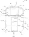
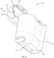
- FIG. 1is a top perspective view of an audio device system (shown in broken lines) encapsulated by a protective outer case, shown in an open state in accordance with an embodiment
- FIG. 2is a top perspective view of the outer case of FIG. 1 , shown in the open state, in accordance with an embodiment
- FIG. 3is a front view of the outer case of FIG. 2 , shown in the open state;
- FIG. 4is a rear view of the outer case of FIG. 2 , shown in the open state;
- FIG. 5is a right side view of the outer case of FIG. 2 , shown in the open state;
- FIG. 6is a left side view of the outer case of FIG. 2 , shown in the open state;
- FIG. 7is a top view of the outer case of FIG. 2 , shown in the open state;
- FIG. 8is a bottom view of the outer case of FIG. 2 , shown in the open state;
- FIG. 9is a bottom perspective view of the outer case of FIG. 2 , shown in the open state;
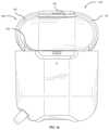
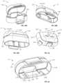
- FIG. 10is a top perspective view of the outer case of FIG. 1 , shown in the closed state in accordance with another embodiment
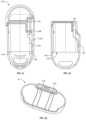
- FIG. 11is a front view of the outer case of FIG. 10 , shown in the closed state;
- FIG. 12is a rear view of the outer case of FIG. 10 , shown in the closed state;
- FIG. 13is a right side view of the outer case of FIG. 10 , shown in the closed state;
- FIG. 14is a left side view of the outer case of FIG. 10 , shown in the closed state;
- FIG. 15is a top view of the outer case of FIG. 10 , shown in the closed state;
- FIG. 16is a bottom view of the outer case of FIG. 10 , shown in the closed state;
- FIG. 17is a bottom perspective view of the outer case of FIG. 10 , shown in the closed state;
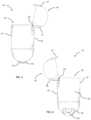
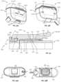
- FIG. 18is a top perspective view of a protective outer case, shown in an open state, in accordance with another embodiment
- FIG. 19is a front view of the outer case of FIG. 18 , shown in the open state;
- FIG. 20is a top perspective view of a protective outer case, shown in the open state, in accordance with another embodiment
- FIG. 21is a cross-sectional right side view of a protective outer case, shown in a closed state, in accordance with another embodiment
- FIG. 22is a cross-sectional right side view of an in-process protective outer case
- FIG. 23is a bottom perspective view of an outer lid layer of the outer cases of FIGS. 1 , 10 , 18 , and 20 in accordance with another embodiment
- FIG. 24is a top perspective view of a protective outer case, shown in an open state, in accordance with another embodiment
- FIG. 25is a bottom perspective view of the outer case of FIG. 24 , shown in the open state;
- FIG. 26is a top perspective view of an earbud device storage system, shown in an open state in accordance with an embodiment
- FIG. 27 Ais a left front perspective view of an outer case in accordance with an embodiment, shown in a closed state;
- FIG. 27 Bis a left front cross-sectional view of the outer case of FIG. 27 A , taken along lines 27 B- 27 B;
- FIG. 27 Cis a left front perspective view of the outer case of FIG. 27 A , shown in an open state;
- FIG. 27 Dis a left front cross-sectional view of the outer case of FIG. 27 A , shown in the open state;
- FIG. 27 Eis an exploded view of the outer case of FIG. 27 A ;
- FIG. 28 Ais a left front perspective view of an upper subassembly of the outer case of FIG. 27 A , shown in the open state;
- FIG. 28 Bis a left bottom perspective view of the upper subassembly of FIG. 28 A , shown in the closed state;
- FIG. 28 Cis a right rear perspective view of the upper subassembly of FIG. 28 A , shown in the closed state;
- FIG. 29is a left bottom perspective view of a lower subassembly of the outer case of FIG. 27 A ;
- FIG. 30is a left bottom perspective view of the upper subassembly of FIG. 28 A ;
- FIG. 31 Ais a left front perspective view of the outer case of FIG. 27 A without a collar;
- FIG. 31 Bis a right rear perspective view of the outer case of FIG. 27 A without a collar;
- FIG. 32is an enlarged view of a front portion of the cross-section of the outer case shown in FIG. 27 B ;
- FIG. 33 Ais a bottom view of the outer case of FIG. 27 A ;
- FIG. 33 Bis a top cross-sectional view of the outer case of FIG. 27 A taken along lines 33 B- 33 B;
- FIG. 34 Ais a left front perspective view of an outer case in accordance with an embodiment, shown in a closed and latched state;
- FIG. 34 Bis a left front perspective cross-sectional view of the outer case of FIG. 34 A , taken along lines 34 B- 34 B;
- FIG. 34 Cis a rear view of the outer case of FIG. 34 A , shown in the closed state;
- FIG. 35 Ais a left front perspective view of the outer case of FIG. 34 A , shown in a closed and unlatched state;
- FIG. 35 Bis a left front perspective cross-sectional view of the outer case of FIG. 34 A as shown in FIG. 35 A , taken along lines 35 B- 35 B.
- any numerical ranges set forth hereinare included to individually disclose every sub-range and number, both whole integer and partial fraction, within the disclosed range.
- a disclosed range of 1-100is intended to individually disclose 10-90, 40-70, 29.5-60.2, 65, 57.3, 94.512924, and every other range and number that falls within the recited range.
- audio device system 5includes left earbud 6 , right earbud 7 , charging case 10 , carabiner 18 , and outer case 20 .
- Charging case 10includes charging base 12 and charging lid 15 attached to the charging base.
- Charging base 12includes left and right base cavities 13 , 14 with shapes corresponding to the respective shapes of bottom portions of left and right earbuds 6 , 7 .
- Charging lid 15includes left and right lid cavities 16 , 17 with shapes corresponding to the respective shapes of top portions of left and right earbuds 6 , 7 such that upon closure of the lid, the left earbud is enclosed by left base cavity 13 and the left lid cavity and the right earbud is enclosed by right base cavity 14 and right lid cavity 17 .
- outer case 20includes base portion 30 and lid portion 40 attached to and closeable onto the base portion via connecting portion 50 .
- Base portion 30covers an entirety of an external surface of charging base 12 and lid portion 40 covers an entirety of an external surface of charging lid 15 such that upon closure of the lid portion onto the base portion of outer case 20 with charging case 10 arranged within the base portion, the entirety of the charging case is enclosed by the outer case (see FIGS. 10 and 17 ).
- outer case 20in either an open position as shown in FIGS. 2 - 9 or in a closed position as shown in FIGS. 10 - 17 , only one or none of left and right earbuds 6 , 7 may be suitably received in the respective left and right base cavities 13 , 14 of charging base 12 .
- base portion 30 of outer case 20includes inner base layer 31 and outer base layer 32 attached to the inner base layer to form a base receptacle 33 defined by the inner base layer.
- base receptacle 33may conform or substantially conform to the shape of charging base 12 of charging case 10 such that the charging base is held in place by the base receptacle in any orientation of the charging base, including when outer case 20 is in the open position.
- Lid portion 40 of outer case 20includes inner lid layer 41 and outer lid layer 42 attached to the inner lid layer to form a lid receptacle 43 defined by the inner lid layer.
- Lid receptacle 43conforms or substantially conforms to the shape of charging lid 15 of charging case 10 such that the charging lid is held in place by the lid receptacle in any orientation of the charging lid, including when outer case 20 is in the open position.
- Either one or both of the combination of inner base layer 31 and outer base layer 32 and the combination of inner lid layer 41 and outer lid layer 42may be co-molded/co-casted together or otherwise permanently affixed to each other, such as with an adhesive, in the manner further described in U.S. Pat. No. 8,755,852 and U.S. Patent Application Publication Nos. 2019/0075899 A1 and 2019/0075900 A1, the entireties of the disclosures of which are hereby incorporated by reference herein.
- Thicknesses of each of inner base layer 31 , inner lid layer 41 , outer base layer 32 , and outer lid layer 42may be in the range of 0.5 mm to 2.0 mm. Moreover, an overall thickness of each of the combination of inner base layer 31 and outer base layer 32 and the combination of inner lid layer 41 and outer lid layer 42 may be in the range of 1.0 mm to 5.0 mm. In some arrangements, either one or both of the combination of inner base layer 31 and outer base layer 32 may be a single base layer and the combination of inner lid layer 41 and outer lid layer 42 may be a single lid layer.
- connecting portion 50acts as a flexible hinge.
- connecting portion 50extends across and along rear wall 67 of base portion 30 and rear wall 77 of lid portion 40 .
- connecting portion 50is overmolded onto lid portion 40 and includes tabs (not shown) snapped into corresponding holes of outer base layer 32 to inhibit pull out of the connecting portion from the outer base layer and retain the connecting portion in the outer base layer.
- the connecting portionmay be overmolded onto base portion 30 and snapped into corresponding holes of outer lid layer 42 .
- the connecting portionsmay be attached to the base portion and the lid portion in another manner, such as through the use of an adhesive or by way of other mechanical connections.
- connecting portion 50When outer case 20 is in the closed position, connecting portion 50 is generally in the form of a curved sheet, as shown for example by FIGS. 12 - 14 . In this manner, rear wall 67 of base portion 30 , connecting portion 50 , and rear wall 77 of lid portion 40 are flush when outer case 20 is in the closed position such that these portions do not catch on other objects during use of the outer case.
- connecting portion 50When outer case 20 is in the open position, connecting portion 50 is generally in the form of a paraboloid, as shown for example by FIGS. 2 , 5 , and 6 . In this manner, lid portion 40 attached to connecting portion 50 rotates upwardly and away from base portion 30 during opening of outer case 20 .
- outer case 20further includes attachment loop 60 extending from base portion 30 .
- a separate hook, key ring, carabiner 18 , and the likemay be attached to attachment loop 60 for easier carrying of outer case 20 and its contents or attachment of outer case 20 and its contents to another object such as a bag or belt loop of a user.
- Attachment loop 60extends from inner base layer 31 and through an opening defined by outer base layer 32 .
- attachment loop 60is integral with inner base layer 31 such that the attachment loop and the inner base layer are inseparable without fracture.
- attachment loop 60may be attached to inner base layer 31 by an adhesive, by way of a tight interference fit within the inner base layer, by way of a flange extending from the attachment loop and preventing separation of the attachment loop from the inner base layer, or by other means known to those skilled in the art.
- a corner formed by bottom wall 34 and side wall 36 of base portion 30may be truncated such that a substantial portion of attachment loop 60 (see FIG. 3 ) extends at an oblique angle to the bottom wall and the sidewall of the base portion within the truncated region of the base portion. In this manner, attachment loop 60 is configured to minimize possible snags on or other interference with objects in the external environment.
- Attachment loop 60extends from and, in the example shown, is integral with loop insert 78 .
- Loop insert 78includes tabs (not shown) snapped into corresponding holes of outer base layer 32 to inhibit pull out of the loop insert from the outer base layer and retain the loop insert in the outer base layer.
- attachment loop 60may be in the form of a hook. In this manner, attachment loop 60 may be attached directly to a bag or belt loop or other object.
- Front wall 37 of base portion 30 of outer case 20includes base flange 35 set into and extending from base recess 38 of the base portion, and front wall 47 of lid portion 40 of the outer case includes lid flange 45 set into and extending from lid flap 48 of the lid portion.
- Lid flap 48is located on lid portion 40 and base recess 38 is located on base portion 30 such that upon closure of outer case 20 , the lid flap is received within the base recess as shown in FIGS. 10 , 11 , and 13 - 17 .
- Lid flange 45is aligned with base flange 35 such that upon closure of outer case 20 , the lid flange overlaps and is below the base flange such that the base flange is closer to base opening 39 of base receptacle 33 than the lid flange.
- either one or both of base flange 35 and lid flange 45is configured with an undercut such that a tip of the other of the base flange and the lid flange is received within such undercut or undercuts when outer case 20 is in the closed position. The use of the undercuts inhibits relative slipping between the base and lid flanges 35 , 45 , allowing the closure of base portion 30 onto lid portion 40 to be more secure.
- one or more dual hinge latchesas known to those skilled in the art may be utilized in place of or in combination with flanges like those of base and lid flanges 35 , 45 .
- Such dual hinge latchesmay be in the form of latches used on fishing tackle boxes sold commercially today.
- outer case 20may define additional openings or cutouts at various locations so as to allow various buttons, ports, or features of a protected device, such as charging case 10 , to be accessed without having to remove the protected device 10 from the outer case.
- opening 91 through front wall 37 of outer case 20is configured to expose a light indicator, e.g., a light-emitting diode (LED) indicator, of charging case 10 to allow a user to be alerted when charging of earbuds 6 , 7 is complete or when additional charging is needed, depending on the default settings of the LED indicator.
- a light indicatore.g., a light-emitting diode (LED) indicator
- opening 92extends through port insert 64 received in a hole defined by bottom wall 34 to provide access to a charging port of charging base 12 .
- port insert 64includes tabs (not shown) snapped into corresponding holes of outer base layer 32 to inhibit pull out of the port insert from the outer base layer and retain the port insert in the outer base layer.
- Port insert 64includes port body 65 and port ribs 66 A, 66 B attached on opposite sides of a top portion of the port body.
- Port body 65defines a lead-in chamfer and port ribs 66 A, 66 B in combination with the top portion of the port body define opening 92 .
- the lead-in chamfer of port body 65 and port ribs 66 A, 66 Bprovide a guide for the insertion of a peripheral component, such as a connector of a power plug, through opening 92 in which the port ribs provide a slight resistance during the insertion of the peripheral component and thereby provide tactile feedback to a user that the connector is received in the opening.
- a peripheral componentsuch as a connector of a power plug
- Inner base layer 31 , inner lid layer 41 , and port insert 64preferably may be made of elastomeric or other suitably flexible materials.
- Preferred materialsinclude thermosetting plastics with a hard durometer having shore 30D to shore 100D, polycarbonate, poly(methyl methacrylate) (“PMMA”), metals, acrylonitrile butadiene styrene (“ABS”), PMMA, polyethylene terephthalate (“PET”), high durometer thermoplastic elastomers (“TPEs”) and thermoplastic polyurethanes (“TPUs”) having shore 30D to shore 100D, and any combination thereof.
- inner base layer 31 and inner lid layer 41may be made of a non-Newtonian dilatant material, as further described in U.S. Patent Application Publication Nos. 2019/0075899 A1 and 2019/0075900 A1.
- Inner base layer 31 and inner lid layer 41preferably are made of the same material, although these layers may be made of different materials.
- Outer base layer 32 and outer lid layer 42preferably may be made of a rigid or hard material to create a rigid/hard shell which provides at least some impact protection as well as protection from being punctured by impacts with sharp objects.
- Preferred hard/rigid materialsinclude hardened plastic material, a rigid or semi-rigid plastic material, a rigid/hard rubber material, a polycarbonate material, a metal, an alloy, a para-aramid material, wood, glass, mirror, quartz, and any combination thereof, and may be any color or texture. Such materials may be the same as or may mimic the material or materials used for charging case 10 .
- Outer base layer 32 and outer lid layer 42preferably are made of the same material, although these layers may be made of different materials.
- any one or any combination of surfaces of inner base layer 31 , outer base layer 32 , inner lid layer 41 , and outer lid layer 42 exposed to users in either one or both of the open and closed positions of outer case 20may be treated with an antimicrobial material applied as a coating or any one of such layers 31 , 32 , 41 , 42 may have an antimicrobial material embedded into such layers.
- Preferred antimicrobial materialsinclude silver or silver alloy (e.g., silver sodium hydrogen zirconium phosphate), copper or copper alloy, organosilanes, quaternary ammonium compounds (e.g., dimethyloctadecyl (3-trimethoxysilyl propyl) ammonium chloride, alkyldimethylbenzylammonium chloride, and didecyldimethylammonium chloride), chlorhexidine, chlorhexidine incorporated hydroxyapatite materials, chlorhexidine-containing polymers (e.g., chlorhexidine-containing polylactide), and antibiotics (e.g., gentamicin, cephalothin, carbenicillin, amoxicillin, cefamandol, tobramycin, vancomycin).
- antibioticse.g., gentamicin, cephalothin, carbenicillin, amoxicillin, cefamandol, tobramycin, vancomycin.
- Preferred antimicrobial coatingsinclude coatings containing any of the aforementioned antimicrobial materials, chlorhexidine-containing polylactide coatings on an anodized surface, and polymer and calcium phosphate coatings with chlorhexidine. These antimicrobial treatments aid in reducing the presence and preventing the growth of microbes (e.g., bacteria, fungi, viruses, etc.), thereby aiding in preventing the spread of related sicknesses, illnesses, or diseases.
- microbese.g., bacteria, fungi, viruses, etc.
- outer case 120is the same or substantially the same as outer case 20 with the exception that outer case 120 includes lid 140 in place of lid 40 .
- Lid 140is the same or substantially the same as lid 40 with the exception that lid 140 includes inner lid layer 141 defining recess 151 and further includes cushion 152 received in the recess.
- Cushion 152extends beyond inner lid layer 141 and is oriented such that the cushion opposes ridge 55 of outer lid layer 42 .
- cushion 152 and ridge 55each contact the charging lid to aid in retaining the charging lid in place in the outer case.
- cushion 152may be made of silicone or other elastic material such that the cushion may be flexible to provide an interference fit with an inserted charging lid 15 and to provide a frictional surface to further aid in retaining the charging lid in outer case 120 .
- outer case 220is the same or substantially the same as outer case 20 with the exception that outer case 220 includes upper inner base layer 231 A and lower inner base layer 231 B in place of inner base layer 31 .
- Lower inner base layer 231 Bis symmetrical about an axis extending from the top to the bottom of outer case 220 and further has a substantially hourglass shape defined by upper wings 281 (only one upper wing being shown as the other wing is symmetrical to the upper wing shown) and lower wings 282 (only one lower wing being shown as the other wing is symmetrical to the lower wing shown) and upper base layer 231 A extends within the rest of outer case 220 such that, together, upper inner base layer 231 A and lower inner base layer 231 B take the same form as inner base layer 31 of outer case 20 .
- a thickness of lower inner base layer 231 Bdefines undercut 283 that extends over bottom portion 284 of upper inner base layer 231 A to inhibit pull out of the upper inner base layer from outer case 220 .
- a thickness of upper inner base layer 231 Aextends over lower wings 282 of lower inner base layer 231 B to inhibit pull out of the lower inner base layer from outer case 220 .
- an underside of outer lid layer 42includes a pair of bumps 44 A, 44 B having central axes extending within parallel planes.
- Outer lid layer 42is utilized for outer cases 20 , 120 , 220 , and the like.
- outer case 320is substantially the same as outer case 20 with the notable exceptions that outer case 320 generally includes base 330 in place of base 30 , lid 340 in place of lid 40 , and connecting portion 350 in place of connecting portion 50 .
- Base 330includes inner base layer 331 having base ribs 339 that define opening 339 A along a top portion of the inner base layer in place of inner base layer 31 that excludes such base ribs.
- Base ribs 339provide additional friction against charging base 12 , relative to surfaces without such ribs, when the charging base is inserted into base receptacle 333 defined by inner base layer 331 .
- Base 330further includes port insert 364 which is substantially the same as port insert 64 with the notable exception that port insert 364 excludes port ribs 66 A, 66 B such that opening 392 defined by the port insert provides less resistance to any connector of a power cord or other peripheral device inserted into the opening.
- Connecting portion 350 of outer case 320includes tabs 354 A, 354 B that, unlike the corresponding tabs of connecting portion 50 of outer case 20 , extend into corresponding holes 368 A, 368 B of inner base layer 331 . In this manner, unlike inner base layer 31 of outer case 20 , inner base layer 331 does not press against tabs 354 A, 354 B.
- Lid 340includes inner lid layer 341 having lid ribs 349 along a bottom portion of the inner lid layer in place of inner lid layer 41 that excludes such lid ribs.
- Lid ribs 349provide additional friction against charging lid 15 , relative to surfaces without such ribs, when the charging lid is inserted into lid receptacle 343 defined by inner lid layer 341 .
- earbud device storage system 501includes charging case 10 and outer case 510 into which the charging case is seated.
- storage system 501forms part of an audio device system that includes earbuds (not shown), e.g., Airpods® wireless earphones by Apple, Inc.
- outer case 510includes base 520 and lid 530 in which lid 530 rotates with a lid of charging case 10 from a closed position to an open position, as in the example shown in FIG. 26 , to allow access to earbuds that may be inserted into the charging case for charging and storage. In the closed position of outer case 510 (see FIG.
- lid 530fully covers an opening of base 520 for receiving charging case 10 and the lid is further secured to collar 560 to thereby secure the charging case and its contents within the outer case.
- charging case 10is protected from dust such that outer case 510 may have an IP5X rating according to IEC 60529 (also EN 60529).
- IEC 60529also EN 60529
- dust that enters outer case 510 during testingdoes not enter charging case 10 .
- Lid 530is opened by depressing and pushing or pulling collar lever 565 of collar 560 in a direction away from lid 530 to release a latched connection (see FIG.
- outer case 510operates in a substantially similar manner to outer case 520 described above.
- outer case 510further includes flexible panel 550 , collar 560 slidably attached to base 520 and attached to lid 530 by the flexible panel, port cover 580 , and attachment member 590 .
- Lid 530includes lid inner layer 531 and lid outer layer 533 attached to the lid inner layer, e.g., via co-molding, co-casting, or an adhesive as known to those skilled in the art.
- Lid inner layer 531may be a flexible layer as described further herein and have lid inner layer rim 532 and lid outer layer 533 may be a rigid layer as described further herein and have lid outer layer rim 534 .
- Lid inner layer 531defines an interior of the lid and lid outer layer 533 defines an exterior of the lid in which the lid inner layer extends beyond lid outer layer rim 534 such that lid inner layer rim 532 is spaced from the lid outer layer rim.
- outer case 510may be divided into upper subassembly 511 and lower subassembly 512 .
- Upper subassembly 511includes lid 530 , collar 560 , and flexible panel 550 that attaches the lid to the collar such that the lid is pivotable away from the collar, as demonstrated by the contrast between FIG. 28 A and FIGS. 28 B, 28 C .
- the components of upper subassembly 511may be assembled and held together without attachment to lower subassembly 512 . As shown in FIG.
- flexible panel 550may be fitted within and extend between lid panel recess 539 of lid 530 and collar panel recess 563 of collar 560 such that the flexible panel may be flush with or, as in the example of FIG. 30 , rest below top edges of the lid panel and collar panel recesses.
- lower subassembly 512includes base 520 , port cover 580 , and attachment member 590 which may be assembled and held together without attachment to upper subassembly 511 .
- base 520includes base main body 521 having base rim 522 , base side flanges 523 A, 523 B extending from left and right sides of the base main body, base rear flanges 524 A, 524 B extending from a rear side of the base main body, and base front flanges 525 A, 525 B, the flanges being described further below.
- lid inner layer rim 532when outer case 510 is in the closed position, lid inner layer rim 532 is in abutment with base rim 522 along front sides, i.e., sides opposite flexible panel 550 , and at least respective left and right sides adjacent to the front sides of lid inner layer 531 and base 520 . In this manner, dust and other particles, e.g., lint, may be prevented from entering outer case 510 when the outer case is in the closed position.
- collar 560includes circumferential band 562 configured to wrap around base 520 and collar latch portion 561 attached to the circumferential band.
- an interior surface of circumferential band 562may be dimensioned such that all or at least a portion of the circumferential band is in contact with all or a substantial portion of a circumference of an exterior surface of base 520 during opening of lid 530 via sliding of collar 560 along base 520 . As shown by FIGS.
- collar 560has collar upper rim 564 that is in abutment with lid outer layer rim 534 when outer case 510 is in the closed position. In this manner, dust and other particles may be further prevented from entering outer case 510 when the outer case is in the closed position.
- Collar 560further includes front track recess 571 and rear track recesses 573 A, 573 B on a side of the collar opposite the front track recesses as well as left and right track recesses 574 A, 574 B between the front and respective ones of the rear track recesses.
- base front flanges 525 A, 525 Bare received within front track recess 571
- base rear flanges 524 A, 524 Bare received within respective rear track recesses 573 A, 573 B
- base side flanges 523 A, 524 Bare received within respective left and right track recesses 574 A, 574 B such that the collar is slidable along base 520 toward and away from lid 530 .
- lid outer layer 533 of lid 530includes lid catch 535 defining lid catch recess 536 and having lid catch taper 537 on an end of the lid catch.
- Collar latch portion 561 of collar 560includes a collar latch body protruding from circumferential band 562 on a front of outer case 510 .
- Collar hook 566extends from one end of the collar latch body 561 A and defines collar hook recess 567 configured for receipt into lid catch recess 536 while collar lever 565 extends from another end of the collar latch body opposite from the collar hook.
- Collar lever 565is spaced from base 520 such that the collar lever may be depressed inwardly towards the base to rotate collar hook 566 away from lid catch 535 .
- a downward forcesuch as a push or pull in a direction towards a bottom of base 520 and thus a bottom of outer case 510 , applied to collar latch portion 561 , lid 530 is released from being held in position by the collar latch portion.
- flexible panel 550when collar 560 is pulled or pushed downwardly, flexible panel 550 is sufficiently elastic such that the flexible panel stretches sufficiently to create clearance by way of a small gap between lid outer layer rim 534 and collar upper rim 564 and thus to allow rearward portion 534 A of lid outer layer rim 534 to rotate inwardly toward base 520 during rotation of lid 530 relative to the base.
- Rearward portion 534 Ais slightly raised relative to the rest of lid outer layer rim 534 and top ends of track recesses 571 , 573 A, 573 B of collar 560 each provide respective lips acting as stops for their respective flanges 24 A, 24 B, 25 A, 25 B of base 520 such that lid 530 is rotated to a fully open state when the flanges contact the top ends of the recesses.
- Rearward portion 534 Afurther creates clearance such that rearward portion 534 A of lid outer layer rim 534 rests below base rim 522 and below a rear portion of collar upper rim 564 upon full rotation of lid 530 relative to the base without interference from either the base (see FIGS.
- FIGS. 27 C and 27 Dshowing the lid and the base in the middle of a rotation of the lid
- collar 560may be slid downwardly such that collar upper rim 564 is below lid outer layer rim 534 initially at full rotation of lid 530 , as shown in FIG. 27 D , but upon release of the collar, the elasticity of flexible panel 550 may be sufficient to pull the collar upwardly such that the rear portion of the collar upper rim is above rearward portion 534 A of outer lay rim 534 .
- rearward portion 534 Athus allows lid 530 to open more fully than if the rearward portion was not raised relative to the rest of lid outer layer rim 534 and further provides for clearance for flexible panel 550 when the lid is rotated open fully.
- rearward portion 534 A of lid outer layer rim 534is aligned in a vertical direction generally near but below base rim 522 such that lid outer layer rim 534 abuts a rearward side of base 520 in this open state.
- base lens 527is inserted into base 520 and collar lens 575 is inserted into collar 560 .
- Base 520further includes base lens cavity 528 and base lens aperture 529 extending through a thickness of base 520 and similarly collar 560 further includes collar lens cavity 576 and collar lens aperture 577 extending through a thickness of collar 560 at collar latch portion 561 .
- Base lens aperture 529 and collar lens aperture 577are configured and aligned such that light emitted by charging case 10 , e.g., a light-emitting diode (LED) indicating power or charging, is visible to the naked eye by a user of earbud device storage system 501 when outer case 510 is in a closed position.
- LEDlight-emitting diode
- Base lens 527is inserted, e.g., by an interference fit, an adhesive, or both, into base lens cavity 528 forming a counterbore of base lens aperture 529 and similarly collar lens 575 is inserted into collar lens cavity 576 forming a counterbore of collar lens aperture 577 .
- Base lens 527 and collar lens 575which preferably may be in the form of a film, prevent intrusion of dust and other particles while allowing light to pass through both base 520 and collar 560 when lid 530 of outer cover 510 is in the closed position.
- port cover 580 of outer case 510extends through the thickness of base 520 at a bottom of the base to allow access into the outer case, e.g., to allow a charging plug to be inserted into charging case 10 through the port cover.
- Port cover 580includes cover base 581 affixed to an interior of base 520 and port cover door 582 attached along one side of the cover base such that the port cover door is rotatable from a position covering a hole through the bottom of base 520 to a position outside of the base to allow exposure of and access to charging case 10 .
- outer case 510further includes attachment member 590 inserted through the thickness of a bottom corner of base 520 .
- Attachment member 590includes loop base 591 affixed to the interior of base 520 and attachment loop 592 attached to or integral with the loop base.
- Attachment loop 592is configured for attachment to a carabiner or other similar attachment object and may be but is not limited to being made of a flexible textile such that when the attachment loop is attached to such attachment object, the attachment loop may be stretched in a direction away from the attachment object to allow for easier access to outer case 510 and thereby charging case 10 or other components of earbud device storage system 501 when the charging case is inserted into the outer case.
- Lid inner layer 531 , port cover 580 , and attachment member 590preferably may be made of elastomeric or other suitably flexible materials.
- Preferred materialsinclude thermosetting plastics with a hard durometer having shore 30D to shore 100D, polycarbonate, poly(methyl methacrylate) (“PMMA”), metals, acrylonitrile butadiene styrene (“ABS”), PMMA, polyethylene terephthalate (“PET”), high durometer thermoplastic elastomers (“TPEs”) and thermoplastic polyurethanes (“TPUs”) having shore 30D to shore 100D, and any combination thereof.
- thermosetting plasticswith a hard durometer having shore 30D to shore 100D
- PMMApoly(methyl methacrylate)
- ABSacrylonitrile butadiene styrene
- PETpolyethylene terephthalate
- TPEshigh durometer thermoplastic elastomers
- TPUsthermoplastic polyurethanes
- lid inner layer 531 , port cover 580 , and attachment member 590may be made of a non-Newtonian dilatant material, as further described in U.S. Patent Application Publication Nos. 2019/0075899 A1 and 2019/0075900 A1.
- Lid inner layer 531 , port cover 580 , and attachment member 590may be made of the same material or a different material than either one or both of the other of the lid inner layer, the port cover, and the attachment member.
- Base 520 and lid outer layer 533preferably may be made of a rigid or hard material to create a rigid/hard shell which provides at least some impact protection as well as protection from being punctured by impacts with sharp objects.
- Preferred hard/rigid materialsinclude hardened plastic material, a rigid or semi-rigid plastic material, a rigid/hard rubber material, a polycarbonate material, a metal, an alloy, a para-aramid material, wood, glass, mirror, quartz, and any combination thereof, and may be any color or texture. Such materials may be the same as or may mimic the material or materials used for charging case 10 .
- Base 520 and lid outer layer 533preferably are made of the same material, although these layers may be made of different materials.
- any one or any combination of surfaces of base 520 , lid inner layer 531 , lid outer layer 533 , collar 560 , port cover 580 , and attachment member 590 exposed to users in either one or both of the open and closed positions of outer case 520may be treated with an antimicrobial material applied as a coating or any one of such components 520 , 531 , 533 , 560 , 580 , and 590 may have an antimicrobial material embedded into such layers.
- Preferred antimicrobial materialsinclude silver or silver alloy (e.g., silver sodium hydrogen zirconium phosphate), copper or copper alloy, organosilanes, quaternary ammonium compounds (e.g., dimethyloctadecyl (3-trimethoxy silyl propyl) ammonium chloride, alkyldimethylbenzylammonium chloride, and didecyldimethylammonium chloride), chlorhexidine, chlorhexidine incorporated hydroxyapatite materials, chlorhexidine-containing polymers (e.g., chlorhexidine-containing polylactide), and antibiotics (e.g., gentamicin, cephalothin, carbenicillin, amoxicillin, cefamandol, tobramycin, vancomycin).
- antibioticse.g., gentamicin, cephalothin, carbenicillin, amoxicillin, cefamandol, tobramycin, vancomycin.
- Preferred antimicrobial coatingsinclude coatings containing any of the aforementioned antimicrobial materials, chlorhexidine-containing polylactide coatings on an anodized surface, and polymer and calcium phosphate coatings with chlorhexidine. These antimicrobial treatments aid in reducing the presence and preventing the growth of microbes (e.g., bacteria, fungi, viruses, etc.), thereby aiding in preventing the spread of related sicknesses, illnesses, or diseases.
- microbese.g., bacteria, fungi, viruses, etc.
- covers for other audio device systemssuch as but not limited to microphones, voice recorders, and the like, that may or may not be encased in or accompanied by a charging case or charging dock, as well as other handheld electronic device systems, such as but not limited to remote controllers, pagers, video game wands or other controllers, and the like, that may or may not be encased in or accompanied by a charging case or charging dock, are encompassed by the present disclosure.
- outer case 610which may be part of an earbud device storage system such as system 501 , is the same or substantially the same as outer case 510 with the exception that outer case 610 includes collar 660 in place of collar 560 .
- Collar 660is attached to base 520 and lid 530 in the same manner as collar 560 is attached to base 520 and lid 530 .
- Collar 660generally includes collar latch base 661 , circumferential band 662 attached to the collar latch base and wrapping around 520 , collar button 670 , collar fulcrum 677 , and collar resilient element 678 .
- collar fulcrum 677may be a rod received within collar latch base 661 .
- Collar fulcrum 677 when in the form of a rodmay be attached to collar latch base 661 such as by insertion into grooves or holes of latch base 661 .
- collar resilient element 678may be a V-shaped spring, which may be made of sheet metal, although other compressible or other resilient elements known to those skilled in the art, e.g., a leaf spring, may be utilized.
- collar button 670 and collar latch base 661each may be attached, such as by an adhesive, a fastener such as a screw, a snap fit, or any other mechanical means known to those skilled in the art, to opposing sides of resilient element 678 .
- collar button 670may be predisposed by collar resilient element 678 in a vertical rest position as shown in FIG. 34 B . Accordingly, when lid 530 is in a closed condition, button hook 676 on an end of collar button 670 is received within lid catch recess 536 to latch the lid closed relative to base 520 . In this closed state, a charging case with or without enclosed earbuds, e.g., charging case 10 , may be enclosed and secured within outer case 610 in a similar manner as the charging case may be enclosed and secured within outer case 510 .
- a charging case with or without enclosed earbudse.g., charging case 10
- collar button release portion 675which may be so designated by a depression in the collar button and which may be adjacent to collar shroud 663 as shown, causes rotation of collar button 670 about collar fulcrum 677 .
- button hook 676rotates away and releases from lid catch recess.
- sufficient downward force applied to collar 660causes lid 530 to open relative to base 520 via flexible panel 550 .
- band 662 of collar 660may include rear recess 665 opposite a recess of collar button release portion 675 .
- Rear recess 655may allow at least some users to better grip the collar than if such recesses were excluded.
- collar shroud 663may extend around a portion of collar button 670 , in particular around collar button release portion 675 , to inhibit unintentional depression of the collar button and thereby to inhibit the unintentional opening of outer case 610 .
- terms such as “front,” “rear,” “side,” “left side,” “right side,” “top,” “bottom,” “horizontal,” and “vertical”describe the orientation of portions of the component within a consistent but arbitrary frame of reference which is made clear by reference to the text and the associated drawings describing the component under discussion. Such terminology will include the words specifically mentioned above, derivatives thereof, and words of similar import.
Landscapes
- Physics & Mathematics (AREA)
- Engineering & Computer Science (AREA)
- Acoustics & Sound (AREA)
- Signal Processing (AREA)
- Telephone Set Structure (AREA)
Abstract
Description
Claims (20)
Priority Applications (1)
| Application Number | Priority Date | Filing Date | Title |
|---|---|---|---|
| US17/379,417US11751652B2 (en) | 2019-07-25 | 2021-07-19 | Protective outer case, especially for portable audio device systems |
Applications Claiming Priority (4)
| Application Number | Priority Date | Filing Date | Title |
|---|---|---|---|
| US16/522,408US20210029424A1 (en) | 2019-07-25 | 2019-07-25 | Protective outer case for audio device systems |
| US202063053295P | 2020-07-17 | 2020-07-17 | |
| US17/109,789US11412823B2 (en) | 2019-07-25 | 2020-12-02 | Protective outer case, especially for portable audio device systems |
| US17/379,417US11751652B2 (en) | 2019-07-25 | 2021-07-19 | Protective outer case, especially for portable audio device systems |
Related Parent Applications (1)
| Application Number | Title | Priority Date | Filing Date |
|---|---|---|---|
| US17/109,789Continuation-In-PartUS11412823B2 (en) | 2019-07-25 | 2020-12-02 | Protective outer case, especially for portable audio device systems |
Publications (2)
| Publication Number | Publication Date |
|---|---|
| US20210345742A1 US20210345742A1 (en) | 2021-11-11 |
| US11751652B2true US11751652B2 (en) | 2023-09-12 |
Family
ID=78411768
Family Applications (1)
| Application Number | Title | Priority Date | Filing Date |
|---|---|---|---|
| US17/379,417ActiveUS11751652B2 (en) | 2019-07-25 | 2021-07-19 | Protective outer case, especially for portable audio device systems |
Country Status (1)
| Country | Link |
|---|---|
| US (1) | US11751652B2 (en) |
Cited By (6)
| Publication number | Priority date | Publication date | Assignee | Title |
|---|---|---|---|---|
| USD1020250S1 (en)* | 2022-10-31 | 2024-04-02 | Wenqi Yao | Protective case for headphone case |
| US12037822B1 (en)* | 2023-01-13 | 2024-07-16 | Spigen Korea Co., Ltd. | Locking module and locking module attachment device including the same |
| USD1046931S1 (en)* | 2019-06-05 | 2024-10-15 | Samsung Electronics Co., Ltd. | Refrigerator |
| USD1048116S1 (en)* | 2019-06-05 | 2024-10-22 | Samsung Electronics Co., Ltd. | Refrigerator |
| USD1084055S1 (en)* | 2019-12-20 | 2025-07-15 | Whirlpool Corporation | Refrigerator |
| US12368310B1 (en)* | 2025-02-19 | 2025-07-22 | Hangzhou Xiyang E-Commerce Co., Ltd | Protective sleeve for earphone case |
Families Citing this family (30)
| Publication number | Priority date | Publication date | Assignee | Title |
|---|---|---|---|---|
| USD974330S1 (en)* | 2019-06-26 | 2023-01-03 | Catalyst Lifestyle Limited | Case for electronic device |
| USD1003284S1 (en) | 2019-10-23 | 2023-10-31 | Catalyst Lifestyle Limited | Sleeve for electronic device |
| USD944011S1 (en)* | 2019-10-28 | 2022-02-22 | Speculative Product Design, Llc | Outer covering for earbud case |
| USD960577S1 (en)* | 2019-12-05 | 2022-08-16 | Shenzhen Guangyipeng Technology Co., Ltd. | Charging case for wireless earphones |
| USD1003884S1 (en) | 2019-12-13 | 2023-11-07 | Catalyst Lifestyle Limited | Sleeve for electronic device |
| USD954715S1 (en) | 2020-01-20 | 2022-06-14 | Catalyst Lifestyle Limited | Sleeve for electronic device |
| USD954716S1 (en) | 2020-01-20 | 2022-06-14 | Catalyst Lifestyle Limited | Sleeve for electronic device |
| USD954063S1 (en) | 2020-01-20 | 2022-06-07 | Catalyst Lifestyle Limited | Sleeve for electronic device |
| USD956765S1 (en) | 2020-02-05 | 2022-07-05 | Doria International Inc | Case |
| USD959141S1 (en) | 2020-02-05 | 2022-08-02 | Doria International Inc | Case |
| USD941023S1 (en)* | 2020-02-05 | 2022-01-18 | Doria International Inc | Sleeve |
| USD974758S1 (en) | 2020-02-26 | 2023-01-10 | Catalyst Lifestyle Limited | Sleeve for electronic device |
| USD986713S1 (en) | 2020-02-28 | 2023-05-23 | Catalyst Lifestyle Limited | Case for electronic device |
| US12127651B1 (en)* | 2020-07-01 | 2024-10-29 | Apple Inc. | Items with hidden magnets |
| USD969815S1 (en) | 2021-03-24 | 2022-11-15 | Catalyst Lifestyle Limited | Case for electronic device |
| USD994327S1 (en) | 2021-03-26 | 2023-08-08 | Catalyst Lifestyle Limited | Case for electronic device |
| CN113142686B (en)* | 2021-04-22 | 2023-07-25 | 立讯精密工业股份有限公司 | Charging box |
| WO2023027213A1 (en)* | 2021-08-26 | 2023-03-02 | 엘지전자 주식회사 | Cradle and portable audio device |
| US11528973B1 (en)* | 2021-09-02 | 2022-12-20 | Bose Corporation | Cases for electronic devices |
| US12069422B2 (en)* | 2022-04-21 | 2024-08-20 | Sony Interactive Entertainment Inc. | Microphone charging case |
| USD970892S1 (en)* | 2022-05-11 | 2022-11-29 | Class and Culture LLC | Earbud case accessory |
| USD1080530S1 (en)* | 2022-06-02 | 2025-06-24 | Beijing Xiaomi Mobile Software Co., Ltd | Charging case for earphones |
| CN218387840U (en)* | 2022-09-20 | 2023-01-24 | 深圳市拙野创意有限公司 | Wireless earphone charging box with prepressing damping effect |
| JP1755799S (en)* | 2022-09-29 | 2023-10-20 | hearing aid charging case | |
| USD1075661S1 (en)* | 2022-09-29 | 2025-05-20 | Xiamen Retone Hearing Technology Co., Ltd. | Charging box |
| USD1007854S1 (en)* | 2023-08-16 | 2023-12-19 | Yi Hu | Earphone case |
| USD1007862S1 (en)* | 2023-09-19 | 2023-12-19 | Maojun Wang | Earphone protective sleeve |
| CN120240786A (en)* | 2024-01-03 | 2025-07-04 | 佳音医疗器材股份有限公司 | Anti-lost rope and anti-lost device |
| CN119094945B (en)* | 2024-08-29 | 2025-08-29 | 东莞市汇恩电子科技有限公司 | A charging compartment for a Bluetooth headset and its safety system |
| USD1074069S1 (en)* | 2024-11-21 | 2025-05-06 | Juanfang Zhong | Protective case for earphone |
Citations (104)
| Publication number | Priority date | Publication date | Assignee | Title |
|---|---|---|---|---|
| USD357919S (en) | 1993-07-26 | 1995-05-02 | Capital Prospect Ltd. | Remote control unit |
| USD386611S (en) | 1996-07-08 | 1997-11-25 | Muh-Chuen Sheu | Waterproof container |
| USD426950S (en) | 1999-05-25 | 2000-06-27 | Optoplast Plc | Case for tampons or other articles |
| USD475946S1 (en) | 2001-08-10 | 2003-06-17 | Fildan Accessories Corporation | Reversible closure |
| US20060091222A1 (en) | 2004-10-25 | 2006-05-04 | Empower Technologies Inc. | Direct-mounted pouch for portable electronic device |
| US20060201833A1 (en) | 2005-03-09 | 2006-09-14 | Pei-Ling Lee | Toolbox |
| USD540651S1 (en) | 2005-11-18 | 2007-04-17 | Wolf Designs, Inc. | Push button box latch |
| EP1847478A1 (en) | 2006-04-20 | 2007-10-24 | Philip Morris Products S.A. | Hinged Lid Container with Sliding Device |
| US20070256946A1 (en) | 2006-04-25 | 2007-11-08 | Travel Caddy, Linc. D/B/A Travelon | Carrying case for headphones |
| US20080090622A1 (en) | 2006-10-13 | 2008-04-17 | Samsung Electronics Co., Ltd. | Charging cradle for a headset device and an earphone cover for the headset device |
| USD576037S1 (en) | 2006-03-15 | 2008-09-02 | Mcneil-Ppc, Inc. | Container cap |
| USD599742S1 (en) | 2008-08-28 | 2009-09-08 | Monster Cable Products, Inc. | Connector strain relief |
| US7673745B2 (en) | 2006-03-28 | 2010-03-09 | Belkin International, Inc. | Case for portable electronic device |
| US7775354B2 (en) | 2006-04-12 | 2010-08-17 | Janet Lee Latchford | Waterproof cover for personal music player |
| US20110005648A1 (en) | 2009-07-12 | 2011-01-13 | Sa Shuang | Protective Cover Case |
| US20110017620A1 (en) | 2006-04-12 | 2011-01-27 | Janet Lee Latchford | Waterproof Cover for Personal Music Player |
| USD643831S1 (en) | 2009-10-14 | 2011-08-23 | Lg Electronics Inc. | Docking station |
| CN103284450A (en) | 2012-02-28 | 2013-09-11 | 膳魔师(中国)家庭制品有限公司 | Drink bottle and lid with button release at back of lid |
| US20140069825A1 (en) | 2012-09-07 | 2014-03-13 | G-Form, LLC | Protective case and methods of making |
| CN103662353A (en) | 2012-08-31 | 2014-03-26 | 膳魔师(中国)家庭制品有限公司 | Food container with fast inlet cover |
| US8755852B2 (en) | 2009-02-06 | 2014-06-17 | Speculative Product Design, Llc | One piece co-formed exterior hard shell case with an elastomeric liner for mobile electronic devices |
| USD708784S1 (en) | 2012-02-09 | 2014-07-08 | Amorepacific Corporation | Cosmetic container |
| USD718657S1 (en) | 2013-02-12 | 2014-12-02 | Speculative Product Design, Llc | Clasp |
| US20140376763A1 (en) | 2010-06-23 | 2014-12-25 | Dean Stevinson | Combination wallet and storage case |
| US20150076187A1 (en) | 2013-09-17 | 2015-03-19 | Medline Industries, Inc. | Antimicrobial Electronic Device Shell |
| USD726690S1 (en) | 2005-09-02 | 2015-04-14 | Apple Inc. | Docking station |
| US9304375B2 (en) | 2014-06-30 | 2016-04-05 | Samsung Electronics Co., Ltd. | Electronic device carrying case and portable electronic device |
| US20160198823A1 (en) | 2015-01-13 | 2016-07-14 | Hit Technologies Inc. | Systems for Securing a Mobile Device in a Waterproof Case |
| USD775818S1 (en)* | 2015-09-21 | 2017-01-10 | Lorie Ingraham | Wearable headphone storage case |
| US9565913B2 (en) | 2012-06-05 | 2017-02-14 | Incipio, Llc | Active suspension case for a mobile device |
| US9565910B2 (en) | 2013-05-18 | 2017-02-14 | Otter Products, Llc | Waterproof protective case for an electronic device |
| WO2017032668A1 (en) | 2015-08-21 | 2017-03-02 | Philip Morris Products S.A. | Container for consumer goods with sliding collar |
| US20170094381A1 (en)* | 2015-09-30 | 2017-03-30 | Apple Inc. | Case with torsion spring over-center mechanism |
| US9686878B2 (en) | 2015-02-27 | 2017-06-20 | Samsung Electronics Co., Ltd. | Exterior cover |
| USD794618S1 (en) | 2017-02-28 | 2017-08-15 | Catalyst Lifestyle Limited | Sleeve for electronic device |
| USD794617S1 (en) | 2017-02-28 | 2017-08-15 | Catalyst Lifestyle Limited | Sleeve for electronic device |
| US9731886B2 (en) | 2014-07-17 | 2017-08-15 | Chi-Yuan Chang | Waterproof enclosure for electronic device |
| US9748998B2 (en) | 2014-12-16 | 2017-08-29 | Otter Products, Llc | Electronic device case with peripheral storage |
| USD806388S1 (en) | 2016-09-06 | 2018-01-02 | Apple Inc. | Case |
| US20180191392A1 (en) | 2017-01-04 | 2018-07-05 | Griffin Technology, Llc | Protective case for electronic device |
| US10085083B2 (en) | 2016-09-23 | 2018-09-25 | Apple Inc. | Wireless headset carrying case with digital audio output port |
| US20180274281A1 (en) | 2015-01-19 | 2018-09-27 | Keith Bernkrant | Portable safe |
| CN208015951U (en) | 2018-03-27 | 2018-10-26 | 深圳市和晨远科技有限公司 | Earphone covers |
| USD834301S1 (en) | 2016-10-28 | 2018-11-27 | 2421501 Ontario Inc. | Case |
| US10144551B2 (en) | 2015-01-20 | 2018-12-04 | Yuhao International Trading Usa, Inc | Beverage bottle with accessible station for portable electronic device |
| CN109130595A (en) | 2018-07-25 | 2019-01-04 | 贾健维 | A kind of Convenient chalk sleeve |
| US20190053610A1 (en) | 2014-08-11 | 2019-02-21 | Apple Inc. | Wearable band including magnets |
| CN208581338U (en) | 2018-06-22 | 2019-03-05 | 东莞市洛联电子科技有限公司 | protective case |
| US20190075899A1 (en) | 2017-09-08 | 2019-03-14 | Samsonite IP Holdings S.àr.I. | Dual-Layer Bumper for a Case for a Mobile Device |
| US20190081299A1 (en) | 2017-09-08 | 2019-03-14 | Samsonite IP Holdings S.ar.l. | Battery Case with Shock-Absorbing Impact Geometry |
| US20190075900A1 (en) | 2017-09-08 | 2019-03-14 | Samsonite Ip Holdings S.Àr.L. | Tri-Layer Case with Shock-Absorbing Impact Geometry |
| US10232986B2 (en) | 2008-05-15 | 2019-03-19 | Csp Technologies, Inc. | Vial with non-round seal |
| CN208939608U (en) | 2018-08-30 | 2019-06-04 | 深圳市时商创展科技有限公司 | Wireless charging protective shell |
| CN209234022U (en) | 2019-01-21 | 2019-08-09 | 李燕威 | A protective case for a bluetooth headset |
| USD858989S1 (en) | 2017-11-09 | 2019-09-10 | Il Han Kim | Portable case for small items |
| CN209391269U (en) | 2018-12-13 | 2019-09-17 | 深圳市乔威电源有限公司 | A kind of charging bluetooth earphone box |
| CN209526847U (en) | 2019-04-28 | 2019-10-22 | 刘南福 | A kind of bluetooth headset protective case |
| USD864565S1 (en) | 2019-07-09 | 2019-10-29 | elago CO. LTD | Protective cover skin for electronic device |
| CN209547264U (en) | 2018-11-16 | 2019-10-29 | 蒋丽丽 | A kind of AirPods charging box protective case |
| USD868453S1 (en) | 2019-04-02 | 2019-12-03 | elago CO. LTD | Protective hang cover skin for electronic device |
| USD869161S1 (en) | 2018-06-07 | 2019-12-10 | Shenzhen Afreezon Innovation Technology Co., Ltd. | Waterproof cover for wireless headset |
| CN209806044U (en) | 2019-06-21 | 2019-12-17 | 深圳市克劳福德科技有限公司 | Wireless charging Bluetooth earphone |
| USD872094S1 (en) | 2018-03-21 | 2020-01-07 | Catalyst Lifestyle Limited | Sleeve for electronic device |
| USD872723S1 (en) | 2018-04-19 | 2020-01-14 | elago CO. LTD | Waterproof hang case for electronic device |
| USD872469S1 (en) | 2019-06-06 | 2020-01-14 | elago CO. LTD | Protective hang cover skin for electronic device |
| USD878754S1 (en) | 2019-10-02 | 2020-03-24 | elago CO. LTD | Protective hang cover skin for electronic device |
| US20200100573A1 (en) | 2018-10-01 | 2020-04-02 | Freebit As | Storage container |
| USD881179S1 (en) | 2018-03-27 | 2020-04-14 | Catalyst Lifestyle Limited | Sleeve for electronic device |
| USD881180S1 (en) | 2018-03-22 | 2020-04-14 | Catalyst Lifestyle Limited | Sleeve for electronic device |
| USD881572S1 (en) | 2019-09-12 | 2020-04-21 | Shenzhen Earfun Technology Co., Ltd. | Earphone box |
| USD881566S1 (en) | 2019-12-18 | 2020-04-21 | elago CO. LTD | Protective cover skin for electronic device |
| USD882259S1 (en) | 2019-11-27 | 2020-04-28 | Shenzhen Weiborui Technology Co., Ltd | Headset and recharger cover |
| CN210609621U (en) | 2019-11-12 | 2020-05-22 | 深圳市锐铭鑫科技有限公司 | Protective housing for Bluetooth headset |
| USD887402S1 (en) | 2019-01-09 | 2020-06-16 | James K Chun | Wireless phone accessory case |
| CN210783233U (en) | 2019-08-19 | 2020-06-19 | Oppo广东移动通信有限公司 | Storage Box |
| USD888408S1 (en) | 2019-04-02 | 2020-06-30 | elago CO. LTD | Protective cover skin for electronic device |
| USD891771S1 (en) | 2019-04-02 | 2020-08-04 | elago CO. LTD | Protective hang cover skin for electronic device |
| USD891774S1 (en) | 2020-04-12 | 2020-08-04 | Shuntao Yu | Earphone cover |
| USD892497S1 (en) | 2018-04-18 | 2020-08-11 | Catalyst Lifestyle Limited | Case for electronic device |
| USD893166S1 (en) | 2019-11-07 | 2020-08-18 | Chuxuan Lu | Earphone case |
| USD898664S1 (en) | 2018-05-07 | 2020-10-13 | Sameer Bhutani | Charging case |
| USD900471S1 (en) | 2019-01-30 | 2020-11-03 | Give Worldwide Limited | Jewellery box |
| USD901382S1 (en) | 2020-06-03 | 2020-11-10 | Shenzhen Wireless Cloud Image Electronics Co., Ltd. | Bluetooth headset charging case |
| USD901177S1 (en) | 2020-07-02 | 2020-11-10 | Bosuntop Hk Co., Limited | Protective case |
| USD907009S1 (en) | 2019-09-20 | 2021-01-05 | Apple Inc. | Case with earphones |
| USD907048S1 (en)* | 2020-07-21 | 2021-01-05 | Shenzhen Ju Network Technology Co., Ltd | Protective cover for earphone charging case |
| USD907049S1 (en) | 2020-07-28 | 2021-01-05 | Shuntao Yu | Headphone case |
| US20210029424A1 (en) | 2019-07-25 | 2021-01-28 | Samsonite Ip Holdings S.Àr.L. | Protective outer case for audio device systems |
| USD911706S1 (en) | 2019-11-15 | 2021-03-02 | Spigen Korea Co., Ltd. | Case for earphones |
| USD913292S1 (en) | 2019-08-23 | 2021-03-16 | Quincy Brown | Earbuds case |
| US20210085047A1 (en) | 2019-07-25 | 2021-03-25 | Samsonite Ip Holdings S.Àr.L. | Protective Outer Case, Especially For Portable Audio Device Systems |
| USD914604S1 (en) | 2020-08-10 | 2021-03-30 | Shenzhen Ju Network Technology Co., Ltd | Protective cover for earphone charging case |
| USD922070S1 (en)* | 2019-08-21 | 2021-06-15 | Urban Armor Gear, Llc | Housing for a charging case |
| USD924565S1 (en) | 2019-04-29 | 2021-07-13 | Jade Nile Llc | Earbud storage case |
| USD924567S1 (en) | 2020-05-07 | 2021-07-13 | Spigen Korea Co., Ltd. | Case for earphones |
| USD924560S1 (en) | 2019-11-19 | 2021-07-13 | Spigen Korea Co., Ltd. | Case for earphones |
| USD925215S1 (en) | 2019-11-07 | 2021-07-20 | Spigen Korea Co., Ltd. | Case for earphones |
| USD930361S1 (en) | 2020-01-27 | 2021-09-14 | Skullcandy, Inc. | Earbud headset case |
| USD933601S1 (en) | 2019-09-05 | 2021-10-19 | Audio-Technica Corporation | Battery charger for earphone |
| USD936968S1 (en) | 2019-08-15 | 2021-11-30 | Wei-Feng Chen | Wireless headphone protective case |
| USD944011S1 (en) | 2019-10-28 | 2022-02-22 | Speculative Product Design, Llc | Outer covering for earbud case |
| USD947198S1 (en) | 2021-06-01 | 2022-03-29 | elago CO. LTD | Cover for earphone case or the like |
| USD958536S1 (en) | 2020-07-17 | 2022-07-26 | Speculative Product Design, Llc | Outer covering for earbud case |
| USD958535S1 (en) | 2020-07-17 | 2022-07-26 | Speculative Product Design, Llc | Outer covering for earbud case |
- 2021
- 2021-07-19USUS17/379,417patent/US11751652B2/enactiveActive
Patent Citations (128)
| Publication number | Priority date | Publication date | Assignee | Title |
|---|---|---|---|---|
| USD357919S (en) | 1993-07-26 | 1995-05-02 | Capital Prospect Ltd. | Remote control unit |
| USD386611S (en) | 1996-07-08 | 1997-11-25 | Muh-Chuen Sheu | Waterproof container |
| USD426950S (en) | 1999-05-25 | 2000-06-27 | Optoplast Plc | Case for tampons or other articles |
| USD475946S1 (en) | 2001-08-10 | 2003-06-17 | Fildan Accessories Corporation | Reversible closure |
| US20060091222A1 (en) | 2004-10-25 | 2006-05-04 | Empower Technologies Inc. | Direct-mounted pouch for portable electronic device |
| US20060201833A1 (en) | 2005-03-09 | 2006-09-14 | Pei-Ling Lee | Toolbox |
| USD726690S1 (en) | 2005-09-02 | 2015-04-14 | Apple Inc. | Docking station |
| USD540651S1 (en) | 2005-11-18 | 2007-04-17 | Wolf Designs, Inc. | Push button box latch |
| USD576037S1 (en) | 2006-03-15 | 2008-09-02 | Mcneil-Ppc, Inc. | Container cap |
| US7673745B2 (en) | 2006-03-28 | 2010-03-09 | Belkin International, Inc. | Case for portable electronic device |
| US7775354B2 (en) | 2006-04-12 | 2010-08-17 | Janet Lee Latchford | Waterproof cover for personal music player |
| US20110017620A1 (en) | 2006-04-12 | 2011-01-27 | Janet Lee Latchford | Waterproof Cover for Personal Music Player |
| EP1847478A1 (en) | 2006-04-20 | 2007-10-24 | Philip Morris Products S.A. | Hinged Lid Container with Sliding Device |
| US20070251984A1 (en) | 2006-04-20 | 2007-11-01 | Philip Morris Usa Inc. | Hinged lid container with sliding device |
| US20070256946A1 (en) | 2006-04-25 | 2007-11-08 | Travel Caddy, Linc. D/B/A Travelon | Carrying case for headphones |
| US20080090622A1 (en) | 2006-10-13 | 2008-04-17 | Samsung Electronics Co., Ltd. | Charging cradle for a headset device and an earphone cover for the headset device |
| US10232986B2 (en) | 2008-05-15 | 2019-03-19 | Csp Technologies, Inc. | Vial with non-round seal |
| USD599742S1 (en) | 2008-08-28 | 2009-09-08 | Monster Cable Products, Inc. | Connector strain relief |
| US8755852B2 (en) | 2009-02-06 | 2014-06-17 | Speculative Product Design, Llc | One piece co-formed exterior hard shell case with an elastomeric liner for mobile electronic devices |
| US20110005648A1 (en) | 2009-07-12 | 2011-01-13 | Sa Shuang | Protective Cover Case |
| USD643831S1 (en) | 2009-10-14 | 2011-08-23 | Lg Electronics Inc. | Docking station |
| US20140376763A1 (en) | 2010-06-23 | 2014-12-25 | Dean Stevinson | Combination wallet and storage case |
| USD708784S1 (en) | 2012-02-09 | 2014-07-08 | Amorepacific Corporation | Cosmetic container |
| CN103284450A (en) | 2012-02-28 | 2013-09-11 | 膳魔师(中国)家庭制品有限公司 | Drink bottle and lid with button release at back of lid |
| US9565913B2 (en) | 2012-06-05 | 2017-02-14 | Incipio, Llc | Active suspension case for a mobile device |
| CN103662353A (en) | 2012-08-31 | 2014-03-26 | 膳魔师(中国)家庭制品有限公司 | Food container with fast inlet cover |
| US20140069825A1 (en) | 2012-09-07 | 2014-03-13 | G-Form, LLC | Protective case and methods of making |
| USD718657S1 (en) | 2013-02-12 | 2014-12-02 | Speculative Product Design, Llc | Clasp |
| US9565910B2 (en) | 2013-05-18 | 2017-02-14 | Otter Products, Llc | Waterproof protective case for an electronic device |
| US20150076187A1 (en) | 2013-09-17 | 2015-03-19 | Medline Industries, Inc. | Antimicrobial Electronic Device Shell |
| US9304375B2 (en) | 2014-06-30 | 2016-04-05 | Samsung Electronics Co., Ltd. | Electronic device carrying case and portable electronic device |
| US9731886B2 (en) | 2014-07-17 | 2017-08-15 | Chi-Yuan Chang | Waterproof enclosure for electronic device |
| US20190053610A1 (en) | 2014-08-11 | 2019-02-21 | Apple Inc. | Wearable band including magnets |
| US10028559B2 (en) | 2014-12-16 | 2018-07-24 | Otter Products, Llc | Protective case for an electronic device with a docking receptacle for a wireless peripheral device |
| US10219598B2 (en) | 2014-12-16 | 2019-03-05 | Otter Products, Llc | Protective case for an electronic device with a docking receptacle for a wireless peripheral device |
| US9748998B2 (en) | 2014-12-16 | 2017-08-29 | Otter Products, Llc | Electronic device case with peripheral storage |
| US9770082B2 (en) | 2014-12-16 | 2017-09-26 | Otter Products, Llc | Electronic device case with audio device storage |
| US20160198823A1 (en) | 2015-01-13 | 2016-07-14 | Hit Technologies Inc. | Systems for Securing a Mobile Device in a Waterproof Case |
| US20180274281A1 (en) | 2015-01-19 | 2018-09-27 | Keith Bernkrant | Portable safe |
| US10144551B2 (en) | 2015-01-20 | 2018-12-04 | Yuhao International Trading Usa, Inc | Beverage bottle with accessible station for portable electronic device |
| US9686878B2 (en) | 2015-02-27 | 2017-06-20 | Samsung Electronics Co., Ltd. | Exterior cover |
| WO2017032668A1 (en) | 2015-08-21 | 2017-03-02 | Philip Morris Products S.A. | Container for consumer goods with sliding collar |
| USD775818S1 (en)* | 2015-09-21 | 2017-01-10 | Lorie Ingraham | Wearable headphone storage case |
| US10225637B2 (en) | 2015-09-30 | 2019-03-05 | Apple Inc. | Magnetic retention of earbud within cavity |
| US10397683B2 (en) | 2015-09-30 | 2019-08-27 | Apple Inc. | Case with torsion spring over-center mechanism |
| US9967650B2 (en) | 2015-09-30 | 2018-05-08 | Apple Inc. | Case with inductive charging system to charge a portable device |
| US9967649B2 (en) | 2015-09-30 | 2018-05-08 | Apple Inc. | Wireless pairing of earbuds and case |
| US9967644B2 (en) | 2015-09-30 | 2018-05-08 | Apple Inc. | Magnetic retention of earbud within cavity |
| US9973840B2 (en) | 2015-09-30 | 2018-05-15 | Apple Inc. | Waterproof receptacle connector |
| US9769558B2 (en) | 2015-09-30 | 2017-09-19 | Apple Inc. | Wireless pairing of earbuds and case |
| US10009678B2 (en) | 2015-09-30 | 2018-06-26 | Apple Inc. | Earbud case with receptacle connector for earbuds |
| US10212506B2 (en) | 2015-09-30 | 2019-02-19 | Apple Inc. | Case with magnetic over-center mechanism |
| US9961431B2 (en) | 2015-09-30 | 2018-05-01 | Apple Inc. | Earbud case with wireless radio shutdown feature |
| US10182282B2 (en) | 2015-09-30 | 2019-01-15 | Apple Inc. | Earbud case with charging system |
| US9961433B2 (en) | 2015-09-30 | 2018-05-01 | Apple Inc. | Case with inductive charging system to charge a portable device |
| US10097913B2 (en) | 2015-09-30 | 2018-10-09 | Apple Inc. | Earbud case with charging system |
| US9967648B2 (en) | 2015-09-30 | 2018-05-08 | Apple Inc. | Case with magnetic over-center mechanism |
| US20170094381A1 (en)* | 2015-09-30 | 2017-03-30 | Apple Inc. | Case with torsion spring over-center mechanism |
| USD806388S1 (en) | 2016-09-06 | 2018-01-02 | Apple Inc. | Case |
| USD818268S1 (en) | 2016-09-06 | 2018-05-22 | Apple Inc. | Case |
| USD849401S1 (en) | 2016-09-06 | 2019-05-28 | Apple Inc. | Case with earphones |
| USD878045S1 (en) | 2016-09-06 | 2020-03-17 | Apple Inc. | Case with earphones |
| US10085083B2 (en) | 2016-09-23 | 2018-09-25 | Apple Inc. | Wireless headset carrying case with digital audio output port |
| USD834301S1 (en) | 2016-10-28 | 2018-11-27 | 2421501 Ontario Inc. | Case |
| US20180191392A1 (en) | 2017-01-04 | 2018-07-05 | Griffin Technology, Llc | Protective case for electronic device |
| USD794617S1 (en) | 2017-02-28 | 2017-08-15 | Catalyst Lifestyle Limited | Sleeve for electronic device |
| USD794618S1 (en) | 2017-02-28 | 2017-08-15 | Catalyst Lifestyle Limited | Sleeve for electronic device |
| US20190081299A1 (en) | 2017-09-08 | 2019-03-14 | Samsonite IP Holdings S.ar.l. | Battery Case with Shock-Absorbing Impact Geometry |
| US20190075900A1 (en) | 2017-09-08 | 2019-03-14 | Samsonite Ip Holdings S.Àr.L. | Tri-Layer Case with Shock-Absorbing Impact Geometry |
| US20190075899A1 (en) | 2017-09-08 | 2019-03-14 | Samsonite IP Holdings S.àr.I. | Dual-Layer Bumper for a Case for a Mobile Device |
| USD858989S1 (en) | 2017-11-09 | 2019-09-10 | Il Han Kim | Portable case for small items |
| USD872094S1 (en) | 2018-03-21 | 2020-01-07 | Catalyst Lifestyle Limited | Sleeve for electronic device |
| USD881180S1 (en) | 2018-03-22 | 2020-04-14 | Catalyst Lifestyle Limited | Sleeve for electronic device |
| USD881179S1 (en) | 2018-03-27 | 2020-04-14 | Catalyst Lifestyle Limited | Sleeve for electronic device |
| CN208015951U (en) | 2018-03-27 | 2018-10-26 | 深圳市和晨远科技有限公司 | Earphone covers |
| USD904346S1 (en) | 2018-04-18 | 2020-12-08 | Catalyst Lifestyle Limited | Sleeve for electronic device |
| USD892498S1 (en) | 2018-04-18 | 2020-08-11 | Catalyst Lifestyle Limited | Case for electronic device |
| USD892497S1 (en) | 2018-04-18 | 2020-08-11 | Catalyst Lifestyle Limited | Case for electronic device |
| USD872723S1 (en) | 2018-04-19 | 2020-01-14 | elago CO. LTD | Waterproof hang case for electronic device |
| USD898664S1 (en) | 2018-05-07 | 2020-10-13 | Sameer Bhutani | Charging case |
| USD869161S1 (en) | 2018-06-07 | 2019-12-10 | Shenzhen Afreezon Innovation Technology Co., Ltd. | Waterproof cover for wireless headset |
| CN208581338U (en) | 2018-06-22 | 2019-03-05 | 东莞市洛联电子科技有限公司 | protective case |
| CN109130595A (en) | 2018-07-25 | 2019-01-04 | 贾健维 | A kind of Convenient chalk sleeve |
| CN208939608U (en) | 2018-08-30 | 2019-06-04 | 深圳市时商创展科技有限公司 | Wireless charging protective shell |
| US20200100573A1 (en) | 2018-10-01 | 2020-04-02 | Freebit As | Storage container |
| CN209547264U (en) | 2018-11-16 | 2019-10-29 | 蒋丽丽 | A kind of AirPods charging box protective case |
| CN209391269U (en) | 2018-12-13 | 2019-09-17 | 深圳市乔威电源有限公司 | A kind of charging bluetooth earphone box |
| USD887402S1 (en) | 2019-01-09 | 2020-06-16 | James K Chun | Wireless phone accessory case |
| CN209234022U (en) | 2019-01-21 | 2019-08-09 | 李燕威 | A protective case for a bluetooth headset |
| USD900471S1 (en) | 2019-01-30 | 2020-11-03 | Give Worldwide Limited | Jewellery box |
| USD868453S1 (en) | 2019-04-02 | 2019-12-03 | elago CO. LTD | Protective hang cover skin for electronic device |
| USD888408S1 (en) | 2019-04-02 | 2020-06-30 | elago CO. LTD | Protective cover skin for electronic device |
| USD891771S1 (en) | 2019-04-02 | 2020-08-04 | elago CO. LTD | Protective hang cover skin for electronic device |
| CN209526847U (en) | 2019-04-28 | 2019-10-22 | 刘南福 | A kind of bluetooth headset protective case |
| USD924565S1 (en) | 2019-04-29 | 2021-07-13 | Jade Nile Llc | Earbud storage case |
| USD872469S1 (en) | 2019-06-06 | 2020-01-14 | elago CO. LTD | Protective hang cover skin for electronic device |
| CN209806044U (en) | 2019-06-21 | 2019-12-17 | 深圳市克劳福德科技有限公司 | Wireless charging Bluetooth earphone |
| USD864565S1 (en) | 2019-07-09 | 2019-10-29 | elago CO. LTD | Protective cover skin for electronic device |
| US20210085047A1 (en) | 2019-07-25 | 2021-03-25 | Samsonite Ip Holdings S.Àr.L. | Protective Outer Case, Especially For Portable Audio Device Systems |
| US20210029424A1 (en) | 2019-07-25 | 2021-01-28 | Samsonite Ip Holdings S.Àr.L. | Protective outer case for audio device systems |
| USD936968S1 (en) | 2019-08-15 | 2021-11-30 | Wei-Feng Chen | Wireless headphone protective case |
| US20210058687A1 (en) | 2019-08-19 | 2021-02-25 | Guangdong Oppo Mobile Telecommunications Corp., Ltd. | Storage box and electronic device |
| CN210783233U (en) | 2019-08-19 | 2020-06-19 | Oppo广东移动通信有限公司 | Storage Box |
| USD922070S1 (en)* | 2019-08-21 | 2021-06-15 | Urban Armor Gear, Llc | Housing for a charging case |
| USD913292S1 (en) | 2019-08-23 | 2021-03-16 | Quincy Brown | Earbuds case |
| USD933601S1 (en) | 2019-09-05 | 2021-10-19 | Audio-Technica Corporation | Battery charger for earphone |
| USD881572S1 (en) | 2019-09-12 | 2020-04-21 | Shenzhen Earfun Technology Co., Ltd. | Earphone box |
| USD907009S1 (en) | 2019-09-20 | 2021-01-05 | Apple Inc. | Case with earphones |
| USD878754S1 (en) | 2019-10-02 | 2020-03-24 | elago CO. LTD | Protective hang cover skin for electronic device |
| USD944011S1 (en) | 2019-10-28 | 2022-02-22 | Speculative Product Design, Llc | Outer covering for earbud case |
| USD925215S1 (en) | 2019-11-07 | 2021-07-20 | Spigen Korea Co., Ltd. | Case for earphones |
| USD893166S1 (en) | 2019-11-07 | 2020-08-18 | Chuxuan Lu | Earphone case |
| CN210609621U (en) | 2019-11-12 | 2020-05-22 | 深圳市锐铭鑫科技有限公司 | Protective housing for Bluetooth headset |
| USD911706S1 (en) | 2019-11-15 | 2021-03-02 | Spigen Korea Co., Ltd. | Case for earphones |
| USD924560S1 (en) | 2019-11-19 | 2021-07-13 | Spigen Korea Co., Ltd. | Case for earphones |
| USD882259S1 (en) | 2019-11-27 | 2020-04-28 | Shenzhen Weiborui Technology Co., Ltd | Headset and recharger cover |
| USD881566S1 (en) | 2019-12-18 | 2020-04-21 | elago CO. LTD | Protective cover skin for electronic device |
| USD930361S1 (en) | 2020-01-27 | 2021-09-14 | Skullcandy, Inc. | Earbud headset case |
| USD891774S1 (en) | 2020-04-12 | 2020-08-04 | Shuntao Yu | Earphone cover |
| USD924567S1 (en) | 2020-05-07 | 2021-07-13 | Spigen Korea Co., Ltd. | Case for earphones |
| USD901382S1 (en) | 2020-06-03 | 2020-11-10 | Shenzhen Wireless Cloud Image Electronics Co., Ltd. | Bluetooth headset charging case |
| USD901177S1 (en) | 2020-07-02 | 2020-11-10 | Bosuntop Hk Co., Limited | Protective case |
| USD958536S1 (en) | 2020-07-17 | 2022-07-26 | Speculative Product Design, Llc | Outer covering for earbud case |
| USD958535S1 (en) | 2020-07-17 | 2022-07-26 | Speculative Product Design, Llc | Outer covering for earbud case |
| USD907048S1 (en)* | 2020-07-21 | 2021-01-05 | Shenzhen Ju Network Technology Co., Ltd | Protective cover for earphone charging case |
| USD907049S1 (en) | 2020-07-28 | 2021-01-05 | Shuntao Yu | Headphone case |
| USD914604S1 (en) | 2020-08-10 | 2021-03-30 | Shenzhen Ju Network Technology Co., Ltd | Protective cover for earphone charging case |
| USD947198S1 (en) | 2021-06-01 | 2022-03-29 | elago CO. LTD | Cover for earphone case or the like |
Non-Patent Citations (30)
| Title |
|---|
| "Catalyst Waterproof Case for AirPods—Special Edition—Glow in the Dark", <URL:https://www.apple.com/shop/product/HMUU2ZM/A/catalyst-waterproof-case-for-airpods-special-edition-glow-in-the-dark?afid=p238%7CsLXTwavx4-dc_mtid_1870765e38482_pcrid_246387003753_pgrid_15434682490_&cid=aos-us-kwgo-pla-btb-catchall—slid—product-HMUU2ZM/A>, as published as of Jun. 27, 2019, 2 pages. |
| AhaStyle, "AhaStyle Upgrade AirPods Case Protective Cover [front LED Visible] Silicone Compatible with Apple AirPods 2 & 1 (Black)", <URL:https://www.amazon.com/AhaStyle-Silicone-Protective-Keychain-AirPods/dp/B077187F2R>, as published as of Jun. 27, 2019, 1 page. |
| Airpods Case sold by Casemate at least as early as Aug. 17, 2019 [online]. [retrieved on Jan. 24, 2020]. Retrieved from the internet <URL:<https://case-mate.com/blush-sheer-crystal-airpod-hookups>>. |
| Airpods Case sold by Casemate at least as early as Jul. 7, 2019 [online]. [retrieved on Jan. 30, 2020]. Retrieved from the internet <URL:<https://case-mate.com/blush-sheer-crystal-airpod-hookups>>. |
| Del Moral et al., U.S. Appl. No. 29/800,487, filed Jul. 21, 2021, titled "Outer Covering for Earbud Case". |
| Del Moral et al., U.S. Appl. No. 29/843,734, filed Jun. 23, 2022, titled "Outer Covering for Earbud Case", as currently pending. |
| Ekelund, U.S. Appl. No. 29/685,199, filed Mar. 27, 2019, titled "Storage Boxes". |
| European Search Report issued in Appln. No. 21186394.9 dated Dec. 15, 2021 (2 pages). |
| European Union Intellectual Property Office, Registered Community Design No. 007546460-0001, entitled "Outer Covering for Earbud Case", filed and registered Jan. 23, 2020, and published on Feb. 13, 2020. |
| European Union Intellectual Property Office, Registered Community Design No. 007546460-0002, entitled "Outer Covering for Earbud Case", filed and registered Jan. 23, 2020, and published on Feb. 13, 2020. |
| European Union Intellectual Property Office, Registered Community Design No. 007546460-0003, entitled "Outer Covering for Earbud Case", filed and registered Jan. 23, 2020, and published on Feb. 13, 2020. |
| European Union Intellectual Property Office, Registered Community Design No. 007843255-0001, entitled "Outer Covering for Earbud Case", filed and registered Apr. 28, 2020, and published on Jun. 12, 2020. |
| European Union Intellectual Property Office, Registered Community Design No. 007843255-0002, entitled "Outer Covering for Earbud Case", filed and registered Apr. 28, 2020, and published on Jun. 12, 2020. |
| European Union Intellectual Property Office, Registered Community Design No. 007843255-0003, entitled "Outer Covering for Earbud Case", filed and registered Apr. 28, 2020, and published on Jun. 12, 2020. |
| European Union Intellectual Property Office, Registered Community Design No. 008403919-0001, entitled "Outer Covering for Earbud Case," filed and registered Jan. 15, 2021, and published on Jan. 22, 2021. |
| European Union Intellectual Property Office, Registered Community Design No. 008403919-0002, entitled "Outer Covering for Earbud Case," filed and registered Jan. 15, 2021, and published on Jan. 22, 2021. |
| European Union Intellectual Property Office, Registered Community Design No. 008403919-0003, entitled "Outer Covering for Earbud Case," filed and registered Jan. 15, 2021, and published on Jan. 22, 2021. |
| European Union Intellectual Property Office, Registered Community Design No. 008403919-0004, entitled "Outer Covering for Earbud Case," filed and registered Jan. 15, 2021, and published on Jan. 22, 2021. |
| Fironst, "2019 Fironst Airpods Case Cover Silicon Fast Wireless Charging Ultra-Thin Soft Front LED Visible Skin Protector Compatible with Apple AirPods 2&1 (Glittery Blue)", <URL:https://www.amazon.com/Fironst-Silicone-Ultra-Thin-Protector-Compatible/dp/B07QC5M8T1?th=1>, as published as of Jun. 27, 2019, 1 page. |
| HALLEAST Compatible for AirPods Pro 2/ Pro Case, announced Jun. 24, 2020 [online], [site visited Mar. 15, 2023]. Available from internet, URL: <https://www.amazon.com/HALLEAST-Compatible-Protective-Accessories-Keychain/dp/B08BRY17LX> (Year: 2020). |
| KeyBudz, "PodSkinz AirPods Case Protective Silicone Cover and Skin Compatible with Apple AirPods 1 & AirPods 2 [Front LED Not Visible] (Cobalt Blue)", <URL:https://www.amazon.com/PodSkinz-Protective-Silicone-Compatible-Charging/dp/B076W7K7L7>, as published as of Jun. 27, 2019, 2 pages. |
| Search Report dated Jul. 18, 2022 from Office Action for Chinese Application No. 202110812468.0 dated Jul. 25, 2022. 3 pgs. |
| SeeHee, "Airpods 2 Silicone Case Cover Compatible Apple Airpods 2&1 [Front LED Visible] (Olive Green)", <URL: https://www.amazon.com/Airpods-Silicone-Cover-Compatible-Visible/dp/B07RQXJ1HF>, as published as of Jun. 27, 2019, 2 pages. |
| Speck Products Presidio Clear Airpods Case (Gen 1/2), first available Nov. 14, 2019, amazon.com [online], [site visited Oct. 1, 2021], Available at internet URL: https://www.amazon.com/Speck-Presidio-Ciear-Airpods-Case/dp/B081GB8H6M (Year: 2019). |
| Wright et al., U.S. Appl. No. 16/522,408, filed Jul. 25, 2019, titled "Protective Outer Case for Audio Device Systems". |
| Wright et al., U.S. Appl. No. 17/109,789, filed Dec. 2, 2020, titled "Protective Outer Case Especially for Audio Device Systems". |
| Wright et al., U.S. Appl. No. 29/699,465, filed Jul. 25, 2019, titled "Outer Covering for Earbud Case". |
| Wright et al., U.S. Appl. No. 29/711,009, filed Oct. 28, 2019, titled "Outer Covering for Earbud Case". |
| Wright et al., U.S. Appl. No. 29/743,050, filed Jul. 17, 2020, titled "Outer Covering for Earbud Case". |
| Wright et al., U.S. Appl. No. 29/843,732, filed Jun. 23, 2022, titled "Outer Covering for Earbud Case", as currently pending. |
Cited By (6)
| Publication number | Priority date | Publication date | Assignee | Title |
|---|---|---|---|---|
| USD1046931S1 (en)* | 2019-06-05 | 2024-10-15 | Samsung Electronics Co., Ltd. | Refrigerator |
| USD1048116S1 (en)* | 2019-06-05 | 2024-10-22 | Samsung Electronics Co., Ltd. | Refrigerator |
| USD1084055S1 (en)* | 2019-12-20 | 2025-07-15 | Whirlpool Corporation | Refrigerator |
| USD1020250S1 (en)* | 2022-10-31 | 2024-04-02 | Wenqi Yao | Protective case for headphone case |
| US12037822B1 (en)* | 2023-01-13 | 2024-07-16 | Spigen Korea Co., Ltd. | Locking module and locking module attachment device including the same |
| US12368310B1 (en)* | 2025-02-19 | 2025-07-22 | Hangzhou Xiyang E-Commerce Co., Ltd | Protective sleeve for earphone case |
Also Published As
| Publication number | Publication date |
|---|---|
| US20210345742A1 (en) | 2021-11-11 |
Similar Documents
| Publication | Publication Date | Title |
|---|---|---|
| US11751652B2 (en) | Protective outer case, especially for portable audio device systems | |
| US11412823B2 (en) | Protective outer case, especially for portable audio device systems | |
| US20210029424A1 (en) | Protective outer case for audio device systems | |
| US11689239B2 (en) | Outer case for a foldable mobile device | |
| US10694825B2 (en) | Tri-layer case with shock-absorbing impact geometry | |
| US10743630B2 (en) | Dual-layer bumper for a case for a mobile device | |
| US20240254809A1 (en) | Cases for electronic tracking devices | |
| US10383416B2 (en) | Folio case with card holder and shock-absorbing impact geometry | |
| US8167127B2 (en) | Protective carrying case for a portable electronic device | |
| US9917937B1 (en) | Protective case for mobile electronic device with integrated camera ring stand | |
| US8958857B1 (en) | Protective case for a mobile electronic device | |
| US7651346B2 (en) | Communication port | |
| WO2007084457A2 (en) | Portable digital media player case | |
| CN102641023A (en) | Wrist band and electronic equipment with same | |
| EP3939467A1 (en) | Protective outer case, especially for portable audio device systems | |
| GB2482877A (en) | Protective casing for a mobile device | |
| US20190269231A1 (en) | RF-Transparent Case with Integral Clip | |
| US7811012B2 (en) | Sliding mechanism for use in portable electronic device | |
| CA2573898C (en) | Semiautomatic finger protection device for a door | |
| JP3248030B2 (en) | Tape cartridge | |
| US6328241B1 (en) | VTR cassette tape | |
| JP2509578Y2 (en) | Carrying case for disc cartridge | |
| JPH0541170Y2 (en) | ||
| JP2002039702A (en) | Tape measure case | |
| JPH05178389A (en) | Cassette case |
Legal Events
| Date | Code | Title | Description |
|---|---|---|---|
| FEPP | Fee payment procedure | Free format text:ENTITY STATUS SET TO UNDISCOUNTED (ORIGINAL EVENT CODE: BIG.); ENTITY STATUS OF PATENT OWNER: SMALL ENTITY | |
| AS | Assignment | Owner name:SPECULATIVE PRODUCT DESIGN, LLC, CALIFORNIA Free format text:ASSIGNMENT OF ASSIGNORS INTEREST;ASSIGNORS:WRIGHT, MONICA ELIZABETH;DEL MORAL, DARRICK;VO, BRYAN;AND OTHERS;SIGNING DATES FROM 20210729 TO 20210730;REEL/FRAME:057035/0652 | |
| AS | Assignment | Owner name:SPECULATIVE PRODUCT DESIGN, LLC, CALIFORNIA Free format text:ASSIGNMENT OF ASSIGNORS INTEREST;ASSIGNOR:SAMSONITE IP HOLDINGS S.A R.L.;REEL/FRAME:057650/0455 Effective date:20210730 | |
| AS | Assignment | Owner name:SAMSONITE IP HOLDINGS S.A R.L., LUXEMBOURG Free format text:RELEASE BY SECURED PARTY;ASSIGNOR:HSBC BANK USA, NATIONAL ASSOCIATION, AS COLLATERAL AGENT;REEL/FRAME:057183/0001 Effective date:20210730 | |
| STPP | Information on status: patent application and granting procedure in general | Free format text:DOCKETED NEW CASE - READY FOR EXAMINATION | |
| FEPP | Fee payment procedure | Free format text:ENTITY STATUS SET TO SMALL (ORIGINAL EVENT CODE: SMAL); ENTITY STATUS OF PATENT OWNER: SMALL ENTITY | |
| STPP | Information on status: patent application and granting procedure in general | Free format text:NON FINAL ACTION MAILED | |
| STPP | Information on status: patent application and granting procedure in general | Free format text:NOTICE OF ALLOWANCE MAILED -- APPLICATION RECEIVED IN OFFICE OF PUBLICATIONS | |
| STPP | Information on status: patent application and granting procedure in general | Free format text:PUBLICATIONS -- ISSUE FEE PAYMENT VERIFIED | |
| STCF | Information on status: patent grant | Free format text:PATENTED CASE | |
| AS | Assignment | Owner name:TRUIST BANK, AS ADMINISTRATIVE AGENT, GEORGIA Free format text:SECURITY INTEREST;ASSIGNOR:SPECULATIVE PRODUCT DESIGN, LLC;REEL/FRAME:070944/0494 Effective date:20250213 |