US11747413B2 - Methods and systems for fast field zeroing for magnetoencephalography (MEG) - Google Patents
Methods and systems for fast field zeroing for magnetoencephalography (MEG)Download PDFInfo
- Publication number
- US11747413B2 US11747413B2US17/004,507US202017004507AUS11747413B2US 11747413 B2US11747413 B2US 11747413B2US 202017004507 AUS202017004507 AUS 202017004507AUS 11747413 B2US11747413 B2US 11747413B2
- Authority
- US
- United States
- Prior art keywords
- magnetic field
- applying
- excitation
- light beam
- opm
- Prior art date
- Legal status (The legal status is an assumption and is not a legal conclusion. Google has not performed a legal analysis and makes no representation as to the accuracy of the status listed.)
- Active, expires
Links
Images


Classifications
- G—PHYSICS
- G01—MEASURING; TESTING
- G01N—INVESTIGATING OR ANALYSING MATERIALS BY DETERMINING THEIR CHEMICAL OR PHYSICAL PROPERTIES
- G01N24/00—Investigating or analyzing materials by the use of nuclear magnetic resonance, electron paramagnetic resonance or other spin effects
- G01N24/006—Investigating or analyzing materials by the use of nuclear magnetic resonance, electron paramagnetic resonance or other spin effects using optical pumping
- G—PHYSICS
- G01—MEASURING; TESTING
- G01R—MEASURING ELECTRIC VARIABLES; MEASURING MAGNETIC VARIABLES
- G01R33/00—Arrangements or instruments for measuring magnetic variables
- G01R33/20—Arrangements or instruments for measuring magnetic variables involving magnetic resonance
- G01R33/24—Arrangements or instruments for measuring magnetic variables involving magnetic resonance for measuring direction or magnitude of magnetic fields or magnetic flux
- G01R33/26—Arrangements or instruments for measuring magnetic variables involving magnetic resonance for measuring direction or magnitude of magnetic fields or magnetic flux using optical pumping
- A—HUMAN NECESSITIES
- A61—MEDICAL OR VETERINARY SCIENCE; HYGIENE
- A61B—DIAGNOSIS; SURGERY; IDENTIFICATION
- A61B5/00—Measuring for diagnostic purposes; Identification of persons
- A61B5/24—Detecting, measuring or recording bioelectric or biomagnetic signals of the body or parts thereof
- A61B5/242—Detecting biomagnetic fields, e.g. magnetic fields produced by bioelectric currents
- A61B5/245—Detecting biomagnetic fields, e.g. magnetic fields produced by bioelectric currents specially adapted for magnetoencephalographic [MEG] signals
- A—HUMAN NECESSITIES
- A61—MEDICAL OR VETERINARY SCIENCE; HYGIENE
- A61B—DIAGNOSIS; SURGERY; IDENTIFICATION
- A61B5/00—Measuring for diagnostic purposes; Identification of persons
- A61B5/68—Arrangements of detecting, measuring or recording means, e.g. sensors, in relation to patient
- A61B5/6801—Arrangements of detecting, measuring or recording means, e.g. sensors, in relation to patient specially adapted to be attached to or worn on the body surface
- G—PHYSICS
- G01—MEASURING; TESTING
- G01R—MEASURING ELECTRIC VARIABLES; MEASURING MAGNETIC VARIABLES
- G01R33/00—Arrangements or instruments for measuring magnetic variables
- G01R33/0017—Means for compensating offset magnetic fields or the magnetic flux to be measured; Means for generating calibration magnetic fields
- G—PHYSICS
- G01—MEASURING; TESTING
- G01R—MEASURING ELECTRIC VARIABLES; MEASURING MAGNETIC VARIABLES
- G01R33/00—Arrangements or instruments for measuring magnetic variables
- G01R33/02—Measuring direction or magnitude of magnetic fields or magnetic flux
- G01R33/032—Measuring direction or magnitude of magnetic fields or magnetic flux using magneto-optic devices, e.g. Faraday or Cotton-Mouton effect
- A—HUMAN NECESSITIES
- A61—MEDICAL OR VETERINARY SCIENCE; HYGIENE
- A61B—DIAGNOSIS; SURGERY; IDENTIFICATION
- A61B2562/00—Details of sensors; Constructional details of sensor housings or probes; Accessories for sensors
- A61B2562/02—Details of sensors specially adapted for in-vivo measurements
- A61B2562/0223—Magnetic field sensors
- A—HUMAN NECESSITIES
- A61—MEDICAL OR VETERINARY SCIENCE; HYGIENE
- A61B—DIAGNOSIS; SURGERY; IDENTIFICATION
- A61B2562/00—Details of sensors; Constructional details of sensor housings or probes; Accessories for sensors
- A61B2562/04—Arrangements of multiple sensors of the same type
- A—HUMAN NECESSITIES
- A61—MEDICAL OR VETERINARY SCIENCE; HYGIENE
- A61B—DIAGNOSIS; SURGERY; IDENTIFICATION
- A61B2562/00—Details of sensors; Constructional details of sensor housings or probes; Accessories for sensors
- A61B2562/06—Arrangements of multiple sensors of different types
Definitions
- the present disclosureis directed to the area of magnetic field measurement systems including systems for magnetoencephalography (MEG).
- MEGmagnetoencephalography
- the present disclosureis also directed to methods and systems for counteracting the ambient background magnetic field.
- neuronspropagate signals via action potentials. These are brief electric currents which flow down the length of a neuron causing chemical transmitters to be released at a synapse.
- the time-varying electrical current within an ensemble of neuronsgenerates a magnetic field.
- MagnetoencephalographyMEG
- the measurement of magnetic fields generated by the brainis one method for observing these neural signals.
- SQUIDssuperconducting quantum interference devices
- OPMsdiscrete optically pumped magnetometers
- An alternative to an array of SQUIDsis an array of OPMs.
- the array of OPMSmay have a large number of OPM sensors that are tightly packed. Such dense arrays can produce a high resolution spatial mapping of the magnetic field, and at a very high sensitivity level.
- OPMs sensorscan be used for a wide range of applications, including sensing magnetic field generated by neural activities, similar to MEG systems.
- One embodimentis a method of operating an optically pumped magnetometer (OPM) that includes directing a light beam through a vapor cell of the OPM including a vapor of atoms; applying RF excitation to the atoms to cause spins of the atoms of the vapor to precess; measuring a frequency of the precession by observing the light beam after passing through the vapor cell; for each of a plurality of different axes relative to the vapor cell, directing a light beam through the vapor cell, applying a magnetic field through the vapor cell along the axis, applying RF excitation to the atoms to cause spins of the atoms of the vapor to precess, and measuring a frequency of the precession in the applied magnetic field by observing the light beam after passing through the vapor cell; determining magnitude and components of an ambient background magnetic field along the axes using the measured frequencies; and applying a magnetic field based on the components around the vapor cell to counteract the ambient background magnetic field to facilitate operation of the OPM in
- Another embodimentis a magnetic field measurement system that includes an optically pumped magnetometer (OPM) having a vapor cell including a housing and a vapor of atoms disposed in the housing, a light source, a detector, and a magnetic field generator; and a processor coupled to the OPM and configured to perform actions including directing a light beam from the light source through the vapor cell of the OPM; applying RF excitation to the atoms to cause spins of the atoms of the vapor to precess; measuring a frequency of the precession by observing the light beam after passing through the vapor cell; for each of a plurality of different axes relative to the vapor cell, directing a light beam from the light source through the vapor cell, applying a magnetic field through the vapor cell along the axis, applying RF excitation to the atoms to cause spins of the atoms of the vapor to precess, and measuring a frequency of the precession in the applied magnetic field by observing the light beam after passing through the vapor cell
- the plurality of different axesis three axes. In at least some embodiments, the three axes are three orthogonal axes.
- each instance of applying RF excitationincludes applying RF excitation through an auxiliary coil of the OPM.
- each instance of applying a magnetic fieldincludes applying a magnetic field using a magnetic field generator of the OPM.
- each instance of applying RF excitationincludes applying RF excitation through the magnetic field generator of the OPM.
- each instance of directing a light beamincludes generating a light beam using a laser of the OPM.
- each instance of applying RF excitationincludes applying RF excitation through one or more RF pulses.
- each instance of applying RF excitationincludes applying RF excitation by sweeping through an RF frequency range.
- the atomsare alkali metal atoms.
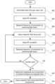
- FIG. 1 Ais a schematic block diagram of one embodiment of a magnetic field measurement system, according to the invention.
- FIG. 1 Bis a schematic block diagram of one embodiment of a magnetometer, according to the invention.
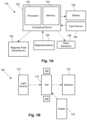
- FIG. 2shows a magnetic spectrum with lines indicating dynamic ranges of magnetometers operating in different modes
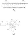
- FIG. 3is a schematic diagram is another embodiment of a magnetometer, according to the invention.
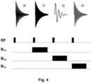
- FIG. 4is a schematic representation of the application of RF excitation and magnetic fields, along with the associated resulting free induction decay, to the magnetometer of FIG. 3 , according to the invention
- FIG. 5is a schematic display of demodulated signals versus frequency arising from operation of the magnetometer of FIG. 3 with continuous-wave RF excitation sweeping through a Zeeman frequency of atoms of a vapor, according to the invention.
- FIG. 6is a flowchart of one embodiment of a method of operating an optically pumped magnetometer (OPM), according to the invention.
- OPMoptically pumped magnetometer
- the present disclosureis directed to the area of magnetic field measurement systems including systems for magnetoencephalography (MEG).
- MEGmagnetoencephalography
- the present disclosureis also directed to methods and systems for counteracting the ambient background magnetic field.
- ambient background magnetic fieldand “background magnetic field” are interchangeable and used to identify the magnetic field or fields associated with sources other than the magnetic field measurement system and the magnetic field sources of interest, such as biological source(s) (for example, neural signals from a user's brain) or non-biological source(s) of interest.
- biological source(s)for example, neural signals from a user's brain
- non-biological source(s) of interestcan include, for example, the Earth's magnetic field, as well as magnetic fields from magnets, electromagnets, electrical devices, and other signal or field generators in the environment, except for the magnetic field generator(s) that are part of the magnetic field measurement system.
- gas cellvapor cell
- vapor gas cellvapor gas cell
- OPMsoptically pumped magnetometers
- vector modethe OPM can measure one, two, or all three vector components of the magnetic field; while in scalar mode the OPM can measure the total magnitude of the magnetic field.
- Vector mode magnetometersmeasure a specific component of the magnetic field, such as the radial and tangential components of magnetic fields with respect the scalp of the human head.
- Vector mode OPMsoften operate at zero-field and may utilize a spin exchange relaxation free (SERF) mode to reach femto-Tesla sensitivities.
- SERF mode OPMis one example of a vector mode OPM, but other vector mode OPMs can be used at higher magnetic fields.
- SERF mode magnetometerscan have high sensitivity but may not function in the presence of magnetic fields higher than the linewidth of the magnetic resonance of the atoms of about 10 nT, which is much smaller than the magnetic field strength generated by the Earth.
- Magnetometers operating in the scalar modecan measure the total magnitude of the magnetic field. (Magnetometers in the vector mode can also be used for magnitude measurements.) Scalar mode OPMs often have lower sensitivity than SERF mode OPMs and are capable of operating in higher magnetic field environments.
- the magnetic field measurement systemssuch as a MEG system, described herein can be used to measure or observe electromagnetic signals generated by one or more magnetic field sources (for example, neural signals or other biological sources) of interest.
- the systemcan measure biologically generated magnetic fields and, at least in some embodiments, can measure biologically generated magnetic fields in a partially shielded environment. Aspects of a magnetic field measurement system will be exemplified below using magnetic signals from the brain of a user; however, biological signals from other areas of the body, as well as non-biological signals, can be measured using the system.
- the systemcan be a wearable MEG system that can be portable and used outside a magnetically shielded room.
- a wearable MEG systemwill be used to exemplify the magnetic field measurement systems and calibration arrangements described herein; however, it will be recognized the calibration arrangements and methods described herein can be applied to other magnetic field measurement systems.
- a magnetic field measurement systemsuch as a MEG system, can utilize one or more magnetic field sensors.
- Magnetometerswill be used herein as an example of magnetic field sensors, but other magnetic field sensors may also be used in addition to, or as an alternative to, the magnetometers.
- FIG. 1A magnetic field measurement system, such as a MEG system, can utilize one or more magnetic field sensors.
- the system 140can include a computing device 150 or any other similar device that includes a processor 152 , a memory 154 , a display 156 , an input device 158 , one or more magnetometers 160 (for example, an array of magnetometers) which can be OPMs, one or more magnetic field generators 162 , and, optionally, one or more other sensors 164 (e.g., non-magnetic field sensors).
- the system 140 and its use and operationwill be described herein with respect to the measurement of neural signals arising from one or more magnetic field sources of interest in the brain of a user as an example. It will be understood, however, that the system can be adapted and used to measure signals from other magnetic field sources of interest including, but not limited to, other neural signals, other biological signals, as well as non-biological signals.
- the computing device 150can be a computer, tablet, mobile device, field programmable gate array (FPGA), microcontroller, or any other suitable device for processing information or instructions.
- the computing device 150can be local to the user or can include components that are non-local to the user including one or both of the processor 152 or memory 154 (or portions thereof).
- the usermay operate a terminal that is connected to a non-local computing device.
- the memory 154can be non-local to the user.
- the computing device 150can utilize any suitable processor 152 including one or more hardware processors that may be local to the user or non-local to the user or other components of the computing device.
- the processor 152is configured to execute instructions stored in the memory 154 .
- the memory 154illustrates a type of computer-readable media, namely computer-readable storage media.
- Computer-readable storage mediamay include, but is not limited to, volatile, nonvolatile, non-transitory, removable, and non-removable media implemented in any method or technology for storage of information, such as computer readable instructions, data structures, program modules, or other data. Examples of computer-readable storage media include RAM, ROM, EEPROM, flash memory, or other memory technology, CD-ROM, digital versatile disks (“DVD”) or other optical storage, magnetic cassettes, magnetic tape, magnetic disk storage or other magnetic storage devices, or any other medium which can be used to store the desired information and which can be accessed by a computing device.
- Communication methodsprovide another type of computer readable media; namely communication media.
- Communication mediatypically embodies computer-readable instructions, data structures, program modules, or other data in a modulated data signal such as a carrier wave, data signal, or other transport mechanism and include any information delivery media.
- modulated data signaland “carrier-wave signal” includes a signal that has one or more of its characteristics set or changed in such a manner as to encode information, instructions, data, and the like, in the signal.
- communication mediaincludes wired media such as twisted pair, coaxial cable, fiber optics, wave guides, and other wired media and wireless media such as acoustic, RF, infrared, and other wireless media.
- the display 156can be any suitable display device, such as a monitor, screen, or the like, and can include a printer. In some embodiments, the display is optional. In some embodiments, the display 156 may be integrated into a single unit with the computing device 150 , such as a tablet, smart phone, or smart watch. In at least some embodiments, the display is not local to the user.
- the input device 158can be, for example, a keyboard, mouse, touch screen, track ball, joystick, voice recognition system, or any combination thereof, or the like. In at least some embodiments, the input device is not local to the user.
- the magnetic field generator(s) 162can be, for example, Helmholtz coils, solenoid coils, planar coils, saddle coils, electromagnets, permanent magnets, or any other suitable arrangement for generating a magnetic field.
- the magnetic field generator 162can include three orthogonal sets of coils to generate magnetic fields along three orthogonal axes. Other coil arrangement can also be used.
- the optional sensor(s) 164can include, but are not limited to, one or more position sensors, orientation sensors, accelerometers, image recorders, or the like or any combination thereof.
- the one or more magnetometers 160can be any suitable magnetometer including, but not limited to, any suitable optically pumped magnetometer. Arrays of magnetometers are described in more detail herein. In at least some embodiments, at least one of the one or more magnetometers (or all of the magnetometers) of the system is arranged for operation in the SERF mode.
- FIG. 1 Bis a schematic block diagram of one embodiment of a magnetometer 160 which includes a vapor cell 170 (also referred to as a “cell”) such as an alkali metal vapor cell; a heating device 176 to heat the cell 170 ; a light source 172 ; and a detector 174 .
- a vapor cell 170also referred to as a “cell”
- a heating device 176to heat the cell 170
- a light source 172to heat the cell 170
- a detector 174detector
- coils of a magnetic field generator 162can be positioned around the vapor cell 170 .
- the vapor cell 170can include, for example, an alkali metal vapor (for example, rubidium in natural abundance, isotopically enriched rubidium, potassium, or cesium, or any other suitable alkali metal such as lithium, sodium, or francium) and, optionally, one, or both, of a quenching gas (for example, nitrogen) and a buffer gas (for example, nitrogen, helium, neon, or argon).
- the vapor cellmay include the alkali metal atoms in a prevaporized form prior to heating to generate the vapor.
- the light source 172can include, for example, a laser to, respectively, optically pump the alkali metal atoms and probe the vapor cell.
- the light source 172may also include optics (such as lenses, waveplates, collimators, polarizers, and objects with reflective surfaces) for beam shaping and polarization control and for directing the light from the light source to the vapor cell 170 and detector 174 .
- suitable light sourcesinclude, but are not limited to, a diode laser (such as a vertical-cavity surface-emitting laser (VCSEL), distributed Bragg reflector laser (DBR), or distributed feedback laser (DFB)), light-emitting diode (LED), lamp, or any other suitable light source.
- the light source 172may include two light sources: a pump light source and a probe light source.
- the detector 174can include, for example, an optical detector to measure the optical properties of the transmitted probe light field amplitude, phase, or polarization, as quantified through optical absorption and dispersion curves, spectrum, or polarization or the like or any combination thereof.
- suitable detectorsinclude, but are not limited to, a photodiode, charge coupled device (CCD) array, CMOS array, camera, photodiode array, single photon avalanche diode (SPAD) array, avalanche photodiode (APD) array, or any other suitable optical sensor array that can measure the change in transmitted light at the optical wavelengths of interest.
- FIG. 2shows the magnetic spectrum from 1 f to 100 ⁇ T in magnetic field strength on a logarithmic scale.
- the magnitude of magnetic fields generated by the human brainare indicated by range 201 and the magnitude of the ambient background magnetic field, including the Earth's magnetic field, by range 202 .
- the strength of the Earth's magnetic fieldcovers a range as it depends on the position on the Earth as well as the materials of the surrounding environment where the magnetic field is measured.
- Range 210indicates the approximate measurement range of a magnetometer (e.g., an OPM) operating in the SERF mode (e.g., a SERF magnetometer) and range 211 indicates the approximate measurement range of a magnetometer operating in a scalar mode (e.g., a scalar magnetometer.)
- a SERF magnetometeris more sensitive than a scalar magnetometer but many conventional SERF magnetometers typically only operate up to about 0 to 200 nT while the scalar magnetometer starts in the 10 to 100 fT range but extends above 10 to 100 ⁇ T.
- Superconducting quantum interference deviceshave been used to detect MEG signals; however such devices use expensive and immobile cryogenic dewars, making them unsuitable for portable/wearable MEG applications.
- Atomic magnetometersand in particular SERF magnetometers, have been used for detecting MEG signals.
- SERF magnetometersutilize a near zero-magnetic field environment.
- Auxiliary solid state sensorscan be employed to determine the ambient background magnetic field; however this can involve additional complexity and such sensors cannot measure the ambient background magnetic field at the location of the atoms.
- a method for determining the ambient background magnetic field rapidly using atomic signalsis highly desirable.
- SERFSpin-exchange relaxation-free
- atomic magnetometersoperating at near zero magnetic field (to within approximately 50-100 nanoTesla) can be used to detect MEG signals.
- active shieldingmethods for rapidly determining the ambient background magnetic field at the magnetometer are highly beneficial.
- FIG. 3One embodiment of a system and method for quickly determining the ambient background magnetic field (for example, in at least some embodiments, making a determination within 5 milliseconds) is illustrated in FIG. 3 .
- a light beam generated by a light source 172(such as a laser) passes through a quarter-wave plate (QWP) 178 and a vapor cell 170 .
- the intensity of the lightis monitored with a detector 174 (such as a photodiode).
- the systemoperates in the ambient background magnetic field (B 0 ) (represented by arrow 182 in FIG. 3 ), which includes contributions from the Earth's dynamo and other man-made sources.
- a magnetic field generator 162(for example, three sets of orthogonal compensation coils as illustrated in FIG.
- An optional auxiliary coil 180can be used to apply RF excitation pulses, although in some embodiments, the RF excitation pulses can be applied using one or more of the coils of the magnetic field generator 162 .
- the light beam from the light source 172is circularly polarized due to the quarter-wave plate 178 and optically pumps the alkali metal atoms of the vapor cell 170 in the direction of the light beam.
- Application of resonant RF magnetic field pulses with the excitation coil 180induces the spins of the alkali metal atoms in the vapor cell 170 to precess at the Larmor precession frequency.
- FIG. 4One embodiment of a method to measure all three vector components of the magnetic field is illustrated in FIG. 4 .
- the free-induction decaycan be fit to a sinusoid or Fourier-transformed. Any other suitable method can be used to determine the frequency.
- SNRsignal-to-noise ratio
- three subsequent RF pulses 406 , 408 , 410are individually applied along with small magnetic fields B 1x , B 1y , B 1z , respectively, from the different sets of orthogonal coils of the magnetic field generator 162 , as illustrated in FIG. 4 .
- the resulting free-induction decays 412 , 414 , 416are observed.
- the precession frequencies f 1 , f 2 , f 3respectively, yield a measure of the projection of the ambient background magnetic field along the three orthogonal axes as follows.
- f 2⁇ ( B 0 2 +2 B 1y B 0y +B 1y 2 ) ⁇ ( B 0 +B 1y B 0y /B 0 )
- f 3⁇ ( B 0 2 +2 B 1z B 0z +B 1z 2 ) ⁇ ( B 0 +B 1z B 0z /B 0 )
- Knowledge of the vector field componentsenables the user or control system to rapidly find the magnetic field components for the magnetic field generator 162 to generate zero field (or near zero field) to enable operation of the magnetometer 160 in the SERF mode.
- the method illustrated in FIG. 4utilizes a pulsed RF field.
- An alternative implementationuses continuous wave RF excitation rather than pulsed RF excitation.
- an RF magnetic fieldis swept across the ground state Zeeman resonance of the alkali metal atoms.
- the detector signalcan be monitored via synchronous lock-in detection to find the location of the Zeeman resonance f 0 .
- Subsequent continuous wave RF sweepsare performed in the presence of small applied magnetic fields in the x, y, and z directions, respectively, producing shifts in the frequency of the Zeeman resonance, as illustrated in FIG. 5 . From here, finding the vector field components of the ambient background magnetic field is the same as the method illustrated in FIG. 4 .
- the systems and methods described hereinallow the use of atomic signals to rapidly measure all three vector field components of the ambient background magnetic field. In at least some embodiments, these methods and systems are fast when working in pulsed mode, and work in the ambient background magnetic field of the Earth.
- FIG. 6illustrates one embodiment of a method of operating an optically pumped magnetometer (OPM) or a method of determining a magnitude and components of an ambient background magnetic field.
- OPMoptically pumped magnetometer
- step 602a light beam from a light source, such as a laser, is directed through a vapor cell of the OPM.
- the vapor cellincludes a vapor of atoms, such as alkali metal atoms.
- the light beampumps the atoms.
- an RF excitationis applied to the alkali metal atoms to cause spins of the atoms of the vapor to precess.
- the RF excitationcan be a pulsed RF excitation, with sufficient bandwidth and a center frequency to excite the spins of the atoms of the vapor, or a continuous-wave RF excitation which sweeps through the Zeeman frequency of the atoms of the vapor.
- the RF excitationcan be applied through an auxiliary coil.
- the RF excitationcan be applied using a magnetic field generator of the OPM.
- a frequency of the precession of the atoms of the vaporis measured by observing the light beam after passing through the vapor cell.
- Steps 608 through 614are individually performed for multiple different axes relative to the vapor cell.
- the number of axesis three.
- the axesare orthogonal to each other.
- a relatively small magnetic fieldas compared to the ambient background magnetic field, is applied through the vapor cell along the axis while a light beam is directed through the vapor cell.
- This relatively small magnetic fieldcan be applied using, for example, a magnetic field generator.
- an RF excitationis applied to the alkali metal atoms to cause spins of the atoms of the vapor to precess similar to that applied in step 604 .
- a frequency of the precession in the applied magnetic fieldis measured by observing the light beam after passing through the vapor cell.
- the magnitude and vector field components of the ambient background magnetic field along the axescan be determined using the measured frequencies.
- a magnetic field based on the vector field componentscan be applied around the vapor cell to counteract or reduce the ambient background magnetic field to facilitate operation of the OPM in a spin exchange relaxation free (SERF) mode.
- SERFspin exchange relaxation free
- the methods, systems, and units described hereinmay be embodied in many different forms and should not be construed as limited to the embodiments set forth herein. Accordingly, the methods, systems, and units described herein may take the form of an entirely hardware embodiment, an entirely software embodiment or an embodiment combining software and hardware aspects. The methods described herein can be performed using any type of processor or any combination of processors where each processor performs at least part of the process.
- the computer program instructionscan be stored on any suitable computer-readable medium including, but not limited to, RAM, ROM, EEPROM, flash memory or other memory technology, CD-ROM, digital versatile disks (“DVD”) or other optical storage, magnetic cassettes, magnetic tape, magnetic disk storage or other magnetic storage devices, or any other medium which can be used to store the desired information and which can be accessed by a computing device.
Landscapes
- Physics & Mathematics (AREA)
- Health & Medical Sciences (AREA)
- Life Sciences & Earth Sciences (AREA)
- General Physics & Mathematics (AREA)
- General Health & Medical Sciences (AREA)
- Pathology (AREA)
- Engineering & Computer Science (AREA)
- Condensed Matter Physics & Semiconductors (AREA)
- Biomedical Technology (AREA)
- Molecular Biology (AREA)
- Surgery (AREA)
- Animal Behavior & Ethology (AREA)
- Medical Informatics (AREA)
- Public Health (AREA)
- Veterinary Medicine (AREA)
- Heart & Thoracic Surgery (AREA)
- Biophysics (AREA)
- Optics & Photonics (AREA)
- High Energy & Nuclear Physics (AREA)
- Chemical & Material Sciences (AREA)
- Analytical Chemistry (AREA)
- Biochemistry (AREA)
- Immunology (AREA)
- Power Engineering (AREA)
- Measurement And Recording Of Electrical Phenomena And Electrical Characteristics Of The Living Body (AREA)
Abstract
Description
This application claims the benefit of U.S. Provisional Patent Applications Ser. Nos. 62/895,197, filed Sep. 3, 2019, and 62/960,548, filed Jan. 13, 2020, both of which are incorporated herein by reference in their entireties.
The present disclosure is directed to the area of magnetic field measurement systems including systems for magnetoencephalography (MEG). The present disclosure is also directed to methods and systems for counteracting the ambient background magnetic field.
In the nervous system, neurons propagate signals via action potentials. These are brief electric currents which flow down the length of a neuron causing chemical transmitters to be released at a synapse. The time-varying electrical current within an ensemble of neurons generates a magnetic field. Magnetoencephalography (MEG), the measurement of magnetic fields generated by the brain, is one method for observing these neural signals.
Existing technology for measuring MEG typically utilizes superconducting quantum interference devices (SQUIDs) or collections of discrete optically pumped magnetometers (OPMs). SQUIDs require cryogenic cooling, which is bulky, expensive, requires a lot of maintenance. These requirements preclude their application to mobile or wearable devices.
An alternative to an array of SQUIDs is an array of OPMs. For MEG and other applications, the array of OPMS may have a large number of OPM sensors that are tightly packed. Such dense arrays can produce a high resolution spatial mapping of the magnetic field, and at a very high sensitivity level. Such OPMs sensors can be used for a wide range of applications, including sensing magnetic field generated by neural activities, similar to MEG systems.
One embodiment is a method of operating an optically pumped magnetometer (OPM) that includes directing a light beam through a vapor cell of the OPM including a vapor of atoms; applying RF excitation to the atoms to cause spins of the atoms of the vapor to precess; measuring a frequency of the precession by observing the light beam after passing through the vapor cell; for each of a plurality of different axes relative to the vapor cell, directing a light beam through the vapor cell, applying a magnetic field through the vapor cell along the axis, applying RF excitation to the atoms to cause spins of the atoms of the vapor to precess, and measuring a frequency of the precession in the applied magnetic field by observing the light beam after passing through the vapor cell; determining magnitude and components of an ambient background magnetic field along the axes using the measured frequencies; and applying a magnetic field based on the components around the vapor cell to counteract the ambient background magnetic field to facilitate operation of the OPM in a spin exchange relaxation free (SERF) mode.
Another embodiment is a magnetic field measurement system that includes an optically pumped magnetometer (OPM) having a vapor cell including a housing and a vapor of atoms disposed in the housing, a light source, a detector, and a magnetic field generator; and a processor coupled to the OPM and configured to perform actions including directing a light beam from the light source through the vapor cell of the OPM; applying RF excitation to the atoms to cause spins of the atoms of the vapor to precess; measuring a frequency of the precession by observing the light beam after passing through the vapor cell; for each of a plurality of different axes relative to the vapor cell, directing a light beam from the light source through the vapor cell, applying a magnetic field through the vapor cell along the axis, applying RF excitation to the atoms to cause spins of the atoms of the vapor to precess, and measuring a frequency of the precession in the applied magnetic field by observing the light beam after passing through the vapor cell; determining magnitude and components of an ambient background magnetic field along the axes using the measured frequencies; and applying a magnetic field based on the components around the vapor cell to counteract the ambient background magnetic field to facilitate operation of the OPM in a spin exchange relaxation free (SERF) mode.
In at least some embodiments, the plurality of different axes is three axes. In at least some embodiments, the three axes are three orthogonal axes.
In at least some embodiments, each instance of applying RF excitation includes applying RF excitation through an auxiliary coil of the OPM. In at least some embodiments, each instance of applying a magnetic field includes applying a magnetic field using a magnetic field generator of the OPM. In at least some embodiments, each instance of applying RF excitation includes applying RF excitation through the magnetic field generator of the OPM.
In at least some embodiments, each instance of directing a light beam includes generating a light beam using a laser of the OPM. In at least some embodiments, each instance of applying RF excitation includes applying RF excitation through one or more RF pulses. In at least some embodiments, each instance of applying RF excitation includes applying RF excitation by sweeping through an RF frequency range. In at least some embodiments, the atoms are alkali metal atoms.
Non-limiting and non-exhaustive embodiments of the present invention are described with reference to the following drawings. In the drawings, like reference numerals refer to like parts throughout the various figures unless otherwise specified.
For a better understanding of the present invention, reference will be made to the following Detailed Description, which is to be read in association with the accompanying drawings, wherein:
The present disclosure is directed to the area of magnetic field measurement systems including systems for magnetoencephalography (MEG). The present disclosure is also directed to methods and systems for counteracting the ambient background magnetic field.
Herein the terms “ambient background magnetic field” and “background magnetic field” are interchangeable and used to identify the magnetic field or fields associated with sources other than the magnetic field measurement system and the magnetic field sources of interest, such as biological source(s) (for example, neural signals from a user's brain) or non-biological source(s) of interest. The terms can include, for example, the Earth's magnetic field, as well as magnetic fields from magnets, electromagnets, electrical devices, and other signal or field generators in the environment, except for the magnetic field generator(s) that are part of the magnetic field measurement system.
The terms “gas cell”, “vapor cell”, and “vapor gas cell” are used interchangeably herein. Below, a vapor cell containing alkali metal vapor is described, but it will be recognized that other vapor cells can contain different gases or vapors for operation.
The methods and systems are described herein using optically pumped magnetometers (OPMs). While there are many types of OPMs, in general magnetometers operate in two modalities: vector mode and scalar mode. In vector mode, the OPM can measure one, two, or all three vector components of the magnetic field; while in scalar mode the OPM can measure the total magnitude of the magnetic field.
Vector mode magnetometers measure a specific component of the magnetic field, such as the radial and tangential components of magnetic fields with respect the scalp of the human head. Vector mode OPMs often operate at zero-field and may utilize a spin exchange relaxation free (SERF) mode to reach femto-Tesla sensitivities. A SERF mode OPM is one example of a vector mode OPM, but other vector mode OPMs can be used at higher magnetic fields. These SERF mode magnetometers can have high sensitivity but may not function in the presence of magnetic fields higher than the linewidth of the magnetic resonance of the atoms of about 10 nT, which is much smaller than the magnetic field strength generated by the Earth.
Magnetometers operating in the scalar mode can measure the total magnitude of the magnetic field. (Magnetometers in the vector mode can also be used for magnitude measurements.) Scalar mode OPMs often have lower sensitivity than SERF mode OPMs and are capable of operating in higher magnetic field environments.
The magnetic field measurement systems, such as a MEG system, described herein can be used to measure or observe electromagnetic signals generated by one or more magnetic field sources (for example, neural signals or other biological sources) of interest. The system can measure biologically generated magnetic fields and, at least in some embodiments, can measure biologically generated magnetic fields in a partially shielded environment. Aspects of a magnetic field measurement system will be exemplified below using magnetic signals from the brain of a user; however, biological signals from other areas of the body, as well as non-biological signals, can be measured using the system. In at least some embodiments, the system can be a wearable MEG system that can be portable and used outside a magnetically shielded room. A wearable MEG system will be used to exemplify the magnetic field measurement systems and calibration arrangements described herein; however, it will be recognized the calibration arrangements and methods described herein can be applied to other magnetic field measurement systems.
A magnetic field measurement system, such as a MEG system, can utilize one or more magnetic field sensors. Magnetometers will be used herein as an example of magnetic field sensors, but other magnetic field sensors may also be used in addition to, or as an alternative to, the magnetometers.FIG.1A is a block diagram of components of one embodiment of a magnetic field measurement system140 (such as a biological signal detection system.) Thesystem 140 can include acomputing device 150 or any other similar device that includes aprocessor 152, amemory 154, adisplay 156, aninput device 158, one or more magnetometers160 (for example, an array of magnetometers) which can be OPMs, one or moremagnetic field generators 162, and, optionally, one or more other sensors164 (e.g., non-magnetic field sensors). Thesystem 140 and its use and operation will be described herein with respect to the measurement of neural signals arising from one or more magnetic field sources of interest in the brain of a user as an example. It will be understood, however, that the system can be adapted and used to measure signals from other magnetic field sources of interest including, but not limited to, other neural signals, other biological signals, as well as non-biological signals.
Thecomputing device 150 can be a computer, tablet, mobile device, field programmable gate array (FPGA), microcontroller, or any other suitable device for processing information or instructions. Thecomputing device 150 can be local to the user or can include components that are non-local to the user including one or both of theprocessor 152 or memory154 (or portions thereof). For example, in at least some embodiments, the user may operate a terminal that is connected to a non-local computing device. In other embodiments, thememory 154 can be non-local to the user.
Thecomputing device 150 can utilize anysuitable processor 152 including one or more hardware processors that may be local to the user or non-local to the user or other components of the computing device. Theprocessor 152 is configured to execute instructions stored in thememory 154.
Anysuitable memory 154 can be used for thecomputing device 150. Thememory 154 illustrates a type of computer-readable media, namely computer-readable storage media. Computer-readable storage media may include, but is not limited to, volatile, nonvolatile, non-transitory, removable, and non-removable media implemented in any method or technology for storage of information, such as computer readable instructions, data structures, program modules, or other data. Examples of computer-readable storage media include RAM, ROM, EEPROM, flash memory, or other memory technology, CD-ROM, digital versatile disks (“DVD”) or other optical storage, magnetic cassettes, magnetic tape, magnetic disk storage or other magnetic storage devices, or any other medium which can be used to store the desired information and which can be accessed by a computing device.
Communication methods provide another type of computer readable media; namely communication media. Communication media typically embodies computer-readable instructions, data structures, program modules, or other data in a modulated data signal such as a carrier wave, data signal, or other transport mechanism and include any information delivery media. The terms “modulated data signal,” and “carrier-wave signal” includes a signal that has one or more of its characteristics set or changed in such a manner as to encode information, instructions, data, and the like, in the signal. By way of example, communication media includes wired media such as twisted pair, coaxial cable, fiber optics, wave guides, and other wired media and wireless media such as acoustic, RF, infrared, and other wireless media.
Thedisplay 156 can be any suitable display device, such as a monitor, screen, or the like, and can include a printer. In some embodiments, the display is optional. In some embodiments, thedisplay 156 may be integrated into a single unit with thecomputing device 150, such as a tablet, smart phone, or smart watch. In at least some embodiments, the display is not local to the user. Theinput device 158 can be, for example, a keyboard, mouse, touch screen, track ball, joystick, voice recognition system, or any combination thereof, or the like. In at least some embodiments, the input device is not local to the user.
The magnetic field generator(s)162 can be, for example, Helmholtz coils, solenoid coils, planar coils, saddle coils, electromagnets, permanent magnets, or any other suitable arrangement for generating a magnetic field. As an example, themagnetic field generator 162 can include three orthogonal sets of coils to generate magnetic fields along three orthogonal axes. Other coil arrangement can also be used. The optional sensor(s)164 can include, but are not limited to, one or more position sensors, orientation sensors, accelerometers, image recorders, or the like or any combination thereof.
The one ormore magnetometers 160 can be any suitable magnetometer including, but not limited to, any suitable optically pumped magnetometer. Arrays of magnetometers are described in more detail herein. In at least some embodiments, at least one of the one or more magnetometers (or all of the magnetometers) of the system is arranged for operation in the SERF mode.
Thelight source 172 can include, for example, a laser to, respectively, optically pump the alkali metal atoms and probe the vapor cell. Thelight source 172 may also include optics (such as lenses, waveplates, collimators, polarizers, and objects with reflective surfaces) for beam shaping and polarization control and for directing the light from the light source to thevapor cell 170 anddetector 174. Examples of suitable light sources include, but are not limited to, a diode laser (such as a vertical-cavity surface-emitting laser (VCSEL), distributed Bragg reflector laser (DBR), or distributed feedback laser (DFB)), light-emitting diode (LED), lamp, or any other suitable light source. In some embodiments, thelight source 172 may include two light sources: a pump light source and a probe light source.
Thedetector 174 can include, for example, an optical detector to measure the optical properties of the transmitted probe light field amplitude, phase, or polarization, as quantified through optical absorption and dispersion curves, spectrum, or polarization or the like or any combination thereof. Examples of suitable detectors include, but are not limited to, a photodiode, charge coupled device (CCD) array, CMOS array, camera, photodiode array, single photon avalanche diode (SPAD) array, avalanche photodiode (APD) array, or any other suitable optical sensor array that can measure the change in transmitted light at the optical wavelengths of interest.
Superconducting quantum interference devices have been used to detect MEG signals; however such devices use expensive and immobile cryogenic dewars, making them unsuitable for portable/wearable MEG applications. Atomic magnetometers, and in particular SERF magnetometers, have been used for detecting MEG signals. However, SERF magnetometers utilize a near zero-magnetic field environment. Auxiliary solid state sensors can be employed to determine the ambient background magnetic field; however this can involve additional complexity and such sensors cannot measure the ambient background magnetic field at the location of the atoms. A method for determining the ambient background magnetic field rapidly using atomic signals is highly desirable.
Spin-exchange relaxation-free (SERF) atomic magnetometers operating at near zero magnetic field (to within approximately 50-100 nanoTesla) can be used to detect MEG signals. To operate in the ambient background magnetic field of the Earth (approximately 50 microTesla) some form of active or passive shielding (or a combination thereof) is used. In the case of active shielding, methods for rapidly determining the ambient background magnetic field at the magnetometer are highly beneficial. Presented herein are systems and methods to rapidly measure all three vector components of the ambient background magnetic field in order to rapidly counteract or reduce the ambient background magnetic field at the magnetometer without auxiliary sensors.
One embodiment of a system and method for quickly determining the ambient background magnetic field (for example, in at least some embodiments, making a determination within 5 milliseconds) is illustrated inFIG.3 . A light beam generated by a light source172 (such as a laser) passes through a quarter-wave plate (QWP)178 and avapor cell 170. The intensity of the light is monitored with a detector174 (such as a photodiode). The system operates in the ambient background magnetic field (B0) (represented byarrow 182 inFIG.3 ), which includes contributions from the Earth's dynamo and other man-made sources. A magnetic field generator162 (for example, three sets of orthogonal compensation coils as illustrated inFIG.3 ) can be used to apply magnetic fields to counteract or reduce the ambient background magnetic field in three orthogonal directions (e.g., x, y, and z directions). An optionalauxiliary coil 180 can be used to apply RF excitation pulses, although in some embodiments, the RF excitation pulses can be applied using one or more of the coils of themagnetic field generator 162.
The light beam from thelight source 172 is circularly polarized due to the quarter-wave plate 178 and optically pumps the alkali metal atoms of thevapor cell 170 in the direction of the light beam. Application of resonant RF magnetic field pulses with theexcitation coil 180 induces the spins of the alkali metal atoms in thevapor cell 170 to precess at the Larmor precession frequency.
One embodiment of a method to measure all three vector components of the magnetic field is illustrated inFIG.4 . An initial RF pulse402 and subsequent free-induction decay404 of the alkali metal spin polarization provides a measure of the magnitude of the ambient background magnetic field B0via the relation f0=γB0, where γ is the gyro-magnetic ratio of the alkali metal atoms. To measure the frequency of spin precession, the free-induction decay can be fit to a sinusoid or Fourier-transformed. Any other suitable method can be used to determine the frequency. The precision of the measurement is approximately given by δv=1/SNR/(2πT23/2). In at least some embodiments, an estimated signal-to-noise ratio (SNR) of at least 100 is readily achievable and for T2=1 ms, the uncertainty in the determination of frequency may be no more 50 Hz, corresponding to about 7 nT which indicates that the ambient background magnetic field can be reliably reduced so that a magnetometer using thevapor cell 170 can operate in SERF mode.
Returning to the method, three subsequent RF pulses406,408,410 are individually applied along with small magnetic fields B1x, B1y, B1z, respectively, from the different sets of orthogonal coils of themagnetic field generator 162, as illustrated inFIG.4 . The resulting free-induction decays412,414,416 are observed. The precession frequencies f1, f2, f3, respectively, yield a measure of the projection of the ambient background magnetic field along the three orthogonal axes as follows.
f0=γB0
f1=γ√(B02+2B1xB0x+B1x2)≈γ(B0+B1xB0x/B0)
f2=γ√(B02+2B1yB0y+B1y2)≈γ(B0+B1yB0y/B0)
f3=γ√(B02+2B1zB0z+B1z2)≈γ(B0+B1zB0z/B0)
f0=γB0
f1=γ√(B02+2B1xB0x+B1x2)≈γ(B0+B1xB0x/B0)
f2=γ√(B02+2B1yB0y+B1y2)≈γ(B0+B1yB0y/B0)
f3=γ√(B02+2B1zB0z+B1z2)≈γ(B0+B1zB0z/B0)
The approximate expressions on the right hand side of the above equations correspond to the first term in a Taylor expansion and are valid in the limit that B1x, B1y, B1zare small compared to B0. Such approximations are convenient and likely to be valid but are not strictly necessary to enable reconstruction of the vector field components B0x, B0y, B0zof the ambient background magnetic field. Other approximations or calculations can be used to determine the vector field components of the ambient background magnetic field.
From measurements of precession frequencies, the vector field components B0x, B0y, B0zof the ambient background magnetic field can be estimated as follows:
B0x=(f1−f0)B0/(γB1x)
B0y=(f2−f0)B0/(γB1y)
B0z=(f3−f0)B0/(γB1z)
B0x=(f1−f0)B0/(γB1x)
B0y=(f2−f0)B0/(γB1y)
B0z=(f3−f0)B0/(γB1z)
Knowledge of the vector field components enables the user or control system to rapidly find the magnetic field components for themagnetic field generator 162 to generate zero field (or near zero field) to enable operation of themagnetometer 160 in the SERF mode.
The method illustrated inFIG.4 utilizes a pulsed RF field. An alternative implementation uses continuous wave RF excitation rather than pulsed RF excitation. In this case an RF magnetic field is swept across the ground state Zeeman resonance of the alkali metal atoms. The detector signal can be monitored via synchronous lock-in detection to find the location of the Zeeman resonance f0. Subsequent continuous wave RF sweeps are performed in the presence of small applied magnetic fields in the x, y, and z directions, respectively, producing shifts in the frequency of the Zeeman resonance, as illustrated inFIG.5 . From here, finding the vector field components of the ambient background magnetic field is the same as the method illustrated inFIG.4 .
In at least some embodiments, the systems and methods described herein allow the use of atomic signals to rapidly measure all three vector field components of the ambient background magnetic field. In at least some embodiments, these methods and systems are fast when working in pulsed mode, and work in the ambient background magnetic field of the Earth.
Instep 604, an RF excitation is applied to the alkali metal atoms to cause spins of the atoms of the vapor to precess. The RF excitation can be a pulsed RF excitation, with sufficient bandwidth and a center frequency to excite the spins of the atoms of the vapor, or a continuous-wave RF excitation which sweeps through the Zeeman frequency of the atoms of the vapor. In at least some embodiments, the RF excitation can be applied through an auxiliary coil. In at least some embodiments, the RF excitation can be applied using a magnetic field generator of the OPM. Instep 606, a frequency of the precession of the atoms of the vapor is measured by observing the light beam after passing through the vapor cell.
Instep 608, a relatively small magnetic field, as compared to the ambient background magnetic field, is applied through the vapor cell along the axis while a light beam is directed through the vapor cell. This relatively small magnetic field can be applied using, for example, a magnetic field generator. Instep 610, an RF excitation is applied to the alkali metal atoms to cause spins of the atoms of the vapor to precess similar to that applied instep 604. Instep 612, a frequency of the precession in the applied magnetic field is measured by observing the light beam after passing through the vapor cell. Instep 614, there is a determination if another axis is to be observed. If so, then the method proceeds back to step608 using the next axis.
Using the measured frequencies, instep 616, the magnitude and vector field components of the ambient background magnetic field along the axes can be determined using the measured frequencies. Instep 618, a magnetic field based on the vector field components can be applied around the vapor cell to counteract or reduce the ambient background magnetic field to facilitate operation of the OPM in a spin exchange relaxation free (SERF) mode.
Examples of magnetic field measurement systems in which the embodiments presented above can be incorporated, and which present features that can be incorporated in the embodiments presented herein, are described in U.S. Patent Application Publications Nos. 2020/0072916; 2020/0056263; 2020/0025844; 2020/0057116; 2019/0391213; 2020/0088811; 2020/0057115; 2020/0109481; 2020/0123416; and 2020/0191883; U.S. patent application Ser. Nos. 16/984,752; 16/984,720; 16/741,593; 16/752,393; 16/820,131; 16/850,380; 16/850,444; 16/884,672; 16/904,281; 16/922,898; and 16/928,810, and U.S. Provisional Patent Applications Ser. Nos. 62/689,696; 62/699,596; 62/719,471; 62/719,475; 62/719,928; 62/723,933; 62/732,327; 62/732,791; 62/741,777; 62/743,343; 62/747,924; 62/745,144; 62/752,067; 62/776,895; 62/781,418; 62/796,958; 62/798,209; 62/798,330; 62/804,539; 62/826,045; 62/827,390; 62/836,421; 62/837,574; 62/837,587; 62/842,818; 62/855,820; 62/858,636; 62/860,001; 62/865,049; 62/873,694; 62/874,887; 62/883,399; 62/883,406; 62/888,858; 62/895,197; 62/896,929; 62/898,461; 62/910,248; 62/913,000; 62/926,032; 62/926,043; 62/933,085; 62/960,548; 62/971,132; 62/983,406; 63/031,469; and 63/037,407, all of which are incorporated herein by reference in their entireties.
The methods, systems, and units described herein may be embodied in many different forms and should not be construed as limited to the embodiments set forth herein. Accordingly, the methods, systems, and units described herein may take the form of an entirely hardware embodiment, an entirely software embodiment or an embodiment combining software and hardware aspects. The methods described herein can be performed using any type of processor or any combination of processors where each processor performs at least part of the process.
It will be understood that each block of the flowchart illustrations, and combinations of blocks in the flowchart illustrations and methods disclosed herein, can be implemented by computer program instructions. These program instructions may be provided to a processor to produce a machine, such that the instructions, which execute on the processor, create means for implementing the actions specified in the flowchart block or blocks disclosed herein. The computer program instructions may be executed by a processor to cause a series of operational steps to be performed by the processor to produce a computer implemented process. The computer program instructions may also cause at least some of the operational steps to be performed in parallel. Moreover, some of the steps may also be performed across more than one processor, such as might arise in a multi-processor computer system. In addition, one or more processes may also be performed concurrently with other processes, or even in a different sequence than illustrated without departing from the scope or spirit of the invention.
The computer program instructions can be stored on any suitable computer-readable medium including, but not limited to, RAM, ROM, EEPROM, flash memory or other memory technology, CD-ROM, digital versatile disks (“DVD”) or other optical storage, magnetic cassettes, magnetic tape, magnetic disk storage or other magnetic storage devices, or any other medium which can be used to store the desired information and which can be accessed by a computing device.
The above specification provides a description of the invention and its manufacture and use. Since many embodiments of the invention can be made without departing from the spirit and scope of the invention, the invention also resides in the claims hereinafter appended.
Claims (20)
1. A method of operating an optically pumped magnetometer (OPM), the method comprising:
directing a first light beam through a vapor cell of the OPM comprising a vapor of atoms;
while directing the first light beam through the vapor cell, applying radiofrequency (RF) excitation to the atoms to cause spins of the atoms of the vapor to precess;
measuring a first frequency of the precession by observing the first light beam after passing through the vapor cell;
determining a magnitude of an ambient background magnetic field from the first frequency;
for each axis of a plurality of different axes relative to the vapor cell,
directing another light beam through the vapor cell,
applying a magnetic field through the vapor cell along the axis,
while directing the other light beam through the vapor cell, applying RF excitation to the atoms to cause spins of the atoms of the vapor to precess,
measuring another frequency of the precession in the applied magnetic field by observing the other light beam after passing through the vapor cell, and
determining a vector field component of the ambient background magnetic field along the axis using the measured other frequency, the determined magnitude of the ambient background magnetic field, and a magnitude of the magnetic field applied along the axis; and
applying a counteracting magnetic field, based on the determined vector field components of the ambient background magnetic field, around the vapor cell to counteract the ambient background magnetic field to facilitate operation of the OPM in a spin exchange relaxation free (SERF) mode.
2. The method ofclaim 1 , wherein the plurality of different axes is three axes.
3. The method ofclaim 2 , wherein the three axes are three orthogonal axes.
4. The method ofclaim 1 , wherein each instance of applying RF excitation comprises applying RF excitation through an auxiliary coil of the OPM.
5. The method ofclaim 1 , wherein each instance of applying a magnetic field comprises applying a magnetic field using a magnetic field generator of the OPM.
6. The method ofclaim 5 , wherein each instance of applying RF excitation comprises applying RF excitation through the magnetic field generator of the OPM.
7. The method ofclaim 1 , wherein each instance of directing a first light beam or directing another light beam comprises generating the first light beam or the other light beam, respectively, using a laser of the OPM.
8. The method ofclaim 1 , wherein each instance of applying RF excitation comprises applying RF excitation through one or more RF pulses.
9. The method ofclaim 1 , wherein each instance of applying RF excitation comprises applying RF excitation by sweeping through a frequency range.
10. The method ofclaim 1 , wherein the atoms are alkali metal atoms.
11. A magnetic field measurement system, comprising:
an optically pumped magnetometer (OPM) comprising
a vapor cell comprising a housing and a vapor of atoms disposed in the housing,
a light source,
a detector, and
a magnetic field generator;
a memory having instructions stored thereon; and
a processor coupled to the OPM and the memory and configured execute the instructions to perform actions, the actions comprising
directing a first light beam through the vapor cell of the OPM;
while directing the first light beam through the vapor cell, applying radiofrequency (RF) excitation to the atoms to cause spins of the atoms of the vapor to precess;
measuring a first frequency of the precession by observing the first light beam after passing through the vapor cell;
determining a magnitude of an ambient background magnetic field from the first frequency;
for each axis of a plurality of different axes relative to the vapor cell,
directing another light beam through the vapor cell,
applying a magnetic field through the vapor cell along the axis,
while directing the other light beam through the vapor cell, applying RF excitation to the atoms to cause spins of the atoms of the vapor to precess,
measuring another frequency of the precession in the applied magnetic field by observing the other light beam after passing through the vapor cell, and
determining a vector field component of the ambient background magnetic field along the axis using the measured other frequency, the determined magnitude of the ambient background magnetic field, and a magnitude of the magnetic field applied along the axis; and
applying a counteracting magnetic field, based on the determined vector field components of the ambient background magnetic field, around the vapor cell to counteract the ambient background magnetic field to facilitate operation of the OPM in a spin exchange relaxation free (SERF) mode.
12. The magnetic field measurement system ofclaim 11 , wherein the processor is configured so that the plurality of different axes is three axes.
13. The magnetic field measurement system ofclaim 11 , wherein the processor is configured so that the three axes are three orthogonal axes.
14. The magnetic field measurement system ofclaim 11 , wherein the processor is configured so that each instance of applying RF excitation comprises applying RF excitation through an auxiliary coil of the OPM.
15. The magnetic field measurement system ofclaim 11 , wherein the processor is configured so that each instance of applying a magnetic field comprises applying a magnetic field using the magnetic field generator of the OPM.
16. The magnetic field measurement system ofclaim 15 , wherein the processor is configured so that each instance of applying RF excitation comprises applying RF excitation through the magnetic field generator of the OPM.
17. The magnetic field measurement system ofclaim 11 , wherein the processor is configured so that each instance of directing a first light beam or directing another light beam comprises generating the first light beam or the other light beam, respectively, using a laser of the OPM.
18. The magnetic field measurement system ofclaim 11 , wherein the processor is configured so that each instance of applying RF excitation comprises applying RF excitation through one or more RF pulses.
19. The magnetic field measurement system ofclaim 11 , wherein the processor is configured so that each instance of applying RF excitation comprises applying RF excitation by sweeping through an RF frequency range.
20. The magnetic field measurement system ofclaim 11 , wherein the atoms are alkali metal atoms.
Priority Applications (1)
| Application Number | Priority Date | Filing Date | Title |
|---|---|---|---|
| US17/004,507US11747413B2 (en) | 2019-09-03 | 2020-08-27 | Methods and systems for fast field zeroing for magnetoencephalography (MEG) |
Applications Claiming Priority (3)
| Application Number | Priority Date | Filing Date | Title |
|---|---|---|---|
| US201962895197P | 2019-09-03 | 2019-09-03 | |
| US202062960548P | 2020-01-13 | 2020-01-13 | |
| US17/004,507US11747413B2 (en) | 2019-09-03 | 2020-08-27 | Methods and systems for fast field zeroing for magnetoencephalography (MEG) |
Publications (2)
| Publication Number | Publication Date |
|---|---|
| US20210063510A1 US20210063510A1 (en) | 2021-03-04 |
| US11747413B2true US11747413B2 (en) | 2023-09-05 |
Family
ID=72433035
Family Applications (1)
| Application Number | Title | Priority Date | Filing Date |
|---|---|---|---|
| US17/004,507Active2042-02-07US11747413B2 (en) | 2019-09-03 | 2020-08-27 | Methods and systems for fast field zeroing for magnetoencephalography (MEG) |
Country Status (2)
| Country | Link |
|---|---|
| US (1) | US11747413B2 (en) |
| WO (1) | WO2021045953A1 (en) |
Families Citing this family (53)
| Publication number | Priority date | Publication date | Assignee | Title |
|---|---|---|---|---|
| US10340408B1 (en) | 2018-05-17 | 2019-07-02 | Hi Llc | Non-invasive wearable brain interface systems including a headgear and a plurality of self-contained photodetector units configured to removably attach to the headgear |
| US10420498B1 (en) | 2018-06-20 | 2019-09-24 | Hi Llc | Spatial and temporal-based diffusive correlation spectroscopy systems and methods |
| US11213206B2 (en) | 2018-07-17 | 2022-01-04 | Hi Llc | Non-invasive measurement systems with single-photon counting camera |
| US11262420B2 (en) | 2018-08-17 | 2022-03-01 | Hi Llc | Integrated gas cell and optical components for atomic magnetometry and methods for making and using |
| US10627460B2 (en) | 2018-08-28 | 2020-04-21 | Hi Llc | Systems and methods including multi-mode operation of optically pumped magnetometer(s) |
| WO2020060652A1 (en) | 2018-09-18 | 2020-03-26 | Hi Llc | Dynamic magnetic shielding and beamforming using ferrofluid for compact magnetoencephalography (meg) |
| US11294008B2 (en) | 2019-01-25 | 2022-04-05 | Hi Llc | Magnetic field measurement system with amplitude-selective magnetic shield |
| US11022658B2 (en) | 2019-02-12 | 2021-06-01 | Hi Llc | Neural feedback loop filters for enhanced dynamic range magnetoencephalography (MEG) systems and methods |
| EP3948317A1 (en) | 2019-03-29 | 2022-02-09 | Hi LLC | Integrated magnetometer arrays for magnetoencephalography (meg) detection systems and methods |
| US11269027B2 (en) | 2019-04-23 | 2022-03-08 | Hi Llc | Compact optically pumped magnetometers with pump and probe configuration and systems and methods |
| JP7539926B2 (en) | 2019-05-06 | 2024-08-26 | エイチアイ エルエルシー | Photodetector architecture for time-correlated single-photon counting |
| US11839474B2 (en) | 2019-05-31 | 2023-12-12 | Hi Llc | Magnetoencephalography (MEG) phantoms for simulating neural activity |
| US10868207B1 (en) | 2019-06-06 | 2020-12-15 | Hi Llc | Photodetector systems with low-power time-to-digital converter architectures to determine an arrival time of photon at a photodetector based on event detection time window |
| US11131729B2 (en) | 2019-06-21 | 2021-09-28 | Hi Llc | Systems and methods with angled input beams for an optically pumped magnetometer |
| US11415641B2 (en) | 2019-07-12 | 2022-08-16 | Hi Llc | Detachable arrangement for on-scalp magnetoencephalography (MEG) calibration |
| WO2021026143A1 (en) | 2019-08-06 | 2021-02-11 | Hi Llc | Systems and methods having an optical magnetometer array with beam splitters |
| US11474129B2 (en) | 2019-11-08 | 2022-10-18 | Hi Llc | Methods and systems for homogenous optically-pumped vapor cell array assembly from discrete vapor cells |
| US11950879B2 (en) | 2020-02-21 | 2024-04-09 | Hi Llc | Estimation of source-detector separation in an optical measurement system |
| US12029558B2 (en) | 2020-02-21 | 2024-07-09 | Hi Llc | Time domain-based optical measurement systems and methods configured to measure absolute properties of tissue |
| US11630310B2 (en) | 2020-02-21 | 2023-04-18 | Hi Llc | Wearable devices and wearable assemblies with adjustable positioning for use in an optical measurement system |
| US11969259B2 (en) | 2020-02-21 | 2024-04-30 | Hi Llc | Detector assemblies for a wearable module of an optical measurement system and including spring-loaded light-receiving members |
| WO2021167876A1 (en) | 2020-02-21 | 2021-08-26 | Hi Llc | Methods and systems for initiating and conducting a customized computer-enabled brain research study |
| US11771362B2 (en) | 2020-02-21 | 2023-10-03 | Hi Llc | Integrated detector assemblies for a wearable module of an optical measurement system |
| US12144653B2 (en) | 2020-02-21 | 2024-11-19 | Hi Llc | Systems, circuits, and methods for reducing common-mode noise in biopotential recordings |
| US11883181B2 (en) | 2020-02-21 | 2024-01-30 | Hi Llc | Multimodal wearable measurement systems and methods |
| US12138068B2 (en) | 2020-03-20 | 2024-11-12 | Hi Llc | Techniques for characterizing a nonlinearity of a time-to-digital converter in an optical measurement system |
| US12059262B2 (en) | 2020-03-20 | 2024-08-13 | Hi Llc | Maintaining consistent photodetector sensitivity in an optical measurement system |
| WO2021188496A1 (en) | 2020-03-20 | 2021-09-23 | Hi Llc | Photodetector calibration of an optical measurement system |
| US12085789B2 (en) | 2020-03-20 | 2024-09-10 | Hi Llc | Bias voltage generation in an optical measurement system |
| US11857348B2 (en) | 2020-03-20 | 2024-01-02 | Hi Llc | Techniques for determining a timing uncertainty of a component of an optical measurement system |
| US11819311B2 (en) | 2020-03-20 | 2023-11-21 | Hi Llc | Maintaining consistent photodetector sensitivity in an optical measurement system |
| US11245404B2 (en) | 2020-03-20 | 2022-02-08 | Hi Llc | Phase lock loop circuit based signal generation in an optical measurement system |
| US11864867B2 (en) | 2020-03-20 | 2024-01-09 | Hi Llc | Control circuit for a light source in an optical measurement system by applying voltage with a first polarity to start an emission of a light pulse and applying voltage with a second polarity to stop the emission of the light pulse |
| US11877825B2 (en) | 2020-03-20 | 2024-01-23 | Hi Llc | Device enumeration in an optical measurement system |
| WO2021188489A1 (en) | 2020-03-20 | 2021-09-23 | Hi Llc | High density optical measurement systems with minimal number of light sources |
| US11645483B2 (en) | 2020-03-20 | 2023-05-09 | Hi Llc | Phase lock loop circuit based adjustment of a measurement time window in an optical measurement system |
| WO2021188487A1 (en) | 2020-03-20 | 2021-09-23 | Hi Llc | Temporal resolution control for temporal point spread function generation in an optical measurement system |
| US12059270B2 (en) | 2020-04-24 | 2024-08-13 | Hi Llc | Systems and methods for noise removal in an optical measurement system |
| US11766217B2 (en) | 2020-05-28 | 2023-09-26 | Hi Llc | Systems and methods for multimodal pose and motion tracking for magnetic field measurement or recording systems |
| WO2021242682A1 (en) | 2020-05-28 | 2021-12-02 | Hi Llc | Systems and methods for recording biomagnetic fields of the human heart |
| US11428756B2 (en) | 2020-05-28 | 2022-08-30 | Hi Llc | Magnetic field measurement or recording systems with validation using optical tracking data |
| WO2021242680A1 (en) | 2020-05-28 | 2021-12-02 | Hi Llc | Systems and methods for recording neural activity |
| US11604237B2 (en) | 2021-01-08 | 2023-03-14 | Hi Llc | Devices, systems, and methods with optical pumping magnetometers for three-axis magnetic field sensing |
| US11803018B2 (en) | 2021-01-12 | 2023-10-31 | Hi Llc | Devices, systems, and methods with a piezoelectric-driven light intensity modulator |
| US11612808B2 (en) | 2021-02-26 | 2023-03-28 | Hi Llc | Brain activity tracking during electronic gaming |
| US20220277852A1 (en) | 2021-02-26 | 2022-09-01 | Hi Llc | Optimizing autonomous self using non-invasive measurement systems and methods |
| US20220280084A1 (en) | 2021-03-04 | 2022-09-08 | Hi Llc | Presentation of Graphical Content Associated With Measured Brain Activity |
| US12007454B2 (en) | 2021-03-11 | 2024-06-11 | Hi Llc | Devices, systems, and methods for suppressing optical noise in optically pumped magnetometers |
| US20220296895A1 (en) | 2021-03-22 | 2022-09-22 | Hi Llc | Optimizing an Individual's Wellness Therapy Using a Non-Invasive Brain Measurement System |
| US20220313133A1 (en) | 2021-04-05 | 2022-10-06 | Hi Llc | Opm module assembly with alignment and mounting components as used in a variety of headgear arrangements |
| CN113341353B (en)* | 2021-05-12 | 2023-05-09 | 北京航天控制仪器研究所 | Small-scale space magnetic field gradient measurement system and method based on digital micromirror array |
| US11543885B2 (en) | 2021-05-26 | 2023-01-03 | Hi Llc | Graphical emotion symbol determination based on brain measurement data for use during an electronic messaging session |
| DE102024101952B3 (en) | 2024-01-24 | 2025-03-20 | Leibniz-Institut für Photonische Technologien e.V. (Engl.Leibniz Institute of Photonic Technology) | Vectorial, optically pumped magnetometer with high sensitivity |
Citations (148)
| Publication number | Priority date | Publication date | Assignee | Title |
|---|---|---|---|---|
| US3173082A (en) | 1961-03-14 | 1965-03-09 | Varian Associates | Optically driven spin precession method and apparatus |
| US3257608A (en) | 1961-02-02 | 1966-06-21 | Varian Associates | Optical magnetometers |
| US3495161A (en) | 1967-01-19 | 1970-02-10 | Varian Associates | Optically driven atomic resonator systems employing means for modulating the sense of rotational polarization of the pumping light |
| US3501689A (en) | 1966-06-06 | 1970-03-17 | Varian Associates | Magnetometer |
| US3513381A (en) | 1967-07-17 | 1970-05-19 | Varian Associates | Off-resonant light as a probe of optically pumped alkali vapors |
| US4193029A (en) | 1963-03-04 | 1980-03-11 | The United States Of America As Represented By The Secretary Of The Navy | Pulsed helium magnetometer |
| US4951674A (en) | 1989-03-20 | 1990-08-28 | Zanakis Michael F | Biomagnetic analytical system using fiber-optic magnetic sensors |
| US5189368A (en) | 1976-09-24 | 1993-02-23 | Lockheed Sanders, Inc. | Magnetometer |
| US5192921A (en) | 1991-12-31 | 1993-03-09 | Westinghouse Electric Corp. | Miniaturized atomic frequency standard |
| US5225778A (en) | 1990-06-14 | 1993-07-06 | Commissariat A L'energie Atomique | Optical pumping, resonance magnetometer using a sequential polarization |
| US5254947A (en) | 1990-06-14 | 1993-10-19 | Commissariat A L'energie Atomique | Optical pumping, resonance magnetometer using a plurality of multiplexed beams |
| US5309095A (en) | 1990-12-21 | 1994-05-03 | Neuromag Oy | Compact magnetometer probe and an array of them covering the whole human skull for measurement of magnetic fields arising from the activity of the brain |
| US5442289A (en) | 1989-07-31 | 1995-08-15 | Biomagnetic Technologies, Inc. | Biomagnetometer having flexible sensor |
| US5444372A (en) | 1992-07-22 | 1995-08-22 | Biomagnetic Technologies, Inc. | Magnetometer and method of measuring a magnetic field |
| US5471985A (en) | 1994-08-01 | 1995-12-05 | Biomagnetic Technologies, Inc. | Biomagnetometer with whole head coverage of a seated or reclined subject |
| US5506200A (en) | 1992-02-06 | 1996-04-09 | Biomagnetic Technologies, Inc. | Compact superconducting magnetometer having no vacuum insulation |
| US5526811A (en) | 1993-06-15 | 1996-06-18 | Biomagnetic Technologies, Inc. | Apparatus and process for determining the sources of biomagnetic activity |
| US5713354A (en) | 1994-08-01 | 1998-02-03 | Biomagnetic Technologies, Inc. | Biomagnetometer with whole head coverage of a seated reclined subject |
| US6144872A (en) | 1999-04-30 | 2000-11-07 | Biomagnetic Technologies, Inc. | Analyzing events in the thalamus by noninvasive measurements of the cortex of the brain |
| US6339328B1 (en) | 1997-03-10 | 2002-01-15 | The Secretary Of State For Defence | Magnetic gradiometer incorporating global feedback |
| US6472869B1 (en) | 2001-06-18 | 2002-10-29 | United States Of America As Represented By The Secretary Of The Air Force | Diode laser-pumped magnetometer |
| US6665553B2 (en) | 2001-04-27 | 2003-12-16 | Hitachi, Ltd. | Biomagnetic field measuring apparatus using squid magnetometers for evaluating a rotational property of a current in a subject |
| US6806784B2 (en) | 2001-07-09 | 2004-10-19 | The National Institute Of Standards And Technology | Miniature frequency standard based on all-optical excitation and a micro-machined containment vessel |
| US20040232912A1 (en) | 2003-05-19 | 2004-11-25 | Akira Tsukamoto | Magnetic field measurement system |
| US6831522B2 (en) | 2001-07-09 | 2004-12-14 | The United States Of America As Represented By The Secretary Of Commerce | Method of minimizing the short-term frequency instability of laser-pumped atomic clocks |
| US20050007118A1 (en) | 2003-04-09 | 2005-01-13 | John Kitching | Micromachined alkali-atom vapor cells and method of fabrication |
| US20050046851A1 (en) | 2003-09-02 | 2005-03-03 | Riley William J. | Miniature gas cell with folded optics |
| WO2005081794A2 (en) | 2004-02-18 | 2005-09-09 | Princeton University | Method and system for operating an atomic clock with alternating-polarization light |
| US20050206377A1 (en) | 2002-10-16 | 2005-09-22 | The Trustees Of Princeton University | High sensitivity atomic magnetometer and methods for using same |
| US20070076776A1 (en) | 2005-07-22 | 2007-04-05 | Honeywell International Inc. | Technique for optically pumping alkali-metal atoms using cpt resonances |
| US20070120563A1 (en) | 2005-11-28 | 2007-05-31 | Ryuuzou Kawabata | Magnetic field measurement system and optical pumping magnetometer |
| US20070167723A1 (en) | 2005-12-29 | 2007-07-19 | Intel Corporation | Optical magnetometer array and method for making and using the same |
| US20070205767A1 (en) | 2005-11-28 | 2007-09-06 | The Regents Of The University Of California | Atomic magnetic gradiometer for room temperature high sensitivity magnetic field detection |
| US20090079426A1 (en) | 2007-09-25 | 2009-03-26 | General Electric Company, A New York Corporation | Electromagnetic tracking employing scalar-magnetometer |
| US7521928B2 (en) | 2006-11-07 | 2009-04-21 | Trustees Of Princeton University | Subfemtotesla radio-frequency atomic magnetometer for nuclear quadrupole resonance detection |
| US20090101806A1 (en) | 2005-03-28 | 2009-04-23 | High Energy Accelerator Research Organization | Vessel for Rare Gas Filling, and Method for Polarization of Rare Gas Atomic Nucleus Using Said Vessel |
| US20100219820A1 (en) | 2007-04-13 | 2010-09-02 | University Of Floarida Research Foundation, Inc. | Atomic Magnetometer Sensor Array Magnetoencephalogram Systems and Methods |
| US7826065B1 (en)* | 2008-07-15 | 2010-11-02 | Sandia Corporation | Tuned optical cavity magnetometer |
| US7872473B2 (en) | 2007-08-07 | 2011-01-18 | The United States of America as represented by the Secretary of Commerce, the National Institute of Standards and Technology | Compact atomic magnetometer and gyroscope based on a diverging laser beam |
| US20110062956A1 (en) | 2008-08-14 | 2011-03-17 | U.S. Government As Represented By The Secretary Of The Army | Mems device with supplemental flux concentrator |
| US7994783B2 (en) | 2008-02-08 | 2011-08-09 | The Regents Of The Univerisity Of California | Integrated microchip incorporating atomic magnetometer and microfluidic channel for NMR and MRI |
| US8054074B2 (en) | 2008-03-26 | 2011-11-08 | Canon Kabushiki Kaisha | Atomic magnetometer and magnetic force measuring method |
| US20120112749A1 (en) | 2010-11-01 | 2012-05-10 | The Regents Of The University Of California | Apparatus and method for increasing spin relaxation times for alkali atoms in alkali vapor cells |
| US8212556B1 (en) | 2010-01-12 | 2012-07-03 | Sandia Corporation | Atomic magnetometer |
| US8258884B2 (en) | 2009-12-22 | 2012-09-04 | Teledyne Scientific & Imaging, Llc | System for charging a vapor cell |
| US8319156B2 (en) | 2009-12-22 | 2012-11-27 | Teledyne Scientific & Imaging, Llc | System for heating a vapor cell |
| US8334690B2 (en) | 2009-08-07 | 2012-12-18 | The United States of America as represented by the Secretary of Commerce, the National Institute of Standards and Technology | Atomic magnetometer and method of sensing magnetic fields |
| US8373413B2 (en) | 2007-06-05 | 2013-02-12 | Canon Kabushiki Kaisha | Magnetic sensing method, atomic magnetometer and magnetic resonance imaging apparatus |
| US8405389B2 (en) | 2007-12-28 | 2013-03-26 | Canon Kabushiki Kaisha | Atomic magnetometer and magnetic sensing method |
| US20130082700A1 (en) | 2011-09-30 | 2013-04-04 | Canon Kabushiki Kaisha | Nuclear magnetic resonance imaging apparatus and nuclear magnetic resonance imaging method |
| US20130082701A1 (en) | 2011-09-30 | 2013-04-04 | Canon Kabushiki Kaisha | Nuclear magnetic resonance imaging apparatus and nuclear magnetic resonance imaging method |
| US20130265042A1 (en) | 2012-04-06 | 2013-10-10 | Hitachi, Ltd. | Optical Pumping Magnetometer |
| US8587304B2 (en) | 2007-09-05 | 2013-11-19 | The Regents Of The University Of California | Optical atomic magnetometer |
| WO2014031985A1 (en) | 2012-08-24 | 2014-02-27 | The Trustees Of Dartmouth College | Method and apparatus for magnetic susceptibility tomography, magnetoencephalography, and taggant or contrast agent detection |
| US20140121491A1 (en) | 2011-07-13 | 2014-05-01 | Sumitomo Heavy Industries, Ltd. | Magnetoencephalography meter and neuromagnetism measuring method |
| EP2738627A2 (en) | 2012-11-05 | 2014-06-04 | CSEM Centre Suisse d'Electronique et de Microtechnique SA - Recherche et Développement | Micro-machined vapor cell |
| US20140159718A1 (en) | 2012-12-11 | 2014-06-12 | Michael S. Larsen | Combined electron paramagnetic resonance (epr) and nuclear magnetic resonance (nmr) magnetometer system |
| US8836327B2 (en) | 2011-12-07 | 2014-09-16 | Texas Instruments Incorporated | Micro-fabricated atomic magnetometer and method of forming the magnetometer |
| US20140306700A1 (en) | 2011-11-18 | 2014-10-16 | Hitachi, Ltd. | Magnetic field measuring apparatus and method for manufacturing same |
| US20140354275A1 (en) | 2013-06-03 | 2014-12-04 | The Trustees Of Princeton University | Atomic magnetometry using pump-probe operation and multipass cells |
| US8906470B2 (en) | 2011-05-26 | 2014-12-09 | CSEM Centre Suisse d'Electronique et de Microtechnique SA—Recherche et Developpment | Method for producing a microfabricated atomic vapor cell |
| US20150022200A1 (en) | 2013-07-18 | 2015-01-22 | Canon Kabushiki Kaisha | Optically pumped magnetometer and optical pumping magnetic force measuring method |
| US8941377B2 (en) | 2012-02-10 | 2015-01-27 | Canon Kabushiki Kaisha | Optically pumped magnetometer and magnetic sensing method |
| US20150054504A1 (en) | 2012-03-29 | 2015-02-26 | Canon Kabushiki Kaisha | Optically pumped magnetometer and method of measuring magnetic force |
| CN104730484A (en) | 2015-03-23 | 2015-06-24 | 东南大学 | Determination method for SERF of atomic spin magnetometer |
| US9084549B2 (en) | 2008-07-15 | 2015-07-21 | Stichting Katholieke Universiteit, Radbound Universiteit Nijmegen | Method for processing a brain wave signal and brain computer interface |
| US9095266B1 (en) | 2010-08-02 | 2015-08-04 | Chi Yung Fu | Method for treating a patient |
| US9116201B2 (en) | 2014-01-30 | 2015-08-25 | QuSpin Inc. | Method for detecting zero-field resonance |
| US9140657B2 (en) | 2009-04-13 | 2015-09-22 | The Regents Of The University Of California | Detection of J-coupling using atomic magnetometer |
| US9140590B2 (en) | 2011-02-09 | 2015-09-22 | Texas Instruments Incorporated | System and method of power-saving in MEMS sensor applications |
| EP2380029B1 (en) | 2009-01-16 | 2015-10-21 | Toyota Jidosha Kabushiki Kaisha | Ultrasensitive magnetic sensor based on giant faraday rotation |
| US9169974B2 (en) | 2013-07-23 | 2015-10-27 | Texas Instruments Incorporated | Multiple-cavity vapor cell structure for micro-fabricated atomic clocks, magnetometers, and other devices |
| US20150378316A1 (en) | 2014-06-30 | 2015-12-31 | Texas Instruments Incorporated | Microfabricated atomic clocks (mfac) & magnetometers (mfam): highsensitivity vapor cell structure with internal condensation site |
| US9244137B2 (en) | 2013-04-25 | 2016-01-26 | Canon Kabushiki Kaisha | Optical pumping magnetometer and magnetic sensing method |
| US20160061913A1 (en) | 2014-08-29 | 2016-03-03 | Canon Kabushiki Kaisha | Optically pumped atomic magnetometer and magnetic sensing method |
| US9291508B1 (en) | 2013-03-13 | 2016-03-22 | Sandia Corporation | Light-pulse atom interferometric device |
| US20160116553A1 (en) | 2014-10-24 | 2016-04-28 | Korea Research Institute Of Standards And Science | Atomic magnetometer and operating method of the same |
| US9343447B2 (en) | 2014-09-26 | 2016-05-17 | Texas Instruments Incorporated | Optically pumped sensors or references with die-to-package cavities |
| JP2016109665A (en) | 2014-12-02 | 2016-06-20 | セイコーエプソン株式会社 | Magnetic field measurement method and magnetic field measurement device |
| US9383419B2 (en) | 2010-08-13 | 2016-07-05 | Canon Kabushiki Kaisha | Magnetic gradiometer and magnetic sensing method |
| US9417293B2 (en) | 2012-12-31 | 2016-08-16 | Texas Instruments Incorporated | Magnetic field sensor linearization architecture and method |
| US9429918B2 (en) | 2014-06-20 | 2016-08-30 | Texas Instruments Incorporated | Atomic clocks and magnetometers with vapor cells having condensation sites in fluid communication with a cavity to hold a vapor condensation away from an optical path |
| US20160291099A1 (en) | 2015-04-06 | 2016-10-06 | Seiko Epson Corporation | Magnetism detection sensor and magnetism measurement apparatus |
| US20160313417A1 (en) | 2013-12-03 | 2016-10-27 | Hitachi, Ltd. | Magnetic Field Measuring Apparatus |
| US20170023654A1 (en) | 2015-07-21 | 2017-01-26 | Canon Kabushiki Kaisha | Optically pumped magnetometer and magnetic sensing method |
| US20170023653A1 (en) | 2015-07-21 | 2017-01-26 | Canon Kabushiki Kaisha | Optically pumped magnetometer and magnetic sensing method |
| US9568565B2 (en) | 2013-07-23 | 2017-02-14 | Texas Instruments Incorporated | Vapor cell structure having cavities connected by channels for micro-fabricated atomic clocks, magnetometers, and other devices |
| US9575144B2 (en) | 2012-10-12 | 2017-02-21 | Twinleaf Llc | System and method for atom-modulated, low-drift sensor |
| US20170067969A1 (en) | 2012-07-11 | 2017-03-09 | Nativis, Inc. | Miniaturized molecular interrogation and data system |
| US9638768B2 (en) | 2014-06-02 | 2017-05-02 | Twinleaf Llc | Circuit board integrated atomic magnetometer and gyroscope |
| US9639062B2 (en) | 2015-03-30 | 2017-05-02 | Texas Instruments Incorporated | Vapor cell and method for making same |
| WO2017095998A1 (en) | 2015-12-02 | 2017-06-08 | The Trustees Of Princeton University | Pulsed scalar atomic magnetometer |
| US20170199251A1 (en) | 2016-01-12 | 2017-07-13 | Seiko Epson Corporation | Magnetism measuring device, gas cell, manufacturing method of magnetism measuring device, and manufacturing method of gas cell |
| US20170199138A1 (en) | 2016-01-11 | 2017-07-13 | Texas Instruments Incorporated | Sensor fluid reservoirs for microfabricated sensor cells |
| US9726733B2 (en) | 2012-02-22 | 2017-08-08 | Geometrics, Inc. | Optical magnetometers |
| US9726626B2 (en) | 2012-02-22 | 2017-08-08 | Geometrics, Inc. | Quantum mechanical measurement device |
| US20170261564A1 (en) | 2016-03-08 | 2017-09-14 | Texas Instruments Incorporated | Reduction of magnetic sensor component variation due to magnetic materials through the application of magnetic field |
| US20170293005A1 (en)* | 2015-02-23 | 2017-10-12 | Alexander Gyles PANTHER | System and method for delta relaxation enhanced magnetic resonance imaging |
| US9791536B1 (en) | 2017-04-28 | 2017-10-17 | QuSpin, Inc. | Mutually calibrated magnetic imaging array |
| US20170331485A1 (en) | 2016-05-11 | 2017-11-16 | CSEM Centre Suisse d'Electronique et de Microtechnique SA - Recherche et Développement | Alkali vapor cell |
| US9829544B2 (en) | 2014-05-05 | 2017-11-28 | Northrop Grumman Systems Corporation | Magnetic field trimming in an atomic sensor system |
| US20170343617A1 (en) | 2016-05-31 | 2017-11-30 | Lockheed Martin Corporation | Selected volume continuous illumination magnetometer |
| US20170343695A1 (en) | 2016-05-31 | 2017-11-30 | Lockheed Martin Corporation | Magneto-Optical Detecting Apparatus and Methods |
| US20170356969A1 (en) | 2016-06-14 | 2017-12-14 | Seiko Epson Corporation | Magnetic field measuring apparatus and manufacturing method of magnetic field measuring apparatus |
| US20170363695A1 (en) | 2016-06-21 | 2017-12-21 | Seiko Epson Corporation | Magnetic field measuring device and method for manufacturing magnetic field measuring device |
| US20170360322A1 (en) | 2016-06-15 | 2017-12-21 | Seiko Epson Corporation | Magnetic field measuring apparatus and cell array |
| US9851418B2 (en) | 2015-11-20 | 2017-12-26 | Element Six Technologies Limited | Diamond magnetometer |
| US20180003777A1 (en) | 2016-06-30 | 2018-01-04 | The Charles Stark Draper Laboratory, Inc. | Calibration and Monitoring for 3-Axis Magnetometer Arrays of Arbitrary Geometry |
| CN107562188A (en) | 2017-07-17 | 2018-01-09 | 北京大学 | Brain machine interface system and its application method based on atom magnetometer |
| JP2018004462A (en) | 2016-07-04 | 2018-01-11 | セイコーエプソン株式会社 | Magnetic field measurement device, method for adjusting magnetic field measurement device, and method for manufacturing magnetic field measurement device |
| US9869731B1 (en) | 2014-03-31 | 2018-01-16 | The Regents Of The University Of California | Wavelength-modulated coherence pumping and hyperfine repumping for an atomic magnetometer |
| US20180038921A1 (en) | 2016-08-03 | 2018-02-08 | Texas Instruments Incorporated | Temperature gradient in microfabricated sensor cavity |
| US9964609B2 (en) | 2012-04-18 | 2018-05-08 | Canon Kabushiki Kaisha | Optically pumped magnetometer |
| US20180128885A1 (en) | 2016-11-10 | 2018-05-10 | Texas Instruments Incorporated | Extended signal paths in microfabricated sensors |
| US9970999B2 (en) | 2012-06-06 | 2018-05-15 | Northrop Grumman Systems Corporation | Nuclear magnetic resonance probe system |
| US20180156875A1 (en) | 2016-12-02 | 2018-06-07 | Texas Instruments Incorporated | Package for chip scale magnetometer or atomic clock |
| US9995800B1 (en) | 2014-04-29 | 2018-06-12 | National Technology & Engineering Solutions Of Sandia, Llc | Atomic magnetometer with multiple spatial channels |
| US20180219353A1 (en) | 2017-02-02 | 2018-08-02 | QuSpin, Inc. | Method for Stabilizing Atomic Devices |
| US20180238974A1 (en) | 2017-02-17 | 2018-08-23 | QuSpin Inc. | Gradient Field Optically Pumped Magnetometer |
| US20180275221A1 (en)* | 2017-03-24 | 2018-09-27 | Lockheed Martin Corporation | Apparatus and method for resonance magneto-optical defect center material pulsed mode referencing |
| US10088535B1 (en) | 2018-06-06 | 2018-10-02 | QuSpin, Inc. | System and method for measuring a magnetic gradient field |
| US20180313908A1 (en) | 2017-04-28 | 2018-11-01 | QuSpin Inc. | System for continuously calibrating a magnetic imaging array |
| US20180313913A1 (en) | 2017-04-28 | 2018-11-01 | Teledyne Scientific & Imaging, Llc. | Physics Package for Compact Atomic Device |
| US20180372813A1 (en) | 2017-05-31 | 2018-12-27 | Northrop Grumman Systems Corporation | Pulsed-beam atomic magnetometer system |
| US10194865B2 (en) | 2013-07-30 | 2019-02-05 | Emotiv, Inc. | Wearable system for detecting and measuring biosignals |
| US20190154769A1 (en) | 2014-12-02 | 2019-05-23 | Seiko Epson Corporation | Magnetic field measurement method and magnetic field measurement apparatus |
| US10314508B2 (en) | 2014-07-24 | 2019-06-11 | Stichting Katholieke Universiteit | Brain computer interface using broadband evoked potentials |
| US10371764B2 (en) | 2015-07-08 | 2019-08-06 | Commissariat A L'energie Atomique Et Aux Energies Alternatives | All-optical and isotropic magnetometer |
| US20190391213A1 (en) | 2018-06-25 | 2019-12-26 | Hi Llc | Magnetic field measurement systems and methods of making and using |
| US20200025844A1 (en) | 2018-07-17 | 2020-01-23 | Hi Llc | Magnetic field measurement system and method of using variable dynamic range optical magnetometers |
| CN110742607A (en) | 2019-11-12 | 2020-02-04 | 北京航空航天大学 | A slide-type wearable brain magnetic cap for measuring human brain magnetic field signals |
| US20200057116A1 (en) | 2018-08-17 | 2020-02-20 | Hi Llc | Integrated gas cell and optical components for atomic magnetometry and methods for making and using |
| US20200057115A1 (en) | 2018-08-20 | 2020-02-20 | Hi Llc | Magnetic field shaping components for magnetic field measurement systems and methods for making and using |
| US20200064421A1 (en) | 2018-08-24 | 2020-02-27 | Hamamatsu Photonics K.K. | Cell for optically pumped magnetic sensor |
| US20200072916A1 (en) | 2018-08-28 | 2020-03-05 | Hi Llc | Systems and methods including multi-mode operation of optically pumped magnetometer(s) |
| CN110859610A (en) | 2018-08-27 | 2020-03-06 | 中科知影(北京)科技有限公司 | Magnetoencephalography detection device |
| US20200088811A1 (en) | 2018-09-18 | 2020-03-19 | Hi Llc | Dynamic magnetic shielding and beamforming using ferrofluid for compact magnetoencephalography (meg) |
| WO2020084194A1 (en) | 2018-10-23 | 2020-04-30 | Megin Oy | Head-mountable apparatus |
| US20200241094A1 (en) | 2019-01-25 | 2020-07-30 | Hi Llc | Magnetic field measurement system with amplitude-selective magnetic shield |
| US20200256929A1 (en) | 2019-02-12 | 2020-08-13 | Hi Llc | Neural feedback loop filters for enhanced dynamic range magnetoencephalography (meg) systems and methods |
| US10772561B2 (en) | 2016-04-01 | 2020-09-15 | Thomas Alan Donaldson | Sensors to determine neuronal activity of an organism to facilitate a human-machine interface |
| US20200309873A1 (en) | 2019-03-29 | 2020-10-01 | Hi Llc | Integrated magnetometer arrays for magnetoencephalography (meg) detection systems and methods |
| US20200334559A1 (en) | 2019-04-19 | 2020-10-22 | Hi Llc | Systems and methods for suppression of interferences in magnetoencephalography (meg) and other magnetometer measurements |
| US20200341081A1 (en) | 2019-04-23 | 2020-10-29 | Hi Llc | Compact optically pumped magnetometers with pump and probe configuration and systems and methods |
| US20200381128A1 (en) | 2019-05-31 | 2020-12-03 | Hi Llc | Magnetoencephalography (meg) phantoms for simulating neural activity |
| US20200400763A1 (en) | 2019-06-21 | 2020-12-24 | Hi Llc | Systems and methods with angled input beams for an optically pumped magnetometer |
| US20210015427A1 (en) | 2019-07-20 | 2021-01-21 | QuSpin Inc. | Easily customizable multi-shell meg helmet |
| US20220011386A1 (en)* | 2018-11-21 | 2022-01-13 | Yoshio Okada | High-Resolution Magnetographic Camera Based On Optically-Pumped Magnetometer |
Family Cites Families (4)
| Publication number | Priority date | Publication date | Assignee | Title |
|---|---|---|---|---|
| US11136647B2 (en) | 2018-08-17 | 2021-10-05 | Hi Llc | Dispensing of alkali metals mediated by zero oxidation state gold surfaces |
| US20200109481A1 (en) | 2018-10-09 | 2020-04-09 | Hi Llc | Dispensing of alkali metals via electrodeposition using alkali metal salts in ionic liquids |
| US11370941B2 (en) | 2018-10-19 | 2022-06-28 | Hi Llc | Methods and systems using molecular glue for covalent bonding of solid substrates |
| US11307268B2 (en) | 2018-12-18 | 2022-04-19 | Hi Llc | Covalently-bound anti-relaxation surface coatings and application in magnetometers |
- 2020
- 2020-08-27WOPCT/US2020/048129patent/WO2021045953A1/ennot_activeCeased
- 2020-08-27USUS17/004,507patent/US11747413B2/enactiveActive
Patent Citations (168)
| Publication number | Priority date | Publication date | Assignee | Title |
|---|---|---|---|---|
| US3257608A (en) | 1961-02-02 | 1966-06-21 | Varian Associates | Optical magnetometers |
| US3173082A (en) | 1961-03-14 | 1965-03-09 | Varian Associates | Optically driven spin precession method and apparatus |
| US4193029A (en) | 1963-03-04 | 1980-03-11 | The United States Of America As Represented By The Secretary Of The Navy | Pulsed helium magnetometer |
| US3501689A (en) | 1966-06-06 | 1970-03-17 | Varian Associates | Magnetometer |
| US3495161A (en) | 1967-01-19 | 1970-02-10 | Varian Associates | Optically driven atomic resonator systems employing means for modulating the sense of rotational polarization of the pumping light |
| US3513381A (en) | 1967-07-17 | 1970-05-19 | Varian Associates | Off-resonant light as a probe of optically pumped alkali vapors |
| US5189368A (en) | 1976-09-24 | 1993-02-23 | Lockheed Sanders, Inc. | Magnetometer |
| US4951674A (en) | 1989-03-20 | 1990-08-28 | Zanakis Michael F | Biomagnetic analytical system using fiber-optic magnetic sensors |
| US5442289A (en) | 1989-07-31 | 1995-08-15 | Biomagnetic Technologies, Inc. | Biomagnetometer having flexible sensor |
| US5225778A (en) | 1990-06-14 | 1993-07-06 | Commissariat A L'energie Atomique | Optical pumping, resonance magnetometer using a sequential polarization |
| US5254947A (en) | 1990-06-14 | 1993-10-19 | Commissariat A L'energie Atomique | Optical pumping, resonance magnetometer using a plurality of multiplexed beams |
| US5309095A (en) | 1990-12-21 | 1994-05-03 | Neuromag Oy | Compact magnetometer probe and an array of them covering the whole human skull for measurement of magnetic fields arising from the activity of the brain |
| US5192921A (en) | 1991-12-31 | 1993-03-09 | Westinghouse Electric Corp. | Miniaturized atomic frequency standard |
| US5506200A (en) | 1992-02-06 | 1996-04-09 | Biomagnetic Technologies, Inc. | Compact superconducting magnetometer having no vacuum insulation |
| US5444372A (en) | 1992-07-22 | 1995-08-22 | Biomagnetic Technologies, Inc. | Magnetometer and method of measuring a magnetic field |
| US5526811A (en) | 1993-06-15 | 1996-06-18 | Biomagnetic Technologies, Inc. | Apparatus and process for determining the sources of biomagnetic activity |
| US5471985A (en) | 1994-08-01 | 1995-12-05 | Biomagnetic Technologies, Inc. | Biomagnetometer with whole head coverage of a seated or reclined subject |
| US5713354A (en) | 1994-08-01 | 1998-02-03 | Biomagnetic Technologies, Inc. | Biomagnetometer with whole head coverage of a seated reclined subject |
| US6339328B1 (en) | 1997-03-10 | 2002-01-15 | The Secretary Of State For Defence | Magnetic gradiometer incorporating global feedback |
| US6144872A (en) | 1999-04-30 | 2000-11-07 | Biomagnetic Technologies, Inc. | Analyzing events in the thalamus by noninvasive measurements of the cortex of the brain |
| US6665553B2 (en) | 2001-04-27 | 2003-12-16 | Hitachi, Ltd. | Biomagnetic field measuring apparatus using squid magnetometers for evaluating a rotational property of a current in a subject |
| US6472869B1 (en) | 2001-06-18 | 2002-10-29 | United States Of America As Represented By The Secretary Of The Air Force | Diode laser-pumped magnetometer |
| US6831522B2 (en) | 2001-07-09 | 2004-12-14 | The United States Of America As Represented By The Secretary Of Commerce | Method of minimizing the short-term frequency instability of laser-pumped atomic clocks |
| US6806784B2 (en) | 2001-07-09 | 2004-10-19 | The National Institute Of Standards And Technology | Miniature frequency standard based on all-optical excitation and a micro-machined containment vessel |
| US20050206377A1 (en) | 2002-10-16 | 2005-09-22 | The Trustees Of Princeton University | High sensitivity atomic magnetometer and methods for using same |
| US7145333B2 (en) | 2002-10-16 | 2006-12-05 | The Trustees Of Princeton University | High sensitivity atomic magnetometer and methods for using same |
| US7038450B2 (en) | 2002-10-16 | 2006-05-02 | Trustees Of Princeton University | High sensitivity atomic magnetometer and methods for using same |
| US20050007118A1 (en) | 2003-04-09 | 2005-01-13 | John Kitching | Micromachined alkali-atom vapor cells and method of fabrication |
| US20040232912A1 (en) | 2003-05-19 | 2004-11-25 | Akira Tsukamoto | Magnetic field measurement system |
| US20050046851A1 (en) | 2003-09-02 | 2005-03-03 | Riley William J. | Miniature gas cell with folded optics |
| WO2005081794A2 (en) | 2004-02-18 | 2005-09-09 | Princeton University | Method and system for operating an atomic clock with alternating-polarization light |
| US7102451B2 (en) | 2004-02-18 | 2006-09-05 | Princeton University, Office Of Technology, Licensing & Intellectual Property | Method and system for operating an atomic clock with alternating-polarization light |
| US20090101806A1 (en) | 2005-03-28 | 2009-04-23 | High Energy Accelerator Research Organization | Vessel for Rare Gas Filling, and Method for Polarization of Rare Gas Atomic Nucleus Using Said Vessel |
| US20070076776A1 (en) | 2005-07-22 | 2007-04-05 | Honeywell International Inc. | Technique for optically pumping alkali-metal atoms using cpt resonances |
| US20070120563A1 (en) | 2005-11-28 | 2007-05-31 | Ryuuzou Kawabata | Magnetic field measurement system and optical pumping magnetometer |
| US20070205767A1 (en) | 2005-11-28 | 2007-09-06 | The Regents Of The University Of California | Atomic magnetic gradiometer for room temperature high sensitivity magnetic field detection |
| US7656154B2 (en) | 2005-11-28 | 2010-02-02 | Hitachi High-Technologies Corporation | Magnetic field measurement system and optical pumping magnetometer |
| US20070167723A1 (en) | 2005-12-29 | 2007-07-19 | Intel Corporation | Optical magnetometer array and method for making and using the same |
| US7521928B2 (en) | 2006-11-07 | 2009-04-21 | Trustees Of Princeton University | Subfemtotesla radio-frequency atomic magnetometer for nuclear quadrupole resonance detection |
| US20100219820A1 (en) | 2007-04-13 | 2010-09-02 | University Of Floarida Research Foundation, Inc. | Atomic Magnetometer Sensor Array Magnetoencephalogram Systems and Methods |
| US8373413B2 (en) | 2007-06-05 | 2013-02-12 | Canon Kabushiki Kaisha | Magnetic sensing method, atomic magnetometer and magnetic resonance imaging apparatus |
| US7872473B2 (en) | 2007-08-07 | 2011-01-18 | The United States of America as represented by the Secretary of Commerce, the National Institute of Standards and Technology | Compact atomic magnetometer and gyroscope based on a diverging laser beam |
| US8587304B2 (en) | 2007-09-05 | 2013-11-19 | The Regents Of The University Of California | Optical atomic magnetometer |
| US20090079426A1 (en) | 2007-09-25 | 2009-03-26 | General Electric Company, A New York Corporation | Electromagnetic tracking employing scalar-magnetometer |
| US8405389B2 (en) | 2007-12-28 | 2013-03-26 | Canon Kabushiki Kaisha | Atomic magnetometer and magnetic sensing method |
| US7994783B2 (en) | 2008-02-08 | 2011-08-09 | The Regents Of The Univerisity Of California | Integrated microchip incorporating atomic magnetometer and microfluidic channel for NMR and MRI |
| US8054074B2 (en) | 2008-03-26 | 2011-11-08 | Canon Kabushiki Kaisha | Atomic magnetometer and magnetic force measuring method |
| US7826065B1 (en)* | 2008-07-15 | 2010-11-02 | Sandia Corporation | Tuned optical cavity magnetometer |
| US9084549B2 (en) | 2008-07-15 | 2015-07-21 | Stichting Katholieke Universiteit, Radbound Universiteit Nijmegen | Method for processing a brain wave signal and brain computer interface |
| US20110062956A1 (en) | 2008-08-14 | 2011-03-17 | U.S. Government As Represented By The Secretary Of The Army | Mems device with supplemental flux concentrator |
| EP2380029B1 (en) | 2009-01-16 | 2015-10-21 | Toyota Jidosha Kabushiki Kaisha | Ultrasensitive magnetic sensor based on giant faraday rotation |
| EP3037836B1 (en) | 2009-01-16 | 2017-09-13 | Toyota Jidosha Kabushiki Kaisha | Ultrasensitive magnetic sensor based on giant faraday rotation |
| US9140657B2 (en) | 2009-04-13 | 2015-09-22 | The Regents Of The University Of California | Detection of J-coupling using atomic magnetometer |
| US8334690B2 (en) | 2009-08-07 | 2012-12-18 | The United States of America as represented by the Secretary of Commerce, the National Institute of Standards and Technology | Atomic magnetometer and method of sensing magnetic fields |
| US8319156B2 (en) | 2009-12-22 | 2012-11-27 | Teledyne Scientific & Imaging, Llc | System for heating a vapor cell |
| US8258884B2 (en) | 2009-12-22 | 2012-09-04 | Teledyne Scientific & Imaging, Llc | System for charging a vapor cell |
| US8212556B1 (en) | 2010-01-12 | 2012-07-03 | Sandia Corporation | Atomic magnetometer |
| US9095266B1 (en) | 2010-08-02 | 2015-08-04 | Chi Yung Fu | Method for treating a patient |
| US9383419B2 (en) | 2010-08-13 | 2016-07-05 | Canon Kabushiki Kaisha | Magnetic gradiometer and magnetic sensing method |
| US20120112749A1 (en) | 2010-11-01 | 2012-05-10 | The Regents Of The University Of California | Apparatus and method for increasing spin relaxation times for alkali atoms in alkali vapor cells |
| US20180100749A1 (en) | 2011-02-09 | 2018-04-12 | Texas Instruments Incorporated | System of power-saving in mems sensor applications |
| US9677905B2 (en) | 2011-02-09 | 2017-06-13 | Texas Instruments Incorporated | Method of power-saving in MEMS sensor applications |
| US9140590B2 (en) | 2011-02-09 | 2015-09-22 | Texas Instruments Incorporated | System and method of power-saving in MEMS sensor applications |
| US9846054B2 (en) | 2011-02-09 | 2017-12-19 | Texas Instruments Incorporated | System of power-saving in MEMS sensor applications |
| US8906470B2 (en) | 2011-05-26 | 2014-12-09 | CSEM Centre Suisse d'Electronique et de Microtechnique SA—Recherche et Developpment | Method for producing a microfabricated atomic vapor cell |
| US20140121491A1 (en) | 2011-07-13 | 2014-05-01 | Sumitomo Heavy Industries, Ltd. | Magnetoencephalography meter and neuromagnetism measuring method |
| US20130082701A1 (en) | 2011-09-30 | 2013-04-04 | Canon Kabushiki Kaisha | Nuclear magnetic resonance imaging apparatus and nuclear magnetic resonance imaging method |
| US20130082700A1 (en) | 2011-09-30 | 2013-04-04 | Canon Kabushiki Kaisha | Nuclear magnetic resonance imaging apparatus and nuclear magnetic resonance imaging method |
| US20140306700A1 (en) | 2011-11-18 | 2014-10-16 | Hitachi, Ltd. | Magnetic field measuring apparatus and method for manufacturing same |
| US8836327B2 (en) | 2011-12-07 | 2014-09-16 | Texas Instruments Incorporated | Micro-fabricated atomic magnetometer and method of forming the magnetometer |
| US8941377B2 (en) | 2012-02-10 | 2015-01-27 | Canon Kabushiki Kaisha | Optically pumped magnetometer and magnetic sensing method |
| US9726626B2 (en) | 2012-02-22 | 2017-08-08 | Geometrics, Inc. | Quantum mechanical measurement device |
| US9726733B2 (en) | 2012-02-22 | 2017-08-08 | Geometrics, Inc. | Optical magnetometers |
| US20150054504A1 (en) | 2012-03-29 | 2015-02-26 | Canon Kabushiki Kaisha | Optically pumped magnetometer and method of measuring magnetic force |
| US9366735B2 (en) | 2012-04-06 | 2016-06-14 | Hitachi, Ltd. | Optical pumping magnetometer |
| US20130265042A1 (en) | 2012-04-06 | 2013-10-10 | Hitachi, Ltd. | Optical Pumping Magnetometer |
| US9964609B2 (en) | 2012-04-18 | 2018-05-08 | Canon Kabushiki Kaisha | Optically pumped magnetometer |
| US9970999B2 (en) | 2012-06-06 | 2018-05-15 | Northrop Grumman Systems Corporation | Nuclear magnetic resonance probe system |
| US20170067969A1 (en) | 2012-07-11 | 2017-03-09 | Nativis, Inc. | Miniaturized molecular interrogation and data system |
| WO2014031985A1 (en) | 2012-08-24 | 2014-02-27 | The Trustees Of Dartmouth College | Method and apparatus for magnetic susceptibility tomography, magnetoencephalography, and taggant or contrast agent detection |
| US9395425B2 (en) | 2012-08-24 | 2016-07-19 | The Trustees Of Dartmouth College | Method and apparatus for magnetic susceptibility tomography, magnetoencephalography, and taggant or contrast agent detection |
| US9915711B2 (en) | 2012-10-12 | 2018-03-13 | Twinleaf Llc | System and method for atom-modulated, low-drift sensor |
| US9575144B2 (en) | 2012-10-12 | 2017-02-21 | Twinleaf Llc | System and method for atom-modulated, low-drift sensor |
| EP2738627A2 (en) | 2012-11-05 | 2014-06-04 | CSEM Centre Suisse d'Electronique et de Microtechnique SA - Recherche et Développement | Micro-machined vapor cell |
| EP2738627A3 (en) | 2012-11-05 | 2015-02-18 | CSEM Centre Suisse d'Electronique et de Microtechnique SA - Recherche et Développement | Micro-machined vapor cell |
| US20140159718A1 (en) | 2012-12-11 | 2014-06-12 | Michael S. Larsen | Combined electron paramagnetic resonance (epr) and nuclear magnetic resonance (nmr) magnetometer system |
| US9417293B2 (en) | 2012-12-31 | 2016-08-16 | Texas Instruments Incorporated | Magnetic field sensor linearization architecture and method |
| US9291508B1 (en) | 2013-03-13 | 2016-03-22 | Sandia Corporation | Light-pulse atom interferometric device |
| US9244137B2 (en) | 2013-04-25 | 2016-01-26 | Canon Kabushiki Kaisha | Optical pumping magnetometer and magnetic sensing method |
| US20140354275A1 (en) | 2013-06-03 | 2014-12-04 | The Trustees Of Princeton University | Atomic magnetometry using pump-probe operation and multipass cells |
| US20150022200A1 (en) | 2013-07-18 | 2015-01-22 | Canon Kabushiki Kaisha | Optically pumped magnetometer and optical pumping magnetic force measuring method |
| US10024929B2 (en) | 2013-07-23 | 2018-07-17 | Texas Instruments Incorporated | Vapor cell structure having cavities connected by channels for micro-fabricated atomic clocks, magnetometers, and other devices |
| US9568565B2 (en) | 2013-07-23 | 2017-02-14 | Texas Instruments Incorporated | Vapor cell structure having cavities connected by channels for micro-fabricated atomic clocks, magnetometers, and other devices |
| US9169974B2 (en) | 2013-07-23 | 2015-10-27 | Texas Instruments Incorporated | Multiple-cavity vapor cell structure for micro-fabricated atomic clocks, magnetometers, and other devices |
| US9601225B2 (en) | 2013-07-23 | 2017-03-21 | Texas Instruments Incorporated | Multiple-cavity vapor cell structure for micro-fabricated atomic clocks, magnetometers, and other devices |
| US10194865B2 (en) | 2013-07-30 | 2019-02-05 | Emotiv, Inc. | Wearable system for detecting and measuring biosignals |
| US20160313417A1 (en) | 2013-12-03 | 2016-10-27 | Hitachi, Ltd. | Magnetic Field Measuring Apparatus |
| US20160223627A1 (en) | 2014-01-30 | 2016-08-04 | QuSpin Inc. | System for detecting zero-field resonance |
| US9964610B2 (en) | 2014-01-30 | 2018-05-08 | QuSpinc, Inc. | System for detecting zero-field resonance |
| US9116201B2 (en) | 2014-01-30 | 2015-08-25 | QuSpin Inc. | Method for detecting zero-field resonance |
| US9869731B1 (en) | 2014-03-31 | 2018-01-16 | The Regents Of The University Of California | Wavelength-modulated coherence pumping and hyperfine repumping for an atomic magnetometer |
| US9995800B1 (en) | 2014-04-29 | 2018-06-12 | National Technology & Engineering Solutions Of Sandia, Llc | Atomic magnetometer with multiple spatial channels |
| US9829544B2 (en) | 2014-05-05 | 2017-11-28 | Northrop Grumman Systems Corporation | Magnetic field trimming in an atomic sensor system |
| US9638768B2 (en) | 2014-06-02 | 2017-05-02 | Twinleaf Llc | Circuit board integrated atomic magnetometer and gyroscope |
| US9429918B2 (en) | 2014-06-20 | 2016-08-30 | Texas Instruments Incorporated | Atomic clocks and magnetometers with vapor cells having condensation sites in fluid communication with a cavity to hold a vapor condensation away from an optical path |
| US20150378316A1 (en) | 2014-06-30 | 2015-12-31 | Texas Instruments Incorporated | Microfabricated atomic clocks (mfac) & magnetometers (mfam): highsensitivity vapor cell structure with internal condensation site |
| US10314508B2 (en) | 2014-07-24 | 2019-06-11 | Stichting Katholieke Universiteit | Brain computer interface using broadband evoked potentials |
| US20160061913A1 (en) | 2014-08-29 | 2016-03-03 | Canon Kabushiki Kaisha | Optically pumped atomic magnetometer and magnetic sensing method |
| US9343447B2 (en) | 2014-09-26 | 2016-05-17 | Texas Instruments Incorporated | Optically pumped sensors or references with die-to-package cavities |
| US20160116553A1 (en) | 2014-10-24 | 2016-04-28 | Korea Research Institute Of Standards And Science | Atomic magnetometer and operating method of the same |
| US9927501B2 (en) | 2014-10-24 | 2018-03-27 | Korea Research Institute Of Standards And Science | Atomic magnetometer and operating method of the same |
| JP2016109665A (en) | 2014-12-02 | 2016-06-20 | セイコーエプソン株式会社 | Magnetic field measurement method and magnetic field measurement device |
| US20190154769A1 (en) | 2014-12-02 | 2019-05-23 | Seiko Epson Corporation | Magnetic field measurement method and magnetic field measurement apparatus |
| US20170293005A1 (en)* | 2015-02-23 | 2017-10-12 | Alexander Gyles PANTHER | System and method for delta relaxation enhanced magnetic resonance imaging |
| CN104730484A (en) | 2015-03-23 | 2015-06-24 | 东南大学 | Determination method for SERF of atomic spin magnetometer |
| US9948314B2 (en) | 2015-03-30 | 2018-04-17 | Texas Instruments Incorporated | Vapor cell and method for making same |
| US9639062B2 (en) | 2015-03-30 | 2017-05-02 | Texas Instruments Incorporated | Vapor cell and method for making same |
| US20160291099A1 (en) | 2015-04-06 | 2016-10-06 | Seiko Epson Corporation | Magnetism detection sensor and magnetism measurement apparatus |
| US10371764B2 (en) | 2015-07-08 | 2019-08-06 | Commissariat A L'energie Atomique Et Aux Energies Alternatives | All-optical and isotropic magnetometer |
| US20170023654A1 (en) | 2015-07-21 | 2017-01-26 | Canon Kabushiki Kaisha | Optically pumped magnetometer and magnetic sensing method |
| US20170023653A1 (en) | 2015-07-21 | 2017-01-26 | Canon Kabushiki Kaisha | Optically pumped magnetometer and magnetic sensing method |
| US9851418B2 (en) | 2015-11-20 | 2017-12-26 | Element Six Technologies Limited | Diamond magnetometer |
| WO2017095998A1 (en) | 2015-12-02 | 2017-06-08 | The Trustees Of Princeton University | Pulsed scalar atomic magnetometer |
| US20170199138A1 (en) | 2016-01-11 | 2017-07-13 | Texas Instruments Incorporated | Sensor fluid reservoirs for microfabricated sensor cells |
| US20170199251A1 (en) | 2016-01-12 | 2017-07-13 | Seiko Epson Corporation | Magnetism measuring device, gas cell, manufacturing method of magnetism measuring device, and manufacturing method of gas cell |
| US10162016B2 (en) | 2016-03-08 | 2018-12-25 | Texas Instruments Incorporated | Reduction of magnetic sensor component variation due to magnetic materials through the application of magnetic field |
| US20170261564A1 (en) | 2016-03-08 | 2017-09-14 | Texas Instruments Incorporated | Reduction of magnetic sensor component variation due to magnetic materials through the application of magnetic field |
| US10772561B2 (en) | 2016-04-01 | 2020-09-15 | Thomas Alan Donaldson | Sensors to determine neuronal activity of an organism to facilitate a human-machine interface |
| US20170331485A1 (en) | 2016-05-11 | 2017-11-16 | CSEM Centre Suisse d'Electronique et de Microtechnique SA - Recherche et Développement | Alkali vapor cell |
| US20170343617A1 (en) | 2016-05-31 | 2017-11-30 | Lockheed Martin Corporation | Selected volume continuous illumination magnetometer |
| US20170343695A1 (en) | 2016-05-31 | 2017-11-30 | Lockheed Martin Corporation | Magneto-Optical Detecting Apparatus and Methods |
| US20170356969A1 (en) | 2016-06-14 | 2017-12-14 | Seiko Epson Corporation | Magnetic field measuring apparatus and manufacturing method of magnetic field measuring apparatus |
| US20170360322A1 (en) | 2016-06-15 | 2017-12-21 | Seiko Epson Corporation | Magnetic field measuring apparatus and cell array |
| US20170363695A1 (en) | 2016-06-21 | 2017-12-21 | Seiko Epson Corporation | Magnetic field measuring device and method for manufacturing magnetic field measuring device |
| US20180003777A1 (en) | 2016-06-30 | 2018-01-04 | The Charles Stark Draper Laboratory, Inc. | Calibration and Monitoring for 3-Axis Magnetometer Arrays of Arbitrary Geometry |
| JP2018004462A (en) | 2016-07-04 | 2018-01-11 | セイコーエプソン株式会社 | Magnetic field measurement device, method for adjusting magnetic field measurement device, and method for manufacturing magnetic field measurement device |
| US20180038921A1 (en) | 2016-08-03 | 2018-02-08 | Texas Instruments Incorporated | Temperature gradient in microfabricated sensor cavity |
| US20180128885A1 (en) | 2016-11-10 | 2018-05-10 | Texas Instruments Incorporated | Extended signal paths in microfabricated sensors |
| US20180156875A1 (en) | 2016-12-02 | 2018-06-07 | Texas Instruments Incorporated | Package for chip scale magnetometer or atomic clock |
| US20180219353A1 (en) | 2017-02-02 | 2018-08-02 | QuSpin, Inc. | Method for Stabilizing Atomic Devices |
| US20180238974A1 (en) | 2017-02-17 | 2018-08-23 | QuSpin Inc. | Gradient Field Optically Pumped Magnetometer |
| US20180275221A1 (en)* | 2017-03-24 | 2018-09-27 | Lockheed Martin Corporation | Apparatus and method for resonance magneto-optical defect center material pulsed mode referencing |
| US20180313913A1 (en) | 2017-04-28 | 2018-11-01 | Teledyne Scientific & Imaging, Llc. | Physics Package for Compact Atomic Device |
| US20180313908A1 (en) | 2017-04-28 | 2018-11-01 | QuSpin Inc. | System for continuously calibrating a magnetic imaging array |
| US9791536B1 (en) | 2017-04-28 | 2017-10-17 | QuSpin, Inc. | Mutually calibrated magnetic imaging array |
| US20180372813A1 (en) | 2017-05-31 | 2018-12-27 | Northrop Grumman Systems Corporation | Pulsed-beam atomic magnetometer system |
| CN107562188A (en) | 2017-07-17 | 2018-01-09 | 北京大学 | Brain machine interface system and its application method based on atom magnetometer |
| US10088535B1 (en) | 2018-06-06 | 2018-10-02 | QuSpin, Inc. | System and method for measuring a magnetic gradient field |
| US20190391213A1 (en) | 2018-06-25 | 2019-12-26 | Hi Llc | Magnetic field measurement systems and methods of making and using |
| US20200025844A1 (en) | 2018-07-17 | 2020-01-23 | Hi Llc | Magnetic field measurement system and method of using variable dynamic range optical magnetometers |
| US20200057116A1 (en) | 2018-08-17 | 2020-02-20 | Hi Llc | Integrated gas cell and optical components for atomic magnetometry and methods for making and using |
| US20200057115A1 (en) | 2018-08-20 | 2020-02-20 | Hi Llc | Magnetic field shaping components for magnetic field measurement systems and methods for making and using |
| US20200064421A1 (en) | 2018-08-24 | 2020-02-27 | Hamamatsu Photonics K.K. | Cell for optically pumped magnetic sensor |
| CN110859610A (en) | 2018-08-27 | 2020-03-06 | 中科知影(北京)科技有限公司 | Magnetoencephalography detection device |
| US20210080522A1 (en)* | 2018-08-28 | 2021-03-18 | Hi Llc | Systems and methods including multi-mode operation of optically pumped magnetometer(s) |
| US20200072916A1 (en) | 2018-08-28 | 2020-03-05 | Hi Llc | Systems and methods including multi-mode operation of optically pumped magnetometer(s) |
| US20200088811A1 (en) | 2018-09-18 | 2020-03-19 | Hi Llc | Dynamic magnetic shielding and beamforming using ferrofluid for compact magnetoencephalography (meg) |
| WO2020084194A1 (en) | 2018-10-23 | 2020-04-30 | Megin Oy | Head-mountable apparatus |
| US20220011386A1 (en)* | 2018-11-21 | 2022-01-13 | Yoshio Okada | High-Resolution Magnetographic Camera Based On Optically-Pumped Magnetometer |
| US20200241094A1 (en) | 2019-01-25 | 2020-07-30 | Hi Llc | Magnetic field measurement system with amplitude-selective magnetic shield |
| US20200256929A1 (en) | 2019-02-12 | 2020-08-13 | Hi Llc | Neural feedback loop filters for enhanced dynamic range magnetoencephalography (meg) systems and methods |
| US20200309873A1 (en) | 2019-03-29 | 2020-10-01 | Hi Llc | Integrated magnetometer arrays for magnetoencephalography (meg) detection systems and methods |
| US20200334559A1 (en) | 2019-04-19 | 2020-10-22 | Hi Llc | Systems and methods for suppression of interferences in magnetoencephalography (meg) and other magnetometer measurements |
| US20200341081A1 (en) | 2019-04-23 | 2020-10-29 | Hi Llc | Compact optically pumped magnetometers with pump and probe configuration and systems and methods |
| US20200381128A1 (en) | 2019-05-31 | 2020-12-03 | Hi Llc | Magnetoencephalography (meg) phantoms for simulating neural activity |
| US20200400763A1 (en) | 2019-06-21 | 2020-12-24 | Hi Llc | Systems and methods with angled input beams for an optically pumped magnetometer |
| US20210015427A1 (en) | 2019-07-20 | 2021-01-21 | QuSpin Inc. | Easily customizable multi-shell meg helmet |
| CN110742607A (en) | 2019-11-12 | 2020-02-04 | 北京航空航天大学 | A slide-type wearable brain magnetic cap for measuring human brain magnetic field signals |
Non-Patent Citations (116)
| Title |
|---|
| A.B. Baranga et al., An atomic magnetometer for brain activity imaging, Real Time Conference 2005. 14th IEEE-NPSS. pp. 417-418. |
| Alexandrov, E. B., Balabas, M. V., Kulyasov, V. N., Ivanov, A. E., Pazgalev, A. S., Rasson, J. L., . . . (2004). Three-component variometer based on a scalar potassium sensor. Measurement Science and Technology, 15(5), 918-922. |
| Allred, J. C., Lyman, R. N., Kornack, T. W., & Romalis, M. V. (2002). High-sensitivity atomic magnetometer unaffected by spin-exchange relaxation. Physical review letters, 89(13), 130801. |
| Anthony P. Colombo, Tony R. Carter, Amir Borna, Yuan-Yu Jau, Cort N. Johnson, Amber L. Dagel, and Peter D. D. Schwindt, "Four-channel optically pumped atomic magnetometer for magnetoencephalography," Opt. Express 24, 15403-15416 (2016). |
| Arjen Stolk, Ana Todorovic, Jan-Mathijs Schoffelen, and Robert Oostenveld. "Online and offline tools for head movement compensation in MEG." Neuroimage 68 (2013): 39-48. |
| Bagherzadeh, Yasaman, Daniel Baldauf, Dimitrios Pantazis, and Robert Desimone. "Alpha synchrony and the neurofeedback control of spatial attention." Neuron 105, No. 3 (2020): 577-587. |
| Balabas et al. Polarized alkali vapor with minute-long transverse spin-relaxation time, Phys. Rev. Lett. 105, 070801—Published Aug. 12, 2010. |
| Barbieri, F., Trauchessec, V., Caruso, L., Trejo-Rosillo, J., Telenczuk, B., Paul, E., . . . & Ouanounou, G. (2016). Local recording of biological magnetic fields using Giant Magneto Resistance-based micro-probes. Scientific reports, 6, 39330. |
| Bell, W.E., and Bloom, A.L., "Optically driven spin precession." Physical Review Letters 6, (6), 280 (1961). |
| Bloom, A. L., "Principles of operation of the rubidium vapor magnetometer." Applied Optics 1(1), 61-68 (1962). |
| Borna, A., Carter, T.R., Goldberg, J.D., Colombo, A.P., Jau, Y.Y., Berry, C., Mckay, J., Stephen, J., Weisend, M. and Schwindt, P.D., "A 20-channel magnetoencephalography system based on optically pumped magnetometers." Physics in Medicine & Biology, 62(23), 8909 (2017). |
| Borna, Amir & Carter, Tony & Colombo, Anthony & Jau, Y-Y & Mckay, Jim & Weisend, Michael & Taulu, Samu & Stephen, Julia & Schwindt, Peter. (2018). Non-Invasive Functional-Brain-Imaging with a Novel Magnetoencephalography System. 9 Pages. |
| Borna, Amir, et al. "A 20-channel magnetoencephalography system based on optically pumped magnetometers." Physics in Medicine & Biology 62.23 (2017): 8909. |
| Boto, E, Holmes, N, Leggett, J, Roberts, G, Shah, V, Meyer, SS, Muñoz, LD, Mullinger, KJ, Tierney, TM, Bestmann, S, Barnes, GR, Bowtell, R & Brookes, MJ 2018, ‘Moving magnetoencephalography towards real world applications with a wearable system’, Nature, vol. 555, pp. 657-661. |
| Boto, Elena, Sofie S. Meyer, Vishal Shah, Orang Alem, Svenja Knappe, Peter Kruger, T. Mark Fromhold, et al. "A New Generation of Magnetoencephalography: Room Temperature Measurements Using Optically-Pumped Magnetometers." NeuroImage 149 (Apr. 1, 2017): 404-14. |
| Bruno, A. C., and P. Costa Ribeiro. "Spatial Fourier Calibration Method for Multichannel Squid Magnetometers." Review of Scientific Instruments 62, No. 4 (Apr. 1, 1991): 1005-9. |
| Budker et al., "Optical Magnetometry"., Nature Physics 3 (4), Dec. 2006. (Year: 2006).* |
| Budker, D. and Romalis, M., "Optical magnetometry". Nature physics, 3(4), 227-234 (2007). |
| Chella, Federico, Filippo Zappasodi, Laura Marzetti, Stefania Della Penna, and Vittorio Pizzella. "Calibration of a Multichannel MEG System Based on the Signal Space Separation Method." Physics in Medicine and Biology 57 (Jul. 13, 2012): 4855-70. |
| Chutani, R., Maurice, V., Passilly, N. et al. Laser light routing in an elongated micromachined vapor cell with diffraction gratings for atomic clock applications. Sci Rep 5, 14001 (2015). https://doi.org/10.1038/srep14001. |
| Dang, H.B. & Maloof, A.C. & Romalis, Michael. (2009). Ultra-high sensitivity magnetic field and magnetization measurements with an atomic magnetometer. Applied Physics Letters. 97. 10.1063/1.3491215. |
| De Cheveigné, A., Wong, D.D., Di Liberto, G.M., Hjortkjaer, J., Slaney, M. and Lalor, E., "Decoding the auditory brain with canonical component analysis." NeuroImage, 172, 206-216 (2018). |
| Dmitry Budker and Michael Romalis, "Optical Magnetometry," Nature Physics, 2008, https://arxiv.org/abs/physics/0611246v1. |
| Donley, E.A. & Hodby, E & Hollberg, L & Kitching, J. (2007). Demonstration of high-performance compact magnetic shields for chip-scale atomic devices. The Review of scientific instruments. 78. 083102. |
| Dupont-Roc, J & Haroche, S & Cohen-Tannoudji, C. (1969). Detection of very weak magnetic fields (10-9gauss) by 37Rb zero-field level crossing resonances. Physics Letters A—Phys Lett A. 28. 638-639. 10.1016/0375-9601(69)90480-0. |
| Eklund, E. Jesper, Andrei M. Shkel, Svenja Knappe, Elizabeth A. Donley and John Kitching. "Glass-blown spherical microcells for chip-scale atomic devices." (2008). |
| F. Jackson Kimball, D & Dudley, J & Li, Y & Thulasi, Swecha & Pustelny, Szymon & Budker, Dmitry & Zolotorev, Max. (2016). Magnetic shielding and exotic spin-dependent interactions. Physical Review D. 94. 10.1103/PhysRevD.94.082005. |
| Fang et al., "In situ triaxial magnetic field compensation for the spin-exchange-relaxation-free atomic magnetometer" Review of Scientific Instrument. 83, 103104 (2012). (Year: 2012).* |
| Fang, J. and Qin, J., 2012. In situ triaxial magnetic field compensation for the spin-exchange-relaxation-free atomic magnetometer. Review of Scientific Instruments, 83(10), p. 103104. |
| Garrido-Jurado, Sergio, Rafael Muñoz-Salinas, Francisco José Madrid-Cuevas and Manuel J. Marín-Jiménez. "Automatic generation and detection of highly reliable fiducial markers under occlusion." Pattern Recognit. 47 (2014): 2280-2292. |
| Gascoyne, L., Furlong, P. L., Hillebrand, A., Worthen, S. F., & Witton, C., "Localising the auditory N1m with event-related beamformers: localisation accuracy following bilateral and unilateral stimulation." Scientific reports, 6(1), 1-9 (2016). |
| Gravrand, O., Khokhlov, A., & JL, L. M. (2001). On the calibration of a vectorial 4He pumped magnetometer. Earth, planets and space , 53 (10), 949-958. |
| Griffith, Clark & Jimenez-Martinez, Ricardo & Shah, Vishal & Knappe, Svenja & Kitching, John. (2009). Miniature atomic magnetometer integrated with flux concentrators. Applied Physics Letters—Appl Phys Lett. 94. 10.1063/1.3056152. |
| Griffith, W.C., Knappe, S. and Kitching, J., "Femtotesla atomic magnetometry in a microfabricated vapor cell." Optics express 18, (26), 27167-27172 (2010). |
| Haifeng Dong et al: "Atomic-Signal-Based Zero-Field Finding Technique for Unshielded Atomic Vector Magnetometer", IEEE Sensors Journal, IEEE Service Center, New York, NY, US, vol. 13, No. 1, Jan. 1, 2013 (Jan. 1. 2013), pp. 186-189. |
| Hämäläinen, Matti & Hari, Riitta & Ilmoniemi, Risto J. & Knuutila, Jukka & Lounasmaa, Olli V. Apr. 1993. Magnetoencephalograph—theory, instrumentation, and applications to noninvasive studies of the working human brain. Reviews of Modern Physics. vol. 65, Issue 2. 413-497. |
| Happer, W., "Optical pumping", Rev. Mod. Phys., 44 (2), 169-249 (1972). |
| Hill RM, Boto E, Holmes N, et al. A tool for functional brain imaging with lifespan compliance [published correction appears in Nat Commun. Dec. 4, 2019;10(1):5628]. Nat Commun. 2019;10(1):4785. Published Nov. 5, 2019. doi:10.1038/s41467-019-12486-x. |
| Hill RM, Boto E, Rea M, et al. Multi-channel whole-head OPM-MEG: Helmet design and a comparison with a conventional system [published online ahead of print, May 29, 2020]. Neuroimage. 2020;219:116995. doi:10.1016/j.neuroimage.2020.116995. |
| Holmes, N., Tierney, T.M., Leggett, J. et al. Balanced, bi-planar magnetic field and field gradient coils for field compensation in wearable magnetoencephalography. Sci Rep 9, 14196 (2019). |
| Hu, Yanhui & Hu, Zhaohui & Liu, Xuejing & Li, Yang & Zhang, Ji & Yao, Han & Ding, Ming. (2017). Reduction of far off-resonance laser frequency drifts based on the second harmonic of electro-optic modulator detection in the optically pumped magnetometer. Applied Optics. 56. 5927. 10.1364/AO.56.005927. |
| Huang, Haichao, et al. "Single-beam three-axis atomic magnetometer." Applied Physics Letters 109.6 (2016): 062404. (Year: 2016). |
| Hunter, D. and Piccolomo, S. and Pritchard, J. D. and Brockie, N. L. and Dyer, T. E. and Riis, E. (2018) Free-induction-decay magnetometer based on a microfabricated Cs vapor cell. Physical Review Applied (10).ISSN 2331-7019. |
| Iivanainen, J., Stenroos, M. and Parkkonen, L., "Measuring MEG closer to the brain: Performance of on-scalp sensor arrays." NeuroImage 147, 542-553 (2017). |
| Iivanainen, J., Zetter, R., Grön, M., Hakkarainen, K. and Parkkonen, L., "On-scalp MEG system utilizing an actively shielded array of optically-pumped magnetometers." Neuroimage 194, 244-258 (2019). |
| Ijsselsteijn, R & Kielpinski, Mark & Woetzel, S & Scholtes, Theo & Kessler, Ernst & Stolz, Ronny & Schultze, V & Meyer, H-G. (2012). A full optically operated magnetometer array: An experimental study. The Review of scientific Instruments. 83. 113106. 10.1063/1.4766961. |
| Ilmoniemi, R. (2009). The triangle phantom in magnetoencephalography. In 24th Annual Meeting of Japan Biomagnetism and Bioelecctromagnetics Society, Kanazawa, Japan, 28.29.5.2009 (pp. 6263). |
| International Search Report and Written Opinion for PCT Application No. PCT/US2020/048129 dated Nov. 6, 2020. |
| J. A. Neuman, P. Wang, and A. Gallagher, Robust high-temperature sapphire cell for metal vapors, Review of Scientific Instruments, vol. 66, Issue 4, Apr. 1995, pp. 3021-3023. |
| J. Kitching, "Chip-scale atomic devices," Appl. Phys. Rev. 5(3), 031302 (2018), 39 pages. |
| J. M. Leger et al., In-flight performance of the Absolute Scalar Magnetometer vector mode on board the Swarm satellites, Earth, Planets, and Space (2015) 67:57. |
| J. Seltzer, S & Romalis, Michael. (2010). High-temperature alkali vapor cells with antirelaxation surface coatings. Journal of Applied Physics. 106. 114905-114905. 10.1063/1.3236649. |
| Jiménez-Martínez R, Kennedy DJ, Rosenbluh M, et al. Optical hyperpolarization and NMR detection of 129Xe on a microfluidic chip. Nat Commun. 2014;5:3908. Published May 20, 2014. doi: 10.1038/ncomms4908. |
| Jiménez-Martínez, R., Griffith, W. C., Wang, Y. J., Knappe, S., Kitching, J., Smith, K., & Prouty, M. D. (2010). Sensitivity comparison of Mx and frequency-modulated bell-bloom Cs magnetometers in a microfabricated cell. IEEE Transactions on Instrumentation and Measurement, 59(2), 372-378. |
| Johnson, et al., Magnetoencephalography with a two-color pump-probe, fiber-coupled atomic magnetometer, Applied Physics Letters 97, 243703 2010. |
| Joon Lee, Hyun & Shim, Jeong & Moon, Han Seb & Kim, Kiwoong. (2014). Flat-response spin-exchange relaxation free atomic magnetometer under negative feedback. Optics Express. 22. 10.1364/OE.22.019887. |
| Kim, Young Jin & Savukov, I. (2016). Ultra-sensitive Magnetic Microscopy with an Optically Pumped Magnetometer. Scientific Reports. 6. 24773. 10.1038/srep24773. |
| Kitching, J., Knappe, S. and Donley, E.A., "Atomic sensors—a review." IEEE Sensors Journal, 11(9), 1749-1758 (2011). |
| Kitching, J., Knappe, S., Gerginov, V., Shah, V., Schwindt, P.D., Lindseth, B., Donley E.A., "Chip-scale atomic devices: precision atomic instruments based on MEMS." In Frequency Standards And Metrology, 445-453 (2009). |
| Kiwoong Kim, Samo Begus, Hui Xia, Seung-Kyun Lee, Vojko Jazbinsek, Zvonko Trontelj, Michael V. Romalis, Multi-channel atomic magnetometer for magnetoencephalography: A configuration study. Neurolmage 89 (2014) 143-151 http://physics.princeton.edu/romalis/papers/Kim_2014.pdf. |
| Knappe, Svenja & Sander, Tilmann & Trahms, Lutz. (2012). Optically-Pumped Magnetometers for MEG. Magnetoencephalography: From Signals to Dynamic Cortical Networks. 993-999. 10.1007/978-3-642-33045-2 49. |
| Kominis, I.K., Kornack, T.W., Allred, J.C. and Romalis, M.V., 2003. A subfemtotesla multichannel atomic magnetometer. Nature, 422(6932), p. 596. |
| Korth, H., K. Strohbehn, F. Tejada, A. G. Andreou, J. Kitching, S. Knappe, S. J. Lehtonen, S. M. London, and M. Kafel (2016), Miniature atomic scalarmagnetometer for space based on the rubidium isotope 87Rb, J. Geophys. Res. Space Physics, 121, 7870-7880, doi:10.1002/2016JA022389. |
| Larry J. Ryan, Robert E. Slocum, and Robert B. Steves, Miniature Vector Laser Magnetometer Measurements of Earth's Field, May 10, 2004, 4 pgs. |
| Ledbetter, M.P., Savukov, I.M., Acosta, V.M., Budker, D. and Romalis, M.V., "Spin-exchange-relaxation-free magnetometry with Cs vapor." Physical Review A, 77(3), 033408 (2008). |
| Lee, S.-K & Romalis, Michael. (2008). Calculation of Magnetic Field Noise from High-Permeability Magnetic Shields and Conducting Objects with Simple Geometry. Journal of Applied Physics. 103. 084904-084904. 10.1063/1.2885711. |
| Lenz, J. and Edelstein, S., 2006. Magnetic sensors and their applications. IEEE Sensors journal, 6(3), pp. 631-649. |
| Li, S & Vachaspati, Pranjal & Sheng, Dehong & Dural, Nezih & Romalis, Michael. (2011). Optical rotation in excess of 100 rad generated by Rb vapor in a multipass cell. Phys. Rev. A. 84. 10.1103/PhysRevA.84.061403. |
| Lightfoot, G., "Summary of the N1-P2 cortical auditory evoked potential to estimate the auditory threshold in adults". Seminars in hearing, 37(1), 1 (2016). |
| Lorenz, V. O., Dai, X., Green, H., Asnicar, T. R., & Cundiff, S. T. (2008). High-density, high-temperature alkali vapor cell. Review of Scientific Instruments, 79(12), 4 pages. |
| Manon Kok, Jeroen D. Hol and Thomas B. Schon (2017), "Using Inertial Sensors for Position and Orientation Estimation", Foundations and Trends in Signal Processing: vol. 11: No. 1-2, pp. 1-153. http://dx.doi.org/10.1561/2000000094. |
| Masuda, Y & Ino, T & Skoy, Vadim & Jones, G.L. (2005). 3He polarization via optical pumping in a birefringent cell. Applied Physics Letters. 87. 10.1063/1.2008370. |
| Maze, J. R., Stanwix, P. L., Hodges, J. S., Hong, S., Taylor, J. M., Cappellaro, P., . . . & Yacoby, A. (2008). Nanoscale magnetic sensing with an individual electronic spin in diamond. Nature, 455(7213), 644. |
| Mellinger, J., Schalk, G., Braun, C., Preissl, H., Rosenstiel, W., Birbaumer, N. and Kübler, A., "An MEG-based brain-computer interface (BCI)." Neuroimage, 36(3), 581-593 (2007). |
| N. Holmes, J. Leggett, E. Boto, G. Roberts, R.M. Hill, T.M. Tierney, V. Shah, G.R. Barnes, M.J. Brookes, R. Bowtell A bi-planar coil system for nulling background magnetic fields in scalp mounted magnetoencephalography Neuroimage, 181 (2018), pp. 760-774. |
| Nagel, S., & Spüler, M. (2019). Asynchronous non-invasive high-speed BCI speller with robust non-control state detection. Scientific Reports, 9(1), 8269. |
| Navau, Carles & Prat-Camps, Jordi & Sanchez, Alvaro. (2012). Magnetic Energy Harvesting and Concentration at a Distance by Transformation Optics. Physical review letters. 109. 263903. 10.1103/PhysRevLett.109.263903. |
| Okada, Y.C., Lahteenmaki, A. and Xu, C., "Experimental analysis of distortion of magnetoencephalography signals by the skull." Clinical neurophysiology 110 (2), 230-238 (1999). |
| Orang Alem, Rahul Mhaskar, Ricardo Jimenez-Martinez, Dong Sheng, John LeBlanc, Lutz Trahms, Tilmann Sander, John Kitching, and Svenja Knappe, "Magnetic field imaging with microfabricated optically-pumped magnetometers," Opt. Express 25, 7849-7858 (2017). |
| Oyama D. Dry phantom for magnetoencephalography—Configuration, calibration, and contribution. J Neurosci Methods. 2015;251:24-36. doi: 0.1016/j.jneumeth.2015.05.004. |
| Pasquarelli, A, M De Melis, Laura Marzetti, Hans-Peter Müller, and S N Erné. "Calibration of a Vector-MEG Helmet System." Neurology & Clinical Neurophysiology□: NCN 2004 (Feb. 1, 2004): 94. |
| Pfeiffer, Christoph, Lau M. Andersen, Daniel Lundqvist, Matti Hämäläinen, Justin F. Schneiderman, and Robert Oostenveld. "Localizing On-Scalp MEG Sensors Using an Array of Magnetic Dipole Coils." PLOS One 13, No. 5 (May 10, 2018): e0191111. |
| Purcell, E.M., Field, G.B., "Influence of collisions upon population of hyperfine states in hydrogen", Astrophys. J., 124, 542 (1956). |
| Pyragius, T., Marin Florez, H., & Fernholz, T. (2019). A Voigt effect based 3D vector magnetometer. Physical Review A, 100(2), https://doi.org/10.1103/PhysRevA.100.023416. |
| R. E. Slocum & L. J. Ryan, Design and operation of the minature vector laser magnetometer, Nasa Earth Science Technology Conference 2003. |
| Roberts, G., Holmes, N., Alexander, N., Boto, E., Leggett, J., Hill, R.M., Shah, V., Rea, M., Vaughan, R., Maguire, E.A. and Kessler, K., "Towards OPM-MEG in a virtual reality environment." Neurolmage, 199, 408-417 (2019). |
| Robinson, J.T., Pohlmeyer, E., Gather, M.C., Kemere, C., Kitching, J.E., Malliaras, G.G., Marblestone, A., Shepard, K. L., Stieglitz, T. and Xie, C., "Developing Next-Generation Brain Sensing Technologies—A Review." IEEE sensors journal, 19(22), 10163-10175 (2019). |
| Rui Zhang, Rahul Mhaskar, Ken Smith, Easswar Balasubramaniam, Mark Prouty. "All Optical Scalar Atomic Magnetometer Capable of Vector Measurement," Submitted on Nov. 17, 2020. https://arxiv.org/abs/2011.08943; Geometrics, Inc., San Jose, CA, 95131, USA. |
| Sander TH, Preusser J, Mhaskar R, Kitching J, Trahms L, Knappe S. Magnetoencephalography with a chip-scale atomic magnetometer. Biomed Opt Express. 2012;3(5):981-90. |
| Schoenmaker, Jeroen & R Pirota, K & Teixeira, Julio. (2013). Magnetic flux amplification by Lenz lenses. The Review of scientific instruments. 84. 085120. 10.1063/1.4819234. |
| SCOTT JEFFREY SELTZER: "Developments in alkali-metal atomic magnetometry", PRINCETON UNIVERSITY, 1 January 2008 (2008-01-01), XP055616618, ISBN: 978-0-549-93355-7, Retrieved from the Internet <URL:http://physics.princeton.edu/atomic/romalis/papers/Seltzer%20Thesis.pdf> |
| Scott Jeffrey Seltzer: "Developments in alkali-metal atomic magnetometry", Nov. 1, 2008 (Nov. 1, 2008), XP055616618, ISBN: 978-0-549-93355-7 Retrieved from the Internet: URL:http://physics.princeton.edu/atomic/romalis/papers/Seltzer%20Thesis.pdf [retrieved on Aug. 29, 2019] pp. 148-159. |
| Seltzer, S. J., and Romalis, M.V., "Unshielded three-axis vector operation of a spin-exchange-relaxation-free atomic magnetometer." Applied physics letters 85.20 (2004): 4804-4806. |
| Shah, V., Knappe, S., Schwindt, P.D. and Kitching, J., "Subpicotesla atomic magnetometry with a microfabricated vapour cell." Nature Photon 1, 649-652 (2007). |
| Sheng, Dehong & Li, S & Dural, Nezih & Romalis, Michael. (2013). Subfemtotesla Scalar Atomic Magnetometry Using Multipass Cells. Physical review letters. 110. 160802. 10.1103/PhysRevLett.110.160802. |
| Sheng, Dong & R. Perry, Abigail & Krzyzewski, Sean & Geller, Shawn & Kitching, John & Knappe, Svenja. (2017). A microfabricated optically-pumped magnetic gradiometer. Applied Physics Letters. 110. 10.1063/1.4974349. |
| Slocum et al., Self-Calibrating Vector Magnetometer for Space, https://esto.nasa.gov/conferences/estc-2002/Papers/B3P4(Slocum).pdf. |
| Taulu S and Kajola M., 2005, Presentation of electromagnetic multichannel data: the signal space separation method. J. Appl. Phys. (97) 124905 (2005). |
| Taulu S, Simola J and Kajola M., 2005, Applications of the signal space separation method. IEEE Trans. Signal Process. (53) 3359-3372 (2005). |
| Taulu S, Simola J., 2006, Spatiotemporal signal space separation method for rejecting nearby interference in MEG measurements. Phys. Med. Biol. (51) 1759-1768 (2006). |
| Thielen, J., van den Broek, P., Farquhar, J., & Desain, P. (2015). Broad-Band Visually Evoked Potentials: Re(con)volution in Brain-Computer Interfacing. Plos One, 10(7), e0133797. https://doi.org/10.1371/journal.pone.0133797. |
| Tierney, T. M., Holmes, N., Meyer, S. S., Boto, E., Roberts, G., Leggett, J., . . . Barnes, G. R. (2018). Cognitive neuroscience using wearable magnetometer arrays: Non-invasive assessment of language function. NeuroImage, 181, 513-520. |
| Tierney, T.M., Holmes, N., Mellor, S., López, J.D., Roberts, G., Hill, R.M., Boto, E., Leggett, J., Shah, V., Brookes, M.J. and Bowtell, R., "Optically pumped magnetometers: From quantum origins to multi-channel magnetoencephalography." NeuroImage, 199, 598-608 (2019). |
| Uusitalo M and Ilmoniemi R., 1997, Signal-space projection method for separating MEG or EEG into components. Med. Biol. Comput. (35) 135-140. |
| V. Kazemi and J. Sullivan, "One millisecond face alignment with an ensemble of regression trees," 2014 IEEE Conference on Computer Vision and Pattern Recognition, Columbus, OH, 2014, pp. 1867-1874, doi: 10.1109/CVPR.2014.241. |
| Virtanen, J., Ahveninen, J., Ilmoniemi, R. J., Näätänen, R., & Pekkonen, E., "Replicability of MEG and EEG measures of the auditory N1/N1m-response." Electroencephalography and Clinical Neurophysiology/Evoked Potentials Section, 108(3), 291-298 (1998). |
| Vivaldi, Valentina, Sara Sommariva, and Alberto Sorrentino. "A Simplex Method for the Calibration of a MEG Device." Communications in Applied and Industrial Mathematics 10 (Jan. 1, 2019): 35-46. |
| Volkmar Schultze et al. An Optically Pumped Magnetometer Working in the Light-Shift Dispersed Mz Mode, Sensors 2017, 17, 561; doi:10.3390/s17030561. |
| Vovrosh, Jamie & Voulazeris, Georgios & Petrov, Plamen & Zou, Ji & Gaber Beshay, Youssef & Benn, Laura & Woolger, David & Attallah, Moataz & Boyer, Vincent & Bongs, Kai & Holynski, Michael. (2018). Additive manufacturing of magnetic shielding and ultra-high vacuum flange for cold atom sensors. Scientific Reports. 8. 10.1038/s41598-018-20352-x. |
| Vrba J, Robinson SE. Signal processing in magnetoencephalography. Methods. 2001;25(2):249-271. doi:10.1006/meth 2001.1238. |
| Wolpaw, J.R., McFarland, D.J., Neat, G.W. and Forneris, C.A., "An EEG-based brain-computer interface for cursor control." Electroencephalography and clinical neurophysiology, 78(3), 252-259 (1991). |
| Xia, H. & Ben-Amar Baranga, Andrei & Hoffman, D. & Romalis, Michael. (2006). Magnetoencephalography with an atomic magnetometer. Applied Physics Letters—Appl Phys Lett. 89. 10.1063/1.2392722. |
| Zetter, R., Iivanainen, J. & Parkkonen, L. Optical Co-registration of MRI and On-scalp MEG. Sci Rep 9, 5490 (2019). https://doi.org/10.1038/s41598-019-41763-4. |
| Zhang Xin et al: "Detection and analysis of MEG signals in occipital region with double channel OPM sensors", Journal of Neuroscience Methods, Elsevier Science Publisher B. V., Amsterdam, NL, vol. 346, Sep. 17, 2020 (Sep. 17, 2020). |
| Zhang, et al., Magnetoencephalography using a compact multichannel atomic magnetometer with pump-probe configuration, AIP Advances 8, 125028 (2018). |
| Zhang, R., Xiao, W., Ding, Y., Feng, Y., Peng, X., Shen, L., Sun, C., Wu, T., Wu, Y., Yang, Y. and Zheng, Z., "Recording brain activities in unshielded Earth's field with optically pumped atomic magnetometers." Science Advances, 6(24) (2020). |
Also Published As
| Publication number | Publication date |
|---|---|
| WO2021045953A1 (en) | 2021-03-11 |
| US20210063510A1 (en) | 2021-03-04 |
Similar Documents
| Publication | Publication Date | Title |
|---|---|---|
| US11747413B2 (en) | Methods and systems for fast field zeroing for magnetoencephalography (MEG) | |
| US11307272B2 (en) | Systems and methods including multi-mode operation of optically pumped magnetometer(s) | |
| US11269027B2 (en) | Compact optically pumped magnetometers with pump and probe configuration and systems and methods | |
| US11480632B2 (en) | Magnetic field measurement systems and methods employing feedback loops with a loops with a low pass filter | |
| US10976386B2 (en) | Magnetic field measurement system and method of using variable dynamic range optical magnetometers | |
| US11415641B2 (en) | Detachable arrangement for on-scalp magnetoencephalography (MEG) calibration | |
| US11262420B2 (en) | Integrated gas cell and optical components for atomic magnetometry and methods for making and using | |
| Colombo et al. | Four-channel optically pumped atomic magnetometer for magnetoencephalography | |
| Liu et al. | Single-beam atomic magnetometer based on the transverse magnetic-modulation or DC-offset | |
| Gerginov et al. | Pulsed operation of a miniature scalar optically pumped magnetometer | |
| Li et al. | All-optical dual-axis zero-field atomic magnetometer using light-shift modulation | |
| Petrenko et al. | Towards the non-zero field cesium magnetic sensor array for magnetoencephalography | |
| US12007454B2 (en) | Devices, systems, and methods for suppressing optical noise in optically pumped magnetometers | |
| Zhao et al. | High-sensitivity pump–probe atomic magnetometer based on single fiber-coupled | |
| US11604237B2 (en) | Devices, systems, and methods with optical pumping magnetometers for three-axis magnetic field sensing | |
| Yin et al. | In-situ relaxation rate measurement in magnetic modulated atomic magnetometers | |
| Azizbekyan et al. | High-speed optical three-axis vector magnetometry based on nonlinear Hanle effect in rubidium vapor | |
| Schönau et al. | Optically pumped vector magnetometer using a strong bias magnetic field | |
| Liu et al. | Single-fiber sagnac-like interferometer for optical rotation measurement in atomic spin precession detection | |
| Du et al. | Magnetic resonance linewidths independent with the laser linewidth in coherent population trapping (CPT) magnetometers | |
| Zhao et al. | Precise measurement of magnetic shielding residual field and light shift based on 87 Rb atomic magnetometer | |
| Wu et al. | Fiber-Coupled OPM in Purely Coil-Shielded Environment | |
| Liu et al. | Optical rotation detection for atomic spin precession using a superluminescent diode | |
| Araz et al. | Magnetometric Sensitivity and Spin Relaxation of Buffered Gas Cell for Cardiomagnetometer | |
| Elson | Advances in Alignment Based Optically Pumped Magnetometers: Techniques, Characterisation and Applications |
Legal Events
| Date | Code | Title | Description |
|---|---|---|---|
| FEPP | Fee payment procedure | Free format text:ENTITY STATUS SET TO UNDISCOUNTED (ORIGINAL EVENT CODE: BIG.); ENTITY STATUS OF PATENT OWNER: SMALL ENTITY | |
| FEPP | Fee payment procedure | Free format text:ENTITY STATUS SET TO SMALL (ORIGINAL EVENT CODE: SMAL); ENTITY STATUS OF PATENT OWNER: SMALL ENTITY | |
| AS | Assignment | Owner name:HI LLC, CALIFORNIA Free format text:ASSIGNMENT OF ASSIGNORS INTEREST;ASSIGNOR:LEDBETTER, MICAH;REEL/FRAME:053715/0792 Effective date:20200903 | |
| STPP | Information on status: patent application and granting procedure in general | Free format text:DOCKETED NEW CASE - READY FOR EXAMINATION | |
| AS | Assignment | Owner name:TRIPLEPOINT PRIVATE VENTURE CREDIT INC., CALIFORNIA Free format text:SECURITY INTEREST;ASSIGNOR:HI LLC;REEL/FRAME:056336/0047 Effective date:20201221 | |
| STPP | Information on status: patent application and granting procedure in general | Free format text:RESPONSE TO NON-FINAL OFFICE ACTION ENTERED AND FORWARDED TO EXAMINER | |
| STCF | Information on status: patent grant | Free format text:PATENTED CASE |