US11745879B2 - Thin film heater configuration for air data probe - Google Patents
Thin film heater configuration for air data probeDownload PDFInfo
- Publication number
- US11745879B2 US11745879B2US16/903,686US202016903686AUS11745879B2US 11745879 B2US11745879 B2US 11745879B2US 202016903686 AUS202016903686 AUS 202016903686AUS 11745879 B2US11745879 B2US 11745879B2
- Authority
- US
- United States
- Prior art keywords
- heater
- ptc
- cnt
- layer
- air data
- Prior art date
- Legal status (The legal status is an assumption and is not a legal conclusion. Google has not performed a legal analysis and makes no representation as to the accuracy of the status listed.)
- Active, expires
Links
- 239000000523sampleSubstances0.000titleclaimsdescription58
- 239000010409thin filmSubstances0.000titledescription2
- OKTJSMMVPCPJKN-UHFFFAOYSA-NCarbonChemical compound[C]OKTJSMMVPCPJKN-UHFFFAOYSA-N0.000claimsabstractdescription106
- 239000002041carbon nanotubeSubstances0.000claimsabstractdescription106
- 229910021393carbon nanotubeInorganic materials0.000claimsabstractdescription106
- 230000015572biosynthetic processEffects0.000claimsabstractdescription57
- 238000009413insulationMethods0.000claimsdescription33
- 239000000853adhesiveSubstances0.000claimsdescription32
- 230000001070adhesive effectEffects0.000claimsdescription32
- 238000000034methodMethods0.000claimsdescription10
- 238000004519manufacturing processMethods0.000claimsdescription3
- 238000010438heat treatmentMethods0.000description19
- 239000010408filmSubstances0.000description18
- 239000002131composite materialSubstances0.000description3
- 229920001296polysiloxanePolymers0.000description3
- 238000010586diagramMethods0.000description2
- 229910001092metal group alloyInorganic materials0.000description2
- 238000012986modificationMethods0.000description2
- 230000004048modificationEffects0.000description2
- 229910001120nichromeInorganic materials0.000description2
- 230000007423decreaseEffects0.000description1
- 230000003247decreasing effectEffects0.000description1
- 239000000463materialSubstances0.000description1
- 238000005259measurementMethods0.000description1
- 238000013021overheatingMethods0.000description1
- 230000001105regulatory effectEffects0.000description1
Images


Classifications
- H—ELECTRICITY
- H05—ELECTRIC TECHNIQUES NOT OTHERWISE PROVIDED FOR
- H05B—ELECTRIC HEATING; ELECTRIC LIGHT SOURCES NOT OTHERWISE PROVIDED FOR; CIRCUIT ARRANGEMENTS FOR ELECTRIC LIGHT SOURCES, IN GENERAL
- H05B3/00—Ohmic-resistance heating
- H05B3/20—Heating elements having extended surface area substantially in a two-dimensional plane, e.g. plate-heater
- H05B3/22—Heating elements having extended surface area substantially in a two-dimensional plane, e.g. plate-heater non-flexible
- H05B3/26—Heating elements having extended surface area substantially in a two-dimensional plane, e.g. plate-heater non-flexible heating conductor mounted on insulating base
- B—PERFORMING OPERATIONS; TRANSPORTING
- B64—AIRCRAFT; AVIATION; COSMONAUTICS
- B64D—EQUIPMENT FOR FITTING IN OR TO AIRCRAFT; FLIGHT SUITS; PARACHUTES; ARRANGEMENT OR MOUNTING OF POWER PLANTS OR PROPULSION TRANSMISSIONS IN AIRCRAFT
- B64D15/00—De-icing or preventing icing on exterior surfaces of aircraft
- B64D15/12—De-icing or preventing icing on exterior surfaces of aircraft by electric heating
- G—PHYSICS
- G01—MEASURING; TESTING
- G01P—MEASURING LINEAR OR ANGULAR SPEED, ACCELERATION, DECELERATION, OR SHOCK; INDICATING PRESENCE, ABSENCE, OR DIRECTION, OF MOVEMENT
- G01P5/00—Measuring speed of fluids, e.g. of air stream; Measuring speed of bodies relative to fluids, e.g. of ship, of aircraft
- G01P5/14—Measuring speed of fluids, e.g. of air stream; Measuring speed of bodies relative to fluids, e.g. of ship, of aircraft by measuring differences of pressure in the fluid
- G01P5/16—Measuring speed of fluids, e.g. of air stream; Measuring speed of bodies relative to fluids, e.g. of ship, of aircraft by measuring differences of pressure in the fluid using Pitot tubes, e.g. Machmeter
- G01P5/165—Arrangements or constructions of Pitot tubes
- H—ELECTRICITY
- H05—ELECTRIC TECHNIQUES NOT OTHERWISE PROVIDED FOR
- H05B—ELECTRIC HEATING; ELECTRIC LIGHT SOURCES NOT OTHERWISE PROVIDED FOR; CIRCUIT ARRANGEMENTS FOR ELECTRIC LIGHT SOURCES, IN GENERAL
- H05B1/00—Details of electric heating devices
- H05B1/02—Automatic switching arrangements specially adapted to apparatus ; Control of heating devices
- H05B1/0227—Applications
- H05B1/023—Industrial applications
- H05B1/0236—Industrial applications for vehicles
- H—ELECTRICITY
- H05—ELECTRIC TECHNIQUES NOT OTHERWISE PROVIDED FOR
- H05B—ELECTRIC HEATING; ELECTRIC LIGHT SOURCES NOT OTHERWISE PROVIDED FOR; CIRCUIT ARRANGEMENTS FOR ELECTRIC LIGHT SOURCES, IN GENERAL
- H05B3/00—Ohmic-resistance heating
- H05B3/10—Heating elements characterised by the composition or nature of the materials or by the arrangement of the conductor
- H05B3/12—Heating elements characterised by the composition or nature of the materials or by the arrangement of the conductor characterised by the composition or nature of the conductive material
- H05B3/14—Heating elements characterised by the composition or nature of the materials or by the arrangement of the conductor characterised by the composition or nature of the conductive material the material being non-metallic
- H05B3/145—Carbon only, e.g. carbon black, graphite
- H—ELECTRICITY
- H05—ELECTRIC TECHNIQUES NOT OTHERWISE PROVIDED FOR
- H05B—ELECTRIC HEATING; ELECTRIC LIGHT SOURCES NOT OTHERWISE PROVIDED FOR; CIRCUIT ARRANGEMENTS FOR ELECTRIC LIGHT SOURCES, IN GENERAL
- H05B2203/00—Aspects relating to Ohmic resistive heating covered by group H05B3/00
- H05B2203/013—Heaters using resistive films or coatings
- H—ELECTRICITY
- H05—ELECTRIC TECHNIQUES NOT OTHERWISE PROVIDED FOR
- H05B—ELECTRIC HEATING; ELECTRIC LIGHT SOURCES NOT OTHERWISE PROVIDED FOR; CIRCUIT ARRANGEMENTS FOR ELECTRIC LIGHT SOURCES, IN GENERAL
- H05B2203/00—Aspects relating to Ohmic resistive heating covered by group H05B3/00
- H05B2203/017—Manufacturing methods or apparatus for heaters
- H—ELECTRICITY
- H05—ELECTRIC TECHNIQUES NOT OTHERWISE PROVIDED FOR
- H05B—ELECTRIC HEATING; ELECTRIC LIGHT SOURCES NOT OTHERWISE PROVIDED FOR; CIRCUIT ARRANGEMENTS FOR ELECTRIC LIGHT SOURCES, IN GENERAL
- H05B2203/00—Aspects relating to Ohmic resistive heating covered by group H05B3/00
- H05B2203/02—Heaters using heating elements having a positive temperature coefficient
- H—ELECTRICITY
- H05—ELECTRIC TECHNIQUES NOT OTHERWISE PROVIDED FOR
- H05B—ELECTRIC HEATING; ELECTRIC LIGHT SOURCES NOT OTHERWISE PROVIDED FOR; CIRCUIT ARRANGEMENTS FOR ELECTRIC LIGHT SOURCES, IN GENERAL
- H05B2214/00—Aspects relating to resistive heating, induction heating and heating using microwaves, covered by groups H05B3/00, H05B6/00
- H05B2214/02—Heaters specially designed for de-icing or protection against icing
- H—ELECTRICITY
- H05—ELECTRIC TECHNIQUES NOT OTHERWISE PROVIDED FOR
- H05B—ELECTRIC HEATING; ELECTRIC LIGHT SOURCES NOT OTHERWISE PROVIDED FOR; CIRCUIT ARRANGEMENTS FOR ELECTRIC LIGHT SOURCES, IN GENERAL
- H05B2214/00—Aspects relating to resistive heating, induction heating and heating using microwaves, covered by groups H05B3/00, H05B6/00
- H05B2214/03—Heating of hydrocarbons
- H—ELECTRICITY
- H05—ELECTRIC TECHNIQUES NOT OTHERWISE PROVIDED FOR
- H05B—ELECTRIC HEATING; ELECTRIC LIGHT SOURCES NOT OTHERWISE PROVIDED FOR; CIRCUIT ARRANGEMENTS FOR ELECTRIC LIGHT SOURCES, IN GENERAL
- H05B2214/00—Aspects relating to resistive heating, induction heating and heating using microwaves, covered by groups H05B3/00, H05B6/00
- H05B2214/04—Heating means manufactured by using nanotechnology
Definitions
- the following descriptionrelates to air data sensors, and more specifically, to heater systems for aircraft air data sensors.
- Ice accretion on aircraft air data sensorscan render the air data sensors inoperable for their intended purpose.
- Heatersare implemented to prevent ice accretion or melt ice that has already accreted on air data sensors.
- nichrome-based metal alloy resistance heatersare used to heat air data sensors.
- nichrome-based metal alloy resistance heatersresult in high power consumption without high heating capacity.
- a hybrid heater system for an aircraft air data sensorincludes a voltage source and a first hybrid heater set.
- the first hybrid heater setincludes a carbon nanotube (CNT) heater, a first positive temperature coefficient (PTC) heater disposed in parallel with the CNT heater to form a parallel formation, and a second PTC heater disposed in series between the voltage source and the parallel formation.
- CNTcarbon nanotube
- PTCpositive temperature coefficient
- a hybrid heater system for ice protection of an air data probe on an aircraftincludes a voltage source, a carbon nanotube (CNT) heater, which includes CNT heater elements, a first positive temperature coefficient (PTC) heater disposed in parallel with the CNT heater to form a parallel formation, and a second PTC heater.
- the first PTC heaterincludes first PTC heater elements interleaved with the CNT heater elements in a first air data probe layer.
- the second PTC heateris disposed in a second air data probe layer and in series between the voltage source and the parallel formation.
- a method of making a heater for an air data probeincludes positioning on the air data probe a first heater layer.
- the first heater layerincludes a carbon nanotube (CNT) heater element and a first positive temperature coefficient (PTC) heater element interleaved with one another.
- the method of heating an air data probefurther includes positioning on the air data probe a second heater layer.
- the second heater layerincludes a second PTC heater element.
- the method of heating an air data probefurther includes wiring the first heater layer and the second heater layer so that the CNT heater element and the first PTC heater element are in parallel with one another defining a parallel formation.
- the method of heating an air data probefurther includes wiring the second heater layer so that the second PTC heater element is in series with the first parallel formation and a voltage source.
- FIG. 1 Ais a perspective view of an air data sensor.
- FIG. 1 Bis a side view of an air data sensor.
- FIG. 1 Cis a zoomed-in cross-sectional view taken along line A-A in FIG. 1 B of an air data sensor.
- FIG. 2 Ais a schematic illustration showing one configuration of the hybrid heater system.
- FIG. 2 Bis a schematic illustration showing hybrid heater elements.
- FIG. 2 Cis a schematic illustration showing the configuration of a hybrid heater system in the strut assembly and a hybrid heater system in the housing assembly in series with one another and a voltage source.
- FIG. 3is a schematic view showing another configuration of the hybrid heater system.
- FIG. 4 Ais a graph showing resistance as a function of temperature for a hybrid heater system.
- FIG. 4 Bis a graph showing power as a function of temperature for a hybrid heater system.
- the present disclosurerelates to air data probes with hybrid heater systems using carbon nanotube (CNT) heaters and positive temperature coefficient (PTC) heaters.
- CNT heatersare made with carbon nanotube and a silicone composite.
- CNT heatershave a negative temperature coefficient (NTC) at low temperatures. Because CNT heaters have an NTC at low temperatures, the electrical resistance of CNT heaters is higher at low temperatures and drops drastically and stabilizes at a lower resistance level at higher temperatures.
- the NTC of CNT heatersmakes CNT heaters great for quickly heating a device or mechanism. However, because CNT heaters have an NTC, there is no regulating mechanism at higher temperatures unless they are installed with temperature sensor feedback systems.
- PTC heatersincrease in electrical resistance as temperature increases.
- the hybrid heater systemis a self-regulating heater system using CNT and PTC heaters.
- the hybrid heater system for air data probeswill be described below with reference to FIGS. 1 A- 4 B .
- FIGS. 1 A- 1 Cwill be discussed concurrently.
- FIG. 1 Ais a perspective view of air data sensor 10 .
- FIG. 1 Bis a side view of air data sensor 10 .
- FIG. 1 Cis a zoomed-in cross-sectional view taken along line A-A in FIG. 1 B of air data sensor 10 .
- Air data sensor 10includes strut assembly 12 and housing assembly 14 .
- Housing assembly 14includes probe surface 16 , hybrid thin-film heater system 18 (“heater system 18 ”), and probe sleeve 20 .
- air data sensor 10is a pitot-tube air data sensor.
- air data sensor 10can be a pitot-static probe, multi-function probe with flow angle measurement, and/or any other air data sensor used on an aircraft.
- Strut assembly 12attaches to an airplane (not shown) and extends radially outward from the airplane.
- Housing assembly 14is tubular in shape and extends from strut assembly 12 .
- Housing assembly 14is generally parallel to the surface of the airplane.
- Sleeve 20is within housing assembly 14 and guides airflow into air data sensor 10 .
- heater system 18can be installed within strut assembly 12 and housing assembly 14 . As shown in FIG. 1 C , heater system 18 is installed within housing assembly 14 between probe surface 16 and probe sleeve 20 . Probe surface 16 is the exterior shell of air data sensor 10 and helps protect air data sensor 10 and heater system 18 . Air flows into air data sensor 10 through probe sleeve 20 . Probe sleeve 20 helps protect air data sensor 10 and heater system 18 . Heater system 18 can effectively heat probe surface 16 and probe sleeve 20 to prevent ice accretion thereon. In the present embodiment, heater system 18 is installed within air data sensor 10 . In another embodiment, heater system 18 can be installed on the exterior of air data sensor 10 .
- FIG. 2 Ais a schematic illustration showing one configuration of heater system 18 .
- first heater layer 22 and second heater layer 24In between heater layer 22 and heater layer 24 , is film adhesive and insulation 26 . Film adhesive and insulation 26 is also used in between probe surface 16 and first heater layer 22 and between probe sleeve 20 and second heater layer 24 . Film adhesive and insulation 26 help hold each heater layer (layers 22 and 24 ) in place within air data sensor 10 . Film adhesive and insulation 26 further help insulate air data sensor 10 .
- First heater layer 22includes CNT heater 28 and first PTC heater 30 .
- Second heater layer 24includes second PTC heater 32 . Because CNT heater 28 is made from carbon nanotube and silicone composite, CNT heater 28 is more rigid and durable than PTC heater 30 and PTC heater 32 . Therefore, CNT heater 28 is in first heater layer 22 to protect first PTC heater 30 and second PTC heater 32 .
- FIG. 2 Bis a schematic illustration showing first heater layer 22 .
- First heater layer 22includes positive terminal 34 , negative terminal 36 , PTC heater elements 38 , and CNT heater elements 40 .
- PTC heater elements 38 and CNT heater elements 40extend from positive terminal 34 to negative terminal 36 and are interleaved with one another. As a result, PTC heater elements 38 and CNT heater elements 40 are connected physically and electrically in parallel to one another.
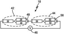
- FIG. 2 Cis a schematic diagram showing the configuration of heater system 18 .
- Heater system 18includes first heater set 42 , second heater set 44 , and voltage source 46 .
- First heater set 42includes CNT heater 28 , first PTC heater 30 , and second PTC heater 32 .
- First CNT heater 28 and first PTC heater 30are wired in parallel, forming first parallel formation 48 .
- Second PTC heater 32is wired in series between voltage source 46 and first parallel formation 48 .
- First heater set 44is installed within strut assembly 12 of air data sensor 10 .
- the resistance of parallel formation 48 in first heater set 42is less than each of the individual resistance of CNT heater 28 and first PTC heater 30 . Therefore, parallel formation 48 ensures faster heating than CNT heater 28 would provide by itself.
- the resistance of second PTC heater 32is selected so that the total resistance of second PTC heater 32 and parallel formation 48 is less than the resistance of CNT heater 28 at a set lower temperature (e.g., less than 20° C.).
- the resistance of second PTC heater 32 and parallel formation 48is less than the resistance of CNT heater 28 at lower temperatures so that PTC heaters ( 30 and 34 ) do not impede CNT heater 28 at low temperatures.
- the resistance of second PTC heater 32is further configured so that the resistance of second PTC heater 32 will increase to a maximum resistance at a set higher temperature, therefore the electrical resistivity of first PTC heater 30 and second PTC heater 32 do not need to be equal.
- the initial lower resistance of first heater set 42 when first heater set 42 is at a low temperatureresults in first heater set 42 rapidly heating strut assembly 12 .
- the resistance of second PTC heater 32increases to a maximum.
- second PTC heater 32restricts the power input to first parallel formation 48 .
- first heater set 42will not overheat and first heater set 42 will reduce the power consumption of heater system 18 .
- First PTC heater 30 and second PTC 32provide self-regulation of first heater set 42 and help mitigate either hot or cold spots on strut assembly 12 .
- Second heater set 44includes second CNT heater 50 , third PTC heater 52 , and fourth PTC heater 54 .
- Third PTC heater 52 and second CNT heater 50are wired in parallel, forming second parallel formation 56 .
- Fourth PTC heater 54is wired in series with voltage source 46 and second parallel formation 56 .
- Second heater set 44is within housing assembly 14 of air data sensor 10 .
- the values of electrical resistance for second heater set 44can be similar to the values discussed in relation to first heater set 42 above. In other embodiments, the values for the electrical resistance of second heater set 44 can be different than the values discussed in relation to first heater set. However, with different resistance values, the relationship of those values will be essentially the same as the relationship of the values in Table 1. For example, the resistance of parallel formation 56 in second heater set 44 is less than each of the individual resistance of second CNT heater 50 and third PTC heater 52 . Therefore, second parallel formation 56 ensures faster heating than second CNT heater 50 would provide by itself.
- the resistance of fourth PTC heater 54is selected so that the total resistance of fourth PTC heater 54 and second parallel formation 56 is less than the resistance of second CNT heater 50 at a lower temperature (e.g., less than 20° C.).
- the resistance of fourth PTC heater 54 and second parallel formation 56is less than the resistance of second CNT heater 50 at lower temperatures so that PTC heaters ( 52 and 54 ) do not impede second CNT heater 50 at low temperatures.
- the resistance of fourth PTC heater 54is further configured so that the resistance of fourth PTC heater 54 will increase to a maximum resistance at a set higher temperature. The initial lower resistance of second heater set 44 when second heater set 44 is at a low temperature results in second heater set 44 rapidly heating housing assembly 14 .
- fourth PTC heater 54At a higher temperature, the resistance of fourth PTC heater 54 increases to a maximum. When the resistance of fourth PTC heater 54 reaches a maximum, fourth PTC heater 54 restricts the power input to second parallel formation 56 . As a result of the power input being restricted to second parallel formation 56 , second heater set 44 will not overheat and second heater set 44 will reduce the power consumption of heating system 18 . Third PTC heater 52 and fourth PTC 54 provide self-regulation of second heater set 44 and help mitigate either hot or cold spots on housing assembly 14 .
- first heater set 42 and second heater set 44are configured to have different resistances to ensure they adequately heat strut assembly 12 and housing assembly 14 , respectively.
- first heater set 42 and second heater set 44can be identical and provide equal heating to strut assembly 12 and housing assembly 14 , respectively.
- first heater set 42can be located within strut assembly 12 and second heater set 44 can be located within housing assembly 14 .
- first heater set 42 and second heater set 44can be wired in series with one another and voltage source 46 .
- first heater set 42is located within strut assembly 12 and second heater set 44 is located within housing assembly 14
- first heater set 42 and second heater set 44each heating system can have dedicated voltage sources, and each system (first heater set 42 and second heater set 44 ) can be a standalone system independent of one another.
- FIG. 3is a schematic diagram of an alternative configuration of the heater system 18 .
- heater system 18includes third heater layer 58 , fourth heater layer 60 , and fifth heater layer 62 .
- Film adhesive and insulation 26is found between each of the heater layers ( 58 , 60 , and 62 ), between probe surface 16 and third heater layer 58 , and between probe sleeve 20 and fifth heater layer 62 .
- Third heater layer 58includes CNT heater 28 .
- Fourth heater layer 60includes PTC heater 30 .
- Fifth heater layer 62includes PTC heater 32 .
- Third heater layer 58 and fourth heater layer 60are wired in parallel to form parallel formation 48 (as shown in FIG. 2 C ).
- Fifth heater layer 62is wired in series with voltage source 46 and parallel formation 48 . Because CNT heater 28 is made from carbon nanotube and silicone composite, CNT heater 28 is more rigid and durable than PTC heater 30 and PTC heater 32 . Therefore, in the configuration of heater system 18 , CNT heater 28 should be in the outermost heater layer (e.g., third heater layer 58 ) so that CNT heater 28 can protected fourth heater layer 60 and fifth heater layer 62 .
- the outermost heater layere.g., third heater layer 58
- first heater set 42(as shown in FIG. 2 C ) can be located within strut assembly 12 and second heater set 44 (as shown in FIG. 2 C ) can be located within housing assembly 14 .
- first heater set 42 and second heater set 44can be wired in series with one another and voltage source 46 .
- first heater set 42is located within strut assembly 12 and second heater set 44 is located within housing assembly 14
- first heater set 42 and second heater set 44each heating system can have dedicated voltage sources, and each system (first heater set 42 and second heater set 44 ) can be a standalone system independent of one another.
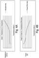
- FIGS. 4 A and 4 Bwill be discussed concurrently.
- FIG. 4 Ais a graph showing resistance as a function of temperature for heater system 18 .
- FIG. 4 Bis a graph showing power as a function of temperature heater system 18 .
- the graphs in FIGS. 4 A and 4 Bshow the relationship among CNT heater 28 , first PTC heater 30 , and second PCT heater 32 of the first heater set 42 , as discussed above.
- the resistance of the heater systemis low when the temperature of the heater system is low.
- the resistance of the heater systemincreases as the temperature of the heater system increases.
- the power supplied to the overall heating systemdecreases as the temperature increases. Decreasing the power to the heating system prevents the heating system from overheating and conserves energy.
- a hybrid heater system for an aircraft air data sensorincludes a voltage source and a first hybrid heater set.
- the first hybrid heater setincludes a carbon nanotube (CNT) heater, a first positive temperature coefficient (PTC) heater disposed in parallel with the CNT heater to form a parallel formation, and a second PTC heater disposed in series between the voltage source and the parallel formation.
- CNTcarbon nanotube
- PTCpositive temperature coefficient
- hybrid heater system of the preceding paragraphcan optionally include, additionally and/or alternatively, any one or more of the following features, configurations and/or additional components:
- an electrical resistance of the second PTC heateris greater than an electrical resistance of the parallel formation at a temperature greater than a set temperature, and wherein the electrical resistance of the second PTC heater is less than the electrical resistance of the parallel formation at a temperature less than the set temperature;
- an effective electrical resistance of the first parallel formationis less than an electrical resistance of each of the CNT heater and the first PTC heater
- an air data sensorthat includes a strut assembly, a housing assembly, extending from the strut assembly, a second heater set including a second CNT heater, a third PTC heater disposed in parallel with the second CNT heater to form a second parallel formation; and a fourth PTC heater disposed in series between the voltage source and the second parallel formation, wherein the first hybrid heater set is within the strut assembly, and the second hybrid heater set is within the housing assembly, and wherein the first hybrid heater set and the second hybrid heater set are electrically connected in series;
- the CNT heater and the first PTC heateroccupy a same layer in the air data sensor, and the same layer occupied by the CNT heater and the first PTC heater includes a first terminal, a second terminal, a first PTC heater elements extending between the first and second terminals, and CNT heater elements interleaved between the first PTC heater elements and extending between the first and second terminals;
- the air data probeincludes an outermost probe surface, a first film adhesive and insulation layer underlying the outermost probe surface, a first heater layer underlying the first film adhesive and insulation layer
- the first heater layerincludes CNT heater elements of the CNT heater and first PTC heater elements of the first PTC heater, a second film adhesive and insulation layer underlying the first heater layer, a second heater layer underlying the second film adhesive and insulation layer
- the second heater layerincludes a second PTC heater, a third film adhesive and insulation layer underlying the second heater layer, and a sleeve surface underlying the third film adhesive and insulation layer;
- the air data probeincludes an outermost probe surface, a first film adhesive and insulation layer underlying the outermost probe surface, a first heater layer underlying the first film adhesive and insulation layer, the first heater layer includes the CNT heater, a second film adhesive and insulation layer underlying the first heater layer, a second heater layer underlying the second adhesive and insulation layer, the second heater layer includes one of the first or second PTC heaters, a third film adhesive and insulation layer underlying the second heater layer, the third heater layer includes the other of the first or second PTC heaters, a fourth film adhesive and insulation layer underlying the third heater layer, and a sleeve surface underlying the fourth film and insulation layer.
- a hybrid heater system for ice protection of an air data probe on an aircraftincludes a voltage source, a carbon nanotube (CNT) heater, which includes CNT heater elements, a first positive temperature coefficient (PTC) heater disposed in parallel with the CNT heater to form a parallel formation, and a second PTC heater.
- the first PTC heaterincludes first PTC heater elements interleaved with the CNT heater elements in a first air data probe layer.
- the second PTC heateris disposed in a second air data probe layer and in series between the voltage source and the parallel formation.
- hybrid heater system of the preceding paragraphcan optionally include, additionally and/or alternatively, any one or more of the following features, configurations and/or additional components:
- the second PTC heaterestablishes the maximum temperature capability for ice protection, and the hybrid heater system operates with an absence of active temperature controls;
- first PTC heater and the second PTC heaterhave different electrical resistivity
- an effective electrical resistance of the first parallel formationis less than an electrical resistance of each of the CNT heater and the first PTC heater
- the air data probe layerincludes first and second terminals between which the interleaved CNT and first PTC heater elements extend; and/or
- the second air data probe layerunderlies the first air data probe layer.
- a method of making a heater for an air data probeincludes positioning on the air data probe a first heater layer.
- the first heater layerincludes a carbon nanotube (CNT) heater element and a first positive temperature coefficient (PTC) heater element interleaved with one another.
- the method of heating an air data probefurther includes positioning on the air data probe a second heater layer.
- the second heater layerincludes a second PTC heater element.
- the method of heating an air data probefurther includes wiring the first heater layer and the second heater layer so that the CNT heater element and the first PTC heater element are in parallel with one another defining a parallel formation.
- the method of heating an air data probefurther includes wiring the second heater layer so that the second PTC heater element is in series with the first parallel formation and a voltage source.
- the method of the preceding paragraphcan optionally include, additionally and/or alternatively, any one or more of the following features, configurations and/or additional components:
- the second PTC heater elementestablishes a maximum temperature capability for ice protection, and the hybrid heater system operates with an absence of active temperature controls;
- first PTC heater element and the second PTC heater elementhave differing electrical resistivity
- an effective electrical resistance of the parallel formationis less than an electrical resistance of each of the CNT heater element and the first PTC heater element;
- the first heater layeris split between two heater layers and includes a layer of film adhesive and insulation therebetween.
Landscapes
- Engineering & Computer Science (AREA)
- Aviation & Aerospace Engineering (AREA)
- Physics & Mathematics (AREA)
- General Physics & Mathematics (AREA)
- Resistance Heating (AREA)
- Thermistors And Varistors (AREA)
Abstract
Description
Claims (18)
Applications Claiming Priority (2)
| Application Number | Priority Date | Filing Date | Title |
|---|---|---|---|
| IN202041012145 | 2020-03-20 | ||
| IN202041012145 | 2020-03-20 |
Publications (2)
| Publication Number | Publication Date |
|---|---|
| US20210291992A1 US20210291992A1 (en) | 2021-09-23 |
| US11745879B2true US11745879B2 (en) | 2023-09-05 |
Family
ID=75108237
Family Applications (1)
| Application Number | Title | Priority Date | Filing Date |
|---|---|---|---|
| US16/903,686Active2041-03-27US11745879B2 (en) | 2020-03-20 | 2020-06-17 | Thin film heater configuration for air data probe |
Country Status (4)
| Country | Link |
|---|---|
| US (1) | US11745879B2 (en) |
| EP (1) | EP3883337A1 (en) |
| BR (1) | BR102021001713A2 (en) |
| CA (1) | CA3109793A1 (en) |
Families Citing this family (2)
| Publication number | Priority date | Publication date | Assignee | Title |
|---|---|---|---|---|
| US11425797B2 (en)* | 2019-10-29 | 2022-08-23 | Rosemount Aerospace Inc. | Air data probe including self-regulating thin film heater |
| US11745879B2 (en) | 2020-03-20 | 2023-09-05 | Rosemount Aerospace Inc. | Thin film heater configuration for air data probe |
Citations (60)
| Publication number | Priority date | Publication date | Assignee | Title |
|---|---|---|---|---|
| US2254155A (en) | 1938-12-13 | 1941-08-26 | Bendix Aviat Corp | Pitot-static tube |
| US4121088A (en) | 1976-10-18 | 1978-10-17 | Rosemount Inc. | Electrically heated air data sensing device |
| US4458137A (en)* | 1981-04-09 | 1984-07-03 | Rosemount Inc. | Electric heater arrangement for fluid flow stream sensors |
| US4801784A (en) | 1986-02-24 | 1989-01-31 | N.V. Raychem S.A. | Electrical device comprising a PTC or NTC composition |
| US5421202A (en) | 1992-08-28 | 1995-06-06 | Intertechnique | Liquid sensor having thermistors |
| US5764470A (en)* | 1995-12-05 | 1998-06-09 | Murata Manufacturing Co., Ltd. | Rush current suppression circuit |
| US6070475A (en) | 1997-10-15 | 2000-06-06 | Rosemont Aerospace Inc. | Air data probe with heater means within wall |
| US6134972A (en) | 1995-02-17 | 2000-10-24 | Rosemount Aerospace, Inc. | Air data sensing probe with chromium surface treatment |
| US6492629B1 (en) | 1999-05-14 | 2002-12-10 | Umesh Sopory | Electrical heating devices and resettable fuses |
| US6591696B2 (en) | 2001-07-12 | 2003-07-15 | Rosemount Aerospace, Inc. | Integral electric pressure probe for aircraft |
| US20080179448A1 (en) | 2006-02-24 | 2008-07-31 | Rohr, Inc. | Acoustic nacelle inlet lip having composite construction and an integral electric ice protection heater disposed therein |
| US20090194525A1 (en) | 2006-02-03 | 2009-08-06 | Exaenc Corp. | Heating element using carbon nano tube |
| US20090314765A1 (en) | 2008-06-13 | 2009-12-24 | Tsinghua University | Carbon nanotube heater |
| US20100059502A1 (en) | 2004-12-24 | 2010-03-11 | Heat Trace Limited | Control of heating cable |
| US20100096507A1 (en) | 2008-07-29 | 2010-04-22 | Markus Villinger | Heating device for deicing aircraft parts |
| US20100102052A1 (en) | 2007-01-04 | 2010-04-29 | 2D Heat Limited | Self-regulating electrical resistance heating element |
| US20100116806A1 (en) | 2007-05-08 | 2010-05-13 | Honeywell International Inc. | Automated heating system for ports susceptible to icing |
| DE102009034306A1 (en) | 2009-07-21 | 2011-03-03 | Fraunhofer-Gesellschaft zur Förderung der angewandten Forschung e.V. | Heating element and method for its production |
| US20110297665A1 (en)* | 2010-06-04 | 2011-12-08 | Robert Parker | Self Regulating Electric Heaters |
| US8164035B2 (en) | 2008-04-17 | 2012-04-24 | Long-Huang Chang | Heating device having dual-core heating cable |
| US8197621B2 (en) | 2006-06-27 | 2012-06-12 | Naos Co. Ltd. | Method for manufacturing planar heating element using carbon micro-fibers |
| KR101184780B1 (en) | 2010-12-20 | 2012-09-20 | 한국항공우주연구원 | Fabrication of deicing pitot-static probe using lamination method |
| US8367986B2 (en) | 2006-10-17 | 2013-02-05 | Conflux Ab | Heating element |
| US8466392B2 (en) | 2006-05-17 | 2013-06-18 | Heat Trace Limited | Material and heating cable |
| US8496854B2 (en) | 2009-10-30 | 2013-07-30 | Sabic Innovative Plastics Ip B.V. | Positive temperature coefficient materials with reduced negative temperature coefficient effect |
| US8525084B2 (en) | 2004-12-17 | 2013-09-03 | Heat Trace Limited | Electrical heating element |
| US8581158B2 (en) | 2006-08-02 | 2013-11-12 | Battelle Memorial Institute | Electrically conductive coating composition |
| US20140034633A1 (en) | 2010-11-17 | 2014-02-06 | Battelle Memorial Institute | Carbon nanotube thin film laminate resistive heater |
| US8664573B2 (en) | 2009-04-27 | 2014-03-04 | Applied Nanostructured Solutions, Llc | CNT-based resistive heating for deicing composite structures |
| US20140070054A1 (en) | 2010-12-31 | 2014-03-13 | Battelle Memorial Institute | Anti-icing, de-icing, and heating configuration, integration, and power methods for aircraft, aerodynamic, and complex surfaces |
| US20140071216A1 (en) | 2012-04-20 | 2014-03-13 | Goodrich Corporation | Printed heating element |
| US8752279B2 (en) | 2007-01-04 | 2014-06-17 | Goodrich Corporation | Methods of protecting an aircraft component from ice formation |
| US8952300B2 (en) | 2008-09-18 | 2015-02-10 | Heat Trace Limited | Heating cable |
| US9091657B2 (en) | 2010-01-26 | 2015-07-28 | Metis Design Corporation | Multifunctional CNT-engineered structures |
| US20150344137A1 (en) | 2014-05-28 | 2015-12-03 | The Boeing Company | External Case Heater For An Angle Of Attack Sensor |
| US20160007474A1 (en) | 2014-07-03 | 2016-01-07 | United Technologies Corporation | Heating circuit assembly and method of manufacture |
| US9237606B2 (en) | 2009-02-17 | 2016-01-12 | Lg Hausys, Ltd. | Carbon nanotube sheet heater |
| US20160113063A1 (en) | 2013-05-21 | 2016-04-21 | Heat Trace Limited | Electrical heater |
| US20160221680A1 (en) | 2015-01-06 | 2016-08-04 | Battelle Memorial Institute | Uniform Heat Distribution in Resistive Heaters For Anti-Icing and De-Icing |
| WO2016144683A1 (en) | 2015-03-06 | 2016-09-15 | Sikorsky Aircraft Corporation | Heating design for rotorcraft blade de-icing and anti-icing |
| US9511871B2 (en)* | 2011-05-26 | 2016-12-06 | Eads Deutschland Gmbh | Composite structure having an ice protection device, and production method |
| US9668301B2 (en) | 2015-07-03 | 2017-05-30 | Ndt Engineering & Aerospace Co., Ltd. | Wet-use plane heater using PTC constant heater-ink polymer |
| US20170158898A1 (en) | 2014-06-12 | 2017-06-08 | LMS Consulting Group | Electrically conductive ptc ink with double switching temperatures and applications thereof in flexible double-switching heaters |
| EP3182794A1 (en) | 2015-12-18 | 2017-06-21 | E.G.O. ELEKTRO-GERÄTEBAU GmbH | Heating device with a carrier and method of making it |
| US9693394B2 (en) | 2015-05-11 | 2017-06-27 | Borgwarner Ludwigsburg Gmbh | Electrical heating device |
| US9719820B1 (en) | 2016-01-29 | 2017-08-01 | Goodrich Aerospace Services Private Limited | Hybrid material pitot tube |
| US20170370960A1 (en) | 2016-06-28 | 2017-12-28 | Rosemount Aerospace, Inc. | Air data sensing probe with icing condition detector |
| US9955531B2 (en) | 2014-06-18 | 2018-04-24 | Suk Hwan KANG | Manufacturing method of PTC element using polymer aqueous emulsion conductive composite, PTC element manufactured by manufacturing method, and planar heating element including PTC element |
| US20180112938A1 (en) | 2016-10-26 | 2018-04-26 | Goodrich Aerospace Services Private Limited | Die-cast bodies with thermal conductive inserts |
| US20180124874A1 (en) | 2016-11-01 | 2018-05-03 | Goodrich Corporation | Multilayered panels |
| EP3321692A1 (en) | 2016-11-09 | 2018-05-16 | Honeywell International Inc. | Air data probe with thin film heating system and method of manufacturing the air data probe |
| US20180160482A1 (en) | 2016-12-02 | 2018-06-07 | Goodrich Corporation | Method to create carbon nanotube heaters with varying resistance |
| CN109683642A (en) | 2019-02-03 | 2019-04-26 | 元能机械科技(上海)有限公司 | Air data probe and its temprature control method with induction heating |
| US10368394B2 (en) | 2016-09-01 | 2019-07-30 | Hamilton Sundstrand Corporation | PTC heater with autonomous control |
| US20190383848A1 (en) | 2018-06-15 | 2019-12-19 | Rosemount Aerospace Inc. | Integration of low ice adhesion surface coatings with air data probes |
| US20200086999A1 (en) | 2018-09-13 | 2020-03-19 | Goodrich Corporation | Hybrid heater for aircraft wing ice protection |
| EP3668270A1 (en) | 2018-12-13 | 2020-06-17 | Goodrich Corporation | A multilayer structure with carbon nanotube heaters |
| US20210127458A1 (en) | 2019-10-29 | 2021-04-29 | Rosemount Aerospace Inc. | Air data probe including self-regulating thin film heater |
| US20210291992A1 (en) | 2020-03-20 | 2021-09-23 | Rosemount Aerospace Inc. | Thin film heater configuration for air data probe |
| US11585826B2 (en) | 2019-07-19 | 2023-02-21 | Rosemount Aerospace Inc. | Thin film heater on a sleeve outer surface in a strut portion and/or a probe head of an air data probe |
- 2020
- 2020-06-17USUS16/903,686patent/US11745879B2/enactiveActive
- 2021
- 2021-01-29BRBR102021001713-9Apatent/BR102021001713A2/enunknown
- 2021-02-19CACA3109793Apatent/CA3109793A1/enactivePending
- 2021-03-18EPEP21163469.6Apatent/EP3883337A1/enactivePending
Patent Citations (67)
| Publication number | Priority date | Publication date | Assignee | Title |
|---|---|---|---|---|
| US2254155A (en) | 1938-12-13 | 1941-08-26 | Bendix Aviat Corp | Pitot-static tube |
| US4121088A (en) | 1976-10-18 | 1978-10-17 | Rosemount Inc. | Electrically heated air data sensing device |
| US4458137A (en)* | 1981-04-09 | 1984-07-03 | Rosemount Inc. | Electric heater arrangement for fluid flow stream sensors |
| US4801784A (en) | 1986-02-24 | 1989-01-31 | N.V. Raychem S.A. | Electrical device comprising a PTC or NTC composition |
| US5421202A (en) | 1992-08-28 | 1995-06-06 | Intertechnique | Liquid sensor having thermistors |
| US6134972A (en) | 1995-02-17 | 2000-10-24 | Rosemount Aerospace, Inc. | Air data sensing probe with chromium surface treatment |
| US5764470A (en)* | 1995-12-05 | 1998-06-09 | Murata Manufacturing Co., Ltd. | Rush current suppression circuit |
| US6070475A (en) | 1997-10-15 | 2000-06-06 | Rosemont Aerospace Inc. | Air data probe with heater means within wall |
| US6492629B1 (en) | 1999-05-14 | 2002-12-10 | Umesh Sopory | Electrical heating devices and resettable fuses |
| US6591696B2 (en) | 2001-07-12 | 2003-07-15 | Rosemount Aerospace, Inc. | Integral electric pressure probe for aircraft |
| US8525084B2 (en) | 2004-12-17 | 2013-09-03 | Heat Trace Limited | Electrical heating element |
| US20100059502A1 (en) | 2004-12-24 | 2010-03-11 | Heat Trace Limited | Control of heating cable |
| US20090194525A1 (en) | 2006-02-03 | 2009-08-06 | Exaenc Corp. | Heating element using carbon nano tube |
| US20080179448A1 (en) | 2006-02-24 | 2008-07-31 | Rohr, Inc. | Acoustic nacelle inlet lip having composite construction and an integral electric ice protection heater disposed therein |
| US8466392B2 (en) | 2006-05-17 | 2013-06-18 | Heat Trace Limited | Material and heating cable |
| US8197621B2 (en) | 2006-06-27 | 2012-06-12 | Naos Co. Ltd. | Method for manufacturing planar heating element using carbon micro-fibers |
| US8581158B2 (en) | 2006-08-02 | 2013-11-12 | Battelle Memorial Institute | Electrically conductive coating composition |
| US8367986B2 (en) | 2006-10-17 | 2013-02-05 | Conflux Ab | Heating element |
| US8752279B2 (en) | 2007-01-04 | 2014-06-17 | Goodrich Corporation | Methods of protecting an aircraft component from ice formation |
| US20100102052A1 (en) | 2007-01-04 | 2010-04-29 | 2D Heat Limited | Self-regulating electrical resistance heating element |
| US20100116806A1 (en) | 2007-05-08 | 2010-05-13 | Honeywell International Inc. | Automated heating system for ports susceptible to icing |
| US8164035B2 (en) | 2008-04-17 | 2012-04-24 | Long-Huang Chang | Heating device having dual-core heating cable |
| US20090314765A1 (en) | 2008-06-13 | 2009-12-24 | Tsinghua University | Carbon nanotube heater |
| US20100096507A1 (en) | 2008-07-29 | 2010-04-22 | Markus Villinger | Heating device for deicing aircraft parts |
| US8952300B2 (en) | 2008-09-18 | 2015-02-10 | Heat Trace Limited | Heating cable |
| US9237606B2 (en) | 2009-02-17 | 2016-01-12 | Lg Hausys, Ltd. | Carbon nanotube sheet heater |
| US8664573B2 (en) | 2009-04-27 | 2014-03-04 | Applied Nanostructured Solutions, Llc | CNT-based resistive heating for deicing composite structures |
| DE102009034306A1 (en) | 2009-07-21 | 2011-03-03 | Fraunhofer-Gesellschaft zur Förderung der angewandten Forschung e.V. | Heating element and method for its production |
| US8496854B2 (en) | 2009-10-30 | 2013-07-30 | Sabic Innovative Plastics Ip B.V. | Positive temperature coefficient materials with reduced negative temperature coefficient effect |
| US9091657B2 (en) | 2010-01-26 | 2015-07-28 | Metis Design Corporation | Multifunctional CNT-engineered structures |
| US8481898B2 (en) | 2010-06-04 | 2013-07-09 | Robert Parker | Self regulating electric heaters |
| US20110297665A1 (en)* | 2010-06-04 | 2011-12-08 | Robert Parker | Self Regulating Electric Heaters |
| US20140034633A1 (en) | 2010-11-17 | 2014-02-06 | Battelle Memorial Institute | Carbon nanotube thin film laminate resistive heater |
| KR101184780B1 (en) | 2010-12-20 | 2012-09-20 | 한국항공우주연구원 | Fabrication of deicing pitot-static probe using lamination method |
| US20140070054A1 (en) | 2010-12-31 | 2014-03-13 | Battelle Memorial Institute | Anti-icing, de-icing, and heating configuration, integration, and power methods for aircraft, aerodynamic, and complex surfaces |
| US9511871B2 (en)* | 2011-05-26 | 2016-12-06 | Eads Deutschland Gmbh | Composite structure having an ice protection device, and production method |
| US20140071216A1 (en) | 2012-04-20 | 2014-03-13 | Goodrich Corporation | Printed heating element |
| US20160113063A1 (en) | 2013-05-21 | 2016-04-21 | Heat Trace Limited | Electrical heater |
| US20150344137A1 (en) | 2014-05-28 | 2015-12-03 | The Boeing Company | External Case Heater For An Angle Of Attack Sensor |
| US20170158898A1 (en) | 2014-06-12 | 2017-06-08 | LMS Consulting Group | Electrically conductive ptc ink with double switching temperatures and applications thereof in flexible double-switching heaters |
| US9955531B2 (en) | 2014-06-18 | 2018-04-24 | Suk Hwan KANG | Manufacturing method of PTC element using polymer aqueous emulsion conductive composite, PTC element manufactured by manufacturing method, and planar heating element including PTC element |
| US20160007474A1 (en) | 2014-07-03 | 2016-01-07 | United Technologies Corporation | Heating circuit assembly and method of manufacture |
| US20160221680A1 (en) | 2015-01-06 | 2016-08-04 | Battelle Memorial Institute | Uniform Heat Distribution in Resistive Heaters For Anti-Icing and De-Icing |
| WO2016144683A1 (en) | 2015-03-06 | 2016-09-15 | Sikorsky Aircraft Corporation | Heating design for rotorcraft blade de-icing and anti-icing |
| US9693394B2 (en) | 2015-05-11 | 2017-06-27 | Borgwarner Ludwigsburg Gmbh | Electrical heating device |
| US9668301B2 (en) | 2015-07-03 | 2017-05-30 | Ndt Engineering & Aerospace Co., Ltd. | Wet-use plane heater using PTC constant heater-ink polymer |
| EP3182794A1 (en) | 2015-12-18 | 2017-06-21 | E.G.O. ELEKTRO-GERÄTEBAU GmbH | Heating device with a carrier and method of making it |
| US9719820B1 (en) | 2016-01-29 | 2017-08-01 | Goodrich Aerospace Services Private Limited | Hybrid material pitot tube |
| US10132824B2 (en) | 2016-06-28 | 2018-11-20 | Rosemount Aerospace Inc. | Air data sensing probe with icing condition detector |
| US20170370960A1 (en) | 2016-06-28 | 2017-12-28 | Rosemount Aerospace, Inc. | Air data sensing probe with icing condition detector |
| EP3264103A1 (en) | 2016-06-28 | 2018-01-03 | Rosemount Aerospace Inc. | Air data sensing probe with icing condition detector |
| US10368394B2 (en) | 2016-09-01 | 2019-07-30 | Hamilton Sundstrand Corporation | PTC heater with autonomous control |
| US20180112938A1 (en) | 2016-10-26 | 2018-04-26 | Goodrich Aerospace Services Private Limited | Die-cast bodies with thermal conductive inserts |
| US20180124874A1 (en) | 2016-11-01 | 2018-05-03 | Goodrich Corporation | Multilayered panels |
| US10197588B2 (en) | 2016-11-09 | 2019-02-05 | Honeywell International Inc. | Thin film heating systems for air data probes |
| EP3321692A1 (en) | 2016-11-09 | 2018-05-16 | Honeywell International Inc. | Air data probe with thin film heating system and method of manufacturing the air data probe |
| US20180160482A1 (en) | 2016-12-02 | 2018-06-07 | Goodrich Corporation | Method to create carbon nanotube heaters with varying resistance |
| US20190383848A1 (en) | 2018-06-15 | 2019-12-19 | Rosemount Aerospace Inc. | Integration of low ice adhesion surface coatings with air data probes |
| US20200086999A1 (en) | 2018-09-13 | 2020-03-19 | Goodrich Corporation | Hybrid heater for aircraft wing ice protection |
| US11235881B2 (en)* | 2018-09-13 | 2022-02-01 | Goodrich Corporation | Hybrid heater for aircraft wing ice protection |
| EP3668270A1 (en) | 2018-12-13 | 2020-06-17 | Goodrich Corporation | A multilayer structure with carbon nanotube heaters |
| US20200189751A1 (en) | 2018-12-13 | 2020-06-18 | Goodrich Corporation | Multilayer structure with carbon nanotube heaters |
| CN109683642A (en) | 2019-02-03 | 2019-04-26 | 元能机械科技(上海)有限公司 | Air data probe and its temprature control method with induction heating |
| US11585826B2 (en) | 2019-07-19 | 2023-02-21 | Rosemount Aerospace Inc. | Thin film heater on a sleeve outer surface in a strut portion and/or a probe head of an air data probe |
| US20210127458A1 (en) | 2019-10-29 | 2021-04-29 | Rosemount Aerospace Inc. | Air data probe including self-regulating thin film heater |
| US11425797B2 (en) | 2019-10-29 | 2022-08-23 | Rosemount Aerospace Inc. | Air data probe including self-regulating thin film heater |
| US20210291992A1 (en) | 2020-03-20 | 2021-09-23 | Rosemount Aerospace Inc. | Thin film heater configuration for air data probe |
Non-Patent Citations (3)
| Title |
|---|
| Chu et al. "Electrical and Thermal Properties of Carbon-Nanotube Composite for Flexible Electric Heating-Unit Applications" IEEE Electron Device Letters vol. 34 No. 5 (May 2013) pp. 668-670. |
| Examination Report for European Patent Application No. 21163469.6, dated Sep. 14, 2022, 4 pages. |
| Extended European Search Report dated Aug. 25, 2021, received for corresponding European Application No. 21163469.6, ten pages. |
Also Published As
| Publication number | Publication date |
|---|---|
| CA3109793A1 (en) | 2021-09-20 |
| US20210291992A1 (en) | 2021-09-23 |
| BR102021001713A2 (en) | 2021-10-05 |
| EP3883337A1 (en) | 2021-09-22 |
Similar Documents
| Publication | Publication Date | Title |
|---|---|---|
| EP3816634B1 (en) | Air data probe including self-regulating thin film heater | |
| US8602359B2 (en) | Ice protection system | |
| US11745879B2 (en) | Thin film heater configuration for air data probe | |
| US8481898B2 (en) | Self regulating electric heaters | |
| EP1997731A2 (en) | Automated heating system for ports susceptible to icing | |
| US11235881B2 (en) | Hybrid heater for aircraft wing ice protection | |
| JP6069734B2 (en) | Vehicle heater manufacturing method and vehicle heater | |
| US9097734B2 (en) | Ceramic heating device | |
| CN111328159A (en) | Multilayer structure with carbon nanotube heater | |
| CA2580163A1 (en) | Adaptable layered heater system | |
| CN110636651B (en) | Electric heater with low drift resistance feedback | |
| CN109683642A (en) | Air data probe and its temprature control method with induction heating | |
| US20210153306A1 (en) | Heating module | |
| JP2021136448A (en) | Self-limiting heater | |
| EP3595404A1 (en) | Multi polymer positive temperature coefficient heater | |
| JP2013026222A (en) | Heating system, heater, and methods of heating component | |
| EP3401617A1 (en) | Electric heater | |
| CN115478930B (en) | Exhaust Heater | |
| SE516018C2 (en) | Device and heating elements for heating a component in a vehicle environment | |
| CN209879223U (en) | Heater film and its applied camera module | |
| EP3941154A1 (en) | Control scheme for negative temperature coefficient of resistivity heaters | |
| JPS6032958B2 (en) | heat sensitive body | |
| JP2004363264A (en) | Resistor element | |
| JPH0398284A (en) | Heating device |
Legal Events
| Date | Code | Title | Description |
|---|---|---|---|
| AS | Assignment | Owner name:GOODRICH AEROSPACE SERVICES PRIVATE LIMITED, INDIA Free format text:ASSIGNMENT OF ASSIGNORS INTEREST;ASSIGNORS:JACOB, ROBIN;MAHAPATRA, GURU PRASAD;SIGNING DATES FROM 20200527 TO 20200601;REEL/FRAME:052962/0115 | |
| FEPP | Fee payment procedure | Free format text:ENTITY STATUS SET TO UNDISCOUNTED (ORIGINAL EVENT CODE: BIG.); ENTITY STATUS OF PATENT OWNER: LARGE ENTITY | |
| AS | Assignment | Owner name:ROSEMOUNT AEROSPACE INC., MINNESOTA Free format text:ASSIGNMENT OF ASSIGNORS INTEREST;ASSIGNOR:GOODRICH AEROSPACE SERVICES PRIVATE LIMITED;REEL/FRAME:054414/0512 Effective date:20201116 | |
| AS | Assignment | Owner name:ROSEMOUNT AEROSPACE INC., MINNESOTA Free format text:ASSIGNMENT OF ASSIGNORS INTEREST;ASSIGNOR:GOODRICH AEROSPACE SERVICES PRIVATE LIMITED;REEL/FRAME:057923/0435 Effective date:20211016 | |
| STPP | Information on status: patent application and granting procedure in general | Free format text:NON FINAL ACTION MAILED | |
| STPP | Information on status: patent application and granting procedure in general | Free format text:RESPONSE TO NON-FINAL OFFICE ACTION ENTERED AND FORWARDED TO EXAMINER | |
| STPP | Information on status: patent application and granting procedure in general | Free format text:NOTICE OF ALLOWANCE MAILED -- APPLICATION RECEIVED IN OFFICE OF PUBLICATIONS | |
| STCF | Information on status: patent grant | Free format text:PATENTED CASE |