US11741775B2 - Automated electromechanical capper for removing or securing a cap on a container - Google Patents
Automated electromechanical capper for removing or securing a cap on a containerDownload PDFInfo
- Publication number
- US11741775B2 US11741775B2US16/731,903US201916731903AUS11741775B2US 11741775 B2US11741775 B2US 11741775B2US 201916731903 AUS201916731903 AUS 201916731903AUS 11741775 B2US11741775 B2US 11741775B2
- Authority
- US
- United States
- Prior art keywords
- container
- cap
- locking mechanism
- gripper
- depicts
- Prior art date
- Legal status (The legal status is an assumption and is not a legal conclusion. Google has not performed a legal analysis and makes no representation as to the accuracy of the status listed.)
- Active
Links
Images


Classifications
- G—PHYSICS
- G07—CHECKING-DEVICES
- G07F—COIN-FREED OR LIKE APPARATUS
- G07F13/00—Coin-freed apparatus for controlling dispensing or fluids, semiliquids or granular material from reservoirs
- G07F13/06—Coin-freed apparatus for controlling dispensing or fluids, semiliquids or granular material from reservoirs with selective dispensing of different fluids or materials or mixtures thereof
- G07F13/065—Coin-freed apparatus for controlling dispensing or fluids, semiliquids or granular material from reservoirs with selective dispensing of different fluids or materials or mixtures thereof for drink preparation
- B—PERFORMING OPERATIONS; TRANSPORTING
- B65—CONVEYING; PACKING; STORING; HANDLING THIN OR FILAMENTARY MATERIAL
- B65B—MACHINES, APPARATUS OR DEVICES FOR, OR METHODS OF, PACKAGING ARTICLES OR MATERIALS; UNPACKING
- B65B3/00—Packaging plastic material, semiliquids, liquids or mixed solids and liquids, in individual containers or receptacles, e.g. bags, sacks, boxes, cartons, cans, or jars
- B65B3/02—Machines characterised by the incorporation of means for making the containers or receptacles
- B—PERFORMING OPERATIONS; TRANSPORTING
- B65—CONVEYING; PACKING; STORING; HANDLING THIN OR FILAMENTARY MATERIAL
- B65B—MACHINES, APPARATUS OR DEVICES FOR, OR METHODS OF, PACKAGING ARTICLES OR MATERIALS; UNPACKING
- B65B3/00—Packaging plastic material, semiliquids, liquids or mixed solids and liquids, in individual containers or receptacles, e.g. bags, sacks, boxes, cartons, cans, or jars
- B65B3/04—Methods of, or means for, filling the material into the containers or receptacles
- B65B3/045—Methods of, or means for, filling the material into the containers or receptacles for filling flexible containers having a filling and dispensing spout, e.g. containers of the "bag-in-box"-type
- B—PERFORMING OPERATIONS; TRANSPORTING
- B65—CONVEYING; PACKING; STORING; HANDLING THIN OR FILAMENTARY MATERIAL
- B65B—MACHINES, APPARATUS OR DEVICES FOR, OR METHODS OF, PACKAGING ARTICLES OR MATERIALS; UNPACKING
- B65B7/00—Closing containers or receptacles after filling
- B65B7/16—Closing semi-rigid or rigid containers or receptacles not deformed by, or not taking-up shape of, contents, e.g. boxes or cartons
- B65B7/28—Closing semi-rigid or rigid containers or receptacles not deformed by, or not taking-up shape of, contents, e.g. boxes or cartons by applying separate preformed closures, e.g. lids, covers
- B65B7/2835—Closing semi-rigid or rigid containers or receptacles not deformed by, or not taking-up shape of, contents, e.g. boxes or cartons by applying separate preformed closures, e.g. lids, covers applying and rotating preformed threaded caps
- B—PERFORMING OPERATIONS; TRANSPORTING
- B67—OPENING, CLOSING OR CLEANING BOTTLES, JARS OR SIMILAR CONTAINERS; LIQUID HANDLING
- B67B—APPLYING CLOSURE MEMBERS TO BOTTLES JARS, OR SIMILAR CONTAINERS; OPENING CLOSED CONTAINERS
- B67B7/00—Hand- or power-operated devices for opening closed containers
- B67B7/18—Hand- or power-operated devices for opening closed containers for removing threaded caps
- B67B7/182—Hand- or power-operated devices for opening closed containers for removing threaded caps power-operated
- G—PHYSICS
- G07—CHECKING-DEVICES
- G07F—COIN-FREED OR LIKE APPARATUS
- G07F13/00—Coin-freed apparatus for controlling dispensing or fluids, semiliquids or granular material from reservoirs
- G07F13/10—Coin-freed apparatus for controlling dispensing or fluids, semiliquids or granular material from reservoirs with associated dispensing of containers, e.g. cups or other articles
- G—PHYSICS
- G07—CHECKING-DEVICES
- G07F—COIN-FREED OR LIKE APPARATUS
- G07F9/00—Details other than those peculiar to special kinds or types of apparatus
- G07F9/10—Casings or parts thereof, e.g. with means for heating or cooling
- G07F9/105—Heating or cooling means, for temperature and humidity control, for the conditioning of articles and their storage
- C—CHEMISTRY; METALLURGY
- C02—TREATMENT OF WATER, WASTE WATER, SEWAGE, OR SLUDGE
- C02F—TREATMENT OF WATER, WASTE WATER, SEWAGE, OR SLUDGE
- C02F1/00—Treatment of water, waste water, or sewage
- C02F1/28—Treatment of water, waste water, or sewage by sorption
- C02F1/283—Treatment of water, waste water, or sewage by sorption using coal, charred products, or inorganic mixtures containing them
- C—CHEMISTRY; METALLURGY
- C02—TREATMENT OF WATER, WASTE WATER, SEWAGE, OR SLUDGE
- C02F—TREATMENT OF WATER, WASTE WATER, SEWAGE, OR SLUDGE
- C02F1/00—Treatment of water, waste water, or sewage
- C02F1/30—Treatment of water, waste water, or sewage by irradiation
- C02F1/32—Treatment of water, waste water, or sewage by irradiation with ultraviolet light
- C—CHEMISTRY; METALLURGY
- C02—TREATMENT OF WATER, WASTE WATER, SEWAGE, OR SLUDGE
- C02F—TREATMENT OF WATER, WASTE WATER, SEWAGE, OR SLUDGE
- C02F1/00—Treatment of water, waste water, or sewage
- C02F1/44—Treatment of water, waste water, or sewage by dialysis, osmosis or reverse osmosis
- C02F1/441—Treatment of water, waste water, or sewage by dialysis, osmosis or reverse osmosis by reverse osmosis
- C—CHEMISTRY; METALLURGY
- C02—TREATMENT OF WATER, WASTE WATER, SEWAGE, OR SLUDGE
- C02F—TREATMENT OF WATER, WASTE WATER, SEWAGE, OR SLUDGE
- C02F2209/00—Controlling or monitoring parameters in water treatment
- C02F2209/005—Processes using a programmable logic controller [PLC]
- C02F2209/008—Processes using a programmable logic controller [PLC] comprising telecommunication features, e.g. modems or antennas
- C—CHEMISTRY; METALLURGY
- C02—TREATMENT OF WATER, WASTE WATER, SEWAGE, OR SLUDGE
- C02F—TREATMENT OF WATER, WASTE WATER, SEWAGE, OR SLUDGE
- C02F2307/00—Location of water treatment or water treatment device
- C02F2307/10—Location of water treatment or water treatment device as part of a potable water dispenser, e.g. for use in homes or offices
Definitions
- the present inventionis an automated electromechanical gripper for handling a container.
- the gripperis used in an automated liquid dispenser.
- the grippercan grab a single container, remove the container from a nested stack of containers, and move the container in three directions (horizontally, laterally, and vertically).
- a typical prior art containeris manufactured using injection blow molding and utilizes a screw cap closure out of PET (polyethylene terephthalate) and HDPE (high-density polyethylene). This packaging will be excessively hard to be broken down by nature which has caused massive amounts of plastic waste to accumulate in waterways, as observed by the NOAA. It is well-known that disposable plastic bottles and other containers being consumed on a global scale have caused massive ecological damage due to the consumption of fossil fuels to both package and transport beverages from the bottling plant to the consumer.
- liquid dispensing devicescomprise novel mechanisms for removing a single container from a nested stack of containers, closing the bottom of the container, decapping the container, filling the container, capping the container, and dispensing the filled container to a user.
- the above-described problems with producing compostable bottled water or beverageare alleviated by using the liquid dispensing devices herein.
- the devicesuse the municipal water supply, filter the water, provide additives in accordance with consumer preferences, fill compostable bottles stored in the chassis, and deliver a sealed, filled bottle to the consumer.
- the beverage containercomprises an external shell, internal pouch, and closure. Its shape is unique and different than a prior art beverage bottle.
- the shellmay be of an easily degradable material such as wood or bamboo pulp.
- the liquidis stored in a thin film pouch within the shell.
- the pouchmay consist of poly-lactic acid (PLA) or polyhydroxyalkanoates (PHA) or polybutyrate (PBAT) in such thickness and of such type that it meets regulatory requirements to be certified as “compostable.”
- PKApoly-lactic acid
- PHApolyhydroxyalkanoates
- PBATpolybutyrate
- the capmay be a typical cap with threads to screw onto the top of the container or an alternative.
- the capmay be made of wood, bio-polymer, or another material.
- the entire containermay be certified as “compostable” by certification organization Vincotte (Brussels, Belgium) or a similar entity.
- the shelloptionally comprises a conical tube with a narrower opening on top and a bottom that is wider, which has a hinged flap that is able to either leave a large opening on the bottom or is able to close the large opening by being folded into it.
- the point of salemay be a beverage kiosk or other point of retail sale. Because the hinged bottom is in the open position at the time of shipping, the containers may be stacked efficiently, with many hundreds or thousands of containers able to be stacked and stored within a space within a kiosk housing that is smaller than the size of a typical vending machine, and allowing for other equipment inside the housing.
- a data collection interfaceis employed to interface with the meter data collection system.
- a number of software applications for cleaning, validating and estimating dataare employed.
- a message bustransfers data or information derived from the data between the data collection system, the data collection interface and the software applications.
- the containerWhen a consumer purchases a beverage using the liquid dispensing devices described herein, the container is filled and delivered to the consumer.
- the terms “purchaser,” “consumer,” “user,” and “beverage recipient”are used interchangeably.
- FIG. 1is a diagram of a first embodiment of a liquid dispensing device.
- FIG. 2is a diagram showing details of bottle storage and the filling mechanism of FIG. 1 .
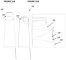
- FIG. 3 Ais a cross-sectional view diagram showing a sealing plug and cap body, where the sealing plug is inserted partially into the cap body through a hole.
- FIG. 3 Bis a perspective view of the sealing plug and cap body of FIG. 3 A .
- FIG. 3 Cis a cross-sectional view diagram showing a sealing plug and cap body, where the sealing plug is inserted completely into the cap body through the hole to form a permanently sealed combined cap assembly.
- FIG. 3 Dis a perspective view of the permanently sealed combined cap assembly of FIG. 3 C sealing plug and cap body.
- FIG. 3 Eis a top view of the main cap body with the sealing plug removed where a hole at the center of the main cap body is for receiving the sealing plug that is to be inserted into the hole of the main cap body first partially and then completely after filling the bottle.
- FIG. 4 Ais a diagram showing the bottle and cap assembly in a filled and permanently sealed condition.
- FIG. 4 Bis a diagram showing a bottle with the cap plug inserted partially and ready for filling.
- FIG. 5shows a network of kiosks connected by a communication network to a central computer that contains a database of information about the kiosks and the customers buying beverages from the kiosks.
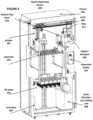
- FIG. 6is a diagram of a second embodiment of a liquid dispensing device.
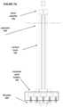
- FIG. 7 Adepicts a lift plate, separator, and related components of the liquid dispensing device.
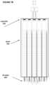
- FIG. 7 Bdepicts a lift plate, separator, and related components of the liquid dispensing device with stacks of containers.
- FIG. 7 Cdepicts a lift plate, separator, and related components of the liquid dispensing device with a single container in the fully upward position.
- FIG. 8depicts a top view of the separator of the liquid dispensing device and the lift plate without stacks of bottles.
- FIG. 9depicts friction members in the separator.
- FIG. 10depicts a sensor in the separator.
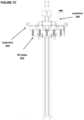
- FIG. 11depicts a front view of a gripper of the liquid dispensing device.
- FIG. 12depicts a side view of the gripper.
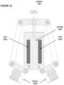
- FIG. 13depicts a front view of the gripper in an “on” state.
- FIG. 14depicts a front view of the gripper in an “off” state.
- FIG. 15depicts a front view of the gripper in an “on” state with a container.
- FIG. 16depicts a front view of the gripper in an “off” state with a grabbed container.
- FIGS. 17 A, 17 B, and 17 Cdepict a sequence of the gripper grabbing the cap of a container.
- FIG. 18depicts a top view of the gripper.
- FIG. 19depicts motorized tracks used to move the gripper.
- FIGS. 20 A, 20 B, and 20 Cdepict additional views of tracks used to move the gripper.
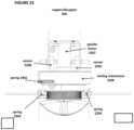
- FIGS. 21 A, 21 B, and 21 Cdepict a sequence of a bottom flap closer of the liquid dispensing device used to close the bottom flap of a container.
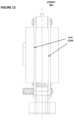
- FIG. 22depicts a side view of a capper/decapper of the liquid dispensing device.
- FIG. 23depicts another side view of the capper/decapper.
- FIGS. 24 A and 24 Bdepict a bottom view and FIG. 24 C depicts a side view of a mechanism in the capper/decapper for grabbing the cap.
- FIGS. 25 A, 25 B, and 25 Cdepict a top view of capper/decapper and sensors used to sense the presence of a cap.
- FIG. 26depicts hardware aspects of a controller of the liquid dispensing device.
- FIG. 27depicts software aspects of the controller.
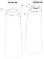
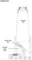
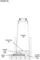
- FIGS. 28 A and 28 Bdepict side views of a container for use with the embodiments of the liquid dispensing devices.
- FIGS. 29 A and 29 Bdepict side views of a nested stack of containers.
- FIGS. 30 A, 30 B, and 30 Cdepict the closing of a bottom flap of the container.
- FIGS. 31 A and 31 Bdepict a side-view of a locking mechanism in the container.
- FIGS. 32 A and 32 Bdepict a side-view of a securing mechanism in the container that secures a liquid-holding bag between a mechanical sealing ring and the closure shoulder.
- FIGS. 33 A, 33 B, and 33 Cdepict a side-view of the container in various states of assembly.
- FIG. 34depicts an exploded side view of various components of the container.
- FIGS. 35 A and 35 Bdepict additional exploded side views of various components of the container.
- FIG. 1is a block diagram illustrating one embodiment of the invention.
- the kiosk 1contains the elements necessary to produce and deliver bottled water or other beverages to the purchaser.
- Water from a municipal water supply facilityenters the kiosk via manifold 33 and is connected to filters 5 that remove impurities, including both inorganic chemicals and undesirable microbes.
- Bottlesare stored in cartridge 3 prior to filling in stacks as shown in FIG. 2 .
- the bottlesare retrieved by a robot arm and placed in a carousel to be filled by filler 4 in FIG. 1 .
- the wateris delivered through tubes to filler 4 , and then injected into the bottle.
- the filled bottleis sealed and delivered to the consumer through the delivery mechanism 2 , as shown in FIG. 1 .
- FIG. 2illustrates the storage and handling of bottles in this embodiment.
- the bottlesare stored in stacks 41 in a partially-completed state in the kiosk, with their bottoms only partially attached. During the filling and sealing process, the bottoms are attached.
- Filling collar 42 of filler 4injects water through a hole in a pre-installed cap to fill the bottles.
- the use of a carouselallows one bottle to be filled while another is taken by the robot arm from storage and added to the carousel. Another bottle can then be filled immediately with a short rotation of the carousel without waiting for the robot arm to retrieve a bottle from the stack.
- FIGS. 3 A- 3 Eillustrate the cap system in a second embodiment to deliver the sealed bottle of an embodiment.
- the caphas two parts: sealing plug 21 and cap body 22 .
- the sealing plugis inserted partially into the cap body through hole 26 as illustrated in the cross-sectional view of FIG. 3 A to form the partially sealed plug and cap body assembly 24 also shown in FIG. 3 B in perspective.
- Four holes 27are defined in the cap body as shown in FIGS. 3 A and 3 E .
- FIG. 3 Eis a top view of the main cap body with the sealing plug removed where a hole 26 at the center of the main cap body is for receiving the sealing plug that is to be inserted into the hole of the main cap body first partially and then completely after filling the bottle.
- This partially sealed plug and cap body assembly 24is screwed onto the bottle at a centralized facility and the breakable paper or plastic seal 35 in FIG. 4 B is attached via adhesive or as shrink-wrap commonly used in the industry.
- the partially sealed plug and cap body assembly 24is delivered to the kiosk already screwed onto the bottle as shown in FIG. 4 B .
- the beverageis injected through the four holes 27 in partially sealed plug and cap body assembly 24 .
- a solenoid(not shown) plunges the plug 21 completely into the cap body 22 to create the sealed plug and cap body assembly 25 shown in FIG. 3 C .
- the assembly 25is then a permanently sealed combined cap assembly having an appearance attractive to the consumer and similar to typical plastic bottle caps.
- the permanently sealed combined cap assembly 25is shown in the perspective view in FIG.
- the Kiosk 1also preferably includes a refrigeration unit in manifold 33 that chills the water before it is injected into the bottle.
- the filler 4 , the refrigeration unit, the solenoid unit that seals the holes 27 , and the robot arm that delivers the filled bottle to the recipientare collectively referred to herein as the “mechanism.”
- the consumerwill first need to break the seal 35 by unscrewing the cap and removing it from bottle 34 .
- the bottle and cap assembly in a filled and permanently sealed conditionis shown in FIG. 4 A .
- FIG. 1illustrates a further embodiment, in which the kiosk has a QR reader or camera 8 to read a QR code displayed by the purchaser's smart phone 6 in another embodiment.
- the QR codecommunicates the purchaser's identity and other information such as payment preferences.
- the QR codemay also be displayed on the tablet computer 10 or on the laptop computer 9 instead of smart phone 6 .
- a smart phone, a tablet computer and a laptop computerare referred to herein collectively as a handheld computer.
- the purchasermay select additives for the water to be added following filtration and prior to filling the bottle.
- the selected additivesare injected into the bottle with filler 4 .
- Additives selected by the end consumerare communicated from the handheld computer such as smart phone 6 via wireless communications to receiver 7 .
- the handheld computermay also be tablet computer 10 or laptop computer 9 .
- a wireless receiver similar to receiver 7may be used to establish two way communication between the kiosk and a centralized computer linked to or with a database providing information to the kiosk as illustrated in FIG. 5 .
- the purchasermay communicate payment information such as identification and account number to the kiosk as well as authorization for payment for the filled container beverage by the purchaser's financial institution on behalf of the purchaser.
- Payment information for the end consumer or purchaseris communicated from the handheld computer such as smart phone 6 via wireless communications to receiver 7 .
- the handheld computermay also be tablet 10 or laptop computer 9 .
- the kioskhas a computer processor 11 that can communicate with a payment processing computer (not shown) at a payment facility (not shown) via wireless link 7 to enable automatic deduction from a pre-paid account that was funded by the beverage recipient in advance of the purchase.
- the kiosk 1has computer processor 11 that contains or is linked to a database 12 of information about persons previously utilizing the kiosk. This database may be linked, to centralized database 13 illustrated in FIG. 5 .
- the kiosk of FIG. 1may be one of the kiosks 14 , 15 , 16 in and forms part of a network of kiosks 14 , 15 , and 16 that are connected via communications network 17 to a central database 13 connected to computer processor 28 and housed at centralized facility 31 .
- the central database 13contains in one embodiment information about persons previously utilizing any one of the kiosks that is part of the network of kiosks. Alternatively, the central database 13 may also be stored in the computer processor 28 .
- the kioskproduces bottled beverages without creating wastewater.
- Wateris received through intake manifold 33 and passed through filters 5 before bottling. Only sufficient water is processed in order to fill a bottle. Any excess water is stored in filler 4 and utilized in filling a subsequent bottle.
- Filters 5may include the use of ultraviolet light, or may include a reverse osmosis filter, or a charcoal filter, or any combination or subset of the three. In one embodiment, the charcoal filter requires no flushing, because it is replaced via maintenance activities before reaching full utilization.
- tubingcarries water from manifold 33 to filler 4 .
- the kioskutilizes only tubing that allows no detectable leaching of impurities in the liquid as the liquid flows through the tubing.
- Such tubingmay include some stainless steel tubing.
- filler 4includes tubes connected to additive containers stored in filler 4 .
- the kioskadds additives to the water via filler 4 during the filling process.
- the additivesare selected by the recipient of the beverage.
- the additiveis one or more flavors.
- the additiveis carbonation, caffeine, or vitamins.
- kiosk 14has a wireless communications component (not shown but similar to wireless link 7 of FIG. 1 ) to communicate via communications network 17 to retrieve the beverage recipient's preferred set of additives from database 13 housed at centralized facility 31 remote from the kiosk. This may be performed by means of the wireless communications component or receiver of kiosk 14 receiving wireless signals from a handheld computer of the recipient.
- the wireless signalscarry information about the purchaser's preferred additives, and the mechanism adds the preferred additives to the water filtered from the standard local water supply facility before filling the at least one container.
- FIG. 5illustrates a further embodiment of the invention in which the kiosk is part of a network of kiosks and where a closed-loop maintenance system is used to maintain the kiosk.
- Such kiosksare connected to computer processor 28 at central facility 31 via communications network 17 .
- the centralized database 13is connected to computer processor 28 .
- the databasemay contain information about the kiosks and number of beverage containers filled at each kiosk in the network.
- the databasemay contain information about all the service calls to each kiosk and information about the history of the filters and pumps in each kiosk in the network.
- FIG. 1illustrates one further embodiment, in which bottles are stored in cartridge 3 prior to filling.
- the use of cartridgesallows for efficient maintenance, because bottles can be pre-loaded into the cartridges at a central maintenance facility. The loaded cartridges can then be quickly exchanged in the kiosk, allowing for addition of hundreds of empty bottles with a minimum of manual labor and in a short time period.
- FIGS. 28 A and 28 Bdepict side-views of container 100 .
- container 100comprises cap 101 , closure shoulder 102 , and liquid-holding bag 111 .
- shell 103is now depicted.
- Shell 103comprises body 104 , hinge 106 , and bottom flap 105 .
- Bottom flap 105comprises notch 107 .
- FIGS. 29 A and 29 Bdepict side-views of a stack of containers 100 .
- container 100is designed to allow a nested configuration, wherein multiple units of container 100 are stacked.
- Each container 100optionally contains cap 101 already secured to its closure shoulder 102 .
- the cap 101 of a first unitcan fit within the closure shoulder 102 of a second unit stacked on top of the first unit.
- the bottom flap 105 of each unitis open and nested together as shown in FIG. 29 B .
- each container 100contains a liquid-holding bag 111 , when the multiple containers 100 are stacked together, each liquid-holding bag 111 remains completely sealed, thus maintaining sterility during transportation without the need to wrap the stack of containers 100 in a plastic bag. This further enhances the utility and ease-of-use of this aspect of the invention.
- FIGS. 30 A, 30 B, and 30 Cdepict side-views of container 100 .
- a bottom perspective view of closure shoulder 102is included.
- Closure shoulder 102comprises locking ring 116 .
- bottom flap 105can move via hinge 106 from an unclosed position to a closed position, wherein bottom flap 105 closes the bottom of container 100 such that it is substantially perpendicular to the side wall of shell 103 .
- notch 107engages with the side wall of shell 103 (optionally, by inserting into a slit in the slide wall of shell 103 ) to hold bottom flap 105 in place.
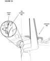
- FIGS. 31 A and 31 Bdepict additional side-views of container 100 and show the mechanism which retains the shoulder 102 to the paper shell 103 .
- FIG. 31 Bcontains an enlarged view of part of closure shoulder 102 after it is inserted into shell 103 .
- Closure shoulder 102comprises protrusion 108 formed by a cavity in closure shoulder 102 .
- Shell 103comprises locking tab 109 , which here is part of shell 103 folded downward. Locking tab 109 engages with protrusion 108 , which prevents closure shoulder 102 from being pulled out of shell 103 during normal usage by a consumer.
- FIGS. 32 A and 32 Bdepict additional side-views of container 100 without a shell.
- Cap 101can screw onto a drinking spout 112 of closure shoulder 102 .
- Drinking spout 112comprises screw threads on its outer vertical surface.
- Closure shoulder 102comprises cavity 113 , which includes locking ring 116 for receiving locking ring 117 on mechanical sealing ring 110 .
- Container 100further comprises liquid-holding bag 111 , which is capable of holding water or other liquid.
- the outer diameter of the top surface of the bottom lip 115 of mechanical sealing ring 110is larger than the opening 114 of liquid-holding bag 111 .
- the diameter of locking ring 117 of mechanical sealing ring 110also is larger than opening 114 of liquid-holding bag 111 , such that the opening 114 is stretched to receive mechanical sealing ring 110 .
- mechanical sealing ring 110is placed into liquid-holding bag 111 from the bottom of liquid-holding bag 111 (which initially is open on the bottom). Mechanical sealing ring 110 is then moved upward until opening 114 rests on top surface of the bottom lip 115 of mechanical sealing ring 110 . Mechanical sealing ring 110 is then pushed into closure shoulder 102 such that locking ring 117 is pushed over locking ring 116 , which locks mechanical sealing ring 110 into place within closure shoulder 102 , which secures liquid-holding bag 111 to closure shoulder 102 . The bottom of liquid-holding bag 111 is then sealed using heat, ultrasound (e.g., Ultrasonic welding), or other known means.
- ultrasounde.g., Ultrasonic welding
- FIGS. 33 A, 33 B, and 33 Cdepict additional side-views of container 100 through the assembly steps.
- liquid-holding bag 111has an open bottom.
- Mechanical sealing ring 110is placed through the bottom of liquid-holding bag 111 (as discussed above) and is secured to closure shoulder 102 .
- FIG. 33 Bmechanical sealing ring 110 extends through opening 114 of liquid-holding bag 111 (which has now been sealed on the bottom) and is secured to closure shoulder 102 .
- cap 101is screwed onto threads of drinking spout 112 . This can be performed by capper/decapper 606 , described below with reference to FIG. 6 and FIG. 22 .
- the terms “capper/decapper” and “capper”will be used interchangeably, as the same device can be used to remove a cap from a container or to add a cap to the container.
- FIG. 34depicts another side-view of container 100 , showing all the individual components that comprise the described bottle. Again, mechanical sealing ring 110 is secured to closure shoulder 102 , which secures liquid-holding bag 111 between mechanical sealing ring 110 and closure shoulder 102 in a watertight fashion.
- FIGS. 35 A and 35 Bdepict another side-view of components of container 100 .
- Locking tab 109 and protrusion 108are depicted.
- the liquid holding assemblyis on the left, which is inserted into the paper shell depicted on the right.
- Mechanical sealing ring 110 , closure shoulder 102 , and cap 101are all injection-molded, preferably using compostable polymers.
- Liquid-holding bag 111is blown film which is cut and then heat-sealed to the form a bag. The bottom of liquid-holding bag 111 is sealed after the mechanical sealing ring 110 is inserted into liquid-holding bag 111 .
- liquid-holding bag 111 and sealing ring 110is inserted into cavity 113 of closure shoulder 102 , where collectively those components form a liquid-tight seal and are permanently fixed because of a strong push-fit and engagement of locking rings 116 and 117 .
- the bottom of liquid-holding bag 111is then heat sealed, leaving only one opening in liquid-holding bag 111 (i.e., drinking spout 112 on closure shoulder 102 , through opening 114 ).
- Cap 101is then tightened onto drinking spout 112 resulting in a sealed container.
- the sealed containeris then inserted into shell 103 , securing the closure assembly to it without the use of adhesives. This can be performed by liquid dispensing device 600 , described below.
- FIG. 6depicts liquid dispensing device 600 .
- Liquid dispensing device 600comprises chassis 605 constructed from metal, plastic, or other firm material.
- Liquid dispensing devicefurther comprises gripper 601 , separator 602 , lift plate 603 , controller 604 , capper/decapper 606 , water filtration and chilling unit 608 , track 609 , bottom flap closer 610 , filler 611 , and other structures as shown.
- liquid dispensing device 600ultimately provides dispensed bottle 607 to a user.
- Lift plate 603is a plate controlled by a linear actuator or other motor that pushes stacked containers 100 (not shown) upward as containers 100 are removed from the top of the stack. Separator 602 enables lift plate 603 to push the top container 100 toward gripper 601 while preventing all containers 100 below top container 100 to remain at or below separator 602 .
- Gripper 601is an electrically-controlled robotic arm that can grab a container (not shown) and move the container in three directions (horizontally, laterally, and vertically) using track 609 and other tracks that are not shown.
- the movement of gripper 601 in these three directionsoptionally is controlled by a stepper motor.
- Bottom flap closer 610is a mechanical structure that is used to close the bottom flap of container 100 .
- Capper/decapper 606removes a cap (such as cap 101 , discussed below) from container 100 and secures the cap back onto container 100 .
- Controller 604comprises hardware and software components for controlling the operation of liquid dispensing device 600 .
- Controller 604can comprise a motherboard with integrated circuits and other structures, or it can be contained wholly within a single integrated circuit (such as a system-on-chip or SoC).
- a userrequests a filled container using an interface (not shown), such as a touch screen, mechanical buttons, a mobile app, voice recognition, or other known interfaces.
- the useroptionally can request that certain additives (such as flavors, caffeine, health supplements, etc.) be included in the liquid.
- Controller 604receives the request and controls the actions of various components of liquid dispensing device 600 .
- lift plate 603already will have pushed stacks of containers upward such that at most a single container protrudes from each aperture in separator 602 .
- Gripper 601grabs a single container from the top of separator 602 and moves the container using track 609 and other tracks to bottom flap closer 610 , where the bottom of the container is closed.
- Capper/decapper 606then removes the cap from the container.
- the containeris then filled with liquid by filler 611 (and any requested additives are also inserted into the container), and then capper/decapper 606 secures the cap back onto the container.
- Gripper 601then grabs the filled container and dispenses it to the user.
- liquid dispensing device 600Additional detail regarding the components of liquid dispensing device 600 will now be provided.
- FIGS. 7 A- 7 Cdepict additional detail regarding separator 602 and lift plate 603 .
- a plurality of container stack holders 703are placed on lift plate 603 and are shaped to receive the bottom of containers 100 .
- Lift plate 603is attached to vertical track 701 and is powered by linear actuator 702 .
- Linear actuator 702is controlled by controller 604 .
- FIG. 7 Bdepicts a plurality of stacks 704 , each stack 704 comprising a plurality of containers 100 in a stacked, nested formation.
- the bottom container 100 in each stack 704is placed on a container stack holder 703 .
- Lift plate 603ideally will push stacks 704 upward into separator 602 .
- FIG. 7 Cdepicts lift plate 603 at its maximum height, which will be achieved when no more than one container 100 is contained on each container stack holder 703 .
- FIGS. 8 - 10depict additional detail regarding separator 602 .
- FIG. 8depicts a top view of separator 602 .
- Separator 602comprises a plurality of apertures 801 , with each aperture 801 properly sized to receive a stack 704 of containers 100 , such that container 100 can fit through aperture 801 when pushed by lift plate 603 .
- FIG. 9a plurality of containers 100 at the top of a stack 704 is depicted, with the containers protruding through an aperture 801 .
- top container 901is the top-most container 100
- second-to-top container 902is immediately below top container 901 .
- Separator 602comprises a plurality of friction members 903 that are placed in the inner perimeter of each aperture 801 .
- Friction members 903are constructed with a material with a sufficient coefficient of friction to stop second-to-top container 902 from being pulled above separator 602 when gripper 601 grabs top container 901 . That is, when gripper 601 removes top container 901 from stack 704 , friction members 903 will prevent second-to-top container 902 from also being removed from separator 602 .
- friction members 903are constructed from rubber.
- FIG. 10depicts a close-up of a portion of separator 602 that includes sensor 1001 .
- Sensor 1001 in this embodimentis an infrared (IR) sensor that is placed in a position such that sensor 1001 will be covered by the bottom flap of top container 901 when top container 901 is protruding through an aperture 801 at the desired height.
- controller 604will receive an electrical signal indicating that sensor 1001 is covered, and controller 604 then will stop linear actuator 702 such that linear actuator 702 stops lifting lift plate 603 .
- IRinfrared
- FIGS. 11 - 18depict additional detail regarding gripper 601 .
- FIG. 11depicts a front view of gripper 601 .
- Gripper 601comprises joints 1101 and 1102 , arms 1103 and 1104 , joints 1105 and 1106 , helix spring 1107 , bearings 1108 , fingers 1109 , and lips 1110 , configured as shown.
- FIG. 12depicts a side view of gripper 601 . In this view, the side of arm 1104 is shown.
- FIG. 13depicts an “on” state of gripper 601 .
- Gripper 601comprises plunger 1301 , which is made of metal, and interacts with the coils 1302 of a solenoid.
- the solenoidis electrically controlled by controller 604 .
- controller 604turns the solenoid on, current will run through the solenoid, a magnetic field will be generated around solenoid, and plunger 1301 will be pulled upward as a result of the magnetic force. This movement causes fingers 1109 to jut outward as bearings 1108 pivot.
- FIG. 14depicts an “off” state of gripper 601 .
- controller 604turns the solenoid off, the magnetic field will cease being generated around the solenoid, and plunger 1301 will fall downward due to its own weight, with additional force being provided by spring helix 1107 . Fingers 1109 then will move inward as the top of the supporting structure eases downward.
- FIG. 15depicts an “on” state of gripper 601 , this time in proximity to container 100 . This is the configuration immediately before gripper 601 grabs a container 100 from above separator 602 . Here, fingers 1109 have moved outward and can receive cap 101 .
- FIG. 16depicts an “off” state of gripper 601 .
- Gripper 601has moved downward in the vertical direction, such that cap 101 is located between fingers 1109 .
- fingers 1109move inward, and lips 1110 are pushed inward under cap 101 .
- gripper 601is able to grab container 100 .
- One aspect of gripper 601 that is novelis that the force that is exerted downward by container 100 causes fingers 1109 to press inward with greater force and therefore to exert a more forceful grab of container 100 . That is, unlike in prior art devices, the grip exerted by gripper 601 increases as the weight of container 100 increases, due to the relative location of joints 1105 and 1106 .
- FIGS. 17 A, 17 B, and 17 Cdepict the sequence by which gripper 601 begins in the “on” state, surrounds cap 101 , and then proceeds to an “off” state whereby it grabs cap 101 and container 100 .
- sensor 1701can be used as a switch to activate gripper 601 once gripper 601 is in the proper vertical location vis a vis cap 101 .
- controller 604then can caused the solenoid to turn off, thereby causing gripper 601 to grab cap 101 .
- FIG. 18depicts a top view of gripper 601 .
- FIG. 19depicts various tracks along which gripper 601 can move. Specifically, gripper 601 moves in the horizontal direction along horizontal tracks 1901 and 1902 (either of which can be track 609 shown in FIG. 6 ), in the lateral direction along lateral track 1903 , and vertically along vertical track 1904 . This allows gripper 601 to be able to grab top container 901 from any stack 704 above any aperture 801 in separator 602 , to move the container to bottom flap closer 610 , and ultimately to dispense the container 100 .
- FIGS. 20 A, 20 B, and 20 Cdepict further views of horizontal tracks 1901 or 1902 and vertical track 1902 .
- controller 604can simply ensure that it grabs the top container 901 from each stack 704 , for example, by first starting in the top row, left column, and then working toward the right until the top container 901 has been removed from each aperture 801 in the top row. It then can grab the top container 901 from the next row, left column, and so forth. Once all top containers 901 have been removed, controller 604 will cause linear actuator 702 to move lift plate 603 upward until sensor 1001 is covered.
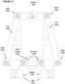
- FIGS. 21 A- 21 Cdepict additional detail regarding bottom flap closer 610 .
- gripper 601begins to place container 100 in bottom flap closer 610 .
- Walls 2101are sized to receive container 100 . It can be seen that bottom flap 105 is extended above movable ramp 2102 . Movable ramp 2102 is suspended on movable platform 2104 , which in turn is connected to spring 2103 .
- gripper 601pushes container 100 further downward in bottom flap closer 610 .
- Bottom flap 105engages with movable ramp 2102 .
- gripper 601pushes container 100 further downward such that bottom flap 105 is secured in the desired position. It can be seen that movable ramp 2102 is now in a fully horizontal position and that movable platform 2104 has moved toward the right, extending spring 2103 in the process. The tension in spring 2103 as this occurs causes movable ramp 2102 to exert force on bottom flap 105 , pushing it upward into the desired position.
- FIGS. 22 - 25depict additional information regarding capper/decapper 606 .
- Capper/decapper 606comprises fixtures 2201 and 2202 , springs 2203 and 2204 , sensors 2205 and 2208 , cap gripping mechanism 2206 , and spindle motor 2207 .
- Fixtures 2201 and 2202are sized to be able to receive container 100 and cap 101 .
- Springs 2203 and 2204exert downward pressure on container 100 to assist in removing container 100 from capper/decapper 606 after the capping or decapping action is complete.
- Fixtures 2201 and 2202provide some resistance to container 100 when cap 101 is screwed off and screwed on, which prevents container 100 from spinning along with cap 101 when rotational force is applied to cap 101 .
- FIG. 23shows another front view of capper/decapper 606 .
- Cap gripping mechanism 2206 , springs 2203 and 2204 , sensors 2205 and 2208 , and spring 2401are depicted.
- FIGS. 24 A, 24 B, and 24 Cprovide additional detail regarding locking mechanism 2206 .
- locking mechanism 2206comprises spring 2401 , hinge 2402 , and sensor gaps 2403 .
- FIG. 24 Adepicts locking mechanism 2206 when no cap 101 is contained within it.
- FIG. 24 Bdepicts locking mechanism 2206 when cap 101 is contained within it (although cap 101 is not shown).
- first piece 2404 and second piece 2405rotate outward along hinge 2402 , and spring 2401 expands. Spring 2401 then exerts force pulling first piece 2404 and second piece 2404 inward to securely grab cap 101 .
- FIG. 24 Cdepicts a side-view of locking mechanism 2206 .
- First piece 2404 and second piece 2405are tapered to receive cap 101 .
- FIGS. 25 A, 25 B, and 25 Cdepict sensors 2205 and 2208 relative to sensor gaps 2403 .
- Sensors 2205 and 2208therefore can be used to detect whether a cap 101 is present in locking mechanism 2206 or not because cap 101 will block sensors 2205 and 2208 if present.
- the following logicis applied to determine whether cap 101 is present or not: (1) If sensors 2205 and 2208 are both not blocked, then no cap 101 is present; (2) If either sensor 2205 or sensor 2208 is blocked, then no cap 101 is present; and (3) If both sensors 2205 and 2208 are blocked, then cap 101 is present.
- Controller 604therefore can use the output of sensors 2205 and 2208 to determine if a cap 101 is contained within locking mechanism 2206 or not.
- FIGS. 26 - 27depict additional detail regarding controller 604 .
- FIG. 26depicts hardware components of controller 604 .
- Controller 604comprises processor 2601 , memory 2602 , non-volatile storage 2603 , microphone 2604 , speaker 2605 , display 2606 , input device 2607 , and network interface 2608 .
- Non-volatile storage 2603optionally is a hard disk drive or flash memory array.
- Display 2606optionally is a touchscreen display capable of receiving commands from a user.
- Network interface 2608can be a wired (e.g., Ethernet) or wireless (e.g., WiFi, Bluetooth, 3G, 4G, GSM, etc.)
- One or more of microphone 2604 , speaker 2605 , display 2606 , input device 2607 , and network interface 2608can be used to interact with a user and can, for example, receive a command from a user for one or more filled containers and can facilitate payment for the one or more filled containers, as in the embodiment of kiosk 1 .
- FIG. 27depicts software components of controller 604 .
- Controller 604comprises operating system 2701 (such as the operating systems known by the trademarks “Android” or “iOS”) and application 2702 .
- Application 2702comprises lines of code to perform the control functions disclosed herein (e.g., stopping linear actuator 702 when sensor 1001 detects an object).
- Application 2702optionally can operate a state machine for controlling the functions of liquid dispensing device 600 .
Landscapes
- Engineering & Computer Science (AREA)
- Mechanical Engineering (AREA)
- Physics & Mathematics (AREA)
- General Physics & Mathematics (AREA)
- Filling Of Jars Or Cans And Processes For Cleaning And Sealing Jars (AREA)
- Chemical & Material Sciences (AREA)
- Water Supply & Treatment (AREA)
- Nanotechnology (AREA)
- Chemical Kinetics & Catalysis (AREA)
- Devices For Dispensing Beverages (AREA)
- Closures For Containers (AREA)
- Packages (AREA)
Abstract
Description
Claims (6)
Priority Applications (2)
| Application Number | Priority Date | Filing Date | Title |
|---|---|---|---|
| US16/731,903US11741775B2 (en) | 2013-04-01 | 2019-12-31 | Automated electromechanical capper for removing or securing a cap on a container |
| US18/228,887US20230377406A1 (en) | 2013-04-01 | 2023-08-01 | Automated kiosk to dispense a filled container |
Applications Claiming Priority (4)
| Application Number | Priority Date | Filing Date | Title |
|---|---|---|---|
| US201361807191P | 2013-04-01 | 2013-04-01 | |
| US14/242,295US20140290181A1 (en) | 2013-04-01 | 2014-04-01 | System and Method for Eco-Friendly Beverage Dispensing Kiosk |
| US15/812,431US10540840B2 (en) | 2013-04-01 | 2017-11-14 | Automated liquid dispensing device and associated method |
| US16/731,903US11741775B2 (en) | 2013-04-01 | 2019-12-31 | Automated electromechanical capper for removing or securing a cap on a container |
Related Parent Applications (1)
| Application Number | Title | Priority Date | Filing Date |
|---|---|---|---|
| US15/812,431ContinuationUS10540840B2 (en) | 2013-04-01 | 2017-11-14 | Automated liquid dispensing device and associated method |
Related Child Applications (1)
| Application Number | Title | Priority Date | Filing Date |
|---|---|---|---|
| US18/228,887ContinuationUS20230377406A1 (en) | 2013-04-01 | 2023-08-01 | Automated kiosk to dispense a filled container |
Publications (2)
| Publication Number | Publication Date |
|---|---|
| US20200134961A1 US20200134961A1 (en) | 2020-04-30 |
| US11741775B2true US11741775B2 (en) | 2023-08-29 |
Family
ID=51619448
Family Applications (4)
| Application Number | Title | Priority Date | Filing Date |
|---|---|---|---|
| US14/242,295AbandonedUS20140290181A1 (en) | 2013-04-01 | 2014-04-01 | System and Method for Eco-Friendly Beverage Dispensing Kiosk |
| US15/812,431Active2034-07-31US10540840B2 (en) | 2013-04-01 | 2017-11-14 | Automated liquid dispensing device and associated method |
| US16/731,903ActiveUS11741775B2 (en) | 2013-04-01 | 2019-12-31 | Automated electromechanical capper for removing or securing a cap on a container |
| US18/228,887PendingUS20230377406A1 (en) | 2013-04-01 | 2023-08-01 | Automated kiosk to dispense a filled container |
Family Applications Before (2)
| Application Number | Title | Priority Date | Filing Date |
|---|---|---|---|
| US14/242,295AbandonedUS20140290181A1 (en) | 2013-04-01 | 2014-04-01 | System and Method for Eco-Friendly Beverage Dispensing Kiosk |
| US15/812,431Active2034-07-31US10540840B2 (en) | 2013-04-01 | 2017-11-14 | Automated liquid dispensing device and associated method |
Family Applications After (1)
| Application Number | Title | Priority Date | Filing Date |
|---|---|---|---|
| US18/228,887PendingUS20230377406A1 (en) | 2013-04-01 | 2023-08-01 | Automated kiosk to dispense a filled container |
Country Status (1)
| Country | Link |
|---|---|
| US (4) | US20140290181A1 (en) |
Families Citing this family (33)
| Publication number | Priority date | Publication date | Assignee | Title |
|---|---|---|---|---|
| CA2977461C (en) | 2009-02-11 | 2020-04-28 | Pepsico, Inc. | Beverage dispense valve controlled by wireless technology |
| JP6175092B2 (en)* | 2015-03-09 | 2017-08-02 | 株式会社日本トリム | Electrolyzed water generation device and management system thereof |
| CN104793550A (en)* | 2015-04-29 | 2015-07-22 | 武汉雨点科技有限公司 | Operation system and operation method of intelligent water dispenser |
| CN205575600U (en)* | 2015-09-21 | 2016-09-14 | 上海巨昂实业有限公司 | Juice extractor automatic packing device including automatic door plant |
| EP3153304B1 (en)* | 2015-10-05 | 2019-12-11 | Tetra Laval Holdings & Finance S.A. | A welding head |
| US10829280B2 (en)* | 2015-12-03 | 2020-11-10 | Drop Water Corporation | Compostable single-use beverage container and associated mechanism for sealing the container |
| US20170170979A1 (en) | 2015-12-15 | 2017-06-15 | Pentair Flow Technologies, Llc | Systems and Methods for Wireless Control and Monitoring of Residential Devices |
| CN105527905A (en)* | 2016-01-26 | 2016-04-27 | 河南理工大学 | Water dispenser information interaction system based on cloud service |
| CN106251490B (en)* | 2016-07-19 | 2019-05-24 | 卜鹏飞 | Fruit juice self-service sale device |
| US10759554B2 (en)* | 2017-02-02 | 2020-09-01 | Rai Strategic Holdings, Inc. | Dispenser unit for aerosol precursor |
| US11625970B2 (en)* | 2017-11-27 | 2023-04-11 | Maximilian M. Anziano | Interactive frozen confectionery vending machine |
| US20230267793A1 (en)* | 2017-11-27 | 2023-08-24 | Maximilian M. Anziano | Ice Cream Vending Machine |
| US11472579B2 (en) | 2018-12-04 | 2022-10-18 | Gpcp Ip Holdings Llc | Film securing apparatus and method |
| EP3501345B1 (en)* | 2017-12-22 | 2021-04-14 | Société des Produits Nestlé S.A. | Exchangeable cartridge for beverage portion dispenser |
| US11208315B2 (en) | 2018-04-02 | 2021-12-28 | Pepsico, Inc. | Unattended beverage dispensing systems and methods |
| GB201809909D0 (en)* | 2018-06-17 | 2018-08-01 | Wet Holdings Global Ltd | Preparation and formulation of drinks |
| CN108961566B (en)* | 2018-07-19 | 2021-03-26 | 惠州市睿元实业有限公司 | Intelligent liquid selling terminal and system |
| CN112912335B (en)* | 2018-08-24 | 2023-09-12 | 贝德福德系统有限责任公司 | Alcoholic concentrate filling system and method of use |
| US11952192B2 (en)* | 2018-09-26 | 2024-04-09 | Robert C. Kelly | Standing pouch with cap on folded edge |
| US12077337B2 (en) | 2018-12-04 | 2024-09-03 | Yum Connect, LLC | Systems and methods for sealing a container |
| IL265049B (en)* | 2019-02-25 | 2020-04-30 | Harduff Hagai | Collapsible bottle and filling station |
| USD956477S1 (en) | 2019-02-25 | 2022-07-05 | Strauss Group Ltd. | Collapsible bottle |
| WO2021173705A1 (en)* | 2020-02-25 | 2021-09-02 | Tkachenko Yury | Magnetic treatment of drinking water by hydromagnetic resonators with permanent magnets contained therein |
| US11961373B2 (en) | 2020-07-01 | 2024-04-16 | Pepsico, Inc. | Method and system of touch-free vending |
| CA3209605A1 (en) | 2021-02-24 | 2022-09-01 | Yum Connect, LLC | Automated beverage dispenser system and method |
| US20230050420A1 (en)* | 2021-08-15 | 2023-02-16 | Maslow Capital Management LLC | Modular Liquid Vending System |
| US20240261901A1 (en)* | 2023-02-03 | 2024-08-08 | Appliance Innovation, Inc. | Apparatus and method for automated preparation and delivery of beverages |
| US12338022B2 (en) | 2023-02-10 | 2025-06-24 | Yum Connect, LLC | Automated beverage dispenser system and method |
| KR20240126903A (en)* | 2023-02-14 | 2024-08-22 | 삼성디스플레이 주식회사 | Display device |
| US12415716B2 (en) | 2023-04-25 | 2025-09-16 | Yum Connect, LLC | Automated beverage dispenser system and method |
| US20250129624A1 (en)* | 2023-10-23 | 2025-04-24 | Tiffany Ann Logan | Vending machine shipping container with integrated advertising screens powered by solar panels |
| HUP2300404A1 (en)* | 2023-11-24 | 2025-06-28 | Ressol 2020 Kft | Automatic bottle filler for refilling bottles with liquid detergent |
| USD1021075S1 (en) | 2023-12-19 | 2024-04-02 | Foshan Pingchuang Medical Technology Co., Ltd. | Medical ultrasound gel automated dispenser |
Citations (42)
| Publication number | Priority date | Publication date | Assignee | Title |
|---|---|---|---|---|
| US873245A (en)* | 1906-10-01 | 1907-12-10 | Georg Kirkegaard | Head for bottle-capping machines. |
| US931624A (en)* | 1909-08-17 | Imp Stopper Company | Bottle filling and capping head. | |
| US1208529A (en)* | 1915-01-27 | 1916-12-12 | Automatic Weighing Machine Company | Machine for securing metallic screw-caps to bottles, jars, and the like. |
| US1773259A (en)* | 1925-01-29 | 1930-08-19 | Capem Machinery Corp | Bottle-capping machine |
| US2593794A (en)* | 1947-07-22 | 1952-04-22 | Resina Automatic Machinery Co | Rotatable cap applying chuck with cap gripping helical spring |
| US2726028A (en)* | 1953-08-05 | 1955-12-06 | Robert W Saumsiegle | Cap screwing and tightening machine |
| US2760391A (en)* | 1953-05-28 | 1956-08-28 | Max Factor & Co | Bottle capping device |
| GB946153A (en)* | 1961-07-27 | 1964-01-08 | Wilfred Layland | Appliances for removing closure members from bottles and similar containers |
| US3795158A (en)* | 1972-12-07 | 1974-03-05 | R Morita | Jar lid remover |
| US3805488A (en)* | 1973-01-03 | 1974-04-23 | Cherry Burrell Corp | Capper chuck device |
| US3913301A (en)* | 1973-01-18 | 1975-10-21 | Hohenzollern Huettenverwalt | Apparatus for threading closures onto bottles and similar containers |
| US3914920A (en)* | 1974-05-06 | 1975-10-28 | Carling O Keefe Ltd | Decapping device for the decapping of bottles |
| US4171650A (en)* | 1977-12-09 | 1979-10-23 | John Cardinal | Jar lid loosening device |
| US4178732A (en)* | 1978-04-21 | 1979-12-18 | Pfleger Frederick W | Apparatus for closing and opening the threaded necks of containers |
| US4232499A (en)* | 1978-08-01 | 1980-11-11 | John H. Holstein | Capper chuck |
| US4246738A (en)* | 1979-06-18 | 1981-01-27 | Shibuya Kogyo Company, Ltd. | Air chuck for capping or uncapping machine |
| US4295320A (en)* | 1980-01-09 | 1981-10-20 | Owens-Illinois, Inc. | Closure conversion apparatus for existing closure applicating machines |
| US4299072A (en)* | 1979-01-17 | 1981-11-10 | John H. Holstein | Turret drive system |
| US4364218A (en)* | 1979-04-25 | 1982-12-21 | Albert Obrist Ag | Closure apparatus incorporating a magnetic clutch for screwing-on a plastic screw closure |
| US4599846A (en)* | 1984-04-19 | 1986-07-15 | Aluminum Company Of America | Capping head |
| DE3538971A1 (en)* | 1985-11-02 | 1987-05-14 | Festo Kg | Apparatus for attaching and/or removing a rotary sealing cap onto and from a container |
| US4674340A (en)* | 1986-01-21 | 1987-06-23 | Adolph Coors Company | System for determining the torque required to loosen a threaded cap |
| US4926717A (en)* | 1989-09-05 | 1990-05-22 | Manostat Corporation | Bottle uncapping and recapping machine |
| US5148652A (en)* | 1991-02-14 | 1992-09-22 | Herzog Kenneth J | Hand capper |
| US5197258A (en)* | 1991-10-24 | 1993-03-30 | Federal Manufacturing Co. | Screwcapping device with torque limiting magnetic clutch |
| US5437139A (en)* | 1991-11-04 | 1995-08-01 | Anderson-Martin Machine Co. | Capping machine head with cap aligning chuck |
| DE4442036A1 (en)* | 1994-11-25 | 1996-05-30 | Groninger & Co Gmbh | Screw top fastener-opener with one or more spindles |
| US6230472B1 (en)* | 1998-02-17 | 2001-05-15 | Reudiger Haaga Gmbh | Process and apparatus for sterilizing, filling and sealing containers |
| JP3103926U (en)* | 2004-01-21 | 2004-08-26 | 山田電器工業株式会社 | Automatic lid opening device |
| US20040226261A1 (en)* | 2002-12-13 | 2004-11-18 | Serac Group | Screw cap tightener apparatus |
| US6874389B1 (en)* | 2003-07-16 | 2005-04-05 | Automated pill bottle opener | |
| US20050132845A1 (en)* | 2003-12-16 | 2005-06-23 | Chervak Steven G. | Apparatus for fastening a lid to a container |
| EP1669321A1 (en)* | 2004-12-10 | 2006-06-14 | Khs Ag | Apparatus for applying closures to bottles or similar containers |
| US20060162286A1 (en)* | 2002-07-19 | 2006-07-27 | Alcoa Deutschland Gmbh | Closing cone |
| US20070098597A1 (en)* | 2003-07-04 | 2007-05-03 | Wolfgang Brunner | Device for the automatic opening and closing of reaction vessels |
| US20100263492A1 (en)* | 2009-04-17 | 2010-10-21 | Mah Pat Y | Bottle opening and closing device |
| US7845149B2 (en)* | 2006-07-26 | 2010-12-07 | The Automation Partnership (Cambridge) Limited | Tube capper/decapper |
| US20110225928A1 (en)* | 2009-01-15 | 2011-09-22 | Khs Gmbh | Closure head for container closure machines and container closure machine |
| US8161714B2 (en)* | 2008-10-14 | 2012-04-24 | Michael Scott Data | Capping chuck |
| DE102011008975A1 (en)* | 2011-01-20 | 2012-07-26 | Bernd Faust | Opener for opening screw-type cap of container, has screw-type cap grippers that are arranged in opposition to central drive shaft, such that drive shaft and grippers are arranged above and below drive gear, respectively |
| US20120318405A1 (en)* | 2010-03-01 | 2012-12-20 | Index-6, Ltd. | Container-filling and weight-related dosing device |
| US10093528B2 (en)* | 2013-04-18 | 2018-10-09 | Michael P. Scott | Bottle capping chucks |
Family Cites Families (66)
| Publication number | Priority date | Publication date | Assignee | Title |
|---|---|---|---|---|
| US1249025A (en)* | 1915-11-27 | 1917-12-04 | Leslie R N Carvalho | Bottle-capping machine. |
| US2454919A (en)* | 1943-01-19 | 1948-11-30 | Lord Baltimore Press | Multiply container with dispensing outlet secured thereto |
| US3082927A (en)* | 1960-07-26 | 1963-03-26 | Hedwin Corp | Lined container |
| AT298279B (en)* | 1967-12-27 | 1972-04-25 | Max Schmidt | System for the automatic production, filling and sealing of hollow bodies, such as bottles or the like. |
| US3533211A (en)* | 1968-05-31 | 1970-10-13 | Leonard Einnehmer | Vending machine for supplying and dispensing sealed containers of potables |
| US3640430A (en)* | 1969-07-22 | 1972-02-08 | Roberts Dairy Co | Bulk dispensing system |
| US3655088A (en)* | 1970-06-01 | 1972-04-11 | Theodor Box | High-impact plastic carrying and stacking case with hinged cover |
| US3841528A (en)* | 1971-09-29 | 1974-10-15 | H Eisenberg | Container for liquids having hinged lid allowing easy stacking |
| FR2161173A5 (en)* | 1971-11-16 | 1973-07-06 | Ono | |
| CH537834A (en)* | 1972-06-15 | 1973-06-15 | Pallana Gmbh | Process for producing and filling bottles from thermoplastically deformable materials |
| CH542746A (en)* | 1972-06-16 | 1973-10-15 | Pallana Gmbh | Mass producing plastics bottles - by welding together upper and lower parts |
| US3852941A (en)* | 1973-08-20 | 1974-12-10 | Pennwalt Corp | Vial capping apparatus |
| US3955341A (en)* | 1975-10-14 | 1976-05-11 | Horix Manufacturing Company | Apparatus for screwing caps on containers |
| US4165023A (en)* | 1977-07-21 | 1979-08-21 | Schmit Justin M | Fluid containing and dispensing structure having a deformable flexible wall portion |
| US4510737A (en)* | 1981-11-13 | 1985-04-16 | B-Bar-B, Inc. | Machine and method for filling flexible containers |
| US4524883A (en)* | 1983-06-27 | 1985-06-25 | Brockway, Inc. | Stackable container |
| FR2568119B1 (en)* | 1984-07-27 | 1987-06-26 | Faas | DISPENSING HOT OR COLD BEVERAGES PREPARED WITH A WATER-SOLUBLE EXTRACT |
| US4801375A (en)* | 1987-02-17 | 1989-01-31 | Cuno Incorporated | Water vending system |
| US4850509A (en)* | 1987-03-13 | 1989-07-25 | Hollenberg Dennis D | Quickly erectable containers |
| US4815256A (en)* | 1987-07-02 | 1989-03-28 | Bhmw Partnership | Capped container dispenser |
| US4911212A (en)* | 1987-07-06 | 1990-03-27 | Burton John W | Bottle filling device |
| DE3808761A1 (en)* | 1988-03-16 | 1989-09-28 | Wolfgang Pfeil | Process and apparatus for the filling and closing of containers |
| US5265753A (en)* | 1992-10-30 | 1993-11-30 | Georgia-Pacific Corporation | Container for flexible bag |
| US5375741A (en)* | 1993-05-12 | 1994-12-27 | Encon, Inc. | Container for bulk material and its method of manufacture |
| US5715992A (en)* | 1995-09-26 | 1998-02-10 | J & M Coffee Container Company, Inc. | Beverage container |
| FI990660A7 (en)* | 1999-03-25 | 2000-09-26 | Mecsel Oy | Device and method for purchasing a product from a vending machine |
| US6397126B1 (en)* | 1999-05-11 | 2002-05-28 | Kim Marie Nelson | Interfaced dispensing machines and remote automated payment and inventory management system |
| IL131067A (en)* | 1999-07-23 | 2002-07-25 | Menachem Vine | Hinged cover for a disposable cup dispenser |
| US6584309B1 (en)* | 1999-12-16 | 2003-06-24 | The Coca-Cola Company | Vending machine purchase via cellular telephone |
| US6453799B1 (en)* | 2000-11-14 | 2002-09-24 | Ecoaid Corp. | Automatic vending machine with functional water generator |
| US6571981B2 (en)* | 2001-04-21 | 2003-06-03 | Joey L Rohlfs | Disposable sipper cups |
| KR20030089626A (en)* | 2002-05-16 | 2003-11-22 | 여태순 | Managing system for vending machine |
| ES2204293A1 (en)* | 2002-06-27 | 2004-04-16 | Jofemar, S.A. | Control system for automatic vending machines |
| US20040026452A1 (en)* | 2002-08-07 | 2004-02-12 | Gema Santiago | Cold powder beverage dispenser |
| US20040031535A1 (en)* | 2002-08-14 | 2004-02-19 | Russell Scott T. | Stackable product packaging |
| US7007825B2 (en)* | 2002-11-13 | 2006-03-07 | Smurfit-Stone Container Enterprises, Inc. | Bag-in-box beverage container |
| US20050006268A1 (en)* | 2003-07-10 | 2005-01-13 | Futernick Karen Rachel Beber | Stackable cooler |
| EP1716054A2 (en)* | 2004-02-17 | 2006-11-02 | John H. Stephenson | Automated bag in box assembly contents fill |
| EP1748950A1 (en)* | 2004-04-08 | 2007-02-07 | Waterwerkz Limited | Water dispenser |
| FR2882027A1 (en)* | 2005-02-11 | 2006-08-18 | Smurfit Bag In Box Sa | Product e.g. liquid product, packaging method for e.g. plug/tap unit, involves producing continuous strip of flexible bags in rows by lower and upper films of synthetic material, by successive stamping and welding operations |
| SE529720C2 (en)* | 2006-03-10 | 2007-11-06 | Tetra Laval Holdings & Finance | Method of manufacturing a package |
| US20080052094A1 (en)* | 2006-08-24 | 2008-02-28 | Img Management Group Inc. | Water dispensing systems and methods |
| DE602008005714D1 (en)* | 2007-01-09 | 2011-05-05 | Imi Vision Ltd | BEVERAGE DISPENSER |
| ATE528233T1 (en)* | 2007-08-28 | 2011-10-15 | Entegris Inc | METHOD AND DEVICE FOR DISPENSING FLUID |
| US20090057321A1 (en)* | 2007-08-28 | 2009-03-05 | Nestle S.A. | Collapsible bottles and methods of using same |
| MX2010008550A (en)* | 2008-02-04 | 2010-09-24 | Coca Cola Co | Methods of creating customized beverage products. |
| WO2009100427A2 (en)* | 2008-02-07 | 2009-08-13 | Akriya Products | Method and apparatus for beverage packaging and vending |
| US7980046B2 (en)* | 2008-02-20 | 2011-07-19 | H2Local, Inc. | Apparatus for cleaning, filling, and capping a container |
| BRPI0801098B1 (en)* | 2008-03-28 | 2021-08-03 | Ana Lucia Schmidt Lourenço Rodrigues | SUBSTANCE PROCESSING EQUIPMENT FOR THE PREPARATION OF COSMETIC AND RELATED PRODUCTS, AND, PROCESS FOR THE PREPARATION OF COSMETIC AND RELATED PRODUCTS |
| US8806843B2 (en)* | 2008-08-26 | 2014-08-19 | S-Pouch Pak Co., Ltd. | Self-standing bag with foldable flange |
| EP2165968A1 (en)* | 2008-09-19 | 2010-03-24 | InBev S.A. | Bag-in-container with prepressurized space between inner bag and outer container |
| US9452863B2 (en)* | 2008-10-01 | 2016-09-27 | Greater Good, Inc. | Biodegradable container for liquid and/or semi-solid products |
| US20100084048A1 (en)* | 2008-10-07 | 2010-04-08 | Chen zhi-rong | Water vending machine with container supply device |
| US8126589B1 (en)* | 2008-10-22 | 2012-02-28 | Ecowell, Inc. | Method and apparatus for a beverage and container vending machine |
| GB2475566B (en)* | 2009-11-24 | 2013-09-04 | Aquatina Ltd | Container and vending machine |
| US8442674B2 (en)* | 2010-02-05 | 2013-05-14 | Ecowell | Container-less custom beverage vending invention |
| DE102010011208A1 (en)* | 2010-03-09 | 2011-09-15 | Vita Pak Ug | packaging system |
| US8864437B1 (en)* | 2010-09-01 | 2014-10-21 | Maxco Supply, Inc. | Stacking apparatuses and/or equipment for objects having foldably-attached parts or flaps and related methods |
| DE102010055745A1 (en)* | 2010-12-22 | 2012-06-28 | Linde Aktiengesellschaft | dispenser |
| US20140353364A1 (en)* | 2011-04-26 | 2014-12-04 | George Coogan | Bag in Box Container |
| US20130193020A1 (en)* | 2011-12-09 | 2013-08-01 | Ecologic | Re-Usable Carafe System with Re-Closable Pouches |
| US20130282164A1 (en)* | 2012-04-20 | 2013-10-24 | Balagru K. Veloo | Automated restaurant beverage device and method |
| US9161887B2 (en)* | 2012-10-11 | 2015-10-20 | John M. McBean | Infant feeding system |
| GB2513418A (en)* | 2013-04-26 | 2014-10-29 | Singer Instr Company Ltd | A method and apparatus for filling a plurality of media plates in a self-supporting stack |
| WO2015053837A2 (en)* | 2013-10-11 | 2015-04-16 | Hydration Labs, Inc. | Beverage dispensing machine and method for dispensing beverages |
| US10035614B2 (en)* | 2015-09-21 | 2018-07-31 | Scholle Ipn Corporation | Method for aseptic filling of pouches |
- 2014
- 2014-04-01USUS14/242,295patent/US20140290181A1/ennot_activeAbandoned
- 2017
- 2017-11-14USUS15/812,431patent/US10540840B2/enactiveActive
- 2019
- 2019-12-31USUS16/731,903patent/US11741775B2/enactiveActive
- 2023
- 2023-08-01USUS18/228,887patent/US20230377406A1/enactivePending
Patent Citations (42)
| Publication number | Priority date | Publication date | Assignee | Title |
|---|---|---|---|---|
| US931624A (en)* | 1909-08-17 | Imp Stopper Company | Bottle filling and capping head. | |
| US873245A (en)* | 1906-10-01 | 1907-12-10 | Georg Kirkegaard | Head for bottle-capping machines. |
| US1208529A (en)* | 1915-01-27 | 1916-12-12 | Automatic Weighing Machine Company | Machine for securing metallic screw-caps to bottles, jars, and the like. |
| US1773259A (en)* | 1925-01-29 | 1930-08-19 | Capem Machinery Corp | Bottle-capping machine |
| US2593794A (en)* | 1947-07-22 | 1952-04-22 | Resina Automatic Machinery Co | Rotatable cap applying chuck with cap gripping helical spring |
| US2760391A (en)* | 1953-05-28 | 1956-08-28 | Max Factor & Co | Bottle capping device |
| US2726028A (en)* | 1953-08-05 | 1955-12-06 | Robert W Saumsiegle | Cap screwing and tightening machine |
| GB946153A (en)* | 1961-07-27 | 1964-01-08 | Wilfred Layland | Appliances for removing closure members from bottles and similar containers |
| US3795158A (en)* | 1972-12-07 | 1974-03-05 | R Morita | Jar lid remover |
| US3805488A (en)* | 1973-01-03 | 1974-04-23 | Cherry Burrell Corp | Capper chuck device |
| US3913301A (en)* | 1973-01-18 | 1975-10-21 | Hohenzollern Huettenverwalt | Apparatus for threading closures onto bottles and similar containers |
| US3914920A (en)* | 1974-05-06 | 1975-10-28 | Carling O Keefe Ltd | Decapping device for the decapping of bottles |
| US4171650A (en)* | 1977-12-09 | 1979-10-23 | John Cardinal | Jar lid loosening device |
| US4178732A (en)* | 1978-04-21 | 1979-12-18 | Pfleger Frederick W | Apparatus for closing and opening the threaded necks of containers |
| US4232499A (en)* | 1978-08-01 | 1980-11-11 | John H. Holstein | Capper chuck |
| US4299072A (en)* | 1979-01-17 | 1981-11-10 | John H. Holstein | Turret drive system |
| US4364218A (en)* | 1979-04-25 | 1982-12-21 | Albert Obrist Ag | Closure apparatus incorporating a magnetic clutch for screwing-on a plastic screw closure |
| US4246738A (en)* | 1979-06-18 | 1981-01-27 | Shibuya Kogyo Company, Ltd. | Air chuck for capping or uncapping machine |
| US4295320A (en)* | 1980-01-09 | 1981-10-20 | Owens-Illinois, Inc. | Closure conversion apparatus for existing closure applicating machines |
| US4599846A (en)* | 1984-04-19 | 1986-07-15 | Aluminum Company Of America | Capping head |
| DE3538971A1 (en)* | 1985-11-02 | 1987-05-14 | Festo Kg | Apparatus for attaching and/or removing a rotary sealing cap onto and from a container |
| US4674340A (en)* | 1986-01-21 | 1987-06-23 | Adolph Coors Company | System for determining the torque required to loosen a threaded cap |
| US4926717A (en)* | 1989-09-05 | 1990-05-22 | Manostat Corporation | Bottle uncapping and recapping machine |
| US5148652A (en)* | 1991-02-14 | 1992-09-22 | Herzog Kenneth J | Hand capper |
| US5197258A (en)* | 1991-10-24 | 1993-03-30 | Federal Manufacturing Co. | Screwcapping device with torque limiting magnetic clutch |
| US5437139A (en)* | 1991-11-04 | 1995-08-01 | Anderson-Martin Machine Co. | Capping machine head with cap aligning chuck |
| DE4442036A1 (en)* | 1994-11-25 | 1996-05-30 | Groninger & Co Gmbh | Screw top fastener-opener with one or more spindles |
| US6230472B1 (en)* | 1998-02-17 | 2001-05-15 | Reudiger Haaga Gmbh | Process and apparatus for sterilizing, filling and sealing containers |
| US20060162286A1 (en)* | 2002-07-19 | 2006-07-27 | Alcoa Deutschland Gmbh | Closing cone |
| US20040226261A1 (en)* | 2002-12-13 | 2004-11-18 | Serac Group | Screw cap tightener apparatus |
| US20070098597A1 (en)* | 2003-07-04 | 2007-05-03 | Wolfgang Brunner | Device for the automatic opening and closing of reaction vessels |
| US6874389B1 (en)* | 2003-07-16 | 2005-04-05 | Automated pill bottle opener | |
| US20050132845A1 (en)* | 2003-12-16 | 2005-06-23 | Chervak Steven G. | Apparatus for fastening a lid to a container |
| JP3103926U (en)* | 2004-01-21 | 2004-08-26 | 山田電器工業株式会社 | Automatic lid opening device |
| EP1669321A1 (en)* | 2004-12-10 | 2006-06-14 | Khs Ag | Apparatus for applying closures to bottles or similar containers |
| US7845149B2 (en)* | 2006-07-26 | 2010-12-07 | The Automation Partnership (Cambridge) Limited | Tube capper/decapper |
| US8161714B2 (en)* | 2008-10-14 | 2012-04-24 | Michael Scott Data | Capping chuck |
| US20110225928A1 (en)* | 2009-01-15 | 2011-09-22 | Khs Gmbh | Closure head for container closure machines and container closure machine |
| US20100263492A1 (en)* | 2009-04-17 | 2010-10-21 | Mah Pat Y | Bottle opening and closing device |
| US20120318405A1 (en)* | 2010-03-01 | 2012-12-20 | Index-6, Ltd. | Container-filling and weight-related dosing device |
| DE102011008975A1 (en)* | 2011-01-20 | 2012-07-26 | Bernd Faust | Opener for opening screw-type cap of container, has screw-type cap grippers that are arranged in opposition to central drive shaft, such that drive shaft and grippers are arranged above and below drive gear, respectively |
| US10093528B2 (en)* | 2013-04-18 | 2018-10-09 | Michael P. Scott | Bottle capping chucks |
Also Published As
| Publication number | Publication date |
|---|---|
| US20230377406A1 (en) | 2023-11-23 |
| US20200134961A1 (en) | 2020-04-30 |
| US20180068515A1 (en) | 2018-03-08 |
| US20140290181A1 (en) | 2014-10-02 |
| US10540840B2 (en) | 2020-01-21 |
Similar Documents
| Publication | Publication Date | Title |
|---|---|---|
| US11741775B2 (en) | Automated electromechanical capper for removing or securing a cap on a container | |
| US10421658B2 (en) | Container with electronically controlled interlock | |
| US8783512B2 (en) | Dosing spout and system | |
| CN102099261B (en) | A packaged bottle beverage having an ingredient release closure with improved additive release and method and apparatus thereof | |
| US20120103926A1 (en) | Sports Bottle and Fluid Dispensing system, device, and method. | |
| CN106458375A (en) | Container for preserving liquid contents | |
| GB2475566A (en) | Collapsible container with identification device for use with vending machine | |
| JP2008547125A (en) | Beverage dispensing system | |
| CA3139779C (en) | Systems, methods and devices for distributing various products | |
| CN115477269B (en) | Local facilities for handling containers | |
| WO2015053837A2 (en) | Beverage dispensing machine and method for dispensing beverages | |
| RU180571U1 (en) | Vending machine water dispenser | |
| US20240391666A1 (en) | Nested stack of capped beverage containers | |
| KR102528115B1 (en) | Automatic extraction device for alcoholic beverages | |
| KR20240066628A (en) | Mobile automatic extraction device for alcoholic beverages | |
| CN103140432A (en) | Vending machine, particularly for cold drinks | |
| AU2023252712A1 (en) | Beverage dispensing system | |
| WO2006079771A1 (en) | Gravity fuelled fluid dispenser | |
| RU91323U1 (en) | BOTTLE | |
| KR20240066629A (en) | Fixed automatic extraction device for alcoholic beverages | |
| KR20090061545A (en) | Vending Machine for Dissimilar Material Receiving Device | |
| WO2024030073A1 (en) | Beverage dispensing system | |
| US20090078319A1 (en) | Method for providing fresh spring water to occupants of a facility directly from a sealable collapsible, insulated, and sanitary container centrally located in the facility | |
| KR20120093029A (en) | Packaging system of heterogeneous material receiving device for aftermarket | |
| KR20150100592A (en) | Robot selling machine using reusable vessels |
Legal Events
| Date | Code | Title | Description |
|---|---|---|---|
| FEPP | Fee payment procedure | Free format text:ENTITY STATUS SET TO UNDISCOUNTED (ORIGINAL EVENT CODE: BIG.); ENTITY STATUS OF PATENT OWNER: SMALL ENTITY | |
| FEPP | Fee payment procedure | Free format text:ENTITY STATUS SET TO SMALL (ORIGINAL EVENT CODE: SMAL); ENTITY STATUS OF PATENT OWNER: SMALL ENTITY | |
| STPP | Information on status: patent application and granting procedure in general | Free format text:DOCKETED NEW CASE - READY FOR EXAMINATION | |
| AS | Assignment | Owner name:DROP WATER CORPORATION, CALIFORNIA Free format text:ASSIGNMENT OF ASSIGNORS INTEREST;ASSIGNOR:EDWARDS, SCOTT PAUL;REEL/FRAME:056029/0202 Effective date:20210422 | |
| STPP | Information on status: patent application and granting procedure in general | Free format text:NON FINAL ACTION MAILED | |
| STPP | Information on status: patent application and granting procedure in general | Free format text:RESPONSE TO NON-FINAL OFFICE ACTION ENTERED AND FORWARDED TO EXAMINER | |
| STPP | Information on status: patent application and granting procedure in general | Free format text:FINAL REJECTION MAILED | |
| STPP | Information on status: patent application and granting procedure in general | Free format text:RESPONSE AFTER FINAL ACTION FORWARDED TO EXAMINER | |
| STPP | Information on status: patent application and granting procedure in general | Free format text:ADVISORY ACTION MAILED | |
| STPP | Information on status: patent application and granting procedure in general | Free format text:DOCKETED NEW CASE - READY FOR EXAMINATION | |
| STPP | Information on status: patent application and granting procedure in general | Free format text:NON FINAL ACTION MAILED | |
| STPP | Information on status: patent application and granting procedure in general | Free format text:RESPONSE TO NON-FINAL OFFICE ACTION ENTERED AND FORWARDED TO EXAMINER | |
| STPP | Information on status: patent application and granting procedure in general | Free format text:FINAL REJECTION MAILED | |
| STPP | Information on status: patent application and granting procedure in general | Free format text:NOTICE OF ALLOWANCE MAILED -- APPLICATION RECEIVED IN OFFICE OF PUBLICATIONS | |
| STPP | Information on status: patent application and granting procedure in general | Free format text:PUBLICATIONS -- ISSUE FEE PAYMENT VERIFIED | |
| STCF | Information on status: patent grant | Free format text:PATENTED CASE |