US11740261B2 - Capacitive voltage sensor assembly - Google Patents
Capacitive voltage sensor assemblyDownload PDFInfo
- Publication number
- US11740261B2 US11740261B2US16/952,990US202016952990AUS11740261B2US 11740261 B2US11740261 B2US 11740261B2US 202016952990 AUS202016952990 AUS 202016952990AUS 11740261 B2US11740261 B2US 11740261B2
- Authority
- US
- United States
- Prior art keywords
- layer
- holes
- insulating material
- longitudinal axis
- tubular shield
- Prior art date
- Legal status (The legal status is an assumption and is not a legal conclusion. Google has not performed a legal analysis and makes no representation as to the accuracy of the status listed.)
- Active, expires
Links
Images


Classifications
- G—PHYSICS
- G01—MEASURING; TESTING
- G01R—MEASURING ELECTRIC VARIABLES; MEASURING MAGNETIC VARIABLES
- G01R15/00—Details of measuring arrangements of the types provided for in groups G01R17/00 - G01R29/00, G01R33/00 - G01R33/26 or G01R35/00
- G01R15/14—Adaptations providing voltage or current isolation, e.g. for high-voltage or high-current networks
- G01R15/16—Adaptations providing voltage or current isolation, e.g. for high-voltage or high-current networks using capacitive devices
- G01R15/165—Adaptations providing voltage or current isolation, e.g. for high-voltage or high-current networks using capacitive devices measuring electrostatic potential, e.g. with electrostatic voltmeters or electrometers, when the design of the sensor is essential
- G—PHYSICS
- G01—MEASURING; TESTING
- G01R—MEASURING ELECTRIC VARIABLES; MEASURING MAGNETIC VARIABLES
- G01R19/00—Arrangements for measuring currents or voltages or for indicating presence or sign thereof
- G01R19/145—Indicating the presence of current or voltage
- G01R19/155—Indicating the presence of voltage
Definitions
- the present inventionrelates to a constructive system comprising a capacitive voltage sensor, wherein said sensor detects the electric field generated by a voltage element of the same capacitive sensor, for example, to determine the voltage value of said live element.
- the present inventionrelates to a constructive system comprising a capacitive voltage sensor, in which said sensor detects the electric field generated by a voltage element of the same sensor without affecting any surrounding electric and/or magnetic fields, such as, for example, the electromagnetic fields generated by other conductors and/or other nearby bars.
- a first drawbackis due to the fact that the resin of dielectric material disposed around the sensor components includes vacuoles (air bubbles) with consequent phenomena of unwanted partial discharges.
- Another disadvantageis due to the fact that the same resin is detached from the elements that make up the capacitive sensor with consequent phenomena of unwanted partial discharges.
- a third drawbackis due to the fact that said resin is not perfectly adherent and/or not perfectly clamped and/or constrained with respect to the organs constituting the capacitive sensor and, therefore, as a result of aging, there are discontinuities between said resin and the organs quoted, with consequent phenomena of unwanted partial discharges.
- This disadvantageis particularly present when the capacitive sensor is used in an environment where the operating temperature (hot/cold) varies cyclically.
- the inventionprovides, in one aspect, a capacitive voltage sensor assembly including an electrode extending along a longitudinal axis, the electrode having a first end and a second end opposite the first end, and a tubular shield surrounding and spaced radially outward from a portion of the electrode.
- the tubular shieldincludes a plurality of through holes.
- the sensor assemblyalso includes a circular sensor element positioned radially inward of the tubular shield and including a first layer made of electrically conductive material and a second layer made of electrically insulating material.
- the circular sensor elementincludes a plurality of circumferentially spaced gaps.
- the inventionprovides, in another aspect, a capacitive voltage sensor assembly including an electrode extending along a longitudinal axis, the electrode having a first end and a second end opposite the first end, and a tubular shield surrounding and spaced radially outward from a portion of the electrode.
- the tubular shieldis adjacent to the second end of the electrode and includes a plurality of regularly spaced through holes and has a first end and a second end opposite the first end.
- the sensor assemblyalso includes a circular sensor element positioned radially inward of the tubular shield.
- the circular sensor elementincludes a first layer of electrically conductive material and a second layer of electrically insulating material, and the second layer of electrically insulating material is positioned between the tubular shield and the first layer of electrically conductive material.
- the circular sensor elementincludes a plurality of circumferentially spaced gaps.
- the sensor assemblyalso includes a mass of dielectric material surrounding the tubular shield and the circular sensor element. The mass of dielectric insulating material fills the plurality of regularly spaced through holes in the tubular shield and the plurality of circumferentially spaced gaps in the circular sensor element.
- the inventionprovides, in another aspect, a capacitive voltage sensor assembly including a source electrode extending along a longitudinal axis, the source electrode having a first end and a second end opposite the first end, and a flexible tubular shield surrounding and spaced radially outward from a portion of the source electrode.
- the tubular shieldincludes a plurality of regularly spaced through holes configured in a mesh-like network, and the tubular shield has a first end and a second end opposite the first end.
- the sensor assemblyalso includes a circular sensor element positioned radially inward of the tubular shield.
- the circular sensor elementincludes a first layer of electrically conductive material and a second layer of electrically insulating material positioned between the tubular shield and the first layer of electrically conductive material.
- the circular sensor elementincludes a plurality of circumferentially spaced gaps, and each gap of the plurality of gaps has a length that extends in a direction parallel to the longitudinal axis.
- the tubular shield, the first layer of electrically conductive material, and the second layer of insulating materialare positioned adjacent the second end of the source electrode and spaced apart from the first end of the source electrode.
- the first layer of electrically conductive materialis configured to form a capacitive coupling with the source electrode
- the second layer of electrically insulating materialis configured to electrically isolate the first layer of electrically conductive material from the tubular shield.
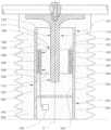
- FIG. 1illustrates a first embodiment of the constructive system object of the present invention, wherein said system is used to produce a capacitive voltage sensor;
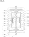
- FIG. 2illustrates a second embodiment of the constructive system object of the present invention, wherein said system is used to make a feedthrough able to also perform the function of capacitive voltage sensor;
- FIGS. 3 , 4 and 5illustrate in schematic manner and as planarly view a possible and preferred embodiment of a structure for forming an electric field sensor prior to its insertion into a shielding tubular body, in which FIG. 4 is a cross-sectional view with respect to the line 4 - 4 of FIG. 3 ;
- FIG. 1 Aillustrates a constructive variation of the system of the first embodiment of FIG. 1 ;
- FIG. 2 Aillustrates a constructive variation of the system that relates to the second embodiment of FIG. 2 ;
- FIG. 6illustrates schematically a constructive detail regarding the constructive variants of FIGS. 1 A and 2 A .
- the constructive system object of the present inventionis able to provide a capacitive electrical voltage sensor, wherein said sensor extends along an axis Y defined longitudinal.
- this systemsubstantially comprises a source electrode 110 / 210 , a shielding tubular body 120 / 220 , an electric field sensor 130 / 230 , and a mass of dielectric insulating material 140 / 240 .
- said source electrode 110 / 210has an elongated shape extending longitudinally along a longitudinal axis Y, in such a way as to configure a first axial end portion 111 / 211 and a second opposite axial end portion 112 / 212 , in which the latter is opposite with respect to the first axial end portion 111 / 211 .
- the shielding tubular body 120 / 220has an elongate shape extending longitudinally along a longitudinal axis Y, so as to configure a first axial end portion 121 / 221 and a second opposite axial end portion 122 / 222 .
- the shielding tubular body 120 / 220is preferably grounded and it is able to shield the electric field sensor 130 / 230 with respect to the field lines generated by live voltage conductors positioned externally with respect to the capacitive sensor, so that the field sensor 130 / 230 detects the field lines generated by the source electrode 110 / 210 .
- Said shielding tubular body 120 / 220comprises a tubular mantle 123 / 223 , wherein said mantle 123 / 223 , configures an inner face 124 / 224 and an outer face 125 / 225 with respect to the central axis Y.
- said electric field sensor 130 / 230is radially spaced with respect and around said source electrode 110 / 210 as well as positioned within said shielding tubular body 120 / 220 and preferably positioned in a intermediate point comprised between the first axial end portion 121 / 221 and the second axial end portion 122 / 222 of said screening tubular body 120 / 220 .
- said massis able to incorporate the various elements of the sensor and, primarily and substantially, said shielding tubular body 130 / 230 , said source electrode 110 / 210 and said electric field sensor 130 / 230 , in order to positioning said elements and in order to form an electrically insulated carrier structure.
- said electric field sensor 130 / 230comprises at least one first inner sheet 131 / 231 and a second external sheet 132 / 232 which are superimposed and joined together, preferably as a monolithic structure, as best described below, wherein the first inner sheet 131 / 231 is made by means of an electrically conductive material (metallic) and the second external sheet 132 / 232 is made by means of an electrically insulating material.
- the second outer sheet 132 / 232made by insulating material it is preferably bonded to the inner face 124 / 224 of the shielding element 120 / 220 , for example, by glue points positioned on the outer face of the sheet 132 / 232 and on the internal face 124 / 224 of the shielding tubular body 120 / 220 , or by other systems as described below.
- the first internal sheet 131 / 231made by conductive material, it is able to detect the electric field lines generated by the source electrode 110 / 210 and, more particularly, it is intended to form a capacitive coupling between said source electrode 110 / 210 and said first sheet 131 / 231 .
- said first sheet 131 / 231may take various forms and/or dimensions and/or sizes which can be different with respect to those illustrated in the figures, without departing from the inventive concept of the present invention.
- said second sheet 132 / 232may take shapes and/or thickness and/or size and/or conformations different with respect of those illustrated in the Figures without departing from the inventive concept of the present invention.
- the shielding tubular body 120 / 220is provided with first through holes 126 / 226 , wherein said first through holes 126 / 226 have a width such that the resin can pass through the same first through holes 126 / 226 during the casting of the same resin while forming the sensor.
- said electric field sensor 130 / 230is provided with second through holes 133 / 233 , wherein said second through holes 133 / 233 have a width able to allow the passage of the resin through the same second holes 133 / 233 during its casting for forming the sensor.
- said first through holes 126 / 226 and said second through holes 133 / 233are axially and mutually communicating, preferably axially aligned with each other, and in any case disposed in such a way as to allow the passage of the resin through said first 126 / 226 and said second 133 / 233 through holes during the casting of the same resin while forming the sensor.
- said electric field sensormay further comprise optional fixing means 150 , which are applied to the external face 133 / 233 of the second outer sheet 132 / 232 , wherein said fixing means 150 are designed to form a bond between the second sheet 132 / 232 and the inner face 124 / 224 of the shielding tubular body 120 / 220 .
- the electric field sensorcomprises only the inner sheet 131 / 231 and the external sheet 132 / 232 , associated with them, provided with through holes 133 / 233 , and in this case it is provided to fix the outer foil 132 / 232 with respect to and/or against the inner face 124 / 224 of the shielding tubular body 120 / 220 by points of glue or other systems.
- FIGS. 3 , 4 and 5they illustrate in detail a particular electric field sensor 130 / 230 , wherein said first inner sheet 131 / 231 is provided with respective through holes defined by a respective perimeter 134 / 234 , said second outer sheet 132 / 232 is provided with respective through holes defined by a respective perimeter 135 / 235 , wherein said through holes in said first inner sheet 131 / 231 have a greater amplitude than the through holes in the second outer sheet 132 / 232 , in such a way as to create between said two perimeters 134 _ 135 / 234 _ 235 (i.e., between said two through holes) an annulus 136 / 236 of insulating material.
- the capacitive coupling between the source electrode 110 / 210 and the electric field sensor 130 / 230detects the electric field generated by the source electrode 110 / 210 , and the relative signal by the cable 160 / 260 can be transmitted to a processing device 170 / 270 , for example to estimate the value of the voltage present in said source electrode 110 / 210 .
- the electric field sensor 130 / 230is formed by a monolithic body comprising at least one first internal sheet 131 / 231 and a second external sheet 132 / 232 overlapped and joined together (glued, associated, bound) before of the their insertion into the shielding tubular body 120 / 220 , there is no undesirable delamination dislocation/separation between said two sheets, thus solving the above-mentioned problems as well as solving other problems associated with the assembling of the sensor components before the casting, as the electric filed sensor 130 / 230 is easily and quickly secured/fixed in position by means of points of glue between the external face 137 / 237 of the external sheet 132 / 232 of the electric field sensor 130 / 230 and the internal face 124 / 224 of the shielding tubular body 120 / 220 .
- the resincan pass and flow through the holes 133 / 233 executed in the two sheets 131 / 231 and 132 / 232 of the electric field sensor 130 / 230 during its casting, and some resin can also and flow through the holes 126 / 226 of the screening tubular body 120 / 220 , and in this manner the characteristics of filling and of gripping of the resin are improved, no undesired vacuoles are formed, and no undesired dislocation/separation shall occur between the shielding body 120 / 220 and the electric field sensor 130 / 230 , thus solving the above-mentioned problems.
Landscapes
- Physics & Mathematics (AREA)
- General Physics & Mathematics (AREA)
- Measuring Instrument Details And Bridges, And Automatic Balancing Devices (AREA)
- Gas-Insulated Switchgears (AREA)
- Measurement Of Current Or Voltage (AREA)
- Measurement Of The Respiration, Hearing Ability, Form, And Blood Characteristics Of Living Organisms (AREA)
- Measurement Of Resistance Or Impedance (AREA)
- Investigating Or Analyzing Materials By The Use Of Electric Means (AREA)
Abstract
Description
Claims (42)
Priority Applications (2)
| Application Number | Priority Date | Filing Date | Title |
|---|---|---|---|
| US16/952,990US11740261B2 (en) | 2016-10-14 | 2020-11-19 | Capacitive voltage sensor assembly |
| US18/346,656US20230375597A1 (en) | 2016-10-14 | 2023-07-03 | Capacitive voltage-sensor assembly |
Applications Claiming Priority (5)
| Application Number | Priority Date | Filing Date | Title |
|---|---|---|---|
| IT102016000103234 | 2016-10-14 | ||
| IT102016000103234AIT201600103234A1 (en) | 2016-10-14 | 2016-10-14 | Constructive system relating to a capacitive voltage sensor |
| PCT/IT2017/000225WO2018069949A2 (en) | 2016-10-14 | 2017-10-12 | Constructive system regarding a capacitive voltage sensor |
| US201916340498A | 2019-04-09 | 2019-04-09 | |
| US16/952,990US11740261B2 (en) | 2016-10-14 | 2020-11-19 | Capacitive voltage sensor assembly |
Related Parent Applications (2)
| Application Number | Title | Priority Date | Filing Date |
|---|---|---|---|
| PCT/IT2017/000225ContinuationWO2018069949A2 (en) | 2016-10-14 | 2017-10-12 | Constructive system regarding a capacitive voltage sensor |
| US16/340,498ContinuationUS10852324B2 (en) | 2016-10-14 | 2017-10-12 | Capacitive voltage-sensor assembly |
Related Child Applications (1)
| Application Number | Title | Priority Date | Filing Date |
|---|---|---|---|
| US18/346,656ContinuationUS20230375597A1 (en) | 2016-10-14 | 2023-07-03 | Capacitive voltage-sensor assembly |
Publications (2)
| Publication Number | Publication Date |
|---|---|
| US20210072289A1 US20210072289A1 (en) | 2021-03-11 |
| US11740261B2true US11740261B2 (en) | 2023-08-29 |
Family
ID=57960727
Family Applications (3)
| Application Number | Title | Priority Date | Filing Date |
|---|---|---|---|
| US16/340,498Active2037-11-25US10852324B2 (en) | 2016-10-14 | 2017-10-12 | Capacitive voltage-sensor assembly |
| US16/952,990Active2038-02-15US11740261B2 (en) | 2016-10-14 | 2020-11-19 | Capacitive voltage sensor assembly |
| US18/346,656AbandonedUS20230375597A1 (en) | 2016-10-14 | 2023-07-03 | Capacitive voltage-sensor assembly |
Family Applications Before (1)
| Application Number | Title | Priority Date | Filing Date |
|---|---|---|---|
| US16/340,498Active2037-11-25US10852324B2 (en) | 2016-10-14 | 2017-10-12 | Capacitive voltage-sensor assembly |
Family Applications After (1)
| Application Number | Title | Priority Date | Filing Date |
|---|---|---|---|
| US18/346,656AbandonedUS20230375597A1 (en) | 2016-10-14 | 2023-07-03 | Capacitive voltage-sensor assembly |
Country Status (6)
| Country | Link |
|---|---|
| US (3) | US10852324B2 (en) |
| EP (1) | EP3526612B1 (en) |
| CA (1) | CA3039861A1 (en) |
| IT (1) | IT201600103234A1 (en) |
| RU (1) | RU2747831C2 (en) |
| WO (1) | WO2018069949A2 (en) |
Families Citing this family (12)
| Publication number | Priority date | Publication date | Assignee | Title |
|---|---|---|---|---|
| IT201600103234A1 (en) | 2016-10-14 | 2018-04-14 | Green Seas Ventures Ldt | Constructive system relating to a capacitive voltage sensor |
| IT201700033017A1 (en)* | 2017-03-27 | 2018-09-27 | Green Seas Ventures Ltd | CONSTRUCTIVE SYSTEM AFFIRMING A CAPACITIVE VOLTAGE SENSOR |
| IT201800004114A1 (en) | 2018-03-30 | 2019-09-30 | Green Seas Ventures Ltd C/O Citco B V I Ltd | CONSTRUCTION SYSTEM WITH A CAPACITIVE VOLTAGE SENSOR |
| CN119986167A (en) | 2018-12-17 | 2025-05-13 | G&W电气公司 | Electrical sensor assembly |
| CN113227802B (en) | 2018-12-17 | 2025-02-11 | G&W电气公司 | Electrical sensor assembly |
| IT201800011146A1 (en)* | 2018-12-17 | 2020-06-17 | Green Seas Ventures Ltd C/O Trident Trust Company Bvi Ltd | Construction System Relating to a Through Insulator |
| WO2021061153A1 (en)* | 2019-09-27 | 2021-04-01 | G & W Electric Company | Capacitive voltage sensor |
| IT202000003128A1 (en)* | 2020-02-17 | 2021-08-17 | Eb Rebosio S R L | MULTILAYER ELEMENT FOR ELECTROTECHNICAL APPLICATIONS |
| DE102020212404B4 (en)* | 2020-09-30 | 2022-05-12 | Siemens Aktiengesellschaft | Field probe combination for use with medium and high voltages |
| US11763703B2 (en) | 2021-11-03 | 2023-09-19 | Samsung Electronics Co., Ltd. | Electronic apparatus |
| EP4276860A1 (en)* | 2022-05-11 | 2023-11-15 | Hitachi Energy Switzerland AG | System comprising a transformer |
| US12287357B2 (en) | 2023-06-23 | 2025-04-29 | John C. Atherton | Power cord voltage indicator |
Citations (149)
| Publication number | Priority date | Publication date | Assignee | Title |
|---|---|---|---|---|
| GB967853A (en) | 1960-03-25 | 1964-08-26 | Reyrolle A & Co Ltd | Improvements relating to high-voltage insulation and insulating components |
| US3396339A (en) | 1963-11-29 | 1968-08-06 | Varian Associates | Capacitive voltage sensing device including coaxially disposed conductive tubes and electrical discharge inhibition means |
| DE2149881A1 (en) | 1971-10-06 | 1973-02-01 | ||
| US3835353A (en) | 1972-03-29 | 1974-09-10 | Siemens Ag | Capacitive voltage-dividing arrangement for high voltage measuring apparatus |
| US4241373A (en) | 1979-03-30 | 1980-12-23 | Mcgraw-Edison Company | Switchgear voltage sensor |
| US4268889A (en) | 1978-05-31 | 1981-05-19 | Automatic Systems Laboratories Limited | Rotary displacement capacitive transducers |
| US4700123A (en) | 1985-09-17 | 1987-10-13 | Sigma Instruments, Inc. | Power distribution systems and means for control thereof |
| GB2203557A (en) | 1987-04-09 | 1988-10-19 | Bonar Wallis Electronics Limit | Voltage sensing devices |
| US5136241A (en) | 1990-08-27 | 1992-08-04 | The United States Of America As Represented By The Secretary Of The Navy | Device for sensing unwanted electric and magnetic fields in a remote sensor electrical lead |
| EP0677747A2 (en) | 1994-04-13 | 1995-10-18 | Robert Bosch Gmbh | Capacitive sensor for detecting high voltage signals |
| US5661240A (en) | 1995-09-25 | 1997-08-26 | Ford Motor Company | Sampled-data interface circuit for capacitive sensors |
| DE19613688A1 (en) | 1996-04-05 | 1997-10-09 | Habemus Electronic & Transfer | Low voltage measurement device |
| EP0912902A1 (en) | 1996-07-15 | 1999-05-06 | Asea Brown Boveri Ab | Method, device and sensor for capacitive detecting of field and voltage and use thereof |
| US5991177A (en) | 1997-04-04 | 1999-11-23 | Asea Brown Boveri Ag | Capacitive voltage transformer for a metal-enclosed, gas-filled high-voltage system |
| US6252388B1 (en) | 1998-12-04 | 2001-06-26 | Nxtphase Corporation | Method and apparatus for measuring voltage using electric field sensors |
| US6307385B1 (en) | 1997-12-30 | 2001-10-23 | Vibrosystm, Inc. | Capacitance measuring circuit for a capacitive sensor |
| US20010048308A1 (en) | 2000-04-26 | 2001-12-06 | Potter David E. | Voltage sensor bushing assembly with integral capacitance screen |
| US20020113596A1 (en) | 2001-02-22 | 2002-08-22 | Kazuyuki Horie | Oil condition sensor and method for making the same |
| ES2221551A1 (en) | 2003-02-20 | 2004-12-16 | Industrias De Aparellaje Electrico, | Capacitive voltage sensor for detecting high voltage of alternating current of power line, has primer comprising high voltage varistors that are connected to protection arresters in parallel manner |
| US20050122118A1 (en) | 2001-12-10 | 2005-06-09 | Zank Paul A. | Electric field sensor |
| US20060033508A1 (en) | 2004-08-16 | 2006-02-16 | Lee Ying L | Linear capacitance measurement and touchless switch |
| US20060119369A1 (en) | 2004-12-03 | 2006-06-08 | Alps Electric Co., Ltd. | Capacity detecting sensor |
| US20060238233A1 (en) | 2003-01-24 | 2006-10-26 | Randolf Kraus | Circuit arrangement for a capacitive proximity switch |
| US20070086130A1 (en) | 2004-01-07 | 2007-04-19 | Thomas Sorensen | Voltage measuring device |
| US20080011093A1 (en) | 2001-07-09 | 2008-01-17 | Nartron Corporation | Anti-entrapment system |
| US7466146B2 (en) | 2006-03-10 | 2008-12-16 | Freescale Semiconductor, Inc. | Frozen material detection using electric field sensor |
| US7541816B1 (en) | 2008-05-05 | 2009-06-02 | Generalplus Technology Inc. | Capacitive sensor |
| US7595648B2 (en) | 2005-12-02 | 2009-09-29 | Stmicroelectronics S.R.L. | Device and method for reading a capacitive sensor, in particular of a micro-electromechanical type |
| WO2009153824A1 (en) | 2008-06-20 | 2009-12-23 | Alberto Bauer | Capacitive sensor to sense an electric field generated by a conductor |
| US20100107775A1 (en)* | 2008-11-06 | 2010-05-06 | Northeastern University | System, Method, And Device For Measuring Parameters Of A Two-Phase Flow |
| WO2010070693A1 (en) | 2008-12-15 | 2010-06-24 | Bauer, Alberto | Construction system for a voltage and/or current sensor |
| US20100283487A1 (en) | 2009-05-08 | 2010-11-11 | Mark Allan Juds | System and method for sensing voltage in medium-to-high voltage applications |
| US20100318306A1 (en) | 2007-05-23 | 2010-12-16 | Onzo Limited | Capacitive voltage sensor |
| US20110012623A1 (en) | 2009-07-20 | 2011-01-20 | Peter Van Gastel | Capacitive sensor array |
| WO2011033548A1 (en) | 2009-09-21 | 2011-03-24 | Alberto Bauer | Capacitive voltage sensor |
| US20110121842A1 (en) | 2008-06-20 | 2011-05-26 | Alberto Bauer | Capacitive sensor to sense an electric field generated by a conductor |
| US20110121820A1 (en) | 2009-11-20 | 2011-05-26 | Smc Electrical Products, Inc. | High voltage sensing capacitor and indicator device |
| US20110204879A1 (en) | 2008-11-18 | 2011-08-25 | Alberto Bauer | Construction system for an electrical current and/or voltage sensor |
| US20110205683A1 (en) | 2008-10-30 | 2011-08-25 | Lorenzo Peretto | Construction system for a capacitive sensor |
| US20110221452A1 (en) | 2010-03-12 | 2011-09-15 | Nuvoton Technology Corporation | Capacitive sensor and sensing method |
| US20110234311A1 (en) | 2010-03-25 | 2011-09-29 | Kabushiki Kaisha Toshiba | Current detection circuit and information terminal |
| WO2011125725A1 (en) | 2010-03-31 | 2011-10-13 | 東海ゴム工業株式会社 | Capacitance-type sensor device and capacitance-type sensor capacitance measuring device |
| US20110298454A1 (en) | 2010-06-07 | 2011-12-08 | Infineon Technologies Ag | Current Sensor |
| WO2011157047A1 (en) | 2010-06-17 | 2011-12-22 | 西安交通大学 | Capacitive sensor calibration system for measuring fast transient over-voltages |
| US8242840B2 (en) | 2009-10-16 | 2012-08-14 | Nxp B.V. | Capacitive sensor |
| US8283934B2 (en) | 2008-03-10 | 2012-10-09 | Fujitsu Semiconductor Limited | Capacitance sensor for detecting a charge voltage of a multi-capacitor circuit |
| US20120261384A1 (en) | 2011-04-14 | 2012-10-18 | Labianco Mike | Interrupter with voltage sensing on both load and source sides |
| US20120326734A1 (en) | 2011-06-24 | 2012-12-27 | Youngho Cho | Capacitance sensor with improved noise filtering characteristics, method for noise filtering of capacitance sensor and computer-readable recording medium |
| WO2013026423A1 (en) | 2011-08-23 | 2013-02-28 | Abb Technology Ag | Combined measuring and detecting system |
| WO2013042155A2 (en) | 2011-09-20 | 2013-03-28 | Alberto Bauer | Capacitive sensor |
| US8446157B2 (en) | 2009-09-18 | 2013-05-21 | Abb Technology Ag | Capacitance meter, method, computer program and computer program product for improved capacitance measurement |
| US8847353B2 (en) | 2010-12-20 | 2014-09-30 | Ps4 Luxco S.A.R.L. | Semiconductor device and data processing system using the same |
| US20140300374A1 (en) | 2011-08-18 | 2014-10-09 | Ultra Electronics Limited | Method and apparatus for measurement of a dc voltage |
| US20140354302A1 (en) | 2013-05-31 | 2014-12-04 | General Electric Company | System and Method for a Capacitive Voltage Sensor System |
| US20140370741A1 (en) | 2011-12-21 | 2014-12-18 | 3M Innovative Properties Company | Terminal connection device for a power cable |
| WO2015044972A1 (en)* | 2013-09-30 | 2015-04-02 | Alberto Bauer | Capacitive sensor to sense an electric field, system and method to obtain it |
| US9118330B2 (en) | 2010-12-01 | 2015-08-25 | Stmicroelectronics (Rousset) Sas | Directional capacitive proximity sensor |
| US20150279642A1 (en) | 2012-10-30 | 2015-10-01 | University Of Sussex | Apparatus for sensing ionic current |
| US20150346907A1 (en) | 2013-07-30 | 2015-12-03 | Sumitomo Riko Company Limited | Input state detection device |
| US20160005511A1 (en) | 2013-02-01 | 2016-01-07 | 3M Innovative Properties Company | Sleeve for a power cable |
| US20160061864A1 (en) | 2014-08-28 | 2016-03-03 | Siemens Industry, Inc. | Isolated Capacitance Line Voltage Sensor |
| EP2993480A1 (en) | 2014-09-04 | 2016-03-09 | 3M Innovative Properties Company | Voltage sensor |
| US9291651B2 (en) | 2011-08-05 | 2016-03-22 | Green Seas Ventures, Ltd. | Feedthrough insulator |
| CN105467187A (en) | 2015-12-04 | 2016-04-06 | 国家电网公司 | A graded type voltage transformer |
| US20160103174A1 (en) | 2014-10-13 | 2016-04-14 | Murata Manufacturing Co., Ltd. | Capacitive microelectromechanical sensor with self-test capability |
| CN105588966A (en) | 2015-12-04 | 2016-05-18 | 国家电网公司 | Gas insulated classification type voltage transformer |
| US20160139181A1 (en) | 2013-06-25 | 2016-05-19 | 3M Innovative Properties Company | Conductor assembly |
| WO2016109009A1 (en) | 2014-12-29 | 2016-07-07 | Eaton Corporation | Voltage sensor system |
| US9389246B2 (en) | 2014-01-08 | 2016-07-12 | Eaton Corporation | Multiple layer capacitor divider voltage sensors suitable for circuit breakers and related circuit breakers |
| US20160202286A1 (en) | 2015-01-12 | 2016-07-14 | Murata Manufacturing Co., Ltd. | Continuous self-test in capacitive sensor |
| US20170030946A1 (en) | 2013-12-18 | 2017-02-02 | 3M Innovative Properties Company | Voltage sensor |
| US20170038414A1 (en) | 2015-08-05 | 2017-02-09 | Schneider Electric USA, Inc. | Capacitive voltage sensor for medium voltage metering |
| US9568506B2 (en) | 2013-05-22 | 2017-02-14 | Panasonic Intellectual Property Management Co., Ltd. | Electric field measurement device |
| US20170061187A1 (en) | 2015-08-28 | 2017-03-02 | Synaptics Incorporated | Capacitive sensor architecture for biometric sensing |
| US20170067938A1 (en) | 2015-09-08 | 2017-03-09 | Hioki Denki Kabushiki Kaisha | Voltage detecting probe and measuring device |
| US20170067939A1 (en) | 2014-03-13 | 2017-03-09 | Omron Corporation | Non-contact voltage measurement device |
| WO2017050058A1 (en) | 2015-09-23 | 2017-03-30 | 深圳信炜科技有限公司 | Capacitive sensing device and electronic device |
| WO2017050039A1 (en) | 2015-09-23 | 2017-03-30 | 深圳信炜科技有限公司 | Capacitive sensing device, packaging structure, sensor module, and electronic device |
| WO2017050045A1 (en) | 2015-09-23 | 2017-03-30 | 深圳信炜科技有限公司 | Capacitive sensor, capacitive sensing device, and electronic device |
| WO2017050042A1 (en) | 2015-09-23 | 2017-03-30 | 深圳信炜科技有限公司 | Capacitive sensing system and electronic device |
| WO2017050044A1 (en) | 2015-09-23 | 2017-03-30 | 深圳信炜科技有限公司 | Capacitive sensing device and capacitive sensing system |
| US20170184634A1 (en) | 2014-05-19 | 2017-06-29 | 3M Innovative Properties Company | Sensored electrical jumper |
| US20170234908A1 (en) | 2014-09-30 | 2017-08-17 | 3M Innovative Properties Company | Voltage sensing device |
| US9739820B2 (en) | 2013-06-19 | 2017-08-22 | 3M Innovative Properties Company | Conductor assembly |
| US9739816B2 (en) | 2013-11-27 | 2017-08-22 | Analog Devices, Inc. | Capacitive sensor with differential shield |
| US9742180B2 (en) | 2013-06-26 | 2017-08-22 | 3M Innovative Properties Company | Power cable terminal connection device |
| US20170250499A1 (en) | 2014-09-22 | 2017-08-31 | Prysmian S.P.A. | Cable termination with an integrated monitoring device |
| US20170276723A1 (en) | 2016-03-23 | 2017-09-28 | Infineon Technologies Ag | Capacitive sensor testing |
| US9846024B1 (en) | 2011-06-21 | 2017-12-19 | The University Of North Carolina At Charlotte | Solid-state electric-field sensor |
| US20170363660A1 (en) | 2015-02-02 | 2017-12-21 | 3M Innovative Properties Company | Electrode foil |
| US9927415B2 (en) | 2014-04-04 | 2018-03-27 | Xylem Analytics Germany Gmbh | Oil quality sensor and fryer with such oil quality sensor |
| US20180092557A1 (en) | 2016-09-30 | 2018-04-05 | The Charles Stark Draper Laboratory, Inc. | Biophysical sensing systems and methods using non-contact electric field detectors |
| US20180100878A1 (en) | 2016-10-07 | 2018-04-12 | Cooper Technologies Company | Sensing device for an electrical system |
| WO2018069949A2 (en) | 2016-10-14 | 2018-04-19 | Alberto Bauer | Constructive system regarding a capacitive voltage sensor |
| US9958505B2 (en) | 2016-03-01 | 2018-05-01 | Denso Corporation | Voltage sensing circuit and battery pack monitoring system |
| US9983032B1 (en) | 2017-06-01 | 2018-05-29 | Nxp Usa, Inc. | Sensor device and method for continuous fault monitoring of sensor device |
| WO2018096567A2 (en) | 2016-11-24 | 2018-05-31 | Alberto Bauer | Constructive system regarding a capacitive sensor |
| WO2018114661A1 (en) | 2016-12-20 | 2018-06-28 | Eaton Industries (Netherlands) B.V. | Bushing with integrated voltage sensor |
| US10025423B2 (en) | 2016-04-25 | 2018-07-17 | Atmel Corporation | Driven shield control |
| DE102017000723A1 (en) | 2017-01-27 | 2018-08-02 | Dipl.-Ing. H. Horstmann Gmbh | voltage sensor |
| US10088963B2 (en) | 2015-10-26 | 2018-10-02 | Semiconductor Components Industries, Llc | Methods and apparatus for a capacitive sensor |
| WO2018179017A1 (en) | 2017-03-27 | 2018-10-04 | Alberto Bauer | Constructive system regarding a capacitive sensor |
| US20180292435A1 (en) | 2015-05-18 | 2018-10-11 | 3M Innovative Properties Company | Voltage sensor |
| US20180374644A1 (en) | 2015-12-17 | 2018-12-27 | 3M Innovative Properties Company | Capacitor, capacitive voltage sensor and method for manufacturing a capacitor |
| US10203814B2 (en) | 2006-04-20 | 2019-02-12 | Nokia Technologies Oy | Sensor arrangement comprising a conductive layer |
| WO2019073497A1 (en) | 2017-10-13 | 2019-04-18 | Alberto Bauer | Constructive system regarding a capacitive sensor |
| US20190146006A1 (en) | 2016-04-19 | 2019-05-16 | Ormazabal Protection & Automation, S.L.U. | High-voltage lead-in insulating device |
| US10317442B2 (en) | 2015-07-31 | 2019-06-11 | Sumitomo Riko Company Limited | Capacitive sensor, sensor sheet, and method for manufacturing capacitive sensor |
| US20190181860A1 (en) | 2017-12-12 | 2019-06-13 | Nxp Usa, Inc. | Reduction of Capacitive Touch Sense Electrode Sample Value Change When Electrode Scan Period is Changed |
| US10345340B2 (en) | 2013-12-18 | 2019-07-09 | 3M Innovative Properties Company | Voltage sensing device |
| EP3513202A1 (en) | 2016-09-14 | 2019-07-24 | Alberto Bauer | Method for obtaining a capacitive voltage sensor and capacitive voltage sensor obtained by this method |
| US20190237260A1 (en) | 2015-12-17 | 2019-08-01 | 3M Innovative Properties Company | Capacitor, Capacitive Voltage Sensor and Method for Manufacturing a Capacitor |
| US10425079B1 (en) | 2018-05-11 | 2019-09-24 | Cirque Corporation | Driven shield for a capacitance sensor |
| WO2019186607A1 (en) | 2018-03-30 | 2019-10-03 | Alberto Bauer | Constructive system regarding a capacitive sensor |
| US20190324073A1 (en) | 2018-04-19 | 2019-10-24 | Simplex Quantum Inc. | Capacitive sensor and capacitive sensor head |
| US20200064376A1 (en) | 2017-05-17 | 2020-02-27 | 3M Innovative Properties Company | Sensors with discrete capacitors for high voltage separable connectors |
| US10591523B2 (en) | 2014-08-29 | 2020-03-17 | Korea University Research And Business Foundation | Capacitive sensor and manufacturing method thereof |
| US20200124642A1 (en) | 2018-10-18 | 2020-04-23 | S&C Electric Company | Capacitive voltage sensor with a hidden sensing electrode |
| US20200158762A1 (en) | 2018-11-20 | 2020-05-21 | 3M Innovative Properties Company | End plug sensor device with voltage divider and test point features |
| WO2020109283A2 (en) | 2018-11-29 | 2020-06-04 | Trust Power Ltd | Non-invasive electricity monitoring |
| WO2020131909A1 (en) | 2018-12-17 | 2020-06-25 | G & W Electric Company | Electrical sensor assembly |
| WO2020131903A1 (en) | 2018-12-17 | 2020-06-25 | G & W Electric Company | Electrical sensor assembly |
| US20200200936A1 (en) | 2018-12-06 | 2020-06-25 | George Axel Kruger | Capacitive sensor |
| US10753962B2 (en) | 2018-10-30 | 2020-08-25 | Prysmian S.P.A. | Shrinkable cable joint and voltage sensor |
| US10790822B2 (en) | 2014-12-31 | 2020-09-29 | Iee International Electronics & Engineering S.A. | Switching arrangement and method for a capacitive sensor |
| WO2021061153A1 (en) | 2019-09-27 | 2021-04-01 | G & W Electric Company | Capacitive voltage sensor |
| EP3828553A1 (en) | 2019-11-28 | 2021-06-02 | 3M Innovative Properties Company | Voltage sensor for power networks |
| EP3840135A1 (en) | 2019-12-20 | 2021-06-23 | 3M Innovative Properties Company | Retrofittable voltage sensing device for power networks |
| US11048367B2 (en) | 2009-05-13 | 2021-06-29 | Synaptics Incorporated | Capacitive sensor device |
| US20210206418A1 (en) | 2018-09-26 | 2021-07-08 | Sumitomo Riko Company Limited | Capacitance sensor, method for manufacturing same, and reticulated soft electrode for capacitance sensor |
| EP3862760A1 (en) | 2020-02-06 | 2021-08-11 | 3M Innovative Properties Company | Insulated component of a voltage sensor |
| WO2021180642A1 (en) | 2020-03-10 | 2021-09-16 | Robert Bosch Gmbh | Circuit for operating a capacitive sensor and associated sensor device |
| EP3881085A1 (en) | 2018-11-16 | 2021-09-22 | ABB Schweiz AG | Voltage sensor and apparatus |
| US20210302478A1 (en) | 2020-03-27 | 2021-09-30 | Lam Research Corporation | Rf signal parameter measurement in an integrated circuit fabrication chamber |
| US20210359533A1 (en) | 2020-05-13 | 2021-11-18 | Toyota Jidosha Kabushiki Kaisha | Controller for power supply circuit, storage medium storing program that controls power supply circuit, and control method for power supply circuit |
| US20210356499A1 (en) | 2020-05-13 | 2021-11-18 | Schneider Electric Industries Sas | Dual-voltage capacitive sensor |
| EP3913379A1 (en) | 2020-05-20 | 2021-11-24 | 3M Innovative Properties Company | Capacitor assembly |
| US20220065910A1 (en) | 2020-09-02 | 2022-03-03 | Lexmark International, Inc. | Combination Magnetic and Capacitive Sensor |
| US11287456B2 (en) | 2019-04-17 | 2022-03-29 | S&C Electric Company | Capacitive compensated voltage sensor |
| WO2022069967A1 (en) | 2020-10-01 | 2022-04-07 | 3M Innovative Properties Company | Dielectric material for a high voltage capacitor |
| WO2022072130A1 (en) | 2020-10-01 | 2022-04-07 | 3M Innovative Properties Company | Dielectric material for a high voltage capacitor |
| US20220123748A1 (en) | 2020-10-15 | 2022-04-21 | Alps Alpine Co., Ltd. | Method To Control Amplitude And Phase Of A Signal |
| WO2022094645A1 (en) | 2020-11-09 | 2022-05-12 | Greenwood-Power GmbH | Voltage sensor with ohmic capacitive voltage divider |
| WO2022124942A1 (en) | 2020-12-07 | 2022-06-16 | Gruppa Companiy Tel Obshchestvo S Ogranichennoy Otvetstvennostyu | Voltage sensor |
| US11378594B2 (en) | 2018-12-12 | 2022-07-05 | S&C Electric Company | Capacitive voltage sensor with hidden sensing electrode |
| US11415611B2 (en) | 2019-08-14 | 2022-08-16 | Texas Instruments Incorporated | Capacitance measuring system and method |
| EP4058815A1 (en) | 2019-11-14 | 2022-09-21 | Greenwood-Power GmbH | Voltage sensor and voltage dividing device |
| US20220311441A1 (en) | 2019-08-27 | 2022-09-29 | Egis Technology Inc. | Capacitive sensing device |
| US20220317158A1 (en) | 2019-09-23 | 2022-10-06 | 3M Innovative Properties Company | Adjustable voltage sensor |
- 2016
- 2016-10-14ITIT102016000103234Apatent/IT201600103234A1/enunknown
- 2017
- 2017-10-12USUS16/340,498patent/US10852324B2/enactiveActive
- 2017-10-12CACA3039861Apatent/CA3039861A1/enactivePending
- 2017-10-12RURU2019112914Apatent/RU2747831C2/enactive
- 2017-10-12WOPCT/IT2017/000225patent/WO2018069949A2/ennot_activeCeased
- 2017-10-12EPEP17833019.7Apatent/EP3526612B1/enactiveActive
- 2020
- 2020-11-19USUS16/952,990patent/US11740261B2/enactiveActive
- 2023
- 2023-07-03USUS18/346,656patent/US20230375597A1/ennot_activeAbandoned
Patent Citations (168)
| Publication number | Priority date | Publication date | Assignee | Title |
|---|---|---|---|---|
| GB967853A (en) | 1960-03-25 | 1964-08-26 | Reyrolle A & Co Ltd | Improvements relating to high-voltage insulation and insulating components |
| US3396339A (en) | 1963-11-29 | 1968-08-06 | Varian Associates | Capacitive voltage sensing device including coaxially disposed conductive tubes and electrical discharge inhibition means |
| DE2149881A1 (en) | 1971-10-06 | 1973-02-01 | ||
| US3835353A (en) | 1972-03-29 | 1974-09-10 | Siemens Ag | Capacitive voltage-dividing arrangement for high voltage measuring apparatus |
| US4268889A (en) | 1978-05-31 | 1981-05-19 | Automatic Systems Laboratories Limited | Rotary displacement capacitive transducers |
| US4241373A (en) | 1979-03-30 | 1980-12-23 | Mcgraw-Edison Company | Switchgear voltage sensor |
| US4700123A (en) | 1985-09-17 | 1987-10-13 | Sigma Instruments, Inc. | Power distribution systems and means for control thereof |
| GB2203557A (en) | 1987-04-09 | 1988-10-19 | Bonar Wallis Electronics Limit | Voltage sensing devices |
| US5136241A (en) | 1990-08-27 | 1992-08-04 | The United States Of America As Represented By The Secretary Of The Navy | Device for sensing unwanted electric and magnetic fields in a remote sensor electrical lead |
| EP0677747A2 (en) | 1994-04-13 | 1995-10-18 | Robert Bosch Gmbh | Capacitive sensor for detecting high voltage signals |
| US5661240A (en) | 1995-09-25 | 1997-08-26 | Ford Motor Company | Sampled-data interface circuit for capacitive sensors |
| DE19613688A1 (en) | 1996-04-05 | 1997-10-09 | Habemus Electronic & Transfer | Low voltage measurement device |
| EP0912902A1 (en) | 1996-07-15 | 1999-05-06 | Asea Brown Boveri Ab | Method, device and sensor for capacitive detecting of field and voltage and use thereof |
| US5991177A (en) | 1997-04-04 | 1999-11-23 | Asea Brown Boveri Ag | Capacitive voltage transformer for a metal-enclosed, gas-filled high-voltage system |
| US6307385B1 (en) | 1997-12-30 | 2001-10-23 | Vibrosystm, Inc. | Capacitance measuring circuit for a capacitive sensor |
| US6252388B1 (en) | 1998-12-04 | 2001-06-26 | Nxtphase Corporation | Method and apparatus for measuring voltage using electric field sensors |
| US20010048308A1 (en) | 2000-04-26 | 2001-12-06 | Potter David E. | Voltage sensor bushing assembly with integral capacitance screen |
| US20020113596A1 (en) | 2001-02-22 | 2002-08-22 | Kazuyuki Horie | Oil condition sensor and method for making the same |
| US20080011093A1 (en) | 2001-07-09 | 2008-01-17 | Nartron Corporation | Anti-entrapment system |
| US20050122118A1 (en) | 2001-12-10 | 2005-06-09 | Zank Paul A. | Electric field sensor |
| US20060238233A1 (en) | 2003-01-24 | 2006-10-26 | Randolf Kraus | Circuit arrangement for a capacitive proximity switch |
| ES2221551A1 (en) | 2003-02-20 | 2004-12-16 | Industrias De Aparellaje Electrico, | Capacitive voltage sensor for detecting high voltage of alternating current of power line, has primer comprising high voltage varistors that are connected to protection arresters in parallel manner |
| US20070086130A1 (en) | 2004-01-07 | 2007-04-19 | Thomas Sorensen | Voltage measuring device |
| US20060033508A1 (en) | 2004-08-16 | 2006-02-16 | Lee Ying L | Linear capacitance measurement and touchless switch |
| US20060119369A1 (en) | 2004-12-03 | 2006-06-08 | Alps Electric Co., Ltd. | Capacity detecting sensor |
| US7595648B2 (en) | 2005-12-02 | 2009-09-29 | Stmicroelectronics S.R.L. | Device and method for reading a capacitive sensor, in particular of a micro-electromechanical type |
| US7466146B2 (en) | 2006-03-10 | 2008-12-16 | Freescale Semiconductor, Inc. | Frozen material detection using electric field sensor |
| US10203814B2 (en) | 2006-04-20 | 2019-02-12 | Nokia Technologies Oy | Sensor arrangement comprising a conductive layer |
| US20100318306A1 (en) | 2007-05-23 | 2010-12-16 | Onzo Limited | Capacitive voltage sensor |
| US8283934B2 (en) | 2008-03-10 | 2012-10-09 | Fujitsu Semiconductor Limited | Capacitance sensor for detecting a charge voltage of a multi-capacitor circuit |
| US7541816B1 (en) | 2008-05-05 | 2009-06-02 | Generalplus Technology Inc. | Capacitive sensor |
| WO2009153824A1 (en) | 2008-06-20 | 2009-12-23 | Alberto Bauer | Capacitive sensor to sense an electric field generated by a conductor |
| US20110121842A1 (en) | 2008-06-20 | 2011-05-26 | Alberto Bauer | Capacitive sensor to sense an electric field generated by a conductor |
| US20110205683A1 (en) | 2008-10-30 | 2011-08-25 | Lorenzo Peretto | Construction system for a capacitive sensor |
| US20100107775A1 (en)* | 2008-11-06 | 2010-05-06 | Northeastern University | System, Method, And Device For Measuring Parameters Of A Two-Phase Flow |
| EP2366108B1 (en) | 2008-11-18 | 2012-08-22 | Green Seas Ventures, Ltd | Construction system for an electrical current and/or voltage sensor |
| US20110204879A1 (en) | 2008-11-18 | 2011-08-25 | Alberto Bauer | Construction system for an electrical current and/or voltage sensor |
| WO2010070693A1 (en) | 2008-12-15 | 2010-06-24 | Bauer, Alberto | Construction system for a voltage and/or current sensor |
| US20100283487A1 (en) | 2009-05-08 | 2010-11-11 | Mark Allan Juds | System and method for sensing voltage in medium-to-high voltage applications |
| US11048367B2 (en) | 2009-05-13 | 2021-06-29 | Synaptics Incorporated | Capacitive sensor device |
| US20110012623A1 (en) | 2009-07-20 | 2011-01-20 | Peter Van Gastel | Capacitive sensor array |
| US8446157B2 (en) | 2009-09-18 | 2013-05-21 | Abb Technology Ag | Capacitance meter, method, computer program and computer program product for improved capacitance measurement |
| WO2011033548A1 (en) | 2009-09-21 | 2011-03-24 | Alberto Bauer | Capacitive voltage sensor |
| US8242840B2 (en) | 2009-10-16 | 2012-08-14 | Nxp B.V. | Capacitive sensor |
| US20130043891A1 (en) | 2009-11-20 | 2013-02-21 | Smc Electrical Products, Inc. | High Voltage Sensing Capacitor and Indicator Device |
| US20110121820A1 (en) | 2009-11-20 | 2011-05-26 | Smc Electrical Products, Inc. | High voltage sensing capacitor and indicator device |
| US8294477B2 (en) | 2009-11-20 | 2012-10-23 | Smc Electrical Products, Inc. | High voltage sensing capacitor and indicator device |
| US20110221452A1 (en) | 2010-03-12 | 2011-09-15 | Nuvoton Technology Corporation | Capacitive sensor and sensing method |
| US20110234311A1 (en) | 2010-03-25 | 2011-09-29 | Kabushiki Kaisha Toshiba | Current detection circuit and information terminal |
| WO2011125725A1 (en) | 2010-03-31 | 2011-10-13 | 東海ゴム工業株式会社 | Capacitance-type sensor device and capacitance-type sensor capacitance measuring device |
| US20110298454A1 (en) | 2010-06-07 | 2011-12-08 | Infineon Technologies Ag | Current Sensor |
| WO2011157047A8 (en) | 2010-06-17 | 2013-01-31 | 西安交通大学 | Capacitive sensor calibration system for measuring fast transient over-voltages |
| WO2011157047A1 (en) | 2010-06-17 | 2011-12-22 | 西安交通大学 | Capacitive sensor calibration system for measuring fast transient over-voltages |
| US9118330B2 (en) | 2010-12-01 | 2015-08-25 | Stmicroelectronics (Rousset) Sas | Directional capacitive proximity sensor |
| US8847353B2 (en) | 2010-12-20 | 2014-09-30 | Ps4 Luxco S.A.R.L. | Semiconductor device and data processing system using the same |
| US20120261384A1 (en) | 2011-04-14 | 2012-10-18 | Labianco Mike | Interrupter with voltage sensing on both load and source sides |
| US9846024B1 (en) | 2011-06-21 | 2017-12-19 | The University Of North Carolina At Charlotte | Solid-state electric-field sensor |
| US20120326734A1 (en) | 2011-06-24 | 2012-12-27 | Youngho Cho | Capacitance sensor with improved noise filtering characteristics, method for noise filtering of capacitance sensor and computer-readable recording medium |
| US9291651B2 (en) | 2011-08-05 | 2016-03-22 | Green Seas Ventures, Ltd. | Feedthrough insulator |
| US20140300374A1 (en) | 2011-08-18 | 2014-10-09 | Ultra Electronics Limited | Method and apparatus for measurement of a dc voltage |
| WO2013026423A1 (en) | 2011-08-23 | 2013-02-28 | Abb Technology Ag | Combined measuring and detecting system |
| WO2013042155A2 (en) | 2011-09-20 | 2013-03-28 | Alberto Bauer | Capacitive sensor |
| US20140370741A1 (en) | 2011-12-21 | 2014-12-18 | 3M Innovative Properties Company | Terminal connection device for a power cable |
| US20150279642A1 (en) | 2012-10-30 | 2015-10-01 | University Of Sussex | Apparatus for sensing ionic current |
| US20160005511A1 (en) | 2013-02-01 | 2016-01-07 | 3M Innovative Properties Company | Sleeve for a power cable |
| US9568506B2 (en) | 2013-05-22 | 2017-02-14 | Panasonic Intellectual Property Management Co., Ltd. | Electric field measurement device |
| US20140354302A1 (en) | 2013-05-31 | 2014-12-04 | General Electric Company | System and Method for a Capacitive Voltage Sensor System |
| US9739820B2 (en) | 2013-06-19 | 2017-08-22 | 3M Innovative Properties Company | Conductor assembly |
| US20160139181A1 (en) | 2013-06-25 | 2016-05-19 | 3M Innovative Properties Company | Conductor assembly |
| US9742180B2 (en) | 2013-06-26 | 2017-08-22 | 3M Innovative Properties Company | Power cable terminal connection device |
| US20150346907A1 (en) | 2013-07-30 | 2015-12-03 | Sumitomo Riko Company Limited | Input state detection device |
| WO2015044972A1 (en)* | 2013-09-30 | 2015-04-02 | Alberto Bauer | Capacitive sensor to sense an electric field, system and method to obtain it |
| US20160245845A1 (en)* | 2013-09-30 | 2016-08-25 | Green Seas Ventures, Ltd | Capacitive sensor to sense an electric field, system and method to obtain it |
| US9921246B2 (en) | 2013-09-30 | 2018-03-20 | Green Seas Venture, Ltd | Capacitive electric-field sensor and method of making same |
| US9739816B2 (en) | 2013-11-27 | 2017-08-22 | Analog Devices, Inc. | Capacitive sensor with differential shield |
| US10215778B2 (en) | 2013-12-18 | 2019-02-26 | 3M Innovative Properties Company | Voltage Sensor |
| US20170030946A1 (en) | 2013-12-18 | 2017-02-02 | 3M Innovative Properties Company | Voltage sensor |
| US10345340B2 (en) | 2013-12-18 | 2019-07-09 | 3M Innovative Properties Company | Voltage sensing device |
| US9389246B2 (en) | 2014-01-08 | 2016-07-12 | Eaton Corporation | Multiple layer capacitor divider voltage sensors suitable for circuit breakers and related circuit breakers |
| US9696348B2 (en) | 2014-01-08 | 2017-07-04 | Eaton Corporation | Multiple layer capacitor divider voltage sensors suitable for circuit breakers and related circuit breakers |
| US20170067939A1 (en) | 2014-03-13 | 2017-03-09 | Omron Corporation | Non-contact voltage measurement device |
| US9927415B2 (en) | 2014-04-04 | 2018-03-27 | Xylem Analytics Germany Gmbh | Oil quality sensor and fryer with such oil quality sensor |
| US20170184634A1 (en) | 2014-05-19 | 2017-06-29 | 3M Innovative Properties Company | Sensored electrical jumper |
| US20160061864A1 (en) | 2014-08-28 | 2016-03-03 | Siemens Industry, Inc. | Isolated Capacitance Line Voltage Sensor |
| US10591523B2 (en) | 2014-08-29 | 2020-03-17 | Korea University Research And Business Foundation | Capacitive sensor and manufacturing method thereof |
| EP2993480A1 (en) | 2014-09-04 | 2016-03-09 | 3M Innovative Properties Company | Voltage sensor |
| US20170250499A1 (en) | 2014-09-22 | 2017-08-31 | Prysmian S.P.A. | Cable termination with an integrated monitoring device |
| US20170234908A1 (en) | 2014-09-30 | 2017-08-17 | 3M Innovative Properties Company | Voltage sensing device |
| US10338103B2 (en) | 2014-09-30 | 2019-07-02 | 3M Innovative Properties Company | Voltage sensing device |
| US20160103174A1 (en) | 2014-10-13 | 2016-04-14 | Murata Manufacturing Co., Ltd. | Capacitive microelectromechanical sensor with self-test capability |
| WO2016109009A1 (en) | 2014-12-29 | 2016-07-07 | Eaton Corporation | Voltage sensor system |
| US10790822B2 (en) | 2014-12-31 | 2020-09-29 | Iee International Electronics & Engineering S.A. | Switching arrangement and method for a capacitive sensor |
| US20160202286A1 (en) | 2015-01-12 | 2016-07-14 | Murata Manufacturing Co., Ltd. | Continuous self-test in capacitive sensor |
| US20170363660A1 (en) | 2015-02-02 | 2017-12-21 | 3M Innovative Properties Company | Electrode foil |
| US20180292435A1 (en) | 2015-05-18 | 2018-10-11 | 3M Innovative Properties Company | Voltage sensor |
| US10317442B2 (en) | 2015-07-31 | 2019-06-11 | Sumitomo Riko Company Limited | Capacitive sensor, sensor sheet, and method for manufacturing capacitive sensor |
| US9739807B2 (en) | 2015-08-05 | 2017-08-22 | Schneider Electric USA, Inc. | Voltage sensor with a capacitive voltage transformer |
| US20170038414A1 (en) | 2015-08-05 | 2017-02-09 | Schneider Electric USA, Inc. | Capacitive voltage sensor for medium voltage metering |
| US20170061187A1 (en) | 2015-08-28 | 2017-03-02 | Synaptics Incorporated | Capacitive sensor architecture for biometric sensing |
| US20170067938A1 (en) | 2015-09-08 | 2017-03-09 | Hioki Denki Kabushiki Kaisha | Voltage detecting probe and measuring device |
| WO2017050042A1 (en) | 2015-09-23 | 2017-03-30 | 深圳信炜科技有限公司 | Capacitive sensing system and electronic device |
| WO2017050058A1 (en) | 2015-09-23 | 2017-03-30 | 深圳信炜科技有限公司 | Capacitive sensing device and electronic device |
| WO2017050045A1 (en) | 2015-09-23 | 2017-03-30 | 深圳信炜科技有限公司 | Capacitive sensor, capacitive sensing device, and electronic device |
| WO2017050039A1 (en) | 2015-09-23 | 2017-03-30 | 深圳信炜科技有限公司 | Capacitive sensing device, packaging structure, sensor module, and electronic device |
| WO2017050044A1 (en) | 2015-09-23 | 2017-03-30 | 深圳信炜科技有限公司 | Capacitive sensing device and capacitive sensing system |
| US10088963B2 (en) | 2015-10-26 | 2018-10-02 | Semiconductor Components Industries, Llc | Methods and apparatus for a capacitive sensor |
| CN105588966A (en) | 2015-12-04 | 2016-05-18 | 国家电网公司 | Gas insulated classification type voltage transformer |
| CN105467187A (en) | 2015-12-04 | 2016-04-06 | 国家电网公司 | A graded type voltage transformer |
| CN105467187B (en) | 2015-12-04 | 2018-05-22 | 国家电网公司 | A kind of stagewise voltage transformer |
| US20190237260A1 (en) | 2015-12-17 | 2019-08-01 | 3M Innovative Properties Company | Capacitor, Capacitive Voltage Sensor and Method for Manufacturing a Capacitor |
| US20180374644A1 (en) | 2015-12-17 | 2018-12-27 | 3M Innovative Properties Company | Capacitor, capacitive voltage sensor and method for manufacturing a capacitor |
| US9958505B2 (en) | 2016-03-01 | 2018-05-01 | Denso Corporation | Voltage sensing circuit and battery pack monitoring system |
| US20170276723A1 (en) | 2016-03-23 | 2017-09-28 | Infineon Technologies Ag | Capacitive sensor testing |
| US20190146006A1 (en) | 2016-04-19 | 2019-05-16 | Ormazabal Protection & Automation, S.L.U. | High-voltage lead-in insulating device |
| US10025423B2 (en) | 2016-04-25 | 2018-07-17 | Atmel Corporation | Driven shield control |
| EP3513202A1 (en) | 2016-09-14 | 2019-07-24 | Alberto Bauer | Method for obtaining a capacitive voltage sensor and capacitive voltage sensor obtained by this method |
| US20180092557A1 (en) | 2016-09-30 | 2018-04-05 | The Charles Stark Draper Laboratory, Inc. | Biophysical sensing systems and methods using non-contact electric field detectors |
| US20180100878A1 (en) | 2016-10-07 | 2018-04-12 | Cooper Technologies Company | Sensing device for an electrical system |
| US20210072289A1 (en) | 2016-10-14 | 2021-03-11 | G & W Electric Company | Capacitive voltage sensor assembly |
| US20190234995A1 (en) | 2016-10-14 | 2019-08-01 | Alberto Bauer | Capacitive voltage sensor |
| WO2018069949A2 (en) | 2016-10-14 | 2018-04-19 | Alberto Bauer | Constructive system regarding a capacitive voltage sensor |
| WO2018096567A2 (en) | 2016-11-24 | 2018-05-31 | Alberto Bauer | Constructive system regarding a capacitive sensor |
| WO2018114661A1 (en) | 2016-12-20 | 2018-06-28 | Eaton Industries (Netherlands) B.V. | Bushing with integrated voltage sensor |
| DE102017000723A1 (en) | 2017-01-27 | 2018-08-02 | Dipl.-Ing. H. Horstmann Gmbh | voltage sensor |
| US20200256896A1 (en) | 2017-03-27 | 2020-08-13 | G & W Electric Company | Constructive System Regarding a Capacitive Sensor |
| WO2018179017A1 (en) | 2017-03-27 | 2018-10-04 | Alberto Bauer | Constructive system regarding a capacitive sensor |
| US11079410B2 (en) | 2017-03-27 | 2021-08-03 | G & W Electric Company | Constructive system regarding a capacitive sensor |
| US20200064376A1 (en) | 2017-05-17 | 2020-02-27 | 3M Innovative Properties Company | Sensors with discrete capacitors for high voltage separable connectors |
| US9983032B1 (en) | 2017-06-01 | 2018-05-29 | Nxp Usa, Inc. | Sensor device and method for continuous fault monitoring of sensor device |
| WO2019073497A1 (en) | 2017-10-13 | 2019-04-18 | Alberto Bauer | Constructive system regarding a capacitive sensor |
| US20190181860A1 (en) | 2017-12-12 | 2019-06-13 | Nxp Usa, Inc. | Reduction of Capacitive Touch Sense Electrode Sample Value Change When Electrode Scan Period is Changed |
| WO2019186607A1 (en) | 2018-03-30 | 2019-10-03 | Alberto Bauer | Constructive system regarding a capacitive sensor |
| US20210018537A1 (en) | 2018-03-30 | 2021-01-21 | G & W Electric Company | Constructive system regarding a capacitive sensor |
| US20190324073A1 (en) | 2018-04-19 | 2019-10-24 | Simplex Quantum Inc. | Capacitive sensor and capacitive sensor head |
| US10425079B1 (en) | 2018-05-11 | 2019-09-24 | Cirque Corporation | Driven shield for a capacitance sensor |
| US20210206418A1 (en) | 2018-09-26 | 2021-07-08 | Sumitomo Riko Company Limited | Capacitance sensor, method for manufacturing same, and reticulated soft electrode for capacitance sensor |
| US20200124642A1 (en) | 2018-10-18 | 2020-04-23 | S&C Electric Company | Capacitive voltage sensor with a hidden sensing electrode |
| US10753962B2 (en) | 2018-10-30 | 2020-08-25 | Prysmian S.P.A. | Shrinkable cable joint and voltage sensor |
| EP3881085A4 (en) | 2018-11-16 | 2022-07-20 | ABB Schweiz AG | Voltage sensor and apparatus |
| EP3881085A1 (en) | 2018-11-16 | 2021-09-22 | ABB Schweiz AG | Voltage sensor and apparatus |
| US20200158762A1 (en) | 2018-11-20 | 2020-05-21 | 3M Innovative Properties Company | End plug sensor device with voltage divider and test point features |
| WO2020109283A2 (en) | 2018-11-29 | 2020-06-04 | Trust Power Ltd | Non-invasive electricity monitoring |
| US20200200936A1 (en) | 2018-12-06 | 2020-06-25 | George Axel Kruger | Capacitive sensor |
| US11378594B2 (en) | 2018-12-12 | 2022-07-05 | S&C Electric Company | Capacitive voltage sensor with hidden sensing electrode |
| WO2020131909A1 (en) | 2018-12-17 | 2020-06-25 | G & W Electric Company | Electrical sensor assembly |
| US20220043033A1 (en) | 2018-12-17 | 2022-02-10 | G & W Electric Company | Electrical sensor assembly |
| WO2020131903A1 (en) | 2018-12-17 | 2020-06-25 | G & W Electric Company | Electrical sensor assembly |
| US11346876B2 (en) | 2018-12-17 | 2022-05-31 | G & W Electric Company | Electrical sensor assembly |
| US11287456B2 (en) | 2019-04-17 | 2022-03-29 | S&C Electric Company | Capacitive compensated voltage sensor |
| US11415611B2 (en) | 2019-08-14 | 2022-08-16 | Texas Instruments Incorporated | Capacitance measuring system and method |
| US20220311441A1 (en) | 2019-08-27 | 2022-09-29 | Egis Technology Inc. | Capacitive sensing device |
| US20220317158A1 (en) | 2019-09-23 | 2022-10-06 | 3M Innovative Properties Company | Adjustable voltage sensor |
| WO2021061153A1 (en) | 2019-09-27 | 2021-04-01 | G & W Electric Company | Capacitive voltage sensor |
| EP4058815A1 (en) | 2019-11-14 | 2022-09-21 | Greenwood-Power GmbH | Voltage sensor and voltage dividing device |
| EP3828553A1 (en) | 2019-11-28 | 2021-06-02 | 3M Innovative Properties Company | Voltage sensor for power networks |
| EP3840135A1 (en) | 2019-12-20 | 2021-06-23 | 3M Innovative Properties Company | Retrofittable voltage sensing device for power networks |
| EP3862760A1 (en) | 2020-02-06 | 2021-08-11 | 3M Innovative Properties Company | Insulated component of a voltage sensor |
| WO2021180642A1 (en) | 2020-03-10 | 2021-09-16 | Robert Bosch Gmbh | Circuit for operating a capacitive sensor and associated sensor device |
| US20210302478A1 (en) | 2020-03-27 | 2021-09-30 | Lam Research Corporation | Rf signal parameter measurement in an integrated circuit fabrication chamber |
| US20210356499A1 (en) | 2020-05-13 | 2021-11-18 | Schneider Electric Industries Sas | Dual-voltage capacitive sensor |
| US20210359533A1 (en) | 2020-05-13 | 2021-11-18 | Toyota Jidosha Kabushiki Kaisha | Controller for power supply circuit, storage medium storing program that controls power supply circuit, and control method for power supply circuit |
| EP3913379A1 (en) | 2020-05-20 | 2021-11-24 | 3M Innovative Properties Company | Capacitor assembly |
| US20220065910A1 (en) | 2020-09-02 | 2022-03-03 | Lexmark International, Inc. | Combination Magnetic and Capacitive Sensor |
| WO2022072130A1 (en) | 2020-10-01 | 2022-04-07 | 3M Innovative Properties Company | Dielectric material for a high voltage capacitor |
| WO2022069967A1 (en) | 2020-10-01 | 2022-04-07 | 3M Innovative Properties Company | Dielectric material for a high voltage capacitor |
| US20220123748A1 (en) | 2020-10-15 | 2022-04-21 | Alps Alpine Co., Ltd. | Method To Control Amplitude And Phase Of A Signal |
| WO2022094645A1 (en) | 2020-11-09 | 2022-05-12 | Greenwood-Power GmbH | Voltage sensor with ohmic capacitive voltage divider |
| WO2022124942A1 (en) | 2020-12-07 | 2022-06-16 | Gruppa Companiy Tel Obshchestvo S Ogranichennoy Otvetstvennostyu | Voltage sensor |
Non-Patent Citations (9)
| Title |
|---|
| International Preliminary Report on Patentability for Application No. PCT/IT2019/000023 dated Oct. 15, 2020 (7 pages). |
| International Preliminary Report on Patentability for Application No. PCT/US2019/066899 dated Jul. 1, 2021 (9 pages). |
| International Preliminary Report on Patentability for Application No. PCT/US2019/066906 dated Jul. 1, 2021 (7 pages). |
| International Search Report and Written Opinion and Application No. PCT/US2019/066906 dated Mar. 18, 2020 (7 pages). |
| International Search Report and Written Opinion for Application No. PCT/IT2019/000023 dated Jul. 26, 2019 (9 pages). |
| International Search Report and Written Opinion for Application No. PCT/US2019/053525 dated Jun. 29, 2020 (12 pages). |
| International Search Report and Written Opinion for Application No. PCT/US2019/066899 dated Mar. 5, 2020 (10 pages). |
| International Search Report and Written Opinion for International Application No. PCT/IT2017/000225 dated Apr. 5, 2018 (11 pages). |
| International Search Report and Written Opinion for International Application No. PCT/IT2018/000037 dated Jul. 17, 2018 (9 pages). |
Also Published As
| Publication number | Publication date |
|---|---|
| US10852324B2 (en) | 2020-12-01 |
| WO2018069949A2 (en) | 2018-04-19 |
| US20230375597A1 (en) | 2023-11-23 |
| RU2019112914A (en) | 2020-11-16 |
| CA3039861A1 (en) | 2018-04-19 |
| EP3526612A2 (en) | 2019-08-21 |
| RU2019112914A3 (en) | 2021-03-05 |
| EP3526612B1 (en) | 2020-07-15 |
| WO2018069949A3 (en) | 2018-05-17 |
| IT201600103234A1 (en) | 2018-04-14 |
| RU2747831C2 (en) | 2021-05-14 |
| US20210072289A1 (en) | 2021-03-11 |
| US20190234995A1 (en) | 2019-08-01 |
Similar Documents
| Publication | Publication Date | Title |
|---|---|---|
| US11740261B2 (en) | Capacitive voltage sensor assembly | |
| US20230143620A1 (en) | Constructive system regarding a capacitive sensor | |
| US11079410B2 (en) | Constructive system regarding a capacitive sensor | |
| US8686716B2 (en) | Electrical current and/or voltage sensor with a screening element for a source electrode and electrical field sensor | |
| US11644484B2 (en) | Electrical sensor assembly | |
| US11774481B2 (en) | Electrical sensor assembly | |
| US20130069639A1 (en) | Flexible Magnetostrictive Sensor | |
| RU2773388C2 (en) | Capacitive voltage sensor (options) | |
| JP2016178361A (en) | antenna | |
| US10270193B1 (en) | Concentric springs for sensor connection | |
| US10978236B2 (en) | Apparatus for electrically connecting at least four electrical conductors | |
| HK40023853B (en) | Constructive system regarding a capacitive sensor | |
| RU2021120664A (en) | Sensor (options) |
Legal Events
| Date | Code | Title | Description |
|---|---|---|---|
| FEPP | Fee payment procedure | Free format text:ENTITY STATUS SET TO UNDISCOUNTED (ORIGINAL EVENT CODE: BIG.); ENTITY STATUS OF PATENT OWNER: LARGE ENTITY | |
| STPP | Information on status: patent application and granting procedure in general | Free format text:APPLICATION DISPATCHED FROM PREEXAM, NOT YET DOCKETED | |
| AS | Assignment | Owner name:BAUER, ALBERTO, UNITED ARAB EMIRATES Free format text:ASSIGNMENT OF ASSIGNORS INTEREST;ASSIGNORS:PERETTO, LORENZO;BAUER, ALBERTO;REEL/FRAME:055294/0492 Effective date:20190411 Owner name:G & W ELECTRIC COMPANY, ILLINOIS Free format text:ASSIGNMENT OF ASSIGNORS INTEREST;ASSIGNOR:BAUER, ALBERTO;REEL/FRAME:055294/0534 Effective date:20190731 | |
| STPP | Information on status: patent application and granting procedure in general | Free format text:DOCKETED NEW CASE - READY FOR EXAMINATION | |
| STPP | Information on status: patent application and granting procedure in general | Free format text:NON FINAL ACTION MAILED | |
| STPP | Information on status: patent application and granting procedure in general | Free format text:PUBLICATIONS -- ISSUE FEE PAYMENT VERIFIED | |
| STCF | Information on status: patent grant | Free format text:PATENTED CASE | |
| STCF | Information on status: patent grant | Free format text:PATENTED CASE |