US11740016B2 - Low profile design air tunnel system and method for providing uniform air flow in a refractance window dryer - Google Patents
Low profile design air tunnel system and method for providing uniform air flow in a refractance window dryerDownload PDFInfo
- Publication number
- US11740016B2 US11740016B2US17/542,197US202117542197AUS11740016B2US 11740016 B2US11740016 B2US 11740016B2US 202117542197 AUS202117542197 AUS 202117542197AUS 11740016 B2US11740016 B2US 11740016B2
- Authority
- US
- United States
- Prior art keywords
- air
- drying
- drying chamber
- belt
- product
- Prior art date
- Legal status (The legal status is an assumption and is not a legal conclusion. Google has not performed a legal analysis and makes no representation as to the accuracy of the status listed.)
- Active
Links
- 238000000034methodMethods0.000titleclaimsabstractdescription18
- 238000013461designMethods0.000titleabstractdescription14
- 238000001035dryingMethods0.000claimsabstractdescription112
- 230000001143conditioned effectEffects0.000claimsabstractdescription42
- 238000010438heat treatmentMethods0.000claimsdescription5
- 238000001816coolingMethods0.000claimsdescription3
- 238000001914filtrationMethods0.000claims1
- 239000007788liquidSubstances0.000abstractdescription10
- 239000003570airSubstances0.000description95
- XLYOFNOQVPJJNP-UHFFFAOYSA-NwaterSubstancesOXLYOFNOQVPJJNP-UHFFFAOYSA-N0.000description17
- 230000008901benefitEffects0.000description5
- 238000001704evaporationMethods0.000description5
- 230000008020evaporationEffects0.000description5
- 238000012986modificationMethods0.000description5
- 230000004048modificationEffects0.000description5
- 239000002002slurrySubstances0.000description4
- 239000012080ambient airSubstances0.000description3
- 238000012546transferMethods0.000description3
- 239000012530fluidSubstances0.000description2
- 239000013529heat transfer fluidSubstances0.000description2
- 230000007246mechanismEffects0.000description2
- 244000000626Daucus carotaSpecies0.000description1
- 235000002767Daucus carotaNutrition0.000description1
- 241000196324EmbryophytaSpecies0.000description1
- 235000016623Fragaria vescaNutrition0.000description1
- 240000009088Fragaria x ananassaSpecies0.000description1
- 235000011363Fragaria x ananassaNutrition0.000description1
- 239000000853adhesiveSubstances0.000description1
- 230000001070adhesive effectEffects0.000description1
- 229910052782aluminiumInorganic materials0.000description1
- XAGFODPZIPBFFR-UHFFFAOYSA-NaluminiumChemical compound[Al]XAGFODPZIPBFFR-UHFFFAOYSA-N0.000description1
- 238000013459approachMethods0.000description1
- 230000015572biosynthetic processEffects0.000description1
- 238000004140cleaningMethods0.000description1
- 239000013078crystalSubstances0.000description1
- 235000013305foodNutrition0.000description1
- -1locksSubstances0.000description1
- 239000000463materialSubstances0.000description1
- 229910052751metalInorganic materials0.000description1
- 239000002184metalSubstances0.000description1
- 229920005597polymer membranePolymers0.000description1
- 239000000565sealantSubstances0.000description1
- 229910001220stainless steelInorganic materials0.000description1
- 239000010935stainless steelSubstances0.000description1
Images


Classifications
- F—MECHANICAL ENGINEERING; LIGHTING; HEATING; WEAPONS; BLASTING
- F26—DRYING
- F26B—DRYING SOLID MATERIALS OR OBJECTS BY REMOVING LIQUID THEREFROM
- F26B3/00—Drying solid materials or objects by processes involving the application of heat
- F26B3/02—Drying solid materials or objects by processes involving the application of heat by convection, i.e. heat being conveyed from a heat source to the materials or objects to be dried by a gas or vapour, e.g. air
- F26B3/04—Drying solid materials or objects by processes involving the application of heat by convection, i.e. heat being conveyed from a heat source to the materials or objects to be dried by a gas or vapour, e.g. air the gas or vapour circulating over or surrounding the materials or objects to be dried
- F—MECHANICAL ENGINEERING; LIGHTING; HEATING; WEAPONS; BLASTING
- F26—DRYING
- F26B—DRYING SOLID MATERIALS OR OBJECTS BY REMOVING LIQUID THEREFROM
- F26B15/00—Machines or apparatus for drying objects with progressive movement; Machines or apparatus with progressive movement for drying batches of material in compact form
- F26B15/10—Machines or apparatus for drying objects with progressive movement; Machines or apparatus with progressive movement for drying batches of material in compact form with movement in a path composed of one or more straight lines, e.g. compound, the movement being in alternate horizontal and vertical directions
- F26B15/12—Machines or apparatus for drying objects with progressive movement; Machines or apparatus with progressive movement for drying batches of material in compact form with movement in a path composed of one or more straight lines, e.g. compound, the movement being in alternate horizontal and vertical directions the lines being all horizontal or slightly inclined
- F26B15/18—Machines or apparatus for drying objects with progressive movement; Machines or apparatus with progressive movement for drying batches of material in compact form with movement in a path composed of one or more straight lines, e.g. compound, the movement being in alternate horizontal and vertical directions the lines being all horizontal or slightly inclined the objects or batches of materials being carried by endless belts
- F—MECHANICAL ENGINEERING; LIGHTING; HEATING; WEAPONS; BLASTING
- F26—DRYING
- F26B—DRYING SOLID MATERIALS OR OBJECTS BY REMOVING LIQUID THEREFROM
- F26B17/00—Machines or apparatus for drying materials in loose, plastic, or fluidised form, e.g. granules, staple fibres, with progressive movement
- F26B17/02—Machines or apparatus for drying materials in loose, plastic, or fluidised form, e.g. granules, staple fibres, with progressive movement with movement performed by belts carrying the materials; with movement performed by belts or elements attached to endless belts or chains propelling the materials over stationary surfaces
- F26B17/023—Machines or apparatus for drying materials in loose, plastic, or fluidised form, e.g. granules, staple fibres, with progressive movement with movement performed by belts carrying the materials; with movement performed by belts or elements attached to endless belts or chains propelling the materials over stationary surfaces the material being a slurry or paste, which adheres to a moving belt-like endless conveyor for drying thereon, from which it may be removed in dried state, e.g. by scrapers, brushes or vibration
- F—MECHANICAL ENGINEERING; LIGHTING; HEATING; WEAPONS; BLASTING
- F26—DRYING
- F26B—DRYING SOLID MATERIALS OR OBJECTS BY REMOVING LIQUID THEREFROM
- F26B17/00—Machines or apparatus for drying materials in loose, plastic, or fluidised form, e.g. granules, staple fibres, with progressive movement
- F26B17/02—Machines or apparatus for drying materials in loose, plastic, or fluidised form, e.g. granules, staple fibres, with progressive movement with movement performed by belts carrying the materials; with movement performed by belts or elements attached to endless belts or chains propelling the materials over stationary surfaces
- F26B17/04—Machines or apparatus for drying materials in loose, plastic, or fluidised form, e.g. granules, staple fibres, with progressive movement with movement performed by belts carrying the materials; with movement performed by belts or elements attached to endless belts or chains propelling the materials over stationary surfaces the belts being all horizontal or slightly inclined
- F—MECHANICAL ENGINEERING; LIGHTING; HEATING; WEAPONS; BLASTING
- F26—DRYING
- F26B—DRYING SOLID MATERIALS OR OBJECTS BY REMOVING LIQUID THEREFROM
- F26B21/00—Arrangements or duct systems, e.g. in combination with pallet boxes, for supplying and controlling air or gases for drying solid materials or objects
- F26B21/003—Supply-air or gas filters
- F—MECHANICAL ENGINEERING; LIGHTING; HEATING; WEAPONS; BLASTING
- F26—DRYING
- F26B—DRYING SOLID MATERIALS OR OBJECTS BY REMOVING LIQUID THEREFROM
- F26B21/00—Arrangements or duct systems, e.g. in combination with pallet boxes, for supplying and controlling air or gases for drying solid materials or objects
- F26B21/004—Nozzle assemblies; Air knives; Air distributors; Blow boxes
- F—MECHANICAL ENGINEERING; LIGHTING; HEATING; WEAPONS; BLASTING
- F26—DRYING
- F26B—DRYING SOLID MATERIALS OR OBJECTS BY REMOVING LIQUID THEREFROM
- F26B21/00—Arrangements or duct systems, e.g. in combination with pallet boxes, for supplying and controlling air or gases for drying solid materials or objects
- F26B21/02—Circulating air or gases in closed cycles, e.g. wholly within the drying enclosure
- F—MECHANICAL ENGINEERING; LIGHTING; HEATING; WEAPONS; BLASTING
- F26—DRYING
- F26B—DRYING SOLID MATERIALS OR OBJECTS BY REMOVING LIQUID THEREFROM
- F26B21/00—Arrangements or duct systems, e.g. in combination with pallet boxes, for supplying and controlling air or gases for drying solid materials or objects
- F26B21/06—Controlling, e.g. regulating, parameters of gas supply
- F26B21/08—Humidity
- F—MECHANICAL ENGINEERING; LIGHTING; HEATING; WEAPONS; BLASTING
- F26—DRYING
- F26B—DRYING SOLID MATERIALS OR OBJECTS BY REMOVING LIQUID THEREFROM
- F26B21/00—Arrangements or duct systems, e.g. in combination with pallet boxes, for supplying and controlling air or gases for drying solid materials or objects
- F26B21/06—Controlling, e.g. regulating, parameters of gas supply
- F26B21/10—Temperature; Pressure
- F—MECHANICAL ENGINEERING; LIGHTING; HEATING; WEAPONS; BLASTING
- F26—DRYING
- F26B—DRYING SOLID MATERIALS OR OBJECTS BY REMOVING LIQUID THEREFROM
- F26B23/00—Heating arrangements
- F26B23/10—Heating arrangements using tubes or passages containing heated fluids, e.g. acting as radiative elements; Closed-loop systems
- F—MECHANICAL ENGINEERING; LIGHTING; HEATING; WEAPONS; BLASTING
- F26—DRYING
- F26B—DRYING SOLID MATERIALS OR OBJECTS BY REMOVING LIQUID THEREFROM
- F26B3/00—Drying solid materials or objects by processes involving the application of heat
- F26B3/18—Drying solid materials or objects by processes involving the application of heat by conduction, i.e. the heat is conveyed from the heat source, e.g. gas flame, to the materials or objects to be dried by direct contact
- F26B3/20—Drying solid materials or objects by processes involving the application of heat by conduction, i.e. the heat is conveyed from the heat source, e.g. gas flame, to the materials or objects to be dried by direct contact the heat source being a heated surface, e.g. a moving belt or conveyor
Definitions
- the present applicationrelates in general to the drying of a product.
- the present disclosureis directed to a low profile design air tunnel system and method for providing uniform air flow in a refractance window dryer.
- the product to be driedis placed on a continuous belt that floats on the surface of a body of heated water. Heat is transferred by conduction from the circulated heated water directly to the product through a belt of a polymer membrane. The heated water is maintained at a pre-determined temperature to allow optimum drying of the product.
- the traditional drying systemutilizes a large volume of ambient air to remove water vapor released during the product drying process.
- the uncontrolled humidity and the temperature of ambient air within the dryerleads to a wide variation in dryer performance and product quality.
- a dryer operating in a dry climateperforms differently in a humid climate.
- dryer performancevaries in cold and hot climates, and from season-to-season or day to night at the same location.
- the traditional drying systemincreases water vapor pressure in the product by increasing the product temperature due to thermal energy conducted from the body of heated water through the drying belt.
- the traditional drying systemdoes not reduce water vapor pressure, increase the temperature of air within the dryer, or reduce the humidity of air within the dryer, all of which can improve dryer performance.
- the productis dried on a continuous belt using a lateral airflow method with and without conditioned air being introduced along one side of the belt in regular intervals, having exhaust mechanisms on the opposite side, in a high and low profile design.
- a lateral airflow methodwith and without conditioned air being introduced along one side of the belt in regular intervals, having exhaust mechanisms on the opposite side, in a high and low profile design.
- Such a designpromotes the short circuiting of air, making for inefficient use of the full moisture carrying capacity of the air that was short circuiting.
- the designfailed to effectively distribute the air across the entire width of the belt.
- a systemcomprises a conditioned air supply manifold that provides air into a drying chamber.
- the systemhas a drying belt directed through the drying chamber.
- a feed application tray at a first end of the drying beltapplies a liquid to the drying belt.
- the systemhas an exhaust manifold located at the first end of the drying belt.
- FIG. 1illustrates a cross-sectional view of an exemplary dryer using an air supply manifold that extends across the width of the drying belt, according to one embodiment.
- FIG. 2illustrates an exemplary dryer air supply manifold that distributes conditioned air, according to one embodiment.
- FIG. 3illustrates a dryer exhaust manifold, according to one embodiment.
- FIG. 4illustrates an exemplary side view of a conditioned air supply manifold, according to one embodiment.
- FIG. 5illustrates an exemplary side view of a conditioned air supply manifold, according to another embodiment.
- FIG. 6illustrates a cross-sectional view of two drying chambers assembled to form a multi-chamber dryer assembly, according to one embodiment.
- a systemcomprises a conditioned air supply manifold that provides air into a drying chamber.
- the systemhas a drying belt directed through the drying chamber.
- a feed application tray at a first end of the drying beltapplies a liquid to the drying belt.
- the systemhas an exhaust manifold located at the first end of the drying belt.
- a multi-chamber dryer using adjustable conditioned counter current air flow with a low profile air tunnel systemis disclosed.
- the present drying systemenables the delivery of airflow to remain near the belt/product surface taking full advantage of the heat gain and the increased moisture capacity of the air flowing counter current respective to the belt/product flow.
- the present drying systemincreases and improves a dryer throughput at steady state operation.
- the present drying systemimproves heat transfer by providing faster water removal from a product surface on a drying belt, uses a simplified and less expensive air handling system, and improves the quality of the dried product with more consistent drying characteristics.
- the components of the drying system described hereinallow for the uniform supply of conditioned air across the width of the drying belt, and a low profile tunnel near the product surface evaporation area with constant air flow that creates a slight negative pressure environment with an exhaust fan, thus the components together enable a more efficient and better performing drying system.
- an apparatusincludes a drying belt configured to receive a product to be dried on a first surface of the drying belt, and a heat medium in contact with a second surface of the drying belt.
- the heat mediumis configured to heat the product and is maintained at a pre-determined temperature.
- the apparatusfurther includes a manifold that is positioned above the drying belt, where the manifold includes one or more slits that inject conditioned air across the entire width of the drying belt, directed through the drying chamber towards the exhaust manifold where the product is applied to the belt. Through this process, evaporated water from the product is removed resulting in the formation of dried crystals.
- conditioned airis air that has a predetermined humidity and temperature. The humidity and temperature of the conditioned air may be specific to the types of products being dried.
- the air injected into the dryeris ambient air taken from outside the room or outside the building in which the dryer is installed.
- the present drying systemdries a liquid or slurry product placed on a continuous drying belt by properly directing conditioned air across the surface of the product, according to one embodiment.
- the liquid or slurrymay be from a plant (e.g., strawberry puree, carrot puree, etc.).
- the present drying systemincludes a series of air distribution manifolds to direct conditioned air and an apparatus to improve product feed and removal.
- low pressure airis distributed through adjustable slots, or air knives, to effectively distribute the air across the entire width of the drying belt.
- the present drying systemhas low profile side panels, enabling the delivery of airflow to remain near the drying belt, requiring less air than previous designs by taking full advantage of the heat gained from the evaporation of water from product on the drying belt.
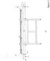
- FIG. 1illustrates a cross-sectional view of an exemplary dryer 100 using an air supply manifold 120 that extends across the width of the drying belt 110 , according to one embodiment.
- the dryer 100includes a cover 101 that provides a cover and headspace above a drying belt 110 for the dryer 100 , an air supply manifold 120 that introduces conditioned air 102 into the dryer 100 and an air outlet exhaust manifold 130 .
- the drying belt 110floats above a heated medium flowing in a trough 150 .
- Trough 150may include a pump to recirculate the heated medium between a heating tank and the trough 150 .
- the heated mediummay include heated water or other forms of heat transfer fluid known in the art.
- Dryer 100includes a single trough 150 , however multiple troughs may be used, with each trough having its own air supply manifold 120 and exhaust manifold 130 . In alternate embodiments, multiple troughs share a single air supply manifold 120 and exhaust manifold 130 .
- dryer 100may be one chamber in a multi-chamber dryer. In a multi-chamber dryer system, a single drying belt 110 spans across all of the drying chambers effectively doubling, tripling, etc. the length of the drying belt 110 . The drying belt 110 is guided by rollers (not shown) that move the drying belt 110 in a continuous loop from one end of the dryer 100 to the other.
- a liquid or slurry productis applied to the drying belt 110 .
- the conditioned air supply manifold 120which extends across the width of the drying belt 110 , introduces conditioned air 102 at the discharge end of the belt 111 , where the dried product is removed from the dryer 100 .
- the exhaust manifold 130is located at the opposite end 112 of the drying belt 110 , near the feed liquid application tray 140 , and moist air is removed via dryer exhaust manifold 130 that extends across the width of the drying belt 110 .
- the liquid or slurry productis dried when moist air is removed by dryer exhaust manifold 130 , at the beginning end 112 of the belt 111 .
- Conditioned air supply manifold 120 at the discharge end 111 of the belt 110provides conditioned air 102 .
- the conditioned air 102 temperatureincreases approximately 15 degrees due to the heat given off by the evaporation of the heated liquid, by the time it reaches the discharge end 111 of the belt 110 , which increases the capacity of moisture that the air can absorb. This can reduce the airflow requirement by as much as 10 times to approximately 200-500 CFM.
- Dried material 190is removed at the discharge end 111 of the belt 110 .
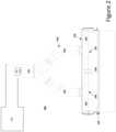
- FIG. 2illustrates an exemplary dryer air supply manifold 240 that distributes conditioned air, according to one embodiment.
- Dryer air supply manifold 240distributes conditioned air 210 across the entire width of the drying belt 220 at the discharge end of the dryer, according to one embodiment.
- Conditioned air supply manifoldhas a Y-shaped design, where the top tube 201 brings in conditioned air 210 from a filtered air system 230 , such as a HEPA system.
- the conditioned air 210travels through lower tubes 202 and 203 and the air is distributed across the entire width of drying belt 220 .
- lower tubes 202 and 203connect to horizontal manifolds 204 and 205 that have sanitary caps allowing for clean-in-place (CIP) cleaning and easy disassembly and reassembly.
- Horizontal manifolds 204 and 205include slits 206 and 207 through which the air 210 is injected into the drying chamber 208 .
- Horizontal manifolds 204 and 205may each have three openings, each opening having a narrow oval shape, according to one embodiment.
- each opening of slit 206 and slit 207is approximately one sixth the width of the dryer belt 320 .
- horizontal manifolds 204 and 205each have a single opening, where each opening is approximately one half the width of the drying belt 220 .
- horizontal manifold 204has a length that is half the width of drying belt 220 .
- Horizontal manifold 204may have a diameter of approximately six inches.
- horizontal manifolds 204 and 205may each include a damper (not shown) to reduce the volume of conditioned air 210 released into chamber 208 through slits 206 and 207 . The damper may also direct the flow of air down towards the drying belt 220 or towards the cover 250 .
- a filtered air system 230provides conditioned air 210 to the conditioned air supply manifold 200 .
- filtered air system 230is an AAON unit, model number RN-025-3-0-EBDA, having a cooling capacity of 290 MBH, and a heating capacity of 328.1 MBH HVAC unit.
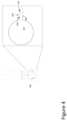
- FIG. 3illustrates a dryer exhaust manifold 300 , according to one embodiment.
- Dryer exhaust manifold 300is located at the beginning end of drying belt 320 near the feed liquid application tray, according to one embodiment.
- Dryer exhaust manifold 300removes moist air 310 across the entire length and width of the drying tunnel 321 .
- Dryer exhaust manifold 300has a rectangular opening 301 that intakes moist air 310 , and pulls up moist air 310 through tube 303 by using an exhaust blower 340 .
- exhaust opening 301has a width that is approximately the width of drying belt 320 .
- exhaust manifold 300may include a damper (not shown) to reduce the volume of moist air 310 removed from the drying chamber.
- An exhaust blower 340discharges moist air 310 to the atmosphere outside the dryer room.
- the exhaust blower 340is a GREENHECK unit, model number CUBE-300XP-50, “Belt Drive Upblast Centrifugal Roof Exhaust Fan” rated for 3000 CFM at SP of 3.5 inches of water gauge driven by a 5 HP variable speed rated motor and variable frequency drive (VFD).
- the exhaust bloweris oversized to create a negative pressure in drying tunnel, increasing the efficiency of evaporation, thus improving the moisture efficiency of moist air 310 removal.
- FIG. 4illustrates an exemplary side view of the conditioned air supply manifold 400 , according to one embodiment.
- Conditioned air supply manifold 400has a circular body 410 that according to one embodiment has a six inch diameter.
- Conditioned air supply manifold 400also includes a supply opening 420 that extends from the circular body 410 .
- Supply opening 420has a top portion 430 and a bottom portion 435 that are parallel to each other.
- top portion 430 and a bottom portion 435are approximately 5/16 of an inch apart from the center of supply opening 420 , creating a 5 ⁇ 8 inch opening 425 .
- Top portion 430 and bottom portion 435may extend approximately 2 inches from the circular body 410 .
- the desired type of opening of dryer air knife 400can vary by application, with circular opening 410 being more efficient for some applications and another type of opening, such as a hexagonal opening, for example, may be more efficient for other applications.
- FIG. 5illustrates an exemplary side view of a hexagonal conditioned air supply manifold 500 , according to one embodiment.
- Conditioned air supply manifold 500has a hexagonal body 510 that according to one embodiment has a six inch width.
- the hexagonal body 510has six sides with adjacent side angles ranging from 120° to 132°, according to some embodiments.
- Conditioned air supply manifold 500also includes a supply opening 520 that extends from the hexagonal body 510 where two sides approach each other.
- Supply opening 520has a top portion 530 and a bottom portion 535 that are parallel to each other.
- top portion 530 and a bottom portion 535are approximately 5/16 of an inch from the center of supply opening 520 , creating a 5 ⁇ 8 inch opening 525 .
- Top portion 530 and bottom portion 535may extend approximately 2 inches from the hexagonal body 510 .
- manifolds described abovemay be made of food grade aluminum or stainless steel, according to one embodiment.
- the manifoldsare made of high temperature plastic such as PVC, or a combination of PVC and metal.
- FIG. 6illustrates a cross-sectional view of two exemplary drying chambers 610 and 620 connectable by way of the discharge end 625 of one chamber and the opposite end 615 of the other chamber, according to one embodiment.
- the connection between drying chambers 610 and 620may be provided by adhesive, locks, sealants, covers, or other attachment mechanisms, according to some embodiments.
- a continuous belt 630may be directed through all of the drying chambers guided by rollers (not shown). These rollers move drying belt 630 in a continuous loop from one end of drying chamber 610 to the opposite end of drying chamber 620 and back again. Drying belt 630 floats above a heated medium flowing in a trough 640 , according to one embodiment. According to another embodiment, one trough per chamber is used where the temperature of the water in each trough is independently controlled.
- Trough 640may include a single pump or one pump per chamber, according to some embodiments.
- the pumps of trough 640recirculate the heated medium between a heating tank and the trough 640 .
- the heated mediummay include heated water or other forms of heat transfer fluid known in the art.
- the temperature of the heated water or other heat transfer fluids within the heated mediumis maintained at a pre-determined temperature.
- Each troughmay have its own conditioned air supply manifold 650 and exhaust manifold 660 .
- multiple troughsshare a single conditioned air supply manifold 650 and exhaust manifold 660 as shown in FIG. 6 .
- Conditioned air supply manifold 650 and exhaust manifold 660attach to the open ends of drying chambers 610 and 620 .
- FIG. 6shows conditioned air supply manifold 650 attaching to the unused side of drying chamber 610 and exhaust manifold 660 attaching to the unused side of dryer 620 .
- These additional drying chambersmay be added or removed in order to provide for an adjustable multi-chamber refractance window dryer, according to one embodiment.
Landscapes
- Engineering & Computer Science (AREA)
- Mechanical Engineering (AREA)
- General Engineering & Computer Science (AREA)
- Life Sciences & Earth Sciences (AREA)
- Microbiology (AREA)
- Chemical & Material Sciences (AREA)
- Combustion & Propulsion (AREA)
- Sustainable Development (AREA)
- Drying Of Solid Materials (AREA)
Abstract
Description
The present application is a continuation of U.S. Non-Provisional application Ser. No. 16/661,830, filed on Oct. 23, 2019 and titled “Low Profile Design Air Tunnel System And Method For Providing Uniform Air Flow In A Refractance Window Dryer,” which claims the benefit of and priority to U.S. Provisional Application Ser. No. 62/751,273, filed on Oct. 26, 2018 and titled “Low Profile Design Air Tunnel System and Method for Providing Uniform Air Flow in a Refractance Window Dryer,” the entire contents of each of which are incorporated by reference.
The present application relates in general to the drying of a product. In particular, the present disclosure is directed to a low profile design air tunnel system and method for providing uniform air flow in a refractance window dryer.
In a traditional drying system, the product to be dried is placed on a continuous belt that floats on the surface of a body of heated water. Heat is transferred by conduction from the circulated heated water directly to the product through a belt of a polymer membrane. The heated water is maintained at a pre-determined temperature to allow optimum drying of the product.
However, the traditional drying system utilizes a large volume of ambient air to remove water vapor released during the product drying process. The uncontrolled humidity and the temperature of ambient air within the dryer leads to a wide variation in dryer performance and product quality. For example, a dryer operating in a dry climate performs differently in a humid climate. Similarly, dryer performance varies in cold and hot climates, and from season-to-season or day to night at the same location.
Furthermore, the traditional drying system increases water vapor pressure in the product by increasing the product temperature due to thermal energy conducted from the body of heated water through the drying belt. However, the traditional drying system does not reduce water vapor pressure, increase the temperature of air within the dryer, or reduce the humidity of air within the dryer, all of which can improve dryer performance.
In a traditional multi-chamber drying system, the product is dried on a continuous belt using a lateral airflow method with and without conditioned air being introduced along one side of the belt in regular intervals, having exhaust mechanisms on the opposite side, in a high and low profile design. Such a design promotes the short circuiting of air, making for inefficient use of the full moisture carrying capacity of the air that was short circuiting. Thus, the design failed to effectively distribute the air across the entire width of the belt.
Another issue with the traditional design was that the perpendicular flow across the belt did not take full advantage of the heat gained from the evaporation of the water from product on belt, consequently requiring significantly more air. The original elevated hood design of the system also resulted in air free flowing high above the belt surface, so any temperature gain was not fully utilized especially given the high CFM flowrate.
A low profile design air tunnel system and method for providing uniform air flow in a refractance window dryer are disclosed. According to one embodiment, a system comprises a conditioned air supply manifold that provides air into a drying chamber. The system has a drying belt directed through the drying chamber. A feed application tray at a first end of the drying belt applies a liquid to the drying belt. The system has an exhaust manifold located at the first end of the drying belt.
The above and other preferred features, including various novel details of implementation and combination of elements, will now be more particularly described with reference to the accompanying drawings and pointed out in the claims. It will be understood that the particular methods and apparatuses are shown by way of illustration only and not as limitations. As will be understood by those skilled in the art, the principles and features explained herein may be employed in various and numerous embodiments.
The present invention will become more apparent in view of the attached drawings and accompanying detailed description. The embodiments depicted therein are provided by way of example, not by way of limitation, wherein like reference numerals/labels generally refer to the same or similar elements. In different drawings, the same or similar elements may be referenced using different reference numerals/labels, however. The drawings are not necessarily to scale, emphasis instead being placed upon illustrating aspects of the invention. In the drawings:
While the present disclosure is subject to various modifications and alternative forms, specific embodiments thereof have been shown by way of example in the drawings and will herein be described in detail. The present disclosure should be understood to not be limited to the particular forms disclosed, but on the contrary, the intention is to cover all modifications, equivalents, and alternatives falling within the spirit and scope of the present disclosure.
A low profile design air tunnel system and method for providing uniform air flow in a refractance window dryer are disclosed. According to one embodiment, a system comprises a conditioned air supply manifold that provides air into a drying chamber. The system has a drying belt directed through the drying chamber. A feed application tray at a first end of the drying belt applies a liquid to the drying belt. The system has an exhaust manifold located at the first end of the drying belt.
The following disclosure provides many different embodiments, or examples, for implementing different features of the subject matter. Specific examples of components and arrangements are described below to simplify the present disclosure. These are, of course, merely examples and are not intended to be limiting. In addition, the present disclosure may repeat reference numerals and/or letters in the various examples. This repetition is for the purpose of simplicity and clarity and does not in itself dictate a relationship between the various embodiments and/or configurations discussed.
Each of the features and teachings disclosed herein can be utilized separately or in conjunction with other features and teachings to provide a multi-chamber dryer using adjustable conditioned air flow with a low profile air tunnel system. Representative examples utilizing many of these additional features and teaching, both separately and in combination, are described in further detail with reference to the attached figures. This detailed description is merely intended to teach a person of skill in the art further details for practicing aspects of the present teachings and is not intended to limit the scope of the claims. Therefore, combinations of features disclosed in the detailed description may not be necessary to practice the teachings in the broadest sense, and are instead taught merely to describe particularly representative examples of the present teachings.
Other features and advantages will become apparent from the following detailed description, taken in conjunction with the accompanying drawings, which illustrate by way of example, the features of the various embodiments.
A multi-chamber dryer using adjustable conditioned counter current air flow with a low profile air tunnel system is disclosed. The present drying system enables the delivery of airflow to remain near the belt/product surface taking full advantage of the heat gain and the increased moisture capacity of the air flowing counter current respective to the belt/product flow. The present drying system increases and improves a dryer throughput at steady state operation. The present drying system improves heat transfer by providing faster water removal from a product surface on a drying belt, uses a simplified and less expensive air handling system, and improves the quality of the dried product with more consistent drying characteristics. The components of the drying system described herein allow for the uniform supply of conditioned air across the width of the drying belt, and a low profile tunnel near the product surface evaporation area with constant air flow that creates a slight negative pressure environment with an exhaust fan, thus the components together enable a more efficient and better performing drying system.
According to one embodiment, an apparatus includes a drying belt configured to receive a product to be dried on a first surface of the drying belt, and a heat medium in contact with a second surface of the drying belt. The heat medium is configured to heat the product and is maintained at a pre-determined temperature. The apparatus further includes a manifold that is positioned above the drying belt, where the manifold includes one or more slits that inject conditioned air across the entire width of the drying belt, directed through the drying chamber towards the exhaust manifold where the product is applied to the belt. Through this process, evaporated water from the product is removed resulting in the formation of dried crystals. According to one embodiment, conditioned air is air that has a predetermined humidity and temperature. The humidity and temperature of the conditioned air may be specific to the types of products being dried. According to another embodiment, the air injected into the dryer is ambient air taken from outside the room or outside the building in which the dryer is installed.
In the description below, for purposes of explanation only, specific nomenclature is set forth to provide a thorough understanding of the present disclosure. However, it will be apparent to one skilled in the art that these specific details are not required to practice the teachings of the present disclosure.
The present drying system dries a liquid or slurry product placed on a continuous drying belt by properly directing conditioned air across the surface of the product, according to one embodiment. The liquid or slurry may be from a plant (e.g., strawberry puree, carrot puree, etc.). The present drying system includes a series of air distribution manifolds to direct conditioned air and an apparatus to improve product feed and removal. In one embodiment, low pressure air is distributed through adjustable slots, or air knives, to effectively distribute the air across the entire width of the drying belt. In another embodiment, the present drying system has low profile side panels, enabling the delivery of airflow to remain near the drying belt, requiring less air than previous designs by taking full advantage of the heat gained from the evaporation of water from product on the drying belt.
According to one embodiment, a liquid or slurry product is applied to the dryingbelt 110. The conditionedair supply manifold 120, which extends across the width of the dryingbelt 110, introduces conditionedair 102 at the discharge end of thebelt 111, where the dried product is removed from thedryer 100. Theexhaust manifold 130 is located at theopposite end 112 of the dryingbelt 110, near the feedliquid application tray 140, and moist air is removed viadryer exhaust manifold 130 that extends across the width of the dryingbelt 110. In one embodiment, the liquid or slurry product is dried when moist air is removed bydryer exhaust manifold 130, at the beginningend 112 of thebelt 111. Conditionedair supply manifold 120 at thedischarge end 111 of thebelt 110 provides conditionedair 102. According to one embodiment, theconditioned air 102 temperature increases approximately 15 degrees due to the heat given off by the evaporation of the heated liquid, by the time it reaches thedischarge end 111 of thebelt 110, which increases the capacity of moisture that the air can absorb. This can reduce the airflow requirement by as much as 10 times to approximately 200-500 CFM. Driedmaterial 190 is removed at thedischarge end 111 of thebelt 110.
A filteredair system 230 provides conditionedair 210 to the conditionedair supply manifold 200. According to one embodiment, filteredair system 230 is an AAON unit, model number RN-025-3-0-EBDA, having a cooling capacity of 290 MBH, and a heating capacity of 328.1 MBH HVAC unit.
According to one embodiment, theexhaust blower 340 is a GREENHECK unit, model number CUBE-300XP-50, “Belt Drive Upblast Centrifugal Roof Exhaust Fan” rated for 3000 CFM at SP of 3.5 inches of water gauge driven by a 5 HP variable speed rated motor and variable frequency drive (VFD). In certain embodiments, the exhaust blower is oversized to create a negative pressure in drying tunnel, increasing the efficiency of evaporation, thus improving the moisture efficiency ofmoist air 310 removal.
The manifolds described above may be made of food grade aluminum or stainless steel, according to one embodiment. In alternate embodiments, the manifolds are made of high temperature plastic such as PVC, or a combination of PVC and metal.
The above example embodiments have been described herein above to illustrate various embodiments of implementing a multi-chamber dryer using adjustable conditioned air flow has been disclosed. Various modifications and departures from the disclosed example embodiments will occur to those having ordinary skill in the art. The subject matter that is intended to be within the scope of the present disclosure is set forth in the following claims.
The foregoing description, for purposes of explanation, used specific nomenclature to provide a thorough understanding of the invention. However, it will be apparent to one skilled in the art that specific details are not required in order to practice the invention. Thus, the foregoing descriptions of specific embodiments of the invention are presented for purposes of illustration and description. They are not intended to be exhaustive or to limit the invention to the precise forms disclosed; many modifications and variations are possible in view of the above teachings. The embodiments were chosen and described in order to best explain the principles of the invention and its practical applications, they thereby enable others skilled in the art to best utilize the invention and various embodiments with various modifications as are suited to the particular use contemplated. It is intended that later filed claims and their equivalents define the scope of the invention.
Claims (20)
1. A drying chamber, comprising:
a drying belt comprising an upper surface configured to transport a product in a first direction, wherein the drying belt floats on a heated medium maintained at a pre-determined temperature;
an air supply manifold positioned at a first end of the drying belt; and
an exhaust manifold positioned at a second end of the drying belt,
wherein air is configured to flow from the air supply manifold to the exhaust manifold above the product and in a second direction opposite to the first direction.
2. The drying chamber ofclaim 1 , wherein the air comprises conditioned air.
3. The drying chamber ofclaim 1 , wherein the exhaust manifold comprises an exhaust fan assembly.
4. The drying chamber ofclaim 1 , wherein the flow of the air creates a negative pressure environment within the drying chamber.
5. The drying chamber ofclaim 1 , wherein the air supply manifold is coupled to a filtered air system that feeds conditioned air into the air supply manifold.
6. The drying chamber ofclaim 5 , wherein the filtered air system has a cooling and heating capacity.
7. The drying chamber ofclaim 1 , wherein the air supply manifold has a circular body.
8. The drying chamber ofclaim 1 , wherein the air supply manifold has a hexagonal body.
9. The drying chamber ofclaim 8 , wherein the hexagonal body has sides with adjacent side angles ranging from 120 degrees to 132 degrees.
10. The drying chamber ofclaim 1 , wherein the product is dried by the air.
11. A method, comprising:
transporting a product in a first direction on an upper surface of a drying belt in a drying chamber, wherein the drying belt floats on a heated medium maintained at a pre-determined temperature;
supplying air to the drying chamber at an air supply manifold positioned at a first end of the drying belt; and
exhausting the air from the drying chamber at an exhaust manifold positioned at a second end of the drying belt,
wherein the air flows from the air supply manifold to the exhaust manifold above the product and in a second direction opposite to the first direction.
12. The method ofclaim 11 , wherein the air flows parallel to the upper surface of the drying belt.
13. The method ofclaim 11 , wherein supplying the air comprises heating the air.
14. The method ofclaim 11 , wherein supplying the air comprises filtering or cooling the air.
15. The method ofclaim 11 , wherein transporting the product comprises applying the product to the upper surface at the second end and removing the product from the upper surface at the first end.
16. The method ofclaim 11 , wherein the air flow creates a negative pressure environment within the drying chamber.
17. The method ofclaim 11 , wherein the air flow is proximal to the upper surface of the drying belt.
18. The method ofclaim 11 , wherein exhausting the air comprises removing the air from the upper surface of the drying belt.
19. The drying chamber ofclaim 1 , wherein the exhaust manifold is positioned at a height above the upper surface.
20. The drying chamber ofclaim 1 , wherein the exhaust manifold comprises an opening having a width that is approximately equal to a width of the drying belt.
Priority Applications (3)
| Application Number | Priority Date | Filing Date | Title |
|---|---|---|---|
| US17/542,197US11740016B2 (en) | 2018-10-26 | 2021-12-03 | Low profile design air tunnel system and method for providing uniform air flow in a refractance window dryer |
| US18/351,038US12181219B2 (en) | 2018-10-26 | 2023-07-12 | Low profile design air tunnel system and method for providing uniform air flow in a Refractance window dryer |
| US18/952,770US20250146748A1 (en) | 2018-10-26 | 2024-11-19 | Low profile design air tunnel system and method for providing uniform air flow in a refractance window dryer |
Applications Claiming Priority (3)
| Application Number | Priority Date | Filing Date | Title |
|---|---|---|---|
| US201862751273P | 2018-10-26 | 2018-10-26 | |
| US16/661,830US11221179B2 (en) | 2018-10-26 | 2019-10-23 | Low profile design air tunnel system and method for providing uniform air flow in a refractance window dryer |
| US17/542,197US11740016B2 (en) | 2018-10-26 | 2021-12-03 | Low profile design air tunnel system and method for providing uniform air flow in a refractance window dryer |
Related Parent Applications (1)
| Application Number | Title | Priority Date | Filing Date |
|---|---|---|---|
| US16/661,830ContinuationUS11221179B2 (en) | 2018-10-26 | 2019-10-23 | Low profile design air tunnel system and method for providing uniform air flow in a refractance window dryer |
Related Child Applications (1)
| Application Number | Title | Priority Date | Filing Date |
|---|---|---|---|
| US18/351,038ContinuationUS12181219B2 (en) | 2018-10-26 | 2023-07-12 | Low profile design air tunnel system and method for providing uniform air flow in a Refractance window dryer |
Publications (2)
| Publication Number | Publication Date |
|---|---|
| US20220090857A1 US20220090857A1 (en) | 2022-03-24 |
| US11740016B2true US11740016B2 (en) | 2023-08-29 |
Family
ID=70326807
Family Applications (4)
| Application Number | Title | Priority Date | Filing Date |
|---|---|---|---|
| US16/661,830Active2040-03-03US11221179B2 (en) | 2018-10-26 | 2019-10-23 | Low profile design air tunnel system and method for providing uniform air flow in a refractance window dryer |
| US17/542,197ActiveUS11740016B2 (en) | 2018-10-26 | 2021-12-03 | Low profile design air tunnel system and method for providing uniform air flow in a refractance window dryer |
| US18/351,038ActiveUS12181219B2 (en) | 2018-10-26 | 2023-07-12 | Low profile design air tunnel system and method for providing uniform air flow in a Refractance window dryer |
| US18/952,770PendingUS20250146748A1 (en) | 2018-10-26 | 2024-11-19 | Low profile design air tunnel system and method for providing uniform air flow in a refractance window dryer |
Family Applications Before (1)
| Application Number | Title | Priority Date | Filing Date |
|---|---|---|---|
| US16/661,830Active2040-03-03US11221179B2 (en) | 2018-10-26 | 2019-10-23 | Low profile design air tunnel system and method for providing uniform air flow in a refractance window dryer |
Family Applications After (2)
| Application Number | Title | Priority Date | Filing Date |
|---|---|---|---|
| US18/351,038ActiveUS12181219B2 (en) | 2018-10-26 | 2023-07-12 | Low profile design air tunnel system and method for providing uniform air flow in a Refractance window dryer |
| US18/952,770PendingUS20250146748A1 (en) | 2018-10-26 | 2024-11-19 | Low profile design air tunnel system and method for providing uniform air flow in a refractance window dryer |
Country Status (10)
| Country | Link |
|---|---|
| US (4) | US11221179B2 (en) |
| EP (2) | EP4632306A2 (en) |
| JP (2) | JP2022505882A (en) |
| CN (1) | CN112867903A (en) |
| AU (2) | AU2019364630B2 (en) |
| BR (1) | BR112021007821A2 (en) |
| CA (1) | CA3115497A1 (en) |
| CL (1) | CL2021001045A1 (en) |
| MX (4) | MX2021004727A (en) |
| WO (1) | WO2020086957A1 (en) |
Cited By (1)
| Publication number | Priority date | Publication date | Assignee | Title |
|---|---|---|---|---|
| US20230349634A1 (en)* | 2018-10-26 | 2023-11-02 | E. & J. Gallo Winery | Low profile design air tunnel system and method for providing uniform air flow in a refractance window dryer |
Families Citing this family (4)
| Publication number | Priority date | Publication date | Assignee | Title |
|---|---|---|---|---|
| WO2013003616A1 (en) | 2011-06-30 | 2013-01-03 | E. & J. Gallo Winery | Natural crystalline colorant and process for production |
| CN112460936B (en)* | 2020-11-30 | 2022-04-29 | 中茶湖南安化第一茶厂有限公司 | Black tea hair drying room and control method thereof |
| EP4572617A1 (en) | 2022-08-17 | 2025-06-25 | E. & J. Gallo Winery | Cannabinoid emulsions and complexes and related methods of manufacture |
| US20240102731A1 (en) | 2022-09-23 | 2024-03-28 | E. & J. Gallo Winery | Mobile refractance window dryer |
Citations (116)
| Publication number | Priority date | Publication date | Assignee | Title |
|---|---|---|---|---|
| US1881063A (en) | 1929-02-18 | 1932-10-04 | Oliver W Randolph | Multiple tray drier |
| US1988031A (en) | 1933-09-30 | 1935-01-15 | S M A Corp | Method of recovering carotene |
| US2134906A (en) | 1935-01-09 | 1938-11-01 | J O Ross Engineering Corp | Metallic lithographic oven |
| GB499539A (en) | 1938-01-04 | 1939-01-25 | Archie Stirling Glen | Improvements in and relating to process of drying materials |
| US2235559A (en)* | 1938-08-17 | 1941-03-18 | Carl F Mayer | Rod baking method and means |
| GB554930A (en) | 1942-01-22 | 1943-07-26 | Alfred Joseph Michael Smith | Improvements relating to apparatus for drying materials |
| GB570827A (en) | 1944-03-25 | 1945-07-24 | Steel Band Conveyor And Engine | An improved method of and means for transferring heat to or from material carried upon a band conveyor |
| GB785584A (en) | 1955-05-06 | 1957-10-30 | Sandvikens Jernverks Ab | Means for cooling or heating of goods |
| US2911732A (en) | 1957-01-11 | 1959-11-10 | George C Webb | Apparatus for dehydration of comestibles |
| US3108402A (en) | 1961-03-16 | 1963-10-29 | Grain Processing Corp | Production of carotenoid pigments |
| US3150005A (en) | 1958-09-22 | 1964-09-22 | Corn Products Co | Machine for treating particulate solids |
| US3151950A (en) | 1960-06-14 | 1964-10-06 | American Can Co | Method and apparatus for drying thin coatings on metallic sheets |
| US3206866A (en) | 1963-02-07 | 1965-09-21 | Magma Power Co | Method and apparatus for dehydrating foods employing geothermal steam |
| US3217421A (en)* | 1962-09-18 | 1965-11-16 | Lowe Edison | Method and apparatus for treating foods with gaseous media |
| US3228113A (en)* | 1960-08-18 | 1966-01-11 | John J Fannon Products Co | Heating apparatus and method |
| US3250315A (en) | 1963-04-08 | 1966-05-10 | American Mach & Foundry | Vapor impingement heating |
| US3258467A (en) | 1963-04-17 | 1966-06-28 | Alexander F H Anderson | Extraction and purification of chlorophyll |
| US3266559A (en) | 1963-02-15 | 1966-08-16 | American Mach & Foundry | Method of drying foamed materials, e. g. foods |
| US3307270A (en) | 1965-10-21 | 1967-03-07 | Lamb Weston Inc | Drying apparatus and method |
| US3436791A (en) | 1965-05-06 | 1969-04-08 | Mach Speciales Sa Soc D Et | Machine for the continuous moulding of a pulverulent or crystalline product in the form of separate lumps |
| US3570576A (en) | 1968-08-22 | 1971-03-16 | Henri Griffon | Continuous dehydration apparatus |
| US3641681A (en) | 1969-10-07 | 1972-02-15 | James Donald Brock | Carpet dryer |
| US3805316A (en) | 1972-06-30 | 1974-04-23 | Purex Corp Ltd | Tray drying apparatus |
| US3915691A (en) | 1972-03-02 | 1975-10-28 | Matsushita Electric Industrial Co Ltd | Method and apparatus of treating industrial waste liquid |
| US4127947A (en) | 1975-01-29 | 1978-12-05 | Wells A. Webb | Method and apparatus for evaporation of moisture from fruit and vegetable particles |
| FR2399467A1 (en) | 1977-08-01 | 1979-03-02 | Verniers Sa | Betalaine colourant prodn. from beet juice - comprises removing sugars by fermentation then concentrating and crystallising |
| US4152842A (en) | 1977-08-04 | 1979-05-08 | Laughlin Enterprises | Dehydrator |
| US4259063A (en)* | 1979-07-30 | 1981-03-31 | Spirin Evgeny T | Apparatus for a heat treatment of products |
| US4306358A (en) | 1979-08-15 | 1981-12-22 | Amf Incorporated | Air drying apparatus |
| JPS57153702A (en) | 1981-03-17 | 1982-09-22 | Okawara Mfg Co Ltd | Nozzle for continuous vacuum drying apparatus |
| US4452822A (en) | 1982-05-17 | 1984-06-05 | United Vintners, Inc. | Extraction and intensification of anthocyanins from grape pomace and other material |
| JPS60248981A (en) | 1984-05-22 | 1985-12-09 | 三洋電機株式会社 | Dehumidifying drying system |
| JPS61223481A (en) | 1985-06-03 | 1986-10-04 | 株式会社日阪製作所 | vacuum belt dryer |
| US4631837A (en) | 1985-05-31 | 1986-12-30 | Magoon Richard E | Method and apparatus for drying fruit pulp and the like |
| US4664061A (en) | 1984-10-26 | 1987-05-12 | Taikisha Ltd. | Spraying booth |
| US4763572A (en) | 1987-04-13 | 1988-08-16 | Kuehl Lawrence J | Apparatus for removing moisture from honey |
| US5052313A (en)* | 1990-04-19 | 1991-10-01 | Combustion Design Corporation | Waste treatment system and method |
| US5098790A (en) | 1988-09-07 | 1992-03-24 | Kaysersberg Packaging, S.A. | Multilayer, uv-radiation stabilized polycarbonate panel |
| JPH04209515A (en) | 1990-12-04 | 1992-07-30 | Murata Mfg Co Ltd | Component drying machine |
| EP0542669A1 (en) | 1991-11-04 | 1993-05-19 | Societe Nouvelle De Chimie Industrielle S.A. | Process for the manufacture of pigments, especially fluorescent pigments |
| US5238503A (en) | 1991-04-09 | 1993-08-24 | International Business Machines Corporation | Device for decontaminating a semiconductor wafer container |
| EP0695510A1 (en) | 1994-07-22 | 1996-02-07 | TMCI (UK) Limited | Sheet material drying |
| US5632097A (en) | 1996-06-28 | 1997-05-27 | Snitchler; William H. | Brine shrimp cyst drying device |
| JPH1015358A (en) | 1996-07-01 | 1998-01-20 | Masatoshi Iwamoto | Production of purified astringent persimmon |
| JPH1151562A (en) | 1997-07-30 | 1999-02-26 | Okawara Mfg Co Ltd | Method and apparatus for preventing clogging of supply nozzle in belt type drying machine |
| US5884769A (en) | 1997-11-19 | 1999-03-23 | Crown Iron Works Company | Particulate material processing tray |
| US6047484A (en) | 1998-07-10 | 2000-04-11 | Bolland; Karin Marie | Method and apparatus for evaporating liquid from a product |
| US6112677A (en) | 1996-03-07 | 2000-09-05 | Sevar Entsorgungsanlagen Gmbh | Down-draft fixed bed gasifier system and use thereof |
| US6195913B1 (en) | 1997-10-10 | 2001-03-06 | Cmc Maquinaria Hortofruiticola | Drying tunnel applicable to fruit and vegetables |
| US6230421B1 (en) | 1999-06-07 | 2001-05-15 | Steven C. Reed, Sr. | Method and apparatus for drying grain |
| US6269550B1 (en)* | 1997-02-12 | 2001-08-07 | Comas S.P.A. | Drying machine for shredded tobacco, in particular for rolls of expanded shredded tobacco |
| CN1323541A (en) | 2000-05-12 | 2001-11-28 | 株式会社富士制作所 | Method and apparatus for hot wind drying instant noodle |
| US20020055471A1 (en) | 2000-08-31 | 2002-05-09 | Bailey David T. | Efficient method for producing compositions enriched in anthocyanins |
| US20020082459A1 (en) | 1997-05-28 | 2002-06-27 | Bailey David T. | High purity beta-carotene and process for obtaining same |
| US20020095818A1 (en) | 2000-09-24 | 2002-07-25 | Jain Nirmal K. | Vapor collection method and apparatus |
| WO2002077105A1 (en) | 2001-03-22 | 2002-10-03 | Fuji Chemical Industry Co., Ltd. | Stable astaxanthin-containing powdery compositions and process for producing the same |
| US6468573B1 (en) | 2000-09-29 | 2002-10-22 | Basic American, Inc. | Process for making rehydratable food pieces using impingement drying |
| US6497107B2 (en) | 2000-07-27 | 2002-12-24 | Idalex Technologies, Inc. | Method and apparatus of indirect-evaporation cooling |
| US20030041780A1 (en) | 1996-01-22 | 2003-03-06 | Isager Per Pihlmann | Water dispersible compositions containing natural hydrophilic water-insoluble pigments, methods of preparing same and their use |
| US6539645B2 (en) | 2001-01-09 | 2003-04-01 | Mark Savarese | Drying apparatus and methods |
| WO2003079816A1 (en) | 2002-03-27 | 2003-10-02 | Indena S.P.A. | A process for the preparation of tomato extracts with high content in lycopene |
| US6688018B2 (en) | 1997-04-02 | 2004-02-10 | Paul B. Soucy | Apparatus for bulk drying of sliced and granular materials |
| US20040191384A1 (en) | 2003-03-25 | 2004-09-30 | Naik Jarpla Pura | Process for the preparation of colorant from oleoresin |
| US20040194337A1 (en) | 2001-06-25 | 2004-10-07 | Gasparini Giacomo Salvatore | Fluid/solid interaction apparatus |
| JP2004293942A (en) | 2003-03-27 | 2004-10-21 | Shibaura Mechatronics Corp | Drying treatment apparatus and drying treatment method |
| US20040231186A1 (en) | 2000-09-24 | 2004-11-25 | Kolb William Blake | Coating process and apparatus |
| US20050068774A1 (en) | 2003-09-26 | 2005-03-31 | Pippa Carlos F. | Spray booth |
| JP2005082588A (en) | 2003-09-04 | 2005-03-31 | Keiichi Tanifuji | Method for producing solution of chlorophyll and screen with light-emitting diode given by reusing sediment |
| US20050115099A1 (en) | 2003-09-12 | 2005-06-02 | Mcd Technologies Incorporated | Method and apparatus for evaporating liquid from a product |
| US20050175720A1 (en) | 2002-04-03 | 2005-08-11 | Mckenzie Maureen A. | Vaccinium species compositions with novel beneficial properties |
| US20050181101A1 (en) | 2004-02-16 | 2005-08-18 | Koichi Harada | Anthocyanin pigments with improved heat-resistance |
| US6990751B2 (en) | 2001-10-03 | 2006-01-31 | Sonic Air Systems, Inc. | Rotatable air knife |
| JP2006506448A (en) | 2002-09-16 | 2006-02-23 | シーピー ケルコ ユー.エス.インク. | Pectin film |
| US20060272174A1 (en) | 2005-05-20 | 2006-12-07 | Klaus Hartig | Deposition chamber desiccation systems and methods of use thereof |
| US20070082399A1 (en) | 2003-07-11 | 2007-04-12 | Tatiana A Egorova-Zachernyuk | Compositions and method for stable isotope labelling of biological compounds |
| US7208181B1 (en) | 2002-06-12 | 2007-04-24 | The United States Of America, As Represented By The Secretary Of Agriculture | Isolation of polyphenolic compounds from fruits or vegetables utilizing sub-critical water extraction |
| US7211413B2 (en) | 2000-09-12 | 2007-05-01 | Meiji Seika Kaisha, Ltd. | Process for producing purified anthocyanin and crystalline anthocyanin |
| US20070110857A1 (en) | 1993-01-21 | 2007-05-17 | Lycored Natural Products Industries Limited | Natural coloring products |
| CN1986539A (en) | 2005-12-20 | 2007-06-27 | 苏州市思源医药科技有限公司 | Bayberry cyanidin extract |
| US20070294911A1 (en) | 2003-09-25 | 2007-12-27 | David Wilson | Dryer, Drying Method and Drying Paint |
| WO2008004206A2 (en) | 2006-07-02 | 2008-01-10 | I.B.R. Israeli Biotechnology Research Ltd. | Carotenoid compositions useful for whitening skin |
| US7325331B2 (en) | 2000-11-29 | 2008-02-05 | Metso Paper, Inc. | Method and equipment for drying a pulp web using hot air of different temperatures |
| US20080075824A1 (en) | 2006-09-25 | 2008-03-27 | Wild Flavors, Inc. | Treatment of Plant Juices, Extracts and Pigments |
| US20080087168A1 (en) | 2006-10-11 | 2008-04-17 | New York Air Brake Corporation | Air Dryer with Pre-Filter |
| US20080201978A1 (en) | 2005-01-13 | 2008-08-28 | Asbjorn Hammer | Device For Drying Material |
| US20080260915A1 (en) | 2007-04-17 | 2008-10-23 | Ahmad Alkayali | Method and apparatus for producing dry food supplements from fruits, vegetables, and other sources |
| CN201184732Y (en) | 2008-01-18 | 2009-01-21 | 山东天力干燥设备有限公司 | Drying apparatus for multi-flowpath horizontal-cycle gypsum board |
| JP2009508877A (en) | 2005-09-19 | 2009-03-05 | ハーバルサイエンス シンガポール ピーティーイー. リミテッド | Compositions and methods comprising Panax species |
| US7572468B1 (en) | 2004-12-28 | 2009-08-11 | The United States Of America As Represented By The Secretary Of Agriculture | Extraction of carotenoids from plant material |
| JP2009531316A (en) | 2006-03-17 | 2009-09-03 | ハーバルサイエンス シンガポール ピーティーイー. リミテッド | Extracts and methods containing elderberry species |
| JP2009531330A (en) | 2006-03-23 | 2009-09-03 | ハーバルサイエンス シンガポール ピーティーイー. リミテッド | Extracts and methods comprising ganoderma species |
| US20090226589A1 (en) | 2008-03-05 | 2009-09-10 | Eber Lopes Ferreira | Manufacturing process of colorant vegetable extracts modified tannin extract |
| US20090246315A1 (en) | 2006-03-03 | 2009-10-01 | Symrise Gmbh & Co. Kg | Pressed agglomerates suitable for consumption having retarded aroma release |
| US20100048957A1 (en) | 2006-06-05 | 2010-02-25 | Kim Darrick S H L | Method to prepare pure curcumin |
| US20100145116A1 (en) | 2007-03-08 | 2010-06-10 | Frederik Van Keulen | Production of High-Purity Carotenoids by Fermenting Selected Bacterial Strains |
| WO2010139746A2 (en) | 2009-06-04 | 2010-12-09 | Sensient Imaging Technologies Gmbh | Spray-dried dye compositions, process for the production and use thereof |
| WO2012009469A2 (en) | 2010-07-13 | 2012-01-19 | Rfi Llc | Enhanced natural colors |
| US20120076904A1 (en) | 2010-09-23 | 2012-03-29 | Sinha Nirmal K | Method for separating and concentrating bioactive phenolics |
| JP2012145281A (en) | 2011-01-12 | 2012-08-02 | Central Research Institute Of Electric Power Industry | Method and system for drying lignite |
| WO2013003616A1 (en) | 2011-06-30 | 2013-01-03 | E. & J. Gallo Winery | Natural crystalline colorant and process for production |
| JP5185098B2 (en) | 2008-12-22 | 2013-04-17 | 株式会社東芝 | Ferroelectric memory |
| US8464437B1 (en) | 2012-05-25 | 2013-06-18 | Wyssmont Company Inc. | Apparatus and method for the treatment of biosolids |
| US20140202028A1 (en) | 2011-08-11 | 2014-07-24 | Avery Dennison Corporation | Inerted Plate Dryer and Method of Drying Solvent Based Coating |
| US8826558B2 (en) | 2012-10-11 | 2014-09-09 | Eastman Kodak Company | Barrier dryer transporting medium through heating liquid |
| US20140259725A1 (en) | 2013-03-15 | 2014-09-18 | E&J Gallo Winery | Multi-Chamber Dryer Using Adjustable Conditioned Air Flow |
| US8889054B2 (en) | 2005-10-17 | 2014-11-18 | The University Of Akron | Hybrid manufacturing platform to produce multifunctional polymeric films |
| CA2987089A1 (en) | 2015-06-19 | 2016-12-22 | Saint-Gobain Isover | Curing oven for crosslinking a continuous mat of inorganic or plant fibres |
| US20170227288A1 (en) | 2014-08-08 | 2017-08-10 | Suez International | Method and facility for thermally drying pasty products |
| CN107388803A (en) | 2017-06-28 | 2017-11-24 | 徐州市沅和牧业有限责任公司 | A kind of herbage drying unit |
| US9829249B2 (en) | 2015-03-10 | 2017-11-28 | Mei, Llc | Wafer dryer apparatus and method |
| US9863704B2 (en) | 2014-03-31 | 2018-01-09 | Pyrotek, Inc. | Chip dryer with integrated exhaust gas treatment |
| US20180045462A1 (en) | 2016-12-11 | 2018-02-15 | Vahid Baeghbali | Ultrasound and infrared assisted conductive hydro-dryer |
| US10335720B2 (en) | 2010-03-18 | 2019-07-02 | Fp Marangoni Inc. | Optimization of vacuum system and methods for drying drill cuttings |
| US20200132370A1 (en) | 2018-10-26 | 2020-04-30 | E&J Gallo Winery | Low Profile Design Air Tunnel System And Method For Providing Uniform Air Flow In A Refractance Window Dryer |
| WO2021022298A2 (en)* | 2019-07-29 | 2021-02-04 | Ksi Conveyor Inc | Mixing and drying conveyor |
| US20220228805A1 (en)* | 2021-01-18 | 2022-07-21 | Rodrick Jolly | Vacuum Grain Drying Apparatus |
Family Cites Families (48)
| Publication number | Priority date | Publication date | Assignee | Title |
|---|---|---|---|---|
| GB862460A (en)* | 1957-02-22 | 1961-03-08 | Coordination Et D Orientation | Drying apparatus |
| LU55862A1 (en)* | 1967-04-22 | 1969-07-03 | ||
| CH567236A5 (en)* | 1973-01-16 | 1975-09-30 | Bereb S A R L Bureau D Etudes | |
| JPS53125433A (en) | 1977-04-08 | 1978-11-01 | Fujimoto Seiyaku Kk | Simultaneous separation and extraction method of pure caroten and red coloring matter from chlorella |
| JPH0633915B2 (en)* | 1987-04-21 | 1994-05-02 | 株式会社前川製作所 | Continuous dry dehumidifier |
| DE4208742A1 (en)* | 1992-03-19 | 1993-09-23 | Schmidt Gmbh Reinhart | Product-drier on moving conveyor using hot air - has skirts at sides of upwards-hinging air-distribution casing extending towards conveyor and regulates air speed dependent on heat-source temp. |
| JPH067750A (en)* | 1992-06-29 | 1994-01-18 | Nippon Seiko Kk | Vacuum degreasing and drying method |
| JPH07158830A (en)* | 1993-12-03 | 1995-06-20 | Masahiro Kubota | Drier and incineration apparatus using the drier |
| JPH07304976A (en) | 1994-05-12 | 1995-11-21 | Sanei Gen F F I Inc | Manufacture of carotenoid dyestuff |
| US5557858A (en)* | 1995-08-25 | 1996-09-24 | Catalytic Industrial Group Inc. | Infrared wood product dryer |
| AUPO705697A0 (en)* | 1997-05-28 | 1997-06-19 | Australian Rural Dehydration Enterprise Pty Ltd | Dehydration plant |
| US6105273A (en)* | 1997-10-28 | 2000-08-22 | Cat-Tec Industries, Inc. | Agitated bed cooling, drying, or heating apparatus |
| US6682598B1 (en)* | 2001-10-01 | 2004-01-27 | Electronic Circuit Systems | Apparatus for casting and drying ceramic tape |
| WO2003063847A1 (en) | 2002-02-01 | 2003-08-07 | Gw Pharma Limited | Compositions comprising cannabinoids for treatment of nausea, vomiting, emesis, motion sickness or like conditions |
| SE527166C2 (en)* | 2003-08-21 | 2006-01-10 | Kerttu Eriksson | Method and apparatus for dehumidification |
| US20050249837A1 (en) | 2004-05-10 | 2005-11-10 | The Procter & Gamble Company | Processes for preparing plant matter extracts and pet food compositions |
| BRPI0516649A (en) | 2004-11-29 | 2008-09-16 | Aloecorp Inc | dehydration of food products |
| JP4677250B2 (en) | 2005-02-24 | 2011-04-27 | Dicライフテック株式会社 | Extraction method of phycocyanin from cyanobacteria |
| AR056742A1 (en) | 2005-10-31 | 2007-10-24 | Gallo Winery E & J | METHOD AND APPARATUS FOR SEPARATING GRAPE SEEDS FROM GRAPE SKIN |
| CN101105363A (en)* | 2007-08-08 | 2008-01-16 | 查晓峰 | Steel belt type dryer |
| JP5272564B2 (en)* | 2008-08-04 | 2013-08-28 | 日産自動車株式会社 | Electrode material drying method and electrode material drying apparatus |
| CN101474833B (en)* | 2009-01-19 | 2011-06-22 | 烟台福松环保科技有限公司 | Technique for drying kation polyacrylamide colloid |
| US8806771B2 (en)* | 2009-02-04 | 2014-08-19 | George A. Holmes | Low impact belt dryer |
| JP5727496B2 (en)* | 2009-10-28 | 2015-06-03 | ダウ テクノロジー インベストメンツ リミティド ライアビリティー カンパニー | Apparatus for drying catalyst roaster conveyor belt and method of using the same |
| JP2011094930A (en)* | 2009-10-30 | 2011-05-12 | Hitachi Plant Technologies Ltd | Environment maintenance method in thin film manufacturing, and device for the same |
| CA2821114C (en)* | 2010-12-10 | 2019-01-15 | Mark Savarese | Drying apparatus and methods |
| US20130122146A1 (en) | 2011-11-16 | 2013-05-16 | Decas Botanical Synergies, Llc | Process for Spray Drying Botanical Food |
| CN102538421B (en)* | 2012-02-29 | 2014-05-14 | 兰州奇正粉体装备技术有限公司 | Method and device for drying by heating and dehydrating |
| BE1020153A5 (en)* | 2012-03-21 | 2013-05-07 | Leon Crosset | CONTINUOUS DRYING APPARATUS FOR PARTICLES. |
| CN103292586A (en)* | 2013-03-20 | 2013-09-11 | 温特牧(北京)科技有限公司 | Drying machine system |
| JP6433646B2 (en) | 2013-10-11 | 2018-12-05 | 三菱重工機械システム株式会社 | Beverage filling method |
| US11143454B2 (en)* | 2013-10-17 | 2021-10-12 | Joseph P. Triglia, Jr. | System and method of removing moisture from fibrous or porous materials using microwave radiation and RF energy |
| US9718065B1 (en) | 2014-02-28 | 2017-08-01 | Tetragrow, Llc | Method of plant resin separation and extraction |
| CN105806066A (en)* | 2014-12-31 | 2016-07-27 | 肖斌 | Intelligent natural leather automatic processing device provided with constant temperature and humidity control system |
| CN104567316B (en)* | 2015-02-02 | 2016-06-22 | 吉首大学 | A kind of heat-pump-type tail recuperation of heat microwave oxygen barrier drying machine |
| US10113795B2 (en)* | 2015-06-26 | 2018-10-30 | M&R Printing Equipment, Inc. | Dryer conveyor belt tracking system |
| CN205425719U (en)* | 2016-02-03 | 2016-08-03 | 叶昌演 | Energy -concerving and environment -protective type domestic fungus flowing water drying -machine |
| US10143706B2 (en) | 2016-06-29 | 2018-12-04 | Cannscience Innovations, Inc. | Decarboxylated cannabis resins, uses thereof and methods of making same |
| IL248150B (en) | 2016-09-29 | 2018-05-31 | Garti Nissim | Method for selective extraction of cannabinoids from a plant source |
| CN106579121B (en)* | 2016-12-13 | 2021-01-29 | 湖南新发食品有限公司 | Method for rapidly preparing dried bamboo shoots |
| EP3554272A4 (en) | 2016-12-16 | 2021-01-06 | Flavorsense | Dried flakes with active ingredients |
| CN207797633U (en)* | 2017-11-13 | 2018-08-31 | 孟州市远弘干燥设备研发有限公司 | Band drier with stirring material function |
| US10955189B2 (en)* | 2017-12-18 | 2021-03-23 | Oliver Manufacturing Company, Inc. | Vibratory fluidized bed dryer |
| WO2019119153A1 (en) | 2017-12-22 | 2019-06-27 | CannScience Innovations Inc. | Apparatus and method for extraction and decarboxylation of phytocannabinoids |
| CN108050816A (en)* | 2018-01-13 | 2018-05-18 | 张培森 | Hydrofuge, alternatively up and down blowing, sirocco reclamation is concentrated to recycle furnace drying method and its equipment |
| CN108278878A (en)* | 2018-03-12 | 2018-07-13 | 哈密绿天使纤维科技有限公司 | Drying cotton machine system |
| WO2019211797A1 (en) | 2018-05-03 | 2019-11-07 | Radient Technologies Inc. | Method of decarboxylating acidic cannabinoids in cannabis extract suspended within a carrier fluid |
| CA3048539A1 (en) | 2018-07-03 | 2020-01-03 | Virgil Macaluso | Methods of heating cannabis plant material |
- 2019
- 2019-10-23USUS16/661,830patent/US11221179B2/enactiveActive
- 2019-10-25CACA3115497Apatent/CA3115497A1/enactivePending
- 2019-10-25MXMX2021004727Apatent/MX2021004727A/enunknown
- 2019-10-25BRBR112021007821-5Apatent/BR112021007821A2/enactiveSearch and Examination
- 2019-10-25EPEP25199170.9Apatent/EP4632306A2/enactivePending
- 2019-10-25CNCN201980068937.3Apatent/CN112867903A/enactivePending
- 2019-10-25EPEP19876047.2Apatent/EP3870918B1/enactiveActive
- 2019-10-25JPJP2021522965Apatent/JP2022505882A/enactivePending
- 2019-10-25WOPCT/US2019/058055patent/WO2020086957A1/ennot_activeCeased
- 2019-10-25AUAU2019364630Apatent/AU2019364630B2/enactiveActive
- 2021
- 2021-04-23MXMX2024008882Apatent/MX2024008882A/enunknown
- 2021-04-23CLCL2021001045Apatent/CL2021001045A1/enunknown
- 2021-04-23MXMX2024008881Apatent/MX2024008881A/enunknown
- 2021-04-23MXMX2024014685Apatent/MX2024014685A/enunknown
- 2021-12-03USUS17/542,197patent/US11740016B2/enactiveActive
- 2023
- 2023-07-12USUS18/351,038patent/US12181219B2/enactiveActive
- 2023-12-05AUAU2023274248Apatent/AU2023274248A1/enactivePending
- 2024
- 2024-11-19USUS18/952,770patent/US20250146748A1/enactivePending
- 2024-12-19JPJP2024223907Apatent/JP2025032373A/enactivePending
Patent Citations (131)
| Publication number | Priority date | Publication date | Assignee | Title |
|---|---|---|---|---|
| US1881063A (en) | 1929-02-18 | 1932-10-04 | Oliver W Randolph | Multiple tray drier |
| US1988031A (en) | 1933-09-30 | 1935-01-15 | S M A Corp | Method of recovering carotene |
| US2134906A (en) | 1935-01-09 | 1938-11-01 | J O Ross Engineering Corp | Metallic lithographic oven |
| GB499539A (en) | 1938-01-04 | 1939-01-25 | Archie Stirling Glen | Improvements in and relating to process of drying materials |
| US2235559A (en)* | 1938-08-17 | 1941-03-18 | Carl F Mayer | Rod baking method and means |
| GB554930A (en) | 1942-01-22 | 1943-07-26 | Alfred Joseph Michael Smith | Improvements relating to apparatus for drying materials |
| GB570827A (en) | 1944-03-25 | 1945-07-24 | Steel Band Conveyor And Engine | An improved method of and means for transferring heat to or from material carried upon a band conveyor |
| GB785584A (en) | 1955-05-06 | 1957-10-30 | Sandvikens Jernverks Ab | Means for cooling or heating of goods |
| US2911732A (en) | 1957-01-11 | 1959-11-10 | George C Webb | Apparatus for dehydration of comestibles |
| US3150005A (en) | 1958-09-22 | 1964-09-22 | Corn Products Co | Machine for treating particulate solids |
| US3151950A (en) | 1960-06-14 | 1964-10-06 | American Can Co | Method and apparatus for drying thin coatings on metallic sheets |
| US3228113A (en)* | 1960-08-18 | 1966-01-11 | John J Fannon Products Co | Heating apparatus and method |
| US3108402A (en) | 1961-03-16 | 1963-10-29 | Grain Processing Corp | Production of carotenoid pigments |
| US3217421A (en)* | 1962-09-18 | 1965-11-16 | Lowe Edison | Method and apparatus for treating foods with gaseous media |
| US3206866A (en) | 1963-02-07 | 1965-09-21 | Magma Power Co | Method and apparatus for dehydrating foods employing geothermal steam |
| US3266559A (en) | 1963-02-15 | 1966-08-16 | American Mach & Foundry | Method of drying foamed materials, e. g. foods |
| US3250315A (en) | 1963-04-08 | 1966-05-10 | American Mach & Foundry | Vapor impingement heating |
| US3258467A (en) | 1963-04-17 | 1966-06-28 | Alexander F H Anderson | Extraction and purification of chlorophyll |
| US3436791A (en) | 1965-05-06 | 1969-04-08 | Mach Speciales Sa Soc D Et | Machine for the continuous moulding of a pulverulent or crystalline product in the form of separate lumps |
| US3307270A (en) | 1965-10-21 | 1967-03-07 | Lamb Weston Inc | Drying apparatus and method |
| US3570576A (en) | 1968-08-22 | 1971-03-16 | Henri Griffon | Continuous dehydration apparatus |
| US3641681A (en) | 1969-10-07 | 1972-02-15 | James Donald Brock | Carpet dryer |
| US3915691A (en) | 1972-03-02 | 1975-10-28 | Matsushita Electric Industrial Co Ltd | Method and apparatus of treating industrial waste liquid |
| US3805316A (en) | 1972-06-30 | 1974-04-23 | Purex Corp Ltd | Tray drying apparatus |
| US4127947A (en) | 1975-01-29 | 1978-12-05 | Wells A. Webb | Method and apparatus for evaporation of moisture from fruit and vegetable particles |
| FR2399467A1 (en) | 1977-08-01 | 1979-03-02 | Verniers Sa | Betalaine colourant prodn. from beet juice - comprises removing sugars by fermentation then concentrating and crystallising |
| US4152842A (en) | 1977-08-04 | 1979-05-08 | Laughlin Enterprises | Dehydrator |
| US4259063A (en)* | 1979-07-30 | 1981-03-31 | Spirin Evgeny T | Apparatus for a heat treatment of products |
| US4306358A (en) | 1979-08-15 | 1981-12-22 | Amf Incorporated | Air drying apparatus |
| JPS57153702A (en) | 1981-03-17 | 1982-09-22 | Okawara Mfg Co Ltd | Nozzle for continuous vacuum drying apparatus |
| US4452822A (en) | 1982-05-17 | 1984-06-05 | United Vintners, Inc. | Extraction and intensification of anthocyanins from grape pomace and other material |
| JPS60248981A (en) | 1984-05-22 | 1985-12-09 | 三洋電機株式会社 | Dehumidifying drying system |
| US4664061A (en) | 1984-10-26 | 1987-05-12 | Taikisha Ltd. | Spraying booth |
| US4631837A (en) | 1985-05-31 | 1986-12-30 | Magoon Richard E | Method and apparatus for drying fruit pulp and the like |
| JPS61223481A (en) | 1985-06-03 | 1986-10-04 | 株式会社日阪製作所 | vacuum belt dryer |
| US4763572A (en) | 1987-04-13 | 1988-08-16 | Kuehl Lawrence J | Apparatus for removing moisture from honey |
| US5098790A (en) | 1988-09-07 | 1992-03-24 | Kaysersberg Packaging, S.A. | Multilayer, uv-radiation stabilized polycarbonate panel |
| US5052313A (en)* | 1990-04-19 | 1991-10-01 | Combustion Design Corporation | Waste treatment system and method |
| US5617647A (en) | 1990-12-04 | 1997-04-08 | Murata Manufacturing Co., Ltd. | Component drier |
| JPH04209515A (en) | 1990-12-04 | 1992-07-30 | Murata Mfg Co Ltd | Component drying machine |
| US5238503A (en) | 1991-04-09 | 1993-08-24 | International Business Machines Corporation | Device for decontaminating a semiconductor wafer container |
| EP0542669A1 (en) | 1991-11-04 | 1993-05-19 | Societe Nouvelle De Chimie Industrielle S.A. | Process for the manufacture of pigments, especially fluorescent pigments |
| US20070110857A1 (en) | 1993-01-21 | 2007-05-17 | Lycored Natural Products Industries Limited | Natural coloring products |
| EP0695510A1 (en) | 1994-07-22 | 1996-02-07 | TMCI (UK) Limited | Sheet material drying |
| US20030041780A1 (en) | 1996-01-22 | 2003-03-06 | Isager Per Pihlmann | Water dispersible compositions containing natural hydrophilic water-insoluble pigments, methods of preparing same and their use |
| US6112677A (en) | 1996-03-07 | 2000-09-05 | Sevar Entsorgungsanlagen Gmbh | Down-draft fixed bed gasifier system and use thereof |
| US5632097A (en) | 1996-06-28 | 1997-05-27 | Snitchler; William H. | Brine shrimp cyst drying device |
| JPH1015358A (en) | 1996-07-01 | 1998-01-20 | Masatoshi Iwamoto | Production of purified astringent persimmon |
| US6269550B1 (en)* | 1997-02-12 | 2001-08-07 | Comas S.P.A. | Drying machine for shredded tobacco, in particular for rolls of expanded shredded tobacco |
| US6688018B2 (en) | 1997-04-02 | 2004-02-10 | Paul B. Soucy | Apparatus for bulk drying of sliced and granular materials |
| US20020082459A1 (en) | 1997-05-28 | 2002-06-27 | Bailey David T. | High purity beta-carotene and process for obtaining same |
| JPH1151562A (en) | 1997-07-30 | 1999-02-26 | Okawara Mfg Co Ltd | Method and apparatus for preventing clogging of supply nozzle in belt type drying machine |
| US6195913B1 (en) | 1997-10-10 | 2001-03-06 | Cmc Maquinaria Hortofruiticola | Drying tunnel applicable to fruit and vegetables |
| US5884769A (en) | 1997-11-19 | 1999-03-23 | Crown Iron Works Company | Particulate material processing tray |
| US6047484A (en) | 1998-07-10 | 2000-04-11 | Bolland; Karin Marie | Method and apparatus for evaporating liquid from a product |
| US6230421B1 (en) | 1999-06-07 | 2001-05-15 | Steven C. Reed, Sr. | Method and apparatus for drying grain |
| US6742277B2 (en) | 2000-05-12 | 2004-06-01 | Fuji Manufacturing Corporation Ltd. | Device and method for drying noodles by hot air |
| CN1323541A (en) | 2000-05-12 | 2001-11-28 | 株式会社富士制作所 | Method and apparatus for hot wind drying instant noodle |
| US6497107B2 (en) | 2000-07-27 | 2002-12-24 | Idalex Technologies, Inc. | Method and apparatus of indirect-evaporation cooling |
| US20020055471A1 (en) | 2000-08-31 | 2002-05-09 | Bailey David T. | Efficient method for producing compositions enriched in anthocyanins |
| US7211413B2 (en) | 2000-09-12 | 2007-05-01 | Meiji Seika Kaisha, Ltd. | Process for producing purified anthocyanin and crystalline anthocyanin |
| US20020095818A1 (en) | 2000-09-24 | 2002-07-25 | Jain Nirmal K. | Vapor collection method and apparatus |
| US20040231186A1 (en) | 2000-09-24 | 2004-11-25 | Kolb William Blake | Coating process and apparatus |
| US6468573B1 (en) | 2000-09-29 | 2002-10-22 | Basic American, Inc. | Process for making rehydratable food pieces using impingement drying |
| US7325331B2 (en) | 2000-11-29 | 2008-02-05 | Metso Paper, Inc. | Method and equipment for drying a pulp web using hot air of different temperatures |
| US6539645B2 (en) | 2001-01-09 | 2003-04-01 | Mark Savarese | Drying apparatus and methods |
| US9068777B2 (en) | 2001-01-09 | 2015-06-30 | Columbia Phytotechnology Llc | Drying apparatus and methods |
| US8984763B2 (en) | 2001-01-09 | 2015-03-24 | Columbia Phyto Technology Llc | Drying apparatus and methods |
| WO2002077105A1 (en) | 2001-03-22 | 2002-10-03 | Fuji Chemical Industry Co., Ltd. | Stable astaxanthin-containing powdery compositions and process for producing the same |
| US20040194337A1 (en) | 2001-06-25 | 2004-10-07 | Gasparini Giacomo Salvatore | Fluid/solid interaction apparatus |
| US6990751B2 (en) | 2001-10-03 | 2006-01-31 | Sonic Air Systems, Inc. | Rotatable air knife |
| WO2003079816A1 (en) | 2002-03-27 | 2003-10-02 | Indena S.P.A. | A process for the preparation of tomato extracts with high content in lycopene |
| US20050175720A1 (en) | 2002-04-03 | 2005-08-11 | Mckenzie Maureen A. | Vaccinium species compositions with novel beneficial properties |
| US7208181B1 (en) | 2002-06-12 | 2007-04-24 | The United States Of America, As Represented By The Secretary Of Agriculture | Isolation of polyphenolic compounds from fruits or vegetables utilizing sub-critical water extraction |
| JP2006506448A (en) | 2002-09-16 | 2006-02-23 | シーピー ケルコ ユー.エス.インク. | Pectin film |
| US20040191384A1 (en) | 2003-03-25 | 2004-09-30 | Naik Jarpla Pura | Process for the preparation of colorant from oleoresin |
| JP2004293942A (en) | 2003-03-27 | 2004-10-21 | Shibaura Mechatronics Corp | Drying treatment apparatus and drying treatment method |
| US20070082399A1 (en) | 2003-07-11 | 2007-04-12 | Tatiana A Egorova-Zachernyuk | Compositions and method for stable isotope labelling of biological compounds |
| JP2005082588A (en) | 2003-09-04 | 2005-03-31 | Keiichi Tanifuji | Method for producing solution of chlorophyll and screen with light-emitting diode given by reusing sediment |
| US20050115099A1 (en) | 2003-09-12 | 2005-06-02 | Mcd Technologies Incorporated | Method and apparatus for evaporating liquid from a product |
| US6990748B2 (en) | 2003-09-12 | 2006-01-31 | Karin M. Bolland | Method and apparatus for evaporating liquid from a product |
| US20070294911A1 (en) | 2003-09-25 | 2007-12-27 | David Wilson | Dryer, Drying Method and Drying Paint |
| US20050068774A1 (en) | 2003-09-26 | 2005-03-31 | Pippa Carlos F. | Spray booth |
| US20050181101A1 (en) | 2004-02-16 | 2005-08-18 | Koichi Harada | Anthocyanin pigments with improved heat-resistance |
| US7572468B1 (en) | 2004-12-28 | 2009-08-11 | The United States Of America As Represented By The Secretary Of Agriculture | Extraction of carotenoids from plant material |
| US20080201978A1 (en) | 2005-01-13 | 2008-08-28 | Asbjorn Hammer | Device For Drying Material |
| US20060272174A1 (en) | 2005-05-20 | 2006-12-07 | Klaus Hartig | Deposition chamber desiccation systems and methods of use thereof |
| JP2009508877A (en) | 2005-09-19 | 2009-03-05 | ハーバルサイエンス シンガポール ピーティーイー. リミテッド | Compositions and methods comprising Panax species |
| US8889054B2 (en) | 2005-10-17 | 2014-11-18 | The University Of Akron | Hybrid manufacturing platform to produce multifunctional polymeric films |
| CN1986539A (en) | 2005-12-20 | 2007-06-27 | 苏州市思源医药科技有限公司 | Bayberry cyanidin extract |
| US20090246315A1 (en) | 2006-03-03 | 2009-10-01 | Symrise Gmbh & Co. Kg | Pressed agglomerates suitable for consumption having retarded aroma release |
| JP2009531316A (en) | 2006-03-17 | 2009-09-03 | ハーバルサイエンス シンガポール ピーティーイー. リミテッド | Extracts and methods containing elderberry species |
| JP2009531330A (en) | 2006-03-23 | 2009-09-03 | ハーバルサイエンス シンガポール ピーティーイー. リミテッド | Extracts and methods comprising ganoderma species |
| US20100048957A1 (en) | 2006-06-05 | 2010-02-25 | Kim Darrick S H L | Method to prepare pure curcumin |
| WO2008004206A2 (en) | 2006-07-02 | 2008-01-10 | I.B.R. Israeli Biotechnology Research Ltd. | Carotenoid compositions useful for whitening skin |
| US20080075824A1 (en) | 2006-09-25 | 2008-03-27 | Wild Flavors, Inc. | Treatment of Plant Juices, Extracts and Pigments |
| US20080087168A1 (en) | 2006-10-11 | 2008-04-17 | New York Air Brake Corporation | Air Dryer with Pre-Filter |
| US20100145116A1 (en) | 2007-03-08 | 2010-06-10 | Frederik Van Keulen | Production of High-Purity Carotenoids by Fermenting Selected Bacterial Strains |
| US20080260915A1 (en) | 2007-04-17 | 2008-10-23 | Ahmad Alkayali | Method and apparatus for producing dry food supplements from fruits, vegetables, and other sources |
| CN201184732Y (en) | 2008-01-18 | 2009-01-21 | 山东天力干燥设备有限公司 | Drying apparatus for multi-flowpath horizontal-cycle gypsum board |
| US20090226589A1 (en) | 2008-03-05 | 2009-09-10 | Eber Lopes Ferreira | Manufacturing process of colorant vegetable extracts modified tannin extract |
| JP5185098B2 (en) | 2008-12-22 | 2013-04-17 | 株式会社東芝 | Ferroelectric memory |
| WO2010139746A2 (en) | 2009-06-04 | 2010-12-09 | Sensient Imaging Technologies Gmbh | Spray-dried dye compositions, process for the production and use thereof |
| US10335720B2 (en) | 2010-03-18 | 2019-07-02 | Fp Marangoni Inc. | Optimization of vacuum system and methods for drying drill cuttings |
| WO2012009469A2 (en) | 2010-07-13 | 2012-01-19 | Rfi Llc | Enhanced natural colors |
| US20120076904A1 (en) | 2010-09-23 | 2012-03-29 | Sinha Nirmal K | Method for separating and concentrating bioactive phenolics |
| JP2012145281A (en) | 2011-01-12 | 2012-08-02 | Central Research Institute Of Electric Power Industry | Method and system for drying lignite |
| WO2013003616A1 (en) | 2011-06-30 | 2013-01-03 | E. & J. Gallo Winery | Natural crystalline colorant and process for production |
| EP2725925B1 (en) | 2011-06-30 | 2021-08-04 | E. & J. Gallo Winery | Process for the production of natural crystalline colorant and related processing system |
| EP3369783A1 (en) | 2011-06-30 | 2018-09-05 | E. & J. Gallo Winery | A system to produce a natural crystalline colorant |
| US20140202028A1 (en) | 2011-08-11 | 2014-07-24 | Avery Dennison Corporation | Inerted Plate Dryer and Method of Drying Solvent Based Coating |
| US8464437B1 (en) | 2012-05-25 | 2013-06-18 | Wyssmont Company Inc. | Apparatus and method for the treatment of biosolids |
| US8826558B2 (en) | 2012-10-11 | 2014-09-09 | Eastman Kodak Company | Barrier dryer transporting medium through heating liquid |
| US20140259725A1 (en) | 2013-03-15 | 2014-09-18 | E&J Gallo Winery | Multi-Chamber Dryer Using Adjustable Conditioned Air Flow |
| WO2014145952A1 (en) | 2013-03-15 | 2014-09-18 | E & J Gallo Winery | Dryer using adjustable conditioned air flow |
| US9863704B2 (en) | 2014-03-31 | 2018-01-09 | Pyrotek, Inc. | Chip dryer with integrated exhaust gas treatment |
| US20170227288A1 (en) | 2014-08-08 | 2017-08-10 | Suez International | Method and facility for thermally drying pasty products |
| US9829249B2 (en) | 2015-03-10 | 2017-11-28 | Mei, Llc | Wafer dryer apparatus and method |
| CA2987089A1 (en) | 2015-06-19 | 2016-12-22 | Saint-Gobain Isover | Curing oven for crosslinking a continuous mat of inorganic or plant fibres |
| US20180156539A1 (en) | 2015-06-19 | 2018-06-07 | Saint-Gobain Isover | Drying oven for crosslinking a continuous mat of mineral or plant fibers |
| FR3037640A1 (en) | 2015-06-19 | 2016-12-23 | Saint Gobain Isover | ETCH FOR CROSSLINKING A CONTINUOUS MATTRESS OF MINERAL OR VEGETABLE FIBERS |
| WO2016203170A1 (en) | 2015-06-19 | 2016-12-22 | Saint-Gobain Isover | Curing oven for crosslinking a continuous mat of inorganic or plant fibres |
| US20180045462A1 (en) | 2016-12-11 | 2018-02-15 | Vahid Baeghbali | Ultrasound and infrared assisted conductive hydro-dryer |
| CN107388803A (en) | 2017-06-28 | 2017-11-24 | 徐州市沅和牧业有限责任公司 | A kind of herbage drying unit |
| US20200132370A1 (en) | 2018-10-26 | 2020-04-30 | E&J Gallo Winery | Low Profile Design Air Tunnel System And Method For Providing Uniform Air Flow In A Refractance Window Dryer |
| WO2020086957A1 (en)* | 2018-10-26 | 2020-04-30 | E. & J. Gallo Winery | Low profile design air tunnel system and method for providing uniform air flow in a refractance window dryer |
| CA3115497A1 (en)* | 2018-10-26 | 2020-04-30 | E. & J. Gallo Winery | Low profile design air tunnel system and method for providing uniform air flow in a refractance window dryer |
| US11221179B2 (en)* | 2018-10-26 | 2022-01-11 | E. & J. Gallo Winery | Low profile design air tunnel system and method for providing uniform air flow in a refractance window dryer |
| US20220090857A1 (en)* | 2018-10-26 | 2022-03-24 | E. & J. Gallo Winery | Low profile design air tunnel system and method for providing uniform air flow in a refractance window dryer |
| WO2021022298A2 (en)* | 2019-07-29 | 2021-02-04 | Ksi Conveyor Inc | Mixing and drying conveyor |
| US20220228805A1 (en)* | 2021-01-18 | 2022-07-21 | Rodrick Jolly | Vacuum Grain Drying Apparatus |
Non-Patent Citations (28)
| Title |
|---|
| Ayhan, Topuz et al; Influence of different drying methods of carotenoids and capsaicinoids of paprika (CV jalapeno) Food Chemistry, Elsevier LtD, NL, vol. 129, No. 3; Nat 5, 2011, pp. 860-865. |
| Bolland: Refractance Window Food Drying System Delivers Quality Product Efficiently, Jul. 21, 2000; Retrieved from the Internet: URL:https://www.foodonline.com/doc/refractance- window-food-drying-system-deliver-0001, retrieved on Jun. 29, 2018. |
| Buskov et al, Separation of chlorophylls and their degradation products using packed column supercritical fluid chromatography (SFC) HRC, Journal of High Resolution Chromatography (1999), vol. 22, No. 6, pp. 339-342. |
| Caparino et al., "Effect of drying methods on the physical properties and microstructures of mango (Philippine ‘Carabao’ var.) powder",, Journal of Food Engineering 111 (2012). |
| Careri, Supercritical fluid extraction for liquid chromatographic determination of carotenoids in Spirulina pacifica algae: a chemometric approach. Journal of chromatography. A, (Mar. 3., 2001) vol. 912, No. 1, pp. 61-71 (Year: 2001). |
| Clarke, Phillip, Refractance Window TM Down Under, Jan. 1, 2004, pp. 813-820, XPO55489211, Retrieved from the internet: URL: http://files.gwdryer.com/dryer-technology-comparison.pdf—Retrieved on Jun. 29, 2018, Chapter: "The Refractance Windows Process"; p. 814. |
| European Search Report dated Jul. 6, 2018 in corresponding EP Application No. EP18154793 filed on Feb. 1, 2018. |
| Hossain, Concentration of anthocyanin pigments in blackcurrant pomace by ultrafiltration. Food Australia (2003), vol. 55, No. 6, pp. 263-266. |
| Ide et al., Ultrafiltration with spiral wound membrane technology. Official Proceedings—International Water Conference (1990), 51st, 362-73. |
| International Search Report and Written Opinion for International Patent Application No. PCT/US2014/030810, dated Aug. 20, 2014 (8 Pages). |
| International Search Report and Written Opinion for International Patent Application No. PCT/US2019/058055, dated Jan. 10, 2020 (8 pages). |
| International Search Report dated Jul. 12, 2012 in corresponding PCT Application No. PCT/US2012/046687, filed Jun. 28, 2012, inventor(s) Rossi, Joseph et al. |
| Lionetto. Effect of the daily ingestion of a purified anthocyanin extract from grape skin on rat serum antioxidant capacity. Physiological research/ Academia Scientiarum Bohemoslovaca, (2011) vol. 60, No. 4, pp. 637-645. Electronic Publication Date: May 16, 2011. |
| Nindo et al., Refractance window dehydration technology: a novel contact drying method. Drying Technology (2007), 25(1-3), 37-48 (Year: 2007). |
| Office Action dated Aug. 21, 2018 by the Japanese Patent Office (JPO) in corresponding Japanese application No. 2017-126421 filed on Jun. 28, 2017. |
| Office Action dated Jul. 24, 2018 by the Japanese Patent Office (JPO) in corresponding Japanese application No. 2017-126401 filed on Jun. 8, 2017. |
| Office Action dated Sep. 5, 2018 by Canadian Intellectual Property Office (CIPO) in corresponding Canadian application No. 2,840,213 filed on Jun. 12, 2012. |
| Pavan,"Effects of freeze drying, refractive window drying and hot-air drying on the quality parameter of Acai", Master Thesis, University of Illinois, 2010. |
| Ravindra, Antioxidant activity of the anthocyanin from carrot (Daucus carota) callus culture. International journal of food sciences and nutrition, (Sep. 2003) vol. 54, No. 5, pp. 349-355. |
| Shao, J; Zydney, A, "Optimization of Ultrafiltration/Diafiltration Processes for Partially Bound Impurities", Biotechnology and Bioengineering, 87/3, pp. 286-292, Jul. 7, 2004. |
| Skerget et al., Separation of paprika components using dense CO2. Acta Alimentaria (Budapest) (1998), vol. 27, No. 2, pp. 149-160. |
| Sunlite Flat Multiwall Polycarbonate Sheet. Palram., (Mar. 4, 2013), URL: https://web.archive.org/Web/20130304050051/http://www.palram.com/SUNLITE, (Jul. 7, 2014), XP055281823. |
| Thao et al.,"Methods to characterize the structure of food powders", Bioscience, Biotechnology, and Biochemistry, vol. 81, Issue 4,Apr. 3, 2017. |
| U.S. Appl. No. 17/201,978, filed Mar. 15, 2021, Natural Crystalline Colorant and Process for Production, Rossi. |
| U.S. Appl. No. 17/558,221, filed Dec. 21, 2021, Multi-Chamber Dryer Using Adjustable Conditioned Air Flow, Rossi. |
| U.S. Appl. No. 17/708,949, filed Mar. 30, 2022, Natural Crystalline Colorant and Process for Production, Rossi. |
| Zhao, Yun-xia et al., Research on the purification and antioxidant activity of mulberry red pigment, Science and Technology of Food Industry, vol. 29, pp. 250-253 2008. |
| Zimmer, Membrane filtration: practical experience with juice pre-treatment and filtration of coloured juices. Fruit Processing (2007), 17(3), 153-158. |
Cited By (2)
| Publication number | Priority date | Publication date | Assignee | Title |
|---|---|---|---|---|
| US20230349634A1 (en)* | 2018-10-26 | 2023-11-02 | E. & J. Gallo Winery | Low profile design air tunnel system and method for providing uniform air flow in a refractance window dryer |
| US12181219B2 (en)* | 2018-10-26 | 2024-12-31 | E. &J. Gallo Winery | Low profile design air tunnel system and method for providing uniform air flow in a Refractance window dryer |
Also Published As
| Publication number | Publication date |
|---|---|
| AU2023274248A1 (en) | 2023-12-21 |
| AU2019364630A1 (en) | 2021-04-29 |
| JP2025032373A (en) | 2025-03-11 |
| US20200132370A1 (en) | 2020-04-30 |
| EP3870918B1 (en) | 2025-09-10 |
| US20230349634A1 (en) | 2023-11-02 |
| MX2021004727A (en) | 2021-06-04 |
| MX2024014685A (en) | 2025-01-09 |
| US20250146748A1 (en) | 2025-05-08 |
| EP3870918A4 (en) | 2022-11-02 |
| WO2020086957A1 (en) | 2020-04-30 |
| CN112867903A (en) | 2021-05-28 |
| MX2024008881A (en) | 2024-07-29 |
| BR112021007821A2 (en) | 2021-07-27 |
| CA3115497A1 (en) | 2020-04-30 |
| US12181219B2 (en) | 2024-12-31 |
| EP3870918A1 (en) | 2021-09-01 |
| US20220090857A1 (en) | 2022-03-24 |
| AU2019364630B2 (en) | 2023-12-07 |
| EP4632306A2 (en) | 2025-10-15 |
| CL2021001045A1 (en) | 2021-11-26 |
| MX2024008882A (en) | 2024-07-29 |
| US11221179B2 (en) | 2022-01-11 |
| JP2022505882A (en) | 2022-01-14 |
Similar Documents
| Publication | Publication Date | Title |
|---|---|---|
| US11740016B2 (en) | Low profile design air tunnel system and method for providing uniform air flow in a refractance window dryer | |
| CA2964453C (en) | Mixed flow grain dryer with vacuum cool heat recovery system | |
| US20220113087A1 (en) | Multi-chamber dryer using adjustable conditioned air flow | |
| CN212457827U (en) | Drying device for agricultural product storage | |
| US20160040932A1 (en) | Multiple intermittence beehive grain dryer | |
| CN209279619U (en) | A kind of organic fertilizer drying equipment | |
| CN110186253A (en) | Microwave dryer for grain processing and drying method thereof | |
| CN114223712B (en) | Efficient fruit vegetables freeze-drying device | |
| JPH10178930A (en) | Cultivation house | |
| KR101621474B1 (en) | Apparatus for roasting and drying laver | |
| CN223345850U (en) | Drying unit with heat management structure and drying device with same | |
| CN222279203U (en) | A belt dryer | |
| CN223271602U (en) | Natural gas tunnel dryer | |
| CN218672909U (en) | Novel clean low temperature drying machine | |
| CN215983600U (en) | Heat pump dehumidification drying equipment that connects in parallel of matrimony vine processing usefulness | |
| CN216522936U (en) | Powder dehumidification drying device | |
| RU60694U1 (en) | GRAIN DRYING DEVICE | |
| CN211526893U (en) | High-efficient dewatering device of fruit vegetables pu' er tea | |
| RU2070693C1 (en) | Convention drier | |
| CN106766715A (en) | A kind of food baking room and application | |
| LV15077B (en) | Device for sunflower drying |
Legal Events
| Date | Code | Title | Description |
|---|---|---|---|
| FEPP | Fee payment procedure | Free format text:ENTITY STATUS SET TO UNDISCOUNTED (ORIGINAL EVENT CODE: BIG.); ENTITY STATUS OF PATENT OWNER: LARGE ENTITY | |
| STPP | Information on status: patent application and granting procedure in general | Free format text:DOCKETED NEW CASE - READY FOR EXAMINATION | |
| AS | Assignment | Owner name:E. & J. GALLO WINERY, CALIFORNIA Free format text:ASSIGNMENT OF ASSIGNORS INTEREST;ASSIGNORS:ORTIZ, JORGE;DELAO, ERNESTO RIOS;BURGESS, DAN;SIGNING DATES FROM 20200324 TO 20200325;REEL/FRAME:059489/0239 | |
| STPP | Information on status: patent application and granting procedure in general | Free format text:NON FINAL ACTION MAILED | |
| STPP | Information on status: patent application and granting procedure in general | Free format text:NOTICE OF ALLOWANCE MAILED -- APPLICATION RECEIVED IN OFFICE OF PUBLICATIONS | |
| STCF | Information on status: patent grant | Free format text:PATENTED CASE |