US11738530B2 - Methods for manufacturing wind turbine rotor blade components - Google Patents
Methods for manufacturing wind turbine rotor blade componentsDownload PDFInfo
- Publication number
- US11738530B2 US11738530B2US15/928,254US201815928254AUS11738530B2US 11738530 B2US11738530 B2US 11738530B2US 201815928254 AUS201815928254 AUS 201815928254AUS 11738530 B2US11738530 B2US 11738530B2
- Authority
- US
- United States
- Prior art keywords
- pultruded
- flat sheet
- rotor blade
- roller
- sheet
- Prior art date
- Legal status (The legal status is an assumption and is not a legal conclusion. Google has not performed a legal analysis and makes no representation as to the accuracy of the status listed.)
- Active, expires
Links
Images


Classifications
- B—PERFORMING OPERATIONS; TRANSPORTING
- B29—WORKING OF PLASTICS; WORKING OF SUBSTANCES IN A PLASTIC STATE IN GENERAL
- B29D—PRODUCING PARTICULAR ARTICLES FROM PLASTICS OR FROM SUBSTANCES IN A PLASTIC STATE
- B29D99/00—Subject matter not provided for in other groups of this subclass
- B29D99/0025—Producing blades or the like, e.g. blades for turbines, propellers, or wings
- B—PERFORMING OPERATIONS; TRANSPORTING
- B29—WORKING OF PLASTICS; WORKING OF SUBSTANCES IN A PLASTIC STATE IN GENERAL
- B29C—SHAPING OR JOINING OF PLASTICS; SHAPING OF MATERIAL IN A PLASTIC STATE, NOT OTHERWISE PROVIDED FOR; AFTER-TREATMENT OF THE SHAPED PRODUCTS, e.g. REPAIRING
- B29C51/00—Shaping by thermoforming, i.e. shaping sheets or sheet like preforms after heating, e.g. shaping sheets in matched moulds or by deep-drawing; Apparatus therefor
- B29C51/08—Deep drawing or matched-mould forming, i.e. using mechanical means only
- B—PERFORMING OPERATIONS; TRANSPORTING
- B29—WORKING OF PLASTICS; WORKING OF SUBSTANCES IN A PLASTIC STATE IN GENERAL
- B29C—SHAPING OR JOINING OF PLASTICS; SHAPING OF MATERIAL IN A PLASTIC STATE, NOT OTHERWISE PROVIDED FOR; AFTER-TREATMENT OF THE SHAPED PRODUCTS, e.g. REPAIRING
- B29C51/00—Shaping by thermoforming, i.e. shaping sheets or sheet like preforms after heating, e.g. shaping sheets in matched moulds or by deep-drawing; Apparatus therefor
- B29C51/12—Shaping by thermoforming, i.e. shaping sheets or sheet like preforms after heating, e.g. shaping sheets in matched moulds or by deep-drawing; Apparatus therefor of articles having inserts or reinforcements
- B—PERFORMING OPERATIONS; TRANSPORTING
- B29—WORKING OF PLASTICS; WORKING OF SUBSTANCES IN A PLASTIC STATE IN GENERAL
- B29C—SHAPING OR JOINING OF PLASTICS; SHAPING OF MATERIAL IN A PLASTIC STATE, NOT OTHERWISE PROVIDED FOR; AFTER-TREATMENT OF THE SHAPED PRODUCTS, e.g. REPAIRING
- B29C51/00—Shaping by thermoforming, i.e. shaping sheets or sheet like preforms after heating, e.g. shaping sheets in matched moulds or by deep-drawing; Apparatus therefor
- B29C51/26—Component parts, details or accessories; Auxiliary operations
- B29C51/42—Heating or cooling
- B29C51/421—Heating or cooling of preforms, specially adapted for thermoforming
- B—PERFORMING OPERATIONS; TRANSPORTING
- B29—WORKING OF PLASTICS; WORKING OF SUBSTANCES IN A PLASTIC STATE IN GENERAL
- B29C—SHAPING OR JOINING OF PLASTICS; SHAPING OF MATERIAL IN A PLASTIC STATE, NOT OTHERWISE PROVIDED FOR; AFTER-TREATMENT OF THE SHAPED PRODUCTS, e.g. REPAIRING
- B29C51/00—Shaping by thermoforming, i.e. shaping sheets or sheet like preforms after heating, e.g. shaping sheets in matched moulds or by deep-drawing; Apparatus therefor
- B29C51/26—Component parts, details or accessories; Auxiliary operations
- B29C51/44—Removing or ejecting moulded articles
- B—PERFORMING OPERATIONS; TRANSPORTING
- B29—WORKING OF PLASTICS; WORKING OF SUBSTANCES IN A PLASTIC STATE IN GENERAL
- B29C—SHAPING OR JOINING OF PLASTICS; SHAPING OF MATERIAL IN A PLASTIC STATE, NOT OTHERWISE PROVIDED FOR; AFTER-TREATMENT OF THE SHAPED PRODUCTS, e.g. REPAIRING
- B29C65/00—Joining or sealing of preformed parts, e.g. welding of plastics materials; Apparatus therefor
- B29C65/02—Joining or sealing of preformed parts, e.g. welding of plastics materials; Apparatus therefor by heating, with or without pressure
- B29C65/08—Joining or sealing of preformed parts, e.g. welding of plastics materials; Apparatus therefor by heating, with or without pressure using ultrasonic vibrations
- B—PERFORMING OPERATIONS; TRANSPORTING
- B29—WORKING OF PLASTICS; WORKING OF SUBSTANCES IN A PLASTIC STATE IN GENERAL
- B29C—SHAPING OR JOINING OF PLASTICS; SHAPING OF MATERIAL IN A PLASTIC STATE, NOT OTHERWISE PROVIDED FOR; AFTER-TREATMENT OF THE SHAPED PRODUCTS, e.g. REPAIRING
- B29C65/00—Joining or sealing of preformed parts, e.g. welding of plastics materials; Apparatus therefor
- B29C65/78—Means for handling the parts to be joined, e.g. for making containers or hollow articles, e.g. means for handling sheets, plates, web-like materials, tubular articles, hollow articles or elements to be joined therewith; Means for discharging the joined articles from the joining apparatus
- B29C65/7841—Holding or clamping means for handling purposes
- B—PERFORMING OPERATIONS; TRANSPORTING
- B29—WORKING OF PLASTICS; WORKING OF SUBSTANCES IN A PLASTIC STATE IN GENERAL
- B29C—SHAPING OR JOINING OF PLASTICS; SHAPING OF MATERIAL IN A PLASTIC STATE, NOT OTHERWISE PROVIDED FOR; AFTER-TREATMENT OF THE SHAPED PRODUCTS, e.g. REPAIRING
- B29C66/00—General aspects of processes or apparatus for joining preformed parts
- B29C66/40—General aspects of joining substantially flat articles, e.g. plates, sheets or web-like materials; Making flat seams in tubular or hollow articles; Joining single elements to substantially flat surfaces
- B29C66/47—Joining single elements to sheets, plates or other substantially flat surfaces
- B29C66/472—Joining single elements to sheets, plates or other substantially flat surfaces said single elements being substantially flat
- B—PERFORMING OPERATIONS; TRANSPORTING
- B29—WORKING OF PLASTICS; WORKING OF SUBSTANCES IN A PLASTIC STATE IN GENERAL
- B29C—SHAPING OR JOINING OF PLASTICS; SHAPING OF MATERIAL IN A PLASTIC STATE, NOT OTHERWISE PROVIDED FOR; AFTER-TREATMENT OF THE SHAPED PRODUCTS, e.g. REPAIRING
- B29C66/00—General aspects of processes or apparatus for joining preformed parts
- B29C66/70—General aspects of processes or apparatus for joining preformed parts characterised by the composition, physical properties or the structure of the material of the parts to be joined; Joining with non-plastics material
- B29C66/72—General aspects of processes or apparatus for joining preformed parts characterised by the composition, physical properties or the structure of the material of the parts to be joined; Joining with non-plastics material characterised by the structure of the material of the parts to be joined
- B29C66/721—Fibre-reinforced materials
- B—PERFORMING OPERATIONS; TRANSPORTING
- B29—WORKING OF PLASTICS; WORKING OF SUBSTANCES IN A PLASTIC STATE IN GENERAL
- B29C—SHAPING OR JOINING OF PLASTICS; SHAPING OF MATERIAL IN A PLASTIC STATE, NOT OTHERWISE PROVIDED FOR; AFTER-TREATMENT OF THE SHAPED PRODUCTS, e.g. REPAIRING
- B29C66/00—General aspects of processes or apparatus for joining preformed parts
- B29C66/70—General aspects of processes or apparatus for joining preformed parts characterised by the composition, physical properties or the structure of the material of the parts to be joined; Joining with non-plastics material
- B29C66/72—General aspects of processes or apparatus for joining preformed parts characterised by the composition, physical properties or the structure of the material of the parts to be joined; Joining with non-plastics material characterised by the structure of the material of the parts to be joined
- B29C66/723—General aspects of processes or apparatus for joining preformed parts characterised by the composition, physical properties or the structure of the material of the parts to be joined; Joining with non-plastics material characterised by the structure of the material of the parts to be joined being multi-layered
- B—PERFORMING OPERATIONS; TRANSPORTING
- B29—WORKING OF PLASTICS; WORKING OF SUBSTANCES IN A PLASTIC STATE IN GENERAL
- B29C—SHAPING OR JOINING OF PLASTICS; SHAPING OF MATERIAL IN A PLASTIC STATE, NOT OTHERWISE PROVIDED FOR; AFTER-TREATMENT OF THE SHAPED PRODUCTS, e.g. REPAIRING
- B29C70/00—Shaping composites, i.e. plastics material comprising reinforcements, fillers or preformed parts, e.g. inserts
- B29C70/04—Shaping composites, i.e. plastics material comprising reinforcements, fillers or preformed parts, e.g. inserts comprising reinforcements only, e.g. self-reinforcing plastics
- B29C70/28—Shaping operations therefor
- B29C70/40—Shaping or impregnating by compression not applied
- B29C70/42—Shaping or impregnating by compression not applied for producing articles of definite length, i.e. discrete articles
- B29C70/46—Shaping or impregnating by compression not applied for producing articles of definite length, i.e. discrete articles using matched moulds, e.g. for deforming sheet moulding compounds [SMC] or prepregs
- B29C70/48—Shaping or impregnating by compression not applied for producing articles of definite length, i.e. discrete articles using matched moulds, e.g. for deforming sheet moulding compounds [SMC] or prepregs and impregnating the reinforcements in the closed mould, e.g. resin transfer moulding [RTM], e.g. by vacuum
- B—PERFORMING OPERATIONS; TRANSPORTING
- B29—WORKING OF PLASTICS; WORKING OF SUBSTANCES IN A PLASTIC STATE IN GENERAL
- B29C—SHAPING OR JOINING OF PLASTICS; SHAPING OF MATERIAL IN A PLASTIC STATE, NOT OTHERWISE PROVIDED FOR; AFTER-TREATMENT OF THE SHAPED PRODUCTS, e.g. REPAIRING
- B29C70/00—Shaping composites, i.e. plastics material comprising reinforcements, fillers or preformed parts, e.g. inserts
- B29C70/04—Shaping composites, i.e. plastics material comprising reinforcements, fillers or preformed parts, e.g. inserts comprising reinforcements only, e.g. self-reinforcing plastics
- B29C70/28—Shaping operations therefor
- B29C70/40—Shaping or impregnating by compression not applied
- B29C70/50—Shaping or impregnating by compression not applied for producing articles of indefinite length, e.g. prepregs, sheet moulding compounds [SMC] or cross moulding compounds [XMC]
- B29C70/504—Shaping or impregnating by compression not applied for producing articles of indefinite length, e.g. prepregs, sheet moulding compounds [SMC] or cross moulding compounds [XMC] using rollers or pressure bands
- F—MECHANICAL ENGINEERING; LIGHTING; HEATING; WEAPONS; BLASTING
- F03—MACHINES OR ENGINES FOR LIQUIDS; WIND, SPRING, OR WEIGHT MOTORS; PRODUCING MECHANICAL POWER OR A REACTIVE PROPULSIVE THRUST, NOT OTHERWISE PROVIDED FOR
- F03D—WIND MOTORS
- F03D1/00—Wind motors with rotation axis substantially parallel to the air flow entering the rotor
- F03D1/06—Rotors
- F03D1/065—Rotors characterised by their construction elements
- F03D1/0675—Rotors characterised by their construction elements of the blades
- B—PERFORMING OPERATIONS; TRANSPORTING
- B29—WORKING OF PLASTICS; WORKING OF SUBSTANCES IN A PLASTIC STATE IN GENERAL
- B29K—INDEXING SCHEME ASSOCIATED WITH SUBCLASSES B29B, B29C OR B29D, RELATING TO MOULDING MATERIALS OR TO MATERIALS FOR MOULDS, REINFORCEMENTS, FILLERS OR PREFORMED PARTS, e.g. INSERTS
- B29K2101/00—Use of unspecified macromolecular compounds as moulding material
- B29K2101/10—Thermosetting resins
- B—PERFORMING OPERATIONS; TRANSPORTING
- B29—WORKING OF PLASTICS; WORKING OF SUBSTANCES IN A PLASTIC STATE IN GENERAL
- B29K—INDEXING SCHEME ASSOCIATED WITH SUBCLASSES B29B, B29C OR B29D, RELATING TO MOULDING MATERIALS OR TO MATERIALS FOR MOULDS, REINFORCEMENTS, FILLERS OR PREFORMED PARTS, e.g. INSERTS
- B29K2101/00—Use of unspecified macromolecular compounds as moulding material
- B29K2101/12—Thermoplastic materials
- B—PERFORMING OPERATIONS; TRANSPORTING
- B29—WORKING OF PLASTICS; WORKING OF SUBSTANCES IN A PLASTIC STATE IN GENERAL
- B29K—INDEXING SCHEME ASSOCIATED WITH SUBCLASSES B29B, B29C OR B29D, RELATING TO MOULDING MATERIALS OR TO MATERIALS FOR MOULDS, REINFORCEMENTS, FILLERS OR PREFORMED PARTS, e.g. INSERTS
- B29K2105/00—Condition, form or state of moulded material or of the material to be shaped
- B29K2105/25—Solid
- B29K2105/253—Preform
- B29K2105/256—Sheets, plates, blanks or films
- B—PERFORMING OPERATIONS; TRANSPORTING
- B29—WORKING OF PLASTICS; WORKING OF SUBSTANCES IN A PLASTIC STATE IN GENERAL
- B29L—INDEXING SCHEME ASSOCIATED WITH SUBCLASS B29C, RELATING TO PARTICULAR ARTICLES
- B29L2031/00—Other particular articles
- B29L2031/08—Blades for rotors, stators, fans, turbines or the like, e.g. screw propellers
- B29L2031/082—Blades, e.g. for helicopters
- B29L2031/085—Wind turbine blades
- F—MECHANICAL ENGINEERING; LIGHTING; HEATING; WEAPONS; BLASTING
- F05—INDEXING SCHEMES RELATING TO ENGINES OR PUMPS IN VARIOUS SUBCLASSES OF CLASSES F01-F04
- F05B—INDEXING SCHEME RELATING TO WIND, SPRING, WEIGHT, INERTIA OR LIKE MOTORS, TO MACHINES OR ENGINES FOR LIQUIDS COVERED BY SUBCLASSES F03B, F03D AND F03G
- F05B2230/00—Manufacture
- F05B2230/40—Heat treatment
- F—MECHANICAL ENGINEERING; LIGHTING; HEATING; WEAPONS; BLASTING
- F05—INDEXING SCHEMES RELATING TO ENGINES OR PUMPS IN VARIOUS SUBCLASSES OF CLASSES F01-F04
- F05B—INDEXING SCHEME RELATING TO WIND, SPRING, WEIGHT, INERTIA OR LIKE MOTORS, TO MACHINES OR ENGINES FOR LIQUIDS COVERED BY SUBCLASSES F03B, F03D AND F03G
- F05B2230/00—Manufacture
- F05B2230/50—Building or constructing in particular ways
- F—MECHANICAL ENGINEERING; LIGHTING; HEATING; WEAPONS; BLASTING
- F05—INDEXING SCHEMES RELATING TO ENGINES OR PUMPS IN VARIOUS SUBCLASSES OF CLASSES F01-F04
- F05B—INDEXING SCHEME RELATING TO WIND, SPRING, WEIGHT, INERTIA OR LIKE MOTORS, TO MACHINES OR ENGINES FOR LIQUIDS COVERED BY SUBCLASSES F03B, F03D AND F03G
- F05B2240/00—Components
- F05B2240/20—Rotors
- F05B2240/30—Characteristics of rotor blades, i.e. of any element transforming dynamic fluid energy to or from rotational energy and being attached to a rotor
- F—MECHANICAL ENGINEERING; LIGHTING; HEATING; WEAPONS; BLASTING
- F05—INDEXING SCHEMES RELATING TO ENGINES OR PUMPS IN VARIOUS SUBCLASSES OF CLASSES F01-F04
- F05B—INDEXING SCHEME RELATING TO WIND, SPRING, WEIGHT, INERTIA OR LIKE MOTORS, TO MACHINES OR ENGINES FOR LIQUIDS COVERED BY SUBCLASSES F03B, F03D AND F03G
- F05B2280/00—Materials; Properties thereof
- F05B2280/60—Properties or characteristics given to material by treatment or manufacturing
- F05B2280/6003—Composites; e.g. fibre-reinforced
- Y—GENERAL TAGGING OF NEW TECHNOLOGICAL DEVELOPMENTS; GENERAL TAGGING OF CROSS-SECTIONAL TECHNOLOGIES SPANNING OVER SEVERAL SECTIONS OF THE IPC; TECHNICAL SUBJECTS COVERED BY FORMER USPC CROSS-REFERENCE ART COLLECTIONS [XRACs] AND DIGESTS
- Y02—TECHNOLOGIES OR APPLICATIONS FOR MITIGATION OR ADAPTATION AGAINST CLIMATE CHANGE
- Y02E—REDUCTION OF GREENHOUSE GAS [GHG] EMISSIONS, RELATED TO ENERGY GENERATION, TRANSMISSION OR DISTRIBUTION
- Y02E10/00—Energy generation through renewable energy sources
- Y02E10/70—Wind energy
- Y02E10/72—Wind turbines with rotation axis in wind direction
- Y—GENERAL TAGGING OF NEW TECHNOLOGICAL DEVELOPMENTS; GENERAL TAGGING OF CROSS-SECTIONAL TECHNOLOGIES SPANNING OVER SEVERAL SECTIONS OF THE IPC; TECHNICAL SUBJECTS COVERED BY FORMER USPC CROSS-REFERENCE ART COLLECTIONS [XRACs] AND DIGESTS
- Y02—TECHNOLOGIES OR APPLICATIONS FOR MITIGATION OR ADAPTATION AGAINST CLIMATE CHANGE
- Y02P—CLIMATE CHANGE MITIGATION TECHNOLOGIES IN THE PRODUCTION OR PROCESSING OF GOODS
- Y02P70/00—Climate change mitigation technologies in the production process for final industrial or consumer products
- Y02P70/50—Manufacturing or production processes characterised by the final manufactured product
Definitions
- the present subject matterrelates generally to wind turbine rotor blades of and, more particularly, to methods for manufacturing wind turbine rotor blade components using thermoforming and/or pultruded members.
- Wind poweris considered one of the cleanest, most environmentally friendly energy sources presently available, and wind turbines have gained increased attention in this regard.
- a modern wind turbinetypically includes a tower, generator, gearbox, nacelle, and one or more rotor blades.
- the rotor bladescapture kinetic energy from wind using known foil principles and transmit the kinetic energy through rotational energy to turn a shaft coupling the rotor blades to a gearbox, or if a gearbox is not used, directly to the generator.
- the generatorthen converts the mechanical energy to electrical energy that may be deployed to a utility grid.
- Wind turbine rotor bladesgenerally include a body shell formed by two shell halves of a composite laminate material.
- the shell halvesare generally manufactured using molding processes and then coupled together along the corresponding ends of the rotor blade.
- the body shellis relatively lightweight and has structural properties (e.g., stiffness, buckling resistance, and strength) which are not configured to withstand the bending moments and other loads exerted on the rotor blade during operation.
- structural propertiese.g., stiffness, buckling resistance, and strength
- wind turbine bladesare becoming increasingly longer in order to produce more power. As a result, the blades must be stiffer and thus heavier so as to mitigate loads on the rotor.
- the body shellis typically reinforced using one or more structural components (e.g. opposing spar caps with a shear web configured therebetween) that engage the inner surfaces of the shell halves.
- the spar capsmay be constructed of various materials, including but not limited to glass fiber laminate composites and/or carbon fiber laminate composites.
- spar capsmay also be constructed of pre-fabricated, pre-cured (i.e. pultruded) composites that can be produced in thicker sections, and are less susceptible to defects.
- pultrusionsin spar caps can decrease the weight and may also increase the strength thereof. Accordingly, the pultruded composites can eliminate various concerns and challenges associated with using dry fabric alone.
- the terms “pultruded composites,” “pultrusions,” “pultruded members” or similargenerally encompass reinforced materials (e.g. fibers or woven or braided strands) that are impregnated with a resin and pulled through a stationary die such that the resin cures or undergoes polymerization through added heat or other curing methods.
- the process of manufacturing pultruded compositesis typically characterized by a continuous process of composite materials that produces composite parts having a constant cross-section.
- a plurality of pultrusionscan then be joined together inside of a casing to form the spar caps and/or various other rotor blade components.
- Typical rotor bladeshave a varying cross-sectional shape from a root end to a tip end.
- the rotor blademay generally curve or taper along a span defined between the root end and the tip end.
- the structural components of the body shellmay also be required to curve or taper to correspond to the rotor blade shape.
- the artis continuously seeking new and improved methods for manufacturing rotor blade components that accommodate the increasing sizes of rotor blades. Accordingly, the present disclosure is directed to methods for manufacturing rotor blade components using thermoforming and/or pultruded members.
- the present disclosureis directed to a method for manufacturing a rotor blade component of a rotor blade.
- the methodincludes feeding a flat sheet of material into a thermoforming system, wherein the material comprises at least one of a thermoplastic or thermoset material.
- the methodalso includes heating the flat sheet of material via the thermoforming system.
- the methodincludes shaping the heated flat sheet of material via at least one roller of the thermoforming system into a desired curved shape.
- the methodincludes dispensing the shaped sheet of material from the thermoforming system.
- the methodincludes cooling the shaped sheet of material to form the rotor blade component.
- the methodmay include shaping the heated flat sheet of material into a U-shaped receptacle via the at least one roller.
- the methodmay further include placing a plurality of pultruded members (e.g. rods or small plates) into the U-shaped receptacle and securing the plurality of pultruded members within the U-shaped receptacle to form the rotor blade component.
- the plurality of pultruded membersmay be secured within the U-shaped receptacle via a resin infusion process.
- the step of placing the plurality of pultruded members into the U-shaped receptaclemay include dispensing a layer at a time of the plurality of pultruded members directly from a pultruded member dispensing assembly into the U-shaped receptacle and stacking subsequent layers of the plurality of pultruded members atop each other until the U-shaped receptacle is filled.
- the methodmay include securing each layer of pultruded members together via a clamp as the layer is dispensed from the pultruded member dispensing assembly.
- the methodmay include placing at least one fiber-reinforced polymer sheet atop the U-shaped receptacle containing the plurality of pultruded members, placing one or more pultruded plates atop the fiber-reinforced polymer sheet, and securing the plurality of pultruded members, the fiber-reinforced polymer sheet, and the one or more pultruded plates together via the resin infusion process to form the rotor blade component.
- the methodmay also include placing at least one ultrasonic transducer atop the at least one fiber-reinforced polymer sheet to assist with packing the plurality of pultruded members within the U-shaped receptacle.
- the at least one rollermay include a first roller mounted to an adjustable frame.
- the methodmay include continuously adjusting a position of the first roller via the adjustable frame to vary an amount of pressure being applied to the heated flat sheet of material to shape the heated flat sheet of material into the desired shape. More specifically, in one embodiment, the method may include adjusting the position of the first roller via the adjustable frame in a vertical direction and/or a horizontal direction to modify a thickness or a width of the heated flat sheet of material.
- the step of shaping the heated flat sheet of material via at least one roller of the thermoforming system into the desired shapemay include pivoting the first roller via the adjustable frame to shape the heated flat sheet of material.
- the present disclosureis directed to a system for manufacturing a rotor blade component for a rotor blade.
- the systemincludes a housing having a first end and second end, at least one heating element at least partially contained within the housing, an adjustable frame secured within the housing, and at least one roller mounted to the adjustable frame.
- the first end of the housingis adapted to receive a flat sheet of material.
- the heating element(s)is configured to heat the flat sheet of material as it passes through the housing.
- the roller(s)is configured to continuously move in a plurality of directions via the adjustable frame to shape the heated flat sheet of material into a curved shape.
- the second end of the housingis adapted to dispense the curved shape to at least partially form the rotor blade component.
- the systemmay further include a curved support structure for supporting the flat sheet of material as the flat sheet of material is being heated via the heating element(s).
- the curved support structure and the roller(s)are configured to shape the heated flat sheet of material into the curved shape.
- the adjustable frameis adapted to move up and down, side-to-side, and about at least one pivot point so as to move the roller(s) in a plurality of directions, thereby achieving the desired curved shape.
- the systemmay also include at least one movable pultruded member dispensing assembly for dispensing a plurality of members into the curved shape.
- the pultruded member dispensing assemblymay be removably mounted adjacent a first end of the curved shape, above the curved shape, or adjacent to the curved shape.
- the systemmay include at least one clamp for securing individual layers of the plurality of pultruded members together as each layer is dispensed from the at least one pultruded member dispensing assembly.
- the methodmay also include at least one spacer positioned within the curved shape for spacing apart the plurality of pultruded members as the members are dispensed from the at least one pultruded member dispensing assembly.
- systemmay further include a controller communicatively coupled to the movable pultruded member dispensing assembly and/or the adjustable frame such that the system can be controlled remotely and/or automatically.
- FIG. 1illustrates a perspective view of one embodiment of a wind turbine according to the present disclosure
- FIG. 2illustrates a perspective view of one of the rotor blades of FIG. 1 ;
- FIG. 3illustrates a cross-sectional view of the rotor blade of FIG. 2 along line 3 - 3 ;
- FIG. 4illustrates a cross-sectional view of one embodiment of a spar cap formed using thermoforming and pultruded rods according to the present disclosure
- FIG. 5illustrates a perspective, span-wise view of one embodiment of a spar cap formed using thermoforming and pultruded rods according to the present disclosure
- FIG. 6illustrates a flow diagram of one embodiment of a method for manufacturing a rotor blade component, particularly a spar cap, according to the present disclosure
- FIG. 7illustrates a partial, perspective view of one embodiment of a front end of a thermoforming system for manufacturing a rotor blade component, particularly a spar cap, according to the present disclosure
- FIG. 8illustrates a partial, perspective view of one embodiment of a rear end of a thermoforming system for manufacturing a rotor blade component, particularly a spar cap, according to the present disclosure
- FIG. 9illustrates a schematic diagram of one embodiment of a roller, adjustable frame, and support structure of a thermoforming system for manufacturing a rotor blade component, particularly a spar cap, according to the present disclosure
- FIG. 10illustrates a schematic diagram of one embodiment of various stages of rollers of a thermoforming system for manufacturing a rotor blade component, particularly a spar cap, according to the present disclosure
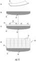
- FIG. 11illustrates a schematic diagram of one embodiment of a method for manufacturing a rotor blade component, particularly a spar cap, according to the present disclosure
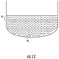
- FIG. 12illustrates a cross-sectional view of another embodiment of a spar cap formed using thermoforming and pultruded rods according to the present disclosure
- FIG. 13illustrates a schematic diagram of one embodiment of a pultruded member dispensing assembly mounted at a first end of a receptacle that forms part of a rotor blade component, such as a spar cap, so as to dispense pultruded rods directly into the receptacle according to the present disclosure
- FIG. 14illustrates a schematic diagram of one embodiment of a pultruded member dispensing assembly mounted above a receptacle that forms part of a rotor blade component, such as a spar cap, so as to dispense pultruded rods directly into the receptacle according to the present disclosure.
- FIG. 1illustrates a perspective view of a horizontal axis wind turbine 10 .
- the wind turbine 10may also be a vertical-axis wind turbine.
- the wind turbine 10includes a tower 12 , a nacelle 14 mounted on the tower 12 , and a rotor hub 18 that is coupled to the nacelle 14 .
- the tower 12may be fabricated from tubular steel or other suitable material.
- the rotor hub 18includes one or more rotor blades 16 coupled to and extending radially outward from the hub 18 .
- the rotor hub 18includes three rotor blades 16 .
- the rotor hub 18may include more or less than three rotor blades 16 .
- the rotor blades 16rotate the rotor hub 18 to enable kinetic energy to be transferred from the wind into usable mechanical energy, and subsequently, electrical energy.
- the hub 18may be rotatably coupled to an electric generator (not illustrated) positioned within the nacelle 14 for production of electrical energy.
- FIGS. 2 and 3one of the rotor blades 16 of FIG. 1 is illustrated in accordance with aspects of the present subject matter.
- FIG. 2illustrates a perspective view of the rotor blade 16
- FIG. 3illustrates a cross-sectional view of the rotor blade 16 along the sectional line 3 - 3 shown in FIG. 2
- the rotor blade 16generally includes a blade root 30 configured to be mounted or otherwise secured to the hub 18 ( FIG. 1 ) of the wind turbine 10 and a blade tip 32 disposed opposite the blade root 30 .
- a body shell 21 of the rotor bladegenerally extends between the blade root 30 and the blade tip 32 along a longitudinal axis 27 .
- the body shell 21may generally serve as the outer casing/covering of the rotor blade 16 and may define a substantially aerodynamic profile, such as by defining a symmetrical or cambered airfoil-shaped cross-section.
- the body shell 21may also define a pressure side 34 and a suction side 36 extending between leading and trailing ends 26 , 28 of the rotor blade 16 .
- the rotor blade 16may also have a span 23 defining the total length between the blade root 30 and the blade tip 32 and a chord 25 defining the total length between the leading edge 26 and the trialing edge 28 .
- the chord 25may vary in length with respect to the span 23 as the rotor blade 16 extends from the blade root 30 to the blade tip 32 .
- the body shell 21 of the rotor blade 16may be formed as a single, unitary component.
- the body shell 21may be formed from a plurality of shell components.
- the body shell 21may be manufactured from a first shell half generally defining the pressure side 34 of the rotor blade 16 and a second shell half generally defining the suction side 36 of the rotor blade 16 , with such shell halves being secured to one another at the leading and trailing ends 26 , 28 of the blade 16 .
- the body shell 21may generally be formed from any suitable material.
- the body shell 21may be formed entirely from a laminate composite material, such as a carbon fiber reinforced laminate composite or a glass fiber reinforced laminate composite.
- one or more portions of the body shell 21may be configured as a layered construction and may include a core material, formed from a lightweight material such as wood (e.g., balsa), foam (e.g., extruded polystyrene foam) or a combination of such materials, disposed between layers of laminate composite material.
- a core materialformed from a lightweight material such as wood (e.g., balsa), foam (e.g., extruded polystyrene foam) or a combination of such materials, disposed between layers of laminate composite material.
- the rotor blade 16may also include one or more longitudinally extending structural components configured to provide increased stiffness, buckling resistance, and/or strength to the rotor blade 16 .
- the rotor blade 16may include a pair of longitudinally extending spar caps 20 , 22 configured to be engaged against the opposing inner surfaces 35 , 37 of the pressure and suction sides 34 , 36 of the rotor blade 16 , respectively.
- one or more shear webs 24may be disposed between the spar caps 20 , 22 so as to form a beam-like configuration.
- the spar caps 20 , 22may generally be designed to control the bending stresses and/or other loads acting on the rotor blade 16 in a generally span-wise direction (a direction parallel to the span 23 of the rotor blade 16 ) during operation of a wind turbine 10 . Similarly, the spar caps 20 , 22 may also be designed to withstand the span-wise compression occurring during operation of the wind turbine 10 .
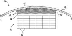
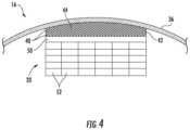
- FIG. 4illustrates, a detailed, cross-sectional view of the spar cap 20 of FIG. 3
- FIG. 5illustrates a perspective view of the spar cap 20 of FIG. 3
- the spar cap 20is constructed of a thermoformed receptacle 42 containing a plurality of pultruded members 40 (which can be pultruded rods or small plates) received therein.
- the receptacle 42may have a generally U-shaped cross-section such that the shape corresponds to the curvature of the suction side 36 (or pressure side 34 ) of the rotor blade 16 .
- the plurality of pultruded rods 40may also be sized to provide flexibility to the spar cap 20 such that the receptacle 42 can conform to the curvature of the rotor blade 16 .
- the rods 40may have a cross-sectional diameter of from about 0.25 millimeters (mm) to about 5 mm.
- the pultruded rods 40may be secured within the receptacle 42 via a resin material 44 using an infusion process.
- the spar cap 20may also include an optional layer 50 , such as a fiber-reinforced polymer layer 50 , positioned adjacent to the receptacle 42 .
- the spar cap 20may include a plurality of pultruded plates 52 stacked adjacent to the optional layer 50 and/or atop or within the pultruded-rod-filled receptacle 42 .
- the receptacle 42has side walls that receive the pultruded rods 40 therein.
- the receptacle 42may have side walls that receive both the pultruded rods 40 and the pultruded plates 52 .
- the plates 52may be arranged in any number of layers with any number of plates 52 arranged in each layer.
- FIG. 11 (A)the receptacle 42 has side walls that receive the pultruded rods 40 therein.
- the receptacle 42may have side walls that receive both the pultruded rods 40 and the pultruded plates 52 .
- the plates 52may be arranged in any number of layers with any number of plates 52 arranged in each layer.
- the pultruded plates 52may be curved to follow the curvature of the rotor blade 16 .
- the pultruded plates 52may be rectangle and arranged in segments to follow the curvature of the rotor blade 16 .
- the spar cap 20may extend between a first end 46 and a tip end 48 in a generally span-wise direction that corresponds to the root end 30 and the top end 32 of the rotor blade 16 . Further, as shown, the spar cap 20 may be curved between the first and second ends 46 , 48 .
- the method 100includes feeding a flat sheet of material 54 into a thermoforming system 56 . More specifically, as shown in FIGS. 7 and 8 , partial, perspective views of one embodiment of the thermoforming system 56 are illustrated. As shown, the thermoforming system 56 generally includes a housing 58 housing having a first end 60 and second end 62 . Thus, as shown particularly in FIG. 7 , the flat sheet of material 54 may be fed into the first end 60 of the thermoforming system 56 .
- the method 100includes heating the flat sheet of material 54 via the thermoforming system 56 .
- the system 56may include at least one heating element 64 at least partially contained within the housing 58 for heating the flat sheet of material 54 .
- the heating element(s) 64 described hereinmay include any suitable element such as, for example, a heater, a coil, or similar.
- the heating elements 64are configured to heat the flat sheet of material 54 as it passes through the housing 58 .
- thermoforming system 54may include one or more rollers 68 , 70 mounted or otherwise secured to an adjustable frame 66 within the housing 58 .
- the system 56includes, at least, a first roller 68 and one or more second rollers 70 mounted to the adjustable frame 66 .
- a first stage of the system 56may include the first roller 68 and a second stage of the system 56 may include a plurality of second rollers 70 .
- the method 100also includes shaping the heated flat sheet of material 54 via the rollers 68 , 70 into a desired curved shape. More specifically, in one embodiment, the rollers 68 , 70 are configured to continuously move in a plurality of directions via the adjustable frame 66 to shape the heated flat sheet of material 54 into the curved shape.
- the adjustable frame 66may be adapted to move up and down, side-to-side, and about at least one pivot point so as to move the rollers 68 , 70 in a plurality of directions, thereby achieving the desired curved shape.
- the method 100may include continuously adjusting a position of the rollers 68 , 70 via the adjustable frame 66 to vary an amount of pressure being applied to the heated flat sheet of material 54 to shape the heated flat sheet of material into the desired shape. More specifically, as indicated in FIG.
- the method 100may include adjusting the position of rollers 68 , 70 via the adjustable frame 66 in a vertical direction 82 and/or a horizontal direction 84 to modify a thickness and/or a width of the heated flat sheet of material 54 .
- the adjustable frame 66may also be capable of rotating such as to pivot the rollers 68 , 70 to further shape the heated flat sheet of material 54 .
- the method 100may include shaping the heated flat sheet of material 54 into the U-shaped receptacle 42 ( FIGS. 4 and 5 ) via the rollers 68 , 70 .
- the system 56may further include a curved support structure 88 for supporting the flat sheet of material 54 as the sheet is being heated via the heating element(s) 64 and shaped by the rollers 68 , 70 .
- the system 56may include one or more additional bottom and/or side rollers positioned below or to the side of the top roller(s) 68 for supporting the flat sheet of material 54 as the sheet is being heated via the heating element(s) 64 and shaped by the rollers 68 , 70 .
- the curved support structure 88 and/or the roller(s) 68 , 70may be position-controlled to shape the heated flat sheet of material 54 into the curved shape.
- the support structure 88 and/or the rollerscan be moved up and down and/or side to side.
- the method 100includes dispensing the shaped sheet of material 54 from the thermoforming system.
- the second end 62 of the housing 58is adapted to dispense the curved shape to at least partially form the spar cap 20 (i.e. to form the receptacle 42 that forms the portion of the component that abuts against the body shell 21 ).
- the method 100includes cooling the shaped sheet of material 54 to form the spar cap 20 .
- the shaped materialis further illustrated in step (A) of FIG. 11 .
- the method 100may further include placing a plurality of pultruded rods 40 into the receptacle 42 and securing the pultruded rods 40 therein.
- the pultruded rods 40may be secured within the receptacle 42 via a resin infusion process.
- the pultruded rods 40may be placed into the receptacle 42 by dispensing a layer 92 at a time of the pultruded rods 40 directly from a movable pultruded member dispensing assembly 72 into the receptacle 42 and stacking subsequent layers of the pultruded rods 40 atop each other until the receptacle 42 is filled.
- the pultruded member dispensing assembly 72may be removably mounted adjacent a first end of the receptacle 42 ( FIG. 13 ), above the receptacle 42 ( FIG. 14 ), or adjacent to the receptacle 42 . Further, in certain embodiments, as shown in FIGS.
- the method 100may include securing each layer 92 of pultruded rods 40 together via at least one clamp 74 as each layer 92 is dispensed from the pultruded member dispensing assembly 72 .
- the stacked layerscan then be infused together via a resin infusion process.
- the method 100may also include one or more spacers 76 positioned within the receptacle 42 for spacing apart the pultruded rods 40 as the rods 40 are dispensed from the pultruded member dispensing assembly 72 .
- the system 56may further include a controller 80 communicatively coupled to the movable pultruded member dispensing assembly 72 and/or the adjustable frame 66 ( FIG. 9 ) such that the various components of the system 56 can be controlled remotely and/or automatically.
- the controller 80may include at least one processor having at least one computer.
- the term computeris not limited to integrated circuits referred to in the art as a computer, but broadly refers to a processor, a microcontroller, a microcomputer, a programmable logic controller (PLC), an application specific integrated circuit, and other programmable circuits, and these terms are used interchangeably herein.
- the method 100may further include placing at least one of the optional layers 50 described herein atop or adjacent to the pultruded-rod-filled receptacle 42 .
- the method 100may also include placing at least one ultrasonic transducer 78 atop or adjacent to the optional layer(s) 50 to assist with packing the pultruded rods 40 within the receptacle 42 .
- the method 100may also include placing or stacking one or more pultruded plates 52 atop the optional layer 50 and securing the pultruded rods 40 , the optional layer 50 , and the pultruded plates 52 together via a resin infusion process to form the final spar cap 20 .
- thermoplastic materialgenerally encompasses a plastic material or polymer that is reversible in nature.
- thermoplastic materialstypically become pliable or moldable when heated to a certain temperature and solidify upon cooling.
- thermoplastic materialsmay include amorphous thermoplastic materials and/or semi-crystalline thermoplastic materials.
- some amorphous thermoplastic materialsmay generally include, but are not limited to, styrenes, vinyls, cellulosics, polyesters, acrylics, polysulphones, and/or imides.
- exemplary amorphous thermoplastic materialsmay include polystyrene, acrylonitrile butadiene styrene (ABS), polymethyl methacrylate (PMMA), glycolised polyethylene terephthalate (PET-G), polycarbonate, polyvinyl acetate, amorphous polyamide, polyvinyl chlorides (PVC), polyvinylidene chloride, polyurethane, or any other suitable amorphous thermoplastic material.
- exemplary semi-crystalline thermoplastic materialsmay generally include, but are not limited to polyolefins, polyamides, fluropolymer, ethyl-methyl acrylate, polyesters, polycarbonates, and/or acetals.
- exemplary semi-crystalline thermoplastic materialsmay include polybutylene terephthalate (PBT), polyethylene terephthalate (PET), polypropylene, polyphenyl sulfide, polyethylene, polyamide (nylon), polyetherketone, or any other suitable semi-crystalline thermoplastic material.
- PBTpolybutylene terephthalate
- PETpolyethylene terephthalate
- Ppropylenepolypropylene
- polyphenyl sulfidepolyethylene
- polyamidenylon
- polyetherketonepolyetherketone
- thermoset materialas described herein generally encompasses a plastic material or polymer that is non-reversible in nature.
- thermoset materialsonce cured, cannot be easily remolded or returned to a liquid state.
- thermoset materialsafter initial forming, are generally resistant to heat, corrosion, and/or creep.
- Example thermoset materialsmay generally include, but are not limited to, some polyesters, esters, epoxies, or any other suitable thermoset material.
Landscapes
- Engineering & Computer Science (AREA)
- Mechanical Engineering (AREA)
- Chemical & Material Sciences (AREA)
- Composite Materials (AREA)
- Life Sciences & Earth Sciences (AREA)
- Sustainable Development (AREA)
- Sustainable Energy (AREA)
- Combustion & Propulsion (AREA)
- General Engineering & Computer Science (AREA)
- Moulding By Coating Moulds (AREA)
- Extrusion Moulding Of Plastics Or The Like (AREA)
Abstract
Description
Claims (19)
Priority Applications (8)
| Application Number | Priority Date | Filing Date | Title |
|---|---|---|---|
| US15/928,254US11738530B2 (en) | 2018-03-22 | 2018-03-22 | Methods for manufacturing wind turbine rotor blade components |
| CN201980034092.6ACN112118952B (en) | 2018-03-22 | 2019-03-20 | Method for manufacturing a wind turbine rotor blade component |
| ES19715637TES2994659T3 (en) | 2018-03-22 | 2019-03-20 | Method for manufacturing wind turbine rotor blade components |
| PL19715637.5TPL3768497T3 (en) | 2018-03-22 | 2019-03-20 | METHOD OF MANUFACTURING COMPONENTS OF A WIND TURBINE ROTOR BLADE |
| DK19715637.5TDK3768497T3 (en) | 2018-03-22 | 2019-03-20 | Method for manufacturing wind turbine rotor blade components |
| MA052081AMA52081A (en) | 2018-03-22 | 2019-03-20 | WIND TURBINE ROTOR BLADE COMPONENTS MANUFACTURING PROCESSES |
| EP19715637.5AEP3768497B1 (en) | 2018-03-22 | 2019-03-20 | Method for manufacturing wind turbine rotor blade components |
| PCT/US2019/023134WO2019183203A1 (en) | 2018-03-22 | 2019-03-20 | Methods for manufacturing wind turbine rotor blade components |
Applications Claiming Priority (1)
| Application Number | Priority Date | Filing Date | Title |
|---|---|---|---|
| US15/928,254US11738530B2 (en) | 2018-03-22 | 2018-03-22 | Methods for manufacturing wind turbine rotor blade components |
Publications (2)
| Publication Number | Publication Date |
|---|---|
| US20190291372A1 US20190291372A1 (en) | 2019-09-26 |
| US11738530B2true US11738530B2 (en) | 2023-08-29 |
Family
ID=66041663
Family Applications (1)
| Application Number | Title | Priority Date | Filing Date |
|---|---|---|---|
| US15/928,254Active2039-08-06US11738530B2 (en) | 2018-03-22 | 2018-03-22 | Methods for manufacturing wind turbine rotor blade components |
Country Status (8)
| Country | Link |
|---|---|
| US (1) | US11738530B2 (en) |
| EP (1) | EP3768497B1 (en) |
| CN (1) | CN112118952B (en) |
| DK (1) | DK3768497T3 (en) |
| ES (1) | ES2994659T3 (en) |
| MA (1) | MA52081A (en) |
| PL (1) | PL3768497T3 (en) |
| WO (1) | WO2019183203A1 (en) |
Families Citing this family (5)
| Publication number | Priority date | Publication date | Assignee | Title |
|---|---|---|---|---|
| US10724502B2 (en)* | 2018-05-22 | 2020-07-28 | Creating Moore, Llc | Vertical axis wind turbine apparatus and system |
| US11524468B2 (en) | 2020-02-03 | 2022-12-13 | Rohr, Inc. | Systems and methods for thermoplastic panel stretch/roll forming |
| EP4271918A1 (en)* | 2020-12-30 | 2023-11-08 | LM Wind Power A/S | Hybrid pultrusion plates for a conductive spar cap of a wind turbine blade |
| CN114211779A (en)* | 2021-11-03 | 2022-03-22 | 中复连众(沈阳)复合材料有限公司 | A special device and method for unwinding, assembling and hoisting pultruded sheets of wind power blade girder |
| CN115742383A (en)* | 2022-11-22 | 2023-03-07 | 中材科技风电叶片股份有限公司 | Pultrusion equipment, production method of section bar, torsion plate and wind driven generator blade |
Citations (151)
| Publication number | Priority date | Publication date | Assignee | Title |
|---|---|---|---|---|
| US1415620A (en) | 1919-10-20 | 1922-05-09 | Albert W Albrecht | Method of making piston rings |
| US2254629A (en)* | 1939-09-26 | 1941-09-02 | Westinghouse Electric & Mfg Co | Method of manufacturing turbine blades |
| US2566152A (en)* | 1948-06-15 | 1951-08-28 | Bird & Son | Machine for edge-coating and bending sheet material |
| US4264278A (en) | 1977-10-31 | 1981-04-28 | Oscar Weingart | Blade or spar |
| NL8104019A (en) | 1981-08-28 | 1983-03-16 | Jan Bos | Fibre-reinforced plastic object has parallel reinforcing rods - with passages between for full penetration by liquid plastic on moulding |
| US4475881A (en)* | 1982-09-14 | 1984-10-09 | Placon Corporation | Thermoforming of plastic sheet material |
| US4883419A (en)* | 1985-09-11 | 1989-11-28 | Joel Queirel | Device for thermoforming parts from synthetic material |
| US4915590A (en) | 1987-08-24 | 1990-04-10 | Fayette Manufacturing Corporation | Wind turbine blade attachment methods |
| US5026447A (en) | 1989-02-10 | 1991-06-25 | Phillips Petroleum Company | Method for making variable cross section pultruded thermoplastic composite articles |
| WO1995002496A1 (en) | 1993-07-12 | 1995-01-26 | Seaward International, Inc. | Elongated structural member and method and apparatus for making same |
| US5476704A (en) | 1992-07-01 | 1995-12-19 | Hoac-Austria Flugzeugwerk Wr.Neustadt Gesellschaft M.B.H. | Plastic-composite profiled girder, in particular a wing spar for aircraft and for wind-turbine rotors |
| US5499904A (en) | 1993-07-12 | 1996-03-19 | Flowind Corporation | Vertical axis wind turbine with pultruded blades |
| US5660527A (en) | 1995-10-05 | 1997-08-26 | The Wind Turbine Company | Wind turbine rotor blade root end |
| JP2002137307A (en) | 2000-11-02 | 2002-05-14 | Toray Ind Inc | Blade structure of windmill made of fiber-reinforced resin |
| US6443701B1 (en) | 1999-01-29 | 2002-09-03 | MüHLBAUER LUFTFAHRTTECHNIK GMBH | Blade root for propeller and rotor blades |
| WO2003082551A1 (en) | 2002-03-28 | 2003-10-09 | Aerodyn Engineering Gmbh | Blade connection for the rotor blades of a wind-energy turbine and a method for the production thereof |
| JP2003293935A (en) | 2002-03-29 | 2003-10-15 | Mitsubishi Heavy Ind Ltd | Windmill blade and wind power generating device |
| US6701990B1 (en)* | 1998-10-23 | 2004-03-09 | Airbus Uk Limited | Roll forming machine |
| US20040140587A1 (en) | 2002-12-13 | 2004-07-22 | Hadley Philip C. | Control of resin flow during molding of composite articles |
| CN2670606Y (en) | 2003-10-10 | 2005-01-12 | 淄博矿业集团有限责任公司许厂煤矿 | Steam sealing cooler of turbine |
| US20050056362A1 (en)* | 2003-08-01 | 2005-03-17 | Benson Vernon M. | Apparatus and methods for forming composite stiffeners and reinforcing structures |
| US20050269016A1 (en) | 2004-04-21 | 2005-12-08 | Ingersoll Machine Tools, Inc. | Automated forming of pre-impregnated composite structural elements |
| US7037568B1 (en) | 2003-07-15 | 2006-05-02 | Rogers Terry W | Joining member for mechanically joining a skin to a supporting rib |
| US20060175731A1 (en) | 2003-03-06 | 2006-08-10 | Anton Bech | Connection between members |
| US20060255486A1 (en)* | 2005-05-10 | 2006-11-16 | Benson Olester Jr | Method of manufacturing composite optical body containing inorganic fibers |
| US7163378B2 (en) | 2002-01-11 | 2007-01-16 | Lm Glasfiber A/S | Embedding element to be embedded in the end part of a windmill blade, a method producing such an embedding element as well as embedding of such embedding elements in a windmill blade |
| US7198471B2 (en) | 2001-07-19 | 2007-04-03 | Neg Micon A/S | Wind turbine blade |
| US20070140863A1 (en) | 2005-12-15 | 2007-06-21 | General Electric Company | Wind turbine rotor blade |
| US20070160479A1 (en) | 2006-01-09 | 2007-07-12 | General Electric Company | Methods of making wind turbine rotor blades |
| EP1808598A1 (en) | 2004-09-14 | 2007-07-18 | Gamesa Innovation & Technology, S.L. Unipersonal | Structural beam for a wind generator blade and production method thereof |
| US20070189902A1 (en) | 2004-02-24 | 2007-08-16 | Mohamed Mansour H | Wind blade spar cap and method of making |
| US20070189903A1 (en) | 2006-02-13 | 2007-08-16 | General Electric Company | Wind turbine rotor blade |
| EP1916090A1 (en)* | 2006-10-25 | 2008-04-30 | Protex Plastics GmbH | Method for manufacturing plastic parts |
| US20080159871A1 (en) | 2005-02-03 | 2008-07-03 | Anton Bech | Method of Manufacturing a Wind Turbine Blade Shell Member |
| US20080181781A1 (en) | 2007-01-26 | 2008-07-31 | General Electric Company | Preform Spar Cap for a Wind Turbine Rotor Blade |
| EP1956235A1 (en) | 2007-02-09 | 2008-08-13 | Harakosan Co. Ltd. | Blade for a wind turbine |
| US20080206059A1 (en) | 2004-12-29 | 2008-08-28 | Mark Hancock | Method Of Manufacturing A Wind Turbine Blade Shell Member With A Fastening Member And A Wind Turbine Blade With A Fastening Member |
| US20090068017A1 (en) | 2007-09-11 | 2009-03-12 | Paul Rudling | Wind turbine blade |
| US7517194B2 (en) | 2006-04-30 | 2009-04-14 | General Electric Company | Rotor blade for a wind turbine |
| US7530168B2 (en) | 2003-06-12 | 2009-05-12 | Ssp Technology A/S | Method of manufacturing a wind turbine blade root |
| US20090175731A1 (en) | 2006-11-23 | 2009-07-09 | Claus Burchardt | Method for manufacturing of a fibre reinforced laminate, use of a wrinkle-preventing material, wind turbine blade and wind turbine |
| WO2009085041A1 (en) | 2007-12-27 | 2009-07-09 | General Electric Company | Flexible wind blade root bulkhead flange |
| US20090196756A1 (en) | 2008-02-05 | 2009-08-06 | General Electric Company | Wind turbine blades and method for forming same |
| WO2009095175A2 (en) | 2008-02-02 | 2009-08-06 | Nordex Energy Gmbh | Rotor blade for wind power plants |
| US20090220747A1 (en) | 2008-03-03 | 2009-09-03 | Abe Karem | Wing and blade structure using pultruded composites |
| DK200801457A (en) | 2008-10-20 | 2009-09-18 | Vestas Wind Sys As | Method of manufacturing a structural element of a wind turbine |
| EP2113373A1 (en) | 2008-04-29 | 2009-11-04 | Siemens Aktiengesellschaft | Method for manufacturing of a fibre reinforced laminate and of a laterally extended material which has in a first lateral direction a greater stiffness than in a second lateral direction |
| WO2009133143A1 (en) | 2008-04-30 | 2009-11-05 | Vestas Wind Systems A/S | A consolidated composite pre-from |
| US7625185B2 (en) | 2003-08-05 | 2009-12-01 | Aloys Wobben | Bearing structure |
| US20100084079A1 (en) | 2008-10-08 | 2010-04-08 | Paul Trevor Hayden | Insert for forming an end connection in a uni-axial composite material |
| US7758313B2 (en) | 2006-02-13 | 2010-07-20 | General Electric Company | Carbon-glass-hybrid spar for wind turbine rotorblades |
| WO2010083921A2 (en) | 2009-01-23 | 2010-07-29 | Vestas Wind Systems A/S | A pre-form and a spar comprising a reinforcing structure |
| US20100290912A1 (en) | 2008-01-14 | 2010-11-18 | Lm Glasfiber A/S | Wind turbine blade and hub assembly |
| US20100310380A1 (en) | 2007-12-19 | 2010-12-09 | Vestas Wind Systems A/S | Method for preparing a pre-form |
| WO2010149806A1 (en) | 2009-06-23 | 2010-12-29 | Gamesa Innovation & Technology, S.L. | Stiffening the blade root of a wind turbine |
| US20110031758A1 (en) | 2009-08-05 | 2011-02-10 | Nitto Denko Corporation | Reinforcing sheet for wind power generator blades, reinforcing structure of wind power generator blade, wind power generator, method for reinforcing the wind power generator blade |
| US20110037191A1 (en) | 2009-08-13 | 2011-02-17 | Henrik Stiesdal | Method and Arrangement to Produce a Wind-Turbine-Blade |
| US20110044817A1 (en) | 2008-04-29 | 2011-02-24 | Urs Bendel | Method for Establishing A Blade Connection of a Rotor Blade, A Blade Connection and a Securing Element for a Blade Connection |
| CN102022288A (en) | 2010-12-03 | 2011-04-20 | 北京可汗之风科技有限公司 | Design for bamboo wood blade root structure of wind driven generator |
| CN102024518A (en) | 2010-11-01 | 2011-04-20 | 山东大学 | Composite wire core bar with thermoplastic resin substrate and preparation die and process thereof |
| US7942637B2 (en) | 2008-12-11 | 2011-05-17 | General Electric Company | Sparcap for wind turbine rotor blade and method of fabricating wind turbine rotor blade |
| US20110135485A1 (en) | 2009-12-30 | 2011-06-09 | Jing Wang | Spar for a wind turbine rotor blade and method for fabricating the same |
| US7963747B2 (en) | 2009-04-02 | 2011-06-21 | General Electric Company | Braided wind turbine blades and method of making same |
| US7966726B2 (en) | 2005-12-28 | 2011-06-28 | Lm Glasfiber A/S | Levelling of root bushings on blades for wind turbines |
| US20110171038A1 (en) | 2009-12-25 | 2011-07-14 | Mitsubishi Heavy Industries, Ltd. | Wind turbine rotor blade and producing method of wind turbine rotor blade |
| US7988423B2 (en) | 2008-07-18 | 2011-08-02 | Vestas Wind Systems A/S | Wind turbine blade |
| WO2011113812A1 (en) | 2010-03-15 | 2011-09-22 | Vestas Wind Systems A/S | Improved wind turbine blade spar |
| US8025485B2 (en) | 2010-06-17 | 2011-09-27 | General Electric Company | Wind turbine blade attachment configuration with flattened bolts |
| US8043067B2 (en) | 2006-03-24 | 2011-10-25 | Mitsubishi Heavy Industries, Ltd. | Wind turbine blade with sufficiently high strength and light weight |
| US8066490B2 (en) | 2009-12-21 | 2011-11-29 | General Electric Company | Wind turbine rotor blade |
| US20120006475A1 (en)* | 2009-03-05 | 2012-01-12 | Constructions Industrielles De La Mediterranee- Cnim | Method and device for the automated manufacture of at least one elongate composite material part with one or more layers |
| US8105040B2 (en) | 2008-11-07 | 2012-01-31 | Vestas Wind Systems A/S | Wind turbine rotor blade |
| US20120027609A1 (en) | 2011-05-17 | 2012-02-02 | Prasad Ogde | Wind turbine rotor blade with precured fiber rods and method for producing the same |
| US20120039720A1 (en) | 2009-01-21 | 2012-02-16 | Vestas Wind Systems A/S | Method of manufacturing a wind turbine blade by embedding a layer of pre-cured fibre reinforced resin |
| US20120082558A1 (en)* | 2008-12-05 | 2012-04-05 | Baker Myles L | Efficient wind turbine blades, wind turbine blade structures, and associated systems and methods of manufacture, assembly and use |
| EP2441571A1 (en) | 2010-10-12 | 2012-04-18 | General Electric Company | Composite components and processes therefor |
| US8168027B2 (en) | 2004-12-29 | 2012-05-01 | Lm Glasfiber A/S | Fibre-reinforced joint |
| US8186960B2 (en) | 2008-04-15 | 2012-05-29 | Frontier Pro Services, Llc | Repair of rotor blade roots |
| US20120183408A1 (en) | 2011-01-18 | 2012-07-19 | Michael Noerlem | Stiffening sheet for use in a fibre reinforced laminate, fibre reinforced laminate and wind turbine blade, and a method of manufacturing a fibre reinforced laminate |
| US20120207607A1 (en) | 2009-09-23 | 2012-08-16 | Suzhou Red Maple Wind Blade Mould Co., Ltd. | Insert for wind turbine blade root |
| EP2181834B1 (en) | 2008-11-04 | 2012-09-19 | REpower Systems SE | Method for manufacturing a rotor blade spar cap |
| US20120237356A1 (en) | 2009-09-23 | 2012-09-20 | Suzhou Red Maple Wind Blade Mould Co., Ltd. | Wind turbine blade and its producing method |
| WO2012140039A2 (en) | 2011-04-11 | 2012-10-18 | Lm Wind Power A/S | Wind turbine blade comprising circumferential retaining means in root regions |
| WO2012161741A2 (en) | 2011-05-24 | 2012-11-29 | Edwards Christopher M | Wind blade spar caps |
| DE102011051172A1 (en) | 2011-06-17 | 2012-12-20 | Lars Kästner | Laminated rotor blade for wind turbine, has several pultrusion portions that are arranged at surface of insert portion, and are coated with fiber or woven fabric tube that is longer than that of insert portion |
| US8337163B2 (en) | 2007-12-05 | 2012-12-25 | General Electric Company | Fiber composite half-product with integrated elements, manufacturing method therefor and use thereof |
| US8348622B2 (en) | 2004-06-30 | 2013-01-08 | Vestas Wind Systems A/S | Wind turbine blades made of two separate sections, and method of assembly |
| US20130111752A1 (en) | 2011-11-04 | 2013-05-09 | Kristian Lehmann Madsen | Manufacture of a root section |
| WO2013087078A1 (en) | 2011-12-16 | 2013-06-20 | Vestas Wind Systems A/S | Wind turbine blades |
| EP2617558A1 (en) | 2010-04-30 | 2013-07-24 | Blade Dynamics Limited | A modular structural composite beam |
| US20130209257A1 (en) | 2010-11-11 | 2013-08-15 | Alstom Wind, S.L.U. | Blade for a Wind Turbine |
| US8529717B2 (en) | 2007-11-09 | 2013-09-10 | Vestas Wind Systems A/S | Structural mat for reinforcing a wind turbine blade structure, a wind turbine blade and a method for manufacturing a wind turbine blade |
| US8540491B2 (en) | 2010-01-14 | 2013-09-24 | Neptco, Inc. | Wind turbine rotor blade components and methods of making same |
| US8545744B2 (en) | 2007-03-29 | 2013-10-01 | Gurit (Uk) Ltd. | Fibre-reinforced composite moulding and manufacture thereof |
| US20130285284A1 (en) | 2011-01-21 | 2013-10-31 | Hexcel Corporation | Module for holding at least one bushing |
| EP2677170A1 (en) | 2011-02-18 | 2013-12-25 | Mitsubishi Heavy Industries, Ltd. | Blade-root-forming piece for wind turbine blade, blade root structure for wind turbine blade using same, wind turbine blade, wind turbine and method for producing wind turbine blade |
| US20140003956A1 (en) | 2011-03-11 | 2014-01-02 | Epsilon Composite | Mechanical reinforcement for a part made of composite material, in particular for a wind turbine blade of large dimensions |
| EP2682256A1 (en) | 2012-07-03 | 2014-01-08 | Fiberline A/S | A method of producing an assembly for use in a fibre reinforced structural element |
| US20140083620A1 (en)* | 2011-05-20 | 2014-03-27 | Coriolis Composites | Fiber application head including a segmented compaction roller |
| WO2014044280A1 (en) | 2012-09-18 | 2014-03-27 | Vestas Wind Systems A/S | Wind turbine blades |
| DE102012219224B3 (en) | 2012-10-22 | 2014-03-27 | Repower Systems Se | System and method for manufacturing a rotor blade belt |
| WO2014063944A1 (en) | 2012-10-22 | 2014-05-01 | Wobben Properties Gmbh | Method and device for producing preforms for producing a rotor blade |
| US8721829B2 (en) | 2004-08-13 | 2014-05-13 | Lm Glasfiber A/S | Method of cutting off laminate layers, eg a glass fibre or carbon-fibre laminate layer in the blade of a wind turbine |
| US20140140853A1 (en) | 2011-07-27 | 2014-05-22 | Alstom Renovables España, S.L. | Wind turbine blade connector assembly |
| CN103817952A (en) | 2014-02-26 | 2014-05-28 | 国电联合动力技术有限公司 | Manufacturing method of pre-buried bolt sleeve prefabticated members of wind driven generator blade root parts |
| WO2014079456A1 (en) | 2012-11-20 | 2014-05-30 | Vestas Wind Systems A/S | Wind turbine blades and method of manufacturing the same |
| US8747098B1 (en) | 2008-03-24 | 2014-06-10 | Ebert Composites Corporation | Thermoplastic pultrusion die system and method |
| US8777578B2 (en) | 2008-06-20 | 2014-07-15 | Vestas Wind Systems A/S | Method of manufacturing a spar for a wind turbine from elements having geometrically well-defined joint surface portions |
| CN103921457A (en) | 2014-04-28 | 2014-07-16 | 连云港中复连众复合材料集团有限公司 | Method for manufacturing main beam or auxiliary beam of fan blade by unidirectional sheets manufactured by use of pultrusion process |
| US20140234109A1 (en) | 2011-10-25 | 2014-08-21 | Blade Dynamics Limited | Method of making a root end joint of a wind turbine blade and a root segment for such a joint |
| US20140271217A1 (en) | 2013-03-15 | 2014-09-18 | Modular Wind Energy, Inc. | Efficient wind turbine blade design and associated manufacturing methods using rectangular spars and segmented shear web |
| US20140271198A1 (en) | 2013-03-13 | 2014-09-18 | Vestas Wind Systems A/S | Wind turbine blades with layered, multi-component spars, and associated systems and methods |
| WO2014147222A2 (en) | 2013-03-22 | 2014-09-25 | Hexcel Holding Gmbh | Improvements in or relating to fibre reinforced composites |
| US8863382B2 (en) | 2010-04-09 | 2014-10-21 | Piasecki Aircraft Corp. | Highly reliable, low cost wind turbine rotor blade |
| US20150023799A1 (en) | 2013-07-19 | 2015-01-22 | Kyle K. Wetzel | Structural Member with Pultrusions |
| US20150217535A1 (en) | 2012-08-23 | 2015-08-06 | Metna Co | Prestressed Rod Stiffened Composite Structures |
| US20150224721A1 (en) | 2012-10-22 | 2015-08-13 | Senvion Se | Apparatus and method for producing a rotor blade spar cap |
| CN104859160A (en) | 2015-05-29 | 2015-08-26 | 连云港中复连众复合材料集团有限公司 | Fan blade root embedded bolt sleeve suitable for pultrusion process and preparation method for fan blade root embedded bolt sleeve |
| WO2015142904A1 (en) | 2014-03-19 | 2015-09-24 | Korecarbon Llc | Turbine blade |
| EP2939821A1 (en) | 2014-04-30 | 2015-11-04 | Airbus Operations S.L. | Method for obtaining a composite laminate |
| US20150337797A1 (en) | 2011-06-10 | 2015-11-26 | Siemens Aktiengesellschaft | Rotor blade for a wind turbine |
| US20150336323A1 (en)* | 2013-02-13 | 2015-11-26 | Ihi Corporation | Method of manufacturing fan blade and apparatus for manufacturing the same fan blade |
| US20150354542A1 (en) | 2014-06-05 | 2015-12-10 | Siemens Aktiengesellschaft | Root bushing for a blade root of a wind turbine rotor blade, a blade root, a wind turbine rotor blade and a wind turbine |
| US20150354531A1 (en) | 2014-06-05 | 2015-12-10 | Siemens Aktiengesellschaft | Root bushing for a blade root of a wind turbine rotor blade, a blade root, a wind turbine rotor blade and a wind turbine |
| US20150361950A1 (en) | 2013-01-10 | 2015-12-17 | Ingenieria Prosix, S.L. | Fixation for a wind turbine blade to the hub |
| US9234497B2 (en) | 2011-06-10 | 2016-01-12 | Siemens Aktiengesellschaft | Rotor blade for a wind turbine |
| KR101590795B1 (en) | 2014-06-19 | 2016-02-03 | 삼성중공업 주식회사 | Blade for wind turbine generator |
| US20160040651A1 (en) | 2014-08-07 | 2016-02-11 | General Electric Company | Methods of manufacturing rotor blades of a wind turbine |
| US20160047355A1 (en) | 2013-03-21 | 2016-02-18 | Alstom Renewable Technologies | Methods of manufacturing an impregnated metal insert |
| US20160053741A1 (en) | 2013-03-25 | 2016-02-25 | Windfin B.V. | Wind turbine blade root and process for manufacturing a wind turbine blade root |
| US9327456B2 (en) | 2012-02-29 | 2016-05-03 | Mitsubishi Heavy Industries, Ltd. | Method and apparatus for manufacturing fiber-reinforced base material |
| US20160146184A1 (en) | 2014-11-25 | 2016-05-26 | General Electric Company | Methods of manufacturing rotor blade components for a wind turbine |
| US20160146185A1 (en) | 2014-11-25 | 2016-05-26 | General Electric Company | Methods for manufacturing a spar cap for a wind turbine rotor blade |
| US20160160837A1 (en) | 2014-12-04 | 2016-06-09 | General Electric Company | Pultruded rotor blade components having interlocking edges |
| US20160169195A1 (en) | 2014-12-10 | 2016-06-16 | General Electric Company | Spar cap for a wind turbine rotor blade |
| US20160167267A1 (en) | 2013-07-11 | 2016-06-16 | Vestas Wind Systems A/S | Wind turbine blade |
| EP3034865A1 (en) | 2014-12-16 | 2016-06-22 | Senvion GmbH | Assembly of pultruded rods |
| CN105881936A (en) | 2016-06-14 | 2016-08-24 | 道生天合材料科技(上海)有限公司 | Method for improving surface roughness and dimension consistency of wind turbine blade root pultrusion preformed units |
| CN105904746A (en) | 2016-06-12 | 2016-08-31 | 南京诺尔泰复合材料设备制造有限公司 | Manufacturing method and production line for thermoset carbon fiber plate for wind vane |
| US20160263844A1 (en) | 2013-10-25 | 2016-09-15 | Vestas Wind Systems A/S | Wind Turbine Blades |
| US20160273516A1 (en) | 2013-11-15 | 2016-09-22 | Vestas Wind Systems A/S | Reinforcing strip for a wind turbine blade |
| US20160281680A1 (en) | 2013-11-05 | 2016-09-29 | Vestas Wind Systems A/S | Modular wind turbine rotor blade |
| US20160319801A1 (en) | 2013-12-23 | 2016-11-03 | Vetas Wind Systems A/S | Wind turbine blades |
| US9500179B2 (en) | 2010-05-24 | 2016-11-22 | Vestas Wind Systems A/S | Segmented wind turbine blades with truss connection regions, and associated systems and methods |
| DE102015007289A1 (en) | 2015-06-10 | 2016-12-15 | Senvion Gmbh | Rotor blade, rotor blade belt and method for producing a rotor blade |
| DE102015007801A1 (en) | 2015-06-19 | 2016-12-22 | Senvion Gmbh | Method for producing a component of a rotor blade of a wind energy plant |
| US20160368230A1 (en) | 2013-12-19 | 2016-12-22 | Airbus Operations Gmbh | Shaping tool, shaping apparatus and method of forming a semi-finished product containing reinforcing fibers |
| US20170080648A1 (en)* | 2015-09-23 | 2017-03-23 | General Electric Company | Methods for manufacturing spar caps for wind turbine rotor blades using thermoplastic-based composite plates |
| US9683545B2 (en) | 2012-05-31 | 2017-06-20 | Vestas Wind Systems A/S | Manufacture of wind turbine blades |
| US9822761B2 (en) | 2014-08-13 | 2017-11-21 | General Electric Company | Structural components and methods of manufacturing |
| US20180009155A1 (en) | 2016-07-08 | 2018-01-11 | Hunter Douglas Industries Bv | Method of manufacture of a linear panel |
Family Cites Families (1)
| Publication number | Priority date | Publication date | Assignee | Title |
|---|---|---|---|---|
| GB2528850A (en)* | 2014-07-31 | 2016-02-10 | Vestas Wind Sys As | Improvements relating to reinforcing structures for wind turbine blades |
- 2018
- 2018-03-22USUS15/928,254patent/US11738530B2/enactiveActive
- 2019
- 2019-03-20MAMA052081Apatent/MA52081A/enunknown
- 2019-03-20ESES19715637Tpatent/ES2994659T3/enactiveActive
- 2019-03-20WOPCT/US2019/023134patent/WO2019183203A1/ennot_activeCeased
- 2019-03-20CNCN201980034092.6Apatent/CN112118952B/enactiveActive
- 2019-03-20EPEP19715637.5Apatent/EP3768497B1/enactiveActive
- 2019-03-20PLPL19715637.5Tpatent/PL3768497T3/enunknown
- 2019-03-20DKDK19715637.5Tpatent/DK3768497T3/enactive
Patent Citations (181)
| Publication number | Priority date | Publication date | Assignee | Title |
|---|---|---|---|---|
| US1415620A (en) | 1919-10-20 | 1922-05-09 | Albert W Albrecht | Method of making piston rings |
| US2254629A (en)* | 1939-09-26 | 1941-09-02 | Westinghouse Electric & Mfg Co | Method of manufacturing turbine blades |
| US2566152A (en)* | 1948-06-15 | 1951-08-28 | Bird & Son | Machine for edge-coating and bending sheet material |
| US4264278A (en) | 1977-10-31 | 1981-04-28 | Oscar Weingart | Blade or spar |
| NL8104019A (en) | 1981-08-28 | 1983-03-16 | Jan Bos | Fibre-reinforced plastic object has parallel reinforcing rods - with passages between for full penetration by liquid plastic on moulding |
| US4475881A (en)* | 1982-09-14 | 1984-10-09 | Placon Corporation | Thermoforming of plastic sheet material |
| US4883419A (en)* | 1985-09-11 | 1989-11-28 | Joel Queirel | Device for thermoforming parts from synthetic material |
| US4915590A (en) | 1987-08-24 | 1990-04-10 | Fayette Manufacturing Corporation | Wind turbine blade attachment methods |
| US5026447A (en) | 1989-02-10 | 1991-06-25 | Phillips Petroleum Company | Method for making variable cross section pultruded thermoplastic composite articles |
| US5476704A (en) | 1992-07-01 | 1995-12-19 | Hoac-Austria Flugzeugwerk Wr.Neustadt Gesellschaft M.B.H. | Plastic-composite profiled girder, in particular a wing spar for aircraft and for wind-turbine rotors |
| US5499904A (en) | 1993-07-12 | 1996-03-19 | Flowind Corporation | Vertical axis wind turbine with pultruded blades |
| WO1995002496A1 (en) | 1993-07-12 | 1995-01-26 | Seaward International, Inc. | Elongated structural member and method and apparatus for making same |
| US5660527A (en) | 1995-10-05 | 1997-08-26 | The Wind Turbine Company | Wind turbine rotor blade root end |
| US6701990B1 (en)* | 1998-10-23 | 2004-03-09 | Airbus Uk Limited | Roll forming machine |
| US6443701B1 (en) | 1999-01-29 | 2002-09-03 | MüHLBAUER LUFTFAHRTTECHNIK GMBH | Blade root for propeller and rotor blades |
| JP2002137307A (en) | 2000-11-02 | 2002-05-14 | Toray Ind Inc | Blade structure of windmill made of fiber-reinforced resin |
| US7503752B2 (en) | 2001-07-19 | 2009-03-17 | Neg Micon A/S | Wind turbine blade |
| US7198471B2 (en) | 2001-07-19 | 2007-04-03 | Neg Micon A/S | Wind turbine blade |
| US7163378B2 (en) | 2002-01-11 | 2007-01-16 | Lm Glasfiber A/S | Embedding element to be embedded in the end part of a windmill blade, a method producing such an embedding element as well as embedding of such embedding elements in a windmill blade |
| US7357726B2 (en) | 2002-01-11 | 2008-04-15 | Fiberline A/S | Method of producing a fibre reinforced structural element |
| WO2003082551A1 (en) | 2002-03-28 | 2003-10-09 | Aerodyn Engineering Gmbh | Blade connection for the rotor blades of a wind-energy turbine and a method for the production thereof |
| JP2003293935A (en) | 2002-03-29 | 2003-10-15 | Mitsubishi Heavy Ind Ltd | Windmill blade and wind power generating device |
| US20040140587A1 (en) | 2002-12-13 | 2004-07-22 | Hadley Philip C. | Control of resin flow during molding of composite articles |
| US20060175731A1 (en) | 2003-03-06 | 2006-08-10 | Anton Bech | Connection between members |
| US7530168B2 (en) | 2003-06-12 | 2009-05-12 | Ssp Technology A/S | Method of manufacturing a wind turbine blade root |
| US7037568B1 (en) | 2003-07-15 | 2006-05-02 | Rogers Terry W | Joining member for mechanically joining a skin to a supporting rib |
| EP3281776A1 (en) | 2003-08-01 | 2018-02-14 | Orbital ATK, Inc. | Apparatus and methods for forming composite stiffeners and reinforcing structures |
| US20050056362A1 (en)* | 2003-08-01 | 2005-03-17 | Benson Vernon M. | Apparatus and methods for forming composite stiffeners and reinforcing structures |
| US7625185B2 (en) | 2003-08-05 | 2009-12-01 | Aloys Wobben | Bearing structure |
| CN2670606Y (en) | 2003-10-10 | 2005-01-12 | 淄博矿业集团有限责任公司许厂煤矿 | Steam sealing cooler of turbine |
| US20070189902A1 (en) | 2004-02-24 | 2007-08-16 | Mohamed Mansour H | Wind blade spar cap and method of making |
| US20050269016A1 (en) | 2004-04-21 | 2005-12-08 | Ingersoll Machine Tools, Inc. | Automated forming of pre-impregnated composite structural elements |
| US8348622B2 (en) | 2004-06-30 | 2013-01-08 | Vestas Wind Systems A/S | Wind turbine blades made of two separate sections, and method of assembly |
| US8721829B2 (en) | 2004-08-13 | 2014-05-13 | Lm Glasfiber A/S | Method of cutting off laminate layers, eg a glass fibre or carbon-fibre laminate layer in the blade of a wind turbine |
| EP1808598A1 (en) | 2004-09-14 | 2007-07-18 | Gamesa Innovation & Technology, S.L. Unipersonal | Structural beam for a wind generator blade and production method thereof |
| US8172538B2 (en) | 2004-12-29 | 2012-05-08 | Vestas Wind Systems A/S | Method of manufacturing a wind turbine blade shell member with a fastening member and a wind turbine blade with a fastening member |
| US20080206059A1 (en) | 2004-12-29 | 2008-08-28 | Mark Hancock | Method Of Manufacturing A Wind Turbine Blade Shell Member With A Fastening Member And A Wind Turbine Blade With A Fastening Member |
| US8168027B2 (en) | 2004-12-29 | 2012-05-01 | Lm Glasfiber A/S | Fibre-reinforced joint |
| US8047798B2 (en) | 2005-02-03 | 2011-11-01 | Vestas Wind Systems A/S | Method of manufacturing a wind turbine blade shell member |
| US8353674B2 (en) | 2005-02-03 | 2013-01-15 | Vestas Wind Systems A/S | Method of manufacturing a wind turbine blade shell member |
| US20080159871A1 (en) | 2005-02-03 | 2008-07-03 | Anton Bech | Method of Manufacturing a Wind Turbine Blade Shell Member |
| US20060255486A1 (en)* | 2005-05-10 | 2006-11-16 | Benson Olester Jr | Method of manufacturing composite optical body containing inorganic fibers |
| US7438533B2 (en) | 2005-12-15 | 2008-10-21 | General Electric Company | Wind turbine rotor blade |
| US20070140863A1 (en) | 2005-12-15 | 2007-06-21 | General Electric Company | Wind turbine rotor blade |
| US7966726B2 (en) | 2005-12-28 | 2011-06-28 | Lm Glasfiber A/S | Levelling of root bushings on blades for wind turbines |
| US20070160479A1 (en) | 2006-01-09 | 2007-07-12 | General Electric Company | Methods of making wind turbine rotor blades |
| US7758313B2 (en) | 2006-02-13 | 2010-07-20 | General Electric Company | Carbon-glass-hybrid spar for wind turbine rotorblades |
| US20070189903A1 (en) | 2006-02-13 | 2007-08-16 | General Electric Company | Wind turbine rotor blade |
| US8043067B2 (en) | 2006-03-24 | 2011-10-25 | Mitsubishi Heavy Industries, Ltd. | Wind turbine blade with sufficiently high strength and light weight |
| US7517194B2 (en) | 2006-04-30 | 2009-04-14 | General Electric Company | Rotor blade for a wind turbine |
| EP1916090A1 (en)* | 2006-10-25 | 2008-04-30 | Protex Plastics GmbH | Method for manufacturing plastic parts |
| US8079818B2 (en) | 2006-11-23 | 2011-12-20 | Siemens Aktiengesellschaft | Method for manufacturing of a fibre reinforced laminate, use of a wrinkle-preventing material, wind turbine blade and wind turbine |
| US20090175731A1 (en) | 2006-11-23 | 2009-07-09 | Claus Burchardt | Method for manufacturing of a fibre reinforced laminate, use of a wrinkle-preventing material, wind turbine blade and wind turbine |
| US20080181781A1 (en) | 2007-01-26 | 2008-07-31 | General Electric Company | Preform Spar Cap for a Wind Turbine Rotor Blade |
| EP1956235A1 (en) | 2007-02-09 | 2008-08-13 | Harakosan Co. Ltd. | Blade for a wind turbine |
| US8545744B2 (en) | 2007-03-29 | 2013-10-01 | Gurit (Uk) Ltd. | Fibre-reinforced composite moulding and manufacture thereof |
| US20090068017A1 (en) | 2007-09-11 | 2009-03-12 | Paul Rudling | Wind turbine blade |
| US8529717B2 (en) | 2007-11-09 | 2013-09-10 | Vestas Wind Systems A/S | Structural mat for reinforcing a wind turbine blade structure, a wind turbine blade and a method for manufacturing a wind turbine blade |
| US20130333823A1 (en) | 2007-11-09 | 2013-12-19 | Vestas Wind Systems A/S | Structural mat for reinforcing a wind turbine blade structure, a wind turbine blade and a method for manufacturing a wind turbine blade |
| US8337163B2 (en) | 2007-12-05 | 2012-12-25 | General Electric Company | Fiber composite half-product with integrated elements, manufacturing method therefor and use thereof |
| US20100310380A1 (en) | 2007-12-19 | 2010-12-09 | Vestas Wind Systems A/S | Method for preparing a pre-form |
| WO2009085041A1 (en) | 2007-12-27 | 2009-07-09 | General Electric Company | Flexible wind blade root bulkhead flange |
| US8545182B2 (en) | 2008-01-14 | 2013-10-01 | Lm Glasfiber A/S | Wind turbine blade and hub assembly |
| US20100290912A1 (en) | 2008-01-14 | 2010-11-18 | Lm Glasfiber A/S | Wind turbine blade and hub assembly |
| WO2009095175A2 (en) | 2008-02-02 | 2009-08-06 | Nordex Energy Gmbh | Rotor blade for wind power plants |
| US20090196756A1 (en) | 2008-02-05 | 2009-08-06 | General Electric Company | Wind turbine blades and method for forming same |
| US20090220747A1 (en) | 2008-03-03 | 2009-09-03 | Abe Karem | Wing and blade structure using pultruded composites |
| US8114329B2 (en) | 2008-03-03 | 2012-02-14 | Abe Karem | Wing and blade structure using pultruded composites |
| US8747098B1 (en) | 2008-03-24 | 2014-06-10 | Ebert Composites Corporation | Thermoplastic pultrusion die system and method |
| US8186960B2 (en) | 2008-04-15 | 2012-05-29 | Frontier Pro Services, Llc | Repair of rotor blade roots |
| US8157939B2 (en) | 2008-04-29 | 2012-04-17 | Siemens Aktiengesellschaft | Method for manufacturing of a fibre reinforced laminate and of a laterally extended material which has in a first lateral direction a greater stiffness than in a second lateral direction |
| EP2113373A1 (en) | 2008-04-29 | 2009-11-04 | Siemens Aktiengesellschaft | Method for manufacturing of a fibre reinforced laminate and of a laterally extended material which has in a first lateral direction a greater stiffness than in a second lateral direction |
| US8727731B2 (en) | 2008-04-29 | 2014-05-20 | Repower Systems Ag | Method for establishing a blade connection of a rotor blade, a blade connection and a securing element for a blade connection |
| US20110044817A1 (en) | 2008-04-29 | 2011-02-24 | Urs Bendel | Method for Establishing A Blade Connection of a Rotor Blade, A Blade Connection and a Securing Element for a Blade Connection |
| WO2009133143A1 (en) | 2008-04-30 | 2009-11-05 | Vestas Wind Systems A/S | A consolidated composite pre-from |
| US8777578B2 (en) | 2008-06-20 | 2014-07-15 | Vestas Wind Systems A/S | Method of manufacturing a spar for a wind turbine from elements having geometrically well-defined joint surface portions |
| US7988423B2 (en) | 2008-07-18 | 2011-08-02 | Vestas Wind Systems A/S | Wind turbine blade |
| US20100084079A1 (en) | 2008-10-08 | 2010-04-08 | Paul Trevor Hayden | Insert for forming an end connection in a uni-axial composite material |
| DK200801457A (en) | 2008-10-20 | 2009-09-18 | Vestas Wind Sys As | Method of manufacturing a structural element of a wind turbine |
| EP2181834B1 (en) | 2008-11-04 | 2012-09-19 | REpower Systems SE | Method for manufacturing a rotor blade spar cap |
| US8105040B2 (en) | 2008-11-07 | 2012-01-31 | Vestas Wind Systems A/S | Wind turbine rotor blade |
| US20120082558A1 (en)* | 2008-12-05 | 2012-04-05 | Baker Myles L | Efficient wind turbine blades, wind turbine blade structures, and associated systems and methods of manufacture, assembly and use |
| US8382440B2 (en) | 2008-12-05 | 2013-02-26 | Modular Wind Energy, Inc. | Efficient wind turbine blades, wind turbine blade structures, and associated systems and methods of manufacture, assembly and use |
| US8506258B2 (en) | 2008-12-05 | 2013-08-13 | Modular Wind Energy, Inc. | Efficient wind turbine blades, wind turbine blade structures, and associated systems and methods of manufacture, assembly and use |
| US20140154091A1 (en) | 2008-12-05 | 2014-06-05 | Modular Wind Energy, Inc. | Efficient wind turbine blades, wind turbine blade structures, and associated systems and methods of manufacture, assembly and use |
| US7942637B2 (en) | 2008-12-11 | 2011-05-17 | General Electric Company | Sparcap for wind turbine rotor blade and method of fabricating wind turbine rotor blade |
| US9073270B2 (en) | 2009-01-21 | 2015-07-07 | Vestas Wind Systems A/S | Method of manufacturing a wind turbine blade by embedding a layer of pre-cured fibre reinforced resin |
| US20120039720A1 (en) | 2009-01-21 | 2012-02-16 | Vestas Wind Systems A/S | Method of manufacturing a wind turbine blade by embedding a layer of pre-cured fibre reinforced resin |
| WO2010083921A2 (en) | 2009-01-23 | 2010-07-29 | Vestas Wind Systems A/S | A pre-form and a spar comprising a reinforcing structure |
| US20120006475A1 (en)* | 2009-03-05 | 2012-01-12 | Constructions Industrielles De La Mediterranee- Cnim | Method and device for the automated manufacture of at least one elongate composite material part with one or more layers |
| US7963747B2 (en) | 2009-04-02 | 2011-06-21 | General Electric Company | Braided wind turbine blades and method of making same |
| WO2010149806A1 (en) | 2009-06-23 | 2010-12-29 | Gamesa Innovation & Technology, S.L. | Stiffening the blade root of a wind turbine |
| US20110031758A1 (en) | 2009-08-05 | 2011-02-10 | Nitto Denko Corporation | Reinforcing sheet for wind power generator blades, reinforcing structure of wind power generator blade, wind power generator, method for reinforcing the wind power generator blade |
| US20110037191A1 (en) | 2009-08-13 | 2011-02-17 | Henrik Stiesdal | Method and Arrangement to Produce a Wind-Turbine-Blade |
| US20120237356A1 (en) | 2009-09-23 | 2012-09-20 | Suzhou Red Maple Wind Blade Mould Co., Ltd. | Wind turbine blade and its producing method |
| US20120207607A1 (en) | 2009-09-23 | 2012-08-16 | Suzhou Red Maple Wind Blade Mould Co., Ltd. | Insert for wind turbine blade root |
| US8066490B2 (en) | 2009-12-21 | 2011-11-29 | General Electric Company | Wind turbine rotor blade |
| US20110171038A1 (en) | 2009-12-25 | 2011-07-14 | Mitsubishi Heavy Industries, Ltd. | Wind turbine rotor blade and producing method of wind turbine rotor blade |
| US20110135485A1 (en) | 2009-12-30 | 2011-06-09 | Jing Wang | Spar for a wind turbine rotor blade and method for fabricating the same |
| US8540491B2 (en) | 2010-01-14 | 2013-09-24 | Neptco, Inc. | Wind turbine rotor blade components and methods of making same |
| EP2752577A2 (en) | 2010-01-14 | 2014-07-09 | Neptco, Inc. | Wind turbine rotor blade components and methods of making same |
| WO2011113812A1 (en) | 2010-03-15 | 2011-09-22 | Vestas Wind Systems A/S | Improved wind turbine blade spar |
| US8863382B2 (en) | 2010-04-09 | 2014-10-21 | Piasecki Aircraft Corp. | Highly reliable, low cost wind turbine rotor blade |
| US9567749B2 (en) | 2010-04-30 | 2017-02-14 | Blade Dynamics Limited | Modular structural composite beam |
| EP2617558A1 (en) | 2010-04-30 | 2013-07-24 | Blade Dynamics Limited | A modular structural composite beam |
| US9500179B2 (en) | 2010-05-24 | 2016-11-22 | Vestas Wind Systems A/S | Segmented wind turbine blades with truss connection regions, and associated systems and methods |
| US8025485B2 (en) | 2010-06-17 | 2011-09-27 | General Electric Company | Wind turbine blade attachment configuration with flattened bolts |
| EP2441571A1 (en) | 2010-10-12 | 2012-04-18 | General Electric Company | Composite components and processes therefor |
| CN102024518A (en) | 2010-11-01 | 2011-04-20 | 山东大学 | Composite wire core bar with thermoplastic resin substrate and preparation die and process thereof |
| CN102024518B (en) | 2010-11-01 | 2012-03-07 | 山东大学 | Composite wire core bar with thermoplastic resin substrate and preparation die and process thereof |
| US20130209257A1 (en) | 2010-11-11 | 2013-08-15 | Alstom Wind, S.L.U. | Blade for a Wind Turbine |
| CN102022288A (en) | 2010-12-03 | 2011-04-20 | 北京可汗之风科技有限公司 | Design for bamboo wood blade root structure of wind driven generator |
| US20120183408A1 (en) | 2011-01-18 | 2012-07-19 | Michael Noerlem | Stiffening sheet for use in a fibre reinforced laminate, fibre reinforced laminate and wind turbine blade, and a method of manufacturing a fibre reinforced laminate |
| US20130285284A1 (en) | 2011-01-21 | 2013-10-31 | Hexcel Corporation | Module for holding at least one bushing |
| EP2677170A1 (en) | 2011-02-18 | 2013-12-25 | Mitsubishi Heavy Industries, Ltd. | Blade-root-forming piece for wind turbine blade, blade root structure for wind turbine blade using same, wind turbine blade, wind turbine and method for producing wind turbine blade |
| US20140003956A1 (en) | 2011-03-11 | 2014-01-02 | Epsilon Composite | Mechanical reinforcement for a part made of composite material, in particular for a wind turbine blade of large dimensions |
| WO2012140039A3 (en) | 2011-04-11 | 2013-02-21 | Lm Wind Power A/S | Wind turbine blade comprising circumferential retaining means in root regions |
| WO2012140039A2 (en) | 2011-04-11 | 2012-10-18 | Lm Wind Power A/S | Wind turbine blade comprising circumferential retaining means in root regions |
| US20120027609A1 (en) | 2011-05-17 | 2012-02-02 | Prasad Ogde | Wind turbine rotor blade with precured fiber rods and method for producing the same |
| US20140083620A1 (en)* | 2011-05-20 | 2014-03-27 | Coriolis Composites | Fiber application head including a segmented compaction roller |
| WO2012161741A2 (en) | 2011-05-24 | 2012-11-29 | Edwards Christopher M | Wind blade spar caps |
| US9234497B2 (en) | 2011-06-10 | 2016-01-12 | Siemens Aktiengesellschaft | Rotor blade for a wind turbine |
| US20150337797A1 (en) | 2011-06-10 | 2015-11-26 | Siemens Aktiengesellschaft | Rotor blade for a wind turbine |
| DE102011051172A1 (en) | 2011-06-17 | 2012-12-20 | Lars Kästner | Laminated rotor blade for wind turbine, has several pultrusion portions that are arranged at surface of insert portion, and are coated with fiber or woven fabric tube that is longer than that of insert portion |
| US20140140853A1 (en) | 2011-07-27 | 2014-05-22 | Alstom Renovables España, S.L. | Wind turbine blade connector assembly |
| US20140234109A1 (en) | 2011-10-25 | 2014-08-21 | Blade Dynamics Limited | Method of making a root end joint of a wind turbine blade and a root segment for such a joint |
| US20130111752A1 (en) | 2011-11-04 | 2013-05-09 | Kristian Lehmann Madsen | Manufacture of a root section |
| US9180630B2 (en) | 2011-11-04 | 2015-11-10 | Siemens Aktiengesellschaft | Manufacture of a root section |
| US20140301859A1 (en) | 2011-12-16 | 2014-10-09 | Vestas Wind Systems A/S | Wind turbine blades |
| WO2013087078A1 (en) | 2011-12-16 | 2013-06-20 | Vestas Wind Systems A/S | Wind turbine blades |
| US9327456B2 (en) | 2012-02-29 | 2016-05-03 | Mitsubishi Heavy Industries, Ltd. | Method and apparatus for manufacturing fiber-reinforced base material |
| US9683545B2 (en) | 2012-05-31 | 2017-06-20 | Vestas Wind Systems A/S | Manufacture of wind turbine blades |
| EP2682256A1 (en) | 2012-07-03 | 2014-01-08 | Fiberline A/S | A method of producing an assembly for use in a fibre reinforced structural element |
| US20150217535A1 (en) | 2012-08-23 | 2015-08-06 | Metna Co | Prestressed Rod Stiffened Composite Structures |
| WO2014044280A1 (en) | 2012-09-18 | 2014-03-27 | Vestas Wind Systems A/S | Wind turbine blades |
| US20150224759A1 (en)* | 2012-09-18 | 2015-08-13 | Vestas Wind Systems A/S | Wind turbine blades |
| US20150224721A1 (en) | 2012-10-22 | 2015-08-13 | Senvion Se | Apparatus and method for producing a rotor blade spar cap |
| US20150224760A1 (en) | 2012-10-22 | 2015-08-13 | Senvion Se | System and method for producing a rotor blade spar cap |
| DE102012219224B3 (en) | 2012-10-22 | 2014-03-27 | Repower Systems Se | System and method for manufacturing a rotor blade belt |
| WO2014063944A1 (en) | 2012-10-22 | 2014-05-01 | Wobben Properties Gmbh | Method and device for producing preforms for producing a rotor blade |
| WO2014079456A1 (en) | 2012-11-20 | 2014-05-30 | Vestas Wind Systems A/S | Wind turbine blades and method of manufacturing the same |
| US20150316027A1 (en) | 2012-11-20 | 2015-11-05 | Vestas Wind Systems A/S | Wind turbine blades and method of manufacturing the same |
| US20150361950A1 (en) | 2013-01-10 | 2015-12-17 | Ingenieria Prosix, S.L. | Fixation for a wind turbine blade to the hub |
| US20150336323A1 (en)* | 2013-02-13 | 2015-11-26 | Ihi Corporation | Method of manufacturing fan blade and apparatus for manufacturing the same fan blade |
| US9470205B2 (en) | 2013-03-13 | 2016-10-18 | Vestas Wind Systems A/S | Wind turbine blades with layered, multi-component spars, and associated systems and methods |
| US20140271198A1 (en) | 2013-03-13 | 2014-09-18 | Vestas Wind Systems A/S | Wind turbine blades with layered, multi-component spars, and associated systems and methods |
| US20140271217A1 (en) | 2013-03-15 | 2014-09-18 | Modular Wind Energy, Inc. | Efficient wind turbine blade design and associated manufacturing methods using rectangular spars and segmented shear web |
| US20160047355A1 (en) | 2013-03-21 | 2016-02-18 | Alstom Renewable Technologies | Methods of manufacturing an impregnated metal insert |
| WO2014147222A2 (en) | 2013-03-22 | 2014-09-25 | Hexcel Holding Gmbh | Improvements in or relating to fibre reinforced composites |
| US20160053741A1 (en) | 2013-03-25 | 2016-02-25 | Windfin B.V. | Wind turbine blade root and process for manufacturing a wind turbine blade root |
| US20160167267A1 (en) | 2013-07-11 | 2016-06-16 | Vestas Wind Systems A/S | Wind turbine blade |
| US20150023799A1 (en) | 2013-07-19 | 2015-01-22 | Kyle K. Wetzel | Structural Member with Pultrusions |
| US20160263844A1 (en) | 2013-10-25 | 2016-09-15 | Vestas Wind Systems A/S | Wind Turbine Blades |
| US20160281680A1 (en) | 2013-11-05 | 2016-09-29 | Vestas Wind Systems A/S | Modular wind turbine rotor blade |
| US20160273516A1 (en) | 2013-11-15 | 2016-09-22 | Vestas Wind Systems A/S | Reinforcing strip for a wind turbine blade |
| US20160368230A1 (en) | 2013-12-19 | 2016-12-22 | Airbus Operations Gmbh | Shaping tool, shaping apparatus and method of forming a semi-finished product containing reinforcing fibers |
| US20160319801A1 (en) | 2013-12-23 | 2016-11-03 | Vetas Wind Systems A/S | Wind turbine blades |
| CN103817952A (en) | 2014-02-26 | 2014-05-28 | 国电联合动力技术有限公司 | Manufacturing method of pre-buried bolt sleeve prefabticated members of wind driven generator blade root parts |
| WO2015142904A1 (en) | 2014-03-19 | 2015-09-24 | Korecarbon Llc | Turbine blade |
| US20170074241A1 (en) | 2014-03-19 | 2017-03-16 | Korecarbon Llc | Turbine blade |
| CN103921457B (en) | 2014-04-28 | 2016-03-30 | 连云港中复连众复合材料集团有限公司 | A kind of unidirectional sheet material adopting pultrude process to manufacture manufactures the method for fan blade main beam or auxiliary beam |
| CN103921457A (en) | 2014-04-28 | 2014-07-16 | 连云港中复连众复合材料集团有限公司 | Method for manufacturing main beam or auxiliary beam of fan blade by unidirectional sheets manufactured by use of pultrusion process |
| EP2939821A1 (en) | 2014-04-30 | 2015-11-04 | Airbus Operations S.L. | Method for obtaining a composite laminate |
| US20150354542A1 (en) | 2014-06-05 | 2015-12-10 | Siemens Aktiengesellschaft | Root bushing for a blade root of a wind turbine rotor blade, a blade root, a wind turbine rotor blade and a wind turbine |
| US20150354531A1 (en) | 2014-06-05 | 2015-12-10 | Siemens Aktiengesellschaft | Root bushing for a blade root of a wind turbine rotor blade, a blade root, a wind turbine rotor blade and a wind turbine |
| KR101590795B1 (en) | 2014-06-19 | 2016-02-03 | 삼성중공업 주식회사 | Blade for wind turbine generator |
| US20160040651A1 (en) | 2014-08-07 | 2016-02-11 | General Electric Company | Methods of manufacturing rotor blades of a wind turbine |
| US9822761B2 (en) | 2014-08-13 | 2017-11-21 | General Electric Company | Structural components and methods of manufacturing |
| US20160146185A1 (en) | 2014-11-25 | 2016-05-26 | General Electric Company | Methods for manufacturing a spar cap for a wind turbine rotor blade |
| US20160146184A1 (en) | 2014-11-25 | 2016-05-26 | General Electric Company | Methods of manufacturing rotor blade components for a wind turbine |
| US20160160837A1 (en) | 2014-12-04 | 2016-06-09 | General Electric Company | Pultruded rotor blade components having interlocking edges |
| US20160169195A1 (en) | 2014-12-10 | 2016-06-16 | General Electric Company | Spar cap for a wind turbine rotor blade |
| EP3034865A1 (en) | 2014-12-16 | 2016-06-22 | Senvion GmbH | Assembly of pultruded rods |
| CN104859160A (en) | 2015-05-29 | 2015-08-26 | 连云港中复连众复合材料集团有限公司 | Fan blade root embedded bolt sleeve suitable for pultrusion process and preparation method for fan blade root embedded bolt sleeve |
| DE102015007289A1 (en) | 2015-06-10 | 2016-12-15 | Senvion Gmbh | Rotor blade, rotor blade belt and method for producing a rotor blade |
| DE102015007801A1 (en) | 2015-06-19 | 2016-12-22 | Senvion Gmbh | Method for producing a component of a rotor blade of a wind energy plant |
| US20170080648A1 (en)* | 2015-09-23 | 2017-03-23 | General Electric Company | Methods for manufacturing spar caps for wind turbine rotor blades using thermoplastic-based composite plates |
| US10213994B2 (en) | 2015-09-23 | 2019-02-26 | General Electric Company | Methods for manufacturing spar caps for wind turbine rotor blades using thermoplastic-based composite plates |
| CN105904746A (en) | 2016-06-12 | 2016-08-31 | 南京诺尔泰复合材料设备制造有限公司 | Manufacturing method and production line for thermoset carbon fiber plate for wind vane |
| CN105881936A (en) | 2016-06-14 | 2016-08-24 | 道生天合材料科技(上海)有限公司 | Method for improving surface roughness and dimension consistency of wind turbine blade root pultrusion preformed units |
| US20180009155A1 (en) | 2016-07-08 | 2018-01-11 | Hunter Douglas Industries Bv | Method of manufacture of a linear panel |
Non-Patent Citations (14)
| Title |
|---|
| Bundy, Use of Pultruded Carbon Fiber/Epoxy Inserts as Reinforcement in Composite Structures, Thesis for degree of Master of Science in Mechanical Engineering, Montana State University, Dec. 2005, pp. 1-325. |
| EP Communication pursuant to Article 94(3) for EP application No. 19715637.5, dated Dec. 21, 2022, 4 pages. |
| Feng, et al., Mechanical Analysis of Stress Distribution in a Carbon Fiber-Reinforced Polymer Rod Bonding Anchor, Polymers, http://www.mdpi.com/2073-4360/6/4/1129, 2014, vol. 6, pp. 1129-1143. |
| Machine translation EP1916090A1 (Year: 2008).* |
| Marske, Graphlite Carbon Rod, internet web capture from https://www.ihpa.ie/carbon-dragon/index.php/home-top/articles/83-graphlite-carbon-rod, 8 pages. |
| Mason, Autoclave Quality Outside the Autoclave, CompositesWorld, https://www.compositesworld.com/articles/autoclave-quality-outside-the-autoclave, Mar. 1, 2006, 7 pages. |
| PCT Search Report and Written Opinion dated Jun. 28, 2019. |
| U.S. Appl. No. 15/399,238, filed Jan. 5, 2017. |
| U.S. Appl. No. 15/428,568, filed Feb. 13, 2017. |
| U.S. Appl. No. 15/428,620, filed Feb. 13, 2017. |
| U.S. Appl. No. 15/628,900, filed Jun. 21, 2017. |
| U.S. Appl. No. 15/628,933, filed Jun. 21, 2017. |
| U.S. Appl. No. 15/791,705, filed Oct. 24, 2017. |
| Van Dijk, Pultrusion Products, DPP: pultrusion rectangular carbon fiber rod/strip, epoxy, 2011, 6 pages. |
Also Published As
| Publication number | Publication date |
|---|---|
| DK3768497T3 (en) | 2024-09-30 |
| US20190291372A1 (en) | 2019-09-26 |
| ES2994659T3 (en) | 2025-01-28 |
| MA52081A (en) | 2021-01-27 |
| EP3768497A1 (en) | 2021-01-27 |
| PL3768497T3 (en) | 2024-10-28 |
| CN112118952A (en) | 2020-12-22 |
| EP3768497B1 (en) | 2024-06-26 |
| CN112118952B (en) | 2023-05-23 |
| WO2019183203A1 (en) | 2019-09-26 |
Similar Documents
| Publication | Publication Date | Title |
|---|---|---|
| EP3768497B1 (en) | Method for manufacturing wind turbine rotor blade components | |
| DK3121441T3 (en) | ROTORVINGE ROAD DEVICE FOR A WINDMILL | |
| US10107257B2 (en) | Wind turbine rotor blade components formed from pultruded hybrid-resin fiber-reinforced composites | |
| US10987879B2 (en) | Methods of manufacturing rotor blade components for a wind turbine | |
| US10113532B2 (en) | Pre-cured composites for rotor blade components | |
| EP3121440B1 (en) | Rotor blade root assembly for a wind turbine | |
| US10422316B2 (en) | Pre-cured rotor blade components having areas of variable stiffness | |
| EP3029314B1 (en) | Pultruded rotor blade components having interlocking edges | |
| EP3857052B1 (en) | Joint interface for wind turbine rotor blade components | |
| CN109695535B (en) | Rotor blade component for a wind turbine and method for manufacturing the same | |
| US10213994B2 (en) | Methods for manufacturing spar caps for wind turbine rotor blades using thermoplastic-based composite plates | |
| EP3026260A1 (en) | Methods of manufacturing rotor blade components for a wind turbine | |
| US20180264749A1 (en) | Shear Webs for Wind Turbine Rotor Blades and Methods for Manufacturing Same | |
| US11969959B2 (en) | Methods for manufacturing blade components for wind turbine rotor blades | |
| EP3787882A1 (en) | Methods of manufacturing rotor blade components for a wind turbine | |
| WO2019103839A2 (en) | Wind turbine rotor blade components and methods of manufacturing the same |
Legal Events
| Date | Code | Title | Description |
|---|---|---|---|
| AS | Assignment | Owner name:GENERAL ELECTRIC COMPANY, NEW YORK Free format text:ASSIGNMENT OF ASSIGNORS INTEREST;ASSIGNORS:ALBERT, BENSELY;ALTHOFF, NICHOLAS K.;JOHNSON, STEPHEN BERTRAM;REEL/FRAME:045312/0137 Effective date:20180321 | |
| FEPP | Fee payment procedure | Free format text:ENTITY STATUS SET TO UNDISCOUNTED (ORIGINAL EVENT CODE: BIG.); ENTITY STATUS OF PATENT OWNER: LARGE ENTITY | |
| STPP | Information on status: patent application and granting procedure in general | Free format text:RESPONSE TO NON-FINAL OFFICE ACTION ENTERED AND FORWARDED TO EXAMINER | |
| STPP | Information on status: patent application and granting procedure in general | Free format text:NON FINAL ACTION MAILED | |
| STPP | Information on status: patent application and granting procedure in general | Free format text:RESPONSE TO NON-FINAL OFFICE ACTION ENTERED AND FORWARDED TO EXAMINER | |
| STPP | Information on status: patent application and granting procedure in general | Free format text:FINAL REJECTION MAILED | |
| STPP | Information on status: patent application and granting procedure in general | Free format text:RESPONSE AFTER FINAL ACTION FORWARDED TO EXAMINER | |
| STPP | Information on status: patent application and granting procedure in general | Free format text:ADVISORY ACTION MAILED | |
| STPP | Information on status: patent application and granting procedure in general | Free format text:DOCKETED NEW CASE - READY FOR EXAMINATION | |
| STPP | Information on status: patent application and granting procedure in general | Free format text:NON FINAL ACTION MAILED | |
| STPP | Information on status: patent application and granting procedure in general | Free format text:NOTICE OF ALLOWANCE MAILED -- APPLICATION RECEIVED IN OFFICE OF PUBLICATIONS | |
| STCF | Information on status: patent grant | Free format text:PATENTED CASE | |
| AS | Assignment | Owner name:LM WIND POWER US TECHNOLOGY APS, DENMARK Free format text:ASSIGNMENT OF ASSIGNORS INTEREST;ASSIGNOR:GENERAL ELECTRIC COMPANY;REEL/FRAME:065531/0160 Effective date:20231109 | |
| AS | Assignment | Owner name:GE INFRASTRUCTURE TECHNOLOGY LLC, SOUTH CAROLINA Free format text:ASSIGNMENT OF ASSIGNORS INTEREST;ASSIGNOR:LM WIND POWER US TECHNOLOGY APS;REEL/FRAME:066869/0770 Effective date:20240322 |