US11730520B2 - Orthopaedic fixation assembly, system, and method of use - Google Patents
Orthopaedic fixation assembly, system, and method of useDownload PDFInfo
- Publication number
- US11730520B2 US11730520B2US17/156,973US202117156973AUS11730520B2US 11730520 B2US11730520 B2US 11730520B2US 202117156973 AUS202117156973 AUS 202117156973AUS 11730520 B2US11730520 B2US 11730520B2
- Authority
- US
- United States
- Prior art keywords
- bone
- orthopaedic fixation
- fixation assembly
- longitudinally extending
- spindle structure
- Prior art date
- Legal status (The legal status is an assumption and is not a legal conclusion. Google has not performed a legal analysis and makes no representation as to the accuracy of the status listed.)
- Active, expires
Links
Images


Classifications
- A—HUMAN NECESSITIES
- A61—MEDICAL OR VETERINARY SCIENCE; HYGIENE
- A61F—FILTERS IMPLANTABLE INTO BLOOD VESSELS; PROSTHESES; DEVICES PROVIDING PATENCY TO, OR PREVENTING COLLAPSING OF, TUBULAR STRUCTURES OF THE BODY, e.g. STENTS; ORTHOPAEDIC, NURSING OR CONTRACEPTIVE DEVICES; FOMENTATION; TREATMENT OR PROTECTION OF EYES OR EARS; BANDAGES, DRESSINGS OR ABSORBENT PADS; FIRST-AID KITS
- A61F2/00—Filters implantable into blood vessels; Prostheses, i.e. artificial substitutes or replacements for parts of the body; Appliances for connecting them with the body; Devices providing patency to, or preventing collapsing of, tubular structures of the body, e.g. stents
- A61F2/02—Prostheses implantable into the body
- A61F2/28—Bones
- A61F2/2814—Bone stump caps
- A—HUMAN NECESSITIES
- A61—MEDICAL OR VETERINARY SCIENCE; HYGIENE
- A61B—DIAGNOSIS; SURGERY; IDENTIFICATION
- A61B17/00—Surgical instruments, devices or methods
- A61B17/56—Surgical instruments or methods for treatment of bones or joints; Devices specially adapted therefor
- A61B17/58—Surgical instruments or methods for treatment of bones or joints; Devices specially adapted therefor for osteosynthesis, e.g. bone plates, screws or setting implements
- A61B17/60—Surgical instruments or methods for treatment of bones or joints; Devices specially adapted therefor for osteosynthesis, e.g. bone plates, screws or setting implements for external osteosynthesis, e.g. distractors, contractors
- A61B17/64—Devices extending alongside the bones to be positioned
- A61B17/6425—Devices extending alongside the bones to be positioned specially adapted to be fitted across a bone joint
- A—HUMAN NECESSITIES
- A61—MEDICAL OR VETERINARY SCIENCE; HYGIENE
- A61B—DIAGNOSIS; SURGERY; IDENTIFICATION
- A61B17/00—Surgical instruments, devices or methods
- A61B17/56—Surgical instruments or methods for treatment of bones or joints; Devices specially adapted therefor
- A61B17/58—Surgical instruments or methods for treatment of bones or joints; Devices specially adapted therefor for osteosynthesis, e.g. bone plates, screws or setting implements
- A61B17/68—Internal fixation devices, including fasteners and spinal fixators, even if a part thereof projects from the skin
- A61B17/74—Devices for the head or neck or trochanter of the femur
- A—HUMAN NECESSITIES
- A61—MEDICAL OR VETERINARY SCIENCE; HYGIENE
- A61F—FILTERS IMPLANTABLE INTO BLOOD VESSELS; PROSTHESES; DEVICES PROVIDING PATENCY TO, OR PREVENTING COLLAPSING OF, TUBULAR STRUCTURES OF THE BODY, e.g. STENTS; ORTHOPAEDIC, NURSING OR CONTRACEPTIVE DEVICES; FOMENTATION; TREATMENT OR PROTECTION OF EYES OR EARS; BANDAGES, DRESSINGS OR ABSORBENT PADS; FIRST-AID KITS
- A61F2/00—Filters implantable into blood vessels; Prostheses, i.e. artificial substitutes or replacements for parts of the body; Appliances for connecting them with the body; Devices providing patency to, or preventing collapsing of, tubular structures of the body, e.g. stents
- A61F2/50—Prostheses not implantable in the body
- A61F2/78—Means for protecting prostheses or for attaching them to the body, e.g. bandages, harnesses, straps, or stockings for the limb stump
- A—HUMAN NECESSITIES
- A61—MEDICAL OR VETERINARY SCIENCE; HYGIENE
- A61B—DIAGNOSIS; SURGERY; IDENTIFICATION
- A61B17/00—Surgical instruments, devices or methods
- A61B17/16—Instruments for performing osteoclasis; Drills or chisels for bones; Trepans
- A61B17/17—Guides or aligning means for drills, mills, pins or wires
- A61B17/1725—Guides or aligning means for drills, mills, pins or wires for applying transverse screws or pins through intramedullary nails or pins
- A—HUMAN NECESSITIES
- A61—MEDICAL OR VETERINARY SCIENCE; HYGIENE
- A61B—DIAGNOSIS; SURGERY; IDENTIFICATION
- A61B17/00—Surgical instruments, devices or methods
- A61B17/16—Instruments for performing osteoclasis; Drills or chisels for bones; Trepans
- A61B17/17—Guides or aligning means for drills, mills, pins or wires
- A61B17/1739—Guides or aligning means for drills, mills, pins or wires specially adapted for particular parts of the body
- A61B17/1742—Guides or aligning means for drills, mills, pins or wires specially adapted for particular parts of the body for the hip
- A—HUMAN NECESSITIES
- A61—MEDICAL OR VETERINARY SCIENCE; HYGIENE
- A61B—DIAGNOSIS; SURGERY; IDENTIFICATION
- A61B17/00—Surgical instruments, devices or methods
- A61B17/56—Surgical instruments or methods for treatment of bones or joints; Devices specially adapted therefor
- A61B17/58—Surgical instruments or methods for treatment of bones or joints; Devices specially adapted therefor for osteosynthesis, e.g. bone plates, screws or setting implements
- A61B17/68—Internal fixation devices, including fasteners and spinal fixators, even if a part thereof projects from the skin
- A61B17/72—Intramedullary devices, e.g. pins or nails
- A—HUMAN NECESSITIES
- A61—MEDICAL OR VETERINARY SCIENCE; HYGIENE
- A61F—FILTERS IMPLANTABLE INTO BLOOD VESSELS; PROSTHESES; DEVICES PROVIDING PATENCY TO, OR PREVENTING COLLAPSING OF, TUBULAR STRUCTURES OF THE BODY, e.g. STENTS; ORTHOPAEDIC, NURSING OR CONTRACEPTIVE DEVICES; FOMENTATION; TREATMENT OR PROTECTION OF EYES OR EARS; BANDAGES, DRESSINGS OR ABSORBENT PADS; FIRST-AID KITS
- A61F2/00—Filters implantable into blood vessels; Prostheses, i.e. artificial substitutes or replacements for parts of the body; Appliances for connecting them with the body; Devices providing patency to, or preventing collapsing of, tubular structures of the body, e.g. stents
- A61F2/02—Prostheses implantable into the body
- A61F2/30—Joints
- A61F2/30721—Accessories
- A61F2/30728—Collars; Bone edge protectors
- A—HUMAN NECESSITIES
- A61—MEDICAL OR VETERINARY SCIENCE; HYGIENE
- A61F—FILTERS IMPLANTABLE INTO BLOOD VESSELS; PROSTHESES; DEVICES PROVIDING PATENCY TO, OR PREVENTING COLLAPSING OF, TUBULAR STRUCTURES OF THE BODY, e.g. STENTS; ORTHOPAEDIC, NURSING OR CONTRACEPTIVE DEVICES; FOMENTATION; TREATMENT OR PROTECTION OF EYES OR EARS; BANDAGES, DRESSINGS OR ABSORBENT PADS; FIRST-AID KITS
- A61F2/00—Filters implantable into blood vessels; Prostheses, i.e. artificial substitutes or replacements for parts of the body; Appliances for connecting them with the body; Devices providing patency to, or preventing collapsing of, tubular structures of the body, e.g. stents
- A61F2/02—Prostheses implantable into the body
- A61F2/30—Joints
- A61F2/30767—Special external or bone-contacting surface, e.g. coating for improving bone ingrowth
- A—HUMAN NECESSITIES
- A61—MEDICAL OR VETERINARY SCIENCE; HYGIENE
- A61F—FILTERS IMPLANTABLE INTO BLOOD VESSELS; PROSTHESES; DEVICES PROVIDING PATENCY TO, OR PREVENTING COLLAPSING OF, TUBULAR STRUCTURES OF THE BODY, e.g. STENTS; ORTHOPAEDIC, NURSING OR CONTRACEPTIVE DEVICES; FOMENTATION; TREATMENT OR PROTECTION OF EYES OR EARS; BANDAGES, DRESSINGS OR ABSORBENT PADS; FIRST-AID KITS
- A61F2/00—Filters implantable into blood vessels; Prostheses, i.e. artificial substitutes or replacements for parts of the body; Appliances for connecting them with the body; Devices providing patency to, or preventing collapsing of, tubular structures of the body, e.g. stents
- A61F2/02—Prostheses implantable into the body
- A61F2/30—Joints
- A61F2/32—Joints for the hip
- A—HUMAN NECESSITIES
- A61—MEDICAL OR VETERINARY SCIENCE; HYGIENE
- A61F—FILTERS IMPLANTABLE INTO BLOOD VESSELS; PROSTHESES; DEVICES PROVIDING PATENCY TO, OR PREVENTING COLLAPSING OF, TUBULAR STRUCTURES OF THE BODY, e.g. STENTS; ORTHOPAEDIC, NURSING OR CONTRACEPTIVE DEVICES; FOMENTATION; TREATMENT OR PROTECTION OF EYES OR EARS; BANDAGES, DRESSINGS OR ABSORBENT PADS; FIRST-AID KITS
- A61F2/00—Filters implantable into blood vessels; Prostheses, i.e. artificial substitutes or replacements for parts of the body; Appliances for connecting them with the body; Devices providing patency to, or preventing collapsing of, tubular structures of the body, e.g. stents
- A61F2/02—Prostheses implantable into the body
- A61F2/30—Joints
- A61F2/38—Joints for elbows or knees
- A61F2/389—Tibial components
- A—HUMAN NECESSITIES
- A61—MEDICAL OR VETERINARY SCIENCE; HYGIENE
- A61F—FILTERS IMPLANTABLE INTO BLOOD VESSELS; PROSTHESES; DEVICES PROVIDING PATENCY TO, OR PREVENTING COLLAPSING OF, TUBULAR STRUCTURES OF THE BODY, e.g. STENTS; ORTHOPAEDIC, NURSING OR CONTRACEPTIVE DEVICES; FOMENTATION; TREATMENT OR PROTECTION OF EYES OR EARS; BANDAGES, DRESSINGS OR ABSORBENT PADS; FIRST-AID KITS
- A61F2/00—Filters implantable into blood vessels; Prostheses, i.e. artificial substitutes or replacements for parts of the body; Appliances for connecting them with the body; Devices providing patency to, or preventing collapsing of, tubular structures of the body, e.g. stents
- A61F2/02—Prostheses implantable into the body
- A61F2/30—Joints
- A61F2002/30001—Additional features of subject-matter classified in A61F2/28, A61F2/30 and subgroups thereof
- A61F2002/30003—Material related properties of the prosthesis or of a coating on the prosthesis
- A61F2002/30004—Material related properties of the prosthesis or of a coating on the prosthesis the prosthesis being made from materials having different values of a given property at different locations within the same prosthesis
- A61F2002/30011—Material related properties of the prosthesis or of a coating on the prosthesis the prosthesis being made from materials having different values of a given property at different locations within the same prosthesis differing in porosity
- A—HUMAN NECESSITIES
- A61—MEDICAL OR VETERINARY SCIENCE; HYGIENE
- A61F—FILTERS IMPLANTABLE INTO BLOOD VESSELS; PROSTHESES; DEVICES PROVIDING PATENCY TO, OR PREVENTING COLLAPSING OF, TUBULAR STRUCTURES OF THE BODY, e.g. STENTS; ORTHOPAEDIC, NURSING OR CONTRACEPTIVE DEVICES; FOMENTATION; TREATMENT OR PROTECTION OF EYES OR EARS; BANDAGES, DRESSINGS OR ABSORBENT PADS; FIRST-AID KITS
- A61F2/00—Filters implantable into blood vessels; Prostheses, i.e. artificial substitutes or replacements for parts of the body; Appliances for connecting them with the body; Devices providing patency to, or preventing collapsing of, tubular structures of the body, e.g. stents
- A61F2/02—Prostheses implantable into the body
- A61F2/30—Joints
- A61F2002/30001—Additional features of subject-matter classified in A61F2/28, A61F2/30 and subgroups thereof
- A61F2002/30108—Shapes
- A61F2002/30199—Three-dimensional shapes
- A61F2002/30242—Three-dimensional shapes spherical
- A61F2002/30245—Partial spheres
- A—HUMAN NECESSITIES
- A61—MEDICAL OR VETERINARY SCIENCE; HYGIENE
- A61F—FILTERS IMPLANTABLE INTO BLOOD VESSELS; PROSTHESES; DEVICES PROVIDING PATENCY TO, OR PREVENTING COLLAPSING OF, TUBULAR STRUCTURES OF THE BODY, e.g. STENTS; ORTHOPAEDIC, NURSING OR CONTRACEPTIVE DEVICES; FOMENTATION; TREATMENT OR PROTECTION OF EYES OR EARS; BANDAGES, DRESSINGS OR ABSORBENT PADS; FIRST-AID KITS
- A61F2/00—Filters implantable into blood vessels; Prostheses, i.e. artificial substitutes or replacements for parts of the body; Appliances for connecting them with the body; Devices providing patency to, or preventing collapsing of, tubular structures of the body, e.g. stents
- A61F2/02—Prostheses implantable into the body
- A61F2/30—Joints
- A61F2002/30001—Additional features of subject-matter classified in A61F2/28, A61F2/30 and subgroups thereof
- A61F2002/30316—The prosthesis having different structural features at different locations within the same prosthesis; Connections between prosthetic parts; Special structural features of bone or joint prostheses not otherwise provided for
- A61F2002/30329—Connections or couplings between prosthetic parts, e.g. between modular parts; Connecting elements
- A61F2002/30331—Connections or couplings between prosthetic parts, e.g. between modular parts; Connecting elements made by longitudinally pushing a protrusion into a complementarily-shaped recess, e.g. held by friction fit
- A61F2002/30354—Cylindrically-shaped protrusion and recess, e.g. cylinder of circular basis
- A61F2002/30357—Stepped cylinders, i.e. having discrete diameter changes
- A—HUMAN NECESSITIES
- A61—MEDICAL OR VETERINARY SCIENCE; HYGIENE
- A61F—FILTERS IMPLANTABLE INTO BLOOD VESSELS; PROSTHESES; DEVICES PROVIDING PATENCY TO, OR PREVENTING COLLAPSING OF, TUBULAR STRUCTURES OF THE BODY, e.g. STENTS; ORTHOPAEDIC, NURSING OR CONTRACEPTIVE DEVICES; FOMENTATION; TREATMENT OR PROTECTION OF EYES OR EARS; BANDAGES, DRESSINGS OR ABSORBENT PADS; FIRST-AID KITS
- A61F2/00—Filters implantable into blood vessels; Prostheses, i.e. artificial substitutes or replacements for parts of the body; Appliances for connecting them with the body; Devices providing patency to, or preventing collapsing of, tubular structures of the body, e.g. stents
- A61F2/02—Prostheses implantable into the body
- A61F2/30—Joints
- A61F2002/30001—Additional features of subject-matter classified in A61F2/28, A61F2/30 and subgroups thereof
- A61F2002/30316—The prosthesis having different structural features at different locations within the same prosthesis; Connections between prosthetic parts; Special structural features of bone or joint prostheses not otherwise provided for
- A61F2002/30329—Connections or couplings between prosthetic parts, e.g. between modular parts; Connecting elements
- A61F2002/30331—Connections or couplings between prosthetic parts, e.g. between modular parts; Connecting elements made by longitudinally pushing a protrusion into a complementarily-shaped recess, e.g. held by friction fit
- A61F2002/30362—Connections or couplings between prosthetic parts, e.g. between modular parts; Connecting elements made by longitudinally pushing a protrusion into a complementarily-shaped recess, e.g. held by friction fit with possibility of relative movement between the protrusion and the recess
- A61F2002/30364—Rotation about the common longitudinal axis
- A61F2002/30367—Rotation about the common longitudinal axis with additional means for preventing said rotation
- A—HUMAN NECESSITIES
- A61—MEDICAL OR VETERINARY SCIENCE; HYGIENE
- A61F—FILTERS IMPLANTABLE INTO BLOOD VESSELS; PROSTHESES; DEVICES PROVIDING PATENCY TO, OR PREVENTING COLLAPSING OF, TUBULAR STRUCTURES OF THE BODY, e.g. STENTS; ORTHOPAEDIC, NURSING OR CONTRACEPTIVE DEVICES; FOMENTATION; TREATMENT OR PROTECTION OF EYES OR EARS; BANDAGES, DRESSINGS OR ABSORBENT PADS; FIRST-AID KITS
- A61F2/00—Filters implantable into blood vessels; Prostheses, i.e. artificial substitutes or replacements for parts of the body; Appliances for connecting them with the body; Devices providing patency to, or preventing collapsing of, tubular structures of the body, e.g. stents
- A61F2/02—Prostheses implantable into the body
- A61F2/30—Joints
- A61F2002/30001—Additional features of subject-matter classified in A61F2/28, A61F2/30 and subgroups thereof
- A61F2002/30316—The prosthesis having different structural features at different locations within the same prosthesis; Connections between prosthetic parts; Special structural features of bone or joint prostheses not otherwise provided for
- A61F2002/30329—Connections or couplings between prosthetic parts, e.g. between modular parts; Connecting elements
- A61F2002/30331—Connections or couplings between prosthetic parts, e.g. between modular parts; Connecting elements made by longitudinally pushing a protrusion into a complementarily-shaped recess, e.g. held by friction fit
- A61F2002/30362—Connections or couplings between prosthetic parts, e.g. between modular parts; Connecting elements made by longitudinally pushing a protrusion into a complementarily-shaped recess, e.g. held by friction fit with possibility of relative movement between the protrusion and the recess
- A61F2002/3037—Translation along the common longitudinal axis, e.g. piston
- A61F2002/30372—Translation along the common longitudinal axis, e.g. piston with additional means for limiting said translation
- A—HUMAN NECESSITIES
- A61—MEDICAL OR VETERINARY SCIENCE; HYGIENE
- A61F—FILTERS IMPLANTABLE INTO BLOOD VESSELS; PROSTHESES; DEVICES PROVIDING PATENCY TO, OR PREVENTING COLLAPSING OF, TUBULAR STRUCTURES OF THE BODY, e.g. STENTS; ORTHOPAEDIC, NURSING OR CONTRACEPTIVE DEVICES; FOMENTATION; TREATMENT OR PROTECTION OF EYES OR EARS; BANDAGES, DRESSINGS OR ABSORBENT PADS; FIRST-AID KITS
- A61F2/00—Filters implantable into blood vessels; Prostheses, i.e. artificial substitutes or replacements for parts of the body; Appliances for connecting them with the body; Devices providing patency to, or preventing collapsing of, tubular structures of the body, e.g. stents
- A61F2/02—Prostheses implantable into the body
- A61F2/30—Joints
- A61F2002/30001—Additional features of subject-matter classified in A61F2/28, A61F2/30 and subgroups thereof
- A61F2002/30316—The prosthesis having different structural features at different locations within the same prosthesis; Connections between prosthetic parts; Special structural features of bone or joint prostheses not otherwise provided for
- A61F2002/30329—Connections or couplings between prosthetic parts, e.g. between modular parts; Connecting elements
- A61F2002/30405—Connections or couplings between prosthetic parts, e.g. between modular parts; Connecting elements made by screwing complementary threads machined on the parts themselves
- A—HUMAN NECESSITIES
- A61—MEDICAL OR VETERINARY SCIENCE; HYGIENE
- A61F—FILTERS IMPLANTABLE INTO BLOOD VESSELS; PROSTHESES; DEVICES PROVIDING PATENCY TO, OR PREVENTING COLLAPSING OF, TUBULAR STRUCTURES OF THE BODY, e.g. STENTS; ORTHOPAEDIC, NURSING OR CONTRACEPTIVE DEVICES; FOMENTATION; TREATMENT OR PROTECTION OF EYES OR EARS; BANDAGES, DRESSINGS OR ABSORBENT PADS; FIRST-AID KITS
- A61F2/00—Filters implantable into blood vessels; Prostheses, i.e. artificial substitutes or replacements for parts of the body; Appliances for connecting them with the body; Devices providing patency to, or preventing collapsing of, tubular structures of the body, e.g. stents
- A61F2/02—Prostheses implantable into the body
- A61F2/30—Joints
- A61F2002/30001—Additional features of subject-matter classified in A61F2/28, A61F2/30 and subgroups thereof
- A61F2002/30316—The prosthesis having different structural features at different locations within the same prosthesis; Connections between prosthetic parts; Special structural features of bone or joint prostheses not otherwise provided for
- A61F2002/30329—Connections or couplings between prosthetic parts, e.g. between modular parts; Connecting elements
- A61F2002/30433—Connections or couplings between prosthetic parts, e.g. between modular parts; Connecting elements using additional screws, bolts, dowels, rivets or washers e.g. connecting screws
- A—HUMAN NECESSITIES
- A61—MEDICAL OR VETERINARY SCIENCE; HYGIENE
- A61F—FILTERS IMPLANTABLE INTO BLOOD VESSELS; PROSTHESES; DEVICES PROVIDING PATENCY TO, OR PREVENTING COLLAPSING OF, TUBULAR STRUCTURES OF THE BODY, e.g. STENTS; ORTHOPAEDIC, NURSING OR CONTRACEPTIVE DEVICES; FOMENTATION; TREATMENT OR PROTECTION OF EYES OR EARS; BANDAGES, DRESSINGS OR ABSORBENT PADS; FIRST-AID KITS
- A61F2/00—Filters implantable into blood vessels; Prostheses, i.e. artificial substitutes or replacements for parts of the body; Appliances for connecting them with the body; Devices providing patency to, or preventing collapsing of, tubular structures of the body, e.g. stents
- A61F2/02—Prostheses implantable into the body
- A61F2/30—Joints
- A61F2/30721—Accessories
- A61F2/30728—Collars; Bone edge protectors
- A61F2002/30731—Bone edge protectors
- A—HUMAN NECESSITIES
- A61—MEDICAL OR VETERINARY SCIENCE; HYGIENE
- A61F—FILTERS IMPLANTABLE INTO BLOOD VESSELS; PROSTHESES; DEVICES PROVIDING PATENCY TO, OR PREVENTING COLLAPSING OF, TUBULAR STRUCTURES OF THE BODY, e.g. STENTS; ORTHOPAEDIC, NURSING OR CONTRACEPTIVE DEVICES; FOMENTATION; TREATMENT OR PROTECTION OF EYES OR EARS; BANDAGES, DRESSINGS OR ABSORBENT PADS; FIRST-AID KITS
- A61F2/00—Filters implantable into blood vessels; Prostheses, i.e. artificial substitutes or replacements for parts of the body; Appliances for connecting them with the body; Devices providing patency to, or preventing collapsing of, tubular structures of the body, e.g. stents
- A61F2/02—Prostheses implantable into the body
- A61F2/30—Joints
- A61F2/30767—Special external or bone-contacting surface, e.g. coating for improving bone ingrowth
- A61F2/30771—Special external or bone-contacting surface, e.g. coating for improving bone ingrowth applied in original prostheses, e.g. holes or grooves
- A61F2002/30772—Apertures or holes, e.g. of circular cross section
- A61F2002/30777—Oblong apertures
- A—HUMAN NECESSITIES
- A61—MEDICAL OR VETERINARY SCIENCE; HYGIENE
- A61F—FILTERS IMPLANTABLE INTO BLOOD VESSELS; PROSTHESES; DEVICES PROVIDING PATENCY TO, OR PREVENTING COLLAPSING OF, TUBULAR STRUCTURES OF THE BODY, e.g. STENTS; ORTHOPAEDIC, NURSING OR CONTRACEPTIVE DEVICES; FOMENTATION; TREATMENT OR PROTECTION OF EYES OR EARS; BANDAGES, DRESSINGS OR ABSORBENT PADS; FIRST-AID KITS
- A61F2/00—Filters implantable into blood vessels; Prostheses, i.e. artificial substitutes or replacements for parts of the body; Appliances for connecting them with the body; Devices providing patency to, or preventing collapsing of, tubular structures of the body, e.g. stents
- A61F2/02—Prostheses implantable into the body
- A61F2/30—Joints
- A61F2/30767—Special external or bone-contacting surface, e.g. coating for improving bone ingrowth
- A61F2/30771—Special external or bone-contacting surface, e.g. coating for improving bone ingrowth applied in original prostheses, e.g. holes or grooves
- A61F2002/30772—Apertures or holes, e.g. of circular cross section
- A61F2002/30784—Plurality of holes
- A—HUMAN NECESSITIES
- A61—MEDICAL OR VETERINARY SCIENCE; HYGIENE
- A61F—FILTERS IMPLANTABLE INTO BLOOD VESSELS; PROSTHESES; DEVICES PROVIDING PATENCY TO, OR PREVENTING COLLAPSING OF, TUBULAR STRUCTURES OF THE BODY, e.g. STENTS; ORTHOPAEDIC, NURSING OR CONTRACEPTIVE DEVICES; FOMENTATION; TREATMENT OR PROTECTION OF EYES OR EARS; BANDAGES, DRESSINGS OR ABSORBENT PADS; FIRST-AID KITS
- A61F2/00—Filters implantable into blood vessels; Prostheses, i.e. artificial substitutes or replacements for parts of the body; Appliances for connecting them with the body; Devices providing patency to, or preventing collapsing of, tubular structures of the body, e.g. stents
- A61F2/02—Prostheses implantable into the body
- A61F2/30—Joints
- A61F2/30767—Special external or bone-contacting surface, e.g. coating for improving bone ingrowth
- A61F2/30771—Special external or bone-contacting surface, e.g. coating for improving bone ingrowth applied in original prostheses, e.g. holes or grooves
- A61F2002/3082—Grooves
- A61F2002/30827—Plurality of grooves
- A—HUMAN NECESSITIES
- A61—MEDICAL OR VETERINARY SCIENCE; HYGIENE
- A61F—FILTERS IMPLANTABLE INTO BLOOD VESSELS; PROSTHESES; DEVICES PROVIDING PATENCY TO, OR PREVENTING COLLAPSING OF, TUBULAR STRUCTURES OF THE BODY, e.g. STENTS; ORTHOPAEDIC, NURSING OR CONTRACEPTIVE DEVICES; FOMENTATION; TREATMENT OR PROTECTION OF EYES OR EARS; BANDAGES, DRESSINGS OR ABSORBENT PADS; FIRST-AID KITS
- A61F2/00—Filters implantable into blood vessels; Prostheses, i.e. artificial substitutes or replacements for parts of the body; Appliances for connecting them with the body; Devices providing patency to, or preventing collapsing of, tubular structures of the body, e.g. stents
- A61F2/50—Prostheses not implantable in the body
- A61F2002/5072—Prostheses not implantable in the body having spring elements
- A—HUMAN NECESSITIES
- A61—MEDICAL OR VETERINARY SCIENCE; HYGIENE
- A61F—FILTERS IMPLANTABLE INTO BLOOD VESSELS; PROSTHESES; DEVICES PROVIDING PATENCY TO, OR PREVENTING COLLAPSING OF, TUBULAR STRUCTURES OF THE BODY, e.g. STENTS; ORTHOPAEDIC, NURSING OR CONTRACEPTIVE DEVICES; FOMENTATION; TREATMENT OR PROTECTION OF EYES OR EARS; BANDAGES, DRESSINGS OR ABSORBENT PADS; FIRST-AID KITS
- A61F2/00—Filters implantable into blood vessels; Prostheses, i.e. artificial substitutes or replacements for parts of the body; Appliances for connecting them with the body; Devices providing patency to, or preventing collapsing of, tubular structures of the body, e.g. stents
- A61F2/50—Prostheses not implantable in the body
- A61F2/78—Means for protecting prostheses or for attaching them to the body, e.g. bandages, harnesses, straps, or stockings for the limb stump
- A61F2002/7887—Means for protecting prostheses or for attaching them to the body, e.g. bandages, harnesses, straps, or stockings for the limb stump for connecting limb exoprostheses to the stump bone
- A—HUMAN NECESSITIES
- A61—MEDICAL OR VETERINARY SCIENCE; HYGIENE
- A61F—FILTERS IMPLANTABLE INTO BLOOD VESSELS; PROSTHESES; DEVICES PROVIDING PATENCY TO, OR PREVENTING COLLAPSING OF, TUBULAR STRUCTURES OF THE BODY, e.g. STENTS; ORTHOPAEDIC, NURSING OR CONTRACEPTIVE DEVICES; FOMENTATION; TREATMENT OR PROTECTION OF EYES OR EARS; BANDAGES, DRESSINGS OR ABSORBENT PADS; FIRST-AID KITS
- A61F2310/00—Prostheses classified in A61F2/28 or A61F2/30 - A61F2/44 being constructed from or coated with a particular material
- A61F2310/00005—The prosthesis being constructed from a particular material
- A61F2310/00011—Metals or alloys
- A61F2310/00023—Titanium or titanium-based alloys, e.g. Ti-Ni alloys
- A—HUMAN NECESSITIES
- A61—MEDICAL OR VETERINARY SCIENCE; HYGIENE
- A61F—FILTERS IMPLANTABLE INTO BLOOD VESSELS; PROSTHESES; DEVICES PROVIDING PATENCY TO, OR PREVENTING COLLAPSING OF, TUBULAR STRUCTURES OF THE BODY, e.g. STENTS; ORTHOPAEDIC, NURSING OR CONTRACEPTIVE DEVICES; FOMENTATION; TREATMENT OR PROTECTION OF EYES OR EARS; BANDAGES, DRESSINGS OR ABSORBENT PADS; FIRST-AID KITS
- A61F2310/00—Prostheses classified in A61F2/28 or A61F2/30 - A61F2/44 being constructed from or coated with a particular material
- A61F2310/00389—The prosthesis being coated or covered with a particular material
- A61F2310/00592—Coating or prosthesis-covering structure made of ceramics or of ceramic-like compounds
- A61F2310/00796—Coating or prosthesis-covering structure made of a phosphorus-containing compound, e.g. hydroxy(l)apatite
Definitions
- the present inventiongenerally relates to an implantable prosthetic device, and more particularly, to an orthopaedic fixation device for in-bone implantation.
- fixation devicesare used in the treatment of bone defects, amputations, and reconstructive surgeries. These devices create an interface between an artificial construct and bone. Under optimal circumstances, the interface should be able to withstand a variety of forces multiplied over several million expected cycles without breakdown. However, should breakdown occur, patients can experience significant local, and occasionally, systemic issues. Some fixation devices thus employ compliant mechanisms to support the prosthesis implantation, reducing bone loss and promoting bone ingrowth fixation.
- an orthopaedic fixation assembly for in-bone implantationmay be provided.
- the orthopaedic fixation assemblymay form a stabilization construct used for internal arthroplasty components, transdermal implant systems, and the like.
- the orthopaedic fixation assemblymay include a main body adapted for insertion into a resected portion of the bone.
- the main bodymay include a longitudinally-extending stem having a proximal end, a distal end, and a cavity body defined therebetween.
- An anchor plugmay be configured to be received within the stem cavity, and securable thereto via complementary mating surfaces.
- a spindle structuremay be fixedly attached to the proximal end of the longitudinally-extending stem and protrude outwardly therefrom such that a portion of the structure extends externally beyond the resected cavity of the bone.
- the spindle structuremay also house at least one compliant biasing member configured to apply a compressive force to the surrounding bone.
- a porous coating, interconnecting porous material, with or without osteoconductive coating,may be provided at the juncture between stem and spindle structure, as well as on anti-rotation chocks, improving an initial stability of the implant and facilitating long-term bone ingrowth.
- an internally-threaded end capmay be provided to secure the anchor plug within the stem cavity.
- the longitudinally-extending stemmay have complementary external threads disposed on the distal end thereof to facilitate tightening of the end cap in place.
- FIG. 1 Ais a cross-sectional view illustrating an exemplary embodiment of an orthopaedic fixation assembly implanted within a portion of a bone;
- FIG. 1 Bis a cross-sectional view illustrating another exemplary embodiment of the orthopaedic fixation assembly implanted within a portion of a bone;
- FIG. 2 Ais an exploded view illustrating a front perspective of an exemplary embodiment of the orthopaedic fixation assembly
- FIG. 2 Bis an exploded view illustrating a side perspective of the orthopaedic fixation assembly of FIG. 2 A ;
- FIG. 3 Ais a perspective view illustrating an exemplary embodiment of an anchor plug
- FIG. 3 Bis a perspective view illustrating another exemplary embodiment of the anchor plug.
- FIG. 4is a perspective view illustrating an exemplary embodiment of a targeting guide for use in conjunction with the orthopaedic fixation assembly
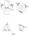
- FIG. 5is a perspective view illustrating an exemplary embodiment of a spindle structure of the orthopaedic fixation assembly.
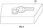
- FIG. 6is a perspective view illustrating a tabletop relief mold for hands-free fabrication of the orthopaedic fixation assembly.
- the word “exemplary”means “serving as an example, instance or illustration.”
- the embodiments described hereinare not limiting, but rather are exemplary only. It should be understood that the described embodiments are not necessarily to be construed as preferred or advantageous over other embodiments.
- the terms “embodiments of the invention”, “embodiments” or “invention”do not require that all embodiments of the invention include the discussed feature, advantage or mode of operation.
- orthopaedic fixation assemblyfor prosthetic biologic attachment may be described herein.
- the orthopaedic fixation assemblymay be used in conjunction with internal arthroplasty components, transdermal implant systems, and the like for achieving osseointegration.
- the orthopaedic fixation assemblymay provide the benefits of compliant pre-stress fixation with the rigidity and initial stability of a stemmed implant.
- the orthopaedic fixation assembly 100may form a stabilization construct that provides a high-pressure bone-implant interface for biologic fixation or attachment and may be configured to be inserted into an intramedullary canal (not shown) of a bone 120 .
- FIG. 1 Amay show the implantation of the orthopaedic fixation assembly 100 within the bone 120 in an upper hind limb, such as a femur.
- the orthopaedic fixation assembly 100may be implanted within any other articulating bone, such as the humerus, pelvis, or tibia. Prior to implantation, a surgeon may make an incision to access and dislocate a joint, such as a hip, knee, ankle, shoulder, or elbow joint, exposing the articulating bone ends. Damaged or diseased cartilage and bone may then be removed, and the intramedullary canal prepared for receiving the orthopaedic fixation assembly 100 .
- the intramedullary bone spacemay be carved out to create an enlarged canal having a predetermined depth and width relative to the osteotomy surface, as would be understood by a person having ordinary skill in the art.
- the surgeonmay make an incision to access the distal aspect of the humerus, pelvis, femur, or tibia.
- the orthopaedic fixation assembly 100may then be inserted into the prepared intramedullary canal, and subsequently affixed or secured thereto via a plurality of transverse pins 102 or any other similar attachment or fixation devices, such as screws, pegs, barbs, wires, or anchors, as would be understood by a person having ordinary skill in the art.
- the orthopaedic fixation assembly 100may include a main body 104 adapted for insertion into the resected portion of the bone 120 .
- the main body 104may include a longitudinally-extending stem 106 having a proximal end 108 , a distal end 110 , and a cavity body 112 defined therebetween.
- a spindle structure 114may be fixedly attached to the proximal end 108 of the longitudinally-extending stem 106 , forming a unitary structure therewith.
- the spindle structure 114may protrude outwardly from the stem 106 , extending externally beyond the osteotomy surface.
- the spindle structure 114may include a housing 116 having an annular flange 118 mounted thereto, the annular flange 118 configured to interface with the osteotomy surface.
- the annular flange 118may thus engage a proximally-faced (or distally-faced, as desired) resected surface of, for example, the femoral, humeral, tibial diaphysis, or pelvic bone.
- the flange 118may assist in maintaining and securing the orthopaedic fixation assembly 100 within the intramedullary canal and facilitate distribution of physiological forces, such as bending, shear, and rotational forces.
- the angle, size, and extent of the flange 118may depend on the anatomy of the patient and the morphology of the femoral, humeral, pelvic, or tibial resection level as would be understood by a person having ordinary skill in the art.
- the orthopaedic fixation assembly 100may be compatible with any bone structure for example, but not limited to, acetabulum, in patients with hip disarticulations, residual pelvic anatomy in patients with pelvic resections, or the distal radius in patients with wrist disarticulations. As shown in FIG. 1 B , the orthopaedic fixation assembly 100 may vary in size and configuration, for example, to accommodate extremely short residual bones, such as those encountered in patients with amputations including, but not limited to, transhumeral, transfemoral, transtibial, hip disarticulation, or partial hemipelvectomy amputations.
- FIGS. 2 A and 2 Bmay depict an exploded view of an exemplary embodiment of the components of an orthopaedic fixation assembly 200 according to the present invention.
- the orthopaedic fixation assembly 200may form a stabilization construct that provides a high-pressure bone-implant interface for biologic fixation or attachment.
- the orthopaedic fixation assembly 200may include a main body 240 adapted for insertion into a resected portion of the bone 120 , as shown in FIGS. 1 A and 1 B .
- the main body 240may include a longitudinally-extending stem 202 having a proximal end 204 , a distal end 206 , and a cavity body 208 defined therebetween.
- the cavity body 208may include one or more apertures 210 for receiving transverse fixation pins 102 (as shown in FIGS. 1 A and 1 B ) or any other similar attachment or fixation devices, such as screws, pegs, barbs, wires, or anchors, therethrough.
- the apertures 210may take the form of elongated slots. As would be understood by a person having ordinary skill in the art, the apertures 210 may take the form of any other shape as may be desired.
- the apertures 210may be arranged substantially parallel to one another, or may alternatively be configured in any suitable arrangement as would be understood by a person having ordinary skill in the art.
- a spindle structure 212may be fixedly attached to the proximal end 204 of the longitudinally-extending stem 202 , and protrude outwardly therefrom, such that a portion of the structure extends externally beyond the resected cavity of the bone.
- the spindle structure 212may include a housing 214 having an annular flange 216 mounted thereto, the annular flange 216 configured to interface with the osteotomy surface.
- the spindle structure 212may also house at least one compliant biasing member 242 , which may be Belleville washers in one exemplary embodiment, configured to apply a compressive force to the surrounding bone.
- the compliant biasing membermay be disposed within an interior of the spindle structure 212 , such that a bone biasing force is applied to at least a portion of the bone.
- the spindle structure 212may be shaped and configured for accommodating the compliant member therein.
- the compliant biasing member 242may generally form a structural member with enhanced compliance (i.e., greater elastic deformation when subjected to an applied force), such as a linear spring, coiled spring, bellow, Belleville washer, or any other elastic biasing member as would be understood by a person having ordinary skill in the art.
- the compliant biasing member 242may include a Belleville washer having a fursto-conical shape and concentric aperture defined therethrough.
- the compliant biasing membermay include a plurality of conical washers stacked atop each other to form a Belleville spring. It should be appreciated that the compliant biasing member 242 may include any number, such as one or more, compliant biasing elements. The compliant biasing member 242 may provide a stable, high-pressure implant interface that allows osseointegration.
- a porous coating 218for example hydroxyapatite may be provided at the juncture between stem 202 and spindle structure 212 , improving the stability and securement of the implant and facilitating long-term bone ingrowth.
- the coatingmay be applied to a roughened surface of the juncture region. The roughened surface may increase the surface area of the juncture, thereby improving adhesion of the coating.
- splines, or sharp longitudinal ridgesmay be added to the coated juncture to provide further stability.
- FIGS. 2 A and 2 Bfurther illustrate an anchor plug 220 that may be received within the body cavity 208 of the stem 202 and securable thereto via complementary mating surfaces.
- the mating surfacesmay be, for example, a tongue and groove locking mechanism that ensures the anchor plug 220 assumes the correct orientation within the body cavity 208 , which will be described in greater detail below in FIGS. 3 A and 3 B .
- the anchor plug 220may form a generally cylindrical body 222 having an elongated shaft 224 extending downwardly therefrom.
- the cylindrical body 222may include a top portion 226 , a bottom portion 228 , and peripheral side wall 230 having a plurality of apertures 232 defined therein.
- an internally-threaded end cap 234may be provided to secure the anchor plug 220 within the body cavity 208 of the stem 202 .
- the longitudinally-extending stem 202may have complementary external threads 236 disposed on the distal end 206 thereof to facilitate tightening of the end cap 234 in place.
- a top portion 238 of the end cap 234may have a female hex impression for engagement with a screwdriver or any other similar type of tool.
- FIGS. 3 A and 3 Bmay illustrate various orientations of the tongue and groove locking mechanism discussed above.
- a groove 302may extend along a length of a cylindrical body 304 of an anchor plug 300 .
- the groove 302may interface with a corresponding tongue component (not shown) disposed within the interior of the body cavity 208 of the stem 202 , as illustrated in FIGS. 2 A and 2 B .
- a tongue or tab element 306may extend along a length of the cylindrical body 304 of the anchor plug 300 .
- the tongue 306may interface with a corresponding groove (not shown) disposed within the interior of the body cavity 208 of the stem 202 , as illustrated in FIGS.
- the stem 202(as shown in FIGS. 2 A and 2 B ) and the anchor plug 300 may be elliptical or any other desired shape, as would be understood by a person having ordinary skill in the art, in which case, no groove 302 or tongue or tab element 306 may be necessary to ensure a correct and singular orientation of the anchor plug 300 within the body cavity 208 of the stem 202 . This can ensure that cross-pins, screws, pegs, or anchors can be inserted using the targeting guide shown in exemplary FIG. 4 .
- FIG. 4may illustrate a perspective view of an exemplary embodiment of a targeting guide 400 for use in conjunction with an orthopaedic fixation assembly.
- the targeting guide 400may fit over the spindle structure 410 and include alignment tabs 402 that ensure proper orientation and alignment of the targeting guide 400 and the spindle structure 410 .
- the alignment tabs 402may be disposed on a front and back of the spindle 410 , for example at a 180-degree interval, so that a same orthopaedic fixation assembly and targeting guide 400 may be used to insert cross pins, screws, pegs, or anchors, in any orientation desired, regardless of the employed surgical exposure.
- a pedestal 404may be utilized to hold a traction bar 406 and attach anchor plug 220 in the correct orientation, so that transverse pins may be guided through corresponding apertures.
- the pedestal 404may be manufactured onto the targeting guide 400 , or, alternatively, may be fastened, screwed, snapped, or the like, into position.
- Targeting guide 400may be utilized to drill holes in the bone and ensure accuracy when placing cross pins into the anchor plug, along with ensuring accuracy and desired performance and placement.
- FIG. 5may provide a perspective view of an orthopaedic implant illustrating an exemplary embodiment of a spindle to prevent rotation of the implant.
- itmay be desirable to control and/or prevent rotation while osseointegration is occurring.
- the shape, size, number, and position of the porous coated chockscan be matched to the shape of the patient's bone at the planned resection level.
- Alignment tabs 402may be constructed of titanium, interconnecting porous or “trabecular” metal with or without osteoconductive coating(s) including, but not limited to, hydroxyapatite.
- FIG. 6may illustrate an exemplary embodiment of tabletop relief mold 600 for hands-free assembly of the implant system of the orthopaedic fixation assembly, prior to instrumentation, in the operating room.
- the assembly and targeting guide 400may be placed in the holder 600 so that the anchor plug 220 can be inserted within the body cavity 208 of the stem 202 and the end-cap 234 screwed into place, as discussed above in FIGS. 2 A and 2 B .
- the relief hold 600may hold the implant in a predetermined posture, such as in an upright position. This may allow a surgeon to release the anchor plug into the body cavity and securely tighten the end cap to the stem.
- the relief mold 600may provide resistance to torque as the end cap is tightened.
Landscapes
- Health & Medical Sciences (AREA)
- Orthopedic Medicine & Surgery (AREA)
- Life Sciences & Earth Sciences (AREA)
- Animal Behavior & Ethology (AREA)
- General Health & Medical Sciences (AREA)
- Engineering & Computer Science (AREA)
- Biomedical Technology (AREA)
- Heart & Thoracic Surgery (AREA)
- Veterinary Medicine (AREA)
- Public Health (AREA)
- Surgery (AREA)
- Oral & Maxillofacial Surgery (AREA)
- Cardiology (AREA)
- Transplantation (AREA)
- Vascular Medicine (AREA)
- Nuclear Medicine, Radiotherapy & Molecular Imaging (AREA)
- Molecular Biology (AREA)
- Medical Informatics (AREA)
- Neurology (AREA)
- Prostheses (AREA)
- Surgical Instruments (AREA)
Abstract
Description
Claims (23)
Priority Applications (2)
| Application Number | Priority Date | Filing Date | Title |
|---|---|---|---|
| US17/156,973US11730520B2 (en) | 2017-08-07 | 2021-01-25 | Orthopaedic fixation assembly, system, and method of use |
| US18/349,441US12256959B2 (en) | 2017-08-07 | 2023-07-10 | Orthopaedic fixation assembly, system, and method of use |
Applications Claiming Priority (3)
| Application Number | Priority Date | Filing Date | Title |
|---|---|---|---|
| US201762541896P | 2017-08-07 | 2017-08-07 | |
| US16/051,732US10952774B2 (en) | 2017-08-07 | 2018-08-01 | Orthopaedic fixation assembly, system, and method of use |
| US17/156,973US11730520B2 (en) | 2017-08-07 | 2021-01-25 | Orthopaedic fixation assembly, system, and method of use |
Related Parent Applications (1)
| Application Number | Title | Priority Date | Filing Date |
|---|---|---|---|
| US16/051,732ContinuationUS10952774B2 (en) | 2017-08-07 | 2018-08-01 | Orthopaedic fixation assembly, system, and method of use |
Related Child Applications (1)
| Application Number | Title | Priority Date | Filing Date |
|---|---|---|---|
| US18/349,441ContinuationUS12256959B2 (en) | 2017-08-07 | 2023-07-10 | Orthopaedic fixation assembly, system, and method of use |
Publications (2)
| Publication Number | Publication Date |
|---|---|
| US20210137563A1 US20210137563A1 (en) | 2021-05-13 |
| US11730520B2true US11730520B2 (en) | 2023-08-22 |
Family
ID=65230801
Family Applications (3)
| Application Number | Title | Priority Date | Filing Date |
|---|---|---|---|
| US16/051,732Active2039-01-06US10952774B2 (en) | 2017-08-07 | 2018-08-01 | Orthopaedic fixation assembly, system, and method of use |
| US17/156,973Active2039-04-20US11730520B2 (en) | 2017-08-07 | 2021-01-25 | Orthopaedic fixation assembly, system, and method of use |
| US18/349,441Active2038-08-17US12256959B2 (en) | 2017-08-07 | 2023-07-10 | Orthopaedic fixation assembly, system, and method of use |
Family Applications Before (1)
| Application Number | Title | Priority Date | Filing Date |
|---|---|---|---|
| US16/051,732Active2039-01-06US10952774B2 (en) | 2017-08-07 | 2018-08-01 | Orthopaedic fixation assembly, system, and method of use |
Family Applications After (1)
| Application Number | Title | Priority Date | Filing Date |
|---|---|---|---|
| US18/349,441Active2038-08-17US12256959B2 (en) | 2017-08-07 | 2023-07-10 | Orthopaedic fixation assembly, system, and method of use |
Country Status (5)
| Country | Link |
|---|---|
| US (3) | US10952774B2 (en) |
| EP (1) | EP3664725B1 (en) |
| AU (1) | AU2018313696B2 (en) |
| CA (1) | CA3072067A1 (en) |
| WO (1) | WO2019032362A1 (en) |
Cited By (1)
| Publication number | Priority date | Publication date | Assignee | Title |
|---|---|---|---|---|
| US20230346430A1 (en)* | 2017-08-07 | 2023-11-02 | Mt Innovations, Llc. | Orthopaedic fixation assembly, system, and method of use |
Families Citing this family (4)
| Publication number | Priority date | Publication date | Assignee | Title |
|---|---|---|---|---|
| US10675456B2 (en)* | 2016-09-20 | 2020-06-09 | Robert Madeira | System and methods for percutaneous mechanical and/or neural interface |
| CN112773569A (en)* | 2021-01-26 | 2021-05-11 | 北京大学人民医院 | Intramedullary pressurization fixing device for reconstruction of adjacent joint bone defect prosthesis |
| CN114224559B (en)* | 2021-12-24 | 2023-02-03 | 夏一丹 | Endoprosthesis for an implantable prosthesis |
| CN114795606A (en)* | 2022-04-18 | 2022-07-29 | 太原理工大学 | Osseointegration implant for installing stepped-containing artificial limb and preparation method |
Citations (12)
| Publication number | Priority date | Publication date | Assignee | Title |
|---|---|---|---|---|
| US5360448A (en)* | 1991-10-07 | 1994-11-01 | Thramann Jeffrey J | Porous-coated bone screw for securing prosthesis |
| US6869450B2 (en) | 2002-10-08 | 2005-03-22 | Eska Implants Gmbh & Co. | Subcutaneous, intramuscular support for a rigid transcutaneous implant |
| US20060129247A1 (en) | 1993-11-01 | 2006-06-15 | Bioment Manufacturing Corp. | Intramedullary compliant fixation |
| US20090048600A1 (en)* | 2007-06-22 | 2009-02-19 | Anthem Orthopaedics Van, Llc | Intramedullary rod with pivotable fastener and method for using same |
| US20090149964A1 (en) | 2007-10-10 | 2009-06-11 | Biomet Manufacturing Corp. | Knee joint prosthesis system and method for implantation |
| WO2009105535A1 (en) | 2008-02-19 | 2009-08-27 | North Carolina State University | Transcutaneous osseointegrated device for prostheses |
| US20110160728A1 (en) | 2009-12-31 | 2011-06-30 | Amei Technologies, Inc. | Intramedullary Compression Nail and Related Method for Jones Fractures |
| US20140214177A1 (en) | 2013-01-31 | 2014-07-31 | Biomet Manufacturing Corporation | Transdermal Intraosseous Device |
| US8915970B2 (en) | 2013-02-08 | 2014-12-23 | Biomet Manufacturing, Llc | Transdermal prosthesis |
| US20150305897A1 (en) | 2014-04-25 | 2015-10-29 | Biomet Manufacturing, Llc | Modular Transdermal Compress Device |
| US9308103B1 (en) | 2013-08-20 | 2016-04-12 | David T. Kluger | Osseointegrated mount for prosthetic limb and peripheral nerve interface |
| US20160100961A1 (en) | 2010-02-01 | 2016-04-14 | Biomet Manufacturing, Llc | Transdermal intraosseous device |
Family Cites Families (1)
| Publication number | Priority date | Publication date | Assignee | Title |
|---|---|---|---|---|
| US10952774B2 (en)* | 2017-08-07 | 2021-03-23 | The Solsidan Group, LLC | Orthopaedic fixation assembly, system, and method of use |
- 2018
- 2018-08-01USUS16/051,732patent/US10952774B2/enactiveActive
- 2018-08-02WOPCT/US2018/044946patent/WO2019032362A1/ennot_activeCeased
- 2018-08-02AUAU2018313696Apatent/AU2018313696B2/ennot_activeCeased
- 2018-08-02EPEP18844513.4Apatent/EP3664725B1/enactiveActive
- 2018-08-02CACA3072067Apatent/CA3072067A1/enactivePending
- 2021
- 2021-01-25USUS17/156,973patent/US11730520B2/enactiveActive
- 2023
- 2023-07-10USUS18/349,441patent/US12256959B2/enactiveActive
Patent Citations (12)
| Publication number | Priority date | Publication date | Assignee | Title |
|---|---|---|---|---|
| US5360448A (en)* | 1991-10-07 | 1994-11-01 | Thramann Jeffrey J | Porous-coated bone screw for securing prosthesis |
| US20060129247A1 (en) | 1993-11-01 | 2006-06-15 | Bioment Manufacturing Corp. | Intramedullary compliant fixation |
| US6869450B2 (en) | 2002-10-08 | 2005-03-22 | Eska Implants Gmbh & Co. | Subcutaneous, intramuscular support for a rigid transcutaneous implant |
| US20090048600A1 (en)* | 2007-06-22 | 2009-02-19 | Anthem Orthopaedics Van, Llc | Intramedullary rod with pivotable fastener and method for using same |
| US20090149964A1 (en) | 2007-10-10 | 2009-06-11 | Biomet Manufacturing Corp. | Knee joint prosthesis system and method for implantation |
| WO2009105535A1 (en) | 2008-02-19 | 2009-08-27 | North Carolina State University | Transcutaneous osseointegrated device for prostheses |
| US20110160728A1 (en) | 2009-12-31 | 2011-06-30 | Amei Technologies, Inc. | Intramedullary Compression Nail and Related Method for Jones Fractures |
| US20160100961A1 (en) | 2010-02-01 | 2016-04-14 | Biomet Manufacturing, Llc | Transdermal intraosseous device |
| US20140214177A1 (en) | 2013-01-31 | 2014-07-31 | Biomet Manufacturing Corporation | Transdermal Intraosseous Device |
| US8915970B2 (en) | 2013-02-08 | 2014-12-23 | Biomet Manufacturing, Llc | Transdermal prosthesis |
| US9308103B1 (en) | 2013-08-20 | 2016-04-12 | David T. Kluger | Osseointegrated mount for prosthetic limb and peripheral nerve interface |
| US20150305897A1 (en) | 2014-04-25 | 2015-10-29 | Biomet Manufacturing, Llc | Modular Transdermal Compress Device |
Non-Patent Citations (4)
| Title |
|---|
| European Search Report dated Mar. 25, 2021, including the Supplementary European Search Report and the European Search Opinion, in connection with corresponding EP Application No. 18844513.4 (4 pp.). |
| Examination Report dated May 17, 2023, in corresponding Australian Application No. 2018313696, 5 pages. |
| Notification of Transmittal of the International Search Report and the Written Opinion of the International Searching Authority dated Nov. 19, 2018, in connection with corresponding International Application No. PCT/US18/44946 (11 pgs.). |
| Office Action dated Apr. 5, 2023, in corresponding European Application No. 18844513.4, 6 pages. |
Cited By (2)
| Publication number | Priority date | Publication date | Assignee | Title |
|---|---|---|---|---|
| US20230346430A1 (en)* | 2017-08-07 | 2023-11-02 | Mt Innovations, Llc. | Orthopaedic fixation assembly, system, and method of use |
| US12256959B2 (en)* | 2017-08-07 | 2025-03-25 | Mt Innovations, Llc. | Orthopaedic fixation assembly, system, and method of use |
Also Published As
| Publication number | Publication date |
|---|---|
| AU2018313696A1 (en) | 2020-02-20 |
| US20230346430A1 (en) | 2023-11-02 |
| US20210137563A1 (en) | 2021-05-13 |
| CA3072067A1 (en) | 2019-02-14 |
| EP3664725A1 (en) | 2020-06-17 |
| EP3664725A4 (en) | 2021-04-28 |
| EP3664725B1 (en) | 2024-06-12 |
| US10952774B2 (en) | 2021-03-23 |
| AU2018313696B2 (en) | 2023-10-12 |
| WO2019032362A1 (en) | 2019-02-14 |
| US20190038317A1 (en) | 2019-02-07 |
| US12256959B2 (en) | 2025-03-25 |
Similar Documents
| Publication | Publication Date | Title |
|---|---|---|
| US12256959B2 (en) | Orthopaedic fixation assembly, system, and method of use | |
| US5989259A (en) | Femoral calcar stop for use with femoral stem inserter | |
| EP1482878B1 (en) | Intramedullary trial fixation device | |
| EP2670360B1 (en) | Arthroplasty plate | |
| US9937048B2 (en) | Femoral stem including an anchor to facilitate assembly and implantation | |
| US9168156B2 (en) | Trial coupler systems and methods | |
| JP4090649B2 (en) | Prosthesis system and modular sleeve | |
| JP6275436B2 (en) | Height-adjustable arthroplasty plate | |
| AU2002336155B2 (en) | Modular acetabular cup, and anchoring screw for fixing a prosthetic implant such as said acetabular cup | |
| US4834081A (en) | Tool for removing modular joint prosthesis | |
| US8118868B2 (en) | Method and apparatus for attaching soft tissue to an implant | |
| US5782920A (en) | Offset coupling for joint prosthesis | |
| US20050071014A1 (en) | Modular long bone prosthesis for partial or total bone replacement | |
| AU7794901A (en) | Modular femoral stem component for a hip joint prosthesis | |
| US7998218B1 (en) | Modular orthopedic implant | |
| US20090171463A1 (en) | Arthrodesis module and method for providing a patient with an arthrodesis | |
| KR20240040069A (en) | Orthopedic Components | |
| JP2004141661A (en) | Implant and method for using it | |
| CN113633440B (en) | Hip joint prosthesis | |
| US11766333B2 (en) | Radial head orthopedic implant apparatus and method of using same | |
| US20150342743A1 (en) | Shoulder endoprosthesis | |
| US20220218488A1 (en) | Internal osseointegrated implant for transfemoral amputee | |
| AU2006341378B2 (en) | Trial coupler systems and methods | |
| Tom Tkach et al. | Target Restoration of Hip Mechanics in THA |
Legal Events
| Date | Code | Title | Description |
|---|---|---|---|
| AS | Assignment | Owner name:THE SOLSIDAN GROUP, LLC, MARYLAND Free format text:ASSIGNMENT OF ASSIGNORS INTEREST;ASSIGNOR:FORSBERG, JONATHAN A.;REEL/FRAME:055017/0769 Effective date:20180709 | |
| FEPP | Fee payment procedure | Free format text:ENTITY STATUS SET TO UNDISCOUNTED (ORIGINAL EVENT CODE: BIG.); ENTITY STATUS OF PATENT OWNER: SMALL ENTITY | |
| FEPP | Fee payment procedure | Free format text:ENTITY STATUS SET TO SMALL (ORIGINAL EVENT CODE: SMAL); ENTITY STATUS OF PATENT OWNER: SMALL ENTITY | |
| STPP | Information on status: patent application and granting procedure in general | Free format text:APPLICATION DISPATCHED FROM PREEXAM, NOT YET DOCKETED | |
| STPP | Information on status: patent application and granting procedure in general | Free format text:DOCKETED NEW CASE - READY FOR EXAMINATION | |
| AS | Assignment | Owner name:FORSBERG, JONATHAN A., MARYLAND Free format text:ASSIGNMENT OF ASSIGNORS INTEREST;ASSIGNOR:THE SOLSIDAN GROUP;REEL/FRAME:060995/0124 Effective date:20220824 | |
| AS | Assignment | Owner name:MT INNOVATIONS, LLC., MONTANA Free format text:ASSIGNMENT OF ASSIGNORS INTEREST;ASSIGNOR:JONATHAN A. FORSBERG;REEL/FRAME:062420/0740 Effective date:20230117 | |
| AS | Assignment | Owner name:MT INNOVATIONS, LLC., MONTANA Free format text:CORRECTIVE ASSIGNMENT TO CORRECT THE FIRST PART OF THE ASSIGNEE ADDRESS SHOULD BE LISTED AS PO. PREVIOUSLY RECORDED AT REEL: 062420 FRAME: 0740. ASSIGNOR(S) HEREBY CONFIRMS THE ASSIGNMENT;ASSIGNOR:JONATHAN A. FORSBERG;REEL/FRAME:062480/0037 Effective date:20230117 | |
| STPP | Information on status: patent application and granting procedure in general | Free format text:NOTICE OF ALLOWANCE MAILED -- APPLICATION RECEIVED IN OFFICE OF PUBLICATIONS | |
| STCF | Information on status: patent grant | Free format text:PATENTED CASE | |
| AS | Assignment | Owner name:ONKOS SURGICAL, INC., NEW JERSEY Free format text:ASSIGNMENT OF ASSIGNORS INTEREST;ASSIGNORS:FORSBERG, JONATHAN, MD, PHD, DR.;MT INNOVATIONS, LLC;THE SOLSIDAN GROUP, LLC;REEL/FRAME:072085/0250 Effective date:20250815 |