US11729871B2 - System and method for applying electromagnetic energy - Google Patents
System and method for applying electromagnetic energyDownload PDFInfo
- Publication number
- US11729871B2 US11729871B2US16/855,757US202016855757AUS11729871B2US 11729871 B2US11729871 B2US 11729871B2US 202016855757 AUS202016855757 AUS 202016855757AUS 11729871 B2US11729871 B2US 11729871B2
- Authority
- US
- United States
- Prior art keywords
- energy
- frequencies
- radiating element
- frequency
- supplied
- Prior art date
- Legal status (The legal status is an assumption and is not a legal conclusion. Google has not performed a legal analysis and makes no representation as to the accuracy of the status listed.)
- Active, expires
Links
Images


Classifications
- H—ELECTRICITY
- H05—ELECTRIC TECHNIQUES NOT OTHERWISE PROVIDED FOR
- H05B—ELECTRIC HEATING; ELECTRIC LIGHT SOURCES NOT OTHERWISE PROVIDED FOR; CIRCUIT ARRANGEMENTS FOR ELECTRIC LIGHT SOURCES, IN GENERAL
- H05B6/00—Heating by electric, magnetic or electromagnetic fields
- H05B6/64—Heating using microwaves
- H05B6/66—Circuits
- H05B6/666—Safety circuits
- H—ELECTRICITY
- H05—ELECTRIC TECHNIQUES NOT OTHERWISE PROVIDED FOR
- H05B—ELECTRIC HEATING; ELECTRIC LIGHT SOURCES NOT OTHERWISE PROVIDED FOR; CIRCUIT ARRANGEMENTS FOR ELECTRIC LIGHT SOURCES, IN GENERAL
- H05B6/00—Heating by electric, magnetic or electromagnetic fields
- H05B6/64—Heating using microwaves
- H05B6/647—Aspects related to microwave heating combined with other heating techniques
- H—ELECTRICITY
- H05—ELECTRIC TECHNIQUES NOT OTHERWISE PROVIDED FOR
- H05B—ELECTRIC HEATING; ELECTRIC LIGHT SOURCES NOT OTHERWISE PROVIDED FOR; CIRCUIT ARRANGEMENTS FOR ELECTRIC LIGHT SOURCES, IN GENERAL
- H05B6/00—Heating by electric, magnetic or electromagnetic fields
- H05B6/64—Heating using microwaves
- H05B6/66—Circuits
- H05B6/68—Circuits for monitoring or control
- H05B6/686—Circuits comprising a signal generator and power amplifier, e.g. using solid state oscillators
- H—ELECTRICITY
- H05—ELECTRIC TECHNIQUES NOT OTHERWISE PROVIDED FOR
- H05B—ELECTRIC HEATING; ELECTRIC LIGHT SOURCES NOT OTHERWISE PROVIDED FOR; CIRCUIT ARRANGEMENTS FOR ELECTRIC LIGHT SOURCES, IN GENERAL
- H05B6/00—Heating by electric, magnetic or electromagnetic fields
- H05B6/64—Heating using microwaves
- H05B6/66—Circuits
- H05B6/68—Circuits for monitoring or control
- H05B6/688—Circuits for monitoring or control for thawing
- H—ELECTRICITY
- H05—ELECTRIC TECHNIQUES NOT OTHERWISE PROVIDED FOR
- H05B—ELECTRIC HEATING; ELECTRIC LIGHT SOURCES NOT OTHERWISE PROVIDED FOR; CIRCUIT ARRANGEMENTS FOR ELECTRIC LIGHT SOURCES, IN GENERAL
- H05B6/00—Heating by electric, magnetic or electromagnetic fields
- H05B6/64—Heating using microwaves
- H05B6/70—Feed lines
- H05B6/705—Feed lines using microwave tuning
Definitions
- Electromagnetic waveshave been used in various applications to apply energy to objects.
- electromagnetic energymay be supplied using a magnetron, which is typically tuned to a single frequency for applying electromagnetic energy only in that frequency.
- RFradio frequency
- One example of a commonly used electromagnetic deviceis a microwave oven.
- Typical microwave ovensapply electromagnetic energy at the single frequency of 2.45 GHz.
- the typical microwave ovenincludes a metallic fan (behind a grill in the oven) to disturb the standing wave pattern and in an attempt to achieve more uniform energy distribution in the oven's cavity.
- absorptive propertiesDue to the nature of the absorptive properties of electromagnetic energy, even if uniform electromagnetic field distribution could be achieved at a particular frequency, energy absorption might not be uniform. This is because differing materials (or materials having varying characteristics) typically have variable absorptive properties. Moreover, absorptive properties are often a function of temperature and/or phase of the materials in the object. Thus, as the temperature and/or phase of an object changes, e.g., due to electromagnetic energy application, the object's absorptive properties may change, and the rate and magnitude of this change may depend on properties of material(s) in the object and the amount of energy required causing those changes. In addition, the shape of an object may contribute to its absorptive properties at a particular frequency. Irregularly shaped objects, for example, may exhibit irregular electromagnetic energy absorption. All these factors can make it difficult to control the absorption of electromagnetic energy in an object.
- Electromagnetic energymay be supplied to the zone and received via the zone. This can occur, for example, through the use of a radiating element that receives electromagnetic energy from a source and transmits it through one or more radiating elements, (e.g., antennas).
- An exemplary apparatus and methodmay further include the determination of a value indicative of energy absorbable absorption by the object at each of a plurality of frequencies. This may occur, for example, through the use of a controller, which may be further configured to cause energy to be supplied to at least one radiating element in at least a subset of the plurality of frequencies.
- Energy applied to the zone at each of the subset of frequenciesmay be a function of the absorbable energy value at each frequency.
- energy applied to the zone at each of the subset of frequenciesmay be a function of the absorbable energy value at more than one of the plurality of frequencies.
- one or more apparatuses or methodmay include determining a value indicative of energy absorbable by an object at each of a plurality of frequencies, and causing energy to be supplied to the at least one radiating element in at least a subset of the plurality of frequencies to an energy application zone. Energy applied to the zone at each of the subset of frequencies may be inversely related to the absorbable energy value at each frequency.
- one or more apparatuses or methodsmay adjust energy supplied to the radiating element(s) as a function of the frequency at which the energy is absorbed.
- exemplary apparatuses and methodsmay determine a desired energy absorption amount in the object to be heated at each of a plurality of frequencies, and may adjust energy supplied at each frequency in order to target the desired energy absorption amount to the object to be heated at each frequency.
- exemplary apparatuses and methodsmay determine a desired energy absorption amount in the object to be heated, and may adjust energy supplied at each frequency in order to target or effect substantially the desired energy absorption amount in the object to be heated.
- one or more apparatuses or methodsmay involve determining a value indicative of energy absorbable by the object at each of a plurality of frequencies, and may further adjust energy supplied such that when the energy supplied is plotted against an absorbable energy value over a range of frequencies, the two plots tend to mirror each other.
- the two plotsmay tend to mirror each other at one or more sub-sets (e.g., sub-band) of the plurality of frequencies.
- one or more apparatuses or methodsmay involve determining a threshold value for the value indicative of energy absorbable at at least one frequency, among the plurality of frequencies, and preventing electromagnetic energy from being supplied to the at least one radiating element at the at least one frequency.
- FIG. 1is a schematic diagram of an apparatus for applying electromagnetic energy to an object, in accordance with some exemplary embodiments of the present invention
- FIGS. 2 A, 2 B, 2 C, and 2 Dare various views of a cavity, in accordance with some exemplary embodiments of the present invention.
- FIGS. 3 A and 3 Bare enlarged views of field adjusting elements such as those illustrated in FIGS. 2 A- 2 D ;
- FIG. 4 Ais a cross-sectional view of an antenna, in accordance with some embodiments of the invention.
- FIG. 4 Bis a perspective view of a helical antenna in accordance with some embodiments of the present invention.
- FIG. 4 Cis a graph of correlation of free space matched frequencies and cavity matched frequencies of the helical antenna of FIG. 4 B ;
- FIG. 4 D- 4 Hare partial cross-sectional side views of various fractal antenna, in accordance with embodiments of the invention.
- FIG. 5 Ais a schematic block diagrams of an exemplary electromagnetic energy application subsystem, in accordance with some embodiments of the present invention.
- FIG. 5 Bis a schematic block diagrams of another exemplary electromagnetic energy application subsystem, in accordance with some embodiments of the present invention.
- FIG. 6is a schematic block diagram of a calculation subsystem, in accordance with some embodiments of the present invention.
- FIG. 7is a schematic block diagram of an exemplary interface 130 , in accordance with some embodiments of the present invention.
- FIG. 8is a flow chart of an exemplary operation process in accordance with some embodiments of the invention.
- FIG. 9is a flow chart of an exemplary process for the calibration routine of FIG. 8 , in accordance with some embodiments of the invention.
- FIG. 10is a flow chart for a process of determining swept power characteristics, in accordance with some embodiments of the invention.
- FIG. 11illustrates a dissipation ratio spectrum (dashed line) and an input energy spectrum (solid line), in accordance with some embodiments of the invention
- FIG. 12illustrate a dissipation ratio spectrum, in accordance with some embodiments of the invention.
- FIGS. 13 A and 13 Brespectively illustrate a truncated absorbable energy spectrum and an input energy spectrum that is a reverse image of the dissipation ratio spectrum, in accordance with some embodiments of the invention
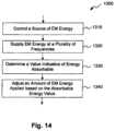
- FIG. 14is a flow chart of exemplary steps of applying electromagnetic energy to an energy application zone in certain embodiments.
- FIG. 15is a flow chart of another exemplary process for applying electromagnetic energy to an object in an energy application zone in certain embodiments.
- the inventionmay involve apparatus and methods for applying electromagnetic energy.
- electromagnetic energyincludes any or all portions of the electromagnetic spectrum, including but not limited to, radio frequency (RF), infrared (IR), near infrared, visible light, ultraviolet, etc.
- applied electromagnetic energymay include RF energy with a wavelength in free space of 100 km to 1 mm, which is a frequency of 3 KHz to 300 GHz, respectively.
- the frequency bandsmay be between 500 MHz to 1500 MHz or between 700 MHz to 1200 MHz or between 800 MHz tol GHz.
- Microwave and ultra high frequency (UHF) energyare both within the RF range.
- electromagnetic energyused for heating.
- these descriptionsare provided to illustrate exemplary principles of the invention.
- the invention, as described and claimed,may benefit various industrial, commercial, and consumer processes involving the application of energy, regardless of whether the application of energy results in heating.
- electromagnetic energymay also be applied to an object for combusting, thawing, defrosting, cooking, drying, accelerating reactions, expanding, evaporating, fusing, causing or altering biologic processes, medical treatments, preventing freezing or cooling, maintaining the object within a desired temperature range, or any other application where it is desirable to apply energy.
- Electromagnetic energymay be applied to the object to, among other things, cause portions of the object to undergo a phase change and/or volume change and/or initiated chemical reaction or reactions.
- electromagnetic energymay be applied to an “object”.
- references to an “object”also known as a “load” or “object to be heated” to which electromagnetic energy is applied is not limited to a particular form.
- An “object” or a “load”may include a liquid, solid, or gas, depending upon the particular process with which the invention is utilized.
- the objectmay also include composites or mixtures of matter in differing phases.
- the term “object”encompasses such matter as food to be defrosted or cooked; clothes or other wet material to be dried; frozen organs to be thawed; chemicals to be reacted; fuel or other combustible material to be to be combusted; hydrated material to be dehydrated, gases to be expanded; liquids to be heated, boiled or vaporized, or any other material for which there is a desire to apply, even nominally, electromagnetic energy.
- the objectmay comprises a plurality of “items” (also known as: portions, regions, sub-regions, areas, parts, or pieces) that may be placed together in the energy application zone.
- the itemsmay be from substantially the same kind of different from each other. It is to be understood that electromagnetic energy is considered “applied to the object” if the electromagnetic energy is applied to at least one of the items (e.g., one portion) in the object.
- the inventionmay involve the application of energy to the object when the object is in the energy application zone. It is to be understood that the object need not be completely located in the energy application zone. That is, it is to be understood that an object is considered “in” the energy application zone if at least a portion of the object is located in the zone or if some portion of the object receives applied electromagnetic radiation.
- electromagnetic energymay be applied to an object for heating, combusting, thawing, defrosting, cooking, drying, accelerating reactions, expanding, evaporating, fusing, causing or altering biologic processes, medical treatments, preventing freezing, maintaining the object within a desired temperature range, or any other application where it is desirable to apply energy.
- the application of electromagnetic energymay occur in an “energy application zone”, such as energy application zone 9 , schematically depicted in FIG. 1 .
- an energy application zonemay be any void, location, region, or area where electromagnetic energy may be applied. It may include a hollow, or may be filled or partially filled with liquids, solids, gases, or combinations thereof.
- zone 9may include an interior of an enclosure, interior of a partial enclosure, open space, solid, or partial solid that allows existence, propagation, evanescent and/or resonance of electromagnetic waves.
- all such energy application zonesmay alternatively be referred to as cavities.
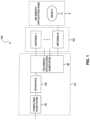
- FIG. 1is a diagrammatic representation of an apparatus 100 for applying electromagnetic energy to an object.
- Apparatus 100may include a controller 101 , an array of antennas 102 including one or more antennas, and an energy application zone 9 .
- Controller 101may include a computing subsystem 92 , an interface 130 , and an electromagnetic energy application subsystem 96 .
- energy application subsystem 96may respond by generating one or more radio frequency signals to be supplied to antennas 102 .
- the one or more antennas 102may apply (e.g., radiate) electromagnetic energy into energy application zone 9 . In certain embodiments, this energy can interact with an object 11 positioned within energy application zone 9 .
- Exemplary energy application zone 9may include locations where energy is applied in an oven, chamber, tank, dryer, thawer, dehydrator, reactor, furnace, engine, chemical or biological processing apparatus, incinerator, material shaping or forming apparatus, conveyor, combustion zone, cooler, freezer, etc.
- the energy application zonemay be part of a vending machine, in which objects are processed once purchased.
- energy application zone 9may include an electromagnetic resonator 10 (also known as cavity resonator, or cavity) ( FIG. 2 ). At times, energy application zone 9 may be congruent with the object or a portion of the object (e.g., the object or a portion thereof, is or may define the energy application zone).
- FIGS. 2 A- 2 Dshow respective sectional views of a cavity 10 , which is one exemplary embodiment of energy application zone 9 .
- Cavity 10may be cylindrical in shape and may be made of a conductor, for example, aluminum, stainless steel or any suitable metal or other conductive material.
- Cavity 10may be resonant in a predetermined range of frequencies (e.g., the UHF or microwave range of frequencies, for example, between 300 MHz and 3 GHz, or between 400 MHz and 1 GHZ). It is contemplated that cavity 10 may be of any other suitable shapes including semi-cylindrical, spherical, hemispherical, rectangular, elliptical, cuboid etc.
- cavity 10may even be of an irregular, symmetrical or asymmetrical shape. It is also contemplated that cavity 10 may be closed, i.e., completely enclosed (e.g., by conductor materials), bounded at least partially, or open, i.e., having non-bounded openings.
- the general methodology of the inventionis not limited to any particular cavity shape or configuration, as discussed earlier.
- the application of electromagnetic energymay occur via one or more power feeds.
- a feedmay include one or more waveguides and/or one or more radiating elements (e.g., antennas) for applying electromagnetic energy to the zone.
- a feedmay include any other suitable structure from which electromagnetic energy may be emitted.
- more than one feed and plurality of radiating elementsmay be provided.
- the radiating elementsmay be located on one or more surfaces of the energy application zone. Alternatively, radiating elements may be located inside or outside the energy application zone.
- the orientation and configuration of each radiating elementmay be distinct or the same, based on the specific energy application. For example, each radiating element may be positioned, adjusted, and/or oriented to transmit electromagnetic waves along a same direction, or various different directions.
- the location, orientation, and configuration of each radiating elementmay be predetermined before applying energy to the object, or dynamically adjusted using a processor while applying energy.
- the location, orientation, and configuration of each radiating elementmay be dynamically adjusted, for example, using a processor during operation of the apparatus, between rounds of energy application.
- the inventionis not limited to radiating elements having particular structures or which are necessarily located in particular areas or regions.
- apparatus 100may include at least one radiating element in the form of at least one antenna 102 for applying electromagnetic energy to the energy application zone 9 .
- the antennamay also be configured to receive electromagnetic energy via the zone.
- an antennaas used herein may function as a transmitter, a receiver, or both, depending on particular application and configuration.
- an antennaacts as a receiver for electromagnetic energy from an energy application zone (e.g., reflect electromagnetic waves), the antenna is said to receive electromagnetic energy via the zone.
- a radiating element and “antenna”may broadly refer to any structure from which electromagnetic energy may radiate and/or be received, regardless of whether the structure was originally designed for the purposes of radiating or receiving energy, and regardless of whether the structure serves any additional function.
- a radiating element or an antennamay include an aperture/slot antenna, or an antenna which includes a plurality of terminals transmitting in unison, either at the same time or at a controlled dynamic phase difference (e.g., a phased array antenna).
- antennas 102may include an electromagnetic energy transmitter (referred to herein as “a transmitting antenna”) that feeds energy into electromagnetic energy application zone 9 , an electromagnetic energy receiver (referred herein as “a receiving antenna”) that receives energy from zone 9 , or a combination of both a transmitter and a receiver.
- a first antennamay be configured to supply (or apply) electromagnetic energy to zone 9
- a second antennamay be configured to receive energy from the first antenna.
- multiple antennasmay each serve as both receivers and transmitters, and some antennas may serve a dual function while others serve a single function.
- a single antennamay be configured to both apply electromagnetic energy to the zone 9 and to receive electromagnetic energy via the zone 9 ; a first antenna may be configured to apply electromagnetic energy to the zone 9 and a second antenna may be configured to receive electromagnetic energy via the zone 9 ; or a plurality of antennas could be used, where at least one of the plurality of antennas is configured to both apply electromagnetic energy to zone 9 and to receive electromagnetic energy via zone 9 .
- an antennamay also be adjusted to affect the field pattern. For example, various properties of the antenna, for example, position, location, orientation, temperature, etc., may be adjusted. Different antenna property settings may result in differing electromagnetic field patterns within the energy application zone thereby affecting energy absorption in the object. Therefore, antenna adjustments may constitute one or more variables that can be varied in an energy application process.
- energymay be supplied to one or more transmitting antennas.
- Energy supplied to a transmitting antennamay result in energy emitted by the transmitting antenna (referred to herein as “incident energy”).
- the incident energymay be applied to zone 9 , and may be in an amount equal to the one that is supplied to the antennas by a source.
- a portionmay be dissipated by the object (referred to herein as “dissipated energy” or “absorbed energy”; the terms dissipated or dissipation are interchangeable with absorbed or absorption).
- Another portionmay be reflected at the transmitting antenna (referred to herein as “reflected energy”).
- Ddissipated energy
- Rreflected energy
- Ttransmitted energy
- the one or more transmitting antennasmay apply electromagnetic energy into zone 9 .
- Antennas 102may be placed in differing locations of zone 9 .
- Antennas 102may be polarized in differing directions in order to, for example, reduce coupling, enhance specific field pattern(s), increase the energy application efficiency, support specific algorithm(s), and in the presently disclosed embodiments, enable the application of specific algorithm.
- the foregoingare examples only, and polarization may be used for other purposes as well.
- three antennasmay be placed parallel to orthogonal coordinates, however it is contemplated that any suitable number of antennas (for example, one, two, three, four, five, six, seven, eight, etc.) may be used.
- a higher number of antennasmay add flexibility in system design and improve control of energy distribution, e.g., greater uniformity and/or resolution of energy application in zone 9 (i.e., the ability to differentiate one region in the zone from another region and apply differing controllable amounts of energy to two different regions).
- zone 9i.e., the ability to differentiate one region in the zone from another region and apply differing controllable amounts of energy to two different regions.
- other aspects of the inventionmay contribute to uniformity of energy application.
- FIGS. 2 A- 2 Dshow antennas ( 16 , 18 and 20 ) as examples of antennas 102 shown in FIG. 1 .
- antenna 16may be positioned on a bottom end 12 of a cylinder, and antennas 18 and 20 may be located in spaced apart relationship on the cylinder side wall 14 .
- Antennas 16 , 18 , and 20may be configured to feed energy at a frequency which is optionally chosen by controller 101 , as is discussed later in greater detail.
- one or more field adjusting elements 22 , 24may be placed inside cavity 10 , optionally near antennas 16 , 18 , and 20 . It is contemplated that field adjusting elements 22 and 24 may be made in shapes and materials other than the two exemplary ones shown in FIGS. 2 A- 2 D .
- field adjusting elements 22 and 24may be adjusted to change the electromagnetic wave pattern in cavity 10 in a way that selectively directs the electromagnetic energy from antennas 16 , 18 , and 20 into object 11 . Additionally or alternatively, field adjusting elements 22 and 24 may be further adjusted to simultaneously match at least one of antennas 16 , 18 , and 20 that act as transmitters, and thus reduce coupling to the other antennas that act as receivers.
- Field adjusting element 22may be situated on bottom end 12 of cavity 10 .
- Element 22may be rotatable in a direction 30 about an axis 28 on cylinder end 12 .
- element 22may be insulated from the end by an insulating sheet 32 which couples element 22 capacitively to end 12 .
- element 22may be conductively attached to end 12 .
- Field adjusting element 24may be situated between antenna 18 and end 12 .
- One end of element 24may be electrically attached to wall portion 14 of cavity 10 .
- the other end of element 24may be spaced and insulted from end 12 by insulating material 36 .
- element 24may slide along end 12 and cylindrical portion 14 as shown by arrows 33 and 34 in FIG. 2 B . The capability of sliding may change the spectral variation of the energy absorption efficiency inside cavity 10 .
- one or more sensor(s)may be used to sense (or detect) information (e.g., signals) relating to object 11 and/or to the energy application process and/or the energy application zone (e.g., zone 9 ).
- one or more antennase.g., antenna 16 , 18 , may be used as sensors.
- the sensorsmay be used to sense any information, including electromagnetic power, temperature, weight, humidity, motion, etc.
- the sensed informationmay be used for any purpose, including, for example, process verification, automation, authentication, safety.
- FIGS. 4 A- 4 Hillustrate three exemplary embodiments of antennas 102 that may be used in apparatus 100 .
- directional and/or wideband antennasmay be used to adjust an amount of electromagnetic energy emitted by the transmitting antennas that is dissipated in object 11 and also an amount of electromagnetic energy transmitted between the transmitting antennas and other receiving antennas.
- Such antennasmay include, for example, patch antennas, fractal antennas, helix antennas, log-periodic antennas, spiral antennas, slot antennas, dipole antennas, loop antennas or any other structure capable of transmitting and/or receiving electromagnetic energy.
- antennas 102may form an antenna array.
- An antenna arraymay occupy a larger area than a single antenna, reducing the dependence of location of an object on an energy application protocol (e.g., a heating protocol).
- an antenna arraymay have a higher directionality or bandwidth than individual antennas.
- two or more of the antenna sourcesmay be consistent, such that antennas 102 may have a common behavior.
- antenna arrayscan be made steerable to provide variable antenna directionality and to allow more efficient transfer of energy to object 11 .
- antennas 102may include one or more feeds supplied with electromagnetic waves having the same or different phases reaching some or all antennas in an antenna array (e.g., phased array).
- antennas 102may be operated as a phased array such that energy is supplied to each of the antennas at a differing phase, thus matching the phase resulting from the geometrical design of the complex antenna and possibly changing the near field geometry of the electromagnetic field and/or concentrating the energy maxima in the object or in one or more portions of the object.
- a phased arraymay allow summing of electromagnetic energy on the object.
- a phased arraymay provide an additional degree of freedom in controlling electromagnetic wave patterns in electromagnetic energy application zone 9 .
- Various types of feedsmay be used to feed the electromagnetic energy, including main wires, cables, transmission lines, waveguides, or any other structure capable of conveying electromagnetic energy.
- FIG. 4 Ashows an exemplary antenna 16 for delivering energy into cavity 10 , in accordance with the presently disclosed embodiments.
- Antenna 16may include, among other things, a coaxial feed 37 with its center conductor 39 bent and extending into cavity 10 . Consistent with the presently disclosed embodiments, center conductor 39 may not touch the walls of cavity 10 . The end of the center conductor 39 may be formed with a conductive element 40 to increase the antenna bandwidth. Center conductor 39 may be bent towards object 11 , such that the electromagnetic energy may be transmitted directionally to improve the energy couple between antenna 16 and object 11 .
- the antenna structuremay vary in order to tune the antenna impedance and change the electromagnetic field pattern inside cavity 10 .
- the radius and the height of a helix antennamay be adjusted.
- FIG. 4 Bshows an exemplary helix antenna 41 for delivering energy into cavity 10 .
- Helix antenna 41may include a coaxial feed 37 with its center conductor 39 ′ having an extension that is formed into a helix.
- Helix antenna 41may be designed to match the impedance of a system (e.g., with different loads) over a relatively wide band of frequencies.
- the directionality of helix antenna 41may be adjusted by changing the number of helix turns.
- FIG. 4 Cis a chart illustrating experimental results of an exemplary helix antenna having seven turns, a diameter equal to the free space wavelength (e.g., the wavelength of the applied electromagnetic energy) and a turn pitch of less than 0.2 wavelengths.
- cavity frequencye.g., the resonant frequency of the cavity
- a free space design of helix antenna 41may be adjusted for use inside cavity 10 based on the chart.
- fractal antennasmay be used as antennas 16 , 18 and 20 .
- FIG. 4 Dshows an exemplary fractal antenna: a bow-tie antenna 50 known in the art for radiation into free space.
- the bandwidth of the bow-tie(in free space) may be, for example, 604 MHz with a 740 MHz center frequency ( ⁇ 3 dB points) and 1917 MHz with a 2.84 GHz center frequency.
- Bow-tie antenna 50may have a monopole, broadband directivity pattern. Such monopole directivity may irradiate in a direction other than parallel to the feed.
- the bandwidth of bow-tie antenna 50may vary between 10 MHz and maximum of 70 MHz depending on the position of object 11 inside cavity.
- FIG. 4 Eshows an exemplary fractal antenna: a Sierpinski antenna 52
- FIGS. 4 F and 4 Gillustrate two exemplary modified Sierpinski antennas 58 and 64 , consistent with embodiments of the present invention.
- cross-hatched areas 54 , 60 , and 66may include metal plates
- white central areas 56 , 62 , and 68may be non-conducting regions.
- the metal plates in each of FIGS. 4 A- 4 Gmay be mounted on a preferably low dielectric constant dielectric and may be connected at the corners and to center conductor 39 of coaxial feed 37 , as shown in FIG. 4 A .
- Sierpinski antennas 52 and 58may have characteristics in the cavity similar to those of bow-tie antenna 50 .
- the center frequency of the modified Sierpinski antenna 58may be about 600 MHz inside cavity 10 .
- Modified Sierpinski antenna 64may have a center frequency of 900 MHz in cavity 10 .
- FIG. 4 Hshows an exemplary multi-layer fractal antenna 70 made up of three fractal antennas spaced a small distance (e.g., 2 mm) from each other. Consistent with the presently disclosed embodiments, the size of each of these antennas may be staggered in order to broaden the bandwidth of the antenna.
- the dimensions of a first antenna 72may be scaled to 80% of those of the Sierpinski antenna 58 in FIG. 4 F .
- a second antenna 74may have the same dimensions as the Sierpinski antenna 58 , and a third antenna 76 may be increased in size over second antenna 74 by a factor of 1.2.
- Multi-layer fractal antenna 70may have an overall bandwidth of 100 MHz, improving over the 70 MHz maximum bandwidth of those single fractal antennas shown in FIGS. 4 D- 4 G .
- processormay include an electric circuit that performs a logic operation on input or inputs.
- processormay include one or more integrated circuits, microchips, microcontrollers, microprocessors, all or part of a central processing unit (CPU), graphics processing unit (GPU), digital signal processors (DSP), field-programmable gate array (FPGA) or other circuit suitable for executing instructions or performing logic operations.
- CPUcentral processing unit
- GPUgraphics processing unit
- DSPdigital signal processors
- FPGAfield-programmable gate array
- the instructions executed by the processormay, for example, be pre-loaded into the processor or may be stored in a separate memory unit such as a RAM, a ROM, a hard disk, an optical disk, a magnetic medium, a flash memory, other permanent, fixed, or volatile memory, or any other mechanism capable of storing instructions for the processor.
- the processor(s)may be customized for a particular use, or can be configured for general-purpose use and can perform different functions by executing different software.
- processorsmay be of similar construction, or they may be of differing constructions electrically connected or disconnected from each other. They may be separate circuits or integrated in a single circuit. When more than one processor is used, they may be configured to operate independently or collaboratively. They may be coupled electrically, magnetically, optically, acoustically, mechanically or by other means permitting them to interact.
- the at least one processormay be configured to cause electromagnetic energy to be applied to zone 9 via one or more antennas across a series of swept frequencies, attempting to apply electromagnetic energy at each such frequency to an object 11 .
- the at least one processormay be configured to regulate one or more other components of controller 101 in order to cause the energy to be applied.
- the at least one processormay be coincident with or may be part of controller 101 , such as is illustrated in FIG. 1 .
- apparatus 100may include, controller 101 electrically coupled to one or more antennas 102 .
- the term “electrically coupled”refers to one or more either direct or indirect electrical connections.
- An indirect electrical connectionmay occur, for example, when the controller influences energy radiating from the antenna through one or more intermediate components.
- the controlleris said to be electrically coupled to the antenna indirectly.
- the controllerconnects to the antenna without any intermediate structure, the controller is said to be electrically coupled to the antenna directly.
- Controller 101may include various components or subsystems configured to control the application of electromagnetic energy through one or more antennas 102 .
- controller 101may include computing subsystem 92 , electromagnetic energy application subsystem 96 , and interface between subsystems 92 and 96 .
- computing subsystem 92may be a general purpose or special purpose computer.
- Computing subsystem 92may be configured to generate control signals for controlling electromagnetic energy application subsystem 96 via interface 130 .
- Computing subsystem 92may further receive measured signals from electromagnetic energy application subsystem 96 via interface 130 . Exemplary embodiments of computing subsystem 92 , electromagnetic energy application subsystem 96 , and interface 130 will be described in greater details in connection with FIGS. 5 A- 5 C , respectively.
- controller 101is illustrated for exemplary purposes as having three subcomponents, control functions may be consolidated in fewer components, or additional components may be included consistent with the desired function and/or design of a particular embodiment. As described herein, controller 101 may be configured to perform various functions/processes for applying electromagnetic energy to zone 9 .
- the at least one processormay be configured to determine a value indicative of energy absorbable by the object at each of a plurality of frequencies. This may occur using one or more lookup tables, by pre-programming the processor or memory associated with the processor, and/or by testing an object in an energy application zone to determine its absorbable energy characteristics.
- One exemplary way to conduct such a testis through a sweep.
- a sweepincludes, for example, the transmission over time of more than one frequency.
- a sweepmay include the sequential transmission of multiple frequencies in a contiguous frequency band; the sequential transmission of multiple frequencies in more than one non-contiguous frequency band; the sequential transmission of individual non-contiguous frequencies; and/or the transmission of synthesized pulses having a desired frequency/power spectral content (i.e. a synthesized pulse in time).
- a sweepmay include the transmission of frequencies in a contiguous frequency band at a predetermined frequency range, e.g., the sequential transmission of multiple frequencies in a frequency band at 0.1 MHz, 0.2 MHz, 0.5 MHz, 1 MHz or any other frequency range.
- the at least one processormay regulate the energy supplied to the at least one antenna to sequentially apply electromagnetic energy at various frequencies to zone 9 , and to receive feedback which serves as an indicator of the energy absorbable by object 11 . While the invention is not limited to any particular measure of feedback indicative of energy absorption in the object, various exemplary indicative values are discussed below.
- electromagnetic energy application subsystem 96may be regulated to receive electromagnetic energy reflected and/or coupled at antenna(s) 102 , and to communicate the measured energy information back to subsystem 92 via interface 130 , as illustrated in FIG. 5 A .
- Subsystem 92may then be regulated to determine a value indicative of energy absorbable by object 11 at each of a plurality of frequencies based on the received information.
- a value indicative of the absorbable energymay be a dissipation ratio (referred to herein interchangeably as “DR” and “dissipation ratio”) associated with each of a plurality of frequencies.
- DRdissipation ratio
- a “dissipation ratio”also known as “absorption efficiency” or “power efficiency”
- a ratioalso known as “absorption efficiency” or “power efficiency”
- Absorbable energyEnergy that may be dissipated or absorbed by an object is referred to herein as “absorbable energy.”
- Absorbable energymay be an indicator of the object's capacity to absorb energy or the ability of the apparatus to cause energy to dissipate in a given object.
- absorbable energymay be calculated as a product of the maximum incident energy supplied to the at least one antenna and the dissipation ratio.
- Reflected energyi.e., the energy not absorbed or transmitted
- a processormight calculate or estimate absorbable energy based on the portion of the incident energy that is reflected and the portion that is transmitted. That estimate or calculation may serve as a value indicative of absorbed energy.
- the at least one processormay be configured to control a source of electromagnetic energy such that energy may be sequentially supplied to an object at a series of frequencies.
- the at least one processormay then receive a signal indicative of energy reflected at each frequency, and optionally also a signal indicative of the energy transmitted to other antennas.
- an absorbable energy indicatormight be calculated or estimated.
- the processormay simply rely on an indicator of reflection as a value indicative of absorbable energy.
- Absorbable energymay also include energy that may be dissipated by the structures of the energy application zone in which the object is located (e.g., cavity walls) or a leakage of energy at an interface between an oven cavity and an oven door.
- absorption in metallic or conducting materiale.g., the cavity walls or elements within the cavity
- Q factorquality factor
- such frequenciesmay be identified as being coupled to conducting material, and at times, a choice may be made not to apply energy in such sub bands.
- the amount of electromagnetic energy absorbed in the cavity wallsmay be substantially small, and thus, the amount of electromagnetic energy absorbed in the object may be substantially equal to the amount of absorbable energy.
- the absorption of electromagnetic energy in the cavity and/or in the object placed in the cavitymay be different for different frequencies. Some frequencies may be associated with a higher energy absorption than other frequencies. Applying electromagnetic energy at all frequencies may result in higher energy absorption in certain locations in the object that are associated with higher energy absorption and thus may result in undesired local rises in temperature. In some embodiments, a choice may be made not to apply electromagnetic energy to frequencies associated with high absorbable energy (e.g., frequencies with a high dissipation ratio). A threshold value of absorbable energy may be determined, such that energy is not applied to the cavity at frequencies associate with energy absorbable value above the threshold value.
- the threshold valuemay be predetermined prior to the energy application, either as a fixed value or a value that changes, for example, during the electromagnetic energy application. Additionally or alternatively, the threshold value may be determined during the electromagnetic application. In some embodiments, the threshold may be determined based on a feedback received from the cavity. For example, the threshold may be determined such that no energy is applied to the energy application zone at frequencies associated with a dissipation ratio above 0.7, 0.75, 0.8, 0.85 or 0.9.
- DRmay be a value between 0 and 1, and, in the presently disclosed embodiments, may be represented by a percentage number.
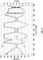
- the dissipation ratiomay change as a function of the frequency of the applied electromagnetic energy. Accordingly, a dissipation ratio spectrum may be generated by plotting the dissipation ratio associated with each frequency against the respective frequencies. Exemplary dissipation ratio (efficiency) spectrums 210 and 250 are illustrated in FIG. 11 and FIG. 12 , respectively.
- FIG. 11 and FIG. 12depict frequencies corresponding to both high and low dissipation ratios, and illustrate dissipation ratio peaks that are broader than others.
- the at least one processormay be configured to regulate subsystem 96 for measuring a first amount of incident energy at a transmitting antenna at a first frequency; measure a second amount of energy reflected at the transmitting antenna as a result of the first amount of incident energy; measure a third amount of energy transmitted to a receiving antenna as a result of the first amount of incident energy; and determine the dissipation ratio based on the first amount, the second amount, and the third amount.
- controller 101may be configured to measure a first amount of incident energy at a first antenna 102 which performs as a transmitter at a first frequency, measure a second amount of energy reflected at first antenna 102 as a result of the first amount of incident energy, measure a third amount of energy transmitted to at least one second antenna 102 which performs as a receiver as a result of the first amount of incident energy, and determine the dissipation ratio based on the first amount, the second amount, and the third amount.
- the value indicative of the absorbable energymay further involve the maximum incident energy associated with power amplifier 112 , illustrated, for example, in FIGS. 5 A and 5 B , of subsystem 96 at the given frequency.
- a “maximum incident energy”may be defined as the maximal power that may be provided to the antenna at a given frequency throughout a given period of time.
- one alternative value indicative of absorbable energymay be the product of the maximum incident energy and the dissipation ratio.
- the at least one processormay also be configured to cause energy to be supplied to the at least one radiating element in at least a subset of the plurality of frequencies, wherein energy applied to the zone at each of the subset of frequencies may be a function of the absorbable energy value at each frequency.
- energy applied to the zone at each of the frequenciese.g., at each of the frequencies for which a DR was calculated
- the energy applied to the at least one antenna 102 at each of the subset of frequenciesmay be determined as a function of the absorbable energy value at each frequency (e.g., as a function of a dissipation ratio, maximum incident energy, a combination of the dissipation ratio and the maximum incident energy, or some other indicator). In the presently disclosed embodiments, this may occur as the result of absorbable energy feedback obtained during a frequency sweep. That is, using this absorbable energy information, the at least one processor may adjust energy applied at each frequency such that the energy at a particular frequency may in some way be a function of an indicator of absorbable energy at that frequency.
- the functional correlationmay vary depending upon application.
- a processormay restrict application of energy at frequencies where absorbable energy is relatively high (e.g., having a DR above 70%, 75%, 80% or 90%). This may be desirable, for example when a more uniform energy distribution profile is desired across object 11 , as will be discussed later in greater detail.
- the at least one processorimplement a function that causes a relatively high energy application. This may be desirable to target specific areas of an object with higher absorbable energy profiles. For yet other applications, it may be desirable to customize the amount of energy supplied to a known or suspected energy absorption profile of the object 11 .
- a dynamic algorithm or a look up tablecan be applied to vary the energy applied as a function of at least the absorbable energy and perhaps one or more other variables or characteristics. These are a few examples of how energy applied into the zone at each of the subset of frequencies may be a function of the absorbable energy value at each frequency.
- the inventionis not limited to any particular scheme, but rather may encompass any technique for controlling the energy supplied by taking into account an indicator of absorbable energy.
- the energy applied to the at least one radiating element at each of the subset of frequenciesmay be a function of the absorbable energy values at the plurality of frequencies other than the frequency at which energy is supplied.
- the dissipation ratios at a range of “neighborhood” frequencies around the frequency at issuemay be used for determining the amount of energy to be applied.
- the entire working band excluding certain frequencies that are associated with extremely low dissipation ratios(which may be associated with metallic materials, for example) may be used for the determination.
- the at least one processormay be configured to cause energy to be supplied to the at least one radiating element in the plurality of frequencies, wherein energy applied to the zone at each of the plurality of frequencies may be inversely related to the absorbable energy value at each frequency.
- the at least one processormay be configured to cause energy to be supplied to the at least one radiating element in at least a subset of the plurality of frequencies, wherein energy applied to the zone at each of the subset of frequencies may be inversely related to the absorbable energy value at each frequency.
- Such an inverse relationshipmay involve a general trend—when an indicator of absorbable energy in a particular frequency subset (i.e., one or more frequencies) tends to be relatively high, the actual incident energy at that frequency subset may be relatively low. And when an indicator of absorbable energy in a particular frequency subset tends to be relatively low, the incident energy may be relatively high.
- the inverse relationshipmay be even more closely correlated.
- the applied energymay be set such that its product with the absorbable energy value (i.e., the absorbable energy by object 11 ) is substantially constant across the frequencies applied.
- a plot of applied energymay generally appear as a reverse image of a value indicative of absorption (e.g., dissipation ratio or a product of the dissipation ratio and the maximal incident power available at each transmitted frequency).
- FIG. 11provides a plotted example of a dissipation ratio spectrum 210 (dashed line) and a corresponding incident power spectrum 220 (solid line) taken during operation of a device constructed and operated in accordance with the presently disclosed embodiments.
- the plots shown in FIG. 11were taken with an oven having a maximum incident power of about 400 Watts, wherein a 100 gr chunk of minced beef was placed.
- a range of frequencies between 800 MHz and 1 GHzwas swept, and energy was supplied based on the sweep, such that essentially uniform dissipation of energy will be affected in the chunk of beef.
- the processormay be configured to determine a threshold value for the value indicative of energy absorbable in the object as a function of the frequencies.
- the processormay further be configured to decrease or prevent energy applied at frequencies having value indicative of energy absorbable above the threshold value.
- threshold 230 in FIG. 11may be determined such that little or no energy is applied to energy application zone 9 at frequencies associated with dissipation ratio above 0.48.
- a thresholdmay be determined such that application of energy to energy application zone 9 is decreased or prevented at frequencies associated with dissipation ratio above 0.7, 0.75, 0.8, 0.85 or 0.9.
- the at least one processormay be configured to adjust energy applied such that when the energy applied is plotted against an absorbable energy value over a range of frequencies, the two plots tend to mirror each other.
- the two plotsmay tend to mirror each other at at least one subset of the range of frequencies.
- the two plotsmay be mirror images of each other.
- the plotsmay not exactly mirror each other, but rather, have generally opposite slope directions, i.e., when the value corresponding to a particular frequency in one plot is relatively high, the value corresponding to the particular frequency in the other plot may be relatively low. For example, as shown in FIG.
- the relationship between the plot of applied energy (e.g., incident power spectrum 220 ) and the plot of the absorbable energy values (e.g., dissipation ratio spectrum 210 )may be compared such that when the applied energy curve is increasing, over at least a section of the curve, the absorbable energy curve will be decreasing over the same section. Additionally, when the absorbable energy curve is increasing, over at least a section of the curve, the applied energy curve will be decreasing over the same section. For example, in FIG. 11 , incident power spectrum 220 increases over the frequency range of 900 Hz-920 Hz, while dissipation ratio spectrum 210 decreases over that frequency range.
- the curve of applied energymight reach a maximum value, above which it may not be increased, in which case a plateau (or almost plateau) may be observed in the transmission curve, irrespective of the absorbable energy curve in that section.
- the incident powerwhen the incident power reaches the maximum value of 400 W, the incident power stays substantially constant regardless of the variations in the dissipation ratio.
- spatial uniformityrefers to a condition where the energy absorption (i.e., dissipated energy) across the object or a portion (e.g., a selected portion) of the object that is targeted for energy application is substantially constant.
- the energy absorptionis considered “substantially constant” if the variation of the dissipated energy at different locations of the object is lower than a threshold value. For instance, a deviation may be calculated based on the distribution of the dissipated energy, and the absorbable energy is considered “substantially constant” if the deviation is less than 50%.
- spatial uniformitymay also refer to a condition where the temperature increase across the object or a portion of the object that is targeted for energy application is substantially constant.
- the temperature increasemay be measured by a sensing device, for example, a temperature sensor in zone 9 .
- controller 101may be configured to hold substantially constant the amount of time at which energy is supplied to antennas 102 at each frequency, while varying the amount of power supplied at each frequency as a function of the absorbable energy value.
- controller 101may be configured to cause the energy to be supplied to the antenna for that particular frequency or frequencies a power level substantially equal to a maximum power level of the device.
- controller 101may be configured to cause the amplifier (e.g. amplifier 112 ) to apply no energy at all at these particular frequency or frequencies.
- a decisionmay be made to apply energy at a power level substantially equal to a maximum power level of the amplifier only if the amplifier may apply to the object at least a threshold percentage of energy as compared with the uniform applied energy level (e.g. 50% or more or even 80% or more).
- a decisionmay be made to apply energy at a power level substantially equal to a maximum power level of the amplifier only if the reflected energy is below a predetermined threshold, in order, for example, to protect the apparatus from absorbing excessive power.
- the decisionmay be made based on the temperature of a dummy load into which reflected energy is introduced, or a temperature difference between the dummy load and the environment.
- the at least one processormay accordingly be configured to control the reflected energy or the absorbed energy by a dummy load.
- the controller 101may be configured to cause the antenna to apply energy at a power level less than a maximum power level of the antenna. In some embodiments, if the absorbable energy value exceeds a predetermined threshold, the controller 101 may be configured to cause the antenna to apply little or no energy (low or zero power level).
- uniform absorptionmay be achieved by varying the duration of energy application while maintaining the power applied at a substantially constant level.
- the duration of energy applicationmay be longer than for frequencies exhibiting higher absorption values.
- an amount of power supplied at multiple frequenciesmay be substantially constant, while an amount of time at which energy is supplied varies, depending on an absorbable energy value at the particular frequency.
- the at least one antennamay include a plurality of antennas, and the at least one processor may be configured to cause energy to be supplied to the plurality of antennas using waves having distinct phases.
- antenna 102may be a phased array antenna including a plurality of antennas forming an array. Energy may be supplied to each antenna with electromagnetic waves at a different phase. The phases may be regulated to match the geometric structure of the phased array.
- the at least one processormay be configured to control the phase of each antenna dynamically and independently. When a phased array antenna is used, the energy supplied to the antenna may be a sum of the energy supplied to each of the antennas in the array.
- absorbable energycan change based on a host of factors including object temperature, depending on application, it may be beneficial to regularly update absorbable energy values and thereafter adjust energy application based on the updated absorbable values. These updates can occur multiple times a second, or can occur every few seconds or longer, depending on application. As a general principle, more frequent updates may increase the uniformity of energy absorption.
- a controllermay be configured to adjust energy applied from the antenna as a function of the frequency at which the energy is applied. For example, regardless of whether a sweep or some other active indicator of energy absorption is employed, certain frequencies may be targeted or avoided for energy application. That is, there may be frequencies that the controller 101 avoids altogether, such as where the absorption level falls below a predetermined threshold. For example, metals tend to be poor absorbers of electromagnetic energy, and therefore certain frequencies associated with metals will exhibit low absorption indicator values. In such instances the metals may fit a known profile, and associated frequencies may be avoided. Or, an absorption indicator value may be dynamically determined, and when it is below a predetermined threshold, controller 101 may prevent an antenna 102 from thereafter applying electromagnetic energy at such frequencies. Alternatively, if it is desirable to apply energy to only portions of an object, energy can be targeted to those portions if associated frequency thresholds are either known or dynamically determined.
- the at least one processormay be configured to determine a desired energy absorption amount and adjust energy supplied from the antenna at each frequency in order to target or achieve the desired energy absorption amount.
- the at least one processormay be configured to determine a desired energy absorption amount at each of a plurality of frequencies and adjust energy supplied from the antenna at each frequency in order to target the desired energy absorption amount at each frequency.
- controller 101may be configured to target a desired energy absorption amount at each frequency in attempt to achieve or approximate substantially uniform energy absorption across a range of frequencies.
- controller 101may be configured to target an energy absorption profile across object 11 , which is calculated to avoid uniform energy absorption, or to achieve substantially uniform absorption in only a portion of object 11 .
- Embodiments of the inventionmay include a source of electromagnetic energy.
- a “source”may include any components that are suitable for generating electromagnetic energy. Consistent with the invention, the source may be configured to apply electromagnetic energy to the energy application zone in the form of propagating electromagnetic waves at predetermined wavelengths or frequencies (also known as electromagnetic radiation).
- propagating electromagnetic wavesmay include resonating waves, evanescent waves, and waves that travel through a medium in any other manner.
- Electromagnetic radiationcarries energy that may be imparted to (or dissipated into) matter with which it interacts.
- Such a sourcemay include, for example, electromagnetic energy application subsystem 96 , as depicted in the schematic of FIG. 5 A .
- Subsystem 96may be a source of electromagnetic energy such as an RF feed system. and may include, among other things, a voltage control oscillator (VCO) 122 , an RF switch 104 , a voltage controlled attenuator (VCA) 106 , a load 108 , a dual directional coupler 110 , an amplifier 112 , an isolator 114 , an RF switch 116 , a power load 118 , and a dual directional coupler 120 , interconnected as illustrated in FIG. 5 A . It is contemplated that subsystem 96 may include fewer or additional components.
- VCO 122may be configured to receive a signal from interface 130 (described in greater details in connection with FIG. 7 ), which may set the frequency of the electromagnetic energy into the port. This energy may be passed through RF switch 104 and VCA 106 , both of which may be controlled by signals from interface 130 . After passing through VCA 106 , the magnitude and frequency of the signal may be set. Consistent with the presently disclosed embodiments, load 108 may be included in subsystem 96 for dumping a signal generated by VCO 122 when the signal from VCO 122 is not switched to VCA 106 .
- the signalmay then be sent through a main line of dual directional coupler 110 .
- the output of coupler 110may be amplified by power amplifier 112 and then passed through isolator 114 . Consistent with the presently disclosed embodiments, a signal proportional to the energy reflected from amplifier 112 may also be fed to interface 130 . Coupler 110 may feedback a portion of the signal entering it to interface 130 . These signals may enable supervision of VCO 122 /VCA 106 and amplifier 112 . In the presently disclosed embodiments such as a production system, dual directional coupler 110 may be omitted.
- RF switch 116may be configured to switch power either to power load 118 or to antennas 102 , via dual directional coupler 120 .
- Dual directional coupler 120may be configured to sample the electromagnetic energy transmitted into and received from cavity 10 and send the energy measurement signals to interface 130 .
- amplifier 112may be based on SiC (silicon carbide) or GaN (gallium nitride) semiconductor technology, with a potential efficiency for example of 70%. Transistors utilizing such technologies are commercially available from companies, such as Eudyna, Nitronex and others. Amplifiers having a maximum power output of 300-600 W (can be built from low power (50-100 Watt) modules) and a bandwidth of 600 MHz (at 700 MHz center frequency) or a bandwidth of 400 MHz (at 2.5 GHz center frequency) may be used as RF amplifier 112 .
- Such amplifiersmay have a much higher efficiency (e.g., an efficiency of 60% consistent with the presently disclosed embodiments) than prior art amplifiers and much higher tolerance to reflected signals. Due to the high efficiency of RF amplifier 112 , isolator 114 may be omitted consistent with the presently disclosed embodiments.
- FIG. 5 Billustrates an alternative exemplary electromagnetic energy application subsystem 196 , consistent with exemplary embodiments of the invention.
- subsystem 196may include components similar to those discussed in connection with FIG. 5 A , such as RF switch 192 configured to switch the output of RF switch 116 to one antenna among a plurality of antennas associated with cavity 10 , and circuitry 200 coupled to the selected antenna.
- FIG. 5 Bonly shows circuitry 200 corresponding to antenna 2 (i.e., via feed 2 ), it is contemplated that subsystem 196 may include additional circuitries corresponding to additional antennas, such as antennas 1 and 3 .
- FIG. 5 Billustrates RF switch 192 for switching signals among three antennas (i.e., via three feeds), it is contemplated that RF switch 192 may be configured to switch signals among more or fewer antennas.
- Circuitry 200may also include, among other things, an RF switch 194 , a load 190 and dual directional coupler 120 , interconnected, for example, as illustrated in FIG. 5 B .
- Circuitry 200may operate in one of two modes. Consistent with the presently disclosed embodiments, circuitry 200 may operate in a power transfer mode. For example, a signal from interface 130 may switch power from RF switch 192 to dual directional coupler 120 , via RF switch 194 . The rest of the operation may be similar to those as described above in connection with FIG. 5 A . Consistent with some embodiments, circuitry 200 may operate in a passive mode.
- RF switch 194may not receive power from power amplifier 112 (referred to interchangeably as “power amplifier 112 ” and “amplifier 112 ”). Rather, RF switch 194 may connect load 190 to the input of dual directional coupler 120 . In the passive mode, load 190 may be configured to absorb power that is received from cavity 10 .
- dual directional coupler 120may be excluded.
- RF switch 194may be replaced by a circulator such that power returned from antenna 2 may be always dumped at load 190 .
- FIG. 5 Bshows RF switches 104 , 116 , 192 , and 194 as separate switches, it is contemplated that any two or more of these switches may be combined into a more complex switch network.
- FIG. 6is a schematic block diagram of an exemplary computing subsystem 92 , in accordance with the presently disclosed embodiments.
- computing subsystem 92may include, among other things, a processing unit 921 , a storage unit 922 , a memory module 923 , a user input interface 924 , an electromagnetic control interface 925 , and a display device 926 . These units may be configured to transfer data and send or receive instructions between or among each other. Each unit of subsystem 92 is described below. Depending on design parameters and intended use, certain embodiments may include more or fewer than all of the components described.
- Processing unit 921may include any suitable microprocessor, digital signal processor, or microcontroller. In the presently disclosed embodiments, processing unit 921 may be part of the at least one processor in controller 101 . Processing unit 921 may be configured to communicate with electromagnetic control interface 925 to provide control instructions to electromagnetic energy application subsystem 96 or 196 and/or obtain measured energy information received from subsystem 96 . Consistent with the presently disclosed embodiments, processor 921 may be configured to execute a frequency sweeping process during which electromagnetic energy at a plurality of frequencies is applied (e.g., sequentially) to zone 9 . Processing unit 921 may be further configured to determine a value indicative of energy absorbable by object 11 at each of the plurality of frequencies based on the received information during the frequency sweep process. Processing unit 921 may also be configured to select one or more frequencies, among the plurality of frequencies swept, and determine the magnitude of electromagnetic energy for subsequent application at each selected frequency, as described earlier.
- Storage unit 922may include any appropriate type of mass storage provided to store any type of information that processing unit 921 may need to operate.
- storage unit 922may include one or more of a RAM, ROM, cache memory, dynamic RAM, static RAM, flash memory, a magnetic disk, an optical disk, or any other structure for storing information.
- memory module 923may include one or more memory devices identified in the list above. The computer program instructions may be accessed and read from the ROM, or any other suitable memory location, and loaded into the RAM for execution by processor 921 .
- both storage unit 922 and memory module 923may be configured to store information used by processing unit 921 , and the functions of both may be combined in a single structure or multiple structures.
- storage unit 922 and/or memory module 923may be configured to store one or more parameters of electromagnetic energy determined by processing unit 921 . Consistent with the presently disclosed embodiments, these parameters may include frequencies of the applied electromagnetic energy, and magnitudes of the energy at these corresponding frequencies.
- Storage unit 922 and/or memory module 923may also be configured to store other intermediate parameters determined by processing unit 921 .
- User input interface 924may be any device accessible by the operator of apparatus 100 to input a control signal.
- user input interface 924may include one or more of a graphic interface (e.g., Graphical User Interface), one or more hard or soft buttons, a keyboard, a switch, a mouse, or a touch screen.
- a graphic interfacee.g., Graphical User Interface
- hard or soft buttonse.g., one or more hard or soft buttons
- a keyboarde.g., a keyboard, a switch, a mouse, or a touch screen.
- Electromagnetic control interface 925may be configured to obtain data from subsystem 96 or 196 via interface 130 and/or to transmit data to these components.
- electromagnetic control interface 925may be coupled with interface 130 and be configured for two way communication between subsystem 92 and subsystem 96 or 196 .
- electromagnetic control interface 925may be configured to provide the plurality of sweeping frequencies to subsystem 96 during the frequency sweeping process and receive from subsystem 96 reflected and/or coupled electromagnetic energy measurements.
- Computing subsystem 92may also provide visualized information to the user via display device 926 .
- display device 926may include a computer screen and provide a graphical user interface (“GUI”) to the user.
- GUIgraphical user interface
- user input interface 924is a touch screen
- user input interface 924 and display device 926may be incorporated in a single device.
- display device 926may display a chart illustrating the absorbable energy value plotted against the swept frequencies.
- Display device 926may also display a chart illustrating the magnitude of applied electromagnetic energy plotted against the selected frequencies.
- FIG. 7is a schematic block diagram of an exemplary interface 130 , in accordance with the presently disclosed embodiments.
- Interface 130may be coupled to computing subsystem 92 through an interface 134 .
- Interface 134may be configured to communicate with, for example, an ALTERA FPGA 124 .
- ALTERA FPGA 124may be coupled to the various elements of subsystem 96 or 196 and may be configured to provide control signals to one or more of these elements. Additionally, ALTERA FPGA 124 may be configured to receive inputs via one or more multiplexers 136 and an A/D converter 138 .
- ALTERA FPGA 124may be configured to set the frequency and magnitude of the applied electromagnetic energy, determined by computing subsystem 92 , via D/A converters 140 . In the presently disclosed embodiments, ALTERA FPGA 124 may be further configured to set positions of field adjusting elements 22 and 24 . When used, for example, in connection with a production system, subsystem 92 may not be included and ALTERA FPGA 124 or a similar controller may be configured for executing the frequency sweeping process.
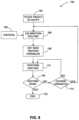
- FIG. 8is a flow chart of an exemplary operation process 150 of apparatus 100 , in accordance with the presently disclosed embodiments.
- operation process 150may be used for apparatuses with smaller or greater numbers of antennas and/or a smaller or greater number of field adjusting elements.
- operation process 150is describe in connection with a heating application, it is contemplated that with minor changes, operation process 150 may be used for applications other than heating.
- step 152object 11 , for example, a frozen organ, frozen or a non-frozen food object, or any other type of object as previously defined, may be placed in cavity 10 .
- step 160a calibration or adjustment routine may then be performed to set operating variables associated with various components of apparatus 100 .
- these variablesmay include power output (e.g., by amplifier 112 to cavity 10 ) at each antenna 102 at each frequency; a subset of frequencies of each VCO 122 ; a selected method of providing electromagnetic energy at the subset of frequencies (for example sequentially applying energy at the subset of frequencies or simultaneously applying energy having the desired frequency and power characteristics as a pulsed signal); positions of the field adjusting elements 22 and 24 , position of object 11 , and any other adjustable variables associated with the electromagnetic energy application process.
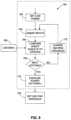
- a calibration routinemay be performed to ensure the uniformity of electromagnetic energy applied to different portions of object 11 .
- step 160may include a frequency sweeping process for determining operating variables for apparatus 100 such that the absorbable energy is substantially uniform throughout object 11 .
- Calibration routinemay be executed by processing unit 921 in subsystem 92 .
- Criteria 156may be provided to the calibration routine.
- criteria 156may be stored in storage device 922 and/or memory module 923 in subsystem 92 . An exemplary calibration process and exemplary criteria are described in greater details in connection with FIG. 9 .
- step 158after the variables are determined, these variables are set in the various components of apparatus 100 through subsystem 96 and heating may commence in step 170 .
- electromagnetic energymay be applied to cavity 10 via antennas 102 , for example, antennas 16 , 18 , and/or 20 .
- the frequency of the electromagnetic energy supplied to the antennasmay be supplied at the center frequency of the resonance mode that couples the highest net power, i.e., the maximum percentage of energy absorbable by object 11 .
- frequenciesmay be swept sequentially across a range of the cavity 10 resonance frequencies or, more preferably along a portion of the range. Consistent with the presently disclosed embodiments, the magnitude of the supplied power may be adjusted during this sweep so that the absorbable energy at each frequency remains constant or substantially constant during the sweep. For example, amplification ratio of power amplifier 112 may be changed inversely with the energy absorption characteristic of object 11 , as were described earlier in connection with FIG. 11 .
- powermay be applied over a predetermined time at each frequency to obtain a certain amount of electromagnetic energy.
- 1 J energymay be applied at 300 MHz in 1 millisecond and 2 J may be applied at 310 MHz in another 1 millisecond.
- an amount of electromagnetic energymay be applied during a variable amount of time at each frequency.
- the amount of timemay be determined for each frequency, such that the applied power at each frequency is substantially the same.
- 1 J energymay be applied at 300 MHz in 1 milliseconds and 2 J may be applied at 310 MHz in 2 milliseconds, so that the supplied power at each of the two frequencies is 1000 W.
- Energy applicationmay be interrupted periodically (e.g., several times a second) for a short time (e.g., only a few milliseconds or tens of milliseconds).
- a short timee.g., only a few milliseconds or tens of milliseconds.
- the criteria for terminationmay vary depending on application. It may be based on time, temperature, total energy absorbed (e.g., total energy absorbed by the object), or any other indicator that the process at issue is compete. In connection with the heating embodiment of FIG. 8 , for example, heating may be terminated when the temperature of object 11 rises to a predetermined temperature threshold. If in step 154 , it is determined that heating should be terminated (step 154 : yes), heating may end in step 153 .
- step 154it may be determined if the variables should be re-determined and reset in step 151 . If not (step 151 : no), process may return to step 170 and continue to provide heating. Otherwise (step 151 : yes), process may return to calibration routine 160 and determine new variables for apparatus 100 . Consistent with the presently disclosed embodiments, less frequencies may be swept in a calibration process performed during the heating phase than those swept in a calibration process performed before the heating phase, such that the heating process is interrupted for a minimum amount of time.
- calibration routine 160may be performed 120 times in a minute during the heating phase.
- Higher (e.g. 200/min, 300/min) or lower (e.g., 100/min, 20/min, 2/min, 10/heating time, 3/heating time) calibration ratesare also non-limiting examples of performance rates that might be used, depending on the details of a desired application.
- calibrationsmay be performed once every 0.5 seconds or once every 5 seconds, a nearly infinite range of possibilities exist.
- non-uniform calibration ratesmay be used. For example, the first interruption may occur after 0.5 second, while the second interruption may occur after another 0.8 second.
- the calibration ratemay be dynamically determined based on the amount of energy applied into cavity 10 and/or the amount of energy dissipated into object 11 .
- itmay be determined that new variables are needed, only if a given amount of energy (e.g., 10 kJ or less or 1 kJ or less or several hundreds of joules or even 100 J or less) has been applied or dissipated into object 11 or into a given portion of object 11 (e.g., by weight such as 100 g or by percentage, such as 50% of object 11 ).
- a given amount of energye.g. 10 kJ or less or 1 kJ or less or several hundreds of joules or even 100 J or less
- the determination in step 151may be made based on information provided by other means, for example an RF/bar-code readable tag (e.g., containing previously determined energy application information or an amount of energy to be dissipated in the object) or temperature sensors that measure the temperature of object 11 .
- an RF/bar-code readable tage.g., containing previously determined energy application information or an amount of energy to be dissipated in the object
- temperature sensorsthat measure the temperature of object 11 .
- heatingmay be terminated once one or more sensor(s) indicate that certain criteria are met. Such criteria may indicate, for example: once sufficient amount of energy is absorbed in the object, once one or more portions of the object are at a predetermined temperature, once time derivatives of absorbed power changes. Such automatic processing adjustment may be useful, for instance, in vending machines where food products are heated or cooked when purchased. Purchase may start the heating and specific heating conditions (for example, energy supplied at each frequency) may be determined in accordance with feedback from the heated product, for example. Additionally or alternatively, heating may be stopped once the sensors sense conditions that are defined to the controller as stopping criteria. Additionally or alternatively, cooking or processing instructions may be provided on a machine readable element (e.g., barcode or a tag, associated with the processed object). The processed object may be, for example, heated food product purchased in the vending machine.
- a machine readable elemente.g., barcode or a tag
- the determination in step 151may be made based on the rate of change in spectral information between interruptions. For example, a threshold of change in dissipation and/or frequencies (e.g., a 10% change in sum integral) may be provided, and once the threshold is exceeded, a calibration may be performed. As another example, different change rates may be provided corresponding to different calibration rates, for example in a form of look-up table. In an alternative scheme, the rate of change may be determined as the average changes between every two calibrations. Such changes may be used to adjust the period between two calibrations once or more than once during a heating session. Additionally or alternatively, the rate of calibration may also be affected by changes in apparatus 100 (e.g., if used in an oven, movement of a plate on which the object is located). Optionally, major changes may increase the rate and minor or no changes may decrease it.
- a threshold of change in dissipation and/or frequenciese.g., a 10% change in sum integral
- FIG. 9is a flow chart of an exemplary process for the calibration routine 160 of FIG. 8 , in accordance with some exemplary embodiments of the invention.
- the powermay be optionally set at a low level so that no substantial heating may take place. However, the power should not be set so low as to prevent signals generated from being reliably detected.
- calibrationmay be performed at full or medium power. Calibration at near operational power levels may reduce the dynamic range of some components, for example VCA 106 , and reduce their cost.
- subsystem 92may provide control signals indicating a plurality of sweeping frequencies to subsystem 96 via interface 130 and subsystem 96 may be configured to apply electromagnetic energy to zone 9 at these plurality of frequencies via antennas 102 .
- different sweeping parametermay be determine (e.g., by controller 101 ) for example the sweeping range and/or the sweeping resolution.
- the sweeping frequenciesmay be within a range of 300-1000 MHz or even up to 3 GHz, depending on the heating application. Consistent with some embodiments, ranges, for example 860-900 MHz, 800-1000 MHz or 420-440 MHz may also be used. In some embodiments, a range of 430-450 MHz may be used.
- the sweeping rangemay include several non-contiguous ranges, if more than one continuous range satisfies the criteria for use in a particular application such as heating.
- a sweepmay include the transmission of multiple frequencies in a contiguous frequency band at a predetermined frequency range (e.g., the transmission of multiple frequencies in a frequency band at 0.1 MHz, 0.2 MHz, 0.5 MHz, 1 MHz or any other frequency range).
- sweeping resultsmay be compared with criteria 156 .
- the sweeping resultsmay be the value indicative of energy absorbable (e.g. dissipation ratio) as a function of the swept frequencies and the criteria may indicate different dissipation ratio threshold values, indicating how much electromagnetic energy may be applied in each frequency.
- one criterionmay be not to apply little or no energy in certain frequencies (e.g. frequencies having dissipation ratio value higher than a threshold value).
- the dissipation ratio for each transmitting antennamay be maximized, i.e., the maximum dissipation ratio within the sweep range may be made as high as possible.
- the maximum dissipation ratio and the frequency at which the maximum ratio is achievedmay then be recorded. Additionally, the width of the dissipation ratio peak and a Q-factor may also be recorded. In some embodiments, the area under each resonance peak of the dissipation ratio (see FIG. 12 ) may be determined. The dissipation ratio and the center frequency of the resonance that correspond to the maximum area/width may be recorded.
- each frequencymay have maximum absorption at a specific location within an object in an energy application zone, and this peak (maximum) energy absorption region (e.g., in the case of FIG. 9 , heating region) may vary among different frequencies. Therefore applying electromagnetic energy at a range of frequencies may cause the energy absorption (e.g., heating) region to cover different parts of the object.
- Computer simulationshave shown that, at least when the Q factor of a peak is low (i.e., a significant amount of energy is dissipated in the object being heated), the peak heating region can substantially cover the entire object.
- the criteria for determining if the variables are properly setmay be that the peak dissipation ratio (in the presently disclosed embodiments) or the area or a width (in other embodiments) is above some predetermined threshold, or a Q-factor is below some predetermined threshold.
- a thresholdmay be set such that only the area above 60% dissipation ratio is maximized for each of the antennas.
- step 168of FIG. 9 , if the criteria is not met (step 168 : no), process 160 may go to step 172 where heating variables are changed. Steps 164 , 166 , and 168 may be repetitively performed until the criteria are met. Once the criteria are met (step 168 : yes), the power supplied into the respective amplifiers for each antenna may be set such that substantially constant power is absorbed in object 11 , in step 174 . The power may be raised to a level suitable for heating. Consistent with the presently disclosed embodiments, the least efficient antenna may determine the power supplied to object 11 .
- step 174 in FIG. 9may be followed by step 158 in FIG. 8 .
- FIG. 10is an exemplary flow chart 201 of a method for determining swept power characteristics, in accordance with the presently disclosed embodiments. This method may be used to implement steps 160 and 158 of FIG. 8 .
- cavity 10may be swept to determine the dissipation efficiency as a function of frequency (step 202 in FIG. 10 ) (e.g., dissipation ratio spectrum 250 as shown in FIG. 12 ).
- the dissipation ratiomay be determined using sequential frequency sweeping as discussed in connection with FIG. 9 .
- a pulse of energyhaving a broad spectrum in the range of interested frequencies may be fed into cavity 10 .
- the reflected energy and the energy transmitted to other antennasmay be determined and their spectrums analyzed, for example using Fourier analysis. Using either method, the dissipation ratio as a function of frequency may be determined.
- a set of look-up tables for different types and sized of objectsmay be developed and stored in storage device 922 or memory module 923 .
- the overall swept bandwidthmay be determined. For example, one or more frequencies may be selected, among the sweeping frequencies, to be applied during an energy application process (e.g., heating process). Consistent with the presently disclosed embodiments, step 204 may include sweeping across a single peak or across several peaks of the dissipation ratio. In some embodiments, during the heating phase, the frequency may be swept across a portion of each of the high dissipation ratio peaks. For example, as shown in FIG. 12 , a threshold 225 may be set such that only frequencies corresponding to dissipation ratios above the threshold may be used for heating. Additionally or alternatively, frequency ranges corresponding to high Q peaks may be eliminated from the sweeping frequencies.
- FIG. 13 Ashows a truncated dissipation ratio spectrum that is above threshold 225 in FIG. 12 , after a high Q peak 254 is eliminated. Accordingly, energy may be applied only in the truncated spectrum, as shown in FIG. 13 B . Alternatively, energy may be applied in the entire spectrum.
- step 204may be omitted and the swept bandwidth may correspond to substantially all the frequencies that were swept in order to determine the dissipation efficiency (e.g., as detailed in step 202 ).
- frequencies corresponding to a dissipation ratio below a predetermined threshold or within a certain predetermined rangemay be used such that certain materials or items in object 11 are selectively heated.
- a predetermined thresholde.g., a predetermined threshold
- certain materials or items in object 11are selectively heated.
- waterhas a dissipation ratio higher than non-water materials. Therefore, by applying energy at frequencies that correspond to low dissipation ratios, the object may be thawed without heating the water inside.
- step 216it may be determined if field adjusting elements 22 and 24 have been properly adjusted. If not (step 216 : no), a desired position and/or orientation of the field adjusting elements may be determined during an integrative process 218 . In step 218 , the positions of field adjusting elements 22 and 24 may be set. This adjustment may be optional and in the presently disclosed embodiments, such elements might not require adjustment. In general, the criterion for such adjustment is that the peaks have as high dissipation ratio as possible with as broad a peak as possible. Depending on specific applications, additional adjustment may be made, for example to move the peak to a certain band.
- a searchmay be performed in iterative process 218 for a position of field adjusting elements 22 and 24 at which the dissipation ratio at all of the antennas meets criteria.
- standard search techniquescan be used or a neural network or other learning system can be used, especially if the same type of object is heated repeatedly. It is contemplated that any iterative process known in the art may also be used.
- step 210the elements are set to the best positions as determined.
- the sweepmay be adjusted to avoid hot spot (e.g., to avoid feeding excess power into certain parts of the object). For example, if the object contains a metal rod or a metal zipper, a high Q peak 254 may be generated in dissipation ratio, as shown in FIG. 12 . A metal rod may cause a concentration of energy near the ends of the rod. Avoiding application of energy at this peak may reduce the effects of such objects on even heating. Alternatively, in some applications, a measured amount of energy application may be desirable even at such peaks, in order to achieve desired effects of a particular application.
- the sweeping parametersmay be determined.
- the inventionmay further include a method for applying electromagnetic energy to an object.
- Electromagnetic energymay be applied to an object, for example, through at least one processor implementing a series of steps of process 1300 of FIG. 14 .
- a methodmay involve controlling a source of electromagnetic energy.
- a “source” of electromagnetic energymay include any components that are suitable for generating electromagnetic energy.
- the at least one processormay be configured to control a source of EM energy (e.g., electromagnetic energy application subsystem 96 ).
- the sourcemay be controlled in order to apply electromagnetic energy at a plurality of frequencies to at least one radiating element, such as is indicated in step 1320 .
- Various examples of frequency applicationincluding sweeping, as discussed earlier, may be implemented in step 1320 .
- other schemes for controlling the sourcemay be implemented so long as that scheme results in the application of energy at a plurality of frequencies.
- the at least one processormay regulate subsystem 96 to apply energy at multiple frequencies to at least one transmitting antenna.
- the methodmay further involve determining a value indicative of energy absorbable by the object at each of the plurality of frequencies, in step 1330 .
- An absorbable energy valuemay include any indicator—whether calculated, measured, derived, estimated or predetermined—of an object's capacity to absorb energy.
- subsystem 92may be configured to determine an absorbable energy value (e.g., a dissipation ratio associated with each frequency).
- the methodmay also involve adjusting an amount of electromagnetic energy incident or applied at each of the plurality of frequencies based on the absorbable energy value at each frequency. In some embodiments, the method may also involve adjusting an amount of electromagnetic energy incident or applied at a sub-band of the plurality of frequencies based on the absorbable energy value at each frequency. For example, in step 1340 , at least one processor may determine an amount of energy to be applied at each frequency, as a function of the absorbable energy value associated with that frequency. In some embodiments, the power level used for applying the EM energy may be adjusted at each of the plurality of frequencies based on the absorbable energy value at each frequency.
- FIG. 15illustrates another exemplary process 1400 for applying electromagnetic energy to an object in an energy application zone according to the presently disclosed embodiments.
- the at least one processormay be configured to control a source, for example electromagnetic energy application subsystem 96 .
- the controlmay be performed by regulating one or more components included in subsystem 96 .
- the at least one processormay regulate subsystem 96 to supply energy at multiple frequencies to at least one transmitting antenna.
- the at least one processormay cause subsystem 96 to apply energy within a pre-determined frequency range, such as a working band of the apparatus.
- the working bandmay, for example, be of any width that would support a desired level of control.
- the working bandmay be 50 MHz wide or more or even 100 MHz wide or more, 150 MHz wide or more or even 200 MHz wide or more.
- the at least one processormay dynamically determine a range of frequencies, based on the nature of the application. The frequencies at which energy is applied may be equally spaced in the range, or unequally or randomly spaced. The energy applied to the at least one radiating element (e.g., antenna) may be emitted into energy application zone 9 .
- the at least one processormay be configured to regulate subsystem 96 to measure reflected energy at the at least one radiating element and transmitted energy at other radiating elements, at each of a plurality of frequencies.
- Subsystem 96may be regulated to receive electromagnetic energy reflected at the transmitting antenna and transmitted energy at receiving antennas, and to communicate the measured energy information back to subsystem 92 via interface 130 .
- reflected power and the transmitted powermay be measured, instead of the energy, by subsystem 96 .
- a processormay take into account any indicator the object's capacity to absorb energy, whether calculated, measured, estimated, or derived from memory.
- the at least one processormay determine an absorbable energy value.
- subsystem 92may be configured to determine the absorbable energy value based on the measurements obtained in step 1430 .
- the determined valuemay be a dissipation ratio determined according to formula (1) based on the measured reflected power and transmitted power.
- the at least one processormay determine a subset of frequencies, out of the frequencies used in step 1420 at which energy is to be applied. For example, the at least processor may generate a dissipation ratio spectrum 250 by plotting the dissipation ratio associated with each frequency against the respective frequencies, as illustrated for example in FIG. 12 . Based on the spectrum, the at least one processor may select a subset of frequencies from the frequency range. For example, frequencies corresponding to dissipation ratios that satisfy a pre-determined condition may be selected. Exemplary conditions may include situations where the dissipation ratio is greater than a threshold or smaller than a threshold. In the presently disclosed embodiments, the entire frequency range that is used in step 1420 may be selected in step 1450 .
- a choicemay be made not to use all possible frequencies in a working band, such that the emitted frequencies are limited to a sub band of frequencies where the Q factor in that sub band is smaller or higher than a threshold.
- a sub bandmay be, for example 50 MHz wide or more or even 100 MHz wide or more, 150 MHz wide or more, or even 200 MHz wide or more.
- FIG. 13 Ashows an exemplary sub band of a working band, corresponding to a dissipation ratio spectrum that is above threshold 225 and excludes high Q peak 254 .
- the choicemay be made such that essentially uniform energy dissipation is performed across a whole working band or sub-band.
- the choicemay be made to cause substantially uniform energy dissipation in at least a selected portion of the object regardless of a location of the object in the zone.
- the at least one processormay determine an amount of energy to be supplied to the radiating element at each candidate frequency, e.g., at each of the subset of frequencies or over the whole working band.
- the energy supplied to the at least one antenna 102 at each of the subset of frequenciesmay be determined as a function of the absorbable energy value at each frequency (e.g., as a function of a dissipation ratio, maximum incident energy, a combination of the dissipation ratio and the maximum incident energy, or some other indicator).
- the functional correlationmay vary depending upon application.
- the at least one processormay implement a function that causes a relatively low supply of energy to be supplied at a frequency where absorbable energy value is relatively high.
- the energy supplied at each of the subset of frequenciesmay be determined as a function of the absorbable energy values at one or more frequencies, among the plurality of frequencies, other than or in addition to the frequency at which energy is supplied.
- FIG. 13 Bshows an exemplary applied energy spectrum that is substantially a reverse image of the truncated dissipation ratio spectrum shown in FIG. 13 A .
- the at least one processormay determine the power level used for applying the determined amount of energy at each frequency, as a function of the absorbable energy value. When making the determination, energy may be applied for a constant amount of time at each frequency. Alternatively, the at least one processor may determine varying durations at which the energy is applied at each frequency, assuming a substantially constant power level. In the presently disclosed embodiments, the at least one processor may determine both the power level and time duration for applying the energy at each frequency.
- the at least one processormay cause the source of electromagnetic energy to supply the determined amount of energy to the radiating element at each candidate frequency, e.g., at each of the subset of frequencies.
- the amount of energy applied in step 1470 at a particular frequencymay be higher than that applied in step 1420 at that frequency.
- the amount of energy applied in step 1470 at a particular frequencymay be substantially the same as that applied in step 1420 at that frequency.
- controller 101may be configured to hold substantially constant the amount of time at which energy is applied at each frequency, while varying the power level at each frequency, as determined in step 1460 .
- controller 101may be configured to cause the energy to be supplied to the antenna at a power level substantially equal to a maximum power level of the device, while supplying the energy over varying time durations at each frequency, as determined in step 1460 .
- the energy supplied to the at least one radiating elementmay be applied to energy application zone 9 and dissipated into object 11 .
- both the power and duration of energy application at different frequenciesmay be varied.
- the at least one processormay determine if energy application should be continued. For example, a temperature sensor may be used to detect the temperature of at least one portion of object 11 . The at least one processor may determine that energy application should be stopped if the temperature reaches a pre-determined threshold. As another example, the at least one processor may determine that energy application should be stopped if energy has been applied for a pre-determined amount of time or if a predetermined amount of energy was dissipated into the object. Accordingly, if there is no need for further application of energy (step 1480 : NO), process 1400 may terminate in step 1500 .
- the at least one processormay determine if new energy absorbable values need to be determined, in step 1490 . Because absorbable energy can change based on a host of factors including object temperature, depending on application, it may be beneficial to regularly update absorbable energy values and thereafter adjust energy application based on the updated absorption values. In the presently disclosed embodiments, the at least one processor may determine to update the dissipation ratios every 10 milliseconds. Alternatively or additionally, other updating rates may be used, for example once in 5 seconds or any value in-between the aforementioned. Depending on the application, updating rates greater than 5 seconds may also be chosen. In the presently disclosed embodiments, the at least processor may be configured to monitor certain characteristic parameters associated with object 11 , for example the temperature of object 11 , and dynamically determine if an update is necessary.
- step 1490If an update is not needed (step 1490 : NO), process 1400 may be redirected to step 1470 and cause the source to continue supplying energy to the radiating elements. If an update is needed (step 1490 : YES), process 1400 may be redirected to step 1420 and determine the absorbable energy values and amount of energy to be supplied at each frequency again.
Landscapes
- Physics & Mathematics (AREA)
- Electromagnetism (AREA)
- Constitution Of High-Frequency Heating (AREA)
- Variable-Direction Aerials And Aerial Arrays (AREA)
Abstract
Description
DR=(Pin−Prf−Pcp)/Pin (1)
where Pinrepresents the electromagnetic energy applied into
DR=1−(|S11|2+|S12|2+|S13|2). (2)
Claims (31)
Priority Applications (1)
| Application Number | Priority Date | Filing Date | Title |
|---|---|---|---|
| US16/855,757US11729871B2 (en) | 2006-02-21 | 2020-04-22 | System and method for applying electromagnetic energy |
Applications Claiming Priority (7)
| Application Number | Priority Date | Filing Date | Title |
|---|---|---|---|
| US77523106P | 2006-02-21 | 2006-02-21 | |
| US80686006P | 2006-07-10 | 2006-07-10 | |
| PCT/IL2007/000236WO2007096878A2 (en) | 2006-02-21 | 2007-02-21 | Electromagnetic heating |
| US12/222,948US8207479B2 (en) | 2006-02-21 | 2008-08-20 | Electromagnetic heating according to an efficiency of energy transfer |
| US32213310P | 2010-04-08 | 2010-04-08 | |
| US13/080,072US10674570B2 (en) | 2006-02-21 | 2011-04-05 | System and method for applying electromagnetic energy |
| US16/855,757US11729871B2 (en) | 2006-02-21 | 2020-04-22 | System and method for applying electromagnetic energy |
Related Parent Applications (1)
| Application Number | Title | Priority Date | Filing Date |
|---|---|---|---|
| US13/080,072ContinuationUS10674570B2 (en) | 2006-02-21 | 2011-04-05 | System and method for applying electromagnetic energy |
Publications (2)
| Publication Number | Publication Date |
|---|---|
| US20200253005A1 US20200253005A1 (en) | 2020-08-06 |
| US11729871B2true US11729871B2 (en) | 2023-08-15 |
Family
ID=45816805
Family Applications (2)
| Application Number | Title | Priority Date | Filing Date |
|---|---|---|---|
| US13/080,072Active2034-04-20US10674570B2 (en) | 2006-02-21 | 2011-04-05 | System and method for applying electromagnetic energy |
| US16/855,757Active2028-06-09US11729871B2 (en) | 2006-02-21 | 2020-04-22 | System and method for applying electromagnetic energy |
Family Applications Before (1)
| Application Number | Title | Priority Date | Filing Date |
|---|---|---|---|
| US13/080,072Active2034-04-20US10674570B2 (en) | 2006-02-21 | 2011-04-05 | System and method for applying electromagnetic energy |
Country Status (1)
| Country | Link |
|---|---|
| US (2) | US10674570B2 (en) |
Families Citing this family (57)
| Publication number | Priority date | Publication date | Assignee | Title |
|---|---|---|---|---|
| US10674570B2 (en) | 2006-02-21 | 2020-06-02 | Goji Limited | System and method for applying electromagnetic energy |
| EP1997349B1 (en)* | 2006-02-21 | 2013-06-26 | Goji Limited | Electromagnetic heating |
| EP2499505B2 (en)* | 2009-11-10 | 2021-05-05 | Goji Limited | Device and method for controlling energy |
| FR2955577B1 (en) | 2010-01-28 | 2014-06-20 | Saint Gobain Ct Recherches | REFRACTORY PRODUCT HAVING A HIGH ZIRCONY CONTENT. |
| CN103004287B (en)* | 2010-05-03 | 2016-01-20 | 高知有限公司 | Loss profile analysis |
| WO2012001523A2 (en)* | 2010-07-01 | 2012-01-05 | Goji Ltd. | Processing objects by radio frequency (rf) energy |
| EP2469974B1 (en)* | 2010-12-21 | 2017-01-25 | Whirlpool Corporation | Methods of controlling cooling in a microwave heating apparatus and apparatus thereof |
| JP6087358B2 (en) | 2011-08-31 | 2017-03-01 | ゴジ リミテッド | Detecting the processing state of objects using RF radiation |
| WO2013066326A1 (en)* | 2011-11-03 | 2013-05-10 | Intel Corporation | Dynamic wireless power control |
| EP2815405B1 (en)* | 2012-02-14 | 2018-01-10 | Goji Limited | A device for applying rf energy to a cavity |
| WO2013140266A2 (en) | 2012-03-19 | 2013-09-26 | Goji Ltd. | Applying rf energy according to time variations in em feedback |
| CN103563482A (en)* | 2012-03-26 | 2014-02-05 | 松下电器产业株式会社 | Microwave heating device |
| US10585971B2 (en)* | 2013-08-19 | 2020-03-10 | The Boeing Company | Quality factor estimation of a reverberant cavity |
| WO2015024177A1 (en) | 2013-08-20 | 2015-02-26 | Whirlpool Corporation | Method for detecting the status of popcorn in a microwave |
| US9989417B2 (en)* | 2013-09-12 | 2018-06-05 | Goji Limited | Temperature measurement arrangement |
| WO2015099649A1 (en) | 2013-12-23 | 2015-07-02 | Whirlpool Corporation | Interrupting circuit for a radio frequency generator |
| US20160323940A1 (en)* | 2013-12-23 | 2016-11-03 | Whirlpool Corporation | Method of calibrating a multifeed radio frequency device |
| JP2017528884A (en) | 2014-09-17 | 2017-09-28 | ワールプール コーポレイション | Direct heating via patch antenna |
| DE102014226280B4 (en)* | 2014-12-17 | 2019-06-13 | E.G.O. Elektro-Gerätebau GmbH | Microwave generator and microwave oven |
| EP3238131A4 (en) | 2014-12-22 | 2018-09-05 | Genie Enterprise Ltd. | Three-dimensional rotatably-readable encoding of data for optical machine-reading |
| JP6740237B2 (en) | 2015-03-06 | 2020-08-12 | ワールプール コーポレイション | High power amplifier calibration method for high frequency power measurement system |
| US10904962B2 (en) | 2015-06-03 | 2021-01-26 | Whirlpool Corporation | Method and device for electromagnetic cooking |
| US10804941B2 (en)* | 2015-09-08 | 2020-10-13 | Isotek Microwave Limited | Microwave switched multiplexer and a mobile telecommunications device including such a multiplexer |
| US10674571B2 (en)* | 2015-09-09 | 2020-06-02 | Illinois Tool Works, Inc. | Apparatus for providing RF stirring with solid state components |
| CN209046906U (en) | 2016-01-08 | 2019-06-28 | 惠而浦有限公司 | RF heating equipment |
| WO2017119909A1 (en) | 2016-01-08 | 2017-07-13 | Whirlpool Corporation | Method and apparatus for determining heating strategies |
| WO2017131698A1 (en) | 2016-01-28 | 2017-08-03 | Whirlpool Corporation | Method and apparatus for delivering radio frequency electromagnetic energy to cook foodstuff |
| EP3417675B1 (en) | 2016-02-15 | 2020-03-18 | Whirlpool Corporation | Method and apparatus for delivering radio frequency electromagnetic energy to cook foodstuff |
| EP3280224A1 (en) | 2016-08-05 | 2018-02-07 | NXP USA, Inc. | Apparatus and methods for detecting defrosting operation completion |
| EP3280225B1 (en) | 2016-08-05 | 2020-10-07 | NXP USA, Inc. | Defrosting apparatus with lumped inductive matching network and methods of operation thereof |
| US10750581B2 (en)* | 2016-11-30 | 2020-08-18 | Illinois Tool Works, Inc. | Apparatus and system for fault protection of power amplifier in solid state RF oven electronics |
| CN109691227B (en) | 2016-12-23 | 2021-07-30 | 松下电器产业株式会社 | Method for diagnosing electromagnetic cooking device, electromagnetic cooking device |
| EP3563637B1 (en)* | 2016-12-29 | 2022-07-27 | Whirlpool Corporation | Electromagnetic cooking device with automatic anti-splatter operation and method of controlling cooking in the electromagnetic device |
| CN107071953A (en)* | 2017-04-10 | 2017-08-18 | 南京航空航天大学 | Based on the complementary microwave heating temperature uniformity Active Control Method of heating mode |
| EP3322027B1 (en)* | 2017-06-02 | 2019-07-24 | Siemens Healthcare GmbH | Near field coupler for transmitting uwb signals. |
| CN111201835A (en)* | 2017-08-15 | 2020-05-26 | 高知有限公司 | Six port power measurement |
| US20190059133A1 (en)* | 2017-08-16 | 2019-02-21 | The Markov Corporation | Sensors for Training Data Acquisition in an Intelligent Electronic Oven |
| EP3451794A1 (en) | 2017-09-01 | 2019-03-06 | Whirlpool Corporation | Crispness and browning in full flat microwave oven |
| US11039510B2 (en) | 2017-09-27 | 2021-06-15 | Whirlpool Corporation | Method and device for electromagnetic cooking using asynchronous sensing strategy for resonant modes real-time tracking |
| US10917948B2 (en)* | 2017-11-07 | 2021-02-09 | Nxp Usa, Inc. | Apparatus and methods for defrosting operations in an RF heating system |
| US10771036B2 (en) | 2017-11-17 | 2020-09-08 | Nxp Usa, Inc. | RF heating system with phase detection for impedance network tuning |
| US10785834B2 (en) | 2017-12-15 | 2020-09-22 | Nxp Usa, Inc. | Radio frequency heating and defrosting apparatus with in-cavity shunt capacitor |
| EP3503679B1 (en) | 2017-12-20 | 2022-07-20 | NXP USA, Inc. | Defrosting apparatus and methods of operation thereof |
| US10772165B2 (en) | 2018-03-02 | 2020-09-08 | Whirlpool Corporation | System and method for zone cooking according to spectromodal theory in an electromagnetic cooking device |
| EP3547801B1 (en) | 2018-03-29 | 2022-06-08 | NXP USA, Inc. | Defrosting apparatus and methods of operation thereof |
| US11404758B2 (en) | 2018-05-04 | 2022-08-02 | Whirlpool Corporation | In line e-probe waveguide transition |
| US10912160B2 (en) | 2018-07-19 | 2021-02-02 | Whirlpool Corporation | Cooking appliance |
| US10952289B2 (en) | 2018-09-10 | 2021-03-16 | Nxp Usa, Inc. | Defrosting apparatus with mass estimation and methods of operation thereof |
| US11800608B2 (en) | 2018-09-14 | 2023-10-24 | Nxp Usa, Inc. | Defrosting apparatus with arc detection and methods of operation thereof |
| US11166352B2 (en) | 2018-12-19 | 2021-11-02 | Nxp Usa, Inc. | Method for performing a defrosting operation using a defrosting apparatus |
| US11202914B2 (en)* | 2018-12-21 | 2021-12-21 | Medtronic, Inc. | Passive propagation fractal antenna for intrabody transmissions |
| US11039511B2 (en) | 2018-12-21 | 2021-06-15 | Nxp Usa, Inc. | Defrosting apparatus with two-factor mass estimation and methods of operation thereof |
| US20220210877A1 (en)* | 2019-07-31 | 2022-06-30 | Panasonic Intellectual Property Management Co., Ltd. | Microwave treatment device |
| CN112385763B (en)* | 2019-08-19 | 2024-07-12 | 青岛海尔特种电冰柜有限公司 | Defrosting box |
| KR20210125289A (en)* | 2020-04-08 | 2021-10-18 | 엘지전자 주식회사 | Oven includes a plurality of antennas and method of control the same |
| IL303568A (en)* | 2020-12-11 | 2023-08-01 | Inficon Inc | HTCC antenna for plasma production |
| GB2615764A (en)* | 2022-02-16 | 2023-08-23 | Freshseal Ltd | Solid state dual-frequency microwave drying and heating apparatus within a vacuum environment using NIR analyser, AI and machine learning |
Citations (322)
| Publication number | Priority date | Publication date | Assignee | Title |
|---|---|---|---|---|
| US2489337A (en) | 1945-08-10 | 1949-11-29 | Us Sec War | Aerial reflecting signal target |
| US2543130A (en) | 1946-07-03 | 1951-02-27 | Bell Telephone Labor Inc | Reflecting system |
| US2593067A (en) | 1947-02-13 | 1952-04-15 | Raytheon Mfg Co | High-frequency apparatus |
| US2895828A (en) | 1958-02-06 | 1959-07-21 | Gen Electric | Electronic heating methods and apparatus |
| US2917739A (en) | 1946-01-15 | 1959-12-15 | Halpern Otto | Corner reflector |
| US3019399A (en) | 1959-03-06 | 1962-01-30 | Microwave Ass | Circular waveguide diameter transformer |
| US3151325A (en) | 1960-08-10 | 1964-09-29 | Bell Telephone Labor Inc | Artificial scattering elements for use as reflectors in space communication systems |
| US3231892A (en) | 1962-06-26 | 1966-01-25 | Philco Corp | Antenna feed system simultaneously operable at two frequencies utilizing polarization independent frequency selective intermediate reflector |
| US3633538A (en) | 1970-10-20 | 1972-01-11 | Colgate Palmolive Co | Spherical device for conditioning fabrics in dryer |
| US3681652A (en) | 1968-08-22 | 1972-08-01 | Raytheon Co | Capacitive filter for suppression of spurious electrical radiation |
| US3767884A (en) | 1971-11-30 | 1973-10-23 | Raytheon Co | Energy seal for high frequency energy apparatus |
| US3806689A (en) | 1972-12-06 | 1974-04-23 | Us Army | Apparatus and method for heating simultaneously with microwaves of two widely different frequencies |
| US3936627A (en) | 1974-01-17 | 1976-02-03 | General Electric Company | Microwave oven with special rack designs |
| US3985993A (en) | 1974-08-29 | 1976-10-12 | U.S. Philips Corporation | Sealing arrangement in a microwave oven |
| JPS5214946A (en) | 1975-07-25 | 1977-02-04 | Toshiba Corp | High frequency heating apparatus |
| GB1465106A (en) | 1973-05-02 | 1977-02-23 | Amana Refrigeration Inc | Microwave heating apparatus |
| US4035599A (en) | 1976-02-23 | 1977-07-12 | Canadian Patents And Development Limited | Control system for non-resonant microwave dryers |
| US4081647A (en) | 1976-05-10 | 1978-03-28 | Roper Corporation | Energy seal for a microwave oven |
| US4115680A (en) | 1975-05-05 | 1978-09-19 | Chemetron Corporation | Apparatus for providing temperature equalization cycles for a microwave oven |
| US4137441A (en) | 1975-03-31 | 1979-01-30 | Amana Refrigeration, Inc. | Microwave oven door seal system |
| US4146768A (en) | 1976-08-18 | 1979-03-27 | U.S. Philips Corporation | Door for a microwave oven |
| US4165454A (en) | 1975-11-07 | 1979-08-21 | U.S. Philips Corporation | Microwave oven |
| JPS5512551A (en) | 1978-07-13 | 1980-01-29 | Tanashin Denki Co | Magnetic reproducing unit |
| US4196332A (en) | 1978-02-09 | 1980-04-01 | Canadian Patents And Development Limited | Controlled heating microwave ovens |
| US4210795A (en)* | 1978-11-30 | 1980-07-01 | Litton Systems, Inc. | System and method for regulating power output in a microwave oven |
| US4250628A (en) | 1979-06-21 | 1981-02-17 | Smith Richard D | Microwave fabric dryer method and apparatus |
| US4271848A (en) | 1979-01-11 | 1981-06-09 | Bio Systems Design, Corp. | Apparatus for electromagnetic radiation of living tissue and the like |
| US4279722A (en) | 1978-10-24 | 1981-07-21 | Kirkbride Chalmer G | Use of microwaves in petroleum refinery operations |
| US4289945A (en) | 1979-10-17 | 1981-09-15 | Whirlpool Corporation | Energy transmission and distribution system for a microwave oven |
| US4297557A (en) | 1976-05-03 | 1981-10-27 | Robertshaw Controls Company | Microwave oven temperature indicator and control means |
| US4336435A (en) | 1981-03-23 | 1982-06-22 | Canadian Patents & Dev. Limited | Microwave apparatus for heating liquid in a closed plastic container |
| US4342035A (en) | 1979-07-23 | 1982-07-27 | The Secretary Of State For Defence In Her Britannic Majesty's Government Of The United Kingdom Of Great Britain And Northern Ireland | Frequency compensating reflector antenna |
| US4342896A (en) | 1976-12-23 | 1982-08-03 | Raytheon Company | Radiating mode stirrer heating system |
| US4354153A (en) | 1979-11-19 | 1982-10-12 | Litton Systems, Inc. | Microwave oven leakage detector and method of using same to test door seal leakage |
| JPS57194500A (en) | 1981-05-26 | 1982-11-30 | Tokyo Shibaura Electric Co | High frequency heat controller for plasma |
| US4371770A (en) | 1980-10-27 | 1983-02-01 | Raytheon Company | Adjustable microwave oven door seal |
| US4377733A (en) | 1978-08-31 | 1983-03-22 | Sharp Kabushiki Kaisha | Temperature-sensing probe structure for wireless temperature-sensing system |
| JPS58111295A (en) | 1981-12-25 | 1983-07-02 | 株式会社東芝 | High frequency heater |
| US4418262A (en) | 1979-09-14 | 1983-11-29 | Tokyo Shibaura Denki Kabushiki Kaisha | Programmable microwave oven with program display |
| DE3326514A1 (en) | 1982-07-23 | 1984-01-26 | Bosch-Siemens Hausgeräte GmbH, 7000 Stuttgart | Radio-frequency heating apparatus |
| US4431888A (en) | 1978-12-21 | 1984-02-14 | Amana Refrigeration, Inc. | Microwave oven with improved feed structure |
| US4434341A (en) | 1980-02-20 | 1984-02-28 | Busby Dennis L | Selective, locally defined heating of a body |
| US4441002A (en) | 1980-09-24 | 1984-04-03 | Raytheon Company | Cook-by-weight microwave oven |
| US4447693A (en) | 1979-09-06 | 1984-05-08 | Litton Systems, Inc. | Power controlled microwave oven |
| US4464554A (en) | 1982-08-25 | 1984-08-07 | General Electric Company | Dynamic bottom feed for microwave ovens |
| US4471194A (en) | 1971-05-20 | 1984-09-11 | Matsushita Electric Industrial Co., Ltd. | Electromagnetic energy seal for high frequency heating apparatus |
| US4475024A (en) | 1978-04-10 | 1984-10-02 | Sharp Kabushiki Kaisha | Wireless food temperature-sensing assembly |
| US4485285A (en) | 1983-03-07 | 1984-11-27 | Control Data Corporation | Quarterwave choke for a microwave oven quartz lamp |
| US4488027A (en) | 1983-06-06 | 1984-12-11 | Raytheon Company | Leakage suppression tunnel for conveyorized microwave oven |
| US4507530A (en) | 1983-08-15 | 1985-03-26 | General Electric Company | Automatic defrost sensing arrangement for microwave oven |
| US4508948A (en) | 1984-01-16 | 1985-04-02 | Amana Refrigeration, Inc. | Microwave cooking method |
| US4517429A (en) | 1978-12-14 | 1985-05-14 | Sanyo Electric Co., Ltd. | Electronic controlled heat cooking apparatus and method of controlling thereof |
| US4520250A (en) | 1982-02-19 | 1985-05-28 | Hitachi Heating Appliances Co., Ltd. | Heating apparatus of thawing sensor controlled type |
| JPS60193292A (en) | 1984-03-15 | 1985-10-01 | 富士通株式会社 | microwave oven |
| US4568810A (en) | 1984-01-17 | 1986-02-04 | The Tappan Company | Oven cooking control system with scanning display |
| US4589423A (en) | 1980-04-02 | 1986-05-20 | Bsd Medical Corporation | Apparatus for creating hyperthermia in tissue |
| US4596915A (en) | 1985-05-07 | 1986-06-24 | Amana Refrigeration, Inc. | Microwave oven having resonant antenna |
| US4602141A (en) | 1985-06-07 | 1986-07-22 | Naito Yoshuki | Device for preventing electromagnetic wave leakage for use in microwave heating apparatus |
| US4629849A (en) | 1984-06-28 | 1986-12-16 | Ngk Insulators Ltd. | Microwave heating device having a rotary reflector means in a heating chamber |
| US4695694A (en) | 1986-02-14 | 1987-09-22 | Fusion Systems Corporation | Structure for minimizing microwave leakage |
| EP0268379A1 (en) | 1986-10-20 | 1988-05-25 | Micro Dry, Incorporated | Heating & drying apparatus for moist fabric |
| JPS63255783A (en) | 1987-04-14 | 1988-10-24 | Alps Electric Co Ltd | Bar code display method |
| US4794218A (en) | 1984-11-20 | 1988-12-27 | Matsushita Electric Industrial Co. Ltd. | Door assembly for microwave heating apparatus |
| EP0296527A2 (en) | 1987-06-23 | 1988-12-28 | Matsushita Electric Industrial Co., Ltd. | Heating apparatus |
| US4795871A (en) | 1986-10-20 | 1989-01-03 | Micro Dry, Inc. | Method and apparatus for heating and drying fabrics in a drying chamber having dryness sensing devices |
| US4822968A (en) | 1986-11-29 | 1989-04-18 | Goldstar Co., Ltd. | Electromagnetic energy seal for a microwave oven |
| JPH01159388A (en) | 1987-12-16 | 1989-06-22 | Mitsubishi Heavy Ind Ltd | Method for chemically cleaning slightly soluble scale |
| US4855555A (en) | 1988-07-11 | 1989-08-08 | Canadian Patents And Development Limited-Societe Canadienne Des Brevets Et D'exploitation Limitee | Microwave apparatus for thawing frozen liquid and a bag holder assembly for use therein |
| US4897151A (en) | 1988-07-27 | 1990-01-30 | General Dynamics Corp., Pomona Division | Method for fabricating a dichroic parabolic lens reflector |
| US4931798A (en) | 1987-06-03 | 1990-06-05 | Tokin Corporation | Electromagnetic anechoic chamber with an inner electromagnetic wave reflection surface and an electromagnetic wave absorption small ball disposed in the chamber |
| US4963709A (en) | 1987-07-24 | 1990-10-16 | The United States Of America As Represented By The Department Of Energy | Method and device for microwave sintering large ceramic articles |
| US5008506A (en) | 1989-10-30 | 1991-04-16 | Board Of Trustees Operating Michigan State University | Radiofrequency wave treatment of a material using a selected sequence of modes |
| EP0429822A1 (en) | 1989-11-29 | 1991-06-05 | ZANUSSI GRANDI IMPIANTI S.p.A. | Combined microwave and forced convection oven |
| US5036172A (en) | 1988-09-23 | 1991-07-30 | Whirlpool International B.V. | Method and device for determining when a food has thawed in a microwave oven |
| US5036171A (en) | 1989-04-06 | 1991-07-30 | Goldstar Co., Ltd. | Electromagnetic wave energy seal arrangement |
| US5044006A (en) | 1990-04-27 | 1991-08-27 | Cyrulnik Reuven A | Microwave frequency modulation of x-ray beam for radio therapy treatment system |
| US5066503A (en) | 1988-06-07 | 1991-11-19 | Officine Meccaniche Attrezzature Per Ceramiche | Method of pasteurizing or sterilizing foodstuffs utilizing microwaves |
| US5140121A (en) | 1986-09-02 | 1992-08-18 | The Pillsbury Company | Microwave food product and methods of their manufacture and heating |
| US5146059A (en) | 1989-12-15 | 1992-09-08 | Goldstar Co., Ltd. | Microwave leakage shielding device for a microwave oven door |
| JPH04259789A (en) | 1991-02-14 | 1992-09-16 | Toshiba Corp | microwave heating device |
| JPH04299282A (en) | 1991-03-28 | 1992-10-22 | Japan Atom Energy Res Inst | High-frequency heating equipment |
| US5191182A (en) | 1990-07-11 | 1993-03-02 | International Business Machines Corporation | Tuneable apparatus for microwave processing |
| US5202095A (en) | 1988-12-27 | 1993-04-13 | Matsushita Electric Industrial Co., Ltd. | Microwave plasma processor |
| US5251645A (en) | 1991-06-26 | 1993-10-12 | Massachusetts Institute Of Technology | Adaptive nulling hyperthermia array |
| US5284144A (en) | 1989-11-22 | 1994-02-08 | The United States Of America As Represented By The Secretary Of The Dept. Of Health & Human Services | Apparatus for hyperthermia treatment of cancer |
| US5293019A (en) | 1991-07-15 | 1994-03-08 | Goldstar Co., Ltd. | Automatic cooking apparatus and method for microwave oven |
| US5321222A (en) | 1991-11-14 | 1994-06-14 | Martin Marietta Energy Systems, Inc. | Variable frequency microwave furnace system |
| US5321897A (en) | 1992-04-27 | 1994-06-21 | Mel Holst | Fabric dryer with arcing avoidance system |
| JPH06193884A (en) | 1992-12-21 | 1994-07-15 | Matsushita Electric Ind Co Ltd | High frequency heating cooker |
| JPH06215871A (en) | 1993-01-19 | 1994-08-05 | Hitachi Home Tec Ltd | High frequency heating device |
| JPH06251866A (en) | 1993-02-24 | 1994-09-09 | Sanyo Electric Co Ltd | Microwave oven |
| EP0615763A2 (en) | 1993-03-16 | 1994-09-21 | TRANSMED Medizintechnik GmbH | Warming up and thawing device |
| JPH06310268A (en) | 1993-04-20 | 1994-11-04 | Zojirushi Corp | Cooking material heating method |
| US5441532A (en) | 1991-06-26 | 1995-08-15 | Massachusetts Institute Of Technology | Adaptive focusing and nulling hyperthermia annular and monopole phased array applicators |
| US5451751A (en) | 1992-01-23 | 1995-09-19 | Kabushiki Kaisha Toshiba | High-frequency heating apparatus with wave guide switching means and selective power switching means for magnetron |
| WO1995027387A1 (en) | 1994-03-31 | 1995-10-12 | Martin Mariette Energy Systems, Inc. | Variable frequency microwave heating apparatus |
| WO1995027388A1 (en) | 1994-03-31 | 1995-10-12 | Martin Mareitta Energy Systems, Inc. | Apparatus and method for microwave processing of materials |
| US5468940A (en) | 1993-11-13 | 1995-11-21 | Goldstar Co., Ltd. | Microwave oven for simultaneously cooking two dishes of food |
| JPH0864359A (en) | 1994-08-17 | 1996-03-08 | Sanyo Electric Co Ltd | High frequency heating device |
| US5503150A (en) | 1994-03-10 | 1996-04-02 | Westinghouse Electric Corp. | Apparatus and method for noninvasive microwave heating of tissue |
| US5512736A (en) | 1993-09-23 | 1996-04-30 | Goldstar Co., Ltd. | Auto-load impedance matching device of a microwave oven |
| US5521360A (en) | 1994-09-14 | 1996-05-28 | Martin Marietta Energy Systems, Inc. | Apparatus and method for microwave processing of materials |
| US5558800A (en) | 1995-06-19 | 1996-09-24 | Northrop Grumman | Microwave power radiator for microwave heating applications |
| EP0752195A1 (en) | 1994-03-08 | 1997-01-08 | Lars Sven Erling Ekemar | Method and apparatus for generating heat in a dielectric material |
| US5616268A (en) | 1994-07-07 | 1997-04-01 | Microwave Medical Systems | Microwave blood thawing with feedback control |
| US5632921A (en) | 1995-06-05 | 1997-05-27 | The Rubbright Group, Inc. | Cylindrical microwave heating applicator with only two modes |
| US5648038A (en) | 1995-09-20 | 1997-07-15 | Lambda Technologies | Systems and methods for monitoring material properties using microwave energy |
| EP0788296A1 (en) | 1994-04-07 | 1997-08-06 | Matsushita Electric Industrial Co., Ltd. | High-frequency heating device |
| JPH09229372A (en) | 1996-02-23 | 1997-09-05 | Matsushita Electric Ind Co Ltd | High frequency heating equipment |
| WO1997036728A2 (en) | 1996-03-29 | 1997-10-09 | Lockheed Martin Energy Research Corporation | Adhesive bonding using variable frequency microwave energy |
| US5698128A (en) | 1995-03-13 | 1997-12-16 | Sanyo Electric Co. | Microwave oven with a projection for uniform heating within the cavity |
| US5721286A (en) | 1991-11-14 | 1998-02-24 | Lockheed Martin Energy Systems, Inc. | Method for curing polymers using variable-frequency microwave heating |
| JPH10196966A (en) | 1996-12-30 | 1998-07-31 | Hiroshi Ishii | Microwave cocker recognizing code of coded cooking method and cooking corresponding to the cooking method |
| US5789724A (en) | 1996-07-30 | 1998-08-04 | Amana Company L.P. | Oven door choke with contamination barrier |
| US5812393A (en) | 1996-05-14 | 1998-09-22 | Microwave Science, Llc | Interpretive BIOS machine and method of use thereof |
| US5818649A (en) | 1995-03-23 | 1998-10-06 | Anderson; John E. | Electromagnetic energy directing method and apparatus |
| US5828042A (en) | 1996-07-11 | 1998-10-27 | Lg Electronics Inc. | Uniform heating apparatus for microwave oven and method thereof |
| US5828040A (en) | 1995-05-31 | 1998-10-27 | The Rubbright Group, Inc. | Rectangular microwave heating applicator with hybrid modes |
| US5834744A (en) | 1997-09-08 | 1998-11-10 | The Rubbright Group | Tubular microwave applicator |
| US5837978A (en) | 1990-07-11 | 1998-11-17 | International Business Machines Corporation | Radiation control system |
| US5873254A (en) | 1996-09-06 | 1999-02-23 | Interface Multigrad Technology | Device and methods for multigradient directional cooling and warming of biological samples |
| US5877479A (en) | 1996-12-27 | 1999-03-02 | Daewoo Electronics Co., Ltd. | Microwave oven with a turntable and mode stirrers |
| US5883801A (en) | 1996-05-14 | 1999-03-16 | Microwave Science, Llc | Method and apparatus for managing electromagnetic radiation usage |
| WO1999013688A1 (en) | 1997-08-22 | 1999-03-18 | Antrad Systems Ab | Apparatus for heating |
| US5889402A (en) | 1995-06-28 | 1999-03-30 | Murata Manufacturing Co., Ltd. | Ferromagnetic resonance measuring cavity resonator and electron spin resonance measuring apparatus having same |
| US5927265A (en) | 1997-05-27 | 1999-07-27 | Turbochef Technologies, Inc. | Recycling cooking oven with catalytic converter |
| US5942144A (en) | 1997-06-25 | 1999-08-24 | Samsung Electronics Co., Ltd. | Door for microwave oven |
| US5958278A (en) | 1997-09-08 | 1999-09-28 | Amana Company, L.P. | Microwave oven having an orthogonal electromagnetic seal |
| US5961871A (en) | 1991-11-14 | 1999-10-05 | Lockheed Martin Energy Research Corporation | Variable frequency microwave heating apparatus |
| US5981928A (en) | 1997-09-23 | 1999-11-09 | Samsung Electronics Co., Ltd. | Microwave dispersing apparatus of microwave oven |
| US5981927A (en) | 1996-12-13 | 1999-11-09 | Osepchuk; John | High visibility microwave oven door with screen and microwave absorbing material |
| US5986249A (en) | 1994-10-20 | 1999-11-16 | Matsushita Electric Industrial Co., Ltd. | High frequency heating apparatus for providing a uniform heating of an object |
| US5998775A (en) | 1997-08-26 | 1999-12-07 | Samsung Electronics Co., Ltd. | Microwave oven having a cooking chamber reflecting microwaves at varying angles |
| US6060701A (en) | 1997-05-27 | 2000-05-09 | Turbochef Technologies, Inc. | Compact quick-cooking convectional oven |
| WO2000036880A2 (en) | 1998-12-17 | 2000-06-22 | Personal Chemistry I Uppsala Ab | Microwave apparatus and methods for performing chemical reactions |
| US6096361A (en) | 1995-03-15 | 2000-08-01 | Hyo-On Incorporated | Method for non-frozen preservation of food at temperature below freezing point |
| US6104018A (en) | 1999-06-18 | 2000-08-15 | The United States Of America As Represented By The United States Department Of Energy | Uniform bulk material processing using multimode microwave radiation |
| US6114677A (en) | 1996-06-03 | 2000-09-05 | Matsushita Electric Industrial Co., Ltd. | Microwave heating apparatus having a metal plate rotatably disposed in a wave guide |
| WO2000052970A1 (en) | 1999-03-04 | 2000-09-08 | Mt Systems, Llc | Microwave heating apparatus for gas chromatographic columns |
| US6157014A (en) | 1999-06-29 | 2000-12-05 | Amana Company, L.P. | Product-based microwave power level controller |
| JP2000357583A (en) | 1999-06-15 | 2000-12-26 | Mitsubishi Electric Corp | microwave |
| US6166551A (en) | 1993-07-26 | 2000-12-26 | Phase Dynamics Inc. | Method for monitoring the state of microcrystalline change of solid materials |
| US6169277B1 (en) | 1997-10-07 | 2001-01-02 | Forschungszentrum Karlsruhe Gmbh | Apparatus for the selective heating of foods disposed on a tray using a gyrotron for microwave heating of the foods |
| JP2001086967A (en) | 1999-09-22 | 2001-04-03 | Airtech Japan Ltd | Refrigeration method and freezer using fluctuation of magnetic field and electric field |
| US6222170B1 (en) | 1999-08-24 | 2001-04-24 | Ut-Battelle, Llc | Apparatus and method for microwave processing of materials using field-perturbing tool |
| US6225940B1 (en) | 1998-09-24 | 2001-05-01 | Kenneth A. Ohlsen | Radar reflecting system and method for small water craft |
| US6249710B1 (en) | 1996-05-14 | 2001-06-19 | Microwave Science, Llc | Method and apparatus for managing the thermal activity of a microwave oven |
| US6252206B1 (en) | 1999-04-15 | 2001-06-26 | Bsh Home Appliances Corporation | Method and apparatus for intelligent cooking process |
| US6263830B1 (en) | 1999-04-12 | 2001-07-24 | Matrix Integrated Systems, Inc. | Microwave choke for remote plasma generator |
| US20010015353A1 (en) | 1999-12-28 | 2001-08-23 | Brennan John H. | Hybrid method for firing of ceramics |
| WO2001062379A1 (en) | 2000-02-25 | 2001-08-30 | Personal Chemistry I Uppsala Ab | Microwave heating apparatus |
| US20010020616A1 (en) | 1999-07-12 | 2001-09-13 | Drozd J. Michael | Method and apparatus for electromagnetic exposure of planar or other materials |
| EP1149234A1 (en) | 1999-12-03 | 2001-10-31 | Nissan Motor Company, Limited | Intake-air quantity control apparatus for internal combustion engines |
| JP2001317741A (en) | 2000-02-28 | 2001-11-16 | Dainippon Printing Co Ltd | Automatic food cooking system and microwave oven |
| US6320169B1 (en) | 1999-09-07 | 2001-11-20 | Thermal Solutions, Inc. | Method and apparatus for magnetic induction heating using radio frequency identification of object to be heated |
| US6320171B1 (en) | 1999-11-16 | 2001-11-20 | Samsung Electronics Co., Ltd. | Microwave oven |
| US6320165B1 (en) | 1999-03-23 | 2001-11-20 | Pizza Hut, Inc. | Impingement oven airflow devices and methods |
| EP1174667A1 (en) | 2000-02-28 | 2002-01-23 | Dai Nippon Printing Co., Ltd. | Automatic refrigerator system, refrigerator, automatic cooking system, and microwave oven |
| JP2002037420A (en) | 2000-07-27 | 2002-02-06 | Hideji Kanemoto | Tracking control system for cargo transport |
| US20020018138A1 (en) | 2000-05-16 | 2002-02-14 | Yamazaki Yoshiro | Image pickup device, image pickup device control method and image processing method |
| WO2002023953A1 (en) | 2000-09-15 | 2002-03-21 | Whirlpool Corporation | Microwave oven and method in connection with the same |
| WO2002035886A2 (en) | 2000-10-25 | 2002-05-02 | Whirlpool Corporation | Feeding of microwaves |
| US6384392B1 (en) | 2000-08-23 | 2002-05-07 | Lg Electronics Inc. | Microwave oven for uniform heating |
| JP2002243161A (en) | 2001-02-15 | 2002-08-28 | Sanyo Engineering Kk | Cooking setting method for electronic cooking range, packaging container, and cooking setting card and electronic cooking range |
| US6444966B2 (en) | 2000-02-29 | 2002-09-03 | Sanyo Electric Co., Ltd. | Microwave oven with a rotational antenna |
| EP1241923A1 (en) | 2001-03-13 | 2002-09-18 | Seb S.A. | Microwave oven |
| JP2002280159A (en) | 2001-03-16 | 2002-09-27 | Matsushita Electric Ind Co Ltd | Induction heating cooker |
| US6462320B1 (en) | 1996-05-17 | 2002-10-08 | Technology Finance Corporation (Proprietary) Limited | Dielectric heating device employing microwave heating for heating or cooking substances |
| US6476766B1 (en) | 1997-11-07 | 2002-11-05 | Nathan Cohen | Fractal antenna ground counterpoise, ground planes, and loading elements and microstrip patch antennas with fractal structure |
| US20020162836A1 (en) | 2001-02-28 | 2002-11-07 | Kazuo Taino | Microwave oven with food search and localized heating |
| US6487950B2 (en) | 1997-04-10 | 2002-12-03 | Thomas Samland | Method and apparatus to clear minefields |
| US20030047559A1 (en) | 2000-04-17 | 2003-03-13 | Kenji Watanabe | High-frequency heating apparatus |
| US6537492B1 (en) | 1996-02-09 | 2003-03-25 | Diffclean A/S | Method and an apparatus for surface sterilizing items and a system suitable for sterilizing bottles |
| US20030068414A1 (en) | 1997-03-17 | 2003-04-10 | Akinori Ito | Method and equipment for treating electrostatic field and electrode used therein |
| US6559882B1 (en) | 1999-09-02 | 2003-05-06 | Ncr Corporation | Domestic appliance |
| US6576879B1 (en) | 2001-11-27 | 2003-06-10 | Samsung Electronics Co., Ltd. | Microwave oven with wave distributing device |
| US20030106891A1 (en) | 2001-10-19 | 2003-06-12 | Magnus Fagrell | Microwave heating apparatus |
| US6586714B2 (en) | 2000-02-29 | 2003-07-01 | Sanyo Electric Co., Ltd. | Microwave oven capable of suitably controlling movement of a member mounted thereto, and control method thereof |
| US6590192B2 (en) | 2001-02-28 | 2003-07-08 | Sanyo Electric Co., Ltd. | Microwave oven with temperature-dependent automatic stop |
| WO2003056919A2 (en) | 2002-01-08 | 2003-07-17 | I.M.T. Interface Multigrad Technology Ltd | Methods and device for freezing and thawing biological samples |
| EP1333012A1 (en) | 2000-10-19 | 2003-08-06 | Japan as represented by Director-General of National Institute for Fusion Science | Burning furnace, burnt body producing method, and burnt body |
| US6606483B1 (en) | 2000-10-10 | 2003-08-12 | Motorola, Inc. | Dual open and closed loop linear transmitter |
| US6614011B2 (en) | 1999-12-07 | 2003-09-02 | Sanyo Electric Co., Ltd. | Microwave oven including antenna for properly propagating microwaves oscillated by magnetron |
| EP1349234A2 (en) | 2002-03-26 | 2003-10-01 | Thales Plc | Compensation of mutual coupling in array antenna systems |
| US20030183972A1 (en) | 2002-03-28 | 2003-10-02 | Jan Weber | Method and apparatus for extruding polymers employing microwave energy |
| US6638475B1 (en) | 2000-11-08 | 2003-10-28 | The Regents Of The University Of California | Method for inhibiting pathogenic and spoilage activity in products |
| US6657173B2 (en) | 1998-04-21 | 2003-12-02 | State Board Of Higher Education On Behalf Of Oregon State University | Variable frequency automated capacitive radio frequency (RF) dielectric heating system |
| US6674056B2 (en) | 2001-02-05 | 2004-01-06 | Young Hee Lee | Apparatus for uniforming microwave and heating system using the same |
| US6680467B1 (en) | 2002-11-20 | 2004-01-20 | Maytag Corporation | Microwave delivery system with multiple magnetrons for a cooking appliance |
| GB2391154A (en) | 2002-07-22 | 2004-01-28 | Antenova Ltd | Dielectric resonator antennas for use as microwave heating applicators |
| US6686567B1 (en) | 2002-08-20 | 2004-02-03 | Samsung Electronics Co., Ltd. | Cooking apparatus having heaters |
| US20040074401A1 (en) | 2000-12-22 | 2004-04-22 | Mcmaster Gayle Edith | Automated production of packaged cooked meals |
| CN1496665A (en) | 2002-03-12 | 2004-05-12 | ���µ�����ҵ��ʽ���� | High-frequency heating apparatus and control method thereof |
| US20040106917A1 (en) | 1998-12-14 | 2004-06-03 | Ormsby Theodore C. | Radio-frequency based catheter system and method for ablating biological tissues |
| JP2004171852A (en) | 2002-11-19 | 2004-06-17 | Matsushita Electric Ind Co Ltd | High frequency heating equipment |
| WO2004054705A1 (en) | 2002-12-18 | 2004-07-01 | Biotage Ab | Microwave heating system |
| WO2004059563A1 (en) | 2002-12-18 | 2004-07-15 | Symbol Technologies, Inc. | System and method for verifying optical code reads and rfid reads |
| US20040134904A1 (en) | 2002-10-29 | 2004-07-15 | Fiore Industries, Inc. | Reverberating adaptive microwave-stirred exposure system |
| US6770859B2 (en) | 2001-12-04 | 2004-08-03 | Samsung Electronics Co., Ltd. | Microwave oven |
| US20040149736A1 (en) | 2003-01-30 | 2004-08-05 | Thermal Solutions, Inc. | RFID-controlled smart induction range and method of cooking and heating |
| EP1447632A1 (en) | 2001-11-01 | 2004-08-18 | Abi Co. Ltd. | Highly-efficient freezing apparatus and highly-efficient freezing method |
| US6807446B2 (en) | 2002-09-03 | 2004-10-19 | Celsion Corporation | Monopole phased array thermotherapy applicator for deep tumor therapy |
| US20040206755A1 (en) | 2003-04-18 | 2004-10-21 | Hadinger Peter James | Microwave heating using distributed semiconductor sources |
| US20040211765A1 (en) | 2002-07-05 | 2004-10-28 | Mcfadden David H. | Multi rack speed cooking oven |
| WO2004093499A1 (en) | 2003-04-16 | 2004-10-28 | Rimm Technologies Corporation N.V. | Microwave or radio frequency device including three decoupled generators |
| US6812443B2 (en) | 2002-12-27 | 2004-11-02 | Sanyo Electric Co., Ltd. | Microwave oven capable of changing the way to supply microwaves into heating chambers |
| US6812442B2 (en) | 2002-10-24 | 2004-11-02 | Lg Electronics Inc. | Microwave oven door with choke structure |
| US6815644B1 (en) | 2003-03-17 | 2004-11-09 | General Electric Company | Multirack cooking in speedcook ovens |
| US6838648B2 (en) | 2002-04-01 | 2005-01-04 | Matsushita Electric Industrial Co., Ltd. | Temperature detection unit in a high-frequency heating and cooking apparatus |
| US6861632B2 (en) | 2003-01-09 | 2005-03-01 | Samsung Electronics Co., Ltd. | Microwave oven |
| US6867402B1 (en) | 2004-04-08 | 2005-03-15 | Maytag Corporation | System for sensing the presence of a load in an oven cavity of a microwave cooking appliance |
| EP1515102A1 (en) | 2002-05-10 | 2005-03-16 | Glocal Co., Ltd. | Freezer, freezing method and frozen objects |
| WO2005027644A2 (en) | 2003-09-16 | 2005-03-31 | Lincoln Foodservice Products, Inc. | Conveyor oven with improved air return and method |
| US20050080373A1 (en) | 2003-10-09 | 2005-04-14 | Xiaoling Wang | Apparatus and a method for treating blood related illnesses |
| US6880545B2 (en) | 2003-08-28 | 2005-04-19 | Gas Research Institute | Dual conveyor jet impingement oven |
| US20050092844A1 (en) | 2003-11-05 | 2005-05-05 | Shenzhen Syscan Technology Co. Ltd. | Information card with multiple storage media and a device and method for reading and writing information in said card |
| US20050092314A1 (en) | 2003-04-15 | 2005-05-05 | Jiri Rabas | Convection oven and related cooking air flow system |
| WO2005041672A2 (en) | 2003-10-21 | 2005-05-12 | Global Appliance Technologies, Inc. | Speed cooking oven with slotted microwave antenna |
| KR20050058824A (en) | 2003-12-12 | 2005-06-17 | 엘지전자 주식회사 | Multi waveguide structure of microwave oven |
| US20050139686A1 (en) | 2002-01-09 | 2005-06-30 | Commonwealth Scientific And Industrial Research Organisation | Identification device |
| US6914226B2 (en) | 2000-12-05 | 2005-07-05 | Comdel, Inc. | Oven for heating a product with RF energy |
| US6917023B2 (en) | 2002-06-26 | 2005-07-12 | Cem Corporation | Reaction and temperature control for high power microwave-assisted chemistry techniques |
| US6927374B2 (en) | 2003-09-15 | 2005-08-09 | Lg Electronics Inc. | Door assembly of microwave oven |
| WO2005073449A1 (en) | 2004-01-30 | 2005-08-11 | Arcelik Anonim Sirketi | A washer/dryer |
| US20050178841A1 (en) | 2002-06-07 | 2005-08-18 | Jones Guilford Ii | System and methods for product and document authentication |
| JP2005228604A (en) | 2004-02-13 | 2005-08-25 | Nagano Japan Radio Co | Plasma generator |
| EP1587345A2 (en) | 2004-04-16 | 2005-10-19 | Matsushita Electric Industrial Co., Ltd. | Microwave baking furnace |
| US20050230385A1 (en) | 2004-02-19 | 2005-10-20 | Lg Electronics Inc. | Microwave oven |
| WO2005106333A1 (en) | 2004-04-28 | 2005-11-10 | Matsushita Electric Industrial Co., Ltd. | Microwave heating method and device therefor |
| US6982401B2 (en) | 2004-02-19 | 2006-01-03 | Lg Electronics Inc. | Microwave oven |
| US20060006173A1 (en) | 2004-07-08 | 2006-01-12 | Samsung Electronics Co., Ltd. | Bar-code reading cooking apparatus and method |
| WO2006016372A1 (en) | 2004-08-12 | 2006-02-16 | I.M.T. Interface Multigrad Technology Ltd. | Method and apparatus for freezing or thawing of a biological material |
| US20060049981A1 (en) | 2002-05-16 | 2006-03-09 | Kristian Merkel | Method and apparatus for processing high time-bandwidth signals using a material with inhomogeneously broadened absorption spectrum |
| US20060049725A1 (en) | 2003-01-10 | 2006-03-09 | Lee Simon | Modular reconfigurable appliance |
| US7015443B2 (en) | 2004-04-15 | 2006-03-21 | Maytag Corp. | Sheathed electric heating element support bracket for RF cooking applications |
| US7053348B1 (en) | 2004-12-08 | 2006-05-30 | Jamco Corporation | Microwave oven |
| US7053346B2 (en) | 2004-05-07 | 2006-05-30 | Highlight Tech System Corp. | Combined microwave/frying apparatus |
| US7078661B2 (en) | 2003-10-01 | 2006-07-18 | Lg Electronics Inc. | Apparatus for shielding electromagnetic wave of microwave oven door |
| US7080593B1 (en) | 2002-10-04 | 2006-07-25 | David Frankel | Controlled cooking system |
| US7087872B1 (en) | 1999-04-19 | 2006-08-08 | Enersyst Development Center, L.L.C. | Multi-shelved convection microwave oven |
| US7091460B2 (en) | 2004-03-15 | 2006-08-15 | Dwight Eric Kinzer | In situ processing of hydrocarbon-bearing formations with variable frequency automated capacitive radio frequency dielectric heating |
| US7096221B2 (en) | 2000-07-12 | 2006-08-22 | Dai Nippon Printing Co., Ltd. | Food information management system |
| US20060186115A1 (en) | 2005-01-11 | 2006-08-24 | Joines William T | Microwave system and method for controling the sterlization and infestation of crop soils |
| US7105789B2 (en) | 2001-01-08 | 2006-09-12 | Ekemar Lars S E | Appliance for the equalization of heat in a dielectric load heated by an oscillating electric/electromagnetic field |
| EP1708118A2 (en) | 2005-03-10 | 2006-10-04 | Symagery | Combination RFID/image reader |
| US20060259547A1 (en) | 1997-05-27 | 2006-11-16 | Jeffrey Bogatin | Rapid cooking oven with broadband communication capability to increase ease of use |
| US7145119B1 (en) | 2005-08-10 | 2006-12-05 | Lg Electronics Inc. | Microwave cooker having antenna in cooperation with movable stirrer |
| US20060278710A1 (en) | 2005-06-10 | 2006-12-14 | Samsung Electronics Co., Ltd. | Apparatus and method for controlling microwave oven using bar code |
| US20060289499A1 (en) | 2003-07-22 | 2006-12-28 | Samsung Electronics Co., Ltd. | Cooking apparatus using barcode |
| US20060289508A1 (en) | 2005-06-27 | 2006-12-28 | Samsung Electronics Co., Ltd. | Microwave oven using bar code and method for controlling the same |
| US20060289526A1 (en) | 2003-04-25 | 2006-12-28 | Matsushita Electric Industrial Co., Ltd. | High-frequency heating device and method for controlling same |
| US20070007348A1 (en) | 2005-07-11 | 2007-01-11 | Get Solo, Llc | Membership cards |
| US20070007279A1 (en) | 2005-07-06 | 2007-01-11 | Samsung Electronics Co., Ltd. | Cooking apparatus, cooking system, and cooking control method utilizing bar code |
| US20070012789A1 (en) | 2005-07-15 | 2007-01-18 | Honeywell International Inc. | System and method for indicating validity of calibration certifications |
| US20070012690A1 (en) | 2005-07-13 | 2007-01-18 | Lg Electronics Inc. | Microwave cooker |
| WO2007018565A2 (en) | 2004-10-04 | 2007-02-15 | Kiefer Karl F | Electromagnetic personnel interdiction control method and system |
| US20070039940A1 (en) | 2005-08-22 | 2007-02-22 | Lg Electronics Inc. | Heating apparatus using electromagnetic wave |
| US7199341B2 (en) | 2002-08-02 | 2007-04-03 | Sharp Kabushiki Kaisha | High-frequency heating apparatus |
| US7207486B1 (en) | 1998-02-09 | 2007-04-24 | Intermec Ip Corp. | Combined optical and radio frequency tag reader |
| US7208710B2 (en) | 2004-11-12 | 2007-04-24 | Hrl Laboratories, Llc | Uniform microwave heating method and apparatus |
| CN1968609A (en) | 2004-03-05 | 2007-05-23 | 特博切夫技术有限公司 | Conveyor oven |
| US20070137633A1 (en) | 2004-03-05 | 2007-06-21 | Mcfadden David | Conveyor oven |
| US7235763B2 (en) | 2004-04-08 | 2007-06-26 | Aga Foodservice Group | Cooking appliance including combination heating system |
| US7258881B2 (en) | 2002-03-27 | 2007-08-21 | Enodis Corporation | Conveyorized oven with moisture laden air impingement and method |
| WO2007096878A2 (en) | 2006-02-21 | 2007-08-30 | Rf Dynamics Ltd. | Electromagnetic heating |
| WO2007095904A1 (en) | 2006-02-20 | 2007-08-30 | Lechmetall Landsberg Gmbh | Method for the intelligent continuous filling of a cooking device and cooking device therefor |
| US20070215612A1 (en) | 2006-03-20 | 2007-09-20 | Hicks Keith R | Apparatus and method for microwave processing of materials |
| US20070221668A1 (en) | 2006-03-23 | 2007-09-27 | Baarman David W | System and method for food preparation |
| DE102007025264A1 (en) | 2007-05-30 | 2007-10-18 | Meiko Maschinenbau Gmbh & Co. Kg | Goods e.g. cutlery, cleaning method, involves handling goods within cleaning chamber or in treatment zone before or after moistening with microwave in such a manner that adherent contaminations are removed |
| DE102007025262A1 (en) | 2007-05-30 | 2007-10-25 | Meiko Maschinenbau Gmbh & Co. Kg | Cleaning device e.g. cycle dishwasher, for e.g. plate, has microwave drying device for partial drying of cleaning goods, where cooling blower of drying device guides air into source of microwave and air is warmed up and applied to goods |
| DE102007025245A1 (en) | 2007-05-30 | 2007-10-25 | Meiko Maschinenbau Gmbh & Co. Kg | Tank content e.g. cleaning fluid, heating device for use in e.g. dishwasher, has microwave source providing microwave input for heating tank content stored in tank of flow dishwasher, where source is formed as vacuum drift tube |
| DE102007025263A1 (en) | 2007-05-30 | 2007-10-31 | Meiko Maschinenbau Gmbh & Co. Kg | Cleaning device e.g. single chamber dishwasher, for e.g. cafeteria, for cleaning e.g. cup, has microwave disinfection device provided with magnetron to generate microwave radiation and to cause hygienization of goods accommodated in device |
| US20070251941A1 (en) | 2006-04-26 | 2007-11-01 | Givens Kenneth R | Modular microwave processing system |
| US20070272684A1 (en) | 2003-10-16 | 2007-11-29 | Lee Sang R | Microwave Oven And Radiating Structure Of Microwave In Microwave Oven |
| US20070278218A1 (en) | 2004-12-14 | 2007-12-06 | Jan Claesson | Impingement/convection/microwave oven and method |
| WO2008007368A2 (en) | 2006-07-10 | 2008-01-17 | Rf Dynamics Ltd. | Food preparation |
| JP2008034244A (en) | 2006-07-28 | 2008-02-14 | Matsushita Electric Ind Co Ltd | Microwave processing apparatus and microwave processing method |
| US20080047948A1 (en) | 2006-08-28 | 2008-02-28 | Ameritherm, Inc. | Portable food heater |
| US20080047959A1 (en) | 2004-10-18 | 2008-02-28 | Matsushita Electric Industrial Co., Ltd. | High Frequency Heating Apparatus |
| WO2008048497A2 (en) | 2006-10-13 | 2008-04-24 | Lincoln Foodservice Products, Llc | Impinging air ovens having high mass flow orifices |
| US20080106483A1 (en) | 2003-07-07 | 2008-05-08 | Turbochef Technologies, Inc. | Antenna cover for microwave ovens |
| US20080105675A1 (en) | 2006-10-27 | 2008-05-08 | Lg Electronics Inc. | Cooking device |
| US20080105136A1 (en) | 2003-07-07 | 2008-05-08 | Turbochef Technologies, Inc. | Griddle |
| US7372209B2 (en) | 2000-07-31 | 2008-05-13 | Luxim Corporation | Microwave energized plasma lamp with dielectric waveguide |
| US7388180B2 (en) | 2005-03-29 | 2008-06-17 | Lg Electronics Inc. | Microwave oven having a driving unit for moving and rotating an antenna |
| US20080160967A1 (en) | 2006-12-28 | 2008-07-03 | Funmobility, Inc. | Tag ticker display on a mobile device |
| WO2008087618A2 (en) | 2007-01-17 | 2008-07-24 | Nice Systems Ltd. | Device, system and method for encoding employing redundancy and switching capabilities |
| US7409311B2 (en) | 2004-10-29 | 2008-08-05 | Rational Ag | Method for cooking a cooking load including cooking items of varying size, and cooking device for carrying out such a method |
| US20080193614A1 (en) | 2007-02-08 | 2008-08-14 | Michael Greiner | Method for Conducting a Treatment Program of a Food Preparation Appliance with Consideration of Aroma Profiles |
| US20080206420A1 (en) | 2002-07-05 | 2008-08-28 | Mcfadden David H | Air Fryer |
| WO2008102360A2 (en) | 2007-02-21 | 2008-08-28 | Bora Appliances Limited | Drying apparatus and methods and accessories for use therewith |
| WO2008102334A1 (en) | 2007-02-21 | 2008-08-28 | Rf Dynamics Ltd. | Rf controlled freezing |
| US20080264269A1 (en) | 2004-12-27 | 2008-10-30 | Rational Ag | Cooking Appliance Comprising at Least One Gas Sensor Array, Sampling System for Such a Cooking Appliance, Method for Cooking Using Said Cooking Appliance and Method for Cleaning Said Cooking Appliance |
| US20080280000A1 (en) | 2007-05-07 | 2008-11-13 | Rational Ag | Method for Conducting at Least One Cooking Process |
| US20080290178A1 (en) | 2007-05-25 | 2008-11-27 | Target Brands, Inc. | Transaction card with thermochromic feature |
| WO2008143942A2 (en) | 2007-05-15 | 2008-11-27 | Appliance Scientific, Inc. | High-speed cooking oven with optimized cooking efficiency |
| US20080296284A1 (en) | 2003-07-07 | 2008-12-04 | Turbochef Technologies, Inc. | Combination speed cooking oven |
| US20090014315A1 (en) | 2007-07-13 | 2009-01-15 | Wei-Hsin Chen | Apparatus for and method of producing hydrogen using microwaves |
| WO2009008344A1 (en) | 2007-07-07 | 2009-01-15 | Idemitsu Kosan Co., Ltd. | Organic el device |
| DE102007035359A1 (en) | 2007-07-27 | 2009-02-05 | Rational Ag | Coupling device for microwave transmission in food treatment device, has emission unit and receiver unit, which are arranged relative to each other, that microwaves emitted from emission unit are delivered into treatment chamber |
| DE102007035357A1 (en) | 2007-07-27 | 2009-02-05 | Rational Ag | Antenna structure for cooking device, has antennas coupled with one another such that lengths of lines and conductors are co-ordinated to antennas, where structure is attached to wall of cooking chamber |
| US7490538B2 (en) | 2005-08-18 | 2009-02-17 | Raytheon Company | Weapon having lethal and non-lethal directed-energy portions |
| US20090057302A1 (en) | 2007-08-30 | 2009-03-05 | Rf Dynamics Ltd. | Dynamic impedance matching in RF resonator cavity |
| US20090071110A1 (en) | 2007-09-17 | 2009-03-19 | Gm Global Technology Operations, Inc. | Microwave mode shifting antenna system for regenerating particulate filters |
| EP2053315A2 (en) | 2007-10-26 | 2009-04-29 | Rational AG | Method for recognising the load state of a cooking device for microwave cooking and cooking device for carrying out such a method |
| WO2009080344A2 (en) | 2007-12-21 | 2009-07-02 | Ovenfeast Limited | Improvements in and relating to cooking methods and a cooking apparatus for use with same |
| WO2009104191A2 (en) | 2008-02-21 | 2009-08-27 | Rf Dynamics Ltd. | A method and a system for a modular device |
| EP2098788A2 (en) | 2008-03-03 | 2009-09-09 | Rational AG | Method for guiding a cooking process and cooking device |
| US20090236335A1 (en) | 2006-02-21 | 2009-09-24 | Rf Dynamics Ltd. | Food preparation |
| US20090256706A1 (en) | 2008-04-11 | 2009-10-15 | Kenneth William Brown | Directed Energy Beam Virtual Fence |
| US7612315B2 (en) | 2005-06-22 | 2009-11-03 | Angelo Po' Grandi Cucine -- Societa' Per Azioni | System for controlling humidity |
| US7626468B2 (en) | 2005-07-22 | 2009-12-01 | Diehl Bgt Defence Gmbh & Co., Kg | Microwave generator with variable frequency emission |
| US7629921B1 (en) | 2004-06-18 | 2009-12-08 | The United States Of America As Represented By The Secretary Of The Navy | Resonance confocal imaging of resonance control points |
| US7629497B2 (en) | 2005-12-14 | 2009-12-08 | Global Resource Corporation | Microwave-based recovery of hydrocarbons and fossil fuels |
| WO2010052725A2 (en) | 2008-11-10 | 2010-05-14 | Rf Dynamics Ltd. | Method and system for heating and/or thawing blood products |
| US20100123001A1 (en) | 2007-01-11 | 2010-05-20 | Lg Electronics Inc. | Cook book, food information provision system and method |
| US20100155392A1 (en) | 2008-12-19 | 2010-06-24 | Whirlpool Corporation | Microwave oven switching between predefined modes |
| US20100176121A1 (en) | 2006-08-08 | 2010-07-15 | Panasonic Corporation | Microwave processing apparatus |
| US20100237067A1 (en) | 2009-03-20 | 2010-09-23 | Whirlpool Corporation | Microwave heating device |
| US20100252551A1 (en) | 2009-04-07 | 2010-10-07 | Whirlpool Corporation | Microwave oven with a regulation system using field sensors |
| WO2010147439A2 (en) | 2009-06-19 | 2010-12-23 | 엘지전자 주식회사 | Cooking apparatus using microwaves |
| US20120067872A1 (en) | 2006-02-21 | 2012-03-22 | Goji Ltd. | System and method for applying electromagnetic energy |
- 2011
- 2011-04-05USUS13/080,072patent/US10674570B2/enactiveActive
- 2020
- 2020-04-22USUS16/855,757patent/US11729871B2/enactiveActive
Patent Citations (381)
| Publication number | Priority date | Publication date | Assignee | Title |
|---|---|---|---|---|
| US2489337A (en) | 1945-08-10 | 1949-11-29 | Us Sec War | Aerial reflecting signal target |
| US2917739A (en) | 1946-01-15 | 1959-12-15 | Halpern Otto | Corner reflector |
| US2543130A (en) | 1946-07-03 | 1951-02-27 | Bell Telephone Labor Inc | Reflecting system |
| US2593067A (en) | 1947-02-13 | 1952-04-15 | Raytheon Mfg Co | High-frequency apparatus |
| US2895828A (en) | 1958-02-06 | 1959-07-21 | Gen Electric | Electronic heating methods and apparatus |
| US3019399A (en) | 1959-03-06 | 1962-01-30 | Microwave Ass | Circular waveguide diameter transformer |
| US3151325A (en) | 1960-08-10 | 1964-09-29 | Bell Telephone Labor Inc | Artificial scattering elements for use as reflectors in space communication systems |
| US3231892A (en) | 1962-06-26 | 1966-01-25 | Philco Corp | Antenna feed system simultaneously operable at two frequencies utilizing polarization independent frequency selective intermediate reflector |
| US3681652A (en) | 1968-08-22 | 1972-08-01 | Raytheon Co | Capacitive filter for suppression of spurious electrical radiation |
| US3633538A (en) | 1970-10-20 | 1972-01-11 | Colgate Palmolive Co | Spherical device for conditioning fabrics in dryer |
| US4471194A (en) | 1971-05-20 | 1984-09-11 | Matsushita Electric Industrial Co., Ltd. | Electromagnetic energy seal for high frequency heating apparatus |
| US3767884A (en) | 1971-11-30 | 1973-10-23 | Raytheon Co | Energy seal for high frequency energy apparatus |
| US3806689A (en) | 1972-12-06 | 1974-04-23 | Us Army | Apparatus and method for heating simultaneously with microwaves of two widely different frequencies |
| GB1465106A (en) | 1973-05-02 | 1977-02-23 | Amana Refrigeration Inc | Microwave heating apparatus |
| US3936627A (en) | 1974-01-17 | 1976-02-03 | General Electric Company | Microwave oven with special rack designs |
| US3985993A (en) | 1974-08-29 | 1976-10-12 | U.S. Philips Corporation | Sealing arrangement in a microwave oven |
| US4137441A (en) | 1975-03-31 | 1979-01-30 | Amana Refrigeration, Inc. | Microwave oven door seal system |
| US4115680A (en) | 1975-05-05 | 1978-09-19 | Chemetron Corporation | Apparatus for providing temperature equalization cycles for a microwave oven |
| JPS5214946A (en) | 1975-07-25 | 1977-02-04 | Toshiba Corp | High frequency heating apparatus |
| US4165454A (en) | 1975-11-07 | 1979-08-21 | U.S. Philips Corporation | Microwave oven |
| US4035599A (en) | 1976-02-23 | 1977-07-12 | Canadian Patents And Development Limited | Control system for non-resonant microwave dryers |
| US4297557A (en) | 1976-05-03 | 1981-10-27 | Robertshaw Controls Company | Microwave oven temperature indicator and control means |
| US4081647A (en) | 1976-05-10 | 1978-03-28 | Roper Corporation | Energy seal for a microwave oven |
| US4146768A (en) | 1976-08-18 | 1979-03-27 | U.S. Philips Corporation | Door for a microwave oven |
| US4342896A (en) | 1976-12-23 | 1982-08-03 | Raytheon Company | Radiating mode stirrer heating system |
| US4196332A (en) | 1978-02-09 | 1980-04-01 | Canadian Patents And Development Limited | Controlled heating microwave ovens |
| US4475024A (en) | 1978-04-10 | 1984-10-02 | Sharp Kabushiki Kaisha | Wireless food temperature-sensing assembly |
| JPS5512551A (en) | 1978-07-13 | 1980-01-29 | Tanashin Denki Co | Magnetic reproducing unit |
| US4377733A (en) | 1978-08-31 | 1983-03-22 | Sharp Kabushiki Kaisha | Temperature-sensing probe structure for wireless temperature-sensing system |
| US4279722A (en) | 1978-10-24 | 1981-07-21 | Kirkbride Chalmer G | Use of microwaves in petroleum refinery operations |
| US4210795A (en)* | 1978-11-30 | 1980-07-01 | Litton Systems, Inc. | System and method for regulating power output in a microwave oven |
| US4517429A (en) | 1978-12-14 | 1985-05-14 | Sanyo Electric Co., Ltd. | Electronic controlled heat cooking apparatus and method of controlling thereof |
| US4431888A (en) | 1978-12-21 | 1984-02-14 | Amana Refrigeration, Inc. | Microwave oven with improved feed structure |
| US4271848A (en) | 1979-01-11 | 1981-06-09 | Bio Systems Design, Corp. | Apparatus for electromagnetic radiation of living tissue and the like |
| US4250628A (en) | 1979-06-21 | 1981-02-17 | Smith Richard D | Microwave fabric dryer method and apparatus |
| US4342035A (en) | 1979-07-23 | 1982-07-27 | The Secretary Of State For Defence In Her Britannic Majesty's Government Of The United Kingdom Of Great Britain And Northern Ireland | Frequency compensating reflector antenna |
| US4447693A (en) | 1979-09-06 | 1984-05-08 | Litton Systems, Inc. | Power controlled microwave oven |
| US4418262A (en) | 1979-09-14 | 1983-11-29 | Tokyo Shibaura Denki Kabushiki Kaisha | Programmable microwave oven with program display |
| US4289945A (en) | 1979-10-17 | 1981-09-15 | Whirlpool Corporation | Energy transmission and distribution system for a microwave oven |
| US4354153A (en) | 1979-11-19 | 1982-10-12 | Litton Systems, Inc. | Microwave oven leakage detector and method of using same to test door seal leakage |
| US4434341A (en) | 1980-02-20 | 1984-02-28 | Busby Dennis L | Selective, locally defined heating of a body |
| US4589423A (en) | 1980-04-02 | 1986-05-20 | Bsd Medical Corporation | Apparatus for creating hyperthermia in tissue |
| US4441002A (en) | 1980-09-24 | 1984-04-03 | Raytheon Company | Cook-by-weight microwave oven |
| US4371770A (en) | 1980-10-27 | 1983-02-01 | Raytheon Company | Adjustable microwave oven door seal |
| US4336435A (en) | 1981-03-23 | 1982-06-22 | Canadian Patents & Dev. Limited | Microwave apparatus for heating liquid in a closed plastic container |
| JPS57194500A (en) | 1981-05-26 | 1982-11-30 | Tokyo Shibaura Electric Co | High frequency heat controller for plasma |
| JPS58111295A (en) | 1981-12-25 | 1983-07-02 | 株式会社東芝 | High frequency heater |
| US4520250A (en) | 1982-02-19 | 1985-05-28 | Hitachi Heating Appliances Co., Ltd. | Heating apparatus of thawing sensor controlled type |
| DE3326514A1 (en) | 1982-07-23 | 1984-01-26 | Bosch-Siemens Hausgeräte GmbH, 7000 Stuttgart | Radio-frequency heating apparatus |
| US4464554A (en) | 1982-08-25 | 1984-08-07 | General Electric Company | Dynamic bottom feed for microwave ovens |
| US4485285A (en) | 1983-03-07 | 1984-11-27 | Control Data Corporation | Quarterwave choke for a microwave oven quartz lamp |
| US4488027A (en) | 1983-06-06 | 1984-12-11 | Raytheon Company | Leakage suppression tunnel for conveyorized microwave oven |
| US4507530A (en) | 1983-08-15 | 1985-03-26 | General Electric Company | Automatic defrost sensing arrangement for microwave oven |
| US4508948A (en) | 1984-01-16 | 1985-04-02 | Amana Refrigeration, Inc. | Microwave cooking method |
| US4568810A (en) | 1984-01-17 | 1986-02-04 | The Tappan Company | Oven cooking control system with scanning display |
| JPS60193292A (en) | 1984-03-15 | 1985-10-01 | 富士通株式会社 | microwave oven |
| US4629849A (en) | 1984-06-28 | 1986-12-16 | Ngk Insulators Ltd. | Microwave heating device having a rotary reflector means in a heating chamber |
| US4794218A (en) | 1984-11-20 | 1988-12-27 | Matsushita Electric Industrial Co. Ltd. | Door assembly for microwave heating apparatus |
| US4596915A (en) | 1985-05-07 | 1986-06-24 | Amana Refrigeration, Inc. | Microwave oven having resonant antenna |
| US4602141A (en) | 1985-06-07 | 1986-07-22 | Naito Yoshuki | Device for preventing electromagnetic wave leakage for use in microwave heating apparatus |
| US4695694A (en) | 1986-02-14 | 1987-09-22 | Fusion Systems Corporation | Structure for minimizing microwave leakage |
| US5140121A (en) | 1986-09-02 | 1992-08-18 | The Pillsbury Company | Microwave food product and methods of their manufacture and heating |
| US4795871A (en) | 1986-10-20 | 1989-01-03 | Micro Dry, Inc. | Method and apparatus for heating and drying fabrics in a drying chamber having dryness sensing devices |
| EP0268379A1 (en) | 1986-10-20 | 1988-05-25 | Micro Dry, Incorporated | Heating & drying apparatus for moist fabric |
| EP0268379B1 (en) | 1986-10-20 | 1992-08-12 | Micro Dry, Incorporated | Heating & drying apparatus for moist fabric |
| US4822968A (en) | 1986-11-29 | 1989-04-18 | Goldstar Co., Ltd. | Electromagnetic energy seal for a microwave oven |
| JPS63255783A (en) | 1987-04-14 | 1988-10-24 | Alps Electric Co Ltd | Bar code display method |
| US4931798A (en) | 1987-06-03 | 1990-06-05 | Tokin Corporation | Electromagnetic anechoic chamber with an inner electromagnetic wave reflection surface and an electromagnetic wave absorption small ball disposed in the chamber |
| EP0296527A2 (en) | 1987-06-23 | 1988-12-28 | Matsushita Electric Industrial Co., Ltd. | Heating apparatus |
| US4963709A (en) | 1987-07-24 | 1990-10-16 | The United States Of America As Represented By The Department Of Energy | Method and device for microwave sintering large ceramic articles |
| JPH01159388A (en) | 1987-12-16 | 1989-06-22 | Mitsubishi Heavy Ind Ltd | Method for chemically cleaning slightly soluble scale |
| US5066503A (en) | 1988-06-07 | 1991-11-19 | Officine Meccaniche Attrezzature Per Ceramiche | Method of pasteurizing or sterilizing foodstuffs utilizing microwaves |
| US5074200A (en) | 1988-06-07 | 1991-12-24 | Officine Meccaniche Attrezzature Per Ceramiche | System for pasteurizing or sterilizing foodstuffs utilizing microwaves |
| US4855555A (en) | 1988-07-11 | 1989-08-08 | Canadian Patents And Development Limited-Societe Canadienne Des Brevets Et D'exploitation Limitee | Microwave apparatus for thawing frozen liquid and a bag holder assembly for use therein |
| US4897151A (en) | 1988-07-27 | 1990-01-30 | General Dynamics Corp., Pomona Division | Method for fabricating a dichroic parabolic lens reflector |
| US5036172A (en) | 1988-09-23 | 1991-07-30 | Whirlpool International B.V. | Method and device for determining when a food has thawed in a microwave oven |
| US5202095A (en) | 1988-12-27 | 1993-04-13 | Matsushita Electric Industrial Co., Ltd. | Microwave plasma processor |
| US5036171A (en) | 1989-04-06 | 1991-07-30 | Goldstar Co., Ltd. | Electromagnetic wave energy seal arrangement |
| WO1991007069A1 (en) | 1989-10-30 | 1991-05-16 | Michigan State University | Radiofrequency wave treatment of a material using a selected sequence of modes |
| US5008506A (en) | 1989-10-30 | 1991-04-16 | Board Of Trustees Operating Michigan State University | Radiofrequency wave treatment of a material using a selected sequence of modes |
| US5284144A (en) | 1989-11-22 | 1994-02-08 | The United States Of America As Represented By The Secretary Of The Dept. Of Health & Human Services | Apparatus for hyperthermia treatment of cancer |
| EP0429822A1 (en) | 1989-11-29 | 1991-06-05 | ZANUSSI GRANDI IMPIANTI S.p.A. | Combined microwave and forced convection oven |
| US5146059A (en) | 1989-12-15 | 1992-09-08 | Goldstar Co., Ltd. | Microwave leakage shielding device for a microwave oven door |
| US5044006A (en) | 1990-04-27 | 1991-08-27 | Cyrulnik Reuven A | Microwave frequency modulation of x-ray beam for radio therapy treatment system |
| US5191182A (en) | 1990-07-11 | 1993-03-02 | International Business Machines Corporation | Tuneable apparatus for microwave processing |
| US5837978A (en) | 1990-07-11 | 1998-11-17 | International Business Machines Corporation | Radiation control system |
| JPH04259789A (en) | 1991-02-14 | 1992-09-16 | Toshiba Corp | microwave heating device |
| JPH04299282A (en) | 1991-03-28 | 1992-10-22 | Japan Atom Energy Res Inst | High-frequency heating equipment |
| US5251645A (en) | 1991-06-26 | 1993-10-12 | Massachusetts Institute Of Technology | Adaptive nulling hyperthermia array |
| US5441532A (en) | 1991-06-26 | 1995-08-15 | Massachusetts Institute Of Technology | Adaptive focusing and nulling hyperthermia annular and monopole phased array applicators |
| US5293019A (en) | 1991-07-15 | 1994-03-08 | Goldstar Co., Ltd. | Automatic cooking apparatus and method for microwave oven |
| US5961871A (en) | 1991-11-14 | 1999-10-05 | Lockheed Martin Energy Research Corporation | Variable frequency microwave heating apparatus |
| US5321222A (en) | 1991-11-14 | 1994-06-14 | Martin Marietta Energy Systems, Inc. | Variable frequency microwave furnace system |
| US5721286A (en) | 1991-11-14 | 1998-02-24 | Lockheed Martin Energy Systems, Inc. | Method for curing polymers using variable-frequency microwave heating |
| US5451751A (en) | 1992-01-23 | 1995-09-19 | Kabushiki Kaisha Toshiba | High-frequency heating apparatus with wave guide switching means and selective power switching means for magnetron |
| US5321897A (en) | 1992-04-27 | 1994-06-21 | Mel Holst | Fabric dryer with arcing avoidance system |
| JPH06193884A (en) | 1992-12-21 | 1994-07-15 | Matsushita Electric Ind Co Ltd | High frequency heating cooker |
| JPH06215871A (en) | 1993-01-19 | 1994-08-05 | Hitachi Home Tec Ltd | High frequency heating device |
| JPH06251866A (en) | 1993-02-24 | 1994-09-09 | Sanyo Electric Co Ltd | Microwave oven |
| EP0615763A2 (en) | 1993-03-16 | 1994-09-21 | TRANSMED Medizintechnik GmbH | Warming up and thawing device |
| JPH06310268A (en) | 1993-04-20 | 1994-11-04 | Zojirushi Corp | Cooking material heating method |
| US6166551A (en) | 1993-07-26 | 2000-12-26 | Phase Dynamics Inc. | Method for monitoring the state of microcrystalline change of solid materials |
| US5512736A (en) | 1993-09-23 | 1996-04-30 | Goldstar Co., Ltd. | Auto-load impedance matching device of a microwave oven |
| US5468940A (en) | 1993-11-13 | 1995-11-21 | Goldstar Co., Ltd. | Microwave oven for simultaneously cooking two dishes of food |
| US5977532A (en) | 1994-03-08 | 1999-11-02 | Antrad System Ab | Method and apparatus for using electromagnetic radiation to heat a dielectric material |
| EP0752195A1 (en) | 1994-03-08 | 1997-01-08 | Lars Sven Erling Ekemar | Method and apparatus for generating heat in a dielectric material |
| US5503150A (en) | 1994-03-10 | 1996-04-02 | Westinghouse Electric Corp. | Apparatus and method for noninvasive microwave heating of tissue |
| WO1995027387A1 (en) | 1994-03-31 | 1995-10-12 | Martin Mariette Energy Systems, Inc. | Variable frequency microwave heating apparatus |
| EP0753240B1 (en) | 1994-03-31 | 2004-10-13 | UT-Battelle, LLC | Apparatus and method for microwave processing of materials |
| EP0753240A1 (en) | 1994-03-31 | 1997-01-15 | Martin Marietta Energy Systems, Inc. | Apparatus and method for microwave processing of materials |
| JPH09511355A (en) | 1994-03-31 | 1997-11-11 | マーチン・マリエッタ・エナジー・システムズ・インク | Variable frequency microwave heating device |
| WO1995027388A1 (en) | 1994-03-31 | 1995-10-12 | Martin Mareitta Energy Systems, Inc. | Apparatus and method for microwave processing of materials |
| US5798395A (en) | 1994-03-31 | 1998-08-25 | Lambda Technologies Inc. | Adhesive bonding using variable frequency microwave energy |
| US5804801A (en) | 1994-03-31 | 1998-09-08 | Lambda Technologies, Inc. | Adhesive bonding using variable frequency microwave energy |
| US6274859B1 (en) | 1994-04-07 | 2001-08-14 | Matsushita Electric Industrial Co., Ltd. | High frequency heating apparatus for selective heating of a desired portion of an object |
| EP0788296A1 (en) | 1994-04-07 | 1997-08-06 | Matsushita Electric Industrial Co., Ltd. | High-frequency heating device |
| US6172348B1 (en) | 1994-04-07 | 2001-01-09 | Matsushita Electric Industrial Co., Ltd. | High frequency heating apparatus |
| US5616268A (en) | 1994-07-07 | 1997-04-01 | Microwave Medical Systems | Microwave blood thawing with feedback control |
| JPH0864359A (en) | 1994-08-17 | 1996-03-08 | Sanyo Electric Co Ltd | High frequency heating device |
| US5521360A (en) | 1994-09-14 | 1996-05-28 | Martin Marietta Energy Systems, Inc. | Apparatus and method for microwave processing of materials |
| US5986249A (en) | 1994-10-20 | 1999-11-16 | Matsushita Electric Industrial Co., Ltd. | High frequency heating apparatus for providing a uniform heating of an object |
| US5698128A (en) | 1995-03-13 | 1997-12-16 | Sanyo Electric Co. | Microwave oven with a projection for uniform heating within the cavity |
| US6096361A (en) | 1995-03-15 | 2000-08-01 | Hyo-On Incorporated | Method for non-frozen preservation of food at temperature below freezing point |
| US5818649A (en) | 1995-03-23 | 1998-10-06 | Anderson; John E. | Electromagnetic energy directing method and apparatus |
| US5828040A (en) | 1995-05-31 | 1998-10-27 | The Rubbright Group, Inc. | Rectangular microwave heating applicator with hybrid modes |
| US5632921A (en) | 1995-06-05 | 1997-05-27 | The Rubbright Group, Inc. | Cylindrical microwave heating applicator with only two modes |
| US5558800A (en) | 1995-06-19 | 1996-09-24 | Northrop Grumman | Microwave power radiator for microwave heating applications |
| US5889402A (en) | 1995-06-28 | 1999-03-30 | Murata Manufacturing Co., Ltd. | Ferromagnetic resonance measuring cavity resonator and electron spin resonance measuring apparatus having same |
| US5648038A (en) | 1995-09-20 | 1997-07-15 | Lambda Technologies | Systems and methods for monitoring material properties using microwave energy |
| US6537492B1 (en) | 1996-02-09 | 2003-03-25 | Diffclean A/S | Method and an apparatus for surface sterilizing items and a system suitable for sterilizing bottles |
| JPH09229372A (en) | 1996-02-23 | 1997-09-05 | Matsushita Electric Ind Co Ltd | High frequency heating equipment |
| WO1997036728A2 (en) | 1996-03-29 | 1997-10-09 | Lockheed Martin Energy Research Corporation | Adhesive bonding using variable frequency microwave energy |
| US6249710B1 (en) | 1996-05-14 | 2001-06-19 | Microwave Science, Llc | Method and apparatus for managing the thermal activity of a microwave oven |
| US5812393A (en) | 1996-05-14 | 1998-09-22 | Microwave Science, Llc | Interpretive BIOS machine and method of use thereof |
| US5883801A (en) | 1996-05-14 | 1999-03-16 | Microwave Science, Llc | Method and apparatus for managing electromagnetic radiation usage |
| US6462320B1 (en) | 1996-05-17 | 2002-10-08 | Technology Finance Corporation (Proprietary) Limited | Dielectric heating device employing microwave heating for heating or cooking substances |
| US6114677A (en) | 1996-06-03 | 2000-09-05 | Matsushita Electric Industrial Co., Ltd. | Microwave heating apparatus having a metal plate rotatably disposed in a wave guide |
| US5828042A (en) | 1996-07-11 | 1998-10-27 | Lg Electronics Inc. | Uniform heating apparatus for microwave oven and method thereof |
| US5789724A (en) | 1996-07-30 | 1998-08-04 | Amana Company L.P. | Oven door choke with contamination barrier |
| US5873254A (en) | 1996-09-06 | 1999-02-23 | Interface Multigrad Technology | Device and methods for multigradient directional cooling and warming of biological samples |
| US5981927A (en) | 1996-12-13 | 1999-11-09 | Osepchuk; John | High visibility microwave oven door with screen and microwave absorbing material |
| US5877479A (en) | 1996-12-27 | 1999-03-02 | Daewoo Electronics Co., Ltd. | Microwave oven with a turntable and mode stirrers |
| JPH10196966A (en) | 1996-12-30 | 1998-07-31 | Hiroshi Ishii | Microwave cocker recognizing code of coded cooking method and cooking corresponding to the cooking method |
| US20030068414A1 (en) | 1997-03-17 | 2003-04-10 | Akinori Ito | Method and equipment for treating electrostatic field and electrode used therein |
| US6487950B2 (en) | 1997-04-10 | 2002-12-03 | Thomas Samland | Method and apparatus to clear minefields |
| US20060259547A1 (en) | 1997-05-27 | 2006-11-16 | Jeffrey Bogatin | Rapid cooking oven with broadband communication capability to increase ease of use |
| US6060701A (en) | 1997-05-27 | 2000-05-09 | Turbochef Technologies, Inc. | Compact quick-cooking convectional oven |
| US5927265A (en) | 1997-05-27 | 1999-07-27 | Turbochef Technologies, Inc. | Recycling cooking oven with catalytic converter |
| US6262406B1 (en) | 1997-05-27 | 2001-07-17 | Turbochef Technologies, Inc. | Compact quick-cooking convectional oven |
| US5942144A (en) | 1997-06-25 | 1999-08-24 | Samsung Electronics Co., Ltd. | Door for microwave oven |
| WO1999013688A1 (en) | 1997-08-22 | 1999-03-18 | Antrad Systems Ab | Apparatus for heating |
| US6191402B1 (en) | 1997-08-22 | 2001-02-20 | Antrad System Ab | Apparatus for heating with a pulsating electromagnetic near field |
| EP0934681A1 (en) | 1997-08-22 | 1999-08-11 | Antrad Systems AB | Apparatus for heating |
| US5998775A (en) | 1997-08-26 | 1999-12-07 | Samsung Electronics Co., Ltd. | Microwave oven having a cooking chamber reflecting microwaves at varying angles |
| US5834744A (en) | 1997-09-08 | 1998-11-10 | The Rubbright Group | Tubular microwave applicator |
| US5958278A (en) | 1997-09-08 | 1999-09-28 | Amana Company, L.P. | Microwave oven having an orthogonal electromagnetic seal |
| US5981928A (en) | 1997-09-23 | 1999-11-09 | Samsung Electronics Co., Ltd. | Microwave dispersing apparatus of microwave oven |
| US6169277B1 (en) | 1997-10-07 | 2001-01-02 | Forschungszentrum Karlsruhe Gmbh | Apparatus for the selective heating of foods disposed on a tray using a gyrotron for microwave heating of the foods |
| US6476766B1 (en) | 1997-11-07 | 2002-11-05 | Nathan Cohen | Fractal antenna ground counterpoise, ground planes, and loading elements and microstrip patch antennas with fractal structure |
| US7207486B1 (en) | 1998-02-09 | 2007-04-24 | Intermec Ip Corp. | Combined optical and radio frequency tag reader |
| US6657173B2 (en) | 1998-04-21 | 2003-12-02 | State Board Of Higher Education On Behalf Of Oregon State University | Variable frequency automated capacitive radio frequency (RF) dielectric heating system |
| US6225940B1 (en) | 1998-09-24 | 2001-05-01 | Kenneth A. Ohlsen | Radar reflecting system and method for small water craft |
| US7070595B2 (en) | 1998-12-14 | 2006-07-04 | Medwaves, Inc. | Radio-frequency based catheter system and method for ablating biological tissues |
| US20040106917A1 (en) | 1998-12-14 | 2004-06-03 | Ormsby Theodore C. | Radio-frequency based catheter system and method for ablating biological tissues |
| US20020175163A1 (en)* | 1998-12-17 | 2002-11-28 | Personal Chemistry I Uppsala Ab | Microwave apparatus and methods of performing chemical reactions |
| WO2000036880A2 (en) | 1998-12-17 | 2000-06-22 | Personal Chemistry I Uppsala Ab | Microwave apparatus and methods for performing chemical reactions |
| US6403939B1 (en) | 1998-12-17 | 2002-06-11 | Personal Chemistry I'uppsala Ab | Microwave apparatus and methods for performing chemical reactions |
| JP2002532239A (en) | 1998-12-17 | 2002-10-02 | パーソナル ケミストリー イ ウプサラ アーベー | Microwave device and method for performing a chemical reaction |
| WO2000052970A1 (en) | 1999-03-04 | 2000-09-08 | Mt Systems, Llc | Microwave heating apparatus for gas chromatographic columns |
| US6320165B1 (en) | 1999-03-23 | 2001-11-20 | Pizza Hut, Inc. | Impingement oven airflow devices and methods |
| US6263830B1 (en) | 1999-04-12 | 2001-07-24 | Matrix Integrated Systems, Inc. | Microwave choke for remote plasma generator |
| US6252206B1 (en) | 1999-04-15 | 2001-06-26 | Bsh Home Appliances Corporation | Method and apparatus for intelligent cooking process |
| US7087872B1 (en) | 1999-04-19 | 2006-08-08 | Enersyst Development Center, L.L.C. | Multi-shelved convection microwave oven |
| JP2000357583A (en) | 1999-06-15 | 2000-12-26 | Mitsubishi Electric Corp | microwave |
| US6104018A (en) | 1999-06-18 | 2000-08-15 | The United States Of America As Represented By The United States Department Of Energy | Uniform bulk material processing using multimode microwave radiation |
| US6157014A (en) | 1999-06-29 | 2000-12-05 | Amana Company, L.P. | Product-based microwave power level controller |
| US20010020616A1 (en) | 1999-07-12 | 2001-09-13 | Drozd J. Michael | Method and apparatus for electromagnetic exposure of planar or other materials |
| US6222170B1 (en) | 1999-08-24 | 2001-04-24 | Ut-Battelle, Llc | Apparatus and method for microwave processing of materials using field-perturbing tool |
| US6559882B1 (en) | 1999-09-02 | 2003-05-06 | Ncr Corporation | Domestic appliance |
| US6320169B1 (en) | 1999-09-07 | 2001-11-20 | Thermal Solutions, Inc. | Method and apparatus for magnetic induction heating using radio frequency identification of object to be heated |
| JP2001086967A (en) | 1999-09-22 | 2001-04-03 | Airtech Japan Ltd | Refrigeration method and freezer using fluctuation of magnetic field and electric field |
| US6320171B1 (en) | 1999-11-16 | 2001-11-20 | Samsung Electronics Co., Ltd. | Microwave oven |
| EP1149234A1 (en) | 1999-12-03 | 2001-10-31 | Nissan Motor Company, Limited | Intake-air quantity control apparatus for internal combustion engines |
| US6614011B2 (en) | 1999-12-07 | 2003-09-02 | Sanyo Electric Co., Ltd. | Microwave oven including antenna for properly propagating microwaves oscillated by magnetron |
| US20010015353A1 (en) | 1999-12-28 | 2001-08-23 | Brennan John H. | Hybrid method for firing of ceramics |
| WO2001062379A1 (en) | 2000-02-25 | 2001-08-30 | Personal Chemistry I Uppsala Ab | Microwave heating apparatus |
| US20040069776A1 (en) | 2000-02-25 | 2004-04-15 | Personal Chemistry I Uppsala Ab. | Microwave heating apparatus |
| US7060953B2 (en) | 2000-02-28 | 2006-06-13 | Dai Nippon Printing Co., Ltd. | Automatic cooking system and microwave oven |
| JP2001317741A (en) | 2000-02-28 | 2001-11-16 | Dainippon Printing Co Ltd | Automatic food cooking system and microwave oven |
| EP1174667A1 (en) | 2000-02-28 | 2002-01-23 | Dai Nippon Printing Co., Ltd. | Automatic refrigerator system, refrigerator, automatic cooking system, and microwave oven |
| US6444966B2 (en) | 2000-02-29 | 2002-09-03 | Sanyo Electric Co., Ltd. | Microwave oven with a rotational antenna |
| US6586714B2 (en) | 2000-02-29 | 2003-07-01 | Sanyo Electric Co., Ltd. | Microwave oven capable of suitably controlling movement of a member mounted thereto, and control method thereof |
| US6720541B2 (en) | 2000-04-17 | 2004-04-13 | Matsushita Electric Industrial Co., Ltd. | High frequency heating apparatus with temperature detection means |
| US20030047559A1 (en) | 2000-04-17 | 2003-03-13 | Kenji Watanabe | High-frequency heating apparatus |
| US20020018138A1 (en) | 2000-05-16 | 2002-02-14 | Yamazaki Yoshiro | Image pickup device, image pickup device control method and image processing method |
| US7096221B2 (en) | 2000-07-12 | 2006-08-22 | Dai Nippon Printing Co., Ltd. | Food information management system |
| JP2002037420A (en) | 2000-07-27 | 2002-02-06 | Hideji Kanemoto | Tracking control system for cargo transport |
| US7372209B2 (en) | 2000-07-31 | 2008-05-13 | Luxim Corporation | Microwave energized plasma lamp with dielectric waveguide |
| US6384392B1 (en) | 2000-08-23 | 2002-05-07 | Lg Electronics Inc. | Microwave oven for uniform heating |
| US6884979B1 (en) | 2000-09-15 | 2005-04-26 | Whirlpool Corporation | Method and apparatus for uniform heating in a microwave oven |
| WO2002023953A1 (en) | 2000-09-15 | 2002-03-21 | Whirlpool Corporation | Microwave oven and method in connection with the same |
| US6606483B1 (en) | 2000-10-10 | 2003-08-12 | Motorola, Inc. | Dual open and closed loop linear transmitter |
| EP1333012A1 (en) | 2000-10-19 | 2003-08-06 | Japan as represented by Director-General of National Institute for Fusion Science | Burning furnace, burnt body producing method, and burnt body |
| WO2002035886A2 (en) | 2000-10-25 | 2002-05-02 | Whirlpool Corporation | Feeding of microwaves |
| US6638475B1 (en) | 2000-11-08 | 2003-10-28 | The Regents Of The University Of California | Method for inhibiting pathogenic and spoilage activity in products |
| US6914226B2 (en) | 2000-12-05 | 2005-07-05 | Comdel, Inc. | Oven for heating a product with RF energy |
| US20040074401A1 (en) | 2000-12-22 | 2004-04-22 | Mcmaster Gayle Edith | Automated production of packaged cooked meals |
| US7105789B2 (en) | 2001-01-08 | 2006-09-12 | Ekemar Lars S E | Appliance for the equalization of heat in a dielectric load heated by an oscillating electric/electromagnetic field |
| US6674056B2 (en) | 2001-02-05 | 2004-01-06 | Young Hee Lee | Apparatus for uniforming microwave and heating system using the same |
| JP2002243161A (en) | 2001-02-15 | 2002-08-28 | Sanyo Engineering Kk | Cooking setting method for electronic cooking range, packaging container, and cooking setting card and electronic cooking range |
| US6590192B2 (en) | 2001-02-28 | 2003-07-08 | Sanyo Electric Co., Ltd. | Microwave oven with temperature-dependent automatic stop |
| US20020162836A1 (en) | 2001-02-28 | 2002-11-07 | Kazuo Taino | Microwave oven with food search and localized heating |
| US6563097B2 (en) | 2001-02-28 | 2003-05-13 | Sanyo Electric Co., Ltd. | Microwave oven with food search and localized heating |
| EP1241923A1 (en) | 2001-03-13 | 2002-09-18 | Seb S.A. | Microwave oven |
| JP2002280159A (en) | 2001-03-16 | 2002-09-27 | Matsushita Electric Ind Co Ltd | Induction heating cooker |
| US20030106891A1 (en) | 2001-10-19 | 2003-06-12 | Magnus Fagrell | Microwave heating apparatus |
| EP1447632A1 (en) | 2001-11-01 | 2004-08-18 | Abi Co. Ltd. | Highly-efficient freezing apparatus and highly-efficient freezing method |
| US6576879B1 (en) | 2001-11-27 | 2003-06-10 | Samsung Electronics Co., Ltd. | Microwave oven with wave distributing device |
| US6770859B2 (en) | 2001-12-04 | 2004-08-03 | Samsung Electronics Co., Ltd. | Microwave oven |
| WO2003056919A2 (en) | 2002-01-08 | 2003-07-17 | I.M.T. Interface Multigrad Technology Ltd | Methods and device for freezing and thawing biological samples |
| US20050139686A1 (en) | 2002-01-09 | 2005-06-30 | Commonwealth Scientific And Industrial Research Organisation | Identification device |
| US7166824B2 (en) | 2002-03-12 | 2007-01-23 | Matsushita Electric Industrial Co., Ltd. | High-frequency heating apparatus and control method thereof |
| CN1496665A (en) | 2002-03-12 | 2004-05-12 | ���µ�����ҵ��ʽ���� | High-frequency heating apparatus and control method thereof |
| US20040232140A1 (en) | 2002-03-12 | 2004-11-25 | Kouji Kanzaki | High-frequency heating apparatus and control method thereof |
| EP1349234A2 (en) | 2002-03-26 | 2003-10-01 | Thales Plc | Compensation of mutual coupling in array antenna systems |
| US7258881B2 (en) | 2002-03-27 | 2007-08-21 | Enodis Corporation | Conveyorized oven with moisture laden air impingement and method |
| US20030183972A1 (en) | 2002-03-28 | 2003-10-02 | Jan Weber | Method and apparatus for extruding polymers employing microwave energy |
| US6838648B2 (en) | 2002-04-01 | 2005-01-04 | Matsushita Electric Industrial Co., Ltd. | Temperature detection unit in a high-frequency heating and cooking apparatus |
| EP1515102A1 (en) | 2002-05-10 | 2005-03-16 | Glocal Co., Ltd. | Freezer, freezing method and frozen objects |
| US20060049981A1 (en) | 2002-05-16 | 2006-03-09 | Kristian Merkel | Method and apparatus for processing high time-bandwidth signals using a material with inhomogeneously broadened absorption spectrum |
| US20050178841A1 (en) | 2002-06-07 | 2005-08-18 | Jones Guilford Ii | System and methods for product and document authentication |
| US6917023B2 (en) | 2002-06-26 | 2005-07-12 | Cem Corporation | Reaction and temperature control for high power microwave-assisted chemistry techniques |
| US7360533B2 (en) | 2002-07-05 | 2008-04-22 | Turbochef Technologies, Inc. | Speed cooking oven |
| US6874495B2 (en) | 2002-07-05 | 2005-04-05 | Global Appliance Technologies, Inc. | Speed cooking oven |
| US20040216732A1 (en) | 2002-07-05 | 2004-11-04 | Mcfadden David H. | Speed cooking oven |
| US7055518B2 (en) | 2002-07-05 | 2006-06-06 | Turbochef Technologies, Inc. | Speed cooking oven with gas flow control |
| US20040211765A1 (en) | 2002-07-05 | 2004-10-28 | Mcfadden David H. | Multi rack speed cooking oven |
| US20080206420A1 (en) | 2002-07-05 | 2008-08-28 | Mcfadden David H | Air Fryer |
| GB2391154A (en) | 2002-07-22 | 2004-01-28 | Antenova Ltd | Dielectric resonator antennas for use as microwave heating applicators |
| WO2004010740A1 (en) | 2002-07-22 | 2004-01-29 | Antenova Limited | Dielectric antennas for use in microwave heating applications |
| US7199341B2 (en) | 2002-08-02 | 2007-04-03 | Sharp Kabushiki Kaisha | High-frequency heating apparatus |
| US6686567B1 (en) | 2002-08-20 | 2004-02-03 | Samsung Electronics Co., Ltd. | Cooking apparatus having heaters |
| US6807446B2 (en) | 2002-09-03 | 2004-10-19 | Celsion Corporation | Monopole phased array thermotherapy applicator for deep tumor therapy |
| US7080593B1 (en) | 2002-10-04 | 2006-07-25 | David Frankel | Controlled cooking system |
| US6812442B2 (en) | 2002-10-24 | 2004-11-02 | Lg Electronics Inc. | Microwave oven door with choke structure |
| US7105787B2 (en) | 2002-10-29 | 2006-09-12 | Fiore Industries, Inc. | Reverberating adaptive microwave-stirred exposure system |
| US20040134904A1 (en) | 2002-10-29 | 2004-07-15 | Fiore Industries, Inc. | Reverberating adaptive microwave-stirred exposure system |
| JP2004171852A (en) | 2002-11-19 | 2004-06-17 | Matsushita Electric Ind Co Ltd | High frequency heating equipment |
| US6680467B1 (en) | 2002-11-20 | 2004-01-20 | Maytag Corporation | Microwave delivery system with multiple magnetrons for a cooking appliance |
| WO2004054705A1 (en) | 2002-12-18 | 2004-07-01 | Biotage Ab | Microwave heating system |
| WO2004059563A1 (en) | 2002-12-18 | 2004-07-15 | Symbol Technologies, Inc. | System and method for verifying optical code reads and rfid reads |
| US6812443B2 (en) | 2002-12-27 | 2004-11-02 | Sanyo Electric Co., Ltd. | Microwave oven capable of changing the way to supply microwaves into heating chambers |
| US6861632B2 (en) | 2003-01-09 | 2005-03-01 | Samsung Electronics Co., Ltd. | Microwave oven |
| US20060049725A1 (en) | 2003-01-10 | 2006-03-09 | Lee Simon | Modular reconfigurable appliance |
| US20040149736A1 (en) | 2003-01-30 | 2004-08-05 | Thermal Solutions, Inc. | RFID-controlled smart induction range and method of cooking and heating |
| US6953919B2 (en) | 2003-01-30 | 2005-10-11 | Thermal Solutions, Inc. | RFID-controlled smart range and method of cooking and heating |
| US6815644B1 (en) | 2003-03-17 | 2004-11-09 | General Electric Company | Multirack cooking in speedcook ovens |
| US20050092314A1 (en) | 2003-04-15 | 2005-05-05 | Jiri Rabas | Convection oven and related cooking air flow system |
| WO2004093499A1 (en) | 2003-04-16 | 2004-10-28 | Rimm Technologies Corporation N.V. | Microwave or radio frequency device including three decoupled generators |
| US20040206755A1 (en) | 2003-04-18 | 2004-10-21 | Hadinger Peter James | Microwave heating using distributed semiconductor sources |
| US20080087662A1 (en) | 2003-04-25 | 2008-04-17 | Matsushita Electric Industrial Co., Ltd. | High frequency heating apparatus and its control method |
| US20060289526A1 (en) | 2003-04-25 | 2006-12-28 | Matsushita Electric Industrial Co., Ltd. | High-frequency heating device and method for controlling same |
| US20080106483A1 (en) | 2003-07-07 | 2008-05-08 | Turbochef Technologies, Inc. | Antenna cover for microwave ovens |
| US20080105136A1 (en) | 2003-07-07 | 2008-05-08 | Turbochef Technologies, Inc. | Griddle |
| US20080296284A1 (en) | 2003-07-07 | 2008-12-04 | Turbochef Technologies, Inc. | Combination speed cooking oven |
| US7473869B2 (en) | 2003-07-22 | 2009-01-06 | Samsung Electronics Co., Ltd. | Cooking apparatus using barcode |
| US7361866B2 (en) | 2003-07-22 | 2008-04-22 | Samsung Electronics Co., Ltd. | Cooking apparatus using barcode |
| US20060289499A1 (en) | 2003-07-22 | 2006-12-28 | Samsung Electronics Co., Ltd. | Cooking apparatus using barcode |
| US6880545B2 (en) | 2003-08-28 | 2005-04-19 | Gas Research Institute | Dual conveyor jet impingement oven |
| US6927374B2 (en) | 2003-09-15 | 2005-08-09 | Lg Electronics Inc. | Door assembly of microwave oven |
| WO2005027644A2 (en) | 2003-09-16 | 2005-03-31 | Lincoln Foodservice Products, Inc. | Conveyor oven with improved air return and method |
| US7078661B2 (en) | 2003-10-01 | 2006-07-18 | Lg Electronics Inc. | Apparatus for shielding electromagnetic wave of microwave oven door |
| US20050080373A1 (en) | 2003-10-09 | 2005-04-14 | Xiaoling Wang | Apparatus and a method for treating blood related illnesses |
| US20070272684A1 (en) | 2003-10-16 | 2007-11-29 | Lee Sang R | Microwave Oven And Radiating Structure Of Microwave In Microwave Oven |
| WO2005041672A2 (en) | 2003-10-21 | 2005-05-12 | Global Appliance Technologies, Inc. | Speed cooking oven with slotted microwave antenna |
| US20050092844A1 (en) | 2003-11-05 | 2005-05-05 | Shenzhen Syscan Technology Co. Ltd. | Information card with multiple storage media and a device and method for reading and writing information in said card |
| KR20050058824A (en) | 2003-12-12 | 2005-06-17 | 엘지전자 주식회사 | Multi waveguide structure of microwave oven |
| WO2005073449A1 (en) | 2004-01-30 | 2005-08-11 | Arcelik Anonim Sirketi | A washer/dryer |
| JP2005228604A (en) | 2004-02-13 | 2005-08-25 | Nagano Japan Radio Co | Plasma generator |
| US7030347B2 (en) | 2004-02-19 | 2006-04-18 | Lg Electronics Inc. | Microwave oven with mode stirrer |
| US6982401B2 (en) | 2004-02-19 | 2006-01-03 | Lg Electronics Inc. | Microwave oven |
| US20050230385A1 (en) | 2004-02-19 | 2005-10-20 | Lg Electronics Inc. | Microwave oven |
| CN1968609A (en) | 2004-03-05 | 2007-05-23 | 特博切夫技术有限公司 | Conveyor oven |
| US20070137633A1 (en) | 2004-03-05 | 2007-06-21 | Mcfadden David | Conveyor oven |
| US7109457B2 (en) | 2004-03-15 | 2006-09-19 | Dwight Eric Kinzer | In situ processing of hydrocarbon-bearing formations with automatic impedance matching radio frequency dielectric heating |
| US7091460B2 (en) | 2004-03-15 | 2006-08-15 | Dwight Eric Kinzer | In situ processing of hydrocarbon-bearing formations with variable frequency automated capacitive radio frequency dielectric heating |
| US7235763B2 (en) | 2004-04-08 | 2007-06-26 | Aga Foodservice Group | Cooking appliance including combination heating system |
| US6867402B1 (en) | 2004-04-08 | 2005-03-15 | Maytag Corporation | System for sensing the presence of a load in an oven cavity of a microwave cooking appliance |
| US7015443B2 (en) | 2004-04-15 | 2006-03-21 | Maytag Corp. | Sheathed electric heating element support bracket for RF cooking applications |
| EP1587345A2 (en) | 2004-04-16 | 2005-10-19 | Matsushita Electric Industrial Co., Ltd. | Microwave baking furnace |
| US20070215608A1 (en) | 2004-04-28 | 2007-09-20 | Matsushita Electric Industrial Co., Ltd. | Microwave Heating Method And Device Therefor |
| WO2005106333A1 (en) | 2004-04-28 | 2005-11-10 | Matsushita Electric Industrial Co., Ltd. | Microwave heating method and device therefor |
| US7053346B2 (en) | 2004-05-07 | 2006-05-30 | Highlight Tech System Corp. | Combined microwave/frying apparatus |
| US7629921B1 (en) | 2004-06-18 | 2009-12-08 | The United States Of America As Represented By The Secretary Of The Navy | Resonance confocal imaging of resonance control points |
| US20060006173A1 (en) | 2004-07-08 | 2006-01-12 | Samsung Electronics Co., Ltd. | Bar-code reading cooking apparatus and method |
| WO2006016372A1 (en) | 2004-08-12 | 2006-02-16 | I.M.T. Interface Multigrad Technology Ltd. | Method and apparatus for freezing or thawing of a biological material |
| WO2007018565A2 (en) | 2004-10-04 | 2007-02-15 | Kiefer Karl F | Electromagnetic personnel interdiction control method and system |
| US20080047959A1 (en) | 2004-10-18 | 2008-02-28 | Matsushita Electric Industrial Co., Ltd. | High Frequency Heating Apparatus |
| US7409311B2 (en) | 2004-10-29 | 2008-08-05 | Rational Ag | Method for cooking a cooking load including cooking items of varying size, and cooking device for carrying out such a method |
| US7208710B2 (en) | 2004-11-12 | 2007-04-24 | Hrl Laboratories, Llc | Uniform microwave heating method and apparatus |
| US7053348B1 (en) | 2004-12-08 | 2006-05-30 | Jamco Corporation | Microwave oven |
| US20070278218A1 (en) | 2004-12-14 | 2007-12-06 | Jan Claesson | Impingement/convection/microwave oven and method |
| US20080264269A1 (en) | 2004-12-27 | 2008-10-30 | Rational Ag | Cooking Appliance Comprising at Least One Gas Sensor Array, Sampling System for Such a Cooking Appliance, Method for Cooking Using Said Cooking Appliance and Method for Cleaning Said Cooking Appliance |
| US20060186115A1 (en) | 2005-01-11 | 2006-08-24 | Joines William T | Microwave system and method for controling the sterlization and infestation of crop soils |
| EP1708118A2 (en) | 2005-03-10 | 2006-10-04 | Symagery | Combination RFID/image reader |
| US7388180B2 (en) | 2005-03-29 | 2008-06-17 | Lg Electronics Inc. | Microwave oven having a driving unit for moving and rotating an antenna |
| US20060278710A1 (en) | 2005-06-10 | 2006-12-14 | Samsung Electronics Co., Ltd. | Apparatus and method for controlling microwave oven using bar code |
| US7612315B2 (en) | 2005-06-22 | 2009-11-03 | Angelo Po' Grandi Cucine -- Societa' Per Azioni | System for controlling humidity |
| US20060289508A1 (en) | 2005-06-27 | 2006-12-28 | Samsung Electronics Co., Ltd. | Microwave oven using bar code and method for controlling the same |
| US20070007279A1 (en) | 2005-07-06 | 2007-01-11 | Samsung Electronics Co., Ltd. | Cooking apparatus, cooking system, and cooking control method utilizing bar code |
| US20070007348A1 (en) | 2005-07-11 | 2007-01-11 | Get Solo, Llc | Membership cards |
| US20070012690A1 (en) | 2005-07-13 | 2007-01-18 | Lg Electronics Inc. | Microwave cooker |
| US20070012789A1 (en) | 2005-07-15 | 2007-01-18 | Honeywell International Inc. | System and method for indicating validity of calibration certifications |
| US7626468B2 (en) | 2005-07-22 | 2009-12-01 | Diehl Bgt Defence Gmbh & Co., Kg | Microwave generator with variable frequency emission |
| US7145119B1 (en) | 2005-08-10 | 2006-12-05 | Lg Electronics Inc. | Microwave cooker having antenna in cooperation with movable stirrer |
| US7490538B2 (en) | 2005-08-18 | 2009-02-17 | Raytheon Company | Weapon having lethal and non-lethal directed-energy portions |
| US20070039940A1 (en) | 2005-08-22 | 2007-02-22 | Lg Electronics Inc. | Heating apparatus using electromagnetic wave |
| US7629497B2 (en) | 2005-12-14 | 2009-12-08 | Global Resource Corporation | Microwave-based recovery of hydrocarbons and fossil fuels |
| WO2007095904A1 (en) | 2006-02-20 | 2007-08-30 | Lechmetall Landsberg Gmbh | Method for the intelligent continuous filling of a cooking device and cooking device therefor |
| EP1987288A1 (en) | 2006-02-20 | 2008-11-05 | Lechmetall Landsberg GmbH | Method for the intelligent continuous filling of a cooking device and cooking device therefor |
| US20090274802A1 (en) | 2006-02-20 | 2009-11-05 | Lechmetall Landsberg Gmbh | Method for the Intelligent Continuous Filling of a Cooking Device and Cooking Device Therefor |
| US8207479B2 (en) | 2006-02-21 | 2012-06-26 | Goji Limited | Electromagnetic heating according to an efficiency of energy transfer |
| US20120067872A1 (en) | 2006-02-21 | 2012-03-22 | Goji Ltd. | System and method for applying electromagnetic energy |
| US20090236333A1 (en) | 2006-02-21 | 2009-09-24 | Rf Dynamics Ltd. | Food preparation |
| JP5179382B2 (en) | 2006-02-21 | 2013-04-10 | ゴジ リミテッド | Electromagnetic heating |
| WO2007096878A2 (en) | 2006-02-21 | 2007-08-30 | Rf Dynamics Ltd. | Electromagnetic heating |
| US20100006564A1 (en) | 2006-02-21 | 2010-01-14 | Rf Dynamics Ltd. | Electromagnetic heating |
| WO2007096877A2 (en) | 2006-02-21 | 2007-08-30 | Rf Dynamics Ltd. | Electromagnetic heating |
| US20090236335A1 (en) | 2006-02-21 | 2009-09-24 | Rf Dynamics Ltd. | Food preparation |
| US20110031240A1 (en) | 2006-02-21 | 2011-02-10 | Eran Ben-Shmuel | Electromagnetic heating |
| US20120267361A1 (en) | 2006-02-21 | 2012-10-25 | Goji Limited | Electromagnetic heating according to an efficiency of energy transfer |
| US8759729B2 (en) | 2006-02-21 | 2014-06-24 | Goji Limited | Electromagnetic heating according to an efficiency of energy transfer |
| US20110017728A1 (en) | 2006-02-21 | 2011-01-27 | Rf Dynamics Ltd. | Electromagnetic heating |
| US20090045191A1 (en) | 2006-02-21 | 2009-02-19 | Rf Dynamics Ltd. | Electromagnetic heating |
| EP2528413A2 (en) | 2006-02-21 | 2012-11-28 | Goji Ltd | Electromagnetic heating |
| US20070215612A1 (en) | 2006-03-20 | 2007-09-20 | Hicks Keith R | Apparatus and method for microwave processing of materials |
| US20070221668A1 (en) | 2006-03-23 | 2007-09-27 | Baarman David W | System and method for food preparation |
| US20070251941A1 (en) | 2006-04-26 | 2007-11-01 | Givens Kenneth R | Modular microwave processing system |
| WO2008007368A2 (en) | 2006-07-10 | 2008-01-17 | Rf Dynamics Ltd. | Food preparation |
| US20090236334A1 (en) | 2006-07-10 | 2009-09-24 | Rf Dynamics Ltd | Food preparation |
| JP2008034244A (en) | 2006-07-28 | 2008-02-14 | Matsushita Electric Ind Co Ltd | Microwave processing apparatus and microwave processing method |
| US20100176121A1 (en) | 2006-08-08 | 2010-07-15 | Panasonic Corporation | Microwave processing apparatus |
| US20080047948A1 (en) | 2006-08-28 | 2008-02-28 | Ameritherm, Inc. | Portable food heater |
| WO2008048497A2 (en) | 2006-10-13 | 2008-04-24 | Lincoln Foodservice Products, Llc | Impinging air ovens having high mass flow orifices |
| US20080105675A1 (en) | 2006-10-27 | 2008-05-08 | Lg Electronics Inc. | Cooking device |
| US20080160967A1 (en) | 2006-12-28 | 2008-07-03 | Funmobility, Inc. | Tag ticker display on a mobile device |
| US20100123001A1 (en) | 2007-01-11 | 2010-05-20 | Lg Electronics Inc. | Cook book, food information provision system and method |
| WO2008087618A2 (en) | 2007-01-17 | 2008-07-24 | Nice Systems Ltd. | Device, system and method for encoding employing redundancy and switching capabilities |
| US20080193614A1 (en) | 2007-02-08 | 2008-08-14 | Michael Greiner | Method for Conducting a Treatment Program of a Food Preparation Appliance with Consideration of Aroma Profiles |
| WO2008102334A1 (en) | 2007-02-21 | 2008-08-28 | Rf Dynamics Ltd. | Rf controlled freezing |
| WO2008102360A2 (en) | 2007-02-21 | 2008-08-28 | Bora Appliances Limited | Drying apparatus and methods and accessories for use therewith |
| US20080280000A1 (en) | 2007-05-07 | 2008-11-13 | Rational Ag | Method for Conducting at Least One Cooking Process |
| WO2008143942A2 (en) | 2007-05-15 | 2008-11-27 | Appliance Scientific, Inc. | High-speed cooking oven with optimized cooking efficiency |
| US20080290087A1 (en) | 2007-05-21 | 2008-11-27 | Rf Dynamics Ltd. | Electromagnetic heating |
| US20080290178A1 (en) | 2007-05-25 | 2008-11-27 | Target Brands, Inc. | Transaction card with thermochromic feature |
| DE102007025264A1 (en) | 2007-05-30 | 2007-10-18 | Meiko Maschinenbau Gmbh & Co. Kg | Goods e.g. cutlery, cleaning method, involves handling goods within cleaning chamber or in treatment zone before or after moistening with microwave in such a manner that adherent contaminations are removed |
| DE102007025262A1 (en) | 2007-05-30 | 2007-10-25 | Meiko Maschinenbau Gmbh & Co. Kg | Cleaning device e.g. cycle dishwasher, for e.g. plate, has microwave drying device for partial drying of cleaning goods, where cooling blower of drying device guides air into source of microwave and air is warmed up and applied to goods |
| DE102007025245A1 (en) | 2007-05-30 | 2007-10-25 | Meiko Maschinenbau Gmbh & Co. Kg | Tank content e.g. cleaning fluid, heating device for use in e.g. dishwasher, has microwave source providing microwave input for heating tank content stored in tank of flow dishwasher, where source is formed as vacuum drift tube |
| WO2008145214A1 (en) | 2007-05-30 | 2008-12-04 | Meiko Maschinenbau Gmbh & Co. Kg | Cleaning appliance comprising a microwave drying system |
| WO2008145217A1 (en) | 2007-05-30 | 2008-12-04 | Meiko Maschinenbau Gmbh & Co.Kg | Cleaning appliance with system for germ reduction using microwaves |
| WO2008145216A1 (en) | 2007-05-30 | 2008-12-04 | Meiko Maschinenbau Gmbh & Co. Kg | Device for cleaning using microwaves |
| WO2008145213A1 (en) | 2007-05-30 | 2008-12-04 | Meiko Maschinenbau Gmbh & Co. Kg | System for heating the contents of a tank using microwaves |
| DE102007025263A1 (en) | 2007-05-30 | 2007-10-31 | Meiko Maschinenbau Gmbh & Co. Kg | Cleaning device e.g. single chamber dishwasher, for e.g. cafeteria, for cleaning e.g. cup, has microwave disinfection device provided with magnetron to generate microwave radiation and to cause hygienization of goods accommodated in device |
| WO2009008344A1 (en) | 2007-07-07 | 2009-01-15 | Idemitsu Kosan Co., Ltd. | Organic el device |
| US20090014315A1 (en) | 2007-07-13 | 2009-01-15 | Wei-Hsin Chen | Apparatus for and method of producing hydrogen using microwaves |
| DE102007035359A1 (en) | 2007-07-27 | 2009-02-05 | Rational Ag | Coupling device for microwave transmission in food treatment device, has emission unit and receiver unit, which are arranged relative to each other, that microwaves emitted from emission unit are delivered into treatment chamber |
| DE102007035357A1 (en) | 2007-07-27 | 2009-02-05 | Rational Ag | Antenna structure for cooking device, has antennas coupled with one another such that lengths of lines and conductors are co-ordinated to antennas, where structure is attached to wall of cooking chamber |
| US20090057302A1 (en) | 2007-08-30 | 2009-03-05 | Rf Dynamics Ltd. | Dynamic impedance matching in RF resonator cavity |
| US20090071110A1 (en) | 2007-09-17 | 2009-03-19 | Gm Global Technology Operations, Inc. | Microwave mode shifting antenna system for regenerating particulate filters |
| EP2053315A2 (en) | 2007-10-26 | 2009-04-29 | Rational AG | Method for recognising the load state of a cooking device for microwave cooking and cooking device for carrying out such a method |
| DE102007051638B3 (en) | 2007-10-26 | 2009-08-20 | Rational Ag | Method for detecting the loading state of a cooking appliance with microwave cooking and cooking appliance for carrying out such a method |
| WO2009080344A2 (en) | 2007-12-21 | 2009-07-02 | Ovenfeast Limited | Improvements in and relating to cooking methods and a cooking apparatus for use with same |
| WO2009104191A2 (en) | 2008-02-21 | 2009-08-27 | Rf Dynamics Ltd. | A method and a system for a modular device |
| EP2098788A2 (en) | 2008-03-03 | 2009-09-09 | Rational AG | Method for guiding a cooking process and cooking device |
| US20090256706A1 (en) | 2008-04-11 | 2009-10-15 | Kenneth William Brown | Directed Energy Beam Virtual Fence |
| WO2010052724A2 (en) | 2008-11-10 | 2010-05-14 | Rf Dynamics Ltd. | Device and method for heating using rf energy |
| WO2010052725A2 (en) | 2008-11-10 | 2010-05-14 | Rf Dynamics Ltd. | Method and system for heating and/or thawing blood products |
| US20100155392A1 (en) | 2008-12-19 | 2010-06-24 | Whirlpool Corporation | Microwave oven switching between predefined modes |
| US20100237067A1 (en) | 2009-03-20 | 2010-09-23 | Whirlpool Corporation | Microwave heating device |
| US20100252551A1 (en) | 2009-04-07 | 2010-10-07 | Whirlpool Corporation | Microwave oven with a regulation system using field sensors |
| WO2010147439A2 (en) | 2009-06-19 | 2010-12-23 | 엘지전자 주식회사 | Cooking apparatus using microwaves |
Non-Patent Citations (144)
| Title |
|---|
| Adams "Microwave Blood Plasma Defroster", Journal of Microwave Power and Electromagnetic Energy, 26(3): 156-159, 1991. |
| Arens et al. "Danger of Overwarming Blood by Microwave", JAMA, 218(7): 1045-1046, 718, Nov. 15, 1971. |
| Bird "Antenna Feeds", Encyclopedia of RF and Microwave Engineering, p. 185-217, 2005. |
| Boström et al. "Rapid Thawing of Fresh-Frozen Plasma With Radio Wave-Based Thawing Technology and Effects on Coagulation Factors During Prolonged Storage at 4° C.", Vox Sanguinis, 97: 34-38, 2009. |
| Bows, J.R., "Variable Frequency Microwave Heating of Food", Journal of Microwave Power and Electromagnetic Energy 34(4), 1999, pp. 227-238. |
| Collin "Electromagnetic Theory: Wave Equation", Foundations for Microwave Engineering, IEEE Press Series on Electromagnetic Wave Theory, 2nd Ed., Chap.2.4: 31-32, 2001. |
| Collin "Transmission Lines and Waveguides", Foundations for Microwave Engineering, IEEE Press Series on Electromagnetic Wave Theory, 2nd Ed., p. 96-99, 2001. |
| Collin, R.E., "Chapter 4: Circuit Theory for Waveguiding Systems," Foundations of Microwave Engineering. 2nd ed. IEEE Press Series on electromagnetic wave theory, pp. 233-254, 2001. |
| Communication of Notice of Opposition from the European Patent Office, Request to File Opposition Observations, Ref. P55775EP3, Application No. 15192062.6-1202, EP Patent No. 3010309, 1 page, dated Jan. 24, 2020. |
| Communication pursuant to Article 94(3) EPC, dated Mar. 22, 2012, in related European Patent Application No. 07 706 172.9 (4 pages). |
| Communication Relating to the Results of the Partial International Search, dated Jul. 10, 2007, for International Application No. PCT/IL2007/000235, from the International Searching Authority. |
| European Search Report dated Jun. 10, 2013, in related European Patent Application No. EP 12 16 5499.0 (6 pages). |
| First Office Action dated Feb. 17, 2012 in related Japanese Patent Application No. 2008-555943 (5 pages). |
| Geedipalli et al., "Heat Transfer in A Combination Microwave-Jet Impingement Oven," Food and Bioproducts Processing, vol. 86, pp. 53-63, 2008. |
| Hambling, "Forget Lasers, Phasers and Other Beam Weapons—Radiofrequency Devices Are Here, and They're Set to ‘Sting,’" Tech Watch: Forecasting Pain, vol. 183, No. 12, p. 32, Dec. 2006. |
| Herring et al. "OSU Tunes Into a Cooking Innovation", OSU News & Communication Services, Oregon State University, 2 P., Apr. 30, 2004. |
| Hirsch et al., "Indicators of Erythocyte Damage After Microwave Warming of Packed Red Blood Cells," Clinical Chemistry, vol. 49, No. 5, pp. 792-799, 2003. |
| Hirsch et al., "Temperature Course and Distribution During Plasma Heating With a Microwave Device," Anaesthesia, vol. 58, pp. 444-447, 2003. |
| Interlocutory Decision dated Apr. 11, 2019, Ref. P55775EP2 in corresponding European Application No./Patent No. 12165499.0-1204/2528414 (51 pages). |
| International Preliminary Report on Patentability and Written Opinion dated Aug. 26, 2009 From the International Bureau of WIPO Re.: Application No. PCT/IL2007/001073. |
| International Preliminary Report on Patentability and Written Opinion dated Aug. 26, 2009 From the International Preliminary Examining Authority Re.: Application No. PCT/IL2008/000231. (6 pages.). |
| International Preliminary Report on Patentability and Written Opinion dated Jan. 13, 2009 From the International Bureau of WIPO Re.: Application No. PCT/IL2007/000864. |
| International Preliminary Report on Patentability dated Aug. 26, 2008 From the International Preliminary Examining Authority Re.: Application No. PCT/IL2007/000235. |
| International Preliminary Report on Patentability dated May 29, 2008, from the International Preliminary Examining Authority Re: Application No. PCT/IL2007/000236. |
| International Search Report and the Written Opinion dated Jun. 15, 2010 From the International Searching Authority Re.: Application No. PCT/IL2009/001058. |
| International Search Report and the Written Opinion dated Jun. 24, 2010 From the International Searching Authority Re.: Application No. PCT/IL2009/001059. |
| International Search Report and the Written Opinion dated Nov. 25, 2009 From the International Searching Authority Re.: Application No. PCT/IL2009/000199. |
| International Search Report and Written Opinion dated Aug. 31, 2007 From the International Searching Authority by the Patent Cooperation Treaty Re.: Application No. PCT/IL20007/000236. |
| International Search Report and Written Opinion dated Dec. 27, 2007 From the International Searching Authority by the Patent Cooperation Treaty Re.: Application No. PCT/IL2007/000864. |
| International Search Report and Written Opinion dated Jun. 15, 2010 From the International Searching Authority Re.: Application No. PCT/IL2009/001058. |
| International Search Report and Written Opinion dated Mar. 3, 2010 From the International Searching Authority Re.: Application No. PCT/IL2009/001057. |
| International Search Report and Written Opinion dated May 20, 2008 From the International Searching Authority by the Patent Cooperation Treaty Re.: Application No. PCT /IL2007/001073. |
| International Search Report and Written Opinion dated Nov. 13, 2008 From the International Searching Authority Re.: Application No. PCT/IL2008/000231. |
| International Search Report and Written Opinion dated Sep. 11, 2007 From the International Searching Authority by the Patent Cooperation Treaty Re.: Application No. PCT/IL2007/000235. |
| International Search Report and Written Opinion regarding International Application No. PCT/IL10100380, dated Aug. 30, 2010, 12 pages. |
| International Search Report and Written Opinion regarding International Application No. PCT/IL10100381, dated Sep. 1, 2010, 124 pages. |
| International Search Report and Written Opinion, dated Jun. 15, 2010, for International Application No. PCT/IL2009/001058, from the International Searching Authority. |
| International Search Report and Written Opinion, dated Jun. 24, 2010, for International Application No. PCT/IL2009/001059, from the International Searching Authority. |
| International Search Report and Written Opinion, dated Nov. 25, 2009, for International Application No. PCT/IL2009/000199, from the International Searching Authority. |
| International Search Report dated Aug. 31, 2007 From the International Searching Authority by the Patent Cooperation Treaty Re.: Application No. PCT/IL20007/000236. |
| International Search Report dated Mar. 3, 2010 From the International Searching Authority Re.: Application No. PCT/IL2009/001057. |
| International Search Report dated May 20, 2008 From the International Searching Authority by the Patent Cooperation Treaty Re.: Application No. PCT/1L2007/001073. |
| International Search Report dated Nov. 13, 2008 From the International Searching Authority Re.: Application No. PCT/IL2008/000231. |
| International Search Report dated Nov. 13, 2008 from the International Searching Authority Re: Application No. PCT/2008/000231. |
| International Search Report dated Sep. 11, 2007 From the International Searching Authority by the Patent Cooperation Treaty Re.: Application No. PCT/IL2007/000235. |
| Invitation Pursuant to Rule 63(1) EPC dated Dec. 18, 2012, in related European Patent Application No. 12 165 473.5 (5 pages). |
| Invitation Pursuant to Rule 63(1) EPC dated Jan. 28, 2013, in related European Patent Application No. 12 165 499.0 (5 pages). |
| J. R. Bows, "Variable Frequency Microwave Heating of Food", Journal of Microwave Power and Electromagnetic Energy 34(4), 1999, pp. 227-238. |
| Khummongkol et al. "Heat Transfer Between Impinging Air and Impinged Surface: A Factorial Design", The Joint International Conference on ‘Sustainable Energy and Environment (SEE)’, Hua Hin, Thailand, Dec. 1-3, 2004, 4-003(O): 431-436, 2004. |
| Kim, J. et al., "Novel Microstrip-to-Stripline Transitions for Leakage Suppression in Multilayer Microwave Circuits," Proceedings of IEEE 7th topical Meeting on Electrical Performance of Electronic Packaging, pp. 252-255, Oct. 1998. |
| Kim, J. et al., "Novel Microstrip-to-Stripline Transitions for Leakage Suppression in Multilayer Microwave Circuits." |
| Kusama, Y. et al., "A Study on the Door Seal Structure of a Microwave Oven Using the Finite-Difference Time-Domain Method," Microwave and Optical Technology Letters, vol. 19, No. 5, Dec. 5, 1998. |
| Kusama, Y. et al., "Analysis of Door Seal Structure of Microwave Oven with Consideration of Higher Modes by the FDTD Method," Electronics and Communications in Japan, Part 2, vol. 85, No. 3, 2002. |
| Kusama, Y. et al., "Size Reduction of the Door Seal Structure of a Microwave Oven by the FDTD Method," Electronics and Communications in Japan, Part 2, vol. 86, No. 10, 2003. |
| Lapin N9GL's RF Safety Column: The Military's New RF Weapon, ARRL Handbook for Radio Amateurs, ARRL Web: N9GL's RF Safety Column: The Military's New RF Weapon. |
| Lee, G. et al., "Suppression of the CPW Leakage in Common Millimeter-Wave Flip-Chip Structures," IEEE Microwave and Guided Wave Letters, vol. 8, No. 11, Nov. 11, 1998. |
| Liang et al. "Multiband Characteristics of Two Fractal Antennas", Microwave and Optical Technology Letters, 23(4): 242-245, Nov. 20, 1999. |
| Mackay et al., "Frequency Agile Sources for Microwave Ovens", Journal of Microwave Power 14(1), 1979, pp. 1-14. |
| Marcroft et al. "Flow Field in a Hot Air Jet Impingement Oven—Part I: A Single Impinging Jet", Journal of Food Processing Preservation, 23: 217-233, 1999. |
| Marcroft et al. "Flow Field in s Hot Air Jet Impingement Oven—Part II: Multiple Impingement Jets", Journal of Food Processing Preservation, 23: 235-248, 1999. |
| Matsumoto, K. et al., "An Analysis of a Door Seal Structure of a Microwave Oven with an Inserted Sheet-Type Lossy Material Using FDTD Method," Electronics and Communications in Japan, Part 1, vol. 85, No. 9, 2002. |
| Matsumoto, K. et al., "An efficient Analysis on Door structure of Microwave Oven Using Combined waves of High Order Modes," 33rd European Microwave Conference, Munich, 2003. |
| Mett, R. R et al., "Microwave leakage from field modulation slots in TE011 electron paramagnetic resonance cavities," Review of Scientific Instruments 76, 014702, 2005. |
| Minutes of the Oral Proceedings held on Jan. 18, 2013 and Annex, in related European Patent Application No. 07 706 172.9 (22 pages). |
| Notice of Allowance issued by the United States Patent and Trademark Office in U.S. Appl. No. 12/563,182 dated Jul. 17, 2014, 21 pages. |
| Notice of Allowance issued by the United States Patent and Trademark Office in U.S. Appl. No. 13/464,754 dated Apr. 28, 2014, 21 pages. |
| Notice of Defects issued from the Israeli Patent Office in corresponding Israeli Patent Application No. 193581, dated Sep. 26, 2011, total 5 pgs (including translation). |
| Notice of Defects issued in Israeli Application No. 228423 dated Jul. 23, 2014, 4 pages. |
| Notice of Opposition against EP 2508414 dated Feb. 10, 2017, Whirlpool EMEA S.p.A. v. Goji Limited, 21 pages. |
| Notice of Opposition against EP 2508414 dated Feb. 13, 2017, Stefan Haas. v. Goji Limited, 25 pages. |
| Notice of Opposition from the European Patent Office, Ref. P55775EP3, Application No. 15192062.6-1202, EP Patent No. 3010309, 72 pages, dated Jan. 15, 2020. |
| Notice of Reason for Rejection dated Aug. 27, 2013 from Patent Office in related Japanese Patent Application No. 2012-179718 (7 pages). |
| Notice of Reason for Rejection dated Oct. 1, 2013 from Japanese Patent Office in related Japanese Patent Application No. 2012-179719 (5 pages). |
| Notice of Reason for Rejection issued by the Japanese Patent Office dated Feb. 6, 2013 in corresponding Japanese Application No. JP 2011-535209, 3 pages. |
| Notice of Reason for Rejection issued by the Japanese Patent Office dated Mar. 14, 2014 in Japanese Application No. JP 2012-179718 (7 pages). |
| Notice of Reason for Rejection issued by the Japanese Patent Office in Japanese Application No. 2012-179718 dated Mar. 14, 2014, 7 pages. |
| Notice of the First Review Opinions dated Dec. 21, 2012 from the Chinese State Intellectual Property Office in related Chinese Application No. 200980154040.9 (11 pages). |
| Notice of the Reasons for Rejection dated Nov. 13, 2012 in related Korean Patent Application No. 2008-7022187 (6 pages). |
| Notification of Transmittal of the International Search Report dated Dec. 27, 2007 from the International Searching Authority by the Patent Cooperation Treaty Re: Application No. PCT/IL2007/000864. |
| Office Action issued by the Japanese Patent Office in Japanese Application No. 2012-179718 dated Mar. 14, 2014. |
| Office Action issued by the United States Patent and Trademark Office in U.S. Appl. No. 12/309,173 dated Aug. 13, 2012, 12 pages. |
| Office Action issued by the United States Patent and Trademark Office in U.S. Appl. No. 12/457,154 dated Sep. 12, 2012, 9 pages. |
| Office Action issued by the United States Patent and Trademark Office in U.S. Appl. No. 12/563,180 dated Aug. 28, 2013, 23 pages. |
| Office Action issued by the United States Patent and Trademark Office in U.S. Appl. No. 12/563,180, dated Aug. 28, 2013 (21 pages). |
| Office Action issued by the United States Patent and Trademark Office in U.S. Appl. No. 12/563,180, dated Dec. 27, 2012 (18 pages). |
| Office Action issued by the United States Patent and Trademark Office in U.S. Appl. No. 12/563,180, dated Jun. 4, 2013 (21 pages). |
| Office Action issued by the United States Patent and Trademark Office in U.S. Appl. No. 12/563,180, dated Mar. 12, 2014 (22 pages). |
| Office Action issued by the United States Patent and Trademark Office in U.S. Appl. No. 12/563,182, dated Feb. 26, 2014 (13 pages). |
| Office Action issued by the United States Patent and Trademark Office in U.S. Appl. No. 12/563,182, dated Jul. 5, 2013 (20 pages). |
| Office Action issued by the United States Patent and Trademark Office in U.S. Appl. No. 12/563,182, dated Oct. 4, 2012 (15 pages). |
| Office Action issued by the United States Patent and Trademark Office in U.S. Appl. No. 12/899,348 dated Jun. 27, 2014, 10 pages. |
| Office Action issued by the United States Patent and Trademark Office in U.S. Appl. No. 12/899,348, dated Jan. 3, 2014 (29 pages). |
| Office Action issued by the United States Patent and Trademark Office in U.S. Appl. No. 12/899,348, dated Jul. 10, 2013 (18 pages). |
| Office Action issued by the United States Patent and Trademark Office in U.S. Appl. No. 12/899,348, dated Jul. 31, 2012 (11 pages). |
| Office Action issued by the United States Patent and Trademark Office in U.S. Appl. No. 12/899,348, dated Sep. 21, 2012 (14 pages). |
| Office Action issued by the United States Patent and Trademark Office in U.S. Appl. No. 12/906,604 dated Jun. 25, 2012, 7 pages. |
| Office Action issued by the United States Patent and Trademark Office in U.S. Appl. No. 12/906,604 dated Nov. 15, 2012, 7 pages. |
| Office Action issued by the United States Patent and Trademark Office in U.S. Appl. No. 12/907,663, dated Apr. 15, 2014 (23 pages). |
| Office Action issued by the United States Patent and Trademark Office in U.S. Appl. No. 12/907,663, dated Aug. 29, 2012 (26 pages). |
| Office Action issued by the United States Patent and Trademark Office in U.S. Appl. No. 12/907,663, dated Jun. 6, 2013 (20 pages). |
| Office Action issued by the United States Patent and Trademark Office in U.S. Appl. No. 13/464,754, dated Jun. 6, 2013 (12 pages). |
| Office Action issued in Israeli Application No. 228423 dated Jul. 23, 2014 4 pages. |
| Official Action dated Jul. 14, 2010 From the State IP Office, P R. China Re.: Application No. 200780014028.9. (9 pages including translations.). |
| Official Action dated Jun. 28, 2011 From the US Patent and Trademark Office Re.: U.S. Appl. No. 12/222,948. |
| Official Action dated Jun. 3, 2010 From the US Patent and Trademark Office Re.: U.S. Appl. No. 12/217,167. |
| Official Action dated Nov. 10, 2011 From the US Patent and Trademark Office Re.: U.S. Appl. No. 12/899,348. |
| Official Action dated Nov. 10, 2011 From the US Patent and Trademark Office Re.: U.S. Appl. No. 12/899,348. (25 pages.). |
| Official Action dated Nov. 22, 2011 From the US Patent and Trademark Office Re.: U.S. Appl. No. 12/907,663. |
| Official Office Action dated May 27, 2013 from Taiwan Patent Office in related Taiwanese U.S. Appl. No. 96/106,448, 10 pages. |
| Penfold et al., "Control of Thermal Runaway and Uniformity of Heating in the Electromagnetic Rewarming of a Cryopreserved Kidney Phantom", Cryobiology, vol. 30, pp. 493-508, 1993. |
| Pozar, D.M., "Chapter 4: Microwave Network analysis," Microwave Engineering, 2nd ed., John Wiley & Sons, Inc., pp. 190-211, 1998. |
| Rabinovitch, J., "New Design for the Mk Irf Finger Contacts in the LHC." |
| Repacholi "Radiofrequency Electromagnetic Field Exposure Standards", IEEE Engineering in Medicine and Biology Magazine, p. 18-21, Mar. 1987. |
| Response to the Written Opinion, dated Feb. 23, 2010, for International Application No. PCT/IL2009/000199, from the International Searching Authority. |
| Risco "Microwaves and Vascular Perfusion: Obtaining Very Rapid Organ Cooling", Cryobiology, 49: 294, Abstract No. 11, 2004. |
| Robinson et al. "Electromagnetic Re-Warming of Cryopreserved Tissues: Effect of Choice of Cryoprotectant and Sample Shape on Uniformity of Heating", Physics in Medicine and Biology, 47: 2311-2325, 2002. |
| Robinson et al. "Rapid Electromagnetic Warming of Cells and Tissues", IEEE Transactions on Biomedical Engineering, 46(12): 1413-1425, Dec. 1999. |
| Rocha, A. M. et al., "Optimization of a door seal structure of a microwave oven using a FDTD method," International Journal of Numerical Modeling: Electronic Networks, Devices and Fields, Int. J. Numer. Model. 2008; 21:507-513, Jul. 21, 2008. |
| Schwan et al. "RF-Field Interactions With Biological Systems: Electrical Properties and Biophysical Mechanisms", Proceedings of the IEEE, 68(1): 104-113, Jan. 1980. |
| Scott "Understanding Microwaves", A Wiley-Interscience Publication, 1: 326-331, 1993. |
| Search Report dated May 9, 2013 in related Taiwanese Patent Application No. 096106448, 1 page. |
| Second Office Action dated Jan. 5, 2012 from the Chinese State Intellectual Property Office in related Chinese Application No. 200780014028.9 (3 pages). |
| Shelley, "Inside View on Deep Heat," Eureka Innovative Engineering Design, 2 P., May 14, 2007. |
| Sherman et al. "A New Rapid Method for Thawing Fresh Frozen Plasma", Transfusion, 14(6): 595-597, Nov.-Dec. 1974. |
| Söhngen et al., "Thawing of Fresh-Frozen Plasma With A New Microwave Oven," Transfusion, vol. 28, No. 6, pp. 576-580,1988. |
| Submission of Response by Stefan Haas dated Jan. 4, 2019, Ref. P55775EP2 in corresponding European Application No./Patent No. 12165499.0-1204 / 2528414 (11 pages). |
| Submission of Response by Whirlpool EMEA S.p.A. dated Jan. 8, 2019, Ref. P55775EP2 in corresponding European Application No./Patent No. 12165499.0-1204 / 2528414 (16 pages). |
| Summons and Annex to Oral Proceedings dated Sep. 19, 2012, in related European Patent Application No. 07 706 172.9 (6 pages). |
| Summons to attend oral proceedings pursuant to Rule 115(1) EPC issued by the European Patent Office in EP 07706172.9, dated Sep. 19, 2012, 6 pages. |
| Summons to Oral Proceedings Pursuant to Rule 115(1) EPC from the European Patent Office, Ref. P55775EP2, Application No. 12165499.0 / Patent No. 2528414, 16 pages, dated Oct. 27, 2021. |
| Swain et al., "What is the most energy efficient method of cooking a ‘British’ roast dinner?," University of Bristol Fryers Research Project, Feb. 29, 2008. |
| Third Office Action dated Aug. 8, 2012 from the Chinese State Intellectual Property Office in related Chinese Application No. 200780014028.9 (3 pages). |
| Tomiyasu, K., "Minimizing Radiation Leakage from Microwave Ovens," IEEE Microwave Magazine, Feb. 1, 2008. |
| U.S. Appl. No. 60/775,231, filed Feb. 21, 2006, Ben-Shmuel et al. |
| U.S. Appl. No. 60/806,860, filed Jul. 10, 2006, Ben-Shmuel et al. |
| Umashankar, K. et al., "A Novel Method to Analyze Electromagnetic Scattering of Complex Objects," IEEE Transactions on Electromagnetic Compatibility, vol. EMC-24, No. 4, Nov. 1, 1982. |
| Umishita, K. et al., "Absorption and Shielding Effect of Electromagnetic Wave at GHz Frequency by Multi-walled Carbon Nanotube/Polymer Composites," Proceedings of the 9th European Conference on Wireless Technology, Sep. 1, 2006. |
| Von Hippel "Theory: A. Macroscopic Properties of Dielectrics. Comples Permittivity and Permeability", Dielectric Materials and Applications, 1: 3-5, 1995. |
| Walker et al. "Fractal Volume Antennas", Electronics Letters, 34(16): 1536-1537, Aug. 6, 1998. |
| Written Opinion dated Aug. 31, 2007 From the International Searching Authority Re.: Application No. PCT/IL2007/000236. |
| Written Opinion dated Dec. 27, 2007 From the International Searching Authority Re.: Application No. PCT/IL2007/000864. |
| Written Opinion dated May 20, 2008 From the International Searching Authority Re.: Application No. PCT/IL2007/001073. |
| Written Opinion dated Nov. 13, 2008 From the International Searching Authority Re.: Application No. PCT/IL2008/000231. |
| Wusteman et al., "Vitrification of Large Tissues With Dielectric Warming: Biological Problems and Some Approaches to Their Solution," Cryobiology, vol. 48, pp. 179-189, 2004. |
Also Published As
| Publication number | Publication date |
|---|---|
| US20200253005A1 (en) | 2020-08-06 |
| US10674570B2 (en) | 2020-06-02 |
| US20120067872A1 (en) | 2012-03-22 |
Similar Documents
| Publication | Publication Date | Title |
|---|---|---|
| US11729871B2 (en) | System and method for applying electromagnetic energy | |
| US10670542B2 (en) | Applying RF energy according to time variations in EM feedback | |
| US10470254B2 (en) | RF energy application based on absorption peaks | |
| US20200037405A1 (en) | Rf energy application based on electromagnetic feedback | |
| US9872344B2 (en) | Methods and devices for applying RF energy according to energy application schedules | |
| US11523474B2 (en) | Electromagnetic heating | |
| US8922969B2 (en) | Ferrite-induced spatial modification of EM field patterns | |
| US20190166659A1 (en) | Apparatus and method for sensing and processing by rf | |
| KR20160011703A (en) | Device and method for controlling energy | |
| KR101765837B1 (en) | Solid state defrosting system | |
| IL193581A (en) | Electromagnetic heating |
Legal Events
| Date | Code | Title | Description |
|---|---|---|---|
| FEPP | Fee payment procedure | Free format text:ENTITY STATUS SET TO UNDISCOUNTED (ORIGINAL EVENT CODE: BIG.); ENTITY STATUS OF PATENT OWNER: LARGE ENTITY | |
| STPP | Information on status: patent application and granting procedure in general | Free format text:DOCKETED NEW CASE - READY FOR EXAMINATION | |
| AS | Assignment | Owner name:GOJI LIMITED, BERMUDA Free format text:ASSIGNMENT OF ASSIGNORS INTEREST;ASSIGNOR:RF DYNAMICS LIMITED;REEL/FRAME:057210/0527 Effective date:20101109 Owner name:RF DYNAMICS LIMITED, BERMUDA Free format text:ASSIGNMENT OF ASSIGNORS INTEREST;ASSIGNORS:BEN-SHMUEL, ERAN;BILCHINSKY, ALEXANDER;REEL/FRAME:057210/0574 Effective date:20100803 Owner name:GOJI LTD., BERMUDA Free format text:ASSIGNMENT OF ASSIGNORS INTEREST;ASSIGNORS:LIBMAN, AVNER;HADAD, SHARON;OBADIA, CAROLINE MYRIAM RACHEL;AND OTHERS;SIGNING DATES FROM 20110406 TO 20110410;REEL/FRAME:057210/0782 Owner name:GOJI LTD., BERMUDA Free format text:ASSIGNMENT OF ASSIGNORS INTEREST;ASSIGNOR:CHAIMOV, ITZHAK;REEL/FRAME:057210/0832 Effective date:20140709 Owner name:GOJI LIMITED, BERMUDA Free format text:ASSIGNMENT OF ASSIGNORS INTEREST;ASSIGNOR:GOJI LTD.;REEL/FRAME:057210/0912 Effective date:20120124 Owner name:GOJI LTD., BERMUDA Free format text:CORRECTIVE ASSIGNMENT TO CORRECT THE THE FOURTH INVENTORS NAME PREVIOUSLY RECORDED AT REEL: 033392 FRAME: 0603. ASSIGNOR(S) HEREBY CONFIRMS THE ASSIGNMENT;ASSIGNORS:BEN-SHMUEL, ERAN;BILCHINSKY, ALEXANDER;REEL/FRAME:057212/0266 Effective date:20100803 Owner name:GOJI LIMITED, BERMUDA Free format text:ASSIGNMENT OF ASSIGNORS INTEREST;ASSIGNORS:BILCHINSKY, ALEXANDER;BEN-SHMUEL, ERAN;REEL/FRAME:057212/0371 Effective date:20160112 | |
| STPP | Information on status: patent application and granting procedure in general | Free format text:NON FINAL ACTION MAILED | |
| STPP | Information on status: patent application and granting procedure in general | Free format text:RESPONSE TO NON-FINAL OFFICE ACTION ENTERED AND FORWARDED TO EXAMINER | |
| AS | Assignment | Owner name:JOLIET 2010 LIMITED, VIRGIN ISLANDS, BRITISH Free format text:ASSIGNMENT OF ASSIGNORS INTEREST;ASSIGNOR:GOJI LIMITED;REEL/FRAME:062582/0813 Effective date:20221130 | |
| STPP | Information on status: patent application and granting procedure in general | Free format text:PUBLICATIONS -- ISSUE FEE PAYMENT VERIFIED | |
| STCF | Information on status: patent grant | Free format text:PATENTED CASE |