US11726491B2 - Wire guidance and remote operation for material handling vehicles - Google Patents
Wire guidance and remote operation for material handling vehiclesDownload PDFInfo
- Publication number
- US11726491B2 US11726491B2US16/280,871US201916280871AUS11726491B2US 11726491 B2US11726491 B2US 11726491B2US 201916280871 AUS201916280871 AUS 201916280871AUS 11726491 B2US11726491 B2US 11726491B2
- Authority
- US
- United States
- Prior art keywords
- material handling
- handling vehicle
- conductive member
- loop
- antenna
- Prior art date
- Legal status (The legal status is an assumption and is not a legal conclusion. Google has not performed a legal analysis and makes no representation as to the accuracy of the status listed.)
- Active, expires
Links
- 239000000463materialSubstances0.000titleclaimsabstractdescription163
- 230000003287optical effectEffects0.000claimsdescription44
- 238000000034methodMethods0.000claimsdescription26
- 238000004891communicationMethods0.000claimsdescription20
- 239000002184metalSubstances0.000claimsdescription6
- 239000011888foilSubstances0.000claimsdescription4
- 230000005672electromagnetic fieldEffects0.000description13
- 229910000831SteelInorganic materials0.000description6
- 239000010959steelSubstances0.000description6
- 239000004593EpoxySubstances0.000description4
- 230000001276controlling effectEffects0.000description4
- 239000003973paintSubstances0.000description4
- 239000000654additiveSubstances0.000description3
- 230000000996additive effectEffects0.000description3
- 230000000875corresponding effectEffects0.000description3
- 230000000694effectsEffects0.000description3
- 238000009434installationMethods0.000description3
- 230000007704transitionEffects0.000description3
- 239000003086colorantSubstances0.000description2
- 230000004048modificationEffects0.000description2
- 238000012986modificationMethods0.000description2
- 239000013589supplementSubstances0.000description2
- 230000009471actionEffects0.000description1
- 239000000853adhesiveSubstances0.000description1
- 230000001070adhesive effectEffects0.000description1
- 238000013459approachMethods0.000description1
- 230000005540biological transmissionEffects0.000description1
- 230000001413cellular effectEffects0.000description1
- 239000011248coating agentSubstances0.000description1
- 238000000576coating methodMethods0.000description1
- 239000004020conductorSubstances0.000description1
- 238000010276constructionMethods0.000description1
- 230000002596correlated effectEffects0.000description1
- 230000002452interceptive effectEffects0.000description1
- 238000012423maintenanceMethods0.000description1
- 238000005259measurementMethods0.000description1
- 238000000691measurement methodMethods0.000description1
- 239000002923metal particleSubstances0.000description1
- 230000008569processEffects0.000description1
- 230000001681protective effectEffects0.000description1
- 238000011160researchMethods0.000description1
- 230000007480spreadingEffects0.000description1
Images


Classifications
- G—PHYSICS
- G05—CONTROLLING; REGULATING
- G05D—SYSTEMS FOR CONTROLLING OR REGULATING NON-ELECTRIC VARIABLES
- G05D1/00—Control of position, course, altitude or attitude of land, water, air or space vehicles, e.g. using automatic pilots
- G05D1/02—Control of position or course in two dimensions
- G05D1/021—Control of position or course in two dimensions specially adapted to land vehicles
- G05D1/0259—Control of position or course in two dimensions specially adapted to land vehicles using magnetic or electromagnetic means
- G05D1/0265—Control of position or course in two dimensions specially adapted to land vehicles using magnetic or electromagnetic means using buried wires
- G—PHYSICS
- G05—CONTROLLING; REGULATING
- G05D—SYSTEMS FOR CONTROLLING OR REGULATING NON-ELECTRIC VARIABLES
- G05D1/00—Control of position, course, altitude or attitude of land, water, air or space vehicles, e.g. using automatic pilots
- G05D1/02—Control of position or course in two dimensions
- G05D1/021—Control of position or course in two dimensions specially adapted to land vehicles
- G05D1/0259—Control of position or course in two dimensions specially adapted to land vehicles using magnetic or electromagnetic means
- G—PHYSICS
- G05—CONTROLLING; REGULATING
- G05D—SYSTEMS FOR CONTROLLING OR REGULATING NON-ELECTRIC VARIABLES
- G05D1/00—Control of position, course, altitude or attitude of land, water, air or space vehicles, e.g. using automatic pilots
- G05D1/02—Control of position or course in two dimensions
- G05D1/021—Control of position or course in two dimensions specially adapted to land vehicles
- G05D1/0212—Control of position or course in two dimensions specially adapted to land vehicles with means for defining a desired trajectory
- G05D1/0219—Control of position or course in two dimensions specially adapted to land vehicles with means for defining a desired trajectory ensuring the processing of the whole working surface
- G—PHYSICS
- G05—CONTROLLING; REGULATING
- G05D—SYSTEMS FOR CONTROLLING OR REGULATING NON-ELECTRIC VARIABLES
- G05D1/00—Control of position, course, altitude or attitude of land, water, air or space vehicles, e.g. using automatic pilots
- G05D1/02—Control of position or course in two dimensions
- G05D1/021—Control of position or course in two dimensions specially adapted to land vehicles
- G05D1/0231—Control of position or course in two dimensions specially adapted to land vehicles using optical position detecting means
- G05D1/0234—Control of position or course in two dimensions specially adapted to land vehicles using optical position detecting means using optical markers or beacons
- G—PHYSICS
- G05—CONTROLLING; REGULATING
- G05D—SYSTEMS FOR CONTROLLING OR REGULATING NON-ELECTRIC VARIABLES
- G05D1/00—Control of position, course, altitude or attitude of land, water, air or space vehicles, e.g. using automatic pilots
- G05D1/02—Control of position or course in two dimensions
- G05D1/021—Control of position or course in two dimensions specially adapted to land vehicles
- G05D1/0231—Control of position or course in two dimensions specially adapted to land vehicles using optical position detecting means
- G05D1/0246—Control of position or course in two dimensions specially adapted to land vehicles using optical position detecting means using a video camera in combination with image processing means
- G—PHYSICS
- G05—CONTROLLING; REGULATING
- G05D—SYSTEMS FOR CONTROLLING OR REGULATING NON-ELECTRIC VARIABLES
- G05D1/00—Control of position, course, altitude or attitude of land, water, air or space vehicles, e.g. using automatic pilots
- G05D1/02—Control of position or course in two dimensions
- G05D1/021—Control of position or course in two dimensions specially adapted to land vehicles
- G05D1/0276—Control of position or course in two dimensions specially adapted to land vehicles using signals provided by a source external to the vehicle
- G—PHYSICS
- G05—CONTROLLING; REGULATING
- G05D—SYSTEMS FOR CONTROLLING OR REGULATING NON-ELECTRIC VARIABLES
- G05D1/00—Control of position, course, altitude or attitude of land, water, air or space vehicles, e.g. using automatic pilots
- G05D1/02—Control of position or course in two dimensions
- G05D1/021—Control of position or course in two dimensions specially adapted to land vehicles
- G05D1/0287—Control of position or course in two dimensions specially adapted to land vehicles involving a plurality of land vehicles, e.g. fleet or convoy travelling
- G05D1/0291—Fleet control
- G05D1/0297—Fleet control by controlling means in a control room
- G05D2201/0216—
- H—ELECTRICITY
- H04—ELECTRIC COMMUNICATION TECHNIQUE
- H04W—WIRELESS COMMUNICATION NETWORKS
- H04W84/00—Network topologies
- H04W84/02—Hierarchically pre-organised networks, e.g. paging networks, cellular networks, WLAN [Wireless Local Area Network] or WLL [Wireless Local Loop]
- H04W84/10—Small scale networks; Flat hierarchical networks
- H04W84/12—WLAN [Wireless Local Area Networks]
Definitions
- Autonomous vehiclesare becoming increasingly popular in the material handling industry.
- An autonomous systemreplaces a human operator with a computer suite of sensors that allow the autonomous vehicle to localize and make basic decisions based on a set of instructions defined by a programmer.
- the autonomous vehicleis supplemented with a Warehouse Management System (WMS) to provide guidance and instructions to the autonomous vehicle.
- WMSWarehouse Management System
- wire guidance navigation systemsare used to direct the autonomous vehicles.
- the autonomous vehiclesuse a wire embedded in a warehouse floor to steer the material handling vehicle.
- the wireincludes a radio frequency signal that is sensed by a truck control system (TCS), which uses the signal to steer the truck precisely in line with the wire.
- TCStruck control system
- Wire guidance navigationhas proven reliable, but includes limitations.
- the installation of wiresincurs a substantial cost. Notches must be cut into the floor to accommodate a wire, and then must be filled with epoxy. While this provides a robust installation, it can be both expensive and inflexible. Any necessary maintenance or modification to the installed system can be time-intensive and costly. Additional navigation equipment can be required to send and receive data from the WMS, which can cause signal interference amongst the various electronic devices present in a warehouse.
- the present disclosurerelates generally to wire guidance and remote operation for vehicles. Specifically, the present disclosure relates to systems and methods for guiding and operating material handling vehicles through a warehouse.
- a wire guidance systemaccording to the present disclosure may be used with an autonomous or semi-autonomous vehicle.
- the wire guidance systemcan include optical guidance as well, and can allow for two-way communication between a material handling vehicle and a Warehouse Management System.
- the present disclosureprovides a material handling vehicle guidance system.
- the material handling vehicle guidance systemincludes a first conductive member and a second conductive member electrically coupled to the first conductive member.
- the second conductive memberextends parallel to the first conductive member to define a loop.
- the first conductive member and the second conductive membersare coupled to a shielded cable connector.
- An electrical current sourcesupplies current to the first conductive member in a first direction and supplies current to the second conductive member in a second direction opposite the first direction.
- the opposing currentsproduce a narrowcast frequency signal that is detectable between the first conductive member and the second conductive member.
- the present disclosureprovides a method of controlling a material handling vehicle in a warehouse.
- the methodincludes passing a current through a loop formed of a first conductive member and a second conductive member.
- the first conductive member and the second conductive memberextend approximately parallel to one another to supply current in a first direction and a second direction substantially opposing the first direction.
- Navigational datais communicated to a material handling vehicle by transmitting a narrowcast radio frequency from the loop to an antenna coupled to the material handling vehicle.
- the present disclosureprovides a material handling vehicle.
- the material handling vehicleincludes a body defining a frame that has a base.
- a receiving and transmitting antennais coupled to the base, and extends downward from the base.
- the antennais configured to detect a narrowcast radio frequency signal generated between a first conductive member and a second conductive member below the frame.
- An optical detector coupled to the baseextends downward from the base as well.
- the optical detector and the receiving and transmitting antennaare electrically coupled to a truck control system.
- the truck control systemis configured to adjust steering of the material handling vehicle based upon data received from the antenna and the optical detector.
- FIG. 1a plan view of a warehouse incorporating a wire guidance system in accordance with an aspect of the disclosure.
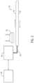
- FIG. 2is a schematic view of a communication system coupled to the wire guidance system of FIG. 1 .
- FIG. 3is cross-sectional view of a warehouse floor having the wire guidance system of FIG. 1 installed therein, taken along cut line 3 - 3 in FIG. 1 .
- FIG. 4is a schematic view of the electromagnetic fields produced by current passing through the wire guidance system of FIG. 1 .
- FIG. 5is a bottom view of a material handling vehicle centered over the wire guidance system of FIG. 1 .
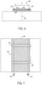
- FIG. 6is an exploded view of a warehouse floor and tape incorporating a wire guidance system in accordance with another aspect of the disclosure.
- FIG. 7is a top view of the wire guidance system of FIG. 6 .
- the present disclosureprovides systems and methods for remotely controlling and operating material handling vehicles. While the systems and methods for remotely controlling and operating vehicles are discussed only with respect to material handling vehicles, it should be appreciated that the various aspects of the disclosure can be applied to other vehicles as well.
- FIG. 1illustrates one non-limiting example of a warehouse 10 according to the present disclosure.
- the warehouse 10includes several racks 12 spaced apart from one another that extend through the warehouse 10 to define aisles 14 .
- the racks 12may store pallets (not shown) or other items that can be retrieved or moved by one or more material handling vehicles 16 present within a fleet 18 .
- a network of wire loops 20extends throughout the warehouse 10 to provide wire guidance to one or more material handling vehicles 16 that operate within the warehouse 10 .
- the network of wire loops 20provide an electrical signal to the material handling vehicles 16 , which helps maintain the vehicles 16 centered over the wire loops 20 during operation.
- the network of wire loops 20can be placed in electrical communication with a Warehouse Management System (WMS), which can provide signals to the wire loops 20 to direct the material handling vehicles 16 through the warehouse 10 .
- WMSWarehouse Management System
- the network of wire loops 20can be arranged to allow rapid and precise movement of material handling vehicles 16 throughout the entire warehouse 10 .
- An outer perimetercan be partially established by a first wire loop 22 , a second wire loop 24 extending approximately parallel to the first wire loop 22 , a third wire loop 26 extending perpendicularly to the first wire loop 22 , and a fourth wire loop 28 extending approximately parallel to the third wire loop 26 .
- the first wire loop 22 , second wire loop 24 , third wire loop 26 , and fourth wire loop 28are positioned outward from the racks 12 , and form a primary material handling vehicle path throughout the warehouse 10 .
- a crossing loop 30can extend away from the outer perimeter of the network 20 (e.g., from the first loop 22 ), which can extend perpendicularly to the racks 12 and aisles 14 .
- the crossing loop 30can be used to navigate the material handling vehicle 16 through the warehouse until it reaches a desired aisle loop 32 .
- each aisle 14includes an aisle loop 32 extending approximately parallel to the racks 12 that define the aisle 14 .
- the aisle loop 32can extend through a portion of the aisle 14 to guide a material handling vehicle 16 within the aisle 14 .
- the aisle loop 32can extend the entire length of the aisle 14 .
- each wire loop in the network 20can be painted over with a visible stripe.
- the visible stripecan be detected by an optical detector (e.g., the optical detector 74 , shown in FIG. 5 ) present on the material handling vehicle 16 .
- the visible stripemay have a color or pattern that indicates which aisle of the warehouse 10 the wire loop is located.
- the optical detectorcan be a digital camera or light sensor with an integrated light source oriented at the floor to sense the visible stripe.
- the visible stripecan be simply painted on the floor or it can be a tape attached to the floor.
- the paint or tapecan be applied on top of a wire loop tape can contain a wire loop.
- a wire loopcan be arranged on an adhesive side of the tape or embedded within the tape before the tape is applied to the floor.
- transitional stripes 34 , 36 , 38can extend between the wire loops 22 , 24 , 26 , 28 , 30 , 32 in the network 20 .
- a gapexists between each wire loop in the network 20 .
- Transitional stripes 34 , 36 , 38can provide optical indication and/or guidance to a material handling vehicle 16 as it transitions from one wire loop (e.g., the first wire loop 22 ) to another wire loop (e.g., the third loop 26 ). As the material handling vehicle 16 approaches the transitional stripe 34 , 36 , 38 , it can optically detect the path it should take to transition from being guided by one wire loop to the next wire loop.
- transitional stripes 34 , 36 , 38can be provided in several locations throughout the network 20 .
- transitional stripes 34can be provided between each wire loop 22 , 24 , 26 , 28 in the outer perimeter of the network 20 .
- the transitional stripes 34may form a smoothly curving arc that extends about 90 degrees to tangentially direct a material handling vehicle 16 from one wire loop to another wire loop.
- Transitional stripes 36can also extend between the wire loops 22 , 24 , 26 , 28 to optically guide a material handling vehicle 16 through a U-turn.
- a 180 degree arccan extend between two parallel loops (e.g., the first and second wire loops 22 , 24 , or the third and fourth wire loops 26 , 28 ) to guide a material handling vehicle 16 as it reverses direction onto an adjacent wire loop.
- Transitional stripes 38can also extend away from the aisle loops 32 toward the outer perimeter loops 22 , 24 , 26 , 28 and the crossing loop 30 .
- the transitional stripes 38can be defined by a smoothly curving arc extending approximately 90 degrees between each loop.
- FIGS. 2 - 5illustrate the wire loop construction and function.
- Each wire loopsuch as the first wire loop 22 shown in FIG. 2
- Each wire loopis constructed of two conductive members 40 , 42 , which are electrically coupled to one another to define a loop.
- Each of the conductive members 40 , 42extend away from a shielded cable connector 44 .
- the first conductive member 40 and the second conductive member 42can extend away from the shielded cable connector 44 in a substantially parallel manner.
- the first conductive member 40 and the second conductive member 42are each placed into notches 45 , 46 formed or cut in the warehouse floor 48 . Epoxy can be filled in around the conductive members 40 , 42 to secure them within the notches 45 , 46 in the floor 48 .
- a single notch(not shown) can accommodate both conductive members 40 , 42 , which may reduce installation costs.
- the conductive members 40 , 42can be constructed from metal wires, metal foil, and/or conductive paint where appropriate.
- the conductive paintcan include an epoxy with metal particles.
- the first conductive member 40 and the second conductive member 42can be spaced apart from one another by a distance D.
- the distance Dcan range between about 0.05 cm (0.02 inches) and about 10.2 cm (4.0 inches).
- the distance Dcan be chosen based upon the desired communication frequency used in the warehouse 10 .
- the distance Dcan be selected to be about four times larger than the wavelength of the communication frequency used in the warehouse 10 , which may help transmit and receive signals at the communication frequency.
- a warehouse 10 operating on a 23.6 GHz frequencymay use conductive members 40 , 42 spaced apart by a distance D of about 5.1 cm (2.0 inches).
- a variety of high frequenciescan be used to communicate signals through the conductive members 40 , 42 .
- frequencies between about 1 GHz to greater than 200 GHzcan be transmitted through and received by the conductive members 40 , 42 .
- Standard frequenciessuch as 2.4 GHz, 3.6 GHz, 5 GHz, or 60 GHz may also be used.
- the currenttravels along the first conductive member 40 in a first direction away from the shielded cable connector 44 , passes to the second conductive member 42 , and returns toward the shielded cable connector 44 along the second conductive member 42 in a second direction substantially opposite of the first direction.
- the opposing currentsproduce electromagnetic fields 50 , 52 , which emanate outwardly from the conductive members 40 , 42 at the current frequency to produce a near field signal.
- the electromagnetic fields 50 , 52 produced by the currentscan extend in opposite directions. As shown in FIG. 4 , for example, the current flowing through the first conductive member 40 can produce an electromagnetic field 50 extending counterclockwise about the first conductive member 40 , while the second conductive member 42 can produce an electromagnetic field 52 extending clockwise about the second conductive member 42 .
- the positioning of the conductive members 40 , 42 relative to one anotherproduces a narrowcasting signal, which may only be detectable in an area 54 between and above the two conductive members 40 , 42 , where it is strongest.
- the electromagnetic fields 50 , 52extend in opposing directions. Although the electromagnetic fields 50 , 52 produced by the first conductive member 40 and the second conductive member 42 oppose one another, the electromagnetic fields 50 , 52 are additive in the area 54 directly between and above the two conductive members 40 , 42 . Because both fields 50 , 52 extend in a similar direction in the additive area 54 , they can produce a strong radio frequency signal that can be detected or received by an antenna or other receiving device present above and between the two conductive members 40 , 42 . The radio frequency signal is strongest along the centerline 56 between the two conductive members 40 , 42 .
- the electromagnetic fields 50 , 52oppose one another, which includes a canceling effect on any resultant radio frequency signal produced by the current passing through the conductive members 40 , 42 .
- the resultant radio frequency signalbecomes weaker further away from the conductive members 40 , 42 , and may be undetectable in these areas.
- the resultant electromagnetic field 58demonstrates the canceling effect of the electromagnetic fields 50 , 52 , which occurs outside the area 54 between the conductive members 40 , 42 .
- the first wire loop 22(and other loops 24 , 26 , 28 , 30 , 32 within the network 20 ) functions as a narrowcasting network, where a strong signal can be detected only within a confined area (i.e., the area 54 between and above the conductive members 40 , 42 ), rather than a broadcasting network, where radio frequency power is distributed throughout a larger area.
- the canceling effect of the resultant electromagnetic field 58can reduce the amount of interference introduced into other communication systems used within the warehouse 10 , such as cellular or WiFi.
- the metal racks 12 in the warehouse 10can also reduce the amount of interference produced by the resultant electromagnetic fields 58 produced by the wire loops in the network 20 .
- the current and/or resulting radio frequency signalcan be supplied to the conductive members 40 , 42 from an outside source, such as a Warehouse Management System (WMS).
- the shielded cable connector 44can be coupled to a local WiFi node 60 (see FIG. 2 ).
- the local WiFi node 60can be a WiFi unit 62 based on the IEEE 802.11 standards, and can use the wire loop (e.g., first wire loop 22 ) as its antenna.
- the local WiFi node 60can be a node on the warehouse Ethernet 64 , which can receive data from a network hub computer (not shown). When the local WiFi node 60 receives a signal from the network hub computer or WMS, the local WiFi node 60 may demodulate the signal to extract information from the received signal.
- the local WiFi node 60can transmit a high frequency radio frequency signal through the shielded cable connector 44 and onto the first and second conductive members 40 , 42 , which may transmit the signal upward, where it can be detected by a material handling vehicle 16 .
- the local WiFi node 60contains a superheterodyne receiver to receive an incoming signal from the WMS and convert the received signal into a frequency that can then be passed onto the conductive members 40 , 42 of the wire loop.
- the radio frequency signal carried by the conductive members 40 , 42can be received by an antenna 66 coupled to the material handling vehicle 16 , as shown in FIG. 5 .
- the antenna 66is coupled to a base 70 of a steel frame 68 that can partially define the material handling vehicle 16 .
- the antenna 66can be positioned between each of the wheels 72 , approximately centered on the base 70 of the steel frame 68 .
- the antenna 66is electrically coupled to a Truck Control System (TCS) (not shown), which can demodulate the radio frequency signal detected by the antenna 66 and use the information contained within the signal to execute various material handling vehicle 16 functions.
- TCSTruck Control System
- the TCScan include a Vehicle Manager (VM) that uses a micro-controller in communication with multiple field-programmable gate array (FPGA) logic chips to communicate with and control various subsystems (e.g., the steering motor, lift pump, traction motor, etc.) on the material handling vehicle 16 through a digital bus.
- VMVehicle Manager
- FPGAfield-programmable gate array
- the TCScan also include relays, display modules, badge readers, RFID chip readers, proximity sensors, and other electronic systems present within the material handling vehicle 16 , such that communication with the TCS can allow the material handling vehicle 16 to be externally controlled.
- the radio frequency signal carried by the conductive members 40 , 42may contain navigation instructions, which can be received and processed by the TCS.
- the VM within the TCScan then navigate the material handling vehicle 16 according to the navigation instructions received by the TCS, and can move the material handling vehicle 16 throughout the warehouse 10 .
- the radio frequency signalcan include remote controlling instructions provided by an operator, who could then operate the material handling vehicle 16 using a computer (e.g., a personal laptop) connected to the warehouse Ethernet 64 . This may allow an operator to semi-autonomously operate a material handling vehicle 16 from a location outside the warehouse 10 entirely.
- the strength of the signal detected by the antenna 66can be used to help locate the material handling vehicle 16 above the wire loop 22 .
- the highest radio frequency signalis present directly between the two conductive members 40 , 42 , and the strength of the signal received by the antenna 66 is directly correlated to the antenna's 66 (and material handling vehicle's 16 ) position relative to the two conductive members 40 , 42 (i.e., the signal may be strongest along the centerline 56 in the narrowcasting area 54 ).
- the TCS of the material handling vehicle 16can be programmed with a threshold signal amplitude, which corresponds to the amplitude of a signal that would be produced if the material handling vehicle 16 is properly located above a wire loop (e.g., the first wire loop 22 ).
- the TCScan continuously monitor the material handling vehicle's 16 position relative to the loop by comparing the signal received by the antenna 66 to the threshold value stored within the TCS. If the value falls below the predetermined “acceptable” amplitude, the TCS can adjust the steering of the material handling vehicle 16 until a value above the amplitude threshold is received by the antenna 66 . This can maintain the material handling vehicle 16 aligned properly with the wire loop.
- several antennae 66can be used to detect the lateral distance of the material handling vehicle 16 relative to the loop, as discussed in U.S. Pat. No. 6,445,984, which is hereby incorporated by reference in its entirety.
- An optical detector 74can be coupled to the base 70 of the steel frame 68 to further guide the material handling vehicle 16 throughout the warehouse.
- the optical detector 74can be a light sensor with an integrated light source that provides visible white light, visible light of a specific color, or infrared light.
- the light sensorcan detect light reflected from the visible stripe of one of the wire loops 22 , 24 , 26 , 28 , 30 , 32 and/or one of the transitional stripes 34 , 36 , 38 .
- the light sensorcan distinguish the color of the reflected light, which may be used to determine a location of the material handling vehicle 16 in the warehouse 10 and/or on one of the wire loops 22 , 24 , 26 , 28 , 30 , or 32 .
- the color of the reflected lightmay indicate if the optical sensor 74 is positioned over visible bars 90 of FIG. 7 .
- the optical detector 74can be a camera that can detect a color or pattern.
- the cameracan have an integrated light source that provides visible white light, visible light of a specific color, or infrared light.
- the optical detectorcan detect color from tape, paint, or concrete dye with or without a top coating of protective epoxy, allowing for colors and/or patterns to be marked in a variety of manners.
- the optical detector 74can be positioned in line with the antenna 66 , and can supplement, or completely replace, the wire guidance provided by the conductive members 40 , 42 . In some aspects, the optical detector 74 is positioned near a leading end 76 of the material handling vehicle 16 . For example, the optical detector 74 can be positioned near one or more forks 78 that extend forward of the steel frame 68 of the material handling vehicle 16 . The optical detector 74 can be used to optically detect the position the material handling vehicle 16 is in currently, as well as to identify obstacles, turns, or the end of an aisle 14 that may be in front of the material handling vehicle 16 .
- the optical detector 74can help direct the material handling vehicle 16 to stay properly positioned above the wire loop. For example, if the antenna 66 detects that the detected radio frequency signal has fallen below the necessary amplitude threshold, the optical detector 74 can optically detect which direction the material handling vehicle 16 must steer in order to be properly aligned with the wire loop once more.
- the visible stripes present above the loops in the network 20provide easily detectable markers for the optical detector 74 to sense. Data taken by the optical detector 74 can be communicated to the TCS, which adjusts the steering of the material handling vehicle 16 as necessary.
- the optical detector 74can help the material handling vehicle 16 transition between the different wire loops in the network 20 to reach a desired destination.
- the optical detector 74can alert the TCS, which can temporarily disable wire guidance.
- the TCScan smoothly steer the material handling vehicle 16 along the transitional stripes 34 , 36 , 38 , until the material handling vehicle 16 is once again centered over a wire loop within the network 20 .
- the TCScan reinitiate the wire guidance system.
- a transmitter 80can also be coupled to the material handling vehicle 16 .
- the transmitter 80like the antenna 66 , can be coupled to the base 70 of the steel frame 68 .
- the transmitter 80can be positioned between each of the wheels 66 , approximately centered on the base 70 of the steel frame 68 .
- the transmitter 80can be placed in electrical communication with the TCS, and can be used to transmit information from the TCS to the wire loop 22 positioned below the material handing vehicle 16 .
- the transmitter 80may have one or more coils configured to transmit RF energy to induce currents at a predetermined frequency in the conductive members 40 , 42 and transmit a signal to the WiFi node 60 .
- the signalmay have a frequency ranging from 1 GHz to 100 GHz.
- the underside of the material handling vehicle 16can prevent the RF energy from spreading away from the conductive members 40 , 42 and thus interfering with components of the warehouse 10 .
- the opposing currentscan carry a signal with information about the material handling vehicle 16 to the WiFi node 60 .
- the transmitter 80could transmit the material handling vehicle's 16 position within the warehouse 10 , based upon readings from the optical detector 74 and the antenna 66 .
- the transmitter 80could communicate with the wire loop 22 (which communicates with the WMS) that an assigned task (e.g., retrieving an item from a specific rack 12 within the warehouse 10 ) has been completed, and that the material handling vehicle 16 is ready to be assigned a new task.
- the material handling vehicle 16could use the transmitter 80 to notify the WMS that an unexpected scenario has been encountered, and the material handling vehicle 16 desires assistance from an operator.
- the transmitter 80 and antenna 66are electrically coupled to one another.
- the transmitter 80 and antenna 66may be a one or more receiving and transmitting antennas each performing at least a portion of the functions of the transmitter 80 and antenna 66 .
- the radio frequency signalcan be carried from the loop to the shielded cable connector 44 , and to the local WiFi node 60 .
- the local WiFi node 60includes a demodulator, which can extract the information from the radio frequency signal received from the material handling vehicle 16 .
- the local WiFi node 60may then transmit a signal through the WiFi unit 62 to the warehouse Ethernet 64 , which may be coupled with the WMS.
- the WMScan receive the signal, demodulate it, and determine the appropriate course of action to respond to the information received from the material handling vehicle 16 .
- the WMScan assign a new task to the material handling vehicle 16 by sending a signal through the local WiFi node 60 , through the shielded cable connector 44 , and onto the conductive members 40 , 42 , where it can be detected by the material handling vehicle 16 .
- the antenna 66 and transmitter 80operate on different channels, so that two-way communication through the conductive members 40 , 42 and the material handling vehicle 16 can occur simultaneously. Both the signal transmitted from the material handling vehicle 16 and the signal transmitted to the material handling vehicle 16 may be present in the conductive members 40 , 42 .
- the demodulatormay be able to separate the signal transmitted from the material handling vehicle 16 and the signal transmitted to the material handling vehicle 16 in order to implement two-way communication.
- the demodulatormay receive a single combined current via the shielded cable connector 44 with both the signal transmitted from the transmitter 80 to the WiFi node 60 and the signal transmitted from the WiFi node 60 to the antenna 66 .
- the demodulatorcan then filter out a signal corresponding to the carrier frequency of the channel the transmitter 80 is operating on and then process the information transmitted from the material handling vehicle 16 .
- the transmitter 80 and the antenna 66may operate on the same channel while still allowing two-way communication to occur.
- the WiFi node 60can use an appropriate technique such as a full-duplex or simultaneous transmission and reception (STR) technique to detect appropriate signals and implement two-way communication.
- STRsimultaneous transmission and reception
- High speed two-way communication between the material handling vehicle 16 and the WMScan enable the autonomous material handling vehicle 16 to be selectively controlled by an operator, who may be present remotely from the material handling vehicle 16 .
- the material handling vehicle's 16 autonomous control systeme.g., the TCS
- the material handling vehicle's 16 autonomous control systemdetects an obstacle that affects its navigation, it may transmit a signal along the network 20 that it requests assistance.
- An operator positioned at a computer in communication with the network 20can accept the assistance request, which can then provide remote control of the material handling vehicle 16 .
- Conductive members 40 , 42 of the loopcan be used with the antenna 66 and transmitter 80 to send and receive high frequency signals between the computer and the material handling vehicle 16 to enable the operator to communicate with and control the material handling vehicle 16 .
- the computercan display a live video feed being taken from one or more video cameras 75 on the material handling vehicle 16 , which can supply the operator with a field of view in front of the material handling vehicle 16 .
- the video cameras 75can be positioned around the material handling vehicle 16 to provide views that might be difficult or even impossible to see by an operator seated within the material handling vehicle 16 .
- video cameras 75can be directed toward the forks 78 , which can allow an operator to align the forks 78 with a pallet, regardless of the pallet's height relative to the material handling vehicle 16 .
- the operatorcan then control the material handling vehicle 16 and navigate it through the scenario that originally created the request for assistance.
- controlcan be returned to the TCS of the material handling vehicle 16 , and autonomous operation can resume.
- a central computerwith the network 20 , multiple material handling vehicles 16 can be selectively controlled by a single remote operator, which can reduce labor costs.
- additional antennaemay be coupled to the material handling vehicle 16 to receive or communicate information throughout the warehouse 10 .
- WiFi units 62may broadcast vehicle instructions throughout the warehouse, which can be received and processed by the TCS of the material handling vehicle 16 .
- the broadcast WiFican also be used to determine the material handling vehicle's 16 position along a wire guidance loop (e.g., wire loops 22 , 24 , 26 , 28 , 30 , 32 ).
- the same instructionscan be transmitted to a material handling vehicle 16 through both broadcast WiFi and the loop network 20 .
- the time delay between receiving a broadcast radio signal and receiving the same signal through a wire loopcan be measured, and the calculated time delay between receiving the signals can determine the location of the material handling vehicle 16 relative to the wire loop.
- time delay measurementcan be used to supplement or replace the optical detector 74 to direct the material handling vehicle 16 throughout the warehouse 10 .
- FIGS. 6 and 7show another aspect of a wire loop 82 that can be incorporated into the warehouse network 20 .
- first and second conductive members 40 ′, 42 ′ in the form of metal foil conductorscan be adhesively coupled to the warehouse floor 48 .
- the wire loop 82can be a tape having multiple layers 84 , 86 , 88 that secure the wire loop 82 to the warehouse floor 48 while also protecting the metal foil of the first and second conductive members 40 ′, 42 ′.
- the conductive members 40 ′, 42 ′are electrically coupled to one another to form a wire loop 82 .
- the first and second conductive members 40 ′, 42 ′are spaced apart by the distance D.
- the wire loop 82can be electrically coupled to a shielded cable connector 44 , as well as a local WiFi node 60 , WiFi unit 62 , warehouse Ethernet 64 , and a WMS.
- a top layer 84can include a visible stripe that can be readily detected by the optical detector 74 of the material handling vehicle 16 .
- the top layer 84also includes visible bars 90 spaced apart about the top layer 84 .
- the visible bars 90can extend across the top layer 84 to indicate distance on the wire loop 82 .
- the optical detector 74can optically detect the visible bars 90 , which can indicate the position of the material handling vehicle 16 relative to the wire loop 82 .
- the visible bars 90can be spaced apart from one another every 0.6 meters (2 feet), and can be about 0.01 m (0.5 in) thick.
- the optical detector 74can be used to count the number of bars traversed, which can be communicated to the wire loop 82 , which can then be transmitted to the WMS.
- the visible bars 90can be given different colors, which can correspond to different distances along the wire loop 82 . If the material handling vehicle 16 is between two visible bars 90 , the position of the material handling vehicle 16 on the wire loop 82 can be calculated using the number of rotations of the material handling vehicle's 16 wheels 72 or by using the time delay measurement technique discussed previously. Data can be broadcasted over the warehouse WiFi and through the wire loop 82 , and the amount of time it takes for the antenna 66 of the material handling vehicle 16 to receive the data can be used to calculate the position of the material handling vehicle 16 on the wire loop 82 .
- remote operation of a material handling vehiclecan be accomplished.
- the network of loopsprovides reliable two-way communication with material handling vehicles, which can transmit and receive information between the TCS and the WMS to effectively accomplish tasks within a warehouse automatically.
- Remote operatorscan be notified when material handling vehicles encounter a scenario outside of their working set of instructions, and can temporarily take over the operation of a material handling vehicle until the unforeseen scenario includes been resolved.
- one remote operatormay manage one or more material handling vehicles, which can reduce labor costs.
Landscapes
- Engineering & Computer Science (AREA)
- Physics & Mathematics (AREA)
- Aviation & Aerospace Engineering (AREA)
- Radar, Positioning & Navigation (AREA)
- Remote Sensing (AREA)
- General Physics & Mathematics (AREA)
- Automation & Control Theory (AREA)
- Electromagnetism (AREA)
- Computer Vision & Pattern Recognition (AREA)
- Multimedia (AREA)
- Warehouses Or Storage Devices (AREA)
- Control Of Position, Course, Altitude, Or Attitude Of Moving Bodies (AREA)
Abstract
Description
Claims (26)
Priority Applications (1)
| Application Number | Priority Date | Filing Date | Title |
|---|---|---|---|
| US16/280,871US11726491B2 (en) | 2018-02-20 | 2019-02-20 | Wire guidance and remote operation for material handling vehicles |
Applications Claiming Priority (2)
| Application Number | Priority Date | Filing Date | Title |
|---|---|---|---|
| US201862632760P | 2018-02-20 | 2018-02-20 | |
| US16/280,871US11726491B2 (en) | 2018-02-20 | 2019-02-20 | Wire guidance and remote operation for material handling vehicles |
Publications (2)
| Publication Number | Publication Date |
|---|---|
| US20190258266A1 US20190258266A1 (en) | 2019-08-22 |
| US11726491B2true US11726491B2 (en) | 2023-08-15 |
Family
ID=65729055
Family Applications (1)
| Application Number | Title | Priority Date | Filing Date |
|---|---|---|---|
| US16/280,871Active2040-07-17US11726491B2 (en) | 2018-02-20 | 2019-02-20 | Wire guidance and remote operation for material handling vehicles |
Country Status (5)
| Country | Link |
|---|---|
| US (1) | US11726491B2 (en) |
| EP (1) | EP3528079B1 (en) |
| CN (1) | CN110174890B (en) |
| AU (1) | AU2019201138B2 (en) |
| CA (1) | CA3034361A1 (en) |
Families Citing this family (7)
| Publication number | Priority date | Publication date | Assignee | Title |
|---|---|---|---|---|
| AU2020257165B2 (en)* | 2019-10-28 | 2025-07-10 | The Raymond Corporation | Systems and methods for transferring routes between material handling devices |
| CN114901585B (en) | 2020-02-21 | 2024-05-28 | 克朗设备公司 | Positioning assistance systems for material handling vehicles |
| CN114166212B (en)* | 2020-09-11 | 2024-05-03 | 苏州科瓴精密机械科技有限公司 | Robot system and robot obstacle avoidance method |
| CN114167852B (en)* | 2020-09-11 | 2024-11-19 | 苏州科瓴精密机械科技有限公司 | Robot system and robot obstacle avoidance method based on magnetic field signal |
| JP2022096338A (en)* | 2020-12-17 | 2022-06-29 | トヨタ自動車株式会社 | Vehicle electromagnetic wave shielding structure |
| CN114939879B (en)* | 2022-05-31 | 2024-10-29 | 天津市山石机器人有限责任公司 | Implementation method of multifunctional composite AGV robot |
| US20240232799A1 (en)* | 2023-01-09 | 2024-07-11 | Steven Kruger | Methods, devices, and systems for improving material handler efficiency |
Citations (71)
| Publication number | Priority date | Publication date | Assignee | Title |
|---|---|---|---|---|
| US937976A (en) | 1908-09-05 | 1909-10-26 | Otto Venter | Apparatus for concentrating liquids. |
| US3470474A (en) | 1966-12-23 | 1969-09-30 | Donald E Bilger | Underground radio communication system for highways |
| US3594571A (en)* | 1968-09-19 | 1971-07-20 | Jungheinrich & Co Maschf | Vehicular guidance system with collision prevention |
| US3735265A (en) | 1970-11-24 | 1973-05-22 | Gureckis P | Radio communication/control system for restricted range signaling near the earth{40 s surface |
| US3763955A (en)* | 1970-10-23 | 1973-10-09 | Merten Kg Pulsotronic | Arrangement for controlling the steering of vehicles directed along apredetermined path |
| US3935922A (en)* | 1974-07-16 | 1976-02-03 | Lear Siegler, Inc. | Vehicle guidance mechanism |
| US4006790A (en)* | 1974-01-11 | 1977-02-08 | Hitachi, Ltd. | Electromagnetic guidance system |
| US4043418A (en)* | 1975-11-06 | 1977-08-23 | Logisticon Inc. | Reverse direction guidance system for lift truck |
| US4044853A (en)* | 1976-04-05 | 1977-08-30 | Jervis B. Webb Company | Driverless vehicle and guidance system |
| US4215759A (en)* | 1975-12-22 | 1980-08-05 | Westinghouse Electric Corp. | Guidance control system for a traction vehicle |
| US4284160A (en)* | 1979-03-19 | 1981-08-18 | Barrett Electronics Corporation | Vehicle guidance system employing radio blocking |
| US4307329A (en) | 1977-10-07 | 1981-12-22 | The Raymond Corporation | Wire guidance method and apparatus |
| US4322670A (en) | 1977-10-07 | 1982-03-30 | The Raymond Corporation | Land vehicle guidance method and apparatus |
| US4361202A (en)* | 1979-06-15 | 1982-11-30 | Michael Minovitch | Automated road transportation system |
| US4486694A (en)* | 1981-05-22 | 1984-12-04 | Shinko Electric Co., Ltd. | Process for changing a running direction of an electromagnetically guided driverless vehicle |
| US4520889A (en)* | 1981-03-02 | 1985-06-04 | Shinko Electric Co., Ltd. | Guidance conductor for driverless vehicle |
| US4530056A (en)* | 1982-10-28 | 1985-07-16 | Modular Automation Corp. | Automated guided vehicle system |
| US4656406A (en)* | 1985-09-20 | 1987-04-07 | Litton Automation Systems, Inc. | Electric field guidance system for automated vehicles |
| US4780817A (en)* | 1986-09-19 | 1988-10-25 | Ndc Technologies, Inc. | Method and apparatus for providing destination and vehicle function information to an automatic guided vehicle |
| US4791570A (en)* | 1985-05-02 | 1988-12-13 | Eaton-Kenway, Inc. | Guide wire communication system and method |
| US4819758A (en)* | 1984-06-07 | 1989-04-11 | Eds Technologies Inc. | Vehicle for delivering large cylindrical shaped loads and the like |
| DE3916610A1 (en) | 1989-05-22 | 1989-12-07 | Goetting Hans Heinrich Jun | Device for data transmission and track guidance of vehicles |
| US4902948A (en)* | 1985-05-02 | 1990-02-20 | Eaton-Kenway, Inc. | Guide wire communication system and method |
| US4919224A (en)* | 1988-05-16 | 1990-04-24 | Industrial Technology Research Institute | Automatic working vehicular system |
| US5032994A (en) | 1989-12-06 | 1991-07-16 | Crown Equipment Corporation | Manual sensing of wire guidance signal |
| US5036935A (en)* | 1989-03-08 | 1991-08-06 | Kabushiki Kaisha Toyoda Jidoshokki Seisakusho | Travel control device for unmanned vehicle |
| US5040116A (en) | 1988-09-06 | 1991-08-13 | Transitions Research Corporation | Visual navigation and obstacle avoidance structured light system |
| US5068790A (en) | 1989-12-06 | 1991-11-26 | Crown Equipment Corporation | Wire guidance control system |
| US5068791A (en)* | 1989-12-06 | 1991-11-26 | Crown Equipment Corporation | Distance and angle measurements in a wire guided vehicle |
| US5091855A (en)* | 1989-04-17 | 1992-02-25 | Kabushiki Kaisha Toyoda Jidoshokki Seisakusho | Operation control system for automated guide vehicles |
| US5111401A (en) | 1990-05-19 | 1992-05-05 | The United States Of America As Represented By The Secretary Of The Navy | Navigational control system for an autonomous vehicle |
| US5127486A (en)* | 1990-11-23 | 1992-07-07 | Eaton-Kenway, Inc. | System for sensing arrival of an automatic guided vehicle at a wire |
| US5175480A (en)* | 1990-01-18 | 1992-12-29 | Mckeefery James | Vehicle guidance and control systems and methods for controllably guiding a vehicle along a predetermined pathway |
| US5187664A (en)* | 1990-11-27 | 1993-02-16 | Eaton-Kenway, Inc. | Proportional position-sensing system for an automatic guided vehicle |
| US5245335A (en) | 1984-03-06 | 1993-09-14 | Comsource Systems Corp. | Transceiver system for communication over wire laid along the path of guided/vehicles |
| US5258911A (en) | 1991-04-09 | 1993-11-02 | Crown Equipment Corporation | End of aisle control system |
| US5281901A (en)* | 1990-12-03 | 1994-01-25 | Eaton-Kenway, Inc. | Downward compatible AGV system and methods |
| US5404087A (en) | 1993-03-03 | 1995-04-04 | Sherman; Leigh E. | Automated guided vehicle wire guidance apparatus |
| US5508731A (en)* | 1986-03-10 | 1996-04-16 | Response Reward Systems L.C. | Generation of enlarged participatory broadcast audience |
| US5519296A (en) | 1993-11-10 | 1996-05-21 | The Raymond Corporation | Method and apparatus for sensing guidewire signals |
| US5650703A (en)* | 1990-06-28 | 1997-07-22 | Hk Systems, Inc. | Downward compatible AGV system and methods |
| US5759101A (en)* | 1986-03-10 | 1998-06-02 | Response Reward Systems L.C. | Central and remote evaluation of responses of participatory broadcast audience with automatic crediting and couponing |
| US5778327A (en) | 1993-11-10 | 1998-07-07 | The Raymond Corporation | Guidewire controls for a material handling vehicle |
| US5869910A (en)* | 1994-02-11 | 1999-02-09 | Colens; Andre | Power supply system for self-contained mobile robots |
| US5938710A (en) | 1996-04-03 | 1999-08-17 | Fiat Om Carrelli Elevatori S.P.A. | Selectively operable industrial truck |
| US20010003099A1 (en)* | 1986-03-10 | 2001-06-07 | Henry Von Kohorn | Evaluation of responses of participatory broadcast audience with prediction of winning contestants; monitoring, checking and controlling of wagering, and automatic crediting and couponing |
| US6445984B1 (en) | 2001-05-25 | 2002-09-03 | The Raymond Corporation | Steer control system for material handling vehicles |
| US20030023356A1 (en)* | 2000-02-02 | 2003-01-30 | Keable Stephen J. | Autonomous mobile apparatus for performing work within a predefined area |
| US20070140195A1 (en)* | 2005-12-20 | 2007-06-21 | Ilan Kaftan | Method and system for providing ip services using cable and wireless infrastructure |
| WO2008057504A2 (en) | 2006-11-06 | 2008-05-15 | Aman James A | Load tracking system based on self- tracking forklift |
| WO2009063387A2 (en) | 2007-11-13 | 2009-05-22 | Koninklijke Philips Electronics N.V. | Wireless communication module comprising an integrated antenna |
| US20100145550A1 (en)* | 2007-04-20 | 2010-06-10 | Advanced Transport Systems Limited | Vehicle Guidance System |
| US20100279582A1 (en) | 2009-04-30 | 2010-11-04 | Abconsulting | Guiding and supply of miniature vehicles |
| US20100300788A1 (en)* | 2007-07-10 | 2010-12-02 | Paul Cox | Automatic vehicle guidance protection system |
| US20110202307A1 (en)* | 2008-10-20 | 2011-08-18 | Robert Bosch Gmbh | Method and System for Recognizing the Working Range of a Mobile Tool |
| US8172033B2 (en) | 2008-02-05 | 2012-05-08 | Crown Equipment Corporation | Materials handling vehicle with a module capable of changing a steerable wheel to control handle position ratio |
| US20120119575A1 (en)* | 2008-09-27 | 2012-05-17 | Kurs Andre B | Wireless energy transfer for vehicles |
| US20120239224A1 (en)* | 2011-03-18 | 2012-09-20 | Mccabe Paul P | Integration of an autonomous industrial vehicle into an asset management system |
| US8406949B2 (en) | 2009-06-26 | 2013-03-26 | Toyota Shatai Kabushiki Kaisha | Travel control device for unmanned conveyance vehicle |
| US8634960B2 (en)* | 2006-03-17 | 2014-01-21 | Irobot Corporation | Lawn care robot |
| US8751147B2 (en) | 2010-08-03 | 2014-06-10 | Fori Automation, Inc. | Sensor system and method for use with an automated guided vehicle (AGV) |
| US20150031975A1 (en)* | 2001-04-13 | 2015-01-29 | MRI Interventions, Inc. | Mri compatible medical leads |
| US8983649B2 (en) | 2007-02-16 | 2015-03-17 | Boomerang Systems, Inc. | Automated storage system and transport vehicle |
| US20160100035A1 (en)* | 2014-10-06 | 2016-04-07 | Eggcyte, Inc. | Personal handheld web server and storage device |
| US9607734B2 (en) | 2010-08-31 | 2017-03-28 | 3M Innovative Properties Company | Shielded electrical ribbon cable with dielectric spacing |
| US20170146622A1 (en)* | 2015-11-20 | 2017-05-25 | Quality Electrodynamics, Llc | Current magnitude control at different sections in one coil |
| US20180094935A1 (en) | 2016-10-04 | 2018-04-05 | Wal-Mart Stores, Inc. | Systems and Methods for Autonomous Drone Navigation |
| US20180304752A1 (en)* | 2017-04-25 | 2018-10-25 | Alstom Transport Technologies | Assembly of a ground power supply system and an electric vehicle |
| US20180339703A1 (en)* | 2017-05-26 | 2018-11-29 | Sucxess LLC | Vehicle with remote-controlled operating mode |
| US20190138025A1 (en)* | 2017-11-07 | 2019-05-09 | Robin Technologies, Inc. | Ground Wire Guidance System for Robotic Vehicle with Doorway Access |
| US10333047B2 (en)* | 2011-03-30 | 2019-06-25 | Ambatrue, Inc. | Electrical, mechanical, computing/ and/or other devices formed of extremely low resistance materials |
Family Cites Families (4)
| Publication number | Priority date | Publication date | Assignee | Title |
|---|---|---|---|---|
| US5610618A (en)* | 1994-12-20 | 1997-03-11 | Ford Motor Company | Motor vehicle antenna systems |
| US7417599B2 (en)* | 2004-02-20 | 2008-08-26 | 3M Innovative Properties Company | Multi-loop antenna for radio frequency identification (RFID) communication |
| EP2912718A4 (en)* | 2012-10-26 | 2016-05-04 | Nokia Technologies Oy | Loop antenna having a parasitically coupled element |
| US10202267B2 (en)* | 2015-10-29 | 2019-02-12 | The Raymond Corporation | Systems and methods for sensing a load carried by a material handling vehicle |
- 2019
- 2019-02-19AUAU2019201138Apatent/AU2019201138B2/enactiveActive
- 2019-02-19EPEP19158132.1Apatent/EP3528079B1/enactiveActive
- 2019-02-20CNCN201910125891.6Apatent/CN110174890B/enactiveActive
- 2019-02-20CACA3034361Apatent/CA3034361A1/enactivePending
- 2019-02-20USUS16/280,871patent/US11726491B2/enactiveActive
Patent Citations (74)
| Publication number | Priority date | Publication date | Assignee | Title |
|---|---|---|---|---|
| US937976A (en) | 1908-09-05 | 1909-10-26 | Otto Venter | Apparatus for concentrating liquids. |
| US3470474A (en) | 1966-12-23 | 1969-09-30 | Donald E Bilger | Underground radio communication system for highways |
| US3594571A (en)* | 1968-09-19 | 1971-07-20 | Jungheinrich & Co Maschf | Vehicular guidance system with collision prevention |
| US3763955A (en)* | 1970-10-23 | 1973-10-09 | Merten Kg Pulsotronic | Arrangement for controlling the steering of vehicles directed along apredetermined path |
| US3735265A (en) | 1970-11-24 | 1973-05-22 | Gureckis P | Radio communication/control system for restricted range signaling near the earth{40 s surface |
| US4006790A (en)* | 1974-01-11 | 1977-02-08 | Hitachi, Ltd. | Electromagnetic guidance system |
| US3935922A (en)* | 1974-07-16 | 1976-02-03 | Lear Siegler, Inc. | Vehicle guidance mechanism |
| US4043418A (en)* | 1975-11-06 | 1977-08-23 | Logisticon Inc. | Reverse direction guidance system for lift truck |
| US4215759A (en)* | 1975-12-22 | 1980-08-05 | Westinghouse Electric Corp. | Guidance control system for a traction vehicle |
| US4044853A (en)* | 1976-04-05 | 1977-08-30 | Jervis B. Webb Company | Driverless vehicle and guidance system |
| US4307329A (en) | 1977-10-07 | 1981-12-22 | The Raymond Corporation | Wire guidance method and apparatus |
| US4322670A (en) | 1977-10-07 | 1982-03-30 | The Raymond Corporation | Land vehicle guidance method and apparatus |
| US4284160A (en)* | 1979-03-19 | 1981-08-18 | Barrett Electronics Corporation | Vehicle guidance system employing radio blocking |
| US4361202A (en)* | 1979-06-15 | 1982-11-30 | Michael Minovitch | Automated road transportation system |
| US4520889A (en)* | 1981-03-02 | 1985-06-04 | Shinko Electric Co., Ltd. | Guidance conductor for driverless vehicle |
| US4486694A (en)* | 1981-05-22 | 1984-12-04 | Shinko Electric Co., Ltd. | Process for changing a running direction of an electromagnetically guided driverless vehicle |
| US4530056A (en)* | 1982-10-28 | 1985-07-16 | Modular Automation Corp. | Automated guided vehicle system |
| US5245335A (en) | 1984-03-06 | 1993-09-14 | Comsource Systems Corp. | Transceiver system for communication over wire laid along the path of guided/vehicles |
| US4819758A (en)* | 1984-06-07 | 1989-04-11 | Eds Technologies Inc. | Vehicle for delivering large cylindrical shaped loads and the like |
| US4791570A (en)* | 1985-05-02 | 1988-12-13 | Eaton-Kenway, Inc. | Guide wire communication system and method |
| US4902948A (en)* | 1985-05-02 | 1990-02-20 | Eaton-Kenway, Inc. | Guide wire communication system and method |
| US4656406A (en)* | 1985-09-20 | 1987-04-07 | Litton Automation Systems, Inc. | Electric field guidance system for automated vehicles |
| US5508731A (en)* | 1986-03-10 | 1996-04-16 | Response Reward Systems L.C. | Generation of enlarged participatory broadcast audience |
| US5759101A (en)* | 1986-03-10 | 1998-06-02 | Response Reward Systems L.C. | Central and remote evaluation of responses of participatory broadcast audience with automatic crediting and couponing |
| US20010003099A1 (en)* | 1986-03-10 | 2001-06-07 | Henry Von Kohorn | Evaluation of responses of participatory broadcast audience with prediction of winning contestants; monitoring, checking and controlling of wagering, and automatic crediting and couponing |
| US4780817A (en)* | 1986-09-19 | 1988-10-25 | Ndc Technologies, Inc. | Method and apparatus for providing destination and vehicle function information to an automatic guided vehicle |
| US4919224A (en)* | 1988-05-16 | 1990-04-24 | Industrial Technology Research Institute | Automatic working vehicular system |
| US5040116A (en) | 1988-09-06 | 1991-08-13 | Transitions Research Corporation | Visual navigation and obstacle avoidance structured light system |
| US5036935A (en)* | 1989-03-08 | 1991-08-06 | Kabushiki Kaisha Toyoda Jidoshokki Seisakusho | Travel control device for unmanned vehicle |
| US5091855A (en)* | 1989-04-17 | 1992-02-25 | Kabushiki Kaisha Toyoda Jidoshokki Seisakusho | Operation control system for automated guide vehicles |
| DE3916610A1 (en) | 1989-05-22 | 1989-12-07 | Goetting Hans Heinrich Jun | Device for data transmission and track guidance of vehicles |
| US5068791A (en)* | 1989-12-06 | 1991-11-26 | Crown Equipment Corporation | Distance and angle measurements in a wire guided vehicle |
| US5068790A (en) | 1989-12-06 | 1991-11-26 | Crown Equipment Corporation | Wire guidance control system |
| US5032994A (en) | 1989-12-06 | 1991-07-16 | Crown Equipment Corporation | Manual sensing of wire guidance signal |
| US5175480A (en)* | 1990-01-18 | 1992-12-29 | Mckeefery James | Vehicle guidance and control systems and methods for controllably guiding a vehicle along a predetermined pathway |
| US5111401A (en) | 1990-05-19 | 1992-05-05 | The United States Of America As Represented By The Secretary Of The Navy | Navigational control system for an autonomous vehicle |
| US5650703B1 (en)* | 1990-06-28 | 1999-03-02 | Hk Systems Inc | Downward compatible agv system and methods |
| US5650703A (en)* | 1990-06-28 | 1997-07-22 | Hk Systems, Inc. | Downward compatible AGV system and methods |
| US5127486A (en)* | 1990-11-23 | 1992-07-07 | Eaton-Kenway, Inc. | System for sensing arrival of an automatic guided vehicle at a wire |
| US5187664A (en)* | 1990-11-27 | 1993-02-16 | Eaton-Kenway, Inc. | Proportional position-sensing system for an automatic guided vehicle |
| US5341130A (en) | 1990-12-03 | 1994-08-23 | Eaton-Kenway, Inc. | Downward compatible AGV system and methods |
| US5281901A (en)* | 1990-12-03 | 1994-01-25 | Eaton-Kenway, Inc. | Downward compatible AGV system and methods |
| US5258911A (en) | 1991-04-09 | 1993-11-02 | Crown Equipment Corporation | End of aisle control system |
| US5404087A (en) | 1993-03-03 | 1995-04-04 | Sherman; Leigh E. | Automated guided vehicle wire guidance apparatus |
| US5778327A (en) | 1993-11-10 | 1998-07-07 | The Raymond Corporation | Guidewire controls for a material handling vehicle |
| US5519296A (en) | 1993-11-10 | 1996-05-21 | The Raymond Corporation | Method and apparatus for sensing guidewire signals |
| US5869910A (en)* | 1994-02-11 | 1999-02-09 | Colens; Andre | Power supply system for self-contained mobile robots |
| US5938710A (en) | 1996-04-03 | 1999-08-17 | Fiat Om Carrelli Elevatori S.P.A. | Selectively operable industrial truck |
| US20030023356A1 (en)* | 2000-02-02 | 2003-01-30 | Keable Stephen J. | Autonomous mobile apparatus for performing work within a predefined area |
| US20150031975A1 (en)* | 2001-04-13 | 2015-01-29 | MRI Interventions, Inc. | Mri compatible medical leads |
| US6445984B1 (en) | 2001-05-25 | 2002-09-03 | The Raymond Corporation | Steer control system for material handling vehicles |
| US20070140195A1 (en)* | 2005-12-20 | 2007-06-21 | Ilan Kaftan | Method and system for providing ip services using cable and wireless infrastructure |
| US8634960B2 (en)* | 2006-03-17 | 2014-01-21 | Irobot Corporation | Lawn care robot |
| WO2008057504A2 (en) | 2006-11-06 | 2008-05-15 | Aman James A | Load tracking system based on self- tracking forklift |
| US8983649B2 (en) | 2007-02-16 | 2015-03-17 | Boomerang Systems, Inc. | Automated storage system and transport vehicle |
| US8433467B2 (en)* | 2007-04-20 | 2013-04-30 | Ultra Global Limited | Vehicle guidance system |
| US20100145550A1 (en)* | 2007-04-20 | 2010-06-10 | Advanced Transport Systems Limited | Vehicle Guidance System |
| US20100300788A1 (en)* | 2007-07-10 | 2010-12-02 | Paul Cox | Automatic vehicle guidance protection system |
| WO2009063387A2 (en) | 2007-11-13 | 2009-05-22 | Koninklijke Philips Electronics N.V. | Wireless communication module comprising an integrated antenna |
| US8172033B2 (en) | 2008-02-05 | 2012-05-08 | Crown Equipment Corporation | Materials handling vehicle with a module capable of changing a steerable wheel to control handle position ratio |
| US20120119575A1 (en)* | 2008-09-27 | 2012-05-17 | Kurs Andre B | Wireless energy transfer for vehicles |
| US20110202307A1 (en)* | 2008-10-20 | 2011-08-18 | Robert Bosch Gmbh | Method and System for Recognizing the Working Range of a Mobile Tool |
| US20100279582A1 (en) | 2009-04-30 | 2010-11-04 | Abconsulting | Guiding and supply of miniature vehicles |
| US8406949B2 (en) | 2009-06-26 | 2013-03-26 | Toyota Shatai Kabushiki Kaisha | Travel control device for unmanned conveyance vehicle |
| US8751147B2 (en) | 2010-08-03 | 2014-06-10 | Fori Automation, Inc. | Sensor system and method for use with an automated guided vehicle (AGV) |
| US9607734B2 (en) | 2010-08-31 | 2017-03-28 | 3M Innovative Properties Company | Shielded electrical ribbon cable with dielectric spacing |
| US20120239224A1 (en)* | 2011-03-18 | 2012-09-20 | Mccabe Paul P | Integration of an autonomous industrial vehicle into an asset management system |
| US10333047B2 (en)* | 2011-03-30 | 2019-06-25 | Ambatrue, Inc. | Electrical, mechanical, computing/ and/or other devices formed of extremely low resistance materials |
| US20160100035A1 (en)* | 2014-10-06 | 2016-04-07 | Eggcyte, Inc. | Personal handheld web server and storage device |
| US20170146622A1 (en)* | 2015-11-20 | 2017-05-25 | Quality Electrodynamics, Llc | Current magnitude control at different sections in one coil |
| US20180094935A1 (en) | 2016-10-04 | 2018-04-05 | Wal-Mart Stores, Inc. | Systems and Methods for Autonomous Drone Navigation |
| US20180304752A1 (en)* | 2017-04-25 | 2018-10-25 | Alstom Transport Technologies | Assembly of a ground power supply system and an electric vehicle |
| US20180339703A1 (en)* | 2017-05-26 | 2018-11-29 | Sucxess LLC | Vehicle with remote-controlled operating mode |
| US20190138025A1 (en)* | 2017-11-07 | 2019-05-09 | Robin Technologies, Inc. | Ground Wire Guidance System for Robotic Vehicle with Doorway Access |
Non-Patent Citations (3)
| Title |
|---|
| Abstract or "Chapter 2: Residential Network Architectures and Services" by Belal Hamzeh, Brian Hedstrom, David Hancock, Kenneth Gould, Kirk Erichsen, Niem Dang, Vikas Sarawat, Alireza Babaei, Mehmet Toy; Jan. 9, 2015 https://doi.org/10.1002/9781119000334.ch2 (Year: 2015).* |
| Chafkin, M., et al., 2017 "These Truckers Work Alongside the Coders Trying to Eliminate Their Jobs" [online] Bloomberg.com. Available at: https://www.bloomberg.com/news/features/2017-06-22/these-truckers-work-alongside-the-coders-trying-to-eliminate-their-jobs [Accessed Feb. 26, 2019]. |
| European Patent Office, Extended European Search Report, Application No. 19158132.1, dated Jun. 27, 2019, 7 pages. |
Also Published As
| Publication number | Publication date |
|---|---|
| US20190258266A1 (en) | 2019-08-22 |
| AU2019201138A1 (en) | 2019-09-05 |
| CA3034361A1 (en) | 2019-08-20 |
| CN110174890B (en) | 2024-08-02 |
| AU2019201138B2 (en) | 2023-12-14 |
| EP3528079A1 (en) | 2019-08-21 |
| EP3528079B1 (en) | 2021-03-31 |
| CN110174890A (en) | 2019-08-27 |
Similar Documents
| Publication | Publication Date | Title |
|---|---|---|
| US11726491B2 (en) | Wire guidance and remote operation for material handling vehicles | |
| US6799099B2 (en) | Material handling systems with high frequency radio location devices | |
| US20010027360A1 (en) | Navigating method and device for an autonomus vehicle | |
| US9541922B2 (en) | Vehicle control system and vehicle control method | |
| US8862397B2 (en) | Article transport facility | |
| RU2617719C2 (en) | Device and method for transmitting and receiving tag excitation | |
| KR101532086B1 (en) | System for Railroad stabilization Management using UHF RFID technique | |
| WO2008118152A2 (en) | Real-time location system using tag interrogator and embedded or fixed tag transmitters | |
| US20020034365A1 (en) | Locating system for indentifying and locating subterranean optical cables | |
| US11110727B2 (en) | Self-driving system with RFID reader and built-in printer | |
| CN108147321B (en) | Method for automatically orienting a transport vehicle and system comprising a transport vehicle and a warehouse | |
| Qi et al. | Application of AGV in intelligent logistics system | |
| JP6684531B2 (en) | Unmanned transport system | |
| US20110205024A1 (en) | Inspection system | |
| JP6645720B1 (en) | Power supply system | |
| HK40013066A (en) | Wire guidance and remote operation for material handling vehicles | |
| KR20190142975A (en) | System and Method for Controlling Position of Drone and Improving Accuracy of Position Using Electronic Wave | |
| JP6713716B1 (en) | Unmanned power supply vehicle and power supply system | |
| US8248209B2 (en) | Device for communicating between a mobile element and a fixed element | |
| JPH1029702A (en) | Conveying means control method and apparatus | |
| KR102823071B1 (en) | Automated guided vehicle control system to prevent collisions | |
| KR102259814B1 (en) | Magnetic field recognition device for unmanned transport vehicle | |
| JP2003069475A (en) | Driving support device for unmanned trolley | |
| JP7484806B2 (en) | Transport System | |
| EP4600697A1 (en) | Automated guided vehicle traveling system |
Legal Events
| Date | Code | Title | Description |
|---|---|---|---|
| FEPP | Fee payment procedure | Free format text:ENTITY STATUS SET TO UNDISCOUNTED (ORIGINAL EVENT CODE: BIG.); ENTITY STATUS OF PATENT OWNER: LARGE ENTITY | |
| STPP | Information on status: patent application and granting procedure in general | Free format text:DOCKETED NEW CASE - READY FOR EXAMINATION | |
| AS | Assignment | Owner name:THE RAYMOND CORPORATION, NEW YORK Free format text:ASSIGNMENT OF ASSIGNORS INTEREST;ASSIGNORS:KIRK, JOHN BRYANT;HEITMANN, ERRIC;MEDWIN, STEVEN;AND OTHERS;SIGNING DATES FROM 20190221 TO 20200127;REEL/FRAME:051809/0663 | |
| STPP | Information on status: patent application and granting procedure in general | Free format text:NON FINAL ACTION MAILED | |
| STPP | Information on status: patent application and granting procedure in general | Free format text:RESPONSE TO NON-FINAL OFFICE ACTION ENTERED AND FORWARDED TO EXAMINER | |
| STPP | Information on status: patent application and granting procedure in general | Free format text:FINAL REJECTION MAILED | |
| STPP | Information on status: patent application and granting procedure in general | Free format text:RESPONSE AFTER FINAL ACTION FORWARDED TO EXAMINER | |
| STPP | Information on status: patent application and granting procedure in general | Free format text:DOCKETED NEW CASE - READY FOR EXAMINATION | |
| STPP | Information on status: patent application and granting procedure in general | Free format text:NON FINAL ACTION MAILED | |
| STPP | Information on status: patent application and granting procedure in general | Free format text:PUBLICATIONS -- ISSUE FEE PAYMENT RECEIVED | |
| STPP | Information on status: patent application and granting procedure in general | Free format text:PUBLICATIONS -- ISSUE FEE PAYMENT VERIFIED | |
| STCF | Information on status: patent grant | Free format text:PATENTED CASE |