US11726285B2 - Cable distribution system - Google Patents
Cable distribution systemDownload PDFInfo
- Publication number
- US11726285B2 US11726285B2US16/916,866US202016916866AUS11726285B2US 11726285 B2US11726285 B2US 11726285B2US 202016916866 AUS202016916866 AUS 202016916866AUS 11726285 B2US11726285 B2US 11726285B2
- Authority
- US
- United States
- Prior art keywords
- splitter
- cable
- feeder
- base
- fiber distribution
- Prior art date
- Legal status (The legal status is an assumption and is not a legal conclusion. Google has not performed a legal analysis and makes no representation as to the accuracy of the status listed.)
- Active
Links
Images


Classifications
- G—PHYSICS
- G02—OPTICS
- G02B—OPTICAL ELEMENTS, SYSTEMS OR APPARATUS
- G02B6/00—Light guides; Structural details of arrangements comprising light guides and other optical elements, e.g. couplings
- G02B6/44—Mechanical structures for providing tensile strength and external protection for fibres, e.g. optical transmission cables
- G02B6/4439—Auxiliary devices
- G02B6/444—Systems or boxes with surplus lengths
- G02B6/4441—Boxes
- G02B6/445—Boxes with lateral pivoting cover
- G—PHYSICS
- G02—OPTICS
- G02B—OPTICAL ELEMENTS, SYSTEMS OR APPARATUS
- G02B6/00—Light guides; Structural details of arrangements comprising light guides and other optical elements, e.g. couplings
- G02B6/24—Coupling light guides
- G02B6/36—Mechanical coupling means
- G02B6/38—Mechanical coupling means having fibre to fibre mating means
- G02B6/3807—Dismountable connectors, i.e. comprising plugs
- G02B6/3897—Connectors fixed to housings, casing, frames or circuit boards
- G—PHYSICS
- G02—OPTICS
- G02B—OPTICAL ELEMENTS, SYSTEMS OR APPARATUS
- G02B6/00—Light guides; Structural details of arrangements comprising light guides and other optical elements, e.g. couplings
- G02B6/44—Mechanical structures for providing tensile strength and external protection for fibres, e.g. optical transmission cables
- G02B6/4439—Auxiliary devices
- G02B6/444—Systems or boxes with surplus lengths
- G02B6/44528—Patch-cords; Connector arrangements in the system or in the box
- G—PHYSICS
- G02—OPTICS
- G02B—OPTICAL ELEMENTS, SYSTEMS OR APPARATUS
- G02B6/00—Light guides; Structural details of arrangements comprising light guides and other optical elements, e.g. couplings
- G02B6/44—Mechanical structures for providing tensile strength and external protection for fibres, e.g. optical transmission cables
- G02B6/4439—Auxiliary devices
- G02B6/4457—Bobbins; Reels
- G—PHYSICS
- G02—OPTICS
- G02B—OPTICAL ELEMENTS, SYSTEMS OR APPARATUS
- G02B6/00—Light guides; Structural details of arrangements comprising light guides and other optical elements, e.g. couplings
- G02B6/44—Mechanical structures for providing tensile strength and external protection for fibres, e.g. optical transmission cables
- G02B6/4439—Auxiliary devices
- G02B6/4471—Terminating devices ; Cable clamps
Definitions
- fiber optic networksare being extended in more and more areas.
- facilitiessuch as multiple dwelling units (MDU's), apartments, condominiums, businesses, etc.
- fiber optic distribution terminals and boxesare used to provide subscriber access points to the fiber optic network.
- Cablesare also used to interconnect the subscriber access points provided by the fiber distribution terminals with subscriber interface units (e.g., Optical Network Terminals) provided at subscriber locations (e.g., at each residence of an MDU).
- subscriber interface unitse.g., Optical Network Terminals
- a cable distribution systemwherein a feeder cable with one or more feeder fibers is received by a distribution terminal, device or box.
- the feeder fibersare terminated to a fiber optic connector.
- Customerscan directly connect to the connectors of the feeder cable through an adapter and a mating connector for a point-to-point connection.
- a splitter inputcan be connected to one or more of the connectors of the feeder cable, such as through a pigtail extending from the splitter, wherein the splitter splits the signal as desired into a plurality of outputs.
- the outputs of the splitterscan be in the form of connectors or adapters. Customers can connect to the splitter outputs through a mating connector (and an adapter if needed).
- the cable distribution systemallows for mixing of connection types to the customer(s) such as a direct connection (point to point), or a split signal connection.
- connection typessuch as a direct connection (point to point), or a split signal connection.
- types of splitterscan be mixed and varied as desired, such as 1 ⁇ 2, 1 ⁇ 4, 1 ⁇ 8, 1 ⁇ 16, 1 ⁇ 32, 2 ⁇ 4, etc., or other.
- Different combinations of splitterscan be used in the distribution device, such as one or more 1 ⁇ 4 splitters, one or more 1 ⁇ 8 splitters, and/or one or more 1 ⁇ 16 splitters. Other combinations are possible.
- the outputs of the splitterscan be in the form of connectors or adapters mounted at or within the splitter housing, or connectors or adapters on the ends of stubs extending from the splitter housings.
- the stubs(semi-rigid) can improve density and improve connector and/or adapter access through movement of the stubs.
- the stubsare not so flexible that the stubs become easily tangled up with each other.
- Protective coversmay be provided for the overall device, the feeder cable, the connectors and/or the adapters of the feeder cable, any splices, and the splitters.
- the connectors and adapters utilized in the cable distribution systemcan be any desired connection type, such as SC type, or LC type. MPO types may be used. Another example is a connector and adapter system as shown in patent document nos. WO2012/112344 and WO 2013/117598, the entire disclosures of which are hereby incorporated by reference. This connector and mating adapter may also be referred to as a LightPlug connector and adapter, or an LP connector and adapter, in the accompanying pages.
- the LightPlug connector systemutilizes ferruleless connectors, with bare fiber to bare fiber connections. This connector type can be terminated to a bare fiber in the factory or in the field using a LightPlug termination tool.
- a hybrid adaptercan be used to connect a ferruleless LightPlug connector to a ferruled connector, like an SC type.
- a fiber distribution device in accordance with the disclosuremay comprise a base, and an external cover (optional).
- An internal cover (optional)may be positioned over a cable area which may cover a splice (optional) and an input cable, such as a feeder cable, including a plurality of fibers.
- a plurality of fiber optic input connectorsextend from the cable and are each matable with a fiber optic adapter, wherein output connectors are connectable to the input connectors through the adapters to provide single service (point to point) outputs.
- a splitter(or a plurality of splitters) can be used instead of the output connectors, wherein the splitter includes a plurality of outputs each with an output connector or adapter, and wherein the splitters each include a splitter input for mating with one of the input connectors.
- the terminations of the feeder input cableare done first, and then it can be decided later whether each of the terminations are to be point to point or split signal. Also, or alternatively, the usage of the terminations can be changed over time, if desired.
- the fiber distribution devicemay be arranged wherein the input connector faces in a first direction and wherein the splitter or splitters include outputs in the form of a line or lines of connectors or adapters which face in the same direction.
- a cable link between the input connector and the splitteris provided.
- a splitter device in accordance with the disclosuremay comprise:
- the first endalso having an input
- outputsare in the form of fiber optic connectors or adapters, and the input is in the form of a cable.
- the outputs of the splitter devicemay be in the form of connectors or adapters mounted at or within the splitter housing, or stubs terminated by connectors or adapters.
- the splitter devicesmay include mounting features for mounting to a base of a distribution device. Some mounting features include one or more openings through the splitter housings.
- aspects of the disclosurealso relate to growing the capacity where the customer may want to put in more splitters than the device or box can accommodate.
- a second dummy-boxcan be mounted next to the initially installed box; extra splitters can be mounted in this second box, the inputs from the added splitters are patched to one of the terminated connectors from the first box.
- An extension patchcordmight be needed if the patching distance is too great.
- a second boxcan be mounted next to the initially installed box; one un-used fiber bundle/tube from the feeder is routed to the new box to the 250 ⁇ m overlength compartment; after stripping to 250 ⁇ m; the second box can be installed similar to the first box. Depending on the feeder-cable, more boxes can be connected.
- a second boxcan be mounted somewhere in the neighborhood; feeder-fibers from un-used bundles/tubes are spliced to a feeder-cable which runs to the second box; this spliced feeder-stub enters the second box in the same way the feeder enters the first box.
- more boxescan be connected in a daisy-chaining manner.
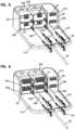
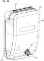
- FIG. 1shows two distribution boxes in perspective view in accordance with aspects of the present invention
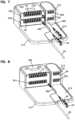
- FIG. 2shows the two distribution boxes of FIG. 1 without the fiber storage covers, the splitters and the feeder termination covers;
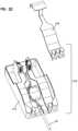
- FIG. 3shows an individual distribution box of the type shown in FIG. 2 ;
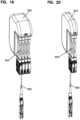
- FIG. 4shows two distribution boxes located at remote locations from one another
- FIG. 5shows another example distribution box in perspective view, including four 1 ⁇ 2 splitters
- FIG. 6shows a similar distribution box to the distribution box of FIG. 5 , with four 1 ⁇ 4 splitters
- FIG. 7shows a similar distribution box to the distribution box of FIG. 5 , with two 1 ⁇ 8 splitters
- FIG. 8shows a similar distribution box to the distribution box of FIG. 5 , with a single 1 ⁇ 16 splitter
- FIG. 9shows an exploded view of the distribution box of FIG. 5 , showing one splitter, and a feeder termination plate separated from a base;
- FIG. 10shows a similar distribution box as in FIG. 5 , showing two 1 ⁇ 4 splitters and one 1 ⁇ 8 splitter connected to feeder terminations;
- FIG. 11shows a 1 ⁇ 2 splitter for use in the distribution box of FIGS. 5 - 10 ;
- FIG. 12shows a 1 ⁇ 4 splitter for use in the distribution box of FIGS. 5 - 10 ;
- FIG. 13shows a 1 ⁇ 8 splitter for use in the distribution box of FIGS. 5 - 10 ;
- FIG. 14shows a 1 ⁇ 16 splitter for use in the distribution box of FIGS. 5 - 10 ;
- FIG. 15shows a perspective view of the feeder termination plate of the distribution box of FIG. 5 ;
- FIG. 16shows an alternative perspective view of the feeder termination plate
- FIG. 17shows another embodiment of a distribution box in perspective view including two 1 ⁇ 16 splitters and splitter output pigtails
- FIG. 18shows a distribution box similar to the distribution box of FIG. 17 , including four 1 ⁇ 8 splitters;
- FIG. 19shows one of the 1 ⁇ 16 splitters of the distribution box of FIG. 17 ;
- FIG. 20shows one of the 1 ⁇ 8 splitters of the distribution box of FIG. 18 ;
- FIG. 21shows the distribution box with the a 1 ⁇ 8 splitter and a 1 ⁇ 16 splitters removed
- FIG. 22shows an exploded perspective view with a termination feeder cover removed from a base
- FIG. 23shows a further perspective view of the exploded view of FIG. 22 ;
- FIG. 24shows an alternative perspective view to the view of FIG. 17 ;
- FIG. 25shows an alternative perspective view to the view of FIG. 18 ;
- FIG. 26shows a perspective view of another embodiment of a distribution box including four 1 ⁇ 4 splitters
- FIG. 27shows the distribution box of FIG. 26 , with three splitters removed
- FIG. 28shows a perspective view of one of the splitters of FIGS. 26 and 27 ;
- FIG. 29shows a perspective view of the splitter of FIG. 28 from another orientation
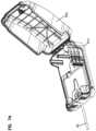
- FIG. 30shows in perspective view another embodiment of a distribution box
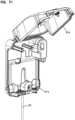
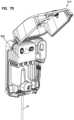
- FIG. 31shows a further perspective view of the distribution box of FIG. 30 and including an outgoing fiber box and tube holder;
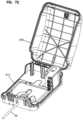
- FIG. 32shows the distribution box of FIG. 30 , with the cover in an open position after being rotatably moved, and showing the internal feeder cabling;
- FIG. 33shows a front view of the distribution box of FIG. 32 ;
- FIG. 34shows the distribution box of FIGS. 30 - 33 , with various covers in place in the interior, and without the splitters or cables;
- FIG. 35shows the base of the distribution box of FIGS. 30 and 31 ;
- FIGS. 36 A and Bshows a cover which fits over the slack and splice area on the base of FIG. 35 ;
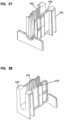
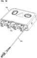
- FIGS. 37 and 38show a feeder cable retention device of the distribution box of FIGS. 30 and 31 ;
- FIG. 39shows a cross-sectional view through the closed distribution box of FIGS. 30 and 31 , showing a portion of the lock which holds the cover to the base;
- FIG. 40shows an exploded perspective view of the outgoing cable box of the distribution box of FIG. 30 ;
- FIG. 41shows a further perspective view of the interior of the distribution box of FIGS. 30 and 31 , without any cables shown in the box;
- FIG. 42shows an another view of the distribution box of FIG. 41 ;
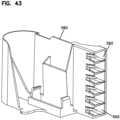
- FIG. 43shows an example of a feeder termination holder of the distribution box of FIGS. 30 and 31 ;
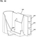
- FIG. 44shows another example of a feeder termination holder of the distribution box of FIGS. 30 and 31 ;
- FIG. 45shows a further example of a feeder termination holder of the distribution box of FIGS. 30 and 31 ;
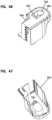
- FIGS. 46 and 47show a feeder termination cover of the distribution box of FIGS. 30 and 31 ;
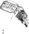
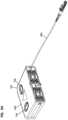
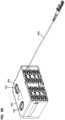
- FIGS. 48 and 49show the distribution box of the distribution box of FIGS. 30 and 31 connected to an input feeder cable and outgoing cables from the splitters;
- FIG. 50shows the distribution box of FIGS. 48 and 49 without any cables connected to the splitter outputs and all the splitter inputs connected to the feeder terminations;
- FIG. 51shows the distribution box of FIGS. 48 and 49 with the addition of the splitter output cables to the view of FIG. 50 ;
- FIG. 52shows the distribution box of FIGS. 48 and 49 with the addition of two point-to-point connections that connect to the feeder terminations and extend out of the distribution box relative to the view of FIG. 51 ;
- FIG. 53shows a 1 ⁇ 4 splitter for use in the distribution box of FIGS. 30 and 31 ;
- FIG. 54shows a 1 ⁇ 8 splitter for use in the distribution box of FIGS. 30 and 31 ;
- FIG. 55shows a 1 ⁇ 16 splitter for use in the distribution box of FIGS. 30 and 31 ;
- FIG. 56shows a latching method for connecting a stack of splitters of FIGS. 53 - 55 ;
- FIG. 57shows a 1 ⁇ 4 splitter of FIG. 53 in exploded view
- FIG. 58shows a further view of the splitter of FIG. 57 ;
- FIGS. 59 - 61show a connector holder for use in the splitters of FIGS. 53 - 55 in various perspective views;
- FIGS. 62 - 64show the connector holder of FIGS. 59 - 61 holding a first connector
- FIGS. 65 - 67show the connector holder and the connector of FIGS. 62 - 64 , and an adapter mounted to the connector;
- FIG. 68shows an inner housing portion of the 1 ⁇ 4 splitter of FIG. 53 ;
- FIG. 69shows an inner housing portion of the 1 ⁇ 8 splitter of FIG. 54 ;
- FIG. 70shows an inner housing portion of the 1 ⁇ 16 splitter of FIG. 55 ;
- FIGS. 71 and 72show the distribution box of FIGS. 30 and 31 ready to receive splitters
- FIGS. 73 and 74show the distribution box of FIGS. 30 and 31 with the feeder termination cover removed;
- FIGS. 75 - 77show the feeder distribution box of FIGS. 30 and 31 connected to splitters and feeder terminations in the form of LC connectors and adapters;
- FIG. 78shows a splitter of the distribution box of FIGS. 75 - 77 with LC adapters as the splitter outputs for a 1 ⁇ 4 splitter;
- FIG. 79shows an alternative splitter utilizing duplex LC adapters for the splitter outputs for a 1 ⁇ 8 splitter
- FIG. 80shows a schematic view illustrating the distribution box of the various embodiments showing feeder fibers connected to splitter outputs and to point-to-point outputs.
- a distribution boxreceives a feeder cable with one or more feeder fibers.
- a variety of splittersare shown having a splitter housing mounted to distribution box for splitting of the signals of the feeder fibers.
- the splitter input in the illustrated examplesis in the form of a cable. Within the interior of the splitter, the splitter input is split into a plurality of outputs.
- the distribution boxcan hold one or more splitters.
- a termination fieldholds connectorized ends of the feeder fibers. Connectorized fibers connect to the feeder fiber connectorized ends at the termination field.
- the preferred distribution boxallows for: 1) split outputs of a splitter input cable connected at the termination field, 2) point to point connection with an output cable at the termination field; or 3) both split feeder signal and point to point feeder signals.
- FIG. 80shows this schematically.
- the schematic representation of a distribution system 10includes a distribution box 12 shown offering both point-to-point 14 and split output 16 connections for the feeder cable 20 to the service users. While connectors 22 are shown as LightPlug connectors as the connection interface for the box, adapters could be used instead to connect the two connectors. Using connectors as the interface delays the cost of the adapters 24 until connection is needed. The splitter inputs 28 and the point to point connections are made at termination field 26 .
- System 10allows for the later addition of splitters 18 to delay early cost if all of the customers initially can be served by point to point connections. At later date, the splitters can be added once the split outputs are desired.
- a distribution box 112having a base 114 and an input (feeder) cable area 116 .
- the base 114also includes a splitter area 118 and an area 120 for feeder terminations 122 .
- the base 114includes one or more storage areas 124 .
- One storage area 126can be used for cable slack for the cables 130 of the feeder terminations.
- a second storage area 128can be used for unused feeder cables 132 .
- the feeder terminations 122are in the form of LightPlug connectors which are held in place ready for mating to a LightPlug adapter.
- the feeder terminationscan be directly connected to a customer with a point-to-point connection.
- the feeder terminationscan also be connected to a splitter input 140 from a splitter 142 mounted within the distribution box 112 , or another distribution box 113 .
- a cover 150encloses the cable storage areas 126 , 128 . If desired, a splice area can also be provided on the base.
- a further cover 160is positioned over the feeder terminations 122 .
- a cover 170covers base 114 and the interior components.
- splittersare mounted to the distribution box.
- the splitter inputsare connected to feeder terminations wherein the feeder signals of those terminations are split into splitter outputs.
- the splitter outputsare shown as fiber optic connectors disposed within the housings of each splitter.
- the distribution cable or output cableis connectorized with a mating connector and a mating adapter for connecting to the splitter outputs.
- feeder terminationsthere are six feeder terminations, three of which are connected to splitters of one distribution box 112 , and three of which are connected to another distribution box 113 .
- Any still open feeder terminationscan be directly connected to a customer in a point-to-point arrangement, or can be connected to further splitter inputs of additional splitters.
- a box cover 170typically is placed over the splitters, the feeder terminations, and the base to protect the interior. Cable management devices 190 help to manage the output cables.
- a second dummy-box 113can be mounted next to the initially installed box 112 .
- Extra splitters 142can be mounted in this second box 113 , the inputs from the added splitters are patched to one of the terminated connectors from the first box 112 .
- Feeder terminations 134 of box 113are not used in the arrangement of FIG. 1 .
- a second box 113can be mounted next to the initially installed box 112 .
- One un-used fiber bundle/tube 132 from the feeder 20is routed to the new box to the 250 ⁇ m overlength compartment 130 . After stripping to 250 ⁇ m.
- the second box 113can be installed similar to the first box 112 .
- more boxescan be connected. Feeder terminations 134 of box 113 are used in the arrangement of FIG. 2 .
- FIG. 3shows an example of feeder cable installation which results in terminated fibers which can be connected in a point-to-point arrangement with a customer, or to a splitter, and then to the costumer(s) as desired.
- terminated feeder fibersare provided.
- Other examplescan include more or less terminated fibers for the distribution box.
- FIG. 3also shows the distribution box at initial installation lacking any splitters, and only providing direct point-to-point connections with the customers. If desired, at a later date, a splitter can be added to provide additional outputs for customers. Additional splitters can be added at that time, or at a later date, as desired. This helps defer costs.
- FIG. 3shows distribution box 112 with an unused fiber bundle/tube 132 in storage3 area 128 , ready for future use, such as for repair, or connection to another box 113 .
- a second box 113can be mounted somewhere in the neighborhood and feeder-fibers from un-used bundles/tubes 132 are spliced in box 112 to a feeder-cable 198 which runs to the second box 113 .
- This spliced feeder-stubenters the second box 113 in the same way the feeder 20 enters the first box 112 .
- Feeder terminations 134 of box 113are used in the arrangement of FIG. 2 .
- more boxescan be connected in a daisy-chaining manner.
- the example splitters 142include a splitter input cable 172 and 174 and multiple outputs formed at the splitter housing. Different lengths of cables 172 and 174 can be provided if necessary. Various examples are shown of different splitter sizes and variations in the number of splitter outputs. As shown, the splitters 142 can have different thicknesses in multiples of T thickness. Each splitter 142 includes one or more holes 182 to receive posts 180 of base 114 . The holes can be round or oval, or another shape.
- splitter 142includes splitter outputs in the form of connectors 178 mounted at and/or within the splitter housing 144 .
- the splitter input 172 , 174connects to the feeder terminations 122 in the form of connectors 22 .
- the cable stub 172 , 174extending from the splitter housing 144 connectors 22 and adapters 24 disposed at the distal ends of the cable stubs.
- Adapters 24can be used instead as the demarcation point for the splitter outputs 16 and/or for the feeder terminations.
- FIGS. 5 - 16show an alternative distribution box 212 having a base 214 wherein the feeder cable 20 is mounted to a cover 216 along with the feeder terminations 222 .
- Cover 216includes a cable storage area 224 on a back side of the cover.
- the example splitters 242include a splitter input cable 250 and multiple outputs 246 formed at the splitter housing 248 .
- the splitters 242can have different thicknesses in multiples of T thickness and/or different widths in multiples of W widths.
- Each splitter 242includes one or more holes 282 to receive posts 280 of base 114 .
- a cover like cover 170can be provided.
- FIGS. 17 - 25various embodiments of a distribution box 312 and splitters 342 are shown including the cable stubs 344 extending from the splitter housing 346 to form the splitter outputs.
- Box 312includes a base 314 and a middle cover 316 over cable storage area 326 on base 314 .
- Each splitter 342has a splitter input 350 in the form of a cable.
- a cover like cover 170can be provided.
- the use of a splitter with the fiber stubs for the outputs of the splittercan improve density, and connector and adapter access.
- FIGS. 26 - 29a further embodiment of a distribution box 412 and splitters 442 are shown.
- the splitters 442slidably mount parallel to the base 414 .
- the splitters 442can be individually removed or partially removed to improve access to the splitter outputs.
- Each splitter 442has a splitter input 450 .
- FIG. 44shows a splitter retention clip or latch 446 for retaining the splitter 442 with the base 414 .
- a cover like cover 170can be provided.
- Splitters 442slide relative to base 114 with an interlocking slide.
- splitters 442include a dovetail projection 460
- base 414includes a mating slot 470 .
- feeder terminations 422have four connectors 22 connected to one of each of the four splitter inputs 450 .
- the two open connectors 22are available for point to point connections or connections to other splitters in other boxes 412 .
- the splitters 442are located orthogonal to the splitters previously noted. Such positioning is an alternative positioning.
- the splitter inputsare located closest to the base 414 in this example.
- FIGS. 1 - 29all use a LightPlug connector and adapter.
- a LightPlug installation toolpermits a bare fiber to be inserted into the tool, and the tool adds the LightPlug connector to the end of the fiber to terminate the fiber.
- Use of the LightPlug installation tool and the LightPlug connectors and mating adaptersprovide just one embodiment of the present distribution system.
- Each splitter outputis in the form of a fiber optic connector, including a shutter.
- the illustrated connectorsare LightPlug connectors.
- the splitter inputhas a LightPlug connector at a distal end mated with a LightPlug adapter.
- the LightPlug adapteris connectable to a distribution cable terminated with a LightPlug connector.
- the LightPlug tool, connector and adapter systemis shown in patent document nos. WO2012/112344 and WO 2013/117598, noted previously incorporated by reference.
- Other forms of connectors, including SC and LCcan be used, in addition to multi-fiber connectors, such
- the splitterscan include port identifiers, a splitter identifier, and an RFID tag, if desired.
- splittersare shown with different numbers of splitter outputs. These splitters can be mixed and matched in the distribution boxes as desired.
- the LightPlug feeder terminationsare shown connected to the base.
- the connectorsare held with clips ready for connection to an adapter, which is added later in combination with a second connector for connection to a customer or the splitters.
- adapterscan be mounted to the base.
- various implementationsare provided for adding capacity over time.
- One implementationis to add the splitters as needed over time.
- Another implementation for adding capacityuses two distribution boxes. Splitters from the second distribution box can be connected to feeder terminations of the first distribution box.
- Another implementation for adding capacityincludes a feeder cable connected to two (or more) distribution boxes as desired. This provides additional feeder terminations for connections to customers directly, or through splitters.
- Another implementation for increasing capacityincludes adding a second (or more) distribution box at a remote location wherein a further feeder cable is spliced to the first feeder cable to link the two distribution boxes.
- Another implementationis to add a new cover 170 to the distribution box to add increased outputs through the use of larger splitters.
- the distribution boxincludes a cover 570 , a base 514 , a lock 572 (with a key 573 ) for the cover, a connection box 580 to secure a corrugated tube 582 for housing cables, and an internal tray 516 used for cable routing and storage (and splice).
- Cover 570is hinged at hinge 574 to base 514 .
- a splitter area 518holds splitters on one or more posts 526 , 528 .
- Posts 526 , 528can be different shapes and/or sizes to facilitate one way fit with the splitters 642 (see FIG. 48 ).
- the feeder cables 20pass through a channel 536 and are terminated at a feeder termination area 522 .
- An internal cover 560is positioned over the splice and storage area 524 .
- a termination cover 560is also provided.
- the internal cover 560or demarcation cover, fits over the storage and splice area 524 .
- Tabs 562 and snaps 564are used to mount the demarcation cover 560 to the base 514 .
- Handles 566are provided on cover 560 .
- the left side of area 524can be used to store active fibers.
- the right side of area 524can be used to store dark fibers or unused fibers. Both the left and right sides of the area 524 can be used to store splice holders.
- a feeder cable clamping device 530is shown for use in the distribution box.
- the clamping device 530includes arms 532 which squeeze one or more feeder cables upon mounting of the demarcation cover 560 to the base.
- the feeder cable clamping device 530can be in the form of a separate part mounted to the base. Arms 568 extend from cover 560 to restrain clamping device 530 and force them to clamp to the cables. Inner teeth can also be provided on arms 532 to grip the cables.
- a strength member clamp 540is shown positioned between a portion of the base 546 and a metal clamping plate 544 .
- a ramp 542promotes upward movement of the strength member to the clamping location.
- Feeder termination inserts 590are shown for holding connectors and/or adapters associated with the feeder terminations.
- the insert 590snaps to the base 514 .
- Different inserts 590are provided for different connectors or adapters.
- FIG. 43includes openings 592 for LightPlug connectors 22 .
- FIG. 44includes openings 594 for three SC or LC connectors 22 .
- FIG. 45includes an opening 596 for six SC or LC connectors 22 or other connectors.
- a feeder termination cover or tower cover 550is shown for use in covering the feeder input cables.
- a latch 554holds the termination cover 550 in place.
- a finger recess 552allows for finger activation of the latch 554 .
- a cutout 556allows for finger access for the installer or technician for handling of the adjacent splitters.
- connection box 580is made of two pieces 584 , 586 and connects a flexible conduitor corrugated tube 586 to the distribution box 512 for organizing and protecting the distribution or output cables extending from the box.
- Connection box 580snaps to base 514 .
- a foam insert 600 with slits 602is used on the base to provide a seal around the cables entering the connection box.
- the cover lock 572is shown wherein a key 573 engages a turning element to open and close the lock. In general, the key cannot be removed from the cover unless the cover is closed and the lock is locked. Additional details of the lock and key are shown and described U.S. Application Ser. No. 62/073,631, the disclosure of which is hereby incorporated by reference in its entirety.
- a feeder cable 20is terminated at the feeder terminations 522 .
- Input cables 650 from the splitters 642are shown connected to the feeder terminations 522 to provide input signals for each of the splitters 642 for splitting and connection to distribution cables 652 .
- FIG. 52also shows some of the feeder terminations 522 are connected to individual cables for point-to-point connections where the use of a split output is not desired.
- FIGS. 48 - 52also illustrate the use of LightPlug connectors and adapters.
- FIGS. 53 - 70various views are shown of splitters or splitter cassettes.
- the splitterscan take many forms and formats. In general, a common profile is provided for use with the distribution box.
- FIG. 53shows a 1 ⁇ 4 splitter 702 .
- FIG. 54shows a 1 ⁇ 8 splitter 704 .
- FIG. 55shows a 1 ⁇ 16 splitter 706 .
- FIGS. 53 - 55show a common profile, but different heights.
- FIG. 56 - 70show the splitter output ports in greater detail in the form of the LightPlug connector 22 .
- FIG. 56also shows a snap feature tomable extending (latch 710 , socket 712 ) for connecting two splitters together or for connecting one splitter to the base. This feature is useful for removing the need for a separate Velcro strap or other fixation device.
- FIGS. 57 - 67show one example of a LightPlug connector retainer 720 utilized utilized with an internal splitter tray 724 for holding the splitter outputs ready for connection to distribution cables.
- LightPlug connector retainer 720includes snaps to mount to a splitter module.
- Splitter tray 724fits into splitter cover or housing 726 .
- Splitters 702 , 704 , 706include oval openings 730 , 732 for mating with posts 526 , 528 .
- FIG. 70a double sided internal splitter tray is utilized in a 1 ⁇ 16 splitter configuration.
- Various snapsare utilized to connect the inner trays to the outer cover of the splitters.
- FIGS. 71 - 74show further views of the box 512 with the cover in the open position.
- FIGS. 75 - 80show similar splitters as shown with the distribution box of FIGS. 30 - 74 , but utilizing LC adapters and connectors for the various fiber connections of the distribution box.
- LC adaptersdefine the feeder terminations 804 and also the splitter outputs of splitters 802 which can be connected to distribution cables terminated with LC connectors.
- the splitter inputsare provided with one or more pigtails terminated by a LC connector connectable to one or more of the adapters, one or more of the LC adapters of the feeder terminations.
- the LC adapterscan be duplex or simplex adapters. MPO connectors and adapters can also be used.
Landscapes
- Physics & Mathematics (AREA)
- General Physics & Mathematics (AREA)
- Optics & Photonics (AREA)
- Light Guides In General And Applications Therefor (AREA)
- Cable Accessories (AREA)
- Mechanical Coupling Of Light Guides (AREA)
- Insulated Conductors (AREA)
Abstract
Description
- 10 distribution system
- 12 distribution box
- 14 point-to-point
- 16 split output
- 18 splitters
- 20 feeder
- 22 connectors
- 24 adapters
- 26 termination field
- 28 splitter inputs
- 112 box
- 113 box
- 114 base
- 116 cable area
- 118 splitter area
- 120 area
- 122 feeder terminations
- 124 storage areas
- 126 cable storage areas
- 128 cable storage areas
- 130 cables
- 132 one un-used fiber bundle/tube
- 134 feeder terminations
- 140 splitter input
- 142 extra splitters
- 144 splitter housing
- 150 cover
- 160 cover
- 170 box cover
- 172 cable stub
- 174 cable stub
- 178 connectors
- 180 posts
- 182 holes
- 190 cable management devices
- 198 feeder-cable
- 212 alternative distribution box
- 214 base
- 216 cover
- 222 feeder terminations
- 224 cable storage area
- 242 splitter
- 246 multiple outputs
- 248 splitter housing
- 250 splitter input cable
- 280 posts
- 282 holes
- 312 box
- 314 base
- 316 middle cover
- 326 cable storage area
- 342 splitter
- 344 cable stubs
- 346 splitter housing
- 350 splitter input
- 412 distribution box
- 414 base
- 422 feeder terminations
- 442 splitter
- 446 latch
- 450 splitter input
- 460 dovetail projection
- 470 mating slot
- 512 distribution box
- 514 base
- 516 internal tray
- 518 splitter area
- 522 feeder termination area
- 524 area
- 526 posts
- 528 posts
- 530 clamping device
- 532 arms
- 536 channel
- 540 strength member clamp
- 542 ramp
- 544 metal clamping plate
- 546 base
- 550 termination cover
- 552 finger recess
- 554 latch
- 556 cutout
- 560 cover
- 562 tabs
- 564 snaps
- 566 handles
- 568 arms
- 570 cover
- 572 cover lock
- 573 key
- 574 hinge
- 580 connection box
- 582 corrugated tube
- 584 two pieces
- 586 flexible conduitor corrugated tube
- 590 feeder termination inserts
- 592 openings
- 594 openings
- 596 opening
- 600 foam insert
- 602 slits
- 642 splitters
- 650 input cables
- 652 distribution cables
- 702 splitter
- 704 splitter
- 706 splitter
- 710 latch
- 712 socket
- 720 lightplug connector retainer
- 724 internal splitter tray
- 726 housing
- 730 oval openings
- 732 oval openings
- 802 splitters
- 804 feeder terminations
Claims (33)
Priority Applications (1)
| Application Number | Priority Date | Filing Date | Title |
|---|---|---|---|
| US16/916,866US11726285B2 (en) | 2014-06-17 | 2020-06-30 | Cable distribution system |
Applications Claiming Priority (6)
| Application Number | Priority Date | Filing Date | Title |
|---|---|---|---|
| US201462013223P | 2014-06-17 | 2014-06-17 | |
| US201462017620P | 2014-06-26 | 2014-06-26 | |
| US201462084416P | 2014-11-25 | 2014-11-25 | |
| PCT/EP2015/063620WO2015193384A2 (en) | 2014-06-17 | 2015-06-17 | Cable distribution system |
| US201615320198A | 2016-12-19 | 2016-12-19 | |
| US16/916,866US11726285B2 (en) | 2014-06-17 | 2020-06-30 | Cable distribution system |
Related Parent Applications (2)
| Application Number | Title | Priority Date | Filing Date |
|---|---|---|---|
| PCT/EP2015/063620ContinuationWO2015193384A2 (en) | 2014-06-17 | 2015-06-17 | Cable distribution system |
| US15/320,198ContinuationUS10732370B2 (en) | 2014-06-17 | 2015-06-17 | Cable distribution system |
Publications (2)
| Publication Number | Publication Date |
|---|---|
| US20200400905A1 US20200400905A1 (en) | 2020-12-24 |
| US11726285B2true US11726285B2 (en) | 2023-08-15 |
Family
ID=53442781
Family Applications (2)
| Application Number | Title | Priority Date | Filing Date |
|---|---|---|---|
| US15/320,198ActiveUS10732370B2 (en) | 2014-06-17 | 2015-06-17 | Cable distribution system |
| US16/916,866ActiveUS11726285B2 (en) | 2014-06-17 | 2020-06-30 | Cable distribution system |
Family Applications Before (1)
| Application Number | Title | Priority Date | Filing Date |
|---|---|---|---|
| US15/320,198ActiveUS10732370B2 (en) | 2014-06-17 | 2015-06-17 | Cable distribution system |
Country Status (6)
| Country | Link |
|---|---|
| US (2) | US10732370B2 (en) |
| EP (2) | EP4050393A3 (en) |
| CN (1) | CN106687841B (en) |
| AU (2) | AU2015276109B2 (en) |
| SA (1) | SA516380544B1 (en) |
| WO (1) | WO2015193384A2 (en) |
Families Citing this family (31)
| Publication number | Priority date | Publication date | Assignee | Title |
|---|---|---|---|---|
| US11251608B2 (en) | 2010-07-13 | 2022-02-15 | Raycap S.A. | Overvoltage protection system for wireless communication systems |
| ES1141660Y (en) | 2012-12-19 | 2015-10-14 | Tyco Electronics Raychem Bvba | Distribution device with incrementally added dividers |
| AU2015276109B2 (en) | 2014-06-17 | 2020-11-19 | Adc Czech Republic, S.R.O. | Cable distribution system |
| BR112017017259A2 (en)* | 2015-02-18 | 2018-04-17 | Adc Communications | fast scrolling indexing terminal layout |
| US9971119B2 (en)* | 2015-11-03 | 2018-05-15 | Raycap Intellectual Property Ltd. | Modular fiber optic cable splitter |
| US10802237B2 (en) | 2015-11-03 | 2020-10-13 | Raycap S.A. | Fiber optic cable management system |
| US10606009B2 (en) | 2015-12-01 | 2020-03-31 | CommScope Connectivity Belgium BVBA | Cable distribution system with fan out devices |
| WO2017124018A1 (en) | 2016-01-14 | 2017-07-20 | Communications Systems, Inc. | Stackable splitters |
| EP3408701B1 (en)* | 2016-01-28 | 2023-04-26 | CommScope Connectivity Belgium BVBA | Modular telecommunications enclosure |
| US10788641B2 (en) | 2016-02-12 | 2020-09-29 | Ppc Broadband, Inc. | Cable spool and storage |
| CN108713157B (en)* | 2016-03-09 | 2020-10-09 | 华为技术有限公司 | Fiber optic cable distribution box and fiber optic cable distribution device |
| US10859781B2 (en) | 2016-09-20 | 2020-12-08 | Clearfield, Inc. | Optical fiber distribution systems and components |
| US10606006B2 (en)* | 2016-09-20 | 2020-03-31 | Clearfield, Inc. | Optical fiber distribution systems and components |
| WO2018136812A1 (en) | 2017-01-20 | 2018-07-26 | Raycap S.A. | Power transmission system for wireless communication systems |
| EP3583455A1 (en) | 2017-02-15 | 2019-12-25 | CommScope Connectivity Belgium BVBA | Interchangeable telecommunications enclosure components |
| WO2018149917A1 (en)* | 2017-02-15 | 2018-08-23 | CommScope Connectivity Belgium BVBA | Modular telecommunications enclosures |
| JP6910456B2 (en)* | 2017-02-28 | 2021-07-28 | 華為技術有限公司Huawei Technologies Co.,Ltd. | Fiber access terminal |
| JP6927311B2 (en) | 2017-08-29 | 2021-08-25 | 日本電気株式会社 | Pluggable optical module and optical communication system |
| US11852882B2 (en)* | 2018-02-28 | 2023-12-26 | Commscope Technologies Llc | Packaging assembly for telecommunications equipment |
| US11536910B2 (en) | 2018-08-14 | 2022-12-27 | Commscope Technologies Llc | Optical fiber cable assembly for monitoring functions |
| US10971928B2 (en) | 2018-08-28 | 2021-04-06 | Raycap Ip Assets Ltd | Integrated overvoltage protection and monitoring system |
| US11061196B2 (en)* | 2018-10-16 | 2021-07-13 | CommScope Connectivity Belgium BVBA | Enclosure with restricted access region |
| EP3867982A4 (en)* | 2018-10-19 | 2022-07-13 | CommScope Technologies LLC | TELECOMMUNICATIONS TERMINAL WITH BREAK CORD |
| US11677164B2 (en) | 2019-09-25 | 2023-06-13 | Raycap Ip Assets Ltd | Hybrid antenna distribution unit |
| CN111258014A (en)* | 2020-03-12 | 2020-06-09 | 宁波通冠电气自动化设备有限公司 | Outdoor optic fibre splice closure of integral type that possesses insulation protection function |
| WO2022093659A1 (en)* | 2020-10-30 | 2022-05-05 | Corning Research & Development Corporation | Configurable optical devices having an optical splitter and duplex connector |
| US11927808B2 (en)* | 2021-04-16 | 2024-03-12 | Commscope Technologies Llc | Holder for an optical component |
| CN113325520A (en)* | 2021-04-30 | 2021-08-31 | 华为技术有限公司 | Optical connection device and local area network system |
| US12237134B2 (en) | 2021-12-28 | 2025-02-25 | Raycap Ip Assets Ltd | Circuit protection for hybrid antenna distribution units |
| US20230236376A1 (en)* | 2022-01-21 | 2023-07-27 | Centurylink Intellectual Property Llc | Network interface device bracket |
| CN114815106B (en)* | 2022-05-18 | 2024-01-09 | 深圳市中德利科技有限公司 | Optical fiber protection structure for wiring inside optical fiber distribution box |
Citations (205)
| Publication number | Priority date | Publication date | Assignee | Title |
|---|---|---|---|---|
| US4650933A (en) | 1985-07-15 | 1987-03-17 | At&T Bell Laboratories | Jack and test plug |
| US4768961A (en) | 1987-10-09 | 1988-09-06 | Switchcraft, Inc. | Jackfield with front removable jack modules having lamp assemblies |
| US4770639A (en) | 1987-03-02 | 1988-09-13 | Switchcraft, Inc. | Channelized jackfield |
| US4797114A (en) | 1987-03-02 | 1989-01-10 | Switchcraft, Inc. | Jack circuit board assembly |
| US4820200A (en) | 1987-02-13 | 1989-04-11 | Switchcraft, Inc. | Slab-like jack module |
| US4840568A (en) | 1987-03-31 | 1989-06-20 | Adc Telecommunications, Inc. | Jack assembly |
| US5171183A (en) | 1991-11-22 | 1992-12-15 | Sony Corporation | Disk drive cooling system bracket |
| US5189410A (en) | 1989-12-28 | 1993-02-23 | Fujitsu Limited | Digital cross connect system |
| DE4130706A1 (en) | 1991-09-14 | 1993-03-18 | Standard Elektrik Lorenz Ag | Optical jack-plug incorporating optical coupler - has optical fibre inserted in capillary provided by jack-plug pin and divergent optical paths coupled to rear optical fibres |
| US5199878A (en) | 1990-11-15 | 1993-04-06 | Adc Telecommunications, Inc. | Plug-in jack card for normally closed contacts |
| US5214673A (en) | 1989-08-04 | 1993-05-25 | Adc Telecommunications, Inc. | Digital cross connect assembly |
| DE4229510A1 (en) | 1992-09-04 | 1994-03-10 | Siemens Ag | Distribution box for optical fibre network - has central wiring region with plug panels and splicing region with distributor modules having pivoted cassette holders |
| US5297000A (en) | 1989-09-22 | 1994-03-22 | Unisys Corporation | Packaged circuit-boards |
| US5317663A (en) | 1993-05-20 | 1994-05-31 | Adc Telecommunications, Inc. | One-piece SC adapter |
| US5339379A (en) | 1993-06-18 | 1994-08-16 | Telect, Inc. | Telecommunication fiber optic cable distribution apparatus |
| US5363465A (en) | 1993-02-19 | 1994-11-08 | Adc Telecommunications, Inc. | Fiber optic connector module |
| US5393249A (en) | 1993-06-30 | 1995-02-28 | Adc Telecommunications, Inc. | Rear cross connect DSX system |
| US5432875A (en) | 1993-02-19 | 1995-07-11 | Adc Telecommunications, Inc. | Fiber optic monitor module |
| US5467062A (en) | 1992-04-02 | 1995-11-14 | Adc Telecommunications, Inc. | Miniature coax jack module |
| US5497444A (en) | 1994-01-21 | 1996-03-05 | Adc Telecommunications, Inc. | High-density fiber distribution frame |
| EP0730177A2 (en) | 1995-02-28 | 1996-09-04 | AT&T Corp. | Patch panel and collar for optical fiber couplers |
| GB2300978A (en) | 1995-04-19 | 1996-11-20 | Smiths Industries Plc | Shutter for connector |
| WO1996036896A1 (en) | 1995-05-15 | 1996-11-21 | The Whitaker Corporation | High density fiber optic interconnection enclosure |
| US5582525A (en) | 1995-01-12 | 1996-12-10 | Adc Telecommunications, Inc. | Drop and insert card |
| US5627925A (en) | 1995-04-07 | 1997-05-06 | Lucent Technologies Inc. | Non-blocking optical cross-connect structure for telecommunications network |
| US5685741A (en) | 1996-06-27 | 1997-11-11 | Adc Telecommunications, Inc. | On demand plug-in jack card and monitor frame |
| US5694511A (en) | 1996-09-09 | 1997-12-02 | Lucent Technologies Inc. | Optical switching apparatus and method for use in the construction mode testing of a modular fiber administration system |
| US5701380A (en) | 1996-06-24 | 1997-12-23 | Telect, Inc. | Fiber optic module for high density supply of patching and splicing |
| EP0828356A2 (en) | 1996-09-09 | 1998-03-11 | Lucent Technologies Inc. | Optical monitoring and test access interconnection module |
| US5740298A (en) | 1993-09-08 | 1998-04-14 | N.V. Raychem S.A. | Optical fibre organizer |
| US5768463A (en) | 1995-08-01 | 1998-06-16 | Bowthorpe Plc | Optical fibre splice enclosures |
| US5946440A (en) | 1997-11-17 | 1999-08-31 | Adc Telecommunications, Inc. | Optical fiber cable management device |
| WO2000007053A2 (en) | 1998-07-27 | 2000-02-10 | Adc Telecommunications, Inc. | Outside plant optical fiber distribution apparatus |
| US6061492A (en) | 1997-04-09 | 2000-05-09 | Siecor Corporation | Apparatus and method for interconnecting fiber cables |
| US6116961A (en) | 1998-11-12 | 2000-09-12 | Adc Telecommunications, Inc. | Jack assembly |
| WO2000075706A2 (en) | 1999-06-03 | 2000-12-14 | Adc Telecommunications, Inc. | Optical fiber distribution frame with connector modules |
| US6208796B1 (en) | 1998-07-21 | 2001-03-27 | Adc Telecommunications, Inc. | Fiber optic module |
| EP1092996A2 (en) | 1999-10-15 | 2001-04-18 | Tyco Electronics Corporation | Fiberoptical device having an integral array interface |
| US6226111B1 (en) | 1996-12-06 | 2001-05-01 | Telcordia Technologies, Inc. | Inter-ring cross-connect for survivable multi-wavelength optical communication networks |
| US6229699B1 (en) | 1998-10-19 | 2001-05-08 | International Business Machines Corporation | Packaging apparatus and method for networks computer chassis |
| EP1107031A1 (en) | 1999-12-07 | 2001-06-13 | Molex Incorporated | Alignment system for mating connectors |
| US6263136B1 (en) | 1999-10-29 | 2001-07-17 | Lucent Technologies | Intelligent optical transmitter module |
| US6328608B1 (en) | 1997-02-28 | 2001-12-11 | Adc Telecommunications, Inc. | DSX module with removable jack |
| EP1179745A2 (en) | 2000-08-10 | 2002-02-13 | F.C.I. - Framatome Connectors International | Optical connector adapter |
| US6363183B1 (en) | 2000-01-04 | 2002-03-26 | Seungug Koh | Reconfigurable and scalable intergrated optic waveguide add/drop multiplexing element using micro-opto-electro-mechanical systems and methods of fabricating thereof |
| US20020037147A1 (en) | 2000-07-31 | 2002-03-28 | Mclean Thomas | Multi-level optical fiber and component storage tray |
| US6370294B1 (en) | 1999-06-25 | 2002-04-09 | Adc Telecommunications, Inc. | Fiber optic circuit and module with switch |
| DE20201170U1 (en) | 2002-01-15 | 2002-05-29 | Infineon Technologies AG, 81669 München | Device for protecting the plug receptacle of an opto-electronic component |
| US6418262B1 (en) | 2000-03-13 | 2002-07-09 | Adc Telecommunications, Inc. | Fiber distribution frame with fiber termination blocks |
| US6424781B1 (en) | 1999-03-01 | 2002-07-23 | Adc Telecommunications, Inc. | Optical fiber distribution frame with pivoting connector panels |
| US6427035B1 (en) | 1999-08-12 | 2002-07-30 | Bellsouth Intellectual Property Corporation | Method and apparatus for deploying fiber optic cable to subscriber |
| WO2002099528A1 (en) | 2001-06-01 | 2002-12-12 | Stratos Lightwave, Inc. | 'modular wavelength division multiplexing (wdm) connector' |
| WO2002103429A2 (en) | 2000-11-20 | 2002-12-27 | Adc Telecommunications, Inc. | Optical fiber distribution frame with outside plant enclosure |
| US6507691B1 (en) | 1999-03-22 | 2003-01-14 | Tyco Electronics Corporation | Fiber optic splice organizer with splicing tray and associated method |
| US20030011287A1 (en) | 2001-07-10 | 2003-01-16 | Searby Tom J. | Configurable air vents on a computer enclosure |
| US6511330B1 (en) | 2001-08-24 | 2003-01-28 | Adc Telecommunications, Inc. | Interconnect module |
| US6532332B2 (en) | 2001-02-15 | 2003-03-11 | Adc Telecommunications, Inc. | Cable guide for fiber termination block |
| US6535682B1 (en) | 1999-03-01 | 2003-03-18 | Adc Telecommunications, Inc. | Optical fiber distribution frame with connector modules |
| US6554652B1 (en) | 2002-02-15 | 2003-04-29 | Adc Telecommunications, Inc. | Jack assembly including baluns interface; and methods |
| US6579014B2 (en) | 2001-09-28 | 2003-06-17 | Corning Cable Systems Llc | Fiber optic receptacle |
| US6591051B2 (en) | 2001-11-16 | 2003-07-08 | Adc Telecommunications, Inc. | Fiber termination block with angled slide |
| US6599024B2 (en) | 2001-04-11 | 2003-07-29 | Adc Telecommunications, Inc. | Fiber optic adapter with attenuator and method |
| US6614953B2 (en) | 2001-03-16 | 2003-09-02 | Photuris, Inc. | Modular all-optical cross-connect |
| US6616459B2 (en) | 2001-08-24 | 2003-09-09 | Adc Telecommunications, Inc. | Card edge contact including compliant end |
| US6632106B2 (en) | 2001-07-24 | 2003-10-14 | Adc Telecommunications, Inc. | Jack; jack assembly; and methods |
| US6647197B1 (en) | 2000-06-02 | 2003-11-11 | Panduit Corp. | Modular latch and guide rail arrangement for use in fiber optic cable management systems |
| WO2003093889A1 (en) | 2002-05-03 | 2003-11-13 | Krone Gmbh | Coupling for glass fiber connectors with retrofittable security valve |
| US6668108B1 (en) | 2000-06-02 | 2003-12-23 | Calient Networks, Inc. | Optical cross-connect switch with integrated optical signal tap |
| US6688780B2 (en) | 2002-02-07 | 2004-02-10 | Amphenol Corporation | Cantilevered shutter for optical adapter |
| US6719382B2 (en) | 2000-12-22 | 2004-04-13 | Aurora Networks, Inc. | Chassis with modular repositionable optical feedthrough plates |
| US6761594B2 (en) | 2001-04-13 | 2004-07-13 | Adc Telecommunications, Inc. | DSX jack including sliding rear connector |
| US20040175090A1 (en) | 2001-04-02 | 2004-09-09 | Kristof Vastmans | Optical fibre organiser |
| US6792191B1 (en) | 2003-04-22 | 2004-09-14 | Corning Cable Systems Llc | Local convergence cabinet |
| US6810193B1 (en) | 1999-11-22 | 2004-10-26 | Ccs Technology, Inc. | Cassette for receiving optical waveguides with overlengths and fiber splices |
| EP1473578A2 (en) | 2003-05-02 | 2004-11-03 | Panduit Corporation | Fiber optic connector removal tool |
| US6822874B1 (en) | 2002-11-12 | 2004-11-23 | Wooshcom Corporation | Modular high availability electronic product architecture with flexible I/O |
| US6824312B2 (en) | 2001-06-04 | 2004-11-30 | Adc Telecommunications, Inc. | Telecommunications chassis and module |
| US6832035B1 (en) | 2003-05-30 | 2004-12-14 | Lucent Technologies Inc. | Optical fiber connection system |
| US6830465B2 (en) | 2001-08-24 | 2004-12-14 | Adc Telecommunications, Inc. | Interconnect chassis and module |
| US6850685B2 (en) | 2002-03-27 | 2005-02-01 | Adc Telecommunications, Inc. | Termination panel with pivoting bulkhead and cable management |
| US6863446B2 (en) | 2002-03-05 | 2005-03-08 | Fci Americas Technology, Inc. | Optical connector adapter with latch inserts |
| US20050053341A1 (en) | 2003-09-08 | 2005-03-10 | Zimmel Steven C. | Fiber optic cable and furcation module |
| WO2005045487A2 (en) | 2003-10-30 | 2005-05-19 | Bktel Communications Gmbh | Housing for optical components |
| US20050129379A1 (en) | 2003-11-17 | 2005-06-16 | Fiber Optic Network Solutions Corporation | Systems and methods for optical fiber distribution and management |
| US6937807B2 (en) | 2002-04-24 | 2005-08-30 | Adc Telecommunications, Inc. | Cable management panel with sliding drawer |
| US20050232565A1 (en) | 2004-04-16 | 2005-10-20 | Ross Heggestad | Normal through optical panel |
| US20050232551A1 (en) | 2004-04-16 | 2005-10-20 | Cheng-Pei Chang | Devices for preventing lens contamination in optoelectronic modules and connectors |
| US20060008231A1 (en) | 2003-11-17 | 2006-01-12 | Fiber Optic Network Solutions Corporation | Hinged parking in fiber distribution hubs |
| EP1626300A1 (en) | 2004-08-12 | 2006-02-15 | Genexis B.V. | Housing for optical network interface device |
| US7029322B2 (en) | 2003-02-27 | 2006-04-18 | Molex Incorporated | Connector panel mount system |
| US20060138268A1 (en) | 2004-12-28 | 2006-06-29 | Ching Huang | Cable winder apparatus |
| US7118284B2 (en) | 2002-09-06 | 2006-10-10 | Seikoh Giken Co., Ltd. | Optical connector plug, optical connector adapter and optical connector |
| US20060228086A1 (en) | 2005-03-31 | 2006-10-12 | Matthew Holmberg | Adapter block including connector storage |
| US7142764B2 (en) | 2003-03-20 | 2006-11-28 | Tyco Electronics Corporation | Optical fiber interconnect cabinets, termination modules and fiber connectivity management for the same |
| WO2006127397A1 (en) | 2005-05-25 | 2006-11-30 | Adc Telecommunications, Inc. | Fiber optic adapter module consisting of plurality of integrally formed adapters |
| US20070036503A1 (en) | 2005-08-10 | 2007-02-15 | Solheid James J | Fiber optic adapter modules with identification system |
| US7190874B1 (en) | 2005-10-03 | 2007-03-13 | Adc Telecommunications, Inc. | Fiber demarcation box with cable management |
| US7218827B2 (en) | 2004-06-18 | 2007-05-15 | Adc Telecommunications, Inc. | Multi-position fiber optic connector holder and method |
| US7218828B2 (en) | 2005-01-24 | 2007-05-15 | Feustel Clay A | Optical fiber power splitter module apparatus |
| JP2007121398A (en) | 2005-10-25 | 2007-05-17 | Nippon Telegr & Teleph Corp <Ntt> | Splitter module |
| US7233731B2 (en) | 2003-07-02 | 2007-06-19 | Adc Telecommunications, Inc. | Telecommunications connection cabinet |
| US20070147765A1 (en) | 2005-12-28 | 2007-06-28 | Jeff Gniadek | Splitter modules for fiber distribution hubs |
| US20070165995A1 (en) | 2005-08-30 | 2007-07-19 | Randy Reagan | Fiber distribution hub with modular termination blocks |
| US20070189691A1 (en) | 2006-02-13 | 2007-08-16 | Michael Barth | Fiber distribution hub with swing frame and modular termination panels |
| US20070189692A1 (en) | 2006-02-13 | 2007-08-16 | Zimmel Steven C | Fiber optic splitter module |
| US7303220B2 (en) | 2003-09-29 | 2007-12-04 | Richco Inc. | Connector coupling/decoupling tool |
| US7310474B2 (en) | 2002-11-29 | 2007-12-18 | Fujitsu Limited | Unit installed in electronic equipment and connection mechanism of transmission line of the electronic equipment |
| US20080031585A1 (en) | 2006-05-04 | 2008-02-07 | Solheid James J | Fiber Distribution Hub with Swing Frame and Wrap-Around Doors |
| US7333706B2 (en) | 2005-08-31 | 2008-02-19 | 3M Innovative Properties Company | Enclosure and organizer for telecommunication lines and splices |
| US7333606B1 (en) | 2000-04-13 | 2008-02-19 | Adc Telecommunications, Inc. | Splitter architecture for a telecommunications system |
| US7346254B2 (en) | 2005-08-29 | 2008-03-18 | Adc Telecommunications, Inc. | Fiber optic splitter module with connector access |
| US20080079341A1 (en) | 2006-10-02 | 2008-04-03 | Steve Anderson | Fiber Distribution Hub with Dual Swing Frames |
| US7376322B2 (en) | 2004-11-03 | 2008-05-20 | Adc Telecommunications, Inc. | Fiber optic module and system including rear connectors |
| US20080124038A1 (en) | 2006-11-28 | 2008-05-29 | Kowalczyk Scott C | Fiber distribution enclosure |
| US7400813B2 (en) | 2005-05-25 | 2008-07-15 | Adc Telecommunications, Inc. | Fiber optic splitter module |
| US20080170824A1 (en) | 2007-01-13 | 2008-07-17 | Furukawa Electric North America, Inc. | Fiber optic cabling for multi-dwelling unit (MDU) and commercial building deployments |
| US20080175550A1 (en) | 2007-01-19 | 2008-07-24 | Hutch Coburn | Fiber optic adapter cassette and panel |
| US7418184B1 (en) | 2007-03-15 | 2008-08-26 | Curtis Paul Gonzales | Fiber optic categorization and management tray |
| US7453706B2 (en) | 2003-11-13 | 2008-11-18 | Adc Telecommunications, Inc. | Module with interchangeable card |
| US20090002941A1 (en) | 2007-06-29 | 2009-01-01 | Rajiv Mongia | Air-permeable, hydrophobic membrane used in a computer device |
| AU2008264211A1 (en) | 2003-11-17 | 2009-01-29 | Adc Telecommunications, Inc. | Frame for optical fiber distribution and management, and associated methods |
| US7495931B2 (en) | 2003-11-13 | 2009-02-24 | Adc Telecommunications, Inc. | Patch panel chassis |
| US20090060440A1 (en) | 2007-08-27 | 2009-03-05 | William Wright | Optical fiber fanout devices and methods for forming the same |
| US20090067802A1 (en) | 2002-11-22 | 2009-03-12 | Adc Gmbh | Distributor system and method for optical fibers |
| US7509016B2 (en) | 2007-03-09 | 2009-03-24 | Adc Telecommunications, Inc. | Telecommunication rack unit tray |
| US20090103879A1 (en) | 2007-10-22 | 2009-04-23 | Adc Telecommunications, Inc. | Fiber Distribution Hub |
| US20090110359A1 (en) | 2007-10-31 | 2009-04-30 | Adc Telecommunications, Inc. | Low profile fiber distribution hub |
| US7536075B2 (en) | 2007-10-22 | 2009-05-19 | Adc Telecommunications, Inc. | Wavelength division multiplexing module |
| US7593617B2 (en) | 2005-02-17 | 2009-09-22 | Koninklijke Philips Electronics N.V. | Optical waveguide |
| US20090263097A1 (en) | 2007-12-18 | 2009-10-22 | Adc Telecommunications, Inc. | Multi-Configuration Mounting System for Fiber Distribution Hub |
| US20090290842A1 (en) | 2008-04-21 | 2009-11-26 | Bran De Leon Oscar Fernando | Fiber optic splice tray |
| US7636507B2 (en) | 2005-06-17 | 2009-12-22 | Adc Telecommunications, Inc. | Compact blind mateable optical splitter |
| US20090317047A1 (en) | 2008-06-19 | 2009-12-24 | Adc Telecommunications, Inc. | Methods and systems for distributing fiber optic telecommunications services to local area |
| US20090324187A1 (en) | 2008-06-26 | 2009-12-31 | Wakileh George I | Fiber distribution hubs with patch and splice enclosures |
| US20100061043A1 (en) | 2008-09-10 | 2010-03-11 | Wistron Neweb Corp. | Casing Assembly and Electronic Device Including the Same |
| US7697812B2 (en) | 2008-01-18 | 2010-04-13 | 3M Innovative Properties Company | Enclosure and organizer for telecommunication lines and splices |
| WO2010040256A1 (en) | 2008-10-09 | 2010-04-15 | Corning Cable Systems Llc | Fiber optic terminal having adapter panel supporting both input and output fibers from an optical splitter |
| US20100129030A1 (en) | 2008-11-24 | 2010-05-27 | Giraud William J | Universal Optical Splitter Modules and Related Mounting Brackets, Assemblies and Methods |
| JP2010122597A (en) | 2008-11-21 | 2010-06-03 | Sumitomo Electric Ind Ltd | Splitter module |
| US7751673B2 (en) | 2007-10-26 | 2010-07-06 | Adc Telecommunications, Inc. | Splice tray holder |
| US20100183274A1 (en) | 2006-09-13 | 2010-07-22 | Herve Brunet | Fiber circuit management system with splice tray |
| DE102009008068A1 (en) | 2009-02-09 | 2010-08-19 | Kathrein-Werke Kg | Network termination enclosure for optical network termination |
| US20100226654A1 (en) | 2009-03-05 | 2010-09-09 | Adc Telecommunications, Inc. | Methods, Systems and Devices for Integrating Wireless Technology into a Fiber Optic Network |
| US7816602B2 (en) | 2006-02-13 | 2010-10-19 | Adc Telecommunications, Inc. | Fiber distribution hub with outside accessible grounding terminals |
| WO2010134157A1 (en) | 2009-05-19 | 2010-11-25 | 住友電気工業株式会社 | Splitter module |
| US20100310221A1 (en) | 2007-09-06 | 2010-12-09 | Arnaud Le Dissez | Modular system and methods for connecting an external communication network to a user network of a building |
| US20100322580A1 (en) | 2009-06-22 | 2010-12-23 | Beamon Hubert B | Fiber Optic Cable Parking Device |
| US20100329624A1 (en) | 2008-02-27 | 2010-12-30 | Junsheng Zhou | High density fiber distribution hub |
| US20110013875A1 (en) | 2009-07-16 | 2011-01-20 | Adc Telecommunications, Inc. | Fiber optic enclosure with adapter bulkhead positioned beneath pivotal splice tray |
| US20110026894A1 (en) | 2009-07-01 | 2011-02-03 | Paula Rudenick | Wall-mounted fiber distribution hub |
| US7885505B2 (en) | 2007-10-22 | 2011-02-08 | Adc Telecommunications, Inc. | Wavelength division multiplexing module |
| US20110058785A1 (en) | 2009-09-04 | 2011-03-10 | Adc Telecommunications, Inc. | Pedestal terminal with swing frame |
| US20110091170A1 (en) | 2009-10-21 | 2011-04-21 | Adc Telecommunications, Inc. | Fiber distribution hub and cable for use therewith |
| US20110164853A1 (en) | 2008-09-23 | 2011-07-07 | Christophe Corbille | Enclosure for telecommunications cables, with removable organizer |
| US20110211799A1 (en) | 2008-10-27 | 2011-09-01 | Mark Edward Conner | Variably configurable and modular local convergence point |
| US8019191B2 (en) | 2005-11-07 | 2011-09-13 | Adc Gmbh | Method and device for coupling optical waveguides |
| US20110262095A1 (en)* | 2010-04-23 | 2011-10-27 | Grzegorz Fabrykowski | Removable fiber optic splice tray |
| US20110274403A1 (en) | 2010-05-07 | 2011-11-10 | Adc Telecommunications, Inc. | Fiber distribution hub with pass-through interfaces |
| US20110293235A1 (en) | 2010-01-26 | 2011-12-01 | Afl Telecommunications Llc | Integrated distribution enabling access apparatus |
| US8086084B2 (en) | 2008-09-09 | 2011-12-27 | Adc Telecommunications, Inc. | Fiber optic splice tray |
| US8107816B2 (en) | 2008-01-29 | 2012-01-31 | Adc Telecommunications, Inc. | Wavelength division multiplexing module |
| US20120027355A1 (en) | 2010-08-02 | 2012-02-02 | Adc Telecommunications, Inc. | Architecture for a Fiber Optic Network |
| WO2012074688A2 (en) | 2010-12-01 | 2012-06-07 | 3M Innovative Properties Company | Fiber organizer and distribution box |
| WO2012112344A1 (en) | 2011-02-17 | 2012-08-23 | Tyco Electronics Raychem Bvba | Portable device for attaching a connector to an optical fiber |
| US8297708B2 (en) | 2009-04-09 | 2012-10-30 | Toyota Boshoku Kabushiki Kaisha | Assembling structure of planar elastic body of vehicle seat |
| US20130056090A1 (en) | 2011-09-01 | 2013-03-07 | Hon Hai Precision Industry Co., Ltd. | Fan assembly with backflow preventing structure |
| US20130114930A1 (en) | 2011-09-27 | 2013-05-09 | Trevor D. Smith | Outside plant termination enclosure |
| US20130170810A1 (en) | 2011-08-24 | 2013-07-04 | Timothy G. Badar | Fiber Management Panel |
| US8494329B2 (en) | 2009-01-15 | 2013-07-23 | Adc Telecommunications, Inc. | Fiber optic module and chassis |
| US20130188966A1 (en) | 2012-01-19 | 2013-07-25 | Huawei Technologies Co., Ltd. | Optical device, and system and method for managing optical device |
| CN203101690U (en) | 2012-12-27 | 2013-07-31 | 深圳市科信通信技术股份有限公司 | A novel optical splitter module |
| WO2013117598A2 (en) | 2012-02-07 | 2013-08-15 | Tyco Electronics Corporation | Optical fiber connection system including optical fiber alignment device |
| US20130231041A1 (en) | 2012-03-05 | 2013-09-05 | Hon Hai Precision Industry Co., Ltd. | Air guiding apparatus |
| US8547694B2 (en) | 2011-12-16 | 2013-10-01 | Hong Fu Jin Precision Industry (Shenzhen) Co., Ltd. | Rack-mount server system |
| US8774585B2 (en) | 2011-04-12 | 2014-07-08 | Adc Telecommunications, Inc. | Strain-relief bracket for fiber optic closure |
| US8774858B2 (en) | 2011-05-18 | 2014-07-08 | Qualcomm Incorporated | Adaptive RF saturation detection in a wireless device implementing multiple wireless protocols |
| US20140219622A1 (en) | 2011-06-24 | 2014-08-07 | Adc Telecommunications, Inc. | Fiber termination enclosure with modular plate assemblies |
| US20140334790A1 (en) | 2011-09-06 | 2014-11-13 | Adc Telecommunications, Inc. | Adapter for fiber optic module |
| US20150003008A1 (en) | 2013-06-29 | 2015-01-01 | Denica N. LARSEN | Thermally actuated vents for electronic devices |
| US20150036279A1 (en) | 2013-07-30 | 2015-02-05 | Tablet Ife Llc | Portable system configured to be deployed in a network |
| US20150062805A1 (en) | 2013-09-05 | 2015-03-05 | Fujitsu Limited | Electronic device |
| US20150137461A1 (en) | 2012-07-02 | 2015-05-21 | Tyco Electronics Raychem Bvba | Cable sealing unit with multiple sealing modules |
| US20150156914A1 (en) | 2013-12-02 | 2015-06-04 | Samsung Electro-Mechanics Co., Ltd. | Heat radiation system for power semiconductor module |
| US20150205064A1 (en)* | 2012-07-09 | 2015-07-23 | Tyco Electronics Raychem Bvba | Cable management system including splitter/filter tray |
| US20150241654A1 (en) | 2014-02-25 | 2015-08-27 | Tyco Electronics Corporation | Modular elements tray |
| US20150286023A1 (en) | 2012-11-07 | 2015-10-08 | Tyco Electronics Raychem Bvba | Cable over-length storage system |
| US20150301301A1 (en) | 2012-11-30 | 2015-10-22 | Julian S. Mullaney | Distributed split configuration for multi-dwelling unit |
| US20150355428A1 (en) | 2012-12-19 | 2015-12-10 | Tyco Electronics Raychem Bvba | Distribution device with incrementally added splitters |
| WO2015193384A2 (en) | 2014-06-17 | 2015-12-23 | Tyco Electronics Raychem Bvba | Cable distribution system |
| US9239442B2 (en) | 2010-04-27 | 2016-01-19 | Adc Communications (Shanghai) Co., Ltd. | Fiber optic module and chassis |
| US9247660B2 (en) | 2014-04-28 | 2016-01-26 | HGST Netherlands, B.V. | Isolator system for a segmented frame for a storage drive |
| US9274285B2 (en) | 2011-04-04 | 2016-03-01 | Afl Telecommunications Llc | Optical fiber distribution cabinet for outdoor use |
| US20160095259A1 (en) | 2014-09-29 | 2016-03-31 | International Business Machines Corporation | Locking louver assembly for air-moving assembly |
| WO2016066780A1 (en) | 2014-10-31 | 2016-05-06 | Tyco Electronics Raychem Bvba | Guaranteed closed safety lock |
| US20160202441A1 (en) | 2013-08-23 | 2016-07-14 | CommScope Connectivity Belgium BVBA | Multi-service terminal and components therefore |
| US20160227670A1 (en) | 2015-02-04 | 2016-08-04 | Wistron Corporation | Vent structure and electronic apparatus therewith |
| CN205484970U (en)* | 2016-03-22 | 2016-08-17 | 宁波广瑞通信技术有限公司 | Improved generation beam split divides fine box |
| US20160309680A1 (en) | 2015-04-21 | 2016-10-27 | Walter Blohm | Backyard wildlife feeder |
| US9494760B2 (en) | 2015-02-17 | 2016-11-15 | 3M Innovative Properties Company | Highly configurable fiber-optic interconnection tray |
| US20160370551A1 (en) | 2012-09-18 | 2016-12-22 | Clearfield, Inc. | Optical fiber management system |
| US20170097486A1 (en) | 2014-05-27 | 2017-04-06 | Communications Systems, Inc. | Hardened drop terminal and clampshell |
| US20170153407A1 (en)* | 2015-12-01 | 2017-06-01 | CommScope Connectivity Belgium BVBA | Cable distribution system with fan out devices |
| US10058011B2 (en) | 2008-06-19 | 2018-08-21 | Panduit Corp. | Passive cooling systems for network cabinet |
| US20190022568A1 (en) | 2016-02-29 | 2019-01-24 | Siemens Aktiengesellschaft | Flame arrestor filter for electric equipment |
| US20190036316A1 (en) | 2016-01-28 | 2019-01-31 | CommScope Connectivity Belgium BVBA | Modular hybrid closure |
Family Cites Families (4)
| Publication number | Priority date | Publication date | Assignee | Title |
|---|---|---|---|---|
| US5510340A (en) | 1992-06-12 | 1996-04-23 | Sri International | Antihypercholesterolemic compounds and related pharmaceutical compositions and methods of use |
| US6667494B1 (en) | 1997-08-19 | 2003-12-23 | Semiconductor Energy Laboratory Co., Ltd. | Semiconductor device and semiconductor display device |
| US5937807A (en) | 1998-03-30 | 1999-08-17 | Cummins Engine Company, Inc. | Early exhaust valve opening control system and method |
| CN203191600U (en)* | 2013-04-01 | 2013-09-11 | 上海藤仓光维通信器材有限公司 | Demultiplexer fixing device and demultiplexer installation apparatus employing same |
- 2015
- 2015-06-17AUAU2015276109Apatent/AU2015276109B2/enactiveActive
- 2015-06-17WOPCT/EP2015/063620patent/WO2015193384A2/enactiveApplication Filing
- 2015-06-17EPEP22153895.2Apatent/EP4050393A3/ennot_activeWithdrawn
- 2015-06-17USUS15/320,198patent/US10732370B2/enactiveActive
- 2015-06-17EPEP15730482.5Apatent/EP3158377B1/enactiveActive
- 2015-06-17CNCN201580042781.3Apatent/CN106687841B/enactiveActive
- 2016
- 2016-12-18SASA516380544Apatent/SA516380544B1/enunknown
- 2020
- 2020-06-30USUS16/916,866patent/US11726285B2/enactiveActive
- 2021
- 2021-02-18AUAU2021201049Apatent/AU2021201049B2/ennot_activeExpired - Fee Related
Patent Citations (267)
| Publication number | Priority date | Publication date | Assignee | Title |
|---|---|---|---|---|
| US4650933A (en) | 1985-07-15 | 1987-03-17 | At&T Bell Laboratories | Jack and test plug |
| US4820200A (en) | 1987-02-13 | 1989-04-11 | Switchcraft, Inc. | Slab-like jack module |
| US4770639A (en) | 1987-03-02 | 1988-09-13 | Switchcraft, Inc. | Channelized jackfield |
| US4797114A (en) | 1987-03-02 | 1989-01-10 | Switchcraft, Inc. | Jack circuit board assembly |
| US4840568A (en) | 1987-03-31 | 1989-06-20 | Adc Telecommunications, Inc. | Jack assembly |
| US4768961A (en) | 1987-10-09 | 1988-09-06 | Switchcraft, Inc. | Jackfield with front removable jack modules having lamp assemblies |
| US5214673A (en) | 1989-08-04 | 1993-05-25 | Adc Telecommunications, Inc. | Digital cross connect assembly |
| US5297000A (en) | 1989-09-22 | 1994-03-22 | Unisys Corporation | Packaged circuit-boards |
| US5189410A (en) | 1989-12-28 | 1993-02-23 | Fujitsu Limited | Digital cross connect system |
| US5199878A (en) | 1990-11-15 | 1993-04-06 | Adc Telecommunications, Inc. | Plug-in jack card for normally closed contacts |
| DE4130706A1 (en) | 1991-09-14 | 1993-03-18 | Standard Elektrik Lorenz Ag | Optical jack-plug incorporating optical coupler - has optical fibre inserted in capillary provided by jack-plug pin and divergent optical paths coupled to rear optical fibres |
| US5171183A (en) | 1991-11-22 | 1992-12-15 | Sony Corporation | Disk drive cooling system bracket |
| US5467062A (en) | 1992-04-02 | 1995-11-14 | Adc Telecommunications, Inc. | Miniature coax jack module |
| DE4229510A1 (en) | 1992-09-04 | 1994-03-10 | Siemens Ag | Distribution box for optical fibre network - has central wiring region with plug panels and splicing region with distributor modules having pivoted cassette holders |
| US5363465A (en) | 1993-02-19 | 1994-11-08 | Adc Telecommunications, Inc. | Fiber optic connector module |
| US5432875A (en) | 1993-02-19 | 1995-07-11 | Adc Telecommunications, Inc. | Fiber optic monitor module |
| US5317663A (en) | 1993-05-20 | 1994-05-31 | Adc Telecommunications, Inc. | One-piece SC adapter |
| US5339379A (en) | 1993-06-18 | 1994-08-16 | Telect, Inc. | Telecommunication fiber optic cable distribution apparatus |
| US5393249A (en) | 1993-06-30 | 1995-02-28 | Adc Telecommunications, Inc. | Rear cross connect DSX system |
| US5740298A (en) | 1993-09-08 | 1998-04-14 | N.V. Raychem S.A. | Optical fibre organizer |
| US5497444A (en) | 1994-01-21 | 1996-03-05 | Adc Telecommunications, Inc. | High-density fiber distribution frame |
| US5717810A (en) | 1994-01-21 | 1998-02-10 | Adc Telecommunications, Inc. | High-density fiber distribution frame |
| USRE38311E1 (en) | 1994-01-21 | 2003-11-11 | Adc Telecommunications, Inc. | High-density cable distribution frame |
| US5582525A (en) | 1995-01-12 | 1996-12-10 | Adc Telecommunications, Inc. | Drop and insert card |
| EP0730177A2 (en) | 1995-02-28 | 1996-09-04 | AT&T Corp. | Patch panel and collar for optical fiber couplers |
| US5627925A (en) | 1995-04-07 | 1997-05-06 | Lucent Technologies Inc. | Non-blocking optical cross-connect structure for telecommunications network |
| GB2300978A (en) | 1995-04-19 | 1996-11-20 | Smiths Industries Plc | Shutter for connector |
| US5613030A (en) | 1995-05-15 | 1997-03-18 | The Whitaker Corporation | High density fiber optic interconnection enclosure |
| WO1996036896A1 (en) | 1995-05-15 | 1996-11-21 | The Whitaker Corporation | High density fiber optic interconnection enclosure |
| US5768463A (en) | 1995-08-01 | 1998-06-16 | Bowthorpe Plc | Optical fibre splice enclosures |
| US5701380A (en) | 1996-06-24 | 1997-12-23 | Telect, Inc. | Fiber optic module for high density supply of patching and splicing |
| US5685741A (en) | 1996-06-27 | 1997-11-11 | Adc Telecommunications, Inc. | On demand plug-in jack card and monitor frame |
| US5694511A (en) | 1996-09-09 | 1997-12-02 | Lucent Technologies Inc. | Optical switching apparatus and method for use in the construction mode testing of a modular fiber administration system |
| EP0828356A2 (en) | 1996-09-09 | 1998-03-11 | Lucent Technologies Inc. | Optical monitoring and test access interconnection module |
| US6226111B1 (en) | 1996-12-06 | 2001-05-01 | Telcordia Technologies, Inc. | Inter-ring cross-connect for survivable multi-wavelength optical communication networks |
| US6328608B1 (en) | 1997-02-28 | 2001-12-11 | Adc Telecommunications, Inc. | DSX module with removable jack |
| US6061492A (en) | 1997-04-09 | 2000-05-09 | Siecor Corporation | Apparatus and method for interconnecting fiber cables |
| US5946440A (en) | 1997-11-17 | 1999-08-31 | Adc Telecommunications, Inc. | Optical fiber cable management device |
| US6307998B2 (en) | 1998-07-21 | 2001-10-23 | Adc Telecommunications, Inc. | Fiber optic module including lens cap |
| US6208796B1 (en) | 1998-07-21 | 2001-03-27 | Adc Telecommunications, Inc. | Fiber optic module |
| WO2000007053A2 (en) | 1998-07-27 | 2000-02-10 | Adc Telecommunications, Inc. | Outside plant optical fiber distribution apparatus |
| US6229699B1 (en) | 1998-10-19 | 2001-05-08 | International Business Machines Corporation | Packaging apparatus and method for networks computer chassis |
| US6116961A (en) | 1998-11-12 | 2000-09-12 | Adc Telecommunications, Inc. | Jack assembly |
| US6535682B1 (en) | 1999-03-01 | 2003-03-18 | Adc Telecommunications, Inc. | Optical fiber distribution frame with connector modules |
| US7149398B2 (en) | 1999-03-01 | 2006-12-12 | Adc Telecommunications, Inc. | Optical fiber distribution frame with outside plant enclosure |
| US6556763B1 (en) | 1999-03-01 | 2003-04-29 | Adc Telecommunications, Inc. | Optical fiber distribution frame with connector modules |
| US6424781B1 (en) | 1999-03-01 | 2002-07-23 | Adc Telecommunications, Inc. | Optical fiber distribution frame with pivoting connector panels |
| US6760531B1 (en) | 1999-03-01 | 2004-07-06 | Adc Telecommunications, Inc. | Optical fiber distribution frame with outside plant enclosure |
| US6507691B1 (en) | 1999-03-22 | 2003-01-14 | Tyco Electronics Corporation | Fiber optic splice organizer with splicing tray and associated method |
| WO2000075706A2 (en) | 1999-06-03 | 2000-12-14 | Adc Telecommunications, Inc. | Optical fiber distribution frame with connector modules |
| US6556738B2 (en) | 1999-06-25 | 2003-04-29 | Alcon Technologies, Inc. | Fiber optic circuit and module with switch |
| US6370294B1 (en) | 1999-06-25 | 2002-04-09 | Adc Telecommunications, Inc. | Fiber optic circuit and module with switch |
| US6427035B1 (en) | 1999-08-12 | 2002-07-30 | Bellsouth Intellectual Property Corporation | Method and apparatus for deploying fiber optic cable to subscriber |
| EP1092996A2 (en) | 1999-10-15 | 2001-04-18 | Tyco Electronics Corporation | Fiberoptical device having an integral array interface |
| US6263136B1 (en) | 1999-10-29 | 2001-07-17 | Lucent Technologies | Intelligent optical transmitter module |
| US6810193B1 (en) | 1999-11-22 | 2004-10-26 | Ccs Technology, Inc. | Cassette for receiving optical waveguides with overlengths and fiber splices |
| EP1107031A1 (en) | 1999-12-07 | 2001-06-13 | Molex Incorporated | Alignment system for mating connectors |
| US6363183B1 (en) | 2000-01-04 | 2002-03-26 | Seungug Koh | Reconfigurable and scalable intergrated optic waveguide add/drop multiplexing element using micro-opto-electro-mechanical systems and methods of fabricating thereof |
| US6418262B1 (en) | 2000-03-13 | 2002-07-09 | Adc Telecommunications, Inc. | Fiber distribution frame with fiber termination blocks |
| US7333606B1 (en) | 2000-04-13 | 2008-02-19 | Adc Telecommunications, Inc. | Splitter architecture for a telecommunications system |
| US6647197B1 (en) | 2000-06-02 | 2003-11-11 | Panduit Corp. | Modular latch and guide rail arrangement for use in fiber optic cable management systems |
| US6668108B1 (en) | 2000-06-02 | 2003-12-23 | Calient Networks, Inc. | Optical cross-connect switch with integrated optical signal tap |
| US20020037147A1 (en) | 2000-07-31 | 2002-03-28 | Mclean Thomas | Multi-level optical fiber and component storage tray |
| EP1179745A2 (en) | 2000-08-10 | 2002-02-13 | F.C.I. - Framatome Connectors International | Optical connector adapter |
| WO2002103429A2 (en) | 2000-11-20 | 2002-12-27 | Adc Telecommunications, Inc. | Optical fiber distribution frame with outside plant enclosure |
| US6719382B2 (en) | 2000-12-22 | 2004-04-13 | Aurora Networks, Inc. | Chassis with modular repositionable optical feedthrough plates |
| US6532332B2 (en) | 2001-02-15 | 2003-03-11 | Adc Telecommunications, Inc. | Cable guide for fiber termination block |
| US6614953B2 (en) | 2001-03-16 | 2003-09-02 | Photuris, Inc. | Modular all-optical cross-connect |
| US20040175090A1 (en) | 2001-04-02 | 2004-09-09 | Kristof Vastmans | Optical fibre organiser |
| US6599024B2 (en) | 2001-04-11 | 2003-07-29 | Adc Telecommunications, Inc. | Fiber optic adapter with attenuator and method |
| US6761594B2 (en) | 2001-04-13 | 2004-07-13 | Adc Telecommunications, Inc. | DSX jack including sliding rear connector |
| WO2002099528A1 (en) | 2001-06-01 | 2002-12-12 | Stratos Lightwave, Inc. | 'modular wavelength division multiplexing (wdm) connector' |
| US6824312B2 (en) | 2001-06-04 | 2004-11-30 | Adc Telecommunications, Inc. | Telecommunications chassis and module |
| US20030011287A1 (en) | 2001-07-10 | 2003-01-16 | Searby Tom J. | Configurable air vents on a computer enclosure |
| US6632106B2 (en) | 2001-07-24 | 2003-10-14 | Adc Telecommunications, Inc. | Jack; jack assembly; and methods |
| US6848952B2 (en) | 2001-08-24 | 2005-02-01 | Adc Telecommunications, Inc. | Card edge contact including compliant end |
| US6830465B2 (en) | 2001-08-24 | 2004-12-14 | Adc Telecommunications, Inc. | Interconnect chassis and module |
| US6511330B1 (en) | 2001-08-24 | 2003-01-28 | Adc Telecommunications, Inc. | Interconnect module |
| US6890187B2 (en) | 2001-08-24 | 2005-05-10 | Adc Telecommunications, Inc. | Interconnect module |
| US6616459B2 (en) | 2001-08-24 | 2003-09-09 | Adc Telecommunications, Inc. | Card edge contact including compliant end |
| US6579014B2 (en) | 2001-09-28 | 2003-06-17 | Corning Cable Systems Llc | Fiber optic receptacle |
| US6591051B2 (en) | 2001-11-16 | 2003-07-08 | Adc Telecommunications, Inc. | Fiber termination block with angled slide |
| DE20201170U1 (en) | 2002-01-15 | 2002-05-29 | Infineon Technologies AG, 81669 München | Device for protecting the plug receptacle of an opto-electronic component |
| US6688780B2 (en) | 2002-02-07 | 2004-02-10 | Amphenol Corporation | Cantilevered shutter for optical adapter |
| US6554652B1 (en) | 2002-02-15 | 2003-04-29 | Adc Telecommunications, Inc. | Jack assembly including baluns interface; and methods |
| US6863446B2 (en) | 2002-03-05 | 2005-03-08 | Fci Americas Technology, Inc. | Optical connector adapter with latch inserts |
| US6850685B2 (en) | 2002-03-27 | 2005-02-01 | Adc Telecommunications, Inc. | Termination panel with pivoting bulkhead and cable management |
| US6937807B2 (en) | 2002-04-24 | 2005-08-30 | Adc Telecommunications, Inc. | Cable management panel with sliding drawer |
| US7470068B2 (en) | 2002-05-03 | 2008-12-30 | Adc Gmbh | Coupling for optical-fiber connectors |
| WO2003093889A1 (en) | 2002-05-03 | 2003-11-13 | Krone Gmbh | Coupling for glass fiber connectors with retrofittable security valve |
| US7118284B2 (en) | 2002-09-06 | 2006-10-10 | Seikoh Giken Co., Ltd. | Optical connector plug, optical connector adapter and optical connector |
| US6822874B1 (en) | 2002-11-12 | 2004-11-23 | Wooshcom Corporation | Modular high availability electronic product architecture with flexible I/O |
| US20090067802A1 (en) | 2002-11-22 | 2009-03-12 | Adc Gmbh | Distributor system and method for optical fibers |
| US7310474B2 (en) | 2002-11-29 | 2007-12-18 | Fujitsu Limited | Unit installed in electronic equipment and connection mechanism of transmission line of the electronic equipment |
| US7029322B2 (en) | 2003-02-27 | 2006-04-18 | Molex Incorporated | Connector panel mount system |
| US7142764B2 (en) | 2003-03-20 | 2006-11-28 | Tyco Electronics Corporation | Optical fiber interconnect cabinets, termination modules and fiber connectivity management for the same |
| US6792191B1 (en) | 2003-04-22 | 2004-09-14 | Corning Cable Systems Llc | Local convergence cabinet |
| EP1473578A2 (en) | 2003-05-02 | 2004-11-03 | Panduit Corporation | Fiber optic connector removal tool |
| US6832035B1 (en) | 2003-05-30 | 2004-12-14 | Lucent Technologies Inc. | Optical fiber connection system |
| US7233731B2 (en) | 2003-07-02 | 2007-06-19 | Adc Telecommunications, Inc. | Telecommunications connection cabinet |
| US20050053341A1 (en) | 2003-09-08 | 2005-03-10 | Zimmel Steven C. | Fiber optic cable and furcation module |
| US6885798B2 (en) | 2003-09-08 | 2005-04-26 | Adc Telecommunications, Inc. | Fiber optic cable and furcation module |
| US7303220B2 (en) | 2003-09-29 | 2007-12-04 | Richco Inc. | Connector coupling/decoupling tool |
| WO2005045487A2 (en) | 2003-10-30 | 2005-05-19 | Bktel Communications Gmbh | Housing for optical components |
| DE10350954A1 (en) | 2003-10-30 | 2005-05-25 | Bktel Communications Gmbh | Housing for optical components |
| US7495931B2 (en) | 2003-11-13 | 2009-02-24 | Adc Telecommunications, Inc. | Patch panel chassis |
| US7453706B2 (en) | 2003-11-13 | 2008-11-18 | Adc Telecommunications, Inc. | Module with interchangeable card |
| US20050129379A1 (en) | 2003-11-17 | 2005-06-16 | Fiber Optic Network Solutions Corporation | Systems and methods for optical fiber distribution and management |
| US20060008231A1 (en) | 2003-11-17 | 2006-01-12 | Fiber Optic Network Solutions Corporation | Hinged parking in fiber distribution hubs |
| AU2008264211A1 (en) | 2003-11-17 | 2009-01-29 | Adc Telecommunications, Inc. | Frame for optical fiber distribution and management, and associated methods |
| US6983095B2 (en) | 2003-11-17 | 2006-01-03 | Fiber Optic Network Solutions Corporation | Systems and methods for managing optical fibers and components within an enclosure in an optical communications network |
| US20050232565A1 (en) | 2004-04-16 | 2005-10-20 | Ross Heggestad | Normal through optical panel |
| US20050232551A1 (en) | 2004-04-16 | 2005-10-20 | Cheng-Pei Chang | Devices for preventing lens contamination in optoelectronic modules and connectors |
| US7218827B2 (en) | 2004-06-18 | 2007-05-15 | Adc Telecommunications, Inc. | Multi-position fiber optic connector holder and method |
| EP1626300A1 (en) | 2004-08-12 | 2006-02-15 | Genexis B.V. | Housing for optical network interface device |
| US8331753B2 (en) | 2004-11-03 | 2012-12-11 | Adc Telecommunications, Inc. | Fiber optic module and system including rear connectors |
| US9213159B2 (en) | 2004-11-03 | 2015-12-15 | Commscope Technologies Llc | Fiber optic module and system including rear connectors |
| US8705928B2 (en) | 2004-11-03 | 2014-04-22 | Adc Telecommunications, Inc. | Fiber optic module and system including rear connectors |
| US7376322B2 (en) | 2004-11-03 | 2008-05-20 | Adc Telecommunications, Inc. | Fiber optic module and system including rear connectors |
| US8023791B2 (en) | 2004-11-03 | 2011-09-20 | Adc Telecommunications, Inc. | Fiber optic module and system including rear connectors |
| US20060138268A1 (en) | 2004-12-28 | 2006-06-29 | Ching Huang | Cable winder apparatus |
| US7218828B2 (en) | 2005-01-24 | 2007-05-15 | Feustel Clay A | Optical fiber power splitter module apparatus |
| US7593617B2 (en) | 2005-02-17 | 2009-09-22 | Koninklijke Philips Electronics N.V. | Optical waveguide |
| US7194181B2 (en) | 2005-03-31 | 2007-03-20 | Adc Telecommunications, Inc. | Adapter block including connector storage |
| US20060228086A1 (en) | 2005-03-31 | 2006-10-12 | Matthew Holmberg | Adapter block including connector storage |
| US8121457B2 (en) | 2005-05-25 | 2012-02-21 | Adc Telecommunications, Inc. | Fiber optic adapter module |
| US8520997B2 (en) | 2005-05-25 | 2013-08-27 | Adc Telecommunications, Inc. | Fiber optic splitter module |
| US7706656B2 (en) | 2005-05-25 | 2010-04-27 | Adc Telecommunications, Inc. | Fiber optic adapter module |
| WO2006127397A1 (en) | 2005-05-25 | 2006-11-30 | Adc Telecommunications, Inc. | Fiber optic adapter module consisting of plurality of integrally formed adapters |
| US7400813B2 (en) | 2005-05-25 | 2008-07-15 | Adc Telecommunications, Inc. | Fiber optic splitter module |
| US7835611B2 (en) | 2005-05-25 | 2010-11-16 | Adc Telecommunications, Inc. | Fiber optic splitter module |
| US20090022468A1 (en) | 2005-05-25 | 2009-01-22 | Adc Telecommunications, Inc. | Fiber optic splitter module |
| US7376323B2 (en) | 2005-05-25 | 2008-05-20 | Adc Telecommunications, Inc. | Fiber optic adapter module |
| US8180192B2 (en) | 2005-05-25 | 2012-05-15 | Adc Telecommunications, Inc. | Fiber optic splitter module |
| US7636507B2 (en) | 2005-06-17 | 2009-12-22 | Adc Telecommunications, Inc. | Compact blind mateable optical splitter |
| US20070036503A1 (en) | 2005-08-10 | 2007-02-15 | Solheid James J | Fiber optic adapter modules with identification system |
| US7346254B2 (en) | 2005-08-29 | 2008-03-18 | Adc Telecommunications, Inc. | Fiber optic splitter module with connector access |
| US20070165995A1 (en) | 2005-08-30 | 2007-07-19 | Randy Reagan | Fiber distribution hub with modular termination blocks |
| US7333706B2 (en) | 2005-08-31 | 2008-02-19 | 3M Innovative Properties Company | Enclosure and organizer for telecommunication lines and splices |
| US7190874B1 (en) | 2005-10-03 | 2007-03-13 | Adc Telecommunications, Inc. | Fiber demarcation box with cable management |
| JP2007121398A (en) | 2005-10-25 | 2007-05-17 | Nippon Telegr & Teleph Corp <Ntt> | Splitter module |
| US8019191B2 (en) | 2005-11-07 | 2011-09-13 | Adc Gmbh | Method and device for coupling optical waveguides |
| US20070147765A1 (en) | 2005-12-28 | 2007-06-28 | Jeff Gniadek | Splitter modules for fiber distribution hubs |
| US20070189692A1 (en) | 2006-02-13 | 2007-08-16 | Zimmel Steven C | Fiber optic splitter module |
| US8798428B2 (en) | 2006-02-13 | 2014-08-05 | Adc Telecommunications, Inc. | Fiber optic splitter module |
| US9563017B2 (en) | 2006-02-13 | 2017-02-07 | Commscope Technologies Llc | Fiber optic splitter module |
| US20070189691A1 (en) | 2006-02-13 | 2007-08-16 | Michael Barth | Fiber distribution hub with swing frame and modular termination panels |
| US7606459B2 (en) | 2006-02-13 | 2009-10-20 | Adc Telecommunications, Inc. | Fiber optic splitter module |
| US7418181B2 (en) | 2006-02-13 | 2008-08-26 | Adc Telecommunications, Inc. | Fiber optic splitter module |
| US9678292B2 (en) | 2006-02-13 | 2017-06-13 | Commscope Technologies Llc | Termination module with termination leg and management leg |
| US20150110442A1 (en) | 2006-02-13 | 2015-04-23 | Adc Telecommunications, Inc. | Fiber optic splitter module |
| US20130114937A1 (en) | 2006-02-13 | 2013-05-09 | Adc Telecommunications, Inc. | Fiber optic splitter module |
| US8346045B2 (en) | 2006-02-13 | 2013-01-01 | Adc Telecommunications, Inc. | Fiber optic splitter module |
| US7853112B2 (en) | 2006-02-13 | 2010-12-14 | Adc Telecommunications, Inc. | Fiber optic splitter module |
| US7816602B2 (en) | 2006-02-13 | 2010-10-19 | Adc Telecommunications, Inc. | Fiber distribution hub with outside accessible grounding terminals |
| US20080031585A1 (en) | 2006-05-04 | 2008-02-07 | Solheid James J | Fiber Distribution Hub with Swing Frame and Wrap-Around Doors |
| US8577198B2 (en) | 2006-05-04 | 2013-11-05 | Adc Telecommunications, Inc. | Fiber distribution hub with swing frame and wrap-around doors |
| US9335504B2 (en) | 2006-05-04 | 2016-05-10 | Commscope Technologies Llc | Fiber distribution hub with swing frame and wrap-around doors |
| US7760984B2 (en) | 2006-05-04 | 2010-07-20 | Adc Telecommunications, Inc. | Fiber distribution hub with swing frame and wrap-around doors |
| US8189983B2 (en) | 2006-09-13 | 2012-05-29 | 3M Innovative Properties Company | Fiber circuit management system with splice tray |
| US20100183274A1 (en) | 2006-09-13 | 2010-07-22 | Herve Brunet | Fiber circuit management system with splice tray |
| US20080079341A1 (en) | 2006-10-02 | 2008-04-03 | Steve Anderson | Fiber Distribution Hub with Dual Swing Frames |
| US20080124038A1 (en) | 2006-11-28 | 2008-05-29 | Kowalczyk Scott C | Fiber distribution enclosure |
| US20080170824A1 (en) | 2007-01-13 | 2008-07-17 | Furukawa Electric North America, Inc. | Fiber optic cabling for multi-dwelling unit (MDU) and commercial building deployments |
| US20080175550A1 (en) | 2007-01-19 | 2008-07-24 | Hutch Coburn | Fiber optic adapter cassette and panel |
| US7509016B2 (en) | 2007-03-09 | 2009-03-24 | Adc Telecommunications, Inc. | Telecommunication rack unit tray |
| US7418184B1 (en) | 2007-03-15 | 2008-08-26 | Curtis Paul Gonzales | Fiber optic categorization and management tray |
| US20090002941A1 (en) | 2007-06-29 | 2009-01-01 | Rajiv Mongia | Air-permeable, hydrophobic membrane used in a computer device |
| US20090060440A1 (en) | 2007-08-27 | 2009-03-05 | William Wright | Optical fiber fanout devices and methods for forming the same |
| US20100310221A1 (en) | 2007-09-06 | 2010-12-09 | Arnaud Le Dissez | Modular system and methods for connecting an external communication network to a user network of a building |
| US20090103879A1 (en) | 2007-10-22 | 2009-04-23 | Adc Telecommunications, Inc. | Fiber Distribution Hub |
| US8542972B2 (en) | 2007-10-22 | 2013-09-24 | Adc Telecommunications, Inc. | Wavelength division multiplexing module |
| US8634689B2 (en) | 2007-10-22 | 2014-01-21 | Adc Telecommunications, Inc. | Wavelength division multiplexing module |
| US7536075B2 (en) | 2007-10-22 | 2009-05-19 | Adc Telecommunications, Inc. | Wavelength division multiplexing module |
| US7885505B2 (en) | 2007-10-22 | 2011-02-08 | Adc Telecommunications, Inc. | Wavelength division multiplexing module |
| US8340491B2 (en) | 2007-10-22 | 2012-12-25 | Adc Telecommunications, Inc. | Wavelength division multiplexing module |
| US7912336B2 (en) | 2007-10-22 | 2011-03-22 | Adc Telecommunications, Inc. | Wavelength division multiplexing module |
| US9146371B2 (en) | 2007-10-22 | 2015-09-29 | Adc Telecommunications, Inc. | Wavelength division multiplexing module |
| US7751673B2 (en) | 2007-10-26 | 2010-07-06 | Adc Telecommunications, Inc. | Splice tray holder |
| US20100329623A1 (en) | 2007-10-31 | 2010-12-30 | Adc Telecommunications, Inc. | Low profile fiber distribution hub |
| US20090110359A1 (en) | 2007-10-31 | 2009-04-30 | Adc Telecommunications, Inc. | Low profile fiber distribution hub |
| US20090263097A1 (en) | 2007-12-18 | 2009-10-22 | Adc Telecommunications, Inc. | Multi-Configuration Mounting System for Fiber Distribution Hub |
| US7697812B2 (en) | 2008-01-18 | 2010-04-13 | 3M Innovative Properties Company | Enclosure and organizer for telecommunication lines and splices |
| US9197346B2 (en) | 2008-01-29 | 2015-11-24 | Tyco Electronics Services Gmbh | Wavelength division multiplexing module |
| US8660429B2 (en) | 2008-01-29 | 2014-02-25 | Adc Telecommunications, Inc. | Wavelength division multiplexing module |
| US8107816B2 (en) | 2008-01-29 | 2012-01-31 | Adc Telecommunications, Inc. | Wavelength division multiplexing module |
| US8488934B2 (en) | 2008-02-27 | 2013-07-16 | 3M Innovative Properties Company | High density fiber distribution hub |
| US20100329624A1 (en) | 2008-02-27 | 2010-12-30 | Junsheng Zhou | High density fiber distribution hub |
| US20090290842A1 (en) | 2008-04-21 | 2009-11-26 | Bran De Leon Oscar Fernando | Fiber optic splice tray |
| US8554044B2 (en) | 2008-04-21 | 2013-10-08 | Adc Telecommunications, Inc. | Fiber optic splice tray |
| US10058011B2 (en) | 2008-06-19 | 2018-08-21 | Panduit Corp. | Passive cooling systems for network cabinet |
| US20090317047A1 (en) | 2008-06-19 | 2009-12-24 | Adc Telecommunications, Inc. | Methods and systems for distributing fiber optic telecommunications services to local area |
| US20090324187A1 (en) | 2008-06-26 | 2009-12-31 | Wakileh George I | Fiber distribution hubs with patch and splice enclosures |
| US8086084B2 (en) | 2008-09-09 | 2011-12-27 | Adc Telecommunications, Inc. | Fiber optic splice tray |
| US20100061043A1 (en) | 2008-09-10 | 2010-03-11 | Wistron Neweb Corp. | Casing Assembly and Electronic Device Including the Same |
| US20110164853A1 (en) | 2008-09-23 | 2011-07-07 | Christophe Corbille | Enclosure for telecommunications cables, with removable organizer |
| WO2010040256A1 (en) | 2008-10-09 | 2010-04-15 | Corning Cable Systems Llc | Fiber optic terminal having adapter panel supporting both input and output fibers from an optical splitter |
| US20110211799A1 (en) | 2008-10-27 | 2011-09-01 | Mark Edward Conner | Variably configurable and modular local convergence point |
| JP2010122597A (en) | 2008-11-21 | 2010-06-03 | Sumitomo Electric Ind Ltd | Splitter module |
| US20100129030A1 (en) | 2008-11-24 | 2010-05-27 | Giraud William J | Universal Optical Splitter Modules and Related Mounting Brackets, Assemblies and Methods |
| US8494329B2 (en) | 2009-01-15 | 2013-07-23 | Adc Telecommunications, Inc. | Fiber optic module and chassis |
| DE102009008068A1 (en) | 2009-02-09 | 2010-08-19 | Kathrein-Werke Kg | Network termination enclosure for optical network termination |
| US20100226654A1 (en) | 2009-03-05 | 2010-09-09 | Adc Telecommunications, Inc. | Methods, Systems and Devices for Integrating Wireless Technology into a Fiber Optic Network |
| US8297708B2 (en) | 2009-04-09 | 2012-10-30 | Toyota Boshoku Kabushiki Kaisha | Assembling structure of planar elastic body of vehicle seat |
| WO2010134157A1 (en) | 2009-05-19 | 2010-11-25 | 住友電気工業株式会社 | Splitter module |
| EP2434317A1 (en) | 2009-05-19 | 2012-03-28 | Sumitomo Electric Industries, Ltd. | Splitter module |
| US20100322580A1 (en) | 2009-06-22 | 2010-12-23 | Beamon Hubert B | Fiber Optic Cable Parking Device |
| US20110026894A1 (en) | 2009-07-01 | 2011-02-03 | Paula Rudenick | Wall-mounted fiber distribution hub |
| US20110013875A1 (en) | 2009-07-16 | 2011-01-20 | Adc Telecommunications, Inc. | Fiber optic enclosure with adapter bulkhead positioned beneath pivotal splice tray |
| US20110058785A1 (en) | 2009-09-04 | 2011-03-10 | Adc Telecommunications, Inc. | Pedestal terminal with swing frame |
| US20110091170A1 (en) | 2009-10-21 | 2011-04-21 | Adc Telecommunications, Inc. | Fiber distribution hub and cable for use therewith |
| US20110293235A1 (en) | 2010-01-26 | 2011-12-01 | Afl Telecommunications Llc | Integrated distribution enabling access apparatus |
| US20110262095A1 (en)* | 2010-04-23 | 2011-10-27 | Grzegorz Fabrykowski | Removable fiber optic splice tray |
| US9239442B2 (en) | 2010-04-27 | 2016-01-19 | Adc Communications (Shanghai) Co., Ltd. | Fiber optic module and chassis |
| US20110274403A1 (en) | 2010-05-07 | 2011-11-10 | Adc Telecommunications, Inc. | Fiber distribution hub with pass-through interfaces |
| US20120027355A1 (en) | 2010-08-02 | 2012-02-02 | Adc Telecommunications, Inc. | Architecture for a Fiber Optic Network |
| CN103238095A (en) | 2010-12-01 | 2013-08-07 | 3M创新有限公司 | Fiber organizer and distribution box |
| US8929708B2 (en)* | 2010-12-01 | 2015-01-06 | 3M Innovative Properties Company | Fiber organizer and distribution box |
| US20130243386A1 (en) | 2010-12-01 | 2013-09-19 | 3M Innovative Properties Company | Fiber organizer and distribution box |
| WO2012074688A2 (en) | 2010-12-01 | 2012-06-07 | 3M Innovative Properties Company | Fiber organizer and distribution box |
| WO2012112344A1 (en) | 2011-02-17 | 2012-08-23 | Tyco Electronics Raychem Bvba | Portable device for attaching a connector to an optical fiber |
| US9274285B2 (en) | 2011-04-04 | 2016-03-01 | Afl Telecommunications Llc | Optical fiber distribution cabinet for outdoor use |
| US8774585B2 (en) | 2011-04-12 | 2014-07-08 | Adc Telecommunications, Inc. | Strain-relief bracket for fiber optic closure |
| US8774858B2 (en) | 2011-05-18 | 2014-07-08 | Qualcomm Incorporated | Adaptive RF saturation detection in a wireless device implementing multiple wireless protocols |
| US20140219622A1 (en) | 2011-06-24 | 2014-08-07 | Adc Telecommunications, Inc. | Fiber termination enclosure with modular plate assemblies |
| US20130170810A1 (en) | 2011-08-24 | 2013-07-04 | Timothy G. Badar | Fiber Management Panel |
| US20130056090A1 (en) | 2011-09-01 | 2013-03-07 | Hon Hai Precision Industry Co., Ltd. | Fan assembly with backflow preventing structure |
| US9417401B2 (en) | 2011-09-06 | 2016-08-16 | Commscope Technologies Llc | Adapter for fiber optic module |
| US20140334790A1 (en) | 2011-09-06 | 2014-11-13 | Adc Telecommunications, Inc. | Adapter for fiber optic module |
| US20130114930A1 (en) | 2011-09-27 | 2013-05-09 | Trevor D. Smith | Outside plant termination enclosure |
| US8547694B2 (en) | 2011-12-16 | 2013-10-01 | Hong Fu Jin Precision Industry (Shenzhen) Co., Ltd. | Rack-mount server system |
| US20130188966A1 (en) | 2012-01-19 | 2013-07-25 | Huawei Technologies Co., Ltd. | Optical device, and system and method for managing optical device |
| WO2013117598A2 (en) | 2012-02-07 | 2013-08-15 | Tyco Electronics Corporation | Optical fiber connection system including optical fiber alignment device |
| US20130231041A1 (en) | 2012-03-05 | 2013-09-05 | Hon Hai Precision Industry Co., Ltd. | Air guiding apparatus |
| US20150137461A1 (en) | 2012-07-02 | 2015-05-21 | Tyco Electronics Raychem Bvba | Cable sealing unit with multiple sealing modules |
| US20150205064A1 (en)* | 2012-07-09 | 2015-07-23 | Tyco Electronics Raychem Bvba | Cable management system including splitter/filter tray |
| US20160370551A1 (en) | 2012-09-18 | 2016-12-22 | Clearfield, Inc. | Optical fiber management system |
| US20150286023A1 (en) | 2012-11-07 | 2015-10-08 | Tyco Electronics Raychem Bvba | Cable over-length storage system |
| US20150301301A1 (en) | 2012-11-30 | 2015-10-22 | Julian S. Mullaney | Distributed split configuration for multi-dwelling unit |
| US10031305B2 (en) | 2012-12-19 | 2018-07-24 | CommScope Connectivity Belgium BVBA | Distribution device with incrementally added splitters |
| US20150355428A1 (en) | 2012-12-19 | 2015-12-10 | Tyco Electronics Raychem Bvba | Distribution device with incrementally added splitters |
| US20190056559A1 (en) | 2012-12-19 | 2019-02-21 | CommScope Connectivity Belgium BVBA | Distribution device with incrementally added splitters |
| US20200183116A1 (en) | 2012-12-19 | 2020-06-11 | CommScope Connectivity Belgium BVBA | Distribution device with incrementally added splitters |
| CN203101690U (en) | 2012-12-27 | 2013-07-31 | 深圳市科信通信技术股份有限公司 | A novel optical splitter module |
| US20150003008A1 (en) | 2013-06-29 | 2015-01-01 | Denica N. LARSEN | Thermally actuated vents for electronic devices |
| US20150036279A1 (en) | 2013-07-30 | 2015-02-05 | Tablet Ife Llc | Portable system configured to be deployed in a network |
| US20160202441A1 (en) | 2013-08-23 | 2016-07-14 | CommScope Connectivity Belgium BVBA | Multi-service terminal and components therefore |
| US20150062805A1 (en) | 2013-09-05 | 2015-03-05 | Fujitsu Limited | Electronic device |
| US20150156914A1 (en) | 2013-12-02 | 2015-06-04 | Samsung Electro-Mechanics Co., Ltd. | Heat radiation system for power semiconductor module |
| US20150241654A1 (en) | 2014-02-25 | 2015-08-27 | Tyco Electronics Corporation | Modular elements tray |
| US9247660B2 (en) | 2014-04-28 | 2016-01-26 | HGST Netherlands, B.V. | Isolator system for a segmented frame for a storage drive |
| US20170097486A1 (en) | 2014-05-27 | 2017-04-06 | Communications Systems, Inc. | Hardened drop terminal and clampshell |
| US10732370B2 (en) | 2014-06-17 | 2020-08-04 | CommScope Connectivity Belgium BVBA | Cable distribution system |
| US20170123175A1 (en) | 2014-06-17 | 2017-05-04 | CommScope Connectivity Belgium BVBA | Cable distribution system |
| WO2015193384A2 (en) | 2014-06-17 | 2015-12-23 | Tyco Electronics Raychem Bvba | Cable distribution system |
| US20160095259A1 (en) | 2014-09-29 | 2016-03-31 | International Business Machines Corporation | Locking louver assembly for air-moving assembly |
| WO2016066780A1 (en) | 2014-10-31 | 2016-05-06 | Tyco Electronics Raychem Bvba | Guaranteed closed safety lock |
| US9888610B2 (en) | 2015-02-04 | 2018-02-06 | Wistron Corporation | Vent structure and electronic apparatus therewith |
| US20160227670A1 (en) | 2015-02-04 | 2016-08-04 | Wistron Corporation | Vent structure and electronic apparatus therewith |
| US9494760B2 (en) | 2015-02-17 | 2016-11-15 | 3M Innovative Properties Company | Highly configurable fiber-optic interconnection tray |
| US20160309680A1 (en) | 2015-04-21 | 2016-10-27 | Walter Blohm | Backyard wildlife feeder |
| US20170153407A1 (en)* | 2015-12-01 | 2017-06-01 | CommScope Connectivity Belgium BVBA | Cable distribution system with fan out devices |
| US10606009B2 (en) | 2015-12-01 | 2020-03-31 | CommScope Connectivity Belgium BVBA | Cable distribution system with fan out devices |
| US20190036316A1 (en) | 2016-01-28 | 2019-01-31 | CommScope Connectivity Belgium BVBA | Modular hybrid closure |
| US10637220B2 (en) | 2016-01-28 | 2020-04-28 | CommScope Connectivity Belgium BVBA | Modular hybrid closure |
| US20190022568A1 (en) | 2016-02-29 | 2019-01-24 | Siemens Aktiengesellschaft | Flame arrestor filter for electric equipment |
| CN205484970U (en)* | 2016-03-22 | 2016-08-17 | 宁波广瑞通信技术有限公司 | Improved generation beam split divides fine box |
Non-Patent Citations (10)
| Title |
|---|
| ADC Telecommunications, Inc., "DSX-1 Digital Signal Cross Connect PIX-DSX-1—Filth Edition," dated Oct. 1994, 36 Pages. |
| ADC Telecommunications, Inc., "DSX-3 Digital Signal Cross-Connect (DSX3) System Application Guide," Document No. ADCP-80-323, 1st Edition, Issue 2, Dec. 1996, p. 1-10; p. 1-11. |
| ADC Telecommunications, Inc., "DSX-3 Digital Signal Cross-Connect, Front and Rear Cross-Connect Products, 2nd Edition," Doc. No. 274, dated Oct. 2004, 65 pp. |
| ADC Telecommunications, Inc., "OmniReach FTTP Solutions," Doc. No. 1276550, dated May 2004, 13 pp. |
| ADC Telecommunications, Inc., "PxPlus™ DS1 Digital Signal Cross-Connect," dated Jan. 1997, 12 Pages. |
| AFL Global: "LGX Optical Coupler Modules," May 17, 2012, XP002744968, retrieved from the Internet: URL.https://web.archive.org/web/20120517022939/http://www.aflglobal.com/Products/Fiber-Inside-Plant/Couplers-Splitters/Optical-Coupler-Modules.aspx. |
| International Search Report and Written Opinion for Application No. PCT/EP2013/077292 dated May 28, 2014. |
| International Search Report and Written Opinion for Application No. PCT/EP2015/063620 dated Feb. 5, 2016. |
| International Search Report and Written Opinion for Application No. PCT/EP2016/079513 dated Mar. 3, 2017. |
| International Search Report and Written Opinion of the International Searching Authority for International Patent Application No. PCT/EP2017/051908 dated Jul. 18, 2017, 19 pages. |
Also Published As
| Publication number | Publication date |
|---|---|
| US20170123175A1 (en) | 2017-05-04 |
| AU2015276109A1 (en) | 2017-01-19 |
| CN106687841A (en) | 2017-05-17 |
| US20200400905A1 (en) | 2020-12-24 |
| AU2015276109B2 (en) | 2020-11-19 |
| EP3158377A2 (en) | 2017-04-26 |
| AU2021201049A1 (en) | 2021-03-11 |
| EP3158377B1 (en) | 2022-02-23 |
| EP4050393A2 (en) | 2022-08-31 |
| WO2015193384A2 (en) | 2015-12-23 |
| US10732370B2 (en) | 2020-08-04 |
| EP4050393A3 (en) | 2022-11-23 |
| WO2015193384A3 (en) | 2016-03-24 |
| CN106687841B (en) | 2020-08-14 |
| AU2021201049B2 (en) | 2023-02-02 |
| SA516380544B1 (en) | 2020-07-07 |
Similar Documents
| Publication | Publication Date | Title |
|---|---|---|
| US11726285B2 (en) | Cable distribution system | |
| US10459181B2 (en) | Splitter module and enclosure for use therein | |
| US11592636B2 (en) | Wall box adapted to be mounted at a mid-span access location of a telecommunications cable | |
| US10712516B2 (en) | Optical connection terminals for fiber optic communications networks | |
| US11387637B2 (en) | Modular hybrid closure | |
| US10031305B2 (en) | Distribution device with incrementally added splitters | |
| US10606009B2 (en) | Cable distribution system with fan out devices | |
| US8380036B2 (en) | Splitter module with connectorized pigtail manager | |
| US8135256B2 (en) | Network interface device | |
| US12353040B2 (en) | Adapter configured to permit a heat shrink splice holder portion of a fiber splice cassette to hold a mechanical crimp splice protector | |
| US11169344B2 (en) | Common module storage within a fiber distribution hub | |
| WO2022192670A1 (en) | Components for fiber optic systems |
Legal Events
| Date | Code | Title | Description |
|---|---|---|---|
| FEPP | Fee payment procedure | Free format text:ENTITY STATUS SET TO UNDISCOUNTED (ORIGINAL EVENT CODE: BIG.); ENTITY STATUS OF PATENT OWNER: LARGE ENTITY | |
| STPP | Information on status: patent application and granting procedure in general | Free format text:NON FINAL ACTION MAILED | |
| STPP | Information on status: patent application and granting procedure in general | Free format text:RESPONSE TO NON-FINAL OFFICE ACTION ENTERED AND FORWARDED TO EXAMINER | |
| STPP | Information on status: patent application and granting procedure in general | Free format text:FINAL REJECTION MAILED | |
| STPP | Information on status: patent application and granting procedure in general | Free format text:DOCKETED NEW CASE - READY FOR EXAMINATION | |
| STPP | Information on status: patent application and granting procedure in general | Free format text:NON FINAL ACTION MAILED | |
| STPP | Information on status: patent application and granting procedure in general | Free format text:RESPONSE TO NON-FINAL OFFICE ACTION ENTERED AND FORWARDED TO EXAMINER | |
| STPP | Information on status: patent application and granting procedure in general | Free format text:FINAL REJECTION MAILED | |
| STPP | Information on status: patent application and granting procedure in general | Free format text:NOTICE OF ALLOWANCE MAILED -- APPLICATION RECEIVED IN OFFICE OF PUBLICATIONS | |
| STPP | Information on status: patent application and granting procedure in general | Free format text:DOCKETED NEW CASE - READY FOR EXAMINATION | |
| STPP | Information on status: patent application and granting procedure in general | Free format text:NOTICE OF ALLOWANCE MAILED -- APPLICATION RECEIVED IN OFFICE OF PUBLICATIONS | |
| AS | Assignment | Owner name:COMMSCOPE CZECH REPUBLIC S.R.O., CZECH REPUBLIC Free format text:CHANGE OF NAME;ASSIGNOR:ADC CZECH REPUBLIC, S.R.O.;REEL/FRAME:063116/0574 Effective date:20191001 | |
| STPP | Information on status: patent application and granting procedure in general | Free format text:PUBLICATIONS -- ISSUE FEE PAYMENT VERIFIED | |
| STCF | Information on status: patent grant | Free format text:PATENTED CASE |